12 Lens Barrel Design Based On Distributed Knowledge-Base
17
12 Lens Barrel Design Based On Distributed Knowledge-Base Kiso Bok 1 , Sehyun Myung 2 & Soon-Hung Han 2 I LG Electronics Inc., Republic 0/ KOREA 2iCAD Lab., Dept. o/Mechanical Eng., Korea Advanced Institute o/Science and Technology, Republic 0/ KOREA Key words: Distributed knowledge-base, CAD, Collaborative design, CORBA, Design expert system Abstract: Engineering designers use computers for their daily work; with their CAD systems, they define their own features, and reuse them to reduce the development cycle time of products. These features can be implemented on a krtowledge-based system which automatically creates geometric models or checks their validity. Further, user-defined features which take the form of a macro or a procedure can be shared by other designers. Company design offices are physically scattered, yet logically connected through the Internet. To improve design productivity, design information about CAD data that is scattered across design offices must be shared among participating designers. This paper explains a collaborative design environment and proposes a product design environment based on distributed knowledge-bases. Such an environment integrates OMG's CORBA (Common Object Request Broker Architecture), Microsoft's OLE (Object Link and Embedding), WWW (World Wide Web) as network architecture, a 3D CAD system, and an expert system shell. A design example of the lens barrel of a projection television is implemented to verify the idea. S. Finger et al. (eds.), Knowledge Intensive Computer Aided Design © Springer Science+Business Media New York 2000
-
Upload
khangminh22 -
Category
Documents
-
view
3 -
download
0
Transcript of 12 Lens Barrel Design Based On Distributed Knowledge-Base
12
Lens Barrel Design Based On Distributed Knowledge-Base
Kiso Bok1, Sehyun Myung2 & Soon-Hung Han2
I LG Electronics Inc., Republic 0/ KOREA 2iCAD Lab., Dept. o/Mechanical Eng., Korea Advanced Institute o/Science and Technology, Republic 0/ KOREA
Key words: Distributed knowledge-base, CAD, Collaborative design, CORBA, Design expert system
Abstract: Engineering designers use computers for their daily work; with their CAD systems, they define their own features, and reuse them to reduce the development cycle time of products. These features can be implemented on a krtowledge-based system which automatically creates geometric models or checks their validity. Further, user-defined features which take the form of a macro or a procedure can be shared by other designers. Company design offices are physically scattered, yet logically connected through the Internet. To improve design productivity, design information about CAD data that is scattered across design offices must be shared among participating designers. This paper explains a collaborative design environment and proposes a product design environment based on distributed knowledge-bases. Such an environment integrates OMG's CORBA (Common Object Request Broker Architecture), Microsoft's OLE (Object Link and Embedding), WWW (World Wide Web) as network architecture, a 3D CAD system, and an expert system shell. A design example of the lens barrel of a projection television is implemented to verify the idea.
S. Finger et al. (eds.), Knowledge Intensive Computer Aided Design© Springer Science+Business Media New York 2000
256 Knowledge Intensive Computer Aided Design
1. INTRODUCTION
1.1 Motivation
CAD systems have become essential tools in the industry, while the design environment continues to change. First, design offices are connected to Internet. The network model is changing from a central host/terminal type to a distributed client/server type. Second, design paradigms are evolving to a concurrent engineering concept. The sequential and procedural design process is inefficient in the present market situation, where continuous development of new products is required. Engineers are asked to develop new products by simultaneous processes. The concurrent engineering must enhance designer efficiency; efficient product development can reduce both development cycle time and cost.
Design engineers can reduce product development cycle time by sharing and reusing design results. The design by editing system, based on a computer network environment, can achieve this goal. This system reuses existing designs and parts data, which are stored in a remote server. As more design offices are equipped with network environments with Internet access, efficient distribution of design information-including the design knowledge and sharing the information using computer network- are required.
Two important aspects of design information sharing are data sharing and knowledge sharing. Current design by editing systems is more oriented to data sharing; however, design knowledge should also be shared among design engineers. Knowledge of a specific domain is mostly used within that domain, and heuristic knowledge continues to change in response to technology development. Therefore, it is desirable that a domain expert manages the knowledge of the domain, and that design information be shared in a distributed environment.
1.2 Literature survey
One method of sharing design information is to express design knowledge with a rule-based expert system. An efficient means of using distributed rule-bases is to control the expert system remotely. The XpertWeb project (Belo & Ribero, 1996) has integrated the World Wide Web and an expert system. The XpertWeb system controls the remote expert system using RPC (Remote Procedure Call) communication technology. The basic structure of the systems is client/server; the server has a knowledgebase and an expert system shell. The expert system shell generates HTML (Hyper Text Markup Language) documents to display the inference results after processing requests from clients. The server is a RPC server and the

Lens Barrel Design Based On Distributed Knowledge-Base 257
client is an web browser (RPC client). The client uses the CGI (Common Gateway Interface) to verify data during communications with the server.
JESS (Java Expert System Shell) is an expert system shell programmed in JAVA language (Sandia National Laboratories 1998). It is a JAVA version of the expert system shell Clips which was developed by NASA. JESS is an expert system which can be downloaded as a JAVA applet; the applet is controlled by a web browser through the Internet. The server is not burdened with inferencing of a large local knowledge-base, because the client performs inferencing after downloading the applet.
Several studies about Internet-based collaborative CAD are being conducted, because of the potential of Internet technology (Regli, 1997), among them the ACORN (Adaptive, Collaborative, Open Research Network) (Michael, 1996) project. The aim of the project is to construct a design and manufacturing architecture based on Internet, with the WWW used as the user interface.
Design agents can be combined with expert systems. The agent is software with an active communication feature (Pak et aI., 1996). Research on agents has been performed based on JAVA and KQML, and a collaborative design system implemented through the WWW (Ahn et aI., 1998). A knowledge-based expert system, that is a multi-agents system, has been studied in the electronic commerce area (Lee et aI., 1995, Lee et aI., 1997).
A design expert system controlled through Internet and integrated with a CAD system visualizes the product shape (Choi & Lee, 1997) ; a ConceptModeler, an expert system shell with a CAD ability, has also been used. The interface between the expert system shell and the web was developed by CGI script using Pearl (Christiansen, 1996). VRML (Virtual Reality Modeling Language) (VRML Consortium, 1998) is used for visualization and HTML is employed to display product information. However, the VRML is used only for viewing shapes; for a design by editing system, a more tightly coupled system is required.
A distributed design expert system should use an expert system shell and provide information related to design and manufacturing through Internet and multi-agents. However, the current distributed design expert system is not based on distributed design knowledge, but is limited to an expert system shell remotely operated through the Internet. A multi-agents system using JAVA and KQML is difficult to integrate with existing CAD systems, because such CAD systems which are fully JAVA based or support KQML are not yet available.
258 Knowledge Intensive Computer Aided Design
1.3 Research questions
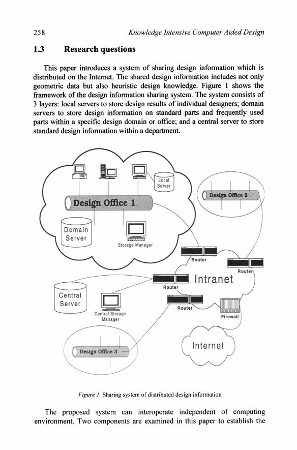
This paper introduces a system of sharing design information which is distributed on the Internet. The shared design information includes not only geometric data but also heuristic design knowledge. Figure 1 shows the framework of the design information sharing system. The system consists of 3 layers: local servers to store design results of individual designers; domain servers to store design information on standard parts and frequently used parts within a specific design domain or office; and a central server to store standard design information within a department.
Central Se rver
Centra l Storage Manager
Intranet
Figure I . Sharing system of distributed design information
The proposed system can interoperate independent of computing environment. Two components are examined in this paper to establish the
Lens Barrel Design Based On Distributed Knowledge-Base 259
framework of the system. The first is the distribution of design expert systems around the network; the method of controlling the remote knowledge-base and the inferencing engine through the Internet is also described. Second, we will address organization of the clients. A client controls the CAD system of an individual designer, the remote CAD data, the knowledge-base, and the remote inference engine.
2. DISTRIBUTED DESIGN EXPERT SYSTEM
In order to distribute the knowledge-base of design information, a communication method is required. It is a difficult task to construct a lowlevel communication interface, because a low-level interface requires complicated programming work when the specifications of its interface are changed. Such programming adjustment may bring about consistency and adjustment problems. To prevent these problems, a standard method is required such as KQML, CORBA, or DCOM, which use a high level interface of communication.
KQML (Knowledge Query and Manipulation Language) is a language designed by the External Interface Working Group of ARPA Knowledge Sharing Effort which works for communication between software agents (DARPA,1993).
2.1 CORDA
CORBA (Common Object Request Broker Architecture) is an open distributed object infrastructure being standardized by the OMG (Object Management Group). It allows applications to communicate with each other regardless of their location or designer. CORBA defines true interoperability by specifying how ORBs (Object Request Broker) from different vendors can inter-operate (Kim et aI., 1998).
ORB is the middleware that establishes client-server relationships between objects. Using ORB, a client can invoke a method on a server; the cI ient need not be aware of the server object's location, operating system, or programming language.
2.2 OLE/COM and DCOM
Whereas CORBA is considered an industry standard, OLE (Object Linking Embedding) / COM (Component Object Model) is a standard from Microsoft (Brockschmidt, 1995). The OLE/COM runs only on MS
260 Knowledge Intensive Computer Aided Design
Windows, and OLE objects are integrated based on COM architecture, which is similar to the CORBA.
OLE supports frameworks to create, manage, and access object~based components which serve other objects or applications on Windows. On the other hand, COM is a protocol for communication among objects; OLE is a COM object. Because Microsoft Windows™ is popular, COM can be regarded as a standard for personal computers.
A COM object consists of member data and member functions. In COM terminology, a set of such member functions is called the interface, in which methods of object-oriented programming are included. COM supports interface pointers to invoke these methods.
DC OM is a network version of COM. While COM runs on a single machine, DCOM supports communications with processes of different machines. The architecture of COM and DC OM is similar to that of CORBA; however, COM does not support the concept of inheritance as does CORBA. It is inconvenient if inheritance is used to implement multiple inheritance. Further, COM runs only on Microsoft operating systems.
2.3 Product design environment and CORBA
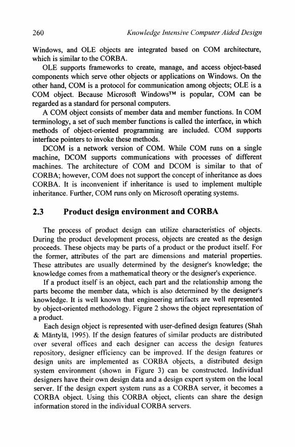
The process of product design can utilize characteristics of objects. During the product development process, objects are created as the design proceeds. These objects may be parts of a product or the product itself. For the former, attributes of the part are dimensions and material properties. These attributes are usually determined by the designer's knowledge; the knowledge comes from a mathematical theory or the designer's experience.
If a product itself is an object, each part and the relationship among the parts become the member data, which is also determined by the designer's knowledge. It is well known that engineering artifacts are well represented by object-oriented methodology. Figure 2 shows the object representation of a product.
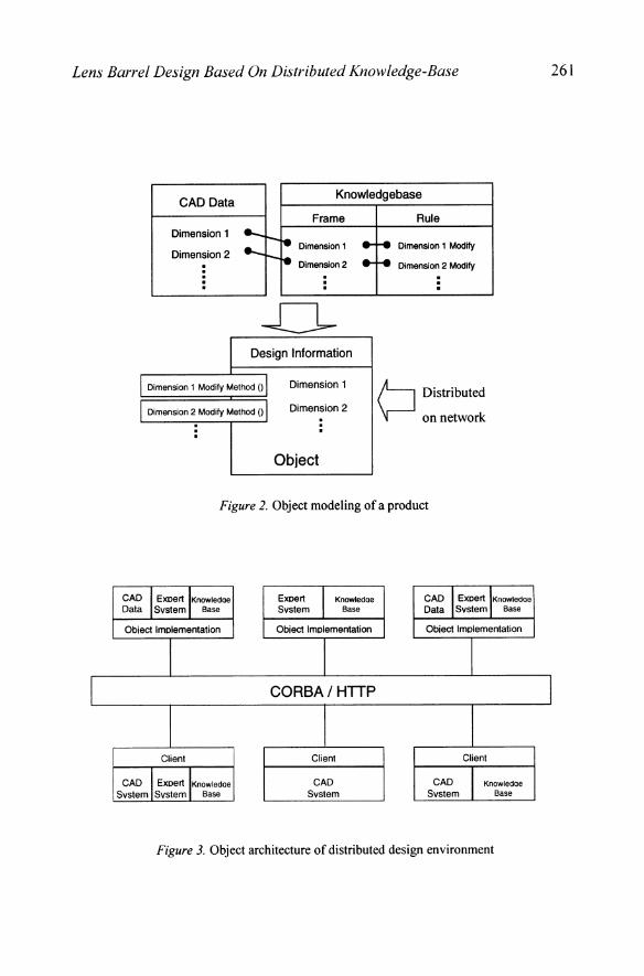
Each design object is represented with user-defined design features (Shah & Mantyla, 1995). If the design features of similar products are distributed over several offices and each designer can access the design features repository, designer efficiency can be improved. If the design features or design units are implemented as CORBA objects, a distributed design system environment (shown in Figure 3) can be constructed. Individual designers have their own design data and a design expert system on the local server. If the design expert system runs as a CORBA server, it becomes a CORBA object. Using this CORBA object, clients can share the design information stored in the individual CORBA servers.
Lens Barrel Design Based On Distributed Knowledge-Base
I
CAD Data Knowledgebase
Dimension 1
Dimension 2
Frame
Dimension 1
Dimension 2
Design Information
I Dimension 1 Modify Method 0 I I Dimension 2 Modify Method 0 I
Dimension 1
Dimension 2
Object
Rule
Dimension 1 Modify
Dimension 2 Modify
Distributed
on network
Figure 2. Object modeling of a product
CAD I. Expert, IKnOWledoe Data SYstem Base
Expert 1 Knowledoe SYstem Base
CAD IExpert,IKnOWledOe Data SYstem Base
Obiect Implementation Obiect Implementation Obiect Implementation
I CORBAI HTTP
I Client Client Client
CAD ,I. Expert,IKnOWledae CAD CAD Knowledae SYstem SYstem Base SYstem SYstem Base
Figure 3. Object architecture of distributed design environment
261
I
262 Knowledge Intensive Computer Aided Design
2.4 Distributed design expert system
The task of product design is to determine the geometry and relationships of its parts. That of product design is to determine system configuration. Parts of a system and its own composition have geometric information. A design expert system is software which aids in the design task with heuristic knowledge. There are various kinds of design expert systems according to their target domains; expert system should have knowledge about geometry, and the geometry should be visualized to users; this geometric information can be shared by designers who are connected on the Internet. Expert systems can show the product geometry by controlling a CAD system, because CAD systems are generally used for product design.
CAD systems and expert system shells have been integrated through the network (CORBA). Distributed design data at client sites can be utilized by expert system. It is assumed that designers use the same CAD system. The expert system which controls design results from the CAD system behaves as a CORBA server. Clients are distributed on the network, and downstream designers access the CAD data through the client. They remotely control the expert system, and modify the CAD data using design methods such as parametric design.
3. SYSTEM ARCHITECTURE AND EXPERIMENT
One efficient way to implement the distributed design expert system is using a web browser. CAD data and the client applet can be transmitted according to the HTTP. The design information sharing environment such as that shown in Figure 3 can be established by applying methods of system integration; when implemented on the intranet, it can meet the requirements of the sharing environment of domain sever layer of Figure I.
3.1 Experimental design task
To verify the design information sharing environment, an experiment was performed with the lens barrel design of a projection TV. The lens-CRT assembly consisted of a CRT, a cooling system, and lenses. The lens was the core component; the barrel controlled and supported the lenses.
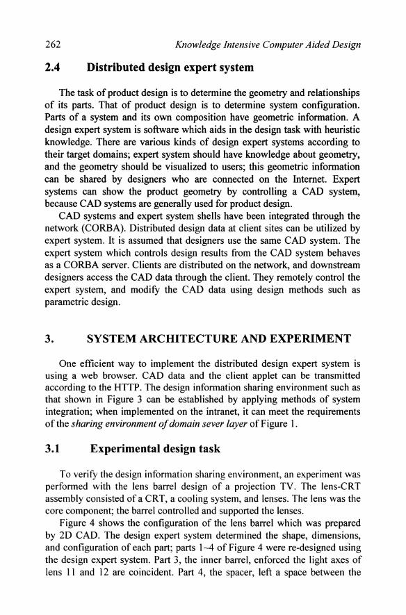
Figure 4 shows the configuration of the lens barrel which was prepared by 2D CAD. The design expert system determined the shape, dimensions, and configuration of each part; parts 1-4 of Figure 4 were re-designed us'ing the design expert system. Part 3, the inner barrel, enforced the light axes of lens 11 and 12 are coincident. Part 4, the spacer, left a space between the

Lens Barrel Design Based On Distributed Knowledge-Base 263
lenses 11 and 12. Part 1, the F-clamp, fixed the two lenses and the spacer to the inner barrel. Part 2, the outer barrel, fixed this lens system. Parts 1-4 were the main parts of the barrel, and were dependent on the configuration of the lenses.
The basic shape of a product depends on the engineer's experience. The design expert system is useful for engineers who have little experience in barrel design. It helps to produce the basic shape and configuration of the barrel model suitable for the lens data. This barrel can be used as the final design or can be changed by downstream engineers.
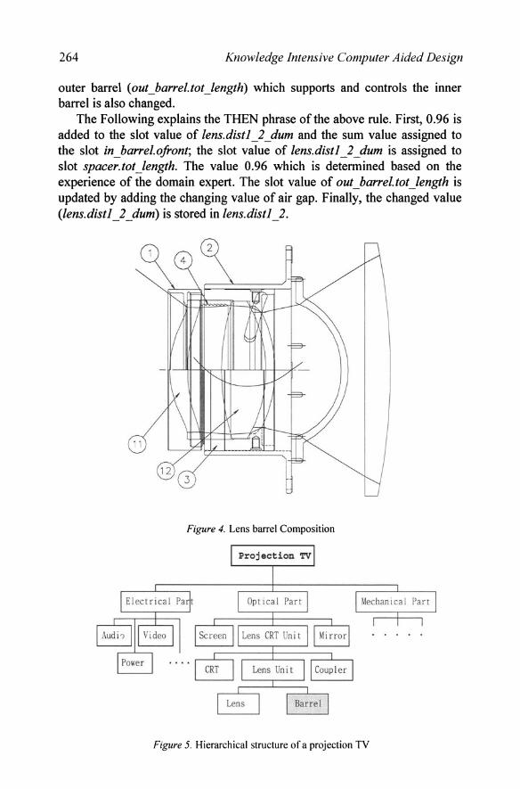
Figure 5 shows the hierarchical structure of a projection TV, which consists of electrical, optical, and mechanical parts. Electrical parts include audio, video, and the power system. Optical parts are comprised of a screen, a lens CRT unit, and a mirror. Mechanical parts are made of a case, a screen frame, a back cover, etc. The lens CRT unit contains a CRT, a lens unit, and a coupler. The lens unit is subdivided into lenses and a barrel.
In this experiment, the knowledge-base is consisted of 9 rules and 5 objects which corresponded to 5 parts. Dimensions of the parts were stored in the slots of objects. Each rule checked the changes of slot values of the lens object, and modified the slot values of the part objects accordingly. Special method of knowledge acquisition was not used, as the authors are domain experts.
The following illustrates a rule in the knowledge-base ..
IF (lens.distl_ 2 • lens.distl_ 2 _dum) AND ( lens.distl_2_dum· 0)
THEN ASSIGN (lens.distl_2_dum+O.96) TO (in_barrel.ofront) ASSIGN (lens.distl_2_dum) TO (spacer.tot_length) ASSIGN (out_barrel.tot_length + (lens.distl_2_dum -lens.distl_2»
TO (out_barrel. tot_length) ASSIGN (lens.distl_2_dum) TO (lens.distl_2)
The above rule changes dimensions and composition of the parts when the air gap between lens II and lens 12. lens.dist 1_2 is a slot corresponding to the air gap in the knowledge-base; its initial value is 16.9mm. The above rule is performed only when the slot value of lens.distl_2_dum changes. lens.distl_2_dum is a slot for the air gap value which can be changed by the user. If the air gap is changed, the length of spacer (spacer. tot_length) and the length of the inner barrel are changed accordingly. The slot in _barrel.ofront controls the length of the inner barrel. The length of the
264 Knowledge Intensive Computer Aided Design
outer barrel (out_barrel. tot_length) which supports and controls the inner barrel is also changed.
The Following explains the THEN phrase of the above rule. First, 0.96 is added to the slot value of lens.distl_2_dum and the sum value assigned to the slot in_barrel.ofront; the slot value of lens.distl_2_dum is assigned to slot spacer. tot_length. The value 0.96 which is detennined based on the experience of the domain expert. The slot value of out_barrel.tol_length is updated by adding the changing value of air gap. Finally, the changed value (iens.distl 2 dum) is stored in lens.distl 2. - - -
Figure 4. Lens barrel Composition
Figure 5. Hierarchical structure of a projection TV
Lens Barrel Design Based On Distributed Knowledge-Base 265
3.2 System integration
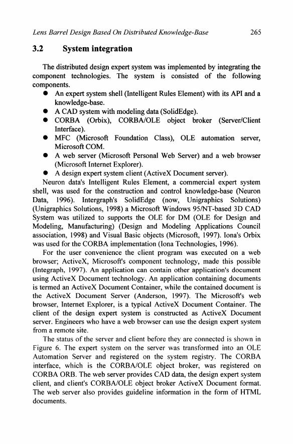
The distributed design expert system was implemented by integrating the component technologies. The system is consisted of the following components.
• An expert system shell (Intelligent Rules Element) with its API and a knowledge-base.
• A CAD system with modeling data (SolidEdge). • CORBA (Orbix), CORBA/OLE object broker (Server/Client
Interface). • MFC (Microsoft Foundation Class), OLE automation server,
Microsoft COM. • A web server (Microsoft Personal Web Server) and a web browser
(Microsoft Internet Explorer). • A design expert system client (ActiveX Document server). Neuron data's Intelligent Rules Element, a commercial expert system
shell, was used for the construction and control knowledge-base (Neuron Data, 1996). Intergraph's SolidEdge (now, Unigraphics Solutions) (Unigraphics Solutions, 1998) a Microsoft Windows 95lNT-based 3D CAD System was utilized to supports the OLE for DM (OLE for Design and Modeling, Manufacturing) (Design and Modeling Applications Council association, 1998) and Visual Basic objects (Microsoft, 1997). lona's Orbix was used for the CORBA implementation (Iona Technologies, 1996).
For the user convenience the client program was executed on a web browser; ActiveX, Microsoft's component technology, made this possible (lntegraph, 1997). An application can contain other application's document using ActiveX Document technology. An application containing documents is termed an ActiveX Document Container, while the contained document is the ActiveX Document Server (Anderson, 1997). The Microsoft's web browser, Internet Explorer, is a typical ActiveX Document Container. The client of the design expert system is constructed as ActiveX Document server. Engineers who have a web browser can use the design expert system from a remote site.
The status of the server and client before they are connected is shown in Figure 6. The expert system on the server was transformed into an OLE Automation Server and registered on the system registry. The CORBA interface, which is the CORBA/OLE object broker, was registered on CORBA ORB. The web server provides CAD data, the design expert system client, and client's CORBA/OLE object broker ActiveX Document format. The web server also provides guideline information in the form of HTML documents.
266 Knowledge intensive Computer A ided Design
Expert System Shell SERVER (Intelligent Rules Element)
API CORBA/OLE Object Broker
KnOWledge- I
I MFC Lib.
base
OLE Automation Proxy Object
-1 Design Expert System Client
A
'I
T i OLE Automation Server
Microsoft COM
CORBA/OLE Object Broker
CORBA Interface
CAD System (Solid Edge)
J (ActiveX Document)
H CAD Data (SolidEdge)
Web Server (Microsoft Personal Web Server)
HTML Document
Web Browser(MS IE 3.0) (ActiveX Container)
Client
Figure 6. Status of server and client before connection
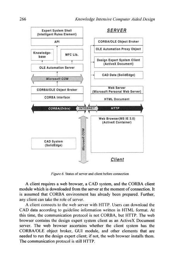
A client requires a web browser, a CAD system, and the CORBA client module which is downloaded from the server at the moment of connection. It is assumed that CORBA environment has already been prepared. Further, any client can take the role of server.
A client connects to the web server with HTTP. Users can download the CAD data according to guideline information written in HTML format. At this time, the communication protocol is not CORBA, but HTTP. The web browser contains the design expert system client as an ActiveX Document server. The web browser ascertains whether the client system has the CORBAIOLE object broker, GUI module, and other elements that are needed to run the design expert client; if not, the web browser installs them. The communication protocol is still HTTP.
Lens Barrel Design Based On Distributed Knowledge-Base 267
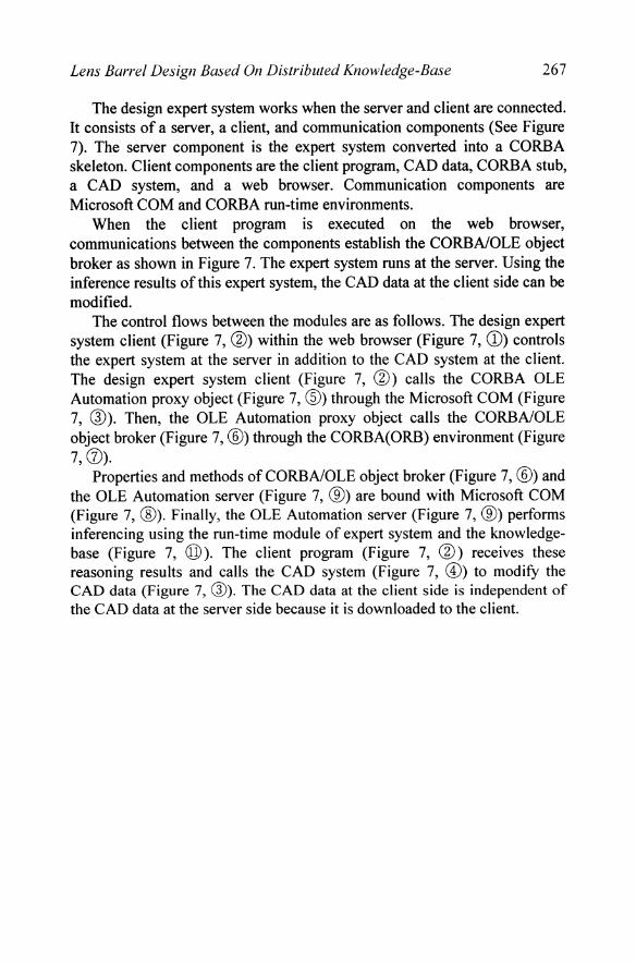
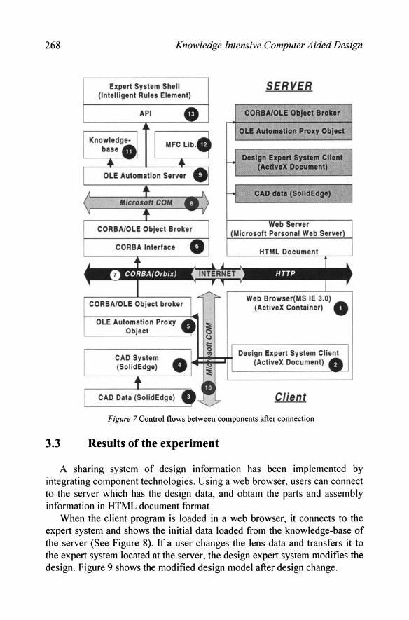
The design expert system works when the server and client are connected. It consists of a server, a client, and communication components (See Figure 7). The server component is the expert system converted into a CORBA skeleton. Client components are the client program, CAD data, CORBA stub, a CAD system, and a web browser. Communication components are Microsoft COM and CORBA run-time environments.
When the client program is executed on the web browser, communications between the components establish the CORBAlOLE object broker as shown in Figure 7. The expert system runs at the server. Using the inference results of this expert system, the CAD data at the client side can be modified.
The control flows between the modules are as follows. The design expert system client (Figure 7, @) within the web browser (Figure 7, CD) controls the expert system at the server in addition to the CAD system at the client. The design expert system client (Figure 7, @) calls the CORBA OLE Automation proxy object (Figure 7, ®) through the Microsoft COM (Figure 7, @). Then, the OLE Automation proxy object calls the CORBA/OLE object broker (Figure 7, @) through the CORBA(ORB) environment (Figure 7,0).
Properties and methods ofCORBAlOLE object broker (Figure 7, @) and the OLE Automation server (Figure 7, ®) are bound with Microsoft COM (Figure 7, ®). Finally, the OLE Automation server (Figure 7, ®) performs inferencing using the run-time module of expert system and the knowledgebase (Figure 7, @). The client program (Figure 7, @) receives these reasoning results and calls the CAD system (Figure 7, @) to modifY the CAD data (Figure 7, @). The CAD data at the client side is independent of the CAD data at the server side because it is downloaded to the client.
268 Knowledge Intensive Computer Aided Design
Expert System Shell (Intelligent Rules Element)
SERVER
CORBA/OLE Object Broker
OLE Automation Proxy Object
Dellgn Expert SYltem Cnent (ActlveX Document)
CAD data (SolidEdge)
Web Browser(MS IE 3.0) (ActiveX Container) 0
I ~t:::pH Design Expert System foil (ActiveX Document)
Client
Figure 7 Control flows between components after connection
3.3 Results of the experiment
A sharing system of design information has been implemented by integrating component technologies. Using a web browser, users can connect to the server which has the design data, and obtain the parts and assembly information in HTML document format
When the client program is loaded in a web browser, it connects to the expert system and shows the initial data loaded from the knowledge-base of the server (See Figure 8). If a user changes the lens data and transfers it to the expert system located at the server, the design expert system modifies the design. Figure 9 shows the modified design model after design change.

Lens Barrel Design Based On Distributed Knowledge-Base
••• I:og "'* !11ft
Figure 8 Creation of a model by default values
--114.
!'!~""".""1!11 ...".01. =;;:;==-,.--. S!:!_'lttC"
I.IAM [::., .' ,_Jib
_t ~.: _U.O[- , _I. _, in,!'I!""--=~
Slop --""Goo njx'"'w,,----': ~
"............. s.Mht ... .,
OJ!;''' I *-''''''>1, n':'l , """11
Figure 9 Modified model after inferencing
269
270 Knowledge Intensive Computer Aided Design
4. CONCLUSION
The following benefits can be identified from the results of the research; • The product design expert system is constructed as an OLE
Automation server using the API of the expert system shell. Because this expert system is integrated with CORBA, not only the OLE containers within the system but also remote Unix-based CORBA clients can control the expert system through network access.
• The expert system client has been implemented and can control the CAD system and can remotely control the expert system server through the CORBA stub.
• The distributed expert system is easy to use because it is embedded in a web browser.
The following observations are made from the research; • A prototype of the collaborative design system which shares
geometric information and design knowledge has been proposed. And through the implementation process, OLE object technology, CORBA technology, an expert system, and the web have been integrated.
• While the prototype system has been tested with the SolidEdge CAD system, the proposed prototype can be applied to any CAD application which works with MS Windows, COM, and CORBA
An expert system efficiently utilizes knowledge of human expert. However, use of the expert system by a practicing engineer can be problematic due to difficulty in knowledge acquisition. The knowledge-base should be easy to build and efficiently maintained. If the domain expert knows how to describe knowledge pieces, the knowledge acquisition bottleneck can be alleviated.
REFERENCES
Ahn, Sang Jun, Lee, Soo Hong (1998), "Agent-based Collaborative Design Environment using WWW" (in Korean), Transactions of the Society of CAD/CAM Engineers, 3(1):31-39.
Anderson, Jerry (1997), ActiveX programming with Visual C++ 5.0, Que Corporation. Belo, Orlando, Ribero, Antonio (1995), "A Web-based framework for distributed expert
systems", 1st Portuguese WWW Conference (CNW3), http://www.di.uminhopt/-anr/ PAPERSlWWW95/www95.htmi, html.
Choi, Hae-Jin, Lee, Soo-Hong (1997), "A Development of Ship-Block Cutting CAD Module Connected to WWW" (in Korean), Proceedings of the Society of CAD/CAM Engineers Conference, pp. 16-25.
DARPA Knowledge Sharing Initiative External Interfaces Working Group (1993), "Specification ofthe KQML Agent - Communication Language (draft)".
Lens Barrel Design Based On Distributed Knowledge-Base 271
Design and Modeling Applications Council association (1998), "What is OLE for Design and Modeling?", http://www.dmac.orglwhatislwhatis.htm.html.
Intergraph Corporation (1997), SolidEdge programming users guide. Iona Technologies Ltd. (1996), Orbix2 : Desktop programming guide, pp. 4-9. Kim, Joon Hwan., Han, Soon-Hung, Han, S. B., Kim, H. (1998), "Retrieving a STEP
Database through the CORBA on the Internet" (in Korean), Proceeding of the Society of CADICAM Engineers Conference, pp.24-29.
Kraig Brockschmidt (1995), Inside OLE, second edition", Microsoft Press. Lee, S. K., Lee, Jae Kyu. Lee K. J. (1997), "Customized Purchase Supporting Expert System:
UNIK-SES", Expert Systems with Applications, 11 (4), pp. 431-441. Lee, W. K., Lee, Jae Kyu (1995), "Intelligent Agent Based Electronic Marketing: UNIK
AGENT", Proceedings of Korean Expert Systems Society '95 Spring Conference, pp. 179-180.
Microsoft Corporation (1997), "Microsoft COM", http://www.microsoft.comlcoml.html. Neuron Data Inc (1996), Neuron Data Elements Environment: Intelligent Rules Element V4.0
- User's Guide, 1996. Pak, S. C., Choi, J. M., Lim, Y. H., Chang M. W., Park, S. K., Lee, K. R. (1996), "Interaction
Contortion a Distributed Multi-agent System" (in Korean), The Transactions of Korea Information Processing Society, 3(7): 1803-1811.
Regli, William C. (1997), "Internet-Enabled Computer-Aided Design", IEEE Internet Computing, 1(1), pp. 39-51.
Sandia National Laboratories (1998), "Jess: the Java Expert System Shell", http://herzberg.ca. sandia.govljessl, html.
Shah, Jami J., Miintylii, Martti (1995), Parametric and Feature-Based CADICAM, John Wiley & Son Inc., New York, pp. 259-266.
Terk Michael (1996), "Changing Priorities of Research on WWW-Based Engineering Services", Workshop Proceedings of Network-Centric CAD : A Research Planning Workshop, pp. 169-185.
Tom Christiansen (1996), "What is Perl?", http://language.perl.comiinfo/synopsis.html,html. Unigraphics Solutions (1998), "SolidEdge", http://134.244.209.211Default.htm, html. VRML Consortium (1998), "What is VRML?", http://www.vrml.org/consort/FAQ.html, html.