10" X 54" CHIPMASTER® 430 EVS VARIABLE-SPEED MILL ...
92
Copyright © May, 2010 Revised April 2018 (KB) For Machines Mfd. Since 3/18 MODEL SB1028 10" X 54" CHIPMASTER ® 430 EVS VARIABLE-SPEED MILL MACHINE OWNER'S MANUAL
-
Upload
khangminh22 -
Category
Documents
-
view
1 -
download
0
Transcript of 10" X 54" CHIPMASTER® 430 EVS VARIABLE-SPEED MILL ...

Copyright © May, 2010 Revised April 2018 (KB) For Machines Mfd. Since 3/18
MODEL SB1028
10" X 54" CHIPMASTER® 430EVS VARIABLE-SPEED MILL MACHINE
OWNER'S MANUAL

Customer ServiceWe stand behind our machines. If you have any service questions, parts requests or general questions about the machine, feel free to contact us.
South Bend Lathe Co.P.O. Box 2027Bellingham, WA 98227Phone: (360) 734-1540Parts Department: (417) 886-2954Fax: (360) 676-1075 (International)Fax: (360) 734-1639 (USA Only)Email: [email protected]
UpdatesFor your convenience, any updates to this manual will be available to download free of charge through our website at:
www.southbendlathe.com
Scope of ManualThis manual helps the reader understand the machine, how to prepare it for operation, how to control it during operation, and how to keep it in good working condition. We assume the reader has a basic understanding of how to operate this type of machine, but that the reader is not familiar with the controls and adjustments of this specific model. As with all machinery of this nature, learning the nuances of operation is a process that happens through training and experience. If you are not an experienced operator of this type of machinery, read through this entire manual, then learn more from an experienced operator, schooling, or research before attempting operations. Following this advice will help you avoid serious personal injury and get the best results from your work.
Manual FeedbackWe've made every effort to be accurate when documenting this machine. However, errors sometimes happen or the machine design changes after the documentation process—so the manual may not exactly match your machine. If a difference between the manual and machine leaves you in doubt, contact our customer service for clarification.
We highly value customer feedback on our manuals. If you have a moment, please share your experience using this manual. What did you like about it? Is there anything you would change to make it better? Did it meet your expectations for clarity, professionalism, and ease-of-use?
South Bend Lathe, Inc.C/O Technical Documentation ManagerP.O. Box 2027Bellingham, WA 98227Email: [email protected]
Table of ContentsINTRODUCTION ...............................................................3About This Machine .............................................3
Foreword .............................................................3Capabilities .........................................................3Features ..............................................................3
Full View Identification .......................................4Drive System & Headstock Identification ..........5Control Panel Identification ................................6Machine Specifications ........................................7
SAFETY ............................................................................. 10Understanding Risks of Machinery ..................10Basic Machine Safety ........................................10Additional Milling Machine Safety ...................12
PREPARATION .............................................................. 13Preparation Overview ........................................13Required for Setup .............................................13Unpacking ..........................................................14Inventory ............................................................14Cleaning & Protecting .......................................15Location ..............................................................16
Physical Environment ........................................16Electrical Installation ........................................16Lighting ............................................................16Weight Load ......................................................16Space Allocation ................................................16
Lifting & Moving ................................................17Leveling & Mounting .........................................18
Leveling ............................................................18Bolting to Concrete Floors ..................................18
Assembly ............................................................19Initial Lubrication .............................................21Power Requirements ..........................................21Power Connection ..............................................22Test Run .............................................................22
Test Run the Mill...............................................22Test Run X-Axis Power Feed ..............................25
Spindle Break-In ................................................26Inspections & Adjustments ...............................26
OPERATION .................................................................... 27Operation Overview ...........................................27Control Panel .....................................................28Table Movement.................................................29
Table & Knee Locks ...........................................29
Graduated Index Rings ......................................30X-Axis Power Feed .............................................30Operating X-Axis Power Feed ............................31
Head Movement .................................................32Tilting Head ......................................................32Rotating Head ...................................................33Tramming Spindle .............................................33
Ram Movement ..................................................36Moving Ram Back and Forth..............................36Rotating Ram ....................................................36
Setting Spindle Speed ........................................37Determining Spindle Speed ................................37Setting Spindle Speed Range .............................37Setting Spindle Speed ........................................38
Downfeed Controls .............................................38Coarse Downfeed ...............................................38Fine Downfeed Controls .....................................40Fine Downfeed Handwheel ................................40Auto-Downfeed System ......................................41
Spindle Brake .....................................................42Loading/Unloading Tooling ...............................43
Loading Tooling .................................................43Unloading Tooling .............................................43
MAINTENANCE .............................................................44Maintenance Schedule .......................................44
Ongoing .............................................................44Before Beginning Operations .............................44Daily, After Operations ......................................44
Cleaning .............................................................46Unpainted & Machined Surfaces ........................46
Lubrication .........................................................46Quill ..................................................................47Table Ways (One-Shot Oiler) ..............................47Speed Range Bearing Sleeve ..............................48Headstock Gearing ............................................48Ram Ways .........................................................48Head & Ram Rack & Pinion Gear ......................49Power Feed Gears ..............................................49
Coolant Reservoir...............................................51Hazards.............................................................51Checking Coolant Level .....................................51Changing Coolant ..............................................52
Machine Storage ................................................53
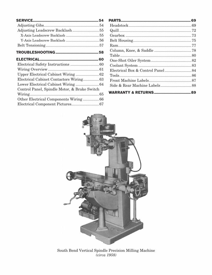
South Bend Vertical Spindle Precision Milling Machine(circa 1958)
SERVICE...........................................................................54Adjusting Gibs....................................................54Adjusting Leadscrew Backlash .........................55
X-Axis Leadscrew Backlash ...............................55Y-Axis Leadscrew Backlash ...............................56
Belt Tensioning ..................................................57
TROUBLESHOOTING .................................................58
ELECTRICAL ...................................................................60Electrical Safety Instructions ...........................60Wiring Overview ................................................61Upper Electrical Cabinet Wiring ......................62Electrical Cabinet Contactors Wiring ...............63Lower Electrical Cabinet Wiring ......................64Control Panel, Spindle Motor, & Brake Switch Wiring .................................................................65Other Electrical Components Wiring ...............66Electrical Component Pictures..........................67
PARTS................................................................................69Headstock ...........................................................69Quill ....................................................................72Gearbox ..............................................................73Belt Housing.......................................................75Ram .....................................................................77Column, Knee, & Saddle ...................................78Table ...................................................................80One-Shot Oiler System ......................................82Coolant System ..................................................83Electrical Box & Control Panel .........................84Tools ....................................................................86Front Machine Labels ........................................87Side & Rear Machine Labels .............................88
WARRANTY & RETURNS ..........................................89

For Machines Mfd. Since 3/18 Model SB1028
-3-
I N T R O D U C T I O N
About This MachineCapabilitiesThis Milling Machine is built for daily, non-stop use in a busy industrial setting, tool room, or school shop. It is easy to set-up, truly accurate, and built to give you many years of service when properly cared for. This milling machine supports large workpieces and is perfect for face milling, end milling, planing, slot or keyway cutting, dovetailing, routing, drilling, reaming, and boring to name a few. With the movable ram and tilting head, all these tasks can be performed on horizontal, vertical, and angled surfaces. When equipped with additional accessories, such as a rotary table or dividing head, this milling machine can do even more.
Foreword"Most boys should learn a trade in order that they may become skilled workmen. The trained workman is always in demand...When a boy has learned a trade, becomes a skilled mechanic, he has excellent equipment with which to begin life's battle, but he need not stop there. George Westinghouse, the Wright Brothers, Henry Ford, and the Studebaker Brothers were mechanics, and it was their mechanical training that made their success possible." —Machine Shop Equipment, 2nd Ed., 1920, by the O'Brien Brothers, founders of South Bend Lathe.
The first South Bend milling machine debuted in the 1950's. During that time, the milling machine and the already well-established South Bend lathes created the foundation of many tool rooms and school shops across America and beyond her borders. Many young people in those days came of age on South Bend equipment, becoming world-class machinists, mechanical engineers, inventors, and manufacturing visionaries.
A lot has changed in the world since then. Those same school shops have mostly been replaced by computer labs. The technology in the rotary dial phone, television set, mechanical calculator, computer, and camera of that decade could barely fit into one large room together—now they fit into a tiny box that is no bigger than a box of breath mints. And the average production machinist spends more time at a computer than at a machine. Technology has been much refined and the world operates on a much faster pace.
But some things haven't changed. The same human ingenuity and passion that created the best mechanical technology of today still exists within us. The core machines of the modern shop, like this South Bend milling machine, are still fundamentally important.
When you think about it, the greatest mechanical technology of the future will be what we create today. As the owner of a South Bend milling machine, you are now part of a great legacy. What will you create with yours?
FeaturesThis milling machine features 3-axis table movement with built-in X-axis and Z-axis power feed. It is constructed with high-grade Meehanite castings, and the saddle and knee ways are Turcite coated and built with wide square ways for maximum support and accuracy through the full range of movement.
To ensure quality work results, we have equipped this mill with NSK/NTN spindle bearings that are rated to P4 (ABEC-7) tolerances. The spindle taper is R8 and has powered downfeed with fine, medium, and coarse feed controls.
The headstock is mounted on a wide dovetail movable ram with 19 1⁄2" of travel on the column and 360° rotating capability. The headstock itself can swivel 90° left/right or 45° forward/back so it can be positioned for nearly any setup needed.
To reduce the time spent doing daily lubrication, this milling machine is outfitted with a one-shot lubrication system that is as quick and easy as one pump of a lever.
Quality Allen-Bradley electrical components and attention to detail provide dependable electrical control of the powered movements.
Last but not least, this milling machine includes a circulating coolant system with the pump and reservoir in the column base.
-4-
For Machines Mfd. Since 3/18Model SB1028 I N T R O D U C T I O N
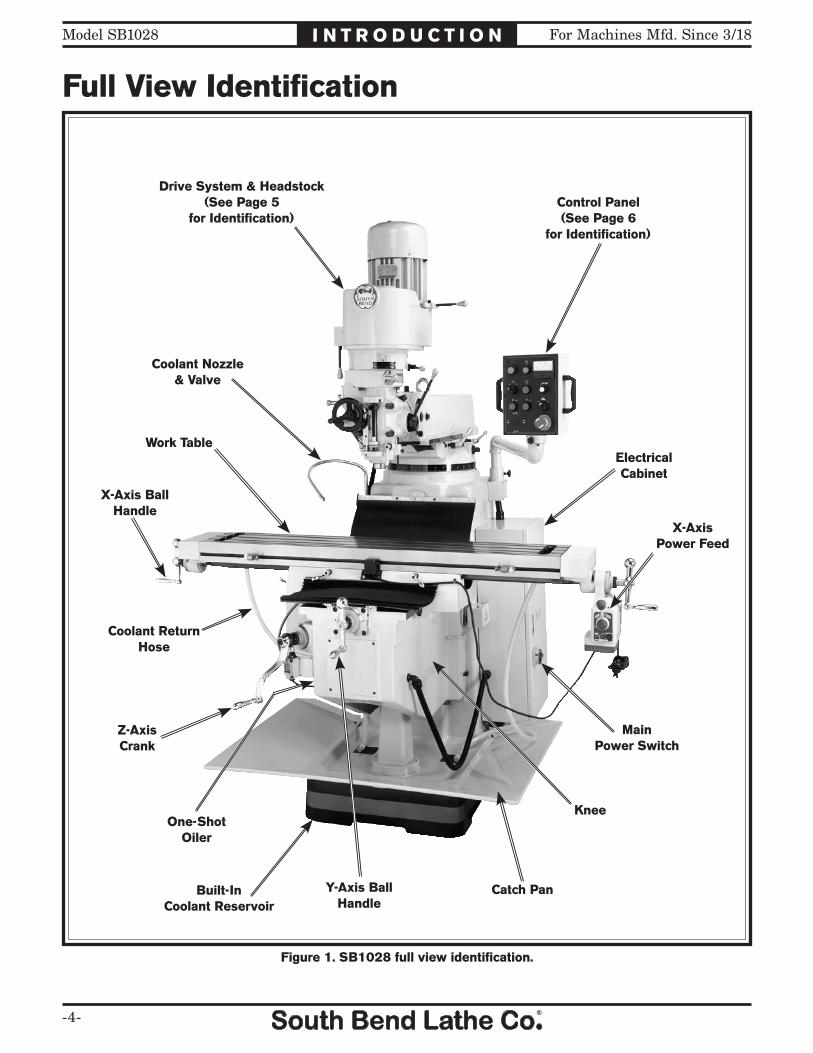
Full View Identification
Figure 1. SB1028 full view identification.
Drive System & Headstock(See Page 5
for Identification)
Coolant Nozzle& Valve
Coolant ReturnHose
One-ShotOiler
X-AxisPower Feed
Control Panel(See Page 6
for Identification)
ElectricalCabinet
Catch Pan
Knee
Work Table
X-Axis Ball Handle
Y-Axis Ball Handle
Z-Axis Crank
MainPower Switch
Built-InCoolant Reservoir

For Machines Mfd. Since 3/18 Model SB1028
-5-
I N T R O D U C T I O N
Drive System & Headstock Identification
Figure 2. Model SB1028 drive system and headstock identification.
Motor
Belt Housing
DownfeedRate Selector
DownfeedDirection Pin
Fine DownfeedHandwheel
Downfeed Clutch Lever
AdjustableDownfeed Stop
Quill LockLever Dial Indicator
Rod
Control Panel(See Page 6
for Identification)
CoarseDownfeed
Lever
Spindle SpeedRange Selector
Ram RotationScale
Belt TensionAdjustment Lever
Spindle BrakeLever
Manual/PowerDownfeedSelector
Quill & Spindle

-6-
For Machines Mfd. Since 3/18Model SB1028 I N T R O D U C T I O N
Control Panel Identification
Figure 3. Model SB1028 control panel identification.
Power ONButton & Lamp
Spindle ONButton
Spindle SpeedTachometer
SpindleSpeed Dial
CoolantSwitch
EmergencySTOP Button
Z-AxisDOWN Button
Z-AxisUP Button
Spindle OFFButton
SpindleDirectionSwitch
Serious personal injury could occur if you connect the machine to power before completing the setup process. DO NOT connect power until instructed to do so later in this manual.
Untrained users have an increased risk of seriously injuring themselves with this machine. Do not operate this machine until you have understood this entire manual and received proper training.
For Machines Mfd. Since 3/18 Model SB1028
-7-
I N T R O D U C T I O N
Model SB1028 Page 1 of 3
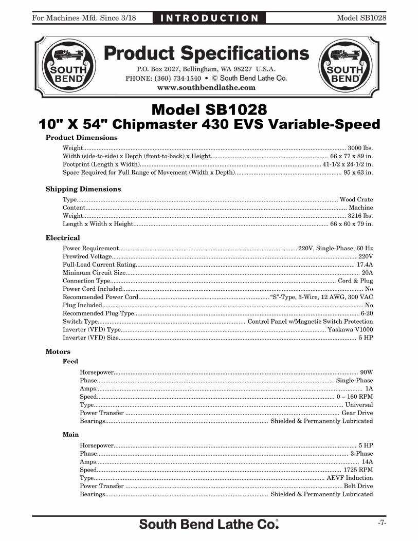
Model SB102810" X 54" Chipmaster 430 EVS VariableSpeed
Product DimensionsWeight........................................................................................................................................................... 3000 lbs.Width (side-to-side) x Depth (front-to-back) x Height..................................................................... 66 x 77 x 89 in.Footprint (Length x Width)........................................................................................................... 41-1/2 x 24-1/2 in.Space Required for Full Range of Movement (Width x Depth)............................................................... 95 x 63 in.
Shipping DimensionsType.......................................................................................................................................................... Wood CrateContent.......................................................................................................................................................... MachineWeight........................................................................................................................................................... 3216 lbs.Length x Width x Height................................................................................................................... 66 x 60 x 79 in.
ElectricalPower Requirement......................................................................................................... 220V, Single-Phase, 60 HzPrewired Voltage................................................................................................................................................ 220VFull-Load Current Rating................................................................................................................................. 17.4AMinimum Circuit Size.......................................................................................................................................... 20AConnection Type..................................................................................................................................... Cord & PlugPower Cord Included.............................................................................................................................................. NoRecommended Power Cord............................................................................. “S”-Type, 3-Wire, 12 AWG, 300 VACPlug Included.......................................................................................................................................................... NoRecommended Plug Type..................................................................................................................................... 6-20Switch Type....................................................................................... Control Panel w/Magnetic Switch ProtectionInverter (VFD) Type......................................................................................................................... Yaskawa V1000Inverter (VFD) Size............................................................................................................................................ 5 HP
MotorsFeed
Horsepower................................................................................................................................................ 90WPhase............................................................................................................................................ Single-PhaseAmps............................................................................................................................................................. 1ASpeed............................................................................................................................................ 0 – 160 RPMType................................................................................................................................................... UniversalPower Transfer .............................................................................................................................. Gear DriveBearings................................................................................................ Shielded & Permanently Lubricated
Main
Horsepower............................................................................................................................................... 5 HPPhase.................................................................................................................................................... 3-PhaseAmps........................................................................................................................................................... 14ASpeed................................................................................................................................................ 1725 RPMType........................................................................................................................................ AEVF InductionPower Transfer ................................................................................................................................ Belt DriveBearings................................................................................................ Shielded & Permanently Lubricated
-8-
For Machines Mfd. Since 3/18Model SB1028 I N T R O D U C T I O N
Model SB1028 Page 2 of 3
Coolant Pump
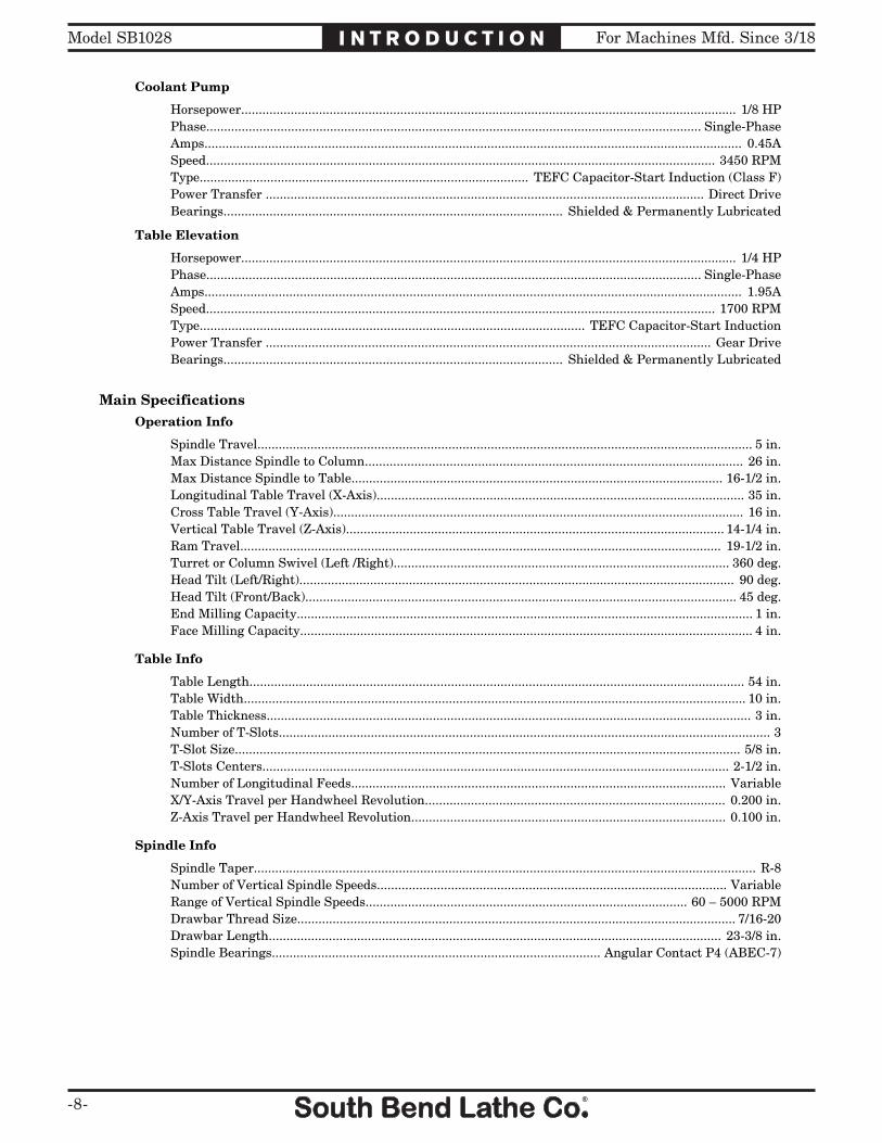
Horsepower............................................................................................................................................ 1/8 HPPhase............................................................................................................................................ Single-PhaseAmps........................................................................................................................................................ 0.45ASpeed................................................................................................................................................ 3450 RPMType............................................................................................. TEFC Capacitor-Start Induction (Class F)Power Transfer ............................................................................................................................ Direct DriveBearings................................................................................................ Shielded & Permanently Lubricated
Table Elevation
Horsepower............................................................................................................................................ 1/4 HPPhase............................................................................................................................................ Single-PhaseAmps........................................................................................................................................................ 1.95ASpeed................................................................................................................................................ 1700 RPMType............................................................................................................. TEFC Capacitor-Start InductionPower Transfer .............................................................................................................................. Gear DriveBearings................................................................................................ Shielded & Permanently Lubricated
Main SpecificationsOperation Info
Spindle Travel............................................................................................................................................ 5 in.Max Distance Spindle to Column........................................................................................................... 26 in.Max Distance Spindle to Table......................................................................................................... 16-1/2 in.Longitudinal Table Travel (X-Axis)........................................................................................................ 35 in.Cross Table Travel (Y-Axis).................................................................................................................... 16 in.Vertical Table Travel (Z-Axis)........................................................................................................... 14-1/4 in.Ram Travel........................................................................................................................................ 19-1/2 in.Turret or Column Swivel (Left /Right)............................................................................................... 360 deg.Head Tilt (Left/Right)........................................................................................................................... 90 deg.Head Tilt (Front/Back).......................................................................................................................... 45 deg.End Milling Capacity................................................................................................................................. 1 in.Face Milling Capacity................................................................................................................................ 4 in.
Table Info
Table Length............................................................................................................................................ 54 in.Table Width.............................................................................................................................................. 10 in.Table Thickness......................................................................................................................................... 3 in.Number of T-Slots........................................................................................................................................... 3T-Slot Size............................................................................................................................................... 5/8 in.T-Slots Centers.................................................................................................................................... 2-1/2 in.Number of Longitudinal Feeds.......................................................................................................... VariableX/Y-Axis Travel per Handwheel Revolution..................................................................................... 0.200 in.Z-Axis Travel per Handwheel Revolution......................................................................................... 0.100 in.
Spindle Info
Spindle Taper.............................................................................................................................................. R-8Number of Vertical Spindle Speeds................................................................................................... VariableRange of Vertical Spindle Speeds........................................................................................... 60 – 5000 RPMDrawbar Thread Size............................................................................................................................ 7/16-20Drawbar Length................................................................................................................................ 23-3/8 in.Spindle Bearings............................................................................................. Angular Contact P4 (ABEC-7)
For Machines Mfd. Since 3/18 Model SB1028
-9-
I N T R O D U C T I O N
Model SB1028 Page 3 of 3
Construction
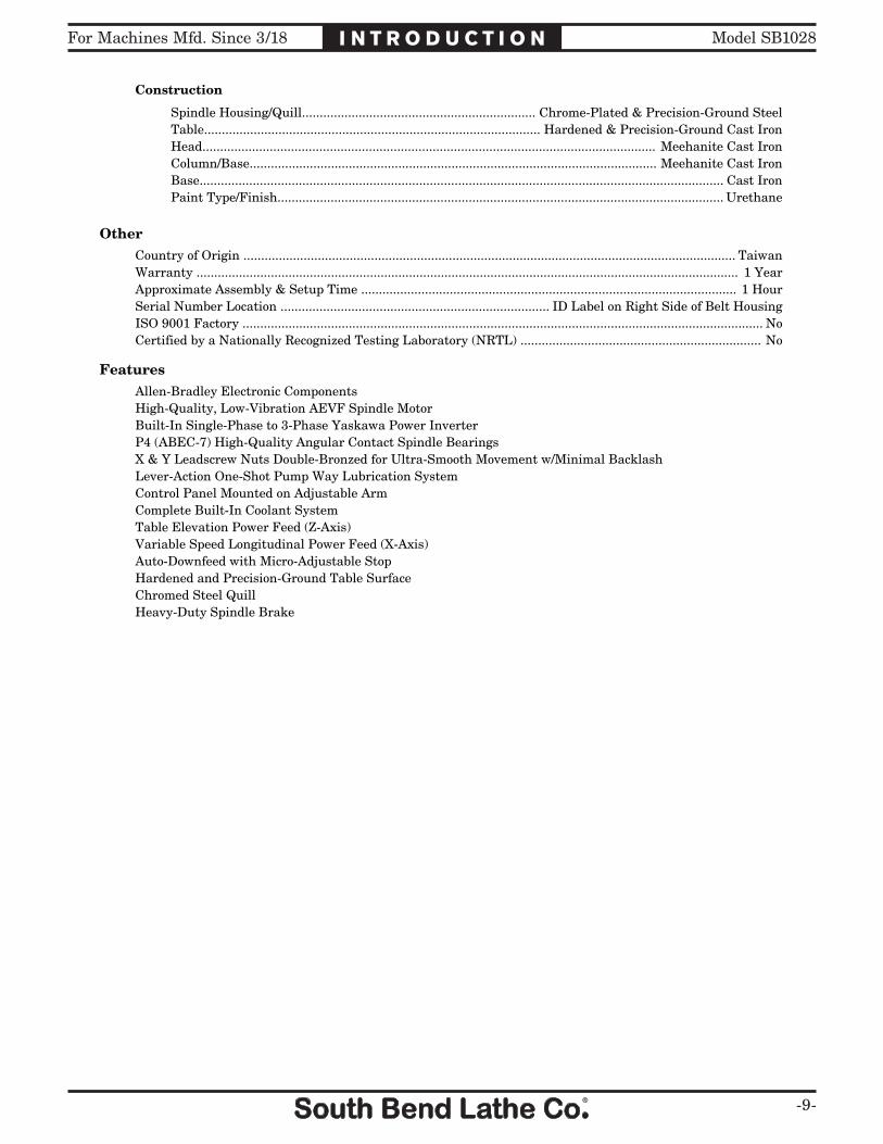
Spindle Housing/Quill.................................................................. Chrome-Plated & Precision-Ground SteelTable............................................................................................... Hardened & Precision-Ground Cast IronHead................................................................................................................................ Meehanite Cast IronColumn/Base................................................................................................................... Meehanite Cast IronBase.................................................................................................................................................... Cast IronPaint Type/Finish.............................................................................................................................. Urethane
OtherCountry of Origin ........................................................................................................................................... TaiwanWarranty ......................................................................................................................................................... 1 YearApproximate Assembly & Setup Time .......................................................................................................... 1 HourSerial Number Location ............................................................................ ID Label on Right Side of Belt HousingISO 9001 Factory ................................................................................................................................................... NoCertified by a Nationally Recognized Testing Laboratory (NRTL) .................................................................... No
FeaturesAllen-Bradley Electronic ComponentsHigh-Quality, Low-Vibration AEVF Spindle MotorBuilt-In Single-Phase to 3-Phase Yaskawa Power InverterP4 (ABEC-7) High-Quality Angular Contact Spindle BearingsX & Y Leadscrew Nuts Double-Bronzed for Ultra-Smooth Movement w/Minimal BacklashLever-Action One-Shot Pump Way Lubrication SystemControl Panel Mounted on Adjustable ArmComplete Built-In Coolant SystemTable Elevation Power Feed (Z-Axis)Variable Speed Longitudinal Power Feed (X-Axis)Auto-Downfeed with Micro-Adjustable StopHardened and Precision-Ground Table SurfaceChromed Steel QuillHeavy-Duty Spindle Brake

-10-
For Machines Mfd. Since 3/18Model SB1028 S A F E T Y
Understanding Risks of MachineryOperating all machinery and machining equipment can be dangerous or relatively safe depending on how it is installed and maintained, and the operator's experience, common sense, risk awareness, working conditions, and use of personal protective equipment (safety glasses, respirators, etc.).
The owner of this machinery or equipment is ultimately responsible for its safe use. This responsibility includes proper installation in a safe environment, personnel training and usage authorization, regular inspection and maintenance, manual availability and comprehension, application of safety devices, integrity of cutting tools or accessories, and the usage of approved personal protective equipment by all operators and bystanders.
The manufacturer of this machinery or equipment will not be held liable for injury or property damage from negligence, improper training, machine modifications, or misuse. Failure to read, understand, and follow the manual and safety labels may result in serious personal injury, including amputation, broken bones, electrocution, or death.
The signals used in this manual to identify hazard levels are as follows:
Death or catastrophic harm WILL occur.
Moderate injury or fire MAY occur.
Death or catastrophic harm COULD occur.
Machine or property damage may occur.
Basic Machine SafetyOwner’s Manual: All machinery and machining
equipment presents serious injury hazards to untrained users. To reduce the risk of injury, anyone who uses THIS item MUST read and understand this entire manual before starting.
Personal Protective Equipment: Operating or servicing this item may expose the user to flying debris, dust, smoke, dangerous chemicals, or loud noises. These hazards can result in eye injury, blindness, long-term respiratory damage, poisoning, cancer, reproductive harm or hearing loss. Reduce your risks from these hazards by wearing approved eye protection, respirator, gloves, or hearing protection.
Trained/Supervised Operators Only: Untrained users can seriously injure themselves or bystanders. Only allow trained and properly supervised personnel to operate this item. Make sure safe operation instructions are clearly understood. If electrically powered, use padlocks and master switches, and remove start switch keys to prevent unauthorized use or accidental starting.
Guards/Covers: Accidental contact with moving parts during operation may cause severe entanglement, impact, cutting, or crushing injuries. Reduce this risk by keeping any included guards/covers/doors installed, fully functional, and positioned for maximum protection.

For Machines Mfd. Since 3/18 Model SB1028
-11-
S A F E T Y
Entanglement: Loose clothing, gloves, neckties, jewelry or long hair may get caught in moving parts, causing entanglement, amputation, crushing, or strangulation. Reduce this risk by removing/securing these items so they cannot contact moving parts.
Mental Alertness: Operating this item with reduced mental alertness increases the risk of accidental injury. Do not let a temporary influence or distraction lead to a permanent disability! Never operate when under the influence of drugs/alcohol, when tired, or otherwise distracted.
Safe Environment: Operating electrically powered equipment in a wet environment may result in electrocution; operating near highly flammable materials may result in a fire or explosion. Only operate this item in a dry location that is free from flammable materials.
Electrical Connection: With electically powered equipment, improper connections to the power source may result in electrocution or fire. Always adhere to all electrical requirements and applicable codes when connecting to the power source. Have all work inspected by a qualified electrician to minimize risk.
Disconnect Power: Adjusting or servicing electrically powered equipment while it is connected to the power source greatly increases the risk of injury from accidental startup. Always disconnect power BEFORE any service or adjustments, including changing blades or other tooling.
Secure Workpiece/Tooling: Loose workpieces, cutting tools, or rotating spindles can become dangerous projectiles if not secured or if they hit another object during operation. Reduce the risk of this hazard by verifying that all fastening devices are properly secured and items attached to spindles have enough clearance to safely rotate.
Chuck Keys or Adjusting Tools: Tools used to adjust spindles, chucks, or any moving/rotating parts will become dangerous projectiles if left in place when the machine is started. Reduce this risk by developing the habit of always removing these tools immediately after using them.
Work Area: Clutter and dark shadows increase the risks of accidental injury. Only operate this item in a clean, non-glaring, and well-lighted work area.
Properly Functioning Equipment: Poorly maintained, damaged, or malfunctioning equipment has higher risks of causing serious personal injury compared to those that are properly maintained. To reduce this risk, always maintain this item to the highest standards and promptly repair/service a damaged or malfunctioning component. Always follow the maintenance instructions included in this documentation.
Unattended Operation: Electrically powered equipment that is left unattended while running cannot be controlled and is dangerous to bystanders. Always turn the power OFF before walking away.
Health Hazards: Certain cutting fluids and lubricants, or dust/smoke created when cutting, may contain chemicals known to the State of California to cause cancer, respiratory problems, birth defects, or other reproductive harm. Minimize exposure to these chemicals by wearing approved personal protective equipment and operating in a well ventilated area.
Difficult Operations: Attempting difficult operations with which you are unfamiliar increases the risk of injury. If you experience difficulties performing the intended operation, STOP! Seek an alternative method to accomplish the same task, ask a qualified expert how the operation should be performed, or contact our Technical Support for assistance.
-12-
For Machines Mfd. Since 3/18Model SB1028 S A F E T Y
Additional Milling Machine SafetyStopping Spindle: To reduce the risk of hand
injuries or entanglement hazards, DO NOT attempt to stop the spindle with your hand or a tool. Allow the spindle to stop on its own or use the spindle brake.
Chip Cleanup: Chips from the operation are sharp and hot and can cause cuts or burns. Using compressed air to clear chips could cause them to fly into your eyes and may drive them deep into the working parts of the machine. Use a brush or vacuum to clear away chips and debris from the machine or workpiece and NEVER clear chips while the spindle is turning.
Machine Care & Maintenance: Operating the mill with excessively worn or damaged machine parts increases the risk of machine or workpiece breakage, which could eject hazardous debris at the operator. Operating a mill that is n poor condition will also reduce the quality of the results. To reduce this risk, maintain the mill in proper working condition by ALWAYS promptly performing routine inspections and maintenance.
Cutting Tool Usage: Cutting tools have very sharp leading edges—handle them with care! Using cutting tools that are in good condition helps to ensure quality milling results and reduces the risk of personal injury from broken tool debris. Inspect cutting tools for sharpness, chips, or cracks before each use, and ALWAYS make sure the cutting tools are firmly held in place before starting the machine.
Understanding Controls: The mill is a complex machine that presents severe cutting or entanglement hazards if used incorrectly. Make sure you understand the use and operation of all controls before you begin milling.
Safety Accessories: Flying chips or debris from the cutting operation can cause eye injury or blindness. Always use a chip guard in addition to your safety glasses or use a face shield when milling.
Work Holding: Milling a workpiece that is not properly clamped to the table could cause the workpiece to fly into the operator with deadly force! Before starting the machine, be certain the workpiece has been properly clamped to the table. NEVER hold the workpiece by hand during operation.
Spindle Speed: To avoid tool or workpiece breakage that could send flying debris at the operator and bystanders, use the correct spindle speed and feed rate for the operation. Allow the mill to gain full speed before beginning the cut.
Spindle Direction Change: Changing spindle rotation direction while it is spinning could lead to gear damage or impact injury from broken tool or workpiece debris. ALWAYS make sure the spindle has completely stopped before changing spindle direction.

For Machines Mfd. Since 3/18 Model SB1028
-13-
P R E P A R AT I O N
Preparation Overview Required for SetupThe items listed below are required to successfully set up and prepare this machine for operation.
For Lifting• A forklift or other power lifting device rated
for at least 3500 lbs.• Lifting chain and safety hook rated for at
least 3500 lbs.• Two lifting straps rated for at least 3500 lbs.
each (refer to Page 17 for details)
For Power Connection• A power source that meets the minimum
circuit requirements for this machine. (Refer to Page 21 for details.)
• A qualified electrician to ensure a safe and code-compliant connection to the power source
For Assembly• Cotton rags • Mineral spirits • Safety glasses • Oil can with any general machine oil• Grease gun with any API GL 2 grease• Stiff grease brush • Floor mounting hardware as needed• Combo wrench 1⁄2" or ratchet and 1⁄2" socket
The purpose of the preparation section is to help you prepare the machine for operation. Specific steps for each of these points will be covered in detail later in this section.
The typical preparation process is as follows:
1. Unpack the machine and inventory the contents of the box/crate.
2. Clean the machine and its components.
3. Identify an acceptable location for the machine and move it to that location.
4. Safely moves the machine to its location.
5. Level the machine and either bolt it to the floor or place it on mounts.
6. Assemble the loose components and make any necessary adjustments or inspections to ensure the machine is ready for operation.
7. Connect the machine to the power source.
8. Test run the machine to make sure it functions properly and is ready for operation.
9. Perform the break-in procedure.

-14-
For Machines Mfd. Since 3/18Model SB1028 P R E P A R AT I O N
UnpackingThis item was carefully packaged to prevent damage during transport. If you discover any damage, please immediately call Customer Service at (360) 734-1540 for advice. You may need to file a freight claim, so save the containers and all packing materials for possible inspection by the carrier or its agent.
InventoryAfter all of the parts, other than the mill, have been removed from the shipping crate, you should have the following inventory.
Description (Figure 4) QtyA. Front Way Cover ............................................1B. Rear Way Cover .............................................1C. Fine Downfeed Handwheel............................1D. Drawbar 7⁄16"-18 x 23 3⁄8" .................................1E. Ball Handles (X-Axis) ....................................2F. Ball Handle (Y-Axis) ......................................1G. Ball Handle Handles ......................................3H. Oil Bottle ........................................................1I. Tool Box ..........................................................1J. Combo Closed-End Wrench 19/21mm ...........1K. Combo Open-End Wrench 12/14mm .............1L. Coarse Downfeed Lever .................................1M. Z-Axis Crank ..................................................1N. Hex Wrench 10 Pc. Set 1.5–10mm ................1O. Screwdrivers Slotted #2, Phillips #2 ....1 EachP. Catch Pan .......................................................1Q. Coolant Return Hose Pipe Elbows ................2R. Coolant Return Hoses w/Clamps ..................2
Figure 4. Shipping inventory.
AB
CD
E
FG
H I
JK
LM
N
O
P
Q
R

For Machines Mfd. Since 3/18 Model SB1028
-15-
P R E P A R AT I O N
The unpainted surfaces are coated at the factory with a heavy-duty rust preventative that prevents corrosion during shipment and storage. The benefit of this rust preventative is that it works very well. The downside is that it can be time-consuming to thoroughly remove.
Be patient and do a careful job when cleaning and removing the rust preventative. The time you spend doing this will reward you with smooth-sliding parts and a better appreciation for the proper care of the unpainted surfaces.
Although there are many ways to successfully remove the rust preventative, we have cleaned thousands of machines and found the following process to be the best balance between efficiency and minimized exposure to toxic fumes or chemicals.
Before cleaning, gather the following:• Disposable rags• Cleaner/degreaser (certain citrus-based
degreasers work extremely well and they have non-toxic fumes)
• Safety glasses & disposable gloves
Note: Automotive degreasers, mineral spirits, or WD•40 can be used to remove rust preventative. Before using these products, though, test them on an inconspicuous area of a painted area to make sure they will not damage it.
Basic steps for removing rust preventative:1. Put on safety glasses and disposable gloves.
2. Coat all surfaces that have rust preventative with a liberal amount of your cleaner or degreaser and let them soak for a few minutes.
3. Wipe off the surfaces. If your cleaner or degreaser is effective, the rust preventative will wipe off easily.
Note: To clean off thick coats of rust preventative on flat surfaces, such as beds or tables, use a PLASTIC paint scraper to scrape off the majority of the coating before wiping it off with your rag. (Do not use a metal scraper or it may scratch the surface.)
4. Repeat Steps 2–3 as necessary until clean, then coat all unpainted surfaces with a quality metal protectant or light oil to prevent rust.GAS
Gasoline and petroleum products have low flash points and can explode or cause fire if used for cleaning. Avoid using these products to remove rust preventative.
Many cleaning solvents are toxic if inhaled. Minimize your risk by only using these products in a well ventilated area.
Avoid chlorine-based solvents, such as acetone or brake parts cleaner that may damage painted surfaces. Always follow the manufacturer’s instructions when using any type of cleaning product.
Cleaning & Protecting

-16-
For Machines Mfd. Since 3/18Model SB1028 P R E P A R AT I O N
Weight LoadRefer to the Machine Specifications for the weight of your machine. Make sure that the surface upon which the machine is placed will bear the weight of the machine, additional equipment that may be installed on the machine, and the heaviest workpiece that will be used. Additionally, consider the weight of the operator and any dynamic loading that may occur when operating the machine.
Space AllocationConsider the largest size of workpiece that will be processed through this machine and provide enough space around the machine for adequate operator material handling or the installation of auxiliary equipment. With permanent installations, leave enough space around the machine to open or remove doors/covers as required by the maintenance and service described in this manual.
Physical EnvironmentThe physical environment where your machine is operated is important for safe operation and longevity of parts. For best results, operate this machine in a dry environment that is free from excessive moisture, hazardous or flammable chemicals, airborne abrasives, or extreme conditions. Extreme conditions for this type of machinery are generally those where the ambient temperature is outside the range of 41°–104°F; the relative humidity is outside the range of 20–95% (non-condensing); or the environment is subject to vibration, shocks, or bumps.
Electrical InstallationPlace this machine near an existing power source. Make sure all power cords are protected from traffic, material handling, moisture, chemicals, or other hazards. Make sure to leave access to a means of disconnecting the power source or engaging a lockout/tagout device.
LightingLighting around the machine must be adequate enough to perform operations safely. Shadows, glare, or strobe effects that may distract or impede the operator must be eliminated.
Children or untrained people may be seriously injured by this machine. Only install in an access restricted location.
Location
= Power connection63"36"
24" 46"
95"
23"
Wall
Wal
l
Min.30"
Min.30"
Figure 5. Clearances.
For Machines Mfd. Since 3/18 Model SB1028
-17-
P R E P A R AT I O N
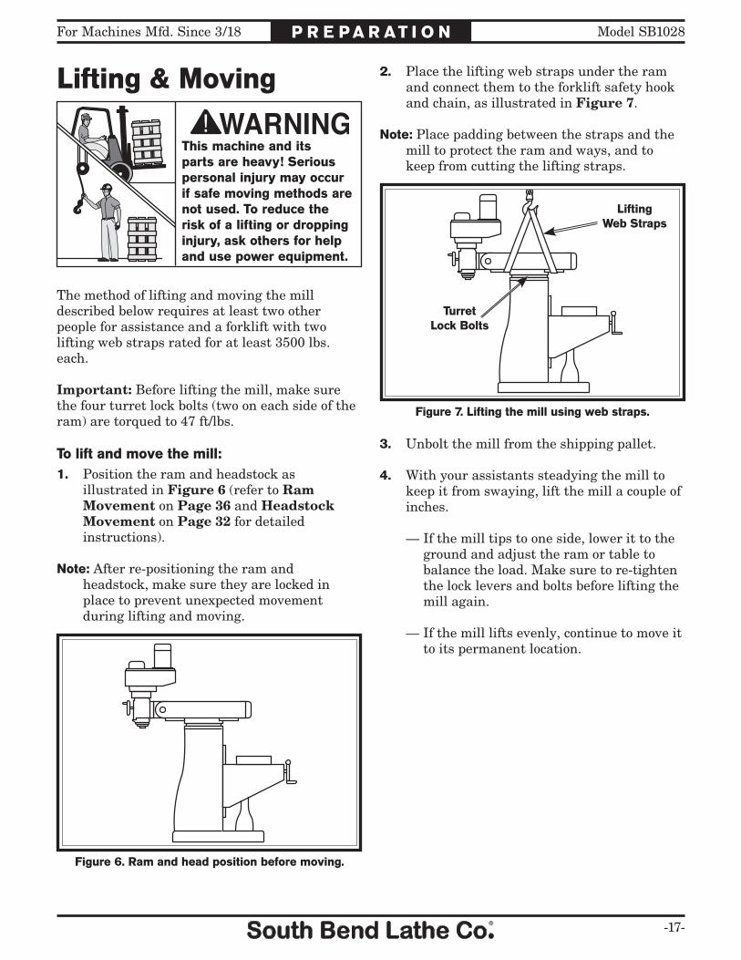
Lifting & Moving
This machine and its parts are heavy! Serious personal injury may occur if safe moving methods are not used. To reduce the risk of a lifting or dropping injury, ask others for help and use power equipment.
The method of lifting and moving the mill described below requires at least two other people for assistance and a forklift with two lifting web straps rated for at least 3500 lbs. each.
Important: Before lifting the mill, make sure the four turret lock bolts (two on each side of the ram) are torqued to 47 ft/lbs.
To lift and move the mill:1. Position the ram and headstock as
illustrated in Figure 6 (refer to Ram Movement on Page 36 and Headstock Movement on Page 32 for detailed instructions).
Note: After re-positioning the ram and headstock, make sure they are locked in place to prevent unexpected movement during lifting and moving.
2. Place the lifting web straps under the ram and connect them to the forklift safety hook and chain, as illustrated in Figure 7.
Note: Place padding between the straps and the mill to protect the ram and ways, and to keep from cutting the lifting straps.
Figure 7. Lifting the mill using web straps.
LiftingWeb Straps
TurretLock Bolts
3. Unbolt the mill from the shipping pallet.
4. With your assistants steadying the mill to keep it from swaying, lift the mill a couple of inches.
— If the mill tips to one side, lower it to the ground and adjust the ram or table to balance the load. Make sure to re-tighten the lock levers and bolts before lifting the mill again.
— If the mill lifts evenly, continue to move it to its permanent location.
Figure 6. Ram and head position before moving.

-18-
For Machines Mfd. Since 3/18Model SB1028 P R E P A R AT I O N
Bolting to Concrete FloorsLeveling & Mounting
Leveling
Figure 8. Example of a precision level.
Leveling machinery helps precision components, such as bed ways, remain straight and flat during the lifespan of the machine. Components on an unleveled machine may slowly twist due to the dynamic loads placed on the machine during operation.
For best results, use a precision level that is at least 12" long and sensitive enough to show a distinct movement when a 0.003" shim (approximately the thickness of one sheet of standard newspaper) is placed under one end of the level.
See the figure below for an example of a high precision level.
To prevent the Model SB1028 from tipping and causing a crushing hazard when heavy workpieces are mounted off-center, we strongly recommend that you bolt the mill to a concrete floor.
There are many different methods of securing the mill to the floor. Lag shield anchors and lag bolts are available in the sizes required for this mill. Also, cutting the floor and pouring footings with embedded J-bolts is another method.
We suggest you research the many options and methods for mounting the mill and choose the best that fits your specific application.
Although not required, we recommend that you level your machine and mount it to the floor. Because this is an optional step and floor materials may vary, mounting hardware is not included.
We strongly recommend securing your machine to the floor if it is hardwired to the power source. Consult with your electrician to ensure compliance with local codes.
For Machines Mfd. Since 3/18 Model SB1028
-19-
P R E P A R AT I O N
AssemblyTo assemble the mill:1. Remove the hex nuts from each end of the
X-axis leadscrew.
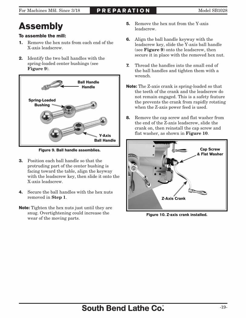
2. Identify the two ball handles with the spring-loaded center bushings (see Figure 9).
Figure 9. Ball handle assemblies.
Ball HandleHandle
Spring-LoadedBushing
Y-AxisBall Handle
5. Remove the hex nut from the Y-axis leadscrew.
6. Align the ball handle keyway with the leadscrew key, slide the Y-axis ball handle (see Figure 9) onto the leadscrew, then secure it in place with the removed hex nut.
7. Thread the handles into the small end of the ball handles and tighten them with a wrench.
Note: The Z-axis crank is spring-loaded so that the teeth of the crank and the leadscrew do not remain engaged. This is a safety feature the prevents the crank from rapidly rotating when the Z-axis power feed is used.
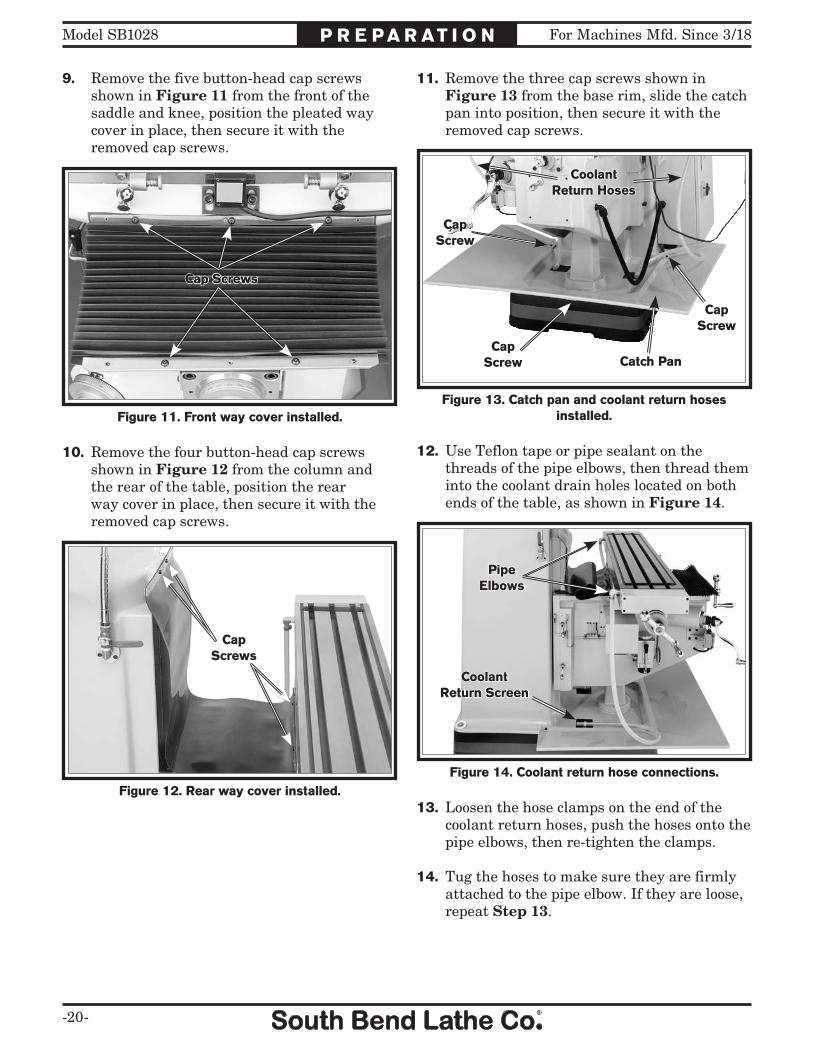
8. Remove the cap screw and flat washer from the end of the Z-axis leadscrew, slide the crank on, then reinstall the cap screw and flat washer, as shown in Figure 10.
Figure 10. Z-axis crank installed.
Z-Axis Crank
Cap Screw& Flat Washer
3. Position each ball handle so that the protruding part of the center bushing is facing toward the table, align the keyway with the leadscrew key, then slide it onto the X-axis leadscrew.
4. Secure the ball handles with the hex nuts removed in Step 1.
Note: Tighten the hex nuts just until they are snug. Overtightening could increase the wear of the moving parts.
-20-
For Machines Mfd. Since 3/18Model SB1028 P R E P A R AT I O N
9. Remove the five button-head cap screws shown in Figure 11 from the front of the saddle and knee, position the pleated way cover in place, then secure it with the removed cap screws.
Figure 11. Front way cover installed.
Cap Screws
10. Remove the four button-head cap screws shown in Figure 12 from the column and the rear of the table, position the rear way cover in place, then secure it with the removed cap screws.
11. Remove the three cap screws shown in Figure 13 from the base rim, slide the catch pan into position, then secure it with the removed cap screws.
12. Use Teflon tape or pipe sealant on the threads of the pipe elbows, then thread them into the coolant drain holes located on both ends of the table, as shown in Figure 14.
13. Loosen the hose clamps on the end of the coolant return hoses, push the hoses onto the pipe elbows, then re-tighten the clamps.
14. Tug the hoses to make sure they are firmly attached to the pipe elbow. If they are loose, repeat Step 13.
Figure 13. Catch pan and coolant return hoses installed.
CapScrew
CapScrew
Catch Pan
CoolantReturn Hoses
CapScrew
Figure 12. Rear way cover installed.
Cap Screws
Figure 14. Coolant return hose connections.
PipeElbows
CoolantReturn Screen

For Machines Mfd. Since 3/18 Model SB1028
-21-
P R E P A R AT I O N
15. Loosen the hose clamp screws above the coolant return screens in the base (see Figure 14 on the previous page), insert the hoses so that they will drain into the screens, then re-tighten the clamp screws to secure them in place.
16. Install the coarse downfeed lever and the fine downfeed handwheel, as shown in Figure 15.
Note: Make sure the pins on the back of these devices are fully seated in the hubs before use.
The machine was lubricated at the factory, but we strongly recommend that you inspect all lubrication points yourself and provide additional lubrication if necessary. Refer to Lubrication on Page 46 for specific details.
Initial Lubrication
Power Requirements
Electrocution or fire may occur if machine is ungrounded, incorrectly connected to power, or connected to an undersized circuit. Use a qualified electrician to ensure a safe power connection.
Once the machine is set up and assembled as previously described in this manual, it is ready to be connected to the power source.
Note About Required Power Source: The milling machine is equipped with a Yaskawa phase inverter that changes single-phase power into 3-phase which is used by the spindle motor.
Note About Extension Cords: Using an incorrectly sized extension cord may decrease the life of electrical components on the machine.
Required Power Source ...........220V, Single-PhaseFull Load Amp Draw ............................ 17.4 AmpsNominal Voltage Range ........................220V/240VFrequency ...................................................... 60 HzMinimum Circuit Size ............................. 20 AmpsPower Cord ........... 12 AWG/3C/300VAC, "S" TypePlug/Receptacle ................................... NEMA 6-20Minimum Extension Cord Size ................ 12 AWGMaximum Extension Cord Length ................ 50 ft.
Figure 15. Coarse downfeed lever and fine downfeed handwheel installed.
CoarseDownfeed
Lever
Fine DownfeedHandwheel
There are a series of steps that must be followed to when turning the machine ON. Before connecting the machine to power as instructed on the next page, make sure the main power switch located on the electrical box remains OFF. This will disable power to the control panel until it is required in the Test Run on Page 22.
-22-
For Machines Mfd. Since 3/18Model SB1028 P R E P A R AT I O N
Test Run
After all preparation steps have been completed, the machine and its safety features must be tested to ensure correct operation.
If you discover a problem with the operation of the machine or its safety components, do not operate it further until you have resolved the problem. Refer to the Troubleshooting section on Page 58 for solutions to common problems that may occur with all mills. If you need additional help, contact our Tech Support at (360) 734-1540.
During the test run, you will verify the proper operation of the following:
• Spindle motor• Emergency STOP button• Electrical cabinet safety switch• Spindle brake• Coolant pump• Z-axis power feed• X-axis power feed
Test Run the Mill1. Read and follow the safety instructions
at the beginning of the manual, take the required safety precautions, and make sure the machine is set up and adjusted properly.
Pulling the power plug from the receptacle while the mill is running could damage the power inverter inside the electrical box or other electrical components. Always use the emergency STOP button, main power switch, or the circuit breaker to turn the mill OFF before pulling the plug.
1. Make sure the incoming power source meets the requirements stated in Power Requirements on the previous page.
2. We recommend that you attach a NEMA 6-20 plug to the included power cord to be used with the corresponding receptacle.
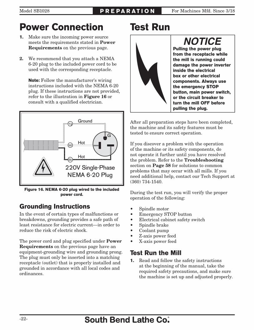
Note: Follow the manufacturer's wiring instructions included with the NEMA 6-20 plug. If these instructions are not provided, refer to the illustration in Figure 16 or consult with a qualified electrician.
Power Connection
Figure 16. NEMA 6-20 plug wired to the included power cord.
220V Single-PhaseNEMA 6-20 Plug
Ground
Hot
Hot
G
Grounding InstructionsIn the event of certain types of malfunctions or breakdowns, grounding provides a safe path of least resistance for electric current—in order to reduce the risk of electric shock.
The power cord and plug specified under Power Requirements on the previous page have an equipment-grounding wire and grounding prong. The plug must only be inserted into a matching receptacle (outlet) that is properly installed and grounded in accordance with all local codes and ordinances.

For Machines Mfd. Since 3/18 Model SB1028
-23-
P R E P A R AT I O N
Operating the coolant pump of this mill without the correct amount of coolant in the reservoir could damage the mill and void the warranty. ALWAYS make sure there is the correct amount of coolant in the reservoir before using the pump.
2. Clean out the coolant reservoir in the base of the mill, then fill it with coolant (refer to the Coolant Reservoir section on Pages 51–52 for specific details).
3. Clear away all tools and objects used during assembly and preparation.
4. Rotate the spindle speed dial on the control panel counterclockwise to the lowest setting, the spindle direction switch to the OFF (middle) position, and the coolant switch to the OFF (left) position (see Figure 17). This will disable these functions for now when the power initially flows to the control panel in the next steps.
Power ONButton & Lamp
Spindle ONButton
Spindle SpeedTachometer
SpindleSpeed Dial
CoolantSwitch
EmergencySTOP ButtonZ-Axis
DOWN Button
Z-AxisUP Button
Spindle OFFButton
SpindleDirectionSwitch
Figure 17. Control panel identification.
5. Set the spindle speed to the low range (refer to the Setting Spindle Speed Range section beginning on Page 37 for detailed instructions).
6. Move the downfeed selector to the manual (forward) position so that the spindle does not feed into the table during this test (refer to the Downfeed Controls section on Page 38 for detailed instructions).
7. Make sure the electrical cabinet door is latched shut, then rotate the main power switch to the ON position so that power flows to the control panel (see Figure 18).
8. Push the emergency STOP button in, then twist it clockwise until it pops out. When the switch pops out, the mill is ready for operation.
9. Press the power ON button to enable power to the control panel and illuminate this button.
Figure 18. Location of main power switch on the electrical box door.
Main Power Switch

-24-
For Machines Mfd. Since 3/18Model SB1028 P R E P A R AT I O N
14. Reset the emergency STOP button, turn the main power switch on the electrical cabinet door to the OFF position, then press the ON button. Again, the machine should not start.
— If the machine does not start, the main power switch safety feature is working correctly.
— If the machine does start (with the main power switch turned to the OFF position), immediately turn the mill OFF and disconnect power to the machine. The main power switch safety feature is not working correctly. This safety feature must work properly before proceeding with regular operations. Call Tech Support for help.
15. Make sure the emergency STOP button has been reset and the main power switch turned to the ON position, then press the ON button to start spindle rotation.
16. Push the spindle brake lever—the spindle motor should turn OFF and the spindle should quickly stop.
17. Position the coolant nozzle over the table, turn the coolant switch ON to start the coolant pump, then open the valve at the base of the nozzle to begin the flow of coolant.
18. Check for leaks from the hose fittings and make sure that the coolant is properly draining back into the reservoir through the screens on the base.
10. Press the spindle ON button, then turn the spindle direction switch to the forward (right) position to start spindle rotation.
11. Listen for abnormal noises and watch for unexpected actions or operation. The mill should run smoothly and without excessive vibration or rubbing noises.
— Strange or unusual noises or actions must be investigated immediately. Press the emergency STOP button to turn the machine OFF and disconnect it from the power source before investigating or correcting potential problems.
12. Press the emergency STOP button to turn the machine OFF, then wait for the spindle to stop on its own.
13. WITHOUT resetting the emergency STOP button, press the power ON button, then attempt to start spindle rotation by using the spindle ON button and the spindle direction switch.
— If the machine does not start, the emergency STOP button safety feature is working correctly.
— If the machine does start (with the emergency STOP button pushed in), immediately disconnect power to the machine. The emergency STOP button safety feature is not working correctly. This safety feature must work properly before proceeding with regular operations. Call Tech Support for help.

For Machines Mfd. Since 3/18 Model SB1028
-25-
P R E P A R AT I O N
19. Use the Z-axis UP and DOWN buttons on the control panel to verify that the table moves in the selected direction.
Test Run X-Axis Power FeedThe mill comes with a power feed unit for X-axis table travel. Proper operation of the limit switch attached to the front of the table is critical for the safe use of this power feed unit.
If the power feed does not operate as expected during the following steps, disconnect it from power and contact our Tech Support at (360) 734-1540 for assistance.
To test run the X-axis power feed:1. Make sure all tools, cables, and other items
are well clear of table movement as you follow these steps.
2. Refer to the Table Movement section, beginning on Page 29, to understand how the power feed, table locks, and limit switch function.
3. Loosen the table locks on the front of the table.
4. Plug the power feed power cord into a 110V power outlet.
Note: There are 110V outlets on the right side of the electrical cabinet that can be used for the power feed.
5. Make sure the power feed directional lever is in the neutral (middle) position, turn the speed dial counterclockwise to the lowest setting, then flip the power switch to the ON (up) position.
6. Turn the directional lever to the left, slowly turn the speed dial clockwise to increase the speed and confirm that the table is moving to the left.
7. Allow the table limit stop to hit the limit switch and turn the power feed OFF, which will stop table movement.
8. Turn the directional lever through the neutral (middle) position and all the way to the right. The table should begin moving to the right.
9. Confirm that the table stops moving when the limit stop presses against the limit switch plunger.
10. Move the directional lever to the neutral (middle) position and flip the power switch to the OFF (down) position.
Congratulations! The Test Run is complete. Continue with the next page to perform the Spindle Break-In and Inspections & Adjustments procedures.

-26-
For Machines Mfd. Since 3/18Model SB1028 P R E P A R AT I O N
Inspections & AdjustmentsThe following list of adjustments were performed at the factory before the machine was shipped:
• Gib Adjustment .................................Page 54• Leadscrew Backlash Adjustment .........................................Page 55
Be aware that machine components can shift during the shipping process. Pay careful attention to the adjustments above during operation of the machine. If you find that the adjustments are not set according to the procedures in this manual or your personal preferences, re-adjust them.
Spindle Break-In
The high-quality bearings and gears used in the mill are manufactured to very close tolerances. Before subjecting the mill to full loads, you must break it in. Bearings will fully seat, gear teeth will find their normal wear pattern, and lubricant will be worked into the required areas.
To perform the spindle break-in procedure:1. Successfully perform all the steps in the
Test Run section beginning on Page 22.
2. Make sure the spindle is completely stopped.
3. Set the spindle speed to the low range (refer to Setting Spindle Speed beginning on Page 37 for detailed instructions).
4. Start the spindle rotation at a medium speed and let the mill run for 20 minutes.
5. Stop the spindle and allow the spindle to completely stop.
6. Set the spindle speed to the high range, then start the spindle at a medium speed and let the mill run for another 20 minutes.
7. Stop the spindle, and turn the mill OFF.
The spindle break-in is now complete!
Complete the spindle bearing break-in procedure to avoid rapid deterioration of spindle components when the mill is placed into operation.
Since the mill head was rotated parallel to the table for shipping purposes, you will need to tram the spindle with the table if your first operation requires 90° alignment. Refer to the Tramming Spindle section on Page 33 for detailed instructions.

For Machines Mfd. Since 3/18 Model SB1028
-27-
O P E R AT I O N
Operation Overview
In a typical milling operation, the operator does the following:1. Examines the workpiece to make sure it is
suitable for milling.
2. Firmly clamps the workpiece to the table.
3. Installs the correct cutting tool for the operation.
4. Uses the manual downfeed and table controls to confirm the correct positioning of the cutting tool and workpiece for the operation. If the X-axis or Z-axis power feed will be used during the operation, the operator confirms the speed and length of table movement required.
Loose hair, clothing, or jewelry could get caught in machinery and cause serious personal injury. Keep these items away from moving parts at all times to reduce this risk.
During operation, small metal chips may become airborne, leading to serious eye injury. Wear safety glasses to reduce this risk.
5. Configures the mill for the correct spindle speed of the operation.
6. Puts on personal protective gear and makes sure the workpiece and table are clear of all tools, cords, and other items.
7. Starts the spindle rotation and performs the operation.
8. Turns the mill OFF.
To reduce the risk of serious injury when using this machine, read and understand this entire manual before beginning any operations.
The purpose of this overview is to provide the novice machine operator with a basic understanding of how the machine is used during operation, so they can more easily understand the controls discussed later in this manual.
Note: Due to the generic nature of this overview, it is not intended to be an instructional guide for performing actual machine operations. To learn more about specific operations and machining techniques, seek training from people experienced with this type of machine, and do additional research outside of this manual by reading "how-to" books, trade magazines, or websites.

-28-
For Machines Mfd. Since 3/18Model SB1028 O P E R AT I O N
Control PanelUse Figures 19–20 and the following descriptions to understand the functions of the mill main power switch and the control panel.
Main Power Switch: When turned ON, enables power to the control panel.
Figure 19. Location of the main power switch on the electrical box door.
Main Power Switch
Power ONButton & Lamp
Spindle ONButton
Spindle SpeedTachometer
SpindleSpeed Dial
CoolantSwitch
EmergencySTOP ButtonZ-Axis
DOWN Button
Z-AxisUP Button
Spindle OFFButton
SpindleDirectionSwitch
Figure 20. Control panel identification.
Power ON Button & Lamp: When pressed, illuminates and enables power to the other functions of the control panel.
Spindle ON Button: Starts spindle rotation.
Spindle Speed Tachometer: Displays the current spindle rotation speed.
Spindle Speed Dial: Controls the spindle speed within the selected spindle speed range.
Coolant Switch: Controls the coolant pump.
Emergency STOP Button: Disables power to all other functions on the control panel; i.e., spindle, coolant pump, and Z-axis power feed.
Z-Axis DOWN Button: Moves the knee and table down.
Z-Axis UP Button: Moves the knee and table up.
Spindle OFF Button: Stops the spindle motor.
Spindle Direction Switch: Controls the direction of spindle rotation.

For Machines Mfd. Since 3/18 Model SB1028
-29-
O P E R AT I O N
Table MovementThe mill table moves in three directions, as illustrated in Figure 21:
• X-axis• Y-axis• Z-axis
Figure 21. The directions of table movement.
X-Axis or Longitudinal Travel(Left & Right)
Y-Axis orCross Travel(In & Out)
Z-Axis or Vertical Elevation(Up & Down)
Top View
Front View
Table & Knee LocksRefer to Figures 22–23 for the locations of the locks used to secure the table in place.
Figure 22. Locations of the X- and Y-axes table locks.
X-Axis LocksY-Axis Lock
Always keep the table locked in place unless table movement is required for your operation. Unexpected movement of the table during operations could damage the cutter or workpiece.
Figure 23. Locations of the Z-axis (knee) locks.
Z-AxisKnee LocksThese movements are controlled by table ball
handles and the Z-axis crank. Additionally, the table can be moved along the X- and Z-axes with the power feeds.

-30-
For Machines Mfd. Since 3/18Model SB1028 O P E R AT I O N
X-Axis Power FeedThe mill is equipped with a power feed unit for X-axis table movement. Refer to the illustration in Figure 25 and the descriptions below to understand the functions of the various components of the power feed system.
Figure 25. Power feed system components.
AB C
D
E
F HG
I
A. Limit Switch: Stops table movement when either side plunger is pressed by a limit stop.
B. Limit Stop: Adjusts along the length of the table to restrict table movement.
C. Rapid Traverse Button: Moves the table at full speed when pressed.
D. Directional Lever: Controls direction of table movement. The middle position is neutral.
E. Speed Dial: Controls the speed of table movement. Turning the dial clockwise causes the table to move faster.
F. Circuit Breaker Reset Button: Resets the internal circuit breaker if the unit becomes overloaded and shuts down.
G. Power Switch: Turns the power feed ON and OFF.
H. X-Axis Ball Handle: Manually moves the table.
I. Graduated Index Ring: Displays the distance of table travel in 0.001" increments, with one full revolution equal to 0.200" of table travel.
Graduated Index RingsThe table ball handles and Z-axis crank have graduated index rings attached (see Figure 24) that display the amount table movement in the increments, as shown in the table below:
Axis IndividualIncrement
One FullRevolution
X 0.001" 0.200"
Y 0.001" 0.200"
Z 0.001" 0.100"
Figure 24. Graduated table index rings.
Index Rings

For Machines Mfd. Since 3/18 Model SB1028
-31-
O P E R AT I O N
Operating X-Axis Power FeedTo confirm the power feed settings you will be using during operation, we recommend that you raise the cutter above the workpiece, then use the power feed to move the table through the intended cutting path before starting the spindle rotation and taking the cut.
Tool Needed QtyHex Wrench 12mm .............................................. 1
To operate the X-axis power feed:1. Loosen the X-axis table locks (refer to
Figure 22 on Page 29 for locations).
2. Position the limit stops along the front table slot to limit the distance of table travel that is correct for your operation.
Note: Make sure the cap screws firmly secure the limit stops in place when positioned.
3. Turn the speed dial all the way counterclockwise to the slowest setting, move the directional lever to neutral (middle) position, then flip the power switch up to turn the unit ON.
4. With your hand poised over the power switch in case you need to suddenly turn the unit OFF, move the directional lever in the desired direction of table travel.
5. Use the speed dial to slowly bring the speed of movement up to the desired rate.
6. When you are finished using the power feed, turn it OFF, then rotate the speed dial all the way counterclockwise and move the directional lever to the neutral (middle) position to avoid unexpected table movement when you next flip the power switch up.

-32-
For Machines Mfd. Since 3/18Model SB1028 O P E R AT I O N
Head MovementThe mill head tilts 45° up and down, and rotates 90° left and right, as shown in Figures 26–27.
Tool Needed QtyWrench 19mm .......................................................1
Figure 27. Head tilts 90° left-and-right.
90°
Figure 26. Head tilts 45° back and forth.
45°
Tilting Head1. DISCONNECT MILL FROM POWER!
2. Loosen the three tilt lock bolts on the right side of the ram adapter shown in Figure 28.
3. Use one hand to apply pressure to the head in the direction of tilt, then slowly rotate the tilt bolt. Rotating this bolt clockwise will tilt the head back.
4. When the head is in the correct position for your operation, re-tighten all three lock bolts.
Always lock the head firmly in place after tilting or rotating it. Unexpected movement of the head during operations could cause damage to the cutter or workpiece.
Figure 28. Head tilting controls.
Lock Bolts
Tilt Bolt
!

For Machines Mfd. Since 3/18 Model SB1028
-33-
O P E R AT I O N
Rotating Head1. DISCONNECT MILL FROM POWER!
2. Loosen the four rotation lock bolts on the face of the head shown in Figure 29.
3. Use one hand to apply pressure in the direction of rotation, then slowly turn the rotation bolt.
4. Re-tighten the lock bolts when you have the head in the desired position.
Figure 29. Head rotating controls.
Lock Bolts
Rotation Bolt!
Tramming SpindleWhen your operation requires that the spindle axis be precisely perpendicular to the table, you must tram or align the spindle with the table to ensure the spindle is exactly 90° to the table.
This procedure involves mounting a dial test indicator to the quill or spindle, rotating it around the table, and adjusting the head position so that the spindle axis is 90° to the table X- and Y-axes, as illustrated in Figure 30.
We encourage you to research the many variations of spindle tramming to find the one that works best for you. If you do not already have a preference for performing this operation, use the following procedure.
Note: Keep in mind that the top surface of your workpiece will not likely be exactly parallel with the table top. Depending on your operation, you may choose to tram the spindle to the top surface of the workpiece after it is mounted instead of tramming the table.
Figure 30. Spindle axis perpendicular to the table X- and Y-axes.
Table
Spindle
X-Axis
Y-Axis
Z-Axis
90º90º
-34-
For Machines Mfd. Since 3/18Model SB1028 O P E R AT I O N
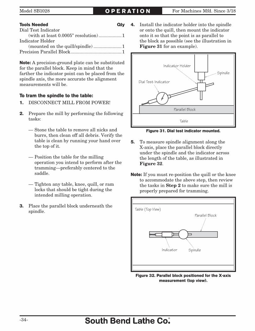
Figure 31. Dial test indicator mounted.
Table
Spindle
Dial Test Indicator
Indicator Holder
Parallel Block
Figure 32. Parallel block positioned for the X-axis measurement (top view).
Parallel Block
Indicator Spindle
Table (Top View)
Tools Needed QtyDial Test Indicator (with at least 0.0005" resolution) ..................1Indicator Holder (mounted on the quill/spindle) ......................1Precision Parallel Block ........................................1
Note: A precision-ground plate can be substituted for the parallel block. Keep in mind that the farther the indicator point can be placed from the spindle axis, the more accurate the alignment measurements will be.
To tram the spindle to the table:1. DISCONNECT MILL FROM POWER!
2. Prepare the mill by performing the following tasks:
— Stone the table to remove all nicks and burrs, then clean off all debris. Verify the table is clean by running your hand over the top of it.
— Position the table for the milling operation you intend to perform after the tramming—preferably centered to the saddle.
— Tighten any table, knee, quill, or ram locks that should be tight during the intended milling operation.
3. Place the parallel block underneath the spindle.
4. Install the indicator holder into the spindle or onto the quill, then mount the indicator onto it so that the point is as parallel to the block as possible (see the illustration in Figure 31 for an example).
5. To measure spindle alignment along the X-axis, place the parallel block directly under the spindle and the indicator across the length of the table, as illustrated in Figure 32.
Note: If you must re-position the quill or the knee to accommodate the above step, then review the tasks in Step 2 to make sure the mill is properly prepared for tramming.

For Machines Mfd. Since 3/18 Model SB1028
-35-
O P E R AT I O N
Figure 33. Parallel block positioned for the Y-axis measurement (top view).
Parallel Block
Indicator
Spindle
Table (Top View)
10. Rotate the spindle so that the indicator point rests on the parallel bar, as illustrated in Figure 33, then zero the dial.
11. Rotate the spindle so that the indicator point rests on the other end of the bar in the same manner, then read the dial.
— If the indicator dial still reads zero or is within the acceptable variance, the spindle is precisely perpendicular to the table in both the X- and Y-axes and the tramming procedure is complete.
— If the indicator dial has moved from zero beyond the acceptable variance, you will need to compensate for that amount by tilting the head forward or backward. Repeat Steps 9–10 until you are satisfied with the spindle axis alignment along the table Y-axis.
Tip: Keep one of the tilt lock bolts snug so that the head is not completely loose while you adjust it in small amounts.
12. Re-tighten the tilt lock bolts.
Note: It is a good idea to repeat Steps 10–11 again in case the head moved slightly during the process of re-tightening the lock bolts.
9. Place the parallel block directly under the spindle and across the width of the table, as illustrated in Figure 33.
Note: Generally, the goal in the next steps is to get the difference of the indicator readings between the ends of the parallel bar down to 0.0005". However, the acceptable variance will depend on the requirements for your operation.
6. Rotate the spindle by hand so that the indicator point rests on one end of the parallel block, as illustrated in Figure 32, then zero the dial.
7. Rotate the spindle so that the indicator point rests in the same manner on the other end of the block, then read the dial.
— If the indicator dial still reads zero or is within the acceptable variance, continue on with Step 8.
— If the indicator dial has moved from zero beyond the acceptable variance, you will need to compensate for that amount by rotating the head left or right. Repeat Steps 6–7 until you are satisfied with the spindle axis alignment along the table X-axis.
Tip: Keep one of the rotation lock bolts snug so that the head does not move loosely while you adjust it small amounts.
8. Re-tighten the rotation lock bolts.
Note: It is a good idea to repeat Steps 6-7 again in case the head moved slightly during the process of re-tightening the lock bolts.

-36-
For Machines Mfd. Since 3/18Model SB1028 O P E R AT I O N
Ram MovementThe ram travels forward and backward 19 1⁄2" and rotates horizontally 360° in either direction around the turret.
Tool Needed QtyWrench 19mm .......................................................1
Moving Ram Back and Forth1. DISCONNECT MILL FROM POWER!
2. Loosen the two lock levers shown in Figure 34 on the right side of the ram.
3. Make sure there are no obstructions to ram travel, especially with the spindle tool around the workpiece, then slowly rotate the adjustment bolt to move the ram. Rotating the bolt clockwise will move the ram backward.
4. Re-tighten the lock levers after you have re-positioned the ram.
Rotating Ram1. DISCONNECT MILL FROM POWER!
2. Loosen the four lock bolts on top of the turret (see Figure 35).
Note: There are two lock bolts on either side of the ram.
Note: In the next step, take care not to entangle or stretch the electrical cabling as you move the ram around the turret.
3. Push on the head to manually rotate it. Use the rotation scale to determine the correct position for your operation, then re-tighten the four lock bolts to secure the ram in place.
Always lock the ram firmly in place after moving it. Unexpected movement of the ram and head during operations could cause damage to the cutter or workpiece.
Figure 34. Ram forward and backward movement controls.
Lock Levers
Adjustment Bolt
!
Figure 35. Ram rotating controls.
Lock Bolts (2 of 4)
Rotation Scale
!

For Machines Mfd. Since 3/18 Model SB1028
-37-
O P E R AT I O N
Setting Spindle Speed
Setting Spindle Speed RangeSetting the spindle speed range involves using the spindle speed range lever to engage/disengage the spindle spline with the bull gear.
To set the spindle speed range:1. DISCONNECT MILL FROM POWER!
2. Use the chart below to find the spindle speed range that includes the required spindle speed for your operation.
Spindle Speed Ranges
Low Range 60–575 RPM
High Range 575–5000 RPM
To avoid damage to the spindle, gears, or cutting tools:
• Spindle rotation must be turned OFF and the spindle must be completely stopped BEFORE you change the spindle speed range.
• The mill is designed to ONLY operate with the spindle speed range selector in either the high or low position. To avoid damaging the moving parts inside the headstock, never start spindle rotation without the range selector detent pin firmly seated in either the high or low position.
• When changing the spindle speed range, the direction of spindle rotation will reverse due to the change in gear configuration. You will need to use the spindle direction switch to change the rotation back to the original direction.
Using the correct spindle speed is important for safe and satisfactory results, as well as maximizing tool life.
To set the spindle speed for your operation, you will need to: (1) Determine the best spindle speed for the cutting task, and (2) configure the mill controls to produce the required spindle speed.
Determining Spindle SpeedMany variables affect the optimum spindle speed to use for any given operation, but the two most important are the recommended cutting speed for the workpiece material and the diameter of the cutting tool, as noted in Figure 36:
Cutting speed, typically defined in feet per minute (FPM), is the speed at which the edge of a tool moves across the material surface.
A recommended cutting speed is an ideal speed for cutting a type of material in order to produce the desired finish and optimize tool life.
The books Machinery’s Handbook or Machine Shop Practice, and some internet sites, provide excellent recommendations for which cutting speeds to use when calculating the spindle speed. These sources also provide a wealth of additional information about the variables that affect cutting speed and they are a good educational resource.
Also, there are a large number of easy-to-use spindle speed calculators that can be found on the internet. These sources will help you take into account all applicable variables to determine the best spindle speed for the operation.
Cutting Speed (FPM) x 12 *Recommended
Tool Dia. (in inches) x 3.14= Spindle Speed (RPM)
*Double if using carbide cutting tool
Figure 36. Spindle speed formula for milling.

-38-
For Machines Mfd. Since 3/18Model SB1028 O P E R AT I O N
3. Press the spindle speed range lever (shown in Figure 37) toward the head to release the pin from the detent plate, then move selector so that the pin is over the other detent and release it.
— When the lever points to the rear and the front detent is engaged, the low speed range is selected. Conversely, when the lever points toward the front and the rear detent is engaged, the high speed range is selected.
Note: It may be necessary to turn the spindle by hand as you move the range lever to allow the gears to mesh.
Setting Spindle SpeedUse the spindle speed dial and display (see Figure 38) to set the required spindle speed within the speed range selected.
The top values of the spindle speed display are for the high spindle speed range, and the bottom values are for the low range.
Downfeed ControlsSpindle downfeed movement is controlled by three mechanisms: 1) The coarse downfeed handle, 2) the fine downfeed handwheel, and 3) the auto-downfeed system.
Coarse Downfeed1. DISCONNECT MILL FROM POWER!
2. To set the downfeed for manual control, pull the downfeed selector knob out (see Figure 39), then rotate it clockwise until the selector pin under the knob seats in the forward manual (disengaged) position.
Note: It may be necessary to turn the spindle by hand as you move the selector to allow the gears to mesh.
Figure 37. Spindle speed range selector.
High Low
Detent PlateSpindle
SpeedRangeLever
Figure 38. Spindle speed dial and display.
SpeedDisplay
SpindleSpeedDial Figure 39. Downfeed selector.
Downfeed Selector
Manual(Disengaged) Position
Auto-Downfeed(Engaged) Position

For Machines Mfd. Since 3/18 Model SB1028
-39-
O P E R AT I O N
5. Make sure the quill lock lever is loose so that the quill can move easily (see Figure 41).
Figure 40. Coarse downfeed handle hub, detents, and pin.
Handle Hub
Detents& Pin
3. Make sure the selector pin is firmly seated in the detent by attempting to move the selector without pulling the knob out.
4. Make sure the pin of the coarse downfeed handle hub is engaged with one of the detents on the downfeed sleeve (see Figure 40).
6. Rotate the coarse downfeed handle around the hub to control the depth of the spindle.
Figure 41. Location of the quill lock lever.
QuillLock Lever

-40-
For Machines Mfd. Since 3/18Model SB1028 O P E R AT I O N
Fine Downfeed ControlsThere are a number of controls on the head that are used with the fine downfeed handwheel or the auto-downfeed system. Refer to Figure 42 and the descriptions that follow to become familiar with these controls.
A. Auto-Downfeed Rate Selector: Selects one of the three auto-downfeed rates.
B. Fine Downfeed Handwheel: Manually controls fine spindle downfeed.
C. Auto-Downfeed Direction Pin: Starts, stops, and reverses the auto-downfeed direction.
D. Fine Downfeed Clutch Lever: Engages the fine/auto-downfeed gears.
E. Downfeed Scale: Used with the quill dog, shows the depth of spindle downfeed in inches.
F. Downfeed Stop & Locking Wheel: Sets the depth of spindle downfeed. The stop is threaded into position, then the locking wheel is used to secure it in place.
When the spindle rotation is reversed, either by changing the spindle speed range or by using the spindle direction switch, the direction of spindle auto-downfeed will reverse.
G. Quill Lock Lever: Secures the quill in place for increased stability during operations.
H. Quill Dog: Moves with the quill and spindle, and disengages the downfeed clutch lever when it meets either the top or downfeed stop.
I. Downfeed Selector: Sets the mill for manual downfeed or auto-downfeed control.
Fine Downfeed Handwheel1. Make sure that the spindle rotation is turned
OFF and the spindle is at a complete stop.
2. Pull the downfeed selector knob out, then rotate the selector clockwise until the selector pin seats in the forward manual (disengaged) position. This will set the downfeed for manual control.
3. Set the auto-downfeed direction pin in the neutral (middle) position to disengage the fine downfeed handwheel from the auto-downfeed gears.
4. Position the downfeed stop at the spindle depth that is correct for your operation, then secure it in place with the locking wheel.
5. Use the coarse downfeed lever to slightly lower the spindle until you can pull the clutch lever out to the left and it locks in place. This will engage the fine downfeed handwheel with the quill and spindle.
6. To lower the spindle, rotate the fine downfeed handwheel. When the quill dog meets the downfeed stop, the clutch lever will disengage and the spindle will return to the top.
Figure 42. Fine downfeed controls.
A
B
C
D
I
H
G
FE

For Machines Mfd. Since 3/18 Model SB1028
-41-
O P E R AT I O N
Auto-Downfeed SystemWhen using the auto-downfeed system, the spindle will move in the direction you choose with the auto-downfeed direction pin. When the quill dog reaches the top or meets the downfeed stop, the downfeed clutch lever releases. Then, if the spindle was traveling upward, the movement simply stops. If the spindle was traveling downward, then the spindle moves back to the top at a rate controlled by the return spring on the left side of the head.
To use the auto-downfeed system:1. Make sure that the spindle rotation is turned
OFF and the spindle is at a complete stop.
2. To set the mill for auto-downfeed, pull the downfeed selector knob out, then rotate the selector clockwise and seat the pin in the rear auto-downfeed (engaged) position, as illustrated in Figure 43.
Figure 43. Downfeed selector in the auto-downfeed (engaged) position.
Manual (Disengaged) Position
Auto-Downfeed (Engaged) Position
4. Position the auto-downfeed direction pin for the spindle travel that is necessary for your operation. You may have to rock the fine downfeed handwheel back-and-forth to move the pin all the way in or out.
Note: The direction pin has three positions: 1) In for one downfeed direction, 2) middle for neutral or no movement, and 3) out for the reverse direction. The direction of spindle travel for the in and out positions is relative to the direction of spindle rotation. Keep in mind that spindle rotation and downfeed direction will reverse when the spindle speed range is changed and you will need to use the spindle direction switch to change the rotation direction back to the original.
5. Make sure the clutch lever is all the way to the right in the disengaged position so that the spindle will not travel when rotation is started.
Note: We recommend that you complete the remaining steps without a cutting tool installed, without a workpiece in place, and the table lower than the maximum spindle downfeed travel. This will enable you to test and confirm the settings before beginning the actual cutting operation.
3. Position the downfeed stop at the spindle depth that is correct for your operation, then secure it in place with the locking wheel.
6. Set the correct spindle speed, then begin spindle rotation.
To avoid damage to the system gearing, never use the auto-downfeed system with spindle speeds over 3000 RPM.
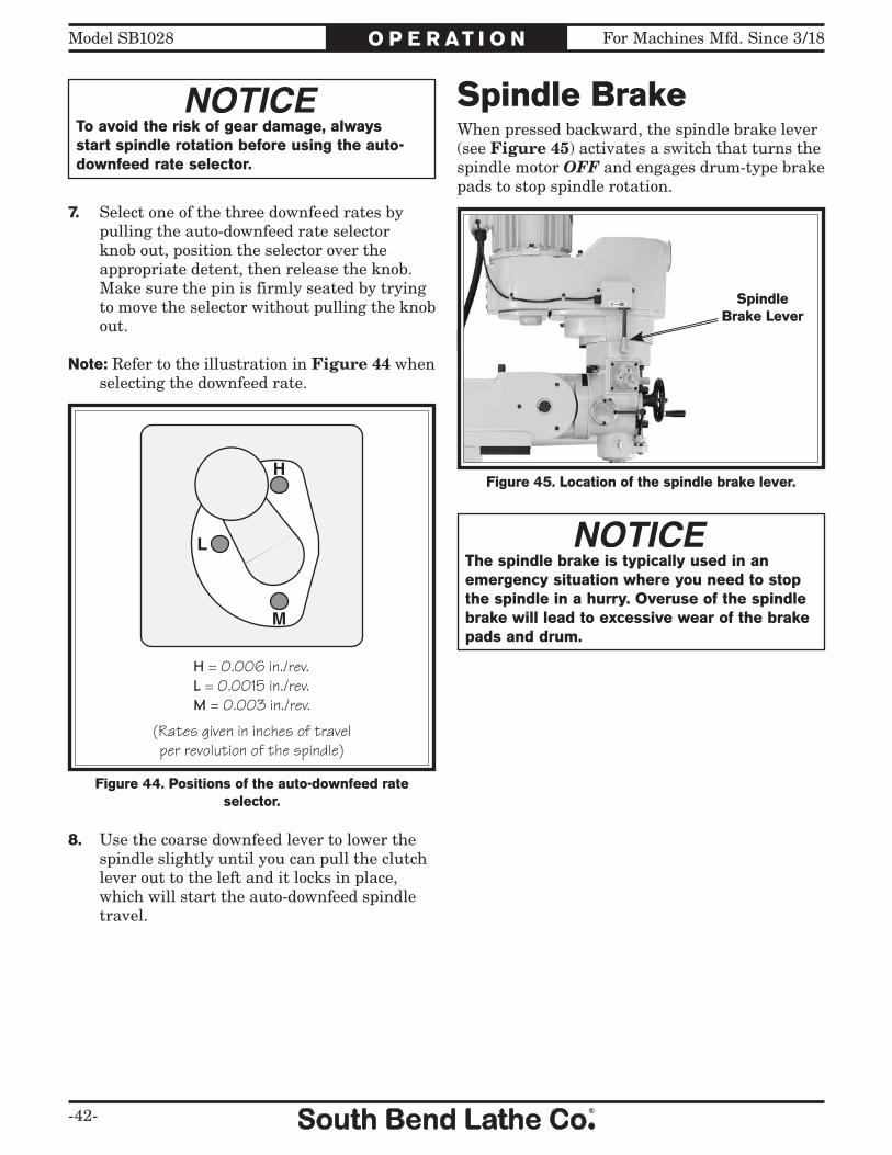
-42-
For Machines Mfd. Since 3/18Model SB1028 O P E R AT I O N
7. Select one of the three downfeed rates by pulling the auto-downfeed rate selector knob out, position the selector over the appropriate detent, then release the knob. Make sure the pin is firmly seated by trying to move the selector without pulling the knob out.
Note: Refer to the illustration in Figure 44 when selecting the downfeed rate.
8. Use the coarse downfeed lever to lower the spindle slightly until you can pull the clutch lever out to the left and it locks in place, which will start the auto-downfeed spindle travel.
To avoid the risk of gear damage, always start spindle rotation before using the auto-downfeed rate selector.
Figure 44. Positions of the auto-downfeed rate selector.
M
L
H
H = 0.006 in./rev.L = 0.0015 in./rev.M = 0.003 in./rev.
(Rates given in inches of travelper revolution of the spindle)
Spindle BrakeWhen pressed backward, the spindle brake lever (see Figure 45) activates a switch that turns the spindle motor OFF and engages drum-type brake pads to stop spindle rotation.
Figure 45. Location of the spindle brake lever.
SpindleBrake Lever
The spindle brake is typically used in an emergency situation where you need to stop the spindle in a hurry. Overuse of the spindle brake will lead to excessive wear of the brake pads and drum.

For Machines Mfd. Since 3/18 Model SB1028
-43-
O P E R AT I O N
Loading/Unloading ToolingThe mill is equipped with an R8 spindle taper and a 7⁄16"-18 x 23 3⁄8" spindle drawbar, as shown in Figure 46.
Figure 46. Spindle drawbar and spacer.
Loading ToolingTool Needed QtyWrench 21mm .......................................................1
To load tooling:1. DISCONNECT MILL FROM POWER!
2. Clean any debris or surface substances from inside the spindle taper and the mating surface of the tooling.
Note: Debris or oily substances can prevent the tooling and spindle from properly mating. This condition can cause excessive vibration, poor cutting results, or tool/workpiece damage.
3. Place the mill in the low spindle speed range to keep the spindle from turning during the next steps.
4. Align the tool keyway with the protruding pin inside the spindle taper, then firmly push the tool into the spindle to seat it.
5. With one hand holding the tool in place, insert the drawbar into the spindle from the top of the head, then thread it into the tool (see Figure 47).
6. Tighten the drawbar until it is snug. Avoid overtightening, as it could make removing the tool difficult.
Unloading ToolingTools Needed QtyWrench 21mm .......................................................1Brass Hammer ......................................................1
To unload tooling:1. DISCONNECT MILL FROM POWER!
2. Place the mill in the low spindle speed range to keep the spindle from turning during the next step.
Note: Make sure that the drawbar has at least three threads engaged with the tooling in the next step to avoid damaging the threads of the drawbar or tool.
3. Loosen the drawbar a couple of turns, then tap the top of it with brass hammer to knock the tool loose at the bottom of the spindle.
4. Support the tool with one hand, then completely unthread the drawbar.
Figure 47. Drawbar loaded into the spindle.
Drawbar
The sharp edges of tools can easily cut your hands and fingers. Always use protection when handling cutting tools.

-44-
For Machines Mfd. Since 3/18Model SB1028 M A I N T E N A N C E
Maintenance Schedule
Always disconnect machine from power before performing maintenance or serious personal injury may result.
!
Regular maintenance will ensure proper care of the equipment. We strongly recommend that all operators make a habit of following the daily maintenance procedures.
For optimum performance from this machine, this maintenance schedule must be strictly followed. Use the Monthly Maintenance Chart on Page 45 to ensure this is done.
OngoingTo maintain a low risk of injury and proper machine operation, if you ever observe any of the items below, shut the machine down immediately, disconnect it from power, and fix the problem before continuing operations.
• Loose mounting bolts or fasteners.• Worn, frayed, cracked, or damaged wires.• Emergency STOP button not working
correctly.• Missing belt guards.• Reduction in braking speed or efficiency.• Coolant not flowing correctly.• Any other unsafe condition.
Before Beginning Operations• Make sure the electric box door is closed and
properly latched.• Turn the spindle direction switch to the
STOP (middle) position and the speed dial all the way counterclockwise to prevent high-speed spindle startup when connected to power (see Page 28).
• Move the downfeed selector to the manual (disengaged) position to prevent the spindle from unexpectedly downfeeding when rotation is started (see Page 38).
• Make sure the X-axis power feed is turned OFF to prevent unintentional table movement when connected to power (see Page 30).
• Check the coolant reservoir in the base. Fill it or clean it out if necessary (see Page 51).
• Perform the lubrication tasks as directed in the Lubrication section on Page 46.
• Check table movement in all three axes for loose/tight gibs. Adjust the gibs if necessary (see Page 54).
Daily, After Operations• Push the emergency STOP button, turn the
main power switch to the OFF position, and disconnect the machine from power.
• Vacuum/clean all chips and swarf from table, slides, and base.
• Wipe down all unpainted or machined surfaces with a high quality rust preventative.

For Machines Mfd. Since 3/18 Model SB1028
-45-
M A I N T E N A N C E
Use
th
is c
har
t to
kee
p t
rack
of
the
mai
nte
nan
ce p
erfo
rmed
on
th
e m
ill.
Cro
ss o
ut
or i
nit
ial
the
“Day
” b
ox f
or e
ach
ite
m o
n t
he
list
. If
th
e b
ox i
s b
lack
ed o
ut,
mai
nte
-n
ance
is
not
req
uir
ed f
or t
hat
ite
m o
n t
hat
day
.
Mak
e co
pie
s of
th
is p
age
to u
se e
ach
mon
th. K
eep
eac
h c
har
ts a
s a
mai
nte
nan
ce
reco
rd f
or t
he
mil
l.
(360
) 73
4-15
40 •
FA
X: (
360)
676
-107
5w
ww
.so
uth
be
nd
lath
e.c
om
So
uth
Ben
d L
ath
e C
o.®
Mo
nth
ly M
ain
ten
ance
Ch
art
for
Mo
del
SB
1028
Mill
ing
Mac
hin
e
12
34
56
78
910
1112
1314
1516
1718
1920
2122
2324
2526
2728
2930
31
Insp
ecti
on
Coo
lan
t S
yste
mG
ib
Adj
ust
men
tE
nd o
f D
ay
Dis
con
nec
ted
Fro
m P
ower
Cle
aned
&
Pro
tect
edLu
bric
atio
n
Qu
ill
Tab
le &
Lea
d-sc
rew
sS
peed
Ran
ge
Bea
rin
g S
leev
eH
eads
tock
G
eari
ng
Z-a
xis
Lea
dscr
ewP
ower
Fee
d G
ears
Day
Item
Mon
th/Y
ear:
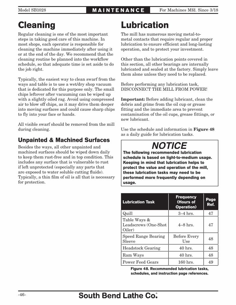
-46-
For Machines Mfd. Since 3/18Model SB1028 M A I N T E N A N C E
LubricationThe mill has numerous moving metal-to-metal contacts that require regular and proper lubrication to ensure efficient and long-lasting operation, and to protect your investment.
Other than the lubrication points covered in this section, all other bearings are internally lubricated and sealed at the factory. Simply leave them alone unless they need to be replaced.
Before performing any lubrication task, DISCONNECT THE MILL FROM POWER!
Important: Before adding lubricant, clean the debris and grime from the oil cup or grease fitting and the immediate area to prevent contamination of the oil cups, grease fittings, or new lubricant.
Use the schedule and information in Figure 48 as a daily guide for lubrication tasks.
The following recommended lubrication schedule is based on light-to-medium usage. Keeping in mind that lubrication helps to protect the value and operation of the mill, these lubrication tasks may need to be performed more frequently depending on usage.
Lubrication TaskFrequency(Hours of
Operation)
Page Ref.
Quill 3–4 hrs. 47
Table Ways & Leadscrews (One-Shot Oiler)
4–8 hrs. 47
Speed Range Bearing Sleeve
Before Every Use 48
Headstock Gearing 40 hrs. 48
Ram Ways 40 hrs. 48
Power Feed Gears 160 hrs. 49
Figure 48. Recommended lubrication tasks, schedules, and instruction page references.
CleaningRegular cleaning is one of the most important steps in taking good care of this machine. In most shops, each operator is responsible for cleaning the machine immediately after using it or at the end of the day. We recommend that the cleaning routine be planned into the workflow schedule, so that adequate time is set aside to do the job right.
Typically, the easiest way to clean swarf from the ways and table is to use a wet/dry shop vacuum that is dedicated for this purpose only. The small chips leftover after vacuuming can be wiped up with a slightly oiled rag. Avoid using compressed air to blow off chips, as it may drive them deeper into moving surfaces and could cause sharp chips to fly into your face or hands.
All visible swarf should be removed from the mill during cleaning.
Unpainted & Machined SurfacesBesides the ways, all other unpainted and machined surfaces should be wiped down daily to keep them rust-free and in top condition. This includes any surface that is vulnerable to rust if left unprotected (especially any parts that are exposed to water soluble cutting fluids). Typically, a thin film of oil is all that is necessary for protection.

For Machines Mfd. Since 3/18 Model SB1028
-47-
M A I N T E N A N C E
Table Ways (One-Shot Oiler)Oil Type ......Mobil Vactra 2 or ISO 68 EquivalentOil Amount ................... One Pull of Pump HandleCheck/Add Frequency ..........4–8 hrs. of OperationReservoir Capacity .....................Approx. 1 1⁄4 Pints
The one-shot oiler is connected to a series of aluminum tubes that carry the lubricant to wear points along the table, saddle, knee ways, and the leadscrews. After using the oiler pump handle shown in Figure 50, move the table through all paths of movement to evenly distribute the lubricant.
Use the sight glass on the side of the oiler to know when to re-fill the reservoir.
QuillOil Type ......Mobil Vactra 2 or ISO 68 EquivalentOil Amount .......................................... Fill Oil CupCheck/Add Frequency ..............4 hrs. of Operation
Lift the oil cup cap shown in Figure 49 to fill it with lubricant.
Failure to follow reasonable lubrication practices as instructed in this manual could lead to premature failure of mill components and will void the warranty.
Figure 49. Quill oil cup location.
Quill Oil Cup
Figure 50. One-shot oiler controls.
PumpHandle
SightGlass
Reservoir Cap
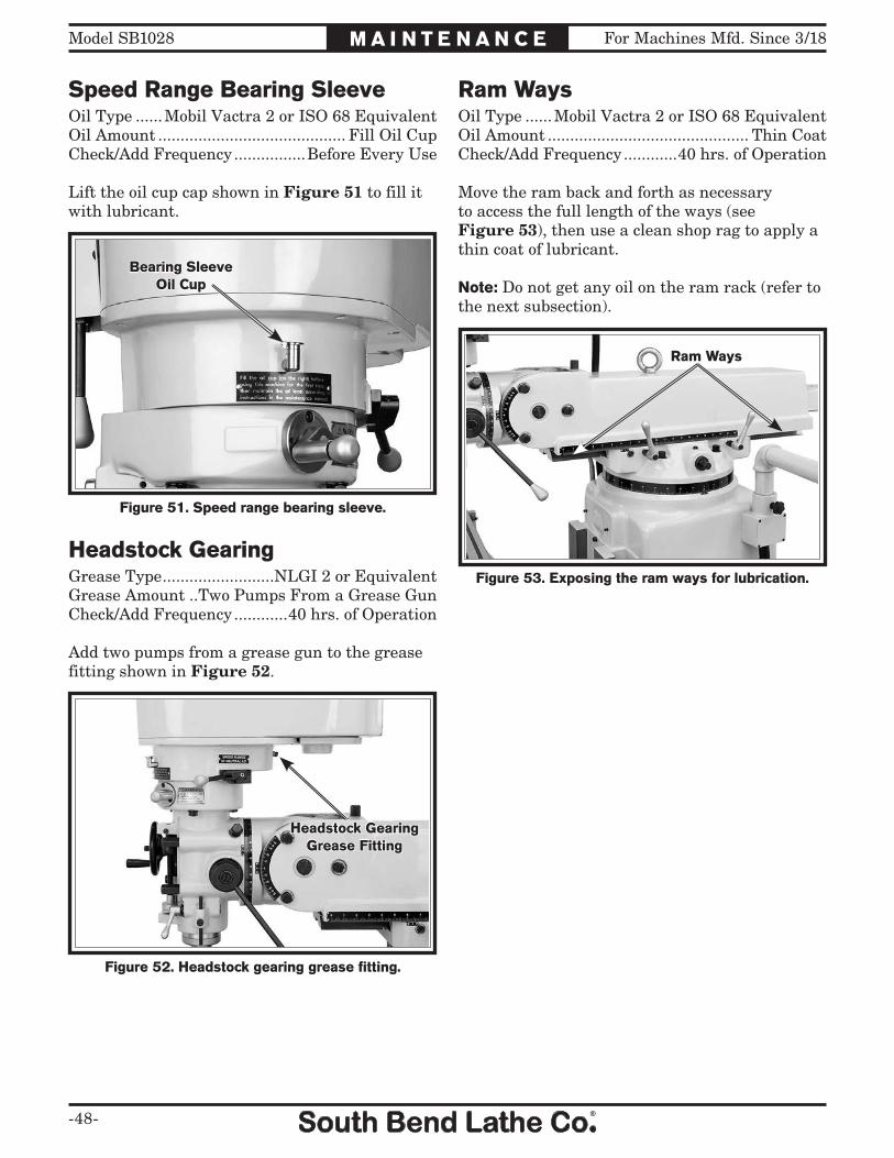
-48-
For Machines Mfd. Since 3/18Model SB1028 M A I N T E N A N C E
Speed Range Bearing SleeveOil Type ......Mobil Vactra 2 or ISO 68 EquivalentOil Amount .......................................... Fill Oil CupCheck/Add Frequency ................Before Every Use
Lift the oil cup cap shown in Figure 51 to fill it with lubricant.
Headstock GearingGrease Type .........................NLGI 2 or EquivalentGrease Amount ..Two Pumps From a Grease GunCheck/Add Frequency ............40 hrs. of Operation
Add two pumps from a grease gun to the grease fitting shown in Figure 52.
Ram WaysOil Type ......Mobil Vactra 2 or ISO 68 EquivalentOil Amount ............................................. Thin CoatCheck/Add Frequency ............40 hrs. of Operation
Move the ram back and forth as necessary to access the full length of the ways (see Figure 53), then use a clean shop rag to apply a thin coat of lubricant.
Note: Do not get any oil on the ram rack (refer to the next subsection).
Figure 51. Speed range bearing sleeve.
Bearing SleeveOil Cup
Figure 52. Headstock gearing grease fitting.
Headstock GearingGrease Fitting
Figure 53. Exposing the ram ways for lubrication.
Ram Ways
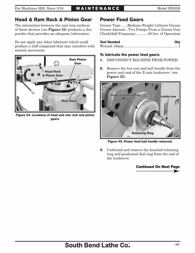
For Machines Mfd. Since 3/18 Model SB1028
-49-
M A I N T E N A N C E
Head & Ram Rack & Pinion GearThe interaction between the cast iron surfaces of these devices (see Figure 54) produces a dry powder that provides an adequate lubrication.
Do not apply any other lubricant which could produce a stiff compound that may interfere with smooth movement.
Power Feed GearsGrease Type .......Medium-Weight Lithium GreaseGrease Amount ..Two Pumps From a Grease GunCheck/Add Frequency ............40 hrs. of Operation
Tool Needed QtyWrench 19mm .......................................................1
To lubricate the power feed gears:1. DISCONNECT MACHINE FROM POWER!
2. Remove the hex nut and ball handle from the power unit end of the X-axis leadscrew (see Figure 55).
Figure 55. Power feed ball handle removed.
Graduated Dial Ring
Retaining Ring
Leadscrew
Figure 54. Locations of head and ram rack and pinion gears.
Ram Rack
Ram PinionGear
Head Rack& Pinion Gear
3. Unthread and remove the knurled retaining ring and graduated dial ring from the end of the leadscrew.
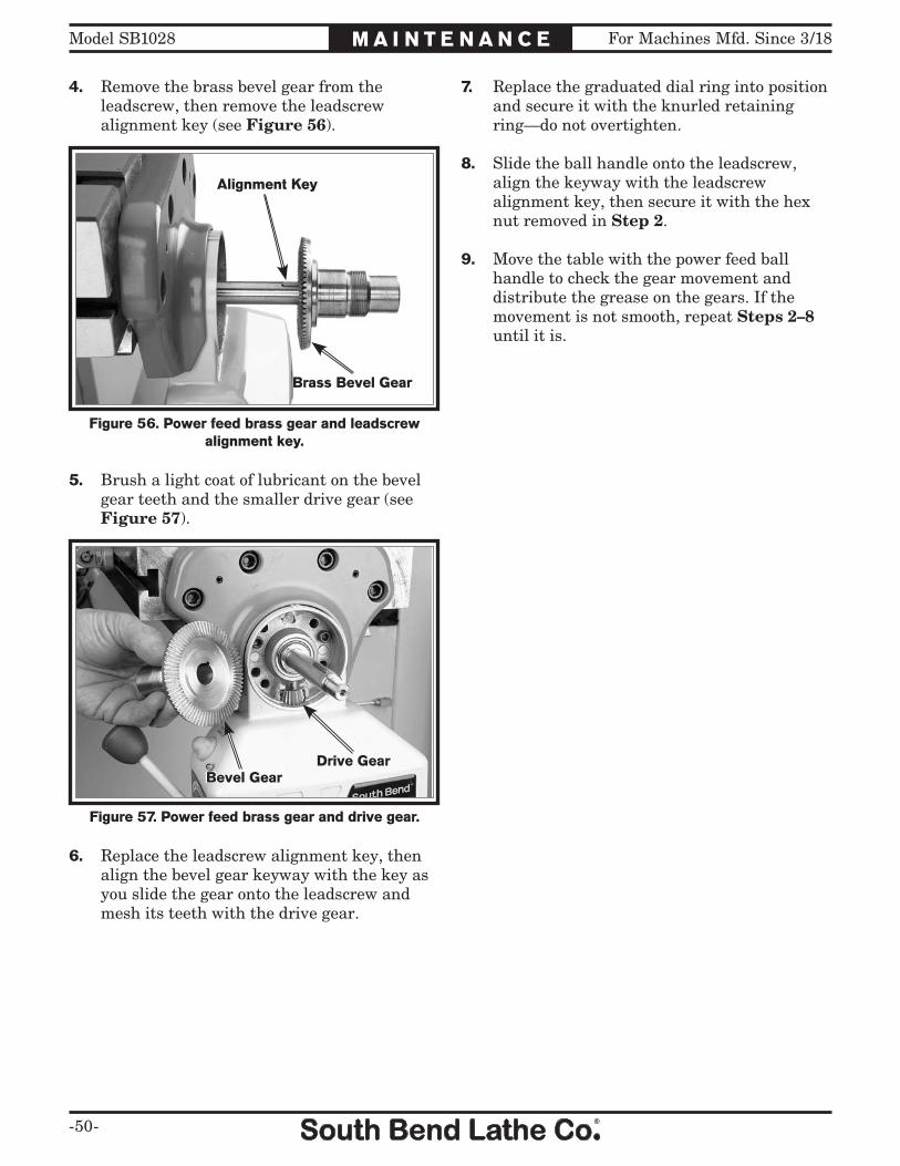
-50-
For Machines Mfd. Since 3/18Model SB1028 M A I N T E N A N C E
5. Brush a light coat of lubricant on the bevel gear teeth and the smaller drive gear (see Figure 57).
7. Replace the graduated dial ring into position and secure it with the knurled retaining ring—do not overtighten.
8. Slide the ball handle onto the leadscrew, align the keyway with the leadscrew alignment key, then secure it with the hex nut removed in Step 2.
9. Move the table with the power feed ball handle to check the gear movement and distribute the grease on the gears. If the movement is not smooth, repeat Steps 2–8 until it is.
Figure 57. Power feed brass gear and drive gear.
Drive GearBevel Gear
6. Replace the leadscrew alignment key, then align the bevel gear keyway with the key as you slide the gear onto the leadscrew and mesh its teeth with the drive gear.
4. Remove the brass bevel gear from the leadscrew, then remove the leadscrew alignment key (see Figure 56).
Figure 56. Power feed brass gear and leadscrew alignment key.
Alignment Key
Brass Bevel Gear
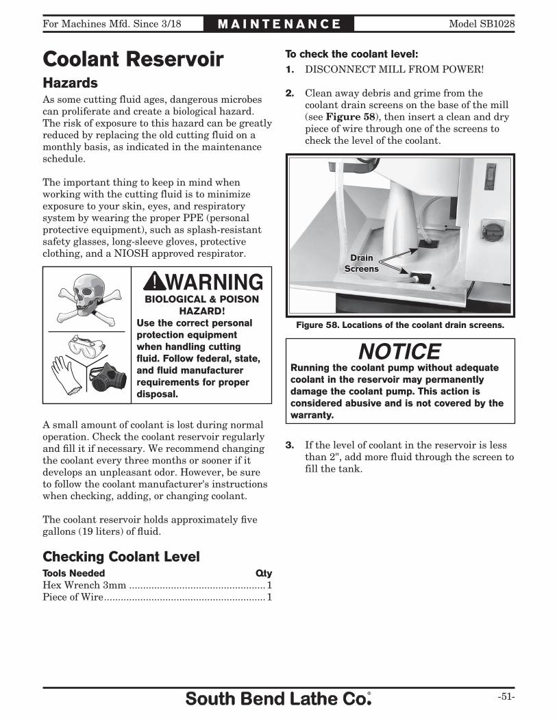
For Machines Mfd. Since 3/18 Model SB1028
-51-
M A I N T E N A N C E
Coolant Reservoir
A small amount of coolant is lost during normal operation. Check the coolant reservoir regularly and fill it if necessary. We recommend changing the coolant every three months or sooner if it develops an unpleasant odor. However, be sure to follow the coolant manufacturer's instructions when checking, adding, or changing coolant.
The coolant reservoir holds approximately five gallons (19 liters) of fluid.
Checking Coolant LevelTools Needed QtyHex Wrench 3mm .................................................1Piece of Wire ..........................................................1
Figure 58. Locations of the coolant drain screens.
DrainScreens
Running the coolant pump without adequate coolant in the reservoir may permanently damage the coolant pump. This action is considered abusive and is not covered by the warranty.
3. If the level of coolant in the reservoir is less than 2", add more fluid through the screen to fill the tank.
BIOLOGICAL & POISON HAZARD!
Use the correct personal protection equipment when handling cutting fluid. Follow federal, state, and fluid manufacturer requirements for proper disposal.
To check the coolant level:1. DISCONNECT MILL FROM POWER!
2. Clean away debris and grime from the coolant drain screens on the base of the mill (see Figure 58), then insert a clean and dry piece of wire through one of the screens to check the level of the coolant.
HazardsAs some cutting fluid ages, dangerous microbes can proliferate and create a biological hazard. The risk of exposure to this hazard can be greatly reduced by replacing the old cutting fluid on a monthly basis, as indicated in the maintenance schedule.
The important thing to keep in mind when working with the cutting fluid is to minimize exposure to your skin, eyes, and respiratory system by wearing the proper PPE (personal protective equipment), such as splash-resistant safety glasses, long-sleeve gloves, protective clothing, and a NIOSH approved respirator.
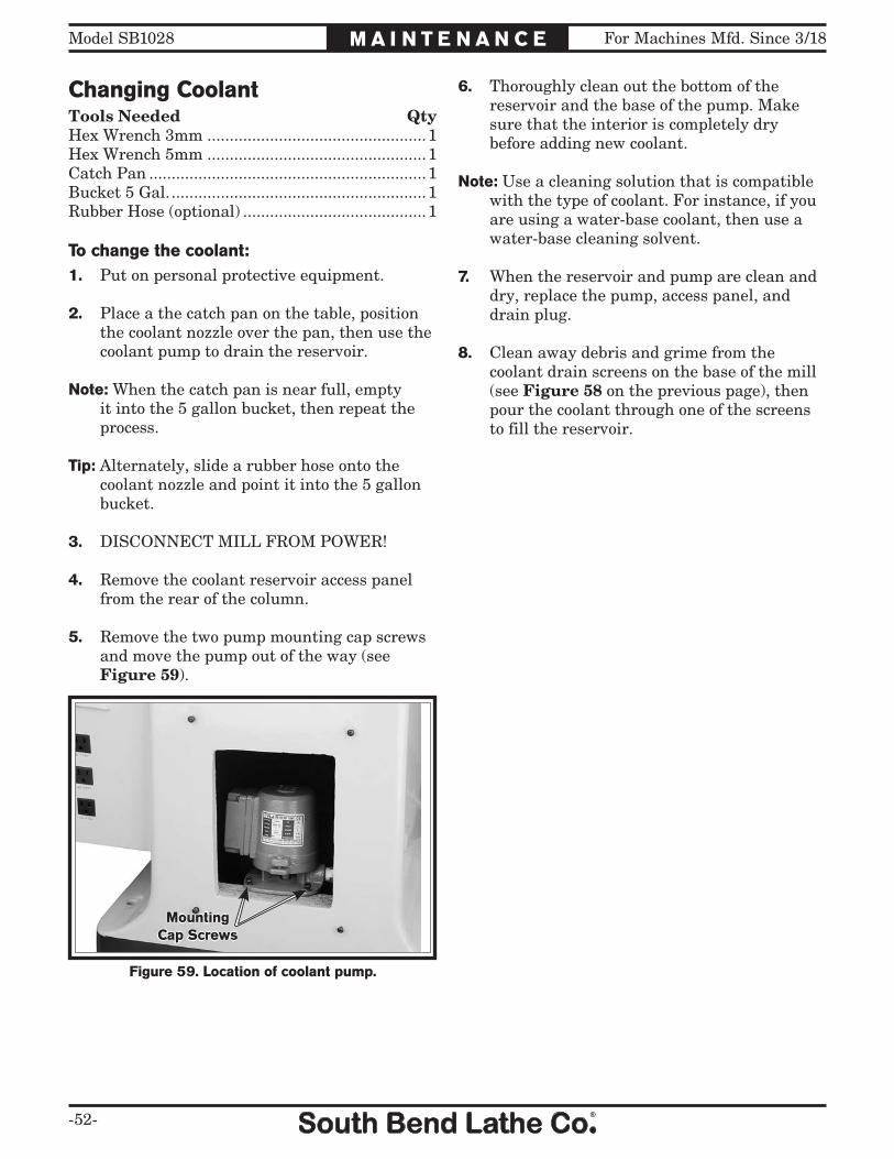
-52-
For Machines Mfd. Since 3/18Model SB1028 M A I N T E N A N C E
6. Thoroughly clean out the bottom of the reservoir and the base of the pump. Make sure that the interior is completely dry before adding new coolant.
Note: Use a cleaning solution that is compatible with the type of coolant. For instance, if you are using a water-base coolant, then use a water-base cleaning solvent.
7. When the reservoir and pump are clean and dry, replace the pump, access panel, and drain plug.
8. Clean away debris and grime from the coolant drain screens on the base of the mill (see Figure 58 on the previous page), then pour the coolant through one of the screens to fill the reservoir.
Changing CoolantTools Needed QtyHex Wrench 3mm .................................................1Hex Wrench 5mm .................................................1Catch Pan ..............................................................1Bucket 5 Gal. .........................................................1Rubber Hose (optional) .........................................1
To change the coolant:1. Put on personal protective equipment.
2. Place a the catch pan on the table, position the coolant nozzle over the pan, then use the coolant pump to drain the reservoir.
Note: When the catch pan is near full, empty it into the 5 gallon bucket, then repeat the process.
Tip: Alternately, slide a rubber hose onto the coolant nozzle and point it into the 5 gallon bucket.
3. DISCONNECT MILL FROM POWER!
4. Remove the coolant reservoir access panel from the rear of the column.
5. Remove the two pump mounting cap screws and move the pump out of the way (see Figure 59).
Figure 59. Location of coolant pump.
MountingCap Screws

For Machines Mfd. Since 3/18 Model SB1028
-53-
M A I N T E N A N C E
Machine StorageTo avoid rust problems or corrosion damage, properly prepare the mill for storage if it will not be operated for any length of time.
To prepare the mill for storage:1. DISCONNECT MILL FROM POWER!
2. Lubricate the mill as directed in the Lubrication section beginning on Page 46.
3. Clean out the coolant reservoir in the base of the mill as directed in the Changing Coolant section on Page 52.
4. Thoroughly clean all unpainted, bare metal surfaces, then coat them with quality rust preventative. Take care to ensure these surfaces are completely covered but that the rust preventative is kept off painted surfaces.
Note: If the machine will be out of service for only a short period of time, use way oil or a good grade of medium-weight machine oil (not auto engine oil) in place of the rust preventative.
5. Loosen the belts to prevent them from stretching during storage. Post a reminder on the mill that the belts need to be re-installed or tensioned before resuming operations.
6. Place a few moisture-absorbing desiccant packs inside the electrical and control panel boxes.
7. Cover and place the machine in a dry area that is out of direct sunlight and away from hazardous fumes, paint, solvents, or gas. Fumes and sunlight can bleach or discolor paint and plastic parts.
8. At least once a month, start the mill and run all gear-driven components for a few minutes. This will keep the bearings, bushings, gears, and shafts well lubricated and protected from corrosion.

-54-
For Machines Mfd. Since 3/18Model SB1028 S E R V I C E
Adjusting GibsGibs are tapered lengths of metal between two sliding surfaces. Gibs control the gap between these surfaces and how accurately they slide. Correctly adjusting the gibs is critical to producing good milling results.
Tight gibs make table movement more accurate but stiff. Loose gibs make moving the table sloppy but easier to do. The goal of gib adjustment is to remove unnecessary sloppiness without causing the ways to bind.
Gibs are adjusted with a screw on each end of the gib, that move the gib back and forth to increase or decrease the friction between the sliding surfaces. The process of properly adjusting the gibs requires trial-and-error and patience.
DISCONNECT MILL FROM POWER BEFORE ADJUSTING THE GIBS!
Note: The saddle and knee have three gibs each—two on each side, and one that is left of center. Adjust the gibs on the sides first, then adjust the left-center gib.
Make sure all table and knee locks are loose and that the table is centered on the saddle. Then, loosen one gib adjustment screw and tighten the other the same amount to move the gib. Use the handwheel/crank to move the table/knee until you feel a slight drag in that path of movement.
Refer to Figures 60–62 to identify the locations of the table, saddle, and knee gibs, and one of the two adjustment screws for each.
Note: It will be necessary to remove small parts, such as way wipers and covers, to access the gib adjustment screws.
Figure 60. Table gib and adjustment screw underneath the left side of the table.
Table Gib & Adjustment Screw
Figure 61. Saddle gib adjustment screws.
Left-Center GibAdjustment Screw
Side GibAdjustment Screw
(1 of 2)
Figure 62. Knee gib adjustment screws.
Side GibAdjustment Screw
(1 of 2)
Left of Center Gib Adjustment Screw

For Machines Mfd. Since 3/18 Model SB1028
-55-
S E R V I C E
Adjusting Leadscrew BacklashLeadscrew backlash is the amount the leadscrew rotates before the attached device begins to move.
Although the mill is equipped with double-bronzed X-axis and Y-axis leadscrew nuts to minimize backlash, leadscrews will always have a certain amount of backlash that will increase with normal wear.
Generally, 0.005"–0.010" leadscrew backlash is acceptable to ensure smooth movement and reduce the risk of premature thread wear. However, if you find it necessary to adjust leadscrew backlash, perform the following procedures.
3. Use the T-handle hex wrench or a similar tool to rotate the adjustment plate on the leadscrew nut in small increments, then rotate the X-axis ball handle to check the amount of backlash.
4. When you are satisfied with the adjustment, re-tighten the two cap screws.
X-Axis Leadscrew BacklashTools Needed QtyT-Handle Hex Wrench 5mm .................................1Hex Wrench 8mm .................................................1
To adjust the X-axis leadscrew backlash:1. DISCONNECT MILL FROM POWER!
2. Loosen the two cap screws on the leadscrew nut accessed from underneath the left side of the table, as shown in Figure 63.
Figure 63. X-axis leadscrew nut and cap screw, as viewed from underneath the left side of the table.
Leadscrew Nut (1 of 2)& Cap Screw

-56-
For Machines Mfd. Since 3/18Model SB1028 S E R V I C E
4. Remove the four cap screws from the bearing housing, then slide it off the leadscrew (see Figure 65).
Note: It may be necessary to use a dead blow hammer or rubber mallet on the housing to knock it loose.
Figure 65. Removing the bearing housing from the Y-axis leadscrew.
BearingHousing
5. Loosen the two cap screws on the face of the leadscrew nut shown in Figure 66.
Figure 66. Y-axis leadscrew nut and cap screws.
Y-axis LeadscrewNut & Cap Screws
6. Re-install the key onto the leadscrew so that you can use the ball handle in the next step.
7. Use the T-handle hex wrench or similar tool to rotate the adjustment plate on the leadscrew nut in small increments, then rotate the Y-axis ball handle to check the amount of backlash.
8. When you are satisfied with the adjustment, re-tighten the two cap screws.
9. Re-install the parts previously removed in the reverse order.
Y-Axis Leadscrew BacklashTools Needed QtyT-Handle Hex Wrench 5mm .................................1Hex Wrench 8mm .................................................1Wrench 19mm .......................................................1
To adjust the Y-axis leadscrew backlash:1. DISCONNECT MILL FROM POWER!
2. Remove the hex nut and ball handle from the Y-axis leadscrew.
Note: In the next step, take care not to misplace the leadscrew key as you remove the parts.
3. Unthread and remove the knurled retaining ring, graduated dial ring, and the leadscrew key, as shown in Figure 64.
Figure 64. Ball handle, rings, and key removed from the Y-axis leadscrew.
Y-axis Leadscrew
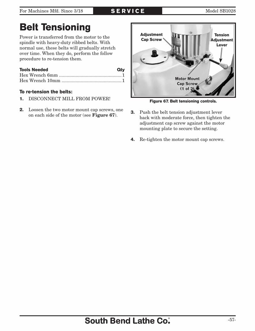
For Machines Mfd. Since 3/18 Model SB1028
-57-
S E R V I C E
Belt TensioningPower is transferred from the motor to the spindle with heavy-duty ribbed belts. With normal use, these belts will gradually stretch over time. When they do, perform the follow procedure to re-tension them.
Tools Needed QtyHex Wrench 6mm .................................................1Hex Wrench 10mm ...............................................1
To re-tension the belts:1. DISCONNECT MILL FROM POWER!
2. Loosen the two motor mount cap screws, one on each side of the motor (see Figure 67).
3. Push the belt tension adjustment lever back with moderate force, then tighten the adjustment cap screw against the motor mounting plate to secure the setting.
4. Re-tighten the motor mount cap screws.
Figure 67. Belt tensioning controls.
TensionAdjustment
Lever
Motor MountCap Screw
(1 of 2)
AdjustmentCap Screw

-58-
For Machines Mfd. Since 3/18Model SB1028 TROUBLESHOOTING
If you need replacement parts, or if you are unsure how to do any of the solutions given here, feel free to call us at (360) 734-1540.
Symptom Possible Cause Possible Solution
Machine does not start or a breaker trips.
1. Emergency stop button is pushed in or is at fault.
1. Rotate the button clockwise until it pops out; replace if necessary.
2. Main power switch not turned ON. 2. Make sure the electrical box door is closed and securely latched, then turn the main power switch ON.
3. Plug/receptacle is at fault or wired incorrectly.
3. Test for good contacts; correct the wiring.
4. Power supply is switched OFF or is at fault.
4. Ensure hot lines have correct voltage on all legs and main power supply is switched ON.
5. Main power switch is at fault. 5. Replace the main power switch.
6. Motor connection wired incorrectly. 6. Correct motor wiring connections (Page 65).
7. ON button or spindle direction switch at fault.
7. Replace faulty ON button or spindle direction switch.
8. Motor windings or motor is at fault. 8. Replace motor.
Machine stalls or is overloaded.
1. Machine is undersized for the task. 1. Use smaller or sharper tooling; reduce the feed rate; reduce the spindle speed; use coolant.
2. Workpiece alignment is poor. 2. Eliminate workpiece binding; use vise or clamps as required for proper workpiece alignment control.
3. Dull or incorrect cutting tool. 3. Use sharp and correct cutting tool for the operation.
4. Spindle speed is incorrect for the operation.
4. Select appropriate spindle speed (Page 37).
5. Motor connection wired incorrectly. 5. Correct motor wiring connections (Page 65).
6. Plug/receptacle is at fault or wired incorrectly; incorrect voltage coming from power source.
6. Test for good contact; correct wiring problems; ensure hot lines have correct voltage on all legs.
7. Pulley(s) slipping on shaft. 7. Replace loose pulley/shaft.
8. Motor bearings at fault. 8. Test by rotating shaft; rotation grinding/loose shaft requires bearing replacement.
9. Motor has overheated. 9. Clean off motor, let cool, and reduce workload.
10. Motor is at fault. 10. Replace motor.
Machine has vibration or noisy operation.
1. Tool holder or cutter is at fault. 1. Replace out-of-round tool holder; replace/re-sharpen cutter; use appropriate feed rate spindle speed.
2. Workpiece alignment is poor. 2. Eliminate workpiece binding; use vise or clamps as required for proper workpiece alignment control.
3. Motor or component is loose. 3. Inspect replace stripped or damaged bolts/nuts and re-tighten with thread locking fluid.
4. Pulley is loose. 4. Re-align/replace shaft, pulley, set screw, and key as required.
5. Machine is incorrectly mounted to floor or sits uneven.
5. Re-tighten/replace mounting bolts in floor; relocate/shim machine.
6. Motor fan is rubbing on fan cover. 6. Replace dented fan cover or fan.
7. Pulley(s) slipping on shaft. 7. Replace loose pulley/shaft.
8. Motor bearings at fault. 8. Test by rotating shaft; rotation grinding/loose shaft requires bearing replacement.
9. Gearbox is at fault. 9. Rebuild gearbox for bad gear(s)/bearing(s).
!

For Machines Mfd. Since 3/18 Model SB1028
-59-
TROUBLESHOOTING
Symptom Possible Cause Possible Solution
Tool slips in collect. 1. Collet is not fully drawn into spindle taper.
1. Snug up the drawbar to fully seat the collet.
2. Wrong size collet. 2. Use correct collect for tool shank diameter.
3. Debris on mating surfaces of collet and spindle.
3. Remove oil and debris from mating surfaces, then re-install.
4. Excessive depth of cut. 4. Decrease depth of cut and allow chips to clear.
Tool breakage. 1. Spindle speed too slow/feed rate too fast.
1. Use correct spindle speed and feed rate (Page 37).
2. Tool getting too hot. 2. Use coolant; reduce spindle speed/feed rate (Page 37).
3. Excessive depth of cut. 3. Decrease depth of cut and allow chips to clear.
Workpiece chatters or vibrates during operation.
1. Table/saddle/knee locks not tight. 1. Tighten all locks on mill that are not associated with necessary table movement for the operation.
2. Workpiece not securely clamped to table or mill vise.
2. Check that clamping is tight and sufficient for the operation; make sure mill vise is clamped tight to table.
3. Tool not secure or is damaged. 3. Properly secure the tool; replace if damaged.
4. Spindle speed too fast/feed rate too slow.
4. Use correct spindle speed and feed rate (Page 37).
5. Gibs are too loose. 5. Properly adjust gibs (Page 54).
Table hard to move.
1. Table/saddle/knee locks are tightened down.
1. Full loosen locks needed for movement.
2. Chips have loaded up on the ways. 2. Frequently clean away chips from the ways that build up during operation.
3. Ways are dry and in need of lubrication.
3. Use the one-shot oiler (Page 47).
4. Gibs are too tight. 4. Properly adjust gibs (Page 54).
Bad surface finish. 1. Wrong spindle speed/feed rate. 1. Use correct spindle speed and feed rate (Page 37).
2. Dull/damaged tool; wrong tool for operation.
2. Sharpen/replace tool; use correct tool for operation.
3. Wrong spindle rotation direction for tool.
3. Check for proper spindle rotation direction for tool.
4. Workpiece not securely clamped to table or mill vise.
4. Check that clamping is tight and sufficient for the operation; make sure mill vise is clamped tight to table.
5. Gibs are too loose. 5. Properly adjust gibs (Page 54).
Power feed chatters or grinds during operation.
1. Brass bevel gear is not meshed with the drive gear.
1. Remove parts from the power feed side of the X-axis leadscrew to ensure the bevel gear is properly meshed; make sure the ball handle nut is tight.
2. Power feed unit is at fault 2. Replace.
!

-60-
For Machines Mfd. Since 3/18Model SB1028 E L E C T R I C A L
Electrical Safety InstructionsThese pages are accurate at the time of printing. In the constant effort to improve, however, we may make changes to the electrical systems of future machines. Study this section carefully. If you see differences between your machine and what is shown in this section, call Technical Support at (360) 734-1540 for assistance BEFORE making any changes to the wiring on the machine.
Shock Hazard: It is extremely dangerous to perform electrical or wiring tasks while the machine is connected to the power source. Touching electrified parts will result in personal injury including but not limited to severe burns, electrocution, or death. For your own safety, disconnect machine from the power source before servicing electrical components or performing any wiring tasks!
Wire Connections: All connections must be tight to prevent wires from loosening during machine operation. Double-check all wires disconnected or connected during any wiring task to ensure tight connections.
Modifications: Using aftermarket parts or modifying the wiring beyond what is shown in the diagram may lead to unpredictable results, including serious injury or fire.
Motor Wiring: The motor wiring shown in these diagrams is current at the time of printing, but it may not match your machine. Always use the wiring diagram inside the motor junction box.
Circuit Requirements: Connecting the machine to an improperly sized circuit will greatly increase the risk of fire. To minimize this risk, only connect the machine to a power circuit that meets the minimum requirements given in this manual.
Capacitors/Inverters: Some capacitors and power inverters store an electrical charge for up to 10 minutes after being disconnected from the power source. To reduce the risk of being shocked, wait at least this long before working on capacitors.
Wire/Component Damage: Damaged wires or components increase the risk of serious personal injury, fire, or machine damage. If you notice that any wires or components are damaged while performing a wiring task, replace those wires or components before completing the task.
Experiencing Difficulties: If you are experiencing difficulties understanding the information included in this section, contact our Technical Support at (360) 734-1540.
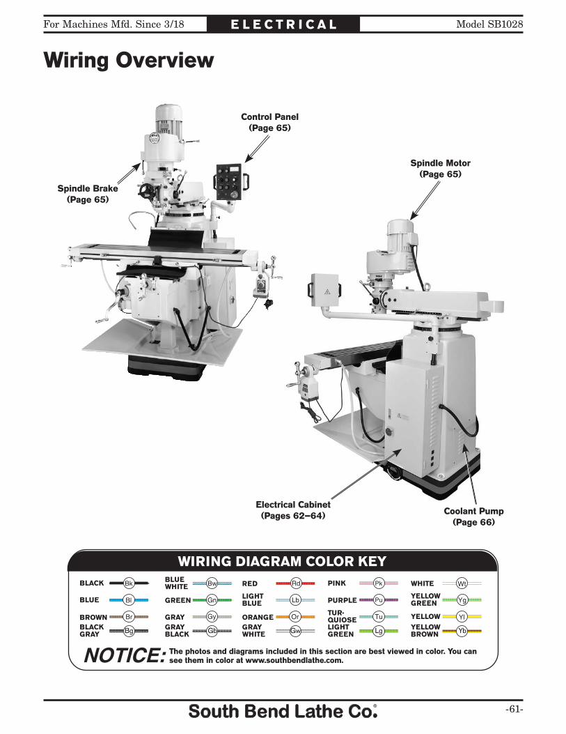
For Machines Mfd. Since 3/18 Model SB1028
-61-
E L E C T R I C A L
Wiring Overview
The photos and diagrams included in this section are best viewed in color. You can see them in color at www.southbendlathe.com.
BLACK WHITE
GREEN
RED
BLUE
BROWN GRAY ORANGE YELLOW
YELLOWGREENPURPLE
PINK
LIGHTBLUE
BLUEWHITE
TUR-QUIOSE
NOTICE:
WIRING DIAGRAM COLOR KEY
BLACKGRAY Bg GbGRAY
BLACKGRAYWHITE
LIGHTGREEN
YELLOWBROWNGw Lg Yb
Spindle Brake(Page 65)
Control Panel(Page 65)
Spindle Motor(Page 65)
Electrical Cabinet(Pages 62–64) Coolant Pump
(Page 66)

-62-
For Machines Mfd. Since 3/18Model SB1028 E L E C T R I C A L
Upper Electrical Cabinet Wiringupper electrical panel wiring
5A Fuse
2A Fuse
5A Fuse
1A Fuse
R/L
1V
/T2
U/T
1+
2+
1–
T/L3
S/L
2W
/T3
OV
220V
230V
380V
460V
415V
110V
24V
12V
0V
E
Yung
-Jen
gTr
ansf
orm
er5
00
VA A
00
9-0
39
2
Yask
awa
Pow
er In
vert
erV
10
00
Brake Resistor 500W/30-Ohm
R1
T1
UV
W
R1T1
1R
1R
2R
2RR
R R
T
T
T
T
33
33
20
20
530
530
00
825
R+
S-
S+
R-
IG
825
C3
C1
–
11
S1
H1
SC
HC
S7
S6
S5
S4
S3
S2
RP
MA
MC
MB
10
R
R
T2
R2
T2
R2
72
7
2
3435
3435
Ron
g S
on6
00
V3
0A
Fus
es
0
Fuse
Fuse
P1
MP
AC
AM
AC
+V
A2
A1
PC
P2
C2
+
B2
B1 W1
W2
W2W1
To Spindle Motor & Brake (Page 65)
To C
ontr
ol P
anel
(P
age
65
)
To C
onta
ctor
s (P
age
63
)To
Low
er E
lect
rica
l Cab
inet
(P
age
64
)To
Low
er E
lect
rica
l Cab
inet
(P
age
64
)
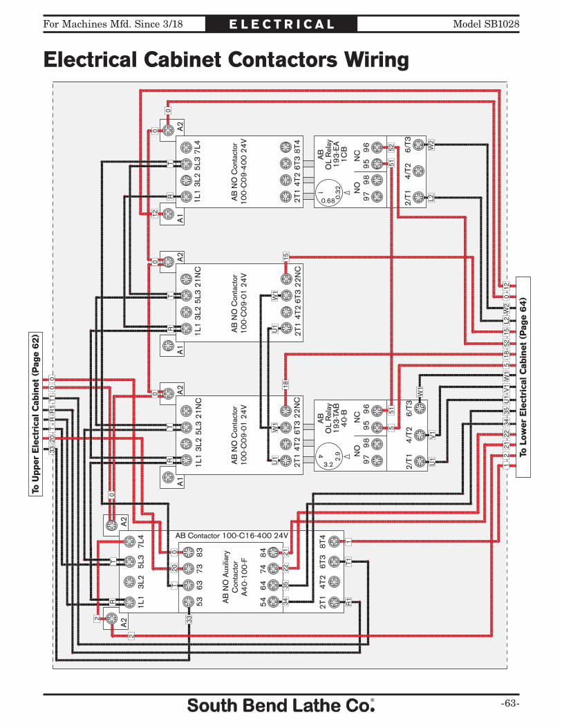
For Machines Mfd. Since 3/18 Model SB1028
-63-
E L E C T R I C A L
Electrical Cabinet Contactors Wiring
A2
A2
53
63
73
83
54
64
748
4
AB
NO
Aux
iliar
yC
onta
ctor
A4
0-1
00
-F
1L1
3L2
5L3
7L4
2T1
4T2
6T3
8T4
AB Contactor 100-C16-400 24V
A1
A2
AB
NO
Con
tact
or1
00
-C0
9-0
1 2
4V
95
96
NC
97
98
NO4
3.2
2.9
2/T
14
/T2
6/T
3
AB
OL
Rel
ay1
93
-TA
B4
0-B
A1
A2
AB
NO
Con
tact
or1
00
-C0
9-0
1 2
4V
95
96
NC
97
98
NO1
0.68 0.3
2
2/T
14
/T2
6/T
3
AB
OL
Rel
ay1
93
-EA
1C
B
A1
A2
AB
NO
Con
tact
or1
00
-C0
9-4
00
24
V
R1
T1
RT
33
33
R1
T1
0
1L1
3L2
5L3
21
NC
2T1
4T2
6T3
22
NC
2T1
4T2
6T3
22
NC
1L1
3L2
5L3
21
NC
1L1
3L2
5L3
7L4
2T1
4T2
6T3
8T4
1
2
2
RT
RT
RT
RT
T20
0
00
0
0
12
L2W
2
12
2122
3435
U1
V1
W1
518
5215
L2W
20
12
2122
3435
U1
W1
18
U1
W1
15
200
0
5152
551
U1
V1
W1
contactor wiringTo
Upp
er E
lect
rica
l Cab
inet
(P
age
62
)
To L
ower
Ele
ctri
cal C
abin
et (
Pag
e 6
4)

-64-
For Machines Mfd. Since 3/18Model SB1028 E L E C T R I C A L
Lower Electrical Cabinet Wiringlower electrical panel wiring
15
3
29
84
7
24
V R
elay
Om
ron
MY4
J
11
0V
Out
lets
25 8825
Main Po
wer
S
witch
3435
L2W2
52U1
V1
1815
W1
1415
1718
2
4
4
3
3
7
79
9
41
41
0
00
L1L3
L1L3
54
312
1413
9
2
4
21
U2
W2
U1
V1W1
L1L3
2122
17
V1
W1
3435
AB
19
4L-
A2
0
Cap
acito
r2
0M
45
0V
13
13
2
2
5
301
5
12
2122
3435
U1V1W1
518
5215
L2W2
012
12
5234
35
2122
2122
2122
2122
30T2
R2
T2
R2
Cab
inet
Fan
To U
pper
Ele
ctri
cal C
abin
et (
Pag
e 6
2)
To C
onta
ctor
s (P
age
63
)To
Upp
er E
lect
rica
l Cab
inet
(P
age
62
)
To Knee Limit Switch (Page 66) To Z-axis Motor & Crank Safety Switch (Page 66)
To P
lug
(Pag
e 6
6)
To C
oola
nt P
ump
(Pag
e 6
6)
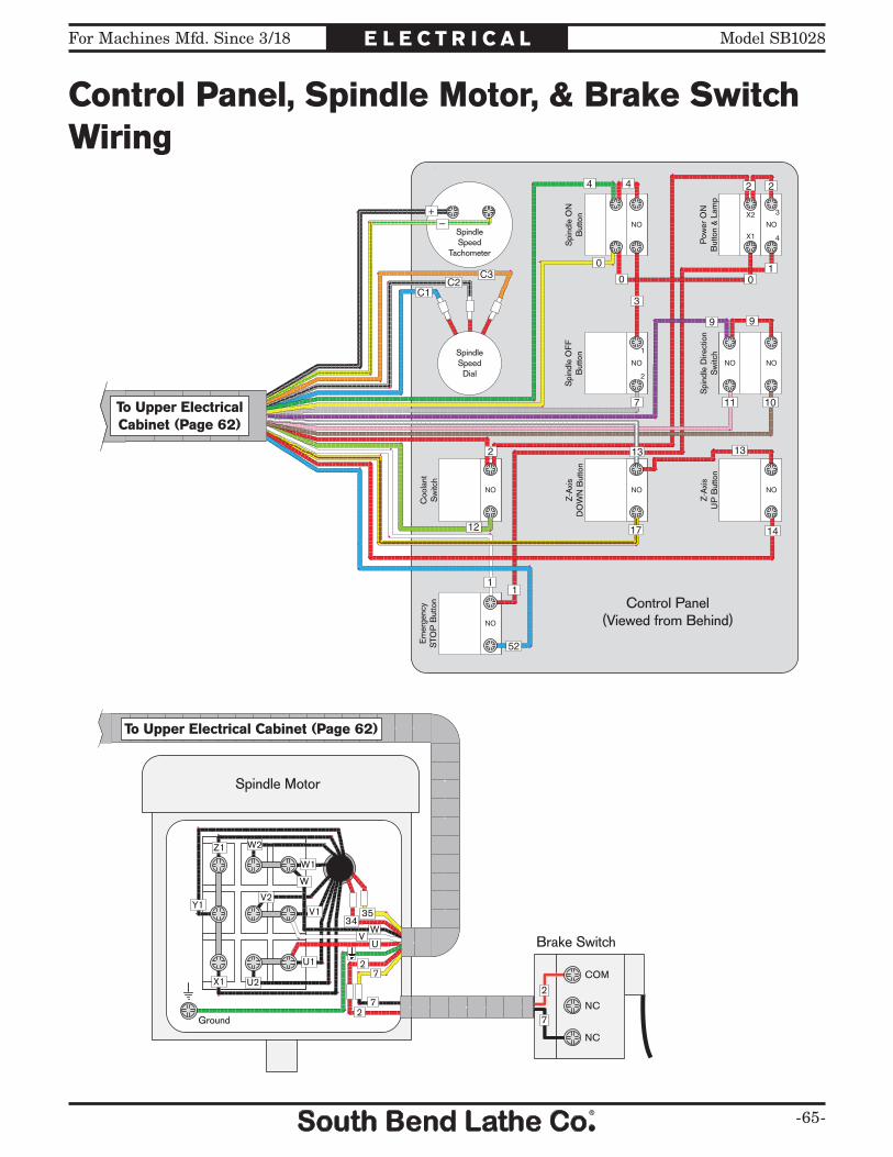
For Machines Mfd. Since 3/18 Model SB1028
-65-
E L E C T R I C A L
Control Panel, Spindle Motor, & Brake Switch Wiring
control panel & spindle motor wiring
2
7
COM
NC
NC
X1
Y1
Z1
U2
V2
W2
U1
V1
W1
W
W34
35
VU
2
2
7
7
Ground
Spindle Motor
Brake Switch
NOX2
X1
NO
NO NO
NO NONO
NO
1
2
3
4
NO
SpindleSpeed
Tachometer
Spi
ndle
ON
But
ton
Pow
er O
NB
utto
n &
Lam
p
Spi
ndle
OFF
But
ton
Spi
ndle
Dire
ctio
nS
witc
h
Coo
lant
Sw
itch
Z-A
xis
DO
WN
But
ton
Z-A
xis
UP
But
ton
SpindleSpeedDial
Em
erge
ncy
STO
P B
utto
n
+–
C3C2
C1
2
12
11
1
17
13 13
14
7
3
0
0
9 9
0
2 24 4
11 10
52
Control Panel(Viewed from Behind)
To Upper ElectricalCabinet (Page 62)
To Upper Electrical Cabinet (Page 62)

-66-
For Machines Mfd. Since 3/18Model SB1028 E L E C T R I C A L
Other Electrical Components Wiringother electrical components wiring
Elevation Motor
Ground
NC NO
13 2
132 Elevation Crank
Safety Switch
W2
U2 S. Capacitor3M 450V
Rd
Rd
Rd
Rd
Yl
Yl
Yl
Coolant Pump
NC
NO
COM
NC
NO
COM
Down KneeLimit Switch
Up KneeLimit Switch
17
18
14
15
220V Single-PhaseNEMA 6-20 Plug
(As Recommended)
Ground
Hot
Hot
G
U1
W1
V1
1
3
2
To Lower ElectricalCabinet (Page 64)
To Upper Electrical Cabinet (Page 62)
To Lower Electrical Cabinet (Page 64)
To Lower Electrical Cabinet (Page 64)

For Machines Mfd. Since 3/18 Model SB1028
-67-
E L E C T R I C A L
Electrical Component Pictures
Figure 68. Control panel wiring. Figure 70. Spindle motor wiring.
Figure 71. Spindle brake switch wiring.
Figure 72. Coolant pump motor wiring.
Figure 69. Electrical cabinet wiring.

-68-
For Machines Mfd. Since 3/18Model SB1028 E L E C T R I C A L
Electrical Component Pictures
Figure 73. Z-axis motor wiring. Figure 75. Z-axis limit switches.
Figure 74. Z-axis crank safety switch.

For Machines Mfd. Since 3/18 Model SB1028
-69-
P A R T S
Headstock1
2
3
4 5 6
78
910
1112
1314
15
17
1819
20
2122
2324
2526
27 28
29 30 31 32 33 34 35
36
37
38
39
40
41
42
4344
45
46 4748
49 50 51 52
5354
55
5657
58
59
60
61
62
63
64
65
66
67
68
69
70 7172
7374
7576
77
7879
80
81
82
83
84
85
86
87
88
89
9091 92
93
94
95
96
97 98
9910
010
1
102
103
104
105
106
107
108
109
110 111 112
113
114
115116
117
118 11912
012
1
122 12
3
124
125
126
127
128
129
130
131
132
133
134
135
136
137 13
8
139
9
49
55
54
38
9 2221
19
20
18
81
21
18
65
316
5112
83
37A
73A
55A
127A
107A
133A
105A

-70-
For Machines Mfd. Since 3/18Model SB1028 P A R T S
Headstock Parts ListREF PART # DESCRIPTION REF PART # DESCRIPTION1 PSB10240449 ROUND KNOB 3/8-16 50 PSB10240037A CLUSTER GEAR SHAFT 18T/12T2 PSB10240002 COARSE DOWNFEED SHAFT LEVER 51 PSB10240037A FEED DRIVE CLUSTER GEAR 23T3 PSB10240003 COARSE DOWNFEED SHAFT HUB 52 PSB10240037A NEEDLE BEARING BZ66Z TIMKEN4 PSTB004 STEEL BALL 3/16 53 PSB10240053 REVERSE CLUTCH ROD 5 PSB10240005 COMPRESSION SPRING 54 PSB10240055A FEED REVERSE BUSHING6 PSS05 SET SCREW 5/16-18 X 1/4 55A PSB10240055A FEED REVERSE BEVEL GEAR ASSY7 PSB10240007 HUB RETAINER 55 PSB10240055A FEED REVERSE BUSHING8 PSB10240008 PINION SHAFT HUB SLEEVE 56 PSB10240056 FEED REVERSE CLUTCH 9 PCAP33M CAP SCREW M5-.8 X 12 57 PRP42M ROLL PIN 3 X 2010 PSB10240010 RETURN SPRING COVER 58 PR03M EXT RETAINING RING 12MM11 PSB10240011 FLAT COIL SPRING 59 PSB10240059 FEED WORM SHAFT BUSHING 12 PK155M KEY 3 X 3 X 18 60 PK39M KEY 3 X 3 X 1013 PSB10240013 RETURN SPRING STUD 61 PK52M KEY 3 X 3 X 1514 PSB10240014 QUILL PINION GEAR SHAFT 10T/16T 62 PSB10240062 WORM 15 PRIV001M STEEL FLUTED RIVET 2 X 5MM 63 PSB10240063 BUSHING 17 PSB10240017 ZERO SCALE 64 PCAP06M CAP SCREW M6-1 X 2518 PSB10240018 ROUND KNOB 1/4-20 65 PSS01M SET SCREW M6-1 X 10¹⁹ PSB10240019 SHIFT CRANK 66 PSB10240066 FEED GEAR SHIFTER FORK 20 PSS11 SET SCREW 1/4-20 X 1/4 67 PSB10240067 CLUSTER GEAR SHIFT CRANK 21 PSB10240021 COMPRESSION SPRING 68 PSB10240068 FEED SHIFT ROD 22 PSB10240022 GEAR SHIFT PLUNGER 69 PSB10240069 CLUSTER GEAR COVER 23 PSB10240023 SHIFT SLEEVE 70 PSB10240070 QUILL PINION SHAFT BUSHING 24 PSB10240024 WORM GEAR CRADLE THROW-OUT 71 PSB10280071 OVERLOAD CLUTCH WORM GEAR 30T25 PSB10240025 WORM SHAFT 72 PR05M EXT RETAINING RING 15MM26 PSS01M SET SCREW M6-1 X 10 73A PSB10240073A PINION OVERLOAD CLUTCH ASSY27 PK102M KEY 4 X 4 X 18 73 PSB10240073A PINION OVERLOAD CLUTCH SHAFT28 PSB10240028 WORM 74 PSB10240073A OVERLOAD CLUTCH 29 PSB10240029 CLUSTER GEAR RETAINER 75 PSB10240073A CLUTCH COMPRESSION SPRING 30 PSB10240030 FEED CLUSTER GEAR 17T/28T/22T 76 PSS05M SET SCREW M5-.8 X 1031 PR06M EXT RETAINING RING 16MM 77 PSB10240073A PINION OVERLOAD CLUTCH COLLAR32 PSB10240032 BEVEL GEAR BUSHING 78 PSB10240078 CLUTCH RING 33 PSB10240033 BEVEL GEAR THRUST SPACER 79 PSB10240079 OVERLOAD CLUTCH WASHER 34 PSB10240034 FEED REVERSE BEVEL PINION 80 PR01M EXT RETAINING RING 10MM35 PK53M KEY 3 X 3 X 45 81 PSB10240081 CLUTCH RING SCREW36 PSB10240037A FEED ENGAGE PIN 82 PSB10240082 OVERLOAD CLUTCH TRIP LEVER 37A PSB10240037A WORM GEAR CRADLE ASSEMBLY 83 PRP03M ROLL PIN 5 X 2037 PSB10240037A WORM GEAR CRADLE 84 PSB10240084 CLUTCH ARM COVER 38 PSS26M SET SCREW M5-.8 X 6 85 PCAP79M CAP SCREW M5-.8 X 3539 PCAP04M CAP SCREW M6-1 X 10 86 PN05 HEX NUT 1/4-2040 PW03M FLAT WASHER 6MM 87 PSS06 SET SCREW 1/4-20 X 3/441 PSB10240037A WORM GEAR SPACER 88 PSB10240088 COMPRESSION SPRING42 PSB10240037A FEED DRIVE WORM GEAR 20T 89 PSB10240089 OVERLOAD CLUTCH PLUNGER43 PSB10240037A WORM CRADLE BUSHING 90 PSB10240090 OIL CUP 1/8"44 PK103M KEY 3 X 3 X 12 91 PSB10240091 TRIP PLUNGER BUSHING 45 PSB10240037A FEED REVERSE BEVEL PINION 92 PSB10240092 FEED TRIP PLUNGER 46 PCAP30 CAP SCREW 5/16-18 X 1/2 93 PSB10240093 FEED TRIP LEVER 47 PSB10240037A BEVEL GEAR FLAT WASHER 8MM 94 PSB10240094 TRIP LEVER PIN48 PSB10240037A FEED BEVEL GEAR 24T 95 PN04M HEX NUT M4-.749 PK03M KEY 3 X 3 X 8 96 PSS49M SET SCREW M4-.7 X 16

For Machines Mfd. Since 3/18 Model SB1028
-71-
P A R T S
Headstock Parts ListREF PART # DESCRIPTION REF PART # DESCRIPTION97 PSB10240097 INDICATOR ROD LOCK KNOB 119 PSTB004M STEEL BALL 5MM98 PSB10240098 INDICATOR ROD 120 PSB10240120 COMPRESSION SPRING99 PSB10240099 REVERSE TRIP BALL LEVER SCREW 121 PSS17M SET SCREW M8-1.25 X 6100 PSB10240100 FEED REVERSE TRIP PLUNGER 122 PSB10240122 QUILL DEPTH SCALE101 PSB10240101 REVERSE TRIP BALL LEVER 123 PS17M PHLP HD SCR M4-.7 X 6102 PSB10240102 QUILL STOP DOG 124 PSB10240124 FINE DOWNFEED HANDWHEEL103 PSB10240105A QUILL MICRO STOP 125 PSB10240124 HANDWHEEL HANDLE104 PSB10240105A MICRO STOP LOCK RING 126 PEC13M E-CLIP 5MM105A PSB10240105A QUILL MICRO STOP ASSEMBLY 127A PSB10240127A KNURLED SLEEVE ASSEMBLY105 PSB10240105A QUILL MICRO STOP SHAFT 127 PSB10240127A KNURLED SLEEVE106 PCAP105 CAP SCREW 3/8-16 X 5/8 128 PSB10240127A HANDWHEEL CAPTIVE PIN107A PSB10240107A STOP TRIP BAR ASSEMBLY 129 PSB10240129 QUILL LOCK NUT 107 PSB10240107A STOP SHAFT TRIP BAR 130 PSB10240130 QUILL LOCK SLEEVE108 PSB10240107A COMPRESSION SPRING 131 PSB10240133A LOCK SHAFT109 PSB10240107A STOP SHAFT TRIP SHAFT 132 PSB10240133A TAPERED COMPRESSION SPRING110 PRP61M ROLL PIN 3 X 12 133A PSB10240133A LOCK HANDLE ASSEMBLY111 PSB10240107A STOP SHAFT END CAP 133 PSB10240133A LOCK HANDLE112 PRP02M ROLL PIN 3 X 16 134 PSB10240133A LOCK HANDLE STEP SCREW113 PSB10240107A TRIP BAR SET SCREW 135 PSB10240135 HEAD ROTATION LOCK BOLT114 PSB10240107A STOP SHAFT PLUNGER 136 PSB10240136 LOWER CLAMPING BOLT SPACER 115 PSB10240115 FEED TRIP BRACKET 137 PSB10240137 LOCK BOLT FLAT WASHER116 PCAP02M CAP SCREW M6-1 X 20 138 PSB10240138 LOCK BOLT HEX NUT117 PSB10240117 STOP SHAFT TRIP LEVER 139 PSB10240139 QUILL HOUSING 118 PSB10240118 HANDWHEEL CLUTCH

-72-
For Machines Mfd. Since 3/18Model SB1028 P A R T S
201
202203
204
205
206207
208
209
210211
212
213
214
215216
217
218
205206A
139
Quill
REF PART # DESCRIPTION REF PART # DESCRIPTION139 PSB10240139 QUILL HOUSING 209 P6206ZZ BALL BEARING 6206ZZ201 PSB10240201 SPINDLE R8 210 PSB10240210 SPANNER NUT LOCK WASHER202 PSS03M SET SCREW M6-1 X8 211 PSB10240211 SPANNER NUT203 PSB10240203 QUILL END CAP 212 PSB10240212 QUILL SKIRT204 PSB10240204 BEARING SEAL 213 PSS26M SET SCREW M5-.8 X 6205 P7207-P4 ANGULAR CONTACT BEARING 7207 P4 214 PSB10240214 QUILL206A PSB10240206A BEARING SPACER ASSEMBLY 215 PW02M FLAT WASHER 5MM206 PSB10240206A BEARING SPACER 216 PS09M PHLP HD SCR M5-.8 X 10207 PSB10240206A BEARING BUSHING 217 PSB10280217 DRAWBAR 7/16-18 X 23-3/8"208 PSB10240208 QUILL SLEEVE 218 PSB10240218 DRAWBAR SPACER
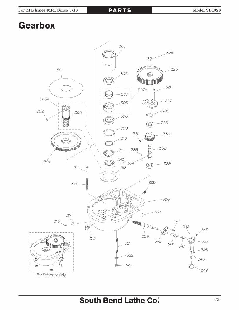
For Machines Mfd. Since 3/18 Model SB1028
-73-
P A R T S
Gearbox
301
302 303
304
305
306
307
308
309
310
311
312
313314
315
316317
318321
322
323
324
325
326
327
328
329
330331
332333
334
335
336
337
339340
341342
343
344
345346 347
348
349
306
329
For Reference Only
303A
307A

-74-
For Machines Mfd. Since 3/18Model SB1028 P A R T S
Gearbox Parts ListREF PART # DESCRIPTION REF PART # DESCRIPTION301 PSB10240301 GEARBOX PLATE 325 PSB10240325 BELT PULLEY GEAR 302 PK70M KEY 8 X 8 X 12 326 PCAP24M CAP SCREW M5-.8 X 16303A PSB10240303A SPINDLE GEAR HUB ASSEMBLY 327 PSB10240327 BULL GEAR PINION BEARING CAP 303 PSB10240303A SPINDLE GEAR HUB 328 PSB10240328 WAVE SPRING WASHER304 PSB10240304 SPINDLE BULL GEAR 329 PSB10280329 BALL BEARING 6203VV NSK305 PSB10240305 BEARING SLEEVE 330 PSB10240330 PINION GEAR 30T306 PSB10280306 BALL BEARING 6908VV NSK 331 PSS20M SET SCREW M8-1.25 X 8307A PSB10240307A BEARING SPACER ASSEMBLY 332 PSB10240332 PINION GEAR SHAFT307 PSB10240307A BULL GEAR BEARING SPACER 333 PK19M KEY 5 X 5 X 14308 PSB10240307A BULL GEAR BEARING SPACER 334 PK14M KEY 5 X 5 X 18309 PR38M INT RETAINING RING 62MM 335 PZERK005 GREASE FITTING ST 1/8 PT310 PSB10240310 SPACER 336 PSB10240336 GEARBOX HOUSING311 PSB10240311 SPINDLE GEAR HUB 337 PCAP14M CAP SCREW M8-1.25 X 20312 PSB10240303A SPANNER NUT 339 PSB10240339 BULL GEAR SHIFT PINION SHAFT313 PSB10240313 BEARING SLEEVE WASHER 340 PSB10240340 HI-LOW DETENT PLATE 314 PSB10240314 STEP PIN 341 PCAP33M CAP SCREW M5-.8 X 12315 PSB10240315 COMPRESSION SPRING 342 PRP02M ROLL PIN 3 X 16316 PFH71M FLAT HD CAP SCR M5-.8 X 8 343 PSS26M SET SCREW M5-.8 X 6317 PSB10240317 BLOCK 344 PSB10240344 HI-LOW PINION BLOCK318 PSB10240090 OIL CUP 1/8" 345 PCAP16M CAP SCREW M4-.7 X 16321 PSB10240321 DOUBLE-END STUD 346 PSB10240346 HIGH-LOW DETENT PLUNGER 322 PLW05 LOCK WASHER 7/16 347 PSB10240005 COMPRESSION SPRING323 PN19 HEX NUT 7/16-14 348 PSB10240348 HIGH-LOW LEVER324 PN09 HEX NUT 5/8-11 349 PSB10240018 ROUND KNOB 1/4-20

For Machines Mfd. Since 3/18 Model SB1028
-75-
P A R T S
Belt Housing401
402
403
403-1404
405
406
407
408409
410
411
412413414
415
416
417418419
420421
422
423
424425426
427428
429
430
431
432
433
434 435
436
437
438
439
440
441442443
444445446
447
448
449
450
451452
453
454
455
456457
458
459
460
461
462
463
412
418
415
442
For Reference Only
466
403A

-76-
For Machines Mfd. Since 3/18Model SB1028 P A R T S
Belt Housing Parts ListREF PART # DESCRIPTION REF PART # DESCRIPTION401 PSB10280403A MOTOR FAN COVER 432 PS68M PHLP HD SCR M6-1 X 10402 PSB10280403A MOTOR FAN 433 PW03M FLAT WASHER 6MM403A PSB10280403A MOTOR ASSEMBLY 434 PSB10240442 BRAKE BEARING CAP403 PSB10280403A SPINDLE MOTOR 5HP 220V 3PH 60HZ 435 PCAP115M BUTTON HD CAP SCR M6-1 X 16403-1 PSB10280403A MOTOR JUNCTION BOX 436 PSB10240444 BRAKE SHOE PIVOT SLEEVE404 PCAP111M CAP SCREW M12-1.75 X 35 437 PS12M PHLP HD SCR M3-.5 X 6405 PW06M FLAT WASHER 12MM 438 PSB10240446 BRAKE SHOE SPRING406 PSB10250403 BELT TENSION ADJUSTMENT LEVER 439 PSB10240447 BRAKE SHOE SET407 PSB10250407 KNOB 5/16-18 440 PSB10280440 BALL BEARING 6010VV NSK408 PSB10270408 MOTOR PULLEY 441 PR47M EXT RETAINING RING 13MM409 PK163M KEY 8 X 7 X 30 442 PSS03M SET SCREW M6-1 X 8410 PSB10270410 MOTOR PULLEY FLAT WASHER 443 PSB10280443 BRAKE SHAFT SLEEVE411 PCAP31M CAP SCREW M8-1.25 X 25 444 PSB10240451 BRAKE SHAFT412 PCAP02M CAP SCREW M6-1 X 20 445 PEC02M E-CLIP 4MM413 PSB10270413 MOTOR ADJUSTMENT BLOCK 446 PSB10240453 BRAKE LEVER PIVOT BRACKET414 PCAP12M CAP SCREW M8-1.25 X 40 447 PSB10280447 CAPTIVE PIN415 PSS26M SET SCREW M5-.8 X 6 448 PSB10240456 BRAKE LEVER416 PSB10270416 TOP BEARING COVER 449 PSB10240449 ROUND KNOB 3/8-16417 PSB10270417 BRAKE SWITCH MOUNTING BLOCK 450 PSB10240458 BRAKE OPERATING FINGER418 PCAP24M CAP SCREW M5-.8 X 16 451 PSB10240459 BRAKE FINGER PIVOT STUD419 PSB10280419 BRAKE SWITCH 452 PR36M EXT RETAINING RING 7MM420 PW05M FLAT WASHER 4MM 453 PSB10240461 BRAKE SEAT421 PCAP21M CAP SCREW M4-.7 X 30 454 PCAP01M CAP SCREW M6-1 X 16422 PSB10270422 BRAKE SWITCH COVER 455 PSB10240463 SPINDLE PULLEY SPACER423 PS09M PHLP HD SCR M5-.8 X 10 456 PSB10270456 SPINDLE PULLEY HUB424 PSB10270424 BELT HOUSING 457 PK109M KEY 7 X 7 X 35425 PSB10270425 SPANNER NUT 458 PK27M KEY 7 X 7 X 25426 PSB10270426 TABBED SPANNER LOCK WASHER 459 PSB10250447 TIMING BELT 225L-100427 PSB10280427 BALL BEARING 6007VV NSK 460 PSB10270460 SPINDLE PULLEY HUB COLLAR428 PSB10270428 BEARING SPACER 461 PSB10240420 BELT HOUSING REAR COVER429 PSB10270429 TIMING BELT 800-8YU-25 462 PS05M PHLP HD SCR M5-.8 X 8430 PSB10270430 SPINDLE PULLEY 463 PSB10270463 BELT HOUSING BOTTOM COVER431 PSB10240438 BRAKE ASSEMBLY COVER 466 PSB10280466 PULLEY COLLAR

For Machines Mfd. Since 3/18 Model SB1028
-77-
P A R T S
Ram
REF PART # DESCRIPTION REF PART # DESCRIPTION501 PCAP31M CAP SCREW M8-1.25 X 25 519 PSB10240519 HEAD TILT WORM SHAFT502 PSB10240502 DOWEL PIN 8 X 30 520 PSB10240520 EYE BOLT 3/4-10503 PSB10240503 GEAR 33T 521 PSB10280521 RAM504 PRIV001M STEEL FLUTED RIVET 2 X 5MM 522 PSB10280522 RAM GIB505 PSB10240505 HEAD ROTATION SCALE 523 PSB10280523 TURRET CLAMP BOLT506 PSB10240506 RAM ADAPTER 524 PSB10240524 RAM PINION SCREW507 PSB10240017 ZERO INDICATOR 525 PSB10280525 TURRET508 PSB10240508 WORM THRUST WASHER 526 PSB10240526 RAM GIB ADJUSTMENT SCREW509 PSB10240509 LOCK COLLAR 527 PN08 HEX NUT 3/8-16510 PSS02M SET SCREW M6-1 X 6 528 PSB10240528 RAM LOCK PLUNGER511 PK36M KEY 5 X 5 X 50 529 PSB10240530A LOCK LEVER STUD512 PSB10240512 HEAD TILT WORM 530A PSB10240530A RAM LOCK HANDLE ASSEMBLY513 PSB10240513 HEAD TILT SCALE 530 PSB10240530A LOCK LEVER514 PSB10280514 TILT LOCK BOLT 531 PSB10240530A COMPRESSION SPRING515 PW10M FLAT WASHER 14MM 532 PSB10240530A STEP SCREW516 PR19M EXT RETAINING RING 28MM 533 PSB10240533 RAM PINION517 PSB10240517 TILT PIVOT STUD 534 PSB10240534 RAM ROTATION SCALE518 PSB10240518 TILT LOCK BOLT BUSHING 535 PSB10240535 TURRET BRACKET
For Reference Only
501
502
503
504
505
506
507
508509510
511
512
513
514
515
516
517
518
519 520
521
522
523
524525
526
527
528529
530531
532
533
534
535
504
510
504
514
515
516
515
504
530A
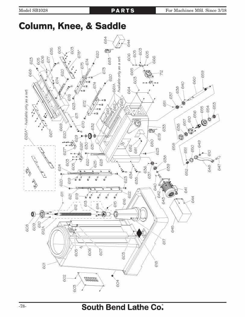
-78-
For Machines Mfd. Since 3/18Model SB1028 P A R T S
Column, Knee, & Saddle
60
1
60
2
60
3 60
4
60
5
60
6
60
7
60
8
60
9 610
611
612 6
13
614 615 6
16
617
618
619
620
621 622
623
624 6
25
626
*
627
*
628
629
630
631
632
633
634
635
636
637
638
639
640
641
642
643 644
645
647
648
649
650
651
652
653
654
655
656
657
658
659
66
0
66
1AAv
aila
ble
only
as
a se
t
66
1 66
2 66
3
66
46
65
66
6
66
7*
66
8
66
9 670
671
672
673
674
675
676
677 6
78*
60
3
612
A
626
A* -
Ava
ilabl
e on
ly a
s a
set
619
620
60
3
623
679
610
638
610
640
638
637
651
60
560
36
05
60
3
620
623
60
3
60
5
635
60
56
06
623
674
620
674
620
620
60
5
60
6
68
26
81 6
80
644
68
36
84
712

For Machines Mfd. Since 3/18 Model SB1028
-79-
P A R T S
Column, Knee, & Saddle Parts ListREF PART # DESCRIPTION REF PART # DESCRIPTION601 PSB10280601 COLUMN 643 PCAP31M CAP SCREW M8-1.25 X 25602 PSB10240604 COOLANT RESERVOIR COVER 644 PS05M PHLP HD SCR M5-.8 X 8603 PS09M PHLP HD SCR M5-.8 X 10 645 PSB10280645 ELEVATION MOTOR COVER604 PSB10240606 COOLANT DRAIN PLUG 1/2" PT 647 PSB10240635 CRANK HANDLE605 PW02M FLAT WASHER 5MM 648 PSB10240636 ELEVATION CRANK606 PS40M PHLP HD SCR M5-.8 X 16 649 PW03M FLAT WASHER 6MM607 PCAP11M CAP SCREW M8-1.25 X 16 650 PSB10280650 CRANK BUSHING608 PSB10280608 DBL ANGULAR CONTACT BEARING 3305 651 PSS02M SET SCREW M6-1 X 6609 PSB10280609 BEARING CAP 652 PSB10280652 COMPRESSION SPRING610 PCAP01M CAP SCREW M6-1 X 16 653 PSB10280653 ELEVATION SHAFT CLUTCH611 PK20M KEY 5 X 5 X 15 654 PSB10240638 FRONT DIAL RETAINER612A PSB10280612A ELEVATION LEADSCREW W/NUT ASSY 655 PSB10240639 VERTICAL DIAL INCH612 PSB10280612A ELEVATION LEADSCREW 656 PSB10240640 REAR DIAL RETAINER613 PCAP02M CAP SCREW M6-1 X 20 657 PSB10240642 BEARING RETAINER614 PSB10280612A ELEVATION LEADSCREW NUT 658 PSB10240644 BEARING SEAT615 PZERK005 GREASE FITTING ST 1/8 PT 659 PK47M KEY 4 X 4 X 15616 PSB10280616 ELEVATION LEADSCREW HOUSING 660 PSB10280660 ELEVATION SHAFT617 PCAP19 CAP SCREW 3/8-16 X 1-1/4 661A PSB10280661A CHIP GUARD SET618 PSB10240625 COOLANT DRAIN SCREEN 661 PSB10280661A SMALL CHIP GUARD619 PCAP108 CAP SCREW 1/2-13 X 1-3/4 662 PSB10280661A MEDIUM CHIP GUARD620 PSB10240661 GIB ADJUSTMENT SCREW 663 PSB10280661A LARGE CHIP GUARD621 PSB10280621 LEFT KNEE GIB 664 PSB10280664 KNEE FRONT COVER622 PSB10280622 LEFT KNEE GIB PLATE 665 PSB10240654 WAY COVER SUPPORT623 PSB10240628 GIB PLATE SCREW 666 PN06M HEX NUT M5-.8624 PSB10280624 RIGHT KNEE GIB 667 PSB10280626A REAR SADDLE WIPER625 PSB10280625 RIGHT KNEE GIB PLATE 668 PSB10280668 SADDLE626A PSB10280626A KNEE/SADDLE WIPER SET 669 PSB10280669 TABLE GIB626 PSB10280626A LEFT COLUMN WIPER 670 PSB10280670 SADDLE LOCK HANDLE ASSEMBLY627 PSB10280626A RIGHT COLUMN WIPER 671 PSB10280671 SADDLE LOCK PLUNGER628 PSB10280628 CENTER KNEE GIB 672 PSB10280672 LEFT SADDLE GIB PLATE629 PN01 HEX NUT 1/2-20 673 PCAP111M CAP SCREW M12-1.75 X 35630 PSB10240631 BEVEL GEAR FLAT WASHER 1/2 674 PSB10280674 SADDLE GIB631 PSB10280631 BEVEL GEAR 675 PSB10280675 RIGHT SADDLE GIB PLATE632 PSB10280632 SPACER 676 PSB10280676 LEFT TABLE LOCK HANDLE PLUNGER633 PSB10280633 KNEE 677 PSB10280677 RIGHT TABLE LOCK HANDLE PLUNGER634 PSB10280634 KNEE LOCK HANDLE PLUNGER 678 PSB10280626A FRONT SADDLE WIPER635 PSB10280635 KNEE LOCK HANDLE ASSEMBLY 679 PSB10280679 ELEVATION CRANK SAFETY SWITCH636 PSS03M SET SCREW M6-1 X 8 680 PSB10280680 SAFETY SWITCH BRACKET637 PSB10280637 BEVEL PINION 681 PCAP33M CAP SCREW M5-.8 X 12638 P6204ZZ BALL BEARING 6204ZZ 682 PW02M FLAT WASHER 5MM639 PR09M EXT RETAINING RING 20MM 683 PSB10280683 KNEE SAFETY SWITCH640 PK48M KEY 4 X 4 X 20 684 PSB10280684 SAFETY SWITCH COVER641 PSB10280641 ELEVATION MOTOR 1/2HP 220V 1PH 712 PSB10240712 CROSS FEED BEARING BRACKET642 PLW04M LOCK WASHER 8MM

-80-
For Machines Mfd. Since 3/18Model SB1028 P A R T S
Table
701
702
703
704
705
706
707
708
709
710
711
723
724
725
729
730
731
732
733
734
701
702
70470
5
706
708
709
710
711
707
712
713
714‡
71571
6
717
718
719
720
721
722
735
736
*
737
738
739
740
‡
741
742*
743‡
744*
745
746
747
748
749
750
751
752
753
715
716717
718
719
720
72172
270
1
702
723
724
725
729
730
705
707
709
731
732
710
711
733
734
735
713
713
738
710
711
736
A*
Avai
labl
e on
ly a
s a
set
714A
‡Av
aila
ble
only
as
a se
t
723A
723A
704A
704A

For Machines Mfd. Since 3/18 Model SB1028
-81-
P A R T S
Table Parts ListREF PART # DESCRIPTION REF PART # DESCRIPTION701 PN01 HEX NUT 1/2-20 725 PSB10240723A BALL HANDLE CLUTCH ASSEMBLY702 PSB10240635 BALL HANDLE KNOB 729 PCAP03M CAP SCREW M5-.8 X 8703 PSB10240703 CROSS FEED BALL HANDLE 730 PSB10280730 TABLE BEARING BRACKET COVER704A PSB10240704A DIAL HOLDER ASSEMBLY 731 PRIV001M STEEL FLUTED RIVET 2 X 5MM704 PSB10240704A FRONT DIAL RETAINER 732 PSB10270732 INDICATOR PLATE705 PSB10240705 TABLE DIAL INCH 733 PSB10270733 BEARING BRACKET706 PSB10240704A INNER DIAL HOLDER 734 PSB10240730 RUBBER TABLE T-SLOT PLUG707 PCAP01M CAP SCREW M6-1 X 16 735 PSB10240606 TABLE DRAIN PLUG 1/2" PT708 PSB10240642 BEARING RETAINER 736A PSB10270736A LONGITUDINAL LEADSCREW W/NUT ASSY709 P6204ZZ BALL BEARING 6204ZZ 736 PSB10280736 LONGITUDINAL LEADSCREW710 PRP05M ROLL PIN 5 X 30 737 PR09M EXT RETAINING RING 20MM711 PCAP14 CAP SCREW 3/8-16 X 1 738 PCAP06M CAP SCREW M6-1 X 25712 PSB10240712 CROSS FEED BEARING BRACKET 739 PW03M FLAT WASHER 6MM713 PK92M KEY 3 X 3 X 25 740 PSB10240714A FRONT CROSS FEED LEADSCREW NUT714A PSB10240714A CROSS FEED LEADSCREW W/NUT ASSY 741 PSB10240736 LEADSCREW NUT BRACKET714 PSB10240714A CROSS FEED LEADSCREW 742 PSB10270736A LEFT LONGITUDINAL LEADSCREW NUT715 PCAP03 CAP SCREW 5/16-18 X 1 743 PSB10240714A REAR CROSS FEED LEADSCREW NUT716 PW07 FLAT WASHER 5/16 744 PSB10270736A LEFT LONGITUDINAL LEADSCREW NUT717 PSB10240717 TRAVEL STOP BRACKET 745 PSB10270745 BEARING RETAINING RING718 PSB10240718 TRAVEL STOP SHAFT 746V2 PSB10280746V2 POWER FEED ASSEMBLY AL-500P719 PSB10240719 COMPRESSION SPRING 747 PSB10240742 BEVEL GEAR BUSHING720 PSB10240720 TRAVEL STOP T-NUT 748 PSB10240743 POWER FEED BEVEL GEAR721 PSB10240721 TRAVEL STOP FLAT WASHER 8MM 749 PSB10240744 BEVEL GEAR NUT722 PR36M EXT RETAINING RING 7MM 750 PSB10280750 TABLE 10" X 54"723A PSB10240723A LONGITUDINAL BALL HANDLE ASSY 751 PSB10240746 LONGITUDINAL LIMIT SWITCH ASSY723 PSB10240723A LONGITUDINAL BALL HANDLE 752 PW04M FLAT WASHER 10MM724 PSS08M SET SCREW M4-.7 X 5 753 PCAP100 CAP SCREW 3/8-16 X 1/2
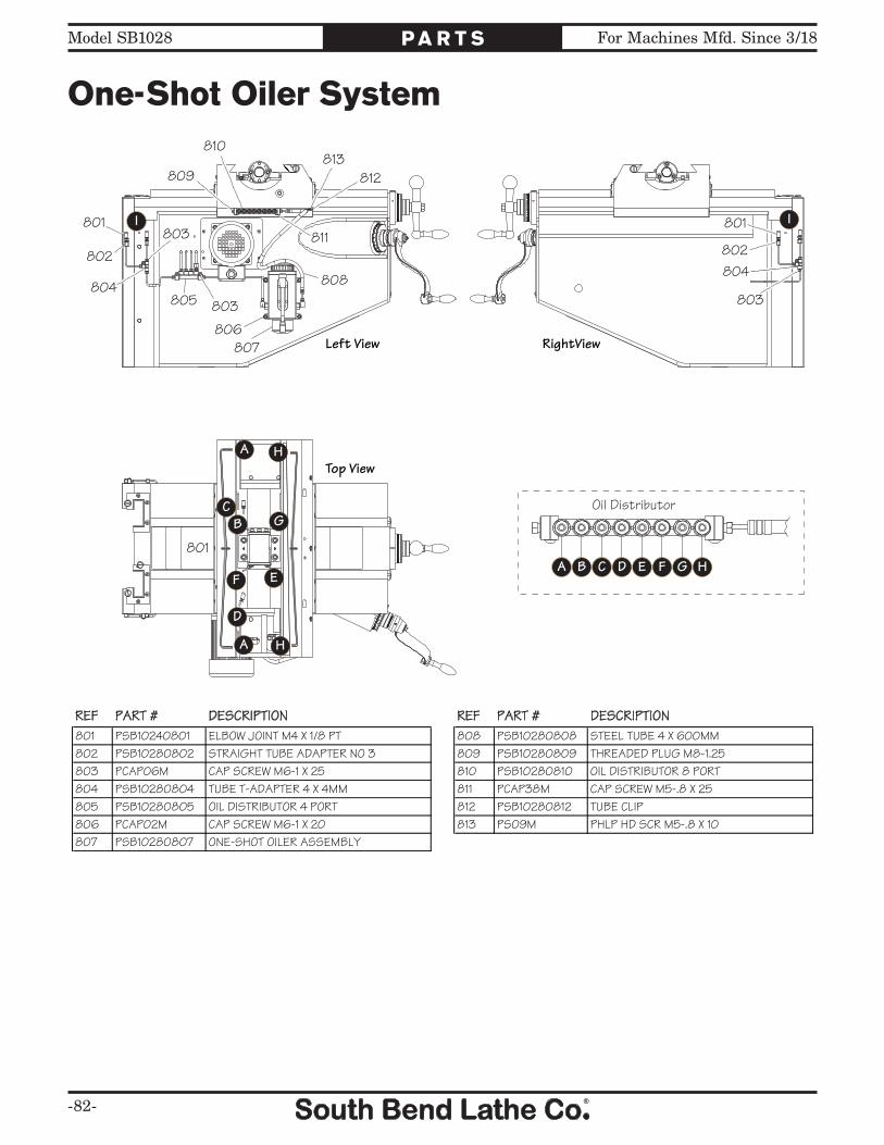
-82-
For Machines Mfd. Since 3/18Model SB1028 P A R T S
One-Shot Oiler System
Oil Distributor
A GFEDCB H801
802803
804805
806807
808
809
810
811
812813
801
803
801
802
803
804
I I
A
G
F E
D
CB
H
A H
Left View RightView
Top View
REF PART # DESCRIPTION REF PART # DESCRIPTION801 PSB10240801 ELBOW JOINT M4 X 1/8 PT 808 PSB10280808 STEEL TUBE 4 X 600MM802 PSB10280802 STRAIGHT TUBE ADAPTER NO 3 809 PSB10280809 THREADED PLUG M8-1.25803 PCAP06M CAP SCREW M6-1 X 25 810 PSB10280810 OIL DISTRIBUTOR 8 PORT804 PSB10280804 TUBE T-ADAPTER 4 X 4MM 811 PCAP38M CAP SCREW M5-.8 X 25805 PSB10280805 OIL DISTRIBUTOR 4 PORT 812 PSB10280812 TUBE CLIP806 PCAP02M CAP SCREW M6-1 X 20 813 PS09M PHLP HD SCR M5-.8 X 10807 PSB10280807 ONE-SHOT OILER ASSEMBLY

For Machines Mfd. Since 3/18 Model SB1028
-83-
P A R T S
Coolant System
901
902
903
904905 906
907908
909910
911
912
913914
915
916
917
918
905
REF PART # DESCRIPTION REF PART # DESCRIPTION901 PCAP02M CAP SCREW M6-1 X 20 910 PSB10270910 PIPE ELBOW 90 DEG 3/8 X 3/8 PT902 PW03M FLAT WASHER 6MM 911 PSB10270911 COOLANT VALVE ASSEMBLY903 PSB10270903 COOLANT PUMP 1/8HP 220V 1PH 60HZ 912 PSB10270912 COOLANT NOZZLE 3/8 X 30"904 PSB10270904 BARBED HOSE FITTING 3/8 PT X 1/2" 913 PSB10270913 PIPE ELBOW 90 DEG 3/8 PT X 1/2"905 PSB10270905 THREADED HOSE CLAMP 3/4" 914 PSB10270914 COOLANT HOSE 1/2 X 59"906 PSB10270906 COOLANT HOSE 1/2 X 43-1/2" 915 PSB10270915 HOSE CLAMP 3/4"907 PSB10270904 BARBED HOSE FITTING 3/8 PT X 1/2" 916 PSB10280916 SPLASH PAN908 PSB10270908 COOLANT NOZZLE BRACKET 917 PCAP50M CAP SCREW M5-.8 X 10909 PCAP33M CAP SCREW M5-.8 X 12 918 PW02M FLAT WASHER 5MM
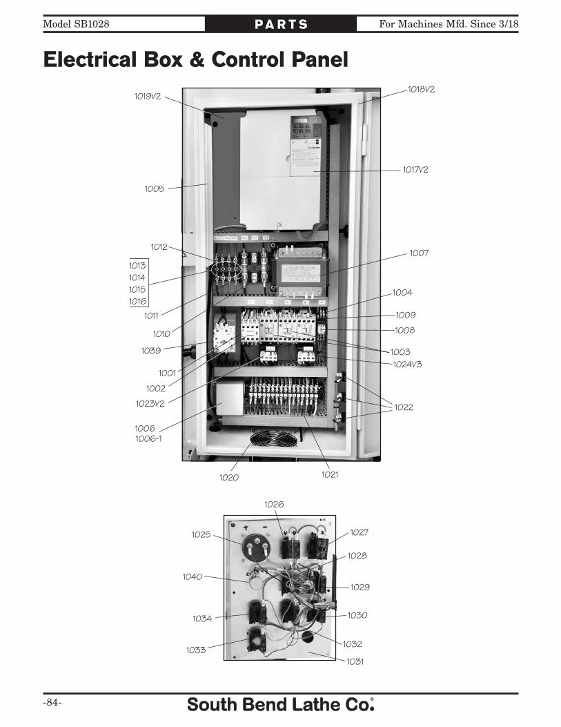
-84-
For Machines Mfd. Since 3/18Model SB1028 P A R T S
Electrical Box & Control Panel
1001
1002
1003
1004
1005
1006
1007
1008
1009
1010
1011
1012
1013101410151016
1017V2
1018V21019V2
1020 1021
10221023V2
1024V3
1025
1026
1027
1028
1029
1030
1031
10321033
1034
1039
1040
1006-1

For Machines Mfd. Since 3/18 Model SB1028
-85-
P A R T S
Electrical Box & Control Panel Parts ListREF PART # DESCRIPTION REF PART # DESCRIPTION1001 PSB10281001 CONTACTOR AB 100-C16-400 24V 1021 PSB10281021 TERMINAL BLOCK ASSEMBLY1002 PSB10281002 AUX CONTACTOR AB 100-F 1022 PSB10281022 ELECTRICAL RECEPTACLE 110V1003 PSB10281003 CONTACTOR AB 100-C09-01 24V 1023V2 PSB10281023V2 OL RELAY AB 193-T 2.9-4.0A V2.07.111004 PSB10281004 CONTACTOR AB 100-C09-400 24V 1024V3 PSB10281024V3 OL RELAY AB 193-EA1CB 0.32-1.0A V3.03.181005 PSB10281005 BRAKE RESISTOR 1025 PSB10281025 SPINDLE SPEED TACHOMETER1006 PC020B CAPACITOR 20M 450V 1-3/4 X 2-3/8 1026 PSB10281026 SPINDLE ON BUTTON1006-1 PSB10281006-1 CAPACITOR COVER 1027 PSB10281027 POWER ON BUTTON/LAMP1007 PSB10281007 TRANSFORMER YUNG A009-0392 500V 1028 PSB10281028 SPINDLE OFF BUTTON1008 PSB10281008 RELAY OMRON MY4J 24V 1029 PSB10281029 SPINDLE DIRECTION SWITCH1009 PSB10281009 RELAY SOCKET OMRON 1030 PSB10281030 Z-AXIS UP BUTTON1010 PSB10271003 FUSE HOLDER 3P 1031 PSB10281031 CONTROL PANEL1011 PSB10281011 FUSE 30A 1032 PSB10281032 Z-AXIS DOWN BUTTON1012 PSB10271017 FUSE HOLDER 4P 1033 PSB10281033 EMERGENCY STOP BUTTON1013 PSB10271016 FUSE 1A 1034 PSB10281034 COOLANT PUMP SWITCH1014 PSB10271013 FUSE 5A 1035* PSB10281035 CONTROL PANEL BOX1015 PSB10271014 FUSE 2A 1036* PSB10281036 CONTROL PANEL ARM ASSEMBLY1016 PSB10271013 FUSE 5A 1037* PSB10281037 CONTROL PANEL ARM JUNCTION BOX1017V2 PSB10281017V2 INVERTER YASKAWA V1000 V2.07.11 1038* PSB10281038 ARM ASSEMBLY LOCK KNOB ASSY1018V2 PSB10281018V2 ELECTRICAL CABINET W/DOOR ASSY V2.07.11 1039 PSB10271012 MAIN POWER SWITCH ASSEMBLY1019V2 PSB10281019V2 ELECTRICAL CABINET BACKBOARD V2.07.11 1040 PSB10260986 SPINDLE SPEED DIAL1020 PSB10281020 COOLING FAN ASSEMBLY *Not Shown
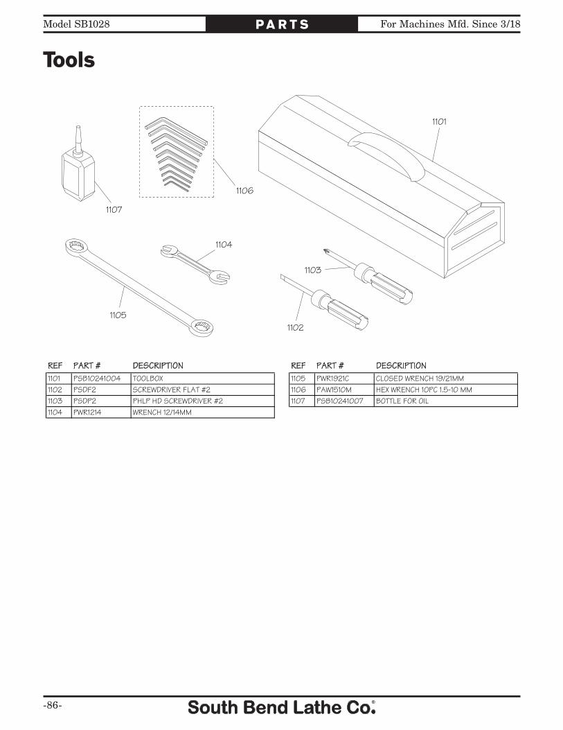
-86-
For Machines Mfd. Since 3/18Model SB1028 P A R T S
Tools
1101
1102
1103
1104
1105
1106
1107
REF PART # DESCRIPTION REF PART # DESCRIPTION1101 PSB10241004 TOOLBOX 1105 PWR1921C CLOSED WRENCH 19/21MM1102 PSDF2 SCREWDRIVER FLAT #2 1106 PAW1510M HEX WRENCH 10PC 1.5-10 MM1103 PSDP2 PHLP HD SCREWDRIVER #2 1107 PSB10241007 BOTTLE FOR OIL1104 PWR1214 WRENCH 12/14MM

For Machines Mfd. Since 3/18 Model SB1028
-87-
P A R T S
Front Machine Labels
The safety labels provided with your machine are used to make the operator aware of the machine hazards and ways to prevent injury. The owner of this machine MUST maintain the original location and readability of these safety labels. If any label is removed or becomes unreadable, REPLACE that label before using the machine again. Contact South Bend Lathe Co. at (360) 734-1540 or www.southbendlathe.com to order new labels.
REF PART # DESCRIPTION REF PART # DESCRIPTION1201 PSBLABEL08HL ENTANGLEMENT HAZARD LABEL 1210 PSBLABEL13HL CLOSE DOOR WARNING LABEL1202 PSB10271202 LUBRICATION DIRECTION LABEL 1211 PSB10241113 RAPID FEED LABEL1203 PSBLABEL03HL EYE INJURY HAZARD LABEL 1212 PSB10241114 POWER FEED CONTROL PANEL LABEL1204 PSBLABEL01HL READ MANUAL LABEL 1213 PSB10281213 MODEL NUMBER LABEL1205 PSB10271205 TRAINED PERSONNEL NOTICE LABEL 1214 PSBPAINT03 SB DARK BLUE TOUCH-UP PAINT1206 PSB10281206 MACHINE ID LABEL 1215 PSBPAINT02 SB LIGHT BLUE TOUCH-UP PAINT1207 PSB10271207 CONTROL PANEL LABEL 1216 PSBPAINT01 SB GRAY TOUCH-UP PAINT1208 PSB10241105 DOWNFEED SELECTOR LABEL 1217 SB1319 SB NAMEPLATE 90MM1209 PSBLABEL02HL DISCONNECT WARNING LABEL
1201
1202
1203
1204
1205
1206
1207
1208
1209
1210
1211
1212
121312141215
1216
1217

-88-
For Machines Mfd. Since 3/18Model SB1028 P A R T S
Side & Rear Machine Labels
REF PART # DESCRIPTION REF PART # DESCRIPTION1218 PSBLABEL15L ELECTRICITY LABEL 1223 PSB10241119 110V OUTLET CAUTION LABEL1219 PSB10271220 SPEED RANGE LABEL 1224 PSB10281223 110V 1PH OUTLET LABEL1220 PSB10281220 INVERTER WARNING LABEL 1225V2 PSB10281225V2 POWER FEED CAUTION LABEL V2.07.111221 PSB10271221 220V 1PH LABEL 1226 PSB10241112 POWER FEED CAUTION LABEL1222 PSBLABEL06HL BIOHAZARD WARNING LABEL 1227 PSB10241116 110V 1PH POWER FEED LABEL
1218
1219
1220
1221
1222
1223
1224
1225V2
1226
1227

W A R R A N T Y
This quality product is warranted by South Bend Lathe Company to the original buyer for one year from the date of purchase. This warranty does not apply to consumable parts, or defects due to any kind of misuse, abuse, negligence, accidents, repairs, alterations or lack of maintenance. We do not reimburse for third party repairs. In no event shall we be liable for death, injuries to persons or property, or for incidental, contingent, special or consequential damages arising from the use of our products.
We do not warrant or represent that this machine complies with the provisions of any law, act, code, regulation, or standard of any domestic or foreign government, industry, or authority. In no event shall South Bend’s liability under this warranty exceed the original purchase price paid for this machine. Any legal actions brought against South Bend Lathe Company shall be tried in the State of Washington, County of Whatcom.
This is the sole written warranty for this machine. Any and all warranties that may be implied by law, including any merchantability or fitness, for any purpose, are hereby limited to the duration of this warranty. To take advantage of this warranty, contact us by mail or phone to give us the details of the problem you are having.
Thank you for your business and continued support.

Printed In Taiwan #TS12715