'. $'56+#4+1 '5%7.2+&1 '0 .15 %#2+6'.'5 &' .# %#6'&4#. 41/Į0+ ...
Upload
khangminh22Category
view
0download
0
1
theMova S360-100 DE WH1030560theMova S360-100 DE GR 1030561
theMova S360-100 AP WH1030550theMova S360-100 AP GR 1030551
307065
Motion detectorEN
1. Product characteristics 42. Safety 53. Intended use 54. Function 6
Functional description 6Channel A light 6
5. Detection area 7Brightness measurement 8
6. Installation 10

2
Ceiling installation 10Surface mount on ceiling 11
7. Switching 12Individual switching 13
8. Settings 13Parameters via remote control 13Control commands via remote control 15Brightness switching value Channel A light 16Time delay channel A light 17Detection sensitivity 18Group address channel A light 18LED display motion 19Factory settings 19

3
9. Start-up 20Switching behaviour 20Test detection area 21
10. Technical data 21Product overview 23Troubleshooting 24LED display 25Guarantee 25Dimensional drawings 27
11. Accessories 2812. Contact 29

4
1. Product characteristics
•Passive infra-red motion detector for ceiling installation •Circular detection area 360°, up to Ø 9 m (64 m2) •Automatic motion and brightness-dependent control for lighting •Mixed light measurement •Channel A light: relay, 230 V •Operation as fully automatic device •Brightness switching value configurable, teach-in function •Pulse function for staircase light time switch •Time delay configurable •Detection sensitivity configurable •Ready for immediate use due to factory presetting •Test mode for checking function and detection area •Installation in false ceilings with springs, type DE •Surface mount on ceiling, type AP •User remote control „theSenda S“ (option) •Management remote control „SendoPro“ (optional) •Service remote control „theSendaP“ (option)

5
2. Safety
Danger of death through electric shock or fire! Installation should only be carried out by a pro- fessional electrician!
WARNING
•Work on electrical systems may only be carried out by electricians or by instructed persons under the leadership and supervision of an electrician in accordance with the technical regulations applying to electricity! •Comply with the country-specific safety regulations for work on electrical systems! Ensure absence of voltage in the cable before installation! •The device is maintenance-free. If the device is opened or penetrated with any objects the guarantee lapses.
3. Intended use
The motion detector is intended for interior instal-lation. The motion detector is exclusively intended for the use as contractually agreed between the manufacturer and the user. Any other use is consi-dered to be unacceptable. The manufacturer does not accept liability for any resulting damages.

6
4. Function
The motion detector is primarily used in passage ways such as corridors, stairs, toilets, basements and garages for easy and energy-efficient control of lighting. The switch contact „light“ switches ligh-ting on with presence and insufficient brightness, and off with absence.
Functional description
Mixed light measurement Motion detection Artificial light Incident daylight
Channel A light
Switching response is controlled by presence and ambient brightness. The switch contact for channel

7
A light closes during darkness and when someone is present. It opens with a delay once the room is vacated after the set time delay.
Time delayThe time delay enables delayed switching off of lighting after the room is vacated. The time delay is adjustable in a range of 10 s to 60 min.
Fully automaticLighting control of the motion detector opera-tes fully automatically for increased comfort. In „fully automatic“ the lights switch on and off automatically.
Pulse functionTime delay can be set to pulse for controlling exis-ting staircase light timer switch. To do so, the light output produces every 10 seconds a pulse of 0.5 seconds duration if people are present or it is dark.
5. Detection area
The circular detection area of theMova S motion detector covers an average detection area. Note that moving persons can be detected in differently-sized areas. The recommended installation height is 2.0 m – 4.0 m. As installation height increases, the sensitivity of the presence detector decreases. The

8
extent and distance between the active and pas-sive zones of the motion detector also increases. The detection range is reduced as temperatures increase.
Installation height (A)
Moving persons Frontal (r)
Moving persons Across (t)
2.0 m 5 m2 Ø 2.5 m 38 m2 Ø 7 m2.5 m 7 m2 Ø 3 m 38 m2 Ø 7 m3.0 m 13 m2 Ø 4 m 50 m2 Ø 8 m3.5 m 13 m2 Ø 4 m 50 m2 Ø 8 m4.0 m 13 m2 Ø 4 m 64 m2 Ø 9 m
Brightness measurement
The motion detector measures the ambient bright-ness below the detector at an opening angle approx. 120°. The installation site is a reference point for the lighting level. The light measurement
9
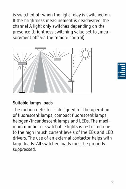
is switched off when the light relay is switched on. If the brightness measurement is deactivated, the channel A light only switches depending on the presence (brightness switching value set to „mea-surement off“ via the remote control).
Suitable lamps loadsThe motion detector is designed for the operation of fluorescent lamps, compact fluorescent lamps, halogen/incandescent lamps and LEDs. The maxi-mum number of switchable lights is restricted due to the high inrush current levels of the EBs and LED drivers. The use of an external contactor helps with large loads. All switched loads must be properly suppressed.

10
6. Installation
Ceiling installation
Installation in false ceilings for ceiling thicknesses of 0.5 mm to 3 cm. The diameter of ceiling cutouts must be between 62 mm and 70 mm. The cable strain relief is with using a cable tie (width: 3.5 – 4.8 mm).The detector requires a clear line of sight to people. The installation height must not be less than 1.7 m and should not exceed 4 m.
11
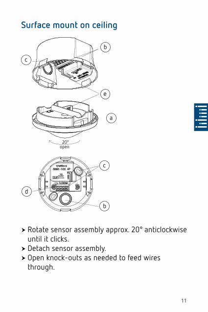
Surface mount on ceiling
20°open
b
e
a
d
c
b
c
�� Rotate sensor assembly approx. 20° anticlockwise until it clicks. �� Detach sensor assembly. �� Open knock-outs as needed to feed wires through.
12
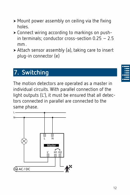
�� Mount power assembly on ceiling via the fixing holes. �� Connect wiring according to markings on push-in terminals; conductor cross-section 0.25 – 2.5 mm . �� Attach sensor assembly (a), taking care to insert plug-in connector (e)
7. Switching
The motion detectors are operated as a master in individual circuits. With parallel connection of the light outputs (L‘), it must be ensured that all detec-tors connected in parallel are connected to the same phase.
AC / DC
H2H1L’

13
Individual switching
In individual switching, the motion detector as master detects presence and brightness and cont-rols lighting.
8. Settings
Motion detector theMova S does not have a setting potentiometer. The motion detector is supplied with a basic setting ready for operation. The reference values for the basic settings are optimised for typi-cal applications. The „SendroPro 868-A“ manage-ment remote control and „theSenda P“ service remote control are optionally available for start-up. They allow the remote adjustment of the setting values.
Parameters via remote control
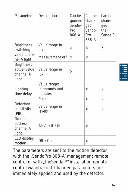
The following parameters can be queried or chan-ged via the remote control for support during installation as well as servicing:
14
Parameter Description Can be queried Sendo-Pro868-A
Can be chan-ged Sendo-Pro868-A
Can be chan-ged the-Senda P
Brightness switching value Chan-nel A light
Value range in lux x x x
Measurement off x x
Brightness actual value channel A light
Value range in lux X
Lighting time delay
Value ranges in seconds and minutes
x x
Pulse x xDetection sensitivity (PIR)
Value range in levels x x
Group address channel A light
All / I / II / III x
LED display motion Off / On x
The parameters are sent to the motion detector with the „SendoPro 868-A“ management remote control or with „theSenda P“ installation remote control via infra-red. Changed parameters are immediately applied and used by the detector.

15
With the „SendoPro 868-A“ management remote control, parameters can be queried by sending values level-by-level to the detector. If the sent values are below the set parameter, the LED illumi-nates briefly. If the sent values are equal or above the set parameter, the LED flickers for 2 seconds.
Control commands via remote control
Control command
Description Can be triggered SendoPro868-A
Can be trig-gered the-Senda P
Teach-in channel A light
The currently measu-red brightness value will be accepted as the brightness switching value. Values outside the permitted range will automatically be set to the appropriate limit value.
x x
Switch lights on/off
Lighting group can be switched on and off. x x
Test detection area On / Off x x
Restart Restart detector x x

16
Control command
Description Can be triggered SendoPro868-A
Can be trig-gered the-Senda P
Factory regulations
Set all parameters and settings to factory setting.
x
Brightness switching value Channel A light
The brightness switching value defines the mini-mum desired brightness. The current prevailing brightness is measured below the motion detector. If the prevailing brightness is below the switching value, the light switches on as soon as motion is detected.
17
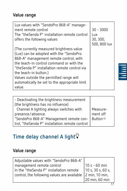
Value range
Lux values with "SendoPro 868-A" manage-ment remote controlThe "theSenda P" installation remote control offers the following values
(The currently measured brightness value (Lux) can be adopted with the "SendoPro 868-A" management remote control, with the teach-in control command or with the "theSenda P" installation remote control via the teach-in button.)Values outside the permitted range will automatically be set to the appropriate limit value.
30 - 3000 Lux30, 300, 500, 800 lux
- Deactivating the brightness measurement (the brightness has no influence) Channel A lighting always switches with presence/absence."SendoPro 868-A" Management remote con-trol, "theSenda P" installation remote control
Measure-ment offButton
Time delay channel A light
Value range
Adjustable values with "SendoPro 868-A" management remote controlIn the "theSenda P" installation remote control, the following values are available
10 s - 60 min10 s, 30 s, 60 s, 2 min, 10 min, 20 min, 60 min

18
Control for staircase light timer switch (0.5 s "on" / 10 s "off")"SendoPro 868-A""theSenda P"
PulseButton 1
Detection sensitivity
The detector has 5 sensitivity increments. The basic setting is the middle level (3). If test detection area mode is selected, the set sen-sitivity increment is not changed. With the „SendoPro 868-A“ management remote control, levels 1 to 5 can be selected and sent to the detector.With the „theSenda P“ installation remote control, the sensitivity can be reduced or increased by one level with every button press.
Level Sensitivity
1 very insensitive
2 insensitive
3 Standard
4 sensitive
5 very sensitive
Group address channel A light
This parameter is applied when using the „the-Senda P“ user remote control.

19
A group address can be assigned to the channel A light.The „SendoPro 868-A“ or „theSenda S“ can be used to program the group addresses in the detector.
Group address value range
Adjustable values "SendoPro 868-A" I, II , III , All
Adjustable values "theSenda S" I, II
LED display motion
The motion detection can be displayed via the LED.
Value range
No display of motion detection. Off
The LED switches on when motion is detected, otherwise switches off.
On
Adjustment possible only with „SendoPro 868-A“.
Factory settings
The theMova P360-100 motion detector is supplied with the following parameter values:
Parameter ValueBrightness switching value Channel A light 300 lux
Lighting time delay 10 min
20
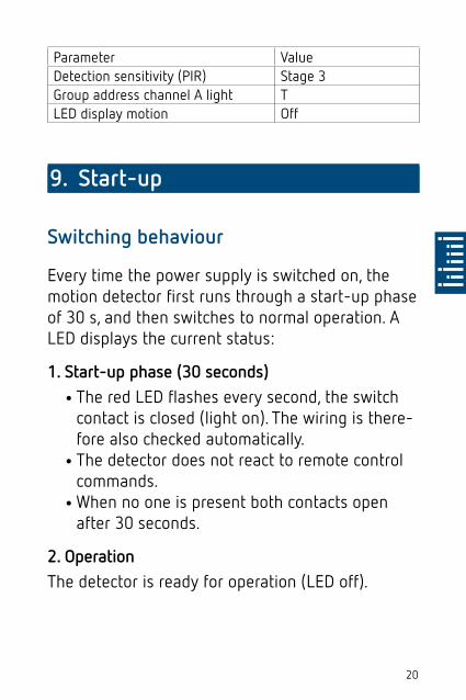
Parameter ValueDetection sensitivity (PIR) Stage 3Group address channel A light TLED display motion Off
9. Start-up
Switching behaviour
Every time the power supply is switched on, the motion detector first runs through a start-up phase of 30 s, and then switches to normal operation. A LED displays the current status:
1. Start-up phase (30 seconds)
•The red LED flashes every second, the switch contact is closed (light on). The wiring is there-fore also checked automatically. •The detector does not react to remote control commands. •When no one is present both contacts open after 30 seconds.
2. OperationThe detector is ready for operation (LED off).

21
Test detection area
The test mode detection area is used for che-cking the detection area. The test mode detection area can be activated with the „Sendo-Pro 868-A“ management remote control and with the „the-Senda P“ installation remote control.
Setting test mode detection area with remote con-trol
•The detector goes directly into test mode when the test mode is set via the remote control:□�Every movement is indicated by the LED.□�The light switch contact closes upon motion.□�When no one is present the light switch contact
opens after 10 seconds.□�Brightness measurement deactivates, detector
does not react to brightness.□�Teach-in cannot be activated in test mode.
•Test mode ends automatically after 10 mins. The detector performs a new start (see switch-on behaviour).
10. Technical data
Operating voltage 230 V AC +- 10 % Frequency 50 HzUpstream protection device: 13 A

22
Power consumption approx. 0.5 WType of installation Ceiling installationRecommended installation height
2.0 – 4.0 m
Minimum height > 1.7 mDetection area horizontal vertical
360°120°
Maximum range Ø 4 m (Mh. 3 m) / 13 m2 radially movingØ 8 m (Mh. 3 m) / 50 m2 tangentially moving
Setting range brightness swit-ching value
30 – 3000 Lux
Lighting time delay A light 10 s – 60 min / PulseChannel A light Relay 230 V / 10 A,
µ-contactMax. switching capacity cos j = 1 resistive
2300 W
Max. switching capacity cos j = 0.5
1150 VA
Max. switching capacity LED
Guide values
see manufacturer concer-ning cos j< 2 W : 25 W / > 2 W : 70 W
Guidance value max. inrush current level
400 A / 200 µs
Maximum number EBs T5/T8 10 x 54/58 W, 16 x 35/36 W5 x 2 x 54/58 W8x 2x 35/36 W
Connection type Screwless terminalsMax. cable cross-section max. 2.5 mm²

23
Protection rating: theMova S360-100 DE
Protection rating: theMova S360-100 AP
IP 20 IP 40 in installed stateIP 54
Ambient temperature -15 °C to +50 °CCE Declaration of Conformity This device conforms to
the safety regulations of the EMC directive 2004/108/EC and of NSR 2006/95/EC.
Product overview
Type of installa-tion
Chan-nel
Ope-rating voltage
Colour Type Item No.
Ceiling installa-tion
Light 230 V AC
White theMova S360 -100 DE WH
1030560
Ceiling installa-tion
Light 230 V AC
Grey theMova S360 -100 DE GR
1030561
Ceiling installa-tion
Light 230 V AC
Special colour in accordance with customer information
theMova S360 -100 DE SF
1030563
Ceiling installa-tion
Light 230 V AC
White theMova S360 -100 AP WH
1030550

24
Ceiling installa-tion
Light 230 V AC
Grey theMova S360 -100 AP GR
1030551
Ceiling installa-tion
Light 230 V AC
Special colour in accordance with customer information
theMova S360 -100 AP SF
1030553
Troubleshooting
Fault CauseLight does not switch on if pre-sence is detected and in darkness
Lux value is set too low; light was switched off via theSenda S; person not within detection area; obstruction(s) interrupting detection; time delay set too short
Light does not switch off and/or light switches on spontaneously when no one is present
Wait for time delay;Thermal sources of interference in the detection area: fan heaters, incande-scent lamps/halogen spotlights, moving objects (e.g. curtains hanging in an open windows); Load (EBs, relays) not cleared
Error flashing (4 x per second)
Error in self-test; Device not properly functional!
25
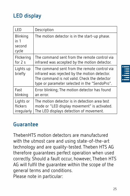
LED display
LED Description
Blinking in 1 second cycle
The motion detector is in the start-up phase.
Flickering for 2 s
The command sent from the remote control via infrared was accepted by the motion detector.
Lights up briefly
The command sent from the remote control via infrared was rejected by the motion detector. The command is not valid. Check the detector type or parameter selected in the "SendoPro".
Fast blinking
Error blinking; The motion detector has found an error.
Lights or flickers irregularly
The motion detector is in detection area test mode or "LED display movement" is activated. The LED displays detection of movement.
Guarantee
ThebenHTS motion detectors are manufactured with the utmost care and using state-of-the-art technology and are quality-tested. Theben HTS AG therefore guarantees perfect operation when used correctly. Should a fault occur, however, Theben HTS AG will fulfil the guarantee within the scope of the general terms and conditions.Please note in particular:

26
•that the guarantee period lasts 24 months from the date of manufacture. •that the guarantee is invalidated if you, or a third party, make changes or undertake repairs to the devices. •that, insofar as the motion detectors are con-nected to a software-controlled system, the guarantee for this connection is only valid when the indicated interface specification is complied with.
We undertake to repair or place as quickly as possible all components of the delivered device that have become defective or unusable through demonstrably poor material, faulty construction or incomplete delivery up to the end of the guarantee period.
ReturnsIn the event of a guarantee claim, please return the device to the relevant dealer together with the delivery note and a brief description of the fault.
Industrial property rightsThe design as well as hardware and software of these devices are protected by copyright.

27
Dimensional drawings
theMova S360-100 DE
theMova S360-100 AP
28
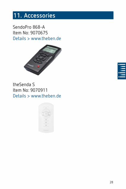
11. Accessories
SendoPro 868-AItem No: 9070675Details > www.theben.de
theSenda SItem No: 9070911Details > www.theben.de

29
theSenda PItem No: 9070910 Details > www.theben.de
12. Contact
ThebenHTS AGIm Langhag 7b8307 EffretikonSWITZERLANDTel. +41 52 355 17 00 Fax +41 52 355 17 01HotlineTel. +41 52 355 17 [email protected], telephone numbers etc. www.theben-hts.ch
30
All countries except SwitzerlandTheben AGHohenbergstraße 3272401 HaigerlochGERMANYPhone: +49 7474/692-0Fax: +49 7474/692-150HotlinePhone: +49 7474/ [email protected]
Copyright © 2022 FDOKUMEN