1) flexibility - ERIC
17
DOCtiMENT RESP+IF ED 023 261 EF 001 952 Direct Multizone System DMS1 -275. Lennox Industries, Inc., Marshalltown, Iowa. Pub Date 15 Mar 68 Note -16p. EDRS Price MF -$0 25 HC -$090 Descriptors -Mir Conditioning Equipment, *euilding Equipment, ',Controlled Environment, Heating, *Mechanical Equipment, *Thermal Environment, Ventilation Lennox Direct Multizone System as a new concept for integrated comfort control is described. The following areas of concern are included--(1) flexibility typical applications, (2) detailed engineering data, (3) -e4ccessories, (4) approvals, (5) guide specifications, (6) dimensional drawings of a typicaf ye-3'A , (7) blower data, (8) mounting data, and (9) mixing boxes. (RH)
-
Upload
khangminh22 -
Category
Documents
-
view
1 -
download
0
Transcript of 1) flexibility - ERIC
DOCtiMENT RESP+IF
ED 023 261EF 001 952
Direct Multizone System DMS1 -275.
Lennox Industries, Inc., Marshalltown, Iowa.
Pub Date 15 Mar 68Note -16p.EDRS Price MF -$0 25 HC -$090Descriptors -Mir Conditioning Equipment, *euilding Equipment, ',Controlled Environment, Heating, *Mechanical
Equipment, *Thermal Environment, Ventilation
Lennox Direct Multizone System as a new concept for integrated comfort control
is described. The following areas of concern are included--(1) flexibility typical
applications, (2) detailed engineering data, (3) -e4ccessories, (4) approvals, (5) guide
specifications, (6) dimensional drawings of a typicaf ye-3'A , (7) blower data, (8) mounting
data, and (9) mixing boxes. (RH)

di411® DIRECT MULTIZONE SYSTEM DMS1-275Lga r
w../ HeatingCoolingVentilating with Multizone Control
100,000 to 700,000 Huh HeatingGas, Oil, Electric or Hot Water93,000 to 2111,000 Btuh CoolingDirect Expansion
5,000 to 10,500 Cfm Air VolumeAdjustable Belt Drive Blowers
Maximum Flexibility
All Controls Furnished
Factory Assembled & Wired
Beige Aluminum Cabinet
Many Cooling Options
P41\
71-
4.
40 NATI 31141
,tt C4 (eta
g d
Tom
_ENG I N EERI NG DATA
COMBINATION UNiTSDIRECT MULTIZONE
SYSTEMS
Page I
March 15, 1968
Supersedes 10-147
U.S. DEPARTMENT OF HEALTH, EDUCATION & WELFARE
OFFICE OF EDUCATION
THIS DOCUMENT HAS BEEN REPRODUM EXACTLY AS RECEIVED FROM THE
PERSON OR ORGANIZATION ORIGINATING IT. POINTS OF VIEW OR OPINI
STATED DO NOT NECESSARILY REPRESENT OFFICIAL OFFICE OF EDUCATION
POSITION OR POLICY.
Single Source Responsibility
Choice of Heating
Distribution System Choice
100% Weatherproof
THE NEW CONCEPT IN MULTIZONE COMFORT CONTROL
Heretofore, in commercial buildings requiring multiple zones of simul-
taneous heating and/or cooling control, engineers have been forced
to use hot and chilled wafer Multizone air handlers, large central
station built-up systems consisting of components manufactured by
several different companies, and controls for these individual com-ponents supplied by yet another manufacturer. Danger of freezingthe hot and chilled wafer coils has eliminated easy methods of utiliz-ing adequate quantities of fresh air for ventilation purposes in coldclimates. Further, most central station units have wafer cooled con-densers and in cold climates water towers must be drained to avoidfreezingthus forcing shutdown of the refrigerated cooling system
during all of the winter months even though there are extensive per-
iods of time during the winter when refrigerated cooling is needed
to maintain proper temperature control in the building.The Lennox Direct Multizone System uses direct-fired heat exchangers
in parallel with direct expansion, air cooled refrigeration to provide
SINGLE SOURCE FORThus, for the first time in the history of commercial Multizone work,
it is possible for the engineer to specify and the customer to purchase
an entire Multizone Comfort System from one manufacturing source.Never before has it been possible for the customer through his en-gineer to turn to a single source for quick, efficient and economicalservicing of his mechanical equipment. All too often in the past the
SELECTED 01/
So successful has the Lennox DMS unit's ability to produce accurateyear-round nontrol of simultaneous heating and/or cooling in individual
zones been that it was seleited over industry-wide competition for
NOTESpecifications, ratings end dimensions subject to change without notice.
precise individual zone control the full year around, simultaneously, in
as many separate and individual zones as can be handled with the
capacity of the DMS unit. The absence of water in the system elim-
inates completely the danger of costly freezeups and allows Lennox
engineers to make the maximum use of the cooling power availablein the outside air to minimize the operating costs involved in cooling
the structure.
The Lennox DMS unit is a complete factory assembly of highly en-gineered, integrated components in a weatherproof, attractive, lowsilhouette "package" including all necessary controls factory installed,
factory tested, and approved by appropriate approval agencies. All
internal wiring is completed including a disconnect switch and the
necessary wiring harness for the adjacent condensing unit. In addition
to the controls factory installed in the DMS unit, Lennox offers twothoroughly tested Zone Control Systems for the Lennox mixing dampers.
COMFORT RESPONSIBILITYcustomer and the engineer have had to involve themselves in attempt-
ing to determine just who, of the many manufacturers contributingparts and pieces to a mechanical system, was responsible for the com-
fort result. Unfortunately, in most cases no one would accept this
responsibility. With DMS, Lennox, and the Lennox-trained installer
are and want to be totally responsible for the end comfort result.
ER COMPETITION
exclusive use in 2,400,000 square feet of California school space bid
under the auspices of the Ford Foundation sponsored School
Construction Systems Development Group in Palo Alto, Calif.4"res,

MAXIMUM FLEXIBILITY IN A COMPLETELY FACTORY-TESTED PACKAGE
HEATINGChoices of gas or oil &rid heat exchangers, straightlectric heating elements, or hot water coils aro available.
Gas HeatingNew Lennox DURATUBE heat exchangers give top
efficiency and handle IOC% outdoor air without condensate problems
due to self elimination. Tube and drum constsuction permit normal
heat element expansion and contraction without metal fatigue. True
power burner principle gives smooth operation regardless of outdoor
wind or atmospheric pressure. All heat xchanger surfaces are DURA-
GLASS coated. Two stage control approximately 50% to 100% isstandard. 6,000 volt spark ignition with "electronic" controls. Flame
rod flame delection, pre.purge and post-purge is standard. Three cap-
acities available-250,000, 350,000 or 500,000 Iituh maximum input.
AGA certified on all sizes. All controls are factory installed, wired
and piped. In addition, the unit is factory fire tested.
Oil Heating--The tube and drum DUMTUIE heat exchanger is con-
structed of aluminized steel and is capable of handling 100% outdoor
air at any temperature. The MAMIE design features: expansion and
contraction without metal fatigue, low resistance to air travel and high
input to heat surface ratio. Equipped with a pressure atomizing oil
burner (490,000 maximum Dish input) designed to use No. 2 fuel oil.
Burner operation is unaffected by wind or atmospheric conditions.
This is the same type of burner that has been time proven in opera-
tion and efficiency in the Lennox OG line of commercial oil units.
Burner consists of combustion air and induced draft blower assembly,
two stage fuel pump (belt driven), nozzle and electrode gun as-sembly, 10,000 volt ignition transformer and solenoid valve. Primary
safety control and separate cadmium sulphide cell flame defector as-
sures complete shutdown, within 30 seconds, in case of flame failure.
A limit control is also provided for added protection in case of ab-
normal operation. Lennox furnishes, as standard equipment, a factory
installed oil supply tank in the DMS unit and an optional booster
pump for installation adjacent to the main supply tank. This equip-
ment provides for pumping the oil from the main tank to a rooftop
unit warming it to a safe operating temperature in the return air
section and storing a small supply integral to the unit. All rooftopinstallations are assured of an oil supply at proper operating tempera-
'tura regardless of outdoor conditions. The booster pump alleviates
any difficulties in supplying oil to a unit installed on a roof above
and some distance away from the supply tank.
Het Water Heat legFactory installed hot wafer coils have either
straight three-way modulating valve control or primary-secondary
control with a factory installed wired and piped pump to give a pos-
sible range of 100,000 to 700,000 Btuh. Continuous pump operation
on primary-secondary systems, total control of the three-way valve with
a long element discharge controller immediately downstream from the
coil and a spring return outdoor air damper motor all add up to
positive coil freeze-up protection.
Electric HeatingElectric resistance elements are available in 15
kw increments from 45 kw to 105 kw. Electric elements carry U. L
Approval, and are controlled by a modulating sequencer. Elements
are available for 240, 480 or 600V, 30 use.
POWER SAVER TO MINIMIZE COOLING COSTSTh. StandardLennox control systems factory installed in the DMS unit minimize the
operating costs involved in cooling the structure by automatically util-
izing fresh outdoor air to do all of the cooling any time the tempera-
ture drops below 511*F. Above SIF., but below 65'F. outdoor air is
used to do as much cooling as possible in conjunction with running
the refrigeration equipment. Above 65 the refrigeration equipment
does all of the cooling. However, a substantial portion of the cooling
season in commercial structures exists while outdoor temperatures arebelow 65', resulting in a great saving in operating costs (as much as
70% in some cases) over the old-fashioned central station system
that ran 100% of the time.COOL1NGAir cooled DX system of 8, 11, 15 or 22 nominal tons is
available. 15 and 22 fon models only have all of the refrigeration pip.
ing and wiring harnesses furnished, field connection is required. Install-
e r must furnish refrigeration piping and wiring for 8 and 11 ton mod-
e ls. Refrigeration connections are mechanicaleither rotalock or flare.
Prepared For Air ConditioningThe DMS unit may also be order-
e d less c:ooling, but prepared for future air conditioning. A perforated
pressure plate is substituted for the direct expansion evaporator and
all of the necessary controls, and refrigeration piping will be installed
in the MS unit during ifs construction. Cooling can then be added
at a later date by simple removal of the pressure plate, installation of
the direct expansion cooling coil, and connection to the companion
condensing unit.
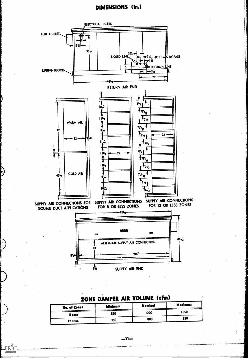
ZONE DAMPERS WHERE DESIREDA choice of 8 or 12 zone
dampen; mounted in the DMS unit is available. These may be used in
any combinationfor instance one damper motor driving 4 zone
mixing dampers feeding one zone. Full capacity of the DMS unit canbe handfed through as few as 9 of the 12-damper set and as few as
6 of the 8-damper set if so desired. The mixing dampers incorporate
an adjusi.sble bypass whereby 0 to 30% of the air can be bypassed
through toe cold duct side of the unit. Further sophisticated construc-
tion and tight sealing reduce leakage to less than I% through theclosed warm air dampers.
For applications where more than 12 zones per DMS unit east orwhere if becomes more practical and economical to run dual hotand cold ducts the length of a building, mixing boues are availablefor application in or near each zone requiring individual room con-
trol. These mixing boxes handle from 150 cfm to a maximum 2200
cfm each. CAUTION: Lennox mixing boxes for dual duct application
and mixing dampen; mounted in the unit are carefully sized to coop-erate with the infernal air handling characteristia of the DM5 unitand, therefore, for optimum, service-free application, the Lennox DMS
unit should not be used with other, job-constructed mixing dampers.
AIR FILTERINGGenerous filter area consisting of 1 inch, 20
pores per inch Scottfoam in rugged, individual galvanized metal
frames with face volocifins below 300 ff. per minute in most applica-
tions is supplied as standard with the Lennox DMS unit. The upstream
face is exposed (net confined by wire fencing) for convenient vacuum
cleaning in place tifilixing the 120V convenience outlet inside the DMS
unit. The multiple metal framed filters are sized for convenient re-moval if if is dashed to clean the filters some place else. Filter media
is oiled at the factory for increased efficiency. When reoiling after
cleaning use RP products #418 heavy duty filter coating. Further, thehigh holding capacity and large face area of the DMS filters meanless frequent servicing than is required with filters in other commer-
cial installations. The DMS filter racks are 3" thick providing room
for 2" of additional filtering materialsuch as activated charcoaldown-stream from the standard filters.
CHOICE OF BLOWER DRIVESA wide range of blower motorhorsepower: and drives for the two 15 x 15 blowers is available to
provide a cfm range varying from 5,000 cfm to 10,500 cfrn againstexternal static pressures varying from 0 to 1.0" water gauge.
TYPIICAL APPLICATIONS
Floor diffusers or Lennox COMFORT CURTAINduct distribution system.
Ceiling distribution system
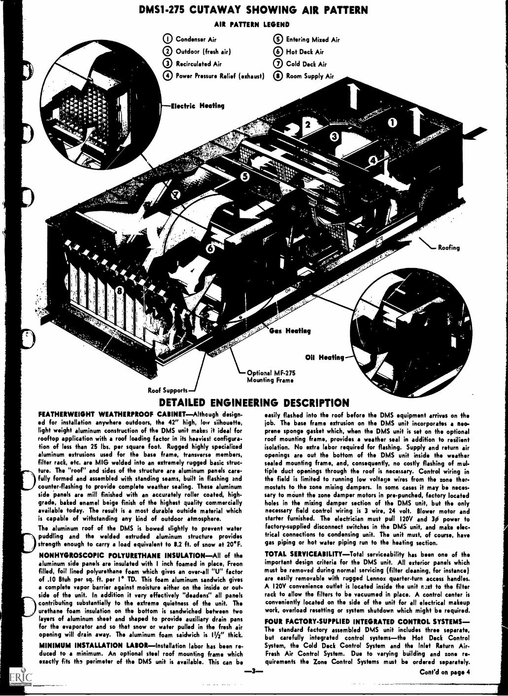
DMS1-275 CUTAWAY SHOWING AIR PATTERNAIR PATTERN LEGEND
Condenser Air
00
Outdoor (fresh air)
Recirculated Air
Power Pressure Relief (exhaust)
Electric Heating
® Entering Mixed Air
® Hof Deck Air
CI Cold Deck Air
CI Room Supply Air
Roofing
Gen Heating
Oil Heating
Roof Supports
DETAILED ENGINEERING DESCRIPTION
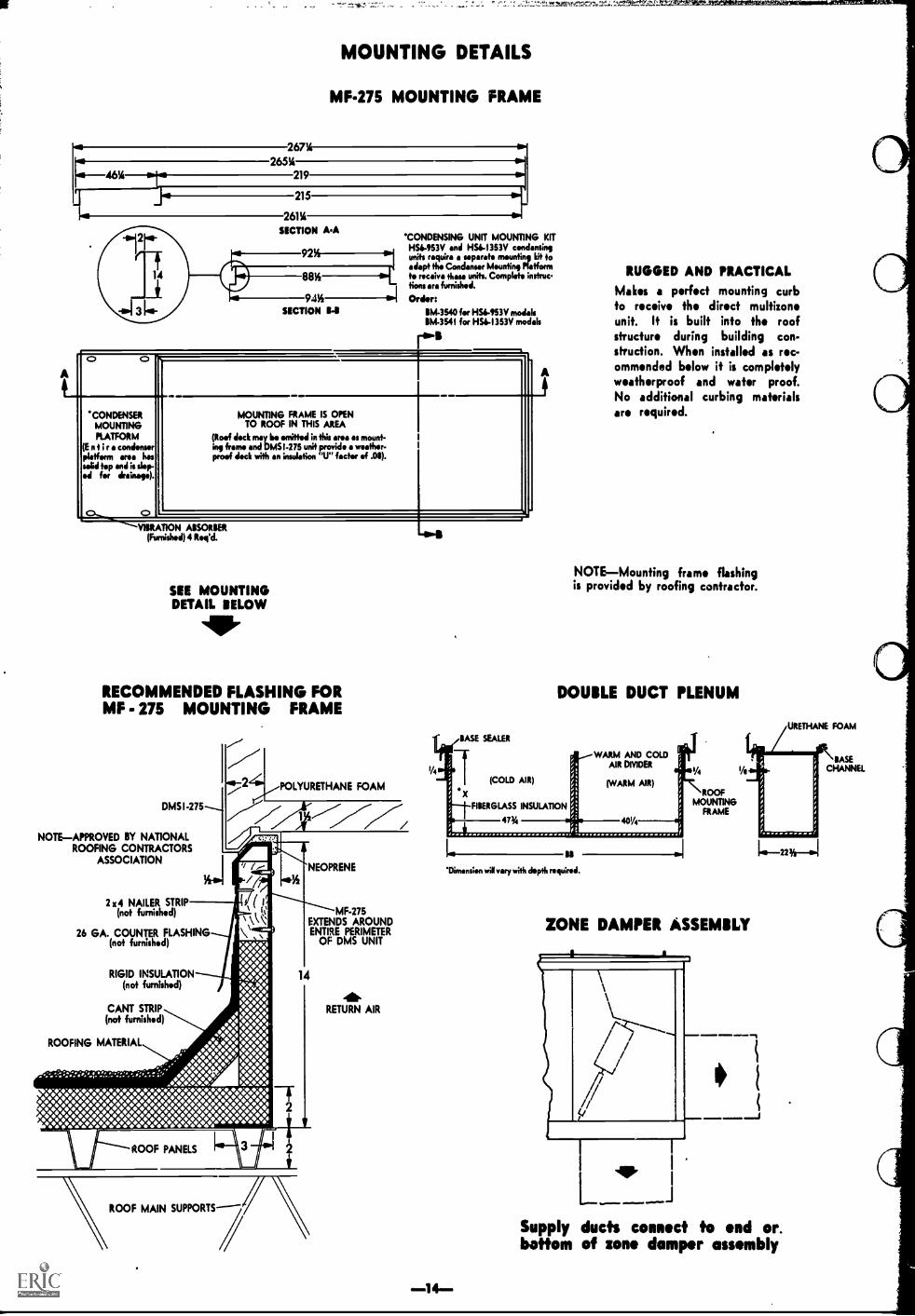
Optional MF-275Mounting Frame
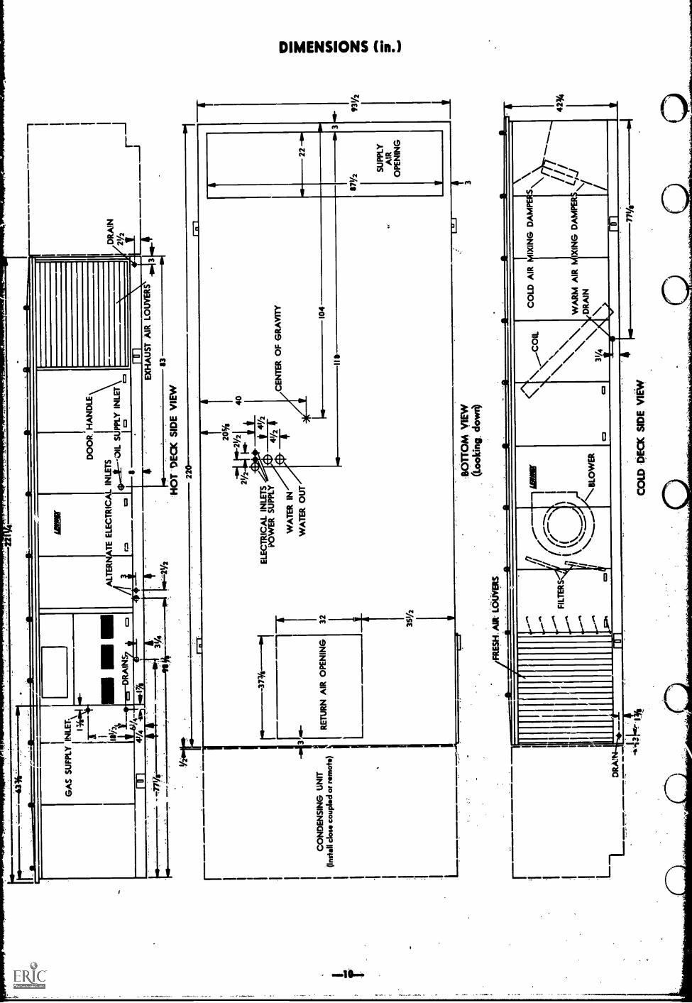
FEATHERWEIGHT WEATHERPROOF CABINETAlthough design-d for installation anywhere outdoors, the 42" high, low silhouette,light weight aluminum construction of the DMS unit makes if ideal forrooftop application with a roof loading factor in ifs heaviest configura-tion of less than 25 lbs. per square foot. Rugged highly specializedaluminum extrusions used for the base frame, transverse members,filter rack, etc. are MIG welded into an extremely rugged basic struc-ture. The "roof" and sides of the structure are aluminum panels care-fully formed and assembled with standing seams, built in flashing andcounter-flashing to provide complete weather sealing. These aluminumside panels are mill finished with an accurately roller coated, high-grade, baked enamel beige finish of the highest quality commerciallyavailable today. The result is a most durable outside material whichis capable of withstanding any kind of outdoor atmosphere.The aluminum roof of the DMS is bowed slightly to prevent waferpuddling and the welded extruded aluminum structure providesstrength enough to carry a load equivalent to 11.2 ft. of snow at 20'F.
NONHYGROSCOPIC POLYURETHANE INSULATIONAll of thealuminum side panels are insulated with 1 inch foamed in place, Freonfilled, foil lined polyurethane foam which gives an over-all "U" factorof .10 Bfuh per sq. ft. per I' TD. This foam aluminum sandwich givesa complete vapor barrier against moisture either on the inside or out-side of the unit. In addition it very effectively "deadens" all panelscontributing substantially to the extreme quietness of the unit. Theurethane foam insulation on the bottom is sandwiched between twolayers of aluminum sheet and shaped to provide auxiliary drain pansfor the evaporator and so that snow or wafer pulled in the fresh airopening will drain away. The aluminum foam saidwich is 11/2" thick.
MINIMUM INSTALLATION LABORInstallation labor has been re-duced to a minimum. An optional steel roof mounting frame whichexactly fits th, perimeter of the DMS unit is available. This can be
easily flashed into the roof before the DMS equipment arrives on thejob. The base frame extrusion on the DMS unit incorporates a neo-prone sponge gasket which, when the DMS unit is set on the optionalroof mounting frame, provides a weather seal in addition to resilientisolation. No extra labor required for flashing. Supply and return airopenings are out the bottom of the DMS unit inside the weathersealed mounting frame, and, consequently, no costly flashing of mul-tiple duct openings through the roof is necessary. Control wiring inthe field is limited to running low voltage wires from the zone ther-mostats to the zone mixing dampers. In some cases if may be neces-sary to mclunt the zone damper motors in pre-punched, factory locatedholes in the mixing damper section of the DMS unit, but the onlynecessary field control wiring is 3 wire, 24 volt. Blower motor andstarter furnished. The electrician must pull 120V and 30 power tofactory-supplied disconnect switches in the DMS unit, and make elec-trical connections to condensing unit. The unit must, of course, havegas piping or hot water piping run to the heating section.
TOTAL SERVICEABILITYTotal serviceability has been one of theimportant design criteria for the DMS unit. All exterior panels whichmust be removed during normal servicing (filter cleaning, for instance)are easily removable with rugged Lennox quarter-turn access handles.A 120V convenience outlet is located inside the unit ruxt to the filterrack to allow the filters to be vacuumed in place. A control center isconveniently located on the side of the unit for all electrical makeupwork, overload resetting or system shutdown which might be required.
FOUR FACTORY-SUPPLIED INTEGRATED CONTROL SYSTEMSThe standard factory assembled DMS unit includes three separate,but carefully integrated control systemsthe Hof Deck ControlSystem, the Cold Deck Control System and the Inlet Return Air-Fresh Air Control System. Due to varying building and zone re.quirements the Zone Control Systems must be ordered separately.
3 . Conf'd on page 4
DETAILED ENGINEERING DESCRIPTION (Conf'd from Page 3)
TI41 INLET FRESH AIR, RETURN AIR CONTROL SYSTEMTiro inlet end of the DMS unit has three separate sets of fresh air,
return air, and xhaust dampers mechanically interconnected and ac-
tuated by an lectric Honeywell sris 90 modulating damper motor.The denim motor is commanded by an air temperature controller set
to maintain 51'F mixed air temperature downstream from the blowers
whenever the outdoor temperature is 58F. As the outdoor tempera-
ture rises toward 511F, the fresh air dampers modulate open and the
return dampers close. When the fresh air dampers open to the 30%
position, the exhaust dampers start to open and the Power Pressure
Relief fan starts to exhaust return air from the building. The exactpolition at which the exhaust dampers open and the Power Pressure
Relief fan starts is field adjustable and should be set to maintain aslight positive pressure in the building.
When the outdoor temperature is below 60F (adjustable) the control
system introduces enough fresh air to satisfy the mixed air tempera-ture controller. At temperatures above 60F the control system re-
turns the modulating damper motor to the minimum air position re-
quired for proper ventilation (this position is field adjustable).
HEATING CONTROLSThe function of these controls is to have
warm air available on the warm side of the system whenever needed
and at a temperature appropriate for the outside weather conditions.
This is accomplished with an adjustable outside reset ductstat which
has a 120 inch long capillary sensing element. The element is serpen-
tined across the warm duct section downstream from C. heating ele-
ment and senses the average air temperature within the warm duct.
The adjustable ductstat is factory set to control a warm duct temper-
ature of SOF when the outdoor air temperature is 70F. At an outdoor
air temperature of 30F, it controls the warm duct temperature at I I3F
and f 0 degrees F outdoor air temperature, if controls a warm duct
temprature of I36F. If the outdoor air temperature rises to 10F, the
ductstat resets to 75F and if the outdoor temperature continues to
rise, the riuctstat will of course shut off the heat source. Morning
warm-up and day-nite control clock timer is available.
OAS HEAT CONTROLFor gas direct-fired heat exchangers this
ductstat is 2-stage wifh the stages about 3' apart. The heater will
cycle on and off the 50% low stage fire very frequently until this 50%
rate is not enough to maintain the average warm air temperature
called for. At this Foint the second, 100% high fire rate begins to
cycle. The net effect is to produce modulation in warm air temper-
ature without the problems involved in modulating a gas fired heat
exchanger. When gas fired heat exchangers are modulated much be-
low the soy. rate, excessive condensation sometimes develops inside
the heat exchanger. Other type heat exchange.: have a problem, es-
pecially in freezing temperatures, in draining away this condensation.
The Lennox GX2 heat section eliminates condensate, therefore no
drainage problem.
OIL HEAT CONTROLFor oil direct-fired heat exchangers this duct-
stat is single stage. The heater will cycle on and off to maintain the
average warm air temperature called for.
HOT WATER CONTROL.For hot water heat, the ductstat is of the
modulating type commanding a Series 90 Honeywell modulating 3-way
wafer valve regardless of whether straight valve control or primary-secondary.pumping control is used.
ELECTRIC HEAT CONTROLFor electric heat the same modulating
reset ductstat used for hot water commands a Series 90 Honeywell
modulating sequencer to bring on just the number of electric stages
required fo maintain the average warm air temperature called for.
Some of the electric heat sections are locked out af outdoor air temp-
ratures .higher than the roijustable setting (usually 58F) on the com-
pressor Monitor. This prerents the entire cooling and heating load
coming on the line at the same time.
COOLING CONTRO10.The Lennox control system is carefully engin-
eered to provide accurate control for the direct xpansion evaporator
and its air cooled condensing unit operating in ambient varying from
158' to well above 11PF and with air volumes varying from a minimum
of 30% of the total air fo a maximum of 100% of the total air circu-
kW by the system.The Lennox condensing units used with DMS are designed specifically
fer that use and use two L2 series Lennox compressces in separate
refrigeration circuits. The high stage compressor cyJes on and off
but is protected against too frequent cycling with the exclusive Len-
nox timed off cycle control. & II ton units hove single compressor.
Refrigeration suction pressure in the low stage refrigeration circuit
is the major influence in commanding compressor activity. The high
stage compressor cycles on and off under timed off cycle protection
to maintain ureter' pressure no lower than 35'. In the case of the
single compressor condensing unit it cycles on and off to maintain a
suction temperature no lower than 35'. If there is so little air or so
little load on the evaporator that even the low stage compressor willea. wow 3e0, uIHng valve will
begin to opon, sending discharge gas into the distributor downstream
from the expansion valve to thoroughly modulate refrigeration capacity
to exactly fit the needs of the system. In addition, an adjustable out-
side reset ductstat with a 240 imch long element senses :add duct air
temperature upstream from the cooling cod, outdoor air temperature
and controls the mixing dampers. It is factory set at 58F and keeps a
cold deck air temperature appropriate to the cooling demand by dilut-f
ing cold outdoor air with room return air. Below 51F (adjustable) the
cooling system is deactivated by a compressor monitor which shuts off
the condensing unit. The entire cooling load is then handled by the
outdoor air. The ductstat will control the cold duct air temperature
appropriate to the outdoor air temperature. At 58F outdoor air temp-
water., it keeps the cold duct air temperature at 58F using 100% out-
door air. At other outdoor air temperatures, the cold duct air temper-
Our. will increase 1 degree F for every 10F drop in outdoor air temp-I
erature. Example: At 41F outdoor air temperature, the cold duct
temperature is 59F, at 18F outdoor temperature the cold duct air
temperature is 62F. This is accomplished by precise control of the
outdoor air and recirculated air mixing dampers.
ANY CONTROL CHOICE7Fully 90% of the total control function
complexity is covered by the factory installed, wired, and tested inlet,
Heating, and Cooling Control Systems. The full complement of factory
installed heating, cooling, and ventilating controls are accurately
described in the A.G.A. and/or U. L. Approvals covering the DMS
unit and hence Lennox cannot offer any change, substitution, or modi-
fication of its control systems without voiding the appropriate approval.
ZONE TEMPERATURE CONTROLSThis surth DMS control system,
the Zone Control System, is not electrically interconnected with the
unit, and is the only control system which requires any field wiring.
The DMS unit and its three integrated control systems continuously
provide to the zone mixing dampers a supply of warm air and cool
air at levels automatically modulated in accordance with outdoor
ambient and infernal loads. The zone control system then has the
simple task of mixing these two air supplies to provide a constant
volume of air with temperature adjusted for the particular zone.
STANDARD ZONE CONTROL SYSTEM--The standard Lennox Zone
Control System consists of a special Honeywell 2-mercury bulb, wall
mounted thermostat and a Lennox 3-position, 24`I damper motor which
produces 3-stage operationfull heating, 50-50 mix of warm and
cold air, or full cooling. The Lennox damper motor is an extremely
rugged 3-position, spring return highly durable motor with the entire
gear train and motor submerged in nontemperatura sensitive oil sealed
in the die cast case. It provides simple, understandable and almost
completely noiseless operation. Internal switches enable slaving of a
second damper motor with one thermostat, with a third motor slaved
to the second, etc. Of the Zone Control Systems tested in the Lennox
Laboratory, this combination of thermostat and damper motor gave
the most accurate and constant control of zone temperature andaccommodated itself to changes in loads quicker than any other type.
OPTIONAL ZONE CONTROL SYSTEMFor those who insist on
modulating :one controls, Lennox has available a Honeywell Series 90
modulating damper motor with the appropriate "slide wire" type of
wall mount thermostat to actuate it. This type of thermostat and its
modulating motor gives reasonably accurate temperature control but
does not follow rapid changes in load, which can occur in almost all
commercial buildings, as well as the standard Lennox control system.
OTHER ZONE CONTROL SYSTEMS TESTED--Pneumatic and solid
state modulating control systems have also been tested, but found
seriously lacking in several important respects. The solid state modu-
lating control has the serious defect of being extremely complicated
to understand and hence difficult to service and adjust in the field.
Pneumatic controls are not available to Lennox or any manufacturer
on an O.E.M. basis, and, hence, Lennox is unable to sell or supervise
installation of them. If pneumatic controls are used with DMS units:
Lennox cannot accept responsibility for the end comfort result.
INTERNAL AIR HANDLINGCareful attention fo detail, thorough(
isolation of all internal moving parts and maintaining relatively low
internal air velocities has allowed Lennox to create the quietest Multi-
zone air handler on the market. External vibration measurement showed
that the amplitude effect of moderate breezes was greater than the
vibratory amplitudes of the DMS and ifs companion condensing unit
which were transmitted to the roof and building structure.
Highly sophisticated and detailed engineering allows the Lennox DMS
unit to handle maximum cfm at exceedingly low internal resistances
regardless of the position of the mixing dampers. The normal external
duct system used with the DMS system will have a relatively much
higher static drop than the internal resistance of the DMS unit and,
hence, the small changes in static drop produced by the different
positions of the mixing damper becomes a negligible part of the
total static pressure experienced by the air movers. Hence, an al-
most constant cfm is supplied to each zone regardless of the position
of the Lennox supplied mixing dampers.

VELOCITY PRESSURE CONVERTERSLennox developed, patent ap-plied for, Velocity Pressure Converters, which are ssentially highlysophisticated diverging nozzles, in front of ach blower, convert thekinetic nergy of the high velocity blower discharge to static presser.to produce nearly laminar air flow within the unit. Laminar air flownot only saves power but also insures xcellent air distribution overthe vaporator which liminates erratic hunting of the rpansionvalves. Also, when Velocity Pressure Converters are not useA highvelocity air impingement forces air partially through the heat ex-changer which then recirculates back to the cooling side adding sub-stantially to the cooling load.
INTERNAL VIBRATION ISOLATIONAll moving parts within theDMS unitthe motor, blower wheels, shafting, and drive are mountedin a rugged steel subassembly which is then resiliently suspended inthe structure of the cabinet. This is the most complete and efficientmethod of isolating the energy of the blower assembly that has verbeen used in the air conditioning industry. Belt tension is easily ad-justed by loosening one nut and jacking the hinged motor mounting
ACCESSORIESROOF MOUNTING FRAMEAn optional roof mounting frame whichexactly fits the perimeter of the DMS unit is also available. This
simplifies installation Making if easier for the roofer to flash in theframe. The DMS unit then sits on top of this frame and a neoprenesponge gasket in the extruded aljrninum base completes the sealingand weather-proofing job. Mounting frame is not insulated.
NIGHT OPERATIONIn mi!cl climates a "system switch" turns offthe entire unit at night. For colder climates a "night protection ther-mostat" located in an average zone is used. If the night temperaturedrops below the setting of this thermostat, the system will operatenormally until the temperature is satisfied and the system again turnsoff completely. A practical and attractive plastic wall mounting plateis furnished with the night thermostat. It mounts to 'rive standardelectricil switch boxes located within the wall. In order to receivethe plee, edges of the switah boxes must have at least 31/2 inchesof clearance to any door or window trimming. Two night thermostatkits are available. A manual nite set back (BM-4102) and a manuallyset 12 hour clock timer nite sef back (BM-4103).Complete mountinginstructions are provided with both kits. A skip-day clock (P4-3744)to program this, unit automatically is also available. A spring poweredcarry over feature keeps this timer going in 'mite of power interrup-tions of reasonable duration.
MORNING WARMUPIn some applications if may be desirableto have morning warmup operation. Lennox has available a simpleadjustable thermostat with remote sensing bulb which mounts in thereturn air stream. If the return air temperature is too cold it closesthe outdoor air damper thus heating the conditioned area faster andwith less cost. It also closes the outdoor air damper, ff the systemis ever out of control.
COMBUSTIBLE ROOF--When DMS is installed on a combustiblecurbing use AF3-275-1 adaptor between DMS unit and curbing. Whenextending supply air plenums (I zone, 12 zone or double duct) throughcombuitible material adaptor frame AF3-275 must be installed aroundperimeter of opening.
IS SPECIAL DUCTWORK RE9UIRED1Principles of duct designapplied to DMS units are exactly the same as principles used withany other air conditioning system. Distribution of the supply air fromthe DMS should be designed on the basis of good engineering prin.ciples applied with any commercial system. If the climate is fairlywarm, so that the major work is cooling, ceiling or high side wall sup-plies should suffice. If the climate is cold and/or the building con-struction poor, perimeter distribution is preferred.
STEP DOWN TRANSFORMER-1n areas where 120 volt power is notreadily available a special transforatar 's available to step down thepower supply to obtain 120 volt control power.
base up or down and locking if again with the one nut.The foamed-in-place insulation in the cabinet contributes to deadeningthe panels producing an extremely quiet unit. All dampers are mount-d in self lubricating, non raffling nylon bearings. Lennox compressorsare the quietest in the industry. Moving parts are thoroughly floatedwithin the hermetic shell. The condenser fans are floated. There ispractically no vibration on the roof.
HUMIDITY CONTROLA surprising amount of humidity control hasbeen designed info the standard DMS control systems. The cool sidebypasses a minimum of 0 to 30% which means that even if every zoneis calling for full heating some of the air will go through the heatingsection and from 0 to 30% through the cooling section. Below 511*
the compressors are off. Even though the outdoor air is saturated atthis temperature if will be comparatively dry when raised to indoortemperatures of around 75*. Above 511* compressors function tomaintain a cold coil constantly on the cool side and, with a minimumof 0 to 30% over this coil, you dehumidify this air and then reheat ifby mixing it with warm air for those zones calling for heating.
APPROVALSWhen equipped with our Lennox GX2 Duratube-Duraglass direct-firedgas heat exchanger, the entire DMS unit carries an A.G.A. certificationfor outdoor use. A.G.A. certified for down-flo installation on com-bustible material when installed with special AF3-275 base. Specialhorizontal discharge unit (DMS1-275H) is A.G.A. certified for in-stallation on combustible material.When equipped with our Lennox 0X2 Duratube-Aluminized oil heatexchanger, the entire DMS unit is U.L. listed for outdoor use. U.L.Listed for horizontal or down-flo installation on combustible material.Optional AF3-275 special base is available if desired.Electric heat models are U.L. listedOil heat and hot wafer models will be U.L. Listed (listing pending).All electrical components have a general (white card) listing.The appropriate condensing units carry U.L. Listing.All of the infernal wiring is in strict compliance with the NationalElectric Code, including the local interpretations of which Lennox isaware.n addition to the wiring requirements by A.G.A. covsred in the
A.Gek. certificafion, the following Underwriters Laboraiories standardsare adhered to:
Oil Heating Equipment (UL-727)Air Conditioners, central cooling (UL-465)Condensing Units, refrigeration (UL-303)Gas Heating Equipment, commercial-industrial (U1-795)Temperature Indicating and Regulating Equipment (UL-1173)
TYPICAL DOUBLE DUCT APPLICATION
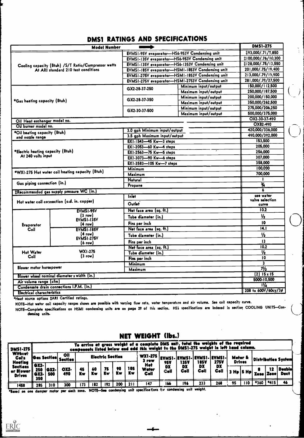
DIM RATINGS AND SPECIFICATIONSModel Number mmumN DM51.275
Cooling capacity (Btuh) /S/T Ratio/Compressor wattsAt AR1 standard 210 test conditions
EVMSI-95V evaporatorHS6-953V Condensing unit *93,000/.71/1,850
EVMSI-135V evaporatorHS6-953V Condensing unit *100,000/.76/10,300
EVMSI-135V evaporatorHS6-1353V Condensing unit *128,000/.75/13,550
EVMS1-185V evaporatorHSM1-1853V Condensing unit 201,000/.75/19,400
EVMSI-275V evaporatorHSM I-1853V Condensing unit 213,000/.79/19,900
EVMSI-275V evaporatorHSMI-2753V Condensing unit 281,000/.78/27,500
*Gas heating capacity (Btuh)
GX2-28-37-250Minimum input/output 150,000/112,500
Maximum input/output 250,000/187,500
GX2-28-37-350Minimum input/output 200,000/150,000
Maximum input/output 350,000/262,500
GX2-30-37-500Minimum input/output 275,000/206,250
Maximum input/output 500,000/375,000
Oil Heat exchanger model no. 0X2-30-37-490
7Uburner model-no. OXB2-490
Oil heating capacity (Btuh)and nozzle range
3.0 gph Minimum input/output 420,000/336,000
3.5 gph Maximum input/output 490,000/392,000
*Electric heating capacity (Btuh)At 240 volts input
EXI-1543--45 Kw-3 steps I 53,500
EXI-2053-60 Kw-4 steps 205,000
EXI-2563-75 Kw-5 steps 256,000
EX1-3073-90 Kw-6 steps 307,000
EXI-3583-105 Kw-7 steps 358,000
*WX1-275 Hot water coil heating capacity (Btuh)Minimum 000I00,
Maximum 700,000
Gas piping connection (in.)Nature 1
Propane V4
*Recommendod gas supply pressure WC (in.) 6
Hof wafer coil counection (o.d. in. copPer)Inlet see wafer
valve selectioncurve10.2
Outlet-
Net face area (sg. ft.)
EvaporatorCoil
EVMSI-95V(3 row)
EVMS1-135V(4 row)
Tube diameter (in.) 1/2
Fins per inchr=letlace area (sc7r)t.
10
14.1EMI -I85V(4 row)
EVMSI -275V(6 row)
Tube diameter (in.) IA
Fins per inch 13
Hot Water WXI -275Coil (3 row)
Net face area sg. . 10.2
Tube diameter (in.) IA
Fins per inch 10
Blower motor horsepowerMinimum 3
Maximum 79i
-tower wheel nominal diameter x width (In. 2 15 x 15
Air volume range (cfm) 5000-10,500
11/4-Teni ensate drain connections I.P.M. i .
Tie=taracteristics , 208 to 600V/r1c7Tr,
*Heat source opfions 2A1t1 Certified ratings.NOTEHot water coil capacity ranges shown are possible with varying flow rata, water temperature and air volume. See coil capacity curve.
NOTEComplete specifications on HSMI condensing units are on page 29 of this section. HS() specificafions are indexed in section COOLING UNITSCon-
densing units.
NET WEIGHT MO
DMS1.275Withal*
Cons Ges SectionHeating
OX2.Sectionsor hinwer 250 OX2-
Drives 0X2. 500350
1458 285 310
T. arrive at gm: weight of a complet* DMS uuif. Mei the weights of the rnquiredcomponents listnd bniew end add this weight ta the DM51.275 weight I. left hand column.
OilSection
on.490
45Kw
Electric Snction WX1.2753 rowHet
60 90 1 05 WaterKw Kw Kw Cell
75Kw
EVMS1-9511DX
300 I 173 182 192 200 211 147
EVMS1.1359
DXCell
EVMS1.1851I
DXCfsil
EVMS1.275V
DXCoil
Meter &Drives Distribution System
3 Hp 5 Hp Zone12
ZoneDoubleDuct
166 196 233 268 95 110 *360 *415
*Beset ea one damper motor per Oath zone. 'NOTESei condensing unit specifications for condensing unit weight.

GUIDE SPECIFICATIONS
Prepared for the guidance of architects, consulting engineers and me-chanical contractors.
GeneralFurnish and install a multizone heating-cooling unitwith all controls, ducts and zone dampers.The Multizone system shall be a standard product of a firmregularly engaged in the manufacture of heating-cooling equip-
ment. The manufacturer shall have dealers and service avail-able throughout the United States.The installed equipment including condensing unit shall have aroof loading no greater than 27 lbs per sq ft. The total instal-led weight less ducts shall not be more than lbs.
Roof Mounting FrameA steel mounting frame shall be fur-nished. It shall conform exactly to the shape of the systemand be contoured to accept the base ofequin. ;; it. Flashingshall be the responsibility of a bonded roc.., ng contractor.
Air DistributionShall be either (double duct or zone dampers
located at the unit).All air distribution ducts shall be insulated with inch
thick lb density fiberglass or equivalent.
DX Cooling SystemThe total certified cooling capacity shallnot be less than Btuh with an evaporator air vol-ume of cfm, an entering wet bulb air temperatureof F and outdoor air temperature of F. The
compressor power input shall not exceed kw atthe above conditions.The coils shall be non-ferrous construction with aluminum finsmechanically bonded to seamless copper tubes.
The 16 and 22 ton evaporator coil shall be 50/50 split witheach section having an expansion valve. The condenser coilshall have sub-cooling rows. All coils shall be factory pressureleak tested at 450-500 psi.Condensing unit shall have spring mounted compressor(s).Compressor( s) shall have built in 3 mode crankshaft lubrica-tion, crankcase heater, discharge temperature limiter, currentand temperature sensing motor overloads and be guaranteedfor five years.
Gas Hating SystemThe certified total heating capacity out-put shall be Btuh with a gas input of Btuh.Automatic controls furnished give 50/50 two stage operation.Cylindrical tube and drum heat exchanger shall be DU RAG LASS
coated. Heat exchanger shall be capable of handling 100%outdoor air at any temperature and have a 10 year nonpro-rated warranty. Stainless steel power burner shall have inter-mittent spark ignition, 100% safety shutoff controls andelectronic flame sensing controls.
Oil Heating System The certified total heating capacity out-put shall be Btuh with a oil input of gph.Cylindrical tube and drum heat exchanger shall be alu m in iz ed
steel. Heat exchanger shall be capable of handling 100%outdoor air at any temperature and have a 10 year warrantywhen handling uncontaminated air. Pressure atmoizing oilburner shall be equipped with 100% safety shutoff controlwith cadmium sulphide cell flame detector and induced draftand combustion air blower assembly.
Hot Water Heating SystemThe certified total heating capacityoutput shall be Btuh, at a water entering tem-perature of F and a flow rate of gpm.
A three way modulating water valve (with-without) primarypump shall be factory installedThe coil shall be of non-ferrous construction with aluminumfins mechanically bonded to seamless copper tubes.
Electric Heating SystemThe certified total heating capacityoutput shall be Btuh with kw inputat volts power supply.Heating elements shall be nichrome base wire exposed directly
to the air stream and be equipped with fusible links. Theyshall be controlled by a (modulating sequencer or two stage
controller).
ControlsAll controls shall be the sole responsibility of themechanical equipment manufacturer and shall be installed,wired and tested.
Fresh Air ControlSha// include an outside reset ductstat with240 inch long element which shall be provided upstream from
the cooling coil. It shall command a modulating dampermotor which has an adjustable potentiometer for minimumposition. An adjustable outdoor air thermostat shall returnthe damper motor to the minimum position at the outdoor airtemperature setting on the control (usually 65 ).
DX Cold Deck ControlsShall include an adjustable outdoorair temperature controller which senses outdoor air tempera-ture and deactivates the cooling system at the adjustable set-ting on the control (usually 60F).16 and 22 TonTwo stage compressor operation shall havemodulated capacity control of the first stage system. Both DXcooling stages and unloading shall be controlled by suctiontemperature.8 and 11 TonSingle stage compressor operation shall havecapacity reduction control!ed by the suction temperature
Gas Heat Hot Deck ControlsSW/ include an adjustable out-side reset ductstat which two stage controls the heat section tomaintain a hot deck air temperature appropriate to the out-door air temperature.
Oil Heat Hot Deck ControlsSha// include an adjustable out-side reset ductstat which controls the heatsection to maintaina hot deck air temperatureappropriate to the outdoor air tem-perature.
Electric Heat Hot Deck ControlsShall include an adfustableoutside reset ductstat which (two stage or modulates) the heatsection to maintain a hot deck air temperature appropriate tothe outdoor air temperature.
Hot Water Heat Hot Deck ControlsShall include an adjust-able outside reset ductstat which modulates a three way watervalve to maintain a hot deck air temperature appropriate tothe outdoor air temperature.
Zone ControlsShal/ be either a ( three position or modulating)zone damper motor which is controlled by a two mercurybulb, wall mounted thermostat.
Air MoverTwin supply air blowers shall have permanentlylubricated ball bearings, have adjustable belt drives and becapable of delivering cfm at an external staticpressure of inches water gauge requiring bph
and rpm.
Mixing Damper and FilterDamper blades shall be edge linedwith urethane foam and ride in nylon bearings. Dampermotor shall be full modulating with adjustable potentiometer'for minimum position. Washable-vacuum cleanable filter shellbe one inch thick with a total free filter area of sq ft.
Frame and CasingBase frame shall be ofaluminum extrusionsshaped to mate with the roof mounting flume. Interior sup-port members shall be 16 ga. steelpainted with outdoor acrylicenamel. Casing shall be of .040 color weld aluminum. Allaccess panels shall have locking door handles. Panels shall belined with 1" thick close cell foil covered insulation. The bot-tom of unit shall be able to serve as a safety water pan.
ApprovalsAll models shall be A.G.A. Certified or U. L. Listedwhichever applies to heat source used. The oilunits, condens-ing units or water chillers) shall be U.L. Listed. .411 wiring shallbe in compliance with NEC. The following Underwriters'Laboratories Standards shall apply:
Oil Heating Equipment ( UL-727)Air Conditioners, central cooling ( UL-465)Condensing Units, refrigeration ( UL-303)Gas Heating Equipment, commercial-industrial ( UL-795)Temperature Indicating and Regulating Equipment
(UL-873

DMSI-275 ELECTRICAL DATAVoltage mow+ 208 220/240 440/480 550/600
DMSI-275BlowyMotor
3hpFull load amps
I9.9 9.0 4.5 3.6
Locked rotor amps 55.0 50.0 25.0 20.0
5hpFull load amps
I16.5 15.0 7.5 6.0
Locked rotor amps 83.6 76.0 38.0 32.0
71/2hpFull load amps
I25.4 23.0 11.5 9.2
Locked rotor amps 155.0 140.0 70.0 56.0
Wvn control transformer (amps) I9.6 8.3 4.2 3.3
*Pressure relief fanFu oa amps I *7.8 *7.8 *7.8 *7.8
Locked rotor ampsI
33.4 33.4 33.4 33.4
*GX2 gas heat (amps) *4.11 *4.1 I *4.11 , *4.11
*X2 oi eat amps 10.0 10.0 10.0 10.0
*Hot water heatValve amps 41.32 41.32 41.32 41.32
Pump (amps) *.26 *.26 *.26 *.26
ElectricHeat
(amps)
EXI-1543 93.5 99/108 49.5/54 39.7/43.3
EXI-2053 124.7 132/144 66/72 52.9/57.7
EXI-2563 156.0 165/180 82.5/90 66.2/72.2
EX1-3073 187.2 198/216 991108 79.4/86.6
EXI-3853 218.3 231/252 115.5/126 92.5/101.0
*Rated at 115V (part of step down control transformer if used). Separate 115V power source is required if transformer is not used, it must be sized for not less
than 15.0 amps load.
FIELD WIRING
A-3 wire power-Ses power supply data fables5-2 wire I I5V control power-Not required if step-down control
transformer is ordered.C-3 wire condensing unit power-Furnished for HSM I models, field
connection required. Not furnished for HS6 models, see follow-ing fable for HS6 wiro sizes.
Medd No.'
r Wiro Sin AWO a9 Available Veltagos
200V 220/240V 440/480V 550/600V
H56-953V 6 6 10 12
HS6-1353y ii 4 4 10 10
IAU. LOW VOLTAGE CONTROLWIRING CONNECTIONS ARE
MADE AT THE FACTORY
FTHERMOSTAT(S)71
D-2 wire isw voltage-Furnished for HSMI models, field connectionrequired. Not furnished for HS6 models, II ga minimum requked.
E-I8 ga. low voltage control wiring furnished II inches external toDMSI unit-Installer must furnish 3 wire low voltage thermostatcable to each thermostat.
NOTE-All wiring must conform to NEC and local codes.
POWER SUPPLY DATA
GASI OIL OR HOT WATER HEATING AND AIR CONDITIONING POWER SUPPLY DATA(Amps Include fell lead of step down control transformer for 120V control power.
Wiro sizes include 125% of the largest meter amp draw.)
VoltageAmps
Wire Size (AVID)Disconnect (Amps)
Gas. Oil or Hot WaterHeating Only
Gas. Oil or Hot Water Heating end Air Conditioning1
HS6453V HS6-1353V I HSM1-11153V I
Blower Motor HpHSM1.2753V
Blower fileor HpMower Meter Hp Blower Meter Hp Newer Motor Hp3 5 71/2 3 3 3 5 71/2 3 5 71/2
208 Volts60 cy - 30
Amps 19.6 26.1 35.0 57.3 67.6 89.1 95.7 104.6 114.5 121.1 1Z0.0
'Zliw:re size10 8 6 4 2 1 1 0 00 00
Disconnect 60 60 60 100 100 100 200 200 200 200 200
121.11220/240v60 cy - 30
--Amps 17.3 23.3 31.3 52.4 63.0 81.5 87.5 95.5 107.5 113.5uhrs size
12 10 8 4 3 1 0 0 00
*Disconnocf 60 60 60 100 100 00 00 200 200 200 200
440/480v60 cy - 30
Amps 8.7 11.7 16.7 26.3 31.6 40.9 43.9 47.9 53.7 56.7 60.7wire size
14 14 12 8 6 6 4 4. 4*Disconnect 60 60 60 60 60 I 60 60 60 100 100 100
550/600v60 cy - 30
..-Amps 6.9 9.3 12.6 21.0 25.7 I 32.7 35.1
.,
38.3 42.9 45.3 48.5uhre size
14 14 12 10 8 8 8 6 6 6 6
*Disconnocf 60 60 60 60 60 1 60 60 60 60 60 60
'Furnished and factory installed. Sized according to its Hp. rating.NOTE-Wire is sized for V to 100' of run. For runs of /401' to 200' use next size larger wire.NOTE-Local codes take precedence.
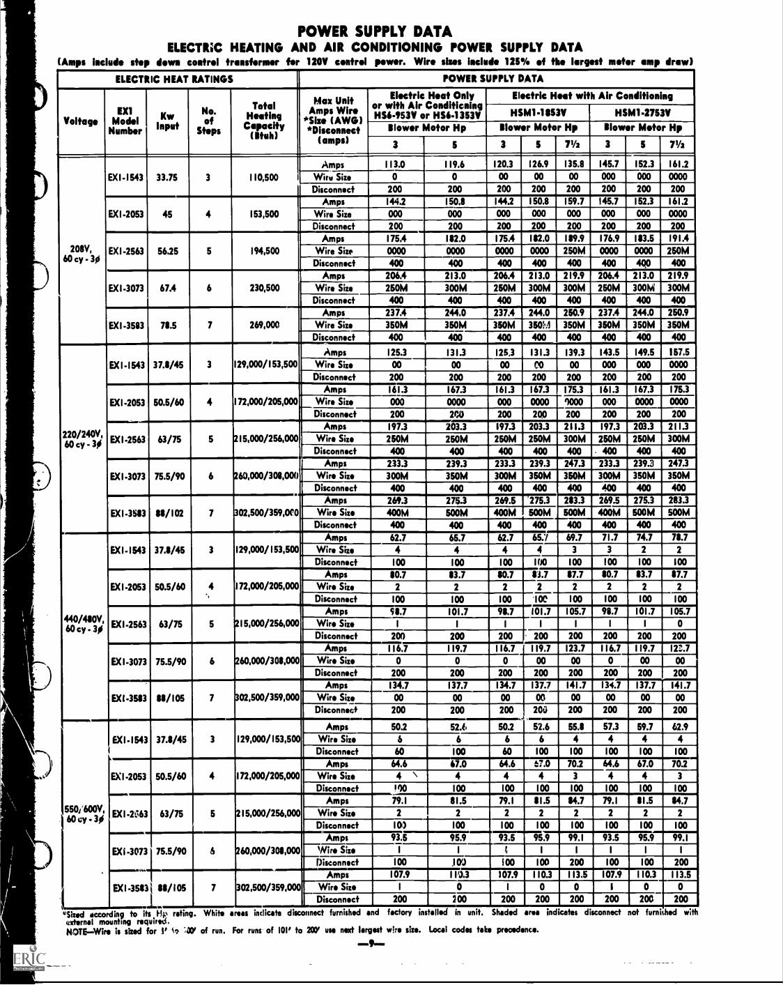
POWER SUPPLY DATAELECTRiC HEATING AND AIR CONDITIONING POWER SUPPLY DATA
(Amps include step down control transformer for 120V control power. Wire sizes include 125% of the largest motor amp draw)
ELECTRIC HEAT RATINGS POWER SUPPLY DATA
VoltageEX1
ModelNumber
v_1.,7'"F"'
No.of
St ps
TotalHeatingCapacity(Ituh)
Max UnitAmps Wire
*Size (AWG)
Electricor with AirHS6-953V or
Heat Only Electric Heat with Air ConditioningConditicning
HS6-1353V -1153VHSM11 HSM1-2753V*Disconnect Blower Motor Hp Blower Motor Hp glower Motor Hp
(amps) 3 5 3 5 71/2 3 5 71/2
EXI-1543 33.75 3
Amps I I 3.0 I 19.6 120.3 126.9 135.8 145.7 152.3 161.2
110,500 Wire Size 0 0 00 00 00 000 000 0000
Disconnect 200 200 200 200 200 200 200 200
EX1-2053 45 4Amps 144.2 I 50.8 144.2 150.8 159.7 145.7 152.3 161.2
I 53,500 Wire Size 000 000 000 000 000 000 000 0000
Disconnect 200 200 200 200 200 200 200 200
208V,60 cy - 30
EXI-2563 56.25 5
Amps I 75.4 182.0 175.4 182.0 189.9 176.9 183.5 191.4
194,500 Wire Size 0000 0000 0000 0000 250M 0000 0000 250MDisconnect 400 400 400
I400 400 400 400
EXI-3073 67.4 6
Amps 206.4 213.0 206.4 213.0 219.9 206.4 213.0 219.9
230,500 Wire Size 250M 300M 250M 300M 300M 250M 30014 300MDisconnect 400 400 400 400 400 400 400 400
EXI-3583 78.5 7
Amps 237.4 244.0 237.4 244.0 250.9 237.4 244.0 250.9
269,000 Wire Size 350M 350M 350M 35010:1 350M 350M 350M 350MDisconnect 400 400 400 400 400 400 400 400
220/240V,60 ey - 30
EX 1-1543 37.8/45 3 129,000/ I 53,500
Amps 125.3 131.3 1253 131.3 139.3 143.5 149.5 157.5
Wire Size 00 00 00 00 00 000 000 0000Disconnect 200 200 200 200 200 200 200 200
EXI-2053 50.5/60 4 I 72,000/205,000
Amps 161.3 I 67.3 161.3 167.3 175.3 161.3 167.3 175.3
Wire Size 000 0000 000 0000 9000 000 0000 0000
Disconnect 200 200 200 200 200 200 200 200
EXI 2563 63/75 5 2 I 5,000/256,000
Amps I 97.3 203.3 197.3 203.3 211.3 197.3 203.3 2 I 1.3
Wire Size 250M 250M 250M 250M 300M 250M 250M 300MDisconnect 400 400 400 400 400 . 400 400 400
EXI-3073 75.5/90 6 260,000/308,000
Amps 233.3 239.3 233.3 239.3 247.3 233.3 239.3 247.3
Wire Size 300M 350M 300M 350M 350M 300M 350M 350MDisconnect 400 400 400 400 440 400 400 400
EXI-3683 88/102 7
....
302,500/359,010
Amps 269.3 275.3 269.6 275.3 283.3 269.5 275.3 283.3
Wire Size 400M 500M 400M BOOM 500M 400M 600M BOOM
Disconnect 400 400 400 400 400 400 400 400
440/480V,60 ey - 30
EXI- I 543 37.8/45 3 129,000/153,500
Amps 62.7 65.7 62.7 65.7 69.7 71 .7 74.7 78.7
Wire Size 4 4 4 4 3 3 2 2
Disconnect 100 I 00 100 100 100 100 100 100
EXI-2053 50.5/60 4 I 72,000/205,000Amps 80.7 83.7 80.7 83.7 87.7 80.7 83.7 87.7
Wire Size 2 2 2 2 2 2 2 2
Disconnect I 00 100 100 '1 OC 100 100 100 100
EXI-2563 63/75 5 215,000/256,000
Amps 98.7 101.7 98.7 101.7 105.7 98.7 101.7 105.7
Wire Size 1 1 1 1 1 1 1 0Disconnect 200 200 200 200 200 200 200 200
EXI-3073 75.5/90 6 260.000/300,000
Amps I 16.7 119.7 116.7 119.7 123.7 116.7 119.7 12?...7
Wire Size 0 0 0 00 00 0 00 00
Disconnect 200 200 200 200 200 200 200 200
EX1-3583 88/105 7 302,500/359,000
Amps I 34.7 137.7 134.7 137.7 141.7 134.7 137.7 141.7
Wire Size 00 00 00 00 00 00 00 00
Disconnect 200 200 200 200 200 200 200 200
550/600V,60 eV - 30
EX 1 - I 543 37.8/45 3 129,000/153,500
Amps 50.2 52.i 50.2 52.6 55.8 57.3 59.7 62.9
Wire Size 6 6 6 6 4 4 4 4Disconnect 60 I 00 60 100 100 100 100 100
EXI-2053 50.5/60 4 172,000/205,000
Amps 64.6 67.0 64.6 t; .0 70.2 64.6 67.0 70.2
Wire Size 4 " 4 4 4 3 4 4 3
Disconnect 100 I 00 100 100 100 100 100 100
EXI-2463 63/75 5 2 I 5,000/256,000
Amps 79.1 81.5 79.1 8 I .5 84.7 79.1 8 I .5 84.7
Wire Size 2 2 2 2 2 2 2 2
Disconnect 10) I 00 100 100 100 100 100 100
EXI -3073 75.5/90 S 260,000/308,000
Amps 93.5 95.9 93.5 95.9 99. I 93.5 95.9 99.1
Wire Size 1 I I, 1 1 1 1 I
Disconnect 100 305 100 100 200 100 100 200
EXI-3583 j 88/105 7 302,500/359,000
Amps I 07.9 110.3 107.9 110.3 113.5 107.9 110.3 113.5
Wire Size 1 o I o o I o 0
Disconnect 200 200 200 200 200 200 200 200
*Sized according to its1.1p rating. White areas indicate disconnect furnished and factory instilled in unit. Shaded rea indicates disconnectfraternal mounting required,NOTE-Wire is sized for 1' v, ;34' of run. For runs of 101' to SPY use nut largest wire size. Local codes take precedence.
0111190111111
not furnii,hed w th
GA
S S
UP
PLY
INLE
T
!Cr.
\4I
41/4
1-4-
767-
17$
RA
IN!"
ALT
ER
N
4+1
DO
OR
. HA
ND
LE
TE
ELE
CT
RIC
AL
INLE
TS
SU
PP
LY IN
LET
1=3
DR
AIN
2I/2
31/4
CO
ND
EN
SIN
G U
NIT
(Ins
tall
doss
cou
plod
or
rom
a,*
21/2
EX
HA
US
T A
IR L
OU
VE
RS
-411
0,
83
HO
T t)
EC
K S
IDE
VIE
W22
0
3
3
RE
TU
RN
AIR
OP
EN
ING
32 351/
2
20%
2=2i
40
ELE
CT
RIC
AL
INLE
TS
---1
4)._
11.4
v241
/2P
OW
ER
SU
PP
LY
WA
TE
R IN
WA
TE
R O
UT
CE
NT
ER
OF
GR
AV
ITY
104
22
8
$71/
2
SU
PP
LYA
IRO
PE
NIN
G
DR
A!
:BO
1TO
M V
IEW
(Loo
king
. dow
it
FR
ES
H.A
IR L
OU
VE
RS
3
93V
2
FIL
TE
RS
I/
e \\\-/
BLO
WE
R
j'\\ 31
/4
CO
LD A
IR M
IXIN
G
WA
RM
AIR
MIX
ING
DR
AIN
DA
MP
E
DA
MP
ER
./\in
42% 1
CO
LD 'D
EC
K S
IDE
VIE
W77
1/s
FLUE OUTLET
LIFTING BLOCK
DIMENSIONS (in.)
ELECTRICAl. INLETS
13%
2
331/4
LIQUID LINE37/8 /0-lie-21/4,HOTI 40
G $1-'1%
---SUCTION0.1 101-35/1
011/29 --
Ina
39
47V2
WARM AIR
22
COLD AIR
Si4
RETURN AIR END
101/4
22 --Id
3
-UV
7,
7v.2i
171/2
1v.21 41
174
7y2t
72$
461/2
BY-PASS
E
22
SUPPLY AIR CONNECTIONS FOR SUPPLY AIR CONNECTIONS IStPPLY AIR CONNEaIONS
DOUBLE DUCT APPUCATIONS FOR 8 OR LESS ZONES FOR 12 OR LESS ZONES
95%
lelfir1=3
ALTERNATE SUPPLY AIR CONNECTION
Ii
IS
90V2
SUPPLY AIR END
ZONE DAMPER AIR VOLUME (cfm)
No. of Zones Minimum Nominal Maximum
9 ion. 550 1200 1550
12 zone 350 800 950

BLOWER DATANOTE-Performance shown is with 50% of zones calling for cooling and 50% for heating or with dampors in the intermediate position and with 20% outdoor
air entry. This condition has the greatest hp requirement.
DMS1-275 BLOWER 'PERFORMANCE-EVMS1-95V OR EVMS1-135V EVAPORATOR COIL(With Multizone Distribution Plenum)
AirVohs'''.(dm)
STATIC PRESSURE EXTERNAL TO UNIT (Inches Water Gauge)
0 .10 .20 .30 .40I '50 AO .70 .80 .90 1.00
RPM HP RPM BHP RPM MP RPM BHP RPM BHP RPM BHP RPM BHP RPM BHP RPM BHP RPM BHP RPM BHP
3500 320 0.1 330 0.1 390 0.1 430 0.2 470 0.3 510 0.4 540 0.5 570 0.6 600 0.7 625 0.8 650 0.9
4000 335 0.1 365 0.1 415 0.2 450 0.3 500 0.4 535 0.5 560 0.6 590 0.7 620 0.8 650 0.9 670 1.0
4500 360 0.1 400 0.2 440 0.3 480 0.4 520 0.5 555 0.6 585 0.7 620 0.8 640 0.9 670 1.0 695 1.1
5000 390 0.4 430 0.5 470 0.6 510 0.7 540 0.8 575 0.9 610 1.0 635 1.1 665 1.2 690 1.3 720 1 A
5500 410 0.6 455 0.7 500 0.8 535 0.9 565 1.0 600 1.1 630 1.2 660 1.3 690 1.4 720 1.5 745 1.6
6000 445 0.9 495 1.0 525 1.1 565 1.2 600 1.3 630 1.4 655 1.5 685 1.6 715 1.8 740 1.9 770 2.0
6500 490 1.1 525 1.2 565 1.4 600 1.5 630 1.6 655 1.7 685 1.9 715 2.0 740 2.1 770 2.2 800 2.4
7000 520 1.4 560 1.5 600 1.7 630 1.9 660 2.0 690 2.1 715 2.2 745 2.3 770 2.5 800 2.7 825 2.8
7500 560 1.7 600 1.8 630 2.0 660 2.1 685 2.3 720 2.5 745 2.7 775 2.8 800 2.9 825 3.1 845 3.2
DMS1-275 BLOWER PERFORMANCE-EVMS145V OR EVMS1-135V EVAPORATOR COIL(With Double Duct Plenum)
AirSTATIC PRESSURE EXTERNAL TO UNIT (Inches Water Gauge)
Volume 0 .10 .20 .30 .40 .50 .60 .70 .10 .90 1.00(dm)
RPM HP RPM BHP RPM HP RPM BHP RPM HP RPM BHP RPM HP RPM BHP RPM BHP RPM BHP RPM HP
3500 315 0.1 365 0.1 390 0.1 425 0.1 460 0.2 I 495 0.3 530 0.4 565 0.5 600 0.6 630 0.7 655 0.8
4000 340 0.1 380 0.1 410 0.2 445 0.3 410 0.4 515 0.5 550 0.6 585 0.7 615 0.8 640 0.9 675 1.0
4500 365 0.2 390 0.3 430 0.4 465 0.5 580 0.6 535 0.7 570 0.8 600 0.9 635 1.0 660 1.1 690 1.2
5000 380 0.3 420 0.4 455 0.5 490 0.6 525 0.7 560 0.13 590 0.9 625 1.0 655 1.1 685 1.2 710 1.3
5500 410 0.6 440 0.7 475 0.8 510 0.9 545 1.0 580 1.1 615 1.2 645 1.3 670 1.4 700 1.5 725 1.6
6000 435 O. 465 0.9 500 1.0 535 1.1 575 1.2 600 1.3 630 1.4 660 1.5 695 1.6 720 1.7 745 1.8
6500 460 1.1 490 1.2 525 1.3 565 1.4 600 1.5 630 1.6 655 1.7 685 1.8 710 2.0 735 2.1 760 2.2
7000 485 1.3 520 1.4 555 1.5 590 1.6 625 1.8 655 1.9 685 2.0 710 2.2 735 2.3 765 2.4 790 2.6
7500 , 510 1.6 550 1.7 590 1.8 615 2.0 645 2.1 675 2.3 710 2.4 735 2.5 760 2.7 785 2.8 810 3.0
DMS1-275 BLOWER PERIFORMANCE-EVMS1-1115V OR EVMS1-275V EVAPORATOR, COIL(With Multizonit DisMbution System)
AirVolume(cfm)
STATIC PRESSURE EXTERNAL TO UNIT-Inches Wafer Gouge
0 .10 .20 .30 .40 .50 .60 .70 .80 .90 1.00
RPM BHP RPM BHP RPM BHP--.1._.
RPM BHP RPM BHP RPM BHP RPM HP RPM BHP RPM BHP
1.4
RPM BHP RPM HP
5000 340 0.6 390 0.7 435 0.8 475 0.9 520 1.0 550 1.1 585 1.2 625 1.3 650 675 1.5 710 1.6
5500 380 0.7 430 0.8 475 0.9 510 1.0 545 I . i 575 1.3 620 1.4 645 1.5 675 1.6 700 1.7 735 1.8
6000 439 0.9 475 1. I 510 1.2 540 1.3 575 1.4 615 1.5 640 1.6 670 1.7 700 1.8 725 1.9 760 2.0
6500 465 1.2 515 1.3 540 1.4 570 1.6 615 1.7 640 1.7 660 1.8 695 1.9 720 2.1 750 2.1 780 2.2
7000 510 1.4 540 1.6 570 1.7 i 1 0 1.8 640 1.9 660 1.9 690 2.1 725 2.2 750 2.4 775 2.4 800 2.6
7500 550 1.7 580 1.8 610 1.9 040 2.1 660 2.2 690 2.2 725 2.5 750 2.6 775 2.7 800 2.8 820 3.1
8000 575 2.0 610 2.1 640 2.3 670 2.4 690 2.5 725 2.7 750 2.9 775 3.0 800 3.2 825 3.3 850 3.6
1500 620 2.4 640 2.5 670 2.6 700 2.8 725 3.0 750 3.2 780 3.4 805 3.5 825 3.7 850 3.8 875 4.1
9000 645 2.7 670 2.8 700 3.1 735 3.3 760 3.4 780 3.6 815 3.9 830 4.1 850 4.2 875 4.3 900 4.6
9500 680 3.2 705 3.4 735 3.6 760 3.8 780 3.8 815 4.3 840 4.4 855 4.6 880 4.7 900 4.9 925 5.2
1 0,000 715 3.7 745 3.9 775 4.2 790 4.3 825 4.5 840 4.7 870 5.0 885 5.2 905 5.4 930 5.6
10,500 750 4.3 775 4.6 810 4.9 830 5.1 850 5.2 870 5.4 890 5.5 910 5.7
BLOWER DATA
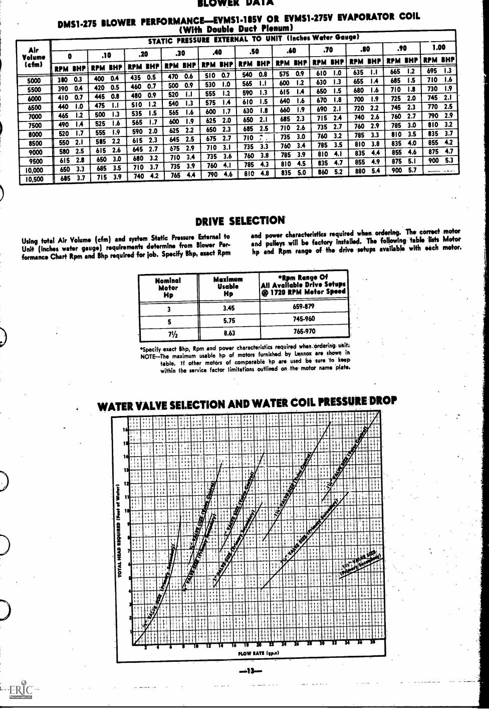
DMS1-275 BLOWER PERFORMANCE-EVMS1-185V OR EVMS1-275V EVAPORATOR COIL
(With Double Duct Plenum)
AirVolume(cfm)
STATIC PRESSURE EXTERNAL TO UNIT (Inches Wafer Gauge)
0 .10 .20 .30 .40 .50 30 .70 .80 .90 1.00
RPM BHP RPM BHP RPM BHP RPM BHP RPM BHP RPM BHP RPM BHP RPM BHP RPM BHP RPM BHP RPM BHP
5000 380 0.3 400 0.4 435 0.5 470 0.6 510 0.7 540 0.8 575 0.9 610 1.0 635 1.1 665 1.2 695_
1.3
5500 390 0.4 420 0.5 460 0.7 SOO 0.9 530 1.0 565 1.1 600 1.2 630 1.3 655 1.4 685 1.5 710 1.6
_6000 41 0 0.7 445 0.8 480 0.9 520 1.1 555 1.2 590 1.3 615 1.4 650 1.5 680 1.6 710 I A 730 11
6500 440 I .0 475 I .1 510 I .2 540 I .3 575 I .4 610 1.5 640 1.6 670 1.8 700 1.9 725 2.0 745 2.1
7000 465 1.2 SOO 1.3 535 1.5 565 1.6 600 1.7 630 1.8 660 1.9 690 2.1 720 2.2 745 2.3 770 2.5
7500 490 1.4 525 1.6 565 1.7 600 1.9 625 2.0 650 2.1 685 2.3 715 2.4 740 2.6 760 2.7 790 2.9
8000 520 1.7 555 1.9 590 2.0 625 2.2 650 2.3 685 2.5 710 2.6 735 2.7 760 2.9 785 3.0 810 3.2
8500 550 2.1 585 2.2 615 2.3 645 2.5 675 2.7 710 - 735 3.0 760 3.2 785 3.3 810 3.5 835 3.7
9000 580 2.5 615 2.6 645 2.7 675 2.9 710 3.1 735 3.3 760 3.4 785 3.5 810 3.8 835 4.0 855 4.2
9500 615 2.8 650 3.0 680 3.2 710 3.4 735 3.6 760 3.8 785 3.9 810 4.1 835 4.4 855 4.6 875 4.7
10,000 650 3.3 685 3.5 710 3.7 735 3.9 760 4,1 785 4.3 810 4.5 835 4.7 855 4.9 875 5.1 900 5.3
10,500 685 3.7 715 3.9 740 4.2 765 4.4 790 4.6 810 4.8 835 5.0 860 5.2 880 5.4 900 5.7
DRIVE SELECTION'
Using total Air Volume (cfm) and sysfirm Static Pressure External to
Unit (inches water gauge) requirements determine from Blower Per-
fortune. Chart Rpm and Bhp required for job. Specify Bhp, exact RpM
and power characteristics- required when. ordering. 'The- correct .motor
and -pulleys will be factory installed. The following, 'table listi Motor
hp and Rpm range of- thw drive lefuPs available with each motor.
NominalMotor
Hp
-Maximum
UsableHp
*Rpm Range OfAll Available Drive Setups@ 1720 RPM Motor Speed
3 3.45 659-879
5 5.75 745-960
71/4,
8.63 765-970
*Specify exact Shp, Rpm end power character stics required when.ordering, unit:
NOTE-The maximum usable hp of motors furnished by Lennox ere shown in
table. If other motors of comparable hp are used be sure 'to keep
within ihe service factor limitations outlined on the motor name *plate.
WATER VALVE SELECTION AND WATER COIL PRESSUREDROP
I
4 f4
4 4 .4
4
9 +
4 4
11
9 6
1 44-
,
t
4
4 4
4-
4
4-4 9-
4-f
I
4
:4
4
4. it
1
4 1.4 I#
11111/1
FARMER
41: II 4 I
I
t
1111
+
4
+
4 44
4
4
4
4
410
11111111111Magid4-1 Jill 11111111111111110
1111111 NO
11111111 1111 1 111104- 11111110111
111111111101111 1111111111111011111111
illopmillimifimpopollmPLOW NATI (ion)
MOUNTING DETAILS
MF-275 MOUNTING FRAME
267%
2654219
215
261%
SECTION A.A
92%
BIM
94%SECTION 114
'CONDENSING UNIT MOUNTING KITHS6453V and HS6.1353V condensingunits require a separate mounting kit toadapt the Condenser Mounting Platformto receive these units. Complete instruc.firms are furnished.
Order:N43540 fer HS6453V modelsB14354I for HS6-1353V models
0 0
*CONDENSERMOUNTINGPLATFORM
(E ntire condenserplatform area hassold fop and is slop-ed fer drainage).
--MOUNTING FRAME IS OPEN
TO ROOF IN THIS AREA
(Roof deck may Ise miffed in this area as mount-ing frame and DMS I-275 unit provide weather-proof duk with an insulation "U" fact., of .04).
----VIBRATION ABSORBER(Furnished) 4 Rowed.
SEE MOUNTINGDETAIL BELOW
RECOMMENDED FLASHING FORMF 275 MOUNTING FRAME
DM5I-275
NOTEAPPROVED BY NATIONALROOFING CONTRACTORS
ASSOCIATION
2 x 4 NAILER STRIP(not furnished)
26 GA. COUNTER FLASHING(not furnished)
24POLYURETHANE FOAM
NEOPRENE
RIGID INSULATION I 444 14(not furnished)
siosmowiseoP11s,eowN-.. "Am4."Awe e4"%we/ e,
AVeS-WeiViVeiVeeVeWeViVeiVeiVee+:40:44,W+:040:.:40:40:40:40:1ely4s:as:40:40:00.440:+:4444:40:0:4
km so ...A &wetta.....66....r-
MF-275EXTENDS AROUNDENTIRE PERIMETER
OF DMS UNIT
CANT STRIP(not furnished)
ROOFING MATERIAL
ROOF PANELS\ ROOF MAIN SUPPORTS
0.RETURN AIR
1/4
BASE SEALER
RUGGED AND PRACTICAL
Makes a perfect mounting curbto receive the direct multizoneunit. It is built info the roofstructure during building con-struction. When installed as rec-ommended below if is completelyweatherproof and water proof.No additional curbing materialsare required.
NOTEMounting frame flashingis provided by roofing contractor.
DOUBLE DUCT PLENUM
WARM AND COLDAIR DIVIDER
(COLD AIR)
X
FIBERGLASS INSULAllON
47
(WARM AIR)
*Dimension will vary with depth required.
401/4
ROOFMOUNTING
FRAME
ZONE DAMPER ASSEMBLY
101--22Vr--owl
Supply ducts connect to nd or.bottom of zone dompor usombly
MIXING BOXES
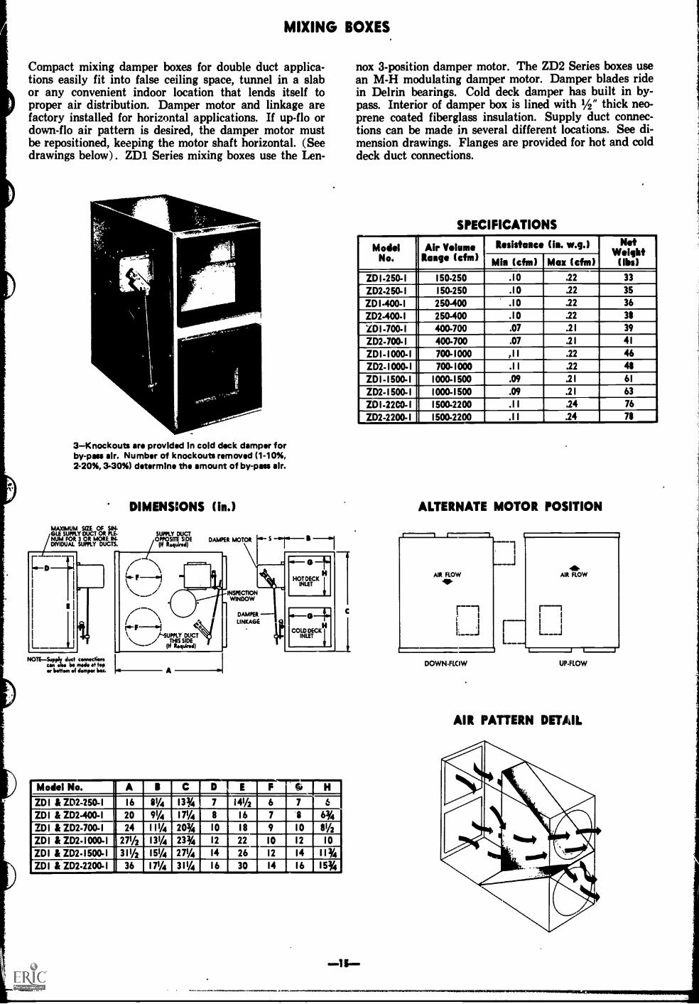
Compact mixing damper boxes for double duct applica-tions easily fit into false ceiling space, tunnel in a slabor any convenient indoor location that lends itself toproper air distribution. Damper motor and linkage arefactory installed for horizontal applications. If up-flo ordown-flo air pattern is desired, the damper motor mustbe repositioned, keeping the motor shaft horizontal. (Seedrawings below). ZD1 Series mixing boxes use the Len-
3Knockouts are provided In cold deck damper forby-pass air. Number of knockouts removed (1-10%,2-20%, 3-30%) determine the amount of by-pass air.
DIMENSIONS (in.)
MAXIMUM SIZE OF SIN-GLE SUPPLY DUCT OR PLE.NUM FOR 2 OR MORE IN-DIVIDUAL SUPPLY DUCTS.
SUPPLY DUCTOPPOSITE SIDE
(If Required)
NOTESupply due connectionscan- Ike be made at Hpea bottom of damper boa
1-SUPPLY DUCT/ THIS SIDE(If Required)
INSPECTIONWINDOW
DAMPER
LINKAGE
Model No. A I C D!EIF'IeIH7 141/2 6 7ID 1 & ID2-250-I I 6 81/4 13% 6
WI & ID2-400-I 20 91/4 111/4 8 I 6 1 8 6%ZDI & ID2-700-I 24 111/4 20% 10 I 8 9 10 81/2
WI & ID2-1000-I 271/2 131/4 23% 12 22 10 12 10
WI & ID2-I 500-1 311/2 151/4 271/4 14 26 12 14 I I %
WI & ID2-2200-I 36 I 71/4 3 11/4 16 30 14 16 15%
nox 3-position damper motor. The ZD2 Series boxes usean M-H modulating damper motor. Damper blades ridein Delrin bearings. Cold deck damper has built in by-pass. Interior of damper box is lined with 1/2" thick neo-prene coated fiberglass insulation. Supply duct connec-tions can be made in several different locations. See di-mension drawings. Flanges are provided for hot and colddeck duct connections.
SPECIFICATIONS_Model
No.Air Volume
Range (cfm)Resistance (In. w.g.) :rt..
(iIg)Min (chi) Max (chi)IDI-250-1 150-250 .10 .22 33
ID2-250- 1 150-250 .10 .22 35
ID I-400-1 250-400 .10 .22 36
ID2-400-I 250-400 .10 .22 38
ZD I -700-1 400-700 .07 .2 I 39
ID2-700-I 400-700 .07 .2 I 41
IDI-1000-1 700-1000 AI .22 46
ID2-I000- 1 700- 1000 .11 .22 48
ID! -1500-1 1000-1500 .09 .2 I 61
ID2- I 500- I 1000-1500 .09 .2 I 63
IDI-22C0-1 1500-2200 .11 .24 76
ID2-2200-I I 500-2200 .1 I .24 78
ALTERNATE MOTOR POSITION
AIR FLOW". AIR FLOW
LiDOWN-FLOW UP-FLOW
AIR PATTERN DETAIL

SCHEMATIC REFRIGERANT LINE ARRANGEMENT
DMS1-275 WITH EVMS1-95V & HS6-953V orDMS1-275 WITH EVMS1-135V & HS6-953V orDMS1-275 WITH EVMS1-135V & HS6-1353V
SUCTION LINELIQUID Lin
---- HOT GAS LINEDISCHARGE LINE
am ROTALOCK FITTINGS
s'NO
DMS1-275 WITH EVMS1-185V & HSM1-11153V orDMS1-275 WITH EVMS1-275V & HSM11853V orDMS1-275 WITH EVMS1-275V & HSM1-2753V-1
toeSUCTION LINELIQUID LINENOT GAS LINEDISCHARGE LINE
so ROTALOCK FITTINGS
ovits
400,00'"
a1.10$ ..40
Orr0.
to:row-
co'
Otos`
0' Os 00#0. IP
1#10o
1 6