05 O• 0Q3.•2 q - Defense Technical Information Center
222
AD-772 950 INVESTIGATION AND ANALYSIS OF RELIA- BILITY AND MAINTAINABILITY PROBLEMS ASSOCIATED WITH ARMY AIRCRAFT ENGINES K. G. Rummel, et al Boeing Vertoi Company Prepared for: Army Air Mobility Research and Development Laboratory August 1973 DISTRIBUTED BY: Nato Technical lIfermotiu Service U. S. DEPARTMENT OF COMMERCE 5285 Port Royal Road, Springfield Va. 22151 05 O• 0Q3.•2 q Best Avat0 Copy
-
Upload
khangminh22 -
Category
Documents
-
view
0 -
download
0
Transcript of 05 O• 0Q3.•2 q - Defense Technical Information Center

AD-772 950
INVESTIGATION AND ANALYSIS OF RELIA-BILITY AND MAINTAINABILITY PROBLEMSASSOCIATED WITH ARMY AIRCRAFT ENGINES
K. G. Rummel, et al
Boeing Vertoi Company
Prepared for:
Army Air Mobility Research and DevelopmentLaboratory
August 1973
DISTRIBUTED BY:
Nato Technical lIfermotiu ServiceU. S. DEPARTMENT OF COMMERCE5285 Port Royal Road, Springfield Va. 22151
05 O• 0Q3.•2 q Best Avat0 Copy

DEPARTMENT OF THE ARMYU. S. ARMY AIR MUBILITY RESEARCH A OEVELOPtMENT LABORATORY
EUSTIS OIRECTORATEFORT LUSTIS. VIRGINIA 23604
This investigation of turboshaft engine reliabilityand maintainability (R&M) characteristics is one of anumber of continuing R&H problem investigations conductedby the U. S. Army Air Mobility Research and DevelopmentLaboratory to provide a clear understanding of the quan-titative and qualitative R&M characteristics associatedwith Army helicopter systems. Efforts are being, andsubsequently will be, pursuted to determine those designcriteria and concepts, test requirements, and/or advancedtechnotogy requirements to provide a quantum improvementin R&M cha'racteristics for future systems.
This study concentrated on all factors contributing tocurrent turboshaft engine R&M characteristics. Typicalof the oroad range of factors considered are designspecifications/standards, technology limitations, develop-ment progran inadequacies, and maintenance procedures.Both inherent and externally induced R&M problems wereconsidered and treated separately. An attempt was madeto quantify the R&M improvement pot-ntial available throughthe use of various program approaches (maximum attentiongiven to R&M versus maximum attention given to performance,for example) and related part/piece design concept selections,e.g., carbon versus labyrinth seals.
This Directorate concurs with the investigation findingsand specifically directs the reader's attention to thatsection that addresses contcibuting factors. It is inter-esting to not.e that a maximum of only 15% of all R&Mproblems are indicated as being technology oriented, whilefactors such as requirements documents, preliminary designefforts, detail design execution (including test), qualitycontrol, and maintenance procedures collectively constitutethe remaining 857. Results of this program are to be usedas a basis for future exploratory and advanced developmentefforts relative to turboshaft engines.
Further investigation of the above-mentioned nontechnologyfactors is being initiated by Lhis Directorate, and results
cqo3eldidTvA 1po2l

will be published in late FY74. Special emphasis hasbeen placed on test requirements as they relate to engineassembly and component reliability achievement.
This program was conducted under the technical managementof Plvid B. Cale, Technology Applications Division(Propulsion Area), with engineering support from Victor
W. Welner, Military Operations Technology Division
(Reliability Area).

Task IF162205A11902Contract DAAJ02-71-C-0055
USAAMRDL Technical Report 73-28/ August 1973
INVESTIGATION AND ANALYSIS OFRELIABILITY AND MAINTAINABILITY PROBLEMS
ASSOCIATED WITH ARMY AIRCRAFT ENGINES
Final Report
by
K. G. RummelH. J. M. Smith
Prepared by
THE BOEING COMPANY, Vertol DivisionBoeing Center
Philadelphia, Pennsylvania
for
EUSTIS DIRECTORATEU.S. ARMY AIR MOBILITY RESEARCH AND DEVELOPMENT LABORATORY
FORT EUSTIS, VIRGINIA
Approved for public release; distribution uWlizited.j
'1

UnclassifiedSecurity Classification
DOCUMENT CONTROL DATA. R St 1'(SeI'utits'c-11.mum fscof of illE.. bodt, of abstract an~d indovind annotedafrni must be enteftel whom 11h. overall repofl is dlaftflail
1. ORIGINATCING ACTIVITY (Corporate Autfia) a.. REPORT SECURITY CIL.ASSIFICATION
The Boeing Company. Vertol Division UnclassifiedBoeing Center ak GROUPPhiladelphia, PennsylvaniaREPORT TITLE9
INVESTIGATION AND ANALYSIS OF RELIABILITY AND MAINTAINABILITY PROBLEMSASSOCIATED WMIT ARMY AIRCRAFT ENGINES
4. OESCROPTIVE NOTES (7?vpa aittapartan.dincsohai.. datit.)
Final Report9 AU TrIORISI (ut'.trni..ma'addw W11.1a, 1.lial nsma
Kirk G. RummelH. J. M. Smith
6. REPORT CATE ?A. TOTAL NO.ý OF AGES 17b. NO. OP1 RCPs
August 1973 1133,Sb. CON TRACT OR GRANT NO, 941. anoRiGAINA'R5 REPORT NUMUBRNIs)
DAAJO2-71-C-OOSS.A. PROJECT NO.
Tas 1F622SA1902USAAMRDL Technical Report 73-28C.S. OTHER REPORT 4O0491 (Any. trlhaes.lamiinaet Matmn ha aaalted
IS DISTP4IBUTION STATEMENT
Approved for public release; distribution unlimited.
11 SUPPLEMENTARY NOTES 12. SPONSORINGS MILITARY ACTIVITY
*Eustis DirectorateIf. S. Army Air Mobility R&D Laboratory
__________________________________ Fort Eustis, Virginia
The reliability slid maintainability problenis associatad with gas tjrbine eng~ifles Tow operational with the 0. S. military servicas wereexamined in tlss study. A broad spectrum of turbcoshaft and turboprop engines to U. S. Army. Navy and Mhiain helicopters andfixed-vtng aircraft was examined. The study concentrated on the detailed R&M experience of the T53, T55, T58, T63, T634, T73and 174, although data is provinded on other gas turbine enin~~es in military and commercial use. The R&M problemnws WuAS U.lif ted at the subsystem, component and failure mnode levels in each of four R&M parameters and was subsequently combined intoa single pa. &rneler expressing the total I itectlveness, logistics and cost Impact of R&M problems. All types of problems were con.Indered, including the, traditional engine. mused1 as well as the flon-engjene-CaUsed reasons for scheduled and unscheduled events.The concept of a composite engine was int. 'Iduced to describe the average R&M expserience of the engInei exlamined; problemswere cquantified and displayed at the failure iiode, component and sybsystem ttevels for this composite engine. Two differentappraaches were taklen in the subssequent anal sis5 detailed design considerations and broader program Eonsi rlerat Oton. CurrenteuPerlence. as described by the conmposite engne, was discussed iT these two approaches. Individual failure modes were dis-
cussed In terms of fallur, nmode and mechanls. is, corrective actions. and the current state of the art in probesm avoidtance.Examples and photographs of *ypfcal failures are provided. These prisflle~ms were also reviewed for the general programCausal factors that c~ontributed to the origin of the problems. Availlable design and tlrogramn features and trentdas were reviewedand surrrlmariled. Categories of design features are used in oreer to provide vIstbilit,/ of their acorptabtillty and cost and per-forreance impacts. These features are configulred into lthiee possible future engines for the 1971182 etav. The three configql-rations reflect varvIng degrees of program emphasis on R&M. R&M levels are quantified at the failure mode andesybsystemlevels for these eng~ines,
I'~?..14 3 RPLAES00 P010 1478. 1 JAN 0A. RNICH .S
OBOLT PO0"Po47 ARMY USB Unclassified* 5fuityt Cassification

S .Loan A LIMNSE LINK C 3
KOLO WY WOLE WT 010L. WT
Reliability and maintainability problemsGas turbine engines'Total effertivenessLogistics and ccst impactTheoretical com~posite engineDetailed .'sign considerationsBroad prc.-.iam considerationsThree possible future engines1975-82 eraFuture remedial actionsRecommendations for future activity
/ ~ . UnclassifiedkemtvCIwfleatwe
SUM•ARY
The reliability and maintainability problems associated withgas turbine engines currently operational with the U.S. mil-itary services were examined in this study. A broad spectrumof turboshaft and turboprop engines in U.S. Army, Navy andMarine helicopters and fixed-wing aircraft was examined. Thestudy concentrated on the detailed R&M experience of the T53,T55, T58, T63, T64, T73 and T74, although quantitative R&Mdata is provided on other gas turbine engines in military andcommercial service.
The R&M problem was quantified at the subsystem, component andfailure mode levels in each of four traditional R&M parametersand was subsequently combined into a single parameter express-ing the total effectiveness, logistics and costs impact of R&Mproblems. All types of problems were considered, includingthe traditional engine-caused as well as the nonengine-causedreasons for scheduled and unscheduled events.
The concept of a composite engine was introduced to describethe average R&M experience of the various engines examined,and problems were quantified and displayed at the failure mode,component and subsystem levels for this composite engine.
Two distinctly different apprczhes were taken in the subse-quent analysis: detailed design considerations and broaderprogram considerations.
The current experience, as described by the composite engine,was discussed in these two approaches. The individual failuremodes were discussed in terms of failure mode and mechanisms,corrective actions applied to these problems, and the currentstate of the art in problem avoidance. Examples and photo-graphs of typical failures are provided. These problems werealso reviewed for the general program causal factors that con-tributed to the origin of the problems.
Currently available design and program features and trendswere reviewed and summarized. Categories of design featuresare utilized in order to provide proper visibility of theiracceptability and cost axd performance impacts.
These features are configured into three possible futureengines for the 1975-1982 era. The three configurations re-flect varying degrees of program emphasis on R&M. R&M levelsare quantified at the failure mode and subsystem levels forthese engines.
Future remedial actions are considered based on the magnitudeof the projected remaining problems. Recommendations for futureactivity are provided from both design and program standpoints.
Siii

FOREWORD
Conducted by The Boeing Company, Vertol Division, for theEustis Directorate of the U.S. Army Air Mobility Research andDevelopment Laboratory (USAAMRDL), Fort Eustis, Virginia,under Contract DAAJ02-71-C-0055, Task lFIf2205A11902, thisreport investigates the reliability and m-intainability prob-lems on Army aircraft turboshaft and turboprop engines.
USAAMRDL technical direction was provided by Messrs. T. House,R. Campbell and V. Welner.
The principal investiqators and authors of this study werev Messrs. K. G. Rummel and H. J. M. Smith, and program manage-
ment was provided by Mr. G. W. Windolph, Director and Mr. R. B.Aronson, Unit Chief of the Boeing Product Assurance staff.Also contributing to the study was Mr. K. Porter, Chief, andMr. T. Connolly of the Propulsion Technology Group.
The authors gratefully acknowledge the significant assistanceof the engineering and product support departments of thefollowing engine manufacturers:
o Avco Lycoming - Stratford, Connecticut
o Detroit Diesel Allison - Indianapolis, Indiana
L General Electric Company - Lynn, Massachusetts
o Pratt & Whitney Aircraft - Hartford, Connecticut
o United Aircraft of Canada - Longueil, Quebec
Preceding page blank v

TABLE OF CONTENTS
Page
SUMM4ARY..... . . . ........ iii
FOREWORD.... ............. v
LIST OF ILLUSTRATIONS .......... ................. ix
LIST OF TABLES ............... ...................... xiii
1.0 INTRODUCTION ........ ....................... .... 1
2.0 STUDY APPROACH AND PROCEDURES ................. 2
Current Engines . .......... ............... 2Near-Term Future Engines ........ .... . . 10Long-Term R&M Requirements .......... 10Selection of R&M Parameters . . ....... .. 10Engine Selection Criteria. .............. 12Data Availability ............. 12
3.0 STATUS OF CURRENT ENCINES ....... ......... . . . 14
Engine Maturity .............. . . . ........ 14Subsystem Definition .... . . . e.".-... ..... .... 17Unscheduled Engine Removal (UER Rate) . . . 18Major Accident Rate ....... ..... .. 20Maintenance Man-Hour per Flight Hour ....... 24Time Between Overhauls (TBO) ............. 25The Composite Engine ....... . . . . . . ... 27Summary of Current-Engine Status . . . . . ... . 32
4.0 DETAILED PROBLEMS OF CURRENT ENGINES ....... 34
Bearings ........ ..... ................ 34qeals .................................. .. 41Compressors ........................ 46Combustor ....... .................. 53Turbine ............. ................... .. 58Cases ............... .................. 65Lubrication ............. ........ ........ 68Fuel System ................ . ..........Air System ............ ................. 76Accessory ......................... 77Torquemeter ........ ........... 78Electrical .• . 81Elcticl..................................8Power-Train Reduction . ..... .......... 84Exhaust ............ ................. 85Foreign Object Danae ................... 86Erosion .... . ......... .......... ..... 91Environment ................... .... . . 97Summary of Current-Engine Problems..... . . 109
Preceding page blank vii
Page
5.0 CURRENT ENGINE PROGRAM CONSIDERATIONS .. . . . 111
Definition of Causal Factors.........111Quantification of Causal Factors ............ 114Discussion of Results ..................... .. 118
6.0 IMPROVEMENTS AVAILABLE TO DESIGNS AND PROGRAMS . . 123
Design Features ..... ............ . . . 123Program Trends ......... .............. .. 139
7.0 NEAR-TERM ENGINE PROJECTION . . . . . ......... 154
Engine Maturity . . . . . . . . ......... 154Specific Configurations .. . . ......... 155Quantification of R&M Levels in Near-Term
(1975-82 Era) Engines . . . . . . . . . .. 1651975-82 Era Engine Summary ....... . . . 167Indirect Effect of R&M Improvements ...... 170
8.0 LONG-TEPM FUTURE-ENGINE DESIGN AND PROGRAMREQUIREMENTS .......... ................... .. 171
Design Considerations ..... ........... .. 17.Program Considerations ............ .. 178
9.0 CONCLUSIONS AND RECOMmENDATIONS . . . . . . . . . 182
LITERATURE CITED ........... ................... . 185
APPENDIXES
I. Conversion of TBO Interval Into Rates .... 189
II. Development of Index Numbers . . . . . . . .. 190
DISTRIBUTION ........................................ 205
viii

LIST OF ILLUSTRATIONS
Figure Page
1 Helicopter Accidents and Operating Costs . . .
2 Avco Lycoming T53 Turbine Engine Cutaway . 3
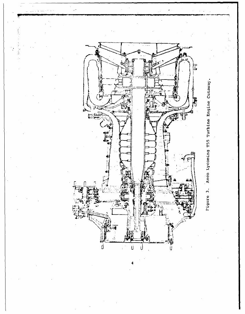
3 Avco Lycoming T55 Turbine Engine Cutaway . . . 4
4 General Electric '58 Turbine Engine Cutaway 5
5 Allison T63 Turbine Engine Cutaway ..... ....... 6
6 General Electric T64 Turbine Engine Cutaway . 7
7 Pratt and Whitney T73 Turbine Engine Cutaway . 8
8 United Aircraft of Canada T74 Turbine EngineCutaway .................. ..................... 9
9 Engine Maturity ............................. 15
10 Enqine Reliability Growth .... .......... .. 15
11 Factors Affecting Major Accident Rates ..... .. 21
12 Composite Engine Major Accident Rates bySubsystem .......... ................... .. 23
13 Composite Engine Major Accident PercentageDistribution by Subsystem ... ............. 23
14 TBO Progression ........ ................ .. 26
15 Bearing UER Rate for VJarious Engines ...... .. 35
16 Seal UER Rate for Various Engines ......... . . 42
17 Carbon Seals . . .. .................... 43
18 Face Seal Bellows . .. ....... ............ .. 44
19 Carbon-Seal Reliability ... ..... .......... 45
20 Compressor UER Rate for Various Engines ... 48
21 Cracking of Forward Diffuser Face. ........ 51
22 Cracking of Aft Diffuser Face ......... ........ 5]
ix

Figure Page
23 Failed Variable Stator Vane Mectanism Dueto FOD . . . . . . . . . . ...... 52
24 Combustor UER Rate for Various Engines .... 54
25 Typical Combustor Liner Cracking .......... .. 55
26 Combustor Liner Support 9racket Cracking . ... 55
27 Ignitor Plug Fitting Failure ... .......... .. 56
28 Swirl-Cup Mounting Spacer Cracking ....... ... 57
29 Mounting Flange Wear and Key Slot Elongation . 58
30 Fuel Nozzle Wear by Swirl Cups ........... .. 58
31 Turbine UER Rate for Various Engines ..... . .. 60
32 Turbine Nozzle Inner-Band Cracks .......... .. 60
33 Corroded Turbine Blade ................... 61
34 Turbine Nozzle With Integral Oil Tubes ...... 64
35 Cracked Turbine Nozzle Support Structure . . .. 64
36 Case UER Rate for Various Engines ....... .. 66
37 Lubrication UER Rate for Various Engines .... 69
38 Fuel UER Rate for Various Engines ....... 72
39 Elongated Rivet Hole on Purifier "V" BandClamp ................. .................. .. 74
40 Purifier With Broken Mountii~g Flanres ...... 75
41 Air UER Rate for Various Engines .......... ....... 76
42 Accessory UER Rate for Various Engines .... .. 77
43 Torquemeter UER Rate fo- Various Engines . . . 79
44 High-Speed Mechanica'. Torquemeter System . .80
45 Wear in a High-Speed Mechanical System ...... 80
46 H1,,draulic Torquemeter System .......... .. 80
x

Figure Page
47L Electrical, UER Rate for Various Engines • . . 81
48 .Cracked Thermocouple Sleeve. ............. 82
49 Alternator Cable Chafing ........ ............. 83
50 Power-Train Reduction UER Rate for VariousEngines 84
51 Exhaust PER Rate for Various Engines ..... ...... 85
52 Sources of FOD .. ............. ........... .. 87
53 FOD UER Rate for Various Engines and AircraftInstallations .......................... 89
54 Erosion of Compressor Blades With CurledLeading Edges 93
55 Erosion of Compressor Vanes After Severe TestConditions ........... ................. .. 93
56 Erosion UER. Rate for Various Engines andAircraft Installations ........ ......... ... 94
57 Environmental Failure Modes .... ........... .. 98
58 Environmental UER Rate for Various Engines . . . 99
59 Operator-Induced UER Rate for Various Engines . 101
60 Improper Maintenance-Caused Removals .. ...... .. 102
61 Distribution of Improper Maintenance UER's -
Various Engines ............................... 103
62 Improper Maintenance UER Exparience ......... .. 103
63 Airframe-Related UER Experience ... ......... .. 106
64 Convenience UER:Experience .... ........... .. 107
65 Unknown UER Experience�. . . ... . ... ........ 108
66 Interrelationships and Examples of CausalFactors ................. .................. .. 113
67 Example of Contributing Factors Analysis ... 115
68 Summazy Results of Contributing Factors ....... 116
xi

Figure Page
69 Future Engine Activity Flow Chart............. 123
70 Development of the Index Number . .* - .... 190
71 R&M Parameter Scale Factors ............ 191
72 Overhaul Cost Ratios of Turbine Engines ...... 193
73 Overhaul Costs of Turbine Engines ... ........ .. 194
74 Repair Criteria for Classification as a MajorAccident ................ .................. ... 195
75 Strike to Major Accident Ratios for Army andNavy Helicopters ........... ................ 195
76 Helicopter Acquisition Costs . .......... 196
77 Costs of Non-Attrited Major Accidents........ 197
78 Aviator Fatalities per Major Accident ....... 199
79 Non-Aviator Flight-Crew Fatalities per MajorAccident ............... .................... .. 199
80 Passenger (Non-Crew) Fatalities per MajorAccident .............. ..................... 200
81 Total Fatalities by Type per Major Accident . . . 200
82 Costs of Fatalities per Major Accident ....... .. 201
83 Costs of a Major Accident .... ........... . .. 202
84 Costs of a Major Accident (Linear Scale) . ... 202
85 Weight of Army Helicopters ................ .. 203
xii

LIST OF TABLES
Table Pg
I R&M Consequences of Parameters Selected . . 11
II Engines Studied ...... ............... ... 13
III Engine Data Available ................. .. 13
IV Subsystem Definition ....... ........... .. 18
V Unscheduled Engine Removal Rates .. ...... .. 19
VI Engine-Related Major Accident Rates ...... 22
VII Maintenance Man-Hour Rates ... ......... 25
VIII Subsystems That Limit TBO Intervals ..... .. 27
IX The Composite Engine............. .. 28
X Composite Engine Subsystem Index Numbers . 29
XI Composite Engine Summary Matrix . .. .... .. 30
XII Composite Engine - Problem Areas in Order ofPriority (Index Numbers) ... .......... .. 31
XIII Composite Engine - Problem Areas in Order ofPriority (UER'S) ........................... 31
XIV Bearing Failure Modes ... . ....... .... .. 35
XV Seal Failure Modes .......... .......... 42
XVI Compressor Failure Modes ... .......... .. 47
XVII Combustor Failure Modes . . . . ........ 53
XVIII Turbine Failure Modes .... ............ 159
XIX Case Failure Modes ......... ............. ... 66
XX Lubrication Failure Modes.. .......... 69
XXI Fuel Failure Modes ....... ............. .. 71
XXII Air Failure Modes ........ ................ 76
XXIII Torquermeter Failure Modes .... .......... .. 78
xiii

Table3 Page
XXIV Electrical Failure Modes . . . . . . . . 81
XXV Factors That Affect FOD ..... ............ 90
XXVI Contributing Factors Subsystem SummaryMatrix ................ ................... 116
XXVII Contributing Factors Failure Mode Matrix . . 117
XXVIII Potential Changes in the BearingSubsystem . ................................ 126
XXIX Potential Changes in the Seals Subsystem . . 127
XXX Potential Changes in the CompressorSubsystem .......... ............ 128
XXXI Potential Changes in the CombustionSubsystem . . . . . . . . .......... 128
XXXII Potential Changes in the TurbineSubsystem ........... ................. .. 129
XXXIII Potential Changes in the Cases Subsystem . 130
XXXIV Potential Changes in the LubricationSubsystem ........... ................. .. 131
XXXV Potential Changes in the Fuel Subsystem . . 131
XXXVI Potential Changes in the Air Subsystem . . . 132
XXXVII Potential Changes in the AccessorySubsystem ........... ................. .. 132
XXXVIII Potential Changes in the TorqueometerSubsystem ........... ................. .. 133
XXXIX Potential Changes in the ElectricalSubsystem ................................. 133
XL Potential Changes in the ExhaustSubsystem ........... ................... 133
XLI Potential Changes in the Power-TrainReduction Subsystem ................... 134
XLII Potential Changes in the FOD Subsystem . . . 134
xiv
Table Page
XLIII Potential Changes in the ErosionSubsystem ...................... ... . 135
XLIV Potential Changes in the EnvironmentalSubsystem ............ ............... ... 136
XLV Potential Changes in the Operator-InducedSubsysteu. ............. .............. .. 137
XLVI Potential Changes in the ImproperMaintenance Subsystem ........ .......... .. 137
XLVII Potential Changes in the Airframe-RelatedSubsystem ...................... ... 138
XLVIII Potential Changes in the Convenience
Subsystem ............................... 139
XLIX Future Engine Features - Bearings ........ .. 155
L Future Engine Features - Seals .. ....... .. 156
LI Future Engine Features - Compressor ...... .. 157
LII Future Engine Features - Combustor .. .... .. 158
LIII Future Engine Features - Turbines ... .... .. 158
LIV Future Engine Features - Cases .. ....... .. 159
LV Future Engine Features - Lubrication .... 159
LVI Future Engine Features - Fuel ... ......... 160
LVII Future Engine Features - Air .. ......... .. 160
LVIII Future Engine Features - Electrical ...... 161
LIX Future Engine Features - Torquemeter . . . 161
LX Future Engine Features - Accessories . . . . 161
LXI Futu-e Engine Features - Power-TrainRedu':tion ............ ................. .. 162
LXII Future Engine Features - FOD ... ........ 162
LXIII Future Engine Features - Erosion .. ...... 162
LXIV Future Engine Features - Environmental . . . 163
xv

Table Page
LXV Future Engine Features - Operator Induced . . 163
LXVI Future Engine Features - ImproperMaintenance .......... ..................... 164
LXVII Future Engine Features - Airframe Related . . 164
LXVIII Future Engine Features - Convenience . . 164
LXIX Future Engines Summary Matrix - Subsystem . . 165
LXX Future Engines Summary Matrix-FailureModes .............. ...................... 166
LXXI Summary of Future Engines .... ......... .. 167
LXXII R&M Improvement Actions and BenefitsApplicable to 1975-82 Era Engines ........ .. 169
LXXIII Indirect Benefits ........ .............. .. 170
LXXIV Remaining Problems of the Full-R&M-Emphasized Engine ......................... 171
LXXV Ratius of Frequency of Occurrence ........ .. 192
LXXVI Costs of Aviator Fatalities ... ......... .. 201
LXXVII Cost of Non-Aviator Crew and PassengerFatalities ............. ................ .. 201
LXXVIII Costs and Relationships .... ........... .. 203
LXXIX Derivation of Weighting Multiplier ...... 204
xvi

1.0 INTRODUCTION
Use of gas turbine engines in their aircraft has given theU.S. Army.a significant increase in mobility. Commitment ofthe engines to battle conditions provided a positive measureof the gas turbine's capability in a difficult environmentthat included frequent operation at low altitudes in sand anddust, frequent power changes with related thermocycling, andconstant exposure to the most difficult of maintenance condi-
Stions. It soon became clear that the perfcrmance benefitsfrom the gas turbine engine were significant. It also becameobvious that the anticipated reliability and maintainability(R&M) attributes of the engines were not being realized inthese operations.
The impact of turbine engine reliability and maintainabilityis of critical concern. Review of historical safety, relia-bility, and maintainability data reveals that Army turbine .engines contribute significantly to the total number of acci-dents, downtime, maintenance burden, and ownership costs ofthe aircraft in which they are installed. The percent ofmajor accidents and ownerships costs attributed to powerplantsis shown in Figure 1. In addition to the two parameters indi-cated in Figure 1, it will be shown that engine R&M levelshave a significant impact on an extremely broad spectrum ofcost incurring coisequences.
This study utilizes extensive data from military operations toquantify the magnitude and reasons for the current level ofR&M of mil.iLary gas turbine engines and identifies ways toimprove R&M in future engines.
MAJOR ACCINDNTS. OPERATING CCOSTS
A.7, nl E r, , s I- itres
121
t5 ~N.r I a-, t oIs•
b[I Ar'y •.llc¢ptMar ClI47A.Direct
;ýfr 't ~lsl F'wlcors artea Costs
Latf¢.r andf Materiall
Figure 1. Helicopter Accidents and Operating Costs.

2.0' STUDY APPROACH AND PROCEDURES
This study investigates seven gas turbine engines in terms t;.Fthe following R&M parameters:
o Unscheduled Engine Removal (UER) Rate
o Accident Rate (Engine-Related)
o Maintenance Man-Hour per Flight Hour Rate
o Time Between Overhaul (TBO) Interval
The study included the Oifferent dash-number variations ofthese basic engines:
o Lycoming T53, Figure 2
o Lycoming T55, Figure 3
o General Electric T58, Figure 4
o Allison'T63, Figure 5
o General Electric T64, Figure 6
o Pratt & Whitney T73, Figure 7
o United Aircraft of Canada T74, Fi(,ure 8
CURRENT ENGINES
Problems were investigated on an engine-by-engine basis andquantified in terms of each of the individual parameters, whereadequate data existed. A composite engine was developed toallow consideration of all problems on a weighted basis withoutundue influence by a single engine or manufacturer and withoutthe proprietary restraints associated with specific failuremodes of individual engines. A single quantified index numberwas developed to express the collective impact of each failuremode in terms of the traditional parameters of UER rate, majoraccident rate, TBO, and maintenance man-hours per flight hour.The result was a list of failure modes for thecompositeengine, listed in order of priority of each mode's frequencyand consequence, as quantified by the index number.
Detailed failure mechanisms for each failure mode of the com-posite engine were examined and'discussed. The study consid-ered the program deficiencies that caused or allowed thevarious failure modes to exist. Program deficiencies were de-fined to include decisions regarding requirements, preliminarydesign, design execution, manufacturing and quality control,and maintenance/operation.
2

-E-
i. -I w
ti,
/L(
-41
f V~l E
LI --II
71
wC

4-J
.4
;0'
E-4
S4J
|Reprodtuced fromS Jbest available Copp/._

41
QU
ca cc
C9 E-4-C4
0 C,
"C"4
6f

rtz
'Ti rT
~~too
2r!,

ti
-444.1
-'4
449

CD
4.4
4J~-H 4.)

NEAR-TERM FUTURE ENGINES
Available defined remedial actions to alleviate current engineR&M problems were tabulated and discussed for each engine sub-system. They were then selectively assigned to each of threepossible near-term future engine configurations, and the R&Mcharacteristics of these configurations were quantified. Itwas necessary to configure three engines because customeremphasis exerts great leverage upon product R&M. The threenear-term engines (configured for the 1975-82 era) are:
o A full-performance-emphasized engine
o A full-R&M-emphasized engine
o A normal engine (representing a balance of R&M andperformance)
LONG-TERM R&M REQUIREMENTS
The near-term R&M-emphasized engine still needs further R&Mimprovement. In general, the hardware and program correctiveaction does not exist today. To further improve the R&Mlevels, aggressive and detailed development is required forpost-1982 engines. The needed improvements are identified anddiscussed in this report.
SELECTION OF R&W PARAMETERS
The myriad of existing parameters complicates the task ofdescribing the magnitude of the engine R&M problem. This inturn makes it difficult to define the courses of action neces-sary for efficient problem solution.
The R&M-oriented parameters currently being used include:
1. Accident Rates
o Majoro Minoro Incidents
2. Schedule Accomplishment Rates
"o In-flight Shutdowns"o Forced Landings"o Precautionary Landincs"o Ground Aborts"o Aircraft Availability
10

3. Life-Cycle Costs
o Malfunction Rateo Unscheduled Removal Rateo Scheduled Removal Rateo TBO Intervalso Maintenance Man-Hour Rateo Operating Costs per Flight Hour
One of the study tasks was to select and integrate the optimumparameters and then provide appropriate quantificatiorn, sothat a credible problem priority list could be developed. Theparameters used to measure safety, reliability, and maintain-ability were selected by considering both their significanceand their general use by the military services and the enginecommunity. The parameters selected for use in this study are:
o Unscheduled Engine Removal (UER) Rate (all causes)
o Major Accident Rate (engine-related)
o Maintenance Man-Hour/Flight Hour (1iMH/FH) (on enginesystems)
o Time Between Overhauls (TBO)
These parameters quantify the safety, schedule accomplishment,and life-cycle cost domains of the engine. Table I displayshow these four parameters reflect the entire spectrum of R&Mconsequences.
TABLE I. R&M CONSEQUENCES OF PARAMETERS SELECTED
Selected Parameters
MajorR&M Consequerces UER Rate MMf,!FH Accident Rate TBO
Major Accidents X x
Minor Accidents X x
Incidents X X
In-Flight Shutdowns X X
Forced Landingý x x
Precautionary Landings X
Ground Aborts x
Aircraft Downtime X x X
Malfunctions X
Unscheduled xmmv s x P
Scherfuled Remov,ý x X
TBO Interval x t
Maintenance Man-Hours x X x
Operating Costs X x x x
11
A number of other parameters were investigated and found to bedeficient. For example, Engine Malfunction Rate is probablythe best indicator of engine unreliability; however, it is notroutinely collected and recorded by the U.S. Army. For thosemilitary services where engine malfunction rate is identified,the usefulness of the data is often compromised by a lack offailure mode and component identification data. In-FlightShutdown Rate ranks high as a measure of engine reliability incommercial areas. It is collected in detail by most airlines,but not rigorously collected by the military services. EngineReturns to Depot is a parameter that has been widely collectedby the U.S. Army and its contractors; however, it is stronglyinfluenced by differing maintenance philosophies. User orga-nizations with sophisticated maintenance philosophies and goodfacilities return engines to depot only as a last resort.Other organizations view the depot as a convenient place tosend work. Also, the exigencies of a battle environment donot always permit engine repair to be accomplished at themaintenance level specified in military manuals.
ENGINE SELECTION CRITERIA
U.S. Army gas turbine aircraft engines are the basis for thisstudy. The principal turboshaft engines used by Navy/Marinecombat helicopters have been included to broaden the scope ofthe study. Inclusion of the Navy/Marine engines permits thestudy to include all the principal gas turbine engines cur-rently used by U.S. military services in helicopter applica-tions. It also permits the study to include engines from allthe major engine manufacturers. Selection of a full range ofengines and manufacturers makes this study a broad overview ofthe current turboshaft and turboprop engine spectrum.
Seven different engines were studied for this report. Theprincipal gas turbine engines currently used by the Army arethe Allison T-63 and the Lycoming T-53 and T-55 series turbo-shaft engines. The Pratt and Whitney T-73 turboshaft and theUnited Aircraft of Canada T-74 turboprop, each in limited usewith the Army, are also included. The Navy/Marine enginesstudied are the General Electric T-58 and T-64 turboshafts.
The engines selected have a power range of 317 to 4800 horse-power; they power light observation aircraft through medium-and heavy-lift helicopters. The engines that have contributedto determining engine safety, reliability and maintainabilitylevels, their manufacturers, and the specific applications arelisted in Table II.
DATA AVAILABILITY
After selecting the parameters for study, an extensive effortwas undertaken to identify compatible data for each engine.
12

Data was successfully obtained and analyzed for approximately85 percent of all engine/parameter combinations as indicatedin Table III.
Data was obtained from the following sources: engine manufac-turers' contractual R&M reports, USABAAR accident reports,ARADMAC (Army Overhaul Facility) engine disassembly inspectionreports, U.S. Navy Material and Maintenance Management Reports(3M), manufacturer Engineering Change Proposals (ECP's),powerplant and engine bulletins and changes, Boeing in-houseengine data, Navy Safety Center data, EIR's and UR's. Consid-erable data was provided by the engine manufacturers. Theyalso provided detailed explanations and interpretations oftheir data.
TABLE II. ENGINES STUDIED
Engine Manufacturer Application Service
T53-L-ll Lycoming UH-i U.S. ArmyT53-L-13 UH-l, AH-l
T55-L-7 Lycoming CH-47 U.S. ArmyT55-L-7C CH-47
T58-8B General CH-46, SH-3 U.S. Navy758-10 Electric CH-46 & Marines
T63-A5A Allison OH-6 U.S. Army
T64-6 General CH-53 U.S.Electric Marines
T73 Pratt & CH-54 U.S. ArmyWhitney
T74 United Acft U-21 & U.S. Army &of Canada Commercial Commercial
TABLE III. ENGINE DATA AVAILABLE
Data AvailabilityEngine UER Rate Accident Rate MMH/FH TBO
T53 yes yes yes yesT55 yes yes yes yesT58 yes yes yes yesT63 yes yes no yesT64 yes yes yes yesT73 Partial yes 1. yesT74 Partial yes no yes
13

/-
3.0 STATUS OF CURRENT ENGINES
This section presents the results of the analyses performed onthe seven current engines. Displays are provided which quan-tify the study parameters (UER rate, major accident rate,TBO's and MMH/FH) to the subsystem level for each engine.Although quantified only to the subsystem level in these dis-plays, the analyses reflect component and failure mode levelexperience in each of the study engines. Also included inthis section are discussions concerning the importance of con-sidering the degree of engine maturity, the rationale for thuparticular subsystem breakdown selected, the concept of thecomposite engine, and the concept of the index number (a de-rived value which encompasses the four quantified studyparameters).
The section concludes with a list of problems (in order ofpriority) encompassing both the component and subsystem levelsas appropriate. Broad conclusions are developed from the dataanalysis at the subsystem level. Conclusions from analysis ofdata at the failure mode and component levels are developed inSection 4, Detailed Problems of Current Engines.
ENGINE MATURITY
Early in the data analysis task, it became apparent thatengine maturity has a tremendous influence on the level ofreliability being achieved by a particular engine. In orderto make meaningful comparisons and assessments, it is essen-tial to recognize that absolute values of reliability varysignificantly over an engine's life cycle. Actual valuesmeasured are the direct result of the caliber and amount ofproduct improvement and learning curve considerations (withrespect to operator and maintenance personnel techniques).
Experience has shown that engines enter operational serviceafter a relatively short development period. While this in-volves several years of effort, it rarely include- more than10,000 hours of engine operation. After introduction intoservice, numerous engineering and procedural changes areusually developed as service-revealed difficulties becomeapparent. Following this, a much slower rate of-reliabilityimprovement occurs until the engine reaches its mature relia-bility. These stages in an engine's maturity are illustratedin Figure 9.
To select the most appropriate engine maturity period for allengines, consideration was given to data availability, thecalendar year of maturity, and the likelihood of the enginehaving received the majority of its product improvement. Itwas concluded that an appropriate maturity level for Armyengine analysis was the 1-million-engine-hour point. Most
14

Product Improve-Enqine ment Phase
TestPetIntroduction into Service
Rapid Solution- • of Problems•l • Level
Sof
Cumulative Operating Hours
Figure 9. Engine Maturity.
military turboshaft engines reach or exceed this value; manyproduct improvement changes have been developed, incorporated,and proven by that time; or the decision has been reached topursue them no further.
For the current engines studied, the 1-million-hour maturitypoint was selected, with three.exceptions. The T64.engine hadonly 250,000 hours of engine operation at the Aime of thelatest available data base. The T53 and T74 engines had wellin excess of 8,000,000 hours at the time of their most appro-priate data with no adequate bases at the l-millicn-hour point,and no acceptable method for synthesizing them. reliabilitygrowth curves for military and commercial engines were con-structed and are illustrated in Figure 10 utilizing the param-eter of engine-caused unscheduled removal rate. These growthcurves suggest that many factors influence engine reliability.
2.6
2.4 -
2,2 T64
S2,0 TF41i4 _ __
S~T58
0 ' b P 2 I1 TTS4r16
? 1.2
TF~~_ýJ I%% D_
m 0.2 '.... . ........ • ..... ........... .. . -. .,
10,000 100,C:0' 1,000,000 i0,000,000 Ibj0,000,0O)0
CWU Iat Ive Elnqn ne Flch: Ho iurs
Figure 10. Engine Reliability Growth.
15
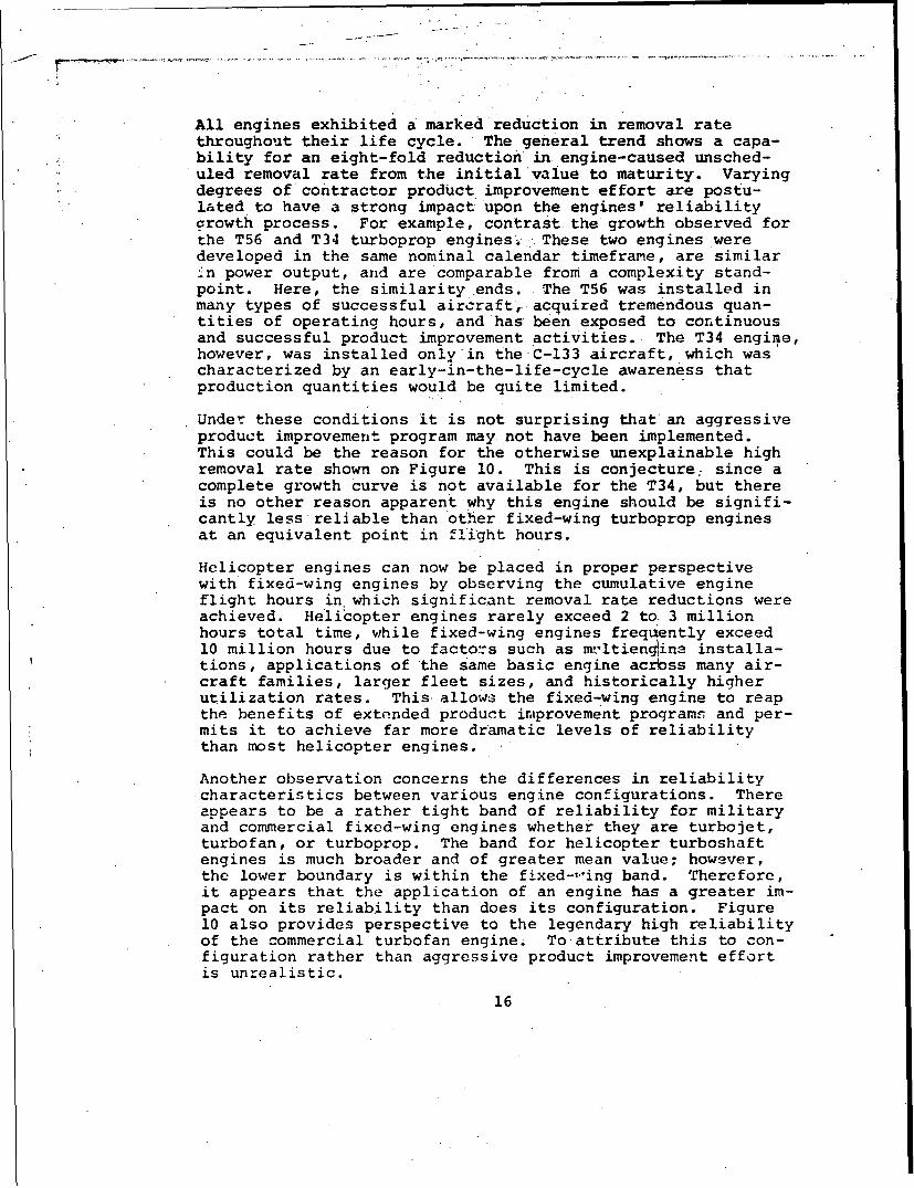
All engines exhibited a marked reduction in removal ratethroughout their life cycle. The general trend shows a capa-bility for an eight-fold reduction in engine-caused unsched-uled removal rate from the initial value to maturity. Varyingdegrees of contractor product improvement effort are postu-lated to have a strong impact upon the engines' reliabilitycrowth process. For example, contrast the growth observed forthe T56 and T34 turboprop engines. ,These two engines weredeveloped in the same nominal calendar timeframe, are similar..n power output, and are comparable from a complexity stand-point. Here, the similarity ends. The T56 was installed inmany types of successful aircraft,. acquired tremendous quan-tities of operating hours, and has been exposed to continuousand successful product improvement activities. The T34 engine,however, was installed only in the C-133 aircraft, which wascharacterized by an early-in-the-life-cycle awareness thatproduction quantities would be quite limited.
Under these conditions it is not surprising that'an aggressiveproduct improvement program may not have been implemented.This could be the reason for the otherwise unexplainable highremoval rate shown on Figure 10. This is conjecture: since acomplete growth Curve is not available for the T34, but thereis no other reason apparent why this engine should be signifi-cantly less reliable than other fixed-wing turboprop enginesat an equivalent point in flight hours.
Helicopter engines can now be placed in proper perspectivewith fixed-wing engines by observing the cumulative engineflight hours in which significant removal rate reductions wereachieved. Helicopter engines rarely exceed 2 toi 3 millionhours total time, while fixed-wing engines frequently exceed10 million hours due to factors such as m-'Itiengtina installa-tions, applications of the same basic engine acrOss many air-craft families, larger fleet sizes, and historically higherutilization rates. This allows the fixed-wing engine to reapthe benefits of extended product improvement proqrams and per-mits it to achieve far more dramatic levels of reliabilitythan most helicopter engines.
Another observation concerns the differences in reliabilitycharacteristics between various engine configurations. Thereappears to be a rather tight band of reliability for militaryand commercial fixed-wing engines whether they are turbojet,turbofan, or turboprop. The band for helicopter turboshaftengines is much broader and of greater mean value; however,the lower boundary is within the fixed-,ing band. Therefore,it appears that the application of an engine has a greater im-pact on its reliability than does its configuration. Figure10 also provides perspective to the legendary high reliabilityof the commercial turbofan engine. To attribute this to con-figuration rather than aggressive product improvement effortis unrealistic.
16

The wide variation of removal rates for helicopter applica-tions warrants comment. Without doubt, the band is a functionof both reliability and maintainability factors. Reliabilityis degraded by more abusive climatic and mechanical environ-ments and/or a shorter mission length which produces morethermocycles per hour. Maintainability aspects (such as pooraccessibility) drive certain helicopter applications to thehigh side of the band.
Of particular interest is the observation that there appears tobe no discernible reliability difference between military andcommercial usage. Although Pigure 10 does not show commercialhelicopter data, the fixed-wing data suggests that the differ-ence is, at most, minimal. Further analysis should be under-taken to clarify this continuing controversy-
With this general perspective of turbine engine reliability,it is appropriate that the subsystems, components, and failuremodes which compose and define helicopter turboshaft engineR&M characteristics .3e examined in detail.
SUBSYSTEM DEFINITION
Establishment of a suitable engine subsysteir breakdown is aprerequisite to an organized identification of engine R&M prob-lems. After evaluating the subsystem breakdowns being used bythe engine manufacturers, it was concluded that a functionalbreakdown was the most suitable for this study. This breakdownwas arranged to include the grouping of engine main-shaft bear-ings and seals under individual headings. The display of thelarge impact of these components on engine reliability is theprincipal reason for this exception. Other systems were ar-ranged functionally so that direct comparisons of lubricationsystems, fuel systems, etc., were possible.
Although the engine manufacturers did not agree on a commonsubsystem breakdown, there was complete agreement on the needto separate engine removals into two categories: engine-causedand non-engine-caused. Engine-caused removals are those inwhich a malfunctioning component of the engine itself necessi-tates a removal. A non-engine-caused removal is one in whichsome external reason (such as FOD or improper maintenance) wasthe cause. For engine-caused removals, definition of theproblem is usually available down to the component level. Fornon-engine-caused removas, information is not routinely dis-played below the failure cause (for example, airframe induced).
It is postulated that the extremely rigorous categorization bythe manufacturers between engine-caused and non-engine-causedremovals is prompted by their seeing a need to identify thosefailures for which they feel directly responsible. Unfortu-nately, this directs attention to only a portion of engine
17
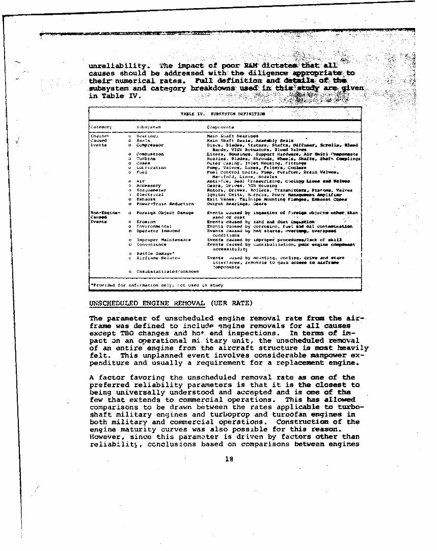
unreliability. The impact of poor RM dictate-% that all.causes should be addressed with the diligence appropriate totheir numerical rates. Ftull definition and details ft th"subsystem and category breakdowns' used in. thi .` st•udy are givenin Table IV.
TABLE IV. SUBSYSTZM D9FINITIOC)W
Category S'isystem components
Enlln"- Bear inq' Main S:'aft bearinsqCaused o SeAs Main Shaft Seals. AaseIly SealsEvents 0 Compressor Discs, Blades. Stators, Shaft*, IVitfuer. Scell• , Wood
Baids, VIGV Actuators. Bleed Valveso Combustion Liners, Housings, Support Hardware, Air Swirl C'ouenetso .'urbjne Nozzles, Blades. Shrouds, Wheels. Shafts. Shaft Cosplinqso Cases Outer Casing. Inlet Housinq, Fittingso LuIxication Pump. Valves, Lines, Filters. Coolerso Fuel Fuel Control Units, Pump. Purttier. Draan Valve%.
Marifold, Lines, Nozzleso Air Anti-!ce, lea] Pr"ssurizing. CGiolig Li.aSe asa Val~o Accessory Gears, Dirives, .'%G3 Housingo Torquemet.r Rotor&, Drives,. Rollers, Transmitters. Pistons, Valves) Electrical Ignitor Units, V..rnczs. Pos-t Mansqsuwt hpltfutz
o Exhaust Exit Vanes, Tailripe Mountinq Flamges. LExaust Cqxeso Power-Traip Reductien OutFut bearingqs 'leaer
Mon-Enqin.- o Foreiqn Object Damage Events caused by ingestion of f revq. ob+acr othme thanCaused sand or dustEvents o Erosion Events caused by 3and and dust tgeLsion
o Snviroansital Eventa caused by corrosion. fuel *P oAi contserisataluo Operator Inauced Events caused by hot starts. overt%. overspend
conditions"o Improper Mairtenanice Events causeo by improp*er procedure/lack of ski•l"o Convenience Events caused by vannibalization, poor eonqme coweataccessibility
"o Battle Damage-o Arirrame Relateui Events _fused by eoJntinq. COnlinq. drEies and st~arrinterlaces, removals to gain access to aifraemecomponents
o Unsubstantiated/unknown
sProvided for, information only, ot used in study
UNSCHEDULED ENGINE REMOVAL (UER RATE)
The parameter of unscheduled engine removal rate from the air-frame was defined to include -engine removals for all causesexcept TBO changes and hot. end inspections. In terms of im-pact on an operational mi. itary unit, the unscheduled removalof an entire engine from the aircraft structure is most heavilyfelt. This unplanned event involves considerable manpower ex-penditure and usually a requirement for a replacement engine.
A factor favoring the unscheduled removal rate as one of thepreferred reliability parameters is that it is the closest tobeing universally understood and accepted and is one of thefew that extends to commercial operations. This has allowedcomparisons to be drawn between the rates applicable to turbo-shaft military engines and turboprop and turoofan engines inboth military and commercial operations. Construction of theengine maturity curves was also possible for this reason.However, since this parameter is driven by factors other thanreliability, ccnclusions based on comparisons between engines
S18B

should only be drawn with caution. Considerations such asmaintainability, accessibility in the aircraft, environment,and. logistics all affect the Uxa rate , although it is notpossible to q~uttify their separate effects..
In the case of the maintainability factors , for,, instance,modularization tends to decrease the number of unscheduledremovals if failures are repaired with the engines installed.The accessibility of an engine also has considerable impact onits removal rate. This was commonly seen on the fuel subsys-tem, for example, where working on the fuel control unit isdifficult when the complete engine is installed in the air-frame. The engine logistics situation impacts convenienceremovals. Many removals are generated by the need to removea serviceable engine from one aircraft to install it inanother aircraft when no other engines are available.
Other non-engine-caused subsystem UER rates are also affectedby operational environment, personnel skill levels, and engineconfiguration in terms of FOD and erosion protection equip-ment. For these reasons, direct comparisons of non-engine-caused or total UER rates are not appropriate.
Despite these shortcomings, the parameter of 'u ;cheduled re-moval rate should be considered one of the prime measures ofengine R&M characteristics. The unscheduled removal rates fora variety of military and commercial turboprop, turbojet,turbofan, and turboshaft engines are displayed in Table V.
4TAOS Vý 440. 140W FVC4 . A4440)1 RIX" T14 I
T51-L-l1i'1•4 T7"- ..-0!A T%$4-1 T7O-IS T o - " .A-SA 1.4-4' T1 C,,0-. 0-, 'NO-L -4 -.3-orh, -4, CW4-OI LAI '0- A I Ch- 0~ AL'0.4 SLO 014r
• mLV44.A . 000' r'+.0 '43 14-+I rl 00.10.40 140.V,'10 *d-i 10 1 60-12144 U,4J'L4.+l 6. 14.6.403
G.114 4.16 .0 2. 0.,45 1.#,S 0. 44 0 0:1% . .04'0 0.40-46,1 ..0 .1014 0.3 Oil43 .0.54 0. L k( 0 1.0 004
* + CoolS 0 .,a. '.613 r . o, 0.o1o 0. a I a.o 5 ]
0.~l•. 0'1 o.1 4't.' ,4 .1_ 2I . 01 l.3 ] 1 . 131 o.093o0 ~ - 114* ' A r+m*• ++; -,+ . -+ .... ,• o. '0 .04 0.03 14.010 -t• o~4 -,o
• +,A t o' 9• ,.0 '4 3.o44 (.6 C+ . 44 0 . 40J 4.010 4.244 0.40$ - 0011,01++ l[ rO~ .+ - 0..+1. ,- - -,I~ .000% -1+• . 0.41
¢ 4.415 ".1 I 0.4% 4 +.016 - 0.000- 0.~,l4- - 0.0411 - 1.021 0.009
+ ,1 ,+ ,., .A- - -... 10
." . o. 0 q .4• .. ., ,04 .46 4.14. 0i,.o
* 4 41.~~~ . I.04 .14 "II
I , < . 11.4,40 1 .4+ 43.1+J ¢ ++ .105 0.1, 01,. .40 0,444 41.400+ 0.0 .041 - _LI
4.1's. -42 400 '41 44 n..04, 4.445 1.4 o .o -~ol.44.4-1i,044 44 . ,+,14 4.4.'.' 14.24+- 0.435 '4.- 4.441'2
'4.' 2441 11. . .,4: . c+". o+ I< .. 44 1... ., 2.'4 0• +.1, 0.00 'VI+ +• +.
+,, ,, . . 0 ,1.1.2 t.+. .0. 4.43• ,.1,0 0. a * 04f 0.W'S 0 .04 0..1
* 4.+ ,, 4' .... ' .4P 4.141%+ 4,. J1 434. • •[+, 44 2.41 4 '. 412 Ifl 0.07
44 ,004 J011."0'... 1 .. ' . o, i - 4d 0 403.-1'
19
Best Available Copy

MAJOR ACCIDENT RATE
Major accidents are defined as those engine-related accidentsclassified as major in accordance with AR385-40 for the U.S.Army, or OPNAVINSTR 3750.6H for the U.S. Navy. These eventsinvolve loss of life or aircraft damage above a specified mai-hour value for each particular aircraft. They specificallyexclude events due to combat. The parameter has been expressedin engine operating hours rather than aircraft operatinghours. Accordingly, for multiengined aircraft, the aircraftaccident rate is obtained by multiplying the per-engine oper-ating hour rate by the number of installed engines.
Very comprehensive data has been collected by each of the U.S.military services on aircraft accidents. Since this parametermeasures a completely unplanned event with 100 percent datareporting, it represents a precise quantification of the mostserious consequence of R&M problems. Major accidents involvehigh costs or loss of life. Their acute psychological impactoften provides the motivation for immediate engineeringchanges where the same failure modes manifested in the otherreliability parameters would not provide sufficient motiva-tion. Since engines contributed to over 50 percent of-Armyand Navy material-caused major accidents, any study of engineR&M should examine this parameter intensively. The accidentrate parameter, like the unscheduled engine removal rate par-ameter, is driven by factors over and above that of enginereliability alone. These factors include aircraft configura-tion, type of mission, environment, pilot skills, and aircraftand engine hardware characteristics.
The configuration issue is one primarily of the number ofengines. The type of mission involves both its aerodynamicrequirements in terms of altitude and speed and its physicalcharacteristics such as internal versus external load, natureof the landing sites, etc. The environmental effects includethose of adverse weather, local terrain in which either no orinadequate emergency landing sites may be available, contami-nated fuel and oil, FOD, etc.
The skill level of the flight crew can have a signficant im-pact on the outcome of an in-flight emergency,. particularlywhen a power-loss-caused forced landing is concerned.
The final factor of aircraft and engine hardware characteris-tics addresses both the failure progression and containmentcharacteristics of the engine as well as the propensity of theaircraft itself to an accident, given an emergency situation.The amount of single engine power available on twin engineaircraft can also affect the accident rates.
Of all these factors, engine reliability, number of engines,
20

power available and type of mission appear to be most influ-ential in the engine-related accident rate. Figure 11 eemon-strates the relationship between the total UER' rate and the
.. ,corresponding accident rate for a variety of Army and Nay:aircraft. The effects of the two largest factors in determin--ing accident rates, engine reliability and number of engines•installed., are obvious in this figure. The scatter of pointswithin the single or twin engine family however, suggests thatother variables such as available rower and mission require-ments are also important.
Sii0 •
S110 a
100
• 90
,-w
80
• 70- Single
- • 60
a• 50
240
* o 30
"20
0
Unscheduled Engine Removal Rate (All Causes)
Figure 11. lfactrrs Affecting Major Accident Rates.
21

T-i 44
~ W
Engine-related accident rates for a variety- oZ tare listed at the subsystem level in, Table VZ ,* d..at&..bases that consisted of 6 or more accidents wem ý include&for realistic subsystem distributions. The, a u -rate.-are displayed in bar graph form in Figure 12- ania.th peyr-centage rates in Figure 13. .
TAOLF VI. WIGN-REL.ATED M4AJOIR ACCIDENT RATrU
Sj5nq1.-Lngirnc He-S2,2ttr Twin-Eft 11xi~e"•A'er ae Avý,r-qe Aeaw a ageSSyIltelr 1 11 |1I Rite Percent I 11 Ill- IV Rate I contt
4.4 .2.0 1!. F 7.1 10b 0 0 6 9 1.71 9.0Fed 0.2 C.5 0.8 0.5 0.7 0 0 1.2 a 0.. 1.6
4.4 16.1 7.5 9.3 13. 1.1 0 1.2 0 0.6 3.2.3 0 0 0 0 0 0 0 a a 0
6.3 1.3 3.4 J.7 5.5 0.6 4.4 0 G 1.1. 6.93 ' 0.8 0.3 0.5 3 0 0 0 0 D
i:0. '.2 3.4 1.2 1.8 0 0 0 0 a 0.L 2 .. 29.1 ;.3 14.6 1.1 0 1.2 0 0.6 3.2C ' C0 03 0 0 0 0 GX 0
'. si ry ' 0 C.2 0 0.. 3.1 0 4.4 0 0 1.1 ,5.6T r u.rct.r 1 0 0 0 ri 0.6 - - - 0.6 3.2F.:i.tr ,ca 0.2 0 0.1 0.1 0 0 0 0 0 0
0 3 0 0 0 0 0 0 0 a 00.2 3 0.8 0.3 0.5 - -
F -re:a" , " t ect 5.3 3 .5 5.'i 5.3 7 .9 0 4 .4 1.2 0 1.4 7 .4Damaq-
Erosion 1.7 0.5 0.8 1.0 1.5 0 8.7 0 a L 1 ].6Crerator : duced 2.7 2.4 0.8 2.0 3.0 1.1 0 0 0 0.3 1 I.6Improper 2.9 3.6 0 2.2 3.3 1.1 0 1.2 3.4 1.4 7.4
Sta i x ne.ance;:r!r•v.e 0.7 1.1 0 ,.7 1.0 0 0 n 00
16.6k r. 13.6 40.2 2J.5 5.3 6 .5" 2 1
.o 1.2 3.4 7-4 3ý.2
T'TAL 46.6 48 0 108.0 67.1 100.0 1.3 43.5 7.2 1..7 1i.% 100I. 0
lm, t " a.'. .,(-ent
s p.-r 1.000.UOO OO ,nij e h(,•lrs
22

S inqle-Erei nd )4elicOpters
Ii ni i 1 .a-
40 -
Figure 12 . Composite Engine Major Accident Rat esnySbyta emDitiuinbySbytm
A23

MAINTENANCE MAN-HOUR PER FLIGHT HOUR
This parameter expresses the maintenance man-hour per flighthour expenditure in performing three major tasks involvingengines:
o Engine removal from the airframe and replacement
o Engine repairs and adjustments with the engineinstalled in the airframe
o Engine hot-end inspections
The levels of maintenance included are the Organizational andDirect Support levels in the U.S. Army and Organizational andpartial Intermediate levels in the U.S. Navy.
The only significant man-hour expenditures which are not in-cluded are those expended at the Intermediate or Direct Supportlevels on the repair of detailed components or subassemblieson an engine, and the man-hours expended at the overhaul depot.Omission of these man-hours is not significant, since theirequivalent costs have been used to quantify the impact of theUER rate parameter.
The apparent value of this parameter lies in its familiarityrather than the significance of its actual cost impact. TheNavy and Air Force routinely collect man-hour data throughtheir 3M and 66-1 systems. Many individuals have becomeaccustomed to the use of this parameter as a means of express-ing both reliability and maintainability.
One of the prime difficulties with this parameter is the lackof accurate and comprehensive man-hour data in U.S. Army oper-ations. In this study, two data bases for Army operationswere analyzed. Both of these were from limited sampJ2 -•o-rams conducted outside the normal Army reporting sys-• b7 cfunded by the Army.
Another factor tending to degrade the significance of thisparameter is the real-world requirement -that manpower beavailable to meet peak demands of maintenance. The impliedmaintenance man-hours that can be eliminated through improvedR&M on any specific problem may be merely artificial savings,since the only real savings are those achieved through directreduction of TOE maintenance personnel.
Man-hours per fli.ght hour for three helicopter engines arepresented in Table VII at the subsystem level expressed asman-hours per 1000 engine hours. The assumption was made thatthe turbine and combustor systems share the manpower require-ment equally for scheduled hot-end inspections.
24

TABLE VII. MAINTENANCE MAN-HOUR RATES*
T53-L13/A/B T55-L7/B/C T64Unscheduled Unscheduled Organi-
Removals/ Scheduled Removals/ Scheduled zational ScheduledSystem Failures Hot Ends Total Failures Hot Ends Total Only Hot Ends Total
Bearings 2.5 2.5 4.5 4.5 3.5 3.5Seals 5.8 5.8 6.9 6.9 1.5 1.5Compressor 1.3 1.3 6.3 6.3 7.0 7.0Comtbustion - 18.5 18.5 0.8 19.0 39.8 1.5 19.0 20.5Turbine 1.7 18.5 20.2 0.5 19.C. 19.5 1.0 i9.0 20.0Cases - - - - -Lut-ricaticon 0.5 0.5 3.2 3.2 2.5 2.5Fuel 2.2 2.2 4.8 4.8 22.5 22.5Air 0.1 0.1 - - 0.5 0.5Accessories 0.7 0.7 2.3 2.3 4.0 4.0Torquemeter - - 2.0 2.0 -Electrical 0.2 0.2 0.4 0.4 11.0 11.0Exhaust - - - - 2.0 .2.0Fower-Train - -
ReductionMiscellano~us 6.1 6.1 9.2 9.2 -Unknown 0.5 0.5 4.3 4.3 10.0 10.0Fcreign Ob~ect 9.5 9.5 10.6 10.6 8.5 8.5
DamraqeErosion/ 0.9 0.9 4.3 4.3 2.0 2.0
CleaningEnvironment - - - - - -
Improper 2.2 2.2 1.1 1.1 1.5 1.5Operation
Improper 4.9 4.9 8.3 8.3 9,5 9.5Maintenance
Airframe 2.2 _212- 1.9 1.9 3.0 3.0Related
Convenience 5.4 5.4 15.0 15.0 8.0 8.0
85.0 131.0 138.0
•KMH per 1000 hours, unscheduled maintenance and hot-end inspections only
TIME BETWEEN OVERHAULS (TBO)
A TBO is an operating time interval at which an engine is re-moved on schedule and returned to depot for replacement and/oroverhaul of one or more of its components. A combination ofhardware and administrative factors determines TBO intervalson engines. From the hardware aspect, a TBO is established tominimize the appearance of some new failure mode or the pre-vention of a frequency increase in an already evident failuremode. The failure modes that are of concern are usually cata-strophic- failures or failures which cause substantial internaldamage. TBO':5 for engines at an early point in their lifecycle reflect concern for the unknown. TBO's at the 1-million-hour maturity point can be related to specific compo-nent areas. Components or failure modes that established ahot-end-inspection inverval were appropriately penalized inthe previous parameter of maintenance man-hours where theimpact of hot-end inspections was quantified. Thus, only sub-systems which required the actual overhaul of the engine orcomponent replacement/repair were considered in the TBO param-eter. Most engines analyzed in this study had TBO limitationsthat could be traced to one or more components or failuremodes.
25

The administrative sources for TBO levels involve a varietyof reasons which may be unrelated to the actual reliabilityexperience of the hardware. These include a desire to cycleengines back to an overhaul facility for configuration ormodel upgrading or a desire to maintain a steady workload inoverhaul/repair facilities. An indication of how great theseadministrative influences can be is displayed in Figure 14where the TBO levels for a variety of commercial and militaryengines are plotted against cumulative engine flight time. Itis readily apparent that commercial operators assign TBO levelsthat are three times the TBO levels assigned for the sameengine in military service.
16000
14000
12000 J3
10000 rcial
S 8000 51 J8 SO0 CJ80 ./
S6000 Dr
4000 T34
2000 T40 5 60708
S.....MILIL
0 10 20 30 40 50 60 70 80
Engine Operating Time - Million Hours
Figure 14. TBO Progression.
26

The TBO's of helicopter turboshaft engines have been identi-fied on Table VIII. The TBO level chosen to represent eachmodel is considered to be the value of the largest portion ofthe! fleet at the 1-million-hour point. Newer models may in-corporate design changes which allow higher TBO's. The TBOfor a given mcdal is increased as confidence is established.Thus, the TBO levels shown are not to be rigorously identified
each specific model or family, since they are subject tocontinuous update. The major subsystems that limited theseTBO levels are indicated on Table VIII.
TABLE VIII. SUBSYSTEMS THAT LIMIT TBO INTERVALS
Engines
T53-11 T53-131 T55 T58 T63 T64
TBO - 1200 600 1200 800 750 800
Bearing X.
Compressor X X X X X
Turbine X X
This table indicates that generally only one subsystem(usually only one mode within that subsystem) defines the TBOinterval on each engine.. in the following paragraphs the con-cept of a composite engine will be introduced. It representsthe average of the study engines with a TBO of 800 hours andthe assigned contributions of the subsystems as bearings 12percent, compressor 63 percent, and turbine 25 percent.
THE COMPOSITE ENGINE
Having quantified the R&M characteristics of the individualengines in this study by utilizing the four selected param-eters, the concept of a composite engine is now introduced.Fundamentally, the composite eng.ne is simply an average ofthe aumerical rates experienced on individual engines analyzedin this study and shown in Tables V, VI, VII, and VIII. Assuch, it has finite values of unscheduled removal rate, majoraccident rate, maintenance man-hour rate and TBO level. Thesevalues are shown on Table IX.
27

TABI.E IX. THE COMPOSITE ENGINE
UER Rate Accident MM Rate TDO*Subsystem xlO-3) Rate x10"6) (X10"3) (800 fir)
bearings 0.107 4.0 3.5 12tf0.021Seals 0.205 0.4. 4.7Compressor 0.072 4.3 4.9 03S(0131Combustion 0.040 0 19.6Turbine 0.058 2.3 19.9 258(0.05)SCase. 0.054 0.1 1.5
U LubrcI a ior. 0.034 0 5 2.1Fu'- 0.0811 4.8 9.8"z A. 0.010 ( 0.2
SA rat-, 0.025 0.7 2.3• Tc ,j. ;,. ter (C.048 0.2 0.7
"".ce ,',oal 0.014 0.1 3.90.00,4 0 0.7
-T0.0: 3 0.3 0.4.,4,duct I on
S3.IlTOTAL .71'1 17.7 74.2 100• (0.2C)SFore; lgn O nL. :t 0. 368 3.1 9.5
Da.rO. e1 . Eroso.. . 6.140 1.7 2.4
S iLr.orgncttl 0.73.9 0 -
OOperitc r Etrror 0.122 1.0 1.6SImp rop3er 0.305 1.7 7.6Mainteninrte
. Airf raec 0.148 0.3 2.4c Re' I td
COnvý.nlon !e 0.495 0 9.5SUnknown 0.356 14.3 8.5
TOTAL 2.782 39.8 115.7
*ThO interval of 800 hours is convertes into removalrates and allocated to subsystems in Appendix I.
The composite engine should be viewed not as a specific engineconfiguration but as an overview of the total R&M problem ofArmy/Navy turboshaft engines. It allows consideration of theproblems from all engines on a weighted basis, without undueinfluence by a single engine or manufacturer, and without theproprietary restraints associated with consideration of spe-cific failure modes on individual engines.
Integration of Parameters - Index Numbers
The composite engine combined the R&M experience of individualengines. This produced occurrence rates in each of four R&Mparameters for each subsystem of the engine. To further sim-plify the determination of the priority of subsystems andfailure modes, the four R&M parameters are integrated into asingle expression. This expression, termed the index number,is on a dimensionless scale of 0 to 10 where 10 is the mostsevere problem.
The complete rationale and numerical development of indexnumbers is provided in Appendix II. Briefly, index numbersare constructed by converting numerical rates for each sub-sys:em in each parameter to a 0 to 10 value, called a scalefactor. These scale factors are then combined into the indexnumber through the application of weighting multipliers.These weighting multipliers reflect the relative impact andfrequencies of events between the various parameters.
28

As an example of the procedure, it was determined that a sin-gle accident is 25 times more costly than an unscheduledremoval of a composite engine; however, the removal frequencyis 75 times greater than the accident frequency. The result-ing relative significance of UER scale factors to accidentscale factors is 3. Similar steps were used to relate theother parameters.
.Subsystem Quantification
Index numbers were established for each subsystem as shown inTable X. Although the composite engine integration and theindex number quantification process were bcth performed at thesubsystem level, they reflect the combined impact of the num-erous individual failure modes encountered. Table XI showsthe contribution of each failure mode against the subsyst(index numbers.
TABLE X. COMPOSITE ENGINE SUBSYSTEM INDEX NUMBERS
Unscheduled Accident MaintenanceRemoval Rat( Rate Man-Hour Rate TBO
Weighting Weighting Weighting Weighting PercentMultiplier Multiplier Multiplier Multiplier Index of
Subsystem 100 33 1 50 Number Total
Bearings 3 9 2 2 3.80 6.33Seals 6 1 3 0 3.46 5.76Compressor 2 9 3 7 4.63 7.71Combusti on 2 0 10 0 1.14 1.90Turbine 2 5 10 3 2.86 4.76
SCases 2 1 1 0 1.27 2.12U Lubrication 2 1 2 0 1.28 2.13). Fuel 3 10 5 0 3.45 5.75
. Air 1 0 1 0 0.55 0.92m Accessories 1 2 2 0 0.91 1.5baSTorquemeter 2 1 1 0 1.27 2.12
Electrical 1 1 2 0 0.73 j.22Exhaus# 1 0 1 0 0.55 0.92Power-train 1 1 1 0 0.72 1.20
ReJuctionSfTITJTAL - - - - 26.62 44.34Fureign Object 10 7 5 0 6.71 11.19
c Damage.n Erosion 4 4 2 0 2.90 4.83SEnvironmental 2 0 0 0 1.09 1.82
Operator Error 4 2 1 0 2.54 4.235 Improper
Maintenance 8 4 4 0 5.09 8.47AirframePelated 4 1 2 0 2.36 3.93
Convenience 10 0 5 0 5.46 9.09- Unknown 12.10
TOTAL 60.03 100.00
Table XI also shows the UER rate for these same elements. In-clusion of these values was not intended to dilute the worthof the index number, but simply to provide a frame of refer-ence to a parameter whose dimensions are universally under-stood. Tables XII and XIII present the top 20 failure mnodes,expressed in terms of index numbers and UER rate-, respectively.
29

~~~0 ~ ~ ~ ~ ~ rw WOV1' AMW l77 ~ ~ 207 .0
slbstak cot" q'OS~ UUZA SESO AOX-
AIS 0AI
7q." Wt9 w 'c a b040 t-k.p j 5O., 1. 0.I~ *5
554 04 17.0 1 .O 34 0.132 0.3? r 0.
M..0 1.00 t.10 00
10055~o . 7.7, 0.012 25
8" 'c-P'0 0."06 1 4-
90414 -331 tooo I.r 'q-2 4.7 a.022 Sa 0.79
CarrsrL--",n W.4. .1' 0 3.`004 6 Q.-4
i0 .47 6.006 9
S~3.4 3.0 .I4
.,j0 0l ~ .96 0.00 0.7
l..o.,rq *.3 'o0 .oo 7 .1 0"10 0."06 I0S.7
Ind, 4. w .* C -4k,3oq .0' 903 6 0.1016 . 15 0CF.3 .11 012 a .Io
oflo*od o,, -d~kl 0.54. 0.90 3.010s 40. a. s
l'1.44. -. 1, wh .: / cz .0, i.17 41 9.5 00 6 .04,5
J.12 It 0
I0*1 Al:0 rl0a135 .2 0.0 .40 0 1
'P. 0.. on
cr0~~0 0,.0.1t
0.14
1.17
.030
Br e,' St via eC p

TAN&~ a# r CeOWUS EUSZJ PWNLw LMS to
lIl 14sabI. ftamq. *%.Yk . 10.14 11.43
.4 ?p~4 ** .iftfem.Wc h,0 k47 .. I4I ~~~ ZIP.. Lih4. ? .4 2s.12A 4~o..o .. 92 4:.93 .4
l....,~ .X~tool l~1 .AI 4.40 34.ZS~ l~o..124.4 4.2] 940.4 4. ml 4Z.44
4 .o4t 1'. .17 3.94 5j.44
4 I0j VA" P& 4.49 1.6-5 54.514
i4 .. .4'4.
P.M F 1".40 0 ;04 3.O'
1.1., 0. 0; 4.0oQ.
w14j' l...o.t L24 1.5 5..'
Vt.b4'. , - I9.4 I .1.2 a., 4192 6S. 69
.4 1.ar 1'.t., w-issp 't at1244 0.2.4 0..04 67.66
- (7. I,,2-4..ril q" 0
J 5 at vi4494 .o.. 0.571 U.") 44.
s3 ~ .;t- W- ft,0- 0.4t, 0.7s2 4.0$
2. o~;* ~W4' ~ fb'.o4.2 0.4;4 L."a 76.73
U..2d 74.12;
21 ~ b. J..a~. 01W . FVNL 9.5 ' :. V iPPE.R
'"."
T . 'r d4 . . W :
(34~ý. a901?
'4..i.4
.7 44I94.a Ua...l. Pa.,
Cr r. 0..jt . . lr: o.. ,1 ert31Pr 4
-~~~~~ e.2o... S2- 02A aia l Copy*2 .. 49 445 4

SUMMARY OF CURRENT-ENGINE STATUS
With engine R&M problems defined and quantified, several in-termediate conclusions are apparent. These range from generalreliability growth issues to limitations of data reporting andfrom the evaluation of individual R&M parameters to the spe-cific hardware failure nodes. Issues of both a philosophicaland design nature have emerged:
a Over 30 percent of engine removals were for unknown andconvenience reasons. While these represent the twolargest single contributors to the total rate, theyhave not been included in the priority tables, sincethey have no unique failure modes or causes. Unknownsare largely represented by data collection problems,and convenience removals are driven by various adminis-trative, logistic, and local conditions. The magnitudeof unknown and convenience removals indicates that im-provements in logistics systems and data reporting isas appropriate as hardware type improvements.
o Excluding the convenience and unknown categories, thefollowing 10 major problem areas for current turboshaftengines represent 52 percent of the problem:
- Foreign Object Damage- Improper Maintenance- Carbon-Seal Leakage- Erosion- Fuel Control Unit- Operator Induced- Compressor Blade/Disc Faticue- Airframe Related- Mainshaft Bearing Spalling (Nonclassical)- High-Speed Torquemeter Systems
o Identified engine-caused removals have been responsiblefor only 28 percent of the total unscheduled removals.The total removal rate appears to be a function of theengine-caused rate. A higher engine-caused rate ap-pears to cause a significantly higher total rate.
o The engine problems which contribute most heavily toaircraft accidents are generally'not the same as thosethat cause high unscheduled removal rates. A signifi-cant exception is FOD, which contributes heavily toboth.
o Failure modes which define TBO intervals are generallythe same as those whJ•:. cause major accidents.
32

o The military philosophy concerning the establishment ofTBO intervals requires intensive examination in view ofthe commercial operators' experience with higher TBOlevels on the same hardware.
o Engines experience similar reliability growth trendsprimarily due to aggressive product improvementprograms.
o Turbojet, turbofan, and turboprop engines installed infixed-wing aircraft have demonstrated higher reliabilitythan turboshaft engines installed in helicopters. Whilethere is insufficient direct evidence available to con-clusively prove the point, it appears that the applica-tion rather thar. the configu. .,n (jet/fa:±/shaft) hasthe greater impact on reliability. The more adverseengine-operating/mission environment of the helicoptermay explain much of the difference.
o The technology to achieve higher reliability is cur-rently available. An engine comprised of the mostreliable subsystems seen on individual engines wouldhave at least a 5f) percent reduction in unscheduledremovals from that encountered with current turboshaftengines.
33

4.0 DETAILED PROBLEMS OF CURRENT ENGINES
This section provides an in-depth analysis of failure modesand rates at the component level for each subsystem of thestudy engines. The impact of each failure mode, expressedquantitatively, forms much of the basis for identification ofrequired design and program improvements. The presentationformat for each subsysten, engine- or non-engine-caused, ±ssimilar. The scale factors for the particular subsystem areextracted from Table X and presented as a reminder of the im-portance of the subsystem in the four R&M parameters and inthe overall index number. Discussion of these values follows.A breakdown into the significant failure modes is presented aspercentages of each mode that contributes to each R&M param-eter. Both of these displays are of the composite engine. Adisplay is shown of how the total subsystem problem and modedistribution, where possible, vary among selected engines inthe UER parameter. Usually the display is on the same fiveengines on which detailed failure mode irformation was avail-able. The rate of UER for the composite engine is transposedfrom Table IX and shown on this UER figure as the symbol, *.Discussion of the individual failure modes follows in a magni-tude usually proportionate to the size of the problem.
BEARINGS
The bearing subsystem contribution in terms of the four R&Mparameters is shown below:
Bearings UER Accidents TBO MMH Index
Scale Factor 3 9 2 2 3.80
This chart indicates that bearings are a major contributor toaccidents and a significant cuntributor to unscheduled remov-als. The high rating for causing accidents is due morm to anadequacy of failure detection than to the structural conse-quences of bearing failure. Most bearing failures generatesufficient debris to cause an in-flight warning which resultsin a forced or precautionary landing. Historical date showshow many accidents have occurred at the time of the actuallanding. Thus, the specific failure progression of the bear-ing, which normally would be relatively benign, is not thedriving factor for the high accident scale factor. It can beconcluded that any failure mode which is highly detectable inflight can cause accidents if emergency landing techniques andsites are not adequate. The failure modes for bearings whichcontribute to the total subsystem values shown above are givenin Table XIV.
34

TABLE XIV. BEARING FAILURE MODES _____
Failure Mode UER Accidents TBO !"MMH Index
Classical Spalling .6 10 30 6 11Nonclassical Spalling 31 65 60 31 49Race Rotation/Displacement 30 7 - 30 16:Cage Wear/Cracking 17 11 10 17 13Roller Skidding 12 6 - 2 :8Miscellaneous 4 1 - 4 3
Total 100% 100% 100% 100% 100%
This table indicates that the failure modes which generatein-flight-detectable debris (such as spalling and.cage break-up) are the greatest contributors to accidents (86 percent).The relative contribution to TBO levels of classical and non-classical spalling is an approximation. In cases where :theTBO has been limited by bearings, it is seldom clear whetherit has been due to a calculated Bl0 life (classical spalling)or to actual service problems (nonclassical spalling).
The distribution of these failure modes among selected enginesis shown in Figure 15 for the UER rate parameter. This figureindicates that bearing UER rate and the distribution of modesare similar for each engine. Detailed discussions of each bear-ing failure mode follow.
0.20- Cage WearRoller
Skidding
Cage Wearo0.150
ClassicalSpalling CS•Cage
Race WearRotation
0 0.10SCage WearRace
Rotation.S Race Nonclassical
Rotation s~tnS0.05 -- "Cage Wear
Nonclissica RAce %"z nclassicalSpalling I Nonclassical Rotation f"Sal Lng " I~ _o .SalnS p a l i n S p a l l i g I N -o n c l a s s ic a i s p a l l i n q l .
T53 T55 T58 T63 T64
Figure 15. "Bearing UER Rate for Various Engines.
35

Classical Spalling
Classical spalling involves bearing failures of a subsurfacefatigue nature which result from the design loads imposed onthe bearing. These are termed B10 failures and are usuallyrandom in their frequency distribution. These failures arepredicted during the initial design using standard or modifiedAFBMA life calculations, with some B10 life being consideredacceptable. There is concern that these life-calculationmethods do not accurately predict service failure frequenciesfor current bearing materials, since the basic equations werebased on ar. confirmed by tests of 52100 steels. Multiplyingfactors (sometimes referred to as material factors) are usedto increase the life values from AFBMA calculations. Theseare usually related to the materials and processing character-istics of the bearing. These factors as well as the effectsof lubrication, speed, and misalignment have been quantifiedin a recant comprehensive review of the bearing life calcula-tion technology.'
Because the design loads can be closely predicted, actualfailu.,es for this mode are low. For the study engines, thecontribution of this mode to bearing-caused unscheduled re-movals was only 6 percent and to bearinc index number was only11 percent. Even these percentages are artificially high,since the only significant failure rate (see Figure 15) wasfrom an application where a limited capacity ball bearing wasused to replace a roller bearing to solve a servere skiddingproblem. Similar observations were made for commercial turbo-jet and turbofan engines 2 where only 6 percent of all bearingfailures are due to pure fatigue. While this classificationdoes not precisely match the classical spalling failure mode,it does suggest that classical spalling is not the prime bear-ing reliability problem.
Nonclassical Spalling
Nonclassical spalling represents the largest single failurecategory for bearings. It describes failures involving raceor rolling-element spalling whose occurrence was not antici-pated. The sources of these problems have been inadequatelubrication, excessive loads, or manufacturing/quality errors.
Inadequate lubrication, which causes approximately 32 percentof the failure rate for this mode, has involved insufficientflow to properly cool the bearing elements, o0 inadequate fil-tration which allowed debris scorin4 damage or debris/carbonblockage of oil jets.
Excessive loads, which caused approximately 52 percent of thismode's failure rate, have originated from three basic sources.First, there have been excessive radial and axial loads that
36

occurred due to unanticipated thermal expansion of bearingsupport housings. Second, there have been excessive loadsfrom external sources such as shock loads, maintenance proce-dures (excessive preload),.or failures of the piston balancingsystem (faulty check valves). The third source of excessiveloads has been the misalignment of modules and lock up ofworking splines.
Manufacturing or quality errors caused the remaining 16 per-cent of the nonclassical spalling failures. Variations indimensions and improper heat treatment-of material have beenthe primary factors in this category.-
The failures that contribute to this mode do not exhibit aprecisely similar mechanism of failure. Usually, spalling-type failures are either surface initiated by distress orsubsurface initiated by fatigue. The important common charac-teristic is that the basic causes were unanticipated. Oftenthese causes appear to arise from inadequate interface betweenthe bearing designer and other subsystem design areas. Limita-tions in the complete understanding of the effects of extremetemperature variations upon bearing support structure, thelubrication and cooling characteristics of the oil system, thesource and magnitude of all possible internally or externallyinduced loads, and the control of the manufacture and assemblyof bearing assemblies are all factors which have led to thisfailure mode.
Detailed discussion of individual problems in individualengines would reveal a wide variety of specific causes. Asshown in Figure 15, each engine has a signi'icant rate forthis mode. Many individuals in the engine community viewfailures of this type as developmental in nature, which can bedetected and corrected in the developmental test program orearly in service experience. There is some merit to thisview, since correction of these type problems has usually beenhighly effective. Since their origin lies in the detailed ex-ecution of the design and does not reflect a basic load orsizing issue, incorporation of fixes once the problem has beenrevealed has not usually required excessive redesign. Thereis no doubt that the manufacturers' ability to solve problemsin this category contributes to the large improvement inengine reliability shown in Figure 10. However, despite thissuggested ease of resolution, the magnitude of this problemremains quite high even after 1 million hours of operation.This failure mode is a prime candidate for further action.
Race Rotation or Displacement
Race rotation or displacement involves problems related to thepositioning of bearing inner and outer races. Included arefailures of retaining keys or pawls and axial displacement of
37
inner or outer races as well as the more familar circumfer-ential movement or rotation of the outer race. This mode hasexhibited more benign consequences than the other failuremodes in the bearing subsystem, as shown in Table XIV.Outer-race rotation, which represents 80 percent of this modecategoryis usually detected by the slow accumulation of finedebris in filters. It does not, therefore, result in an in-flight warning.
This category also included a small portion (7 percent) forinner-race displacement. This occurred when a locking tanginstead of a locknut was used to retain the inner race of adifferential bearing. This introduced a greater susceptibil-ity to maintenance error. The remaining 13 percent of thiscategory involves wear on antirotation keys of positivelyretained outer races. This occurred on a bearing with oil-film viscous damping which undoubtedly contributed to theproblem.
Five of the six bearing locations in the study engines whichexhibited problems in this category involved roller bearings.The primary reason for the susceptibility of roller bearingsis that ball bearings normally have a more secure means ofaxial retention since they carry thrust loads. A secondaryreason is that radial damping is usually accomplished onroller bearings. When the damping approach is an oil filmbetween the outer race and the housing, additional retentionproblems are introduced. A third reason for roller bearingshaving a greater outer-race problem is the high rotationforces generated when an elliptical outer race is used to pre-clude a roller skidding problem. There does not appear to bea consistent policy of inner- and outer-race retention withinthe engine community or even within individual companies.
Race rotation represents a large percentage of the failures inthe relatively mature (1 milLion hour) bearing subsystem, andlike nonclassical spalling, is even higher during the develop-ment and early service phases. The rationale that this is abenign mode which can be quickly identified and for which cor-rective action can be readily developed should be reexaminedin light of this high rate after 1 million hours. Bearingdesigners should recognize that bearing installation consid-erations require the same attention as internal bearing loadsand configurations.
Positive mechanical retention of bearing outer races has thepotential for significant rate reduction if incorporated atinitial design. Despite this potential, many contractors arereluctant to incorporate this feature during initial design.Their hesitation stems fron the following concerns:
38

o Bearing outer race spinning problems encountered duringdevelopment testing or early service experience can bequickly corrected.
o The positive retention devices may themselves introduceproblems. Instances of pawl wear or race crackingthrough the pawl slot have been known to occur. Inaddition, there is a possibility that additional main-tenance problems may occur due to the lack of installa-tion or misinstallation of the pawl or locking device.
o The anticipated value in allowing the outer race tocreep around, thereby distributing a steady radial loadthroughout the outer race circumference and theoreti-cally extending the outer race fatigue life.
o The cost of installing this feature.
o The further complication that arises if viscous dampingof rotors is desired. Viscous damping is normally ob-tained by an oil film between the outer race and thebearing housing. Under these conditions, the method ofouter race retention may compromise the success of thedamping function.
Considering all of these factors, the concensus appears to bethat positive mechanical retention should be incorporated onhigh-speed main shaft bearings whenever high reliability isdesired. The specific methods for positive retention are asnumerous as are their applications. An extreme is the approachof bolting through an integral flange of the outer race. Thisapproach is used by several manufacturers for small bearingsin the AGB section and has been used for all main shaft balland roller bearings by one manufacturer. Other means such aspawls, keys, pins, etc., are more widely used and usuallyappear to be an effective means of preventing race rotationproblems. No specific design approach can be recommendedwithout further research to identify the cost and reliabilitycharacteristics of each method.
Cage Wear and/or Breakup
This mode has a consistent rate in the study engines as shownin Figure 15. Like nonclassical spalling, the causes ot cagefailure do not appear to be well uiderstood by the enginedesigners. The same unusual loads, thermal variations, orinadequate lubrication create cage wear and fatigue cracking.Wear is generally at the interface with the ball or roller.Occasionally, cage-to-race wear is seen. Since the sources ofcage problems are factors such as misalignment, spline locking,and maintenance damage, the issue is basically one of applica-tion and installation which routine life calculations do notaddress.
39

Most cages for main-shaft bearings have been one-piecemachined designs. A few have been two-piece riveted designs.Stamped and riveted cages are inexpensive and allow a fullball complement without splitting the inner or outer race.These designs have presented problems involving rivets break-ing, and consequently they are seeing less frequent use. Thedesign of reliable cages appears to be an art rather than ascience. A trade-off is involved between wear characteristicsand strenght., S-Monel (nickel-copper), silicon bronze, andbasic steels are all prevalent materials. Silver plating hasbeen added to many cages with excellent results.
Roller Skidding
Data show that roller skidding is a problem encountered earlyin the development cycle of most engines, but one which isusually corrected by the time a significant number of fieldhours is accrued. Figure 15 shows that the T64 still has asignificant roller skidding problem, but it had considerablyless than 1 million hours accrued at the time of data analy-sis. Roller skidding is a phenomenon associated with lightlyloaded roller bearings at any DN value above 1.0 x 10⁶. Underlow radial load conditions, the rollers may not maintain suf-ficient tractive contact with the driving race (usually theinner race), and cage slip and roller skidding can occur. Themechanism of this failure mode, the factors affecting theamount of slip, and the degree of race or roller damage arediscussed in detail in Reference 3.
Elliptical or out-of-round outer races have been a familiarsolution to roller-bearing skidding problems. By deformingthe outer race roller, control is maintained continuously andcage slip reduced or eliminated. Much researcL has beendirected at the problem of roller skidding becaus, the deviceof elliptical outer race bearings is not considered an optimumsolution. The disadvantages of elliptical outer races are ahigher cost of procurement, a theoretically reduced fatiguelife, and installation problems, since the bearing should beinstalled in a specified radial position.
The research to find a more suitable solution has taken twodirections. The first investigates new or different bearingconfigurations, including engine designs which avoid the useof roller bearings completely through the use of axially,spring-mounted ball bearings. Other investigations have beendirected at new roller bearing internal configurations, citedin Reference 4, which studies the concept of a few circumfer-entially spaced, preloaded, annular rollers whose preload
* would always drive the cage. The referenced study suggeststhat this approach would result in serious fatigue life com-promises. More promise is likely in the other direction ofcurrent research. This involves an analytical understanding
4 G

of the mechanism of roller skidding with the resultant ability.to control elements such as internal clearances, cage balance,external radial loads, oil film thickness and other factorswhich are found to be important.
The analysis results in models which are designed to indicatethe amount of cage slip that results from a given set of inputdata. In some cases the models produce the oil film thickness,at the roller contact. This film thickness can then be evalu-ated in terms of adequacy. Because of obvious measurementproblems, little correlation has been established between theresults of these models and empirical data. Models to calcu-late cage slip appear to be quite accurate. In References 3and 5, analytical data is compared to test data with a highdegree of correlation indicated. Less clear is the amount ofslip or oil film thickness that may be a borderline condition.The value of 10 percent cage slip is suggested in Reference 3as the limit value, although there are many instances of bear-ings operating successfully with up to 30 to 40 percent slip.Conversely, bearings with as little as 6 percent have had seri-ous skidding damage. The real issue is, of course, that thereis a distinction between skidding and skidding damage. Rela-tionships between the amount of slip and actual failure causingskidding damage are most likely related primarily to theamount, type, and particle size of the debris entrapped in thebearing or circulating in the lubrication system. This latterpoint will continue to be examined in future research withdocumentation and dissemination of test results and analyticalstudies, allowing a wider acceptance of design limitations.
SEALS
The contribution of seals to the engine R&M problem in termsof the four parameters is:
Seals- LUER Accidents MMH TBO Index
Scale Factors 6 1 3 0 3.46
The chart indicates that seals are high contributors to un-scheduled removals but cause few accidents and do not limitTBO intervals. Seal leakage is usually detected during groundoperations or inspections and thus does not cause precaution-ary or forced landings (with the attendant potential for acci-dents upon landing). In-flight seal leakage rarely depletesthe entire oil supply. The failure modes of seals which con-tribute to the total subsystem values are shown in Table XV.
As can be seen, the problem is basically one of main-shaftoil-sump carbon-seal leakage, regardless of the parameter
41

TABLE XVI SEAL FAILURE MODES
Failure Mode' UER Accidents MMH TBO Index
Positive-Contact (Carbon) 93 100 90 95Seal Leakage
Labyrinth-Seal Abradable 3 - 2 - 2Surface Wear
Static Seals (0 Rings and 3 - 5 - 2Gaskets)
Miscellaneous (other 1 - 3 - 1rotating seals)
Total 100% 100% 100% 0 100%
examined. The labyrinth-seal leakage rate reflects both oilsump (oil-to-air) and interstage (air-to-air) seal applica-tions. Static seals contribute a slightly higher percentagein the man-hour' parameter due to many repairs/replacements ofstatic seals without removal of the engine from the airframe.Because the man-hour parameter is so weak (after weighting),the higher percentage does not affect the index number per-centage. The distribution of these failure modes among se-lected engines is shown on Figure 16 for the UER rateparameter.
0S0.8oo 0.6 - -- ,U)0.6 Static Seals
Carbon0.5 - Seal
S0.4 -- Leakage Carbon Seal Leakaae
0.3 - Carbon L~ab seal LeakageS0.2- Sea] Carbon Static Seal Leakage
M 0.1 - Leakage Seal0 Leakaae -
i 0 |,
Static Seal Leakage Carbon Seal Leakage
T53 T55 T59 T63 T64
Figure 16. Seal UER Rate for Various Engines.
This display indicates that carbon-seal leakage rates havevaried considerably among the study engines. This chart doesnot reflect *he failure rates on a per-seal basis, since thenumber of carbon seals in each of the study engines variesconsiderably. The T53, T55, and T64 engines use carbon sealsfor main-shaft oil sumps throughout, while the T58 and T63 use
42

combinations of labyrinth and carbon seals. The T73 and T74,used in the calculation of the composite engine rate but notshown above, have all carbon seals and all labyrinth sealsrespectively. Discussion of each of the major failure modesfollows.
Carbon-Seal Leakage
The carbon seals that failed in the engines examined were ofboth the face and circumferential types. These are shown inFigure 17. The usual failure mechanism of the face seal wassurface damage to the carbon element or out-of-flatness condi-tions of the runner. Face seals have experienced a particu-larly high degree of sensitivity to maintenance damage, sincethe two elements (runner and carbon body assembly) are sepa-rated during disassembly, thus providing opportunities forcontamination, surface damage, or runner distortion. Circum-ferential types usually fail to seal when the ring segmentsbecome clogged with carbonized oil which prevents the segmentsfrom assuming a tight seat on the shaft. Other failure mecha-nisms have involved the antirotation pins or other componentswithin the seal assembly.
CIRCUMFERENTIAL TYPE FACE TYPE
Vent
Seat
Figure 17. Carbon Seals.
In most cases, there appeared to be unique conditions whichcaused these failures. Face-seal runners distorting upon in-stallation on the shaft, inadequate oil scavenging causingexcessive heat, and exposure of the seal face to excessivecontamination are typical conditions leading to seal failures.One interesting failure mechanism was a resonant condition ofa bellows spring used in a face seal (see Figure 18). Thisresonance caused the sealing element to lift off the runnerwith ensuing leakage. This problem was corrected with theinstallation of a damper, as also shown in Figure 18.
43
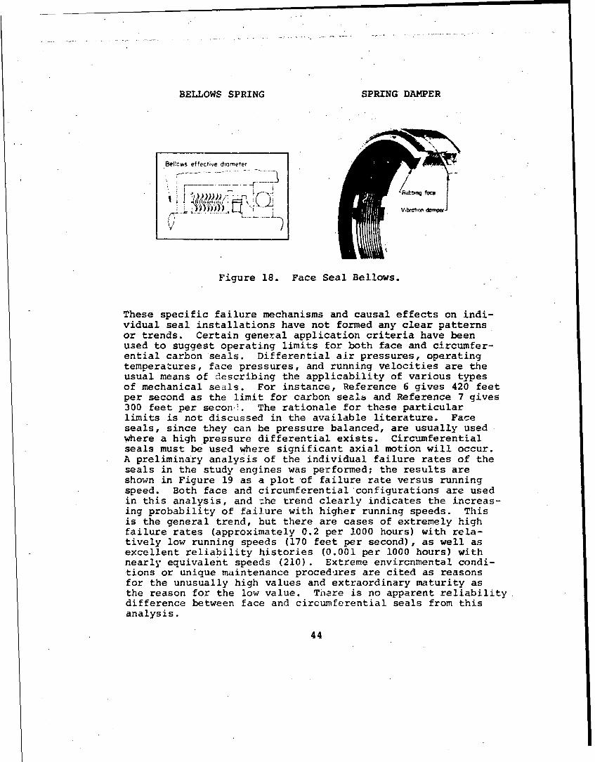
BELLOWS SPRING SPRING DAMPER
Bellows effective diometer
'-Rutb~ig face
911 L4, Vibrctwodanqwp
Figure 18. Face Seal Bellows.
These specific failure mechanisms and causal effects on indi-vidual seal installations have not formed any clear patternsor trends. Certain general application criteria have beenused to suggest operating limits for both face and circumfer-ential carbon seals. Differential air pressures, operatingtemperatures, face pressures, and running velocities are theusual means of describing the applicability of various typesof mechanical seals. For instance, Reference 6 gives 420 feetper second as the limit for carbon seals and Reference 7 gives300 feet per secon-. The rationale for these particularlimits is not discussed in the available literature. Faceseals, since they can be pressure balanced, are usually usedwhere a high pressure differential exists. Circumferentialseals must be used where significant axial motion will occur.A preliminary analysis of the individual failure rates of theseals in the study engines was performed; the results areshown in Figure 19 as a plot of failure rate versus runningspeed. Both face and circumferential configurations are usedin this analysis, and the trend clearly indicates the increas-ing probability of failure with higher running speeds. Thisis the general trend, but there are cases of extremely highfailure rates (approximately 0.2 per 1000 hours) with rela-tively low running speeds (170 feet per second), as well asexcellent reliability histories (0.001 per 1000 hours) withnearly equivalent speeds (210). Extreme envircnmental condi-tions or unique maintenance procedures are cited as reasonsfor the unusually high values and extraordinary maturity asthe reason for the low value. Taere is no apparent reliabilitydifference between face and circumferential seals from thisanalysis.
44

0.20
'T55 (2)
r3 T63 (2)
E 0.05 N
-400•= T~58(5O
00 T5 M\ T531(2)4j
U Z Drawn with Linear ScalesThis Curve Appears as: T56
0.15r_ 0.10
0.05
U 0.01 - 00 100 200 300
Indicates SealCL T58(I) Poition Number
-JT-8
.0020 50 100 150 200 250 300 350
Seal Running Speed - Feet per Second
Figure 19. Carbon-Seal Reliability.
The choice of mechanical positive-contacting seals appears tobe the result of a decision-making process that is independentof the reliability history of these seals. Carbon seals, evenmore than bearings, are viewed in a somewhat proprietary lightwith little reliability data exchanged. The choice of thistype of seals has been basically driven by the need to providepositive sealing, over a range of engine attitudes in a smallenvelope, and with the minimum of airflow losses. Alternativeseal configurations, such as close-contact or labyrinth seals,are being used instead of the positive contact seal in newengine designs.
The carbon seal has developed (and deserves) an image ofunreliability in view of its 95 percent contribution to ourcurrent problem. Despite claims by seal designers that prob-lems of the past have been solved, many individuals as well
45

as entire engine companies have elected to develop the close-contact or labyrinth seal and accept the penalties of in-creased engine weight and size. Only in instances where thecompetition is clearly on the basis of performance and/orweight are carbon seals being utilized.
Labyrinth Seal Abradable Material Wear
Despite the dramatically higher reliability of labyrinthseals, their failure modes merit discussion. The bulk of thelabyrinth-seal leakage problem has been as oil sump seals.Since they are normally noncontacting, wear is normally non-existent. There have been some instances, however, whereexcessive radial displacement of the spool has caused contactand wear of the adjacent surfaces. These displacements oc-curred on spools whose supporting bearings were flexiblymounted to provide damping during operation at criticalspeeds. Another source of wear has been unpredicted differ-ential thermal growth causing interference between rotatingand nonrotating elements. Some small degree of erosion ofthe abradable surface and knife edges has also been observed.
A maintainability problem relating to labyrinth seals has beenthe lack of repairability of seal "knives" in instances wherethey were machined as an integral part of a wheel or disc.Under these conditions, wear or damage to the knives would te-quire replacement of the expensive wheel or disc. The obviouscorrective action in these cases was the use of a separateelement (ring) containing the knives.
Stati.: Seals
Static seals, both "0" rings and gaskets, do not exhibit ahigh rate in any of the study engines. Most failures are dueto a combination of installation procedures or elementary de-sign oversights buch as sharp edges on "O"-ring lead-ins. Theeffect of static-seal leakage is usually an air pressure loss,oil weepage, or corrosion of the sealing surfaces.
:*.scellaneous Seals (Rotating, Non Main Shaft)
The rates for rotating seals other than those on the mainshaft are infinitesimal. Seals, usually of the lip variety,used for accessory or output shafts operate at sufficientlylow speeds and cool environments such that only random fail-ures occur. They are probably of a manufacturing or instal-lation origin.
COMPRESSORS
The compressor subsystem contribution to engine R&M problemsin terms of the four parameters is:
46

Compressor UER Accidents MMH TBO Index
SScale Factors 2 9 3 7 4.63
The chart indicates that, although compressors have been a;relatively low contributor to unscheduled removals, their im-..pact as an accident-causing component has been significant.
,,Compressor failures usually cause either partial or completeloss ofpower with the subsequent initiation of either a pre-cautionary or forced landing, which presents an opportunityfor a major accident. This possibility is further increasedif the failure mode is oneiwhere the compressor wheel or discloses structural integrity. Under these circumstances, con-tý.lment of the high-speed rotating mass is usually not possi-ble, and the result is airframe/control damage or fire andsevere damage to the aircraft. Compressor components also
* were the limiting items in the establishment of TBO intervalsin many of the study engines (see Table VII). The failuremodes which contribute to the total subsystem values shownabove are given in Table XVI.
TABLE XVI. COMPRESSOR FAILURE MODES
Failure Mode UER Accidents MMH TBO Index
Corrosion/Erosion 38 20 30 20 24Induced Vane Fatigue
Blade/Disc Fatigue 8 70 6 60 52Diffuser Crac] ing 30 - 30 - 6Lining Wear/C acking 6 - 7 - 1Variable Stattr/Bleed 9 - 18 - 2
SystemMiscellaneous 9 10 9 20 15
Total 100% 100% 100% 100% 100%
Table XVI confirms that the losses of compressor blades, vanes,or wheels are the prime accident-causing failure modes. Thisis not surprising, since the compressor and turbine are thetwo major rotating components in which large quantities ofkinetic energy are stored. The effects of significant unbal-
-ance are manifested in either an accident or engine removal.The high propo" ion of accidents caused by undetected blade/disc failures _0 percent) and the low percentage if unsched-uled removals (8 percent) indicate the serious consequences ofthese failures. Other problems in the compressor subsystemsare largely nuisance items or p6rformance-loss-causing failuremodes of a passive nature (e.g., liner wear/cracking and
47

compressor diffuser cracking). The distribution of thesefailure modes among selected engines is shown in Figure 20 forthe UER rate parameter.
varsat~le situlcJ C.• t lr ir
S3, o Wn'll'd Syq@
DIll,.", NC
Figure 20. Compressor UER Rate for Various Engines.
This illustration shows a vastly different distribution ofmores among the study engines. Only the T58 and T64 had sig-n-.ficant corrosion/erosion-induced vane failures. Only theT55 and T63 had significant diffuser cracking problems. Com-pressor lining cracking was only seen in the T63, which has aunique plastic lining on the inside of the compressor case.These differences stem from the different basic compressorconfigurations in the study engines. The T58 and T64 areall-axial designs. The T53, T55, and T63 are axial/centrifugaldesigns. The thin bladesvanes inherent in the latter stagesof axial compressors lead to erosion and corrosion problemswhich progress into failures. Centrifugal designs have theattendant complexity of large diffusers. It is because ofthese offsetting characteristics that conclusions regardingthe relative R&M of axial versus centrifugal compressorsshould be drawn with caution. The average rates for the twoaxial flow engines and the two axial/centrifugal designs (dis-regarding the T53 whose rates are at a significantly differentpoint on the maturity curve) are within 15 percent of eachother. A more discernible difference, however, between axialand centrifugal compressors will become .pparent when consid-ering the failure mode (subsystem) of erosion in the non-engine-caused subsystems.
Corrosion/Erosion-Induced Vane Failures
This mode appears primarily on two engines: both, all axialflow uesigns. Classification of these failures as engine-caused as opposed to non-engine-caused (erosion) arises fromthe mechanisn of failure involved. The sequence of failurewas erosion of the vane protective coating, followed by ero-sion of the base material to the point where the resonantfrequency of the vane was excited by the operating frequencyof the engine. Operation under these conditions produced high
48

stress so that even minor corrosion pits were sufficient tocause fatigue failures. Corrective action for both engineswas incorporation of more corrosion-resistant metals (AM355/INCO718 replaced 403 stainless) with additional emphasis onfield procedures for compressor cleaning and application ofpreservatives.
Thus, the magnitude of this mode was driven by a combinatio-nof design, environment, and maintenance-procedure factors.Analyses were not adequate in that the inevitable loss ofcorrosion-preventive coatings was not considered. On somecompressor designs in an abrasive environment, this mode couldlimit TBO intervals. The close relationship between this modeand the usual power-loss erosion mode suggests that environ-mental requirements and environmental testing should fullyconsider the progressive effects of erosion.
Blade/Disc Fatigue Failures
This mode, as shown on Table XVI, contributes a small per-centage of unscheduled removals (8 percent) but has been amajor factor in causing accidents and TBO limitations. Threespecific types of failures that'were observed are classifiedunder this failure mode. First are blade fatigue failures dueto resonance producing higher stress levels than anticipated.These frequencies were either mechanically or aerodynamicallyinduced. Aerodynamic sources include cases where localizedinlet blockage by airborne debris (grass) created an aero-dynamic disturbance which, in combination with the properrotating speed, excited blades at their natural frequency. Amechanical source was the accessory drive-train gear mesh.Failures usually were limited to blade loss, with no progres-sion into the wheels. Even then, however, significant sec-ondary damage to other compressor blades occurred-to resultin immediate power loss.
The second typ'. of failure involved the blade-to-wheel reten-tion devices. Failures were due to stress corrosion, fretting,or, in some cases, maintenance damage. There were some occur-rences of wheel cracking as the failures progressed beyond thetenon area of the wheel.
The third type of failure originated in the wheel itself. Itinvolved low cycle fatigue and manufacturing variations ofwheels with intergrally cast blade3. These failures are cata-strophic, since compressor cases can rarely contaii; disc por-tions. TBO limits were usually established for this mode.
Diffuser Cracking/Leakage
The diffuser cracking problem occurs only on engines whichutilize the centrifugal compressor design, and involves a
49

variety of locations. Inclusion of this mode in the compressorsubsystem allows a more equal comparison between axial andcentrifugal compressors.
The failure mechanisms contributing the largest diffuser crack-ing rate were fatigue failures of the forward and aft faces ofthe diffuser, as shown in Figures 21 and 22. The precisecauses of these failures have not been agreed upon. Factorssuch as aircraft-induced vibration, local degradation of theface material due to welding procedures, and local thermalgradients are considered to individually or collectively con-tribute to the cracking. Improved materials and use of cast-ings have significantly reduced the rate of this problem.
Another diffuser problem was cracking of the oil and air linesrouted through the air path. Cracking at the forward or aftdiffuser face requires engine replacement. The fittings forthese lines were tack-welded onto the diffuser face (seeFigure 22) and fabricated from three separate elements. Oneot the primary causes of failure was the suspected use of bothlines as handholds by maintenance personnel, with resultinghigh loads on the welds.
A failure mode on another engine with diffuser problems wasrelated to the unique airpath utilized. in this case, com-pressor-discharge air was collected in the diffuser scroll,routed through two tubes to the rear of the engine, and theninto the aft-mounted combustirn chamber. The connection ofthe diffuser scroll to thes= -wo tubes was a slip-joint con-figuration using piston rings of a design similar to thepiston-ri.ng concept in an automobile engine. Distortion ofthe diffuser scroll would cause misalignment, with the pistonrings locking and binding on the tube surface, thus pullingthe ring assembly out of the scroll and allowing air leakage.This distcrtion was caused by a combination of air pressureand the thermal expansion characteristics of magnesium.
These failure modes may not appear to be related to the basiccompressor function, but collectively they represent theactual problems encountered with use of the centrifugal con-figuration and the attendant diffuser. Routing of oil and airlines through this structure and the attachment of the manyvanes are more difficult with this diffuser than with thestraight-through case and inserted-vane design of axial flowcompressors.
Compressor Lining Wear or Cracking
This failure mode has only appeared in any magnitude on oneengine, and reflects its unique design approach. To achievelow cost and high efficiency in a small engine, an approachwas taken which involved brazing of individual vanes directly
5o

Figure 21. Cracking of Forward- - Diffuser Face.
Figure 22. Cracking of Aft
Diffuser Face.
51

onto the compressor case and utilizing a plastic lining toachieve maximum aerodynamic efficiency. This plastic wasapplied through a centrifuging process which caused the denserelements to separate out near the compressor case and allowedthe softer elements to be exposed to the erosive effects ofcompressor air. Cracking was induced by an inadequate case
-- bond and the effects of thermal cycles. Corrosion was alsoevident on the compressor case due to this inadequate bond.
This specific instance of failure is obviously related to theunique approach. The traditional design approach of usinginsertable metallic rings between the vane rows has not ex-hibited any measurable problem other than some small amount oferosion on magnesium cases that did not utilize abradablerings. This mode, however, is properly considered in theerosion subsystem.
Variable Stator and Bleed System Problems
When examining this mode, the repairability of variable-geometry stator and compressor bleed system hardware withoutrequirements for removal of the complete engine must he remem-bered. The UER rate for this mode in no manner relects thebasic failure rate of these items. There have been many prob-lems with this hardware, the primary mode being binding andsubsequent breaking of the actuating rings, levers, andattaching hardware. A typical failure caused by the presenceof FOD (a bolt) i.s shown in Figur. 23. Binding due to dirtand debris resulte' in excessive loads which caused fatigue orultimate failures. Excessive looseness was also observedwhich allowed inconsistent stator positioning around the cir-cumference. Ma'erial changes, use of dirt shields, and use ofdual (180-degree--displaced) actuators were typical correctiveact 4.ons. Engine performance is usually tolerant to problemsia this area, and in-flight detection is unusual.
- P-
Figure 23. Failed Variable Stator Vane Mechanism Due To FOD.
52

Bleed system problems usually involve the control valves. Themost frequent mode is binding of spools from contamination. Afew cases of mechanical linkage wear inside the valves, with-out the presence of contamination, were also observed.
COMBUSTOR
The combustor subsystem contribution to engine R&M problems interms of the four parameters is:
Combustion UER Accidents MMH TBO Index
Scale Factors 2 0 10 0 1.14
The chart indicates that the only significant impact that thecombustion subsystem has had as an R&M problem has been in themaintenance man-hour parameter. This is due mainly to contin-uing requirements for hot-end inspections. These inspections,which are normally required to check turbine blades, nozzles,and combustion system components, account for relatively largemaintenance man-hour expenditures. No accidents were causedby combustion system coxronents, and no TBO limitations wereimposed by them. This latter point is academic, since a hot-.end inspection can be construed as an interim TBO, which pro-vides an opportunity to change combustion system componentswhere necessary.
The low index number assigned to this subsystem is a directresult of the relative weakness of maintenance man-hour expen-ditures as a parameter in the total spectrum of R&M problems.The failure modes which contribute to the total subsystemvalues are shown in Table XVII.
TABLE XVII. COMBUSTOR FAILURE MODES
Failure Modes TER Adcidents MMH TBO Index
Liner Cracking/Warping 17 - 17 - 17Liner Support Structure 17 - 17 - 17
CrackingHousing Cracking/Corrosion 50 - .50 - 50
Fitting ProblemsSwirl Cup Problems 15 - 15 - 15Miscellaneous 1 - 1 - 1
Total 100% 100% 100%
53

This table indicates that those failure modes which cause un-scheduled removals are also responsible for man-hour expendi-ture. This is expected, since unscheduled engine removals areone consequence of problems that justify the imposition of ahot-end inspection. The failure modes in the combustion sub-system are passive and were usually detected by a gradual powerloss or during a hot-end inspection. The distribution of thesefailure modes among selected engines is shown in Figure 24 forthe UER rate parameter.
Figure 24. Combustor UER Rate for Various Engines.
The extreme values of rates among the stidy engines warrantcomment. The low rate for the T53 is somewhat explainable byits higher flight-hour accumulation than the rest of the studyengines. The T63 combustion system is a single chambermounted on the rear of the engine with the minimum of attach-ments, fittings and structural complexity. The remainingengines (T55, T58 and T64) represent a more appropriate levelof R&M problems for the average engine of intermediate sizeand a maturity point of 1 million hours. The effect of vari-ous combustor configurations may also be indicated by theserates. The T53 and T55 possess a folded combustor, while theT58 and T64 have the straight-through type. The suggestionthat the folded combustor design introduces additional primaryand secondary structural complexity may have some merit. Thespecific failure modes observed in this subsystem are dis-cussed as follows.
Liner Cracking/Warping
Although this mode is usually viewed as the primary reliabil-ity issue, the data indicates that it only accounts for 17percent of the combustor problem. A better understanding ofmaterials capability and aerodynamics of cooling flows hasbeen obtained over the years from the extensive use cf com-bustor test rigs. This technology has played an effectiverole in maintaining basic liner integrity within the tempera-tures and overhaul intervals of existing engines.. Typicalcracking is shown on Figure 25. It is usually associated withthermal fatigue in the area of louvers, holes, or complexcurvatures, such as in the header or dome area.
54

Figure 25. Typical Combustor Liner Cracking._portReproducedbt rom uj
Liner Support Structure Cracking best available copy.
This mode has been experienced by only one engine in the study.The problem occurred on brackets supporting the liner assembly,as is illustrated in Figure 26. In this particular instance,
Figure 26. Combustor Liner Support Bracket Cracking.
55

aircraft vibration was determined to be a primary source offatigue failures. The thin design of the supports was intendedto minimize airflow distortion and was not adequate from astrength standpoint. This failure mode was not observed dur-ing early development testing but was later reproduced in thesame test rig after imposing a one-per-rev rotor vibration onthe assembly. This problem illustrates t•.e need to specifyexpected' airframe-induced vibration levels prior to full-scaleengine testing and to perform endurance tests with externalvibration levels imposed.
Housing Cracking, Corrosion, and Fitting Problems
The failures that contributed to this category represent avariety of modes. Combustor drain valves and ignitor plugswere a large portion of the problem due to corrosion andcracking of the fitting attachments to the' combustor housing.An example of an ignitor plug fitting failure is shown inFigure 27. These failures were usually related to inadequatedetail design. In one instance, an internal weld fillet wasmachined flat for aerodynamic cleanliness, with inadequatequality control of the amount of fillet removed. In manycases application of excessive force on the attaching lines bymaintenance personnel was suspected to contribute to problems.In cases involving drain-valve boss cracking, the primaryfactor was corrosion leading to strength deterioration. Inthis instance, engine drying cycles were not rigorously accom-plished after washing. This accelerated the corrosion.Seizure of bolts and studs due to corrosion was also encoun-tered. These problems indicate that much of the R&M problemarises from lack of attention to a wide variety of small de-sign details.
Figure 27. Ignitor Plug Fitting Failure.
56

Swirl-Cup Problems
This is another problem experienced by only one of the enginesstudied. The failure mode was wear and cracking of the swirl-cup mounting spacers, as shown in Figure 28. The design re-quirement for the swirl-cup mounting system dictated provisionsfor swirl-cup displacement relative to the mounting on thecombustion liner to accept the fuel nozzles mounted on theouter case and whose position would vary in relation to theswirl cups. Production variability and differential thermalgrowth cause this shift in relative position.
Figure 28. Swirl-Cup Mounting Spacer Cracking.
To provide this displacement capability, the swirl cups weredesigned to be mounted with a spring type spacer retaining theswirl cup against the liner with a snug fit which allowedradial positioning. The initial design utilized toleranceswhich provided adequate retention, and the early testing withthese components indicated the adequacy of the design. Subse-quent to the development testing and for reasons of manufac-turing and assembly economy, the tolerances were increased.These larger tolerances on the stackup allowed excess.ivelooseness between the swirl cup and mounting surface.
The resultant swirl-cup motion, encouraged by the soft swirl-cup mounting system, leads to swirl-cup mounting flange wear,elongation of the swirl-cup key slots (Figure 29), and even-tual swirl-cup spacer crackii.g (Figure 28). The swirl cupswould then drop into the combustion chamber. Alternately, theswirl cups rubbed or vibrated against the nozzles, causingwear (Figure 30).
57

/
Figure 29. Mounting Flange Wear and Key Slot Elongation.
Figure 30. Fuel Nozzle Wear by Swirl Cups.
TURBINE
The turbine subsystem contribution to engine R&M problems interms of the four parameters is:
Turbine UER Accidents MMH TBO Index
Scale Factors 2 5 10 3 2.86
The chart indicates that the turbine subsystem has a broad im-pact in all the selectec. R&M parameters. Its prime impact isapparent in the accident and maintenance man-hour parameters.The predominant reason for its high rating in maintenance isdue to continuing requirements for engine hot-end inspections.The major reasons for hot-end inspections are to inspect forcontinuea serviceability of turbine blades and nozzles and forcertain combustion subsystem component serviceability. Theturbine subsystem's importance as a potential cause of acci-dents is highlighted by its appearance as a TBO-limiting sub-system. Those subsystems having a significant accident recordalso contribute to engine TBO.
58

Although the turbine subsystem has traditionally been consid-ered the prime offender from an engine R&M standpoint, thisstudy does not confirm the belief. Four subsystems, namelycompressor, bearings, seals, and fuel, are more significantR&M restraints (see Table X). The failure modes for compo-nents which contribute to the total subsystem values are shownin Table XVIII. Table XVIII indicates that.approximately 90
'percent of the unscheduled removals are caused by nonrotatingcomponents. The smaller percentage of accidents due to thesecomponents (31 percent) reflects the passive nature of fail-ures in this area. In general, these failures result ingradual power degradation.
TABLE XVIII. TURBINE FAILURE MODES
Failure Mode UER Accidents MMH TBO Index
Nozzle Band Cracking 27 23 30 - 20Nozzle Erosion/Oxidation 8 8 10 - 6
SulfidationNozzle Support Structure 44 - 40 - 19
Wear/CrackingBlade/Wheel Cracks 1 54 - 100 41Shafts/Coupling/Hardware 6 15 5 - 8Miscellaneous 14 - 15 - 6
Total- 100% 100% 100% 100% 100%
Failures of rotating components, on the other hand, contrib-uted to only 7 percent of the unscheduled removals but causednearly 70 percent of the accidents. These components werealso the only items within the turbine subsystem to limit theTBO intervals. The instantaneous power losses and highkinetic energy involved with turbine blade and disc failuresand the inability of the case to contain disc failures are thereasons for this modes's potential for causing accidents. Thedistribution of turbine subsystem failure modes among selectedengines is shown in Figure 31 for the UER rate parameter. Thestudy engine modes are generally similar in terms of both typeand rate.
Nozzle Inner/Outer-Band and Partition Cracking
This mode appeared in every study engine examined at a ratherconsistent rate. Cracking has been evidenced in both theinner and outer bands as well as in the nozzles or partitionsthemselves. An example of inner-band cracking is shown inFigure 32. The cracking is usually most severe on first-stagegas-producer turbine nozzles (where the temperatures are
59

highest). It appears at the discontinuities of fabricated as-
semblies and is attributed to thermal stresses. All enginesstudied except one had brazed nozzle ajsemblies fabricated outof separate inner'bands, outer bands, partitions, relatedflanges, etc. The alternative design approach, an integral
Figure 32. Turbine Nozzle Inner-Band Cracks.
casting, has been demonstra ted to be superior from a reliabil-ity standpoint. The absence of discontinuities reduces stressconcentrations at the brazed joints, particularily at thevane-to-shroud intersections. Virtually every engine in thisstudy which began with fabricated nozzles has either incorpo-rated or proposed cast nozzles as the corrective action forits cracking problem. The initial incorporation of integrallycast assemblies, however, was not considered practical, sinceit allows virtually no flexibility in vane shapes, angles, orbasic throat areas. Initial tooling costs are very high forcastings, although on a large-scale production basis, fabri-cated assembly unit costs are higher. Unfortunately, evalua-tions of competing engines are performed with the ground rulesof limited production quantities. This emphasizes the impactof initial tooling cost differences, thereby penalizing thecast designs.
Another corrective action applied to in-service engines toresolve nozzle cracking problems has been the slotting of the
60
* ~-~I
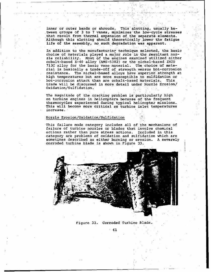
inner or outer bands or shrouds. This slotting, usually be-tween groups of 3 to 7 vanes, minimizes the low-cycle stressesthat result from thermal expansion of the separate elements.Although this slotting should theoretically lower the fatiguelife of the assembly, no such degradation was apparent.
In addition to the manufacturinc' technique selected, the basicchoice of materials played a major role in the resultant noz-zle reliability. Most of the engines examined utilized eithercobalt-based X-40 alloy (AMS-5382) or the nickel-based INCO713C alloy for the basic vane material. The choice of mate-rial is basically a trade-off of strength.versus hot- corrosionresistance. The nickel-based alloys have superior strength athigh temperatures but are more susceptible to sulfidation orhot-corrosion attack than are cobalt-based materials. Thistrade will be discussed in more detail under Nozzle Erosion/Oxidation/Sulfidation.
The magnitude of the cracking problem is particularly highon turbine engines in helicopters because of the frequentthermocycles experienced during typical helicopter missions.This will become more critical as turbine inlet temperaturesincrease.,
Nozzle Erosion/Oxidation/Sulfidation
This failure mode category includes all of the mechanisms offailure of turbine nozzles or blades that involve chemicalactions rather than pure stress actions. Included in thiscategory are problems of oxidation and sulfidation which aresometimes described as either burning or erosion. A severelycorroded turbine blade is shown in Figure 33.
Figure 33. Corroded Turbine Blade.
61
Oxidation reflects the classical limit of materials in high-temperature applications. It involves the formation of oxideson the surface of the metal which can progress to penetratethe structure, causing element diffusion and subsequent lossof strength. Sulfidation is a more complex phenomenon thatrequires the presence of sodium sulfates. These sulfates area constituent of sea salt and can be ingested directly fromthe atmosphere; or they can be produced in the combustionprocess by the combination of sodium chloride in sea air re-acting with sulfur contained in engine fuel. At high tempera-ture, sodium sulfate reacts with any oxide scale, causing itto become unprotective. Once the oxide film has been dis-rupted, sodium sulfate reacts rapidly with the base materialsto form sulfides and large amounts of sodium oxide. The sodi-um oxide prevents reformation of a protective metal oxidescale, thus permitting the corrosion process to continue atan accelerating rate. Although these mechanisms have notcaused unscheduled removals to any large degree (only 8 per-cent), they are one restraint to the continual demand forhigher operating temperatures and will, riost likely, becomethe limiting element to "on-condition" nrintenance in futureengines.
Because of the performance penalties associated with the useof cooling air to reduce metal temperatures, much past andcurrent research is directed at increasing the capability ofmetals and developing coatings to resist the effects of highertemperatures. This research has been extensive, and it isneither possible nor necessary to describe it all here. How-ever, an overview is in order since these modes will become alarger portion of the total problem as turbine temperaturesincrease, unless continued emphasis is applied.
Somewhat oversimplified, the problem is that contemporaryturbine-blade materials suffer degradation from sulfidation at16500 to 1750*F and higher and from oxidation at 18000 to1900*F and higher. The use of appropriate coatings can raisethese values approximately 100*F. Since both of these mecha-nisms are time dependent, with attack severity depending oncomponent material, coatings, .Aad in the case of sulfidation,the presence of other elements from the atmosphere or fuel,rigorous absolute limits cannot be set. Some research has in-dicated that the most severe temperature range for sulfidationis ietween 1550OF and 1650OF,B although the test conditionsmay not have precisely represented actual turbine operations.
The primary metals used for many years in turbine blades andvanes (nozzles) were nickel-based alloys. The trend of de-creasing the chromium content in these metals to achievebetter high-temperature strength compromised oxidation andsulfidation resistance.9 Relief from these restraints hastaken several paths. The cobalt-based superalloys were
62
developed and are now extensively used in stationary componentssuch as nozzles. Cobalt-based alloys are generally recognizedas having a higher resistance to sulfidation. They are alsoconsidered to possesh superior oxidation capabilities1 " to thenickel-base metals, although some research indicates this-maynot hold univf~rsally, particularly in uncoated states."
A second path has been the development of coatings for theprotection of both nozzles and blades. The most widely usedare intermetallic alumide diffusion coatings under a widerange of product names, most.of them proprietary. These coat-ings are highly effective in extending life (or allowing high--er temperatures), but they suffer the disadvantages of beingerodible by airborne contaminants, are expensive, and presentproblems in overhaul/repair at military depots.
The third approach to avoiding these problems is the use ofnew blade-vane cooling techniques. The trend from convection,film/convection, and impingement/film to transpiration coolingmethods has allowed significant increases in T5 with only mod-est increases in metal temperature. Turbine inlet temperaturesof 2200OF are now possible with metal temperatures remainingat 17000F. 2
The technology is adequate to eliminate this mode in futureengines. This, plus other controls (such as preventing theuse of alkali mptal-based agents for cleanilig engines, thesource of some problems experienced in the study engines),should be sufficient to prevent the appearance of these modes,even at the desired high operating intervals, providing con-servative operating-temperature increases are postulated forgrowth engines.
Nozzle Support Structure Cracking
This failure category is the largest contributor to unsched-uled removals in the turbine subsystem. Similar to otherproblems with a large magnitude, it does not consist of asingle failure mode or location, but represents a variety ofindividual failure instances on the study engines. The commonelement of these failures is that they occur in stationarycomponents outside the main gas stream. They are frequentlyunrelated to the primary functional purposes of the turbinesection and are coded in this turbine subsystem more from aproximity standpoint.
An example of this category is the cracking of oil-deliverytubes at the joint with the basic nozzle asst-mbly (see Figure34). The connection points for antirotation pins are alsoshown in this figure. On several study engines, these pinshave exhibited wear and breakage. In some irstances, all pinswere broken and the nozzle (not the configuration shown) began
63
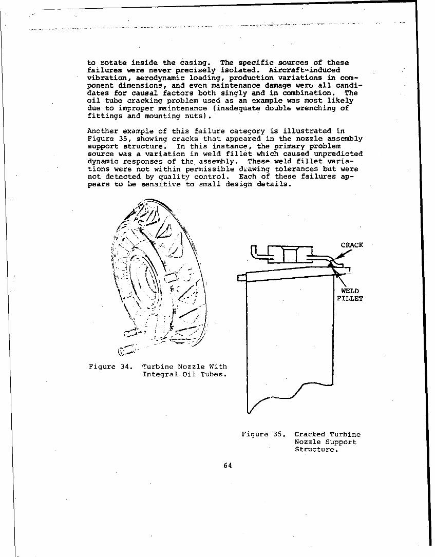
to rotate inside the casing. The specific. sources of thesefailures were never precisely isolated. Aircraft-inducedvibration, aerodynamic loading, production variations in com-ponent dimensions, and even maintenance damage weru all candi-dates for causal factors both singly and in combination. Theoil tube cracking problem used as an example was most likelydue to improper maintenance (inadequate double wrenching offittings and mounting nuts).
Another example of this failure category is illustrated inFigure 35, showing cracks that appeared in the nozzle assemblysupport structure. In this instance, the primary problemsource was a variation in weld fillet which caused unpredicteddynamic responses of the assembly. These weld fillet varia-tions were not within permissible d. 1awing tolerances but werenot detected by quality control. Each of these failures ap-pears to be sen3itive to small design details.
///
"" ..... "FILLET
. 7, ; f , o.
Figure 34. Turbine Nozzle WithIntegral Oil Tubes.
Figure 35. Cracked TurbineNozzle SupportStructure.
64

Blade/Wheel Cracking
This category was the largest single problem area in theturbine subsystem. It includes failure mechanisms of bothturbine blades and the wheels or discs. This mode has beentraditionally considered the most critical R&M issue in tur-bine engines, although this study found that it has had aproblem magnitude only half that of compressor blade and wheelfailures (see Table XI).
The specific failure instances that defined this category havemany similarities to those experienced in the compressor sec-tion. This included low-cycle fatigue cracking of the wheels,high-cycle fatigue failures of the blades, fretting and/orstress corrosion at the blade-to-wheel connection, and prob-lems initiated by the blade retention devices. Sources ofproblems unique to the turbine section included excessivetemperature gradients on wheels due to inadequate control ofcooling air, and blade to shroud rubs which changed the basicdamping characteristics of the blades.
The technology demanded to properly design rotating turbinecomponents is probably the most complex of all engine mechan-ical areas. It has received a great deal of research atten-tion directed at improving analytical techniques as well asobtaining improved materials and manufacturing techniques.The key to future improvements in reliability is the develop-ment of analytical techniques to recognize not only the clas-sical sources of loads, such as low frequency thermal cycling,but also the obscure problems with cooling air variations andother similar lessons from field experience.
CASES
The case subsystem contribution to engine R&M problems interms of the four parameters is:
Cases UER Accidents MIH TBO Index
Scale Factor 2 1 1 - 1.27
The chart indicates that cases do not have a major contribu-tion to the overall R&M problem. The unscheduled engineremoval parameter is the only parameter of signficance. Thefailure modes for components which contribute to the totalcases subsystem problem are shown in Table XIX. This tableindicates that case corrosion has necessitated both unsched-uled engine removals and maintenance man-hours to prevent andfix'the corrosion, but it has had no influence on aircraftaccidents. The largest single contributing mode had been
65

TABLE XIX. CASE FAILURE MODES
Failure Mode UER Accidents* M14H TBO Index
Case Corrosion 23 - 30 - 21Case Cracking 31 65 20 - 35Tube, Boss, & Fitting 39 35 40 - 37
Crac!:s and Loose InsertsMiscellaneous 7 - 10 - 7
Total 100% 100% 100% - 100%
cracking of external tubes, bosses, and fittings and problemswith loose inserts. These problfms have been of a relativelylow rate and random nature, but their collective impact isconsiderable. The distribution of case failure modes amongselected engines is shown in Figure 36 for the UER rateparameter.
= 0. 14
S0.Crucks
Tubes , Bcses- o,0 -- Fitti~r•
C3se CrackingCase " MisCellarousro |Support I \I Case
T1T TS8 T63 T64
Figure 36. Case UER Rate for Various Engines.
The unusually high rate for a single engine in Figure 36 maybe somewhat artificial. The definition of the case subsystemis not precise.. Failure modes on the remaining engines, which
.were coded in other subsystems, could just as reasonably havebeen coded into the case subsystem. For instance, in the T55compressor system, there are approximately 0.06 removals per1000 flight hours due to failures of air and oil line fittingson the compressor diffuser that could be considered equivalentto some of the modes shown here in the cases subystem.
66
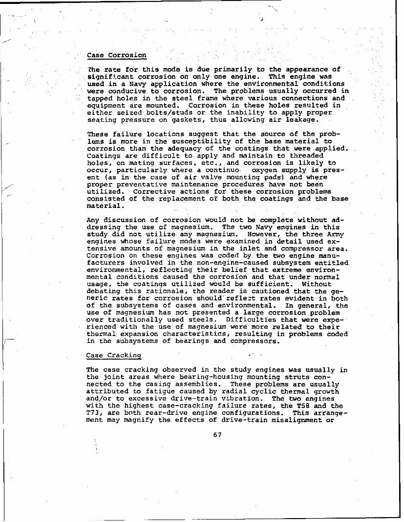
Case Corrosion
The rate for this mode is due primarily to the appearance ofsignificant corrosion on only one engine. This engine wasused in a Navy application where the environmental conditions
.were conducive to corrosion. The problems usually occurred intapped holes in the steel frame where various connections andequipment are mounted. Corrosion in these holes resulted ineither seized bolts/studs or the inability to apply properseating pressure on gaskets, thus allowing air leakage.
These failure locations suggest that the source of the prob-lems is more in the susceptibility of the base material tocorrosion than the adequacy of the coatings that were applied.Coatings are difficult to apply and maintain to threadedholes, on mating surfaces, etc., and corrosion is likely tooccur, particularly where a continuo, oxygen supply is pres-ent (as in the case of air valve mounting pads) and whereproper preventative maintenance procedures have not beenutilized. Corrective actions for these corrosion problemsconsisted of the replacement of both the coatings and the basematerial.
Any discussion of corrosion would not be complete without ad-dressing the use of magnesium. The two Navy engines in thisstudy did not utilize any magnesium. However, the three Armyengines whose failure modes were examined in detail used ex-tensive amounts of magnesium in the inlet and compressor area.Corrosion on these engines was coded by the two engine manu-facturers involved in the non-engine-caused subsystem entitledenvironmental, reflecting their belief that extreme environ-mental conditions caused the corrosion and that under normalusage, the coatings utilized would be sufficient. Withoutdebating this rationale, the reader is cautioned that the ge-neric rates for corrosion should'*reflezt rates evident in bothof the subsystems of cases and environmental. In general, theuse of magnesium has not presented a large corrosion problemover traditionally used steels. Difficulties that were expe-rienced with the use of magnesium were more related to theirthermal expansion characteristics, resulting in problems codedin the subsystems of bearings and compressors.
Case Cracking
The case cracking observed in the study engines was usually inthe joint areas where bearing-housing mounting struts con-nected to the casing assemblies. These problems are usuallyattributed to fatigue caused by radial cyclic thermal growthand/or to excessive drive-train vibration. The two engineswith the highest case-cracking failure rates, the T58 and theT73, are both rear-drive engine configurations. This arrange-ment may magnify the effects of drive-train misalignment or
67

/.
unbalance on the case structure. Rear-drive engines usuallyhave the power-turbine output shaft bearings mounted in hous-ings which are cantilevered out rearward from the main case.This mounting introduces bending loads on the strut to housing/case joints not normally experienced when the bearing housingis axially located under the main case structure.
Tube, Boss, and Fitting Cracking and Loose Inserts
The above failure modes are similar to failures coded in thecompressor and combustion subsystems as a function of thespecific engine involved. Failure locations, component causalfactors, and corrective actions are similar to those modespreviously discussed. The drain-valve boss problem, for ex-ample (described in the combustion subsystem), is similar toa failure mode whose rate is coded in this subsystem. Theboss-cracking problem here was due to a riveted fitting withinadequate strength. Another failure mode was insert loose-ness in a magnesium case. These inserts were used to mountthe compressor assembly where looseness would promce mis-alignment and cause subsequent bearing failures. The loose-ness resulted from a differential expansion with temperaturechange involving steel and magnesium. The desire to have aminimum number of compressor module mounting bolts may havecontributed to the problem. This is one indication of a po-tential penalty associated with designing for increasedmodularization.
LUBRICATION
The lubrication subsystem contribution to engine R&" problemsin terms of the four parameters i :
Lubrication UER Accidents MMH TBO Index
Scale Factors 2 1 2 0 1.28
The chart indicates that the lubrication subsystem does nothave a major contribution to the overall engine R&M problem.The unscheduled engine rem .I parameter is the only parameterof significance. Because the great variety of failuremodes experienced in thiF .Istem, failures have been organizedby component classes rather than failure modes and are shownin Table XX.
This table indicates that the majority of the problems withthe lubrication subsystem have been associated with lube pumpand check valve failures. Although the failure rate was rela-tively low, it is a common one for all the engines in thisstudy. The only accident-causing mode was, surprisingly,.
68
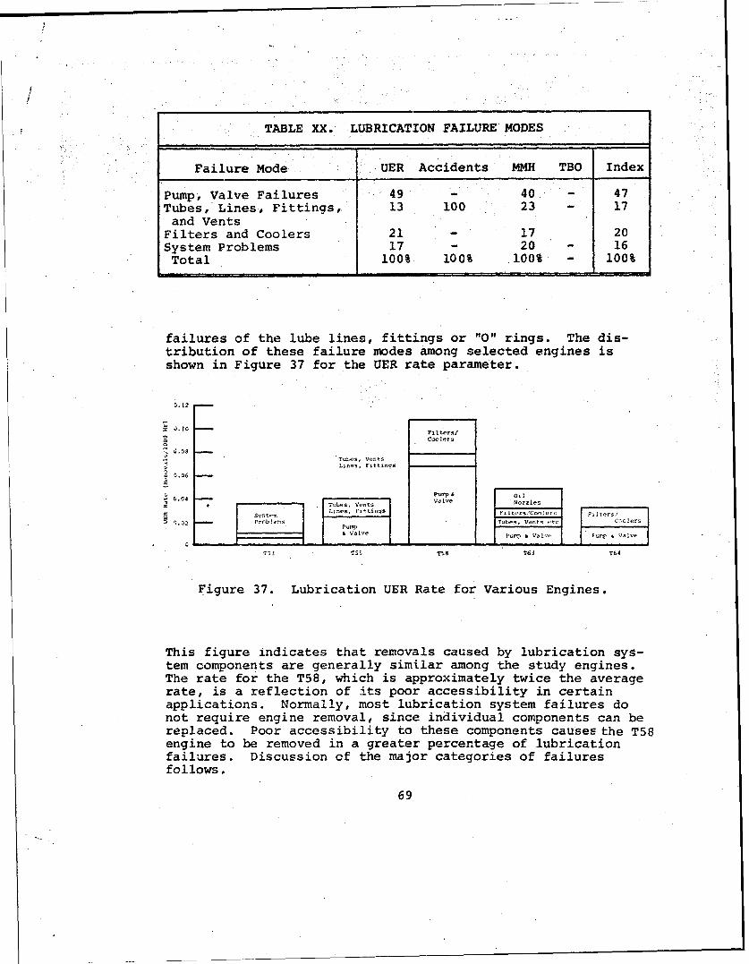
TABLE XX. LUBRICATION FAILURE MODES
Failure Mode UER Accidents MMH TBO Index
Pump, Valve Failures 49 - 40 - 47Tubes, Lines, Fittings, 13 100 23 - 17
and VentsFilters and Coolers 21 - 17 20System Problems 17 - 20 - 16Total 100% 100% 100% - 100%
failures of the lube lines, fittings or "0" rings. The dis-tribution of these failure modes among selected engines isshown in Figure 37 for the UER rate parameter.
0.10 PFilters/C Colers
TuLes, V0n.tsLines, F1tttnqs
I s IS. i SOil r
0 .2 Tues. Vents
Ti Vlve .u V -p &V
TS3 T55 T58 T63 T64
Figure 37. Lubrication UER Rate for Various Engines.
This figure indicates that removals caused by lubrication sys-tem components are generally similar among the study engines.The rate for the T58, which is approximately twice the averagerate, is a reflection of its poor accessibility in certainapplications. Normally, most lubrication system failures donot require engine removal, since individual components can bereplaced. Poor accessibility to these components causes the T58engine to be removed in a greater percentage of lubricationfailures. Discussion of the major categories of failuresfollows.
69

Pump and Valve Failures
This category is the largest contributor to lubrication systemproblems and includes failures of the main pump and assortedvalves contained in the body of the pump unit. In instanceswhere the oil reservoir is mounted above the engine, a checkvalve is required to prevent sump flooding during engine shut-down. Problems associated with this design have included con-tamination-induced leakage of the check valve and inadequatescavenge pump pressure at low engine speeds, both of whichcaused sump flooding. The contamination problem was due tothe location of the check valve'upstream of the filter.
Other than specific identified failure modes such as these,there have been many instances where failures of relatedlubrication system components were mistakenly attributed tothe main pump or the control valves. Many system type prob-lems would have been eliminated if complete system testing hadbeen performed during the development phase. This would havebeen difficult for three engines in the study which requiredairframe-mounted components (reservoirs, coolers).
Tubes, Lines, Fittings, and Vents
These failures were almost entirely of components mounted out-side the engine which did not normally require engine removalfor resolution. That these failures did cause engine removalscan only be attributed to the lack of accessibility, spareparts, or insufficient maintenance time or skills. The fail-ures evidenced in this mode were the most routine of tube andhose leakage and chafing. No dramatic or unusual mechanismswere evident. Basic inattention to design details, includingrouting, clamping, possible maintenance damage, and theeffects of vibrations, was the only identifiable cause of mostof these failures. The few accidents caused by the lubrica-tion system were due to line, tuze, and 0-ring leakage andwere due more to precautionary landings that became out ofcontrol on the ground than to the actual functional nature ofthe leaks. In only one case did a failure of a line cause oildepletion and engine oil starvation.
Filters and Coolers
The major problems experienced in this category were withcoolers. High oil temperatures which necessitated preventa-tive engine removals were suspected to be due to clogged oilcoolers., for several study engines. Leakage of oil coolerswas also observed. Filters were a rather small problem.Collapsed screen elements and binding bypass valves were theonly identifiable filter failure modes.
70

FUEL SYSTEM
The fuel subsystem contribution to the R&M problem is shownbelow in terms of the four R&M parameters:
Fuel UER Accidents MMH TBO Index
Scale Factors 3 10 5 0 3.45
This chart indicates that the fuel subsystem is a high con-tributor to three of the four parameters. There is only oneengine-related subsystem that causes more unscheduled removalsand two that cause more man-hour expenditures. The fuel sub-system causes more accidents than any other subsystem (engine-related or not). The reason for the high accident-causingpotential of this subsystem should be readily apparent. Anyfailure mode which can c;use a sudden interruption of powerhas a potential for causing accidents. The failure modes ofthe fuel subsystem, as in the case of lubrication subsystemfailure modes, do not form any meaningful patterns. Furtherbreakdown as to the major types of fuel system components in-volved is shown in Table XXI.
TABLE XXI. FUEL FAILURE MODES
IndexFailure Mode UER Accidents MMH TBO Nuiber
Fuel Controls Units 68 85 80 - 75Other Components: Pumps,Valves, etc. 24 8 15 - 15
Tubes and Hoses 2 5 2 - 5Miscellaneous 6 2 3 - 5
Tccal 100% 100% 100% - 100%
As the table shows, the fuel subsystem problem is largely afuel control unit problem. Fuel controls are 75 percent ofthe total problem, with nearly equivalent percentages in eachseparate parameter. The distribution of the failure modesamong selected engines for the UER rate parameter is shown inFigure 38.
71
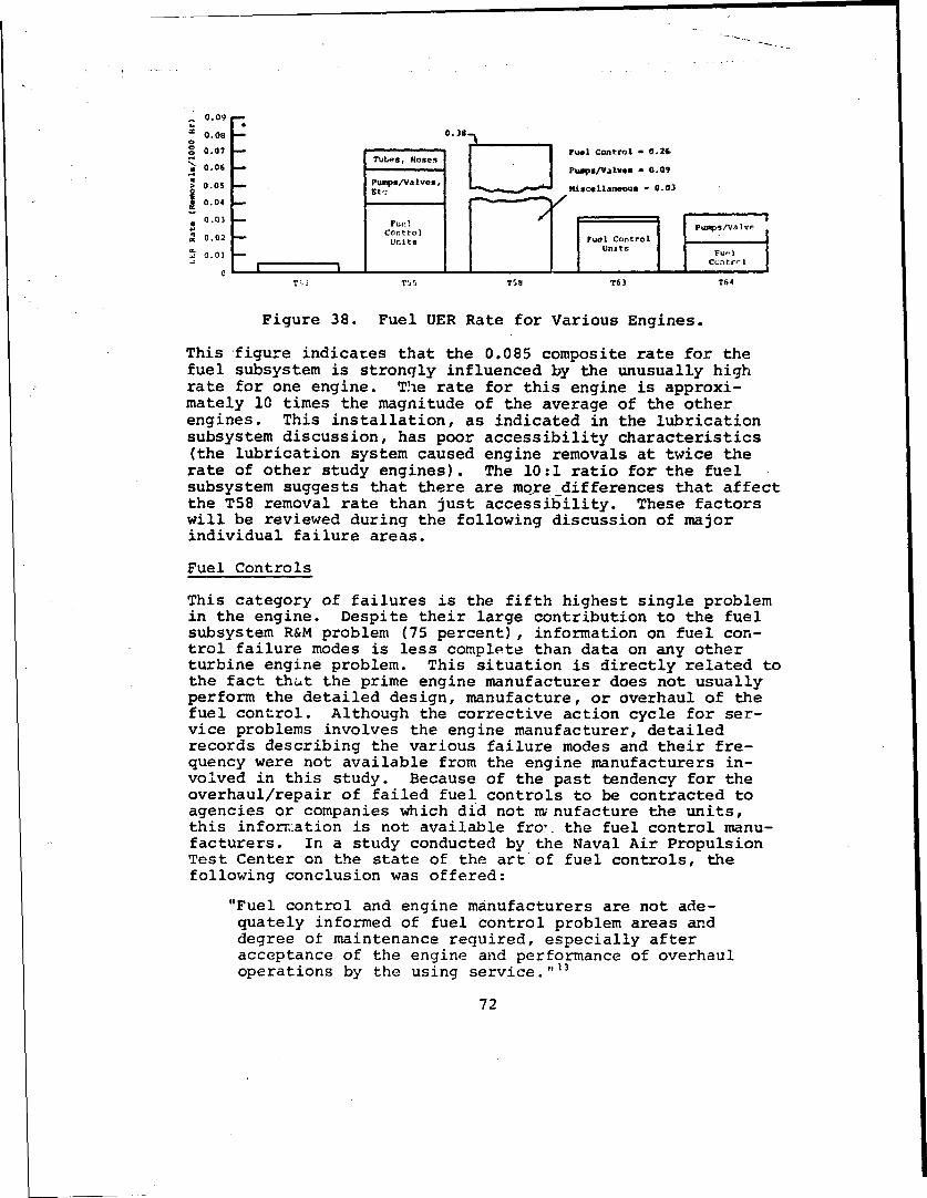
0.09
0.08 - 0.38
o0.07 I I Fuel control - 0.260.6Tubes, Hoses
a0.06 Pumps/Valves - 0.09> 0.05 Pumps/alves,
Etc Miscellaneous - 0.03
0.04
0.03 Fuel l leControl
0.02 Units Fuel Controli Units
0.01 u, I
T', Tt5 T58 T63 T64
Figure 38. Fuel UER Rate for Various Engines.
This figure indicates that the 0.085 composite rate for thefuel subsystem is strongly influenced by the unusually highrate for one engine. The rate for this engine is approxi-mately 10 times the magnitude of the average of the otherengines. This installation, as indicated in the lubricationsubsystem discussion, has poor accessibility characteristics(the lubrication system caused engine removals at twice therate of other study engines). The 10:1 ratio for the fuelsubsystem suggests that there are more differences that affectthe T58 removal rate than just accessibility. These factorswill be reviewed during the following discussion of majorindividual failure areas.
Fuel Controls
This category of failures is the fifth highest single problemin the engine. Despite their large contribution to the fuelsubsystem R&M problem (75 percent), information on fuel con-trol failure modes is less complete than data on any otherturbine engine problem. This situation is directly related tothe fact that the prime engine manufacturer does not usuallyperform the detailed design, manufacture, or overhaul of thefuel control. Although the corrective action cycle for ser-vice problems involves the engine manufacturer, detailedrecords describing the various failure modes and their fre-quency were not available from the engine manufacturers in-volved in this study. Because of the past tendency for theoverhaul/repair of failed fuel controls to be contracted toagencies or companies which did not m nufacture the units,this inforr..ation is not available fro,. the fuel control manu-facturers. In a study conducted by the Naval Air PropulsionTest Center on the state of the art of fuel controls, thefollowing conclusion was offered:
"Fuel control and engine manufacturers are not ade-quately informed of fuel control problem areas anddegree ot maintenance required, especially afteracceptance of the engine and performance of overhauloperations by the using service."13
72

"Wit1. this background, it-is not possible to provide a numeri-cal a'location of the relative contributions of various fail-ure modes to fuel control problems. In general, the failuremodes observed in the study engines can be grouped into thefollowing categories:
o Contamination from the ictuating media or from the fuel"itself causing sticking and- binding of spools, leakageof valves, and clogged orifices
o Wear on moving or contacting elementsK"o Fatigue failures of springs, bellows, retention
devices,etcý'
o Misadjustment, erroneous troubleshooting, etc.
The magnitude of the last category has been estimated by oneengine manufacturer to be as high as 50 percent.1 3 The con-tribution of the first category depends on the type of actu-ation system used in the fuel control unit.- Fuel controlunits used in the study engines are hydro-mechanical, exceptfor one pneumatic-mechanical system. -The pneumatic systemexperienced many air contamination problems, but its easy ac-cessibility prevented an unusually high engine removal rate.
The fuel control which contributed approximately 10 times asmany unscheduled removals as the average (Figure 38) is signif-icantly more complex than the average. This complexity arisesfrom the several functions it possesses over equivalent fuelcontrols including its integration into a complete power-manag ment system. This unit is larger than average; it ac-count@ for 7.2 percent of total engine weight as compared tothe 2!to 3.5 percent of engine weight for typical fuel con-trols. 13 This factor, coupled with the general inaccessibil-ity of the fuel control on this installation, contributed tothe large UER rate.
Since good failure-mode information was not available, littlefurther discussion on the factors driving the R&M character-istics appears warranted. It is clear that there is not anadequate baseline of R&M history on these components to alloweither effective corrective action on existing fuel controlsor meaningful trade-offs of functions, mounting arrangements,or types of systems for future designs.
Pumps, Valves, and Other Components
Fuel pumps, purifiers and filters, and associated fuel systemcomponents (such as divider assemblies, manifolds, and nozzles)are the three areas that equally share.the responsibility forunscheduled removals in this category.
73

The usual failure modes of fuel pumps are shaft-seal leakageand drive-spline wear. Spline wear appears to be more prev-alent on those configurations where the fuel pump and controlare mounted in series, with the fuel control driven by shaftsand splines extending through the pump, or vice versa. Thisarrangement reduces the radial size of the engine and elim-inates a takeoff pad from the accessory gearbox with itsattendant gears, bearings, and seals. Unfortunately, theseapparent advantages appear to be outweighted by the spline-wear problem that arises from greater loads, possibilities ofmisalignment, maintenance damage, or a combination of triesefactors when the pump and fuel control are mounted in series.Inadequate lubrication was cited as a frequent cause of splinewear which in turn was due to poor preventative maintenance orfuel seal leaks which washed the lubricants from the splines.
Purifier and filter failures have primarily involved purifiersin the study engines. Failure modes included wear of thehousing due to interferences when interchanging covers during
-cleaning, wear of drive shaft pins, elongation of quick dis-connect mounting clamps which allowed fuel leakage (see Figure39), and breaking of mounting flanges (see Figure 40). Thesources of these problems were varied. Some wear was dueto the interchanging of noninterchangeable components by main-tenance personnel; other wear and shearing of the drive shaftpins were due to improper hardness pins (a manufacturing andquality control problem). Breaking of the mounting lugs was
Figure 39. Elongated Rivet Hole on Purifier "V" Band Clamp.
74

Figure 40. Purifier With Broken Mounting Flanges.
an installation problem where the exposed purifier would con-tact the airframe or transport stand during engine replacement.Elongation of a quick-disconnect clamp was a straightforwarddesign error which specified an upper limit to the installationtorque which would yield the pin hole brackets.
The failure modes of the other components in the fuel systemare just as varied as in purifiers and filters. Fatigue fail-ures of clamps mounting manifolds to the engine housings re-sulted in fuel spillage. Dividers failed due to bellows guidewear. No particular pattern is evir-ent in this grouping offuel system problems. There will be an increasing tendencyfor problems with increasing hardware complexity. The effectof poor accessibility has been clearly shown. Engine removalrates are 3 times as high as normal if accessibility is poor.
75

AIR SYSTEM
The air subsystem contribution to the engine R&M problem interms of the four parameters is:
Air UER Accidents MMH TBO Index
Scale Factors 1 0 1 0 0.55
The problem is clearly a minimal one. Since this subsystemconsists only of anti-icing, cooling, or balance air systemsand usually involves components which can be-repaired or re-placed without engine removal, this conclusion should not besurprising. Since no failure mode pattern was evident,further breakdown of this subsystem is performed only on thetype of component involved (see Table XXII).
TABLE XXII. AIfl FAILURE MODES
IndexFailure Mode UER Accidents MMH TBO Number
Control Valves 71 - 60 - 70Tubes, Hoses, Fittings, 29 - 40 - 30etc.
Total 100% - 100% 100%
The distribution of these failure categories among the enginesstudied for the UER parameter is shown in Figure 41. No con-clusions are evident from this figure. Since the small ratesrepresent only one or two occurrences, no failure pattern isevident. No discussion of the failure categories is-war-ranted. The only failure mode which was documented was bind-ing of valves due to air contamination.
0.020
Tub5 & Tubes &Hioses floses
M c 0.010 * otrolConrol Control Valve>• Vulve Va lve
S0 _ _I II _ II I I'T53 ,,s TS T63 T54
Figure 41. Air UER Rate for Various Engines.
76

/4
•- ACCESSORY
The accessory contribution to the engine R&M problem is shownbelow.
Accessory UER Accidents MMFI TBO Index
Scale Factors 1 2 2 - 0.91
These scale factors indicate that the accessory subsystem isnot a major problem area despite the relatively large numberof components involved. The higher scale factor for accidentsthan removals reflects the fact that failures of the accessorydrive train to drive the fual control or fuel pump can causeimmediate power loss.
The types of failures experienced in this subsystem by each ofthe study engines were so varied that no common patterns wereevident to suggest a logical further breakdown. Accordingly,"Figure 42 shows the total accessory subsystem contribution tounsch~ediled engine removals for the engines studied. Thisfigure indicates that the rate for this subsystem is generallyconsistent among the study engines although somewhat higherthan the composite rate of 0.025 removals per thousand hours.
Z 0.06 -
o 0.05 -
4 0.04 -
0.03 -
S0 0.02 -
0.01 -T53 T55 T58 T6 3 T64
Figure 42. Accessory UER Rate for Various Engines.
The one causal factor that was repetitive among the studyengines was inadequate consideration of the effect of thestarting cycle on the accessory system. Specifically, prob-lems of gear scoring occurred in one engine due to inadequatelubrication of the gears during engine start-up. In anotherengine there were problems due to the loads imposed on acces-sory drive bearings. Failures of the hydraulic starter im-posed excessive axial loads on these bearings irn one case,while high impact loads of electric starters contributed tobearing failures in the same engine on another aircraft.
77

Maintenance damage was also prevalent in the accessory system,with failures due to individual unique situations. One prob-lem involved the careless installation of the AGB onto the
basic engine, with damage to the accessory drive shaft resul.-ing. A second problem involved unauthorized turning of thecompressor by the mechanics using a bearing ret3ntion bolt.This caused bolt looseness and loss of axial retention of thegear train. Other failure modes evident were spinning ofbearing inner :ace spacers and shaft/gear Woodruff key wearand/or breakage. Since the accessory subsystem includes sucha large number of components, the experienced rate -can be con-sidered acceptable.
TORQUEMETER
The torquemeter subsystem contribution to the engine R&M prob-lem is shown below in terms of the four study parameters.
Torquemeter U`R Accident MMH TBO Index
Scale Factors 2 1 1 0 1.27
To conclude from this chart that the torquemaeter subsystem isa significant contributor to the engine R&M problem would beerroneous. The scale factors shown are only as high as theyare because of the influence of one specific torquemeter de-sign approach, which was installed in only one study engine.Specifically, an engine that did not include an integral re-duction gearbox ,iade use of an electro-mechanical system,which became a significant R&M problem. All of the otherengine3 that use torquemeters also incluce integral reductiongearing, thus permitting the use of the well-understood con-ventional hydraulic-type system, which involves sensing theaxial displacement of a helical gear. The distribution oftorquemeter component failures is reflected in Table XXIII.
TABLE XXIII. TORQUEMETER FAILURE MODES
IndexFailure Mode UER Accident MMH TBO Number
High-Speed Mechanical 93 100 93 - 95System
Low-Speed tlechanical 7 - 7 - 5System
Total 103% .O'% 100% - 100%
78

SThe greater percentage value for accidents than for unsched-uled removals for the high-speed system has no significance.Failures of low-speed systems were so infrequent that therelatively small accident data bases did not statisticallypermit a single accident to occur due to low-speed systems.
:The influence of the single high-speed system on the UER rateparameter is also illustrated in Figure 43. Since the T58and T64 did not have integral torquemeters, their displayshave been replaced by displays for two turboprop engines, theT56 and T74. The T56 features a shaft torsional-displacementsystem (high speed). The T74 incorporates the normal hydrau-lic (gear axial-displacement) type. The figure shows theinfluence of the single high-speed system on the compositerate of 0.048 removals per thousand hours. The remainingsystems have a generally consistent rate of 0.003 to 0.005removals per thousand hours.
0.229Composite
.048
S0.0045
g 0.003
C> 0.002 FC0 0ES0.001
T53 T55 T56 T63 T74
Figure 43. Torquemeter UER Rate for Various Engines.
The high-speed mechani7al system is complex (see Figure 44).Spalling was experiencel in the bearings, and wear was evidentat various locations. One point of wear is illustrated inFigure 45. Maintenance damage was also prevalent in thisconfiguration. Removal of the power turbine shaft requireddisengagement of the entire torquemeter assembly from theshaft. The tendency for maintenance damage is discussed inmore detail under Improper Maintenance.
In contrast to the high-speed mechanical configuration, th_hydraulic system is relatively simple (see Figure 46). Thefailure rates of the hydraulic systems are so low that theyonly produced one- or two-time occurrences in the data basesused in this study. The only genuinely repetitive failuremode was binding of the spool due to oil contamination.
79

VIEW LOOKING DOWN
OUTPUTSHAFT
ROLLERASSEMBLY
FRONT OF ENGINETORQUEMETERDRIVEASSEMBLY
Figure 44. High-Speed Mechanical Torquemeter System.
Figure 45. Wear in a High- Figure 46. Hydraulic Torque-Speed Mechanical meter Syster.System.
80

ELECTRICAL
The electrical subsystem contribution to the total R&M problemis shown below for the four study parameters.
Electrical UER Accidents MWI! TBO Index
Scale Factors 1 1 2 - 0.73
The electrical subsystem is not a significant problem area.This reflects the relative ease of repair of most of the elec-trical subsystem components without need for engine removal.The electrical subsystem problem is divided among three com-ponents. Table XXIV shows the percentage contribution ofthese components in the four study parameters.
TABLE XXIV. ELECTRICAL FAILURE MODES
Index. Eailure Mode UER Accidents MMH TBO Number
Ignition Components 47 - 40 - 35Power Management Systems 18 - 50 - 22Wiring and Thermocouples 35 100 10 - 43
Total 100% 100% 100% - 100%
The numerical value assigned to wiring and thermocouples asaccident causal factors is misleading; it reflects a verysmall frequency of occurrence in a relatively small accidentdata base. The distribution of problems among the studyengines for the UER rate parameter is shown in Figure 47.Deviations from the average reflect varying levels of engineaccessibility in the airframe (T58 and T63) and maturity(T53). A discussion of specific problems follows.
0.04
02 r Igni tionS•Syr; t ýn Pwr Pqr~f
and Wirin md Th-r .u
T5 v T55-7 T 58 T6 "7T(1 4
Figure 47. Electrical UER Rate for Various Engines.
81

Ignition Components
The ignition componernts which caused unscheduled engine remov-.als were primarily elements of the ignition subsystem blackboxes and reflected poor accessibility of the black boxes asinstalled in the aircraft. The failure modes of black-boxelements varied from shorted internal wiring to malfunctioningtransformers and filters. Ignitor plugs did not cause anymeasurable rate of UER's on the study engines.
Power Management Subsystems
Only one of the study engines contained a power managementsubsystem. Its functions included T5 limiting and assuringequal load sharing in a twin-engine installation. The spe-cific failure modes encountered include relay contact failuresin the main amplifier box, moisture-shorted wires at connec-tors, sensitivity to radio frequency signals, and problemsreflecting misrigging or poor troubleshooting of thesubsystem.
Wiring and Thermocouples
This problem is the most repetitive mode across all enginemodels and is largely a thermocouple problem. Failures ofthermocouples have taken many forms. Among the modes experi-enced were sulfidation of the probe tip, fuel/oil entranceinto the sheaths causing insulation breakdown and shiftingresistance, connector wire breakage, and cracking of mountinghousings or sleeves. An example of the latter mode is shownin Figure 48.
Figure 48. Cracked Thermocouple Sleeve.
82

Engine wiring problems, in contrast to thermocouple problems,are more routine in their failure modes. Moisture entranceinto plugs, breakage of wires at the junction to the connec-Lors, and ordinary chafing have been the predominant modes.The causes of these problems are usually traced to inadequateenvironmental and movement protection. Maintenance damage andaircraft/engine vibration are usually cited as contributingcauses. An example of wire chafing is shown in Figure 49.
L!
Figure 49. Alternator Cable Chafing.
83

I-
POWER-TRAIN REDUCTION
The contribution of the power-train reduction subsystem isshown below in the four R&M parameters.
Power-TrainReduction UER Accident MMH TBO Index
Scale Factors 1 1 1 - 0.72
The chart shows that this subsystem is a small contributor t,the R&M problem, with only two subsystems (air and exhaust)having lower index numbers. Since some of the engines exam-ined in this study did not have an integral power-train reduc-tion function, the above scale factors represent an averagefrom only those engines with this feature. If the scalefactors represented the average of all engines, the valuewould be approximately half that'shown. Therefore, this sub-system's contribution to the total R&M problem is small.
Because of these low rates, insufficient failures were experi-enced to establish any clear failure patterns. Figure 50shows the rates for the total subsystem for the 3 engines withintegral gearboxes. Two models of the T53 are shown: thebasic -11 series which has previously been discussed and the-13 which is an uprated model. The removal rate for thespeed-decreaser gearbox for the T58 when installed in theUH-lF is also shown for general interest. This gearbox isused in conjunction with the T58 when installed in both theUH-1F and H-2 series aircraft. The rates for the T63 arethose experienced by the power-train reduction components butwhich were coded into the subsystems of bearings or seals.
0 40-t
T53-11 TS3-1] T', (LT- I F) 163 T74
Figure 50. Power-Train Reduction UER Rate for Various Engines.
Figure 50 indicates that reduction-gearbox-caused removal ratesare generally consistent; the two exceptions, the T53-11 andT74, are explained on the basis of being more mature than theother engines studied. The failure modes experienced can begrouped into three categories: bearings, retention hardware,and seals. Further discussion is not possible due to the lackof failure-mechanism definition.
84

EXHAUST
The contribution of the exhaust subsystem to the total engineR&M problem is shown below.
Exhaust UER Accident *M!! TEO Index
Scale Factors 1 0 1 0 0.55
This chart indicates that the exhaust subsystem is a minorproblem compared to other engine subsystems. This subsystemand the air subsystem have the lowest index numbers of anysubsystems. The low frequency of occurrence experienced inthe study engines did not permit any pattern or classificationof failures to be established. The distribution of the totalrate among the study engines is shown in Figure 51.
0.020
4J 0
04 ." CodedU > Under •
o I. Cases
T53 T55 T58 T63 T64
Figure 51. Exhaust UER Rate for Various Engines.
There is a generally consistent rate among the study engines,with exceptions reflecting either high maturity (T53) or asubsystem definition problem (T58). Since it is a rear-driveengine, the T58 exhaust casing also serves as the main supportfor the power turbine assembly. As such, it is considered asprimary casing, and all-problems associated with this assemblyon the T58 were coded in the case subsystem. In the discus-sion concerning.the relative rates of the case subsystem amongthe study engines, it was suggested that the rear-drive con-figuration created additional problems since the T58 and T73experienced high case-caused removal rates. This suggestionis somewhat reinforced here with the T73 experiencing a remov-al rate of 0.021 (approximately 5 times the composite rate).The two engines with amidships exhaust configurations (T63 andT74) experienced exhaust rates slightly above the average. TheT74 exhaust rate was .009 (see Table V).
Problems with exhaust components have usually been fatiguefailures of structure at the intersection of exit guide vanes
85
K, /i
or struts. Some minor problems have been experienced with'theretention systems of the inner cones on engines possessingthat configuration. Both of these problem areas appearor rcoften early in the development cycle. They are-the kind ofproblem where adequate design analytical predictive techniquesdo not appear to exist but are relatively easy to resolveearly in the test program. By the 1-million-hour point, theyhave usually been corrected; hence the rates displayed hereare relatively low.
FOREIGN OBJECT DAMAGE
The contribution of foreign object damage (FOD) to the totalengine R&M problem is shown below in the four R&M parameters:
FOD UER Accident MMH TBO Index
Scale Factors 10 7 5 - 6.71
This problem has the highest index number of any single sub-.system or failure cause in the engine. It hai caused moreunscheduled removals for failure than any other subsystem orcause and ranks fourth in listings of both accidents andman-hour expenditures. Since it represents random occurrences(not a function of component operating time), impositions ofTBO's are not appropriate as a means of rate control.
The FOD problem is basically one of compressor damage. Over90 percent of the incidents reported are caused by compressorvane or blade damage.' 4 The sources of FOD can be classifiedin four categories:
o Objects with an origin outside the engine which are,unrelated to the engine or airci-aft (such as birds,ice, ordnance, etc.)
o Ground debris (such as rocks, pieces of failed tires,debris from accidents, hardware, etc.)
o Aircraft-originated objects (such as probes, fasteners,covers, etc.)
o Items left in the engine area during repairs or inspec-tions '(tools, flashlights, cloths, nuts, bolts, etc.)
These categories are based on the origins of the objectsrather than the types of objects. This identification of FODsources is necessary for effective corrective action in thefuture. The first two categories are operational hazardswhose origins are basically uncontrollable. The second two
86
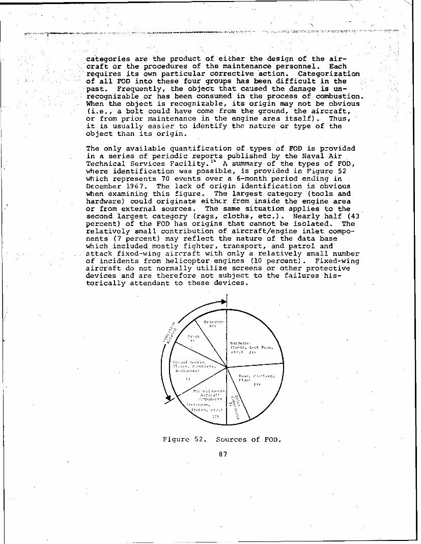
/
• ,,•.•:o• ... •.•...• ,•<•:•. • .. r• • •t.• .•.:•• .•.• ,• .:• •:•:•'7J•-•-•-- •'•',•/7•.:•:::;•o•:•,:•7,•.•..•,','•,• •;•'• ¢v•'•:•:•'•'7 "x•°•i•7'•'•v•;•'•'•
i
il categories are the product of either the design of the air-Scraft or the procedures of the maintenance personnel. EachS• i requires its own particular corrective action . CategorizationS....... of all FOD into these four groups has been difficult in theSi• past, Frequently, the objec• that caused the damage is un-Srecognizable or has been consumed in the process of combustion.SWhen the object is recognizable , its origin may not be obvious
! (i.e., a bolt could have come from the ground, the aircraft,or from prior maintenance in the engine area itself). Thus,it is usually easier to identify the nature or type of theobject than its origin.
The only available quantification of types of FOD is providedin a series of periodic reports published by the Naval AirT i i•echnical Services Facil'ty. A summary Of the types of FOD,where identification was possible, is provided in Figure 52which represents 70 events over a 6-month period ending inD•cember 1967. The lack of origin identification is obviouswhen examining this figure. The largest category (tools andhardware) could originate eith&r from inside the engine areaor from external sources. The same situation applies to thesecond largest category (rags, cloths, etc.). Nearly half (43percent) of the FOD has origins that cannot be isolated. Therelatively small contribution of aircraft/engine inlet compo-nents (7 percent) may reflect the nature of the data basewhich included mostly fighter, transport, and patrol and
S; attack fixed-wing aircraft with only a relatively small numberSof incidents from helicopter engines (i0 percent). Fixed-wing
aircraft do not normally utilize screens or other protectivedevices and are therefore not subject to the failures his-torically attendant to these devices.
Ha •'dwa rt.S(Tools, I.oc• Pi=•s,
etc.) 24•
j•Ct•por•t,!lt• & jF i a•;•
Ai rcl ,/ft
r, b,-s, elc.) •'
Figure 52. Sources of FOD°
87

Despite our inability to quantify the exact sources of FOD toturbine cngines, the resultant effects in terms of accidents,unscheduled removals, and maintenance man-hours have beenquantified. This quantification was shown in Table IX to re-present the experience of the composite engine. The enginesin the data bases examined were equipped with various degreesof protection. Some engines had no protection devices, somehad devices installed on only part of the fleet, and otherswere equipped with filters or screens throughout the fleet.
To provide more perspective on the quantitative effects ofFOD, the rates of unscheduled removals for FOD on a variety ofArmy, Navy, and Air Force aircraft are displayed in Figure 53.Not all of the engine data points shown were used to calculatethe composite engine rate. Three basic divisions are shown onFigure 53: helicopters without any specific FOD protectiondevices, helicopters with some type of protection (whether itbe screens, full barrier filters, or panel type inertial sepa-rators), and fixed-wing aircraft, which normally do not possessprotection devices (the exception is the T74 which has anintegral protective screen around its center body air intake).The engines are arranged within these three divisions in de-scending crder of rates. Efforts were made to obtain data onthe same engines in different aircraft with and without pro-tection and performing a variety of rissions.
Analysis of this data suggests that there are six basic
factors which affect the FOD rates experienced:
o Mission type
o Environment
"o Aircraft installation
"o Extent of protection
"o Engine compressor design
"o Sortie length
These factors affect the FOD rates in varying degrees. Fullextremes of variations were experienced in some factors. Forexample, the mission category included assault missions fromunprepared sites as well as ASW missions from prepared sites,of long durations over water. Other factors, such as theextent of protection, are not complete in that the FOD rateswhen using second-generation engine-integral self-purginginertial separators are not available. Also, the factor ofcompressor design is not complete in that an FOD rate on anall-centrifugal compressor design was not available. Despitetnese limitations, an estimate was made of the separate
88
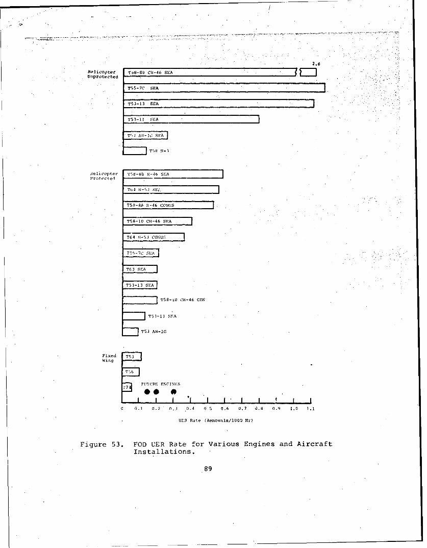
Helicopter Tig-88 CH-46 SEAUnprotected
T55-7C SEA
T53-13 SEA
T53-11 SEA
T53 AII-IG SEA
T58 H1-3
deleicopter 'C58-8B 11-46 SEAProtected
T64 li-53 SE, ]
TS-881 H-46 COUS
T58-10 Ct-46 SEA
T64 *l-53 CONU:3
TS,- 7C SEA . •!
T63 SEA
T53-13 SEA"
T58-i0 CiH-46 CON
T53-1I SEA
T53 AH-IG
FixedWing
7 FUTURE MNINES
i 1 0.2 0.3 0.4 0-5 0.6 0.7 0.8 0.9 1.0 1.1
UER Rate (Removals/1000 HO)
Figure 53. FOD UER Rate for Various Engines and AircraftInstallations.
89
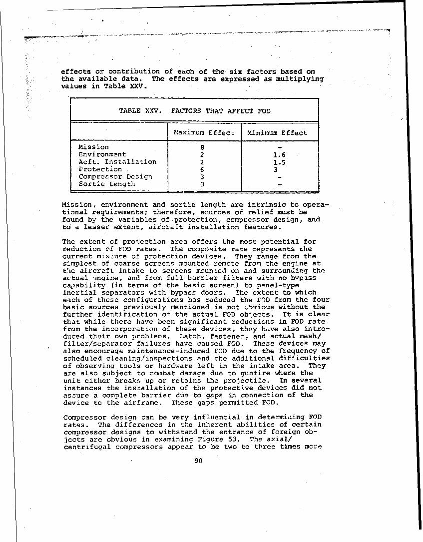
* effects or contribution of each of the six factors based on" the available data. The effects are expressed as multiplying
values in Table XXV.
TABLE XXV. FACTORS THAT AFFECT FOD
Maximum Effect Minimum Effect
Mission 8 -Environment 2 1.6Acft. Installation 2 1.5Protection . 6 3Compressor Design 3 -Sortie Length 3 -
Mission, environment and sortie length are intrinsic to opera-tional requirements; therefore, sources of relief must befound by the variables of protection, compressor design, andto a lesser extent, aircraft installation features.
The extent of protection area offers the most potential forreduction of FUD rates. The composite rate represents thecurrent mix.;ure of protection devices. They range from thesimplest of coarse screens mounted remote fron the engine atthe aircraft intake to screens mounted on and surrounding theactual engine, and from full-barrier filters with no bypassca,-ability (in terms of the basic screen) to panel-typeinertial separators with bypass doors. The extent to whicheach of these configurations has reduced the rOD from the fourbasic sources previously mentioned is not cbvious without thefurther identification of the actual FOD ob-*ects. It is clearthat while there have been significant reductions in FOD ratefrom the incorporation of these devices, they have also intro-duced their own problems. Latch, fastene-, and actual mesh/filter/separator failures have caused FOD. These devices mayalso encourage maintenance-induced FOD due to the frequency ofscheduled cleaning/inspections and the additional difficultiesof observing tools or hardware left in the intake area. Theyare also subject to combat damage due to gunfire where theunit either breaks, up or retains the projectile. In severalinstances the installation of the protecti.ve devices did notassure a complete barrier due to gaps in connection of thedevice to the airframe. These gaps permitted FOD.
Compressor design can be very influential in determiing FODrates. The differences in the inherent abilities of certaincompressor designs to withstand the entrance of foreign ob-jects are obvious in examining Figure 53. The axial/centrifugal compressors appear to be two to three times more
90
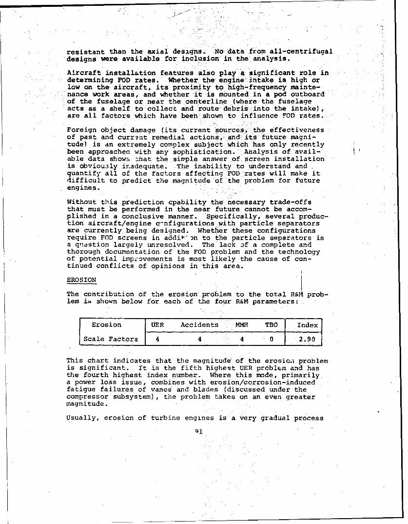
resistant than the axial designs.ý No data from all-centrifugaldesigns were available for inclusion in the analysis.
Aircraft installation features*also play a significant role indetermining FOD rates. Whether: the engine .intake is high orlow on the aircraft, its proximity to high-frequency mainte-nance work areas, and whether it is mounted in a pod outboardof the fuselage or near the centerline (where-the fuselageacts as a shelf to collect and route• debris, into the intake),are all factors which have been shown to influence FOD rates.
Foreign object damage (its current sources-, the effectivenessof past and current remedial actions,-andw-its future magni-tude) is an extremely complex subject which has only recentlybeen approachec with any sophistication. Analysis of avail-able data shows -hat the simple answer of. screen installationis obviou3ly inadequate. The inability to understand andquantify all of the factors affecting.FOD rates will make itdifficult to predict the magnitude of the problem for futureengines.
Without this prediction cpability the necessary trade-offs"that must be performed in the near future cannot be accom-plished in a conclusive'manner. Specifically, several produc-tion aircraft/engine c€nfigurationswith particle separatorsare currently being designed. Whether these configurationsrequire FOD screens in addit-' )n to the particle separators isa aqestion largely unresolved. The lack of a complete andthorough documentation of the FOD problem and the technologyof potential improvements is most likely the cause of con-tinued conflicts of opinions in this area.
EROSION
The contribution of the erosion problem to the total R& prob-lem is shown below for each of the four R&M parameters:
Erosion UER Accidents MMH TBO Index
Scale Factors 4 4 4 0 -2.90
This chart indicates that the magnitude' of the erosion problemis significant. It is the fifth highest UER problem and hasthe fourth highest index number. Where this mode, primarilya power loss issue, combines with erosion/corrosion-inducedfatigue failures of vanes and blades (discussed under thecompressor subsystem), the problem takes on an even greatermagnitude.
Usually, erosion.of turbine engines is a very gradual process
ql

which is apparent through a loss of available power at a givenoperating temperature. As such, thL. mode should not normallycause accidents. However, erosion of compressor componentsalso has the effect of reducing the compressor-surge margin.In certain compressor designs, this l'ss is more critical thanthe loss of steady-state power. Table VI indicates that thehigh scale factor shown for accidents is due to one engine/airframe installation with a relatively high accident rate dueto erosion. This rate was due to accidents which usually oc-curred during 'a flared landing where a sudden application ofpower on eroded engines caused surging and loss of full power.This erosion loss of surge-margin should be considered whenestablishing new requirements and testing procedures.
Althov4h the erosion phenomenon is a time-dependent mode (un-like FOD which is a random occurrence), it has not influencedTBO intervals in the past because, although the amount of ero-sion damage is cumulative and increases with operating time,the process only occurs if the engine is exposed to an erosiveenvironment. Thus, it would be inappropriate to establish afleet-wide TBO interval fo: engines when they see only partialor no erosive environrant. Additionally, the effect of ero-sion in terms of power loss is usually very detectable andthus allows removal of engines before they reach a point ofthreshold deterioration. The problem of inadequate surgemargin is an exception.
Erosion is primarily due to the passage of sand and dirt (be-low 1000 microns) through the engine and is basically a com-press-r performance issue. Engine removal from service isalmost exclusively due to losses in compressor performance,although a few sand-related turbine problems have been experi-enced during specializee tnrt programs such as accumulation ofsemimolten material on the first-stage turbine vanes's or ero-sion of the pro4.ccvion coatings on turbine blades and vanes.The T64 experiencea field erosion of the honeycomb turbineshroud which contributed to nearly 40 percent of the totalperfrormance. loss."17 Normally, however, compressor blades (seeFiqatre 54) and vanes (Figure 55) are the most critical items.
T. .:•ni::ude cf the erosicn problem, as represented by theci. oocice engine rate, results from a combination of engirnedc-signs.. airc:a-ft installations, and degrees of protection.In order to provide perspective of the impact of the factorsaffecting erosion rates, the erosion-causing removal rates ofa variety of engines installed on fixed-wing aircraft and heli-copters are shown in Figure 56. Two basic divisions are shown:those rates experienced on aircraft which do not incorporateany means of protection or filtration, and those which do.The rates displayed on this figure (like the FOD rates dis-played in Figure 53) are dependent on the exposure to specificenvironments, in this case sand and dir't. Also, since the
92

FIRST-STArEROTO( P
Figure 54. Erosion of Compressor Blades With CurledLeading Edges.
Figure 55. Erosion cf Compressor Vanes
After Severe Test Conditions.
93

S~8.0
T58-OB CH-46 SEA 0
T53-11 U11-1 SEA
T55-7 cl -47 S;A
,oU T55-7 C11-47 MEAU
T55-7C WWr
T56 SEA
T55-7 WW
"T53 OV-1 WW
'T58-8B 11-3 WW
153-8P CII-46 SEA
T6,4 C-53 SEA
IT58-10 CII-46 SEA
T53 L-13 U1I-I SrA
T53-13 AH-1G SEA
SU -• T53-13 UH-i SEA
o
T53-11 UH-I SEA
T64 C11-53 CONUS
T63 011-6 SEA
FUTURE ENGINES
•.I , I I I I I0 0.1 0.2 0.3 0.4 0.5 0.6
UER Rate (Removals/1000 Hr)
Figure 56. Erosion UER Rate for Various Engines andAircraft Installations.
94

erosion process is cumulative and therefore has an increasingfailure characteristic with operating time, the TBO level onthe engines w-All affect the actual UER rates due to erosion.Since the aircraft/engines used in the analysis could not ex-perience the precisely same environment and had varying levelsof TBO, caution should be used when comparing the rates.
The various factors which ultimately define a UER rate forerosion are similar to those which determine FOD rates:
o. Mission type
o Ground environment
o Aircraft installation
o Extent of protection
o Engine compressor design
o Sortie length
The separate effects on erosion of each of these factors havebeen quantified by the industry to a further degree than theyhave been for FOD. Considerable time and funds have beenallocated to quantifying and understanding these effects.
The ground environment has been addressed in a host of studiesand papers too numerous to reference. Both the particle sizeand chemical distribution of ground environments throughoutthe world have been described.
The aircraft downwash and recirculation pattern effects onboth the contaminant concentration and particle size distribu-tion are less well known. Studies have indicated that theeffect of rotor disc loading and hover height upon the concen-tration and particle distribution can be significant factorsin determining what contaminants will be ingested into theintake.' 5
The specific design of the engine/airframe interface and theheight and location of the intake are other factors that havebeen shown to be important. Designs which scoop or trap air-borne particles and direct them to the engine are obviouslyinferior to remote pod-mounted designs, where the rotor down-wash can be used to sweep the engine intake area clear ofairborne particles.
The extent of protection is one of the most important consid-erations. It is a factor with a high erosion reduction poten-tial and one over which the customer and contractor have directcontrol. The evaluation of filters and particle-separator
95

hardware has been accompanied by an increasing ability toquantitatively predict their benefits. The normal means ofexpressing the effectiveness of these devices is by measuringthe percent by weight of various size particles removed.
is is not possible to review all of the developments in theevolution of protection devices. It is sufficient for reviewpurposes to indicate that efficiencies approaching 98 or 99percent are b.Ang achieved on the latest separator designs attheir optimum particle size. The past levels of efficienciesexperienced in the engines shown in Figure 56 were consider-ably less (60 to 80 percent). Despite these low efficiencies,reductions of rates from unprotected to protected by factorsof 10 to 15 are evident. Clearly, the technology for achiev-ing significant benefits from the installation of 'rotectiondevices is available.
Engine compressor design is nearly as influential as the ex-tent of protection. While tkte maximum effect of extremes ofcompressor designs on FOD rates was shown to be only 3 (seeTable XXV), the maximum effect for erosion is as high as 8 or10. The factors which define the compressor's ability towithstand erosive particles are both aerodynamic and mechan-ical. The aerodynamic trends toward high efficiencies in com-pressors have been accomplished Yy the use, in some instarces,of axial flow compressors with thin blades and vanes in thelatter stages and minimum air leakages through reduced clear-ances. In a study concerned primarily with the aerodynamicfactors in compressor designs, 18 analysis of existing enginesindicated that the relative tolerance of axial compressorscould be related to expressions which basically describe thework performed by each stage. Stage relative tangentialvelocities were also found to be a good indicator of totalerosion resistance (as well as a means of isolating criticalstages). From a mechanical standpoint, the blade and vanematarials and coatings are perhaps the most critical. Limitedtests have shown that titanium has a lower wear resistancethan steel by a factor of at least 1.419 and aluminum isanother factor of 2 lower than titanium. 6
The relative erosion characteristics of axial versus centrifu-gal compressors have not been well quantified. Despite theimportance of this understanding in engine configuration de-velopment, few tests or analyses have been performed thatwould allow direct comparison. One of the few studies avail-able" indicated that under similar concentrations and particledistributions, a centrifugal design would take twice as longto reach the same power loss as an axial design for the samemass flow and pressure ratio.
The capability of an engine to withstand the induction oferosive particles is usually described by a finite weight of
96
/

material'that can be ingested before a given percent of powerdegradation is reached. This is possible, since tests havedemonstrated that erosion is independent of the concentrationof the contaminant in the air. The total weight, however, isspecified for a given distribution of particle sizes andmaterials, since they have been shown to have a significanteffect on the erosion rate. Generally, the larger size par-ticles cause greater erosion for a given total weight.
When the erosion characteristics of engines are described inthis manner, the variables of airborne concentration, sortielength (exposure time to sand and dirt), and the effectivenessof protection devices need not be specified. Goals are estab-lished in terms of total weight of sand and dirt at a givendistribution, and accelerated tests can be performed to verifycompliance.
The effect of many various compressor approaches has been rel-atively well quantified through the analysis of field data,and more importantly, from controlled tests. Although notdocumented into one single report or analysis, the technologyappears to exist to calculate the compressor erosion tolerancerequirement based on:
o Separator efficiency
o Required minimum removal rate
o Percent of time exposed to sand
o Ingestion concentration
An approach for graphically relating these .variables isgiven in Reference 20 which allows solution for any one vari-able when given the other four.
Erosion is an extremely complex subject whose full technologycannot be adequately summarized in this short treatment. Themajor point is that erosion is a failure mode, and it can bepredicted and therefore controlled, to higher degrees of ac-curacy than many other areas of the engine R&M problem.
ENVIRONMENT
The contribution of this subsystem to the total R&M problem isshown below for the four parameters:
Environmental UIER Accidents WaH TBO Index
Scale Factors 2 0 0 0 1.09
97
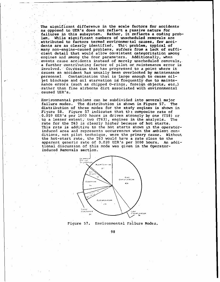
The significant difference in the scale factors for accidentsas opposed to UER's does not refler.t a rassive nature forfailures in this subsystem. Rather, it reflects a coding prob-lem. While significant numbers of unscheduled removals areattributed to factors termed environmertal causes, few acci-
Sdents are as clearly identified. Thi-s problem, typical ofmany non-engine-caused problems, suffers from a lack of suffi-cient detail that would allow consistent categorization amongengines and among the four parameters. Additionally, whenSevents cause accidents instead of merely unscheduled removals,a further contrib3uting factor of pilot or maintenance error isinvolved. Co-rrosion that has progressed to a point where itcauses an accident has usually been overlooked by maintenancepersonnel Contamination that is 'large enough to cause oil-jlet blockage and oil starvation iý frequently due to mainte-nance errors (such as chipped O-rings, foreign objects, etc.)rather than fine airborne dirt associated with environmentalcaused UER's.
Environmental problems can be subdivided into several majorfailure modes. The distribution is shown in Figure 57. Thedistribution of these modes for the study engines is shown inFigure 58. Figure 57 indicates that thB composite rate of
:0.059 UER's per 1000 hours is driven strongly by one (T58) orto, a lesser extent, two (T63), engines in the analysis. Therate for the T63 is clearly higher because of hot starts.This rate is additive to the hot starts shown 1.n the operator-induced area and represents occurrences when the ambient con-ditions, not pilot technique, were the primary cause. Withoutthe hot-start rate, the T63 would have a rate close to theapparent generic rate of 0.020 UZR's per 1000 hours. An addi-tional discussion of this mode was given in the Operator-Induced Removals section.
Ce t in ion i ;at o
Figure 57. Environmental Failure Modes.
98

0.05
0.04
Com'posite Hot
0.059 StartsCO 0.03 -
S0.0
Ccxnpressor o Lui~r ication Miscellaneousp n- t __mi.nt IOn F I
0 .0 Co r ros i or Oil Miscellaneous
0.01 BlocageEnvirornmentaltContaminatin Conditions
1-53 T-55 'T-58 T-63 T-64
Figure 58. Environmental UER Rate for Various Engines.
L[The unusually high rate for the T58 warrants more discussionthan the data permits. While a factor of two can be attrib-uted to the poor engine accessibility when installed in the
CH-6,there is still a factor of 5 that requires explanation.Since the T58 rate was not separable into fuel and oil contam-ination, the relative contributions cannot be estimated. Thesource of oil contamination is frequently not uncovered duringteardown of the engines. Reports show that over 50 percent ofenaines removed for oil contamination were erroneously re-moved. Whether the use of labyrinth seals on the T58 allowedexcessive airborne contamination of the lubrication system orthe seals themselves were contributing to the contaminationas they W-ore in is not known.
Fuel contamination was known to be a problem and was signifi-,cantly reduced with the incorporation of an airframe fuelfilter.
The comparatively high corrosion rates for the T53 and T55 aredue to the large amounts of magnesium used in the inlet andcompressor sections. While the coatings which have been de-
veloped appear adequate for normal use, they may be subject toerosion or maintenance damage (scratches). The T63, which'uses magnesium for compressor components, also experiencedsome corrosion. The T58 and T64 contain no magnesium.
Additional iiscussion of the failure modes in this subsystemis di*fficult beýcause of the lack of definitive information.It is unlikely that the envircnments encountered by theseengines were significantly more severe than those outlined in
their basic specifications. Hence, there appears to be littlerationale for any significant rate in this area. The codingof problems in this area reflects the inability to identifythe actual problem more than the severity of the environment.
99

Future R&D programs must provide more detail on these non-engine-caused removals to allow precise identification ofproblems.
Operator-induced Removals
This subsystem's contriLution to the total engine R&M problemis shown below in the four parameters.
Operator Induced UER Accidents MMLI TBO Index
Scale Factors 4 2 1 0 2.54
The operator-induced area is only a medium-sized problem area,when considered in terms of index number. Yet, it causes moreunscheduled engine removals than any engine-caused subsystemexcept seals. It does not cause many accidents, since mostremovals in this area are precautionary, and no actual hard-ware discrepancy is observed.
Opera:.or-inducel removals can be caused either intentionallyor unintencionally, although the events themselves cannotalways be categorized in this manner due to inadequate de-scription of the circumstances surrcunding the incidents.This lack of good data repurting, coupled with the lack ofpriority that non-engine-caused'problems appear to receive,prevents a conclusive distribution of failure modes beingestablished. However, based on limited samples and discus-sions with representatives from the various engine manufac-turers, the following breakdown is sugnested for unscheduledremovals:
Hot starts 25 percent* Overspeed/overtemp 20 percent* Low power* Not confirmed 15 percent• Miscellaneous 40 percent
Total 10-0 percent
These modes dc not usually contribute to accidents, since theyare normally ornly precautionary removals. Accidents occur dueto situations such as inadvertent fuel shutoff, fuel exhaust-ion, or misuse of engine controls. The use of leaded gas,which caused several accidents, is considered a maintenanceerror and is -cded in the Improper Maintenance section. Werecognize that some of these incidents occurred due to oper-ator actions, particularly under emergency situations, andshould be coded in this section; once again however, inade-quate description of accompanying circumstances prevents thisdistinction. The breakdown of failure modes above does not
100

provide a clear perspective of intentional versus noninten-tional events. The three identifiable modes and the manymodes.which contribute to the miscellaneous 40 percent caneach be generated by deliberate actions. The distribution ofthese failure modes and the absolute rates in the UER param-eter are shown in Figure 59.
.2GMisc
S1Misc0
' 0. Hot
Hot Starts/ StartsPo wover TempT
•0.5 JLow Power] Over TempSUnconfirind Uno e Over Speed/
0.. .. .. .9 v e r T o rq u_
T53 T55 T58 T63 T64
Figure 59. Operator-Induced UER Rate for Various Engines.
This figure indicates that the rate of unscheduled removalsdue to this mode is relatively constant among the studyc:ngines, and suggests that the rates may be due more to thepersonnel operating engines than to the design itself. Cer-tain higher-than-average rates, however, reflect certaindesign characteristics of the engines. Specifically, the T63had an unusually high hot-start rate, which can be traced backto a fuel mixture problem during starting which was later cor-rected by fuel control system modification. The significantportion of unconfirmed low power on the T58 wao no doubt re-lated to the hi'ih erosion rates experienced on this engine asshown in Figure 56. Complete mode distribution was not per-formed on the remaining engines due to insufficient detail ofthe reported events. This subsystem i. a prime example of acollection of failure events which require more attention infuture R&M data-collection programs, if future engines andoperators are to benefit from past experience.
101

Improper Maintenance
The contribution of this subsystem to the total R&M problemis shown below for each of the four parameters.
Imp. Maint. GER Accidents MMH TBO Index
Scale Factors 8 4 4 5.09
As the chart indicates, this subsystem contributes heavily toeach of the parameters except TBO limitations. It is thethird highest identifiable cause of unscheduled removals andis also high in causing accidents. The data includes onlythose events where improper maintenance was proven to be thecause. It is probable that many more events involved impropermaintenance, but positive proof could not be established. Inactuality, the real contribution is probably considerablyhigher.
Maintenance errors take many forms; some are errors of cc,-iis-sion, while others are erio'rT of omission. FLuture correctiveaction requires a more detailed definition of the specificmechanisms of maintenance errors. Toward this objective,large samples of unscheduled removals on each of the studyenginez were examined in order to identify common failuuemechanism.3. Based on over 350 actual cases of improper main-tenance on the five study engines, the distribution shown inFigure 60 was identified.
D(po} Mlsriq"
Sru,' F.ýI n "• tt
I1- ', l inq 7* 1,pr;-;,.r
46.
Figure 60. Improper Maintenance-Caused Removals.
102

These categories are largely self-explanatory, with the cate-gory of improper repair being a general one that representsactual damage to the hardware in the process of repair. Thecategory of over/under torque is also damage during repair,but its high contribution as a single identifiable mechansimappeared to warrant separate categorization. The category ofdepot errors could also be actual damage, but past interestin this source of problems also justifies a separate listing.This distribution of problem areas is rather consistent foreach engine examined, although the absolute rates varied con-siderably. The distributions for various engines are shownas a percentage of the total in Figure 61.
S".0 -m sceli an,-ods M SeI~fe lno ~lsD•'pot • : - Miscrl laneou.MlscelI~neous Dep:ot t£r:ors : Crt,•
fl- Fuel ,.(•a D•Ft Ire Asihndl inq
p 40- Overtomue*,Improprer lepro$,er
Sr op•e r Repair Repair23 - l Zip ro[.r-
Repa o r
T-53 T-55 T-58 T-63
Figure 61. Distribution of Improper Maintenance UER's -Various Engines.
The fact that the distribution is consistent among the enginesexamined suggests that the rate of maintenance error is notdue to uniquely poor design characteristics cf ar.v engine, butis more a function of the general skill and motivation levelsof the maintenance personnel. The suggestion is supported byFigure 62 which plots the rate of unscheduled removals due tomaintenance errors against the total unscheduled removal ratesdue to engine causes.
Figure 62. Improper Maintenance UER Experience.
103

The high degree of cor..elation suggests that the magnitude ofthe maintenance-error problem is directly related to the fre-quency of total maintenance exposure of the engine. If a moredirect measurement of total touch frequency were available, aneven better .orrelation might be evident. Another observationavailable from Figure 62 is that there does not appear to beany discernible difference in the maintenance error rate be-tween the various military services or, even more surprising,no discernible difference between a combat environment, suchas Southeast Asia, and CONUS.
An additional observation concerns the zignificant differencebetween the military band of data points and the few pointsfrom commercial usage. Much of this difference may be due tothe significant disparity in sortie :.-ngths between the mili-tary and commercial data groups. The military data is largelyhelicopter experience of short sortie lengths, while the com-merical data is fixed-wing experiLnce with considerably longersorties leng.t"hs. Since maintenance damage only occurs whilean engine is being repaired or inspected (therefore, on theground), longer sortie lengths would have the effect of decreas-ing the events-per-hour rate. Nevertheless, Figure 62 surelysuggests that there may be inherent limitations to either theskills or motivation of maintenance personnel on military en-gines. The magnitude of the difference demands that furtheranalysis be performed to understand the specifics of this situ-ation and to determine if the limitations arise from a lack ofadequate training, tools, manuals, or some other factor.
This emphasis on maintenance personnel should not, however.diminish the fact that engine designs have been characterizedby features that are susceptible to maintenance error. Manyof these features or design details have been identified pre-viously in the vrious discussions on each engine subsystem.For example, the mechanical torquemcter system illustrated inFigure 44 was responsible for over 70 percent of the improperrepair category on the T55. Similarly, engines with non-metallic compressor linings such as the T63 could be expectedto present problems when improper cleaning agents were used.
Thus, the improper-maintenance-caused problem is shown to bea function of three variables:
"o The basic reliability of the engine and the associatedopportunities for error
"o The skill and motivation of the maintenance personnel
"o The susceptibility of the engine to maintenance error
The first two factors were identified as the primary contribu-tors, with little observable difference in hardware character-istics ax.ong the study engines.
104
Airframe-Related Removals
The contribution of this area to the total engine R&M problemis shown below for each of the four R&M parameters.
Airframe-Related UER Accidents MMH TBO Index
Scale Factors 4 1 2 0 2.36
This chart indicates that the airframe-related area ranks as amedium-sized problem laigely due to the unscheduled-removalportion. Few accidents are caustd by failures in this area.This grouping of z>roblems consists of two distinctly differenttypes. The firs' type is actual damage to the engine due toairframe or non-engine equipment. Th" second type is merelyremovals from the airframe in order to gain accessibility toairframe-related components in the general area of the engine.Clearly, accidents can be caused by problems in the firstcategory only. Also, the second category does not requireengine repair. Since the weighting factor applied to the rateof unscheduled removals presumes repair or overhaul, its usagein this area provides a somewhat higher priority rating to theairframe-related area than it actually warrants.
The division of airframe-related unscheduled removals in-othese two categories (damage or mere accessibility) could notbe precisely determined. It is estimated to be split 20 to30 percent actual damage and 70 to 80 percent accessibility-induced. More definitive allocations were aot possible ý.ieto inadequate data reporting.
The two types of problems included in this subsystem arisefrom different sources. The damage type is a hardware reli-ability issue involving not only the frequency of failuresbut also their progression and detectability. Examples ofairframe-related engine damage include oil leakage into theengine from hydraulic starters mounted in the inlet area (onrear-drive engines) or from airframe responsible transmissionsmounted in the same inlet area. Misalignment or unbalance orhigh-speed airframe output shafts has caused engine. bsacing orhousing failures and also contributes tc sr.l leakage. Nor-mally, aircraft rotor-induced vibration levels ara not identi-fied as the prime causal factor to engine failures andtherefore do not contribute to this subsystem.
The accessibility type of remcval is a function of the com-.plexity and failure rate of the airframe equipment in thenacelle area, as well as the ability to gain access to thesea!mnonents fco replacement, repair, or adjustment. Eventhough accessibility is not rigorously quantifiable, it
105
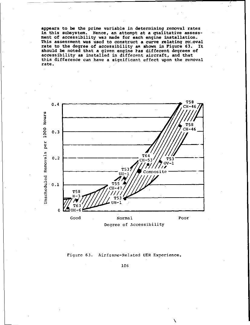
appears to be the prime variable in determining removal ratesin this subsystem. Hence, an attempt at a qualitative assess-ment of accessibility wa3 made for each engine installation.This assessment was used to construct a curve relating re:.:ovalrate to the degree of accessibility an shown in Figure 63. Itshould be noted that a given engine has different degrees ofaccessibility as installed in different aircraft, and thatthJis difference can have a significant effect upon the removalrate.
0.4 c -46
0
ST58 _
o 0 • 3 CH-46 -o0.3
-4
ý4 T64m 0.2 T53> CH-53',,
S~~~~T53 CoostUH- c
,-.2 0 . 1 T 5 5a C-4
M UH-
Good Normal Poor
Degree of Accessibility
Figure 63. Airframe-Related UER Experience.
106
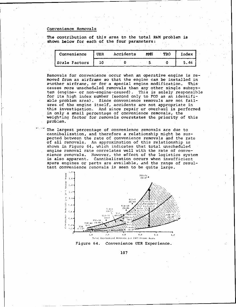
Convenience Removals
The contribution of this area to the total R&M problem isshown below for each of the four parameters:
SConvenience UER Accidents MMH TBO Index
Scale Factors 10 0 5 0 5.46
Removals for convenience occur when an operative engine is re-moved from an airframe so that the engine can be installed inanother airframe, or for a special engine modification. Thiscauses more unscheduled removals than any other single subsys-tem (engine- or non-engine-caused). This is solely responsiblefor its high index number (second only to FOD as an identifi-able problem area). Since convenience removals are not fail-ures of the engine itself, accidents are not appropriate inthis investigation. And since repair or overhaul is performedin only a small percentage of convenience removals, theweighting factor for removals overstates the priority of thisproblem.
The largest percentage of convenience removals are due tocannibalization, and therefore a relationship might be sus-pected between the rate of convenience removals and the rateof all removals. An approximation of this relationship isshown in Figure 64, which indicates that total unscheduledengine removal rate correlates well with the rate of conve-nience removals. However, the effect of the logistics systemis also apparent. Cannibalization occurs when insufficientspare engines or parts are available, and the range of resul-tant convenience removals is seen to be quite large.
1- . 6 C-47
S1.0' T55-7 IOf- 7 .... 0 I ; • t 1 , l., c.-4• T a l //l /,,
T , - N • 76
T 5•.• 3Is -hoh l, 11 ,- I a I •, ,OO /j(T O /lu . , ,/ 5 - B "
2.4 ui-IT 1 H 4f
2.0 .04.0 5.0 6.0
Figure 64. Convenience UER Experience.
107

Unknown
The contribution of this category of problems is shown belowfor each of the four parameters.
Unknown UER Accidents MMH TBO Index
Scale Factors 10 10 5 - 7.26
This chart indicates that the number or removals and accidentsfor unknown reasons is significant. The factors that cause aremoval or accident to be unknown are more likely related tothe effort made in determining the cause, rather than thenature or detectability of the failure itself. Many enginesdo not receive the intensive analysis that allows definitionof problem cause. This may occur because of the economics ofthe situation, where repairs or overhauls are performed byagencies who do not have a specific responsibility for problemdefinition. It also occures when engines are not retar.4d forrepair or analysis, such as in the case of a severe accidentwhere the extent of damage or cost to recover is excessive.
Assuming that the unknown problem is merely the lack of posi-tive identification of already-defined prcblems, there shouldbe a correlation between the rate of unknown problems and therate of all other problems combined. This relationship isplotted in Figure 65, which supports this contention. Variousengine manufacturers treat unknown or unsubstantiated problemsdifferently, with some classifying them all as engine-causedand others as all non-engine-caused. The rates shown on TableV proportioned the total unknown unscheduled removals betweenengine-caused and non-engine-caused.
0.8-/ / /
S//i, '// / '.o-
CTH8{- / T -
TI, /1/~ '4
TiT, I' -
[ .0 2.0 ~ f) 4.( o . 6.0 :;0
•T,t.,lJ t~l'ln- l+h-H4 -1Re, ,il+?v'l t, fpri 1000 V.i~nptfl H- -.l
Figure 65. Unknown UER Experience.
108
SUMMARY OF CURRENT-ENGINE PROBLEMS
Based on the examination of the detailed failure modes experi-enced by the study engines and the preceding discussion of thespecific mechanisms, causal factors, and numerical rates, thefollowing conclusions are appropriate.
Many of the failure modes with the largest rates are thedirect result of specific design approaches or criteriaadopted during the development phases of the engine, Signifi-cant examples of failure modes in this category are bearingouter-race rotation, carbon-seal leakage, compressor blade andvane erosion, compressor FOD, turbine-nozzle-band'cracking,turbine-vane sulfidation, case cracking and corrosion, andtorquemeter system problems. In most of these cases, the re-sultant problems could not have been predicted at the time ofinitial design due to the lack of either historical experienceor sufficiently advanced analytical prediction techniques.
Other failure modes appear to be common to all design ap-proaches. Examples include nonclassical bearing spalling;case fitting problems; and fuel, oil, and electrical subsystemproblems.
Certain failure modes are intimately related to the climaticand mechanical environment and appear to be largely independ-ent of the design or configuration of engines. Fuel and oilcontamination, operator-induced and maintenance-error-causedproblems are examples of significant magnitude.
All of these three failure mode categories have been addressedby corrective action during the operational phase of the studyengines. Corrective action usually involves only minor re-design of the local failure area, particularly when directedat problems classified as engine caused. Non-engine-causedproblems frequently involve more extensive actions, such asthe addition of screens or separators.
Precise identification of the causes of many failure modes isfrequently impossible. The separate effects of normal engineoperating loads, improper manufacturing or quality control,maintenance abuse, and environmental conditions are not clear-ly evident in many cases. Often the allocation of an incidentto engine- or non-engine-caused subsystems involves an assump-tion of what is considered a normal environment, whether thisenvironment is climatic, mechanical, or personnel related.
The inherent R&M characteristics of many various design ap-proaches are nct clearly identifiable from this analysis.Design alternatives such as rear versus front drive, axialversus centrifugal compressors, face versus circumferentialcarbon seals, and others did not exhibit sufficiently
109
/

consistent R&M rates to allow quantification of their inherent"differences. The limited number of engine configurations ex-amined undoubtedly contributed to this lack of discriminationcapability.
Certain subsystems, or groups of problems, were related to thetotal removal rate of the engine. These subsystem problems"were improper-maintenance-caused removals, convenience remov-als, and removals for unknown reasons.
/1
110

5.0 CURRENT ENGINE PROGRAM CONSIDERATIONS
The engine-contractor's design/test program and manufacturing/quality control capability, the airframe-contractor's instal-lation, the encountered environments and stresses, and theservices' operational/maintenance practices all combine todirectly produce the R&M levels exhibited by military turbo-shaft engines.
The R&M problem areas are influenced by a- complex set of pro-gram considerations. The program for a specific engine devel-opment/production project will influence the specificationsand requirements; detailed design and testing; and the engines'manufacturing and quality control and installation. Broadprogram considerations also have an effect on downstream oper-ations and maintenance practices. This section describes howthese program considerations affect R&M problems.
The specific R&M problems discussed in Section 4 will be exam-ined from a broader customer/contractor program managementviewpoint to identify considerations that influenced the R&Mof the study engines. A review of the background of individualR&M problems will determine what in the requirements, designdevelopment, and operational phases contributed to the prob-lem. The contribution of these factors to the compositeengine will be quantified and discussed.
Five program-oriented causal factors were identified which,collectively, can be considered to represent 100 percent re-sponsibility for problems. Against these five factors, over163 different case histories of individual R&M problems infive of the study engines (T53, T55, T58, T63 and T64) wereexamined. The relative influence of each factor was thendetermined in conjunction with the manufacturer of eachengine.
DEFINITION OF CAUSAL FACTORS
Requirements
All engine design commences with a requirement and a set ofspecifications. The detailed requirements and specificationsestablish the basic sizing, cost, and technology level for theengine and thereby influence its R&M chay icteristics. Thestipulation of specific R&M beneficial diign features and/orthe imposition of R&M levels are direct influences. Indirectinfluences occur when no R&M requirement is imposed or the re-quirement for the engine is driven at the expense of good R&Mby performance or cost considerations. R&M is a competingparameter with the engine performance and sizing parameterssuch as SHP, SFC, weight and space envelope. Reliability andmaintainability is therefore a by-product of other actions
111

,N -
where there is no cortractual requirement to design it into anengine. Further requirements which influence R&M includeprime design requiremints of low cost, modularization, ortight scheduling.
preliminary Design
This represents the broad design selecticr. -ý:iade by the enginemanufacturer to meet the customer-specifieu requirements whichconceptually define the engine. During this phase of enginedesign the physical arrangement of the engine is formulatedand fixed. This includes decisions on such intrinsic require-ments as the selection of centrifugal versus axial flow'com-pressors, straight versus folded combustors, nunber of shafts,number of compressor and turbine stages, and relative posi-tioning of the compressor in relation to the turbine and com-bustor section and gearbox. The preliminary design stagemolds significant reliability features into an engine design.A decision, for example, to ise carbon-face, main shaft sealswould prohibit any subsequent engine redesign to-utilizelabyrinth seals. Basic pressure loss allowables, bearingthrust balancing, bearing cooling, bearing sump size and otherimportant variables would have been predicated on the use ofcarbon' seals. Decisions made at the preliminary design stagewill have a significant effect on the engines' reliabilitypotential and on the alternatives available to achieve itduring later detailed design stages.
Design Execution and Devielopmental Test
With the basic layout, sizing and design decisions made in thepreliminary d(:sign phase, the next phases of R&M are detaileddesign and test. Here the detailed design effort and decisionsare made, tests are formulated and detailed drawings are is-sued. Drawing board decisions now directly affect engine R&Mand will reflect the basic' emphasis of the original require-ments. Materials choice, structural application and thermo-structural analytical techniques, and experience of pastproblems are applied in the design execution stage. Tests areconducted to verify performance and improve the reliability atthe component level. Subsequently, similar tests are conductedon the complete engine for extended durations under a varietyof operating and environmental conditions. These tests can de-tect R&M problems not anticipated during the design and-serveas a backup to the analytical process. Reliability and main-tainability problems may originate during the design executionand development test phase. During this phase these problemscan be found and eliminated with developmental tests.
Manufacturing and Quality Control
R&M problems can also be created during the manufacturing andquality ccntrol phases. Specific problems were noted during
112

the conduct of this study as originating from excessive toler-ances, inadequate care during assembly, or inadequate inspec-tion of components or assemblies. In these situations theinherent reliability can be significantly degraded. Manufac-turing and quality control problems are usually transient,since they are normally identified and resolved rapidly.Generally, this category contributed least to the R&M problems.
Operations and Maintenance
Many problems have traditionally first appeared during the op-erational phase. Problems such as induced high soak-back tem-peratures into the engine due to improper engine shutdown tech-niques and ingestion of FOD have caused extreme difficulty duringoperational use. During this stage of engine use, maintain-ability problems become more apparent, the effect of human errorbecomes critical and the distinction between engine-caused andnon-engine-caused R&M problems first appears. Earlier conclu-sions regarding the magnitude of the non-engine-caused problemclearly indicated that strong corrective action is required.
Figure 66 presents R&M problem causal factors and includes asummary of the detailed factors included in each category.
CAUSAL FACTORS FOR ONINE R&M PROBLEMS
7; ic n~ y it 'rt to a=
F__ Ma .t Lenancec
L.1C
St 1xrc--; !e• tac I,; Lnei-iinqui.-c: Arnc M,cl'.a*toUt~a and Oco2.ratocsg• a~nd---I.---t[ ri '.
1 Ic irv PcU -LW.ZS '-''-' .l a P .,:i >tt C'•r, ren a C
w i lt N i r: tr 0 t* c P o r i t i vl q , .-t -n t n 1 C I -l c a.id, tt A t ctt i -'t 1 C 0, - r a t or F r r cr
-''z~naslc P.- ,h - t,Cqral with, of Foarin. Out-r R -c.., t Stilt !nslls- c Mainte Lance irror..[r;: .<: ; -c. :Lh'~,: -,.* •r Icadlequatc tab,, 1,1i LIu, DL? 101 iqlcn.
S-.r S .. . . ....• ., , •.,. ['i-- ;rac~ . % ,r 2 f'..a;ro,:r ric'1
-• i. t sr' . -, •(" l -0 • F; b t"• is, ti-I .i 1'j
, - ... r , i. - . . .t. .r . : , , • .• • h f
• ',,,.•1 rt..,t,,r.. *.1 ..r 'a Li4t2t±LV -) i. r
"-. •!2-ti n o Co.i..:- 1:.' is~l, ";.'.t!,r; a Iiii'onr•,ct Ch,,. ' i ,e f
ticr-t -,t c:,cfi,4.; , . I.-, l r altl I 5 't.it, rld-:;.rc' .(:,(:;Oiir,,ltrnc. St~*:• *iiI.21t~lr l
.;.,iatc 5'', A .1-:',•
rI Flitnltc I-d
b~-tt Ilrl
0 Icadcs.catn Cimptifs.t'~rLLnlnq Mater ,al
Figure 66. Interrelationships and Examples of Causal Factors.
7113

This figure eetails the broad areas in which the actions ofcustomer, contractor, and operator are responsible for engineR&M problems. An interaction between requirements, preliminarydesign and design execution has been indicated in Figure 66.This interaction reflects a progressive, time-sequenced rela-tionship to problem creation. Even when the specification ofR&M requirements is deficient, the R&M hardware need not beirrevocably compromised since an opportunity may exist, in theensuin'i preliminary design phase, to salvage R&M. Correspond-ingly, when R&M-compromising decisions are reached in prelim-inary design, some opportunity may exist to recover, if thecontractor chooses, during the ensuing detailed design or testphase. in assessing causal factors for specific problems, itwas frequently found that the origin of the problem might havebeen deficient R&M specifications or requirements; but it wasalso recognized that subsequent failure to make use of oppor-tunities present in preliminary design and detailed design/test also contributed to the problem.
The following example is illustrative of this phenomenon. Inone study engine, the customer specified the requirement for alow-cost, highly modularized engine which resulted in a pre-liminary design concept with an unorthodox arrangement of themajor sections of the engine. This involved the transfer ofcompressor air around a miC-section gearbox. The continuingrequirement for low cost led to detailed design features forthe transfer air joints which were not optimum from an R&Mstandpoint. Problems soon followed. Analysis of the causalfactors for this probler" showed that, although it was predom-inantly one of detailed design execution, both the require-ments and preliminary design phases contributed to the fail-ures. Although the problem was initiated from a specificcustomer's requirement, the preliminary design phase offeredan opportunity to preclude the requirement from inducing anR&M problem. Tae detailed design phase offered alternativesto avoid the problem. More development testing would haveidentified this problem prior to release of the engine tooperational use. This example is not unique. It serves toillustrate the interaction of R&M problems experienced at therequirements, preliminary design and design execution phasesof an engine program.
QUANTIFICATION OF CAUSAL FACTORS
In order to determine the relative impact of the five causalfactors in the overall R&M problem, 163 individual case his-cories were investigated. The pezcentage of the problem dueto each contriL.Jting factor was assigned in cooperation withthe engine manufacturerE. An example of this process is showi,on Figure 67 which illustrates the case cited above. The con-tribution of each factor was measured according to the mag-nitude of the basic problem in each of the four R&M parameters.
114
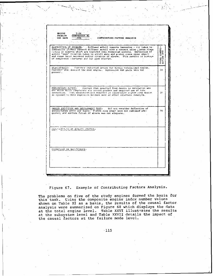
ENGINE T-XXPROBLEM COMPRESSOR #1UER RATE . CONTRIBUTING FACTORS ANALYSIS
DESCRIPTION OF PROBLEM: Diffuser scroll inserts loosening - o'ir tubes toc -mbus•t•ion, be-r connect diffuser scroll with a concept using ;iston rings Wriding on sleeves which are threaded into magnesium scrolls. Deflection of Vscroll 'legs" misalign tubes to scroll axis and pistorn rinqs gouge slee-c 00and cause axial movement and/or rotation of sleeve. This results in leakage.of compressor -ischarge air out past sleeves.
C :
_FQUIRE•ME-NTS: Customor indicated desire tor highly s-adula,:ized engine.Custo`ir also desired low cost engine. Aggressive R&M goals mJere not 10present.
PRELIMINAPRY DESIGN: Concept that resulted from desire to modularize wasone which split compressor air around gearbox and required use of tubeconnection. ý'ost considerations resulted in inexpensive pisto.n ring desiar. 26as opposed t3 more expeunsive bellows seal or other alternate conce.=ts.
DESIGN EXECUTION AND DEVELOPMENT TEST: DiI nct consider deflection ofscroll/tubes uncir air loads- Pistcn ring edger were not radiused ade- 70quately and surface finish of sleeve was not adequate.
. 4A• -AT''Rý':C OR UAIYCONqTROL;
CPERATIONS OR MAIt7EANCE:
Figure 67. Example of Contributing Factors Analysis.
The problems on five of the study engines formed the basis forthis task. U:3ing the composite engine index number valuesshown on Table XI as a basis, the results of the causal factoranalysis were summarized on Figure 68 which displays the dataat the total engine level. Table XXVI illustrates the resultsat the subsystem level and Table XXVII details the impact ofthe causal factors at the failure mode level.
'115

Opt-rat-zne a I~qu i rowents
amlI 27%
Figure 68. Summary Results of Contributing Factors.
TArLI: XXV1. CO.TP.IBlTIN, FACTORS SUBStYSTOEM MARY 1MATRIX
r Contrjbut 3 Factors
Manufacturing f.D,.- S !Ign and QuaIity Operatlcr. anL
aLPs,:'-,eT u~ rv-.'n-t s s 1k :l Eytjti Cc trol Maintenance
-r,,!I r t .'a N-,t 0,'rc, nt , L V IJ. PI,'rc- -t I V., I i P rcv ' ale P1'rrc.,t V Jlue
La'r-ncs i.)0 12 0.4' ', 0.34 67 2.55 i 0.27 5 0.19
is 1.46 ?10 0. , 2 U 7.,, ' 1_74 5 a.17 3 0.101- ,fprvrs:- 4.61 3 1 .,7 6 01,' 44 2.04 9 0.42 7 0.32
om u t 1cr. 1.I., 2 h 0. Q2 7 5 .i i r.. ,. 3 7 0.08 3 0.03T r ..,. 2 6 46 '.31 .0.0 42 1.20 3 0.09 6 O.17
1.27 22 G.."I 2 o.0 7 ' f 0.7. - 19 0. 2iL! ri ca t i ý 1.28 4 1) . "! 2.1 o.m, 44 0.17 U .06 19 o0.24,F.,I 3.45 24 0. 22 0.76 28 2H 7 1 0.03 25 P.;
Air 0.55 h. 0.06 65 0.35 10 0.06 15 0.08
S0.91 - - - 80 0.' 3 20 1.i8 -
TArcueSretr 1.27 20 0.25 0 42 0.54 19 0.24E 1,-c' tr ca 1 1.73 !.¢# 0.14 - - 21 0.21 52 1). 3
r"E1 rst lorS 44 G . 24. 21 0.12 7" 0.18! -2 0.3,
F -wer-Tr,,: n -1.72 40 0.;'1" 10 0.07 3o 0.22 0 0.67 0 0.07
6.4 1 3.13; i2.6(4 1.43 2.,)-'
'TtaI - ir-7ihc- 26.62 .24, 48'1 51 11.
-"!'.P1• li.'.,: 6.71 70 4.70 10 0.0' 5 0.34 - 15 1.01D•,' 2'- 1:1 7 ,.. .4- ,
2.90 70 0., 1. (.44 5 0.115 - 10 0.2'•F., 1 r2r t 1 ].?09 0.22 -- 80 0. 7
- e r., - -r 2.,4 16 3.2. 1( 0.25- 15 0.38 - I-5 1.6
r, r 5.09 10 6.5, 5 0.2', 5 0.25 0.252 7ý 3.83
3r,- 2.36 n.5 ,1 10 0.24 45 1.06- 4) 0.94
<,41,.-.- , - , ' .4-,- 100 5.46
7. C 2.0'. 2.18 0.25 14.0f2T.15 --___,,__,-
,, 7.26 4S. .. .. . .. .... . |40- ".I "- 1.1. 712 1.6R' .. •
An T1. 160 27, 3
116

T~~~ilor~~~ 400. 14' i 1 il . ,A ii
20
4117411.
In - 34
r.FT
,,,7T-~ T .7 ý
0 Or~or ,d01,.. ,, i
- - - --- - - - --
...
DISCUSSION OF RESULTS
Certain of the causal factors have a more powerful influence*than others in the establishment of the R&M characteristics.In the case of the engine-caused category of R&M problems, twoSeausal factors predominate - requirements and design execu-tion. Two causal factors also dominate the non-engine-causedproblems - requirements, and operations and maintenance. Whenthe total engine R&M problem is considered, three causal fac-tors uf relati.vely equal magnitude (requirements, design ex-ecution, and operations and maintenance) are collectivelyresponsible for almost 90 percent of the total problems. Thefollowing sections will discuss the significance of each ofthe five causal factors.
Significance of Requirements on R&M Achievement
The requirements phase for the study engines was in the 1950to 1960 time period. It was noted in discussions with theengine manufacturers that these engine programs did not haveformal or even any specific reliability and maintainabilityrequirements at the commencement of the design. phase. Theengine reliability achieved under these circumstances was theresult of R&M receivinj lower priorit" in the trade-off deci-sions than contractual parameters of performance and weight.
A lack of requirements is the principal reason why require-ments were seen to be responsible for over 25 percent of pastengines' R&M problems. Reiterating, when the detailed re-quirements do not include R&M, the resulting effects on R&Mof the other parameters will probably be deleterious. Severalinstances of this situation were noted in the study. On onestudy engine, the requirement- for a high-performance, small,lightweight engine led tu design decisions to use carbon-sealmain shaft bearing sea:. to minimize compressor air losses.The decision to use carbon seels which caused reliabilityproblems was made on the basis of a requirement that did notinclude a reliability parameter. On another study engine,particular compressor-liner material was used on the basis ofa cost requirement. Again, there was no R&M requirement. Inboth examples, the absence of specific reliability requiire-ments did not allow R&M to be treated with adequate emphasisduring critical design dEcisions.
Significance of Prelimihary D'1gn.g on R&M Achievement
The preliminary design phase represents the first tangible en-gine manufacturers' response to givei. customer requirements.It is almost always possible to propose more than one enginedesign configuration to meet a requirement, and some basic en-gine layouts have a lower probability of causing R&M problemsat later design stages than others. At the preliminary design
li"

stage, several of the basic reliability-affecting variablesare decided upon and fixed. Included in these basic variablesare the number of engine shafts, number and types of bearingsand main shaft seals, engine materials and similar major de-sign decisions. The preliminary concept selected by theengine designer utilimately defines the mature, generic reli-ability rate attainable for that engine after all reasonablereliability improvement changes have been incorporated.
The preliminary design phase allows the manufacturer to incor-porate beneficial R&M features and thereby reduce the proba-bility of problems later. Alternately, some problems resultingdirectly from the preliminary design phase were noted. Onestudy engine coupled Lhe fuel pump, fuel control unit andpurifier in series. Significant problems occurred with drivespline wear and inadequate spline lubrication. Since therewere no known requirements specifying this arrangement, thepreliminary design was mainly responsible for this problem.
The impact of the preliminary design phase on the achievementof good R&M levels was relatively low. Its main impact wason dcfining the detailed design features necessary to satisfythe requirements phase and determining the difficulties of thedesign execution phase.
Design Execution and Development Test Impact on R&MAchievement
The effort expended during this stage of engine developmentcycle is important in determining the R&M levels ultimatelyfound in field operations. This effort consists of not onlythe actual design of the hardware, but the entire spectrum ofanalysis and testing that is applied in support of the designeffort. The actual drawing process is a complex inteiactionand integration of requirements imposed, available technology,past experience, and the skills of the project and designpersonnel.
This phase contributed to nearly one-half (47 percent; seeTable XXVII) of the engine-caused problem, but to only 8 per-cent of the non-engine-caused problem. In the engine-causedarea, nearly every subsystem was significantly influenced bythis factor. Bearing problems were particularly prevalent,with most failure modes having traceable origins to inadequatedesign efforts and testing. Typical bearing problems were ex-cessive axial or radial loads caused by inadequate calcula-tions of housing/case thermal growths, outer race rotationcaused by lack of positive retention, and roller skidding dueto excessive clearances or insufficient radial load. Otherproblem subsystems due to this factor are seals, compressor,turbine .nd fuel. Most of the many failure modes in these sub-systems follow a pattern of wide variety similar to that dis-played for bearings.
119

To better understand this factor, specific failure modes whichwere due, wholly or in part, to this factor were reexamined toestablish lower-level visibility. This additional analysisresulted in the discovery of four basic faults as follows: 55percent analysis test procedures available but not utilized;20 percent past R&M experience/history not utilized; 15 per-cent alternate design or materials not available; 10 percentanalysis test procedures not available. This suggests thatthe prime cause (75 percent) was a lack of application of ex-isting and available analysis/test or historical experience.Limitations that appear to be most critical are developmenttime and funding, not technological restraints. This explainswhy engines can experience such large improvements in relia-bility over a relatively short time frame. Little new tech-nol-gy his been made available; operational experience wasused to replace analysis during design.
The effect of design execution and development test in thenon-engine-caused areas are minimal. Once the base require-ments have been established (for example, not to have a screenor separator), the preliminary design chosen (for example, anaxial-flow compressor design) and the operational environmentfixed, there is little that can be done during this phase toincrease the resultant reliability. Only the detailed instal-lation of airframe components on or near the engine contrib-utes any significant effect. The importance of this factor inengine R&M should not be minimized in spite of the greatvariety of failure mechanisms and specific causes evidencedby examining various engines.
Significance of Manufacturing and Quality Control on R&MAchievement
This phase during which R&M problems can be induced in an en-gine tends to receive more vocal comment than its importancewarrants. Table XXVI indicates the low contribution that man-ufacturing. and quality control represents to the total R&Mdilemma. The problems that occur are usually transient andare quickly resolved.
Manufacturing problems have been associated with assemblydifficulties rather than with the production of detail parts.Several examples of this situation were noted in this study.One engine which used the engine power turbine shaft as anintegral inner roller bearing race experienced externally in-duced damage which occasionally led to bearing failures be-cause of difficulty installing the shaft into the bearingassembly.
Another engina utilizing a differential bearing in a mainshaft application had considerable problems from the diffi-culty of installing the retaining ring for the bearing outer
120
race. Improper seating of this bearing outer race with sub-sequent lack of retention by its retaining ring allowed axialmovement of the bearing.
A new manufacturing technique for installing compressor linermaterial was partly responsible for later R&M problems. Thisprocess involved the centrifuging of the plastic lining ontothe case, which caused separation of the denser elements ofthe mixture out to the case sutfaces. This produced a non-homogeneous mixture and allowed softer elements of the plasticto become exposed to compressor air, with subsequent linercracking.
An assembly-induced problem was that proper inspection waseither extremely difficult or impossible following completion.Occasional quality control problems were encountered. Typi-cally, a grinding operation removed much of the weld materialsecuring a drain boss to a combustor housing. Several prob-lems unique to military overhaul depot activities were alsonoted. Prime among these was that a metal flame spray tech-nique which did not produce an adequate surface finish wasused as the bearing inner race, and the incorporation of thisrework technique caused severe bearing problems. This problemreflected a military overhaul-activities emphasis on cost andtime savings which in some cases was instrumental'in causingR&M problems.
Most manufacturing and quality control problems appeared to berelated to general personnel and facilities limitations andhence were largely independent of the requirements, preliminarydesign and design execution phases of any specific engine.
Significance of Operations and Maintenance on R&M Achievement
The introduction and use of engines in operationzl serviceusually generate a new series of R&M problems not previouslyencountered. Operation of the engine under field conditionsbegins to reveal situations that result from actual opera-tional environments which may be more adverse than those ofthe test proqram. Table XXVI illustrates that the majority ofproblems to which operations and maintenance have a significantimpact are non-engine-caused.
Several of these non-engine-caused problems, specifically FOD,erosion and airframe-related, where major responsibility layin requirements or design execution, were magnified by mainte-nance personnel action. As an example, engines have beenoperated without the specified FOD screens or particle sepa-rators iistalled.
The other categories of non-engine-caused-problems (operatorinduced, improper maintenance and environmental) were
121

principally the result of personnel action or inaction. Theseproblems were exaggerated by factors largely unrelated to theparticular engine. With maintenance-induced R&M problems, theproblems included skill levels of the personnel and the ade-quacy and utilization of equipment and facilities. Theoperator-induced problems included both deliberate overtemper-ature operations and unintentional engine hot starts. Asses-sing the causal factors for these types of problems, it isobvious that they were universally unrelated to a particularengine. To what ex-ent specific design features led to theserates is not altogether obvious. Certainly the application offeatures to prevent hot starts could provide one solution tothat problem; but flight crews will always require the optionof overtemping an eaLge to ;ArciCt addi'iional power If theemergency warrants. More than 50 percent of maintenance-induced problems were unrelated to the particular engine beingworked on, but were really a more general type that could haveoccurrLd on any engine.
Operaticons and maintenance also affect, to a lesser degree,engine- aused problems. Analyzing the R&M problem causalfactors for engine-caused problems, the operation and mainte-nance phase was somewhat contributory to many failure modes.Many fuel system problems originated in the operationalreality of contaminated fuel. Another engine-caused problemoccurred in the electrical system during abusive field-operations/maintenance. The mechanical torquemeter systemprovided another classic example of this phenomenon. Hereone manufacturer did encounter both reliability and iraintain-ability problems during test cell operations, but these wereconsidered tolerable. However, the problem took on signifi-cantly large proportions when the engine was released. to thefield where the general operational and maintenance environ-ments were not as adequate as those in the manufacturers'facilities.
The R&M problems that have occurred in this operations andmaintenance phase of the engines life cycle warrant close ex-amination of how program management can prevent them. Latersections of this report will propose some considerations forthis purpose.
122
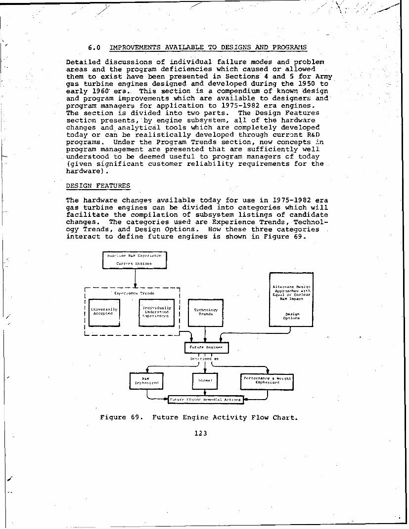
6.0 IMPROVEMENTS AVAILABLE TO DESIGNS AND PROGRAX1S
Detailed discussions of individual failure modes and problemareas and the program deficiencies which caused or allowedthem to exist have been presented in Sections 4 and 5 for Armygas turbine engines designed and developed during the 1950 toearly 1960' era. This section is a compendium of known designand program improvements which are available to designers andprogram managers for application to 1975-1982 era engines.The section is divided into two parts. The Design Featuressection presents, by engine subsystem, all of the hardwarechanges and analytical tools which are completely developedtoday or can be realistically developed through current R&Dprograms. Under the Program Trends section, new concepts inprogram management are presented that are sufficiently wellunderstood to be deemed useful to program managers cf today(given significant customer reliability requirements for thehardware).
DESIGN FEATURES
The hardware changes available today for use in 1975-1982 eragas turbine engines can be divided into categories which willfacilitate the compilation of subsystem listings of candidatechanges. The categories used are Experience Trends, Technol-ogy Trends, and Design Options. How these three categoriesinteract to define future engines is shown in Figure 69.
Current Engines
Alternate DesiqnApproaches with
Experlence Trends Equal or Unclear" . R&M impact
l~niersll7Indildu~lyTechnologyAceI td ndrs n£Spel~•-•Trends Design
Options
IAI P
Figure 69. Future Engine Activity Flow Chart.
123

Experience Trends
An experience trend is a design approach or material usagewhich is known to the majority of engine manufacturers and hasbeen proven superior through service experience. Experiencetrends generally stem from the development of correctiveaction for R&M problems that are common to the majority of
Sengines in a given era. Since the problems are common, thesolutions are relatively common, and as such, they representlessons learned throughout the industry. However, sometimescompanies, and agencies or individuals within companies oragencies, disagree that a given design approach or material
* usage is preferred from an R&M standpoint. This would notprevent their consideration ýs experience trends, since themajority of the members of the engine design community con-sider them advantageous.
For example, the mechanical retention of a bearing outer raceto prevent rotation in its liner or housing is an experiencetrend because it is common to all engiaes. Where a problemis unique to one engine due to a specialized design approach,material selection, or configuration requirement, the problem
* solution is not considered to represent an experience trend,since it is very unlikely that the lesson was learned through-out the industry.
Technology Trends
A technology trend is ai. advanced design approach which typ-ically results from a new concept, new analytical technique,or new manufacturing approach. These advanced approaches mayhave resulted from Government and industry R&M investments intechniques and mhterials. They include technology changesnecessitated by the continued demand for higher power, reducedspecific weight, and decreased specific volume, in addition toimproved R&M. Recent requirements for IR suppression andnoise and smoke attenuation are considered to impact R&M as
.technology trends.
There are two basic sources of technology trends. The firstis the direct influences representing advancements in mate-rials capability, etc., of the component or subsystem inquestion. The improvement in turbine alloys, which permitshigher turbine inlet temperatures, is an example. The secondtype of technology trend is indirect in nature. An exampleis the concept of a two-spool compressor design to improveengine acceleration and specific fuel consumption (SFC) whichin turn requires additional bearings and seals with theirattendant impact on R&M.
124

Design Options
Design options are engineering features whose incorporation isat the discretion of the designer because alternative means ofaccomplishing the same objective are available. The key ele-ment of the design option as used in this study is that theR&M characteristics of the design feature are not obvious,either because of a lack of agreement between manufacturers oragencies concerning the R&M levels associated with a partic-ular approach or because entirely different ways of achievingthe same objective may have similar R&M levels.
The design option category is created with reluctance. Thereis no doubt that most design options have one alterrative withbetter R&M characteristics than the others, but the lack ofexperience with the alternatives prevents rigorous idlentifi-cation of the superior approach.
Each of the engine subsystems has been examined for possibledesign charges. These changes are summarized in tables accom-panied by a brief discussion of the overall trend. All of thechanges listed may not be incorporated in future engines forseveral reasons: first, the item may not appear to be suffi-ciently developed for incorporation in near-term engines (gas"bearings is an example) or the feature may be an alternativeto another feature (refinements in carbon-seal design wouldnot be applicable if all labyrinth seals are used).
Bearings
The candidate changes for future engines that affect the bear-ing subsystem largely result from R&M problems in past enginesor from engine configuration changes. The most R&M-significantchanges stem from corrective actions applied to past enginesin response to problems. Other changes involve materials orconfiguration improvements which apparently are initiated sothat the bearing can handle greater loads. Changes of thistype are not expected to have significant R&M impact. Of moreimportance are the indirect changes which result from overallengine configuration changes, such as use of multispool com-pressors and the resultant additional number of bearings.Changes that affect future bearing R&M are presented in TableXXVIII.
Seals
Changes in the seal subsystem will result from the need forconsiderable improvement in reliability. Historically, thissubsystem has been one of the largest contributors to engineremovals. It appears that £fture engine reliability shouldbe the direct result of the incorporation of changes identi-fied in this section.
125

TAULL XXVIII. POTENTIAL CHANGES IN THE1 DEARING SUBSYSTEM
EXPLRIENOE TRENDS TECINOLOGY TRENDS DMSMGL OPTIONiS
Interna I
PinneJ beirina OCuter Ra,•:s Improved Analytical Mo-]els * Differential Bearinqsfor Caee Si,
" Macl.ne! Bearing Cages Advanced Materials - Integral Inner Ra.-esNew Bearing Confiqurations
Impreo T?,rust 1AoacI Cnctrol - Gas Race-or Jet Lubrication- .ar I C C.
Sltration - T .,pe.•-.,!l ert- Co-rotation vs. Coontor- 1ýllow Rall; & Rollers Rotation
i'iliLtri,'2' %:tcr kac,,.'2 Exotic, ImprovneA Luh-'wcarts Inner Race Riuin, ýaues
Ext Žrnal
"lfirhvr 9R,.rlng) .SpoleH,0e 1ti onr 3 er, 3 toS i n,'
n:rpr-,natlon of Yrace MaterialsSrose Menu larl2dt iOn(A, r.oIrf;, f ffeot or. Mi alignmrnt)N ',i! tnx-np,. c I C,;r~pr,..s r -
tAIAitio:.a? Numlr sf H.-.1rings
The commonly used carbon seal will give way to various formsof noncontact labyrinth or close-contact seals. The popular-ity of the carbon seal has been due to its very low bleed-airdemand for seal pressurization and its low air leakage charac-teristics. This seal, however, has been prone to assemblydamage, oil contamination and coking, and other reliabilityproblems. There are definite limits to its effectiveness atsurface running speeds of approximately 300 feet per secondand greater. Although bleed air losses are being reduced withmore refined forms of labyrinth seals, these losses and thedifficulty of providing static sealing capabilities for oilsutmps remain the major barriers to their universal applicationfor all air/i.Jr and air/oil seals in turbine engines. There-fore, continued improvements will be evident in the design andreliability of carbon and other types of positive or close-
.contact seals.
The important issue in this subsystem is the selection ofvarious seal concepts for main shaft bearings, rather thandetailed improvements in any one seal concept. Changes thataffect future seal R&M are presconted in Table XXIX.
Compressors
The principal changes in the compressor subsystem will resultfrom the increased efficiency that will be available for-futureengine compressors. Analytical and developmental research hascontinued on both axial and centrifugal com'- essors, and pro-gressive improvements in compressor efficie -y are beingachieved. Advances made in aerodynamic efficiency have causedrenewed interest in the certrifugal compressor, particularlyfor the smaller turboshaft engines. They provide a means of
126

TABLE XXIX." POTENTIAL. CBANGES IN THE SEALS SUBSYSTEM
EXPERIENCE TrENGS TECHINOLOY TRENDS DESIGN OptIONS
External°Increased use of Labyrinth Higher Seal Speeds Fluid damping of shaftsskals Additional Seals (Due to multi- may cause seal difficulties
spool comrpressor) over mechanical dampinqContinued bht redkxed number Oil coking problem will become Bore vs. face carbon sealsof Carbon Seals more significant as soak back Tighter seals - less leakage
temps incriarc as a means of obtaining
"I,-ocemente !iV Stai- S ea5 j Corýtairmarj levels wi11 be redficed more performancemt,-r~a i Corf mqucat o & - Improved oil f litrat;on Fewer static seal-s if amr/ol1
l.rsi llatio'ns - mnte.cil a:r inlet sepurator lines integrally routedIn. erna I
"lMcre axracn~ie use or l m,,!nements in Labyrinth Seal Co-rotation vs. counterPiston Ri•r: Seals designs rotation
Refinements in Carbon Seal Greater potentijl for staticdesigns seal leakage with use of
centrifugal compressors
avoiding small blades and vanes with their attendant manufac-turing difficulties.
Ii is probable that higher stage loadings, and pressure ratioswill be required for future engine compressors as well as in-creased bleed-air requirements, including those for enginesump and balanced air labyrinth seals. In addition, the in-creasing requirements for turboshaft engines to have moreefficient partial power operating conditions are almost cer-tain to lead to more complex compressor bleed systems. Noisereduction and ecological considerations will influence com-pressor design and may result in greater complexity.
To offset some of the R&M degradation resulting from theseperformance-oriented changes, significant improvements inanalyi:ical techniques will be available to preclude some ofthe major reliability problems experienced in the past. Thoseof particular note concern the prediction of low-cycle fatigueand blade/vane resonance. Changes that affect future compres-sor R&M are presented in Table XXX.
Combustion
Changes in the combustion subsystem will result from a seriesof relatively minor problems that have been encountered in cur-rent engines. From the R&M standpoint, combustor design remainsan art, rather than science, and history has demonstrated theneed for considerable component development testing.
Nuisance problems predominate. Problem solution is relativelystraightforward once the problem has been adequately identi-fied. Most problems resulted from the nonpredichtability ofthermal stresses on components in the combustor assembly.Typical nuisance problems encountered included combustor linercracking, louvre cracking, nozzle support structure cracking,and the cracking of miscellaneous fittings.
127
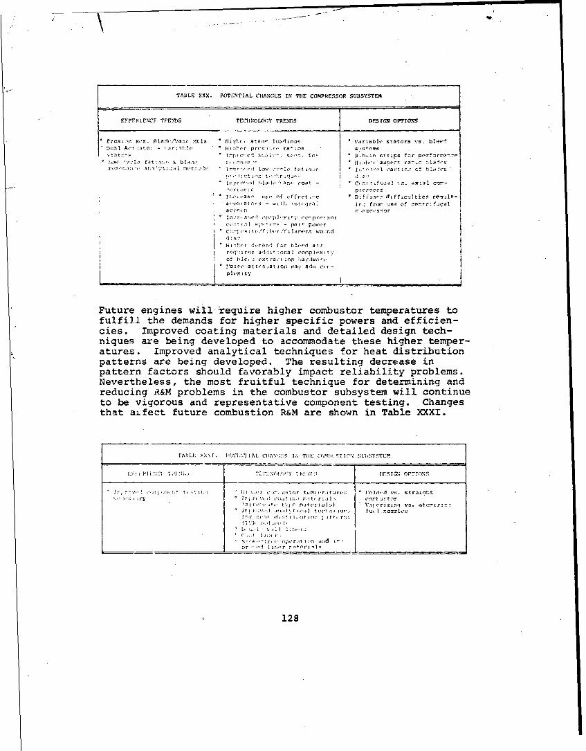
TABLE XXX. POTE:NTIAL CHANCES IN THE CO04PRESSOR SUBSYSTEM
EYPFRIE';CF TPEN!DS TEChINOLOGY TRENDS DFrSIC OPT1Os
Erosin R,'s. lad/,c/Van- :4tls " flihc, stair loarin-j * Variabl,' stators vs. bl,-f-DuL,1 Ao-t xito: - irile * i-i Ic r prvstirýt ratis t0 P.M.SfC
tzvo'r -1~. 1 . tor~r. r-~ * ph-in strr~ps for .rrxi.";""':i- :1 ,; fa~gt & b!a:r i, i.-•*~ , "O " hl[:lh,-ra.so*Ot ra•;c i.3s•:L'
rcsz:;a,*-, 3nriiy'ti l i¶t ,'- lI r ,-i low -. I'V f0'tia.:(. * ent r;l cavt:..' Cf hla.?'
Cr1. 40:+t1, t " n ,I "-:. C- lr ',? r° ;:~ •'• b o ,., ¢oa~t - • t •# •] .. axial ccrt-
* It. W- oas,, f , . fect .* Diffus-r dif'oc%;!tiea resullt-
s•,payatrs - with intejral irs, frorm Se of ce'! ,r;f0 alscrl•r' r -C . •sinrI
" "In -r, 4o pl ltot crpr,-F-oor
C,.,:It i' '.rr•,- - parr powerI Cr;ý.:,~s itc/fj?,•.r/ i larent wo,:nd
* Hl-h'-- -jera-i', tor ble-ed air
rrq:Ir'r 3�1 3�1 o ror-Pplexit',"o bC t I e rrt o ardae
* !'oxs.' attn.-.ation r00 ada cor -phexity
Future engines will require higher combustor temperatures tofulfi.l the demands for higher specific powers and efficien-cies. Improved coating materials and detailed design tech-niques are being developed to accommodate these higher temper-atures. Improved analytical techniques for heat distributionpatterns are being developed. The resulting decrease inpattern factors should favorably impact reliability problems.Nevertheless, the most fruitful technique for determining andreducing R&M problems in the combustor subsystem will continueto be vigorous and representative component testing. Changesthat aifect future combustion R&M are shown in Table XXXI.
1AOI'A ;yI.E X 1. ('-(T:;!IIAL. II 1 :f ýI Th:" C()M:'•ifT -" SUhf;YSTEM
r - jV -Cnr,'; N t . -, It .,; I 7..,--r ")r. u;tor t£Lt •.rsturc,; I'Vld,,d vs. stral'lhtr:. ,.;.,• • lrtrr,\ 1 Cl:.,? I::, C t.. , r; i]i, con urt-'r
I Ci 10 t,- t.-Ic r1it(,rial L) ti, (.rizitnq vs. atmo'zl0-
for :I, r ' •- , rI, 1t o, n atir r' ;:
1 I , - ,' ; . 1 r • . .
' •,:,k•- or,-, ¢ i t' l i.n -ird i'-rnr -. 1.. 1 •r r ntor ' 11
128
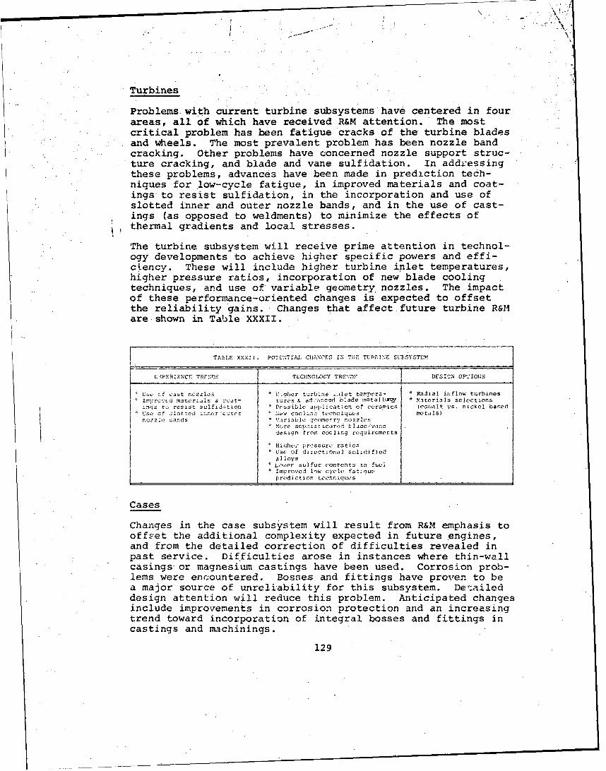
Turbines
Problems with current turbine subsystems have centered in fourareas, all of which have received R&M attention. The mostcritical problem has been fatigue cracks of the turbine bladesand wheels. The most prevalent problem has been nozzle bandcracking. Other problems have concerned nozzle support struc-ture cracking, and blade and vane sulfidation. In addressingthese problems, advances have been made in prediction tech-niques for .low-cycle fatigue, in improved materials and coat-ings to resist sulfidation, in the incorporation and use ofslotted inner and outer nozzle bands, and in the use of cast-ings (as opposed to weldments) to minimize the effects ofthermal gradients and local stresses.
The turbine subsystem will receive prime attention in technol-ogy developments to achieve higher specific powers and effi-ciency. These will include higher turbine inlet temperatures,higher pressure ratios, incorporation of new blade coolingtechniques, and use of variable geometry, nozzles. The impactof these.performance-oriented changes is expected to offsetthe reliability gains. Changes that affect future turbine R&Mare shown in Table XXXII.
TAalE XXX!I. POTENTIAL CH1ANCES IN TiE TUPIANE SIUBSYSTEM
E(PERIENCE TRENGGs TMCINOLOCGY TRE';Dl DESIGN OPTIONS
LUX. cf cast nozzles H.hqher turbine -.ilet temrpera- * Radial inflow turbines;'aterls r advanced blade Yetaz[ j i ysterials selections
inqs Sa res Ist sulfidation. Possible aiplication of ceramics (cobalt vs. nickel basedUSe of slotted troor cit.r ..e cool.ni tkc'hnb ques " etals)n cz7h 2 ands • Variable qeometry nozzles"M ore sopust icttId tlade/vane
design from cooling requirererts
leiahes: pressure ratios"" Use of directional solidifiedalloysfl,.ver sulfur contents in fuel
• o IImroved low cycle fatigueprediction. tcchnoques
Cases
Changes in the case subsystem will result from R&M emphasis tooffset the additional complexity expected in future engines,and from the detailed correction of difficulties revealed in
* past service. Difficulties arose in instances where thin-wallcasings-or magnesium castings have' been used. Corrosion prob-
* lems were encountered. Bosses and fittings have proven to bea major source of unreliability for this subsystem. Detaileddesign attention will reduce this problem. Anticipated changesinclude improvements in corrosion protection and an increasingtrend toward incorporation of integral bosses and fittings incastings and rachinings.
129

V&
This latter point will become increasingly important as diag-nostic systems in engines become more comprehensive with anincreased number oif interface points. The decreasing emphasison thin wall casings will allow more robust structure capableof accomrudating these design details.
The reqL r'ments cr engine noi'ze attenuation are expected tocomplica-e enqine cases. Cases are a prime example of an areain which v.:i:•, careful detailed design will be necessary toavoid R&V: .roblems. Changes that affect future cases R&M aregiven in Table XXXIII.
TA:.E XXX I 1. POTL':T1AL CHANGES IN THE CASEbs SUBSYSTEM
EXPERIENCEr TRZNDS (T)'Ch -O';Y TRP.NDS DESIG' OPTIONS
.o L.ss e, tsis on thin wall o ncreas•! modularization Hard vs. soft zmountingIncreased case temrperatures of engines
* Improved corrosion protection Additional bosses/fittings Different materials* borses & fittings should be for both in rnal and
integrally c•.:t external aia,:;•.sticsMignesium should not be used Additiona' bosses/fittingsfor any structural support for extra bleed controls
* Noise attenuation require-mentS May O•rompicate caSes
0 Imrcroved ercii .n characteristics
Lubrication
The need for improved filtration and protection from minordebris will necessitate changes in the lubrication subsystem.Experience has proven that the majority of problems encoun-tered were contaminant related, either from metallic debrisand carbon contamination, or from mixing of contaminated seal-pressurizing air with the engine oil.
Demands on the lubrication system will become more severe asengine operating temperatures and soak-back temperatures in-crease. The trend toward the use of more labyrinth seals willincrease the need for improved filtration and involve the useof more complex air/oil separators. Problems encountered withlubrication system operation (such ad check valves sticking,marginal scavenge capabilities, and fitting leakage) havedemonstrated the need for increased system testing. Changesthat affect future lubrication system R&M are presented inTab'le XXXIV.
Fuel
Changes in the fuel subsystem will result from the necessityof improving filtration protection and improving accessibilityand maintainability of the fuel control unit. While the fuelcontrol unit has been the major contributor to system unreli-ability and will probably continue to be, several factors willreduce this rate on future engines. Contarmination of this
130
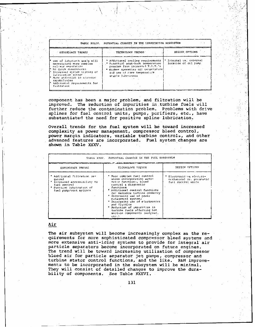
'II
TABLE XXXIV. POTENTIAL CHANGES IN THE LUBRICATION SUBSYSTEM
EXPERIENCE TRENDS TECHNOLOGY TRENDS { DESIGN OPTIONS
use of labyrinth seals will * Additional cooling requirements Internal 1s. externalnecssitate more complex * Potential soak-back temperature location of oil pumpoLl/•ir seairation problem from increasel T.I.T. 'sNo quick disconnects 4 Higher operatinq oil temperatureIiicreased system testing of ard use of rore temporaturelenrication 5;.stdr stable lubr'.cants
o Mre attbntion to scavenge-
capabilltieso Additional requirements for
filtration "
component has been a major problem, and filtration will beimproved. The reduction of impurities in.turbine fuels willfurther reduce the contamination problem. Problems with drivesplines for fuel control units, pumps, purifiers, etc., havesubstantiated the need for positive spline-lubrication.
Overall trends for the fuel system will be toward increasedcomplexity as power management, compressor bleed control,power margin indicators, variable turbine controlo, and otheradvanced features are incorporated. Fuel system changes areshown in Table XXXV.
TABLE XXXV. POTENTIAL CHANCES IN THE FUEL SUBSYSTEM
EXPERIENCE TRENDS TECHNOLOGY IRPNDS DESIGN OPTIONS
Additional filtration re- More complex fuel control o Electronic "a. elecvxc-
qulred units incorporating auto- ricchanical vs. pneumaticIncreased accessibility to matic functionn, bleed fuel control. unitsfuel control control & diagr.ostic
SPositivc lubrication of functionsfuel pump/cont splines 4 Additional control functions
for variable turbine geometry* Increasing use of power
management systemj. Increasing use of e!ectronics
and fluidicsWeduction of impurities inturbine fuels affecting hotsecti.on components (sulphur.
Air
The air subsystem will become increasingly complex as the re-quirements for more sophisticated compressor bleed systems andmore extensive anti-icincr systems to provide for integral airparticle separators become incorporated on future engines.The trend will be toward increasing utilization of compressorbleed air for particle separator jet pumps, compressor andturbine stator control functions, and the like. R&M improve-ments to be incorporated in the subsystem will be minimal.They will consist of detailed changes to improve the dura-bility of components. See Table XXXVI.
131

-4
TABLE XXXVI. POTENTIAL CHANGES IN THE AIR SUBSYS,
EXPERIENCE _TENDr' TECHNOLOGY TRENDS DESIGN OTIONS
,%,ore ruaqed construction * More corplex air systems for * Inteo:P. versus sx-o0 external lincs and compressor bleed (part power ternd, passages forflttinqs performance and aircraft anti-icin•, pi-ton
systems power) balancinqa..d cool-"More extensive anti-icing ingsysterrs for use cn part-icle separators"Need for built-in lowpressure air supply fornacelle coolinrw and IR sup-pression I
Accessory
The trend for future accesscry subsystems will be toward anincreased number of component drives. Experience has indi-cated that tandem grouping of accessories from a single drivehas caused problems. The *trend will be toward more individualaccessory drives for this purpose and to provide mechanicaldrives for particle separator blowers ' nd like purposes. Theoperating environm-nt for the accessory system will Lecoimemore severe as engine case temperatures A'is'e. Changes in theaccessory subsystem are given on Table XXXVII.
STA',11! XXXVII POTl :','TAL CJ1-NCLS IN TliE ACCL. 'ORY. TEy
I rF:PE[RIENCE TR!:%ND TLCHNOLOGY T1Z.r:DS Durrc orTO:s
Y~tY ;::!.%;,].J] !rl~:'3o Ad iti nal ¢:t" :m..•t-';" llia!ýer s.,octd !-u7-- R, • n. , etc
S " : ,,rtlc S r ;r bl!rers, ccu.d rcdj1uý ac r-, r' drv:'c.!s..A t:." &. Vu er.- t ,t' }i: e" 3arr t. t r.(-r turos- functlO• Of .ocf :::•ci '
Torquemeter
The trend of torquemeter subsystems for fiture engines willbecome more reliable and more accurate. Zxperience indicatesthat high-speed mechanical and remote airf,ame-mounted torque-meter systems have neither adequate reliability nor accuracy.It is ui.likely that either type will be used on future engines.Features of future engine torquemeter systems are likely toinclude integral high-speed electrical/electroric systems withself-checking capatility for torquemeter calil,-ation. Changesthat will affect future torquemeter system R&M _re given inTable XXXVIII.
132

TABLE XXXVrII. POTENTIAL CHANGES IN TILE TOROUEPETER SUSYSTEM
EXPERIENCE TFENDS TELUNOLOGY TRENDS DSIGN OPTIONS
Purely mechanical systems are All engines will have inteqral , Electronic vs. electro-unlikely to be used I torquemeters mechanical on larger enginesSmall high-speed turbines will I - Self-check (pwr. margin ind.) fcontinue to incorporate hydro- -of torque system will bemechanical systems i required
N Neel for improved accuracy
Electrical
Electrical systems will become more complex to provide for theincreasing use of power management systems and more comprehen-sive built-in engine diagnostic systems. The operating envi-ronment for the electrical system will become more severe asambient temperatures rise due to higher engine operating tem-peratures. Changes that affect future electrical subsystemsare presented in '2able XXXIX.
TABLE XXXIX. POTENTIAL CHANGES IN THE ELECTRICAL SUBSYSTEM
EXPERIENCE TRENDS TECHNOLOGY TRENDS DESIGN OPTIONS
More rugged mounting of Additional complexity due to Integral generators (shaft
electrical lines & diagnostics power management driven) on smaller enginescomponents Higher ambie:: temperatures from
higher engine temps (>250*F)
Exhaust
The general trend for the exhaust system will be toward sim-plification as the conventional front-shaft-drive configurationbecomes more universal on medium and large engines. Small en-gines are likely to continue to show the diversity of exhaustconfigurations apjarent on current engines. IR suppression isriot likely to impact the exhaust-system removal ratessincemounting and load-carrying provisions will be part of the air-frame and will, most likely, be maintained as a separatemodule. Table XL shows the changes that will affect futuresystems.
TABLE XL. POTENTIAL CHANGES IN THE EXHAUST SUBSYSTEM
EXPERIENCE TPENDS TECHFNOL.OGY TRENDS DESIGN OPTIONS
Redundant retention mounting o Front-drive engines gener-
of exhaust cones ally simplify exhaust con-figuration
133

Power-Train Reduction
Small engines with 'try high turbine shaft spaeds will con-tinue to employ power-train reduction gearing for helicopterdrive systems. Changes in this subsystem will occur to takeadvantage of advanced gear and bearing materials. No overallchange in reliability is foreseen. The introduction of in-tegral particle separators may force redu:cion gearirq to beoffset from the engine centerline. Factors affecting futureR&M are given in Table XLI.
TABLE XLI. POTENTIAL CHANGES IN THE POWER-TRA!:, REDUCC.!ON SUBSYSTEM
EXPERIENCE TRENDS TECHNOLOGY TRENDS DESIGN OPTrIONS
* Advanced gear and bearing * Higher speed outputs would
mnteria!s lead to less reduction gear-ing
* intejral separatror may forcereduction gcaring to beoffset
Foreign Object Damage
The major trend toward preventing the FOD problem will be theuniversal application of FOD screens. Improvements can be ex-pected in screen size optimization and design of more ruggedattaching hardware. The development of second-generationinertial particle separators may provide the basis for a suit-able alternative to FOD screens. The separator provides anoverboard flow path for sand and dust, and it may be capableof handling large objects in the same manner. Studies anddevelopment efforts will determine this through analysis andtesting under various power conditions witl. a variety of FODsources.
Experience shows that design of compressors to withstand ero-sion and FOD can provide considerable benefit (see Figure 53).Engine configurations with an emphasis on durability and rug-gedness will be characterized by compressor designs which aremore tolerant of FOD and will result in significant reductionsin removals due to FOD. Table XLII shows changes that willaffect engine FOD.
TABLE XLII. POTENTIAL CHANCES IN THE POP SUBSYSTEM
EXPFPIrNCI TPNDS TECHN'OLOCY TRENDS DFS ICN rprTONS
" FOV snreens mandatory j Reduced inlet los-so FOD-resistant confressordesigns
" Optirized screen stze s Anti-eel screens
"0 irFrcved scrern-attaching o In .-tial separators insteaChardware I of ;rrecns
134

Erosion
General trends in erosion damage reduction will be in thedirection of mandatory incorporation of inertial particleseparators and further refinement of these devices. Second-generation air particle separators with increased separatorefficiencies and reduced ram air losses will be available.The past generation of add-on separators will be supersededby an era in which the air particle separator is designed bythe engine manufacturer as an integral portion of the engineassembly. It i being recognized that the design of the com-pressor can have an R&M improvement potential nearly as greatas the installation of particle separators. Erosion-resistantcompressor designs will be considered for future engines whereR&M is emphasized over performance and weight.
Several of the study engines were considerably more erosiontolerant than others. This tended to reduce the index numberassigned to the composite engine. If R&M emphasis in 1975-1982 era engines does not outweigh performance emphasis, it ispossible that these engines will experience erosion rates inexcess of that assigned to the composite engine. Changes thatwill improve engine R&M through reduction of erosion arelisted in Table XLIII.
TAVLF XLIII. POTENTIAL CHANGES IN THFf EROSION SUBSYS-TM
Experler.e Trends Technology Trends Design Cptions
o Particle separators o Increased separator o Power sources forare an artory efficiency scavenging particle
;esr•ratcrs (hydraulic,electric, compressorair)
o Self-purging separators o Reduced ram air losses
o Separators integralwith enqine
Environment
The trend for the environment domain will be toward moreeffective protection against identified problems. It is un-likely that contaminant levels present in fuel or oil fromexternal sources will be significantly reduced. Similarly,environmental conditions leading to corrosion will not change.Operations will continue in adverse environments.
Activities are under way to more closely identify the specificconditions causing fuel and oil contamination. This effort
135
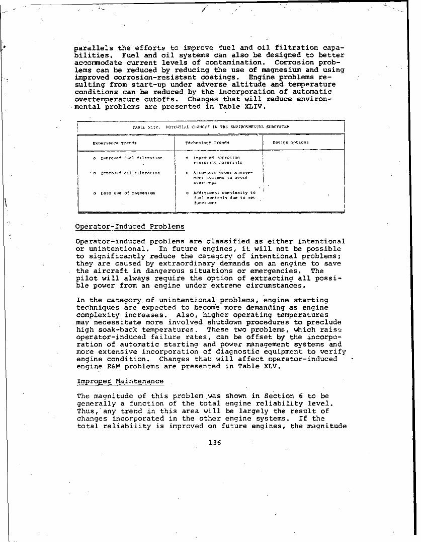
parallels the efforts to improve fuel and oil filtration capa-bilities. Fuel and oil systems can also be designed to betteraccommodate current levels of contamination. Corrosion prob-lems can be reduced by reducing the use of magnesium and usingimproved corrosion-resistant coatings. Engine problems re-sulting from start-up under adverse altitude and temperatureconditions can be reduced by the incorporation of automaticovertemperature cutoffs. Changes that will reduce environ-mental problems are presented in Table XLIV.
TABLE XLIV. POTENTIAL CIHANCN:S IN T•E ENVIRON'MENAL SUBSYSTEM
ExDerLence Trerds Teohnoloqy Trends Deqin Options
o ImproveA fuel filtration o Impro,,el ýorroAiorrosistint ..iteruis
o Itrproe'i oil filtrst an 0 Aojto tic power manale-cent sy:tens to avoidover enps
O Less use of magnesium o Additional ccmelexity tofiel controls due to ne-functions
Operator-Induced Problems
Operator-induced problems-are classified as either intentionalor unintentional. In future engines, it will not be possibleto significantly reduce the category of intentional problems;they are caused by extraordinary demands on an engine to savethe aircraft in dangerous situations or emergencies. Thepilot will always require the option of extracting all possi-ble power from an engine under extreme circumstances.
In the category of unintentional problems, engine startingtechniques are expected to become more demanding as enginecomplexity increases. Also, higher operating temperaturesmay necessitate more involved shutdown procedures to precludehigh soak-back temperatures. These two problems, which rais'eoperator-induced failure rates, can be offset by the incorpo-ration of automatic starting and power management systems andmore extensive incorporation of diagnostic equipment to verifyengine condition. Changes that will affect operator-inducedengine R&M problems are presented in Table XLV.
Improper Maintenance
The magnitude of this problem was shown in Section 6 to begenerally a function of the total engine reliability level.Thus, any trend in this area will be largely the result ofchanges incorporated in the other engine systems. If thetotal reliability is improved on future engines, the magnitude
136

TABLE XLV. POT'ENTIAL CHIANGES IN THE OPERATOR-rNDUCEO SUBSYSTEM
Experience Trends Technolog~y Trends Design Options
o Higher operating trends oF contingenci pow.erwith greater soak-back temp problems
o Inr~eaesed e~igine per-
fo rtna 2e sophistiatiMonl
tecbniques
0 A. t)m t i Ola-L ' rtairt .nq
j - j o Car'eition o~nitcrina
of this problem will be reduced accordingly. Thus, R&M ermpha-sis throughout the engine will influence the magnitude ofproblems caused by improper maintenance.
in addition to this indirect relationship, a direct improve-ment is possible through the stringent application of mainte-nance engineering disciplines to the design of turbine engines.This benefit from this improvement alone can be substantial.Examination of specific-instances of maintenance damage (asdiscussed in Section 5) indicates that there are several areasthat .can profit .!rom increased attention. Certain of thesechanges are showr in Table XLVI. Other improvements can re-sult from'close attention to detailed design and from recog-nition of past maintainability problems. All changes toreduce the magnitude of this problem will require signifi-cantly more emphasis on R&M than has boeen manifested in thepa6L.
Ttcnes .~ TeOC" ocWIoy Trerds Desijrr Opt icnr
o Standardized aý. ci tr,..s.r a .ncteaspd i rnd Iarl- o [,eel of~ capaz& jut'st .djs and b'Glts zat IlaL
( re-lwasn,,rae- folds i o tpro-!d er . r .T nsie.
II I
137

Airframe-Related Problems
Only slight improvements are expec - .rd in this area in the nearfuture. The magnitude of the reduction will be a function ofthe overall emphasis on R&M. Since the bulk of removals inthis category are due to poor accessibility of airframe-mountedcomponents, the application of rigorous maintainability analy-sis to engine compartment design can be of significant value.
The emergence of formal interface agreements between airframeand engine manufacturers can provide a means of reducing fail-ures caused by airframes. Engine/airframe interfaces (start-ing system, drive-train output connections,.nacelle cooling,fuel filtration, mounting techniques, etc.) can be more,closely controlled under these agreements.
The requirement to specify airframe-induced vibration levelswill permit endurance testing in an environment similar tothat which will be experienced on the aircraft. Detection andresolution of potential vibration-induced problems will thenbe possible. Table XLVII lists the changes that affectairframe-related R&M problems.
TABLE XLVII. POTFLNTIAL CIfANCES. IN THE AIRFRAME-RELA'T " SUBLYSTEM
Experlerce Trends TechnoloTy Trends Design Optio's
o Engine temting with A/C 1) Improved airframe/engine 0 Hard vs soft •o~rting ofvibration levels interfaces enqr
o Lnproved accessibility o Developmernt of drive systemdynamics aralysis tech-
0 RiqCgO.s m•iu•tal.ratlity ni aoesanal-.1is
Convenience Removals
The two dominant factors that influence this problem wereshown to be the overall reliability of the engine and the man-agement of the logistics system. Since the magnitude of thisproblem in future engines will be the indirect result of basicengine reliability, it will reflect the specific emphasis onR&M given to each program. In addition to this, indirect bene-fit, significant reductions in this rate can be obtained by animprovement in the logistics system. Specifically, the non-availability of spare engines or engine components has beenshown to be the significant factor in convenience removals.Improvements in the skills of logistics management should pro-vide considerable relief to this problem. The magnitude ofimprovement will be greatest on those engines which are mostunreliable and least on those which are most reliable, asshown on Figure 63. Improved accessibility can provide for
138

more in-place repair, thus avoiding unnecessary engine remov-als. This accessibility improvement will result from increasedR&M emphasis. Changes that will reduce convenience removalsare shown in Table XLVIII.
TABLE XLVIII. POTENTIAL CHANGES IN THE CONVENIENCE SOBSYST:.M
Experience Trends Technology Trends Design Options
o Improvements in logistics 0 Improved accessibilitymanagement
c Grouping of accessorieso Influenced strongly by
engine accessibility
PROGRAM TRENDS
In the previous section the individual R&M problems of currentengines were exarined to determine general program deficien-cies. This portion of Section 6 reviews contemporary programtrends to identify activities that can effectively offset theimpact of past program deficiencies in future (1975-82 era)engines.
There are five major areas that influence the R&M of anyengine. The first three (Specifications and Requirements,Development Design and Testing, and Operational Use and Prod-uct Improvement) relate to the development and use of specificengine models. The fourth and fifth areas (Environment andMaterials and Design Concepts Technology) are not related tospecific engines, but to engines in general.
Prior to discussing these areas, it would be valuable to re-view the various approaches that could be used to improveR&M. The term approach is used to indicate that there canbe significantly =FFernt roles assumed by the customer andmanufacturer in the totOl cycle of engine development. Thespectrum of approaches can best be visualized by outliningthe two extremes.
One extreme concentrates the achievement of R&M in the estab-lishment of numerical objectives at the total engine levelwith minimal customer contact with the detailed design. Asso-ciated with these objectives are formal contractual demonstra-tion requirements with economic incentives and penalties.This approach utilizes the design and management skills of tneengine manufacturer to determine appropriate design concepts,execute the detail design, plan and perform the testing pro-gram, evaluate the need for corrective action, and conceiveand implement design changes. Customer activity is limited
139

to the establishment of initial requirements and confirmationthat the objectives are achieved.
The other extreme requires that the customer be intimatelyinvolved with all phases of the program - establishing de-tailed design requirements, reviewing design approaches andanalyses, exercising close and authoritative monitoring of thetest, determining the need for corrective action, and assuringthe adequacies of the corrective action.
The first approach has the advantages of simplicity, minimumcosts, and minimum coordination. However, little or no knowl-edge of contractor progress is available to the customer, andcontractual penalties notwithstanding, it is unlikely that thecustomer could ever completely recover the reliability growthschedule or the life-cycle cost objectives if the contractor'sR&M program were deficient.
The second approach involves lower risks but requires muchmore customer effort. Customer evaluation and auditing at thedetailed design level require skill across the full spectrumof engine design. A possible disadvantage is that this levelof interface could essentially relieve the engine manufacturerof responsibility for achieving the R&M objectives..
Selecting the superior approach becomes even more complex whendemonstration of the various R&M parameters that might be ofinterest is ez .- ined. It is relatively easy to perform ademonstration test of erosion characteristics. It is moredifficult to demonstrate a removal rate for all causes. It isnearly impossible to demonstrate a safety-affecting failurerate, due to the low frequencies of occurrence and long demon-stration times involved. The timing of the demonstration inrelation to production go-ahead decisions and the customer'sbasic model evaluation and selection process are two otherareas that must be considered in adopting a basic approach.
The two roles described are extremes and may not ever repre-sent actual programs. They indicate the contrasts in emphasisthat could affect future activities. Contemporary programssuggest that a combination of the two approaches is beingtaken with emphasis on numerical demonstration. Selected de-sign features are being specified (such as erosion resistance,blade containment, accessory mounting locations, and similarcharacteristics) which can be separately demonstrated, usuallythrough testing. General customer monitoring of the designand testing phases will provide some indication of goalachievement, but will not alleviate the contractor's basicresponr;ibility for attaining the R&M objectives. A programapproach midway between the two extremes is assumed in thediscussion of the five program areas.
140

Specifications and Requirements
There is growing recognition that specifications and require-ments is the prime area where the customer can influence majorR&M characteristics. Later phases, especially the Operationand Product Improvement period, produce numerous detailedimprovements; but by that time, the ability to make the majorchanges that grossly affect R&M has been lost due to the ex-treme costs involved. Consistent with the overall programapproach of customer noninvolvement with design details, R&Mobjectives can presently be established with the followingcharacteristics:
o Individual, realistic objectives for each engine
o Use of clearly understood parameters for whichhistorical data is available
o Formal demonstration tests for each objective
R&M requirements for engines can and should be unique for aparticular engine, just as weight, performance, SFC, and othercharacteristics are unique for a particular engine. Thisapproach places the R&M objectives in the individual iv.)delspecification rather than in general specifications such asMIL-E-5007, General Specification for Turbojet and TurbofanAircraft Engines, which does include a numerical objective.General specifications should not include actual numericalvalues since R&M characteristics are so intimately related toother -1rogram issues (such as performance and weight require-ments, development program effort, and state of the art intechnology at the time of development).
Realistic numerical requirements are essential. Unrealisticor unquantified requirements will inevitably be ignored. TheR&M objectives can be consistent with what is achievable,based on simultaneous cons-.deration of past experience, cur-rent available technology, and othe-r engine requirements fromnoise to performance. The numerical value can have a timedimension which denotes when in the life cycle of the enginethe rnumerical value is to be reached. Both this time dimen-sion and the numerical values can realictically reflect theschedule and planned' extent of the developmental effort.
The requirement that the parameters be clearly understood andhave historical data available has an imnortance that cannotbe minimized. The value of historical data in the specificparameter enables the contractor and customer alike to hon-estly evaluate the design against the re.iiremera. This re-quirement can be satisfied today for many parameters.
Finally, demonstration is required to make the otihea
141

requirements meaningful. Formal demonstration of objectiveachievement is the ingredient that makes improved R&M areality.
Demonstration of R&M objective achievement can be in the formof tests or analyses. Some parameters lend themselves toverification thru tests. Among these are erosion rates, fuelcontamination resistance, total malfunction rate, maintenancetask times, too. and GSE requirements, some failure progres-sions including containment, dry-lube operation, and others.Characteristics that are dependent on factors which can beunderstood and controlled are likely candidates for formaltests. Other characteristics driven by factors such as air-craft installation, maintenance concept, mechanics skills,pilot judgement, and local logistics and environmental condi-tions are difficult to demonstrate with the conclusivenessappropriate to a contractual obligation.
These elements are the prerequisites for effective R&M re-quirements and are generally available today for applicationto 1975-82 e. engines. They help R&M to compete effectivelyagainst other engine requirements that are universally under-stood and immediately demonstrable.
For current engines developed in the 1950-60 era, inadequate,misdirected, or absent specifications were directly responsi-ble for 27 percent of the engine R&M problem. The individualsubsystems/modes which were the sou:ce of this percentage areshown (Table ZXVI). As indicated in the discussion, specifi-cations were directly influential in a relatively few, butnevertheless important, modes and subsystems. However, inade-quate specifications and requirements have an indirect effectupon the contributing factors Preliuinary Design and DesignExecution, and these factors influence every mode and sub-system. Thus, the potential improvement of R&M from morerigoroais numerical specifications can be- significant.
The direction of contempotary engine development programsshould be examined against this background. Based on recentengine specifications, data presented at symposiums, and thevarious studies performed under contract to military custom-ers, the following observations are offered:
o Numerical requirements at a specific point in thematurity cycle are being imposed at the engine-causedlevel ir .aany parameters. Several of these parameterslack either historical data or the ability to bedemonstrated through tests. Others are extremelysensitive to issues unrelated to the design (such asmaintenance concept and skill levels).
142

o Several-of these numerical values are to be demon-strated through testing. There appears to be a growingappreciation of the mathematical relationships involvedwith reliability demonstration tests, and this has en-abled more meaningful tests to be established.
o Economic incentives and penalties are being associatedwith achievement of R&M goals.
o In addition to overall numerical objectives, specificdesign features are being specified and quantitativerequirements established for specific failure modes.Erosion resistance, operation with contaminated fuel,low-cycle fat'gue lives, no-lube operationibearingB10 lives, and blade containment are being controlled.Certain design features, such as pinned bearing outerraces, are being required. Other features that mayalso fall into this category are type of oil seals,case and compressor materials, type of torquemeter,fuel control actuating media, installation of FODscreens, sizes of fluid, air, and mechanical connec-tions, and location and sequence of accessory mounting.Establishing these design features as requirementsforces initial proposals to address these featuresdirectly and, where alternates are proposed, forcesthe proposers to justify, from an R&M standpoint,their decision to propose an alternate.
o Appropriate durations for demonstration tests are beingrecognized. Demonstration tests for overall enginereliability that require longe durations than prac-tical for the development phas are being scheduled tooccur in the production phase.
o Some engine programs are requiring that the configura-tion utilize an existing core. This approach capital-izes on the "Volkswagen principle" and is an effectivemethod of obtaining good R&M by benefitting from theexperience on already mature designs. This approach,if accompanied by restraints in increasing the operat-ing temperatures and in the whole definition of"existing," can achieve both improved R&M as well aslower development costs.
In general there appear to be significant improvements incontemporary specifications and requirements. These improve-ments should produce future engines with R&M characteristicssuperior to the study engines.
Developmental Design and Testing
Consistent with the program approach discussed in previous
143

paragraphs, participation of the customer in development de-.sign and testing should be limited primarily to observationand assistance. The responsibility for developing the basicdesign approaches, executing the detailed design, planninq andperforming the test program, and initially evaluating the re-sultant product should be the manufacturer's. The degree offreedom of the manufacturers in this area should be consistentwith the contractual obligations they have assumed.
Essential to the process of developing the optimum:engine forthe given requirement is an understanding of the relativecharacteristics of alternative design approaches, materials,etc., and the ability to utilize these characteristics inmeaningful trade-off studies. The inherent R&M characteris-tics of many design alternatives have not always been welldefined. Most engine manufacturers possess a rather limiteddata bank that is restricted to the field experiences of theirown engines and the tests of research programs they have con-ducted. This has severely limited their exposure to a widerange of configurations, designs, and materials with known R&Mattributes, and thus has resulted in trade studies of confinedscope. This lack of interchange of data among the enginemanufacturers extends into other areas such as exchange ofanalytical techniques. Associations such as the SAE, AGMA,and many Governnent agencies contribute some relief from thisproblem. Much more effort is required. This is discussedunder Material and Design Concepts Technology.
The problem has not been merely accessibility to R&M data.Even when data bases are available, the R&M qualities of al-ternate designs may not be evident due to variations in over-lapping designs, environmental or usage differences, ordissimilar points on maturity curves. The design optioncategory of engine features included many important and con-troversial design alternatives available to the engine de-signer. Significant questions such as the relative erosioncharacteristics of axial and centrifugal compressors have notbeen conclusively answered through either field or test data.This prevents the designer from relating a compressor designdecision to a numerical goal for erosion resistance. It isfelt that the study reported herein may represent a steptoward alleviation of these problems, in that it representsboth a compendium of field data and manufacturers' experiencefer a wide variety of turboshaft engine designs. Exposure tothe R&M experience from growing families of engine configura-tioas is assisting engine manufacturers in evaluating thedesign characteristics of at least the alternative approachesthey have utilized in their own products.
It was suggested in Section 5 that only 25 percent of theproblems arising from design execution were due to a technol-ogy or data limit. The remaining 75 percent were due to the
144
omission of analytical calculations, disregard of clear histo-rical experience, or failure to plan or execute test programsadequately. Thus, it is appropriate to suggest that what maybe missing is an escalation in application rather than tech-nology. This reflects again the indirect effects of inade-quate R&M objectives and specifications. When the technologyexists to adequately perform the design and testing phases andis not utilized, it can only be attributed to a lack of time,funds, or R&M emphasis. The current tendency, reported underSpecifications and Requirements, toward meaningful numericalobjectives with a contractual obligation to demonstrateachievement should cause the contractors to utilize theiravailable analytical tools to a far greater extent in thedesign of contemporary engines.
The role cf complete assembly testing in the development phaserequires discussion at this point. Development testing, asopposed to demonstration testing, should be viewed as a back-up to the design analytical process. It should never beconsidered as less than an integral element of the total de-velopmental effort in response to a given requirement. Assuch, it reflects not only the uniqueness of a given configur-ation but the manufacturer's engineering and management skillsas well as his total facilities and financial situation. Theengine design, management, and procurement community is, un-fortunately, not currently able to size a test program interms of a stated reliability objective ",ithout making certainassumptions concerning initial desigii reliability, problemdetectability in the test stands, and the contractor's abilityto recognize, understand and correct problems. Assumptionssuch as these may be quite-subjective.
Given this uncertainty on the required test program, the cur-rent trend is that minimum test iurations and basic operatingconditions are being specified by the customer. There are twobasic reasons for this trend.
The first relates to the initial proposals by various competi-tors for the development contract award. Since the test pro-gram represents such a large portion of the development costs,it affords the individual manufacturer an opportunity forsignificant cost reductions through abbreviated efforts inthis area. Given the inexact science of reliability predic-tion and control, military customers have chosen to establisha finite value of test duration in order to obtain comparablecost and schedule estimates. This eliminates one variablefrom the evaluation process but prevents any offeror fromrealizing his due competitive advantage from a superior reli-ability approach. Inherently more reliable design features,use of existing mature components or subsystems, or moresophisticated analytical procedures would be reflectedonly in the obscurity of an heretofore unprovable higher
145
reliability level instead of the more obvious lower costprogram.
The second reason for specified minimum test durations isrelated to the first in that it reflects the current inabilityto size a test program based on a reliability goal. Minimumtest durations have been escalating throughout the years withthe hope that higher reliability would be achieved. Durationsare currently between 9000 and 14,000 hours on new engines.
There is a natural reluctance to reduce these durations, ata time when good R&M is the dominant theme. This may result,however, in higher development program costs than are actuallyrequired.
The growing concern for minimum costs, when coupled with theconcurrent desire for improving the re]lability levels, hasproduced an interest in developing methods for relating reli-ability and testing requirements. An approach for relatingtest requirements to reliability objectives for helicoptertransmissions and -ther major dynamic compinents is availabletoday for application to the design of tesc programs for con-temporary engines. 2' Application of thc¢se principles wouldresult in a more efficient development test program, by tail-oring the level and duration of the testz to the R&Mrequirements.
The following is a summary of current treris in the developmentdesign and testing area:
"o Design and testing has been and will be primazily thecontractor's responsibility. The customer is generallyassuming a passive role in the evolution and executionof the detailed design, but a more aggressive role inthe testing area by specifying minimum test durations.Methods are appearing to aid in the establishment oftest requirements.
"o Relationships between testing duration and reliabilityobjectives are be iming better understood. Rigoroussiring of test programs requires sorte improvement.s inour ability to predict anticipated initial designreliability, test detection effectiveness, and timer~quired for corrective action.
"o Information relating to the R&M characteristics of al-ternate design approaches or materials has been severelylimited due to the general lack of widely available pub-lished field and test data. Exposure to availableanalyticail techniques is similarly limited. Steps arebeing taken to relieve this problem, and material isavailable for application to contemporary engines.
146
In general, devt opment design and testing is a fertile areafor activities that will apply, expand, and upgrade theresources for improving the R&M of future engines.
Operational Use and Product Improvement
This phase represents the activities occurring after theengine has been fielded for operational use. The emphasisapplied to the product improvement program affects the slope(rate of improvement) of the growth curves. Depending on theprecise nature of the developmental and production contractsin the area cf R&M goals, the responsibility for R&M improve-ment in this phase may lie with either the contractor or thecustomer. It has been suggested that, in an era of formalR&M demonstrations, most of the responsibility for correctiveaction will rest with the contractor until the point of demon-stration. However, there will still be a significant oppor-tunity for improvement after this point, with prime responsi-bility for implementation, if not initiation, resting with thecustomer.
Unfortunately, past production programs have not been modelsof efficiency or effectiveness. Three areas of these programsrequire remedial action:
o The evaluation process for initiating and implementingdesign changes to correct reliability problems
o The system for the uprating of the basic model forhigher powers through changes in speeds, operatingtemperatures, or additional stages
o The procedures for establishing initial TBO intervalsand progression programs
The entire process of product support has suffe -ed because ofweaknesses in both the contractor and customer roles. On thecontractors' part, the design and support teams tend to bedisbanded after the initial development phase is completed.Thus, the response to service-identified problems has not beencharacterized by the same talents and enthusiasms encounteredin the development of a new design.
On the other hand, even when the contractor has respondedquickly to the indication of a problem, the customer sometimesfails to approve the corrective action or to have it incorpo-rated into field engines in a timely manner. The problems onboth fronts arose from the lack of clear reliability growthobjectives for the hardware and the difficulties of evaluatingthe need for, or value of, specific corrective action forproblems.
147

Two basic approaches have been followed in the past for iden-tifying problems; each has its own merits. The first concen-trates the R&M program in the collection of quantitative dataand the periodic publishing of this failure data in order toidentify existing and potential problems. The second reliesmore on qualitative judgements formulated during periodicjoint conferences between the contractor and the severalcustomer organizations involved.
Both systems have their faults: the first, with its emphasison numerical expression, tends to minimize or at least dis-courage a good description and discussion of the mechanismsof failure. And many times, the collection and display ofseveral R&M parameters fail to emphasize the consequences ofa single failure mode in each of these parameters. The dis-advantage of the second approach is that a tendency exists forindividuals to emphasize problems of which they are locally orimmediately aware regardless of their actual magnitude or con-sequences. It has been difficult to determine priority ofproblems under these circumstances.
Recent product improvement programs appear zo have recognizedthe basic advantages and disadvantages of the two extremesnoted above and have developed data reporting systems whichhave combined the advantagas of both. More qualitativedescriptions of problems are provided, but the basic numericalexpressions are maintained. It would appear that for contem-porary engines, these new reportirg systems will be used moreas working documents than in past programs and will be corre-spondingly more effective in achieving rapid visibility ofproblem cause and magnitude, and in providing a more efficientproduct improvement program. The data reporting systems forthe T63 in the U.S. Army and the TF41 in the U.S. Navy are twoexamples of this improvement trend.
The second major probleir area, the development of reliable andmaintainable uprated models, has been as serious as the firstproblem area. Several dramatic instances have occurred in thelast decade where significant problems accompanied the intro-duction of uprated models. Failure modes were experiencedthat caused accidents and unscheduled removals at rates muchgreater than those for the basic model.
These problems arose essentially from a lack cf adequate veri-fication testing. Confidence that the new model was similarto the existing design led tn an overreliance on analysistechniques as opposed to testing. Frequently, the schedulebecame a dominant restraint to further activities, with thenew airframe becoming available prior to the new engine modelwith the attendant pressures to accelerate the introduction ofthe engine.
148

The technology that achieves the required level of R&M in newdevelopment engines will be adequate to achieve it in upratedmodels, if it is applied. What has been lacking is recogni-tion that an uprated model of an existing engine needs thesame R&M attention during specification, design, detail, andtesting as did the basic model. The concept of numerical ob-jectives and demonstration requirements for uprated models isavailable today for application to the derivatives of contem-porary engines.
The third area, TBO interval establishment, has traditionallybeen the joint domain of the developmental and productionphases. Objectives for TBO intervals have not been clearlyestablished in the basic specifications. Terminology has beeninconsistent, and no rigorous means of verification has beensuggested. Even when TBO objectives were quantitativelyestablished, no programs were defined for extending the in-tervals beyond the initial levels after the aircraft/engineswere tested and introduced into operational service.
The actual TBO progressions have been the responsibility ofvarious committees representing a wide range of technical andadministrative assignments. In some cases, decisions havebeen made based on samples returned from normal operationalaircraft; while in other cases, a specialized acceleratedtest activity was utilized. In either case, the criteria fordetailed component evaluation were ill-defined or inconsistentfor different engines or evaluating agencies.
Recent efforts at the Naval Air Integrated Logistics SystemCommand (NAILSC) and the Eustis Directorate, United StatesArmy Air Mobility Research and Development Laboratory(USAAMRDL), are directed at establishing the hardware, cri-teria, and mathematical procedures for determining appropriateTBO intervals. When developed, these procedures must be in-corporated into the basic R&M program and applied throughoutthe life cycles of the engines.
The following trends are apparent:
o There is some indication of improvement in procedures.and responsibilities for the identification and cor-rection of service-revealed problems. Data reportingsystems and their documentation are more oriented tothe rapid detection and correction of problems than inpast programs.
o There are current activities being directed at up-grading the logic and mathematical tools required forTBO establishment. Rigorous procedures will soon beavailable for application to engines now in service.
149

Environment
This area pertains to all engines and represents the totalenvironment (climatic, mechanical and personnel) to which en-gines are subjected. In spite of its universality of effect,insufficient resources have been addressed to this area.
In the previous subsystem discussicas, the effect of the en-vironment on individual failure modes was noted, and specificremedial actions were defined. It should be recognized, how-ever, that the effect of environment on individual problems isnormally minimized; the dialogue usually concentrates on themeans of correcting the problem. The impact of environmentrequires increased attention by customer agencies chartered toimprove R&M, but notinvolved with specific engine modeldevelopment programs.
It may be presumptuous to suggest that environment could besignificantly changed. However, there has been a growingrecognition that there is a very real value in better defi-nition of E.,vironment as a prerequisite to defining adequatedesign criteria.
Climatic environment involves terrain-related topics such assand. types and concentrations as well as atmosphere-related
*J issues such as humidity and salt concantrations. The impactof variations in these elements on engine R&M has previouslybeen discussed for specific failure modes. Specializedstudies (iuch as Reference 22 which quantifies the salt de-posits on compressor blades and vanes) aid in understandin'.specific problem areas. Of even more value are the Conferences on Environmental Effects on Aircraft and PropulsiorSyztemd sponsored by the Naval Air Propulsion Test Cenit-ir."These •onferences provide a forum where military and _-cm-merciaJ interests can publish and discuss the result-.- ofclimatic environment analyses and tests.
Activities such as these provide a means by which configura-tions and materials can be selected for contemporary engineswhich permit them to achieve reliability objectives.
The mechanical environment consists primarily of the aircraft-imposed loads on the engine. Aircraft vibration levels anddrive-train torque or alignment fluctuations have contributedto engine failures. This mechanical environment, significantlymore severe for helicopters than for fixed-wing aircraft, isprobably a major reason for the differences in reliability in-dicated in Figure 10. floated discussions of problem responsi-bilities (engine versis airframe) have done little to providea solid data bank of helicopter vibration levels for futureengine design criteria. Recent effort by the Helicopter Power-plant Committee of the SAE (S-12) to standardize vibration
150
7/
measurement techniques is a start toward such a data bank.Progress has been made in reducing rotor-induced vibrationlevels in helicopters of recent designs.
Other physical dimensions of the environment that should bementioned in this category include fueling equipment and thearray of ground support equipment at all levels of mainte-nance. The impacts of contaminated fuel and maintenancedamage have previously been shown to be substantial.
The effect of the physical limitat ons of fuel nozzles orfueling locations on the contamination problem needs to be ex-plored. Actual fuel and oil contaminacion levels experiencedin the field have not been adequately defined. Recent re-quirements for aircraft pressure fueling systems should dimin-ish the fuel contamination problem, ai d design improvements inoil filtration devices will contribute some relief to the oilcontamination problem.
The personnel who maintain and operate turbine engines havehad an even greater effect on engine R&M. Analyses indicatedthat 32 percent of the problem was directly attributable tooperations and maintenance, with approximately 40 percentoperator-induced and 60 percent maintenance-induced. Over 65percent of this operations and maintenance contribution wasexperienced in the Improper Maintenance, Operator-Induced andConvenience modes. The inevitability of this people problemrequires emphasis for all types of hardware.
It should be clear that military helicopter turbir'e engineshave not experienced the required step function improvementin their ability to operate reliably within the people envi-ronment that exists. A clear recognition of the performancecharacteristics of operating and maintenance personnel will beessential to this upgrading. While undoubtedly fore difficultthan a definition of the sand environment, any effort to es-tablish some type of baseline of human performance has apotential for large reductions in the R&M problem. Individualskills, maintenance concepts, and pilot workloads are a fewof the factors that should be examined. The impact of thevolunteer army may provide some relief to the maintenance- andoperator-induced problem, although the benefit may be nominal.More gain may be achieved through the application of humanfactors engineering to the manual and handbook software aswell as to the design itself.
The climatic environment is receiving the bulk of industry'sattention. Progress is apparent in that sector and willfavorably impact contemporary engines. Additional attentionneeds to be given to the persoinel and mechanical aspects ofthe environment. Progzels is evident in vibration reductioni.
131
Materials and Design Technology
This area is intended to represent the development of designconcepts and materials technology that is performed independ-
Sently of specific engine programs. No rigid distinction isimplied here, since much research is funded by specific engineprograms. The required research encompasses investigationsinto the properties, characteristics, and applications of newand existing materials or design concepts. There are threebasic domains of this research:
-o Subsystem- or component-oriented research
o General engine configuration or sizing studies
o Engine-related topics such as improved fuels andlubricants
Subsystem-oriented research has recei.ved the bulk of the R&Deffort with nearly every aubsystem being considered. TheDetailed Problems of Current Engines section cited studiescovering topics ranging from turbine vane materials1 0 to high-speed fuel pumps 2 3 and air bearings. 2 • Investigations in thesenew areas are valuable, since they allow the engine designteam to choose from an expanding pool of design techniques.When funded and publisheC by Government agencies, they dilutethe effects of the rct-invented-here syndrome. Unfortunately,most of this research is primarily directed at reducing size,weight or rosts, and secondarily if at all, at improving reli-.ability o: maintainability. Of more interest to those con-cerned with R&M are the studies that address trade studyissues, involving the application of existing alternative de-sign approaches or materials. For example, the performancepenalties associated with the use of labyrinth seals have beenquantified. 25 Studies such as these assist in the practicalselection of designs with proven reliability or maintainabilitycharacteristics.
The additional emphasis that should be applied to studies ofthis type should not be postponed because of a prevalent atti-tude that increased R&M demands new materials, design concepts,or significant increases in available technologies. There aremany areas that are candidates for these studies; it was notedin the Developmental Design and Testing section that manydesign features used to configure future engines had to beclassified as design options because their inherent f&Mcharacteristics were not fully understood.
Other research has been directed at more general engine designareas such as the feasibility of regeneration or recoupera-tion26 or the applicability of diagnostics and condition mon-.itoring. Additional topics that should be pursued in this
152

category include a formal methodology for engine TBO establish-ment, realistic examination of the concept of an expendableengine, and optimum engine output speeds based on considera-tions of the entire drive train. However, this engine researchcategory is not nearly as critical to future R&M as is the pre-vious area of more detailed component research.
The third area of research is in subjects relating to enginesbut not directly to their design. The most notable exampleshere arE the research programs directed at improved fuels andlubricants. These activities are usually intended to improveperformance, with little consideration given to improving R&M.An exception is the current research directed at improved loadcapacities of lubricants..
Studies directed at describing the R&M problem of turbine en-ginesin general have not been undertaken by the full varietyof agencies and interests with active responsibilities in en-gine development and design. Other than the study reportedherein, the authors are aware of only one other comprehensivestudy of turbine-engine R&M. 27 That study, however, describedonly turbojet engines designed in the 1940's and operated inthe 1950's. The study is, however, valuable due to the depthof design discussion in several of the major subsystems.
The many forums, symposiums and conferences that promote theexchange of existing and rewly developed reliability-orienteddesign technology warrant discussion. These Government andprofessional-society sponsored meetings provide a necessarytechnical interchange of information directly applicable tothe development of contemporary engines. The Mechanical Fail-ures Prevention Group meetings held three times a year underthe sponsorship of the Office of Naval Research and the annualR&M Conference sponsored by the SAE, ASME, and the AIAA areexcellent examples.
These categories encompass a vast array of effort in the publicand private sectors of engine development. This area hqs madeavailable considerable technology for application to 1975-82era engines and will continue this contribution for subsequentdevelopments. This area is second only to Specifications andRequirements in its potential benefit to improved engine R&M.
153

7.0 NEAR-TERM ENGINE PROJECTION
The previous section outlined the probable changes that willor could be incorporated in 1982 engines. No clear patternhas emerged to define the degree of emphasis that will beplaced on R&M in 1982 engines. Some of the changes that wereoutlined, particularly in the Experience Trend group, had asignificant R&M impact, while others, particularly in theDesign Options group, had no apparent R&M impact.
The engines that will emerge in 1982 will represent some com-bination of features that were outlined in the previous sec-tion. The R&M levels that will be achieved depend on the par-ticular emphasis placed on these characteristics by thecustomer, and in turn by the manufacturer, during the designand developmental stages. It is possible to define two ex-tremes of options that exist: first, an engine with a full andrigorous R&M emphasis, sufficient to dominate all other con-siderations in the trade-offs; and second, an engine in whichperformance receives the predominant emphasis, and R&M featuresare included only where they do not compromise performance.The configurations and designs of the individual engines in-tended to meet these two different objectives would be quitedifferent. Since engineering endeavors usually involve a morejudicious balance of emphasis during trade-offs, a third con-figuration will be defined which incorporates the anticipatedbalance of R&M features in its design. This 1982 normal en-gine will have a configuration and R&M level that lie betweenthe extremes of full-R&M-oriented and full-performance-orientedengines.
ENGINE MATURITY
Earlier sections of this study presented the effects of prod-uct improvement efforts upon the R&M levels that were measuredon individual engines at any particular time. It was shownthat considerable reliability improvements were observed fol-lowing the completion of development testing and after in-service introduction (see Figure 9).
In order to make a valid comparison between R&M values measuredfor current engines and those predicted for 1975-82 era en-gines, it is necessary to compare them at a common point ofmaturity. The composite engine developed earlier in the studywas assumed to be at the reliability level appropriate for 1million engine hours. Therefore, the three future engines tobe defined will each be considered to have 1 million hours ofoperation. The importance of this point is twofold. First,all component and engine development testing will have beenaccomplished; many of the major design oversights, deficien-cies, etc., will have been detected and eliminated; aad theengine will have been fielded for large-scale operaticn.
154
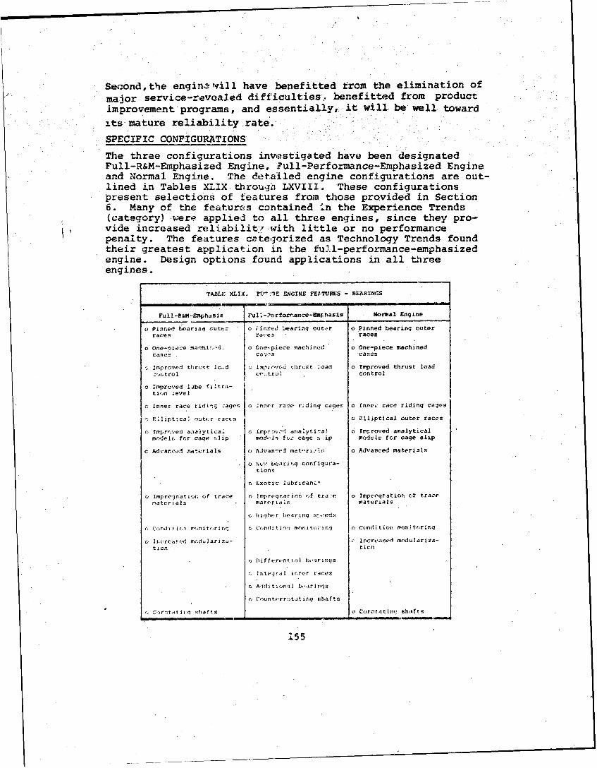
Second,the enginalwrill have benefitted from the elimination ofmajor service-revealed difficulties, benefitted from productimprovement programs, and essentially, it will be well towardits mature reliability rate.
SPECIFIC CONFIGURATIONS
The three configurations investigated have been designatedFull-R&M-Emphasized Engine, Full-Performance-Emphasized Engineand Normal Engine. The detailed engine configurations are out-lined in Tables XLIX through LXVIII. These configurationspresent selections of features from those provided in Section6. Many of the features contained -.n the Experience Trends"(category) were applied to all three engines, since they pro-vide increased reliabilit' with little or no performancepenalty. The features categorized as Technology Trends foundtheir greatest application in the full-performance-emphasizedengine. Design options found applications in all threeengines.
TABLE XLIX. FV1.'1E ENGINE VETURES - BEARINGS
Full-R&N-Emphdsis Ful 1 -Perforiý,ance-Em• hasis Normal Engine
o Pinned bearing outer o i-inred bearing outer o Pinned bearing outerraces raises races
o One-piece machi%.. o One-piece machined o One-piece machinedcases Ca5OS cases
Improved thrust lord lmpzcvcd t ruSt >oad a Improved thrust load:'wntrol cc,:;trCl control
o improved lobe filtra-tion ievel
o Inner race tridin; cages o rnner rar:e r~dinq cages o Inne, race riding cages
E Illipttca, out,:r races o Elliptical outer races
o Improved a.naiytical o Impr.",.d analyti7a) 6 Imcroved analyticalmoodelf. for cage flip mod'1.s Fuz cage !,Lip models for cage slip
c Advanced materials o Aivanetl mat'ýrýsIsi a Advanced materials
o N,:- bearlnq configura-tionS
o Exotic lubricaniL,
o Inprelnation of trace o Impregnatirmn of trace o Impregration of tracematerials materials materials
•, higher iearinq s:.,eds
o Condi tir, n -nite.rn< o Condhtin li rnritu iirq o Condition monit'ring
o 0ncr d modulariza- c Increased modulariza-tion tion
o Differtntial bearimis
c0 Itegrald i roct races
oC AliditiOn:al boarirgs
o Cou(ntcrrotat rig shafts
SCbtt~f ir! shafts o Corotatini' shafts
155
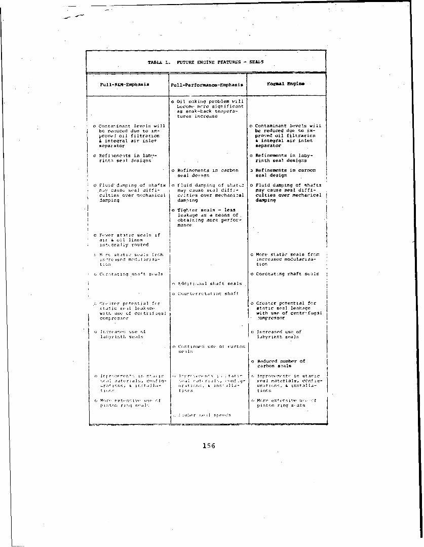
TABLU L. FUTURE ENGINE FEATURES - SEAlS
Full.&M•iEiphasis Full-Performance-Emphasis I or3-l Engine
o Oil coking problem will] become, more significant
as soak-back te.mpera-tures increase
o Conrarinant levols will o Contaminant leve•s willbe rer:uced due to ita- be reduced due to im-provel oil filtration proved oil filtraticnI inteqral air inlet & integral air inletseparator separator
0 Refiiereits in lab,,- o Refinements in laby-rinth seil designs rinth seal designs
o R,!finements in carbon 3 Refinements in carnonseal desian seal design
o Fluid damping of shalts o Fluid damping of shatxz o Fluid damping of shaftsmiy cause seal diffi- I may cause seal diff;- psay cause seal diffi-"culties over rechanical ;cties over mechanizal culties over mechaicaldamping daw;., ing dampin9
o Tightcr seals - lessleakage as a means ofobtaining more perfor-mance.
c F,.er st3tic seals ifaii . oil lines Iint,..graliy routed
C. M, rc st.tiz- seoas 'rcmr, 0 More static seals froc!. irsed mcdfl I za- .ncreasea mmodulariza-
t Cn -tior.
C,,cctatlng Srs't S..Is 0 Corctjt4ng i-haft seals
1o Additi;,nal shaft seals
o Crurterrctat inq shaft
C'-r5iter pcotentLal fcr o Creator pctential forstatic scsi lcaklars tatio seal leakacewts, trse of cc trifugal with use of centr.'fugalco Ilsprcaacr •omprossor
G lr.2t(a'.': use Af o Increased use oflat;y. inth se, Ils jabyrinth seals
o CrntiniI use o0 sartfon
o Reduced number ofcarbon seals
o IrI r,.et r,,. mn nt, in I:rrC,,os' i. tt;- C, lnpro.v,.-,nt' in static'.•,si .[t.,tsr~ala;. cs t ig- ;.', C at. ms '., ,.n real raterials, cc. tiq-
..r,' mono, & mrI- sr.stTC Inn,, & jr 1; ill- urat(;n-., & inrtilla-
o M',rF. (.yt*.nf;i j ut. s .'.f r, More exlc.rsivýý u5- ,:tpmý;tCTn rinq T;! s, piston rinq's-als
156
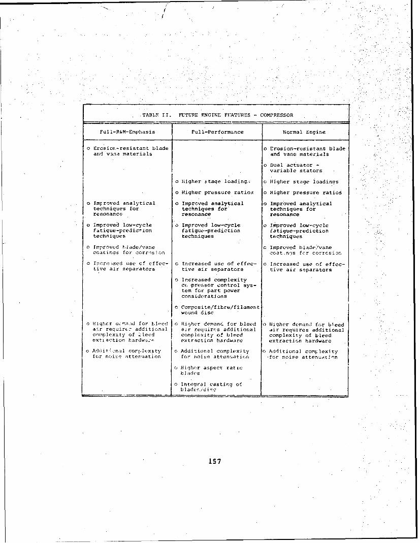
TABLE LT. FUTURE NGINE FEATURES .COMPRESSOR
Full-R&M-Emphasis Full-Performance Normal Engine
o Erosior-resistant blade o Erosion-resistant bladearid vanse materials and vane materials
o Dual actuator
variable stators
o Nigher stage loadings o Higher stage loadings
o Higher pressure ratios o Higher pressure ratios
o Imrroved analytical o Improved analytical o Improved analyticaltechniques for techniques for' techniques forresonance resonance resonance
oimproved low-cycle o Improved low-cycle o Improved low-cyclefatigue-prediction fatigue-prediction fatigue-predictiontechniques techniques techniques
o Improved -YIade/vane c. Imprved blade;/vanecoatinF s for corr&M osion Foat.n--s rc-n corrNm Eg n
o ncore-sesi use cf effec- o Increased use of effec- o Increase use of effec-tive air separators tive air separators tive air smparators
o Increased complexityccDcpressor control sys-tem for part powerconsiderations
o Composite/fibre/filament.wound disc
o Hiqh(-.r uaid for bleed i Hijher detanc for bleed o Higher demand for bleedair reauirt7 add'itinal air reqsirs additional air requires additional
corovexity of Aeed l ccomplexity of bleed complexity of bleedrexsiaction hardwi- extrsction hardware extraction hardware
o Additmpro dl corwy.lexity o Additional complexity o Additional com-lexityfor rtoiu-p ttenuation for noiee attenauation fcr noise atten-aat- n
tciu tichniqur aspect ratioblades
o Integral casting of
bo Inrease/d copext
157

,. / /
TABLE LI. FUTURE ENGINE FEATURES - COBUSTOR
Full-R&M-Emphasis Full-Performance-Emphasiso Normal Engine
"o Improved component o Improved component o Improved componenttesting necessary testing necessary testing necessary
o Higher combustor o Higher combustortemperatures temperatures
o Improved coatingmaterials
"o Improved analytical o Improved analytical o Improved analyticaltechniquos for heat techniques for heat techniques for heatdistribution patterns distribution patterns distribution patterns'TVR reduced) (MVR reduced) (TVR reduced)
o Double wall liners
"o Cast liners
"o Straight combustor o Straight combustor
TABLE LIII. FUTURE ENGINE FEATURES - TURBINEC
Fil l-R&M-Emphasis Full-Pefformance-Emphasis Normal Engine
o use of cast nozzles o use of cast nozzles o Use of cap,- nozzles
o Improved materials and o Improved materials and o Improved materials andcoatings to resist coatings to resist coar.tngs to resistbulfidation sulfidation suifidation
o UsL of slotted inner/ o Use of slotted inner/outer nozzle bands outer nozzle bands
" Higher TIT's o digher TIT's
o Possibie appiAxcationof cefa5• ,s
o New cooling "techniques o New cooling techniques
o ';ariale, geomertrynozzles
o Moro sophisticated o More sophisticatedbladt./vane de.ign from blade/vane design fromcooling r(:;nuirements cooling requirements
o Higher pressure ratios
o Lsf. of directional o Use of directional o Use of directionalsolij-if Id lloys- solidified alloys solidified alloys
o Lower sulfur conte.nts Low .r sulfur t;rFts o Lower su'.fur contentsin fuel in fu(el in fuel
O Improved low-cycle o Improved low--cycle o Improved low-cyclefa? igue-prediction fat igi(e-predi ct ion fat ique-predictionterhhn iquc-ri t.cr.T1P( techn cl (1.S
158

TABLE LIV. FUTURE ENGINE FEATURES - CASES
Full-R&A-Emphasis Full-Per formance-Emphasis Normal Engine
o Less emphasis on thin o Less emphasis on thinwall casings wall casings
o Improved corrosion o Improved corrosionprotectien protection
o Bosses & fittings o Bosses & fittingsintegrally cast integrally cast
o Magnesium minimized as o Magnesium minimized asstructural support structural support
o Increaced modulariza- o Increased modulariza-tion tion
o Increased case temper-atures-
o Additional bosses/' o Additional bosses/ o Additional bosses!fittings for both fittings for both fittings for bothinternal and external internal ara external internal and externaldiagnostics diagnostics diagnostics
o Additional bosses! o Additional bosses/ o Additional bosses/fittings for extra fittings for extra fittings for extrableed control bleed control bleed control
o Noise attenuation o Noise attenuation o Noise attenuationrequirements may ccm- requirements may com- requirements may com-plicate cases I plicate cases plicate cases
TABLE LV. FUTURZ 'ENGINE FEATURES - LUERICATION
Puli-R&M-Emphasis full-Performince-Emphasis Normal Engine
" Use of labyrinth sealpwill necessitate morecomplex air/oil.Sepa ra t ion
" No quick disconnects o No quick disconnects o No quick disconnects
" Increased system o Increased systemtesting testing
" More attention to o More attention toscavenge capabilities scavenge capabilities
" Additional requiremrents o Additional renuirementsfor filtration for filtration
"o Additional coolingrequirements
"o Potential soak-backtemperature problemfrom incresaed TIT
159

! ' I
TASLE LVI. FUTURE ENGINE FEATURES - FUEL
Full-R&M-Emphasis Full-Performance-Emphasis Nonmal Engine
o Additional filtration 0 Additional filtration o Additional filtrationrequired required required
o increased accessibility o Increased accessibility o Increased accessibilityto fuel control to fuel control to fuel control
o Po-itive lubric-tion offuel pump/contrclsp ;nes
o More complex fuel coa- o More complex fuel ce-trol units incorporat- trol units incorporat-iig automatic func- ing automatic func-tions, bleed control, tions, bleed control.i& diagnostic functions & diagnostic functions
O Additiqnal controlfunctiors for variableturbine geometry
o ýcreasing use of power o Increasing use of powermanagement systems management systems
o Increaring use of elec-I tronlcs and fluidics
o Reduction ot impurities o Reduction cf imp:urities o Reduction of impuritiesis turbine fuels Of- in turbine fuels (af- in turbine fuels ('-fecting hot sectieon fecting hot sec. ton fectinq hot sectionccsni.cner ts:) componcnts) components)
o Prwvr marqn ind'atcr o Power margin indicator o Power margi. indicator
TABLE LVII. FUTtLAR ENIT:V FEA;"RU'S - AIR
Full-R&M-Emphasis Full-Perfarmasce-Enphasis NormaI Engine
a Mre ruqqcd cnstruc-ticn of extrrnal lines:an~d fit ti]ng.F,
C, Mor, :cnmp.x air sym- o r!, compl,.ex ai. r sys- c More complex air s'-cter v fur co.mrres:-r t(cms for comrrr•.sor tems for compressorlv..,d (partia! po'.r bleed
porfi•rmance 6 aircirafts'yse power)
0 M n,re ext , ;.e', ari r, ant.sn M o tonr,.imv. ntiit1- 0 W e (" exteir i:v•. art•ti-icrrij s y::''r for "nu iClc g 4yy stn:.: for uno icing se stems for usecr. ;-rtv v,• ;';,rat1v.s on particle soiparatrs on particle separatora
160
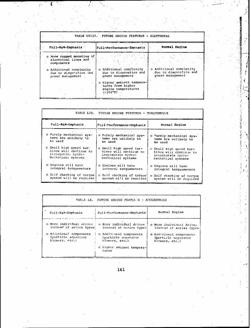
TABLE LVIII. FUTURE ENGIN4E FEATURES - ELECTRICAL
Full-R&M-Emphasis Full-Performance-Emrhasis Normal Engine
o More rugged mounting of relectrical lines andcomponents
o Additional compleition al complexoity Additional complexitydue to diagnnstics and due to diagnostics and due to diagnostics andpower management power management power management
o Higher ambient tempera-tures from higherengine temperatures(>250*F)
TABLE LIX. FUTURE ENGINE FEATURES - TORQUEMETLR 4
Full-R&M-Emphasis Full-Performance-Emphasis Normal Engine
" Purely mechanical sys- o Purely mechanical sys- o "urely mechanical sys-tems are unlikely to tems are unlikely to tems are unlikely tobe used be used be used
" Small high speed tur- 0 Small high speed tur- o Small high speed tur-bines will continue to bines will continue to bines will continue toincorporate hydro- incorporate hydro- incorporate hydro-mechanical systems mechanical systems mechanical systems
"O Engines will have o Engines will have o Engines will haveintegral torquemeters integral torquemeters integral torquemeters
"O Self checking of torque o Self checking of torquel o Self checking of torquesystem will be reouired system will be required. system will be required
TABLE LX. FUTURE ENGINE FEATUkS - ACCESSORIES
Full-R&M-Emphasis Full-Performance-Emphasis Normal Engine
o More individual drives o More individual drives o More individual drive-instead of series types! instead of series types instead of series types
o Additional components I o Additional components o Additional components(particle separator (particle separator (particle separatorblowers, etc.) I blowers, etc.') blowers, etc.)
o Higher ambient tempera-tures
161

TABLE LXI. FUTURE ENGINE FEATURES - POWER-TRAIN REDUCTION
Full-R&M-Emphasis Full-Performance-Emphasis Normal Engine
O Advanced gear and o Advanced gear and o Advanced gear andbearing materials bearing materials bearing materials
o Integral separator may o Integral scparator may o Integral separator mayforce reduction gearing force reduction gearing force reduction gearingto be offset to be offset to be offset
TABLE LXII. FUTURE ENGINE FEATURES - FOD
Full-R&M-Emphasis Full-Performance-Emphasis Normal Engine
o Inertial separators o Inertial separators o Inertial separators
o Screens installed o Screens installed o Screens installeI
o Optimized mesh size o Optim-zed mesh size o Optimized mesh size
o Improved screen o Improved screen o Improved screenattaching hardware attaching hardware attaching hardware
o FOD-resistant com- o FOD-resistant com-pressor (max) pressor (max)
TABLE LXIII. FUTURE ENGINE FEATURES - EROSION
Full-R&M-Ephasis Full-Performance-Emphasis Normal EngincFuNormal Enginemhasi
o Inertial separators o Inertial separators o Inertial separators
o Increased separator Increased separator o Increased separatorefficiency efficiency efficiency
c Erosion-r,' stant o Erosion-resistantcomrn ssor compressor
162

TABLE LXIV. FUTURE ENGINE FEATURES - ENVIRONMENTAL
Full-R&M-Emphasis Full-Performance-Emphasis Normal Engine
o Improved lube filtra- o Improved lube filtra-
tion tion
o Improved fuel filtra- Improved fuel filtra- o Improved fuel filtra-
tion tion tion
o Automatic power mgmt o Automatic power mgmt
o Less use of magnesium
c Mr4re use of magnesium
o Additional complexityof fuel controls withootential for contami-nation
TABLE LXV. FUTURE ENGINE FEATURES - OPERATOR INDUCED
Full-R&M-Emphasis {Full-Performfance-Emphasis Normal Engine
O Improve4 condition o Improved conditior o Improved conditionmnoritoring monitoring monitoring
o IMtientine power o Multiengine power o Multiengife powermatching matching matching
o Automatic power
management
Eme~rqency power
capebility
o Higher operating
temperatures
163

TABLE LXVI. FUTURE ENGINE FEATURES -IMPROPER MAINTr4ANCE
Full-R&M-Emphasis F~ull-Performance-Emphasis. 'Nornwl Engine
"o Improved engine. o 'Improved engine a Improved engine'diagnostics diagnostics diagnostics
"o Clearer maintenance o Clearer maintenance 0 Clearer maintenancemanuals manuals T-ma.nuals
"o Imprcv~ed studs &. bolts
o Intearal wash nmanjfods
"o Reduction of blindinstallations
"o Murr!h -Droof desicins
"o O~: imrnu screen/filterlocations
"o Maintenance d,-. -Dility
TAB~LE LXVII. FUTURE ENGINE FEATURES - :.AIRFRJAIE .RELATED
F u II- R&M,- Empa! r~ zrli-Perfo!7mance-Emphiasis %ormal Engine
c, E..,iinclairfrar'. o FEtine/airframo o Engine/airfratneint'erfac,. agreemren. interface agrcemonts interface agreementsl
c:T :nr:.e accessibilty o Improved accessibili
o Enai no testinq* with
acft/vibraticonloeh
TAi, 'ELVIII FI aI I:c 1'n -AI. FS-cFVC ;C
F.1 '~I: I,¶ -ul -Po'r f'rmanri~-l ha! No rmal I~in,
;,7 rT-:rr: I 1o? , r~r-rvod I1c(jstjo.,ni-r- o C)mproved logistic5 rmc;E-ýt
164

QUANTIFICATION OF R&M LEVELS IN NEAR-TERM (1975-82 ERA)ENGINES
The previous tables defined the specific features expected in1975-82 era engines. This section quantifies the reliabilityof the features at the subsystem and failure mode levels. Twoseparate quantifications are developed, namely index numberand UER rate. These are provided in Table LXIX at the sub-system level and in Table LXX at the failure mode level.
The reliabilities listed represent the extremes of an enginewith a rigorous emphasis on R&M and one with a full emphasison performance. The decision to pursue R&M versus performanceas the prime objective will have been made prior to the de-tailed design phase.. The assumption has been made in thisstudy that both the full-reliability-emphasized and full-performance-emphasized engines will have received similar at-tention to R&M during development testing and operational use.Thus, the shapes of the maturity curves are considered to besimilar to those experienced in the past. The predictionsrepresent an RVN (combat, climate, etc.,) type environment.
TABLE LXIX. FUTURE ENGINES SUMMARY MATRIX - SUBSYSTEMS
_F__T__R "FNGINESPELIABI IIY, PERFORMANCE" L
COMPOSITE MAINTAINABILLTY WEIGHT NORMA
SUBSYSTZM ENGINE EMPHASIZED EMPHASIZED GROWTH
INrEX INDEX INDEX INDEXVALUE UER VALUE UER VALUE UER VALUE UER
BEARINGS 3.80 0.107 2.65 0.057 4.68 0.127 2.80 0.062SEALS .346 0.205 0.26 0.020 5.2R 0.303 2.41 0.144ýOWWRZSSOR 4,63 0.072 3.47 0.051 4.68 0.067 3.76 0.057
1B TY 1,14 0.n40 0.94 0.033 1.02 0.035 0.98 0.034TUPVI3INL 2.86 0.,58 2.24 G.047 3.03 0.082 2.24 0.047CASES 1.27 0.054 0.83 0.039 1.42 0.063 0.91 0.041LUBRICATION 1.28 0.034 1.03 0.028 1.21 0.028 0.98 0.026FUEL 3.45 0.085 2.73 0.070 3.37 0.084 3.12 0.078AIR 0.55 0.015 0.58 0.011 0.61 0n011 0.61 0.011ACCESSORY 0.91 0.025 1.0O 0.P28 1.04 0.029 1.00 0.028T7 RQUEM-TrP 1.27 0.148 0.43 0.016 0.43 0.016 3.43 0.016ELECTRiCAL 0.73 0.014 0.71 0.013 0.77 0.015 0.76 0.014
0.55 0 .,W)94 0.28 0.002 r.29 0.002 0.28 0.002'AR-TPAI N RODUCTrON 0.72 0.013 0.72 0.013 0.72 0.313 0.72 0.013NFLET AIR SE PARATION_ - - 0.50 0.013 0.56 .1 013 0.50 0.013
TOTAL - EN;[`'N:E AUS 26.62 0.769 18.37 0.441 29.01 0.R87 21.50 0.58"
SURE:;' ObJECT LA',A• 6.71 0.388 2.59 0.150 5.02 0.290 3.32 0.1F0I O,'N310 2. 0 f.140 0.20 r.020 2.9', 0.200 1.2" 0 .on
EAP ON.I:;;AL 1 .4 ý9 n S. 59 0.87 0.147 1.16 0.063 0.89 0.04PP IN:'7CED 2.',4 0.122 2.54 0.122 2.54 0.122 2.54 0.12-
!'" IVER MAINTENENA!:Ct: 5.90 0.305 2.50 0.150 5.85 0.3 30 3.85 0.230A I. NELATED 23,6 0.149 1.6" 0.100 2.40 0.150 1.92 0.120S. 4. 0:_.410 0.77 9.9170 2.1R 0. 200 1.10 n. 10
frA- L' L;r:;. A':SILD 26.1; 1.697 11.1, 0. q59 22.05 1.345 14.58 0. 66"
7.26 3 1.3 0.060 5.90 0.290 2.65 0.130
1 TOTA6L - ALL) AU;Lm 603 2.782 30.76 1.160 56.96 2.522 38.73 11596
165

lADLE L41. F1W4 1499.46 SUMON WM4pA1.F44w OMWr
49-. r-19 %",
4*404 ý*a4S.du. 1 44.4449. ~ ~ ~ ~ ~ ~ Rb M1-14. 64904.. M~94.*~44~9.9"4
3446.1 ~ ~ ~ ~ ~ ~ R "I-* ft.99 .zd. 4l4 99 .nS ,
S*S1
UeP TC9.41 990. 4... 9.P 4*4~ IP94,t , 4.94 ~ Vai. 34* 4j~w 444
.. '06__ 0.16 0.49,4 .94, .. 44
., . 4 .* 9.94 <Ci 4.9.
2 4.9946~ýk 44~ j0 1.64 .l .
9. .91 4442 9.9 4.49.
04.92 94 &i
9 .44.924.~a* 42 . 29, 9 4 .6. 9.44 iS .. 47i
4 4 4 .9 9.9,1.16694
Bes Av ilbl Copy.,4 '' 9.

1975-82 ERA ENGINE SUMMARY
Examination of the summary matrix (Table LXX) for the 1975-82era engines indicates that a factor of two improvement inengine reliability can be achieved over that measured for cur-rent engines, provided that the user is prepared to pay theweight and performance price for this benefit. The means toachieve this reliability improvement are available now and re-quire no quantum jumps in technology. Further examination ofTable LXX reveals that the reliability of engines with fullperformance emphasis will not be significantly different fromtoday's engines. This represents a significant increase inlife-cycle costs above that of the full-R&M-emphasis engine.
The normal engine is shown to achieve a level of reliabilitythat represents a 30 percent increase over today's engines,but which still leaves considerable room for improvement. Thenormal engine configured and quantified in this study cannotrepresent a hard and fast configuration. In this study, it isstructured by a median consideration of R&M, performance, cost,weight, volume, schedule and other dictates of engine design.This engine's reliability level is fully variable between thetwo extremes, and only with very careful attention to relia-bility details will it tend toward the full R&M emphasizedengine.
This section has shown how major R&M benefits can be achievedin near-term 1975-82 era engines through the incorporation ofcertain design features or approaches reflecting a programemphasis on R&M. Significant differences were indicated be-tween the R&M-emphasized engine and the full-performance engineas indicated on Table LXIX and summarized below in Table LXXI.
TABLE LXXI. SUMMARY OF FUTURE ENGINES
ULR Rate Expressed in Removals/1000 Hr
R&M FullEmphasized Performance Normal Composite
UER UER UER UERIndex Rate Index Rate Index Rate Index Rate
Engine Caused 18.37 .441 29.01 .887 21.50 .586 26.62 .769
Non Engine 11.16 .659 22.05 1.345 14.58 .860 26.15 1.657Caused
Unknown 1.23 .060 5.90 .290 2.65 .130 7.26 .356
Total 30.76 1.160 56.96 2.522 38.13 1.596 60.03 2.782
167
The reader is cautioned, however, that these predictions reston the assumption that all engines, including the full-performance engines, will have benefitted from the irclusionof certain R&M features which should be available for theseengines. Incorporation of these features, however, is not in-evitable, and conscious effort will be required to insure theirinclusion.
The full-R&M-emphasized engine, and to a lesser degree thenormal engine, require the inclusion of features which are ingeneral of greater reliability significance than those featuresapplied to the full-performance-emphasized engine. The 20 mostsignificant changes listed in order of priority by index numberare shown in Table LXXII.
The cumulative effect of incorporation of these 20 remedialactions represents a 57 percent Lmprovement in reliability fromthe current composite engine and is 98 percent of the total re-duction from the composite engine to the R&M-emphasized engine.The individual effects of some remediA. actions on the threeconfigurations of future engines are {.ifferent, principally be-cause the configurations differ from each other. The probableapplicability of each remedial action to a particular configur-.ation of future engine has also been indicated on Table LXXI.
The conclusions tha- may be drawn from Table LXXII vary widelyas a function of the reader's past knowledge of turbine engineR&M and preconceived ideas about where problems lie. The mostdisturbing observation is that many of the remedial actionswhich provide large reductions are addressed to non-engine-caused failure modes/subsystems, and are intimately related tothe external environment. FOD, erosion, fuel and oil contami-nation, and logistics and munagement are problems that requiresignificantly different approaches from those applied againstclassical internal failure modes. The acknowledged difficultyin initiating and implementing corrective action in theseareas was fully accounted for in estimating benefits. Never-theless, these conservative estimates produce numerical rateimprovements which are very high and indicate that improve-ments in these non-engine-caused subsystems must be undertakenthrough a combination of customer and supplier actions.
The high ranking of bearing and seal remedial actions may alsobe surprising to some. Many in the engine design, management,and procurement communities tend to minimize the bearing andseal problem and correspondingly downplay the value of improve-ments in these subsystems. The significant benefits to begained through remedial actions in these areas indicated inTable LXXII should provide better perspective of the costeffectiveness of improved bearing and seal reliability.
A third observation involves the rapid decrease in numerical
168

* TABLE LXXII. R&M IMPROVEMENT ACTIONS AND BENEFITS APPLICABLETO 1975-82 nRA ENGINES
"R&M Incorporation i .- Benefit 1975-82 Era Engines
Re:- dia" Actin 'Index UER Full
" Remedial Action NumiWer .Rate** Full. R&M Performance Normal
I Use of Labyrinth Se 4s 3.19- 0.183
2 roIeeign Object Damage 2.42 0.j38 *
Rcs:stant CompressoT
3 Use of High Effici.ncy Pa•ricle 1.74 0.080 ,' - /Separato s in lieu of Filters
4 Improved. Foreign Object Screen 1.70 0.100 1Arranqements
5 Eros ionoCorros ton R?,sistant 1.61 0.060 *
Compresseor
6 Improvod Raintc-f,.'cc Durabil-.ty 0., - .155
7 Posi tive Re t¢:tion Q.arl :g 0.85 0.029
8 Eliminati.o of .i -d 0.84 0.0'2 /Mechanical Tor uemeters
9 Improved Engine and Component 0.76 0.04ý. / *
Accessibility
10 Imprcvw:d Fuel Filtration 0.53 0.01"
11. Impror'vd "Aruiolyttvil~ ~'je .2 00for ad s s,nance
t ror s0.34 0.0t:
13 Us (. ,f F• iptical Face Rcller 0.30 0.00',w.i r iqs
14 L! i-rt ion of T.iin Wall 0.28 0.M1G
.rmprrved Fue' Contrl 0.26 0.006 * /Aco(5I3• iity,
It l ,rov(r' Thrust ,.odd Control 0.22, D.00'3or. sri-Sla1t Boarlr.Tt I
•.17 lnrovod Lo5i'stics (Ful! Perf Bon1.80 0. 170 *
i b s. E f <.ast T*uriine irlot 0.15 0.00
1 . of F• et -td Inncr/,O.ter 0.14 0 .' 3 4
2' lrr 1. . ricnt Fi r, t . io- n 0.12 0.f)04
"*lt.. ;•:i:t,"; t~h-t fe, .tore Is [,ati ,n :- in orerr(? t•, n. roT<ritI ,, neh.•flt is le:s't t~an Sh(tein
benefit proceeding down the list of remedial actions. Afterthe first 11 remedial act.Lons, there is only 1/10 of the bene-fit that the first item provided. The first 5 remedial actionsalone contribute approximately 50 to 60 percent of the totaldifference between the composite engine and the R&M-emphasizedengine. This suggests that future activity in improving engine.
169

reliability can be focused on a few problem areas without fearthat significant problems would be overlooked.
In comparing Table LXX to the basic problem summary matrix(Table XI), a question may arise regarding improvement in theunknown, maintenance caused, and convenience categories. Theserank high in both index number and UER. Yet, only one remedialaction is specifically directed at them. This is discussedbelow.
INDIRECT EFFECT OF R&M IMPROVEMENTS
It has been shown previously that a relationship exists betweentotal engine removal rates and the associated convenience,maintenalice-caused and unknown removal rates (see Figures 62,64, and 65). This means, in effect, that any time specificR&M improvements are made in the various subsystems, an in-direct benefit will be realized in the three subsystems notedabove.
The relationship is definitive enough so that an estimate ofits magnitude can be made for each remedial action for the twoparameters, index number and UER rate. The indirect benefitsare shown in Table LXXIII expressed as an additive percentage.
TABLE LX.III. INDIRECT BENEFITS
Indirect
Parameter Percentage Additive
Index Number 64
Unscheduled Engine Rerovals 82
Therefore, the actual anticipated benefit of any of theremedial actions shown on Table LXXII will be nearly twicuthe valueZ shown when considering the indirect benefit. Itshould be noted that the total engine rates on Tables LXIX,LXX, and LXXI already include this indirect benefit, sincethe subsystems of unknown, converience, and improper mainte-nance are included in the total.
170

8.0 LONG-TgRM FUTURE-ENGINE DESIGNAND PROGRAM REQUIREMENTS
ImproVement of R&M beyond that indicated for the near-termengines will require considerable effcrt. Program management,design skills, and support programs must be upgraded. Thissection identifies specific areas of potential improvement.Two discussions are presented. Specific failure modes remain-ing in the 1975-82-era fitll-R&M-emphasized engine are identi-fied, and analyses and research that must be directed towardtheir reduction or elimination are discussed. The accompanyingprogram-type activities that must be applied to the same 1975-82-era engine to improve R&M are also presented.
DES IGN CONSIDERATIONS
The significantly different remaining rates for the R&M-emphasized eingine and the performance-emphasized engine pri-marily reflect design priorities and failure to incorporatecertain R&M design features in the full-performance engine.It is apprcpriate to utilize the residual rates in the R&M-emphasized engine as the basis for identifying priorities forfuture research. There is no doubt, however, that some avail-able R&M features may not be incorporated into future enginesbecause their full impacts in weight, cost, or performance arenot fully understood. In these cases, it is appropriate thaton-going studies be directed at the quantification of weightand performance penalties so that these features can be incor-porated when they match the objectives of a specific set ofrequirements.
The residual rates at the subsystem and failure mode level for,;he R&M-emphasized engine were given in Table LXX. The high-est 10 problems in terms of index number have been extractedand are presented in Table LXXIV. For convenience, the asso-ciated UER rate for each mode is also shown. The followingdiscussion addresses these remaining problem areas.
.TABLE LXXIV. REMAINING PROBLF•MS OF THEFULL-R&M-EMPHAS ZV.I) .;NrINE
Prohb •m Ma. iitadtoPriority Pernma i ning Problem Ind.x Numbc r UEW
I F;rweign 0)leict Damage 2.59 0. 1502 Op-rator Indced 2.54 0.6123 Improper Maintcenance 2.50 0.1504 Conpre;ss'r Blade/Disc Fat igue i .s88 0.f04
Fail ures5 Fuel Control Units 1.81 0.040
Iivarihqs - Noic laqi;ica1 1.76 0.03ispa] 1 inq
7 Airframe kelated 1 60 0.1(108 Turbl Ini t. lado/Whuel Cracks 1.06 0.0019 A'cesscry 1.00 0.029
10 Env i crimon t a 1 0.87 0.047
171
/
Foreign Object Damage (FOD)
The magnitude of the FOD problem remaining reflects the indus-try's uncertainty of the sources and types of foreign objects.Without this knowledge, it will be difficult to justify addi-tional remedial actions. The remedial actions listed in TableLXXII already include screens in addition to particle separa-tors, improved detailed designs for mounting the screens, andmore rugged compressor configurations. The residual rate mayonly represent FOD fcom operation with the screens removed orbypass doors open; tools or debris left in the engine intakeduring maintenance; or enemy gunfire not properly identifiedas being due to combat. Under these conditions, furtheraction may not be cost-effective or warranted.
It remains to be confirmed, however, that these will be theonly remaining sources of FOD. A more comprehensive defini-tion of FOD sources is required from current aircraft equippedwith varieties of screens and separators, operating in variouslocations, and performing various missicns. This could be ac-complished through an examination of engines during overhaul/repair or perhaps by the collection of debris scavenged frominertial-type separators. The data-collection program previ-ously conducted by the Naval Air Technical Services Facility14
should be reinstituted.
It is assumed that present attention to the FOD problem willdetermine answer. to such issý:es as optimum mesh size, detailedmounting and fastening techniques, and effective anti-icingsystems. The rk::ommendation to define the erosion resistancecharacteristics of axial versus centrifugal compressors alsoapplies for FOD resistance.
It may be that the residual rate of 0.15 removals per 1000engine hourz must b) accepted for hplicopter applications. Ageneric rate of approximately 0.07 has been observed for fixed-wing aircraft. It may be reasonable to expect a factor of 2.0or higher for helicopters, based on the relative frequenciesof landings.
Operator Induced Problems
This area is deliberate or unintentional engine abuse or un-certainity as to the engine's condition. Since this may bethe indirect result of basic reliability problems, some benefitmay occur as those problems are corrected. Removals due to asuspected low power condition that is later unconfirmed maydecrease if the erosion characteristics of engines areimproved.
Perhaps the only clearly identifiable improvement is the de-velopment of a reliable device to measure the power available
172

from an engine. Although some development effort is currentlybeing applied to such a device, it was not considered suffi-ciently advanced for application in the 1975-82 generation ofengine installations. This research should be accelerated,since a significant poetion of the removals in this subsystemwere attributable to suspected low power.
A more general remedial action is the thorough exploration ofstarting and shutdown procedures and responses during thedevelopment phase. Early testing in this area should be ex-panded, particularly in light of the advent of the three-engined helicopters with their attendant power management com-plexity. The application of human factorr engineering wouldbe productive in establishing analysis and testing criteria.
A concluding comment that applies to many of the other non-engine-caused removal categories is that more problem defini-tion should be required in R&M reporting programs on thissubsystem. Further reduction of this rate requires a moredetailed understanding of the precise mechanisms, personnelintentions, and contributing circumstances involved withoperator-induced problems.
Improp-r Maintenance -
The magnitude of the improper maintenance problem was shown tobe primarily a function of tne basic reliability of the engine(Figure 62) and largely independent of the particular militaryservice. Examination of the figure reveals no obvious differ-ences in the damageability of various engines. The specificsources of improper maintenance were reviewed in Section 5with the conclusion that no significant single characteristicor area of engine design could be isolated as being partic-ularly sensitive to maintenance damage. It was also shownthat depot-originated maintenance errors were a small percent-age of the total, and therefore a shift in overhaul/repair tothe admittedly higher quality contractor facilities could notprovide a significant improvement in the rates.
To further reduce the magnitude of this problem requiresaggressive action in two areas. First, the specific instancesof improper maintenance should be researched and published ata greater level of detail than provided in this report. Astudy of this type could profitably extend into other aircraftsystems and still provide benefit to engine design. Analysisof this history would provide the general trends or patternsas well as specific design details which .hculd be avoided infuture engine designs.
The second area involves the skill:, procedures, and toolsutilized during actual engin- maintenance. The dramatic dif-ference between the military and commercial trends (Figurc 62)
173

suggests that improvements in the military maintenance environ-ment are necessary. The question of whether the militarymaintenance environment can approach the commercial environ-ment is an issue requiring in-depth analysis. Maintenanceconcepts, skill/task allocations, and facilities should allbe examined.
Compressor Blade/Disc 'atigue
The magnitude 3f this problem in the 1975-82 engine reflectsour inability to adequately understand the preci.se state ofthe art of fatigue analysis methods employed throughout theindustry. The magnitude of this problem in past and currentengines has certainly led to significant improvements inanalysis techniques and dpplication within the individualengine companies. Greater attention to potential resonancesituations, emphasis on low-cycle fatigue, and improved r-,•e-ness, if not control, of production variabilities of machi:.dand cast components will reduce this problem.
Since much of this technology is both complex and proprietary,we are reluctant to recommend any general cataloguing ofanalysis methods. Fror. the customer's standpoint, the mosteffective action is the imposition of low-cycle fatigue-lif,.requirements during the specification stage of engine develop-ment. Since the frequency of failure of this mode is low,demonstration tests are impractical. Existing specificationsadequately require blade containment, althoucgh disc contain-ment appears to impose a weight penalty which is unwarrantedon the basis of the low probabilities of occurrence.
The increasing use of titanium for compressor design hascaused a great deal of attention to be directed to its prop-erties. It offers significant weight savinqs at the expenseof erosion resistance. Stress corrosion and fretting are twofailure mechanisms which have received particular empliasis.It is believed that this technology is progressing at an &de-quate pace and no additional emphasis need De applied.
The potential use of composites, however, i6 of concern.Filament designs that w:ould afford slower crack-progressionra~tes are being considered for advanced designs. The produc-tion variability of these composites is of concern. Thestrength distribution of mass-produced units shou)d be thor-oughly explored before incorporation into production engines.
Fuel-Control Units
The lek of quantification of the various fuel-control problemareas was noted previously. Future R&M trends were calculatedbased on external chanqes such as fuel and air filtration im-provements and a f(.w internal improvements such as positive
174
lubrication of driving splines. Beyond these, no identifiablechanges were apparent. The additional complexity of futurefuel controls and the potential for problems causing accidents,as well as frequent component and engine removals, demand thatthis area be subject to intensive examination.
A recently released contract from the Eustis Directorate ofUSAA14RDL to examine the current and future R&M characteristicsof fuel controls should provide a baseline for identifyingfuture remedial actions.
Nonclassical Bearing Spalling
Since fewspecific remedial actions were identified for thisfailure mode, the residual failure rate is quite high. Thislack of corrective action stems from the great variety of de-tailed causes and failure mechanisms. Experience retention isdifficult in this area, since the individual bearing installa-tion details that cause the problems vary greatly. Thesefailures are unpredictable by current classical bearing analy-sis methods.
Failure rate reductions, therefore, require compilation of thedetails of failure for as many engine bearing installations aspossible. Analysis of these data by skilled bearing designersmay reveal patterns that have not been identified up to now.
The emergence of the air bearing concept for gas turbineengines is a promising development. Analysis, fabrication,and testing should continue in this area. A word of cautionis appropriate: Design glitches that cause nonclassical-spalling problems in rolling-element bearings could alsodegrade air bearing reliability. Various mounting and instal-lation approaches should be explored, and extensive testsshould be conducted over a wide range of engine sizes andconfigurations to prevent this.
Airframe-Related Problems
It has been assumed that future engines will have generallygood accessibility. Therefore, the relatively large remainingrate results more from the airframe and the environmentcausing suspected or actual engine damrge, rather than fromremovals of the engine to perform maintenance on airframe com-ponents. Accordingly, the most productive future remedialaction is the strengthening of the engine/airframe manufac-turer interface agreements which have recently been develoi'edon engine/airframe programs. These agreements, although quitefamiliar on commercial programs, are still somewhat new tomilitary systems and will require some experience before max-imum benefit can be expected.
175

* One specific area of these agreements that will requirefurther definition is particularly pertinent to helicopterinstallations. This is the effect of aircraft vibration onengine reliability. Specification of maximum aircraft vibra-tion levels prior to airframe development will in turn requirea level of prcdictive capability that has yet to be demon-strated. Research into the state of the art would be useful.
These activities, coupled with anticipated improved relia-bility of airframe components, should allow further reductionof this problem.
Turbine Blade/Disc Fatigue Failures
The magnitude of this problem in the 1975-82 engine is thesame as in current engines because specific remedial actionscould not be quantified, although some improvements in method-ology and application are recognized.
The additional complexity of turbine mechanical design due tothermal effects has resulted in a corresponding effort to im-prove the predictioa and control techniques for thermal andfatigue life of turbine components. The success of theseefforts is evidenced by the continued escalation in turbineinlet temperatures, more complex blade cooling system, andmore weight-efficient discs with no observable decrease inreliability. Literature is extensive on these efforts, al-though the detailed effect on reliability of this rapidlyevolving technology is not well understood. Some of the mate-rials, cooling, and analysis improvements in turbine designtechnology are summarized in Reference 12. More detailed in-formation on specific areas such as transpiration-cooled bladesis provided in Reference 28.
The sources of turbine blade/disc failures in past engineshave not been directly attributable to fatigue in the purestsense. The sources, as described in Detailed Problems ofCurrent Engines (Section 4), were such factors as blade-to-disc fretting or a decay in vibration damping characteristicsdue to wear. Since these factors are not routinely addressedas an element of the classical fatigue calculations, the pre-viously suggested improvement in analysis capability &nd mate-rials may not directly reduce the magnitude of this problem.If anything, they may allow further refinement of turbineweight, size and performance to the detriment of safety marginsheretofore designed into turbines through the natural conser-vatism that accompanies inadequate technology.
Based on this discussion, it is recommended that a state-of-the-art review of the analysis methods be undertaken in con-junction with an analysis of past turbine blade and disc fail-ures. Since this technology, like the compressor blade/disc
176

fatigue technology, is extremely complex and highly propri-etary, this recommendation may not be practical. Thus, aclose review of this area by the customer during the develop-ment stages of specific engine programs, is also suggested.
Accessory
The specific failure modes in the accessory subsystem were ofa vlaried nature with no one area or failare mode consistentlyhigh. It was suggested that this ri-te m.y be considered ageneric rate based on the number of individual components andthe relatively low operating loads of the gears, bearings, andother elements of the accessory system.
Thus, the only apparent action that could alleviate thisproblem is a reduction in the complexity of the accessorysystems. This can be accomplished through the integration ofdrive functions (su:h as tandem mounting of fuel pump and fuelcontrols) or through the elimination of drive functions (suchas air impingement starting systems). The potential formounting a high-speed fuel pump on the main shaft has beenexplored,, and other accessories could possibly serve ascandidates for similar research.
Environmental Conditions
Over 50 percent of the residual rate represents fuel controlcontamination. Even with the increased fuel filtration antic-ipated in all future engines, control unit contamination willcontinue, due to filter bypass and/or accumulation of contam-inants passing through the filters. Lubrication system con-tamination and structure/case corrosion are other modes inthis category; each contributes approximately 10 percent.
Further remedial action for fuel contamination requires a moredefinitive statement of the degree of contaminants actuallyexperienced in aircraft. This would allow further optimiza--tion of filter mesh sizes.
Closed loop fueling systems would reduce fuel contamination inthe field. Gravity refueling into an open fuel filler tubewith helicopter rotors turning is not conducive to fuel clean-liness. Pressure refuelinc. gravity close-loop, or simplybetter nozzle-to-filler sealing are the responsibilities ofboth the customer and the airframe manufacturer. Engine re-quirements should be more clearly expressed by the engine man-ufacturer in order that the airframe fuel systems be improved.
Lubrication system contamination co':ld increase over thatexperienced in the current engines if extensive use is madeof labyrinth seals. To preclude this problem and reducescheduled maintenance on oil filter systems, devices should
177

be developed which would continuously clear the oil to the10-micron level and have a self-cleaning capability. Onesuch device is discussed in Reference 29.
Some degree of corrosion has been experienced on all enginesexamined in this study. Usually the incidents are recordedas being due to unusually severe environmental conditions.They were only experienced in any magnitude on engines utiliz-ing extensive amounts of magnesium. Although the one ccmpanyusing magnesium extensively has developed a rather effective(proprietary) protective coating, its benefits are lost whereerosion takes place. If erosion is reduced in the future, thecorrosion problem will be reduced without further remedialaction.
PROGRAM CONSIDERATIONS
The program elements that contributed to past R&M problemswere reviewed in Section 5; current improvements in programswere examined in Section 6. This discussion will suggestareas of the prc-1ram that require additional remedial actionand will utilize the five program elements previously intro--duced in SectiDn 6:
"o Specifications and Requirements
"o Development Design and Testing
"o Operational Use and Product Improvement
o Environment
o Materials and Design Concepts Technology
Specifications and Requirements
Two remedial actions in the specifications area are appropri-ate. First, overall R&M objectives should be strengthenedthirough the sel:ction of well-understood parameters with nu-merical values enforced by contractual demonstrations. Second,the restrained and selective imposition of design requirementsshould be exercised at the detailed level. Specific recom-mendations along these lines are as follows.
Three main R&M parameters should be adopted to describe thetotal engine. These are unscheduled engine removal (UER) fromthe airframe, time between overhaul (if appropriate) and hot-end inspection intervals, and maintenance ta!;k times on se-lected tasks. All other parameters either ,,ive insufficienthistorical data available or are undemonstrakle.
Specific individual subsystems/failure modes should be
178

controlled through separate quantitative requirements. Thesefailure modes are erosion, fuel contamination, turbine vanesulfidation, no-lube operation, blade containment, and com-pressor and turbine fatigue. Each of these modes, as well asmaintanance task times or tool requirements, can be demon-strated by testing under accelerated or controlled conditions.The criteria for acceptance can be clearly defined in eachinstance.
Certain design features should be specified wnere the trade-off aspects are clearly understood. The R&M, cost, weiqht,performance: space, and schedule implications of a legislateddesign feature must be acknowledged in the total enginenumerical objectivws.
All requirements must be demonstrated through either test oranalysi.. Emphasis should be placed on test verification,with minimum of subjectivity in acceptance criteria. Testsfor overall engine reliability may require longer durationsthan would be practical in the development phase and thusshould be conducted in a downstream production or operationalphase-. Since these two phases are usually authorized by sepa-rate contracts, arrangements must be devised so that theobligation of demonstrations is clearly manifested in thedevelopment contract.
Developmental Design and Testing
Although the prime responsibility for hardware improvements inthis area rests with the engine manufacturer, certain recom-mendations are appropriate for engine customers. These sug-gestions require customer initiation and funding for maximumeffectiveness.
First priority should be given to providing the engine de-signer with the tools necessary for meaningful trade-offdecisions. The customer can accomplish this through expandeddata collection systems on in-service engines with the datamade routinely available to all engine manufacturers. Periodicsummaries of reduced data should be published. This is a pre-requisite to vigorous prediction, evaluation, ana control ofengine R&M in the future.
A series of studies of the detailed design problems in thevarious engine subsy7stems should be accomplished. As a case-book of past problems, the studies would contribute to experi-ence retention that should avoid the repetition of certainfailure modes. These studies would be integrated with thesubsystem design studies recommended in the Materials andDesign Concepts Technology discussion.
A general relationship between reliability and development
179
testing should be established. A study of turbine enginessimilar to that performed on helicopter dynamic components 21
would allow the engine contractor to realistically size thetest program to the reliability requirements. This studycould also examine the present specifications relating to PFRTand MQT testing and clarify acceptance criteria and testconditions.
Operational Use and Product Improvement
Improvements in this area should cause a decrease in R&M prob-lems as larae as that expected from improved specifications.
An R&M program to control the operational phase product im-provement of every engine should be defined. It must reflectspecific contractual responsibilities and specify the detailsof data reporting, meeting, timing and personnel attendance,criteria for ptoblem identification and correction, and TBOgrowth criteria. It is most important that an attitude ofcommitment to identifying, acknowlidging, and fixing problems,and increasing the TBO quickly be generated.
The R&M data-collection system on a specific engine programshould collect data on parameters in addition to those specif-ically recommended in the specifications and requirementsparagraphs and those required for demonstration purposes.
Thesc additional parameters should be:
o Maintenance man-hours
o in-flight and ground aborts
o Unscheduled engine removals requiring depot :eturn
o Component or module removals
o Total malfunctions
Current and near-term fature programs should collect thisdata in anticipation of the expansion of R&M quantification.
Contractor data-collection teams should be used to providequantitative rates and failure-mode and mechanism detail.
Members assigned to operating units, field repair activities,and depot level facilities would contribute necessary informa-tion to the reporting system and could expedite retrieval offailed units for engineering analysis.
Uprated models should receive R&M controls similar to thebasic model. Numerical R&M goals and demonstration tests
180

should be utilized, with the contractor deciding the appro-
priate mix of analysis and testing.
Environment
No specific recommendations are given in this area other thanthat additional effort should be applied in the mechanical andpersonnel areas. Vibration levels of today's helicoptersshould be measured, collected and published. Realistic per-fcrmance capabilities of maintenance and operating personnelshould be quantified. The effects of an all-volunteer Armyshould be predicted in terms of skills, morale, *.ndmotivation.
More generally, non-project-aligned Government agencies shouldcontinue to define the total environment. dith this defini-tion, the nature and magnitude of the environments impact onR&M will be better understood. Future R&?I control programs,including demonstration tests, require this understanding forproblem responsibility assignment and cost-effective correc-tive action. The physical and human environment will mostlikely change little -what is ultimately required is thedesign of equipment to withstand conditions heretofore calledabusive but now recognized as normal.
Materials and Design Concepts Technology
The following recommendations may generate many specific areasof design or analysis research and provide a real foundationfor a logical industry-wide program for improved R&M in futureengines.
A serie of R&M oriented state-of-the-art studies should bedirecteý at the major subsystems of the engine. These studies,conducted by design specialists, would review the R&M historyof the particular subsystem, evaluate alternative designapproaches, discuss current research and future trends, and
* provide specific recommendations for future anticipated engine-equirements.
Government agencies should increase their sponsorship and en-courage wide attendance of forums and conferences in an effortto maximize the exposure to design lessons leatned throughoutthe industry.
181

9.0 CONCLUSIONS AND RECOMMENDATIONS
Current engine R&M problems have been identified and quanti-fied. Fifty problem areas have been used to describe thecauses of current and predictions of future engine R&Mproblems.
Non-engine-caused problems are responsibile for two-thirds ofall unscheduled engine removals. These problems must bealleviated in new engine/aircraft programs.
Engine programs have been continually improved through productimprovement programs as service experience is gained.
The significance of advanced technology in new engines can beassessed against current engine problem areas.
More R&D is required to evaluate the R&M characteristics ofmany design features and approaches.
Engines typically have experienced extensive improvement afterservice introduction. This implies that more developmentcould economically eliminate future service problems.
Firm and realistic specification of requirements for design,test and quality contrcl are essential for new engineprograms.
A numher of design features and approaches have R&M advan-tages. These are available for consideration in design tradestudies.
The following recommendations are appropriate:
o The combination of approximately 20 design featuresidentified in this study that can reduce the currentR&14 problem should be considered in future enginesrequiring improved reliability.
o A series of studies on selected, advantageous R&Mchanges should be undertaken to quantify the fullimpact of these changes over a range cf engine sizesand configurations. The perforsance, weight, cost anddevelopmental schedule characteristics of R&M bene-ficial changes must be understood and developed toachieve the rapid and effective incorporation of thesechanges into future desigrs.
o Non-engine-caused reliability problems must he closelyidentified; engineering changes must be impiemented toreduce their rate.
182

o Procuring agencies, at the initiation of requests forproposals and design/development work on new engines,should implement the following actions to improve theR&M characteristics:
Provide clear, nrecise requirements and objectivesfor program requirement documents and hardwarespecifications that are realistic in terms of thenumerical rates and parameters selected and aredemonstrable within prescribed time limits.
- Establish reliability growth goals for each engine.
- Require formal R&M demonstration tests at prescribedpoints in the life cycle.
- Require contractors to develop R&M plans to allowfor R&M growth through adequate consideration of R&Min the trade-off process, accomplishment of analysesthat reflect realistic environments, reliabilitytesting to identify problems, development of timelycorrective action, and verification of correctiveaction effectiveness.
o The reliability of an engine should continue to bemonitored after it is committed to production andfielded for operational use. This will provide alogical basis for the assessment of engine productimprovements necessary to achieve the engine's long-term reliability goals.
o The customer should establish a uniform and orcanizedR&M data collection system for each engine program.Information gathered should sufficiently establish thecauses and frequency of all problems. The parametersmeasured should include as a minimum:
- Unscheduled engine removals
- Maintenance man-hourn
- Total malfunction rates
- Abort rates
o The reliability objectives for uprated-power enginemodels should be clearly specified at the initiation ofthe uprating program. Adequate, additional reliabilitytesting on the complete engine should be provided anddemonstrations should be required to ensure that theseobjectives are met.
1.83

"o TBO growth program for each engine should be estab-lished, based on rigorous analytical techniquesincluding the consequences, detectability and rateof progression of failures and the shape of the hazardfunction.
"o Engine modularization policy should be reexamined.Existing modulariz;ition in Army engines is not beingfully utilized. Potential reliability, weight, costand performance penalties are associated with extensiveengine modula'ization. A reap-iraisal of organizationaland direct support level engine maintenance tasksshould be initiated to determire if current levels ofmodularization are warranted. Xf not warranted, theyshould be reduced.
"o Study and development efforts should be completed onthe following specific topics which adversely affectcurrent R&M levels:
- FOD - Identify origins and types of FOD, optimizescreens as an interim step, and investigate alter-nate concepts for FOD prevention.
- Operator and maintenance error - Identify commonfactors in operation and maintenance errors anddevelop proposals to reduce/eliminate them.
- Vibration environment - Identify vibrationfrequencies/amplitudes imposed on engines and theireffects on engine components. Determine the rela-tive merits of hard versus soft mounting of engines.
"o Unique design features have been identified whose R&Mcharacteristics are either unknown or potentially ad-verse. Stuidies and hardware development programs toinclude R&M considerations are recommended on thefollowing:
- Variable geometry turbine nozzles and their
associated operating hardware.
- Air bearings in engine main shaft applications.
"o Studies should be implemented to develop the relation-ship between the necessary testing duration and theengine reliability requirements and objectives.
184

LITERATURE CITED
1. Bamberger, E. N., et al., LIFE ADJUSTMENT FACTORS FORBALL AND ROLLER BEARINGS, New York, The American Societyof Mechanical Engineers, 1971.
2. Shevchenko, R. P., AIRCRAFT JET ENGINE ROLLING CONTACTBEARING FATIGUE, Presented at Eleventh Meeting of theMechanical Failures Prevention Group, Williamsburg,Virginia, April 7-8, 19'i3, AD 724 475.
3. Rumbarger, J. H., and Dunfee, J. D., SURVEY OF THESTATE-OF-THE-ART FC- THE DESIGN OF FIGH SPEED ROLLINGELEMENT BEARINGS USE. IN GAS TURBINE ENGINES, FranklinInstitute Research Laboratories, Report No. F-C2138-l(2 volumes), May 1969.
4. Harris, T. A., and Aaronson, S. F., AN ANALYTICAL INVES-TIGATION OF SKIDDING IN A HIGH SPEED, CYLINDRICAL ROLLERBEARING HAVING CIRCUMFERENTIALLY SPACED, PRELOADED,ANNULAR ROLLERS, ASLE Paper 67AM-lC-2, Toronto,May 1-4, 1967.
5. Harris, T. A., AN ANALYTICAL METHOD TO PREDICT SKIDDINGIN HIGH SPEED ROLLER BEARINGS, ASLE Paper 65-LC-14,San Francisco, California, October 18-20, 1955.
6. Ziron, L. I., BEARING AND SEAL SCALABILITY STUDY,USAAMRDL Technical Report 71-27, U.S. Army Air MobilityResearch and Develcpment Laboratory, Fort Eustis,Virginia, June 1971, AD 729329.
7. Cawley, L. J., and Ducan, R. M , HIGH PERFORMAN1CE SEALS,Machine Design, April 1, 1971, pp 152-159.
8. Rentz, W. A., Walters, J. J., and Freeman, A DYNAMICHOT-CORROSION RIG TESTING PROCEDURE, Journal of Materials,Vol 4, No. 3, American Society for Testing and -,aterials,1969, AD 822 779.
9. Silverstein, A., PPOGRESS IN AIRCRAFT -AS TURBINE ENGINEDEVELOPME.T, Aerospace Proceedings, IV66, pp 587-605.
10. Coutsouradis, D., MEE'ZING REQUIREMENTS FOR HIGH TEMPER-ATURE GAS TUPRINE, A CHALLENGE TO METALLURGISTS, Papoerpresented at AGARD, Propulsion arid Energetics Panel -High T. Trbines, Florence, Italy, September21-25, 1970.
11. Gedwili, M. A., AN EVALUATION OF THREE OXIDATION-RE.SISTANT ALLOY CLADDINGS FOR IN 100 and WI 52 SUPER-ALLOYS, NASA TAN D-5483, October 3969.
185
12. Siiciu, S. N., HIGH TEMPERATURE TURBINE DESIGN CONSID-ERATIONS, Paper 710462, presented at SAE National AirTransportation Meeting, Ga., Ma,' 10-13, 1971.
13. Avbel, J., STATE-OF-THE-ART REVIEW FOR AIRCRAFT ENGINEFUEL CONTROLS, Naval Air Propulsion Test Center, NAPTC-AED-1943, February 1971, AD 881 169L.
14. INFORMATION CONCERNING FOREIGN OBJECT DAMAGED GAS TURBINEENGINES, JULY 1969 THROUGH DECEMBER 1969; forwarding ofDept. of the Navy, NATSE, Ref MLRR:JTM:em/490, November10, 1970.
15. Bianchini, G. V., and Koschmann, R. B., T63 ENGINE SANDAND DUST TOLERANCE, Paper presented at Sixth AnnualNational Conference on Environmental Effects on Aircraftand Propulsioa Systems, U.S. Naval Air Turoine TestStation, Trenton, New Jersey, September 26-28, 1966.
16. Pillar, C. E., INLET DUS - INGESTION TEST, The BoeingCompany, Document Number D4-3473, May 1967.
17. Rapp, G. C., and Rosenthal, S. H., PROBLEMS AND SOLUTIONSFOR SAND ENVIRON'MENT OPERATION OF HELICOPTER GAS TURBINES,ASME Paper No. 68-GT-37, presentel at the Gas TurbineConference and Product Show, Washington, D.C., March17-21, 1968.
18. Wood, R. M., STUDY-CORRELATION OF AERODYNAMIC PARAOMETERSWITH COMPRE.S7SOR EROSION, Allison Division-General MotorsDocument No. EDR 6-92, February 18, 1969.
19. Shallman, I., E7:AR AND CHANGE IN THE PARAMETERS OF THEAXIAL ANID CENTRIF:UGAL COMPRESSOR STAGES DURING OPEP.ATIONIN DUSTY AIR, Helicopter Gas Turbine Enqines, Mo.scow,1966, A67-24531.
20. Darling, R. S., Hogg, G. J., and Staudt, E. H., REQUIRE-MENTS AND DEVELOPMIENTAL TECHNIQUES FOR ENGINE AIR PARTICLESrPARATORS IN VTOL AIRCRAFT, Paper presented at JointSymposium on Environmental Effects on VTOL Designs,Arlington, Texas, Novembe2r 1970.
21. Rummel, K. G., IIF.LICCPTER DEVELOPMENT RELIABILITY TESTREQUIREMENTS, USAu\MPI)L Technical Report 71-18A, U.S. ArmyAir Mobility Research and Development Laboratory, FortEustis, Virginia, April 1971, AD 725595.
22. *Ashbrook, R. L., A SURVEY OF S.AJT DEPOSITS IN CCMPRESSORSOF FLIGHT GAS TURI3.NE ENGINES, NASA TN D-4999, January1969.
186

.4. oonnson, H. T., DESIGN AND EVALUATION OF ADVANCED HIGHSPEED FUEL PUMP, USAAMRDL Technical Report 71-37, U.S.Army Air Mobility Research and Development Laboratory,Fort Eustis, Virginia, July 1971, An 729867.
24. Waldron, W. D., Young, W. E., and Curwen, P. W., ANINVESTIGATION OF AIR BEARINGS FOR GAS TURBINE ENGINES,USAAMRDL Technical Report 71-59, U.S. Army Air MobilityResearch and Development Laboratory, Fort Eustis,Virginia, December 1971, AD 894578.
25. Paladini, W., STATIC AND ROTATING AIR/GAS SEAL EVALUATION,USAAMRDL Technical Report 71-28, U.S. Army Air MobilityResearch and Development Laboratory, Fort Eustis,Virginia, June 1971, AD 730361.
26. Wheeler, A. J., Dolf, H. R., Klein, V. J., and Acurio, J.,SMALL GNAS TURBINE ENGINE COMPONENT TECK0OLOGY REGENERATORRESEA7,CH, USAAVLABS Technical Report 66-90, U.S. ArmyAviation Materiel Laboratories, Fort Eustis, Virginia,January 1967, AD 809557L.
27. Lewis Center Staff, FACTORS THAT AFFECT OPERATIONALRELIABILITY OF TURBOJET ENGINES, NASA Report TR-R-54,National Aeronautics and Space Administration, LewisResearch Center, Cleveland, Ohio, 1960.
28. Tombardo, S., and Woskowit7, S. L., EXPERIENCE WITHTRANSPIRATION COOLED BLADES, Paper presented at AGARDPropulsion and Energetics Panel-High Temperature Turbine,Florence, Italy, September 21-25, 1970.
29. Seielstad, H. D., and Sherlock, J. J., THE CENTRIFUGALFILTER FOR GAS TURBINE LUBE SYSTEMS, Paper presented atNinth Annual National Conference on Environmental Effectson Aircraft and Prcpulsion Systems, U.S. Naval Air Propul-sion Test Center, Trenton, New Jersey, 1969.
30. O'Fleherty, J., and U'Rorke, R. J., COST OF EQUTPmENTOVERHAUL AT DEPOTS, RAC-R-35, Research Analysis Corpora-tion, McLean, Virginia, July 1968, AD 876 276.
31. Senderoff, I., HELICOPTER ESCAPE AND PERSONNEL SUPVIVALACCIDENT DATA STUDY, U.S. Naval Air Development CenterContract N62269-70-C-0094, Boeing-Vertol Division ReportNo. D210-10267-1, April 1967, AD 904 373L.
32. Zilioli, A. E., CRASH INJURY ECONOMICS: THE COSTS OFTRAINING AND MAINTAINING AN ARMY AVIATOR, USAARL Report71-17, April 197.1.
187
33. MILITARY OCCUPATIONAL SPECIALTY TRAINING COST HANDBOOK,FOD-II0-72, U.S. Army Field Operating Cost Agency,November 1972.
188

APPENDIX I
CONVERSION OF TBO INTERVAL INTO RATES
Three of the four R&M parameters used in this study are ex-pressed as rates (events per unit time)1 . The TBO parameteris, however, usually expressed as intervals (hours) and mustbe converted into a rate for integration with the otherparameters.
The rate desired is the scheduled removal rate. It is impor-tant to understand that, since premature removals preventengines from reaching their designated TBO interval, thescheduled removal rate is not the reciprocal of the TBO.Instead, the scheduled removal, rate is obtained by subtractingthe unscheduled removal rate (measured) from the total removalrate (calculated). This total removal rate is obtained byusing the following formula which is applicable with an ex-ponential distribution:
Total Removal Rate 1 -(TBO)(UER Rate
UER Rate-
Specifically:
Total Removal Rate - 1
LO .10 828]0[2 - e (800)(0.00278 ]
= 0.00298
Scheduled Removal Rate = Total Removal Rate - UnscheduledRemoval Rate
= 0.00298 - 0.00278 = 0.00020 ScheduledRemovals Per Engine Flight Hour (or0.200 Removals Per 1000 Engine Hours)
This total scheduled removal rate is apportioned to the vari-ous subsystems as shown in Table IX where 12% of the TBO wasconsidered due to bearings, 63% to compressors, and 25% toturbines. Thus:
Bearings = (12%)(.20) = .024 use .02 removals per 1000 hoursCompressor = (63%) (.20) = .126 use .13 reiovals per 1000 hoursTurbine = (25%)(.20) = .050 use .05 removals per 1000 hours
Total .20
189

APPENDIX II
DEVELOPMENT OF INDEX NUMBERS
THE CONCEPT
The index number is designed to integrate the frequen,:ies andconsequences of failure modes and/or subsystems in. each offour separate R&M parameters. The use of the index number re-suits in a single value for each failure mode or subsystem ona dimensionless scale of 0 to 10.
Construction of the index numbers is- a straightforward three-step process involving first, the conversion of the numericalrate for all problems (subsystems) within each paramecer to ascale factor; second, the creation of weighting multiplierswhich consider the relative frequencias and consequences ofevents among the four parameters; and third, the applicationof the weighting multipliers to the scale factors to producethe index numbers. This process is illustrated in Figure 70.
PRODU2CING ADJUSTED BYRATES FOR EACH RATE CONWERTUD SUI3CYSTCMa WEIGHTING~*EACH SUBSYSTEM TO SC ALE FACTOR SCAIIC FACTOR Mt LTIPLlIERSý
Rareque9.9cy P aane Cf(' 1 U10 F'rrce
Mrar.enc ta'ste ýr,10n HrneU~c A'ant
Example~~~~~ ~ ~ ~ ~ Thiisf ubn ubytn ti~ ai is calculated iq corrparinq
dlnda~ . ictrsr~e (livlect V1 1th t o thefnequncylo two cosamtsof a site ~~and in which parnmeterin all paramt er.Chpra r
Flehigq ure 70. Deeomn of thX ne ubr
190

SCALE FACTOR
Assignment of the scale factors is the first step in theprocess of deriving index nimbers. The scale factor is, as isth-ý index number, a value of 0 to 10 which reflects the fre-quency of occurrence of each problem (subsystem) within eachparameter. The relationships between scale facto.-s and fre-quencies for each parameter are shown on Figure il. Thenumerical relationships on Figure 71 are constructed so thatusually the scale factor of 10 is set equal to the largestsingle subsystem value observed in each parameter. Subsystemswith lower occurrence rates then, have a proportionately lowerscale factor. The resulting scale factors for each subsystemin each parameter are shown in Table X.
I10 U
7'
4.
U E•
011 0.2 0.3 0.4
Remwvals por 1,000 E-ngine Hours
Accidl.nt1.0 2.0 ).0 4.0 5.0
Accitidnts ner 1,('00,000 En-,ine Hours
•-- 5 10 15 20S.-hours per 1,000 Vnqine Hlours
0 - 0.10 0.25 0.20
Ro•mowls [pr 1,000 vnainre Hours
EXA[,[I N-t turbi ne system
.. .h th,5s numerica Lr Ites frun 'l'ablu IX: 010 - 0.05b Accidents - 2.3
N- 09.9 ITO - 0.,5
Thr se are read as: [ER - i AcCldents - 5MM! t-o0 TOO - 3
Fijure 71. R&M Parameter Scale Factors.
191

WEIGHTING MULTIPLIERS
Establishing the weighting multipliers for each parameter is aprocess somewhat more complex than for the scale factors.Since the scale factor merely reflects the relative frequen-cies of problems within an individual parameter, considerationof both the relative consequences and relative frequenciesfrom one parameter to another is handled by the weighting mul-tiolier. Calculation of th: relative frequencies of the f-arR&M parameters is performed through an examination of Figure71 which relates scale factors to a frequency of occurrencefor each parameter. The ratios of frequencies for a commonscale factor are shown below in Table LXXV.
TABLE LXXV. RATIOS OF FREQUENCY OF OCCURRENCE
Parameter Frequency Ratio to Accidents
Unscheduled Removals 75Major Accidents 1Maintenance Man-Hours 3400Scheduled Removals 37
Calculation of the relative consequences of the four param-eters is performed by examining the impact of a specific event(a single major aczident, a single maintenance man-hcur, or asingle scheduled or unscheduled removal) in each of the fourparameters and relating these impacts.
Several measures of consequences were considered as potentialevaluators of the relative nmoact among the four R&M param-eters. Among those considered were:
o Program response criteria: the number of similarevents that have been historically necessary in orderto initiate and impleinent corrective action
o Impact on availability: the loss in available flyingtime that each event consumes
These and other parameters were considered but discarde4 dueto either a requirement for an excessive amount cf subjectivity-to be applied or a lack of applicability across all four R&Mparameters.
Cost as a consequence was chosen for the evaluation of therelative impact among the four parameters. The cost parameterchosen consists principally of direct costs incurred fromeach event. They were quantified using existing publisheddata.
192

The calculations of the relative cost consequences are pre-sented in the following manner:
1. The costs per event in each of the four parametersare calculated. In most cases the costs vary over arange of engine/aircraft sizes.
2. An average aircraft is chosen.
3. Ratios of costs per event among each of the parametersare established.
COSTS OF AN UNSCHEDULED ENGINE PF2OVAL (UER)
The cost impact of an unscheduled removal is dominated by thecost incurred during overhaul or major repair. In the Army,overhaul/repair is usually accomplished at the depot level.While the Navy and Air Force utiliie intermediate levels ofmaintenance to perform repairs involving the complete dis-assembly of the engine, this Practice has not been effectivelyimplemented by the Army despice recent efforts to utilize thegeneral support level of maintenance. In actuality, approxi-mately 70-80% of Army turbine engines removed from the air-frame are returned to a depot level activity for finaldisposition/repair/overhaul.
The mrterial and labor costs to overhaul gas turbine enginesat the depot level are described in one study 3 0 as being re-lated to the acquisition costs of the engines. This studyarr 4 ed at a cost equation which is expressed mathematicallyas:
overhaul cost .2646 + .00000 18429 (acquisition cost)acquisition cost
Expressed in graphic form the equation appear3 as shown inFigure 72.
S40 7
V,
S2 0 ... II I0 25 50 75 100 125, 156
AcquF uiteon Costs - Thousands of Dol'ars
Figure 72. Overhaul Cost Ratios cf Tu, ine Engines.
193
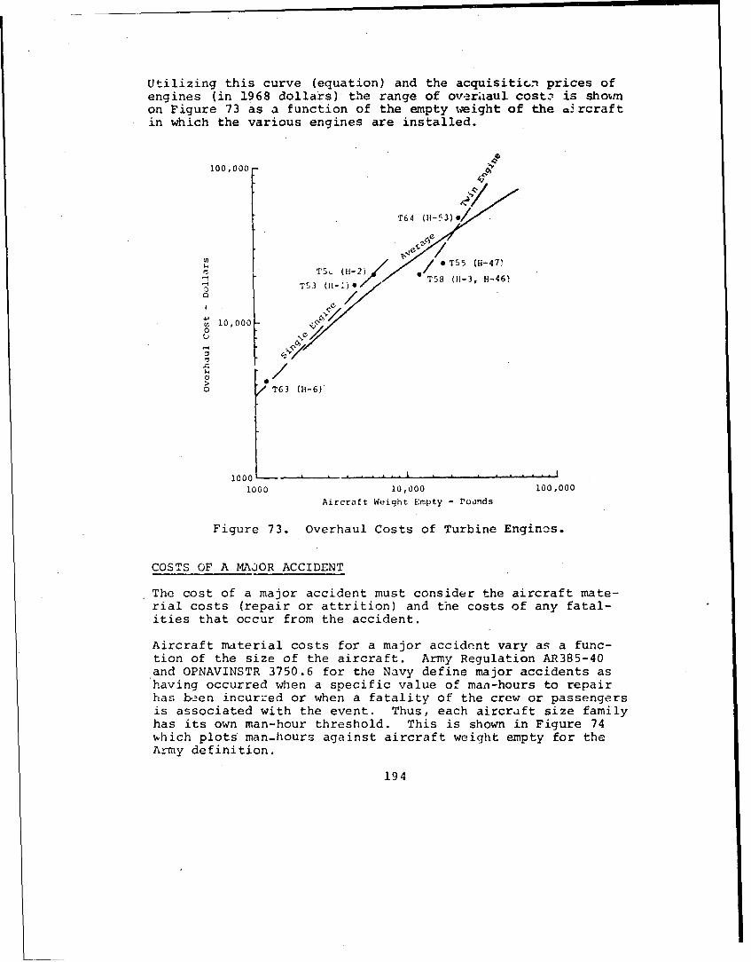
Utilizing this curve (equation) and the acquisiticn prices ofengines (in 1968 dollars) the range of overhiaul costs is showmon Figure 73 as a function of the empty weight of the m•rcraftin which the various engines are installed.
100,000 -
•. •~T64 (H1-53) •
S• / T55 (H-471
ST53 (11-I)!/)"/
S 0,0000
>
o /T63 (H1-6)
1000 -- -- A -- , A - .............
1000 10,000 100,000
Aircraft Weight Empty - Poands
Figure 73. Overhaul Costs of Turbine Engines.
COSTS OF A MAJOR ACCIDENT
The cost of a major accident must consider the aircraft mate-rial costs (repair or attrition) and the costs of any fatal-ities that occur from the accident.
Aircraft material costs for a major accident vary as a func-tion of the size of the aircraft. Army Regulation AR385-40and OPNAVINSTR 3750.6 for the Navy define major accidents ashaving occurred when a specific value of man-hours to repairhas be2en incurred or when a fatality of the crew or passengersis associated with the event. Thus, each aircraft size familyhas its own man-hour threshold. This is shown in Figure 74%hich plots man-hours against aircraft weight empty for theArmy definition.
194

H-47AH-56
1000
0H 1, -2
S.H-6 ' H-13 H-340 H-22 H-55 9 ..
.0.
0 Ref: AR 385_-40
1,000 I0,000 100,000
Aircraft Weight Empty - Pounds
Figure 74. Repair Criteria for Classificationas a Major Accident.
The specific cost threshold fcr each.aircraft is exceeded,naturally, whenever 1-he aircraft is stricken as a result of anaccident. Figure 75 shows the ratio of strikes to major ac-cidents as a function of aircraft weight empty. It is plottedusing both Army and Mivy data as published in Reference 31.
0-4 1.0-
H-2 11-3 H-5311-13 -i 11-34. H-54
"' • ~11-1 I•S0.5 H3 '14
*h6H-19 0 H1-46 Legend-0 11-21
-AH-IG 9 Army HelicoptersH1-23- Navy Helicopters
F-550
4.)
i,0uO0 10,000 100,000Weight Empty - Pounds
Figure 75. Strike to Major Accident Ratios
for Army and Navy Helicopters.
195
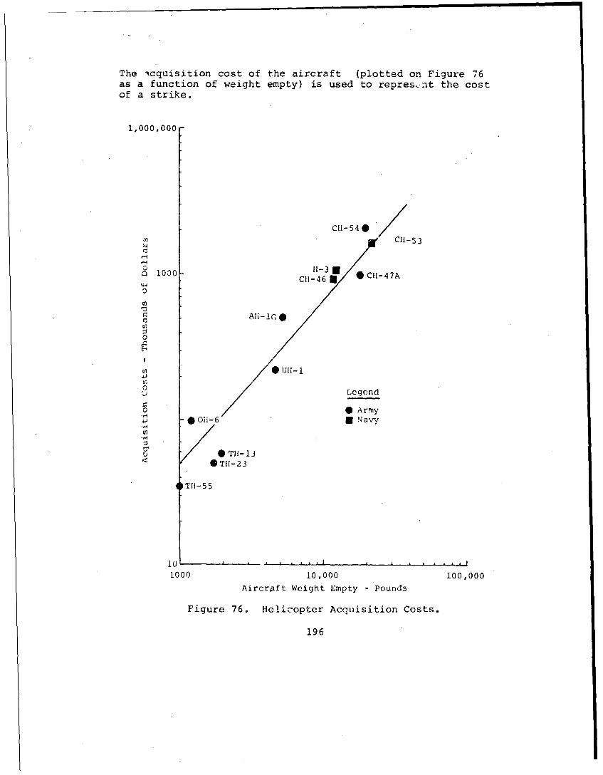
The icquisition cost of the aircraft (plotted on Figure 76as a function of weight empty) is used to represnt the costof a strike.
1,000,000
CH-54 0/c" , • C H-53
'-4
0 H-33"M 1000 C1-46 0 -47A
V)
0
U11-
Legend
* Army0011-6 N Navy
oTH-13< -/ TII-23
'1T11-55
1000 10,000 100,000
Aircraft Weight Empty -Pounds
Figure 76. Helicopter Acquisition Costs.
196

The aircraft which were involved in rmjor accidents which wererepaired and returned to service (not attrited) incurred costswhich were obtained from the U.S. Army Agency for AviationSafety (USAAAVS). Average costs by aircraft model are shownon Figure 77 plotted against aircraft weight empty.
1)00-
CII-47CH-5
CH-54
i00
44
0
10" 100r. AH-lGo
.C 0 UH-l
E-0<
*01-6
101 -LL.-L ~ . L J
1000 10,000 100,000
Aircraft Weight Empty - Pounds
Figure 77. Costs of Non-Attrited Major Accidents.
197

Historical data was reviewed to determine the average numberof fatalities per major accident. These fatalities weredivided into three groups:
"o Aviators - (pilots and copilots)
"o Non-Aviator Flight Crew - (crew chiefs, gunners,observers)
"o Passengers - (military and civilian)
The results are expressed in fatalities per major accident, ineach of these three personnel categories, for individual air-craft models as a function of aircraft weight emrty. Thesedata are plotted in Figures ?8 through 81.
The costs per death Were considered to have two elements: com-pensation costs, and retraining costs. Compensation costsinclude Social Security benefits, death gratuities, dependencyand indemnity compensation, and funeral costs. Some of thesecosts vary as a function of the rank or grade of the individ-ual fatality. Retraining costs represent the costs of replac-ing the deceased person, from a training standpoint. TableLXXVI shows the compensadion and traininq costs for aviatorfatalities, based on an estimated distribution of ranks.
The costs of non-aviator flight crew and passenger fatalitiesare shown below in Table LXXVII.
Considering the fatality rates shown on Figure O1 and thecosts per fatality in Tables LXXVI anrd LXXVII, the fatalitycosts of a major accident are shown on Figure 82.
Using the equipment ccsts from Figures 76 and 77 and thefatality costs fronr Figure 82, the total cost per major ac-cident in the U.S. Army is shown on Figure 83 as a functionof aircraft weight empty. Figure 84 is the same data asFigure 83 except that costs are plotted with a linear scale.
COSTS OF A MAINTENANCE MAN-4OUR
The cost (in 1968 dcllars) of a maintenance man-hour is assumedto be $4.00.
COSTS OF A TBO (SCHEFCULED) REMOVAL
The labor and material costs of a scheduled removal are consid-eted to be the same as for an unscheduled renoval (as shown inFigure 74).
198

1.0
C4I- 47CHI-46 CI5
5{-21
.U -I H-2
i5-55U *. i -34
j. 01H-23
I S ArrmyI • Navy
10)0 10,000 )00.000
Aircraft Weight Empty - Pounds
Figure 78. Aviator Fatal.ities per Major Accident.
ii-47 0
Ci5-53
• 5 •CH-46
li-34g / 0 i4
U 11-21 0h5
0
011-6 *Arm~y
.60(0 " i'0
AiIrcraft Woiqht. Empty -Pounr~d
Figure 79. Non-Aviator rlight-crew Fatalities
per Major Accident.
199

Uinc'-5 3
,-47
If-3440
S1-34 / i-46
/
1,006 10], L 1, 60,&,;6
Figure 80. Passenger (Non-Crew) Fatalitiesper Major Accident.
IU --:f t, r
"I "
200
/
Figure 80. Pasngr(N Crw Fatalitie
Fiur 8. oalFaaltesbyTyeper Major Accident.
20

TABLE LXXVI. COSTS OF AVIATOR FATALITIESa
Comp. Costb Retrng. Costc Aviator FatalitiesRank (dollars) (dollars) Total (pct) (est. dist,)
Wol 4,073 55,000 59,073 - -W02 47,068 102,068 20 20,414W03 61,182 116,183 30 35,000W04 111,911 166,911 10 16,6912LT 4,118 59,118 10 5,912ILT 42,894 97,894 15 14,684CPT 69,324 124,324 10 12,432MAJ 58,-2_ 113,238 5 5,662LTC 51,5z6 106,526 - -
COL 33,559 55,000 8P,559 -
aAvg. aviator $110,795 bRef. 32 CRef. 33
TABLE LXXVII. COST OF NON-AVIATOR CREWAND PASSENGER FATALITIES
Comp. Costa Retrnq. Costb
(dollars) (dollars) Total
Non-AviatorFlight Crew 52,000 15,000 67,000
Passenger 37,000 11,000 48,000
aEst. from Ref. 32 bRef. 33
25I t0a
o /0(2 001
1000 t.r Crew
Aircratt Wetgiit EMpty - Porlnds
Figure 82. Costs o2 Fatalities per Major Accident.
201

,10,00r
T(.alAt trtit•,-,
Co~t.
ht•*a I,.r t
b,. ,;
t,
1000 . 1____ _ '__,Of")A'-.,ft WMIqht tnpty - Pound,
Figure 83. Costs of a Major Accident.
A rI t,.1-
1000. o ,
Figure 84. Costs of a Major Accident (Linear Scale).
202

SELECTION OF AN AVERAGE AIRCRAFT
Since the costs per event for three of the four parametersvary over a range of engine/aircraft size, an average sizeaircraft must be chosen to facilitate subsequent calculations.For the purposes of this study, a helicopter of 7,000-poundweight empty was selected as being typical of past U.S. Armyhelicopter experience. Figure 85 illustrates the weight rangeof Army helicopters, and the average size aircraft chosen.
Average Army Helicopter
7000 Pounds
H-55 H-23 AH-lG HLH
H-6 /H-13 H jfr AS H-54
1000 10,000 100,000
Aircraft Weight Empty - Pounds
Figure 85. Weight of Army Helicopters.
DETERIIINATION OF COST RATIOS
At the 7,000-pound weight empty point, the cost per event andassociated ratios for each of the four R&M parameters areshowm on Table LXXVIII.
TABLE LXXVIII. COSTS AND RELATIONSHIPS
Cost perEvent Cost Ratio
Parameter (dollars) to Accidents
Unscheduled Removals 16,000 1/25Major Accidents 400,000 1Maintenance Man-Hours 4 1/100,000Scheduled Removals 16,000 1/25
203
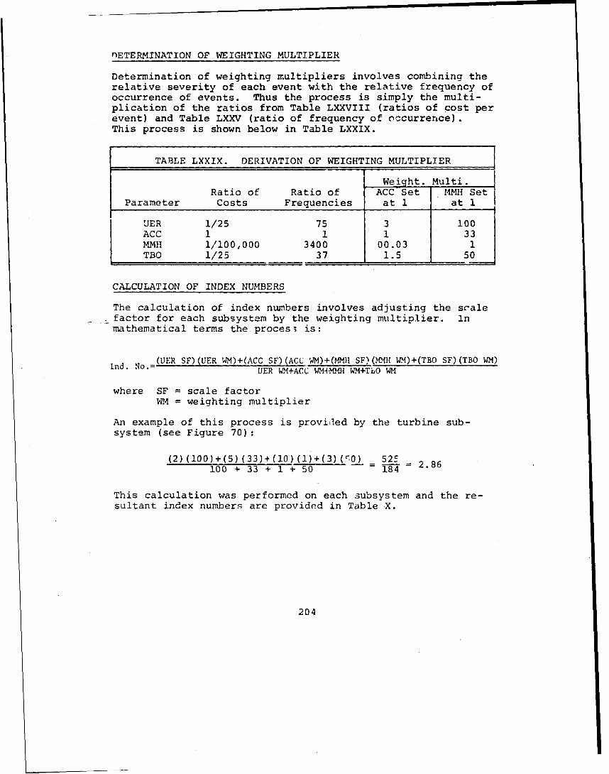
"nETERMINATION OF WEIGHTING MULTIPLIER
Determination of weighting multipliers involves combining therelative severity of each event with the relative frequency ofoccurrence of events. Thus the process is simply the multi-plication of the ratios from Table LXXVIII (ratios of cost perevent) and Table LXXV (ratio of frequency of occurrence).This process is shown below in Table LXXIX.
TABLE LXXIX. DERIVATION OF WEIGHTING MULTIPLIER
Weight. Multi.Ratio of Ratio of ACC Set MMH Set
Parameter Costs Frequencies at 1 at 1
UER 1/25 75 3 100ACC 1 1 1 33MMH 1/100,000 3400 00.03 1TBO 1/25 37 1.5 50
CALCULATION OF INDEX NUMBERS
The calculation of index numbers involves adjusting the scale- factor for each subsystem by the weighting multiplier. in
mathematical terms the proces3 is:
(HER SF)(UER WM)+(ACC SF)(ACU WM)+(MMI SF)('MIH WIM)+(TBO SF)(TBO WM)UER WM+ACC WM*MNH WM+TLO WM
where SF = scale factorWM = weighting multiplier
An example of this process is providled by the turbine sub-system (see Figure 70):
(2)(100)+(5)(33)+(i0)(l)+(3)V(5O) 525100 + 33 + 1 + 50 = = 2.86
This calculation was performed on each subsystem and the re-sultant index numbers are provided in Table X.
204

![\ ] q § n ' § b](https://static.fdokumen.com/doc/165x107/633204227f0d9c38da013cb8/-q-n-b.jpg)