04/2018 December Seshadri Srinivasan Asian ... - e-mosty
88
04/2018 December Seshadri Srinivasan Asian, Australian and New Zealand Bridges
-
Upload
khangminh22 -
Category
Documents
-
view
1 -
download
0
Transcript of 04/2018 December Seshadri Srinivasan Asian ... - e-mosty
04/2018 December Seshadri Srinivasan
Asian, Australian and New Zealand Bridges

4/2018
International, interactive magazine about bridges
e-mosty (“e-bridges”).
It is published on www.e-mosty.cz. Open Access.
Released quarterly:
20 March, 20 June, 20 September and 20 December
Peer-reviewed.
Number: 4/2018, December.
Year: IV.
©All rights reserved. Please respect copyright. When referring to any information contained herein, please use the title
of the magazine „e-mosty“, volume, author and page. In case of any doubts please contact us. Thank you.
Chief Editor: Magdaléna Sobotková
Contact: [email protected]
Editorial Board
The Publisher: PROF-ENG, s. r. o. Velká Hraštice 112, 262 03 Czech Republic
VAT Id. Number: CZ02577933
E-MOSTY ISSN 2336-8179
On BridgesSeshadri Srinivasan
Interview with Seshadri SrinivasanJuan C. Gray, T. Y. Lin International Inc.S. Srinivasan´s CV
The Tale of EJ Whitten Bridge, AustraliaRobert Percy, Peter Robinson, COWI UK Limited
Water of Leith Bridge, New ZealandDan Crocker, DC Structures Studio
Concrete Filled Steel Tube Bridges in ChinaMagdaléna Sobotková
Installation of the Matagarup Bridge, Perth, AustraliaTies Van Sluisveld, Frank Janssen, ALE
LIST OF CONTENTS
Bridge to the Future to help beat CancerLawrence Shackman
Front Cover: Bandra-Worli Sea Link, Photo Credit: Seshadri SrinivasanBack Cover: Matagarup Bridge. Photo Credit: ALE
6
29
36
44
54
64
76
4/2018
Dear Readers It is a big honour and pleasure for us to feature in this magazine Dr Seshadri Srinivasan and his Work. In the first article of this issue he describes his approach to designing bridges and gives examples of his work. We also include an interview with him and his CV. Next article looks at the EJ Whitten Bridge, drawing lessons on how bridges can better adapt to the future, and the innovative design approaches needed to take them there. The article about the new Matagarup Bridge focuses on Lifting and Installation of bridge´s wishbones. It is accompanied with relevant drawings and photo gallery. Design and construction of The Water of Leith Bridge in New Zealand is described by the designer of the bridge. The article is also accompanied by drawings. Last technical article of this issue is an overview of latest advancement in Concrete Filled Steel Tube Arch Bridges in China. The article is based on papers published in the Book of Papers from the ARCH 2016 Conference. We are happy to support Lawrence Shackman´s initiative “The Bridge to the Future to help beat Cancer”. We go on with supporting Bridges to Prosperity. We have also started to support Bridging the Gap Africa. And we are a medial partner of the ARCH 2019 – 9th Conference on Arch Bridges. I am happy to announce that the company BERD will be our partner in 2019 again. Together with ARUP and COWI, three companies have already confirmed partnership for 2019. Thank you all very much for your support. I would very much like to thank all people and companies who have helped me prepare this issue, to all the authors and also to our partners; special thanks to Ken Wheeler and Richard Cooke who reviewed this issue, and also to Juan C. Gray who helped me with Dr Srinivasan´s presentation.
Juan C. Gray of T. Y. Lin International Inc. has accepted our invitation and becomes a member of our Editorial Board. Thank you! Let me announce that we established a new magazine called “e-maritime” about design, construction, operation and maintenance of vessels and maritime equipment, docks and ports from around the world. You can find more information on www.e-maritime.cz. Thank you all for excellent and fruitful cooperation in 2018 and we already look forward to our cooperation in next year.
Magdaléna Sobotková
Chief Editor

4/2018
International, interactive magazine about bridges
e-mosty (“e-bridges”).
It is published on www.e-mosty.cz. Open Access.
Released quarterly:
20 March, 20 June, 20 September and 20 December
Peer-reviewed.
Number: 4/2018, December.
Year: IV.
©All rights reserved. Please respect copyright. When referring to any information contained herein, please use the title
of the magazine „e-mosty“, volume, author and page. In case of any doubts please contact us. Thank you.
Chief Editor: Magdaléna Sobotková
Contact: [email protected]
Editorial Board
The Publisher: PROF-ENG, s. r. o. Velká Hraštice 112, 262 03 Czech Republic
VAT Id. Number: CZ02577933
E-MOSTY ISSN 2336-8179
4/2018
Dear Readers It is a big honour and pleasure for us to feature in this magazine Dr Seshadri Srinivasan and his Work. In the first article of this issue he describes his approach to designing bridges and gives examples of his work. We also include an interview with him and his CV. Next article looks at the EJ Whitten Bridge, drawing lessons on how bridges can better adapt to the future, and the innovative design approaches needed to take them there. The article about the new Matagarup Bridge focuses on Lifting and Installation of bridge´s wishbones. It is accompanied with relevant drawings and photo gallery. Design and construction of The Water of Leith Bridge in New Zealand is described by the designer of the bridge. The article is also accompanied by drawings. Last technical article of this issue is an overview of latest advancement in Concrete Filled Steel Tube Arch Bridges in China. The article is based on papers published in the Book of Papers from the ARCH 2016 Conference. We are happy to support Lawrence Shackman´s initiative “The Bridge to the Future to help beat Cancer”. We go on with supporting Bridges to Prosperity. We have also started to support Bridging the Gap Africa. And we are a medial partner of the ARCH 2019 – 9th Conference on Arch Bridges. I am happy to announce that the company BERD will be our partner in 2019 again. Together with ARUP and COWI, three companies have already confirmed partnership for 2019. Thank you all very much for your support. I would very much like to thank all people and companies who have helped me prepare this issue, to all the authors and also to our partners; special thanks to Ken Wheeler and Richard Cooke who reviewed this issue, and also to Juan C. Gray who helped me with Dr Srinivasan´s presentation.
Juan C. Gray of T. Y. Lin International Inc. has accepted our invitation and becomes a member of our Editorial Board. Thank you! Let me announce that we established a new magazine called “e-maritime” about design, construction, operation and maintenance of vessels and maritime equipment, docks and ports from around the world. You can find more information on www.e-maritime.cz. Thank you all for excellent and fruitful cooperation in 2018 and we already look forward to our cooperation in next year.
Magdaléna Sobotková
Chief Editor

The magazine e-mosty (“e-bridges”) is an international, interactive, peer-reviewed
magazine about bridges.
It is published on www.e-mosty.cz and can be read free of charge
(open access) with possibility to subscribe.
It is published quarterly: 20 March, 20 June, 20 September and 20 December.
The magazines stay available on-line on our website.
It is also possible to download them as pdf.
The magazine brings original articles about bridges and bridge engineers
from around the world. Its electronic form enables publishing of high-quality photos, videos, drawings, links etc.
Editorial Plan
We aim to include all important and technical information
and show the grace and beauty of the structures.
We are happy to provide media support for important bridge conferences, educational activities, charitable projects, books etc.
Our Editorial Board comprises bridge engineers and experts from the UK, US and Australia.
The readers are mainly bridge engineers, designers, constructors and managers of construction companies, university lecturers
and students, or people who just love bridges.
www.e-mosty.cz
ISSN: E-MOSTY 2336-8179
PARTNERS
Partnership and promotion of your company
in our magazine e-mosty
Basic price for Annual Partnership is 990 EUR a year plus VAT.
For this money you will get:
- A logo on the main page on our website. - 1 page interactive presentation of your company in every issue. - Your logo and / or the name of your company on every publication
and output we release. - In compliance with our Editorial Plan we can also publish one
technical article during the year (which we can help you prepare).
Both the price and the extent of cooperation are fully negotiable.
Additional Information
The magazine e-mosty (“e-bridges”) is an international, interactive, peer-reviewed magazine
about bridges published quarterly on www.e-mosty.cz
It is open access with a possibility to subscribe.
It was established in April 2015 and its first issue was released on 20 June 2015
as a bilingual Czech – English magazine aimed mainly for Czech and Slovak bridge engineers.
Very quickly it reached an international readership.
In 2016 we extended the already existing Czech and Slovak editorial board by two bridge experts
from the UK, and in 2017 two colleagues – from the USA and Australia – joined us.
Since December 2016 the magazine has been published solely in English.
Each issue now has thousands of readers worldwide.
Generally the readership has reached almost 10 000 in two years.
Many of our readers share the magazine in their companies and among their colleagues
so the final number of readers is much higher.
Most importantly the readership covers our target segment – managers in construction
companies, bridge designers and engineers, universities and other bridge related experts.
We also know that the readers usually go back to older issues.
www.e-mosty.cz
ISSN: E-MOSTY 2336-8179

4/2018
ON BRIDGES Seshadri Srinivasan
Figure 1: Bandra-Worli Sealink at night
Creator of Elegance
For over 50 years, I have led the evolution thought and understanding of concrete bridges. From the early 1970s as an early exponent of aesthetic design of concrete bridges, I have put the case that engineers are best placed to lead the holistic design of bridges.
This article looks back over a range of structures where I have been personally and fully responsible for the concept, design and successful implementation, to reflect on the success of this approach.
I have designed a wide range of structures of all forms all of which have a combination of aesthetic grace and structural efficiency. Many of my projects have been borne out of very particular circumstance giving rise to a range of unique projects.
Though varied, the projects have a consistent personal style which embodies a high level of engineering excellence in concept, technical innovation, delivery economy and aesthetics.
As a designer I have aimed to bring to Civil Engineering structures in particular the aesthetic grace and attractiveness to rebut the common belief that they
cannot be but uninteresting and massive in appearance. I believe that every project is unique in that it presents its own guidelines for the design to follow.
This leads me to take a holistic approach that also takes into account the construction methodology, to produce an adequate response to these specific requirements.
I use concrete as a mouldable material most suited to express the ideas of form that are true to its function, both economically and efficiently.
Whilst I have an unusual approach in believing in having a single controlling mind for design and to drive the execution of projects, I have been fortunate to have led an exceptional team over the years and I have aimed to enthuse those engineers under my guidance to rise to their own professional challenges.
Innovations in analytical methods and construction techniques developed by myself and my team have been used extensively on my projects and by the industry, with considerable success and economy.
4/2018
.
I have taken advanced techniques and introduced them to developing countries, for example my signature spine and cantilever deck and the use of span-by-span erection techniques.
This has taken a great deal of effort, more than would have been necessary to just gain the work, but has been to show that good engineering is not expensive or hard, but requires thought and determination. Partly because of this I have found that it has been vital for me to personally participate through-out the project, working with the Contractor and Client to obtain the best final result.
I have been fortunate to see that my focus on detail, quality of design, and technical advancement have helped move forward the standard and engineering culture in several countries from an attitude of ‘just acceptable’ to ‘world class’. I am an advocate of engineering design being driven by engineers, not architects and aim show this by my work.
Most of my work is in a commercial context where competition and economy dominate, my contribution is to apply technical skill and experience to produce structures which are more economic than my competitors but also of intriguing form and aesthetic excellence. I hope that in my work I have helped to challenge the perception of what an Engineer does and can create and contribute to society.
I have been personally responsible for the first precast segmental bridges in India and for bringing world class design and construction to India to inspire others.
I have worked with contractors to develop their skills, both technically and to give them confidence to be able to execute his works.
My structures in India are immediately recognisable. They are bold statements, but economic and have a suitable aesthetic for their locations.
Perhaps due to the location of many of my structures they are not as well-known as some others but they are designed to be of the highest quality no matter the location. Over many years I have seen that my reputation in many parts of the world due to my personal drive to produce exceptional pieces of civil engineering has influenced and aided others.
I have been fortunate that I have been able to work in a time and environment where I have had sole responsibility for the concept design, and have directly led the team for analysis and construction supervision of hundreds of bridge structures, bridges, and underpasses and long-span roofs. For each of these projects work stemmed from sketches and calculations in my calculation pad followed by a challenge to my team to make the concept even better.
A testament to my approach is that my structures look fresh and exciting even today. When compared to other concrete bridges of the 1970, 80s or even 90s my work is very different especially when one thinks that much of my work was before the advent of CAD or the analytical capability that we now have.
In almost five decades long engineering career, I have been exceptionally focussed in realising my dream of emulating great engineers of the past by adopting a holistic approach to the design and construction of structures. I hope that my achievements in realising works in the Art of Structural Design enthuse, excite and challenge those that follow me.
EXAMPLES OF MY WORK
As with all engineers, my approach to bridge design is best captured looking at my work. For this article two bridges are examined in more detail to explain my philosophy: Wadi Abdoun, Jordan, and Sungai Prai, Malaysia.
WADI ABDOUN – KAMAL SHAIR BRIDGE, AMMAN JORDAN
The Wadi Abdoun Bridge, in Amman, the Capital City of the Hashemite Kingdom of Jordan is an outstanding example of civil engineering design in concrete and a
rare example of innovation in the application of prestressed and reinforced concrete in directly providing solutions to practical engineering problems. It is an example of how experience and knowledge of the use of materials gives a dramatic but efficient and elegant solution.
It also shows how understanding of construction and construction methodology is applied at the concept stage to produce safe and economic execution. I personally worked with the contractor, to produce the largest bridge in the country and its first cable-stayed

4/2018
Figure 2: Completed Wadi Abdoun Bridge
bridge, transferred knowledge to the local engineers and showed the public that good design is achievable economically.
I used concrete as a material which can be moulded, textured and formed into dramatic shapes with ease and without unnecessary cost.
It is an engineering driven structural response to the constraints and criteria but done in a way which is innovative, expressive and elegant. It is this that makes my structure truly unique.
It is an expression of my ideals in promoting prestressed and in particular segmental concrete bridges, in many areas of the world over a career ranging over 50 years. I have pioneered the use of segmental bridges into the Middle East and India, in many cases having to change outdated national design standards in the process.
The Wadi Abdoun Bridge provides a social and physical link in the Jordanian Capital, Amman, connecting a previously disadvantaged area to the centre of the city, and reducing chronic traffic congestion.
I developed a unique structure, the ‘S’-shaped bridge and sculpted Y-shaped piers responding to the engineering demands but also gives a dramatic exciting aesthetic. The structure has become a symbol of the city in a very short period of time being shown in adverts, cartoons and even inspiring jewellery.
An innovative use of a saddle developed specifically for this project to allow replacement of the stay cables enable me to provide very slender towers.
My design allowed new techniques to be developed and brought to a new country.
The understanding of design and construction brought not only a low cost, but also a structure that works effectively. Its universal acceptance as a landmark structure is in its elegance, attributable to the intrinsic clarity of the structural form without any cosmetic treatment to enhance its appearance.
The structure is efficient, economic, safe and visually attractive in an urban environment. Structural elements are to a human scale, in tune with the surrounding buildings and the local environment.
The structure was used as an exemplar project by the jury for the US/Canada Peace Bridge in 2005. It was awarded a High Commendation in the UK Structural Awards.
The Project was one of those that earned the designer the Milne Medal for Design Excellence from the IABSE British Group, and the lead engineer the fib Medal for Younger Engineers 2007.
I found particular enjoyment in taking a small, highly-constrained project and guided the contractor to produce an outstanding project at a low cost, to enable its people to develop and improve their environment.
The structure responds to its environment, is functional while instilling a sense of comfort and fun in the end users.
As a designer I feel the bridge has produced a good balance between creating an iconic presence in the city without dominating the skyline.
As one of my later works, it is a repository of years of experiment, with a feast of detail and texture available for viewing up-close and from all angles.
It derives a myriad of visual interest as no two views of the structure are the same.
In this is an expression of my signature approach: attention to detail and dynamic forms ensure that both at day and at night the structure provides interest, and drama as well as an extremely economic solution to a complex engineering problem and a structure which has become a symbol of the city.
4/2018
Figure 3: General Arrangement Drawing of the bridge
STRUCTURE
The bridge has four continuous, cable-supported spans which comprise an entirely precast, segmental match-cast deck and are supported by three ‘Y’ shaped pylons.
The bridge’s sinuous ‘S’ curve alignment results from the need to transition into tunnels and existing roundabouts at both ends of the bridge. The deck is approximately 45m above the deepest part of the valley floor.
While the tallest pylon is 71m high, with others at 56m, above deck-level the pylons are identical and as a whole follow the same morphology, with the lower stem being truncated to suit the required level.
Because the bridge’s alignment requires radii of as low as 180m and it is situated in a highly seismic region near the Jordan Valley Fault, structural form and function are brought together in a unique manner.
I hung the deck from the outstretched arms of the towers, giving lateral as well as vertical support. This structural form allows for a fluid dynamism to this urban landmark.
The plan curvature, slope of the vertical alignment and superelevation - coupled with the sloping pylons and cable planes - makes using the bridge an engaging experience for Amman’s residents.
1. COMPLEXITY VS SIMPLICITY
In addition to creating a structure to fit into the existing urban context and landscape, the bridge also addresses a number of engineering challenges.
The solutions are integrated - I personally took the lead and responsibility for all aspects from aesthetics, structure, finish, construction support and even lighting.
The result - a unique ‘S’ shaped cable-stayed bridge boasting titles for the longest span bridge in Jordan, the first cable-stayed bridge in Jordan, and the first cable-stayed bridge built by the contractor.
All accomplished within an extremely economical budget.
The key concept is about how to use the different properties, advantages of reinforced and prestressed concrete in the most advantageous manner

4/2018
combining innovation and experience with signature motifs to produce project-specific solutions:
Total design quality – elegance in aesthetics, structural efficiency clarity and economic buildability.
My signature texturing of the concrete to visually break up the surfaces compliments the bridge’s flowing form and brings interest in the way light plays on the structure, both at night as well as during the day; a vital requirement as all parts of the structure are highly visible and can be closely observed.
The unusual ‘S’-shaped plan form is a response to the available land. The constraints of location of piers and tunnels at each end give rise to an alignment which is fluid, moving in 3 dimensions. With an elevation of over 40m from the valley bed below, this gives users an experience unlike any other bridge – excitement visually and in use.
Being on a curve, torsion is generated by the geometry which drives the design. This is carried by a simplified deck comprising two edge box girders attached to the towers and interconnected with T beams. Deck torsion is resisted by the combination of the towers and stay system.
The deck is of precast, match cast prestressed, segmental-concrete construction. The edge box girders carry the stay anchorages and deck torsion and have longitudinal prestress. The segments are similar to maximise repetition with the extreme
deck curvature accommodated by modification of the simpler, less-critical infill transverse T-beam panels (which are transversely prestressed to the edge girders).
This ensures that the most critical structural components, with prestress and stay cable anchorages, are produced with minimal changes to allow for the ease of fabrication and decrease both geometric errors and formwork cost.
The deck stiff for torsion; this also gives rise to good bending performance and hence economises on the number of stays, The decomposition of the deck into edge beams and in-fill panels allow for small precast elements which are easy to handle and erect.
I used twin leaves for each of the three towers to give flexibility in a highly seismic area. The ‘Y’ form is driven by engineering requirements on cable clearances on the ‘S’ shaped deck, minimum deck width and seismic performance and results in a strong aesthetic statement.
I paid particular attention to developing tower geometry to make the formwork for the towers highly repetitive with multiple uses; it has simple geometrically varying elements giving economy even with a complex shape. I used an integral deck tower connection to negate the need for bearings or joints in inaccessible locations and to provide stability for safe construction.
Figure 4: Elevation of the bridge across the valley
4/2018
Figure 5: Night view with stay lighting
A harp arrangement of stay is used to give uniform stay sizes which rationalises the types of saddles and anchorage details. The stay cables are replaceable and, to the detail, filled with foam at discrete locations to prevent the vibration of the HDPE duct against the strands.
Unusually I developed asymmetric prestress within the towers to counter the torsion in the deck and cater for a range of stress states in construction and in the permanent condition.
The crossbeams at the towers carry significant structural forces and cope with different deck geometries at each pier. The dramatic curve and detail of deck connection with the beam offers needed stiffness whilst minimizing the visual impact and gives interest and clarity when viewed from underneath. The cross beams are prestressed to cope with erection and permanent loads and are designed to be robust enough to be used as bases for tower cranes to minimise the size of crane required.
Prestressed earth anchors tie the pilecaps into the bed rock to provide a sufficiently-robust foundation under seismic loads.
In an environment where economic factors often produce uninspiring structures with brutal short spans and simply supported precast beams on bearings or in-situ concrete box girders – the Wadi Abdoun Bridge is unique. I utilised my experience in design and engineering to give efficient and economical construction. I believe that the bridge stands as a landmark of quality and excellence for Jordan’s capital city.
2. NEED FOR KNOWLEDGE ON SITE & CARE
The buildability of the structure was an important consideration in the concept, especially given the limited local experience with this structure type. The bridge is also a complex structure to construct, with large cantilevers deforming in three dimensions and to be accounted for with the deck and tower precamber.
Further complexities include super elevation and the effect of staged stay stressing on a curved deck. I personally guided the contractor through these issues adding value above and beyond the contractual requirements to enable the project to be completed successfully.
Balanced cantilever erection over the arterial road at the base of the valley give safe construction over a busy live road using bespoke gantries.
3. CLARITY OF THE STRUCTURAL FORMS
I believe that the forms of structural elements adopted for any particular project are integral with and inseparable from the concept design. The development of the type of bridge deck, supporting pier, rationalisation of long span structures, precasting for achieving quality, economy and durability and construction technology are then all considered at the concept stage.
4. SIMPLICITY IN CONSTRUCTION
The construction method often dictates the economics of the structure, but with the emergence of the privatisation of infrastructure projects some of the criteria hitherto ignored are assuming greater importance. In particular, the construction time should be as short as possible, quality should be guaranteed and above all the structures should be constructed with simplicity and minimal risk.
In arriving at the total cost of the project, the material cost must be considered together with the time required for construction. Thus the material cost of structures taken alone is not of overriding significance now that market forces have also placed the engineer in a managerial role to conceive and deliver a complete project on time and on budget.

4/2018
Figures 6 - 8: View of the curving deck (a) from above showing uncluttered deck; (b) from below showing
the structural form of edge boxes with middle T beams; (c) Tower at night
Hence, I feel it is important that an appropriate construction method must be chosen with this objective in mind at the concept stage.
Where construction is largely a repetitive process in viaduct and bridge design, a precast concrete segmental approach satisfies all of the criteria deemed necessary to achieve this through standardisation of the bridge’s main structural components.
Such an ethos can be employed even on a structure such as this. I achieved standardisation of edge beam units using a harp cable system to ensure that the stay anchorage segments were identical, giving minimum number of complex or special units.
With the increasing trend to design and build, this structure is an example of the counter point where by a good designer considers the whole process of design and construction that are needed to execute a project. In doing so, by understanding fabrication, construction, temporary works, long term maintenance requirements as well as structural design, the project can be completed extremely economically.
The Wadi Abdoun Bridge is the first cable stayed bridge in Jordan, and multi-spans. It is technically challenging to build moreover in a country where contractors are not experienced in such structures.
The design is composed of elements with maximum repetition. The towers are integral into the deck. This minimises the need for bearings and long term costs, but also allows a safe and robust erection method.
I as the designer was on site for long periods during the construction. This is unusual, but here it directly helped the contractor to execute the works.
My input went much further than my contractual role in working with the contractor to ensure accurate and safe work.
5. RATIONALISATION OF THE FORMS AND FALSEWORK
I introduced rationalisation at the design stage to minimise the number and types of forms, maximise their use and as far as possible standardise the bridge’s components. Forms are invariably lined with a purpose designed elastic polymer or reinforced plastic liners which produce an immaculate concrete finish.
In the case of the Wadi Abdoun Bridge, pier and tower forms must accommodate a constantly changing profile which diminishes in cross-section over the full height of the towers. The variable shaped concrete sections optimise the stresses in the concrete and effectively prestress the sections to resist the forces due to torsion in the deck.
They vary in shape from a modified straight-sided ellipse at the base 45m below deck level, to a circular section 26m above the deck at the top. Slenderness is achieved by the elimination of tower anchors in favour of a saddle system for the stays and placing mass where it is required the most.
This variable geometry requires that different formwork was needed for each 3m lift, but each formwork section was used four times per pair of towers, and twelve times in total providing economy in their use. The formwork is designed in 3m high sections using an innovative concept in the fabrication of variable sections.
4/2018
Thin sheet steel is cut to the developed shape of the geometry and controlled by the use of steel diaphragm stiffeners, a similar process employed in the shipbuilding industry.
Another innovative structural element occurs in the cable stay design where steel saddles are housed within the tower and allow for the load transfer of the stay cables to occur in a natural compressive state applied radial to the axis of the saddle and virtually along the axis of the tower.
This arrangement offers several benefits over the use of traditional tower cable anchors. Importantly, it allows for a slender tower with sculpted surfaces as less mass is required to resist the forces found in the stays of a conventional cable stay design.
It also allows flexibility in the range of tower shapes, and is cheaper to build and maintain.
Figures 9 - 11: Tower Details
6. QUALITY CONTROL AND FINISHES
The finishes to any concrete structural element of the bridge are a trademark of a designer and have always played a significant part in my personal design process. I considered finishes at concept stage as integral to the overall harmony of the finished product.
Similarly the detail of the finishes to retaining walls, abutments, facings and ancillary elements play an important role in determining the total quality of the project. A textured finish to exposed inclined concrete surfaces will not only allow uniform weathering and reduce streaking but will also enhance and maintain its long term appearance.
I use a juxtaposition of plain and textured surfaces using high quality tactile finishes moreover to contribute to the vibrancy of the completed structure and engage all of its users. The aesthetics of dividing what would otherwise be a large plain surface by texture is well known and I extend this to express the form of the structural element.
The final quality of finish could not be achieved of course without good workmanship and quality control at all stages. This requires the designer to be in control of the project throughout its construction and to approve the results of trial segments, which must form part of the specification, irrespective of whether they are pier, tower, deck or parapet segments. For this bridge, and most of my others I personally inspected all test panels as a control of quality but also to impress on the construction team the importance of this facet of the works.
Figure 12: Construction of the bridge showing scale and form of the tower.
Integral deck and tower allows safe construction and a stable platform to mount cranes.

4/2018
Figures 13 - 15: Sculptured and textured piers LIGHTING
I designed the lighting as part of the bridge concept. The deck is lit by luminaires on the top of the traffic barriers so avoiding lamp posts which would visually and geometrically clash with the stays. Architectural lighting is provided by spot lights on the stays and towers and uniquely fibre optic strip lights set into a groove in the tower to gently accentuate the curved form.
Government budgets do not extend to creating signature structures among the capital’s infrastructure improvements. What I hope I have delivered – however – is just that. A highly economic structure that fulfils not only its structural requirements, relieves the city’s congestion and bridges the valley that cuts the city in half but affords a stunning visual impact and has become Amman’s new landmark in the hearts of the residents.
Figures 16 - 20: Details of the bridge
SUMMARY
It is a testament to the close work and co-operation of Client, Engineer and Contractor that the structure was built so successfully. The project is also an example of my approach of achieving value by looking at the project in total and understanding that what is drawn and calculated is only part of the process. Engineering is about the realisation of ideas and hence economic design is design that can be built efficiently not only in terms of materials but also of effort on site. Errors are expensive and hence it is vital that the Designer aims for simplicity and works with the site team.
4/2018
SUNGAI PRAI BRIDGE, BUTTERWORTH, MALAYSIA
As a designer I am guided by my mantra of the ‘3-Es’ – Economy, Efficiency and Elegance. An example of this approach is my design for the Sungai Prai Bridge in Butterworth, Malaysia, which was awarded the Institution of Structural Engineers (UK) Supreme Award with the judges’ citation:
‘The Sungai Prai Bridge is an excellent example of structural engineering, and bridge engineering in particular. And it is a superb example of bridge engineering at its most effective and imaginative - a landmark structure for the 21st Century’.
This is a relatively conventional project of 3km of dual 3 lane road viaduct with a 185m main span river crossing.
It is an example of my work that brings high quality design and finish to an urban structure not just to a ‘signature’ set piece project.
As such it reflects my consistent approach to engineering quality.
The complexity of the project came from the location, geometry of multiple ramps and integration of ramps into the main line.
It formed an alternative design and hence my focus was about capital cost as well as whole life-cost and construction.
But as these are fundamentally linked I brought a clarity of thought at an early stage that gave benefit overall.
Figure 21: Sungai Prai Bridge Main Span
I devised a concept that showed ease of construction with uniform deck depth, standardized elements giving elegance in that environment.
The bridge is an example of my use of concrete as a mouldable material. I utilised my understanding of how concrete elements are formed to allow changes of geometry creating a deck family that had the same base form for all the different elements in the bridge from ramps to main line to cable stayed span by simple variations such as moving stop ends.
This is part of my fundamental approach to holistic concept design with all the structure being developed together not a focus on a main bridge with ramps as afterthought.
On the main span, my design solution was the interaction of the 3-E’s: I replaced the reference scheme twin deck by single deck with multi-cellular box with side cantilevers.
The 185m main span is carried by a single tower using saddles at a time when they were not in vogue. This avoided need for access in the tower and hence produced slender towers and narrower deck.
My concept embodied elements of safe construction and operation:
Cable anchorages within the deck cell made for safe stressing and easier longer term maintenance;
Pier diaphragms designed as split into two to allow construction with an unmodified launching girder;
Side cantilevers allowed a straightforward route to accommodate varying deck width;
Side spans built to the tower by launching girder so that main span erection only from deck – requiring no work in the river even for barges (hence a safe method, with no disruption to marine traffic, and being less wind sensitive – less construction down time, and
Low maintenance – integral deck and towers only bearings at junction with approach spans and where piers are short at ramps.

4/2018
Figure 22: Typical Deck Section Through Bifurcation
Figures 24 - 26: Main Span Segment erection from deck level
with segments brought along the constructed deck
The shaped towers were driven by load and construction as well as visual theme. These towers were an evolution of my approach on the earlier Wadi Leban and Bahrain bridges and later further evolved on Wadi Abdoun Bridge.
Slender towers with saddles have been one of my design signatures for 30 years but one which has been appropriate for locations and with benefits that others are now also adopting.
Figure 23: Typical Cross Section Through Main Span
4/2018
Figure 31: Bifurcation geometry by use of standard segments
and varying cantilevers and ramp segments
Figures 29 and 30: Main line construction showing symmetric
bifurcations to maximise repetition
Figures 27 and 28: Split Tower Segment erection assembled
from ground level and jacked up
The junction of main line into the ramps shows some of my key themes. The visual effect is a smooth transition from main line with the ramp structure peeling off. There is only one structure, not several, a detail that is very rarely attempted by other designers.
But it is a bifurcation where form follows function.
My experience of segment fabrication and the flexibility of the spine and cantilever construction allows for straightforward modification of segments to allow a gradual separation of the carriageway.

4/2018
Figures 32 and 33: Precast side cantilevers
and temporary connection details
Concrete materials also play a large part in my work. High strength concretes are used; 80MPa for the tower which was unusual at the time and in the location. Since the 1970s I have used microsilica mixes to provide durability and corrosion protection.
Sungai Prai like most of my structures uses preformed liners to provide consistent textures on the concrete to enable uniformity in weathering.
But this is detailed at the design stage so that precise changes in texture are co-ordinated with construction joints and formwork ties. The linear geometry formed part of the mandatory construction sequence information to the contractor.
This is an unusual level of detailed thought and a key reason behind the success of this project. It is too common for small construction changes to affect the overall elegance of the work. But it is also a function of a full understanding of the construction process to be part of the design.
One of the most important aspects of my philosophy shown by Sungai Prai is that the engineering thought needs to be robust and extensive to allow for full realization of a concept and a single mind taking a project from start to fruition.
My approach starts with a visit to the site, an essential part of the process.
Figures 34 and 35: Completed Tower showing slenderness above deck
and integral pier connection
4/2018
Figures 36 and 37: Finished bridge showing variation and quality in finishes and designed construction joints
Then comes the idea in my mind as to what the structure should look in that environment and how it can be created in that environment, establishing the sensitivity of the structure in that environment. Also gaining an idea of problems in construction process that would follow.
I always design for construction – even if it is not a design and build contract. I have always understood that providing solutions that are buildable with minimizing risk in construction gives overall economy.
My concepts are never geared to availability in skill in that area. But instead I work with inexperienced teams, to assist and enable them to gain skill and produce work.
This is viable only if the concept is robust, the designer is willing to help the contractor, and has the
fundamental competence to provide leadership as required, with the design which has a safe and appropriate construction method.
Sungai Prai is an example of a single mind, enabling team work, but with the focus to minimize change. Not design by committee.
ACKNOWLEDGEMENT
For the projects described in this article, I was lead designer, Director, and Head of Bridges and Special Structures at Dar Al-Handasah (Shair and Partners). I am grateful for the support of the firm and my team during this period in producing an exceptional range a quality of work. Of the many people who have collaborated with me the following deserve special mention: Charles Malek, Kelvin Moneypenny, Dr Arabi El-Shenawi, Ali Hussain and Dr Gopal Srinivasan.
FURTHER EXAMPLES OF MY WORK For all of the structures presented below, I was the sole originator of the concept and personally responsible for concept design without any architects.
I also personally ran the teams which took the concepts through detailed design and to site.
I visited the sites of all structures during all stage of the work.
I was also fully responsible for the contractual and financial aspects of the projects.
In most cases I was personally responsible for the award of the project.

4/2018
PROJECT RECORDS: Longest span cable-stayed bridge in the
Middle East for more than 17 years Longest single plane concrete cable-stayed bridge
in the world for 16 years
Longest bridge in Africa for over 25 years First cable-stayed bridge in Jordan
Largest precast concrete shell roof and 5th
largest roof for more than 20 years
First Precast Segmental concrete bridge in Jordan
Longest bridge in Jordan First Build-Operate-Transfer bridge in India
Longest 3 viaducts in India First Precast Segmental concrete bridge in India
Longest urban viaduct in the world for 10 years
Figure 39: Wadi Leban Bridge: General Arrangement Drawing
Figure 38: Completed Wadi Leban Bridge with 405m main span
WADI LEBAN BRIDGE, SAUDI ARABIA (2000)
Concrete cable stayed bridge with 405m main span, single precast deck 36m wide, central plane of cables. Highly Commended, British Construction Industry Awards, 2000. International Category.
The texture of the deck and towers is designed to break up the large surfaces and to provide visual interest as the sunlight changes during the day.
The design of the towers incorporated a platform to enable a tower crane to be sited at deck level.
Longest cable-stayed bridge in the Middle East since 2000 and for 16 years the longest single plane concrete cable-stayed bridge in the world.
4/2018
Figure 40: Wadi Leban Bridge: Tower geometry showing integral deck to tower connection and stay saddle detail
Figure 45: Details showing integral deck to tower connection Figures 41 - 44: Wadi Leban Bridge: Construction and Views of the bridge

4/2018
Figures 46 and 47: Completed Wadi Leban Bridge showing parapet detail and deck finishes
Figure 48: Bandra – Worli Main span tower
BANDRA-WORLI SEALINK BRIDGE, INDIA (2009)
A precast segmental bridge consisting of 51x 50m approach span and two cable-stayed bridge of 350m (Worli) and 500m (Bandra) length, for a total bridge length of 3.5km. Each typical 50m span consists of 15 120t segments which were lifted in place by a 1200t erection gantry; it is one of the longest span bridges in India.
The link lies just off the coast across a bay and provides an 8-lane relief to chronic congestion in a particularly busy part of India’s commercial capital.
In a city which grew out of 7 islands and hence only a few routes, a car population of over 1.5m and rapidly booming usage, the link provides significant reductions in vehicle congestion and hence emissions, with minimal impact on the environment.
Figure 49: Bandra Worli-Sealink under construction.
The sweep of the viaducts leading to the main span
with the centre of the city in the distance
The spans of the structures allow for the local fishermen to easily access the deep water and hence continue with their traditional lifestyle. The dramatic form gives an iconic landmark to the city and has already been used in national adverting campaigns as a symbol of the advancement of modern India.
The structure comprises twin parallel bridges, sharing only common the stay towers. The erection was complicated by a working season of only six months due to the monsoon.
The contractor was not experienced in erection of such complicated bridges, so I spent approximately 50% of the working season on site, actively aiding the contractor with erection methodology and but also best practice in safety and management of the project.
4/2018
Figure 50: Main Span Tower General Arrangement
The design was specifically tailored to enable one carriageway to be completed before the other to enable opening as rapidly as possible – to maximise benefit to the users - and also because very constrained financial conditions were given by the Client.
However, unlike many parallel structures, the key elements where repetition and continuity of work are need - such as the foundations and tower - these were done as one piece of work.
The project is also a beacon of trade links between the UK and India and we hosted the UK Prime Minister, Gordon Brown, when he visited the site in January 2007.
The first phase of the bridge opened in June 2009, with immediate benefit to traffic flow and significant reduction in traffic emissions. The local population talk of the bridge as an ‘engineering marvel’.
It captured the imagination of the public to the extent that for the first 5 days after opening there were queues on the bridge as people wanted to experience the drive.
Figure 51 ←: Bandra Bridge Towers.
The pyramidal form gives a stable platform for construction
and for good aerodynamic performance during service
Figure 52 ↑: Completed Bridge at day
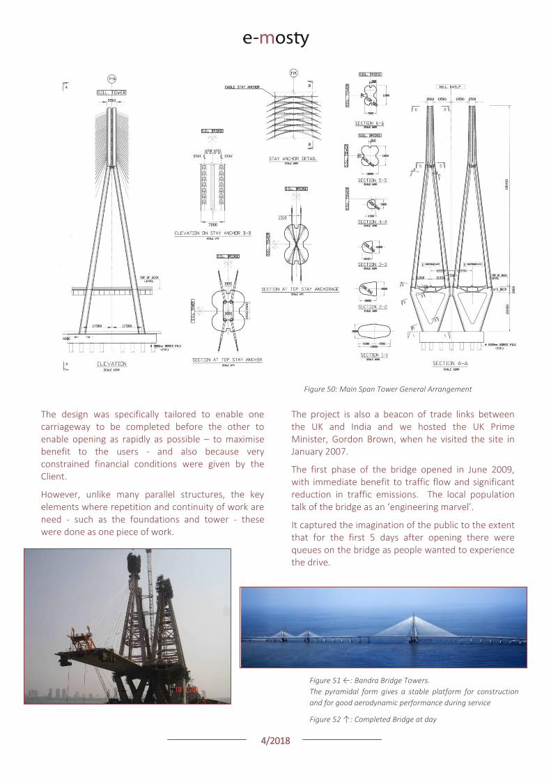
4/2018
This structure is almost 30 years old, but shows that in partnership with the Contractor good design and engineering, encompassing structural design, understanding of form and material, texture and construction produces a structure which fits in and improves the urban landscape and still does so when many other structures of similar ages are demolished.
As the designer I personally designed the landscaping and lighting to work with the structure.
AL-KHALEEJ VIADUCT, SAUDI ARABIA (1989)
Precast segmental bridge with variable depth box girder. Viaduct over 3 km long with bifurcations. Organic form and a main span of 130m, (typical 101m). Outstanding design of exceptional aesthetic quality in design.
I was responsible for structural design and construction supervision, but also landscaping and lighting.
Figure 53: Dramatic sweeping main span curves in plan and
elevation as well as having a variable depth deck
Figure 54: Al-Khaleej Viaduct: General Arrangement
Figures 55 - 57:
Al-Khaleej Viaduct: View above
and under variable depth main
line showing absence of piers and
deck touching the ground. Typical
Deck segment erection via gantry
crane
4/2018
SHAIKH ISA BIN SALMAN BRIDGE, BAHRAIN (1998)
Cable stayed bridge using pre-compressed stays. Single deck 36m wide with central plane of stays. Precast segmental. FIP Outstanding Concrete Structures Award 1998. Shortlist.
This bridge provides a vital transport link, but the drama and elegance of the bridge has made it a national symbol and appeared on national stamps.
Figure 58 →: Outstanding concrete finishes characterise
the sails and the parapets
Figure 59: Shaikh Isa bin Salman Bridge showing
pre-compresssed encased stays
Figure 60: Night time illumination
Figure 61: Shaikh Isa bin Salman Bridge: General Arrangement

4/2018
Figure 62: Shaikh Isa bin Salman Bridge: Tower and ‘Sail’ Details
JJ HOSPITAL VIADUCT, INDIA. (1999)
The longest urban viaduct in India on completion. Particularly constricted urban location in the centre of Mumbai. Association of Civil Consulting Engineers, India: FOSROC AWARD. 2000.
Figure 63 ↑: JJ Hospital viaduct in its congested city centre location.
Design utilised maximum precasting, deck, parapets and some piers to
minimise disruption.
SIRSI CIRCLE VIADUCT, INDIA (1998)
2.0 km long prestressed segmental urban viaduct. First use of precast segmental construction in India. Design included design of launching girder and method of construction for Contractor. Changed the Indian design standards, which previously did not allow precast segmental construction.
ACCE Som Datt Award for Sirsi Circle flyover at Bangalore from Association of Consulting Civil Engineers, India.
Figure 64 →: First structure of its type in India and significant
knowledge transfer with information for permanent and temporary
works, including erection girder design and even casting yard layout.
4/2018
JEDDAH – MAKKAH EXPRESSWAY. SAUDI ARABIA (1985)
Longest urban viaduct in the world on completion. Dual 12.5 km structure completely precast including 8 ramp/viaduct junctions. Exceptional aesthetic merit.
Figures 65 and 66: Structure in both urban and sub-urban
contexts gives the light and porosity
under the alignment
DIWAN UNDERPASS, SAUDI ARABIA (1981)
Cut and cover underpass adjacent to the sea-front in Jeddah.
Sole responsibility for design of structures and lighting, including bespoke luminaires and textures precast concrete retaining walls.
Figure 1: Integrated design of an underpass. Simple use of texture
and light gives an improved user experience
WADI MUJIB BRIDGE, JORDAN (1994)
80m span cable supported bridge with precompressed encased stays.
Longest span bridge in Jordon on completion.
Figure 68: Wadi Mujib Bridge is located on the bank
of the Dead Sea with encased stays giving
superior corrosion protection

4/2018
MUNA BULK STORAGE RESERVOIR, SAUDI ARABIA (1986)
Cable stayed shell roof 340m diameter. One of the largest concrete shell roofs in the world. The clear span of 210m and the overall diameter are larger than the Millennium Dome in the UK, and the concrete material gives long life and minimal maintenance in a very harsh environment.
Figure ↑ 69: Concrete roof in its mountainous desert bowl.
The picture was taken more than 5 years after
completions and shows the exeptional durability
even without maintenance.
Figures 70 ↗ and 71 →: Interior and exterior views of the cable-
net domes. Multi-layers of cables separated by
circumferential trusses give a robust three-
dimensional cable dome.
CAIRO STADIUM ROOF, EGYPT (1991).
120m diameter and 60m diameter tension cable roofs. Using conventional prestressing strand with straight cables to define a cable net allowed inexperienced contractors to build a complex structure in record time, for the African Games. Main hall seats over 20,000 people. Concept to completion for the whole stadium including 4 cable net roofs was in under 18 months.
SELECTED OTHER STRUCTURES:
Car park at the Prophet’s Mosque, Medina, Saudi Arabia (1992). A multi-level underground car park with 3,000 spaces and 70m spans. Utilising bridge engineering techniques and construction methodology to construct one of the largest car parks in a very sensitive site enclosing the Mosque on three sides.
Second Narmada Bridge, India (1997). A 1.3 km long river crossing with 95m spans. The first BOT bridge in India. Design of temporary works including the launching girder. Indian Institute of Bridge Engineers: Winner Most Outstanding Bridge National Awards 2000.
Bridge Across the Straits of Malacca. (1997). Concept design studies for 1200m and 900m cable stayed bridges. Approaches 350m cable stayed bridges constructed on shore and floated into position.
Limbang Bridge, Malaysia (1994). 100m span composite box girder with unique erection method for river crossing in rainforest area.
Yangtze River Bridge, China (1993). Preliminary Engineering Design for a cable stayed bridge 1100m main span for BOT project. Work also included traffic surveys and traffic and financial forecasting.
Pyramidal Tension cable roof, Saudi Arabia (1985). Modules of 44m x 75m to from roof 352m x 150m as a cover to a potable water reservoir. Prestress strand cables support prestressed beams up to 150m long and transverse reinforced beams. Low maintenance aluminium cladding attached directly to the cables.
Niger Bridge at Ajaokuta, Nigeria (1985). Twin deck 3km long river crossing with 80m spans in river with high scour. Longest bridge in Africa on completion.
Long Span Cable Structure. Concept for 1-2km main span; Submission for the competition ‘The Bridge Image’ sponsored by the New Civil Engineer.
4/2018
INTERVIEW WITH SESHADRI SRINIVASAN
Juan C. Gray, T. Y. Lin International Inc.
Please tell us about your professional studies, and how you started your involvement in bridge design.
I introduce myself as a Civil and Structural Engineer/Designer having been involved in the design and construction of bridges and other structures for over 50 years. My major skills include the Concept Design, Structural Analyses and Construction techniques of varied structures.
Professional studies:
Bachelor of Engineering in Civil Engineering 1956 University of Madras India
Master of Science in Structural Engineering 1957 University of Madras India
Thesis: Precast /match cast segmental bridge post-tensioned spans
Which was your professional timeline?
1956 - 1958: Design Engineer with Dr Carbone - Associate of Pier Luigi Nervi in India 1957-1958. Design of shell structures before the advent of computers, which was a demanding undertaking.
1958 - 1960: Design Engineer – Concrete Ltd. Leeds, England. Design of complete buildings for schools, warehouses etc. in precast concrete.
1960 - 1976: Design Engineer/ Associate -Design Analyses – Arup. One of the major structures In Britain at the time, and Arup’s first multicellular box girder bridge using innovative design techniques. (Refer to: Gateshead Viaduct: Analysis of a complex Multicellular Box structure- Structural Engineer March 1971). Other structures include Pompidou Centre France, which was a major innovation in terms of architecture and engineering, and several shell structures in Malaysia and South Africa.
1976 - 1980: Director Dar Al Handasah (Shair & Partners) London.
1980 - 1999: Chairman Dar Consultants London & Senior Partner /Director Bridges and Special Structures- Dar Al Handasah.
1999 - 2013: Director- Director Bridges and Special structures Dar Al Handasah (Shair & Partners).
2013: Consulting Engineer.
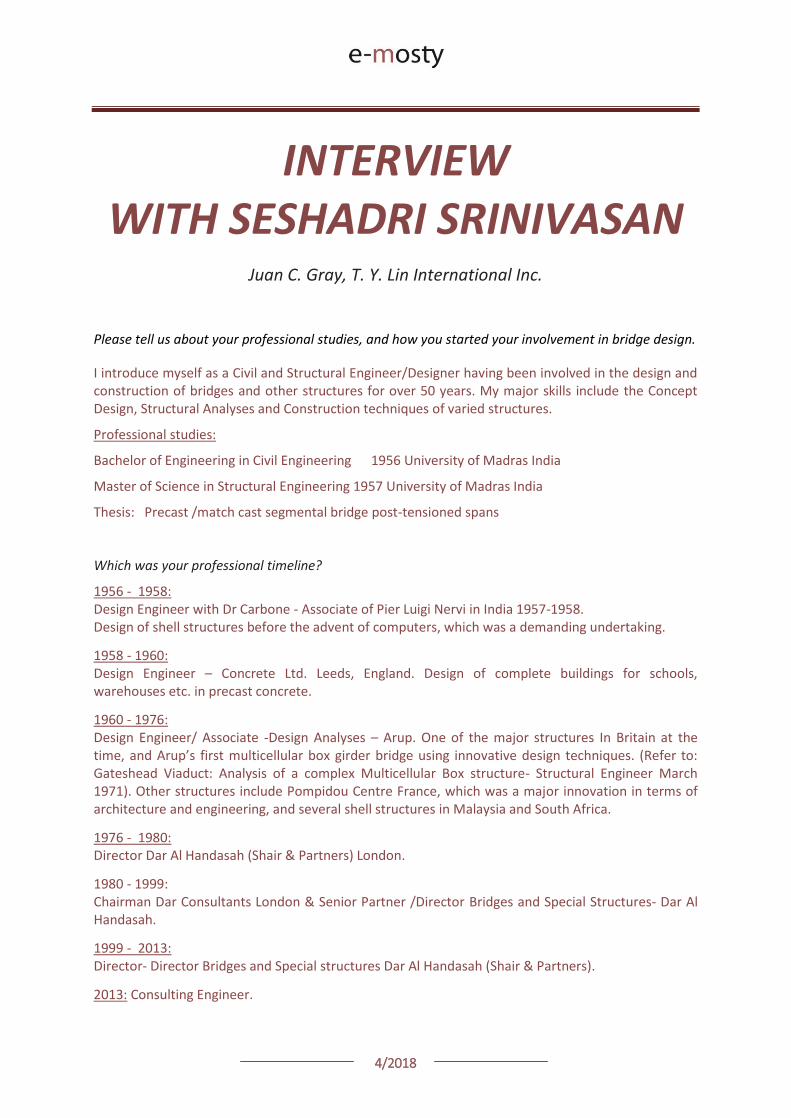
4/2018
Was there a specific person that influenced your thought in bridge design?
I was impressed by the way Nervi designed and built his structures - elegant structures true to function and simple in form. Working with Dr. Carbone, I took a leading role in the construction of his projects. Most of them have withstood the test of time. His structures covered a wide range.
He has been my model. Likewise, for me my career has involved varied structures and bridge forms, part of them not necessarily the only type. In all structures I prefer to use my intuitive knowledge and experience in the design from concept, detailed structural design and construction engineering. If you choose to view your design as sacrosanct and not be replaced by an alternative design by contractors, it would be wise to suggest a method by which the contractor would find it safe and comfortable to adopt. Hence a designer should always suggest an optional method of construction.
Which Bridge do you consider your best achievement?
There are many, and many have won several awards. All of them demanded special time and thought.
Regarding the Prai and Kamal Shair bridges: it would be a common starting point for a designer and a contractor to consider cast in place concrete for the horizontally curved portions of these, as he would think it was easier. Which factors assured you that a precast segmental approach would be more successful?
All the structures that I have been responsible for have gone through a series of progression in various aspects of design and process of construction, significantly in precast concrete which made us the leader in design of precast segmental bridges.
The first cable stayed bridge -The Wadi Leban bridge is a truly elegant structure with single plane of cables using significant innovations in concept and construction (deck width 35.8m using my innovation of precast deck and side cantilevers as in the case of the Sungai Prai bridge, the use of saddles for cables, and lighting for the roadway from the tower tops, the use of micro silica to develop concrete of high strength (100 MPa for increased durability and strength.)
This happened to be the contractor’s first cable stayed bridge, and they were able to produce a great work.
Among other similar projects this was a very happy collaboration between the Client, Contractor and the designer.
I was involved in the construction engineering of the Sirsi Circle flyover (1998). A considerable length of viaduct in an urban situation with ramp viaduct intersections and curved ramps. We provided all information to the contractor from design of launching girder to design of formwork.
My extensive experience in the design of formwork has given me the confidence that precasting is in most cases easier in construction and erection of segments, particularly the ease of casting, handling and the time schedule of operations and the quality of the work, all of which have a direct relation to the economics of the project.
Furthermore, it has always been my belief that the concept should be based on at least a method of construction.
4/2018
Following the previous question, was it difficult to convince or guide the Contractor to achieve the final results, in terms of geometry variations, and overall quality?
It is my belief that most contractors shy away from precasting because of the preplanning and skill involved in the work which by definition requires few skilled workmen. If this information is well documented in advance and available for the contractor to follow, he feels confident to embrace it.
In my experience on almost all our projects the contractor has accepted our suggestion of construction methods which had been well thought out and well documented at tender stage and made a success of it. It is useful to note that almost all our projects have been built by advanced precast design based on careful thought and experience. These projects have included structures on significant curves.
Regarding the Bandra-Worli bridge; we understand that part of the work was already built when the Authorities decided to substitute the Designer, and you came on board. Please give us some details on how the original design was transitioned to your design.
Our involvement on the Worli Bandra Project has an interesting history which gives great credits to our work as a firm involved in the design of bridges. Our involvement as far as the design is concerned was related to the Design of the Bandra and the Worli cable stayed bridges and the supervision of the whole project which included in addition the standard approach spans.
The basic design consisted of a single tower supporting two interconnected deck structures by four lines of cables with anchorages in the tower. Our design, which had some constraints because the contractor was already on site, consisted of two deck structures with two dedicated towers. The advantages of this design are significant and the contractor and client accepted alternative with grace.
Our alternative design was a single deck approx. 40m wide consisting of spine and cantilever supported by a single tower with 250m spans on either side of the tower and a single plane of cable in the middle. The savings in cost were significant.
How do you see the status of bridge design today? Do you see any interesting developments?
Bridge Design today is a process that has taken a very different course to what used to be an organised established system with well defined responsibilities. A number of consultants are now involved in the same project and it is not very clear how the responsibilities are shared. The design is more by committee and the process certainly may not be able to bring out the single minded focus that is so necessary for the success of a project.
The main drawback and a reason for some of the problems now on delivering a project is that very few involved can visualise the project as a whole. Engineers are more committed to a digital process reducing the need to think it through. This has virtually killed the Art of design. We do not produce stalwarts in the profession like Nervi, Ove Arup, Christian Menn, Fritz Leonhardt to name a few, anymore.
The scene is now set for more computerised intervention with robots that one might see more the garbled type of structures requiring structural gymnastics and complex construction methods rather than the varied simple brilliance of work that often distinguished engineers of the past. Perhaps less need for engineers but more for technicians.
Thank you very much for your time and cooperation.

4/2018
Seshadri Srinivasan FREng, FNAE, FICE, FIStructE, CEng, MSc(Eng)
Born in Dar Es Salaam in Tanzania in 1933.
B.E (Civil Engineering) Madras University, India, 1956.
MSc (Structural Engineering) Madras University, 1958.
Fellow, Royal Academy of Engineering, UK
Foreign Fellow, Indian National Academy of Engineering.
Fellow, Institution of Civil Engineers, London.
Fellow, Institution of Structural Engineers, London.
Member, IABSE.
1965 – 1976 Awards:
Award for Engineering Excellence, World Federation of Engineering Organisations, 2009
International Award, Institution of Civil Engineers, London 2007.
Inaugural Milne Medal for Design Excellence by the British Group of IABSE 2003
S.B. Joshi Award" for excellence in 'Bridge and Structural Engineering'. 2007 Alumni Association of College of Engineering, Pune
UK-India Trade Award
fib Outstanding Structure Award: Wadi Abdoun Bridge
Supreme Award & Transportation Award, Institution of Structural Engineers
Srinivasan is one of the world’s leading bridge and special structures designers, and is responsible for the concept, design and successful implementation of many prestigious projects which have been acclaimed for their combination of aesthetic grace and structural efficiency.
He has an exceptional oeuvre of a wide range of structures, buildings, stadia, long-span roofs and bridges of all forms; many have been borne out of very particular circumstance giving rise to a rarely rivalled range of unique projects.
He is has recently been involved in a variety of viaducts and cable supported bridges in India, the Middle East and Europe including Mersey Gateway, UK, proposal for a crossing of the Narmada River, India and light rail viaducts in Saudi Arabia. He was responsible for the structural design on the unique Jamarat Bridge which has recently been completed. In addition he has ongoing roles in large roof and building schemes in the Arabian Gulf.
4/2018
Relevant Achievements
Selected Recent Completed and Current Bridge structures: 3rd Narmada Bridge (2012): Tender design for a multi-span cable supported 1.5km river crossing.
Jamarat Bridge, Mecca, Saudi Arabia. (2011) Multi level building for pilgrimage near Mecca. 60-974m clear transverse spans, 600m long. Multi-level – 4 in phase 1, 5 in Phase 2. Construction on the first level in less than 10 months to not disrupt the pilgrimage. Design of a 2 storey structure to carry exceptional loads which could also be built in a location with limited access to be completed in less than a year including demolition of the previous structure.
Bandra-Worli Sealink (2009) 500m long cable stayed bridge and 2.3km of approaches across the sea (with additional 150m span cable stay bridge). Precast segmental construction. One of the longest span bridges in India and the longest bridge across the sea in India.
University Circle & Agricultural Circle Flyover’s Pune (2007)
1.6 km of urban viaduct including complex bifurcations done entirely with precast elements.
Wadi Abdoun Bridge, Jordan (2006).
(Shortlist for British Construction Industry Award, 2007 and IStructE Awards, 2007)
A continuous cable stayed bridge of outstanding conceptual design. ‘S’ shaped precast segmental cable-stayed multi-span. Main spans 134m. ‘Y’ shaped towers in a highly seismic region.
Wadi Leban Bridge, Saudi Arabia (2000). Concrete cable stayed bridge with 410 m main span, single precast deck 36m wide, central plane of cables. Commended, British Construction Industry Awards, 2000. International Category. Longest cable-stayed bridge in the Middle East since 2000 and for 16 years the longest single plane concrete cable-stayed bridge in the world.
Shaikh Isa bin Salman Bridge, Bahrain (1998). Cable stayed bridge using pre-compressed stays. Single deck 36m wide with central plane of stays. Precast segmental. FIP Outstanding Concrete Structures Award 1998. Shortlist.
Sungai Prai Bridge, Malaysia (2006). Main span cable stayed bridge 185m with approaches on both sides with 50m spans. Institution of Structural Engineers Awards 2006. Winner Award for Transportation Structures. Winner of Supreme Award.
JJ Hospital Viaduct, India. (1999). The longest urban viaduct in India on completion. Particularly constricted urban location in the centre of Mumbai. Association of Civil Consulting Engineers, India: FOSROC AWARD. 2000.
Second Narmada Bridge, India (1997). A 1.3 km long river crossing with 95m spans. The first BOT bridge in India. Design of temporary works including the launching girder. Indian Institute of Bridge Engineers: Winner Most Outstanding Bridge National Awards 2000
Bridge Across the Straits of Malacca. (1997). Concept design studies for 1200m and 900m cable stayed bridges. Approaches 350m cable stayed bridges constructed on shore and floated into position.
Limbang Bridge, Malaysia (1994). 100m span composite box girder with unique erection method for river crossing in rainforest area.
Yangtze River Bridge, China (1993). Preliminary Engineering Design for a cable stayed bridge 1100m main span.

4/2018
Niger Bridge at Ajaokuta, Nigeria (1985). Twin deck 3km long river crossing with 80m spans in river with high scour. Longest bridge in Africa on completion.
Long Span Cable Structure. Concept for 1-2km main span; Submission for the competition ‘The Bridge Image’ sponsored by the New Civil Engineer.
Al-Khaleej Viaduct, Saudi Arabia (1989). Precast segmental bridge with variable depth box girder. Organic form and a main span of 130m, (typical 101m). Outstanding design of exceptional aesthetic quality in design.
Sirsi Circle Viaduct, India (1998). 2.0 km long prestressed segmental urban viaduct. First use of precast segmental construction in India. Design included design of launching girder and method of construction for Contractor. Changed the Indian design standards, which previously did not allow precast segmental construction. ACCE Som Datt Award for Sirsi Circle flyover at Bangalore from Association of Consulting Civil Engineers, India.
Jeddah – Makkah Expressway. Saudi Arabia (1985). Longest urban viaduct in the world at completion. Dual 12.5 km structure completely precast including 8 ramp/viaduct junctions. Exceptional aesthetic merit.
Diwan Underpass, Saudi Arabia (1981)
Cut and cover underpass adjacent to the sea-front in Jeddah. Sole responsibility for design of structures and lighting, including bespoke luminaires and textures precast concrete retaining walls. Wadi Mujib Bridge, Jordan (1994). 80m span cable supported bridge with precompressed encased stays. Longest span bridge in Jordon on completion.
Special Structures:
Confidential Roof: (2012 ): Concept design for an ultra-long span roof in the Gulf.
Makkah Royal Clock Tower (2008-2012): Design of transfer structure and peer review of the second tallest building in the world (610m).
Pyramidal Tension cable roof, Saudi Arabia (1985). Modules of 44m x 75m- continuous to from roof 352m x 150m.
Muna Bulk storage reservoir, Saudi Arabia (1986). Cable stayed shell roof 340m diameter. One of the largest concrete shell roofs in the world. The clear span of 210m and the overall diameter are larger than the Millennium Dome in the UK, and the concrete material give long life and minimal maintenance in a very harsh environment.
Cairo Stadium Roof, Egypt (1991). 120m diameter and 60m diameter tension cable roof. Using conventional prestressing strand with straight cables to define a cable net allowed inexperienced contractors to build a complex structure in record time.
Car park at the Prophet’s Mosque, Medina, Saudi Arabia (1992). A multi-level underground car park with 3,000 spaces and 70m spans. Utilising bridge engineering techniques and construction methodology to construct one of the largest car parks in a very sensitive site enclosing the Mosque on three sides.
He also acts as an internal reviewer and specialist advisor on airport, off-shore projects and large buildings. He has also been an independent checker and reviewer for many structures.
4/2018
Project Awards:
fib Outstanding Structure Award 2009: Wadi Abdoun Bridge
UKTI UK-India Business Award: Banda-Worli Bridge
Institution of Structural Engineers, London: Highly Commended in Award for Transportation Structures 2007 (for Wadi Abdoun Bridge)
Institution of Structural Engineers, London: Supreme Award for Structural Engineering 2006 (for Sungai Prai Bridge. Malaysia)
Institution of Structural Engineers, London: Award for Transportation Structures 2006 (for Sungai Prai Bridge)
British Construction Industry Awards, 2000. International Category. High Commendation (for Wadi Leban Bridge, Saudi Arabia)
Indian Institute of Bridge Engineers: Winner Most Outstanding Bridge National Awards 2000 (BOT) category (Narmada Bridge, India)
Association of Civil Consulting Engineers, India: FOSROC AWARD. 2000. (for Sir JJ Hospital Viaduct, Mumbai, India)
Association of Civil Consulting Engineers, India: Som Datt Award 1998 (for Sirsi Circle flyover, Bangalore, India)
FIP Outstanding Concrete Structures Award 1998. Shortlist (for Sheikh Isa Bin Salman Bridge)
Published Interviews and articles on Srinivasan’s work:
Mylius, A.: ‘Wadi Abdoun Bridge – Amman with a vision’, New Civ. Eng., 9/16 August 2001, p 34–35
Bird, T.: ‘Quiet Achiever’, New Civ. Eng., 17 November 1994, p 27–31
‘The bridges and Special Structures Group, under Srinivasan, has been responsible for some spectacular civil engineering around the world, especially the Middle East’
Smith, P.: Interview. ‘Srinivasan: Creator of elegance’, Bridge Des. & Eng., No.19, Second Quarter 2000, p 16–19
Smith, P., Wadi Leban Bridge – The height of elegance’, Bridge Des. & Eng., No.13, Fourth Quarter 1998, p 44–47
Brown, D. J.: ‘Wadi Leban Bridge – Building bridges’, World Architecture, No.53 February 1997, p 84–103
Khuma, Z.: ‘Sirsi Circle Flyover – Keeping Bangalore moving’, Concrete Eng., 5/.1, Spring 2001, p 11–13
‘Awards for outstanding structures’ Sheikh Isa bin Salman Bridge, XIIIth FIP Congress, Amsterdam, May 23-29 1998, p 6–7
Mylius, A.: Sirsi Circle Flyover – ‘Launching a new future’, Civ. Eng. Intl, No.45 December 1998, p 8–10
Fleming, D.: Sheikh Isa bin Salman Bridge – ’Plain sailing in Bahrain’, Civ. Eng. Intl, No.20 November 1996, p 31–32
Publications:
Over a 40 year period he has presented papers at IABSE / IASS & FIB Congresses; been an invited speaker to ICE, IABSE national groups events and fib conferences; Papers at Institutions and Universities in Malaysia, Singapore, and India. Several journal papers including Selected examples:
Analysis of Complex Box Girder Structures – Proceedings of Conference on Bridge Design and Construction, Cardiff 1966
Gateshead Viaduct: Analysis of a complex Multicellular Box Structure – The Structural Engineer, March 1971.
Innovations in Design and Construction – Designers View point-Proceedings of FIP , Tenth Congress, February 1986
Design and Construction of a Tension Cable roof for the African Games in Cairo Egypt – IASS Proceedings Space Structures- Fourth International Conference, London, 1993.
Design and Construction of an Ultra Long Span Bridge – Proceedings of the Third Symposium on Straits Crossing, Alesund Norway, June 1994.
The Art of structural engineering: presentation delivered at the ICE East of Scotland Association 26 November 1997
Design and construction of modern concrete bridges, The Structural Engineer, November 2004. (Attached as Appendix B.)
4/2018
Niger Bridge at Ajaokuta, Nigeria (1985). Twin deck 3km long river crossing with 80m spans in river with high scour. Longest bridge in Africa on completion.
Long Span Cable Structure. Concept for 1-2km main span; Submission for the competition ‘The Bridge Image’ sponsored by the New Civil Engineer.
Al-Khaleej Viaduct, Saudi Arabia (1989). Precast segmental bridge with variable depth box girder. Organic form and a main span of 130m, (typical 101m). Outstanding design of exceptional aesthetic quality in design.
Sirsi Circle Viaduct, India (1998). 2.0 km long prestressed segmental urban viaduct. First use of precast segmental construction in India. Design included design of launching girder and method of construction for Contractor. Changed the Indian design standards, which previously did not allow precast segmental construction. ACCE Som Datt Award for Sirsi Circle flyover at Bangalore from Association of Consulting Civil Engineers, India.
Jeddah – Makkah Expressway. Saudi Arabia (1985). Longest urban viaduct in the world at completion. Dual 12.5 km structure completely precast including 8 ramp/viaduct junctions. Exceptional aesthetic merit.
Diwan Underpass, Saudi Arabia (1981)
Cut and cover underpass adjacent to the sea-front in Jeddah. Sole responsibility for design of structures and lighting, including bespoke luminaires and textures precast concrete retaining walls. Wadi Mujib Bridge, Jordan (1994). 80m span cable supported bridge with precompressed encased stays. Longest span bridge in Jordon on completion.
Special Structures:
Confidential Roof: (2012 ): Concept design for an ultra-long span roof in the Gulf.
Makkah Royal Clock Tower (2008-2012): Design of transfer structure and peer review of the second tallest building in the world (610m).
Pyramidal Tension cable roof, Saudi Arabia (1985). Modules of 44m x 75m- continuous to from roof 352m x 150m.
Muna Bulk storage reservoir, Saudi Arabia (1986). Cable stayed shell roof 340m diameter. One of the largest concrete shell roofs in the world. The clear span of 210m and the overall diameter are larger than the Millennium Dome in the UK, and the concrete material give long life and minimal maintenance in a very harsh environment.
Cairo Stadium Roof, Egypt (1991). 120m diameter and 60m diameter tension cable roof. Using conventional prestressing strand with straight cables to define a cable net allowed inexperienced contractors to build a complex structure in record time.
Car park at the Prophet’s Mosque, Medina, Saudi Arabia (1992). A multi-level underground car park with 3,000 spaces and 70m spans. Utilising bridge engineering techniques and construction methodology to construct one of the largest car parks in a very sensitive site enclosing the Mosque on three sides.
He also acts as an internal reviewer and specialist advisor on airport, off-shore projects and large buildings. He has also been an independent checker and reviewer for many structures.
4/2018
Project Awards:
fib Outstanding Structure Award 2009: Wadi Abdoun Bridge
UKTI UK-India Business Award: Banda-Worli Bridge
Institution of Structural Engineers, London: Highly Commended in Award for Transportation Structures 2007 (for Wadi Abdoun Bridge)
Institution of Structural Engineers, London: Supreme Award for Structural Engineering 2006 (for Sungai Prai Bridge. Malaysia)
Institution of Structural Engineers, London: Award for Transportation Structures 2006 (for Sungai Prai Bridge)
British Construction Industry Awards, 2000. International Category. High Commendation (for Wadi Leban Bridge, Saudi Arabia)
Indian Institute of Bridge Engineers: Winner Most Outstanding Bridge National Awards 2000 (BOT) category (Narmada Bridge, India)
Association of Civil Consulting Engineers, India: FOSROC AWARD. 2000. (for Sir JJ Hospital Viaduct, Mumbai, India)
Association of Civil Consulting Engineers, India: Som Datt Award 1998 (for Sirsi Circle flyover, Bangalore, India)
FIP Outstanding Concrete Structures Award 1998. Shortlist (for Sheikh Isa Bin Salman Bridge)
Published Interviews and articles on Srinivasan’s work:
Mylius, A.: ‘Wadi Abdoun Bridge – Amman with a vision’, New Civ. Eng., 9/16 August 2001, p 34–35
Bird, T.: ‘Quiet Achiever’, New Civ. Eng., 17 November 1994, p 27–31
‘The bridges and Special Structures Group, under Srinivasan, has been responsible for some spectacular civil engineering around the world, especially the Middle East’
Smith, P.: Interview. ‘Srinivasan: Creator of elegance’, Bridge Des. & Eng., No.19, Second Quarter 2000, p 16–19
Smith, P., Wadi Leban Bridge – The height of elegance’, Bridge Des. & Eng., No.13, Fourth Quarter 1998, p 44–47
Brown, D. J.: ‘Wadi Leban Bridge – Building bridges’, World Architecture, No.53 February 1997, p 84–103
Khuma, Z.: ‘Sirsi Circle Flyover – Keeping Bangalore moving’, Concrete Eng., 5/.1, Spring 2001, p 11–13
‘Awards for outstanding structures’ Sheikh Isa bin Salman Bridge, XIIIth FIP Congress, Amsterdam, May 23-29 1998, p 6–7
Mylius, A.: Sirsi Circle Flyover – ‘Launching a new future’, Civ. Eng. Intl, No.45 December 1998, p 8–10
Fleming, D.: Sheikh Isa bin Salman Bridge – ’Plain sailing in Bahrain’, Civ. Eng. Intl, No.20 November 1996, p 31–32
Publications:
Over a 40 year period he has presented papers at IABSE / IASS & FIB Congresses; been an invited speaker to ICE, IABSE national groups events and fib conferences; Papers at Institutions and Universities in Malaysia, Singapore, and India. Several journal papers including Selected examples:
Analysis of Complex Box Girder Structures – Proceedings of Conference on Bridge Design and Construction, Cardiff 1966
Gateshead Viaduct: Analysis of a complex Multicellular Box Structure – The Structural Engineer, March 1971.
Innovations in Design and Construction – Designers View point-Proceedings of FIP , Tenth Congress, February 1986
Design and Construction of a Tension Cable roof for the African Games in Cairo Egypt – IASS Proceedings Space Structures- Fourth International Conference, London, 1993.
Design and Construction of an Ultra Long Span Bridge – Proceedings of the Third Symposium on Straits Crossing, Alesund Norway, June 1994.
The Art of structural engineering: presentation delivered at the ICE East of Scotland Association 26 November 1997
Design and construction of modern concrete bridges, The Structural Engineer, November 2004. (Attached as Appendix B.)

4/2018
THE TALE OF EJ WHITTEN BRIDGE
OVERVIEW
This article looks at the EJ Whitten Bridge, drawing lessons on how bridges can better adapt to the future, and the innovative design approaches needed to take them there.
The EJ Whitten Bridge opened in 1995 and forms part of the M80 Orbital Freeway around Melbourne, Aus-tralia.
The c.518m long bridge is composed of twin multi-span concrete viaducts, and carries around 160,000 vehicles per day over the Maribyrnong River.
In 2017, widening of the structure commenced through the addition of a new deck structure between the existing viaducts.
Unusually for a bridge, provision for widening had been made in the original foundation and pier design, although increased highway loads and seismic re-quirements necessitated an innovative design ap-proach.
This case study looks at how well this bridge has stood up to the comparatively recent future.
From this, and knowledge from similar works on other bridges, lessons are then drawn for today’s designers and those procuring bridges to enable bridges to bet-ter withstand the test of time and to lower the cost of future works.
Robert Percy, Peter Robinson
COWI UK Limited
Figure 1: Steel boxes resting on concrete crosshead beam
between the existing viaduct structures
4/2018
Figures 2 and 3: Location of the bridge
Source: Maps Google(Left) and OpenStreetMap © OpenStreetMap contributors
https://www.openstreetmap.org/way/206031539#map=14/-37.7500/144.8437
INTRODUCTION
Modern transport demands on bridges continue to increase.
By their very nature, bridges are often highly utilised structures located at key points in a transport net-work.
There is rarely excess capacity, or convenient alterna-tive routes, and so users come to depend upon the operation of these highly critical pieces of infrastruc-ture 24 hours a day, 365 days a year.
Because of this dependence, maintenance periods are short, and the consequences of over-running works are severe in terms of disruption and financial penal-ties imposed.
Historically, the design of bridges has not fully antici-pated or catered for this level of high service demand, and unfortunately, we see shortcomings being ruth-lessly exposed when designers have not anticipated the future well enough.
This article looks at EJ Whitten, a comparatively re-cent bridge, to review how it has been adapted to meet current demands, and the innovation needed to enable this. Lessons are then drawn on how designers and owners can better future-proof their bridges.
This major viaduct structure has recently been modi-fied to carry additional lanes of traffic. Unusually for a bridge structure, some provision had been made at the time of original design for future widening. Never-
theless, the anticipated future loads were exceeded, and constraints within the existing structure de-manded innovation and alternative approaches to successfully realise the widened design.
EJ WHITTEN BRIDGE
The EJ Whitten Bridge (formerly named Maribyrnong Bridge) is a twin post-tensioned prestressed concrete box girder viaduct that forms part of the M80 Ring Road around Melbourne, Australia.
The viaducts cross the Maribyrnong River Valley and are composed of ten spans with a total viaduct length of 520m.
In addition to longitudinal post-tensioning of the gird-ers, the concrete box girder decks are also trans-versely prestressed, with the tendons running from cantilever tip to cantilever tip, typically at 3.6m inter-vals.
HISTORY OF THE BRIDGE
During the original design and construction on the bridge in the early 1990s, provision was made for future widening through infilling the central reserve gap between the two viaduct structures.
The concept incorporated a third concrete box girder, supported on a concrete crosshead beam between existing piers (Figure 4).

4/2018
.
Figure 4: Image of the intended future widening concept (Noonan, 1994)
The construction technique assumed was to cast in situ the crosshead beam, and launch the concrete box girder – similar to the original construction technique. The original designer included key elements to facili-tate the future widening, including:
Post Tensioning Ducts
12No. (laid out in two rows of six) 105mm di-ameter ducts were provided across the top of the piers to allow for a post tensioned con-crete crosshead beam to be installed.
Foundations
The piers and foundations were designed for the loads from the future widened structure, namely a third concrete box girder under Aus-troads 92 T44 / L44 traffic loading. The origi-nal design also included a tie beam between pile caps to assist with any lateral forces from the portal frame action that would arise once the new crosshead beam is installed. Aside from the provision of a new crosshead beam, new foundations or piers would only be re-quired at the two bridge abutments for future widening.
Deck Connection
The future concept anticipated an integral deck connection so top and bottom rein-forcement was provided in the cantilever tip.
When the widened structure is completed, under transverse load distribution, the inner cantilevers of the existing concrete box gird-ers will be transformed from cantilever spans to continuous sections.
This means the previous cantilever tip be-comes an area of high sag moment. The origi-nal design accounted for this change in the behaviour of this element and provided suffi-cient reinforcement in both the top and bot-tom layers of bars to account for both the original and future behaviours of this section.
The detail at the end of the cantilever en-sured the transverse reinforcement extended beyond transverse tendon anchorages and cantilever tip u-bars so a connection between the new and existing reinforcement could be made.
Articulation
Bearings were provided with removable guide strips so the articulation could be changed in the widened condition.
Main bridge abutments and expansion joints were aligned so that the expansion joints in the widened structure could be made con-tinuous over the full width.
4/2018
Figures 5 and 6: EJ Whitten Bridge before widening
Figure 8: Typical section of actual widening scheme Figure 7: Render of final widened configuration
WIDENING OF THE BRIDGE
In 2016, the widening of EJ Whitten Bridge was ten-dered by VicRoads as part of the Sunshine Avenue to Calder Freeway upgrade of the M80. With a Design and Construct contract, all tenderers were free to propose alternatives to the reference scheme of a third concrete box.
The winning tender design incorporated twin compos-ite steel boxes with an in situ concrete deck placed on precast concrete slabs. The superstructure was sup-ported on new pierhead crossbeams (as the original intended) and made integral with the existing deck.
Advantage was taken of the presence of the existing structure to place the steel girders with a pair of gan-try cranes running along the cantilevers of the original viaducts. The gantry cranes were also used to place the precast deck panels and the formwork for the pier crosshead beams.
The final design solution is shown in Figures 7 and 8.
The lighter weight of the superstructure elements was a major factor in adopting this design. This resulted in the elimination of any strengthening requirements for the existing substructure.
The crosshead beams consist of in situ concrete sec-tion built between existing pier columns, supporting the new bridge superstructure. Both ends of the new crosshead beams were made integral to the existing pier columns.
The post tensioning ducts provided within the existing piers were utilised as envisaged, and were sufficient to provide the structural connection capacity between the existing pier and new crosshead.

4/2018
Strengthening of existing girders was included in the scope of works for the widening. As a Design and Con-struct contract, it was necessary to determine the full extent of strengthening of existing girders at tender stage. This was done through detailed analysis and assessment of the existing concrete girders.
The final design aimed to minimise strengthening requirements, by using steel girders to provide the necessary stiffness without weight. The steel girders were sized for stiffness, to limit bending of the slab from differential displacements between the new and existing girders, and to satisfy height limits for trans-port, and weight limits for the travelling gantry crane. These requirements resulted in two 3.2m deep steel girders of 85 tonnes each (per 54m span).
The analysis was initially carried our using a 3D finite element grillage model, which was supplemented by a 3D shell model when greater accuracy was needed for the effects of distortion and slab bending. The shell model showed that strengthening to the existing deck slab and existing diaphragms was not required.
Substantial benefit was taken from material testing of the existing concrete girders to avoid shear strength-ening in the webs. The concrete was tested using 100mm diameter core samples and the results sup-ported a cylinder strength of approximately 60MPa for assessment. This was a significant benefit com-pared to the design value of 45MPa, and showed the existing webs to be fully adequate without strength-ening.
VicRoads specified some specific upgrades as part of the widening works, including the addition of high anti-climb public safety barriers to the edges of each carriageway to provide enhanced safety, as well as the provision of high containment vehicle barriers.
As the original design did not consider public safety barriers (PSB), they were particularly problematic to fit as there was a lack of viable attachment points. The provision of barriers over a long length requires a standardised post and panel system with repetitive components to not only achieve economies in pro-duction and installation, but also for future mainte-nance and repair where a standard panel can be swapped out.
There was a concrete fascia beam on the carriageway edge with the Shared User Path (SUP) for cyclists and pedestrians. However, this was neither of sufficient size, nor attached to the box girder cantilever well enough to be able to form an anchorage for the sig-nificant post loads.
Similarly, the cantilever tip was also lightly reinforced, which meant that the post anchorage had to make use of the additional reinforcement provided locally to the original transverse deck pre-stressing anchor-ages to achieve satisfactory capacity.
Although the additional reinforcement provides the capacity required, the post anchorages had to span the post tensioning anchors and be sufficiently flexible to hold down bolt positions to avoid the congested reinforcement.
There is no pedestrian path on the other side of the carriageway and the PSB posts were anchored on the rear face of the concrete vehicle parapets. This was also a fairly complex connection, requiring the an-chorage plate to be embedded under the inside face of the precast barriers.
The other requirement to impact the main bridge was the upgrade of the vehicle barriers to high contain-ment level. With the capacity of the existing barrier limited by its connection to the deck, which in turn exceeds the cantilever's own capacity, the options for anchoring in a new, higher containment barrier were limited.
An alternative approach was used which replaced the barrier rails only, and used a combination of rail con-tinuity and tailored stiffness to achieve high contain-ment performance. This was underwritten with finite element analysis including both vehicles and barrier modelling undertaken by a barrier impact simulation specialist.
The limitation on use of bonded dowelled in bars put a severe constraint on the design. There is a VicRoads requirement which prohibits the use of bonded dow-elled in bars acting in tension in any permanent works.
This means that the use of bonded dowelled in bars in tension was not used for any primary structural con-nections. This is a relatively severe constraint when strengthening and adapting an existing structure, particularly where many new elements are to be made integral with the original structure as you can-not simply drill in new reinforcement to connect the two.
For EJ Whitten Bridge, the design of the stitch be-tween the new and existing deck, the connection of the pier connections to the crosshead beam, and the integral connections between the new and existing abutment structures were affected.
4/2018
Figure 10: Complete Bridge Widening Figure 9: Blue gantry crane used to lift steel girders into place
In the case of the pier crosshead beam, the problem was resolved by using the pre-stress to eliminate ten-sion at the connection.
For the deck stitch, the solution was confined to only using existing reinforcement bars, and making them work optimally, which resulted in having to achieve a high fatigue classification for the welded connection between the stitch reinforcement and the existing cantilever bars.
For the abutments, a shear only connection was suffi-cient, however the problem of differential settlement between the existing and new abutments had to be catered for. Where differential settlement was pre-dicted to be significant, dowelled bars in ducts were used, which were grouted when the full permanent load was reached.
The integral nature of the final configuration meant that the original articulation would no longer suffice, as there would be two bearings with transverse re-straint on the same pier axis. VicRoads also took the opportunity to specify the replacement of the existing 20-year-old bearings as part of the contract.
In addition, transverse seismic restraint blocks needed to be installed at each pier. The solution was to change the transverse restraint to occur at one of the new steel box girder bearings, while the longitudinal restraint remained at the three tall piers in the middle of the viaduct.
Future maintenance access and durability were im-portant considerations in the design of the new struc-ture and upgrades. Efforts were made to ensure that new steel elements, such as the PSB, could largely be
maintained either above deck, or removed for off-site maintenance.
Although the new steel box girders are shielded by the concrete boxes either side and so are in a rela-tively benign environment, provision for future main-tenance was made by providing four access hanging points per section, at 2m intervals along the length of the structure.
As this option caters for a variety of access platform formats and functions, including local and whole bridge maintenance, it was considered a better option for the future than designing a bespoke maintenance platform that would itself require maintenance and refurbishment in time.
FORM OF CONTRACT
Contract forms such as Alliance, Early Constructor Involvement, or Design Construct, all permit the De-signer to work with the Contractor from the early concept design stage to incorporate preferred con-struction methodology.
This is highly advantageous, particularly when working with existing structures.
For this project, the Design Construct contract created many challenges, such as the need to accurately de-termine strengthening requirements at tender stage. Several parts of the existing structure were approach-ing the limit where strengthening would be required.
There is a large cost difference between strengthen-ing and not strengthening, which required the tender stage analysis to be extremely precise.

4/2018
This situation has the potential to impose substantial risk on the constructors and designers which could have been avoided through an Alliance form of con-tract.
In this instance, the proposed use of gantry cranes to install the new steel box girders from the existing viaducts was a key decision which acted as a con-straint on the remainder of the design. The limited capacity of the existing viaduct cantilevers, and to avoid the need to strengthen them, constrained both the local wheel loads from the gantry and the weight of the new box girders.
As the gantry cranes were also used to install the formwork for the pier crossbeams, the designers un-dertook considerable analysis to maximise construc-tion flexibility, whilst respecting the weight limit pa-rameters. Temporary cantilever props were required at each end of the bridge where the gantry crane wheel loads would not be able to distribute loads into the cantilever in both directions.
COMMENTARY ON WIDENING PROVISION VERSUS DEMANDS
The widening scheme utilised all provision made by the original designers, making the provisions a suc-cess. However, access for construction and launching of the originally envisaged scheme would have been difficult under current traffic closure constraints, and replacement of bearings under traffic load was not anticipated.
This required some local strengthening of the pier tops to be undertaken in advance of the main works. More generally, the higher traffic and seismic loading of current design standards was not anticipated.
Provision for future widening was less pronounced in the 130m concrete approach structure. Although the concrete slab did not make direct provision for con-nection of the new deck, and the expansion joints were not aligned, a widening scheme was achieved to match the existing structural form.
LESSONS FOR THE FUTURE
This article provides an interesting example of how this structure withstood the demands of time and upgrade work in order to meet today's transportation demands.
Together with experience of maintenance and up-grade works on other bridge structures, the authors propose the following lessons for the future:
1. Limitations of Code Compliant Design
While bridges are designed to the codes in force at the time, Code Compliant Design is not a guarantee that the bridge will see through its service life with no problems. Unanticipated behaviour can still occur.
Codes and standards are, through necessity, a simpli-fication to reduce a range of details and behaviours down to a level where they may be represented by rules and equations.
Design innovation and constraint are increasingly necessary in modern design, but the research and testing behind the codes becomes more distant and inaccessible to the engineer. This may permit the de-sign of details which were not adequately covered, or were beyond the intent of the original research.
Research and testing can also become dated, and therefore may not adequately reflect the current transportation and environmental conditions, or cur-rent construction methodologies. Engineers should have greater access to this research to be able to make an informed decision on its adequacy.
Where the codes and current research do not provide sufficient authority, engineers need to acknowledge and promote the need for further testing and re-search for novel or unusual features at design stage. Clients and Owners must understand and recognise the value of this additional testing or research.
Prototypes, including full scale mock up modules, can provide immense value to a project, and sufficient time and funding must be allowed.
2. Future provision versus retrofit
In the case of EJ Whitten, the provision made for the future was largely successful, albeit narrowly so, con-sidering the increased demands of current loads. The lesson here is to anticipate future demands and aim to build in sufficient reserve beyond that for the inevi-table changes that will occur.
Although it is not always possible to predict the fu-ture, trends are usually evident and provide a good basis for prediction. The most economical time to provide modest additional capacity is at the time of original construction.
In our experience of retrofitting, it is often very com-plex and heavily constrained. With a modest degree of additional foresight by the original designer and owner, retrofitting would be made easier and more cost effective.
4/2018
Typically, access to many structures remains poor and must be upgraded in advance of the main works. Pro-vision for replacement of bearings and movement joints also remains patchy, even in comparatively re-cent structures.
For EJ Whitten, the restrictions on traffic closures required all bearing replacements on the existing girders to be done under full traffic load, but design requirements for many newer structures (including the new parts of this structure) do not typically con-sider this. More focus must be placed on the ade-quacy and practicality of any provision made.
Even if provision is made, it is often insufficient and has an unnecessary impact on bridge operation. Take the following examples: Movement joints need to be replaced periodically during a structure's life, but they are typically encased in concrete. This means major works need to be undertaken to replace them. And bearings are rarely replaceable under full live load, so traffic reduction measures must be put in place, with high cost and user dissatisfaction.
Operation and maintenance must be included as de-sign inputs and the operation and maintenance man-ual, at least at principles level, drafted prior to com-pletion of the outline design. Basic provisions for maintenance access are still often overlooked during design, and yet basic provisions can improve the safety of the structure over its lifetime.
As an example, the new steel girders for EJ Whitten included multi-purpose drainage holes at regular in-tervals, which could also function as hanging points for scaffold or future maintenance platforms. Such provisions are also likely to be used during construc-tion, for bolting platforms or to ventilate the girder's confined space.
Additional provision for the future is also rarely eco-nomically feasible during strengthening, as each fur-ther amount of reserve provided takes the structure further beyond its original design.
While more sophisticated analysis means new struc-tures can be designed with greater optimisation (which itself will yield less future reserve) it can also be onerous for existing structures where the advent of computing power enables more exhaustive load conditions to be examined.
This means that theoretical full utilisation of major components is comparatively common in existing structures, even before upgrade works commence, and that the additional capacity yielded by upgrade is limited by extent of the structure requiring work.
3. Analysis and investigation
Analysis and investigative technologies can investigate behaviour to a level which was often not possible at the time of original design. This is due to increases in the power of modern analytical software and the use of instrumentation.
The structure itself provides the best analytical model of behaviour and with the ever-increasing options for, and decreasing cost of instrumentation, it is possible to investigate the structure's behaviour in great depth.
Instrumentation can often be used to mitigate the extent of intervention required, and to manage the problems predicted in service. The route can be in-strumented for vehicle loading using weigh-in-motion sensors, which can be used to inform a route or struc-ture specific load model.
It is also apparent that the feedback loop from reality back to codes and standards is inadequate. This feed-back loop must be strengthened to ensure lessons from the past are learned, and that mistakes or mis-judgments are not repeated.
Design Construct contracts put increasing pressure on performance to the letter of the design codes, rather than permitting alternative approaches based on a combination of first principle approaches, supplemen-tary evidence and research, and reviewing the intent and application of the original code provisions.
SUMMARY
Whilst it is clear that future provision is best made at design stage, there is no standard guidance or ap-proach. Asset owners or developers rarely see an incentive to doing so, despite the long term cost to society, including road closures.
Even today, engineers are rarely able to close a high-way for any significant length of time due to the great economic cost to a wide range of stakeholders. In the future, we envisage that full, or even partial closures might be inconceivable, and so it is up to engineers to ensure provision is made at the start of any structural design process.
ACKNOWLEDGEMENTS
We would like to acknowledge the other parties in the project who, together with COWI, contributed to the successful outcome of the widening to EJ Whitten Bridge including co-designers, Arup and SMEC; the constructor, Fulton Hogan; and client, VicRoads.

4/2018
INSTALLATION OF THE MATAGARUP BRIDGE
PERTH, AUSTRALIA Ties van Sluisveld / Frank Janssen
Figure 1: General View of the Bridge after erection of the wishbones
I. INTRODUCTION
The new Matagarup Bridge, located on the Swan River, will connect the Eastern side of the Perth city with the Burswood Peninsula, where a new 60.000 seat stadium was recently opened.
Built for pedestrians and cyclists only, it forms an important part of the transport options for major events and provides a permanent link for residents and visitors to enjoy parklands and other entertainment.
ALE executed the complex lifting and installation works for two 400t steel wishbones that form the large central arch of the bridge, with the completed arch reaching 72m above water level at its highest point.
II. DESIGN AND PREPARATORY WORKS
The ALE scope for the Matagarup Bridge project consisted of four main stages.
The wishbones assembled at a temporary quay side and assembly area needed to be transported from their assembly position onto two barges.
The second stage was the marine scope, consisting of the transport of each individual wishbone from the load-out area to the foundations of the bridge.
The third stage was the installation of the Mega Jack system on both sides of the Swan River, the lifting of the both individual wishbones and the docking of the wishbones which gained the complete arch of the bridge to be completed.
4/2018
For these manoeuvres, ALE utilised barges on the Swan River to float the wishbones to the designated piers and used the Mega Jack as temporary 50m high towers to pull the wishbones up.
After successfully lifting the first wishbone using strand jacks, the second wishbone was lifted and concurrently the both wishbones were successfully docked within two weeks’ time.
The fourth stage was the lifting of the five bridge decks, which formed the pedestrian and cycle path crossing the river.
III. SPMT TRANSPORT
The two wishbones were transported from the assembly area onto the barges using SPMTs.
The SPMTs were prepared under ALE supervision in the required configurations, and temporary supports were installed and lashed on the trailer deck.
Following the assembly, the trailers were positioned under the wishbones and concurrently transported to the quay side for load-out.
As the two wishbones had a unique design, the configuration of the temporary supports was changed under ALE supervision allowing the trailers to be positioned and the wishbone to be transported for load-out.
IV. MARINE TRANSPORT
The marine transport was executed using two barges. These barges were connected with a truss system causing the barges to act as a single floating system.
The load-out followed the pre-determined procedure which involved coordination between three parties and the use of crawler cranes and SPMTs.
When the load-out was completed, all mooring lines were installed to allow the float-in itself to commence.
Due to the assembly restrictions, one of the wishbones required a 180° rotation on the water, which required the repositioning of all mooring lines during this rotation.
Following the float-in of each wishbone, the wishbones were docked on their designated foundation and secured for unwanted movements.
As no ballasting of the barges was involved in any of the operations, the tidal compensation and any required height changes for docking were executed by using hydraulic cylinders. These were able to lift and lower the wishbone individually on each barge.
V. INSTALLATION OF MEGA JACK TOWERS
During the SPMT and the water transportation, ALE personnel executed the installation of the Mega Jack system concurrent on each pier.
The main structure of the Mega Jack system and the lifting construction was built as low level as possible.
This was to reduce the amount of heavy crane works required, and, more importantly, to reduce the amount of working at height hours.
Following the installation of the Mega Jack system, the towers were individually jacked-up to a height of 65 m above the level of the assembly area of the wishbones.
After docking the wishbone(s), the strand wires were connected from the top lifting construction with the wishbone(s) using Dyneema slings. This gave the necessary flexibility, eased the connections of the strand lift system, and reduced lead times required for connections.
Finally, the main lifts were executed and each wishbone was lifted to an over rotated stage to allow the final docking of the wishbones to take place.
The final docking took place with a strand jack operator on each side of the river, which were able to lower the wishbone(s).
The full connection in the top of the wishbone was established using camera systems and geometrical survey.
VI. INSTALLATION OF THE BRIDGE DECKS
Concurrent the final docking of the wishbones, the barge system was floated back to the assembly area. There, the old transport construction was modified and the barges were connected together.
This allowed the bridge decks to be lifted on top of the new barge system using a 650t crawler crane.
In the new barge system, also hydraulic cylinders were present to overcome any barge draft and compensate tidal levels.
The bridge decks were floated one by one under the main arch and connected to the cables hanging from the arch.
After installation, each bridge deck was lifted individually to allow the pretensions adjustment of the cables. When all works were finished, all equipment was removed from the site and demobilised.

4/2018
4/2018
1 Transport Arrangement - Configuration 1 - Eastern Wishbone
2 Barge Deck Layout

4/2018
3 Load out Simulation Eastern Wishbone
4/2018

4/2018
4/2018
4 West Sea Construction General Arrangement
5 Western Wishbone Building Heights

4/2018
4/2018
6 Top and Side Views - Phase 1 and 2
7 Top and Side Views - Phase 3 and 4

4/2018
4/2018
8 Top and Side Views Final
9 Scaffold Top

4/2018
4/2018
12 Lifting
10 3D VIEW - VERTICAL STRANDJACK
11 Mast Climber - General Arrangement

4/2018

4/2018
4/2018
Video: Floating and Installation of the bridge, Mega Jack lifts arch

4/2018
Water of Leith Bridge, New Zealand Dan Crocker
Figure 1: Artist’s impression of Water of Leith Bridge
Location: Dunedin, New Zealand
Commencement of design: January 2018
Opening of bridge: December 2018
Type of bridge: Steel Cable Stay Footbridge
Main span: 45m
Usable Bridge Width: 3.5m
Tower height: 22m
Steel for tower: 9 tonnes
Steel for bridge deck: 22 tonnes
Client: Dunedin City Council
Bridge Engineer: DC Structures Studio
Architect: DC Structures Studio
Geotechnical Engineer: Geosolve Consultants
Main Contractor: Edifice Contracts
Client advisor: GHD and Bonisch Consultants
Cost: $1.5M
4/2018
Our vision is for “a modern bridge built from sustainable
and environmentally conscious materials with a sleek
design gracefully traversing the Water of Leith”.
Figure 2 ←: Map of New Zealand showing Dunedin in the south island
Figure 3 ↑: Map of Dunedin showing bridge location (indicated as red line)
I. GENERAL INTRODUCTION
The Water of Leith Bridge is a 45m span x 3.5m wide
cable stay footbridge with a 22m high steel mast. The
bridge is adjacent to the Forsyth Barr Stadium and
crosses the Leith south of the adjacent railway.
The steelwork of the main-span is encased in durable
but modern and architecturally expressive
glulaminated timber.
Although the glulaminated timber acts structurally to
carry loads between steel cross beams, it also
performs a key role as the bridge’s primary
architectural element by creating a visual centerpiece
along with the elegant steel mast.
By using traditional bridge building materials such as
concrete and steel and combining them effectively
with the soft modernity and sustainability offered by
engineered timber, we have tried to create a truly
unique bridge which is economical, durable, and
architecturally striking.
The bridge was selected by Dunedin City Council
following a successful Design and Construct (D&C)
tendering process.
II. BRIDGE LOCATION
The bridge crosses the Water of Leith adjacent to the
Forsyth Barr in Dunedin.
Dunedin is a city in the south west of New Zealand’s
South Island.

4/2018
Figure 4: Steel driven piles being installed
III. SPECIMEN DESIGN VS. TENDER DESIGN
The Water of Leith Bridge project was a Design and
Construct contract to deliver a cycle-bridge for
Dunedin City Council.
The original Specimen Design released with the
tender documents was for a 45m span steel truss
bridge with steel decking covered in epoxy non-slip
surfacing. Early estimates predicted a steel weight in
the order of 50 tonnes would be required to traverse
the 45m span.
The Edifice Contracts D&C Team featuring bridge
Architect and Engineer Dan Crocker of DC Structures
Studio and Eli Maynard of Geosolve Consultants
developed a striking but economical alternative cable-
stay bridge concept.
The proposed design reduced the amount of
steelwork to circa 30 tonnes by promoting the use of
glulaminated timber and composite decking.
By preferring the use of timber, stainless steel, and/or
man-made plastics the design provided enhanced
durability and lower overall maintenance compared to
the steel truss in the Specimen Design.
The client team also noted the iconic nature of the
cable-stay was a governing factor in the selection
process compared to the industrial look of the truss
that they were expecting.
IV. SUBSTRUCTURE AND FOUNDATIONS
DESIGN
Bridge abutments are formed from reinforced
concrete abutment beams supported by steel driven
H piles founded in the gravels.
A range of piling options were considered including
bored piles, grouted micro-piles, and driven piles
(concrete, H-piles, timber etc.). Driven steel H-piles
were selected for constructability and performance
reasons.
They are installed behind the existing Water of Leith
Sea Walls. Piles are 12m long at the west abutment
As part of the tendering process a proprietary
composite decking manufactured from 90% recycled
materials (HDPE plastics and bamboo) was proposed.
The product is a highly durable non-slip surfacing
integrated into the top surface with incredible
sustainable credential compared to steel and/or FRP
equivalents.
A key benefit of using the composite decking
(compared to concrete or steel decking options)
comes from its lightweight properties and proven
performance in marine environments.
Figure 5: Deadman anchorage prior to pouring concrete
4/2018
Figure 6: Mast base following second stage concrete pour
and dead-man and 18m long underneath the mast.
Steel H piles were designed as “maintenance-free”
with sacrificial thickness of steel (assumed to corrode
during the life of the structure).
The reinforced concrete mast abutment is cast above
ground and is 6.25m long x 1.2m deep x 2m wide. The
reinforced concrete dead-man is cast 2.5m below
ground and is 7.3m long x 1.5m wide x 1.5m deep.
The western abutment beam is 3.5m long x 1m deep x
0.8m wide.
Transverse seismic forces are transferred by the plan
cross bracing and taken at both abutments
transferred by the hold down bolts. In the longitudinal
direction the west abutment is free to move because
of hold down bolts in slotted holes.
The top 5m of the site has the potential to liquefy in a
large seismic event. Since the cable stay structure
relies on a passive dead-man anchorage which is
embedded in liquefiable layers there is a potential risk
during a liquefaction event that the passive dead-man
can pull through the liquefied soil layers leading to
large displacements and significant loss of cable
stress.
To accommodate the above scenario, the design
includes 3 raked piles in the dead-man. By raking each
pile with a 1H:6V incline, the design is able to mobilize
more compressive forces when anchoring the dead-
man into the non-liquefiable layers lower down.
CONSTRUCTION
The mast base (eastern abutment beam) was
constructed in stages to reduce the influence of
vertical demands on the existing Leith Wall.
The first stage was a 300mm concrete pour. The
300mm of concrete has rebar passing through the
piles so that the subsequent 1100mm of wet
abutment concrete can be assumed taken by the
300mm concrete raft and transferred directly to the
piles (i.e. will not load the wall).
On this basis the eastern abutment beam is treated as
a composite beam with staged construction
accounted for in the accumulation of SLS cracking
stresses and ULS reinforcing demands.
During construction the interface between the two
pours was scabbled and prepared as a “construction
joint”.

4/2018
Figure 7: Superstructure steelwork being lifted
Figure 8: Superstructure steel touching down
on western abutment
V. SUPERSTRUCTURE
DESIGN
The superstructure is formed from a steel ladder
bridge deck. Glulaminated timber beams run in the
longitudinal direction supported by the steel cross
beams.
The glulaminated beams help reduce the overall
weight and loading of the structure and provide
reliable support for the composite deck planking.
The balustrades are formed from tapered
glulaminated timber posts, with horizontal stainless-
steel rails and stainless-steel anti-climb infill to
prevent hazards to pedestrians and cyclists from
falling. The smooth mirror-finish stainless steel top rail
is at 1.4m high to restrain cyclists.
The deck steel is erected in a single lift meaning there
are no geometry issues associated with lining up
cantilever construction of a cable stay (this single lift
approach was done for speed and ease of erection).
The primary beams, cross beams, steel outriggers and
the main mast are all governed by the maximum dead
+ live load-case.
The bracing is governed by the transverse seismic
case. For the design of the primary beams an effective
length as 3000mm has been used base on a ‘U-frame’
lateral restraint.
FABRICATION AND ERECTION
The superstructure steelwork was delivered to site in
three sections and bolted together prior to lifting.
Steelwork was lifted from the eastern side using a 350
tonne mobile crane.
A further crane was positioned on the western side to
take some of the load as the steelwork reached halfway.
The steelwork was designed as self-supporting (without
the need for stay cables) under its own weight so that a
safe working platform was available for the construction
crew.
Four sets of cables were installed and stressed prior to
installing the additional weight of the decking and
balustrades.
VI. MAST
DESIGN
The superstructure is supported by spiral strand stay-
cables tensioned back to a 22m high inverted Y-shape
steel mast.
The crisp white mast is anchored back to a reinforced
concrete anchorage beam set into the existing ground.
The buckling analysis confirms the first buckling mode of
the mast is in the transverse direction when subjected
to the influence of deadload, live load, and the cable-
stay forces.
4/2018
Figure 9: Transverse Buckling of the Mast
(Buckling Factor = 7.5 times Dead + Live Loads)
Figure 10: Hip joint designed as a stiffened joint
Figure 11: Mast being fabricated in Blenheim
Figures 12 and 13: Mast being erected, View of mast
and superstructure steelwork following erection
Buckling occurs in the CHS 610x16 inclined legs. The
resultant buckling shape is not the buckling shape of a
typical cantilever (Effective length 2H) and is instead
consistent with the effective length of a mast pinned
at both ends (effective length = H). This is because the
stays act to restrain the top of the mast in the plan
direction.
The “hip joint” (where the base vertical meets the
inclined leg) has been designed as a stiffened joint.
The joint was initially considered for an unstiffened
conditioned but based on the diameter / thickness
ratio of 38 it would only be able to mobilise 30% of
the section capacity.
Since the CHS is operation at circa 65% at this location
this would not work and would also require modelling
as a non-rigid connection which would be difficult to
quantify for analysis.
CONSTRUCTION
The mast was fabricated in Blenheim (north of NZ’s
south-island) by HML Fabrication. It was transported
to site and lifted into place following the
superstructure steel erection.
The mast is bolted to the reinforced concrete
abutment beam using hold-down bolts cast into the
concrete base.
To ensure accurate fitment, steel jigs were created as
part of the fabrication process to enable accurate on-
site set-out of all hold-down bolts prior to arrival of
the mast.

4/2018
Figures 14 and 15 ←: Spiral strand stay cable detail
Back-span cables being stressed
VII. CABLES
The bridge uses 1x37 1620MPa spiral strand cables
sourced from Germany. For the main span 20mm
cables are adopted, and for the back-spans 25mm are
used. There are 6 sets of cables for the main span (12
total) and 3 sets for the back-span (6 total).
Adjustable sockets are used on the main span and an
adjuster block made from 80mm steel plate in
combination with 32mm threaded bar is used at the
anchorage. All of the cable attachment points have
been designed with an additional 50 diameter hole to
accommodate the stressing equipment.
Corrosion protection of the cables is achieved by the
adoption of a minimum 250g/m2 coating of 95% zinc
+ 5% aluminium to all strands making up the strand.
Cables are designed as per the Post Tensioning
Institute (PTI) Recommendations for Stay-Cable
Design, Installation and Testing, 6th edition 2012.
Figures 16 – 18 ↙ ↓: Completed Bridge
4/2018

4/2018
4/2018

4/2018
4/2018

4/2018
Concrete Filled Steel Tube (CFST)
Arch Bridges in China
Magdaléna Sobotková
Figure 1: Bosideng Bridge in China
Figure 2: Trend in growth of span
1. INTRODUCTION TO CFST
Since 1990 when the Wangcang Bridge – as the first
CFST Arch Bridge - was completed, more than 400
Concrete Filled Steel Tube (CFST) Arch Bridges with a
main span more than 50m have been built in China.
Figure 2 shows the trend in growth of span. The record
is held by the Bosideng Bridge over the Yangtze River
in Hejiang County, Sichuan Province, China. The bridge
is the key project of Luzhou – Chongqing Highway
across the Yangtze River. The main span is 530m, the
span combination is 10x20m + 530m + 4x20m. The
steel-concrete composite deck is 30.6m wide.
The construction started in 2009 and the bridge was
opened to traffic in 2012.
4/2018
Figure 3: Depelopment and distribution of CFST Arch Bridges
By industry use they can be divided into four
categories: highway, municipal, railway and other
bridges (such as pedestrian bridges and dock trestles).
Their development and distribution are shown in
Figure 3 below.
2. CHINESE NATIONAL STANDARD TECHNICAL CODE
Specifications of these bridges have been developing
since 1990. Based on engineering research results and
practical experience, The China National Standard
Technical Code for CFST Arch Bridges GB 50923-2013
was edited and published on 11th November 2013.
It deals with design, construction and maintenance of
CFST Arch Bridges in accordance with the
requirements for safety, reliability, durability and
usability, technical advancement, economy and
rationality.
Based on Chinese requirements, the Code is expected
to be revised in 2018, and also translated into English.
The code applies to the ribs and other structural
components such as hanger cables and tied cables; the
remaining components such as deck system,
abutments and foundations (steel, reinforced
concrete, prestressed concrete or masonry) shall be in
compliance with other relevant national standards.
CFST Arch Bridge Specificaton
A CFST arch bridge is defined in the Code as a bridge
whose main load resisting component(s) comprises
typically circular cross-section concrete-filled steel
tube arch rib(s).
They benefit from the mutual interaction between the
steel tube and the core concrete: the concrete delays
local buckling of the steel tube, while the steel tube
reinforces the concrete core to resist tension stresses
and improve its compression strength and ductility.
They can be of circular, square or other type of cross-
section. Circular CFST are mostly used due to their
symmetry, resulting good performance and easy
fabrication.
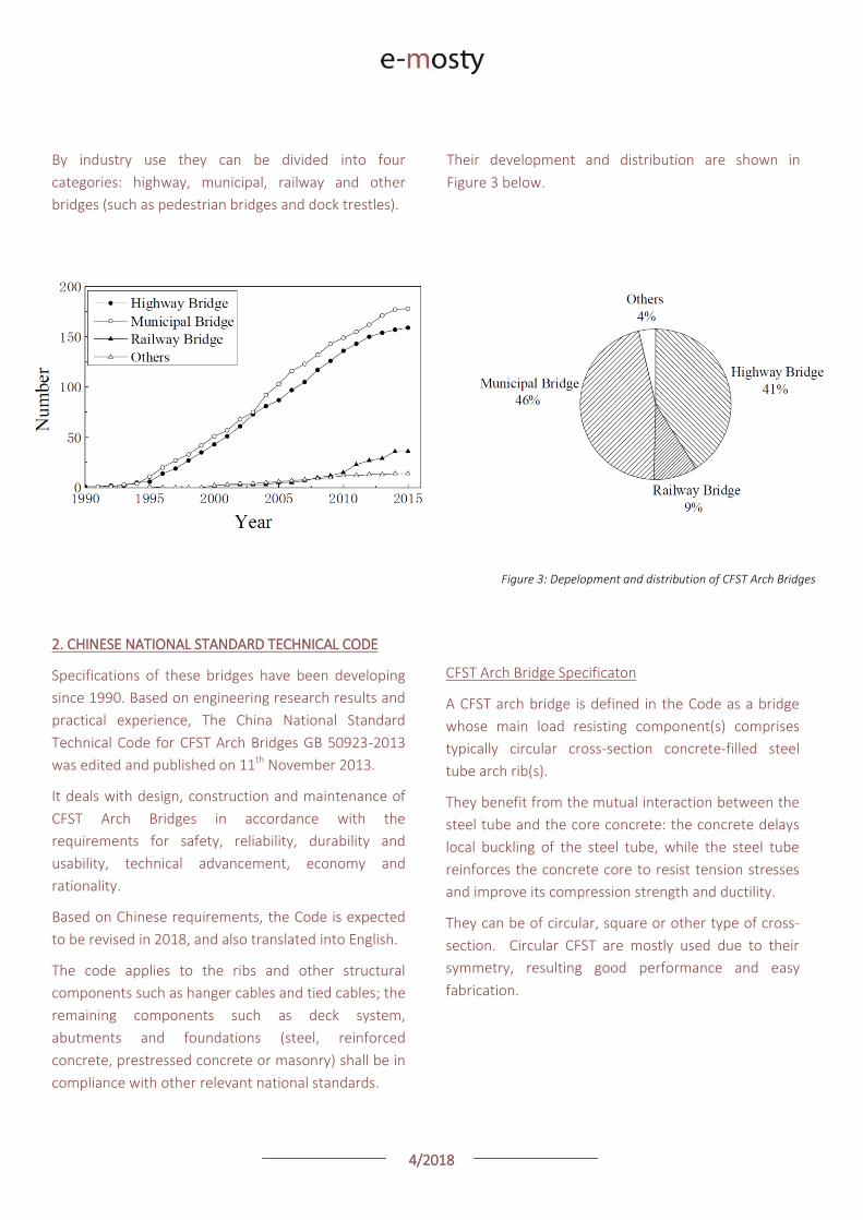
4/2018
Figure 4: Main structural types of CFST Arches: a) Deck-arch b) Half-through arch c) Rigid-frame tied half-through arch (‘Flying Bird’)
d) Rigid-frame tied through arch e) Arch and girder combined structure
Legend: 1 – Deck System 2 – Arch Ribs 3 – Tie girder 4 – Tie Bar 5 – Pier 6 – Main Arch Rib 7 – Side Arch Rib 8 – Main Pier 9 – Side Pier
Figure 5: Rise-to-span ratio distribution Figure 6: Rise-to-span ratio of different structural types
Main Structural Types
In the technical code CFST bridges are divided into five
main structural types, see Figure 4 below:
The rise-to-span ratio (L/f) generally ranges between
1/3.5 and 1/6.0. For the rigid-frame tied half-through
CFST arch bridges (‘Flying Bird’ type) the side span (L2)
is usually 1/4.0 – 1/5.5 of the main span (L1); the rise of
the side span should be 1/3.5 – 1/4.5 of that of the
main span ([f-f1]/f); and the rise-to-span ratio of the
side span should be 1/1.1 – 1/2.0 of that of the main
span.
Figure 5 shows the rise-to-span ratio distribution of
331 CFST arch bridges in China. Figure 6 shows rise-
span ratio of different structural types.
4/2018
Figure 7: a) Single tube section b) Dumbbell Section c) Three-chord truss section d) Four-chord truss section e) Horizontal dumbbell truss
Legend: 1 – Chord 2 – Web Plate 3 – Web Truss 4 – Horizontal Connection Bar 5 – Horizontal Connection Plate
Rib section types
The cross section shall be determined according to the
arch span, width of the bridge and vehicle load level.
The arch rib may be a single tube (generally used for a
bridge with a span smaller than 80m), dumbbell
section (a span smaller than 150m) or truss types (with
a large span, from 120m to the longest one with a
span of 500m), see Figure 7.
Rib Material
Main materials used for arch ribs are Q235 steel and
Q345 steel, but in recent years, Q235 steel has
gradually replaced Q345 steel and high strength steel
Q390 has also be used. Strength of infilled concrete
generally exceeds C40, only five bridges built before
2005 used C30.
To take full advantage of the mechanical
characteristics of concrete filled steel tube and
guarantee the stability of the steel tube wall, it is
necessary to limit the ratio of the tube diameter to
wall thickness. In 97% of bridges the ratio ranges from
35 to 100, with the majority between 35 and 70. The
wall thickness shall not be less than 8mm.
Design Calculation
The Code adopts the limit state design concept based
on the probability theory. Partial safety factors are
used in design calculation. The bridges shall be
designed based to two limit states:
a) Ultimate Limit State: The state where the bridge or
any of its components reaches the maximum load
capacity or the deformation / displacement which
makes it no longer able to resist peak loading.
b) Serviceability Limit State: The state where the
bridge or any of its components reaches certain
functionality or durability limit.
The Code gives guidance on three alternative methods
of analysis based on:
a) Resistance of a single CFST member in axial
compression, which is the basic formula of the
calculation of the ultimate load-carrying capacity
of CFST arch.
b) Resistance of long CFST columns with defined
eccentricity and slenderness parameters in
compression.
c) Ultimate load-carrying capacity and stability of
CFST arch based on a beam-column method with
an equivalent effective length.

4/2018
Figure 8: Overall view of Baiwang Bridge in Shaoguan, Guangdong
III. CONSTRUCTION METHODS
Various construction methods used for CFST Arch
Bridges include:
1) Stiffened scaffolding methods:
a) Scaffolding construction (typically through arch-
girder composite bridges)
b) Cantilever construction (typically for deck and
half-through arch bridges)
c) Swing construction (rarely used)
‘Flying-bird’ type arch bridges, half-through rigid-
framed tied arch bridges, can adopt both scaffolding
and cantilever methods.
2) Lifting of complete structure
3) Push or incremental launching
IV. EXAMPLES OF CFST ARCH BRIDGES IN CHINA
CONTINUOUS DESIGN OF CANTILEVER BEAM OF CFST
HALF-THROUGH ARCH BRIDGE: BAIWANG BRIDGE IN
SHAOGUAN, GUANGDONG PROVINCE
DESIGN
Baiwang bridge in Shaoguan, Guangdong Province is a
city bridge across the Bei river, as shown in Figure 8.
The total length of the bridge is 798m, and the
general layout of the 27 span bridge is 3×16m
(continuous girder of reinforced concrete hollow slab)
+ 2×16m (simply supported prestress hollow slab
girder) + 3×5m (box rib arch) + 14×16m (simply
supported prestress hollow slab girder) + 111m (CFST
half-through arch bridge) + 2×55m (box rib arch) +
2×16m (simply-supported prestress hollow slab
girder).
The half-through arch consists of three arch ribs, and
the corresponding rise span ratio is 3.33 with a net
span of 111.44m and net rise of 33.45m.
4/2018
Figure 9: Layout of the bridge
The width of the deck is 30m, as shown in Figure 9,
which consists of sidewalk 3m, arch rib 2m, the
bicycle lane 1.5m, 2-lane carriageway 7.5m, arch rib
2m, carriageway 7.5m, bicycle lane 1.5m, arch rib 2m
and sidewalk 3m.
The section of arch rib comprises three tubes. The
advantages of this solution include:
a) Low centre of gravity and excellent lateral
stability.
b) Significant saving in temporary lateral stability
works.
c) Decrease in the number of lateral braces between
the arch ribs.
Instead of using a simply supported deck structure,
the longitudinal girders are made structurally
continuous between the adjacent lateral beams.
This means that any excess traffic load, which is an
increasingly common occurrence in China, can be
distributed to 2 - 3 suspenders along the longitudinal
girder, which will then decrease the over-stress on the
suspender.
This also has the advantage of the longitudinal girder
and lateral beam forming a continuous frame, and
with the continuous bridge decks, will overcome the
cracking and potential slippage of at the edges of a
simply-supported deck system.
If the conventional longitudinal girders are set below
the arch rib, they cannot be continuous due to
interference with the arch ribs. To overcome this they
are split into two halves passing either side of the arch
rib.
After years of study, a new floating system was
proposed in the design of the bridge deck.
The floating continuous frame system with the length
of 127m and the width of 26.8m is supported by 16
rows of suspenders and 4 rows of columns, as shown
in Figure 10.
The system comprises six longitudinal girders and 20
lateral beams. The arch ribs go through the frame, the
clearance width to the frame is 0.2m.
The bridge deck has a thickness of 0.28m made up of
precast panels set within the frame. With temporary
support to the deck panels, insitu concrete joints then
connect the panels to both the longitudinal and
lateral beams.

4/2018
Figure 10: Longitudinal girders and lateral beams frame
CONSTRUCTION
The superstructure was erected by using a cable-
hoisting construction method. The single steel tube
arch rib was divided into six parts – the weight of each
section is less than 400kN (40 tonnes) – for precast
segment assembly.
Erection of hollow slabs and box rib arch was also
assisted by cable-hoisting construction method. The
total weight was more than 40,000kN, which meant
rapid construction and efficient use of equipment.
Figure 11 ↑: Precasting rectangular small frame
Figure 12 →: Hoisting small frame
The construction of floating continuous frame system
is as follows:
1) Fabricating a rectangular small frame which
consists of two short lateral beams (length 3.6m)
between the adjacent suspenders and the
longitudinal girders on both sides (length 5m) The
corresponding size is 3.6m (width)×7.6m
(length)×(1.17~1.33 m)(height), as shown in
Figure 11.
2) After attaining the required design strength, the
rectangular small frame is hoisted by cable lifting
system, as shown in Figure 12.
4/2018
Figure 13: Assembling lateral beam Figure 14: Forming long lateral beam
3) Forming the connections between the long lateral
beams. After hoisting into position, the temporary
bailey girder scaffolds are lifted onto the foot of
three lateral suspenders locating the same row in
order to assemble the lateral beam precast block
(length of 7.4m) between three small frames, as
shown in Figure 13.
The long lateral beam is formed when finishing
the following stages, including welding the joint
reinforcement, casting the concrete in the
connection and tensioning the lateral prestressed
tendons, as shown in Figure 14.
4) Forming the whole frame. When 23 rows of lateral
beams are in position, the short longitudinal
girders are placed on the bailey scaffolds, and the
total frame is formed by welding the joint
reinforcement, casting the concrete joints and
tensioning the longitudinal prestressed tendons,
as shown in Figure 15.
5) Forming the continuous bridge deck system.
When the floating frame system is established,
the precast bridge deck panels will be hoisted
onto the frame, as shown in Figure 16, and the
continuous bridge deck system is formed by
welding the reinforcement between the decks and
casting the joint, as shown in Figure 17.
Figure 15: Forming the frame
Figure 16: Erecting bridge decks on the frame
Figure 17: Casting the joints of bridge deck
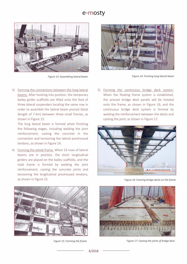
4/2018
Suspender Support System
When considering the fatigue damage and corrosion
which often occurs in the fracture of the short
suspenders, double suspenders with various sections
having different vibrating frequency were adopted.
The bearing capacity of the lateral single row
suspenders was calculated based on the dead load of
adjacent spans to prevent the potential collapse of
cantilever beam once a single suspender is broken.
This also allows the replacement of a suspender
without disrupting the traffic or during the normal
service cycle of 30 years.
The bridge has 96 double suspenders, including 64
double suspenders on both sides and 32 double
suspenders in the central section. Double suspenders
on both sides consist of 55 parallel wires and 61
parallel wires with the diameter of 7mm, respectively
and the central double suspenders consist of 61
parallel wires and 73 parallel wires with the diameter
of 7mm, respectively.
CFST TIED ARCH BRIDGE CONSTRUCTED
BY INCREMENTAL LAUNCHING METHOD:
WULITING BRIDGE IN SHAOGUAN CITY
The Wuliting Bridge was constructed on the ring road
in Shaoguan City, Guangdong Province, China, in
2003. The total length of the bridge is 505m, width
30m, the main CFST tied arch bridge is combined with
prestressed concrete continuous girder with spans
35m+120m+35m. It was built using an incremental
launching method.
The main foundations of this bridge comprise a single
non-uniform section pile without a pile cap. This
variable cross section pier-pile combined structure
Figure 18: Wuliting Bridge
was proposed to reduce the structural weight. The
diameter of exposed bridge piers was 4m.
The piles had a variable cross section with three
diameters: 5.6m / 3.5m / 3m, as shown in Figure 19. The
upper section of pile with 5.6m diameter part was built
in an open caisson, and lower 3.5m diameter part was
cast-in-place pile bored into the underlying soil. The 3m
diameter sections were bored piles embedded in
bedrock.
The deck system comprises tied girders which are two
single box continuous beams with 190m length, 11.75m
width and 2.5m height. Three circular CFST sections were
used in the main arch ring, and the suspension cables are
a series of parallel wire cables.
The deck system was constructed by incremental
launching method using temporary supports in the river,
and then the main arch ring steel tube was constructed
by a vertical rotation method from a horizontal position.
Then the concrete of the main arch ring was pumped
along the steel tube and the deck system was connected
to the main arch ring by suspension cables.
For this bridge a new main arch ring with three tubes
was proposed (as shown in Figure 20) to solve in-plane
buckling of this bridge. The arch is composed of two
0.85m diameter tubes at the bottom, one 1.8m diameter
tube at the top and stiffened plate connections between
three tubes.
Figure 20: Cross-section of main arch ring structure
4/2018
Figure 19: The design drawing of the Wuliting Bridge
The out-of-plane buckling calculation results show
that the main arch ring has enough flexural-torsion
buckling resistance, with a safety factor K > 8 during
the construction process and K > 4 in the operation
stage.
This construction method was applied to this CFST
tied arch bridge for its safety and economy, and was
proven as a qualified construction method following a
thorough detail inspection checks results in 2014 of
this arch bridge.
CONSTRUCTION INNOVATIONS
Incremental Launching Method in Tied Girders
In the construction stage, two tied girders were
divided into six parts along the bridge longitudinal
axis, each section was a 20-34m box beam which was
split into 8-9 box precast segments. The box girder
casting yard was positioned in the centre of the
ground on the approaches to the bridge, and a 60 m
steel truss beam was selected as an assembly
platform, as shown in Figure 21. It took 12-15 days to
build up each box beam, and the average incremental
launching speed was 3m per day.
Construction technologies
For the concrete post-tensioning system, seven
parallel wires of 7mm diameter were prestressed. The
proprietary ‘HM’ anchor system was used for the
prestressed anchor system, which included fixed ends,
tension ends and a special connector between the
fixed anchor and tension anchor. The fixed ends of
this system were DM7-84 anchors and the tension
side were an OVM21-12 anchor, as shown in Figure
22. The temporary construction analysis also showed
that HM anchors were suitable for prestressing of
incremental launching box beam.
Figure 21: Box girder casting yard and assembly platform

4/2018
Figure 22: HM anchor system
For the incremental launching process a 100t
continuous jack was installed on every pier, which can
balance the box beam-pier friction resistance with its
horizontal tension force. Using this method, the 190m
continuous beam was incremental launched in 6
months, as shown in Figures 23 - 26.
Figure 23: Incremental launching of continuous box beam
Figure 24: 100t continuous jack
Figure 25: Construction of steel tube main arch
Figure 26: Slide equipment
4/2018
REFERENCES:
CHINA TECHNICAL CODE FOR CFST ARCH BRIDGES B.C. Chen, J.G. Wei, Q.X. Wu College of Civil Engineering, Fuzhou University, Fujian, 350108, CHINA
APPLICATION OF CONCRETE-FILLED STEEL TUBE ARCH BRIDGES IN CHINA J. Wei, J. Zhou, J. Liu, B. Chen College of Civil Engineering, Fuzhou University, Fuzhou 350108, CHINA
CONTINUOUS DESIGN OF CANTILEVER BEAM OF CFST HALF-THROUGH ARCH BRIDGE X. Zuo
1, X. Liu
1, L. Ren
2, S. Tan
2, G. Shang
2, W. Li
3
1 Hunan road & bridge construction group Co., Ltd, Changsha
410004, CHINA 2 CCCC FHDI engineering Co., Ltd., Guangzhou 510230, CHINA
3 Shaoguan public utilities board, Shaoguan 512031, CHINA
Construction of beam arch combination bridge
After incremental launching of continuous box beam,
the steel tube was constructed on the top of deck
system.
Bailey girder trusses were used for the temporary
support system, and the steel tube was rotated
vertically for the main arch ring closure.
Concrete was placed in the steel tube using a
concrete pump machine, as shown in Figure 27.
The main arch ring and continuous box beam were
connected by 28 suspenders, each one was composed
by 18no. 7 strand 7mm parallel wires with 4900 kN
initial tension force.
After concrete filled steel tube main arch ring was
completed, each suspender was tensioned to design
force, causing the box beam to lift up and disconnect
from the construction temporary piers, as shown in
Figure 28.
RESEARCH ON A CFST TIED ARCH BRIDGE CONSTRUCTED BY INCREMENTAL LAUNCHING METHOD J. Huang
1, J. Shi
1, X. Shangguan
2, C. Hu
2, Z. Dai
3
1 Fourth Harbor Engineering Investigation and Design Institute,
Guangzhou, CHINA 2 East China Jiaotong University, School of Civil Engineering and
Architecture, Nanchang, CHINA 3 China Railway Fourteenth Civil Engineering Group, Jinan, CHINA
GB 50923-2013, China National Standard-- Technical Code for CFST Arch Bridges (In Chinese), 2013 All papers were presented at 8th International Conference Arch 2016: Arch Bridges in Culture, which was held in Wroclaw in Poland, from 5th to 7th October 2016. They were published in a book of papers from the conference.
OTHER REFERENCES:
COLLINGS, David: Steel-Concrete Composite Bridges. ICE Publishing 2013
Figure 27: Main arch bridge construction process
Figure 28: Completed main arch

4/2018
Bridge to the Future to help beat Cancer Lawrence Shackman
STORY
I was the Project Manager for the Queensferry Crossing Bridge which opened just over a year ago.
Sadly my mother passed away from cancer just a few weeks later. She was so impressed with the bridge and I suppose my efforts in getting it built but I would like to go further ....
I would like to help find a cure for this terrible disease which has claimed the lives of so many including my father, uncle and mother-in-law.
So, I have written and produced a song and video to celebrate the bridge construction and by watching the video I would then like people to donate to Cancer Research UK – any donation is very welcome!
See the video on my LinkedIN or Facebook pages. Thank you for taking time to visit my JustGiving page.
ABOUT THE CHARITY
Cancer Research UK
Cancer Research UK is the world's leading charity dedicated to beating cancer through research. We are fighting cancer on all fronts, finding new ways to prevent, diagnose and treat it to save more lives. We are entirely funded by the public. With your help, we can ensure more people beat cancer.
Charity Registration No. in England and Wales 1089464, Scotland SC041666
View of the Queensferry Crossing
4/2018
The Hålogaland Bridge, Norway, opens to traffic
CONGRATULATIONS
Read about its design and construction:
Photo Credit: Srđan Bošković

4/2018
Bridge to the Future to help beat Cancer Lawrence Shackman
STORY
I was the Project Manager for the Queensferry Crossing Bridge which opened just over a year ago.
Sadly my mother passed away from cancer just a few weeks later. She was so impressed with the bridge and I suppose my efforts in getting it built but I would like to go further ....
I would like to help find a cure for this terrible disease which has claimed the lives of so many including my father, uncle and mother-in-law.
So, I have written and produced a song and video to celebrate the bridge construction and by watching the video I would then like people to donate to Cancer Research UK – any donation is very welcome!
See the video on my LinkedIN or Facebook pages. Thank you for taking time to visit my JustGiving page.
ABOUT THE CHARITY
Cancer Research UK
Cancer Research UK is the world's leading charity dedicated to beating cancer through research. We are fighting cancer on all fronts, finding new ways to prevent, diagnose and treat it to save more lives. We are entirely funded by the public. With your help, we can ensure more people beat cancer.
Charity Registration No. in England and Wales 1089464, Scotland SC041666
View of the Queensferry Crossing
4/2018
The Hålogaland Bridge, Norway, opens to traffic
CONGRATULATIONS
Read about its design and construction:
Photo Credit: Srđan Bošković

The magazine e-maritime is an international, interactive, peer-reviewed magazine
about vessels and maritime equipment.
It is published three times a year – 30 March, 30 June and 30 November – on
www.e-maritime.cz and it can be read free of charge (open access) with possibility
to subscribe.
Its first issue will be released on 30 March 2019.
September Issue is shared with the magazine e-mosty (“e-bridges”): “Vessels and
Equipment for Bridge Construction” which is published on 20 September on
www.e-mosty.cz.
The magazine brings original articles about design, construction, operation
and maintenance of vessels and maritime equipment, docks and ports from
around the world. Its electronic form enables publishing of high-quality photos,
videos, drawings, links etc. We aim to include all important and technical
information and show the grace and beauty of the vessels and structures as well.
The magazines stay available online on our website. It is also possible
to download them as pdf.
ISSN: E-MARITIME
www.e-maritime.cz
Under the theme “Arch Bridges – Natural beauty for all time“, the 9th International Conference on Arch Bridges (ARCH 2019), will be held in Porto, Portugal, on October 2 to 4, 2019. The conference will be orga-nized by the Civil Engineering Depart-ment of the Faculty of Engineering of the University of Porto.
Since the first ARCH Conference (UK 1995), seven subsequent editions took place (Italy 1998, France 2001, Spain 2004, Portugal 2007, China 2010, Croatia 2013 and Wroclaw 2016), all high quality and successful events. Stemming from such heritage, it is our pleasure to invite you to the next 2019 ARCH conference edition.
On behalf of the Organizing Commit-tee we hope you consider accepting this invitation, as we are committing ourselves to provide the best possible for your overall satisfaction during and after the conference.
Sincerely yours,
António ArêdeChairman of the Organizing Committee
António Adão da FonsecaChairman of the Scientific Committee
Rui CalçadaCo-Chairman of the Organizing Committee
Elsa CaetanoCo-Chairman of the Scientific Committee
CONFERENCE MAIN TOPICS
· Heritage arch bridges
· Analytic and numerical studies of arch structures
· Experimental studies of arch structures
· Design and construction of arch bridges
· Rehabilitation, maintenance and condition assessment of arch bridges
· New and future trends in a rch bridges
IMPORTANT DATES
Submission of abstracts: November 2nd, 2018
Acceptance of abstracts: December 17th, 2018
Submission of full papers: March 16th, 2019
Acceptance of papers: May 18th, 2019
Close of early registration: June 16th, 2019
CONFERENCE VENUE
The conference will be held at the Fac-ulty of Engineering of the University of Porto (FEUP), in one major campus of the University of Porto (UPorto) locat-ed at the north limit zone of Porto city (www.fe.up.pt).
CONFERENCE LANGUAGE
English will be the conference official language, including sessions, proceedings and general organization.
The conference website
www.fe.up.pt/arch19
provides more detailed information.
+ INFO: ARCH 2019 Secretariat Department of Civil Engineering Faculty of Engineering o University of Porto Rua Dr Roberto Frias 4200 465 Porto Portugal
+351 22 508 2190 + 351 22 041 3703
www.fe.up.pt/arch19 [email protected]
9TH INTERNATIONAL CONFERENCE ON ARCH BRIDGES
PORTO OCTOBER 2>4
2019
INSTITUTIONAL
SPONSORS
FINANCIAL
SPONSORS

The magazine e-maritime is an international, interactive, peer-reviewed magazine
about vessels and maritime equipment.
It is published three times a year – 30 March, 30 June and 30 November – on
www.e-maritime.cz and it can be read free of charge (open access) with possibility
to subscribe.
Its first issue will be released on 30 March 2019.
September Issue is shared with the magazine e-mosty (“e-bridges”): “Vessels and
Equipment for Bridge Construction” which is published on 20 September on
www.e-mosty.cz.
The magazine brings original articles about design, construction, operation
and maintenance of vessels and maritime equipment, docks and ports from
around the world. Its electronic form enables publishing of high-quality photos,
videos, drawings, links etc. We aim to include all important and technical
information and show the grace and beauty of the vessels and structures as well.
The magazines stay available online on our website. It is also possible
to download them as pdf.
ISSN: E-MARITIME
www.e-maritime.cz
Under the theme “Arch Bridges – Natural beauty for all time“, the 9th International Conference on Arch Bridges (ARCH 2019), will be held in Porto, Portugal, on October 2 to 4, 2019. The conference will be orga-nized by the Civil Engineering Depart-ment of the Faculty of Engineering of the University of Porto.
Since the first ARCH Conference (UK 1995), seven subsequent editions took place (Italy 1998, France 2001, Spain 2004, Portugal 2007, China 2010, Croatia 2013 and Wroclaw 2016), all high quality and successful events. Stemming from such heritage, it is our pleasure to invite you to the next 2019 ARCH conference edition.
On behalf of the Organizing Commit-tee we hope you consider accepting this invitation, as we are committing ourselves to provide the best possible for your overall satisfaction during and after the conference.
Sincerely yours,
António ArêdeChairman of the Organizing Committee
António Adão da FonsecaChairman of the Scientific Committee
Rui CalçadaCo-Chairman of the Organizing Committee
Elsa CaetanoCo-Chairman of the Scientific Committee
CONFERENCE MAIN TOPICS
· Heritage arch bridges
· Analytic and numerical studies of arch structures
· Experimental studies of arch structures
· Design and construction of arch bridges
· Rehabilitation, maintenance and condition assessment of arch bridges
· New and future trends in a rch bridges
IMPORTANT DATES
Submission of abstracts: November 2nd, 2018
Acceptance of abstracts: December 17th, 2018
Submission of full papers: March 16th, 2019
Acceptance of papers: May 18th, 2019
Close of early registration: June 16th, 2019
CONFERENCE VENUE
The conference will be held at the Fac-ulty of Engineering of the University of Porto (FEUP), in one major campus of the University of Porto (UPorto) locat-ed at the north limit zone of Porto city (www.fe.up.pt).
CONFERENCE LANGUAGE
English will be the conference official language, including sessions, proceedings and general organization.
The conference website
www.fe.up.pt/arch19
provides more detailed information.
+ INFO: ARCH 2019 Secretariat Department of Civil Engineering Faculty of Engineering o University of Porto Rua Dr Roberto Frias 4200 465 Porto Portugal
+351 22 508 2190 + 351 22 041 3703
www.fe.up.pt/arch19 [email protected]
9TH INTERNATIONAL CONFERENCE ON ARCH BRIDGES
PORTO OCTOBER 2>4
2019INSTITUTIONAL
SPONSORS
FINANCIAL
SPONSORS
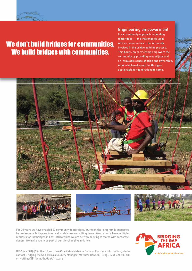
/bridgestoprosperity
/bridgestoprosperity
@b2p
Bridges to Prosperity envisions a world where poverty caused by rural isolation no longer exists.
Our programs provide access to healthcare, education, and markets by
teaching communities how to build footbridges over impassable rivers, in
partnership with organizations and professionals. We prove the value of
our work through a commitment to the community and its bridge that
lasts long after the opening celebration.
Contact:
12%MORE CHILDREN
ENROLLED IN SCHOOL
18%INCREASE IN
HEALTHCARE TREATMENT
59%HOUSEHOLD INCREASE IN
WOMEN ENTERING LABOR
FORCE
30%INCREASE IN L ABOR
MARKET INCOME
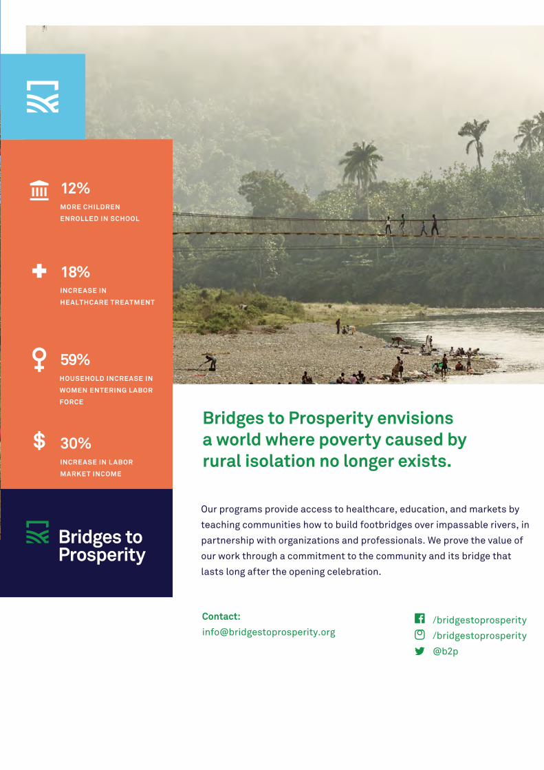
/bridgestoprosperity
/bridgestoprosperity
@b2p
Bridges to Prosperity envisions a world where poverty caused by rural isolation no longer exists.
Our programs provide access to healthcare, education, and markets by
teaching communities how to build footbridges over impassable rivers, in
partnership with organizations and professionals. We prove the value of
our work through a commitment to the community and its bridge that
lasts long after the opening celebration.
Contact:
12%MORE CHILDREN
ENROLLED IN SCHOOL
18%INCREASE IN
HEALTHCARE TREATMENT
59%HOUSEHOLD INCREASE IN
WOMEN ENTERING LABOR
FORCE
30%INCREASE IN L ABOR
MARKET INCOME

POWERING YOUR 360° SOLUTIONSCOWI is a leading consulting group that creates value for customers, people and society through our 360° approach. We tackle challenges from many vantage points to create coherent solutions for our customers.
MAINTAINING THE WORLD’S INFRASTRUCTURE www.cowi.com
Arup works in active partnership with clients to understand their needs so
that the solutions make their bridge aspirations possible —big and small.
The Arup global specialist technical skills blended with essential local
knowledge adds unexpected benefits.
www.arup.com
Whether to span nations, make a statement or
improve everyday links, Arup crafts better bridges
Naeem Hussain Richard Hornby Steve Kite Deepak Jayaram
[email protected] [email protected] [email protected] [email protected]
Global UK, Middle East & Africa East Asia UK, Middle East, India
and Africa
Peter Burnton Marcos Sanchez Matt Carter Pheku Montwedi
[email protected] [email protected] [email protected] [email protected]
Australasia Europe Americas Africa
Queensferry Crossing Scotland

Intelligent Engineering Solutions
RAILWAY ARCH BRIDGE OVER ALMONTE RIVER (HSR -SPAIN)Special equipments (4 formwork travellers) for the execution of the arch bridge (384 m free span)
VIADUCT OVER TAJO RIVER (HSR - SPAIN)Pair of tri-hinged formwork travellers for compressive arch construction (324 m free span)
ATLANTIC BRIDGE (PANAMA) 4 No. R-1900 series form travellers for the construction of a cable stayedbridge -Assembly stage-
MERSEY GATEWAY6 No. R-1900 series (1900 tn*m) . formwork travellers and 2 No.wing travellers for the approaches for the construction of a cable stay bridge
CZECH LAW FIRM
Set your goals,We find the way
KGS LEGAL
ABOUT US
Office PRAGUEBucharova 2657/12, 158 00 Prague 5
Office LIBERECNám. Štefánikovo 780/5, 460 01 Liberec
KGS legal provides assistance and guidance to foreign enti-ties and individuals wishing to enter Czech market re-gardless whether they are a new company or a subsidiary having its parent company abroad.
We offer our clients analysis of certain business area of the Czech market, advisory services relating to entering Czech market in the relevant area. In this regard, we provide our clients with support in legal and commercial matters relating to their business activities, as a secondary activity, we are able to assist them with accounting and tax issues.
KGSKGS legal specializes mainly in acquisitions of small and me-dium-sized enterprises and investment groups doing their business in all branches of public procurement, civil and light engineering, energetics, renewable resources and me-dical technologies.
Our services are most of all based on a personal approach to each client; tailor-made solutions based on their requests and possibilities, on long-term cooperation, their trust, our diligence and maximal flexibility so that we are available whenever the clients need our services. We always aim to understand our client́s needs and wishes, and endeavour to give their ideas the expected shape. We are always sear-chingching and considering all possible ways that lead to our goal – the most complex solution for a particular client. We always consider all future aspects of such solution as well. We provide our clients with complex view without legal technicalities so that it is brief but clear and fitting.
After you enter the Czech market, our company KGS legal offers you in connection with your activities the following services:
• Legal counselling in the field of corporate law • Negotiation and drafting of contracts • Public procurement counselling • Labour and employment law counselling • Representation in court and other state bodies
www.kgslegal.cz
M1-70-S: PUMAREJO BRIDGE, COLOMBIA
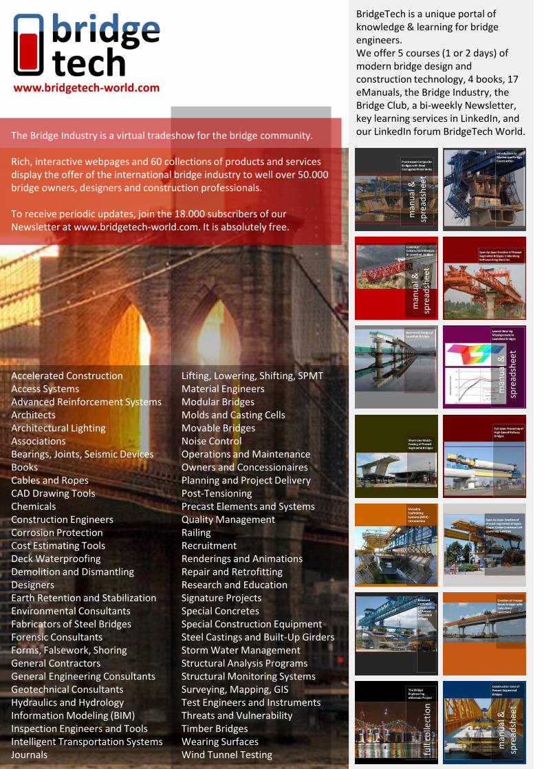
Accelerated ConstructionAccess SystemsAdvanced Reinforcement SystemsArchitectsArchitectural LightingAssociationsBearings, Joints, Seismic DevicesBooksCables and RopesCAD Drawing ToolsChemicalsConstruction EngineersCorrosion ProtectionCost Estimating ToolsDeck WaterproofingDemolition and DismantlingDesignersEarth Retention and StabilizationEnvironmental ConsultantsFabricators of Steel BridgesForensic ConsultantsForms, Falsework, ShoringGeneral ContractorsGeneral Engineering ConsultantsGeotechnical ConsultantsHydraulics and HydrologyInformation Modeling (BIM)Inspection Engineers and ToolsIntelligent Transportation SystemsJournals
Lifting, Lowering, Shifting, SPMTMaterial EngineersModular BridgesMolds and Casting CellsMovable BridgesNoise ControlOperations and MaintenanceOwners and ConcessionairesPlanning and Project DeliveryPost-TensioningPrecast Elements and SystemsQuality ManagementRailingRecruitmentRenderings and AnimationsRepair and RetrofittingResearch and EducationSignature ProjectsSpecial ConcretesSpecial Construction EquipmentSteel Castings and Built-Up GirdersStorm Water ManagementStructural Analysis ProgramsStructural Monitoring SystemsSurveying, Mapping, GISTest Engineers and InstrumentsThreats and VulnerabilityTimber BridgesWearing SurfacesWind Tunnel Testing
The Bridge Industry is a virtual tradeshow for the bridge community.
Rich, interactive webpages and 60 collections of products and services display the offer of the international bridge industry to well over 50.000 bridge owners, designers and construction professionals.
To receive periodic updates, join the 18.000 subscribers of our Newsletter at www.bridgetech-world.com. It is absolutely free.
BridgeTech is a unique portal of knowledge & learning for bridge engineers. We offer 5 courses (1 or 2 days) of modern bridge design and construction technology, 4 books, 17 eManuals, the Bridge Industry, the Bridge Club, a bi-weekly Newsletter, key learning services in LinkedIn, and our LinkedIn forum BridgeTech World.
Intelligent Engineering Solutions
RAILWAY ARCH BRIDGE OVER ALMONTE RIVER (HSR -SPAIN)Special equipments (4 formwork travellers) for the execution of the arch bridge (384 m free span)
VIADUCT OVER TAJO RIVER (HSR - SPAIN)Pair of tri-hinged formwork travellers for compressive arch construction (324 m free span)
ATLANTIC BRIDGE (PANAMA) 4 No. R-1900 series form travellers for the construction of a cable stayedbridge -Assembly stage-
MERSEY GATEWAY6 No. R-1900 series (1900 tn*m) . formwork travellers and 2 No.wing travellers for the approaches for the construction of a cable stay bridge
CZECH LAW FIRM
Set your goals,We find the way
KGS LEGAL
ABOUT US
Office PRAGUEBucharova 2657/12, 158 00 Prague 5
Office LIBERECNám. Štefánikovo 780/5, 460 01 Liberec
KGS legal provides assistance and guidance to foreign enti-ties and individuals wishing to enter Czech market re-gardless whether they are a new company or a subsidiary having its parent company abroad.
We offer our clients analysis of certain business area of the Czech market, advisory services relating to entering Czech market in the relevant area. In this regard, we provide our clients with support in legal and commercial matters relating to their business activities, as a secondary activity, we are able to assist them with accounting and tax issues.
KGSKGS legal specializes mainly in acquisitions of small and me-dium-sized enterprises and investment groups doing their business in all branches of public procurement, civil and light engineering, energetics, renewable resources and me-dical technologies.
Our services are most of all based on a personal approach to each client; tailor-made solutions based on their requests and possibilities, on long-term cooperation, their trust, our diligence and maximal flexibility so that we are available whenever the clients need our services. We always aim to understand our client́s needs and wishes, and endeavour to give their ideas the expected shape. We are always sear-chingching and considering all possible ways that lead to our goal – the most complex solution for a particular client. We always consider all future aspects of such solution as well. We provide our clients with complex view without legal technicalities so that it is brief but clear and fitting.
After you enter the Czech market, our company KGS legal offers you in connection with your activities the following services:
• Legal counselling in the field of corporate law • Negotiation and drafting of contracts • Public procurement counselling • Labour and employment law counselling • Representation in court and other state bodies
www.kgslegal.cz

04/2018 December Seshadri Srinivasan
Asian, Australian and New Zealand Bridges