03 RA45313EN05GLA0 Flexi WCDMA BTS Installation Planning
39
1 © Nokia Siemens Networks RA45313EN05GLA0 Nokia Siemens Networks Flexi WCDMA BTS Installation Planning (WN5.0 – RU10)
-
Upload
univ-ibnzohr -
Category
Documents
-
view
3 -
download
0
Transcript of 03 RA45313EN05GLA0 Flexi WCDMA BTS Installation Planning
1 © Nokia Siemens Networks RA45313EN05GLA0
Nokia Siemens Networks Flexi WCDMA BTS Installation Planning(WN5.0 – RU10)
2 © Nokia Siemens Networks RA45313EN05GLA0
Nokia Siemens Networks Academy
Legal notice
Intellectual Property RightsAll copyrights and intellectual property rights for Nokia Siemens Networks training documentation, product documentation and slide presentation material, all of which are forthwith known as Nokia Siemens Networks training material, are the exclusive property of Nokia Siemens Networks. Nokia Siemens Networks owns the rights to copying, modification, translation, adaptation or derivatives including any improvements or developments. Nokia Siemens Networks has the sole right to copy, distribute, amend, modify, develop, license, sublicense, sell, transfer and assign the Nokia Siemens Networks training material. Individuals can use the Nokia Siemens Networks training material for their own personal self-development only, those same individuals cannot subsequently pass on that same Intellectual Property to others without the prior written agreement of Nokia Siemens Networks. The Nokia Siemens Networks training material cannot be used outside of an agreed Nokia Siemens Networks training session for development of groups without the prior written agreement of Nokia Siemens Networks.
3 © Nokia Siemens Networks RA45313EN05GLA0
Learning Element Objectives
After completing this learning element, the participant will be able to:
• Describe the site requirements for Flexi WCDMA BTS installation
• Describe Installation option for Flexi WCDMA BTS• Describe site clearance and anchoring points• Describe power requirements, grounding and site earthing• Describe module dimensions
4 © Nokia Siemens Networks RA45313EN05GLA0
General Site Requirements 1/2
• All required documentation is available, for example, site-specific installation instructions
• When radio link transmission is used, the line-of-sight to the far end radios has been ensured
• External connections for the cabinet are available: site grounding point, mains power (AC or DC according to the site), and transmission connection point. Furthermore, AC or DC distribution panel and AC electric are available for power tools
• Main grounding (earthing) is installed and tested
• Floor or wall surface is even (installation base flatness requirement is 2 mm (0.08 in.)
• Wall or pole at the BTS site is strong enough to withstand the weight of the BTS
• Wall or pole at the BTS site is strong enough to meet earthquake requirement Telcordia GR-63-CORE Zone 4 (only applicable in earthquake areas)
5 © Nokia Siemens Networks RA45313EN05GLA0
• Pole at the BTS site is strong enough to withstand the wind load
• The BTS is not taken out of its delivery package until the site construction work is finished and the site is clean and dry
• Site security is established so the BTS and other units can remain undisturbed at the site
• Make sure you can take the BTS to the installation site. For example, in roof top installations, the hole through which you take the BTS to the roof must be large enough
General Site Requirements 2/2
6 © Nokia Siemens Networks RA45313EN05GLA0
Indoor Site Requirements
• Door and lock to site room are properly installed and operational (recommended).
• Access to the site is secure• The site is adequately lit• Feeder entry hole and cable rack for feeder and power
cables are ready, if needed• Heater, or air conditioner, is installed and operational,
if needed. This depends on the heat emission and the environment.
7 © Nokia Siemens Networks RA45313EN05GLA0
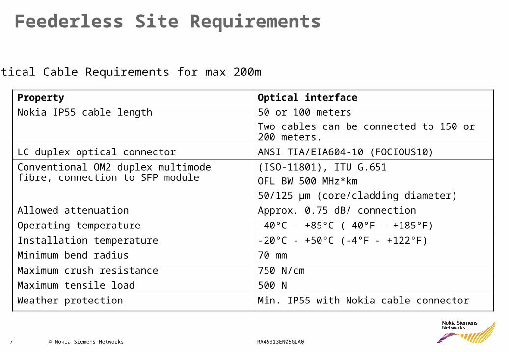
Feederless Site Requirements
Property Optical interfaceNokia IP55 cable length 50 or 100 meters
Two cables can be connected to 150 or 200 meters.
LC duplex optical connector ANSI TIA/EIA604-10 (FOCIOUS10)Conventional OM2 duplex multimode fibre, connection to SFP module
(ISO-11801), ITU G.651OFL BW 500 MHz*km50/125 μm (core/cladding diameter)
Allowed attenuation Approx. 0.75 dB/ connectionOperating temperature -40°C - +85°C (-40°F - +185°F)Installation temperature -20°C - +50°C (-4°F - +122°F)Minimum bend radius 70 mmMaximum crush resistance 750 N/cmMaximum tensile load 500 NWeather protection Min. IP55 with Nokia cable connector
Optical Cable Requirements for max 200m
8 © Nokia Siemens Networks RA45313EN05GLA0
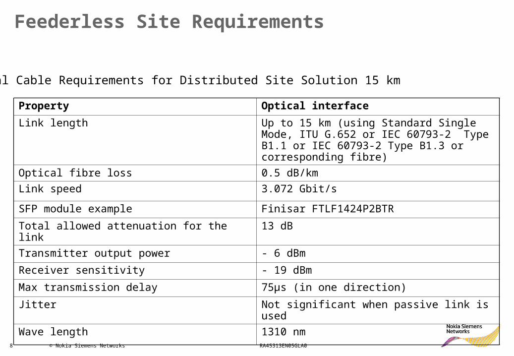
Feederless Site Requirements
Property Optical interfaceLink length Up to 15 km (using Standard Single
Mode, ITU G.652 or IEC 60793-2 Type B1.1 or IEC 60793-2 Type B1.3 or corresponding fibre)
Optical fibre loss 0.5 dB/kmLink speed 3.072 Gbit/sSFP module example Finisar FTLF1424P2BTRTotal allowed attenuation for the link
13 dB
Transmitter output power - 6 dBmReceiver sensitivity - 19 dBmMax transmission delay 75μs (in one direction)Jitter Not significant when passive link is
usedWave length 1310 nm
Optical Cable Requirements for Distributed Site Solution 15 km

9 © Nokia Siemens Networks RA45313EN05GLA0
General issues to be considered when installing the DC cables of the feederless site:• In case of a power break, the BTS functions with batteries.
The output voltage of the batteries starts to decrease in time• The batteries should be installed in the proximity of the
System Module to minimize additional voltage drop before the RF Module.
• If the cables are under a protective cover, the temperature of the cables can increase. This increases the resistance of the cables and the voltage drop is greater between the System Module and RF Module.
• The power dissipation of the DC cable adds to the power consumption of the site. Examples:• Power dissipation with a Dual RF Module (with max. load of 2x40W) of the 100m DC cable is ~50 W when 16 mm2 is used and ~130 W when 6 mm2 is used.
• Power dissipation with a Triple RF module (with max. load of 3x60W) of the 100m DC cable is ~100 W when 25 mm2 is used and ~160 W when 16mm2 is used.
10 © Nokia Siemens Networks RA45313EN05GLA0
DC Cabling Principles and Shielding
The basic procedure is to use a locally supplied standard DC cable.
DC cable extension:• There is an additional Nokia IP55 2m DC cable in the FSEC
sales package. By cutting both cables in one end and using IP55 protection to both the RF and System Module they can be used for extending the DC cable distance.
• A long DC cable needs to be shielded and grounded.• Connection of the long DC cable and Nokia IP55 cable is
recommended to be done in an IP55 outdoor weather protected space, e.g. in Flexi External OVP box (FSEC).
• The FSEC clamping range is from 19 to 28 mm DC cable diameters.
11 © Nokia Siemens Networks RA45313EN05GLA0
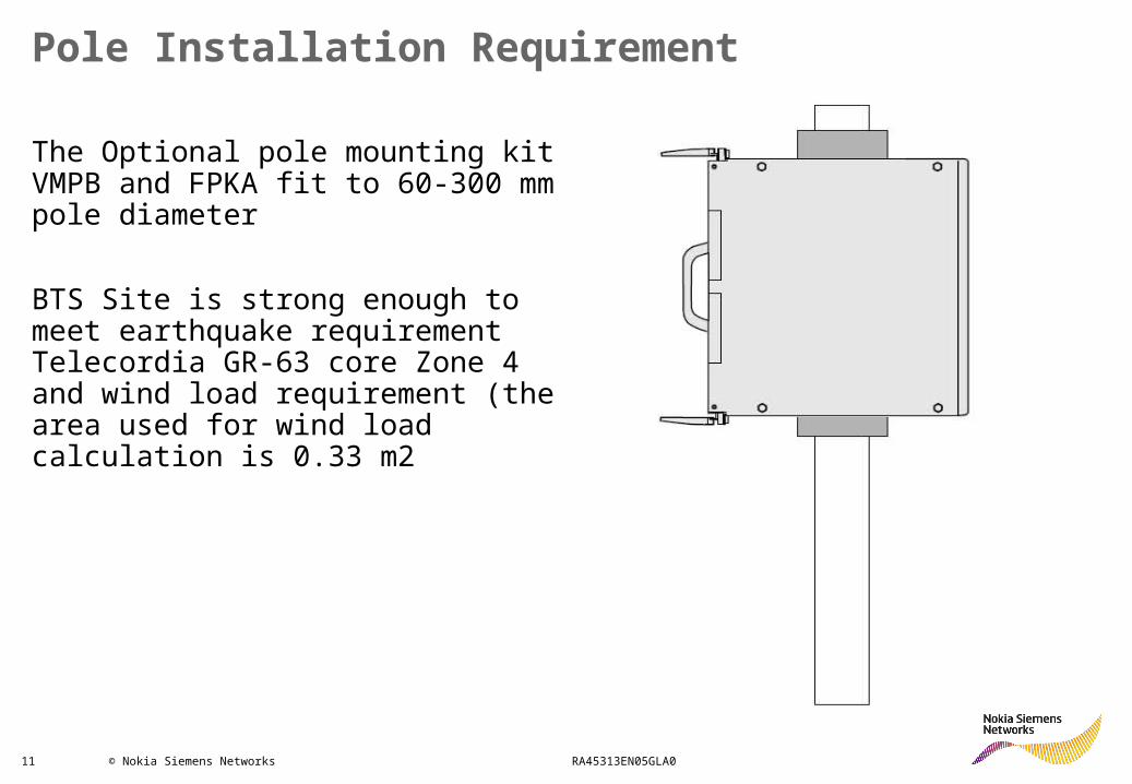
Pole Installation Requirement
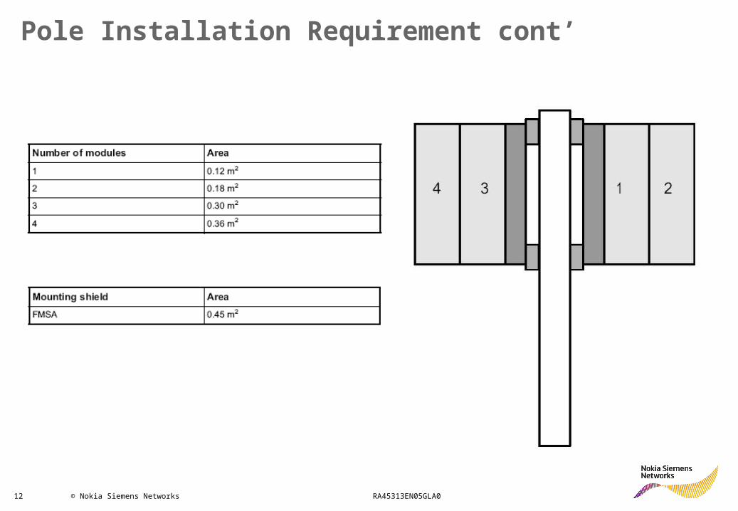
The Optional pole mounting kit VMPB and FPKA fit to 60-300 mm pole diameter
BTS Site is strong enough to meet earthquake requirement Telecordia GR-63 core Zone 4 and wind load requirement (the area used for wind load calculation is 0.33 m2
12 © Nokia Siemens Networks RA45313EN05GLA0
Pole Installation Requirement cont’
13 © Nokia Siemens Networks RA45313EN05GLA0
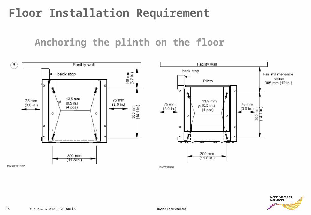
Floor Installation Requirement
Anchoring the plinth on the floor
14 © Nokia Siemens Networks RA45313EN05GLA0
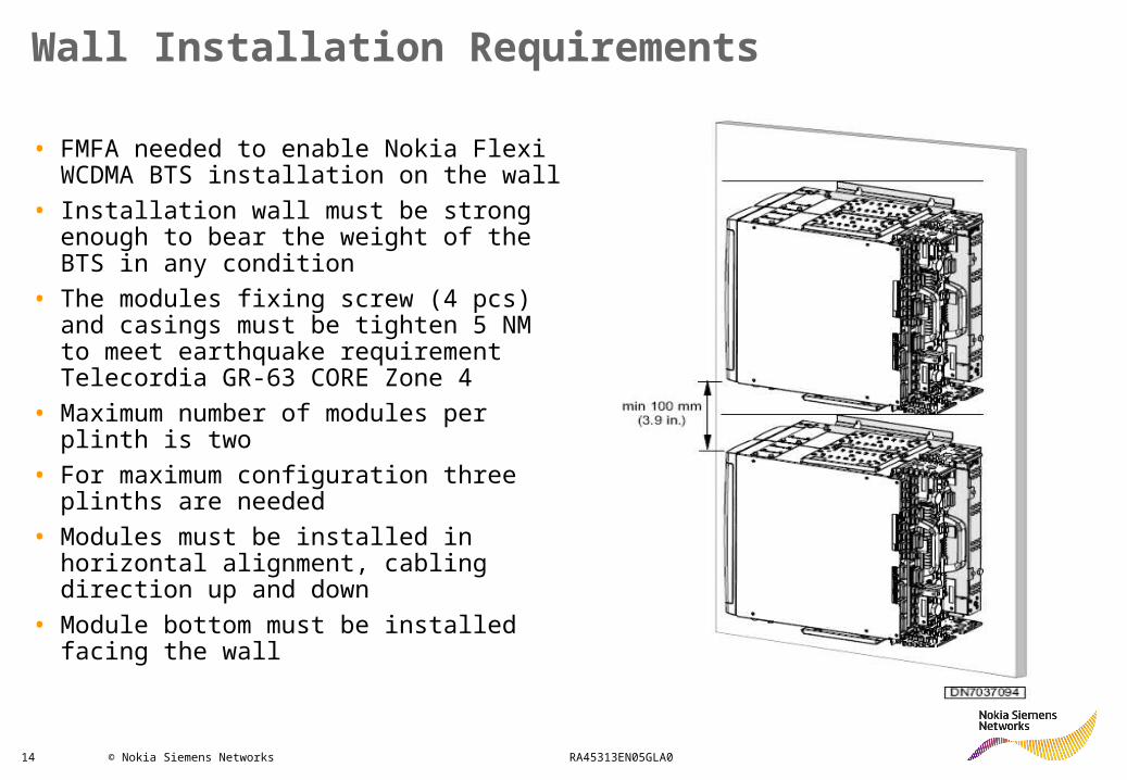
Wall Installation Requirements
• FMFA needed to enable Nokia Flexi WCDMA BTS installation on the wall
• Installation wall must be strong enough to bear the weight of the BTS in any condition
• The modules fixing screw (4 pcs) and casings must be tighten 5 NM to meet earthquake requirement Telecordia GR-63 CORE Zone 4
• Maximum number of modules per plinth is two
• For maximum configuration three plinths are needed
• Modules must be installed in horizontal alignment, cabling direction up and down
• Module bottom must be installed facing the wall
15 © Nokia Siemens Networks RA45313EN05GLA0
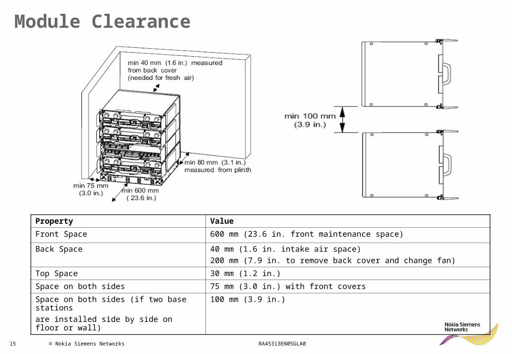
Module Clearance
Property ValueFront Space 600 mm (23.6 in. front maintenance space)Back Space 40 mm (1.6 in. intake air space)
200 mm (7.9 in. to remove back cover and change fan)Top Space 30 mm (1.2 in.)Space on both sides 75 mm (3.0 in.) with front coversSpace on both sides (if two base stationsare installed side by side on floor or wall)
100 mm (3.9 in.)
16 © Nokia Siemens Networks RA45313EN05GLA0
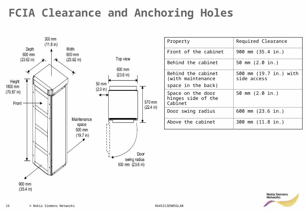
FCIA Clearance and Anchoring Holes
Property Required Clearance
Front of the cabinet 900 mm (35.4 in.)
Behind the cabinet 50 mm (2.0 in.)
Behind the cabinet (with maintenancespace in the back)
500 mm (19.7 in.) with side access
Space on the door hinges side of the Cabinet
50 mm (2.0 in.)
Door swing radius 600 mm (23.6 in.)
Above the cabinet 300 mm (11.8 in.)
17 © Nokia Siemens Networks RA45313EN05GLA0
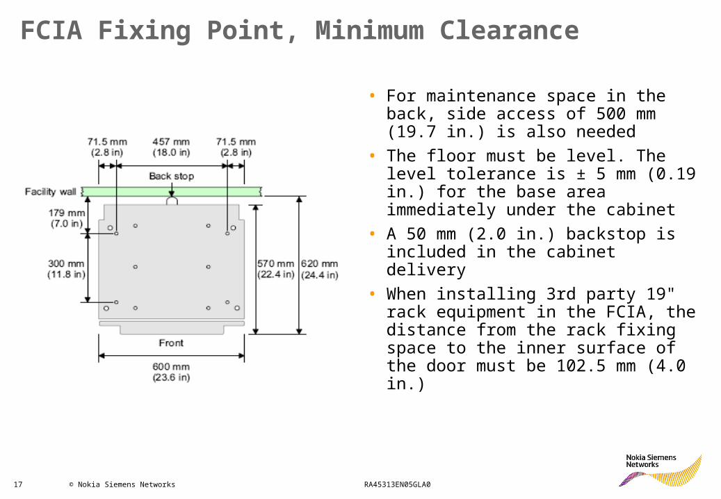
FCIA Fixing Point, Minimum Clearance
• For maintenance space in the back, side access of 500 mm (19.7 in.) is also needed
• The floor must be level. The level tolerance is ± 5 mm (0.19 in.) for the base area immediately under the cabinet
• A 50 mm (2.0 in.) backstop is included in the cabinet delivery
• When installing 3rd party 19" rack equipment in the FCIA, the distance from the rack fixing space to the inner surface of the door must be 102.5 mm (4.0 in.)
18 © Nokia Siemens Networks RA45313EN05GLA0
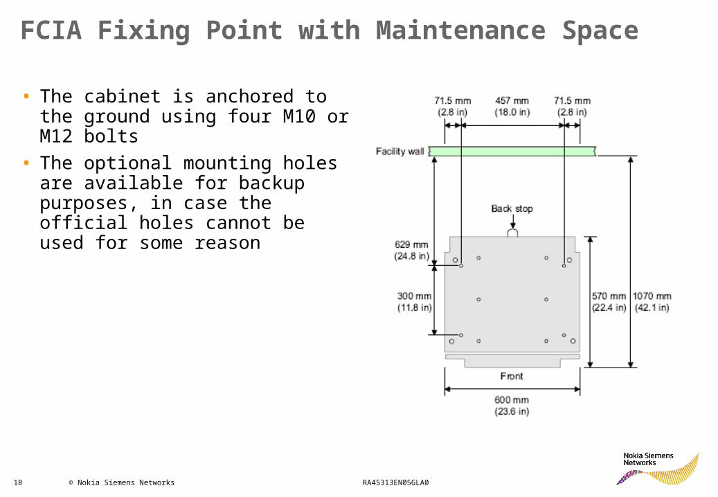
FCIA Fixing Point with Maintenance Space
• The cabinet is anchored to the ground using four M10 or M12 bolts
• The optional mounting holes are available for backup purposes, in case the official holes cannot be used for some reason
19 © Nokia Siemens Networks RA45313EN05GLA0
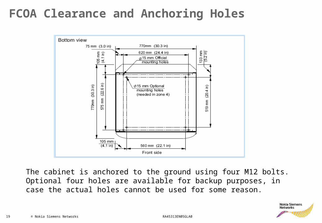
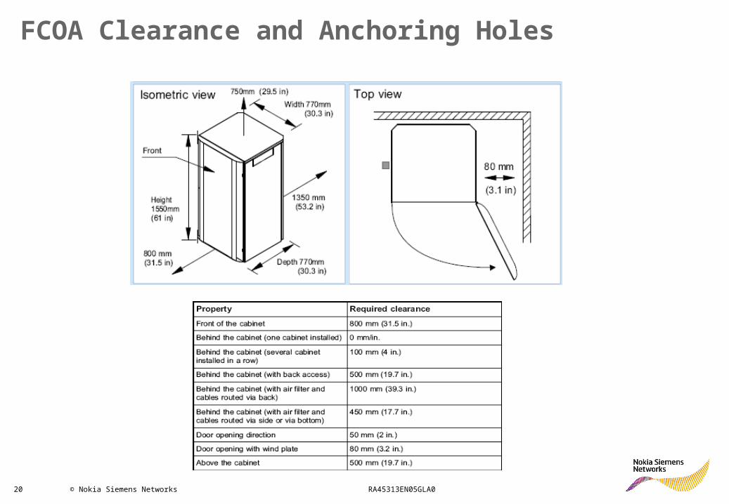
FCOA Clearance and Anchoring Holes
The cabinet is anchored to the ground using four M12 bolts. Optional four holes are available for backup purposes, in case the actual holes cannot be used for some reason.
20 © Nokia Siemens Networks RA45313EN05GLA0
FCOA Clearance and Anchoring Holes
21 © Nokia Siemens Networks RA45313EN05GLA0
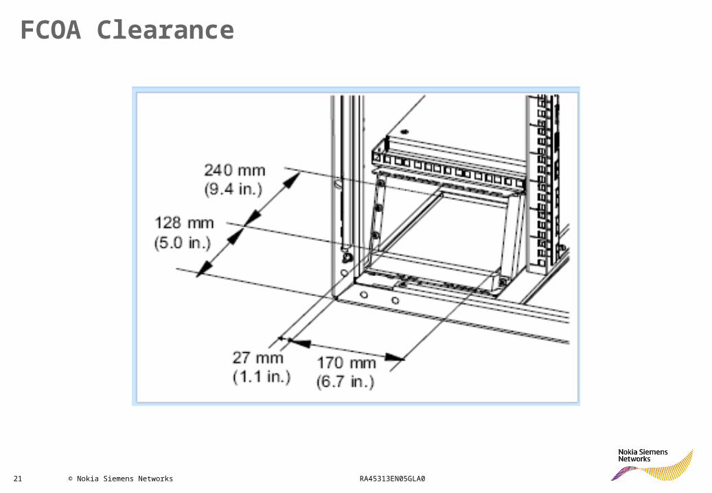
FCOA Clearance
22 © Nokia Siemens Networks RA45313EN05GLA0
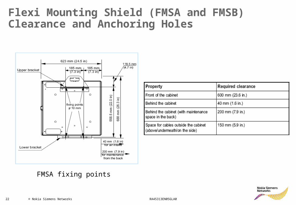
Flexi Mounting Shield (FMSA and FMSB) Clearance and Anchoring Holes
FMSA fixing points
23 © Nokia Siemens Networks RA45313EN05GLA0
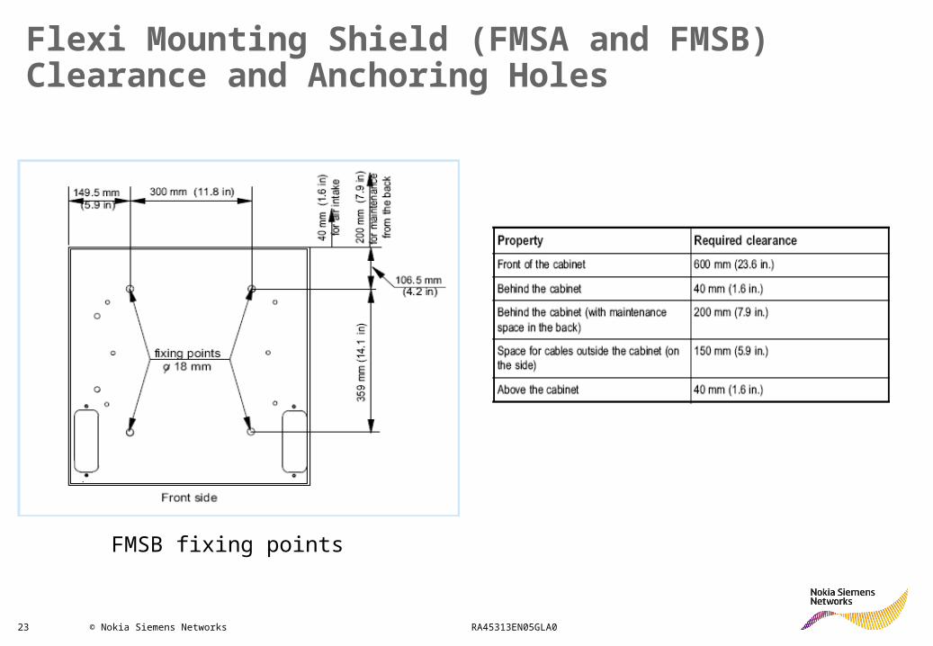
FMSB fixing points
Flexi Mounting Shield (FMSA and FMSB) Clearance and Anchoring Holes
24 © Nokia Siemens Networks RA45313EN05GLA0
Site Earth and Grounding Principle
BTS Site Grounding :• Site Earthing• Site Equipment Grounding
To protect the BTS from damaging overvoltages through antenna equipment, communication cables, or power supply lines, grounding cabling must be planned and installed before the installation of the base station.
The function of the site earth is to convoy the lethal and hazardous voltages and electric currents from the site main grounding point (main grounding busbar) to the earth.
25 © Nokia Siemens Networks RA45313EN05GLA0
The earthing (grounding) resistance target of the BTS site is ≤10 Ω
The cross-sectional area of the Main Earthing Conductor shall not be smaller than live (L) and neutral never less than 6 mm2,recommended size is 16 mm2
Grounding must have a fixed, non-removable connection
Site Earth and Grounding Principle
26 © Nokia Siemens Networks RA45313EN05GLA0
Recommendation for BTS Grounding Planning
• Grounding cable cross-section has to be more than any of AC or DC power feeding cable cross-section
• The grounding cable is connected with screws to the BTS mains grounding point
• The grounding cable must be connected to a main grounding busbar with a minimum of 6 mm2 grounding cable
• Route the grounding cables as directly as possible from the• equipment to the grounding point.• The grounding cables should not be run parallel with power
cables.• The external antenna feeders must also be grounded
according to the local legislation if the antennas are exposed to lightning.
27 © Nokia Siemens Networks RA45313EN05GLA0
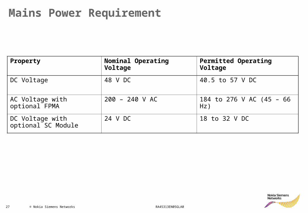
Mains Power Requirement
Property Nominal Operating Voltage
Permitted Operating Voltage
DC Voltage 48 V DC 40.5 to 57 V DC
AC Voltage with optional FPMA
200 – 240 V AC 184 to 276 V AC (45 – 66 Hz)
DC Voltage with optional SC Module
24 V DC 18 to 32 V DC
28 © Nokia Siemens Networks RA45313EN05GLA0
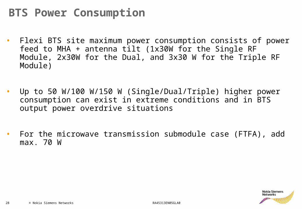
• Flexi BTS site maximum power consumption consists of power feed to MHA + antenna tilt (1x30W for the Single RF Module, 2x30W for the Dual, and 3x30 W for the Triple RF Module)
• Up to 50 W/100 W/150 W (Single/Dual/Triple) higher power consumption can exist in extreme conditions and in BTS output power overdrive situations
• For the microwave transmission submodule case (FTFA), add max. 70 W
BTS Power Consumption
29 © Nokia Siemens Networks RA45313EN05GLA0
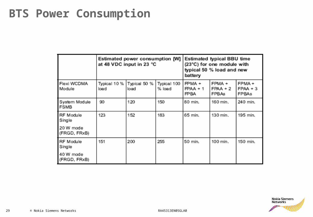
BTS Power Consumption

30 © Nokia Siemens Networks RA45313EN05GLA0
AppendixDimensions and Weight
31 © Nokia Siemens Networks RA45313EN05GLA0
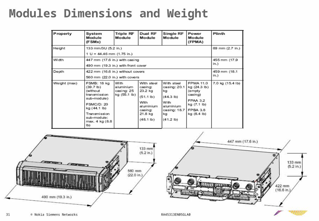
Modules Dimensions and Weight
32 © Nokia Siemens Networks RA45313EN05GLA0
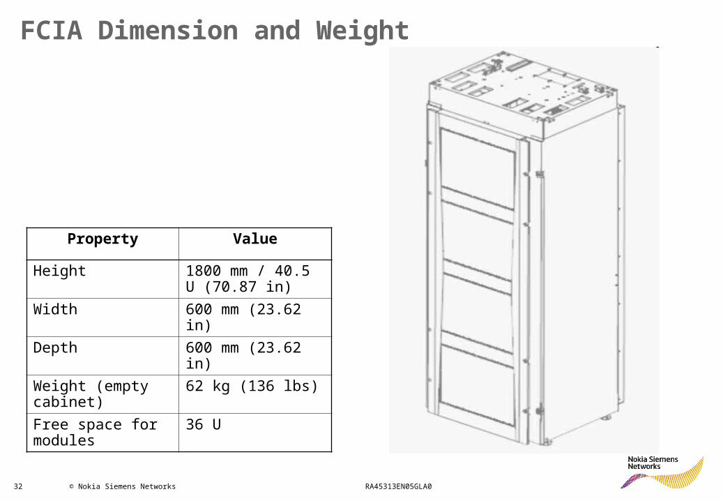
FCIA Dimension and Weight
Property Value
Height 1800 mm / 40.5 U (70.87 in)
Width 600 mm (23.62 in)
Depth 600 mm (23.62 in)
Weight (empty cabinet)
62 kg (136 lbs)
Free space for modules
36 U
33 © Nokia Siemens Networks RA45313EN05GLA0
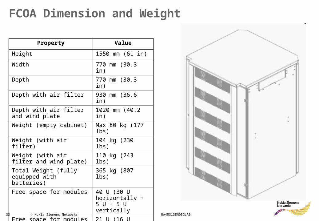
FCOA Dimension and Weight
Property ValueHeight 1550 mm (61 in)Width 770 mm (30.3
in)Depth 770 mm (30.3
in)Depth with air filter 930 mm (36.6
in)Depth with air filter and wind plate
1020 mm (40.2 in)
Weight (empty cabinet) Max 80 kg (177 lbs)
Weight (with air filter)
104 kg (230 lbs)
Weight (with air filter and wind plate)
110 kg (243 lbs)
Total Weight (fully equipped with batteries)
365 kg (807 lbs)
Free space for modules 40 U (30 U horizontally + 5 U + 5 U vertically
Free space for modules (site support and batteries installed)
21 U (16 U horizontally + 5 U vertically)
34 © Nokia Siemens Networks RA45313EN05GLA0
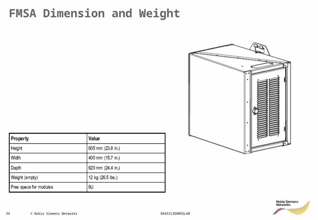
FMSA Dimension and Weight
35 © Nokia Siemens Networks RA45313EN05GLA0
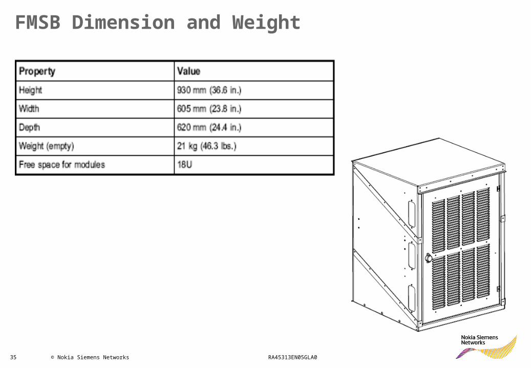
FMSB Dimension and Weight
36 © Nokia Siemens Networks RA45313EN05GLA0
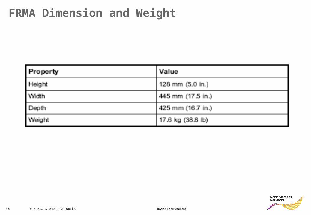
FRMA Dimension and Weight
37 © Nokia Siemens Networks RA45313EN05GLA0
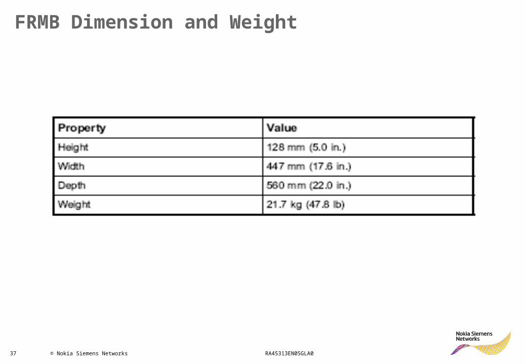
FRMB Dimension and Weight
38 © Nokia Siemens Networks RA45313EN05GLA0
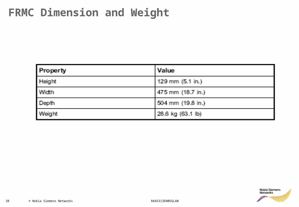
FRMC Dimension and Weight
39 © Nokia Siemens Networks RA45313EN05GLA0
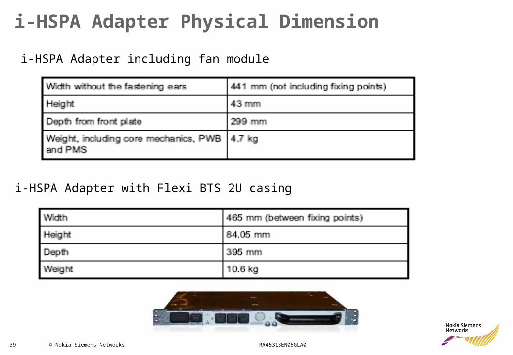
i-HSPA Adapter Physical Dimension i-HSPA Adapter including fan module
i-HSPA Adapter with Flexi BTS 2U casing