03 PPP TTE VLS AND API 510
53
© Matthews Engineering Training Ltd INSPECTING PRESSURE VESSELS (INCLUDING API 510)
-
Upload
independent -
Category
Documents
-
view
1 -
download
0
Transcript of 03 PPP TTE VLS AND API 510

© Matthews Engineering Training Ltd
INSPECTING PRESSURE VESSELS (INCLUDING API 510)

© Matthews Engineering Training Ltd
Try this
What are the major design differences between these two
vessels ?

© Matthews Engineering Training Ltd
Vessel design
Design has an effect on:
• Where the greatest stresses are
• Which locations are most critical for defects
• Key areas for inspection
© Matthews Engineering Training Ltd
Key design issues related to inspection
1.Shell stresses2.Head/shell ‘discontinuity’ stresses3.The principles of compensation4.Shell distortions
© Matthews Engineering Training Ltd
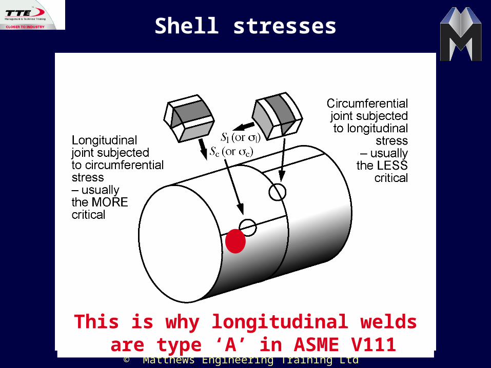
Shell stresses
1
© Matthews Engineering Training Ltd
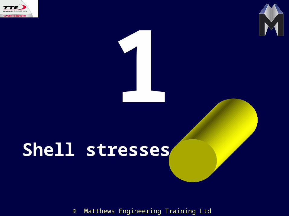
2 basic sets of assumptions:
Thick shell assumptions(mainly headers)
Thin shell assumptions (just about everything else)
Membrane theory (easy)
Lame equations(more complex)
© Matthews Engineering Training Ltd
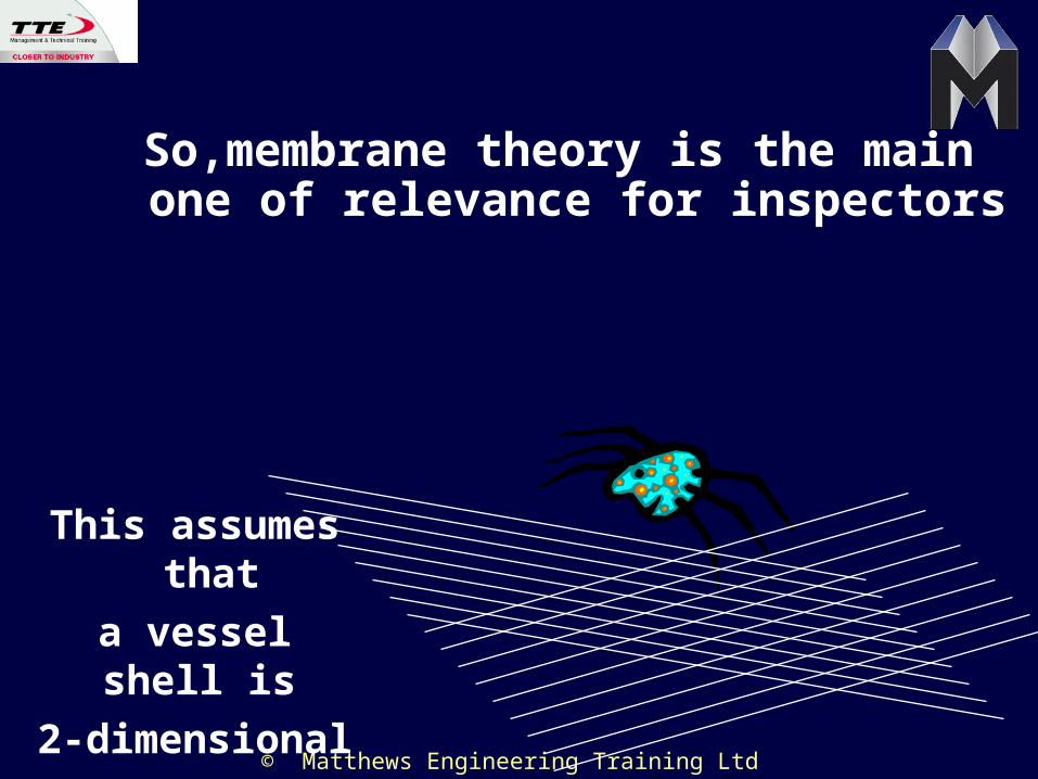
So,membrane theory is the main one of relevance for inspectors
This assumes that
a vessel shell is
2-dimensional

© Matthews Engineering Training Ltd
Shell welds
Which weld is the most critical and why?
Longitudinal
Circumferential
© Matthews Engineering Training Ltd
Shell stresses
This is why longitudinal welds are type ‘A’ in ASME V111

© Matthews Engineering Training Ltd
The evidence

© Matthews Engineering Training Ltd
Head-to-shell stresses
2

© Matthews Engineering Training Ltd
The head/shell joint
P
How is the shell
trying to deform?
What effect is the
head having

© Matthews Engineering Training Ltd
The result is:
HERE

© Matthews Engineering Training Ltd
What affects the size of the head/shell
discontinuity stress?

© Matthews Engineering Training Ltd
Discontinuity stresses
Types of head:Ellipsoidal,Torispheroidal
Note the a:b ratio
What is this for?

© Matthews Engineering Training Ltd
How far down the shell do the discontinuity stresses
extend?
?
© Matthews Engineering Training Ltd
3Compensation
© Matthews Engineering Training Ltd
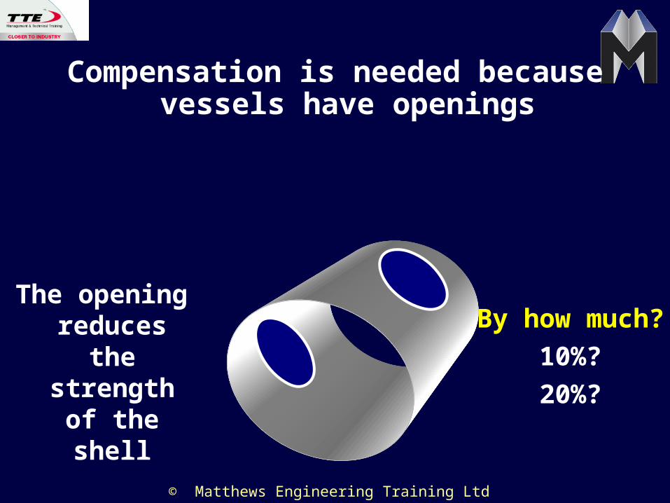
Compensation is needed because vessels have openings
The opening reduces the
strength of the shell
By how much?10%?20%?
© Matthews Engineering Training Ltd
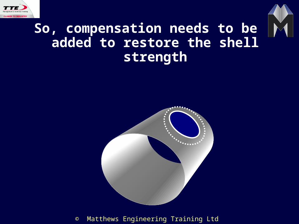
So, compensation needs to be added to restore the shell
strength

© Matthews Engineering Training Ltd
2 different types of compensation
Use a thicker nozzle
and/or a thicker shell
Use a compensation pad
on the shell
© Matthews Engineering Training Ltd
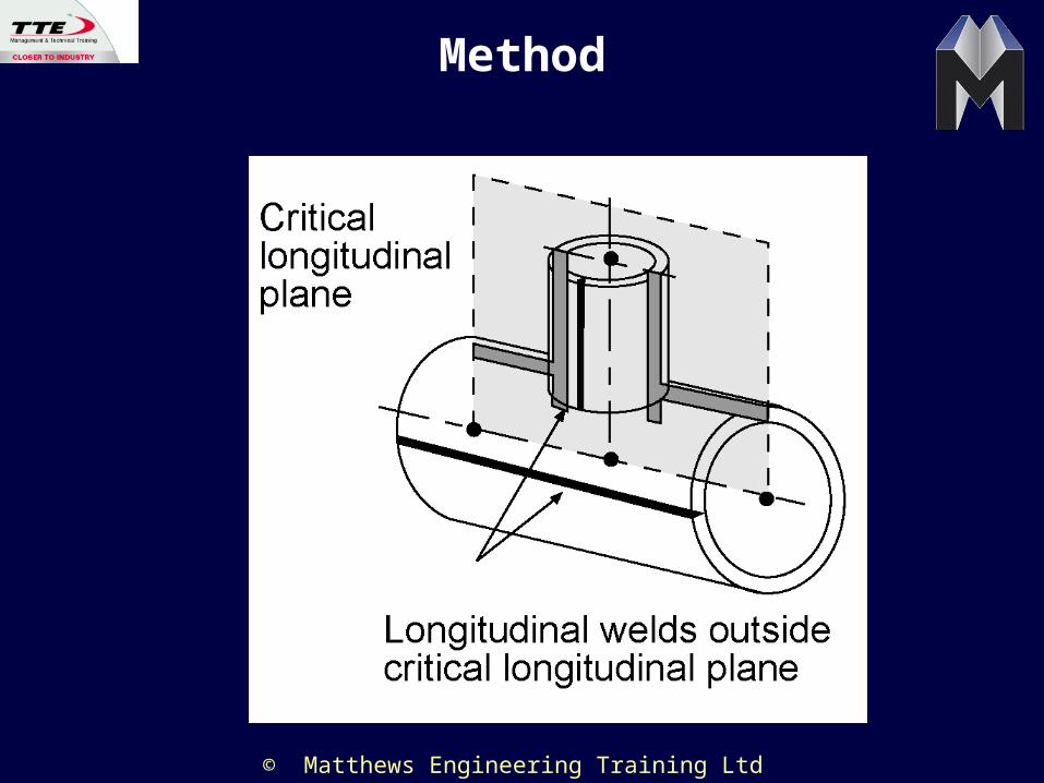
Method
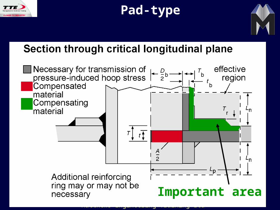
© Matthews Engineering Training LtdImportant area
Pad-type

© Matthews Engineering Training Ltd
Example:Pad type
Note small width of pad

© Matthews Engineering Training Ltd
What type is this?

© Matthews Engineering Training Ltd
Which type?
© Matthews Engineering Training Ltd
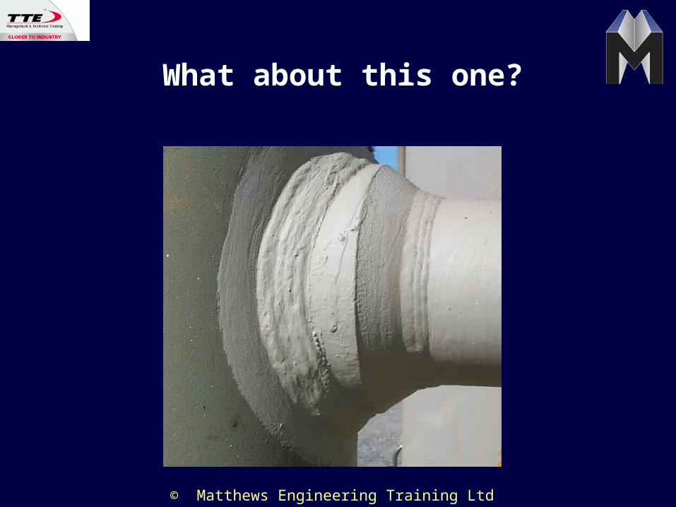
What about this one?
© Matthews Engineering Training Ltd
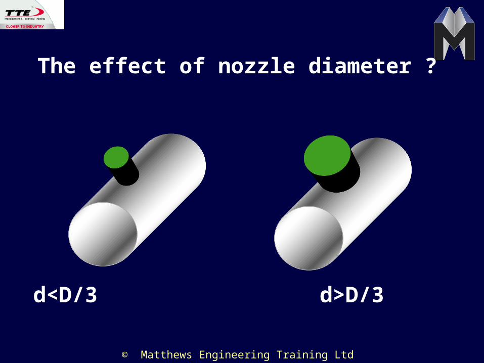
The effect of nozzle diameter ?
d<D/3 d>D/3
© Matthews Engineering Training Ltd
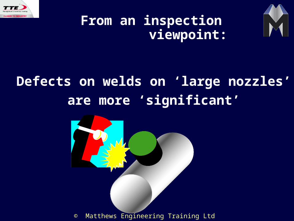
From an inspection viewpoint:
Defects on welds on ‘large nozzles’are more ‘significant’
© Matthews Engineering Training Ltd
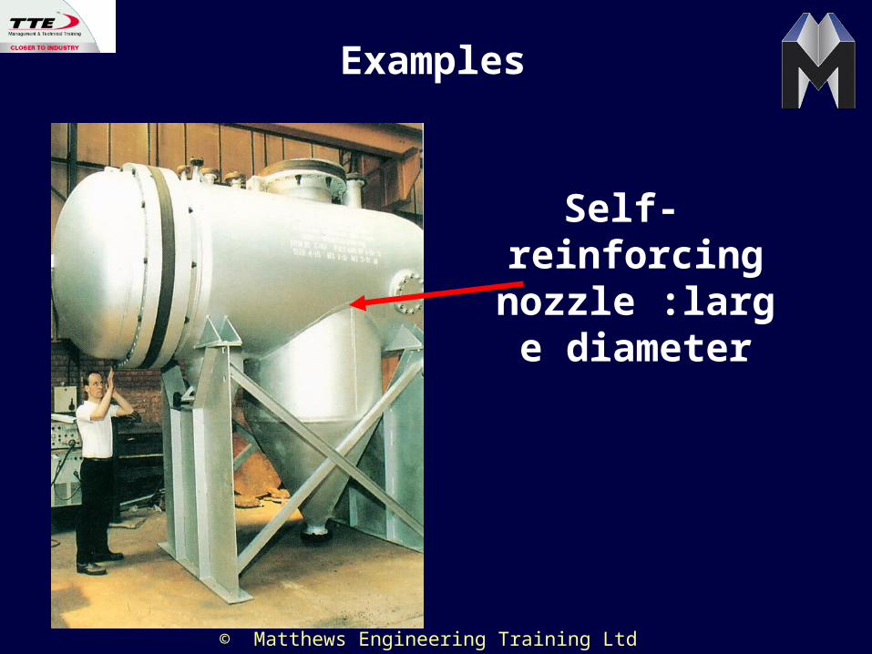
Examples
Self-reinforcing nozzle :large diameter
© Matthews Engineering Training Ltd
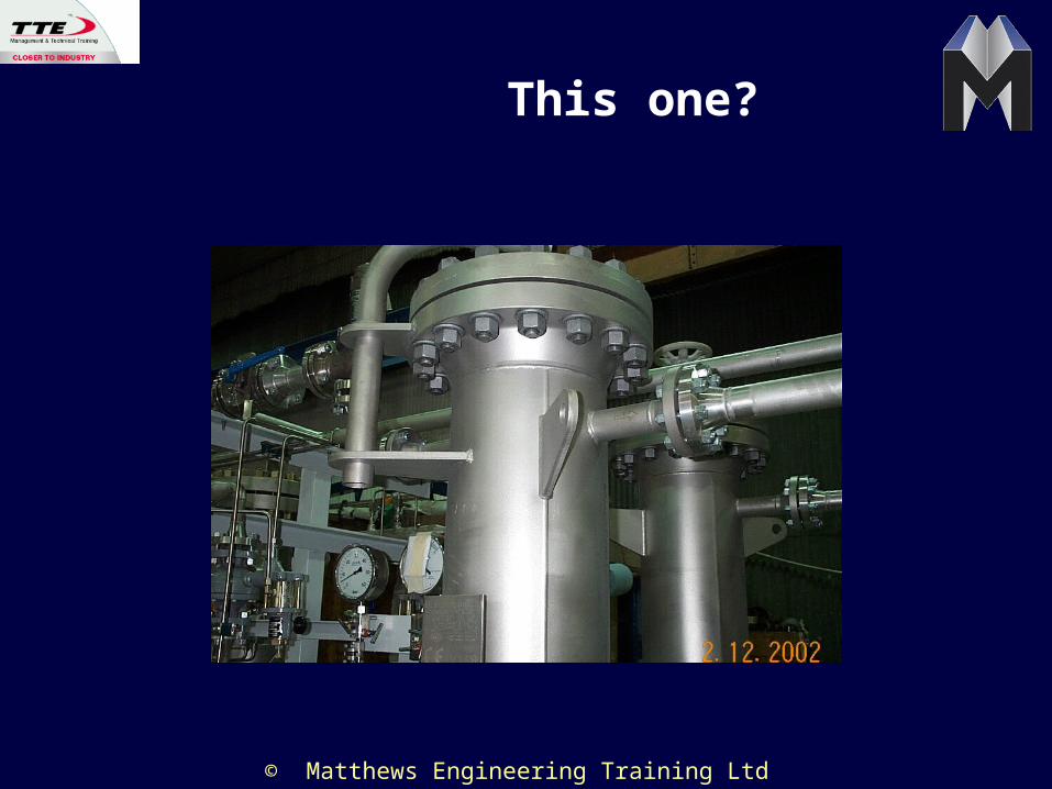
This one?

© Matthews Engineering Training Ltd
44
Shell distortions

© Matthews Engineering Training Ltd
Out of roundness
OOR produces large
increases in
membrane stresses owing to bending
Typical limits

© Matthews Engineering Training Ltd
OOR example
What would you conclude about this vessel ?
© Matthews Engineering Training Ltd
Vessel codes have tight limits on other types of shell
distortions
© Matthews Engineering Training Ltd
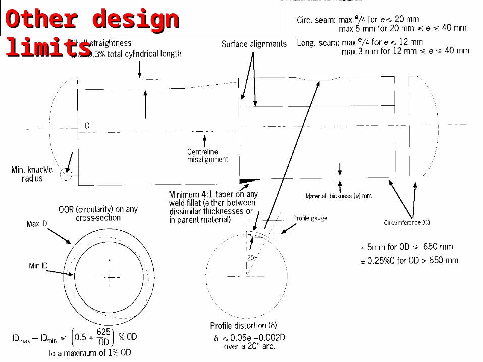
Other design Other design limitslimits

© Matthews Engineering Training Ltd
Basic vessel design:Summary
• Why is a little bit of design knowledge important in inspection?
• Where are the highest stress levels likely to be in a pressure vessel?
• Which are generally the ‘most critical’ welds
© Matthews Engineering Training Ltd
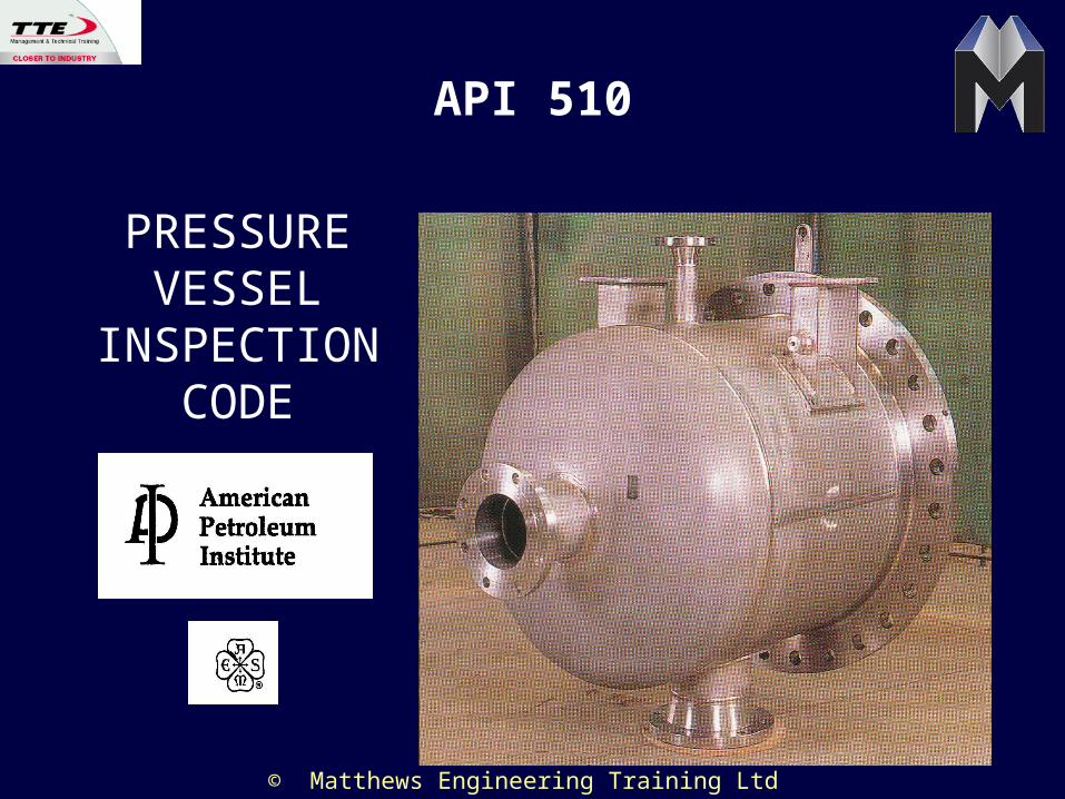
API 510
PRESSURE VESSEL
INSPECTION CODE

© Matthews Engineering Training Ltd
THE PURPOSE OF THE STANDARD IS, BASICALLY:
To fit in with the philosophy of ASME 1 and V111 For activities relating to:
Maintenance inspection Repair Alteration
and re-rating
API 510

© Matthews Engineering Training Ltd
THE US-BASED ‘FAMILIES’ OF CODESComponents
Storage Tanks
Power Boilers
Unfired Vessels
Piping Systems
Valves Pressure Relief Valves
Construction codes (i.e. manufacture only)
API 620 API 1650
ASME 1 ASME VIII-1
ASME B31-1ASME B31.3
ASME 16.34API 600-609
ASME 1ASME VIIIAPI 2000‘In-
service’ codes (covering inspection, repair, and re-rating)
API 653
-
API 510
API 570
API 598API RP 591
API RP 576
‘Support’ technical documents
API 651API 652API RP 575
ASME RP-573ASME II, V, VI, IX
ASME B16.5API RP 572ASME II, V, IX
ASME II, V, IXAPI RP 574
API RP 574ASME V, X
ASME PRC 25API 527ASME V, IX API RP 579 ‘Fitness for service’
API Guides for Inspection of Refinery Equipment (IRE)
© Matthews Engineering Training Ltd
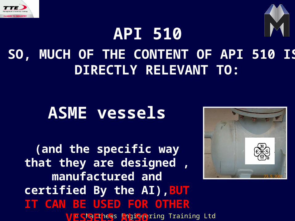
SO, MUCH OF THE CONTENT OF API 510 IS DIRECTLY RELEVANT TO:
ASME vessels
(and the specific way that they are designed ,
manufactured and certified By the AI),BUT IT CAN BE USED FOR OTHER
VESSELS ALSO
API 510

© Matthews Engineering Training Ltd
THE SCOPE OF API 510
Vol>0.141 m3 and P>250 psig
Vol>0.042 m3 and P>600psig
P=design pressure (not working pressure)
API 510
© Matthews Engineering Training Ltd
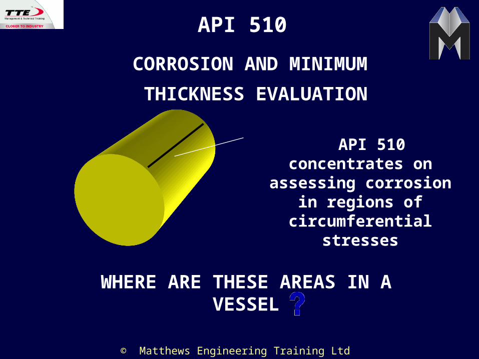
CORROSION AND MINIMUM THICKNESS EVALUATION
API 510 concentrates on
assessing corrosion in regions of circumferential
stresses
WHERE ARE THESE AREAS IN A VESSEL
API 510

© Matthews Engineering Training Ltd
WHAT ABOUT REAL VESSELS WITH NOZZLES?
API 510
© Matthews Engineering Training Ltd
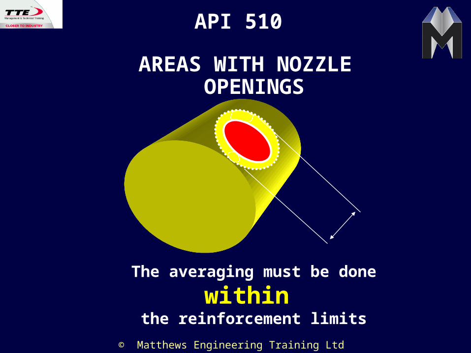
AREAS WITH NOZZLE OPENINGS
The averaging must be done within
the reinforcement limits
API 510
© Matthews Engineering Training LtdImportant area
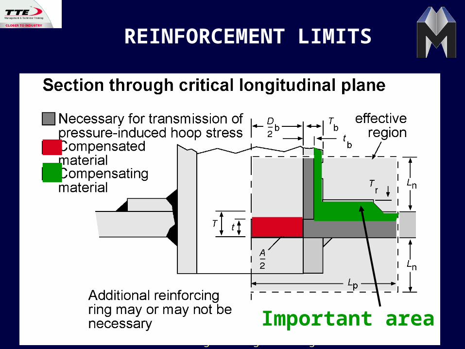
REINFORCEMENT LIMITS
© Matthews Engineering Training Ltd
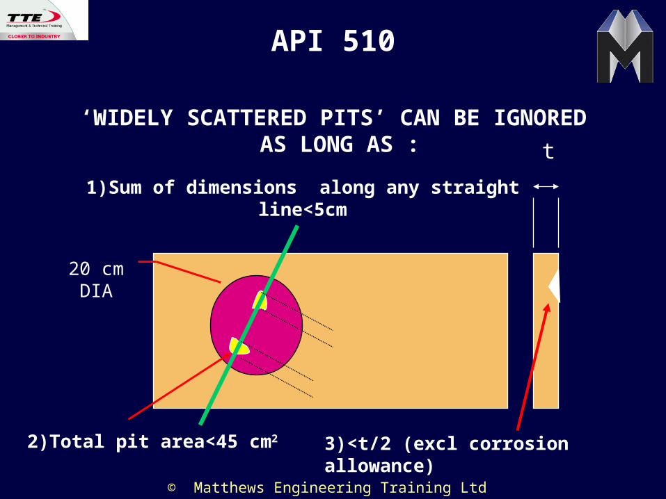
‘WIDELY SCATTERED PITS’ CAN BE IGNORED AS LONG AS :
20 cm DIA
2)Total pit area<45 cm2
1)Sum of dimensions along any straight line<5cm
3)<t/2 (excl corrosion allowance)
t
API 510

© Matthews Engineering Training Ltd
WHAT ABOUT THIS?
API 510
© Matthews Engineering Training Ltd
A year-interval
Maximum period between on-stream inspections
= the smaller of:
½ the remaining life of the vessel (based on corrosion rate)
Or
10 Years
10 API
SPECIFIES:
© Matthews Engineering Training Ltd
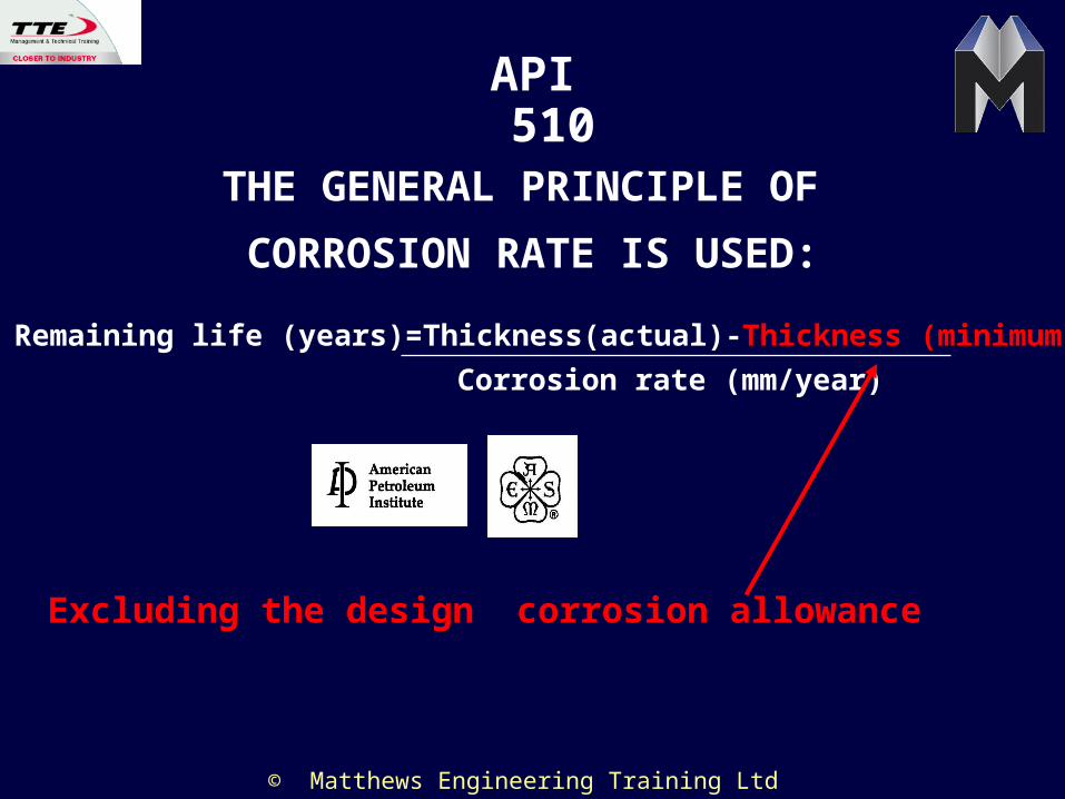
THE GENERAL PRINCIPLE OF CORROSION RATE IS USED:
Remaining life (years)=Thickness(actual)-Thickness (minimum)Corrosion rate (mm/year)
Excluding the design corrosion allowance
API 510

© Matthews Engineering Training Ltd
WHAT API 510 CONSIDERS AS ‘LOW RISK’ VESSELSCorrosion history has been tracked for 5 yearsVessel not in creep rangeVessel not subjected to Hydrogen damage from the process fluidVessel is not strip or plate-lined
ON-STREAM INSPECTIONS ALLOWED(with UT thickness measurements)
API 510

© Matthews Engineering Training Ltd
Low risk vessels
Higher-risk vessels
15 years or 2/3 remaining ‘corrosion-rate life’
10 years or ½ remaining‘corrosion-rate life’
A general acceptance that on-stream inspections can be used
API 510

© Matthews Engineering Training Ltd
IF A VESSEL IS MOVED OR ITS USE CHANGED:
API 510 specifies that an inspection needs to be done
(but the extent of this inspection is up to the user)
API 510

© Matthews Engineering Training Ltd
SUMMARY:SO: API 510:
Specifies principles of vessel inspections……...BUT…….leaves many
technical decisions to the inspector
API 510 is not
particularly definitive by itself