© This item is protected by original copyright
15
LOAD TEST OF 0.5HP AC INDUCTION MOTOR USING COUPLING SYSTEM by TING SIU HUI Report submitted in partial fulfillment of the requirements for the degree of Bachelor of Engineering MAY 2011 © This item is protected by original copyright
-
Upload
khangminh22 -
Category
Documents
-
view
0 -
download
0
Transcript of © This item is protected by original copyright
LOAD TEST OF 0.5HP AC INDUCTION MOTOR
USING COUPLING SYSTEM
by
TING SIU HUI
Report submitted in partial fulfillment
of the requirements for the degree
of Bachelor of Engineering
MAY 2011
© T
his ite
m is
pro
tect
ed by o
rigin
al co
pyrigh
t

LOAD TEST OF 0.5HP AC INDUCTION MOTOR
USING COUPLING SYSTEM
TING SIU HUI
SCHOOL OF ELECTRICAL SYSTEMS
ENGINEERING UNIVERSITY MALAYSIA PERLIS
2011
© T
his ite
m is
pro
tect
ed by o
rigin
al co
pyrigh
t

i
ACKNOWLEDGEMENT
Thanks God for giving me the wisdom, strength, healthy and blessing for me to
successfully complete my Final Year Project. First and foremost, I would like to express
my highest thankful to my supervisor, En.Anayet Karim for his support and guidance
that he given to me during the process on doing my project, which has led me to the
completion of the project.
Secondly, to my family for the financial support and to my girlfriend, Kelly Hii for the
moral support which given me the encouragement to success in this project.
Thanks to all of the quality and reliability personnel, especially Uncle Kok for provide
me the workshop to do the coupling steel bar for the use in load test of induction motor.
And to En.Azrin, the lab assistant for given me the ideal on doing the hardware
construction in the lab. And also my fellow friends that working together with me that
provide the necessary support, valuable advice, friendly help and interesting in
discussions around my work which help me so much to gain new ideal in my project.
Finally, my special thanks to University Malaysia Perlis (UniMAP) for given me the
change to expose myself to the Final Year Project and allowed me to apply theory and
practical knowledge as well.
© T
his ite
m is
pro
tect
ed by o
rigin
al co
pyrigh
t
ii
DECLARATION SHEET
I hereby declare that my Final Year Project Thesis is the result of my research
work under supervision of ANAYET KARIM. All literature sources used for the
writing of this thesis have been adequately referenced.
Name : TING SIU HUI
Candidate number : 071091278
Supervisor : ANAYET KARIM
Title of thesis : LOAD TEST OF 0.5HP AC INDUCTION MOTOR
USING COUPLING SYSTEM
Candidate’s signature: …………………. . Supervisor signature: …………………
Date: ………………………….. Date: …..………………………
© T
his ite
m is
pro
tect
ed by o
rigin
al co
pyrigh
t

iii
APPROVAL AND DECLARATION SHEET
This project report titled Load Test of 0.5HP AC Induction Motor Using Coupling
System was prepared and submitted by Ting Siu Hui (Matrix Number: 071091278)
and has been found satisfactory in terms of scope, quality and presentation as
partial fulfillment of the requirement for the Bachelor of Engineering ( Electrical
Systems Engineering ) in Universiti Malaysia Perlis (UniMAP).
Checked and Approved by
_______________________
(ANAYET KARIM)
Project Supervisor
School of Electrical Systems Engineering
Universiti Malaysia Perlis
May 2011
© T
his ite
m is
pro
tect
ed by o
rigin
al co
pyrigh
t
iv
UJIAN BEBAN PENJANA MOTOR
DENGAN MENGGUNAKAN SISTEM SINAPSIS
ABSTRAK
Penjana motor digunakan di seluruh dunia sebagai pekerja dalam aplikasi
industri seperti kipas, pam, peralatan mesin, lif dan alat pengangkutan. Penjana motor
mempunyai ciri-ciri yang ringkas dan pelbagai, mudah diservis, mempunyai kecekapan
yang tinggi dan harganya adalah berpatutan. Ciri-ciri ini mendorong kepada
standardisasi dan perkembangan motor dalam bidang pembuatan dan infrastruktur dan
diperkenalkan secara meluas dalam pelbagai bidang. Oleh itu, usaha untuk
meningkatkan kecekapan motor akan memberikan kesan yang positif dalam
mengurangkan pembaziran tenaga elektrik terutamanya dalam bidang industri. Terdapat
pelbagai kaedah yang boleh dipakai untuk menentukan kecekapan penjana motor.
Antaranya adalah menjalankan ujian tanpa beban, ujian angkir terkunci, ujian rintangan
arus terus dan ujian beban terhadap penjana motor untuk mendapatkan berbagai-bagai
nilai yang dikehendaki. Pengiraan akan dijalankan untuk menentukan spesifikasi
penjana motor seperti nilai rintangan keseluruhan, kebocoran galangan, kehilangan
kuasa, arus dan lain-lain. Akhirnya, kecekapan penjana motor dapat ditentukan.
© T
his ite
m is
pro
tect
ed by o
rigin
al co
pyrigh
t

v
LOAD TEST OF 0.5HP AC INDUCTION MOTOR
USING COUPLING SYSTEM
ABSTRACT
Induction motors are used worldwide as the workhorse in industrial application
such as fan, pumps, machine tools, elevators and conveyors. It offers users simplicity,
rugged construction, easy maintenance, relatively high efficiency and cost effective
pricing. These factors have promoted standardization and development of a
manufacturing infrastructure that has led to a vast installed base of motors. Thus,
improvements in the efficiency of the electrical drives would offer significant effects in
reducing industrial electrical energy usage. There are various types of method in
determining the efficiency of induction motors. Among them are No-Load Test,
Blocked Rotor Test, DC Resistance Test and Load Test for rotating machine to get
various data on the induction motor. A proper parameter calculation need to be carried
on to obtain the range of specification of the induction motor such as the total
resistance,the leakage impedances, the losses estimation, stator current, rotor current and
so on. Finally, the efficiency of the AC Induction Motor is determined.
© T
his ite
m is
pro
tect
ed by o
rigin
al co
pyrigh
t
vi
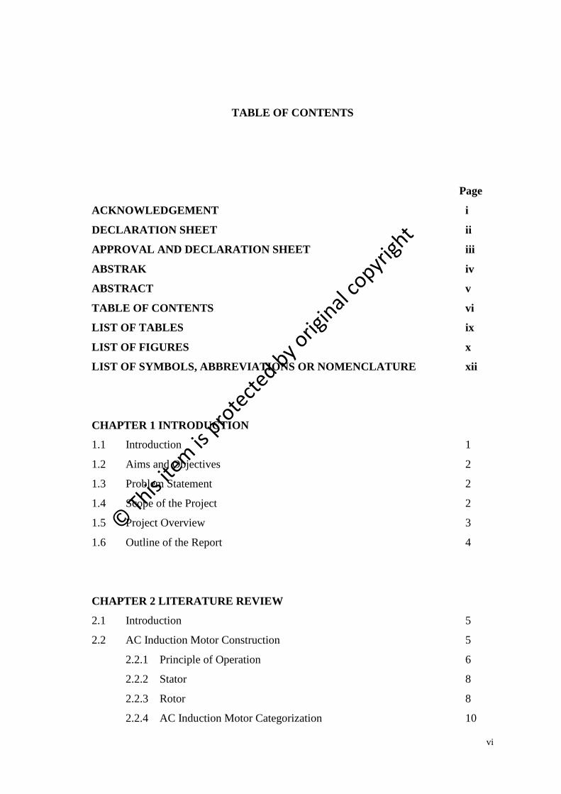
TABLE OF CONTENTS
Page
ACKNOWLEDGEMENT i
DECLARATION SHEET ii
APPROVAL AND DECLARATION SHEET iii
ABSTRAK iv
ABSTRACT v
TABLE OF CONTENTS vi
LIST OF TABLES ix
LIST OF FIGURES x
LIST OF SYMBOLS, ABBREVIATIONS OR NOMENCLATURE xii
CHAPTER 1 INTRODUCTION
1.1 Introduction 1
1.2 Aims and Objectives 2
1.3 Problem Statement 2
1.4 Scope of the Project 2
1.5 Project Overview 3
1.6 Outline of the Report 4
CHAPTER 2 LITERATURE REVIEW
2.1 Introduction 5
2.2 AC Induction Motor Construction 5
2.2.1 Principle of Operation 6
2.2.2 Stator 8
2.2.3 Rotor 8
2.2.4 AC Induction Motor Categorization 10
© T
his ite
m is
pro
tect
ed by o
rigin
al co
pyrigh
t
vii
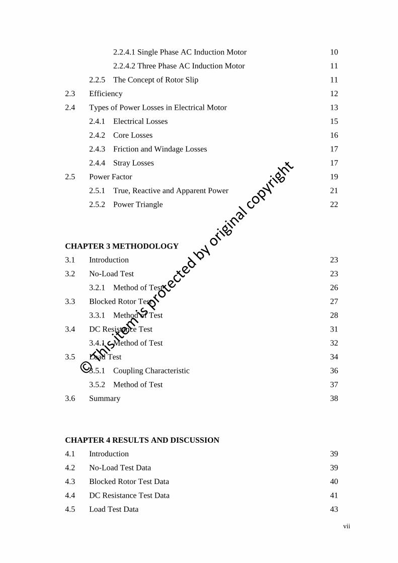
2.2.4.1 Single Phase AC Induction Motor 10
2.2.4.2 Three Phase AC Induction Motor 11
2.2.5 The Concept of Rotor Slip 11
2.3 Efficiency 12
2.4 Types of Power Losses in Electrical Motor 13
2.4.1 Electrical Losses 15
2.4.2 Core Losses 16
2.4.3 Friction and Windage Losses 17
2.4.4 Stray Losses 17
2.5 Power Factor 19
2.5.1 True, Reactive and Apparent Power 21
2.5.2 Power Triangle 22
CHAPTER 3 METHODOLOGY
3.1 Introduction 23
3.2 No-Load Test 23
3.2.1 Method of Test 26
3.3 Blocked Rotor Test 27
3.3.1 Method of Test 28
3.4 DC Resistance Test 31
3.4.1 Method of Test 32
3.5 Load Test 34
3.5.1 Coupling Characteristic 36
3.5.2 Method of Test 37
3.6 Summary 38
CHAPTER 4 RESULTS AND DISCUSSION
4.1 Introduction 39
4.2 No-Load Test Data 39
4.3 Blocked Rotor Test Data 40
4.4 DC Resistance Test Data 41
4.5 Load Test Data 43
© T
his ite
m is
pro
tect
ed by o
rigin
al co
pyrigh
t
viii
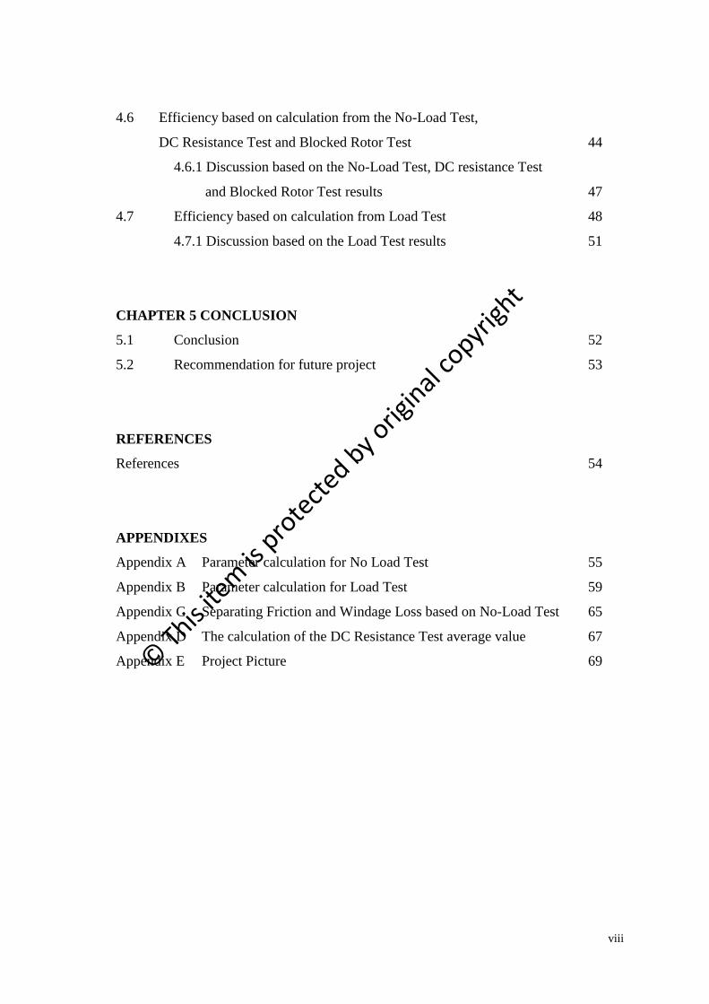
4.6 Efficiency based on calculation from the No-Load Test,
DC Resistance Test and Blocked Rotor Test 44
4.6.1 Discussion based on the No-Load Test, DC resistance Test
and Blocked Rotor Test results 47
4.7 Efficiency based on calculation from Load Test 48
4.7.1 Discussion based on the Load Test results 51
CHAPTER 5 CONCLUSION
5.1 Conclusion 52
5.2 Recommendation for future project 53
REFERENCES
References 54
APPENDIXES
Appendix A Parameter calculation for No Load Test 55
Appendix B Parameter calculation for Load Test 59
Appendix C Separating Friction and Windage Loss based on No-Load Test 65
Appendix D The calculation of the DC Resistance Test average value 67
Appendix E Project Picture 69
© T
his ite
m is
pro
tect
ed by o
rigin
al co
pyrigh
t
ix
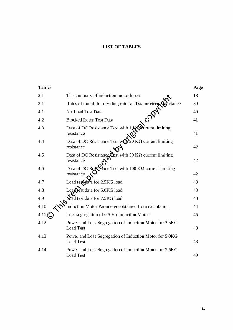
LIST OF TABLES
Tables Page
2.1 The summary of induction motor losses 18
3.1 Rules of thumb for dividing rotor and stator circuit reactance 30
4.1 No-Load Test Data 40
4.2 Blocked Rotor Test Data 41
4.3 Data of DC Resistance Test with 1 KΩ current limiting
resistance 41
4.4 Data of DC Resistance Test with 20 KΩ current limiting
resistance 42
4.5 Data of DC Resistance Test with 50 KΩ current limiting
resistance 42
4.6 Data of DC Resistance Test with 100 KΩ current limiting
resistance 42
4.7 Load test data for 2.5KG load 43
4.8 Load test data for 5.0KG load 43
4.9 Load test data for 7.5KG load 43
4.10 Induction Motor Parameters obtained from calculation 44
4.11 Loss segregation of 0.5 Hp Induction Motor 45
4.12 Power and Loss Segregation of Induction Motor for 2.5KG
Load Test 48
4.13 Power and Loss Segregation of Induction Motor for 5.0KG
Load Test 48
4.14 Power and Loss Segregation of Induction Motor for 7.5KG
Load Test 49
© T
his ite
m is
pro
tect
ed by o
rigin
al co
pyrigh
t

x
LIST OF FIGURES
Figures Page
1.1 Flow chart process of the project 3
2.1 Moving magnet cutting across a conducting ladder 6
2.2 Ladder bent upon itself to form a squirrel cage 7
2.3 Induction Motor stator 8
2.4 Sketch of cage rotor [3] 9
2.5 Wound rotor 9
2.6 Electric motor categorization 10
2.7 Typical distribution of the induction motor losses as a
function of the load [9] 13
2.8 Power flow diagram 14
2.9 Losses Chart 15
2.10 Phasor diagram of the voltage and current 19
2.11 Power Factor Correction circuit [2] 20
2.12 Power triangle [7] 22
3.1 No-Load Test Connection [3] 24
3.2 Equivalent circuit of No-Load Test [3] 24
3.3 No-Load Test setup 26
3.4 Blocked Rotor test circuit [3] 27
3.5 Block rotor test setup 28
3.6 Equivalent circuit of Blocked Rotor Test 29
3.7 Test circuit for a dc resistance test [3] 31
3.8 Connection of DC resistance test with three phase induction
motor 32
3.9 DC resistance test setup 33
3.10 Load Test circuit connection [3] 34
3.11 Load Test setup 35
© T
his ite
m is
pro
tect
ed by o
rigin
al co
pyrigh
t
xi
3.12 Coupling 36
4.1 The percentage of loss segregation of 0.5 Hp Induction Motor 45
4.2 The number loss segregation of 0.5 Hp Induction Motor 46
4.3 The power flow diagram of the losses 46
4.4 Number of power and loss segregation with different load 49
4.5 The power flow diagram for load test 50
© T
his ite
m is
pro
tect
ed by o
rigin
al co
pyrigh
t

xii
LIST OF SYMBOLS, ABBREVIATIONS OR NOMENCLATURE
EMF Electromagnetic Force
ɳ Efficiency
NEMA National Electrical Manufacturers Association
𝐼1 Stator Current
PF Power Factor
S Slip
Hp Horsepower
𝑃𝐹&𝑊 Friction and Windage Losses
𝑛𝑠 Synchronous Speed
kVAR Kilo Volt-Amperes-Reactive
kW Kilowatt
kVA Kilovolts-Amperes
𝐼𝐿 Line Current
𝑉𝐿−𝐿 Line-to-Line Voltage
𝐼𝑋 Reactive Component
𝐼𝑃 Load Component current
𝜃 Electrical Angle
𝑃𝑖𝑛 Input Power
𝑃𝑜𝑢𝑡 Output Power
𝑃𝑟𝑜𝑡 Rotational Losses
𝑃𝑚𝑒𝑐 ℎ Mechanical Power
𝑃𝐴𝐺 Air Gap power
𝑅2 Rotor Resistance
𝑃𝑐𝑜𝑟𝑒 Core Losses
𝑃𝑁𝐿 No-Load Power
𝐼𝑁𝐿 No-Load Current
𝑅𝑁𝐿 No-Load Resistance
© T
his ite
m is
pro
tect
ed by o
rigin
al co
pyrigh
t
xiii
𝑍𝑁𝐿 No-Load Impedance
𝑅1 Stator Resistance
𝑋1 Stator Leakage Reactance
𝑋2 Rotor Leakage Reactance
𝑋𝑚 Magnetizing Reactance
𝑃𝐵𝑅 Blocked Rotor Power
𝐼𝐵𝑅 Blocked Rotor Current
𝑅𝐵𝑅 Blocked Rotor Resistance
𝑍𝐵𝑅 Blocked Rotor Impedance
𝑋𝐵𝑅 Blocked Rotor Reactance
𝑉𝑑𝑐 DC Voltage
𝐼𝑑𝑐 DC Current
𝐼𝑐 Per-Phase Stator Core Loss Current
𝐼𝑚 Magnetizing Current
𝑅𝑐 Per-Phase Stator Core Loss Resistance
𝐿𝑚 Per-Phase Stator Magnetizing Inductance
𝑉𝑝 Phase Voltage
𝑃𝑐𝑜𝑟𝑒 Core Losses
𝑃𝑆𝐶𝐿 Stator Copper Losses
𝑃𝑅𝐶𝐿 Rotor Copper Losses
𝑓𝑡 Frequency of the Blocked-Rotor Test Voltage
𝑓𝐵 Rated Frequency
𝑃𝑠𝑡𝑟𝑎𝑦 𝐼𝐸𝐸𝐸 Stray Load Losses Based On IEEE 112-B Standard
𝑃 True Power
Q Reactive Power
S Apparent Power
nslip Slip Speed
nm Mechanical Shaft Speed
𝑤𝑠𝑦𝑛𝑐 Synchronous Angular Velocity
𝑤𝑚 Mechanical Angular velocity
© T
his ite
m is
pro
tect
ed by o
rigin
al co
pyrigh
t