® - Dave Carter & Associates, Inc
388
® www.bryant-electric.com Full Line Catalog Wiring Devices for the Industrial Commercial Institutional and Residential Markets
-
Upload
khangminh22 -
Category
Documents
-
view
0 -
download
0
Transcript of ® - Dave Carter & Associates, Inc

®
www.bryant-electric.com
Full L ine Catalog
Wiring Devices
for the
Industrial
Commercial
Institutional and
Residential Markets

The f i r s t “pu
sh-p
ull sw
itch”
More than a Century of World Class Innovation, Quality and ExperienceBuilding on more than 122 years of excellence, Bryant Electric offers an expanded and enhanced product offering for industrial, commercial, institutional and residential markets. Our new product lines and product enhancements showcased in this latest catalog continue to combine the innovation, value, quality and superior performance you’ve grown to expect from Bryant.
Innovation and ValueIn 1888, Waldo Calvin Bryant received a patent for the first push-pull switch that established the wiring device industry. Bryant’s product development and innovation continues today with systems and solutions that provide better value through safety and labor savings.
Bryant’s Quick-Tech™ connectorized receptacles provide an innovative quick and simple wiring method to cut down on installation costs. The CIRCUITPRO® Self-Test GFCI receptacles not only continuously monitor for ground fault conditions, but also test themselves every 60 seconds to ensure their continued ability to provide safety and protection. Bryant Motor Controllers are suitable as motor disconnects, providing a solution that saves material, space and cost. Bryant’s metal raceway product line incorporates the features customers asked for but could not find. And building on our industrial and commercial experience, Bryant has also introduced a complete line of residential wiring devices and voice/data/communication products that incorporate innovation, value and leading-edge features and style for today’s homes.

Quality and Superior PerformanceBryant’s new product offering serves to enhance our existing wiring device product line with better safety, ease-of-use and lower installation costs. Our plugs and connectors provide a full range of features from the Triple Gripper® cord grip and dust shield, to the durable impact-resistant nylon construction that Bryant introduced to the industry more than 40 years ago. Our hospital grade and industrial specification grade receptacles continue to incorporate a “true” one-piece grounding system, and the product offering has expanded to include tamper resistant, weather-resistant and connectorized devices. Bryant’s feature-rich devices continue to be preferred by specifiers, contractors and original equipment manufacturers for their quality and superior performance.
Our Growing PortfolioBryant’s commitment to distributors and customers is reflected in our continued growth and product line expansions. Since
1888, Bryant Electric has been a pioneer in the wiring device
industry, and we continue to expand the brand
by offering innovative solutions for the industrial, commercial, institutional and residential markets. Our proven track record of engineering
dependable and durable products
continues to make Bryant a respected leader in the
industry. Whether it’s to receive technical expertise, design guidance
or product information, we are ready to service your needs.
Contact us toll-free at 1-800-323-2792, or visit us on the web at www.bryant-electric.com.
Brya
nt Q
uic
k-Te
ch™
Rec
epta
c les

www.bryant-electric.com Specifications are subject to change without notice.ii
Table of Contents
Section AStraight Blade Devices
Section BGround Fault Devices
Section CSurge and Isolated Ground Devices
Section DDecorator Products
Section ESwitches
Section FLighting Controls
Section GControl Products
Section HLocking Devices
Section IWatertight/ Dust-Tight Products
Section JCorrosion- Resistant Devices
Section KPin & Sleeve Devices
Section LWire Management Products
Section MLampholders, Starters and Adapters
Section NDelivery Systems
RoHScompliant
Section OWallplates
Section PNetwork Wiring
Section QTechnical Information
Section RNEMA Configuration Charts
Section SAlphanumeric Index
Section TRoHS Index

General Information
Bryant TrademarksAssociations
www.bryant-electric.comSpecifications are subject to change without notice. iii
Since 1888, Bryant Electric has been a pioneer in the wiring industry. Just as the Bryant name is recognized as a mark of durability and quality, so are many of the trade names we use with our devices, These include:
CIRCUITPRO®
Cobra®
Fashion Series®
JLOAD™netSELECT®
Plugbox®
Quad Gripper®
QUADCAB®
QUADPLEX® Quick-Tech™RE-BOX®
Speakon®
TechSpec®
Triple Gripper®
No material will be accepted for return unless permission is granted in writing by Bryant. All orders received on special items are accepted as firm orders and are not subject to cancellation by the customer.
Claims for freight charges or allowances of any kind will not be considered after 30 days from receipt of goods and our responsibility ceases when we have delivered such shipments to the carriers and hold their receipts.
All Bryant devices are UL Listed and CSA Certified unless otherwise indicated.
Product dimensions in this catalog are nominal and are provided for the convenience of our customers. We reserve the right to make changes from time to time, without notice, which may change the dimensions shown. Therefore, we recommend verifying dimensions with us before using them for product developments or prints.
The designs and dimensions of the products listed in this catalog, correct at the date of publication, are subject to change without notice.
This catalog is published solely for information purposes and should not be considered all-inclusive.
Typographical or pictorial errors which are brought to our attention will be corrected in subsequent issues.
Since 1908, NAED has served as the trade association for the electrical distribution industry. To be an NAED associate member, your company must be a manufacturer or value-added reseller.
National Association of Electrical Distributors
ISO (International Organization for Standardization) is the world’s largest developer and publisher of International Standards.
International Organization for Standardization
NEMA promotes the competitiveness of its member companies by providing a forum for the development of technical standards that are in the best interests of the industry and the users of its products.
National Electrical Manufacturers Association
The RoHS Directive stands for “the restriction of the use of certain hazardous substances in electrical and electronic equipment”.
Restriction of Hazardous Substances
RoHScompliant
Bryant is a US Green Building Council (USGBC) member dedicated to advancing buildings that are environmentally responsible in the way they are designed, built and operated.
U.S. Green Building Council Member
General Information

This catalog has been revised and updated to include the most current information on the complete line of Bryant products. Selecting the right product is simple. Everything you need—including description, catalog number, dimensions (including metric), and specifications are in the listing.
Table of ContentsEach product section is color-coded to guide you to the exact information you want.
Catalog PagesFeature pages are located throughout the catalog sections. These pages offer detailed photos or illustrations and highlight the benefits of each featured product.
Technical InformationTechnical information pertaining to each product group is located at the back of each section and is listed in the index. In addition, Section Q’s General Technical Information provides useful information on industry standards.
How to get the most functionality from Bryant’s newest online tool.With the on-line dynamic PDF catalog, users have the power to view the catalog the way they wish. Click on the table of contents to jump to the specific catalog page or flip the pages like a paper catalog to browse. This functional tool allows users to examine the product detail by zooming and panning catalog pages, search with the full-text search function and print or PDF one or more catalog pages.
Product InformationThese pages provide valuable product details such as photos, ratings, dimensions, NEMA configurations, and catalog numbers, as well as important ordering information. Products have been positioned in each section in the following order:• Hospital Grade• Industrial• Commercial• Residential
Section IndexQuickly turn to the section you need with the help of the color-coded page corners. The first page of each section provides a detailed index of products. General descriptions are bold and sub-categories with rating and/or type information help to speed the selection process.
Alphanumeric and RoHS IndexThe alphanumeric index at the back of the catalog allows you to easily locate specific catalog numbers and the pages on which they appear. The RoHS index follows providing a current list of compliant product at the time of this printing
How to find what you need quickly and efficiently
Search Features Catalog Pages
Online Virtual Catalog
www.bryant-electric.com Specifications are subject to change without notice.iv
How To Use This Catalog

A1www.bryant-electric.com
Section AStraight Blade Devices
INDEX PAGEStraight Blade DevicesNEMA Configuration Chart . . . . . . . . . . . . . . . . . . . . . . . . . . . . . . . . . . . . . . . . . . . . . . . . . . . . . . . . . . . . . . . .A-2
Hospital Grade DevicesHospital Grade Product Features . . . . . . . . . . . . . . . . . . . . . . . . . . . . . . . . . . . . . . . . . . . . . . . . . . . . . . . . . .A-3TECH-SPEC® - 15 and 20 Amp 125V; 20 Amp 250V; 2-Pole 3-Wire . . . . . . . . . . . . . . . . . . . . . . . . . . . . . . .A-4Fashion Series™ 9000 - 15 and 20 Amp 125V; 2-Pole 3-Wire . . . . . . . . . . . . . . . . . . . . . . . . . . . . . . . . . . . .A-5Quick-Tech™ Product Features . . . . . . . . . . . . . . . . . . . . . . . . . . . . . . . . . . . . . . . . . . . . . . . . . . . . . . . . . . . .A-6Quick-Tech™ Connectorized Receptacles - 15 and 20 Amp 125V; 2-Pole 3-Wire. . . . . . . . . . . . . . . . . . . . .A-7QUADPLEX® Product Features . . . . . . . . . . . . . . . . . . . . . . . . . . . . . . . . . . . . . . . . . . . . . . . . . . . . . . . . . . . . .A-8QUADPLEX® Receptacles - 15 and 20 Amp 125V; 2-Pole 3-Wire . . . . . . . . . . . . . . . . . . . . . . . . . . . . . . . . .A-9Plugs and Connectors Product Features . . . . . . . . . . . . . . . . . . . . . . . . . . . . . . . . . . . . . . . . . . . . . . . . . . . .A-10Plugs and Connectors - 15 and 20 Amp 125V; 15 and 20 Amp 250V; 2-Pole 3-Wire . . . . . . . . . . . . . . . . .A-11
Industrial GradeProduct Features . . . . . . . . . . . . . . . . . . . . . . . . . . . . . . . . . . . . . . . . . . . . . . . . . . . . . . . . . . . . . . . . . . . . . .A-12TECH-SPEC® Extra Heavy-Duty Receptacles - 15 and 20 Amp 125V; 2-Pole 3-Wire . . . . . . . . . . . . . . . . .A-13Heavy-Duty - 15 Amp 125V; 2-Pole 3-Wire . . . . . . . . . . . . . . . . . . . . . . . . . . . . . . . . . . . . . . . . . . . . . . . . . .A-15TECH-SPEC® Extra Heavy-Duty Receptacles - 15 and 20 Amp 250V; 2-Pole 3-Wire . . . . . . . . . . . . . . . . .A-16TECH-SPEC® Extra Heavy-Duty Combination Receptacles - 15 and 20 Amp 125V; 2-Pole 3-Wire . . . . . .A-17Receptacles and Attachment Plugs - 15 Amp 277V and 347V; 2-Pole 3-Wire . . . . . . . . . . . . . . . . . . . . . . .A-18
Heavy-Duty Specification Grade - 15 and 20 Amp 125V; 2-Pole 3-Wire . . . . . . . . . . . . . . . . .A-19
Commercial GradeCommercial Grade Product Features and Receptacles - 15 and 20 Amp 125V; 2-Pole 3-Wire . . . . . . . . . .A-20QUADPLEX® Product Features and Receptacles - 15 and 20 Amp 125V; 2-Pole 3-Wire . . . . . . . . . . . . . .A-24QUADPLEX® Portable Cord Sets - 15 Amp 125V; 2-Pole 3-Wire . . . . . . . . . . . . . . . . . . . . . . . . . . . . . . . . .A-26Special Use Products - 15 and 20 Amp 125V; 2-Pole 3-Wire . . . . . . . . . . . . . . . . . . . . . . . . . . . . . . . . . . . .A-27
Residential GradeQuick Thread Product Features . . . . . . . . . . . . . . . . . . . . . . . . . . . . . . . . . . . . . . . . . . . . . . . . . . . . . . . . . . .A-28 Receptacles - 15 and 20 Amp 125V; 15 and 20 Amp 250V; 2-Pole 3-Wire . . . . . . . . . . . . . . . . . . . . . . . . .A-29
Plugs and Connectors Triple Gripper® Product Features . . . . . . . . . . . . . . . . . . . . . . . . . . . . . . . . . . . . . . . . . . . . . . . . . . . . . . . . . .A-30Triple Gripper® - 15 and 20 Amp 125V; 15 and 20 Amp 250V; 2-Pole 3-Wire . . . . . . . . . . . . . . . . . . . . . . .A-31Cobra® Product Features . . . . . . . . . . . . . . . . . . . . . . . . . . . . . . . . . . . . . . . . . . . . . . . . . . . . . . . . . . . . . . . .A-32 Cobra® - 15 and 20 Amp 125V; 15 and 20 Amp 250V; 2-Pole 3-Wire . . . . . . . . . . . . . . . . . . . . . . . . . . . . .A-33Plugs and Connectors - 15 and 20 Amp 125V; 2-Pole 3-Wire . . . . . . . . . . . . . . . . . . . . . . . . . . . . . . . . . . .A-34TECH-SPEC® - 15 and 20 Amp 250V; 2-Pole 3-Wire . . . . . . . . . . . . . . . . . . . . . . . . . . . . . . . . . . . . . . . . . .A-36Industrial Grade - 15 Amp 125V; 2-Pole 2-Wire and 20 Amp 125/250V; 3-Pole 3-Wire . . . . . . . . . . . . . . . .A-38Residential Grade - 15 Amp 125V; 2-Pole 2-Wire . . . . . . . . . . . . . . . . . . . . . . . . . . . . . . . . . . . . . . . . . . . . .A-40
High Amperage Devices 20 Amp 3ØY 120/208V; 4-Pole 4-Wire . . . . . . . . . . . . . . . . . . . . . . . . . . . . . . . . . . . . . . . . . . . . . . . . . . . . . .A-4130 Amp 125V and 250V; 2-Pole 3-Wire and 125V/250V AC; 3-Pole 3-Wire . . . . . . . . . . . . . . . . . . . . . . . . .A-4230 Amp 125/250V AC and 3Ø 250V AC; 3-Pole 4-Wire . . . . . . . . . . . . . . . . . . . . . . . . . . . . . . . . . . . . . . . . .A-4350 Amp 125V and 250V; 2-Pole 3-Wire and 125/250V AC; 3-Pole 3-Wire . . . . . . . . . . . . . . . . . . . . . . . . . .A-4450 Amp 125/250V and 3Ø 250V AC; 3-Pole 4-Wire and 3ØY 120/208V AC; 4-Pole 4-Wire . . . . . . . . . . . .A-4560 Amp 125/250V AC and 3Ø 250V AC; 3-Pole 4-Wire and 3ØY 120/208V AC; 4-Pole 4-Wire . . . . . . . . .A-46Weather Protective Boots; 5200 and 7400 BP, BC and BSR Series . . . . . . . . . . . . . . . . . . . . . . . . . . . . . . .A-47 Plugbox® Devices . . . . . . . . . . . . . . . . . . . . . . . . . . . . . . . . . . . . . . . . . . . . . . . . . . . . . . . . . . . . . . . . . . . . . .A-48
Technical Specifications . . . . . . . . . . . . . . . . . . . . . . . . . . . . . . . . . . . . . . . . . . . . . . . . . . . . . . . . .A-49

A2 www.bryant-electric.com Specifications are subject to change without notice.
Straight Blade DevicesNEMA Configuration Chart
Receptacle Plug Receptacle Plug Receptacle Plug Receptacle Plug Receptacle Plug
125V
1-15R 1-15P
250V
2-15P 2-20R 2-20P 2-30R 2-30P
125V
5-15R 5-15P 5-20R 5-20P 5-30R 5-30P 5-50R 5-50P
250V
6-15R 6-15P 6-20R 6-20P 6-30R 6-30P 6-50R 6-50P
277V AC
7-15R 7-15P 7-20R 7-20P 7-30R 7-30P 7-50R 7-50P
347V AC
24-15R 24-15P 24-20R 24-20P 24-30R 24-30P 24-50R 24-50P
480V AC
600V AC
125/250V
10-20R 10-20P 10-30R 10-30P 10-50R 10-50P
3Ø 250V11-15R 11-15P 11-20R 11-20P 11-30R 11-30P 11-50R 11-50P
3Ø 480V
3Ø 600V
125/250V
14-15R 14-15P 14-20R 14-20P 14-30R 14-30P 14-50R 14-50P 14-60R 14-60P
3Ø 250V AC
15-15R 15-15P 15-20R 15-20P 15-30R 15-30P 15-50R 15-50P 15-60R 15-60P
3Ø 480V AC
3Ø 600V AC
3ØY120/208V AC
18-15R 18-15P 18-20R 18-20P 18-30R 18-30P 18-50R 18-50P 18-60R 18-60P
3ØY277/480V AC
3ØY347/600V AC
3ØY120/208V AC
3ØY277/480V AC
3ØY347/600V AC
1
2
5
6
7
24
8
9
10
11
12
13
14
15
16
17
18
19
20
21
22
23
277V
600V
3
4
(RESERVED FOR FUTURE CONFIGURATIONS)
(RESERVED FOR FUTURE CONFIGURATIONS)
(RESERVED FOR FUTURE CONFIGURATIONS)
(RESERVED FOR FUTURE CONFIGURATIONS)
(RESERVED FOR FUTURE CONFIGURATIONS)
(RESERVED FOR FUTURE CONFIGURATIONS)
(RESERVED FOR FUTURE CONFIGURATIONS)
(RESERVED FOR FUTURE CONFIGURATIONS)
(RESERVED FOR FUTURE CONFIGURATIONS)
(RESERVED FOR FUTURE CONFIGURATIONS)
(RESERVED FOR FUTURE CONFIGURATIONS)
(RESERVED FOR FUTURE CONFIGURATIONS)
(RESERVED FOR FUTURE CONFIGURATIONS)
15 Ampere 20 Ampere 30 Ampere 50 Ampere 60 Ampere
2-P
ole
2-W
ire
2-P
ole
3-W
ire
Gro
un
din
g3
-Po
le 3
-Wir
e4
-Po
le 4
-Wir
e4-
P 5
-W G
rdg
3-P
ole
4-W
ire
Gro
un
din
g

A3www.bryant-electric.comSpecifications are subject to change without notice.
BRY8200RED
Super-Safe DesignBryant hospital grade receptacles are specifically designed to provide maximum safety and withstand severe abuse in hospitals and heavy-duty industrial applications. The green dot • signifying UL hospital grade listing is more than just a symbol of compliance. It is your assurance that each device has passed the most stringent requirements for grounding reliability, security of assembly, strength and durability.
Available Hospital Grade Receptacles
• 15 amp 125V; 20 amp 125V and 250V• Single and duplex receptacles• Fashion Series™ 9000 receptacles• Quick-Tech™ duplex receptacles• Ground fault receptacles• Isolated ground receptacles• Surge suppression receptacles• Lighted face receptacles
Fashion Series™ 9000
Lighted Face
GFCI Single Receptacle
Quick-Tech™
Straight Blade DevicesHospital Grade Product Features
Heavy-duty; copper-alloy self-grounding system (tin plated)
Green dot signifies UL hospital grade compliance; assures maximum toughness in high-abuse applications
Full face; wrap-around design; high-impact; chemical-resistant nylon
One-piece; triple-wipe brass line contacts (nickel plated) to resist corrosion
Double-wipe; copper-alloy grounding contacts
ID surface for marking identification of circuits
Entire device meets or exceeds UL, CSA, NEMA/ANSI and Federal Specifications
Back wiring: eight wiring pockets for convenient feed-thru wiring; clamp-type terminals
High-impact molded nylon base provides strong support for current-carrying parts
Heavy-duty; brass over nickel plated wrap-around steel yoke locked in for maximum strength and security
Strip gauge for accurate back wiring

A4 www.bryant-electric.com Specifications are subject to change without notice.
8310I
BRY8300RED
BRY8200ITR
Straight Blade DevicesHospital Grade; 15 and 20 Amp 125V; 20 Amp 250V; 2-Pole 3-Wire Grounding
NEMA 5-1515A 125V
NEMA 5-1515A 125V
NEMA 5-2020A 125V
NEMA 5-2020A 125V
NEMA 6-2020A 250V
BRY8200IG
HOSPITAL GRADE •DUPLEX RECEPTACLESDescription Color Catalog Number
Nylon construction; self-grounding; back and side wired
BrownGrayIvoryLight AlmondRedWhite
BRY8200BRY8200GRYBRY8200IBRY8200LABRY8200REDBRY8200W
BRY8300BRY8300GRYBRY8300IBRY8300LABRY8300REDBRY8300W
Isolated groundΔ; nylon construction; self-grounding; back and side wired
Orange BRY8200IG BRY8300IG
Tamper-resistant*; thermoplastic polyester; self-grounding; stranded wire leads
Almond BrownGrayIvoryLight AlmondRedWhite
BRY8200ALTR BRY8200TRBRY8200GTRBRY8200ITRBRY8200LATRBRY8200RTRBRY8200WTR
BRY8300ALTR BRY8300TRBRY8300GTRBRY8300ITRBRY8300LATRBRY8300RTRBRY8300WTR
Weather resistant*; thermoplastic polyester; self-grounding; back and side wired
BrownGrayIvoryLight AlmondRedWhite
BRY8200WRBRY8200GRYWRBRY8200IWRBRY8200LAWRBRY8200REDWRBRY8200WWR
BRY8300WRBRY8300GRYWRBRY8300IWRBRY8300LAWRBRY8300REDWRBRY8300WWR
Lighted face; nylon face; self-grounding; back and side wired
GrayIvoryRedWhite
BRY8200GRYLBRY8200ILBRY8200REDLBRY8200WL
BRY8300GRYLBRY8300ILBRY8300REDLBRY8300WL
Note: ΔSee page C-7 for isolated ground product features. *See page Q-6 for tamper-resistant and weather resistant descriptions.
HOSPITAL GRADE •SINGLE RECEPTACLESDescription Color Catalog Number
Nylon construction; self-grounding; back and side wired
BrownGrayIvoryLight AlmondRedWhite
82108210GRY8210I8210LA8210RED8210W
83108310GRY8310I8310LA8310RED8310W
8410BRN8410GRY8410I —8410RED8410W
Weather resistant*; nylon construction; self-grounding; back and side wired
BrownGrayIvoryLight AlmondRedWhite
8210WR8210GRYWR8210IWR8210LAWR8210REDWR8210WWR
8310WR8310GRYWR8310IWR8310LAWR8310REDWR8310WWR
— — — — — —
Isolated groundΔ; nylon construction; back and side wired
Orange 8210IG 8310IG 8410IG
Note: ΔSee page C-7 for isolated ground product features. *See page Q-6 for tamper-resistant and weather resistant descriptions.
TR*
WR*
WR*

A5www.bryant-electric.comSpecifications are subject to change without notice.
Duplex Receptacle Standard, Lighted and
Isolated Ground BRY8200
Single Receptacle Standard and
Isolated Ground 8210
Tamper-Resistant Receptacle BRY8200TR
NEMA 5-1515A 125V
NEMA 5-2020A 125V
.92(23.4)
2.69(68.3)
4.06(103.1)
3.29(83.6)
1.54 (39.1)1.16 (29.5)
2.75(69.9)
3.29(83.6)
1.65 (41.9)
1.30(33.0)
1.04(26.4)
1.30 (33.0)
2.38(60.5)
3.28(83.3)
4.06(103.1)
1.38(35.1)
.91(23.1)
1.78(45.2)
9200IG
9200 9300
9200GRY
9200RED
1.36 (34.5)
1.03(26.2)
.80(20.3)
2.75(69.9)
3.28(83.3)
9300I
1.36 (34.5)
1.03(26.2)
.80(20.3)
2.75(69.9)
3.28(83.3)
Straight Blade DevicesHospital Grade; 15 and 20 Amp 125V; 2-Pole 3-Wire Grounding
HOSPITAL GRADE •FASHION SERIES DUPLEX RECEPTACLESDescription Color Catalog Number
Nylon construction; self-grounding; back and side wired
BrownGrayIvoryRedWhite
92009200GRY9200I9200RED9200W
93009300GRY9300I9300RED9300W
Isolated groundΔ; nylon construction; back and side wired
OrangeGrayIvoryRedWhite
9200IG9200IGGRY9200IGI9200IGRED9200IGW
9300IG9300IGGRY9300IGI9300IGRED9300IGW
Lighted, nylon face; self-grounding; back and side wired
GrayIvoryRedWhite
9200GRYL9200IL9200REDL9200WL
9300GRYL9300IL9300REDL9300WL
Note: ΔSee page C-7 for isolated ground product features.
PRODUCT DIMENSIONS Inches (mm)

A6 www.bryant-electric.com Specifications are subject to change without notice.
Straight Blade DevicesHospital Grade; Quick-Tech™ Product Features
Bryant’s Quick-Tech™ receptacle provides a quick and simple method to wire a receptacle. Easy as 1, 2, 3.
1 2 3
One piece, solid brass grounding contact
Solid brass contacts ensure reliable, low-impedance current flow
Deep nylon face; safely and securely encloses the contacts providing a rugged, impact resistant design
Solid brass mounting strap
Nylon base with eight locking tabs secure the receptacle together
Three assembly screws for added durability in hospital grade
Stainless steel self-grounding clip
QT8200I
• Modular design eliminates screw terminals and speeds installation
• Straight and 90° angle Quick-Tech™ pigtail terminals maximize wiring space
• Quick-Tech™ receptacles eliminate screw terminals, wire stripping, and taping to provide a fast consistent installation every time

A7www.bryant-electric.comSpecifications are subject to change without notice.
NEMA 5-1515A 125V
NEMA 5-1515A 125V
NEMA 5-2020A 125V
NEMA 5-2020A 125V
QT1R
QT6R1
Straight Blade DevicesHospital Grade; Quick-Tech™; 15 and 20 Amp 125V; 2-Pole 3-Wire Grounding
HOSPITAL GRADE • QUICK-TECH™CONNECTORIZED FASHION SERIES DUPLEX RECEPTACLESDescription Color Catalog Number
Nylon face; requires pigtail terminal below
AlmondBlackBrownGrayIvoryLight AlmondRedWhite
QT9200ALQT9200BKQT9200QT9200GYQT9200IQT9200LAQT9200RQT9200W
QT9300ALQT9300BKQT9300QT9300GYQT9300IQT9300LAQT9300RQT9300W
QT9200
QUICK-TECH™ PIGTAIL TERMINALSDescription Catalog Number
Angle pigtail terminal; clear connector with 6" leads; solid wire QT1R
Angle pigtail terminal; clear connector with 6" leads; stranded wire QT2R
Straight pigtail terminal; clear connector with 6" leads; solid wire QT6R1
Straight pigtail terminal; clear connector with 6" leads; stranded wire QT6R2
PRODUCT DIMENSIONS Inches (mm)
QT8300 QT9300
2.62(66.5)
2.62(66.5)
3.28(83.3)
3.28(83.3)
.86(21.9)
1.56(39.7)
1.64(41.7)
.86(21.9)
.24(6.1)
.24(6.1)
HOSPITAL GRADE • QUICK-TECH™CONNECTORIZED DUPLEX RECEPTACLES*Description Color Catalog Number
Nylon face; requires pigtail terminal below
AlmondBlackBrownGrayIvoryLight AlmondRedWhite
QT8200ALQT8200BKQT8200QT8200GYQT8200IQT8200LAQT8200RQT8200W
QT8300ALQT8300BKQT8300QT8300GYQT8300IQT8300LAQT8300RQT8300W
Note: *Fed. Spec. Listed.QT8200W

A8 www.bryant-electric.com Specifications are subject to change without notice.
Straight Blade DevicesHospital Grade; QUADPLEX® Product Features
+ =
• Receptacles meet or exceed all UL tests for hospital grade • and are listed to UL Standards 498
• Mounts directly to 4 inch square or octagon boxes; no cover plate required; meets NEC®
• Adapter plate required for mounting on 1- and 2-gang device boxes; 4 inch square boxes and 4 inch square boxes with mud rings
• Break off tabs for split circuit wiring (except surge units)
• Saves wiring and installation time
Lexan® is a registered trademark of Sabic Innovative Plastics.
NEC® is a registered trademark of the National Fire Protection Association (NFPA).
1254HI
“A” and “B” circuits molded into face for easy identification
Easily removable knockouts for mounting to octagon concrete ring or box
Heavy-duty; triple-wipe; high performance brass line contacts for excellent retention and conductivity
Rugged Lexan® construction
Large #8 combination Slot/Robertson head terminal screws accept up to #12 solid or stranded wire
Accepts up to four straight or angle plugs Snub hole for fast,
easy terminations
Break-off tabs for split circuit wiring (except surge units)
Strip gauge
All four outlets internally connected

A9www.bryant-electric.comSpecifications are subject to change without notice.
HOSPITAL GRADE •QUADPLEX® RECEPTACLESDescription Color Catalog Number
QUADPLEX® receptacles; Lexan®; with terminal screws
BrownGrayIvoryRedWhite
1254HB1254HGY1254HI1254HR1254HW
21254HB21254HGY21254HI21254HR21254HW
With wire leads BrownIvory
— —
21254HBL21254HIL
Isolated ground; Lexan®; with terminal screws
Orange 1254HIGO 21254HIGO
Surge suppression*; isolated ground; Lexan®; with terminal screws
BlueIvory
1254HSA1254HSIA
21254HSA21254HSIA
Note: *See page C-5 for additional information on QUADPLEX® surge receptacles.
Receptacle Adapter Plate Portable Box 1254HB ADAPB 4SQBXB
Note: *Mounting dimensions for 4 " adapter plate.
1254HI w/ ADAPI
21254HI
21254HR
Straight Blade DevicesHospital Grade; QUADPLEX®; 15 and 20 Amp 125V; 2-Pole 3-Wire Grounding
ADAPTER PLATES PORTABLE BOXES** Inches (mm)
Description Color Catalog Number Description Color Catalog Number
For 1- and 2-gang device boxes
Black BlueBrown Gray Ivory Orange RedWhite
ADAPBLK ADAPBLU ADAPBADAPGRYADAPIADAPOADAPRADAPW
4.0 (101.6) square with cord grip
Black BlueBrown Gray Ivory Orange RedWhite
4SQBXBLK 4SQBXBLU 4SQBXB4SQBXGRY4SQBXI4SQBXO4SQBXR4SQBXW
For 411/16" boxes Ivory ADAPIS 4.0 (101.6) square feed-thru with two cord grips
Black IvoryRed
4SQBXFBLK 4SQBXFI4SQBXFR
Note: **Portable boxes not UL Listed or CSA Certified.
PRODUCT DIMENSIONS Inches (mm)
.84" (21.3)
.75"(19.1)
Two Each.66" (16.7)
Dia.Cord Hole
3.38" Sq.(85.9)
4.05" Sq.(102.9)
4.30" Sq.(109.2)
3.28" (85.9)
2Punchouts
.38" (9.5)
.19" (4.8)
2.75"(6.9).31"
(7.9)
3.28"(83.3)
2.75" (69.9)*
4.25"(108.0)*
3.38" (85.9)
3.38"(85.9)
1.75"(44.5)
4.78" Sq. (121.4)
1.75"(44.5)
.92"(23.4)
.10" (2.6)4.30" Sq.(109.2)
3.02" (76.7)
3.38" (85.9)
HOSPITAL
GRADE
ADAPI
4SQBXI Lexan® is a registered trademark of Sabic Innovative Plastics.
NEMA 5-1515A 125V
NEMA 5-2020A 125V

A10 www.bryant-electric.com Specifications are subject to change without notice.
Interlocking teeth assure integrity of assembly for each of 12 angle positions
Device meets or exceeds UL, CSA, NEMA/ANSI and Federal Specification requirements
UL hospital grade listing assures maximum toughness in high-abuse applications
Clamp-type terminals provide secure terminations; terminal screws are color-coded for easy identification
Thermoplastic cord grip firmly grips power cord; assures maximum strain relief; accepts 3-conductor cords .300-.625 in. (7.6-15.9mm) diameter
Transparent wiring chamber and cover for visual inspection of wire terminations without disassembly
Strip gauge for accurate wiring
Rugged polycarbonate construction
Complete Line
In addition to the transparent angle plug, Bryant offers a complete line of straight body design hospital grade plugs and connectors in white and transparent thermoplastic, 15 amp and 20 amp, 125 and 250V. Hospital grade devices meet or exceed UL’s toughest hospital grade test requirements and Listed to UL Standard 498.
12 Angle Positions
The Bryant transparent angle plug can be assembled in any one of 12 different angle positions from 1 o’clock to 12 o’clock (see illustration above). Unique design provides optimum application flexibility. Angle plugs are also available in standard white nylon.
121
2
3
4567
8
9
10
11
Suitable for Space Restricted Areas
All Bryant angle devices are ideally suited for any location where space restrictions or obstructions require the power cord to lay close to the wall or flat against the floor.Bryant hospital grade transparent angle plugs are designed for straight blade applications in hospitals, as well as industrial, commercial and institutional environments – wherever attachment plugs must withstand severe abuse.No matter which angle position you choose, you’re assured of the safety of straight-in wiring. Power cord exits parallel to receptacle face, eliminating the space needed for cord to bend. Allows machinery to be placed close to the wall; minimizes the possibility of cord breakage and internal shorts.
Straight Blade DevicesHospital Grade; Plugs and Connectors Product Features
BRY8266NP BRY8269NC
8266T 8269T
8295T

A11www.bryant-electric.comSpecifications are subject to change without notice.
Straight Blade Devices; Plugs and ConnectorsHospital Grade; 15 and 20 Amp 125V; 15 and 20 Amp 250V; 2-Pole 3-Wire
BRY8266NP BRY8269NC
HOSPITAL GRADE •PLUGS Inches (mm)
Description Catalog Number
White; thermoplastic; .245-.655 (6.2-16.6) cord diameter
BRY8266NP BRY8366NP BRY8466NP
Transparent; nylon/polycarbonate; .245-.655 (6.2-16.6) cord diameter
8266T 8366T —
HOSPITAL GRADE •CONNECTORS Inches (mm)
Description Catalog Number
White; thermoplastic; .245-.655 (6.2-16.6) cord diameter
BRY8269NC BRY8369NC BRY8469NC
Transparent; nylon/polycarbonate; .245-.655 (6.2-16.6) cord diameter
8269T 8369T —
HOSPITAL GRADE •TRANSPARENT ANGLE PLUGS Inches (mm)
Description Catalog Number
Transparent; nylon/polycarbonate; .300-.625 (7.6-15.9) cord diameter
8295T 8395T 8695T 8495T
PRODUCT DIMENSIONS Inches (mm)
BRY8269NC 8295TBRY8266NP
8266T 8269T
1.30(33.0)
2.07 (52.6)
1.52(38.6)
8295T
• Impact-resistant thermoplastic construction with automatic cord grip• Available with transparent polycarbonate cover; allows visual inspection of wire terminations
without disassembly• Pre-attached TPE (thermoplastic elastomer) dust seal helps prevent contaminants from
entering wiring chamber• Two quick-fasten captive assembly screws automatically tighten cord grip• Single side terminal screws reduce wiring time and are color coded for proper terminations• Transparent terminal cover allows visual inspection for proper terminations• Tapered individual wire pockets speed wiring termination
NEMA 5-1515A 125V
NEMA 5-1515A 125V
NEMA 5-1515A 125V
NEMA 5-2020A 125V
NEMA 5-2020A 125V
NEMA 5-2020A 125V
NEMA 6-1515A 250V
NEMA 6-2020A 250V
NEMA 6-2020A 250V
NEMA 6-2020A 250V
2.18(55.4)
1.52(38.6)
1.38(35.1)
2.95(74.9)
1.38(35.1)
1.52(38.6)

A12 www.bryant-electric.com Specifications are subject to change without notice.
• 15 and 20 amp• 125V, 250V and 277V• Single and duplex receptacles• Isolated ground (also see section C)• Hospital grade • Corrosion-resistant (also see section J)
Straight Blade DevicesIndustrial Grade; Product Features
THE BRY5362 DESIGN
AVAILABLE TYPES AVAILABLE COLORS
� Back wire ground clamp
� One-piece grounding system with integral solid brass grounding contacts
Thread-cleaning, captive mounting screws
� Heavy-duty nickel and brass plated steel wrap-around yoke
� Thick-walled, high-impact nylon wrap-around face and base
Back wiring: eight wiring pockets for convenient feed-thru wiring; clamp-type terminals
Easy access break-off tab for two-circuit wiring
� Heavy-duty, copper-alloy self-grounding system
Brass terminal screws; accepts up to #10 wire
UL Listed; CSA Certified; Complies with NEMA Standards WD-1 and WD-6; Listed to UL 498; Verified under Federal Specification WC596
Circuit ID marking area
� One-piece, triple-wipe line contacts
BRY5362I
� Triple-wipe brass line contacts deliver excellent conductivity for low resistance, low heat rise. Superior spring properties provide reliable, long-life blade retention.
� Heavy-duty, nickel and brass plated .050 in. (1.3mm) steel yoke is wrapped around the receptacle to provide excellent mechanical strength.
� All nylon, wrap-around, full-face design provides secure assembly, even under stress.
� One-piece ground system. Provides a more reliable continuity to ground than riveted designs.

A13www.bryant-electric.comSpecifications are subject to change without notice.
BRY5262I
Straight Blade DevicesIndustrial Grade; 15 and 20 Amp 125V; 2-Pole 3-Wire Grounding
EXTRA HEAVY-DUTYINDUSTRIAL SPECIFICATION GRADE DUPLEX RECEPTACLES Inches (mm)
Description Color Catalog Number
Nylon construction; self-grounding; back and side wired
BlackBlueBrownGrayIvoryRedWhite
BRY5262BLKBRY5262BUBRY5262BRY5262GRYBRY5262IBRY5262REDBRY5262W
BRY5362BLKBRY5362BUBRY5362BRY5362GRYBRY5362IBRY5362REDBRY5362W
Weather resistant*; nylon construction; self-grounding; back and side wired
BlackBlueBrownGrayIvoryRedWhite
BRY5262BLKWRBRY5262BUWRBRY5262WRBRY5262GRYWRBRY5262IWRBRY5262REDWRBRY5262WWR
BRY5362BLKWRBRY5362BUWRBRY5362WRBRY5362GRYWRBRY5362IWRBRY5362REDWRBRY5362WWR
Isolated groundΔ; nylon construction; back and side wired
Brown GrayIvoryOrangeWhite
BRY5262IGBBRY5262IGGRYBRY5262IGIBRY5262IGBRY5262IGW
BRY5362IGBBRY5362IGGRYBRY5362IGIBRY5362IGBRY5362IGW
Weather resistant*; Isolated groundΔ; nylon construction; back and side wired
GrayIvoryOrangeWhite
BRY5262IGGRYWRBRY5262IGIWRBRY5262IGWRBRY5262IGWWR
BRY5362IGGRYWRBRY5362IGIWRBRY5362IGWRBRY5362IGWWR
Corrosion-resistant**; nylon construction; self-grounding; back and side wired
Brown Yellow
BRY5262BCRBRY5262CR
—BRY5362CR
BRY5262/BRY5362 on 4.0 (101.6) round metal box cover
Brown BRY5282 BRY5382
Note: ΔSee page C-7 for isolated ground product features. *See page Q-6 for weather resistant description. **See page I-3 for corrosion-resistant product features.
PRODUCT DIMENSIONS Inches (mm)
WR*
WR*
BRY5362IG
1.54(39.1)
1.16(29.5)
3.28(83.3)
4.06(103.1)
.92(23.4)
2.69(68.3)
BRY5262
NEMA 5-1515A 125V
NEMA 5-2020A 125V

A14 www.bryant-electric.com Specifications are subject to change without notice.
1.75(44.5)
1.38(35.1)
#8-32
.85(21.6)
1.49(37.8)
1.94(49.3)
#8-32
2.25(57.2) 1.78
(45.3)
.81(20.6)
1.38(35.1)
5261I
5284
5258
5284
5258
2.38(60.5)
3.28(83.3)
4.06(103.1)
.91(23.1)
1.78(45.2)
1.38(35.1)
Straight Blade DevicesIndustrial Grade; 15 and 20 Amp 125V; 2-Pole 3-Wire Grounding
EXTRA HEAVY-DUTYINDUSTRIAL SPECIFICATION GRADE SINGLE RECEPTACLES Inches (mm)
Description Color Catalog Number
Nylon construction; self-grounding; back and side wired
Black BrownGrayIvoryRedWhite
5261BLK52615261GRY5261I5261RED5261W
5361BLK53615361GRY5361I5361RED5361W
Weather resistant*; nylon construction; self-grounding; back and side wired
Black BrownGrayIvoryRedWhite
5261BLKWR5261WR5261GRYWR5261IWR5261REDWR5261WWR
5361BLKWR5361WR5361GRYWR5361IWR5361REDWR5361WWR
Isolated groundΔ; nylon construction; back and side wired
GrayIvoryOrangeWhite
5261IGGRY5261IGI5261IG5261IGW
5361IGGRY5361IGI5361IG5361IGW
Weather resistant*; isolated groundΔ; nylon construction; back and side wired
GrayIvoryOrangeWhite
5261IGGRYWR5261IGIWR5261IGWR5261IGWWR
5361IGGRYWR5361IGIWR5361IGWR5361IGWWR
Corrosion-resistant**; nylon construction; self-grounding; back and side wired
Yellow 5261CR 5361CR
Short yoke; nylon construction; self-grounding; back and side wired;1.94 (49.3) mounting dimension
Brown 5284 —
Weather resistant*; short yoke; nylon construction; self-grounding; back and side wired; 1.94 (49.3) mounting dimension
Brown 5284WR 5384WR
Short yoke; urea face; side wired; 1.75 (44.5) mounting dimension
Brown 5258 —
5261 on 4.0 (101.6) round metal box cover Brown 5281 —
Note: ΔSee page C-7 for isolated ground product features. *See page Q-6 for weather resistant description. **See page I-3 for corrosion-resistant product features.
NEMA 5-1515A 125V
NEMA 5-2020A 125V
5261
WR*
WR*
WR*
PRODUCT DIMENSIONS Inches (mm)

A15www.bryant-electric.comSpecifications are subject to change without notice.
5351I
5342
5378
53792.00 (50.8)
1.84(46.7)
2.50 (63.5)
.187 (4.7)
1.55(39.4)
.08(2.0)
1.61 (40.9)
2.00 (50.8)
1.84(46.7)
2.50 (63.5)
.187 (4.7)
1.31(33.3)
1.47 (37.3)
5379
2.38(60.5)
3.28(83.3)
4.06(103.1)
.91(23.1)
1.78(45.2)
1.38(35.1)
5351
5378, 5378G
5252I
5252, 5242
HEAVY-DUTY COMPACTINDUSTRIAL SPECIFICATION GRADE DUPLEX RECEPTACLESDescription Color Catalog Number
Nylon construction; self-grounding; back and side wired
AlmondBlackBlueBrownGrayIvoryRedWhite
5252AL5252BLK —52525252GRY5252I5252RED5252W
5352AL5352BLK5352BU53525352GRY5352I5352RED5352W
Nylon construction; self-grounding; side wired
BlackBrownGrayIvoryRedWhite
5242BLK52425242GRY5242I5242RED5242W
5342BLK53425342GRY5342I5342RED5342W
HEAVY-DUTY SPECIFICATION GRADESINGLE RECEPTACLESDescription Color Catalog Number
Nylon construction; self-grounding; side wired
AlmondBlack BrownIvory
5251AL —52515251I
5351AL5351BLK53515351I
EQUIPMENT DEVICESDescription Color Catalog Number
Male equipment base; white nylon cup; clamp-type back wiring
White 5278 5378
Male equipment base; black thermoplastic with self-grounding strap; clamp type back wiring
Black 5278G 5378G
Female equipment receptacle; white nylon cup; clamp-type back wiring
White 5279 5379
PRODUCT DIMENSIONS Inches (mm)
Straight Blade DevicesHeavy-Duty; 15 Amp 125V; 2-Pole 3-Wire Grounding
3.28(83.3)
4.06(103.1)
1.38(35.1)
.92(23.4)
2.68(68.1)
NEMA 5-1515A 125V
NEMA 5-1515A 125V
NEMA 5-2020A 125V
NEMA 5-2020A 125V

A16 www.bryant-electric.com Specifications are subject to change without notice.
5661I
BRY5662I
5678
5679
5684
5679
5678
2.38(60.5)
3.28(83.3)
4.06(103.1)
.91(23.1)
1.78(45.2)
1.38(35.1)
1.55(39.4)
.08(2.0)
1.61 (40.9)
2.00 (50.8)
1.84(46.7)
2.50 (63.5)
.187(4.7)
1.94(49.3)
#8-32
2.25(57.2)
1.38 (35.1)
1.31(33.3)
1.47 (37.3)
.92(23.4)
2.69(68.3)
4.06(103.1)
3.29(83.6)
1.54(39.1)
1.16(29.5)
EXTRA HEAVY-DUTY INDUSTRIAL SPECIFICATION GRADEDUPLEX RECEPTACLESDescription Color Catalog Number
Nylon construction; self-grounding; back and side wired
BlackBrownGrayIvoryRedWhite
BRY5662BLKBRY5662BRY5662GRYBRY5662IBRY5662REDBRY5662W
BRY5462BLKBRY5462BRY5462GRYBRY5462IBRY5462REDBRY5462W
Isolated groundΔ; nylon construction; back and side wired
Orange BRY5662IG BRY5462IG
Corrosion-resistant*; nylon construction; self-grounding; back and side wired
Yellow BRY5662CR BRY5462CR
Heavy-duty; nylon construction; self-grounding; side wired
BrownIvory
56425642I
54425442I
EXTRA HEAVY-DUTY INDUSTRIAL SPECIFICATION GRADE SINGLE RECEPTACLES Inches (mm)
Description Color Catalog Number
Nylon construction; self-grounding; back and side wired
Black BrownGrayIvoryRedWhite
5661BLK56615661GRY5661I5661RED5661W
5461BLK54615461GRY5461I5461RED5461W
Corrosion-resistant*; nylon construction; self-grounding; back and side wired
Yellow — 5461CR
Nylon construction; self-grounding; back and side wired; 1.94 (49.3) mounting dimension
Brown 5684 5484
EQUIPMENT DEVICESDescription Color Catalog Number
Male equipment base; white nylon cup; clamp-type back wiring
White 5678 5478
Male equipment base; white nylon cup; self-grounding strap
White 5678G —
Female equipment base; white nylon cup; clamp-type back wiring
White 5679 5479
Note: ΔSee page C-7 for isolated ground product features. *See page I-3 for corrosion-resistant product features.
Straight Blade DevicesIndustrial Grade; 15 and 20 Amp 250V; 2-Pole 3-Wire Grounding
PRODUCT DIMENSIONS Inches (mm)
NEMA 6-1515A 250V
NEMA 6-1515A 250V
NEMA 6-2020A 250V
NEMA 6-2020A 250V
5678, 5678G, 5679
BRY5662 5661
5684

A17www.bryant-electric.comSpecifications are subject to change without notice.
EXTRA HEAVY-DUTY INDUSTRIAL SPECIFICATION GRADE COMBINATION 15A DUPLEX RECEPTACLESDescription Color Catalog Number
Nylon construction; self-grounding; back and side wired
BrownGrayIvory
BRY5292BRY5292GRYBRY5292I
EXTRA HEAVY-DUTY INDUSTRIAL SPECIFICATION GRADE COMBINATION 20A DUPLEX RECEPTACLESDescription Color Catalog Number
Nylon construction; self-grounding; back and side wired
BrownGrayIvory
BRY5492BRY5492GRYBRY5492I
EXTRA HEAVY-DUTY INDUSTRIAL SPECIFICATION GRADE COMBINATION 15A STRAIGHT BLADE AND LOCKING RECEPTACLEDescription Color Catalog Number
RTP*; self-grounding; back and side wired; 1 feed; 1 return
Brown 4792DR**
Note: *Reinforced Thermoplastic Polyester. **Combination devices accommodate standard duplex wall plates.
Straight Blade DevicesIndustrial Grade; 15 and 20 Amp; 125V and 250V; 2-Pole 3-Wire Grounding
BRY5292 BRY5492 4792DR
.92(23.4)
2.69(68.3)
4.06(103.1)
3.29(83.6)
1.54(39.1)
1.16(29.5)
1.19(30.2)
.97(24.6)
2.74(69.6)
1.69(42.9)
3.28(83.3)
15A125V
L5-15R WH
ITEB
LAC
K
.92(23.4)
2.69(68.3)
4.06(103.1)
3.29(83.6)
1.54(39.1)
1.16(29.5)
NEMA 6-1515A 250V
NEMA 6-2020A 250V
PRODUCT DIMENSIONS Inches (mm)
NEMA L5-1515A 125V
BRY5292I
BRY5492I
4792DR
NEMA 5-1515A 125V
NEMA 5-2020A 125V
NEMA 5-1515A 125V

A18 www.bryant-electric.com Specifications are subject to change without notice.
5856
5756
5782
5762
5762 5756 5856
3.28(83.3)
4.06(103.1)
1.38 (35.1).86
(21.8)
2.62(66.5)
1.72(43.7)
1.54 (39.1)
1.72(43.7)
1.54 (39.1)
HEAVY-DUTY INDUSTRIALSPECIFICATION GRADE DUPLEX RECEPTACLES15 AMP 277V GROUNDING Inches (mm)
Description Color Catalog Number
Self-grounding; back and side wired Brown 5762
Catalog number 5762 on 4.0 (101.6) round metal box cover
5782*
Note: *Not UL Listed or CSA Certified.
ATTACHMENT PLUG 15 AMP 277V GROUNDING Inches (mm)
Description Color Cord Diameter Catalog Number
Black phenolic; clamp-type terminals; dead front
Black .296-.625 (7.5-15.9)
5756
ATTACHMENT PLUG 15 AMP 347V GROUNDING Inches (mm)
Description Color Cord Diameter Catalog Number
Black thermoset; clamp-type terminals; dead front
Black .296-.625 (7.5-15.9)
5856
Note: See page Q-8 for horsepower ratings.
Straight Blade DevicesIndustrial Grade; 15 Amp 277V; 15 Amp 347V; 2-Pole 3-Wire Grounding
PRODUCT DIMENSIONS Inches (mm)
NEMA/CSA 24-1515A 347V
NEMA 7-1515A 277V
NEMA 7-1515A 277V
RECEPTACLE POLARITY TESTERDescription Catalog Number
Circuit tester with neon indicator lamps to check NEMA 5-15 and 5-20 receptacles
5266PT
5266PT

A19www.bryant-electric.comSpecifications are subject to change without notice.
HEAVY-DUTY SPECIFICATION GRADEQUICK-TECH™ CONNECTORIZED DUPLEX RECEPTACLESDescription Color Catalog Number
Nylon face; requires pigtail terminal below
AlmondBlackBrownGrayIvoryLight AlmondRedWhite
QT5262ALQT5262BLKQT5262QT5262GYQT5262IQT5262LAQT5262RQT5262W
QT5362ALQT5362BLKQT5362QT5362GYQT5362IQT5362LAQT5362RQT5362W
Note: See page A-6 for Quick-Tech™ product features.
HEAVY-DUTY SPECIFICATION GRADEDUPLEX RECEPTACLESDescription Color Catalog Number
Nylon construction; self-grounding; back and side wired
BlackBrownGrayIvoryRedWhite
5262BBLK5262BN5262BGRY5262BI5262BRED5262BW
5362BBLK5362BN5362BGRY5362BI5362BRED5362BW
5362BI
Straight Blade DevicesHeavy-Duty Specification Grade; 15 and 20 Amp 125V; 2-Pole 3-Wire Grounding
NEMA 5-1515A 125V
NEMA 5-1515A 125V
NEMA 5-2020A 125V
NEMA 5-2020A 125V
PRODUCT DIMENSIONS Inches (mm)
QT5362 5262BN
2.62(66.5)
3.28(83.3)
.24(6.1)
1.56(39.7)
.86(21.9)
1.41(35.8)
3.28(83.3)
2.73(69.3)
.83(23.4)
1.09(27.7)
#6-32UNC THD
QUICK-TECH™ PIGTAIL TERMINALS*Description Catalog Number
Angle pigtail terminal; clear connector with 6" leads; solid wire QT1R
Angle pigtail terminal; clear connector with 6" leads; stranded wire QT2R
Straight pigtail terminal; clear connector with 6" leads; solid wire QT6R1
Straight pigtail terminal; clear connector with 6" leads; stranded wire QT6R2
Note: *Not Fed. Spec. Listed.
Bryant’s Quick-Tech™ receptacle provides a quick and simple method to wire a receptacle. Easy as 1, 2, 3.
1 2 3
QT6R1
QT5362GY
QT1R

A20 www.bryant-electric.com Specifications are subject to change without notice.
Straight Blade DevicesCommercial Grade; Product Features
COMMERCIAL SPECIFICATION GRADE DUPLEX RECEPTACLESDescription Color Catalog Number
Smooth nylon face; self-grounding; side wired
AlmondBlackBrownGrayIvoryLight AlmondWhite
CRS15ALCRS15BLKCRS15CRS15GRYCRS15ICRS15LACRS15W
CRS20ALCRS20BLKCRS20CRS20GRYCRS20ICRS20LACRS20W
Smooth nylon face; self-grounding; solid wire leads
AlmondBlackBrownGrayIvoryLight AlmondWhite
CRS15ALP1CRS15BLKP1CRS15P1CRS15GRYP1CRS15IP1CRS15LAP1CRS15WP1
CRS20ALP1CRS20BLKP1CRS20P1CRS20GRYP1CRS20IP1CRS20LAP1CRS20WP1
Smooth nylon face; self-grounding; stranded wire leads
AlmondBlackBrownGrayIvoryLight AlmondWhite
CRS15ALP2CRS15BLKP2CRS15P2CRS15GRYP2CRS15IP2CRS15LAP2CRS15WP2
CRS20ALP2CRS20BLKP2CRS20P2CRS20GRYP2CRS20IP2CRS20LAP2CRS20WP2
CRS15IP1
CRS15BLK
Single tab breakoff ears
Impact resistant molded nylon face and base
Snub hole for fast and easy side wiring accepts up to #10 wire
Thred cleaning, captive mounting screws
Open design accepts fork terminal
Easy access break-off tab for two-circuit wiring
Sturdy construction with wrap-around galvanized steel strap
Self-grounding staple
CRS20GRY
NEMA 5-1515A 125V
NEMA 5-2020A 125V

A21www.bryant-electric.comSpecifications are subject to change without notice.
CR15IG
3.28(83.3)
2.73(69.4)
1.57(39.9) 1.07
(27.1)1.32(33.6) .83
(21.1)
3.28(83.3)
2.73(69.4)
1.57(39.9) 1.07
(27.1)1.32(33.6) .83
(21.1)
Straight Blade DevicesCommercial Grade; 15 and 20 Amp 125V; 2-Pole 3-Wire Grounding
COMMERCIAL SPECIFICATION GRADE TAMPER-RESISTANT DUPLEX RECEPTACLESDescription Color Catalog Number
Smooth nylon face; self-grounding; side wired
AlmondBlackBrownGrayIvoryLight AlmondWhite
CRS15ALTRCRS15BLKTRCRS15TRCRS15GRYTRCRS15ITRCRS15LATRCRS15WTR
CRS20ALTRCRS20BLKTRCRS20TRCRS20GRYTRCRS20ITRCRS20LATRCRS20WTR
Smooth nylon face; self-grounding; solid wire leads
AlmondBlackBrownGrayIvoryLight AlmondWhite
CRS15ALTRP1CRS15BLKTRP1CRS15TRP1CRS15GRYTRP1CRS15ITRP1CRS15LATRP1CRS15WTRP1
CRS20ALTRP1CRS20BLKTRP1CRS20TRP1CRS20GRYTRP1CRS20ITRP1CRS20LATRP1CRS20WTRP1
Smooth nylon face; self-grounding; stranded wire leads
AlmondBlackBrownGrayIvoryLight AlmondWhite
CRS15ALTRP2CRS15BLKTRP2CRS15TRP2CRS15GRYTRP2CRS15ITRP2CRS15LATRP2CRS15WTRP2
CRS20ALTRP2CRS20BLKTRP2CRS20TRP2CRS20GRYTRP2CRS20ITRP2CRS20LATRP2CRS20WTRP2
Note: *See page Q-6 for tamper-resistant description.
COMMERCIAL SPECIFICATION GRADE ISOLATED GROUND DUPLEX RECEPTACLESDescription Color Catalog Number
Isolated groundΔ; smooth nylon face; self-grounding; side wired
GrayIvoryOrangeWhite
CR15IGRYCR15IGICR15IGCR15IGW
CR20IGRYCR20IGICR20IGCR20IGW
Note: ΔSee page C-7 for isolated ground product features.
TR*
TR*
TR*
CR20IG
CRS15BLKTRCRS15BLKTR
CRS15ITRP1
PRODUCT DIMENSIONS Inches (mm)
CRS15
NEMA 5-1515A 125V
NEMA 5-1515A 125V
NEMA 5-2020A 125V
NEMA 5-2020A 125V

A22 www.bryant-electric.com Specifications are subject to change without notice.
CBRS20I
CBRS15 CBRS20TR
2.73(69.3)
1.32(33.6)
1.57(39.9)
3.28(83.3)
.83(21.1)
1.07(21.2)
#6-32 TAP 2.73(69.3)
1.32(33.6)
1.57(39.9)
3.28(83.3)
.91(23.1)
1.15(29.1)
#6-32 TAP
Straight Blade DevicesCommercial Grade; 15 and 20 Amp 125V; 2-Pole 3-Wire Grounding
COMMERCIAL SPECIFICATION GRADE DUPLEX RECEPTACLES*Description Color Catalog Number
Smooth nylon face; self-grounding; back and side wired
AlmondBlackBrownGrayIvoryLight AlmondWhite
CBRS15ALCBRS15BLKCBRS15CBRS15GRYCBRS15ICBRS15LACBRS15W
CBRS20AL CBRS20BLKCBRS20CBRS20GRYCBRS20ICBRS20LACBRS20W
Note: *Fed. Spec. Listed.
COMMERCIAL SPECIFICATION GRADE TAMPER-RESISTANT DUPLEX RECEPTACLESDescription Color Catalog Number
Smooth nylon face; self-grounding; back and side wired
AlmondBlackBrownGrayIvoryLight AlmondWhite
CBRS15ALTRCBRS15BLKTRCBRS15TRCBRS15GRYTRCBRS15ITRCBRS15LATR CBRS15WTR
CBRS20ALTRCBRS20BLKTRCBRS20TRCBRS20GRYTRCBRS20ITRCBRS20LATRCBRS20WTR
Note: **See page Q-6 for tamper-resistant description.
PRODUCT DIMENSIONS Inches (mm)
TR**
NEMA 5-1515A 125V
NEMA 5-1515A 125V
NEMA 5-2020A 125V
NEMA 5-2020A 125V
CBRS20BLKTR

A23www.bryant-electric.comSpecifications are subject to change without notice.
CBRS15WR CBRS15WRTR
2.73(69.3)
1.32(33.6)
1.57(39.9)
3.28(83.3)
#6-32 TAP
.83(21.1)
1.17(27.1)
2.73(69.3)
1.32(33.6)
1.57(39.9)
3.28(83.3)
.91(23.1)
1.15(29.1)
#6-32 TAP
Straight Blade DevicesCommercial Grade; 15 and 20 Amp 125V; 2-Pole 3-Wire Grounding
COMMERCIAL SPECIFICATION GRADE WEATHER RESISTANTDUPLEX RECEPTACLES*Description Color Catalog Number
Smooth nylon face; self-grounding; back and side wired
AlmondBlackBrownGrayIvoryLight AlmondWhite
CBRS15ALWRCBRS15BLKWRCBRS15WRCBRS15GRYWRCBRS15IWRCBRS15LAWRCBRS15WWR
CBRS20ALWRCBRS20BLKWRCBRS20WRCBRS20GRYWRCBRS20IWRCBRS20LAWRCBRS20WWR
Note: *Fed. Spec. Listed.
COMMERCIAL SPECIFICATION GRADE WEATHER RESISTANT AND TAMPER-RESISTANTDUPLEX RECEPTACLESDescription Color Catalog Number
Smooth nylon face; self-grounding; back and side wired
AlmondBlackBrownGrayIvoryLight AlmondWhite
CBRS15ALWRTRCBRS15BLKWRTRCBRS15WRTRCBRS15GRYWRTRCBRS15IWRTRCBRS15LAWRTRCBRS15WWRTR
CBRS20ALWRTRCBRS20BLKWRTRCBRS20WRTRCBRS20GRYWRTRCBRS20IWRTRCBRS20LAWRTRCBRS20WWRTR
Note: **See page Q-6 for tamper-resistant and weather resistant descriptions.
PRODUCT DIMENSIONS Inches (mm)
CBRS15BLKWR
WR**
TR**
WR**
NEMA 5-1515A 125V
NEMA 5-1515A 125V
NEMA 5-2020A 125V
NEMA 5-2020A 125V
CBRS20BLKWRTR

A24 www.bryant-electric.com Specifications are subject to change without notice.
For new or retrofit applications, QUADPLEX® receptacles mount to one and two-gang device boxes with adapter plate.
QUADPLEX® mounts directly to 4" square box, eliminating the need for cover. Complies with NEC® Article 410-56(i). Mounting screws are color-matched to the face of receptacle.
QUADPLEX® receptacles can be mounted to non-metallic portable box for temporary power applications.
Pre-assembled QUADPLEX® Cord Sets offer portable ground fault protection with the convenience of a four-outlet receptacle. Surge Suppression and standard units also available.
Wide Selection - QUADPLEX® receptacles, adapter plates and portable boxes are available in eight colors: black, blue (surge suppression), red, brown, orange (isolated ground), white, ivory and gray. Receptacle ratings include 15 amp and 20 amp 125V. Types: Industrial Grade, Hospital Grade, Wire Leads, Isolated Ground, Surge Suppression.
Straight Blade DevicesQUADPLEX®; Product Features
Lexan® is a registered trademark of Sabic Innovative Plastics.
NEC® is a registered trademark of the National Fire Protection Association (NFPA).
1254I
“A” and “B” circuits molded into face for easy identification
Easily removable knockouts for mounting to octagon concrete ring or box
Heavy-duty; triple-wipe; high performance brass line contacts for excellent retention and conductivity
Rugged Lexan® construction
Large #8 combination Slot/Robertson head terminal screws accept up to #12 solid or stranded wire
Accepts up to four straight or angle plugs Snub hole for fast,
easy terminations
Break-off tabs for split circuit wiring (except surge units)
Strip gauge
All four outlets internally connected

A25www.bryant-electric.comSpecifications are subject to change without notice.
1254l with ADAPI
21254SA
Straight Blade DevicesQUADPLEX®; 15 and 20 Amp 125V; 2-Pole 3-Wire Grounding
QUADPLEX® RECEPTACLESDescription Color Catalog Number
QUADPLEX® receptacles; Lexan®; with terminal screws
Black BrownGrayIvoryRedWhite
1254BLK1254B1254GY1254I1254R1254W
21254BLK21254B21254GY21254I21254R21254W
Isolated ground; with terminal screws Orange 1254IGO 21254IGO
Isolated ground; bulk package; with terminal screws
Orange 1254IGOB —
Isolated ground; with wire leads Orange — 21254IGOL
Surge suppression*; isolated ground; with terminal screws
Blue Ivory
1254SA1254SIA
21254SA21254SIA
Surge suppression; isolated ground;with wire leads
Blue Ivory
— —
21254SLA21254SILA
Note: *See page C-5 for additional information on QUADPLEX® surge receptacles.
ADAPI
4SQBXI
Receptacle Adapter Plate Portable Box 1254B ADAPB 4SQBXB
Note: *Mounting dimensions for 4 " adapter plate.
PRODUCT DIMENSIONS Inches (mm)
.84" (21.3)
.75"(19.1)
Two Each.66" (16.7)
Dia.Cord Hole
3.38" Sq.(85.9)
4.05" Sq.(102.9)
4.30" Sq.(109.2)
3.28" (85.9)
2Punchouts
.38" (9.5)
.19" (4.8)
2.75"(6.9).31"
(7.9)
3.28"(83.3)
2.75" (69.9)*
4.25"(108.0)*
3.38" (85.9)
3.38"(85.9)
1.75"(44.5)
4.78" Sq. (121.4)
1.75"(44.5)
.92"(23.4)
.10" (2.6)4.30" Sq.(109.2)
3.02" (76.7)
3.38" (85.9)
HOSPITAL
GRADE
ADAPTER PLATES PORTABLE BOXES** Inches (mm)
Description Color Catalog Number Description Color Catalog Number
For 1- and 2-gang device boxes
Black BlueBrown Gray Ivory Orange RedWhite
ADAPBLK ADAPBLU ADAPBADAPGRYADAPIADAPOADAPRADAPW
4.0 (101.6) square with cord grip
Black BlueBrown Gray Ivory Orange RedWhite
4SQBXBLK 4SQBXBLU 4SQBXB4SQBXGRY4SQBXI4SQBXO4SQBXR4SQBXW
For 411/16" boxes Ivory ADAPIS 4.0 (101.6) square feed-thru with 2 cord grips
Black IvoryRed
4SQBXFBLK 4SQBXFI4SQBXFR
Note: **Portable boxes not UL Listed or CSA Certified.
Lexan® is a registered trademark of Sabic Innovative Plastics.
NEMA 5-1515A 125V
NEMA 5-2020A 125V

A26 www.bryant-electric.com Specifications are subject to change without notice.
T1254GF6
T1254SI6A
CORD SETS Feet (m)
Description Color Catalog Number
6 ft. (182.9) 12/3 SJO;surge suppression; Lexan®
Ivory T1254SI6A
6 ft. (182.9) 12/3 SJO; GFCI protection; Lexan®
Yellow T1254GF6
ELECTRICAL SPECIFICATIONSCatalog Number T1254SI6A — Surge Suppression
• Transient suppression capacity peak energy • Capacitance @ 1 kHz; 2000 pf ± 30% 80 joules for a 10 X 1000 μS* pulse • Response time: approximately 5ns (nanoseconds) • Common and normal mode protection; • Suppressed voltage common mode transients: hot to ground 530V (3000 amp) nominal and neutral to ground; normal mode 436V (750 amp) transients: hot to neutral 412V (500 amp) • Maximum clamping voltage test current 400V (125 amp) 100 amperes peak 212V (1 mA) (8X20μS); 360 volts • Input voltage 125V AC; 60 Hz • Varistor peak clamping voltage • Current 20 ampere max branch circuit 212 volts minimum; 243 volts maximum • Receptacle rating 15 and 20 ampere 125V @ 1 milliampere DC • Varistor size: 20mm • Varistor continuous RMS voltage rating: 150 volts
Catalog Number T1254GF6 — Ground Fault Protection
• Rated supply voltage 120V AC; 60 Hz • Rated current 15 amps • Operating voltage range 102 to 132V AC • Ground fault trip current 5 ± 1 milliampere • Ground neutral resistance 4 ohms minimum • Trip response time for ground fault and Less than 25mS grounded neutral trip • Contacts Two pole; normally open • Voltage surge withstand 6kV impulse; 1/2 microsecond rise time 100 kHz ringing frequency with 40% decay per cycle • Endurance Exceeds 10,000 operations typical • Overload current 78 amp; 0.45 p.f.; 2 sec. max. • Insulation voltage 4000 VRMS - 1 min. • Operating temperature range -35° C to +66° C • Power on indication Mechanical trip indicator • Connections input 3 pin grounding plug; NEMA 5-15P
Note: *μS (microseconds).
Straight Blade DevicesQUADPLEX®; Portable Cord Sets; 15 Amp 125V; 2-Pole 3-Wire
NEMA 5-1515A 125V
Lexan® is a registered trademark of Sabic Innovative Plastics.

A27www.bryant-electric.comSpecifications are subject to change without notice.
RR151CHW
2828GS
3799G
5236BOX
RESIDENTIAL CLOCK HANGERS Inches (mm)
Description Color/Material Catalog Number
Clock hanger/recessed receptacle; grounding; side wire terminations
BrassStainless Steel Ivory (Nylon)White (Nylon)
RR151CHBSRR151CHSSRR151CHIRR151CHW
RR201CHBSRR201CHSSRR201CHIRR201CHW
Tamper-resistant; clock hanger/recessed receptacle; grounding; side wire terminations
BrassStainless Steel Ivory (Nylon)White (Nylon)
RR151CHBSTRRR151CHSSTRRR151CHITRRR151CHWTR
RR201CHBSTRRR201CHSSTRRR201CHITRRR201CHWTR
Note: See section N for floor and under cabinet box options. *See page Q-6 for tamper-resistant description.
TR*
Straight Blade DevicesSpecial Use Products; 15 and 20 Amp 125V; 2-Pole 3-Wire Grounding
Receptacle and Plate 3799G
2.88 (73.0)
2.51(63.8)
2.10(53.3)
1.89(48.1)
1.65(42.0)
2.08(52.8)
.23(6.0)
3.28(83.3)
4.63(117.5)
1.51(38.4)
4.50(114.3)
2.75(69.9)
2.38(60.5)
1.65(41.9)
2.76(70.1)
3.28(83.3)
.21 (5.3)
FLOOR BOX ASSEMBLIES Inches (mm)
Description Color/Material Catalog Number
Specification grade single receptacle; .040 (1.0) brushed brass plate; gasketing and floor rated single-gang steel box
Brushed Brass Plate
5236BOX —
Specification grade isolated ground receptacle; .040 (1.0) brushed brass plate; gasketing and floor rated single-gang steel box
Brushed Brass Plate
5236IGBOX —
DISPLAY RECEPTACLES Inches (mm)
Description Color/Material Catalog Number
Specification grade single receptacle; .040 (1.0) brass plate; smooth brushed brass finish
Smooth Brushed Brass Finish
3799G —
Specification grade single receptacle; type 302 stainless steel; .031 (.8) plate;smooth brushed stainless finish
Smooth Brushed Brass Finish
3799GS —
SPECIFICATION GRADE CLOCK HANGERS Inches (mm)
Description Color/Material Catalog Number
Specification grade single receptacle; .040 (1.0) brass plate; smooth brushed brass finish
Smooth Brushed Brass Finish
2828G —
Specification grade single receptacle; type 302 stainless steel; .031 (.8) plate;smooth brushed stainless finish
Smooth Brushed Stainless Finish
2828GS —
PRODUCT DIMENSIONS Inches (mm)
RR151CHW
NEMA 5-1515A 125V
NEMA 5-2020A 125V

A28 www.bryant-electric.com Specifications are subject to change without notice.
RR15QW
QUICK THREAD DUPLEX RECEPTACLESDescription Color Tamper-Resistant Standard
Quick thread duplex receptacle;self-grounding; push and side wire terminations
AlmondBlackBrownIvoryLight AlmondWhite
RR15QALTRRR15QBKTR RR15QTRRR15QITRRR15QLATRRR15QWTR
RR15QALRR15QBKRR15QRR15QIRR15QLARR15QW
Quick thread duplex receptacle; eight push wire holes only;#14 AWG
AlmondBlackBrownIvoryLight AlmondWhite
RR15EQALTRRR15EQBKTRRR15EQTRRR15EQITRRR15EQLATRRR15EQWTR
RR15EQALRR15EQBKRR15EQRR15EQIRR15EQLARR15EQW
Note: *See page Q-6 for tamper-resistant description.
Quick and Easy Does ItResidential Grade exclusive “Quick Thread” makes installation of wallplates and receptacles quicker and easier. One push for a snug fit. Just push in the screw and turn.
TR*
Elongated strap with continuous plaster ears to secure device
Face design provides smooth appearance to complement interiors and the convenience of finder grooves
Multiple-drive Slot/Phillips/Robertson head screws
Push wire “sure hold” termination for extra holding power
Tough thermoplastic ultrasonically welded cover and base
HOW “QUICK THREAD” WORKS
A stainless steel spring grabs the threads and locks the screw in place; “Quick Thread” works with any wallplate screw
Just push the screw in with a screwdriver
NEMA 5-1515A 125V
Straight Blade DevicesResidential Grade; Product Features
RR15QW

A29www.bryant-electric.comSpecifications are subject to change without notice.
RR15W
RR15EW
RR15KW
RR151W
RR201W
SINGLE RECEPTACLES15 AMP 125V AND 250V
Description ColorWeather and Tamper-Resistant Tamper-Resistant Standard
Single receptacle; self-grounding; side wire terminations; 15A 125V;NEMA 5-15R
AlmondBlackBrownGrayIvoryLight AlmondWhite
RR151ALWRTRRR151BKWRTRRR151WRTRRR151GYWRTRRR151IWRTRRR151LAWRTRRR151WWRTR
RR151ALTRRR151BKTRRR151TRRR151GYTRRR151ITRRR151LATRRR151WTR
RR151ALRR151BKRR151RR151GYRR151IRR151LARR151W
Single receptacle; self-grounding; side wire terminations; 15A 250V;NEMA 6-15R
AlmondBlackBrownGrayIvoryLight AlmondWhite
RR155ALWRRR155BKWRRR155WRRR155GYWRRR155IWRRR155LAWRRR155WWR
— — — — — — —
RR155ALRR155BKRR155RR155GYRR155IRR155LARR155W
SINGLE RECEPTACLES20 AMP 125V AND 250V
Description ColorWeather and Tamper-Resistant Tamper-Resistant Standard
Single receptacle; self-grounding;side wire terminations; 20A 125V;NEMA 5-20R
AlmondBlackBrownGrayIvoryLight AlmondWhite
RR201ALWRTRRR201BKWRTRRR201WRTRRR201GYWRTRRR201IWRTRRR201LAWRTRRR201WWRTR
RR201ALTRRR201BKTRRR201TRRR201GYTRRR201ITRRR201LATRRR201WTR
RR201ALRR201BKRR201RR201GYRR201IRR201LARR201W
Single receptacle; self-grounding;side wire terminations; 20A 250V;NEMA 6-20R
AlmondBlackBrownGrayIvoryLight AlmondWhite
RR205ALWRRR205BKWRRR205WRRR205GYWRRR205IWRRR205LAWRRR205WWR
— — — — — — —
RR205ALRR205BKRR205RR205GYRR205IRR205LARR205W
Note: *See page Q-6 for tamper-resistant and weather resistant descriptions.
DUPLEX RECEPTACLES
Description ColorWeather and Tamper-Resistant Tamper-Resistant Standard
Duplex receptacle; grounding;push and side wire terminations
AlmondBlackBrownIvoryLight AlmondWhite
— — — — — —
— — — — — —
RR15ALRR15BKRR15RR15IRR15LARR15W
Duplex receptacle; self-grounding; push and side wire terminations
AlmondBrownBlackGrayIvoryLight AlmondWhite
RR15SALWRTRRR15SWRTRRR15SBKWRTRRR15SGYWRTRRR15SIWRTRRR15SLAWRTRRR15SWWRTR
RR15SALTRRR15STRRR15SBKTR —RR15SITRRR15SLATRRR15SWTR
RR15SALRR15SRR15SBK —RR15SIRR15SLARR15SW
Duplex receptacle; grounding; eight push wire holes only #14 AWG
AlmondBlackBrownIvoryLight AlmondWhite
— — — — — —
RR15EALTRRR15EBKTRRR15ETRRR15EITRRR15ELATRRR15EWTR
RR15EALRR15EBKRR15ERR15EIRR15ELARR15EW
Duplex receptacle; without ears;grounding; push and side wire terminations; 100 per case; bulk packed; mounting screws inserted into strap
AlmondBrownIvoryLight AlmondWhite
— — — — —
RR15KALTRRR15KTRRR15KITRRR15KLATRRR15KWTR
RR15KALRR15KRR15KIRR15KLARR15KW
Note: *See page Q-6 for tamper-resistant and weather resistant descriptions.
TR*
WR TR**
TR*
WR TR**
TR*
WR TR**
Straight Blade DevicesResidential Grade; 15 and 20 Amp; 125V and 250V; 2-Pole 3-Wire
NEMA 6-2020A 250V
NEMA 6-1515A 250V
NEMA 5-1515A 125V
NEMA 5-1515A 125V
NEMA 5-2020A 125V

A30 www.bryant-electric.com Specifications are subject to change without notice.
Transparent terminal cover features a see-thru window to permit visual inspection for proper wiring. Individual wire pockets provide maximum conductor separation. “Teardrop” design provides ease of entry for stranded conductors. Terminal designations are imprinted on terminal cover for easy identification.
TPE dust seal surrounds cord, helping to prevent conductive dust, moisture and contaminants from entering the wiring chamber, thus minimizing the possibility of internal shorts. Tapered cover eliminates snagging of cord when dragged along floors.
Amperage, voltage and NEMA configuration imprinted on face for easy identification. Catalog number and rating are also visible “while in use.” Three combination Phillips/slotted quick-fasten assembly screws simultaneously secure Triple Gripper® cord grip as device is assembled.
Triple Gripper® cord grip with exclusive “radius teeth” design provides secure cord retention without damaging the cord jacket or electrical conductors. It automatically centers and secures cord as three assembly screws are tightened, eliminating the need for separate external cord grip screws.
One-piece, rivetless connector power contact design reduces chances for resistance and heat buildup. High performance, triple-wipe copper-alloy contacts have excellent spring properties and provide superior contact pressure and conductivity.
Straight Blade DevicesTriple Gripper® Product Features
Combination Slot/Phillips captive terminal screws are “backed out” and ready for wiring
Face and body feature alignment keys for easy assembly
Double wall construction provides extra protection for internal components
Impact/chemical resistant; toughened nylon construction
Hand grip features wide-rib; non-slip design
Universal cord grip design accepts .300 - .655 in. (7.6 – 16.6mm) cord without inserts or adapters
BRY5266NP
UL ListedCSA CertifiedComplies with NEMAStandards WD-1WD-6 and UL 498Verified under Federal Specification WC 596 (where applicable)

A31www.bryant-electric.comSpecifications are subject to change without notice.
BRY5266NP
2.18(55.4)
1.52(38.6)
1.38(35.1)
2.95(74.9)
1.38(35.1)
1.52(38.6)
BRY5266NP
BRY5266NPCR
BRY5269NC
BRY5269NCCR
PRODUCT DIMENSIONS Inches (mm)
Straight Blade DevicesTriple Gripper®; 15 and 20 Amp; 125V and 250V; 2-Pole 3-Wire
EXTRA HEAVY-DUTY INDUSTRIAL PLUGS Inches (mm)
Description Color Cord Diameter Catalog Number
Hospital grade; white nylon/polymer
White .245-.655 (6.2-16.6) — BRY8466NP
Sentinel yellow; nylon/polymer Yellow .245-.655 (6.2-16.6) BRY5666NPSY BRY5466NPSY
Black/white nylon Black/White .300-.655 (7.6-16.6) BRY5666NP BRY5466NP
EXTRA HEAVY-DUTY INDUSTRIAL CONNECTORS Inches (mm)
Description Color Cord Diameter Catalog Number
Hospital grade; white nylon/polymer
White .245-.655 (6.2-16.6) — BRY8469NC
Sentinel yellow; nylon/polymer Yellow .245-.655 (6.2-16.6) — BRY5469NCSY
Black/white nylon Black/White .300-.655 (7.6-16.6) BRY5669NC BRY5469NC
NEMA 6-2020A 250V
NEMA 6-1515A 250V
EXTRA HEAVY-DUTY INDUSTRIAL PLUGS Inches (mm)
Description Color Cord Diameter Catalog Number
Hospital grade; white nylon/polymer
White .245-.655 (6.2-16.6) BRY8266NP BRY8366NP
Hospital grade; water/dust-tight; black and white nylon
Black/White .300-.655 (7.6-16.6) 8266TSP 8366TSP
Sentinel yellow; nylon/polymer Yellow .245-.655 (6.2-16.6) BRY5266NPSY BRY5366NPSY
Corrosion-resistant; sentinel yellow; nylon/polymer
Yellow .245-.655 (6.2-16.6) BRY5266NPCR BRY5366NPCR
Black/white nylon Black/White .300-.655 (7.6-16.6) BRY5266NP BRY5366NP
Nylon/polymer BlackOrange
.245-.655 (6.2-16.6) BRY5266NPBBRY5266NPOR
— —
EXTRA HEAVY-DUTY INDUSTRIAL CONNECTORS Inches (mm)
Description Color Cord Diameter Catalog Number
Hospital grade; white nylon/polymer
White .245-.655 (6.2-16.6) BRY8269NC BRY8369NC
Hospital grade; water/dust-tight; black and white nylon
Black/White .300-.655 (7.6-16.6) 8269TSC 8369TSC
Sentinel yellow; nylon/polymer Yellow .245-.655 (6.2-16.6) BRY5269NCSY BRY5369NCSY
Corrosion-resistant; sentinel yellow; nylon/polymer
Yellow .245-.655 (6.2-16.6) BRY5269NCCR BRY5369NCCR
Black/white nylon Black/White .300-.655 (7.6-16.6) BRY5269NC BRY5369NC
Nylon/polymer Black .245-.655 (6.2-16.6) BRY5269NCB —
NEMA 5-1515A 125V
NEMA 5-2020A 125V
BRY5269NC

A32 www.bryant-electric.com Specifications are subject to change without notice.
Captive combination Slot/Phillips/Robertson head terminal and assembly screws
Impact/chemical resistant nylon construction
Hinged one piece body opens wide for easy wiring
Clamp type terminals ensure secure wire terminations
Internal cord grips prevent conductor slippage
Adjustable cord inserts accommodate .220 - .660 in. (5.6 - 16.8mm) diameter cord
High visibility yellow for easy identification
Amperage/voltage rating molded in face
BRY5965Y
BRY5969Y
Insulation displacement blades - no terminal screws to tighten - eliminates need to strip individual conductors
Internal cord grips provide secure cord retention
One-piece housing opens wide for lay in wiring
As “jaws” clamp down, blades displace the conductor insulation to make proper electrical connections
Captive combination Slot/Phillips/Robertson head assembly screws
Accommodates #18/3 SV - #16/3 SJ cord
Insulation Displacement Plugs and Connectors
Impact/chemical resistant nylon construction
5966VBK
5969VBK
Straight Blade DevicesCobra® Product Features

A33www.bryant-electric.comSpecifications are subject to change without notice.
BRY5969Y
1.60(40.6)
1.24(31.5)
1.17(29.7)
5969VBK
1.25(31.8)
1.88(47.8)
1.13(28.7)
1.25(31.8)
2.62(66.5)
1.12(28.4)
1.25(31.8)
2.25(57.2)
1.17(29.7)
5966VBKBRY5965Y
BRY5965Y
5966VBK
BRY5969Y
5969VBK
Straight Blade DevicesCobra® Plugs and Connectors; 15 and 20 Amp; 125V and 250V; 2-Pole 3-Wire
PRODUCT DIMENSIONS Inches (mm)
HEAVY-DUTY PLUGS Inches (mm)
Description Color Cord Diameter Catalog Number
High visibility; nylon Yellow .220-.660 (7.6-16.8)
BRY5965Y 5364Y
Nylon; insulation displacement Black .220-.660 (7.6-16.8)
5966VBK —
HEAVY-DUTY CONNECTORS Inches (mm)
Description Color Cord Diameter Catalog Number
High visibility; nylon Yellow .220-.660 (7.6-16.8)
BRY5969Y 5369Y
Nylon; insulation displacement Black .220-.660 (7.6-16.8)
5969VBK —
HEAVY-DUTY PLUGS Inches (mm)
Description Color Cord Diameter Catalog Number
High visibility; nylon Yellow .220-.660 (7.6-16.8)
5666Y 5464Y
HEAVY-DUTY CONNECTORS Inches (mm)
Description Color Cord Diameter Catalog Number
High visibility; nylon Yellow .220-.660 (7.6-16.8)
5669Y 5469Y
NEMA 6-2020A 250V
NEMA 6-2020A 250V
NEMA 6-1515A 250V
NEMA 6-1515A 250V
NEMA 5-1515A 125V
NEMA 5-1515A 125V
NEMA 5-2020A 125V
NEMA 5-2020A 125V

A34 www.bryant-electric.com Specifications are subject to change without notice.
5965B
2.10(53.3)
1.53 (38.9)
1.38 (35.1)
1.25(31.8)
2.07 (52.6)
PRODUCT DIMENSIONS Inches (mm)
Straight Blade DevicesPlugs; 15 and 20 Amp 125V; 2-Pole 3-Wire
PLUGS Inches (mm)
Description Color Cord Diameter Catalog Number
Hospital grade; water/dust-tight; white nylon
White .300-.655 (7.6-16.6)
8266TSP 8366TSP
Hospital grade; transparent nylon/polycarbonate
Transparent .245-.655 (6.2-16.6)
8266T 8366T
Thermoplastic Black GrayYellow
.245-.655 (6.2-16.6)
5965B5965BGRY 5965BY
5364B —5364BY
Watertight; elastomeric Yellow .300-.655 (7.6-16.6)
14W47BRY 14W33BRY
Dust-tight; elastomeric Yellow .300-.655 (7.6-16.6)
1447BRY 1433BRY
ANGLE PLUGS Inches (mm)
Description Color Cord Diameter Catalog Number
Hospital grade; angle 12 position;transparent nylon/polycarbonate
Transparent .300-.625 (7.6-15.9)
8295T 8395T
Angle 12 position; black and white nylon
Black/White .300-.625 (7.6-15.9)
5295 5395
WEATHER PROTECTIVE BOOTSDescription Color Catalog Number
Thermoplastic elastomer boot for use with 5266N and 5965B series plugs
BlackYellow
5200BPB*5200BP*
Note: *Not UL Listed or CSA Certified. See page Q-8 for horsepower ratings. See page A-10 for hospital grade features and specifications. See page J-2 for corrosion-resistant features and specifications. See page I-2 for water/dust-tight features and specifications. See page A-43 for more information on weather protective boots.
5295
5965B
5200BPB, 5200BCB
w/5200BSRB
5295
NEMA 5-1515A 125V
NEMA 5-1515A 125V
NEMA 5-2020A 125V
NEMA 5-2020A 125V

A35www.bryant-electric.comSpecifications are subject to change without notice.
5969B
1.53 (38.9)
1.38 (35.1)
2.68(68.1)
1.88(47.8)
1.88(47.8) .125 (3.18)
1.38(35.1)
1.75(44.5)
PRODUCT DIMENSIONS Inches (mm)
Straight Blade DevicesConnectors; 15 and 20 Amp 125V; 2-Pole 3-Wire
CONNECTORS Inches (mm)
Description Color Cord Diameter Catalog Number
Hospital grade; water/dust-tight; white nylon
White .300-.655 (7.6-16.6)
8269TSC 8369TSC
Hospital grade; transparent nylon/polycarbonate
Transparent .245-.655 (6.2-16.6)
8269T 8369T
Thermoplastic Black GrayYellow
.245-.655 (6.2-16.6)
5969B5969BGRY 5969BY
5369B —5369BY
Watertight; elastomeric Yellow .300-.655 (7.6-16.6)
15W47BRY 15W33BRY
Dust-tight; elastomeric Yellow .300-.655 (7.6-16.6)
1547BRY 1533BRY
Weather protective pigtail outlet inches (mm)
Description Color Cord Diameter Catalog Number
Yellow neoprene with three 6" (152.4) No. 14 wire leads
Yellow .300-.625 (7.6-15.9)
— 5393
WEATHER PROTECTIVE BOOTSDescription Color Catalog Number
Thermoplastic elastomer boot for use with 5369N and 5369B series connectors
BlackYellow
5200BCB*5200BC*
Thermoplastic elastomer sealing ring for use with 5200 series connector boot
BlackYellow
5200BSRB*5200BSR*
Note: *Not UL Listed or CSA Certified. See page Q-8 for horsepower ratings. See page A-10 for hospital grade features and specifications. See page J-2 for corrosion-resistant features and specifications. See page I-2 for water/dust-tight features and specifications. See page A-43 for more information on weather protective boots.
5393
5369B
5200BPB, 5200BCB
w/5200BSRB
5393
NEMA 5-1515A 125V
NEMA 5-2020A 125V

A36 www.bryant-electric.com Specifications are subject to change without notice.
PLUGS Inches (mm)
Description Color Cord Diameter Catalog Number
Hospital grade; water/dust-tight; white nylon
White .300-.655 (7.6-16.6)
8666TSP 8466TSP
Sentinel yellow; nylon/polymer Yellow .245-.655 (6.2-16.6)
BRY5666NSY BRY5466NSY
Thermoplastic Black .245-.655 (6.2-16.6)
5666B 5464B
Dust-tight; elastomeric Yellow .300-.655 (7.6-16.6)
1449BRY 1448BRY
ANGLE PLUGS Inches (mm)
Description Color Cord Diameter Catalog Number
Hospital grade; angle 12 position;transparent nylon/polycarbonate
Transparent .300-.625 (7.6-15.9)
8695T 8495T
Angle 12 position; black and white nylon
Black/White .300-.625 (7.6-15.9)
5695 5475
WEATHER PROTECTIVE BOOTSDescription Color Catalog Number
Thermoplastic elastomer boot for use with 5266N and 5965B series plugs
BlackYellow
5200BPB*5200BP*
Note: *Not UL Listed or CSA Certified. See page Q-8 for horsepower ratings. See page A-10 for hospital grade features and specifications. See page J-2 for corrosion-resistant features and specifications. See page I-2 for water/dust-tight features and specifications. See page A-43 for more information on weather protective boots. Not all TECH-SPEC® features apply to these devices; consult factory.
5666B
5695
5200BPB, 5200BCB
w/5200BSRB
5464B
Straight Blade DevicesPlugs; 15 and 20 Amp 250V; 2-Pole 3-Wire
NEMA 6-2020A 250V
NEMA 6-2020A 250V
NEMA 6-1515A 250V
NEMA 6-1515A 250V
PRODUCT DIMENSIONS Inches (mm)
5666B
2.10(53.3)
1.53 (38.9)
1.38 (35.1)
1.25(31.8)
2.07 (52.6)
5659

A37www.bryant-electric.comSpecifications are subject to change without notice.
CONNECTORS Inches (mm)
Description Color Cord Diameter Catalog Number
Hospital grade; water/dust-tight; white nylon
White .300-.655 (7.6-16.6)
8669TSC 8469TSC
Sentinel yellow; nylon/polymer Yellow .245-.655 (6.2-16.6)
BRY5669NSY BRY5469NSY
Thermoplastic Black .245-.655 (6.2-16.6)
5669B 5469B
Dust-tight; elastomeric Yellow .300-.655 (7.6-16.6)
1549BRY 1548BRY
WEATHER PROTECTIVE BOOTSDescription Color Catalog Number
Thermoplastic elastomer boot for use with 5369N and 5369B series connectors
BlackYellow
5200BCB* 5200BC*
Thermoplastic elastomer sealing ring for use with 5200 series connector boot
BlackYellow
5200BSRB* 5200BSR*
Note: *Not UL Listed or CSA Certified. See page A-10 for hospital grade features and specifications. See page J-2 for corrosion-resistant features and specifications. See page I-2 for water/dust-tight features and specifications. See page A-43 for more information on weather protective boots. Not all TECH-SPEC® features apply to these devices; consult factory.
NEMA 6-2020A 250V
NEMA 6-1515A 250V
5669B
5200BPB, 5200BCB
w/5200BSRB
5469B
Straight Blade DevicesConnectors; 15 and 20 Amp 250V; 2-Pole 3-Wire
PRODUCT DIMENSIONS Inches (mm)
5669B
1.53 (38.9)
1.38 (35.1)
2.68(68.1)

A38 www.bryant-electric.com Specifications are subject to change without notice.
9700S
9754NS
9755N
9754NS
1.12(28.4)
1.(4 . )
1.12(28.4)
2.25(57.2)
PLUGS Inches (mm)
Description Color Cord Diameter Catalog Number
Black/white nylon; polarized
Black/White .281-.625 (7.1-15.9)
9754NS
CONNECTORS Inches (mm)
Description Color Cord Diameter Catalog Number
Black/white nylon; polarized
Black/White .281-.625 (7.1-15.9)
9755N
ADAPTER SLEEVESDescription Color Catalog Number
Sleeve; strain relief; converts SPT cord to round
White 9700S*
WEATHER PROTECTIVE BOOTSDescription Color Catalog Number
Yellow neoprene boot for use on both 9754NS and 9755N
Yellow 7400BCR*
Note: *Not UL Listed.
Straight Blade DevicesIndustrial Grade; 15 Amp 125V; 2-Pole 2-Wire
PRODUCT DIMENSIONS Inches (mm)
NEMA 1-1515A 125V
NEMA 1-1515A 125V
9755N

A39www.bryant-electric.comSpecifications are subject to change without notice.
9151N
9326
9326
Ø 1.31(33.3)
2.50(63.5)
Cord clamp takes cords from .39 (9.9) to .84 (21.4)
2.38(60.5)
3.28(83.3)
.93(23.6)
1.50(38.1)1.56
(39.7)
1.39(35.2)
1.16(29.4)
Straight Blade DevicesIndustrial Grade; 20 Amp 125/250V; 3-Pole 3-Wire
SINGLE RECEPTACLESDescription Color Catalog Number
Black thermoset; side wired Black 9326
PLUGS Inches (mm)
Description Color Cord Diameter Catalog Number
Black and white nylon; with cord grip
Black/White .320-.910 (8.1-23.1)
9151N
PLATES FOR SINGLE RECEPTACLES*Description Material Catalog Number
1-Gang type 302/304 stainless steel Stainless Steel SS7
2-Gang type 302/304 stainless steel Stainless Steel SS747
Outdoor cast aluminum plate with lift cover
Cast Aluminum 7418B
Note: *See section O more information on plates.
PRODUCT DIMENSIONS Inches (mm)
NEMA 10-2020A 250V
NEMA 10-2020A 250V
9151N

A40 www.bryant-electric.com Specifications are subject to change without notice.
RP123I
RP123PI
RP101BK
RP102BK
RP646
RP648
RP649
Polarized and non-polarized plugs and connectors for lamps and appliances.• Plug replacement and repair• Made of high impact-resistant thermoplastic for safety and long-term durability• UL Listed and CSA Certified
RESIDENTIAL GRADE PLUGS Inches (mm)
Description Color Catalog Number
Straight plug; non-polarized;two blade; SPT 1 and 2 cord 18/2 and 16/2 AWG
IvoryWhite
RP123IRP123W
Straight plug; polarized;two blade; SPT 1 and 2 cord 18/2 and 16/2 AWG
IvoryWhite
RP123PIRP123PW
Straight plug; polarized;two blade; light-duty; wire range: #16, 18 AWG;up to .25 (6.4) diameter cord
BlackWhite
RP101BKRP101W
Straight plug; non-polarized;two blade; heavy-duty; wire range: #14-18 AWG;up to .33 (8.4) diameter cord
Black RP646
Straight plug; polarized;two blade; heavy-duty; wire range: #14-18 AWG;up to .33 (8.4) diameter cord
Black RP648
RESIDENTIAL GRADE CONNECTORS Inches (mm)
Description Color Catalog Number
Straight connector; polarized;two blade; light-duty; wire range: #16, 18 AWG;up to .25 (6.4) diameter cord
BlackWhite
RP102BKRP102W
Straight connector; polarized;two blade; heavy-duty; wire range: #14-18 AWG;up to .33 (8.4) diameter cord
Black RP649
Straight Blade DevicesResidential Grade; 15 Amp 125V; 2-Pole 2-Wire
NEMA 1-1515A 125V
NEMA 1-1515A 125V

A41www.bryant-electric.comSpecifications are subject to change without notice.
7250
7251N
1.50 (38.1)
2.38(60.5)
3.28(83.3)
3.62(91.9)
.90(22.9)
2.43(61.7)
2.12 (53.8)
2.35(59.7)
72507251N
PLUGS Inches (mm)
Description Color Cord Diameter Catalog Number
Thermoplastic construction Gray .375-1.000 (9.5-25.4)
7251N*
FLUSH RECEPTACLES Description Color Catalog Number
Flush phenolic Black 7250*
PLATES FOR SINGLE RECEPTACLES** Inches (mm)
Description Material Catalog Number
1-Gang type 302/304 stainless steel Stainless Steel SS7
2-Gang type 302/304 stainless steel Stainless Steel SS747
Outdoor cast aluminum plate with lift cover
Cast Aluminum 7418B
Note: *Device has no provision for a grounding conductor. Intended for use in applications where a separate grounding means is provided. **See section O for more information on plates. Receptacles fit standard boxes " square and not less than 2.23 (54.0) deep.
NEMA 18-2020A 3ØY 120/208V AC
NEMA 18-2020A 3ØY 125/208V AC
Straight Blade Devices20 Amp 3ØY 120/208V AC; 4-Pole 4-Wire
PRODUCT DIMENSIONS Inches (mm)

A42 www.bryant-electric.com Specifications are subject to change without notice.
PLUGS Inches (mm)
Description Color Cord Diameter Catalog Number
Thermoplastic Gray .425-1.320 (10.8-33.5)
9530NP 9630NP 9337NP**
ANGLE PLUGS Inches (mm)
Description Color Cord Diameter Catalog Number
Nylon Black/ White
.625-1.380 (15.9-35.1)
9530ANPB 9630ANPB —
Residential grade; without ground; 3-pole, 3-wire; plugs supplied with interchangeable blades for 30 or 50 amp configuration
Black .600-1.110 (15.2-28.2)
— — RR335P**
CONNECTORS Inches (mm)
Description Color Cord Diameter Catalog Number
Thermoplastic Gray .425-1.320 (10.8-33.5)
9530NC 9630NC 9337NC**
FLUSH RECEPTACLESDescription Color Catalog Number
RTP* Black 9530FR 9630FR 9303**
Isolated ground; RTP* Orange 9530IG 9630IG —
Residential grade; without ground; 3-pole, 3-wire
Black — — RR330F**
SURFACE RECEPTACLESDescription Color Catalog Number
Residential grade; without ground; 3-pole, 3-wire
Black — — RR330**
Note: *RTP – Reinforced Thermoplastic Polyester. **Device has no provision for a grounding conductor. Intended for use in applications where a separate grounding means is provided. See section O for more information on plates. Receptacles can be mounted in single or two-gang boxes.
9530ANPB
9530FR
9630NP
9630NC
3.25 (82.6)
4.19(106.4)
1.75 (44.5)
3.81(96.8) MAX
3.12 (79.2)
5.19(131.8)
MAX
2.59 (65.8)3.12 (79.2)
Straight Blade Devices30 Amp 125V and 250V; 2-Pole 3-Wire and 125/250V AC; 3-Pole 3-Wire
NEMA 6-3030A 250V
NEMA 5-3030A 125V
NEMA 10-3030A 125/250V AC
9530ANPB
9303
1.80 (45.7)
2.12(54.0)
2.38(60.5)
3.28(83.3)
2.50(63.5)
6 x 32 TAP
1.78 (45.2)
1.61(40.9)
9303
9630NP 9630NC
PRODUCT DIMENSIONS Inches (mm)
1.81 (46.0)
2.37(60.3)
3.28(83.3) 2.50
(63.3)
6 x 32 TAP
3.68(93.5)
2.25 (57.2)
2.45 (62.2)
2.12(54.0)
1.79 (45.6)
9530FR

A43www.bryant-electric.comSpecifications are subject to change without notice.
3.81(96.8) MAX
3.12 (79.2)
Straight Blade Devices30 Amp 125/250V AC and 3Ø 250V AC; 3-Pole 4-Wire
9432ANPB
PLUGS Inches (mm)
Description Color Cord Diameter Catalog Number
Thermoplastic Gray .425-1.320 (10.8-33.5)
— 8430NP
ATTACHMENT ANGLE PLUGS Inches (mm)
Description Color Cord Diameter Catalog Number
Nylon Black/White .625-1.320 (15.9-33.5)
9432ANPB 8432ANPB
Residential grade; without ground; 3-pole, 4-wire; plugs supplied with interchangeable blades for 30 or 50 amp configuration
Black .600-1.110 (15.2-28.2)
RR435P —
FLUSH RECEPTACLES Description Color Catalog Number
RTP* Black 9430FR 8430FR
Residential grade; without ground; 3-pole, 3-wire; mounts on 1- or 2-gang box
Black White
RR430FRR430FW
— —
PANEL MOUNT RECEPTACLESDescription Color Catalog Number
Residential grade; with ground; 3-pole, 4-wire
Black RR430PM —
SURFACE RECEPTACLESDescription Color Catalog Number
Residential grade; with ground; 3-pole, 3-wire
Black RR430 —
Note: *RTP – Reinforced Thermoplastic Polyester. See section O for more information on plates. Receptacles fit standard boxes 4 " square and not less than 2.23 (54.0) deep.
NEMA 14-3030A 125/250V AC
NEMA 15-3030A 3Ø 250V AC
9432ANPB
9430FR
8430NP
8430NP
PRODUCT DIMENSIONS Inches (mm)
1.81 (46.0)
2.37(60.3)
3.28(83.3) 2.50
(63.3)
6 x 32 TAP
3.68(93.5)
2.25 (57.2)
2.45 (62.2)
2.12(54.0)
1.79 (45.6)
9430FR
3.25 (82.6)
4.19(106.4)
1.75 (44.5)
RR430PM
RR430FW

A44 www.bryant-electric.com Specifications are subject to change without notice.
1.80 (45.7)
2.12(54.0)
2.38(60.5)
3.28(83.3)
2.50(63.5)
6 x 32 TAP
1.78 (45.2)
1.61(40.9)
9550FR
9650NC
9650NP
9550ANPB
1.81 (46.0)
2.37(60.3)
3.28(83.3) 2.50
(63.3)
6 x 32 TAP
3.68(93.5)
2.25 (57.2)
2.45 (62.2)
2.12(54.0)
1.79 (45.6)
NEMA 10-5050A 125/250V ACPLUGS Inches (mm)
Description Color Cord Diameter Catalog Number
Thermoplastic Gray .425-1.320 (10.8-33.5)
— 9650NP 7513NP**
ANGLE PLUGS Inches (mm)
Description Color Cord Diameter Catalog Number
Angle plug; nylon Black/White
.625-1.380 (15.9-35.1)
9550ANPB 9650ANPB —
Residential grade; without ground; 3-pole, 3-wire; plugs supplied with interchangeable blades for 30 or 50 amp config.
Black .600-1.110 (15.2-28.2)
— — RR335P**
CONNECTORS Inches (mm)
Description Color Cord Diameter Catalog Number
Thermoplastic Gray .425-1.320 (10.8-33.5)
— 9650NC 7516NC**
FLUSH RECEPTACLESDescription Color Catalog Number
RTP* BlackBrown
9550FR 9650FR — 9306**
Isolated ground; RTP* Orange 9550IG 9650IG —
SURFACE RECEPTACLESDescription Color Catalog Number
Phenolic; aluminum enclosure Black — — 3926BRY**
Residential grade; without ground; 3-pole, 3-wire
Black — — RR350**
Note: *RTP – Reinforced Thermoplastic Polyester. **Device has no provision for a grounding conductor. Intended for use in applications where a separate grounding means is provided. See section O for more information on plates. Receptacles can be mounted in single or two-gang boxes.
Straight Blade Devices50 Amp 125V and 250V; 2-Pole 3-Wire and 125/250V AC; 3-Pole 3-Wire
NEMA 6-5050A 250V
NEMA 5-5050A 125V
93069550ANPB
PRODUCT DIMENSIONS Inches (mm)
3.81(96.8) MAX
3.12 (79.2)
5.19(131.8)
MAX
2.59 (65.8)3.12 (79.2)
9650NP 9650NC 9550FR
3.25 (82.6)
4.19(106.4)
1.75 (44.5)

A45www.bryant-electric.comSpecifications are subject to change without notice.
9452ANPB
9450FR
9450FR
3.28(83.3)
2.38(60.5)
1.81 (46.0)2.75 (69.9)
3.69(93.7)
2.44(62.0)
1.81 (46.0)
2.44 (62.0)
3.25 (82.6)
4.19(106.4)
1.75 (44.5)
PLUGS Inches (mm)
Description Color Cord Diameter Catalog Number
Thermoplastic Gray .425-1.320 (10.8-33.5)
9450NP 8450NP —
ANGLE PLUGS Inches (mm)
Description Color Cord Diameter Catalog Number
Nylon Black/White
.625-1.320 (15.9-33.5)
9452ANPB 8452ANPB 8352ANPB
Residential grade; with ground; 3-pole, 4-wire; plugs supplied with interchangeable blades for 30 or 50 amp config.
Black .600-1.110 (15.2-28.2)
RR435P — —
FLUSH RECEPTACLES Description Color Catalog Number
RTP* Black 9450FR 8450FR 8350FR
Residential grade; without ground; 3-pole, 4-wire; mounts on 1- or 2-gang box
Black White
RR450FRR450FW
— —
— —
PANEL MOUNT RECEPTACLES
Description Color Catalog Number
Residential grade; with ground; 3-pole, 4-wire
Black RR450PM — —
SURFACE RECEPTACLES
Description Color Catalog Number
Residential grade; with ground; 3-pole, 4-wire
Black RR450 — —
WALLPLATES FOR FLUSH RECEPTACLES Inches (mm)
Description Color Standard Mid-Size Material Catalog Number
1-Gang; 2.15 in. (54.6) diameter openning
IvoryWhite
NP724INP724W
NPJ724INPJ724W
Chrome Stainless Steel
SCH723 SS723
2-Gang; 2.15 in. (54.6) diameter opening
IvoryWhite
NP703INP703W
NPJ703INPJ703W
Stainless Steel SS703
Note: *RTP – Reinforced Thermoplastic Polyester. See section O for more information on plates. Receptacles fit standard boxes 4 " square and not less than 2.23 (54.0) deep.
PRODUCT DIMENSIONS Inches (mm)
Straight Blade Devices50 Amp 125/250V and 3Ø 250V AC; 3-Pole 4-Wire and 3ØY 120/208V AC; 4-Pole 4-Wire
NEMA 14-5050A 125/250V
NEMA 15-5050A 3Ø 250V
NEMA 18-5050A 3ØY 120/208V AC
9450NP
9450NP 9452ANPBRR450
RR450FW
3.81(96.8) MAX
3.12 (79.2)

A46 www.bryant-electric.com Specifications are subject to change without notice.
8462ANPB
8460FR
8462ANPB
3.81(96.8)MAX
3.12 (79.2)
3.25 (82.6)
4.19(106.4)
1.75(44.5)
8460NP
3.28(83.3)
2.38(60.5)
1.81 (46.0)2.75 (69.9)
3.69(93.7) 2.44
(62.0)
1.81 (46.0)
2.44 (62.0)
PLUGS Inches (mm)
Description Color Cord Diameter Catalog Number
Thermoplastic Gray .425-1.320 (10.8-33.5)
9460NP 8460NP —
ANGLE PLUGS Inches (mm)Description Color Cord Diameter Catalog Number
Nylon Black/White
.625-1.320 (15.9-33.5)
9462ANPB 8462ANPB 8362ANPB**
FLUSH RECEPTACLESDescription Color Catalog Number
RTP* Black 9460FR 8460FR 8360FR**
NEMA 14-6060A 125/250V
NEMA 15-6060A 3Ø 250V AC
Straight Blade Devices60 Amp 125/250V AC and 3Ø 250V AC; 3-Pole 4-Wire and 3ØY 120/208V AC; 4-Pole 4-Wire
8360FR
NEMA 18-6060A 3ØY 120/208V AC
8460FR8460NP
WALLPLATES FOR FLUSH RECEPTACLES Inches (mm)
Description Color Standard Mid-Size Material Catalog Number
1-Gang; 2.15 in. (54.6) diameter openning
IvoryWhite
NP724INP724W
NPJ724INPJ724W
Chrome Stainless Steel
SCH723 SS723
2-Gang; 2.15 in. (54.6) diameter openning
IvoryWhite
NP703INP703W
NPJ703INPJ703W
Stainless Steel SS703
Note: *RTP – Reinforced Thermoplastic Polyester. **Device has no provision for a grounding conductor. Intended for use in applications where a separate grounding means is provided. See section O for more information on plates. Receptacles fit standard boxes 4 " square and not less than 2.23 (54.0) deep.
PRODUCT DIMENSIONS Inches (mm)
NP703W
NP724W
3ØY

A47www.bryant-electric.comSpecifications are subject to change without notice.
Straight Blade DevicesWeather Protective Boots; 5200 and 7400 BP, BC and BSR Series
• For use with Bryant Tech-Spec® and 5900 Series straight blade plugs and connectors• Help prevent moisture, dust and other contaminants from infiltrating plugs and connectors• Available in high-visibility yellow or standard black• Thermoplastic elastomer construction• Excellent ozone and weather resistance• Resistant to deterioration by oils and heat • Connector sealing ring provides extra protection when plug and connector are not mated • Ribbed exterior provides firm grip
WEATHER PROTECTIVE BOOTSDescription Catalog Number
Yellow thermoplastic elastomer boot for use with 15 amp nylon locking and straight blade plugs
5200BP
Yellow thermoplastic elastomer boot for use with 15 amp nylon locking and straight blade connectors
5200BC
Yellow thermoplastic elastomer sealing cap for use with 5200BC connector boot 5200BSR
Black thermoplastic elastomer boot for use with 15 amp nylon locking and straight blade plugs
5200BPB
Black thermoplastic elastomer boot for use with 15 amp nylon locking and straight blade connectors
5200BCB
Black thermoplastic elastomer sealing cap for use with 5200BCB connector boot 5200BSRB
Yellow neoprene boot for use with 15 amp nylon locking plugs and connectors 5200BCR*
Yellow neoprene boot for use with 2-pole 2-wire straight blade nylon plugs and connectors; NEMA 1-15
7400BCR
Black thermoplastic elastomer boot for use with 7465N plug when used with 7464N connector or 7468N female equipment receptacle; also for use with connector when used with 7466N male base
7460BP
Black thermoplastic elastomer boot for use with 7464N connector when used with 7465N plug
7460BC
Note: *To be discontinued when supplies are exhausted.
ADAPTER SLEEVESDescription Catalog Number
Rubber adapter sleeve; strain relief; black; for Triple Gripper® nylon plugs and connectors
5200S
Rubber adapter sleeve; strain relief; white; for use with 2-pole 2-wire straight blade nylon plugs and connectors; NEMA 1-15
9700S
5200BCR
7400BCR
5200S
9700S
5200BCB with 5200BSRB
5200BPB
7460BC
7460BP

A48 www.bryant-electric.com Specifications are subject to change without notice.
Straight Blade DevicesPlugbox® Devices
PLUGBOX® DEVICESDescription Catalog Number
Red polypropylene lockout device accommodates: 3-wire; 15A locking molded-on plugs up to 277V rating
BLDMP
Red polypropylene lockout device accommodates: 2- and 3-wire; 15A locking plugs up to 277V rating; 3-wire; 20A 125V power interrupting plugs and 3-, 4- and 5-wire; 20A and 30A NEMA and non-NEMA locking plugs
BLD
Red polypropylene lockout device accommodates: 4- and 5-wire; 30A power interrupting plugs and 3- and 4-wire; 50A locking plugs
BLD2
Plugbox®
• Complies with OSHA Lockout/Tagout regulation 29CFR 1910.147• Protect against unexpected start-up of equipment during maintenance and repair work• Discourages unauthorized use of tools and equipment• UV stabilized polypropylene housing• High-visibility red for easy identification
BLDMP
BLD
BLD2
Plugbox®
EMax.F
Min. - Max.Dia.
G Max.
Cable Dia.
Recommended Plug Sizes
D
B
LOCK LO
CK
LO CKLO CK
SLID
E
CLOSE
OPEN
A
C
PRODUCT DIMENSIONS Inches (mm)
A B C DMax
EDia. Min-Max
F GBLDMP 3.14
(79.8)4.22
(107.2)(2) .32 (8.1)
2.57 (65.3)
3.70 (94.0)
.79 - 1.73 (20.1 - 43.9)
.64 (16.3)
BLD 4.27 (108.5)
7.27 (184.7)
(4) .39 (9.9)
3.10 (78.7)
4.75 (120.7)
1.50 - 2.75 (38.1 - 69.9)
1.11 (28.2)
BLD2 6.31 (160.3)
12.51 (317.8)
(4) .39 (9.9)
5.00 (127.0)
10.15 (257.8)
1.90 - 4.50 (48.3 - 114.3)
1.45 (36.8)

A49www.bryant-electric.comSpecifications are subject to change without notice.
Straight Blade DevicesTechnical Specifications
BRY8200I
HOSPITAL GRADE STRAIGHT BLADE DUPLEX RECEPTACLE
HOSPITAL GRADE STRAIGHT BLADE FASHION SERIES DUPLEX
DESCRIPTION
Typical specification – Catalog number BRY8200Manufacturer’s identification – Bryant BRY8200Description – Hospital grade straight blade duplex receptacle; back and side wiredType – 2-pole, 3-wire; GroundingRating – 15A 125V; NEMA 5-15R
DESCRIPTION
Typical specification – Catalog number 9200Manufacturer’s identification – Bryant 9200Description – Hospital grade straight blade duplex receptacle; back and side wiredType – 2-pole, 3-wire; groundingRating – 15A 125V; NEMA 5-15R
CERTIFICATION
• UL Listed to 498• Verified under Fed. Spec. WC596• Complies with NEMA WD-1 and WD-6 requirements• CSA Certified to C22.2; No. 42
CERTIFICATION
• UL Listed to 498• CSA Certified to C22.2; No. 42
PERFORMANCE
ElectricalDielectric voltage Withstands 2,000V minimumMax. working voltage 250VCurrent interrupting Certified for current interrupting at full rated currentTemperature rise Max 30°C temperature rise at full rated current after 50 cycles of overload at 150% of rated direct currentMechanicalTerminal identification Terminals identified in accordance with UL 498 (brass, white, green)Terminal accommodation #14-10 AWG solid or stranded copper conductor onlyProduct identification Ratings are a permanent part of the device
EnvironmentalFlammability Top: UL 94 V2; Base: UL 94 V2Operating temperatures Maximum continuous 60°C; minimum -40°C (without impact)
PERFORMANCE
ElectricalDielectric voltage Withstands 2,000V minimumMax. working voltage 125V or 250V as ratedCurrent interrupting Certified for current interrupting at full rated currentTemperature rise Max 30°C temperature rise at full rated current after 50 cycles of overload at 150% of rated direct current
MechanicalTerminal identification Terminals identified in accordance with UL 498 (brass, white, green)Terminal accommodation #14-10 AWG solid or stranded copper conductor onlyProduct identification Ratings are a permanent part of the device
EnvironmentalFlammability Top: UL 94 V2; Base: UL 94 V2Operating temperatures Maximum continuous 60°C; minimum -40°C (without impact)
COMPONENTS MATERIALS
Cover and base NylonLine contacts High performance copper alloy (nickel plated)Clamp nut Brass Mounting yoke Steel, nickel and brass plated .05" (1.3mm)Terminal screws Combination brass #10-32Grounding screw Combination brass (green) #8-32Grounding contacts High-performance copper alloyAuto. Grounding assembly High-performance copper alloy; tin platedMounting screws Combination steel-zinc platedCircuit ID Hot stamp
COMPONENTS MATERIALS
Cover and base NylonLine contacts High performance copper alloyClamp nut Brass Mounting yoke Steel .05" (1.3mm)Terminal screws Combination brass #10-32Grounding screw Combination brass (Green) #8-32Grounding contacts High-performance copper alloyAuto. grounding assembly High-performance copper alloy; tin platedMounting screws Combination steel-zinc plated
9200I

A50 www.bryant-electric.com Specifications are subject to change without notice.
Straight Blade DevicesTechnical Specifications
DESCRIPTION
Typical specification – Catalog number QT8200Manufacturer’s identification – Bryant QT8200Description – Straight blade duplex receptacleType – 2-pole, 3-wire; groundingRating – 15A 125V; NEMA 5-15R
QUICK-TECH™ PIGTAIL TERMINAL DESCRIPTION
Terminal – Catalog number QT1R, QT6R1
COMPONENTS MATERIALS
Contact BrassTerminal body Clear polycarbonateWire Solid #12 AWG THHN/THWN-2 600V; T90 nylon FT-1; PVC 90C (min)
CERTIFICATION
• UL Listed to UL 498• CSA Certified to C22.2; No. 42
QT8200W
PERFORMANCE
ElectricalDielectric voltage Withstands 2,000V minimumMax. working voltage 125V as ratedCurrent interrupting Receptacle certified for current interrupting at full rated current with equivalently rated NEMA plugTemperature rise Max 30°C temperature rise at full rated current after 100 cycles of overload at 150% of rated DC current
MechanicalTerminal identification Terminals identified in accordance with UL 498 (black, white, green)Product identification Ratings are a permanent part of the device
EnvironmentalFlammability UL 94V-2Operating temperatures Maximum continuous 75°C; minimum -40°C (without impact)
COMPONENTS MATERIALS
Cover and base NylonTriple wipe power contacts BrassMounting yoke Brass Automatic grounding clip Stainless steelFlat head mounting screws Steel-zinc plated/self tapping
QUICK-TECH™ DUPLEX RECEPTACLE
QT8200
2.62(66.5)
3.28(83.3)
.86(21.9)
1.56(39.7)
1.56(39.7)
.24(6.1)
CERTIFICATION
• UL Listed to 498• Fed. Spec. WC596• Complies with NEMA WD-1 and WD-6 requirements• CSA Certified to C22.2; No. 42
PRODUCT DIMENSIONS Inches (mm)QT6R1
QT1R

A51www.bryant-electric.comSpecifications are subject to change without notice.
BRY5262I
Straight Blade Devices; Industrial GradeTechnical Specifications
STRAIGHT BLADE DUPLEX RECEPTACLE
PERFORMANCE
ElectricalDielectric voltage Withstands 2,000V minimumMax. Working voltage 125V or 250V as ratedCurrent interrupting Certified for current interrupting at full rated currentTemperature rise Max 30°C temperature rise at full rated current after 50 cycles of overload at 150% of rated direct current
MechanicalTerminal identification Terminals identified in accordance with UL 498 (brass, white, green)Terminal accommodation #14-10 AWG solid or stranded copper conductor onlyProduct identification Ratings are a permanent part of the device
EnvironmentalFlammability Top: UL 94 V2 Base: UL 94 V2Operating temperatures Maximum continuous 60°C; minimum -40°C (without impact)
DESCRIPTION
Typical specification – Catalog number BRY5262Manufacturer’s identification – Bryant BRY5262Description – Industrial grade straight blade duplex receptacle; back and side wiredType – 2-pole, 3-wire; groundingRating – 15A 125V; NEMA 5-15R
CERTIFICATION
• UL Listed to 498• Verified under Fed. Spec. WC596• Complies with NEMA WD-1 and WD-6 requirements• CSA Certified to C22.2; No. 42 where applicable
PRODUCT DIMENSIONS Inches (mm)
COMPONENTS MATERIALS
Cover and base NylonLine contacts High performance copper alloyClamp nut Steel-zinc plated Mounting yoke Steel, nickel and brass plated .050" (1.3mm)Terminal screws Combination brass #10-32Grounding screw Combination brass (green) #8-32Grounding clamp nut BrassCircuit ID Hot stampAuto. grounding assembly High performance copper alloyMounting screws Combination steel-zinc plated
1.54(39.1)
1.16(29.5)
3.28(83.3)
4.06(103.1)
.92(23.4)
2.69(68.3)
BRY5262

A52 www.bryant-electric.com Specifications are subject to change without notice.
Valox® is a registered trademark of Sabic Innovative Plastics.
Straight Blade DevicesTechnical Specifications
STRAIGHT BLADE PLUG AND CONNECTOR
PERFORMANCE
ElectricalDielectric Voltage Withstands 1500V per UL498Max. Working Voltage 250V AC or DCCurrent Interrupting Certified for current interrupting at full rated currentTemperature Rise Max 30°C temperature rise at full rated current after 50 cycles of overload at 150% of rated direct current
MechanicalTerminal Identification Terminals identified in accordance with UL 498 (brass, white, green)Terminal Accommodation #18-10 AWG flexible cordProduct Identification Ratings and NEMA identification are permanently marked on deviceCord Accommodation Round portable service cords in accordance with device ratings as defined in UL Standard 62; CSA C22.2 No. 49Cord Grip Range .25-.66" (6.2-16.6mm)
EnvironmentalFlammability HB or better per UL 94Operating Temperatures Maximum continuous 60°C; minimum -40°C (without impact)
DESCRIPTION
Typical specification – Catalog number BRY5266NP, BRY5269NCManufacturer’s identification – Bryant BRY5266NP, BRY5269NCDescription – Heavy-duty straight blade plug/connectorType – 2-pole, 3-wire; groundingRating – 15A 125V; NEMA 5-15
CERTIFICATION
• UL Listed; Guide AXUT• CSA Certified; Guide 20T2• Listed to UL Standard 498 (attachment plug
and receptacles)• CSA Certified to C22.2; No. 42 (general use receptacles)• Fed. Spec. WC596 (where applicable)• Complies with NEMA Standards WD-1, WD-6
COMPONENTS MATERIALS
Face/cord grip Impact modified nylonCover (housing) High-impact, V-O Valox®
Terminal cover Clear polycarbonateDust seal Thermoplastic elastomerPlug blades BrassConnector contacts High performance copper alloyTerminal clamp nut Zinc-plated steelTerminal screws #8-32 brass; silver finish on neutral screw; green finish on grounding screwAssembly screws Zinc-plated steel
BRY5266NP
BRY5269NC
BRY5266NP BRY5269NC
2.18(55.4)
1.52(38.6)
1.38(35.1)
2.95(74.9)
1.38(35.1)
1.52(38.6)
PRODUCT DIMENSIONS Inches (mm)

B1www.bryant-electric.com
INDEX PAGE
Product FeaturesGround Fault Receptacle Devices . . . . . . . . . . . . . . . . . . . . . . . . . . . . . . . . . . . . . . . . . . . . . . . . . . . . . . . . . .B-2Tamper-Resistant and Weather Resistant GFCI Receptacles . . . . . . . . . . . . . . . . . . . . . . . . . . . . . . . . . . . . .B-3
Heavy Duty Commercial and Hospital GradeTamper-Resistant and Weather Resistant GFCI Receptacles, LED . . . . . . . . . . . . . . . . . . . . . . . . . . . . . . . . .B-4GFCI Receptacles with Auto Grounding, LED . . . . . . . . . . . . . . . . . . . . . . . . . . . . . . . . . . . . . . . . . . . . . . . . .B-6Self Test GFCI Receptacles . . . . . . . . . . . . . . . . . . . . . . . . . . . . . . . . . . . . . . . . . . . . . . . . . . . . . . . . . . . . . . .B-8
GFCI Sensing ModuleGFCI Sensing Modules and Circuit Breakers . . . . . . . . . . . . . . . . . . . . . . . . . . . . . . . . . . . . . . . . . . . . . . . . .B-10
Portable GFCI Products and Temporary PowerCommercial Grade, Manual Set GFCI Line Cords . . . . . . . . . . . . . . . . . . . . . . . . . . . . . . . . . . . . . . . . . . . . .B-11 Manual Set GFCI Line Cords . . . . . . . . . . . . . . . . . . . . . . . . . . . . . . . . . . . . . . . . . . . . . . . . . . . . . . . . . . . . .B-12Plug-In Portable GFCI . . . . . . . . . . . . . . . . . . . . . . . . . . . . . . . . . . . . . . . . . . . . . . . . . . . . . . . . . . . . . . . . . . .B-13Temporary Power Distribution Boxes . . . . . . . . . . . . . . . . . . . . . . . . . . . . . . . . . . . . . . . . . . . . . . . . . . . . . . .B-14
Technical SpecificationsGround Fault Receptacles . . . . . . . . . . . . . . . . . . . . . . . . . . . . . . . . . . . . . . . . . . . . . . . . . . . . . . . . . . . . . . .B-16
Section BGround Fault Devices

B2 www.bryant-electric.com Specifications are subject to change without notice.
Ground Fault Devices Product Features
The LED With a GFCI Message!
The Bryant LED indicates the ability of the GFCI to perform its “ground fault protection” function when tested.
There has been a common industry indicator for the past 30 years that has been recognized when GFCI receptacles are tested. If a ground fault receptacle was unable to provide protection when the test button is pressed, the reset button would remain recessed. When the reset button was no longer “popping out”, it signified that GFCI protection was no longer available.
Today, the new Bryant GFCI receptacle provides additional helpful information regarding protection. When tested, a rapid-flashing red LED will be activated if the ability of the GFCI to provide protection is no longer present.
Additional Features• Miswire Protection: If the line and load are miswired, there
will be no power at both the face and downstream. In addition, the unit will not be able to be reset.
• The LED provides an “end of life” indicator. GFCI Protection Indicator: Upon test, rapid-flashing red LED indicates discontinuation of GFCI protection.
• Meets UL943 surge testing (3kA, 6kV) without having to resort to an inoperative power condition that denies power and locks out the end user.
Note: Available as a combination switch and ground fault receptacle.
Self Test Ground Fault Receptacle With Diagnostic Technology!
Today, most GFCI manufacturers rely entirely on the end user to “test and verify” the functionality and protection capability of their ground fault receptacles. End users are advised by manufacturers to test every GFR at a minimum interval of once per month. Operation of the “test and reset” function on a GFR provides the user with vital information relating to its ability to protect. Unfortunately, end users seldom heed this advice and only on a rare occasion actually test their GFCI receptacle. It is with this in mind that Bryant has expanded the functionality of the ground fault receptacle.
The Bryant Self Test GFR breaks new ground, utilizing patented design technology along with unique and innovative safety features. Benefiting from a superior printed circuit board design and programmed software, a self test diagnostic evaluation is performed every sixty seconds. This means that not only is the Bryant GFCI continuously monitoring for a ground fault condition but also the unit is monitoring the ability to protect. This is a significant benefit that surpasses the previous monthly test. In addition, the “test and reset” function can also be operated manually similar to a standard ground fault receptacle.
LED GFR
GFTR15W
Self Test GFR
GFST20I
Hospital Grade Self Test
GF82WST

B3www.bryant-electric.comSpecifications are subject to change without notice.
Ground Fault Devices Tamper-Resistant and Weather Resistant GFCI Receptacles
Tamper-Resistant Duplex ReceptaclesComplies with NEC 406.11 Complies with NEC 210.52 Complies with NEC 511.12
Weather Resistant Duplex ReceptaclesComplies with NEC 406.8(A)
These symbols appear
throughout for easy
identification.
“Receptacles in Damp and Wet Locations”. All 125V and 250V, 15A and 20A receptacles shall be listed as weather resistant type per NEC Article 406.8,
Schools
Day-Care Centers
Pediatric Healthcare Facilities
Lobbies
Tamper-Resistant
Washdown AreasTransit Centers
Open Air MarketsAmusement Parks
Weather Resistant
“Tamper-Resistant Receptacles in Dwelling Units”. All 125V, 15A and 20A receptacles shall be listed tamper-resistant receptacles per NEC Article 406.11,
What Do These Code Requirements Mean?
Tamper-Resistant (TR) receptacles incorporate internal mechanisms to limit access to energized internal components.
Tamper-Resistant receptacles are a mandatory requirement in the 2008 NEC® for use in dwelling unit outlets. There are also many other applications where the use of Tamper-Resistant receptacles can provide an additional level of electrical safety such as schools, pediatric facilities, lobbies and day-care centers.
Weather Resistant (WR) receptacles installed outdoors or in wet and damp locations are subject to more demanding temperature variations, direct sunlight and unusual mechanical abuse than those in a typical dry environment. Bryant’s Weather Resistant receptacles are specifically designed to withstand these environments and conditions.
TR
WR
Why Tamper-Resistant?The tamper-resistant code requirement is all about safety.• Approximately 2,400 children per year suffer electrical outlet related injuries• For years, the design and use of tamper-resistant receptacles has been proven effective in pediatric areas and hospital installations nationwide. It makes sense to have them in homes as well• The additional cost per device is minimal and well worth it• Required by states that adopt 2008 NEC®
NEC® is a registered trademark of the National Fire Protection Association (NFPA).

www.bryant-electric.com Specifications are subject to change without notice.
B4
HOSPITAL GRADE • GFCI RECEPTACLES TAMPER-RESISTANT, WEATHER RESISTANTDescription Color Catalog Number
Hospital grade; flush; thermoplastic face; brass bridge; back and side wired;multiple drive screws; automatic grounding clip
Almond GF82ALTR GF83ALTRBlack GF82BKTR GF83BKTRBrown GF82TR GF83TRGray GF82GYTR GF83GYTRIvory GF82ITR GF83ITRLight Almond GF82LATR GF83LATROffice White GF82OWTR GF83OWTRRed GF82RTR GF83RTRWhite GF82WTR GF83WTR
Note: *See page B-3 for tamper-resistant and weather resistant descriptions. GFCI type receptacles should not be used in critical care patient areas or for electrical life support equipment applications
because of the possibility of power interruption. All GFCI receptacles listed above are furnished with a matching color nylon wallplate. 20 amp feedthrough capability.
GF83ITR
TR*
WR*
Patented tamper-resistant protection
Rapid-flashing RED indicates device has lost capability to provide ground fault protection
Open circuit condition eliminates false assumption of protection at face
Internal back wiring; automatic grounding feature; captive mounting screws
Open terminal design
Ground Fault Devices Heavy Duty Hospital Grade GFCI Tamper-Resistant Receptacles
NEMA 5-1515A 125V AC
NEMA 5-2020A 125V AC
UL Standard 943Class A GFCI
GF83ITR
10kA Short Circuit Current Rating

www.bryant-electric.comSpecifications are subject to change without notice.
B5
COMMERCIAL GFCI RECEPTACLES TAMPER-RESISTANT, WEATHER RESISTANTDescription Color Catalog Number
Flush; thermoplastic face;back and side wired;multiple drive screws; automatic grounding clip
Almond GFTR15AL GFTR20ALBlack GFTR15BK GFTR20BKBrown GFTR15 GFTR20Gray GFTR15GY GFTR20GYIvory GFTR15I GFTR20ILight Almond GFTR15LA GFTR20LAOffice White GFTR15OW GFTR20OWRed GFTR15R GFTR20RWhite GFTR15W GFTR20W
Note: *See page B-3 for tamper-resistant and weather resistant descriptions. GFCI type receptacles should not be used in critical care patient areas or for electrical life support equipment applications because of the possibility of power interruption. All GFCI receptacles listed above are furnished with a matching color nylon wallplate. 20 amp feedthrough capability.
GFTR20I
TR*
WR*
Ground Fault Devices Heavy Duty Commercial Grade GFCI Tamper-Resistant Receptacles
ALL GFCI RECEPTACLE SPECIFICATIONSTrip level 4 to 6 mATrip time .025 sec. nominalFrequency 60 HzVoltage 120V AC +10% - 15%Amperage 15A/20A; 20A feed thruMaximum interrupting capacity 10,000 AmpsOperating temperature -35°C to +66°C or -30°F to +150°FMaximum humidity 95%Listings and standards Meets UL498 for receptacles; UL943 Class A for GFCIs UL Listed; CSA CertifiedCodes Meets all NEC® and CEC requirements
WHITE
WHITE
HOT
HOT
LINE
LOAD
WARRANTY VOIDIF UNIT OPENED
STRIP GAUGE
REPLAC
E
IF LIGH
T
GFC
I
FLASH
ES
WRTR
WR TR
1.75(44.5)
1.06(26.8)
1.43(36.3)
2.76(70.0)
3.28(83.3)
NEMA 5-1515A 125V AC
NEMA 5-2020A 125V AC
NEC® is a registered trademark of the National Fire Protection Association (NFPA).
PRODUCT DIMENSIONS Inches (mm)
UL Standard 943Class A GFCI

www.bryant-electric.com Specifications are subject to change without notice.
B6
HOSPITAL GRADE • GFCI RECEPTACLESDescription Color Catalog Number
Hospital grade; flush; nylon face; brass bridge; back and side wired; multiple drive screws; automatic grounding clip
Almond GF82ALLA GF83ALLABlack GF82BKLA GF83BKLABrown GF82LA GF83LAGray GF82GYLA GF83GYLAIvory GF82ILA GF83ILALight Almond GF82LALA GF83LALAOffice White GF82OWLA GF83OWLARed GF82RLA GF83RLAWhite GF82WLA GF83WLAGF82OWLA
Ground Fault Devices Heavy Duty GFCI Receptacles with Auto Grounding
When test button is actuated, both the electronic components and mechanical trip mechanism are functionally tested
COMMERCIAL GFCI RECEPTACLESDescription Color Catalog Number
Flush; nylon face; back and side wired; multiple drive screws; automatic grounding clip
Almond GF15ALLA GF20ALLABlack GF15BKLA GF20BKLABrown GF15LA GF20LAGray GF15GYLA GF20GYLAIvory GF15ILA GF20ILALight Almond GF15LALA GF20LALAOffice White GF15OWLA GF20OWLARed GF15RLA GF20RLAWhite GF15WLA GF20WLA
Note: GFCI type receptacles should not be used in critical care patient areas or for electrical life support equipment applications because of the possibility of power interruption. All GFCI receptacles listed above are furnished with a matching color nylon wallplate. 20 amp feedthrough capability.
GF15ILA
NEMA 5-1515A 125V AC
NEMA 5-2020A 125V AC
UL Standard 943Class A GFCI
Internal back wiring; automatic grounding features; captive mounting screws
Open circuit condition eliminates false assumption of protection at face
Rapid-flashing RED indicates device has lost capability to provide ground fault protection
GF15ILA
10kA Short Circuit Current Rating

www.bryant-electric.comSpecifications are subject to change without notice.
B7
COMMERCIAL FACELESS GFCIDescription Color Catalog Number
Faceless; nylon top; back and side wired; multiple drive screws; automatic grounding clip
Almond GFBF20ALLABlack GFBF20BKLABrown GFBF20LAGray GFBF20GYLAIvory GFBF20ILALight Almond GFBF20LALAOffice White GFBF20OWLARed GFBF20RLAWhite GFBF20WLA
Note: GFCI type receptacles should not be used in critical care patient areas or for electrical life support equipment applications because of the possibility of power interruption. All GFCI receptacles listed above are furnished with a matching color nylon wallplate.
GFBF20ILA
NEC® is a registered trademark of the National Fire Protection Association (NFPA).
Ground Fault Devices Heavy Duty GFCI Receptacles with Auto Grounding
WHITE
WHITE
HOT
HOT
LINE
LOAD
WARRANTY VOIDIF UNIT OPENED
STRIP GAUGE
REPLAC
E
IF LIGH
T
GFC
I
FLASH
ES
1.75(44.5)
1.06(26.8)
1.43(36.3)
2.76(70.0)
3.28(83.3)
COMMERCIAL GFCI RECEPTACLESDescription Color Catalog Number
Bulk packed; 50 pieces Almond GF15ALLABULK GF20ALLABULKBlack GF15BKLABULK GF20BKLABULKBrown GF15LABULK GF20LABULKGray GF15GYLABULK GF20GYLABULKIvory GF15ILABULK GF20ILABULKLight Almond GF15LALABULK GF20LALABULKOffice White GF15OWLABULK GF20OWLABULKRed GF15RLABULK GF20RLABULKWhite GF15WLABULK GF20WLABULKGF15ILABULK
PRODUCT DIMENSIONS Inches (mm)
NEMA 5-1515A 125V AC
NEMA 5-2020A 125V AC
ALL GFCI RECEPTACLE SPECIFICATIONSTrip level 4 to 6 mATrip time .025 sec. nominalFrequency 60 HzVoltage 120V AC +10% - 15%Amperage 15A/20A; 20A feed thruMaximum interrupting capacity 10,000 AmpsOperating temperature -35°C to +66°C or -30°F to +150°FMaximum humidity 95%Listings and standards Meets UL498 for receptacles; UL943 Class A for GFCIs UL Listed; CSA CertifiedCodes Meets all NEC® and CEC requirements
UL Standard 943Class A GFCI
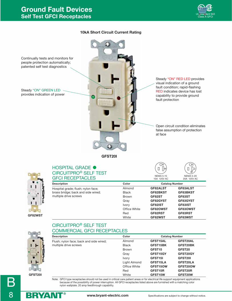
www.bryant-electric.com Specifications are subject to change without notice.
B8
GF82WST
Continually tests and monitors for people protection automatically; patented self test diagnostics
Steady “ON” RED LED provides visual indication of a ground fault condition; rapid-flashing RED indicates device has lost capability to provide ground fault protection
Steady “ON” GREEN LED provides indication of power
Ground Fault Devices Self Test GFCI Receptacles
HOSPITAL GRADE •CIRCUITPRO® SELF TESTGFCI RECEPTACLESDescription Color Catalog Number
Hospital grade; flush; nylon face; brass bridge; back and side wired; multiple drive screws
Almond GF82ALST GF83ALSTBlack GF82BKST GF83BKSTBrown GF82ST GF83STGray GF82GYST GF83GYSTIvory GF82IST GF83ISTOffice White GF82OWST GF83OWSTRed GF82RST GF83RSTWhite GF82WST GF83WST
GFST20I
CIRCUITPRO® SELF TEST COMMERCIAL GFCI RECEPTACLESDescription Color Catalog Number
Flush; nylon face; back and side wired; multiple drive screws
Almond GFST15AL GFST20ALBlack GFST15BK GFST20BKBrown GFST15 GFST20Gray GFST15GY GFST20GYIvory GFST15I GFST20ILight Almond GFST15LA GFST20LAOffice White GFST15OW GFST20OWRed GFST15R GFST20RWhite GFST15W GFST20W
Note: GFCI type receptacles should not be used in critical care patient areas or for electrical life support equipment applications because of the possibility of power interruption. All GFCI receptacles listed above are furnished with a matching color nylon wallplate. 20 amp feedthrough capability.
NEMA 5-1515A 125V AC
NEMA 5-2020A 125V AC
UL Standard 943Class A GFCI
Open circuit condition eliminates false assumption of protection at face
10kA Short Circuit Current Rating
GFST20I

www.bryant-electric.comSpecifications are subject to change without notice.
B9
GFSTBF20I
Ground Fault Devices Self Test GFCI Receptacles
1.75(44.5)
1.06(26.8)
1.43(36.3)
2.76(70.0)
3.28(83.3)
WHITE
WHITE
HOT
HOT
LINE
LOAD
WARRANTY VOIDIF UNIT OPENED
STRIP GAUGE
REPLAC
E GFC
I
IF RED LIG
HT FLA
SHES
SEE
IN
STRU
CTI
ON
S
T
EST
MO
NTH
LY GFC
I 20 AM
P. 125V 60 H
Z
15 A
. REC
EPTA
CLE
CLA
SS A
GFST20IBULK
CIRCUITPRO® SELF TEST COMMERCIAL GFCI RECEPTACLESDescription Color Catalog Number
Bulk packed; 50 pieces Almond GFST15ALBULK GFST20ALBULKBlack GFST15BKBULK GFST20BKBULKBrown GFST15BULK GFST20BULKGray GFST15GYBULK GFST20GYBULKIvory GFST15IBULK GFST20IBULKLight Almond GFST15LABULK GFST20LABULKOffice White GFST15OWBULK GFST20OWBULKRed GFST15RBULK GFST20RBULKWhite GFST15WBULK GFST20WBULK
NEMA 5-1515A 125V AC
NEMA 5-2020A 125V AC
ALL GFCI RECEPTACLE SPECIFICATIONSTrip level 4 to 6 mATrip time .025 sec. nominalFrequency 60 HzVoltage 120V AC +10% - 15%Amperage 15A/20A; 20A feed thruMaximum interrupting capacity 10,000 AmpsOperating temperature -35°C to +66°C or -30°F to +150°FMaximum humidity 95%Listings and standards Meets UL498 for receptacles; UL943 Class A for GFCIs UL Listed; CSA CertifiedCodes Meets all NEC® and CEC requirements
CIRCUITPRO® SELF TEST, FACELESS COMMERCIAL GFCIDescription Color Catalog Number
Faceless; nylon top; back and side wired; multiple drive screws
Almond GFSTBF20ALBlack GFSTBF20BKBrown GFSTBF20Gray GFSTBF20GYIvory GFSTBF20ILight Almond GFSTBF20LAOffice White GFSTBF20OWRed GFSTBF20RWhite GFSTBF20W
Note: GFCI type receptacles should not be used in critical care patient areas or for electrical life support equipment applications because of the possibility of power interruption. All GFCI receptacles listed above are furnished with a matching color nylon wallplate. 20 amp feedthrough capability.
NEC® is a registered trademark of the National Fire Protection Association (NFPA).
PRODUCT DIMENSIONS Inches (mm)
UL Standard 943Class A GFCI

B10 www.bryant-electric.com Specifications are subject to change without notice.
The sensing module functions interdependently with a magnetic branch circuit breaker. The module monitors the electrical circuit by use of an external differential current transformer. No direct load is present at the module. In the event of a ground fault, the load is interrupted by way of the hydraulic magnetic circuit breaker utilizing a shunt trip coil.
This line of Sensing Modules is rated from 1 to 50 Amps and circuit current-carrying conductors from 1 to 3 poles.
Product is available with an automatic or manual “safe start” reset feature. The enclosure, when mounted with the supplied gasket, achieves a NEMA 4X Rating. This module and breaker system is ideal for portable generator integration protecting all outlets on a generator. This system meets the proposed requirements for generators Underwriters Laboratory Subject 2201. UL/cUL 943 Listed, Class A 4-6mA trip level and UL 1053 Compliant.
Typical Applications Include: Power Generators, Spas, High Pressure Washers, Power Centers, Refineries and Agricultural Equipment.
GFCI SENSING MODULES – 50A MAXIMUM Description Catalog Number
120V AC Sensing Module Auto GFMD120A
120V AC Sensing Module Manual GFMD120M
240V AC Sensing Module Auto GFMD240A
240V AC Sensing Module Manual GFMD240M
WIRING SCHEMATICS
GFCI SENSING MODULE CIRCUIT BREAKERS
Catalog Number Configurator
Example Catalog Number: GFMDCB120401P
GFMDCB* 120 40 1P
GROUND FAULT
MODULE
CIRCUIT BREAKER
120V AC
240V AC
120/240V AC
1 thru 50 Amp
1P
2P
3P
Other Examples: GFMDCB240502P: 240V 50A 2P GFMDCB240203P: 240V 20A 3P*GFMDCB = Ground Fault MoDule Circuit Breaker
GFMD120M
GFMDCB120401P
SPLIT PHASE 120/240VAC (L1, L2, N, GRND)
YELLOW (SHUNT)BLACKWHITE
L1L2
LOAD
LINE
N
GROUND
120VAC GFCISENSINGMODULE
CIRCUITBREAKER
NOC
Current carrying leads mustbe twisted as they go through the sensing module.
G
LOAD--->
120/240 VAC IN
GFMDCB120XX2P
L1
N
L2
CIRCUITBREAKER
GROUNDSINGLE PHASE 120VAC (HOT, NEUTRAL, GRND)
YELLOW (SHUNT)BLACKWHITE
NH
LOAD
LINE
NOC
ORANGE SHUNTJUMPER
ORANGE SHUNTJUMPER
ORANGE SHUNTJUMPER
Current carrying leads mustbe twisted as they go through the sensing module.
G
N
GFMDCB120XX1P
LOAD--->
H
120 VAC IN
LINE
LOAD
L1L2
REDBLACKYELLOW (SHUNT)
SINGLE PHASE 240VAC (L1, L2, GRND)GROUND
240VAC GFCISENSINGMODULE
120VAC GFCISENSINGMODULE
CIRCUITBREAKER
NOC
Current carrying leads mustbe twisted as they go through the sensing module.
G
240 VACIN
L2
L1
GFMDCB240XX2P
LOAD--->
Ground Fault Devices GFCI Sensing Modules and Circuit Breakers

www.bryant-electric.comSpecifications are subject to change without notice.
B11
GFCI115
Ground Fault Devices Manual Set GFCI Line Cords
SJTW-A cord #14/3
Sealed molded plug
Bright fault light indicator
High-impact PVC watertight housing
Easy-to-operate sealed key pad
IP20SUITABILITY
T1254GF6
NEC® is a registered trademark of the National Fire Protection Association (NFPA).
9.00 (228.6)
2.56(65.0)
5.19 (131.8)
“A” (See Catalog Number)
NEMA 15-5P15A 125V
NEMA 15-5R15A 125V#14-3 SJTW-A
1.58 (40.1)
MANUAL SET PORTABLE GFCI LINE CORDS 15A 120V ACDescription Catalog Number
18" (45.7 cm) GFCI line cord GFCI1156' (182.9 cm) GFCI line cord GFCI61525' (762.0 cm) GFCI line cord GFCI2515
QUADPLEX® GROUND FAULT CORD SETS 15A 120V ACDescription Catalog Number
6' (182.9 cm) 12/3 SJO cord; pilot light; yellow; thermoplastic T1254GF6
SPECIFICATIONSPortable GFCI Line Cords
Trip level 4 to 6 mATrip time .025 sec. nominalFrequency 60 HzVoltage 120V AC +10% - 15%; incorporates no voltage release featureCurrent 15 AmpsMaximum interrupting capacity 2,000 AmpsOperating temperature -35°C to +66°C or -30°F to +150°FMaximum humidity 95%Housing High-impact; UV stabilized PVC; UL 94V-0 flammability classification Meets UL and CSA watertight requirements; adhesive bondedInput NEMA 5-15PPower “ON” indication LED indicator lightCord type #14 AWG SJTW-A (UL); SJTW (CSA)Visual fault indication light on Indicates faultListing and standards Meets UL943 Class A; UL Listed; CSA CertifiedCodes Meets all NEC® and CEC requirements
Portable GFCI Line Cords provide ground fault protection both indoors and out. They interrupt electrical power to protect personnel when leakage to ground is 4-6 milliamperes. Available in lengths of 18" (45.7 cm), 6' (182.9 cm), and 25' (762 cm). A 15' (457.2 cm) OEM version with stripped leads is also available. They are offered with Manual Set feature to meet your application.
PRODUCT DIMENSIONS Inches (mm)

B12 www.bryant-electric.com Specifications are subject to change without notice.
4.25 (108.0)
5.16 (131.0)
1.36 (34.5)
.843 (21.4)
.125 (3.18)
P.N.# and date code label section
Reset buttongreen color
Test buttonblue color
Warning label engraved
“LED” indicator
1.72 (43.7)
1.90 (48.3)
GFCI15125TRIM
GFCI15125A
GFC2TRIA
GFC2A
PORTABLE GFCI – SINGLE AND TRIPLE TAP 15A 120V ACDescription Catalog Number
2' (60.9 cm) GFCI line cord; single; automatic set GFC2A2' (60.9 cm) GFCI line cord; single; manual set GFC2M25' (762.0 cm) GFCI line cord; single; manual set GFC25M2' (60.9 cm) GFCI line cord; triple tap; automatic set GFC2TRIA2' (60.9 cm) GFCI line cord; triple tap; manual set GFC2TRIM
GFCI IN LINE GFCI – SINGLE AND TRIPLE TAP 15A 120V ACDescription Catalog Number
2' (60.9 cm); 5-15 single tap; automatic set GFCI15125A2' (60.9 cm); 5-15 single tap; manual set GFCI15125M2' (60.9 cm); 5-15 triple tap; automatic set GFCI15125TRIA2' (60.9 cm); 5-15 triple tap; manual set GFCI15125TRIM
OEM EQUIPMENT INTEGRATED CORD SETS 15A 120V ACDescription Catalog Number
15' (457.2 cm) GFCI with flying leads; automatic set GFCL15AGFCI black plug; field wireable; automatic set GFP15AGFCI black plug; field wireable; manual set GFP15MA
SPECIFICATIONSPortable GFCI Line Cords
Trip Level 4 to 6 mATrip Time .025 sec. nominalFrequency 60 HzVoltage 120V AC +10% - 15%; incorporates no voltage release featureCurrent 15 AmpsMaximum Interrupting Capacity 2,000 AmpsOperating Temperature -35°C to +66°C or -30°F to +150°FMaximum Humidity 95%Housing High-impact; UV stabilized PVC; UL 94V-0 flammability classification; Meets UL and CSA watertight requirements; adhesive bondedCord Type #14 AWG SJTW-A (UL); SJTWVisual Fault Indication Light On LED indicates faultListing and Standards Meets UL943 Class A; UL ListedCodes Meets all NEC® and CEC requirements
NEC® is a registered trademark of the National Fire Protection Association (NFPA).
Ground Fault Devices Portable GFCI Products
GFCL15A
GFP15A
PRODUCT DIMENSIONS Inches (mm)
GFP15 Series

www.bryant-electric.comSpecifications are subject to change without notice.
B13
Ground Fault Devices Bryant® Plug-In Portable GFCI
FAULTLIGHT RESET TEST
5.50(139.7)
3.45(87.6)
5.83(148.0)
1.50(38.1)
.82(20.8)
1.76(44.7)
Center screw mounting available High impact ABS housing
UV stabilized 94VO
One piece sealed key pad test and reset buttons
Three NEMA 5-15R portable plug-in GFCI
Ultrasonically welded housing
Large neon indicating light for ground fault indication
GFP153R
NEC® is a registered trademark of the National Fire Protection Association (NFPA).
PRODUCT DIMENSIONS Inches (mm)
BRYANT® PLUG-IN PORTABLE GFCIDescription Rating Catalog Number
Three outlet plug-in 15A, 120V AC GFP153R
SPECIFICATIONSGFP153R
Trip level 4 to 6 mATrip time .025 sec. nominalFrequency 60 HzVoltage 120V AC +10% - 15%; incorporates no voltage release featureCurrent 15 AmpsMaximum interrupting capacity 2,000 AmpsOperating temperature -35°C to +66°C or -30°F to +150°FMaximum humidity 95%Housing High-impact ABSInput NEMA 5-15POutput Three NEMA 5-15RFault indication Indicator lightCenter screw For optional permanent mountingListings and standards Meets UL498 for receptacles; UL943 Class A for GFCIs UL Listed; CSA CertifiedCodes Meets all NEC® and CEC requirements

www.bryant-electric.com Specifications are subject to change without notice.
B14
Individual GFCI module for each receptacle
Over current protection for each circuit
Nested leg designallows boxes to beeasily stacked
Weatherproofreceptacle lift covers
Features 50A locking input and output
Available with six 20A straight blade or locking receptacles
Temporary Power Distribution Boxes• Designed to address temporary power needs on construction sites and outdoor events• Boxes are UL Type 3R for outdoor rainproof applications• Weatherproof boots available for connecting plugs for additional protection from elements
Certifications• Bryant’s Temporary Power Distribution Boxes meet NEC® 305.6 requirements for personal protection• Listed to the latest UL 1640 standard for Portable Power Distribution Equipment
Applications
Ground Fault Devices Temporary Power Distribution Boxes Product Features
Universities/Schools• Graduation Ceremonies• Concerts/Lectures• Sporting Events
Construction Sites• Renovations• New Construction• Demolition
Stage/Theater• Movie/Broadcasting• Concerts• Plays/Musicals
Outdoor Entertainment• Carnivals• Festivals• Professional Sports
TPDLB
NEC® is a registered trademark of the National Fire Protection Association (NFPA).

www.bryant-electric.comSpecifications are subject to change without notice.
B15
TEMPORARY POWER DISTRIBUTION BOXES
Rating Type QtyReceptacleRatings
ProtectionOverload
GFCIProtected Catalog Number
50A, 120/240V AC (Max.)
Straight BladeLockingLocking (inlet)Locking (outlet)
6111
20A, 125V30A, 250V50A, 125/250V50A, 125/250V
YesYesNoNo
YesNoNoNo
TPDSB
50A, 120/240V AC (Max.)
LockingLockingLocking (inlet)Locking (outlet)
6111
20A, 125V30A, 250V50A, 125/250V50A, 125/250V
YesYesNoNo
YesNoNoNo
TPDLB
CABLE SETSDescription Catalog Number
50A cord set; 50 foot cable; 6/3, 8/1 cable type; with 50A locking plug and connector TPC50B*
50A cord set; 100 foot cable; 6/3, 8/1 cable type; with 50A locking plug and connector TPC100B*
Note: *Not UL Listed or CSA Certified.
REPLACEMENT PARTSDescription Catalog Number
20A, 125V straight blade receptacle CRS20
30A, 250V locking receptacle 70530FR
50A, 125/250V locking receptacle CS6369L
50A, 125/250V locking plug CS6365L
50A, 125/250V locking connector CS6364L
50A, 125/250V locking inlet CS6375L
Weather protective plate for 20A receptacle RW51470
Weather protective plate for 30A receptacle 7420B
Weather protective plate for 50A receptacle 7774CR
Weather protective plate for 50A inlet 7780
SPECIFICATIONSBoxes Cables
Listings/CertificationsEnvironment
Enclosure type
Code compliance
UL 1640, UL 943Indoor and outdoor wet and dry locations3R, rainproof, suitable for use in damp locationsNEC®, ANSI/NFPA 70
Listings/Certifications
Environment
Connectors: UL/CSA; Cable: MSHAIndoor and outdoor wet and dry locations
PRODUCT DIMENSIONS Inches (mm)
Ground Fault Devices Temporary Power Distribution Boxes
14.50(368.3)
21.50(546.1)
Inlet Outlet
10.23(259.8)
12.52(317.9)
MONITOR
RESET
POWER
TEST
MONITOR
RESET
POWER
TEST
TPDLB
TPC50B
7774CR
7780
CS6365L
CS6375L
NEC® is a registered trademark of the National Fire Protection Association (NFPA).

B16 www.bryant-electric.com Specifications are subject to change without notice.
Ground Fault Receptacles Technical Specifications
COMPONENTS
Cover and baseLine contactsMounting yokeTerminal screwsBack wire clampGrounding screwTest/reset buttonsMounting screws
MATERIALS
ThermoplasticBrassHospital grade - brass#8-32SteelSteel (green) #8-32ThermoplasticPlated steel
GFCI DUPLEX RECEPTACLES
PERFORMANCE
ElectricalTrip level 4 – 6 mATrip time .025 secFrequency 60HzVoltage 120V AC +10% - 15%Amperage 15A/20A; 20A feed thruMaximum interrupting capacity 10,000 AmpsTerminal accommodations #14-10 AWG stranded or solid copper conductors only
EnvironmentalOperating temperature -35° C to +66° C (-30° F to +150° F)Maximum humidity 95%
DESCRIPTION
Typical Specification – Catalog No. GF82ILA, GF82ISTManufacturer’s Identification – GF82ILA, GF82ISTDescription – Straight blade ground fault receptacleType – 2-pole, 3-wire; groundingRating – 15A, 125V; NEMA 5-15
CERTIFICATION
• Meets UL 943 Class A GFCIs and UL 498 for receptacles
• Complies to NEC® and CEC requirements; UL Listed; CSA Certified
GF82WST
GF82OWLA
WHITE
WHITE
HOT
HOT
LINE
LOAD
WARRANTY VOIDIF UNIT OPENED
STRIP GAUGE
REPLAC
E
IF LIGH
T
GFC
I
FLASH
ES
WRTR
WR TR
1.75(44.5)
1.06(26.8)
1.43(36.3)
2.76(70.0)
3.28(83.3)
PRODUCT DIMENSIONS Inches (mm)
NEC® is a registered trademark of the National Fire Protection Association (NFPA).

C1www.bryant-electric.com
Section CSurge and Isolated Ground Devices
INDEX PAGE
Surge Suppression ReceptaclesProduct Features . . . . . . . . . . . . . . . . . . . . . . . . . . . . . . . . . . . . . . . . . . . . . . . . . . . . . . . . . . . . . . . . . . . . . . . .C-2Hospital and Specification Grade Receptacles . . . . . . . . . . . . . . . . . . . . . . . . . . . . . . . . . . . . . . . . . . . . . . . .C-3
QUADPLEX® Surge Suppression Receptacles Product Features . . . . . . . . . . . . . . . . . . . . . . . . . . . . . . . . . . . . . . . . . . . . . . . . . . . . . . . . . . . . . . . . . . . . . . . .C-4Hospital Grade and Surge Suppression Receptacles . . . . . . . . . . . . . . . . . . . . . . . . . . . . . . . . . . . . . . . . . . .C-5
Portable Surge DevicesProduct Features and Ordering Data . . . . . . . . . . . . . . . . . . . . . . . . . . . . . . . . . . . . . . . . . . . . . . . . . . . . . . . .C-6
Isolated Ground Straight Blade ReceptaclesProduct Features . . . . . . . . . . . . . . . . . . . . . . . . . . . . . . . . . . . . . . . . . . . . . . . . . . . . . . . . . . . . . . . . . . . . . . . .C-7Hospital Grade and 15 and 20 Amp; Back and Side Wired . . . . . . . . . . . . . . . . . . . . . . . . . . . . . . . . . . . . . . .C-8QUADPLEX® Receptacles . . . . . . . . . . . . . . . . . . . . . . . . . . . . . . . . . . . . . . . . . . . . . . . . . . . . . . . . . . . . . . . . .C-930 and 50 Amp; Back Wired . . . . . . . . . . . . . . . . . . . . . . . . . . . . . . . . . . . . . . . . . . . . . . . . . . . . . . . . . . . . . .C-10
Isolated Ground Locking Receptacles15, 20 and 30A; Back or Side Wired . . . . . . . . . . . . . . . . . . . . . . . . . . . . . . . . . . . . . . . . . . . . . . . . . . . . . . .C-11
Isolated Ground Surge Suppression ReceptaclesTechnical Specifications . . . . . . . . . . . . . . . . . . . . . . . . . . . . . . . . . . . . . . . . . . . . . . . . . . . . . . . . . . . . . . . . .C-12

C2 www.bryant-electric.com Specifications are subject to change without notice.
Plug Into Protection
Eliminate costly equipment damage and subsequent downtime from transient voltage fluctuations with Bryant’s CIRCUIT WATCH isolated ground duplex surge suppression receptacles. These devices stop virtually all voltage transients from internal and external sources. All CIRCUIT WATCH devices are UL Listed and CSA Certified.
Specifications
Bryant surge receptacles conform to the following specifications.• Transient suppression capacity peak energy will be
240 joules for a 10 x 1000 microsecond pulse• Common and normal mode protection; normal mode
(L-N), common mode (L-G) (N-G)• Response time less than 5 nano-seconds• MCOV rating: 150 volts maximum continuous
operating voltage rating• Receptacle rating are 15 or 20 amps, 125 volts• Base and cover are constructed of high-impact
thermoplastic
• Available with and without isolated ground feature • Receptacles meet the following standards: IEEE 587,
Category A and B; UL 1449, UL 498, CSA C22.2, No. 42
Available Types
• 2-pole 3-wire; 15 and 20 amp• Receptacles available in brown, blue, ivory, white,
and gray• Hospital grade/industrial grade• 240 joule Isolated Ground terminal receptacles
Isolated Ground Surge Receptacle
Combines isolated ground feature with 240 joule surge suppression protection in one easy-to-wire duplex receptacle. Large #8 brass binding head terminal accepts up to #10 solid or stranded wire.
Surge and Isolated Ground DevicesSurge Supression Receptacle Features
Damage-alert alarm sounds when surge protection is no longer functioning; muting screw allows damage-alert alarm to be silenced until device is replaced
Power-on indicator light verifies that suppression circuit is fully functional; light off means power has been interrupted; flashing light indicates surge protection circuitry has been damaged
Distinctive surge symbol provides quick visual identification of surge suppression receptacle
High-impact nylon face resists breakage
Fits standard wall box
Automatic grounding clip attached to bridge meets NEC® requirements
SP83A
NEC® is a registered trademark of the National Fire Protection Association (NFPA).

C3www.bryant-electric.comSpecifications are subject to change without notice.
HOSPITAL GRADE • DUPLEX RECEPTACLESDescription Color Catalog Number
Surge suppression receptacles with light and alarm; 240 joules/15,000 amps per mode
BlueGrayIvoryWhite
SP82ASP82GYASP82IASP82WA
SP83ASP83GYASP83IASP83WA
Isolated ground; surge suppression receptacles with light and alarm; 240 joules/15,000 amps per mode
BlueGrayIvoryOrangeRed White
SP82IGASP82IGGYASP82IGIASP82IGOASP82IGRASP82IGWA
SP83IGASP83IGGYASP83IGIASP83IGOASP83IGRA SP83IGWA
SPECIFICATION GRADE DUPLEX RECEPTACLESDescription Color Catalog Number
Surge suppression receptacles with light and alarm; 240 joules/15,000 amps per mode
AlmondBlueGrayIvoryWhite
SP52ALASP52ASP52GYASP52IASP52WA
SP53ALASP53ASP53GYASP53IASP53WA
Isolated ground; surge suppression receptacles with light and alarm; 240 joules/15,000 amps per mode
Almond BlueGrayIvoryOrangeWhite
SP52IGALASP52IGASP52IGGYASP52IGIASP52IGOASP52IGWA
SP53IGALASP53IGASP53IGGYASP53IGIASP53IGOASP53IGWA
SP52IGA
Surge Duplex Receptacle Series
SP83IA
Surge and Isolated Ground DevicesHospital and Specification Grade Surge Supression Receptacles
PRODUCT DIMENSIONS Inches (mm)
20A 125V AC
N
ALARM OFF
H
PROTECTIVE
T
D
E
P
SURGECOT E
DEVICEE
E
G
DT
R
HLI
W
GROUNDW
HITE
BACK
WIR
E ST
RIP
GAGE
BLAC
KUS
E CU
WIR
E O
NLY
1.72(43.7)
4.04(102.6)
2.80(71.1)
1.24(31.5)
.31(7.9)
1.60(40.6)
NEMA 5-1515A 125V
NEMA 5-1515A 125V
NEMA 5-2020A 125V
NEMA 5-2020A 125V

C4 www.bryant-electric.com Specifications are subject to change without notice.
Surge and Isolated Ground DevicesQUADPLEX® Surge Suppression Receptacle Features
+ =
• Receptacles meet or exceed all UL tests for hospital grade • and are listed to UL Standards 498
• Mounts directly to 4 inch square or octagon boxes; no cover plate required; meets NEC®
• Adapter plate required for mounting on 1- and 2-gang device boxes; 4 inch square boxes and 411/16 inch square boxes with mud rings
• Break off tabs for split circuit wiring (except surge units)
• Saves wiring and installation time
Lexan® is a registered trademark of Sabic Innovative Plastics.
NEC® is a registered trademark of the National Fire Protection Association (NFPA).
1254HI
“A” and “B” circuits molded into face for easy identification
Easily removable knockouts for mounting to octagon concrete ring or box
Heavy-duty; triple-wipe; high performance brass line contacts for excellent retention and conductivity
Rugged Lexan® construction
Large #8 combination Slot/Robertson head terminal screws accept up to #12 solid or stranded wire
Accepts up to four straight or angle plugs Snub hole for fast,
easy terminations
Break-off tabs for split circuit wiring (except surge units)
Strip gauge
All four outlets internally connected

C5www.bryant-electric.comSpecifications are subject to change without notice.
HOSPITAL GRADE • QUADPLEX® RECEPTACLESDescription Color Catalog Number
Hospital grade; surge suppression; Lexan® BlueIvory
1254HSA1254HSIA
21254HSA21254HSIA
SURGE SUPPRESSION QUADPLEX® RECEPTACLESDescription Color Catalog Number
Surge suppression; Lexan®; with terminal screws
BlueIvory
1254SA1254SIA
21254SA21254SIA
Wire leads; isolated ground; Lexan® BlueIvory
— —
21254SLA21254SILA
Note: See page A-9 for additional information on Quadplex® receptacles.
Surge and Isolated Ground DevicesQUADPLEX® Surge Supression Receptacles
ADAPTER PLATES PORTABLE BOXES Inches (mm)
Description Color Catalog Number Description Color Catalog Number
For 1- and 2-gang device boxes
Blue Ivory
ADAPBLUADAPI
4 in. (101.6) square with two cord grips
Blue Ivory
4SQBXBLU*4SQBXI*
Note: *Portable boxes not UL Listed or CSA Certified. For indoor use only.
PRODUCT DIMENSIONS Inches (mm)
.84 (21.3)
.75(19.1)
Two Each.66 (16.7)
Dia.Cord Hole
3.38 Sq.(85.9)
4.05 Sq.(102.9)
4.30 Sq.(109.2)
3.28(83.3)
2Punchouts
.38 (9.5)
.19 (4.8)
2.75(6.9).31
(7.9)
3.28(83.3)
2.75 (69.9)*
4.25(108.0)*
3.38 (85.9)
3.38(85.9)
1.75(44.5)
4.78 Sq. (121.4)
1.75(44.5)
.92(23.4)
.10 (2.6)4.30 Sq.(109.2)
3.02 (76.7)
3.38 (85.9)
HOSPITAL
GRADE
Lexan® is a registered trademark of Sabic Innovative Plastics.
21254SA
ADAPI
1254HSIA
Receptacle Adapter Plate Portable Box 1254HB ADAPB 4SQBXB
Note: *Mounting dimensions for 4 " adapter plate.
NEMA 5-1515A 125V
0.5 HP
NEMA 5-1515A 125V
0.5 HP
NEMA 5-2020A 125V
1.0 HP
NEMA 5-2020A 125V
1.0 HP

C6 www.bryant-electric.com Specifications are subject to change without notice.
PORTABLE SURGE STRIPS NEMA 5-15 15 AMP 125V Feet (m)
Description ColorCircuit Breaker
RatingJoule
Rating Catalog Number
6 outlets; 6 ft. (1.83) cord; competitive protection
Ivory 15A 140 ST16
6 outlets; 15 ft. (4.57) cord; competitive protection
Ivory 15A 140 ST115
Portable Surge Strips
• #14/3 SJT ivory cord 6 foot (1.83 m) and 15 foot (4.57 m) available
• Tech-Spec® ivory nylon plug• Plug-in unit has phone line protection
All Units
• Surge protection “ON” indicator light• 140 joule rated• Quality EMI/RFI filtering
• Press-to-reset circuit breaker• Lightweight and durable aluminum construction • Impact-resistant plastic end caps• Nylon, spiral strain relief
ST16
ST16
See Catalog Number
Strain ReliefCircuitBreakerReset Button
Power ON-OFF Indicator Light
2.08(52.8)
1.96(49.8)
13.00 (330.2)
Bryant Industrial Grade receptacles
Impact-resistant plastic end caps
High-quality noise filtering
Aluminum construction; lightweight and durable
“Press-to-reset” circuit breaker Indicator light — when
lit, surge suppression is working
Combination master switch/ pilot light
Ivory cord; #14/3 SJT; available in 6 and 15 foot lengths
Nylon, spiral strain relief
Bryant Tech-Spec® ivory nylon plug
Surge and Isolated Ground DevicesPortable Surge Protective Devices
PRODUCT DIMENSIONS Inches (mm)
NEMA 5-1515A 125V

C7www.bryant-electric.comSpecifications are subject to change without notice.
Characteristics of Isolated Ground Wiring Devices
Isolated ground devices help limit electrical noise on the equipment grounding circuit by providing two grounding paths for the installation. The device grounding circuit terminal and grounding contacts are isolated from the grounding path of the metal outlet box, device mounting means, and metal cover or wall plate, thus establishing a separate, dedicated equipment grounding path for connecting noise-sensitive equipment.
Isolated Ground ReceptacleIsolated ground receptacles are not grounded to building ground at the receptacle location. Grounding of this device requires that an isolated ground path be established from the receptacle grounding terminal to a suitable equipment grounding point “upstream” from the device.
Insulating barrier (a) prevents isolated grounding circuit (b) from making contact with the outlet box (c) which otherwise would ground the receptacle through the building ground.
Conventional ReceptacleConventional receptacles are grounded to building ground at the receptacle outlet. When mounted in the box, a single grounding path is established through the grounded metal outlet box and the building ground system.
Building Ground
Isolated Ground (b)
Conduit
InsulatingBarrier (a)
Green Hex HeadGrounding Screwand Circuit
Mounting Strap GroundedMetal OutletBox (c)
BondingJumper
Ground path indicated in green
Building Ground
Conduit
Green Hex HeadGrounding Screwand Circuit
Mounting Strap GroundedMetal OutletBox
Principles of Operation
Bushing
Nylon deep face design
One-piece;triple-wipe brass line contacts
Nylon base Insulation barrier
Nickel and brass plated wraparound steel yoke
Ground contacts and ground termination
Surge and Isolated Ground DevicesIsolated Ground Receptacle Features

C8 www.bryant-electric.com Specifications are subject to change without notice.
HOSPITAL GRADE • 15 AND 20 AMP, 120V RECEPTACLESDescription Color Catalog Number
Duplex; nylon; back and side wired Orange BRY8200IG BRY8300IG
Single; nylon; back and side wired Orange 8210IG 8310IG
Fashion Series™; duplex; nylon; back and side wired
GrayIvory OrangeRedWhite
9200IGGRY9200IGI9200IG9200IGRED9200IGW
9300IGGRY9300IGI9300IG9300IGRED9300IGW
EXTRA HEAVY DUTY, INDUSTRIAL 15 AND 20 AMP, 125V RECEPTACLESDescription Color Catalog Number
Duplex; nylon; back and side wired GrayIvory OrangeWhite
BRY5262IGGRY BRY5262IGIBRY5262IGBRY5262IGW
BRY5362IGGRYBRY5362IGIBRY5362IGBRY5362IGW
Single; nylon; back and side wired GrayIvory OrangeWhite
5261IGGRY5261IGI5261IG5261IGW
5361IGGRY5361IGI5361IG5361IGW
EXTRA HEAVY DUTY, INDUSTRIAL 15 AND 20 AMP, 250V RECEPTACLESDescription Color Catalog Number
Duplex; nylon; back and side wired Orange BRY5662IG BRY5462IG
Single; nylon; back and side wired Orange — 8410IG
BRY5262IG
5261IG
9200IG
BRY8200IG
BRY5262IG BRY5261IG 9300IG
1.38 (35.1)
3.28(83.3)
4.06(103.1)
.92(23.4)
2.68(68.1)
2.38(60.5)
3.28(83.3)
4.06(103.1)
1.38 (35.1).91
(23.1)
1.78(45.2)
1.38 (35.1)
1.29(32.8)
3.28(83.3)
3.81(96.8)
1.17 (29.7)
.93(23.6)
2.69(68.3)
2.61(66.3)
Surge and Isolated Ground DevicesIsolated Ground Straight Blade Receptacles
PRODUCT DIMENSIONS Inches (mm)
NEMA 5-1515A 125V
NEMA 5-1515A 125V
NEMA 5-2020A 125V
NEMA 5-2020A 125V
NEMA 6-2020A 250V
NEMA 6-1515A 250V
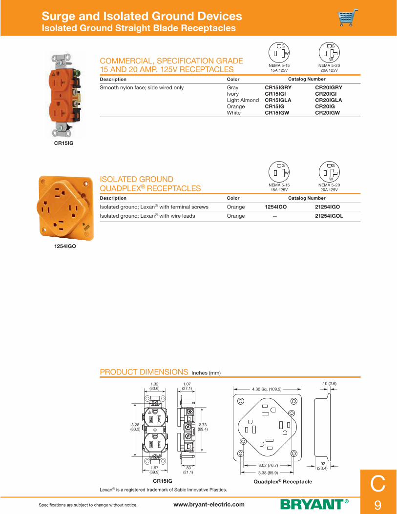
C9www.bryant-electric.comSpecifications are subject to change without notice.
CR15IG
1254IGO
Surge and Isolated Ground DevicesIsolated Ground Straight Blade Receptacles
COMMERCIAL, SPECIFICATION GRADE 15 AND 20 AMP, 125V RECEPTACLESDescription Color Catalog Number
Smooth nylon face; side wired only GrayIvoryLight Almond OrangeWhite
CR15IGRY CR15IGICR15IGLACR15IGCR15IGW
CR20IGRY CR20IGICR20IGLACR20IGCR20IGW
ISOLATED GROUND QUADPLEX® RECEPTACLESDescription Color Catalog Number
Isolated ground; Lexan® with terminal screws Orange 1254IGO 21254IGO
Isolated ground; Lexan® with wire leads Orange — 21254IGOL
PRODUCT DIMENSIONS Inches (mm)
Quadplex® Receptacle
4.30 Sq. (109.2)
3.02 (76.7)
3.38 (85.9)
.92(23.4)
.10 (2.6)
CR15IG
.83(21.1)
1.07(27.1)
1.32(33.6)
3.28(83.3)
2.73(69.4)
1.57(39.9)
Lexan® is a registered trademark of Sabic Innovative Plastics.
NEMA 5-1515A 125V
NEMA 5-1515A 125V
NEMA 5-2020A 125V
NEMA 5-2020A 125V

C10 www.bryant-electric.com Specifications are subject to change without notice.
9530IG
9550IG
NPJ8CO
NP8OIG
9530IG, 9630IG, 9550IG & 9650IG
2.35 (59.9)
2.12(54.0)
1.79 (45.6)
1.81 (46.0)
2.37(60.3)
3.28(83.3)
2.50(63.3)
6 x 32 TAP
3.68(93.5)
2.25 (57.2)
30 AMP STRAIGHT BLADE DEVICESDescription Color Catalog Number
Single; flush; RTP* nylon face; 2-pole, 3-wire; back wired
Orange 9530IG 9630IG
50 AMP STRAIGHT BLADE DEVICESDescription Color Catalog Number
Single; flush; RTP* nylon face; 2-pole, 3-wire; back wired
Orange 9550IG 9650IG
“ISOLATED GROUND” WALLPLATES**Description Opening Color Catalog Number
Nylon; standard size; 1-gang; hot stamped; recessed black lettering
DuplexSingle receptacleLocking 1.60 (40.6) IDFashion type
OrangeOrangeOrangeOrange
NP8OIGNP7OIGNP720OIGNP26OIG
“COMPUTER ONLY” WALLPLATES**
Description Opening Color Catalog Number
Nylon; mid-size; 1-gang;hot stamped; recessed black lettering
DuplexDuplexFashion type
OrangeIvoryIvory
NPJ8CONPJ8CNPJ26C
Note: *Reinforced Thermoplastic Polyester. **See section O for more information on wallplates.
PRODUCT DIMENSIONS Inches (mm)
ISOLATEDGROUND
COMPUTERONLY
Surge and Isolated Ground DevicesIsolated Ground Straight Blade Receptacles
NEMA 5-30R30A 125V
NEMA 5-50R50A 125V
NEMA 6-30R30A 250V
NEMA 6-50R50A 250V

C11www.bryant-electric.comSpecifications are subject to change without notice.
15 AMP LOCKING RECEPTACLESDescription Color Catalog Number
Duplex; RTP* nylon face; 2-pole, 3-wire; back and side wired
Orange 4700DRIG 70615DRIG**
Single; nylon face; 2-pole, 3-wire; back and side wired
Orange 4710IG** 70615IG**
20 AMP LOCKING RECEPTACLESDescription Color Catalog Number
Single; nylon face; 2-pole, 3-wire; back and side wired
Orange 70520IG 70620IG
20 AMP LOCKING RECEPTACLESDescription Color Catalog Number
Single; nylon face; 3-pole, 4-wire; back and side wired
Orange 71420IG 71430IG
30 AMP LOCKING RECEPTACLESDescription Color Catalog Number
Single; nylon face; 2-pole, 3-wire; back and side wired
Orange 70530IG 70630IG
30 AMP LOCKING RECEPTACLESDescription Color Catalog Number
Single; nylon face; 4-pole, 5-wire; back and side wired
Orange 72120IG 72130IG
Note: *Reinforced Thermoplastic Polyester. **See page H-8 for dimensions on 4710 and 70615 series receptacles.
72130IG
4700DRIG
4700DRIG 70520IG 72130IG
70520IG
4710IG
3.28(83.3)
2.38(60.5)
6 x 32TAP
1.70 (43.2)
2.67(67.8)
1.56(39.6)Dia.
1.24 (31.5)
.26(6.6)
3.28(83.3)
2.74(69.5)
1.70(43.2)
1.17(29.67)
.934(23.72)
3.28(83.3)
2.38(60.5)
6 x 32TAP
1.70 (43.2)
2.67(67.8)
1.56(39.6)Dia.
1.30 (33.0)
.26(6.6)
PRODUCT DIMENSIONS Inches (mm)
Surge and Isolated Ground DevicesIsolated Ground Locking Receptacles
NEMA L5-15R15A 125V
NEMA L21-20R20A 120/208V 3ØY
NEMA L5-20R20A 125V
NEMA L6-15R15A 250V
NEMA L5-30R30A 125V
NEMA L6-30R30A 250V
NEMA L21-30R30A 120/208V 3ØY
NEMA L6-20R20A 250V
NEMA L14-20R20A 125/250V
NEMA L14-30R30A 125/250V

C12 www.bryant-electric.com Specifications are subject to change without notice.
SP52IG
DESCRIPTION
Manufacturer’s Identification — Bryant SP52IG SeriesDescription — Industrial grade isolated ground surge suppression duplex receptacleType — 2-pole, 3-wire; groundingRating — 15A, 125V
CERTIFICATION
• UL Listed• UL Standards 1449 surge protective devices
and 498 receptacles• Certified to CSA; C22.2, No. 42 • ANSI/IEEE C62.41 (IEEE 587) categories
“A” and “B”• NEMA WD-6• Meets UL and CSA varistor thermal protection
requirements
COMPONENTS MATERIALS
Cover NylonBase Nylon Line contacts High performance brass alloy Clamp nut .03 inch (.8) brass Mounting yoke .05 inch (1.3)Terminal screws Brass #8-32Grounding screw Brass (green) #8-32Ground contacts High performanceAuto grounding assembly Stainless steelFlat head mounting screws Zinc-plated steel
Surge and Isolated Ground DevicesIsolated Ground Surge Suppression Receptacles Technical Specifications
STRAIGHT BLADE DUPLEX RECEPTACLE
PERFORMANCE
ElectricalUL voltage protection level 500V Operating voltage 125V ACFrequency 60 HzProtection modes Normal mode (L-N); common mode (L-G) (N-G)Noise filtration RFI and EMI 100KHz; 4MHz-10DB to -20DBResponse time Less than 5 nanoseconds (ns)Peak energy 10X 1000μs 240 joulesPeak current 8X 20μs 15,000 Amps
MechanicalTerminal identification Terminals identified in accordance with UL 498 (brass, white, green)Terminal accommodation #14-10 AWG copper conductor only; solid or strandedProduct identification Ratings are a permanent part of the device
EnvironmentalFlammability Cover: UL 94 V2 Base: UL 94 V2Operating temperatures Maximum continuous 20°C to 55°C
PRODUCT DIMENSIONS Inches (mm)
SP52IG
20A 125V AC
N
ALARM OFF
H
PROTECTIVE
T
D
E
P
SURGECOT E
DEVICEE
E
G
DT
R
HLI
W
GROUNDW
HITE
BACK
WIR
E ST
RIP
GAGE
BLAC
KUS
E CU
WIR
E O
NLY
1.72(43.7)
4.04(102.6)
2.80(71.1)
1.24(31.5)
.31(7.9)
1.60(40.6)

D1www.bryant-electric.com
D1www.bryant-electric.com
Section DDecorator Products
INDEX PAGE
SwitchesCommercial Product Features . . . . . . . . . . . . . . . . . . . . . . . . . . . . . . . . . . . . . . . . . . . . . . . . . . . . . . . . . . . . .D-2 Commercial 15 and 20 Amp 120-277V AC Back and Side Wired . . . . . . . . . . . . . . . . . . . . . . . . . . . . . . . . . .D-3 Residential Product Features . . . . . . . . . . . . . . . . . . . . . . . . . . . . . . . . . . . . . . . . . . . . . . . . . . . . . . . . . . . . . .D-4 Residential Quiet Rocker Switches . . . . . . . . . . . . . . . . . . . . . . . . . . . . . . . . . . . . . . . . . . . . . . . . . . . . . . . . . .D-5 Combination Quiet Rocker Switches/Devices . . . . . . . . . . . . . . . . . . . . . . . . . . . . . . . . . . . . . . . . . . . . . . . . .D-6
ReceptaclesTamper-Resistant and Weather Resistant . . . . . . . . . . . . . . . . . . . . . . . . . . . . . . . . . . . . . . . . . . . . . . . . . . . .D-8Hospital Grade and Industrial Product Features . . . . . . . . . . . . . . . . . . . . . . . . . . . . . . . . . . . . . . . . . . . . . . .D-9 Hospital Grade Receptacles; 15 and 20 Amp 125V; 2-Pole 3-Wire . . . . . . . . . . . . . . . . . . . . . . . . . . . . . . . .D-10 Industrial and Specification Grade; 15 and 20 Amp 125V; 2-Pole 3-Wire . . . . . . . . . . . . . . . . . . . . . . . . . . .D-11 Commercial Grade Receptacles; 15 and 20 Amp 125V; 2-Pole 3-Wire . . . . . . . . . . . . . . . . . . . . . . . . . . . .D-12 Residential Grade Receptacles; 15 and 20 Amp, 125 and 250V; 2-Pole 3-Wire . . . . . . . . . . . . . . . . . . . . . .D-13 Surge Suppression and Isolated Ground Receptacles; 15 and 20 Amp 125V; 2-Pole 3-Wire . . . . . . . . . . .D-14 JLOAD™ Multimedia Outlet; 15 and 20 Amp 125V; 2-Pole 3-Wire . . . . . . . . . . . . . . . . . . . . . . . . . . . . . . . .D-15
Wallplates Decorator Snap-On Wallplates . . . . . . . . . . . . . . . . . . . . . . . . . . . . . . . . . . . . . . . . . . . . . . . . . . . . . . . . . . . .D-16 Decorator Nylon and Metal Wallplates . . . . . . . . . . . . . . . . . . . . . . . . . . . . . . . . . . . . . . . . . . . . . . . . . . . . . .D-17
Communication FramesDecorator Frames and HDMI Devices . . . . . . . . . . . . . . . . . . . . . . . . . . . . . . . . . . . . . . . . . . . . . . . . . . . . . .D-18
Technical Specifications Industrial Series and Commercial Series . . . . . . . . . . . . . . . . . . . . . . . . . . . . . . . . . . . . . . . . . . . . . . . . . . . .D-19 Residential Series . . . . . . . . . . . . . . . . . . . . . . . . . . . . . . . . . . . . . . . . . . . . . . . . . . . . . . . . . . . . . . . . . . . . . .D-20

www.bryant-electric.com Specifications are subject to change without notice.
D2
9901I
Decorator Products Commercial Product Features
The Face of QualityThe 9901 AC Rocker Switch shown is typical of Bryant’s full line of Fashion Series 9000 designer switches. They combine the quality, features, and durability — the face of quality you’ve come to expect from Bryant — in a high-fashion look. All switches meet Bryant’s rigid performance standards for hospital, industrial and commercial applications. Available Types• 15 and 20 amp, 120-277V AC ratings• Horsepower rated• Rocker handles in almond, ivory, white, gray, black
and brown• Single-pole, double-pole, 3-way and 4-way• Two grounding options: grounding screw terminal or
self-grounding clip• Pilot light and lighted handle switches for specialized
applications
Pilot Light SwitchesLong-lasting neon lamp in handle lights when switch is in the “On” position, indicating that the circuit is energized. Applications include control of circuits which are not easily accessible or are out of sight such as motors, fans, and remote lights.
Lighted Handle SwitchesLong-lasting neon lamp in handle glows when switch is in the “Off” position to help locate the switch in darkness. It also serves as a nightlight in rooms and hallways.
Color-Coded Base Indicates Ampere Rating
15 Amp Blue Base 20 Amp Red Base 9801 Series 9901 Series
Large; silver alloy contacts
Self-grounding clip
Color-coded base for quick identification of ampere rating
Back wiring; clamp-type terminals accept up to two #10 AWG wires
Terminal screws: brass combination Slot/Phillips
Heat-resistant base provides superior resistance to arcing and tracking
Thread cleaning captive combination Slot/Phillips mounting screws

www.bryant-electric.comSpecifications are subject to change without notice.
D3
Single-Pole, 3-Way Double-Pole, 4-Way
Decorator Products Commercial 15 and 20 Amp 120-277V AC; Back and Side Wired
1.13(28.7)
2.78(70.6)
.45 (11.4) Max.
3.28(83.3)
1.48(37.6)
3.81(96.8)
Self-grounding
clip
Groundingscrew
1.13(28.7)
.45 (11.4) Max.
2.78(70.6)
Green (insulated)grounding
wire
Self- grounding
clip
1.48 (37.6)
3.81(96.8)
3.28(83.3)
• General use rocker switches are designed for controlling, resistive, inductive, tungsten-filament, fluorescent and motor loads for AC branch lighting and appliance circuits, as permitted by NEC®
• Reliable, heavy-duty copper alloy construction• Approved for copper wire only, solid and stranded
COMMERCIAL AC ROCKER SWITCHES
Description ColorCatalog Number
15A 120-277V AC 20A 120-277V AC
Single-pole rocker switch; back and side wired
AlmondBlackBrownGrayIvoryWhite
9801AL —98019801GRY9801I9801W
9901AL9901BLK99019901GRY9901I9901W
Double-pole rocker switch; back and side wired
AlmondBlackBrownGrayIvoryWhite
— — — — — —
9902AL9902BLK99029902GRY9902I9902W
3-Way rocker switch; back and side wired
AlmondBlackBrownGrayIvoryWhite
9803AL —98039803GRY 9803I9803W
9903AL9903BLK99039903GRY9903I9903W
4-Way rocker switch; back and side wired
AlmondBlackBrownGrayIvoryWhite
— — — — — —
9904AL9904BLK99049904GRY9904I9904W
HORSEPOWER RATINGSRATING 120V 240V 277V AC RATING 120V 240V 277V AC
15 AMP ½ HP 2 HP 2 HP 20 AMP 1 HP 2 HP 2 HP
PRODUCT DIMENSIONS Inches (mm)
COMMERCIAL AC LIGHTED ROCKER SWITCHES
Description ColorCatalog Number20A 120V AC
Single-pole illuminated rocker IvoryWhite
9901GLI*9901GLW*
Single-pole pilot rocker IvoryWhite
9901PLI120**9901PLW120**
3-Way illuminated rocker IvoryWhite
9903GLI*9903GLW*
Note: *Illuminates when switch is “OFF”. **Pilot on when switch is “ON”.
9803GRY
9903GLI
9801I
9801
9902
NEC® is a registered trademark of the National Fire Protection Association (NFPA).

www.bryant-electric.com Specifications are subject to change without notice.
D4
Choice of Wiring TerminationSingle-pole and 3-way decorator switches offer push, side and back wire terminations. Double-pole and 4-way switches offer side and back wire terminations.
Push Wire When extra speed
is required
Side Wire WrapTraditional wiring method
Back WireExcellent when using
stranded wire
COLOR SELECTION
Almond Black Brown Gray Ivory WhiteLight
Almond
Decorator Products Residential Product Features
Hi-visibility yellow base for easy installation in low light working conditions
Multiple-drive Slot/Phillips/Robertson head screws
UL Listed and CSA Certified
Ultrasonically welded thermoplastic cover and base
Quiet snap rocker action
Impact resistant polycarbonate rocker
Elongated strap with continuous plaster ears to fit device flush to the wall surface
RSD115W

www.bryant-electric.comSpecifications are subject to change without notice.
D5
1.47(37.3)
Grounding Screw
3.28(83.3)
2.77(70.4)
3.81(96.8)
Self-Grounding Clip
1.02(25.9)
0.41 (10.4) Max.
1.47(37.3)
Grounding Screw
3.28(83.3)
2.77(70.4)
3.81(96.8)
Self-Grounding Clip
1.02(25.9)
0.41 (10.4) Max.
PRODUCT DIMENSIONS Inches (mm)
RESIDENTIAL ROCKER SWITCHES
Description Rating Color
Catalog Number
Single-Pole Double-Pole 3-Way 4-Way
Rocker switch;self-grounding; push, side and back wire terminations
15A 120-277V AC
AlmondBlackBrownGrayIvoryLight AlmondWhite
RSD115ALRSD115BKRSD115RSD115GYRSD115IRSD115LARSD115W
RSD215ALRSD215BKRSD215RSD215GYRSD215IRSD215LARSD215W
RSD315ALRSD315BKRSD315RSD315GYRSD315IRSD315LARSD315W
RSD415ALRSD415BKRSD415RSD415GYRSD415IRSD415LARSD415W
RESIDENTIAL LIGHTED ROCKER SWITCHES
Description Rating Color
Catalog Number
Single-Pole 3-Way
Rocker switch; illuminated; self-grounding; push, side and back wire terminations; illuminates when switch is “OFF”; does not require a neutral wire
15A 120V AC
AlmondIvoryLight AlmondWhite
RSD115ILALRSD115ILIRSD115ILLARSD115ILW
RSD315ILALRSD315ILIRSD315ILLARSD315ILW
Rocker switch; pilot light; self-grounding; push, side and back wire terminations; illuminates when switch is “ON”; requires a neutral wire
15A 120V AC
AlmondIvoryLight AlmondWhite
RSD115PLALRSD115PLIRSD115PLLARSD115PLW
— — — —
• Available in a wide variety of colors to match any decor• Smooth, quiet rocker• Self-grounding feature is standard• Ultrasonically welded cover and base provides maximum strength
RSD115W
RSD115ILW
RSD115PLW
RSD415W
Decorator Products Residential Quiet Rocker Switches
Single-Pole Decorator Switch 3-Way Decorator Switch

www.bryant-electric.com Specifications are subject to change without notice.
D6
RCD111W
RCD101W
RCD108W
RCD109W
COMBINATION QUIET ROCKER SWITCHES/DEVICESDescription Rating Color Catalog Number
Three (3) single-pole switches;self-grounding; side wire termination
15A 120-277V AC
AlmondIvoryLight AlmondWhite
RCD111ALRCD111IRCD111LARCD111W
Two (2) single-pole switches;self-grounding; side wire termination
15A 120-277V AC
AlmondBlackGrayIvoryLight AlmondWhite
RCD101ALRCD101BKRCD101GYRCD101IRCD101LARCD101W
Single-pole and 3-way switch;self-grounding; side wire termination
15A 120-277V AC
AlmondBlackGrayIvoryLight AlmondWhite
RCD103ALRCD103BKRCD103GYRCD103IRCD103LARCD103W
Single-pole switch; 2-pole, 3-wire; receptacle; self-grounding; side wire termination
15A 120V AC15A 125VNEMA 5-15R
AlmondBlackGrayIvoryLight AlmondWhite
RCD108ALRCD108BKRCD108GYRCD108IRCD108LARCD108W
Single-pole switch; tamper- resistant; 2-pole, 3-wire; receptacle; self-grounding; side wire termination
15A 120V AC15A 125VNEMA 5-15R
AlmondBlackGrayIvoryLight AlmondWhite
RCD108ALTRRCD108BKTRRCD108GYTRRCD108ITRRCD108LATRRCD108WTR
Single-pole switch; pilot light;clear lens; amber neon bulb;self-grounding; side wire termination;neutral required for pilot light; see page D-7 for wiring diagram
15A 120V AC AlmondIvoryLight AlmondWhite
RCD109ALRCD109IRCD109LARCD109W
Note: *See page D-8 for tamper-resistant description.
• Low profile, less than 1 inch deep• Self-grounding feature is standard• Smooth rocker action• Elegant appearance
Decorator Products Combination Quiet Rocker Switches/Devices
TR*
NEMA 5-1515A 125V
NEMA 5-1515A 125V

www.bryant-electric.comSpecifications are subject to change without notice.
D7
Hot
Single Pole
Neutral
Pilot Light Wiring Diagram Pilot Light Wiring Diagram
3-Way Switch
3-Way
Hot
Neutral
RCD303W
RCD308W
RCD309W
GFSP15W
• Low profile, less than 1 inch deep• Self-grounding feature is standard• Smooth rocker action• Elegant appearance
COMBINATION QUIET ROCKER SWITCHES/DEVICESDescription Rating Color Catalog Number
Two (2) 3-way switches;self-grounding; side wire termination
15A 120-277V AC
AlmondBlackIvoryLight AlmondWhite
RCD303ALRCD303BKRCD303IRCD303LARCD303W
3-Way switch; 2-pole, 3-wire; receptacle; self-grounding; side wire termination
15A 120V AC15A 125VNEMA 5-15R
AlmondBlackIvoryLight AlmondWhite
RCD308ALRCD308BKRCD308IRCD308LARCD308W
3-Way switch; tamper- resistant; 2-pole, 3-wire; receptacle; self-grounding; side wire termination
15A 120V AC15A 125VNEMA 5-15R
AlmondBlackIvoryLight AlmondWhite
RCD308ALTRRCD308BKTRRCD308ITRRCD308LATRRCD308WTR
3-Way switch; pilot light;clear lens, amber neon bulb;self-grounding; side wire termination;neutral required for pilot light
15A 120V AC AlmondIvoryLight AlmondWhite
RCD309ALRCD309IRCD309LARCD309W
Single-pole switch; GFCI grounding receptacle; back and side wire terminations; matching nylon wallplate included
8.3A 1000W 15A 125V ACNEMA 5-15R
Almond BrownIvoryWhite
GFSP15ALGFSP15GFSP15IGFSP15W
Note: *See page D-8 for tamper-resistant description.
Decorator Products Combination Quiet Rocker Switches/Devices
PRODUCT WIRING DIAGRAM
TR*
NEMA 5-1515A 125V
NEMA 5-1515A 125V

www.bryant-electric.com Specifications are subject to change without notice.
D8
Decorator Products Tamper-Resistant and Weather Resistant
Because Safety Always Comes FirstTamper-Resistant receptacles are designed to keep children safer, because they keep objects like prying fingers, safety pins and keys out.
Safety In ActionSpring-loaded shutters lock out a single object, effectively blocking entry to the contacts. Entry is allowed when a 2- or 3-bladed plug is inserted. The result is a receptacle that is tamper-resistant and always on the job.
Tamper-Resistant Duplex Receptacles
Complies with NEC® 406.11 Complies with NEC® 210.52 Complies with NEC® 511.12
Weather Resistant Duplex Receptacles
Complies with NEC® 406.8(A)
“Receptacles in Damp and Wet Locations”. All 125V and 250V, 15A and 20A receptacles shall be listed as weather resistant type per NEC® Article 406.8
“Tamper-Resistant Receptacles in Dwelling Units”. All 125V, 15A and 20A receptacles shall be listed tamper-resistant receptacles per NEC® Article 406.11
Tamper-Resistant (TR) receptacles incorporate internal mechanisms to limit access to energized internal components.
Tamper-resistant receptacles are a mandatory requirement in the 2008 NEC® for use in dwelling unit outlets. There are also many other applications where the use of tamper-resistant receptacles can provide an additional level of electrical safety such as schools, pediatric facilities, lobbies and day-care centers.
Weather Resistant (WR) receptacles installed outdoors or in wet and damp locations are subject to more demanding temperature variations, direct sunlight and unusual mechanical abuse than those in a typical dry environment. Bryant’s Weather Resistant receptacles are specifically designed to withstand these environments and conditions.
NEC® is a registered trademark of the National Fire Protection Association (NFPA).
Self-grounding staple for fast and easy installation
Durable construction using nylon face and base
Accepts fork terminals
Easy access split circuit tab
WR - weather resistant marking on receptacle face
Sturdy construction wrap-around galvanized steel strap
Fashion Series® provides modern architectural appearance

www.bryant-electric.comSpecifications are subject to change without notice.
D9
Decorator Products Hospital Grade and Industrial Product Features
The Face of QualityThe built-in features of the 9200 self-grounding receptacle reflect the super-safe design, solid construction, and attention to details — the Face of Quality of Bryant’s full line of Fashion Series 9000 designer receptacles. This line assures you of the exact device you need for hospital, industrial or commercial applications. Available Types• 2-pole, 3-wire, 15 and 20 amp, 125 and 250V• Duplex receptacles• Hospital and industrial• Isolated ground and lighted face receptacles for special
applications Available Colors• Almond, ivory, white, gray, black, red, brown and isolated
ground orange
Hospital Grade ReceptacleBryant Fashion Series 9000 hospital grade receptacles are designed to provide maximum safety and will withstand abuse in hospital and industrial applications. Each device passes the most stringent requirements for grounding reliability, security of assembly, strength and durability.
Isolated Ground ReceptaclePrevents stray currents from affecting ultra-sensitive electronic equipment such as data collecting systems and medical monitoring equipment. A separate grounding wire provides a pure isolated path to ground. Refer to Section C for more information.
Lighted Face ReceptacleBryant Fashion Series 9000 lighted face receptacles utilize a unique clear base design for an outlined view of the receptacle face. Used in hard-to-find locations in hospitals, schools, plants and office buildings. Available in 2-pole, 3-wire, 15 and 20 amp, 125V.
Double-wipe brass grounding contacts
Thread-cleaning captive combination Slot/Phillips/ Robertson mounting screws
Heavy-duty; wraparound steel yoke
High-impact thermoplastic face and base
Back wiring: eight wiring pockets for convenient feed-thru wiring; clamp-type terminals
Break-off tab for two-circuit wiring
One-piece; triple-wipe brass line contacts
Terminal screws: brass combination Slot/Phillips/ Robertson binding head accepts up to #10 AWG wire
9200I

www.bryant-electric.com Specifications are subject to change without notice.
D10
QT1R
HOSPITAL GRADE •QUICK-TECH™ CONNECTORIZEDDUPLEX RECEPTACLESDescription Color Catalog Number
Nylon face; requires pigtail terminal below
AlmondBlackBrownGrayIvoryLight AlmondRedWhite
QT9200ALQT9200BKQT9200QT9200GYQT9200IQT9200LAQT9200RQT9200W
QT9300ALQT9300BKQT9300QT9300GYQT9300IQT9300LAQT9300RQT9300W
Angle pigtail terminal; clear connector with 6" leads; solid wire QT1R
Angle pigtail terminal; clear connector with 6" leads; stranded wire QT2R
Straight pigtail terminal; clear connector with 6" leads; solid wire QT6R1
Straight pigtail terminal; clear connector with 6" leads; stranded wire QT6R2
HOSPITAL GRADE • DUPLEX RECEPTACLESDescription Color Catalog Number
Nylon construction; self-grounding
BrownGrayIvoryRedWhite
92009200GRY9200I9200RED9200W
93009300GRY9300I9300RED9300W
HOSPITAL GRADE • LIGHTED FACE DUPLEX RECEPTACLESDescription Color Catalog Number
Nylon face; self-grounding
GrayIvoryRedWhite
9200GRYL9200IL9200REDL9200WL
9300GRYL9300IL9300REDL9300WL
HOSPITAL GRADE • ISOLATED GROUNDΔ DUPLEX RECEPTACLESDescription Color Catalog Number
Nylon construction OrangeGrayIvoryRedWhite
9200IG9200IGGRY9200IGI9200IGRED9200IGW
9300IG9300IGGRY9300IGI9300IGRED9300IGW
Note: ΔSee pages C-7 and C-12 for isolated ground features and specifications.
1.36 (34.5)
1.03(26.2)
.80(20.3)
2.75(69.9)
3.28(83.3)
9200RED
9200IG
9200GRY
1.36 (34.5)
1.03(26.2)
.80(20.3)
2.75(69.9)
3.28(83.3)
PRODUCT DIMENSIONS Inches (mm)
Decorator Products Hospital Grade Receptacles; 15 and 20 Amp 125V; 2-Pole 3-Wire
9200 9300
NEMA 5-2020A 125V
NEMA 5-1515A 125V
QT9200BK
QT6R1

www.bryant-electric.comSpecifications are subject to change without notice.
D11
9252I
QT1R
Decorator Products Industrial and Specification Grade; 15 and 20 Amp 125V; 2-Pole 3-Wire
SPECIFICATION GRADE QUICK-TECH™ CONNECTORIZED DUPLEX RECEPTACLESDescription Color Catalog Number
Nylon face; requires pigtail terminal below
AlmondBlackBrownGrayIvoryLight AlmondRedWhite
QT9252ALQT9252BKQT9252QT9252GYQT9252IQT9252LAQT9252RQT9252W
QT9352ALQT9352BKQT9352QT9352GYQT9352IQT9352LAQT9352RQT9352W
Angle pigtail terminal; clear connector with 6" leads; solid wire QT1R
Angle pigtail terminal; clear connector with 6" leads; stranded wire QT2R
Straight pigtail terminal; clear connector with 6" leads; solid wire QT6R1
Straight pigtail terminal; clear connector with 6" leads; stranded wire QT6R2
INDUSTRIAL GRADE DUPLEX RECEPTACLESDescription Color Catalog Number
Nylon construction; self-grounding; back and side wired
AlmondBrownBlackGrayIvoryWhite
9252AL92529252BLK9252GRY9252I9252W
9352AL9352BRN9352BLK9352GRY9352I9352W
PRODUCT DIMENSIONS Inches (mm)
9352BRN
QT9252BK
NEMA 5-2020A 125V
NEMA 5-1515A 125V
QT9252 QT9300
2.62(66.5)
3.28(83.3)
1.64(41.7)
.86(21.9)
.24(6.1)
2.62(66.5)
3.28(83.3)
1.64(41.7)
.86(21.9)
.24(6.1)
QT6R1

www.bryant-electric.com Specifications are subject to change without notice.
D12
NEMA 5-1515A 125V
NEMA 5-2020A 125V
Decorator Products Commercial Grade Receptacles; 15 and 20 Amp 125V; 2-Pole 3-Wire
DUPLEX COMMERCIAL RECEPTACLESDescription Color Catalog Number
Duplex receptacles; thermoplastic polyester; self-grounding; back and side wired
AlmondBlackBrownGrayIvoryLight AlmondWhite
DRS15ALDRS15BLKDRS15DRS15GRYDRS15IDRS15LADRS15WHI
DRS20ALDRS20BLKDRS20DRS20GRYDRS20IDRS20LADRS20WHI
TAMPER-RESISTANT COMMERCIAL RECEPTACLESDescription Color Catalog Number
Duplex receptacles; thermoplastic polyester; self-grounding; back and side wired
AlmondBlackBrownGrayIvoryLight AlmondWhite
DRS15ALTRDRS15BLKTRDRS15TRDRS15GRYTRDRS15ITRDRS15LATRDRS15WTR
DRS20ALTRDRS20BLKTRDRS20TRDRS20GRYTRDRS20ITRDRS20LATRDRS20WTR
WEATHER RESISTANT AND TAMPER-RESISTANT COMMERCIAL RECEPTACLESDescription Color Catalog Number
Duplex receptacles; thermoplastic polyester; self-grounding; back and side wired
AlmondBlackBrownGrayIvoryLight AlmondWhite
DRS15ALWRTRDRS15BLKWRTRDRS15WRTRDRS15GRYWRTRDRS15IWRTRDRS15LAWRTR DRS15WWRTR
DRS20ALWRTRDRS20BLKWRTRDRS20WRTRDRS20GRYWRTRDRS20IWRTRDRS20LAWRTRDRS20WWRTR
Note: *See page D-8 for weather resistant and tamper-resistant descriptions.
DRS20GRYWRTR
DRS20ITR
DRS20GRY
PRODUCT DIMENSIONS Inches (mm)
2.73(69.4)
3.28(83.3)
.83(21.1)
1.07(27.1)
1.57 (39.9)
1.30(32.9)
2.73(69.4)
3.28(83.3)
.91(23.1)
1.15(29.1)
1.57 (39.9)
1.30(32.9)
Standard Tamper Resistant
TR*
TR**

www.bryant-electric.comSpecifications are subject to change without notice.
D13
RRD15W
RRD15EW
RRD15KW
RRD151W
RRD15SW
WEATHER RESISTANT, TAMPER-RESISTANT AND STANDARD RECEPTACLES
Description ColorWeather and Tamper-Resistant Tamper-Resistant Standard
Duplex receptacles; 2-pole; 3-wire; self-grounding; push and side wire terminations
AlmondBlackBrownGrayIvoryLight AlmondWhite
RRD15SALWRTRRRD15SBKWRTRRRD15SWRTRRRD15SGYWRTRRRD15SIWRTRRRD15SLAWRTRRRD15SWWRTR
RRD15SALTRRRD15SBKTRRRD15STRRRD15SGYTRRRD15SITRRRD15SLATRRRD15SWTR
RRD15SALRRD15SBKRRD15SRRD15SGYRRD15SIRRD15SLARRD15SW
WR TR**
Decorator Products Residential Grade Receptacles; 15 and 20 Amp, 125 and 250V; 2-Pole 3-Wire
NEMA 5-1515A 125V
TAMPER-RESISTANT AND STANDARD RECEPTACLESDescription Color Tamper-Resistant Standard
Decorator duplex receptacle; 2-pole; 3-wire; push and side wire terminations
AlmondBlackBrownGrayIvoryLight AlmondWhite
— — — — — — —
RRD15ALRRD15BKRRD15RRD15GYRRD15IRRD15LARRD15W
Decorator duplex receptacle; 2-pole; 3-wire; self-grounding; eight push wire holes only;#14 AWG wire
AlmondBlackBrownGrayIvoryLight AlmondWhite
RRD15EALTRRRD15EBKTRRRD15ETRRRD15EGYTRRRD15EITRRRD15ELATRRRD15EWTR
RRD15EALRRD15EBKRRD15ERRD15EGYRRD15EIRRD15ELARRD15EW
Decorator duplex receptacle; without ears; 2-pole; 3-wire; self-grounding; push and side wire terminations; 100 per case, bulk packed; mounting screws inserted into strap
AlmondBlackBrownGrayIvoryLight AlmondWhite
RRD15KALTRRRD15KBKTRRRD15KTRRRD15KGYTRRRD15KITRRRD15KLATRRRD15KWTR
RRD15KALRRD15KBKRRD15KRRD15KGYRRD15KIRRD15KLARRD15KW
Decorator single receptacle; 2-pole; 3-wire; self-grounding;side wire termination
AlmondBlackBrownGrayIvoryLight AlmondWhite
RRD151ALTRRRD151BKTRRRD151TRRRD151GYTRRRD151ITRRRD151LATRRRD151WTR
RRD151ALRRD151BKRRD151RRD151GYRRD151IRRD151LARRD151W
Decorator single receptacle; 2-pole; 3-wire; self-grounding;side wire termination
AlmondBlackBrownGrayIvoryLight AlmondWhite
RRD201ALTRRRD201BKTRRRD201TRRRD201GYTRRRD201ITRRRD201LATRRRD201WTR
RRD201ALRRD201BKRRD201RRD201GYRRD201IRRD201LARRD201W
Decorator single receptacle; 2-pole; 3-wire; self-grounding;side wire termination
AlmondBlackBrownGrayIvoryLight AlmondWhite
— — — — — — —
RRD155ALRRD155BKRRD155RRD155GYRRD155IRRD155LARRD155W
Decorator single receptacle; 2-pole; 3-wire; self-grounding;side wire termination
AlmondBlackBrownGrayIvoryLight AlmondWhite
— — — — — — —
RRD205ALRRD205BKRRD205RRD205GYRRD205IRRD205LARRD205W
Note: *See page D-8 for weather resistant and tamper-resistant descriptions.
TR*
TR*
NEMA 5-2020A 125V
NEMA 6-2020A 250V
NEMA 6-1515A 250V
NEMA 5-1515A 125V
NEMA 5-1515A 125V
NEMA 5-1515A 125V
NEMA 5-1515A 125V

www.bryant-electric.com Specifications are subject to change without notice.
D14
Decorator Products Surge Suppression and Isolated Ground Receptacles; 15 and 20 Amp 125V
SP83A
HOSPITAL GRADE • RECEPTACLESDescription Color Catalog Number
Surge suppression receptacles with light and alarm; 240 joules/15000A per mode
BlueGrayIvoryWhite
SP82ASP82GYASP82IASP82WA
SP83ASP83GYASP83IASP83WA
Isolated ground; surge suppression receptacles with light and alarm; 240 joules/15000A per mode
BlueGrayIvoryOrangeRedWhite
SP82IGASP82IGGYASP82IGIASP82IGOASP82IGRASP82IGWA
SP83IGASP83IGGYASP83IGIASP83IGOASP83IGRASP83IGWA
SPECIFICATION GRADE RECEPTACLESDescription Color Catalog Number
Surge suppression receptacles with light and alarm; 240 joules/15000A per mode
AlmondBlueGrayIvoryWhite
SP52ALASP52ASP52GYASP52IASP52WA
SP53ALASP53ASP53GYASP53IASP53WA
Isolated ground; surge suppression receptacles with light and alarm; 240 joules/15000A per mode
AlmondBlueGrayIvoryOrangeWhite
SP52IGALA SP52IGASP52IGGYASP52IGIASP52IGOASP52IGWA
SP53IGALASP53IGASP53IGGYASP53IGIASP53IGOA SP53IGWA
PRODUCT DIMENSIONS Inches (mm)
NEMA 5-1515A 125V
NEMA 5-2020A 125V
20A 125V AC
N
ALARM OFF
H
PROTECTIVE
T
D
E
P
SURGECOT E
DEVICEE
E
G
DT
R
HLI
W
GROUNDW
HITE
BACK
WIR
E ST
RIP
GAGE
BLAC
KUS
E CU
WIR
E O
NLY
1.72(43.7)
4.04(102.6)
2.80(71.1)
1.24(31.5)
.31(7.9)
1.60(40.6)
SP52IGA
SP83IA
Damage-alert alarm sounds when surge protection is no longer functioning; muting screw allows damage-alert alarm to be silenced until device is replaced
Power-on indicator light verifies that suppression circuit is fully functional; light off means power has been interrupted; flashing light indicates surge protection circuitry has been damaged
Distinctive surge symbol provides quick visual identification of surge suppression receptacle
High-impact nylon face resists breakage
Fits standard wall boxAutomatic grounding clip attached to bridge meets NEC requirements
Surge Duplex Receptacle Series

www.bryant-electric.comSpecifications are subject to change without notice.
D15
PRODUCT DIMENSIONS Inches (mm)
1.29(32.8)
1.50(38.1)
2.61(66.3)
3.65(92.7)4.13
(104.9)
RJ620W RJ600
RJ620W
RJ62W
RJ600
JLOAD™ MULTIMEDIA OUTLET
Description ColorTamper-Resistant Standard
Tamper-Resistant Standard
JLOAD™ multimedia outlet; provides power, Cat. 5e and coaxial in a single-gang box; requires JLOAD™ multimedia box RJ600; includes decorator frame, one Cat. 5e, one F-connector and single receptacle with voltage divider
Almond Black Gray IvoryLight AlmondWhite
RJ650ALTRRJ650BKTRRJ650GYTRRJ650ITRRJ650LATRRJ650WTR
RJ650AL RJ650BK RJ650GYRJ650I RJ650LARJ650W
RJ620ALTRRJ620BKTRRJ620GYTRRJ620ITRRJ620LATRRJ620WTR
RJ620AL RJ620BK RJ620GYRJ620I RJ620LARJ620W
JLOAD™ multimedia outlet; includes decorator frame with two open ports for custom configuration and one single receptacle with voltage divider
Almond Black Gray IvoryLight AlmondWhite
RJ65ALTR RJ65BKTRRJ65GYTRRJ65ITRRJ65LATRRJ65WTR
RJ65AL RJ65BK RJ65GYRJ65I RJ65LARJ65W
RJ62ALTRRJ62BKTRRJ62GYTRRJ62ITRRJ62LATRRJ62WTR
RJ62AL RJ62BK RJ62GYRJ62I RJ62LARJ62W
JLOAD™ multimedia box; 3.0 inch deep with seven ½-inch knockouts; non-metallic sheathed cable clamps on each side; screw in mounting to stud
Steel RJ600 RJ600
Note: *See page D-8 for tamper-resistant descriptions.
TR*
TR*
Provides for data, telephone and coaxial
Accepts Bryant snap fit jacks
Isolates low voltage and power in the same box
Custom mounting
JLOAD™ requires RJ600
Available in 15 or 20 Amp
Decorator Products JLOAD™ Multimedia Outlet; 15 and 20 Amp 125V; 2-Pole 3-Wire
NEMA 5-2020A 125V
NEMA 5-1515A 125V
.8 (21)
1.7(42)
3.2(80)4.1
(103) 1.7(42)
½" Knockouts7 places.
3.1 (79)
2.3(58)
1.3(33)
1.9 (49)
4.1 (103)
JLOAD™ multimedia outlet JLOAD™ multimedia box

www.bryant-electric.com Specifications are subject to change without notice.
D16
Decorator Products Decorator Snap-On Wallplates
• Smooth gloss finish• Virtually unbreakable thermoplastic• Four snaps securely hold the cover• Multi-gang auto alignment• UL Listed; CSA Certified
DECORATOR SNAP-ON WALLPLATESDescription Color Catalog Number
1-Gang AlmondIvoryLight AlmondWhite
RCW1ALRCW1IRCW1LARCW1W
2-Gang AlmondIvoryLight AlmondWhite
RCW2ALRCW2IRCW2LARCW2W
3-Gang AlmondIvoryLight AlmondWhite
RCW3ALRCW3IRCW3LARCW3W
4-Gang AlmondIvoryLight AlmondWhite
RCW4ALRCW4IRCW4LARCW4W
5-Gang AlmondIvoryLight AlmondWhite
RCW5ALRCW5IRCW5LARCW5W
6-Gang AlmondIvoryLight AlmondWhite
RCW6ALRCW6IRCW6LARCW6W
PRODUCT DIMENSIONS Inches (mm)
2.88"(72.4)
4.63"(117.5)
2.88"(72.4)
4.63"(117.5)
Sub-Plate Cover Plate
SnapsSub-plateMountingScrews
0.13"(3.2)
0.13"(3.2)

www.bryant-electric.comSpecifications are subject to change without notice.
D17
Decorator Products Decorator Nylon and Metal Wallplates
• Pre-inserted captive screws for faster assembly, up to six-gang. • Virtually unbreakable nylon• Curved corners blend into any interior• Reinforcement ribs for stiffness• Smooth wallplate for easy cleaning
DECORATOR NYLON AND METAL WALLPLATESDescription Nylon Color Standard Mid-Size Material Metal
1-Gang AlmondBlackBrownGrayIvoryLight AlmondWhite
NP26ALNP26BKNP26NP26GYNP26INP26LANP26W
NPJ26ALNPJ26BKNPJ26NPJ26GYNPJ26INPJ26LANPJ26W
BrassBrass PlatedChromeStainless Steel
SB26SBP26SCH26SS26
2-Gang AlmondBlackBrownGrayIvoryLight AlmondWhite
NP262ALNP262BKNP262NP262GYNP262INP262LANP262W
NPJ262ALNPJ262BKNPJ262NPJ262GYNPJ262INPJ262LANPJ262W
BrassBrass PlatedChromeStainless Steel
SB262SBP262SCH262SS262
3-Gang AlmondBlackBrownGrayIvoryLight AlmondWhite
NP263ALNP263BKNP263NP263GYNP263INP263LANP263W
NPJ263ALNPJ263BKNPJ263NPJ263GYNPJ263INPJ263LANPJ263W
BrassBrass PlatedChromeStainless Steel
SB263SBP263 —SS263
4-Gang AlmondBlackBrownGrayIvoryLight AlmondWhite
NP264ALNP264BKNP264NP264GYNP264INP264LANP264W
NPJ264ALNPJ264BKNPJ264NPJ264GYNPJ264INPJ264LANPJ264W
BrassBrass PlatedChromeStainless Steel
SB264 — —SS264
5-Gang AlmondBlackBrownGrayIvoryLight AlmondWhite
NP265ALNP265BKNP265NP265GYNP265INP265LANP265W
— — — — — — —
BrassBrass PlatedChromeStainless Steel
SB265 — —SS265
6-Gang AlmondBlackBrownGrayIvoryLight AlmondWhite
NP266ALNP266BKNP266NP266GYNP266INP266LANP266W
— — — — — — —
BrassBrass PlatedChromeStainless Steel
SB266 — —SS266
2.88"(72.4)
4.63"(117.5)
3.13"(79.4)0.25"
(6.4)
4.88"(123.8)
Standard Size Nylon Mid-Size Nylon
CaptiveScrews
0.25"(6.4)
CaptiveScrews
PRODUCT DIMENSIONS Inches (mm)
Note: See wallplate section O for additional configurations.

www.bryant-electric.com Specifications are subject to change without notice.
D18
DECORATOR OUTLET FRAMESDescription Color 2-Port 3-Port 4-Port 6-Port
Multimedia jacks insert into frame for custom configuration; high impact-resistant thermo-plastic
AlmondBlackIvoryGrayWhiteLight Almond
NS612ALNS612BKNS612INS612GYNS612WNS612LA
NS613ALNS613BKNS613INS613GYNS613WNS613LA
NS614ALNS614BKNS614INS614GYNS614WNS614LA
NS616ALNS616BKNS616INS616GYNS616WNS616LA
HDMI DEVICESDescription Color Catalog Number
1-Gang; 1-port HDMI;decorator frame;female to female
Almond Black Gray IvoryLight AlmondWhite
NS801AL NS801BKNS801GY NS801INS801LANS801W
1-Gang; 2-port HDMI;decorator frame;female to female
Almond Black Gray IvoryLight AlmondWhite
NS802AL NS802BKNS802GY NS802INS802LANS802W
Note: See network wiring section P for complete offering of HDMI products.
+ + =
Decorator Products Decorator Frames and HDMI Devices
NS616INS614I
NS613INS612I
NS801W
NS802W
HDPC06BK
HDMI CORDSHDMI Device Patch Cords Catalog Number
HDMI (24 AWG); 3 ft. HDPC03BKHDMI (24 AWG); 6 ft. HDPC06BK
Horizontal Cords (Connector to Connector) Catalog Number
HDMI (24 AWG); XX ft. HDHXXBK
Link Cords (Connector to Device) Catalog Number
HDMI (24 AWG); XX ft. HDLXXBK
Coupler Cords (Coupler to Device) Catalog Number
HDMI (24 AWG); XX ft. HDCXXBK
Note: XX = Length in feet. '10' = 10 ft., '15' = 15 ft., '20' = 20 ft., '25' = 25 ft., '30' = 30 ft., Black and Non-Plenum only.

www.bryant-electric.comSpecifications are subject to change without notice.
D19
Decorator Products Technical Specifications
Commercial Series
Residential Series
DESCRIPTION
Typical Specification — Catalog Number 9801, 9901Manufacturer’s Identification — Bryant 9801, 9901Description — Commercial grade fashion series rocker switchType — Single-pole; double-pole; 3-way and 4-wayRating — 15A and 20A, 125V-277V AC
DESCRIPTION
Typical Specification — Catalog Number RSD115Manufacturer’s Identification — Bryant RSD115Description — Residential grade decorator series rocker switchType — Single-pole; double-pole; 3-way and 4-wayRating — 15A, 125V-277V AC
CERTIFICATION
• Listed to UL Standard 20• CSA Certified
CERTIFICATION
• Listed to UL Standard 20• CSA Certified
COMPONENTS MATERIALS
BaseBody and rockerBezelTerminalsMounting strapContactsMovable contact arm
PVCUreaPolycarbonateBrassGalvanized steelSilver alloyCopper alloy
COMPONENTS MATERIALS
Base and bodyRockerTerminalsMounting strapContactsMovable contact armTerminal screws
PVCPolycarbonateBrassGalvanized steelSilver alloyCopper alloySteel
PERFORMANCE
ElectricalDielectric voltage Withstands 1,500V AC minimum for 1 minuteMax. working voltage 277V ACOverload 1.5 times ratingEndurance 30,000 cycles minimum
MechanicalTerminal accommodation Back and side wire: up to #10 AWG max. solid and stranded copper wire only
EnvironmentalFlammability UL 94 V-2Operating temperatures Maximum continuous 60°C; minimum -20°C (without impact)
PERFORMANCE
ElectricalDielectric voltage Withstands 1,500V AC minimum for 1 minuteMax. working voltage 120VOverload 1.5 times ratingEndurance 30,000 cycles minimum
MechanicalTerminal accommodation Back and side wire: #14 AWG min. - #12 AWG max. solid and stranded copper wire only; push wire: #14 AWG solid copper wire only
EnvironmentalFlammability UL V0Operating temperatures Maximum continuous 60°C; minimum -20°C (without impact)
RSD115W
9801I

www.bryant-electric.com Specifications are subject to change without notice.
D20
Industrial Series
Commercial Series
DESCRIPTION
Typical Specification — Catalog Number 9252Manufacturer’s Identification — Bryant 9252Description — Industrial grade fashion series straight blade duplex receptacle; back and side wiredType — 2-pole, 3-wire; groundingRating — 15A, 125V
DESCRIPTION
Typical Specification — Catalog No. DRS15 (TR, WRTR)Manufacturer’s Identification — Bryant DRS15Description — Commercial grade fashion series straight blade duplex receptacle; back and side wiredType — 2-pole, 3-wire; groundingRating — 15A, 125V
CERTIFICATION
• Complies with NEMA WD-1 and WD-6 requirements
• Listed to UL Standard 498 • Certified to CSA; C22.2; No. 42 where
applicable
CERTIFICATION
• Listed to UL Standard 498• C22.2; No. 42
COMPONENTS MATERIALS
CoverBaseLine contactsClamp nutMounting strapTerminal screwsGrounding screwGrounding contactsGrounding assemblyMounting screws
NylonThermoplastic polyesterHigh-performance brassSteel.050" (1.3mm) steel (yellow finish over zinc plated)Combination brass #8-32Combination brass (green) #8-32High-performance brass Heavy copper rivetsCombination steel-zinc plated
COMPONENTSMATERIALS (DRS15 and DRS15TR)
MATERIALS (DRS15 and DRS15WRTR)
Cover and baseDouble wipe power contactsWire clampMounting strapGround contactLine terminal screwsGround screwGround stapleMounting screws
Nylon.030" (.8mm) brass.062" (1.6mm) steel-nickel plated.040" (1mm) steel (galvanized).031" (.8mm) brass#8-32 plated steel; multiple drive#8-32 plated steel; multiple driveStainless steelZinc plated steel
Nylon (UV rated).030" (.8mm) brass.062" (1.6mm) steel-nickel plated.040" (1mm) steel (galvanized).031" (.8mm) brass#8-32 stainless steel; multiple drive#8-32 stainless steel; multiple driveStainless steelStainless steel
PERFORMANCE
ElectricalDielectric voltage Withstands 2,000V minimumMax. working voltage 250VCurrent interrupting Certified for current interrupting at full rated currentTemperature rise Max 30°C temperature rise at full rated current after 50 cycles of overload at 150% of rated current with direct current
MechanicalTerminal identification Terminals identified in accordance with UL 498 and CSA C22.2 No. 42 (brass, white, green)Terminal accommodation #14-10 AWG stranded or solid copper conductor onlyProduct identification Ratings are a permanent part of the device
EnvironmentalFlammability UL 94 V-2Operating temperatures Maximum continuous 60°C; minimum -40°C (without impact)
PERFORMANCE
ElectricalDielectric voltage Withstands 2,000V minimum Max. working voltage 125VCurrent interrupting Certified for current interrupting at full rated currentTemperature rise Max 30°C temperature rise at full rated current after 100 cycles of overload at 150% of rated current
MechanicalTerminal identification Terminals identified in accordance with UL 498 and CSA C22.2 No. 42 (brass, white, green)Terminal accommodation #14-10 AWG stranded or solid copper conductor onlyProduct identification Ratings are a permanent part of the device
EnvironmentalFlammability UL 94 V-2Operating temperatures Maximum continuous 75°C; minimum -40°C (without impact)
Decorator Products Technical Specifications
9252I
DRS20GRY

www.bryant-electric.com
E1
INDEX PAGE
Product FeaturesAC Quiet Switches Industrial Grade . . . . . . . . . . . . . . . . . . . . . . . . . . . . . . . . . . . . . . . . . . . . . . . . . . . . . . . . .E-2AC Barrel Locking Switch . . . . . . . . . . . . . . . . . . . . . . . . . . . . . . . . . . . . . . . . . . . . . . . . . . . . . . . . . . . . . . . . .E-3
Industrial Grade Switches15 and 20 Amp; 120-277V AC . . . . . . . . . . . . . . . . . . . . . . . . . . . . . . . . . . . . . . . . . . . . . . . . . . . . . . . . . . . . .E-415 and 20 Amp; 120-277V AC; Locking Switches . . . . . . . . . . . . . . . . . . . . . . . . . . . . . . . . . . . . . . . . . . . . . .E-530 Amp; 120-277V AC . . . . . . . . . . . . . . . . . . . . . . . . . . . . . . . . . . . . . . . . . . . . . . . . . . . . . . . . . . . . . . . . . . .E-6Maintained Contact; 15, 20 and 30 Amp; 120-277V AC . . . . . . . . . . . . . . . . . . . . . . . . . . . . . . . . . . . . . . . . .E-7Momentary Contact; 15 and 20 Amp; 120-277V AC . . . . . . . . . . . . . . . . . . . . . . . . . . . . . . . . . . . . . . . . . . . .E-8Push Button; 20 Amp; 120V AC and 120-277V AC . . . . . . . . . . . . . . . . . . . . . . . . . . . . . . . . . . . . . . . . . . . . .E-9
Specification Grade SwitchesHeavy Duty; 15 and 20 Amp; 120-277V AC . . . . . . . . . . . . . . . . . . . . . . . . . . . . . . . . . . . . . . . . . . . . . . . . . .E-10
Commercial Grade SwitchesCommercial Grade; 15 and 20 Amp; 120-277V AC . . . . . . . . . . . . . . . . . . . . . . . . . . . . . . . . . . . . . . . . . . . .E-11
Residential Grade Switches15 Amp; Single-Pole; Push and Side Wired . . . . . . . . . . . . . . . . . . . . . . . . . . . . . . . . . . . . . . . . . . . . . . . . . .E-12 15 Amp; 3-Way and 4-Way; Push and Side Wired . . . . . . . . . . . . . . . . . . . . . . . . . . . . . . . . . . . . . . . . . . . . .E-13
Combination Switch/Devices15 Amp; Single-Pole Side Wired . . . . . . . . . . . . . . . . . . . . . . . . . . . . . . . . . . . . . . . . . . . . . . . . . . . . . . . . . . .E-14 15 Amp; 3-Way; Side Wired . . . . . . . . . . . . . . . . . . . . . . . . . . . . . . . . . . . . . . . . . . . . . . . . . . . . . . . . . . . . . .E-15
AccessoriesPilot Lights and Miscellaneous Switches . . . . . . . . . . . . . . . . . . . . . . . . . . . . . . . . . . . . . . . . . . . . . . . . . . . .E-16 Special Use Products . . . . . . . . . . . . . . . . . . . . . . . . . . . . . . . . . . . . . . . . . . . . . . . . . . . . . . . . . . . . . . . . . . .E-17
Technical Specifications . . . . . . . . . . . . . . . . . . . . . . . . . . . . . . . . . . . . . . . . . . . . . . . . . . . . . . . .E-18
Wiring Diagrams . . . . . . . . . . . . . . . . . . . . . . . . . . . . . . . . . . . . . . . . . . . . . . . . . . . . . . . . . . . . . . . . .E-19
Motor Controllers and DisconnectsQuick Reference Guide . . . . . . . . . . . . . . . . . . . . . . . . . . . . . . . . . . . . . . . . . . . . . . . . . . . . . . . . . . . . . . . . . .E-20
Section EAC Switches

www.bryant-electric.com Specifications are subject to change without notice.
E2
AC Switches AC Quiet Switches Industrial Grade Product Features
Super-Safe DesignThe above design features characterize Bryant’s full line of TECH-SPEC, quiet-action AC switches. All meet rigid Bryant standards for safety, quality, and durability; all are performance proven in industrial and commercial applications.
Available Types• 15, 20, and 30 amp
120-277V AC rating• Single-pole, double-pole,
3-way and 4-way• Momentary and maintained
contact• Pilot light and illuminated
handle• Locking switches• Ivory, white, gray, red, brown
and black handles available
Rivetless one-piece contact arm and terminal provides superior conductivity; minimizes heat build up and prevents contact misalignment. Large silver alloy contacts reduce contact wear for long life and excellent electrical conductivity.
Nylon toggle is exceptionally rugged and resists chemical attack. Large size enhances the ease of operation. The toggle cam controls a fast “make” and slow “break” operation of the one-piece contact arm and thermoplastic elastomer rocker/spring assembly.
Elastomer rocker assures precise alignment of the high-carbon steel coil compression spring and the permanently lubricated assembly will not weaken, even after thousands of operations.
Heavy-duty yoke is extra wide to assure maximum strength and structural integrity of the switch body. Nickel and brass plating provides excel-lent corrosion resistance. Two grounding options; an integral grounding terminal and stain-less steel self-grounding clip.
15 Amp Blue Face
4801L
20 Amp Red Face
4901PLR120
30 Amp Green Face 3003BRN
Color coded face indicates ampere rating
4902W
High impact and chemical resistant nylon toggle
Color-coded face indicates ampere rating
Corrosion-resistant brass and nickel-plated yoke
Back wiring: each clamp-type terminal accepts two wires, avoiding the need to pigtail
Strip gauge for accurate wiring
Large silver alloy contacts
UL Listed; CSA Certified; complies with NEMA Standard WD-1 UL 20 verified under Federal Specification WS 896 (1P-2P-3W) horsepower rated
Dual-grounding options; grounding terminal or stainless steel self-grounding clip
Terminal screws: brass combination Slot/Phillips/ Robertson binding head; accepts up to #10 wire

www.bryant-electric.comSpecifications are subject to change without notice.
E3
AC SwitchesAC Barrel Locking Switch Product Features
Available with clearly marked stainless steel type 302/304 wallplates in 1- and 2-gang configurations
Plates shipped with standard and tamper-proof screws
Barrel key replacement is available
4902RKL
6006RKL
Barrel locking key for maximum security
Available in single-pole, double-pole, 3-way and 4-way versions
Tapered head steel lock construction resists impact
Six point tumbler cylinder provides superior protection
Push and turn with ratcheting feel 9–12 o'clock action for intuitive use
Locks keyed alike for planned security use by authorized personnel

www.bryant-electric.com Specifications are subject to change without notice.
E4
4801I
4802
4904I
4903GLI
4801
1.30(33.0)
4.06(103.1)
3.28(83.3)
2.38(60.5)
1.11(28.2)
2.27(57.7)
(2) #6-32 Tapped holes for wallplate
BRYANT
OFF
Appliesto 1P and
2P only
AC Switches Industrial Grade; 15 and 20 Amp; 120-277V AC
EXTRA HEAVY DUTY INDUSTRIAL SPECIFICATION GRADEBACK AND SIDE WIRED, 15 AMP 120-277V AC TOGGLE SWITCHES
Catalog Number
Description Color Single-Pole Double-Pole 3-Way 4-Way
Toggle switch BlackBrownGrayIvoryRedWhite
4801BLK48014801GRY4801I4801RED4801W
4802BLK48024802GRY4802I4802RED4802W
4803BLK48034803GRY4803I 4803RED4803W
4804BLK48044804GRY4804I4804RED4804W
15 AMP LIGHTED SWITCHESCatalog Number
Description Color Single-Pole Double-Pole 3-Way 4-Way
Illuminated toggle switch Ivory 4801GLI* — 4803GLI* —
PRODUCT DIMENSIONS Inches (mm)
HORSEPOWER RATINGSRATING 120V 240V 277V AC RATING 120V 240V 277V AC
15 AMP ½ HP 2 HP 2 HP 20 AMP 1 HP 2 HP 2 HP
20 AMP TOGGLE SWITCHESCatalog Number
Description Color Single-Pole Double-Pole 3-Way 4-Way
Toggle switch BlackBrownGrayIvoryRedWhite
4901BLK49014901GRY4901I4901RED4901W
4902BLK49024902GRY4902I4902RED4902W
4903BLK49034903GRY4903I4903RED4903W
4904BLK49044904GRY4904I4904RED4904W
20 AMP LIGHTED SWITCHESCatalog Number
Description Color Single-Pole Double-Pole 3-Way 4-Way
Illuminated toggle switch ClearIvory
4901GLC*4901GLI*
— —
4903GLC*4903GLI*
— —
Pilot toggle switch; 120V AC
ClearGreenRed
4901PLC120**4901PLG120**4901PLR120**
— —4902PLR120**
4903PLC120**4903PLG120**4903PLR120**
— — —
Pilot toggle switch; 277V AC
ClearRed
4901PLC277**4901PLR277**
—4902PLR277**
—4903PLR277**
— —
Note: *Illuminates when switch is “OFF”. **Pilot on when switch is “ON”.

www.bryant-electric.comSpecifications are subject to change without notice.
E5
6006
4902RKL
4902RKL4801L
6006RKL
4904L
4801L
1.31(33.3)
4.06(103.1)
3.28(83.3)
2.38(60.5)
1.13(28.6)
2.28(57.9)
BRYANT
(2) #6-32 Tapped holes for wallplate
1.25(31.8)
4.06(103.1)
3.28(83.3)
2.38(60.5)
1.66(42.2)
2.28(57.9)
BRYANT
90°
(2) #6-32 Tapped holes for wallplate
AC Switches Industrial Grade; 15 and 20 Amp; 120-277V AC
EXTRA HEAVY DUTY INDUSTRIAL SPECIFICATION GRADEBACK AND SIDE WIRED, 15 AMP 120-277V AC LOCKING SWITCHES
Catalog Number
Description Single-Pole Double-Pole 3-Way 4-Way
Lock type switch; straight-key included
4801L 4802L 4803L 4804L
HORSEPOWER RATINGSRATING 120V 240V 277V AC RATING 120V 240V 277V AC
15 AMP ½ HP 2 HP 2 HP 20 AMP 1 HP 2 HP 2 HP
EXTRA HEAVY DUTY INDUSTRIAL SPECIFICATION GRADEBACK AND SIDE WIRED, 20 AMP 120-277V AC LOCKING SWITCHES
Catalog Number
Description Single-Pole Double-Pole 3-Way 4-Way
Lock type switch; straight-key included
4901L 4902L 4903L 4904L
Lock type switch; barrel-key included
4901RKL 4902RKL 4903RKL 4904RKL
REPLACEMENT KEYSDescription Catalog Number
Replacement straight-key; one key provided with each straight locking switch
6006
Replacement barrel-key; two keys provided with each barrel-key locking switch
6006RKL
PRODUCT DIMENSIONS Inches (mm)

www.bryant-electric.com Specifications are subject to change without notice.
E6
3001
3002BRN
3003I
3001PLR120
1.30(33.0)
4.06(103.1)
3.28(83.3)
2.38(60.5)
1.11(28.2)
2.27(57.7)
(2) #6-32 Tapped holes for wallplate
BRYANT
OFF
Appliesto 1P and
2P only
3001
EXTRA HEAVY DUTY INDUSTRIAL SPECIFICATION GRADEBACK AND SIDE WIRED, 30 AMP 120-277V AC TOGGLE SWITCHES
Catalog Number
Description Color Single-Pole Double-Pole 3-Way
Toggle switch BrownGrayIvory
3001 —3001I
3002BRN3002GRY3002I
3003BRN3003GRY3003I
EXTRA HEAVY DUTY INDUSTRIAL SPECIFICATION GRADEBACK AND SIDE WIRED, 30 AMP TOGGLE SWITCHES
Catalog Number
Description Color Single-Pole Double-Pole 3-Way
Pilot toggle switch; 120V AC Red 3001PLR120* 3002PLR120* —
Pilot toggle switch; 277V AC Red — 3002PLR277* —
Note: *Pilot on when switch is “ON”.
PRODUCT DIMENSIONS Inches (mm)
AC Switches Industrial Grade; 30 Amp; 120-277V AC
HORSEPOWER RATINGSRATING 120V 240V 277V AC
30 AMP 2 HP 2 HP 2 HP

www.bryant-electric.comSpecifications are subject to change without notice.
E7
6006
4822L
4925
4822I
3025BRN
Single-Pole, Double Throw Switches Double-Pole, Double Throw Switches
1.30(33.0)
(2) #6-32 Tapped holes for wallplate
4.06(103.1)
3.28(83.3)
2.38(60.5)
1.11(28.2)
2.27(57.7)
1.30(33.0)
(2) #6-32 Tapped holes for wallplate
4.06(103.1)
3.28(83.3)
2.38(60.5)
1.11(28.2)
2.27(57.7)
THREE-POSITION TWO-CIRCUIT MAINTAINED CONTACT “CENTER OFF”SINGLE-POLE, DOUBLE-THROW
Description Color
Catalog Number
15 AMP 120-277V AC 20 AMP 120-277V AC 30 AMP 120-277V AC
Nylon toggle BrownGrayIvoryWhite
4822 —4822I —
49224922GRY4922I4922W
— — — —
Lock type switch; straight-key included
Black 4822L — —
Replacement; straight-key — 6006 — —
DOUBLE-POLE, DOUBLE-THROWCatalog Number
Description 15 AMP 120-277V AC 20 AMP 120-277V AC 30 AMP 120-277V AC
Nylon toggle BrownIvoryWhite
48254825I —
49254925I4925W
3025BRN3025I
—
Lock type switch; straight-key included
Black — 4925L —
Replacement; straight-key — — 6006 —
PRODUCT DIMENSIONS Inches (mm)
AC Switches Industrial Grade; Maintained Contact; 15, 20 and 30 Amp; 120-277V AC
HORSEPOWER RATINGSRATING 120V 240V 277V AC RATING 120V 240V 277V AC RATING 120V 240V 277V AC
15 AMP ½ HP 2 HP 20 AMP 1 HP 2 HP 2 HP 30 AMP 3 HP 2 HP 2 HP

www.bryant-electric.com Specifications are subject to change without notice.
E8
4821I
4921I
4921L
6006
Single-Pole, Double Throw Switches
1.30(33.0)
(2) #6-32 Tapped holes for wallplate
4.06(103.1)
3.28(83.3)
2.38(60.5)
1.11(28.2)
2.27(57.7)
AC Switches Industrial Grade; Momentary Contact; 15 and 20 Amp; 120-277V AC
PRODUCT DIMENSIONS Inches (mm)
SINGLE-POLE THREE-POSITION TWO-CIRCUIT MOMENTARY CONTACT “CENTER OFF”
Catalog Number
Description Color 15 AMP 120-277V AC 20 AMP 120-277V AC
Nylon toggle BrownGrayIvory
48214821GRY4821I
49214921GRY4921I
Lock type switch; straight-key included
Black 4821L 4921L
Replacement; straight-key — 6006 6006
HORSEPOWER RATINGSRATING 120V 240V 277V AC RATING 120V 240V 277V AC
15 AMP ½ HP 2 HP 2 HP 20 AMP 1 HP 2 HP 2 HP

www.bryant-electric.comSpecifications are subject to change without notice.
E9
Weatherproof CoverPush Button Switch
1.50(38.1)
3.28(83.3)
2.38(60.5)
1.88 (47.8)
2.38(60.5)
3.25(82.6)
2.94 (74.7)
4.63(117.6)
.94(23.9).97
(24.6)
2.44(62.0)
(2) #6-32 Tapped holes for wallplate
4997PLR
4981
1795WP
PUSH BUTTON SWITCHES20 AMP 120-277V AC
Description Color
Catalog Number
Single-Pole Double-Pole 3-Way 4-Way
Push button switch Brown 4981 4982 4983* 4984*
Note: *Not UL Listed or CSA Certified.
WEATHERPROOF COVERDescription Catalog Number
1-Gang; clear silicone rubber cover; fits both FS/FD and standard boxes 1795WPΔ
Note: ΔNot CSA Certified.
LIGHTED SWITCHES20 AMP 120-277V AC
Description Color
Catalog Number
Single-Pole Double-Pole 3-Way 4-Way
Pilot push button switch Red 4997PLR** — 4998PLR**† —
Note: **Pilot on when switch is “ON”. †Not UL LIsted or CSA Certified.
AC Switches Push Button; 20 Amp; 120V AC and 120-277V AC
PRODUCT DIMENSIONS Inches (mm)

www.bryant-electric.com Specifications are subject to change without notice.
E10
4901B
4803BI
1P, 2P, 3W, 4W Switches
1.30(33.0)
4.06(103.1)
3.28(83.3)
2.38(60.5)
1.11(28.2)
2.27(57.7)
(2) #6-32 Tapped holes for wallplate
BRYANT
OFF
Appliesto 1P and
2P only
AC Switches Heavy Duty Specification Grade; 15 and 20 Amp; 120-277V AC
PRODUCT DIMENSIONS Inches (mm)
HEAVY DUTY SPECIFICATION GRADEBACK AND SIDE WIRED15 AMP TOGGLE SWITCHES
Catalog Number
Description Color Single-Pole Double-Pole 3-Way 4-Way
Self-grounding AlmondBlackBrownGrayIvoryLight AlmondRedWhite
4801BAL4801BBLK4801B4801BGRY4801BI4801BLA4801BRED4801BW
— — — — — — — —
4803BAL4803BBLK4803B4803BGRY4803BI4803BLA4803BRED4803BW
— — — — — — — —
HEAVY DUTY SPECIFICATION GRADEBACK AND SIDE WIRED 20 AMP TOGGLE SWITCHES
Catalog Number
Description Color Single-Pole Double-Pole 3-Way 4-Way
Self-grounding AlmondBlackBrownGrayIvoryLight AlmondRedWhite
4901BAL4901BBLK4901B4901BGRY4901BI4901BLA4901BRED4901BW
4902BAL4902BBLK4902B4902BGRY4902BI4902BLA4902BRED4902BW
4903BAL4903BBLK4903B4903BGRY4903BI4903BLA4903BRED4903BW
4904BAL4904BBLK4904B4904BGRY4904BI4904BLA4904BRED4904BW

www.bryant-electric.comSpecifications are subject to change without notice.
E11
CSB115BI
CSB320B
1P, 2P, 3W, 4W Switches
CS115BW
CS320BI
1.30(33.0)
4.18(106.2)
3.28(83.3)
2.38(60.5)
1.08(27.4)
2.31(58.7)
(2) #6-32 Tapped holes for wallplate
Appliesto 1P and
2P only
OFF
AC Switches Commercial Grade; 15 and 20 Amp; 120-277V AC
COMMERCIAL SPECIFICATION GRADEBACK AND SIDE WIRED15 AMP TOGGLE SWITCHES
Catalog Number
Description Color Single-Pole Double-Pole 3-Way 4-Way
Toggle switch; back and side wired;self-grounding
AlmondBlackBrownGrayIvoryLight AlmondWhite
CSB115BALCSB115BBLKCSB115BCSB115BGRYCSB115BICSB115BLACSB115BW
CSB215BALCSB215BBLKCSB215BCSB215BGRYCSB215BICSB215BLACSB215BW
CSB315BALCSB315BBLKCSB315BCSB315BGRYCSB315BICSB315BLACSB315BW
CSB415BALCSB415BBLKCSB415BCSB415BGRYCSB415BICSB415BLACSB415BW
20 AMP TOGGLE SWITCHESCatalog Number
Description Color Single-Pole Double-Pole 3-Way 4-Way
Toggle switch; back and side wired;self-grounding
AlmondBlackBrownGrayIvoryLight AlmondRedWhite
CSB120BALCSB120BBLKCSB120BCSB120BGRYCSB120BICSB120BLACSB120BREDCSB120BW
CSB220BALCSB220BBLKCSB220BCSB220BGRYCSB220BICSB220BLACSB220BREDCSB220BW
CSB320BALCSB320BBLKCSB320BCSB320BGRYCSB320BICSB320BLACSB320BREDCSB320BW
CSB420BALCSB420BBLKCSB420BCSB420BGRYCSB420BICSB420BLACSB420BREDCSB420BW
PRODUCT DIMENSIONS Inches (mm)
TOGGLE SWITCHES, 15 AND 20 AMP
Description Color
15 Amp Catalog Number 20 Amp Catalog Number
Single-Pole 3-Way Single-Pole 3-Way
Toggle switch; side wired only; self-grounding
AlmondBlackBrownGrayIvoryLight AlmondWhite
CS115BALCS115BLKCS115BCS115BGRYCS115BICS115BLACS115BW
CS315BALCS315BLKCS315BCS315BGRYCS315BICS315BLACS315BW
CS120BALCS120BLKCS120BCS120BGRYCS120BICS120BLACS120BW
CS320BALCS320BLKCS320BCS320BGRYCS320BICS320BLACS320BW
HORSEPOWER RATINGSRATING 120V 240V 277V AC RATING 120V 240V 277V AC
15 AMP ½ HP 2 HP 2 HP 20 AMP 1 HP 2 HP 2 HP

www.bryant-electric.com Specifications are subject to change without notice.
E12
High-visibility yellow base for easy installation in low light working conditions
Multiple-drive Slot/Phillips/Robertson head screws
UL Listed and CSA Certified
Tough thermoplastic ultrasonically welded cover and baseQuiet snap action
mechanism
Elongated strap with continuous plaster ears to fit device flush to the wall surface
RS115W
RS115KW
RS115W
RS115ILC
RESIDENTIAL GRADE SINGLE-POLE TOGGLE SWITCHES, 15 AMP 120V ACDescription Color Catalog Number
Single-pole toggle switch;grounding; push and side wired
AlmondBlackBrown IvoryLight AlmondWhite
RS115ALRS115BKRS115RS115IRS115LARS115W
Single-pole toggle switch; without ears; ground-ing; push and side wired;bulk packed; 100 per case; mounting screws inserted into strap
AlmondIvoryLight AlmondWhite
RS115KALRS115KIRS115KLARS115KW
Single-pole toggle switch; self-grounding; push and side wired
AlmondBrownIvoryLight AlmondWhite
RS115SALRS115SRS115SIRS115SLARS115SW
Single-pole toggle switch; illuminated; self-grounding; push and side wired; frame is clear and illuminates; toggle is colored; does not require a neutral wire
ClearAlmondIvoryLight AlmondWhite
RS115ILCRS115ILALRS115ILIRS115ILLARS115ILW
AC Switches Residential Grade; 15 Amp 120V AC; Single-Pole; Push and Side Wired

www.bryant-electric.comSpecifications are subject to change without notice.
E13
RS415RS315RS115
RS315W
RS315KW
RS315ILC
RS415W
.52(13.2)
.88(22.4)
4.19(106.5)
1.30(33.0) .52
(13.2)
.88(22.4)
4.19(106.5)
1.30(33.0)
3.28(83.3)
4.20(106.7)
1.88 (47.7)1.38(34.9)
1.16(29.6)
1.30(33.0)
Standard toggle switches feature:• Tough thermoplastic with ultrasonically welded cover and base• Elongated strap for easier wall box mounting• Hi-visibility yellow base for easy installation• Operating temperature: -20°C to 60°C• UL Listed, CSA Certified
RESIDENTIAL GRADE 3-WAY AND 4-WAY TOGGLE SWITCHES, 15 AMP 120V ACDescription Color Catalog Number
3-Way toggle switch; grounding; push and side wired
AlmondBlackBrown IvoryLight AlmondWhite
RS315ALRS315BKRS315RS315IRS315LARS315W
3-Way toggle switch; without ears; self-grounding; push and side wired; bulk packed; 100 per case; mounting screws inserted into strap
AlmondIvoryLight AlmondWhite
RS315KALRS315KIRS315KLARS315KW
3-Way toggle switch; self-grounding; push and side wired
AlmondBrownIvoryLight AlmondWhite
RS315SALRS315SRS315SIRS315SLARS315SW
3-Way toggle switch; illuminated; self-grounding; push and side wired; frame is clear and illuminates; toggle is colored; does not require a neutral wire
ClearAlmondIvoryLight AlmondWhite
RS315ILCRS315ILALRS315ILIRS315ILLARS315ILW
4-Way toggle switch; self-grounding; side wired
AlmondBlackBrownIvoryLight AlmondWhite
RS415ALRS415BKRS415RS415IRS415LARS415W
AC Switches Residential Grade; 15 Amp 120V AC; 3-Way and 4-Way; Push and Side Wired
PRODUCT DIMENSIONS Inches (mm)

www.bryant-electric.com Specifications are subject to change without notice.
E14
RC101I
RC108I
RC109I
UL Listed and CSA Certified
High visibility yellow base for easy installation in low light working conditions
Multiple-drive Slot/Phillips/Robertson head screws
Low profile; less than 1 inch allows for maximum wiring room in the box
Self-grounding tab is standard
Quiet snap action mechanism
Combination devices provide compact switches in a single-gang opening
Elongated strap with continuous plaster ears to fit device flush to the wall surface
RC108I
RESIDENTIAL GRADE COMBINATION SWITCHES/DEVICESDescription Rating Color Catalog Number
Two (2) single-pole switches;self-grounding; side wired
15A 120V AC AlmondBrownIvoryLight AlmondWhite
RC101ALRC101RC101IRC101LARC101W
Single-pole switch;2-pole; 3-wire; receptacle;self-grounding; side wired
15A 120V AC15A 125VNEMA 5-15R
AlmondBrownIvoryLight AlmondWhite
RC108ALRC108RC108IRC108LARC108W
Tamper-resistant; single-pole switch;2-pole, 3-wire; receptacle;self-grounding; side wired
15A 120V AC15A 125VNEMA 5-15R
AlmondBrownIvoryLight AlmondWhite
RC108ALTRRC108TRRC108ITRRC108LATRRC108WTR
Single-pole switch; pilot light; clear lens; amber neon bulb; self-grounding; side wired; neutral required for pilot light; see page D-7 for wiring diagram
15A 120V AC AlmondBrownIvoryLight AlmondWhite
RC109ALRC109RC109IRC109LARC109W
Note: *See page Q-6 for tamper-resistant description.
TR*
AC Switches Residential Grade; 15 Amp 120V AC; Single-Pole; Side Wired
NEMA 5-1515A 125V
NEMA 5-1515A 125V

www.bryant-electric.comSpecifications are subject to change without notice.
E15
RC103I
RC303I
RC308I
RC309I
RC101 RC108
RC109
2.82(71.7)
3.27(83.0)
4.20(106.7)
1.53 (38.8).97
(24.6).75
(19.0)
1.32(33.6)
2.82(71.7)
3.27(83.0)
4.20(106.7)
1.46 (37.0).97
(24.6).72
(18.4)
1.32(33.6)
2.82(71.7)
3.27(83.0)
4.20(106.7)
1.53 (38.8).97
(24.6).72
(18.4)
1.32(33.6)
Mini-toggles provide for multiple switches in a compact single gang. Maximize control while maintaining function and appearance.• Low profile, less than 1 inch• Self-grounding feature is standard• Smooth toggle action• Operating temperature: -20°C to 60°C• UL Listed, CSA Certified
RESIDENTIAL GRADE COMBINATION SWITCHES/DEVICESDescription Rating Color Catalog Number
Single-pole and 3-way switch;self-grounding; side wired
15A 120V AC AlmondBrownIvoryLight AlmondWhite
RC103ALRC103RC103IRC103LARC103W
Two (2) 3-way switches;self-grounding; side wired
15A 120V AC AlmondBrownIvoryLight AlmondWhite
RC303ALRC303RC303IRC303LARC303W
3-Way switch; 2-pole, 3-wire; receptacle; self-grounding; side wired
15A 120V AC15A 125VNEMA 5-15R
AlmondBrownIvoryWhite
RC308ALRC308RC308IRC308W
Tamper-resistant; 3-way switch;2-pole, 3-wire; receptacle;self-grounding; side wired
15A 120V AC15A 125VNEMA 5-15R
AlmondBrownIvoryWhite
RC308ALTRRC308TRRC308ITRRC308WTR
3-Way switch; pilot light; clear lens; amber neon bulb; self-grounding; side wired; neutral required for pilot light
15A 120V AC AlmondBrownIvoryWhite
RC309ALRC309RC309IRC309W
Note: *See page Q-6 for tamper-resistant description.
TR*
AC Switches Residential Grade; 15 Amp 120V AC; 3-Way; Side Wired
PRODUCT DIMENSIONS Inches (mm)

www.bryant-electric.com Specifications are subject to change without notice.
E16
48071R
427
BSLD
4600A
4600B
3850
746
NEON PILOT LIGHTSDescription Color Watts Catalog Number
Plastic jewel; back and side wired OpalRed
1/251/25
48071048071R
PLASTIC JEWELSDescription Color Catalog Number
Rectangular; for standard switch plate opening
RedGreen
746*746GREEN*
Bullseye; for standard single receptacle plate opening
Red 3850*
Note: *Not UL Listed or CSA Certified.
SAFETY DOOR SWITCHESDescription Rating Catalog Number
Plug portion 10A 125V; 5A 250V
4600A*
Receptacle portion 10A 125V; 5A 250V
4600B*
Note: *Not UL Listed or CSA Certified.
INCANDESCENT PILOT LIGHT LAMPHOLDERSDescription Catalog Number
Phenolic lampholder with 6W 125V candelabra base lamp
427
Phenolic lampholder; less lamp
427LL
TOGGLE SWITCH LOCKOUTDescription Color Catalog Number
Thermoplastic Red BSLD*
Note: *Not UL Listed or CSA Certified.
AC Switches Accessories

www.bryant-electric.comSpecifications are subject to change without notice.
E17
RDS50
RDS30
RS100W
RS101W
1.50(3.81)
1.34(3.40)
0.35(0.89)
4.00(10.16)
3.13(7.95)
½ KO0.87(2.21)
0.08 (0.20)
1.76(4.47)
0.07 (0.18)
2.67(6.78)
RDS50, RDS30
COMPACT DESIGN DOOR REPLACEMENT SWITCHESDescription Rating Catalog Number
Switch only; for Cat. No. RDS50; complete withNo. 18 wire leads and adjustable plunger
6A 125V;3A 250V
1205BRY**
Switch only; for Cat. No. RDS30; complete withNo. 18 wire leads and adjustable plunger
6A 125V;3A 250V
1206BRY**
Note: **Not UL Listed or CSA Certified.
AC Switches Accessories
COMPACT DESIGN DOOR SWITCHESDescription Material Rating Catalog Number
Door switch; “ON” when door is open;switch with cover plate and box
Zinc Plated Steel 3A 125V AC RDS50*
Door switch; “OFF” when door is open;switch with cover plate and box
Zinc Plated Steel 3A 125V AC RDS30*
Note: *Not UL Listed.
IN-LINE CORD SWITCHESDescription Color Rating Catalog Number
Mini in-line cord switch; #18 AWG; for use with flat lamp cord; SPT 1 and SPT 2
White 6A 125V AC RS100W
Heavy duty in-line cord switch;18/2-16/2; SPT 1 and SPT 2
Ivory White
6A 125V AC HP
RS101IRS101W
PRODUCT DIMENSIONS Inches (mm)

www.bryant-electric.com Specifications are subject to change without notice.
E18
4801I
4801
1.30(33.0)
4.06(103.1)
3.28(83.3)
2.38(60.5)
1.11(28.2)
2.27(57.7)
(2) #6-32 Tapped holes for wallplate
BRYANT
OFF
Appliesto 1P and
2P only
DESCRIPTION CERTIFICATION
Typical specification — Catalog No. 4801Manufacturer’s identification — Bryant 4801 Description — Industrial grade AC switch; back and side wiredType — Single-pole; single-throw; groundedRating — 15A, 120-277V AC
• UL Listed; Guide #WMUZ• Verified under Fed. Spec. #WS 896 • Complies with UL 20 and NEMA Standard WD-1
PERFORMANCE
Electrical
Dielectric voltageMaximum working voltageOverloadTemperature riseMaximum continuous currentEndurance
Withstands 1500V minimum277V ACMinimum 4.8 times rated current for 100 cycles30° C maximum at rated current15A, 20A, 30A50,000 cycles minimum; tungsten filament lamp load (Fed. Spec.) #WS 896; single-pole, double-pole, 3-way and 4-way
Mechanical
Terminal accommodations #14 AWG minimum - #10 AWG maximum
Environmental
Flammability Operating temperatures
UL 94 V2Maximum continuous 75°C; minimum -40°C (without impact)
COMPONENTS MATERIALS
BaseFaceToggleTerminalsTerminal screwsMounting yokeContactsMovable contact armRockerGround terminalGround screwAuto ground clip
Thermoset; ivoryThermoset; color coded by amperageNylonHigh performance copper-alloyBrass #8 combination headBrass and nickel-plated steelSilver cadmium oxideHigh performance copper-alloyElastomerBrass and nickel-plated steelBrass (green)Stainless steel
AC Switches Technical Specifications
INDUSTRIAL GRADE
PRODUCT DIMENSIONS Inches (mm)

www.bryant-electric.comSpecifications are subject to change without notice.
E19
HOT
HOTNEUTRAL
Single-PolePilot Light Switch
Handle Glows When Switch Is On
Single-PoleGlow Handle SwitchHandle Glows When
Switch Is Off
Center Off Maintainedand Momentary Contact
Single-PoleDouble Throw Switches
LINE
LOAD
GRDLOAD
BLACK WHITE BLACK BLACK
LOAD LOAD LOADGRD GRD
LOAD
BLACK RED
GRD
LOAD
L-2
B-2
A-2 L-1
A-1
B-1
Center Off Maintained Contact
Double-PoleDouble Throw Switches
Single-Pole
LOAD
GRD
WHITE BLACK
Double-Pole
LOAD
GRD
REDBLACK
3-Way To 3-Way
LOADGRD GRD GRD
3-Way
GRD
BLACK
4-Way 3-Way
GRD
LOAD
B
HOT
HOTNEUTRAL
B B
B
BLACK
M
3-Way To 3-Way120V AC Pilot Light Switch
Handle Glows When Switch Is On
HOT
HOTNEUTRAL
GRD
BLACK LOAD
GRD
B B B
GRD BLACK GRD LOAD
B
3-Way To 3-Way277V AC Pilot Light Switch
Handle Glows When Switch Is On
BLACKLEAD
WHITELEAD
WHITELEAD
BLACKLEAD
The handles of the two 3-way 120V AC pilot light switches will glow in both open and closed position when the load is disconnected.
277V AC pilot light switches require a third “runner” wire between the two switches.These pilot light switches operate on either 120 or 277V AC.
AC Switches Wiring Diagrams
AC SWITCHES

www.bryant-electric.com Specifications are subject to change without notice.
E20
30302D
664S33D
30102D
664X33D
60003D
30003D
50003D
66033D
60003D
660AC
Motor Controllers and Disconnects Quick Reference Guide
TOGGLE AND ROTARY ENCLOSED SWITCHESSUITABLE AS DISCONNECTS (See Section G for Product Features)
HP Ratings
Description Amp Phase Poles 120V AC 240V AC 480V AC 600V AC Catalog Number
NEMA 1 aluminum – toggle 30 1 2 2 5 10 15 30102DNEMA 1 aluminum – toggle 30 3 3 3 7.5 15 20 30103DNEMA 1 aluminum – rotary 30 1 2 2 5 10 15 661032DNEMA 1 aluminum – rotary 30 3 3 3 7.5 15 20 661033DNEMA 3/3R non-metallic 30 1 2 2 5 10 15 30322DNEMA 3/3R non-metallic 30 3 3 3 7.5 15 20 30323DNEMA 3R die cast aluminum 30 1 2 2 5 10 15 30312DNEMA 3R die cast aluminum 30 3 3 3 7.5 15 20 30313DNEMA 3R aluminum 30 1 2 2 5 10 15 30302DNEMA 3R aluminum 30 3 3 3 7.5 15 20 30303DNEMA 3R aluminum 60 1 2 — 10 15 20 60302DNEMA 3R aluminum 60 3 3 — 10 25 30 60303DNEMA 4X stainless steel 30 3 3 3 7.5 15 20 664S33DNEMA 4X stainless steel 60 3 3 — 10 25 30 664S63DNEMA 4X rotary motor controller 30 3 3 3 7.5 15 20 664X33DNEMA 4X rotary motor controller 40 3 3 3 7.5 15 20 664X43DNEMA 4X rotary motor controller 40 3 3 — 10 25 30 664X63D
TOGGLE AC MOTOR CONTROLLERSSUITABLE AS DISCONNECTS (See Section G for Product Features)
HP Ratings
Description Amp Phase Poles 120V AC 240V AC 480V AC 600V AC Catalog Number
Toggle switch 30 1 2 2 5 10 15 30002DShort toggle switch 30 1 2 2 5 10 15 30002DSToggle switch 30 3 3 3 7.5 15 20 30003DShort toggle switch 30 3 3 3 7.5 15 20 30003DSToggle switch 40 1 2 2 5 10 15 40002DToggle switch 40 3 3 3 7.5 15 20 40003DToggle switch 50 1 2 2 5 10 15 50002DToggle switch 50 3 3 3 7.5 15 25 50003DToggle switch 60 1 2 — 10 15 20 60002DToggle switch 60 3 3 — 10 25 30 60003DToggle switch – front wire 60 1 2 — 10 15 20 60002FWDToggle switch – front wire 60 3 3 — 10 25 30 60003FWDToggle switch 85 1 2 — 10 15 20 85002DToggle switch 85 3 3 — 10 25 40 85003D
ROTARY AC MANUAL MOTOR CONTROLLERSSUITABLE AS DISCONNECTS (See Section G for Product Features)
HP RatingsDescription Amp Phase Poles 120V AC 240V AC 480V AC 600V AC Catalog Number
Rotary switch 30 1 2 2 5 10 15 66032DRotary switch 30 3 3 3 7.5 15 20 66033DRotary switch 40 1 2 2 5 10 15 66042DRotary switch 40 3 3 3 7.5 15 20 66043DRotary switch 60 1 2 — 10 15 20 66062DRotary switch 60 3 3 — 10 25 30 66063D
ACCESSORIES (See Section G for Product Features)Description Catalog Number
Finger guards; red; for use with 30, 40 and 50 amp switches (set of 2) 30003FGHandle kit for rotary switch; includes handle, shaft, mounting brackets and required screws 6610MKWeatherproofing kit for rotary switch; includes 4 seals, neoprene bushing and 3 “O” rings 664XWPAuxiliary contact NO/NC; includes 1 contact for use with push-on terminals 660ACMounting feet for NEMA 4X enclosure 664XFTNeutral buss connector for NEMA 4X enclosure 6603N

F1www.bryant-electric.com
INDEX PAGE
Lighting Controls Wall Switch Product Features . . . . . . . . . . . . . . . . . . . . . . . . . . . . . . . . . . . . . . . . . . . . . . . . . . . . . . . . . . . . . F-2Adaptive Technology Wall Switches . . . . . . . . . . . . . . . . . . . . . . . . . . . . . . . . . . . . . . . . . . . . . . . . . . . . . . . . F-3Passive Infrared Wall Switches . . . . . . . . . . . . . . . . . . . . . . . . . . . . . . . . . . . . . . . . . . . . . . . . . . . . . . . . . . . . . F-4Ceiling Sensors . . . . . . . . . . . . . . . . . . . . . . . . . . . . . . . . . . . . . . . . . . . . . . . . . . . . . . . . . . . . . . . . . . . . . . . . . F-5Wall Mount Sensors, Control Units And Sensor Accessories . . . . . . . . . . . . . . . . . . . . . . . . . . . . . . . . . . . . . F-6Passive Infrared Occupancy and Vacancy Sensors . . . . . . . . . . . . . . . . . . . . . . . . . . . . . . . . . . . . . . . . . . . . . F-7Architectural Grade Preset Slide Dimmers . . . . . . . . . . . . . . . . . . . . . . . . . . . . . . . . . . . . . . . . . . . . . . . . . . . . F-8Specification Grade Dimmers, Fan Speed Controls and Electronic Timers . . . . . . . . . . . . . . . . . . . . . . . . . . . F-9Decorator Dimmers and Fan Speed Controls . . . . . . . . . . . . . . . . . . . . . . . . . . . . . . . . . . . . . . . . . . . . . . . . F-10Slide Dimmers and Fan Speed Controls . . . . . . . . . . . . . . . . . . . . . . . . . . . . . . . . . . . . . . . . . . . . . . . . . . . . F-11Toggle Dimmers and Fan Speed Controls . . . . . . . . . . . . . . . . . . . . . . . . . . . . . . . . . . . . . . . . . . . . . . . . . . . F-12Rotary Dimmers and Fan Speed Controls . . . . . . . . . . . . . . . . . . . . . . . . . . . . . . . . . . . . . . . . . . . . . . . . . . . F-13Technical Specifications . . . . . . . . . . . . . . . . . . . . . . . . . . . . . . . . . . . . . . . . . . . . . . . . . . . . . . . . . . . . . . . . . F-14
Section FLighting Controls

F2 www.bryant-electric.com Specifications are subject to change without notice.
Wall Switch Sensor Wiring Diagram - MS1200AT Series
WHITE
(NEUTRAL)
BLACK
(LINE)
(GROUND)(GROUND)
RED
GREEN
BLACK
LOAD
RED
BLACK
GREEN
LOAD
WHITE(NEUTRAL)
RED
BLACK
(LINE)
(GROUND)
GREEN
Single-Pole3-Way
Available in two standard colors, ivory and white; light almond, black and gray are special order
Dual technology sensing combinesthe individual advantages of passiveinfrared and ultrasonic detection
Impact resistant hard lens is standard
Designed for use on 120 or 277V AC circuits
Adaptive technology - “Install and forget” operation, analyzes environment and adjusts sensitivity and timer, eliminating the need for manual adjustment
Built in photocell with manual super saver mode for daylight harvesting
Auto or manual “ON” operating modes; available in either single or dual circuit versions
Ivory and white models available to match office decor
High density 1200 square foot coverage
Two-color LED provides instant feedback of sensor status
Front press switch allows the occupant to switch the sensor from automatic operation to momentary off mode; the sensor returns to automatic operation mode 30 minutes after the last detected motion
Designed for use on 120 or 277V AC circuits
Heavy-duty relay controls up to1800 watts at 120V AC or4155 watts at 277V AC
Soft tone alert provides audibleindication of sensor time-out12 seconds prior to switchinglights out
Digital pushbutton ambient light level control located behind cover allows for quick, accurate setting of ambient light threshold
Adaptive Passive Infrared Wall Switches
Adaptive Dual Technology Wall Switches
Lighting ControlsWall Switch Product Features
MSD1000W1
MS12000ATW

F3www.bryant-electric.comSpecifications are subject to change without notice.
Lighting Controls Adaptive Technology Wall Switches
14.5'
14.5'
24'
26'21'
28'
28'
24'29'
26'21'
50'
MSD1000 Series MSU400 Series
Major Motion: Ultrasonic UltrasonicPIR PIRMinor Motion:
MSD1000W1
MSU400W1
MSD1000W2
MSU400W1N
ADAPTIVE TECHNOLOGY, DUAL (ULTRASONIC AND PASSIVE INFRARED)50/60Hz, 1000 sq. ft. coverage with photocell, 800W Incandescent, 1000W Fluorescent at 120V AC, 1800W Fluorescent at 277V AC
Description Color Catalog Number
Single circuit; 1 button for manual/auto control IvoryWhite
MSD1000I1MSD1000W1
Single circuit; auto control with no button IvoryWhite
MSD1000I1NMSD1000W1N
Dual circuit; 2 buttons for manual/auto control IvoryWhite
MSD1000I2MSD1000W2
Dual circuit; auto control with no button IvoryWhite
MSD1000I2NMSD1000W2N
ADAPTIVE TECHNOLOGY, ULTRASONIC50/60Hz, 400 sq. ft. coverage with photocell, 800W Incandescent, 1000W Fluorescent at 120V AC, 1800W Fluorescent at 277V AC
Description Color Catalog Number
Single circuit; 1 button for manual/auto control IvoryWhite
MSU400I1MSU400W1
Single circuit; auto control with no button IvoryWhite
MSU400I1NMSU400W1N
• Adaptive technology - “Install and forget” operation
• All digital sensing technology• Dual 120/277V AC operation• Auto or manual “On” operating modes• No minimum load requirements
• Hard lens (dual technology, passive infrared)• Zero arc point switching • Built in photocell with manual super saver
mode for daylight harvesting• Two relays for two level switching or dual load
control (MSD and MSU switch series)• C-UL US
COVERAGE PATTERNS

F4 www.bryant-electric.com Specifications are subject to change without notice.
POLY IR® is a registered trademark of Fresnel Technologies, Inc.
MS1200AT30' (9.2m)
40'(12.2m)
MS1200ATI
MSP2CS C
MSP2C
25' (7.6m)
35'(10.8m)
RMS14116' (4.9m)
35'(10.8m)
RMS141W
Lighting Controls Passive Infrared Wall Switches
For use in small offices, classrooms, conference rooms, small storage areas, laundry rooms, rest rooms and closets.• 180° field-of-view; 36 to 54 inch recommended mounting height• Operating Temp: 32°F to 122°F (0°C to 50°C)• Humidity 90% non condensing• High density Fresnel POLY IR® lens provides exceptional sensing• No minimum load required• Red LED trip indicator• Compatible with most electronic ballasts• Installation: line, load and ground• California Title 24 compliant
COMMERCIAL SPECIFICATION GRADE PASSIVE INFRARED WALL SWITCHESDescription Coverage Rating Color Catalog Number
Adaptive timing wall switch sensor; 180° field-of- view; no minimum load; 800W maximum load at 120V AC; 1200W maximum load at 277V AC; adjustable photocell; 30-300 foot-candle; nylon wallplate included
1,200 sq. ft. (111 m2)
120/277V AC, 60 Hz
GrayIvoryWhite
MS1200ATGY*MS1200ATI*MS1200ATW*
Wall switch sensor; 180° field-of-view; no minimum load; 800W maximum load at 120V AC; 1200W maximum load at 277V AC; adjustable photocell; 30-300 foot-candle
1,200 sq. ft. (111 m2)
120/277V AC, 60 Hz
IvoryWhite
MS1200IMS1200W
Wall switch sensor; AUTO ON/OFF; 180° field-of-view; 800W incandescent at 120V AC; 1000W fluorescent at 120V AC; 1800W fluorescent at 277V AC; HP at 120V
900 sq. ft. (83.6 m2)
120/277V AC, 60 Hz
AlmondIvoryWhite
RMS141ALRMS141IRMS141W
Wall switch sensor; MANUAL ON/ AUTO OFF; 180° field-of-view; 800W incandescent at 120V AC; 1000W fluorescent at 120V AC; 1800W fluorescent at 277V AC; HP at 120V
900 sq. ft. (83.6 m2)
120/277V AC, 60 Hz
AlmondIvoryWhite
RMS140ALRMS140IRMS140W
Wall switch sensor; dual circuit; 600W incandescent at 120V AC; 1000W fluorescent at 120V AC; 1800W fluorescent at 277V AC
1,000 sq. ft. (92.9 m2)
120/277V AC, 60 Hz
White MSP2C*
Note: *UL Listed only, not cUL.
COVERAGE PATTERNS

F5www.bryant-electric.comSpecifications are subject to change without notice.
Lighting Controls Ceiling Sensors
22'
64'45'
12'
23'32'
22'
32'23'
12'
23'32'
22'12'
32'
64'45'
23' 23'32'
32'23'
56'
16'
MSD2000C
MSU2000C
MSD1000C/MSD500C
MSU1000C/ MSU500C
ADAPTIVE TECHNOLOGY, DUAL (ULTRASONIC AND PASSIVE INFRARED)Combines the excellent minor motion detection of ultrasonic with the outstanding passive infrared (PIR) long-range major motion detectionCoverage Color Catalog Number
2000 sq. ft. White MSD2000C
1000 sq. ft. White MSD1000C
500 sq. ft. White MSD500CNote: All MSD ceiling sensors must use a MSCU series control unit. See page F-6 for details.
ADAPTIVE TECHNOLOGY, ULTRASONICExcellent minor motion detectionCoverage Color Catalog Number
2000 sq. ft. White MSU2000C
1000 sq. ft. White MSU1000C
500 sq. ft. White MSU500CNote: All MSU ceiling sensors must use a MSCU series control unit. See page F-6 for details.
• Adaptive Technology- “Install and forget”• All digital sensing technology• Non-volatile memory- learned and adjusted
settings retained after power outage• 24V DC, 33mA
• 32kHz (MSD/MSU ceiling sensors - 40kHz)• Mounting base included with sensor
MSU2000C MSU1000C MSU2000C Hallway Application
MSD2000C MSD1000C
MSP1500C/ MSP600C
ADAPTIVE TECHNOLOGY, PASSIVE INFRAREDOutstanding long range major motion detectionCoverage Color Catalog Number
1500 sq. ft. White MSP1500C
450 sq. ft. White MSP600C
Note: All MSP ceiling sensors must use a MSCU series control unit. See page F-6 for details.
MSP1500C
COVERAGE PATTERNS
NON-ADAPTIVE LINE VOLTAGE SENSORSCatalog Number
Type Coverage Dual Technology Ultrasonic Passive Infrared
120V AC 1500 sq. ft.2000 sq. ft.
—MSD2000L120
MSU1500L120MSU2000L120
— —
277V AC 1500 sq. ft.2000 sq. ft.
—MSD2000L277
MSU1500L277MSU2000L277
— —
120-347V AC 1500 sq. ft. — — MSP1500CL
MSD2000L120
MSP1500CL
MSU1500L120 MSU2000L120

F6 www.bryant-electric.com Specifications are subject to change without notice.
Lighting Controls Wall Mount Sensors, Control Units And Sensor Accessories
Major Motion: Ultrasonic UltrasonicPIR PIRMinor Motion:
COVERAGE PATTERNS
20
10
0
300 10 20 30 40 50
7'
7'
MSP120HB Top View
Side View
32'
40'
23'
20'
32'
23'
40'20'
MSD1600W MSP1600W
DUAL (ULTRASONIC AND PASSIVE INFRARED)Description Coverage Color Catalog Number
32kHz 1600 sq. ft. White MSD1600W
PASSIVE INFRAREDDescription Coverage Color Catalog Number
Wide angle coverage 1600 sq. ft. White MSP1600W
For aisle and high bay applications 120 linear ft. White MSP120HB
Note: All wall mount sensors must use a control unit. See below for part number.
MSD1600W
MSP1600W, MSP120HB
• Adaptive Technology - “Install and forget” operation• Swivel mounting bracket included for wall or ceiling mounting• All digital sensing technology• 24V DC, 33MA
CONTROL UNITSThe MSCU provides a 24V DC power supply for 1 to 4 sensors or sensor/Add-A-Relay combinations. MSCU347 control unit provides a 24V DC power supply for 1 to 3 sensors or sensor/Add-A-Relay combinations. The con-trol units contain an internal relay for the control of an external lighting load. All control units are plenum rated.
Description Catalog Number
120/277V AC, 50/60 Hz for use with MSD, MSU and MSP series ceiling sensors and wall mount sensors
MSCU
347V AC, 60 Hz, for use with MSD, MSU and MSP series ceiling and wall mount sensors MSCU347
ADD-A-RELAYAdd-A-Relay contains an internal relay for control of an external lighting load. The MSAR requires a 24V DC power supply from the control unit series. The MSAR is typically used when: 1- It is desired to switch more than one circuit when occupancy is sensed. 2- The lighting load exceeds the maximum rating of the control unit.
Description Catalog Number
For use with control units and low voltage ceiling and wall mount sensors MSAR
MSCU,MSCU347
MSAR
SENSOR ACCESSORIESDescription Catalog Number
Wall switch wire guard MSWGS
Wall mount wire guard MSWGW
Ceiling sensor passive infrared, NEMA 4X protective enclosure MSP4X
Ceiling mount wire guard MSWGC
Ceiling mount raceway adapter MSCRA
MSWGW
MSWGS MSP4X
MSWGC

F7www.bryant-electric.comSpecifications are subject to change without notice.
Vertical CoverageHorizontal Coverage
16'(4.9m)
16'(4.9m)
35'(10.7m)
Mounting Height36" to 54"(91.44 to 137.16 cm)
5°
5°
35'(10.7m)
RMS100WRMS101W
RMS120ILW RMS121ILW
Auto-on occupancy sensors turn on the load when motion is detected in an area. The device turns lights off when motion ceases. Vacancy sensor switches are specifically designed for California Title 24 compliance. When a person enters an area, the manual switch must be pressed to turn on the light. The device turns lights off when motion ceases.• Passive infrared sensing technology• Patent pending “alert to off” feature dims lights prior to off; if motion is sensed within 30 seconds,
the RMS100, RMS101, RMS120 and RMS121 units return to full brightness• Photocell equipped• Delayed off, adjustment from 30 seconds to 30 minutes• Durable thermoplastic construction• LED motion detector indicator• 6-inch wire lead terminations• California Title 24 compliant
RESIDENTIAL GRADE PASSIVE INFRARED WALL SWITCHES
Description Coverage Rating Color
Catalog Number
Occupancy Vacancy
Sensor switch for basic on/off control; 150º view
800 sq. ft. (74.3 m2)
500W 120V AC,Incandescent only
AlmondIvoryLight AlmondWhite
RMS101ALRMS101IRMS101LARMS101W
RMS100ALRMS100IRMS100LARMS100W
Sensor switch for basic on/off control; 150º view; with nightlight
800 sq. ft. (74.3 m2)
500W 120V AC,Incandescent only
AlmondIvoryLight AlmondWhite
RMS101ILALRMS101ILIRMS101ILLARMS101ILW
RMS100ILALRMS100ILIRMS100ILLARMS100ILW
Sensor switch with dimming for enhanced control; 150º view
800 sq. ft. (74.3 m2)
500W 120V AC,Incandescent only
AlmondIvoryLight AlmondWhite
RMS121ALRMS121IRMS121LARMS121W
RMS120ALRMS120IRMS120LARMS120W
Sensor switch with dimming for enhanced control; 150º view; with nightlight
800 sq. ft. (74.3 m2)
500W 120V AC,Incandescent only
AlmondIvoryLight AlmondWhite
RMS121ILALRMS121ILIRMS121ILLARMS121ILW
RMS120ILALRMS120ILIRMS120ILLARMS120ILW
Lighting Controls Passive Infrared Occupancy and Vacancy Sensors
COVERAGE PATTERNS

F8 www.bryant-electric.com Specifications are subject to change without notice.
Note: ΔHigh watt models up to 1.71 in. (43.4).
BAS103W BAS63W
BAS203W BAS153W
4.50(114.3)
2.75(69.9)
2.75(69.9)
.62(15.7)
1.31Δ
(33.3)
4.50(114.3)
4.50(114.3)
BAS103, BAS63BAS203, BAS153
• Reduces energy costs• Advanced circuitry reduces motor hum and radio interference• Infinitely variable control • All solid state circuitry• 100% tested for full operation• Fits standard wall box
Lighting Controls Architectural Grade Preset Slide Dimmers
PRODUCT DIMENSIONS Inches (mm)
ARCHITECTURAL PRESET SLIDE DIMMERSDescription Rating Color Catalog Number
Single-pole/3-way 2000W 120V AC, 60 Hz
IvoryWhite
BAS203IBAS203W
Single-pole/3-way 1500W 120V AC, 60 Hz
IvoryWhite
BAS153IBAS153W
Single-pole/3-way 1000W 120V AC, 60 Hz
IvoryWhite
BAS103IBAS103W
Single-pole/3-way 600W 120V AC, 60 Hz
IvoryWhite
BAS63IBAS63W
Note: See page Q-11 for ganging and derating information.
Complete solid-state electronics
Full-range dimming preset slider
Rating stamped on yoke for permanent identification
Advanced RFI protection circuitry
BAS103W Bryant Lighting Controls are available for commercial, industrial, residential and institutional installations where light levels require a variable range of control, extended lamp life, and energy efficiency. Dimmers are available in ivory and white and in rotary, slide and preset slide styles. Bryant dimmers can control up to 2000 watts of incandescent load.
The Fan Speed Control is available in rotary style and is rated for permanently installed split capacitor and/or shaded pole motors only. This type of motor is most commonly used in ceiling fans.
Bryant dimmers and fan speed controls have a smooth, even, positive on/off position for ease of operation. Bryant dimmers offer a smooth, even dimming range from barely “on” to full brightness. You will appreciate the quality features of true full-range dimming, quiet fan control and a selection of switch styles to meet most specifications.
Available Types Dimmers• Slide, Preset Slide and Rotary• Incandescent, single-pole, 3-way• 600, 1000, 1500 and 2000 watts
Specifications — All Dimmers• Advanced RFI protection circuitry• Reliable, low-intensity operation• Full-range dimming control• Fits all standard wall boxes• UL Listed, CSA Certified• Individually tested for full operation
Preset Slide Dimmer• ON/OFF rocker switch• Slider dimming control
Rotary Dimmers• Push ON/OFF • Includes control knob
Rotary Fan Speed Control• For permanently installed split
capacitor/shaded pole motors only• UL Listed, CSA Certified
Slide
Preset Slide
Rotary

F9www.bryant-electric.comSpecifications are subject to change without notice.
DT12H
1.39(35.3)
3.28(83.3)
1.72(43.7)
1.42(36.1)
2.70(68.6)
2.63(66.8)
BS61W BS11W
BS61PI BS11PI
BR61I BR63I
BRF5I
DT12H
DT12H• Input: Dual voltage 120/277V AC, 60 Hz• Timing accuracy: 99.8%• Operating temperature: 32°F to 122°F (0°C to 50°C)• Operating humidity: 90% RH, non-condensing• No minimum load required• Compatible with electronic ballasts, incandescent lighting, or motor loads• Dip switch control of intervals, flicker on/off, beeper on/off and scroll on/off• Zero Cross Power switching prolongs relay contact life• Manual scroll override feature• Electroluminescent and backlit LCD for greater visibility• Single-pole operation
PRODUCT DIMENSIONS Inches (mm)
ELECTRONIC TIMERSDescription Rating Color Catalog Number
Digital countdown timer; 5, 15, 30 minute; 1, 3, 6, 9, 12 hour intervals; visual and audio alert to off indicator; tamper-resistant settings; nylon wallplate included
1/6 HP at 120V AC; 800W at 120V AC;1200W at 277V AC; 60 Hz
White DT12H*
Note: *cUL Listed.
Lighting Controls Specification Grade Dimmers, Fan Speed Controls and Electronic Timers
• Reduces energy costs• Advanced circuitry reduces motor
hum and radio interference• Infinitely variable control• All solid-state circuitry• May be ganged for multi-circuit
applications• Fits standard wall box• 100% tested for full operation
PRESET SLIDE DIMMERSDescription Rating Color Catalog Number
Single-pole 1000W 120V AC, 60 Hz
IvoryWhite
BS11PIBS11PW
3-Way 1000W 120V AC, 60 Hz
IvoryWhite
BS13PIBS13PW
Single-pole 600W 120V AC, 60 Hz
IvoryWhite
BS61PIBS61PW
3-Way 600W 120V AC, 60 Hz
IvoryWhite
BS63PIBS63PW
SLIDE DIMMERSDescription Rating Color Catalog Number
Single-pole 1000W 120V AC, 60 Hz
IvoryWhite
BS11IBS11W
Single-pole 600W 120V AC, 60 Hz
IvoryWhite
BS61IBS61W
ROTARY ON/OFF DIMMERSDescription Rating Color Catalog Number
Single-pole 600W 120V AC, 60 Hz
Ivory BR61I
3-Way 600W 120V AC, 60 Hz
Ivory BR63I
FAN SPEED CONTROLSDescription Rating Color Catalog Number
Single-pole 5A 120V AC, 60 Hz
IvoryWhite
BRF5IBRF5W

F10 www.bryant-electric.com Specifications are subject to change without notice.
RDVFSQFW
RDV600PW
DECORATOR DIMMERSCatalog Number
Description Rating Color Single-Pole 3-Way
Rocker dimmer; side slide adjustment; incandescent;preset with nightlight
1000W 120V AC
AlmondIvoryLight AlmondWhite
RDV10PALRDV10PIRDV10PLARDV10PW
RDV103PALRDV103PIRDV103PLARDV103PW
Rocker dimmer; side slide adjustment; incandescent;preset with nightlight
600W120V AC
AlmondIvoryLight AlmondWhite
RDV600PALRDV600PIRDV600PLARDV600PW
RDV603PALRDV603PIRDV603PLARDV603PW
Rocker dimmer; magnetic low voltage; preset with nightlight
600VA (450W) 120V AC
AlmondIvoryLight AlmondWhite
RDVLV600PALRDVLV600PIRDVLV600PLARDVLV600PW
RDVLV603PALRDVLV603PIRDVLV603PLARDVLV603PW
Rocker dimmer; electronic low voltage; preset with nightlight; requires neutral
300W 120V AC
AlmondIvoryLight AlmondWhite
RDVELV300PALRDVELV300PIRDVELV300PLARDVELV300PW
RDVELV303PALRDVELV303PIRDVELV303PLARDVELV303PW
FAN SPEED CONTROLS
Description Rating ColorCatalog NumberSingle-Pole/3-Way
Rocker fan control; 3-speed; slide adjustment
1.5A120V AC
AlmondIvoryLight AlmondWhite
RDVFSQFALRDVFSQFIRDVFSQFLARDVFSQFW
Rocker lighting controls enable the user to operate the device similar to switches, but with the convenience of dimming. The side slide adjustment is built into the frame and out of the way, but there when you need it.• Matches decorator devices• Easy to activate• Large heat sink for longer circuit life• Superior RFI suppression circuitry• Wire lead terminations
Lighting Controls Decorator Dimmers and Fan Speed Controls

F11www.bryant-electric.comSpecifications are subject to change without notice.
RS600PW
RSFSQFW
RSKI
RSKW
RS2LFSQW
RESIDENTIAL GRADE SLIDE DIMMERS
Catalog Number
Description Rating Color Single-Pole 3-Way
Incandescent; preset with on/off switch
1000W 120V AC
AlmondIvoryLight AlmondWhite
RS10PALRS10PIRS10PLARS10PW
RS103PALRS103PIRS103PLARS103PW
Incandescent; preset with on/off switch
600W 120V AC
AlmondIvoryLight AlmondWhite
RS600PALRS600PIRS600PLARS600PW
RS603PALRS603PIRS603PLARS603PW
Magnetic low voltage; preset with on/off switch
600VA (450W) 120V AC
AlmondIvoryLight AlmondWhite
RSLV600PALRSLV600PIRSLV600PLARSLV600PW
RSLV603PALRSLV603PIRSLV603PLARSLV603PW
Electronic low voltage; preset with on/off switch; requires neutral
300W 120V AC
AlmondIvoryLight AlmondWhite
RSELV300PALRSELV300PIRSELV300PLARSELV300PW
RSELV303PALRSELV303PIRSELV303PLARSELV303PW
RESIDENTIAL GRADE FAN SPEED CONTROLS
Catalog Number
Description Rating Color Single-Pole 3-Way
Slide fan control; slide to off;3-speed
1.5A120V AC
AlmondIvoryLight AlmondWhite
RSFSQFALRSFSQFIRSFSQFLARSFSQFW
— — — —
Combination slide dimmer;incandescent and 3-speed fan control
300W1.5A 120V AC
AlmondIvoryLight AlmondWhite
RS2LFSQALRS2LFSQIRS2LFSQLARS2LFSQW
— — — —
REPLACEMENT SLIDE KNOBSDescription Color Catalog Number
Replacement slide knobs AlmondIvoryLight AlmondWhite
RSKALRSKIRSKLARSKW
Slide lighting controls provide preset on/off action and dimming. The slide bar provides a visual indication of the preset light level.• Matches decorator devices• Easy to activate• Large heat sink for longer circuit life• Superior RFI suppression circuitry• Wire lead terminations
Lighting Controls Slide Dimmers and Fan Speed Controls

F12 www.bryant-electric.com Specifications are subject to change without notice.
RAY600PW
RAYFSQFW
RAY2LFSQW
Toggle lighting controls provide the perfect look to match traditional interiors. The side slide adjustment is built into the frame and out of the way, but there when you need it.• Matches traditional styling• Easy to activate• Large heat sink for longer circuit life• Superior RFI suppression circuitry• Wire lead terminations
RESIDENTIAL GRADE TOGGLE DIMMERS
Catalog Number
Description Rating Color Single-Pole 3-Way
Incandescent;preset
1000W 120V AC
AlmondIvoryLight AlmondWhite
RAY10PALRAY10PIRAY10PLARAY10PW
RAY103PALRAY103PIRAY103PLARAY103PW
Incandescent; preset; terminal screws on 600 watt version
600W 120V AC
AlmondIvoryLight AlmondWhite
RAY600PALRAY600PIRAY600PLARAY600PW
RAY603PALRAY603PIRAY603PLARAY603PW
RESIDENTIAL GRADE FAN SPEED CONTROLS
Description Rating ColorCatalog NumberSingle-Pole/3-Way
Toggle fan control;3-speed
1.5A120V AC
AlmondIvoryLight AlmondWhite
RAYFSQFALRAYFSQFIRAYFSQFLARAYFSQFW
RESIDENTIAL GRADE COMBINATION FAN SPEED CONTROLS
Description Rating ColorCatalog Number Single-Pole Only
Combination toggle fan/light controls;incandescent and3-speed fan control
300W1.5 A 120V AC
Almond IvoryLight AlmondWhite
RAY2LFSQALRAY2LFSQIRAY2LFSQLARAY2LFSQW
Lighting Controls Toggle Dimmers and Fan Speed Controls

F13www.bryant-electric.comSpecifications are subject to change without notice.
RD600RW
RFSQ2FDK
R28032406
R28032401
RRKDK
Rotary lighting controls provide for basic adjustment of light and fans in an economical package.• Fit with toggle wallplates• Easy to activate• Large heat sink for longer circuit life• Superior RFI suppression circuitry
RESIDENTIAL GRADE ROTARY DIMMERS
Catalog Number
Description Rating Color Single-Pole 3-Way
On/off dimmer;incandescent
600W 120V AC
IvoryWhite
RD600RIRD600RW
— —
Push on/off dimmer;incandescent; control knobs included for both ivory and white
600W 120V AC
Ivory/White RD600PDK RD603PDK
REPLACEMENT KNOBSDescription Color Catalog Number
Replacement knobs for rotary/push dimmer;two (2) piece kit
Ivory/White RRKDK
RESIDENTIAL GRADE FAN SPEED CONTROLS
Catalog Number
Description Rating Color Single-Pole 3-Way
On/off fan control;3-speed; control knobs included for both ivory and white
1.5A120V AC
Ivory/White RFSQ2FDK —
REPLACEMENT KNOBSDescription Color Catalog Number
Replacement knobs for 3-speed fan control
IvoryWhite
R28032406R28032401
Lighting Controls Rotary Dimmers and Fan Speed Controls

F14 www.bryant-electric.com Specifications are subject to change without notice.
1.81(46.0)1.29(32.8)
4.11(104.4)
3.81(96.8) 2.61
(66.3)
.71(17.9)
.96(24.4)
2.72(69.1)3.28
(83.3)
PRODUCT DIMENSIONS Inches (mm)
PIR ADAPTIVE TIMING WALL SWITCH OCCUPANCY SENSOR
DESCRIPTION
Manufacturer’s Identification — Bryant MS1200ATWDescription — Adaptive Timing wall switch occupancy sensor comprised of a pyroelectric detector and Fresnel POLY IR® lens to sense the passive infrared energy within its field of viewType — Single-poleRating — 800W at 120V AC; 1200W at 277V AC
CERTIFICATION
• UL Listed• cUL Certified• California Title 24
COMPONENTS MATERIALS
Base and bodyRockerTerminalsMounting strapContactsMovable contact armWallplate
ThermoplasticPolycarbonateWire leadsGalvanized steelSilver alloyBrassNylon
PERFORMANCE
ElectricalVoltage 120-277V AC 60 HzMax. load rating 0 minimum load; 800W at 120V AC; 1200W at 277V AC; 60 HzWorking voltage 90V AC – 300V AC
MechanicalHousing Flame retardant UL94; V-O; ABSLens Multi-element polyethyleneWire identification Black-line; red-load; green-ground
EnvironmentalOperating temperatures 32°F to 122°F (0°C to 50°C)Relative humidity 20% – 90% non-condensing
MS1200ATW
POLY IR® is a registered trademark of Fresnel Technologies, Inc.
MS1200AT
FEATURES
For use in small offices, classrooms, conference rooms, small storage areas, laundry rooms, rest rooms and closets.• 180° field-of-view; 36 to 54 inch recommended mounting height• High density Fresnel POLY IR® lens provides exceptional sensing• No minimum load required• Red LED trip indicator• Compatible with most electronic ballasts• California Title 24 compliant• Five-year limited warranty• UL and cUL Listed
Lighting Controls Technical Specifications

G1www.bryant-electric.com
Section GMotor Control Products
INDEX PAGE
Motor Control Products "Suitable as Motor Disconnects" . . . . . . . . . . . . . . . . . . . . . . . . . . . . . . . . . . . . . . . . . . . . . . . . . . . . . . . . . . G-2Quick Reference Guide . . . . . . . . . . . . . . . . . . . . . . . . . . . . . . . . . . . . . . . . . . . . . . . . . . . . . . . . . . . . . . . . . . G-3
Toggle AC Manual Motor Controllers/Disconnects Product Features . . . . . . . . . . . . . . . . . . . . . . . . . . . . . . . . . . . . . . . . . . . . . . . . . . . . . . . . . . . . . . . . . . . . . . . G-430, 40, 50, 60 and 85 Amp 600V AC and Accessories . . . . . . . . . . . . . . . . . . . . . . . . . . . . . . . . . . . . . . . . . G-5
NEMA 1 and 3R Enclosed AC Manual Motor Controllers/Disconnects Product Features . . . . . . . . . . . . . . . . . . . . . . . . . . . . . . . . . . . . . . . . . . . . . . . . . . . . . . . . . . . . . . . . . . . . . . . G-630 and 60 Amp 600V AC . . . . . . . . . . . . . . . . . . . . . . . . . . . . . . . . . . . . . . . . . . . . . . . . . . . . . . . . . . . . . . . . G-7
Rotary AC Manual Motor Controllers/Disconnects Product Features . . . . . . . . . . . . . . . . . . . . . . . . . . . . . . . . . . . . . . . . . . . . . . . . . . . . . . . . . . . . . . . . . . . . . . . G-830, 40 and 60 Amp 600V AC and Accessories . . . . . . . . . . . . . . . . . . . . . . . . . . . . . . . . . . . . . . . . . . . . . . . G-9
NEMA 1 and 4X Enclosed Rotary Motor Controllers/Disconnects Product Features . . . . . . . . . . . . . . . . . . . . . . . . . . . . . . . . . . . . . . . . . . . . . . . . . . . . . . . . . . . . . . . . . . . . . . G-1030, 40 and 60 Amp 600V AC and Accessories . . . . . . . . . . . . . . . . . . . . . . . . . . . . . . . . . . . . . . . . . . . . . . G-11
Pendant Control Stations Product Features . . . . . . . . . . . . . . . . . . . . . . . . . . . . . . . . . . . . . . . . . . . . . . . . . . . . . . . . . . . . . . . . . . . . . . G-12Ordering Information . . . . . . . . . . . . . . . . . . . . . . . . . . . . . . . . . . . . . . . . . . . . . . . . . . . . . . . . . . . . . . . . . . . G-13
Technical Specifications . . . . . . . . . . . . . . . . . . . . . . . . . . . . . . . . . . . . . . . . . . . . . . . . . . . . . . . G-14

G2 www.bryant-electric.com
Safety is our primary concern
Bryant motor controllers are “suitable as motor disconnects,” which means that every motor controller can also be used as a motor disconnect. From a safety perspective, this means a motor load can now be isolated and locked-out in one convenient location. By utilizing Bryant’s compact motor controllers and disconnects, you benefit through the convenience of one device fulfilling two needs. Bryant offers flexibility, strict compliance to UL standards and the highest quality for greater productivity and safety.
All Bryant controllers can be used as disconnects
In order to understand the benefits of the Bryant design, it is important to understand the difference between a motor controller and a motor disconnect. A motor controller is simply used to activate a motor load “ON” or “OFF” and perform this function thousands of times. A motor disconnect, however, is designed and tested to withstand motor overloads and high short-circuit fault currents while maintaining the ability to disconnect the motor for service or maintenance.
According to the 2008 National Electric Code (NEC®) article 430.102, all motor controllers must have a disconnecting means located within the line of sight of the controller. Because the NEC® recognizes that a controller and disconnect can be the same unit (article 430.109), Bryant has taken the opportunity to design a compact controller that will also meet the rigorous demands of a motor disconnect. Bryant’s controllers are listed as “Suitable as Motor Disconnect” under UL Standard 508 – Industrial Control Equipment – qualifying them to perform both operations in one compact package.
Bryant provides the products you need, with the quality you expect
Exceeding quality and performance expectations is one of the things Bryant does best. Our line of controllers/disconnects is certainly no exception. Patented technology has been crafted into a compact, efficient design which is available in a variety of NEMA enclosure types or as a component switch giving one the options needed to meet specific application requirements.
NEC® is a registered trademark of the National Fire Protection Association (NFPA).
Motor Control Products “Suitable as Motor Disconnects”
Specifications are subject to change without notice.

www.bryant-electric.comSpecifications are subject to change without notice.
G3
30302D
664S33D
30102D
664X33D
Motor Control Products Quick Reference Guide
60003D
30003D
50003D
66033D
30003FG
660AC
TOGGLE AND ROTARY ENCLOSED SWITCHESSUITABLE AS DISCONNECTS
HP Ratings
Description Amp Phase Poles 120V AC 240V AC 480V AC 600V AC Catalog Number
NEMA 1 aluminum – toggle 30 1 2 2 5 10 15 30102DNEMA 1 aluminum – toggle 30 3 3 3 7.5 15 20 30103DNEMA 1 aluminum – rotary 30 1 2 2 5 10 15 661032DNEMA 1 aluminum – rotary 30 3 3 3 7.5 15 20 661033DNEMA 3/3R non-metallic 30 1 2 2 5 10 15 30322DNEMA 3/3R non-metallic 30 3 3 3 7.5 15 20 30323DNEMA 3R die cast aluminum 30 1 2 2 5 10 15 30312DNEMA 3R die cast aluminum 30 3 3 3 7.5 15 20 30313DNEMA 3R aluminum 30 1 2 2 5 10 15 30302DNEMA 3R aluminum 30 3 3 3 7.5 15 20 30303DNEMA 3R aluminum 60 1 2 — 10 15 20 60302DNEMA 3R aluminum 60 3 3 — 10 25 30 60303DNEMA 4X stainless steel 30 3 3 3 7.5 15 20 664S33DNEMA 4X stainless steel 60 3 3 — 10 25 30 664S63DNEMA 4X rotary motor controller 30 3 3 3 7.5 15 20 664X33DNEMA 4X rotary motor controller 40 3 3 3 7.5 15 20 664X43DNEMA 4X rotary motor controller 40 3 3 — 10 25 30 664X63D
TOGGLE AC MOTOR CONTROLLERSSUITABLE AS DISCONNECTS
HP Ratings
Description Amp Phase Poles 120V AC 240V AC 480V AC 600V AC Catalog Number
Toggle switch 30 1 2 2 5 10 15 30002DShort toggle switch 30 1 2 2 5 10 15 30002DSToggle switch 30 3 3 3 7.5 15 20 30003DShort toggle switch 30 3 3 3 7.5 15 20 30003DSToggle switch 40 1 2 2 5 10 15 40002DToggle switch 40 3 3 3 7.5 15 20 40003DToggle switch 50 1 2 2 5 10 15 50002DToggle switch 50 3 3 3 7.5 15 25 50003DToggle switch 60 1 2 — 10 15 20 60002DToggle switch 60 3 3 — 10 25 30 60003DToggle switch – front wire 60 1 2 — 10 15 20 60002FWDToggle switch – front wire 60 3 3 — 10 25 30 60003FWDToggle switch 85 1 2 — 10 15 20 85002DToggle switch 85 3 3 — 10 25 40 85003D
ROTARY AC MANUAL MOTOR CONTROLLERSSUITABLE AS DISCONNECTS
HP RatingsDescription Amp Phase Poles 120V AC 240V AC 480V AC 600V AC Catalog Number
Rotary switch 30 1 2 2 5 10 15 66032DRotary switch 30 3 3 3 7.5 15 20 66033DRotary switch 40 1 2 2 5 10 15 66042DRotary switch 40 3 3 3 7.5 15 20 66043DRotary switch 60 1 2 — 10 15 20 66062DRotary switch 60 3 3 — 10 25 30 66063D
ACCESSORIESDescription Catalog Number
Finger guards; red; for use with 30, 40 and 50 amp switches (set of 2) 30003FGHandle kit for rotary switch; includes handle, shaft, mounting brackets and required screws 6610MKWeatherproofing kit for rotary switch; includes 4 seals, neoprene bushing and 3 “O” rings 664XWPAuxiliary contact NO/NC; includes 1 contact for use with push-on terminals 660ACMounting feet for NEMA 4X enclosure 664XFTNeutral buss connector for NEMA 4X enclosure 6603N

www.bryant-electric.com Specifications are subject to change without notice.
G4
Motor Control ProductsToggle AC Manual Motor Controllers/Disconnects
Steel screws and copper terminals
Recessed wiring wells;finger safe environments
60003D
AC Manual Toggle Motor Controllers/DisconnectsThermoset body• Provides high resistance to electrical arc tracking• Withstands high temperatures• Excellent dimensional stability• Superior dielectric strength
30003D
Silver alloy contacts • Four large contacts per pole• Excellent conductivity• Extended life
#10 brass terminal screw;clamping plate for secure back or side wiring
Optional side guard;for close wall applications and finger safe environments
30003FG
40002D
30003FG
High temperature thermoset body
Optional side guard;for close wall applications and finger safe environments

www.bryant-electric.comSpecifications are subject to change without notice.
G5
Motor Control Products 30, 40, 50, 60 and 85 Amp 600V AC
2.25(57.2)
3.78(96.0)
3.78(96.0)
2.38(60.4)
3.28 (83.3)
3.28(83.3)
ON
2.43 (62.0)
1.53 (38.9)
2.83(71.9)
1.92(48.8)
3.56(90.4)
1.25(31.8)
2.38(60.5)
2.38(60.5) 2.26
(57.4)
4.06(103.1)
(2) #6-32TAP
(2) .195 (5.0) Diameter
OFF
.06(1.5)
ON
1.30(33.0)
1.11(28.2)
TOGGLE AC MANUAL MOTOR CONTROLLERS/DISCONNECTSIdeal motor controller suitable as a disconnect. Toggle motor controllers/disconnects can be built into equipment and enclosures with either box or panel-mount installation. Strong on/off action with quick-make, slow break operation provides long-life and reliability; 10,000 amp high fault short circuit withstand rating.
Amp Poles Toggle Type Wired HP Rating Catalog Number
120V AC 240V AC 480V AC 600V AC Toggle
303030 30
2233
StandardShortStandardShort
Back and sideBack and sideBack and sideBack and side
2233
55
7.57.5
10101515
15152020
30002D30002DS30003D30003DS
404040
223
StandardStandardStandard
SideSideSide
223
55
7.5
101015
151520
4002*40002D40003D
50 50
2 3
Standard Standard
SideSide
23
57.5
1015
1525
50002D50003D
60 60 60 60
2 3 2 3
Standard Standard StandardStandard
BackBackFront Front
————
10101010
15251525
20302030
60002D60003D60002FWD60003FWD
85 85
23
Standard Standard
BackBack
——
1010
1525
2040
85002D85003D
Note: *Motor controller only.
60003D
40002D
30003D
30003FG
4002Toggles 30002D, 30003D and 40002D, 40003D
60002D, 60003D and 85002D, 85003D
PRODUCT DIMENSIONS Inches (mm)
ACCESSORIESDescription Catalog Number
Finger guards; red; for use with 30, 40 and 50 amp switches (set of 2) 30003FG

www.bryant-electric.com Specifications are subject to change without notice.
G6
Motor Control ProductsNEMA 1 and 3R Enclosed AC Manual Motor Controllers/Disconnects
NEMA 1 Motor Controllers/DisconnectsWiring conduit knockouts• ½ inch and ¾ inch NPT• Top, bottom or back wire entry points• Surface mount control
NEMA 3R Motor Controllers/Disconnects
Lockout/tagout capability
All aluminum cover and base; base is pre-drilled for surface mounting
Rain tight drip shield top; rolled seamless sides
All aluminum cover and base; base is pre-drilled for surface mounting
Wiring conduit knockouts: ½ inch NPT KO for 30 amp; bottom or back wire entry points
Wiring conduit knockouts:¾ inch / 1 inch NPT KO for 60 amp; bottom or back wire entry points
30303D
60303DValox® is a registered trademark of SABIC Innovative Plastics.
Lockout/tagout capability
All aluminum cover and base; base is pre-drilled for rear surface mounting
30103D
30323D
Valox® enclosure;chemical and impact resistant
Installer determined wire entry; no pre-drilled openings or knockouts
External activation lever switch
Heavy duty flip lid; 3-sided protection
Lockout/tagout capability
Die cast aluminum enclosure; gray zinc powder coat finish
Three ½ inch NPT threaded openings on top, bottom and back of enclosure
NEMA 3/3R Motor Controllers/Disconnects• Raintight enclosures• Designed for surface mounting
30313D

www.bryant-electric.comSpecifications are subject to change without notice.
G7
0.92(23.2)
½ x ¾Knockout Each End
2.41(61.3)
3.15(80.0)
4.72(120.0)
2.75(69.8)
2.44(61.9)
1.50(38.1)
0.27 (6.7)2 - Holes
2 - ½ (12.7)Knockouts
3.20(81.2)
4.40(111.8)
5.52(140.2)
4.28 (108.7)
0.31 (7.9)Padlock Hole
3.30(83.3)
2.75 (69.9)
1.99 (50.5)
1.06 (26.9)
2 - ¾ Knockouts
4.40 (111.8)
10.11 (256.8)
4.28 (108.7)
0.31 (7.9)Padlock Hole
3.30(83.8)
2.75(69.9)
2.00(50.8)
1.52 (38.6)
2 - ¾ X 1Knockouts
30302D, 30303D and 30300
60302D, 60303D and 60300
30102D and 30103D
30102D
Motor Control Products30 and 60 Amp 600V AC
NEMA 1 ENCLOSED SWITCH MOTOR CONTROLLERS/DISCONNECTSIdeal for use in indoor environments.
Amp Poles HP Rating
Catalog Number120V AC 240V AC 480V AC 600V AC
3030
23
23
57.5
1015
1520
30102D30103D
Note: For controller/disconnect specifications refer to page G-14.
ENCLOSURE WITHOUT CONTROLLER/DISCONNECTDescription Catalog Number
Enclosure; use with 30002D and 30003D 30100
NEMA 3R ENCLOSURES WITH CONTROLLER/DISCONNECTIdeal for use in outdoor environments.
Amp Poles HP Rating
Catalog Number120V AC 240V AC 480V AC 600V AC
3030
23
23
57.5
1015
1520
30302D30303D
60 60
23
——
1010
1525
2030
60302D60303D
ENCLOSURES WITHOUT CONTROLLER/DISCONNECTDescription Catalog Number
For use with 30A; use with 30002D and 30003D (see page G-5)For use with 60A; use with 60003FWD (see page G-5)
3030060300
PRODUCT DIMENSIONS Inches (mm)
30303D
60303D
30322D
30312D
30322D and 30323D
0.30" (7.6)PADLOCK HOLE
2.99"(75.9)
4.55"(115.6)
2.99"(75.9)
2.22"(56.4)
4.76"(120.9)
5.42"(137.7)
OFF
ON
Front Side
NEMA 3R ENCLOSED AC MANUAL MOTOR CONTROLLERS/DISCONNECTSIdeal for use on outdoor equipment.
Amp Poles Enclosure Material HP Rating
Catalog Number120V AC 240V AC 480V AC 600V AC
303030 30
2323
ThermoplasticThermoplasticAluminumAluminum
2323
57.55
7.5
10151015
15201520
30322D*30323D*30312D30313D
Note: For controller/disconnect specifications refer to page G-14. *Drill weephole to alter from NEMA 3 to NEMA 3R.

www.bryant-electric.com Specifications are subject to change without notice.
G8
Rotary AC Manual Motor Controllers/DisconnectsThermoset body• Provides high resistance to electrical arc tracking• Withstands high temperatures• Excellent dimensional stability• Superior dielectric strength
Motor Control ProductsRotary AC Manual Motor Controllers/Disconnects
Handle kit for rotary devices• One-way, keyed mounting
assembly to facilitate installation• Impact and chemical resistant
Valox® parts
Lubrication-free controller• Continued on/off cycling
even in harsh, dust and high heat environments
100% copper contact arm• High heat management
Steel screws and copper terminals
66063D
Recessed wiring wells;finger safe environments
Valox® is a registered trademark of SABIC Innovative Plastics.
Bryant’s panel mount series of products is specifically designed for simple and reliable installation into both industrial and electrical control panels. Engineered to front mount on panels from inch to inch thick, the compact switch can be used as a circuit controller.Bryant’s premium design insures that panel mount controllers can only be assembled one way — the correct way. All parts key together, minimizing guesswork, to simplify assembly and upgrading.• Ideal for use in building custom controllers• Rugged, durable assembly• Accommodates two (2) N.O. or N.C. contacts for remote monitoring or
PLC interface• Facilitates “through the door” assembly• Available as NEMA 1 or NEMA 4X
Panel Mount Rotary Controllers
With 60A controller
With 30A controller
#10 brass terminal screw;clamping plate for secure back or side wiring
Optional side guard; for close wall applications and finger safe environments
66033D
30003FG

www.bryant-electric.comSpecifications are subject to change without notice.
G9
Motor Control Products 30, 40, and 60 Amp 600V AC
1.50(38.1)
3.09(78.5)
3.40(86.4)
3.78(96.0)
2.88(73.0)
1.56 R.(36.6 R.)
2.81(71.4)
2.44(61.9)
(.06 - .125 Thk. Range)
2.31(58.7)
1.50(38.1)
3.56(90.3)
3.40(86.4)
3.78(96.0)
2.88(73.0)
1.56 R.(36.6 R.)
2.81(71.4)
2.96(75.2)
(.06 - .125 Thk. Range)
ROTARY AC MANUAL MOTOR CONTROLLERS/DISCONNECTSIdeal motor controller suitable as a disconnect. Rotary controllers can be built into equipment and enclosures for either box or panel-mount installation. Strong on/off action with quick-make, slow break operation provides long-life and reliability; 10,000 amp high fault short circuit withstand rating.
Amp Poles Toggle Type Wired HP Rating
Catalog Number120V AC 240V AC 480V AC 600V AC
30 30
23
StandardStandard
Back and sideBack and side
23
57.5
1015
1520
66032D66033D
4040
23
StandardStandard
SideSide
23
57.5
1015
1520
66042D66043D
60 60
2 3
Standard Standard
BackBack
——
1010
1525
2030
66062D66063D
66063D
66033D
6610MK
30003FG
660AC
664XWP
Rotary 66032D, 66033D, 66042D, 66043D with Handle Kit 6610MK
Rotary 66062D, 66063D with Handle Kit 6610MK
PRODUCT DIMENSIONS Inches (mm)
Valox® is a registered trademark of SABIC Innovative Plastics.
ACCESSORIESDescription Catalog Number
Finger guards; red; for use with 30, 40 and 50 amp switches (set of 2) 30003FGHandle kit for rotary switch; includes handle, shaft, mounting brackets and required screws 6610MKWeatherproofing kit for rotary switch; includes 4 seals, neoprene bushing and 3 “O” rings 664XWPAuxiliary contact NO/NC; includes 1 contact for use with push-on terminals 660AC
Corrosion-resistant,galvanized steel strap
Heavy-duty silver alloy contacts
Corrosion-resistant,steel bracket for secure switch mounting
Accommodates from in. to in. thick panel
(.06 in. – .125 in., or a gauge size of 16-11)
Impact and chemical-resistant Valox® assembly handle
One-way, keyed mounting assembly to facilitate installation
Pre-engineered shaftsize for proper fit
Waterproofing seals to obtain NEMA 4X and IP66 performance
Positioning of up to two (2) N.O. and/or N.C. auxiliary contacts
Overcenter rotary switching mechanism ensures reliable operation

www.bryant-electric.com Specifications are subject to change without notice.
G10
Motor Control ProductsNEMA 1 and 4X Enclosed Rotary AC Manual Motor Controllers/Disconnects
Lockout/tagout capability
Valox® handle and collar;chemical and impact resistant
304 stainless steel enclosure; chemical and corrosion resistant
Undrilled case allows custom placement of wire entry
664S33D
NEMA 4X Stainless Steel Enclosed AC Manual Motor Controller/Disconnect
Undrilled caseallows custom placement of entry positions with normal tools and knockouts
Clearly identified "ON/OFF" indicators
Lockout/tagout capability
High visibility Red/Yellow handle assembly for quick identification
All thermoplastic, non-corrosive, non-metallic enclosure
664X63D
Four grounding screws
Knuckle room for easy wiring
Interlocking shaft handle assemblyprevents cover removal when in the "ON" position
Neutral buss bar
Wire bending space for drip loops
Keyed base and cover
Two positions for auxiliary contacts
Keyed one-way device mounting
Accessible front wiring termination
NEMA 4X Non-Metallic AC Manual Motor Controller/Disconnect
Valox® is a registered trademark of SABIC Innovative Plastics.
NEMA 1 Motor Controller/DisconnectWiring conduit knockouts• ½ inch and ¾ inch NPT• Top, bottom or back wire entry points• Surface mount control
Sure-Grip high visibility handle; impact and chemical-resistant Valox® assembly handle
661033D
Lightweight aluminum; perfect for indoor use; protection against falling dirt
Lockout/tagout capability

www.bryant-electric.comSpecifications are subject to change without notice.
G11
664S33D
664S63D
Front Front664S33D Side Side664S63D
4.25"(108.0)
6.10"(154.9)
6.00"(152.4)6.75"
(171.5)
7.44"(189.0)
6.96"(176.8)4.00"
(101.6)
9.44"(239.8)
8.00"(203.2)
4.25"(108.0)
6.10"(154.9)
4.00"(101.6)
6.95"(176.5)
8.75"(222.3)
664XFT
6603N
664X63D
660AC
5.50"(139.7)
6.00"(152.4)
4.80"(121.9)
6.70"(170.2) 90
5.55"(141.0)
3.80"(96.5)
5.50"(139.7)
8.30"(210.8)
4.80"(121.9)
9.00"(228.6) 90
5.55"(141.0)
3.80"(96.5)
664X33D, 664X43D 664X63DFront FrontSide Side
Motor Control Products30, 40, and 60 Amp 600V AC
NEMA 4X ENCLOSED ROTARY MOTOR CONTROLLERS/DISCONNECTS STAINLESS STEEL ENCLOSURESIdeal for use in environments where washdown is necessary (i.e., food processing, laboratories, etc.).
Amp Poles HP Rating
Catalog Number120V AC 240V AC 480V AC 600V AC
30
60
3
3
3
—
7.5
10
15
25
20
30
664S33D
664S63D
Note: For controller/disconnect specifications refer to page G-14.
NON-METALLIC ENCLOSURESUsed primarily in heavy wash-down and corrosive environments.
Amp Poles HP Rating
Catalog Number120V AC 240V AC 480V AC 600V AC
304060
333
33—
7.57.510
151525
202030
664X33D664X43D664X63D
Note: For controller/disconnect specifications refer to page G-14.
PRODUCT DIMENSIONS Inches (mm)
ACCESSORIESDescription Catalog Number
Finger guard option for 30A switch (set of 2) 30003FG
Auxiliary contact NO/NC; pilot duty 660AC
Mounting feet for NEMA 4X enclosure 664XFT
Neutral buss connector for NEMA 4X enclosure 6603N
Note: For controller/disconnect specifications refer to page G-14.
661032D
NEMA 1 ENCLOSED ROTARY MOTOR CONTROLLERS/DISCONNECTSIdeal for use in indoor environments.
Amp Poles HP Rating
Catalog Number120V AC 240V AC 480V AC 600V AC
3030
23
23
57.5
1015
1520
30102D30103D
Note: For controller/disconnect specifications refer to page G-14.

G12 www.bryant-electric.com
PCS002
Motor Control ProductsPendant Control Stations Product Features
Push-button control of:• Industrial cranes• Electric hoists• Remote jog of industrial machines
Ideal for use in:• Assembly shops• Transport operations• Construction industry• Agriculture and food processing industry
Applications
Pendant Control Stations• Heavy-duty nickel-plated beryllium
copper contacts• Mechanical interlock on single and
two-speed stations• “Saddle” type wire terminations
Cord diameter range: .375 - .625 in. (9.5 - 15.9mm)
Safety-yellow “Super-Tuff” polymer enclosure
Raised button guards
Compact size; designed for comfort fit
Specifications are subject to change without notice.

www.bryant-electric.comSpecifications are subject to change without notice.
G13
Top Ctr.
Bot.
N.O.1 N.O.2Com.
Single-Speed* PCS002 Momentary (Start/Stop) PCS102
Top Ct
r.
Bot.
N.O.1 N.O.2Com.
Two-Speed* PCS202
Top T
Bot.
N.O.1 N.O.2Ctr.
2.0(50.8)
1.5(38.1)
.4(10.2)
(Crimp)
Cable strippedlength
Two-speed only
1.5(38.1)
2.5(63.5)
Cord connectorkitGround screw
(green)
Internalstrainrelief
Ensure gasket
is properly seated
Note: *Mechanical “floating ball” interlock prevents actuating both push buttons simultaneously.
CONTACT RATINGS - COMPACT PENDANT PUSH BUTTONSTATIONS NEMA 1 AND NEMA 4X VERSIONS
Single-Speed Two-Speed
Voltage Current Voltage Current
AC 35% power
factor
120V
240V
6.0 Amp
3.0 Amp
120V
240V
3.0 Amp
1.5 Amp
DC
Inductive
125V
250V
1.1 Amp
0.55 Amp
—
—
—
—
Note: Contacts will carry the above currents on a continuous basis and have the same interrupting ratings.
PCS002
PENDANT CONTROL STATIONSIdeal for use on outdoor equipment.
Description Catalog Number
Single speed with mechanical interlock between push buttons PCS002
Single speed normally open-normally closed without mechanical interlock PCS102
Two speed with mechanical interlock between push buttons PCS202
WIRING DIAGRAM
Motor Control ProductsPendant Control Stations

G14 www.bryant-electric.com
SPECIFICATIONS AC MANUAL TOGGLE AND ROTARY MOTOR CONTROLLERS/DISCONNECTS
CERTIFICATION
UL 508CSA-C22.2 No.14
Industrial Control Equipment File #E70402Industrial Control Equipment File #LR-46186
PERFORMANCE
Electrical
Dielectric voltageElectrical life Max working voltage
2,200V AC minimum for 1 minute6,000 cycles at rated switch load600V AC RMSSwitches 10,000 RMS
Short circuit Withstand rating As motor disconnect
30A and 40A50A60A and 85A
60A max J fuses50A max J fuses80A max J fuses
Short circuit withstand rating as motor controller
All switches 125A max RK5 fuses
Mechanical
Mechanical life 10,000 minimum cyclesTerminal accommodations Amps AWG Minimum AWG Maximum
30 40 and 50 60 and 85
#14#14#14
#10 # 8 # 4
Terminal torque 30 - 5060 - 85
20 inch pounds25 inch pounds
Environmental
Flammability UL94HB/VOperating temperature Maximum continuous 30, 40 and 60A – 60 °C
Maximum continuous 50 and 85A – 75 °CMinimum continuous without impact – -40 °C
Motor Control ProductsTechnical Specifications – Controllers/Disconnects and Enclosures
Specifications are subject to change without notice.

H1www.bryant-electric.com
Section HLocking Devices
INDEX PAGE
Product Features Triple Gripper® . . . . . . . . . . . . . . . . . . . . . . . . . . . . . . . . . . . . . . . . . . . . . . . . . . . . . . . . . . . . . . . . . . . . . . . . . .H-2 20 Amp Receptacle and Equipment Devices . . . . . . . . . . . . . . . . . . . . . . . . . . . . . . . . . . . . . . . . . . . . . . . . . .H-3
NEMA Configuration Chart. . . . . . . . . . . . . . . . . . . . . . . . . . . . . . . . . . . . . . . . . . . . . . . . . . . . . . .H-4
Locking Devices15 Amp 125V; 2-Pole 2-Wire . . . . . . . . . . . . . . . . . . . . . . . . . . . . . . . . . . . . . . . . . . . . . . . . . . . . . . . . . . . . . .H-5 20 Amp 250V; 2-Pole 2-Wire . . . . . . . . . . . . . . . . . . . . . . . . . . . . . . . . . . . . . . . . . . . . . . . . . . . . . . . . . . . . . .H-6Midget; 15 Amp 125V; 2-Pole 2-Wire, 2-Pole 3-Wire Grounding and 125/250V; 3-Pole 3-Wire . . . . . . . . . . .H-7 15 Amp 125V, 250V and 277V AC; 2-Pole 3-Wire Grounding . . . . . . . . . . . . . . . . . . . . . . . . . . . . . . . . . . . . .H-8 20 Amp 125V, 250V and 277V AC; 2-Pole 3-Wire Grounding . . . . . . . . . . . . . . . . . . . . . . . . . . . . . . . . . . . .H-10 20 Amp 480V AC and 600V AC; 2-Pole 3-Wire Grounding . . . . . . . . . . . . . . . . . . . . . . . . . . . . . . . . . . . . . .H-1120 Amp 3Ø 125/250V AC, 250V AC and 3Ø 480V AC; 3-Pole 3-Wire . . . . . . . . . . . . . . . . . . . . . . . . . . . . . .H-1220 Amp 125/250V AC, 3Ø 250V AC and 3Ø 480V AC; 3-Pole 4-Wire . . . . . . . . . . . . . . . . . . . . . . . . . . . . . .H-1320 Amp 3ØY 120/208V AC, 3ØY 277/480V AC and 3ØY 347/600V AC; 4-Pole 4-Wire . . . . . . . . . . . . . . . .H-1420 Amp 3ØY 120/208V AC, 3ØY 277/480V AC and 3ØY 347/600V AC; 4-Pole 5-Wire . . . . . . . . . . . . . . . .H-1530 Amp 125, 250V and 277V AC; 2-Pole 3-Wire Grounding . . . . . . . . . . . . . . . . . . . . . . . . . . . . . . . . . . . . .H-16 30 Amp 480V AC and 600V AC; 2-Pole 3-Wire Grounding . . . . . . . . . . . . . . . . . . . . . . . . . . . . . . . . . . . . . .H-17 30 Amp 125/250V AC and 3Ø 250V AC; 3-Pole 3-Wire . . . . . . . . . . . . . . . . . . . . . . . . . . . . . . . . . . . . . . . . .H-18 30 Amp 3Ø 480V AC and 3Ø 600V AC; 3-Pole 3-Wire . . . . . . . . . . . . . . . . . . . . . . . . . . . . . . . . . . . . . . . . .H-19 30 Amp 125/250V AC and 3Ø 250V AC; 3-Pole 4-Wire Grounding . . . . . . . . . . . . . . . . . . . . . . . . . . . . . . . .H-20 30 Amp 3Ø 480V AC and 3Ø 600V AC; 3-Pole 4-Wire Grounding . . . . . . . . . . . . . . . . . . . . . . . . . . . . . . . .H-21 30 Amp 3ØY 120/208V AC, 3ØY 277/480V AC and 3ØY 347/600V AC; 4-Pole 4-Wire . . . . . . . . . . . . . . . .H-2230 Amp 3ØY 120/208V AC, 3ØY 277/480V AC and 3ØY 347/600V AC; 4-Pole 5-Wire . . . . . . . . . . . . . . . .H-2330 Amp 28V DC, 400 Hz 120V, 400 Hertz 3ØΔ 120V and 400 Hertz 3ØY 120/208V . . . . . . . . . . . . . . . . . .H-24 20 Amp 400 Hertz 3ØY 120/208V; 4-Pole 5-Wire Grounding . . . . . . . . . . . . . . . . . . . . . . . . . . . . . . . . . . . .H-25 10 Amp 250V; 3-Pole 3-Wire and 15 Amp 125V; 2-Pole 3-Wire . . . . . . . . . . . . . . . . . . . . . . . . . . . . . . . . . .H-26 20 Amp 125/250V; 3-Pole 3-Wire and 250V AC; 2-Pole 3-Wire . . . . . . . . . . . . . . . . . . . . . . . . . . . . . . . . . .H-27 20 Amp 3ØY 120/208V AC; 4-Pole 4-Wire and 250V AC; 3-Pole 4-Wire . . . . . . . . . . . . . . . . . . . . . . . . . . .H-28 20 Amp 3ØY 120/208V AC; 4-Pole 5-Wire Grounding . . . . . . . . . . . . . . . . . . . . . . . . . . . . . . . . . . . . . . . . . .H-29 30 Amp 125/250V; 3-Pole 3-Wire and 250V; 2-Pole 3-Wire . . . . . . . . . . . . . . . . . . . . . . . . . . . . . . . . . . . . . .H-30 30 Amp 3ØY 120/208V; 4-Pole 4-Wire and 250V AC; 3-Pole 4-Wire . . . . . . . . . . . . . . . . . . . . . . . . . . . . . .H-31 Locking Kits – Pool Pump Kit and Generator Kit . . . . . . . . . . . . . . . . . . . . . . . . . . . . . . . . . . . . . . . . . . . . . .H-32 Accessories – Angle Adapters and Plugbox . . . . . . . . . . . . . . . . . . . . . . . . . . . . . . . . . . . . . . . . . . . . . . . . . .H-33 Weather Protective Boots . . . . . . . . . . . . . . . . . . . . . . . . . . . . . . . . . . . . . . . . . . . . . . . . . . . . . . . . . . . . . . . .H-34Technical Specifications . . . . . . . . . . . . . . . . . . . . . . . . . . . . . . . . . . . . . . . . . . . . . . . . . . . . . . . . . . . . . . . . .H-36
50 Amp Locking Devices50 Amp 125/250V AC and 3Ø 250V AC; 3-Pole 4-Wire Grounding . . . . . . . . . . . . . . . . . . . . . . . . . . . . . . . .H-37 50 Amp 125/250V AC, 3Ø 250V AC and 3Ø 480V AC; 3-Pole 4-Wire Grounding . . . . . . . . . . . . . . . . . . . . .H-38 50 Amp 125V, 250V and 480V AC; 2-Pole 3-Wire Grounding . . . . . . . . . . . . . . . . . . . . . . . . . . . . . . . . . . . .H-39 50 Amp 250V DC and 600V AC; 2-Pole 3-Wire Grounding . . . . . . . . . . . . . . . . . . . . . . . . . . . . . . . . . . . . . .H-40 50 Amp 250V DC and 600V AC; 2-Pole 3-Wire and 3-Pole 4-Wire Grounding . . . . . . . . . . . . . . . . . . . . . . .H-41
Power Interrupting Locking Devices Product Features . . . . . . . . . . . . . . . . . . . . . . . . . . . . . . . . . . . . . . . . . . . . . . . . . . . . . . . . . . . . . . . . . . . . . . .H-42 20 Amp 125V AC or DC and 10 Amp 250V DC, 480V AC . . . . . . . . . . . . . . . . . . . . . . . . . . . . . . . . . . . . . . .H-43 30 Amp 600V AC; 20 Amp 250V DC; 3-Pole 4-Wire Grounding . . . . . . . . . . . . . . . . . . . . . . . . . . . . . . . . . .H-44 60 Amp 600V AC; 3-Pole 4-Wire Grounding . . . . . . . . . . . . . . . . . . . . . . . . . . . . . . . . . . . . . . . . . . . . . . . . .H-4660 Amp 600V AC; 4-Pole 5-Wire Grounding . . . . . . . . . . . . . . . . . . . . . . . . . . . . . . . . . . . . . . . . . . . . . . . . .H-47 Accessories . . . . . . . . . . . . . . . . . . . . . . . . . . . . . . . . . . . . . . . . . . . . . . . . . . . . . . . . . . . . . . . . . . . . . . . . . . .H-48ccessories . . . . . . . . . . . . . . . . . . . . . . . . .

H2 www.bryant-electric.com
70520NC
70520NP
Configuration-specific plug face surrounds blades to prevent infiltration of contaminants
Double wall construction for extra durability
Neutral blade is nickel-plated for easy identification
Hand grip features wide-rib; non-slip design
Impact/chemical resistant; toughened nylon construction
Amperage, voltage and NEMA configuration imprinted on face for easy identification
Face and body feature alignment keys for easy assembly
High Performance ContactHigh-performance copper-alloy contacts have excellent conductivity and spring properties to provide superior contact pressure. Clamp-type terminals have .078 inch thick over-sized clamp nut with undercut for secure retention of conductor. Captive, combination phillips/slotted #10 brass terminal screws are color-coded for easy wiring.
EPDM Dust Seal Triple Gripper® Terminal Cover Angle Adapter
Internal “self-center-ing” Triple Gripper® cord grip with “radius teeth” design provides secure cord retention.
Transparent termi-nal cover, extended “teardrop” wiring pockets and backed out “captive” terminal screws simplify wiring.
Nylon angle adapter (catalog number 70204ANA) converts 20A and 30A nylon lock-ing plugs and connec-tors into space-saving angle devices.
Resiliant dust seal surrounds cord, helping to prevent moisture and contaminants from entering wiring chamber. Tapered cover eliminates snagging.
Locking DevicesTriple Gripper® Product Features
Captive, combination Slot/Phillips assembly screws
Specifications are subject to change without notice.

H3www.bryant-electric.com
70520FR
High strength #10 terminal screws resist corrosion and provide secure terminations
Captive terminal screws are deep slotted for easy installations
One-piece, rivetless copper-alloy contact design reduces heat buildup and provides secure blade retention
Base is molded of rugged reinforced thermoplastic polyester to minimize heat buildup and resist breakage. Thick wall construction provides terminal isolation and strong support for current-carrying parts
Combination back and side wiring terminals accept #14 thru #8 AWG solid or stranded conductors
Heavy-duty mounting straps are nickel-plated to resist corrosion; wide width design assures secure assembly
NEMA rating and configuration are molded into face for easy identification
NEMA configuration and rating are permanently marked on face for easy identification
Face is molded of toughened nylon to resist breakage
Space-saving design allows more room in box for wiring
Both mounting straps are grounded for safe installations
Transparent terminal cover; extended “tear-drop” wiring pockets and backed out “captive” terminal screws simplify wiring
70520ER
70520MBImpact/chemical resistant toughened nylon construction
Configuration-specific plug face surrounds blades to help prevent infiltration of contaminants
Available in Isolated Ground and Corrosion Resistant Devices
Locking DevicesReceptacle and Equipment Devices Product Features
Equipment Devices
Captive, combination Slot/Phillips mounting screws
Combination Slot/Phillips head terminal screws for versatile wiring
Specifications are subject to change without notice.

H4 www.bryant-electric.com
Locking DevicesNEMA Configuration Chart
15 Ampere 20 Ampere 30 AmpereReceptacle Plug Receptacle Plug Receptacle Plug
2-P
ole
2-W
ire 125V ML1
H-7
ML-1R
H-7
ML-1P
125V L1H-5
L1-15R
H-5
L1-15P
250V L2H-6
L2-20R
H-6
L2-20P
2-P
ole
3-W
ire
Gro
un
din
g
125V ML2H-7
ML-2R
H-7
ML-2P
125V L5H-8, 9
L5-15R
H-9
L5-15P
H-10
L5-20R
H-10
L5-20P
H-16
L5-30R
H-16
L5-30P
250V L6H-8, 9
L6-15R
H-9
L6-15P
H-10
L6-20R
H-10
L6-20P
H-16
L6-30R
H-16
L6-30P
277V AC L7H-8, 9
L7-15R
H-9
L7-15P
H-10
L7-20R
H-10
L7-20P
H-16
L7-30R
H-16
L7-30P
480V AC L8H-11
L8-20R
H-11
L8-20P
H-17
L8-30R
H-17
L8-30P
600V AC L9H-11
L9-20R
H-11
L9-20P
H-17
L9-30R
H-17
L9-30P
28V DC FSL1H-24
FSL1
H-24
FSL1
400Hz 120V FSL2H-24
FSL2
H-24
FSL2
3-P
ole
3-W
ire
125/250V AC ML3H-7
ML-3R
H-7
ML-3P
125/250V AC L10H-12
L10-20R
H-12
L10-20P
H-18
L10-30R
H-18
L10-30P
3Ø 250V AC L11L11-15R L11-15P
H-12
L11-20R
H-12
L11-20P
H-18
L11-30R
H-18
L11-30P
3Ø 480V AC L12H-12
L12-20R
H-12
L12-20P
H-19
L12-30R
H-19
L12-30P
3Ø 600V AC L13H-19
L13-30R
H-19
L13-30P
3-P
ole
4-W
ire
Gro
un
din
g 125/250V AC L14H-13
L14-20R
H-13
L14-20P
H-20
L14-30R
H-20
L14-30P
3Ø 250V AC L15H-13
L15-20R
H-13
L15-20P
H-20
L15-30R
H-20
L15-30P
3Ø 480V AC L16H-13
L16-20R
H-13
L16-20P
H-21
L16-30R
H-21
L16-30P
3Ø 600V AC L17H-21
L17-30R
H-21
L17-30P
400Hz 3Ø 120V FSL3H-24
FSL3
H-24
FSL3
4-P
ole
4-W
ire 3ØY 120/208V AC L18
H-14
L18-20R
H-14
L18-20P
H-22
L18-30R
H-22
L18-30P
3ØY 277/480V AC L19H-14
L19-20R
H-14
L19-20P
H-22
L19-30R
H-22
L19-30P
3ØY 347/600V AC L20H-14
L20-20R
H-14
L20-20P
H-22
L20-30R
H-22
L20-30P
4-P
ole
5-W
ire
Gro
un
din
g
3ØY 120/208V AC L21H-15
L21-20R
H-15
L21-20P
H-23
L21-30R
H-23
L21-30P
3ØY 277/480V AC L22H-15
L22-20R
H-15
L22-20P
H-23
L22-30R
H-23
L22-30P
3ØY 347/600V AC L23H-15
L23-20R
H-15
L23-20P
H-23
L23-30R
H-23
L23-30P
400Hz 3ØY 120/208V
FSL4H-24
FSL4
H-24
FSL4
Specifications are subject to change without notice.

H5www.bryant-electric.comSpecifications are subject to change without notice.
2.78(70.6)
1.97(50.0)
1.53(38.8)
2
V.
55
1.
A1
2.19 (55.6)
1.72 (43.7)
.06 (1.5)
1.69 (42.9)
2.56(65.1)
(2) .16 (4.0) Dia.
5V.
512
A.
1
2.19 (55.6)
2.56(65.1)
(2) .16 (4.0) Dia.
1.72 (43.7)
.06 (1.5)
1.69 (42.9)
2.38(60.5)
2.38(60.5) 1.38
(34.9)
1.00(25.4)
1.39(35.3)
3.28(83.3)
1.50 (38.1)
.91(23.1)
2.72(69.1)
RECEPTACLESDescription Catalog Number
Single; black phenolic; back and side wired 7535
Duplex; black phenolic; back and side wired 7540
PLUGS AND CONNECTORSDescription Cord Diameter Catalog Number
Plug; black/white nylon polarized; with non-metallic cord grip
.296-.562 (7.5-14.3) 7548
Connector; black/white nylon polarized; with non-metallic cord grip
.296-.562 (7.5-14.3) 7506
FLANGED DEVICESDescription Catalog Number
Male equipment base; binding screw terminals 7523
Female equipment receptacle; binding screw terminals 7526
7548 and 75067535 and 7540 75267523
7535
7540
7506
7523
7526
Locking Devices15 Amp 125V; 2-Pole 2-Wire
PRODUCT DIMENSIONS Inches (mm)
ACCESSORIES
DescriptionStainless Steel Wallplate
Nylon Wallplate
Weather Protective Wallplate
Single receptacle SS7 NP7BK 7418BDuplex receptacle SS8 NP8BK 4510BNote: See section O for additional information on wallplates.
Note: See page Q-8 for horsepower ratings.
NEMA L1-1515A 125V

H6 www.bryant-electric.com Specifications are subject to change without notice.
NEMA L2-2020A 250V
1.97(50.0)
1.53(38.8)
2.78(70.6)
1.53(38.8)
1.69(42.9) Dia.
1.72(43.7)
.06 (1.5)
2.56 (65.0) Dia.
2.18(55.4)
(2) .16 (4.1) Dia. Holes
2.56 (65.0) Dia.
2.18(55.4)
(2) .16 (4.1) Dia. Holes
1.11(28.2)
1.39(35.3)
2.09(53.1)2.38
(60.5)
3.28(83.3)
.12(3.0)
1.69(42.9) Dia.
1.72(43.7)
.06 (1.5)
7210B
7102N
8808MB
7210B
7102N 7101 8808MB 8809ER
7101
8809ER
Locking Devices20 Amp 250V; 2-Pole 2-Wire
SINGLE RECEPTACLESDescription Catalog Number
Black phenolic; back and side wired 7210B
LOCKING PLUGS AND CONNECTORS Inches (mm)Description Cord Diameter Catalog Number
Plug; black/white nylon polarized; with non-metallic cord grip
.250-.656 (6.4-16.7) 7102N
Plug; black/white nylon with dual non-metallic cord grip .250-.656 (6.4-16.7) 9102N
Connector; thermoplastic with cord grip .250-.656 (6.4-16.7) 7101
FLANGED DEVICESDescription Catalog Number
Male equipment base; polarized; white nylon 8808MB
Female equipment receptacle; white nylon 8809ER
PRODUCT DIMENSIONS Inches (mm)
ACCESSORIES
DescriptionStainless Steel Wallplate
Nylon Wallplate
Weather Protective Wallplate
Single receptacle SS7 NP7BK 7418BNote: See section O for additional information on wallplates.
Note: See page Q-8 for horsepower ratings.

H7www.bryant-electric.com
1.12(28.4)
1.16(29.5)
.16-.29(4.1-7.4)
1.08(27.4)
.47 (11.9)
1.08(27.4)
1.12(28.4)
1.16(29.5)
.61-.73(15.5-18.5)
1.38 (35.1)1.63 (41.4)
.28(7.1)
.28(7.1)
(2) .16 (4.1) Dia.Mtg. Holes
.09 (2.3)
1.19(30.2)
1.08(27.4)
1.38 (35.1)1.63 (41.4)
(2) .16 (4.1) Dia.Mtg. Holes
.95 (24.1) O.D.
1.09(27.7)
.96 (24.4)Dia
.16(4.1)
.09(2.3)
1.60(40.6)
1.25 (31.8)
1.12 (28.4) 1.12 (28.4)
1.25 (31.8)
2.15(54.6)
1.75 (44.5)
2.06 (52.3)
1.62 (41.1)
.16 (4.0) Dia.
1.23 (31.2)
1.17(29.7)
NEMA ML-215A 125V
NEMA ML-315A 125/250V
NEMA ML-115A 125V
7594NP
7593NC
7466N
7468N
7465N
7594NP, 7485NP
7593NC, 7484NC
7466N 7468N 7595MB, 7596ER, 7486MB and 7487ER
7464N
Locking DevicesMidget; 15 Amp 125V; 2-Pole 2-Wire, 2-Pole 3-Wire and 125/250V; 3-Pole 3-Wire
PLUGS AND CONNECTORS Inches (mm)
Description Cord Diameter Catalog Number
Plug; black/white nylon polarized with non-metallic cord grip
.220-.425 (5.6-10.8) 7465N — —
Connector; black/white nylon with non-metallic cord grip
.220-.425 (5.6-10.8) 7464N* — —
Plug; black nylon polarized with non-metallic cord grip
.220-.425 (5.6-10.8) 7465NB — —
Connector; black nylon with non-metallic cord grip .220-.425 (5.6-10.8) 7464NB* — —
Plug; black/white nylon; Quad Gripper® cord grip .281-.625 (7.1-15.9) — 7594NP 7485NP
Connector; black/white nylon; Quad Gripper® cord grip
.281-.625 (7.1-15.9) — 7593NC 7484NC
Note: *Will accommodate both polarized and nonpolarized plugs.
EQUIPMENT DEVICESDescription Catalog Number
Male equipment base; white nylon cup 7466N 7595MB 7486MB
Female equipment receptacle; white nylon cup 7468N* 7596ER 7487ER
Note: *Will accommodate both polarized and nonpolarized plugs.
ACCESSORIESDescription Catalog Number
Boots for plugs; black thermoplastic 7460BP** — —
Boots for connectors; black thermoplastic 7460BC** — —
Boots for plugs and connectors; yellow neoprene — 7400BCR** 7400BCR**
Note: **Boots are not UL Listed or CSA Certified. See page H-34 for additional information on boots.
7465N
7464N
7595MB
7596ER
PRODUCT DIMENSIONS Inches (mm)
Note: See page Q-8 for horsepower ratings.
Specifications are subject to change without notice.

H8 www.bryant-electric.com
NEMA L5-1515A 125V
NEMA L6-1515A 250V
NEMA L7-1515A 277V AC
1.09(27.7)
.16 (4.1)
.33(8.4)
1.41(35.8)
(2) #8-32Threaded
Inserts
2.38(60.5)1.75 (44.5)
or1.94 (49.3)
1.38(35.1)
1.17(29.7)
.93 (23.6)
3.28(83.3)
2.74(69.6)
1.70(43.2)
1.37(37.8)
1.01 (25.7)
.25(6.4)1.41
(35.8)
1.38(35.1)
2.38(60.5)
3.28(83.3)
(2) #6-32TAP
4700DR
4710
SINGLE RECEPTACLES Inches (mm)Description Catalog Number
Black nylon; back and side wired 4710 70615FR 4760
Corrosion-resistant; yellow nylon; back and side wired 4710CR — —
Isolated ground; orange nylon; back and side wired 4710IG 70615IG —
Black nylon with quick connect spade terminals 471044 7061544 —
Panel mounting; black nylon; 1.94 in. (49.3) mounting hole center; back and side wired
4712BRY 7061594 —
Panel mounting; black nylon; 1.75 in. (44.5) mounting hole center; back and side wired
4713BRY 7061575 —
Black nylon; back and side wired mounted on 4 in. (101.6) round metal box cover
4711BRY — 4761
Note: See section J for more information on corrosion-resistant devices. See section C for more information on isolated ground devices.
DUPLEX RECEPTACLESDescription Catalog Number
Brown; reinforced thermoplastic polyester (RTP); back and side wired
4700DR 70615DR 4750DR
Ivory; reinforced thermoplastic polyester (RTP); back and side wired
4700DRI — —
Corrosion-resistant; yellow; reinforced thermoplastic polyester (RTP); back and side wired
4700DRCR — —
Isolated ground; orange reinforced thermoplastic polyester (RTP); back and side wired
4700DRIG 70615DRIG —
Note: See section J for more information on corrosion-resistant devices. See section C for more information on isolated ground devices.
4712BRY
471044
4712BRY and 4713BRY4710, 70615FR and 4760 4700DR, 70615DR and 4750DR
Locking Devices15 Amp 125V, 250V and 277V AC; 2-Pole 3-Wire Grounding
PRODUCT DIMENSIONS Inches (mm)
70615DR
ACCESSORIES
DescriptionStainless Steel Wallplate
Nylon Wallplate Weather Protective WallplateBlack Brown
Single receptacle SS7 NP7BK NP7 7418BDuplex receptacle SS8 NP8BK NP8 4510BNote: See section O for additional information on wallplates.
Note: See page Q-8 for horsepower ratings.
Specifications are subject to change without notice.

H9www.bryant-electric.com
1.53 (38.9)
1.56(39.6)
2.00(50.8)
1.30(33.0)
2.07 (52.6)
1.52(38.6)
1.54(39.1)
1.72(43.7)
1.38(35.1)
1.53(38.9)
2.78(70.6)
2.33(59.2)
2.18(55.4)
1.53(38.9)
1.38(35.1)
2.95(75.0)
1.38(35.1)
1.53(38.9)
2.19(55.6)2.00(50.8)
1.84(46.8)
2.50(63.5)
1.58(40.1)
1.68(42.6)
.08(2.0)
NEMA L5-1515A 125V
NEMA L6-1515A 250V
NEMA L7-1515A 277V AC
4715ER
4716MB
70615NP
70615NC
4726BRY
4730
4722N4726BRY 70615NP 4723BRY
4716MB and 4715ER
4730 70615NC
4722N
Locking Devices15 Amp 125V, 250V and 277V AC; 2-Pole 3-Wire Grounding
TRIPLE GRIPPER® LOCKING PLUGS Inches (mm)Description Cord Diameter Catalog Number
Black/white nylon; clamp-type terminals .300-.655 (7.6-16.6) 4721NP 70615NP 4770NP
All black nylon; clamp-type terminals .300-.655 (7.6-16.6) 4721NPB — —
Corrosion-resistant; yellow/white nylon; clamp-type terminals
.300-.655 (7.6-16.6) 4721NPCR — —
TRIPLE GRIPPER® LOCKING CONNECTORS Inches (mm)Description Cord Diameter Catalog Number
Black/white nylon; clamp-type terminals .300-.655 (7.6-16.6) 4732NC 70615NC 4779NC
All black nylon, clamp-type terminals .300-.655 (7.6-16.6) 4732NCB — —
Corrosion-resistant; yellow/white nylon; clamp-type terminals; Triple Gripper cord grip
.300-.655 (7.6-16.6) 4732NCCR — —
LOCKING PLUGS Inches (mm)Description Cord Diameter Catalog Number
Angle plug; black/white nylon; 12-position adjustment; clamp-type terminals
.300-.625 (7.6-15.9) 4722N — —
Black phenolic; clamp-type terminals .296-.625 (7.5-15.9) 4723BRY — 4773
Black nylon; clamp-type terminals .300-.570 (7.6-14.5) 4726BRY — —
LOCKING CONNECTORS Inches (mm)Description Cord Diameter Catalog Number
Black nylon; clamp-type terminals .300-.570 (7.6-14.5) 4730 — —
EQUIPMENT DEVICESDescription Catalog Number
Male equipment base; white nylon cup 4716MB 70615MB 4786MB
Female equipment receptacle; white nylon cup 4715ER 70615ER 4785ER
PRODUCT DIMENSIONS Inches (mm)
TRIPLE GRIPPER® STYLE ACCESSORIES
DescriptionBlack Weather Protective Boot
Yellow Weather Protective Boot
Plug 5200BPB* 5200BP*Connector 5200BCB* 5200BC*Connector sealing cap 5200BSRB* 5200BSR*Note: *Boots are not UL Listed or CSA Certified. See page H-34 for additional information on boots.
Note: See page Q-8 for horsepower ratings.
Specifications are subject to change without notice.

H10 www.bryant-electric.com
1.70(43.2)
(83.3)(60.5)3.282.38
6 x 32TAP
2.67(67.8)
1.56(39.6)Dia.
1.24(31.5)
.26(6.6)
2.88(73.2)Dia.
2.50 (63.5) Dia. Bolt Circle
(3) .19(4.8) Dia.equally spaced
2.05(52.1)
2.02(51.3)
120˚
2.85(72.4)Max
1.83 Dia.(46.5)
2.13 Dia.(54.1)
3.90(99.1)Max
1.83 Dia.(46.5)
2.13 Dia.(54.1)
NEMA L5-20 20A 125V
NEMA L6-20 20A 250V
NEMA L7-20 20A 277V ACSINGLE RECEPTACLES
Description Catalog Number
Black nylon 70520FR 70620FR 70720FR
Corrosion-resistant; yellow nylon 70520FRCR — —
Isolated ground; orange nylon 70520IG 70620IG —
Note: See section C for more information on isolated ground and section J for more information on corrosion-resistant devices.
TRIPLE GRIPPER® PLUGS Inches (mm)Description Cord Diameter Catalog Number
Black/white nylon .300-.950 (7.6-24.1) 70520NP 70620NP 70720NP
All black nylon .300-.950 (7.6-24.1) 70520NPB — —
Corrosion-resistant; yellow/white nylon .300-.950 (7.6-24.1) 70520NPCR 70620NPCR —
Note: See section J for more information on corrosion-resistant devices.
TRIPLE GRIPPER® CONNECTORS Inches (mm)Description Cord Diameter Catalog Number
Black/white nylon .300-.950 (7.6-24.1) 70520NC 70620NC 70720NC
All black nylon .300-.950 (7.6-24.1) 70520NCB — —
Corrosion-resistant; yellow/white nylon .300-.950 (7.6-24.1) 70520NCCR 70620NCCR —
Note: See section J for more information on corrosion-resistant devices.
FLANGED DEVICESDescription Catalog Number
Male base; white nylon cup 70520MB 70620MB 70720MB
Female equipment receptacle; white nylon cup 70520ER 70620ER 70720ER
WEATHER PROTECTIVE POWER INLETSDescription Catalog Number
Weather protective, die cast aluminum plate supplied with gaskets; mounting screws and spring-loaded, self-closing lift cover
70520MBWP 70620MBWP —
70520FR
70520FR
70520NP
70520NP
70520MB
70520MB and 70520ER
70520NC
70520NC
70520ER
70520MBWP
Locking Devices20 Amp 125V, 250V and 277V AC; 2-Pole 3-Wire Grounding
PRODUCT DIMENSIONS Inches (mm)
70204ANA
ACCESSORIES
DescriptionStainless Steel Wallplate
Nylon Wallplate
Weather Protective Plate
Weather Protective Boot Nylon Angle AdapterBlack Yellow
Single receptacle SS720 NP720BK 7420B — — —
Plug — — — 5200BPB* 5200BP* 70204ANA*
Connector — — — 5200BCB* 5200BC* 70204ANA*
Connector sealing cap — — — 5200BSRB* 5200BSR* —Note: See section O for additional information on wallplates. See page H-33 for additional information on angle adapters. *Boots are not UL Listed or CSA Certified. See page H-34 for additional information on boots.
Note: See page Q-8 for horsepower ratings.
Specifications are subject to change without notice.

H11www.bryant-electric.com
1.70(43.2)
(83.3)(60.5)3.282.38
6 x 32TAP
2.67(67.8)
1.56(39.6)Dia.
1.24(31.5)
.26(6.6)
2.85(72.4)Max
1.83 Dia.(46.5)
2.13 Dia.(54.1)
3.90(99.1)Max
1.83 Dia.(46.5)
2.13 Dia.(54.1)
2.88(73.2)Dia.
2.50 (63.5) Dia.Bolt Circle
(3) .19(4.8) Dia.equally spaced
2.05(52.1)
2.02(51.3)
120˚
NEMA L8-2020A 480V AC
NEMA L9-2020A 600V AC
Locking Devices20 Amp 480V AC and 600V AC; 2-Pole 3-Wire Grounding
PRODUCT DIMENSIONS Inches (mm)
SINGLE RECEPTACLESDescription Catalog Number
Black nylon 70820FR 70920FR
TRIPLE GRIPPER® LOCKING PLUGS Inches (mm)Description Cord Diameter Catalog Number
Black/white nylon .300-950 (7.6-24.1) 70820NP 70920NP
TRIPLE GRIPPER® LOCKING CONNECTORS Inches (mm)Description Cord Diameter Catalog Number
Black/white nylon .300-950 (7.6-24.1) 70820NC 70920NC
FLANGED DEVICESDescription Catalog Number
Male base; white nylon cup 70820MB 70920MB
Female equipment receptacle; white nylon cup 70820ER 70920ER
70820FR 70820NP 70820NC 70820MB and 70820ER
ACCESSORIES
DescriptionStainless Steel Wallplate
Nylon Wallplate
Weather Protective Plate
Weather Protective Boot Nylon Angle AdapterBlack Yellow
Single receptacle SS720 NP720BK 7420B — — —
Plug — — — 72002BPB* 72002BP* 70204ANA*
Connector — — — 72002BCB* 72002BC* 70204ANA*
Connector sealing cap — — — 72002BSRB* 72002BSR* —Note: See section O for additional information on wallplates. *Boots are not UL Listed or CSA Certified. See page H-35 for additional information on boots. See page H-33 for additional information on angle adapters.
70820FR
70820NP
70820MB
70820NC
70820ER
70204ANA
Note: See page Q-8 for horsepower ratings.
Specifications are subject to change without notice.

H12 www.bryant-electric.com
2.38(60.5)
3.28(83.3)
1.71 (43.4)
1.56(39.8) Dia.
6 x 32TAP
2.85(72.4)MAX
1.83 Dia.(46.5)
2.13 Dia.(54.1)
3.90(99.1)Max
1.83 Dia.(46.5)
2.13 Dia.(54.1)
2.88(73.2)Dia.
2.50 (63.5) Dia.Bolt Circle
(3) .19(4.8) Dia.equally spaced
2.12(53.8)
2.02(51.3)
120˚
1.14(29.0)
2.50(63.5)
NEMA L10-20 20A 125/250V AC
NEMA L11-20 20A 3Ø 250V AC
NEMA L12-20 20A 3Ø 480V AC
71020FR
71020NP
71020MB
71020NC
71020ER
Locking Devices20 Amp 125/250V AC, 3Ø 250V AC and 3Ø 480V AC; 3-Pole 3-Wire
PRODUCT DIMENSIONS Inches (mm)
SINGLE RECEPTACLESDescription Catalog Number
Black urea 71020FR 71120FR 71220FR
TRIPLE GRIPPER® LOCKING PLUGS Inches (mm)Description Cord Diameter Catalog Number
Black/white nylon .300-950 (7.6-24.1) 71020NP 71120NP 71220NP
TRIPLE GRIPPER® LOCKING CONNECTORS Inches (mm)Description Cord Diameter Catalog Number
Black/white nylon .300-950 (7.6-24.1) 71020NC 71120NC 71220NC
FLANGED DEVICESDescription Catalog Number
Male base; white nylon cup 71020MB 71120MB 71220MB
Female equipment receptacle; white nylon cup 71020ER 71120ER 71220ER
71020FR 71020NP 71020NC 71020MB and 71020ER
70204ANA
ACCESSORIES
DescriptionStainless Steel Wallplate
Nylon Wallplate
Weather Protective Plate
Weather Protective Boot Nylon Angle AdapterBlack Yellow
Single receptacle SS720 NP720BK 7420B — — —
Plug — — — 72002BPB* 72002BP* 70204ANA*
Connector — — — 72002BCB* 72002BC* 70204ANA*
Connector sealing cap — — — 72002BSRB* 72002BSR* —Note: See section O for additional information on wallplates. *Boots are not UL Listed or CSA Certified. See page H-35 for additional information on boots. See page H-33 for additional information on angle adapters.
Note: See page Q-8 for horsepower ratings.
Specifications are subject to change without notice.

H13www.bryant-electric.com
1.70(43.2)
3.28(83.3)
2.38(60.5)
6 x 32TAP
2.85(72.4)Max
1.83 Dia.(46.5)
2.13 Dia.(54.1)
3.90(99.1)Max
1.83 Dia.(46.5)
2.13 Dia.(54.1)
3.06(77.7)
2.68 (68.1) Dia.Bolt Circle
(3) .19(4.8) Dia.equally spaced
120˚
2.16(54.9)
2.03(51.6)
2.67(67.8)
1.56(39.6)Dia.
1.24(31.5)
.26(6.6)
NEMA L14-20 20A 125/250V AC
NEMA L15-20 20A 3Ø 250V AC
NEMA L16-20 20A 3Ø 480V AC
71520FR
71520NP
71520MB
71520NC
71520ER
SINGLE RECEPTACLESDescription Catalog Number
Black nylon 71420FR 71520FR 71620FR
Isolated ground; flush; orange nylon 71420IG 71520IG 71620IG
Note: See section C for more information on isolated ground devices.
TRIPLE GRIPPER® LOCKING PLUGS Inches (mm)Description Cord Diameter Catalog Number
Black/white nylon .465-1.150 (11.8-29.2) 71420NP 71520NP 71620NP
TRIPLE GRIPPER® LOCKING CONNECTORS Inches (mm)Description Cord Diameter Catalog Number
Black/white nylon .465-1.150 (11.8-29.2) 71420NC 71520NC 71620NC
FLANGED DEVICESDescription Catalog Number
Male base; white nylon cup 71420MB 71520MB 71620MB
Female equipment receptacle; white nylon cup 71420ER 71520ER 71620ER
WEATHER PROTECTIVE POWER INLETSDescription Catalog Number
Weather protective; die cast aluminum plate supplied with gaskets; mounting screws and spring-loaded, self-closing lift cover
71420MBWP 71520MBWP 71620MBWP
PRODUCT DIMENSIONS Inches (mm)
Locking Devices20 Amp 125/250V AC, 3Ø 250V AC and 3Ø 480V AC; 3-Pole 4-Wire
71520FR 71520NP 71520NC 71520MB and 71520ER
71520MBWP
Note: See page Q-8 for horsepower ratings.
ACCESSORIES
DescriptionStainless Steel Wallplate
Nylon Wallplate
Weather Protective Plate
Weather Protective Boot Nylon Angle AdapterBlack Yellow
Single receptacle SS720 NP720BK 7420B — — —
Plug — — — 72002BPB* 72002BP* 70204ANA*
Connector — — — 72002BCB* 72002BC* 70204ANA*
Connector sealing cap — — — 72002BSRB* 72002BSR* —Note: See section O for additional information on wallplates. *Boots are not UL Listed or CSA Certified. See page H-35 for additional information on boots. See page H-33 for additional information on angle adapters.
Specifications are subject to change without notice.

H14 www.bryant-electric.com
NEMA L18-20 20A 3ØY 120/208V AC
NEMA L19-20 20A 3ØY 277/480V AC
NEMA L20-20 20A 3ØY 347/600V AC SINGLE RECEPTACLES
Description Catalog Number
Black nylon 71820FR 71920FR 72020FR
TRIPLE GRIPPER® LOCKING PLUGS Inches (mm)Description Cord Diameter Catalog Number
Black/white nylon .465-1.150 (11.8-29.2) 71820NP 71920NP 72020NP
TRIPLE GRIPPER® LOCKING CONNECTORS Inches (mm)Description Cord Diameter Catalog Number
Black/white nylon .465-1.150 (11.8-29.2) 71820NC 71920NC 72020NC
FLANGED DEVICESDescription Catalog Number
Male base; white nylon cup 71820MB 71920MB 72020MB
Female equipment receptacle; white nylon cup 71820ER 71920ER 72020ER
PRODUCT DIMENSIONS Inches (mm)
71820FR
71820NP
71820MB
71820NC
71820ER
3.28(83.3)
2.38(60.5)
6 x 32TAP
1.70(43.1)
2.85(72.4)Max
1.83 Dia.(46.5)
2.13 Dia.(54.1)
3.90(99.1)Max
1.83 Dia.(46.5)
2.13 Dia.(54.1)
2.16(54.9)
2.03(51.6)
3.06(77.7)
2.68 (68.1) Dia.Bolt Circle
(3) .19(4.8) Dia.equally spaced
120˚
2.67(67.8)
1.56(39.6) Dia.
1.24(31.5)
.26(6.6)
71820FR 71820NP 71820NC 71820MB and 71820ER
Locking Devices20 Amp 3ØY 120/208V AC, 3ØY 277/480V AC and 3ØY 347/600V AC; 4-Pole 4-Wire
70204ANA
Note: See page Q-8 for horsepower ratings.
ACCESSORIES
DescriptionStainless Steel Wallplate
Nylon Wallplate
Weather Protective Plate
Weather Protective Boot Nylon Angle AdapterBlack Yellow
Single receptacle SS720 NP720BK 7420B — — —
Plug — — — 72002BPB* 72002BP* 70204ANA*
Connector — — — 72002BCB* 72002BC* 70204ANA*
Connector sealing cap — — — 72002BSRB* 72002BSR* —Note: See section O for additional information on wallplates. *Boots are not UL Listed or CSA Certified. See page H-35 for additional information on boots. See page H-33 for additional information on angle adapters.
Specifications are subject to change without notice.

H15www.bryant-electric.com
1.70(43.1)
3.28(83.3)
2.38(60.5)
6 x 32TAP
2.85(72.4)Max
1.83 Dia.(46.5)
2.13 Dia.(54.1)
3.90(99.1)Max
1.83 Dia.(46.5)
2.13 Dia.(54.1)
3.06(77.7)
2.68 (68.1) Dia.Bolt Circle
(3) .19(4.8) Dia.equally spaced
120˚
2.16(54.9)
2.03(51.6)
2.67(67.8)
1.56(39.6) Dia.
1.24(31.5)
.26(6.6)
NEMA L21-20 20A 3ØY 120/208V AC
NEMA L22-20 20A 3ØY 277/480V AC
NEMA L23-20 20A 3ØY 347/600V ACSINGLE RECEPTACLES
Description Catalog Number
Black nylon 72120FR 72220FR 72320FR
Isolated ground; orange nylon 72120IG — —
Note: See section C for more information on isolated ground devices.
TRIPLE GRIPPER® LOCKING PLUGS Inches (mm)Description Cord Diameter Catalog Number
Black/white nylon .465-1.150 (11.8-29.2) 72120NP 72220NP 72320NP
All black nylon .465-1.150 (11.8-29.2) 72120NPB — —
TRIPLE GRIPPER® LOCKING CONNECTORS Inches (mm)Description Cord Diameter Catalog Number
Black/white nylon .465-1.150 (11.8-29.2) 72120NC 72220NC 72320NC
All black nylon .465-1.150 (11.8-29.2) 72120NCB — —
FLANGED DEVICESDescription Catalog Number
Male base; white nylon cup 72120MB 72220MB 72320MB
Female equipment receptacle; white nylon cup 72120ER 72220ER 72320ER
PRODUCT DIMENSIONS Inches (mm)
72120FR
72120NP
72120MB
72120NC
72120ER
Locking Devices20 Amp 3ØY 120/208V AC, 3ØY 277/480V AC and 3ØY 347/600V AC; 4-Pole 5-Wire
72120FR 72120NP 72120NC 72120MB and 72120ER
70204ANA
ACCESSORIES
DescriptionStainless Steel Wallplate
Nylon Wallplate
Weather Protective Plate
Weather Protective Boot Nylon Angle AdapterBlack Yellow
Single receptacle SS720 NP720BK 7420B — — —
Plug — — — 72002BPB* 72002BP* 70204ANA*
Connector — — — 72002BCB* 72002BC* 70204ANA*
Connector sealing cap — — — 72002BSRB* 72002BSR* —Note: See section O for additional information on wallplates. *Boots are not UL Listed or CSA Certified. See page H-35 for additional information on boots. See page H-33 for additional information on angle adapters.
Note: See page Q-8 for horsepower ratings.
Specifications are subject to change without notice.

H16 www.bryant-electric.com
1.70(43.1)
3.28(83.3)
2.38(60.5)
6 x 32TAP
2.85(72.4)Max
1.83 Dia.(46.5)
2.13 Dia.(54.1)
3.90(99.1)Max
1.83 Dia.(46.5)
2.13 Dia.(54.1)
2.88(73.0)Dia.
2.50 (63.5) Dia. Bolt Circle
(3) .19(4.8) Dia.equally spaced
120˚
2.05(52.1)
2.02(51.4)
2.67(67.8)
1.56(39.6)Dia.
1.30(33.0)
.26(6.6)
NEMA L5-30 30A 125V
NEMA L6-30 30A 250V
NEMA L7-30 30A 277V ACSINGLE RECEPTACLES
Description Catalog Number
Black nylon 70530FR 70630FR 70730FR
Corrosion resistant; yellow nylon 70530FRCR — —
Isolated ground; orange nylon 70530IG 70630IG —
Note: See section J for information on corrosion-resistant devices. See section C for information on isolated ground devices.
TRIPLE GRIPPER® PLUGS Inches (mm)Description Cord Diameter Catalog Number
Black/white nylon .300-.950 (7.6-24.1) 70530NP 70630NP 70730NP
All black nylon .300-.950 (7.6-24.1) 70530NPB 70630NPB —
Corrosion resistant; yellow/white nylon .300-.950 (7.6-24.1) 70530NPCR 70630NPCR —
Note: See section J for information on corrosion-resistant devices.
TRIPLE GRIPPER® CONNECTORS Inches (mm)Description Cord Diameter Catalog Number
Black/white nylon .300-.950 (7.6-24.1) 70530NC 70630NC 70730NC
All black nylon .300-.950 (7.6-24.1) 70530NCB 70630NCB —
Corrosion resistant; yellow/white nylon .300-.950 (7.6-24.1) 70530NCCR 70630NCCR —
Note: See section J for information on corrosion-resistant devices.
FLANGED DEVICESDescription Catalog Number
Male base; white nylon cup 70530MB 70630MB 70730MB
Female equipment receptacle; white nylon cup 70530ER 70630ER 70730ER
WEATHER PROTECTIVE POWER INLETSDescription Catalog Number
Weather protective; die cast aluminum plate supplied with gaskets; mounting screws and spring-loaded, self-closing lift cover
70530MBWP 70630MBWP —
PRODUCT DIMENSIONS Inches (mm)
70530FR
70530NP
70530MB
70530NC
70530ER
70530FR 70530NP 70530NC
70530MB and 70530ER
Locking Devices30 Amp 125V, 250V and 277V AC; 2-Pole 3-Wire Grounding
70530MBWP
ACCESSORIES
DescriptionStainless Steel Wallplate
Nylon Wallplate
Weather Protective Plate
Weather Protective Boot Nylon Angle AdapterBlack Yellow
Single receptacle SS720 NP720BK 7420B — — —
Plug — — — 72002BPB* 72002BP* 70204ANA*
Connector — — — 72002BCB* 72002BC* 70204ANA*
Connector sealing cap — — — 72002BSRB* 72002BSR* —Note: See section O for additional information on wallplates. *Boots are not UL Listed or CSA Certified. See page H-35 for additional information on boots. See page H-33 for additional information on angle adapters.
Note: See page Q-8 for horsepower ratings.
Specifications are subject to change without notice.

H17www.bryant-electric.com
1.70(43.1)
3.28(83.3)
2.38(60.5)
6 x 32TAP
2.88(73.2)Dia.
2.50 (63.5) Dia. Bolt Circle
(3) .19(4.8) Dia.equally spaced
2.05(52.1)
2.02(51.3)
120˚
2.67(67.8)
1.56(39.6)Dia.
1.24(31.5)
.26(6.6)
NEMA L8-30 30A 480V AC
NEMA L9-30 30A 600V AC
2.85(72.4)Max
1.83 Dia.(46.5)
2.13 Dia.(54.1)
3.90(99.1)Max
1.83 Dia.(46.5)
2.13 Dia.(54.1)
SINGLE RECEPTACLEDescription Catalog Number
Black nylon 70830FR 7093 0FR
TRIPLE GRIPPER® PLUG Inches (mm)Description Cord Diameter Catalog Number
Black/white nylon .300-.950 (7.6-24.1) 70830NP 70930NP
TRIPLE GRIPPER® CONNECTOR Inches (mm)Description Cord Diameter Catalog Number
Black/white nylon .300-.950 (7.6-24.1) 70830NC 70930NC
FLANGED DEVICESDescription Catalog Number
Male base; white nylon cup 70830MB 70930MB
Female equipment receptacle; white nylon cup 70830ER 70930ER
PRODUCT DIMENSIONS Inches (mm)
70830FR
70830NP
70830MB
70830NC
70830ER
Locking Devices30 Amp 480V AC and 600V AC; 2-Pole 3-Wire Grounding
70830FR 70830NC70830NP 70830MB and 70830ER
70204ANA
ACCESSORIES
DescriptionStainless Steel Wallplate
Nylon Wallplate
Weather Protective Plate
Weather Protective Boot Nylon Angle AdapterBlack Yellow
Single receptacle SS720 NP720BK 7420B — — —
Plug — — — 72002BPB* 72002BP* 70204ANA*
Connector — — — 72002BCB* 72002BC* 70204ANA*
Connector sealing cap — — — 72002BSRB* 72002BSR* —Note: See section O for additional information on wallplates. *Boots are not UL Listed or CSA Certified. See page H-35 for additional information on boots. See page H-33 for additional information on angle adapters.
Note: See page Q-8 for horsepower ratings.
Specifications are subject to change without notice.

H18 www.bryant-electric.com
2.38(60.5)
3.28(83.3)
1.71 (43.4)
1.56(39.6) Dia.
6 x 32TAP
2.88(73.2)Dia.
2.50 (63.5) Dia. Bolt Circle
(3) .19(4.8) Dia.equally spaced
2.05(52.1)
2.02(51.3)
120˚
2.85(72.4)MAX
1.83 Dia.(46.5)
2.13 Dia.(54.1)
NEMA L10-30 30A 125/250V AC
NEMA L11-30 30A 3Ø 250V AC
1.14(29.0)
2.50(63.5)
3.90(99.1)Max
1.83 Dia.(46.5)
2.13 Dia.(54.1)
71030FR
71030NP
71030MB
71030NC
71030ER
Locking Devices30 Amp 125/250V AC and 3Ø 250V AC; 3-Pole 3-Wire
71030FR 71030NP 71030NC 71030MB and 71030ER
70204ANA
SINGLE RECEPTACLESDescription Catalog Number
Black urea 71030FR 71130FR
TRIPLE GRIPPER® PLUGS Inches (mm)Description Cord Diameter Catalog Number
Black/white nylon .300-.950 (7.6-24.1) 71030NP 71130NP
TRIPLE GRIPPER® CONNECTORS Inches (mm)Description Cord Diameter Catalog Number
Black/white nylon .300-.950 (7.6-24.1) 71030NC 71130NC
FLANGED DEVICESDescription Catalog Number
Male base; white nylon cup 71030MB 71130MB
Female equipment receptacle; white nylon cup 71030ER 71130ER
PRODUCT DIMENSIONS Inches (mm)
ACCESSORIES
DescriptionStainless Steel Wallplate
Nylon Wallplate
Weather Protective Plate
Weather Protective Boot Nylon Angle AdapterBlack Yellow
Single receptacle SS720 NP720BK 7420B — — —
Plug — — — 72002BPB* 72002BP* 70204ANA*
Connector — — — 72002BCB* 72002BC* 70204ANA*
Connector sealing cap — — — 72002BSRB* 72002BSR* —Note: See section O for additional information on wallplates. *Boots are not UL Listed or CSA Certified. See page H-35 for additional information on boots. See page H-33 for additional information on angle adapters.
Note: See page Q-8 for horsepower ratings.
Specifications are subject to change without notice.

H19www.bryant-electric.com
2.38(60.5)
3.28(83.3)
1.71 (43.4)
1.56(39.6) Dia.
6 x 32TAP
2.85(72.4)MAX
1.83 Dia.(46.5)
2.13 Dia.(54.1)
2.88(73.2)Dia.
2.50 (63.5) Dia. Bolt Circle
(3) .19(4.8) Dia.equally spaced
2.12(53.8)
2.02(51.3)
120˚
NEMA L12-30 30A 3Ø 480V AC
NEMA L13-30 30A 3Ø 600V AC
1.14(29.0)
2.50(63.5)
3.90(99.1)Max
1.83 Dia.(46.5)
2.13 Dia.(54.1)
71230FR
71230NP
71230MB
71230NC
71330ER
Locking Devices30 Amp 3Ø 480V AC and 3Ø 600V AC; 3-Pole 3-Wire
71230FR 71230NC71230NP 71230MB and 71230ER
SINGLE RECEPTACLESDescription Catalog Number
Black nylon 71230FR 71330FR
TRIPLE GRIPPER® PLUGS Inches (mm)Description Cord Diameter Catalog Number
Black/white nylon .300-.950 (7.6-24.1) 71230NP 71330NP
TRIPLE GRIPPER® CONNECTORS Inches (mm)Description Cord Diameter Catalog Number
Black/white nylon .300-.950 (7.6-24.1) 71230NC 71330NC
FLANGED DEVICESDescription Catalog Number
Male base; white nylon cup 71230MB 71330MB
Female equipment receptacle; white nylon cup 71230ER 71330ER
PRODUCT DIMENSIONS Inches (mm)
ACCESSORIES
DescriptionStainless Steel Wallplate
Nylon Wallplate
Weather Protective Plate
Weather Protective Boot Nylon Angle AdapterBlack Yellow
Single receptacle SS720 NP720BK 7420B — — —
Plug — — — 72002BPB* 72002BP* 70204ANA*
Connector — — — 72002BCB* 72002BC* 70204ANA*
Connector sealing cap — — — 72002BSRB* 72002BSR* —Note: See section O for additional information on wallplates. *Boots are not UL Listed or CSA Certified. See page H-35 for additional information on boots. See page H-33 for additional information on angle adapters.
70204ANA
Note: See page Q-8 for horsepower ratings.
Specifications are subject to change without notice.

H20 www.bryant-electric.com
3.90(99.1)Max
1.83 Dia.(46.5)
2.13 Dia.(54.1)
1.70(43.2)
3.28(83.3)2.38
(60.5)
6 x 32TAP
2.85(72.4)Max
1.83 Dia.(46.5)
2.13 Dia.(54.1)
2.16(54.9)
2.03(51.6)
3.06(77.7)Dia.
2.68 (68.1) Dia. Bolt Circle
(3) .19(4.8) Dia.equally spaced
120˚
2.67(67.8)
1.56(39.6)Dia.
1.30(33.0)
.26(6.6)
NEMA L14-30 30A 125/250V AC
NEMA L15-30 30A 3Ø 250V AC SINGLE RECEPTACLES
Description Catalog Number
Black nylon 71430FR 71530FR
Isolated ground; orange nylon 71430IG 71530IG
TRIPLE GRIPPER® PLUGS Inches (mm)Description Cord Diameter Catalog Number
Black/white nylon .465-1.150 (11.8-29.2) 71430NP 71530NP
TRIPLE GRIPPER® CONNECTORS Inches (mm)Description Cord Diameter Catalog Number
Black/white nylon .465-1.150 (11.8-29.2) 71430NC 71530NC
FLANGED DEVICESDescription Catalog Number
Male base; white nylon cup 71430MB 71530MB
Female equipment receptacle; white nylon cup 71430ER 71530ER
WEATHER PROTECTIVE POWER INLETSDescription Catalog Number
Weather protective; die cast aluminum plate supplied with gaskets; mounting screws and spring-loaded, self-closing lift cover
71430MBWP 71530MBWP
PRODUCT DIMENSIONS Inches (mm)
71530FR
71530NP
71530MB
71530NC
71530ER
Locking Devices30 Amp 125/250V AC and 3Ø 250V AC; 3-Pole 4-Wire Grounding
71530FR 71530NP 71530NC 71530MB and 71530ER
71530MBWP
Note: See page Q-8 for horsepower ratings.
ACCESSORIES
DescriptionStainless Steel Wallplate
Nylon Wallplate
Weather Protective Plate
Weather Protective Boot Nylon Angle AdapterBlack Yellow
Single receptacle SS720 NP720BK 7420B — — —
Plug — — — 72002BPB* 72002BP* 70204ANA*
Connector — — — 72002BCB* 72002BC* 70204ANA*
Connector sealing cap — — — 72002BSRB* 72002BSR* —Note: See section O for additional information on wallplates. *Boots are not UL Listed or CSA Certified. See page H-35 for additional information on boots. See page H-33 for additional information on angle adapters.
Specifications are subject to change without notice.

H21www.bryant-electric.com
1.70(43.2)
3.28(83.3)
2.38(60.5)
6 x 32TAP
2.85(72.4)Max
1.83 Dia.(46.5)
2.13 Dia.(54.1)
3.90(99.1)Max
1.83 Dia.(46.5)
2.13 Dia.(54.1)
2.16(54.9)
2.03(51.6)
3.06(77.7)Dia.
2.68 (68.1) Dia. Bolt Circle
(3) .19(4.8) Dia.equally spaced
120˚
2.67(67.8)
1.56(39.6)Dia.
1.30(33.0)
.26(6.6)
NEMA L16-30 30A 3Ø 480V AC
NEMA L17-30 30A 3Ø 600V AC
71630FR
71630FR
71630NP
71630NP
71630MB
71630NC
71630NC
71630ER
SINGLE RECEPTACLESDescription Catalog Number
Black nylon 71630FR 71730FR
TRIPLE GRIPPER® PLUGS Inches (mm)Description Cord Diameter Catalog Number
Black/white nylon .465-1.150 (11.8-29.2) 71630NP 71730NP
TRIPLE GRIPPER® CONNECTORS Inches (mm)Description Cord Diameter Catalog Number
Black/white nylon .465-1.150 (11.8-29.2) 71630NC 71730NC
FLANGED DEVICESDescription Catalog Number
Male base; white nylon cup 71630MB 71730MB
Female equipment receptacle; white nylon cup 71630ER 71730ER
WEATHER PROTECTIVE POWER INLETSDescription Catalog Number
Weather protective; die cast aluminum plate supplied with gaskets; mounting screws and spring-loaded, self-closing lift cover
71630MBWP —
PRODUCT DIMENSIONS Inches (mm)
71630MB and 71630ER
Locking Devices30 Amp 3Ø 480V AC and 3Ø 600V AC; 3-Pole 4-Wire Grounding
71630MBWP
ACCESSORIES
DescriptionStainless Steel Wallplate
Nylon Wallplate
Weather Protective Plate
Weather Protective Boot Nylon Angle AdapterBlack Yellow
Single receptacle SS720 NP720BK 7420B — — —
Plug — — — 72002BPB* 72002BP* 70204ANA*
Connector — — — 72002BCB* 72002BC* 70204ANA*
Connector sealing cap — — — 72002BSRB* 72002BSR* —Note: See section O for additional information on wallplates. *Boots are not UL Listed or CSA Certified. See page H-35 for additional information on boots. See page H-33 for additional information on angle adapters.
Note: See page Q-8 for horsepower ratings.
Specifications are subject to change without notice.

H22 www.bryant-electric.com
2.85(72.4)Max
1.83 Dia.(46.5)
2.13 Dia.(54.1)
3.90(99.1)Max
1.83 Dia.(46.5)
2.13 Dia.(54.1)
2.16(54.9)
2.03(51.6)
3.06(77.7)Dia.
2.68 (68.1) Dia. Bolt Circle
(3) .19(4.8) Dia.equally spaced
120˚
1.70(43.2)
3.28(83.3)
2.38(60.5)
6 x 32TAP
2.67(67.8)
1.56(39.6)Dia.
1.30(33.0)
.26(6.6)
NEMA L18-30 30A 3ØY 120/208V AC
NEMA L19-30 30A 3ØY 277/480V AC
NEMA L20-30 30A 3ØY 347/600V AC SINGLE RECEPTACLES
Description Catalog Number
Black nylon 71830FR 71930FR 72030FR
TRIPLE GRIPPER® PLUGS Inches (mm)Description Cord Diameter Catalog Number
Black/white nylon .465-1.150 (11.8-29.2) 71830NP 71930NP 72030NP
TRIPLE GRIPPER® CONNECTORS Inches (mm)Description Cord Diameter Catalog Number
Black/white nylon .465-1.150 (11.8-29.2) 71830NC 71930NC 72030NC
FLANGED DEVICESDescription Catalog Number
Male base; white nylon cup 71830MB 71930MB 72030MB
Female equipment receptacle; white nylon cup 71830ER 71930ER 72030ER
PRODUCT DIMENSIONS Inches (mm)
71830FR
71830NP
71830MB
71830NC
71830ER
Locking Devices30 Amp 3ØY 120/208V AC, 3ØY 277/480V AC and 3ØY 347/600V AC; 4-Pole 4-Wire
71830FR 71830NP 71830NC 71830MB and 71830ER
70204ANA
ACCESSORIES
DescriptionStainless Steel Wallplate
Nylon Wallplate
Weather Protective Plate
Weather Protective Boot Nylon Angle AdapterBlack Yellow
Single receptacle SS720 NP720BK 7420B — — —
Plug — — — 72002BPB* 72002BP* 70204ANA*
Connector — — — 72002BCB* 72002BC* 70204ANA*
Connector sealing cap — — — 72002BSRB* 72002BSR* —Note: See section O for additional information on wallplates. *Boots are not UL Listed or CSA Certified. See page H-35 for additional information on boots. See page H-33 for additional information on angle adapters.
Note: See page Q-8 for horsepower ratings.
Specifications are subject to change without notice.

H23www.bryant-electric.com
2.85(72.4)Max
1.83 Dia.(46.5)
2.13 Dia.(54.1)
3.90(99.1)Max
1.83 Dia.(46.5)
2.13 Dia.(54.1)
2.16(54.9)
2.03(51.6)
3.06(77.7)Dia.
2.68 (68.1) Dia. Bolt Circle
(3) .19(4.8) Dia.equally spaced
120˚
1.70(43.2)
3.28(83.3)
2.38(60.5)
6 x 32TAP
2.67(67.8)
1.56(39.6)Dia.
1.30(33.0)
.26(6.6)
NEMA L21-30 30A 3ØY 120/208V AC
NEMA L22-30 30A 3ØY 277/480V AC
NEMA L23-30 30A 3ØY 347/600V ACSINGLE RECEPTACLES
Description Catalog Number
Black nylon 72130FR 72230FR 72330FR
Isolated ground; orange nylon 72130IG — —
Note: See section C for information on isolated ground devices.
TRIPLE GRIPPER® PLUGS Inches (mm)Description Cord Diameter Catalog Number
Black/white nylon .465-1.150 (11.8-29.2) 72130NP 72230NP 72330NP
TRIPLE GRIPPER® CONNECTORS Inches (mm)Description Cord Diameter Catalog Number
Black/white nylon .465-1.150 (11.8-29.2) 72130NC 72230NC 72330NC
FLANGED DEVICESDescription Catalog Number
Male base; white nylon cup 72130MB 72230MB 72330MB
Female equipment receptacle; white nylon cup 72130ER 72230ER 72330ER
PRODUCT DIMENSIONS Inches (mm)
Locking Devices30 Amp 3ØY 120/208V AC, 3ØY 277/480V AC and 3ØY 347/600V AC; 4-Pole 5-Wire
72130FR 72130NP 72130NC 72130MB and 72130ER
72130FR
72130NP
72130MB
72130NC
72130ER
70204ANA
ACCESSORIES
DescriptionStainless Steel Wallplate
Nylon Wallplate
Weather Protective Plate
Weather Protective Boot Nylon Angle AdapterBlack Yellow
Single receptacle SS720 NP720BK 7420B — — —
Plug — — — 72002BPB* 72002BP* 70204ANA*
Connector — — — 72002BCB* 72002BC* 70204ANA*
Connector sealing cap — — — 72002BSRB* 72002BSR* —Note: See section O for additional information on wallplates. *Boots are not UL Listed or CSA Certified. See page H-35 for additional information on boots. See page H-33 for additional information on angle adapters.
Note: See page Q-8 for horsepower ratings.
Specifications are subject to change without notice.

H24 www.bryant-electric.com
NEMA FSL1 30A 28V DC2P 3W GND
NEMA FSL2 30A 400Hz 120V
2P 3W GND
NEMA FSL3 30A 400Hz 3ØΔ 120V
3P 4W GND
NEMA FSL4 30A 400Hz
3ØY 120/280V4P 5W GNDSINGLE RECEPTACLES
Description Catalog Number
Black urea FSL1FR FSL2FR FSL3FR FSL4FR
TRIPLE GRIPPER® PLUGS Inches (mm)Description Cord Diameter Catalog Number
Black/white nylon .300-.950 (7.6-24.1) FSL1NP FSL2NP — —
Black/white nylon .465-1.150 (11.9-29.5) — — FSL3NP FSL4NP
TRIPLE GRIPPER® CONNECTORS Inches (mm)Description Cord Diameter Catalog Number
Black/white nylon .300-.950 (7.6-24.1) FSL1NC FSL2NC — —
Black/white nylon .465-1.150 (11.9-29.5) — — FSL3NC FSL4NC
Note: 400 Hertz locking devices have a unique locking configuration that is not interchangeable with existing locking configurations. They have been designed, tested and approved for use on 400 Hz (400 cycles per second) circuits. This higher frequency (400 Hz) is used in place of the normal 60 Hz in certain military, industrial and aircraft applications. Where power, size and weight are important factors, the application of 400 Hz, in aircraft for example, permits the use of small, powerful electric motors that result in a substantial weight reduction.
The National Electrical Code requires that “receptacles connected to circuits having different voltages, frequencies or types of current (AC or DC) on the same premises shall be of such design that the attachment plugs used on these circuits are not interchangeable.” Thus users of 400 Hz and 60 Hz attachment plugs and receptacles must segregate the frequencies when used on the same premises.
PRODUCT DIMENSIONS Inches (mm)
2.38(60.5)
3.28(83.3)
1.71 (43.4)
1.56(39.6) Dia.
6 x 32 TAP
2.50(63.5)
1.14(29.0)
3.90(99.1)Max
1.83 Dia.(46.5)
2.13 Dia.(54.1)
2.85(72.4)Max
1.83 Dia.(46.5)
2.13 Dia.(54.1)
FSL1FR
FSL1NP
FSL1NC
Locking Devices30 Amp 28V DC, 400 Hz 120V, 400 Hertz 3ØΔ 120V and 400 Hertz 3ØY 120/208V
FSL1FR FSL1NP FSL1NC
70204ANA
Note: See page Q-8 for horsepower ratings.
ACCESSORIES
DescriptionStainless Steel Wallplate
Nylon Wallplate
Weather Protective Plate
Weather Protective Boot Nylon Angle AdapterBlack Yellow
Single receptacle SS720 NP720BK 7420B — — —
Plug — — — 72002BPB* 72002BP* 70204ANA*
Connector — — — 72002BCB* 72002BC* 70204ANA*
Connector sealing cap — — — 72002BSRB* 72002BSR* —Note: See section O for additional information on wallplates. *Boots are not UL Listed or CSA Certified. See page H-35 for additional information on boots. See page H-33 for additional information on angle adapters.
Specifications are subject to change without notice.

H25www.bryant-electric.com
2.38(60.5)
3.28(83.3)
1.71 (43.4)
1.56(39.6) Dia.
6 x 32 TAP
1.20(30.5)
2.50(63.5)
2.85(72.4)Max
1.83 Dia.(46.5)
2.13 Dia.(54.1)
3.90(99.1)Max
1.83 Dia.(46.5)
2.13 Dia.(54.1)
2.16(54.9)
2.03(51.6)
3.06(77.7)Dia.
2.68 (68.1) Dia. Bolt Circle
(3) .19(4.8) Dia.equally spaced
120˚
70204ANA
20A 400Hz 3ØY 120/208V
Locking Devices20 Amp 400 Hertz 3ØY 120/208V; 4-Pole 5-Wire Grounding
SINGLE RECEPTACLESDescription Catalog Number
Black urea 40045FR
TRIPLE GRIPPER® PLUGS Inches (mm)Description Cord Diameter Catalog Number
Black/white nylon .465-1.150 (11.8-29.2) 40045NP
TRIPLE GRIPPER® CONNECTORS Inches (mm)Description Cord Diameter Catalog Number
Black/white nylon .465-1.150 (11.8-29.2) 40045NC
FLANGED DEVICESDescription Catalog Number
Male base; white nylon cup 40045MB
Female equipment receptacle; white nylon cup 40045ER
Note: 400 Hertz locking devices have a unique locking configuration that is not interchangeable with existing locking configurations. They have been designed, tested and approved for use on 400 Hz (400 cycles per second) circuits. This higher frequency (400 Hz) is used in place of the normal 60 Hz in certain military, industrial and aircraft applications. Where power, size and weight are important factors, the application of 400 Hz, in aircraft for example, permits the use of small, powerful electric motors that result in a substantial weight reduction. The National Electrical Code requires that “receptacles connected to circuits having different voltages, frequencies or types of current (AC or DC) on the same premises shall be of such design that the attachment plugs used on these circuits are not interchangeable.” Thus users of 400 Hz and 60 Hz attachment plugs and receptacles must segregate the frequencies when used on the same premises.
PRODUCT DIMENSIONS Inches (mm)
40045FR 40045NP 40045NC 40045MB and 40045ER
40045FR40045FR
40045NP
40045MB
40045NC
40045ER
Note: See page Q-8 for horsepower ratings.
ACCESSORIES
DescriptionStainless Steel Wallplate
Nylon Wallplate
Weather Protective Plate
Weather Protective Boot Nylon Angle AdapterBlack Yellow
Single receptacle SS720 NP720BK 7420B — — —
Plug — — — 72002BPB* 72002BP* 70204ANA*
Connector — — — 72002BCB* 72002BC* 70204ANA*
Connector sealing cap — — — 72002BSRB* 72002BSR* —Note: See section O for additional information on wallplates. *Boots are not UL Listed or CSA Certified. See page H-35 for additional information on boots. See page H-33 for additional information on angle adapters.
Specifications are subject to change without notice.

H26 www.bryant-electric.com Specifications are subject to change without notice.
1.41(35.8)
1.38(35.1)
2.38(60.5)
3.28(83.3)
(2) #6-32TAP
1.37(34.8)
1.01(25.7)
.25(6.4)
2.18(55.4)
1.53(38.9)
1.38(35.1)
2.95(75.0)
1.38(35.1)
1.53(38.9)
3.28(83.3)
2.74(69.5)
1.70(43.2)
1.17(29.7)
.93 (23.6)
2.19(55.5)2.00(50.8)
1.84(46.7)
2.50(63.5)
1.58(40.1)
1.68(42.6)
.078(1.98)
7582
7580DR
7565NC
7568NP
7556MB
SINGLE AND DUPLEX RECEPTACLESDescription Catalog Number
Single; black nylon; back and side wired 7582 7582G
Duplex; black; reinforced thermoplastic polyester (RTP); back and side wired
7580DR 7580GDR
See note below.
TRIPLE GRIPPER® PLUGS AND CONNECTORS Inches (mm)Description Cord Diameter Catalog Number
Plug; black/white nylon .300-.655 (7.6-16.6) 7568NP —
Plug; yellow/white nylon; corrosion resistant .300-.655 (7.6-16.6) 7568NPCR —
Connector; black/white nylon .300-.655 (7.6-16.6) 7565NC —
Connector; yellow/white nylon; corrosion resistant .300-.655 (7.6-16.6) 7565NCCR —
See note below.
FLANGED DEVICESDescription Catalog Number
Male equipment base; white nylon cup 7556MB —
Female equipment receptacle; white nylon cup 7557ER —
Note: Wiring devices on this page are no longer listed by Underwriters Laboratories Inc., and are intended for replacement use only in existing installations. We recommend that they not be used in new installations. These devices formerly complied with UL Standards, however, due to revisions of these Standards, the devices can no longer be listed. For new installations, refer to the NEMA configuration chart on page H-4 for the products suited for your particular current and voltage requirements. CAUTION: To Avoid Electric Shock-Review premises carefully and do not use if slot or blade configuration (design) is already in a circuit having a rating differing from the rating of this device.
7557ER
7556MB and 7557ER
7565NC7568NP
7580DR7582
Locking Devices10 Amp 250V; 3-Pole 3-Wire and 15 Amp 125V; 2-Pole 3-Wire
PRODUCT DIMENSIONS Inches (mm)
10A 250V 3P 3W
Non-Grounding
15A 125V 2P 3W
Grounding
ACCESSORIES
DescriptionStainless Steel Wallplate
Nylon Wallplate
Weather Protective Plate
Weather Protective Boot Nylon Angle AdapterBlack Yellow
Single receptacle SS7 NP7BK 7418B — — —
Duplex receptacle SS8 NP8BK 4510B — — —
Plug — — — 5200BPB* 5200BP* 70204ANA*
Connector — — — 5200BCB* 5200BC* 70204ANA*
Connector sealing cap — — — 5200BSRB* 5200BSR* —Note: See section O for additional information on wallplates. *Boots are not UL Listed or CSA Certified. See page H-34 for additional information on boots. See page H-33 for additional information on angle adapters.
Note: See page Q-8 for horsepower ratings.

H27www.bryant-electric.com
2.11(53.6) Dia.
2.60(66.0)
1.80(45.7) Dia.
1.80(45.7) Dia.
2.11(53.6) Dia.
3.73(94.7)
2.01 (51.1)Dia.
1.98(50.3)
1.27(32.3)
1.87 (47.5)Cup I.D.
2.87(73.9)Dia.
2.50 (63.5) Dia. Bolt Circle
(3) .19(4.8) Dia.equally spaced
120˚
2.38(60.5)
3.28(83.3)
1.39 (35.3)
1.38 (35.1)Dia.
6 x 32 TAP
.86(21.8)
2.20(55.9)
7310 9965 7314
7310
9965
7327
7314
7328
7327 and 7328
Locking Devices20 Amp 125/250V; 3-Pole 3-Wire and 250V AC; 2-Pole 3-Wire
SINGLE RECEPTACLESDescription Catalog Number
Black urea 7310 7310G*
Note: *Not listed by Underwriters Laboratories Inc. For replacement use only.
PLUGS AND CONNECTORS Inches (mm)Description Cord Diameter Catalog Number
Plug; black/white nylon .375-1.000 (9.5-25.4) 9965 —
Plug; yellow/white nylon; corrosion resistant .375-1.000 (9.5-25.4) 9965NB —
Plug; sentinel yellow nylon .375-1.000 (9.5-25.4) 9965NSY —
Connector; black/white nylon .375-1.000 (9.5-25.4) 7314 —
Connector; yellow/white nylon; corrosion resistant .375-1.000 (9.5-25.4) 7314NB —
Connector; sentinel yellow nylon .375-1.000 (9.5-25.4) 7314NSY —
See note below.
FLANGED DEVICESDescription Catalog Number
Male equipment base; white nylon cup 7327 —
Female equipment receptacle; white nylon cup 7328 —
Note: Rating Change: All devices listed on this page are intended for replacement use only in existing installations. We recommend that they not be used in new installations. Both standard and suffix “G” devices were formerly dual rated 20 Amp 250V AC or DC; 10 Amp 600V AC. Suffix “G” devices are intended for equipment grounding applications and formerly complied with UL Standards. However; due to revisions of these Standards, suffix “G” devices are no longer UL Listed and the rating of non-grounding devices has been changed to 20 Amp 125/250V. For new installations; refer to the NEMA configuration chart on page H-4 for the products suited for your particular current and voltage requirements. CAUTION: To Avoid Electric Shock-Review premises carefully and do not use if slot or blade configuration (design) is already in a circuit having a rating differing from the rating of this device.
PRODUCT DIMENSIONS Inches (mm)
70204ANA
20A 125/250V 3P 3W
Non-Grounding
20A 250V AC 2P 3W
Grounding
ACCESSORIES
DescriptionStainless Steel Wallplate
Nylon Wallplate
Weather Protective Plate
Weather Protective Boot Nylon Angle AdapterBlack Yellow
Single receptacle SS720 NP720BK 7420B — — —
Plug — — — 72002BPB* 72002BP* 70204ANA*
Connector — — — 72002BCB* 72002BC* 70204ANA*
Connector sealing cap — — — 72002BSRB* 72002BSR* —Note: See section O for additional information on wallplates. *Boots are not UL Listed or CSA Certified. See page H-35 for additional information on boots. See page H-33 for additional information on angle adapters.
Note: See page Q-8 for horsepower ratings.
Specifications are subject to change without notice.

H28 www.bryant-electric.com
SINGLE RECEPTACLESDescription Catalog Number
Black urea 7410 7410G*
Cat No. 7410 on 4 in. (101.6) round metal box cover 7417** —
Note: *Not UL Listed or CSA Certified. For replacement use only. **Not CSA Certified.
PLUGS AND CONNECTORS Inches (mm)Description Cord Diameter Catalog Number
Plug; black/white nylon .625-1.150 (15.9-29.2) 9967 —
Plug; sentinel yellow nylon .625-1.150 (15.9-29.2) 9967NSY —
Connector; black/white nylon .625-1.150 (15.9-29.2) 7414 —
Connector; sentinel yellow nylon .625-1.150 (15.9-29.2) 7414NSY —
See note below.
FLANGED DEVICESDescription Catalog Number
Male base; white nylon cup 7408MB —
Female equipment receptacle; white nylon cup 7409ER —
Note: Rating Change: Effective July 1, 1981, the ratings of devices listed on this page were changed from 20 Amp 250V AC/DC; 10 Amp 600V AC to 20 Amp 3ØY 120/208V in order to comply with Underwriters Laboratories' requirements. Note that although the voltage rating has changed, the configuration will remain the same. Suffix “G” devices are intended for equipment grounding applications and formerly complied with UL Standards. However, due to revisions of these Standards, suffix “G” devices are no longer UL Listed. Devices listed on this page are intended for replacement use only. For new installations, refer to the NEMA configuration chart on page H-4 for your particular current and voltage requirements. CAUTION: To Avoid Electric Shock-Review premises carefully and do not use if slot or blade configuration (design) is already in a circuit having a rating differing from the rating of this device.
7410
9967
7408MB
7414
7409ER
2.38(60.5)
3.28(83.3)
1.71 (43.4)
1.56(39.8) Dia.
6 x 32 TAP
1.14(29.0)
2.50(63.5)
2.11(53.6) Dia.
2.60(66.0)
1.80(45.7) Dia.
1.80(45.7) Dia.
2.11(53.6) Dia.
3.73(94.7)
2.23 (56.6)
2.27(57.7)
.09(2.3)
.17(4.3)
3.06(77.7)Dia.
2.68 (68.1) Dia. Bolt Circle
(3) .19(4.8) Dia.equally spaced
120˚
PRODUCT DIMENSIONS Inches (mm)
7410 9967 7414 7408MB and 7409ER
Locking Devices20 Amp 3ØY 120/208V AC; 4-Pole 4-Wire and 250V AC; 3-Pole 4-Wire
70204ANA
20A 3ØY 120/208V AC 4P 4W
Non-Grounding
20A 250V AC 3P 4W
Grounding
ACCESSORIES
DescriptionStainless Steel Wallplate
Nylon Wallplate
Weather Protective Plate
Weather Protective Boot Nylon Angle AdapterBlack Yellow
Single receptacle SS720 NP720BK 7420B — — —
Plug — — — 72002BPB* 72002BP* 70204ANA*
Connector — — — 72002BCB* 72002BC* 70204ANA*
Connector sealing cap — — — 72002BSRB* 72002BSR* —Note: See section O for additional information on wallplates. *Boots are not UL Listed or CSA Certified. See page H-35 for additional information on boots. See page H-33 for additional information on angle adapters.
Note: See page Q-8 for horsepower ratings.
Specifications are subject to change without notice.

H29www.bryant-electric.com
1.80(45.7) Dia.
2.11(53.6) Dia.
3.73(94.7)
2.11(53.6) Dia.
2.60(66.0)
1.80(45.7) Dia.
2.38(60.5)
1.71(43.4)
1.56(39.8) Dia.
6 x 32 TAP
3.28(83.3)
1.20(30.5)
2.50(63.5)
Locking Devices20 Amp 3ØY 120/208V AC; 4-Pole 5-Wire Grounding
SINGLE RECEPTACLESDescription Catalog Number
Black urea 3520BRY
See note below.
PLUGS AND CONNECTORS Inches (mm)Description Cord Diameter Catalog Number
Plug; black/white nylon .625-1.150 (15.9-29.2) 3521
Connector; black/white nylon .625-1.150 (15.9-29.2) 3523
Note: Wiring devices listed on this page are intended for replacement use only in existing installations. For new installations; refer to the NEMA configuration chart on page H-4 for products suited for your particular current and voltage requirements. CAUTION: To Avoid Electric Shock-Review premises carefully and do not use if slot or blade configuration (design) is already in a circuit having a rating differing from the rating of this device.
PRODUCT DIMENSIONS Inches (mm)
3520BRY 3521 3523
20A 3ØY 120/280V AC 4P 5W
Grounding
ACCESSORIES
DescriptionStainless Steel Wallplate
Nylon Wallplate
Weather Protective Plate
Weather Protective Boot Nylon Angle AdapterBlack Yellow
Single receptacle SS720 NP720BK 7420B — — —
Plug — — — 72002BPB* 72002BP* 70204ANA*
Connector — — — 72002BCB* 72002BC* 70204ANA*
Connector sealing cap — — — 72002BSRB* 72002BSR* —Note: See section O for additional information on wallplates. *Boots are not UL Listed or CSA Certified. See page H-35 for additional information on boots. See page H-33 for additional information on angle adapters.
3520BRY
3521
3523
70204ANA
Note: See page Q-8 for horsepower ratings.
Specifications are subject to change without notice.

H30 www.bryant-electric.com
2.38(60.5)
3.28(83.3)
1.71 (43.4)
1.56(39.6) Dia.
6 x 32 TAP
1.14(29.0)
2.50(63.5)
2.85(72.4)MAX
1.83(46.5) Dia.
2.13(54.1) Dia.
3.90(99.1)MAX
1.83(46.5) Dia.
2.13(54.1) Dia.
SINGLE RECEPTACLESDescription Catalog Number
Black urea 3330 3330G*
Note: *Not UL Listed or CSA Certified. For replacement use only. See note below.
TRIPLE GRIPPER® PLUGS AND CONNECTORS Inches (mm)Description Cord Diameter Catalog Number
Plug; black/white nylon .300-.950 (7.6-24.1) 3331 —
Connector; black/white nylon .300-.950 (7.6-24.1) 3333 —
Note: Rating Change: Effective July 1, 1981, the ratings of devices listed on this page were changed from 30 Amp 250V to 30 Amp 125/250V in order to comply with Underwriters Laboratories' requirements. Note that although the voltage rating has changed, the configuration will remain the same. Suffix “G” devices are intended for equipment grounding applications and formerly complied with UL Standards. However, due to revisions of these Standards, suffix “G” devices are no longer UL Listed. Devices listed on this page are intended for replacement use only. For new installations, refer to the NEMA configuration chart on page H-4 for your particular current and voltage requirements. CAUTION: To Avoid Electric Shock-Review premises carefully and do not use if slot or blade configuration (design) is already in a circuit having a rating differing from the rating of this device.
3331
3333
3330
Locking Devices30 Amp 125/250V; 3-Pole 3-Wire and 250V; 2-Pole 3-Wire
3330 3331 3333
PRODUCT DIMENSIONS Inches (mm)
ACCESSORIES
DescriptionStainless Steel Wallplate
Nylon Wallplate
Weather Protective Plate
Weather Protective Boot Nylon Angle AdapterBlack Yellow
Single receptacle SS720 NP720BK 7420B — — —
Plug — — — 72002BPB* 72002BP* 70204ANA*
Connector — — — 72002BCB* 72002BC* 70204ANA*
Connector sealing cap — — — 72002BSRB* 72002BSR* —Note: See section O for additional information on wallplates. *Boots are not UL Listed or CSA Certified. See page H-35 for additional information on boots. See page H-33 for additional information on angle adapters.
70204ANA
Note: See page Q-8 for horsepower ratings.
Specifications are subject to change without notice.
30A 125/250V3P 3W
Non-Grounding
30A 250V2P 3W
Grounding

H31www.bryant-electric.com
2.38(60.5)
3.28(83.3)
1.71 (43.4)
1.56(39.6) Dia.
6 x 32 TAP
1.42(36.1)
1.20(30.5)
2.50(63.5)
3.90(99.1)MAX
1.83(46.5) Dia.
2.13(54.1) Dia.
2.85(72.4)MAX
1.83(46.5) Dia.
2.13(54.1) Dia.
3430BRY
3431
3433
Locking Devices30 Amp 3ØY 120/208V; 4-Pole 4-Wire and 250V AC; 3-Pole 4-Wire
SINGLE RECEPTACLESDescription Catalog Number
Black urea 3430BRY 3430G*
Note: *Not UL Listed or CSA Certified. For replacement use only. See note below.
TRIPLE GRIPPER® PLUGS AND CONNECTORS Inches (mm)Description Cord Diameter Catalog Number
Plug; black/white nylon .465-1.150 (11.9-29.5) 3431 —
Connector; black/white nylon .465-1.150 (11.9-29.5) 3433 —
Note: Rating Change: Effective July 1, 1981, the ratings of devices listed on this page were changed from 30 Amp 250V; 30 Amp 600V AC to 30 Amp 3ØY 120/208V in order to comply with Underwriters Laboratories' requirements. Note that although the voltage rating has changed, the configuration will remain the same. Suffix “G” devices are intended for equipment grounding applications and formerly complied with UL Standards. However, due to revisions of these Standards, suffix “G” devices are no longer UL Listed. Devices listed on this page are intended for replacement use only. For new installations, refer to the NEMA configuration chart on page H-4 for your particular current and voltage requirements. CAUTION: To Avoid Electric Shock-Review premises carefully and do not use if slot or blade configuration (design) is already in a circuit having a rating differing from the rating of this device.
3430BRY 3431 3433
PRODUCT DIMENSIONS Inches (mm)
ACCESSORIES
DescriptionStainless Steel Wallplate
Nylon Wallplate
Weather Protective Plate
Weather Protective Boot Nylon Angle AdapterBlack Yellow
Single receptacle SS720 NP720BK 7420B — — —
Plug — — — 72002BPB* 72002BP* 70204ANA*
Connector — — — 72002BCB* 72002BC* 70204ANA*
Connector sealing cap — — — 72002BSRB* 72002BSR* —Note: See section O for additional information on wallplates. *Boots are not UL Listed or CSA Certified. See page H-35 for additional information on boots. See page H-33 for additional information on angle adapters.
70204ANA
Note: See page Q-8 for horsepower ratings.
Specifications are subject to change without notice.
30A 3ØY 120/208V 4P 4W
Non-Grounding
30A 250V AC 3P 4W
Grounding

H32 www.bryant-electric.com
Locking DevicesLocking Kits – Pool Pump Kit and Generator Kit
GENERATOR POWER CONNECTION KITDescription Catalog Number
Generator kit RB58405
POOL PUMP KITDescription Catalog Number
Pool pump receptacle kit PKL520 PKL620
Pool Kit Contains:
• Heavy duty, industrial grade locking receptacle (NEMA L5-20, 20A 125V or NEMA L6-20, 20A 250V)
• Single-pole or double-pole switch (20A, 120-277V AC)
• Two-gang, 2 inch deep die-cast aluminum weatherproof box with (4) ¾ inch threaded outlets
• Two-gang, weatherproof while-in-use cover
• Includes mounting hardware, gasket, wire connector and (3) closure plugs
• Complete assembly instructions
Compact 2-gang design
Locking receptacle prevents unintentional disconnection of mating pump plug
High-impact, polycarbonate while-in-use cover will not rust or corrode; cover is NEMA 3R rated
Tinted lid is aesthetically pleasing in any location
Male inlet is securely mounted to the cover for additional durability
Installation hardware, gasket and ground screw are provided
State-of-the-art powder-coated finish provides years of protection against the elements
Deep weatherproof box gives installers the room needed to wire the box efficiently
Generator Kit Contains:
• Heavy duty industrial grade male base integrated with cast aluminum weatherproof cover
• Single-gang, 2 inch deep cast aluminum box
• Mounting hardware, grounding screw and gasket
PKL520
Specifications are subject to change without notice.
NEMA L5-20 20 AMP 125V
2P 3WGrounding
NEMA L4-30 30A 125/250V
3P 4W
NEMA L6-20 20 AMP 250V
2P 3WGrounding

H33www.bryant-electric.comSpecifications are subject to change without notice.
BLDMP
BLD
BLD2
Triple Gripper® Angle Adapters
• Nylon angle adapters convert 20 and 30 amp nylon locking plugs/connectors into space-saving angle devices
• Adapters permit wire to exit parallel to the receptacle; eliminating space needed for wire to bend
NYLON ANGLE ADAPTER Inches (mm)
Description Cord Grip Range Catalog Number
Angle adapter; black nylon .500-1.00 (12.7-25.4) 70204ANA
PLUGBOX® DEVICESDescription Catalog Number
Red polypropylene lockout device accommodates: 3-wire, 15 amp locking molded-on plugs up to 277V rating
BLDMP
Red polypropylene lockout device accommodates: 2- and 3-wire, 15 amp locking plugs up to 277V rating; 3-wire; 20 amp 125V power interrupting plugs and 3-, 4- and 5-wire, 20 and 30 amp NEMA and non-NEMA locking plugs
BLD
Red polypropylene lockout device accommodates: 4- and 5-wire, 30 amp power interrupting plugs and 3- and 4-wire, 50 amp locking plugs
BLD2
70204ANA
2.25(57.2)
2.88(73.2)
1.33(33.8)
1.80(45.7)Dia.
1.86(47.2)Dia.
3.35(85.1)
2.88(73.2)
1.33(33.8)
1.80(45.7)Dia.
1.86(47.2)Dia.
Plugbox®
• Plugbox® devices provide an assured method of complying with OSHA lockout/tagout regulation• Protect against unexpected start-up of equipment during maintenance and repair work• Discourages unauthorized use of tools and equipment• UV stabilized polypropylene housing• High visibility red for easy identification
Angle Adapter
Plugbox®
EMAXF
Min. - Max.Dia.
G Max
Cable Dia.
Recommended Plug Sizes
D
B
LOCK LO
CK
LO CKLO CK
SLI
DE
CLOSE
OPEN
A
C
Locking DevicesAccessories – Angle Adapters and Plugbox
+ =
+ =OR
PRODUCT DIMENSIONS Inches (mm)
A B C DE
MaxF
Dia. Min-Max GBLDMP 3.14
(79.8)4.22
(107.2)(2)
.32 (8.1)2.57
(65.3)3.70
(94.0).79 - 1.73
(20.1 - 43.9).64
(16.3)BLD 4.27
(108.5)7.27
(184.7)(4)
.39 (9.9)3.10
(78.7)4.75
(120.7)1.50 - 2.75
(38.1 - 69.9)1.11
(28.2)BLD2 6.31
(160.3)12.51 (317.8)
(4) .39 (9.9)
5.00 (127.0)
10.15 (257.8)
1.90 - 4.50 (48.3 - 114.3)
1.45 (36.8)

H34 www.bryant-electric.com Specifications are subject to change without notice.
Locking DevicesWeather Protective Boots; 5200 BP, BC and BSR Series
• For use with Bryant Tech-Spec® and 5900 Series straight blade plugs and connectors• Help prevent moisture, dust and other contaminants from infiltrating plugs and connectors• Available in high visibility yellow or standard black• Thermoplastic elastomer construction• Excellent ozone and weather resistance• Resistant to deterioration by oils and heat • Connector sealing ring provides extra protection when plug and connector are not mated • Ribbed exterior provides firm grip
WEATHER PROTECTIVE BOOTSDescription Catalog Number
Yellow thermoplastic elastomer boot for use with 15 amp nylon locking and straight blade plugs
5200BP
Yellow thermoplastic elastomer boot for use with 15 amp nylon locking and straight blade connectors
5200BC
Yellow thermoplastic elastomer sealing cap for use with 5200BC connector boot 5200BSR
Black thermoplastic elastomer boot for use with 15 amp nylon locking and straight blade plugs
5200BPB
Black thermoplastic elastomer boot for use with 15 amp nylon locking and straight blade connectors
5200BCB
Black thermoplastic elastomer sealing cap for use with 5200BCB connector boot 5200BSRB
Yellow neoprene boot for use with 15 amp nylon locking plugs and connectors 5200BCR*
Yellow neoprene boot for use with 2-pole 2-wire straight blade nylon plug and connector and nylon midget locking plugs and connectors; NEMA L1-15, ML-2 and ML-3
7400BCR
Black thermoplastic elastomer boot for use with 7465N plug when used with 7464N connector or 7468N female equipment receptacle; also for use with connector when used with 7466N male base
7460BP
Black thermoplastic elastomer boot for use with 7464N connector when used with 7465N plug
7460BC
Note: *To be discontinued when supplies are exhausted.
ADAPTER SLEEVESDescription Catalog Number
Rubber adapter sleeve; strain relief; black; for Triple Gripper® nylon plugs and connectors
5200S
Rubber adapter sleeve; strain relief; white; for use with 2-pole 2-wire straight blade nylon plug and connector and midget locking nylon plugs and connectors; NEMA L1-15, ML-2 and ML-3
9700S
5200BCB with 5200BSRB
5200BPB
5200BCR
7400BCR
7460BP 7460BC
5200S
9700S

H35www.bryant-electric.comSpecifications are subject to change without notice.
H35www.bryant-electric.comSpecifications are subject to change without notice.
WEATHER PROTECTIVE BOOTSDescription Catalog Number
Black neoprene boot for use with 20 and 30 amp nylon locking plugs 72002BPB
Yellow neoprene boot for use with 20 and 30 amp nylon locking plugs 72002BP
Black neoprene boot for use with 20 and 30 amp nylon locking connectors 72002BCB
Yellow neoprene boot for use with 20 and 30 amp nylon locking connectors 72002BC
Black neoprene sealing cap seals connector 72002BSRB
Yellow neoprene sealing cap seals connector 72002BSR
Black elastomer weather protective boot for 50 amp plugs when used in a cord set and connectors when used with flanged inlets
7716B
Black elastomer weather protective boot for 50 amp connectors when used in a cord set
7717B
• Help prevent moisture, dust and other contaminants from infiltrating plugs and connectors• Chemical/UV-resistant construction• Available in high visibility yellow or standard black• Ribbed exterior provides firm grip• Sealing ring seals connector when not mated• For use with Bryant Triple Gripper® 20 and 30 amp nylon plugs and connectors
7717B
7716B
Locking DevicesWeather Protective Boots; 72002 Series
72002BC with 72002BSR
72002BP

H36 www.bryant-electric.com
Locking DevicesTechnical Specifications
LOCKING RECEPTACLE LOCKING PLUG AND CONNECTOR
PERFORMANCEElectricalDielectric voltage Withstands 2,000V minimumMax. working voltage 250VCurrent interrupting Certified for current interrupting at full rated currentTemperature rise Max 30°C temperature rise at full rated current after 50 cycles of overload at 150% of rated direct currentMechanicalTerminal identification Terminals identified in accordance with UL 498 (brass, white, green)Terminal accommodation #14-10 AWG (solid or stranded) copper conductor onlyProduct identification Ratings are a permanent part of the device
EnvironmentalFlammability Top: UL 94 V2.; Base: UL 94 V2Operating temperatures Maximum continuous 60°C; minimum -40°C without impact
PERFORMANCEElectricalDielectric voltage Withstands 3500V per UL498Max. working voltage 600V AC 250V DCCurrent interrupting Certified for current interrupting at full rated currentTemperature rise Maximum 30° temperature rise at full rated current after 50 cycles overload at 150% rated current for either AC or DC applications per UL498
MechanicalTerminal identification (X, Y, Z brass, hot) (G, green, grounding) (W, silver, neutral)Terminal accommodation #18-8 AWG flexible cordProduct identification Ratings and NEMA identification are permanently marked on deviceCord grip range 3-wire .30-.95" (7.6-24.1mm); 4-, 5-wire .47-1.15" (11.8-29.2mm)
EnvironmentalFlammability HB or better per UL 94 or CSA 22.2 No. 17Operating temperatures Maximum continuous 60°C; minimum -40°C without impact
DESCRIPTIONManufacturer’s Identification - Bryant 70520NP and 70520NCDescription - Heavy-duty locking plug and connectorType - 2-pole, 3-wire; groundingRating - 20A 125V; NEMA L5-20
DESCRIPTIONManufacturer’s Identification - Bryant 70520FRDescription - Heavy-duty locking receptacleType - 2-pole, 3-wire; groundingRating - 20A 125V; NEMA L5-20
COMPONENTS MATERIALS Inches (mm)
Base Reinforced thermoplastic polyesterFace NylonTerminal contacts .040 (1.0) copper alloyTerminal clamp .040 (1.0) copper alloyGround contact (5-wire) .040 (1.0) copper alloyGround shunt .015 (.3) copper alloyMounting straps .050 (1.3) steel (nickel-plated)Back plate .040 (1.0) plated copper alloyTerminal screws #10 brassSelf-ground clip Stainless steel (IG and 4-pole, 4-wire receptacles)Mounting screws Plated steel
COMPONENTS MATERIALSFace/terminal assembly NylonCover (housing) Toughened nylonTerminal cover Clear polycarbonateCord grip assembly Impact modified nylonPlug blades Brass-neutral blade nickel-platedConnector contacts High performance copper alloyTerminal clamp nut Zinc-plated steelTerminal screws #10-32 Brass; silver finish (neutral screw); green finish (grounding screw)Assembly Screws Zinc-plated steel
CERTIFICATION• UL Listed Standard 498 (attachment plug and receptacles)• Certified to CSA Standard C22.2 No. 42 (general use recep-
tacles, attachment plugs and similar devices) and C22.2 No. 182.2 (industrial locking type, special use attachment plugs, receptacles and connectors) where applicable
• UL Listed, Guide AXUT• CSA Certified, Guide 20T2• Federal Specifications WC596 (where applicable)• Complies with NEMA standards WD-1, WD-6 and UL-498
CERTIFICATION• UL Listed Standard 498 (attachment plug and receptacles)• Certified to CSA Standard C22.2 No. 42 (general use
receptacles, attachment plugs and similar devices) and C22.2 No. 182.2 (industrial locking type, special use attachment plugs, receptacles and connectors) where applicable
• UL Listed, Guide RTRT• CSA Certified, Guide 365-E-1• Federal Specifications WC596 (where applicable)• Complies with NEMA standards WD-1, WD-6
Specifications are subject to change without notice.

H37www.bryant-electric.com
SINGLE RECEPTACLESDescription Catalog Number
Receptacle armored; grounded CS6369L CS8369L
PLUGS AND CONNECTORS Inches (mm)Description Cord Diameter Catalog Number
Nylon plug .65-1.20 (16.5-30.5)
CS6365L CS8365L
Nylon connector .65-1.20 (16.5-30.5)
CS6364L CS8364L
FLANGED DEVICESDescription Catalog Number
Male base; nylon CS6375L CS8375L
Male base; nylon with cover; UL 3R CS6375LC CS8375LC
Locking Devices50 Amp 125/250V AC and 3Ø 250V AC; 3-Pole 4-Wire Grounding
PRODUCT DIMENSIONS Inches (mm)
CS6369L
CS6365L
CS6364L
CS6375L
CS6375LC
7780
CS6375LC
Ø 3.5 (89) Ø 2.2(56)
4x Ø .2 (5) 2.1 (53)
1.1(28)
2.7(69)
2.5(64)
3.2(81)
1.1 (28)
Ø 2.4(61)
5.5 (140) Max4.9 (124) Min
CS6364L
Ø 2.4(61)
5.8 (147) Max5.1 (103) Min
CS6365L
Ø 2.2(56)
2.7(69)
2.6(66)
Ø 3.5 (89)
4x Ø .2 (5)
2.1(53)
2.1 (53)
1.1(28)
1.1 (28)
CS6375L
2.1(53)
3.3(84)
2x 6-32Screws
2.7(69)
2.1(53)
Ø 2.1(53)
Ø 2.0(51)
2.4(61)
1.0(25)
CS6369L
ACCESSORIESDescription Catalog Number
Weather protective plate for 50 amp receptacle 7774CR
Weather protective plate for 50 amp male base 7780
7774CR
Specifications are subject to change without notice.
50A 125/250V AC 3P 4W
Grounding
50A 3Ø 250V AC 3P 4W
Grounding

H38 www.bryant-electric.com
3.28(83.3)
2.44(62.0)
2.12(53.8)
2.69(68.3)
.62(15.7)
1.03(26.2)
2.12(53.8)SQ.
2.56(65.0)
6.38(162.1)
6.50(165.1)
2.56(65.0)
.62(15.7)
3.50(88.9)
.19 (4.8) Dia.
2.77(70.4)
2.17(55.1)
SINGLE RECEPTACLESDescription Catalog Number
Receptacle armored; grounded CS6369A CS8369A CS8169A
PLUGS AND CONNECTORS Inches (mm)Description Cord Diameter Catalog Number
Nylon plug; heavy-duty .830-1.250 (21.1-31.8)
CS6365 CS8365 CS8165
Nylon connector; heavy-duty .830-1.250 (21.1-31.8)
CS6364 CS8364 CS8164
FLANGED DEVICESDescription Catalog Number
Male base; steel casing CS6375A CS8375A CS8175A
Male base; steel casing with weatherproof cover plate
— CS8375MBWP —
Locking Devices50 Amp 125/250V AC, 3Ø 250V AC and 3Ø 480V AC; 3-Pole 4-Wire Grounding
PRODUCT DIMENSIONS Inches (mm)
CS6369A
CS6365
CS6364
CS6375A
CS6375A
CS6369A CS6365 CS6364
7382
ACCESSORIES
DescriptionStainless Steel Wallplate
Aluminum PlateWeather Protective Plate
Weather Protective BootFor use with Cordsets
For use with Flanged InletsCover No Cover
Single receptacle SS750 7382 7383 7774CR — —
Plug — — — — 7716B* —
Connector — — — — 7717B* 7716B*Note: See section O for additional information on wallplates. *Boots are not UL Listed or CSA Certified. See page H-35 for additional information on boots.
7383
Specifications are subject to change without notice.
50A 125/250V AC 3P 4W
Grounding
50A 3Ø 250V AC 3P 4W
Grounding
50A 3Ø 480V AC 3P 4W
Grounding

H39www.bryant-electric.com
2.44(62.0)
.62(15.7)
1.03(26.2)
2.69(68.3)
3.28(83.3)
2.12(53.8)
2.56(65.0)
6.38(162.1)
6.50(165.1)
2.56(65.0)
.62(15.7)
3.50(88.9)
2.12(53.8)SQ.
.19 (4.8) Dia.
2.77(70.4)
2.17(55.1)
CS8269A
CS8265
CS8264
CS8275A
SINGLE RECEPTACLESDescription Catalog Number
Receptacle armored; grounded CS6370A CS8269A CS8469A
PLUGS AND CONNECTORS Inches (mm)Description Cord Diameter Catalog Number
Nylon plug; heavy-duty .830-1.250 (21.1-31.8)
CS6361 CS8265 CS8465
Nylon connector; heavy-duty .830-1.250 (21.1-31.8)
CS6360 CS8264 CS8464
FLANGED DEVICESDescription Catalog Number
Male base; steel casing CS6377A CS8275A CS8475A
CS8275A
CS8269A CS8265 CS8264
Locking Devices50 Amp 125V, 250V and 480V AC; 2-Pole 3-Wire Grounding
PRODUCT DIMENSIONS Inches (mm)
ACCESSORIES
DescriptionStainless Steel Wallplate
Aluminum PlateWeather Protective Plate
Weather Protective BootFor use with Cordsets
For use with Flanged InletsCover No Cover
Single receptacle SS750 7382 7383 7774CR — —
Plug — — — — 7716B* —
Connector — — — — 7717B* 7716B*Note: See section O for additional information on wallplates. *Boots are not UL Listed or CSA Certified. See page H-35 for additional information on boots.
7774CR
Specifications are subject to change without notice.
50A 480V AC 2P 3W
Grounding
50A 250V 2P 3W
Grounding
50A 125V 2P 3W
Grounding

H40 www.bryant-electric.com
3.28(83.3)
2.69(68.3)
2.56(65.0)
6.38(162.1)
6.50(165.1)
2.56(65.0)
2.12(53.8)
2.44(62.0)
1.03(26.2)
2.12(53.8)SQ.
3.50(88.9)
.19 (4.8) Dia.
2.77(70.4)
2.17(55.1)
.75(19.1)
50A 250V DC 50A 600V AC
2P 3W GroundingSINGLE RECEPTACLES
Description Catalog Number
Receptacle armored; grounded 3771*
PLUGS AND CONNECTORS Inches (mm)Description Cord Diameter Catalog Number
Nylon plug; heavy-duty .830-1.250 (21.1-31.8)
3763*
Nylon connector; heavy-duty .830-1.250 (21.1-31.8)
3762*
FLANGED DEVICESDescription Catalog Number
Male base; steel casing; with lift cover and gasket 3767*
Note: *These devices are not interchangeable with other 50 amp configurations listed in this catalog.
3767
3771 3763 3762
Locking Devices50 Amp 250V DC and 600V AC; 2-Pole 3-Wire Grounding
PRODUCT DIMENSIONS Inches (mm)
3771
3763
3762
3767
7382
ACCESSORIES
DescriptionStainless Steel Wallplate
Aluminum PlateWeather Protective Plate
Weather Protective BootFor use with Cordsets
For use with Flanged InletsCover No Cover
Single receptacle SS750 7382 7383 7774CR — —
Plug — — — — 7716B* —
Connector — — — — 7717B* 7716B*Note: See section O for additional information on wallplates. *Boots are not UL Listed or CSA Certified. See page H-35 for additional information on boots.
7383
Specifications are subject to change without notice.

H41www.bryant-electric.com
6.50(165.1)
2.56(65.0)
2.56(65.0)
6.38(162.1)
2.12(53.8)SQ.
.19 (4.8) Dia.
3.50(88.9)
2.17(55.1)
2.77(70.4).75
(19.1)
1.03(26.2)
2.44(62.0)
2.12(53.8)
2.69(68.3)
3.28(83.3)
Locking Devices50 Amp 250V DC and 600V AC; 2-Pole 3-Wire and 3-Pole 4-Wire Grounding
50A 250V DC 50A 600V AC
2P 3W Grounding
50A 250V DC 50A 600V AC
3P 4W Grounding
3769 3765 3764
3769
3765
3764
3768
3768
SINGLE RECEPTACLESDescription Catalog Number
Receptacle armored; grounded 3769* 7379**
PLUGS AND CONNECTORS Inches (mm)Description Cord Diameter Catalog Number
Nylon plug; heavy-duty .830-1.250 (21.1-31.8)
3765* 7765**
Nylon connector; heavy-duty .830-1.250 (21.1-31.8)
3764* 7764**
FLANGED DEVICESDescription Catalog Number
Male base; steel casing 3768* 7968**
Note: *These devices are not interchangeable with other 50 amp configurations listed in this catalog. **These devices are intended for replacement use only in existing installations. We recommend that they not be used in new installations.
PRODUCT DIMENSIONS Inches (mm)
ACCESSORIES
DescriptionStainless Steel Wallplate
Aluminum PlateWeather Protective Plate
Weather Protective BootFor use with Cordsets
For use with Flanged InletsCover No Cover
Single receptacle SS750 7382 7383 7774CR — —
Plug — — — — 7716B* —
Connector — — — — 7717B* 7716B*Note: See section O for additional information on wallplates. *Boots are not UL Listed or CSA Certified. See page H-35 for additional information on boots.
7774CR
Specifications are subject to change without notice.

H42 www.bryant-electric.com
Note: Above cut-away view and call-outs are construction elements pertaining specifically to the 30 amp power interrupting series. While the power interrupting contact interface design applies to all, there are construction elements that are different, depending on the amperage.
Three-piece thermoplastic clamp assembly with fast-lead stainless screws provides a more consistent durable grip; grommets provide a sealed cable entry that protects against the entry of moisture and dust
Superior wire terminations are assured with box terminals and screws with pressure pads; this design captures stray wire strands and permits more clamping pressure on the wire without damaging it; relaxation of terminations and resulting heat build-up are greatly reduced
No “lazy” connections because a spring-loaded safety shutter automatically ejects the plug if it hasn’t been properly locked into the female device; this eliminates teasing of the contacts; a major cause of contact burn-up
Arcs are snuffed out when devices are mated or unmated under load; by spring-loaded safety shutter
Longer contact life is assured by supplementary springs; other devices rely just on contacts themselves to provide proper contact pressure
Enhanced safety because access to live female contacts is restricted by the spring-loaded safety shutter
Positive locking is ensured by the nose of the plug being keyed into a detent in female device; this lock is independent of the contacts or a separate mechanical lock
Insulated non-metallic housing enhances safety and resistance to impact
Locking DevicesPower Interrupting Product Features
21414
21415
Specifications are subject to change without notice.

H43www.bryant-electric.com
1.72(43.7)
3.22(81.8)
2.31(58.7)
1.62(41.4)
3.56(90.4)
1.62(41.4)
2.38(60.5)
3.28(83.3)
2.50(63.5)
#6-32 TAP2 HOLES
1.38(35.1)
1.47(37.3)
20A 125V AC or DC10A 250V DC, 480V AC
2P 3W Grounding
20A 125V AC or DC10A 250V DC, 480V AC
3P 3W Non-Grounding
23007
23000G 23005G 23002G
23005G
23002G
23000G
SS7
Locking DevicesPower Interrupting; 20 Amp 125V AC or DC and 10 Amp 250V DC, 480V AC
SINGLE RECEPTACLESDescription Catalog Number
Black phenolic; back wired 23000G* —
Note: *These devices are not listed by Underwriters Laboratories Inc. and are for replacement use only in existing installations.
PLUGS AND CONNECTORS Inches (mm)Description Cord Diameter Catalog Number
Plug; black/white nylon; clamp-type terminals
.320-.660 (8.1-16.8) 23005G* 23005
Connector; black/white nylon; clamp-type terminals
.320-.660 (8.1-16.8) 23002G* —
Note: *These devices are not listed by Underwriters Laboratories Inc. and are for replacement use only in existing installations.
PRODUCT DIMENSIONS Inches (mm)
ACCESSORIES
DescriptionStainless Steel Wallplate
Brass Wallplate
Nylon Wallplate
Cast Aluminum Plate with Cover
Weather Protective Plate
Single receptacle SS7 SB7 NP7BK 23007 7418B
Note: See section O for additional information on wallplates.
Specifications are subject to change without notice.

H44 www.bryant-electric.com
2.33(59.2)
5.62(142.7)
.94(23.9)
2.44(62.0)
6.00(152.4)
45°
¾" NPT2.25(57.2) .28
(7.1)
3.06 (77.7)3.25 (82.6)
2.19(55.6)
1.50(38.1)
LN
L
CK
O
RT U UN
COK
3.25(82.6)
5.94(151.0)
5.09 (129.3)
45°
¾" NPT
LN
L
CK
O
RT U UN
COK
2.25(57.2) .28
(7.1)
3.06 (77.7)3.25 (82.6)
2.19(55.6)
1.50(38.1)
3.25(82.6)
5.94(151.0)
5.09 (129.3)
1.88 (47.8)
3.25(82.6)
4.56(115.8)
2.84 (72.1)
1.81(46.0)
2.41(61.2)
1.94(49.3)
3.28(83.3)
1.22(31.0)
1.75 (44.5)
30A 600V AC 20A 250V DC
3P 4W Grounding
21415 2141420403 20418
21415
21414
20403
20418
21420
21420 21447
Locking DevicesPower Interrupting; 30 Amp 600V AC; 20 Amp 250V DC; 3-Pole 4-Wire
SINGLE RECEPTACLESDescription Catalog Number
Flush receptacle; black phenolic 20403
PLUGS AND CONNECTORS Inches (mm)Description Cord Diameter Catalog Number
Plug; black nylon housing with cord grip .700-1.20 (17.8-30.5) 21415
Connector; black nylon housing with cord grip .700-1.20 (17.8-30.5) 21414
FLANGED INLETS AND RECEPTACLES Inches (mm)Description Catalog Number
Male flanged inlet; cast aluminum; for F.S. and F.D. boxes 20418
Female flanged receptacle; cast aluminum; weather protective angle housing with ¾ in. NPT hub
21420
Male flanged inlet; cast aluminum; weather protective angle housing with ¾ in. NPT hub
21447
PRODUCT DIMENSIONS Inches (mm)
ACCESSORIES
DescriptionWeather Protective Plate
Cast Aluminum Plate
Liquid-Tight Conduit Adapters “Mini” Weather Protective Boot½" Conduit ¾" Conduit
Single receptacle 20405 20406 — — —Plug — — SAB12A SAB34A 20425*Connector — — SAB12A SAB34A 20424*Note: See section O for additional information on wallplates. *Boots are not UL Listed or CSA Certified.
Specifications are subject to change without notice.

H45www.bryant-electric.com
25415 25414
30A 600V AC 20A 250V DC
4P 5W Grounding
25403
25250
25415
25414
25403
25250
2.50(63.5) Dia.
6.78(172.2)
2.69(68.3) Dia.
3.25(82.6)
4.56(115.8)
1.88 (47.8)
.19 (4.8) Dia.4 Holes
2.84 (72.1)
3.28 (83.3)
2.23(56.6)
1.44 (36.6)
6.56(166.6)
.05(1.3) 2.25
(57.2) Dia.2.50
(63.5) Dia.
3.25(82.6)
4.56(115.8)
2.84 (72.1)
1.88 (47.8)
.19 (4.8) Dia.4 Holes
1.69(42.9)
1.25(31.8)
Locking DevicesPower Interrupting; 30 Amp 600V AC; 20 Amp 250V DC; 4-Pole 5-Wire
SINGLE RECEPTACLESDescription Catalog Number
Receptacle; black phenolic; metal housing for F.S. and F.D. boxes; blue finish 25403
Receptacle; black phenolic; aluminum weather protective housing/cover for F.S. and F.D. boxes; blue finish
25250
PLUGS AND CONNECTORS Inches (mm)Description Cord Diameter Catalog Number
Plug; black nylon housing with cord grip .700-1.20 (17.8-30.5) 25415
Connector; black nylon housing with cord grip .700-1.20 (17.8-30.5) 25414
PRODUCT DIMENSIONS Inches (mm)
ACCESSORIES
DescriptionLiquid-Tight Conduit Adapters
½" Conduit ¾" ConduitSingle receptacle — —Plug SAB12A SAB34AConnector SAB12A SAB34ANote: Boots are not available for 5-wire 30 amp power interrupting plugs and connectors.
Specifications are subject to change without notice.

H46 www.bryant-electric.com
.37 (9.3)
4.62(116.8)
3.57 (90.6)
1.84(46.7)
2.56(65.0)Dia.
3.26(82.8)Dia.
3.50 sq.(88.9)
.25 (6.3) Dia., 4 Holes
2.87 sq.(72.8)
.31 (7.8)
2.70*(68.6)4.12 (104.6)
.19 (4.8) Dia.4 Holes
1.20(30.5)
2.75**(69.9)
90˚
26410
26410
26419
2641926418
26418
26421
2642226422 and 26421
Note: *For catalog number 26421 dimension is 2.88 (73.0). **For catalog number 26421 dimension is 3.33 (84.5).
Locking DevicesPower Interrupting; 60 Amp 600V AC; 3-Pole 4-Wire Grounding
SINGLE RECEPTACLESDescription Catalog Number
Receptacle; black phenolic with short aluminum housing and lift cover 26410
PLUGS AND CONNECTORS Inches (mm)Description Cord Diameter Catalog Number
Plug; yellow polycarbonate outer cover and adjustable cord grip
.920-1.450 (23.4-36.8) 26419
Connector; yellow polycarbonate outer cover and adjustable cord grip
.920-1.450 (23.4-36.8) 26418
FLANGED INLETS AND RECEPTACLESDescription Catalog Number
Male flanged inlet; steel housing 26422
Female flanged receptacle; steel housing 26421
PRODUCT DIMENSIONS Inches (mm)
SINGLE RECEPTACLE ACCESSORIESBOX AND ADAPTERS (BOX REQUIRES ONE ADAPTER)Description Catalog Number
Box; cast aluminum 26401*
Straight adapter plate; cast aluminum; to mount 26410 to 26401 box 26402*
45˚ angle adapter; cast aluminum; to mount 26410 to 26401 box 26404*
Note: Boots are not available for 4-wire 60 amp power interrupting plugs and connectors. *See page H-48 for box and adapters additional information.
60A 600V AC 3P 4W
Grounding
4.81(122.1)
1.09(27.6)
3.03(76.9)Dia.
5.43(137.9)
1.09(27.6)
3.18(80.8)Dia.
Specifications are subject to change without notice.

H47www.bryant-electric.com
26520
26520
26519
2651926516
26516
3.50 sq.(88.9)
.25 (6.3) Dia., 4 Holes
2.87 sq.(72.8)
4.62(117.3)
.31 (7.8)
4.87 (123.6)
.37 (9.3)
4.81(122.1)
1.09(27.6)
3.03(76.9)Dia.
5.43(137.9)
1.09(27.6)
3.18(80.8)Dia.
26521
26522 26522 and 26521
2.70*(68.6)4.12 (104.6)
.19 (4.8) Dia.4 Holes
1.20(30.5)
2.75**(69.9)
90˚
Locking DevicesPower Interrupting; 60 Amp 600V AC; 4-Pole 5-Wire Grounding
SINGLE RECEPTACLESDescription Catalog Number
Receptacle; black phenolic with long aluminum housing and lift cover 26520
PLUGS AND CONNECTORS Inches (mm)Description Cord Diameter Catalog Number
Plug; blue polycarbonate outer cover and adjustable cord grip
.920-1.450 (23.4-36.8) 26519
Connector; blue polycarbonate outer cover and adjustable cord grip
.920-1.450 (23.4-36.8) 26516
FLANGED INLETS AND RECEPTACLESDescription Catalog Number
Male flanged inlet; steel housing 26522
Female flanged receptacle; steel housing 26521
PRODUCT DIMENSIONS Inches (mm)
SINGLE RECEPTACLE ACCESSORIESBOX AND ADAPTERS (BOX REQUIRES ONE ADAPTER)Description Catalog Number
Box; cast aluminum 26401*
Straight adapter plate; cast aluminum; to mount 26520 to 26401 box 26402*
45˚ angle adapter; cast aluminum; to mount 26520 to 26401 box 26404*
Note: Boots are not available for 5-wire 60 amp power interrupting plugs and connectors. *See page H-48 for box and adapters additional information.
Note: *For catalog number 26521 dimension is 2.88 (73.0). **For catalog number 26521 dimension is 3.33 (84.5).
60A 600V AC 4P 5W
Grounding
Specifications are subject to change without notice.

H48 www.bryant-electric.com
3.53(89.6) Sq.
4.50(114.3) Sq.
3.87(98.2) Sq.
2.87(72.8) Sq.
10 - 32 TAP4 Holes
.40(10.1)
.21(5.3)
4.59 (116.5) Sq.
3.87(98.2) Sq.
2.71(68.8)
1.31(33.3)
1½" NPT TAP
¼ - 20 TAP4 Holes
4.53(115.1) Sq.
3.87(98.3) Sq.
.28 Dia. (7.1)4 Holes
3.43 (87.1)
2.87(72.8) Sq.
3.56
(90.4)
Sq.
.34(8.6)10 - 32 TAP
4 Holes
26401
SS7
23007
26402
26404
20424
20425
SAB34A
4.56(115.8)
3.25(82.6)
2.84 (72.1)
.19 (4.8) Dia. Thru(4) Holes
1.88 (47.8)
1.16(29.5)
.38(9.7)
4.56(115.8)
3.25(82.6)
2.84 (72.1)
.19 (4.8) Dia. Thru(4) Holes
1.88 (47.8)
.59(15.0)
.38(9.7)
Locking DevicesPower Interrupting Accessories
PRODUCT DIMENSIONS Inches (mm)
20 AMP ACCESSORIESRECEPTACLE PLATES Inches (mm)Description Catalog NumberStainless steel; type 302/304; single-gang; 1.40 in. (35.6) opening SS7Brass; single-gang; 1.40 in. (35.6) opening SB7Black nylon; single-gang; 1.40 in. (35.6) opening NP7BKCast aluminum; with lift cover; indoor use; box mount 23007Weather protective cast aluminum; with cover; F.S. box mount 7418B
30 AMP ACCESSORIESLIQUID-TIGHT METALLIC CONDUIT ADAPTERSDescription Catalog NumberFor use with plug and connector with ½ in. conduit SAB12A*
For use with plug and connector with ¾ in. conduit SAB34A*Note: *Not CSA Certified.
“MINI” WEATHER PROTECTIVE BOOTSDescription Catalog NumberMini boot for use with female connector 20424**Mini boot for use with male plug 20425**Note: Boots are not available for 5-wire 30 amp power interrupting plugs and connectors.
**Not UL Listed or CSA Certified.
RECEPTACLE PLATESDescription Catalog NumberWeather protective plate; cast aluminum for wet locations with cover closed 20405Cast aluminum; no lift cover 20406Note: *Not CSA Certified.
60 AMP SINGLE RECEPTACLE ACCESSORIESBOX AND ADAPTERS (BOX REQUIRES ONE ADAPTER)Description Catalog Number
Box; cast aluminum 26401Straight adapter plate; cast aluminum 2640245˚ angle adapter; cast aluminum 26404
26401
20405
26402
20406
26404
Specifications are subject to change without notice.

www.bryant-electric.comSpecifications are subject to change without notice.
I1www.bryant-electric.com
Section IWatertight/Dust-Tight Products
INDEX PAGE
Product FeaturesWatertight Products . . . . . . . . . . . . . . . . . . . . . . . . . . . . . . . . . . . . . . . . . . . . . . . . . . . . . . . . . . . . . . . . . . . . . I-2
Plugs and ConnectorsWatertight Straight Blade and Locking Devices . . . . . . . . . . . . . . . . . . . . . . . . . . . . . . . . . . . . . . . . . . . . . . . . I-3
Boxes and CoversPortable Outlet Boxes and Weather Protective Covers . . . . . . . . . . . . . . . . . . . . . . . . . . . . . . . . . . . . . . . . . . I-4Replacement Covers . . . . . . . . . . . . . . . . . . . . . . . . . . . . . . . . . . . . . . . . . . . . . . . . . . . . . . . . . . . . . . . . . . . . . I-4

I2 www.bryant-electric.com Specifications are subject to change without notice.
Watertight/Dust-Tight ProductsProduct Features
Weather Protective Covers
Back View
Pre-wired ground
See-thru view for security
Large wiring chambers for easy termination
Fiber reinforced polycarbonate for impact and chemical resistance
Weather resistant elastomeric seal
67W47BRY
Available with or without receptacles
Portable Outlet Box
Self closing flip seals provide protection against moisture when closed
Compression neoprene bushings seal out moisture (cord sizes #16/3 SO to #12/3 SO)
Large internal cavity for easy wiring of two duplex receptacles (not included)
3005BRY
Watertight DevicesClosure cap seals out water and dirt when not in use
Strain relief compression cord seal with neoprene bushing
Double insulated elastomeric cover and thermoplastic body for extra safety and water resistance
Tongue and groove sealing system
Extra BushingsColor coded rubber cord sealing bushings supplied for diameter ranges .30-.91
24W47BRY24W47BRY
Accepts #18/3 to #10/3 cord
Thermoplastic elastomer housing
Corrosion-resistant nickel plated blades and stainless steel captive assembly screws
27W47BRY

I3www.bryant-electric.comSpecifications are subject to change without notice.
14W47BRY
15W47BRY
28W76BRY
29W76BRY
20 Amp Locking
2.45(62.2)
1.58(4 .1)
. 5( 5. )
1.8(46.5)
.00( 6.2)
2.18(55.4)
4. 0(11 .4)
2.5(65. )
15 and 20 Amp Straight Blade15 Amp Locking
STRAIGHT BLADE DEVICESCatalog Number
Amp Volts Poles / Wires NEMA* Plug Connector
15A 125V 2-pole 3-wire 5-15 14W47BRY 15W47BRY
250V 2-pole 3-wire 6-15 14W49BRY 15W49BRY
20A 125V 2-pole 3-wire 5-20 14W33BRY 15W33BRY
250V 2-pole 3-wire 6-20 14W48BRY 15W48BRY
LOCKING DEVICESCatalog Number
Amp Volts Poles / Wires NEMA* Plug Connector
15A 125V 2-pole 3-wire L5-15 24W47BRY 25W47BRY
250V 2-pole 3-wire L6-15 24W49BRY 25W49BRY
20A 125V 2-pole 3-wire L5-20 26W47BRY 27W47BRY
125/250V 3-pole 4-wire L14-20 26W74BRY 27W74BRY
250V 2-pole 3-wire L6-20 26W48BRY 27W48BRY
250V 3Ø 3-pole 4-wire L15-20 26W75BRY 27W75BRY
480V 3Ø 3-pole 4-wire L16-20 26W76BRY 27W76BRY
30A 125V 2-pole 3-wire L5-30 28W47BRY 29W47BRY
125/250V 3-pole 4-wire L14-30 28W74BRY 29W74BRY
250V 2-pole 3-wire L6-30 28W48BRY 29W48BRY
250V 3Ø 3-pole 4-wire L15-30 28W75BRY 29W75BRY
480V 3Ø 3-pole 4-wire L16-30 28W76BRY 29W76BRY
600V 3Ø 3-pole 4-wire L17-30 28W77BRY 29W77BRY
Note: *For NEMA configurations, see pages R-2 for straight blade and R-3 for locking devices.
Watertight/Dust-Tight ProductsWatertight Plugs and Connectors
• UL Listed and CSA Certified• Meets NEC® requirements for “Wet and Damp Locations”• NEMA type 4, 4X, 6, 6P• Recommended where moisture exists• Stainless steel captive assembly screws• Nickel-plated contacts and blades• Rugged thermoplastic interiors provide resistance to moisture and temperatures• Keyed body and cover for proper alignment• Tongue and groove plug to connector sealing system provides optimum protection• High visibility — yellow thermoplastic elastomeric housing
PRODUCT DIMENSIONS Inches (mm)
NEC® is a registered trademark of the National Fire Protection Association (NFPA).

I4 www.bryant-electric.com Specifications are subject to change without notice.
1.85(47.0)
3.30(83.8)
3.14(79.8)
4.64(117.9)
NEC® is a registered trademark of the National Fire Protection Association (NFPA).
2.50(63.5)
4.00 (101.6)4.71 (119.6)
StandardDepth Box3.16 (80.3)
Extra DeepBox
4.17 (105.9)
2.50(63.5)
4.00 (101.6)4.71 (119.6)
StandardDepth Box3.16 (80.3)
Extra DeepBox
4.17 (105.9)
60W47BRY
67W47BRY
3000BRY
3005BRY
WEATHER PROTECTIVE COVERSDescription Amp / Volts NEMA Catalog Number
Cover and seal; excludes receptacle; for use with 15 and 20 amp straight blade single and 15 amp locking receptacles
15A or 20A — 6500BRY
Cover; seal; and receptacle assembly 15A 125V 5-15R 60W47BRY
Cover; seal; and receptacle assembly 20A 125V 5-20R 65W47BRY
Cover and seal; excludes receptacle; for use with 20 and 30 amp locking single receptacles; 3-wire only
20A or 30A — 6700BRY
Cover; seal; and locking receptacle assembly 20A 125V L5-20R 67W47BRY
Cover and seal; excludes receptacle; for use with 30 amp locking single receptacles; 4-wire only
30A — 6800BRY
PORTABLE OUTLET BOXES / REPLACEMENT COVERS* Inches (mm)
Description Box Depth Size Catalog Number
Water-resistant; standard box 3.16 (80.3) 3005BRY
Water-resistant; extra deep box 4.17 (105.9) 3085BRY
Dust-tight; standard box 3.16 (80.3) 3000BRY
Dust-tight; extra deep box 4.17 (105.9) 3080BRY
Replacement duplex flip cover — 3017BRY
Replacement single receptacle flip cover — 3018BRY
Replacement GFCI flip cover — 3019BRY
Note: *Portable boxes not UL Listed or CSA Certified. Receptacles sold separately. See sections A and H for straight blade and locking devices.
Dust-Tight Boxes• Non-conductive, impact resistant
thermoplastic elastomer boxes reduce the exposure to potential hazards
• Automatic centering strain relief cord clamps
• IP45 environments
PRODUCT DIMENSIONS Inches (mm)
Water-Resistant Boxes• Flip seals protect against wet environments
when closed • Neoprene seal bushings accommodate cord
size #16/3 SO to #12/3 SO
Weather Protective Covers• Meets NEC® requirements for “Wet and
Damp Locations”• Mounts to FS and FD boxes• Self closing stainless steel spring loaded cover• Weather resistant elastomeric seals around
receptacles and plugs while in use
Watertight/Dust-Tight ProductsPortable Outlet Boxes and Weather Protective Covers

J1www.bryant-electric.com
Section JCorrosion-Resistant Devices
INDEX PAGE
Product Features Corrosion-Resistant Devices . . . . . . . . . . . . . . . . . . . . . . . . . . . . . . . . . . . . . . . . . . . . . . . . . . . . . . . . . . . . . . . J-2
Corrosion-Resistant Straight Blade Devices 15 and 20 Amp 125V; 2-Pole 3-Wire Grounding . . . . . . . . . . . . . . . . . . . . . . . . . . . . . . . . . . . . . . . . . . . . . . . J-3 15 and 20 Amp 250V; 2-Pole 3-Wire Grounding . . . . . . . . . . . . . . . . . . . . . . . . . . . . . . . . . . . . . . . . . . . . . . . J-3
Corrosion-Resistant Locking Devices15 Amp 125V; 2-Pole 3-Wire Grounding . . . . . . . . . . . . . . . . . . . . . . . . . . . . . . . . . . . . . . . . . . . . . . . . . . . . . J-4 20 Amp 125V; 2-Pole 3-Wire Grounding . . . . . . . . . . . . . . . . . . . . . . . . . . . . . . . . . . . . . . . . . . . . . . . . . . . . . J-530 Amp 125V; 2-Pole 3-Wire Grounding . . . . . . . . . . . . . . . . . . . . . . . . . . . . . . . . . . . . . . . . . . . . . . . . . . . . . J-6

J2 www.bryant-electric.com Specifications are subject to change without notice.
70530NPCR Plug72002BP Boot
70530NCCR Connector72002BC Boot
Nickel and tin plated copper-alloy contacts and terminals resist corrosion
Heavy-duty nickel-plated brass mounting straps resist corrosion; wide width design assures secure assembly
70530FRCR
Locking Receptacle
Locking Plug
Weather Protective Boots
Stainless steel mounting screws resist corrosion
Bryant offers a complete line of corrosion-resistant devices for industrial, commercial and marine applications. Available in locking and straight blade configurations. Each device is designed to provide extra protection in corrosive conditions such as food processing plants, breweries, dairies, chemical plants, metal fabrication facilities, marine/shipboard and temporary power applications. Bryant corrosion-resistant devices are engineered with materials such
as impact/chemical resistant nylon, to provide strength and resistance to chemicals such as hydrocarbons and solvents typically found in industrial environments. Brass and copper-alloy metal parts are nickel-plated to resist corrosion and oxidation which can occur in salt air/water environments. Weather-protective boots and outdoor plates provide additional protection against infiltration of contaminants. Corrosion-resistant devices are molded of high visibility yellow nylon for easy identification.
70530F
One-piece rivetless copper-alloy power contacts reduce heat buildup and provide secure plug blade retention
70530NPCR
Universal non-metallic Triple Gripper® cord grip
See-through terminal cover allows visual inspection for proper wire terminations
Thermoplastic elastomer dust seal helps prevent moisture and foreign matter from entering wiring chamber
Corrosion-Resistant DevicesProduct Features

J3www.bryant-electric.comSpecifications are subject to change without notice.
• Nickel plated copper-alloy metallic components• Molded of impact/chemical resistant high visibility yellow nylon
Receptacle• Stainless steel mounting screws• Back wired; accepts up to #10 wire• One-piece grounding system with built-in self-grounding strap
Plug/Connector• Stainless steel assembly screws• Triple Gripper® cord grip• Pre-attached thermoplastic elastomer dust seal
5369NCR 5266NCR 5361CR
BRY5362CR
Corrosion-Resistant DevicesStraight Blade; 15 and 20 Amp, 125 and 250V; 2-Pole 3-Wire
15 AND 20 AMP 125V RECEPTACLES, PLUGS AND CONNECTORSDescription Catalog Number
Single receptacle; yellow nylon; back and side wired 5261CR* 5361CR*
Duplex receptacle; yellow nylon; back and side wired BRY5262CR BRY5362CR
Duplex receptacle; brown nylon; back and side wired BRY5262BCR —
Plug; yellow nylon/polymer 5266NCR* 5366NCR
Connector; yellow nylon/polymer 5269NCR* 5369NCR*
Note: See page A-47 for information on weather protective boots. See page Q-8 for horsepower ratings. *Not Fed. Spec.
15 AND 20 AMP 250V RECEPTACLESDescription Catalog Number
Duplex receptacle; yellow nylon; back and side wired BRY5662CR BRY5462CR
Single receptacle; yellow nylon; back and side wired — 5461CR* Note: See page A-47 for information on weather protective boots. See page Q-8 for horsepower ratings. *Not Fed. Spec.
PRODUCT DIMENSIONS Inches (mm)
BRY5262CR
2.38(60.5)
3.28(83.3)
4.06(103.1)
1.38(35.1)
.91(23.1)
1.78(45.2)
.92(23.4)
2.69(68.3)
4.06(103.1)
3.29(83.6)
1.54(39.1)
1.16(29.5)
2.95(74.9)
Ø 1.38(35.1)
Ø 1.52(38.5)
2.18(55.4)
Ø 1.52(38.5)
Ø 1.38(35.1)
5266NCR
5269NCR
5261CR
NEMA 5-1515A 125V
NEMA 5-2020A 125V
NEMA 6-2020A 250V
NEMA 6-1515A 250V

J4 www.bryant-electric.com Specifications are subject to change without notice.
• Nickel plated copper-alloy metallic components• Molded of impact/chemical resistant high visibility yellow nylon
Receptacle• Stainless steel mounting screws• Back and side wired; accepts up to #10 wire
Plug/Connector• Stainless steel assembly screws• Triple Gripper® cord grip• Three captive assembly screws automatically tighten cord grip• Individual wire pockets with clamp-type terminals
4700DRCR 4721NPCR 4732NCCR 4710CR
4710CR
5200BP 5200BC
4700DRCR
PRODUCT DIMENSIONS Inches (mm)
2.18(55.2)
1.53(39.1)
1.38(35.1)
2.95(75.0)
1.38(35.1)
1.53(39.1)
3.28(83.3)
2.74(69.5)
1.70(43.2)
1.17(29.67)
.93(23.72)1.41
(35.8)
1.38(35.1)
2.38(60.5)
3.28(83.3)
1.37(34.8)
1.01(25.7)
.25(6.4)
4721NPCR
15A 125V RECEPTACLES, PLUGS AND CONNECTORS Inches (mm)
Description Cord Diameter Catalog Number
Single receptacle; yellow nylon; back and side wired — 4710CR*
Duplex receptacle; yellow thermoplastic; back wired; clamp-type terminals
— 4700DRCR
Plug; yellow nylon; back wired; clamp-type terminals .300-.655 (7.6-16.6)
4721NPCR*
Connector; yellow nylon; back wired; clamp-type terminals .300-.655 (7.6-16.6)
4732NCCR*
Note: See page Q-8 for horsepower ratings.*Not Fed. Spec.
WEATHER PROTECTIVE BOOTSDescription Catalog Number
Yellow neoprene boot for use with plug 5200BP**
Yellow neoprene boot for use with connector 5200BC**
Yellow neoprene sealing ring; seals connector 5200BSR**
Note: See page H-34 for information on weather protective boots. **Boots are not UL Listed or CSA Certified.
Corrosion-Resistant Devices Locking; 15 Amp 125V; 2-Pole 3-Wire Grounding
4732NCCR
NEMA L5-1515A 125V

J5www.bryant-electric.comSpecifications are subject to change without notice.
72002M
70520NPCR
70520NCCR
70520FRCR 70520NCCR70520NPCR
2.85(72.3)MAX
1.83 Dia.(46.5)
2.13 Dia.(54.0)
3.90(99.0)MAX
1.83 Dia.(46.5)
2.13 Dia.(54.0)
1.70 (43.2)
3.28(83.3)
2.38(60.5)
6 x 32TAP
2.67(67.8)
1.56(39.6)Dia.
1.24 (31.5).26(6.6)
20A 125V RECEPTACLES, PLUGS AND CONNECTORS Inches (mm)
Description Cord Diameter Catalog Number
Single flush receptacle; yellow nylon face; back or side wiring; clamp-type terminals
— 70520FRCR
Plug; yellow nylon; back wired; clamp-type terminals .300-.950 (7.6-24.1)
70520NPCR*
Connector; yellow nylon; back wired; clamp-type terminals .300-.950 (7.6-24.1)
70520NCCR
Note: See page Q-8 for horsepower ratings. *Not Fed. Spec.
WEATHER PROTECTIVE BOOTSDescription Catalog Number
Yellow neoprene boot for use with plug 72002BP**
Yellow neoprene boot for use with connector 72002BC**
Yellow neoprene sealing ring; seals connector 72002BSR**
Yellow neoprene boot with threaded nonmetallic sealing ring; for use with 70520NCCR
72002M**
Note: See page H-35 for information on weather protective boots. **Boots are not UL Listed or CSA Certified.
PRODUCT DIMENSIONS Inches (mm)
Corrosion-Resistant Devices Locking; 20 Amp 125V; 2-Pole 3-Wire Grounding
• Nickel plated copper-alloy metallic components• Molded of impact/chemical resistant high visibility yellow nylon
Receptacle• Stainless steel mounting screws• Back wired; accepts up to #10 wire• One-piece grounding system with built-in self-grounding strap
Plug/Connector• Stainless steel assembly screws• Triple Gripper® cord grip• Pre-attached thermoplastic elastomer dust seal
70520FRCRNEMA L5-20
20A 125V

J6 www.bryant-electric.com Specifications are subject to change without notice.
2.85(72.3)MAX
1.83 Dia.(46.5)
2.13 Dia.(54.0)
70530FRCR 70530NPCR 70530NCCR
3.90(99.0)MAX
1.83 Dia.(46.5)
2.13 Dia.(54.0)
1.70 (43.2)
3.28(83.3)
2.38(60.5)
6 x 32TAP
2.67(67.8)
1.56(39.6)Dia.
1.24 (31.5).26(6.6)
30A 125V RECEPTACLES, PLUGS AND CONNECTORS Inches (mm)
Description Cord Diameter Catalog Number
Single flush receptacle; yellow nylon face; back or side wiring; clamp-type terminals
— 70530FRCR
Plug; yellow nylon; clamp-type terminals; Triple Gripper cord grip
.300-.950 (7.6-24.1)
70530NPCR
Connector; yellow nylon; clamp-type terminals; Triple Gripper cord grip
.300-.950 (7.6-24.1)
70530NCCR
30A 125V pre-wired 25 ft. cord set 10 AWG; 3 conductor STO; yellow
— 530MCS25*
Note: See page Q-8 for horsepower ratings. *Not Fed. Spec.
WEATHER PROTECTIVE BOOTSDescription Catalog Number
Yellow neoprene boot for use with plug 72002BP**
Yellow neoprene boot for use with connector 72002BC**
Yellow neoprene sealing ring; seals connector 72002BSR**
Yellow neoprene boot with threaded nonmetallic sealing ring; for use with 70530NCCR
72002M**
Note: See page H-35 for information on weather protective boots. **Boots are not UL Listed or CSA Certified.
PRODUCT DIMENSIONS Inches (mm)
Corrosion-Resistant Devices Locking; 30 Amp 125V; 2-Pole 3-Wire Grounding
• Nickel plated copper-alloy metallic components
• Molded of impact/chemical resistant high visibility yellow nylon
Receptacle• Stainless steel mounting screws• Back and side wired; accepts up to #10 wire
Plug/Connector• Stainless steel assembly screws• Triple Gripper® cord grip• Three captive assembly screws automatically tighten cord grip
70530FRCR
70530NCCR
70530NPCR
72002BP
NEMA L5-3015A 125V

K1www.bryant-electric.com
K1www.bryant-electric.com
Section KPin & Sleeve Devices
INDEX PAGE
IEC Configurations and Ratings . . . . . . . . . . . . . . . . . . . . . . . . . . . . . . . . . . . . . . . . . . . . . . . . .K-2
Catalog Numbering System . . . . . . . . . . . . . . . . . . . . . . . . . . . . . . . . . . . . . . . . . . . . . . . . . . . . . .K-3
Watertight DevicesProduct Features . . . . . . . . . . . . . . . . . . . . . . . . . . . . . . . . . . . . . . . . . . . . . . . . . . . . . . . . . . . . . . . . . . . . . . . .K-4Dimensional Data . . . . . . . . . . . . . . . . . . . . . . . . . . . . . . . . . . . . . . . . . . . . . . . . . . . . . . . . . . . . . . . . . . . . . .K-14Specifications . . . . . . . . . . . . . . . . . . . . . . . . . . . . . . . . . . . . . . . . . . . . . . . . . . . . . . . . . . . . . . . . . . . . . . . . .K-16Ordering Information:North American Ratings20A, 125V AC – 3ØY 277/480, 3W, 4W, 5W . . . . . . . . . . . . . . . . . . . . . . . . . . . . . . . . . . . . . . . . . . . . . . . . . . .K-630A, 125V AC – 3ØY 277/480, 3W, 4W, 5W . . . . . . . . . . . . . . . . . . . . . . . . . . . . . . . . . . . . . . . . . . . . . . . . . . .K-660A, 125V AC – 3ØY 347/600, 3W, 4W, 5W . . . . . . . . . . . . . . . . . . . . . . . . . . . . . . . . . . . . . . . . . . . . . . . . . . .K-6100A, 250V AC – 3ØY 277/480, 3W, 4W, 5W . . . . . . . . . . . . . . . . . . . . . . . . . . . . . . . . . . . . . . . . . . . . . . . . . .K-7International Ratings16A, 100-130 – 200/346, 240/415, 3W, 4W, 5W . . . . . . . . . . . . . . . . . . . . . . . . . . . . . . . . . . . . . . . . . . . . . . .K-732A, 380V AC 3Ø 50 Hz, 440V AC 3Ø, 60 Hz, 4W . . . . . . . . . . . . . . . . . . . . . . . . . . . . . . . . . . . . . . . . . . . . .K-763A, 200-250 – 200/346, 240/415, 3W, 4W, 5W . . . . . . . . . . . . . . . . . . . . . . . . . . . . . . . . . . . . . . . . . . . . . . .K-7125A, 380-415 – 200/346, 240/415, 4W, 5W . . . . . . . . . . . . . . . . . . . . . . . . . . . . . . . . . . . . . . . . . . . . . . . . . .K-7
Splashproof DevicesProduct Features . . . . . . . . . . . . . . . . . . . . . . . . . . . . . . . . . . . . . . . . . . . . . . . . . . . . . . . . . . . . . . . . . . . . . . . .K-8Dimensional Data . . . . . . . . . . . . . . . . . . . . . . . . . . . . . . . . . . . . . . . . . . . . . . . . . . . . . . . . . . . . . . . . . . . . . . .K-9Specifications . . . . . . . . . . . . . . . . . . . . . . . . . . . . . . . . . . . . . . . . . . . . . . . . . . . . . . . . . . . . . . . . . . . . . . . . .K-17Ordering Information:International Ratings16A, 100-130 – 200/346, 240/415, 3W, 4W, 5W . . . . . . . . . . . . . . . . . . . . . . . . . . . . . . . . . . . . . . . . . . . . . . .K-932A, 100-130 – 200-250, 3W . . . . . . . . . . . . . . . . . . . . . . . . . . . . . . . . . . . . . . . . . . . . . . . . . . . . . . . . . . . . . .K-9Back Boxes, Closure Caps, AccessoriesOrdering Information . . . . . . . . . . . . . . . . . . . . . . . . . . . . . . . . . . . . . . . . . . . . . . . . . . . . . . . . . . . . . . . . . . . .K-10Dimensional Data . . . . . . . . . . . . . . . . . . . . . . . . . . . . . . . . . . . . . . . . . . . . . . . . . . . . . . . . . . . . . . . . . . . . . .K-10
Switched Mechanical InterlocksProduct Features . . . . . . . . . . . . . . . . . . . . . . . . . . . . . . . . . . . . . . . . . . . . . . . . . . . . . . . . . . . . . . . . . . . . . .K-12Dimensional Data . . . . . . . . . . . . . . . . . . . . . . . . . . . . . . . . . . . . . . . . . . . . . . . . . . . . . . . . . . . . . . . . . . . . . .K-18Specifications . . . . . . . . . . . . . . . . . . . . . . . . . . . . . . . . . . . . . . . . . . . . . . . . . . . . . . . . . . . . . . . . . . . . . . . . .K-18Ordering Information:20A, 240V AC 3Ø – 600V AC 3Ø, 4W . . . . . . . . . . . . . . . . . . . . . . . . . . . . . . . . . . . . . . . . . . . . . . . . . . . . . . .K-1330A, 120V AC – 277/480V AC 3ØY, 3W, 4W, 5W . . . . . . . . . . . . . . . . . . . . . . . . . . . . . . . . . . . . . . . . . . . . . .K-1332A, 380V AC 3Ø 50 Hz, 440V AC 3Ø, 60 Hz, 4W . . . . . . . . . . . . . . . . . . . . . . . . . . . . . . . . . . . . . . . . . . . .K-1360A, 120V AC – 347/600V AC 3ØY, 3W, 4W, 5W . . . . . . . . . . . . . . . . . . . . . . . . . . . . . . . . . . . . . . . . . . . . .K-13100A, 240V AC – 120/208V AC 3ØY, 3W, 4W, 5W . . . . . . . . . . . . . . . . . . . . . . . . . . . . . . . . . . . . . . . . . . . .K-13

K2 www.bryant-electric.com Specifications are subject to change without notice.
IEC Configurations Make Safe Connections As Easy As Clockwork
Rated Voltage Color Rated Voltage Color
100V-130V 277V
125V/250V 380V-480V
200V-250V 500V and above
IEC Pin & Sleeve device housings are color coded by voltage rating for easy identification.
Female Grounding Sleeve
Female Housing Keyway
The housing keyway is always located at the 6 o’clock position on all female devices and is clearly visible to the user.
125/250V AC
380V 50Hz
440V 60Hz
200/346V AC240/415V AC
380-415V AC
3Ø 600V AC
125V AC
250V DC
250V AC277V AC480V AC
3ØY 347/600V
3Ø480V AC
3ØY 277/480V
3ØY120/208V
3Ø250V
380-415V
440-460V(60HZ)
11 12 123
4567
8
910
4-Pole 5-Wire
2-Pole 3-Wire
3-Pole 4-Wire
Pin & Sleeve DevicesIEC Configurations and Ratings

K3www.bryant-electric.comSpecifications are subject to change without notice.
Bryant’s Pin & Sleeve line safeguards against mismating devices of different amperage and voltage ratings. Conformance with IEC 60309-1 and IEC 60309-2 international standards results in a singly-rated, non-interchangeable configuration for each amperage/voltage type.
A housing size has been specified for each amperage rating. The voltage rating can be identified by the clock position of the female grounding sleeve relative to the housing keyway. With the keyway always positioned at 6 o’clock, the female grounding sleeve is located at a specific clock position for each voltage rating. For example, the female grounding sleeve for a 125V device is located at the 4 o’clock position. The location of the corresponding male pin is a mirror image of the female device and is located at the 8 o’clock position. In addition, device housings are color-coded by voltage rating for easy identification (see clock position chart at left).
First Digit Wires
Next Series of Digits North American Amps
Letter Device Type
Last Digit(s) Clock Position
Letter Environmental Classification
3 – 3-Wire 20 30 60
100
– 20 Amp – 30 Amp – 60 Amp – 100 Amp
P – Plug 9 – After the letter. This denotes the position of the ground sleeve and the assigned voltage in the receptacle as it relates to the hours of the clock. This is done to eliminate interchangeability between devices with different voltages.
W – Watertight
4 – 4-Wire C – Connector S – Splashproof
5 – 5-Wire R – Receptacle
B – Inlet
International
163263
125
– 16 Amp– 32 Amp– 63 Amp– 125 Amp
4 30 C 9 W
Watertight
Female Ground Sleeve at 9 O’Clock Position (3Ø 250V AC)
“C” Connector
4-Wire
30 Amp
Catalog Numbering System: Receptacles, Plugs, Connectors, and Inlets
Example: 430C9W
Pin & Sleeve DevicesIEC Catalog Numbering System

K4 www.bryant-electric.com Specifications are subject to change without notice.
Swing-Away Cord ClampHousing Keyway
External housing key on male devices mates with keyway on female devices to provide proper alignment and simplify the connection of devices; keyway is always located at the 6 o’clock position and is clearly visible to the user, helping to prevent the mismating of devices with different ratings.
Wiring is simplified with swing-away cord clamp; strain relief clamp assembly swings out for greater access when terminating individual conductors and securing cord clamp; retaining strap maintains position of upper strain relief during assembly; includes additional inserts to accommodate cords of varying diameters.
Wiring is simplified with swing-away
Retaining Strap
Devices conform to IEC 60309-1 and 60309-2 International Standards for singly-rated, non-interchangeable configurations for each amperage/voltage type. Prevents mismating of devices with different voltages.
No exposed metal screws or clamps promotes safe handling and prevents snagging
Solid brass pins provide contact reliability, and superior conductivity; shrouded housing helps protect pins from contaminants and abuse
Toughened nylon housing protects against cracking, warping, corrosion, and chemical abrasion
Gland nut and body have opposing thread profiles to prevent pull-out and reduce wear (available in most ratings)
Neoprene sealing glands provide a watertight seal
Cord clamp screws fasten into threaded steel nuts to prevent strip-out
460P7W
Additional Key Features
Pin & Sleeve DevicesWatertight Plug Product Features IP67
Suitability

K5www.bryant-electric.comSpecifications are subject to change without notice.
Watertight Receptacle Watertight Inlet
460C7W
Box terminal design with pressure plate (60 and 100A) permits greater clamping pressure without damaging conductors
High temperature contact carrier
Radial rib exterior
Terminal screws are backed out for easy assembly
Phase contacts are recessed in deep insulated chambers to minimize arcing
Ground contact in forward position ensures first make, last break; neutral contact connects next, then phase contacts
Spring-loaded gasketed cover Self-adjusting contacts provide accurate pin insertion; producing self-cleaning effect as pin is inserted and withdrawn from sleeve
Bryant’s exclusive 60A and 100A contact design features a well-defined contact area and a stainless steel clip to provide more consistent contact pressure
Watertight Inlet
Additional Types of Connections
Pin & Sleeve DevicesWatertight Connector Product Features IP67
Suitability

K6 www.bryant-electric.com Specifications are subject to change without notice.
WATERTIGHT 20, 30, 60 AMPNORTH AMERICAN RATINGS
Amps
Poles and Wires
Configuration
Voltage
Watertight DevicesRecep./
Conn.Plug/ Inlet Receptacle Plug Connector Inlet Back Box* Closure Cap**
20
2P 3W 125V AC 320R4W 320P4W 320C4W 320B4W BB201WA BB301WA
CC320A
2P 3W 250V AC 320R6W 320P6W 320C6W 320B6W BB201WA BB301WA
CC320A
2P 3W 480V AC 320R7W 320P7W 320C7W 320B7W BB201WA BB301WA
CC320A
3P 4W 125/250V AC 420R12W 420P12W 420C12W 420B12W BB201WA BB301WA
CC420A
3P 4W 3Ø250 420R9W 420P9W 420C9W 420B9W BB201WA BB301WA
CC420A
3P 4W 3Ø480 420R7W 420P7W 420C7W 420B7W BB201WA BB301WA
CC420A
3P 4W 3Ø600 420R5W 420P5W 420C5W 420B5W BB201WA BB301WA
CC420A
4P 5W 3ØY120/208 520R9W 520P9W 520C9W 520B9W BB201WA BB301WA
CC520
4P 5W 3ØY277/480 520R7W 520P7W 520C7W 520B7W BB201WA BB301WA
CC520
30
2P 3W 125V AC 330R4W 330P4W 330C4W 330B4W BB201WA BB301WA
CC330
2P 3W 250V AC 330R6W 330P6W 330C6W 330B6W BB201WA BB301WA
CC330
2P 3W 480V AC 330R7W 330P7W 330C7W 330B7W BB201WA BB301WA
CC330
3P 4W 125/250V AC 430R12W 430P12W 430C12W 430B12W BB201WA BB301WA
CC330
3P 4W 3Ø250 430R9W 430P9W 430C9W 430B9W BB201WA BB301WA
CC330
3P 4W 3Ø480 430R7W 430P7W 430C7W 430B7W BB201WA BB301WA
CC330
3P 4W 3Ø600 430R5W 430P5W 430C5W 430B5W BB201WA BB301WA
CC330
4P 5W 3ØY120/208 530R9W 530P9W 530C9W 530B9W BB201WA BB301WA
CC530
4P 5W 3ØY277/480 530R7W 530P7W 530C7W 530B7W BB201WA BB301WA
CC530
60
2P 3W 125V AC 360R4W 360P4W 360C4W 360B4W BB601WA BB602WA
CC560
2P 3W 250V AC 360R6W 360P6W 360C6W 360B6W BB601WA BB602WA
CC560
2P 3W 480V AC 360R7W 360P7W 360C7W 360B7W BB601WA BB602WA
CC560
3P 4W 125/250V AC 460R12W 460P12W 460C12W 460B12W BB601WA BB602WA
CC560
3P 4W 3Ø250 460R9W 460P9W 460C9W 460B9W BB601WA BB602WA
CC560
3P 4W 3Ø480 460R7W 460P7W 460C7W 460B7W BB601WA BB602WA
CC560
3P 4W 3Ø600 460R5W 460P5W 460C5W 460B5W BB601WA BB602WA
CC560
4P 5W 3ØY120/208 560R9W 560P9W 560C9W 560B9W BB601WA BB602WA
CC560
4P 5W 3ØY277/480 560R7W 560P7W 560C7W 560B7W BB601WA BB602WA
CC560
4P 5W 3ØY347/600 560R5W 560P5W 560C5W 560B5W BB601WA BB602WA
CC560
Note: *Back boxes for: 20 and 30 amp receptacles require AP2030 adapter plate (page K-10) ordered separately. Also see direct mounting back box DM20301 (page K-11). 60 amp receptacles require AP60 adapter plate ordered separately (page K-10). Also see direct mounting back box DM602 (page K-11). **For use with plugs and inlets. Provides watertight protection.
Pin & Sleeve DevicesWatertight; 20, 30 and 60 Amp Ordering Information IP67
Suitability

K7www.bryant-electric.comSpecifications are subject to change without notice.
WATERTIGHT 16, 32, 63, 125 AMPINTERNATIONAL RATINGS***
Amps
Poles and Wires
Configuration
Voltage
Watertight DevicesRecep./
Conn.Plug/ Inlet Receptacle Plug Connector Inlet Back Box* Closure Cap**
16
2P 3W 100-130 316R4W 316P4W 316C4W 316B4W BB201WA BB301WA
CC320A
2P 3W 200-250 316R6W 316P6W 316C6W 316B6W BB201WA BB301WA
CC320A
3P 4W 380-415 416R6W 416P6W 416C6W 416B6W BB201WA BB301WA
CC420A
4P 5W 200/346240/415
516R6W 516P6W 516C6W 516B6W BB201WA BB301WA
CC520
32
2P 3W 100-130 332R4W 332P4W 332C4W 332B4W BB201WA BB301WA
CC330
2P 3W 200-250 332R6W 332P6W 332C6W 332B6W BB201WA BB301WA
CC330
3P 4W 380-415 432R6W 432P6W 432C6W 432B6W BB201WA BB301WA
CC330
3P 4W 380V 50Hz440V 60Hz
432R3W 432P3W 432C3W 432B3W BB201WA BB301WA
CC330
4P 5W 200/346240/415
532R6W 532P6W 532C6W 532B6W BB201WA BB301WA
CC530
63
2P 3W 200-250 363R6W 363P6W 363C6W 363B6W BB601WA BB602WA
CC560
3P 4W 380-415 463R6W 463P6W 463C6W 463B6W BB601WA BB602WA
CC560
4P 5W 200/346240/415
563R6W 563P6W 563C6W 563B6W BB601WA BB602WA
CC560
125
3P 4W 380-415 4125R6W 4125P6W 4125C6W 4125B6W BB1001WA BB1002WA
CC510
4P 5W 200/346240/415
5125R6W 5125P6W 5125C6W 5125B6W BB1001WA BB1002WA
CC510
Note: *Back boxes for: 16 and 32 amp receptacles require AP2030 adapter plate ordered separately (page K-10). Also see direct mounting back box DM20301 (page K-11).
63 amp receptacles require AP60 adapter plate ordered separately (page K-10). Also see direct mounting back box DM602 (page K-11). 125 amp receptacles require AP100 adapter plate ordered separately (page K-10).
**For use with plugs and inlets. Provides watertight protection. ***Not UL Listed, nor CSA Certified.
WATERTIGHT 100 AMPNORTH AMERICAN RATINGS
Amps
Poles and Wires
Configuration
Voltage
Watertight DevicesRecep./
Conn.Plug/ Inlet Receptacle Plug Connector Inlet Back Box* Closure Cap**
100
2P 3W 250V AC 3100R6W 3100P6W 3100C6W 3100B6W BB1001WABB1002WA
CC510
2P 3W 480V AC 3100R7W 3100P7W 3100C7W 3100B7W BB1001WABB1002WA
CC510
3P 4W 125/250V AC 4100R12W 4100P12W 4100C12W 4100B12W BB1001WABB1002WA
CC510
3P 4W 3Ø250 4100R9W 4100P9W 4100C9W 4100B9W BB1001WABB1002WA
CC510
3P 4W 3Ø480 4100R7W 4100P7W 4100C7W 4100B7W BB1001WABB1002WA
CC510
3P 4W 3Ø600 4100R5W 4100P5W 4100C5W 4100B5W BB1001WABB1002WA
CC510
4P 5W 3ØY120/208 5100R9W 5100P9W 5100C9W 5100B9W BB1001WABB1002WA
CC510
4P 5W 3ØY277/480 5100R7W 5100P7W 5100C7W 5100B7W BB1001WABB1002WA
CC510
Note: *Back boxes for 100 amp receptacles require AP100 adapter plate ordered separately (page K-10). **For use with plugs and inlets. Provides watertight protection.
Pin & Sleeve DevicesWatertight; 100 Amp and International Ordering Information IP67
Suitability

K8 www.bryant-electric.com Specifications are subject to change without notice.
Solid brass pins provide contact reliability, and superior conductivity
Ground contact in forward position to ensure first make, last break; neutral contact connects next, then phase contacts
Self-adjusting contact sleeve provides consistent contact pressure
Pins are recessed in shrouded housing
Cord clamp screws fasten into threaded, steel nuts to prevent strip-out
Insulated nylon housing resists impact, corrosion, and chemicals
Neoprene sealing glands seal out moisture and contaminants at cord entry
Combination straight/Phillips head screws
Gland nut and ring compress sealing gland around cord to seal out contaminants
When devices are exposed to limited splashing of water or other liquids, Bryant offers splashproof devices in six of the most popular international voltage and amperage ratings. These devices are ideally suited for OEM manufacturers, who build equipment for export overseas. Devices are required to withstand impact from handling and fluctuations in heat and cold without interruption of performance. The Splashproof series is ideal for this application. Available in 16 and 32A, splashproof devices meet IEC 60309-1 and IEC 60309-2 standards, resulting in singly rated, non-interchangeable configurations. They comply with VDE and CE requirements and have a moisture resistance rating of IP44. Like their watertight counterparts, these devices simply cannot be mismated.
Designed for value and performance, these devices integrate the key features that make them reliable, and durable.
Singly-rated, non-interchangeable configurations in accordance with IEC 60309-1 and 60309-2 standards. Prevents mismating of devices with different voltage ratings. Color coded for easy identification.
Single side terminals simplify wiring
Pin & Sleeve DevicesSplashproof Devices Product Features IP44
Suitability

K9www.bryant-electric.comSpecifications are subject to change without notice.
SPLASHPROOF 16, 32 AMPINTERNATIONAL RATINGS
Amps
Poles and Wires
Configuration
Voltage
Receptacle Plug Connector Back Box*Recep./ Conn.
Plug/ Inlet
16
2P 3W 100-130 316R4S 316P4S 316C4S BB201WA BB301WA
2P 3W 200-250 316R6S 316P6S 316C6S BB201WA BB301WA
3P 4W 380-415 416R6S 416P6S 416C6S BB201WA BB301WA
4P 5W 200/346
240/415
516R6S 516P6S 516C6S BB201WA BB301WA
32
2P 3W 100-130 332R4S 332P4S 332C4S BB201WA BB301WA
2P 3W 200-250 332R6S 332P6S 332C6S BB201WA BB301WA
Note: *Requires AP2030 adapter plate, ordered separately (page K-10). Also see direct mounting back box DM20301 (page K-11).
SPLASHPROOF PLUGDimensions In. (mm)
KEY 16A 3-Wire 16A 4-Wire 16A 5-Wire 32A 3-Wire
A 1.99 (51) 2.26 (58) 2.50 (64) 2.57 (66)
B 5.38 (138) 5.38 (138) 5.58 (143) 6.83 (175)
C 3.99 (102) 3.99 (102) 4.17 (107) 5.07 (130)
D 0.66 (17) 0.66 (17) 0.66 (17) 0.96 (24.5)
SPLASHPROOF CONNECTORDimensions In. (mm)
KEY 16A 3-Wire 16A 4-Wire 16A 5-Wire 32A 3-Wire
A 1.99 (51) 2.26 (58) 2.50 (64) 2.57 (66)
B 5.85 (150) 5.89 (151) 6.05 (155) 7.33 (188)
C 2.77 (71) 3.08 (79) 3.32 (85) 3.63 (93)
D 0.66 (17) 0.66 (17) 0.66 (17) 0.96 (24.5)
SPLASHPROOF RECEPTACLEDimensions In. (mm)
KEY 16A 3-Wire 16A 4-Wire 16A 5-Wire 32A 3-Wire
A 2.44 (62) 2.93 (75) 2.93 (75) 2.93 (75)
B 2.44 (62) 2.93 (75) 2.93 (75) 2.93 (75)
C 1.88 (47) 2.34 (60) 2.34 (60) 2.34 (60)
D 1.88 (47) 2.34 (60) 2.34 (60) 2.34 (60)
E 0.22 (5.5) 0.22 (5.5) 0.21 (5.5) 0.21 (5.5)
F 0.27 (7) 0.27 (7) 0.27 (7) 0.31 (8)
G 0.66 (17) 1.01(26) 0.66 (17) 1.40 (36)
H 1.99 (51) 2.07 (53) 2.07 (53) 2.42 (62)
I 2.73 (70) 3.12 (80) 3.32 (85) 3.51 (90)
J 1.76 (45) 1.76 (45) 2.15 (55) 2.34 (60)
K 0.14 (3.5) 0.27 (7) 0.45 (11.5) 0.47 (12)
Plug Connector
Receptacle
BC
A
D
B
AC
D
A C
BD
E
I
H
K
G F
J
Pin & Sleeve Devices Splashproof; 16 and 32 Amp International Ordering Information IP44
Suitability

K10 www.bryant-electric.com Specifications are subject to change without notice.
DescriptionCatalog Number
Hub Size
Dimensions In. (mm) Capacity Cu. In. (Cm3)A B C D E F
15° angle - 20/30A devices BB201WA* ¾" 5.12 (130.2) 4.00 (101.6) 4.19 (106.4) 3.75 (95.3) 3.00 (76.2) 4.00 (101.6) 30 (492)
15° angle - 20/30A devices BB301WA* 1" 5.12 (130.2) 4.00 (101.6) 4.19 (106.4) 3.75 (95.3) 3.00 (76.2) 4.00 (101.6) 30 (492)
15° angle - 60A devices BB601WA* 1¼" 7.25 (184.2) 5.25 (133.4) 6.00 (152.4) 4.50 (114.3) 3.75 (95.3) 6.19 (157.2) 80 (1312)
15° angle - 60A devices BB602WA* 1½" 7.25 (184.2) 5.25 (133.4) 6.00 (152.4) 4.50 (114.3) 3.75 (95.3) 6.19 (157.2) 80 (1312)
15° angle - 100A devices BB1001WA* 1½" 8.12 (206.4) 6.75 (171.5) 6.88 (174.6) 5.50 (139.7) 4.75 (120.7) 6.94 (176.2) 130 (2132)
15° angle - 100A devices BB1002WA* 2 8.12 (206.4) 6.75 (171.5) 6.88 (174.6) 5.50 (139.7) 4.75 (120.7) 6.94 (176.2) 130 (2132)
Feed-thru - 20/30A devices FT202WA* ¾" 8.25 (209.6) 3.06 (77.8) 7.14 (181.4) 4.50 (114.3) 3.75 (95.3) 3.13 (79.5) 48 (787)
Feed-thru - 20/30A devices FT302WA* 1" 8.25 (209.6) 3.06 (77.8) 7.14 (181.4) 4.50 (114.3) 3.75 (95.3) 3.13 (79.5) 48 (787)
Four-way - 60/100A devices FW60100A** 1½" 8.75 (222.3) 9.75 (247.7) 7.75 (196.9) 6.75 (171.5) 6.00 (152.4) — 210 (3444)
Note: *Adapter plates: 20/30A devices requires AP2030, 60A devices require AP60 and 100A devices require AP100 adapter plates, ordered separately. **Requires AP60 adapter plate to mount 60A receptacle or inlet. 100A receptacle mounts directly to box. 100A inlet does not mount to this box.
DescriptionCatalog Number
Dimensions In. (mm)A B C D E F G
Required to mount 20 and 30A receptacles and inlets to BB201WA, BB301WA, FT202WA, FT302WA back boxes
AP2030 3.76 (96.4)
3.13 (80.3)
2.76 (70.8)
2.36 (60.5)
— — —
Required to mount 60A receptacles and inlets to BB601WA, BB602WA and FW60100A back boxes
AP60 4.51 (115.6)
3.88 (99.5)
— — 3.03 (77.7)
3.35 (85.9)
—
Required to mount 100A receptacles and inlets to BB1001WA and BB1002WA back boxes
AP100 5.52 (141.5)
4.87 (124.9)
— — 3.94 (101.0)
— 4.25 (109.0)
Adapter PlatesValox® adapter plates permit receptacles and inlets to be mounted to back boxes. Mounting hardware and gasket included.
To complete your installation, Bryant offers a full line of back boxes, adapter plates and closure caps. Pin & Sleeve accessories feature the heavy-duty construction and durability you require for reliable performance in harsh environments.
Back BoxesBryant offers a complete line of angled and feed-thru back boxes for mounting receptacles and inlets. Each back box features heavy-duty cast aluminum construction with a durable enamel finish. Adapter plate required to mount receptacles and inlets to back boxes - order separately. See ordering information below.
AP2030 AP60 AP100
Angle Box Four-Way BoxFeed-Through Box
Valox® is a registered trademark of SABIC Innovative Plastics, acquired from General Electric Company.
AC
F
B DE
15°
A
B DE
C
15°
BED
A C F
.22 .(5.6) (4.6)
.18 .
20 0
.22 . .18 .
1
(5. ) (4. ).22 . .18 .
60
(5.6) (4.6)
Pin & Sleeve DevicesAccessories; Back Boxes and Plates

K11www.bryant-electric.comSpecifications are subject to change without notice.
DescriptionCatalog Number Hub Size
Dimensions In. (mm) Capacity
Cu. In. (Cm3)A B C D
15° angle - 20/30A devices DM20301 ¾" 5.07 (130.0) 3.38 (78.0) 4.13 (106.0) 3.62 (92.0) 20 (328.0)
15° angle - 60A devices DM602 1¼" 5.81 (149.0) 4.28 (110.0) 4.56 (117.0) 4.58 (117.0) 40.0 (656.0)
Closure CapsClosure caps provide a watertight seal for male plugs and flanged inlets when not mated. Thick wall, heavy-duty thermoplastic construction protects male pins from contaminants and abuse. Ideal for applications in wash down areas or when equipment is being transported.
GUIDE TO WATERTIGHT APPLICATIONS
Industry Application
Agriculture For farming applications including outdoor fans, HVAC pumps, heaters and related equipment
Chemical Processing
Areas where equipment is exposed to water or corrosive chemicals
Computer Processing
To maintain critical continuous connection in enclosed floors or other spaces where moisture may be present
Construction Outdoor environments where exposed to moisture, severe weather/temperature, and rugged handling
Entertainment For outdoor sound and lighting applications subject to weather and temperature changes
Food Processing
For use in areas exposed to wash downs, chemicals, and rough handling
Food Service Indoor use where subject to water, chemical, and cleaning agents
Light Manufacturing
Industrial areas where exposed to water, cleaners, solvents, and chemicals
Manufacturing Industrial locations subject to water, chemicals, contaminants, impact, crushing, and rough use
Military Outdoor environments subject to water, severe weather/temperature changes, and rough handling
Wastewater Treatment
For safe connection in outdoor areas prone to moisture and chemical exposure
Direct Mounting Back Boxes15° angle cast aluminum back boxes permit 20, 30 and 60A receptacles to be mounted directly to box without adapter plate.
Catalog Number For Use With
CC320A 16/20A 3-Wire devices
CC420A 16/20A 4-Wire devices
CC520 16/20A 5-Wire devices
CC330 30/32A 3-, 4-Wire devices
CC530 30/32A 5-Wire devices
CC560 60/63A 3-, 4-, 5-Wire devices
CC510 100/125A 3-, 4-, 5-Wire devices
A
B
C
D
15°
Pin & Sleeve DevicesAccessories; Back Boxes and Closure Caps

K12 www.bryant-electric.com Specifications are subject to change without notice.
30 and 60 Amp units provide top or bottom feed option (20 and 100 Amp are top feed)
NEMA 4x and 12 enclosures provide watertight and dust-tight protection
Watertight conduit hub and grounding plate included for use with metallic conduit
Handle can be padlocked to comply with OSHA lockout/tagout requirements
Impact corrosion resistant thermoplastic enclosure
Color-coded receptacle cover insert provides voltage rating identification
Interlocks are compatible with IEC 60309-2 plugs
Neutral and ground terminal blocks are conveniently located
Prewired IEC Pin & Sleeve receptacle
Heavy-duty disconnect switches are horse-power rated for motor load applications
Switches are DIN rail mounted for easy installations
Heavy-Duty Construction For Demanding Applications Bryant’s rugged mechanical interlocks combine the safety of a disconnect switch and IEC 309 Pin & Sleeve receptacle in one compact non-metallic enclosure. Designed to meet the National Electrical Code requirements for a separate disconnect means within sight of all motor loads, the enclosures provide ON/OFF switched control of a plug connected load. The interlocking feature prevents the plug from being disconnected while the receptacle is energized. The switch cannot be turned ON until the plug is properly inserted. The plug cannot be removed until the switch is turned OFF. Durable, watertight and corrosion-resistant, these interlocks are IP67 rated and may be locked out as a method of compliance with OSHA Lockout/Tagout regulations. Bryant mechanical interlocks are available in 20, 30, 60 and 100 amp ratings and 3-, 4- or 5-wire configurations.
430SMI7W
Pin & Sleeve DevicesUnfused Mechanical Interlocks Product Features

K13www.bryant-electric.comSpecifications are subject to change without notice.
AmpsPoles and Wires
Configuration
Voltage Interlock Mating Plug* Recep./ Conn.
Plug/ Inlet
20
3P 4W 240V AC 3Ø 420SMI9W 420P9W
3P 4W 480V AC 3Ø 420SMI7W 420P7W
3P 4W 600V AC 3Ø 420SMI5W 420P5W
30
2P 3W 120V AC 330SMI4W 330P4W
2P 3W 240V AC 330SMI6W 330P6W
2P 3W 480V AC 330SMI7W 330P7W
3P 4W 240V AC 3Ø 430SMI9W 430P9W
3P 4W 480V AC 3Ø 430SMI7W 430P7W
3P 4W 600V AC 3Ø 430SMI5W 430P5W
4P 5W 120/208V AC 3ØY 530SMI9W 530P9W
4P 5W 277/480V AC 3ØY 530SMI7W 530P7W
32 3P 4W 380V AC 3Ø 50Hz440V AC 3Ø 60Hz
432SMI3W 432P3W
60
2P 3W 120V AC 360SMI4W 360P4W
2P 3W 240V AC 360SMI6W 360P6W
2P 3W 480V AC 360SMI7W 360P7W
3P 4W 240V AC 3Ø 460SMI9W 460P9W
3P 4W 480V AC 3Ø 460SMI7W 460P7W
3P 4W 600V AC 3Ø 460SMI5W 460P5W
4P 5W 120/208V AC 3ØY 560SMI9W 560P9W
4P 5W 277/480V AC 3ØY 560SMI7W 560P7W
4P 5W 347/600V AC 3ØY 560SMI5W 560P5W
100
2P 3W 240V AC 3100SMI6W 3100P6W
3P 4W 240V AC 3Ø 4100SMI9W 4100P9W
3P 4W 480V AC 3Ø 4100SMI7W 4100P7W
3P 4W 600V AC 3Ø 4100SMI5W 4100P5W
4P 5W 120/208V AC 3ØY 5100SMI9W 5100P9W
Note: *Mating plug sold separately.
Applications Mechanical interlocks combine the safety of a disconnect switch and IEC Pin & Sleeve receptacle in one compact non- metallic enclosure and provide ON/OFF switched control of a plug connected load. Interlocking feature prevents the plug from being disconnected while the receptacle is energized. The switch cannot be turned ON until plug is properly inserted. Plug cannot be removed until the switch is turned OFF.
460SMI7W
IP67Suitability
Pin & Sleeve DevicesUnfused Mechanical Interlocks; 20, 30, 32, 60, 100 Amp
IEC 60309

K14 www.bryant-electric.com Specifications are subject to change without notice.
WATERTIGHT PLUG20, 30, 60, 100 AMP
Key
20 Amp 30 Amp 60 Amp 100 Amp
3-Wire In. (mm)
4-Wire In. (mm)
5-Wire In. (mm)
3-Wire In. (mm)
4 -Wire In. (mm)
5-Wire In. (mm)
3-, 4-, 5-Wire In. (mm)
3-, 4-, 5-Wire In. (mm)
A 2.75 (70.5)
3.04 (78.0)
3.37 (86.5)
3.67 (94.0)
3.67 (94.0)
3.96 (101.5)
4.43 (113.5)
4.88 (125.0)
B 4.37 (112.0)
4.37 (112.0)
4.60 (118.0)
5.62 (144.0)
5.62 (144.0)
5.62 (144.0)
8.81 (226.0)
9.87 (253.0)
C 5.42 (139.0)
5.42 (139.0)
5.66 (145.0)
6.67 (171.0)
6.67 (171.0)
6.67 (171.0)
9.91 (254.0)
11.15 (286.0)
Cable Grip
.36 - .62(9.0 - 15.5)
.56 - .88(14.0 - 22.5)
.78 - 1.40(20.0 - 36.0)
.92 - 1.72(23.5 - 43.5)
WATERTIGHT RECEPTACLE20, 30, 60, 100 AMP
Key
20 Amp 30 Amp 60 Amp 100 Amp
3-Wire In. (mm)
4-Wire In. (mm)
5-Wire In. (mm)
3-Wire In. (mm)
4-Wire In. (mm)
5-Wire In. (mm)
3-, 4-, 5-Wire In. (mm)
3-, 4-, 5-Wire In. (mm)
A 2.93 (75.0)
2.93 (75.0)
2.93 (75.0)
2.93 (75.0)
2.93 (75.0)
2.93 (75.0)
4.17 (107.0)
4.68 (120.0)
B 2.93 (75.0)
2.93 (75.0)
2.93 (75.0)
2.93 (75.0)
2.93 (75.0)
2.93 (75.0)
3.9 (100.0)
4.68 (120.0)
C 2.34 (60.0)
2.34 (60.0)
2.34 (60.0)
2.34 (60.0)
2.34 (60.0)
2.34 (60.0)
3.32 (85.0)
3.9 (100.0)
D 2.34 (60.0)
2.34 (60.0)
2.34 (60.0)
2.34 (60.0)
2.34 (60.0)
2.34 (60.0)
3.00 (77.0)
3.9 (100.0)
E .22 (5.5)
.22 (5.5)
.22 (5.5)
.22 (5.5)
.22 (5.5)
.22 (5.5)
.25 (6.5)
.25 (6.5)
F .27 (7.0)
.27 (7.0)
.27 (7.0)
.31 (8.0)
.31 (8.0)
.31 (8.0)
.47 (12.0)
.82 (21.0)
G .66 (17.0)
1.01 (26.0)
.66 (17.0)
1.40 (36.0)
1.40 (36.0)
.74 (19.0)
2.20 (56.5)
1.95 (50.0)
H 2.22 (57.0)
2.26 (58.0)
2.22 (57.0)
2.54 (65.0)
2.54 (65.0)
2.54 (65.0)
2.96 (76.0)
4.56 (117.0)
I 2.96 (76.0)
3.24 (83.0)
3.63 (93.0)
3.9 (100.0)
3.9 (100.0)
3.9 (100.0)
4.41 (113.0)
5.03 (129.0)
J 1.76 (45.0)
1.76 (45.0)
2.15 (55.0)
2.34 (60.0)
2.34 (60.0)
2.34 (60.0)
3.43 (88.0)
3.62 (92.0)
K .14 (3.5)
.27 (7.0)
.45 (11.5)
.47 (12.0)
.47 (12.0)
.66 (17.0)
.27 (7.0)
.23 (6.0)
20, 30 Amp
60, 100 Amp
20, 30, 60, 100 Amp Front View
20, 30, 60, 100 Amp Side View
20, 30, 60, 100 Amp Receptacle Opening
Pin & Sleeve DevicesWatertight; Dimensional Data IP67
Suitability

K15www.bryant-electric.comSpecifications are subject to change without notice.
WATERTIGHT CONNECTOR20, 30, 60, 100 AMP
Key
20 Amp 30 Amp 60 Amp 100 Amp
3-Wire In. (mm)
4-Wire In. (mm)
5-Wire In. (mm)
3-Wire In. (mm)
4-Wire In. (mm)
5-Wire In. (mm)
3-, 4-, 5-Wire In. (mm)
3-, 4-, 5-Wire In. (mm)
A 2.75 (70.5)
3.04 (78.0)
3.37 (86.5)
3.67 (94.0)
3.67 (94.0)
3.96 (101.5)
4.29 (110.0)
4.91 (126.0)
B 5.97 (153.0)
5.97 (153.0)
6.20 (159.0)
7.33 (188.0)
7.33 (188.0)
7.33 (188.0)
10.61 (272.0)
12.01 (308.0)
C 3.00 (77.0)
3.24 (83.0)
3.63 (93.0)
3.86 (99.0)
3.86 (99.0)
4.17 (107.0)
4.43 (113.5)
4.99 (128.0)
Cable Grip
.36 - .62(9.0 - 15.5)
.56 - .88(14.0 - 22.5)
.78 - 1.40(20.0 - 36.0)
.92 - 1.72(23.5 - 43.5)
WATERTIGHT INLET20, 30, 60, 100 AMP
Key
20 Amp 30 Amp 60 Amp 100 Amp
3-Wire In. (mm)
4-Wire In. (mm)
5-Wire In. (mm)
3-Wire In. (mm)
4-Wire In. (mm)
5-Wire In. (mm)
3-, 4-, 5-Wire In. (mm)
3-, 4-, 5-Wire In. (mm)
A 3.32 (85.0)
3.32 (85.0)
3.32 (85.0)
3.32 (85.0)
3.32 (85.0)
3.32 (85.0)
4.17 (107.0)
5.07 (130.0)
B 3.32 (85.0)
3.32 (85.0)
3.32 (85.0)
3.32 (85.0)
3.32 (85.0)
3.32 (85.0)
3.9 (100.0)
4.68 (120.0)
C 2.73 (70.0)
2.73 (70.0)
2.73 (70.0)
2.73 (70.0)
2.73 (70.0)
2.73 (70.0)
3.32 (85.0)
4.21 (108.0)
D 2.73 (70.0)
2.73 (70.0)
2.73 (70.0)
2.73 (70.0)
2.73 (70.0)
2.73 (70.0)
3.00 (77.0)
3.9 (100.0)
E .25 (6.3)
.25 (6.3)
.25 (6.3)
.25 (6.3)
.25 (6.3)
.25 (6.3)
.25 (6.5)
.25 (6.5)
F .43 (11.0)
.43 (11.0)
.43 (11.0)
.43 (11.0)
.43 (11.0)
.43 (11.0)
.47 (12.0)
.51 (13.0)
G 4.06 (104.0)
4.29 (110.0)
.4.53 (116.0)
4.72 (121.0)
4.72 (121.0)
4.95 (127.0)
6.05 (155.0)
5.07 (130.0)
H 3.24 (83.0)
3.51 (90.0)
3.59 (92.0)
3.78 (97.0)
3.78 (97.0)
3.94 (101.0)
4.60 (118.0)
5.27 (135.0)
I 2.75 (70.5)
3.10 (79.5)
3.37 (86.5)
3.71 (95.0)
3.71 (95.0)
3.96 (101.5)
4.43 (113.5)
4.91 (126.0)
J — — — — — — .90 (23.0) —
K — — — — — — 4.06 (104.0) —
20, 30 Amp
20, 30 Amp Front View
60, 100 Amp Front View
60, 100 Amp Receptacle Opening
60, 100 Amp
20, 30 Amp Side View
60, 100 Amp Side View
10
G
H
F
Pin & Sleeve DevicesWatertight; Dimensional Data IP67
Suitability

K16 www.bryant-electric.com Specifications are subject to change without notice.
LISTINGS• UL Listed Standard 1682 (plugs, receptacles, and cable
connectors of the pin & sleeve type)• Conforms to UL1686 (pin & sleeve configuration)• CSA Certified C22.2 No. 182.1 - 2002• Complies with IEC 60309-1 and 60309-2 International
Standards for singly-rated non-interchangeable configurations• CE
PERFORMANCEElectricalDielectric voltage withstand 3,000 Volts - receptacle; 2,200 Volts - plug and connectorMax. working voltage 600 Volts ACSpacings ¼" minimum creepage and clearance per UL 1682Current interrupting Certified for current interrupting at full rated current where applicable per UL 1682Temperature rise Less than 30°C temperature rise at full rated current after 50 cycles of overload tested at 150% of rated current at .75 pf.Endurance Up to 5,000 connect and disconnect cycles at full rated current and voltage per UL 1682
MechanicalImpact resistance After 6 hours at -25°C, 8 drops from 21/2' with 71/2' length cordMechanical crush test 250 lbs. force for 1 minute after 6 hours at -25°CTerminal identification Terminals identified in accordance with North American CodesProduct identification Catalog number and rating indicated on device
EnvironmentalMoisture resistance Submerged 24 hours at 2" below water surfaceFlammability (enclosure) V2 minimum per UL 94Operating temperatures Maximum continuous 95°C with impact, minimum continuous -40°C without impactIngress protection IP67 suitabilityPolarization integrity Mating devices will not energize ground if polarization feature is removed from housing and 40 lbs. force is applied The following international electrical regulatory agencies recognize IEC 309 standard Pin & Sleeve devices.
MATERIALSReceptacleHousing/mounting flange Toughened nylonCover arm Toughened nylonCover ring PolycarbonateCover spring Stainless steelSeals/gaskets Neoprene, EPDM, TPEContact carrier* Glass-reinforced nylonTerminal cover** Toughened nylonPhase/ground sleeves BrassSleeve spring Nickel-plated spring steelHinge pins BrassMounting screws Stainless steelTerminal screws Plated steel
PlugHousing Toughened nylonCord clamp assembly Toughened nylonGland nut Toughened nylonCord gland NeopreneLocking ring PolycarbonateSeals/gaskets Neoprene, EPDM, TPEContact carrier* Glass-reinforced nylonTerminal cover** Toughened nylonPhase/ground pins BrassGland friction washer Plated carbon steel (30, 60, 100A), nylon (20A)Assembly screws Stainless steel (60/100A); plated steel (20/30A)Terminal screws Plated steel
ConnectorHousing Toughened nylonCord clamp assembly Toughened nylonGland nut Toughened nylonCord gland NeopreneCover ring PolycarbonateCover spring Stainless steelSeals/gaskets Neoprene, EPDM, TPEContact carrier* Glass-reinforced nylonTerminal cover** Toughened nylonPhase/ground sleeves BrassSleeve spring Nickel-plated spring steelHinge pins BrassGland friction washer Plated carbon steel (30, 60, 100A); nylon (20A)Assembly screws Stainless steel (60/100A); plated steel (20/30A)Terminal screws Plated steel
InletHousing Toughened nylonMounting flange Toughened nylonLocking ring PolycarbonateSeals/gaskets Neoprene, EPDM, TPEContact carrier* Glass-reinforced nylonTerminal cover** Toughened nylonPhase/ground pins BrassAssembly screws Stainless steel (60/100A); plated steel (20/30A)Terminal screws Plated steelMounting screws Stainless steel Note: *Except 60A (nylon). **Except 100A (glass-reinforced nylon).
EMAEURK
SwedenNorwayNetherlandsItaly
CEBECOVE
GF HG
Pin & Sleeve DevicesWatertight Specifications IP67
Suitability

K17www.bryant-electric.comSpecifications are subject to change without notice.
MATERIALSReceptacleHousing/mounting flange Toughened nylonCover/arm Toughened nylonCover spring Stainless steelSeals/gaskets Neoprene, EPDM, TPEHinge pins BrassContact carrier Glass-reinforced nylonTerminal cover Toughened nylonPhase/ground sleeves BrassSleeve spring Nickel-plated spring steelMounting screws Stainless steelTerminal screws Plated steel
PlugHousing Toughened nylonCord clamp assembly Toughened nylonGland nut Toughened nylonCord gand NeopreneSeals/gaskets Neoprene, EPDM, TPEContact carrier Glass-reinforced nylonTerminal cover Toughened nylonPhase/ground pins BrassGland friction washer Plated carbon steel 32A; nylon 16AAssembly screws Plated steelTerminal screws Plated steel
ConnectorHousing Toughened nylonCord clamp assembly Toughened nylonGland nut Toughened nylonCord gland NeopreneCover spring Stainless steelSeals/gaskets Neoprene, EPDM, TPEContact carrier Glass-reinforced nylonTerminal cover Toughened nylonPhase/ground sleeves BrassSleeve spring Nickel-plated spring steelHinge pins BrassGland friction washer Plated carbon steel 32A; nylon 16AAssembly Screws Plated steel Terminal Screws Plated steel
LISTINGS• Complies with IEC 60309-1 and 60309-2 international standards
for singly-rated non-interchangeable configurations• CE• VDE
PERFORMANCEElectricalDielectric voltage withstand 3,000 Volts-receptacle; 2,200 Volts plug & connectorMax. working voltage 500 Volts ACSpacings ¼" minimum creepage and clearance Current Interrupting Certified for current interrupting at full rated currentEndurance Up to 5,000 connect and disconnect cycles at full-rated current and voltageMechanical Impact resistance After 6 hours at -25°C, 8 drops from 2½' with 7½' length cordMechanical crush test 250 lbs. force for 1 minute after 6 hours at -25°C Terminal identification Terminals identified in accordance with IEC 309 Product identification Catalog number and rating indicated on device
EnvironmentalFlammability (enclosure) V2 minimum per UL 94Operating temperatures Maximum continuous 95°C with impact, minimum continuous -40°C without impactIngress protection IP44 suitabilityPolarization integrity Mating devices will not energize ground if polarization feature is removed from housing and 40 lbs. force is applied
The following international electrical regulatory agencies recognize IEC 309 standard Pin & Sleeve devices.
GF HG
Pin & Sleeve DevicesSplashproof Specifications IP44
Suitability

K18 www.bryant-electric.com Specifications are subject to change without notice.
Valox® is a registered trademark of GE Company.
Catalog No. Amps Rating Horsepower
420SMI9W 20 240V AC 3Ø 5420SMI7W 20 480V AC 3Ø 10420SMI5W 20 600V AC 3Ø 15330SMI4W 30 120V AC 2330SMI6W 30 240V AC 3330SMI7W 30 480V AC 7.5430SMI9W 30 240V AC 3Ø 7.5430SMI7W 30 480V AC 3Ø 15430SMI5W 30 600V AC 3Ø 20530SMI9W 30 120/208V AC 3ØY 5530SMI7W 30 277/480V AC 3ØY 15
432SMI3W 32 380V AC 3Ø 50 Hz440V AC 3Ø 60Hz
15 (440V AC 3Ø 60 Hz)
Catalog No. Amps Rating Horsepower
360SMI4W 60 120V AC 3360SMI6W 60 240V AC 7.5360SMI7W 60 480V AC 20460SMI9W 60 240V AC 3Ø 15460SMI7W 60 480V AC 3Ø 30460SMI5W 60 600V AC 3Ø 40560SMI9W 60 120/208V AC 3ØY 15560SMI7W 60 277/480V AC 3ØY 30560SMI5W 60 347/600V AC 3ØY 403100SMI6W 100 240V AC 154100SMI9W 100 240V AC 3Ø 254100SMI7W 100 480V AC 3Ø 404100SMI5W 100 600V AC 3Ø 505100SMI9W 100 120/208V AC 3ØY 20
Product Dimensions
HORSEPOWER RATINGS
.
.
.
20 AmpKey Inches (mm)
A 4.65 (118)B 8.86 (225)C 3.98 (101)D 8.19 (208)E 5.00 (127)F 9.65 (245)
G DIA. .26 (6.5)H .31 (8.0)I 3/4" NPT
30 Amp, 32 AmpKey Inches (mm)
A 6.30 (160.0)B 10.24 (260.0)C 5.51 (140.0)D 9.45 (240.0)E 6.78 (172.0)F 11.68 (297.0)
G DIA. .32 (8.1)H .39 (10.0)I 1" NPT
60 AmpKey Inches (mm)
A 6.30 (160.0)B 10.24 (260.0)C 5.51 (140.0)D 9.45 (240.0)E 7.68 (195.0)F 11.97 (304.0)
G DIA. .32 (8.1)H .39 (10.0)I 1¼" NPT
100 AmpKey Inches (mm)
A 7.09 (180.0)B 18.11 (460.0)C 6.30 (160.0)D 17.32 (440.0)E 8.19 (208.0)F 20.08 (510.0)
G DIA. .33 (8.3)H .26 (6.5)I 1¼" NPT
.
MATERIALSReceptacleEnclosure base Valox®
Enclosure cover Valox®
Handle Valox®
Enclosure gasket NeopreneEnclosure screws Valox®
Hinge pins Stainless steelHinge spring Stainless steel Conduit hub ZincGround plate Galvanized steelCover gasket Neoprene
LISTINGS• UL 508 - Industrial control equipment; manual motor controller• CSA Certified C22.2 No. 14• Complies with UL 50, UL 746C and IEC 60309• Configuration meets UL 1686• IP67 suitability
PERFORMANCEElectricalDielectric voltage withstand 3,000 volts min.Max. working voltage 600 volts RMSCurrent interrupting Certified for current interrupting at full rated current and voltage Short circuit withstand rating Suitable for use on a circuit capable of delivering not more that 10,000 RMS symmetrical amperes at the voltage rating of the receptacle (30, 60, 100A)Operations Mechanical - 10,000 cycles; Electrical - 6,000 cyclesMechanical Impact resistance In accordance with UL 746CTerminal identification In accordance with UL, CSA and international conventionsProduct identification Identification and ratings are part of the external labelEnvironmentalMoisture resistance Outdoor - 4x (watertight, washdown) IP67; indoor 12 (dust-tight; falling dirt and noncorrosive liquids) Flammability UL94-5V and VO classification Operating temperature Max. continuous +60º C; Min. continuous -40º CUV resistance All exposed materials are UV stabilized
Valox® is a registered trademark of SABIC Innovative Plastics, acquired from General Electric Company.
Pin & Sleeve DevicesMechanical Interlock Specifications IP67
Suitability

L1www.bryant-electric.com
INDEX PAGEProduct Features and General Information . . . . . . . . . . . . . . . . . . . . . . . . . . . . . . . . . . . . . . . . . . . . . . . . . . . . L-2Quick Reference Selection Guide for Grip Attachments . . . . . . . . . . . . . . . . . . . . . . . . . . . . . . . . . . . . . . . . . L-3Illustrated Guide to Wire Management . . . . . . . . . . . . . . . . . . . . . . . . . . . . . . . . . . . . . . . . . . . . . . . . . . . . . . . L-4
Pulling GripsProduct Features . . . . . . . . . . . . . . . . . . . . . . . . . . . . . . . . . . . . . . . . . . . . . . . . . . . . . . . . . . . . . . . . . . . . . . . . L-6Heavy Duty, Overhead, Flexible Eye, Closed Mesh . . . . . . . . . . . . . . . . . . . . . . . . . . . . . . . . . . . . . . . . . . . . . L-7Heavy Duty, Underground, Revolving Eye, Closed Mesh . . . . . . . . . . . . . . . . . . . . . . . . . . . . . . . . . . . . . . . . . L-8Heavy Duty, Underground, Flexible Eye, Closed Mesh . . . . . . . . . . . . . . . . . . . . . . . . . . . . . . . . . . . . . . . . . . L-9Light Duty, Low Tension, Flexible Eye, Closed Mesh . . . . . . . . . . . . . . . . . . . . . . . . . . . . . . . . . . . . . . . . . . . L-10Junior, Low Tension, Flexible Eye, Closed Mesh . . . . . . . . . . . . . . . . . . . . . . . . . . . . . . . . . . . . . . . . . . . . . . L-11Special Purpose, Slack Pull, Offset Eye, Closed Mesh . . . . . . . . . . . . . . . . . . . . . . . . . . . . . . . . . . . . . . . . . L-12Special Purpose, Slack Pull, Offset Eye, Split Mesh, Rod Closing . . . . . . . . . . . . . . . . . . . . . . . . . . . . . . . . L-13Special Purpose, Splicing, Wire Rope, Multiple Weave . . . . . . . . . . . . . . . . . . . . . . . . . . . . . . . . . . . . . . . . . L-14
Support GripsProduct Features . . . . . . . . . . . . . . . . . . . . . . . . . . . . . . . . . . . . . . . . . . . . . . . . . . . . . . . . . . . . . . . . . . . . . . . L-15Heavy Duty, Single and Double Eye, Closed Mesh . . . . . . . . . . . . . . . . . . . . . . . . . . . . . . . . . . . . . . . . . . . . L-16Heavy Duty, Single and Double Eye, Split Mesh, Lace Closing . . . . . . . . . . . . . . . . . . . . . . . . . . . . . . . . . . . L-17Standard Duty, Single and Double Eye, Closed Mesh . . . . . . . . . . . . . . . . . . . . . . . . . . . . . . . . . . . . . . . . . . L-18Standard Duty, Offset and Looped Bale Eye, Closed Mesh . . . . . . . . . . . . . . . . . . . . . . . . . . . . . . . . . . . . . L-19Standard Duty, Single and Double Eye, Split Mesh, Lace Closing . . . . . . . . . . . . . . . . . . . . . . . . . . . . . . . . L-20Standard Duty, Offset and Looped Bale Eye, Split Mesh, Lace Closing . . . . . . . . . . . . . . . . . . . . . . . . . . . . L-21Standard Duty, Single and Double Eye, Split Mesh, Rod Closing . . . . . . . . . . . . . . . . . . . . . . . . . . . . . . . . . L-22Standard Duty, Offset and Looped Bale Eye, Split Mesh, Rod Closing . . . . . . . . . . . . . . . . . . . . . . . . . . . . . L-23Service Drop, Heavy Duty, Single and Looped Bale Eye, Closed Mesh . . . . . . . . . . . . . . . . . . . . . . . . . . . . L-24Service Drop, Light Duty, Single and Looped Bale Eye, Closed Mesh . . . . . . . . . . . . . . . . . . . . . . . . . . . . . L-25Bus Drop, Single and Looped Bale Eye, Closed Mesh and Safety Springs . . . . . . . . . . . . . . . . . . . . . . . . . L-26Conduit Riser, Ring Type, Closed Mesh . . . . . . . . . . . . . . . . . . . . . . . . . . . . . . . . . . . . . . . . . . . . . . . . . . . . . L-27Conduit Riser, Ring Type, Split Mesh, Lace Closing . . . . . . . . . . . . . . . . . . . . . . . . . . . . . . . . . . . . . . . . . . . L-28Conduit Riser, Ring Type, Split Mesh, Rod Closing . . . . . . . . . . . . . . . . . . . . . . . . . . . . . . . . . . . . . . . . . . . . L-29
Strain Relief GripsProduct Features . . . . . . . . . . . . . . . . . . . . . . . . . . . . . . . . . . . . . . . . . . . . . . . . . . . . . . . . . . . . . . . . . . . . . . . L-30Deluxe Cord, Straight Male, Straight Female, 45˚ and 90˚ Male Fittings . . . . . . . . . . . . . . . . . . . . . . . . . . . . L-31Dust-Tight, Wide Range . . . . . . . . . . . . . . . . . . . . . . . . . . . . . . . . . . . . . . . . . . . . . . . . . . . . . . . . . . . . . . . . . L-32Liquidtight, Straight, 45˚ and 90˚ Male Fittings . . . . . . . . . . . . . . . . . . . . . . . . . . . . . . . . . . . . . . . . . . . . . . . . L-33Plug and Connector . . . . . . . . . . . . . . . . . . . . . . . . . . . . . . . . . . . . . . . . . . . . . . . . . . . . . . . . . . . . . . . . . . . . L-34
Technical DataApplication Selection, Materials and Sizes . . . . . . . . . . . . . . . . . . . . . . . . . . . . . . . . . . . . . . . . . . . . . . . . . . . L-35Multiple Cable, Grip Selection Chart . . . . . . . . . . . . . . . . . . . . . . . . . . . . . . . . . . . . . . . . . . . . . . . . . . . . . . . L-36
Section LWire Management Products

L2 www.bryant-electric.com Specifications are subject to change without notice.
Strand equalizers maintain equal loading
Extra large reinforced eye
A System For Wire Management
One source. Many solutions. Bryant Economy Cable Grips give you the advantage of selecting all your wire management strain relief, support, and pulling products from a respected, single source supplier. Whether you need to securely hold or pull cable, wire rope, or flexible conduit during and after the installation process, you’ll find support in Economy grips from Bryant.
Quality Bryant Economy Cable Grips are application-specific by design to enable the user to select the most appropriate product for the project at hand. As a part of the renowned Bryant family of products, Economy Cable Grips are built for safety and designed to last.
Each grip is engineered and manufactured to meet highly specific performance levels within a variety of demanding applications. These include use in industrial strain relief, support, and cable pulling. To facilitate easy selection, grips have been categorized into three general groupings: Pulling Grips, Support Grips, and Strain Relief Grips. Common applications are also offered to help you select the grip best suited to your needs.
Types of Cable Grips
Pulling Grips are designed to pull cable, rope, and service lines in utility work and construction. Manufactured in a variety of light, medium, and heavy duty styles, they can be used in aerial and underground work. They also serve as a temporary splice, when replacing old cable with new, and to pull slack in new construction or maintenance operations.
Support Grips are applied to the vertical or horizontal runs of cable or service lines to support dead weight and reduce potential damage due to breakage or stress. These are available in styles to accommodate attachment to cable ends or any point in between. Split grips are used when the cable ends are not available and closed grips are used when they are. Conduit riser support grips feature a ring attachment for holding cable in standard electrical rigid metal conduit and schedule 40 rigid PVC conduit. Not suitable for use with EMT.
Strain Relief Grips are used to control arc-of-bend and prevent cable pullout by securing cable and flexible conduit with electrical assemblies in industrial environments. Used in conjunction with bus drop support grips and safety springs, they are an integral part of an overall support and strain relief system designed to reduce the potential of cable disconnects and machine downtime.
Reliable Support in Demanding Applications
Quality grip construction is the result of quality Bryant manufacturing. That is why every cable grip we produce is carefully manufactured to provide reliable service in the demanding environments in which they are used. Only the finest quality stranded wire is approved for the manufacture of Bryant Economy Cable Grips.
The power, gripping force, and strength of the grip you select is determined by the wire material used and the type of weave. Single weave is used for light duty applications. Double weave is specified for grips requiring
an intermediate degree of strength and pulling action. And triple weave wire is used for grips demanding maximum pulling power, strength, and safety.
Three types of wire are specified to meet the standards we demand for strength, flexibility, durability, and longevity. Galvanized Plow Steel has specific metallurgical attributes to withstand strain, abrasion, and abuse. Tin-Coated Bronze offers a combination of non-magnetic and corrosion-resistant properties to withstand environmental exposure and tensile strength for permanent stationary support both in and out of doors. Stainless Steel has exceptional resistance to rust and corrosion with superior strength and flexibility for heavy duty mechanical applications required in harsh environments.
A Framework for Quality
The stranded wire is woven and assembled with critical precision to ensure the highest level of performance reliability. We add to this a wire terminating method to deliver attachments capable of withstanding the most demanding uses. This includes precision swaging and crimping for maximum holding capability, strand equalizers for equal weight loading, and collars or shoulders to protect cable ends.
These components form the framework of reliability you demand and expect from Bryant Economy Cable Grips. Superior performance, safety, and security are the end result. With Bryant as your cable grip supplier, you can be confident that your cable operation will be free of stress, strain, vibration, and tension the factors that contribute to pullout. Economy grips hold tight.
Tubular collar facilitates ease while pulling
Conduit ring provides maximum support
Endless weave for easy installation
Dust-tight and liquidtight fittings available
Wire Management ProductsProduct Features and General Information
Pulling Grips Support Grips Strain Relief Grips

L3www.bryant-electric.comSpecifications are subject to change without notice.
WIDE RANGE BUS DROPUsed indoors for cable support where flexible cable connects electrical equipment to bus duct. Support or restrain air hose and water hose. See page L-26.
LIQUIDTIGHT, FLEXIBLE METAL CONDUITWiring of machine tools, electrical enclosures, motors, and systems subjected to vibration, flexure, motion, or strain. Also available in straight, 90° or 45° configurations. See page L-31.
DELUXE CORDIndoor or outdoor use where subject to moisture, splash, or washdown. Examples are crane hoist and pendant drop stations, hand tools, pumps, and processing equipment. See page L-32.
WIDE RANGE STRAIN RELIEFIndoor use only for wiring of electrical enclosures, machine tools, portable power tools, bus drop cable systems. See page L-33.
SINGLE U EYEFor single hook attachment of permanent indoor/outdoor cable. Available on heavy duty, standard duty, and service drop grips. See pages L-16, L-17, L-18, L-20, L-22, L-24, and L-25.
DOUBLE U EYEFor double hook attachment of permanent indoor/outdoor cable. Available on heavy duty and standard duty grips. See pages L-16, L-17, L-18, L-20, and L-22.
LOOPED BALE For wraparound attachment to an existing fastener in permanent indoor/outdoor applications. Available on standard duty and light duty service drop grips. See pages L-19, L-21, L-23, L-24, and L-25.
SINGLE OFFSET EYEFor offset hook attachment of permanent indoor/outdoor cable. Available on heavy duty, standard duty and light duty support grips. See pages L-19, L-21, and L-23.
HEAVY DUTY REVOLVING EYEFor underground heavy duty pulling of service lines and construction cable. See page L-8.
HEAVY DUTY FLEXIBLE EYEFor underground and overhead transmission and distribution line stringing. See pages L-7 and L-9.
LIGHT DUTY FLEXIBLE EYEFor light industrial pulling of electrical cable and for underground and industrial plant wiring and re-wiring. See pages L-10 and L-11.
SLACK PULLFor removing underground cable and pulling slack in existing cable and new installations and when end of cable is not available. See pages L-12 and L-13.
SPLICING GRIPSUsed as temporary splice for cable and wire rope, or as rein-forcement to protect cables and hoses. See page L-14.
CONDUIT RISER GRIPSIdeal for supporting electrical cable inside rigid conduit via a supporting ring. See pages L-27, L-28 and L-29. Note: Not suitable for use with EMT.
PULLING GRIPS
SUPPORT GRIPS
STRAIN RELIEF GRIPS
SPECIALTY GRIPS
Wire Management ProductsQuick Reference Selection Guide for Grip Attachments
SUPPORT GRIPS

L4 www.bryant-electric.com Specifications are subject to change without notice.
Support GripConduitSupport Grip
FlexibleConduitGrip
StrainReliefGrip
DeluxeCord Grip
Support GripBus DropSupport Grip
FlexibleConduit Grip
INDUSTRY
UTILITY
Support Grip
To help you fully visualize the variety of uses available to you through Bryant Economy Cable Grips, we have prepared this diagram of common applications. It follows the typical pattern of usage you would find traveling from utility to industrial, commercial and residential environments.
Pulling Grips are instrumental in the installations of transmission lines, service lines and cabling for construction and maintenance.
Support Grips provide holding management for indoor and outdoor permanent cable installations.
Strain Relief Grips are most often used to provide maximum reliability and minimum maintenance in areas where cords on machinery or equipment is impacted by motion or vibration or at risk of damage from cable pullout.
Beyond the electrical applications illustrated here, Bryant Economy Cable Grips can be used for wire management on radio and microwave communications towers, crane and hoist wire rope maintenance, elevator cable management and more.
Wire Management ProductsIllustrated Guide to Wire Management

L5www.bryant-electric.comSpecifications are subject to change without notice.
OverheadPulling Grip
Bus DropSupport Grip
Support Grip
Conduit Support
UndergroundPulling Grip
Bus DropSupport Grip Deluxe Cord Grip
Flexible Conduit Grip
UndergroundPulling Grip
INDUSTRY
UTILITY
COMMERCIAL RESIDENTIAL
Wire Management ProductsIllustrated Guide to Wire Management

L6 www.bryant-electric.com Specifications are subject to change without notice.
Wire Management ProductsPulling Grips Product Features
Flexible and revolving eye styles• Mates easily with line stringing swivels • Maximum strength for trouble free pulls
Shoulder• Contains and protects the cable inside the grip• Facilitates the grips smooth passage over line stringing blocks and
conduit bends
Galvanized steel mesh• Flexible for navigating through a variety of cable paths• Multiple weave provides strength and positive gripping power• Endless weave for easy insertion of cable
Designed to be a reusable tool, pulling grips can be used in a variety of overhead and underground pulling applications.

L7www.bryant-electric.comSpecifications are subject to change without notice.
MST125FE
E
M
A
OverheadPulling Grip
OverheadPulling Grip
Wire Management ProductsHeavy Duty, Overhead Pulling Grips
FLEXIBLE EYE, CLOSED MESH
CatalogNumber
Cable DiameterRange Inches (cm)
Approx. BreakingStrength Lbs. (N) E Inches (cm) M
Eye (A) Dia. Inches (cm)
MST025FE .25-.49 (.63-1.24) 6,800 (30,246) 9 (22.86) 26 (66.04) ¼ (.63)
MST050FE .50-.74 (1.27-1.88) 10,000 (44,480) 9 (22.86) 32 (81.28) (.79)
MST075FE .75-.99 (1.90-2.51) 14,400 (64,051) 11 (27.94) 41 (104.14) (.95)
MST100FE 1.00-1.24 (2.54-3.15) 24,600 (109,420) 12 (30.48) 52 (132.08) ½ (1.27)
MST125FE 1.25-1.49 (3.17-3.78) 30,600 (136,109) 12 (30.48) 56 (142.24) ½ (1.27)
MST150FE 1.50-1.74 (3.81-4.42) 30,600 (136,109) 12 (30.48) 60 (152.40) ½ (1.27)
MST175FE 1.75-2.24 (4.44-5.69) 48,000 (213,504) 18 (45.72) 70 (177.80) (1.59)
MST200FE 2.00-2.49 (5.08-6.32) 48,000 (213,504) 18 (45.72) 50 (127.00) (1.59)
MST250FE 2.50-2.99 (6.35-7.59) 48,000 (213,504) 18 (45.72) 52 (132.08) (1.59)
MST300FE 3.00-3.49 (7.62-8.86) 48,000 (213,504) 18 (45.72) 50 (127.00) (1.59)
MST350FE 3.50-3.99 (8.89-10.13) 48,000 (213,504) 18 (45.72) 53 (134.62) (1.59)
Note: Do not run grips or swivels over bullwheels while under tension.
CAUTION: Never use grip to approximate breaking strength. Refer to page L-35 for safety and working load factors. Banding is necessary to guard against accidental release of grip and provide maximum reliability.
Application:Pulling aluminum or copper bare conductor, ground wires, messenger strands, wire rope and insulated cables
Ideal For Use In:• Overhead transmission and
distribution line stringing• Utility work• Attaching conductors to
pulling lines

L8 www.bryant-electric.com Specifications are subject to change without notice.
REVOLVING EYE, CLOSED MESH
CatalogNumber
Cable DiameterRange Inches (cm)
Approx. BreakingStrength Lbs. (N) E Inches (cm) M
Revolving Eye Dia. Inches (cm)
PHS050 .50-.61 (1.27-1.55) 4,800 (21,350) 5 (12.70) 16 (40.64) (2.22)
PHS062 .62-.74 (1.57-1.88) 6,800 (30,246) 5 (12.70) 16 (40.64) (2.22)
PHS075 .75-.99 (1.90-2.51) 9,600 (42,700) 6 (15.24) 32 (81.28) 1 (2.54)
PHS100 1.00-1.49 (2.54-3.78) 16,400 (72,947) 7 (17.78) 33 (83.82) 1 (3.49)
PHS150 1.50-1.99 (3.81-5.05) 16,400 (72,947) 7 (17.78) 34 (86.36) 1 (3.49)
PHS200 2.00-2.49 (5.08-6.32) 27,200 (120,986) 9 (22.86) 36 (91.44) 1 (4.13)
PHS250 2.50-2.99 (6.35-7.59) 33,000 (146,784) 10 (25.40) 38 (96.52) 1 (4.76)
PHS300 3.00-3.49 (7.62-8.86) 41,000 (182,368) 10 (25.40) 39 (99.06) 1 (4.76)
PHS350 3.50-3.99 (8.89-10.13) 48,000 (213,504) 10 (25.40) 41 (104.14) 1 (4.76)
PHS400 4.00-4.49 (10.16-11.40) 48,000 (213,504) 10 (25.40) 42 (106.68) 1 (4.76)
PHS450 4.50-4.99 (11.43-12.67) 48,000 (213,504) 10 (25.40) 58 (147.32) 1 (4.76)
PHS500 5.00-5.99 (12.70-15.21) 40,000 (177,920) 10 (25.40) 60 (152.40) 1 (4.76)
PHS600 6.00-6.99 (15.24-17.75) 54,000 (240,192) 10 (25.40) 66 (167.64) 1 (4.76)
Note: Eye revolves when pressure is released to reduce twisting and turning. If constant swivel action is required, a swivel should be used. Revolving eye is not a swivel and will not turn under tension; it can turn to relieve pulling torque when the tension is relaxed.
Wire Management ProductsHeavy Duty, Underground Pulling Grips
Application:Pulling underground power cables, communication lines and service lines
Ideal For Use In:• Utility work• Factory maintenance• Construction
CAUTION: Never use grip to approximate breaking strength. Refer to page L-35 for safety and working load factors. Banding is necessary to guard against accidental release of grip and provide maximum reliability.
PHS150
E
M
UndergroundPulling Grip

L9www.bryant-electric.comSpecifications are subject to change without notice.
PH150
E
M
Wire Management ProductsHeavy Duty, Underground Pulling Grips
FLEXIBLE EYE, CLOSED MESH
Catalog NumberCable Diameter
Range Inches (cm)Approx. BreakingStrength Lbs. (N) E Inches (cm) M
PH050 .50-.61 (1.27-1.55) 4,500 (20,016) 8 (20.32) 21 (53.34)
PH062 .62-.74 (1.57-1.88) 5,600 (24,909) 8 (20.32) 24 (60.96)
PH075 .75-.99 (1.90-2.51) 6,800 (30,246) 9 (22.86) 24 (60.96)
PH100 1.00-1.49 (2.54-3.78) 9,600 (42,701) 9 (22.86) 24 (60.96)
PH150 1.50 -1.99 (3.81-5.05) 16,400 (72,947) 11 (27.94) 24 (60.96)
PH200 2.00-2.49 (5.08-6.32) 18,500 (82,288) 12 (30.48) 24 (60.96)
PH250 2.50-2.99 (6.35-7.59) 24,500 (108,976) 12 (30.48) 24 (60.96)
PH300 3.00-3.49 (7.62-8.86) 24,500 (108,976) 14 (35.56) 24 (60.96)
PH350 3.50-3.99 (8.89-10.13) 31,000 (137,888) 14 (35.56) 26 (66.04)
Bus DropSupport Grip
UndergroundPulling GripUndergroundPulling Grip
CAUTION: Never use grip to approximate breaking strength. Refer to page L-35 for safety and working load factors. Banding is necessary to guard against accidental release of grip and provide maximum reliability.
Application:Pulling underground power cables, communication lines and service lines
Ideal For Use In:• Utility work• Factory maintenance• Construction

L10 www.bryant-electric.com Specifications are subject to change without notice.
FLEXIBLE EYE, CLOSED MESH
Catalog NumberCable Diameter
Range Inches (cm)Approx. BreakingStrength Lbs. (N) E Inches (cm) M
PA050 .50-.61 (1.27-1.55) 2,800 (12,454) 5 (12.70) 11 (27.94)
PA062 .62-.74 (1.57-1.88) 2,800 (12,454) 5 (12.70) 11 (27.94)
PA075 .75-.99 (1.90-2.51) 4,000 (17,792) 6 (15.24) 12 (30.48)
PA100 1.00-1.24 (2.54-3.15) 5,300 (23,574) 7 (17.78) 13 (33.02)
PA125 1.25-1.49 (3.17-3.78) 5,300 (23,574) 7 (17.78) 14 (35.56)
PA150 1.50 -1.74 (3.81-4.42) 6,800 (30,246) 8 (20.32) 15 (38.10)
PA175 1.75-1.99 (4.44-5.05) 8,500 (37,808) 8 (20.32) 17 (43.18)
PA200 2.00-2.49 (5.08-6.32) 8,500 (37,808) 9 (22.86) 18 (45.72)
PA250 2.50-2.99 (6.35-7.59) 10,600 (47,149) 9 (22.86) 27 (68.58)
PA300 3.00-3.49 (7.62-8.86) 14,700 (65,386) 10 (25.40) 30 (76.20)
E
M
Wire Management ProductsLight Duty, Low Tension Pulling Grips
Application: Low tension, underground electrical construction
Ideal For Use In:• Utility work• Industrial and commercial
building service lines• Underground transmission
lines stringing
PA150
CAUTION: Never use grip to approximate breaking strength. Refer to page L-35 for safety and working load factors. Banding is necessary to guard against accidental release of grip and provide maximum reliability.

L11www.bryant-electric.comSpecifications are subject to change without notice.
FLEXIBLE EYE, CLOSED MESH
Catalog NumberCable Diameter
Range Inches (cm)Approx. BreakingStrength Lbs. (N) E Inches (cm) M
PJ019 .19-.24 (.48-.61) 400 (1,779) 3¼ (8.25) 4¼ (10.79)
PJ025 .25-.36 (.63-.91) 450 (2,002) 3¼ (8.25) 4¼ (10.79)
PJ037 .37-.49 (.94-1.24) 900 (4,003) 3¾ (9.52) 7 (17.78)
PJ050 .50-.61 (1.27-1.55) 1,300 (5,782) 4¼ (10.79) 8½ (21.59)
PJ062 .62-.74 (1.57-1.88) 1,950 (8,674) 5 (12.70) 10 (25.40)
PJ075 .75-.99 (1.90-2.51) 2,800 (12,454) 5¾ (14.60) 10 (25.40)
PJ100 1.00-1.24 (2.54-3.15) 3,900 (17,347) 6½ (16.51) 11½ (29.21)
PJ075
E
M
Pulling Grip
Wire Management ProductsJunior, Low Tension Pulling Grips
Application: Low tension, underground electrical construction
Ideal For Use In:• Utility work• Industrial and commercial
building service lines• Underground transmission
lines stringing
CAUTION: Never use grip to approximate breaking strength. Refer to page L-35 for safety and working load factors. Banding is necessary to guard against accidental release of grip and provide maximum reliability.

L12 www.bryant-electric.com Specifications are subject to change without notice.
SCD100
E
M
OFFSET EYE, CLOSED MESH
Catalog NumberCable Diameter
Range Inches (cm)Approx. BreakingStrength Lbs. (N) E Inches (cm) M
SCD075 .75-.99 (1.90-2.51) 2,600 (11,565) 7 (17.78) 12 (30.48)
SCD100 1.00-1.24 (2.54-3.15) 4,000 (17,792) 8 (20.32) 15 (38.10)
SCD125 1.25-1.49 (3.17-3.78) 5,400 (24,019) 8 (20.32) 16 (40.64)
SCD150 1.50-1.74 (3.81-4.42) 6,600 (29,357) 9 (22.86) 20 (50.80)
SCD175 1.75-1.99 (4.44-5.05) 10,000 (44,480) 10 (25.40) 18 (45.72)
SCD200 2.00-2.49 (5.08-6.32) 11,000 (48,928) 10 (25.40) 19 (48.26)
SCD250 2.50-2.99 (6.35-7.59) 11,000 (48,928) 10 (25.40) 20 (50.80)
SCD300 3.00-3.49 (7.62-8.86) 14,500 (64,496) 12 (30.48) 21 (53.34)
SCD350 3.50-3.99 (8.89-10.13) 14,500 (64,496) 12 (30.48) 22 (55.88)
Wire Management ProductsSpecial Purpose, Slack Pull Grips
Application: Removing underground cable and for pulling slack after new cable has been laid
Ideal For Use In:• Utility work• Construction• Replacement of underground cable• Factory maintenance
CAUTION: Never use grip to approximate breaking strength. Refer to page L-35 for safety and working load factors. Banding is necessary to guard against accidental release of grip and provide maximum reliability.

L13www.bryant-electric.comSpecifications are subject to change without notice.
Split rod closing grips are used for pulling slack or providing support when ends of cable are not available. The provided stainless steel rod makes threading fast and easy. The strands of mesh pass around the rod and match up with strands from the opposite direction. Since the rod does not touch the cable at any point it cannot cut the cable. Rod closing grips can be removed and reused as many times as desired.
The following procedures should be used when installing the grip: Wrap the grip around the cable and thread the rod through the pre-formed loops with a corkscrew motion, using the curved end of the rod to engage the loops. This requires a simultaneous steady twist and push motion. The fingers of the left hand are used to bring the loops together just ahead of the hook on the end of the rod. To remove, simply pull out rod.
SSR125
E
M
SPLIT ROD CLOSING
OFFSET EYE, SPLIT MESH, ROD CLOSING
Catalog NumberCable Diameter
Range Inches (cm)Approx. BreakingStrength Lbs. (N) E Inches (cm) M
SSR050 .50-.61 (1.27-1.55) 1,500 (6,672) 7 (17.78) 6 (15.24)
SSR062 .62-.74 (1.57-1.88) 1,800 (8,006) 7 (17.78) 8 (20.32)
SSR075 .75-.99 (1.90-2.51) 2,200 (9,786) 7 (17.78) 10 (25.40)
SSR100 1.00-1.24 (2.54-3.15) 3,400 (15,123) 8 (20.32) 12 (30.48)
SSR125 1.25-1.49 (3.17-3.78) 4,500 (20,016) 8 (20.32) 14 (35.56)
SSR150 1.50-1.74 (3.81-4.42) 5,800 (25,798) 9 (22.86) 15 (38.10)
SSR175 1.75-1.99 (4.44-5.05) 7,600 (33,805) 10 (25.40) 16 (40.64)
SSR200 2.00-2.49 (5.08-6.32) 9,000 (40,032) 10 (25.40) 19 (48.26)
SSR250 2.50-2.99 (6.35-7.59) 11,000 (48,928) 10 (25.40) 20 (50.80)
SSR300 3.00-3.49 (7.62-8.86) 12,000 (53,376) 12 (30.48) 21 (53.34)
SSR350 3.50-3.99 (8.89-10.13) 12,000 (53,376) 12 (30.48) 24 (60.96)
Wire Management ProductsSpecial Purpose, Slack Pull Grips
Application: Pulling up slack where cable is in service and when ends of cable are not available
Ideal For Use In:• Utility work• Construction• Replacement of underground cable• Factory maintenance
CAUTION: Never use grip to approximate breaking strength. Refer to page L-35 for safety and working load factors. Banding is necessary to guard against accidental release of grip and provide maximum reliability.

L14 www.bryant-electric.com Specifications are subject to change without notice.
FTD10024
FLEXIBLE TUBE
Catalog NumberCable Diameter
Range Inches (cm)Approx. BreakingStrength Lbs. (N)
Mesh Length Inches (cm)
FTD03718 .37-.49 (.94-1.24) 3,200 (14,234) 18 (45.72)
FTD05018 .50-.61 (1.27-1.55) 3,200 (14,234) 18 (45.72)
FTD05024 .50-.61 (1.27-1.55) 3,200 (14,234) 24 (60.96)
FTD06218 .62-.74 (1.57-1.88) 4,000 (17,792) 18 (45.72)
FTD06224 .62-.74 (1.57-1.88) 4,000 (17,792) 24 (60.96)
FTD06236 .62-.74 (1.57-1.88) 4,000 (17,792) 36 (91.44)
FTD07524 .75-.99 (1.90-2.51) 6,800 (30,246) 24 (60.96)
FTD07536 .75-.99 (1.90-2.51) 6,800 (30,246) 36 (91.44)
FTD07548 .75-.99 (1.90-2.51) 6,800 (30,246) 48 (121.92)
FTD07572 .75-.99 (1.90-2.51) 6,800 (30,246) 72 (182.88)
FTD10024 1.00-1.49 (2.54-3.78) 9,000 (40,032) 24 (60.96)
FTD10036 1.00-1.49 (2.54-3.78) 9,100 (40,477) 36 (91.44)
FTD10048 1.00-1.49 (2.54-3.78) 9,100 (40,477) 48 (121.92)
FTD10072 1.00-1.49 (2.54-3.78) 9,100 (40,477) 72 (182.88)
Wire Management ProductsSpecial Purpose, Splicing Grips
Application: Temporary splice for cable and wire rope; can be used as cable reinforcement and to protect cables and hoses from abrasion; used to replace old wire rope with new wire rope
Ideal For Use In:• Cranes• Oil derricks• Drag lines• Hoists• Factory control cables
CAUTION: Never use grip to approximate breaking strength. Refer to page L-35 for safety and working load factors. Banding is necessary to guard against accidental release of grip and provide maximum reliability.

L15www.bryant-electric.comSpecifications are subject to change without notice.
Wire Management ProductsSupport Grips Product Features
Eye assemblyFour styles available for varying applications • Single eye • Double eye • Looped bale eye • Offset eye
ID tag• Catalog number• Bar code• Cable diameter range• Agency approval listing
Tin-Coated bronze mesh• Available for light duty, standard duty and heavy duty applications• Closed mesh fits over cable end• Split mesh is used when cable end is inaccessible• Strand equalizers reinforce gripping strength and position;
distributes load equally• Stainless steel available; consult factory for more information

L16 www.bryant-electric.com Specifications are subject to change without notice.
SHC125
SHC125U
E
M
E
M
SINGLE EYE, CLOSED MESH
Catalog NumberCable DiameterRange Inches (cm)
Approx. BreakingStrength Lbs. (N)
E Inches (cm) MTin-Coated Bronze
StainlessSteel
Tin-Coated Bronze
StainlessSteel
SHC075U SHC075US .75-.99 (1.90-2.51) 2,820 (12,543) 4,200 (18,682) 10 (25.40) 25 (63.50)
SHC100U SHC100US 1.00-1.24 (2.54-3.15) 4,280 (19,037) 7,300 (32,470) 12 (30.48) 28 (71.12)
SHC125U SHC125US 1.25-1.49 (3.17-3.78) 4,280 (19,037) 7,300 (32,470) 12 (30.48) 30 (76.20)
SHC150U SHC150US 1.50-1.99 (3.81-5.05) 4,280 (19,037) 11,150 (49,595) 12 (30.48) 34 (86.36)
DOUBLE EYE, CLOSED MESH
Catalog NumberCable DiameterRange Inches (cm)
Approx. BreakingStrength Lbs. (N)
E Inches (cm) MTin-Coated Bronze
StainlessSteel
Tin-Coated Bronze
StainlessSteel
SHC075 — .75-.99 (1.90-2.51) 2,820 (12,543) — 10 (25.40) 25 (63.50)
SHC100 — 1.00-1.24 (2.54-3.15) 4,280 (19,037) — 10 (25.40) 28 (71.12)
SHC125 — 1.25-1.49 (3.17-3.78) 4,280 (19,037) — 10 (25.40) 30 (76.20)
SHC150 — 1.50-1.99 (3.81-5.05) 4,280 (19,037) — 10 (25.40) 34 (86.36)
SHC200 SHC200DES 2.00-2.49 (5.08-6.32) 8,050 (35,806) 20,100 (89,405) 12 (30.48) 36 (91.44)
SHC250 SHC250DES 2.50-2.99 (6.35-7.59) 8,050 (35,806) 20,100 (89,405) 12 (30.48) 38 (96.52)
SHC300 SHC300DES 3.00-3.49 (7.62-8.86) 10,060 (44,747) 25,200 (112,090) 12 (30.48) 40 (101.60)
SHC350 — 3.50-3.99 (8.89-10.13) 12,070 (53,687) — 12 (30.48) 44 (111.76)
SHC400 — 4.00-4.49 (10.16-11.40) 12,070 (53,687) — 12 (30.48) 46 (116.84)
SHC450 — 4.50-5.00 (11.43-12.70) 13,790 (61,338) — 12 (30.48) 68 (172.72)
Wire Management ProductsHeavy Duty Support Grips
Application: Permanent support of heavy loads and long runs of vertical and horizontal cables indoors and outdoors where ends of cable are available
Ideal For Use In:• Industrial applications• Communication towers• Utility work• Heavy equipment• Construction
CAUTION: Never use grip to approximate breaking strength. Refer to page L-35 for safety and working load factors. Banding is necessary to guard against accidental release of grip and provide maximum reliability.

L17www.bryant-electric.comSpecifications are subject to change without notice.
SHS125U
SHS125
E
M
E
M
SINGLE EYE, SPLIT MESH, LACE CLOSING
Catalog NumberCable DiameterRange Inches (cm)
Approx. BreakingStrength Lbs. (N)
E Inches (cm) MTin-Coated Bronze
StainlessSteel
Tin-Coated Bronze
StainlessSteel
SHS075U SHS075US .75-.99 (1.90-2.51) 2,820 (12,543) 4,250 (18,904) 10 (25.40) 25 (63.50)
SHS100U SHS100US 1.00-1.24 (2.54-3.15) 4,280 (19,037) 7,300 (32470) 12 (30.48) 28 (71.12)
SHS125U SHS125US 1.25-1.49 (3.17-3.78) 4,280 (19,037) 7,300 (32,470) 12 (30.48) 30 (76.20)
SHS150U SHS150US 1.50-1.99 (3.81-5.05) 4,280 (19,037) 11,150 (49,595) 12 (30.48) 34 (86.36)
DOUBLE EYE, SPLIT MESH, LACE CLOSING
Catalog NumberCable DiameterRange Inches (cm)
Approx. BreakingStrength Lbs. (N)
E Inches (cm) MTin-Coated Bronze
StainlessSteel
Tin-Coated Bronze
StainlessSteel
SHS075 — .75-.99 (1.90-2.51) 2,820 (12,543) — 10 (25.40) 25 (63.50)
SHS100 — 1.00-1.24 (2.54-3.15) 4,280 (19,037) — 10 (25.40) 28 (71.12)
SHS125 — 1.25-1.49 (3.17-3.78) 4,280 (19,037) — 10 (25.40) 30 (76.20)
SHS150 — 1.50-1.99 (3.81-5.05) 4,280 (19,037) — 10 (25.40) 34 (86.36)
SHS200 SHS200DES 2.00-2.49 (5.08-6.32) 8,050 (35,806) 20,150 (89,627) 12 (30.48) 36 (91.44)
SHS250 SHS250DES 2.50-2.99 (6.35-7.59) 8,050 (35,806) 20,150 (89,627) 12 (30.48) 38 (96.52)
SHS300 SHS300DES 3.00-3.49 (7.62-8.86) 10,060 (44,747) 25,200 (112,090) 12 (30.48) 40 (101.62)
SHS350 SHS350DES 3.50-3.99 (8.89-10.13) 12,070 (53,687) 30,200 (134,330) 12 (30.48) 44 (111.76)
SHS400 SHS400DES 4.00-4.49 (10.16-11.40) 12,070 (53,687) 30,200 (134,330) 12 (30.48) 46 (116.84)
SHS450 — 4.50-4.99 (11.43-12.67) 12,070 (53,687) — 12 (30.48) 68 (172.72)
Wire Management ProductsHeavy Duty Support Grips
Application: Supporting heavy loads and long runs of vertical and horizontal cables indoors and outdoors where ends of cable are not available
Ideal For Use In:• Industrial applications• Communication towers• Heavy equipment• Utility work
LACE CLOSING INSTRUCTIONSDesigned for use when cable ends are unavailable. The grip is wrapped around the cable and then drawn closed with a wire lace. It is important that the wire lacing be the same type and gauge as supplied with the grip from the factory.
The following procedures should be used when installing the grip: Bend the wire lace in the middle so both ends are even. Wrap grip around the cable. Starting at the first loop closest to the eye, thread each end of the wire lace through the first loop on each side of the split; pull both ends of the lace until they are even. Criss-cross laces and thread each end of the lace through the next loop, on opposite sides of the split. Continue doing the same for the full length of the split, pulling the lace after each loop so the space between both sides of the split is no greater than the spaces of the mesh. When end of split is reached, twist lacing tightly together. Wrap ends of lace around grip. Twist ends to secure. Only new laces should be used. A split grip is only as good as its lacing or closing of the split.
CAUTION: Never use grip to approximate breaking strength. Refer to page L-35 for safety and working load factors. Banding is necessary to guard against accidental release of grip and provide maximum reliability.

L18 www.bryant-electric.com Specifications are subject to change without notice.
SPC125U
Support Grip
E
M
DOUBLE EYE, CLOSED MESH
Catalog NumberCable DiameterRange Inches (cm)
Approx. BreakingStrength Lbs. (N)
E Inches (cm) MTin-Coated Bronze
StainlessSteel
Tin-Coated Bronze
StainlessSteel
SPC050DE SPC050DES .50-.62 (1.27-1.57) 530 (2,357) 1,370 (6,094) 4 (10.16) 10 (25.40)
SPC062DE SPC062DES .63-.74 (1.60-1.88) 790 (3,514) 2,060 (9,163) 4 (10.16) 10 (25.40)
SPC075DE SPC075DES .75-.99 (1.90-2.51) 1,020 (4,537) 2,060 (9,163) 5½ (13.97) 12 (30.48)
SPC100DE SPC100DES 1.00-1.24 (2.54-3.15) 1,610 (7,161) 2,670 (11,876) 5 (12.70) 14 (35.56)
SPC125DE SPC125DES 1.25-1.49 (3.17-3.78) 1,610 (7,161) 4,490 (19,972) 5 (12.70) 15 (38.10)
SPC150DE SPC150DES 1.50-1.74 (3.81-4.42) 1,610 (7,161) 4,490 (19,972) 5 (12.70) 17 (43.18)
SPC175DE SPC175DES 1.75-1.99 (4.44-5.05) 2,150 (9,563) 5,000 (22,240) 6 (15.24) 19 (48.26)
SPC200DE SPC200DES 2.00-2.49 (5.08-6.32) 3,260 (14,500) 8,940 (39,765) 6 (15.24) 21 (53.34)
SPC250DE SPC250DES 2.50-2.99 (6.35-7.59) 3,260 (14,500) 8,940 (39,765) 6 (15.24) 23 (58.42)
SPC300DE SPC300DES 3.00-3.49 (7.62-8.86) 4,900 (21,795) 12,000 (53,376) 8 (20.32) 25 (63.50)
SPC350DE SPC350DES 3.50-3.99 (8.89-10.13) 4,900 (21,795) 12,000 (53,376) 8 (20.32) 27 (68.58)
SINGLE EYE, CLOSED MESH
Catalog NumberCable DiameterRange Inches (cm)
Approx. BreakingStrength Lbs. (N)
E Inches (cm) MTin-Coated Bronze
StainlessSteel
Tin-Coated Bronze
StainlessSteel
SPC050U SPC050US .50-.62 (1.27-1.57) 530 (2,357) 1,370 (6,094) 7 (17.78) 10 (25.40)
SPC062U SPC062US .63-.74 (1.60-1.88) 790 (3,514) 2,060 (9,163) 8 (20.32) 10 (25.40)
SPC075U SPC075US .75-.99 (1.90-2.51) 1,020 (4,537) 2,060 (9,163) 8 (20.32) 13 (33.02
SPC100U SPC100US 1.00-1.24 (2.54-3.15) 1,610 (7,161) 2,678 (11,912) 9 (22.86) 14 (35.56
SPC125U SPC125US 1.25-1.49 (3.17-3.78) 1,610 (7,161) 4,490 (19,972) 10 (25.40) 15 (38.10)
SPC150U SPC150US 1.50-1.74 (3.81-4.42) 1,610 (7,161) 4,490 (19,972) 12 (30.48) 17 (43.18)
SPC175U SPC175US 1.75-1.99 (4.44-5.05) 2,150 (9,563) 5,000 (22,240) 14 (35.56) 19 (48.26)
SPC200U SPC200US 2.00-2.49 (5.08-6.32) 3,260 (14,500) 8,940 (39,765) 16 (40.64) 21 (53.34)
SPC250U SPC250US 2.50-2.99 (6.35-7.59) 3,260 (14,500) 8,940 (39,765) 18 (45.72) 23 (58.42)
SPC300U SPC300US 3.00-3.49 (7.62-8.86) 4,900 (21,795) 13,420 (59,692) 21 (53.34) 25 (63.50)
SPC350U — 3.50-3.99 (8.89-10.13) 4,900 (21,795) — 24 (60.96) 27 (63.58)
Wire Management ProductsStandard Duty Support Grips
Application: Permanent support of vertical and horizontal cable indoors and outdoors where ends of cable are available
Ideal For Use In:• Industrial applications• Communication towers• Utility work• Heavy equipment• Construction
CAUTION: Never use grip to approximate breaking strength. Refer to page L-35 for safety and working load factors. Banding is necessary to guard against accidental release of grip and provide maximum reliability.

L19www.bryant-electric.comSpecifications are subject to change without notice.
SPC125L
E
Dim. to Sliding Bar Fully Ext'd.
M
OFFSET EYE, CLOSED MESH
Catalog NumberCable DiameterRange Inches (cm)
Approx. BreakingStrength Lbs. (N)
E Inches (cm) MTin-Coated Bronze
StainlessSteel
Tin-Coated Bronze
StainlessSteel
SPC050SO SPC050SOS .50-.62 (1.27-1.57) 500 (2,724) 1,370 (6,094) 4 (10.16) 10 (25.40)
SPC062SO SPC062SOS .63-.74 (1.60-1.88) 750 (3,336) 2,060 (9,163) 4 (10.16) 10 (25.40)
SPC075SO SPC075SOS .75-.99 (1.90-2.51) 950 (4,226) 2,060 (9,163) 4 (10.16) 13 (33.02)
SPC100SO SPC100SOS 1.00-1.24 (2.54-3.15) 1,500 (6,672) 2,670 (11,876) 5 (12.70) 14 (35.56)
SPC125SO SPC125SOS 1.25-1.49 (3.17-3.78) 1,500 (6,672) 4,490 (19,972) 5 (12.70) 15 (38.10)
SPC150SO SPC150SOS 1.50-1.74 (3.81-4.42) 1,500 (6,672) 3,700 (16,458) 5 (12.70) 17 (43.10)
SPC175SO SPC175SOS 1.75-1.99 (4.44-5.05) 2,000 (8,896) 4,370 (19,438) 6 (15.24) 19 (48.26)
SPC200SO SPC200SOS 2.00-2.49 (5.08-6.32) 3,100 (13,789) 5,500 (24,464) 9 (22.86) 21 (53.34)
— SPC250SOS 2.50-2.99 (6.35-7.59) — 5,500 (24,464) 9 (22.86) 23 (58.42)
SPC300SO — 3.00-3.49 (7.62-8.86) 3,800 (16,902) — 9 (22.86) 25 (63.50)
SPC350SO — 3.50-3.99 (8.89-10.13) 3,250 (14,456) — 11 (27.94) 27 (68.58)
Wire Management ProductsStandard Duty Support Grips
Application: Permanent support of vertical and horizontal cable indoors and outdoors where ends of cable are available
Ideal For Use In:• Industrial applications• Communication towers• Utility work• Heavy equipment• Construction
LOOPED BALE EYE, CLOSED MESH
Catalog NumberCable DiameterRange Inches (cm)
Approx. BreakingStrength Lbs. (N)
E Inches (cm) MTin-Coated Bronze
Tin-Coated Bronze
SPC050L .50-.62 (1.27-1.57) 530 (2,357) 18 (45.72) 10 (25.40)
SPC062L .63-.74 (1.60-1.88) 790 (3,514) 18 (45.72) 10 (25.40)
SPC075L .75-.99 (1.90-2.51) 1,020 (4,537) 18 (45.72) 13 (33.02)
SPC100L 1.00-1.24 (2.54-3.15) 1,610 (7,161) 18 (45.72) 14 (35.56)
SPC125L 1.25-1.49 (3.17-3.78) 1,610 (7,161) 18 (45.72) 15 (38.10)
SPC150L 1.50-1.74 (3.81-4.42) 1,610 (7,161) 18 (45.72) 17 (43.10)
SPC175L 1.75-1.99 (4.44-5.05) 2,150 (9,563) 18 (45.72) 19 (48.26)
SPC200L 2.00-2.49 (5.08-6.32) 3,260 (14,500) 18 (45.72) 21 (53.34)
SPC250L 2.50-2.99 (6.35-7.59) 3,260 (14,500) 18 (45.72) 23 (58.42)
SPC300L 3.00-3.49 (7.62-8.86) 4,900 (21,795) 18 (45.72) 25 (63.50)
CAUTION: Never use grip to approximate breaking strength. Refer to page L-35 for safety and working load factors. Banding is necessary to guard against accidental release of grip and provide maximum reliability.

L20 www.bryant-electric.com Specifications are subject to change without notice.
SPS125DE
E
M
DOUBLE EYE, SPLIT MESH, LACE CLOSING
Catalog NumberCable DiameterRange Inches (cm)
Approx. BreakingStrength Lbs. (N)
E Inches (cm) MTin-Coated Bronze
StainlessSteel
Tin-Coated Bronze
StainlessSteel
SPS050DE SPS050DES .50-.62 (1.27-1.57) 530 (2,357) 1,140 (5,071) 4 (10.16) 10 (25.40)
SPS062DE SPS062DES .63-.74 (1.60-1.88) 850 (3,781) 2,060 (9,163) 4 (10.16) 10 (25.40)
SPS075DE SPS075DES .75-.99 (1.90-2.51) 1,020 (4,537) 2,060 (9,163) 5½ (13.97) 13 (33.02)
SPS100DE SPS100DES 1.00-1.24 (2.54-3.15) 1,610 (7,161) 2,670 (11,876) 5 (12.70) 14 (35.56)
SPS125DE SPS125DES 1.25-1.49 (3.17-3.78) 1,610 (7,161) 4,490 (19,972) 5 (12.70) 15 (38.10)
SPS150DE SPS150DES 1.50-1.74 (3.81-4.42) 1,610 (7,161) 3,750 (16,680) 5 (12.70) 17 (43.18)
SPS175DE SPS175DES 1.75-1.99 (4.44-5.05) 2,150 (9,563) 5,000 (22,240) 6 (15.24) 19 (48.26)
SPS200DE SPS200DES 2.00-2.49 (5.08-6.32) 3,260 (14,500) 8,940 (39,765) 6 (15.24) 21 (53.34)
SPS250DE — 2.50-2.99 (6.35-7.59) 3,260 (14,500) — 6 (15.24) 23 (58.42)
SPS300DE — 3.00-3.49 (7.62-8.86) 4,900 (21,795) — 8 (20.32) 25 (63.50)
SPS350DE — 3.50-3.99 (8.89-10.13) 4,900 (21,795) — 8 (20.32) 27 (68.58)
Note: See page L-20 for lace closing instructions.
SINGLE EYE, SPLIT MESH, LACE CLOSING
Catalog NumberCable DiameterRange Inches (cm)
Approx. BreakingStrength Lbs. (N)
E Inches (cm) MTin-Coated Bronze
StainlessSteel
Tin-Coated Bronze
StainlessSteel
SPS050U SPS050US .50-.62 (1.27-1.57) 530 (2,357) 1,370 (6,094) 7 (17.78) 10 (25.40)
SPS062U SPS062US .63-.74 (1.60-1.88) 790 (3,514) 2,060 (9,163) 8 (20.32) 10 (25.40)
SPS075U SPS075US .75-.99 (1.90-2.51) 1,020 (4,537) 2,060 (9,163) 8 (20.32) 13 (33.02)
SPS100U SPS100US 1.00-1.24 (2.54-3.15) 1,610 (7,161) 2,670 (11,876) 9 (22.86) 14 (35.56)
SPS125U SPS125US 1.25-1.49 (3.17-3.78) 1,610 (7,161) 4,490 (19,972) 10 (25.40) 15 (38.10)
SPS150U SPS150US 1.50-1.74 (3.81-4.42) 1,610 (7,161) 4,490 (19,972) 12 (30.48) 17 (43.18)
SPS175U SPS175US 1.75-1.99 (4.44-5.05) 2,150 (9,563) 4,375 (19,460) 14 (35.56) 19 (48.26)
SPS200U SPS200US 2.00-2.49 (5.08-6.32) 3,260 (14,500) 8940 (39,765) 16 (40.64) 21 (53.34)
SPS250U SPS250US 2.50-2.99 (6.35-7.59) 3,260 (14,500) 8,940 (39,765) 18 (45.72) 23 (58.42)
SPS300U SPS300US 3.00-3.49 (7.62-8.86) 4,900 (21,795) 13,420 (59,692) 21 (53.34) 25 (63.50)
SPS350U SPS350US 3.50-3.99 (8.89-10.13) 4,900 (21,795) 13,420 (59,692) 24 (60.96) 27 (68.58)
Application: Permanent support of vertical and horizontal cable indoors and outdoors where ends of cable are not available
Ideal For Use In:• Industrial applications• Communication towers• Utility work• Heavy equipment• Construction
Wire Management ProductsStandard Duty Support Grips
CAUTION: Never use grip to approximate breaking strength. Refer to page L-35 for safety and working load factors. Banding is necessary to guard against accidental release of grip and provide maximum reliability.
LACE CLOSING INSTRUCTIONS

L21www.bryant-electric.comSpecifications are subject to change without notice.
Wire Management ProductsStandard Duty Support Grips
Application: Supporting vertical and horizontal runs of cable indoors and outdoors when the ends of cables are not available
Ideal For Use In:• Industrial applications• Communication towers• Utility work• Heavy equipment• Construction
LOOPED BALE EYE, SPLIT MESH, LACE CLOSING
Catalog NumberCable DiameterRange Inches (cm)
Approx. BreakingStrength Lbs. (N)
E Inches (cm) MTin-Coated Bronze
Tin-Coated Bronze
SPS050L .50-.62 (1.27-1.57) 530 (2,357) 18 (45.72) 10 (25.40)
SPS062L .63-.74 (1.60-1.88) 790 (3,514) 18 (45.72) 10 (25.40)
SPS075L .75-.99 (1.90-2.51) 1,020 (4,537) 18 (45.72) 13 (33.02)
SPS100L 1.00-1.24 (2.54-3.15) 1,610 (7,161) 18 (45.72) 14 (35.56)
SPS125L 1.25-1.49 (3.17-3.78) 1,610 (7,161) 18 (45.72) 15 (38.10)
SPS150L 1.50-1.74 (3.81-4.42) 1,610 (7,161) 18 (45.72) 17 (43.18)
SPS175L 1.75-1.99 (4.44-5.05) 2,150 (9,563) 18 (45.72) 19 (48.26)
SPS200L 2.00-2.49 (5.08-6.32) 3,260 (14,500) 18 (45.72) 21 (53.34)
SPS250L 2.50-2.99 (6.35-7.59) 3,260 (14,500) 18 (45.72) 23 (58.42)
SPS300L 3.00-3.49 (7.62-8.86) 4,900 (21,795) 18 (45.72) 25 (63.50)
SPS350L 3.50-3.99 (8.89-10.13) 4,900 (21,795) 18 (45.72) 27 (68.58)
Note: Stainless steel support grips are available upon request. Consult Factory. See page L-17 for lace closing instructions.
OFFSET EYE, SPLIT MESH, LACE CLOSING
Catalog NumberCable DiameterRange Inches (cm)
Approx. BreakingStrength Lbs. (N)
E Inches (cm) MTin-Coated Bronze
Tin-Coated Bronze
SPS050SO .50-.62 (1.27-1.57) 500 (2,724) 4 (10.16) 10 (25.40)
SPS062SO .63-.74 (1.60-1.88) 750 (3,336) 4 (10.16) 10 (25.40)
SPS075SO .75-.99 (1.90-2.51) 950 (4,226) 4 (10.16) 13 (33.02)
SPS100SO 1.00-1.24 (2.54-3.15) 1,500 (6,672) 5 (12.70) 14 (35.56)
SPS125SO 1.25-1.49 (3.17-3.78) 1,500 (6,672) 5 (12.70) 15 (38.10)
SPS150SO 1.50-1.74 (3.81-4.42) 1,500 (6,672) 5 (12.70) 17 (43.18)
SPS175SO 1.75-1.99 (4.44-5.05) 1,800 (8,006) 6 (15.24) 19 (48.26)
SPS200SO 2.00-2.49 (5.08-6.32) 2,150 (9,563) 9 (22.86) 21 (53.34)
SPS250SO 2.50-2.99 (6.35-7.59) 2,150 (9,563) 9 (22.86) 23 (58.42)
SPS300SO 3.00-3.49 (7.62-8.86) 3,250 (14,456) 11 (27.94) 25 (63.50)
SPS350SO 3.50-3.99 (8.89-10.13) 3,250 (14,456) 11 (27.94) 27 (68.58)
Support Grip
CAUTION: Never use grip to approximate breaking strength. Refer to page L-35 for safety and working load factors. Banding is necessary to guard against accidental release of grip and provide maximum reliability.
E
M
SPS150L
Dim. to Sliding Bar Fully Ext'd.

L22 www.bryant-electric.com Specifications are subject to change without notice.
SPSR125U
E
M
DOUBLE EYE, SPLIT MESH, ROD CLOSING
Catalog NumberCable DiameterRange Inches (cm)
Approx. BreakingStrength Lbs. (N)
E Inches (cm) MTin-Coated Bronze
StainlessSteel
Tin-Coated Bronze
StainlessSteel
SPSR050DE — .50-.62 (1.27-1.57) 790 (3,514) — 4 (10.16) 6½ (16.51)
SPSR062DE SPSR062DES .63-.74 (1.60-1.88) 790 (3,514) 2,050 (9,118) 4 (10.16) 8½ (21.59)
SPSR075DE SPSR075DES .75-.99 (1.90-2.51) 1,020 (4,537) 2,050 (9,118) 5½ (13.97) 10½ (26.67)
SPSR100DE SPSR100DES 1.00-1.24 (2.54-3.15) 1,610 (7,161) 2,650 (11,787) 5 (12.70) 12½ (31.75)
SPSR125DE — 1.25-1.49 (3.17-3.78) 1,610 (7,161) — 5 (12.70) 14½ (36.83)
SPSR150DE SPSR150DES 1.50-1.74 (3.81-4.42) 1,610 (7,161) 3,750 (16,680) 5 (12.70) 15½ (39.37)
SPSR175DE SPSR175DES 1.75-1.99 (4.44-5.05) 2,150 (9,563) 5,000 (22,240) 6 (15.24) 16½ (41.91)
SPSR200DE SPSR200DES 2.00-2.49 (5.08-6.32) 3,260 (14,500) 8,950 (39,810) 6 (15.24) 19½ (49.53)
SPSR250DE SPSR250DES 2.50-2.99 (6.35-7.59) 3,260 (14,500) 8,950 (39,810) 6 (15.24) 21½ (54.61)
SPSR300DE — 3.00-3.49 (7.62-8.86) 5,750 (25,576) — 8 (20.32) 23½ (59.69)
SPSR350DE — 3.50-3.99 (8.89-10.13) 5,750 (25,576) — 8 (20.32) 25½ (64.77)
Note: See page L-13 for rod closing Instructions.
SINGLE EYE, SPLIT MESH, ROD CLOSING
Catalog NumberCable DiameterRange Inches (cm)
Approx. BreakingStrength Lbs. (N)
E Inches (cm) MTin-Coated Bronze
StainlessSteel
Tin-Coated Bronze
StainlessSteel
SPSR050U SPSR050US .50-.62 (1.27-1.57) 790 (3,514) 1,050 (4,670) 7 (17.78) 6½ (16.51)
SPSR062U SPSR062US .63-.74 (1.60-1.88) 790 (3,514) 2,050 (9,118) 8 (20.32) 8½ (21.59)
SPSR075U SPSR075US .75-.99 (1.90-2.51) 1020 (4,537) 2,050 (9,118) 8 (20.32) 10½ (26.67)
SPSR100U SPSR100US 1.00-1.24 (2.54-3.15) 1,610 (7,161) 2,650 (11,787) 9 (22.86) 12½ (31.75)
SPSR125U SPSR125US 1.25-1.49 (3.17-3.78) 1,610 (7,161) 4,500 (20,016) 10 (25.40) 14½ (36.83)
SPSR150U SPSR150US 1.50-1.74 (3.81-4.42) 1,610 (7,161) 4,500 (20,016) 12 (30.48) 15½ (39.37)
SPSR175U SPSR175US 1.75-1.99 (4.44-5.05) 2,150 (9,563) 6,000 (26,688) 14 (35.56) 16½ (41.91)
SPSR200U SPSR200US 2.00-2.49 (5.08-6.32) 3,260 (14,500) 8,950 (39,810) 16 (40.64) 19½ (49.53)
SPSR250U SPSR250US 2.50-2.99 (6.35-7.59) 3,260 (14,500) 7,750 (34,472) 18 (45.72) 21½ (54.61)
SPSR300U SPSR300US 3.00-3.49 (7.62-8.86) 5,750 (25,576) 8,500 (37,808) 21 (53.34) 23½ (59.69)
SPSR350U — 3.50-3.99 (8.89-10.13) 5,750 (25,576) — 24 (60.96) 25½ (64.77)
Wire Management ProductsStandard Duty Support Grips
Application: Supporting vertical and horizontal runs of cable indoors and outdoors when the ends of cables are not available
Ideal For Use In:• Industrial applications• Communication towers• Utility work• Heavy equipment• Construction
ROD CLOSING INSTRUCTIONS
CAUTION: Never use grip to approximate breaking strength. Refer to page L-35 for safety and working load factors. Banding is necessary to guard against accidental release of grip and provide maximum reliability.

L23www.bryant-electric.comSpecifications are subject to change without notice.
Wire Management ProductsStandard Duty Support Grips
Application: Supporting vertical and horizontal runs of cable indoors and outdoors when the ends of cables are not available
Ideal For Use In:• Industrial applications• Communication towers• Utility work• Heavy equipment• Construction
OFFSET EYE, SPLIT MESH, ROD CLOSING
Catalog NumberCable DiameterRange Inches (cm)
Approx. BreakingStrength Lbs. (N)
E Inches (cm) MTin-Coated Bronze
StainlessSteel
Tin-Coated Bronze
StainlessSteel
SPSR062SO SPSR062SOS .63-.74 (1.60-1.88) 750 (3,336) 1,950 (8,674) 4 (10.16) 9 (22.86)
SPSR075SO SPSR075SOS .75-.99 (1.90-2.51) 950 (4,226) 1,950 (8,674) 4 (10.16) 10 (25.40)
SPSR100SO SPSR100SOS 1.00-1.24 (2.54-3.15) 1,500 (6,672) 2,500 (11,121) 5 (12.70) 12 (30.48)
SPSR125SO SPSR125SOS 1.25-1.49 (3.17-3.78) 1,500 (6,672) 4,200 (18,683) 5 (12.70) 14 (35.56)
SPSR150SO SPSR150SOS 1.50-1.74 (3.81-4.42) 1,500 (6,672) 4,500 (20,017) 5 (12.70) 15 (38.10)
SPSR175SO SPSR175SOS 1.75-1.99 (4.44-5.05) 2,000 (8,896) 4,375 (19,461) 6 (15.24) 16 (40.64)
SPSR200SO — 2.00-2.49 (5.08-6.32) 3,100 (13,789) — 9 (22.86) 19 (48.26)
SPSR250SO — 2.50-2.99 (6.35-7.59) 3,100 (13,789) — 9 (22.86) 20 (50.80)
SPSR300SO — 3.00-3.49 (7.62-8.86) 4,300 (19,127) — 11 (27.94) 21 (53.34)
SPSR350SO — 3.50-3.99 (8.89-10.13) 4,300 (19,127) — 11 (27.94) 24 (60.96)
LOOPED BALE EYE, SPLIT MESH, ROD CLOSING
Catalog NumberCable DiameterRange Inches (cm)
Approx. BreakingStrength Lbs. (N)
E Inches (cm) MTin-Coated Bronze
Tin-Coated Bronze
SPSR062L .63-.74 (1.60-1.88) 790 (3,514) 18 (45.72) 8½ (21.59)
SPSR075L .75-.99 (1.90-2.51) 1,020 (4,537) 18 (45.72) 10½ (26.67)
SPSR100L 1.00-1.24 (2.54-3.15) 1,610 (7,161) 18 (45.72) 12½ (31.75)
SPSR125L 1.25-1.49 (3.17-3.78) 1,610 (7,161) 18 (45.72) 14½ (36.83)
SPSR175L 1.75-1.99 (4.44-5.05) 2,150 (9,564) 18 (45.72) 16½ (41.91)
SPSR200L 2.00-2.49 (5.08-6.32) 3,260 (14,501) 18 (45.72) 19½ (49.53)
SPSR250L 2.50-2.99 (6.35-7.59) 3,260 (14,501) 18 (45.72) 21½ (54.61)
Note: See page L-13 for rod closing Instructions.
ROD CLOSING INSTRUCTIONS
CAUTION: Never use grip to approximate breaking strength. Refer to page L-35 for safety and working load factors. Banding is necessary to guard against accidental release of grip and provide maximum reliability.
SPSR125L
E
M
Dim. to Sliding Bar Fully Ext'd.

L24 www.bryant-electric.com Specifications are subject to change without notice.
SPJ075UD
E
M
Wire Management ProductsService Drop, Heavy Duty Support Grips
Application: For heavy duty support of all types of suspended service cables used in indoor or outdoor minimum abuse environments
Ideal For Use In:• Industrial applications• Communication towers• Utility work• Construction• Transportation power systems• Residential
SINGLE EYE, CLOSED MESH
Catalog NumberCable DiameterRange Inches (cm)
Approx. BreakingStrength Lbs. (N)
E Inches (cm) MTin-Coated Bronze
Tin-Coated Bronze
SPJ023UD .23-.31 (.58-.79) 500 (2,224) 5½ (13.97) 4½ (11.43)
SPJ029UD .29-.37 (.74-.94) 500 (2,224) 5½ (13.97) 5½ (13.97)
SPJ035UD .35-.44 (.89-1.12) 870 (3,870) 6 (15.24) 6½ (16.51)
SPJ041UD .41-.50 (1.04-1.27) 870 (3,870) 6 (15.24) 7½ (19.05)
SPJ046UD .46-.56 (1.17-1.42) 1,050 (4,670) 6 (15.24) 8 (20.32)
SPJ052UD .52-.62 (1.32-1.57) 1,050 (4,670) 7 (17.78) 8½ (21.59)
SPJ058UD .58-.68 (1.47-1.73) 1,050 (4,670) 7 (17.78) 9½ (24.13)
SPJ064UD .64-.75 (1.63-1.90) 1,390 (6,183) 7 (17.78) 9½ (24.13)
SPJ075UD .75-.87 (1.90-2.21) 1,390 (6,183) 8 (20.32) 10½ (26.67)
SPJ087UD .87-1.00 (2.21-2.54) 1,790 (7,962) 8 (20.32) 11½ (29.21)
SPJ100UD 1.00-1.18 (2.54-3.00) 1,790 (7,962) 9 (22.86) 13½ (34.29)
SPJ106UD 1.06-1.24 (2.69-3.15) 1,790 (7,962) 9 (22.86) 14½ (36.83)
LOOPED BALE EYE, CLOSED MESH
Catalog NumberCable DiameterRange Inches (cm)
Approx. BreakingStrength Lbs. (N)
E Inches (cm) MTin-Coated Bronze
Tin-Coated Bronze
SPJ023LD .23-.31 (.58-.79) 500 (2,224) 11 (27.94) 4½ (11.43)
SPJ029LD .29-.37 (.74-.94) 500 (2,224) 11 (27.94) 5½ (13.97)
SPJ035LD .35-.44 (.89-1.12) 870 (3,870) 12 (30.48) 6½ (16.51)
SPJ041LD .41-.50 (1.04-1.27) 870 (3,870) 12 (30.48) 7½ (19.05)
SPJ046LD .46-.56 (1.17-1.42) 1,050 (4,670) 12 (30.48) 8 (20.32)
SPJ052LD .52-.62 (1.32-1.57) 1,050 (4,670) 13 (33.02) 8½ (21.59)
SPJ058LD .58-.68 (1.47-1.73) 1,050 (4,670) 13 (33.02) 9½ (24.13)
SPJ064LD .64-.75 (1.63-1.90) 1,390 (6,183) 13 (33.02) 9½ (24.13)
SPJ075LD .75-.87 (1.90-2.21) 1,390 (6,183) 14 (35.56) 10½ (26.67)
SPJ087LD .87-1.00 (2.21-2.54) 1,790 (7,962) 14 (35.56) 11½ (29.21)
SPJ100LD 1.00-1.18 (2.54-3.00) 1,790 (7,962) 15 (38.10) 13½ (34.29)
SPJ106LD 1.06-1.25 (2.69-3.17) 1,790 (7,962) 15 (38.10) 14½ (36.83)
CAUTION: Never use grip to approximate breaking strength. Refer to page L-35 for safety and working load factors. Banding is necessary to guard against accidental release of grip and provide maximum reliability.
SPJ075LD
E
M
Dim. to Sliding Bar Fully Ext'd.

L25www.bryant-electric.comSpecifications are subject to change without notice.
SPJ075U
E
M
Wire Management ProductsService Drop, Light Duty Support Grips
Application: For light duty support of all types of suspended service cables used in indoor or outdoor minimum abuse environments
Ideal For Use In:• Industrial applications• Communication towers• Utility work• Construction• Transportation power systems• Residential
SINGLE EYE, CLOSED MESH
Catalog NumberCable DiameterRange Inches (cm)
Approx. BreakingStrength Lbs. (N)
E Inches (cm) MTin-Coated Bronze
Tin-Coated Bronze
SPJ023U .23-.31 (.58-.79) 290 (1,290) 3 (7.62) 3¾ (9.52)
SPJ029U .29-.37 (.74-.94) 290 (1,290) 5 (12.70) 4½ (11.43)
SPJ035U .35-.44 (.89-1.12) 500 (2,224) 5½ (13.97) 4¾ (12.06)
SPJ041U .41-.50 (1.04-1.27) 500 (2,224) 5½ (13.97) 5 (12.70)
SPJ046U .46-.56 (1.17-1.42) 660 (2,936) 6 (15.24) 5¼ (13.33)
SPJ052U .52-.62 (1.32-1.57) 790 (3,514) 7 (17.78) 6¼ (15.87)
SPJ058U .58-.68 (1.47-1.73) 790 (3,514) 7 (17.78) 6½ (16.51)
SPJ064U .64-.75 (1.63-1.90) 790 (3,514) 7 (17.78) 6¾ (17.14)
SPJ075U .75-.87 (1.90-2.21) 1,020 (4,537) 8 (20.32) 8 (20.32)
SPJ087U .87-1.00 (2.21-2.54) 1,020 (4,537) 8 (20.32) 8¾ (22.22)
SPJ100U 1.00-1.18 (2.54-3.00) 1,020 (4,537) 9 (22.86) 9½ (24.13)
SPJ106U 1.06-1.24 (2.69-3.15) 1,020 (4,537) 9 (22.86) 9½ (24.13)
LOOPED BALE EYE, CLOSED MESH
Catalog NumberCable DiameterRange Inches (cm)
Approx. BreakingStrength Lbs. (N)
E Inches (cm) MTin-Coated Bronze
Tin-Coated Bronze
SPJ023L .23-.31 (.58-.79) 290 (1,290) 9 (22.86) 3¾ (9.52)
SPJ029L .29-.37 (.74-.94) 290 (1,290) 10 (25.40) 4¼ (11.43)
SPJ035L .35-.44 (.89-1.12) 500 (2,224) 10 (25.40) 4¾ (12.06)
SPJ041L .41-.50 (1.04-1.27) 500 (2,224) 11 (27.94) 5 (12.70)
SPJ046L .46-.56 (1.17-1.42) 660 (2,936) 12 (30.48) 5¼ (13.33)
SPJ052L .52-.62 (1.32-1.57) 790 (3,514) 13 (33.02) 6¼ (15.87)
SPJ058L .58-.68 (1.47-1.73) 790 (3,514) 13 (33.02) 6½ (16.51)
SPJ064L .64-.75 (1.63-1.90) 790 (3,514) 13 (33.02) 6¾ (17.14)
SPJ075L .75-.87 (1.90-2.21) 1,020 (4,537) 14 (35.56) 8 (20.32)
SPJ087L .87-1.00 (2.21-2.54) 1,020 (4,537) 14 (35.56) 8¾ (22.22)
SPJ100L 1.00-1.18 (2.54-3.00) 1,020 (4,537) 15 (38.10) 9½ (24.13)
SPJ106L 1.06-1.25 (2.69-3.17) 1,020 (4,537) 15 (38.10) 9½ (24.13)
CAUTION: Never use grip to approximate breaking strength. Refer to page L-35 for safety and working load factors. Banding is necessary to guard against accidental release of grip and provide maximum reliability.

L26 www.bryant-electric.com Specifications are subject to change without notice.
BDS56L
BDS56U
Enclosure
Bus DropGrip
SafetySpring
S80
E
M
E
M
Wire Management ProductsBus Drop Support Grips
Application: Used for light duty support of the dead weight of flexible cable connections of electrical machinery to bus ducts, relieving strain, pull, vibration, and flexing; when used with safety springs, these grips reduce tension, prevent pullouts, electrical accidents, and downtime; often used in conjunction with strain relief grips
Ideal For Use In:• All factory equipment• Cable drops for electrical connections
SINGLE EYE, CLOSED MESH
Catalog NumberCable DiameterRange Inches (cm)
Approx. BreakingStrength Lbs. (N)
E Inches (cm) MGalvinized Steel Galvinized Steel
BDS24U .24-.32 (.61-.81) 350 (1,557) 3 (7.62) 3½ (8.89)
BDS32U .32-.43 (.81-1.09) 450 (2,002) 4 (10.16) 4 (10.16)
BDS43U .43-.56 (1.09-1.42) 550 (2,446) 6 (15.24) 4¾ (12.06)
BDS56U .56-.73 (1.42-1.85) 1,000 (4,448) 7 (17.78) 6 (15.24)
BDS73U .73-.85 (1.85-2.16) 1,400 (6,227) 7 (17.78) 6¾ (17.14)
BDS85U .85-1.00 (2.16-2.54) 1,400 (6,227) 8 (20.32) 8 (20.32)
BDS100U 1.00-1.25 (2.54-3.17) 1,500 (6,672) 9 (22.86) 9½ (24.13)
LOOPED BALE EYE, CLOSED MESH
Catalog NumberCable DiameterRange Inches (cm)
Approx. BreakingStrength Lbs. (N)
E Inches (cm) MGalvinized Steel Galvinized Steel
BDS24L .24-.32 (.61-.81) 350 (1,557) 9 (22.86) 3½ (8.89)
BDS32L .32-.43 (.81-1.09) 450 (2,002) 10 (25.40) 4 (10.16)
BDS43L .43-.56 (1.09-1.42) 550 (2,446) 12 (30.48) 4¾ (12.06)
BDS56L .56-.73 (1.42-1.85) 1,000 (4,448) 13 (33.02) 6 (15.24)
BDS73L .73-.85 (1.85-2.16) 1,400 (6,227) 13 (33.02) 6¾ (17.14)
BDS85L .85-1.00 (2.16-2.54) 1,400 (6,227) 14 (35.56) 8 (20.32)
BDS100L 1.00-1.25 (2.54-3.17) 1,500 (6,672) 15 (38.10) 9½ (24.13)
BUS DROP SAFETY SPRINGS
Catalog NumberDiameter
Inches (cm)Approx. BreakingStrength Lbs. (N)
LengthInches (cm)
Maximum Deflection Inches/Lbs. (cm/N)
S40 ¾ (1.90) 500 (2,224) 8¼ (20.95) 2¾ at 40 Lbs. (6.67 cm at 178 N)
S80 1 (2.54) 850 (3,781) 8¼ (20.95) 3 at 80 Lbs. (7.94 cm at 356 N)
CAUTION: Never use grip to approximate breaking strength. Refer to page L-35 for safety and working load factors. Banding is necessary to guard against accidental release of grip and provide maximum reliability.

L27www.bryant-electric.comSpecifications are subject to change without notice.
CC125R3
RING TYPE, CLOSED MESHCable
Dia. RangeIn. (cm)
.50-.62(1.27-1.57)
.63-.74(1.60-1.88)
.75-.99(1.90-2.51)
1.00-1.24(2.54-3.15)
1.25-1.49(3.17-3.78)
1.50-1.74(3.81-4.42)
LengthIn. (cm)
8(20.32)
9(22.86)
11(27.94)
12(30.48)
12.5(31.75)
14(35.56)
ConduitTrade Size
Catalog Number — Material Tin-Coated Bronze Approx. Breaking Strength Lbs. (N)
¾ CC050R34440 (1,957)
— — — — —
1 CC050R1480 (2,135)
CC062R1790 (3,514)
— — — —
1¼ CC050R114450 (2,002)
CC062R114740 (3,292)
CC075R1141,030 (4,581)
— — —
1½ — CC062R112690 (3,069)
CC075R112980 (4,359)
CC100R112590 (2,624)
— —
2 CC050R2370 (1,645)
CC062R2640 (2,847)
CC075R2920 (4,092)
CC100R21,520 (6,761)
CC125R21,610 (7,161)
—
2½—
— — — — CC150R2121,610 (7,161)
3 — — CC075R3820 (3,647)
CC100R31,340 (5,960)
CC125R31,400 (6,227)
CC150R31,490 (6,627)
4 — — CC075R4720 (3,203)
CC100R41,160 (5,160)
CC125R41,205 (5,338)
—
Cable Dia. Range
In. (cm)
1.75-1.99 (4.44-5.05)
2.00-2.49 (5.08-6.32)
2.50-2.99 (6.35-7.59)
3.00-3.49 (7.62-8.86)
3.50-3.99 (8.89-10.13)
LengthIn. (cm)
15(38.10)
16.5(41.91)
18(45.72)
20(50.80)
21(53.34)
ConduitTrade Size
Catalog Number — Material Tin-Coated Bronze Approx. Breaking Strength Lbs. (N)
2½ CC175R212 2,150 (9,563)
— — — —
3 CC175R3 1,990 (8,851)
CC200R3 3,260 (14,500)
— — —
3½ — CC200R3122,970 (13,211)
CC250R3123,260 (14,500)
— —
4 CC175R41,667 (7,410)
CC200R42,670 (11,876)
CC250R42,890 (12,855)
CC300R44,080 (18,148)
—
5 — — CC250R52,160 (9,608)
CC300R52,860 (12,721)
CC350R53,160 (14,056)
6 — — — CC300R62,240 (9,963)
CC350R62,240 (9,963)
Applicable RequirementsBryant Economy Conduit Riser Support Grips meet the requirements of NEC® 300.19
Wire Management ProductsConduit Riser Support Grips
Application: Supports vertical or sloping cable in schedule 40 rigid PVC conduit or standard electrical rigid metal conduit; prevents strain on terminals by transferring weight to support rim of the conduit; not suitable for EMT
Ideal For Use In:• Building and pole risers• Underground cable lines• Areas where ring termination is practical
Suitable for standard electrical rigid metal conduit and schedule 40 rigid PVC conduit. Not suitable for use with EMT.
CAUTION: Never use grip to approximate breaking strength. Refer to page L-35 for safety and working load factors. Banding is necessary to guard against accidental release of grip and provide maximum reliability.
NEC® is a registered trademark of the National Fire Protection Association (NFPA).

L28 www.bryant-electric.com Specifications are subject to change without notice.
RING TYPE, SPLIT MESH, LACE CLOSINGCable
Dia. RangeIn. (cm)
.75-.99(1.90-2.51)
1.00-1.24(2.54-3.15)
1.25-1.49(3.17-3.78)
1.50-1.74(3.81-4.42)
1.75-1.99(4.44-5.05)
LengthIn. (cm)
11(27.94)
12(30.48)
12.5(31.75)
14(35.56)
15(38.10)
ConduitTrade Size
Catalog Number — Material Tin-Coated Bronze Approx. Breaking Strength Lbs. (N)
1½ — CSD100L1122,040 (9,074)
— — —
2 CSD075L21,420 (6,316)
CSD100L21,920 (8,540)
CSD125L22,040 (9,074)
— —
2½ — — CSD125L2121,910 (8,496)
CSD150L2122,040 (9,074)
CSD175L2122,730 (12,143)
3 — — CSD125L31,780 (7,917)
CSD150L31,880 (8,362)
CSD175L32,520 (11,209)
4 — — — CSD150L4 1,580 (7,028)
CSD175L42,110 (9,385)
Cable Dia. Range
In. (cm)
2.00-2.49(5.08-6.32)
2.50-2.99(6.35-7.59)
3.00-3.49(7.62-8.86)
3.50-3.99(8.89-10.13)
LengthIn. (cm)
16.5(41.91)
18(45.72)
20(50.80)
21(53.34)
ConduitTrade Size
Catalog Number — Material Tin-Coated Bronze Approx. Breaking Strength Lbs. (N)
3 CSD200L34,300 (19,126)
— — —
3½ CSD200L3123,910 (17,392)
CSD250L3124,300 (19,126)
— —
4 CSD200L43,530 (15,701)
CSD250L43,820 (16,991)
CSD300L45,380 (23,930)
—
5 — CSD250L52,849 (12,672)
CSD300L53,760 (16,724)
CSD350L54,170 (18,548)
6 — CSD250L62,365 (10,519)
CSD300L62,955 (13,144)
CSD350L62,955 (13,144)
Note: See page L-17 for lace closing instructions.
Applicable RequirementsBryant Economy Conduit Riser Support Grips meet the requirements of NEC® 300.19
Wire Management ProductsConduit Riser Support Grips
Application: Supports vertical or sloping cable in schedule 40 rigid PVC conduit or standard electrical rigid metal conduit; prevents strain on terminals by transferring weight to support rim of the conduit; not suitable for EMT Ideal For Use In:• Building and pole risers• Underground cable lines• Where ring termination is practical
CSD125L3
Suitable for standard electrical rigid metal conduit and schedule 40 rigid PVC conduit. Not suitable for use with EMT.
CAUTION: Never use grip to approximate breaking strength. Refer to page L-35 for safety and working load factors. Banding is necessary to guard against accidental release of grip and provide maximum reliability.
LACE CLOSING INSTRUCTIONS
NEC® is a registered trademark of the National Fire Protection Association (NFPA).

L29www.bryant-electric.comSpecifications are subject to change without notice.
RING TYPE, SPLIT MESH, ROD CLOSINGCable
In. (cm).75-.99
(1.90-2.51)1.00-1.24(2.54-3.15)
1.25-1.49(3.17-3.78)
1.50-1.74(3.81-4.42)
1.75-1.99(4.44-5.05)
2.00-2.49(5.08-6.32)
2.50-2.99(6.35-7.59)
LengthIn. (cm)
10.5(26.67)
12(30.48)
13.5(34.29)
14(35.56)
15.5(39.37)
16(40.64)
18.5(46.99)
ConduitTrade Size
Catalog Number — Material Tin-Coated Bronze Approx. Breaking Strength Lbs. (N)
1¼ CSR075R1141,020 (4,537)
— — — — — —
1½ CSR075R112970 (4,315)
CSR100R1121,610 (7,161)
— — — — —
2 — CSR100R21,520 (6,761)
CSR125R21,610 (7,161)
— — — —
2½ — CSR100R2121,430 (6,361)
CSR125R2121,510 (6,716)
CSR150R212*2,150 (9,563)
— — —
3 — — CSR125R31,400 (6,227)
CSR150R3*1,990 (8,851)
CSR175R31,990 (8,851)
CSR200R33,260 (14,500)
—
3½ — — — — — CSR200R3122,970 (13,211)
CSR250R3123,260 (14,500)
4 — — — — — CSR200R42,670 (11,876)
CSR250R42,890 (17,855)
Note: See page L-13 for rod closing instructions.
Applicable RequirementsBryant Economy Conduit Riser Support Grips meet the requirements of NEC® 300.19
Wire Management ProductsConduit Riser Support Grips
Application: Supports vertical or sloping standard rigid cable in conduit; prevents strain on terminals by transferring weight to support rim of the conduit; not suitable for EMT
Ideal For Use In:• Building and pole risers• Underground cable lines• Where ring termination is practical
CSR125R3
Suitable for standard electrical rigid metal conduit and schedule 40 rigid PVC conduit. Not suitable for use with EMT.
CAUTION: Never use grip to approximate breaking strength. Refer to page L-35 for safety and working load factors. Banding is necessary to guard against accidental release of grip and provide maximum reliability.
ROD CLOSING INSTRUCTIONS
NEC® is a registered trademark of the National Fire Protection Association (NFPA).

L30 www.bryant-electric.com Specifications are subject to change without notice.
Wire Management ProductsStrain Relief Grips Product Features
Wire mesh• Endless weave for easy installation • Provides arc-of-bend control• Stainless and galvanized steel options
Corrosion resistant• Indoor and outdoor applications• UL and CSA agency certifications
Connector types• Deluxe cord grips• Liquidtight • Dust-tight

L31www.bryant-electric.comSpecifications are subject to change without notice.
DC62434
DC6234
DC62F34
DC50934
Aluminum Compression Nut
Aluminum Body
Tapered Threads
Stainless Steel Mesh
Aluminum Collar
Neoprene Bushing
Wire Management ProductsDeluxe Cord Strain Relief Grips
Application: Indoor and outdoor environments where cable or arc-of-bend control; cord is exposed to moisture, splash or washdown; provides pullout from tension, vibration, motion and strain
Ideal For Use In:• Industrial applications• Chemical machinery• Control cabinets• Pumps and compressors• Machine tool shops • Motor connections
DELUXE CORD GRIPSCatalog Number
N.P.T.Hub Size
StraightMale Thread
StraightFemale Thread
45° Male Thread
90° Male Thread
Grip Dia. RangeInches (cm)
DC2538DC3138DC3738
— — —
— — —
DC25938DC31938DC37938
.250-.312 (.63-.79)
.312-.375 (.79-.95)
.375-.437 (.95-1.11)
½
DC1812DC2512DC3712DC5012DC6212
—DC25F12DC37F12DC50F12 —
—DC25412DC37412DC50412 —
DC18912DC25912DC37912DC50912 —
.187-.250 (.47-.63)
.250-.375 (.63-.95)
.375-.500 (.95-1.27)
.500-.625 (1.27-1.59)
.625-.750 (1.59-1.90)
¾
DC1834DC2534DC3734DC5034DC6234DC7534
—DC25F34DC37F34DC50F34DC62F34 —
— — —DC50434DC62434 —
— —DC37934DC50934DC62934 —
.187-.250 (.47-.63)
.250-.375 (.63-.95)
.375-.500 (.95-1.27)
.500-.625 (1.27-1.59)
.625-.750 (1.59-1.90)
.750-.875 (1.90-2.22)
1
DC501DC621DC751DC871
— — — —
DC5041DC6241DC7541DC8741
DC5091DC6291DC7591DC8791
.500-.625 (1.27-1.59)
.625-.750 (1.59-1.90)
.750-.875 (1.90-2.22)
.875-1.000 (2.22-2.54)
1¼
DC87114DC100114DC112114DC125114
— — — —
—DC1004114DC1124114DC1254114
DC879114DC1009114DC1129114DC1259114
.875-1.000 (2.22-2.54)1.000-1.125 (2.54-2.86)1.125-1.250 (2.86-3.17)1.250-1.375 (3.17-3.49)
1½
DC87112DC100112DC112112DC125112DC131112DC143112DC156112DC168112
— — — — — — — —
— DC1004112DC1124112DC1254112 — — — —
—DC1009112DC1129112DC1259112 — — — —
.875-1.000 (2.22-2.54)1.000-1.125 (2.54-2.86)1.125-1.250 (2.86-3.17)1.250-1.375 (3.17-3.49)1.312-1.437 (3.33-3.65)1.437-1.562 (3.65-3.97)1.562-1.687 (3.97-4.28)1.687-1.812 (4.28-4.60)
2
DC1312DC1432DC1562DC1682DC1752DC181X2DC1932DC2062
— — — — — — — —
— — — — — — — —
— — — — — — — —
1.312-1.437 (3.33-3.65)1.437-1.562 (3.65-3.97)1.562-1.687 (3.97-4.28)1.687-1.812 (4.28-4.60)1.750-1.875 (4.44-4.76)1.812-1.937 (4.60-4.92)1.937-2.062 (4.92-5.24)2.062-2.187 (5.24-5.55)
2½
DC168212DC181212DC193212DC206212DC218212DC231212
— — — — — —
— — — — — —
— — — — — —
1.687-1.812 (4.28-4.60)1.812-1.937 (4.60-4.92)1.937-2.062 (4.92-5.24)2.062-2.187 (5.24-5.55)2.187-2.312 (5.55-5.87)2.312-2.437 (5.87-6.19)
3
DC1933DC2063DC2183DC2313DC2433DC2623DC2813
— — — — — — —
— — — — — — —
— — — — — — —
1.937-2.062 (4.92-5.24)2.063-2.187 (5.24-5.55)2.187-2.312 (5.55-5.87)2.312-2.437 (5.87-6.19)2.437-2.625 (6.19-6.67)2.625-2.812 (6.67-7.14)2.812-3.000 (7.14-7.62)

L32 www.bryant-electric.com Specifications are subject to change without notice.
BDSR43
WIDE RANGE GRIPSN.P.S./N.P.T.*Hub Size Catalog Number
Cable Diameter Range Inches (cm)
Mesh LengthInches (cm)
½ N.P.S. BDSR24 .24-.32 (.61-.81) 3¼ (8.25)
½ N.P.S. BDSR32 .32-.43 (.81-1.09) 3¾ (9.52)
½ N.P.S. BDSR43 .43-.54 (1.09-1.37) 4¾ (12.06)
¾ N.P.S. BDSR54 .54-.73 (1.37-1.85) 6½ (16.51)
1 N.P.S. BDSR73 .73-.97 (1.85-2.46) 7 (17.78)
1¼ N.P.S. BDSR97 .97-1.25 (2.46-3.17) 9 (22.86)
1½ N.P.T. BDSR125 1.25-1.50 (3.17-3.81) 11¾ (29.84)
2 N.P.T. BDSR150 1.50-1.70 (3.81-4.32) 13¼ (33.65)
2½ N.P.T. BDSR170 1.70-2.00 (4.32-5.08) 13½ (34.29)
2½ N.P.T. BDSR200 2.00-2.45 (5.08-6.22) 13¾ (34.92)
Note: *N.P.S. = National Pipe Straight; N.P.T. = National Pipe Taper.
KNOCKOUT HOLESN.P.S./N.P.T.*Hub Size
Knockout Hole RecommendedMin. To Max. Inches (mm)
¼ .54-.57 (13.7-14.5)
.67-.70 (17.0-17.8)
½ .86-.91 (21.8-23.1)
¾ 1.09-1.14 (27.7-29.0)
1" 1.36-1.41 (34.5-35.8)
1¼ 1.72-1.77 (43.7-44.9)
1½ 1.97-2.02 (50.0-51.3)
2 2.45-2.50 (62.2-63.5)
2½ 2.95-3.00 (74.9-76.2)
3 3.58-3.63 (90.9-92.2)
Note: *N.P.S. = National Pipe Straight; N.P.T. = National Pipe Taper.
Wire Management ProductsDust-Tight Strain Relief Grips
Application: For indoor use only to connect flexible cord or bus drop cables to electrical enclosures; used for preventing cable pullout damage and for controlling arc-of-bend by absorbing tension from terminals
Ideal For Use In:• Bus drop systems• Motor connections• Panel boards• Internal wiring of machines
and cabinets

L33www.bryant-electric.comSpecifications are subject to change without notice.
LocknutInsulated Connector Steel Ferrule
Nylon Ring
Hexagonal Compression Nut
Stainless Steel Mesh
N.P.T. Threads
Wire Management ProductsLiquidtight Strain Relief Grips
Application: Any application for type B liquidtight conduit; flexible conduit grips are suitable for use in hazardous locations per Class I Div. 2, Class II Div. 1 and 2, Class III Div. 1 and 2 of the NEC® sections 501.10(b), 502.10(a), 502.10(b), 503.10(a), and 503.10(b)
Ideal For Use In:• On-machine wiring • HVAC applications• Food processing• Chemical plants• Mines• Machine tool shops• Motor connections
STRAIGHT MALE FITTINGConduitTrade Size Catalog Number
Mesh Length Inches (cm)
N.P.T.Hub Size
FC38 3 (7.62) ½
½ FC50 4 (10.16) ½
¾ FC75 4 (10.16) ¾
1 FC100 5 (12.70) 1
1¼ FC125 6 (15.24) 1¼
1½ FC150 6¾ (17.14) 1½
2 FC200 8 (20.32) 2
2½ FC250 9¾ (24.76) 2½
3 FC300 11 (27.94) 3
4 FC400 14 (35.56) 4
90° MALE FITTINGConduitTrade Size Catalog Number
Mesh Length Inches (cm)
N.P.T.Hub Size
FC3890 3 (7.62) ½
½ FC5090 4 (10.16) ½
¾ FC7590 4 (10.16) ¾
1 FC10090 5 (12.70) 1
1¼ FC12590 6 (15.24) 1¼
1½ FC15090 6¾ (17.14) 1½
2 FC20090 8 (20.32) 2
2½ FC25090 9¾ (24.76) 2½
45° MALE FITTINGConduitTrade Size Catalog Number
Mesh Length Inches (cm)
N.P.T.Hub Size
FC3845 3 (7.62) ½
½ FC5045 4 (10.16) ½
¾ FC7545 4 (10.16) ¾
1 FC10045 5 (12.70) 1
1¼ FC12545 6 (15.24) 1¼
1½ FC15045 6¾ (17.14) 1½
2 FC20045 8 (20.32) 2
FC75
FC7590
FC7545
NEC® is a registered trademark of the National Fire Protection Association (NFPA).
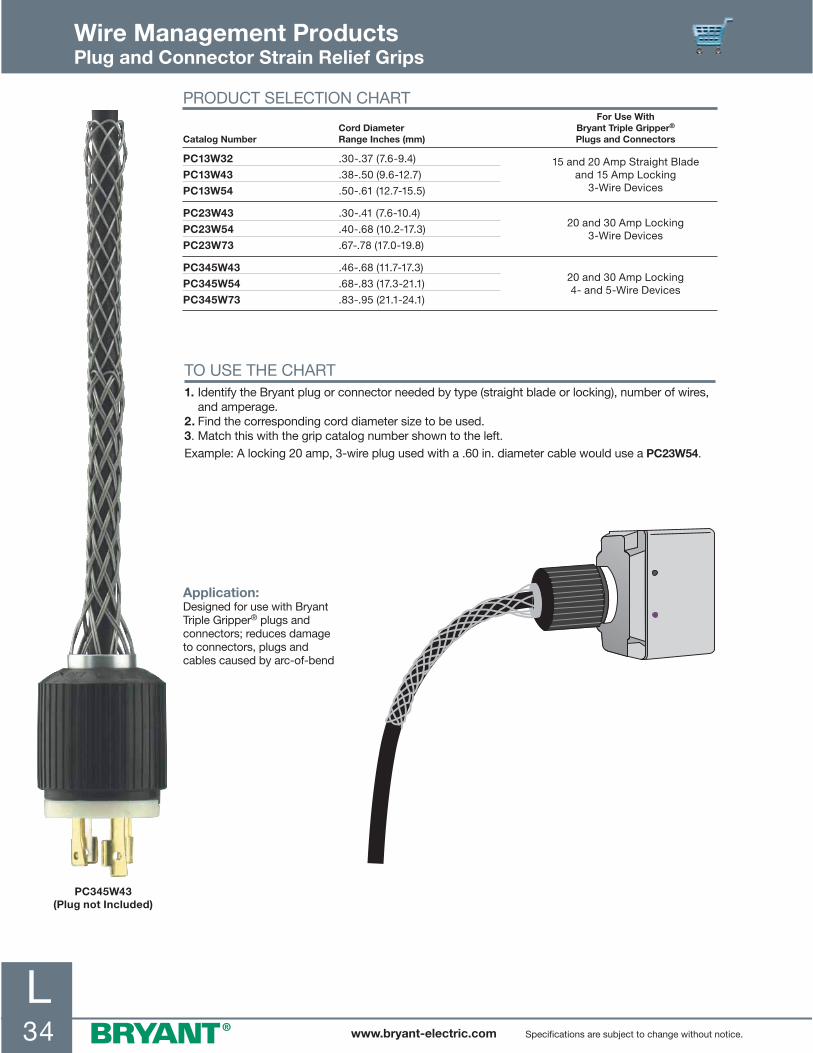
L34 www.bryant-electric.com Specifications are subject to change without notice.
TO USE THE CHART1. Identify the Bryant plug or connector needed by type (straight blade or locking), number of wires,
and amperage.2. Find the corresponding cord diameter size to be used.3. Match this with the grip catalog number shown to the left.Example: A locking 20 amp, 3-wire plug used with a .60 in. diameter cable would use a PC23W54.
PC345W43(Plug not Included)
Wire Management ProductsPlug and Connector Strain Relief Grips
Application: Designed for use with Bryant Triple Gripper® plugs and connectors; reduces damage to connectors, plugs and cables caused by arc-of-bend
PRODUCT SELECTION CHART
Catalog NumberCord Diameter Range Inches (mm)
For Use With Bryant Triple Gripper® Plugs and Connectors
PC13W32
PC13W43
PC13W54
.30-.37 (7.6-9.4)
.38-.50 (9.6-12.7)
.50-.61 (12.7-15.5)
15 and 20 Amp Straight Bladeand 15 Amp Locking
3-Wire Devices
PC23W43
PC23W54
PC23W73
.30-.41 (7.6-10.4)
.40-.68 (10.2-17.3)
.67-.78 (17.0-19.8)
20 and 30 Amp Locking3-Wire Devices
PC345W43
PC345W54
PC345W73
.46-.68 (11.7-17.3)
.68-.83 (17.3-21.1)
.83-.95 (21.1-24.1)
20 and 30 Amp Locking4- and 5-Wire Devices

L35www.bryant-electric.comSpecifications are subject to change without notice.
WIRE MESH GRIP MATERIALSMaterial Features Product Group
Galvanized steel wire High strength Pulling grips
Not subject to continuous outside environment Splicing grips
Bus Drop grips
Tin-Coated bronze wire Corrosion-resistant for normal outside areas Support grips
Non-magnetic
Moderate strength
Stainless steel wire (302/304) High strength Support grips
Corrosion resistant Strain relief grips
SELECTION TABLE FOR MULTIPLE CABLES OF DIFFERENT DIAMETERS Inches (cm)
Working Load Factors for Wire Mesh Grips
There are many variables associated with the use of wire mesh cable grips. Working load is an estimation of several factors including tension, cable diameter, number of cables gripped, gripping surface and more. Safety factors associated in the product’s use must be considered together with the effects of abrasion, corrosion, prior use and abuse and other variables specific to the application.
The appropriate breaking strength of a Bryant Economy Cable Grip represents an average calculation based on
data established from actual testing performed in our engineering laboratories. Under normal usage conditions, our recommended factor of safety is five for pulling grips and ten for support grips.
Any warranty as to quality, performance of fitness-for-use of the grips is always premised on the condition that the published strengths apply only to new, unused grips, and that such products are properly stored, handled, used, maintained and inspected by the user at a frequency appropriate for the use and condition of the grip.
EXAMPLE
Grip Style Catalog Number
Approx. BreakingStrength (Lbs.) Safety Factor
Max. RecommendedLoad (Lbs.)
Pulling PHS200 27,200 5 5,440
Support SPS125U 1,610 10 161
Note: The maximum recommended working load is the greatest tension to be exerted on a grip for any application, with a margin of safety to protect against unforeseen and unusual circumstances.
Wire Management ProductsTechnical Data
Applicable Code Requirements: Bryant Economy Cable Grips meet the following requirements:NEC® 300.19 Support of conductors in vertical racewaysNEC® 350 Liquidtight flexible metal conduit terminationNEC® 400.14 Flexible cord and cable protectionNEC® 400.10 Strain relief at joints and terminalsNEC® 501.10 (B) Class I, Division 2, Tensile stress avoidance at termination fittingsNEC® 502.10 (A) and (B) Class II, Division 1 and 2, Tensile stress avoidance at termination fittingsNEC® 503.10 (A) and (B) Class III, Division 1, Tensile stress avoidance at termination fittings
How to choose the correct grip size:1. Find the grip circumference range by measuring the circumference of the bundle of different diameter cables to be gripped (see illustration).2. Divide the bundle circumference by 3.14 to determine the diameter.3. Choose a grip offering a range of cable diameters the same as the cable diameter.
For cables of equal diametersUnder “number of cables in one grip”, find the diameter of your single cable in vertical column. Read the grip diameter range to the right.If your diameter is the maximum of the range shown, go to the next larger size for split grips, stay with the same size for closed grips.
Example: 3 cables, each with .89 (2.26) diameter, for a closed grip select the 1.50-1.74 (3.81-4.42) range, for a split grip select the 1.75-1.99 (4.44-5.05) range.
NEC® is a registered trademark of the National Fire Protection Association (NFPA).

L36 www.bryant-electric.com Specifications are subject to change without notice.
Wire Management ProductsMultiple Cable, Grip Selection Chart
GripSize
Grip Dia. Range
Inches (cm)
Number of Cables in One Grip
2 3 4 5 6 and 7 8 9
50 .50-.61(1.27-1.55)
.30-.38(.76-.97)
.25-.31(.63-.79)
.22-.27(.56-.69)
.19-.24(.48-.61)
.17-.22(.43-.56)
.15-.19(.38-.48)
.14-.18(.36-.46)
62 .62-.74(1.57-1.88)
.38-.44(.97-1.12)
.31-.36(.79-.91)
.27-.31(.69-.79)
.24-.29(.61-.74)
.22-.26(.56-.66)
.19-.23(.48-.56)
.18-.21(.46-.53)
75 .75-.99(1.90-2.51)
.44-.59(1.12-1.50)
.36-.49(.91-1.24)
.31-.42(.79-1.07)
.29-.38(.74-.97)
.26-.34(.66-.86)
.23-.31(.58-.79)
.21-.28(.53-.71)
100 1.00-1.24(2.54-3.15)
.59-.75(1.50-1.90)
.49-.63(1.24-1.60)
.42-.54(1.07-1.37)
.38-.48(.97-1.22)
.34-.43(.86-1.09)
.31-.39(.79-.99)
.28-.35(.71-.89)
125 1.25-1.49(3.17-3.78)
.75-.90(1.90-2.29)
.63-.76(1.60-1.93)
.54-.65(1.37-1.65)
.48-.58(1.22-1.47)
.43-.521.09-1.32)
.39-.46(.99-1.17)
.35-.42(.89-1.07)
150 1.49-1.74(3.81-4.42)
.90-1.07(2.29-2.72)
.76-.89(1.93-2.26
.65-.77(1.65-1.96)
.58-.67(1.47-1.70)
.52-.60(1.32-1.52)
.46-.54(1.17-1.37)
.42-.49(1.07-1.24)
175 1.75-1.99(4.44-5.05)
1.07-1.22(2.72-3.10)
.89-1.02(2.26-2.59)
.77-.88(1.96-2.24)
.67-.77(1.70-1.96)
.60-.69(1.52-1.75)
.54-.62(1.37-1.57)
.49-.56(1.24-1.42)
200 2.00-2.49(5.08-6.32)
1.22-1.53(3.10-3.89)
1.02-1.28(2.59-3.25)
.88-1.10(2.24-2.79)
.77-.96(1.96-2.44)
.69-.86(1.75-2.18)
.62-.77(1.57-1.96)
.56-.71(1.42-1.80)
250 2.50-2.99(6.35-7.59)
1.53-1.83(3.89-4.65)
1.28-1.53(3.25-3.89)
1.10-1.32(2.79-3.35)
.96-1.16(2.44-2.95)
.86-1.03(2.18-2.62)
.77-.93(1.96-2.36)
.71-.85(1.80-2.16)
300 3.00-3.49(7.62-8.86)
1.83-2.14(4.65-5.44)
1.53-1.79(3.89-4.55)
1.32-1.54(3.35-3.91
1.16-1.35(2.95-3.43)
1.03-1.20(2.62-3.05)
.93-1.08(2.36-2.74)
.85-.99(2.16-2.51)
350 3.50-3.99(8.89-10.13)
2.14-2.44(5.44-6.20)
1.79-2.05(4.55-5.21)
1.54-1.76(3.91-4.47)
1.35-1.54(3.43-3.91)
1.20-1.37(3.05-3.48)
1.08-1.24(2.74-3.15)
.99-1.13(2.51-2.87)
400 4.00-4.49(10.16-11.40)
2.44-2.75(6.20-6.98)
2.05-2.30(5.21-5.84)
1.76-1.98(4.47-5.03)
1.54-1.74(3.91-4.42)
1.37-1.55(3.48-3.94)
1.24-1.39(3.15-3.53)
1.13-1.27(2.87-3.23)
450 4.50-4.99(11.43-12.67)
2.75-3.06(6.98-7.77)
2.30-2.56(5.84-6.50)
1.98-2.20(5.03-5.59)
1.74-1.93(4.42-4.90)
1.55-1.72(3.94-4.37)
1.39-1.55(3.53-3.94)
1.27-1.41(3.23-3.58)
50 .50-.62(1.27-1.57)
.29-.36(.74-.91)
.24-.30(.61-.76)
.21-.25(.53-.63)
.18-.22(.46-.56)
.16-.20(.41-.51)
.15-.18(.38-.46)
.14-.17(.36-.43)
62 .63-.74(1.60-1.88)
.37-.43(.94-1.09)
.31-.36(.79-.91)
.26-.30(.66-.76)
.23-.27(.58-.69)
.21-.24(.53-.61)
.19-.22(.48-.56)
.18-.20(.46-.51)
75 .75-.99(1.90-2.51)
.44-.58(1.12-1.47)
37-.48(.94-1.22)
.31-.41(.79-1.04)
.28-.36(.71-.91)
.25-.32(.63-.81)
.23-.29(.58-.74)
.21-.27(.53-.69)
100 1.00-1.24(2.54-3.15)
.59-.72(1.50-1.83)
.49-.60(1.24-1.52)
.42-.51(1.07-1.30)
.37-.45(.94-1.14)
.33-.40(.84-1.02)
.30-.36(.76-.91)
.28-.34(.71-.86)
125 1.25-1.49(3.17-3.78)
.73-.87(1.85-2.21)
.61-.72(1.55-1.83)
.52-.61(1.32-1.55)
.46-.54(1.17-1.37)
.41-.48(1.04-1.22)
.37-.43(.94-1.09)
.35-.40(.89-1.02)
150 1.50-1.74(3.81-4.42)
.88-1.01(2.24-2.57)
.73-.85(1.85-2.16)
.62-.71(1.57-1.80)
.55-.63(1.40-1.60)
.49-.56(1.24-1.42)
.44-.51(1.12-1.30)
.41-.47(1.04-1.19)
175 1.75-1.99(4.44-5.05)
1.02-1.16(2.59-2.95)
.86-.96(2.18-2.44)
.72-.81(1.83-2.06)
.64-.72(1.63-1.83)
.57-.64(1.45-1.63)
.52-.58(1.32-1.49)
.48-.54(1.22-1.37)
200 2.00-2.49(5.08-6.32)
1.17-1.44(2.97-3.66)
.97-1.20(2.46-3.05)
.82-1.02(2.08-2.59)
.73-.90(1.85-2.29)
.65-.80(1.65-2.03)
.59-.72(1.50-1.83)
.55-.67(1.40-1.70)
250 2.50-2.99(6.35-7.59)
1.45-1.73(3.68-4.39)
1.21-1.45(3.07-3.68)
1.03-1.22(2.62-3.10)
.91-1.08(2.31-2.74)
.81-.96(2.06-2.44)
.73-.87(1.85-2.21)
.68-.81(1.73-2.06)
300 3.00-3.49(7.62-8.86)
1.74-2.02(4.42-5.13)
1.46-1.69(3.71-4.29)
1.23-1.43(3.12-3.63)
1.09-1.26(2.77-3.20)
.97-1.11(2.46-2.82)
.83-1.01(2.11-2.57)
.82-.94(2.08-2.39)
350 3.50-3.99(8.89-10.13)
2.75-3.06(5.16-5.87)
1.70-1.93(4.32-4.90)
1.44-1.63(3.66-4.14)
1.27-1.44(3.23-3.66)
1.12-1.27(2.84-3.23)
1.02-1.15(2.59-2.92)
.95-1.08(2.41-2.74)
PU
LLIN
G A
ND
SU
PP
OR
TC
ON
DU
IT R
ISE
R
� Under “Number of Cables in One Grip”, find the diameter range of your cables in vertical column. Read grip size and grip diameter range to the left.
� If your diameter is the maximum of the range shown, go to the next larger size for split grips or stay with the same size for closed grips.
� Example: 3 cables, each with .89 in. diameter; a closed grip would use a 150 grip size while a split grip would use a 175 grip size.
SELECTION CHART FOR DETERMINING GRIP SIZE WHEN MORE THAN ONE CABLE IS HELD IN A SINGLE GRIP

www.bryant-electric.com
M1www.bryant-electric.com
INDEX PAGE
Fluorescent LampholdersMedium Bi-Pin . . . . . . . . . . . . . . . . . . . . . . . . . . . . . . . . . . . . . . . . . . . . . . . . . . . . . . . . . . . . . . . . . . . . . . . . . M-2Slimline . . . . . . . . . . . . . . . . . . . . . . . . . . . . . . . . . . . . . . . . . . . . . . . . . . . . . . . . . . . . . . . . . . . . . . . . . . . . . . M-3Recessed Double Contact . . . . . . . . . . . . . . . . . . . . . . . . . . . . . . . . . . . . . . . . . . . . . . . . . . . . . . . . . . . . . . . M-4Snap-In Quickwire . . . . . . . . . . . . . . . . . . . . . . . . . . . . . . . . . . . . . . . . . . . . . . . . . . . . . . . . . . . . . . . . . . . . . . M-5
Incandescent LampholdersPorcelain . . . . . . . . . . . . . . . . . . . . . . . . . . . . . . . . . . . . . . . . . . . . . . . . . . . . . . . . . . . . . . . . . . . . . . . . . . . . . M-6Plastic . . . . . . . . . . . . . . . . . . . . . . . . . . . . . . . . . . . . . . . . . . . . . . . . . . . . . . . . . . . . . . . . . . . . . . . . . . . . . . . M-7
AccessoriesIncandescent Lampholders . . . . . . . . . . . . . . . . . . . . . . . . . . . . . . . . . . . . . . . . . . . . . . . . . . . . . . . . . . . . . . . M-8Incandescent Accessories . . . . . . . . . . . . . . . . . . . . . . . . . . . . . . . . . . . . . . . . . . . . . . . . . . . . . . . . . . . . . . . M-9Fluorescent Starters and Starter Socket. . . . . . . . . . . . . . . . . . . . . . . . . . . . . . . . . . . . . . . . . . . . . . . . . . . . M-10Plugs, Taps and Adapters . . . . . . . . . . . . . . . . . . . . . . . . . . . . . . . . . . . . . . . . . . . . . . . . . . . . . . . . . . . . . . . M-11Plugs and Connectors . . . . . . . . . . . . . . . . . . . . . . . . . . . . . . . . . . . . . . . . . . . . . . . . . . . . . . . . . . . . . . . . . . M-12
Section MLampholders, Starters And Adapters

M2 www.bryant-electric.com
.87(22.1)
1.00 (25.4)
1.25 (31.8)
1.73(43.9)
.37(9.4)
.37(9.4)
.33(8.4)
1.73(43.9)
1.00 (25.4)
.91(23.1)
.37(9.4)
.33(8.4)
.37(9.4)
1.18 (30.0)
1.00 (25.4)1.37 (35.0)
1.47(37.4)
1.00(25.4)
.34(8.7)
.18(4.6)
1.17 (29.7)
1.00 (25.4)
1.8(46.0)
.88 (22.4)
1.00(25.4)
.32(8.0)
.30(7.6)
.69(17.5)
.05(1.2)
.06(1.4) .04
(1.0)
1.01 (25.7)
1.45 (36.8)
2.35(59.7)
1.17(29.7)
.59(15.0)
.81(20.6)
.38(9.7)
.315(8.0)
.75(19.1)
1.00 (25.4)
1.40 (36.0)
2.00(50.8)
.17(4.3)
1.17(29.7)
.51(13.0)
4300W
4301W
4400W
4070
4304W
4051
1.23(31.2)
2.14(54.4)
.38(9.7)
1.75(44.5)
RL320
.99(25.1)
1.23(31.2)
.33(8.4)
.70(17.8)
1.65(41.9)
1.28(32.5)
RL3254300W
4301W
4070
4400W
4304W
RL320
RL325
MEDIUM BI-PIN – LAMP SIZE T8, T12 Inches (mm)
Description Rating Color Catalog Number
Tall profile; slide-on 4-wire with captive nut; push wire terminations
660W 600V White RL320
Pal-nut installed with slide-on lugs for 18-gauge metal
660W 600V White 4051*
U-bend lampholder with slide-on lugs for 18-gauge metal
660W 600V White 4070**
Tapped bracket; .32 (8.0) thick; #6-32x14" screw assembled
660W 600V White 4301W
Note: *Screws supplied separately. **U Bend circuit interrupting not available.
MEDIUM BI-PIN LOW PROFILE – LAMP SIZE T8, T12 Inches (mm)
Description Rating Color Catalog Number
Tapped bracket; .34 (8.7) thick; screw assembled
660W 600V White 4304W
Lampholder without bracket; .34 (8.7) thick; with centered vertical slot in base to engage lance tab
660W 600V White 4304W12
Center hole tapped for #8-32 screw; .34 (8.7) thick
660W 600V White 4304W7
MEDIUM BI-PIN – LAMP SIZE T6, T8, T12 FOR PRE-HEAT OR RAPID START LAMPS Inches (mm)
Description Rating Color Catalog Number
Low profile; push wire terminations:Slide-on 4-wire with captive nutSlide-on 4-wireSlide-on 2-wire
660W 600V660W 600V660W 600V
WhiteWhiteWhite
RL325RL325ARL325B
Tall profile .32 (8.0) thick with “U” base; slide-on lugs
660W 600V White 4400W
Surface mount; tombstone with terminal screws
660W 600V White 4300W
Lampholders, Starters and Adapters Medium Bi-Pin Fluorescent Lampholders
PRODUCT DIMENSIONS Inches (mm)

M3www.bryant-electric.com
2.31(58.7)
1.13(28.7)
1.45 (36.8)
1.13(28.7)
1.66 (42.2)
1.17(29.8)
.59(15.0)
.34(8.6)
1.31 (33.3)
1.54(39.1)
1.13(28.7)
.16 (4.1)
R .19 (4.8) 1.20 (30.5)
1.89(48.0)
.95(24.1)
.05(1.3)
1.31 (33.3)
.09 (2.3)
1.81 (46.0)1.14(30.0)
1.56 (39.6)
1.17(29.8)
.47(11.9)
.58(14.7)
2.31(58.7)
1.13(28.7)
1.45 (36.8)
1.78 (45.2)1.13(28.7)
1.66 (42.2)
1.17(29.8)
.59(15.0)
.79(20.1)
1.54 (39.1)
1.90(48.3)
1.50(38.1)
.68(17.3)
.14 (3.6)
R .40 (10.2)
R .32 (8.1)
1.12(28.4)
.75(19.1)
1.89(48.0)
.95(24.1)
.05(1.3)
.33(8.4)
1.31(33.3)
.09(2.3)
1.14(30.0)
1.56 (39.6).06(1.5)
1.17(29.8)
.47(11.9)
4385W7 4386W7
4377RL310 4376
RL311
4377
4385W7
4386W7
4376
RL310
RL311
SLIMLINE LAMPHOLDERS – LAMP SIZE T6, T8, T12Description Rating Color Catalog Number
Stationary end; pedestal type; single pin lamp; slide-on base;push wire terminations
660W 600V White RL311
Plunger end; pedestal type; single pin lamp; slide-on base;push wire terminations
660W 600V White RL310
Stationary end; quick wired with slide-on lugs and solid platform
660W 600V White 4385W7
Plunger end; quick wired with slide-on lugs and solid platform
660W 600V White 4386W7
Stationary end with pal-nut and screw installed
660W 600V White 4376
Plunger end with pal-nut and screw installed
660W 600V White 4377
Lampholders, Starters and Adapters Slimline Fluorescent Lampholders
PRODUCT DIMENSIONS Inches (mm)

M4 www.bryant-electric.com
650SHB Side 650SHB, 650PHB 650PHB Side
4876 Side 4876, 4877 4877 Side
1.45 (36.8)
1.13(28.7)
1.66 (42.0)
1.88 (47.8)
1.66 (42.0)
1.17(29.7)
2.39(60.7)
2.33(59.2)
.59(15.0)
1.17(29.7)
1.13(28.7)
1.13(28.7)
.83(21.1)
2.43(61.7)
.05(1.3)
1.33 (33.8)
1.75 (44.5)
1.50 (38.1)1.50 (38.1)
1.56(39.6) 1.56
(39.6)
2.31(58.7)
1.12(28.5)
1.12(28.5) 1.12
(28.5).83(21.1)
1.45 (36.8) 1.26 (32.0)
1.34(34.0)
.81(20.6)
R .56 (14.2) 1.12(28.4)
.14 (3.6)
RL306
1.54 (39.1) 1.26 (32.0)
1.90(48.3)
1.34(34.0)
R .45(11.4)
1.12(28.4)
1.12(28.4)
.75(19.1)
.14 (3.6)
RL305
650PH
4877
RL305
650SHB
650SH
4876
650PHB
RL306
RECESSED DOUBLE CONTACT – LAMP SIZE T12, T17Description Rating Color Catalog Number
Horizontal stationary end; pedestal type for high output lamp; slide-on base;push wire terminations
660W 600V White RL306
Horizontal plunger end; pedestal type for high output lamp; slide-on base;push wire terminations
660W 600V White RL305
Horizontal stationary end; terminal screws
660W 600V White 4876
Horizontal plunger end; terminal screws
660W 600V White 4877
Horizontal stationary end; with “U” slot base;push wire terminations
660W 600V White 650SH
Horizontal plunger end; with “U” slot base;push wire terminations
660W 600V White 650PH
Horizontal stationary end; with slide-on lugs and platform;push wire terminations
660W 600V White 650SHB
Horizontal plunger end; with slide-on lugs and platform;push wire terminations
660W 600V White 650PHB
Lampholders, Starters and Adapters Recessed Double Contact Fluorescent Lampholders
PRODUCT DIMENSIONS Inches (mm)

M5www.bryant-electric.com
600S 620S
600P 620P
620S
600P
600S
620P
.82 (20.8)
1.0(2 .2)
.82 (2 .8)
1.84(4 .7)
.8(21.8)
1.65(41. )
.82 (20.8)
1.0(2 .2)
.82 (2 .8)
1.88(47.8)
.8(21.8)
1. 5 (41.9)
Lampholders, Starters and Adapters Snap-In Quickwire Fluorescent Lampholders
MEDIUM BI-PIN – LAMP SIZE T6, T8, T12, T17Description Rating Color Catalog Number
Stationary end; medium bi-pin; push wire terminations
660W 600V White 600S
Plunger end; medium bi-pin; push wire terminations
660W 600V White 600P
Stationary end; recessed double contact; push wire terminations
660W 600V White 620S
Plunger end; recessed double contact; push wire terminations
660W 600V White 620P
PRODUCT DIMENSIONS Inches (mm)

M6 www.bryant-electric.com
Ø 4.35 (110.5)
1.50(38.1)
Ø 1.84(46.7)
Ø 4.55(115.6)
1.55(39.4)
Ø 1.84(46.7)
Ø 4.35(110.5)
1.50(38.1)
Ø 1.84(46.7)
Ø 4.55 (115.6)
1.55(39.4)
Ø 1.84(46.7)
Ø 4.55 (115.6)
1.55(39.4)
Ø 1.84(46.7)
RL8806
RL8804
RL8816
RL8812 Rl8822
RL8822
RL8812
RL8816
RL8804
RL8806
PORCELAIN LAMPHOLDERSDescription Rating Color Catalog Number
Keyless; 4 terminal screws 660W 250V White RL8804
Keyless; 6-inch pigtails 660W 250V White RL8806
Pull chain; 2 terminal screws 660W 250V White RL8812
Pull chain; 6-inch pigtails 660W 250V White RL8816
Pull chain with receptacle; 2 terminal screws
660W 250V15A 125VNEMA 5-15R
White RL8822
Lampholders, Starters and Adapters Incandescent Lampholders
PRODUCT DIMENSIONS Inches (mm)

M7www.bryant-electric.com
Ø 4.55 (115.6)
1.55(39.4)
Ø 1.57(39.9)
Ø 4.55(115.6)
1.55(39.4)
Ø 1.57(39.9)
Ø 4.55 (115.6)
1.55(39.4)
Ø 1.57(39.9)
Ø 4.55(115.6)
1.55(39.4)
Ø 1.57(39.9)
RL8504 RL8512
RL8506 Rl8516
RL8516
RL8512
RL8504
RL8506
Lampholders, Starters and Adapters Incandescent Lampholders
PLASTIC LAMPHOLDERSDescription Rating Color Catalog Number
Keyless; 4 terminal screws 660W 600V White RL8504
Keyless; 6-inch pigtails 660W 600V White RL8506
Pull chain; 2 terminal screws 660W 250V White RL8512
Pull chain; 6-inch pigtails 660W 250V White RL8516
PRODUCT DIMENSIONS Inches (mm)

M8 www.bryant-electric.com
RL152 RL3742
R .73 (18.5)
1.13(28.7)
1.93(49.0)
.46 (11.7)
1.93(49.0)
2.18(55.4)
Ø 1.92(48.8)
RL152
RL3742
RL101
RL105
RL106
3743R
INCANDESCENT LAMPHOLDERSDescription Rating Color Catalog Number
Incandescent; medium base socket; turn knob; on/off
250W 250V Brass RL101
Incandescent; medium base socket; turn knob; 3-way; low, medium and high
250W 250V Brass RL102
Incandescent; medium base socket; push through; on/off
660W 250V Brass RL105
Incandescent; medium base socket; keyless
660W 250V Brass RL100
Incandescent; medium base socket; pull chain; on/off
660W 250V Brass RL106
Pony cleat; medium base socket; porcelain
660W 250V White RL152
Pony cleat; medium base socket; plastic
660W 250V Black RL153
HID socket; prefocus type;medium base bayonet; porcelain;surface or clamp mounting
1200W 250V White RL3742
HID socket; prefocus type;medium base bayonet; porcelain;surface or clamp mounting;with thermoplastic base
1000W 250V Black 3743R
Lampholders, Starters and Adapters Incandescent Lampholders
PRODUCT DIMENSIONS Inches (mm)

M9www.bryant-electric.com
RL150
RL124
RL124H
RL200
RL201
RL202
INCANDESCENT ACCESSORIESDescription Rating Color Catalog Number
Pigtail medium base socket with 6-inch leads;rubber with #14 gauge wire; approved for use at construction sites when used with bulb cages; acceptable for open wiring without an outlet box when using suitable splices
660W 250V Black RL124
Phenolic medium base socket with hook;insulation piercing termination
660W 250V Black RL124H
Porcelain socket extension;medium base to medium base
600W 250V White RL150
Outlet adapter; 2-prong non-polarized plug to medium base lampholder
15A 125VNEMA 1-15P
Ivory RL200
Medium lampholder adapter;medium base lampholder to outlet; without ground
15A 125VNEMA 1-15R
Ivory RL201
Medium base lampholder to lampholder adapter;pull chain with two 2-prong outlets;without ground
660W 250V15A 125VNEMA 1-15R
Black RL202
Lampholders, Starters and Adapters Incandescent Accessories

M10 www.bryant-electric.com
FS2A FS850 4309
4309
FS4A
FS850
.81 (2 . )
1.31(33.3)
1.85(47. )
1.13 (28.7)
. 1(18.0)
1.25( 1.8)1. 5 (44.5)
1.18( 0.0)
1.5 (39. )
.5(14.2)
MANUAL RESET STARTERSNumber of Pins Lamp Watts Catalog Number
2 14, 15 and 20 watts FS20A
2 40 watts FS40400A
4 85, 90 and 100 watts FS850
FLUORESCENT STARTER SOCKET – FOR FS2A, FS4A, FS5A, FS20A, FS25A, FS40400A
Description Catalog Number
Standard size; 2-pin 4309*
Note: *Not CSA Certified.
STANDARD TYPE STARTERSNumber of Pins Lamp Watts Catalog Number
2 14, 15 and 20 watts FS2A
2 13, 30 and 40 watts FS4A
2 4, 6 and 8 watts FS5A
2 25 watts FS25A
Lampholders, Starters and Adapters Fluorescent Starters and Starter Socket
PRODUCT DIMENSIONS Inches (mm)

M11www.bryant-electric.com
PLUGS, TAPS AND ADAPTERSDescription Color Catalog Number
Duplex receptacle to six outlets;with ground; polarized
IvoryWhite
RT600IRT600W
Single receptacle to three outlets;with ground; polarized
IvoryWhite
RT300IRT300W
Single receptacle to three outlets;heavy duty rubber; with ground; polarized
Orange RT303
Two wire to U-ground; polarized Ivory RT200
Cube tap; without ground; polarized White RT100W
Note: Adapters are not intended to be used as a replacement for permanent devices. They are intended for temporary use only.
PLUGS, TAPS AND ADAPTERSDescription Color Catalog Number
Male end : 3-wire 10A 250V; 15A 125V; non-NEMA locking blades; female end: 3-wire; 15A 125V; straight slot grounding
White 9053AB*
Male end: 3-wire 15A 125V straight blade grounding; female end: 10A 250V; 15A 125V; non-NEMA locking slots
White 9054AB*•
Note: Adapters are not intended to be used as a replacement for permanent devices. They are intended for temporary use only. *Not UL Listed. •Must always be used with grounded receptacle.
Lampholders, Starters and Adapters Plugs, Taps and Adapters
NEMA 5-1515A 125V
NEMA 5-1515A 125V
NEMA 5-1515A 125V
NEMA 5-1515A 125V
RT600W
RT300W
RT303
RT200
RT100W
9053AB
9054AB

M12 www.bryant-electric.com
RP123I
RP123PI
RP101BK
RP102BK
RP646
RP648
RP649
PLUGS AND CONNECTORSDescription Color Catalog Number
Straight plug; non-polarized;two blade; SPT 1 and 2 cord 18/2 and 16/2 AWG
IvoryWhite
RP123IRP123W
Straight plug; polarized;two blade; SPT 1 and 2 cord 18/2 and 16/2 AWG
IvoryWhite
RP123PIRP123PW
Straight plug; polarized;two blade; light duty; wire range: #16-18 AWG;up to .25 inch diameter cord
BlackWhite
RP101BKRP101W
Straight connector; polarized;two blade; light duty; wire range: #16-18 AWG;up to .25 inch diameter cord
BlackWhite
RP102BKRP102W
Straight plug; non-polarized;two blade; heavy duty; wire range: #14-18 AWG;up to .33 inch diameter cord
Black RP646
Straight plug; polarized;two blade; heavy duty; wire range: #14-18 AWG;up to .33 inch diameter cord
Black RP648
Straight connector; polarized;two blade; heavy duty; wire range: #14-18 AWG;up to .33 inch diameter cord
Black RP649
Lampholders, Starters and Adapters Plugs and Connectors

www.bryant-electric.com
N1
INDEX PAGE
Floor BoxesFloor Boxes for Wood Floors . . . . . . . . . . . . . . . . . . . . . . . . . . . . . . . . . . . . . . . . . . . . . . . . . . . . . . . . . . . . . .N-2Floor Boxes for Concrete Floors . . . . . . . . . . . . . . . . . . . . . . . . . . . . . . . . . . . . . . . . . . . . . . . . . . . . . . . . . . . .N-4
Under Cabinet/Counter Power DistributionFeatures . . . . . . . . . . . . . . . . . . . . . . . . . . . . . . . . . . . . . . . . . . . . . . . . . . . . . . . . . . . . . . . . . . . . . . . . . . . . . . .N-6Boxes . . . . . . . . . . . . . . . . . . . . . . . . . . . . . . . . . . . . . . . . . . . . . . . . . . . . . . . . . . . . . . . . . . . . . . . . . . . . . . . .N-7
Metal RacewayFeatures . . . . . . . . . . . . . . . . . . . . . . . . . . . . . . . . . . . . . . . . . . . . . . . . . . . . . . . . . . . . . . . . . . . . . . . . . . . . . . .N-8HBL500 and HBL750 Series . . . . . . . . . . . . . . . . . . . . . . . . . . . . . . . . . . . . . . . . . . . . . . . . . . . . . . . . . . . . . . .N-9HBL2000 Series . . . . . . . . . . . . . . . . . . . . . . . . . . . . . . . . . . . . . . . . . . . . . . . . . . . . . . . . . . . . . . . . . . . . . . .N-11
Metal PlugTrak®
15 Amp 125V . . . . . . . . . . . . . . . . . . . . . . . . . . . . . . . . . . . . . . . . . . . . . . . . . . . . . . . . . . . . . . . . . . . . . . . . . .N-12
AccessoriesPainted Metal Plates . . . . . . . . . . . . . . . . . . . . . . . . . . . . . . . . . . . . . . . . . . . . . . . . . . . . . . . . . . . . . . . . . . . .N-13Combination Plates . . . . . . . . . . . . . . . . . . . . . . . . . . . . . . . . . . . . . . . . . . . . . . . . . . . . . . . . . . . . . . . . . . . . .N-13Communication Plates and Frames . . . . . . . . . . . . . . . . . . . . . . . . . . . . . . . . . . . . . . . . . . . . . . . . . . . . . . . .N-13
Technical InformationWire Fill Capacity . . . . . . . . . . . . . . . . . . . . . . . . . . . . . . . . . . . . . . . . . . . . . . . . . . . . . . . . . . . . . . . . . . . . . .N-14Specifications . . . . . . . . . . . . . . . . . . . . . . . . . . . . . . . . . . . . . . . . . . . . . . . . . . . . . . . . . . . . . . . . . . . . . . . . .N-14
Section NDelivery Systems

www.bryant-electric.com Specifications are subject to change without notice.
N2
Delivery Systems Floor Boxes for Structural Wood Floors
RF507BP
RF500
RF506BP
RF515BP
FLOOR BOXES FOR WOOD FLOORS
Description Material FinishCatalog Number Finish
Catalog Number
Decorator duplex receptacle floor box kit; includes steel box, flange and hinged door cover assembly with tamper-resistant duplex receptacle; designed for installation in wood floors; mounts to sub-floor or joists
Solid BrassAluminumAluminumAluminumAluminum
Clear Lacquer Stainless PaintAlmond PaintBlack PaintChestnut Brown Paint
RF515BRRF515SSRF515ALRF515BK RF515BN
Brass PlateChrome PlateCopper PlateNickel Plate
RF515BPRF515CHRF515CURF515NI
Flange and hinged door cover assembly; includes tamper-resistant duplex receptacle; neoprene gaskets; for use with steel box RF500
Solid BrassAluminumAluminumAluminumAluminum
Clear Lacquer Stainless PaintAlmond PaintBlack PaintChestnut Brown Paint
RF506BRRF506SSRF506ALRF506BK RF506BN
Brass PlateChrome PlateCopper PlateNickel Plate
RF506BPRF506CHRF506CURF506NI
Adjustable floor box; 3 inches deep; three ½-inch knockouts: one on bottom, one on each side; non-metallic sheathed cable clamps on each side
Steel — RF500 — —
Hinged door cover only;replacement door for RF515 and RF506 series
Solid BrassAluminumAluminumAluminumAluminum
Clear Lacquer Stainless PaintAlmond PaintBlack PaintChestnut Brown Paint
RF507BRRF507SSRF507ALRF507BK RF507BN
Brass PlateChrome PlateCopper PlateNickel Plate
RF507BPRF507CHRF507CURF507NI
Note: *See page Q-6 for tamper-resistant description.
Pre-assembled flange and cover
Recessed receptacle minimizes plug protrusion; allows furniture to be located over the plug
Height accessible adjustments after the box is mounted
Removable neoprene gaskets
Optional low voltage divider
RF515BP
Wood floor boxes allow for the placement of electrical power or a combination of power and voice/data devices. Boxes easily mount into the floor and are height adjustable (up to ¾ inch) for optimal alignment and fit.
TR*
TR*
NEMA 5-1515A 125V
NEMA 5-1515A 125V

www.bryant-electric.comSpecifications are subject to change without notice.
N3
Delivery Systems Floor Boxes for Structural Wood Floors
RF151
RF151D
RF151R
Duplex floor receptacles provide ample connections to service lighting, entertainment equipment and computers for family rooms and offices. Single receptacle configurations available for minimum requirements.• Solid brass resists wear and provides a distinctive finish
FLOOR BOXES FOR WOOD FLOORSDescription Material Catalog Number Catalog Number
Drop in floor box; mounts in 2.50 inch hole opening; includes solid brass cover, single tamper-resistant receptacle, includes device mount for two (2) voice/data video ports; suitable for feed through circuitry; impact resistant box
Solid Brass RF151R RF201R
Single receptacle; floor box rated; includes steel box; single receptacle and cover
Solid Brass RF151 —
Single receptacle; floor box rated; includes steel box; single receptacle and cover
Solid Brass RF151TR —
Single receptacle; display rated; receptacle and cover only; excludes box
Solid Brass RF151D —
Note: *See page Q-6 for tamper-resistant description.
TR*
TR*
NEMA 5-2020A 125V
RJ650BK
RJ65BK
JLOAD™ MULTIMEDIA OUTLET(FOR USE WITH RF500 SERIES)
Description ColorTamper-Resistant Standard
Tamper-Resistant Standard
JLOAD™ multimedia outlet; provides power, Cat. 5e and coaxial in a single-gang box; requires JLOAD™ multimedia box RJ600; includes decorator frame, one Cat. 5e, one F-connector and single receptacle with voltage divider
Almond Black Gray IvoryLight AlmondWhite
RJ650ALTRRJ650BKTRRJ650GYTRRJ650ITRRJ650LATRRJ650WTR
RJ650AL RJ650BK RJ650GYRJ650I RJ650LARJ650W
RJ620ALTRRJ620BKTRRJ620GYTRRJ620ITRRJ620LATRRJ620WTR
RJ620AL RJ620BK RJ620GYRJ620I RJ620LARJ620W
JLOAD™ multimedia outlet; includes decorator frame with two open ports for custom configuration and one single receptacle with voltage divider
Almond Black Gray IvoryLight AlmondWhite
RJ65ALTR RJ65BKTRRJ65GYTRRJ65ITRRJ65LATRRJ65WTR
RJ65AL RJ65BK RJ65GYRJ65I RJ65LARJ65W
RJ62ALTRRJ62BKTRRJ62GYTRRJ62ITRRJ62LATRRJ62WTR
RJ62AL RJ62BK RJ62GYRJ62I RJ62LARJ62W
JLOAD™ multimedia box; 3.0 inch deep with seven ½-inch knockouts; non-metallic sheathed cable clamps on each side; screw in mounting to stud
Steel RJ600 RJ600
Note: *See page Q-6 for tamper-resistant description.
TR*
TR*
NEMA 5-2020A 125V
NEMA 5-1515A 125V
NEMA 5-1515A 125V

www.bryant-electric.com Specifications are subject to change without notice.
N4
Delivery Systems Floor Boxes for Structural Concrete Floors
Round non-metallic floor box offers an economical solution for electrical power or a combination of power and voice/data applications. Designed for slab-on-grade installation. Quick and easy installation is assured using a push in place leveling system.
Removable neoprene gaskets allow for independent use of either side of the receptacle with the cover closed
Recessed receptacle minimizes plug protrusion, allowing furniture to be located over the plug
Apply PVC glue to the leveling ring and simply push into place, hold and wait 10 seconds, automatically levels the cover to the floor
Cut box after pour for height adjustment
Pre-assembled flange, cover and leveling ring for quick installation
Parallel PVC hubs for 1 inch and ¾ inch conduit
RF400
RF406BK

www.bryant-electric.comSpecifications are subject to change without notice.
N5
Delivery Systems Floor Boxes for Structural Concrete Floors
RF408
RF407BK
RF400
RF406BK
FLOOR BOXES FOR CONCRETE FLOORSDescription Material Color Catalog Number
Flange and hinged door cover assembly; includes tamper-resistant duplex receptacle, gasket, floor leveling PVC ring; factory pre-assembled for easy drop-in installation
Solid BrassThermoplasticThermoplasticThermoplasticThermoplastic
—AlmondBlackChestnut BrownGray
RF406BRRF406ALRF406BKRF406BNRF406GY
Tile ring and door cover assembly Solid Brass — RF409BR
Floor box with concrete protective cover; accepts ¾ in. and 1 in. schedule 40 and schedule 80 PVC conduit; includes round box (4 in. diameter x 6 in. deep), four reducers, closure plugs, and concrete cover with locator flag
PVC Gray RF400
Hinged replacement door cover; includes neoprene gasket to seal plug openings; replacement cover for RF406 series
Solid BrassThermoplasticThermoplasticThermoplasticThermoplastic
—AlmondBlackChestnut BrownGray
RF407BRRF407ALRF407BKRF407BNRF407GY
Low voltage divider: for use in PVC box RF400 when JLOAD™ multimedia outlet is used
Thermoplastic Gray RF408
Note: *See page Q-6 for tamper-resistant description.
Secure in concrete, cut for height, apply PVC glue and push the cover assembly into the box. No fasteners or adjustment screws required.• Four inch minimum concrete pour• Recessed GFCI/Decorator opening• Self adjusting leveling ring
NEMA 5-1515A 125V
RJ650BK
RJ65BK
TR*
JLOAD™ MULTIMEDIA OUTLET(FOR USE WITH RF400 SERIES)
Description ColorTamper-Resistant Standard
Tamper-Resistant Standard
JLOAD™ multimedia outlet; provides power, Cat. 5e and coaxial in a single-gang box; requires JLOAD™ multimedia box RJ600; includes decorator frame, one Cat. 5e, one F-connector and single receptacle with voltage divider
Almond Black Gray IvoryLight AlmondWhite
RJ650ALTRRJ650BKTRRJ650GYTRRJ650ITRRJ650LATRRJ650WTR
RJ650AL RJ650BK RJ650GYRJ650I RJ650LARJ650W
RJ620ALTRRJ620BKTRRJ620GYTRRJ620ITRRJ620LATRRJ620WTR
RJ620AL RJ620BK RJ620GYRJ620I RJ620LARJ620W
JLOAD™ multimedia outlet; includes decorator frame with two open ports for custom configuration and one single receptacle with voltage divider
Almond Black Gray IvoryLight AlmondWhite
RJ65ALTR RJ65BKTRRJ65GYTRRJ65ITRRJ65LATRRJ65WTR
RJ65AL RJ65BK RJ65GYRJ65I RJ65LARJ65W
RJ62ALTRRJ62BKTRRJ62GYTRRJ62ITRRJ62LATRRJ62WTR
RJ62AL RJ62BK RJ62GYRJ62I RJ62LARJ62W
JLOAD™ multimedia box; 3.0 inch deep with seven ½-inch knockouts; non-metallic sheathed cable clamps on each side; screw in mounting to stud
Steel RJ600 RJ600
Note: *See page Q-6 for tamper-resistant description.
TR*
TR*
NEMA 5-2020A 125V
NEMA 5-1515A 125V

www.bryant-electric.com Specifications are subject to change without notice.
N6
Slim Fit and GFCI Fit Surface Boxes enable receptacles and voice/data products to be surface mounted exactly where they are needed. Similar to under cabinet lighting products, these surface boxes provide a precise fit—horizontally or vertically.
Instead of compromising the decorative look of a granite backsplash or designer tiling, hide receptacles beneath cabinets and counters.
Use the new JLOAD™ Multimedia Outlet, specifically designed to provide power, Category 5e and coaxial. Perfect for under cabinet TV, DVD and security systems. Enables multiple service in a small area.
Delivery Systems Under Cabinet/Counter Power and Low Voltage Device Distribution

www.bryant-electric.comSpecifications are subject to change without notice.
N7
UNDER CABINET/COUNTER POWER DISTRIBUTIONDescription Material Color Catalog Number
Slim fit box; offers the slimmest, sleekest, most stylish option for low profile, out-of-sight mounting; devices sold separately
Stainless Steel MetalNylon
—WhiteWhite
RU100SS RU100WRU170W*
GFCI fit box; designed for GFCI or JLOAD™ accommodation where internal wiring space is needed; devices sold separately
Stainless Steel MetalNylon
—WhiteWhite
RU200SS RU200WRU270W*
Note: *Steel box with nylon cover.
3.40"(86.4) 5.57"
(141.5)
1.55"(39.4)
3.40"(86.4) 5.57"
(141.5)
1.95"(49.5)
RU200SS
RU100W
Under Cabinet/Counter Boxes provide a convenient, out-of-sight way to distribute power and voice/data. These boxes comply with the NEC® for kitchen receptacles, with placement not more than 20 inches above the counter surface. They can also be placed under counter islands, not lower than 15 inches from the surface.• Available with nylon or metal cover• Custom configurable, accepts any decorator style device• Mounting hardware included
VERTICAL MOUNT HORIZONTAL MOUNT
Optional
Optional
NEC® is a registered trademark of the National Fire Protection Association (NFPA).
PRODUCT DIMENSIONS Inches (mm)
RU200SSRU100W
Delivery Systems Under Cabinet/Counter Power and Low Voltage Device Distribution

INNOVATIVE BOX DESIGN
• Handy screw eliminates difficult to install long screws for easier installation
• Rounded corners eliminate sharp edges
• One seam construction provides “clean” look
• Box design allows standard wall plates to be mounted flush with virtually no perimeter profile exposed
ENHANCED DATACOM CAPABILITIES
• New HBL750 Series exclusive to Bryant
• Largest single channel, low-profile raceway available in its class
• Ideal for datacom and oversized neutral applications
• Allows up to five Category 5e, or three Category 6 cables
• Available with 1½ inch (38.1 mm) bend radius fittings for high-speed Category 5e, 6 and 6A cables
TRANSITION FITTINGS
• UL Classified for transition from Wiremold® Metal Raceway to Bryant Metal Raceway
• Complete line of transition fittings for HBL500, HBL750 and HBL2000 Series Metal Raceway
Wiremold® is a registered trademark of The Wiremold Company.
BEND RADIUS FITTINGS
• 1½ inch (38.1 mm) bend radius
• Ideal for high speed data cables including Category 5, 5e, 6 and 6a applications
• Can be used in either HBL500 or HBL750 Series Metal Raceway
www.bryant-electric.com Specifications are subject to change without notice.
N8
Delivery Systems Metal Raceway

HBL500 Base and Cover 10 ft. Base and Cover 5 ft.
Ivory HBL50010IV HBL5005IV
HBL750 Base and Cover 10 ft. Base and Cover 5 ft.
Ivory HBL75010IV HBL7505IV
A: .76" (19.3 mm) B: .53" (13.5 mm)
A: .76" (19.3 mm) B: .85" (21.6 mm)
Raceway Series
Internal Elbow Ivory
External Elbow Ivory
Flat Elbow 90° Ivory
Flat Elbow 45° Ivory
Mounting Strap; Ivory
Bushing Steel
Connection Cover; Ivory
HBL500 HBL517IV HBL518IV HBL511IV HBL512IV HBL504IV HBL502B HBL506IV
HBL750 HBL717IV HBL718IV HBL711IV HBL712IV HBL704IV HBL702B HBL706IV
Raceway Series
Internal Elbow 1½" bend radius; Ivory
External Elbow 1½" bend radius; Ivory
Flat Elbow 1½" bend radius; Ivory
Tee Fitting 1½" bend radius; Ivory
Tee Fitting Ivory
HBL500 or HBL750 HBL5717BRIV HBL5718BRIV HBL5711BRIV HBL5715BRIV HBL5715IV
Note: *For transitioning from either Wiremold® V500 to Bryant HBL500 Raceway or Wiremold® V700 to Bryant HBL750 Raceway.
Internal Twisted Elbows For double turns at right angles; Ivory
Corner Box For connecting HBL500 or HBL750 Raceway from ceiling or corner; Ivory
Coupling Galvanized Steel
Support Clip Ivory
Transition Fitting* Wiremold® to Bryant; Ivory
Raceway Series
Right Elbow Left Elbow
HBL500 or HBL750 HBL5711RHIV HBL5711LHIV HBL5719IV HBL5701C HBL5703IV HBL500TFIV
HBL750TFIV
Raceway Series
Elbow Box Connector Right angles to boxes with ½" KO; Ivory
Elbow Conduit Connector Right angles to ½" conduit; Ivory
Combination Connector No offsetting needed to 3¼" or 4" box; Ivory
Adjustable Offset Connector with (2) ½" KOs; Ivory
Entrance Connector ¾" KO and ¾" Chase Nipple; Ivory
HBL500 or HBL750
HBL5783IV HBL5784IV HBL5785IV HBL5786IV HBL5786AIV
HBL500 AND HBL750 SERIES FITTINGS
.40 in2
(2.6 cm2)
A
B
.22 in2
(1.4 cm2)
A
B
Wiremold® is a registered trademark of The Wiremold Company.
www.bryant-electric.comSpecifications are subject to change without notice.
N9
Delivery Systems HBL500 and HBL750 Series Metal Raceway

Raceway Series
Flexible Section Box Connector Conduit Connector Grounding Clamp Special Nipple(2)
18" long; Ivory ½" male ¾" male ½" female ¾" female For ½" conduit For ½" trade size KOs
HBL500 or HBL750
HBL5700FIV HBL5781 HBL5781A HBL5782C HBL5782A HBL5709GC HBL5780
HBL500 AND HBL750 SERIES DEVICE BOXES(1)
Device Box 1.75" deep
Color 1-Gang 2-Gang 3-Gang 4-Gang 5-Gang 6-Gang
Ivory HBL5748IV HBL57482IV HBL57483IV HBL57484IV HBL57485IV HBL57486IV
Shallow Device Box 1.38" deep Deep Device Box 2.25" deep
Color 1-Gang 2-Gang 3-Gang 1-Gang 2-Gang 3-Gang
Ivory HBL5747IV HBL57472IV HBL57473IV HBL5744SIV HBL5744S2IV HBL5744S3IV
Round Extension Box Open base
Round Fixture Box Solid base
Blank Cover(3) ½" trade KO in centerColor 4.75" diameter 5.5" diameter 6.375" diameter 4.75" diameter 5.5" diameter 6.375" diameter
Ivory HBL5737IV HBL5737AIV HBL5739AIV HBL5738IV HBL5738AIV HBL5739IV HBL5736IV
HBL500 AND HBL750 SERIES ROUND EXTENSION AND FIXTURE BOXES(1)
ColorOutlet Box 3" diameter
Blank Cover For use with HBL5733IV
Ivory HBL5733IV HBL5731IV
Note: (1) Almond devices and plates match Ivory metal raceway. (2) Not UL Listed or CSA Certified. (3) For use with HBL5735IV, HBL5737IV, HBL5737AIV, HBL5739AIV, HBL5738IV, HBL5738AIV and HBL5739IV. (4) Use catalog number HBL5791 for connecting ½" EMT to all HBL5700 Series round and rectangular boxes having a ½" trade size KO.
Color
Extra Deep Device Box 2.75" deep
Extension Box Open base; 1.38" deep
Extension Box Open base 1.75" deep1-Gang1-Gang 2-Gang 3-Gang 1-Gang 2-Gang 3-Gang
Ivory HBL5744IV HBL57442IV HBL57443IV HBL5751IV HBL57512IV HBL57513IV HBL5751AIV
Color
Device Box Low-profile 1.13" deep
Device Box ½" side KOs 1.75" deep
Ivory HBL5748SIV HBL5745IV
ColorAlarm Device Box 1.38" deep
Alarm Device Box 2.75" extra deep
Ivory HBL5752IV HBL5753IV
Red HBL5752R HBL5753R
HBL500 AND HBL750 SERIES SPECIALTY BOXES(1)
Description HBL500 HBL750
Cutter HBL605CUT HBL607CUT
Replacement Blade HBL605K HBL607K
Bender HBL600B HBL600B
Touch-Up Pen, Ivory HBLIWEP HBLIWEP
HBL500 AND HBL750 SERIES TOOLS(2)
Raceway Series
Armored Cable Connector
Ground Clamp
EMT ½" Connector(4)
HBL500 or HBL750
HBL5790B HBL5709 HBL5791
ColorFanbox Fans up to 50 lbs.
Ivory HBL5738AFIV
Color
Round Fixture Box For round alarm sensors
Ivory HBL5739AABIV
Color
Blank Extension Box Open base
Ivory HBL5760IV
ColorUtility Box ½" KO in base and face
Ivory HBL57242IV
Color
Distribution Box 1.38" deep, mounting screw centers of 2.75", 3.5", 4.06"
Ivory HBL5735IV
HBL500 AND HBL750 SERIES FITTINGS
www.bryant-electric.com Specifications are subject to change without notice.
N10
Delivery Systems HBL500 and HBL750 Series Metal Raceway

Note: (1) Almond devices and plates match Ivory metal raceway. (2) Not UL Listed or CSA Certified.
Color90° Flat Elbow 90° Flat Elbow
1½" Bend RadiusTee Fitting Tee Fitting
1½" Bend RadiusExternal Elbow Coupling
External Elbow 1½" Bend Radius
Internal Elbow 1½" Bend Radius
Ivory HBL2011IV HBL2011BRIV HBL2015IV HBL2015BRIV HBL2018CIV HBL2018BRIV HBL2017BRIV
Gray HBL2011GY HBL2011BRGY HBL2015GY HBL2015BRGY HBL2018CGY HBL2018BRGY HBL2017BRGY
Color Base and Cover* 5 ft.
Ivory HBL2000BCIV
Gray HBL2000BCGY
Color
Device Box 1-Gang; 1.75" Deep
Device Box2-Gang; 1.75" Deep
Ivory HBL2048IV HBL20482IV
Gray HBL2048GY HBL20482GY
HBL2000 SERIES METAL RACEWAY BOXES
Color Touch-Up Paint Pen
Ivory HBLIWEP
Gray HBLGWEP
Raceway Cutter Cutter Replacement Blade Set
Catalog No. HBL620C HBL620BCK
HBL2000 SERIES TOOLS(2)
Color Cover* 5 ft. Base 5 ft.
Ivory HBL2000CIV HBL2000B5IV
Gray HBL2000CGY HBL2000B5GY
Note: *Cover is .025" thick for up to 300V AC applications.
Color
Side Reducing Connector To HBL500
End Reducing Connector To HBL500
Coupling Galvanized Steel
Internal Corner Coupling Galvanized Steel
Wire Clip Galvanized Steel
Support Clip Galvanized Steel;Temporary use only
Ground ClampGalvanized Steel
Ivory HBL2089IV HBL2089EIVHBL2001C HBL2017TC HBL2000WC HBL2003SC HBL2009GC
Gray — —
Color
Blank End Fitting
Entrance End Fitting ½" KOs
Entrance End Fitting Large Capacity ½" and ¾" KOs
Cover Clip To hide seams in cover
Flush Plate Adaptor
Transition Fitting Wiremold® to Bryant
Ivory HBL2010BIV HBL2010A2IV HBL2010A3IV HBL2006IV HBL2051HIV HBL2000TFIV
Gray HBL2010BGY HBL2010A2GY HBL2010A3GY HBL2006GY HBL2051HGY HBL2000TFGY
HBL2000 SERIES METAL RACEWAY FITTINGS(1)
A: 1.31" (33.3 mm)B: .83" (21.1 mm)
.89 in2
(5.7 cm2)
A
B
Wiremold® is a registered trademark of The Wiremold Company.
www.bryant-electric.comSpecifications are subject to change without notice.
N11
Delivery Systems HBL2000 Series Metal Raceway

www.bryant-electric.com Specifications are subject to change without notice.
N12
HBL2048IV
HBL2011IV
HBL2010A2IV
A
B
A: 1.31" (33.3 mm) B: .92" (23.4 mm)
METAL PLUGTRAK® BOXES AND FITTINGS(1)
Catalog Number
Description Ivory Gray
1-Gang device box HBL2048IV HBL2048GY
2-Gang device box HBL20482IV HBL20482GY
External elbow HBL2018CIV HBL2018CGY
Flat elbow HBL2011IV HBL2011GY
Tee HBL2015IV HBL2015GY
Entrance end fitting HBL2010A2IV HBL2010A2GY
Large entrance end fitting HBL2010A3IV HBL2010A3GY
Blank end fitting HBL2010BIV HBL2010BGY
Cover clip HBL2006IV HBL2006GY
Galvanized Steel
Internal corner coupling HBL2017TC
Supporting clip HBL2003SC
Coupling HBL2001C
Note: (1) Almond devices and plates match Ivory metal raceway. Bryant Metal PlugTrak is supplied with two HBL2010B(IV) or (GY) Blank End Fittings and one HBL2001C. Receptacles match raceway color. “IG” Isolated Ground receptacles are orange color.
5 FOOT METAL PLUGTRAK®
Circuits
No. of Single
Receptacles
Receptacle Spacing
(in.)
Catalog Number
Ivory Gray
Single 5 12 HBL20GB512IV HBL20GB512GY
Two 5 12 HBL20GBA512IV HBL20GBA512GY
IG/Single 5 12 HBL20IG512IV HBL20IG512GY
3 FOOT METAL PLUGTRAK®
Circuits
No. of Single
Receptacles
Receptacle Spacing
(in.)
Catalog Number
Ivory Gray
Single 6 6 HBL20GB306IV HBL20GB306GY
IG/Single 6 6 HBL20IG306IV HBL20IG306GY
6 FOOT METAL PLUGTRAK®
Circuits
No. of Single
Receptacles
Receptacle Spacing
(in.)
Catalog Number
Ivory Gray
Single 8 9 HBL20GB609IV HBL20GB609GY
Single 6 12 HBL20GB612IV HBL20GB612GY
Single 4 18 HBL20GB618IV HBL20GB618GY
Two 8 9 HBL20GBA609IV HBL20GBA609GY
Two 6 12 HBL20GBA612IV HBL20GBA612GY
Two 4 18 HBL20GBA618IV HBL20GBA618GY
IG/Single 12 6 HBL20IG606IV HBL20IG606GY
Delivery Systems Metal PlugTrak® 15 Amp 125V
Metal PlugTrak® is a registered trademark of Hubbell incorporated.

www.bryant-electric.comSpecifications are subject to change without notice.
N13
.76"(19.3)
.53" (13.5)
.76"(19.3)
.85" (21.6)
1.31"(33.3)
.83" (21.1) .92" (23.4)
1.31"(33.3)
.22 in2
(1.4 cm2) .40 in2
(2.6 cm2).89 in2
(5.7 cm2)
HBL500Ivory
HBL750Ivory
HBL2000Ivory/Gray
Metal PlugTrak®
Ivory/Gray
SP1AL
PHPS1AL
SP8AL
SP7AL
SP18AL
SP28AL
PJS126AL
NS612AL NS613AL NS614AL
NS616AL NS620ALNS621AL
METAL RACEWAY PROFILES QUICK REFERENCE GUIDE Inches (mm)
Note: (1) Almond devices and plates match Ivory metal raceway. Bryant's Audio/Video Connectors allow custom creation of multimedia outlets and workstations while maintaining a decorative look.
See pages P-13 to P-17 for more information.
PAINTED METAL PLATES(1)
Color Gang Switch Duplex Rectangular
Blank Single Receptacle 1.40 in. (35.6) Dia. HoleBox Mount Strap Mount
Almond 123456
SP1ALSP2ALSP3ALSP4ALSP5ALSP6AL
SP8ALSP82ALSP83AL
— — —
PHPS1ALPHPS2ALPHPS3ALPHPS4ALPHPS5ALPHPS6AL
SP14BALSP24BALSP34BAL
— — —
SP14ALSP24ALSP34AL
— — —
SP7AL — — — — —
Gray 12
SP1GYSP2GY
SP8GYSP82GY
PHPS1GYPHPS2GY
SP14BGYSP24BGY
SP14GYSP24GY
SP7GY —
COMMUNICATION FRAMES(1)
Color Gang
2-Port Decorator Frame
3-Port Decorator Frame
4-Port Decorator Frame
6-Port Decorator Frame
Decorator; .41 in. (10.3) Dia. Hole
Decorator; Blank
Almond 1 NS612AL NS613AL NS614AL NS616AL NS621AL NS620AL
Gray 1 NS612GY NS613GY NS614GY — NS621GY —
PAINTED METAL COMBINATION PLATES(1)
Color Gang1-Toggle; 1-Duplex
1-Toggle; 1-Decorator
2-Toggle; 1-Duplex
2-Toggle; 1-Decorator
Almond 2 SP18AL PJS126AL SP28AL —
Gray 3 SP18GY PJS126GY SP28GY PJS226G
Delivery Systems Painted Metal Plates and Communication Frames

www.bryant-electric.com Specifications are subject to change without notice.
N14
WIRE FILL CAPACITIES
Power (THHN/T90 Nylon)
VoiceData
(Copper Cables)Data
(Multimode Fiber Optic Cables)
14 AWG
12 AWG
10 AWG
4-Pair 25-PairType
RG59UCat. 5e
Cat. 6
Cat.6A
Cat. 6STP
(2) or (4) Fiber Round
Cable
Fiber Optic
Jumpers
Fiber Optic
Zip Cord
Wire O.D. (inches) 0.111 0.13 0.164 0.19 0.41 0.242 0.21 0.25 0.35 0.29 0.19 0.118 .12 x .24
Wire Area (square in.) 0.0097 0.0133 0.0211 0.0283 0.1320 0.0460 0.0346 0.0491 0.0962 0.0660 0.0283 0.0109 0.0288
Channel Area Square inches (cm2)
40% Wire Fill Capacity
HBL500 0.22 (1.4) 7 5 3 3 1 2 3 2 1 1 3 8 3
HBL750 0.40 (2.6) 12 9 5 6 1 3 5 3 2 2 6 15 6
HBL2000 0.89 (5.7) 7 7 0 13 3 8 10 7 4 5 13 33 12
Note: Pathway (Raceway) fill shall be 40% maximum. Raceway fittings and outlets/receptacles reduce the cross section of the raceway system, thus reducing overall cable fill capacity.
SPECIFICATIONS
Receptacle configurationWire sizeReceptacle faceReceptacle ratingMaterial
NEMA 5-15R#12 AWG stranded copperThermoplastic15A 125VSteel
CODES/STANDARDS
TIA/EIAUL StandardUL File NumberCSA Standard Surface Metal
569B Commercial Building Standard for Telecommunications Pathways and SpacesUL 5 Surface Metal Raceway and FittingsE253976 / E253830 / E253833C22.2 No. 62 Surface Raceway Systems
Delivery Systems Metal Raceway Technical Information
METAL RACEWAY SERIES
METAL PLUGTRAK®
Metal PlugTrak® is a registered trademark of Hubbell incorporated.

O1www.bryant-electric.com
INDEX PAGE
Nylon and MetalProduct Features . . . . . . . . . . . . . . . . . . . . . . . . . . . . . . . . . . . . . . . . . . . . . . . . . . . . . . . . . . . . . . . . . . . . . . . O-2
Snap-On Wallplates Decorator and Toggle . . . . . . . . . . . . . . . . . . . . . . . . . . . . . . . . . . . . . . . . . . . . . . . . . . . . . . . . . . . . . . . . . . . O-3
Standard, Mid-Size and Jumbo WallplatesDecorator . . . . . . . . . . . . . . . . . . . . . . . . . . . . . . . . . . . . . . . . . . . . . . . . . . . . . . . . . . . . . . . . . . . . . . . . . . . . O-4Toggle . . . . . . . . . . . . . . . . . . . . . . . . . . . . . . . . . . . . . . . . . . . . . . . . . . . . . . . . . . . . . . . . . . . . . . . . . . . . . . . O-5Duplex and Single Receptacle . . . . . . . . . . . . . . . . . . . . . . . . . . . . . . . . . . . . . . . . . . . . . . . . . . . . . . . . . . . . O-6Telephone and Coaxial . . . . . . . . . . . . . . . . . . . . . . . . . . . . . . . . . . . . . . . . . . . . . . . . . . . . . . . . . . . . . . . . . . O-8“D” Hole . . . . . . . . . . . . . . . . . . . . . . . . . . . . . . . . . . . . . . . . . . . . . . . . . . . . . . . . . . . . . . . . . . . . . . . . . . . . . O-9Blank . . . . . . . . . . . . . . . . . . . . . . . . . . . . . . . . . . . . . . . . . . . . . . . . . . . . . . . . . . . . . . . . . . . . . . . . . . . . . . . O-10Combination . . . . . . . . . . . . . . . . . . . . . . . . . . . . . . . . . . . . . . . . . . . . . . . . . . . . . . . . . . . . . . . . . . . . . . . . . O-11Data Communication and Louver . . . . . . . . . . . . . . . . . . . . . . . . . . . . . . . . . . . . . . . . . . . . . . . . . . . . . . . . . O-14Jumbo Metal . . . . . . . . . . . . . . . . . . . . . . . . . . . . . . . . . . . . . . . . . . . . . . . . . . . . . . . . . . . . . . . . . . . . . . . . . O-15 Custom Metal . . . . . . . . . . . . . . . . . . . . . . . . . . . . . . . . . . . . . . . . . . . . . . . . . . . . . . . . . . . . . . . . . . . . . . . . O-16Premarked and Specialty . . . . . . . . . . . . . . . . . . . . . . . . . . . . . . . . . . . . . . . . . . . . . . . . . . . . . . . . . . . . . . . O-18Barrel Key Switch and Accessories . . . . . . . . . . . . . . . . . . . . . . . . . . . . . . . . . . . . . . . . . . . . . . . . . . . . . . . O-19
TechnicalSelection Chart . . . . . . . . . . . . . . . . . . . . . . . . . . . . . . . . . . . . . . . . . . . . . . . . . . . . . . . . . . . . . . . . . . . . . . . O-20Dimensions and Material Specifications . . . . . . . . . . . . . . . . . . . . . . . . . . . . . . . . . . . . . . . . . . . . . . . . . . . . O-21
Weatherproof CoversZinc Die Cast, 1- and 2-Gang, Vertical or Horizontal Mount . . . . . . . . . . . . . . . . . . . . . . . . . . . . . . . . . . . . O-22Zinc Die Cast Alluminum and Non-Metallic, 1-Gang, Vertical Mount . . . . . . . . . . . . . . . . . . . . . . . . . . . . . O-23Non-Metallic, 1- and 2-Gang, Vertical Mount for Flanged Devices . . . . . . . . . . . . . . . . . . . . . . . . . . . . . . . O-24 Non-Metallic, 1- and 2-Gang, While-In-Use . . . . . . . . . . . . . . . . . . . . . . . . . . . . . . . . . . . . . . . . . . . . . . . . . O-25
Pool Pump and Generator Kits Pool Pump Receptacle Kit . . . . . . . . . . . . . . . . . . . . . . . . . . . . . . . . . . . . . . . . . . . . . . . . . . . . . . . . . . . . . . O-26 Generator Power Connection Kit . . . . . . . . . . . . . . . . . . . . . . . . . . . . . . . . . . . . . . . . . . . . . . . . . . . . . . . . . O-26
Section OWallplates

O2 www.bryant-electric.com Specifications are subject to change without notice.
Nylon WallplatesNylon wallplates are designed for durability and easy cleaning. Standard sized wallplates are inch larger to give you that extra coverage to hide rough box openings. The depth is ¼ inch so that it will comfortably fit over the device even on imperfect installations or on retrofit work.
• Nylon wallplate is virtually unbreakable
• Smooth finish is easy to clean
Metal WallplatesAluminum• Non-magnetic for static free requirements • Corrosion resistant
Brass• Plush finish coated to inhibit oxidation
Metallic Plated Steel• Available in either chrome or brass finishes
302/304 Stainless Steel (18.0% Chromium, 8.0% Nickel)• Non-magnetic for static-free requirements• For use in Industrial and Commercial applications exposed
to highly corrosive environments• Brushed finish
430 Stainless Steel (17.0% Chromium, less than .50% Nickel)• Magnetic• For use in Industrial and Commercial applications where
corrosion resistance is less critical• Brushed finish
Captive screws mean no more fumbling, no more lost screws
Extra strength reinforcement ribs make wallplates extra tough
Curved corners blend beautifully into any wall texture
Wallplates bring an unparalleled combination of features, benefits and advantages. They are elegant enough for the home and tough enough to withstand the most rigorous environments.
WallplatesProduct Features
Light Almond
White Red Orange
Almond Black Brown Gray Ivory
Aluminum Brass Chrome Plated
430 S/S
Brass Plated
302/304 S/S
NP26I
SS262 with protective film
SS262
NP8I
Note: All metal wallplates (except brass) are packaged with a white protective film; which protects the wallplate during installation and is easily peeled off.

O3www.bryant-electric.comSpecifications are subject to change without notice.
WallplatesSnap-On Wallplates
Decorator snap-on wallplates offer a clean, elegant look that can be installed in seconds. Toggle snap-on wallplates offer traditional styling, two piece construction, and four snaps that securely hold the cover to the sub-plate.
• Smooth finish• Virtually unbreakable thermoplastic• Easy to snap-on• Multi-gang auto alignment
DECORATOR AND TOGGLE
Description ColorCatalog Number
Decorator Toggle
1-Gang AlmondIvoryLight AlmondWhite
RCW1ALRCW1IRCW1LARCW1W
—RFW1I —RFW1W
2-Gang AlmondIvoryLight AlmondWhite
RCW2ALRCW2IRCW2LARCW2W
—RFW2I —RFW2W
3-Gang AlmondIvoryLight AlmondWhite
RCW3ALRCW3IRCW3LARCW3W
—RFW3I —RFW3W
4-Gang AlmondIvoryLight AlmondWhite
RCW4ALRCW4IRCW4LARCW4W
— — — —
5-Gang AlmondIvoryLight AlmondWhite
RCW5ALRCW5IRCW5LARCW5W
— — — —
6-Gang AlmondIvoryLight AlmondWhite
RCW6ALRCW6IRCW6LARCW6W
— — — —
PRODUCT DIMENSIONS Inches (mm)
2.88"(72.4)
4.63"(117.5)
2.88"(72.4)
4.63"(117.5)
Sub-Plate Cover Plate
SnapsSub-plateMountingScrews
0.13"(3.2)
0.13"(3.2)

O4 www.bryant-electric.com Specifications are subject to change without notice.
DECORATOR WALLPLATESDescription Nylon Color Standard Mid-Size Material Metal1-Gang Almond
BlackBrownGrayIvoryLight AlmondRedWhite
NP26ALNP26BKNP26NP26GYNP26INP26LANP26RNP26W
NPJ26ALNPJ26BKNPJ26NPJ26GYNPJ26INPJ26LANPJ26RNPJ26W
AluminumBrassBrass PlatedChrome302/304 S/S430 S/S
�SB26SBP26SCH26SS26SS26L
2-Gang AlmondBlackBrownGrayIvoryLight AlmondRedWhite
NP262ALNP262BKNP262NP262GYNP262INP262LANP262RNP262W
NPJ262ALNPJ262BKNPJ262NPJ262GYNPJ262INPJ262LANPJ262RNPJ262W
AluminumBrassBrass PlatedChrome302/304 S/S430 S/S
�SB262SBP262SCH262SS262SS262L
3-Gang AlmondBlackBrownGrayIvoryLight AlmondRedWhite
NP263ALNP263BKNP263NP263GYNP263INP263LANP263RNP263W
NPJ263ALNPJ263BKNPJ263NPJ263GYNPJ263INPJ263LANPJ263RNPJ263W
AluminumBrassBrass PlatedChrome302/304 S/S430 S/S
� �SBP263 �SS263 �
4-Gang AlmondBlackBrownGrayIvoryLight AlmondRedWhite
NP264ALNP264BKNP264NP264GYNP264INP264LANP264RNP264W
NPJ264ALNPJ264BKNPJ264NPJ264GYNPJ264INPJ264LANPJ264RNPJ264W
AluminumBrassBrass PlatedChrome302/304 S/S430 S/S
� � � �SS264 �
5-Gang AlmondBlackBrownGrayIvoryLight AlmondRedWhite
NP265ALNP265BKNP265NP265GYNP265INP265LA —NP265W
— — — — — — — —
AluminumBrassBrass PlatedChrome302/304 S/S430 S/S
� � � �SS265 �
6-Gang AlmondBlackBrownGrayIvoryLight AlmondRedWhite
NP266ALNP266BKNP266NP266GYNP266INP266LA —NP266W
— — — — — — — —
AluminumBrassBrass PlatedChrome302/304 S/S430 S/S
� � � �SS266 �
Note: All standard and mid-size nylon wallplates feature pre-inserted captive screws for faster assembly. � Available as a custom wallplate; see page O-16.
WallplatesDecorator Wallplates
2.88"(72.4)
4.63"(117.5)
3.13"(79.4)0.25"
(6.4)
4.88"(123.8)
Standard Size Nylon Mid-Size Nylon
CaptiveScrews
0.25"(6.4)
CaptiveScrews
PRODUCT DIMENSIONS Inches (mm)

O5www.bryant-electric.comSpecifications are subject to change without notice.
TOGGLE WALLPLATESDescription Nylon Color Standard Mid-Size Material Metal1-Gang Almond
BlackBrownGrayIvoryLight AlmondRedWhite
NP1ALNP1BKNP1NP1GYNP1INP1LANP1RNP1W
NPJ1ALNPJ1BKNPJ1NPJ1GYNPJ1INPJ1LANPJ1RNPJ1W
AluminumBrassBrass PlatedChrome302/304 S/S430 S/S
SA1SB1SBP1SCH1SS1SS1L
2-Gang AlmondBlackBrownGrayIvoryLight AlmondRedWhite
NP2ALNP2BKNP2NP2GYNP2INP2LANP2RNP2W
NPJ2ALNPJ2BKNPJ2NPJ2GYNPJ2INPJ2LANPJ2RNPJ2W
AluminumBrassBrass PlatedChrome302/304 S/S430 S/S
SA2SB2SBP2SCH2SS2SS2L
3-Gang AlmondBlackBrownGrayIvoryLight AlmondRedWhite
NP3ALNP3BKNP3NP3GYNP3INP3LANP3RNP3W
NPJ3ALNPJ3BKNPJ3NPJ3GYNPJ3INPJ3LANPJ3RNPJ3W
AluminumBrassBrass PlatedChrome302/304 S/S430 S/S
�SB3SBP3SCH3SS3SS3L
4-Gang AlmondBlackBrownGrayIvoryLight AlmondRedWhite
NP4ALNP4BKNP4NP4GYNP4INP4LA —NP4W
NPJ4ALNPJ4BKNPJ4NPJ4GYNPJ4INPJ4LA —NPJ4W
AluminumBrassBrass PlatedChrome302/304 S/S430 S/S
�SB4SBP4 �SS4SS4L
5-Gang AlmondBlackBrownGrayIvoryLight AlmondRedWhite
NP5ALNP5BKNP5NP5GYNP5INP5LA —NP5W
— — — — — — — —
AluminumBrassBrass PlatedChrome302/304 S/S430 S/S
�SB5 � �SS5 �
6-Gang AlmondBlackBrownGrayIvoryLight AlmondRedWhite
NP6AL —NP6NP6GYNP6INP6LA —NP6W
— — — — — — — —
AluminumBrassBrass PlatedChrome302/304 S/S430 S/S
�SB6 � �SS6 �
7-Gang AlmondBlackBrownGrayIvoryLight AlmondRedWhite
— — — — — — — —
— — — — — — — —
AluminumBrassBrass PlatedChrome302/304 S/S430 S/S
� � � �SS607 �
8-Gang AlmondBlackBrownGrayIvoryLight AlmondRedWhite
— — — — — — — —
— — — — — — — —
AluminumBrassBrass PlatedChrome302/304 S/S430 S/S
� � � �SS608 �
2-Gang; 1-toggle AlmondBlackBrownGrayIvoryLight AlmondRedWhite
— — — — — — — —
— — — — — — — —
AluminumBrassBrass PlatedChrome302/304 S/S430 S/S
— — — —SS740 —
Note: All standard and mid-size nylon wallplates feature pre-inserted captive screws for faster assembly. � Available as a custom wallplate; see page O-16.
WallplatesToggle Switch Wallplates
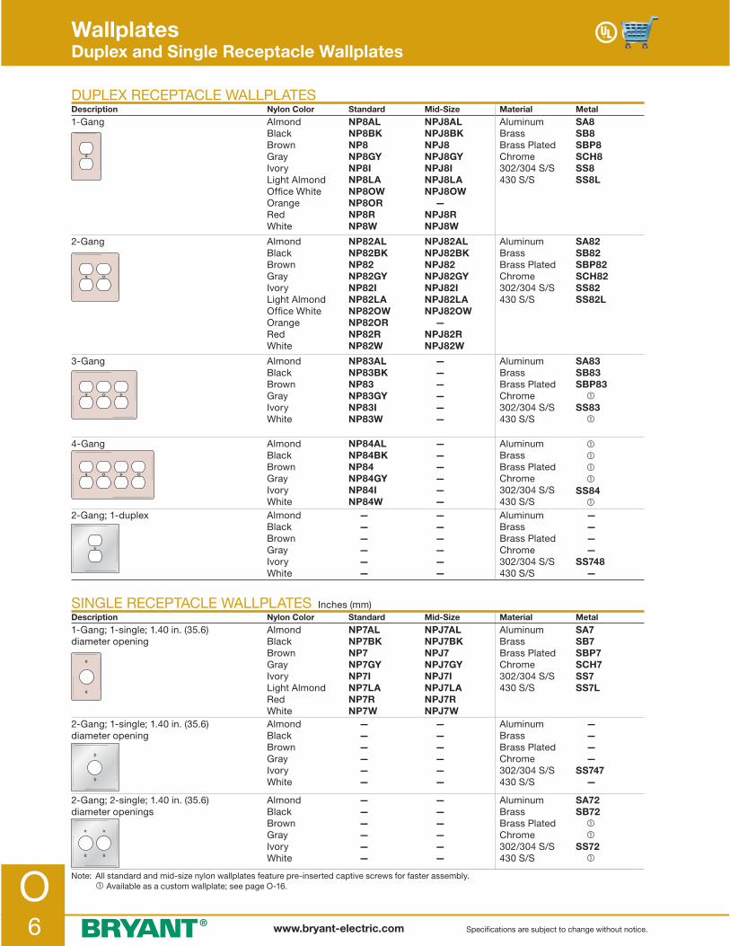
O6 www.bryant-electric.com Specifications are subject to change without notice.
WallplatesDuplex and Single Receptacle Wallplates
DUPLEX RECEPTACLE WALLPLATESDescription Nylon Color Standard Mid-Size Material Metal
1-Gang AlmondBlackBrownGrayIvoryLight AlmondOffice WhiteOrangeRedWhite
NP8ALNP8BKNP8NP8GYNP8INP8LANP8OWNP8ORNP8RNP8W
NPJ8ALNPJ8BKNPJ8NPJ8GYNPJ8INPJ8LANPJ8OW —NPJ8RNPJ8W
AluminumBrassBrass PlatedChrome302/304 S/S430 S/S
SA8SB8SBP8SCH8SS8SS8L
2-Gang AlmondBlackBrownGrayIvoryLight AlmondOffice WhiteOrangeRedWhite
NP82ALNP82BKNP82NP82GYNP82INP82LANP82OWNP82ORNP82RNP82W
NPJ82ALNPJ82BKNPJ82NPJ82GYNPJ82INPJ82LANPJ82OW —NPJ82RNPJ82W
AluminumBrassBrass PlatedChrome302/304 S/S430 S/S
SA82SB82SBP82SCH82SS82SS82L
3-Gang AlmondBlackBrownGrayIvoryWhite
NP83ALNP83BKNP83NP83GYNP83INP83W
— — — — — —
AluminumBrassBrass PlatedChrome302/304 S/S430 S/S
SA83SB83SBP83 �SS83 �
4-Gang AlmondBlackBrownGrayIvoryWhite
NP84ALNP84BKNP84NP84GYNP84INP84W
— — — — — —
AluminumBrassBrass PlatedChrome302/304 S/S430 S/S
� � � �SS84 �
2-Gang; 1-duplex AlmondBlackBrownGrayIvoryWhite
— — — — — —
— — — — — —
AluminumBrassBrass PlatedChrome 302/304 S/S430 S/S
— — — —SS748 —
SINGLE RECEPTACLE WALLPLATES Inches (mm)Description Nylon Color Standard Mid-Size Material Metal
1-Gang; 1-single; 1.40 in. (35.6) diameter opening
AlmondBlackBrownGrayIvoryLight AlmondRedWhite
NP7ALNP7BKNP7NP7GYNP7INP7LANP7RNP7W
NPJ7ALNPJ7BKNPJ7NPJ7GYNPJ7INPJ7LANPJ7RNPJ7W
Aluminum BrassBrass PlatedChrome302/304 S/S430 S/S
SA7SB7SBP7SCH7SS7SS7L
2-Gang; 1-single; 1.40 in. (35.6) diameter opening
AlmondBlackBrownGrayIvoryWhite
— — — — — —
— — — — — —
Aluminum BrassBrass PlatedChrome302/304 S/S430 S/S
— — — —SS747 —
2-Gang; 2-single; 1.40 in. (35.6) diameter openings
AlmondBlackBrownGrayIvoryWhite
— — — — — —
— — — — — —
Aluminum BrassBrass PlatedChrome302/304 S/S430 S/S
SA72SB72 � �SS72 �
Note: All standard and mid-size nylon wallplates feature pre-inserted captive screws for faster assembly. � Available as a custom wallplate; see page O-16.

O7www.bryant-electric.comSpecifications are subject to change without notice.
SINGLE RECEPTACLE WALLPLATES Inches (mm)Description Nylon Color Standard Mid-Size Material Metal
1-Gang; 1-single; 1.60 in. (40.6) dia. opening; 20/30A locking devices
AlmondBlackBrownGrayIvoryOffice WhiteRedWhite
NP720ALNP720BKNP720NP720GYNP720INP720OWNP720RNP720W
— — — — — — — —
Aluminum BrassBrass PlatedChrome302/304 S/S430 S/S
SA720SB720 � �SS720 �
2-Gang; 1-single; 1.60 in. (40.6) dia. opening; 20/30A locking devices
AlmondBlackBrownGrayIvoryWhite
— — — — — —
— — — — — —
Aluminum BrassBrass PlatedChrome302/304 S/S430 S/S
— — —SS749 —
3-Gang; 2-single; 1.60 in. (40.6) dia. opening; 20/30A locking devices
AlmondBlackBrownGrayIvoryWhite
— — — — — —
— — — — — —
Aluminum BrassBrass PlatedChrome302/304 S/S430 S/S
— — —SS320 —
1-Gang; 1-single; 1.70 in. (43.2) dia. opening; 20/30A locking devices
AlmondBlackBrownGrayIvoryWhite
— — — — — —
— — — — — —
Aluminum BrassBrass PlatedChrome302/304 S/S430 S/S
— — —SS725 —
3-Gang; 2-single; 1.70 in. (43.2) dia. opening; 20/30A locking devices
AlmondBlackBrownGrayIvoryWhite
— — — — — —
— — — — — —
Aluminum BrassBrass PlatedChrome302/304 S/S430 S/S
— — —SS330 —
1-Gang; 1-single; 1.97 in. (50.0) dia. opening; 20/30A locking devices
AlmondBlackBrownGrayIvoryWhite
— — — — — —
— — — — — —
Aluminum BrassBrass PlatedChrome302/304 S/S430 S/S
— — —SS737 —
1-Gang; 1-single; 2.15 in. (54.6) dia. opening
AlmondBlackBrownGrayIvoryWhite
NP724ALNP724BKNP724NP724GYNP724INP724W
NPJ724ALNPJ724BKNPJ724NPJ724GYNPJ724INPJ724W
Aluminum BrassBrass PlatedChrome302/304 S/S430 S/S
SA723 � �SCH723SS723SS723L
2-Gang; 1-single; 2.15 in. (54.6) dia. opening
AlmondBlackBrownGrayIvoryWhite
NP703ALNP703BKNP703NP703GYNP703INP703W
NPJ703ALNPJ703BKNPJ703NPJ703GYNPJ703INPJ703W
Aluminum BrassBrass PlatedChrome302/304 S/S430 S/S
— — — —SS703SS703L
2-Gang; 1-single; 2.15 in. (54.6) dia. opening
AlmondBlackBrownGrayIvoryWhite
— — — — — —
— — — — — —
Aluminum BrassBrass PlatedChrome302/304 S/S430 S/S
— —SCH702SS702 —
2-Gang, 1-single; 2.48 in. (63.0) dia. opening
AlmondBlackBrownGrayIvoryWhite
— — — — — —
— — — — — —
Aluminum BrassBrass PlatedChrome302/304 S/S430 S/S
— — —SS701 —
2-Gang, 1-single; 2.66 in. (67.6) dia. opening
AlmondBlackBrownGrayIvoryWhite
— — — — — —
— — — — — —
Aluminum BrassBrass PlatedChrome302/304 S/S430 S/S
— — —SS716 —
Note: All standard and mid-size nylon wallplates feature pre-inserted captive screws for faster assembly. � Available as a custom wallplate; see page O-16.
WallplatesSingle Receptacle Wallplates

O8 www.bryant-electric.com Specifications are subject to change without notice.
WallplatesTelephone and Coaxial Wallplates
TELEPHONE AND COAXIAL WALLPLATES Inches (mm)Description Nylon Color Standard Mid-Size Material Metal
1-Gang; 1-telephone; .375 in. (9.7) hole; box mount
AlmondBrownIvoryWhite
— — — —
— — — —
BrassBrass PlatedChrome302/304 S/S430 S/S
� � �SS739 �
1-Gang; 1-telephone; .375 in. (9.7) hole; strap mount
AlmondBrownIvoryWhite
— — — —
— — — —
BrassBrass PlatedChrome302/304 S/S430 S/S
�SB738 �SS738 �
1-Gang; 1-telephone; .406 in. (10.3) hole; box mount
AlmondBlackBrownGrayIvoryLight AlmondWhite
NP11ALNP11BKNP11NP11GYNP11INP11LANP11W
NPJ11AL —NPJ11 —NPJ11INPJ11LANPJ11W
BrassBrass PlatedChrome302/304 S/S430 S/S
�SBP11* �SS11*SS11L*
1-Gang; 1-telephone; .406 in. (10.3) hole; strap mount
AlmondBlackBrownGrayIvoryWhite
NP12ALNP12BKNP12NP12GYNP12INP12W
— — — — — —
BrassBrass PlatedChrome302/304 S/S430 S/S
SB12*SBP12*SCH12*SS12* �
2-Gang; 2-telephone; .406 in. (10.3) hole; box mount
AlmondBrownIvoryWhite
NP21ALNP21NP21INP21W
— — — —
BrassBrass PlatedChrome302/304 S/S430 S/S
— — — � �
2-Gang; 2-telephone; .406 in. (10.3) hole; strap mount
AlmondBrownIvoryWhite
— — — —
— — — —
BrassBrass PlatedChrome302/304 S/S430 S/S
— — —SS22* �
1-Gang; 1-telephone; .625 in. (15.9) hole; box mount
AlmondBrownIvoryWhite
NP737ALNP737NP737INP737W
— — — —
BrassBrass PlatedChrome302/304 S/S430 S/S
— — — — —
1-Gang; 1-telephone; .625 in. (15.9) hole; strap mount
AlmondBrownIvoryWhite
NP730ALNP730NP730INP730W
— — — —
BrassBrass PlatedChrome302/304 S/S430 S/S
— — — — —
2-Gang; 1-telephone; .64 in. (16.3) hole; box mount
AlmondBrownIvoryWhite
— — — —
— — — —
BrassBrass PlatedChrome302/304 S/S430 S/S
— — —SS741* �
Note: All standard and mid-size nylon wallplates feature pre-inserted captive screws for faster assembly. � Available as a custom wallplate; see page O-16. * .50" (12.7) nylon bushing provided.

O9www.bryant-electric.comSpecifications are subject to change without notice.
“D” HOLE WALLPLATES Inches (mm)Description Nylon Color Standard Mid-Size Material Metal
1-Gang; 1-“D” hole; .51 in. (12.9) dia.; .44 in. (11.2) flat; box mount
AlmondBlackBrownGrayIvoryWhite
— — — — — —
— — — — — —
AluminumBrassBrass PlatedChrome302/304 S/S430 S/S
� � � �SSD1422 �
1-Gang; 2-“D” hole; .51 in. (12.9) dia.; .44 in. (11.2) flat; box mount
AlmondBlackBrownGrayIvoryWhite
— — — — — —
— — — — — —
AluminumBrassBrass PlatedChrome302/304 S/S430 S/S
� � � �SSD1423 �
1-Gang; 2-“D” hole; .51 in. (12.9) dia.; .44 in. (11.2) flat; box mount
AlmondBlackBrownGrayIvoryWhite
— — — — — —
— — — — — —
AluminumBrassBrass PlatedChrome302/304 S/S430 S/S
� � � �SSD1426 �
1-Gang; 1-“D” hole; .58 in. (14.7) dia.; .55 in. (14.0) flat; box mount
AlmondBlackBrownGrayIvoryWhite
— — — — — —
— — — — — —
Aluminum BrassBrass PlatedChrome302/304 S/S430 S/S
� � � �SSD1428 �
1-Gang; 2-“D” hole; .58 in. (14.7) dia.; .55 in. (14.0) flat; box mount
AlmondBlackBrownGrayIvoryWhite
— — — — — —
— — — — — —
Aluminum BrassBrass PlatedChrome302/304 S/S430 S/S
� � � �SSD1429 �
1-Gang; 1-“D” hole; .76 in. (19.3) dia.; .73 in. (18.5) flat; box mount
AlmondBlackBrownGrayIvoryWhite
— — — — — —
— — — — — —
Aluminum BrassBrass PlatedChrome302/304 S/S430 S/S
� � � �SSD1430 �
Note: � Available as a custom wallplate; see page O-16.
Wallplates“D” Hole Wallplates

O10 www.bryant-electric.com Specifications are subject to change without notice.
BLANK STRAP MOUNT WALLPLATESDescription Nylon Color Standard Mid-Size Material Metal
1-Gang AlmondBlackBrownGrayIvoryLight AlmondWhite
NP14ALNP14BKNP14NP14GYNP14INP14W
— — — — — —
BrassBrass PlatedChrome302/304 S/S430 S/S
SB14 � �SS14SS14L
2-Gang AlmondBlackBrownGrayIvoryWhite
NP24ALNP24BKNP24NP24GYNP24INP24W
— — — — — —
BrassBrass PlatedChrome302/304 S/S430 S/S
� � �SS24SS24L
3-Gang AlmondBrownIvoryWhite
NP34ALNP34NP34INP34W
— — — —
BrassBrass PlatedChrome302/304 S/S430 S/S
� � �SS34 �
4-Gang AlmondBrownIvoryWhite
NP44ALNP44NP44INP44W
— — — —
BrassBrass PlatedChrome302/304 S/S430 S/S
� � �SS44 �
Note: All standard and mid-size nylon wallplates feature pre-inserted captive screws for faster assembly. � Available as a custom wallplate; see page O-16.
WallplatesBlank Wallplates
BLANK BOX MOUNT WALLPLATESDescription Nylon Color Standard Mid-Size Material Metal
1-Gang AlmondBlackBrownGrayIvoryLight AlmondWhite
NP13ALNP13BKNP13NP13GYNP13INP13LANP13W
NPJ13ALNPJ13BKNPJ13NPJ13GYNPJ13INPJ13LANPJ13W
AluminumBrassBrass PlatedChrome302/304 S/S430 S/S
SA13SB13SBP13SCH13SS13SS13L
2-Gang AlmondBlackBrownGrayIvoryLight AlmondWhite
NP23ALNP23BKNP23NP23GYNP23INP23LANP23W
NPJ23AL —NPJ23 —NPJ23INPJ23LANPJ23W
AluminumBrassBrass PlatedChrome302/304 S/S430 S/S
SA23SB23SBP23SCH23SS23SS23L
3-Gang AlmondBrownIvoryWhite
NP33ALNP33NP33INP33W
— — — —
AluminumBrassBrass PlatedChrome302/304 S/S430 S/S
� �SBP33 �SS33 �
4-Gang AlmondBrownIvoryWhite
NP43ALNP43NP43INP43W
— — — —
AluminumBrassBrass PlatedChrome302/304 S/S430 S/S
� � � �SS43 �

O11www.bryant-electric.comSpecifications are subject to change without notice.
WallplatesCombination Wallplates
COMBINATION WALLPLATES Inches (mm)Description Nylon Color Standard Mid-Size Material Metal
2-Gang; 1-toggle; 1-duplex AlmondBlackBrownGrayIvoryLight AlmondWhite
NP18ALNP18BKNP18NP18GYNP18INP18LANP18W
NPJ18ALNPJ18BKNPJ18NPJ18GYNPJ18INPJ18LANPJ18W
Aluminum BrassBrass PlatedChrome302/304 S/S430 S/S
�SB18SBP18SCH18SS18SS18L
2-Gang; 1-duplex; 1-decorator AlmondBlackBrownGrayIvoryLight AlmondWhite
NP826ALNP826BKNP826NP826GYNP826INP826LANP826W
NPJ826ALNPJ826BKNPJ826NPJ826GYNPJ826INPJ826LANPJ826W
Aluminum BrassBrass PlatedChrome302/304 S/S430 S/S
�SB826 � �SS826 �
2-Gang; 1-toggle; 1-decorator AlmondBlackBrownGrayIvoryLight AlmondWhite
NP126ALNP126BKNP126NP126GYNP126INP126LANP126W
NPJ126ALNPJ126BKNPJ126NPJ126GYNPJ126INPJ126LANPJ126W
Aluminum BrassBrass PlatedChrome302/304 S/S430 S/S
�SB126SBP126 �SS126SS126L
2-Gang; 1-telephone .41 in. (10.3) hole; 1-duplex; strap mount
AlmondBrownIvoryWhite
NP128ALNP128NP128INP128W
— — — —
Aluminum BrassBrass PlatedChrome302/304 S/S430 S/S
— — — — — —
2-Gang; 1-toggle; 1-telephone .41 in. (10.3) hole; strap mount
AlmondBrownIvoryWhite
NP112ALNP112NP112INP112W
— — — —
Aluminum BrassBrass PlatedChrome302/304 S/S430 S/S
— — — — — —
2-Gang; 1-telephone .41 in. (10.3) hole; 1-decorator; strap mount
AlmondBrownIvoryWhite
NP1226ALNP1226NP1226INP1226W
— — — —
Aluminum BrassBrass PlatedChrome302/304 S/S430 S/S
— — — — — —
2-Gang; 1-single receptacle1.40 in. (35.6) dia. opening; 1-duplex
AlmondBrownIvoryWhite
NP78ALNP78NP78INP78W
— — — —
Aluminum BrassBrass PlatedChrome302/304 S/S430 S/S
� � � �SS78 �
2-Gang; 1-single receptacle1.60 in. (40.6) dia. opening; 1-duplex
AlmondBrownIvoryWhite
— — — —
— — — —
Aluminum BrassBrass PlatedChrome302/304 S/S430 S/S
� � � �SS8720 �
2-Gang; 1-toggle; 1-single receptacle 1.40 in. (35.6) dia. opening
AlmondBlackBrownGrayIvoryWhite
NP17ALNP17BKNP17NP17GYNP17INP17W
— — — — — —
Aluminum BrassBrass PlatedChrome302/304 S/S430 S/S
� � � �SS17 �
2-Gang; 1-toggle; 1-blank; box mount
AlmondBrownIvoryLight AlmondWhite
NP113ALNP113NP113INP113LANP113W
NPJ113ALNPJ113NPJ113INPJ113LANPJ113W
Aluminum BrassBrass PlatedChrome302/304 S/S430 S/S
� � � �SS113 �
Note: All standard and mid-size nylon wallplates feature pre-inserted captive screws for faster assembly. � Available as a custom wallplate; see page O-16.

O12 www.bryant-electric.com Specifications are subject to change without notice.
WallplatesCombination Wallplates
COMBINATION WALLPLATES Inches (mm)Description Nylon Color Standard Mid-Size Material Metal
2-Gang; 1-toggle; 1-blank; strap mount
AlmondBrownIvoryLight AlmondWhite
— — — — —
— — — — —
Aluminum BrassBrass PlatedChrome302/304 S/S430 S/S
� � � �SS114 �
2-Gang; 1-blank; 1-duplex; box mount
AlmondBrownIvoryWhite
NP138ALNP138NP138INP138W
NPJ138ALNPJ138NPJ138INPJ138W
Aluminum BrassBrass PlatedChrome302/304 S/S430 S/S
� � � �SS138 �
2-Gang; 1-blank; 1-duplex; strap mount
AlmondBrownIvoryWhite
— — — —
— — — —
Aluminum BrassBrass PlatedChrome302/304 S/S430 S/S
� � � �SS148 �
2-Gang; 1-blank; 1-decorator; box mount
AlmondBlackBrownGrayIvoryLight AlmondWhite
NP1326ALNP1326BKNP1326NP1326GYNP1326INP1326LANP1326W
NPJ1326AL —NPJ1326 —NPJ1326INPJ1326LANPJ1326W
Aluminum BrassBrass PlatedChrome302/304 S/S430 S/S
� � � �SS1426 �
2-Gang; 1-telephone .41 in. (10.3) hole; 1-blank; strap mount
AlmondBrownIvoryWhite
NP1214ALNP1214NP1214INP1214W
— — — —
Aluminum BrassBrass PlatedChrome302/304 S/S430 S/S
— — — — — —
2-Gang; 1-single receptacle 1.40 in. (35.6) dia. opening; 1-blank; strap mount
AlmondBlackBrownGrayIvoryWhite
NP147ALNP147BKNP147NP147GYNP147INP147W
— — — — — —
Aluminum BrassBrass PlatedChrome302/304 S/S430 S/S
— — — — — —
3-Gang; 2-toggle; 1-duplex AlmondBlackBrownGrayIvoryLight AlmondWhite
NP28ALNP28BKNP28NP28GYNP28INP28LANP28W
NPJ28AL —NPJ28 —NPJ28INPJ28LANPJ28W
Aluminum BrassBrass PlatedChrome302/304 S/S430 S/S
� �SBP28 �SS28 �
3-Gang; 1-toggle; 2-duplex AlmondBrownIvoryWhite
NP182ALNP182NP182INP182W
— — — —
Aluminum BrassBrass PlatedChrome302/304 S/S430 S/S
� � � �SS182 �
Note: All standard and mid-size nylon wallplates feature pre-inserted captive screws for faster assembly. � Available as a custom wallplate; see page O-16.

O13www.bryant-electric.comSpecifications are subject to change without notice.
COMBINATION WALLPLATESDescription Nylon Color Standard Mid-Size Material Metal
3-Gang; 2-toggle; 1-decorator AlmondBlackBrownGrayIvoryLight AlmondWhite
NP226ALNP226BKNP226NP226GYNP226INP226LANP226W
NPJ226ALNPJ226BKNPJ226NPJ226GYNPJ226INPJ226LANPJ226W
Aluminum BrassBrass PlatedChrome302/304 S/S430 S/S
� � � �SS226 �
3-Gang; 1-toggle; 2-decorator AlmondBlackBrownGrayIvoryLight AlmondWhite
NP1262ALNP1262BKNP1262NP1262GYNP1262INP1262LANP1262W
— — — — — — —
Aluminum BrassBrass PlatedChrome302/304 S/S430 S/S
� � � � � �
3-Gang; 2-duplex; 1-blank; box mount AlmondBrownIvoryWhite
— — — —
— — — —
Aluminum BrassBrass PlatedChrome302/304 S/S430 S/S
� � � �SS211 �
3-Gang; 1-duplex; 1-blank; 1-duplex; box mount
AlmondBrownIvoryWhite
— — — —
— — — —
Aluminum BrassBrass PlatedChrome302/304 S/S430 S/S
� � � �SS8147 �
3-Gang; 2-toggle; 1-blank; box mount AlmondBrownIvoryWhite
— — — —
— — — —
Aluminum BrassBrass PlatedChrome302/304 S/S430 S/S
— — — —SS213 �
4-Gang; 3-toggle; 1-duplex AlmondBrownIvoryLight AlmondWhite
NP38ALNP38NP38INP38LANP38W
— — — — —
Aluminum BrassBrass PlatedChrome302/304 S/S430 S/S
� � � �SS38 �
4-Gang; 3-toggle; 1-decorator AlmondBlackBrownGrayIvoryLight AlmondWhite
NP326ALNP326BKNP326NP326GYNP326INP326LANP326W
— — — — — — —
Aluminum BrassBrass PlatedChrome302/304 S/S430 S/S
� � � �SS326 �
4-Gang; 2-toggle; 2-decorator AlmondBlackBrownGrayIvoryLight AlmondWhite
NP2262ALNP2262BKNP2262NP2262GYNP2262INP2262LANP2262W
— — — — — — —
Aluminum BrassBrass PlatedChrome302/304 S/S430 S/S
� � � � � �
5-Gang; 4-toggle; 1-duplex AlmondBrownIvoryWhite
NP48ALNP48NP48INP48W
— — — —
Aluminum BrassBrass PlatedChrome302/304 S/S430 S/S
� � � � � �
Note: All standard and mid-size nylon wallplates feature pre-inserted captive screws for faster assembly. � Available as a custom wallplate; see page O-16.
WallplatesCombination Wallplates

O14 www.bryant-electric.com Specifications are subject to change without notice.
WallplatesData Communication and Louver Wallplates
RJ11 AND RJ45 MODULAR JACK WALLPLATES Inches (mm)Description Nylon Color Standard Mid-Size Material Metal
1-Gang; 1- .59 in. x .76 in.(15.0 x 19.3) opening
AlmondBlackBrownGrayIvoryWhite
— — — — — —
— — — — — —
AluminumBrassBrass PlatedChrome302/304 S/S430 S/S
� � � �SST1473 �
1-Gang; 2- .59 in. x .76 in.(15.0 x 19.3) opening
AlmondBlackBrownGrayIvoryWhite
— — — — — —
— — — — — —
AluminumBrassBrass PlatedChrome302/304 S/S430 S/S
� � � �SST1474 �
2-Gang; 4- .59 in. x .76 in.(15.0 x 19.3) opening
AlmondBlackBrownGrayIvoryWhite
— — — — — —
— — — — — —
AluminumBrassBrass PlatedChrome302/304 S/S430 S/S
� � � �SST2474 �
1-Gang; 1- .59 in. x .82 in.(15.0 x 20.8) opening
AlmondBlackBrownGrayIvoryWhite
— — — — — —
— — — — — —
Aluminum BrassBrass PlatedChrome302/304 S/S430 S/S
� � � �SST1476 �
1-Gang; 2- .59 in. x .82 in.(15.0 x 20.8) opening
AlmondBlackBrownGrayIvoryWhite
— — — — — —
— — — — — —
Aluminum BrassBrass PlatedChrome302/304 S/S430 S/S
� � � �SST1477 �
LOUVER WALLPLATESDescription Nylon Color Standard Mid-Size Material Metal
1-Gang; vertical box mounted AlmondBlackBrownGrayIvoryWhite
— — — — — —
— — — — — —
Aluminum BrassBrass PlatedChrome302/304 S/S430 S/S
�SB771SBP771 �SS771 �
Note: � Available as a custom wallplate; see page O-16.
RS232 WALLPLATESDescription Nylon Color Standard Mid-Size Material Metal
1-Gang; 1- 25-pin opening AlmondBlackBrownGrayIvoryWhite
— — — — — —
— — — — — —
Aluminum BrassBrass PlatedChrome302/304 S/S430 S/S
� � � �SS232 �
1-Gang; 2- 25-pin openings AlmondBlackBrownGrayIvoryWhite
— — — — — —
— — — — — —
Aluminum BrassBrass PlatedChrome302/304 S/S430 S/S
� � � �SS234 �

O15www.bryant-electric.comSpecifications are subject to change without notice.
WallplatesJumbo Metal Wallplates
JUMBO, STAINLESS STEEL, BRUSHED FINISH Inches (mm)
Description Material Catalog Number Description Material Catalog Number
1-Gang; 1-toggle 302/304 S/S430 S/S
SSJ1 —
1-Gang; 1-single receptacle 2.09–2.13 in. (53.1–54.1) dia. opening
302/304 S/S430 S/S
SSJ723 —
2-Gang; 2-toggle 302/304 S/S430 S/S
SSJ2 —
1-Gang; blank; box mount 302/304 S/S430 S/S
SSJ13 —
1-Gang; 1-duplex 302/304 S/S430 S/S
SSJ8 —
1-Gang; 1-telephone .64 in. (16.3) hole; box mount
302/304 S/S430 S/S
SSJ11* —
2-Gang; 2-duplex 302/304 S/S430 S/S
SSJ82 —
2-Gang; 1-toggle; 1-duplex 302/304 S/S430 S/S
SSJ18 —
1-Gang; 1-decorator 302/304 S/S430 S/S
SSJ26 —
2-Gang; 1-toggle; 1-decorator 302/304 S/S430 S/S
SSJ126 —
2-Gang; 2-decorator 302/304 S/S430 S/S
SSJ262 —
3-Gang; 2-toggle; 1-decorator 302/304 S/S430 S/S
SSJ226 —
1-Gang; 1-single receptacle 1.36–1.39 in. (34.5–35.3) dia. opening
302/304 S/S430 S/S
SSJ7 —
Note: * .50" (12.7) nylon bushing provided.3.50"(88.9)
5.25"(133.4)
2.15" (54.6)I.D. opening
1.40" (35.6)I.D. opening
Jumbo Metal Wallplate Dimensions 1-Gang; 5.25 in. x 3.50 in. (133.4 x 88.9) 2-Gang; 5.25 in. x 5.31 in. (133.4 x 134.9) 3-Gang; 5.25 in. x 7.12 in. (133.4 x 180.8)

O16 www.bryant-electric.com Specifications are subject to change without notice.
Step 1: Determine wallplate material and enter in box marked "Catalog Number"
Step 2: Enter quantity.
Smooth Metal Material Code
Aluminum ALBrass plated steel BPSolid brass BRChrome plated steel CHStainless steel 302/304 SSStainless steel 430 SL
Number ofGangs Code
1-Gang 12-Gang 23-Gang 34-Gang 45-Gang 56-Gang 67-Gang 78-Gang 8
Determine number of gangs required and enter in box marked "Catalog Number" next to material.
Step 3: Select the custom metal wallplate configuration.
Refer to the custom wallplate configuration chart to select a configuration for each gang in the wallplate. Each configuration has a specific 3-digit code located in the chart on page O-17. Enter this 3-digit configuration code in the corresponding box on the order form grid to match the position required on the finished custom wallplate.
� � � �
The 3-digit numbers listed in the Sample Order Form above (001, 149, etc.) represent the configuration for the custom metal wallplate selected on the right. See Configuration Chart and Bryant Configuration Selector Guide on page O-17 for additional configuration choices.
Note: *BWC are preprinted on the distributor order form. � Number to use for pricing.
Item Position Position Position Position No. Catalog Number Quantity 1 2 3 4
1 BWCSS4 001 149 008 026
2
HOW TO SELECT A CUSTOM METAL WALLPLATE
WallplatesCustom Metal Wallplates
Enter Catalog Number.
� BWC* SS 4

O17www.bryant-electric.comSpecifications are subject to change without notice.
CONFIGURATION CHART Inches (mm)
WallplatesCustom Metal Wallplates
001 Toggle switch
007 Single receptacle; 1.40 in. (35.6) I.D. opening
008 Duplex receptacle
011 1-Telephone .64 in. (16.3) I.D. hole; box mount; .50 in. (12.7) I.D.; nylon bushing
012 1-Telephone .64 in. (16.3) I.D. hole; strap mount; .50 in. (12.7) I.D.; nylon bushing
013 Blank; box mount
014 Blank; strap mount
026 Decorator opening
055 1-Telephone; .38 in. (9.7) I.D. hole; strap mount
056 1-Telephone; .38 in. (9.7) I.D. hole; box mount
057 1-Telephone; .50 in. (12.7) I.D. hole; strap mount
058 1-Telephone; .50 in. (12.7) I.D. hole; box mount
078 Barrel key switch
079 Barrel key switch with hash marks
080 Barrel key switch with ON/OFF and hash marks
091 Single receptacle; 1.60 in. (40.6) I.D. opening
098 Single receptacle; 2.16 in. (54.7) I.D. opening
135 Louver; vertical mount
149 Blank; no mounting holes
Coax/Twinax and Modular Jack Openings
422 1-“D” hole; .51 in. (12.9) dia.; .44 in. (11.2) flat; box mount 425 1-“D” hole; .51 in. (12.9) dia.;
.47 in. (12.0) flat; box mount 428 1-“D” hole; .58 in. (14.7) dia.; .55 in. (14.0) flat; box mount 430 1-“D” hole; .76 in. (19.3) dia.; .73 in. (18.5) flat; box mount
423 2-“D” hole; .51 in. (12.9) dia.; .44 in. (11.2) flat; box mount 426 2-“D” hole; .51 in. (12.9) dia.; .47 in. (12.0) flat; box mount 429 2-“D” hole; .58 in. (14.7) dia.; .55 in. (14.0) flat; box mount 431 2-“D” hole; .76 in. (19.3) dia.; .73 in. (18.5) flat; box mount
456 2-Telephone .38 in. (9.7) dia. hole; box mount 458 2-Telephone .50 in. (12.7) dia. hole; box mount 411 2-Telephone .64 in. (16.3) dia. hole; box mount
435 9-Pin; vertical box mount
438 15-Pin; vertical box mount
295 25-Pin; vertical box mount
314 1-IBM® type opening; box mount
415 1-IBM® type opening; 1- .59 in. X .76 in. (15.0 X 19.3) opening
Voice/Data Opening
470 1- .54 in. X .75 in. (13.8 X 19.1) opening; vertical box mount 473 1- .59 in. X .76 in. (15.0 X 19.3) opening; vertical box mount 476 1- .59 in. X .82 in. (15.0 X 20.8) opening; vertical box mount 479 1- .58 in. X .78 in. (14.6 X 19.8) opening; vertical box mount
471 2- .54 in. X .75 in. (13.8 X 19.1) opening; vertical box mount 474 2- .59 in. X .76 in. (15.0 X 19.3) opening; vertical box mount 477 2- .59 in. X .82 in. (15.0 X 20.8) opening; vertical box mount 480 2- .58 in. X .78 in. (14.6 X 19.8) opening; vertical box mount
Note: For detailed dimensions of the above configurations, contact Technical Service at [email protected]. Available in brushed metal, standard size only up to and including 8-gang type. IBM® is a registered trademark of International Business Machines Corporation.
ON
OFF

O18 www.bryant-electric.com Specifications are subject to change without notice.
“EMERGENCY” WALLPLATES
Description
302/304 Stainless Steel; Standard Size; Engraved Red Filled Lettering
Red Nylon; Mid-Size; Hot Stamped White Lettering
1-Gang; 1-duplex SS8MEV NPJ8RMEV2-Gang; 2-duplex SS82MEV N2202MEM1-Gang; 1-toggle SS1ME NPJ1RMENote: All lettering is ¼ inch (6.4 mm) high.
“COMPUTER ONLY” WALLPLATES
Description
Orange Nylon; Mid-Size; Hot Stamped Black Lettering
Ivory Nylon; Mid-Size; Hot Stamped Black Lettering
Blue Nylon; Mid-Size; Hot Stamped Black Lettering
1-Gang; 1-duplex NPJ8CO NPJ8C —1-Gang; 1-decorator — NPJ26C NPJ26CBL2-Gang; 2-duplex NPJ82CO — —Note: All lettering is ¼ inch (6.4 mm) high.
OIL AND GAS BURNER EMERGENCY PLATES Inches (mm)
Description Oil Burner Cover Gas Burner Cover Emergency Cover
1-Gang; 1-toggle; ¼ in. (6.4) silk screened white letters on red enameled steel
S22710EM S2271GEM —
Utility/handy box cover; 1-toggle; ¼ in. (6.4) silk screened white letters on red enameled steel
SY865OEM SY865GEM SY865EM
4 in. (101.6) square box cover; 1-toggle; ¼ in. (6.4) silk screened white letters on red enameled steel
SY800OEM SY800GEM —
4 in. (101.6) square box cover; 2-toggle; ¼ in. (6.4) silk screened white letters on red enameled steel
— SY803GEM —
“ISOLATED GROUND” Inches (mm)
Description Orange Nylon; Standard-Size; Hot Stamped Black Lettering
1-Gang; 1-duplex NP8OIG
1-Gang; 1-duplex; no marking NP8OR
1-Gang; 1-decorator NP26OIG
1-Gang; 1-single receptacle 1.40 in. (35.6) dia. opening for receptacles with face diameter 1.36–1.39 in. (34.5-35.3)
NP7OIG
1-Gang; 1-single receptacle 1.60 in. (40.6) dia. opening for 20A and 30A locking receptacles with face diameter 1.55–1.58 in. (39.4-40.1)
NP720OIG
Note: All lettering is ¼ inch (6.4 mm) high.
ISOLATEDGROUND
ISOLATED
GROUND
ISOLATEDGROUND
COMPUTERONLY
COMPUTER
ONLY
WallplatesPremarked and Specialty Wallplates

O19www.bryant-electric.comSpecifications are subject to change without notice.
“LOCKING” WALLPLATES AND ACCESSORIES
Description
Catalog Number
1-Gang 2-Gang
302 stainless steel with on/off marking SS12RKL SS22RKL
302 stainless steel with position marking SS12RKLM SS22RKLM
Accessories Catalog Number
Tamper proof wallplate screws ½ in.; 302 SS spanner head SSTP12
Spaner head screw driver SSTPD
Replacement barrel key 6006RKL
WallplatesBarrel Key Switch Wallplates and Accessories
ADAPTERS Inches (mm)
Description Color Catalog Number
1-Gang; decorator frame adapter .41 in. (10.3) diameter hole AlmondIvoryLight AlmondWhite
NS621ALNS621INS621LANS621W
1-Gang; blank decorator frame adapter; to fill an unused decorator opening or to adapt for custom application
AlmondIvoryLight AlmondWhite
NS620ALNS620INS620LANS620W
YOKES**Description Color Catalog Number
Blank toggle adapter; to fill an unused toggle opening BrownIvoryWhite
RA756RA756IRA756W
Mounting strap; with screws Steel RA40
TAMPERPROOF STAINLESS STEEL PLATE SCREWS TYPE 302/304 AND SCREWDRIVER** Inches (mm)
DescriptionLength in. (mm) Catalog Number
Spanner head type 6-32 thread " (3.2)" (9.5)" (12.7)" (15.9)
1" (25.4)2" (50.8)
SSTP14SSTP38SSTP12SSTP58SSTP1SSTP2
Spanner head screwdriver — SSTPDNote: Screws sold in carton quantities of 100.
WALLPLATE SCREWS**Catalog Number
Description Color/MaterialDecorator
" LongStandard ½" Long
Standard 1" Long
Wallplate screws; oval head milled slot; 6-32 thread; 100 per box (order 1 to receive a box of 100)
AlmondBlackBrownGrayIvoryLight AlmondWhiteBrassChrome302/304 S/S
RA38ALPK100RA38BKPK100RA38PK100RA38GYPK100RA38IPK100RA38LAPK100RA38WPK100RA38BRPK100RA38CHPK100RA38SSPK100
RA12ALPK100RA12BKPK100RA12PK100RA12GYPK100RA12IPK100RA12LAPK100RA12WPK100RA58BRPK100*RA58CHPK100*RA58SSPK100*
— — — — RA88IPK100 — RA88WPK100 — —RA88SSPK100
Note: * inch long. ** Not UL Listed or CSA Certified.

O20 www.bryant-electric.com Specifications are subject to change without notice.
WALLPLATE SELECTION CHART FOR SINGLE RECEPTACLES Inches (mm)
Typical Receptacle
Matching Wallplate
Stainless Steel
302/304
Stainless Steel 430
Solid Brass
Hi-Impact Nylon
Ivory Brown
15 or 20 amp straight blade
devices
15 amplocking devices
1-Gang; single receptacle
1.40 (35.6) I.D. opening
SS7 SS7L SB7 NP7I NP7*
20 or 30 amp locking devices 3-wire, 4-wire
or 5-wire
1-Gang; single receptacle
1.60 (40.6) I.D. opening
SS720 — SB720 NP720I NP720*
30 or 50 amp 3-wire power
outlets
1-Gang; power outlet 2.15 (54.6) I.D.
openingSS723 SS723L — NP724I NP724*
2-Gang; power outlet 2.15 (54.6) I.D.
openingSS702 — — — —
2-Gang; 2.15 (54.6) I.D. opening 1.81 W. (46.0) x 2.38 H. (60.3)
mounting
SS703 SS703L — NP703I NP703*
30, 50 or 60 amp 3-wire power outlets
2-Gang; 2.48 (63.0) I.D. opening 1.81 W. (46.0) x 2.38 H. (60.3)
mounting
SS701 — — — —
Note: *Catalog number indicated is Brown, for full offering of color options and materials see page O-7.
WallplatesSelection Chart

O21www.bryant-electric.comSpecifications are subject to change without notice.
A
B
A
B
Standard Size Mid-Size Jumbo
Gang A B A B A B
1-Gang2-Gang3-Gang4-Gang5-Gang6-Gang7-Gang8-Gang
4.50" (114.3)4.50" (114.3)4.50" (114.3)4.50" (114.3)4.50" (114.3)4.50" (114.3)4.50" (114.3)4.50" (114.3)
2.87" (72.9) 4.60" (116.8)6.41" (162.8)8.22" (208.8)10.03" (254.8)11.81" (300.0)13.63" (347.5)15.44" (392.1)
4.88" (124.0)4.88" (124.0)4.88" (124.0) — — — — —
3.13" (79.5)4.94" (125.5)6.75" (171.5) — — — — —
5.25" (133.4)5.25" (133.4)5.25" (133.4) — — — — —
3.50" (88.9)5.31" (134.9)7.12" (180.8) — — — — —
Standard Size Mid-Size Snap-on
Gang A B A B A B
1-Gang2-Gang3-Gang4-Gang5-Gang6-Gang
4.63" (117.6)4.63" (117.6)4.63" (117.6)4.63" (117.6)4.63" (117.6)4.63" (117.6)
2.88" (73.2)4.69" (119.1)6.50" (165.1)8.31" (211.1)10.12" (256.1)11.93" (303.0)
4.88" (124.0)4.88" (124.0)4.88" (124.0)4.88" (124.0) — —
3.13" (79.5)4.94" (125.4)6.75" (171.5)8.56" (217.4) — —
4.68" (118.9)4.68" (118.9)4.68" (118.9)4.68" (118.9)4.68" (118.9)4.68" (118.9)
2.94" (74.7)4.75" (120.7)6.56" (166.6)8.37" (212.6)10.18" (258.6)11.99" (304.5)
Wallplates Dimensions and Material Specifications
NYLON Inches (mm)
SpecificationsThicknessMounting Screw(s)Feature
Operating TemperatureAppearance
.06 in. (1.5)Brass (painted slotted screw head)Captive mounting screw hole; positive bow for flush mounting-40°C to 85°CSmooth
NYLON, STAINLESS STEEL AND BRASSListings
Conforms to applicable NEMA and ANSI StandardsMeets UL Standard 514D and CSA C22.2 #42.1UL Listed (Brass, Stainless Steel and Nylon)CSA Certified
302/304 STAINLESS STEEL (18% CHROMIUM, 8% NICKEL) Inches (mm)
SpecificationsThicknessMounting Screw(s)
Appearance
.035 in. (.9) nominal302/304 stainless steel (18% chromium, 8% nickel); slotted screw headBrushed finish
430 STAINLESS STEEL (17% CHROMIUM, LESS THAN 0.50% NICKEL) Inches (mm)
SpecificationsThicknessMounting Screw(s)
Appearance
.035 in. (.9) nominal302/304 stainless steel (18% chromium, 8% nickel); slotted screw headBrushed finish
BRASS (70% COPPER, 30% ZINC) Inches (mm)
SpecificationsThicknessMounting Screw(s)
Operating TemperatureAppearance
.04 in. (1.0)Brass (70% copper, 30% zinc); slotted screw head-40°C to 85°CBrushed finish
ALUMINUM Inches (mm)
SpecificationsThicknessMounting Screw(s)Appearance
.05 in. (1.3)Aluminum slotted headBrushed finish; clear anodized
BRASS-PLATED STEEL Inches (mm)
SpecificationsThicknessMounting Screw(s)Appearance
.03 in. (.8) nominalBrass slotted headPolished finish; coated to inhibit oxidation
CHROME-PLATED STEEL Inches (mm)
Specifications
ThicknessMounting Screw(s)Appearance
.03 in. (.8) NominalZinc-plated steel slotted headPolished finish; coated to inhibit oxidation
METAL PRODUCT DIMENSIONS Inches (mm)
NYLON PRODUCT DIMENSIONS Inches (mm)

O22 www.bryant-electric.com Specifications are subject to change without notice.
ZINC DIE CAST; 1-GANG; VERTICAL MOUNT Inches (mm)
Description Dimensions
Height x Width x Depth Catalog Number
1-Duplex; box mount; gray 4.58" x 2.82" x 0.57"(116.3 x 71.6 x 14.5)
RW51470
1-Single receptacle; 1.40 in. (35.6) dia. opening; box mount; gray
4.56" x 2.81" x 0.88"(115.8 x 71.4 x 22.4)
RW51550*
1-Decorator; box mount; gray 4.58" x 2.81" x 0.57"(116.3 x 71.4 x 14.5)
RW51040
ZINC DIE CAST; 1-GANG; HORIZONTAL MOUNT Inches (mm)
Description Dimensions
Height x Width x Depth Catalog Number
1-Duplex; box mount; gray 2.82" x 4.57" x 0.79"(71.6 x 116.1 x 20.1)
RW51810
1-Single receptacle; 1.40 in. (35.6) dia. opening; box mount; gray
2.81" x 4.56" x 0.99"(71.4 x 115.8 x 25.1)
RW51520*
1-Decorator; box mount; gray 2.82" x 4.56" x 0.52"(71.6 x 115.8 x 11.3)
RW51020
ZINC DIE CAST; 2-GANG; VERTICAL MOUNT Inches (mm)
Description Dimensions
Height x Width x Depth Catalog Number
2-Duplex; box mount; gray 4.54" x 4.54" x 0.75"(115.3 x 115.3 x 19.1)
RW51320
1-Duplex; 1-decorator; box mount; gray 4.54" x 4.54" x 0.77"(115.3 x 115.3 x 19.6)
RW51330
2-Single receptacle; 1.40 in. (35.6) dia. opening; box mount; gray
4.54" x 4.54" x 0.77"(115.3 x 115.3 x 19.6)
RW51380
2-Decorator; box mount; gray 4.54" x 4.56" x 0.73"(115.3 x 115.8 x 18.5)
RW51450
Note: All weatherproof plates are UL Listed for WET LOCATIONS WITH COVER CLOSED, for intermittent use in wet locations or use in damp locations. All plates are gasketed and self-closing. *cULus Listed.
WallplatesWeatherproof Covers

O23www.bryant-electric.comSpecifications are subject to change without notice.
WallplatesWeatherproof Covers
DIE CAST ALUMINUM; 1-GANG; VERTICAL MOUNT Inches (mm)
Description Catalog Number
1.62 in. (41.1) dia. opening; 20 and 30 amp; locking receptacle 7420B
2.15 in. (54.6) dia. opening; 30 and 50 amp; 3-wire power receptacle 7427B
2.31 in. (58.7) dia. opening for “MBWP” inlet 7429B
20 amp power interrupting; locking receptacle 23007
30 amp power interrupting; locking receptacle; lift cover 20405
50 amp standard locking receptacle 7770
Front Side
2.81 (71.4)
4.67(118.6)
.86(21.8)
PRODUCT DIMENSIONS Inches (mm)
CATALOG NUMBER FOR RECEPTACLES IN GROUPS Inches (mm)
Boss diameter1.36" to 1.39"(34.5 to 35.3)
Boss diameter1.55" to 1.58"(39.4 to 40.1)
Boss diameter1.68" to 1.72"(42.7 to 43.7)
Boss diameter2.09" to 2.13"(53.1 to 54.1)
Boss diameter2.28" to 2.44"(57.9 to 62.0)
52615251566153615351546147104760758273108210
83107250528452585684538454845261IG5361IG753570615FR
70520FR70620FR70720FR70820FR70920FR70530FR70630FR70730FR70830FR70930FR71020FR71120FR
71220FR71030FR71130FR 71230FR71330FR71420FR71520FR71620FR71430FR71530FR71630FR71730FR
71820FR71920FR72020FR71830FR71930FR72030FR 72120FR72220FR72320FR72130FR72230FR72330FR
333034303520741040045FRFSL1FRFSL2FRFSL3FRFSL4FR
9530FR9630FR930393069550FR9650FR
3771737937696369CR6370CR
CS6369LCS6370LCS8169LCS8269LCS8369LCS8469L CS6369ACS6370ACS8169ACS8269ACS8369ACS8469A
NON-METALLIC; 1-GANG; VERTICAL MOUNT FOR FLANGED DEVICESDescription Catalog Number
Yellow fiberglass weatherproof plate with lift lid for 50 amp locking receptacles; fits F.S. and F.D. boxes
7774CR
7774CR7420B
4.56(115.8)
3.25(82.6)
2.84(72.1)
.188 (4.8) Dia. Thru(4) Holes
1.88 (47.8)
2.40(61.0)
23007
7420B
7770
7774CR

O24 www.bryant-electric.com Specifications are subject to change without notice.
NON-METALLIC; 1-GANG; VERTICAL MOUNT FOR FLANGED DEVICESDescription Catalog Number
Weatherproof lift cover for use with 15 amp locking flanged equipment devices (inlets and receptacles)
WPC1
Weatherproof lift cover for use with 20 and 30 amp locking flanged equipment devices (inlets and receptacles)
WPC2
Weatherproof lift cover for use with 50 amp locking non-metallic flanged inlets 7780*
Note: *cULus Listed only; not CSA Certified.
USE WITH FLANGED INLETS AND FLANGED RECEPTACLES LISTED BELOWCatalog Number Use with flanged inlets and flanged receptacles listed below
WPC1 4716MB 4715ER 70615MB 70615ER 4786MB 4785ER 7556MB 7557ER
8808 8809
WPC2 70520MB 70520ER 70620MB 70620ER 70720MB 70720ER 70820MB 70820ER
70920MB 70920ER 70530MB 70530ER 70630MB 70630ER 70730MB 70730ER
70830MB 70830ER 70930MB 70930ER 7327 7328 71020MB 71020ER
71120MB 71120ER 71220MB 71220ER 71030MB 71030ER 71230MB 71230ER
71330MB 71330ER 71420MB 71420ER 71520MB 71520ER 71620MB 71620ER
71430MB 71430ER 71530MB 71530ER 71630MB 71630ER 71730MB 71730ER
7408MB 7409ER 71820MB 71820ER 71920MB 71920ER 72020MB 72020ER
71830MB 71830ER 71930MB 79130ER 72030MB 72030ER 72120MB 72120ER
72220MB 72220ER 72320MB 72320ER 40045MB 40045ER 72130MB 72130ER
72230MB 72230ER 72330MB 72330ER
7780 CS6375L
CS8375L
WPC2 7780
2.84(72.1)
.188 (4.8) Dia. Thru(4) Holes1.88 (47.8)
1.22(31.0)
3.25(82.6)
4.56(115.8)
.19 (4.8) Dia. Thru(4) Holes
2.84 (72.1)
1.09(27.7)
1.88 (47.8)
3.25(82.6)
4.56(115.8)
Note: Device not included.
PRODUCT DIMENSIONS Inches (mm)
WallplatesWeatherproof Covers

O25www.bryant-electric.comSpecifications are subject to change without notice.
NON-METALLIC; 1-GANG; WHILE-IN-USE Inches (mm)
DescriptionDimensions
Height x Width x Depth Catalog Number
Vertical mount; four plates included; 1-duplex, 1-decorator, 1-toggle and 1-single receptacle with eight dia. openings to choose from. (1.34 in., 1.41 in., 1.47 in., 1.59 in., 1.66 in., 1.79 in., 2.03 in. and 2.16 in.)
3.88" x 6.00" x 2.88"(98.6 x 152.4 x 73.2)
RW57300
Deep cover; vertical mount; four plates included; 1-duplex, 1-decorator, 1-toggle and 1-single receptacle with eight dia. openings to choose from. (1.34 in., 1.41 in., 1.47 in., 1.59 in., 1.66 in., 1.79 in., 2.03 in. and 2.16 in.)
3.88" x 6.00" x 4.88"(98.6 x 152.4 x 124.0)
RW57350
Horizontal mount; four plates included; 1-duplex, 1-decorator, 1-toggle and 1-single receptacle with eight dia. openings to choose from. (1.34 in., 1.41 in., 1.47 in., 1.59 in., 1.66 in., 1.79 in., 2.03 in. and 2.16 in.)
5.50" X 4.38" x 2.88" (139.7 x 111.3 x 73.2)
RW57400
NON-METALLIC; 2-GANG; WHILE-IN-USE Inches (mm)
DescriptionDimensions
Height x Width x Depth Catalog Number
Four plates included; 2-duplex, 2-decorator, 1-toggle and 1-single receptacle with eight dia. openings to choose from. (1.34 in., 1.41 in., 1.47 in., 1.59 in., 1.66 in., 1.79 in., 2.03 in. and 2.16 in.)
5.50" x 6.00" x 2.88"(139.7 x 152.4 x 73.2)
RW57750
Deep cover; four plates included; 2-duplex, 2-decorator, 1-toggle and 1-single receptacle with eight dia. openings to choose from. (1.34 in., 1.41 in., 1.47 in., 1.59 in., 1.66 in., 1.79 in., 2.03 in. and 2.16 in.)
5.50" x 6.00" x 4.88"(139.7 x 152.4 x 124.0)
RW57900
Deep cover; two plates included; 1-single receptacle with 2.66 in. dia. opening; 1-single receptacle with eight dia. openings to choose from. (1.34 in., 1.41 in., 1.47 in., 1.59 in., 1.66 in., 1.79 in., 2.03 in. and 2.16 in.)
5.50" x 6.00" x 4.88"(139.7 x 152.4 x 124.0)
RW57950
WallplatesWeatherproof Covers

O26 www.bryant-electric.com Specifications are subject to change without notice.
• Extra deep weatherproof box gives installers the room needed to wire the box efficiently• State-of-the-art powder-coated finish provides years of protection against the elements• Includes hardware; gasket and ground screw are provided• Male inlet is securely mounted to the cover for additional durability• Industrial grade device• 1-Gang; cast aluminum
While-in-use cover protects switch and receptacle from weather and dirt while in use;and can be locked for added security (lock not included)
Locking receptacle helps prevent unintentional disconnection of mating pump plug
POOL PUMP RECEPTACLE KITDescription Catalog Number
20A 125V pool pump receptacle kit; includes a NEMA L5-20 locking receptacle and single pole 20A 120-277V AC switch
PKL520*
20A 250V pool pump receptacle kit; includes a NEMA L6-20 locking receptacle and a double pole 20V 120-277V AC switch
PKL620*
Note: *Includes mounting hardware; gasket; wire connector; (3) closure plugs for the ¾ inch threaded outlets and assembly instructions.
GENERATOR POWER CONNECTION KITDescription Catalog Number
NEMA L14-30; 30A 125/250V; 3-pole 4-wire generator kit RB58405*
Note: *Includes mounting hardware; gasket; ground screw; (2) closure plugs for the ¾ inch threaded outlets and assembly instructions.
• 2-Gang; die cast aluminum; weatherproof box; compact design• 2-Gang; polycarbonate; while-in-use cover; high resistance to impact and corrosion• 20A 125V or 250V heavy duty locking receptacle• 20A 120-277V AC switch; single-pole or double-pole• Locking receptacle prevents accidental disconnection of mating pump plug• NEMA 3R while-in-use cover; tinted lid aesthetically pleasing for any location
Wallplates Pool Pump Receptacle Kit and Generator Power Connection Kit

P1www.bryant-electric.com
INDEX PAGE
Network WiringAdvantages . . . . . . . . . . . . . . . . . . . . . . . . . . . . . . . . . . . . . . . . . . . . . . . . . . . . . . . . . . . . . . . . . . . . . . . . . . . .P-2Structured Wiring Layout . . . . . . . . . . . . . . . . . . . . . . . . . . . . . . . . . . . . . . . . . . . . . . . . . . . . . . . . . . . . . . . . .P-3netSELECT® Network Enclosures . . . . . . . . . . . . . . . . . . . . . . . . . . . . . . . . . . . . . . . . . . . . . . . . . . . . . . . . . . .P-4netSELECT® Network Modules and Accessories . . . . . . . . . . . . . . . . . . . . . . . . . . . . . . . . . . . . . . . . . . . . . . .P-5Universal Consolidation Blocks, Patch Panels, Patch Cords and Plugs . . . . . . . . . . . . . . . . . . . . . . . . . . . . .P-7Wall Mounted Enclosures and Accessories . . . . . . . . . . . . . . . . . . . . . . . . . . . . . . . . . . . . . . . . . . . . . . . . . . .P-8Cable Management Racks . . . . . . . . . . . . . . . . . . . . . . . . . . . . . . . . . . . . . . . . . . . . . . . . . . . . . . . . . . . . . . .P-10Power Strips . . . . . . . . . . . . . . . . . . . . . . . . . . . . . . . . . . . . . . . . . . . . . . . . . . . . . . . . . . . . . . . . . . . . . . . . . .P-12
Data Communications and Audio VideoVoice/Data Jacks . . . . . . . . . . . . . . . . . . . . . . . . . . . . . . . . . . . . . . . . . . . . . . . . . . . . . . . . . . . . . . . . . . . . . .P-13F-Type Connectors . . . . . . . . . . . . . . . . . . . . . . . . . . . . . . . . . . . . . . . . . . . . . . . . . . . . . . . . . . . . . . . . . . . . .P-14Audio/Video Connectors . . . . . . . . . . . . . . . . . . . . . . . . . . . . . . . . . . . . . . . . . . . . . . . . . . . . . . . . . . . . . . . . .P-15RCA Connectors . . . . . . . . . . . . . . . . . . . . . . . . . . . . . . . . . . . . . . . . . . . . . . . . . . . . . . . . . . . . . . . . . . . . . . .P-16Multimedia Face Plates . . . . . . . . . . . . . . . . . . . . . . . . . . . . . . . . . . . . . . . . . . . . . . . . . . . . . . . . . . . . . . . . . .P-18iSTATION™ Face Plates . . . . . . . . . . . . . . . . . . . . . . . . . . . . . . . . . . . . . . . . . . . . . . . . . . . . . . . . . . . . . . . .P-19Outlet Frames and Plates . . . . . . . . . . . . . . . . . . . . . . . . . . . . . . . . . . . . . . . . . . . . . . . . . . . . . . . . . . . . . . . .P-20HDMI Products . . . . . . . . . . . . . . . . . . . . . . . . . . . . . . . . . . . . . . . . . . . . . . . . . . . . . . . . . . . . . . . . . . . . . . . .P-21iSTATION™ HD Connectors, and VGA Horizontal Runs . . . . . . . . . . . . . . . . . . . . . . . . . . . . . . . . . . . . . . . .P-22iSTATION™ Front-Loading Frames and Modules . . . . . . . . . . . . . . . . . . . . . . . . . . . . . . . . . . . . . . . . . . . . .P-23iSTATION™ Audio/Video Modules . . . . . . . . . . . . . . . . . . . . . . . . . . . . . . . . . . . . . . . . . . . . . . . . . . . . . . . . .P-24iSTATION™ Surface Mount Boxes . . . . . . . . . . . . . . . . . . . . . . . . . . . . . . . . . . . . . . . . . . . . . . . . . . . . . . . . .P-26Telephone Surface Mount Wall Jacks . . . . . . . . . . . . . . . . . . . . . . . . . . . . . . . . . . . . . . . . . . . . . . . . . . . . . .P-27Molded-In Voice/Data/Video . . . . . . . . . . . . . . . . . . . . . . . . . . . . . . . . . . . . . . . . . . . . . . . . . . . . . . . . . . . . . .P-28Molded-In Plates . . . . . . . . . . . . . . . . . . . . . . . . . . . . . . . . . . . . . . . . . . . . . . . . . . . . . . . . . . . . . . . . . . . . . . .P-30Telephone Wall Jacks . . . . . . . . . . . . . . . . . . . . . . . . . . . . . . . . . . . . . . . . . . . . . . . . . . . . . . . . . . . . . . . . . . .P-32Labeling Solutions . . . . . . . . . . . . . . . . . . . . . . . . . . . . . . . . . . . . . . . . . . . . . . . . . . . . . . . . . . . . . . . . . . . . . .P-33Tools and Accessories . . . . . . . . . . . . . . . . . . . . . . . . . . . . . . . . . . . . . . . . . . . . . . . . . . . . . . . . . . . . . . . . . .P-34Standard UTP Wiring Conventions . . . . . . . . . . . . . . . . . . . . . . . . . . . . . . . . . . . . . . . . . . . . . . . . . . . . . . . . .P-36
Section PNetwork Wiring

P2 www.bryant-electric.com Specifications are subject to change without notice.
Easy for Installers
An easy-to-hang cabinet featuring surface or recess mounts between 16-inch studs on center, 2 x 4 inch minimum. netSELECT® modular components snap into the box horizontally or vertically, optimizing space. A blank module provides flexibility for installers to use their own choice of manufacturer's active components. Also included: A reversible and lockable hinged door, ample cable entrance locations and a complete offering of jacks, plates and other work station accessories.
Easy for Users
Built in flexibility to upgrade and keep pace with evolving technologies. An easy-to-read label helps you to keep track of the system's infrastructure. The white powder coat finish provides a clean, durable chassis to house all components.
netSELECT® is an innovative network solution that's perfect for any home or small office. The netSELECT® System satisfies the need for a dependable, flexible system that can accommodate all of today's fast-changing voice, data and video requirements. Built-in flexibility makes it easy to upgrade and keep pace with evolving technologies.
Network Wiring Advantages
Features and Benefits• Share single analog, cable or DSL internet connection• Local file access• Shared peripherals• Multiple telephone distribution• Call handling (PBX)• Video distribution• Play games that allow multi-users• Support home automation systems

Internet/Networking
EntertainmentGaming/Video
Communications
CATV distribution
Telephone distribution
Provides internet and networking service to systems and computers
Telephone
Internet
CATV
Audio controls
P3www.bryant-electric.comSpecifications are subject to change without notice.
Today’s Communications Entail a Lot More Than Just Talking. netSELECT® Keeps You Connected—Internet, Voice, Data and Entertainment
Network Wiring Structured Wiring Layout

P4 www.bryant-electric.com Specifications are subject to change without notice.
NETWORK ENCLOSURES
• Flush or surface mount enclosure (hardware provided)• Hinged cover can be mounted to swing from either side• Integral trim ring on hinged door• Horizontal and vertical module mounting holes• Unique 89D bracket mounting holes• Integral cable management slots and tie-wraps• Material: 20-18 gauge steel• Finish: white; powder coat
Network Wiring netSELECT® Network Enclosures
WiFi Antenna Kit NSOKA*
Pre-Configured Network Enclosure 14"H with Hinged Cover NSOBNK14
Basic home network kit includes: 1 box with hinged cover (NSOBOX14); 1 primary 8-port telephone module (NSOPTM8); 1 4-way coaxial splitter module (NSOVDM4)
10" Network Enclosure for MDU and Modular Applications Catalog Number
Dimensions: 14.38"W x 10"H x 3.96"DKnockouts: Top: four 1½" NPT or completely open combo Bottom: four 1½" NPT or completely open combo Side: 1½" NPT
10" Enclosure with hinged cover NSOBX1010" Enclosure with panel cover NSOBX10BC10" Enclosure box only NSOBX10BHinged door NSOBX10DPanel cover NSOBX10CBlank plate for custom KO patterns NSOPLT
NSOBX10
14" Network Enclosure Catalog Number
Dimensions: 14.38"W x 14"H x 3.96"DKnockouts: Top: two 1" dia. and three 1½" NPT combo Bottom: one 1" Dia. and one 1½" NPT combo; 1 power kit knockout Back: two 1" NPT
14" Enclosure with hinged cover NSOBOX1414" Enclosure with panel cover NSOBOX14BC14" Enclosure box only NSOBOX14BHinged door NSOBOX14DVented door NSOBOX14DLPanel cover NSOBOX14C2"D Extension bracket with ventilation NSOBOX14X2 and WiFi KOs
NSOBOX14
28" and 48" Network Enclosures Catalog Number
28" EnclosureDimensions: 14.38"W x 28"H x 3.96"DKnockouts: Top: five 1½" NPT Bottom: two power kit knockouts Back: four 1" NPT 48" EnclosureDimensions: 14.38"W x 48"H x 3.96"DKnockouts: Top: five 1½" NPT Bottom: two power kit knockouts Back: none
28" Enclosure with hinged cover NSOBOX2828" Enclosure with panel cover NSOBOX28BC28" Enclosure box only NSOBOX28BHinged door NSOBOX28DVented door NSOBOX28DLPanel cover NSOBOX28C2"D Extension bracket with ventilation NSOBOX28X2 and WiFi KOs48" Enclosure with hinged cover NSOBOX48
NSOBOX28
Power Kits Catalog NumberStandard power kit; includes duplex NSOKP* receptacle 15A 125V; NEMA 5-15R; electrical steel box and wallplateSurge suppression power kit; includes NSOKPS* duplex receptacle 15A 125V; NEMA 5-15R; 240 Joules/15,000A protection per mode; electrical steel box and wallplate
Lock Kit, Chromed Steel FLOCK1*Includes two keys; eliminates unwanted tampering
Attaches to extension brackets; 7dB gain for better coverageNote: *Not UL or cULus listed.

NSOTVM6
P5www.bryant-electric.comSpecifications are subject to change without notice.
• Dimensions: 6.47"W x 2.95"H; except NSOMTM24 6.47"W x 6.00"H• Meets FCC part 68 standard• Finish: black; powder coat• Material: 18 gauge steel or high impact plastic• Snaps horizontally or vertically into enclosure• Telephone and data modules are TIA-568A wired
Network Wiring netSELECT® Network Modules
VELCRO® is a registered trademark of Velcro Industries B.V.
Combo Module, 6-Port Catalog Number
6-port telephone panel and 6-port coaxial splitter with optional 6-port cat. 5e panel; provides voice, video, and data distribution; for use with NSOBOX10 and NS790xx plates to quickly establish a comprehensive network
NSOTVDM6
Telephone and video NSOTVM6Telephone, video and cat. 5e NSOTVDM6Category 5e data upgrade kit NSODK6
Primary Telephone Module, 8-Port Catalog Number
NSOPTM8Supports 8 phone outlets with up to 4 incoming lines for voice; RJ31X interface jack for security system connection; RJ45 jack interfaces with optional NSOETM8 telephone expansion module for additional extensions
Expansion Telephone Module, 8-Port Catalog Number
NSOETM8Adds additional 8 phone outlets with up to 4 incoming lines when used with the primary telephone module; RJ45 jumper cord to connect with NSOPTM8 primary telephone module
Data Module, 8-Port Catalog NumberCategory 5e data module; supports NSODM8 up to gigabit ethernet with front 110 punch-down terminations Category 6 data module; supports NSODM8C6 enhanced transmission speeds beyond gigabit ethernet
NSODM8
Multiport Patchable Telecom Module Catalog Number
NSOMTM24Terminates lines via modular plug to accommodate flexibility, by changing plug locations; reconfigure where phone lines go at the panel level; includes nine RJ45 jumper cords
Combination Module, 6-Port Telephone and 1-Port Cat. 5e Data Catalog Number
NSO6P1DMProvides basic telephone and data delivery in a small package; allows data lines to be converted to voice, with the move of a patch cord
Blank Module Plate Catalog Number
NSOBMAllows mounting of active components (i.e., switches, routers) or other devices (66 blocks, audio components) onto a modular platform; can be custom drilled or used with two self-adhesive VELCRO® strips included to mount components onto module
NETWORK MODULES

P6 www.bryant-electric.com Specifications are subject to change without notice.
Fixed Video Amplifier Module, 10dB Catalog Number
Provides video signal amplification NSOVAMPfor incoming cable feeds recommended for use when more than four outputs are installed or when signal level is low; provides 10dB forward path gain and supports current digital cable systems and modems with a passive return; includes RG59 cable jumper to connect amplifier to passive video splitter
F-Connector Adapter Panel Catalog NumberSix populated coaxial connectors FSPFP6X
Modular Adapter Panel Catalog NumberSix blank openings for Bryant jacks FSPHD6X and modular connectorss
Panel Bracket Adapter Catalog NumberFor use with adapter panels NSOFSB shown below and FSP series modules; snap mounts into structured cabling enclosures
8 Room Audio Module Catalog Number
Distributes audio from an NSOAM8amplifier to matching volume controllers; supports up to eight rooms of audio; power handling – 200W RMS@20° C per channel; requires impedance matching volume controls
Network Wiring netSELECT® Network Modules and Accessories
NSOVM8
4-Way Coaxial Splitter Modules Catalog Number
1 Ghz; basic unit NSOVM42.3 Ghz; enhanced capability NSOVM42G
NSOVM4
NSOVM6
6-Way Coaxial Splitter Modules Catalog Number
1 Ghz; basic unit NSOVM62.3 Ghz; enhanced capability NSOVM62G
8-Way Coaxial Splitter Modules Catalog Number
1 Ghz; basic unit NSOVM82.3 Ghz; enhanced capability NSOVM82G
AUDIO/VIDEO MODULES AND ACCESSORIES
Slide Stereo Volume Controller Catalog NumberDecorator styling; includes both NSOSAVCivory and white slides and frames; power handling – 70W RMS@20° C; impedance matching for up to eight pairs of speakers
Rotary Stereo Volume Controller Catalog NumberDecorator styling; includes both NSORAVCivory and white knobs and frames; power handling – 70W RMS@20° C; impedance matching for up to eightpairs of speakers
Gold Speaker Post Connectors and Plugs Ring Color Catalog NumberSpeaker post connector; office white housing
BlackRed
SFSPGBK*SFSPGR*
Speaker banana plugs; gold; screw termination; 10-packs
BlackRed
SPPBK10*SPPR10*
Note: *Not UL Listed.
SPPBK10SFSPGR

NS5E12U
NS612U
NS5E48U
NS648U
NS5E24U
NS624U
P7www.bryant-electric.comSpecifications are subject to change without notice.
UNIVERSAL PATCH CORDS, CATEGORY 6 AND CATEGORY 5eDescription Color 1-Foot 3-Foot 5-Foot 7-Foot 10-Foot 15-Foot 20-Foot 25-Foot
Category 5e Patch Cord
Blue
Gray
Yellow
Red
SC5EB01
SC5EGY01
SC5EY01
SC5ER01
SC5EB03
SC5EGY03
SC5EY03
SC5ER03
SC5EB05
SC5EGY05
SC5EY05
SC5ER05
SC5EB07
SC5EGY07
SC5EY07
SC5ER07
SC5EB10
SC5EGY10
SC5EY10
SC5ER10
SC5EB15
SC5EGY15
SC5EY15
SC5ER15
SC5EB20
SC5EGY20
SC5EY20
SC5ER20
SC5EB25
SC5EGY25
SC5EY25
SC5ER25
Category 6 Patch Cord
Blue
Gray
Yellow
Red
SC6B01
SC6GY01
SC6Y01
SC6R01
SC6B03
SC6GY03
SC6Y03
SC6R03
SC6B05
SC6GY05
SC6Y05
SC6R05
SC6B07
SC6GY07
SC6Y07
SC6R07
SC6B10
SC6GY10
SC6Y10
SC6R10
SC6B15
SC6GY15
SC6Y15
SC6R15
SC6B20
SC6GY20
SC6Y20
SC6R20
SC6B25
SC6GY25
SC6Y25
SC6R25
Snap-On Plugs
• All plug contacts 50 micro-inch gold-plated• IDC wire contacts• Plastic: 94V-0 rated• For voice applications• For solid cable
• Meets and exceeds ANSI/TIA - Category 6 or Category 5e standards• UL and cUL Listed
UNIVERSAL NETSELECT® PATCH PANELSDescription Catalog Number
Category 5e 12-port universal consolidation block;89D bracket mount
NS5E12U
Category 6 12-port universal consolidation block;89D bracket mount
NS612U
Category 5e universal patch panel; 24-port - 1.75 inch H (1 rack unit)
NS5E24U
48-port - 3.50 inch H (2 rack units) NS5E48U
Category 6 universal patch panel24-port - 1.75 inch H (1 rack unit)
NS624U
48-port - 3.50 inch H (2 rack units) NS648U
• Meets ANSI/TIA category 6 and category 5e standards• cULus Listed• Consolidation blocks mount in or on the wall for telephone, data and AV systems
BRFTP4P
SNAP-ON MODULAR PLUGDescription AWG Catalog Number
Snap-on; 8-position modular plug 24 to 26 BRFTP4P
Network Wiring Universal Consolidation Blocks, Patch Panels and Patch Cords

P8 www.bryant-electric.com Specifications are subject to change without notice.
REKH
REKHS
REKF
REKFF
REKSJ20
REKR24
RE4B
RE-BOX® WALL MOUNT ENCLOSURES
PRE-CONFIGURED VERSIONDelivery: 1 base/rear section with welded 19-inch brackets for 2 hubs; 1 front door with 2 locks (NSQ tool); 1 set 19-inch extension brackets for 2 additional hubs (RE4xx only); 1 set 19-inch bottom hinge brackets for patch panels
Switch Capacity
Max. HubWidth Depth Color Catalog NumberDepth Height
2U2U5U5U5U5U
14.0" (356)14.0" (356)14.0" (356)14.0" (356)22.0" (559)22.0" (559)
32.0" (818)32.0" (818)32.0" (818)32.0" (818)42.0" (1067)42.0" (1067)
24.2" (615)24.2" (615)24.2" (615)24.2" (615)24.2" (615)24.2" (615)
7.0" (178)7.0" (178)10.0" (254)10.0" (254)10.0" (254)10.0" (254)
Light grayBlackLight grayBlackLight grayBlack
RE2RE2BRE4RE4BRE4XRE4XB
USER-CONFIGURABLE VERSIONDelivery: 1 base/rear section and 1 front door with 2 locks (NSQ tool) (IDF24 has only 1 lock)
RWU Height Width Depth Color Catalog Number
2U2U4U6U
24.0" (600)24.0" (600)32.0" (813)42.0" (1067)
24.2" (615)24.2" (615)24.2" (615)24.2" (615)
7.0" (178)10.0" (254)10.0" (254)10.0" (254)
Light GrayLight GrayLight GrayLight Gray
IDF24L*IDF24IDF32IDF42
Note: IDF24L and IDF24 do not use the same base section; knock-out patterns are different. See page P-9 for key lock kits. *Front door includes Cat60 key locks.
RE-BOX® WALL MOUNT ENCLOSURE ACCESSORIESDescription Size Catalog Number
Door conversion kit (RE2 to RE4); light gray — REKU
Door conversion kit (RE2 to RE4); black — REKUB
Fan kit; 57CFM (order 1 per RE2, 2 per RE4, RE4X, IDF) — REKF
Fan plate, blank 4.0" fan H1KB
Fan 125V/7A REKEF
Fan filter kit — REKFF
Filler panel 3.5"H MCCBP350
Joining kits Top-to-bottomSide-by-side (IDF24, IDF24L)Side-by-side (RE2, RE4, IDF32)Side-by-side (RE4X, IDF42)
REKTJREKSJ20REKSJ30REKSJ40
Padlock hasp kit — REKH
For mounting NSO modules (see pages P-5 and P-6) — REKHS
Recessed mounting kit 24.0"32.0"42.0"
REKR24REKR32REKR42
Reverse hinge kit — REKI
Sound dampening kit — REKS
Network Wiring Wall Mounted Enclosures

P9www.bryant-electric.comSpecifications are subject to change without notice.
Network Wiring Wall Mounted Enclosures
REKMT10
CTK
REKGB
REKP
REKFP HIDRUBCKIT
REKZ
QUADCAB® WALL MOUNT ENCLOSURECabinet Depth Door Style Color* Catalog Number
20.0"26.0"36.0"20.0"26.0"36.0"
WindowWindowWindowSolidSolidSolid
BlackBlackBlackBlackBlackBlack
HSQXXHSQXX26HSQXX36HSQXXSHSQXXS26HSQXXS36
Note: XX = Height in inches. ‘24’ = 24"/12 Rack Units; ‘36’ = 36"/19 Rack Units; ‘48’ = 48"/26 Rack Units. *For Office White, add “W” to the end of the catalog number. Delivery: 1 rear section (arrives disassembled, facilitating installation); 1 front door; 2 19-inch mounting angles; 1 center section with 2 CH751 locks; 2 top/bottom cover plates; 2 hinge pins; 2 security cotter pins.
RE-BOX® AND QUADCAB® WALL MOUNT ENCLOSURE ACCESSORIESDescription Size/Style Catalog Number
¾" plywood backboard 20.0" x 19.0"30.0" x 19.0"40.0" x 19.0"
REKBB20REKBB30REKBB40
110/66 block mounting rails — REK110
DIN rail utility box — DRUBTVSS15
DIN rail communications kit — HIDRUBCKIT
Equipment mounting bracket 8.75"5.25"
REKZREKZL
Fiber optic bracket — REKFP
Filler panel 3.5"H MCCBP350
Gasket kit - padded grommet 30' HWKGT
Gasket kit - adhesive backed foam 10' REKG
Ground kit — REKGB
Ground strap kit; economy — REKEGS
Key lock kits: CH751333Bellcore 716Cat60Cat70
CKL751CKL333CKL716CKLCAT60CKLCAT70
Patch panel mounting bracket 7.0"3.5"
REK19REK19L
Power kit; 20A — REKP
Thermostat — CTK

P10 www.bryant-electric.com Specifications are subject to change without notice.
HPW84RR19
HPW84RR19ML
Network Wiring Cable Management Racks
EQUIPMENT RACKS Inches (mm)
Rack Height Rack Units Mounting Width Finish* Catalog Number
48.0" (1219)
48.0" (1219)
68.5" (1676)
84.0" (2134)
84.0" (2134)
89.7" (2286)
89.7" (2286)
96.0" (2438)
96.0" (2438)
24
24
36
45
45
48
48
51
51
19.0" (483)
23.0" (584)
19.0" (483)
19.0" (483)
23.0" (584)
19.0" (483)
23.0" (584)
19.0" (483)
23.0" (584)
Black
Black
Black
Black
Black
Black
Black
Black
Black
HPW48RR19HPW48RR23HPW66RR19HPW84RR19HPW84RR23HPW90RR19HPW90RR23HPW96RR19HPW96RR23
Note: Shipped unassembled. *For aluminum mill finish rack, add “ML” to end of catalog number.
19" EQUIPMENT RACKS WITH 6" WIDE ‘Z’ CHANNELS Feet (m)
Rack Height Rack Units Finish Cover Style Catalog Number
7.0' (2.13)7.0' (2.13)7.0' (2.13)
454545
BlackBlackAluminum
HingedClip onClip on
CS1976HCS1976CS1976A
Note: Delivery: 1 rack - 7'H (HPW84RR19); 2 vertical organizers (VS76/VS76A).
19" EQUIPMENT RACKS WITH 3.25" WIDE ‘C’ CHANNELS Feet (m)
Rack Height Rack Units Finish Cover Style Catalog Number
7.0' (2.13)7.0' (2.13)7.0' (2.13)
454545
BlackBlackAluminum
HingedClip onClip on
CS1973HCS1973CS1973A
Note: Delivery: 1 rack - 7'H (HPW84RR19); 2 vertical organizers (VS73/VS73A); 4 covers (VCC3/VCC3A).

P11www.bryant-electric.comSpecifications are subject to change without notice.
VS76H
HC219CC3N
HC119CC3P
Network Wiring Cable Management Racks
VERTICAL CHANNELS FOR 7' RACK Feet (m)
Rack Height Hinged Cover Color
Catalog Number
6"W 3.25"W
7' (2134) Black VS76H VS73H
6" ‘Z’ CHANNEL WITH COVER Feet (m)
Rack Height
Catalog Number
Black Aluminum
7' (2134) or 7.5' (2.29) VS76 VS76A
8' (2.44) VS86 VS86A
¾" ‘C’ CHANNEL Feet (m)
Rack Height
Catalog Number
Black Aluminum
7' (2.13) VS73 VS73A
METAL ORGANIZERS, 19" WIDE Inches (mm)
Rack Units Panel HeightFront Ring Depth
Rear Ring Depth Catalog Number
1U
1U
2U
2U
2U
2U
3U
1.75" (44.5)
1.75" (44.5)
3.5" (88.9)
3.5" (88.9)
3.5" (88.9)
3.5" (88.9)
5.25" (133.4)
3.5" (88.9)
3.5" (88.9)
3.5" (88.9)
6.0" (152.4)
3.5" (88.9)
3.5" (88.9)
6.0" (152.4)
6.0" (152.4)
———
4.6" (116.8)——
HC119GC36*HC119MS3NHC219CE3NHC219CE6NHC219CC3NHC219MS3NHC319CE6N
Note: *Includes rear wire frame and rear cover—no pass-through holes.
PLASTIC FINGER DUCT ORGANIZERS Inches (mm)
Rack Units Panel HeightFront Duct Depth
Rear Duct Depth Catalog Number
2U
2U
1U
1U
3.5" (88.9)
3.5" (88.9)
1.75" (44.5)
1.75" (44.5)
3.0" (76.2)
3.0" (76.2)
3.0" (76.2)
3.0" (76.2)
5.0" (127.0)—
5.0" (127.0)
—
HC219CC3PHC219CE3PHC119CC3PHC119CE3P

P12 www.bryant-electric.com Specifications are subject to change without notice.
MCCPSS19TS
HPWPWR
PR20620
PRAMB
PRSLB4
POWER STRIPS, 19" RACK MOUNTAll units utilize 1U of rack space and include circuit breakers (except PR10720); 15A units feature 10-foot cable with NEMA 5-15P plug; 20A units feature 10-foot cable with NEMA 5-20P plug; delivery: 1 strip, 1 kit mounting hardwareElectricalSpecification
Receptacle Type
Outlets MountingStyle
SurgeProtected
TransformerSpaced Switch
CurrentMonitor Catalog NumberFront Rear
15A/120V NEMA 5-15R 0 10 Flush No No Yes No HPWPWR
15A/120V NEMA 5-15R 0 10 Flush Yes* No Yes No MCCPSS19
15A/120V NEMA 5-15R 4 4 Recess Yes* Yes No No MCCPSS19TS
20A/120V NEMA 5-20R 0 10 Flush No No No No PR10120
20/16A, 120/250V
IEC 320-C13 10 0 Flush No No Yes No PR10720**
15A/120V NEMA 5-15R 0 6 Flush No No No No PR0615
20A/120V NEMA 5-20R 0 10 Flush No No Yes Yes PR1020
60A/250V IEC 320-C19 0 3 Adjustable No N/A CB/Switch
No PR0360***
Note: *Joule rating = 720J. **PR10720 includes an IEC 320 (C-20) inlet for power input; vertical mount brackets are also included. ***PR0360 features 10' cable with IEC 60A 2P/3W plug.
POWER STRIPS, VERTICAL MOUNTAll units include circuit breakers and full length mounting bracket; feature 10-foot cable (except PR20820I); delivery: 1 strip; 1 kit mounting hardware; universal mounting brackets
ElectricalSpecification
Receptacle Type
Outlets Front Type
PlugCircuits
Number of Protected
SurgeSwitch
CurrentMonitor Catalog Number
15A/120V NEMA 5-15R 10 NEMA 5-15P 1 No No No PR104
20A/120V NEMA 5-20R 10 NEMA 5-20P 1 No No No PR10420
15A/120V NEMA 5-15R 20 NEMA 5-15P 1 No No No PR206
20A/120V NEMA 5-20R 20 NEMA 5-20P 1 No No No PR20620
20A/120V NEMA 5-20R 20 NEMA 5-20P 1 No Yes Yes PR20820DRTL
30A/120V NEMA 5-20R 20 NEMA L5-30P 1 No No No PR20830
20/16A/ circuit 120V
NEMA 5-20R 20 NEMA 5-20P 2 No No No PR20820A*
20/16A-120/ 250V
IEC 320C-13 20 IEC 320 (C-20) 1 No No No PR20820I**
30/24A-250V IEC 320C-13 24 NEMA L6-30P 1 No No No PR24
Note: *PR20820A features (2) 20A circuits each fed by 10-foot cable with NEMA 5-20 plug. **PR20820I includes an IEC 320 (C-20) inlet for power input.
MOUNTING BRACKETS FOR POWER STRIPSPower Strip Style Description Catalog Number
19" Rack mount Adjustable mounting brackets; allows numerous recess or flush mount PRAMB*
19" Rack mount Panel mount brackets; ideal for zero ‘U’ mounting applications by effectivelyallowing the unit to be hung from a cross beam or flat surface
PRPMB*
Vertical mount ‘L’ brackets – turned ‘in’ for rack/rail mounting; turned ‘out’ to extend mounting options an additional 8 inches
PRSLB4*
Vertical mount Left, right, front or back rail mounting; may be installed in conjunction with other equipment mounted in the same ‘U’ space
PREZB*
Note: *Not UL recognized.
MOUNTING BRACKETS OPTIONSType Catalog Number Integral Fixed Brackets Pre-Assembled Brackets Included Optional Brackets Available
19"
Rac
k M
oun
t
HPWPWR, MCCPSS19 PR10120, PR0615, PR1020 Flush Mount
N/A N/A
MCCPSS19TS N/A Recess Mount PRAMB, PRPMB
PR10720 N/A Flush Mount and PRSLB4 PREZBPR0360 N/A PRAMB PRPMB
Vert
ical
M
oun
t PR104, PR10420, PR206, PR20620, PR20820A, PR20820I, PR20820DRTL, PR24, PR20830
N/A Full Length PRSLB4, PREZB
Network Wiring Power Strips

Customize your jack selections and look.
+ =
NSJUW
NSJ5EW
NSJ6W
P13www.bryant-electric.comSpecifications are subject to change without notice.
netSELECT® Voice/Data Jacks provide for a wide range of applications ranging from high performance data demands of Cat. 6 and Cat. 5e, to simple voice grade USOC jacks.• Easy to terminate angled wiring towers• Meets FCC part 68• Meets and exceeds ANSI/TIA - Category 6 and
Category 5e standards• UL Listed and CSA Certified
MODULAR JACKS
Description Color Catalog NumberBag of 25Catalog Number
Category 6 jacks Almond BlackBlueGrayGreenIvoryLight AlmondOrangeRedWhiteYellow
NSJ6AL NSJ6BK NSJ6BNSJ6GYNSJ6GNNSJ6INSJ6LANSJ6ORNSJ6RNSJ6WNSJ6Y
NSJ6AL25NSJ6BK25NSJ6B25NSJ6GY25NSJ6GN25NSJ6I25NSJ6LA25NSJ6OR25NSJ6R25NSJ6W25NSJ6Y25
Category 5e jacks Almond BlackBlueGrayGreenIvoryLight AlmondOrangeRedWhiteYellow
NSJ5EAL NSJ5EBKNSJ5EBNSJ5EGYNSJ5EGNNSJ5EINSJ5ELANSJ5EORNSJ5ERNSJ5EWNSJ5EY
NSJ5EAL25NSJ5EBK25NSJ5EB25NSJ5EGY25NSJ5EGN25NSJ5EI25NSJ5ELA25NSJ5EOR25NSJ5ER25NSJ5EW25NSJ5EY25
Category USOC jacks Almond BlackBlueGrayGreenIvoryLight AlmondOrangeRedWhiteYellow
NSJUALNSJUBKNSJUBNSJUGYNSJUGNNSJUINSJULANSJUORNSJURNSJUWNSJUY
— — — — — — — — — — —
Note: For a complete list of A/V and fiber modular connectors see pages P-14 to P-17.
Network Wiring Modular Jacks

NSF70I
SFRFGEI
SFFGEI
SFGRFEI
SFSV110BK
SFBGOW
SFBOW
FRG625
P14 www.bryant-electric.com Specifications are subject to change without notice.
Network Wiring Modular Connectors
RG6 AND RG59 COMPRESSION CONNECTORSTermination Type Cable Type Number of Pieces Catalog Number
Compression Compression Crimp
RG6/RG6 Quad ShieldRG59RG6
252525
FRG625*FRG5925*FRG6C25*
Note: *Not UL Listed. See page P-35 for compression tool.
F-TYPE CONNECTORS
Description Color
Catalog Number
Standard Bulkhead Recessed
Gold F-type coupler bulkhead;female to female
Almond BlackGray IvoryLight AlmondOffice White White
SFFGALSFFGBKSFFGGYSFFGEISFFGLASFFGOWSFFGW
SFGRFALSFGRFBKSFGRFGYSFGRFEISFGRFLASFGRFOWSFGRFW
Nickel F-type coupler bulkhead;female to female
Almond BlackGray IvoryLight AlmondOffice White White
NSF70ALNSF70BKNSF70GYNSF70INSF70LANSF70OWNSF70W
— — — — — — —
Nickel F-type coupler bulkhead;male to female; bag of 25
NSC9025* —
Gold F-type to RCA bulkhead; female to female
BlackGray IvoryOffice White White
SFRFGBK*SFRFGGY*SFRFGEI*SFRFGOW*SFRFGW*
— — — — —
Note: *Not UL Listed.
S-VIDEO CONNECTORSDescription Color Catalog Number
S-video; 110 punch-down Black SFSV110BK
S-video; female to female coupler Black SFSVBK
BNC CONNECTORSDescription Color Catalog Number
Nickle finish; BNC connector BlackGrayIvoryLight AlmondOffice WhiteWhite
SFBBKSFBGYSFBEISFBLASFBOWSFBW
Gold finish; BNC connector BlackGrayIvoryLight AlmondOffice WhiteWhite
SFBGBKSFBGGYSFBGEISFBGLASFBGOWSFBGW

SPPBK10
SF35ST
SFC5EBK
SFC5EW
SFUSBABB
SFUSBAAB
SF5ECOGY
SFSPGR
SF35FF
P15www.bryant-electric.comSpecifications are subject to change without notice.
GOLD SPEAKER POST CONNECTORS AND PLUGSDescription Ring Color Catalog Number
Speaker post connector; office white housing
BlackRed
SFSPGBK*SFSPGR*
Speaker post/banana plugs BlackRed
SPPBK10*SPPR10*
Note: *Not UL Listed.
3.5MM STEREO JACKSDescription Housing Color Catalog Number
3.5mm F/F coupler BlackGrayIvoryLight AlmondOffice WhiteWhite
SF35FFBK*SF35FFGY*SF35FFEI*SF35FFLA*SF35FFOW*SF35FFW*
3.5mm stereo jack BlackGrayIvoryLight AlmondOffice WhiteWhite
SF35SJBK*SF35SJGY*SF35SJEI*SF35SJLA*SF35SJ*SF35SJW*
3.5mm screw term BlackGrayIvoryLight AlmondOffice WhiteWhite
SF35STBK*SF35STGY*SF35STEI*SF35STLA*SF35STOW*SF35STW*
Note: *Not UL Listed.
INLINE COUPLERSDescription Color Catalog Number
Wiring: T568A/B Black White
SFC5EBK* SFC5EW*
Crossover Gray SF5ECOGY*
Note: *Not UL Listed.
USB CONNECTORSDescription Color Catalog Number
Format: A-to-B Blue Office WhiteWhite
SFUSBABB SFUSBABOWSFUSBABW
Format: A-to-A Blue Office WhiteWhite
SFUSBAABSFUSBAAOWSFUSBAAW
Network Wiring Modular Connectors

SFRCGREI
SFRCBKREI
SFRCORREI
SFRCGFFEI
SFRCBKFFEI
SFRCORFFEI
SFRCBREISFRCBFFEI
SFRCYREISFRCYFFEI
SFRCWREISFRCWFFEI
SFRCRREISFRCRFFEI
P16 www.bryant-electric.com Specifications are subject to change without notice.
RCA CONNECTORS
DescriptionHousing Color
Catalog Number
Standard Bulkhead Recessed
RCA 110 punch-down; black housing
BlueGreenRedWhiteYellow
SFRC110B SFRC110GN SFRC110R SFRC110W SFRC110Y
— — — — —
RCA gold pass through;female to female;red interior
Almond BlackGray IvoryLight Almond Office WhiteWhite
SFRCRFFALSFRCRFFBKSFRCRFFGYSFRCRFFEISFRCRFFLA SFRCRFFSFRCRFFW
SFRCRRALSFRCRRBKSFRCRRGYSFRCRREISFRCRRLA SFRCRRSFRCRRW
RCA gold pass through;female to female;white interior
Almond BlackGray IvoryLight Almond Office WhiteWhite
SFRCWFFAL SFRCWFFBKSFRCWFFGYSFRCWFFEISFRCWFFLA SFRCWFFSFRCWFFW
SFRCWRAL SFRCWRBKSFRCWRGYSFRCWREISFRCWRLA SFRCWRSFRCWRW
RCA gold pass through;female to female;yellow interior
Almond BlackGray IvoryLight Almond Office WhiteWhite
SFRCYFFALSFRCYFFBKSFRCYFFGYSFRCYFFEISFRCYFFLA SFRCYFFSFRCYFFW
SFRCYRALSFRCYRBKSFRCYRGYSFRCYREISFRCYRLA SFRCYRSFRCYRW
RCA gold pass through;female to female;blue interior
Almond BlackGray IvoryLight Almond Office WhiteWhite
SFRCBFFALSFRCBFFBKSFRCBFFGYSFRCBFFEISFRCBFFLA SFRCBFFOWSFRCBFFW
SFRCBRALSFRCBRBKSFRCBRGYSFRCBREISFRCBRLA SFRCBROWSFRCBRW
RCA gold pass through;female to female;green interior
Almond BlackGray IvoryLight Almond Office WhiteWhite
SFRCGNFFALSFRCGNFFBKSFRCGNFFGYSFRCGNFFEISFRCGNFFLA SFRCGNFFOWSFRCGNFFW
SFRCGNRALSFRCGNRBKSFRCGNRGYSFRCGNREISFRCGNRLA SFRCGNROWSFRCGNRW
RCA gold pass through;female to female;black interior
Almond BlackGray IvoryLight Almond Office WhiteWhite
SFRCBKFFALSFRCBKFFBKSFRCBKFFGYSFRCBKFFEISFRCBKFFLA SFRCBKFFSFRCBKFFW
SFRCBKRALSFRCBKRBKSFRCBKRGYSFRCBKREISFRCBKRLA SFRCBKRSFRCBKRW
RCA gold pass through;female to female;orange interior
Almond BlackGray IvoryLight AlmondOffice White White
SFRCORFFALSFRCORFFBKSFRCORFFGYSFRCORFFEISFRCORFFLASFRCORFFOW SFRCORFFW
SFRCORRALSFRCORRBKSFRCORRGYSFRCORREISFRCORRLA SFRCORROWSFRCORRW
Network Wiring Modular Connectors
SFRC110R
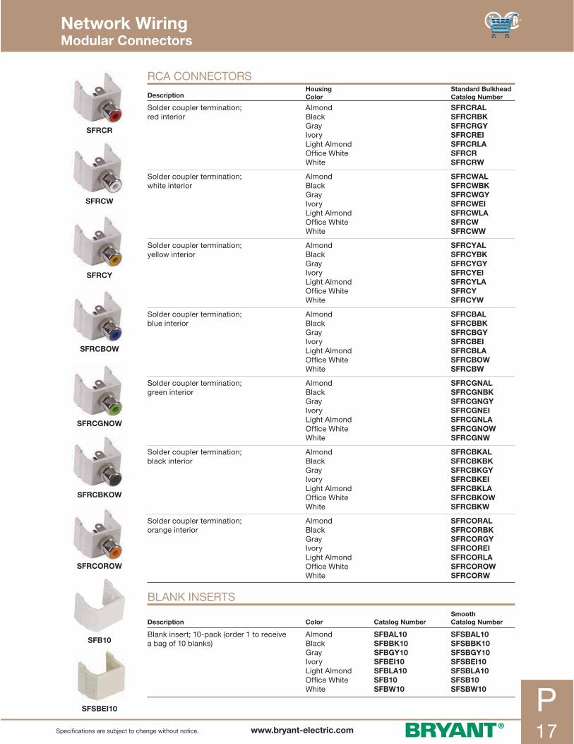
SFSBEI10
SFRCR
SFRCW
SFRCY
SFRCBOW
SFRCGNOW
SFRCBKOW
SFRCOROW
SFB10
P17www.bryant-electric.comSpecifications are subject to change without notice.
RCA CONNECTORS
DescriptionHousing Color
Standard BulkheadCatalog Number
Solder coupler termination;red interior
Almond Black Gray IvoryLight Almond Office White White
SFRCRALSFRCRBKSFRCRGYSFRCREISFRCRLASFRCRSFRCRW
Solder coupler termination;white interior
Almond BlackGray IvoryLight Almond Office White White
SFRCWALSFRCWBKSFRCWGYSFRCWEISFRCWLASFRCWSFRCWW
Solder coupler termination;yellow interior
Almond BlackGray IvoryLight Almond Office White White
SFRCYALSFRCYBKSFRCYGYSFRCYEISFRCYLASFRCYSFRCYW
Solder coupler termination; blue interior
Almond BlackGray IvoryLight Almond Office White White
SFRCBALSFRCBBKSFRCBGYSFRCBEISFRCBLASFRCBOWSFRCBW
Solder coupler termination; green interior
Almond BlackGray IvoryLight Almond Office White White
SFRCGNALSFRCGNBKSFRCGNGYSFRCGNEISFRCGNLASFRCGNOWSFRCGNW
Solder coupler termination;black interior
Almond BlackGray IvoryLight Almond Office White White
SFRCBKALSFRCBKBKSFRCBKGYSFRCBKEISFRCBKLASFRCBKOWSFRCBKW
Solder coupler termination;orange interior
Almond BlackGray IvoryLight Almond Office White White
SFRCORALSFRCORBKSFRCORGYSFRCOREISFRCORLASFRCOROWSFRCORW
BLANK INSERTS
Description Color Catalog NumberSmoothCatalog Number
Blank insert; 10-pack (order 1 to receive a bag of 10 blanks)
Almond BlackGray IvoryLight Almond Office White White
SFBAL10SFBBK10SFBGY10SFBEI10SFBLA10 SFB10SFBW10
SFSBAL10SFSBBK10SFSBGY10SFSBEI10SFSBLA10 SFSB10SFSBW10
Network Wiring Modular Connectors

NSP26I
NSP24I
NSP16I
NSP14I
NSP13I
NSP12I
NSP11I
P18 www.bryant-electric.com Specifications are subject to change without notice.
MULTIMEDIA FACE PLATES
Description Color
Catalog Number
Standard Mid-Size
1-Gang; 1-port plate Almond Black Gray Ivory Light AlmondWhite
NSP11AL NSP11BKNSP11GYNSP11INSP11LANSP11W
NSP101ALNSP101BKNSP101GYNSP101INSP101LANSP101W
1-Gang; 2-port plate Almond Black Gray Ivory Light AlmondWhite
NSP12AL NSP12BKNSP12GYNSP12INSP12LANSP12W
NSP102ALNSP102BKNSP102GY NSP102INSP102LANSP102W
1-Gang; 3-port plate Almond Black Gray Ivory Light AlmondWhite
NSP13AL NSP13BKNSP13GY NSP13INSP13LANSP13W
NSP103ALNSP103BKNSP103GY NSP103INSP103LANSP103W
1-Gang; 4-port plate Almond Black Gray Ivory Light AlmondWhite
NSP14ALNSP14BKNSP14GYNSP14INSP14LANSP14W
NSP104AL NSP104BKNSP104GY NSP104INSP104LANSP104W
1-Gang; 6-port plate Almond Black Gray Ivory Light AlmondWhite
NSP16ALNSP16BKNSP16GYNSP16INSP16LANSP16W
NSP106AL NSP106BKNSP106GY NSP106INSP106LANSP106W
2-Gang; 4-port plate Almond Black Gray Ivory Light AlmondWhite
NSP24AL NSP24BKNSP24GYNSP24INSP24LANSP24W
— — — — — —
2-Gang; 6-port plate Almond Black Gray Ivory Light AlmondWhite
NSP26ALNSP26BKNSP26GYNSP26INSP26LANSP26W
— — — — — —
netSELECT® multimedia face plates offer a perfect match to electrical wallplates for a consistent smooth finish look.• Accepts AV and Voice/Data connectors• High impact-resistant thermoplastic plate• UL Listed 1863 - Communication Circuit Accessory• CSA Certified
Network Wiring Multimedia Face Plates

630 WALL PHONE PLATES
Color1-Gang1-Port 2-Port 3-Port 4-Port 6-Port
2-Gang6-Port 9-Port 12-Port
AlmondBlackGrayIvoryLight Almond*Office WhiteWhite
IFP11ALIFP11BKIFP11GYIFP11EIIFP11LAIFP11OWIFP11W
IFP12ALIFP12BKIFP12GYIFP12EIIFP12LAIFP12OWIFP12W
IFP13ALIFP13BKIFP13GYIFP13EIIFP13LAIFP13OWIFP13W
IFP14ALIFP14BKIFP14GYIFP14EIIFP14LAIFP14OWIFP14W
IFP16ALIFP16BKIFP16GYIFP16EIIFP16LAIFP16OWIFP16W
IFP26ALIFP26BKIFP26GYIFP26EIIFP26LAIFP26OWIFP26W
—IFP29BKIFP29GYIFP29EIIFP29LAIFP29OWIFP29W
—IFP212BKIFP212GYIFP212EIIFP212LAIFP212OWIFP212W
Note: *Light Almond plates match Office White non-metallic raceway, boxes, jacks and connectors.
1-Gang1-Port 2-Port 3-Port 4-Port 6-Port
2-Gang4-Port 6-Port 9-Port 12-Port
SSF11 SSF12 SSF13 SSF14 SSF16 SSF204 SSF206 SSF209 SSF212
1-Gang Catalog Number
1-Port2-Port3-Port4-Port6-Port
SSFL11SSFL12SSFL13SSFL14SSFL16
Color Duplex Plate Decorator Plate
AlmondOffice White
IFP18ALIFP18OW
IFP126ALIFP126OW
STAINLESS STEEL FACE PLATES WITHOUT LABEL FIELDS
IFP FACE PLATES, WITH LABEL FIELDS, 1- AND 2-GANG
STAINLESS STEEL FACE PLATES WITH LABEL FIELDS
DUPLEX AND DECORATOR PLATES WITH LABEL FIELDS
Description Jack Format Includes Catalog Number
Stainless steel; 1-gang wall phone plate
FlushFlushRecessedRecessed
6-position USOC gray jack, RJ258-position Cat. 5e, gray jack, RJ456-position USOC gray jack, RJ258-position Cat. 5e, gray jack, RJ45
P630S1GJ6P630S1GJ8P630SR1GJ6P630SR1GJ8
Color1-GangDuplex Plate
1-GangDecorator Plate
2-GangDecorator Plate
AlmondBlackGrayIvoryLight Almond*White
NP8ALNP8BKNP8GYNP8INP8LANP8W
NP26ALNP26BKNP26GYNP26INP26LANP26W
NP262ALNP262BKNP262GYNP262INP262LANP262W
Note: *Light Almond plates match Office White non-metallic raceway, boxes, jacks and connectors.
STANDARD DUPLEX AND DECORATOR PLATES WITH NO LABEL FIELDS
P19www.bryant-electric.comSpecifications are subject to change without notice.
Network Wiring iSTATION™ Face Plates

Q106W
BR106B
NS620I
SL5E4A
NS621I
SL5E4B
NS613INS612I
TPF1W TWPF1GYP20 www.bryant-electric.com Specifications are subject to change without notice.
Network Wiring Outlet Frames and Plates
DECORATOR OUTLET FRAMES
Description Color
Catalog Number
2-Port 3-Port 4-Port 6-Port
netSELECT® decorator unloaded frames provide a stylized look for that finishing touch; multimedia jacks insert into frame for custom configuration; high impact-resistant thermoplastic frame
Almond Black Gray IvoryLight AlmondWhite
NS612AL NS612BKNS612GY NS612INS612LANS612W
NS613ALNS613BKNS613GYNS613INS613LANS613W
NS614ALNS614BKNS614GYNS614INS614LANS614W
NS616ALNS616BKNS616GYNS616INS616LANS616W
Description Color Catalog Number
1-Gang adapter; .40" (10.3 mm) dia. hole; for use with rotary dimmers or to pull through AV or telephone cable
AlmondIvory Light AlmondWhite
NS621ALNS621INS621LANS621W
1-Gang adapter blank; to fill an extra decorator opening or to create customized openings
AlmondIvory Light AlmondWhite
NS620ALNS620INS620LANS620W
4-Port; T568B; loaded Black SL5E4B
4-Port; T568A; loaded Black SL5E4A
DUPLEX OUTLET FRAMESDescription Color Catalog Number
2-Port duplex; unloaded AlmondBlackGrayIvoryLight AlmondOffice White White
BR106ALBR106BBR106GBR106EBR106LABR106OWBR106W
4-Port duplex; unloaded AlmondBlackGrayIvoryLight AlmondOffice White White
Q106ALQ106BQ106GQ106EQ106LAQ106OWQ106W
SECURE-IT™ PLATESSecure-IT™ plates protect mated and unmated connections from physical damage and unauthorized tampering. Available in tamper-resistant and weatherproof versions.
Description Color Catalog Number
Tamper-resistant plates BlackGrayOffice White White
TPF1BKTPF1GYTPF1OWTPF1W
NEMA 3R weatherproof plates Gray TWPF1GY

NS801W
NS802W
HDPC06BK
HDMIC1
HDMIT1
P21www.bryant-electric.comSpecifications are subject to change without notice.
netSELECT® HDMI Decorator Frames deliver uncompromising digital audio and video wherever you need it. Unleash the full potential of your high definition display and audio installations.• Third party tested for 1080p resolutions• UL Listed - Communications Circuit Accessory • CSA Certified
HDMI PRODUCTSDescription Color Catalog Number
1-Gang; 1-port HDMI;decorator frame;female to female
Almond Black Gray IvoryLight AlmondWhite
NS801AL NS801BKNS801GY NS801INS801LANS801W
1-Gang; 2-port HDMI;decorator frame;female to female
Almond Black Gray IvoryLight AlmondWhite
NS802AL NS802BKNS802GY NS802INS802LANS802W
HDMI CORDSDescription Feet Catalog Number
HDMI device patch cords HDMI (24 AWG) 3 ft.
6 ft.
HDPC03BKHDPC06BK
Link cords (connector to device) HDMI (24 AWG)
xx ft. HDLXXBK
Coupler cords (coupler to device) HDMI (24 AWG)
xx ft. HDCXXBK
Horizontal cords (connector to connector) HDMI (24 AWG)
xx ft. HDHXXBK
Note: XX = Length in feet. 10 = 10 ft., 15 = 15 ft., 20 = 20 ft., 25 = 25 ft., 30 = 30 ft., Black and Non-Plenum only.
HDMI CONNECTORSDescription Packaging Catalog Number
HDMI feed thru coupler Single
10-Pack
HDMIC1HDMIC10
HDMI feed thru 4.0" tail Single
10-Pack
HDMIT1HDMIT10
Network Wiring HDMI Products
Gold-plated HDMIfemale connector
High impact thermoplastic frame
4.0" flexible extension reduces bend radius issues in confined spaces
Thumbscrew prevents accidental disconnection only when used with Bryant’s HDMI patch cords
Connector sized to fit 1.0" conduit

IMBDS1W
IMBDSA15W
ISFBDSW
9GC10
9ST10
P22 www.bryant-electric.com Specifications are subject to change without notice.
HD (HIGH DEFINITION) 15-PIN/9-PIN CONNECTORS AND MODULESDescription Color Catalog Number
Flat blank HD15/9 or HDMI module; 1 unit; 10-pack
Almond Black Gray IvoryLight AlmondOffice White White
IMBDS1ALIMBDS1BKIMBDS1GYIMBDS1EIIMBDS1OWIMBDS1W
Angled blank HD15/9 or HDMI module; 1 unit; 10-pack
Almond Black Gray IvoryLight AlmondOffice White White
IMBDSA15AL IMBDSA15BKIMBDSA15GY IMBDSA15EI IMBDSA15LWIMBDSA15OWIMBDSA15W
HD 9-PIN AND HD 15-PIN VGA-STYLE CONNECTORSDescription Packaging Catalog Number
HD 9-pin F/F coupler 10-Pack 9GC10*
HD 9-pin screw term 10-Pack 9ST10
HD 15-pin F/F coupler 10-Pack 15GC10*
HD 15-pin screw term 10-Pack 15ST10
HD 15-pin to 8-pin angled 45° 1-Pack10-Pack
15A6P115A6P10
HD 15-pin to 8-pin straight 180° 1-Pack10-Pack
15S6P115S6P10
HD 15-pin to 8-pin angled 90° 1-Pack10-Pack
15N6P115N6P10
HD 15-pin to 8-pin 8.0" tail; 1-pack 1-Pack 15T6P1
Note: *Not UL Listed.
PLUG-N-PLAY VGA HORIZONTAL RUNS*Description Catalog Number
VGA; 8-pin; non-plenum; black VGA6XXBK
VGA; 8-pin; plenum; black VGA6PXXBK
VGA; 8-pin; 15-pin F; non-plenum; black VG15F6XXBK
VGA; 8-pin; 15-pin M; non-plenum; black VG15M6XXBK
VGA; 8-pin; 15-pin M; plenum; black VG15MP6XXBK
Note: *Maximum supported distance varies by application and resolution. Refer to X-END™ brochure for details. XX = Length: 05, 10, 15, 20, 25, 30, 35, 40, 45, 50, 55, 60, 65, 70, 75, 80, 85, 90, 95, 100.
Network Wiring iSTATION™ HD Connectors and VGA Horizontal Runs
15ST10
15GC10
15A6P1
15S6P1
15N6P1
15T6P1
15N6P1

P23www.bryant-electric.comSpecifications are subject to change without notice.
DescritpionAV blank1.5 unit
XLR screw terminal
XLRsolder-type
Speakon® connector;solder-type
USB feed-thru; A-to-B
¼" stereo jack; solder-type
Catalog No. IMAVB15OW* XLRST10 XLR10 SC10 USB10 14S10
Note: *Color listed is Office White, for other colors, replace “OW” with: “AL” = Almond; “BK” = Black; “EI” = Ivory; “GY” = Gray; “W” = White.
Network Wiring iSTATION™ Front-Loading Frames and Modules
MODULAR FACE PLATE FRAMESDescription Color Catalog Number
Modular face plate frame; 1-gang
Almond Black Gray IvoryOffice WhiteWhite
IMF1ALIMF1BKIMF1GYIMF1EIIMF1OWIMF1W
Modular face plate frame; 2-gang
Almond Black Gray IvoryOffice WhiteWhite
IMF2ALIMF2BKIMF2GYIMF2EIIMF2OWIMF2W
Raceway bezel frame AlmondGrayOffice White
KPIMBZALKPIMBZGYKPIMBZOW
UNLOADED MODULESDescription Color Flat Catalog No. Angled Catalog No.
Modular; 1-port; 1 unit (flat); 1.5 unit (angled)
Almond Black Gray IvoryOffice WhiteWhite
IM1K1ALIM1K1BKIM1K1GYIM1K1EIIM1K1OWIM1K1W
IM1KA15ALIM1KA15BKIM1KA15GYIM1KA15EIIM1KA15OWIM1KA15W
Modular; 2-port; 1 unit (flat); 1.5 unit (angled)
Almond Black Gray IvoryOffice WhiteWhite
IM2K1ALIM2K1BKIM2K1GYIM2K1EIIM2K1OWIM2K1W
IM2KA15ALIM2KA15BKIM2KA15GYIM2KA15EIIM2KA15OWIM2KA15W
Description Color 1 Duplex Catalog No. 2 Duplex Catalog No.
SC angled; 1.5 unit (1 duplex); 2 unit (2 duplex)
Black Gray IvoryOffice WhiteWhite
IM1SCA15BKIM1SCA15GYIM1SCA15EIIM1SCA15OWIM1SCA15W
IM2SCA15BKIM2SCA15GYIM2SCA15EIIM2SCA15OWIM2SCA15W
Description Color 1 Port Catalog No. 2 Port Catalog No.
Modular recessed angle; 1.5 unit Black Gray IvoryOffice WhiteWhite
IM1IA15BKIM1IA15GYIM1IA15EIIM1IA15OWIM1IA15W
IM2IA15BKIM2IA15GYIM2IA15EIIM2IA15OWIM2IA15W
Description Color .5 Unit Catalog No. 1 Unit Catalog No. 1.5 Unit Catalog No.
Flat blank Almond Black Gray IvoryOffice WhiteWhite
IMB05AL IMB05BKIMB05GYIMB05EIIMB05OWIMB05W
IMB1AL IMB1BKIMB1GYIMB1EIIMB1OWIMB1W
IMB15AL IMB15BKIMB15GYIMB15EIIMB15OWIMB15W
ISTATION™ AUDIO/VIDEO MODULES (10-PACK)
IMF1OW
IMF2OW
KPIMBZOW
IM1K1OW
IM2K1OW
IM1SCA15OW
IM1IA15OW
IMB05OW
IM2KA15OW
IM2KA15OW
IM2SCA2OW
IM2IA15OW
IMB1OW
IMB15OW

P24 www.bryant-electric.com Specifications are subject to change without notice.
IMCR1101W
IMSR1101W
IMSV351101W
IMR1101W
IMAR1101W
110 AUDIO VIDEO MODULES Feet (m)
Description Housing Color Catalog Number
RCA component; video to 110 termination; 1 unit; 75' (19.1) max. HD Cat 5, 5e, 6 UTP
AlmondBlackElectric IvoryGrayOffice WhiteWhite
IMCR1101ALIMCR1101BKIMCR1101EIIMCR1101GYIMCR1101OWIMCR1101W
S-video; stereo RCA audio to 110 termination; 1 unit; 100' (25.4) max. Cat 5, 5e, 6 UTP
AlmondBlackElectric IvoryGrayOffice WhiteWhite
IMSR1101ALIMSR1101BKIMSR1101EIIMSR1101GYIMSR1101OWIMSR1101W
S-video; 3.5mm stereo audio jack to 110 termination; 1 unit; 100' (25.4) max. Cat 5, 5e, 6
BlackElectric IvoryGrayOffice White White
IMSV351101BKIMSV351101EIIMSV351101GYIMSV351101OWIMSV351101W
RCA composite; video; stereo; audio to 110 termination; 1 unit; 100' (25.4) max. Cat 5, 5e, 6
AlmondBlackElectric IvoryGrayOffice WhiteWhite
IMR1101ALIMR1101BKIMR1101EIIMR1101GYIMR1101OWIMR1101W
RCA stereo; audio 110 termination; 1 unit; 100' (25.4) max. Cat 5, 5e, 6
AlmondBlackElectric IvoryGrayOffice WhiteWhite
IMAR1101ALIMAR1101BKIMAR1101EIIMAR1101GYIMAR1101OWIMAR1101W
Network Wiring iSTATION™ Audio/Video Modules

P25www.bryant-electric.comSpecifications are subject to change without notice.
IMCRS15OW
IMCRS1OW
IM3RF1OW
IM3RS1OW
IMSP1OW
IMRSJ1OW
SPPBK10SPPR10
SOLDER AUDIO VIDEO MODULESDescription Housing Color Catalog Number
RCA component; video; stereo audio or RGBHV; solder; 1.5 unit
AlmondBlackElectric IvoryGrayOffice WhiteWhite
IMCRS15AL*IMCRS15BK*IMCRS15EI*IMCRS15GY*IMCRS15OW*IMCRS15W*
RCA component; video; solder; 1 unit
AlmondBlackElectric IvoryGrayOffice WhiteWhite
IMCRS1AL*IMCRS1BK*IMCRS1EI*IMCRS1GY*IMCRS1OW*IMCRS1W*
RCA composite; video; stereo audio; solder; 1 unit
AlmondBlackElectric IvoryGrayOffice WhiteWhite
IM3RS1ALIM3RS1BKIM3RS1EIIM3RS1GYIM3RS1OWIM3RS1W
RCA composite; video; 3.5mm stereo audio jack; solder; 1 unit
AlmondBlackElectric IvoryGrayOffice WhiteWhite
IMRSJ1ALIMRSJ1BKIMRSJ1EIIMRSJ1GYIMRSJ1OWIMRSJ1W
Note: *Not UL Listed.
GOLD FEED-THROUGH AUDIO VIDEO RCA COUPLERSDescription Housing Color Catalog Number
RCA component; video; gold; pass-through; F/F coupler;1 unit
AlmondBlackElectric IvoryGrayOffice WhiteWhite
IMCRF1AL*IMCRF1BK*IMCRF1EI*IMCRF1GY*IMCRF1OW*IMCRF1W*
RCA composite; video; audio; gold; pass-through; F/F coupler; 1 unit
AlmondBlackElectric IvoryGrayOffice WhiteWhite
IM3RF1ALIM3RF1BKIM3RF1EIIM3RF1GYIM3RF1OWIM3RF1W
Note: *Not UL Listed.
GOLD SPEAKER POSTS MODULES AND BANANA PLUGSDescription Housing Color Catalog Number
Speaker post; gold, black and red; screw termination
AlmondBlackElectric IvoryGrayOffice WhiteWhite
IMSP1ALIMSP1BKIMSP1EIIMSP1GYIMSP1OWIMSP1W
Speaker banana plugs; gold; screw termination; 10-packs
BlackRed
SPPBK10*SPPR10*
Note: *Not UL Listed.
Network Wiring iSTATION™ Audio/Video Modules
IMCRF1OW

P26 www.bryant-electric.com Specifications are subject to change without notice.
ISM1OW
ISM2OW
ISM4OW
ISM6OW
• Low-profile design• Accepts XJ jacks, audio video and fiber connectors• Provided with double-sided tape and mounting screws
for easy installation• UL and cULus Listed• Constructed with a high-impact resistant, flame-
retardant polymer• ANSI/TIA-606A compliant
ISM SURFACE MOUNT BOXES, 1- AND 2-PORTIdeal for open office, compact surface mount environments, and retrofits to support data, voice, and multimedia applications; can be mounted with supplied surface mounting screws or double-sided adhesive tape
Color1-Port Catalog Number
2-PortCatalog Number
IvoryOffice WhiteWhite
ISM1EIISM1OWISM1W
ISM2EIISM2OWISM2W
ISM SURFACE MOUNT BOXES, 4- AND 6-PORTIdeal for open office MUTOA cabling, compact surface mount environments, and retrofits to support data, voice, and multimedia applications; features adjustable furniture latches to provide an additional mounting option to common ANSI/TIA/EIA standard furniture openings, and solutions requiring fiber; box bases feature fiber storage posts that can store one meter fiber cable after termination
Color4-Port Catalog Number
6-PortCatalog Number
IvoryOffice WhiteWhite
ISM4EIISM4OWISM4W
ISM6EIISM6OWISM6W
ISM SURFACE MOUNT BOXES, 12-PORTIdeal for open office MUTOA cabling, large capacity surface mount applications and retrofits to support data, voice, and multimedia installations. Can be mounted with supplied surface mounting screws or double-sided adhesive tape and mounted to NEMA electric boxes or relay racks
Color12-Port Catalog Number
IvoryOffice WhiteWhite
ISM12EIISM12OWISM12W
Network Wiring iSTATION™ Surface Mount Boxes
ISM12OW

ISM1EI
ISM2EI
NS761I
NS760I
P27www.bryant-electric.comSpecifications are subject to change without notice.
Telephone surface mount jacks are available in 4- or 6-conductor configurations for voice. Alternatively, multimedia surface mount boxes can be custom loaded for computer and media use. • High impact-resistant thermoplastic• Mounts using screws or double sided tape (both included)• Meets FCC part 68• UL Listed 1863 - Communication Circuit Accessory• CSA Certified
TELEPHONE SURFACE MOUNT WALL JACKSDescription Color Catalog Number
Telephone surface mount jack;6-position; 4-conductor; screw terminations
IvoryWhite
NS760INS760W
Telephone surface mount jack;6-position; 6-conductor;screw terminations
IvoryWhite
NS761INS761W
MODULAR SURFACE HOUSINGSDescription Color Catalog Number
Multimedia 1-port surface mount box;jack not included
IvoryWhite
ISM1EI*ISM1W*
Multimedia 2-port surface mount box;jacks not included
IvoryWhite
ISM2EI*ISM2W*
Note: *cULus Listed 1863 - Communication Circuit Accessory. See pages P-13 to P-17 for modular jacks and A/V connectors.
Network Wiring Telephone Surface Mount Wall Jacks

P28 www.bryant-electric.com Specifications are subject to change without notice.
NS770I
NS771I
NS772I
NS784I
MOLDED-IN VOICE/LOW-SPEED DATADescription Color Catalog Number
Decorator frame; one RJ11 jack;6-position; 4-conductor;screw terminations
Almond BlackBrownGrayIvoryLight AlmondWhite
NS770ALNS770BKNS770NS770GYNS770INS770LANS770W
Decorator frame;one RJ11 jack;6-position; 6-conductor; screw terminations
Almond BrownIvoryLight Almond White
NS771ALNS771NS771INS771LANS771W
Decorator frame;duplex RJ11 jacks;6-position; 6-conductor;screw terminations
Almond IvoryLight Almond White
NS772AL NS772INS772LANS772W
Decorator frame; one cat. 5e 110 punch-down;one RJ11 jack; 6-position; 4-conductor;screw terminations
Almond BlackBrownGrayIvoryLight AlmondWhite
NS784ALNS784BKNS784NS784GYNS784INS784LANS784W
Designed to complement decorator styling, these jacks offer voice and Cat. 5e devices to fit within a decorator wallplate. Create a look to match your voice/data, switch, and receptacle devices.• High impact-resistant thermoplastic frame• Meets FCC part 68• UL Listed 1863 - Communication Circuit Accessory • CSA Certified
Network Wiring Molded-In Voice/Data/Video

P29www.bryant-electric.comSpecifications are subject to change without notice.
NS780I
NS782I
NS783I
NS785I
MOLDED-IN VOICE/LOW-SPEED DATADescription Color Catalog Number
Decorator frame;single F-type coupler bulkheadfemale to female
Almond IvoryLight AlmondWhite
NS780AL NS780INS780LANS780W
Decorator frame;duplex F-type coupler bulkheadfemale to female
Almond IvoryLight AlmondWhite
NS782ALNS782INS782LANS782W
Decorator frame; one RJ11 jack;6-position; 4-conductor;one F-type coupler bulkheadfemale to female
Almond IvoryLight AlmondWhite
NS783ALNS783INS783LANS783W
Decorator frame;one cat. 5e 110 punch-down;one F-type coupler bulkheadfemale to female
Almond BlackBrownGrayIvoryLight AlmondWhite
NS785ALNS785BKNS785NS785GYNS785INS785LANS785W
Coaxial video and combination jacks complement multimedia needs in a 1-gang decorator opening.• High impact-resistant thermoplastic frame• Jacks meet FCC part 68• UL Listed 1863 - Communication Circuit Accessory• CSA Certified
Network Wiring Molded-In Voice/Data/Video

NS730I
NS732I
NS742I
NS744I
P30 www.bryant-electric.com Specifications are subject to change without notice.
Designed for voice, these devices provide an economical alternative to wall phone outlet placement.• High impact-resistant thermoplastic plate• Convenient screw down terminals• Meets FCC part 68• UL Listed 1863 - Communication Circuit Accessory• CSA Certified
MOLDED-IN PLATES
Description Color
Catalog Number
Standard Mid-Size
1-Gang plate;one RJ11 jack;6-position; 4-conductor;screw terminations
Almond Brown IvoryLight AlmondWhite
NS730AL NS730NS730INS730LANS730W
NS735AL NS735NS735INS735LANS735W
1-Gang plate; one RJ11 jack;6-position; 6-conductor;screw terminations
Almond Brown IvoryLight AlmondWhite
NS732AL NS732NS732INS732LANS732W
— — — — —
1-Gang plate; duplex RJ11 jacks;6-position; 4-conductor;screw terminations
AlmondIvoryLight AlmondWhite
NS742ALNS742INS742LANS742W
—NS745I
—NS745W
1-Gang plate; duplex RJ11 jacks;6-position; 6-conductor;screw terminations
AlmondIvoryLight AlmondWhite
NS744ALNS744I
—NS744W
— — — —
Network Wiring Molded-In Plates

NS748I
NS750I
NS752I
NS790I
NS747I
P31www.bryant-electric.comSpecifications are subject to change without notice.
Designed for voice CATV/satellite and data applications, these devices offer an economical alternative to snap fit style products.• High impact-resistant thermoplastic frame• Combination jack and coaxial minimize ganging requirements• Meets FCC part 68• UL Listed 1863 - Communication Circuit Accessory• CSA Certified
MOLDED-IN PLATES
Description Color
Catalog Number
Standard Mid-Size
1-Gang plate;F-type coupler bulkheadfemale to female;one RJ11 jack;6-position; 4-conductor
Almond IvoryLight AlmondWhite
NS747ALNS747INS747LANS747W
— — — —
1-Gang plate;F-type coupler bulkhead female to female;one RJ11 jack;6-position; 6-conductor
Almond IvoryLight AlmondWhite
NS748ALNS748INS748LANS748W
NS755ALNS755INS755LANS755W
1-Gang plate;single F-type coupler bulkhead female to female
Almond IvoryLight AlmondWhite
NS750ALNS750INS750LANS750W
NS751ALNS751INS751LANS751W
1-Gang plate;duplex F-type coupler bulkhead female to female
Almond IvoryLight AlmondWhite
NS752ALNS752INS752LANS752W
— — — —
1-Gang plate;one cat. 5e 110 punch-down:one RJ11 jack; 6-position; 4-conductor;one F-type coupler bulkhead female to female
Almond BlackBrownGrayIvoryLight AlmondWhite
NS790ALNS790BKNS790NS790GYNS790INS790LANS790W
— — — — — — —
Network Wiring Molded-In Plates

NS722I
NS725I
NS723SS
NS726SS
NS721I
P32 www.bryant-electric.com Specifications are subject to change without notice.
TELEPHONE WALL JACKSDescription Color Catalog Number
Wall phone jack quick connect;6-position; 4-conductor;punch-down termination tool included
Almond IvoryLight AlmondWhite
NS721AL NS721I
—NS721W
Wall phone jack;6-position; 4-conductor;screw terminations
Almond IvoryLight AlmondWhite
NS722ALNS722I
—NS722W
Wall phone jack;6-position; 6-conductor;screw terminations
Almond IvoryLight AlmondWhite
NS725AL NS725INS725LANS725W
Wall phone jack quick connect;6-position; 4-conductor;punch-down termination tool included
Stainless Steel NS723SS
Wall phone jack;6-position; 4-conductor;screw terminations
Stainless Steel NS726SS
Designed for voice applications, these jacks provide an economical alternative to basic wall mount and performance needs.• Available in high impact-resistant thermoplastic or stainless steel• Meets FCC part 68• UL Listed 1863 - Communication Circuit Accessory• CSA Certified
Network Wiring Telephone Wall Jacks

P33www.bryant-electric.comSpecifications are subject to change without notice.
• Meets TIA/EIA-606-A labeling administration standards
• Labor savings; installer can produce and print labels before installation
• Saving job files reduces potential for error and eliminates the time to re-enter information when changes and additions are required
• Makes closets and workstations look professional with clearly marked connections and leaves an impression of quality workmanship
• In ever-changing work environments, clearly marked connections will make moves, adds, and changes easier by eliminating mistakes and wasted time
LABELING SOLUTIONS SOFTWAREDescription Catalog Number
Software package for custom labeling; consult factory for download instructions
XPSOFT
PATCH PANEL AND RACK LABELS Inches (mm)
Delivery: Package of 10; 8.5" x 11" (215.9 x 279.4) paper sheets
DescriptionLabels per sheet
Label SheetsCatalog Number
Extra Label HoldersCatalog Number
Adhesive 8-port front label strips 20 XPLPPA10W —
Paper 8-port front label strips (use with label holders supplied with panel)
18 XPLPP10W XPHPP50
Paper ID labels for all panel sizes (use with vertical ID label holders on panels)
18 XPLPPID10W XPHPPID1U10 (for 1U)
— XPHPPID2U10 (for 2U)
Rack and cabinet labels (use with XPHRC10) XPLRC10W XPHRC10
MULTIMEDIA PANEL LABELS Inches (mm)
Delivery: Package of 10; 8.5" x 11" (215.9 x 279.4) paper sheets
DescriptionLabels per sheet
Label SheetsCatalog Number
Extra Label HoldersCatalog Number
Paper 8-port front label strips (use with label holders supplied with panel)
18 XPLUDX2410W XPHUDX2410
Note: Use XPLFOSEPAW labels for the UDX36 multimedia panel.
Network Wiring Labeling Solutions

P34 www.bryant-electric.com Specifications are subject to change without notice.
TX4PP
TX4P
TPD110
TBLH
1-PUNCH JACK TERMINATION TOOLThis tool should be used exclusively with netSELECT® jacks; used with the HXTA termination aid
Description Catalog Number
1-Punch XJ tool with head; blades and HXTA termination aid TX4P
1-Punch XJ replacement head (includes blades) TX4PH
1-Punch XJ replacement blades TX4PHBL
Hand Termination Aid “Jack Knuckles” HXTA
Snap-X Termination Puck (Bag of 25) HXTP25
1-PUNCH PANEL TERMINATION TOOLDescription For use with Catalog Number
1-Punch panel tool with head and blades P6EXXU panel TX4PP
1-Punch panel replacement head P6EXXU panel TX4PPH
1-Punch panel replacement blades P6EXXU panel TX4PPBL
110 PUNCH-DOWN TOOLComfortable, ergonomic grip with insulated, rubber-embedded handle; terminated 28-22AWG solid/stranded wire; high visibility colors; lanyard holes in the handle end; latching blade storage cover; adjustable high- and low-impact settings; twist and lock blades
Description Catalog Number
Standard 110 punch-down tool TPD110
1-pair NSJ; 110 blade TBLH
Punch-down tool; 1-pair TPDH
Replacement 110 blade TBL110
Replacement 66 Blade TBL66
TOOL KITS• Punch-down tool with 110 and 66 blades; rubber-embedded handle• Durable; black; nylon belt pouch• Belt pouch fits up to 2½" belt (slide on style)
3-PIECE TOOL KITDescription Catalog Number
Delivery: 1 punch-down tool with 110 and 66 blades; 1 pair of snips; and 1 belt pouch
TK3
8-PIECE TOOL KITDescription Catalog Number
Delivery: 1 punch-down tool with 110 and 66 blades; 1 pair of snips; 4-bit screwdriver; UTP/STP cable stripper/cutter; Maglite™; 1 belt pouch; and 1 Snap-X termination aid
TK8
Network Wiring Tools and Accessories
TK8
TK3
Maglite™ is a trademark of Mag Instruments, Inc.

P35www.bryant-electric.comSpecifications are subject to change without notice.
UCT
ECT
COMPTRG659
TCS3
NS4
CRIMP TOOLS• Universal frame accepts interchangeable dies to crimp different plugs• Color-coded die-sets for different plug sizes• Complete ratchet cycle release assures no-fault crimpsDescription Catalog Number
Crimp tool frame (die-sets sold separately). UCT
Complete tool kit in hard, plastic case includes crimp tool; UTP cable stripper; 3 die-sets (RJ45, RJ22 and RJ11)
UCTKIT
RG6 compression connector (optional die-set not included in tool kit) FRG6C25
RG59 compression connector (optional die-set not included in tool kit) FRG5925
RJ11 die-set CDTSR11
RJ22 die-set CDTSR22
RJ45 die-set; non-snagless CDTSR45
RJ45 die-set; snagless CDTSR45S
RG6 and RG59 hex crimp die-set CDTSRG659
Economy crimp tool – includes non-replaceable RJ11, RJ22and RJ45 die-sets
ECT
RG6 OR RG59 COMPRESSION TOOLUse to terminate onto 75 ohm RG6 or RG59 coaxial cable.
Description Catalog Number
RG6 and RG59 compression toolCoaxial stripping tool
COMPTRG659CSTRPR
Note: See page P-14 for compression connectors.
COMMUNICATIONS CABLE STRIPPER/CUTTER Inches (mm)
• Strips round Cat. 5e and 6 UTP/STP• Cuts cable• Strips flat cables• Compact size• High-visibility for quick locatingDescription Catalog Number
Communications cable stripper/cutter;strips round Cat. 5e and Cat. 6 UTP/STP with diameters of 0.145" to 0.275" (3.7 to 7.0) ; cuts round UTP/STP cables up to 0.350" (8.9); adjusting screw for varied cable diameters to avoid scoring interior conductor insulation; high-visibility for quick locating; strips flat cables; non-metallic body
TCS3
HAND HELD 110 TERMINATION TOOLDescription Catalog Number
Designed as an economical alternative for low volume use where the installer press fits the conductors
NS4
Network Wiring Tools and Accessories

P36 www.bryant-electric.com Specifications are subject to change without notice.
HORIZONTAL UTP CABLE AND PATCH CORDS• Solid copper 4-pair 24 AWG UTP is specified for distribution
cabling; stranded UTP is specified for patch cords for flexibility; shielded cable is not commonly used in the U.S.; splices bridge taps are not permitted
• Cable, connectors and patch cords shall be marked with the performance category; always match performance categories of cables and components throughout the infrastructure
• All cable, cords and connecting hardware shall meet performance requirements of ANSI/TIA/EIA-568-B.1 and 568-B.2; Bryant assures this compliance with all products and cable partners
RECOGNIZED CONNECTOR AND WIRING CONFIGURATIONS• 8-position modular jack/plug• 8-position modular panel/plug• T568A wiring or T568B wiring options• Cat. 5e or Cat. 6 recommended
RJ 45 - TIA/EIA-568 CONVENTIONSTwo wiring standards were adopted; both configurations provide equivalent transmission performance
LAN WIRING CONVENTIONSLocal Area Network standards designed to operate over UTP specify pin/pair assignments on modular connectors for various signal transmission protocols. While TIA/EIA-568A and 568B conventions support all of these designations, there are some cases where the user chooses to cable only the number of pairs required to support these applications.
COLOR CODING:
white-blue/blue
white-orange/orange
white-green/green
white-brown/brown
• Preferred method
• Directly compatible with 2-pair voice and Token Ring systems utilizing 6-position connectors
• Optional method
• AT&T’s standard
• Directly compatible with AT&T phone systems
• 1000 Mbps/10Gb Ethernet over UTP
• Uses all four pairs
• 100 Mbps FDDI over copper (pending)
• 4/16 Mbps Token Ring over copper
• 10 Mbps Ethernet over UTP
• 100 Mbps Ethernet
Network Wiring Standard UTP Wiring Conventions

Q1www.bryant-electric.com
INDEX PAGECodes and Standards Organizations . . . . . . . . . . . . . . . . . . . . . . . . . . . . . . . . . . . . . . . . . . . . . . . . . . . . . . . Q-2Certification Agencies and Markings . . . . . . . . . . . . . . . . . . . . . . . . . . . . . . . . . . . . . . . . . . . . . . . . . . . . . . . Q-3Wiring Device Standards and Testing . . . . . . . . . . . . . . . . . . . . . . . . . . . . . . . . . . . . . . . . . . . . . . . . . . . . . . . Q-4RoHS, TR, WR and IP Meanings . . . . . . . . . . . . . . . . . . . . . . . . . . . . . . . . . . . . . . . . . . . . . . . . . . . . . . . . . . Q-6Architectural Symbols For Electrical Wiring Devices . . . . . . . . . . . . . . . . . . . . . . . . . . . . . . . . . . . . . . . . . . . Q-7Materials Commonly Used in Wiring Devices and Horsepower Ratings Table . . . . . . . . . . . . . . . . . . . . . . . Q-8AC Switch and Horsepower Ratings . . . . . . . . . . . . . . . . . . . . . . . . . . . . . . . . . . . . . . . . . . . . . . . . . . . . . . . Q-9Switches Wiring Diagrams . . . . . . . . . . . . . . . . . . . . . . . . . . . . . . . . . . . . . . . . . . . . . . . . . . . . . . . . . . . . . . Q-10Dimmer – Ganging and Derating. . . . . . . . . . . . . . . . . . . . . . . . . . . . . . . . . . . . . . . . . . . . . . . . . . . . . . . . . . Q-11Wiring Diagrams . . . . . . . . . . . . . . . . . . . . . . . . . . . . . . . . . . . . . . . . . . . . . . . . . . . . . . . . . . . . . . . . . . . . . . Q-12Network Cabling Requirements . . . . . . . . . . . . . . . . . . . . . . . . . . . . . . . . . . . . . . . . . . . . . . . . . . . . . . . . . . Q-16
Section QTechnical Information

Q2 www.bryant-electric.com Specifications are subject to change without notice.
CERTIFICATION AGENCIES
Primarily involved in certification of products or manufacturers to standards developed by the certification agency or by others. For convenience, the following listings define common acronyms for a variety of organizations.
ANCE National Association of Normalization and Certification of the Electrical Sector BSI British Standards Institute CE Self Certification Marking of European Community CCC China Compulsory Certification CSA Canadian Standards Association or CSA International FM Factory Mutual NRTL Nationally Recognized (by OSHA) Testing Laboratory TÜV TÜV Rheinland of N.A., Inc. UL Underwriters Laboratories Inc. VDE Verband Deutscher Elektrotechniker (Germany) GOVERNMENT AGENCIESDSCC Defense Supply Center – ColumbusEU European UnionFCC Federal Communications CommissionIAPA Industrial Accident and Prevention Association (Canada)OSHA Occupational Safety and Health Administration
Technical Information Codes and Standards Organizations
MR
4700DR4700DRCR4700DRI4700DRIG47104721NP4750DR47604779NC4785ER52425242BLK5242GRY5242I5242RED5242W52515251AL5251BLK5251I52525252AL5252BLK5252BU5252GRY5252I5252RED5252W52615261BLK5261BLKWR5261GRY5261GRYWR5261I5261IGGRY5261IGW5261IWR5261RED5261REDWR5261W5261WR5261WWR53425342BLK5342GRY5342I5342RED5342W53515351AL5351BLK5351I53525352AL
5352BLK5352BU5352GRY5352I5352RED5352W53615361BLK5361BLKWR5361GRY5361GRYWR5361I5361IWR5361RED5361REDWR5361W5361WR5361WWR5364B5364BY5366N5369B5369BY54615461BLK5461GRY5461I5461RED5461W5464B5469B56425642I56615661BLK5661GRY5661I5661RED5661W5666B5669B70520FR70520FRCR70520MB70520NC70520NCCR70520NP70520NP70530FR70530FRCR70530MB70530MBWP70530NC70530NCB
70530NCCR70530NP70530NPB70530NPC70615DR70615DRIG70615ER70615FR70615MB70620ER70620FR70620MB70620NC70620NP70620NPCR70630ER70630FR70630NC70630NP70720ER70720FR70720MB70720NC70720NP70730FR70730NP71020ER71020FR71020NP71420ER71420FR71420MB71420NC71420NP71430ER71430FR71430MB71430MBWP71430NC71430NP71520ER71520FR71520MB71520MBWP71520NC71520NP71530ER71530FR71530MB71530MBWP71530NC71530NP71620NC71620NP
71630NC71630NP71820NC71820NP72120ER72120FR72120MB72120NC72120NCB72120NP72120NPB72120NPC72130ER72130FR72130NC72130NP72330FR82108210GRY8210GRYWR8210I8210IWR8210RED8210REDWR8210W8210WR8210WWR8266T8269T8295T83108310GRYWR8310I8310IWR8310RED8310REDWR8310WR8310WWR8366T8366TSP8369T8395T8410BRN8410W8466N8466TSP8495T8666TSP8695T9200GRY9200GRYL9200I9200IG9200IGGRY
9200IGI9200IGRED9200IGW9200RED9200W9300GRY9300I9300IL9300REDBRY5262BRY5262BCRBRY5262BLKBRY5262BLKWRBRY5262BUBRY5262BUWRBRY5262CRBRY5262GRYBRY5262GRYWRBRY5262IBRY5262IWRBRY5262REDBRY5262REDWRBRY5262WBRY5262WRBRY5262WWRBRY5266NPBRY5266NPBBRY5266NPCRBRY5266NPORBRY5266NPSYBRY5269NCBRY5269NCCRBRY5269NCSYBRY5362BRY5362BLKBRY5362BLKWRBRY5362BUBRY5362BUWRBRY5362CRBRY5362GRYBRY5362GRYWRBRY5362IBRY5362IWRBRY5362REDBRY5362REDWRBRY5362WBRY5362WRBRY5362WWRBRY5366NPBRY5366NPCRBRY5366NPSYBRY5369NCBRY5369NCCRBRY5369NCSY
BRY5382BRY5462BRY5462BLKBRY5462CRBRY5462GRYBRY5462IBRY5462REDBRY5462WBRY5466NPBRY5466NPSYBRY5469NCBRY5469NCSYBRY5662BRY5662BLKBRY5662CRBRY5662GRYBRY5662IBRY5662REDBRY5662WBRY5666NPBRY5666NPSYBRY5669NCBRY8200BRY8200ALTRBRY8200GRYBRY8200GRYLBRY8200GRYWRBRY8200GTRBRY8200IBRY8200ITRBRY8200IWRBRY8200REDBRY8200REDLBRY8200REDWRBRY8200RTRBRY8200TRBRY8200WBRY8200WLBRY8200WRBRY8200WTRBRY8200WWRBRY8266NPBRY8266NPBBRY8269NCBRY8300BRY8300ALTRBRY8300GRYBRY8300GRYWRBRY8300GTRBRY8300IBRY8300IGBRY8300ITRBRY8300IWRBRY8300RED
BRY8300REDWRBRY8300RTRBRY8300TRBRY8300WBRY8300WRBRY8300WWRBRY8366NPBRY8369NCBRY8466NPBRY8469NCFSL1NCFSL1NPFSL2NCFSL2NPFSL3NCFSL3NPFSL4NCFSL4NPQT5262QT5262ALQT5262BLKQT5262GYQT5262IQT5262LAQT5262RQT5262WQT5362QT5362ALQT5362BLKQT5362GYQT5362IQT5362LAQT5362RQT5362WQT8200QT8200ALQT8200BKQT8200GYQT8200IQT8200LAQT8200RQT8200WQT8300QT8300ALQT8300BKQT8300GYQT8300IQT8300LAQT8300RQT8300W
BRYANT WIRING DEVICES QUALIFIED UNDER FED. SPEC. W-C-596

Q3www.bryant-electric.comSpecifications are subject to change without notice.
UNDERSTANDING CERTIFICATION MARKSCertification marks vary significantly with respect to testing required to achieve a particular mark. In some cases, (i.e.: Specification Grade), no outside certification agency is involved. The manufacturer decides which of their products they wish to be so identified. The following table for 15 and 20A straight blade receptacles demonstrates these wide differences. The understanding of these marks permits the user/specifier to make more meaningful product selections.
Understanding Product Certification Marks — 15 and 20 Amp Straight Blade Receptacles.Products that carry certification marks must meet the specific testing standards indicated.
CertificationMark Description UL 498
CSA,C22.2
No. 42
UL 498Hospital Grade
CSA, C22.2No. 42 MHospital Grade
Fed.Spec.
W-C-596
Spec Grade* Self Certified, No Testing Required — Advertising/Trade Name
**
Used on recognized component parts that are part of a Listed product or system intended for the United States. Component “C” intended for Canada. Recognized components are intended for installation by Original Equipment Manufacturers (OEMs) within their Listed, and are not accepted by electrical inspectors for general-use field installations.
X
**
Used on recognized component parts that are part of a Listed product or system intended for the United States and Canada. Recognized components are intended for installation by Original Equipment Manufacturers (OEMs) within their Listed, and are not accepted by electrical inspectors for general-use field installations.
X
LISTED
Products found with this mark means Underwriters Laboratories or CSA International found that representative samples of this product met Underwriters Laboratories' published Standards for Safety intended for the US market.
X
Products found with this mark are certified primarily for the Canadian market. X
Products intended for US and Canada.
X X
In addition to complying with general use requirements, this mark denotes these devise have been specially designed and are subject to additional requirements of the standards. X X
In addition to complying with general use requirements, this mark denotes these devise have been specially designed and are subject to additional requirements of the standards. X X
In addition to complying with general use grade requirements, this mark denotes receptacles also have been investigated for compliance with United States Federal Specification W-C-596. X X
e
In addition to complying with general use and hospital grade requirements, this mark denotes receptacles also have been investigated for compliance with United States Federal Specification W-C-596.
X X X
Note: *Includes such variation as Premium Spec, Super Spec, etc. ** End product test also required.
CROSS REFERENCE NOTE
Recognize that cross reference guides supplied by some manufacturers should be used only to determine compatible devices (rating and configuration). It does not, in any way, deal with performance levels (which will vary widely by manufacturer). Common catalog numbers are often used for convenience of selection. The use of the same catalog number is solely the discretion of the manufacturer. It in no way implies compliance to any standard or testing criteria.
Technical Information Certification Agencies and Markings

Q4 www.bryant-electric.com Specifications are subject to change without notice.
WIRING DEVICE STANDARDSThere are many different marketing terms in the electrical industry to describe the various electrical receptacles available from different manufacturers. Some of these terms include: Spec-Grade, Commercial, Heavy Duty, Industrial, Hard-Use, etc. There are no clear or universal definitions for these terms. There is no criteria established to differentiate one term from the next. Reliance solely upon these terms is not a reliable measure of performance or durability in a given application.Underwriters Laboratories (UL) recognized a need to categorize receptacles based on application and expectations of performance. As a result, UL verifies performance to the following designations. Here are brief descriptions of each:
General Use - UL 498 – All duplex receptacles are required to meet these general requirements. Devices bearing the UL mark for general use have been tested to insure they can safely provide power in typical everyday usage (vacuum, lamps, electronics, etc.).
Fed. Spec. - W-C-596 – The Federal Government wanted some way to determine that a receptacle performed better than average and would withstand the tougher demands of institutional use (post offices, military installations, prisons, etc.). Fed. Spec. listing identifies receptacles as having construction features, marking specifications and performance requirement (i.e., plug retention, increased cycle testing) beyond the requirements of the general use listing.
Hospital Grade – In addition to compliance with general use requirements, Hospital Grade receptacles must meet performance criteria designed to test: ground reliability, assembly integrity, overall strength and reliability. Hospital Grade devices are marked with a green dot on their face.
Hospital Grade Fed. Spec. – Receptacles meeting this designation meet requirements and have completed test programs for both Fed. Spec. and Hospital Grade receptacles. All Bryant Hospital Grade devices are UL listed to this designation.
These UL designations are a better determinant of performance than marketing descriptions, for performance and durability.
e
Technical Information Wiring Device Standards and Testing

Q5www.bryant-electric.comSpecifications are subject to change without notice.
TESTING FOR HOSPITAL GRADE AND FED. SPEC. LISTING OF BRYANT RECEPTACLES, PLUGS AND CONNECTORSAll Bryant Hospital Grade products are tested quarterly in our factories with Underwriters Laboratories.
RECEPTACLES
Fed. Spec. Test: Ground Pin Retention Test - The grounding contact of the receptacle is conditioned by twenty insertions with a 0.204 inch oversized diameter pin. After conditioning, a 0.184 inch diameter pin is inserted in the grounding contact must be capable of supporting a weight of at least 4 ounces for one minute. Fed. Spec. Test: Power Blade Retention Test - A test plug with a single oversized blade measuring 0.075 inch thick is inserted into each current carrying contact for twenty conditioning cycles. When the conditioning cycles are completed, each contact must be capable of supporting, for one minute, 1.5 pounds secured to a single 0.055 inch thick solid steel blade without holes. HG Test: Abrupt Removal of Plug Test - A steel bodied test plug with blades made of brass is inserted into the receptacle. A 10 pound weight dropped from at least 24 inches, pulls the plug out of the receptacle abruptly. This test is done eight times with the receptacle rotated in different positions to create the greatest stress to the face and contacts. Then, with the receptacle facing down, the grounding contact must retain a 4 ounce grounding pin with a 0.184 inch diameter for one minute. After this test there shall be no breakage of the receptacle that interferes with the receptacle function or to the integrity of the enclosure. Fed. Spec. Test: Assembly Security Test - A force of 100 pounds is applied through the slots of the receptacle into the base while the bridge is supported at its screw mounting positions. Each receptacle is then examined for damage.
PLUGS AND CONNECTORS
HG Test: Impact Test – A plug or connector wired with the minimum size flexible cord is subjected to an impact from a 10 pound cylindrical weight having a flat face with a 2 inch diameter dropped from a height of 18 inches. After the test, there shall be no breakage or other damage that may effect the function of the device. HG Test: Mechanical Drop Test – The cord connector is wired to #18 AWG flexible cord and suspended horizontally. It is released so it impacts a hardwood surface 45 inches below the point of suspension. This is repeated for 1,300 cycles. After the test, there shall be no breakage, deformation or other effect that may interfere with the function of the device. HG Test: 500 Pound Crush Test – A wired plug or connector is placed between two hardwood slabs while subjected to a force which is progressively increased to 500 pounds. After the test, there shall be no breakage, deformation or other effect that may interfere with the function of the device. HG Test: Strain Relief Test – While assembled to a plug or connector but not wired to the terminals; the cord must remain securely fastened after a straight pull of 30 pounds and a rotary motion within 3 inch circles with a 10 pound force applied for two consecutive hours. Displacement of conductors, insulation and outer jacket of the flexible cord shall not exceed 0.031 inch. There shall be no cuts, rips or tears in the insulation of the cord.
Technical Information Wiring Device Standards and Testing

Q6 www.bryant-electric.com Specifications are subject to change without notice.
Meaning for the Protection of Equipment
First NumberCode Letters Second Number
IP
Ingress Protection Against Ingress ofSolid Foreign Objects
Against Ingress of Waterwith Harmful Effects
0 – Non-protected
1 ≥ 50mm diameter
2 ≥ 12.5mm diameter
3 ≥ 2.5mm diameter
4 ≥ 1.0mm diameter
5 – Dust-protected
6 – Dust-tight
0 – Non-protected
1 – Vertically dripping
2 – Dripping (15 Tilted)
3 – Spraying
4 – Splashing
5 – Jetting
6 – Power jetting
7 – Temporary immersion
8 – Continuous immersion
The numerals stand for the following:
1. First Numeral: degree of protection for persons against access to hazardous parts inside the enclosure and/or against the ingress of solid foreign objects.
2. Second Numeral: degree of protection of equipment inside enclosures against damage from the ingress of water. Note: ≥ Denotes greater than or equal to.
RoHS – RESTRICTION OF HAZARDOUS SUBSTANCESThis EU Directive, 2002/95/EC, prohibits the use of mercury, cadmium, lead, chromium VI, PBB (polybrominated biphenyls) and PBDE (polybrominated diphenyl ethers) in certain electrical products. The regulatory maximums for these items are 0.01%, by weight, for cadmium and 0.1%, by weight, for the other five items in each "homogenous unit" contained within that product. There are certain exemptions available from the RoHS requirements.
TAMPER RESISTANT RECEPTACLESPer the 2008 National Electrical Code (NEC®) Article 406.11; All 125 volt, 15 and 20 amp receptacles in dwelling units shall be a listed tamper resistant type. Dwelling units are defined as a single unit, providing complete and independent living facilities for one or more persons, including permanent provisions for living, sleeping, cooking and sanitation. Listed devices are required to have a TR marking on the face visible when installed without a cover plate.
WEATHER RESISTANT RECEPTACLESPer the 2008 National Electrical Code (NEC®) Article 406.8; All 125 and 250 volt, 15 and 20 amp non-locking receptacles for use in damp or wet locations shall be a listed weather resistant type. Listed devices are required to have a WR marking on the face visible when installed.
ELEMENTS OF THE IP CODE AND THEIR MEANINGS – In Accordance with Standard IEC 60529
IP Suitability Ratings are a system for classifying the degree of ingress protection provided by enclosures of electrical equipment. Generally, the higher the number, the greater the degree of protection; they apply ONLY to properly installed equipment.
Example: IP67 = Ingress Protection/Dust-Tight/Temporary Immersion
TR
WR
RoHScompliant
Technical Information RoHS, TR, WR and IP Meanings
IPSUITABILITY
NEC® is a registered trademark of the National Fire Protection Association (NFPA).

Q7www.bryant-electric.comSpecifications are subject to change without notice.
Technical Information Architectural Symbols For Electrical Wiring Devices
GENERAL OUTLETSCeiling Wall
Lighting Outlet
Blanked outlet
Clock outlet (specify voltage)
Deep cord
Electrical outlet: for use only when circle used alone might be confused with columns, plumbing symbols, etc.
Fan outlet
Junction box
Lamp holder
Lamp holder with pull switch
Pull switch
Outlet for vapor discharge lamp
Exit light outlet or light
CONVENIENCE OUTLETS Duplex convenience outlet
Convenience outlet other than duplex 1-single, 3-triplex, etc.
Weatherproof convenience outlet
Range outlet
Switch and convenience outlet
Radio and convenience outlet
Special purpose outlet (Desc. in Spec.)
Floor outlet
SWITCH OUTLETS S Single-pole switch
S2 Double-pole switch
S3 3-Way switch
S4 4-Way switch
SD Automatic door switch
SE Electrolier switch
SK Key operated switch
SP Switch and pilot lamp
SCB Circuit breaker switch
SWCB Weatherproof circuit breaker
SMC Momentary contact switch
SRC Remote control switch
SWP Weatherproof switch
SF Fused switch
SWF Weatherproof fused switch
SPECIAL OUTLETSAny standard symbol as given above with the addition of a lower case subscript letter may be used to designate some special variation of standard equipment of particular interest in a specific set of architectural plans.
a,b,c,etc
When used they must be listed in the Key of Symbols
a,b,c,etcSa,b,c,etc
on each drawing and if necessary further described in the specifications.
PANELS, CIRCUITS AND MISCELLANEOUS Lighting panel
Power panel
Branch circuit; concealed in ceiling or wall
Branch circuit; concealed in floor
Branch circuit; exposed Home run to panel board. Indicated number of circuits by number of arrows. Note: Any circuit without further designation indicates a 2-wire circuit. For a greater number of wires indicate as follows: (3-wires) (4-wires), etc.
Feeders Note: Use heavy lines and designate by number of corresponding to listing in feeder schedule.
Underfloor duct and junction box. Triple system Note: For double or single systems eliminate one or two lines. This symbol is equally adaptable to auxiliary system layouts
Generator
Motor
Instrument
Power transformer (or draw to scale)
Controller
Isolating switch
AUXILIARY SYSTEMS Push Button Buzzer
Bell Annunciator
Outside telephone
Interconnecting telephone
Telephone switchboard
Bell ringing transformer
Electric door opener
Fire alarm bell Fire alarm station
City fire alarm station
Fire alarm central station
Automatic fire alarm device
Watchman’s station
Watchman’s central station
Horn
Nurse’s signal plug Maid’s signal plug
Radio outlet
Signal central section
Interconnection box Battery
Auxiliary system circuits
Special Auxiliary Outlets Subscript letters refer to notes on plans or detailed description in specifications.

Q8 www.bryant-electric.com Specifications are subject to change without notice.
TABLE I – MECHANICAL AND ELECTRICAL PROPERTIES OF MATERIALSProperties 6/6 Nylon 6 Nylon Polycarbonate PC/PET Phenolic Urea
Tensile Strength (PSI) 11,000 6000+* 9,000 6,000 6,500-10,000 5,500-13,000
Elongation (%) 300+* 300* 130 120 0.4-0.8 .5-1.0
Flex. Mod. (Stiffness) (PSI) 175,000* 140,000* 340,000 325,000 1,000,000 1,500,000
Izod (Notched) ft.-lb./in. 2.1* 3.0* 15.0 12.0 .3-1.9 .25-.4
Hardness Rockwell 59M*108R*
—119R
70M118R
—115R
105-120M—
110-120M—
Heat Deflection Temp ºF66 PSI264 PSI
464194
370185
—270
265260
—400
—260-290
UL Thermal Index ºCElectricalMechanical w/ImpactMechanical w/o Impact
1257585
1257585
125115125
105105105
150150150
100100100
Flame Class UL 94 V-2 V-2 V-2 V-0 HB-V0 HB-V0
Dielectric V/mil 600 400 380 307 200-400 300-400
Specific Gravity 1.14 1.13 1.2 1.33 1.4 1.5
UL Comparative Tracking Index (Volts)
600+ 600+ 250+ 230 175+ 600+
Note: *Conditioned to 50% relative humidity.
TABLE II – CHEMICAL RESISTANCE OF MATERIALSChemical Nylon Phenolic Urea Polycarbonate
Acids C B B A
Alcohol A A A B
Caustic Bases A B B C
Gasoline A A C A
Grease A A A B
Kerosene A A A A
Oil A A A B
Solvents A A A C
Water A A A A
Note: A–Completely resistant. Good to excellent, general use. B–Resistant. Fair to good, limited service. C–Slow attack. Not recommended for use.
Advantages of Nylon Bryant nylon wiring devices provide these safety benefits:
• Excellent insulator: Shock hazards are minimized by the superior dielectric strength of nylon and the heavy-duty molded interior walls of Bryant’s completely-enclosed individual wire pocket areas.
• Resistant to chemicals: Nylon provides excellent resistance to chemicals such as alcohol, caustic bases, gasoline, grease, kerosene, oil, solvents and water. See Table II.
• High impact resistance: Bryant nylon devices are designed to withstand high impact in heavy duty industrial and commercial applications. Each molded piece supports an adjacent molded piece, resulting in unsurpassed resiliency and strength.
Devices housed in neoprene, urea or phenolic materials can crack or be damaged under great pressure. Such damage can be invisible and cause direct shorts and other hazards. In the unlikely event that a nylon device is damaged, the damage can be easily detected and the device replaced.
Universal Cord Grip Bryant’s nylon plugs and connectors have a universal cord grip. One device can be used for most cord size applications. Adapter sleeves are available for flat cord and other small diameter cords. In addition to reducing the cord grip to the desired size, the sleeve helps protect the interior of the device by blocking entry of solvents, oil and other foreign matter.
TABLE III – HORSEPOWER RATINGSNEMA Config.
AC HP Rating**
Nema Config.
AC HPRating**
1-15 2-15 2-20 2-30 5-15 5-20 5-30 5-50 6-15 6-20 6-30 6-50 7-15 7-20 7-30 7-50 10-20 10-30 10-50 11-15 11-20 11-30 11-50 14-15 14-20 14-30 14-50 14-60 15-15 15-20 15-30 15-50 15-60 18-15 18-20 18-30 18-50 18-60
0.5 1.5 2 2 0.5 1 2 2 1.5 2 2 3 2 2 3 5 2 L-L/1 L-N2 L-L/2 L-N3 L-L/2 L-N2 3 3 7.5 1.5 L-L/0.5 L-N2 L-L/1 L-N2 L-L/2 L-N3 L-L/2 L-N3 L-L/2 L-N2 3 3 7.5 10 2 237.57.5
L1-15 L2-20 L5-15 L5-20 L5-30 L6-15 L6-20 L6-30 L7-15 L7-20 L7-30 L8-20 L8-30 L10-20 L10-30 L11-15 L11-20L11-30L12-20L12-30 L14-20 L14-30 L15-20 L15-30L16-20L16-30L18-20L18-30L19-20 L19-30 L21-20 L21-30 L22-20 L22-30
0.520.5121.522223352 L-L/1 L-N2 L-L/2 L-N2335102 L-L/1 L-N2 L-L/2 L-N335102351023510
Note: **The phase-to-phase horsepower ratings are noted by “L-L”. The phase-to-neutral ratings are identified by “L-N”.
Technical Information Materials Commonly Used in Wiring Devices and Horsepower Ratings Table

Q9www.bryant-electric.comSpecifications are subject to change without notice.
Prior to 1950, Underwriters Laboratories, Inc. listed only AC/DC general use switches. These switches were designed with over-center, snap-acting mechanisms which opened the circuit by widely separating the contacts at a high peed. This was necessary because the switches were tested on DC which has a steady-state voltage.
With the introduction of AC only general use switches, it was unnecessary to have the high-powered, over-center, snap-acting mechanisms because the contacts did not have to be widely separated at high speed.
Bryant introduced, in the mid 1930’s, the first AC only range switch. The experience gained in this development indicated the ideal AC switch should have a positive closing and a slow limited opening.
Positive closing is the closing of the contacts without bounce or chatter, which can occur due to the inertia of a high-speed closing of the contacts.
This is important, especially on the tungsten lamp load where, due to the low resistance of tungsten filament, an inrush current from 8 to 16 times the lighted (high resistance) rated current occurs. This inrush occurs in the first quarter cycle, 1/240 of a second, or when the contacts first close and would be bouncing (rapidly opening and closing of the circuit). Contact bouncing, at high current,
could cause considerable arcing which would dissipate the contact material and result in welding of the contacts.
Slow limited opening is the separation of the contact, under load, at a low rate and limiting the contact separation to a very small fraction of that required for DC control.
On AC, the voltage passes through zero voltage every 1/2 cycle, on 60 cycle frequency every 1/120 of a second. By opening the contacts slowly, the arc is suppressed by the zero voltage. By limiting the break, the contact gap is not ionized and air insulation prevents arc formation and restriking.
This control of the opening is essential on inductive and motor loads when, due to low power factor, voltage surges occur on opening the circuit.
Bryant AC switches are designed so the contacts are closed with controlled contact closing pressure by utilizing the flexibility of the resilient contact carrying arm.
The contacts, of a special non-oxidizing silver alloy, are opened by a simple cam operation which limits the speed and opening. The indexing of the handle is by an elastomer rocker or simple cantilever steel rod. This provides a minimum of parts, along with a solid and dependable design.
AC TEST REQUIREMENTS When AC general use switches were considered by the industry and Underwriters Laboratories, Inc., thought was given to the ratings and it was decided to rate the switches in accordance with NEC® branch circuit ratings of 15, 20 and 30 amperes. It was also decided to test the switch for all the loads that could be applied to a branch circuit. Therefore, all AC switches are tested on resistance, tungsten lamp and inductive loads to 100% of switch rating.
Underwriters Laboratories Test Requirements for AC General Use Switches
In order to be listed by Underwriters Laboratories, Inc., all 15, 20 and 30 ampere AC 120/277 volt switches must perform, without failure, the following sequence of tests.
1. An overload test of 100 cycles at 4.8 times rated current and 40-50% power factor and rated voltage. This overload test is performed at 144 amps, 277 volts for 30 ampere switches, at 6 cycles per minute.
2. 10,000 cycles on a plain resistance load at full rating of 15, 20 or 30 amperes, at 277 volts at 24 cycles per minute.
3. 10,000 cycles on an inductive load of either 15, 20 or 30 amperes at 277 volts, 80% power factor at 24 cycles per minute.
4. 10,000 cycles at 15, 20 or 30 amperes, 120 volts on a tungsten filament lamp load, at 6 cycles per minute.
5. Heat rise at test-rated load. In this test, temperature rise must not exceed 30 degrees C.
6. A switch shall withstand, without breakdown, 1500V for 1 minute between live parts of opposite polarity and between live parts and dead metal parts, with the switch at the maximum operating temperature reached in intended use.
EXPLANATION OF “HORSEPOWER” RATINGS Performance of Bryant Switches Exceed Underwriters Laboratories’ Requirements.
Switches marked with Horsepower Ratings are suitable for controlling the Motor Loads of the HP ratings shown on the switch as well as for lower HP ratings.
To qualify for an HP rating, a switch is tested at six (6) times the full load Motor Current corresponding to the HP rating marked on the switch. (For DC Motor Controllers, the test is made at 10 times the full load Motor Current corresponding to the DC HP rating marked on the switch). The test consists of 50 on-off operations at this load and the test is conducted on six (6) samples. For 3/4 HP 120 volts-240 volts AC rating, two (2) sets of six (6) samples each are tested in addition to the regular overload endurance, heating and insulation tests. The test circuit characteristics are:
For 3/4 HP For 3/4 HP 120 Volts AC 240 Volts AC
Closed Circuit Volts 120 Volts AC 240 Volts AC
Current 82.8 Amps 41.4 Amps
Power-Factor 0.40-0.50 0.40-0.50
Note: Current at 240V AC is 1/2 that at 120V AC.
All switches must be in good operating condition after the tests have been completed. There must be no excessive arcing, welding or burning of the contacts nor arc-over to ground (the switch frames are grounded during the stalled rotor test).
Technical Information AC Switch and Horsepower Ratings
NEC® is a registered trademark of the National Fire Protection Association (NFPA).

Q10 www.bryant-electric.com Specifications are subject to change without notice.
Technical Information Switches Wiring Diagrams
Single-PoleLOAD
GRD
WHITE BLACK
Double-PoleLOAD
GRD
REDBLACK
3-Way To 3-Way
LOADGRD GRD GRD
3-Way
GRD
BLACK
4-Way 3-Way
GRD
LOAD
B
HOT
HOTNEUTRAL
B B
B
BLACK
M
HOT
HOTNEUTRAL
Single-PolePilot Light Switch
Handle Glows When Switch Is On
Single-PoleGlow Handle SwitchHandle Glows When
Switch Is Off
Center Off Maintainedand Momentary Contact
Single-PoleDouble Throw Switches
LINE
LOAD
GRDLOAD
BLACK WHITE BLACK BLACK
LOAD LOAD LOADGRD GRD
LOAD
BLACK RED
GRD
LOAD
L-2
B-2
A-2 L-1
A-1
B-1
Center Off Maintained Contact
Double-PoleDouble Throw Switches
3-Way To 3-Way120V AC Pilot Light Switch
Handle Glows When Switch Is On
HOT
HOTNEUTRAL
GRD
BLACK LOAD
GRD
B B B
GRD BLACK GRD LOAD
B
3-Way To 3-Way277V AC Pilot Light Switch
Handle Glows When Switch Is On
BLACKLEAD
WHITELEAD
WHITELEAD
BLACKLEAD
The handles of the two 3-way 120V AC pilot light switches will glow in both open and closed position when the load is disconnected.
277V AC pilot light switches require a third “runner” wire between the two switches.These pilot light switches operate on either 120 or 277V AC.
AC SWITCHES
SENSOR SWITCHES
Parallel Wiring
(Ground)(Ground)
RED
GRN
LOADRED
BLACK
GRN
(Line)
WHITE(Neutral)
GRN
LOAD
WHITE(Neutral)
REDBLACK(Line)
(Ground)
Red
(Green)Ground
Black Violet
Blue
Black(Line)
Load
Load
Single Circuit
Line Circuit 2(Black)
Line Circuit 1(Blue)
Red
(Green)Ground
Violet
Load
Load
Dual Circuit
Note: Pre-wire to replace two 3-way switches. Load cannot exceed the rating of one switch. Series switches: MS1200, MSPI, RMS141 and RMS140.
MSP2C
Single-Pole

Q11www.bryant-electric.comSpecifications are subject to change without notice.
Technical Information Dimmer – Ganging and Derating
Onesmall
dimmerin thisbox.
Three small dimmers in this box.
Example of 4-Gang Installation
4-Gang GangableSwitchbox
1-GangGangableSwitchbox
¾ inch Space(Use Close Nipple)
Remove All InnerSide Sections (Shaded)
Do NotRemove OuterSide Sections
ARCHITECTURAL GRADE SLIDE AND ROTARY SERIESNumber of Switchboxes Required with Dimmer Side sections Intact
Number of Small Controls (600W and 1000W) 0 1 2 3 4 5 6
Number of 0 0 1 1+1 4 1+4 7 1+7 Large Controls 1 1 3 5 6 8 9 11 (1500W and 2000W) 2 4 6 7 9 10 12 13 3 6 8 10 11 13 14 16 4 9 11 12 14 15 17 18 Number of Gangs RequiredNote: When ganging an even number of small controls with no side sections removed (plus numbers in chart), use gangable switchboxes with tapped ears as shown below. Do not use plaster rings or gangbox covers. Space an additional switchbox ¾ in. apart from the other switchbox(es). A ¾ in. close nipple is recommended as a spacer between the switchboxes.
Number of Switchboxes Required with Side sections Removed
Number of Small Controls (600W and 1000W) 0 1 2 3 4 5 6
Number of 0 0 1 2 3 4 5 6 Large Controls 1 1 3 4 5 6 7 8 (1500W and 2000W) 2 3 5 6 7 8 9 10 3 5 7 8 9 10 11 12 4 7 9 10 11 12 13 14 Number of Gangs RequiredNote: When removing side sections, remove only inner side sections. Do not remove side sections on outer ends of gang. The same installation rules apply to rotary dimmers (not shown).
DERATING CHARTNo side One side Both side sections removed section removed sections removed
600W 600W 500W
1000W 900W 700W
1500W 1250W 1000W
2000W 1800W 1500WNote: When ganging any combination of small and large controls, place a small control on one extreme end of the gang, and a large control at the other end of the gang. When ganging with side sections intact, use offset mounting holes. When ganging with side sections removed, use center mounting holes. Allow a in. gap (space) between controls for ease in attaching the faceplate.
SPECIFICATION GRADE SLIDE AND ROTARY SERIESSwitchboxes Required: Side sections removed
DERATING CHART1 dimmer 2 dimmers 3 or more dimmers in wall box in wall box in wall box
600W 500W 400W 1000W 800W 650W 5A fan speed 4A fan speed 3A fan speed

Q12 www.bryant-electric.com Specifications are subject to change without notice.
1-15R L1-15R ML1-R
125VW
SYS.GR.
L8-20R L8-30R
480V AC
G
EQUIP.GR.
2-20R 2-30R L2-20R
208V or 250V
L9-20R L9-30R
600V AC
EQUIP.GR.
G
5-15R 5-20R 5-30R 5-50R L5-15R L5-20R L5-30R ML2-R
125VW
SYS.GR.
EQUIP.GR.
G
6-15R 6-20R 6-30R 6-50R L6-15R L6-20R L6-30R
208V or 250V
EQUIP.GR.
G
7-15R 7-20R 7-30R 7-50R L7-15R L7-20R L7-30R
277V AC
EQUIP.GR.
G
W
SYS.GR.
Technical Information Wiring Diagrams
2-POLE 2-WIRE125V
125V
277V AC
208V or 250V
208V or 250V
480V AC 600V AC
2-POLE 3-WIRE GROUNDING

Q13www.bryant-electric.comSpecifications are subject to change without notice.
10-20R 10-30R 10-50R L10-20R L10-30R ML3-R
W
SYS.GR.
250V AC 125V AC
125V AC
11-15R 11-20R 11-30R 11-50R L11-15R L11-20R L11-30R
250V AC250V AC
250V AC
L12-20R L12-30R
480V AC480V AC
480V AC
Technical Information Wiring Diagrams
125/250V AC
125/250V AC
3Ø 250V AC
3Ø 250V AC
3Ø 480V AC 3Ø 600V AC
3-POLE 3-WIRE
L13-30R
600V AC600V AC
600V AC
14-15R 14-20R 14-30R 14-50R 14-60R L14-20R L14-30R
250V AC 125V AC
125V AC
W
SYS.GR.
G
EQUIP.GR.
3-POLE 4-WIRE GROUNDING
15-15R 15-20R 15-30R 15-50R 15-60R L15-20R L15-30R
250V AC250V AC
250V AC
G
EQUIP.GR.

Q14 www.bryant-electric.com Specifications are subject to change without notice.
600V AC600V AC
600V AC
G
EQUIP.GR.
L17-30R
18-15R 18-20R 18-30R 18-50R 18-60R
208V AC
120V AC
W
SYS.GR. 208V AC
208V AC
120V AC
L18-20R L18-30R
120V AC
480V ACW
SYS.GR. 480V AC
480V AC
277V AC
L19-20R L19-30R
277V AC
277V AC
L16-20R L16-30R
480V AC480V AC
480V AC
G
EQUIP.GR.
L20-20R
347V AC
W
SYS.GR. 600V AC
600V AC
347V AC
L20-30R
600V AC 347V AC
Technical Information Wiring Diagrams
3-POLE 4-WIRE GROUNDING
4-POLE 4-WIRE3Ø 120/208V AC
3Ø 277/480V AC
3Ø 347/600V AC
3Ø 480V AC 3Ø 600V AC

Q15www.bryant-electric.comSpecifications are subject to change without notice.
Technical Information Wiring Diagrams
L21-20R
208V AC
120V AC
W
SYS.GR. 208V AC
208V AC
120V AC
120V AC
L21-30R
G
EQUIP.GR.
L22-20R
480V AC
277V AC
W
SYS.GR. 480V AC
480V AC
277V AC
277V AC
L22-30R
G
EQUIP.GR.
L23-20R
600V AC
347V AC
W
SYS.GR. 600V AC
600V AC
347V AC
347V AC
L23-30R
G
EQUIP.GR.
4-POLE 5-WIRE GROUNDING3ØY 120/208V AC
3ØY 277/480V AC
3ØY 347/600V AC

Q16 www.bryant-electric.com Specifications are subject to change without notice.
Technical Information Network Cabling Requirements
Maintain a maximum bend radius of 4x the cable diameter (4-pair cables)
Apply cable ties loosely and at random intervals
Try to minimize the amount of jacket twisting
Avoid stretching the cable
Use appropriate methods for dressing and securing cables:• Cable ties• Cable support bar• Wire management panels• Releasable straps
Never exceed a 90 degree bend
Don’t over-tighten cable ties
Don’t over-twist cable, it can lead to torn jackets
Don’t exceed 25 lbs. of pulling tension
Don’t use a staple gun to position cable
• Strip back only as much cable jacket as is required for termination and maintain pair twists as close as possible to the point of mechanical termination• At a minimum, never allow untwisting of pairs as specified: Category 5e and 6/6A: 0.5 inch max.
SUPPORTED MEDIA - INTERNATIONALDesignation ANSI/TIA-568-C ISO/IEC 11801 2nd Ed. 2002 CENELEC EN-50173-1: 2002
Category 3 (16 MHz) Supported Supported: Class C Supported: Class C
120Ω Category 3 (16 MHz) Not Supported Supported: Class C Supported: Class C
Category 5e (100 MHz) Supported Supported: Class D Supported: Class D
Category 6 (250 MHz) Supported Supported: Class E Supported: Class E
Category 6A (500 MHz) Supported Supported: Class EA* Supported: Class EA*
Category 7 (600 MHz) Not Recognized Supported: Class F Supported: Class F
50/125 - 62.5/125 Multimode Supported Supported Supported
Singlemode Fiber Supported Supported Supported
Singlemode Fiber to the Work Area Not Supported Supported Supported
Work Area Outlet Configuration 4 Pairs T568A or B 4 Pairs T568A Only 4 Pairs T568A Only
Stranded Patch Cord Attenuation 120% of Horiz. Cable 150% of Horiz. Cable 150% of Horiz. Cable
Note: *Category 6A requirements will be incorporated into ISO/IEC 11801 and CENELEC EN-50173 after the release of the ANSI/TIA-568-C Standards Series.

R1www.bryant-electric.com
R1www.bryant-electric.com
Section RNEMA Configuration Charts
INDEX PAGE
NEMA Configuration ChartsStraight Blade Devices . . . . . . . . . . . . . . . . . . . . . . . . . . . . . . . . . . . . . . . . . . . . . . . . . . . . . . . . . . . . . . . . . . .R-2Locking Devices . . . . . . . . . . . . . . . . . . . . . . . . . . . . . . . . . . . . . . . . . . . . . . . . . . . . . . . . . . . . . . . . . . . . . . . .R-350 Amp Locking, Power Interrupting and Non-NEMA Locking Devices . . . . . . . . . . . . . . . . . . . . . . . . . . . . .R-4

R2 www.bryant-electric.com
NEMA Configuration ChartsStraight Blade Devices
Receptacle Plug Receptacle Plug Receptacle Plug Receptacle Plug Receptacle Plug
125V
1-15R 1-15P
250V
2-15P 2-20R 2-20P 2-30R 2-30P
125V
5-15R 5-15P 5-20R 5-20P 5-30R 5-30P 5-50R 5-50P
250V
6-15R 6-15P 6-20R 6-20P 6-30R 6-30P 6-50R 6-50P
277V AC
7-15R 7-15P 7-20R 7-20P 7-30R 7-30P 7-50R 7-50P
347V AC
24-15R 24-15P 24-20R 24-20P 24-30R 24-30P 24-50R 24-50P
480V AC
600V AC
125/250V
10-20R 10-20P 10-30R 10-30P 10-50R 10-50P
3Ø 250V11-15R 11-15P 11-20R 11-20P 11-30R 11-30P 11-50R 11-50P
3Ø 480V
3Ø 600V
125/250V
14-15R 14-15P 14-20R 14-20P 14-30R 14-30P 14-50R 14-50P 14-60R 14-60P
3Ø 250V AC
15-15R 15-15P 15-20R 15-20P 15-30R 15-30P 15-50R 15-50P 15-60R 15-60P
3Ø 480V AC
3Ø 600V AC
3ØY120/208V AC
18-15R 18-15P 18-20R 18-20P 18-30R 18-30P 18-50R 18-50P 18-60R 18-60P
3ØY277/480V AC
3ØY347/600V AC
3ØY120/208V AC
3ØY277/480V AC
3ØY347/600V AC
1
2
5
6
7
24
8
9
10
11
12
13
14
15
16
17
18
19
20
21
22
23
(RESERVED FOR FUTURE CONFIGURATIONS)
(RESERVED FOR FUTURE CONFIGURATIONS)
(RESERVED FOR FUTURE CONFIGURATIONS)
(RESERVED FOR FUTURE CONFIGURATIONS)
(RESERVED FOR FUTURE CONFIGURATIONS)
(RESERVED FOR FUTURE CONFIGURATIONS)
(RESERVED FOR FUTURE CONFIGURATIONS)
(RESERVED FOR FUTURE CONFIGURATIONS)
(RESERVED FOR FUTURE CONFIGURATIONS)
(RESERVED FOR FUTURE CONFIGURATIONS)
277V
600V
3
4
(RESERVED FOR FUTURE CONFIGURATIONS)
(RESERVED FOR FUTURE CONFIGURATIONS)
(RESERVED FOR FUTURE CONFIGURATIONS)
15 Ampere 20 Ampere 30 Ampere 50 Ampere 60 Ampere
2-P
ole
2-W
ire
2-P
ole
3-W
ire
Gro
un
din
g3
-Po
le 3
-Wir
e4
-Po
le 4
-Wir
e4-
P 5
-W G
rdg
3-P
ole
4-W
ire
Gro
un
din
g

R3www.bryant-electric.com
NEMA Configuration ChartsLocking Devices
15 Ampere 20 Ampere 30 AmpereReceptacle Plug Receptacle Plug Receptacle Plug
2-P
ole
2-W
ire 125V ML1
H-7
ML-1R
H-7
ML-1P
125V L1H-5
L1-15R
H-5
L1-15P
250V L2H-6
L2-20R
H-6
L2-20P
2-P
ole
3-W
ire
Gro
un
din
g
125V ML2H-7
ML-2R
H-7
ML-2P
125V L5H-8, 9
L5-15R
H-9
L5-15P
H-10
L5-20R
H-10
L5-20P
H-16
L5-30R
H-16
L5-30P
250V L6H-8, 9
L6-15R
H-9
L6-15P
H-10
L6-20R
H-10
L6-20P
H-16
L6-30R
H-16
L6-30P
277V AC L7H-8, 9
L7-15R
H-9
L7-15P
H-10
L7-20R
H-10
L7-20P
H-16
L7-30R
H-16
L7-30P
480V AC L8H-11
L8-20R
H-11
L8-20P
H-17
L8-30R
H-17
L8-30P
600V AC L9H-11
L9-20R
H-11
L9-20P
H-17
L9-30R
H-17
L9-30P
28V DC FSL1H-24
FSL1
H-24
FSL1
400Hz 120V FSL2H-24
FSL2
H-24
FSL2
3-P
ole
3-W
ire
125/250V AC ML3H-7
ML-3R
H-7
ML-3P
125/250V AC L10H-12
L10-20R
H-12
L10-20P
H-18
L10-30R
H-18
L10-30P
3Ø 250V AC L11L11-15R L11-15P
H-12
L11-20R
H-12
L11-20P
H-18
L11-30R
H-18
L11-30P
3Ø 480V AC L12H-12
L12-20R
H-12
L12-20P
H-19
L12-30R
H-19
L12-30P
3Ø 600V AC L13H-19
L13-30R
H-19
L13-30P
3-P
ole
4-W
ire
Gro
un
din
g 125/250V AC L14H-13
L14-20R
H-13
L14-20P
H-20
L14-30R
H-20
L14-30P
3Ø 250V AC L15H-13
L15-20R
H-13
L15-20P
H-20
L15-30R
H-20
L15-30P
3Ø 480V AC L16H-13
L16-20R
H-13
L16-20P
H-21
L16-30R
H-21
L16-30P
3Ø 600V AC L17H-21
L17-30R
H-21
L17-30P
400Hz 3Ø 120V FSL3H-24
FSL3
H-24
FSL3
4-P
ole
4-W
ire 3ØY 120/208V AC L18
H-14
L18-20R
H-14
L18-20P
H-22
L18-30R
H-22
L18-30P
3ØY 277/480V AC L19H-14
L19-20R
H-14
L19-20P
H-22
L19-30R
H-22
L19-30P
3ØY 347/600V AC L20H-14
L20-20R
H-14
L20-20P
H-22
L20-30R
H-22
L20-30P
4-P
ole
5-W
ire
Gro
un
din
g
3ØY 120/208V AC L21H-15
L21-20R
H-15
L21-20P
H-23
L21-30R
H-23
L21-30P
3ØY 277/480V AC L22H-15
L22-20R
H-15
L22-20P
H-23
L22-30R
H-23
L22-30P
3ØY 347/600V AC L23H-15
L23-20R
H-15
L23-20P
H-23
L23-30R
H-23
L23-30P
400Hz 3ØY 120/208V
FSL4H-24
FSL4
H-24
FSL4

R4 www.bryant-electric.com
Configuration Charts50 Amp Locking, Power Interrupting and Non-NEMA Locking Devices
50 AMP LOCKING DEVICESRating Receptacle Plug
50A 125VH-39 H-39
50A 250VH-39 H-39
50A 480V ACH-39 H-39
50A 125/250V AC
H-37, 38 H-37, 38
50A 3Ø 250V AC
H-37, 38 H-37, 38
50A 3Ø 480V AC
H-38 H-38
3-P
ole
4-W
ire
Gro
und
ing
2-P
ole
3-W
ire
Gr
NON-NEMA LOCKING DEVICESRating Receptacle Plug
20A 125/250VH-27 H-27
30A 125/250VH-30 H-30
20A 3ØY 120/208V AC
H-28 H-28
30A 3ØY 120/208V AC
H-31 H-31
20A 400Hz 3ØY 120/208V
H-25 H-25
20A 3ØY 120/208V AC
H-29 H-29
4-P
ole
4-W
ire
4-P
ole
5-W
ire
3-P
ole
3-W
ire
GFCI DEVICESRating Receptacle Plug
15A 125V ACB - 4 — 9 B - 11 — 13
20A 125V ACB-4 — 9
2-P
ole
3-W
ire
SURGE DEVICESRating Receptacle Plug
15A 125V ACC - 3 — 6
20A 125V ACC-3 — 5
2-P
ole
3-W
ire
POWER INTERRUPTING DEVICESRating Receptacle Plug
20A 125V AC/DC 10A 250V DC
480V AC (NOTE: These devices are not UL Listed and are for replacement use only in existing installations.)
H-43 H-43
30A 600V AC 20A 250V DC
H-44 H-44
60A 600V ACH-46 H-46
30A 600V AC 20A 250V DC
H-45 H-46
60A 600V ACH-47 H-47
4P 5
W G
r3-
Po
le 4
-Wir
e G
r2-
Po
le 3
-Wir
e G
r
For more information of these products can be easily found in the following sections:
AStraight Blade
Devices
BGFCI Devices
CIsolated Ground
Devices
CSurge Devices
HLocking Devices

www.bryant-electric.com
Alphanumeric Index
4SQBXB . . . . . . . .A-9, 254SQBXBLK . . . . . .A-9, 254SQBXBLU . . . . . .A-9, 25, C-54SQBXFBLK . . . . .A-9, 254SQBXFI. . . . . . . .A-9, 254SQBXFR . . . . . . .A-9, 254SQBXGRY . . . . . .A-9, 254SQBXI . . . . . . . .A-9, 25, C-54SQBXO . . . . . . . .A-9, 254SQBXR . . . . . . . .A-9, 254SQBXW . . . . . . .A-9, 259GC10 . . . . . . . . .P-229ST10 . . . . . . . . .P-2214S10 . . . . . . . . .P-2314W33BRY . . . . . .A-34, I-314W47BRY . . . . . .A-34, I-314W48BRY . . . . . .I-314W49BRY . . . . . .I-315A6P1 . . . . . . . .P-2215A6P10 . . . . . . .P-2215GC10 . . . . . . . .P-2215N6P1 . . . . . . . .P-2215N6P10 . . . . . . .P-2215S6P1 . . . . . . . .P-2215S6P10 . . . . . . .P-2215ST10 . . . . . . . .P-2215T6P1 . . . . . . . .P-2215W33BRY . . . . . .A-35, I-315W47BRY . . . . . .A-35, I-315W48BRY . . . . . .I-315W49BRY . . . . . .I-324W47BRY . . . . . .I-324W49BRY . . . . . .I-325W47BRY . . . . . .I-325W49BRY . . . . . .I-326W47BRY . . . . . .I-326W48BRY . . . . . .I-326W74BRY . . . . . .I-326W75BRY . . . . . .I-326W76BRY . . . . . .I-327W47BRY . . . . . .I-327W48BRY . . . . . .I-327W74BRY . . . . . .I-327W75BRY . . . . . .I-327W76BRY . . . . . .I-328W47BRY . . . . . .I-328W48BRY . . . . . .I-328W74BRY . . . . . .I-328W75BRY . . . . . .I-328W76BRY . . . . . .I-328W77BRY . . . . . .I-329W47BRY . . . . . .I-329W48BRY . . . . . .I-329W74BRY . . . . . .I-329W75BRY . . . . . .I-329W76BRY . . . . . .I-329W77BRY . . . . . .I-360W47BRY . . . . . .I-465W47BRY . . . . . .I-467W47BRY . . . . . .I-4316B4W . . . . . . . .K-7316B6W . . . . . . . .K-7316C4S . . . . . . . .K-9316C4W . . . . . . . .K-7316C6S . . . . . . . .K-9316C6W . . . . . . . .K-7316P4S . . . . . . . .K-9316P4W . . . . . . . .K-7316P6S . . . . . . . .K-9316P6W . . . . . . . .K-7316R4S . . . . . . . .K-9316R4W . . . . . . . .K-7316R6S . . . . . . . .K-9316R6W . . . . . . . .K-7320B4W . . . . . . . .K-6320B6W . . . . . . . .K-6320B7W . . . . . . . .K-6320C4W . . . . . . . .K-6320C6W . . . . . . . .K-6320C7W . . . . . . . .K-6320P4W . . . . . . . .K-6320P6W . . . . . . . .K-6320P7W . . . . . . . .K-6320R4W . . . . . . . .K-6320R6W . . . . . . . .K-6320R7W . . . . . . . .K-6330B4W . . . . . . . .K-6330B6W . . . . . . . .K-6330B7W . . . . . . . .K-6330C4W . . . . . . . .K-6330C6W . . . . . . . .K-6330C7W . . . . . . . .K-6330P4W . . . . . . . .K-6, 13330P6W . . . . . . . .K-6, 13
330P7W . . . . . . . .K-6, 13330R4W . . . . . . . .K-6330R6W . . . . . . . .K-6330R7W . . . . . . . .K-6330SMI4W . . . . . .K-13330SMI6W . . . . . .K-13330SMI7W . . . . . .K-13332B4W . . . . . . . .K-7332B6W . . . . . . . .K-7332C4S . . . . . . . .K-9332C4W . . . . . . . .K-7332C6S . . . . . . . .K-9332C6W . . . . . . . .K-7332P4S . . . . . . . .K-9332P4W . . . . . . . .K-7332P6S . . . . . . . .K-9332P6W . . . . . . . .K-7332R4S . . . . . . . .K-9332R4W . . . . . . . .K-7332R6S . . . . . . . .K-9332R6W . . . . . . . .K-7360B4W . . . . . . . .K-6360B6W . . . . . . . .K-6360B7W . . . . . . . .K-6360C4W . . . . . . . .K-6360C6W . . . . . . . .K-6360C7W . . . . . . . .K-6360P4W . . . . . . . .K-6, 13360P6W . . . . . . . .K-6, 13360P7W . . . . . . . .K-6, 13360R4W . . . . . . . .K-6360R6W . . . . . . . .K-6360R7W . . . . . . . .K-6360SMI4W . . . . . .K-13360SMI6W . . . . . .K-13360SMI7W . . . . . .K-13363B6W . . . . . . . .K-7363C6W . . . . . . . .K-7363P6W . . . . . . . .K-7363R6W . . . . . . . .K-7416B6W . . . . . . . .K-7416C6S . . . . . . . .K-9416C6W . . . . . . . .K-7416P6S . . . . . . . .K-9416P6W . . . . . . . .K-7416R6S . . . . . . . .K-9416R6W . . . . . . . .K-7420B5W . . . . . . . .K-6420B7W . . . . . . . .K-6420B9W . . . . . . . .K-6420B12W . . . . . . .K-6420C5W . . . . . . . .K-6420C7W . . . . . . . .K-6420C9W . . . . . . . .K-6420C12W . . . . . . .K-6420P5W . . . . . . . .K-6, 13420P7W . . . . . . . .K-6, 13420P9W . . . . . . . .K-6, 13420P12W . . . . . . .K-6420R5W . . . . . . . .K-6420R7W . . . . . . . .K-6420R9W . . . . . . . .K-6420R12W . . . . . . .K-6420SMI5W . . . . . .K-13420SMI7W . . . . . .K-13420SMI9W . . . . . .K-13427. . . . . . . . . . . .E-16427LL . . . . . . . . . .E-16430B5W . . . . . . . .K-6430B7W . . . . . . . .K-6430B9W . . . . . . . .K-6430B12W . . . . . . .K-6430C5W . . . . . . . .K-6430C7W . . . . . . . .K-6430C9W . . . . . . . .K-6430C12W . . . . . . .K-6430P5W . . . . . . . .K-6, 13430P7W . . . . . . . .K-6, 13430P9W . . . . . . . .K-6, 13430P12W . . . . . . .K-6430R5W . . . . . . . .K-6430R7W . . . . . . . .K-6430R9W . . . . . . . .K-6430R12W . . . . . . .K-6430SMI5W . . . . . .K-13430SMI7W . . . . . .K-13430SMI9W . . . . . .K-13432B3W . . . . . . . .K-7432B6W . . . . . . . .K-7432C3W . . . . . . . .K-7432C6W . . . . . . . .K-7432P3W . . . . . . . .K-7, 13432P6W . . . . . . . .K-7432R3W . . . . . . . .K-7
432R6W . . . . . . . .K-7432SMI3W . . . . . .K-13460B5W . . . . . . . .K-6460B7W . . . . . . . .K-6460B9W . . . . . . . .K-6460B12W . . . . . . .K-6460C5W . . . . . . . .K-6460C7W . . . . . . . .K-6460C9W . . . . . . . .K-6460C12W . . . . . . .K-6460P5W . . . . . . . .K-6, 13460P7W . . . . . . . .K-6, 13460P9W . . . . . . . .K-6, 13460P12W . . . . . . .K-6460R5W . . . . . . . .K-6460R7W . . . . . . . .K-6460R9W . . . . . . . .K-6460R12W . . . . . . .K-6460SMI5W . . . . . .K-13460SMI7W . . . . . .K-13460SMI9W . . . . . .K-13463B6W . . . . . . . .K-7463C6W . . . . . . . .K-7463P6W . . . . . . . .K-7463R6W . . . . . . . .K-7516B6W . . . . . . . .K-7516C6S . . . . . . . .K-9516C6W . . . . . . . .K-7516P6S . . . . . . . .K-9516P6W . . . . . . . .K-7516R6S . . . . . . . .K-9516R6W . . . . . . . .K-7520B7W . . . . . . . .K-6520B9W . . . . . . . .K-6520C7W . . . . . . . .K-6520C9W . . . . . . . .K-6520P7W . . . . . . . .K-6520P9W . . . . . . . .K-6520R7W . . . . . . . .K-6520R9W . . . . . . . .K-6530B7W . . . . . . . .K-6530B9W . . . . . . . .K-6530C7W . . . . . . . .K-6530C9W . . . . . . . .K-6530MCS25 . . . . . .J-6530P7W . . . . . . . .K-6, 13530P9W . . . . . . . .K-6, 13530R7W . . . . . . . .K-6530R9W . . . . . . . .K-6530SMI7W . . . . . .K-13530SMI9W . . . . . .K-13532B6W . . . . . . . .K-7532C6W . . . . . . . .K-7532P6W . . . . . . . .K-7532R6W . . . . . . . .K-7560B5W . . . . . . . .K-6560B7W . . . . . . . .K-6560B9W . . . . . . . .K-6560C5W . . . . . . . .K-6560C7W . . . . . . . .K-6560C9W . . . . . . . .K-6560P5W . . . . . . . .K-6, 13560P7W . . . . . . . .K-6, 13560P9W . . . . . . . .K-6, 13560R5W . . . . . . . .K-6560R7W . . . . . . . .K-6560R9W . . . . . . . .K-6560SMI5W . . . . . .K-13560SMI7W . . . . . .K-13560SMI9W . . . . . .K-13563B6W . . . . . . . .K-7563C6W . . . . . . . .K-7563P6W . . . . . . . .K-7563R6W . . . . . . . .K-7600P . . . . . . . . . .M-5600S . . . . . . . . . .M-5620P . . . . . . . . . .M-5620S . . . . . . . . . .M-5650PH . . . . . . . . .M-4650PHB . . . . . . . .M-4650SH . . . . . . . . .M-4650SHB . . . . . . . .M-4660AC . . . . . . . . .G-3, 9, 11664S33D . . . . . . .G-3, 11664S63D . . . . . . .G-3, 11664X33D . . . . . . .G-3, 11664X43D . . . . . . .G-3, 11664X63D . . . . . . .G-3, 11664XFT . . . . . . . .G-3, 11664XWP . . . . . . . .G-3, 9746. . . . . . . . . . . .E-16746GREEN . . . . . .E-161205BRY . . . . . . .E-171206BRY . . . . . . .E-17
1254B . . . . . . . . .A-251254BLK . . . . . . .A-251254GY . . . . . . . .A-251254HB . . . . . . . .A-91254HGY . . . . . . .A-91254HI . . . . . . . . .A-91254HIGO. . . . . . .A-91254HR . . . . . . . .A-91254HSA . . . . . . .A-9, C-51254HSIA . . . . . . .A-9, C-51254HW . . . . . . . .A-91254I . . . . . . . . . .A-251254IGO . . . . . . . .A-25, C-91254IGOB. . . . . . .A-251254R . . . . . . . . .A-251254SA . . . . . . . .A-25, C-51254SIA . . . . . . . .A-25, C-51254W . . . . . . . . .A-251433BRY . . . . . . .A-341447BRY . . . . . . .A-341448BRY . . . . . . .A-361449BRY . . . . . . .A-361533BRY . . . . . . .A-351547BRY . . . . . . .A-351548BRY . . . . . . .A-371549BRY . . . . . . .A-371795WP . . . . . . . .E-92828G . . . . . . . . .A-272828GS . . . . . . . .A-273000BRY . . . . . . .I-43001. . . . . . . . . . .E-63001I . . . . . . . . . .E-63001PLR120 . . . .E-63002BRN . . . . . . .E-63002GRY . . . . . . .E-63002I . . . . . . . . . .E-63002PLR120 . . . .E-63002PLR277 . . . .E-63003BRN . . . . . . .E-63003GRY . . . . . . .E-63003I . . . . . . . . . .E-63005BRY . . . . . . .I-43017BRY . . . . . . .I-43018BRY . . . . . . .I-43019BRY . . . . . . .I-43025BRN . . . . . . .E-73025I . . . . . . . . . .E-73080BRY . . . . . . .I-43085BRY . . . . . . .I-43100B6W . . . . . . .K-73100B7W . . . . . . .K-73100C6W . . . . . . .K-73100C7W . . . . . . .K-73100P6W . . . . . . .K-7, 133100P7W . . . . . . .K-73100R6W . . . . . . .K-73100R7W . . . . . . .K-73100SMI6W . . . . .K-133330. . . . . . . . . . .H-303330G . . . . . . . . .H-303331. . . . . . . . . . .H-303333. . . . . . . . . . .H-303430BRY . . . . . . .H-313430G . . . . . . . . .H-313431. . . . . . . . . . .H-313433. . . . . . . . . . .H-313520BRY . . . . . . .H-293521. . . . . . . . . . .H-293523. . . . . . . . . . .H-293743R . . . . . . . . .M-83762. . . . . . . . . . .H-403763. . . . . . . . . . .H-403764. . . . . . . . . . .H-413765. . . . . . . . . . .H-413767. . . . . . . . . . .H-403768. . . . . . . . . . .H-413769. . . . . . . . . . .H-413771. . . . . . . . . . .H-403799G . . . . . . . . .A-273799GS . . . . . . . .A-273850. . . . . . . . . . .E-163926BRY . . . . . . .A-444002. . . . . . . . . . .G-54051. . . . . . . . . . .M-24070. . . . . . . . . . .M-24100B5W . . . . . . .K-74100B7W . . . . . . .K-74100B9W . . . . . . .K-74100B12W . . . . . .K-74100C5W . . . . . . .K-74100C7W . . . . . . .K-74100C9W . . . . . . .K-74100C12W . . . . . .K-74100P5W . . . . . . .K-7, 13
4100P7W . . . . . . .K-7, 134100P9W . . . . . . .K-7, 134100P12W . . . . . .K-74100R5W . . . . . . .K-74100R7W . . . . . . .K-74100R9W . . . . . . .K-74100R12W . . . . . .K-74100SMI5W . . . . .K-134100SMI7W . . . . .K-134100SMI9W . . . . .K-134125B6W . . . . . . .K-74125C6W . . . . . . .K-74125P6W . . . . . . .K-74125R6W . . . . . . .K-74300W . . . . . . . . .M-24301W . . . . . . . . .M-24304W . . . . . . . . .M-24304W7 . . . . . . . .M-24304W12 . . . . . . .M-24309. . . . . . . . . . .M-104376. . . . . . . . . . .M-34377. . . . . . . . . . .M-34385W7 . . . . . . . .M-34386W7 . . . . . . . .M-34400W . . . . . . . . .M-24600A . . . . . . . . .E-164600B . . . . . . . . .E-164700DR . . . . . . . .H-84700DRCR . . . . . .H-8, J-44700DRI . . . . . . . .H-84700DRIG . . . . . .C-11, H-84710. . . . . . . . . . .H-84710CR . . . . . . . .H-8, J-44710IG . . . . . . . . .C-11, H-84711BRY . . . . . . .H-84712BRY . . . . . . .H-84713BRY . . . . . . .H-84715ER . . . . . . . .H-94716MB . . . . . . . .H-94721NP . . . . . . . .H-94721NPB . . . . . . .H-94721NPCR . . . . . .H-9, J-44722N . . . . . . . . .H-94723BRY . . . . . . .H-94726BRY . . . . . . .H-94730. . . . . . . . . . .H-94732NC . . . . . . . .H-94732NCB . . . . . . .H-94732NCCR . . . . . .H-9, J-44750DR . . . . . . . .H-84760. . . . . . . . . . .H-84761. . . . . . . . . . .H-84770NP . . . . . . . .H-94773. . . . . . . . . . .H-94779NC . . . . . . . .H-94779NP . . . . . . . .H-94785ER . . . . . . . .H-94786MB . . . . . . . .H-94792DR . . . . . . . .A-174801. . . . . . . . . . .E-44801B . . . . . . . . .E-104801BAL . . . . . . .E-104801BBLK . . . . . .E-104801BGRY . . . . . .E-104801BI . . . . . . . . .E-104801BLA . . . . . . .E-104801BLK . . . . . . .E-44801BRED . . . . . .E-104801BW . . . . . . . .E-104801GLI . . . . . . . .E-44801GRY . . . . . . .E-44801I . . . . . . . . . .E-44801L . . . . . . . . . .E-54801RED . . . . . . .E-44801W . . . . . . . . .E-44802. . . . . . . . . . .E-44802BLK . . . . . . .E-44802GRY . . . . . . .E-44802I . . . . . . . . . .E-44802L . . . . . . . . . .E-54802RED . . . . . . .E-44802W . . . . . . . . .E-44803. . . . . . . . . . .E-44803B . . . . . . . . .E-104803BAL . . . . . . .E-104803BBLK . . . . . .E-104803BGRY . . . . . .E-104803BI . . . . . . . . .E-104803BLA . . . . . . .E-104803BLK . . . . . . .E-44803BRED . . . . . .E-104803BW . . . . . . . .E-104803GLI . . . . . . . .E-44803GRY . . . . . . .E-4
4803I . . . . . . . . . .E-44803L . . . . . . . . . .E-54803RED . . . . . . .E-44803W . . . . . . . . .E-44804. . . . . . . . . . .E-44804BLK . . . . . . .E-44804GRY . . . . . . .E-44804I . . . . . . . . . .E-44804L . . . . . . . . . .E-54804RED . . . . . . .E-44804W . . . . . . . . .E-44821. . . . . . . . . . .E-84821GRY . . . . . . .E-84821I . . . . . . . . . .E-84821L . . . . . . . . . .E-84822. . . . . . . . . . .E-74822I . . . . . . . . . .E-74822L . . . . . . . . . .E-74825. . . . . . . . . . .E-74825I . . . . . . . . . .E-74876. . . . . . . . . . .M-44877. . . . . . . . . . .M-44901. . . . . . . . . . .E-44901B . . . . . . . . .E-104901BAL . . . . . . .E-104901BBLK . . . . . .E-104901BGRY . . . . . .E-104901BI . . . . . . . . .E-104901BLA . . . . . . .E-104901BLK . . . . . . .E-44901BRED . . . . . .E-104901BW . . . . . . . .E-104901GLC . . . . . . .E-44901GLI . . . . . . . .E-44901GRY . . . . . . .E-44901I . . . . . . . . . .E-44901L . . . . . . . . . .E-54901PLC120 . . . .E-44901PLC277 . . . .E-44901PLG120 . . . .E-44901PLR120 . . . .E-44901PLR277 . . . .E-44901RED . . . . . . .E-44901RKL . . . . . . .E-54901W . . . . . . . . .E-44902. . . . . . . . . . .E-44902B . . . . . . . . .E-104902BAL . . . . . . .E-104902BBLK . . . . . .E-104902BGRY . . . . . .E-104902BI . . . . . . . . .E-104902BLA . . . . . . .E-104902BLK . . . . . . .E-44902BRED . . . . . .E-104902BW . . . . . . . .E-104902GRY . . . . . . .E-44902I . . . . . . . . . .E-44902L . . . . . . . . . .E-54902PLR120 . . . .E-44902PLR277 . . . .E-44902RED . . . . . . .E-44902RKL . . . . . . .E-54902W . . . . . . . . .E-44903. . . . . . . . . . .E-44903B . . . . . . . . .E-104903BAL . . . . . . .E-104903BBLK . . . . . .E-104903BGRY . . . . . .E-104903BI . . . . . . . . .E-104903BLA . . . . . . .E-104903BLK . . . . . . .E-44903BRED . . . . . .E-104903BW . . . . . . . .E-104903GLC . . . . . . .E-44903GLI . . . . . . . .E-44903GRY . . . . . . .E-44903I . . . . . . . . . .E-44903L . . . . . . . . . .E-54903PLC120 . . . .E-44903PLG120 . . . .E-44903PLR120 . . . .E-44903PLR277 . . . .E-44903RED . . . . . . .E-44903RKL . . . . . . .E-54903W . . . . . . . . .E-44904. . . . . . . . . . .E-44904B . . . . . . . . .E-104904BAL . . . . . . .E- 104904BBLK . . . . . .E-104904BGRY . . . . . .E-104904BI . . . . . . . . .E-104904BLA . . . . . . .E-104904BLK . . . . . . .E-44904BRED . . . . . .E-10
4904BW . . . . . . . .E-104904GRY . . . . . . .E-44904I . . . . . . . . . .E–44904L . . . . . . . . . .E-54904RED . . . . . . .E-44904RKL . . . . . . .E-54904W . . . . . . . . .E-44921. . . . . . . . . . .E-84921GRY . . . . . . .E-84921I . . . . . . . . . .E-84921L . . . . . . . . . .E-84922. . . . . . . . . . .E-74922GRY . . . . . . .E-74922I . . . . . . . . . .E-74922W . . . . . . . . .E-74925. . . . . . . . . . .E-74925I . . . . . . . . . .E-74925L . . . . . . . . . .E-74925W . . . . . . . . .E-74981. . . . . . . . . . .E-94982. . . . . . . . . . .E-94983. . . . . . . . . . .E-94984. . . . . . . . . . .E-94997PLR . . . . . . .E-94998PLR . . . . . . .E-95100B7W . . . . . . .K-75100B9W . . . . . . .K-75100C7W . . . . . . .K-75100C9W . . . . . . .K-75100P7W . . . . . . .K-75100P9W . . . . . . .K-7, 135100R7W . . . . . . .K-75100R9W . . . . . . .K-75100SMI9W . . . . .K-135125B6W . . . . . . .K-75125C6W . . . . . . .K-75125P6W . . . . . . .K-75125R6W . . . . . . .K-75200BC . . . . . . . .A-47, H-34, J-45200BCB . . . . . . .A-47, H-345200BCR . . . . . . .A-47, H-345200BP . . . . . . . .A-47, H-34, J-45200BPB . . . . . . .A-47, H-345200BSR . . . . . . .A-47, H-34, J-45200BSRB . . . . . .A-47, H-345200S . . . . . . . . .A-47, H-345236BOX . . . . . . .A-275236IGBOX . . . . .A-275242. . . . . . . . . . .A-155242BLK . . . . . . .A-155242GRY . . . . . . .A-155242I . . . . . . . . . .A-155242RED . . . . . . .A-155242W . . . . . . . . .A-155251. . . . . . . . . . .A-155251AL . . . . . . . .A-155251I . . . . . . . . . .A-155252. . . . . . . . . . .A-155252AL . . . . . . . .A-155252BLK . . . . . . .A-155252GRY . . . . . . .A-155252I . . . . . . . . . .A-155252RED . . . . . . .A-155252W . . . . . . . . .A-155258. . . . . . . . . . .A-145261. . . . . . . . . . .A-145261BLK . . . . . . .A-145261BLKWR . . . . .A-145261CR . . . . . . . .A-14, J-35261GRY . . . . . . .A-145261GRYWR . . . .A-145261I . . . . . . . . . .A-145261IG . . . . . . . . .A-14, C-85261IGGRY . . . . .A-14, C-85261IGGRYWR . . .A-145261IGI . . . . . . . .A-14, C-85261IGIWR . . . . . .A-145261IGW . . . . . . .A-14, C-85261IGWR . . . . . .A-145261IGWWR. . . . .A-145261IWR . . . . . . .A-145261RED . . . . . . .A-145261REDWR . . . .A-145261W . . . . . . . . .A-145261WR . . . . . . . .A-145261WWR . . . . . .A-145262BBLK . . . . . .A-195262BGRY . . . . . .A-19
S1
CAT. NO. PAGE CAT. NO. PAGE CAT. NO. PAGE CAT. NO. PAGE CAT. NO. PAGE CAT. NO. PAGE CAT. NO. PAGE

www.bryant-electric.com
Alphanumeric IndexCAT. NO. PAGE CAT. NO. PAGE CAT. NO. PAGE CAT. NO. PAGE CAT. NO. PAGE CAT. NO. PAGE CAT. NO. PAGE
5262BI . . . . . . . . .A-195262BN . . . . . . . .A-195262BRED . . . . . .A-195262BW . . . . . . . .A-195266NCR . . . . . . .J-35266PT . . . . . . . .A-185269NCR . . . . . . .J-35278. . . . . . . . . . .A-155278G . . . . . . . . .A-155279. . . . . . . . . . .A-155281. . . . . . . . . . .A-145284. . . . . . . . . . .A-145284WR . . . . . . . .A-145295. . . . . . . . . . .A-345342. . . . . . . . . . .A-155342BLK . . . . . . .A-155342GRY . . . . . . .A-155342I . . . . . . . . . .A-155342RED . . . . . . .A-155342W . . . . . . . . .A-155351. . . . . . . . . . .A-155351AL . . . . . . . .A-155351BLK . . . . . . .A-155351I . . . . . . . . . .A-155352. . . . . . . . . . .A-155352AL . . . . . . . .A-155352BLK . . . . . . .A-155352BU . . . . . . . .A-155352GRY . . . . . . .A-155352I . . . . . . . . . .A-155352RED . . . . . . .A-155352W . . . . . . . . .A-155361. . . . . . . . . . .A-145361BLK . . . . . . .A-145361BLKWR . . . . .A-145361CR . . . . . . . .A-14, J-35361GRY . . . . . . .A-145361GRYWR . . . .A-145361I . . . . . . . . . .A-145361IG . . . . . . . . .A-14, C-85361IGGRY . . . . .A-14, C-85361IGGRYWR . . .A-145361IGI . . . . . . . .A-14, C-85361IGIWR . . . . . .A-145361IGW . . . . . . .A-14, C-85361IGWR . . . . . .A-145361IGWWR. . . . .A-145361IWR . . . . . . .A-145361RED . . . . . . .A-145361REDWR . . . .A-145361W . . . . . . . . .A-145361WR . . . . . . . .A-145361WWR . . . . . .A-145362BBLK . . . . . .A-195362BGRY . . . . . .A-195362BI . . . . . . . . .A-195362BN . . . . . . . .A-195362BRED . . . . . .A-195362BW . . . . . . . .A-195364B . . . . . . . . .A-345364BY . . . . . . . .A-345364Y . . . . . . . . .A-335366NCR . . . . . . .J-35369B . . . . . . . . .A-355369BY . . . . . . . .A-355369NCR . . . . . . .J-35369Y . . . . . . . . .A-335378. . . . . . . . . . .A-155378G . . . . . . . . .A-155379. . . . . . . . . . .A-155384WR . . . . . . . .A-145393. . . . . . . . . . .A-355395. . . . . . . . . . .A-345442. . . . . . . . . . .A-165442I . . . . . . . . . .A-165461. . . . . . . . . . .A-165461BLK . . . . . . .A-165461CR . . . . . . . .A-16, J-35461GRY . . . . . . .A-165461I . . . . . . . . . .A-165461RED . . . . . . .A-165461W . . . . . . . . .A-165464B . . . . . . . . .A-365464Y . . . . . . . . .A-335469B . . . . . . . . .A-375469Y . . . . . . . . .A-335475. . . . . . . . . . .A-365478. . . . . . . . . . .A-16
5479. . . . . . . . . . .A-165484. . . . . . . . . . .A-165642. . . . . . . . . . .A-165642I . . . . . . . . . .A-165661. . . . . . . . . . .A-165661BLK . . . . . . .A-165661GRY . . . . . . .A-165661I . . . . . . . . . .A-165661RED . . . . . . .A-165661W . . . . . . . . .A-165666B . . . . . . . . .A-365666Y . . . . . . . . .A-335669B . . . . . . . . .A-375669Y . . . . . . . . .A-335678. . . . . . . . . . .A-165678G . . . . . . . . .A-165679. . . . . . . . . . .A-165684. . . . . . . . . . .A-165695. . . . . . . . . . .A-365756. . . . . . . . . . .A-185762. . . . . . . . . . .A-185782. . . . . . . . . . .A-185856. . . . . . . . . . .A-185965B . . . . . . . . .A-345965BGRY . . . . . .A-345965BY . . . . . . . .A-345966VBK . . . . . . .A-335969B . . . . . . . . .A-355969BGRY . . . . . .A-355969BY . . . . . . . .A-355969VBK . . . . . . .A-336006. . . . . . . . . . .E-5, 7, 86006RKL . . . . . . .E-5, O-196500BRY . . . . . . .I-46603N . . . . . . . . .G-3, 116610MK . . . . . . . .G-3, 96700BRY . . . . . . .I-46800BRY . . . . . . .I-47101. . . . . . . . . . .H-67102N . . . . . . . . .H-67210B . . . . . . . . .H-67250. . . . . . . . . . .A-417251N . . . . . . . . .A-417310. . . . . . . . . . .H-277310G . . . . . . . . .H-277314. . . . . . . . . . .H-277314NB . . . . . . . .H-277314NSY . . . . . . .H-277327. . . . . . . . . . .H-277328. . . . . . . . . . .H-277379. . . . . . . . . . .H-417400BCR . . . . . . .A-38, 47, H-347408MB . . . . . . . .H-287409ER . . . . . . . .H-287410. . . . . . . . . . .H-287410G . . . . . . . . .H-287414. . . . . . . . . . .H-287414NSY . . . . . . .H-287417. . . . . . . . . . .H-287418B . . . . . . . . .A-39, H-487420B . . . . . . . . .B-15, O-237427B . . . . . . . . .O-237429B . . . . . . . . .O-237460BC . . . . . . . .A-47, H-7, 347460BP . . . . . . . .A-47, H-7, 347464N . . . . . . . . .H-77464NB . . . . . . . .H-77465N . . . . . . . . .H-77465NB . . . . . . . .H-77466N . . . . . . . . .H-77468N . . . . . . . . .H-77484NC . . . . . . . .H-77485NP . . . . . . . .H-77486MB . . . . . . . .H-77487ER . . . . . . . .H-77506. . . . . . . . . . .H-57513NP . . . . . . . .A-447516NC . . . . . . . .A-447523. . . . . . . . . . .H-57526. . . . . . . . . . .H-57535. . . . . . . . . . .H-57540. . . . . . . . . . .H-57548. . . . . . . . . . .H-57556MB . . . . . . . .H-267557ER . . . . . . . .H-267565NC . . . . . . . .H-267565NCCR . . . . . .H-267568NP . . . . . . . .H-267568NPCR . . . . . .H-267580DR . . . . . . . .H-267580GDR . . . . . . .H-267582. . . . . . . . . . .H-267582G . . . . . . . . .H-267593NC . . . . . . . .H-7
7594NP . . . . . . . .H-77595MB . . . . . . . .H-77596ER . . . . . . . .H-77716B . . . . . . . . .H-357717B . . . . . . . . .H-357764. . . . . . . . . . .H-417765. . . . . . . . . . .H-417770. . . . . . . . . . .O-237774CR . . . . . . . .B-15, O-237780. . . . . . . . . . .B-15, O-247968. . . . . . . . . . .H-418210. . . . . . . . . . .A-48210GRY . . . . . . .A-48210GRYWR . . . .A-48210I . . . . . . . . . .A-48210IG . . . . . . . . .A-4, C-88210IWR . . . . . . .A-48210LA . . . . . . . .A-48210LAWR . . . . . .A-48210RED . . . . . . .A-48210REDWR . . . .A-48210W . . . . . . . . .A-48210WR . . . . . . . .A-48210WWR . . . . . .A-48266T. . . . . . . . . .A-11, 348266TSP . . . . . . .A-31, 348269T. . . . . . . . . .A-11, 358269TSC . . . . . . .A-31, 358295T. . . . . . . . . .A-11, 348310. . . . . . . . . . .A-48310GRY . . . . . . .A-48310GRYWR . . . .A-48310I . . . . . . . . . .A-48310IG . . . . . . . . .A-4, C-88310IWR . . . . . . .A-48310LA . . . . . . . .A-48310LAWR . . . . . .A-48310RED . . . . . . .A-48310REDWR . . . .A-48310W . . . . . . . . .A-48310WR . . . . . . . .A-48310WWR . . . . . .A-48350FR . . . . . . . .A-458352ANPB . . . . . .A-458360FR . . . . . . . .A-468362ANPB . . . . . .A-468366T. . . . . . . . . .A-11, 348366TSP . . . . . . .A-31, 348369T. . . . . . . . . .A-11, 358369TSC . . . . . . .A-31, 358395T. . . . . . . . . .A-11, 348410BRN . . . . . . .A-48410GRY . . . . . . .A-48410I . . . . . . . . . .A-48410IG . . . . . . . . .A-4, C-88410RED . . . . . . .A-48410W . . . . . . . . .A-48430FR . . . . . . . .A-438430NP . . . . . . . .A-438432ANPB . . . . . .A-438450FR . . . . . . . .A-458450NP . . . . . . . .A-458452ANPB . . . . . .A-458460FR . . . . . . . .A-468460NP . . . . . . . .A-468462ANPB . . . . . .A-468466TSP . . . . . . .A-368469TSC . . . . . . .A-378495T. . . . . . . . . .A-11, 368666TSP . . . . . . .A-368669TSC . . . . . . .A-378695T. . . . . . . . . .A-11, 368808MB . . . . . . . .H-68809ER . . . . . . . .H-69053AB . . . . . . . .M-119054AB . . . . . . . .M-119102N . . . . . . . . .H-69151N . . . . . . . . .A-399200. . . . . . . . . . .A-5, D-109200GRY . . . . . . .A-5, D-109200GRYL . . . . . .A-5, D-109200I . . . . . . . . . .A-5, D-109200IG . . . . . . . . .A-5, C-89200IGGRY . . . . .A-5, C-89200IGI . . . . . . . .A-5, C-89200IGRED . . . . .A-5, C-89200IGW . . . . . . .A-5, C-89200IL . . . . . . . . .A-5, D-109200RED . . . . . . .A-5, D-109200REDL . . . . . .A-5, D-109200W . . . . . . . . .A-5, D-109200WL . . . . . . . .A-5, D-109252. . . . . . . . . . .D-119252AL . . . . . . . .D-11
9252BLK . . . . . . .D-119252GRY . . . . . . .D-119252I . . . . . . . . . .D-119252W . . . . . . . . .D-119300. . . . . . . . . . .A-5, D-109300GRY . . . . . . .A-5, D-109300GRYL . . . . . .A-5, D-109300I . . . . . . . . . .A-5, D-109300IG . . . . . . . . .A-5, C-89300IGGRY . . . . .A-5, C-89300IGI . . . . . . . .A-5, C-89300IGRED . . . . .A-5, C-89300IGW . . . . . . .A-5, C-89300IL . . . . . . . . .A-5, D-109300RED . . . . . . .A-5, D-109300REDL . . . . . .A-5, D-109300W . . . . . . . . .A-5, D-109300WL . . . . . . . .A-5, D-109303. . . . . . . . . . .A-429306. . . . . . . . . . .A-449326. . . . . . . . . . .A-399337NC . . . . . . . .A-429337NP . . . . . . . .A-429352AL . . . . . . . .D-119352BLK . . . . . . .D-119352BRN . . . . . . .D-119352GRY . . . . . . .D-119352I . . . . . . . . . .D-119352W . . . . . . . . .D-119430FR . . . . . . . .A-439432ANPB . . . . . .A-439450FR . . . . . . . .A-459450NP . . . . . . . .A-459452ANPB . . . . . .A-459460FR . . . . . . . .A-469460NP . . . . . . . .A-469462ANPB . . . . . .A-469530ANPB . . . . . .A-429530FR . . . . . . . .A-429530IG . . . . . . . . .A-42, C-109530NC . . . . . . . .A-429530NP . . . . . . . .A-429550ANPB . . . . . .A-449550FR . . . . . . . .A-449550IG . . . . . . . . .A-44, C-109630ANPB . . . . . .A-429630FR . . . . . . . .A-429630IG . . . . . . . . .A-42, C-109630NC . . . . . . . .A-429630NP . . . . . . . .A-429650ANPB . . . . . .A-449650FR . . . . . . . .A-449650IG . . . . . . . . .A-44, C-109650NC . . . . . . . .A-449650NP . . . . . . . .A-449700S . . . . . . . . .A-38, 47, H-349754NS . . . . . . . .A-389755N . . . . . . . . .A-389801. . . . . . . . . . .D-39801AL . . . . . . . .D-39801GRY . . . . . . .D-39801I . . . . . . . . . .D-39801W . . . . . . . . .D-39803. . . . . . . . . . .D-39803AL . . . . . . . .D-39803GRY . . . . . . .D-39803I . . . . . . . . . .D-39803W . . . . . . . . .D-39901. . . . . . . . . . .D-39901AL . . . . . . . .D-39901BLK . . . . . . .D-39901GLI . . . . . . . .D-39901GLW . . . . . . .D-39901GRY . . . . . . .D-39901I . . . . . . . . . .D-39901PLI120 . . . . .D-39901PLW120 . . . .D-39901W . . . . . . . . .D-39902. . . . . . . . . . .D-39902AL . . . . . . . .D-39902BLK . . . . . . .D-39902GRY . . . . . . .D-39902I . . . . . . . . . .D-39902W . . . . . . . . .D-39903. . . . . . . . . . .D-39903AL . . . . . . . .D-39903BLK . . . . . . .D-39903GLI . . . . . . . .D-39903GLW . . . . . . .D-39903GRY . . . . . . .D-39903I . . . . . . . . . .D-39903W . . . . . . . . .D-39904. . . . . . . . . . .D-39904AL . . . . . . . .D-3
9904BLK . . . . . . .D-39904GRY . . . . . . .D-39904I . . . . . . . . . .D-39904W . . . . . . . . .D-39965. . . . . . . . . . .H-279965NB . . . . . . . .H-279965NSY . . . . . . .H-279967. . . . . . . . . . .H-289967NSY . . . . . . .H-2820403. . . . . . . . . .H-4420405. . . . . . . . . .H-4820406. . . . . . . . . .H-4820418. . . . . . . . . .H-4420424. . . . . . . . . .H-4820425. . . . . . . . . .H-4821254B . . . . . . . .A-2521254BLK . . . . . .A-2521254GY . . . . . . .A-2521254HB . . . . . . .A-921254HBL . . . . . .A-921254HGY . . . . . .A-921254HI . . . . . . . .A-921254HIGO. . . . . .A-921254HIL . . . . . . .A-921254HR . . . . . . .A-921254HSA . . . . . .A-9, C-521254HSIA . . . . . .A-9, C-521254HW . . . . . . .A-921254I . . . . . . . . .A-2521254IGO . . . . . . .A-25, C-921254IGOL . . . . . .A-25, C-921254R . . . . . . . .A-2521254SA . . . . . . .A-25, C-521254SIA . . . . . . .A-25, C-521254SILA . . . . . .A-25, C-521254SLA . . . . . .A-25, C-521254W . . . . . . . .A-2521414. . . . . . . . . .H-4421415. . . . . . . . . .H-4421420. . . . . . . . . .H-4421447. . . . . . . . . .H-4423000G . . . . . . . .H-4323002G . . . . . . . .H-4323005. . . . . . . . . .H-4323005G . . . . . . . .H-4323007. . . . . . . . . .H-48, O-2325250. . . . . . . . . .H-4525403. . . . . . . . . .H-4525414. . . . . . . . . .H-4525415. . . . . . . . . .H-4526401. . . . . . . . . .H-4826402. . . . . . . . . .H-4826404. . . . . . . . . .H-4826410. . . . . . . . . .H-4626418. . . . . . . . . .H-4626419. . . . . . . . . .H-4626421. . . . . . . . . .H-4626422. . . . . . . . . .H-4626516. . . . . . . . . .H-4726519. . . . . . . . . .H-4726520. . . . . . . . . .H-4726521. . . . . . . . . .H-4726522. . . . . . . . . .H-4730002D . . . . . . . .G-3, 530002DS . . . . . . .G-3, 530003D . . . . . . . .G-3, 530003DS . . . . . . .G-3, 530003FG . . . . . . .G-3, 5, 9, 1130100. . . . . . . . . .G-730102D . . . . . . . .G-3, 7, 1130103D . . . . . . . .G-3, 7, 1130300. . . . . . . . . .G-730302D . . . . . . . .G-3, 730303D . . . . . . . .G-3, 730312D . . . . . . . .G-3, 730313D . . . . . . . .G-3, 730322D . . . . . . . .G-3, 730323D . . . . . . . .G-3, 740002D . . . . . . . .G-3, 540003D . . . . . . . .G-3, 540045ER . . . . . . .H-2540045FR . . . . . . .H-2540045MB . . . . . . .H-2540045NC . . . . . . .H-2540045NP . . . . . . .H-2548071R . . . . . . . .E-1650002D . . . . . . . .G-3, 550003D . . . . . . . .G-3, 560002D . . . . . . . .G-3, 560002FWD . . . . . .G-3, 560003D . . . . . . . .G-3, 560003FWD . . . . . .G-3, 560300. . . . . . . . . .G-760302D . . . . . . . .G-3, 7
60303D . . . . . . . .G-3, 766032D . . . . . . . .G-3, 966033D . . . . . . . .G-3, 966042D . . . . . . . .G-3, 966043D . . . . . . . .G-3, 966062D . . . . . . . .G-3, 966063D . . . . . . . .G-3, 970204ANA . . . . . .H-3370520ER . . . . . . .H-1070520FR . . . . . . .H-1070520FRCR . . . . .H-10, J-570520IG . . . . . . . .C-11, H-1070520MB . . . . . . .H-1070520MBWP . . . .H-1070520NC . . . . . . .H-1070520NCB . . . . . .H-1070520NCCR . . . . .H-10, J-570520NP . . . . . . .H-1070520NPB . . . . . .H-1070520NPCR . . . . .H-10, J-570530ER . . . . . . .H-1670530FR . . . . . . .B-15, H-1670530FRCR . . . . .H-16, J-670530IG . . . . . . . .C-11, H-1670530MB . . . . . . .H-1670530MBWP . . . .H-1670530NC . . . . . . .H-1670530NCB . . . . . .H-1670530NCCR . . . . .H-16, J-670530NP . . . . . . .H-1670530NPB . . . . . .H-1670530NPCR . . . . .H-16, J-670615DR . . . . . . .H-870615DRIG . . . . .C-11, H-870615ER . . . . . . .H-970615FR . . . . . . .H-870615IG . . . . . . . .C-11, H-870615MB . . . . . . .H-970615NC . . . . . . .H-970615NP . . . . . . .H-970620ER . . . . . . .H-1070620FR . . . . . . .H-1070620IG . . . . . . . .C-11, H-1070620MB . . . . . . .H-1070620MBWP . . . .H-1070620NC . . . . . . .H-1070620NCCR . . . . .H-1070620NP . . . . . . .H-1070620NPCR . . . . .H-1070630ER . . . . . . .H-1670630FR . . . . . . .H-1670630IG . . . . . . . .C-11, H-1670630MB . . . . . . .H-1670630MBWP . . . .H-1670630NC . . . . . . .H-1670630NCB . . . . . .H-1670630NCCR . . . . .H-1670630NP . . . . . . .H-1670630NPB . . . . . .H-1670630NPCR . . . . .H-1670720ER . . . . . . .H-1070720FR . . . . . . .H-1070720MB . . . . . . .H-1070720NC . . . . . . .H-1070720NP . . . . . . .H-1070730ER . . . . . . .H-1670730FR . . . . . . .H-1670730MB . . . . . . .H-1670730NC . . . . . . .H-1670730NP . . . . . . .H-1670820ER . . . . . . .H-1170820FR . . . . . . .H-1170820MB . . . . . . .H-1170820NC . . . . . . .H-1170820NP . . . . . . .H-1170830ER . . . . . . .H-1770830FR . . . . . . .H-1770830MB . . . . . . .H-1770830NC . . . . . . .H-1770830NP . . . . . . .H-1770920ER . . . . . . .H-1170920FR . . . . . . .H-1170920MB . . . . . . .H-1170920NC . . . . . . .H-1170920NP . . . . . . .H-1170930ER . . . . . . .H-1770930FR . . . . . . .H-1770930MB . . . . . . .H-1770930NC . . . . . . .H-1770930NP . . . . . . .H-1771020ER . . . . . . .H-1271020FR . . . . . . .H-1271020MB . . . . . . .H-1271020NC . . . . . . .H-12
71020NP . . . . . . .H-1271030ER . . . . . . .H-1871030FR . . . . . . .H-1871030MB . . . . . . .H-1871030NC . . . . . . .H-1871030NP . . . . . . .H-1871120ER . . . . . . .H-1271120FR . . . . . . .H-1271120MB . . . . . . .H-1271120NC . . . . . . .H-1271120NP . . . . . . .H-1271130ER . . . . . . .H-1871130FR . . . . . . .H-1871130MB . . . . . . .H-1871130NC . . . . . . .H-1871130NP . . . . . . .H-1871220ER . . . . . . .H-1271220FR . . . . . . .H-1271220MB . . . . . . .H-1271220NC . . . . . . .H-1271220NP . . . . . . .H-1271230ER . . . . . . .H-1971230FR . . . . . . .H-1971230MB . . . . . . .H-1971230NC . . . . . . .H-1971230NP . . . . . . .H-1971330ER . . . . . . .H-1971330FR . . . . . . .H-1971330MB . . . . . . .H-1971330NC . . . . . . .H-1971330NP . . . . . . .H-1971420ER . . . . . . .H-1371420FR . . . . . . .H-1371420IG . . . . . . . .C-11, H-1371420MB . . . . . . .H-1371420MBWP . . . .H-1371420NC . . . . . . .H-1371420NP . . . . . . .H-1371430ER . . . . . . .H-2071430FR . . . . . . .H-2071430IG . . . . . . . .C-11, H-2071430MB . . . . . . .H-2071430MBWP . . . .H-2071430NC . . . . . . .H-2071430NP . . . . . . .H-2071520ER . . . . . . .H-1371520FR . . . . . . .H-1371520IG . . . . . . . .H-1371520MB . . . . . . .H-1371520MBWP . . . .H-1371520NC . . . . . . .H-1371520NP . . . . . . .H-1371530ER . . . . . . .H-2071530FR . . . . . . .H-2071530IG . . . . . . . .H-2071530MB . . . . . . .H-2071530MBWP . . . .H-2071530NC . . . . . . .H-2071530NP . . . . . . .H-2071620ER . . . . . . .H-1371620FR . . . . . . .H-1371620IG . . . . . . . .H-1371620MB . . . . . . .H-1371620MBWP . . . .H-1371620NC . . . . . . .H-1371620NP . . . . . . .H-1371630ER . . . . . . .H-2171630FR . . . . . . .H-2171630MB . . . . . . .H-2171630MBWP . . . .H-2171630NC . . . . . . .H-2171630NP . . . . . . .H-2171730ER . . . . . . .H-2171730FR . . . . . . .H-2171730MB . . . . . . .H-2171730NC . . . . . . .H-2171730NP . . . . . . .H-2171820ER . . . . . . .H-1471820FR . . . . . . .H-1471820MB . . . . . . .H-1471820NC . . . . . . .H-1471820NP . . . . . . .H-1471830ER . . . . . . .H-2271830FR . . . . . . .H-2271830MB . . . . . . .H-2271830NC . . . . . . .H-2271830NP . . . . . . .H-2271920ER . . . . . . .H-1471920FR . . . . . . .H-1471920MB . . . . . . .H-1471920NC . . . . . . .H-1471920NP . . . . . . .H-1471930ER . . . . . . .H-2271930FR . . . . . . .H-22
S2

www.bryant-electric.com
Alphanumeric Index
71930MB . . . . . . .H-2271930NC . . . . . . .H-2271930NP . . . . . . .H-2272002BC . . . . . . .H-35, J-572002BCB . . . . . .H-3572002BP . . . . . . .H-35, J-572002BPB . . . . . .H-3572002BSR . . . . . .H-35, J-572002BSRB . . . . .H-3572002M . . . . . . . .J-5, 672020ER . . . . . . .H-1472020FR . . . . . . .H-1472020MB . . . . . . .H-1472020NC . . . . . . .H-1472020NP . . . . . . .H-1472030ER . . . . . . .H-2272030FR . . . . . . .H-2272030MB . . . . . . .H-2272030NC . . . . . . .H-2272030NP . . . . . . .H-2272120ER . . . . . . .H-1572120FR . . . . . . .H-1572120IG . . . . . . . .C-11, H-1572120MB . . . . . . .H-1572120NC . . . . . . .H-1572120NCB . . . . . .H-1572120NP . . . . . . .H-1572120NPB . . . . . .H-1572130ER . . . . . . .H-2372130FR . . . . . . .H-2372130IG . . . . . . . .C-11, H-2372130MB . . . . . . .H-2372130NC . . . . . . .H-2372130NP . . . . . . .H-2372220ER . . . . . . .H-1572220FR . . . . . . .H-1572220MB . . . . . . .H-1572220NC . . . . . . .H-1572220NP . . . . . . .H-1572230ER . . . . . . .H-2372230FR . . . . . . .H-2372230MB . . . . . . .H-2372230NC . . . . . . .H-2372230NP . . . . . . .H-2372320ER . . . . . . .H-1572320FR . . . . . . .H-1572320MB . . . . . . .H-1572320NC . . . . . . .H-1572320NP . . . . . . .H-1572330ER . . . . . . .H-2372330FR . . . . . . .H-2372330MB . . . . . . .H-2372330NC . . . . . . .H-2372330NP . . . . . . .H-2385002D . . . . . . . .G-3, G-585003D . . . . . . . .G-3, G-5471044. . . . . . . . .H-8480710. . . . . . . . .E-16661032D . . . . . . .G-3661033D . . . . . . .G-37061544. . . . . . . .H-87061575. . . . . . . .H-87061594. . . . . . . .H-8ADAPB . . . . . . . . .A-9, 25ADAPBLK . . . . . . .A-9, 25ADAPBLU . . . . . . .A-9, 25, C-5ADAPGRY . . . . . . .A-9, 25ADAPI . . . . . . . . .A-9, 25, C-5ADAPIS . . . . . . . .A-9, 25ADAPO . . . . . . . . .A-9, 25ADAPR . . . . . . . . .A-9, 25ADAPW . . . . . . . .A-9, 25AP60 . . . . . . . . . .K-10AP100 . . . . . . . . .K-10AP2030 . . . . . . . .K-10BAS63I . . . . . . . . .F-8BAS63W . . . . . . . .F-8BAS103I . . . . . . . .F-8BAS103W . . . . . . .F-8BAS153I . . . . . . . .F-8BAS153W . . . . . . .F-8BAS203I . . . . . . . .F-8BAS203W . . . . . . .F-8BB201WA . . . . . .K-10BB301WA . . . . . .K-10BB601WA . . . . . .K-10BB602WA . . . . . .K-10BB1001WA . . . . .K-10BB1002WA . . . . .K-10BDS24L . . . . . . . .L-26BDS24U . . . . . . . .L-26BDS32L . . . . . . . .L-26BDS32U . . . . . . . .L-26BDS43L . . . . . . . .L-26
BDS43U . . . . . . . .L-26BDS56L . . . . . . . .L-26BDS56U . . . . . . . .L-26BDS73L . . . . . . . .L-26BDS73U . . . . . . . .L-26BDS85L . . . . . . . .L-26BDS85U . . . . . . . .L-26BDS100L . . . . . . .L-26BDS100U . . . . . . .L-26BDSR24 . . . . . . . .L-32BDSR32 . . . . . . . .L-32BDSR43 . . . . . . . .L-32BDSR54 . . . . . . . .L-32BDSR73 . . . . . . . .L-32BDSR97 . . . . . . . .L-32BDSR125 . . . . . . .L-32BDSR150 . . . . . . .L-32BDSR170 . . . . . . .L-32BDSR200 . . . . . . .L-32BLD . . . . . . . . . . .A-48, H-33BLD2 . . . . . . . . . .A-48, H-33BLDMP . . . . . . . . .A-48, H-33BR61I . . . . . . . . . .F-9BR63I . . . . . . . . . .F-9BR106AL . . . . . . .P-20BR106B . . . . . . . .P-20BR106E . . . . . . . .P-20BR106G . . . . . . . .P-20BR106LA . . . . . . .P-20BR106OW . . . . . .P-20BR106W . . . . . . . .P-20BRF5I . . . . . . . . . .F-9BRF5W . . . . . . . . .F-9BRFTP4P . . . . . . .P-7BRY5262 . . . . . . .A-13BRY5262BCR . . . .A-13, J-3BRY5262BLK . . . .A-13BRY5262BLKWR .A-13BRY5262BU . . . . .A-13BRY5262BUWR . .A-13BRY5262CR . . . . .A-13, J-3BRY5262GRY . . . .A-13BRY5262GRYWR .A-13BRY5262I . . . . . . .A-13BRY5262IG . . . . .A-13, C-8BRY5262IGB . . . .A-13BRY5262IGGRY . .A-13, C-8BRY5262IGGRYWR A-13BRY5262IGI . . . . .A-13, C-8BRY5262IGIWR . .A-13BRY5262IGW . . . .A-13, C-8BRY5262IGWR . . .A-13BRY5262IGWWR .A-13BRY5262IWR . . . .A-13BRY5262RED . . . .A-13BRY5262REDWR .A-13BRY5262W . . . . . .A-13BRY5262WR . . . .A-13BRY5262WWR . . .A-13BRY5266NP . . . . .A-31BRY5266NPB . . . .A-31BRY5266NPCR . . .A-31BRY5266NPOR . . .A-31BRY5266NPSY . . .A-31BRY5269NC . . . . .A-31BRY5269NCB . . . .A-31BRY5269NCCR . . .A-31BRY5269NCSY . . .A-31BRY5282 . . . . . . .A-13BRY5292 . . . . . . .A-17BRY5292GRY . . . .A-17BRY5292I . . . . . . .A-17BRY5362 . . . . . . .A-13BRY5362BLK . . . .A-13BRY5362BLKWR .A-13BRY5362BU . . . . .A-13BRY5362BUWR . .A-13BRY5362CR . . . . .A-13, J-3BRY5362GRY . . . .A-13BRY5362GRYWR .A-13BRY5362I . . . . . . .A-13BRY5362IG . . . . .A-13, C-8BRY5362IGB . . . .A-13BRY5362IGGRY . .A-13, C-8BRY5362IGGRYWR A-13BRY5362IGI . . . . .A-13, C-8BRY5362IGIWR . .A-13BRY5362IGW . . . .A-13, C-8BRY5362IGWR . . .A-13BRY5362IGWWR .A-13BRY5362IWR . . . .A-13BRY5362RED . . . .A-13BRY5362REDWR .A-13BRY5362W . . . . . .A-13
BRY5362WR . . . .A-13BRY5362WWR . . .A-13BRY5366NP . . . . .A-31BRY5366NPCR . . .A-31BRY5366NPSY . . .A-31BRY5369NC . . . . .A-31BRY5369NCCR . . .A-31BRY5369NCSY . . .A-31BRY5382 . . . . . . .A-13BRY5462 . . . . . . .A-16BRY5462BLK . . . .A-16BRY5462CR . . . . .A-16, J-3BRY5462GRY . . . .A-16BRY5462I . . . . . . .A-16BRY5462IG . . . . .A-16, C-8BRY5462RED . . . .A-16BRY5462W . . . . . .A-16BRY5466NP . . . . .A-31BRY5466NPSY . . .A-31BRY5466NSY . . . .A-36BRY5469NC . . . . .A-31BRY5469NCSY . . .A-31BRY5469NSY . . . .A-37BRY5492 . . . . . . .A-17BRY5492GRY . . . .A-17BRY5492I . . . . . . .A-17BRY5662 . . . . . . .A-16BRY5662BLK . . . .A-16BRY5662CR . . . . .A-16, J-3BRY5662GRY . . . .A-16BRY5662I . . . . . . .A-16BRY5662IG . . . . .A-16, C-8BRY5662RED . . . .A-16BRY5662W . . . . . .A-16BRY5666NP . . . . .A-31BRY5666NPSY . . .A-31BRY5666NSY . . . .A-36BRY5669NC . . . . .A-31BRY5669NSY . . . .A-37BRY5965Y . . . . . .A-33BRY5969Y . . . . . .A-33BRY8200 . . . . . . .A-4BRY8200ALTR . . .A-4BRY8200GRY . . . .A-4BRY8200GRYL . . .A-4BRY8200GRYWR .A-4BRY8200GTR . . . .A-4BRY8200I . . . . . . .A-4BRY8200IG . . . . .A-4, C-8BRY8200IL . . . . . .A-4BRY8200ITR . . . .A-4BRY8200IWR . . . .A-4BRY8200LA . . . . .A-4BRY8200LATR . . .A-4BRY8200LAWR . .A-4BRY8200RED . . . .A-4BRY8200REDL . . .A-4BRY8200REDWR .A-4BRY8200RTR . . . .A-4BRY8200TR . . . . .A-4BRY8200W . . . . . .A-4BRY8200WL . . . . .A-4BRY8200WR . . . .A-4BRY8200WTR . . .A-4BRY8200WWR . . .A-4BRY8266NP . . . . .A-11, 31BRY8269NC . . . . .A-11, 31BRY8300 . . . . . . .A-4BRY8300ALTR . . .A-4BRY8300GRY . . . .A-4BRY8300GRYL . . .A-4BRY8300GRYWR .A-4BRY8300GTR . . . .A-4BRY8300I . . . . . . .A-4BRY8300IG . . . . .A-4, C-8BRY8300IL . . . . . .A-4BRY8300ITR . . . .A-4BRY8300IWR . . . .A-4BRY8300LA . . . . .A-4BRY8300LATR . . .A-4BRY8300LAWR . .A-4BRY8300RED . . . .A-4BRY8300REDL . . .A-4BRY8300REDWR .A-4BRY8300RTR . . . .A-4BRY8300TR . . . . .A-4BRY8300W . . . . . .A-4BRY8300WL . . . . .A-4BRY8300WR . . . .A-4BRY8300WTR . . .A-4BRY8300WWR . . .A-4BRY8366NP . . . . .A-11, 31BRY8369NC . . . . .A-11, 31BRY8466NP . . . . .A-11, 31
BRY8469NC . . . . .A-11, 31BS11I . . . . . . . . . .F-9BS11PI . . . . . . . . .F-9BS11PW . . . . . . . .F-9BS11W . . . . . . . . .F-9BS13PI . . . . . . . . .F-9BS13PW . . . . . . . .F-9BS61I . . . . . . . . . .F-9BS61PI . . . . . . . . .F-9BS61PW . . . . . . . .F-9BS61W . . . . . . . . .F-9BS63PI . . . . . . . . .F-9BS63PW . . . . . . . .F-9BSLD . . . . . . . . . .E-16CBRS15 . . . . . . . .A-22CBRS15AL . . . . . .A-22CBRS15ALTR . . . .A-22CBRS15ALWR . . .A-23CBRS15ALWRTR .A-23CBRS15BLK . . . . .A-22CBRS15BLKTR . . .A-22CBRS15BLKWR . .A-23CBRS15BLKWRTR .A-23CBRS15GRY . . . . .A-22CBRS15GRYTR . .A-22CBRS15GRYWR . .A-23CBRS15GRYWRTR .A-23CBRS15I . . . . . . .A-22CBRS15ITR . . . . .A-22CBRS15IWR . . . . .A-23CBRS15IWRTR . . .A-23CBRS15LA . . . . . .A-22CBRS15LATR . . . .A-22CBRS15LAWR . . .A-23CBRS15LAWRTR .A-23CBRS15TR . . . . . .A-22CBRS15W . . . . . .A-22CBRS15WR . . . . .A-23CBRS15WRTR . . .A-23CBRS15WTR . . . .A-22CBRS15WWR . . . .A-23CBRS15WWRTR . .A-23CBRS20 . . . . . . . .A-22CBRS20AL . . . . . .A-22CBRS20ALTR . . . .A-22CBRS20ALWR . . .A-23CBRS20ALWRTR .A-23CBRS20BLK . . . . .A-22CBRS20BLKTR . . .A-22CBRS20BLKWR . .A-23CBRS20BLKWRTR .A-23CBRS20GRY . . . . .A-22CBRS20GRYTR . .A-22CBRS20GRYWR . .A-23CBRS20GRYWRTR .A-23CBRS20I . . . . . . .A-22CBRS20ITR . . . . .A-22CBRS20IWR . . . . .A-23CBRS20IWRTR . . .A-23CBRS20LA . . . . . .A-22CBRS20LATR . . . .A-22CBRS20LAWR . . .A-23CBRS20LAWRTR .A-23CBRS20TR . . . . . .A-22CBRS20W . . . . . .A-22CBRS20WR . . . . .A-23CBRS20WRTR . . .A-23CBRS20WTR . . . .A-22CBRS20WWR . . . .A-23CBRS20WWRTR . .A-23CC050R1 . . . . . . .L-27CC050R2 . . . . . . .L-27CC050R34 . . . . . .L-27CC050R114 . . . . .L-27CC062R1 . . . . . . .L-27CC062R2 . . . . . . .L-27CC062R112 . . . . .L-27CC062R114 . . . . .L-27CC075R2 . . . . . . .L-27CC075R3 . . . . . . .L-27CC075R4 . . . . . . .L-27CC075R112 . . . . .L-27CC075R114 . . . . .L-27CC100R2 . . . . . . .L-27CC100R3 . . . . . . .L-27CC100R4 . . . . . . .L-27CC100R112 . . . . .L-27CC125R2 . . . . . . .L-27CC125R3 . . . . . . .L-27CC125R4 . . . . . . .L-27CC150R3 . . . . . . .L-27CC150R212 . . . . .L-27CC175R3 . . . . . . .L-27CC175R4 . . . . . . .L-27
CC175R212 . . . . .L-27CC200R3 . . . . . . .L-27CC200R4 . . . . . . .L-27CC200R312 . . . . .L-27CC250R4 . . . . . . .L-27CC250R5 . . . . . . .L-27CC250R312 . . . . .L-27CC300R4 . . . . . . .L-27CC300R5 . . . . . . .L-27CC300R6 . . . . . . .L-27CC320A . . . . . . . .K-11CC330 . . . . . . . . .K-11CC350R5 . . . . . . .L-27CC350R6 . . . . . . .L-27CC420A . . . . . . . .K-11CC510 . . . . . . . . .K-11CC520 . . . . . . . . .K-11CC530 . . . . . . . . .K-11CC560 . . . . . . . . .K-11CDTSR11 . . . . . . .P-35CDTSR22 . . . . . . .P-35CDTSR45 . . . . . . .P-35CDTSR45S . . . . . .P-35CDTSRG659 . . . . .P-35CKL333 . . . . . . . .P-9CKL716 . . . . . . . .P-9CKL751 . . . . . . . .P-9CKLCAT60 . . . . . .P-9CKLCAT70 . . . . . .P-9COMPTRG659 . . .P-35CR15IG . . . . . . . . .A-21, C-9CR15IGI . . . . . . . .A-21, C-9CR15IGLA . . . . . .C-9CR15IGRY . . . . . .A-21, C-9CR15IGW . . . . . . .A-21, C-9CR20IG . . . . . . . . .A-21, C-9CR20IGI . . . . . . . .A-21, C-9CR20IGLA . . . . . .C-9CR20IGRY . . . . . .A-21, C-9CR20IGW . . . . . . .A-21, C-9CRS15 . . . . . . . . .A-20CRS15AL . . . . . . .A-20CRS15ALP1 . . . . .A-20CRS15ALP2 . . . . .A-20CRS15ALTR . . . . .A-21CRS15ALTRP1 . . .A-21CRS15ALTRP2 . . .A-21CRS15BLK . . . . . .A-20CRS15BLKP1 . . . .A-20CRS15BLKP2 . . . .A-20CRS15BLKTR . . . .A-21CRS15BLKTRP1 . .A-21CRS15BLKTRP2 . .A-21CRS15GRY . . . . . .A-20CRS15GRYP1 . . . .A-20CRS15GRYP2 . . . .A-20CRS15GRYTR . . . .A-21CRS15GRYTRP1 . .A-21CRS15GRYTRP2 . .A-21CRS15I . . . . . . . . .A-20CRS15IP1 . . . . . . .A-20CRS15IP2 . . . . . . .A-20CRS15ITR . . . . . .A-21CRS15ITRP1 . . . .A-21CRS15ITRP2 . . . .A-21CRS15LA . . . . . . .A-20CRS15LAP1 . . . . .A-20CRS15LAP2 . . . . .A-20CRS15LATR . . . . .A-21CRS15LATRP1 . . .A-21CRS15LATRP2 . . .A-21CRS15P1 . . . . . . .A-20CRS15P2 . . . . . . .A-20CRS15TR . . . . . . .A-21CRS15TRP1 . . . . .A-21CRS15TRP2 . . . . .A-21CRS15W . . . . . . . .A-20CRS15WP1. . . . . .A-20CRS15WP2. . . . . .A-20CRS15WTR . . . . .A-21CRS15WTRP1 . . .A-21CRS15WTRP2 . . .A-21CRS20 . . . . . . . . .A-20, B-15CRS20AL . . . . . . .A-20CRS20ALP1 . . . . .A-20CRS20ALP2 . . . . .A-20CRS20ALTR . . . . .A-21CRS20ALTRP1 . . .A-21CRS20ALTRP2 . . .A-21CRS20BLK . . . . . .A-20CRS20BLKP1 . . . .A-20CRS20BLKP2 . . . .A-20CRS20BLKTR . . . .A-21CRS20BLKTRP1 . .A-21
CRS20BLKTRP2 . .A-21CRS20GRY . . . . . .A-20CRS20GRYP1 . . . .A-20CRS20GRYP2 . . . .A-20CRS20GRYTR . . . .A-21CRS20GRYTRP1 . .A-21CRS20GRYTRP2 . .A-21CRS20I . . . . . . . . .A-20CRS20IP1 . . . . . . .A-20CRS20IP2 . . . . . . .A-20CRS20ITR . . . . . .A-21CRS20ITRP1 . . . .A-21CRS20ITRP2 . . . .A-21CRS20LA . . . . . . .A-20CRS20LAP1 . . . . .A-20CRS20LAP2 . . . . .A-20CRS20LATR . . . . .A-21CRS20LATRP1 . . .A-21CRS20LATRP2 . . .A-21CRS20P1 . . . . . . .A-20CRS20P2 . . . . . . .A-20CRS20TR . . . . . . .A-21CRS20TRP1 . . . . .A-21CRS20TRP2 . . . . .A-21CRS20W . . . . . . . .A-20CRS20WP1. . . . . .A-20CRS20WP2. . . . . .A-20CRS20WTR . . . . .A-21CRS20WTRP1 . . .A-21CRS20WTRP2 . . .A-21CS115B . . . . . . . .E-11CS115BAL . . . . . .E-11CS115BGRY . . . . .E-11CS115BI . . . . . . . .E-11CS115BLA . . . . . .E-11CS115BLK . . . . . .E-11CS115BW . . . . . . .E-11CS120B . . . . . . . .E-11CS120BAL . . . . . .E-11CS120BGRY . . . . .E-11CS120BI . . . . . . . .E-11CS120BLA . . . . . .E-11CS120BLK . . . . . .E-11CS120BW . . . . . . .E-11CS315B . . . . . . . .E-11CS315BAL . . . . . .E-11CS315BGRY . . . . .E-11CS315BI . . . . . . . .E-11CS315BLA . . . . . .E-11CS315BLK . . . . . .E-11CS315BW . . . . . . .E-11CS320B . . . . . . . .E-11CS320BAL . . . . . .E-11CS320BGRY . . . . .E-11CS320BI . . . . . . . .E-11CS320BLA . . . . . .E-11CS320BLK . . . . . .E-11CS320BW . . . . . . .E-11CS1973 . . . . . . . .P-10CS1973A . . . . . . .P-10CS1973H . . . . . . .P-10CS1976 . . . . . . . .P-10CS1976A . . . . . . .P-10CS1976H . . . . . . .P-10CS6360 . . . . . . . .H-39CS6361 . . . . . . . .H-39CS6364 . . . . . . . .H-38CS6364L . . . . . . .B-15, H-37CS6365 . . . . . . . .H-38CS6365L . . . . . . .B-15, H-37CS6369A . . . . . . .H-38CS6369L . . . . . . .B-15, H-37CS6370A . . . . . . .H-39CS6375A . . . . . . .H-38CS6375L . . . . . . .B-15, H-37CS6375LC . . . . . .H-37CS6377A . . . . . . .H-39CS8164 . . . . . . . .H-38CS8165 . . . . . . . .H-38CS8169A . . . . . . .H-38CS8175A . . . . . . .H-38CS8264 . . . . . . . .H-39CS8265 . . . . . . . .H-39CS8269A . . . . . . .H-39CS8275A . . . . . . .H-39CS8364 . . . . . . . .H-38CS8364L . . . . . . .H-37CS8365 . . . . . . . .H-38CS8365L . . . . . . .H-37CS8369A . . . . . . .H-38CS8369L . . . . . . .H-37CS8375A . . . . . . .H-38CS8375L . . . . . . .H-37CS8375LC . . . . . .H-37
CS8375MBWP . . .H-38CS8464 . . . . . . . .H-39CS8465 . . . . . . . .H-39CS8469A . . . . . . .H-39CS8475A . . . . . . .H-39CSB115B . . . . . . .E-11CSB115BAL . . . . .E-11CSB115BBLK . . . .E-11CSB115BGRY . . . .E-11CSB115BI . . . . . .E-11CSB115BLA . . . . .E-11CSB115BW . . . . .E-11CSB120B . . . . . . .E-11CSB120BAL . . . . .E-11CSB120BBLK . . . .E-11CSB120BGRY . . . .E-11CSB120BI . . . . . .E-11CSB120BLA . . . . .E-11CSB120BRED . . . .E-11CSB120BW . . . . .E-11CSB215B . . . . . . .E-11CSB215BAL . . . . .E-11CSB215BBLK . . . .E-11CSB215BGRY . . . .E-11CSB215BI . . . . . .E-11CSB215BLA . . . . .E-11CSB215BW . . . . .E-11CSB220B . . . . . . .E-11CSB220BAL . . . . .E-11CSB220BBLK . . . .E-11CSB220BGRY . . . .E-11CSB220BI . . . . . .E-11CSB220BLA . . . . .E-11CSB220BRED . . . .E-11CSB220BW . . . . .E-11CSB315B . . . . . . .E-11CSB315BAL . . . . .E-11CSB315BBLK . . . .E-11CSB315BGRY . . . .E-11CSB315BI . . . . . .E-11CSB315BLA . . . . .E-11CSB315BW . . . . .E-11CSB320B . . . . . . .E-11CSB320BAL . . . . .E-11CSB320BBLK . . . .E-11CSB320BGRY . . . .E-11CSB320BI . . . . . .E-11CSB320BLA . . . . .E-11CSB320BRED . . . .E-11CSB320BW . . . . .E-11CSB415B . . . . . . .E-11CSB415BAL . . . . .E-11CSB415BBLK . . . .E-11CSB415BGRY . . . .E-11CSB415BI . . . . . .E-11CSB415BLA . . . . .E-11CSB415BW . . . . .E-11CSB420B . . . . . . .E-11CSB420BAL . . . . .E-11CSB420BBLK . . . .E-11CSB420BGRY . . . .E-11CSB420BI . . . . . .E-11CSB420BLA . . . . .E-11CSB420BRED . . . .E-11CSB420BW . . . . .E-11CSD075L2 . . . . . .L-28CSD100L2 . . . . . .L-28CSD100L112 . . . .L-28CSD125L2 . . . . . .L-28CSD125L3 . . . . . .L-28CSD125L212 . . . .L-28CSD150L3 . . . . . .L-28CSD150L4 . . . . . .L-28CSD150L212 . . . .L-28CSD175L3 . . . . . .L-28CSD175L4 . . . . . .L-28CSD175L212 . . . .L-28CSD200L3 . . . . . .L-28CSD200L4 . . . . . .L-28CSD200L312 . . . .L-28CSD250L4 . . . . . .L-28CSD250L5 . . . . . .L-28CSD250L6 . . . . . .L-28CSD250L312 . . . .L-28CSD300L4 . . . . . .L-28CSD300L5 . . . . . .L-28CSD300L6 . . . . . .L-28CSD350L5 . . . . . .L-28
S3
CAT. NO. PAGE CAT. NO. PAGE CAT. NO. PAGE CAT. NO. PAGE CAT. NO. PAGE CAT. NO. PAGE CAT. NO. PAGE

www.bryant-electric.com
Alphanumeric IndexCAT. NO. PAGE CAT. NO. PAGE CAT. NO. PAGE CAT. NO. PAGE CAT. NO. PAGE CAT. NO. PAGE CAT. NO. PAGE
CSD350L6 . . . . . .L-28CSR075R112 . . . .L-29CSR075R114 . . . .L-29CSR100R2 . . . . . .L-29CSR100R112 . . . .L-29CSR100R212 . . . .L-29CSR125R2 . . . . . .L-29CSR125R3 . . . . . .L-29CSR125R212 . . . .L-29CSR150R3 . . . . . .L-29CSR150R212 . . . .L-29CSR175R3 . . . . . .L-29CSR200R3 . . . . . .L-29CSR200R4 . . . . . .L-29CSR200R312 . . . .L-29CSR250R4 . . . . . .L-29CSR250R312 . . . .L-29CSTRPR . . . . . . . .P-35CTK . . . . . . . . . . .P-9CU300A . . . . . . . .F-6CU347A . . . . . . . .F-6DC25F12 . . . . . . .L-31DC25F34 . . . . . . .L-31DC37F12 . . . . . . .L-31DC37F34 . . . . . . .L-31DC50F12 . . . . . . .L-31DC50F34 . . . . . . .L-31DC62F34 . . . . . . .L-31DC181X2 . . . . . . .L-31DC501 . . . . . . . . .L-31DC621 . . . . . . . . .L-31DC751 . . . . . . . . .L-31DC871 . . . . . . . . .L-31DC1312 . . . . . . . .L-31DC1432 . . . . . . . .L-31DC1562 . . . . . . . .L-31DC1682 . . . . . . . .L-31DC1752 . . . . . . . .L-31DC1812 . . . . . . . .L-31DC1834 . . . . . . . .L-31DC1932 . . . . . . . .L-31DC1933 . . . . . . . .L-31DC2062 . . . . . . . .L-31DC2063 . . . . . . . .L-31DC2183 . . . . . . . .L-31DC2313 . . . . . . . .L-31DC2433 . . . . . . . .L-31DC2512 . . . . . . . .L-31DC2534 . . . . . . . .L-31DC2538 . . . . . . . .L-31DC2623 . . . . . . . .L-31DC2813 . . . . . . . .L-31DC3138 . . . . . . . .L-31DC3712 . . . . . . . .L-31DC3734 . . . . . . . .L-31DC3738 . . . . . . . .L-31DC5012 . . . . . . . .L-31DC5034 . . . . . . . .L-31DC5041 . . . . . . . .L-31DC5091 . . . . . . . .L-31DC6212 . . . . . . . .L-31DC6234 . . . . . . . .L-31DC6241 . . . . . . . .L-31DC6291 . . . . . . . .L-31DC7534 . . . . . . . .L-31DC7541 . . . . . . . .L-31DC7591 . . . . . . . .L-31DC8741 . . . . . . . .L-31DC8791 . . . . . . . .L-31DC18912 . . . . . . .L-31DC25412 . . . . . . .L-31DC25912 . . . . . . .L-31DC25938 . . . . . . .L-31DC31938 . . . . . . .L-31DC37412 . . . . . . .L-31DC37912 . . . . . . .L-31DC37934 . . . . . . .L-31DC37938 . . . . . . .L-31DC50412 . . . . . . .L-31DC50434 . . . . . . .L-31DC50912 . . . . . . .L-31DC50934 . . . . . . .L-31DC62434 . . . . . . .L-31DC62934 . . . . . . .L-31DC87112 . . . . . . .L-31DC87114 . . . . . . .L-31DC100112 . . . . . .L-31DC100114 . . . . . .L-31
DC112112 . . . . . .L-31DC112114 . . . . . .L-31DC125112 . . . . . .L-31DC125114 . . . . . .L-31DC131112 . . . . . .L-31DC143112 . . . . . .L-31DC156112 . . . . . .L-31DC168112 . . . . . .L-31DC168212 . . . . . .L-31DC181212 . . . . . .L-31DC193212 . . . . . .L-31DC206212 . . . . . .L-31DC218212 . . . . . .L-31DC231212 . . . . . .L-31DC879114 . . . . . .L-31DC1004112 . . . . .L-31DC1004114 . . . . .L-31DC1009112 . . . . .L-31DC1009114 . . . . .L-31DC1124112 . . . . .L-31DC1124114 . . . . .L-31DC1129112 . . . . .L-31DC1129114 . . . . .L-31DC1254112 . . . . .L-31DC1254114 . . . . .L-31DC1259112 . . . . .L-31DC1259114 . . . . .L-31DM602 . . . . . . . . .K-11DM20301 . . . . . . .K-11DR15IG . . . . . . . .C-9DR15IGI . . . . . . . .C-9DR15IGLA . . . . . .C-9DR15IGRY . . . . . .C-9DR15IGW . . . . . . .C-9DR20IG . . . . . . . .C-9DR20IGI . . . . . . . .C-9DR20IGLA . . . . . .C-9DR20IGRY . . . . . .C-9DR20IGW . . . . . . .C-9DRS15 . . . . . . . . .D-12DRS15AL . . . . . . .D-12DRS15ALTR . . . . .D-12DRS15ALWRTR . .D-12DRS15BLK . . . . . .D-12DRS15BLKTR . . . .D-12DRS15BLKWRTR . .D-12DRS15GRY . . . . . .D-12DRS15GRYTR . . . .D-12DRS15GRYWRTR .D-12DRS15I . . . . . . . . .D-12DRS15ITR . . . . . .D-12DRS15IWRTR . . . .D-12DRS15LA . . . . . . .D-12DRS15LATR . . . . .D-12DRS15LAWRTR . .D-12DRS15TR . . . . . . .D-12DRS15WHI . . . . . .D-12DRS15WRTR . . . .D-12DRS15WTR . . . . .D-12DRS15WWRTR . . .D-12DRS20 . . . . . . . . .D-12DRS20AL . . . . . . .D-12DRS20ALTR . . . . .D-12DRS20ALWRTR . .D-12DRS20BLK . . . . . .D-12DRS20BLKTR . . . .D-12DRS20BLKWRTR . .D-12DRS20GRY . . . . . .D-12DRS20GRYTR . . . .D-12DRS20GRYWRTR .D-12DRS20I . . . . . . . . .D-12DRS20ITR . . . . . .D-12DRS20IWRTR . . . .D-12DRS20LA . . . . . . .D-12DRS20LATR . . . . .D-12DRS20LAWRTR . .D-12DRS20TR . . . . . . .D-12DRS20WHI . . . . . .D-12DRS20WRTR . . . .D-12DRS20WTR . . . . .D-12DRS20WWRTR . . .D-12DRUBTVSS15 . . . .P-9DT12H . . . . . . . . .F-9ECT . . . . . . . . . . .P-35FC38 . . . . . . . . . .L-33FC50 . . . . . . . . . .L-33FC75 . . . . . . . . . .L-33FC100 . . . . . . . . .L-33FC125 . . . . . . . . .L-33FC150 . . . . . . . . .L-33FC200 . . . . . . . . .L-33FC250 . . . . . . . . .L-33FC300 . . . . . . . . .L-33FC400 . . . . . . . . .L-33
FC3845 . . . . . . . .L-33FC3890 . . . . . . . .L-33FC5045 . . . . . . . .L-33FC5090 . . . . . . . .L-33FC7545 . . . . . . . .L-33FC7590 . . . . . . . .L-33FC10045 . . . . . . .L-33FC10090 . . . . . . .L-33FC12545 . . . . . . .L-33FC12590 . . . . . . .L-33FC15045 . . . . . . .L-33FC15090 . . . . . . .L-33FC20045 . . . . . . .L-33FC20090 . . . . . . .L-33FC25090 . . . . . . .L-33FLOCK1 . . . . . . . .P-4FRG6C25 . . . . . . .P-14, 35FRG625 . . . . . . . .P-14FRG5925 . . . . . . .P-14, 35FS2A . . . . . . . . . .M-10FS4A . . . . . . . . . .M-10FS5A . . . . . . . . . .M-10FS20A . . . . . . . . .M-10FS25A . . . . . . . . .M-10FS850 . . . . . . . . .M-10FS40400A . . . . . .M-10FSL1FR . . . . . . . .H-24FSL1NC . . . . . . . .H-24FSL1NP . . . . . . . .H-24FSL2FR . . . . . . . .H-24FSL2NC . . . . . . . .H-24FSL2NP . . . . . . . .H-24FSL3FR . . . . . . . .H-24FSL3NC . . . . . . . .H-24FSL3NP . . . . . . . .H-24FSL4FR . . . . . . . .H-24FSL4NC . . . . . . . .H-24FSL4NP . . . . . . . .H-24FSPFP6X . . . . . . .P-6FSPHD6X . . . . . . .P-6FT202WA . . . . . . .K-10FT302WA . . . . . . .K-10FTD03718 . . . . . .L-14FTD05018 . . . . . .L-14FTD05024 . . . . . .L-14FTD06218 . . . . . .L-14FTD06224 . . . . . .L-14FTD06236 . . . . . .L-14FTD07524 . . . . . .L-14FTD07536 . . . . . .L-14FTD07548 . . . . . .L-14FTD07572 . . . . . .L-14FTD10024 . . . . . .L-14FTD10036 . . . . . .L-14FTD10048 . . . . . .L-14FTD10072 . . . . . .L-14FW60100A . . . . . .K-10GF15ALLA . . . . . .B-6GF15ALLABULK . .B-7GF15BKLA . . . . . .B-6GF15BKLABULK . .B-7GF15GYLA . . . . . .B-6GF15GYLABULK . .B-7GF15ILA . . . . . . . .B-6GF15ILABULK . . .B-7GF15LA . . . . . . . .B-6GF15LABULK . . . .B-7GF15LALA . . . . . .B-6GF15LALABULK . .B-7GF15OWLA . . . . . .B-6GF15OWLABULK .B-7GF15RLA . . . . . . .B-6GF15RLABULK . . .B-7GF15WLA . . . . . . .B-6GF15WLABULK . .B-7GF20ALLA . . . . . .B-6GF20ALLABULK . .B-7GF20BKLA . . . . . .B-6GF20BKLABULK . .B-7GF20GYLA . . . . . .B-6GF20GYLABULK . .B-7GF20ILA . . . . . . . .B-6GF20ILABULK . . .B-7GF20LA . . . . . . . .B-6GF20LABULK . . . .B-7GF20LALA . . . . . .B-6GF20LALABULK . .B-7GF20OWLA . . . . . .B-6GF20OWLABULK .B-7GF20RLA . . . . . . .B-6GF20RLABULK . . .B-7GF20WLA . . . . . . .B-6GF20WLABULK . .B-7GF82ALLA . . . . . .B-6
GF82ALST . . . . . .B-8GF82ALTR . . . . . .B-4GF82BKLA . . . . . .B-6GF82BKST . . . . . .B-8GF82BKTR . . . . . .B-4GF82GYLA . . . . . .B-6GF82GYST . . . . . .B-8GF82GYTR . . . . . .B-4GF82ILA . . . . . . . .B-6GF82IST . . . . . . . .B-8GF82ITR . . . . . . . .B-4GF82LA . . . . . . . .B-6GF82LALA . . . . . .B-6GF82LATR . . . . . .B-4GF82OWLA . . . . . .B-6GF82OWST . . . . . .B-8GF82OWTR. . . . . .B-4GF82RLA . . . . . . .B-6GF82RST . . . . . . .B-8GF82RTR . . . . . . .B-4GF82ST . . . . . . . .B-8GF82TR . . . . . . . .B-4GF82WLA . . . . . . .B-6GF82WST . . . . . . .B-8GF82WTR . . . . . . .B-4GF83ALLA . . . . . .B-6GF83ALST . . . . . .B-8GF83ALTR . . . . . .B-4GF83BKLA . . . . . .B-6GF83BKST . . . . . .B-8GF83BKTR . . . . . .B-4GF83GYLA . . . . . .B-6GF83GYST . . . . . .B-8GF83GYTR . . . . . .B-4GF83ILA . . . . . . . .B-6GF83IST . . . . . . . .B-8GF83ITR . . . . . . . .B-4GF83LA . . . . . . . .B-6GF83LALA . . . . . .B-6GF83LATR . . . . . .B-4GF83OWLA . . . . . .B-6GF83OWST . . . . . .B-8GF83OWTR. . . . . .B-4GF83RLA . . . . . . .B-6GF83RST . . . . . . .B-8GF83RTR . . . . . . .B-4GF83ST . . . . . . . .B-8GF83TR . . . . . . . .B-4GF83WLA . . . . . . .B-6GF83WST . . . . . . .B-8GF83WTR . . . . . . .B-4GFBF20ALLA . . . .B-7GFBF20BKLA . . . .B-7GFBF20GYLA . . . .B-7GFBF20ILA . . . . . .B-7GFBF20LA . . . . . .B-7GFBF20LALA . . . .B-7GFBF20OWLA . . .B-7GFBF20RLA . . . . .B-7GFBF20WLA . . . . .B-7GFC2A . . . . . . . . .B-12GFC2M . . . . . . . . .B-12GFC2TRIA . . . . . .B-12GFC2TRIM . . . . . .B-12GFC25M . . . . . . . .B-12GFCI115 . . . . . . . .B-11GFCI615 . . . . . . . .B-11GFCI2515 . . . . . . .B-11GFCI15125A . . . . .B-12GFCI15125M . . . .B-12GFCI15125TRIA . .B-12GFCI15125TRIM. .B-12GFCL15A . . . . . . .B-12GFMD120A. . . . . .B-10GFMD120M . . . . .B-10GFMD240A. . . . . .B-10GFMD240M . . . . .B-10GFP15A . . . . . . . .B-12GFP15MA . . . . . . .B-12GFP153R . . . . . . .B-13GFSP15 . . . . . . . .D-7GFSP15AL . . . . . .D-7GFSP15I . . . . . . . .D-7GFSP15W . . . . . . .D-7GFST15 . . . . . . . .B-8GFST15AL . . . . . .B-8GFST15ALBULK . .B-9GFST15BK . . . . . .B-8GFST15BKBULK . .B-9GFST15BULK . . . .B-9GFST15GY . . . . . .B-8GFST15GYBULK . .B-9GFST15I . . . . . . . .B-8GFST15IBULK . . .B-9
GFST15LA . . . . . .B-8GFST15LABULK . .B-9GFST15OW . . . . . .B-8GFST15OWBULK .B-9GFST15R . . . . . . .B-8GFST15RBULK . . .B-9GFST15W . . . . . . .B-8GFST15WBULK . .B-9GFST20 . . . . . . . .B-8GFST20AL . . . . . .B-8GFST20ALBULK . .B-9GFST20BK . . . . . .B-8GFST20BKBULK . .B-9GFST20BULK . . . .B-9GFST20GY . . . . . .B-8GFST20GYBULK . .B-9GFST20I . . . . . . . .B-8GFST20IBULK . . .B-9GFST20LA . . . . . .B-8GFST20LABULK . .B-9GFST20OW . . . . . .B-8GFST20OWBULK .B-9GFST20R . . . . . . .B-8GFST20RBULK . . .B-9GFST20W . . . . . . .B-8GFST20WBULK . .B-9GFSTBF20 . . . . . .B-9GFSTBF20AL . . . .B-9GFSTBF20BK . . . .B-9GFSTBF20GY . . . .B-9GFSTBF20I . . . . . .B-9GFSTBF20LA . . . .B-9GFSTBF20OW . . .B-9GFSTBF20R . . . . .B-9GFSTBF20W . . . . .B-9GFTR15 . . . . . . . .B-5GFTR15AL . . . . . .B-5GFTR15BK . . . . . .B-5GFTR15GY . . . . . .B-5GFTR15I . . . . . . . .B-5GFTR15LA . . . . . .B-5GFTR15OW. . . . . .B-5GFTR15R . . . . . . .B-5GFTR15W . . . . . . .B-5GFTR20 . . . . . . . .B-5GFTR20AL . . . . . .B-5GFTR20BK . . . . . .B-5GFTR20GY . . . . . .B-5GFTR20I . . . . . . . .B-5GFTR20LA . . . . . .B-5GFTR20OW. . . . . .B-5GFTR20R . . . . . . .B-5GFTR20W . . . . . . .B-5H1KB . . . . . . . . . .P-8HBL20GB306GY . .N-12HBL20GB306IV . .N-12HBL20GB512GY . .N-12HBL20GB512IV . .N-12HBL20GB609GY . .N-12HBL20GB609IV . .N-12HBL20GB612GY . .N-12HBL20GB612IV . .N-12HBL20GB618GY . .N-12HBL20GB618IV . .N-12HBL20GBA512GY .N-12HBL20GBA512IV . .N-12HBL20GBA609GY .N-12HBL20GBA609IV .N-12HBL20GBA612GY .N-12HBL20GBA612IV .N-12HBL20GBA618GY .N-12HBL20GBA618IV .N-12HBL20IG306GY . .N-12HBL20IG306IV . . .N-12HBL20IG512GY . .N-12HBL20IG512IV . . .N-12HBL20IG606GY . .N-12HBL20IG606IV . . .N-12HBL500TFIV . . . . .N-9HBL502B . . . . . . .N-9HBL504IV . . . . . . .N-9HBL506IV . . . . . . .N-9HBL511IV . . . . . . .N-9HBL512IV . . . . . . .N-9HBL517IV . . . . . . .N-9HBL518IV . . . . . . .N-9HBL600B . . . . . . .N-10HBL605CUT . . . . .N-10HBL605K . . . . . . .N-10HBL607K . . . . . . .N-10HBL620BCK . . . . .N-11HBL620C . . . . . . .N-11HBL702B . . . . . . .N-9HBL704IV . . . . . . .N-9
HBL706IV . . . . . . .N-9HBL711IV . . . . . . .N-9HBL712IV . . . . . . .N-9HBL717IV . . . . . . .N-9HBL718IV . . . . . . .N-9HBL2000B5GY . . .N-11HBL2000B5IV . . .N-11HBL2000BCGY . . .N-11HBL2000BCIV . . .N-11HBL2000CGY . . . .N-11HBL2000CIV. . . . .N-11HBL2000TFIV . . . .N-11HBL2000WC . . . . .N-11HBL2001C . . . . . .N-11, 12HBL2003SC . . . . .N-11, 12HBL2006GY . . . . .N-11, 12HBL2006IV . . . . . .N-11, 12HBL2009GC . . . . .N-11HBL2010A2GY . . .N-11, 12HBL2010A2IV . . .N-11, 12HBL2010A3GY . . .N-11, 12HBL2010A3IV . . .N-11, 12HBL2010BGY . . . .N-11, 12HBL2010BIV . . . .N-11, 12HBL2011BRGY . . .N-11HBL2011BRIV . . .N-11HBL2011GY . . . . .N-11, 12HBL2011IV . . . . . .N-11, 12HBL2015BRGY . . .N-11HBL2015BRIV . . .N-11HBL2015GY . . . . .N-11, 12HBL2015IV . . . . . .N-11, 12HBL2017BRGY . . .N-11HBL2017BRIV . . .N-11HBL2017TC . . . . .N-11, 12HBL2018BRGY . . .N-11HBL2018BRIV . . .N-11HBL2018CGY . . . .N-11, 12HBL2018CIV. . . . .N-11, 12HBL2048GY . . . . .N-11, 12HBL2048IV . . . . . .N-11, 12HBL2051HGY . . . .N-11HBL2051HIV . . . .N-11HBL2089EIV . . . . .N-11HBL2089IV . . . . . .N-11HBL5005IV . . . . . .N-9HBL5700FIV . . . . .N-10HBL5701C . . . . . .N-9HBL5703IV . . . . . .N-9HBL5709 . . . . . . .N-10HBL5709GC . . . . .N-10HBL5711BRIV . . .N-9HBL5711LHIV. . . .N-9HBL5711RHIV . . .N-9HBL5715BRIV . . .N-9HBL5715IV . . . . . .N-9HBL5717BRIV . . .N-9HBL5718BRIV . . .N-9HBL5719IV . . . . . .N-9HBL5731IV . . . . . .N-10HBL5733IV . . . . . .N-10HBL5735IV . . . . . .N-10HBL5736IV . . . . . .N-10HBL5737AIV . . . .N-10HBL5737IV . . . . . .N-10HBL5738AFIV. . . .N-10HBL5738AIV . . . .N-10HBL5738IV . . . . . .N-10HBL5739AABIV . .N-10HBL5739AIV . . . .N-10HBL5739IV . . . . . .N-10HBL5744IV . . . . . .N-10HBL5744S2IV . . . .N-10HBL5744S3IV . . . .N-10HBL5744SIV . . . . .N-10HBL5745IV . . . . . .N-10HBL5747IV . . . . . .N-10HBL5748IV . . . . . .N-10HBL5748SIV . . . . .N-10HBL5751AIV . . . .N-10HBL5751IV . . . . . .N-10HBL5752IV . . . . . .N-10HBL5752R . . . . . .N-10HBL5753IV . . . . . .N-10HBL5753R . . . . . .N-10HBL5760IV . . . . . .N-10HBL5780 . . . . . . .N-10HBL5781 . . . . . . .N-10HBL5781A . . . . . .N-10HBL5782A . . . . . .N-10HBL5782C . . . . . .N-10HBL5783IV . . . . . .N-9HBL5784IV . . . . . .N-9HBL5785IV . . . . . .N-9
HBL5786AIV . . . .N-9HBL5786IV . . . . . .N-9HBL5790B . . . . . .N-10HBL5791 . . . . . . .N-10HBL7505IV . . . . . .N-9HBL20482GY . . . .N-11, 12HBL20482IV . . . . .N-11, 12HBL50010IV . . . . .N-9HBL57242IV . . . . .N-10HBL57442IV . . . . .N-10HBL57443IV . . . . .N-10HBL57472IV . . . . .N-10HBL57473IV . . . . .N-10HBL57482IV . . . . .N-10HBL57483IV . . . . .N-10HBL57484IV . . . . .N-10HBL57485IV . . . . .N-10HBL57486IV . . . . .N-10HBL57512IV . . . . .N-10HBL57513IV . . . . .N-10HBL75010IV . . . . .N-9HBLGWEP . . . . . .N-11HBLIWEP . . . . . . .N-10HC119CC3P . . . . .P-11HC119CE3P . . . . .P-11HC119GC36 . . . . .P-11HC119MS3N . . . .P-11HC219CC3P . . . . .P-11HC219CE3N . . . . .P-11HC219CE3P . . . . .P-11HC219CE6N . . . . .P-11HC219MS3N . . . .P-11HC319CE6N . . . . .P-11HDC10BK . . . . . . .D-18, P-21HDC15BK . . . . . . .D-18, P-21HDC20BK . . . . . . .D-18, P-21HDC25BK . . . . . . .D-18, P-21HDC30BK . . . . . . .D-18, P-21HDH10BK . . . . . . .D-18, P-21HDH15BK . . . . . . .D-18, P-21HDH20BK . . . . . . .D-18, P-21HDH25BK . . . . . . .D-18, P-21HDH30BK . . . . . . .D-18, P-21HDL10BK . . . . . . .D-18, P-21HDL15BK . . . . . . .D-18, P-21HDL20BK . . . . . . .D-18, P-21HDL25BK . . . . . . .D-18, P-21HDL30BK . . . . . . .D-18, P-21HDMIC1 . . . . . . . .P-21HDMIC10 . . . . . . .P-21HDMIT1 . . . . . . . .P-21HDMIT10 . . . . . . .P-21HDPC03BK . . . . . .D-18, P-21HDPC06BK . . . . . .D-18, P-21HIDRUBCKIT . . . .P-9HPW48RR19 . . . .P-10HPW48RR23 . . . .P-10HPW66RR19 . . . .P-10HPW84RR19 . . . .P-10HPW84RR23 . . . .P-10HPW90RR19 . . . .P-10HPW90RR23 . . . .P-10HPW96RR19 . . . .P-10HPW96RR23 . . . .P-10HPWPWR . . . . . . .P-12HSQ24 . . . . . . . . .P-9HSQ36 . . . . . . . . .P-9HSQ48 . . . . . . . . .P-9HSQ2426 . . . . . . .P-9HSQ3626 . . . . . . .P-9HSQ4826 . . . . . . .P-9HSQ2436 . . . . . . .P-9HSQ3636 . . . . . . .P-9HSQ4836 . . . . . . .P-9HSQ24S . . . . . . . .P-9HSQ36S . . . . . . . .P-9HSQ48S . . . . . . . .P-9HSQ24S26 . . . . . .P-9HSQ36S26 . . . . . .P-9HSQ48S26 . . . . . .P-9HSQ24S36 . . . . . .P-9HSQ36S36 . . . . . .P-9HSQ48S36 . . . . . .P-9HWKGT. . . . . . . . .P-9HXTA . . . . . . . . . .P-34HXTP25 . . . . . . . .P-34IDF24 . . . . . . . . . .P-8IDF24L . . . . . . . . .P-8IDF32 . . . . . . . . . .P-8IDF42 . . . . . . . . . .P-8IFP11AL . . . . . . . .P-19IFP11BK . . . . . . . .P-19IFP11EI . . . . . . . .P-19IFP11GY . . . . . . . .P-19
S4

www.bryant-electric.com
Alphanumeric IndexCAT. NO. PAGE CAT. NO. PAGE CAT. NO. PAGE CAT. NO. PAGE CAT. NO. PAGE CAT. NO. PAGE CAT. NO. PAGE
IFP11LA . . . . . . . .P-19IFP11OW . . . . . . .P-19IFP11W . . . . . . . .P-19IFP12AL . . . . . . . .P-19IFP12BK . . . . . . . .P-19IFP12EI . . . . . . . .P-19IFP12GY . . . . . . . .P-19IFP12LA . . . . . . . .P-19IFP12OW . . . . . . .P-19IFP12W . . . . . . . .P-19IFP13AL . . . . . . . .P-19IFP13BK . . . . . . . .P-19IFP13EI . . . . . . . .P-19IFP13GY . . . . . . . .P-19IFP13LA . . . . . . . .P-19IFP13OW . . . . . . .P-19IFP13W . . . . . . . .P-19IFP14AL . . . . . . . .P-19IFP14BK . . . . . . . .P-19IFP14EI . . . . . . . .P-19IFP14GY . . . . . . . .P-19IFP14LA . . . . . . . .P-19IFP14OW . . . . . . .P-19IFP14W . . . . . . . .P-19IFP16AL . . . . . . . .P-19IFP16BK . . . . . . . .P-19IFP16EI . . . . . . . .P-19IFP16GY . . . . . . . .P-19IFP16LA . . . . . . . .P-19IFP16OW . . . . . . .P-19IFP16W . . . . . . . .P-19IFP18AL . . . . . . . .P-19IFP18OW . . . . . . .P-19IFP26AL . . . . . . . .P-19IFP26BK . . . . . . . .P-19IFP26EI . . . . . . . .P-19IFP26GY . . . . . . . .P-19IFP26LA . . . . . . . .P-19IFP26OW . . . . . . .P-19IFP26W . . . . . . . .P-19IFP29BK . . . . . . . .P-19IFP29EI . . . . . . . .P-19IFP29GY . . . . . . . .P-19IFP29LA . . . . . . . .P-19IFP29OW . . . . . . .P-19IFP29W . . . . . . . .P-19IFP126AL . . . . . . .P-19IFP126OW . . . . . .P-19IFP212BK . . . . . . .P-19IFP212EI . . . . . . .P-19IFP212GY . . . . . . .P-19IFP212LA . . . . . . .P-19IFP212OW . . . . . .P-19IFP212W . . . . . . .P-19IM1IA15BK . . . . .P-23IM1IA15EI . . . . . .P-23IM1IA15GY. . . . . .P-23IM1IA15OW . . . . .P-23IM1IA15W . . . . . .P-23IM1K1AL . . . . . . .P-23IM1K1BK . . . . . . .P-23IM1K1EI . . . . . . . .P-23IM1K1GY . . . . . . .P-23IM1K1OW . . . . . . .P-23IM1K1W . . . . . . . .P-23IM1KA15AL . . . . .P-23IM1KA15BK . . . . .P-23IM1KA15EI . . . . . .P-23IM1KA15GY . . . . .P-23IM1KA15OW . . . .P-23IM1KA15W . . . . . .P-23IM1SCA15BK . . . .P-23IM1SCA15EI . . . . .P-23IM1SCA15GY . . . .P-23IM1SCA15OW . . .P-23IM1SCA15W . . . . .P-23IM2IA15BK . . . . .P-23IM2IA15EI . . . . . .P-23IM2IA15GY. . . . . .P-23IM2IA15OW . . . . .P-23IM2IA15W . . . . . .P-23IM2K1AL . . . . . . .P-23IM2K1BK . . . . . . .P-23IM2K1EI . . . . . . . .P-23IM2K1GY . . . . . . .P-23IM2K1OW . . . . . . .P-23IM2K1W . . . . . . . .P-23IM2KA15AL . . . . .P-23IM2KA15BK . . . . .P-23IM2KA15EI . . . . . .P-23IM2KA15GY . . . . .P-23IM2KA15OW . . . .P-23IM2KA15W . . . . . .P-23IM2SCA15BK . . . .P-23
IM2SCA15EI . . . . .P-23IM2SCA15GY . . . .P-23IM2SCA15OW . . .P-23IM2SCA15W . . . . .P-23IM3RF1AL . . . . . .P-25IM3RF1BK . . . . . .P-25IM3RF1EI . . . . . . .P-25IM3RF1GY . . . . . .P-25IM3RF1OW . . . . . .P-25IM3RF1W . . . . . . .P-25IM3RS1AL . . . . . .P-25IM3RS1BK . . . . . .P-25IM3RS1EI . . . . . . .P-25IM3RS1GY . . . . . .P-25IM3RS1OW . . . . .P-25IM3RS1W . . . . . . .P-25IMAR1101AL . . . .P-24IMAR1101BK . . . .P-24IMAR1101EI . . . . .P-24IMAR1101GY . . . .P-24IMAR1101OW . . .P-24IMAR1101W . . . . .P-24IMAVB15OW . . . .P-23IMB1AL . . . . . . . .P-23IMB1BK . . . . . . . .P-23IMB1EI . . . . . . . . .P-23IMB1GY . . . . . . . .P-23IMB1OW . . . . . . . .P-23IMB1W . . . . . . . . .P-23IMB05AL . . . . . . .P-23IMB05BK . . . . . . .P-23IMB05EI . . . . . . . .P-23IMB05GY . . . . . . .P-23IMB05OW . . . . . . .P-23IMB05W . . . . . . . .P-23IMB15AL . . . . . . .P-23IMB15BK . . . . . . .P-23IMB15EI . . . . . . . .P-23IMB15GY . . . . . . .P-23IMB15OW . . . . . . .P-23IMB15W . . . . . . . .P-23IMBDS1AL . . . . . .P-22IMBDS1BK . . . . . .P-22IMBDS1EI . . . . . .P-22IMBDS1GY . . . . . .P-22IMBDS1OW . . . . .P-22IMBDS1W . . . . . .P-22IMBDSA15AL . . . .P-22IMBDSA15BK . . . .P-22IMBDSA15EI . . . .P-22IMBDSA15GY . . . .P-22IMBDSA15LW . . .P-22IMBDSA15OW . . .P-22IMBDSA15W . . . .P-22IMCR1101AL . . . .P-24IMCR1101BK . . . .P-24IMCR1101EI . . . . .P-24IMCR1101GY . . . .P-24IMCR1101OW . . .P-24IMCR1101W . . . . .P-24IMCRF1AL . . . . . .P-25IMCRF1BK . . . . . .P-25IMCRF1EI . . . . . . .P-25IMCRF1GY . . . . . .P-25IMCRF1OW . . . . .P-25IMCRF1W . . . . . . .P-25IMCRS1AL . . . . . .P-25IMCRS1BK . . . . . .P-25IMCRS1EI . . . . . . .P-25IMCRS1GY . . . . . .P-25IMCRS1OW . . . . .P-25IMCRS1W. . . . . . .P-25IMCRS15AL . . . . .P-25IMCRS15BK . . . . .P-25IMCRS15EI . . . . . .P-25IMCRS15GY . . . . .P-25IMCRS15OW . . . .P-25IMCRS15W. . . . . .P-25IMF1AL . . . . . . . .P-23IMF1BK . . . . . . . .P-23IMF1EI . . . . . . . . .P-23IMF1GY . . . . . . . .P-23IMF1OW . . . . . . . .P-23IMF1W . . . . . . . . .P-23IMF2AL . . . . . . . .P-23IMF2BK . . . . . . . .P-23IMF2EI . . . . . . . . .P-23IMF2GY . . . . . . . .P-23IMF2OW . . . . . . . .P-23IMF2W . . . . . . . . .P-23IMR1101AL . . . . .P-24IMR1101BK . . . . .P-24IMR1101EI . . . . . .P-24IMR1101GY . . . . .P-24
IMR1101OW . . . . .P-24IMR1101W . . . . . .P-24IMRSJ1AL . . . . . .P-25IMRSJ1BK . . . . . .P-25IMRSJ1EI . . . . . . .P-25IMRSJ1GY . . . . . .P-25IMRSJ1OW. . . . . .P-25IMRSJ1W . . . . . . .P-25IMSP1AL . . . . . . .P-25IMSP1BK . . . . . . .P-25IMSP1EI . . . . . . . .P-25IMSP1GY . . . . . . .P-25IMSP1OW . . . . . . .P-25IMSP1W . . . . . . . .P-25IMSR1101AL . . . .P-24IMSR1101BK . . . .P-24IMSR1101EI . . . . .P-24IMSR1101GY . . . .P-24IMSR1101OW . . .P-24IMSR1101W . . . . .P-24IMSV351101BK . .P-24IMSV351101EI . . .P-24IMSV351101GY . .P-24IMSV351101OW . .P-24IMSV351101W . . .P-24ISM1EI . . . . . . . . .P-26, 27ISM1OW . . . . . . . .P-26ISM1W . . . . . . . . .P-26, 27ISM2EI . . . . . . . . .P-26, 27ISM2OW . . . . . . . .P-26ISM2W . . . . . . . . .P-26, 27ISM4EI . . . . . . . . .P-26ISM4OW . . . . . . . .P-26ISM4W . . . . . . . . .P-26ISM6EI . . . . . . . . .P-26ISM6OW . . . . . . . .P-26ISM6W . . . . . . . . .P-26ISM12EI . . . . . . . .P-26ISM12OW . . . . . . .P-26ISM12W . . . . . . . .P-26KPIMBZAL . . . . . .P-23KPIMBZGY . . . . . .P-23KPIMBZOW . . . . .P-23MCCBP350. . . . . .P-8,9MCCPSS19. . . . . .P-12MCCPSS19TS . . .P-12MS1200ATGY . . . .F-4MS1200ATI . . . . .F-4MS1200ATW . . . .F-2,4MS1200I . . . . . . .F-4MS1200W . . . . . .F-4MSAR . . . . . . . . . .F-6MSCRA . . . . . . . .F-6MSCU . . . . . . . . . .F-6MSCU347 . . . . . . .F-6MSD1000C . . . . . .F-5MSD1000I1 . . . . .F-3MSD1000I1N . . . .F-3MSD1000I2 . . . . .F-3MSD1000I2N . . . .F-3MSD1000W1 . . . .F-3MSD1000W1N . . .F-3MSD1000W2 . . . .F-3MSD1000W2N . . .F-3MSD1600W . . . . .F-6MSD2000C . . . . . .F-5MSD500C . . . . . . .F-5MSP120HB. . . . . .F-6MSP1500C . . . . . .F-5MSP1600W . . . . .F-6MSP2C . . . . . . . . .F-4MSP600C . . . . . . .F-5MSP4X . . . . . . . . .F-6MST025FE . . . . . .L-7MST050FE . . . . . .L-7MST075FE . . . . . .L-7MST100FE . . . . . .L-7MST125FE . . . . . .L-7MST150FE . . . . . .L-7MST175FE . . . . . .L-7MST200FE . . . . . .L-7MST250FE . . . . . .L-7MST300FE . . . . . .L-7MST350FE . . . . . .L-7MSU1000C . . . . . .F-5MSU2000C . . . . . .F-5MSU400I1 . . . . . .F-3MSU400I1N . . . . .F-3MSU400W1 . . . . .F-3MSU400W1N . . . .F-3MSU500C . . . . . . .F-5MSWGC . . . . . . . .F-6MSWGS . . . . . . . .F-6MSWGW . . . . . . . .F-6
N2202MEM . . . . .O-18NP1 . . . . . . . . . . .O-5NP1AL . . . . . . . . .O-5NP1BK . . . . . . . . .O-5NP1GY . . . . . . . . .O-5NP1I . . . . . . . . . . .O-5NP1LA . . . . . . . . .O-5NP1R . . . . . . . . . .O-5NP1W . . . . . . . . . .O-5NP2 . . . . . . . . . . .O-5NP2AL . . . . . . . . .O-5NP2BK . . . . . . . . .O-5NP2GY . . . . . . . . .O-5NP2I . . . . . . . . . . .O-5NP2LA . . . . . . . . .O-5NP2R . . . . . . . . . .O-5NP2W . . . . . . . . . .O-5NP3 . . . . . . . . . . .O-5NP3AL . . . . . . . . .O-5NP3BK . . . . . . . . .O-5NP3GY . . . . . . . . .O-5NP3I . . . . . . . . . . .O-5NP3LA . . . . . . . . .O-5NP3R . . . . . . . . . .O-5NP3W . . . . . . . . . .O-5NP4 . . . . . . . . . . .O-5NP4AL . . . . . . . . .O-5NP4BK . . . . . . . . .O-5NP4GY . . . . . . . . .O-5NP4I . . . . . . . . . . .O-5NP4LA . . . . . . . . .O-5NP4W . . . . . . . . . .O-5NP5 . . . . . . . . . . .O-5NP5AL . . . . . . . . .O-5NP5BK . . . . . . . . .O-5NP5GY . . . . . . . . .O-5NP5I . . . . . . . . . . .O-5NP5LA . . . . . . . . .O-5NP5W . . . . . . . . . .O-5NP6 . . . . . . . . . . .O-5NP6AL . . . . . . . . .O-5NP6GY . . . . . . . . .O-5NP6I . . . . . . . . . . .O-5NP6LA . . . . . . . . .O-5NP6W . . . . . . . . . .O-5NP7 . . . . . . . . . . .O-6, 20NP7AL . . . . . . . . .O-6NP7BK . . . . . . . . .H-48, O-6NP7GY . . . . . . . . .O-6NP7I . . . . . . . . . . .O-6, 20NP7LA . . . . . . . . .O-6NP7OIG . . . . . . . .C-10, O-18NP7R . . . . . . . . . .O-6NP7W . . . . . . . . . .O-6NP8 . . . . . . . . . . .O-6NP8AL . . . . . . . . .O-6, P-19NP8BK . . . . . . . . .O-6, P-19NP8GY . . . . . . . . .O-6, P-19NP8I . . . . . . . . . . .O-6, P-19NP8LA . . . . . . . . .O-6, P-19NP8OIG . . . . . . . .C-10, O-18NP8OR . . . . . . . . .O-6, 18NP8OW. . . . . . . . .O-6NP8R . . . . . . . . . .O-6NP8W . . . . . . . . . .O-6, P-19NP11 . . . . . . . . . .O-8NP11AL . . . . . . . .O-8NP11BK . . . . . . . .O-8NP11GY . . . . . . . .O-8NP11I . . . . . . . . . .O-8NP11LA . . . . . . . .O-8NP11W . . . . . . . . .O-8NP12 . . . . . . . . . .O-8NP12AL . . . . . . . .O-8NP12BK . . . . . . . .O-8NP12GY . . . . . . . .O-8NP12I . . . . . . . . . .O-8NP12W . . . . . . . . .O-8NP13 . . . . . . . . . .O-10NP13AL . . . . . . . .O-10NP13BK . . . . . . . .O-10NP13GY . . . . . . . .O-10NP13I . . . . . . . . . .O-10NP13LA . . . . . . . .O-10NP13W . . . . . . . . .O-10NP14 . . . . . . . . . .O-10NP14AL . . . . . . . .O-10NP14BK . . . . . . . .O-10NP14GY . . . . . . . .O-10NP14I . . . . . . . . . .O-10NP14W . . . . . . . . .O-10NP17 . . . . . . . . . .O-11NP17AL . . . . . . . .O-11NP17BK . . . . . . . .O-11
NP17GY . . . . . . . .O-11NP17I . . . . . . . . . .O-11NP17W . . . . . . . . .O-11NP18 . . . . . . . . . .O-11NP18AL . . . . . . . .O-11NP18BK . . . . . . . .O-11NP18GY . . . . . . . .O-11NP18I . . . . . . . . . .O-11NP18LA . . . . . . . .O-11NP18W . . . . . . . . .O-11NP21 . . . . . . . . . .O-8NP21AL . . . . . . . .O-8NP21I . . . . . . . . . .O-8NP21W . . . . . . . . .O-8NP23 . . . . . . . . . .O-10NP23AL . . . . . . . .O-10NP23BK . . . . . . . .O-10NP23GY . . . . . . . .O-10NP23I . . . . . . . . . .O-10NP23LA . . . . . . . .O-10NP23W . . . . . . . . .O-10NP24 . . . . . . . . . .O-10NP24AL . . . . . . . .O-10NP24BK . . . . . . . .O-10NP24GY . . . . . . . .O-10NP24I . . . . . . . . . .O-10NP24W . . . . . . . . .O-10NP26 . . . . . . . . . .O-4NP26AL . . . . . . . .O-4, P-19NP26BK . . . . . . . .O-4, P-19NP26GY . . . . . . . .O-4, P-19NP26I . . . . . . . . . .O-4, P-19NP26LA . . . . . . . .O-4, P-19NP26OIG . . . . . . .C-10, O-18NP26R . . . . . . . . .O-4NP26W . . . . . . . . .O-4, P-19NP28 . . . . . . . . . .O-12NP28AL . . . . . . . .O-12NP28BK . . . . . . . .O-12NP28GY . . . . . . . .O-12NP28I . . . . . . . . . .O-12NP28LA . . . . . . . .O-12NP28W . . . . . . . . .O-12NP33 . . . . . . . . . .O-10NP33AL . . . . . . . .O-10NP33I . . . . . . . . . .O-10NP33W . . . . . . . . .O-10NP34 . . . . . . . . . .O-10NP34AL . . . . . . . .O-10NP34I . . . . . . . . . .O-10NP34W . . . . . . . . .O-10NP38 . . . . . . . . . .O-13NP38AL . . . . . . . .O-13NP38I . . . . . . . . . .O-13NP38LA . . . . . . . .O-13NP38W . . . . . . . . .O-13NP43 . . . . . . . . . .O-10NP43AL . . . . . . . .O-10NP43I . . . . . . . . . .O-10NP43W . . . . . . . . .O-10NP44 . . . . . . . . . .O-10NP44AL . . . . . . . .O-10NP44I . . . . . . . . . .O-10NP44W . . . . . . . . .O-10NP48 . . . . . . . . . .O-13NP48AL . . . . . . . .O-13NP48I . . . . . . . . . .O-13NP48W . . . . . . . . .O-13NP78 . . . . . . . . . .O-11NP78AL . . . . . . . .O-11NP78I . . . . . . . . . .O-11NP78W . . . . . . . . .O-11NP82 . . . . . . . . . .O-6NP82AL . . . . . . . .O-6NP82BK . . . . . . . .O-6NP82GY . . . . . . . .O-6NP82I . . . . . . . . . .O-6NP82LA . . . . . . . .O-6NP82OR . . . . . . . .O-6NP82OW. . . . . . . .O-6NP82R . . . . . . . . .O-6NP82W . . . . . . . . .O-6NP83 . . . . . . . . . .O-6NP83AL . . . . . . . .O-6NP83BK . . . . . . . .O-6NP83GY . . . . . . . .O-6NP83I . . . . . . . . . .O-6NP83W . . . . . . . . .O-6NP84 . . . . . . . . . .O-6NP84AL . . . . . . . .O-6NP84BK . . . . . . . .O-6NP84GY . . . . . . . .O-6NP84I . . . . . . . . . .O-6NP84W . . . . . . . . .O-6
NP112 . . . . . . . . .O-11NP112AL . . . . . . .O-11NP112I . . . . . . . . .O-11NP112W . . . . . . . .O-11NP113 . . . . . . . . .O-11NP113AL . . . . . . .O-11NP113I . . . . . . . . .O-11NP113LA . . . . . . .O-11NP113W . . . . . . . .O-11NP126 . . . . . . . . .O-11NP126AL . . . . . . .O-11NP126BK . . . . . . .O-11NP126GY . . . . . . .O-11NP126I . . . . . . . . .O-11NP126LA . . . . . . .O-11NP126W . . . . . . . .O-11NP128 . . . . . . . . .O-11NP128AL . . . . . . .O-11NP128I . . . . . . . . .O-11NP128W . . . . . . . .O-11NP138 . . . . . . . . .O-12NP138AL . . . . . . .O-12NP138I . . . . . . . . .O-12NP138W . . . . . . . .O-12NP147 . . . . . . . . .O-12NP147AL . . . . . . .O-12NP147BK . . . . . . .O-12NP147GY . . . . . . .O-12NP147I . . . . . . . . .O-12NP147W . . . . . . . .O-12NP182 . . . . . . . . .O-12NP182AL . . . . . . .O-12NP182I . . . . . . . . .O-12NP182W . . . . . . . .O-12NP226 . . . . . . . . .O-13NP226AL . . . . . . .O-13NP226BK . . . . . . .O-13NP226GY . . . . . . .O-13NP226I . . . . . . . . .O-13NP226LA . . . . . . .O-13NP226W . . . . . . . .O-13NP262 . . . . . . . . .O-4NP262AL . . . . . . .O-4, P-19NP262BK . . . . . . .O-4, P-19NP262GY . . . . . . .O-4, P-19NP262I . . . . . . . . .O-4, P-19NP262LA . . . . . . .O-4, P-19NP262R . . . . . . . .O-4NP262W . . . . . . . .O-4, P-19NP263 . . . . . . . . .D-17, O-4NP263AL . . . . . . .D-17, O-4NP263BK . . . . . . .D-17, O-4NP263GY . . . . . . .D-17, O-4NP263I . . . . . . . . .D-17, O-4NP263LA . . . . . . .D-17, O-4NP263R . . . . . . . .O-4NP263W . . . . . . . .D-17, O-4NP264 . . . . . . . . .D-17, O-4NP264AL . . . . . . .D-17, O-4NP264BK . . . . . . .D-17, O-4NP264GY . . . . . . .D-17, O-4NP264I . . . . . . . . .D-17, O-4NP264LA . . . . . . .D-17, O-4NP264R . . . . . . . .O-4NP264W . . . . . . . .D-17, O-4NP265 . . . . . . . . .D-17, O-4NP265AL . . . . . . .D-17, O-4NP265BK . . . . . . .D-17, O-4NP265GY . . . . . . .D-17, O-4NP265I . . . . . . . . .D-17, O-4NP265LA . . . . . . .D-17, O-4NP265W . . . . . . . .D-17, O-4NP266 . . . . . . . . .D-17, O-4NP266AL . . . . . . .D-17, O-4NP266BK . . . . . . .D-17, O-4NP266GY . . . . . . .D-17, O-4NP266I . . . . . . . . .D-17, O-4NP266LA . . . . . . .D-17, O-4NP266W . . . . . . . .D-17, O-4NP326 . . . . . . . . .O-13NP326AL . . . . . . .O-13NP326BK . . . . . . .O-13NP326GY . . . . . . .O-13NP326I . . . . . . . . .O-13NP326LA . . . . . . .O-13NP326W . . . . . . . .O-13NP703 . . . . . . . . .O-7, 20NP703AL . . . . . . .O-7NP703BK . . . . . . .O-7NP703GY . . . . . . .O-7NP703I . . . . . . . . .O-7, 20NP703W . . . . . . . .O-7NP720 . . . . . . . . .O-7, 20NP720AL . . . . . . .O-7
NP720BK . . . . . . .O-7NP720GY . . . . . . .O-7NP720I . . . . . . . . .O-7, 20NP720OIG . . . . . .C-10, O-18NP720OW. . . . . . .O-7NP720R . . . . . . . .O-7NP720W . . . . . . . .O-7NP724 . . . . . . . . .O-7, 20NP724AL . . . . . . .O-7NP724BK . . . . . . .O-7NP724GY . . . . . . .O-7NP724I . . . . . . . . .O-7, 20NP724W . . . . . . . .O-7NP730 . . . . . . . . .O-8NP730AL . . . . . . .O-8NP730I . . . . . . . . .O-8NP730W . . . . . . . .O-8NP737 . . . . . . . . .O-8NP737AL . . . . . . .O-8NP737I . . . . . . . . .O-8NP737W . . . . . . . .O-8NP826 . . . . . . . . .O-11NP826AL . . . . . . .O-11NP826BK . . . . . . .O-11NP826GY . . . . . . .O-11NP826I . . . . . . . . .O-11NP826LA . . . . . . .O-11NP826W . . . . . . . .O-11NP1214 . . . . . . . .O-12NP1214AL . . . . . .O-12NP1214I . . . . . . . .O-12NP1214W . . . . . . .O-12NP1226 . . . . . . . .O-11NP1226AL . . . . . .O-11NP1226I . . . . . . . .O-11NP1226W . . . . . . .O-11NP1262 . . . . . . . .O-13NP1262AL . . . . . .O-13NP1262BK . . . . . .O-13NP1262GY . . . . . .O-13NP1262I . . . . . . . .O-13NP1262LA . . . . . .O-13NP1262W . . . . . . .O-13NP1326 . . . . . . . .O-12NP1326AL . . . . . .O-12NP1326BK . . . . . .O-12NP1326GY . . . . . .O-12NP1326I . . . . . . . .O-12NP1326LA . . . . . .O-12NP1326W . . . . . . .O-12NP2262 . . . . . . . .O-13NP2262AL . . . . . .O-13NP2262BK . . . . . .O-13NP2262GY . . . . . .O-13NP2262I . . . . . . . .O-13NP2262LA . . . . . .O-13NP2262W . . . . . . .O-13NPJ1 . . . . . . . . . .O-5NPJ1AL . . . . . . . .O-5NPJ1BK . . . . . . . .O-5NPJ1GY . . . . . . . .O-5NPJ1I . . . . . . . . . .O-5NPJ1LA . . . . . . . .O-5NPJ1R . . . . . . . . .O-5NPJ1RME . . . . . . .O-18NPJ1W . . . . . . . . .O-5NPJ2 . . . . . . . . . .O-5NPJ2AL . . . . . . . .O-5NPJ2BK . . . . . . . .O-5NPJ2GY . . . . . . . .O-5NPJ2I . . . . . . . . . .O-5NPJ2LA . . . . . . . .O-5NPJ2R . . . . . . . . .O-5NPJ2W . . . . . . . . .O-5NPJ3 . . . . . . . . . .O-5NPJ3AL . . . . . . . .O-5NPJ3BK . . . . . . . .O-5NPJ3GY . . . . . . . .O-5NPJ3I . . . . . . . . . .O-5NPJ3LA . . . . . . . .O-5NPJ3R . . . . . . . . .O-5NPJ3W . . . . . . . . .O-5NPJ4 . . . . . . . . . .O-5NPJ4AL . . . . . . . .O-5NPJ4BK . . . . . . . .O-5NPJ4GY . . . . . . . .O-5NPJ4I . . . . . . . . . .O-5NPJ4LA . . . . . . . .O-5
S5

www.bryant-electric.com
Alphanumeric IndexCAT. NO. PAGE CAT. NO. PAGE CAT. NO. PAGE CAT. NO. PAGE CAT. NO. PAGE CAT. NO. PAGE CAT. NO. PAGE
NPJ4W . . . . . . . . .O-5NPJ7 . . . . . . . . . .O-6NPJ7AL . . . . . . . .O-6NPJ7BK . . . . . . . .O-6NPJ7GY . . . . . . . .O-6NPJ7I . . . . . . . . . .O-6NPJ7LA . . . . . . . .O-6NPJ7R . . . . . . . . .O-6NPJ7W . . . . . . . . .O-6NPJ8 . . . . . . . . . .O-6NPJ8AL . . . . . . . .O-6NPJ8BK . . . . . . . .O-6NPJ8C . . . . . . . . .C-10, O-18NPJ8CO . . . . . . . .C-10, O-18NPJ8GY . . . . . . . .O-6NPJ8I . . . . . . . . . .O-6NPJ8LA . . . . . . . .O-6NPJ8OW . . . . . . . .O-6NPJ8R . . . . . . . . .O-6NPJ8RMEV. . . . . .O-18NPJ8W . . . . . . . . .O-6NPJ11 . . . . . . . . .O-8NPJ11AL . . . . . . .O-8NPJ11I . . . . . . . . .O-8NPJ11LA . . . . . . .O-8NPJ11W . . . . . . . .O-8NPJ13 . . . . . . . . .O-10NPJ13AL . . . . . . .O-10NPJ13BK . . . . . . .O-10NPJ13GY . . . . . . .O-10NPJ13I . . . . . . . . .O-10NPJ13LA . . . . . . .O-10NPJ13W . . . . . . . .O-10NPJ18 . . . . . . . . .O-11NPJ18AL . . . . . . .O-11NPJ18BK . . . . . . .O-11NPJ18GY . . . . . . .O-11NPJ18I . . . . . . . . .O-11NPJ18LA . . . . . . .O-11NPJ18W . . . . . . . .O-11NPJ23 . . . . . . . . .O-10NPJ23AL . . . . . . .O-10NPJ23I . . . . . . . . .O-10NPJ23LA . . . . . . .O-10NPJ23W . . . . . . . .O-10NPJ26 . . . . . . . . .D-17, O-4NPJ26AL . . . . . . .D-17, O-4NPJ26BK . . . . . . .D-17, O-4NPJ26C . . . . . . . .C-10, O-18NPJ26CBL . . . . . .O-18NPJ26GY . . . . . . .D-17, O-4NPJ26I . . . . . . . . .D-17, O-4NPJ26LA . . . . . . .D-17, O-4NPJ26R . . . . . . . .D-17, O-4NPJ26W . . . . . . . .D-17, O-4NPJ28 . . . . . . . . .O-12NPJ28AL . . . . . . .O-12NPJ28I . . . . . . . . .O-12NPJ28LA . . . . . . .O-12NPJ28W . . . . . . . .O-12NPJ82 . . . . . . . . .O-6NPJ82AL . . . . . . .O-6NPJ82BK . . . . . . .O-6NPJ82CO . . . . . . .O-18NPJ82GY . . . . . . .O-6NPJ82I . . . . . . . . .O-6NPJ82LA . . . . . . .O-6NPJ82OW . . . . . . .O-6NPJ82R . . . . . . . .O-6NPJ82W . . . . . . . .O-6NPJ113 . . . . . . . .O-11NPJ113AL . . . . . .O-11NPJ113I . . . . . . . .O-11NPJ113LA . . . . . .O-11NPJ113W . . . . . . .O-11NPJ126 . . . . . . . .O-11NPJ126AL . . . . . .O-11NPJ126BK . . . . . .O-11NPJ126GY . . . . . .O-11NPJ126I . . . . . . . .O-11NPJ126LA . . . . . .O-11NPJ126W . . . . . . .O-11NPJ138 . . . . . . . .O-12NPJ138AL . . . . . .O-12NPJ138I . . . . . . . .O-12NPJ138W . . . . . . .O-12NPJ226 . . . . . . . .O-13NPJ226AL . . . . . .O-13
NPJ226BK . . . . . .O-13NPJ226GY . . . . . .O-13NPJ226I . . . . . . . .O-13NPJ226LA . . . . . .O-13NPJ226W . . . . . . .O-13NPJ262 . . . . . . . .D-17, O-4NPJ262AL . . . . . .D-17, O-4NPJ262BK . . . . . .D-17, O-4NPJ262GY . . . . . .D-17, O-4NPJ262I . . . . . . . .D-17, O-4NPJ262LA . . . . . .D-17, O-4NPJ262R . . . . . . .O-4NPJ262W . . . . . . .D-17, O-4NPJ263 . . . . . . . .D-17, O-4NPJ263AL . . . . . .D-17, O-4NPJ263BK . . . . . .D-17, O-4NPJ263GY . . . . . .D-17, O-4NPJ263I . . . . . . . .D-17, O-4NPJ263LA . . . . . .D-17, O-4NPJ263R . . . . . . .O-4NPJ263W . . . . . . .D-17, O-4NPJ264 . . . . . . . .D-17, O-4NPJ264AL . . . . . .D-17, O-4NPJ264BK . . . . . .D-17, O-4NPJ264GY . . . . . .D-17, O-4NPJ264I . . . . . . . .D-17, O-4NPJ264LA . . . . . .D-17, O-4NPJ264R . . . . . . .O-4NPJ264W . . . . . . .D-17, O-4NPJ703 . . . . . . . .O-7NPJ703AL . . . . . .O-7NPJ703BK . . . . . .O-7NPJ703GY . . . . . .O-7NPJ703I . . . . . . . .A-45, O-7NPJ703W . . . . . . .A-45, O-7NPJ724 . . . . . . . .O-7NPJ724AL . . . . . .O-7NPJ724BK . . . . . .O-7NPJ724GY . . . . . .O-7NPJ724I . . . . . . . .A-45, O-7NPJ724W . . . . . . .A-45, O-7NPJ826 . . . . . . . .O-11NPJ826AL . . . . . .O-11NPJ826BK . . . . . .O-11NPJ826GY . . . . . .O-11NPJ826I . . . . . . . .O-11NPJ826LA . . . . . .O-11NPJ826W . . . . . . .O-11NPJ1326 . . . . . . .O-12NPJ1326AL . . . . .O-12NPJ1326I . . . . . . .O-12NPJ1326LA . . . . .O-12NPJ1326W . . . . . .O-12NS4 . . . . . . . . . . .P-35NS5E12U . . . . . . .P-7NS5E24U . . . . . . .P-7NS5E48U . . . . . . .P-7NS612AL . . . . . . .D-18, P-20NS612BK . . . . . . .D-18, P-20NS612GY . . . . . . .D-18, P-20NS612I . . . . . . . . .D-18, P-20NS612LA . . . . . . .D-18, P-20NS612U . . . . . . . .P-7NS612W . . . . . . . .D-18, P-20NS613AL . . . . . . .D-18, P-20NS613BK . . . . . . .D-18, P-20NS613GY . . . . . . .D-18, P-20NS613I . . . . . . . . .D-18, P-20NS613LA . . . . . . .D-18, P-20NS613W . . . . . . . .D-18, P-20NS614AL . . . . . . .D-18, P-20NS614BK . . . . . . .D-18, P-20NS614GY . . . . . . .D-18, P-20NS614I . . . . . . . . .D-18, P-20NS614LA . . . . . . .D-18, P-20NS614W . . . . . . . .D-18, P-20NS616AL . . . . . . .D-18, P-20NS616BK . . . . . . .D-18, P-20NS616GY . . . . . . .D-18, P-20NS616I . . . . . . . . .D-18, P-20NS616LA . . . . . . .D-18, P-20NS616W . . . . . . . .D-18, P-20NS620AL . . . . . . .O-19, P-20NS620I . . . . . . . . .O-19, P-20NS620LA . . . . . . .O-19, P-20NS620W . . . . . . . .O-19, P-20NS621AL . . . . . . .O-19, P-20NS621GY . . . . . . .N-13NS621I . . . . . . . . .O-19, P-20NS621LA . . . . . . .O-19, P-20NS621W . . . . . . . .O-19, P-20NS624U . . . . . . . .P-7NS648U . . . . . . . .P-7NS721AL . . . . . . .P-32
NS721I . . . . . . . . .P-32NS721W . . . . . . . .P-32NS722AL . . . . . . .P-32NS722I . . . . . . . . .P-32NS722W . . . . . . . .P-32NS723SS . . . . . . .P-32NS725AL . . . . . . .P-32NS725I . . . . . . . . .P-32NS725LA . . . . . . .P-32NS725W . . . . . . . .P-32NS726SS . . . . . . .P-32NS730 . . . . . . . . .P-30NS730AL . . . . . . .P-30NS730I . . . . . . . . .P-30NS730LA . . . . . . .P-30NS730W . . . . . . . .P-30NS732 . . . . . . . . .P-30NS732AL . . . . . . .P-30NS732I . . . . . . . . .P-30NS732LA . . . . . . .P-30NS732W . . . . . . . .P-30NS735 . . . . . . . . .P-30NS735AL . . . . . . .P-30NS735I . . . . . . . . .P-30NS735LA . . . . . . .P-30NS735W . . . . . . . .P-30NS742AL . . . . . . .P-30NS742I . . . . . . . . .P-30NS742LA . . . . . . .P-30NS742W . . . . . . . .P-30NS744AL . . . . . . .P-30NS744I . . . . . . . . .P-30NS744W . . . . . . . .P-30NS745I . . . . . . . . .P-30NS745W . . . . . . . .P-30NS748AL . . . . . . .P-31NS748I . . . . . . . . .P-31NS748LA . . . . . . .P-31NS748W . . . . . . . .P-31NS750AL . . . . . . .P-31NS750I . . . . . . . . .P-31NS750LA . . . . . . .P-31NS750W . . . . . . . .P-31NS751AL . . . . . . .P-31NS751I . . . . . . . . .P-31NS751LA . . . . . . .P-31NS751W . . . . . . . .P-31NS752AL . . . . . . .P-31NS752I . . . . . . . . .P-31NS752LA . . . . . . .P-31NS752W . . . . . . . .P-31NS755AL . . . . . . .P-31NS755I . . . . . . . . .P-31NS755LA . . . . . . .P-31NS755W . . . . . . . .P-31NS760I . . . . . . . . .P-27NS760W . . . . . . . .P-27NS761I . . . . . . . . .P-27NS761W . . . . . . . .P-27NS770 . . . . . . . . .P-28NS770AL . . . . . . .P-28NS770BK . . . . . . .P-28NS770GY . . . . . . .P-28NS770I . . . . . . . . .P-28NS770LA . . . . . . .P-28NS770W . . . . . . . .P-28NS771 . . . . . . . . .P-28NS771AL . . . . . . .P-28NS771I . . . . . . . . .P-28NS771LA . . . . . . .P-28NS771W . . . . . . . .P-28NS772AL . . . . . . .P-28NS772I . . . . . . . . .P-28NS772LA . . . . . . .P-28NS772W . . . . . . . .P-28NS780AL . . . . . . .P-29NS780I . . . . . . . . .P-29NS780LA . . . . . . .P-29NS780W . . . . . . . .P-29NS782AL . . . . . . .P-29NS782I . . . . . . . . .P-29NS782LA . . . . . . .P-29NS782W . . . . . . . .P-29NS783AL . . . . . . .P-29NS783I . . . . . . . . .P-29NS783LA . . . . . . .P-29NS783W . . . . . . . .P-29NS784 . . . . . . . . .P-28NS784AL . . . . . . .P-28NS784BK . . . . . . .P-28NS784GY . . . . . . .P-28NS784I . . . . . . . . .P-28NS784LA . . . . . . .P-28NS784W . . . . . . . .P-28
NS785 . . . . . . . . .P-29NS785AL . . . . . . .P-29NS785BK . . . . . . .P-29NS785GY . . . . . . .P-29NS785I . . . . . . . . .P-29NS785LA . . . . . . .P-29NS785W . . . . . . . .P-29NS790 . . . . . . . . .P-31NS790AL . . . . . . .P-31NS790BK . . . . . . .P-31NS790GY . . . . . . .P-31NS790I . . . . . . . . .P-31NS790LA . . . . . . .P-31NS790W . . . . . . . .P-31NS801AL . . . . . . .D-18, P-21NS801BK . . . . . . .D-18, P-21NS801GY . . . . . . .D-18, P-21NS801I . . . . . . . . .D-18, P-21NS801LA . . . . . . .D-18, P-21NS801W . . . . . . . .D-18, P-21NS802AL . . . . . . .D-18, P-21NS802BK . . . . . . .D-18, P-21NS802GY . . . . . . .D-18, P-21NS802I . . . . . . . . .D-18, P-21NS802LA . . . . . . .D-18, P-21NS802W . . . . . . . .D-18, P-21NSC9025* . . . . . .P-14NSF70AL . . . . . . .P-14NSF70BK . . . . . . .P-14NSF70GY . . . . . . .P-14NSF70I . . . . . . . . .P-14NSF70LA . . . . . . .P-14NSF70OW . . . . . . .P-14NSF70W . . . . . . . .P-14NSJ5EAL . . . . . . .P-13NSJ5EAL25 . . . . .P-13NSJ5EB . . . . . . . .P-13NSJ5EB25 . . . . . .P-13NSJ5EBK . . . . . . .P-13NSJ5EBK25 . . . . .P-13NSJ5EGN . . . . . . .P-13NSJ5EGN25 . . . . .P-13NSJ5EGY . . . . . . .P-13NSJ5EGY25 . . . . .P-13NSJ5EI . . . . . . . . .P-13NSJ5EI25 . . . . . . .P-13NSJ5ELA . . . . . . .P-13NSJ5ELA25 . . . . .P-13NSJ5EOR . . . . . . .P-13NSJ5EOR25 . . . . .P-13NSJ5ER . . . . . . . .P-13NSJ5ER25 . . . . . .P-13NSJ5EW . . . . . . . .P-13NSJ5EW25 . . . . . .P-13NSJ5EY . . . . . . . .P-13NSJ5EY25 . . . . . .P-13NSJ6AL . . . . . . . .P-13NSJ6AL25 . . . . . .P-13NSJ6B . . . . . . . . .P-13NSJ6B25 . . . . . . .P-13NSJ6BK . . . . . . . .P-13NSJ6BK25 . . . . . .P-13NSJ6GN . . . . . . . .P-13NSJ6GN25 . . . . . .P-13NSJ6GY . . . . . . . .P-13NSJ6GY25 . . . . . .P-13NSJ6I . . . . . . . . . .P-13NSJ6I25 . . . . . . . .P-13NSJ6LA . . . . . . . .P-13NSJ6LA25 . . . . . .P-13NSJ6OR . . . . . . . .P-13NSJ6OR25 . . . . . .P-13NSJ6R . . . . . . . . .P-13NSJ6R25 . . . . . . .P-13NSJ6W . . . . . . . . .P-13NSJ6W25 . . . . . . .P-13NSJ6Y . . . . . . . . .P-13NSJ6Y25 . . . . . . .P-13NSJUAL . . . . . . . .P-13NSJUB . . . . . . . . .P-13NSJUBK . . . . . . . .P-13NSJUGN . . . . . . . .P-13NSJUGY . . . . . . . .P-13NSJUI . . . . . . . . . .P-13NSJULA . . . . . . . .P-13NSJUOR . . . . . . . .P-13NSJUR . . . . . . . . .P-13NSJUW . . . . . . . . .P-13NSJUY . . . . . . . . .P-13NSO6P1DM . . . . .P-5NSOAM8 . . . . . . .P-6NSOBM . . . . . . . .P-5NSOBNK14 . . . . . .P-4NSOBOX14 . . . . . .P-4
NSOBOX14B. . . . .P-4NSOBOX14BC . . .P-4NSOBOX14C . . . . .P-4NSOBOX14D . . . .P-4NSOBOX14DL. . . .P-4NSOBOX14X2 . . . .P-4NSOBOX28 . . . . . .P-4NSOBOX28B. . . . .P-4NSOBOX28BC . . .P-4NSOBOX28C . . . . .P-4NSOBOX28D . . . .P-4NSOBOX28DL. . . .P-4NSOBOX28X2 . . . .P-4NSOBOX48 . . . . . .P-4NSOBX10 . . . . . . .P-4NSOBX10B . . . . . .P-4NSOBX10BC . . . . .P-4NSOBX10C . . . . . .P-4NSOBX10D . . . . . .P-4NSODK6 . . . . . . . .P-5NSODM8 . . . . . . .P-5NSODM8C6 . . . . .P-5NSOETM8 . . . . . . .P-5NSOFSB . . . . . . . .P-6NSOKA . . . . . . . . .P-4NSOKP . . . . . . . . .P-4NSOKPS . . . . . . . .P-4NSOMTM24 . . . . .P-5NSOPLT . . . . . . . .P-4NSOPTM8 . . . . . .P-5NSORAVC . . . . . . .P-6NSOSAVC . . . . . . .P-6NSOTVDM6 . . . . .P-5NSOTVM6. . . . . . .P-5NSOVAMP . . . . . .P-6NSOVM4 . . . . . . .P-6NSOVM6 . . . . . . .P-6NSOVM8 . . . . . . .P-6NSOVM42G . . . . .P-6NSOVM62G . . . . .P-6NSOVM82G . . . . .P-6NSP11AL . . . . . . .P-18NSP11BK . . . . . . .P-18NSP11GY . . . . . . .P-18NSP11I . . . . . . . . .P-18NSP11LA . . . . . . .P-18NSP11W . . . . . . . .P-18NSP12AL . . . . . . .P-18NSP12BK . . . . . . .P-18NSP12GY . . . . . . .P-18NSP12I . . . . . . . . .P-18NSP12LA . . . . . . .P-18NSP12W . . . . . . . .P-18NSP13AL . . . . . . .P-18NSP13BK . . . . . . .P-18NSP13GY . . . . . . .P-18NSP13I . . . . . . . . .P-18NSP13LA . . . . . . .P-18NSP13W . . . . . . . .P-18NSP14AL . . . . . . .P-18NSP14BK . . . . . . .P-18NSP14GY . . . . . . .P-18NSP14I . . . . . . . . .P-18NSP14LA . . . . . . .P-18NSP14W . . . . . . . .P-18NSP16AL . . . . . . .P-18NSP16BK . . . . . . .P-18NSP16GY . . . . . . .P-18NSP16I . . . . . . . . .P-18NSP16LA . . . . . . .P-18NSP16W . . . . . . . .P-18NSP24AL . . . . . . .P-18NSP24BK . . . . . . .P-18NSP24GY . . . . . . .P-18NSP24I . . . . . . . . .P-18NSP24LA . . . . . . .P-18NSP24W . . . . . . . .P-18NSP26AL . . . . . . .P-18NSP26BK . . . . . . .P-18NSP26GY . . . . . . .P-18NSP26I . . . . . . . . .P-18NSP26LA . . . . . . .P-18NSP26W . . . . . . . .P-18NSP101AL . . . . . .P-18NSP101BK . . . . . .P-18NSP101GY . . . . . .P-18NSP101I . . . . . . . .P-18NSP101LA . . . . . .P-18NSP101W . . . . . . .P-18NSP102AL . . . . . .P-18NSP102BK . . . . . .P-18NSP102GY . . . . . .P-18NSP102I . . . . . . . .P-18NSP102LA . . . . . .P-18
NSP102W . . . . . . .P-18NSP103AL . . . . . .P-18NSP103BK . . . . . .P-18NSP103GY . . . . . .P-18NSP103I . . . . . . . .P-18NSP103LA . . . . . .P-18NSP103W . . . . . . .P-18NSP104AL . . . . . .P-18NSP104BK . . . . . .P-18NSP104GY . . . . . .P-18NSP104I . . . . . . . .P-18NSP104LA . . . . . .P-18NSP104W . . . . . . .P-18NSP106AL . . . . . .P-18NSP106BK . . . . . .P-18NSP106GY . . . . . .P-18NSP106I . . . . . . . .P-18NSP106LA . . . . . .P-18NSP106W . . . . . . .P-18P630S1GJ6 . . . . .P-19P630S1GJ8 . . . . .P-19P630SR1GJ6 . . . .P-19P630SR1GJ8 . . . .P-19PA050 . . . . . . . . .L-10PA062 . . . . . . . . .L-10PA075 . . . . . . . . .L-10PA100 . . . . . . . . .L-10PA125 . . . . . . . . .L-10PA150 . . . . . . . . .L-10PA175 . . . . . . . . .L-10PA200 . . . . . . . . .L-10PA250 . . . . . . . . .L-10PA300 . . . . . . . . .L-10PC13W32 . . . . . . .L-34PC13W43 . . . . . . .L-34PC13W54 . . . . . . .L-34PC23W43 . . . . . . .L-34PC23W54 . . . . . . .L-34PC23W73 . . . . . . .L-34PC345W43 . . . . . .L-34PC345W54 . . . . . .L-34PC345W73 . . . . . .L-34PCS002 . . . . . . . .G-13PCS102 . . . . . . . .G-13PCS202 . . . . . . . .G-13PH050 . . . . . . . . .L-9PH062 . . . . . . . . .L-9PH075 . . . . . . . . .L-9PH100 . . . . . . . . .L-9PH150 . . . . . . . . .L-9PH200 . . . . . . . . .L-9PH250 . . . . . . . . .L-9PH300 . . . . . . . . .L-9PH350 . . . . . . . . .L-9PHPS1AL . . . . . . .N-13PHPS1GY . . . . . . .N-13PHPS2AL . . . . . . .N-13PHPS2GY . . . . . . .N-13PHPS3AL . . . . . . .N-13PHPS4AL . . . . . . .N-13PHPS5AL . . . . . . .N-13PHPS6AL . . . . . . .N-13PHS050 . . . . . . . .L-8PHS062 . . . . . . . .L-8PHS075 . . . . . . . .L-8PHS100 . . . . . . . .L-8PHS150 . . . . . . . .L-8PHS200 . . . . . . . .L-8PHS250 . . . . . . . .L-8PHS300 . . . . . . . .L-8PHS350 . . . . . . . .L-8PHS400 . . . . . . . .L-8PHS450 . . . . . . . .L-8PHS500 . . . . . . . .L-8PHS600 . . . . . . . .L-8PJ019 . . . . . . . . .L-11PJ025 . . . . . . . . .L-11PJ037 . . . . . . . . .L-11PJ050 . . . . . . . . .L-11PJ062 . . . . . . . . .L-11PJ075 . . . . . . . . .L-11PJ100 . . . . . . . . .L-11PJS126AL . . . . . .N-13PJS126GY . . . . . .N-13PJS226G . . . . . . .N-13PKL520 . . . . . . . .H-32, O-26PKL620 . . . . . . . .H-32, O-26PR24 . . . . . . . . . .P-12PR104 . . . . . . . . .P-12PR206 . . . . . . . . .P-12PR0360 . . . . . . . .P-12PR0615 . . . . . . . .P-12PR1020 . . . . . . . .P-12PR10120 . . . . . . .P-12
PR10420 . . . . . . .P-12PR10720 . . . . . . .P-12PR20620 . . . . . . .P-12PR20820A . . . . . .P-12PR20820DRTL . . .P-12PR20820I . . . . . . .P-12PR20830 . . . . . . .P-12PRAMB . . . . . . . .P-12PREZB . . . . . . . . .P-12PRPMB. . . . . . . . .P-12PRSLB4 . . . . . . . .P-12Q106AL . . . . . . . .P-20Q106B . . . . . . . . .P-20Q106E . . . . . . . . .P-20Q106G . . . . . . . . .P-20Q106LA . . . . . . . .P-20Q106OW . . . . . . . .P-20Q106W . . . . . . . . .P-20QT1R . . . . . . . . . .A-7, D-10QT2R . . . . . . . . . .A-7, D-10QT6R1 . . . . . . . . .A-7, D-10QT6R2 . . . . . . . . .A-7, D-10QT5262 . . . . . . . .A-19QT5262AL . . . . . .A-19QT5262BLK . . . . .A-19QT5262GY . . . . . .A-19QT5262I . . . . . . . .A-19QT5262LA . . . . . .A-19QT5262R . . . . . . .A-19QT5262W . . . . . . .A-19QT5362 . . . . . . . .A-19QT5362AL . . . . . .A-19QT5362BLK . . . . .A-19QT5362GY . . . . . .A-19QT5362I . . . . . . . .A-19QT5362LA . . . . . .A-19QT5362R . . . . . . .A-19QT5362W . . . . . . .A-19QT8200 . . . . . . . .A-7QT8200AL . . . . . .A-7QT8200BK . . . . . .A-7QT8200GY . . . . . .A-7QT8200I . . . . . . . .A-7QT8200LA . . . . . .A-7QT8200R . . . . . . .A-7QT8200W . . . . . . .A-7QT8300 . . . . . . . .A-7QT8300AL . . . . . .A-7QT8300BK . . . . . .A-7QT8300GY . . . . . .A-7QT8300I . . . . . . . .A-7QT8300LA . . . . . .A-7QT8300R . . . . . . .A-7QT8300W . . . . . . .A-7QT9200 . . . . . . . .A-7, D-10QT9200AL . . . . . .A-7, D-10QT9200BK . . . . . .A-7, D-10QT9200GY . . . . . .A-7, D-10QT9200I . . . . . . . .A-7, D-10QT9200LA . . . . . .A-7, D-10QT9200R . . . . . . .A-7, D-10QT9200W . . . . . . .A-7, D-10QT9252 . . . . . . . .D-11QT9252AL . . . . . .D-11QT9252BK . . . . . .D-11QT9252GY . . . . . .D-11QT9252I . . . . . . . .D-11QT9252LA . . . . . .D-11QT9252R . . . . . . .D-11QT9252W . . . . . . .D-11QT9300 . . . . . . . .A-7, D-10QT9300AL . . . . . .A-7, D-10QT9300BK . . . . . .A-7, D-10QT9300GY . . . . . .A-7, D-10QT9300I . . . . . . . .A-7, D-10QT9300LA . . . . . .A-7, D-10QT9300R . . . . . . .A-7, D-10QT9300W . . . . . . .A-7, D-10QT9352 . . . . . . . .D-11QT9352AL . . . . . .D-11QT9352BK . . . . . .D-11QT9352GY . . . . . .D-11QT9352I . . . . . . . .D-11QT9352LA . . . . . .D-11QT9352R . . . . . . .D-11QT9352W . . . . . . .D-11R28032401 . . . . .F-13R28032406 . . . . .F-13RA12ALPK100 . . .O-19RA12BKPK100 . . .O-19RA12GYPK100 . . .O-19RA12IPK100 . . . .O-19RA12LAPK100 . . .O-19RA12PK100 . . . . .O-19
S6

www.bryant-electric.com
Alphanumeric IndexCAT. NO. PAGE CAT. NO. PAGE CAT. NO. PAGE CAT. NO. PAGE CAT. NO. PAGE CAT. NO. PAGE CAT. NO. PAGE
RA12WPK100 . . .O-19RA38ALPK100 . . .O-19RA38BKPK100 . . .O-19RA38BRPK100 . . .O-19RA38CHPK100 . . .O-19RA38GYPK100 . . .O-19RA38IPK100 . . . .O-19RA38LAPK100 . . .O-19RA38PK100 . . . . .O-19RA38SSPK100 . . .O-19RA38WPK100 . . .O-19RA40 . . . . . . . . . .O-19RA58BRPK100 . . .O-19RA58CHPK100 . . .O-19RA58SSPK100 . . .O-19RA88IPK100 . . . .O-19RA88SSPK100 . . .O-19RA88WPK100 . . .O-19RA756 . . . . . . . . .O-19RA756I . . . . . . . . .O-19RA756W . . . . . . . .O-19RAY2LFSQAL . . . .F-12RAY2LFSQI . . . . . .F-12RAY2LFSQLA . . . .F-12RAY2LFSQW . . . .F-12RAY10PAL . . . . . .F-12RAY10PI . . . . . . . .F-12RAY10PLA . . . . . .F-12RAY10PW . . . . . . .F-12RAY103PAL . . . . .F-12RAY103PI . . . . . . .F-12RAY103PLA . . . . .F-12RAY103PW . . . . . .F-12RAY600PAL . . . . .F-12RAY600PI . . . . . . .F-12RAY600PLA . . . . .F-12RAY600PW . . . . . .F-12RAY603PAL . . . . .F-12RAY603PI . . . . . . .F-12RAY603PLA . . . . .F-12RAY603PW . . . . . .F-12RAYFSQFAL . . . . .F-12RAYFSQFI . . . . . . .F-12RAYFSQFLA . . . . .F-12RAYFSQFW . . . . .F-12RB58405 . . . . . . .H-32, O-26RC101 . . . . . . . . .E-14RC101AL . . . . . . .E-14RC101I . . . . . . . . .E-14RC101LA . . . . . . .E-14RC101W . . . . . . . .E-14RC103 . . . . . . . . .E-15RC103AL . . . . . . .E-15RC103I . . . . . . . . .E-15RC103LA . . . . . . .E-15RC103W . . . . . . . .E-15RC108 . . . . . . . . .E-14RC108AL . . . . . . .E-14RC108ALTR . . . . .E-14RC108I . . . . . . . . .E-14RC108ITR . . . . . . .E-14RC108LA . . . . . . .E-14RC108LATR . . . . .E-14RC108TR . . . . . . .E-14RC108W . . . . . . . .E-14RC108WTR. . . . . .E-14RC109 . . . . . . . . .E-14RC109AL . . . . . . .E-14RC109I . . . . . . . . .E-14RC109LA . . . . . . .E-14RC109W . . . . . . . .E-14RC303 . . . . . . . . .E-15RC303AL . . . . . . .E-15RC303I . . . . . . . . .E-15RC303LA . . . . . . .E-15RC303W . . . . . . . .E-15RC308 . . . . . . . . .E-15RC308AL . . . . . . .E-15RC308ALTR . . . . .E-15RC308I . . . . . . . . .E-15RC308ITR . . . . . . .E-15RC308TR . . . . . . .E-15RC308W . . . . . . . .E-15RC308WTR. . . . . .E-15RC309 . . . . . . . . .E-15RC309AL . . . . . . .E-15RC309I . . . . . . . . .E-15RC309W . . . . . . . .E-15RCD101AL . . . . . .D-6RCD101BK . . . . . .D-6RCD101GY . . . . . .D-6RCD101I. . . . . . . .D-6RCD101LA . . . . . .D-6RCD101W . . . . . .D-6
RCD103AL . . . . . .D-6RCD103BK . . . . . .D-6RCD103GY . . . . . .D-6RCD103I. . . . . . . .D-6RCD103LA . . . . . .D-6RCD103W . . . . . .D-6RCD108AL . . . . . .D-6RCD108ALTR . . . .D-6RCD108BK . . . . . .D-6RCD108BKTR . . . .D-6RCD108GY . . . . . .D-6RCD108GYTR . . . .D-6RCD108I. . . . . . . .D-6RCD108ITR . . . . .D-6RCD108LA . . . . . .D-6RCD108LATR . . . .D-6RCD108W . . . . . .D-6RCD108WTR . . . .D-6RCD109AL . . . . . .D-6RCD109I. . . . . . . .D-6RCD109LA . . . . . .D-6RCD109W . . . . . .D-6RCD111AL . . . . . .D-6RCD111I. . . . . . . .D-6RCD111LA . . . . . .D-6RCD111W . . . . . .D-6RCD303AL . . . . . .D-7RCD303BK . . . . . .D-7RCD303I. . . . . . . .D-7RCD303LA . . . . . .D-7RCD303W . . . . . .D-7RCD308AL . . . . . .D-7RCD308ALTR . . . .D-7RCD308BK . . . . . .D-7RCD308BKTR . . . .D-7RCD308I. . . . . . . .D-7RCD308ITR . . . . .D-7RCD308LA . . . . . .D-7RCD308LATR . . . .D-7RCD308W . . . . . .D-7RCD308WTR . . . .D-7RCD309AL . . . . . .D-7RCD309I. . . . . . . .D-7RCD309LA . . . . . .D-7RCD309W . . . . . .D-7RCW1AL . . . . . . . .D-16, O-3RCW1I . . . . . . . . .D-16, O-3RCW1LA . . . . . . . .D-16, O-3RCW1W . . . . . . . .D-16, O-3RCW2AL . . . . . . . .D-16, O-3RCW2I . . . . . . . . .D-16, O-3RCW2LA . . . . . . . .D-16, O-3RCW2W . . . . . . . .D-16, O-3RCW3AL . . . . . . . .D-16, O-3RCW3I . . . . . . . . .D-16, O-3RCW3LA . . . . . . . .D-16, O-3RCW3W . . . . . . . .D-16, O-3RCW4AL . . . . . . . .D-16, O-3RCW4I . . . . . . . . .D-16, O-3RCW4LA . . . . . . . .D-16, O-3RCW4W . . . . . . . .D-16, O-3RCW5AL . . . . . . . .D-16, O-3RCW5I . . . . . . . . .D-16, O-3RCW5LA . . . . . . . .D-16, O-3RCW5W . . . . . . . .D-16, O-3RCW6AL . . . . . . . .D-16, O-3RCW6I . . . . . . . . .D-16, O-3RCW6LA . . . . . . . .D-16, O-3RCW6W . . . . . . . .D-16, O-3RD600PDK . . . . . .F-13RD600RI . . . . . . .F-13RD600RW . . . . . .F-13RD603PDK . . . . . .F-13RDS30 . . . . . . . . .E-17RDS50 . . . . . . . . .E-17RDV10PAL . . . . . .F-10RDV10PI . . . . . . .F-10RDV10PLA . . . . . .F-10RDV10PW . . . . . .F-10RDV103PAL . . . . .F-10RDV103PI . . . . . .F-10RDV103PLA . . . . .F-10RDV103PW . . . . .F-10RDV600PAL . . . . .F-10RDV600PI . . . . . .F-10RDV600PLA . . . . .F-10RDV600PW . . . . .F-10RDV603PAL . . . . .F-10RDV603PI . . . . . .F-10RDV603PLA . . . . .F-10RDV603PW . . . . .F-10RDVELV300PAL . .F-10RDVELV300PI . . . .F-10RDVELV300PLA . .F-10
RDVELV300PW . . .F-10RDVELV303PAL . .F-10RDVELV303PI . . . .F-10RDVELV303PLA . .F-10RDVELV303PW . . .F-10RDVFSQFAL . . . . .F-10RDVFSQFI . . . . . .F-10RDVFSQFLA . . . . .F-10RDVFSQFW . . . . .F-10RDVLV600PAL . . .F-10RDVLV600PI . . . . .F-10RDVLV600PLA . . .F-10RDVLV600PW . . . .F-10RDVLV603PAL . . .F-10RDVLV603PI . . . . .F-10RDVLV603PLA . . .F-10RDVLV603PW . . . .F-10RE2 . . . . . . . . . . .P-8RE2B . . . . . . . . . .P-8RE4 . . . . . . . . . . .P-8RE4B . . . . . . . . . .P-8RE4X . . . . . . . . . .P-8RE4XB . . . . . . . . .P-8REK19 . . . . . . . . .P-9REK19L . . . . . . . .P-9REK110 . . . . . . . .P-9REKBB20 . . . . . . .P-9REKBB30 . . . . . . .P-9REKBB40 . . . . . . .P-9REKEF . . . . . . . . .P-8REKEGS . . . . . . . .P-9REKF . . . . . . . . . .P-8REKFF . . . . . . . . .P-8REKFP . . . . . . . . .P-9REKG . . . . . . . . . .P-9REKGB . . . . . . . . .P-9REKH . . . . . . . . . .P-8REKHS . . . . . . . . .P-8REKI . . . . . . . . . . .P-8REKP . . . . . . . . . .P-9REKR24 . . . . . . . .P-8REKR32 . . . . . . . .P-8REKR42 . . . . . . . .P-8REKS . . . . . . . . . .P-8REKSJ20 . . . . . . .P-8REKSJ30 . . . . . . .P-8REKSJ40 . . . . . . .P-8REKTJ . . . . . . . . .P-8REKU . . . . . . . . . .P-8REKUB . . . . . . . . .P-8REKZ . . . . . . . . . .P-9REKZL . . . . . . . . .P-9RF151 . . . . . . . . .N-3RF151D . . . . . . . .N-3RF151R . . . . . . . .N-3RF151TR . . . . . . .N-3RF201R . . . . . . . .N-3RF400 . . . . . . . . .N-5RF406AL . . . . . . .N-5RF406BK . . . . . . .N-5RF406BN . . . . . . .N-5RF406BR . . . . . . .N-5RF406GY . . . . . . .N-5RF407AL . . . . . . .N-5RF407BK . . . . . . .N-5RF407BN . . . . . . .N-5RF407BR . . . . . . .N-5RF407GY . . . . . . .N-5RF408 . . . . . . . . .N-5RF409BR . . . . . . .N-5RF500 . . . . . . . . .N-2RF506AL . . . . . . .N-2RF506BK . . . . . . .N-2RF506BN . . . . . . .N-2RF506BP . . . . . . .N-2RF506BR . . . . . . .N-2RF506CH . . . . . . .N-2RF506CU . . . . . . .N-2RF506NI . . . . . . . .N-2RF506SS . . . . . . .N-2RF507AL . . . . . . .N-2RF507BK . . . . . . .N-2RF507BN . . . . . . .N-2RF507BP . . . . . . .N-2RF507BR . . . . . . .N-2RF507CH . . . . . . .N-2RF507CU . . . . . . .N-2RF507NI . . . . . . . .N-2RF507SS . . . . . . .N-2RF515AL . . . . . . .N-2RF515BK . . . . . . .N-2RF515BN . . . . . . .N-2RF515BP . . . . . . .N-2RF515BR . . . . . . .N-2
RF515CH . . . . . . .N-2RF515CU . . . . . . .N-2RF515NI . . . . . . . .N-2RF515SS . . . . . . .N-2RFSQ2FDK . . . . . .F-13RFW1I . . . . . . . . .O-3RFW1W . . . . . . . .O-3RFW2I . . . . . . . . .O-3RFW2W . . . . . . . .O-3RFW3I . . . . . . . . .O-3RFW3W . . . . . . . .O-3RJ62AL . . . . . . . . N-3, 5RJ62ALTR . . . . . . N-3, 5RJ62BK . . . . . . . . N-3, 5RJ62BKTR . . . . . . N-3, 5RJ62GY . . . . . . . . N-3, 5RJ62GYTR . . . . . . N-3, 5RJ62I . . . . . . . . . . N-3, 5RJ62ITR . . . . . . . . N-3, 5RJ62LA . . . . . . . . N-3, 5RJ62LATR . . . . . . N-3, 5RJ62W . . . . . . . . . N-3, 5RJ62WTR . . . . . . . N-3, 5RJ65AL . . . . . . . . N-3, 5RJ65ALTR . . . . . . N-3, 5RJ65BK . . . . . . . . N-3, 5RJ65BKTR . . . . . . N-3, 5RJ65GY . . . . . . . . N-3, 5RJ65GYTR . . . . . . N-3, 5RJ65I . . . . . . . . . . N-3, 5RJ65ITR . . . . . . . . N-3, 5RJ65LA . . . . . . . . N-3, 5RJ65LATR . . . . . . N-3, 5RJ65W . . . . . . . . . N-3, 5RJ65WTR . . . . . . . N-3, 5RJ600 . . . . . . . . . N-3, 5RJ620AL . . . . . . . N-3, 5RJ620ALTR . . . . . N-3, 5RJ620BK . . . . . . . N-3, 5RJ620BKTR . . . . . N-3, 5RJ620GY . . . . . . . N-3, 5RJ620GYTR . . . . . N-3, 5RJ620I . . . . . . . . . N-3, 5RJ620ITR . . . . . . . N-3, 5RJ620LA . . . . . . . N-3, 5RJ620LATR . . . . . N-3, 5RJ620W . . . . . . . . N-3, 5RJ620WTR . . . . . . N-3, 5RJ650AL . . . . . . . N-3, 5RJ650ALTR . . . . . N-3, 5RJ650BK . . . . . . . N-3, 5RJ650BKTR . . . . . N-3, 5RJ650GY . . . . . . . N-3, 5RJ650GYTR . . . . . N-3, 5RJ650I . . . . . . . . . N-3, 5RJ650ITR . . . . . . . N-3, 5RJ650LA . . . . . . . N-3, 5RJ650LATR . . . . . N-3, 5RJ650W . . . . . . . . N-3, 5RJ650WTR . . . . . . N-3, 5RL100 . . . . . . . . .M-8RL101 . . . . . . . . .M-8RL102 . . . . . . . . .M-8RL105 . . . . . . . . .M-8RL106 . . . . . . . . .M-8RL124 . . . . . . . . .M-9RL124H . . . . . . . .M-9RL150 . . . . . . . . .M-9RL152 . . . . . . . . .M-8RL153 . . . . . . . . .M-8RL200 . . . . . . . . .M-9RL201 . . . . . . . . .M-9RL202 . . . . . . . . .M-9RL305 . . . . . . . . .M-4RL306 . . . . . . . . .M-4RL310 . . . . . . . . .M-3RL311 . . . . . . . . .M-3RL320 . . . . . . . . .M-2RL325 . . . . . . . . .M-2RL325A . . . . . . . .M-2RL325B . . . . . . . .M-2RL3742 . . . . . . . .M-8RL8504 . . . . . . . .M-7RL8506 . . . . . . . .M-7RL8512 . . . . . . . .M-7RL8516 . . . . . . . .M-7RL8804 . . . . . . . .M-6RL8806 . . . . . . . .M-6RL8812 . . . . . . . .M-6RL8816 . . . . . . . .M-6RL8822 . . . . . . . .M-6RMS100AL . . . . . .F-7RMS100I . . . . . . .F-7RMS100ILAL . . . .F-7
RMS100ILI . . . . . .F-7RMS100ILLA . . . .F-7RMS100ILW . . . . .F-7RMS100LA . . . . . .F-7RMS100W . . . . . .F-7RMS101AL . . . . . .F-7RMS101I . . . . . . .F-7RMS101ILAL . . . .F-7RMS101ILI . . . . . .F-7RMS101ILLA . . . .F-7RMS101ILW . . . . .F-7RMS101LA . . . . . .F-7RMS101W . . . . . .F-7RMS120AL . . . . . .F-7RMS120I . . . . . . .F-7RMS120ILAL . . . .F-7RMS120ILI . . . . . .F-7RMS120ILLA . . . .F-7RMS120ILW . . . . .F-7RMS120LA . . . . . .F-7RMS120W . . . . . .F-7RMS121AL . . . . . .F-4RMS121I . . . . . . .F-4RMS121ILAL . . . .F-4RMS121ILI . . . . . .F-4RMS121ILLA . . . .F-4RMS121ILW . . . . .F-4RMS121LA . . . . . .F-4RMS121W . . . . . .F-4RMS140AL . . . . . .F-4RMS140I . . . . . . .F-4RMS140W . . . . . .F-4RMS141AL . . . . . .F-4RMS141I . . . . . . .F-4RMS141W . . . . . .F-4RP101BK . . . . . . .A-40RP101W . . . . . . . .A-40RP102BK . . . . . . .A-40RP102W . . . . . . . .A-40RP123I . . . . . . . . .A-40RP123PI . . . . . . . .A-40RP123PW . . . . . . .A-40RP123W . . . . . . . .A-40RP646 . . . . . . . . .A-40RP648 . . . . . . . . .A-40RP649 . . . . . . . . .A-40RR15 . . . . . . . . . .A-29RR15AL . . . . . . . .A-29RR15BK . . . . . . . .A-29RR15E . . . . . . . . .A-29RR15EAL . . . . . . .A-29RR15EALTR . . . . .A-29RR15EBK . . . . . . .A-29RR15EBKTR . . . . .A-29RR15EI . . . . . . . . .A-29RR15EITR. . . . . . .A-29RR15ELA . . . . . . .A-29RR15ELATR . . . . .A-29RR15EQ . . . . . . . .A-28RR15EQAL . . . . . .A-28RR15EQALTR . . . .A-28RR15EQBK . . . . . .A-28RR15EQBKTR . . . .A-28RR15EQI. . . . . . . .A-28RR15EQITR . . . . .A-28RR15EQLA . . . . . .A-28RR15EQLATR . . . .A-28RR15EQTR . . . . . .A-28RR15EQW . . . . . .A-28RR15EQWTR . . . .A-28RR15ETR . . . . . . .A-29RR15EW . . . . . . . .A-29RR15EWTR . . . . .A-29RR15I . . . . . . . . . .A-29RR15K . . . . . . . . .A-29RR15KAL . . . . . . .A-29RR15KALTR . . . . .A-29RR15KI . . . . . . . . .A-29RR15KITR . . . . . .A-29RR15KLA . . . . . . .A-29RR15KLATR . . . . .A-29RR15KTR . . . . . . .A-29RR15KW. . . . . . . .A-29RR15KWTR . . . . .A-29RR15LA . . . . . . . .A-29RR15Q . . . . . . . . .A-28RR15QAL . . . . . . .A-28RR15QALTR . . . . .A-28RR15QBK . . . . . . .A-28RR15QBKTR . . . . .A-28RR15QI. . . . . . . . .A-28RR15QITR . . . . . .A-28RR15QLA . . . . . . .A-28RR15QLATR . . . . .A-28
RR15QTR . . . . . . .A-28RR15QW . . . . . . .A-28RR15QWTR . . . . .A-28RR15S . . . . . . . . .A-29RR15SAL . . . . . . .A-29RR15SALTR . . . . .A-29RR15SALWRTR . .A-29RR15SBK . . . . . . .A-29RR15SBKTR . . . . .A-29RR15SBKWRTR . .A-29RR15SGYWRTR . .A-29RR15SI . . . . . . . . .A-29RR15SITR . . . . . .A-29RR15SIWRTR . . . .A-29RR15SLA . . . . . . .A-29RR15SLATR . . . . .A-29RR15SLAWRTR . .A-29RR15STR . . . . . . .A-29RR15SW . . . . . . . .A-29RR15SWRTR . . . .A-29RR15SWTR . . . . .A-29RR15SWWRTR . . .A-29RR15W . . . . . . . . .A-29RR151 . . . . . . . . .A-29RR151AL . . . . . . .A-29RR151ALTR . . . . .A-29RR151ALWRTR . .A-29RR151BK . . . . . . .A-29RR151BKTR . . . . .A-29RR151BKWRTR . .A-29RR151CHBS . . . . .A-27RR151CHBSTR . . .A-27RR151CHI . . . . . .A-27RR151CHITR . . . .A-27RR151CHSS . . . . .A-27RR151CHSSTR . . .A-27RR151CHW . . . . .A-27RR151CHWTR . . .A-27RR151GY . . . . . . .A-29RR151GYTR . . . . .A-29RR151GYWRTR . .A-29RR151I . . . . . . . . .A-29RR151ITR. . . . . . .A-29RR151IWRTR . . . .A-29RR151LA . . . . . . .A-29RR151LATR . . . . .A-29RR151LAWRTR . .A-29RR151TR . . . . . . .A-29RR151W . . . . . . . .A-29RR151WRTR . . . .A-29RR151WTR . . . . .A-29RR151WWRTR . . .A-29RR155 . . . . . . . . .A-29RR155AL . . . . . . .A-29RR155ALWR. . . . .A-29RR155BK . . . . . . .A-29RR155BKWR . . . .A-29RR155GY . . . . . . .A-29RR155GYWR . . . .A-29RR155I . . . . . . . . .A-29RR155IWR . . . . . .A-29RR155LA . . . . . . .A-29RR155LAWR . . . .A-29RR155W . . . . . . . .A-29RR155WR . . . . . .A-29RR155WWR . . . . .A-29RR201 . . . . . . . . .A-29RR201AL . . . . . . .A-29RR201ALTR . . . . .A-29RR201ALWRTR . .A-29RR201BK . . . . . . .A-29RR201BKTR . . . . .A-29RR201BKWRTR . .A-29RR201CHBS . . . . .A-27RR201CHBSTR . . .A-27RR201CHI . . . . . .A-27RR201CHITR . . . .A-27RR201CHSS . . . . .A-27RR201CHSSTR . . .A-27RR201CHW . . . . .A-27RR201CHWTR . . .A-27RR201GY . . . . . . .A-29RR201GYTR . . . . .A-29RR201GYWRTR . .A-29RR201I . . . . . . . . .A-29RR201ITR. . . . . . .A-29RR201IWRTR . . . .A-29RR201LA . . . . . . .A-29RR201LATR . . . . .A-29RR201LAWRTR . .A-29RR201TR . . . . . . .A-29RR201W . . . . . . . .A-29RR201WRTR . . . .A-29RR201WTR . . . . .A-29
RR201WWRTR . . .A-29RR205 . . . . . . . . .A-29RR205AL . . . . . . .A-29RR205ALWR. . . . .A-29RR205BK . . . . . . .A-29RR205BKWR . . . .A-29RR205GY . . . . . . .A-29RR205GYWR . . . .A-29RR205I . . . . . . . . .A-29RR205IWR . . . . . .A-29RR205LA . . . . . . .A-29RR205LAWR . . . .A-29RR205W . . . . . . . .A-29RR205WR . . . . . .A-29RR205WWR . . . . .A-29RR330 . . . . . . . . .A-42RR330F . . . . . . . .A-42RR335P . . . . . . . .A-42, 44RR350 . . . . . . . . .A-44RR430 . . . . . . . . .A-43RR430F . . . . . . . .A-43RR430FW . . . . . . .A-43RR430PM . . . . . . .A-43RR435P . . . . . . . .A-43, 45RR450 . . . . . . . . .A-45RR450F . . . . . . . .A-45RR450FW . . . . . . .A-45RR450PM . . . . . . .A-45RRD15 . . . . . . . . .D-13RRD15AL . . . . . . .D-13RRD15BK . . . . . . .D-13RRD15E . . . . . . . .D-13RRD15EAL . . . . . .D-13RRD15EALTR . . . .D-13RRD15EBK . . . . . .D-13RRD15EBKTR . . . .D-13RRD15EGY . . . . . .D-13RRD15EGYTR . . . .D-13RRD15EI . . . . . . .D-13RRD15EITR . . . . .D-13RRD15ELA . . . . . .D-13RRD15ELATR . . . .D-13RRD15ETR . . . . . .D-13RRD15EW . . . . . .D-13RRD15EWTR . . . .D-13RRD15GY . . . . . . .D-13RRD15I . . . . . . . .D-13RRD15K . . . . . . . .D-13RRD15KAL . . . . . .D-13RRD15KALTR . . . .D-13RRD15KBK . . . . . .D-13RRD15KBKTR . . .D-13RRD15KGY . . . . . .D-13RRD15KGYTR. . . .D-13RRD15KI . . . . . . .D-13RRD15KITR . . . . .D-13RRD15KLA . . . . . .D-13RRD15KLATR . . . .D-13RRD15KTR . . . . . .D-13RRD15KW . . . . . .D-13RRD15KWTR . . . .D-13RRD15LA . . . . . . .D-13RRD15S . . . . . . . .D-13RRD15SAL . . . . . .D-13RRD15SALTR . . . .D-13RRD15SALWRTR . .D-13RRD15SBK . . . . . .D-13RRD15SBKTR. . . .D-13RRD15SBKWRTR .D-13RRD15SGY . . . . . .D-13RRD15SGYTR . . . .D-13RRD15SGYWRTR .D-13RRD15SI . . . . . . .D-13RRD15SITR . . . . .D-13RRD15SIWRTR . . .D-13RRD15SLA . . . . . .D-13RRD15SLATR . . . .D-13RRD15SLAWRTR . .D-13RRD15STR . . . . . .D-13RRD15SW . . . . . .D-13RRD15SWRTR . . .D-13RRD15SWTR . . . .D-13RRD15SWWRTR .D-13RRD15W . . . . . . .D-13RRD151 . . . . . . . .D-13RRD151AL . . . . . .D-13RRD151ALTR . . . .D-13RRD151BK . . . . . .D-13
S7

www.bryant-electric.com
Alphanumeric IndexCAT. NO. PAGE CAT. NO. PAGE CAT. NO. PAGE CAT. NO. PAGE CAT. NO. PAGE CAT. NO. PAGE CAT. NO. PAGE
RRD151BKTR . . . .D-13RRD151GY . . . . . .D-13RRD151GYTR . . . .D-13RRD151I . . . . . . .D-13RRD151ITR . . . . .D-13RRD151LA . . . . . .D-13RRD151LATR . . . .D-13RRD151TR . . . . . .D-13RRD151W . . . . . .D-13RRD151WTR . . . .D-13RRD155 . . . . . . . .D-13RRD155AL . . . . . .D-13RRD155BK . . . . . .D-13RRD155GY . . . . . .D-13RRD155I . . . . . . .D-13RRD155LA . . . . . .D-13RRD155W . . . . . .D-13RRD201 . . . . . . . .D-13RRD201AL . . . . . .D-13RRD201ALTR . . . .D-13RRD201BK . . . . . .D-13RRD201BKTR . . . .D-13RRD201GY . . . . . .D-13RRD201GYTR . . . .D-13RRD201I . . . . . . .D-13RRD201ITR . . . . .D-13RRD201LA . . . . . .D-13RRD201LATR . . . .D-13RRD201TR . . . . . .D-13RRD201W . . . . . .D-13RRD201WTR . . . .D-13RRD205 . . . . . . . .D-13RRD205AL . . . . . .D-13RRD205BK . . . . . .D-13RRD205GY . . . . . .D-13RRD205I . . . . . . .D-13RRD205LA . . . . . .D-13RRD205W . . . . . .D-13RRKDK . . . . . . . . .F-13RS2LFSQAL . . . . .F-11RS2LFSQI . . . . . . .F-11RS2LFSQLA . . . . .F-11RS2LFSQW . . . . . .F-11RS10PAL . . . . . . .F-11RS10PI . . . . . . . . .F-11RS10PLA . . . . . . .F-11RS10PW . . . . . . . .F-11RS100W . . . . . . . .E-17RS101I . . . . . . . . .E-17RS101W . . . . . . . .E-17RS103PAL . . . . . .F-11RS103PI . . . . . . . .F-11RS103PLA . . . . . .F-11RS103PW . . . . . . .F-11RS115 . . . . . . . . .E-12RS115AL . . . . . . .E-12RS115BK . . . . . . .E-12RS115I . . . . . . . . .E-12RS115ILAL . . . . . .E-12RS115ILC . . . . . . .E-12RS115ILI . . . . . . .E-12RS115ILLA . . . . . .E-12RS115ILW . . . . . .E-12RS115KAL . . . . . .E-12RS115KI . . . . . . . .E-12RS115KLA . . . . . .E-12RS115KW . . . . . . .E-12RS115LA . . . . . . .E-12RS115S . . . . . . . .E-12RS115SAL . . . . . .E-12RS115SI . . . . . . . .E-12RS115SLA . . . . . .E-12RS115SW . . . . . . .E-12RS115W . . . . . . . .E-12RS315 . . . . . . . . .E-13RS315AL . . . . . . .E-13RS315BK . . . . . . .E-13RS315I . . . . . . . . .E-13RS315ILAL . . . . . .E-13RS315ILC . . . . . . .E-13RS315ILI . . . . . . .E-13RS315ILLA . . . . . .E-13RS315ILW . . . . . .E-13RS315KAL . . . . . .E-13RS315KI . . . . . . . .E-13RS315KLA . . . . . .E-13RS315KW . . . . . . .E-13RS315LA . . . . . . .E-13
RS315S . . . . . . . .E-13RS315SAL . . . . . .E-13RS315SI . . . . . . . .E-13RS315SLA . . . . . .E-13RS315SW . . . . . . .E-13RS315W . . . . . . . .E-13RS415 . . . . . . . . .E-13RS415AL . . . . . . .E-13RS415BK . . . . . . .E-13RS415I . . . . . . . . .E-13RS415LA . . . . . . .E-13RS415W . . . . . . . .E-13RS600PAL . . . . . .F-11RS600PI . . . . . . . .F-11RS600PLA . . . . . .F-11RS600PW . . . . . . .F-11RS603PAL . . . . . .F-11RS603PI . . . . . . . .F-11RS603PLA . . . . . .F-11RS603PW . . . . . . .F-11RSD115 . . . . . . . .D-5RSD115AL . . . . . .D-5RSD115BK . . . . . .D-5RSD115GY . . . . . .D-5RSD115I . . . . . . . .D-5RSD115ILAL . . . .D-5RSD115ILI . . . . . .D-5RSD115ILLA . . . .D-5RSD115ILW . . . . .D-5RSD115LA . . . . . .D-5RSD115PLAL . . . .D-5RSD115PLI. . . . . .D-5RSD115PLLA . . . .D-5RSD115PLW . . . . .D-5RSD115W. . . . . . .D-5RSD215 . . . . . . . .D-5RSD215AL . . . . . .D-5RSD215BK . . . . . .D-5RSD215GY . . . . . .D-5RSD215I . . . . . . . .D-5RSD215LA . . . . . .D-5RSD215W. . . . . . .D-5RSD315 . . . . . . . .D-5RSD315AL . . . . . .D-5RSD315BK . . . . . .D-5RSD315GY . . . . . .D-5RSD315I . . . . . . . .D-5RSD315ILAL . . . .D-5RSD315ILI . . . . . .D-5RSD315ILLA . . . .D-5RSD315ILW . . . . .D-5RSD315LA . . . . . .D-5RSD315W. . . . . . .D-5RSD415 . . . . . . . .D-5RSD415AL . . . . . .D-5RSD415BK . . . . . .D-5RSD415GY . . . . . .D-5RSD415I . . . . . . . .D-5RSD415LA . . . . . .D-5RSD415W. . . . . . .D-5RSELV300PAL . . .F-11RSELV300PI . . . . .F-11RSELV300PLA . . .F-11RSELV300PW . . . .F-11RSELV303PAL . . .F-11RSELV303PI . . . . .F-11RSELV303PLA . . .F-11RSELV303PW . . . .F-11RSFSQFAL . . . . . .F-11RSFSQFI . . . . . . . .F-11RSFSQFLA . . . . . .F-11RSFSQFW . . . . . . .F-11RSKAL . . . . . . . . .F-11RSKI . . . . . . . . . . .F-11RSKLA . . . . . . . . .F-11RSKW . . . . . . . . . .F-11RSLV600PAL . . . .F-11RSLV600PI . . . . . .F-11RSLV600PLA . . . .F-11RSLV600PW . . . . .F-11RSLV603PAL . . . .F-11RSLV603PI . . . . . .F-11RSLV603PLA . . . .F-11RSLV603PW . . . . .F-11RT100W . . . . . . . .M-11RT200 . . . . . . . . .M-11RT300I . . . . . . . . .M-11RT300W . . . . . . . .M-11RT303 . . . . . . . . .M-11RT600I . . . . . . . . .M-11RT600W . . . . . . . .M-11RU100SS . . . . . . .N-7RU100W . . . . . . . .N-7RU170W . . . . . . . .N-7
RU200SS . . . . . . .N-7RU200W . . . . . . . .N-7RU270W . . . . . . . .N-7RW51020 . . . . . . .O-22RW51040 . . . . . . .O-22RW51320 . . . . . . .O-22RW51330 . . . . . . .O-22RW51380 . . . . . . .O-22RW51450 . . . . . . .O-22RW51470 . . . . . . .O-22RW51520 . . . . . . .O-22RW51550 . . . . . . .O-22RW51810 . . . . . . .O-22RW57300 . . . . . . .O-25RW57350 . . . . . . .O-25RW57400 . . . . . . .O-25RW57750 . . . . . . .O-25RW57900 . . . . . . .O-25RW57950 . . . . . . .O-25S12RKL . . . . . . . .O-19S12RKLM . . . . . . .O-19S40 . . . . . . . . . . .L-26S80 . . . . . . . . . . .L-26S2271GEM . . . . . .O-18S22710EM . . . . . .O-18SA1 . . . . . . . . . . .O-5SA2 . . . . . . . . . . .O-5SA7 . . . . . . . . . . .O-6SA8 . . . . . . . . . . .O-6SA13 . . . . . . . . . .O-10SA23 . . . . . . . . . .O-10SA72 . . . . . . . . . .O-6SA82 . . . . . . . . . .O-6SA83 . . . . . . . . . .O-6SA720 . . . . . . . . .O-7SA723 . . . . . . . . .O-7SAB12A . . . . . . . .H-48SAB34A . . . . . . . .H-48SB1 . . . . . . . . . . .O-5SB2 . . . . . . . . . . .O-5SB3 . . . . . . . . . . .O-5SB4 . . . . . . . . . . .O-5SB5 . . . . . . . . . . .O-5SB6 . . . . . . . . . . .O-5SB7 . . . . . . . . . . .O-6, 20SB8 . . . . . . . . . . .O-6SB12 . . . . . . . . . .O-8SB13 . . . . . . . . . .O-10SB14 . . . . . . . . . .O-10SB18 . . . . . . . . . .O-11SB23 . . . . . . . . . .O-10SB26 . . . . . . . . . .O-4SB72 . . . . . . . . . .O-6SB82 . . . . . . . . . .O-6SB83 . . . . . . . . . .O-6SB126 . . . . . . . . .O-11SB262 . . . . . . . . .O-4SB263 . . . . . . . . .D-17SB264 . . . . . . . . .D-17SB265 . . . . . . . . .D-17SB266 . . . . . . . . .D-17SB720 . . . . . . . . .O-7SB738 . . . . . . . . .O-8SB771 . . . . . . . . .O-14SB826 . . . . . . . . .O-11SBP1 . . . . . . . . . .O-5SBP2 . . . . . . . . . .O-5SBP3 . . . . . . . . . .O-5SBP4 . . . . . . . . . .O-5SBP7 . . . . . . . . . .O-6SBP8 . . . . . . . . . .O-6SBP11 . . . . . . . . .O-8SBP12 . . . . . . . . .O-8SBP13 . . . . . . . . .O-10SBP18 . . . . . . . . .O-11SBP23 . . . . . . . . .O-10SBP26 . . . . . . . . .D-17, O-4SBP28 . . . . . . . . .O-12SBP33 . . . . . . . . .O-10SBP82 . . . . . . . . .O-6SBP83 . . . . . . . . .O-6SBP126 . . . . . . . .O-11SBP262 . . . . . . . .D-17, O-4SBP263 . . . . . . . .D-17, O-4SBP771 . . . . . . . .O-14SC5EB01 . . . . . . .P-7SC5EB03 . . . . . . .P-7SC5EB05 . . . . . . .P-7SC5EB07 . . . . . . .P-7SC5EB10 . . . . . . .P-7SC5EB15 . . . . . . .P-7SC5EB20 . . . . . . .P-7SC5EB25 . . . . . . .P-7SC5EGY01 . . . . . .P-7
SC5EGY03 . . . . . .P-7SC5EGY05 . . . . . .P-7SC5EGY07 . . . . . .P-7SC5EGY10 . . . . . .P-7SC5EGY15 . . . . . .P-7SC5EGY20 . . . . . .P-7SC5EGY25 . . . . . .P-7SC5ER01 . . . . . . .P-7SC5ER03 . . . . . . .P-7SC5ER05 . . . . . . .P-7SC5ER07 . . . . . . .P-7SC5ER10 . . . . . . .P-7SC5ER15 . . . . . . .P-7SC5ER20 . . . . . . .P-7SC5ER25 . . . . . . .P-7SC5EY01 . . . . . . .P-7SC5EY03 . . . . . . .P-7SC5EY05 . . . . . . .P-7SC5EY07 . . . . . . .P-7SC5EY10 . . . . . . .P-7SC5EY15 . . . . . . .P-7SC5EY20 . . . . . . .P-7SC5EY25 . . . . . . .P-7SC6B01 . . . . . . . .P-7SC6B03 . . . . . . . .P-7SC6B05 . . . . . . . .P-7SC6B07 . . . . . . . .P-7SC6B10 . . . . . . . .P-7SC6B15 . . . . . . . .P-7SC6B20 . . . . . . . .P-7SC6B25 . . . . . . . .P-7SC6GY01 . . . . . . .P-7SC6GY03 . . . . . . .P-7SC6GY05 . . . . . . .P-7SC6GY07 . . . . . . .P-7SC6GY10 . . . . . . .P-7SC6GY15 . . . . . . .P-7SC6GY20 . . . . . . .P-7SC6GY25 . . . . . . .P-7SC6R01 . . . . . . . .P-7SC6R03 . . . . . . . .P-7SC6R05 . . . . . . . .P-7SC6R07 . . . . . . . .P-7SC6R10 . . . . . . . .P-7SC6R15 . . . . . . . .P-7SC6R20 . . . . . . . .P-7SC6R25 . . . . . . . .P-7SC6Y01 . . . . . . . .P-7SC6Y03 . . . . . . . .P-7SC6Y05 . . . . . . . .P-7SC6Y07 . . . . . . . .P-7SC6Y10 . . . . . . . .P-7SC6Y15 . . . . . . . .P-7SC6Y20 . . . . . . . .P-7SC6Y25 . . . . . . . .P-7SC10 . . . . . . . . . .P-23SCD075 . . . . . . . .L-12SCD100 . . . . . . . .L-12SCD125 . . . . . . . .L-12SCD150 . . . . . . . .L-12SCD175 . . . . . . . .L-12SCD200 . . . . . . . .L-12SCD250 . . . . . . . .L-12SCD300 . . . . . . . .L-12SCD350 . . . . . . . .L-12SCH1 . . . . . . . . . .O-5SCH2 . . . . . . . . . .O-5SCH3 . . . . . . . . . .O-5SCH7 . . . . . . . . . .O-6SCH8 . . . . . . . . . .O-6SCH12 . . . . . . . . .O-8SCH13 . . . . . . . . .O-10SCH18 . . . . . . . . .O-11SCH23 . . . . . . . . .O-10SCH26 . . . . . . . . .D-17, O-4SCH82 . . . . . . . . .O-6SCH262 . . . . . . . .D-17, O-4SCH702 . . . . . . . .O-7SCH723 . . . . . . . .O-7SF5ECOGY . . . . . .P-15SF35FFBK . . . . . .P-15SF35FFEI . . . . . . .P-15SF35FFGY . . . . . .P-15SF35FFLA . . . . . .P-15SF35FFOW . . . . . .P-15SF35FFW . . . . . . .P-15SF35SJ . . . . . . . .P-15SF35SJBK . . . . . .P-15SF35SJEI . . . . . . .P-15SF35SJGY . . . . . .P-15SF35SJLA . . . . . .P-15SF35SJW . . . . . . .P-15SF35STBK . . . . . .P-15SF35STEI . . . . . . .P-15
SF35STGY . . . . . .P-15SF35STLA . . . . . .P-15SF35STOW . . . . . .P-15SF35STW . . . . . . .P-15SFB10 . . . . . . . . .P-17SFBAL10 . . . . . . .P-17SFBBK . . . . . . . . .P-14SFBBK10 . . . . . . .P-17SFBEI . . . . . . . . . .P-14SFBEI10 . . . . . . . .P-17SFBGBK . . . . . . . .P-14SFBGEI . . . . . . . . .P-14SFBGGY . . . . . . . .P-14SFBGLA . . . . . . . .P-14SFBGOW . . . . . . .P-14SFBGW . . . . . . . . .P-14SFBGY . . . . . . . . .P-14SFBGY10 . . . . . . .P-17SFBLA . . . . . . . . .P-14SFBLA10 . . . . . . .P-17SFBOW . . . . . . . . .P-14SFBW . . . . . . . . . .P-14SFBW10 . . . . . . . .P-17SFC5EBK . . . . . . .P-15SFC5EW . . . . . . . .P-15SFFGAL . . . . . . . .P-14SFFGBK . . . . . . . .P-14SFFGEI . . . . . . . . .P-14SFFGGY . . . . . . . .P-14SFFGLA . . . . . . . .P-14SFFGOW . . . . . . . .P-14SFFGW . . . . . . . . .P-14SFGRFAL . . . . . . .P-14SFGRFBK . . . . . . .P-14SFGRFEI . . . . . . . .P-14SFGRFGY . . . . . . .P-14SFGRFLA . . . . . . .P-14SFGRFOW . . . . . .P-14SFGRFW . . . . . . . .P-14SFRC110B . . . . . .P-16SFRC110GN . . . . .P-16SFRC110R . . . . . .P-16SFRC110W . . . . . .P-16SFRC110Y . . . . . .P-16SFRCBAL . . . . . . .P-17SFRCBBK . . . . . . .P-17SFRCBEI. . . . . . . .P-17SFRCBFFAL . . . . .P-16SFRCBFFBK . . . . .P-16SFRCBFFEI . . . . . .P-16SFRCBFFGY . . . . .P-16SFRCBFFLA . . . . .P-16SFRCBFFOW . . . .P-16SFRCBFFW . . . . . .P-16SFRCBGY . . . . . . .P-17SFRCBKAL . . . . . .P-17SFRCBKBK . . . . . .P-17SFRCBKEI . . . . . .P-17SFRCBKFF . . . . . .P-16SFRCBKFFAL . . . .P-16SFRCBKFFBK . . . .P-16SFRCBKFFEI . . . .P-16SFRCBKFFGY . . . .P-16SFRCBKFFLA . . . .P-16SFRCBKFFW . . . .P-16SFRCBKGY . . . . . .P-17SFRCBKLA . . . . . .P-17SFRCBKOW . . . . .P-17SFRCBKR . . . . . . .P-16SFRCBKRAL . . . . .P-16SFRCBKRBK . . . .P-16SFRCBKREI . . . . .P-16SFRCBKRGY. . . . .P-16SFRCBKRLA . . . . .P-16SFRCBKRW . . . . .P-16SFRCBKW . . . . . .P-17SFRCBLA . . . . . . .P-17SFRCBOW . . . . . .P-17SFRCBRAL . . . . . .P-16SFRCBRBK . . . . . .P-16SFRCBREI . . . . . .P-16SFRCBRGY . . . . . .P-16SFRCBRLA . . . . . .P-16SFRCBROW . . . . .P-16SFRCBRW . . . . . .P-16SFRCBW . . . . . . .P-17SFRCGNAL . . . . . .P-17SFRCGNBK . . . . . .P-17SFRCGNEI . . . . . .P-17SFRCGNFFAL . . . .P-16SFRCGNFFBK . . . .P-16SFRCGNFFEI . . . .P-16SFRCGNFFGY . . . .P-16SFRCGNFFLA . . . .P-16
SFRCGNFFOW . . .P-16SFRCGNFFW . . . .P-16SFRCGNGY . . . . . .P-17SFRCGNLA . . . . . .P-17SFRCGNOW . . . . .P-17SFRCGNRAL . . . . .P-16SFRCGNRBK . . . .P-16SFRCGNREI . . . . .P-16SFRCGNRGY . . . .P-16SFRCGNRLA . . . . .P-16SFRCGNROW . . . .P-16SFRCGNRW . . . . .P-16SFRCGNW . . . . . .P-17SFRCORAL . . . . . .P-17SFRCORBK . . . . . .P-17SFRCOREI . . . . . .P-17SFRCORFFAL . . . .P-16SFRCORFFBK . . . .P-16SFRCORFFEI . . . .P-16SFRCORFFGY . . . .P-16SFRCORFFLA . . . .P-16SFRCORFFOW . . .P-16SFRCORFFW . . . .P-16SFRCORGY . . . . . .P-17SFRCORLA . . . . . .P-17SFRCOROW . . . . .P-17SFRCORRAL . . . . .P-16SFRCORRBK . . . .P-16SFRCORREI . . . . .P-16SFRCORRGY . . . .P-16SFRCORRLA . . . . .P-16SFRCORROW . . . .P-16SFRCORRW . . . . .P-16SFRCORW . . . . . .P-17SFRCR . . . . . . . . .P-17SFRCRAL . . . . . . .P-17SFRCRBK . . . . . . .P-17SFRCREI. . . . . . . .P-17SFRCRFF . . . . . . .P-16SFRCRFFAL . . . . .P-16SFRCRFFBK . . . . .P-16SFRCRFFEI . . . . . .P-16SFRCRFFGY . . . . .P-16SFRCRFFLA . . . . .P-16SFRCRFFW . . . . . .P-16SFRCRGY . . . . . . .P-17SFRCRLA . . . . . . .P-17SFRCRR . . . . . . . .P-16SFRCRRAL . . . . . .P-16SFRCRRBK . . . . . .P-16SFRCRREI . . . . . .P-16SFRCRRGY . . . . . .P-16SFRCRRLA . . . . . .P-16SFRCRRW . . . . . .P-16SFRCRW . . . . . . .P-17SFRCW . . . . . . . . .P-17SFRCWAL. . . . . . .P-17SFRCWBK . . . . . .P-17SFRCWEI . . . . . . .P-17SFRCWFF . . . . . . .P-16SFRCWFFAL . . . . .P-16SFRCWFFBK . . . .P-16SFRCWFFEI . . . . .P-16SFRCWFFGY . . . .P-16SFRCWFFLA . . . . .P-16SFRCWFFW . . . . .P-16SFRCWGY . . . . . .P-17SFRCWLA. . . . . . .P-17SFRCWR . . . . . . .P-16SFRCWRAL . . . . .P-16SFRCWRBK . . . . .P-16SFRCWREI . . . . . .P-16SFRCWRGY . . . . .P-16SFRCWRLA . . . . .P-16SFRCWRW . . . . . .P-16SFRCWW . . . . . . .P-17SFRCY . . . . . . . . .P-17SFRCYAL . . . . . . .P-17SFRCYBK . . . . . . .P-17SFRCYEI . . . . . . . .P-17SFRCYFF . . . . . . .P-16SFRCYFFAL . . . . .P-16SFRCYFFBK . . . . .P-16SFRCYFFEI . . . . . .P-16SFRCYFFGY . . . . .P-16SFRCYFFLA . . . . .P-16SFRCYFFW . . . . . .P-16SFRCYGY . . . . . . .P-17SFRCYLA . . . . . . .P-17SFRCYR . . . . . . . .P-16SFRCYRAL . . . . . .P-16SFRCYRBK . . . . . .P-16SFRCYREI . . . . . .P-16SFRCYRGY . . . . . .P-16
SFRCYRLA . . . . . .P-16SFRCYRW . . . . . .P-16SFRCYW . . . . . . . .P-17SFRFGBK . . . . . . .P-14SFRFGEI . . . . . . . .P-14SFRFGGY . . . . . . .P-14SFRFGOW . . . . . .P-14SFRFGW . . . . . . . .P-14SFSB10 . . . . . . . .P-17SFSBAL10 . . . . . .P-17SFSBBK10 . . . . . .P-17SFSBEI10 . . . . . . .P-17SFSBGY10 . . . . . .P-17SFSBLA10 . . . . . .P-17SFSBW10 . . . . . . .P-17SFSPGBK . . . . . . .P-6, 15SFSPGR . . . . . . . .P-6, 15SFSV110BK . . . . .P-14SFSVBK . . . . . . . .P-14SFUSBAAB . . . . . .P-15SFUSBAAOW . . . .P-15SFUSBAAW . . . . .P-15SFUSBABB . . . . . .P-15SFUSBABOW . . . .P-15SFUSBABW . . . . .P-15SHC075 . . . . . . . .L-16SHC075U . . . . . . .L-16SHC075US . . . . . .L-16SHC100 . . . . . . . .L-16SHC100U . . . . . . .L-16SHC100US . . . . . .L-16SHC125 . . . . . . . .L-16SHC125U . . . . . . .L-16SHC125US . . . . . .L-16SHC150 . . . . . . . .L-16SHC150U . . . . . . .L-16SHC150US . . . . . .L-16SHC200 . . . . . . . .L-16SHC200DES . . . . .L-16SHC250 . . . . . . . .L-16SHC250DES . . . . .L-16SHC300 . . . . . . . .L-16SHC300DES . . . . .L-16SHC350 . . . . . . . .L-16SHC400 . . . . . . . .L-16SHC450 . . . . . . . .L-16SHS075 . . . . . . . .L-17SHS075U . . . . . . .L-17SHS075US . . . . . .L-17SHS100 . . . . . . . .L-17SHS100U . . . . . . .L-17SHS100US . . . . . .L-17SHS125 . . . . . . . .L-17SHS125U . . . . . . .L-17SHS125US . . . . . .L-17SHS150 . . . . . . . .L-17SHS150U . . . . . . .L-17SHS150US . . . . . .L-17SHS200 . . . . . . . .L-17SHS200DES . . . . .L-17SHS250 . . . . . . . .L-17SHS250DES . . . . .L-17SHS300 . . . . . . . .L-17SHS300DES . . . . .L-17SHS350 . . . . . . . .L-17SHS350DES . . . . .L-17SHS400 . . . . . . . .L-17SHS400DES . . . . .L-17SHS450 . . . . . . . .L-17SL5E4A . . . . . . . .P-20SL5E4B . . . . . . . .P-20SP1AL . . . . . . . . .N-13SP1GY . . . . . . . . .N-13SP2AL . . . . . . . . .N-13SP2GY . . . . . . . . .N-13SP3AL . . . . . . . . .N-13SP4AL . . . . . . . . .N-13SP5AL . . . . . . . . .N-13SP6AL . . . . . . . . .N-13SP7AL . . . . . . . . .N-13SP7GY . . . . . . . . .N-13SP8AL . . . . . . . . .N-13SP8GY . . . . . . . . .N-13SP14AL . . . . . . . .N-13SP14BAL . . . . . . .N-13SP14BGY . . . . . . .N-13SP14GY . . . . . . . .N-13SP18AL . . . . . . . .N-13SP18GY . . . . . . . .N-13SP24AL . . . . . . . .N-13SP24BAL . . . . . . .N-13SP24BGY . . . . . . .N-13SP24GY . . . . . . . .N-13SP28AL . . . . . . . .N-13
S8

S9www.bryant-electric.com
Alphanumeric IndexCAT. NO. PAGE CAT. NO. PAGE CAT. NO. PAGE CAT. NO. PAGE CAT. NO. PAGE CAT. NO. PAGE CAT. NO. PAGE
SP28GY . . . . . . . .N-13SP34AL . . . . . . . .N-13SP34BAL . . . . . . .N-13SP52A . . . . . . . . .C-3, D-14SP52ALA . . . . . . .C-3, D-14SP52GYA . . . . . . .C-3, D-14SP52IA . . . . . . . . .C-3, D-14SP52IGA. . . . . . . .C-3, D-14SP52IGALA . . . . .C-3, D-14SP52IGGYA . . . . .C-3, D-14SP52IGIA . . . . . . .C-3, D-14SP52IGOA . . . . . .C-3, D-14SP52IGWA . . . . . .C-3, D-14SP52WA . . . . . . . .C-3, D-14SP53A . . . . . . . . .C-3, D-14SP53ALA . . . . . . .C-3, D-14SP53GYA . . . . . . .C-3, D-14SP53IA . . . . . . . . .C-3, D-14SP53IGA. . . . . . . .C-3, D-14SP53IGALA . . . . .C-3, D-14SP53IGGYA . . . . .C-3, D-14SP53IGIA . . . . . . .C-3, D-14SP53IGOA . . . . . .C-3, D-14SP53IGWA . . . . . .C-3, D-14SP53WA . . . . . . . .C-3, D-14SP82A . . . . . . . . .C-3, D-14SP82AL . . . . . . . .N-13SP82GY . . . . . . . .N-13SP82GYA . . . . . . .C-3, D-14SP82IA . . . . . . . . .C-3, D-14SP82IGA. . . . . . . .C-3, D-14SP82IGGYA . . . . .C-3, D-14SP82IGIA . . . . . . .C-3, D-14SP82IGOA . . . . . .C-3, D-14SP82IGRA . . . . . .C-3, D-14SP82IGWA . . . . . .C-3, D-14SP82WA . . . . . . . .C-3, D-14SP83A . . . . . . . . .C-3, D-14SP83AL . . . . . . . .N-13SP83GYA . . . . . . .C-3, D-14SP83IA . . . . . . . . .C-3, D-14SP83IGA. . . . . . . .C-3, D-14SP83IGGYA . . . . .C-3, D-14SP83IGIA . . . . . . .C-3, D-14SP83IGOA . . . . . .C-3, D-14SP83IGRA . . . . . .C-3, D-14SP83IGWA . . . . . .C-3, D-14SP83WA . . . . . . . .C-3, D-14SPC050DE . . . . . .L-18SPC050DES . . . . .L-18SPC050L . . . . . . .L-19SPC050SO . . . . . .L-19SPC050SOS . . . . .L-19SPC050U . . . . . . .L-18SPC050US . . . . . .L-18SPC062DE . . . . . .L-18SPC062DES . . . . .L-18SPC062L . . . . . . .L-19SPC062SO . . . . . .L-19SPC062SOS . . . . .L-19SPC062U . . . . . . .L-18SPC062US . . . . . .L-18SPC075DE . . . . . .L-18SPC075DES . . . . .L-18SPC075L . . . . . . .L-19SPC075SO . . . . . .L-19SPC075SOS . . . . .L-19SPC075U . . . . . . .L-18SPC075US . . . . . .L-18SPC100DE . . . . . .L-18SPC100DES . . . . .L-18SPC100L . . . . . . .L-19SPC100SO . . . . . .L-19SPC100SOS . . . . .L-19SPC100U . . . . . . .L-18SPC100US . . . . . .L-18SPC125DE . . . . . .L-18SPC125DES . . . . .L-18SPC125L . . . . . . .L-19SPC125SO . . . . . .L-19SPC125SOS . . . . .L-19SPC125U . . . . . . .L-18SPC125US . . . . . .L-18SPC150DE . . . . . .L-18SPC150DES . . . . .L-18SPC150L . . . . . . .L-19SPC150SO . . . . . .L-19SPC150SOS . . . . .L-19SPC150U . . . . . . .L-18SPC150US . . . . . .L-18SPC175DE . . . . . .L-18SPC175DES . . . . .L-18SPC175L . . . . . . .L-19SPC175SO . . . . . .L-19
SPC175SOS . . . . .L-19SPC175U . . . . . . .L-18SPC175US . . . . . .L-18SPC200DE . . . . . .L-18SPC200DES . . . . .L-18SPC200L . . . . . . .L-19SPC200SO . . . . . .L-19SPC200SOS . . . . .L-19SPC200U . . . . . . .L-18SPC200US . . . . . .L-18SPC250DE . . . . . .L-18SPC250DES . . . . .L-18SPC250L . . . . . . .L-19SPC250SOS . . . . .L-19SPC250U . . . . . . .L-18SPC250US . . . . . .L-18SPC300DE . . . . . .L-18SPC300DES . . . . .L-18SPC300L . . . . . . .L-19SPC300SO . . . . . .L-19SPC300U . . . . . . .L-18SPC300US . . . . . .L-18SPC350DE . . . . . .L-18SPC350DES . . . . .L-18SPC350SO . . . . . .L-19SPC350U . . . . . . .L-18SPJ023L . . . . . . .L-25SPJ023LD . . . . . .L-24SPJ023U . . . . . . .L-25SPJ023UD . . . . . .L-24SPJ029L . . . . . . .L-25SPJ029LD . . . . . .L-24SPJ029U . . . . . . .L-25SPJ029UD . . . . . .L-24SPJ035L . . . . . . .L-25SPJ035LD . . . . . .L-24SPJ035U . . . . . . .L-25SPJ035UD . . . . . .L-24SPJ041L . . . . . . .L-25SPJ041LD . . . . . .L-24SPJ041U . . . . . . .L-25SPJ041UD . . . . . .L-24SPJ046L . . . . . . .L-25SPJ046LD . . . . . .L-24SPJ046U . . . . . . .L-25SPJ046UD . . . . . .L-24SPJ052L . . . . . . .L-25SPJ052LD . . . . . .L-24SPJ052U . . . . . . .L-25SPJ052UD . . . . . .L-24SPJ058L . . . . . . .L-25SPJ058LD . . . . . .L-24SPJ058U . . . . . . .L-25SPJ058UD . . . . . .L-24SPJ064L . . . . . . .L-25SPJ064LD . . . . . .L-24SPJ064U . . . . . . .L-25SPJ064UD . . . . . .L-24SPJ075L . . . . . . .L-25SPJ075LD . . . . . .L-24SPJ075U . . . . . . .L-25SPJ075UD . . . . . .L-24SPJ087L . . . . . . .L-25SPJ087LD . . . . . .L-24SPJ087U . . . . . . .L-25SPJ087UD . . . . . .L-24SPJ100L . . . . . . .L-25SPJ100LD . . . . . .L-24SPJ100U . . . . . . .L-25SPJ100UD . . . . . .L-24SPJ106L . . . . . . .L-25SPJ106LD . . . . . .L-24SPJ106U . . . . . . .L-25SPJ106UD . . . . . .L-24SPPBK10 . . . . . . .P-6, 15, 25SPPR10 . . . . . . . .P-6, 15, 25SPS050DE . . . . . .L-20SPS050DES . . . . .L-20SPS050L . . . . . . .L-21SPS050SO . . . . . .L-21SPS050U . . . . . . .L-20SPS050US . . . . . .L-20SPS062DE . . . . . .L-20SPS062DES . . . . .L-20SPS062L . . . . . . .L-21SPS062SO . . . . . .L-21SPS062U . . . . . . .L-20SPS062US . . . . . .L-20SPS075DE . . . . . .L-20SPS075DES . . . . .L-20SPS075L . . . . . . .L-21SPS075SO . . . . . .L-21SPS075U . . . . . . .L-20SPS075US . . . . . .L-20
SPS100DE . . . . . .L-20SPS100DES . . . . .L-20SPS100L . . . . . . .L-21SPS100SO . . . . . .L-21SPS100U . . . . . . .L-20SPS100US . . . . . .L-20SPS125DE . . . . . .L-20SPS125DES . . . . .L-20SPS125L . . . . . . .L-21SPS125SO . . . . . .L-21SPS125U . . . . . . .L-20SPS125US . . . . . .L-20SPS150DE . . . . . .L-20SPS150DES . . . . .L-20SPS150L . . . . . . .L-21SPS150SO . . . . . .L-21SPS150U . . . . . . .L-20SPS150US . . . . . .L-20SPS175DE . . . . . .L-20SPS175DES . . . . .L-20SPS175L . . . . . . .L-21SPS175SO . . . . . .L-21SPS175U . . . . . . .L-20SPS175US . . . . . .L-20SPS200DE . . . . . .L-20SPS200DES . . . . .L-20SPS200L . . . . . . .L-21SPS200SO . . . . . .L-21SPS200U . . . . . . .L-20SPS200US . . . . . .L-20SPS250DE . . . . . .L-20SPS250L . . . . . . .L-21SPS250SO . . . . . .L-21SPS250U . . . . . . .L-20SPS250US . . . . . .L-20SPS300DE . . . . . .L-20SPS300L . . . . . . .L-21SPS300SO . . . . . .L-21SPS300U . . . . . . .L-20SPS300US . . . . . .L-20SPS350DE . . . . . .L-20SPS350L . . . . . . .L-21SPS350SO . . . . . .L-21SPS350U . . . . . . .L-20SPS350US . . . . . .L-20SPSR050DE . . . . .L-22SPSR050U . . . . . .L-22SPSR050US . . . . .L-22SPSR062DE . . . . .L-22SPSR062DES . . . .L-22SPSR062L . . . . . .L-23SPSR062SO . . . . .L-23SPSR062SOS . . . .L-23SPSR062U . . . . . .L-22SPSR062US . . . . .L-22SPSR075DE . . . . .L-22SPSR075DES . . . .L-22SPSR075L . . . . . .L-23SPSR075SO . . . . .L-23SPSR075SOS . . . .L-23SPSR075U . . . . . .L-22SPSR075US . . . . .L-22SPSR100DE . . . . .L-22SPSR100DES . . . .L-22SPSR100L . . . . . .L-23SPSR100SO . . . . .L-23SPSR100SOS . . . .L-23SPSR100U . . . . . .L-22SPSR100US . . . . .L-22SPSR125DE . . . . .L-22SPSR125L . . . . . .L-23SPSR125SO . . . . .L-23SPSR125SOS . . . .L-23SPSR125U . . . . . .L-22SPSR125US . . . . .L-22SPSR150DE . . . . .L-22SPSR150DES . . . .L-22SPSR150SO . . . . .L-23SPSR150SOS . . . .L-23SPSR150U . . . . . .L-22SPSR150US . . . . .L-22SPSR175DE . . . . .L-22SPSR175DES . . . .L-22SPSR175L . . . . . .L-23SPSR175SO . . . . .L-23SPSR175SOS . . . .L-23SPSR175U . . . . . .L-22SPSR175US . . . . .L-22SPSR200DE . . . . .L-22SPSR200DES . . . .L-22SPSR200L . . . . . .L-23SPSR200SO . . . . .L-23SPSR200U . . . . . .L-22SPSR200US . . . . .L-22
SPSR250DE . . . . .L-22SPSR250DES . . . .L-22SPSR250L . . . . . .L-23SPSR250SO . . . . .L-23SPSR250U . . . . . .L-22SPSR250US . . . . .L-22SPSR300DE . . . . .L-22SPSR300SO . . . . .L-23SPSR300U . . . . . .L-22SPSR300US . . . . .L-22SPSR350DE . . . . .L-22SPSR350SO . . . . .L-23SPSR350U . . . . . .L-22SS1 . . . . . . . . . . .O-5SS1L . . . . . . . . . .O-5SS1ME . . . . . . . . .O-18SS2 . . . . . . . . . . .O-5SS2L . . . . . . . . . .O-5SS3 . . . . . . . . . . .O-5SS3L . . . . . . . . . .O-5SS4 . . . . . . . . . . .O-5SS4L . . . . . . . . . .O-5SS5 . . . . . . . . . . .O-5SS6 . . . . . . . . . . .O-5SS7 . . . . . . . . . . .O-6, 20SS7L . . . . . . . . . .O-6, 20SS8 . . . . . . . . . . .O-6SS8L . . . . . . . . . .O-6SS8MEV . . . . . . . .O-18SS11 . . . . . . . . . .O-8SS11L . . . . . . . . .O-8SS12 . . . . . . . . . .O-8SS13 . . . . . . . . . .O-10SS13L . . . . . . . . .O-10SS14 . . . . . . . . . .O-10SS14L . . . . . . . . .O-10SS17 . . . . . . . . . .O-11SS18 . . . . . . . . . .O-11SS18L . . . . . . . . .O-11SS22 . . . . . . . . . .O-8SS22RKL . . . . . . .O-19SS22RKLM . . . . . .O-19SS23 . . . . . . . . . .O-10SS23L . . . . . . . . .O-10SS24 . . . . . . . . . .O-10SS24L . . . . . . . . .O-10SS26 . . . . . . . . . .D-17, O-4SS26L . . . . . . . . .O-4SS28 . . . . . . . . . .O-12SS33 . . . . . . . . . .O-10SS34 . . . . . . . . . .O-10SS38 . . . . . . . . . .O-13SS43 . . . . . . . . . .O-10SS44 . . . . . . . . . .O-10SS72 . . . . . . . . . .O-6SS78 . . . . . . . . . .O-11SS82 . . . . . . . . . .O-6SS82MEV . . . . . . .O-18SS83 . . . . . . . . . .O-6SS84 . . . . . . . . . .O-6SS113 . . . . . . . . .O-11SS114 . . . . . . . . .O-12SS126 . . . . . . . . .O-11SS126L . . . . . . . .O-11SS138 . . . . . . . . .O-12SS148 . . . . . . . . .O-12SS182 . . . . . . . . .O-12SS211 . . . . . . . . .O-13SS213 . . . . . . . . .O-13SS226 . . . . . . . . .O-13SS232 . . . . . . . . .O-14SS234 . . . . . . . . .O-14SS262 . . . . . . . . .D-17, O-4SS262L . . . . . . . .O-4SS263 . . . . . . . . .D-17, O-4SS264 . . . . . . . . .D-17, O-4SS265 . . . . . . . . .D-17, O-4SS266 . . . . . . . . .D-17, O-4SS320 . . . . . . . . .O-7SS326 . . . . . . . . .O-13SS330 . . . . . . . . .O-7SS607 . . . . . . . . .O-5SS608 . . . . . . . . .O-5SS701 . . . . . . . . .O-7, 20SS702 . . . . . . . . .O-7, 20SS703 . . . . . . . . .O-7, 20SS703L . . . . . . . .O-7, 20SS716 . . . . . . . . .O-7SS720 . . . . . . . . .O-7, 20SS723 . . . . . . . . .O-7, 20SS723L . . . . . . . .O-7, 20SS725 . . . . . . . . .O-7SS737 . . . . . . . . .O-7SS738 . . . . . . . . .O-8
SS739 . . . . . . . . .O-8SS740 . . . . . . . . .O-5SS741 . . . . . . . . .O-8SS747 . . . . . . . . .O-6SS748 . . . . . . . . .O-6SS749 . . . . . . . . .O-7SS771 . . . . . . . . .O-14SS826 . . . . . . . . .O-11SS1426 . . . . . . . .O-12SS8147 . . . . . . . .O-13SS8720 . . . . . . . .O-11SSD1422 . . . . . . .O-9SSD1423 . . . . . . .O-9SSD1426 . . . . . . .O-9SSD1428 . . . . . . .O-9SSD1429 . . . . . . .O-9SSD1430 . . . . . . .O-9SSF11 . . . . . . . . .P-19SSF12 . . . . . . . . .P-19SSF13 . . . . . . . . .P-19SSF14 . . . . . . . . .P-19SSF16 . . . . . . . . .P-19SSF204 . . . . . . . .P-19SSF206 . . . . . . . .P-19SSF209 . . . . . . . .P-19SSF212 . . . . . . . .P-19SSFL11 . . . . . . . .P-19SSFL12 . . . . . . . .P-19SSFL13 . . . . . . . .P-19SSFL14 . . . . . . . .P-19SSFL16 . . . . . . . .P-19SSJ1 . . . . . . . . . .O-15SSJ2 . . . . . . . . . .O-15SSJ7 . . . . . . . . . .O-15SSJ8 . . . . . . . . . .O-15SSJ11 . . . . . . . . .O-15SSJ13 . . . . . . . . .O-15SSJ18 . . . . . . . . .O-15SSJ26 . . . . . . . . .O-15SSJ82 . . . . . . . . .O-15SSJ126 . . . . . . . .O-15SSJ226 . . . . . . . .O-15SSJ262 . . . . . . . .O-15SSJ723 . . . . . . . .O-15SSR050 . . . . . . . .L-13SSR062 . . . . . . . .L-13SSR075 . . . . . . . .L-13SSR100 . . . . . . . .L-13SSR125 . . . . . . . .L-13SSR150 . . . . . . . .L-13SSR175 . . . . . . . .L-13SSR200 . . . . . . . .L-13SSR250 . . . . . . . .L-13SSR300 . . . . . . . .L-13SSR350 . . . . . . . .L-13SST1473 . . . . . . .O-14SST1474 . . . . . . .O-14SST1476 . . . . . . .O-14SST1477 . . . . . . .O-14SST2474 . . . . . . .O-14SSTP1 . . . . . . . . .O-19SSTP2 . . . . . . . . .O-19SSTP12 . . . . . . . .O-19SSTP14 . . . . . . . .O-19SSTP38 . . . . . . . .O-19SSTP58 . . . . . . . .O-19SSTPD . . . . . . . . .O-19ST16 . . . . . . . . . .C-6ST115 . . . . . . . . .C-6SY800GEM . . . . . .O-18SY800OEM . . . . . .O-18SY803GEM . . . . . .O-18SY865EM . . . . . . .O-18SY865GEM . . . . . .O-18SY865OEM . . . . . .O-18T1254GF6 . . . . . .A-26, B-11T1254SI6A . . . . . .A-26TBL66 . . . . . . . . .P-34TBL110 . . . . . . . .P-34TBLH . . . . . . . . . .P-34TCS3 . . . . . . . . . .P-35TK3 . . . . . . . . . . .P-34TK8 . . . . . . . . . . .P-34TPC50B . . . . . . . .B-15TPC100B . . . . . . .B-15TPD110 . . . . . . . .P-34TPDH . . . . . . . . . .P-34TPDLB . . . . . . . . .B-15TPDSB . . . . . . . . .B-15TPF1BK . . . . . . . .P-20TPF1GY . . . . . . . .P-20TPF1OW . . . . . . . .P-20TPF1W . . . . . . . . .P-20TWPF1GY . . . . . . .P-20
TX4P . . . . . . . . . .P-34TX4PH . . . . . . . . .P-34TX4PHBL . . . . . . .P-34TX4PP . . . . . . . . .P-34TX4PPBL . . . . . . .P-34TX4PPH . . . . . . . .P-34UCT . . . . . . . . . . .P-35UCTKIT . . . . . . . . .P-35USB10 . . . . . . . . .P-23VG15F605BK . . . .P-22VG15F610BK . . . .P-22VG15F615BK . . . .P-22VG15F620BK . . . .P-22VG15F625BK . . . .P-22VG15F630BK . . . .P-22VG15F635BK . . . .P-22VG15F640BK . . . .P-22VG15F645BK . . . .P-22VG15F650BK . . . .P-22VG15F655BK . . . .P-22VG15F660BK . . . .P-22VG15F665BK . . . .P-22VG15F670BK . . . .P-22VG15F675BK . . . .P-22VG15F680BK . . . .P-22VG15F685BK . . . .P-22VG15F690BK . . . .P-22VG15F695BK . . . .P-22VG15F65100BK . .P-22VG15M605BK . . .P-22VG15M610BK . . .P-22VG15M615BK . . .P-22VG15M620BK . . .P-22VG15M625BK . . .P-22VG15M630BK . . .P-22VG15M635BK . . .P-22VG15M640BK . . .P-22VG15M645BK . . .P-22VG15M650BK . . .P-22VG15M655BK . . .P-22VG15M660BK . . .P-22VG15M665BK . . .P-22VG15M670BK . . .P-22VG15M675BK . . .P-22VG15M680BK . . .P-22VG15M685BK . . .P-22VG15M690BK . . .P-22VG15M695BK . . .P-22VG15M6100BK . .P-22VG15MP605BK . .P-22VG15MP610BK . .P-22VG15MP615BK . .P-22VG15MP620BK . .P-22VG15MP625BK . .P-22VG15MP630BK . .P-22VG15MP635BK . .P-22VG15MP640BK . .P-22VG15MP645BK . .P-22VG15MP650BK . .P-22VG15MP655BK . .P-22VG15MP660BK . .P-22VG15MP665BK . .P-22VG15MP670BK . .P-22VG15MP675BK . .P-22VG15MP680BK . .P-22VG15MP685BK . .P-22VG15MP690BK . .P-22VG15MP695BK . .P-22VG15MP6100BK .P-22VGA6P05BK . . . . .P-22VGA6P10BK . . . . .P-22VGA6P20BK . . . . .P-22VGA6P25BK . . . . .P-22VGA6P30BK . . . . .P-22VGA6P35BK . . . . .P-22VGA6P40BK . . . . .P-22VGA6P45BK . . . . .P-22VGA6P50BK . . . . .P-22VGA6P55BK . . . . .P-22VGA6P60BK . . . . .P-22VGA6P65BK . . . . .P-22VGA6P70BK . . . . .P-22VGA6P75BK . . . . .P-22VGA6P80BK . . . . .P-22VGA6P85BK . . . . .P-22VGA6P90BK . . . . .P-22VGA6P95BK . . . . .P-22VGA6P100BK . . . .P-22VGA605BK . . . . . .P-22VGA610BK . . . . . .P-22VGA615BK . . . . . .P-22VGA620BK . . . . . .P-22VGA625BK . . . . . .P-22VGA630BK . . . . . .P-22
VGA635BK . . . . . .P-22VGA640BK . . . . . .P-22VGA645BK . . . . . .P-22VGA650BK . . . . . .P-22VGA655BK . . . . . .P-22VGA660BK . . . . . .P-22VGA665BK . . . . . .P-22VGA670BK . . . . . .P-22VGA675BK . . . . . .P-22VGA680BK . . . . . .P-22VGA685BK . . . . . .P-22VGA690BK . . . . . .P-22VGA695BK . . . . . .P-22VGA6100BK . . . . .P-22VGA605BK . . . . . .P-22VGA610BK . . . . . .P-22VGA615BK . . . . . .P-22VGA620BK . . . . . .P-22VGA625BK . . . . . .P-22VGA635BK . . . . . .P-22VGA635BK . . . . . .P-22VGA640BK . . . . . .P-22VGA645BK . . . . . .P-22VGA650BK . . . . . .P-22VGA655BK . . . . . .P-22VGA660BK . . . . . .P-22VGA665BK . . . . . .P-22VGA670BK . . . . . .P-22VGA675BK . . . . . .P-22VGA680BK . . . . . .P-22VGA685BK . . . . . .P-22VGA690BK . . . . . .P-22VGA695BK . . . . . .P-22VGA6100BK . . . . .P-22VS73 . . . . . . . . . .P-11VS73A . . . . . . . . .P-11VS73H . . . . . . . . .P-11VS76 . . . . . . . . . .P-11VS76A . . . . . . . . .P-11VS76H . . . . . . . . .P-11VS86 . . . . . . . . . .P-11VS86A . . . . . . . . .P-11WPC1 . . . . . . . . . .O-24WPC2 . . . . . . . . . .O-24XLR10 . . . . . . . . .P-23XLRST10 . . . . . . .P-23XPHPP50 . . . . . . .P-33XPHPPID1U10 . . .P-33XPHPPID2U10 . . .P-33XPHRC10 . . . . . . .P-33XPHUDX2410 . . . .P-33XPLPP10W . . . . . .P-33XPLPPA10W . . . . .P-33XPLPPID10W . . . .P-33XPLRC10W. . . . . .P-33XPLUDX2410W . .P-33XPSOFT . . . . . . . .P-33

T1 www.bryant-electric.com
RoHS Index by Catalog NumberRoHScompliant
300133313333343134333521352337633765471048014802480348044822482549014902490349044922492549814982498349845242525152525261527852795284529553425351535253615378537953955442546154785479548456425661567856795684569557565762578258566006731473277328741475407765920092009252930093009303930698019803990199029903990499659967204242042523005706157570615941254B1254BLK1254GY1254HB1254HGY1254HI1254HIGO
4901I4901L4901PLC1204901PLC2774901PLG1204901PLR1204901PLR2774901RED4901RKL4901W4902BLK4902GRY4902I4902L4902PLR1204902PLR2774902RED4902RKL4902W4903BLK4903GLC4903GLI4903GRY4903I4903L4903PLC1204903PLG1204903PLR1204903PLR2774903RED4903RKL4903W4904BLK4904GRY4904I4904L4904RED4904RKL4904W4922GRY4922I4922W4925I4925L4925W4SQBXB4SQBXBLK4SQBXBLU4SQBXBLU4SQBXFBLK4SQBXFI4SQBXFR4SQBXGRY4SQBXI4SQBXI4SQBXO4SQBXR4SQBXW50002D 50003D 5100B7W5100B9W5100C7W5100C9W5100P7W5100P9W5100R7W5100R9W5125B6W5125P6W5125R6W516B6W516C6S516C6W516P6S516P6W516R6S516R6W5200BC5200BC5200BCB5200BCB520B7W520B9W520C7W520C9W520P7W520P9W520R7W520R9W5242BLK5242GRY5242I5242RED5242W5251I
320R7W330B4W330B6W330B7W330C4W330C6W330C7W330P4W330P6W330P7W330R4W330R6W330R7W332B4W332B6W332C4S332C4W332C6S332C6W332P4S332P4W332P6S332P6W332R4S332R4W332R6S332R6W360B4W360B6W360B7W360C4W360C6W360C7W360P4W360P6W360P7W360R4W360R6W360R7W363B6W363C6W363P6W363R6W3926BRY40003D 40045ER40045FR40045MB40045NC40045NP4100B12W4100B5W4100B7W4100B9W4100C12W4100C5W4100C7W4100C9W4100P12W4100P5W4100P7W4100P9W4100R12W4100R5W4100R7W4100R9W4125B6W4125P6W4125R6W416B6W416C6S416C6W416P6S416P6W416R6S416R6W420B12W420B5W420B7W420B9W420C12W420C5W420C7W420C9W420P12W420P5W420P7W420P9W420R12W420R5W420R7W420R9W430B12W430B5W430B7W430B9W
560P5W560P7W560P9W560R5W560R7W560R9W563B6W563P6W563R6W5642I5661BLK5661GRY5661I5661RED5661W5666B5669B5669Y5678G5965B5965BGRY5965BY5966VBK5969B5969BGRY5969BY5969VBK60002D 60002FWD 60003D 60003FWD 70520ER70520FR70520FRCR70520IG70520MB70520MBWP70520NC70520NCB70520NCCR70520NP70520NPB70520NPCR70530ER70530FR70530FR 70530FRCR70530IG70530MB70530MBWP70530NC70530NCB70530NCCR70530NP70530NPB70530NPCR70615DR70615DRIG70615ER70615FR70615IG70615MB70615NC70615NP70620ER70620FR70620IG70620MB70620MBWP70620NC70620NCCR70620NP70620NPCR70630ER70630FR70630IG70630MB70630MBWP70630NC70630NCB70630NCCR70630NP70630NPB70630NPCR70720ER70720FR70720MB70720NC70720NP70730ER70730FR70730MB70730NC70730NP70820ER70820FR
7568NP7568NPCR7593NC7594NP7595MB7596ER7716B7717B8266T8350FR8352ANPB8360FR8362ANPB8366T8369T8430FR8432ANPB8450FR8452ANPB8460FR8462ANPB85002D 85003D 9200GRY9200GRY9200I9200I9200IG9200IG9200IGGRY9200IGGRY9200IGI9200IGI9200IGRED9200IGRED9200IGW9200IGW9200RED9200RED9200W9200W9252AL9252BLK9252GRY9252I9252W9300GRY9300GRY9300I9300I9300IG9300IG9300IGGRY9300IGGRY9300IGI9300IGI9300IGRED9300IGRED9300IGW9300IGW9300RED9300RED9300W9300W9352AL9352BLK9352BRN9352GRY9352I9352W9430FR9432ANPB9450FR9452ANPB9460FR9462ANPB9530ANPB9530FR9530IG9530IG9550ANPB9550FR9550IG9550IG9630ANPB9630FR9630IG9630IG9630NP9650ANPB9650FR9650IG9650IG9754NS9755N9801AL
1254HR1254HW1254I1254IGO1254IGO1254IGOB1254R1254W14S1015A6P115A6P1015GC1015N6P115N6P1015S6P115S6P1015ST1015T6P121254B21254BLK21254GY21254HB21254HGY21254HI21254HIGO21254HR21254HW21254I21254IGO21254IGO21254IGOL21254R23000G23002G23005G30002D30002D 30002DS30002DS 30003D30003D 30003DS30003DS 30003FG30003FG 3001I3001PLR1203002BRN3002GRY3002I3002PLR1203002PLR2773003BRN3003GRY3003I3025BRN3025I3100B6W3100B7W3100C6W3100C7W3100P6W3100P7W3100R6W3100R7W316B4W316B6W316C4S316C4W316C6S316C6W316P4S316P4W316P6S316P6W316R4S316R4W316R6S316R6W320B4W320B6W320B7W320C4W320C6W320C7W320P4W320P6W320P7W320R4W320R6W
5252BLK5252GRY5252I5252RED5252W5261BLK5261CR5261CR5261GRY5261I5261IG5261IGGRY5261IGGRY5261IGI5261IGW5261IGW5261RED5261W5262BBLK5262BGRY5262BI5262BN5262BRED5262BW5266NCR5269NCR5278G5284WR530B7W530B9W530C7W530C9W530P7W530P9W530R7W530R9W532B6W532C6W532P6W532R6W5342BLK5342GRY5342I5342RED5342W5351BLK5351I5352BLK5352GRY5352I5352RED5352W5361BLK5361CR5361CR5361GRY5361I5361IG5361IG5361IGGRY5361IGGRY5361IGI5361IGI5361IGW5361IGW5361RED5361W5362BBLK5362BGRY5362BI5362BN5362BRED5362BW5364B5364Y5366NCR5369B5369NCR5369Y5378G5442I5461BLK5461CR5461CR5461GRY5461I5461RED5461W5464B5469B560B5W560B7W560B9W560C5W560C7W560C9W
71730MB71730NC71730NP71820ER71820FR71820MB71820NC71820NP71830ER71830FR71830MB71830NC71830NP71920ER71920FR71920MB71920NC71920NP71930ER71930FR71930MB71930NC71930NP72002BC72002BCB72002BP72002BPB72002BSR72002BSRB72002M72020ER72020FR72020MB72020NC72020NP72030ER72030FR72030MB72030NC72030NP72120ER72120FR72120IG72120MB72120NC72120NCB72120NP72120NPB72130ER72130FR72130IG72130MB72130NC72130NP72220ER72220FR72220MB72220NC72220NP72230ER72230FR72230MB72230NC72230NP72320ER72320FR72320MB72320NC72320NP72330ER72330FR72330MB72330NC72330NP7400BCR7400BCR7408MB7409ER7418B7418B7420B 7420B 7427B 7464N7464NB7465N7465NB7466N7468N7484NC7485NP7486MB7487ER7556MB7557ER7565NC
430C12W430C5W430C7W430C9W430P12W430P5W430P7W430P9W430R12W430R5W430R7W430R9W432B3W432B6W432C3W432C6W432P3W432P6W432R3W432R6W460B12W460B5W460B7W460B9W460C12W460C5W460C7W460C9W460P12W460P5W460P7W460P9W460R12W460R5W460R7W460R9W463B6W463C6W463P6W463R6W4700DR4700DRCR4700DRI4700DRIG4710CR4710IG4712BRY4713BRY4715ER4716MB4721NP4721NPB4721NPCR4722N4723BRY4732NC4732NCB4732NCCR4750DR4770NP4785ER4786MB4792DR4801BLK4801GLI4801GRY4801I4801L4801RED4801W4802BLK4802GRY4802I4802L4802RED4802W4803BLK4803GLI4803GRY4803I4803L4803RED4803W4804BLK4804GRY4804I4804L4804RED4804W4822I4822L4825I4901BLK4901GLC4901GLI4901GRY
70820MB70820NC70820NP70830ER70830FR70830MB70830NC70830NP70920ER70920FR70920MB70920NC70920NP70930ER70930FR70930MB70930NC70930NP71020ER71020FR71020MB71020NC71020NP71030ER71030FR71030MB71030NC71030NP71120ER71120FR71120MB71120NC71120NP71130ER71130FR71130MB71130NC71130NP71220ER71220FR71220MB71220NC71220NP71230ER71230FR71230MB71230NC71230NP71330ER71330FR71330MB71330NC71330NP71420ER71420FR71420IG71420MB71420MBWP71420NC71420NP71430ER71430FR71430IG71430MB71430MBWP71430NC71430NP71520ER71520FR71520IG71520MB71520MBWP71520NC71520NP71530ER71530FR71530IG71530MB71530MBWP71530NC71530NP71620ER71620FR71620IG71620MB71620MBWP71620NC71620NP71630ER71630FR71630MB71630MBWP71630NC71630NP71730ER71730FR
9801GRY9801I9801W9803AL9803GRY9803I9803W9901AL9901BLK9901GLI9901GLW9901GRY9901I9901PLI1209901PLW1209901W9902AL9902BLK9902GRY9902I9902W9903AL9903BLK9903GLI9903GLW9903GRY9903I9903W9904AL9904BLK9904GRY9904I9904W9GC109ST10ADAPBADAPBLKADAPBLUADAPBLUADAPGRYADAPIADAPIADAPOADAPRADAPWBB201WABB301WABB601WABB602WABDS24U BDS32U BDS43U BDS56U BDS73U BDS85U BDSR32 BDSR43 BDSR54 BLDBLDBLD2BLD2BLDMPBLDMPBR106ALBR106BBR106EBR106GBR106LABR106OWBR106WBRFTP4PBRY5262BRY5262BCRBRY5262BCRBRY5262BLKBRY5262BUBRY5262CRBRY5262CRBRY5262GRYBRY5262IBRY5262IGBRY5262IGBRY5262IGBBRY5262IGGRYBRY5262IGGRYBRY5262IGIBRY5262IGIBRY5262IGWBRY5262IGWBRY5262REDBRY5262WBRY5266NBBRY5266NCRBRY5266NORBRY5266NP
BRY5266NSYBRY5269NBBRY5269NCBRY5269NCRBRY5269NORBRY5269NSYBRY5282BRY5292BRY5292GRYBRY5292IBRY5362BRY5362BLKBRY5362BUBRY5362CRBRY5362CRBRY5362GRYBRY5362IBRY5362IGBRY5362IGBRY5362IGBRY5362IGBBRY5362IGGRYBRY5362IGGRYBRY5362IGGRYBRY5362IGIBRY5362IGIBRY5362IGIBRY5362IGWBRY5362IGWBRY5362IGWBRY5362REDBRY5362WBRY5366NBBRY5366NCRBRY5366NORBRY5366NPBRY5366NSYBRY5369NBBRY5369NCBRY5369NCRBRY5369NORBRY5369NSYBRY5382BRY5462BRY5462BLKBRY5462CRBRY5462CRBRY5462GRYBRY5462IBRY5462IGBRY5462IGBRY5462REDBRY5462WBRY5466NPBRY5466NSYBRY5469NCBRY5469NSYBRY5492BRY5492GRYBRY5492IBRY5662BRY5662BLKBRY5662CRBRY5662CRBRY5662GRYBRY5662IBRY5662IGBRY5662IGBRY5662REDBRY5662WBRY5666NPBRY5666NSYBRY5669NCBRY5669NSYBRY5965YBRY5969YBRY8200BRY8200GRYBRY8200GRYLBRY8200IBRY8200IGBRY8200IGBRY8200ILBRY8200LABRY8200REDBRY8200REDLBRY8200WBRY8200WLBRY8266NPBRY8266TSPBRY8269NCBRY8269TSCBRY8300BRY8300GRYBRY8300GRYLBRY8300I
BRY8300IGBRY8300IGBRY8300ILBRY8300LABRY8300REDBRY8300REDLBRY8300TRBRY8300WBRY8300WLBRY8366NPBRY8366TSPBRY8369NCBRY8369TSCBRY8466NPBRY8469NCCBRS15CBRS15ALCBRS15ALTRCBRS15ALWRCBRS15ALWRTRCBRS15BLKCBRS15BLKTRCBRS15BLKWRCBRS15BLKWRTRCBRS15GRYCBRS15GRYTRCBRS15GRYWRCBRS15GRYWRTRCBRS15ICBRS15ITRCBRS15IWRCBRS15IWRTRCBRS15LACBRS15LATRCBRS15LAWRCBRS15LAWRTRCBRS15TRCBRS15WCBRS15WRCBRS15WRTRCBRS15WTRCBRS15WWRCBRS15WWRTRCBRS20CBRS20ALCBRS20ALTRCBRS20ALWRCBRS20ALWRTRCBRS20BLKCBRS20BLKTRCBRS20BLKWRCBRS20BLKWRTRCBRS20GRYCBRS20GRYTRCBRS20GRYWRCBRS20GRYWRTRCBRS20ICBRS20ITRCBRS20IWRCBRS20IWRTRCBRS20LACBRS20LATRCBRS20LAWRCBRS20LAWRTRCBRS20TRCBRS20WCBRS20WRCBRS20WRTRCBRS20WTRCBRS20WWRCBRS20WWRTRCC320ACC330CC420ACC510CC520CC530CC560CKL333CKL716CKL751CKLCAT60CKLCAT70CR15IGCR15IGCR15IGICR15IGICR15IGRYCR15IGRYCR15IGWCR15IGWCR20IGCR20IGCR20IGICR20IGICR20IGRY

RoHS Index by Catalog NumberRoHScompliant
T2www.bryant-electric.com
CR20IGRYCR20IGWCR20IGWCRS15CRS15ALCRS15ALTRCRS15BLKCRS15BLKTRCRS15GRYCRS15GRYTRCRS15ICRS15ITRCRS15LACRS15LATRCRS15TRCRS15WCRS15WTRCRS20CRS20 CRS20ALCRS20ALTRCRS20BLKCRS20BLKTRCRS20GRYCRS20GRYTRCRS20ICRS20ITRCRS20LACRS20LATRCRS20TRCRS20WCRS20WTRCS115BCS115BALCS115BGRYCS115BICS115BLACS115BLKCS115BWCS120BCS120BALCS120BGRYCS120BICS120BLACS120BLKCS120BWCS1973CS1973ACS1973HCS1976CS1976ACS1976HCS315BCS315BALCS315BGRYCS315BICS315BLACS315BLKCS315BWCS320BCS320BALCS320BGRYCS320BICS320BLACS320BLKCS320BWCS6361CS6364L CS6365CS6365L CS6369L CS6375L CS6377ACS8165CS8265CS8365CS8465CSB115BCSB115BALCSB115BBLKCSB115BGRYCSB115BICSB115BLACSB115BWCSB120BCSB120BALCSB120BBLKCSB120BGRYCSB120BICSB120BLACSB120BREDCSB120BWCSB215BCSB215BALCSB215BBLKCSB215BGRY
GF83BKST GF83BKTR GF83GYST GF83GYTR GF83IST GF83ITR GF83LATR GF83OWST GF83OWTR GF83RST GF83RTR GF83ST GF83TR GF83WST GF83WTR GFBF20ALLA GFBF20BKLA GFBF20GYLA GFBF20ILA GFBF20LA GFBF20LALA GFBF20OWLA GFBF20RLA GFBF20WLA GFC25M GFC2A GFC2M GFC2TRIA GFC2TRIM GFCI15125A GFCI15125M GFCI15125TRIA GFCI15125TRIM GFCL15A GFP15A GFP15MA GFSP15GFSP15ALGFSP15IGFSP15WGFST15 GFST15AL GFST15ALBULK GFST15BK GFST15BKBULK GFST15BULK GFST15GY GFST15GYBULK GFST15I GFST15IBULK GFST15LA GFST15LABULK GFST15OW GFST15OWBULK GFST15R GFST15RBULK GFST15W GFST15WBULK GFST20 GFST20AL GFST20ALBULK GFST20BK GFST20BKBULK GFST20BULK GFST20GY GFST20GYBULK GFST20I GFST20IBULK GFST20LA GFST20LABULK GFST20OW GFST20OWBULK GFST20R GFST20RBULK GFST20W GFST20WBULK GFSTBF20 GFSTBF20AL GFSTBF20BK GFSTBF20GY GFSTBF20I GFSTBF20LA GFSTBF20OW GFSTBF20R GFSTBF20W GFTR15 GFTR15AL GFTR15BK GFTR15GY GFTR15I GFTR15LA GFTR15OW GFTR15R GFTR15W GFTR20 GFTR20AL
HSQXXS36HWKGTHXTAHXTP25IDF24IDF24LIDF32IDF42IFP11ALIFP11BKIFP11EIIFP11GYIFP11LAIFP11OWIFP11WIFP126ALIFP126OWIFP12ALIFP12BKIFP12EIIFP12GYIFP12LAIFP12OWIFP12WIFP13ALIFP13BKIFP13EIIFP13GYIFP13LAIFP13OWIFP13WIFP14ALIFP14BKIFP14EIIFP14GYIFP14LAIFP14WIFP16ALIFP16BKIFP16EIIFP16GYIFP16LAIFP16OWIFP16WIFP18ALIFP18OWIFP212BKIFP212EIIFP212GYIFP212LAIFP212OWIFP212WIFP26ALIFP26BKIFP26EIIFP26GYIFP26LAIFP26OWIFP26WIFP29BKIFP29EIIFP29GYIFP29LAIFP29OWIFP29WIM1IA15BKIM1IA15EIIM1IA15GYIM1IA15OWIM1IA15WIM1K1ALIM1K1BKIM1K1EIIM1K1GYIM1K1OWIM1K1WIM1KA15ALIM1KA15BKIM1KA15EIIM1KA15GYIM1KA15OWIM1KA15WIM1SCA15BKIM1SCA15EIIM1SCA15GYIM1SCA15OWIM1SCA15WIM2IA15BKIM2IA15EIIM2IA15GYIM2IA15OWIM2IA15WIM2K1ALIM2K1BKIM2K1EIIM2K1GY
CSB215BICSB215BLACSB215BWCSB220BCSB220BALCSB220BBLKCSB220BGRYCSB220BICSB220BLACSB220BREDCSB220BWCSB315BCSB315BALCSB315BBLKCSB315BGRYCSB315BICSB315BLACSB315BWCSB320BCSB320BALCSB320BBLKCSB320BGRYCSB320BICSB320BLACSB320BREDCSB320BWCSB415BCSB415BALCSB415BBLKCSB415BGRYCSB415BICSB415BLACSB415BWCSB420BCSB420BALCSB420BBLKCSB420BGRYCSB420BICSB420BLACSB420BREDCSB420BWCTKDC1752 DC181X2 DC1932 DC1933 DC2062 DC2063 DC2183 DC2313 DC2433 DC2512 DC2534 DC2623 DC2813 DC3712 DC3734 DC501 DC5012 DC5034 DC621 DC6212 DC6234 DC751 DC7534 DC7591 DC871 DR15IGDR15IGIDR15IGLADR15IGWDR20IGDR20IGIDR20IGLADR20IGWDRS15DRS15ALDRS15ALTRDRS15ALWRTRDRS15BLKDRS15BLKTRDRS15BLKWRTRDRS15GRYDRS15GRYTRDRS15GRYWRTRDRS15IDRS15ITRDRS15IWRTRDRS15LADRS15LATRDRS15LAWRTRDRS15TRDRS15WHIDRS15WRTRDRS15WTRDRS15WWRTR
GFTR20BK GFTR20GY GFTR20I GFTR20LA GFTR20OW GFTR20R GFTR20W H1KBHBL2000B5GYHBL2000B5IVHBL2000BCGYHBL2000BCIVHBL2000CGYHBL2000CIVHBL2000TFIVHBL2000WCHBL2001CHBL2003SCHBL2006GYHBL2006IVHBL2009GCHBL2010A2GYHBL2010A2IVHBL2010A3GYHBL2010A3IVHBL2010BGYHBL2010BIVHBL2011BRGYHBL2011BRIVHBL2011GYHBL2011IVHBL2015BRGYHBL2015BRIVHBL2015GYHBL2015IVHBL2017BRGYHBL2017BRIVHBL2017TCHBL2018BRGYHBL2018BRIVHBL2018CGYHBL2018CIVHBL20482GYHBL20482IVHBL2048GYHBL2048IVHBL2051HGYHBL2051HIVHBL2089EIVHBL2089IVHBL20GB306GYHBL20GB306IVHBL20GB512GYHBL20GB512IVHBL20GB609GYHBL20GB609IVHBL20GB612GYHBL20GB612IVHBL20GB618GYHBL20GB618IVHBL20GBA512GYHBL20GBA512IVHBL20GBA609GYHBL20GBA609IVHBL20GBA612GYHBL20GBA612IVHBL20GBA618GYHBL20GBA618IVHBL20IG306GYHBL20IG306IVHBL20IG512GYHBL20IG512IVHBL20IG606GYHBL20IG606IVHBL50010IVHBL5005IVHBL500TFIVHBL502BHBL504IVHBL506IVHBL511IVHBL512IVHBL517IVHBL518IVHBL5700FIVHBL5701CHBL5703IVHBL5709HBL5709GCHBL5711BRIVHBL5711LHIVHBL5711RHIVHBL5715BRIVHBL5715IVHBL5717BRIVHBL5718BRIV
IM2K1OWIM2K1WIM2KA15ALIM2KA15BKIM2KA15EIIM2KA15GYIM2KA15OWIM2KA15WIM2SCA15BKIM2SCA15EIIM2SCA15GYIM2SCA15OWIM2SCA15WIM3RF1ALIM3RF1BKIM3RF1EIIM3RF1GYIM3RF1OWIM3RF1WIM3RS1ALIM3RS1BKIM3RS1EIIM3RS1GYIM3RS1OWIM3RS1WIMAR1101ALIMAR1101BKIMAR1101EIIMAR1101GYIMAR1101OWIMAR1101WIMAVB15OWIMB05ALIMB05BKIMB05EIIMB05GYIMB05OWIMB05WIMB15ALIMB15BKIMB15EIIMB15GYIMB15OWIMB15WIMB1ALIMB1BKIMB1EIIMB1GYIMB1OWIMB1WIMBDS1ALIMBDS1BKIMBDS1EIIMBDS1GYIMBDS1OWIMBDS1WIMBDSA15ALIMBDSA15BKIMBDSA15EIIMBDSA15GYIMBDSA15LWIMBDSA15OWIMBDSA15WIMCR1101ALIMCR1101BKIMCR1101EIIMCR1101GYIMCR1101OWIMCR1101WIMCRF1ALIMCRF1BKIMCRF1EIIMCRF1GYIMCRF1OWIMCRF1WIMCRS15ALIMCRS15BKIMCRS15EIIMCRS15GYIMCRS15OWIMCRS15WIMCRS1ALIMCRS1BKIMCRS1EIIMCRS1GYIMCRS1OWIMCRS1WIMF1ALIMF1BKIMF1EIIMF1GYIMF1OWIMF1WIMF2ALIMF2BKIMF2EI
DRS20DRS20ALDRS20ALTRDRS20ALWRTRDRS20BLKDRS20BLKTRDRS20BLKWRTRDRS20GRYDRS20GRYTRDRS20GRYWRTRDRS20IDRS20ITRDRS20IWRTRDRS20LADRS20LATRDRS20LAWRTRDRS20TRDRS20WHIDRS20WRTRDRS20WTRDRS20WWRTRFLOCK1FRG6C25FS850 FSL1FRFSL1NCFSL1NPFSL2FRFSL2NCFSL2NPFSL3FRFSL3NCFSL3NPFSL4FRFSL4NCFSL4NPFSPFP6XFSPHD6XFT202WAFT302WAFW60100AGF15ALLA GF15ALLABULK GF15BKLA GF15BKLABULK GF15GYLA GF15GYLABULK GF15ILA GF15ILABULK GF15LA GF15LABULK GF15LALA GF15LALABULK GF15OWLA GF15OWLABULK GF15RLA GF15RLABULK GF15WLA GF15WLABULK GF20ALLA GF20ALLABULK GF20BKLA GF20BKLABULK GF20GYLA GF20GYLABULK GF20ILA GF20ILABULK GF20LA GF20LABULK GF20LALA GF20LALABULK GF20OWLA GF20OWLABULK GF20RLA GF20RLABULK GF20WLA GF20WLABULK GF82ALST GF82ALTR GF82BKST GF82BKTR GF82GYST GF82GYTR GF82IST GF82ITR GF82LATR GF82OWST GF82OWTR GF82RST GF82RTR GF82ST GF82TR GF82WST GF82WTR GF83ALST GF83ALTR
HBL5719IVHBL57242IVHBL5731IVHBL5733IVHBL5735IVHBL5736IVHBL5737AIVHBL5737IVHBL5738AFIVHBL5738AIVHBL5738IVHBL5739AABIVHBL5739AIVHBL5739IVHBL57442IVHBL57443IVHBL5744IVHBL5744S2IVHBL5744S3IVHBL5744SIVHBL5745IVHBL57472IVHBL57473IVHBL5747IVHBL57482IVHBL57483IVHBL57484IVHBL57485IVHBL57486IVHBL5748IVHBL5748SIVHBL57512IVHBL57513IVHBL5751AIVHBL5751IVHBL5752IVHBL5752RHBL5753IVHBL5753RHBL5760IVHBL5780HBL5781HBL5781AHBL5782AHBL5782CHBL5783IVHBL5784IVHBL5785IVHBL5786AIVHBL5786IVHBL5790BHBL5791HBL600BHBL605CUTHBL605KHBL607KHBL702BHBL704IVHBL706IVHBL711IVHBL712IVHBL717IVHBL718IVHBL75010IVHBL7505IVHBLIWEPHC119CC3PHC119CE3PHC119GC36HC219CC3PHC219CE3PHC219CE6NHDCXXBKHDHXXBKHDLXXBKHDMIC1HDMIC10HDMIT1HDMIT10HDPC03BKHDPC06BKHPW48RR19HPW48RR23HPW66RR19HPW84RR19HPW84RR23HPW90RR19HPW90RR23HPW96RR19HPW96RR23HPWPWRHSQXXHSQXX26HSQXX36HSQXXSHSQXXS26
IMF2GYIMF2OWIMF2WIMR1101ALIMR1101BKIMR1101EIIMR1101GYIMR1101OWIMR1101WIMRSJ1ALIMRSJ1BKIMRSJ1EIIMRSJ1GYIMRSJ1OWIMRSJ1WIMSP1ALIMSP1BKIMSP1EIIMSP1GYIMSP1OWIMSP1WIMSR1101ALIMSR1101BKIMSR1101EIIMSR1101GYIMSR1101OWIMSR1101WIMSV351101BKIMSV351101EIIMSV351101GYIMSV351101OWIMSV351101WISM12EIISM12OWISM12WISM1EIISM1OWISM1WISM2EIISM2OWISM2WISM4EIISM4OWISM4WISM6EIISM6OWISM6WKPIMBZALKPIMBZGYKPIMBZOWMCCBP350MCCPSS19MCCPSS19TSMS1200ATGYMS1200ATIMS1200ATWMS1200IMS1200WMST025FE MST050FE MST075FE MST100FE MST125FE MST150FE MST175FE MST200FE MST250FE MST300FE MST350FE N2202MEM N3901DN3901IGN3901MCN39111IGN3911IGNP1 NP11 NP112 NP112AL NP112I NP112W NP113 NP113AL NP113I NP113LA NP113W NP11AL NP11BK NP11GY NP11I NP11LA NP11W NP12 NP1214 NP1214AL NP1214I
NP1214W NP1226 NP1226AL NP1226I NP1226W NP126 NP1262 NP1262AL NP1262BK NP1262GY NP1262I NP1262LA NP1262W NP126AL NP126BK NP126GY NP126I NP126LA NP126W NP128 NP128AL NP128I NP128W NP12AL NP12BK NP12GY NP12I NP12W NP13 NP1326 NP1326AL NP1326BK NP1326GY NP1326I NP1326LA NP1326W NP138 NP138AL NP138I NP138W NP13AL NP13BK NP13GY NP13I NP13LA NP13W NP14 NP147 NP147AL NP147BK NP147GY NP147I NP147W NP14AL NP14BK NP14GY NP14I NP14W NP17 NP17AL NP17BK NP17GY NP17I NP17W NP18 NP182 NP182AL NP182I NP182W NP18AL NP18BK NP18GY NP18I NP18LA NP18W NP1AL NP1BK NP1GY NP1I NP1LA NP1R NP1W NP2 NP21 NP21AL NP21I NP21W NP226 NP2262 NP2262AL NP2262BK NP2262GY NP2262I NP2262LA NP2262W NP226AL
NP226BK NP226GY NP226I NP226LA NP226W NP23 NP23AL NP23BK NP23GY NP23I NP23LA NP23W NP24 NP24AL NP24BK NP24GY NP24I NP24W NP26NP26 NP262NP262 NP262ALNP262AL NP262BKNP262BK NP262GYNP262GY NP262INP262I NP262LANP262LA NP262WNP262W NP263NP263 NP263ALNP263AL NP263BKNP263BK NP263GYNP263GY NP263INP263I NP263LANP263LA NP263WNP263W NP264NP264 NP264ALNP264AL NP264BKNP264BK NP264GYNP264GY NP264INP264I NP264LANP264LA NP264WNP264W NP265NP265 NP265ALNP265AL NP265BKNP265BK NP265GYNP265GY NP265INP265I NP265LANP265LA NP265WNP265W NP266NP266 NP266ALNP266AL NP266BKNP266BK NP266GYNP266GY NP266INP266I NP266LANP266LA NP266WNP266W

T3 www.bryant-electric.com
RoHS Index by Catalog NumberRoHScompliant
NP26ALNP26AL NP26BKNP26BK NP26GYNP26GY NP26INP26I NP26LANP26LA NP26OIG NP26WNP26W NP28 NP28AL NP28BK NP28GY NP28I NP28LA NP28W NP2AL NP2BK NP2GY NP2I NP2LA NP2R NP2W NP3 NP326 NP326AL NP326BK NP326GY NP326I NP326LA NP326W NP33 NP33AL NP33I NP33W NP34 NP34AL NP34I NP34W NP38 NP38AL NP38I NP38LA NP38W NP3AL NP3BK NP3GY NP3I NP3LA NP3R NP3W NP4 NP43 NP43AL NP43I NP43W NP44 NP44AL NP44I NP44W NP48 NP48AL NP48I NP48W NP4AL NP4BK NP4GY NP4I NP4LA NP4W NP5 NP5AL NP5BK NP5GY NP5I NP5LA NP5W NP6 NP6AL NP6GY NP6I NP6LA NP6W NP7 NP703 NP703AL
NP703BK NP703GY NP703INP703I NP703WNP703W NP720 NP720AL NP720BK NP720GY NP720I NP720OIG NP720R NP720W NP724 NP724AL NP724BK NP724GY NP724INP724I NP724WNP724W NP730 NP730AL NP730I NP730W NP737 NP737AL NP737I NP737W NP78 NP78AL NP78I NP78W NP7AL NP7BKNP7BK NP7GY NP7I NP7LA NP7OIG NP7R NP7W NP8 NP82 NP826 NP826AL NP826BK NP826GY NP826I NP826LA NP826W NP82AL NP82BK NP82GY NP82I NP82LA NP82OR NP82OW NP82R NP82W NP83 NP83AL NP83BK NP83GY NP83I NP83W NP84 NP84AL NP84BK NP84GY NP84I NP84W NP8ALNP8AL NP8BKNP8BK NP8GYNP8GY NP8INP8I NP8LANP8LA NP8OIG NP8OR NP8OW NP8R NP8WNP8W NPJ1 NPJ11 NPJ113 NPJ113AL NPJ113I NPJ113LA NPJ113W
NS745WNS748ALNS748INS748LANS748WNS750ALNS750INS750LANS750WNS751ALNS751INS751LANS751WNS752ALNS752INS752LANS752WNS755ALNS755INS755LANS755WNS760INS760WNS761INS761WNS770NS770ALNS770BKNS770GYNS770INS770LANS770WNS771NS771ALNS771INS771LANS771WNS772ALNS772INS772LANS772WNS780ALNS780INS780LANS780WNS782ALNS782INS782LANS782WNS783ALNS783INS783LANS783WNS784NS784ALNS784BKNS784GYNS784INS784LANS784WNS785NS785ALNS785BKNS785GYNS785INS785LANS785WNS790NS790ALNS790BKNS790GYNS790INS790LANS790WNS801ALNS801BKNS801GYNS801INS801LANS801WNS802ALNS802BKNS802GYNS802INS802LANS802WNSC9025NSF70ALNSF70BKNSF70GYNSF70INSF70LANSF70OWNSF70WNSJ5EALNSJ5EAL25
NPJ264LA NPJ264WNPJ264W NPJ26ALNPJ26AL NPJ26BKNPJ26BK NPJ26CNPJ26C NPJ26CBL NPJ26GYNPJ26GY NPJ26INPJ26I NPJ26LANPJ26LA NPJ26WNPJ26W NPJ28 NPJ28AL NPJ28I NPJ28LA NPJ28W NPJ2AL NPJ2BK NPJ2GY NPJ2I NPJ2LA NPJ2R NPJ2W NPJ3 NPJ3AL NPJ3BK NPJ3GY NPJ3I NPJ3LA NPJ3R NPJ3W NPJ4 NPJ4AL NPJ4BK NPJ4GY NPJ4I NPJ4LA NPJ4W NPJ7 NPJ703 NPJ703AL NPJ703BK NPJ703GY NPJ703INPJ703I NPJ703WNPJ703W NPJ724 NPJ724AL NPJ724BK NPJ724GY NPJ724INPJ724I NPJ724WNPJ724W NPJ7AL NPJ7BK NPJ7GY NPJ7I NPJ7LA NPJ7R NPJ7W NPJ8 NPJ82 NPJ826 NPJ826AL NPJ826BK NPJ826GY NPJ826I NPJ826LA NPJ826W NPJ82AL NPJ82BK NPJ82CO NPJ82GY NPJ82I NPJ82LA NPJ82OW NPJ82R NPJ82W NPJ8AL NPJ8BK NPJ8CNPJ8C NPJ8CONPJ8CO NPJ8GY NPJ8I NPJ8LA
NSP101GYNSP101INSP101LANSP101WNSP102ALNSP102BKNSP102GYNSP102INSP102LANSP102WNSP103ALNSP103BKNSP103GYNSP103INSP103LANSP103WNSP104ALNSP104BKNSP104GYNSP104INSP104LANSP104WNSP106ALNSP106BKNSP106GYNSP106INSP106LANSP106WNSP11ALNSP11BKNSP11GYNSP11INSP11LANSP11WNSP12ALNSP12BKNSP12GYNSP12INSP12LANSP12WNSP13ALNSP13BKNSP13GYNSP13INSP13LANSP13WNSP14ALNSP14BKNSP14GYNSP14INSP14LANSP14WNSP16ALNSP16BKNSP16GYNSP16INSP16LANSP16WNSP24ALNSP24BKNSP24GYNSP24INSP24LANSP24WNSP26ALNSP26BKNSP26GYNSP26INSP26LANSP26WP630S1GJ6P630S1GJ8P630SR1GJ6P630SR1GJ8P703 P720 P724 PA050 PA062 PA075 PA100 PA125 PA150 PA175 PA200 PA250 PA300 PH050 PH062 PH075 PH100 PH150 PH200 PH250 PH300 PH350
QT9200RQT9200WQT9200WQT9252LAQT9262QT9262ALQT9262BLKQT9262GRYQT9262IQT9262RQT9262WQT9300QT9300QT9300ALQT9300ALQT9300BKQT9300BLKQT9300GRYQT9300GYQT9300IQT9300IQT9300LAQT9300LAQT9300RQT9300RQT9300WQT9300WQT9352LAQT9362QT9362ALQT9362BLKQT9362GRYQT9362IQT9362RQT9362WRA12ALPK100 RA12BKPK100 RA12GYPK100 RA12IPK100 RA12LAPK100 RA12PK100 RA12WPK100 RA38ALPK100 RA38BKPK100 RA38BRPK100 RA38CHPK100 RA38GYPK100 RA38IPK100 RA38LAPK100 RA38PK100 RA38SSPK100 RA38WPK100 RA40 RA58BRPK100 RA58CHPK100 RA58SSPK100 RA88IPK100 RA88SSPK100 RA88WPK100 RC101RC101ALRC101IRC101LARC101WRC103RC103ALRC103IRC103LARC103WRC108RC108ALRC108ALTRRC108IRC108ITRRC108LARC108LATRRC108TRRC108WRC108WTRRC109RC109ALRC109IRC109LARC109WRC303RC303ALRC303IRC303LARC303WRC308RC308ALRC308ALTRRC308IRC308ITRRC308TRRC308W
NPJ11AL NPJ11I NPJ11LA NPJ11W NPJ126 NPJ126AL NPJ126BK NPJ126GY NPJ126I NPJ126LA NPJ126W NPJ13 NPJ1326 NPJ1326AL NPJ1326I NPJ1326LA NPJ1326W NPJ138 NPJ138AL NPJ138I NPJ138W NPJ13AL NPJ13BK NPJ13GY NPJ13I NPJ13LA NPJ13W NPJ18 NPJ18AL NPJ18BK NPJ18GY NPJ18I NPJ18LA NPJ18W NPJ1AL NPJ1BK NPJ1GY NPJ1I NPJ1LA NPJ1R NPJ1RME NPJ1W NPJ2 NPJ226 NPJ226AL NPJ226BK NPJ226GY NPJ226I NPJ226LA NPJ226W NPJ23 NPJ23AL NPJ23I NPJ23LA NPJ23W NPJ26NPJ26 NPJ262NPJ262 NPJ262ALNPJ262AL NPJ262BKNPJ262BK NPJ262GYNPJ262GY NPJ262INPJ262I NPJ262LANPJ262LA NPJ262WNPJ262W NPJ263NPJ263 NPJ263ALNPJ263AL NPJ263BKNPJ263BK NPJ263GYNPJ263GY NPJ263INPJ263I NPJ263LANPJ263LA NPJ263WNPJ263W NPJ264NPJ264 NPJ264ALNPJ264AL NPJ264BKNPJ264BK NPJ264GYNPJ264GY NPJ264INPJ264I NPJ264LA
NSJ5EBNSJ5EB25NSJ5EBKNSJ5EBK25NSJ5EGNNSJ5EGN25NSJ5EGYNSJ5EGY25NSJ5EINSJ5EI25NSJ5ELANSJ5ELA25NSJ5EORNSJ5EOR25NSJ5ERNSJ5ER25NSJ5EWNSJ5EW25NSJ5EYNSJ5EY25NSJ6ALNSJ6AL25NSJ6BNSJ6B25NSJ6BKNSJ6BK25NSJ6GNNSJ6GN25NSJ6GYNSJ6GY25NSJ6INSJ6I25NSJ6LANSJ6LA25NSJ6ORNSJ6OR25NSJ6RNSJ6R25NSJ6WNSJ6W25NSJ6YNSJ6Y25NSJUALNSJUBNSJUBKNSJUGNNSJUGYNSJUINSJULANSJUORNSJURNSJUWNSJUYNSO6P1DMNSOAM8NSOBMNSOBNK14NSOBOX14NSOBOX14BNSOBOX14BCNSOBOX14CNSOBOX14DNSOBOX14DLNSOBOX14X2NSOBOX28NSOBOX28BNSOBOX28BCNSOBOX28CNSOBOX28DNSOBOX28DLNSOBOX28X2NSOBOX48NSOBX10NSOBX10BNSOBX10BCNSOBX10CNSOBX10DNSODK6NSODM8NSODM8C6NSOETM8NSOFSBNSOKANSOMTM24NSOPLTNSOPTM8NSORAVCNSOTVDM6NSOTVM6NSOVAMPNSOVDM42GNSOVDM6NSOVDM62GNSOVM4NSP101ALNSP101BK
NPJ8OW NPJ8R NPJ8RMEV NPJ8W NS4NS5E12UNS5E24UNS5E48UNS612ALNS612ALNS612BKNS612GYNS612GYNS612INS612LANS612UNS612WNS613ALNS613ALNS613BKNS613GYNS613GYNS613INS613LANS613WNS614ALNS614ALNS614BKNS614GYNS614GYNS614INS614LANS614WNS616ALNS616ALNS616BKNS616GYNS616INS616LANS616WNS620ALNS620ALNS620AL NS620INS620I NS620LANS620LA NS620WNS620W NS621ALNS621ALNS621AL NS621GYNS621INS621I NS621LANS621LA NS621WNS621W NS624UNS648UNS721ALNS721INS721WNS722ALNS722INS722WNS723SSNS725ALNS725INS725LANS725WNS726SSNS730NS730ALNS730INS730LANS730WNS732NS732ALNS732INS732LANS732WNS735NS735ALNS735INS735LANS735WNS742ALNS742INS742LANS742WNS744ALNS744INS744WNS745I
PHS050 PHS062 PHS075 PHS100 PHS150 PHS200 PHS250 PHS300 PHS350 PHS400 PHS450 PHS500 PHS600 PJ019 PJ025 PJ037 PJ050 PJ062 PJ075 PJ100 PR0360PR0615PR10120PR104PR10420PR10720PR206PR20620PR20820APR20820IPR20830PR24PRAMBPREZBPRPMBPRSLB4Q106ALQ106BQ106EQ106GQ106LAQ106OWQ106WQT1RQT1RQT2RQT2RQT5262QT5262ALQT5262BLKQT5262GYQT5262IQT5262LAQT5262RQT5262WQT5362QT5362ALQT5362BLKQT5362GYQT5362IQT5362LAQT5362RQT5362WQT6R1QT6R1QT6R2QT6R2QT8200QT8200ALQT8200BKQT8200GYQT8200IQT8200LAQT8200RQT8200WQT8300QT8300ALQT8300BKQT8300GYQT8300IQT8300LAQT8300RQT8300WQT9200QT9200QT9200ALQT9200ALQT9200BKQT9200BLKQT9200GRYQT9200GYQT9200IQT9200IQT9200LAQT9200LAQT9200R
RC308WTRRC309RC309ALRC309IRC309WRCD101ALRCD101BKRCD101GYRCD101IRCD101LARCD101WRCD103ALRCD103BKRCD103GYRCD103IRCD103LARCD103WRCD108ALRCD108ALTRRCD108BKRCD108BKTRRCD108GYRCD108GYTRRCD108IRCD108ITRRCD108LARCD108LATRRCD108WRCD108WTRRCD109ALRCD109IRCD109LARCD109WRCD111ALRCD111IRCD111LARCD111WRCD303ALRCD303BKRCD303IRCD303LARCD303WRCD308ALRCD308ALTRRCD308BKRCD308BKTRRCD308IRCD308ITRRCD308LARCD308LATRRCD308WRCD308WTRRCD309ALRCD309IRCD309LARCD309WRE2RE2BRE4RE4BRE4XRE4XBREK110REK19REK19LREKBB20REKBB30REKBB40REKEFREKEGSREKFREKFFREKFPREKGREKGBREKHREKHSREKIREKR24REKR32REKR42REKSREKSJ20REKSJ30REKSJ40REKTJREKUREKUBREKZREKZLRF151RF151RRF151TRRF201RRF400RF406AL
RF406BKRF406BNRF406BRRF406GYRF407ALRF407BKRF407BNRF407BRRF407GYRF408RF409BRRF500RF506ALRF506BKRF506BNRF506BPRF506BRRF506CHRF506CURF506NIRF506SSRF507ALRF507BKRF507BNRF507BPRF507BRRF507CHRF507CURF507NIRF507SSRF515ALRF515BKRF515BNRF515BPRF515BRRF515CHRF515CURF515NIRF515SSRJ600RJ600RJ620ALRJ620ALRJ620ALTRRJ620ALTRRJ620BKRJ620BKRJ620BKTRRJ620BKTRRJ620GYRJ620GYRJ620GYTRRJ620GYTRRJ620IRJ620IRJ620ITRRJ620ITRRJ620LARJ620LARJ620LATRRJ620LATRRJ620WRJ620WRJ620WTRRJ620WTRRJ62ALRJ62ALRJ62ALTRRJ62ALTRRJ62BKRJ62BKRJ62BKTRRJ62BKTRRJ62GYRJ62GYRJ62GYTRRJ62GYTRRJ62IRJ62IRJ62ITRRJ62ITRRJ62LARJ62LARJ62LATRRJ62LATRRJ62WRJ62WRJ62WTRRJ62WTRRJ650ALRJ650ALRJ650ALTRRJ650ALTRRJ650BKRJ650BKRJ650BKTR

RoHS Index by Catalog NumberRoHScompliant
T4www.bryant-electric.com
RJ650BKTRRJ650GYRJ650GYRJ650GYTRRJ650GYTRRJ650IRJ650IRJ650ITRRJ650ITRRJ650LARJ650LARJ650LATRRJ650LATRRJ650WRJ650WRJ650WTRRJ650WTRRJ65ALRJ65ALRJ65ALTRRJ65ALTRRJ65BKRJ65BKRJ65BKTRRJ65BKTRRJ65GYRJ65GYRJ65GYTRRJ65GYTRRJ65IRJ65IRJ65ITRRJ65ITRRJ65LARJ65LARJ65LATRRJ65LATRRJ65WRJ65WRJ65WTRRJ65WTRRL100 RL101 RL102 RL105 RL106 RL124H RL150 RL152 RL153 RL200 RL201 RL202 RL305 RL306 RL310 RL311 RL320 RL325 RL3742 RL8504 RL8506 RL8512 RL8516 RL8804 RL8806 RL8812 RL8816 RL8822 RMS100ALRMS100IRMS100LARMS100WRMS101ALRMS101IRMS101LARMS101WRMS120ALRMS120IRMS120LARMS120WRMS121ALRMS121IRMS121LARMS121WRP101BKRP101BK RP101WRP101W RP102BKRP102BK RP102WRP102W RP123IRP123I RP123PI
RP123PI RP123PWRP123PW RP123WRP123W RP646RP646 RP648RP648 RP649RP649 RR15RR151RR151ALRR151ALTRRR151ALWRTRRR151BKRR151BKTRRR151BKWRTRRR151CHBSRR151CHBSTRRR151CHIRR151CHITRRR151CHSSRR151CHSSTRRR151CHWRR151CHWTRRR151GYRR151GYTRRR151GYWRTRRR151IRR151ITRRR151IWRTRRR151LARR151LATRRR151LAWRTRRR151TRRR151WRR151WRTRRR151WTRRR151WWRTRRR155RR155ALRR155ALWRRR155BKRR155BKWRRR155GYRR155GYWRRR155IRR155IWRRR155LARR155LAWRRR155WRR155WRRR155WWRRR15ALRR15BKRR15ERR15EALRR15EALTRRR15EBKRR15EBKTRRR15EIRR15EITRRR15ELARR15ELATRRR15EQRR15EQALRR15EQALTRRR15EQBKRR15EQBKTRRR15EQIRR15EQITRRR15EQLARR15EQLATRRR15EQTRRR15EQWRR15EQWTRRR15ETRRR15EWRR15EWTRRR15IRR15KRR15KALRR15KALTRRR15KIRR15KITRRR15KLARR15KLATRRR15KTRRR15KWRR15KWTRRR15LARR15QRR15QALRR15QALTR
RR15QBKRR15QBKTRRR15QIRR15QITRRR15QLARR15QLATRRR15QTRRR15QWRR15QWTRRR15SRR15SALRR15SBKRR15SIRR15SLARR15SWRR15WRR201RR201ALRR201ALTRRR201ALWRTRRR201BKRR201BKTRRR201BKWRTRRR201CHBSRR201CHBSTRRR201CHIRR201CHITRRR201CHSSRR201CHSSTRRR201CHWRR201CHWTRRR201GYRR201GYTRRR201GYWRTRRR201IRR201ITRRR201IWRTRRR201LARR201LATRRR201LAWRTRRR201TRRR201WRR201WRTRRR201WTRRR201WWRTRRR205RR205ALRR205ALWRRR205BKRR205BKWRRR205GYRR205GYWRRR205IRR205IWRRR205LARR205LAWRRR205WRR205WRRR205WWRRR330RR330FRR335PRR350RR430RR430FRR430FWRR430PMRR435PRR450RR450FRR450FWRR450PMRRD15RRD151RRD151ALRRD151ALTRRRD151BKRRD151BKTRRRD151GYRRD151GYTRRRD151IRRD151ITRRRD151LARRD151LATRRRD151TRRRD151WRRD151WTRRRD155RRD155ALRRD155BKRRD155GYRRD155IRRD155LARRD155WRRD15ALRRD15BK
RRD15ERRD15EALRRD15EALTRRRD15EBKRRD15EBKTRRRD15EGYRRD15EGYTRRRD15EIRRD15EITRRRD15ELARRD15ELATRRRD15ETRRRD15EWRRD15EWTRRRD15GYRRD15IRRD15KRRD15KALRRD15KALTRRRD15KBKRRD15KBKTRRRD15KGYRRD15KGYTRRRD15KIRRD15KITRRRD15KLARRD15KLATRRRD15KTRRRD15KWRRD15KWTRRRD15LARRD15SRRD15SALRRD15SALTRRRD15SALWRTRRRD15SBKRRD15SBKTRRRD15SBKWRTRRRD15SGYRRD15SGYTRRRD15SGYWRTRRRD15SIRRD15SITRRRD15SIWRTRRRD15SLARRD15SLATRRRD15SLAWRTRRRD15STRRRD15SWRRD15SWRTRRRD15SWTRRRD15SWWRTRRRD15WRRD201RRD201ALRRD201ALTRRRD201BKRRD201BKTRRRD201GYRRD201GYTRRRD201IRRD201ITRRRD201LARRD201LATRRRD201TRRRD201WRRD201WTRRRD205RRD205ALRRD205BKRRD205GYRRD205IRRD205LARRD205WRS100WRS101IRS101WRS115RS115ALRS115BKRS115IRS115ILALRS115ILCRS115ILIRS115ILLARS115ILWRS115KALRS115KIRS115KLARS115KWRS115LARS115SRS115SALRS115SIRS115SLARS115SW
RS115WRS315RS315ALRS315BKRS315IRS315ILALRS315ILCRS315ILIRS315ILLARS315ILWRS315KALRS315KIRS315KLARS315KWRS315LARS315SRS315SALRS315SIRS315SLARS315SWRS315WRS415RS415ALRS415BKRS415IRS415LARS415WRSD115RSD115ALRSD115BKRSD115GYRSD115IRSD115ILALRSD115ILIRSD115ILLARSD115ILWRSD115LARSD115PLALRSD115PLIRSD115PLLARSD115PLWRSD115WRSD215RSD215ALRSD215BKRSD215GYRSD215IRSD215LARSD215WRSD315RSD315ALRSD315BKRSD315GYRSD315IRSD315ILALRSD315ILIRSD315ILLARSD315ILWRSD315LARSD315WRSD415RSD415ALRSD415BKRSD415GYRSD415IRSD415LARSD415WRT100W RT200 RT300I RT300W RT303 RT600I RT600W RU100SSRU100WRU170WRU200SSRU200WRU270WS12RKL S12RKLM SA1 SA2 SA7 SA72 SA8 SA82 SB1 SB12 SB126 SB13 SB14 SB18 SB2 SB23
SB26SB26 SB262SB262 SB263SB264SB265SB266SB3 SB4 SB5 SB6 SB7SB7 SB72 SB771 SB8 SB82 SB826 SBP1 SBP11 SBP12 SBP126 SBP13 SBP18 SBP2 SBP23 SBP26SBP26 SBP262SBP262 SBP263SBP263 SBP28 SBP3 SBP33 SBP4 SBP7 SBP771 SBP8 SBP82 SC10SC5EB01SC5EB03SC5EB05SC5EB07SC5EB10SC5EB15SC5EB20SC5EB25SC5EGY01SC5EGY03SC5EGY05SC5EGY07SC5EGY10SC5EGY15SC5EGY20SC5EGY25SC5ER01SC5ER03SC5ER05SC5ER07SC5ER10SC5ER15SC5ER20SC5ER25SC5EY01SC5EY03SC5EY05SC5EY07SC5EY10SC5EY15SC5EY20SC5EY25SC6B01SC6B03SC6B05SC6B07SC6B10SC6B15SC6B20SC6B25SC6GY01SC6GY03SC6GY05SC6GY07SC6GY10SC6GY15SC6GY20SC6GY25SC6R01SC6R03SC6R05SC6R07SC6R10SC6R15
SC6R20SC6R25SC6Y01SC6Y03SC6Y05SC6Y07SC6Y10SC6Y15SC6Y20SC6Y25SCD075 SCD100 SCD125 SCD150 SCD175 SCD200 SCD250 SCD300 SCD350 SCH1 SCH12 SCH13 SCH18 SCH2 SCH23 SCH26SCH26 SCH262SCH262 SCH3 SCH7 SCH702 SCH723SCH723 SCH8 SCH82 SF35FFBKSF35FFEISF35FFGYSF35FFLASF35FFOWSF35FFWSF35SJSF35SJBKSF35SJEISF35SJGYSF35SJLASF35SJWSF35STBKSF35STEISF35STGYSF35STLASF35STOWSF35STWSF5ECOGYSFB10SFBAL10SFBBKSFBBK10SFBEISFBEI10SFBGBKSFBGEISFBGGYSFBGLASFBGOWSFBGWSFBGYSFBGY10SFBLASFBLA10SFBOWSFBWSFBW10SFC5EBKSFC5EWSFFGALSFFGBKSFFGEISFFGGYSFFGLASFFGOWSFFGWSFGRFALSFGRFBKSFGRFEISFGRFGYSFGRFLASFGRFOWSFGRFWSFRC110BSFRC110GNSFRC110RSFRC110WSFRC110YSFRCBAL
SFRCBBKSFRCBEISFRCBFFALSFRCBFFBKSFRCBFFEISFRCBFFGYSFRCBFFLASFRCBFFOWSFRCBFFWSFRCBGYSFRCBKALSFRCBKBKSFRCBKEISFRCBKFFSFRCBKFFALSFRCBKFFBKSFRCBKFFEISFRCBKFFGYSFRCBKFFLASFRCBKFFWSFRCBKGYSFRCBKLASFRCBKOWSFRCBKRSFRCBKRALSFRCBKRBKSFRCBKREISFRCBKRGYSFRCBKRLASFRCBKRWSFRCBKWSFRCBLASFRCBOWSFRCBRALSFRCBRBKSFRCBREISFRCBRGYSFRCBRLASFRCBROWSFRCBRWSFRCBWSFRCGNALSFRCGNBKSFRCGNEISFRCGNFFALSFRCGNFFBKSFRCGNFFEISFRCGNFFGYSFRCGNFFLASFRCGNFFOWSFRCGNFFWSFRCGNGYSFRCGNLASFRCGNLASFRCGNOWSFRCGNOWSFRCGNRALSFRCGNRBKSFRCGNREISFRCGNRGYSFRCGNRLASFRCGNROWSFRCGNRWSFRCGNWSFRCORALSFRCORBKSFRCOREISFRCORGYSFRCORLASFRCOROWSFRCORWSFRCRSFRCRALSFRCRBKSFRCREISFRCRFFSFRCRFFALSFRCRFFBKSFRCRFFEISFRCRFFGYSFRCRFFLASFRCRFFWSFRCRGYSFRCRLASFRCRRSFRCRRALSFRCRRBKSFRCRREISFRCRRGYSFRCRRLASFRCRRWSFRCRWSFRCWSFRCWALSFRCWBKSFRCWEI
SFRCWFFSFRCWFFALSFRCWFFBKSFRCWFFEISFRCWFFGYSFRCWFFLASFRCWFFWSFRCWGYSFRCWLASFRCWRSFRCWRALSFRCWRBKSFRCWREISFRCWRGYSFRCWRLASFRCWRWSFRCWWSFRCYSFRCYALSFRCYBKSFRCYEISFRCYFFSFRCYFFALSFRCYFFBKSFRCYFFEISFRCYFFGYSFRCYFFLASFRCYFFWSFRCYGYSFRCYLASFRCYRSFRCYRALSFRCYRBKSFRCYREISFRCYRGYSFRCYRLASFRCYRWSFRCYWSFRFGBKSFRFGEISFRFGGYSFRFGOWSFRFGWSFSBAL10SFSBBK10SFSBEI10SFSBGY10SFSBLA10SFSBW10SFSPGBKSFSPGRSFSV110BKSFSVBKSFUSBAABSFUSBAAOWSFUSBAAWSFUSBABBSFUSBABOWSFUSBABWSHC075US SHC100US SHC125US SHC150US SHC200DES SHC250DES SHC300DES SHS075US SHS100US SHS125US SHS150US SHS200DES SHS250DES SHS300DES SHS350DES SHS400DES SL5E4ASL5E4BSPC050U SPC062DE SPC062SO SPC062U SPC075DE SPC075SO SPC075U SPC100DE SPC100SO SPC100U SPC125DE SPC125SO SPC125U SPC150DE SPC150SO SPC150U SPC175SO SPC175U SPC200DES
SPC200SOS SPC200US SPC250DES SPC250SOS SPC250US SPC300DES SPC300SO SPPBK10SPPR10SPS050U SPS062DES SPS062U SPS075DES SPS075U SPS100DES SPS100U SPS125U SPS150DES SPS150US SPS175U SPS175US SPS200DES SPS200US SPS250US SPS350US SPSR050U SPSR062SO SPSR062U SPSR075DE SPSR075SO SPSR075U SPSR100DE SPSR100U SPSR125DE SPSR125SO SPSR125U SPSR150DE SPSR150SO SPSR150U SPSR175SO SPSR175U SPSR200DES SPSR200US SPSR250DES SPSR250US SPSR300US SS1 SS11 SS113 SS114 SS11L SS12 SS126 SS126L SS13 SS138 SS13L SS14 SS1426 SS148 SS14L SS18 SS182 SS18L SS1L SS1ME SS2 SS211 SS213 SS22 SS226 SS22RKL SS22RKLM SS23 SS232 SS234 SS23L SS24 SS24L SS26SS26 SS262SS262 SS262L SS263SS263 SS264SS264 SS265SS265 SS266SS266 SS26L SS28 SS2L SS3
SS320 SS326 SS33 SS330 SS34 SS38 SS3L SS4 SS43 SS44 SS4L SS5 SS6 SS607 SS608 SS7SS7SS7 SS701 SS702 SS703SS703 SS703L SS716 SS72 SS720 SS723SS723 SS723L SS725 SS737 SS738 SS739 SS740 SS741 SS747SS747 SS748 SS749 SS771 SS78 SS7L SS8 SS8147 SS82 SS826 SS82MEV SS83 SS84 SS8720 SS8L SS8MEV SSD1422 SSD1423 SSD1428 SSD1430 SSF11SSF12SSF13SSF14SSF16SSF204SSF206SSF209SSF212SSFL11SSFL12SSFL13SSFL14SSFL16SSJ1 SSJ11 SSJ126 SSJ13 SSJ18 SSJ2 SSJ226 SSJ26 SSJ262 SSJ7 SSJ723 SSJ8 SSJ82 SSR050 SSR062 SSR075 SSR100 SSR125 SSR150 SSR175 SSR200 SSR250 SSR300 SSR350 SST1473 SST1474
SST1476 SST1477 SST2474 TBL110TBL66TCS3TK3TK8TPD110TPF1BKTPF1GYTPF1OWTPF1WTWPF1GYTX4PTX4PHTX4PHBLTX4PPTX4PPBLTX4PPHUSB10VG15F6XXBKVG15M6XXBKVG15MP6XXBKVGA6PXXBKVGA6XXBKVS73VS73AVS73HVS76VS76AVS76HVS86VS86AXLR10XLRST10XPHPP50XPHPPID1U10XPHPPID2U10XPHRC10XPHUDX2410XPLPP10WXPLPPA10WXPLPPID10WXPLRC10WXPLUDX2410W

HO
SP
ITA
LG
RA
DE
ONOOOOOOO
www.bryant-electric.com
Bryant Electric
Hubbell Incorporated (Delaware) 185 Plains Road Milford, CT 06461
Phone (800) 323-2792 FAX (800) 543-0538
FAX (800) 543-0538
Printed in U.S.A. Specifications subject to change without notice. Bryant® is a registered trademark of Hubbell Incorporated. BC001 7/09