) (51) InternationalPatent Classification: (72) Inventors: DUHAIN ...
39
) ( (51) International Patent Classification: (72) Inventors: DUHAIN, Antoine; c/o LUXEMBOURG C25D 5/54 (2006.01) C25D 15/00 (2006.01) INSTITUTE OF SCIENCE AND TECHNOLOGY (LIST), B05D 1/00 (2006.01) C01B 32/00 (2017.01) 5, avenue des Hauts -Fourneaux, L-4362 ESCH-SUR- B82Y 30/00 (201 1.01) ALZETTE (LU). MICHEL, Marc; c/o Luxembourg In¬ (21) International Application Number: stitute of Science and Technology (LIST), 5 avenue des PCT/EP20 19/072454 Hauts Fourneaux, 4362 Esch sur Alzette (LU). LAMBLIN, Guillaume; 61b, rue des Cours, B-5590 LEIGNON (BE). (22) International Filing Date: LENOBLE, Damien; 9 La Marliere, B-6920 WELLIN 22 August 2019 (22.08.2019) (BE). (25) Filing Language: English (74) Agent: PRONOVEM LUXEMBOURG S.A.; BP 327, 12, avenue du Rock n'Roll, L-4004 Esch-sur-Alzette (LU). (26) Publication Language: English (81) Designated States (unless otherwise indicated, for every (30) Priority Data: kind of national protection av ailable) . AE, AG, AL, AM, LU 1009 19 27 August 2018 (27.08.2018) LU AO, AT, AU, AZ, BA, BB, BG, BH, BN, BR, BW, BY, BZ, (71) Applicant: LUXEMBOURG INSTITUTE OF CA, CH, CL, CN, CO, CR, CU, CZ, DE, DJ, DK, DM, DO, SCIENCE AND TECHNOLOGY (LIST) [LU/LU]; 5 av¬ DZ, EC, EE, EG, ES, FI, GB, GD, GE, GH, GM, GT, HN, enue des Hauts Fourneaux, 4362 Esch sur Alzette (LU). HR, HU, ID, IL, IN, IR, IS, JO, JP, KE, KG, KH, KN, KP, KR, KW, KZ, LA, LC, LK, LR, LS, LU, LY, MA, MD, ME, MG, MK, MN, MW, MX, MY, MZ, NA, NG, NI, NO, NZ, (54) Title: METAL-CNT COMPOSITE, PRODUCTION METHOD AND MATERIALS THEREFOR Fig. 9 (57) Abstract: According to a first aspect of the invention, a method for producing a metal-CNT composite material is proposed. The method includes providing a layer of CNTby depositing CNT coated with a polyphenol or poly(catecholamine) coating and filling the interstices of the carbon nanotubes layer with a metal so as to form a metal matrix, in which CNT are embedded. The filling is effected by electrode position or by electroless deposition. The polyphenol or poly(catecholamine) coating is crosslinked by metal ions, the metal ions promoting, as metal seeds, adhesion and/or growth of the metal matrix during the filling step. A further aspect of the invention relates to the metal-CNT composite obtainable by the method. [Continued on next page]
-
Upload
khangminh22 -
Category
Documents
-
view
1 -
download
0
Transcript of ) (51) InternationalPatent Classification: (72) Inventors: DUHAIN ...

)
(
(51) International Patent Classification: (72) Inventors: DUHAIN, Antoine; c/o LUXEMBOURGC25D 5/54 (2006.01) C25D 15/00 (2006.01) INSTITUTE OF SCIENCE AND TECHNOLOGY (LIST),B05D 1/00 (2006.01) C01B 32/00 (2017.01) 5, avenue des Hauts -Fourneaux, L-4362 ESCH-SUR-B82Y 30/00 (201 1.01) ALZETTE (LU). MICHEL, Marc; c/o Luxembourg In¬
(21) International Application Number:stitute of Science and Technology (LIST), 5 avenue des
PCT/EP20 19/072454Hauts Fourneaux, 4362 Esch sur Alzette (LU). LAMBLIN,Guillaume; 61b, rue des Cours, B-5590 LEIGNON (BE).
(22) International Filing Date: LENOBLE, Damien; 9 La Marliere, B-6920 WELLIN22 August 2019 (22.08.2019) (BE).
(25) Filing Language: English (74) Agent: PRONOVEM LUXEMBOURG S.A.; B P 327,12, avenue du Rock n'Roll, L-4004 Esch-sur-Alzette (LU).
(26) Publication Language: English(81) Designated States (unless otherwise indicated, for every
(30) Priority Data: kind of national protection av ailable) . AE, AG, AL, AM,LU 1009 19 27 August 2018 (27.08.2018) LU AO, AT, AU, AZ, BA, BB, BG, BH, BN, BR, BW, BY, BZ,
(71) Applicant: LUXEMBOURG INSTITUTE OF CA, CH, CL, CN, CO, CR, CU, CZ, DE, DJ, DK, DM, DO,SCIENCE AND TECHNOLOGY (LIST) [LU/LU]; 5 av¬ DZ, EC, EE, EG, ES, FI, GB, GD, GE, GH, GM, GT, HN,enue des Hauts Fourneaux, 4362 Esch sur Alzette (LU). HR, HU, ID, IL, IN, IR, IS, JO, JP, KE, KG, KH, KN, KP,
KR, KW, KZ, LA, LC, LK, LR, LS, LU, LY, MA, MD, ME,MG, MK, MN, MW, MX, MY, MZ, NA, NG, NI, NO, NZ,
(54) Title: METAL-CNT COMPOSITE, PRODUCTION METHOD AND MATERIALS THEREFOR
Fig. 9
(57) Abstract: According to a first aspect of the invention, a method for producing a metal-CNT composite material is proposed. Themethod includes providing a layer of CNTby depositing CNT coated with a polyphenol or poly(catecholamine) coating and fillingthe interstices of the carbon nanotubes layer with a metal so as to form a metal matrix, in which CNT are embedded. The filling iseffected by electrode position or by electroless deposition. The polyphenol or poly(catecholamine) coating is crosslinked by metal ions,the metal ions promoting, as metal seeds, adhesion and/or growth of the metal matrix during the filling step.A further aspect of theinvention relates to the metal-CNT composite obtainable by the method.
[Continued on next page]


METAL-CNT COMPOSITE, PRODUCTION METHOD AND MATERIALS
THEREFOR
Field of the Invention
[1] The invention generally relates to metal-carbon nanotube composites,
methods for producing such composites and materials (e.g. intermediate products)
useful in the production methods.
Background of the Invention
[2] Due to the ongoing trend to miniaturization in microelectronics, more and
more conductors operate close to their maximum current-carrying capacity. The
maximum current density that a material can withstand without damage on its
functional properties is referred to hereinafter as “ampacity”. Operating conductors
close to their ampacity limit leads to decreased lifetime of electronic devices. As a
consequence, increased research efforts are made to develop materials with
similar electrical conductivities as copper, silver or gold but having higher
ampacity. Such materials could also be used in various domains, like lightning
strike protection (e.g. in airplanes), in microelectronics, power electronics and so
on.
[3] Metal-carbon nanotube composites have been devised as particularly
promising materials in the above respect. Carbon nanotubes (CNT) have received
a lot of interest since the publications of S. lijima in the 1990s (e.g. lijima S.,
“Helical microtubules of graphite carbon,” Nature 1991 ; 354:56-8 and lijima S,
lchihashi T., “Single-shell carbon nanotubes of 1-nm diameter,” Nature 1993;
363:603-5). A lot of scientific work is ongoing regarding integration of CNT into a
copper matrix in order to improve its thermal and electrical properties. An overview
of the most common manufacturing routes, i.e., based on powder metallurgy,
electroplating or electroless deposition, may be found in Janas D., Liszka B.,
“Copper matrix nanocomposites based on carbon nanotubes or graphene,” Mater.
Chem. Front., 201 8, 2 , 22-35. As indicated in that publication, a difficulty that one
encounters in the above methods resides in the inherent “cuprophobic” nature of
the CNT. As regards the electroplating technique, it is particularly difficult to

achieve a good filling of the interstices between the CNT with copper due to the
high hydrophobicity of the CNT.
[4] It is an objective of aspects of the present invention to facilitate
manufacturing of metal-CNT composites. Specific aspects of the invention relate
to the fabrication of Cu-CNT composites but other metals may be used as well.
Summary of the Invention
[5] According to a first aspect of the invention, a method for producing a
metal-CNT composite material is proposed. The method includes:
o providing a layer of CNT by depositing, on a substrate, CNT coated with a
polyphenol or poly(catecholamine) coating;
o filling the interstices of the carbon nanotubes layer with a metal so as to
form a metal matrix, in which CNT are embedded. The filling is effected by
electrodeposition or by electroless deposition.
[6] It will be appreciated that the method according to the first aspect uses
polyphenol- or poly(catecholamine)-coated CNT rather than “naked” CNT.
Particularly preferred CNT coatings include polydopamine (“pda”), tannic acid and
polycatechol. These coatings may form metal-organic complexes by chelation
and/or by crosslinking with metal ions. Tests showed that these coatings help to
improve the homogeneity of the CNT suspension and thus to improve
homogeneity of the CNT concentration throughout the metal matrix as well as the
bond strength between the CNT and the metal matrix. The CNT themselves could
be single-walled CNT (SWCNT), multi-walled CNT (MWCNT) or mixtures thereof.
[7] Preferably, the layer of CNT forms a tangle. As used herein, the term
“tangle” designates a three-dimensional cluster or accumulation of CNT having
generally disordered appearance. Preferably, the CNT are randomly oriented,
such that the CNT tangle resembles a thicket rather than a so-called CNT “forest”
wherein the CNT are generally aligned in parallel. It should be noted that perfect
randomness of the orientations of the CNT within the tangle (implying isotropy) is
not a requirement but may be advantageous for specific applications.
[8] The coated carbon nanotubes may be provided within a suspension and
depositing the carbon nanotubes may include spraying the suspension on a

substrate and causing the dispersion medium to evaporate. The spraying (and
evaporation) may be repeated until a desired thickness of the CNT layer is
reached. It may be worthwhile noting that thanks to the invention, metal-CNT
composites with increased thickness could be obtained, while maintaining a
satisfactory degree of filling of the interstices. The thickness of the CNT layer and
thus of the metal-CNT composites could, e.g., be greater than 10 pm, or greater
than 20 pm, or greater than 50 pm. Preferred thickness ranges of the CNT layer
and thus of the metal-CNT composites are from from 50 nm to 100 pm and from
50 nm to 50 pm.
[9] The polyphenol or poly(catecholamine) coatings of the carbon nanotubes
comprise metal seeds for promoting adhesion and/or growth of the metal matrix
during the filling step(s). The metal seeds comprise metal ions crosslinking
polyphenol or poly(catecholamine). Optionally, there may also be metal ions that
are chelated by polyphenol or poly(catecholamine). The metal seeds may be of
the same species as the metal matrix. Alternatively, the metal seeds could be of a
different species than the metal matrix. The presence of the metal seeds leads to
a more homogeneous filling of the CNT layer with metal and improves the
interface between the metal phase and the CNT. This is expected to improve the
thermal and electrical conductivities of the composite material.
[ 1 0] The metal matrix may comprise any metal species or combination of metal
species. Particularly preferred for forming the metal matrix are the following
metals: Cu, Ag, Au, Sn, Zn, Cd, Cr, Ni, Pt, Pb, Pd, Co, Ti, Fe, and alloys thereof.
[ 1 1] The filling of the interstices of the CNT layer is effected from an aqueous
solution comprising metal ions, in particular, by electrodeposition (also:
electroplating) or by electroless deposition.
[ 1 2] Deposition of the metal matrix may be carried out while the CNT layer
remains attached to the substrate. In the case of electrodeposition, the substrate
typically forms the working electrode and becomes part of the composite material.
Electroless deposition may also be carried out while the CNT layer remains
attached to a substrate. Alternatively, however, the CNT layer could be removed
from the substrate on which it has been deposited prior to or during electroless
deposition.

[ 1 3] The deposition of the metal matrix could be stopped when the filling of the
interstices is complete. If a more porous composite is desired, the deposition could
also be stopped before that moment. The deposition could also be continued when
the filling of the interstices is complete, in such a way that a metal capping layer
(essentially free of CNT) is formed on the composite material.
[14] The composite material could be annealed after the filling step has been
terminated. The annealing could lead to destruction of the polyphenol or
poly(catecholamine) coating and result in the formation of a graphitic and/or
amorphous carbon layer at the interface between the CNT and the metal matrix.
Annealing may be advisable, in particular, for applications in which the composite
material is likely to heat up to relatively high temperatures. Annealed metal-CNT
composites could also exhibit improved thermal and/or electrical properties.
[ 1 5] The method may use polyphenol- or poly(catecholamine)-coated CNT as
a base product. Alternatively, the coating of the CNT may be part of the method. In
this case, coating is preferably carried out in a solution containing phenol and/or
catecholamine moieties wherein initially uncoated carbon nanotubes are
dispersed. Such a solution would also contain a certain amount of metal ions
capable of crosslinking the phenol and/or catecholamine moieties. The coating of
the CNT may be carried out under sonication, e.g. under ultra-sonication, and/or
under stirring. The solution may further comprise one or more catalysts, buffering
agents, etc. The carbon nanotubes are preferably oxidized prior to dispersion in
the solution containing phenol and/or catecholamine moieties.
[ 1 6] The composite material may be produced so as to form one or more
electrical conductors on a substrate by using a patterning technique. Any
patterning technique compatible with the deposition process could be used, for
example, the techniques described in WO 02/103085 A 1, WO 2007/058603 A 1, as
well as later techniques relying on these.
[ 1 7] A second aspect of the invention relates to a composite conductive
material obtainable by the method described above. The material is a metal-CNT
composite and comprises:
o a layer of CNT that are coated with a polyphenol or poly(catecholamine)
coating, and

o a metal matrix filling the interstices of the carbon nanotubes layer.
[ 1 8] The polyphenol or poly(catecholamine) coating also comprises metal ions
crosslinking the polyphenol or poly(catecholamine) coating. Optionally, there may
also be metal ions chelated by polyphenol or poly(catecholamine).
[ 1 9] As indicated above, the polyphenol or poly(catecholamine) coating could
be destroyed in an annealing step. Accordingly, according to a third aspect of the
invention, the CNT comprise a graphitized or amorphous carbon coating at the
interfaces with the metal matrix.
[20] The CNT are preferably oriented in a generally random manner.
[21] Conductive materials according to various aspects of the invention could
be used in electrical conductors (e.g. for lightning protection, such as lightning
arrestors, etc., or for power circuitry), Faraday cages, etc.
[22] Yet a further aspect of the invention relates to carbon nanotubes coated
with a polyphenol or poly(catecholamine) coating, wherein metal ions crosslink
and/or are chelated by polyphenol or poly(catecholamine). It will be appreciated
that such coated CNT could be manufactured separately from the composite
metal-CNT material. Furthermore, such CNT could be used in different
applications. The coated CNT could be conditioned and packaged as a dry powder
or, alternatively as a suspension or dispersion in a compatible dispersion medium.
As a further possibility, the coated CNT could be provided in the form of a CNT
tissue (packaged in dry form or in a liquid medium).
Brief Description of the Drawings
[23] By way of example, preferred, non-limiting embodiments of the invention
will now be described in detail with reference to the accompanying figures, in
which:
Fig. 1: is a STEM image of pda-coated CNT obtained by a 1st coating protocol;
Fig. 2 : is a STEM image of pda-coated CNT obtained by a 2nd coating protocol;
Fig. 3 : is a STEM image of metal-seeded pda-coated CNT obtained by a 3rd
coating protocol;

Fig. 4 : is a SEM image of a layer of pda-coated CNT obtained by spraying
dispersion of pda-coated CNT produced by the 2nd coating protocol in an
ethanol/water mixture on a substrate;
Fig. 5 : is a SEM image of a layer of metal-seeded pda-coated CNT obtained by
spraying dispersion of pda-coated CNT produced by the 3rd coating protocol in
an ethanol/water mixture on a substrate;
Fig. 6 : is a SEM image of the surface of a Cu-CNT composite obtained by
chronoamperometry (1440 s, -0.4 V vs saturated calomel electrode (SCE));
Fig. 7 : is a SEM image of a cross section of the Cu-CNT composite of Fig. 6;
Fig. 8 : is a SEM image of a cross section of a Cu-CNT composite obtained by
electroplating, using a chronoamperometry process, copper-seeded pda-
coated CNT produced by the 3rd coating protocol;
Fig. 9 : is a SEM image of a cross section of a Cu-CNT composite obtained by
electroplating, using a pulsed-potential process, copper-seeded pda-coated
CNT produced by the 3rd coating protocol;
Fig. 10 : is a detail view of the Cu-CNT composite of Fig. 9;
Fig. 11: is a diagram representing ampacity measurements made on Cu-CNT
composite wires (top curves: ” and “ ”) and, for comparison, on
naked copper wires (bottom curves: “ ”) as well as on coppoer wires
clamped between alumina plates (bottom curves:
Fig. 12 : is a SEM image of a cross section of a 50 pm thick Cu-CNT composite
obtained by electroplating, using a pulsed-potential process, copper-seeded
pda-coated CNT produced by the 3rd coating protocol;
Fig. 13 : is a cross-sectional SEM image of a Cu-CNT composite obtained by
electroless copper deposition;
Fig. 14: is a cross-sectional SEM image of a layer of copper-seeded, tannic-acid-
coated CNT;
Fig. 15 : is a SEM image of a cross section of a Cu-CNT composite obtained by
electroplating the tannic-acid-coated CNT of Fig. 14;

Fig. 16 : is another SEM image of a cross section of the Cu-CNT composite
obtained by electroplating the tannic-acid-coated CNT of Fig. 14
Fig. 17 : is a SEM image of a cross section of a Fe-CNT composite;
Fig. 18 : is a SEM image of a copper-seeded pda-coated CNT after annealing in a
reductive environment.
Detailed Description of Embodiments and Examples
[24] The invention will hereinafter be discussed mostly on the basis of example
embodiments involving copper-CNT (Cu-CNT) composites. Such Cu-CNT
composites exhibit improved performance in terms of ampacity which could be
used in various domains, such as, for example, lightning strike protection in
airplanes, microelectronics and so on. It should be noted, however, that copper is
only one among several metals that are considered for forming metal-CNT
composites in the context of the present invention.
[25] In aircraft design, materials and their geometries have to be chosen in
order to reduce aircraft weight while keeping an acceptable lightning strike
protection capacity.
[26] For this, the following material properties should be maximized in electrical
conductors used for that purpose:
o electrical conductivity, to allow the material to effectively conduct the
current on the desired paths, and
o ampacity, to allow the material to resist to high current densities and to
reduce the amount of material needed (reduced weight).
[27] The ampacity can be defined as the current density as from which the
resistivity of the material starts to exponentially increase. Its value depends mainly
on two phenomena, which are Joule heating and electromigration.
Electromigration failure may occur in high current regime, when atoms begin to
migrate by interaction with the electron flow and cause crack formation due to
material depletion in a point of the conductor.
[28] High ampacity and high electrical conductivity are generally mutually
excluded properties. The first needs a strongly bonded system while the second

needs a weakly bonded system. One potential way to combine both properties is
to use a composite of two materials exhibiting high ampacity and high electrical
conductivity respectively. Subramaniam et al., (Nature communications 4 2202
(201 3)) used CNT for their high ampacity and copper for its high conductivity and
obtained outstanding results (conductivity roughly as in copper but an ampacity
about 100 times higher than for copper). Besides demonstrating improved
ampacity, Subramaniam et al. showed that their composite also exhibited a lower
dependence of electrical conductivity on temperature than copper. The Cu-CNT
composite had exhibited thermal conductivity of 395 W nr 1 K- 1 (which is close to
that of copper: 400 W nrf 1 K- 1) and a low thermal expansion coefficient
(5 ppm K- 1) , similar to that of silicon. The combination of these two properties
leads to a value of the thermal distortion parameter (TDP), which characterizes the
thermal stability of a material, TDP = CTE/K (where κ is the thermal conductivity
and CTE the thermal expansion coefficient), comparable to that of silicon, which is
the lowest one of all available materials.
[29] As mentioned previously, achieving a satisfactory filling of the interstices
between the CNT with copper (or other metals) is a difficult task due to the high
hydrophobicity of the CNT. Subramaniam et al. used a two-step approach: a first
electroplating step was made using an organic solution of acetonitrile and copper
acetate; in a second step, electroplating was carried out with a typical
electroplating solution. In detail, an impregnation step of the CNT in acetonitrile-
copper acetate solution was carried out for nucleation of Cu seeds, followed by
electroplating in the same solution at 5 mA/cm2. The resulting intermediate product
was washed with acetonitrile and dried 30 minutes at 60°C in a vacuum
desiccator. Then an annealing step at 250°C during 3 h in a tube furnace was
performed, followed by cooling under at 150 seem. This was then followed by
electroplating in a CuS0 4 solution to fill the interstices and the same drying and
annealing steps were repeated.
[30] The present invention uses a different approach. A layer of CNT coated
with polyphenol or poly(catecholamine) is provided. The interstices of the CNT
layer are then filled with the metal matrix, such that the CNT become embedded
therein. Examples of polyphenol or poly(catecholamine) are tannic acid and

polydopamine, respectively. Polyphenol and poly(catecholamine) are hydrophilic
and have redox activity (i.e. are capable of reducing metal ions). Specifically, they
are capable of chelating and/or crosslinking with metal ions. Another property that
makes these substances interesting in the present context is their ability to coat
CNT due to - - interaction. As an example of these substances, polydopamine
will be discussed in more detail. It is worthwhile noting that annealing steps are not
required in most embodiments.
[31] Polydopamine (pda) coatings are inspired of the mussel foot which is able
to strongly attach on any surface in a wet or dry environment. The protocol of pda
formation is relatively simple as it is generally obtained by oxidative polymerization
of the dopamine in slightly basic environment (marine pH) using oxygen in the air
as oxidant. However, the chemistry of catechols is very versatile and so it is for
dopamine. Dopamine is known to be able to polymerize according to three main
paths. The first is oxidative polymerization and covalent bonds formation via
inverse disproportionation and Michael addition mechanisms leading generally to
small oligomers (3 - 4 units). The second is radical polymerization in presence of
a radical initiator. The third is the formation of supramolecular structures via π - π
stacking, metal complexation, etc. between pda oligomers. Pda is typically the
result of a combination these mechanisms. Each mechanism can be impacted by
the pH, the nature of the oxidant, the nature of the buffer, the presence or absence
of metal ions, the concentrations, etc., and the same is true for the resulting pda
structure.
[32] The catechol/quinone groups of pda strongly interact with metals. They
show both strong binding with hydroxylated metal surfaces and high chelating
behaviour with metals ions. The interaction with metal surface is believed to
enhance the adhesion of sprayed CNT on a metallic surface. The metal chelation
ability of pda increases the amount of copper ions on the pda surface in presence
of a copper aqueous solution. This aspect improves the content of copper in a
CNT-pda layer for further plating and thereby also improves the filling ratio. Since
metal ions can act as reversible crosslinkers between the catechols/quinone
groups of pda, they can play an important role in pda superstructure formation. It

could thus be possible to saturate the pda coating with copper during the
polymerization process.
[33] Carrying out polymerization of dopamine in the presence of copper ions
modifies the zeta potential of pda. Indeed, pda is unstable in acidic conditions,
leading to large aggregates and precipitation. The addition of positively charged
copper ions seems able to counter the negative charge of pda and stabilize it at
low pH. When pda is used as a coating on the CNT, this aspect is expected to
improve the stability of CNT-pda in acidic solution.
[34] Just as the pda coating of the CNT improves the filling with metal in an
electroplating process, it also allows (noble) metal (Ag, Pd, ...) growth thereon by
electroless deposition. Depending of the metal species, it may be possible to carry
out electroless deposition without any additional reducing agent, because the pda
coating acts as reducing agent and efficient seed layer for further metal grow.
However, certain metal species and/or process parameters may require the
presence of additional reducing agent in the solution. For instance, the addition of
reducing agent in the electrolyte solution may be beneficial for electroless
deposition of copper on pda-coated CNT.
[35] CNT coating with pda may be effected in a number of ways. Preferably,
one uses a dispersion of oxidized CNT in Tris-HCI (Tris =
tris(hydroxymethyl)aminomethane). Dopamine hydrochloride is then added and
the dispersion is stirred the time it takes for the dopamine to polymerize and to
reach the desired degree of coverage. Depending on the amount of coating on the
CNT, the polymerization time may range from 1 minute to 24 hours, preferably
from 20 minutes to several hours (e.g. 10 hours or more). If a metal-seeded pda
coating is desired, a mixture of dopamine hydrochloride and a metal salt solution
may be employed. The solution could be saturated in metal ions but lower
concentrations could be used as well.
[36] Oxidization of the CNT may be carried out in nitric acid solution (e.g. in
52 wt.% aqueous HNO3 solution), preferably under sonication. The CNT are then
preferably washed with water and filtrated on a suitable membrane (e.g.
SartoriusStedim PC membrane with a pore diameter of 0.4 pm). The oxidized CNT

can then be dried (e.g. at 80°C) until all water is evaporated or be directly
dispersed in the desired concentration in the coating solution.
CNT coating
Example 1 ( 1st coating protocol)
[37] 5 mg of oxidized CNT (MWCNT, average size: 12 nm 10 m) are
dispersed in 60 ml of Tris-HCI 10 mM in water (pH 8.5). The solution is ultra-
sonicated until good dispersion is observed (about 1 minute). Dopamine
hydrochloride (DA) is then added to reach a concentration of 0.1 mg/ml and the
dispersion is stirred during 24 hours (h) at room temperature.
Example 2 (2nd coating protocol)
[38] 20 mg of oxidized CNT (MWCNT, average size: 12 nm 10 m) are
dispersed in 50 ml of DA 0.1 mg/ml aqueous solution. The solution is ultra-
sonicated. Small volumes of DA solution are then added in combination with ultra-
sonication until a volume of 606 ml of DA solution is reached (15 to 30 min).
363.3 ml of Tris-HCI 10 mM is then added to the dispersion. The dispersion is
ultra-sonicated to maintain the CNT well dispersed during the first stage of the
polymerization. A stable dispersion is obtained after (about) 15 to 45 min. The
dispersion is then stirred for 23.5h. The coated CNT are retrieved by washing with
water and filtration on a PC membrane. If the oxidized CNT to be used are dry, a
variant of the 2nd coating protocol may be used. According to the variant, the dry
oxidized CNT are directly dispersed in 606 ml of the DA solution. The rest of the
coating process remains the same.
[39] Variants of the above coating protocols may be used to produce CNT
coated with pda comprising metal ions crosslinking pda oligomers and/or chelated
by pda moieties.
Example 3 (3rd coating protocol)
[40] 374 mg of CuS0 4-5 H2O is added to 606 ml of 0.1 mg/ml DA solution
(corresponding to a molar ratio [DA]f [Cu ] ¾3 /14): first, 20 mg of oxidized CNT
are dispersed in 50 ml of DA CuS0 4 solution. Then, as in the 2nd protocol, small
amounts of the DA CuS0 4 solution are progressively added and the dispersion is

ultra-sonicated until the volume reaches 606 ml. 363.3 ml of Tris-HCI 10 mM are
then added and the dispersion is ultra-sonicated to maintain the CNT well
dispersed during the first stage of the polymerization. After 15 to 45 minutes, the
dispersion is stirred for 23.5 h (at pH 7). The coated CNT are retrieved by filtration
after pH adjustment to 11- 12 by addition of NaOH. Adjustment of the pH helps
promotes dispersion of pda and thus facilitates evacuation of excess or uncoated
pda through the filter. Furthermore, increasing the pH may also improve chelation
and/or crosslinking a lead to higher retention of metal in the pda coatings.
[41] Figs. 1, 2 and 3 show STEM (scanning transmission electron microscopy)
images of pda-coated CNT obtained by the 1st, 2nd and 3rd coating protocols,
respectively. Excellent coverage ratio was observed for each coating protocol,
though the pda layer obtained using the 1st protocol (Fig. 1) was more irregular
than the coating obtained via the 2nd protocol (Fig. 2). This was expected as the in
the 2nd protocol, the DA is let the time to be adsorbed on CNT surface through
—i interaction before oxidative polymerization is triggered. Fig. 3 shows the
pda-Cu coated CNT obtained with the 3rd protocol. The thicknesses of the pda
layers obtained by the 1st, 2nd and 3rd coating protocols were measured to be
about 4 to 10 nm. That pda coatings with greater thickness are obtained with the
2nd and 3rd coating protocols may be explained by the formation of a DA pre-layer,
which then polymerizes.
Example 3bis (“quick” coating protocol)
[42] 40 mg of oxidized CNT were added to 50 ml of DA CuS0 4 solution (cf. 3rd
protocol). The dispersion was periodically ultra-sonicated during 10 minutes. DA
CuS0 4 solution was added to reach 100 ml. The dispersion was again periodically
ultra-sonicated during 10 minutes. Small volumes of DA CuS0 4 solution were
added to reach 250 ml of dispersion while periodically ultra-sonicating the
dispersion. 150 ml of Tris-HCI solution ( 10 mM in water) was then added and the
dispersion was once more periodically ultra-sonicated during 5 minutes. The pH
was adjusted to a value ranging from 11 to 12 and the coated CNT were filtrated .

CNT layer production
[43] CNT layers are preferably obtained by spraying a dispersion of coated
CNT on a substrate. In case the metal matrix is to be produced by
electrodeposition, the substrate is preferably the working electrode of the
electrodeposition step. The substrate could also be a temporary substrate, from
which the layer is removed after formation.
[44] The pda-coated CNT are preferably dispersed in a mixture of water and
one or more alcohols. The concentration of pda-coated CNT in the dispersion
preferably amounts to between 0.1 mg/ml and 5 mg/ml, more preferably to
between 0.2 mg/ml and 1.5 mg/ml, e.g. 0.5 mg/ml or 1 mg/ml.
[45] Dispersion of pda-coated CNT in isopropyl alcohol (IPA) only is possible
but may lead to CNT aggregate formation in the sprayed layer. This may be
undesirable for certain applications. Experiments have shown that the pda-coated
CNT can be well dispersed in water. The dispersions in water were stable for
days. This may be explained by the high affinity of pda for highly polar solvents.
When pda-coated CNT are dispersed in mixtures of water, ethanol and IPA, with
relative polarities of 1, 0.654 and 0.546 (see Christian Reichardt, “Solvents and
Solvent Effects in Organic Chemistry,” Wiley-VCH Publishers, 3rd ed., 2003),
sedimentation became visible after several hours. While water allows improving
the dispersion, it consequently reduces the evaporation rate of the sprayed film.
This may lead to flowing problems on the substrate during spraying and thus to a
decrease of layer homogeneity. This effect may be counterbalanced by a
proportion of alcohol in the dispersion medium. Although water and alcohol could
be used in any proportion, a compromise between evaporation rate and dispersion
stability was found with a mixture of 50%/50% (by volume) of water and ethanol.
With this mixture, an increased wettability of the substrate was observed, whereby
the flowing of the dispersion was reduced. Furthermore, with increasing number of
sprays, the sprayed solution tended to form a continuous film on the substrate
surface without any flowing leading to improved layer homogeneity with increasing
CNT layer thickness.
[46] Spraying tests also indicated that the CNT coating protocol may have an
impact on aggregate formation and thus on the homogeneity of the CNT layer. For

instance, it was observed that the number of aggregates could be reduced when
producing the pda-coated CNT according to the 2nd coating protocol and starting
with still wet oxidized CNT rather than with dry oxidized CNT. This may be
explained by the fact that when oxidized CNT are used directly (without drying),
the first ultra-sonication is performed in 50 ml instead of 606 ml of DA solution.
Furthermore, ultra-sonication in smaller volumes allows breaking more CNT
aggregates before launching pda polymerization, with the result that more CNT
can be coated individually. CNT aggregates that are not broken prior to pda
polymerization, can be irreversibly encapsulated in pda. To obtain as many as
possible individually pda-coated CNT, it is therefore recommended to maintain the
CNT well dispersed (e.g. by repeated ultra-sonication) when Tris-HCI is added,
until a stable dispersion is observed.
[47] To produce a CNT layer, the dispersion of pda-coated CNT is sprayed on
a substrate, which may be heated to a temperature ranging from room
temperature (about 20°C) to (about) 150°C in order to make the dispersion
medium evaporate faster. The spraying is repeated when the dispersion medium
is fully evaporated. The thickness of the CNT layer is controlled by the number of
spraying steps. In the following examples, a Paasche VL series airbrush was used
to apply the sprays. The substrates has a square surface of 3.5 cm χ 3.5 cm and
the sprays were applied from a distance of about 10-20 cm at pressures between
1.4 and 3.8 bar.
Example 4 (spraying)
[48] Pda-coated CNT obtained according to the 2nd coating protocol were
dispersed in a 50%/50% (by volume) mixture of water and ethanol so as to arrive
at a CNT concentration of 0.5 mg/ml. The dispersion was sprayed on a copper
substrate (copper foil of 50 pm thickness) heated at 70°C. The number of spray
layers was 50. Fig. 4 shows a SEM (scanning electron microscopy) image of a
layer of pda-coated CNT in accordance with example 4 .
Example 5 (spraying)
[49] A layer of Pda-coated CNT was obtained as in example 4, except that an
ethanol/water mixture of 25 %/75 % (by volume) was used and the number of
spraying steps was increased to 136.
Example 6 (spraying)
[50] Pda-coated CNT obtained according to the 2nd coating protocol were
dispersed in a 50%/50% (by volume) mixture of water and ethanol so as to arrive
at a CNT concentration of 0.5 mg/ml. The dispersion was sprayed on a glass
substrate heated at 70°C. The number of sprayed layers was 50.
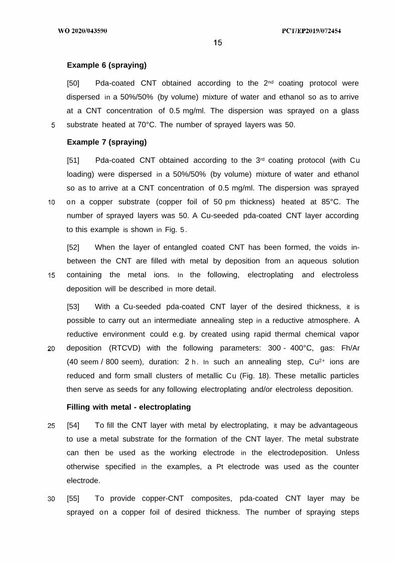
Example 7 (spraying)
[51] Pda-coated CNT obtained according to the 3rd coating protocol (with Cu
loading) were dispersed in a 50%/50% (by volume) mixture of water and ethanol
so as to arrive at a CNT concentration of 0.5 mg/ml. The dispersion was sprayed
on a copper substrate (copper foil of 50 pm thickness) heated at 85°C. The
number of sprayed layers was 50. A Cu-seeded pda-coated CNT layer according
to this example is shown in Fig. 5 .
[52] When the layer of entangled coated CNT has been formed, the voids in-
between the CNT are filled with metal by deposition from an aqueous solution
containing the metal ions. In the following, electroplating and electroless
deposition will be described in more detail.
[53] With a Cu-seeded pda-coated CNT layer of the desired thickness, it is
possible to carry out an intermediate annealing step in a reductive atmosphere. A
reductive environment could e.g. by created using rapid thermal chemical vapor
deposition (RTCVD) with the following parameters: 300 - 400°C, gas: Fh/Ar
(40 seem / 800 seem), duration: 2 h . In such an annealing step, Cu2+ ions are
reduced and form small clusters of metallic Cu (Fig. 18). These metallic particles
then serve as seeds for any following electroplating and/or electroless deposition.
Filling with metal - electroplating
[54] To fill the CNT layer with metal by electroplating, it may be advantageous
to use a metal substrate for the formation of the CNT layer. The metal substrate
can then be used as the working electrode in the electrodeposition. Unless
otherwise specified in the examples, a Pt electrode was used as the counter
electrode.
[55] To provide copper-CNT composites, pda-coated CNT layer may be
sprayed on a copper foil of desired thickness. The number of spraying steps

determines the thickness of the CNT layer. The copper foil covered with the CNT
layer may then be impregnated in a CuS0 4 solution in order to pre-charge the pda
with copper ions. Tests were carried out with a 0.1 M aqueous CuS0 4 solution with
impregnation taking place during 30 min but longer impregnation times may be
recommended to improve the Cu filling. A Pt counter electrode and a standard
hydrogen reference electrode were used. The pH of the plating solution was
adjusted to 1 with H2S0 4. The plating was made by chronoamperometry at -0.4 V
or -0.2 V (vs SCE) during various times (240, 1440, 8640 s) and/or by pulsed
potential (-0.2 V - 0.01 s, OFF - 0.01 s) during 14400 s .
Example 8 (electroplating)
[56] The pda-coated CNT layer of example 5 was impregnated in 0.1 M CuS0 4
solution during 30 minutes. Chronoamperometries at -0.4 V and -0.2 V (vs SCE)
and with various times (240 and 1440 s) were carried out. The filling of the CNT
layer was observed to be slightly better when the potential was reduced from -
0.4 V (about 14 mA/cm2) to -0.2 V (about 5 mA/cm 2) . As shown in Fig. 6, the
surface was almost totally covered with copper after 1440 seconds (at -0.4 V vs
SCE). Fig. 7 shows the obtained composite in cross section. Copper nuclei were
seen in and on the CNT layer as well as close to the copper substrate which
proved good penetration of plating solution into the CNT matrix and the ability of
copper to nucleate on pda-coated CNT. The filling of the CNT layer by copper
was, however, incomplete, which may be explained by insufficient charging of the
CNT layer with copper during the impregnation step.
Example 9 (electroplating)
[57] The pda-coated CNT containing Cu2+ ions obtained by the 3rd protocol
were sprayed on a copper foil as in example 7 . The CNT layer was then
impregnated in 0.1 M aqueous CuS0 4 solution. A chronoamperometry at -0.2 V
(about 5 mA/cm2) during 8640 s was necessary to cover the sample almost
completely. This large increase of the time it took to see copper deposit appear on
top of the CNT layer (in comparison with example 8) was a first indication of a
higher filling of the CNT layer with copper. This was confirmed by SEM: as can be
seen in Fig. 8, the copper matrix almost completely fills the CNT layer. This

example demonstrates that copper-seeded pda coating may be very useful for the
production of highly filled CNT layers.
Example 10 (electroplating)
[58] The pda-coated CNT containing Cu2+ ions obtained by the 3rd protocol
were sprayed on a copper foil as in example 7 . The CNT layer was then
impregnated in 0.1 M CuS0 4 solution. The sample was subjected to electroplating
using a pulsed potential (-0.2 V - 0.01 s, OFF - 0.01 s, vs SCE) during 14400 s in
order to improve diffusion of copper ions into the voids of the CNT layer as well as
to smoothen the composite surface with respect to the surface that was observed
in example 8 (Figure 8). The plating was stopped after 14440 s (corresponding to
7220 s ON time at -0.2 V vs SCE). As shown in Fig. 9, the resulting Cu-CNT
composite layer was smooth and exempt from cracks. SEM analysis revealed that
the CNT were perfectly embedded in a copper matrix (Fig. 10).
[59] To illustrate the performance of Cu-CNT composite material, an ampacity
test was carried out. For comparison, wires made of standard copper foil (the
same as the one that was used as the substrate in electroplating) were tested as
well. The copper test lines had widths of about 450 - 480 pm and were made by
stamping with two clamped razors blades. A first set of Cu test lines were exposed
to air, whereas a second set was clamped between two alumina plates for better
evacuation of heat. The Cu-CNT composite test lines were obtained as in
examples 9 and 10 and had widths of about 480 pm. The Cu-CNT composite test
lines remained exposed to air (i.e. they were not clamped between alumina
plates). In all tests, a Princeton Applied Research VersaSTAT MC potentiostat
coupled to a Kepco BOP 20-20M amplifier was used to generate a voltage ramp
(0.02 V/s), while the current was measured until breaking of the line.
[60] Fig. 11 illustrates the measured resistance versus the current density. It
should be noted that the leads used to connect the different samples to the power
source were not identical and, therefore, the resistance offsets between the
different samples should be disregarded. The presence of the Cu-CNT composite
layer (made as in examples 9 and 10) increased the ampacity values with respect
to the naked copper foil. Furthermore, one observes a decrease of the resistance
in the first stages of the ampacity measurement. This behaviour is coherent with
was observed by Subramaniam et al. and is likely to be due to an improvement of
the Cu-CNT interface and to thermally activated carriers when the Cu-CNT
interface is stressed by the current.
Example 11 (electroplating)
[61] The pda-coated CNT containing Cu2+ ions obtained by the 3rd protocol
were sprayed on a copper foil as in example 7, except that the copper substrate
was only 6 m thick, was heated to 150°C and spraying was repeated until a
thickness of 45-50 pm was reached. No impregnation was carried out but the
sample was subjected to electroplating from aqueous 0.1 M CuS0 4 solution (pH
adjusted to 1 by addition of H2S0 4) using a pulsed potential (-0.2 V - 0.01 s, OFF -
0.01 s, vs SCE) during 16 h, at room temperature, under stirring. The resulting Cu-
CNT composite (Fig. 12) had a thickness of 50 pm.
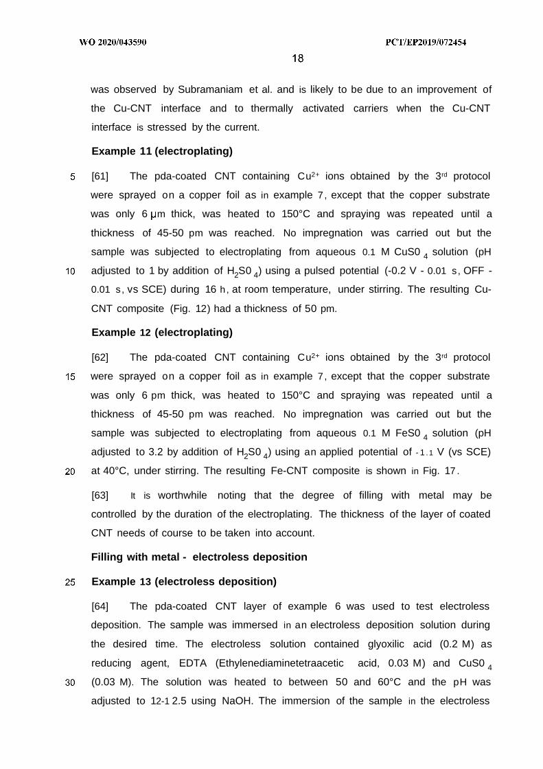
Example 12 (electroplating)
[62] The pda-coated CNT containing Cu2+ ions obtained by the 3rd protocol
were sprayed on a copper foil as in example 7, except that the copper substrate
was only 6 pm thick, was heated to 150°C and spraying was repeated until a
thickness of 45-50 pm was reached. No impregnation was carried out but the
sample was subjected to electroplating from aqueous 0.1 M FeS0 4 solution (pH
adjusted to 3.2 by addition of H2S0 4) using an applied potential of - 1 . 1 V (vs SCE)
at 40°C, under stirring. The resulting Fe-CNT composite is shown in Fig. 17 .
[63] It is worthwhile noting that the degree of filling with metal may be
controlled by the duration of the electroplating. The thickness of the layer of coated
CNT needs of course to be taken into account.
Filling with metal - electroless deposition
Example 13 (electroless deposition)
[64] The pda-coated CNT layer of example 6 was used to test electroless
deposition. The sample was immersed in an electroless deposition solution during
the desired time. The electroless solution contained glyoxilic acid (0.2 M) as
reducing agent, EDTA (Ethylenediaminetetraacetic acid, 0.03 M) and CuS0 4
(0.03 M). The solution was heated to between 50 and 60°C and the pH was
adjusted to 12-1 2.5 using NaOH. The immersion of the sample in the electroless

solution led to delamination of the CNT layer from the glass substrate, probably
due to bubbles trapped between the CNT layer and the substrate. Although
relatively fragile, the CNT layer conserved its cohesion and kept floating in the
solution. When the CNT layer was progressively filled by copper, it turned became
a more and more stable Cu-CNT composite (Fig. 13). This fabrication path is
interesting as it allows fabricating self-supported Cu-CNT composites.
[65] It may be worthwhile noting that delamination is not a necessary process
step but it may be used to produce very thin CNT tissues. The ampacity of the
composite of example 13 was slightly increased compared to copper foil in same
conditions (about 8-1 04A/cm2) . Although this was not tested, it is expected that
using CNT coated with pda containing copper seeds would improve the copper
filling with the electroless deposition technique.
Metal-CNT composites using CNT with tannic acid coating
Example 14 (CNT coating with tannic acid)
[66] 125 ml of tannic acid (0.01 mg/ml) + CvS0 .SH20 (0.6 mg/ml) were
prepared in water. 20 mg of oxidized CNT were added to 50 ml of this solution.
The dispersion was periodically ultra-sonicated while adding tannic acid CuS0 4
solution until a volume of 125 ml was reached. The dispersion was then
periodically ultra-sonicated during 20 minutes. 75 ml of Tris-HCI solution ( 10 mM)
was added and periodical ultra-sonications were carried out during 30 minutes.
The pH was adjusted to a value ranging from 11 to 12 and the coated CNT were
filtrated.
Example 15 (spraying)
[67] The metal-ion-seeded coated CNT of example 14 were dispersed in 40 ml
ethanol/water mixture (50%/50% by volume) so as to arrive at a concentration of
0.5 mg/ml. The dispersion was then sprayed in several layers on a on a Si-TaN
( 10 nm) -Ta ( 15 nm) - Cu ( 150 nm) substrate using the Paasche VL series
airbrush (distance from the substrate about 15 cm. The substrate temperature was
90°C. The resulting sprayed layer (Fig. 14) had a thickness of about 3.5 pm.

Example 16 (electroplating)
[68] The CNT layer of example 15 was subjected to electroplating in an
aqueous 0.1 M CuS0 4 solution (at room temperature). The pH was adjusted to 1
by addition of H2S0 4. During the electroplating (potential: -0.2 V vs SCE, duration:
30 minutes) the solution was stirred. The resulting composite (Figs. 15 and 16)
had a thickness of about 5 pm.
[69] While specific embodiments have been described herein in detail, those
skilled in the art will appreciate that various modifications and alternatives to those
details could be developed in light of the overall teachings of the disclosure.
Accordingly, the particular arrangements disclosed are meant to be illustrative only
and not limiting as to the scope of the invention, which is to be given the full
breadth of the appended claims and any and all equivalents thereof.

Claims
1. A method for producing a composite material, comprising:
providing a layer of carbon nanotubes;
filling the interstices of the carbon nanotubes layer with a metal so as to form
a metal matrix, in which the carbon nanotubes are embedded, said filling
being effected by electrodeposition or by electroless deposition;
wherein the layer of carbon nanotubes is obtained by depositing, on a
substrate, carbon nanotubes coated with a polyphenol or
poly(catecholamine) coating, the polyphenol or poly(catecholamine) coating
being crosslinked by metal ions, said metal ions promoting, as metal seeds,
adhesion and/or growth of the metal matrix during the filling step.
2 . The method as claimed in claim 1, wherein the coated carbon nanotubes are
provided within a suspension and wherein depositing the carbon nanotubes
comprises spraying the suspension on the substrate and causing the
dispersion medium to evaporate, the spraying being repeated until a desired
thickness of the carbon nanotubes layer is reached.
3 . The method as claimed in claim 1 or 2, wherein the metal seeds are of the
same species as the metal matrix.
4 . The method as claimed in claim 1 or 2, wherein the metal seeds are of a
different species than the metal matrix.
5 . The method as claimed in any one of claims 1 to 4, wherein the metal matrix
consists of a metal selected from: Cu, Ag, Au, Sn, Zn, Cd, Cr, Ni, Pt, Pb, Pd,
Co, Ti, Fe, and an alloy thereof.
6 . The method as claimed in any one of claims 1 to 5, wherein the carbon
nanotubes are coated with a polydopamine coating.
7 . The method as claimed in any one of claims 1 to 5, wherein the carbon
nanotubes are coated with a tannic acid-metal complex.

8 . The method as claimed in any one of claims 1 to 7, wherein the filling of the
interstices of the carbon nanotubes layer is effected from an aqueous
solution comprising metal ions.
9 . The method as claimed in claim 8, wherein the filling of the interstices of the
carbon nanotubes layer is effected by electrodeposition.
10 . The method as claimed in claim 8, wherein the filling of the interstices of the
carbon nanotubes layer is effected by electroless deposition.
11. The method as claimed in claim 10, wherein the layer of carbon nanotubes is
removed from the substrate on which it has been deposited prior to or during
electroless deposition.
12 . The method as claimed in any one of claims 1 to 11, wherein deposition of
the metal matrix is continued when the filling of the interstices is complete, so
as to form a metal capping layer on the composite material.
13 . The method as claimed in any one of claims 11, wherein the composite
material is annealed.
14. The method as claimed in any one of claims 1 to 15, comprising coating the
carbon nanotubes with the polyphenol or poly(catecholamine) coating, the
coating being carried out in a solution containing phenol and/or
catecholamine moieties wherein initially uncoated carbon nanotubes are
dispersed, the solution further containing metal ions capable of crosslinking
the phenol and/or catecholamine moieties.
15 . The method as claimed in claim 14, wherein the carbon nanotubes are
oxidized prior to dispersion in the solution containing phenol and/or
catecholamine moieties.
16 . The method as claimed in any one of claims 1 to 16, wherein the composite
material is produced as one or more electrical conductors on a substrate by
using a patterning technique.
17 . The method as claimed in any one of claims 1 to 16, wherein the layer of
carbon nanotubes forms a tangle of carbon nanotubes.
18 . A composite conductive material, comprising

a layer of carbon nanotubes,
a metal matrix filling the interstices of the carbon nanotubes layer;
wherein the carbon nanotubes are coated with a polyphenol or
poly(catecholamine) coating, the polyphenol or poly(catecholamine) coating
being crosslinked by metal ions.
19 . A composite conductive material comprising
a layer of carbon nanotubes,
a metal matrix filling the interstices of the carbon nanotubes layer;
wherein the carbon nanotubes comprise a graphitised or amorphous carbon
coating at the interfaces with the metal matrix.
20. The composite conductive material as claimed in any one of claims 18 or 19,
wherein the carbon nanotubes are randomly oriented.
2 1 . Electrical conductor comprising a composite conductive material as claimed
in any one of claims 18 to 20.


INTERNATIONAL SEARCH REPORTInternational application No
PCT/ EP20 19/072454
A. CLASSIFICATION OF SUBJECT MATTERI NV . C25D5/54 B05D 1/00 B82Y30/00 C25D 15/00 C0 1B32/00ADD .
According to International Patent Classification (IPC) or to both national classification and IPC
B. FIELDS SEARCHED
Minimum documentation searched (classification system followed by classification symbols)
C25D C23C C0 1B B82Y C23D B05D
Documentation searched other than minimum documentation to the extent that such documents are included in the fields searched
Electronic data base consulted during the international search (name of data base and, where practicable, search terms used)
EPO - I nterna l , WP I Data
* Special categories of cited documents :"T" later document published after the international filing date or priority
"A" document defining the general state of the art which is not considereddate and not in conflict with the application but cited to understand
to be of particular relevancethe principle or theory underlying the invention
Έ " earlier application or patent but published on or after the internationalfiling date
"X" document of particular relevance; the claimed invention cannot beconsidered novel or cannot be considered to involve an inventive
"L" document which may throw doubts on priority claim(s) orwhich is step when the document is taken alone
rnational search report
on , C
Form PCT/ISA/210 (second sheet) (April 2005)

INTERNATIONAL SEARCH REPORTInternational application No
PCT/EP2019/072454
Form PCT/ISA/210 (continuation of second sheet) (April 2005)

Form PCT/ISA/21 0 (continuation of first sheet (2)) (April 2005)

International Application No. PCTV EP2 19/ 072454

INTERNATIONAL SEARCH REPORTInternational application No
Information on patent family membersPCT/EP2019/072454
Patent document Publication Patent family Publicationcited in search report date member(s) date
CN 107604419 A 19-01-2018 NONE
CN 107252695 A 17-10-2017 NONE
CN 107093748 A 25-08-2017 NONE
US 2010038251 A1 18-02-2010 KR 20100021333 A 24-02-2010US 2010038251 A1 18-02-2010