२२० के वी एवं उच्चतर ववभव के सबस्टेशन...
257
२२० के वी एवं उतर ववभव के सबेशनं के वत उपकरणं पर ववशेषं की थायी सविवत की ररपट (जनवरी २०१७-िाट २०१८) REPORT OF STANDING COMMITTEE OF EXPERTS ON FAILURE OF 220 kV & ABOVE VOLTAGE CLASS SUBSTATION EQUIPMENT (JANUARY 2017-MARCH 2018) भारत सरकार Government of India केीय विद् युत ाविकरण Central Electricity Authority विद् युत मंालय Ministry of Power नई वदी New Delhi (ववद् युत अविवनयि २००३ की िारा ७३(एल) के तहत के .वव.ा. के दावय का वनवटहन करते ए) (In fulfillment of CEA’s obligation under Section 73(l) of the Electricity Act, 2003)
-
Upload
khangminh22 -
Category
Documents
-
view
0 -
download
0
Transcript of २२० के वी एवं उच्चतर ववभव के सबस्टेशन...
२२० क वी एव उचचतर ववभव क सबसटशन क कषवतगरसत उपकरण पर ववशषज की सथायी
सविवत की ररप रट
(जनवरी २०१७-िारट २०१८)
REPORT OF STANDING COMMITTEE OF EXPERTS ON FAILURE OF 220 kV & ABOVE VOLTAGE CLASS SUBSTATION EQUIPMENT
(JANUARY 2017-MARCH 2018)
भारत सरकार
Government of India
कनदरीय विदयत पराविकरण
Central Electricity Authority विदयत मतरालय
Ministry of Power नई वदलली
New Delhi
(ववदयत अविवनयि २००३ की िारा ७३(एल) क तहत क.वव.परा. क दावयतव का वनवटहन करत हए)
(In fulfillment of CEA’s obligation under Section 73(l) of the Electricity Act, 2003)
२२० क वी एव उचचतर ववभव क सबसटशन क कषवतगरसत उपकरण पर ववशषज की सथायी
सविवत की ररप रट (जनवरी २०१७-िारट २०१८)
REPORT OF STANDING COMMITTEE OF EXPERTS ON FAILURE OF 220 kV & ABOVE VOLTAGE CLASS SUBSTATION EQUIPMENT
(JANUARY 2017-MARCH 2018)
भारत सरकार
Government of India
कनदरीय विदयत पराविकरण
Central Electricity Authority विदयत मतरालय
Ministry of Power नई वदलली
New Delhi
(ववदयत अविवनयि २००३ की िारा ७३(एल) क तहत क.वव.परा. क दावयतव का वनवटहन करत हए)
(In fulfillment of CEA’s obligation under Section 73(l) of the Electricity Act, 2003)
TABLE OF CONTENTS
DESCRIPTION PAGE
NO.
Executive Summary 1
1.0 Introduction 1
2.0 Brief details of the failure of substation
equipment reported to CEA between 1st
January 2017 and 31st March 2018
2
3.0 Observations 15
4.0 Recommendations 16
Annexure I Detailed Information In Respect of Each
Failed Equipment Reported To CEA
Between January 2017 And March 2018 And
Brief Analysis Of Failure Of These
Equipment
24
Annexure II Failure Report as Provided by PGCIL 179
Annexure III Format for reporting of failure of the
Transformer/ Reactor and other substation
equipment
237
Annexure IV Minutes of Meeting of the Standing
Committee of Experts to investigate the
Failure of 220 kV and above voltage class
Substation Equipment held on 24th
September 2018 in CEA
244
Annexure V Office Order Constituting the Standing
Committee
252
CENTRAL ELECTRICITY AUTHORITY
Report on failure of 220 kV and above voltage class substation equipment 1
EXECUTIVE SUMMARY
1.0 INTRODUCTION
1.1 A Standing Committee comprising experts in the field of design and operation of EHV Substations from CEA, various power utilities and research/academic institutes was constituted under Section 73, Clause (l)
of the Electricity Act, 2003, to investigate the failure of 220 kV and above voltage class substation / switchyard equipment such as Power/Generator Transformer, Circuit Breaker (CB), Instrument Transformer [i.e. Current
Transformer (CT), Potential Transformer (PT) & Capacitor Voltage Transformer (CVT)], Surge Arrester (SA), Isolator etc. and recommend
measures to avert recurrence of such failures in future. As a part of such activity, CEA has been receiving reports of failures of various substation / switchyard equipment from power utilities. Office order vide which
Standing Committee was constituted is enclosed at Annexure- V.
1.2 The prime objective of Standing Committee is to visit site of failure,
investigate the cause of failure, discuss the cause of failure of various substation / switchyard equipment of Power utilities in the meeting,
recommend remedial measures to prevent recurrence of such failures in future and prepare a compendium of all failures. In the process, the participating utilities are mutually benefitted so as to adopt best practices.
1.3 As per the requirement of the Standing Committee, all utilities are
supposed to report the failure of substation/ switchyard equipment of 220 kV & above voltage class to CEA. In fact, number of failure cases remain unreported as many of power utilities [State Transmission Utilities, Private
Utilities/Licensees, Central Transmission Utilities, Public Sector Power Utilities] in the country neither report the failure of substation / switchyard equipment nor participate in such National level meeting.
Hence, the basic purpose of formation of above standing committee gets defeated. This fact has been brought to the notice of Hon’ble Central
Electricity Regulatory Commission, Joint Electricity Regulatory Commission and all State Regulatory Commissions.
1.4 In most of the cases, due to delay in reporting of event, the visit to site of failure do not materialize and analysis of cause of failure is done based on
CENTRAL ELECTRICITY AUTHORITY
Report on failure of 220 kV and above voltage class substation equipment 2
information provided by utilities. The information furnished by utilities is
generally found to be inadequate for analysis of cause of failure. Either many vital information is found to be missing or not available with O&M section because the O&M history of equipment / transformer, records of
all test results including tests carried out before & after failure incidences (factory tests, pre-commissioning tests, tests carried out during O&M etc.) are not properly maintained.
1.5 For the information and use of the utilities, the format for furnishing of
information of failure of substation equipment is provided at Annexure III. The utilities should provide adequate information in the format and submit it to CEA along with supporting test reports, O&M history, disturbance
recorder data, photographs etc. as early as possible after the occurrence of failure.
1.6 A meeting of the Standing Committee of experts was held in CEA on 24th September 2018 to discuss cause of failure of substation equipment for
which information/failure report was received in CEA between 1st January 2017 and 31st March 2018 from various utilities. Minutes of the meeting are enclosed at Annexure – IV.
1.7 During discussion in the meeting on the failure of Surge Arresters of
KPTCL, it emerged that some of the arresters were reported failed in view of leakage current in these arresters found to be more than acceptable values during leakage current measurement. The committee decided that
such cases should not be treated as failures and hence has been left out from the report.
1.8 Previous report on failure of substation equipment was published in July 2017 which contained the information regarding failure of substation
equipment reported to CEA between 1st September 2015 and 31st December 2016.
2.0 Brief details of the failure of substation equipment reported to CEA
between 1st January 2017 and 31st March 2018
2.1 The Committee investigates failures of 220 kV and above voltage class
equipment only. Failure of total 72 Nos. of Transformers, GTs, Reactors, Circuit Breakers, Instrument Transformers, Surge Arresters and XLPE

CENTRAL ELECTRICITY AUTHORITY
Report on failure of 220 kV and above voltage class substation equipment 3
Cable of 220 kV and above voltage rating was reported to CEA between
1st January 2017 and 31st March 2018. The voltage wise quantity of each equipment has been indicated in the Table-1 below:
TABLE-1
Equipment Voltage Class
Total Quantity
(Nos.) 220 kV 400 kV 765 kV
Quantity (Nos.)
Interconnecting
Transformers
9 6 0 15
Generator Transformers
0 1 0 1
Reactors
0 3 2 5
Circuit Breaker
4 0 0 4
Current Transformer
8 0 0 8
Potential Transformer/Capacitive
Voltage Transformer
11 2 0 13
Surge Arrester 19 6 0 25
XLPE Cable 1 0 0 1
Grand Total 72
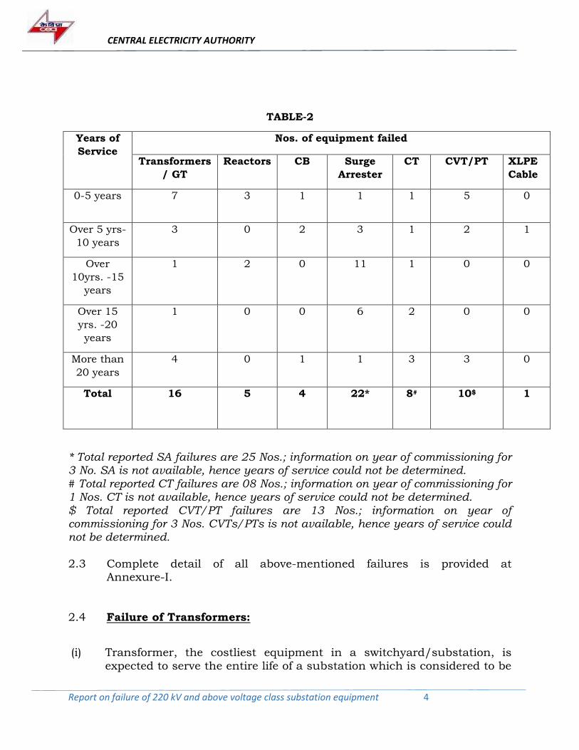
2.2 Quantity of failed equipment and years of service put in by these equipment before failure, reported to CEA between 1st January 2017 and
31st March 2018, is given in Table-2.
CENTRAL ELECTRICITY AUTHORITY
Report on failure of 220 kV and above voltage class substation equipment 4
TABLE-2
Years of
Service
Nos. of equipment failed
Transformers
/ GT
Reactors CB Surge
Arrester
CT CVT/PT XLPE
Cable
0-5 years 7 3 1 1 1 5 0
Over 5 yrs-
10 years
3 0 2 3 1 2 1
Over
10yrs. -15
years
1 2 0 11 1 0 0
Over 15
yrs. -20
years
1 0 0 6 2 0 0
More than
20 years
4 0 1 1 3 3 0
Total 16 5 4
22* 8#
10$ 1
* Total reported SA failures are 25 Nos.; information on year of commissioning for 3 No. SA is not available, hence years of service could not be determined. # Total reported CT failures are 08 Nos.; information on year of commissioning for 1 Nos. CT is not available, hence years of service could not be determined. $ Total reported CVT/PT failures are 13 Nos.; information on year of commissioning for 3 Nos. CVTs/PTs is not available, hence years of service could not be determined.
2.3 Complete detail of all above-mentioned failures is provided at
Annexure-I.
2.4 Failure of Transformers:
(i) Transformer, the costliest equipment in a switchyard/substation, is
expected to serve the entire life of a substation which is considered to be
CENTRAL ELECTRICITY AUTHORITY
Report on failure of 220 kV and above voltage class substation equipment 5
35 years as per CERC norm. The expected life in other countries are 40
years in USA, 45 years in Germany and 36 years in Australia. However, it has been observed that many transformers installed in Indian utilities have failed within first few years of service which is a matter of concern.
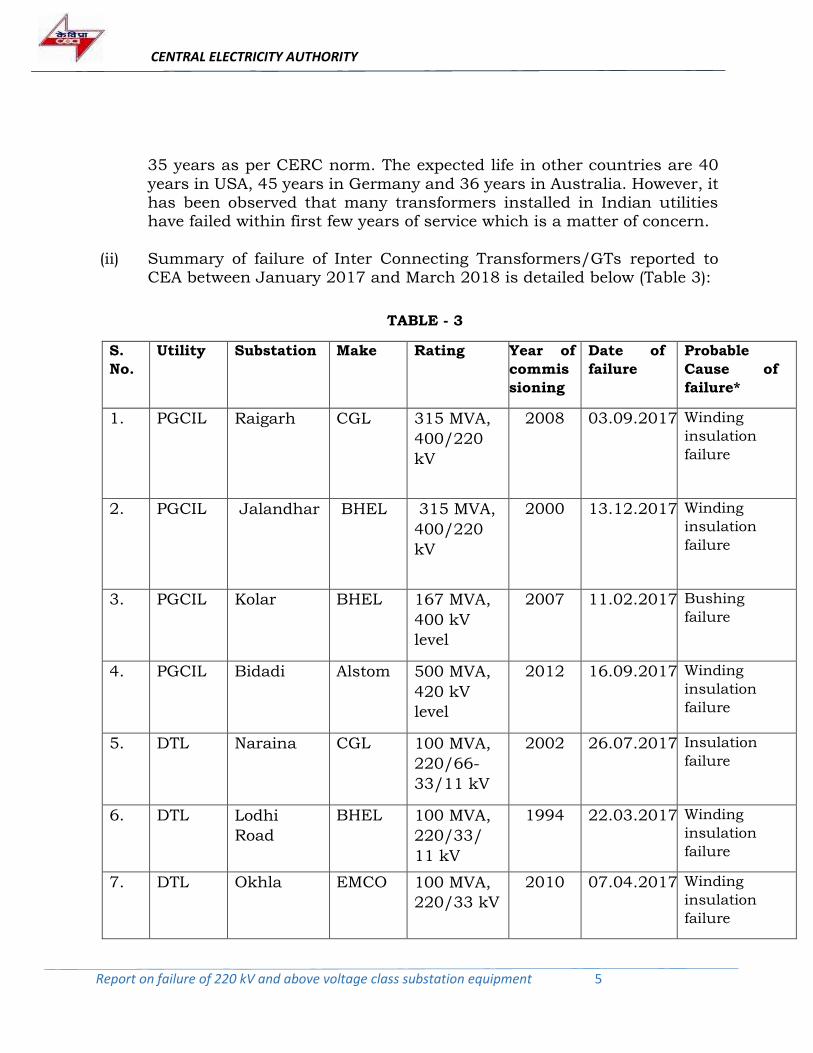
(ii) Summary of failure of Inter Connecting Transformers/GTs reported to
CEA between January 2017 and March 2018 is detailed below (Table 3):
TABLE - 3
S.
No.
Utility Substation Make Rating Year of
commis
sioning
Date of
failure
Probable
Cause of
failure*
1. PGCIL
Raigarh CGL 315 MVA,
400/220
kV
2008 03.09.2017 Winding
insulation
failure
2. PGCIL Jalandhar BHEL 315 MVA,
400/220
kV
2000 13.12.2017 Winding
insulation
failure
3. PGCIL Kolar BHEL 167 MVA,
400 kV
level
2007 11.02.2017 Bushing
failure
4. PGCIL Bidadi Alstom 500 MVA,
420 kV
level
2012 16.09.2017 Winding
insulation
failure
5. DTL Naraina CGL 100 MVA,
220/66-
33/11 kV
2002 26.07.2017 Insulation
failure
6. DTL Lodhi
Road
BHEL 100 MVA,
220/33/
11 kV
1994 22.03.2017 Winding
insulation
failure
7. DTL Okhla EMCO 100 MVA,
220/33 kV
2010 07.04.2017 Winding
insulation
failure
CENTRAL ELECTRICITY AUTHORITY
Report on failure of 220 kV and above voltage class substation equipment 6
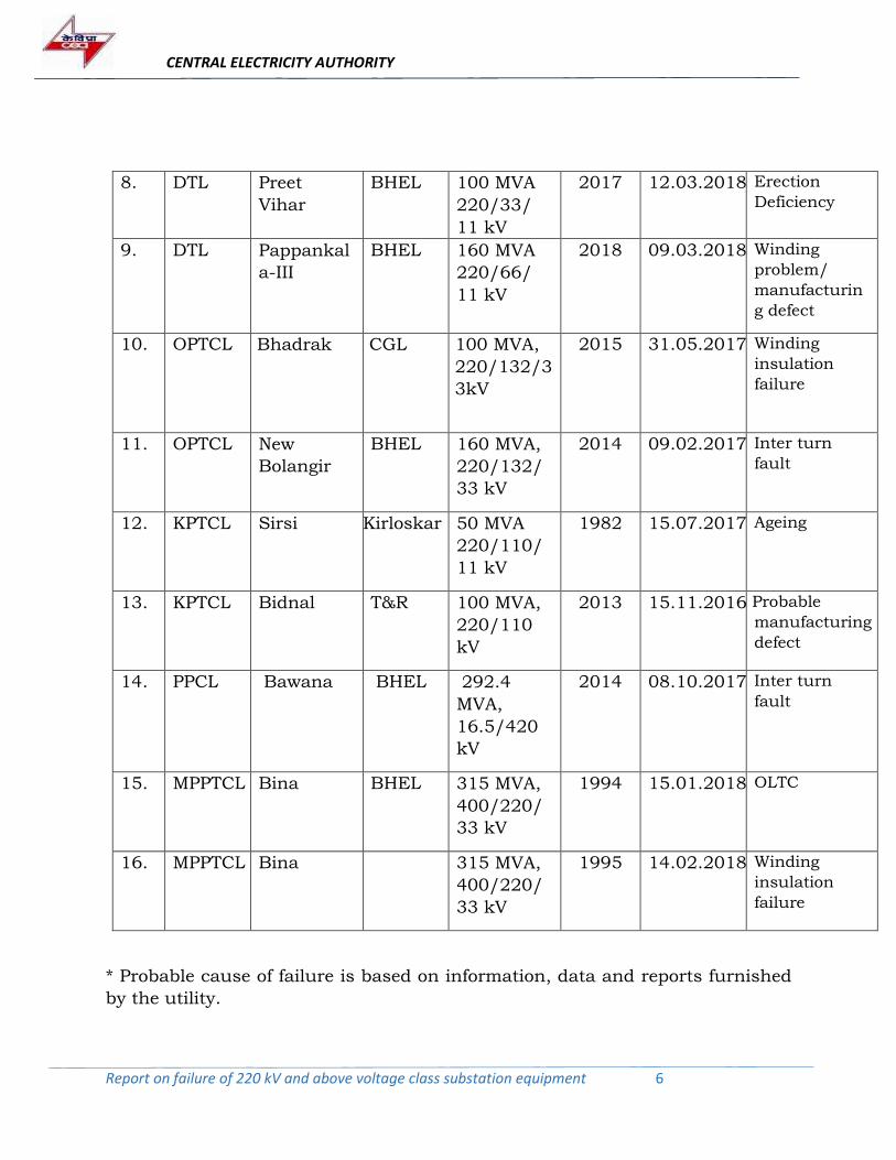
8. DTL Preet
Vihar
BHEL 100 MVA
220/33/
11 kV
2017 12.03.2018 Erection
Deficiency
9. DTL Pappankal
a-III
BHEL 160 MVA
220/66/
11 kV
2018 09.03.2018 Winding
problem/
manufacturin
g defect
10. OPTCL Bhadrak CGL 100 MVA,
220/132/3
3kV
2015 31.05.2017 Winding
insulation
failure
11. OPTCL New
Bolangir
BHEL 160 MVA,
220/132/
33 kV
2014 09.02.2017 Inter turn
fault
12. KPTCL Sirsi Kirloskar 50 MVA
220/110/
11 kV
1982 15.07.2017 Ageing
13. KPTCL Bidnal T&R 100 MVA,
220/110
kV
2013 15.11.2016 Probable
manufacturing
defect
14. PPCL Bawana BHEL 292.4
MVA,
16.5/420
kV
2014 08.10.2017 Inter turn
fault
15. MPPTCL Bina BHEL 315 MVA,
400/220/
33 kV
1994 15.01.2018 OLTC
16. MPPTCL Bina 315 MVA,
400/220/
33 kV
1995 14.02.2018 Winding
insulation
failure
* Probable cause of failure is based on information, data and reports furnished
by the utility.
CENTRAL ELECTRICITY AUTHORITY
Report on failure of 220 kV and above voltage class substation equipment 7
(iii) As can be seen from Table 3 above, sixteen (16) transformer failure cases
have been reported to CEA during the period from January 2017 and March 2018 by six (6) Utilities. It is a matter of concern that more than 50% of the reported failed transformers were in operation/service for less
than 10 years. It is highlighted that a large number of transformer failure cases remains unreported as many of power utilities [State Transmission Utilities, Private Utilities/Licensees, Central Transmission Utilities, Public
Sector Power Utilities] in the Country do not report the failures.
(iv) In case of failure of Transformers in the substations of PGCIL, a team constituted by PGCIL carried out the investigation of failure of these Transformers. Reports as prepared by the team has been enclosed as
Annexure-II.
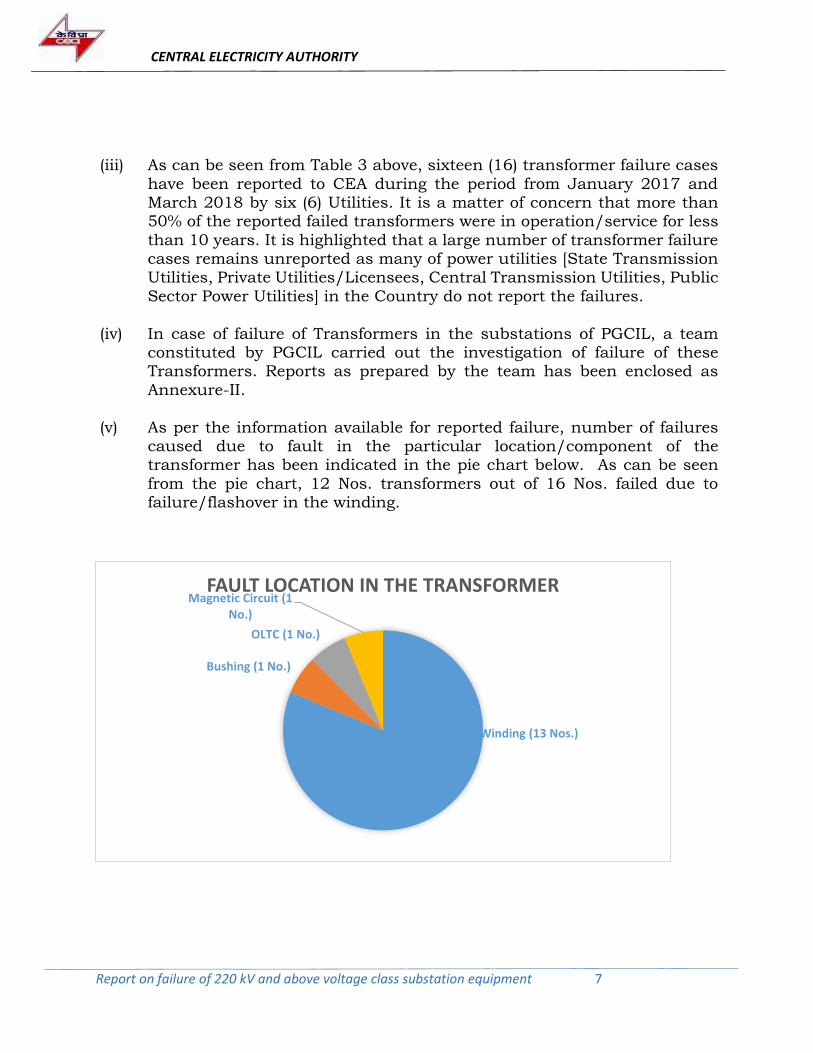
(v) As per the information available for reported failure, number of failures caused due to fault in the particular location/component of the transformer has been indicated in the pie chart below. As can be seen
from the pie chart, 12 Nos. transformers out of 16 Nos. failed due to failure/flashover in the winding.
Winding (13 Nos.)
Bushing (1 No.)
OLTC (1 No.)
Magnetic Circuit (1No.)
FAULT LOCATION IN THE TRANSFORMER
CENTRAL ELECTRICITY AUTHORITY
Report on failure of 220 kV and above voltage class substation equipment 8
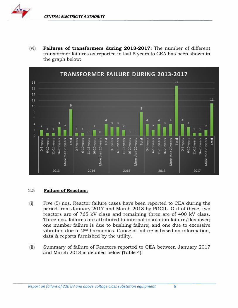
(vi) Failures of transformers during 2013-2017: The number of different
transformer failures as reported in last 5 years to CEA has been shown in the graph below:
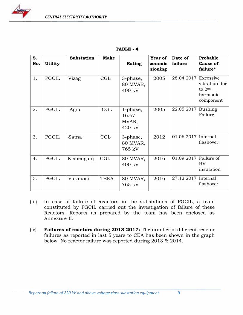
2.5 Failure of Reactors:
(i) Five (5) nos. Reactor failure cases have been reported to CEA during the period from January 2017 and March 2018 by PGCIL. Out of these, two
reactors are of 765 kV class and remaining three are of 400 kV class. Three nos. failures are attributed to internal insulation failure/flashover;
one number failure is due to bushing failure; and one due to excessive vibration due to 2nd harmonics. Cause of failure is based on information, data & reports furnished by the utility.
(ii) Summary of failure of Reactors reported to CEA between January 2017
and March 2018 is detailed below (Table 4):
21 1
32
9
1 10
2
0
43 3
2
0 0
8
4
2
43
4
17
43
1 12
11
0
2
4
6
8
10
12
14
16
18
0-5
yea
rs
6-1
0 y
ears
11
-15
yea
rs
16
-20
yea
rs
Mo
re t
han
20
yea
rs
Tota
l
0-5
yea
rs
6-1
0 y
ears
11
-15
yea
rs
16
-20
yea
rs
Mo
re t
han
20
yea
rs
Tota
l
0-5
yea
rs
6-1
0 y
ears
11
-15
yea
rs
16
-20
yea
rs
Mo
re t
han
20
yea
rs
Tota
l
0-5
yea
rs
6-1
0 y
ears
11
-15
yea
rs
16
-20
yea
rs
Mo
re t
han
20
yea
rs
Tota
l
0-5
yea
rs
6-1
0 y
ears
11
-15
yea
rs
16
-20
yea
rs
Mo
re t
han
20
yea
rs
Tota
l
2013 2014 2015 2016 2017
TRANSFORMER FAILURE DURING 2013-2017
CENTRAL ELECTRICITY AUTHORITY
Report on failure of 220 kV and above voltage class substation equipment 9
TABLE - 4
S.
No. Utility
Substation Make
Rating
Year of
commis
sioning
Date of
failure
Probable
Cause of
failure*
1. PGCIL
Vizag CGL 3-phase,
80 MVAR,
400 kV
2005 28.04.2017 Excessive
vibration due
to 2nd
harmonic
component
2. PGCIL Agra CGL 1-phase,
16.67
MVAR,
420 kV
2005 22.05.2017 Bushing
Failure
3. PGCIL Satna CGL 3-phase,
80 MVAR,
765 kV
2012 01.06.2017 Internal
flashover
4. PGCIL Kishenganj CGL 80 MVAR,
400 kV
2016 01.09.2017 Failure of
HV
insulation
5. PGCIL Varanasi TBEA 80 MVAR,
765 kV
2016 27.12.2017 Internal
flashover
(iii) In case of failure of Reactors in the substations of PGCIL, a team
constituted by PGCIL carried out the investigation of failure of these Reactors. Reports as prepared by the team has been enclosed as
Annexure-II.
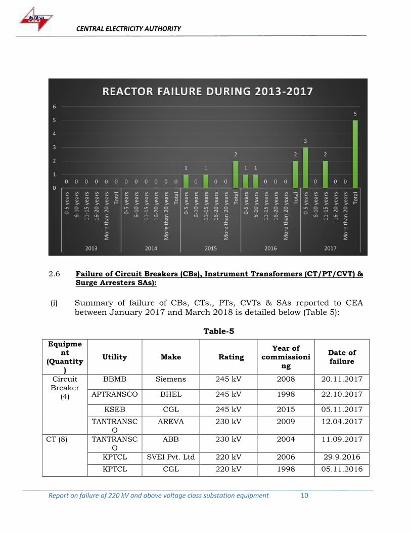
(iv) Failures of reactors during 2013-2017: The number of different reactor
failures as reported in last 5 years to CEA has been shown in the graph below. No reactor failure was reported during 2013 & 2014.
CENTRAL ELECTRICITY AUTHORITY
Report on failure of 220 kV and above voltage class substation equipment 10
2.6 Failure of Circuit Breakers (CBs), Instrument Transformers (CT/PT/CVT) &
Surge Arresters SAs):
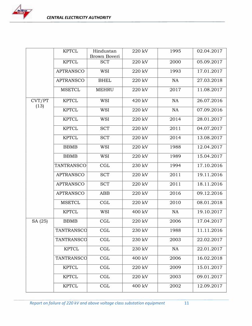
(i) Summary of failure of CBs, CTs., PTs, CVTs & SAs reported to CEA
between January 2017 and March 2018 is detailed below (Table 5):
Table-5
Equipment
(Quantity)
Utility Make Rating Year of
commissioning
Date of failure
Circuit Breaker
(4)
BBMB Siemens 245 kV 2008 20.11.2017
APTRANSCO BHEL 245 kV 1998 22.10.2017
KSEB CGL 245 kV 2015 05.11.2017
TANTRANSCO
AREVA 230 kV 2009 12.04.2017
CT (8)
TANTRANSCO
ABB 230 kV 2004 11.09.2017
KPTCL SVEI Pvt. Ltd 220 kV 2006 29.9.2016
KPTCL CGL 220 kV 1998 05.11.2016
0 0 0 0 0 0 0 0 0 0 0 0
1
0
1
0 0
2
1 1
0 0 0
2
3
0
2
0 0
5
0
1
2
3
4
5
6
0-5
yea
rs
6-1
0 y
ears
11
-15
yea
rs
16
-20
yea
rs
Mo
re t
han
20
yea
rs
Tota
l
0-5
yea
rs
6-1
0 y
ears
11
-15
yea
rs
16
-20
yea
rs
Mo
re t
han
20
yea
rs
Tota
l
0-5
yea
rs
6-1
0 y
ears
11
-15
yea
rs
16
-20
yea
rs
Mo
re t
han
20
yea
rs
Tota
l
0-5
yea
rs
6-1
0 y
ears
11
-15
yea
rs
16
-20
yea
rs
Mo
re t
han
20
yea
rs
Tota
l
0-5
yea
rs
6-1
0 y
ears
11
-15
yea
rs
16
-20
yea
rs
Mo
re t
han
20
yea
rs
Tota
l
2013 2014 2015 2016 2017
REACTOR FAILURE DURING 2013-2017
CENTRAL ELECTRICITY AUTHORITY
Report on failure of 220 kV and above voltage class substation equipment 11
KPTCL Hindustan Brown Boveri
220 kV 1995 02.04.2017
KPTCL SCT 220 kV 2000 05.09.2017
APTRANSCO WSI 220 kV 1993 17.01.2017
APTRANSCO BHEL 220 kV NA 27.03.2018
MSETCL MEHRU 220 kV 2017 11.08.2017
CVT/PT (13)
KPTCL WSI 420 kV NA 26.07.2016
KPTCL WSI 220 kV NA 07.09.2016
KPTCL WSI 220 kV 2014 28.01.2017
KPTCL SCT 220 kV 2011 04.07.2017
KPTCL SCT 220 kV 2014 13.08.2017
BBMB WSI 220 kV 1988 12.04.2017
BBMB WSI 220 kV 1989 15.04.2017
TANTRANSCO CGL 230 kV 1994 17.10.2016
APTRANSCO SCT 220 kV 2011 19.11.2016
APTRANSCO SCT 220 kV 2011 18.11.2016
APTRANSCO ABB 220 kV 2016 09.12.2016
MSETCL CGL 220 kV 2010 08.01.2018
KPTCL WSI 400 kV NA 19.10.2017
SA (25) BBMB CGL 220 kV 2006 17.04.2017
TANTRANSCO CGL 230 kV 1988 11.11.2016
TANTRANSCO CGL 230 kV 2003 22.02.2017
KPTCL CGL 230 kV NA 22.01.2017
TANTRANSCO CGL 400 kV 2006 16.02.2018
KPTCL CGL 220 kV 2009 15.01.2017
KPTCL CGL 220 kV 2003 09.01.2017
KPTCL CGL 400 kV 2002 12.09.2017
CENTRAL ELECTRICITY AUTHORITY
Report on failure of 220 kV and above voltage class substation equipment 12
KPTCL CGL 400 kV NA 29.10.2016
KPTCL CGL 220 kV 2003 06.11.2016
KPTCL CGL 400 kV NA 11.11.2016
KPTCL CGL 220 kV 2003 18.11.2016
KPTCL CGL 220 kV 1999 19.11.2016
BBMB CGL 220 kV 2006 18.12.2016
APTRANSCO ELPRO 220 kV 1998 02.12.2016
TANTRANSCO LAMCO 220 kV 2015 07.08.2016
TANTRANSCO CGL 220 kV 2006 24.12.2016
TANTRANSCO CGL 400 kV 2006 05.02.2017
KPTCL CGL 220 kV 2003 11.12.2017
KPTCL CGL 220 kV 2003 23.02.2018
KPTCL CGL 220 kV 2002 07.03.2018
KPTCL CGL 400 kV 2002 21.01.2018
KPTCL CGL 220 kV 2002 07.03.2018
MSETCL CGL 220 kV 2008 25.07.2017
MSETCL CGL 400 kV 2002 30.03.2018
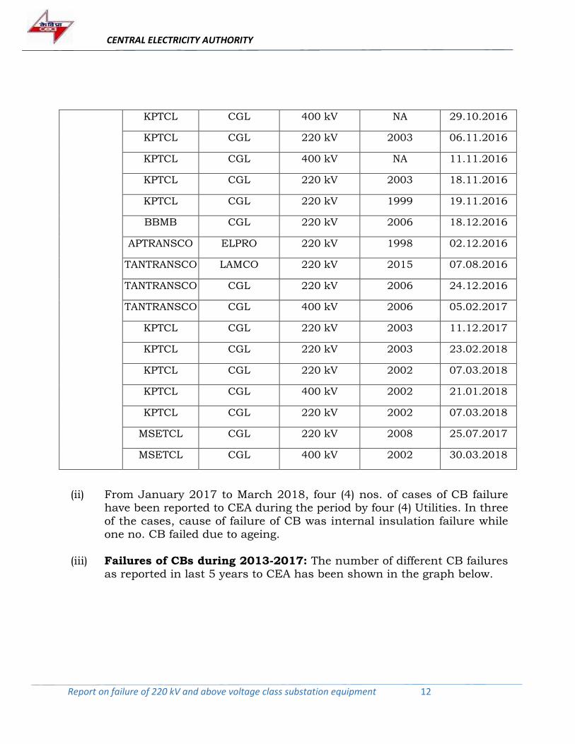
(ii) From January 2017 to March 2018, four (4) nos. of cases of CB failure have been reported to CEA during the period by four (4) Utilities. In three
of the cases, cause of failure of CB was internal insulation failure while one no. CB failed due to ageing.
(iii) Failures of CBs during 2013-2017: The number of different CB failures as reported in last 5 years to CEA has been shown in the graph below.
CENTRAL ELECTRICITY AUTHORITY
Report on failure of 220 kV and above voltage class substation equipment 13
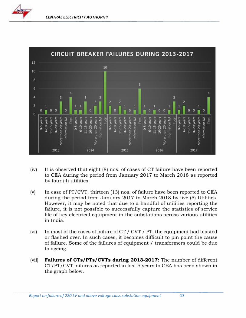
(iv) It is observed that eight (8) nos. of cases of CT failure have been reported
to CEA during the period from January 2017 to March 2018 as reported by four (4) utilities.
(v) In case of PT/CVT, thirteen (13) nos. of failure have been reported to CEA during the period from January 2017 to March 2018 by five (5) Utilities. However, it may be noted that due to a handful of utilities reporting the
failure, it is not possible to successfully capture the statistics of service life of key electrical equipment in the substations across various utilities
in India.
(vi) In most of the cases of failure of CT / CVT / PT, the equipment had blasted
or flashed over. In such cases, it becomes difficult to pin point the cause of failure. Some of the failures of equipment / transformers could be due
to ageing.
(vii) Failures of CTs/PTs/CVTs during 2013-2017: The number of different
CT/PT/CVT failures as reported in last 5 years to CEA has been shown in the graph below.
01
0 0
3
0
4
1 1
3
0
23
10
2
0
21
01
6
10
10 0
1
3
12
0 01
0
4
0
2
4
6
8
10
12
0-5
yea
rs
6-1
0 y
ears
11
-15
yea
rs
16
-20
yea
rs
Mo
re t
han
20
yea
rs
Info
rmat
ion
NA
Tota
l
0-5
yea
rs
6-1
0 y
ears
11
-15
yea
rs
16
-20
yea
rs
Mo
re t
han
20
yea
rs
Info
rmat
ion
NA
Tota
l
0-5
yea
rs
6-1
0 y
ears
11
-15
yea
rs
16
-20
yea
rs
Mo
re t
han
20
yea
rs
Info
rmat
ion
NA
Tota
l
0-5
yea
rs
6-1
0 y
ears
11
-15
yea
rs
16
-20
yea
rs
Mo
re t
han
20
yea
rs
Info
rmat
ion
NA
Tota
l
0-5
yea
rs
6-1
0 y
ears
11
-15
yea
rs
16
-20
yea
rs
Mo
re t
han
20
yea
rs
Info
rmat
ion
NA
Tota
l
2013 2014 2015 2016 2017
CIRCUIT BREAKER FAILURES DURING 2013-2017
CENTRAL ELECTRICITY AUTHORITY
Report on failure of 220 kV and above voltage class substation equipment 14
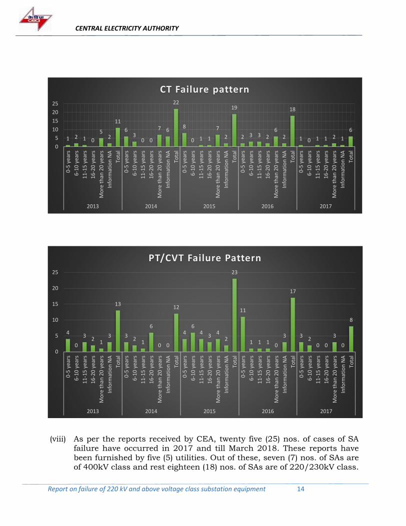
(viii) As per the reports received by CEA, twenty five (25) nos. of cases of SA failure have occurred in 2017 and till March 2018. These reports have
been furnished by five (5) utilities. Out of these, seven (7) nos. of SAs are of 400kV class and rest eighteen (18) nos. of SAs are of 220/230kV class.
1 2 1 0
52
11
63
0 0
7 6
22
8
0 1 1
7
2
19
2 3 3 26
2
18
1 0 1 1 2 1
6
0
5
10
15
20
25
0-5
yea
rs
6-1
0 y
ears
11
-15
yea
rs
16
-20
yea
rs
Mo
re t
han
20
yea
rs
Info
rmat
ion
NA
Tota
l
0-5
yea
rs
6-1
0 y
ears
11
-15
yea
rs
16
-20
yea
rs
Mo
re t
han
20
yea
rs
Info
rmat
ion
NA
Tota
l
0-5
yea
rs
6-1
0 y
ears
11
-15
yea
rs
16
-20
yea
rs
Mo
re t
han
20
yea
rs
Info
rmat
ion
NA
Tota
l
0-5
yea
rs
6-1
0 y
ears
11
-15
yea
rs
16
-20
yea
rs
Mo
re t
han
20
yea
rs
Info
rmat
ion
NA
Tota
l
0-5
yea
rs
6-1
0 y
ears
11
-15
yea
rs
16
-20
yea
rs
Mo
re t
han
20
yea
rs
Info
rmat
ion
NA
Tota
l
2013 2014 2015 2016 2017
CT Failure pattern
4
0
32
13
13
32
1
6
0 0
12
46
43
42
23
11
1 1 10
3
17
32
0 0
3
0
8
0
5
10
15
20
25
0-5
yea
rs
6-1
0 y
ears
11
-15
yea
rs
16
-20
yea
rs
Mo
re t
han
20
yea
rs
Info
rmat
ion
NA
Tota
l
0-5
yea
rs
6-1
0 y
ears
11
-15
yea
rs
16
-20
yea
rs
Mo
re t
han
20
yea
rs
Info
rmat
ion
NA
Tota
l
0-5
yea
rs
6-1
0 y
ears
11
-15
yea
rs
16
-20
yea
rs
Mo
re t
han
20
yea
rs
Info
rmat
ion
NA
Tota
l
0-5
yea
rs
6-1
0 y
ears
11
-15
yea
rs
16
-20
yea
rs
Mo
re t
han
20
yea
rs
Info
rmat
ion
NA
Tota
l
0-5
yea
rs
6-1
0 y
ears
11
-15
yea
rs
16
-20
yea
rs
Mo
re t
han
20
yea
rs
Info
rmat
ion
NA
Tota
l
2013 2014 2015 2016 2017
PT/CVT Failure Pattern
CENTRAL ELECTRICITY AUTHORITY
Report on failure of 220 kV and above voltage class substation equipment 15
(ix) Failures of SAs during 2013-2017: The number of different SA failures
as reported in last 5 years to CEA has been shown in the graph below.
2.7 One number case of failure of 220 kV XLPE Cable of DTL was reported.
The cable had failed in February 2018. The failure may be attributed to improper restoration of original installation conditions of cable during excavation for metro work.
3.0 OBSERVATIONS:
(i) It is observed that reported failures are primarily due to following reasons:
a. Normal Ageing
b. Failure of Insulation system for CB/CT/PT/CVT/SA.
c. Failure of Insulation system & Bushing for Transformers &
Reactors.
d. Lack of prudent maintenance practices
e. Frequent System Faults and transient over voltages generated by the system.
f. Improper installation (XLPE cable)
(ii) In most of the failure cases of CT/PT/CVT/SA, equipment blast or get
completely damaged making it impossible to carry out any test after
32
31 1
0
10
24
6
1 13
17
21 1
01 1
6
1
53
5
12
17
02
6
0 01
9
02468
1012141618
0-5
yea
rs
6-1
0 y
ears
11
-15
yea
rs
16
-20
yea
rs
Mo
re t
han
20
yea
rs
Info
rmat
ion
NA
Tota
l
0-5
yea
rs
6-1
0 y
ears
11
-15
yea
rs
16
-20
yea
rs
Mo
re t
han
20
yea
rs
Info
rmat
ion
NA
Tota
l
0-5
yea
rs
6-1
0 y
ears
11
-15
yea
rs
16
-20
yea
rs
Mo
re t
han
20
yea
rs
Info
rmat
ion
NA
Tota
l
0-5
yea
rs
6-1
0 y
ears
11
-15
yea
rs
16
-20
yea
rs
Mo
re t
han
20
yea
rs
Info
rmat
ion
NA
Tota
l
0-5
yea
rs
6-1
0 y
ears
11
-15
yea
rs
16
-20
yea
rs
Mo
re t
han
20
yea
rs
Info
rmat
ion
NA
Tota
l
2013 2014 2015 2016 2017
SA FAILURE PATTERN
CENTRAL ELECTRICITY AUTHORITY
Report on failure of 220 kV and above voltage class substation equipment 16
failure. Without tests, internal condition of the failed equipment cannot
be assessed and cause of failure cannot be determined. However, in most of the cases it is assumed that degradation of insulation due to ingress of moisture and transient system voltages might be the reason of failure
of these equipment.
(iii) Condition Based Maintenance (CBM) Practices using modern diagnostic tools is not being followed by most of the utilities and in general, periodic
Time Based Maintenance (TBM) is still being practiced.
(iv) Adequate modern Diagnostic tools are not available with most of the State Utilities.
(v) Most of the utilities are facing problem due to shortage of technical staff for operation & maintenance of sub-station equipment. Sometimes
interpretation of test results becomes difficult in absence of experts / experienced O&M staff.
(vi) Sometimes due to unavailability of shut down, maintenance of
equipment is deferred which affects the efficient functioning of the equipment and further deteriorate the health of equipment.
(vii) In most of the cases of failures, utilities do not furnish factory test reports, pre-commissioning test reports, history of O&M & repairs, relay
settings, environmental & system conditions at the time of failure etc. which makes it very difficult to analyse the cause of failure.
(viii) In case of failure of transformers and reactors, report of detailed internal
inspection carried out by OEM at site or at its works are not provided.
(ix) In some cases, even though, there are indications of abnormalities after carrying out diagnostic tests, no corrective actions are taken.
(x) It is observed that sometimes same tests are carried out using different test methods with different kind/rating of test apparatus under different
environment conditions which results in inconsistent and erroneous results.
4.0 RECOMMENDATIONS:
Recommended measures suggested by the Committee for the Utilities to
improve the performance of the substation equipment are listed below.
Some of the recommendations are being repeated from the previous report
(July 2017) with the objective to remind the actions required to be taken
by utilities to improve performance of equipment and to use modern
diagnostic tools for condition assessment so as to keep substation
equipment healthy for long trouble-free and reliable operation.
CENTRAL ELECTRICITY AUTHORITY
Report on failure of 220 kV and above voltage class substation equipment 17
4.1 General Recommendations:
(i) The utilities should report to the Original Equipment Manufacturer (OEM)
about the failure of equipment, even if warranty has expired, which may
help the manufacturers to take corrective action for improving the product design.
(ii) The practice of Condition Based Monitoring using modern diagnostic tools should be followed instead of conventional Periodic / Time Based
Maintenance. Some of the important diagnostic tools have also been suggested in Central Electricity Authority (Technical Standards for Construction of Electrical Plants and Electric Lines) Regulations.
(iii) The frequency/periodicity of measurement should be changed depending
on condition/healthiness of equipment in operation. The trend of the test results should be monitored rather than absolute values of test result.
(iv) Utilities should follow best practices for maintenance of each equipment. All the equipment which have reached/approaching end of service life need to be monitored closely and utility should plan and take action in advance
for replacement of such equipment in a phased manner.
(v) The utilities should make it a practice to carry out various tests on major electrical equipment at sites one or two months prior to expiry of warranty period of respective equipment so that any abnormality observed in test
results can be discussed with OEM for taking up further necessary action within warranty period.
(vi) The utilities must be careful while storing the equipment as spare or
keeping transformer in the yard for long time before putting in to service.
The manufacturer’s recommendation for storage should be followed strictly.
(vii) Utilities should take appropriate actions for repair/replacement of concerned equipment as soon as some abnormality is observed through
visual inspection or diagnostic tests.
(viii) Frequent failures of equipment of any particular make should be
thoroughly investigated in consultation with OEM and necessary action including design modification, if required, should be carried out by OEM.
CENTRAL ELECTRICITY AUTHORITY
Report on failure of 220 kV and above voltage class substation equipment 18
(ix) Most of the utilities are facing problem due to shortage of supporting staff
for operation & maintenance of sub-station equipment. The manpower should be strengthened for efficient operation & maintenance.
(x) The regular cleaning of dust deposited on the housings of major equipment and bushings of transformer in Thermal Power Plant are essential to avoid flash over across the insulators, as such frequent flashover across the
bushing / housing of equipment (due to operation in such dusty environment) may lead to failure of equipment. Wherever feasible, the
porcelain housings of major equipment (CB/LA/CT/CVT) and bushings of transformer may be protected by providing Room Temperature Vulcanisation (RTV) coating. RTV coating over porcelain housing of
equipment (CB/LA/CT/CVT) / bushings of transformer & reactors may also be considered by utilities for substation equipment installed in
pollution prone areas.
(xi) Utilities should create and maintain complete data base of
equipment/transformers including previous test reports (reports of factory tests/pre-commissioning tests/tests during O&M etc.), operation & maintenance history of equipment with make, model & year of
commissioning etc. for proper evaluation, interpretation of test results and for taking Run-Refurbish-Replacement decision.
(xii) However, merely maintaining the history of O&M is not sufficient. Test
results are not useful if correct method of testing is not followed. All tests
and maintenance should be carried out as per best practices. The method of testing as well as the conditions while conducting the tests should be
consistent / identical to previous testing condition as far as possible. For example, test voltage, tap position at which test is conducted etc. should be maintained while measuring IR or Turns Ratio, or conducting SFRA
and other similar tests. Details of test kits, should be maintained so that the test results can be compared with subsequent test results. For variation in temperature, required correction factors could be
incorporated. Calibration of the testing instruments should be ensured for reliability of the assessment.
4.2 Recommendations for Transformers (ICT & GT) and Instrument Transformers (CT/PT/CVT):
(i) The proper handling, loading, transportation, unloading, and storage at
site before assembling play important role in satisfactory operation of
equipment / transformer.
CENTRAL ELECTRICITY AUTHORITY
Report on failure of 220 kV and above voltage class substation equipment 19
(ii) The erection of major equipment including transformers should always
be carried out by experienced technical team under the close supervision of manufacturer.
(iii) Inordinate delay in commissioning of equipment /transformer after reaching at site should be avoided.
(iv) When there is a wide gap between the year of manufacturing and year of commissioning of the transformers, proper care must be taken to ensure
satisfactory operation of transformer. Storage of transformer should be done as per manufacturer’s recommendations.
(v) Transformer should not be kept for more than three (3) months with dry air/inert gas (Nitrogen) filling and all throughout the period, required
pressure needs to be maintained in order to avoid the exposure of active part to atmosphere. After three (3) months, transformer should be filled with oil under vacuum and transformer should be provided with oil
conservator including oil level indicator and breather. The oil parameters need to be monitored regularly.
(vi) As far as possible the transformer should be transported filled with dry air. Use of nitrogen for this purpose should be avoided.
(vii) Whenever there is movement of transformer either from manufacturing
works or from one station to other, SFRA should be carried out before
movement and after shifting to new location. SFRA signature would provide valuable information about deformation in winding /core during
transportation.
(viii) OLTC is one of the contributors to the failure of transformer. Possibility
of eliminating OLTC from 400kV & 765kV class transformer should be considered (based on system studies) in consultation with Regional Power Committee (RPC) and Regional Load Dispatch Centre (RLDC) / POSOCO
and CEA. The reduction in number of taps/steps can also be considered in case of OLTC of 220kV and below voltage class transformers. The
removal of OLTC will simplify the design and manufacturing of transformers.
(ix) Tertiary winding should be avoided, wherever feasible, as it increases the probability of failure of the transformer. Tertiary terminals of transformer prone to short circuiting by external element such as bird or animal may
be suitably insulated.
CENTRAL ELECTRICITY AUTHORITY
Report on failure of 220 kV and above voltage class substation equipment 20
(x) An internal inspection of the failed transformer on-site is warranted at
times to locate fault inside the transformer and to assess the extent of damage. As far as possible, internal inspection should be carried out in association with OEM / in presence of representative of OEM. All safety
precautions must be observed at all times. Internal inspection must be performed by experienced staff with proper training. The internal inspection should not cause any further damage to the transformer and
precaution should be taken to prevent ingress of moisture and any foreign material into the transformer and hence internal inspection should be
meticulously planned.
(xi) The capacitance and tan delta measurement of transformer bushing at
variable frequency and DGA of bushing oil should be carried out for health assessment of bushings as this has been proved to be very effective in
assessing the condition of in-service bushings.
(xii) Periodic oil testing including DGA (wherever feasible) in case of
instrument transformers are recommended. Health of gaskets and bellows needs to be checked periodically for CTs. Thermo vision scanning of CTs, CVTs and PTs should also be carried out regularly as a good
maintenance practice.
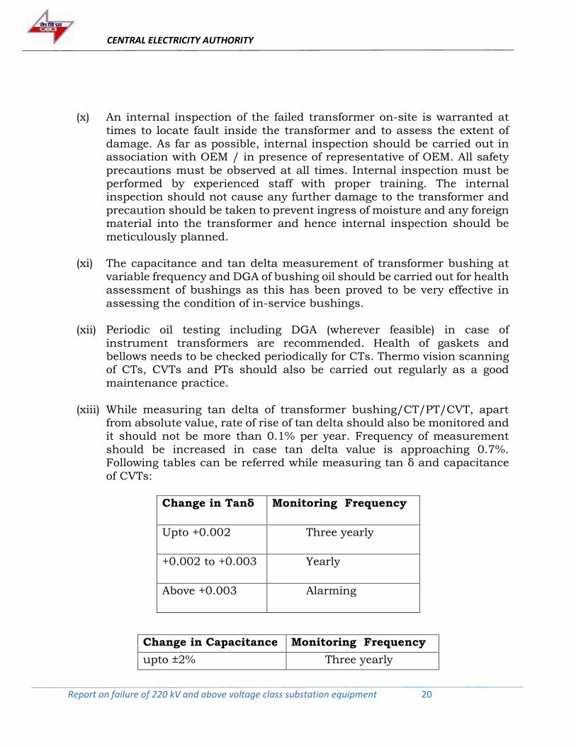
(xiii) While measuring tan delta of transformer bushing/CT/PT/CVT, apart from absolute value, rate of rise of tan delta should also be monitored and it should not be more than 0.1% per year. Frequency of measurement
should be increased in case tan delta value is approaching 0.7%. Following tables can be referred while measuring tan δ and capacitance
of CVTs:
Change in Tanδ
Monitoring Frequency
Upto +0.002 Three yearly
+0.002 to +0.003 Yearly
Above +0.003 Alarming
Change in Capacitance Monitoring Frequency
upto ±2% Three yearly
CENTRAL ELECTRICITY AUTHORITY
Report on failure of 220 kV and above voltage class substation equipment 21
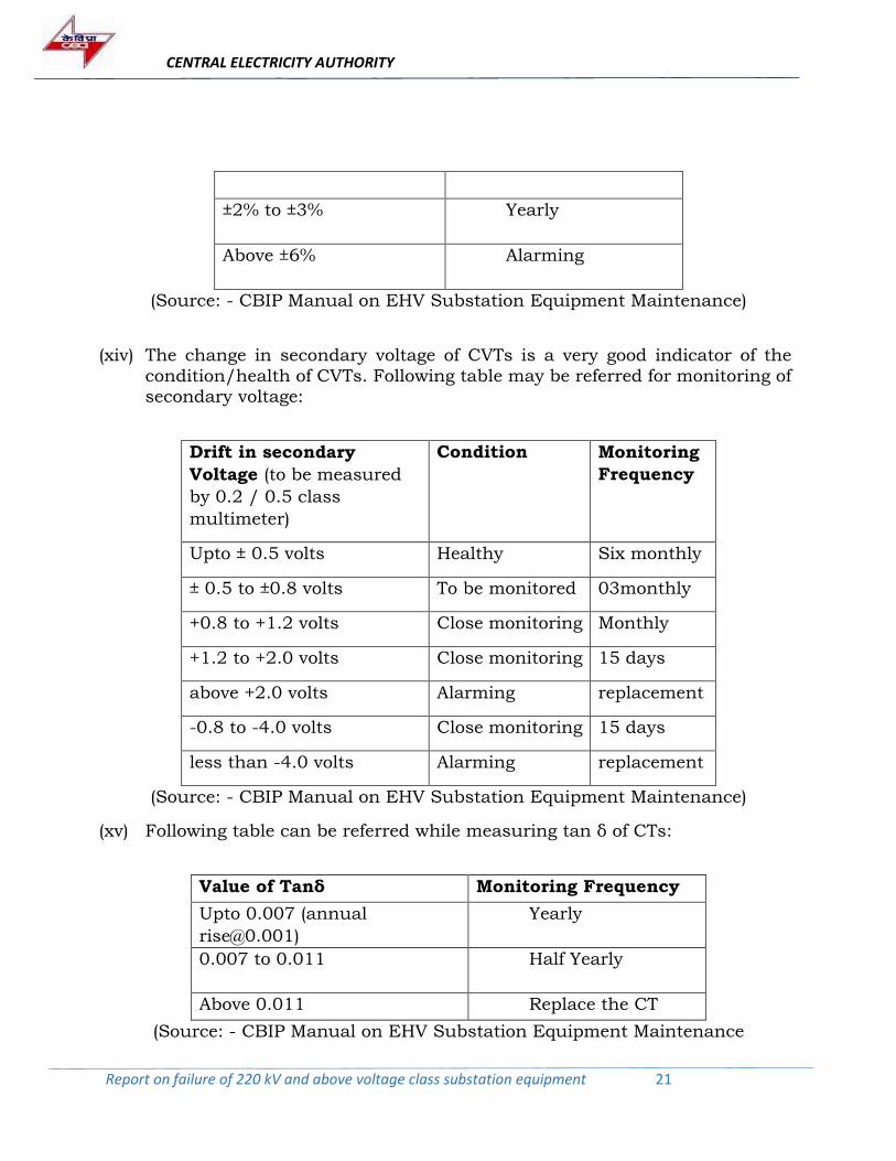
±2% to ±3% Yearly
Above ±6% Alarming
(Source: - CBIP Manual on EHV Substation Equipment Maintenance)
(xiv) The change in secondary voltage of CVTs is a very good indicator of the
condition/health of CVTs. Following table may be referred for monitoring of secondary voltage:
Drift in secondary
Voltage (to be measured
by 0.2 / 0.5 class
multimeter)
Condition Monitoring
Frequency
Upto ± 0.5 volts Healthy Six monthly
± 0.5 to ±0.8 volts To be monitored 03monthly
+0.8 to +1.2 volts Close monitoring Monthly
+1.2 to +2.0 volts Close monitoring 15 days
above +2.0 volts Alarming replacement
-0.8 to -4.0 volts Close monitoring 15 days
less than -4.0 volts Alarming replacement
(Source: - CBIP Manual on EHV Substation Equipment Maintenance)
(xv) Following table can be referred while measuring tan δ of CTs:
Value of Tanδ Monitoring Frequency
Upto 0.007 (annual
Yearly
0.007 to 0.011 Half Yearly
Above 0.011 Replace the CT
(Source: - CBIP Manual on EHV Substation Equipment Maintenance
CENTRAL ELECTRICITY AUTHORITY
Report on failure of 220 kV and above voltage class substation equipment 22
(xvi) Oil level should be checked before charging. For CTs with metallic bellows,
the oil should be present upto the top of the bellow for proper functioning. The oil leakage needs to be checked periodically. Bellow level should be closely watched. The level of bellows of all CTs in one bay should be same
at any time. Different bellow level may be an indicator of oil leakage, gassing or fault. Similarly, Capacitor units & EMU of CVTs in one bay should have same oil level indication at any time.
(xvii) Varistors protect the CVT from over voltage due to Ferro-resonance (FR)
oscillations. They may fail in service if FR is sustained or the energy to be discharged is beyond its designed capacity. Simple visual check will ensure the healthiness. A varistor should be replaced by the varistor of the same
voltage rating, as secondary voltage is tuned to a varistor.
4.3 Recommendations for Surge Arrester:
(i) Measurement of the 3rd harmonic resistive component of leakage current is
a very good method for assessing healthiness of SA. If 3rd harmonic component of resistive current is more than 150 µA, then Insulation Resistance (IR) value test should also be conducted and if current exceeds
350 µA, then SA should be removed from service and replaced. The measurement of leakage current before and after the monsoon should be
carried out so as to ascertain the effect of moisture.
(ii) Before erection, the condition of the Arrester unit should be checked and it
should be ensured that there is no damage during erection. If SA is kept on an uneven surface, it is likely to damage the pressure relief diaphragm. Any damage to this thin & sensitive material while handling & erecting will result
into moisture entry into Surge Arrester, which will lead to its failure.
(iii) Thermal scanning is another simple on-line check often used on SAs to locate hot spot due to improper/defective terminations/excessive watt loss.
(iv) The specification of SA should include Sealing Test which can be carried out at manufacturer’s works to ensure proper sealing against ingress of moisture.
(v) Digital surge counter’s employment in substations could be explored.
CENTRAL ELECTRICITY AUTHORITY
Report on failure of 220 kV and above voltage class substation equipment 23
4.4 Recommendations for Circuit Breaker:
Dynamic Contact Resistance Measurement (DCRM) test kit is a very
important tool to assess the healthiness of circuit breaker. This test may
be carried out once in two years. Moreover, while formulating the
specification for procurement of CB for new substation, provision for
procurement of Operational Analyzer along with Dynamic Contact
Resistance Measurement (DCRM) test kit should be included for one
substation or a group of nearby substations depending upon the
requirement.
4.5 Recommendations for XLPE Cable:
(i) The cable should be laid in the configuration as approved during design stage as per manufacturer’s recommendations. If cable is repaired, it
should be restored to its original laying condition.
(ii) The monitoring of healthiness of Sheath Voltage Limiter (SVL) and
monitoring of Partial Discharge (PD) of all straight-through joints & terminations in addition to hot spot monitoring using Distributed Temperature Sensor (DTS) is essential.
CENTRAL ELECTRICITY AUTHORITY
Report on failure of 220 kV and above voltage class substation equipment 24
ANNEXURE-I
Detailed Information of All Failed Equipment Reported To
CEA between January 2017 and March 2018
CENTRAL ELECTRICITY AUTHORITY
Report on failure of 220 kV and above voltage class substation equipment 25
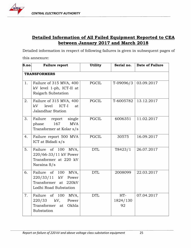
Detailed Information of All Failed Equipment Reported to CEA
between January 2017 and March 2018
Detailed information in respect of following failures is given in subsequent pages of
this annexure:
S.no. Failure report Utility Serial no. Date of Failure
TRANSFORMERS
1. Failure of 315 MVA, 400
kV level 1-ph, ICT-II at
Raigarh Substation
PGCIL T-09096/3
03.09.2017
2. Failure of 315 MVA, 400
kV level ICT-I at
Jalandhar Station
PGCIL T-6005782
13.12.2017
3. Failure report single
phase 167 MVA
Transformer at Kolar s/s
PGCIL 6006351 11.02.2017
4. Failure report 500 MVA
ICT at Bidadi s/s
PGCIL 30575 16.09.2017
5. Failure of 100 MVA,
220/66-33/11 kV Power
Transformer at 220 kV
Naraina S/s
DTL T8423/1
26.07.2017
6. Failure of 100 MVA,
220/33/11 kV Power
Transformer at 220kV
Lodhi Road Substation
DTL 2008099 22.03.2017
7. Failure of 100 MVA,
220/33 kV, Power
Transformer at Okhla
Substation
DTL HT-
1824/130
92
07.04.2017
CENTRAL ELECTRICITY AUTHORITY
Report on failure of 220 kV and above voltage class substation equipment 26
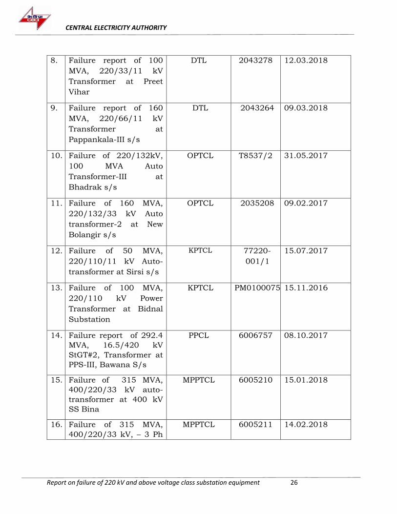
8. Failure report of 100
MVA, 220/33/11 kV
Transformer at Preet
Vihar
DTL 2043278 12.03.2018
9. Failure report of 160
MVA, 220/66/11 kV
Transformer at
Pappankala-III s/s
DTL 2043264 09.03.2018
10. Failure of 220/132kV,
100 MVA Auto
Transformer-III at
Bhadrak s/s
OPTCL T8537/2
31.05.2017
11. Failure of 160 MVA,
220/132/33 kV Auto
transformer-2 at New
Bolangir s/s
OPTCL 2035208 09.02.2017
12. Failure of 50 MVA,
220/110/11 kV Auto-
transformer at Sirsi s/s
KPTCL 77220-
001/1
15.07.2017
13. Failure of 100 MVA,
220/110 kV Power
Transformer at Bidnal
Substation
KPTCL PM0100075 15.11.2016
14. Failure report of 292.4
MVA, 16.5/420 kV
StGT#2, Transformer at
PPS-III, Bawana S/s
PPCL 6006757 08.10.2017
15. Failure of 315 MVA,
400/220/33 kV auto-
transformer at 400 kV
SS Bina
MPPTCL 6005210 15.01.2018
16. Failure of 315 MVA,
400/220/33 kV, – 3 Ph
MPPTCL 6005211 14.02.2018
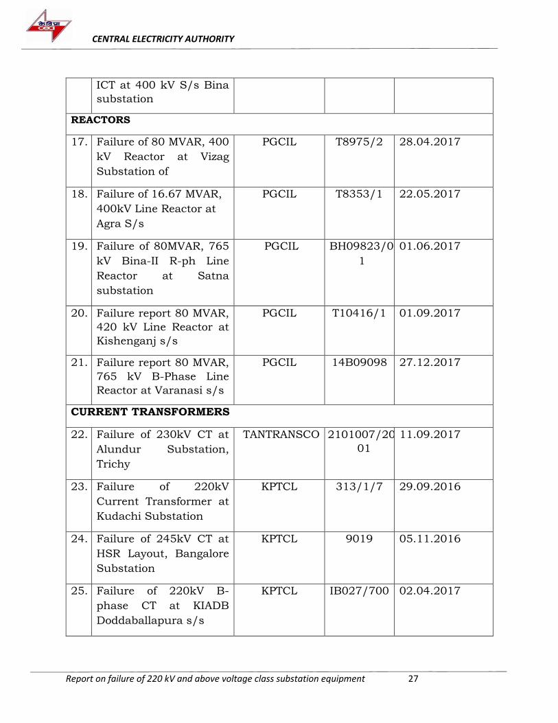
CENTRAL ELECTRICITY AUTHORITY
Report on failure of 220 kV and above voltage class substation equipment 27
ICT at 400 kV S/s Bina
substation
REACTORS
17. Failure of 80 MVAR, 400
kV Reactor at Vizag
Substation of
PGCIL T8975/2 28.04.2017
18. Failure of 16.67 MVAR,
400kV Line Reactor at
Agra S/s
PGCIL T8353/1 22.05.2017
19. Failure of 80MVAR, 765
kV Bina-II R-ph Line
Reactor at Satna
substation
PGCIL BH09823/0
1
01.06.2017
20. Failure report 80 MVAR,
420 kV Line Reactor at
Kishenganj s/s
PGCIL T10416/1 01.09.2017
21. Failure report 80 MVAR,
765 kV B-Phase Line
Reactor at Varanasi s/s
PGCIL 14B09098
27.12.2017
CURRENT TRANSFORMERS
22. Failure of 230kV CT at
Alundur Substation,
Trichy
TANTRANSCO 2101007/20
01
11.09.2017
23. Failure of 220kV
Current Transformer at
Kudachi Substation
KPTCL 313/1/7 29.09.2016
24. Failure of 245kV CT at
HSR Layout, Bangalore
Substation
KPTCL 9019 05.11.2016
25. Failure of 220kV B-
phase CT at KIADB
Doddaballapura s/s
KPTCL IB027/700 02.04.2017
CENTRAL ELECTRICITY AUTHORITY
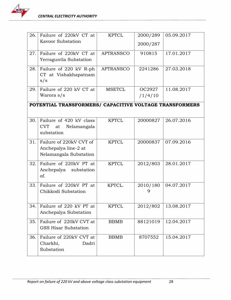
Report on failure of 220 kV and above voltage class substation equipment 28
26. Failure of 220kV CT at
Kavoor Substation
KPTCL 2000/289
2000/287
05.09.2017
27. Failure of 220kV CT at
Yerraguntla Substation
APTRANSCO 910815 17.01.2017
28. Failure of 220 kV R-ph
CT at Vishakhapatnam
s/s
APTRANSCO 2241286 27.03.2018
29. Failure of 220 kV CT at
Warora s/s
MSETCL OC2927
/1/4/10
11.08.2017
POTENTIAL TRANSFORMERS/ CAPACITIVE VOLTAGE TRANSFORMERS
30. Failure of 420 kV class
CVT at Nelamangala
substation
KPTCL 20000827 26.07.2016
31. Failure of 220kV CVT of
Anchepalya line-2 at
Nelamangala Substation
KPTCL 20000837 07.09.2016
32. Failure of 220kV PT at
Anchepalya substation
of.
KPTCL 2012/803
28.01.2017
33. Failure of 220kV PT at
Chikkodi Substation
KPTCL. 2010/180
9
04.07.2017
34. Failure of 220 kV PT at
Anchepalya Substation
KPTCL 2012/802 13.08.2017
35. Failure of 220kV CVT at
GSS Hisar Substation
BBMB 88121019
12.04.2017
36. Failure of 220kV CVT at
Charkhi, Dadri
Substation
BBMB 8707552 15.04.2017
CENTRAL ELECTRICITY AUTHORITY
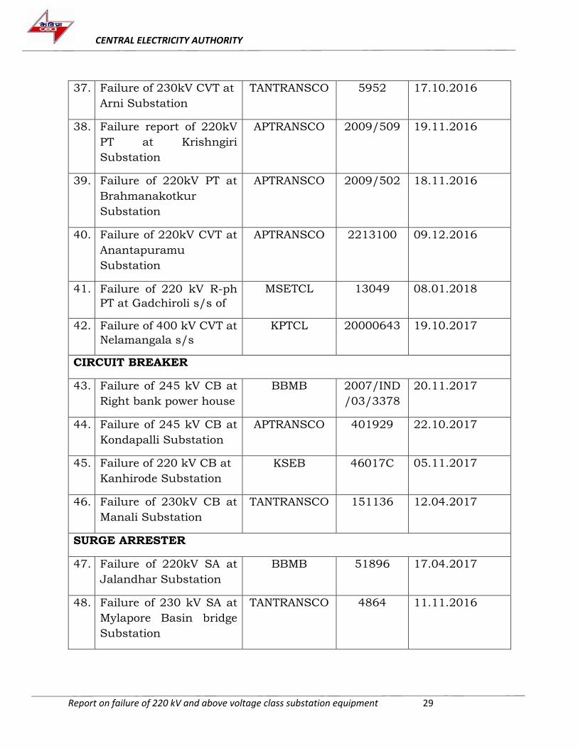
Report on failure of 220 kV and above voltage class substation equipment 29
37. Failure of 230kV CVT at
Arni Substation
TANTRANSCO 5952 17.10.2016
38. Failure report of 220kV
PT at Krishngiri
Substation
APTRANSCO 2009/509 19.11.2016
39. Failure of 220kV PT at
Brahmanakotkur
Substation
APTRANSCO 2009/502 18.11.2016
40. Failure of 220kV CVT at
Anantapuramu
Substation
APTRANSCO 2213100 09.12.2016
41. Failure of 220 kV R-ph
PT at Gadchiroli s/s of
MSETCL 13049 08.01.2018
42. Failure of 400 kV CVT at
Nelamangala s/s
KPTCL 20000643 19.10.2017
CIRCUIT BREAKER
43. Failure of 245 kV CB at
Right bank power house
BBMB 2007/IND
/03/3378
20.11.2017
44. Failure of 245 kV CB at
Kondapalli Substation
APTRANSCO 401929 22.10.2017
45. Failure of 220 kV CB at
Kanhirode Substation
KSEB 46017C
05.11.2017
46. Failure of 230kV CB at
Manali Substation
TANTRANSCO 151136 12.04.2017
SURGE ARRESTER
47. Failure of 220kV SA at
Jalandhar Substation
BBMB 51896 17.04.2017
48. Failure of 230 kV SA at
Mylapore Basin bridge
Substation
TANTRANSCO 4864 11.11.2016
CENTRAL ELECTRICITY AUTHORITY
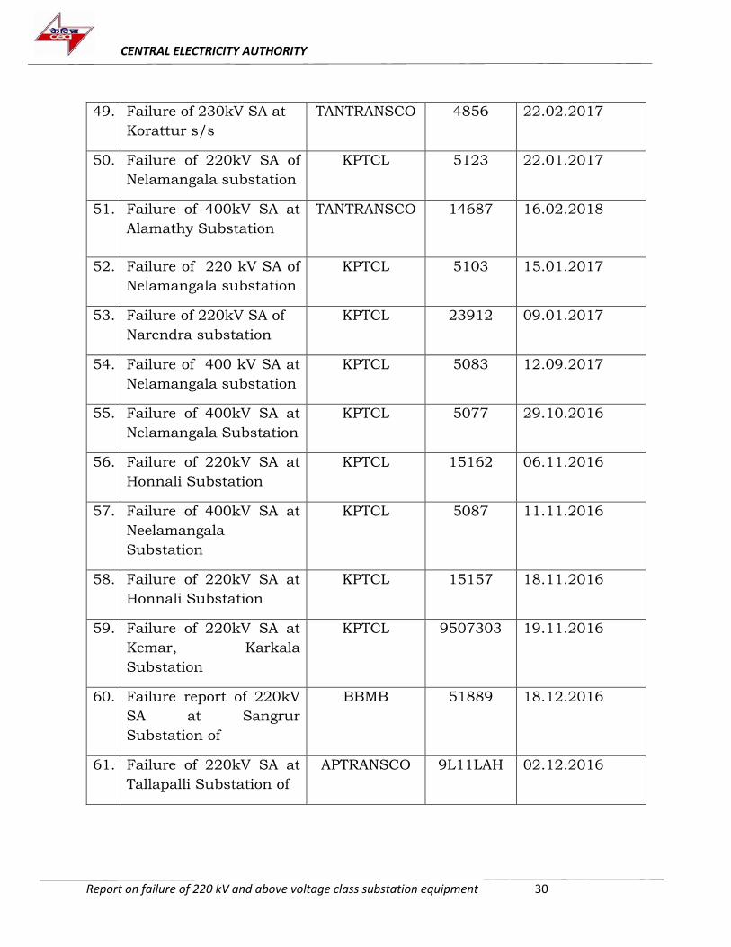
Report on failure of 220 kV and above voltage class substation equipment 30
49. Failure of 230kV SA at
Korattur s/s
TANTRANSCO 4856 22.02.2017
50. Failure of 220kV SA of
Nelamangala substation
KPTCL 5123 22.01.2017
51. Failure of 400kV SA at
Alamathy Substation
TANTRANSCO 14687
16.02.2018
52. Failure of 220 kV SA of
Nelamangala substation
KPTCL 5103 15.01.2017
53. Failure of 220kV SA of
Narendra substation
KPTCL 23912 09.01.2017
54. Failure of 400 kV SA at
Nelamangala substation
KPTCL 5083 12.09.2017
55. Failure of 400kV SA at
Nelamangala Substation
KPTCL 5077 29.10.2016
56. Failure of 220kV SA at
Honnali Substation
KPTCL 15162 06.11.2016
57. Failure of 400kV SA at
Neelamangala
Substation
KPTCL 5087 11.11.2016
58. Failure of 220kV SA at
Honnali Substation
KPTCL 15157 18.11.2016
59. Failure of 220kV SA at
Kemar, Karkala
Substation
KPTCL 9507303 19.11.2016
60. Failure report of 220kV
SA at Sangrur
Substation of
BBMB 51889 18.12.2016
61. Failure of 220kV SA at
Tallapalli Substation of
APTRANSCO 9L11LAH 02.12.2016
CENTRAL ELECTRICITY AUTHORITY
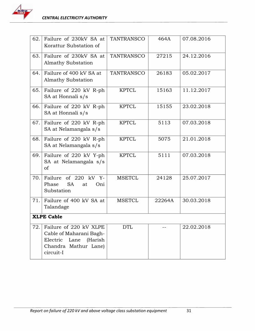
Report on failure of 220 kV and above voltage class substation equipment 31
62. Failure of 230kV SA at
Korattur Substation of
TANTRANSCO 464A 07.08.2016
63. Failure of 230kV SA at
Almathy Substation
TANTRANSCO 27215 24.12.2016
64. Failure of 400 kV SA at
Almathy Substation
TANTRANSCO 26183 05.02.2017
65. Failure of 220 kV R-ph
SA at Honnali s/s
KPTCL 15163 11.12.2017
66. Failure of 220 kV R-ph
SA at Honnali s/s
KPTCL 15155 23.02.2018
67. Failure of 220 kV R-ph
SA at Nelamangala s/s
KPTCL 5113 07.03.2018
68. Failure of 220 kV R-ph
SA at Nelamangala s/s
KPTCL 5075 21.01.2018
69. Failure of 220 kV Y-ph
SA at Nelamangala s/s
of
KPTCL 5111 07.03.2018
70. Failure of 220 kV Y-
Phase SA at Oni
Substation
MSETCL 24128 25.07.2017
71. Failure of 400 kV SA at
Talandage
MSETCL 22264A 30.03.2018
XLPE Cable
72. Failure of 220 kV XLPE
Cable of Maharani Bagh-
Electric Lane (Harish
Chandra Mathur Lane)
circuit-I
DTL -- 22.02.2018
CENTRAL ELECTRICITY AUTHORITY
Report on failure of 220 kV and above voltage class substation equipment 32
Transformers
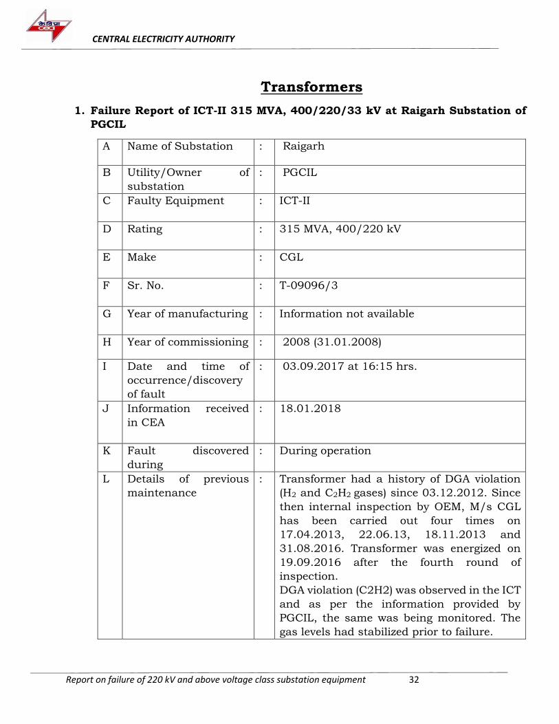
1. Failure Report of ICT-II 315 MVA, 400/220/33 kV at Raigarh Substation of
PGCIL
A Name of Substation : Raigarh
B Utility/Owner of
substation
: PGCIL
C Faulty Equipment : ICT-II
D Rating : 315 MVA, 400/220 kV
E Make : CGL
F Sr. No. : T-09096/3
G Year of manufacturing : Information not available
H Year of commissioning : 2008 (31.01.2008)
I Date and time of
occurrence/discovery
of fault
: 03.09.2017 at 16:15 hrs.
J Information received
in CEA
: 18.01.2018
K Fault discovered
during
: During operation
L Details of previous
maintenance
: Transformer had a history of DGA violation
(H2 and C2H2 gases) since 03.12.2012. Since
then internal inspection by OEM, M/s CGL
has been carried out four times on
17.04.2013, 22.06.13, 18.11.2013 and
31.08.2016. Transformer was energized on
19.09.2016 after the fourth round of
inspection.
DGA violation (C2H2) was observed in the ICT
and as per the information provided by
PGCIL, the same was being monitored. The
gas levels had stabilized prior to failure.
CENTRAL ELECTRICITY AUTHORITY
Report on failure of 220 kV and above voltage class substation equipment 33
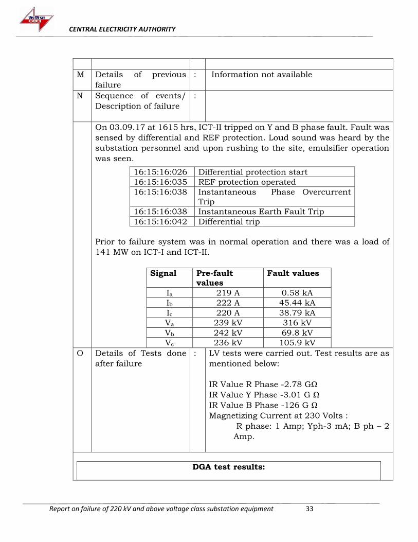
M Details of previous
failure
: Information not available
N Sequence of events/
Description of failure
:
On 03.09.17 at 1615 hrs, ICT-II tripped on Y and B phase fault. Fault was
sensed by differential and REF protection. Loud sound was heard by the
substation personnel and upon rushing to the site, emulsifier operation
was seen.
Prior to failure system was in normal operation and there was a load of
141 MW on ICT-I and ICT-II.
Signal Pre-fault values
Fault values
Ia 219 A 0.58 kA
Ib 222 A 45.44 kA
Ic 220 A 38.79 kA
Va 239 kV 316 kV
Vb 242 kV 69.8 kV
Vc 236 kV 105.9 kV
16:15:16:026 Differential protection start
16:15:16:035 REF protection operated
16:15:16:038 Instantaneous Phase Overcurrent
Trip
16:15:16:038 Instantaneous Earth Fault Trip
16:15:16:042 Differential trip
O Details of Tests done
after failure
: LV tests were carried out. Test results are as
mentioned below:
IR Value R Phase -2.78 GΩ
IR Value Y Phase -3.01 G Ω
IR Value B Phase -126 G Ω
Magnetizing Current at 230 Volts :
R phase: 1 Amp; Yph-3 mA; B ph – 2
Amp.
DGA test results:
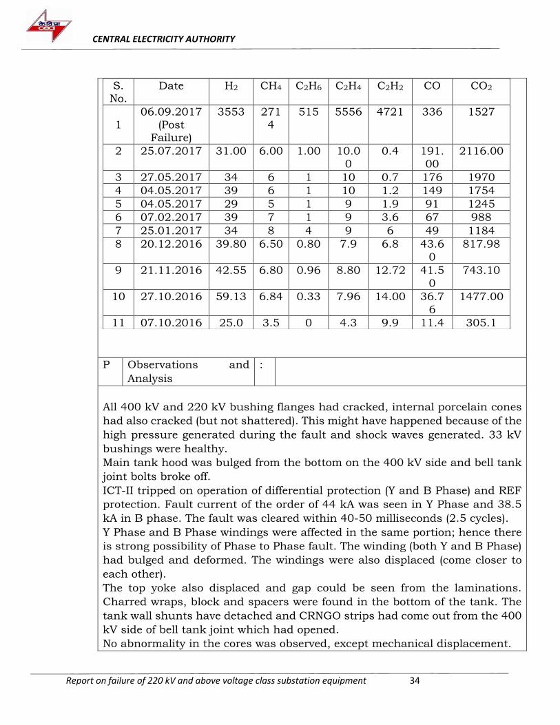
CENTRAL ELECTRICITY AUTHORITY
Report on failure of 220 kV and above voltage class substation equipment 34
S. No.
Date H2 CH4 C2H6 C2H4 C2H2 CO CO2
1
06.09.2017
(Post Failure)
3553 271
4
515 5556 4721 336 1527
2 25.07.2017 31.00 6.00 1.00 10.00
0.4 191.00
2116.00
3 27.05.2017 34 6 1 10 0.7 176 1970
4 04.05.2017 39 6 1 10 1.2 149 1754
5 04.05.2017 29 5 1 9 1.9 91 1245
6 07.02.2017 39 7 1 9 3.6 67 988
7 25.01.2017 34 8 4 9 6 49 1184
8 20.12.2016 39.80 6.50 0.80 7.9 6.8 43.6
0
817.98
9 21.11.2016 42.55 6.80 0.96 8.80 12.72 41.5
0
743.10
10 27.10.2016 59.13 6.84 0.33 7.96 14.00 36.7
6
1477.00
11 07.10.2016 25.0 3.5 0 4.3 9.9 11.4 305.1
P Observations and
Analysis
:
All 400 kV and 220 kV bushing flanges had cracked, internal porcelain cones
had also cracked (but not shattered). This might have happened because of the
high pressure generated during the fault and shock waves generated. 33 kV
bushings were healthy.
Main tank hood was bulged from the bottom on the 400 kV side and bell tank
joint bolts broke off.
ICT-II tripped on operation of differential protection (Y and B Phase) and REF
protection. Fault current of the order of 44 kA was seen in Y Phase and 38.5
kA in B phase. The fault was cleared within 40-50 milliseconds (2.5 cycles).
Y Phase and B Phase windings were affected in the same portion; hence there
is strong possibility of Phase to Phase fault. The winding (both Y and B Phase)
had bulged and deformed. The windings were also displaced (come closer to
each other).
The top yoke also displaced and gap could be seen from the laminations.
Charred wraps, block and spacers were found in the bottom of the tank. The
tank wall shunts have detached and CRNGO strips had come out from the 400
kV side of bell tank joint which had opened.
No abnormality in the cores was observed, except mechanical displacement.
CENTRAL ELECTRICITY AUTHORITY
Report on failure of 220 kV and above voltage class substation equipment 35
OLTC was operated manually and tap change occurred on all phases. However,
due to the mechanical force, the selector switch housing detached from the
diverter chamber for Y-Phase.
As the transformer was running with intermittent DGA violation since
December, 2012, there is a possibility of weakening of phase barrier insulation
between the Y and B phase winding due to intermittent high energy discharges.
It is possible that just prior to the failure, the insulation had deteriorated to an
extent that it could not withstand power frequency voltage and led to phase to
phase fault between Y & B phases. Operation of REF and earth fault relay
indicates that phase to phase fault might have spread to earthed components+.
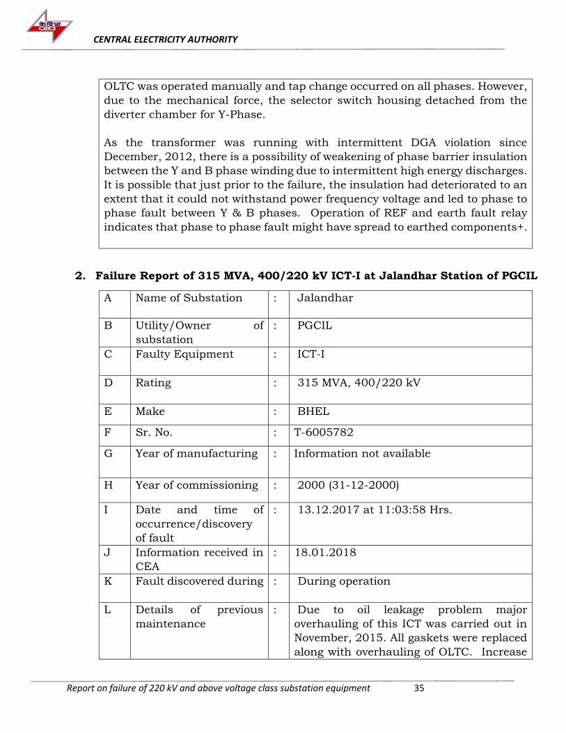
2. Failure Report of 315 MVA, 400/220 kV ICT-I at Jalandhar Station of PGCIL
A Name of Substation : Jalandhar
B Utility/Owner of
substation
: PGCIL
C Faulty Equipment : ICT-I
D Rating : 315 MVA, 400/220 kV
E Make : BHEL
F Sr. No. : T-6005782
G Year of manufacturing : Information not available
H Year of commissioning : 2000 (31-12-2000)
I Date and time of
occurrence/discovery
of fault
: 13.12.2017 at 11:03:58 Hrs.
J Information received in
CEA
: 18.01.2018
K Fault discovered during : During operation
L Details of previous
maintenance
: Due to oil leakage problem major
overhauling of this ICT was carried out in
November, 2015. All gaskets were replaced
along with overhauling of OLTC. Increase
CENTRAL ELECTRICITY AUTHORITY
Report on failure of 220 kV and above voltage class substation equipment 36
in gases (H2) was observed in February,
2017 and since then ICT was kept under 15
days DGA monitoring. Last Annual
Maintenance result of said ICT was under
limit and next maintenance was due in
March, 2018.
M Details of previous
failure
: Information not available
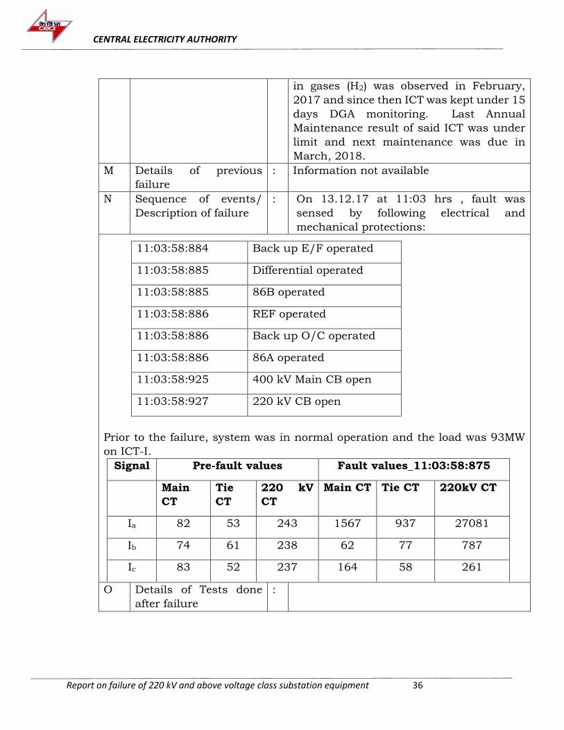
N Sequence of events/
Description of failure
: On 13.12.17 at 11:03 hrs , fault was
sensed by following electrical and
mechanical protections:
11:03:58:884 Back up E/F operated
11:03:58:885 Differential operated
11:03:58:885 86B operated
11:03:58:886 REF operated
11:03:58:886 Back up O/C operated
11:03:58:886 86A operated
11:03:58:925 400 kV Main CB open
11:03:58:927 220 kV CB open
Prior to the failure, system was in normal operation and the load was 93MW
on ICT-I.
Signal Pre-fault values Fault values_11:03:58:875
Main
CT
Tie
CT
220 kV
CT
Main CT Tie CT 220kV CT
Ia 82 53 243 1567 937 27081
Ib 74 61 238 62 77 787
Ic 83 52 237 164 58 261
O Details of Tests done
after failure
:
CENTRAL ELECTRICITY AUTHORITY
Report on failure of 220 kV and above voltage class substation equipment 37
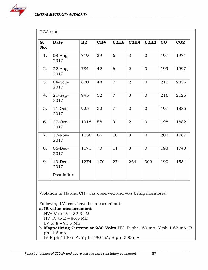
DGA test:
S.
No.
Date H2 CH4 C2H6 C2H4 C2H2 CO CO2
1. 08-Aug-
2017
719 39 6 3 0 197 1971
2. 22-Aug-
2017
784 42 6 2 0 199 1997
3. 04-Sep-
2017
870 48 7 2 0 211 2056
4. 21-Sep-
2017
945 52 7 3 0 216 2125
5. 11-Oct-
2017
925 52 7 2 0 197 1885
6. 27-Oct-
2017
1018 58 9 2 0 198 1882
7. 17-Nov-
2017
1136 66 10 3 0 200 1787
8. 06-Dec-
2017
1171 70 11 3 0 193 1743
9. 13-Dec-
2017
Post failure
1274 170 27 264 309 190 1534
Violation in H2 and CH4 was observed and was being monitored.
Following LV tests have been carried out:
a. IR value measurement
HV+IV to LV – 32.3 kΩ HV+IV to E – 86.5 MΩ
LV to E – 91.5 MΩ b. Magnetizing Current at 230 Volts HV- R ph: 460 mA; Y ph-1.82 mA; B-
ph -1.8 mA
IV-R ph:1140 mA; Y ph -590 mA; B ph -590 mA
CENTRAL ELECTRICITY AUTHORITY
Report on failure of 220 kV and above voltage class substation equipment 38
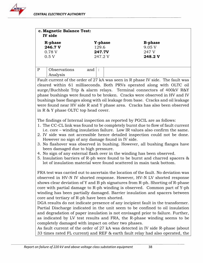
c. Magnetic Balance Test:
IV side R-phase Y-phase B-phase 246.7 V 129.6 9.05 V
0.78 V 247.7V 247 V 0.5 V 247.2 V 248.2 V
P Observations and
Analysis
:
Fault current of the order of 27 kA was seen in R phase IV side. The fault was
cleared within 61 milliseconds. Both PRVs operated along with OLTC oil
surge/Buchholz Trip & alarm relays. Terminal connectors of 400kV R&Y
phase bushings were found to be broken. Cracks were observed in HV and IV
bushings base flanges along with oil leakage from base. Cracks and oil leakage
were found near HV side R and Y phase area. Cracks has also been observed
in R & Y phase OLTC top head cover.
The findings of Internal inspection as reported by PGCIL are as follows:
1. The CC-CL link was found to be completely burnt due to flow of fault current i.e. core – winding insulation failure. Low IR values also confirm the same.
2. IV side was not accessible hence detailed inspection could not be done. However no sign of any damage found in IV side.
3. No flashover was observed in bushing. However, all bushing flanges have been damaged due to high pressure.
4. No sign of any external flash over in the winding has been observed.
5. Insulation barriers of R-ph were found to be burnt and charred spacers & lot of insulation material were found scattered in main tank bottom.
FRA test was carried out to ascertain the location of the fault. No deviation was
observed in HV-N IV shorted response. However, HV-N LV shorted response
shows clear deviation of Y and B ph signatures from R-ph. Shorting of R-phase
core with partial damage to R-ph winding is observed. Common part of Y-ph
winding has been partially damaged. Barrier insulation and spacers between
core and tertiary of R-ph have been shorted.
DGA results do not indicate presence of any incipient fault in the transformer.
Partial Discharge indicated in the unit seem to be confined to oil insulation
and degradation of paper insulation is not envisaged prior to failure. Further,
as indicated by LV test results and FRA, the R-phase winding seems to be
completely damaged with impact on other two phases.
As fault current of the order of 27 kA was detected in IV side R-phase (about
33 times rated FL current) and REF & earth fault relay had also operated, the
CENTRAL ELECTRICITY AUTHORITY
Report on failure of 220 kV and above voltage class substation equipment 39
phase to ground fault is envisaged in R-phase of the IV side. However, same
can be confirmed only through detailed inspection after dismantling of
windings.
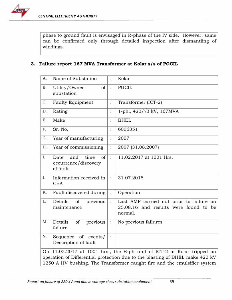
3. Failure report 167 MVA Transformer at Kolar s/s of PGCIL
A. Name of Substation : Kolar
B. Utility/Owner of
substation
: PGCIL
C. Faulty Equipment : Transformer (ICT-2)
D. Rating : 1-ph., 420/√3 kV, 167MVA
E. Make : BHEL
F. Sr. No. : 6006351
G. Year of manufacturing : 2007
H. H Year of commissioning : 2007 (31.08.2007)
I. I Date and time of
occurrence/discovery
of fault
: 11.02.2017 at 1001 Hrs.
J. J Information received in
CEA
: 31.07.2018
K. K Fault discovered during : Operation
L. M Details of previous
maintenance
: Last AMP carried out prior to failure on
25.08.16 and results were found to be
normal.
M. N Details of previous
failure
: No previous failures
N. O Sequence of events/
Description of fault
:
On 11.02.2017 at 1001 hrs., the B-ph unit of ICT-2 at Kolar tripped on
operation of Differential protection due to the blasting of BHEL make 420 kV
1250 A HV bushing. The Transformer caught fire and the emulsifier system
CENTRAL ELECTRICITY AUTHORITY
Report on failure of 220 kV and above voltage class substation equipment 40
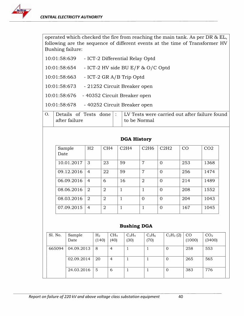
operated which checked the fire from reaching the main tank. As per DR & EL,
following are the sequence of different events at the time of Transformer HV
Bushing failure:
10:01:58:639 - ICT-2 Differential Relay Optd
10:01:58:654 - ICT-2 HV side BU E/F & O/C Optd
10:01:58:663 - ICT-2 GR A/B Trip Optd
10:01:58:673 - 21252 Circuit Breaker open
10:01:58:676 - 40352 Circuit Breaker open
10:01:58:678 - 40252 Circuit Breaker open
O. P Details of Tests done
after failure
: LV Tests were carried out after failure found
to be Normal
DGA History
Sample
Date
H2 CH4 C2H4 C2H6 C2H2 CO CO2
10.01.2017 3 23 59 7 0 253 1368
09.12.2016 4 22 59 7 0 256 1474
06.09.2016 4 6 16 2 0 214 1489
08.06.2016 2 2 1 1 0 208 1552
08.03.2016 2 2 1 0 0 204 1043
07.09.2015 4 2 1 1 0 167 1045
Bushing DGA
Sl. No. Sample
Date
H2
(140)
CH4
(40)
C2H4
(30)
C2H6
(70)
C2H2 (2) CO
(1000)
CO2
(3400)
665094 04.09.2013 8 4 1 1 0 258 553
02.09.2014 20 4 1 1 0 265 565
24.03.2016 5 6 1 1 0 383 776
CENTRAL ELECTRICITY AUTHORITY
Report on failure of 220 kV and above voltage class substation equipment 41
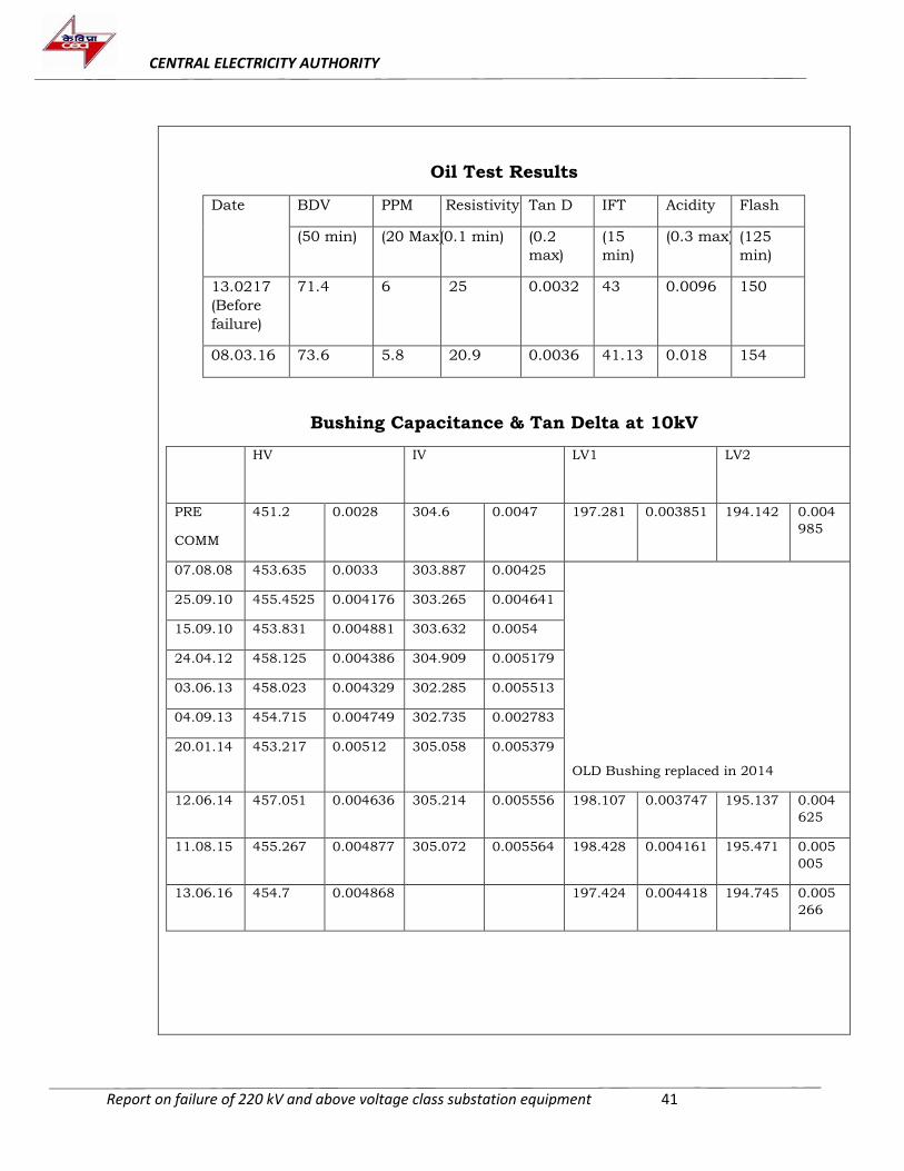
Oil Test Results
Date BDV PPM Resistivity Tan D IFT Acidity Flash
(50 min) (20 Max) ( (0.1 min) (0.2
max)
(15
min)
(0.3 max) (125
min)
13.0217
(Before
failure)
71.4 6 25 0.0032 43 0.0096 150
08.03.16 73.6 5.8 20.9 0.0036 41.13 0.018 154
Bushing Capacitance & Tan Delta at 10kV
HV IV LV1 LV2
PRE
COMM
451.2 0.0028 304.6 0.0047 197.281 0.003851 194.142 0.004
985
07.08.08 453.635 0.0033 303.887 0.00425
OLD Bushing replaced in 2014
25.09.10 455.4525 0.004176 303.265 0.004641
15.09.10 453.831 0.004881 303.632 0.0054
24.04.12 458.125 0.004386 304.909 0.005179
03.06.13 458.023 0.004329 302.285 0.005513
04.09.13 454.715 0.004749 302.735 0.002783
20.01.14 453.217 0.00512 305.058 0.005379
12.06.14 457.051 0.004636 305.214 0.005556 198.107 0.003747 195.137 0.004
625
11.08.15 455.267 0.004877 305.072 0.005564 198.428 0.004161 195.471 0.005
005
13.06.16 454.7 0.004868 197.424 0.004418 194.745 0.005
266
CENTRAL ELECTRICITY AUTHORITY
Report on failure of 220 kV and above voltage class substation equipment 42
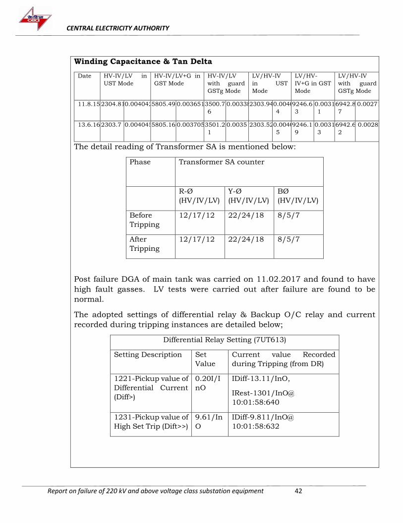
Winding Capacitance & Tan Delta
Date HV-IV/LV in
UST Mode
HV-IV/LV+G in
GST Mode
HV-IV/LV
with guard
GSTg Mode
LV/HV-IV
in UST
Mode
LV/HV-
IV+G in GST
Mode
LV/HV-IV
with guard
GSTg Mode
11.8.15 2304.81 0.004042 5805.49 0.003651 3500.7
6
0.00338 2303.94 0.0040
4
9246.6
3
0.0031
1
6942.8
7
0.00271
13.6.16 2303.7 0.004045 5805.16 0.003705 3501.2
1
0.0035 2303.52 0.0040
5
9246.1
9
0.0031
3
6942.6
2
0.00282
The detail reading of Transformer SA is mentioned below:
Phase Transformer SA counter
R-Ø
(HV/IV/LV)
Y-Ø
(HV/IV/LV)
BØ
(HV/IV/LV)
Before
Tripping
12/17/12 22/24/18 8/5/7
After
Tripping
12/17/12 22/24/18 8/5/7
Post failure DGA of main tank was carried on 11.02.2017 and found to have
high fault gasses. LV tests were carried out after failure are found to be
normal.
The adopted settings of differential relay & Backup O/C relay and current
recorded during tripping instances are detailed below;
Differential Relay Setting (7UT613)
Setting Description Set
Value
Current value Recorded
during Tripping (from DR)
1221-Pickup value of
Differential Current
(Diff>)
0.20I/I
nO
IDiff-13.11/InO,
IRest-1301/InO@
10:01:58:640
1231-Pickup value of
High Set Trip (Dift>>)
9.61/In
O
IDiff-9.811/InO@
10:01:58:632
CENTRAL ELECTRICITY AUTHORITY
Report on failure of 220 kV and above voltage class substation equipment 43
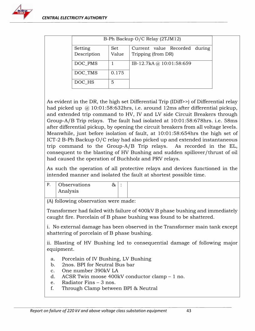
B-Ph Backup O/C Relay (2TJM12)
Setting
Description
Set
Value
Current value Recorded during
Tripping (from DR)
DOC_PMS 1 IB-12.7kA @ 10:01:58:659
DOC_TMS 0.175
DOC_HS 5
As evident in the DR, the high set Differential Trip (IDiff>>) of Differential relay
had picked up @ 10:01:58:632hrs, i.e. around 12ms after differential pickup,
and extended trip command to HV, IV and LV side Circuit Breakers through
Group-A/B Trip relays. The fault had isolated at 10:01:58:678hrs. i.e. 58ms
after differential pickup, by opening the circuit breakers from all voltage levels.
Meanwhile, just before isolation of fault, at 10:01:58:654hrs the high set of
ICT-2 B-Ph Backup O/C relay had also picked up and extended instantaneous
trip command to the Group-A/B Trip relays. As recorded in the EL,
consequent to the blasting of HV Bushing and sudden spillover/thrust of oil
had caused the operation of Buchholz and PRV relays.
As such the operation of all protective relays and devices functioned in the
intended manner and isolated the fault at shortest possible time.
P. Q Observations &
Analysis
:
(A) following observation were made:
Transformer had failed with failure of 400kV B phase bushing and immediately
caught fire. Porcelain of B phase bushing was found to be shattered.
i. No external damage has been observed in the Transformer main tank except
shattering of porcelain of B phase bushing.
ii. Blasting of HV Bushing led to consequential damage of following major
equipment.
a. Porcelain of IV Bushing, LV Bushing b. 2nos. BPI for Neutral Bus bar
c. One number 390kV LA d. ACSR Twin moose 400kV conductor clamp – 1 no.
e. Radiator Fins – 3 nos. f. Through Clamp between BPI & Neutral
CENTRAL ELECTRICITY AUTHORITY
Report on failure of 220 kV and above voltage class substation equipment 44
iii. A clear hole was found in the air end portion of HV phase bushing. The
location of hole is approximately 1.7 mtr from bottom of bushing.
iv. Oil end side porcelain of HV bushing was found to be completely shattered and porcelain pieces and burnt paper were found laid at the bottom of the tank.
v. Some flash marks where found in the inner surface of the metallic portion meant for BCT accommodation of bushing
vi. HV winding lead take off was found to be damaged and uprooted. However,
the winding lead was found to be intact and no other visible abnormalities were noticed during the internal inspection.
The blasting of HV Bushing in ICT-2 B-ph had resulted flashover between HV
bushing lead & BCT metallic portion and heavy flow of fault current to the
ground through transformer body. The fault current in turn activated
differential relay @ 10:01:58:639 and Back-up O/C relay of HV side @
10:01:58:654.
Prima facie, the fault seems to be initiated from HV Bushing and it is suspected that failure occurred due to failure of the bushing. As evident from the variable
frequency test results and bushing DGA test results, bushing condition was normal prior to 8 months of failure. Failure of the bushing seems to be random in nature and due to explosion of the B phase bushing, air end portion
porcelain got shattered leading to flashover of bushing condenser core with the flange which is evident from the punctured hole nearer to bushing flange.
4. Failure of 500 MVA, 420 kV ICT at Bidadi s/s of PGCIL
A. Name of Substation : Bidadi
B. Utility/Owner of substation
: PGCIL
C. Faulty Equipment : ICT
D. Rating : 500 MVA, 420 kV
E. Make : ALSTOM
F. Sr. No. : 30575
G. Year of manufacturing : 2011
CENTRAL ELECTRICITY AUTHORITY
Report on failure of 220 kV and above voltage class substation equipment 45
H Year of commissioning : 2012 (29.03.2012)
I Date and time of occurrence/discovery
of fault
: 16.09.2017 at 04:56:22 hrs.
J Information received in CEA
: 31.07.18
K Fault discovered during : Operation
L Details of previous maintenance
: On 24.09.2012, tap lead modification was carried out on the said Transformer on
11.02.2013 (Insertion of Treated PBD barrier in all phases has been provided) and re-commissioned on
10.04.2013. Further, due to tan delta test tap issues, all the 245 kV and 52 kV
bushings were replaced with new bushings on 08.04.2015.
DGA History
Sample Date
H2 CH4 C2H4 C2H6 C2H2 CO CO2
30.05.2014 7.29 0.96 0.09 0.15 0.049 85 520
01.07.2014 10 1 0.13 0.27 0.09 115 646
04.08.2014 17 2 0.13 0.35 0.05 164 821
10.10.2015 45 8 0.38 1.2 0 448 1757
01.08.2016 49 8 0 1 0 408 2433
04.01.2017 49 7 1 2 0 450 2061
10.04.2017 38 8 0 1 0 428 3183
M Details of previous failure
: None
N Sequence of events/ Description of fault
:
CENTRAL ELECTRICITY AUTHORITY
Report on failure of 220 kV and above voltage class substation equipment 46
On 16.09.2017, said Transformer failed and fault current of 10.6 kA was
observed in 220kV side.
Following indication were noted at the time of tripping:
- REF Trip - Transformer Differential trip
- PRV Trip (Both) - HV Back up O/C Earth fault relay operated - Transformer Buchholz Trip
- OSR trip
Prima facie, from the DGA history and AMP test results, it may be inferred that
the transformer was healthy prior to failure and had failed due to sudden fault inside the transformer.
O Details of Tests done
after failure
: The details of tests done after failure are not
available.
P Observations & Analysis
:
Committee visited GE, Naini works for inspection as well as for failure
investigation and following observations was made:
a. Cracks were observed in tank stiffeners and severe deformation was observed on both sides of tank wall and tank cannot be reused.
b. U-phase outer wrap was found burnt at different locations in middle portion. The lead take out portion was found to be intact. V-phase and W-phase outer wrap and lead take out portion was found to be intact.
c. Flashover mark was observed between disc no.50 and 52 in outer side of U-phase HV(series) winding along with pitting (melting) of copper. Black
spot was observed on tank wall just opposite to the above flashover mark. d. Some deformation was also observed on Bottom Clamping frame near U-
phase.
e. Common winding part, leads and regulating winding were found to be intact.
f. The middle part of bottom yoke clamping studs between U and V phases was found to be burnt.
g. Burn marks were also observed in outer part of V-phase winding outer
wrap, no further burn mark was observed from outside on coil stacks of V and W phase windings.
CENTRAL ELECTRICITY AUTHORITY
Report on failure of 220 kV and above voltage class substation equipment 47
Based on the internal inspection carried out on site, it was difficult to exactly
establish the failure cause. Hence, it was decided to shift the Transformer to GE, Naini works for establishing cause of failure.
From the inspection, it may be inferred that failure of Transformer was
occurred due to failure of R phase winding. As suspected earlier, tap lead was not involved in the failure. Fault might have initiated in winding turns/inter disc in HV series winding. Considering the extent of damage, carbonization
and exposure of other winding insulations, it was recommended to replace all the windings along with all insulation materials and tank.
5. Failure of 100 MVA, 220/66-33/11 kV Power Transformer at 220 kV
Naraina Substation of DTL
A Name of Substation : Naraina Substation
B Utility/Owner of
substation
: Delhi Transco Ltd. (DTL)
C Faulty Equipment : Power Transformer
D Rating : 100 MVA, 220/66-33/11kV
E Make : CGL
F Sr. No. : T8423/1
G Year of manufacturing : 1994
H Year of commissioning : 2002
I Date and time of
occurrence/discovery
of fault
: 26.07.2017 at 2348 hrs.
J Information received
in CEA
: 27.07.2017
K Fault discovered
during
: During running condition
L Details of previous
maintenance
:
CENTRAL ELECTRICITY AUTHORITY
Report on failure of 220 kV and above voltage class substation equipment 48
Major tripping and maintenance detail since commissioning as provided in
DTL’s preliminary report is as under:
Sr.
No.
Date Reason of outage Action taken by DTL
1. 25.04.13 Replacement of Y-ph LV
bushing
Bushing replaced as the
result of tan δ test was on
high side
2. 18.04.14 Replacement of R-ph LV
bushing
Bushing replaced as the
result of tan δ test was on
higher side
3. 04.09.16 Buchholz alarm,
Protection trip group 86A,
Auxiliary trouble, Control
cable found damaged
Replacement of damaged
control cable with healthy
one
i) Oil of Transformer-I was tested in CPRI on 10.03.2016 and 14.03.2017 and all properties were found to be within permissible limits as per IS-1886.
ii) DGA on 27.02.2017 indicate increased values of CO2 (3242 ppm) and CO (457 ppm) which could be attributed to cellulose overheating. All other
gases were found to be within permissible limits. iii) LV tests were performed on the transformer on 02.12.2016 and results were
found to be satisfactory.
iv) Earth resistance was measured on 01.06.2017 and its value was 0.55 ohm which is within acceptable limit.
v) As per DTL’s report, last thermos-vision scanning done on 27.04.2017 did
not indicate any hot-spots.
M Details of previous
failure
: No other fault in the transformer prior to this
failure.
N Sequence of events/
Description of failure
: On 26.7.17 at 2348 hrs, subject Power
Transformer tripped on Differential (R&B
ph), Buchholz, PRD, SPR, WTI and OTI trip.
O Details of Tests done
after failure
: As the transformer had blasted, no test was
possible.
P Observations and
Analysis
:
1. DTL informed that CGL make power Transformer-I tripped on 26.07.2017
at 2348 hrs. on Differential relay (R& B ph), Buchholz relay, PRD, SPR, WTI
CENTRAL ELECTRICITY AUTHORITY
Report on failure of 220 kV and above voltage class substation equipment 49
trip and OTI trip and caught fire. Further, power transformer-II running in
parallel, tripped on overcurrent relay after the load of power Transformer-I
was shifted on the former.
2. It was informed by DTL that the transformer was operating on the tap no.
5. The transformer – I was running in parallel with 100 MVA transformer –
II. The load at transformer –I was 74 MW and at transformer – II was 67
MW, CB (HV side) of transformer – III was in lock – out condition
3. As per the DR data, the faulty transformer was isolated within 64 ms.
4. During physical inspection by CEA officers, it was observed that the
transformer had severely damaged due to blazing fire.
5. All bushing (HV, LV & Tertiary) and three LAs (on HV side) were completely
shattered. Two turrets were found open.
6. The conservator tank fell on the ground due to bending of its support;
radiators and marshalling box were damaged; and all control winding were
burnt.
7. Spilled transformer oil was observed around the tank.
8. Due to fire and flying debris of transformer/SA, insulator of nearby isolator
and jumper conductor also got damaged.
9. No fire protection system was available for the transformer except for
portable fire extinguishers. Fire tenders were called for extinguishing the
fire.
10. Factory test results and pre-commissioning test result for the failed
transformer were not available with DTL.
11. Year of mfg. of the Transformer is 1994 while it was commissioned in 2002.
Information regarding its storage and maintenance during the period 1994-
2002 was not available with DTL.
12. All relays were electromechanical type and disturbance recording facility
was not available.
13. It was informed that flags of the relays were reset manually; hence,
operation of the relays could not be verified through flag position.
14. Disturbance recorder data for 220 kV Bamnuali Ckt-II was provided.
During its study, it was found that R- Phase voltage was recorded as 10 kV.
Upon enquiry, DTL representative informed that this was due to technical
problem with R- Phase CVT.
15. As the transformer had blasted, no test was possible.
16. No disturbance recorder is installed for transformer, hence, no data of fault
current could be determined. DR data of 220kV Bamnauli Ckt-II was
provided which indicated flow of 1300A current.
17. Since the transformer had caught fire, no oil sample for testing could be
collected. In the absence of oil testing report, amount of gas generated
during fault could not be determined.
CENTRAL ELECTRICITY AUTHORITY
Report on failure of 220 kV and above voltage class substation equipment 50
18. Since the transformer could not be opened at the time of visit, internal
inspection of transformer could not be carried out. Without detailed internal
inspection of transformer, exact cause of failure can not be ascertained.
Since the transformer had burnt for considerable period, even internal
inspection might not present enough evidences to reach any conclusion.
19. Report of DTL transformer committee suggests that the external fire in the
oil around the transformer or control cable due to AC/DC leakages may be
the cause of failed and that the transformer got burnt due to damage of LV
side R-ph bushing. However, based on available information and considering
the fact that cables were FRLS type, reason claimed in DTL report does not
seem satisfactory enough to accept as probable cause of failure.
20.Operation of Differential, Buchholz, PRD & SPR relays indicates internal
fault of the transformer. It appears that insulation of winding might have
failed causing short circuit and arcing. High energy arcing due to fault inside
the transformer tank might have led to sudden pressure rise in tank,
tripping of Buchholz, SPR & PRV and blasting of bushing. The flow of heavy
fault current in windings might have caused rise in winding temperature
and operation of OTI & WTI trip. As soon as heated oil found an opening
through turrets and came in contact of oxygen, it caught fire.
6. Failure of 100 MVA, 220/33/11 kV Power Transformer at 220kV Lodhi Road
Substation of Delhi Transco Ltd.
A. Name of Substation : Lodhi Road
B. Utility/Owner of
substation
: DTL
C. Faulty Equipment : Power Transformer
D. Rating : 100 MVA, 220/33/11 kV
E. Make : BHEL
F. Sr. No. : 2008099
G. Year of manufacturing : 1994
H. Year of commissioning : 1994
I. Date and time of
occurrence/discovery
of fault
: 22.03.17 at 2230 hrs.
CENTRAL ELECTRICITY AUTHORITY
Report on failure of 220 kV and above voltage class substation equipment 51
J. Information received in
CEA
: 30.03.17
K. Fault discovered during : Operation
L. Details of previous
maintenance
: Information not available
M. Details of previous
failure
: According to DTL officers, there has not been
any other fault in the transformer prior to this failure.
N. Sequence of events/
Description of failure
:
The transformer had tripped on 22.03.2017 at 2230 hrs on differential (R &
B phase), HV REF, LV REF, O/C (R & B phase), Buchholz relay, PRD and
SPRV.
It was informed by DTL that the transformer was operating on tap no. 3 and
the load on the transformer was 25 MW at the time of failure
It was also informed that OLTC is generally operated bi-annually, at the
onset of winter and summer season.
O. Details of Tests done
after failure
:
Following tests were conducted by DTL on the transformer post failure:
Magnetic balance
Magnetizing current
Tan δ test of HV, LV and Tertiary windings
Sweep Frequency Response Analysis (SFRA)
DGA
Voltage Ratio
Insulation Resistance
Winding resistance
P. Observations &
Analysis
:
During physical inspection by CEA Officers, it was observed that there was no
visible sign of bulging of or cracks on the tank and all HV, LV, Tertiary and
CENTRAL ELECTRICITY AUTHORITY
Report on failure of 220 kV and above voltage class substation equipment 52
Neutral bushings were intact. Further, spilled transformer oil was observed
around the tank due to PRV operation.
No fire protection system was available for the transformer except for portable
fire extinguishers.
Factory test results and pre-commissioning test results for the failed
transformer were not available with DTL.
DTL informed that the service engineer of OEM, M/s BHEL Ltd. visited the site on 30.03.2017 and inspected the failed transformer. DTL had drained the oil from the transformer. The transformer was physically inspected from inside by
the service engineer of BHEL.
Following observations from physical inspection were made by M/s BHEL, as
per MOM provided by DTL: (a) All HV, LV, Tertiary and Neutral bushings and their leads were found
intact. (b) OLTC selector switch was found in normal position. (c) Top core lamination stampings on R phase side was found distorted in
shape and gap between them was between them was found increased & irregular during internal inspection which indicates shifting of core along
with widening of air-gap.
CENTRAL ELECTRICITY AUTHORITY
Report on failure of 220 kV and above voltage class substation equipment 53
(d) Perma-wood supports and pin pad nut bolts were found broken near R
phase windings. (e) Burnt pieces of paper insulation were found below HV windings.
DGA of oil indicates high concentration of Hydrogen (H2-2185 ppm), Ethylene (C2H4-586 ppm), Ethane (C2H6-160 ppm), Methane (CH4-413 ppm) and Acetylene (C2H2-709.5). Total Dissolved Combustible Gases (TDCG) was 3900
ppm which is higher than normal value. The high concentration of acetylene gas could be due to arcing inside the tank. Values of Roger’s ratio (CO2/CO = 9.88 and C2H4/C2H6= 3.66) also suggest high energy discharge. Due to the
generation of these gases, high pressure might have built up, which led to the
operation of PRV and SPRV.
Operation of Differential, Buchholz, PRD & SPRV relays indicates internal fault
of the transformer. Operation of REF indicates that the fault involved ground.
Magnetising current of R-phase HV winding was 760 mA which is much higher than 2.7 mA in Y-phase & B-phase of HV winding. Similarly, magnetising
current of R-phase LV winding was 29.4 A which is much higher than 63.3 mA in Y-phase & 62.7 mA in B-phase of LV winding. The findings suggest fault in
R-phase winding. The same is also corroborated by the abnormal results of magnetic balance test and the fault current of 15.75 kA in R-phase of the
winding, as per DR data.
Tan δ value of HV-LV insulation had jumped from earlier value of 0.43%, measured on 28.03.16, to 16.38% after fault which is much higher than the
permissible limits and indicates deterioration of insulation between HV and LV winding. The same is suggested by low values of insulation resistance and
Polarisation Index for HV-LV insulation.
SFRA carried out on transformer after fault is found to be dissimilar, especially
in low frequency zone, to SFRA recorded on same transformer on 28.03.16 which is indicative of shifting of core/winding and the same has also been
verified by internal inspection carried out by BHEL Engineer.
The extent of damage to the core & winding, exact cause of failure and type of
failure could be determined only after thorough internal inspection.
7. Failure of 100 MVA, 220/33 kV, Power Transformer at Okhla Substation of
DTL
A. Name of Substation : Okhla s/s
CENTRAL ELECTRICITY AUTHORITY
Report on failure of 220 kV and above voltage class substation equipment 54
B. Utility/Owner of
substation
: DTL
C. Faulty Equipment : Power Transformer
D. Rating : 100 MVA, 220/66-33/11 kV
E. Make : EMCO
F. Sr. No. : HT-1824/13092
G. Year of manufacturing : 2010
H. Year of commissioning : 2010
I. Date and time of
occurrence/discovery
of fault
: 07.04.17 at 1115 hrs
J. Information received in
CEA
: 13.04.17
K. Fault discovered during : Operation
L. Details of previous
maintenance
: Maintained as per utility’s O&M schedule
M. Details of previous
failure
:
According to DTL officers, on 05.07.2016 at 1053 hrs, the transformer had tripped with huge sound. On inspection, selection switch of OLTC and all phase HV & LV bushing were found cracked. The transformer was
energised on 01.08.2016 after repairing work was carried out under supervision of OEM. OLTC was repaired and HV & LV bushings were
replaced with new ones. All LV & HV tests were carried out.
N. Sequence of events/
Description of failure
:
The transformer had tripped on 07.04.2017 at 1115 hrs on differential (B phase), Master Relay and both PRDs. The transformer tripped when during the
shifting of 33 kV Masjid Moth feeder (on load condition) from Bus-I to Bus-II with 33 kV bus-coupler on. B phase Bus-II isolator suffered a mechanical fault
and flash over occurred between equipment support structure and live jumper.
CENTRAL ELECTRICITY AUTHORITY
Report on failure of 220 kV and above voltage class substation equipment 55
The transformer was operating on tap no. 3 and the load on the transformer
was 15 MW at the time of failure.
O. Details of Tests done
after failure
: Following tests were conducted by DTL on
the transformer post failure:
Magnetic balance
Magnetizing current
Tan δ test of HV, LV and Tertiary windings
Sweep Frequency Response Analysis (SFRA)
DGA
Voltage Ratio
Insulation Resistance
Winding resistance
P. Observations &
Analysis
:
All relays for the Power Transformer were electromechanical type which is obsolete. In the absence of numerical relays, disturbance recording data was
not available and amount of fault current could not be determined.
During physical inspection, it was observed that there was no visible sign of
bulging of or cracks on the tank and all HV, LV, Tertiary and Neutral bushings
were intact.
DTL informed that the service engineer of OEM, M/s EMCO Ltd. visited the site on 08.04.2017 and inspected the failed transformer through top inspection
window and side inspection window after oil was drained from the transformer.
Following observations from physical inspection were made by M/s EMCO, as
per MOM provided by DTL:
(a) HV & LV winding of Y-phase were found damaged.
(b) Transformer oil was found highly carbonized and consisting of copper particles.
(c) Carbon and copper particles were ingressed in R & B phase windings too.
DGA of oil indicates high concentration of Hydrogen (H2-1696 ppm), Ethylene (C2H4-1934 ppm), Ethane (C2H6-194 ppm), Methane (CH4-721 ppm) and
Acetylene (C2H2-549.5). Total Dissolved Combustible Gases (TDCG) was 6344 ppm which is higher than normal value. The high concentration of acetylene gas could be due to arcing inside the tank. Values of Roger’s ratio (CH4/H2 =
0.43, C2H2/C2H4 = 0.28 and C2H4/C2H6= 9.97) also suggest high energy
CENTRAL ELECTRICITY AUTHORITY
Report on failure of 220 kV and above voltage class substation equipment 56
discharge. Due to the generation of these gases, high pressure might have built
up, which led to the operation of both PRDs.
Operation of Differential relay (B phase) and PRDs indicates internal fault of
the transformer.
Magnetising current of Y-phase HV winding was 740 mA which is much higher
than 4.4 mA in R-phase & B-phase of HV winding. Similarly, magnetising current of Y-phase LV winding was immeasurable due to very high current
while it was 118 mA in R & B phases of LV winding. The findings suggest fault
in Y-phase HV and LV windings.
Magnetic balance test report indicates that negligible voltage was being induced in Y phase windings upon application of 240 V to R phase and B phase
windings.
Tan δ value of HV-LV insulation had increased by 0.0048 and of LV-T by
0.0027 as compared to values measured 8 months back, which exceeds permissible limits and indicates deterioration of insulation between HV and LV
winding & between LV-T winding.
Y phase HV winding resistance was found to be very high while Y phase LV winding resistance was 11.2% lower than R and B phase LV winding resistance
which indicates shorted turns. The same is also corroborate by higher HV to
LV Y phase voltage ratios as compared to R & B phase values.
SFRA carried out on transformer after fault is found to be dissimilar (for some configurations) both at lower frequencies (< 1kHz) and at high frequencies
(around 100 kHz) from the results of SFRA test conducted on 01.08.2016. The findings of SFRA are found to be inconclusive towards determination of nature
of fault.
During excitation current test at 10 kV across YN of HV winding, voltage could
not be injected due to fault in Y phase winding.
Disturbance Recorder data was extracted from relay of incomer at Badarpur
TPD and the fault current of 3.8 kA (approx.) and 4.2 kA (approx.) in B phase and Y phase respectively was observed. Fault current appeared in B phase 80
ms (approx.) earlier than in Y phase.
Taking into consideration, a) Very high HV Y phase winding resistance, b) low LV Y phase winding resistance, c) higher Y-phase HV and LV magnetising
currents, d) abnormal magnetic balance test results and e) tan δ change for HV-LV insulation, there is a higher probability of HV-LV winding insulation
failure in Y phase.
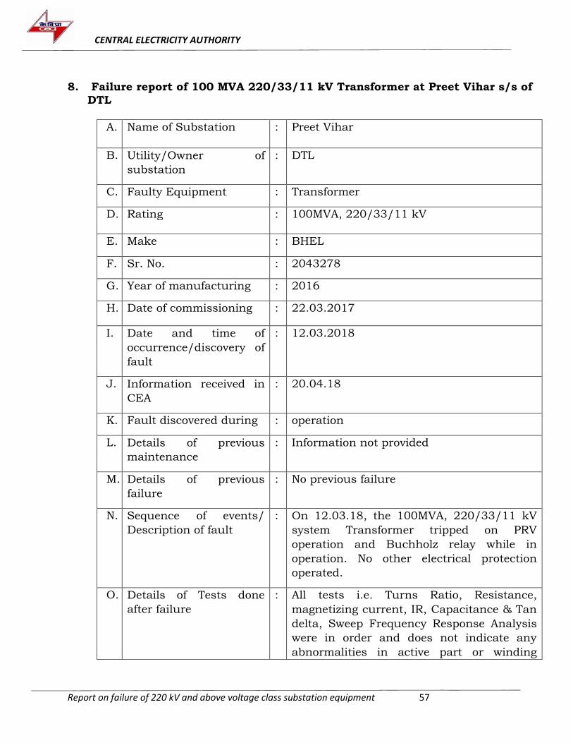
CENTRAL ELECTRICITY AUTHORITY
Report on failure of 220 kV and above voltage class substation equipment 57
8. Failure report of 100 MVA 220/33/11 kV Transformer at Preet Vihar s/s of
DTL
A. Name of Substation : Preet Vihar
B. Utility/Owner of
substation
: DTL
C. Faulty Equipment : Transformer
D. Rating : 100MVA, 220/33/11 kV
E. Make : BHEL
F. Sr. No. : 2043278
G. Year of manufacturing : 2016
H. Date of commissioning : 22.03.2017
I. Date and time of
occurrence/discovery of
fault
: 12.03.2018
J. Information received in
CEA
: 20.04.18
K. Fault discovered during : operation
L. Details of previous
maintenance
: Information not provided
M. Details of previous
failure
: No previous failure
N. Sequence of events/
Description of fault
: On 12.03.18, the 100MVA, 220/33/11 kV
system Transformer tripped on PRV
operation and Buchholz relay while in
operation. No other electrical protection
operated.
O. Details of Tests done
after failure
: All tests i.e. Turns Ratio, Resistance,
magnetizing current, IR, Capacitance & Tan
delta, Sweep Frequency Response Analysis
were in order and does not indicate any
abnormalities in active part or winding
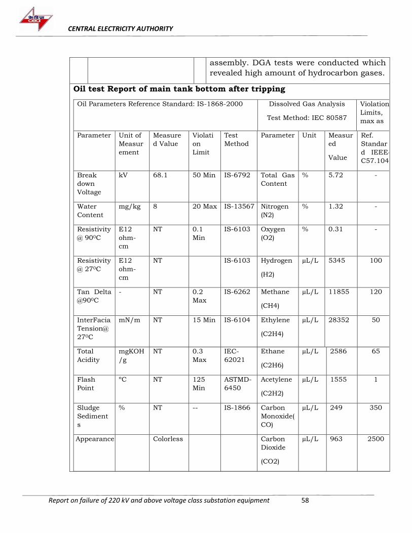
CENTRAL ELECTRICITY AUTHORITY
Report on failure of 220 kV and above voltage class substation equipment 58
assembly. DGA tests were conducted which
revealed high amount of hydrocarbon gases.
Oil test Report of main tank bottom after tripping
Oil Parameters Reference Standard: IS-1868-2000 Dissolved Gas Analysis
Test Method: IEC 80587
Violation
Limits,
max as
Parameter Unit of
Measur
ement
Measure
d Value
Violati
on
Limit
Test
Method
Parameter Unit Measur
ed
Value
Ref.
Standar
d IEEE-
C57.104
Break
down
Voltage
kV 68.1 50 Min IS-6792 Total Gas
Content
% 5.72 -
Water
Content
mg/kg 8 20 Max IS-13567 Nitrogen
(N2)
% 1.32 -
Resistivity
@ 900C
E12
ohm-
cm
NT 0.1
Min
IS-6103 Oxygen
(O2)
% 0.31 -
Resistivity
@ 270C
E12
ohm-
cm
NT IS-6103 Hydrogen
(H2)
µL/L 5345 100
Tan Delta
@900C
- NT 0.2
Max
IS-6262 Methane
(CH4)
µL/L 11855 120
InterFacia
Tension@
270C
mN/m NT 15 Min IS-6104 Ethylene
(C2H4)
µL/L 28352 50
Total
Acidity
mgKOH
/g
NT 0.3
Max
IEC-
62021
Ethane
(C2H6)
µL/L 2586 65
Flash
Point
ºC NT 125
Min
ASTMD-
6450
Acetylene
(C2H2)
µL/L 1555 1
Sludge
Sediment
s
% NT -- IS-1866 Carbon
Monoxide(
CO)
µL/L 249 350
Appearance Colorless Carbon
Dioxide
(CO2)
µL/L 963 2500
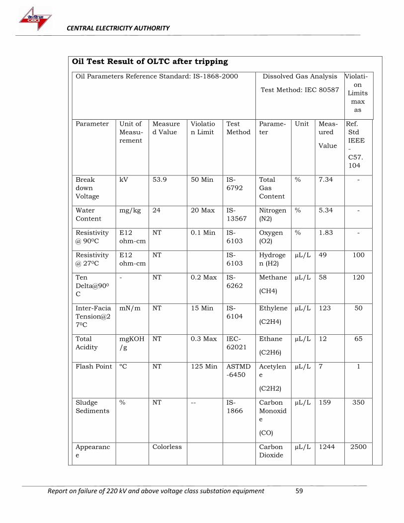
CENTRAL ELECTRICITY AUTHORITY
Report on failure of 220 kV and above voltage class substation equipment 59
Oil Test Result of OLTC after tripping
Oil Parameters Reference Standard: IS-1868-2000 Dissolved Gas Analysis
Test Method: IEC 80587
Violati-
on
Limits
max
as
Parameter Unit of
Measu-
rement
Measure
d Value
Violatio
n Limit
Test
Method
Parame-
ter
Unit Meas-
ured
Value
Ref.
Std
IEEE
-
C57.
104
Break
down
Voltage
kV 53.9 50 Min IS-
6792
Total
Gas
Content
% 7.34 -
Water
Content
mg/kg 24 20 Max IS-
13567
Nitrogen
(N2)
% 5.34 -
Resistivity
@ 900C
E12
ohm-cm
NT 0.1 Min IS-
6103
Oxygen
(O2)
% 1.83 -
Resistivity
@ 270C
E12
ohm-cm
NT IS-
6103
Hydroge
n (H2)
µL/L 49 100
Ten
Delta@900
C
- NT 0.2 Max IS-
6262
Methane
(CH4)
µL/L 58 120
Inter-Facia
Tension@2
70C
mN/m NT 15 Min IS-
6104
Ethylene
(C2H4)
µL/L 123 50
Total
Acidity
mgKOH
/g
NT 0.3 Max IEC-
62021
Ethane
(C2H6)
µL/L 12 65
Flash Point ºC NT 125 Min ASTMD
-6450
Acetylen
e
(C2H2)
µL/L 7 1
Sludge
Sediments
% NT -- IS-
1866
Carbon
Monoxid
e
(CO)
µL/L 159 350
Appearanc
e
Colorless Carbon
Dioxide
µL/L 1244 2500
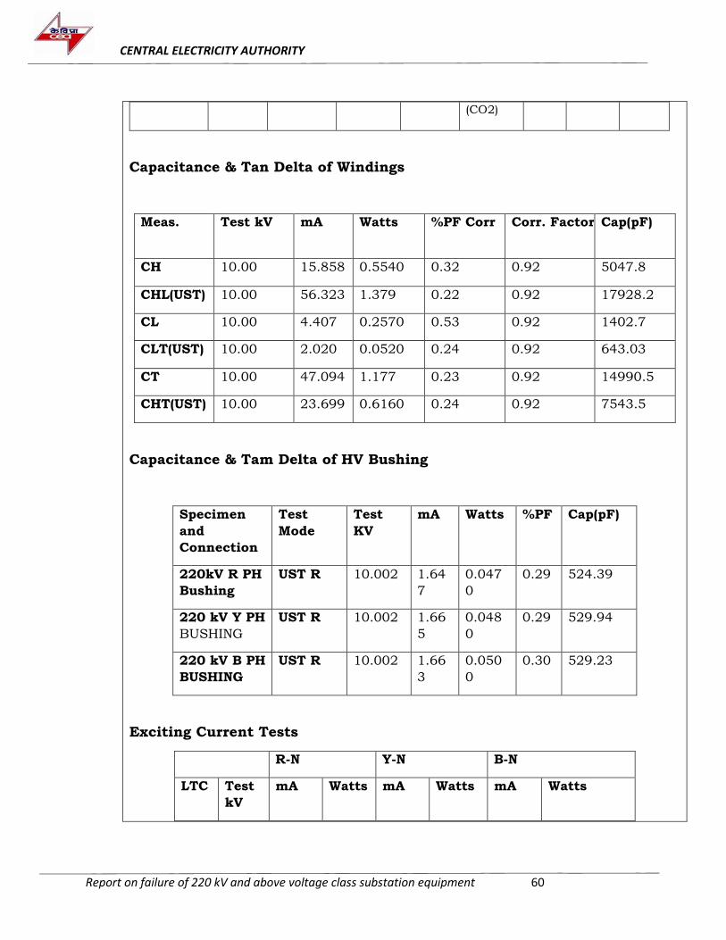
CENTRAL ELECTRICITY AUTHORITY
Report on failure of 220 kV and above voltage class substation equipment 60
(CO2)
Capacitance & Tan Delta of Windings
Meas. Test kV mA Watts %PF Corr Corr. Factor Cap(pF)
CH 10.00 15.858 0.5540 0.32 0.92 5047.8
CHL(UST) 10.00 56.323 1.379 0.22 0.92 17928.2
CL 10.00 4.407 0.2570 0.53 0.92 1402.7
CLT(UST) 10.00 2.020 0.0520 0.24 0.92 643.03
CT 10.00 47.094 1.177 0.23 0.92 14990.5
CHT(UST) 10.00 23.699 0.6160 0.24 0.92 7543.5
Capacitance & Tam Delta of HV Bushing
Specimen
and
Connection
Test
Mode
Test
KV
mA Watts %PF Cap(pF)
220kV R PH
Bushing
UST R 10.002 1.64
7
0.047
0
0.29 524.39
220 kV Y PH
BUSHING
UST R 10.002 1.66
5
0.048
0
0.29 529.94
220 kV B PH
BUSHING
UST R 10.002 1.66
3
0.050
0
0.30 529.23
Exciting Current Tests
R-N Y-N B-N
LTC Test
kV
mA Watts mA Watts mA Watts
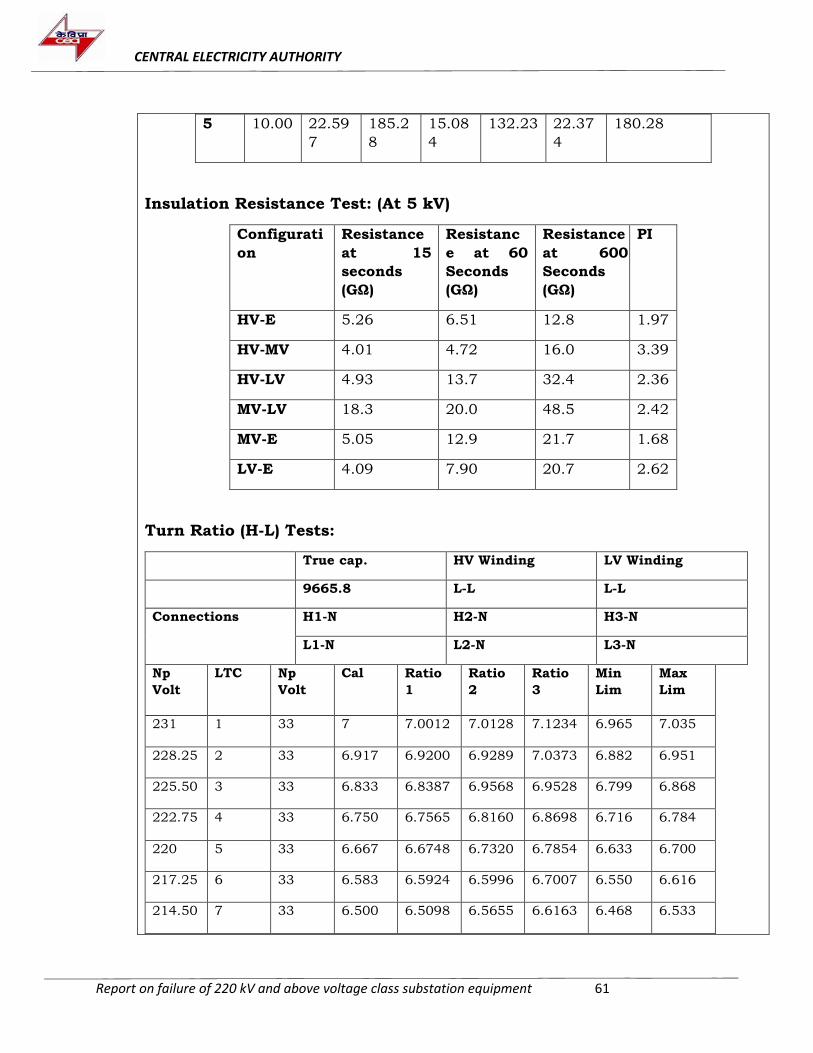
CENTRAL ELECTRICITY AUTHORITY
Report on failure of 220 kV and above voltage class substation equipment 61
5 10.00 22.59
7
185.2
8
15.08
4
132.23 22.37
4
180.28
Insulation Resistance Test: (At 5 kV)
Configurati
on
Resistance
at 15
seconds
(GΩ)
Resistanc
e at 60
Seconds
(GΩ)
Resistance
at 600
Seconds
(GΩ)
PI
HV-E 5.26 6.51 12.8 1.97
HV-MV 4.01 4.72 16.0 3.39
HV-LV 4.93 13.7 32.4 2.36
MV-LV 18.3 20.0 48.5 2.42
MV-E 5.05 12.9 21.7 1.68
LV-E 4.09 7.90 20.7 2.62
Turn Ratio (H-L) Tests:
True cap. HV Winding LV Winding
9665.8 L-L L-L
Connections H1-N H2-N H3-N
L1-N L2-N L3-N
Np
Volt
LTC Np
Volt
Cal Ratio
1
Ratio
2
Ratio
3
Min
Lim
Max
Lim
231 1 33 7 7.0012 7.0128 7.1234 6.965 7.035
228.25 2 33 6.917 6.9200 6.9289 7.0373 6.882 6.951
225.50 3 33 6.833 6.8387 6.9568 6.9528 6.799 6.868
222.75 4 33 6.750 6.7565 6.8160 6.8698 6.716 6.784
220 5 33 6.667 6.6748 6.7320 6.7854 6.633 6.700
217.25 6 33 6.583 6.5924 6.5996 6.7007 6.550 6.616
214.50 7 33 6.500 6.5098 6.5655 6.6163 6.468 6.533
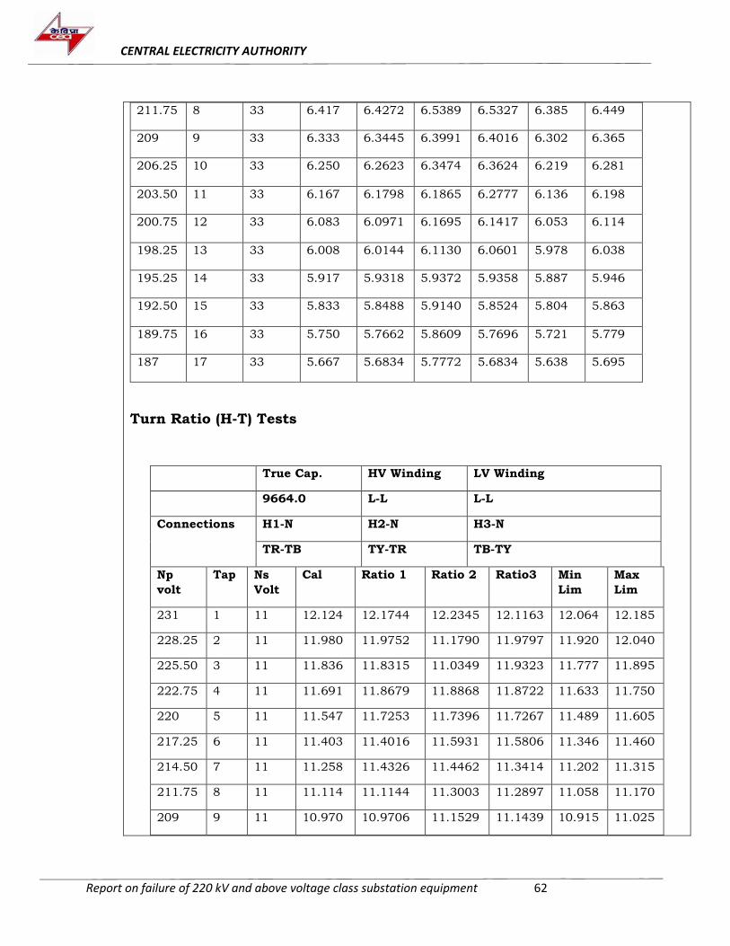
CENTRAL ELECTRICITY AUTHORITY
Report on failure of 220 kV and above voltage class substation equipment 62
211.75 8 33 6.417 6.4272 6.5389 6.5327 6.385 6.449
209 9 33 6.333 6.3445 6.3991 6.4016 6.302 6.365
206.25 10 33 6.250 6.2623 6.3474 6.3624 6.219 6.281
203.50 11 33 6.167 6.1798 6.1865 6.2777 6.136 6.198
200.75 12 33 6.083 6.0971 6.1695 6.1417 6.053 6.114
198.25 13 33 6.008 6.0144 6.1130 6.0601 5.978 6.038
195.25 14 33 5.917 5.9318 5.9372 5.9358 5.887 5.946
192.50 15 33 5.833 5.8488 5.9140 5.8524 5.804 5.863
189.75 16 33 5.750 5.7662 5.8609 5.7696 5.721 5.779
187 17 33 5.667 5.6834 5.7772 5.6834 5.638 5.695
Turn Ratio (H-T) Tests
True Cap. HV Winding LV Winding
9664.0 L-L L-L
Connections H1-N H2-N H3-N
TR-TB TY-TR TB-TY
Np
volt
Tap Ns
Volt
Cal Ratio 1 Ratio 2 Ratio3 Min
Lim
Max
Lim
231 1 11 12.124 12.1744 12.2345 12.1163 12.064 12.185
228.25 2 11 11.980 11.9752 11.1790 11.9797 11.920 12.040
225.50 3 11 11.836 11.8315 11.0349 11.9323 11.777 11.895
222.75 4 11 11.691 11.8679 11.8868 11.8722 11.633 11.750
220 5 11 11.547 11.7253 11.7396 11.7267 11.489 11.605
217.25 6 11 11.403 11.4016 11.5931 11.5806 11.346 11.460
214.50 7 11 11.258 11.4326 11.4462 11.3414 11.202 11.315
211.75 8 11 11.114 11.1144 11.3003 11.2897 11.058 11.170
209 9 11 10.970 10.9706 11.1529 11.1439 10.915 11.025
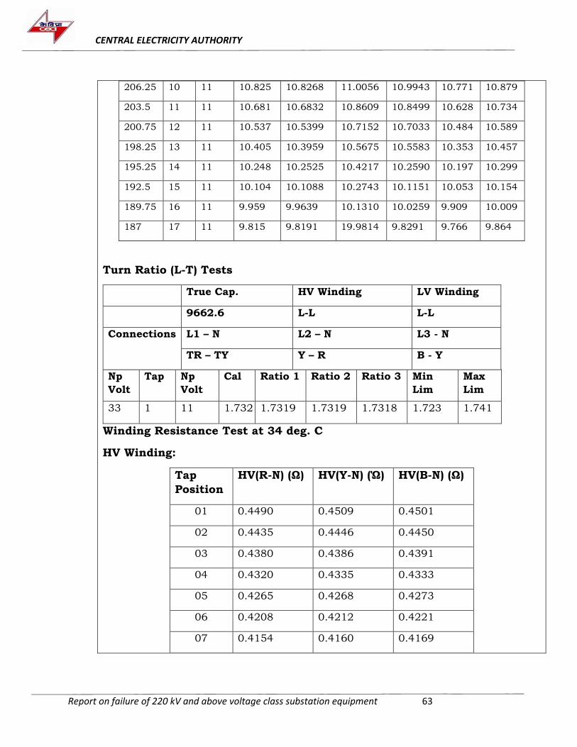
CENTRAL ELECTRICITY AUTHORITY
Report on failure of 220 kV and above voltage class substation equipment 63
206.25 10 11 10.825 10.8268 11.0056 10.9943 10.771 10.879
203.5 11 11 10.681 10.6832 10.8609 10.8499 10.628 10.734
200.75 12 11 10.537 10.5399 10.7152 10.7033 10.484 10.589
198.25 13 11 10.405 10.3959 10.5675 10.5583 10.353 10.457
195.25 14 11 10.248 10.2525 10.4217 10.2590 10.197 10.299
192.5 15 11 10.104 10.1088 10.2743 10.1151 10.053 10.154
189.75 16 11 9.959 9.9639 10.1310 10.0259 9.909 10.009
187 17 11 9.815 9.8191 19.9814 9.8291 9.766 9.864
Turn Ratio (L-T) Tests
True Cap. HV Winding LV Winding
9662.6 L-L L-L
Connections L1 – N L2 – N L3 - N
TR – TY Y – R B - Y
Np
Volt
Tap Np
Volt
Cal Ratio 1 Ratio 2 Ratio 3 Min
Lim
Max
Lim
33 1 11 1.732 1.7319 1.7319 1.7318 1.723 1.741
Winding Resistance Test at 34 deg. C
HV Winding:
Tap
Position
HV(R-N) (Ω) HV(Y-N) (Ώ) HV(B-N) (Ω)
01 0.4490 0.4509 0.4501
02 0.4435 0.4446 0.4450
03 0.4380 0.4386 0.4391
04 0.4320 0.4335 0.4333
05 0.4265 0.4268 0.4273
06 0.4208 0.4212 0.4221
07 0.4154 0.4160 0.4169
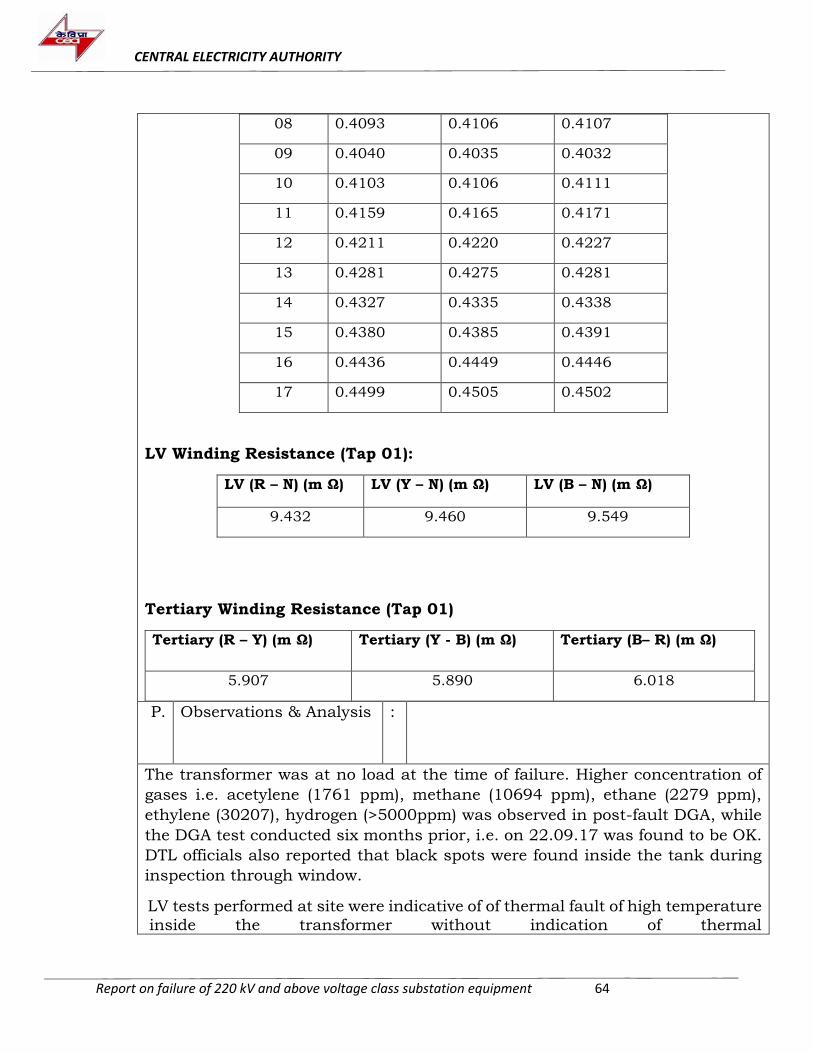
CENTRAL ELECTRICITY AUTHORITY
Report on failure of 220 kV and above voltage class substation equipment 64
08 0.4093 0.4106 0.4107
09 0.4040 0.4035 0.4032
10 0.4103 0.4106 0.4111
11 0.4159 0.4165 0.4171
12 0.4211 0.4220 0.4227
13 0.4281 0.4275 0.4281
14 0.4327 0.4335 0.4338
15 0.4380 0.4385 0.4391
16 0.4436 0.4449 0.4446
17 0.4499 0.4505 0.4502
LV Winding Resistance (Tap 01):
LV (R – N) (m Ω) LV (Y – N) (m Ω) LV (B – N) (m Ω)
9.432 9.460 9.549
Tertiary Winding Resistance (Tap 01)
Tertiary (R – Y) (m Ω) Tertiary (Y - B) (m Ω) Tertiary (B– R) (m Ω)
5.907 5.890 6.018
P. Observations & Analysis
:
The transformer was at no load at the time of failure. Higher concentration of
gases i.e. acetylene (1761 ppm), methane (10694 ppm), ethane (2279 ppm),
ethylene (30207), hydrogen (>5000ppm) was observed in post-fault DGA, while
the DGA test conducted six months prior, i.e. on 22.09.17 was found to be OK.
DTL officials also reported that black spots were found inside the tank during
inspection through window.
LV tests performed at site were indicative of of thermal fault of high temperature
inside the transformer without indication of thermal
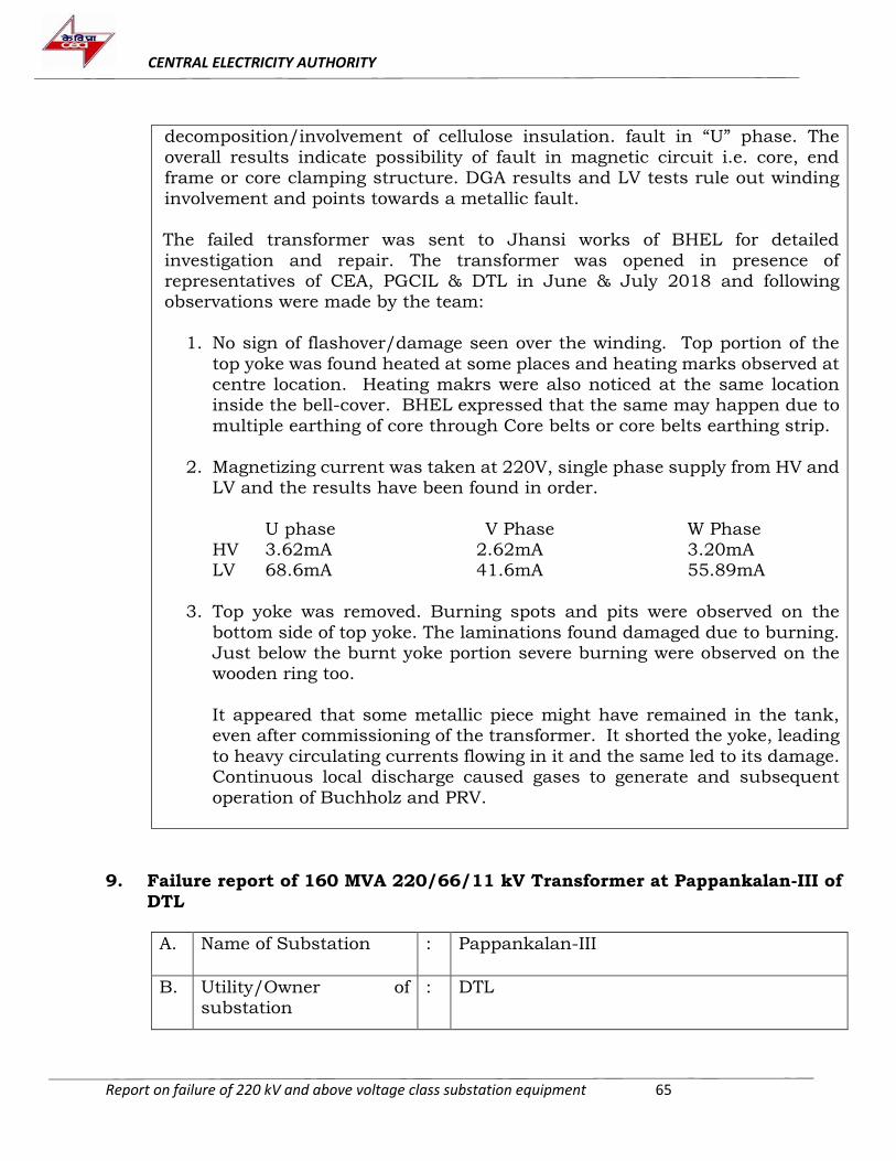
CENTRAL ELECTRICITY AUTHORITY
Report on failure of 220 kV and above voltage class substation equipment 65
decomposition/involvement of cellulose insulation. fault in “U” phase. The
overall results indicate possibility of fault in magnetic circuit i.e. core, end frame or core clamping structure. DGA results and LV tests rule out winding
involvement and points towards a metallic fault. The failed transformer was sent to Jhansi works of BHEL for detailed
investigation and repair. The transformer was opened in presence of representatives of CEA, PGCIL & DTL in June & July 2018 and following observations were made by the team:
1. No sign of flashover/damage seen over the winding. Top portion of the
top yoke was found heated at some places and heating marks observed at centre location. Heating makrs were also noticed at the same location inside the bell-cover. BHEL expressed that the same may happen due to
multiple earthing of core through Core belts or core belts earthing strip.
2. Magnetizing current was taken at 220V, single phase supply from HV and LV and the results have been found in order.
U phase V Phase W Phase HV 3.62mA 2.62mA 3.20mA LV 68.6mA 41.6mA 55.89mA
3. Top yoke was removed. Burning spots and pits were observed on the
bottom side of top yoke. The laminations found damaged due to burning. Just below the burnt yoke portion severe burning were observed on the wooden ring too.
It appeared that some metallic piece might have remained in the tank, even after commissioning of the transformer. It shorted the yoke, leading
to heavy circulating currents flowing in it and the same led to its damage. Continuous local discharge caused gases to generate and subsequent
operation of Buchholz and PRV.
9. Failure report of 160 MVA 220/66/11 kV Transformer at Pappankalan-III of
DTL
A. Name of Substation : Pappankalan-III
B. Utility/Owner of substation
: DTL
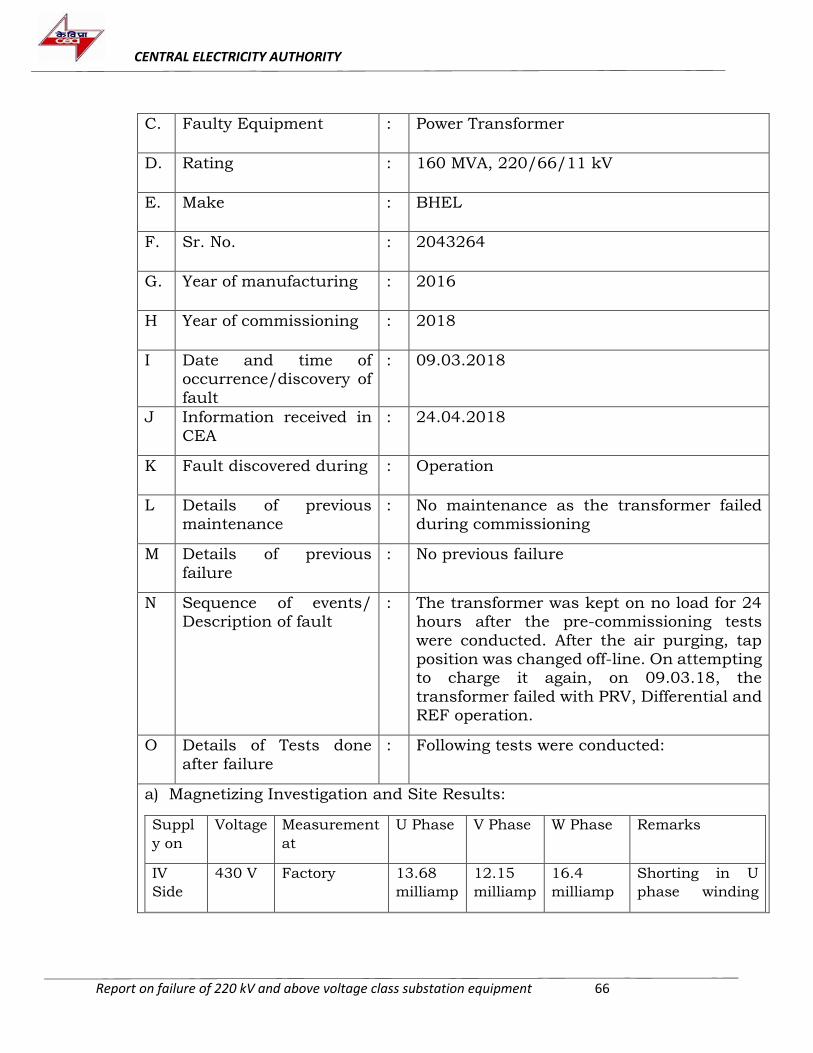
CENTRAL ELECTRICITY AUTHORITY
Report on failure of 220 kV and above voltage class substation equipment 66
C. Faulty Equipment : Power Transformer
D. Rating : 160 MVA, 220/66/11 kV
E. Make : BHEL
F. Sr. No. : 2043264
G. Year of manufacturing : 2016
H Year of commissioning : 2018
I Date and time of occurrence/discovery of
fault
: 09.03.2018
J Information received in
CEA
: 24.04.2018
K Fault discovered during : Operation
L Details of previous maintenance
: No maintenance as the transformer failed during commissioning
M Details of previous
failure
: No previous failure
N Sequence of events/ Description of fault
: The transformer was kept on no load for 24 hours after the pre-commissioning tests
were conducted. After the air purging, tap position was changed off-line. On attempting to charge it again, on 09.03.18, the
transformer failed with PRV, Differential and REF operation.
O Details of Tests done
after failure
: Following tests were conducted:
a) Magnetizing Investigation and Site Results:
Suppl
y on
Voltage Measurement
at
U Phase V Phase W Phase Remarks
IV
Side
430 V Factory 13.68
milliamp
12.15
milliamp
16.4
milliamp
Shorting in U
phase winding
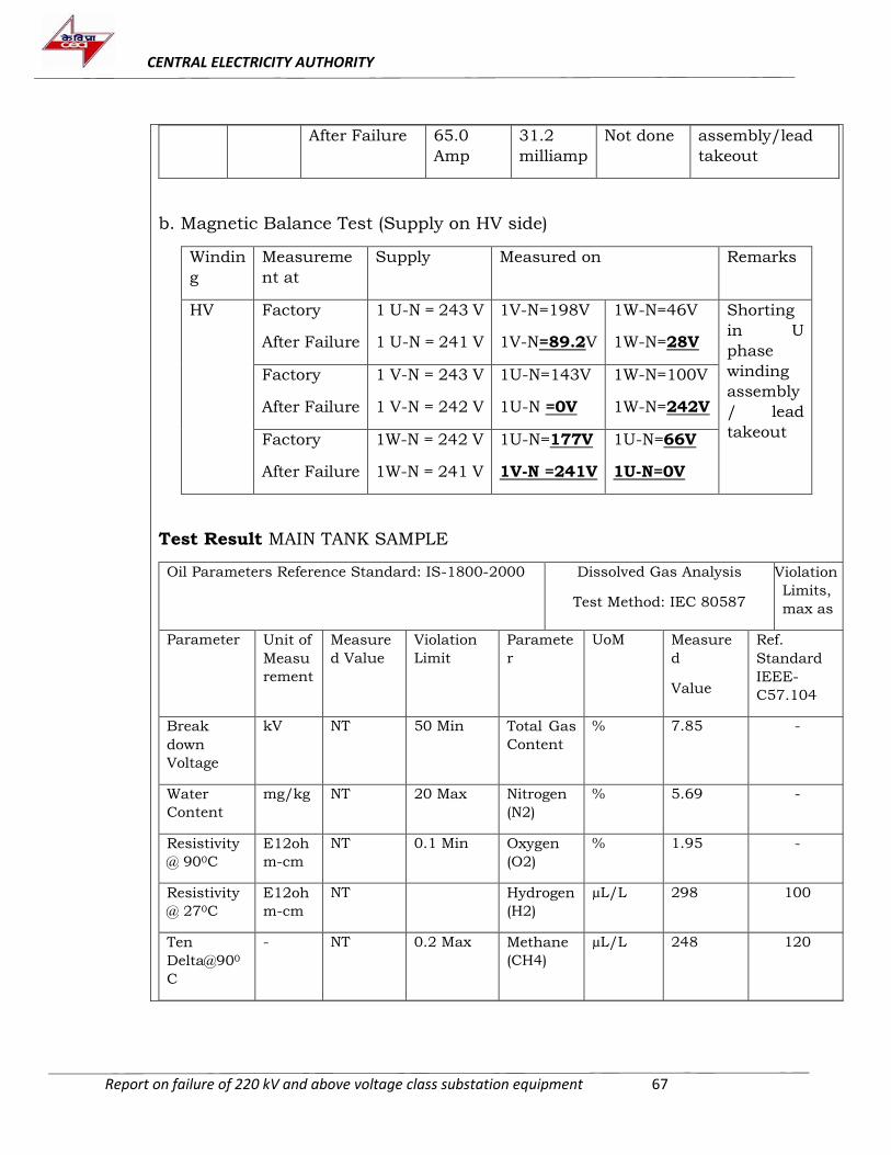
CENTRAL ELECTRICITY AUTHORITY
Report on failure of 220 kV and above voltage class substation equipment 67
After Failure 65.0
Amp
31.2
milliamp
Not done assembly/lead
takeout
b. Magnetic Balance Test (Supply on HV side)
Windin
g
Measureme
nt at
Supply Measured on Remarks
HV Factory
After Failure
1 U-N = 243 V
1 U-N = 241 V
1V-N=198V
1V-N=89.2V
1W-N=46V
1W-N=28V
Shorting
in U
phase
winding
assembly
/ lead
takeout
Factory
After Failure
1 V-N = 243 V
1 V-N = 242 V
1U-N=143V
1U-N =0V
1W-N=100V
1W-N=242V
Factory
After Failure
1W-N = 242 V
1W-N = 241 V
1U-N=177V
1V-N =241V
1U-N=66V
1U-N=0V
Test Result MAIN TANK SAMPLE
Oil Parameters Reference Standard: IS-1800-2000 Dissolved Gas Analysis
Test Method: IEC 80587
Violation
Limits,
max as
Parameter Unit of
Measu
rement
Measure
d Value
Violation
Limit
Paramete
r
UoM Measure
d
Value
Ref.
Standard
IEEE-
C57.104
Break
down
Voltage
kV NT 50 Min Total Gas
Content
% 7.85 -
Water
Content
mg/kg NT 20 Max Nitrogen
(N2)
% 5.69 -
Resistivity
@ 900C
E12oh
m-cm
NT 0.1 Min Oxygen
(O2)
% 1.95 -
Resistivity
@ 270C
E12oh
m-cm
NT Hydrogen
(H2)
µL/L 298 100
Ten
Delta@900
C
- NT 0.2 Max Methane
(CH4)
µL/L 248 120
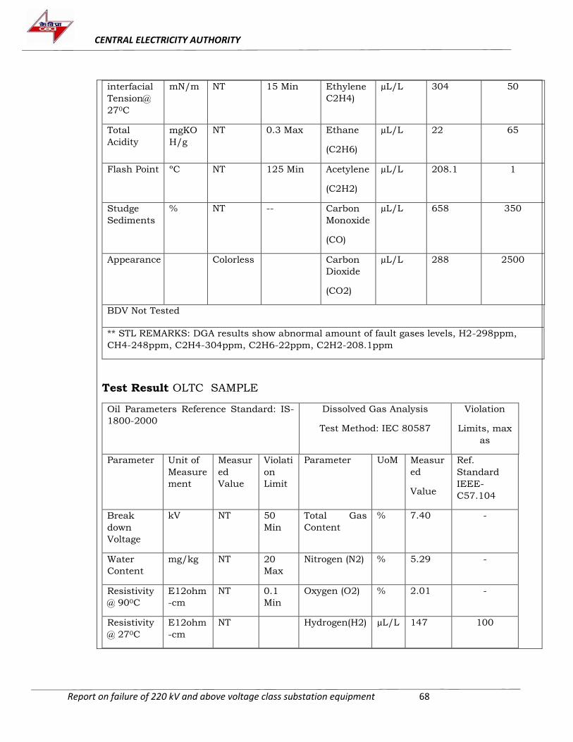
CENTRAL ELECTRICITY AUTHORITY
Report on failure of 220 kV and above voltage class substation equipment 68
interfacial
Tension@
270C
mN/m NT 15 Min Ethylene
C2H4)
µL/L 304 50
Total
Acidity
mgKO
H/g
NT 0.3 Max Ethane
(C2H6)
µL/L 22 65
Flash Point ºC NT 125 Min Acetylene
(C2H2)
µL/L 208.1 1
Studge
Sediments
% NT -- Carbon
Monoxide
(CO)
µL/L 658 350
Appearance Colorless Carbon
Dioxide
(CO2)
µL/L 288 2500
BDV Not Tested
** STL REMARKS: DGA results show abnormal amount of fault gases levels, H2-298ppm,
CH4-248ppm, C2H4-304ppm, C2H6-22ppm, C2H2-208.1ppm
Test Result OLTC SAMPLE
Oil Parameters Reference Standard: IS-
1800-2000
Dissolved Gas Analysis
Test Method: IEC 80587
Violation
Limits, max
as
Parameter Unit of
Measure
ment
Measur
ed
Value
Violati
on
Limit
Parameter UoM Measur
ed
Value
Ref.
Standard
IEEE-
C57.104
Break
down
Voltage
kV NT 50
Min
Total Gas
Content
% 7.40 -
Water
Content
mg/kg NT 20
Max
Nitrogen (N2) % 5.29 -
Resistivity
@ 900C
E12ohm
-cm
NT 0.1
Min
Oxygen (O2) % 2.01 -
Resistivity
@ 270C
E12ohm
-cm
NT Hydrogen(H2) µL/L 147 100
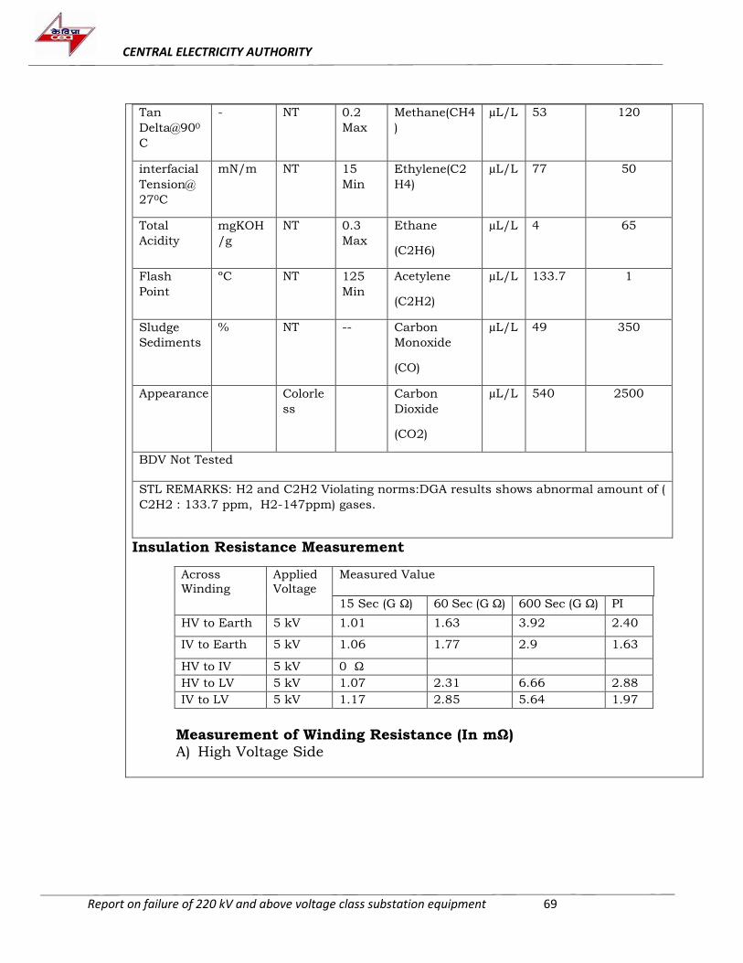
CENTRAL ELECTRICITY AUTHORITY
Report on failure of 220 kV and above voltage class substation equipment 69
Tan
Delta@900
C
- NT 0.2
Max
Methane(CH4
)
µL/L 53 120
interfacial
Tension@
270C
mN/m NT 15
Min
Ethylene(C2
H4)
µL/L 77 50
Total
Acidity
mgKOH
/g
NT 0.3
Max
Ethane
(C2H6)
µL/L 4 65
Flash
Point
ºC NT 125
Min
Acetylene
(C2H2)
µL/L 133.7 1
Sludge
Sediments
% NT -- Carbon
Monoxide
(CO)
µL/L 49 350
Appearance Colorle
ss
Carbon
Dioxide
(CO2)
µL/L 540 2500
BDV Not Tested
STL REMARKS: H2 and C2H2 Violating norms:DGA results shows abnormal amount of (
C2H2 : 133.7 ppm, H2-147ppm) gases.
Insulation Resistance Measurement
Across
Winding
Applied
Voltage
Measured Value
15 Sec (G Ω) 60 Sec (G Ω) 600 Sec (G Ω) PI
HV to Earth 5 kV 1.01 1.63 3.92 2.40
IV to Earth 5 kV 1.06 1.77 2.9 1.63
HV to IV 5 kV 0 Ω
HV to LV 5 kV 1.07 2.31 6.66 2.88
IV to LV 5 kV 1.17 2.85 5.64 1.97
Measurement of Winding Resistance (In mΩ) A) High Voltage Side
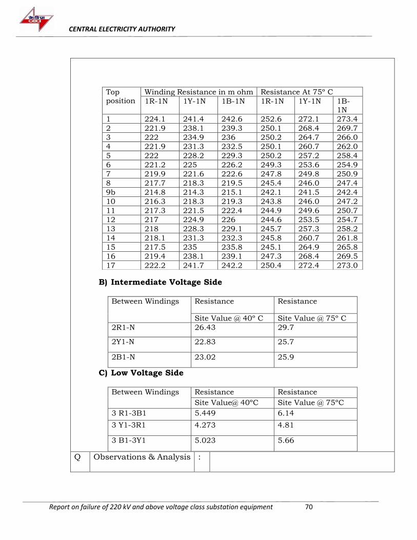
CENTRAL ELECTRICITY AUTHORITY
Report on failure of 220 kV and above voltage class substation equipment 70
B) Intermediate Voltage Side Between Windings Resistance Resistance
Site Value @ 40º C Site Value @ 75º C
2R1-N 26.43 29.7
2Y1-N 22.83 25.7
2B1-N 23.02 25.9
C) Low Voltage Side
Between Windings Resistance Resistance
Site Value@ 40ºC Site Value @ 75ºC
3 R1-3B1 5.449 6.14
3 Y1-3R1 4.273 4.81
3 B1-3Y1 5.023 5.66
Top position
Winding Resistance in m ohm Resistance At 75º C
1R-1N 1Y-1N 1B-1N 1R-1N 1Y-1N 1B-1N
1 224.1 241.4 242.6 252.6 272.1 273.4
2 221.9 238.1 239.3 250.1 268.4 269.7
3 222 234.9 236 250.2 264.7 266.0
4 221.9 231.3 232.5 250.1 260.7 262.0
5 222 228.2 229.3 250.2 257.2 258.4
6 221.2 225 226.2 249.3 253.6 254.9
7 219.9 221.6 222.6 247.8 249.8 250.9
8 217.7 218.3 219.5 245.4 246.0 247.4
9b 214.8 214.3 215.1 242.1 241.5 242.4
10 216.3 218.3 219.3 243.8 246.0 247.2
11 217.3 221.5 222.4 244.9 249.6 250.7
12 217 224.9 226 244.6 253.5 254.7
13 218 228.3 229.1 245.7 257.3 258.2
14 218.1 231.3 232.3 245.8 260.7 261.8
15 217.5 235 235.8 245.1 264.9 265.8
16 219.4 238.1 239.1 247.3 268.4 269.5
17 222.2 241.7 242.2 250.4 272.4 273.0
Q Observations & Analysis :
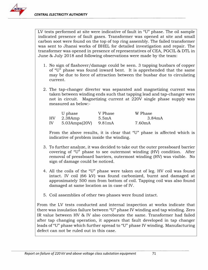
CENTRAL ELECTRICITY AUTHORITY
Report on failure of 220 kV and above voltage class substation equipment 71
LV tests performed at site were indicative of fault in “U” phase. The oil sample
indicated presence of fault gases. Transformer was opened at site and small carbon soot were found on the top of top ring assembly. The failed transformer
was sent to Jhansi works of BHEL for detailed investigation and repair. The transformer was opened in presence of representatives of CEA, PGCIL & DTL in June & July 2018 and following observations were made by the team:
1. No sign of flashover/damage could be seen. 3 tapping busbars of copper
of “U” phase was found inward bent. It is apprehended that the same
may be due to force of attraction between the busbar due to circulating current.
2. The tap-changer diverter was separated and magnetizing current was
taken between winding ends such that tapping lead and tap-changer were
not in circuit. Magnetizing current at 220V single phase supply was measured as below:-
U phase V Phase W Phase
HV 2.38Amp 5.5mA 3.84mA
IV 5.03Amps(20V) 9.81mA 7.60mA
From the above results, it is clear that “U” phase is affected which is
indicative of problem inside the winding.
3. To further analyze, it was decided to take out the outer pressboard barrier covering of “U” phase to see outermost winding (HV) condition. After removal of pressboard barriers, outermost winding (HV) was visible. No
sign of damage could be noticed.
4. All the coils of the “U” phase were taken out of leg. HV coil was found
intact. IV coil (66 kV) was found carbonized, burnt and damaged at approximately 500 mm from bottom of coil. Tapping coil was also found
damaged at same location as in case of IV.
5. Coil assemblies of other two phases were found intact.
From the LV tests conducted and internal inspection at works indicate that
there was insulation failure between “U” phase IV winding and tap winding. Zero
IR value between HV & IV also corroborate the same. Transformer had failed
after tap changing operation, it appears that fault developed in tap changer
leads of “U” phase which further spread to “U” phase IV winding. Manufacturing
defect can not be ruled out in this case.
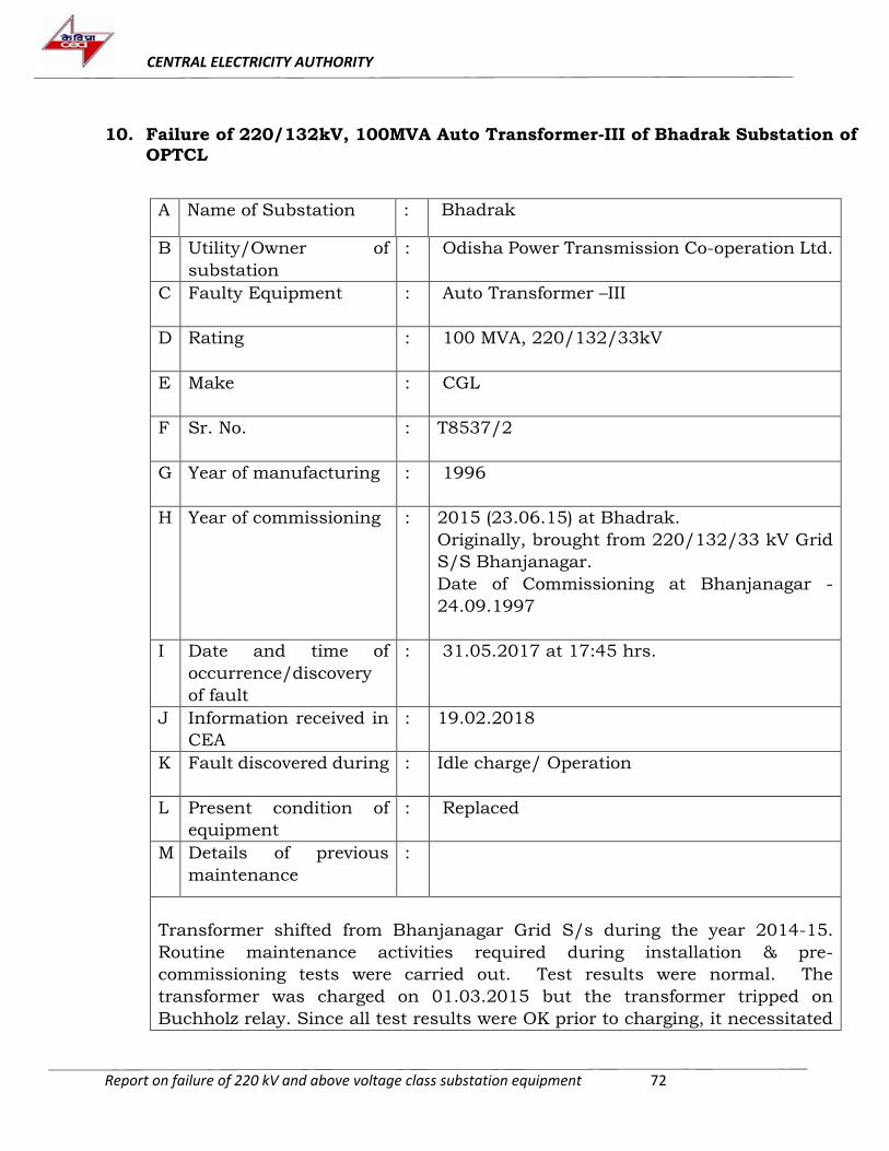
CENTRAL ELECTRICITY AUTHORITY
Report on failure of 220 kV and above voltage class substation equipment 72
10. Failure of 220/132kV, 100MVA Auto Transformer-III of Bhadrak Substation of
OPTCL
A Name of Substation : Bhadrak
B Utility/Owner of
substation
: Odisha Power Transmission Co-operation Ltd.
C Faulty Equipment : Auto Transformer –III
D Rating : 100 MVA, 220/132/33kV
E Make : CGL
F Sr. No. : T8537/2
G Year of manufacturing : 1996
H Year of commissioning : 2015 (23.06.15) at Bhadrak.
Originally, brought from 220/132/33 kV Grid
S/S Bhanjanagar.
Date of Commissioning at Bhanjanagar -
24.09.1997
I Date and time of
occurrence/discovery
of fault
: 31.05.2017 at 17:45 hrs.
J Information received in
CEA
: 19.02.2018
K Fault discovered during : Idle charge/ Operation
L Present condition of
equipment
: Replaced
M Details of previous
maintenance
:
Transformer shifted from Bhanjanagar Grid S/s during the year 2014-15.
Routine maintenance activities required during installation & pre-
commissioning tests were carried out. Test results were normal. The
transformer was charged on 01.03.2015 but the transformer tripped on
Buchholz relay. Since all test results were OK prior to charging, it necessitated
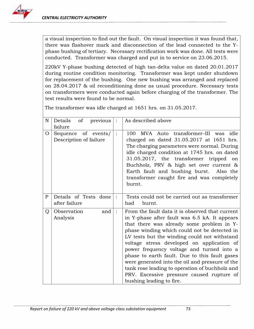
CENTRAL ELECTRICITY AUTHORITY
Report on failure of 220 kV and above voltage class substation equipment 73
a visual inspection to find out the fault. On visual inspection it was found that,
there was flashover mark and disconnection of the lead connected to the Y-
phase bushing of tertiary. Necessary rectification work was done. All tests were
conducted. Transformer was charged and put in to service on 23.06.2015.
220kV Y-phase bushing detected of high tan-delta value on dated 20.01.2017
during routine condition monitoring. Transformer was kept under shutdown
for replacement of the bushing. One new bushing was arranged and replaced
on 28.04.2017 & oil reconditioning done as usual procedure. Necessary tests
on transformers were conducted again before charging of the transformer. The
test results were found to be normal. The transformer was idle charged at 1651 hrs. on 31.05.2017.
N Details of previous
failure
: As described above
O Sequence of events/
Description of failure
: 100 MVA Auto transformer–III was idle
charged on dated 31.05.2017 at 1651 hrs.
The charging parameters were normal. During
idle charged condition at 1745 hrs. on dated
31.05.2017, the transformer tripped on
Buchholz, PRV & high set over current &
Earth fault and bushing burst. Also the
transformer caught fire and was completely
burnt.
P Details of Tests done
after failure
: Tests could not be carried out as transformer
had burnt.
Q Observation and
Analysis
: From the fault data it is observed that current
in Y-phase after fault was 6.5 kA. It appears
that there was already some problem in Y-
phase winding which could not be detected in
LV tests but the winding could not withstand
voltage stress developed on application of
power frequency voltage and turned into a
phase to earth fault. Due to this fault gases
were generated into the oil and pressure of the
tank rose leading to operation of buchholz and
PRV. Excessive pressure caused rupture of
bushing leading to fire.
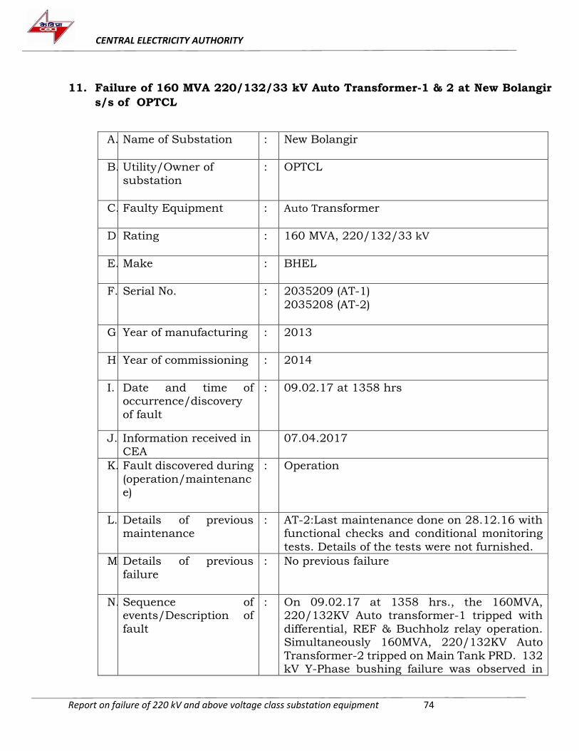
CENTRAL ELECTRICITY AUTHORITY
Report on failure of 220 kV and above voltage class substation equipment 74
11. Failure of 160 MVA 220/132/33 kV Auto Transformer-1 & 2 at New Bolangir
s/s of OPTCL
A. Name of Substation
: New Bolangir
B. Utility/Owner of
substation
: OPTCL
C. Faulty Equipment
: Auto Transformer
D. Rating
: 160 MVA, 220/132/33 kV
E. Make
: BHEL
F. Serial No.
: 2035209 (AT-1)
2035208 (AT-2)
G. Year of manufacturing
: 2013
H. Year of commissioning
: 2014
I. Date and time of occurrence/discovery
of fault
: 09.02.17 at 1358 hrs
J. Information received in
CEA
07.04.2017
K. Fault discovered during
(operation/maintenance)
: Operation
L. Details of previous maintenance
: AT-2:Last maintenance done on 28.12.16 with functional checks and conditional monitoring
tests. Details of the tests were not furnished.
M. Details of previous
failure
: No previous failure
N. Sequence of events/Description of
fault
: On 09.02.17 at 1358 hrs., the 160MVA, 220/132KV Auto transformer-1 tripped with
differential, REF & Buchholz relay operation. Simultaneously 160MVA, 220/132KV Auto
Transformer-2 tripped on Main Tank PRD. 132 kV Y-Phase bushing failure was observed in
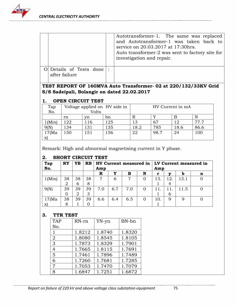
CENTRAL ELECTRICITY AUTHORITY
Report on failure of 220 kV and above voltage class substation equipment 75
Autotransformer-1. The same was replaced
and Autotransformer-1 was taken back to service on 20.03.2017 at 17:30hrs.
Auto transformer-2 was sent to factory site for investigation and repair.
O. Details of Tests done after failure
:
TEST REPORT OF 160MVA Auto Transformer- 02 at 220/132/33KV Grid
S/S Sadeipali, Bolangir on dated 22.02.2017
1. OPEN CIRCUIT TEST
Tap No.
Voltage applied on HV side in Volts
HV Current in mA
rn yn bn R Y B N
1(Min) 122 116 125 13 67 12 77.7
9(N) 134 131 135 18.2 785 18.6 86.6
17(Max)
150 151 156 22 98.7 24 100
Remark: High and abnormal magnetising current in Y phase.
2. SHORT CIRCUIT TEST
Tap No.
RY YB RB HV Current measured in Amp
LV Current measured in Amp
R Y B N r y b n
1(Min) 382
386
388
7 6 7 0 13.1
12.4
13.1 0
9(N) 390
392
393
7.0 6.7 7.0 0 11.1
11.6
11.5 0
17(Max)
388
391
390
6.6 6.4 6.5 0 10.1
9 9 0
3. TTR TEST
TAP
No.
RN-rn YN-yn BN-bn
1 1.8212 1.8740 1.8320
2 1.8080 1.8545 1.8105
3 1.7873 1.8329 1.7901
4 1.7665 1.8115 1.7691
5 1.7461 1.7896 1.7489
6 1.7260 1.7681 1.7285
7 1.7053 1.7470 1.7079
8 1.6847 1.7251 1.6872
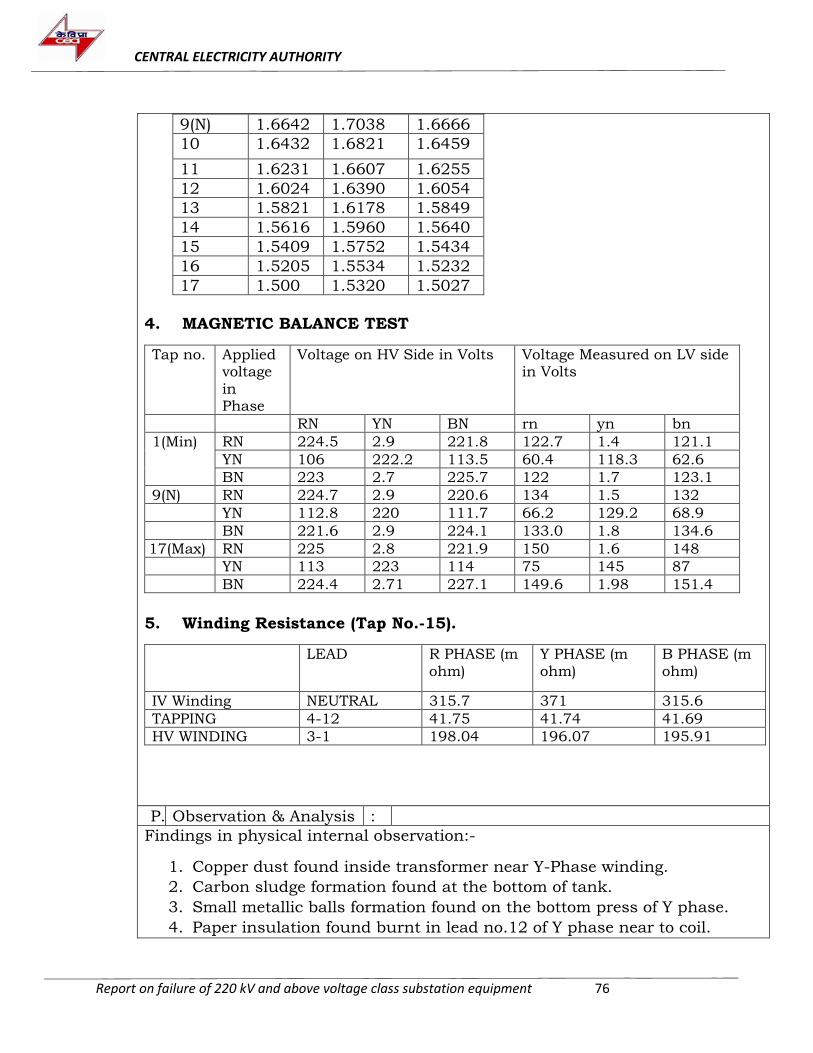
CENTRAL ELECTRICITY AUTHORITY
Report on failure of 220 kV and above voltage class substation equipment 76
9(N) 1.6642 1.7038 1.6666
10 1.6432 1.6821 1.6459
11 1.6231 1.6607 1.6255
12 1.6024 1.6390 1.6054
13 1.5821 1.6178 1.5849
14 1.5616 1.5960 1.5640
15 1.5409 1.5752 1.5434
16 1.5205 1.5534 1.5232
17 1.500 1.5320 1.5027
4. MAGNETIC BALANCE TEST
Tap no. Applied voltage in Phase
Voltage on HV Side in Volts Voltage Measured on LV side in Volts
RN YN BN rn yn bn
1(Min) RN 224.5 2.9 221.8 122.7 1.4 121.1
YN 106 222.2 113.5 60.4 118.3 62.6
BN 223 2.7 225.7 122 1.7 123.1
9(N) RN 224.7 2.9 220.6 134 1.5 132
YN 112.8 220 111.7 66.2 129.2 68.9
BN 221.6 2.9 224.1 133.0 1.8 134.6
17(Max) RN 225 2.8 221.9 150 1.6 148
YN 113 223 114 75 145 87
BN 224.4 2.71 227.1 149.6 1.98 151.4
5. Winding Resistance (Tap No.-15).
LEAD R PHASE (m ohm)
Y PHASE (m ohm)
B PHASE (m ohm)
IV Winding NEUTRAL 315.7 371 315.6
TAPPING 4-12 41.75 41.74 41.69
HV WINDING 3-1 198.04 196.07 195.91
P. Observation & Analysis :
Findings in physical internal observation:-
1. Copper dust found inside transformer near Y-Phase winding.
2. Carbon sludge formation found at the bottom of tank.
3. Small metallic balls formation found on the bottom press of Y phase.
4. Paper insulation found burnt in lead no.12 of Y phase near to coil.
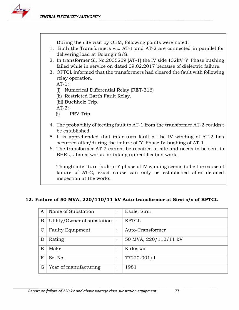
CENTRAL ELECTRICITY AUTHORITY
Report on failure of 220 kV and above voltage class substation equipment 77
During the site visit by OEM, following points were noted:
1. Both the Transformers viz. AT-1 and AT-2 are connected in parallel for
delivering load at Bolangir S/S.
2. In transformer Sl. No.2035209 (AT-1) the IV side 132kV ‘Y’ Phase bushing
failed while in service on dated 09.02.2017 because of dielectric failure.
3. OPTCL informed that the transformers had cleared the fault with following
relay operation.
AT-1:
(i) Numerical Differential Relay (RET-316)
(ii) Restricted Earth Fault Relay.
(iii) Buchholz Trip.
AT-2:
(i) PRV Trip.
4. The probability of feeding fault to AT-1 from the transformer AT-2 couldn’t
be established.
5. It is apprehended that inter turn fault of the IV winding of AT-2 has
occurred after/during the failure of ‘Y’ Phase IV bushing of AT-1.
6. The transformer AT-2 cannot be repaired at site and needs to be sent to
BHEL, Jhansi works for taking up rectification work.
Though inter turn fault in Y phase of IV winding seems to be the cause of
failure of AT-2, exact cause can only be established after detailed
inspection at the works.
12. Failure of 50 MVA, 220/110/11 kV Auto-transformer at Sirsi s/s of KPTCL
A Name of Substation : Esale, Sirsi
B Utility/Owner of substation : KPTCL
C Faulty Equipment : Auto-Transformer
D Rating : 50 MVA, 220/110/11 kV
E Make : Kirloskar
F Sr. No. : 77220-001/1
G Year of manufacturing : 1981
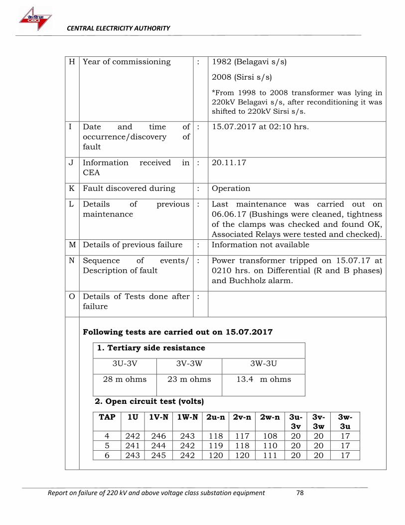
CENTRAL ELECTRICITY AUTHORITY
Report on failure of 220 kV and above voltage class substation equipment 78
H Year of commissioning : 1982 (Belagavi s/s)
2008 (Sirsi s/s)
*From 1998 to 2008 transformer was lying in
220kV Belagavi s/s, after reconditioning it was
shifted to 220kV Sirsi s/s.
I Date and time of
occurrence/discovery of
fault
: 15.07.2017 at 02:10 hrs.
J Information received in
CEA
: 20.11.17
K Fault discovered during : Operation
L Details of previous
maintenance
: Last maintenance was carried out on
06.06.17 (Bushings were cleaned, tightness
of the clamps was checked and found OK,
Associated Relays were tested and checked).
M Details of previous failure : Information not available
N Sequence of events/
Description of fault
: Power transformer tripped on 15.07.17 at
0210 hrs. on Differential (R and B phases)
and Buchholz alarm.
O Details of Tests done after
failure
:
Following tests are carried out on 15.07.2017
1. Tertiary side resistance
3U-3V 3V-3W 3W-3U
28 m ohms 23 m ohms 13.4 m ohms
2. Open circuit test (volts)
TAP 1U 1V-N 1W-N 2u-n 2v-n 2w-n 3u-3v
3v-3w
3w-3u
4 242 246 243 118 117 108 20 20 17
5 241 244 242 119 118 110 20 20 17
6 243 245 242 120 120 111 20 20 17
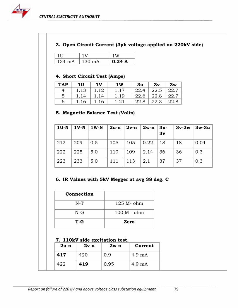
CENTRAL ELECTRICITY AUTHORITY
Report on failure of 220 kV and above voltage class substation equipment 79
3. Open Circuit Current (3ph voltage applied on 220kV side) 1U 1V 1W
134 mA 130 mA 0.24 A
4. Short Circuit Test (Amps)
TAP 1U 1V 1W 3u 3v 3w
4 1.13 1.12 1.17 22.4 22.5 22.7
5 1.14 1.14 1.19 22.6 22.8 22.7
6 1.16 1.16 1.21 22.8 22.3 22.8
5. Magnetic Balance Test (Volts)
1U-N 1V-N 1W-N 2u-n 2v-n 2w-n 3u-
3v
3v-3w 3w-3u
212 209 0.5 105 105 0.22 18 18 0.04
222 225 5.0 110 109 2.14 36 36 0.3
223 233 5.0 111 113 2.1 37 37 0.3
6. IR Values with 5kV Megger at avg 38 deg. C
Connection
N-T 125 M- ohm
N-G 100 M - ohm
T-G Zero
7. 110kV side excitation test.
2u-n 2v-n 2w-n Current
417 420 0.9 4.9 mA
422 419 0.95 4.9 mA
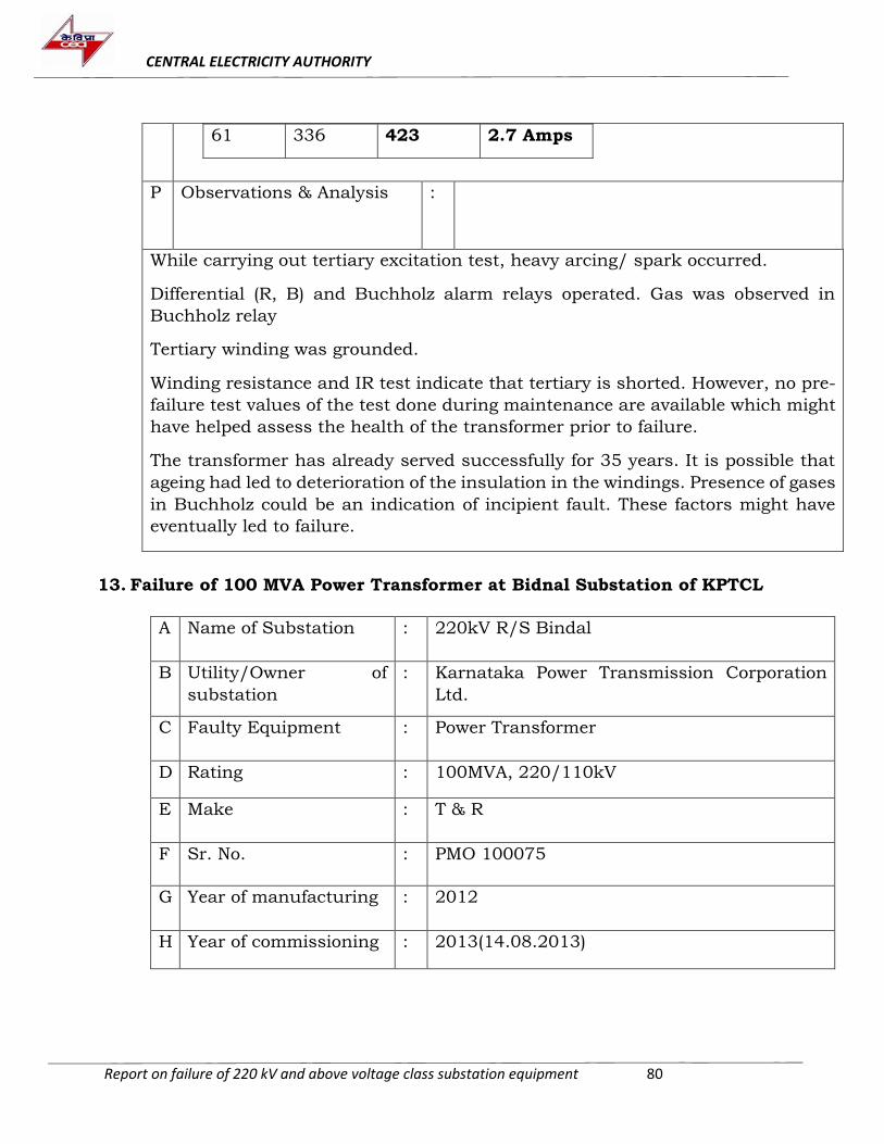
CENTRAL ELECTRICITY AUTHORITY
Report on failure of 220 kV and above voltage class substation equipment 80
61 336 423 2.7 Amps
P Observations & Analysis
:
While carrying out tertiary excitation test, heavy arcing/ spark occurred.
Differential (R, B) and Buchholz alarm relays operated. Gas was observed in
Buchholz relay
Tertiary winding was grounded.
Winding resistance and IR test indicate that tertiary is shorted. However, no pre-
failure test values of the test done during maintenance are available which might
have helped assess the health of the transformer prior to failure.
The transformer has already served successfully for 35 years. It is possible that
ageing had led to deterioration of the insulation in the windings. Presence of gases
in Buchholz could be an indication of incipient fault. These factors might have
eventually led to failure.
13. Failure of 100 MVA Power Transformer at Bidnal Substation of KPTCL
A Name of Substation : 220kV R/S Bindal
B Utility/Owner of
substation
: Karnataka Power Transmission Corporation
Ltd.
C Faulty Equipment : Power Transformer
D Rating : 100MVA, 220/110kV
E Make : T & R
F Sr. No. : PMO 100075
G Year of manufacturing : 2012
H Year of commissioning : 2013(14.08.2013)
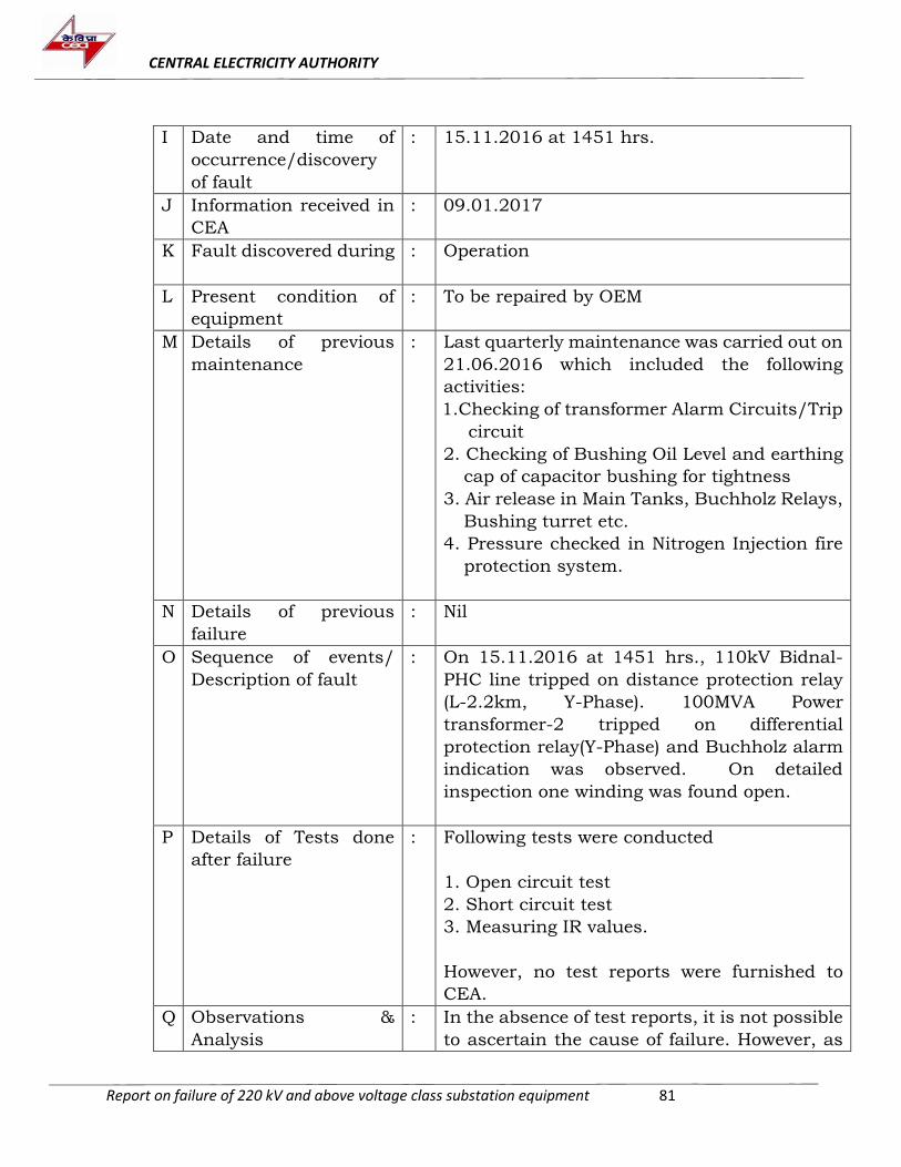
CENTRAL ELECTRICITY AUTHORITY
Report on failure of 220 kV and above voltage class substation equipment 81
I Date and time of
occurrence/discovery
of fault
: 15.11.2016 at 1451 hrs.
J Information received in
CEA
: 09.01.2017
K Fault discovered during : Operation
L Present condition of
equipment
: To be repaired by OEM
M Details of previous
maintenance
: Last quarterly maintenance was carried out on
21.06.2016 which included the following
activities:
1.Checking of transformer Alarm Circuits/Trip
circuit
2. Checking of Bushing Oil Level and earthing
cap of capacitor bushing for tightness
3. Air release in Main Tanks, Buchholz Relays,
Bushing turret etc.
4. Pressure checked in Nitrogen Injection fire
protection system.
N Details of previous
failure
: Nil
O Sequence of events/
Description of fault
: On 15.11.2016 at 1451 hrs., 110kV Bidnal-
PHC line tripped on distance protection relay
(L-2.2km, Y-Phase). 100MVA Power
transformer-2 tripped on differential
protection relay(Y-Phase) and Buchholz alarm
indication was observed. On detailed
inspection one winding was found open.
P Details of Tests done
after failure
: Following tests were conducted
1. Open circuit test
2. Short circuit test
3. Measuring IR values.
However, no test reports were furnished to
CEA.
Q Observations &
Analysis
: In the absence of test reports, it is not possible
to ascertain the cause of failure. However, as
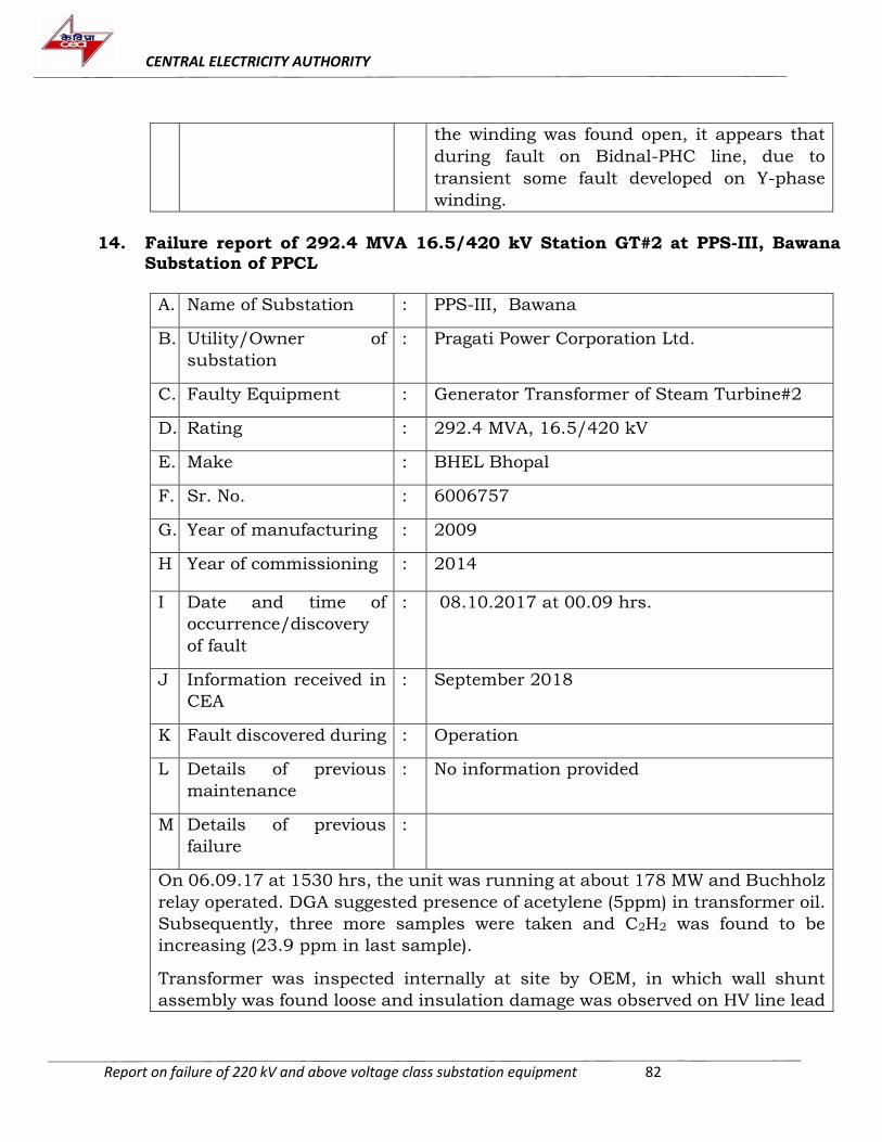
CENTRAL ELECTRICITY AUTHORITY
Report on failure of 220 kV and above voltage class substation equipment 82
the winding was found open, it appears that
during fault on Bidnal-PHC line, due to
transient some fault developed on Y-phase
winding.
14. Failure report of 292.4 MVA 16.5/420 kV Station GT#2 at PPS-III, Bawana Substation of PPCL
A. Name of Substation : PPS-III, Bawana
B. Utility/Owner of
substation
: Pragati Power Corporation Ltd.
C. Faulty Equipment : Generator Transformer of Steam Turbine#2
D. Rating : 292.4 MVA, 16.5/420 kV
E. Make : BHEL Bhopal
F. Sr. No. : 6006757
G. Year of manufacturing : 2009
H Year of commissioning : 2014
I Date and time of
occurrence/discovery
of fault
: 08.10.2017 at 00.09 hrs.
J Information received in
CEA
: September 2018
K Fault discovered during : Operation
L Details of previous
maintenance
: No information provided
M Details of previous
failure
:
On 06.09.17 at 1530 hrs, the unit was running at about 178 MW and Buchholz
relay operated. DGA suggested presence of acetylene (5ppm) in transformer oil.
Subsequently, three more samples were taken and C2H2 was found to be
increasing (23.9 ppm in last sample).
Transformer was inspected internally at site by OEM, in which wall shunt
assembly was found loose and insulation damage was observed on HV line lead
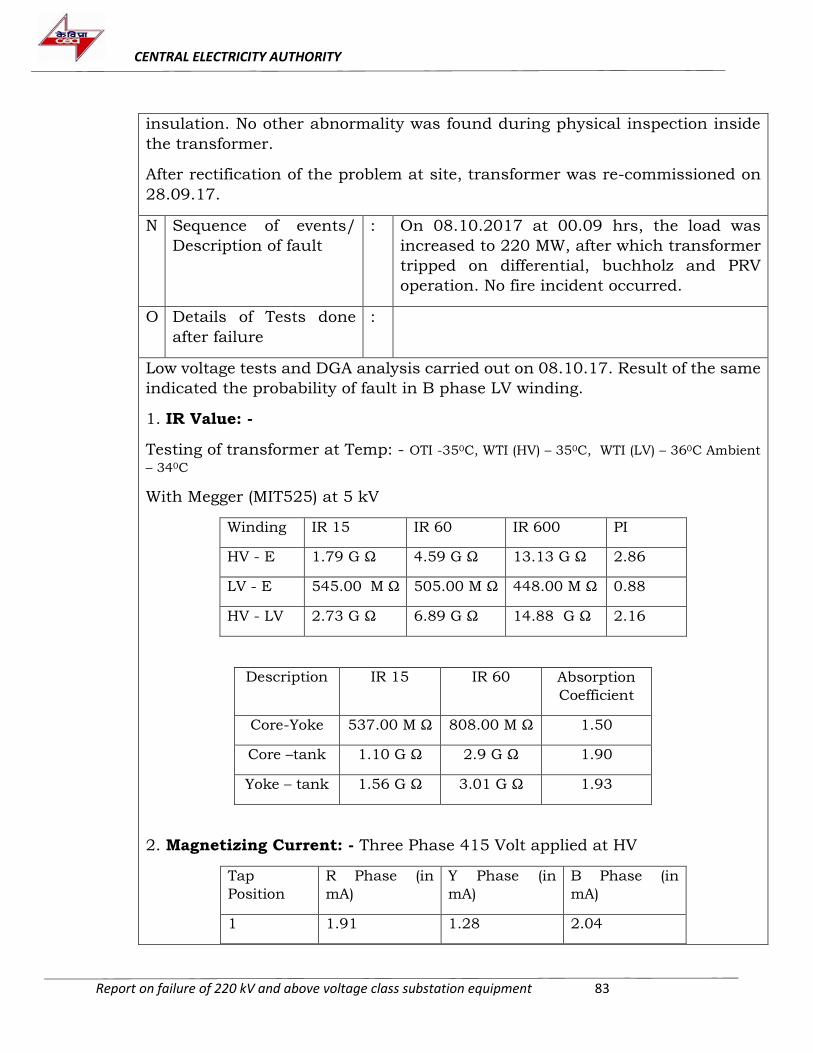
CENTRAL ELECTRICITY AUTHORITY
Report on failure of 220 kV and above voltage class substation equipment 83
insulation. No other abnormality was found during physical inspection inside
the transformer.
After rectification of the problem at site, transformer was re-commissioned on
28.09.17.
N Sequence of events/
Description of fault
: On 08.10.2017 at 00.09 hrs, the load was
increased to 220 MW, after which transformer
tripped on differential, buchholz and PRV
operation. No fire incident occurred.
O Details of Tests done
after failure
:
Low voltage tests and DGA analysis carried out on 08.10.17. Result of the same
indicated the probability of fault in B phase LV winding.
1. IR Value: -
Testing of transformer at Temp: - OTI -350C, WTI (HV) – 350C, WTI (LV) – 360C Ambient
– 340C
With Megger (MIT525) at 5 kV
Winding IR 15 IR 60 IR 600 PI
HV - E 1.79 G Ω 4.59 G Ω 13.13 G Ω 2.86
LV - E 545.00 M Ω 505.00 M Ω 448.00 M Ω 0.88
HV - LV 2.73 G Ω 6.89 G Ω 14.88 G Ω 2.16
Description IR 15 IR 60 Absorption
Coefficient
Core-Yoke 537.00 M Ω 808.00 M Ω 1.50
Core –tank 1.10 G Ω 2.9 G Ω 1.90
Yoke – tank 1.56 G Ω 3.01 G Ω 1.93
2. Magnetizing Current: - Three Phase 415 Volt applied at HV
Tap
Position
R Phase (in
mA)
Y Phase (in
mA)
B Phase (in
mA)
1 1.91 1.28 2.04

CENTRAL ELECTRICITY AUTHORITY
Report on failure of 220 kV and above voltage class substation equipment 84
2 2.30 1.26 2.20
3 2.15 1.36 2.22
4 2.16 1.24 2.20
5 2.12 1.30 2.26
3. Magnetic Balance (HV Side): - Single phase voltage applied at R-N
RN = 251.30 V YN = 128.70 V BN = 7.20 V
Single phase voltage applied at Y-N
RN = 121.60 V YN = 251.10 V BN = 118.20 V
Single phase voltage applied at B-N
RN = 7.00 V YN = 128.20 V BN = 250.60 V
4. Voltage Ratio: -
Tap
No.
Voltage Applied (HV) (in
Volts)
Measured Voltage (LV) (in
Volts)
RY YB BR ry yb br
1 436 435 436 14.5 14.6 15.7
2 436 435 436 14.9 15.3 16.3
3 436 435 436 15.3 15.7 16.8
4 436 435 436 15.8 16.2 17.2
5 436 435 436 16.5 17.1 17.8
5. Winding Resistance: -
HV Side:
Tap Position R - N (in m Ω) Y- N (in m Ω) B – N (in m Ω)
1 462.2 462.6 461.9
2 453.6 454.2 453.1
3 444.9 445.5 444.4
4 436.6 437.4 436.0
5 427.9 428.8 427.2
LV Side: -
r – y (in m Ω) y – b (in m Ω) b – r (in m Ω)
1.51 3.04 1.53
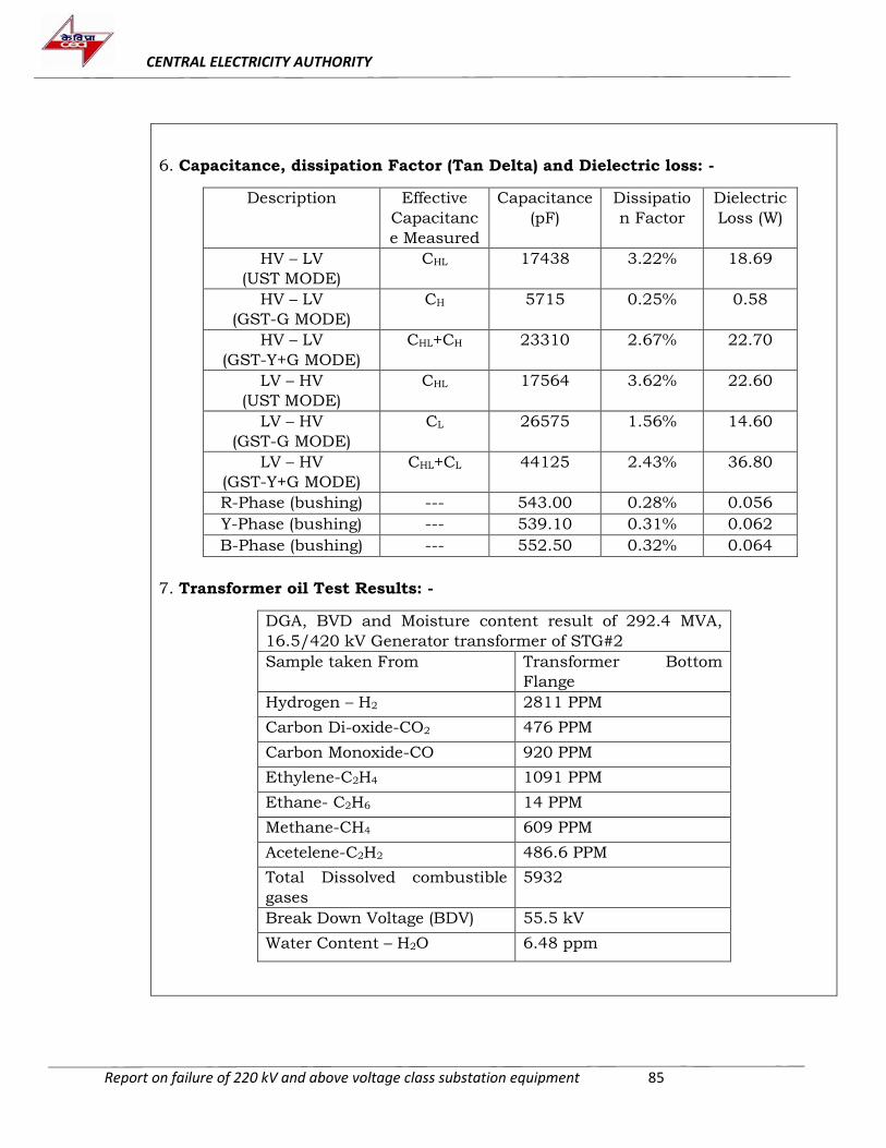
CENTRAL ELECTRICITY AUTHORITY
Report on failure of 220 kV and above voltage class substation equipment 85
6. Capacitance, dissipation Factor (Tan Delta) and Dielectric loss: -
Description Effective
Capacitanc
e Measured
Capacitance
(pF)
Dissipatio
n Factor
Dielectric
Loss (W)
HV – LV
(UST MODE)
CHL 17438 3.22% 18.69
HV – LV
(GST-G MODE)
CH 5715 0.25% 0.58
HV – LV
(GST-Y+G MODE)
CHL+CH 23310 2.67% 22.70
LV – HV
(UST MODE)
CHL 17564 3.62% 22.60
LV – HV
(GST-G MODE)
CL 26575 1.56% 14.60
LV – HV
(GST-Y+G MODE)
CHL+CL 44125 2.43% 36.80
R-Phase (bushing) --- 543.00 0.28% 0.056
Y-Phase (bushing) --- 539.10 0.31% 0.062
B-Phase (bushing) --- 552.50 0.32% 0.064
7. Transformer oil Test Results: -
DGA, BVD and Moisture content result of 292.4 MVA,
16.5/420 kV Generator transformer of STG#2
Sample taken From Transformer Bottom
Flange
Hydrogen – H2 2811 PPM
Carbon Di-oxide-CO2 476 PPM
Carbon Monoxide-CO 920 PPM
Ethylene-C2H4 1091 PPM
Ethane- C2H6 14 PPM
Methane-CH4 609 PPM
Acetelene-C2H2 486.6 PPM
Total Dissolved combustible
gases
5932
Break Down Voltage (BDV) 55.5 kV
Water Content – H2O 6.48 ppm
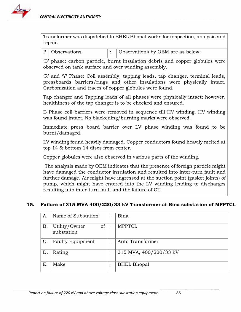
CENTRAL ELECTRICITY AUTHORITY
Report on failure of 220 kV and above voltage class substation equipment 86
Transformer was dispatched to BHEL Bhopal works for inspection, analysis and
repair.
P Observations : Observations by OEM are as below:
‘B’ phase: carbon particle, burnt insulation debris and copper globules were
observed on tank surface and over winding assembly.
‘R’ and ‘Y’ Phase: Coil assembly, tapping leads, tap changer, terminal leads,
pressboards barriers/rings and other insulations were physically intact.
Carbonization and traces of copper globules were found.
Tap changer and Tapping leads of all phases were physically intact; however,
healthiness of the tap changer is to be checked and ensured.
B Phase coil barriers were removed in sequence till HV winding. HV winding
was found intact. No blackening/burning marks were observed.
Immediate press board barrier over LV phase winding was found to be
burnt/damaged.
LV winding found heavily damaged. Copper conductors found heavily melted at
top 14 & bottom 14 discs from center.
Copper globules were also observed in various parts of the winding.
The analysis made by OEM indicates that the presence of foreign particle might
have damaged the conductor insulation and resulted into inter-turn fault and
further damage. Air might have ingressed at the suction point (gasket joints) of
pump, which might have entered into the LV winding leading to discharges
resulting into inter-turn fault and the failure of GT.
15. Failure of 315 MVA 400/220/33 kV Transformer at Bina substation of MPPTCL
A. Name of Substation : Bina
B. Utility/Owner of
substation
: MPPTCL
C. Faulty Equipment : Auto Transformer
D. Rating : 315 MVA, 400/220/33 kV
E. Make : BHEL Bhopal
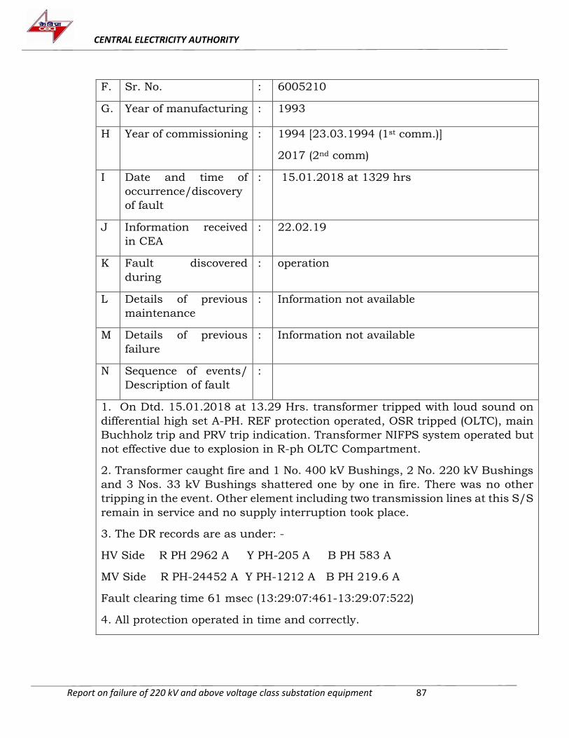
CENTRAL ELECTRICITY AUTHORITY
Report on failure of 220 kV and above voltage class substation equipment 87
F. Sr. No. : 6005210
G. Year of manufacturing : 1993
H Year of commissioning : 1994 [23.03.1994 (1st comm.)]
2017 (2nd comm)
I Date and time of
occurrence/discovery
of fault
: 15.01.2018 at 1329 hrs
J Information received
in CEA
: 22.02.19
K Fault discovered
during
: operation
L Details of previous
maintenance
: Information not available
M Details of previous
failure
: Information not available
N Sequence of events/
Description of fault
:
1. On Dtd. 15.01.2018 at 13.29 Hrs. transformer tripped with loud sound on
differential high set A-PH. REF protection operated, OSR tripped (OLTC), main
Buchholz trip and PRV trip indication. Transformer NIFPS system operated but
not effective due to explosion in R-ph OLTC Compartment.
2. Transformer caught fire and 1 No. 400 kV Bushings, 2 No. 220 kV Bushings
and 3 Nos. 33 kV Bushings shattered one by one in fire. There was no other
tripping in the event. Other element including two transmission lines at this S/S
remain in service and no supply interruption took place.
3. The DR records are as under: -
HV Side R PH 2962 A Y PH-205 A B PH 583 A
MV Side R PH-24452 A Y PH-1212 A B PH 219.6 A
Fault clearing time 61 msec (13:29:07:461-13:29:07:522)
4. All protection operated in time and correctly.
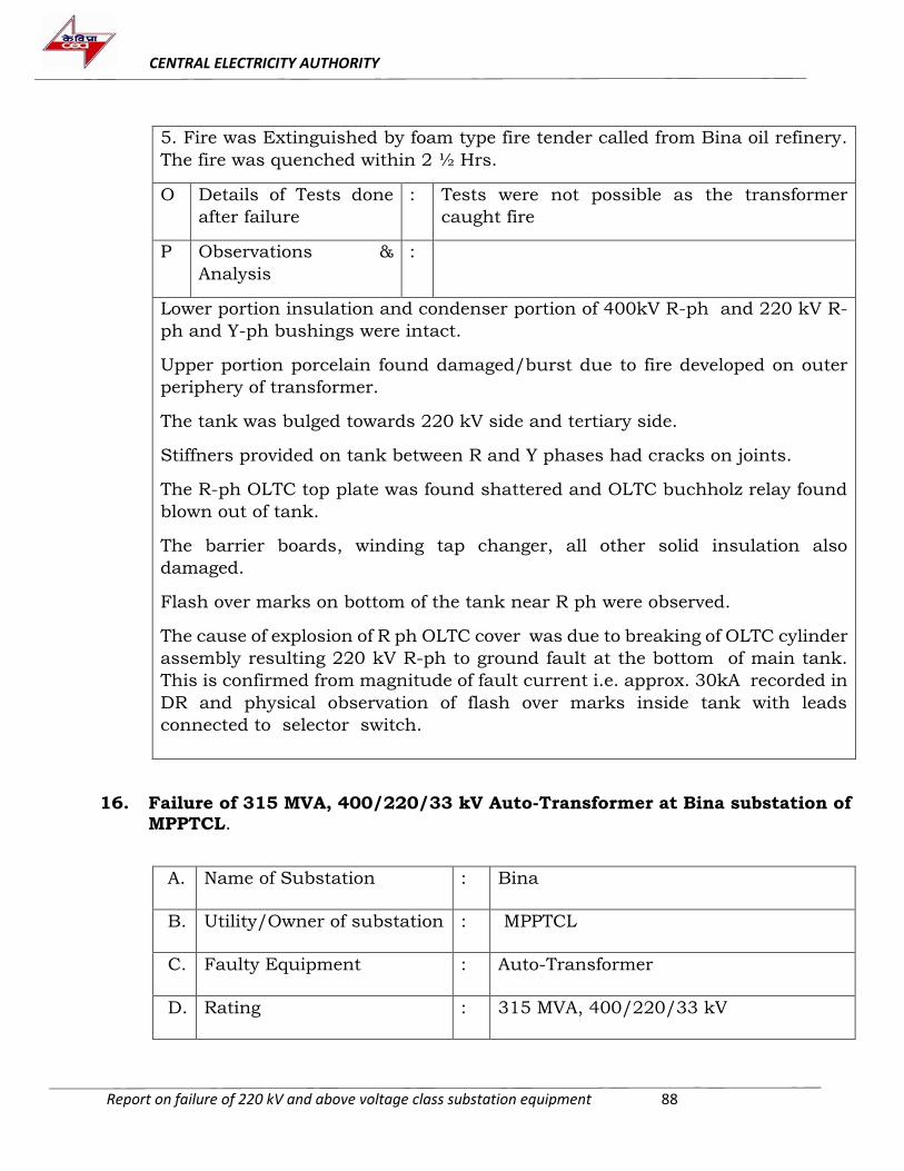
CENTRAL ELECTRICITY AUTHORITY
Report on failure of 220 kV and above voltage class substation equipment 88
5. Fire was Extinguished by foam type fire tender called from Bina oil refinery.
The fire was quenched within 2 ½ Hrs.
O Details of Tests done
after failure
: Tests were not possible as the transformer
caught fire
P Observations &
Analysis
:
Lower portion insulation and condenser portion of 400kV R-ph and 220 kV R-
ph and Y-ph bushings were intact.
Upper portion porcelain found damaged/burst due to fire developed on outer
periphery of transformer.
The tank was bulged towards 220 kV side and tertiary side.
Stiffners provided on tank between R and Y phases had cracks on joints.
The R-ph OLTC top plate was found shattered and OLTC buchholz relay found
blown out of tank.
The barrier boards, winding tap changer, all other solid insulation also
damaged.
Flash over marks on bottom of the tank near R ph were observed.
The cause of explosion of R ph OLTC cover was due to breaking of OLTC cylinder
assembly resulting 220 kV R-ph to ground fault at the bottom of main tank.
This is confirmed from magnitude of fault current i.e. approx. 30kA recorded in
DR and physical observation of flash over marks inside tank with leads
connected to selector switch.
16. Failure of 315 MVA, 400/220/33 kV Auto-Transformer at Bina substation of MPPTCL.
A. Name of Substation
: Bina
B. Utility/Owner of substation
: MPPTCL
C. Faulty Equipment
: Auto-Transformer
D. Rating
: 315 MVA, 400/220/33 kV
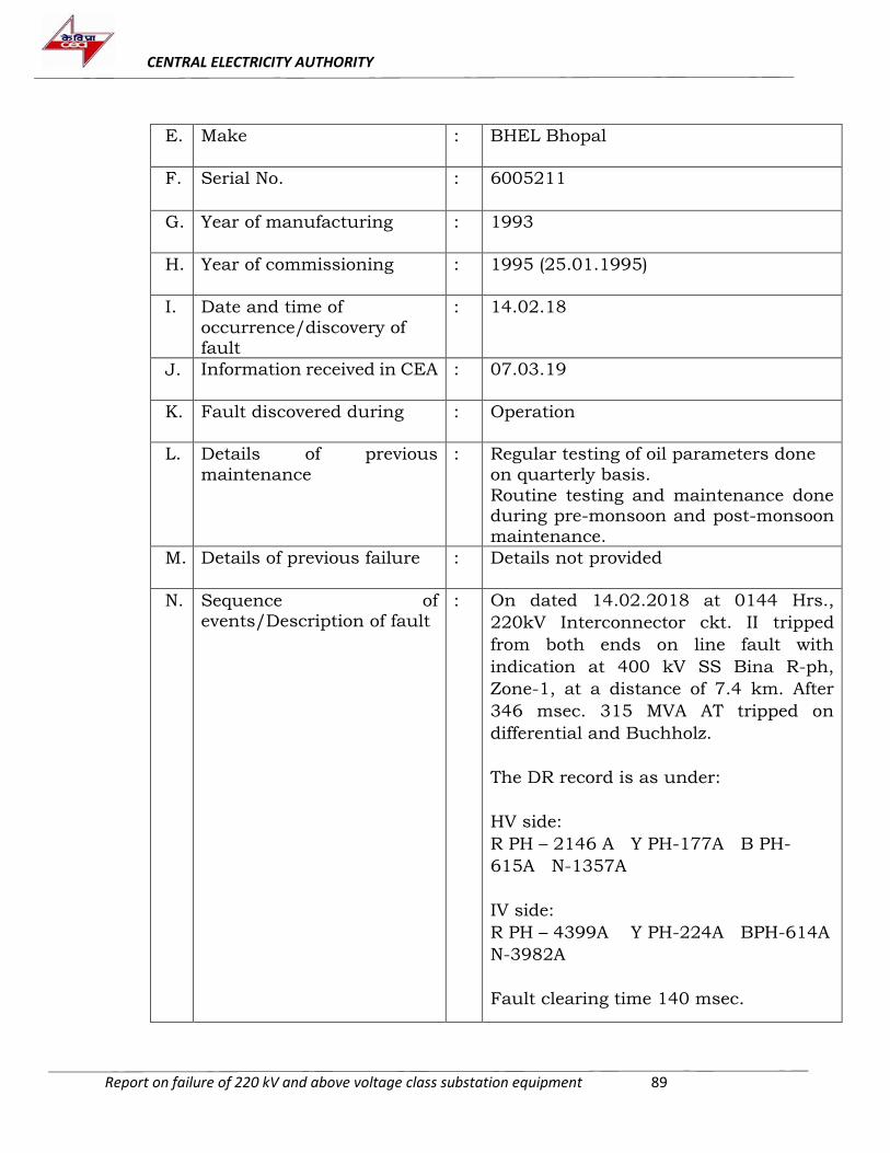
CENTRAL ELECTRICITY AUTHORITY
Report on failure of 220 kV and above voltage class substation equipment 89
E. Make
: BHEL Bhopal
F. Serial No.
: 6005211
G. Year of manufacturing
: 1993
H. Year of commissioning
: 1995 (25.01.1995)
I. Date and time of
occurrence/discovery of fault
: 14.02.18
J. Information received in CEA : 07.03.19
K. Fault discovered during : Operation
L. Details of previous
maintenance
: Regular testing of oil parameters done
on quarterly basis.
Routine testing and maintenance done during pre-monsoon and post-monsoon
maintenance.
M. Details of previous failure
: Details not provided
N. Sequence of events/Description of fault
: On dated 14.02.2018 at 0144 Hrs.,
220kV Interconnector ckt. II tripped
from both ends on line fault with
indication at 400 kV SS Bina R-ph,
Zone-1, at a distance of 7.4 km. After
346 msec. 315 MVA AT tripped on
differential and Buchholz.
The DR record is as under:
HV side:
R PH – 2146 A Y PH-177A B PH-
615A N-1357A
IV side:
R PH – 4399A Y PH-224A BPH-614A
N-3982A
Fault clearing time 140 msec.
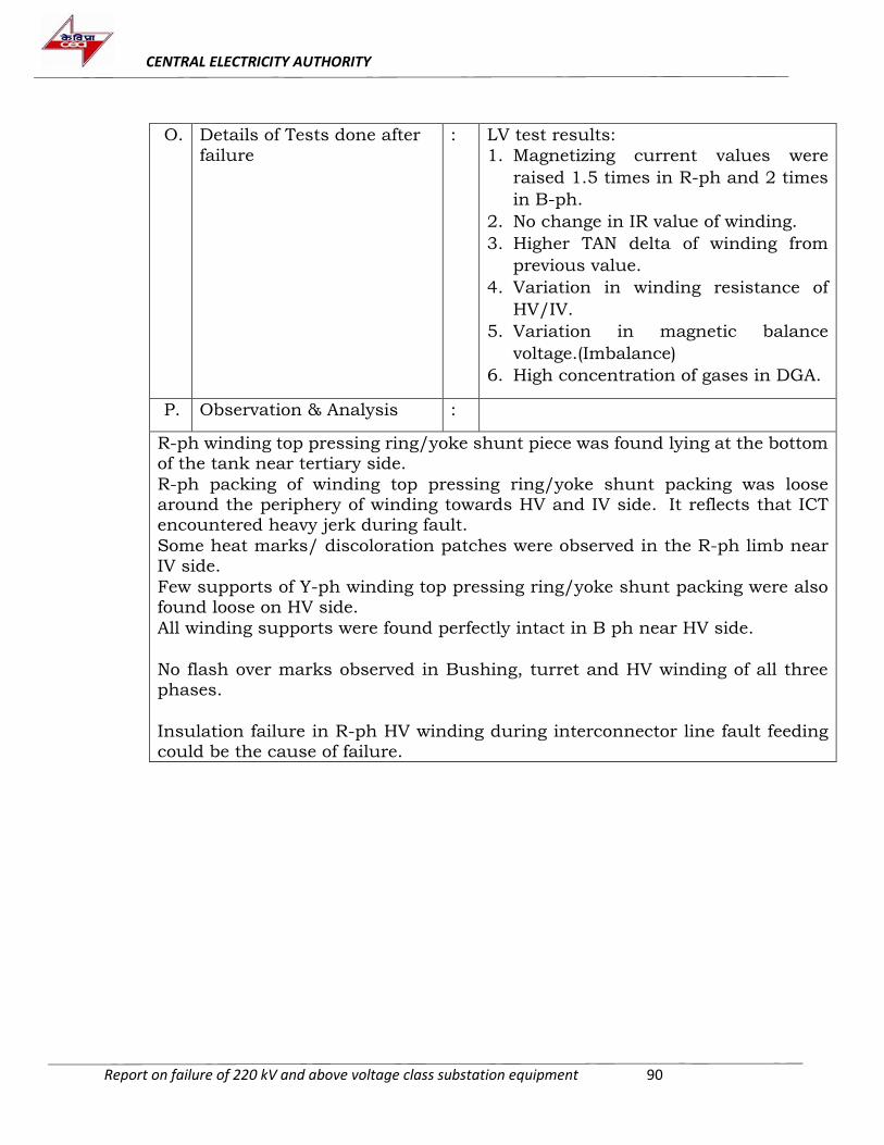
CENTRAL ELECTRICITY AUTHORITY
Report on failure of 220 kV and above voltage class substation equipment 90
O. Details of Tests done after
failure
: LV test results:
1. Magnetizing current values were
raised 1.5 times in R-ph and 2 times
in B-ph.
2. No change in IR value of winding.
3. Higher TAN delta of winding from
previous value.
4. Variation in winding resistance of
HV/IV.
5. Variation in magnetic balance
voltage.(Imbalance)
6. High concentration of gases in DGA.
P. Observation & Analysis :
R-ph winding top pressing ring/yoke shunt piece was found lying at the bottom of the tank near tertiary side.
R-ph packing of winding top pressing ring/yoke shunt packing was loose around the periphery of winding towards HV and IV side. It reflects that ICT encountered heavy jerk during fault.
Some heat marks/ discoloration patches were observed in the R-ph limb near IV side.
Few supports of Y-ph winding top pressing ring/yoke shunt packing were also found loose on HV side.
All winding supports were found perfectly intact in B ph near HV side.
No flash over marks observed in Bushing, turret and HV winding of all three phases.
Insulation failure in R-ph HV winding during interconnector line fault feeding could be the cause of failure.
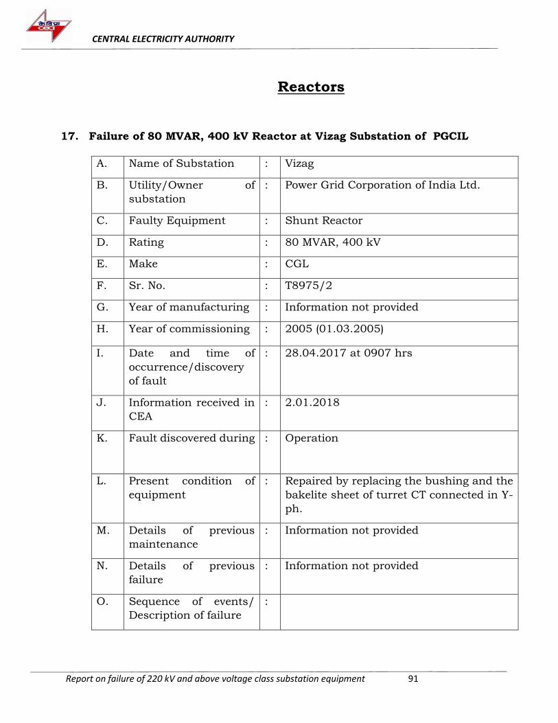
CENTRAL ELECTRICITY AUTHORITY
Report on failure of 220 kV and above voltage class substation equipment 91
Reactors
17. Failure of 80 MVAR, 400 kV Reactor at Vizag Substation of PGCIL
A. Name of Substation : Vizag
B. Utility/Owner of
substation
: Power Grid Corporation of India Ltd.
C. Faulty Equipment : Shunt Reactor
D. Rating : 80 MVAR, 400 kV
E. Make : CGL
F. Sr. No. : T8975/2
G. Year of manufacturing : Information not provided
H. Year of commissioning : 2005 (01.03.2005)
I. Date and time of
occurrence/discovery
of fault
: 28.04.2017 at 0907 hrs
J. Information received in
CEA
: 2.01.2018
K. Fault discovered during : Operation
L. Present condition of
equipment
: Repaired by replacing the bushing and the
bakelite sheet of turret CT connected in Y-
ph.
M. Details of previous
maintenance
: Information not provided
N. Details of previous
failure
: Information not provided
O. Sequence of events/
Description of failure
:
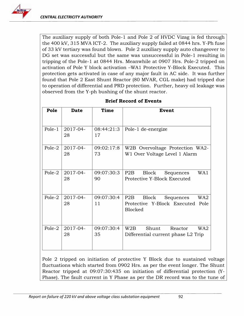
CENTRAL ELECTRICITY AUTHORITY
Report on failure of 220 kV and above voltage class substation equipment 92
The auxiliary supply of both Pole-1 and Pole 2 of HVDC Vizag is fed through
the 400 kV, 315 MVA ICT-2. The auxiliary supply failed at 0844 hrs. Y-Ph fuse
of 33 kV tertiary was found blown. Pole 2 auxiliary supply auto changeover to
DG set was successful but the same was unsuccessful in Pole-1 resulting in
tripping of the Pole-1 at 0844 Hrs. Meanwhile at 0907 Hrs. Pole-2 tripped on
activation of Pole Y block activation –WA1 Protective Y-Block Executed. This
protection gets activated in case of any major fault in AC side. It was further
found that Pole 2 East Shunt Reactor (80 MVAR, CGL make) had tripped due
to operation of differential and PRD protection. Further, heavy oil leakage was
observed from the Y-ph bushing of the shunt reactor.
Brief Record of Events
Pole Date Time Event
Pole-1 2017-04-
28
08:44:21:3
17
Pole-1 de-energize
Pole-2 2017-04-
28
09:02:17:8
73
W2B Overvoltage Protection WA2-
W1 Over Voltage Level 1 Alarm
Pole-2 2017-04-
28
09:07:30:3
90
P2B Block Sequences WA1
Protective Y-Block Executed
Pole-2 2017-04-
28
09:07:30:4
11
P2B Block Sequences WA2
Protective Y-Block Executed Pole
Blocked
Pole-2 2017-04-
28
09:07:30:4
35
W2B Shunt Reactor WA2
Differential current phase L2 Trip
Pole 2 tripped on initiation of protective Y Block due to sustained voltage
fluctuations which started from 0902 Hrs. as per the event longer. The Shunt
Reactor tripped at 09:07:30:435 on initiation of differential protection (Y-
Phase). The fault current in Y Phase as per the DR record was to the tune of
CENTRAL ELECTRICITY AUTHORITY
Report on failure of 220 kV and above voltage class substation equipment 93
785 A and the voltage went upto 626.46 kV during the same instance.
Continuous overvoltage had been observed along with dominant presence of
second harmonics prior to failure.
P. Details of Tests done
after failure
:
Magnetizing Current measurements and winding resistance measurements
were carried out.
Magnetizing Current Readings Winding Resistance Measurement
R-ph Y-ph B-ph R-ph Y-ph B-ph
120.7 mA 120 mA 120.3 mA 2.233 Ω 2.232 Ω 2.232 Ω
The test results were found to be normal. Subsequently, DGA of the reactor oil sample was carried out to look for any fault generation in the reactor.
DGA:
S.no.
Date H2 CH4 C2H6 C2H4 C2H2 CO CO2
1 28.4.17 53 19 4 20 6.4 300 3671
2 18.4.17 27 18 5 18 0.9 375 3904
3 27.2.17 7 3 12 2 0.4 231 1911
4 06.12.16
24 7 0 7 0 315 4539
No significant gases were generated post failure. The rise in acetylene may be attributed to broken insulator from the bushing.
Also, no abnormalities were observed in core/winding during internal inspection.
Q. Observations &
Analysis
:
(i) Porcelain Insulator was found to be detached from the middle of the Y-
Phases Bushing of the reactor and scattered near the ground. Oil was also observed to be flowing out of the inspection cover at the bottom of the turret. The inspection turret was deformed and had attained concave shape facing
inwards. (ii) Cracks were observed on the metal flange joints.
CENTRAL ELECTRICITY AUTHORITY
Report on failure of 220 kV and above voltage class substation equipment 94
(iii) No flashover marks on paper insulation
(iv) Single point flashover mark on the inside body of the turret. (v) Corona shield also contained flashover marks and was found to be
damaged with broken connecting points (vi) Oil end porcelain dome of Y-ph bushing was broken and was found
scattered on the bottom inside the Reactor main tank
(vii) REF did not operate during the tripping (viii) Dominant 2nd harmonics were present in the system prior to fault.
Higher second harmonic component in the Eastern bus may have caused
vibration in the reactor resulting in the stress in the bushing. Due to high stress, it is likely that flashover occurred between turret body and corona
shield leading to shattering of oil end insulator. Consequently, high pressure developed leading to loosening of terminal connector and leakage of oil. Due to the vibrations caused by the development of high stress, cracks appeared
in metal flange and insulator pieces from the middle section broke off at the joints.
18. Failure of 16.67 MVAR, 400KV Bhiwadi-I R-ph Line Reactor at Agra S/s of
PGCIL
A Name of Substation : Agra
B Utility/Owner of
substation
: PGCIL
C Faulty Equipment : Line Reactor
D Rating : 16.67 MVAR, 400 kV
E Make : Crompton Greaves limited
F Sr. No. : T8353/1
G Year of manufacturing : Information not available
H Year of commissioning : 2005 (01.03.2005)
I Date and time of
occurrence/discovery
of fault
: 22.05.2017 at 01:27 hrs
J Information received in
CEA
: 02.01.2018
K Fault discovered during : Operation
CENTRAL ELECTRICITY AUTHORITY
Report on failure of 220 kV and above voltage class substation equipment 95
L Present condition of
equipment
: Repaired by replacing the bushing
M Details of previous
maintenance
:
Tan delta and capacitance test results:
Cap
(pF)
TD
(%)
Diff
Cap
(pF)
TD
(%)
Diff
Cap
(pF)
TD
(%)
Diff
Cap
(pF)
TD
(%)
Diff
17.08.2016 13.07.2015 07.04.2015 05.04.2014
500.4 0.377 0.02
2
502 0.35
5
0.022 500.
6
0.33
3
0.01
7
499.
4
0.31
6
0.07
1
387.7 0.371 0.02
6
384.2 0.34
5
-0.07 382.
5
0.41
5
0.04
7
382.
6
0.36
8
0.03
5
DGA was also carried out regularly during maintenance and results are
indicated in subsequent para.
N Details of previous
failure
: Information Not Available
O Sequence of events/
Description of failure
:
The Agra–Bhiwadi-I Line tripped at 01:27 Hrs. on 22.05.2017 on single phase
fault on R-N at 15.7 km (Main 1) from Agra End with failure of bushing. During
failure, fault current of 35.78 kA was recorded to have flown through the
reactor. Following protection operated:
01:27:24.977 Main 1(D60)-gnd dist Z1 optd
01:27:24.984 Main2- zone 4 pickup
01:27:25.016 Main2- zone 1 optd
01:27:25.029 R-ph main and tie CB open
01:27:25.047 Y-ph and B ph Main and tie CB open
P Details of Tests done
after failure
:
IR Value: 85 GΩ
Magnetizing Current: 69.6 mA
Winding Resistance: 3.63 Ω
CENTRAL ELECTRICITY AUTHORITY
Report on failure of 220 kV and above voltage class substation equipment 96
DGA :
No significant gases were generated post failure. The rise in acetylene may be
attributed to consequential damage.
S.no.
Date H2 CH4 C2H6 C2H4 C2H2 CO CO2
1 29.5.17 643 283 290 26 327 367 2533
2 21.11.16
11 11 2 5 0 122 1157
3 31.5.16 12 8 2 4 0 109 1100
4 17.5.16 13 9 2 5 0 110 1087
Q Observations &
Analysis
:
The bushing of the Agra-Bhiwadi 1 LR was charred from the top and
subsequently caught fire. The burning oil falling from the bushing damaged
the nearby cables and Marshaling Box. However, recording instruments were
found to be in working order.
Outer sheath of the cable from reactor to MB box was found burnt and MB was
damaged.
No abnormalities were found in the core/ windings during internal inspection.
Charred paper and broken pieces of oil end insulator were found in the bottom
of the tank.
Puncture mark observed in the metal rod of the bushing above the first
aluminium insulation, at a distance of 1.63 m from the bottom of the expansion
chamber just beneath the first porcelain joint.
Metal flange was also found to be burnt at the bottom of the bushing with partial
melting of the flange and signs of sparking present.
Bushing was 31 years old and it appears that due to ageing its insulation got
weak over time. It is likely that during fault on Agra-Bhiwadi line, bushing
insulation could not withstand high stress and internal flashover occurred
below the top porcelain joint of the bushing (weakest mechanical part of the
bushing). Fire developed in the bushing oil and the insulation paper was
completely charred. The spark travelled to the bottom flange (providing ground
point to the current) causing its partial melt on the sides.
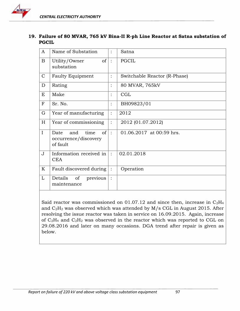
CENTRAL ELECTRICITY AUTHORITY
Report on failure of 220 kV and above voltage class substation equipment 97
19. Failure of 80 MVAR, 765 kV Bina-II R-ph Line Reactor at Satna substation of
PGCIL
A Name of Substation : Satna
B Utility/Owner of
substation
: PGCIL
C Faulty Equipment : Switchable Reactor (R-Phase)
D Rating : 80 MVAR, 765kV
E Make : CGL
F Sr. No. : BH09823/01
G Year of manufacturing : 2012
H Year of commissioning : 2012 (01.07.2012)
I Date and time of
occurrence/discovery
of fault
: 01.06.2017 at 00:59 hrs.
J Information received in
CEA
: 02.01.2018
K Fault discovered during : Operation
L Details of previous
maintenance
:
Said reactor was commissioned on 01.07.12 and since then, increase in C2H4
and C2H2 was observed which was attended by M/s CGL in August 2015. After
resolving the issue reactor was taken in service on 16.09.2015. Again, increase
of C2H4 and C2H2 was observed in the reactor which was reported to CGL on
29.08.2016 and later on many occasions. DGA trend after repair is given as
below.
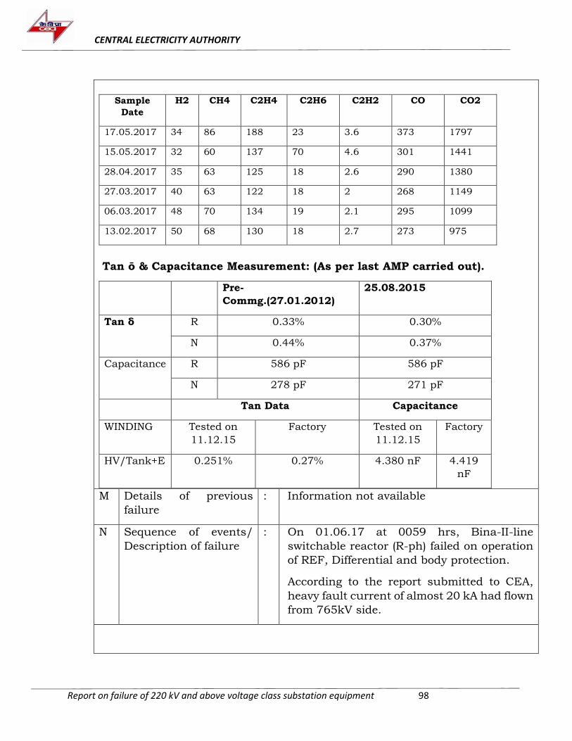
CENTRAL ELECTRICITY AUTHORITY
Report on failure of 220 kV and above voltage class substation equipment 98
Sample
Date
H2 CH4 C2H4 C2H6 C2H2 CO CO2
17.05.2017 34 86 188 23 3.6 373 1797
15.05.2017 32 60 137 70 4.6 301 1441
28.04.2017 35 63 125 18 2.6 290 1380
27.03.2017 40 63 122 18 2 268 1149
06.03.2017 48 70 134 19 2.1 295 1099
13.02.2017 50 68 130 18 2.7 273 975
Tan ō & Capacitance Measurement: (As per last AMP carried out).
Pre-
Commg.(27.01.2012)
25.08.2015
Tan δ R 0.33% 0.30%
N 0.44% 0.37%
Capacitance R 586 pF 586 pF
N 278 pF 271 pF
Tan Data Capacitance
WINDING Tested on
11.12.15
Factory Tested on
11.12.15
Factory
HV/Tank+E 0.251% 0.27% 4.380 nF 4.419
nF
M Details of previous
failure
: Information not available
N Sequence of events/
Description of failure
: On 01.06.17 at 0059 hrs, Bina-II-line
switchable reactor (R-ph) failed on operation
of REF, Differential and body protection.
According to the report submitted to CEA,
heavy fault current of almost 20 kA had flown
from 765kV side.
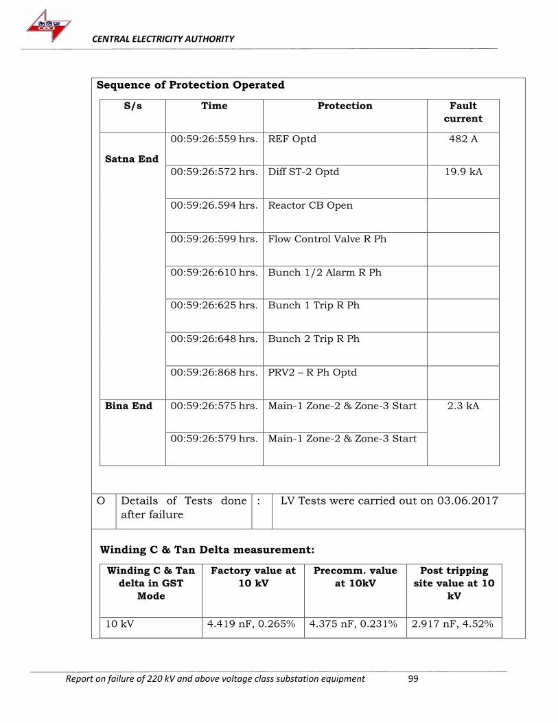
CENTRAL ELECTRICITY AUTHORITY
Report on failure of 220 kV and above voltage class substation equipment 99
Sequence of Protection Operated
S/s Time Protection Fault
current
Satna End
00:59:26:559 hrs. REF Optd 482 A
00:59:26:572 hrs. Diff ST-2 Optd 19.9 kA
00:59:26.594 hrs. Reactor CB Open
00:59:26:599 hrs. Flow Control Valve R Ph
00:59:26:610 hrs. Bunch 1/2 Alarm R Ph
00:59:26:625 hrs. Bunch 1 Trip R Ph
00:59:26:648 hrs. Bunch 2 Trip R Ph
00:59:26:868 hrs. PRV2 – R Ph Optd
Bina End 00:59:26:575 hrs. Main-1 Zone-2 & Zone-3 Start 2.3 kA
00:59:26:579 hrs. Main-1 Zone-2 & Zone-3 Start
O Details of Tests done
after failure
: LV Tests were carried out on 03.06.2017
Winding C & Tan Delta measurement:
Winding C & Tan
delta in GST
Mode
Factory value at
10 kV
Precomm. value
at 10kV
Post tripping
site value at 10
kV
10 kV 4.419 nF, 0.265% 4.375 nF, 0.231% 2.917 nF, 4.52%
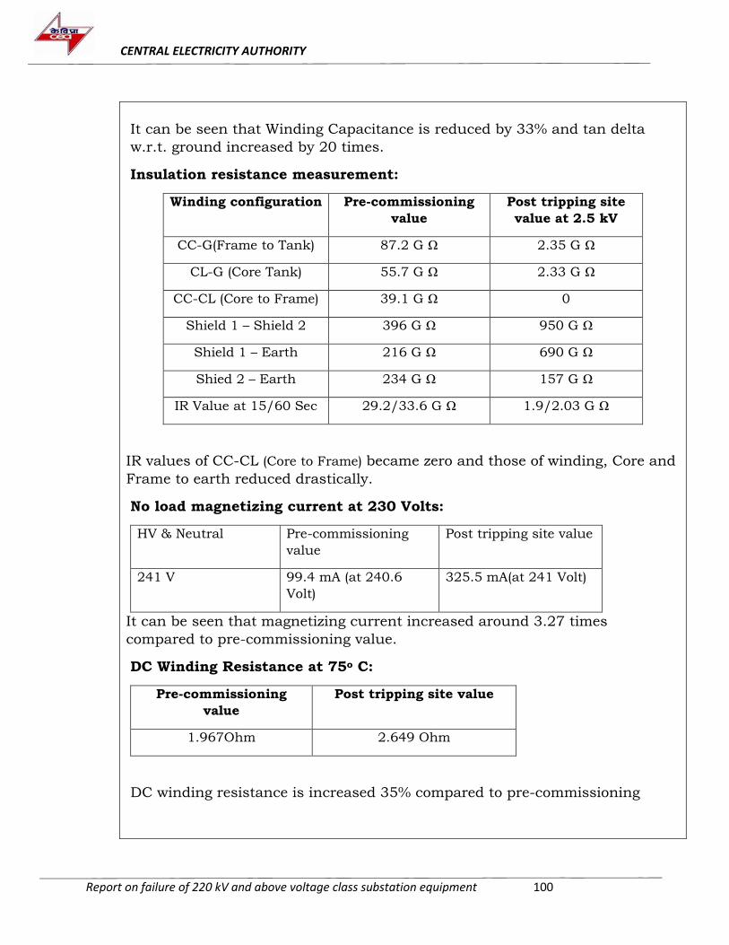
CENTRAL ELECTRICITY AUTHORITY
Report on failure of 220 kV and above voltage class substation equipment 100
It can be seen that Winding Capacitance is reduced by 33% and tan delta
w.r.t. ground increased by 20 times.
Insulation resistance measurement:
Winding configuration Pre-commissioning
value
Post tripping site
value at 2.5 kV
CC-G(Frame to Tank) 87.2 G Ω 2.35 G Ω
CL-G (Core Tank) 55.7 G Ω 2.33 G Ω
CC-CL (Core to Frame) 39.1 G Ω 0
Shield 1 – Shield 2 396 G Ω 950 G Ω
Shield 1 – Earth 216 G Ω 690 G Ω
Shied 2 – Earth 234 G Ω 157 G Ω
IR Value at 15/60 Sec 29.2/33.6 G Ω 1.9/2.03 G Ω
IR values of CC-CL (Core to Frame) became zero and those of winding, Core and
Frame to earth reduced drastically.
No load magnetizing current at 230 Volts:
HV & Neutral Pre-commissioning
value
Post tripping site value
241 V 99.4 mA (at 240.6
Volt)
325.5 mA(at 241 Volt)
It can be seen that magnetizing current increased around 3.27 times
compared to pre-commissioning value.
DC Winding Resistance at 75o C:
Pre-commissioning
value
Post tripping site value
1.967Ohm 2.649 Ohm
DC winding resistance is increased 35% compared to pre-commissioning
CENTRAL ELECTRICITY AUTHORITY
Report on failure of 220 kV and above voltage class substation equipment 101
P Observations &
Analysis
:
On physical inspection, following observations were made :
(i) Tank was heavily bulged towards HV side damaging the MB. Stiffeners were
found cracked and oil came out from the reactor.
(ii) HV Bushing flange & cement joint was found broken, oil level in bushing
was below minimum
(iii) Neutral bushing porcelain found displaced at bottom side.
(iv) Reactor bottom welding at jacking pad found broken on all side which
shows reactor displacement.
(v) Consequential damage was also observed in radiator.
(vi) 132 kV Neutral SA failed, Earth lead of SA got removed from its bottom
stack & its counter was found blasted.
Internal Inspection:
Internal inspection was carried out jointly by CGL and PGCIL and following
observations were made:
(i) Most of the pressboard barriers found badly broken and burnt.
(ii) The winding insulation components viz., washers and caps were found to
be dislocated.
(iii) Winding near HV bushing lead area was damaged and the insulation over
winding was also damaged badly. The bare copper was visible in the HV
lead area. Similarly, copper was also visible in the top part of winding near
Neutral.
(iv) Heavy charring of insulation was found inside.
(v) No oil was left inside tank.
From the DR details it was observed that heavy fault current of almost 20 kA
flown from 765 kV side. The Reactor tripped on REF, differential and Body
protections. Also, winding tan delta increased almost 20 times and core to frame
insulation failed.
It appears that there was an internal flashover between top portions of HV side
and neutral side winding, short circuiting the reactor impedance altogether.
Heavy internal pressure was generated due to high fault current leading to the
heavy bulging of reactor.
NGR SA failure may be due to neutral voltage rise during heavy fault current
(Vn=680 kV at the time of tripping).
CENTRAL ELECTRICITY AUTHORITY
Report on failure of 220 kV and above voltage class substation equipment 102
20. Failure report 80 MVAR, 420 kV Patna-1 Line Reactor at Kishenganj s/s of
PGCIL
A. Name of Substation : Kishenganj
B. Utility/Owner of
substation
: PGCIL
C. Faulty Equipment : Patna -1 line Reactor (Switchable)
D. Rating : 80 MVAR, 420 kV
E. Make : CGL
F. Sr. No. : T10416/1
G. Year of manufacturing : 2014
H Year of commissioning : 2016 (14.03.2016)
I Date and time of
occurrence/discovery of
fault
: 01.09.2017 at 11:03 hrs
J Information received in
CEA
: 31.07.18
K Fault discovered during : Operation
L Details of previous
maintenance
: Information not provided
M Details of previous
failure
: Information not provided
N Sequence of events/
Description of fault
:
Prior to the failure, system was in normal condition and all lines (New Siliguri-
1&2, New Purea-1&2 and patna-1&2) were in service and charged at 400 kV
level. The weather was clear and there was a load of 120 MW each on
Kishenganj-patna lines. The Bus voltage was 413 kV.
It was found that the reactor had tripped three times in August 2017 due to
“NGR Buchholz operation”. It was informed that the alarm was disregarded as
maloperation and was not investigated properly. On 01.09.2017 too, there was
a tripping on the same alarm at 08:19 hrs. and the reactor was taken in service
CENTRAL ELECTRICITY AUTHORITY
Report on failure of 220 kV and above voltage class substation equipment 103
at 08:25 hrs. The reactor again tripped again at 11:02 hrs. on the same alarm
and was again taken back in service at 11:03:36. Immediately after being taken
in service, a loud sound was heard in the control room and surrounding area
and Patna-1 Line Reactor tripped along with the line. Upon investigation by the
operation staff, it was found that the line reactor had tripped on REF, Buchholz
and PRD operation.
At the same time, the Main-1 protection also detected the fault in Zone-1 and
extended a single phase tripping to Y phase Main & Tie CBs & sent carrier to
remote end. Due to the priority scheme in the Auto Reclose, Tie CB closed after
2 seconds but the main CB did not reclose causing the remaining two poles to
trip on Pole Discrepancy. However, direct trip was received immediately from
remote end causing the line to trip again.
Sequence of operation of protection devices is as below:
11:03:36:950 Reactor REF protection operated
11:03:36:950 Reactor PRV operated
11:03:37:000 Tie CB (417) Y Phase opened
11:03:37:003 Reactor Switchable CB (415) opened
11:03:37:005 Reactor Buchholz protection operated
11:03:37:006 Main CB (416) Y Phase opened
11:03:39:088 Tie CB (417) Y Phase closed
11:03:39:647 Main CB (416) R&B Phase opened
11:03:40:261 Direct Trip received and Tie CB (417) tripped
The various parameters during the incidence were as shown:
Signal Pre-fault values Fault values
Ia 110 A 406 A
Ib 223 A 15 kA
Ic 110 A 655 A
Va-n 276 kV 276 kV
Vb-n 272 kV 4.8 kV
Vc-n 274 kV 273 kV
CENTRAL ELECTRICITY AUTHORITY
Report on failure of 220 kV and above voltage class substation equipment 104
O Details of Tests done
after failure
:
Initial Test Results of the Reactor:
Pre-commissioning
Values
Last Testing (10.05.17) After Failure (04.09.17)
Magnetizing Current
R-N: 16.22 mA
Y-N: 16.33 mA
B-N: 17.27 mA
IR Value
HV-E: 9.40 GΩ (600 sec)
Winding Resistance
R-N: 1.6071 Ω
Y-N: 1.6118 Ω
B:N 1.6025 Ω
IR Value
HV-E:9.50 GΩ
Tan delta of Bushing
R ph: 0.3018%/533 pF
Y ph: 0.2646%/533.38
pF
B ph: 0.2484%/534.41
pF
Magnetizing Current
R-N: 110.61 mA
Y-N: 290.23 mA
B-N: 111.10 mA
IR Value
HV-E: Zero
Winding Resistance
R-N: 1.67 Ω
Y-N: 1.78 Ω
B-N:1.65 Ω
DGA Result of the reactor:
Date H2 CH4 C2H
6
C2H
4
C2H
2
CO CO
2
02.9.17
(Post Failure)
450
2
210
7
206 2330 1706 968 475
20.7.17 15 13 3 21 0 202 584
20.4.17 10 4 0 0 0 101 166
9.12.16 8 3 0 0 0 68 157
4. There is a strong indication of a fault in paper, either a hot spot or electrical
arcing.
CENTRAL ELECTRICITY AUTHORITY
Report on failure of 220 kV and above voltage class substation equipment 105
P Observations & Analysis :
There was no visual damage to the bushings of the reactor. The main tank was
intact and there was no bulging or any physical damage. Both the PRDs had
operated and oil had discharged. CC-CL Earthing link on top of the reactor was
found damaged.
There was a sudden rise of gases on failure causing the PRD/Buchholz to
operate. The tripping signals also indicate a rapid development of fault inside
the reactor. Consequently, internal inspection was carried out of the reactor in
the presence of the representative of CGL, Mumbai and the findings as shared
by the utility are as follows:
1. The HV Lead exits of R&B phase were found intact but the insulation around
the Y phase was found damaged.
2. Black residue was found at the bottom of the tank and at many places inside
the reactor. The preliminary investigation indicates that there has been a
flashover from the Y phase HV side to the core. The burn marks could not be
verified in core at site however there is a strong possibility of an inter-turn fault
in the reactor.
3. The Y-phase winding was subjected to fault, wherein the insulation of winding
was adversely affected due to same.
4. As per DGA Report dated 26 July 2017, the ratio of CO2/CO was less than 3.
5. The reactor was in idle condition during 26.07.2016 to 03.04.2017, while re-
commissioning.
The probable reason for failure may be failure of HV insulation around Y-phase
winding causing flashover to core. The exact cause could only be ascertained
only after detailed internal inspection at works.
21. Failure of 80 MVAR, 765 kV B-Phase Line Reactor at Varanasi s/s of PGCIL
A. Name of Substation : Varanasi
B. Utility/Owner of
substation
: PGCIL
C. Faulty Equipment : Kanpur-2 Line Reactor (B Phase)
D. Rating : 80 MVAR, 765 kV
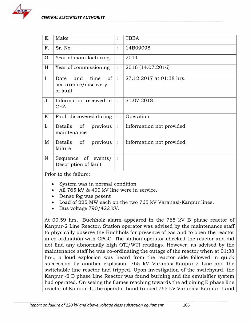
CENTRAL ELECTRICITY AUTHORITY
Report on failure of 220 kV and above voltage class substation equipment 106
E. Make : TBEA
F. Sr. No. : 14B09098
G. Year of manufacturing : 2014
H Year of commissioning : 2016 (14.07.2016)
I Date and time of
occurrence/discovery
of fault
: 27.12.2017 at 01:38 hrs.
J Information received in
CEA
: 31.07.2018
K Fault discovered during : Operation
L Details of previous
maintenance
: Information not provided
M Details of previous
failure
: Information not provided
N Sequence of events/
Description of fault
:
Prior to the failure:
System was in normal condition
All 765 kV & 400 kV line were in service.
Dense fog was pesent
Load of 225 MW each on the two 765 kV Varanasi-Kanpur lines.
Bus voltage 790/422 kV.
At 00.59 hrs., Buchholz alarm appeared in the 765 kV B phase reactor of
Kanpur-2 Line Reactor. Station operator was advised by the maintenance staff
to physically observe the Buchholz for presence of gas and to open the reactor
in co-ordination with CPCC. The station operator checked the reactor and did
not find any abnormally high OTI/WTI readings. However, as advised by the
maintenance staff he was co-ordinating the outage of the reactor when at 01:38
hrs., a loud explosion was heard from the reactor side followed in quick
succession by another explosion. 765 kV Varanasi-Kanpur-2 Line and the
switchable line reactor had tripped. Upon investigation of the switchyard, the
Kanpur -2 B phase Line Reactor was found burning and the emulsifier system
had operated. On seeing the flames reaching towards the adjoining R phase line
reactor of Kanpur-1, the operator hand tripped 765 kV Varanasi-Kanpur-1 and
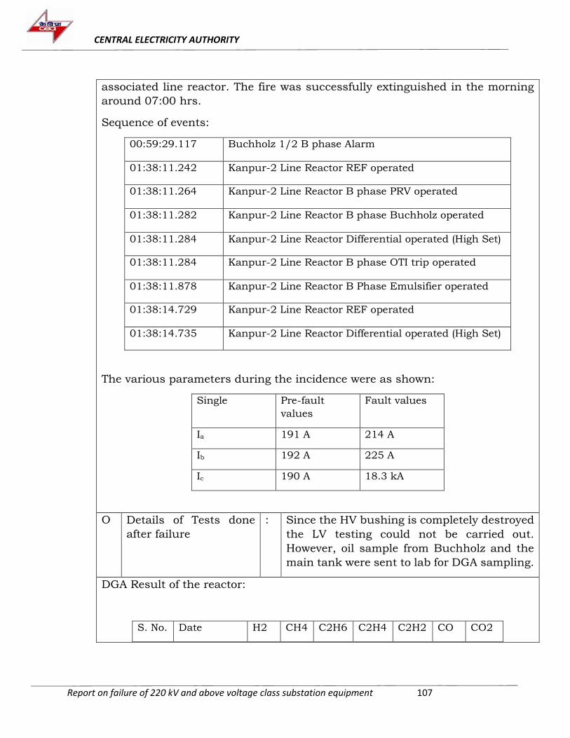
CENTRAL ELECTRICITY AUTHORITY
Report on failure of 220 kV and above voltage class substation equipment 107
associated line reactor. The fire was successfully extinguished in the morning
around 07:00 hrs.
Sequence of events:
00:59:29.117 Buchholz 1/2 B phase Alarm
01:38:11.242 Kanpur-2 Line Reactor REF operated
01:38:11.264 Kanpur-2 Line Reactor B phase PRV operated
01:38:11.282 Kanpur-2 Line Reactor B phase Buchholz operated
01:38:11.284 Kanpur-2 Line Reactor Differential operated (High Set)
01:38:11.284 Kanpur-2 Line Reactor B phase OTI trip operated
01:38:11.878 Kanpur-2 Line Reactor B Phase Emulsifier operated
01:38:14.729 Kanpur-2 Line Reactor REF operated
01:38:14.735 Kanpur-2 Line Reactor Differential operated (High Set)
The various parameters during the incidence were as shown:
Single Pre-fault
values
Fault values
Ia 191 A 214 A
Ib 192 A 225 A
Ic 190 A 18.3 kA
O Details of Tests done
after failure
: Since the HV bushing is completely destroyed
the LV testing could not be carried out.
However, oil sample from Buchholz and the
main tank were sent to lab for DGA sampling.
DGA Result of the reactor:
S. No. Date H2 CH4 C2H6 C2H4 C2H2 CO CO2
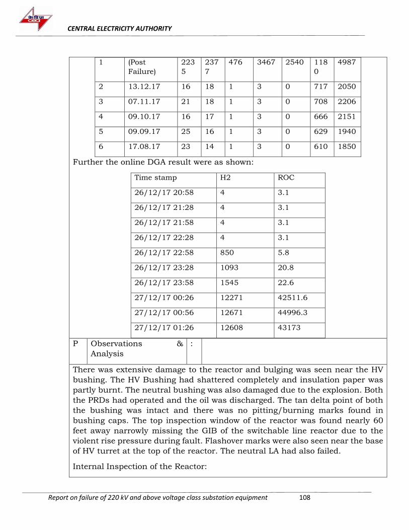
CENTRAL ELECTRICITY AUTHORITY
Report on failure of 220 kV and above voltage class substation equipment 108
1 (Post
Failure)
223
5
237
7
476 3467 2540 118
0
4987
2 13.12.17 16 18 1 3 0 717 2050
3 07.11.17 21 18 1 3 0 708 2206
4 09.10.17 16 17 1 3 0 666 2151
5 09.09.17 25 16 1 3 0 629 1940
6 17.08.17 23 14 1 3 0 610 1850
Further the online DGA result were as shown:
Time stamp H2 ROC
26/12/17 20:58 4 3.1
26/12/17 21:28 4 3.1
26/12/17 21:58 4 3.1
26/12/17 22:28 4 3.1
26/12/17 22:58 850 5.8
26/12/17 23:28 1093 20.8
26/12/17 23:58 1545 22.6
27/12/17 00:26 12271 42511.6
27/12/17 00:56 12671 44996.3
27/12/17 01:26 12608 43173
P Observations &
Analysis
:
There was extensive damage to the reactor and bulging was seen near the HV
bushing. The HV Bushing had shattered completely and insulation paper was
partly burnt. The neutral bushing was also damaged due to the explosion. Both
the PRDs had operated and the oil was discharged. The tan delta point of both
the bushing was intact and there was no pitting/burning marks found in
bushing caps. The top inspection window of the reactor was found nearly 60
feet away narrowly missing the GIB of the switchable line reactor due to the
violent rise pressure during fault. Flashover marks were also seen near the base
of HV turret at the top of the reactor. The neutral LA had also failed.
Internal Inspection of the Reactor:
CENTRAL ELECTRICITY AUTHORITY
Report on failure of 220 kV and above voltage class substation equipment 109
As per the report submitted by the utility, findings of the internal inspection are
as follows:
HV lead exit had violently sheared away from the HV bushing and the insulation
was completely burnt. However, the HV bushing oil end corona ring seemed to
be intact and there was no abnormality observed on the tan delta point. The
lead of the neutral bushing was intact. The visible portion of winding also
seemed to be intact except for minor fire damage. This indicates that the fault
had initiated from the HV lead exit to Static end ring (SER) of the neutral end of
the winding either at the top or bottom.
The second fault seems to have been caused due to burning material rising from
the reactor which caused an ionized path to the bushing from the line (which
was charged) above the failed reactor. The flashover then travelled through the
bushing CT and then through the tank so it cannot be seen in the Neutral CT.
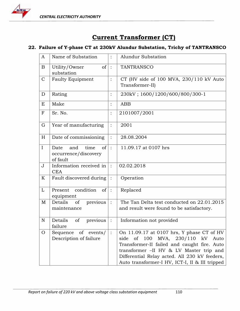
CENTRAL ELECTRICITY AUTHORITY
Report on failure of 220 kV and above voltage class substation equipment 110
Current Transformer (CT)
22. Failure of Y-phase CT at 230kV Alundur Substation, Trichy of TANTRANSCO
A Name of Substation : Alundur Substation
B Utility/Owner of
substation
: TANTRANSCO
C Faulty Equipment : CT (HV side of 100 MVA, 230/110 kV Auto
Transformer-II)
D Rating : 230kV ; 1600/1200/600/800/300-1
E Make : ABB
F Sr. No. : 2101007/2001
G Year of manufacturing : 2001
H Date of commissioning : 28.08.2004
I Date and time of
occurrence/discovery
of fault
: 11.09.17 at 0107 hrs
J Information received in
CEA
: 02.02.2018
K Fault discovered during : Operation
L Present condition of
equipment
: Replaced
M Details of previous
maintenance
: The Tan Delta test conducted on 22.01.2015
and result were found to be satisfactory.
N Details of previous
failure
: Information not provided
O Sequence of events/
Description of failure
: On 11.09.17 at 0107 hrs, Y phase CT of HV
side of 100 MVA, 230/110 kV Auto
Transformer-II failed and caught fire. Auto
transformer –II HV & LV Master trip and
Differential Relay acted. All 230 kV feeders,
Auto transformer-I HV, ICT-I, II & III tripped
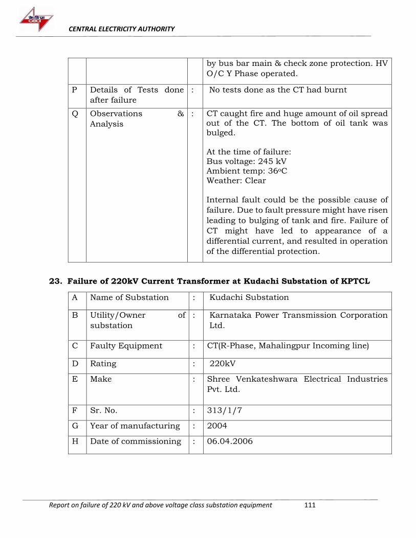
CENTRAL ELECTRICITY AUTHORITY
Report on failure of 220 kV and above voltage class substation equipment 111
by bus bar main & check zone protection. HV
O/C Y Phase operated.
P Details of Tests done
after failure
: No tests done as the CT had burnt
Q Observations &
Analysis
: CT caught fire and huge amount of oil spread out of the CT. The bottom of oil tank was
bulged.
At the time of failure: Bus voltage: 245 kV Ambient temp: 36oC
Weather: Clear
Internal fault could be the possible cause of
failure. Due to fault pressure might have risen
leading to bulging of tank and fire. Failure of
CT might have led to appearance of a
differential current, and resulted in operation
of the differential protection.
23. Failure of 220kV Current Transformer at Kudachi Substation of KPTCL
A Name of Substation : Kudachi Substation
B Utility/Owner of
substation
: Karnataka Power Transmission Corporation
Ltd.
C Faulty Equipment : CT(R-Phase, Mahalingpur Incoming line)
D Rating : 220kV
E Make : Shree Venkateshwara Electrical Industries
Pvt. Ltd.
F Sr. No. : 313/1/7
G Year of manufacturing : 2004
H Date of commissioning : 06.04.2006
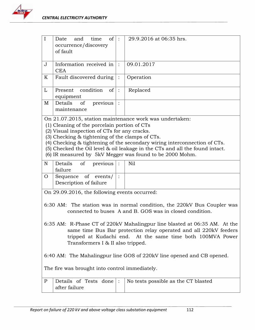
CENTRAL ELECTRICITY AUTHORITY
Report on failure of 220 kV and above voltage class substation equipment 112
I Date and time of
occurrence/discovery
of fault
: 29.9.2016 at 06:35 hrs.
J Information received in
CEA
: 09.01.2017
K Fault discovered during : Operation
L Present condition of
equipment
: Replaced
M Details of previous
maintenance
:
On 21.07.2015, station maintenance work was undertaken:
(1) Cleaning of the porcelain portion of CTs (2) Visual inspection of CTs for any cracks. (3) Checking & tightening of the clamps of CTs.
(4) Checking & tightening of the secondary wiring interconnection of CTs. (5) Checked the Oil level & oil leakage in the CTs and all the found intact.
(6) IR measured by 5kV Megger was found to be 2000 Mohm.
N Details of previous
failure
: Nil
O Sequence of events/
Description of failure
:
On 29.09.2016, the following events occurred:
6:30 AM: The station was in normal condition, the 220kV Bus Coupler was
connected to buses A and B. GOS was in closed condition.
6:35 AM: R-Phase CT of 220kV Mahalingpur line blasted at 06:35 AM. At the
same time Bus Bar protection relay operated and all 220kV feeders
tripped at Kudachi end. At the same time both 100MVA Power
Transformers I & II also tripped.
6:40 AM: The Mahalingpur line GOS of 220kV line opened and CB opened.
The fire was brought into control immediately.
P Details of Tests done
after failure
: No tests possible as the CT blasted
CENTRAL ELECTRICITY AUTHORITY
Report on failure of 220 kV and above voltage class substation equipment 113
Q Observations &
Analysis
: Internal fault could be the possible cause of
failure. Failure of CT might have led to
appearance of a differential current, and
resulted in operation of the differential
protection.
24. Failure of 220 kV CT at HSR Layout, Bangalore Substation of KPTCL
A. Name of Substation : HSR Layout
B. Utility/Owner of
substation
: KPTCL
C. Faulty Equipment : R-ph CT for 220 kV Hoody line at 220/66/11
kV substation
D. Rating : 245kV
E. Make : Crompton Greaves Limited
F. Sr. No. : 9019
G. Year of manufacturing : 1996
H. Date of commissioning : 26.01.1998
I. Date and time of
occurrence/discovery of
fault
: 05.11.2016 at 13:00 hrs.
J. Information received in
CEA
: 11.08.2017
K. Fault discovered during : Operation
L. Present condition of
equipment
: Replaced by new CT
M. Details of previous
maintenance
: Last maintenance was carried out on
16.05.2016, however, further details were not
provided.
N. Details of previous failure : Nil
CENTRAL ELECTRICITY AUTHORITY
Report on failure of 220 kV and above voltage class substation equipment 114
O. Sequence of events/
Description of fault
: On 05.11.2016 at 13:00 hrs., CT Bellow
expanded and oil leakage from top was
observed.
P. Details of Tests done
after failure
: Information not provided
Q. Observations & Analysis : The CT had spent over 18 years in service.
Expansion of below indicates that some gases
were generated in the CT due to partial
discharge in the insulation.
25. Failure of 220kV B-phase CT at KIADB Doddaballapura s/s of KPTCL
A Name of Substation : 220/66/11kV KIADB R/S Doddaballapura
B Utility/Owner of
substation
: KPTCL
C Faulty Equipment : CT (B-phase of 50 MVA transformer)
D Rating : 220 kV, 800-600-400-300/1-1-1A
E Make : Hindustan Brown Boveri
F Sr. No. : IB027/700
G Year of manufacturing : Information not available
H Date of commissioning : 13.07.1995
I Date and time of
occurrence/discovery of
fault
: 02.04.2017 at 2210 Hrs.
J Information received in
CEA
: 20.11.17
K Fault discovered during : Operation
L Present condition of
equipment
: Replaced
M Details of previous
maintenance
: Last routine maintenance done on
15.03.2017 (Tightening of Clamps Terminals,
cleaning of insulators, observing oil level)
CENTRAL ELECTRICITY AUTHORITY
Report on failure of 220 kV and above voltage class substation equipment 115
N Details of previous
failure
: Information not available
O Sequence of events/
Description of fault
:
On 02.04.2017 at 2210 hrs., loud sound was heard in 220 kV Yard. Upon
inspection it was found that ‘B’ Phase 220kV CT of 50 MVA transformer had
flashed over and burnt.
Tripping Details are as follows:
Transformer Differential protection operated 87C
Trip supervision relay 895
Tripping relay 286 V2
HV Side: Directional over current relay 67C
LV Side: Directional over Current relay 167A, 167B, 167C
P Details of Tests done
after failure
: Not possible as CT had burnt
Q Observations & Analysis : Internal fault could be the possible cause of
failure. Failure of CT might have led to
appearance of a differential current, and
resulted in operation of the differential
protection.
26. Failure of 220kV CT at Kavoor Substation of KPTCL
A Name of Substation : Kavoor
B Utility/Owner of
substation
: KPTCL
C Faulty Equipment : Y and B ph Current Transformers of Bajpe-1
line
D Rating : 220kV
E Make : SCT Ltd.
CENTRAL ELECTRICITY AUTHORITY
Report on failure of 220 kV and above voltage class substation equipment 116
F Sr. No. : 1. 2000/289 (Y Phase CT)
2. 2000/287 (B Phase CT)
G Year of manufacturing : 1. 1999 (Y Phase CT)
2. 1999 (B Phase CT)
H Year of commissioning : 1. 2000 (Y Phase CT)
2. 2000 (B Phase CT)
I Date and time of
occurrence/discovery of
fault
: 05.09.2017 at 18:00 hrs.
J Information received in
CEA
: 20.11.2017
K Fault discovered during : Operation
L Present condition of
equipment
: Both CTs Irreparable
M Details of previous
maintenance
: Carried out routine maintenance works on
29.07.2017. Details of maintenance work is
not available.
N Details of previous
failure
: No previous failures
O Sequence of events/
Description of fault
: On 05.09.2017 at about 18:00 hrs, 220kV
Kavoor-Bajpe line -1 tripped on Distance relay
due to rupturing of B Phase CT and flashover
of Y-Phase Current Transformer at 220kV
SRS, Kavoor.
The B-Phase CT had ruptured entirely. Y-
Phase CT had flashed over, deglazing of jacket
insulator and mechanical damages like
damages to primary stud, delink of cemented
portion were observed.
P Details of Tests done
after failure
: No test was possible as both CTs had
damaged.
Q Observations & Analysis : As no test values of tests conducted during
previous maintenance is available, it is hard to
CENTRAL ELECTRICITY AUTHORITY
Report on failure of 220 kV and above voltage class substation equipment 117
ascertain the health of the CTs. Flashover of Y-
phase CT could be due to internal fault.
Damage of B-phase CT could be due to
splinters of Y-phase CT, however, sufficient
information is not available to corroborate the
same.
27. Failure of 220kV CT at Yerraguntla Substation of APTRANSCO
A. Name of Substation : Yerraguntla substation
B. Utility/Owner of
substation
: APTRANSCO
C. Faulty Equipment : R-Phase CT of RTPP-I
D. Rating : 800-600-400/1-1-1-1-1A
E. Make : WS
F. Sr. No. : 910815
G. Year of manufacturing : 1991
H Year of commissioning : 1993
I Date and time of
occurrence/discovery of
fault
: 17.01.17 at 1110 hrs
J Information received in
CEA
: 28.03.2017
K Fault discovered during : Operation
L Present condition of
equipment
: Replaced
M Details of previous
maintenance
: Information not available
N Details of previous failure : Information not available
CENTRAL ELECTRICITY AUTHORITY
Report on failure of 220 kV and above voltage class substation equipment 118
O Sequence of events/
Description of fault
: On 17.01.17 at 1110 hrs, 220kV RTPP-I R-ph
CT blasted while in operation.
P Details of Tests done
after failure
: No test was possible as the CT had blasted.
Q Observations & Analysis
: Sufficient information is not available to
ascertain cause of failure. However, it
appears, reduction in dielectric strength of
the insulation due to ageing might have led to
the failure and blasting of CT.
28. Failure report of 220 kV R-ph CT at Vishakhapatnam s/s of APTRANSCO
A. Name of Substation : Vishakhapatnam s/s
B. Utility/Owner of
substation
: APTRANSCO
C. Faulty Equipment : R-ph CT of Bus Coupler
D. Rating : 220 kV
E. Make : BHEL
F. Sr. No. : 2241286
G. Year of manufacturing : 2003
H Year of commissioning : Information not available
I Date and time of
occurrence/discovery
of fault
: 27.03.2018 at 1610 hrs
J Information received in
CEA
: 29.06.18
K Fault discovered during : Operation
L Present condition of
equipment
: Replaced on 28.03.2018
M Details of previous
maintenance
: No maintenance as the CT was in store.
CENTRAL ELECTRICITY AUTHORITY
Report on failure of 220 kV and above voltage class substation equipment 119
N Details of previous
failure
: Earlier CT installed in R-phase of Bus-I side, was
replaced on 25.03.19 because oil leakage was
observed from stud and H2 was found in the oil.
The CT had served for 26 years.
O Sequence of events/
Description of fault
: On 27.03.18, the current transformer blasted.
P Details of Tests done
after failure
: No tests could be conducted as CT had blasted.
Q Observations &
Analysis
: As reported by the utility, the subject CT was
in idle condition at the Stackyard at TLC
stores Gajuwaka since 2003. It appears that
since CT was in store for a long time, due to
moisture ingress and other environmental
factors, its internal insulation might have
weakened which could not sustain voltage
stress when put into service.
29. Failure report of 220 kV CT at Warora s/s of MSETCL
A. Name of Substation : Warora
B. Utility/Owner of
substation
: MSETCL
C. Faulty Equipment : Y-ph CT of Bhugaon-1 line
D. Rating : 220 kV
E. Make : MEHRU
F. Sr. No. : OC2927/1/4/10
G. Year of manufacturing : 2010
H Date of commissioning : 29.07.2017
I Date and time of
occurrence/discovery
of fault
: 11.08.2017, 2323 hrs
CENTRAL ELECTRICITY AUTHORITY
Report on failure of 220 kV and above voltage class substation equipment 120
J Information received in
CEA
: 05.07.2018
K Fault discovered during : During Operation
L Present condition of
equipment
: Replaced by new CT
M Details of previous
maintenance
: Information not available
N Details of previous
failure
: Information not available
O Sequence of events/
Description of fault
: On 11.08.2017 at 23:23 hrs, bus sectionalizer,
LBB operated resulting in tripping of SWPCL
line 1 & line 2 and Bhugaon ckt. 2, due to
bursting of Y-Phase CT.
P Details of Tests done
after failure
: Test could not be done as the CT was
completely damaged.
Q Observations &
Analysis
: It is highlighted that CT was manufactured in
2010 and commissioned in 2017. Information
on the conditions under which CT was stored
during this period is not available. Internal
insulation failure due to ingress of moisture
appears to be cause of failure of CT.
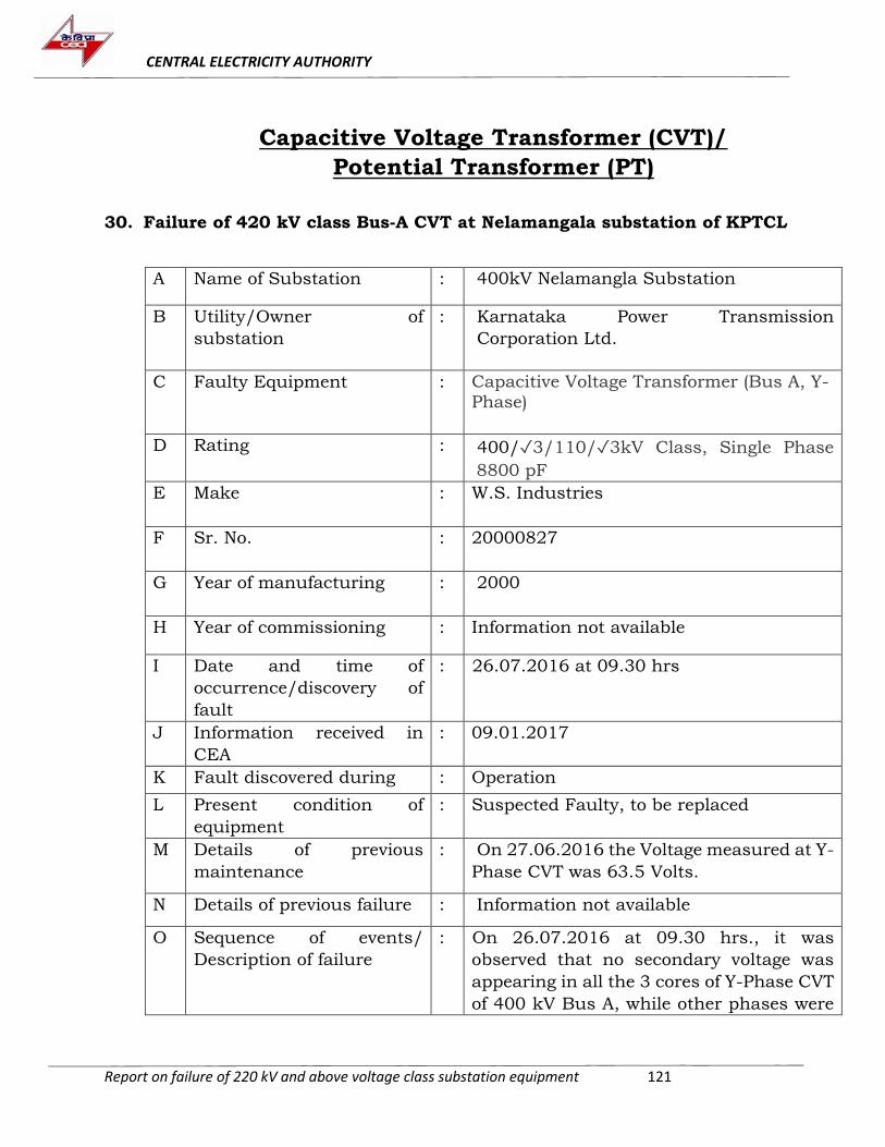
CENTRAL ELECTRICITY AUTHORITY
Report on failure of 220 kV and above voltage class substation equipment 121
Capacitive Voltage Transformer (CVT)/
Potential Transformer (PT)
30. Failure of 420 kV class Bus-A CVT at Nelamangala substation of KPTCL
A Name of Substation : 400kV Nelamangla Substation
B Utility/Owner of
substation
: Karnataka Power Transmission
Corporation Ltd.
C Faulty Equipment : Capacitive Voltage Transformer (Bus A, Y-Phase)
D Rating
: 400/3/110/3kV Class, Single Phase
8800 pF
E Make : W.S. Industries
F Sr. No. : 20000827
G Year of manufacturing : 2000
H Year of commissioning : Information not available
I Date and time of
occurrence/discovery of
fault
: 26.07.2016 at 09.30 hrs
J Information received in
CEA
: 09.01.2017
K Fault discovered during : Operation
L Present condition of
equipment
: Suspected Faulty, to be replaced
M Details of previous
maintenance
: On 27.06.2016 the Voltage measured at Y-
Phase CVT was 63.5 Volts.
N Details of previous failure : Information not available
O Sequence of events/
Description of failure
: On 26.07.2016 at 09.30 hrs., it was
observed that no secondary voltage was
appearing in all the 3 cores of Y-Phase CVT
of 400 kV Bus A, while other phases were
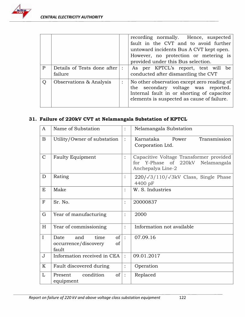
CENTRAL ELECTRICITY AUTHORITY
Report on failure of 220 kV and above voltage class substation equipment 122
recording normally. Hence, suspected
fault in the CVT and to avoid further
untoward incidents Bus A CVT kept open.
However, no protection or metering is
provided under this Bus selection.
P Details of Tests done after
failure
: As per KPTCL’s report, test will be
conducted after dismantling the CVT
Q Observations & Analysis : No other observation except zero reading of
the secondary voltage was reported. Internal fault in or shorting of capacitor
elements is suspected as cause of failure.
31. Failure of 220kV CVT at Nelamangala Substation of KPTCL
A Name of Substation : Nelamangala Substation
B Utility/Owner of substation : Karnataka Power Transmission
Corporation Ltd.
C Faulty Equipment : Capacitive Voltage Transformer provided
for Y-Phase of 220kV Nelamangala Anchepalya Line-2
D Rating : 220/3/110/3kV Class, Single Phase
4400 pF
E Make : W. S. Industries
F Sr. No. : 20000837
G Year of manufacturing : 2000
H Year of commissioning : Information not available
I Date and time of
occurrence/discovery of
fault
: 07.09.16
J Information received in CEA : 09.01.2017
K Fault discovered during : Operation
L Present condition of
equipment
: Replaced
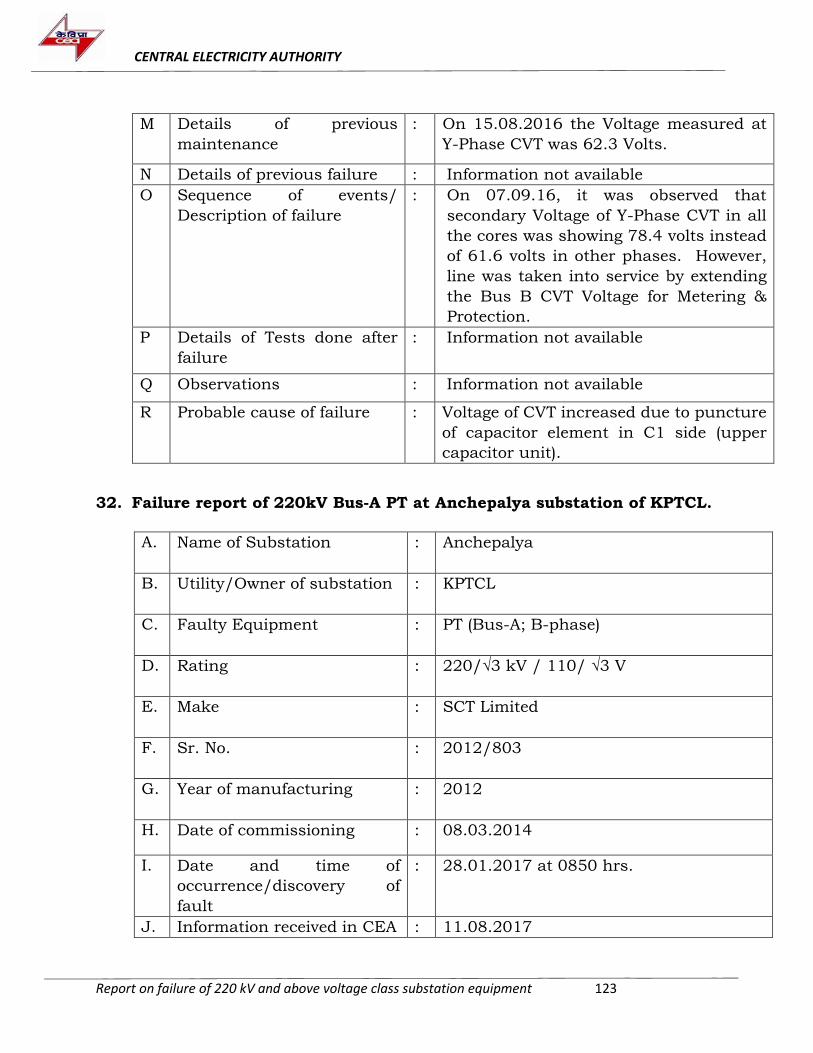
CENTRAL ELECTRICITY AUTHORITY
Report on failure of 220 kV and above voltage class substation equipment 123
M Details of previous
maintenance
: On 15.08.2016 the Voltage measured at
Y-Phase CVT was 62.3 Volts.
N Details of previous failure : Information not available
O Sequence of events/
Description of failure
: On 07.09.16, it was observed that
secondary Voltage of Y-Phase CVT in all
the cores was showing 78.4 volts instead
of 61.6 volts in other phases. However,
line was taken into service by extending
the Bus B CVT Voltage for Metering &
Protection.
P Details of Tests done after
failure
: Information not available
Q Observations : Information not available
R Probable cause of failure : Voltage of CVT increased due to puncture
of capacitor element in C1 side (upper
capacitor unit).
32. Failure report of 220kV Bus-A PT at Anchepalya substation of KPTCL.
A. Name of Substation : Anchepalya
B. Utility/Owner of substation : KPTCL
C. Faulty Equipment : PT (Bus-A; B-phase)
D. Rating : 220/√3 kV / 110/ √3 V
E. Make : SCT Limited
F. Sr. No. : 2012/803
G. Year of manufacturing : 2012
H. Date of commissioning : 08.03.2014
I. Date and time of
occurrence/discovery of
fault
: 28.01.2017 at 0850 hrs.
J. Information received in CEA : 11.08.2017
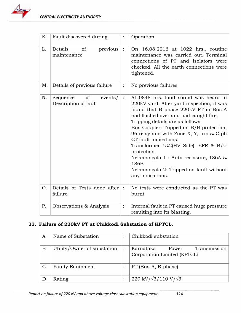
CENTRAL ELECTRICITY AUTHORITY
Report on failure of 220 kV and above voltage class substation equipment 124
K. Fault discovered during : Operation
L. Details of previous
maintenance
: On 16.08.2016 at 1022 hrs., routine
maintenance was carried out. Terminal
connections of PT and isolators were
checked. All the earth connections were
tightened.
M. Details of previous failure : No previous failures
N. Sequence of events/
Description of fault
: At 0848 hrs. loud sound was heard in
220kV yard. After yard inspection, it was
found that B phase 220kV PT in Bus-A
had flashed over and had caught fire.
Tripping details are as follows:
Bus Coupler: Tripped on B/B protection,
96 relay and with Zone X, Y, trip & C ph
CT fault indications.
Transformer 1&2(HV Side): EFR & B/U
protection
Nelamangala 1 : Auto reclosure, 186A &
186B
Nelamangala 2: Tripped on fault without
any indications.
O. Details of Tests done after
failure
: No tests were conducted as the PT was
burnt
P. Observations & Analysis
: Internal fault in PT caused huge pressure
resulting into its blasting.
33. Failure of 220kV PT at Chikkodi Substation of KPTCL.
A Name of Substation : Chikkodi substation
B Utility/Owner of substation : Karnataka Power Transmission
Corporation Limited (KPTCL)
C Faulty Equipment : PT (Bus-A, B-phase)
D Rating : 220 kV/√3/110 V/√3
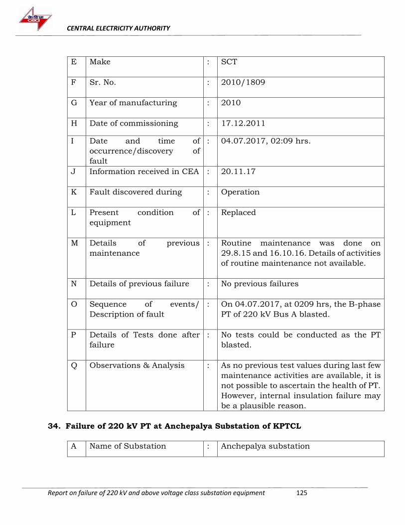
CENTRAL ELECTRICITY AUTHORITY
Report on failure of 220 kV and above voltage class substation equipment 125
E Make : SCT
F Sr. No. : 2010/1809
G Year of manufacturing : 2010
H Date of commissioning : 17.12.2011
I Date and time of
occurrence/discovery of
fault
: 04.07.2017, 02:09 hrs.
J Information received in CEA : 20.11.17
K Fault discovered during : Operation
L Present condition of
equipment
: Replaced
M Details of previous
maintenance
: Routine maintenance was done on
29.8.15 and 16.10.16. Details of activities
of routine maintenance not available.
N Details of previous failure : No previous failures
O Sequence of events/
Description of fault
: On 04.07.2017, at 0209 hrs, the B-phase
PT of 220 kV Bus A blasted.
P Details of Tests done after
failure
: No tests could be conducted as the PT
blasted.
Q Observations & Analysis
: As no previous test values during last few
maintenance activities are available, it is
not possible to ascertain the health of PT.
However, internal insulation failure may
be a plausible reason.
34. Failure of 220 kV PT at Anchepalya Substation of KPTCL
A Name of Substation : Anchepalya substation
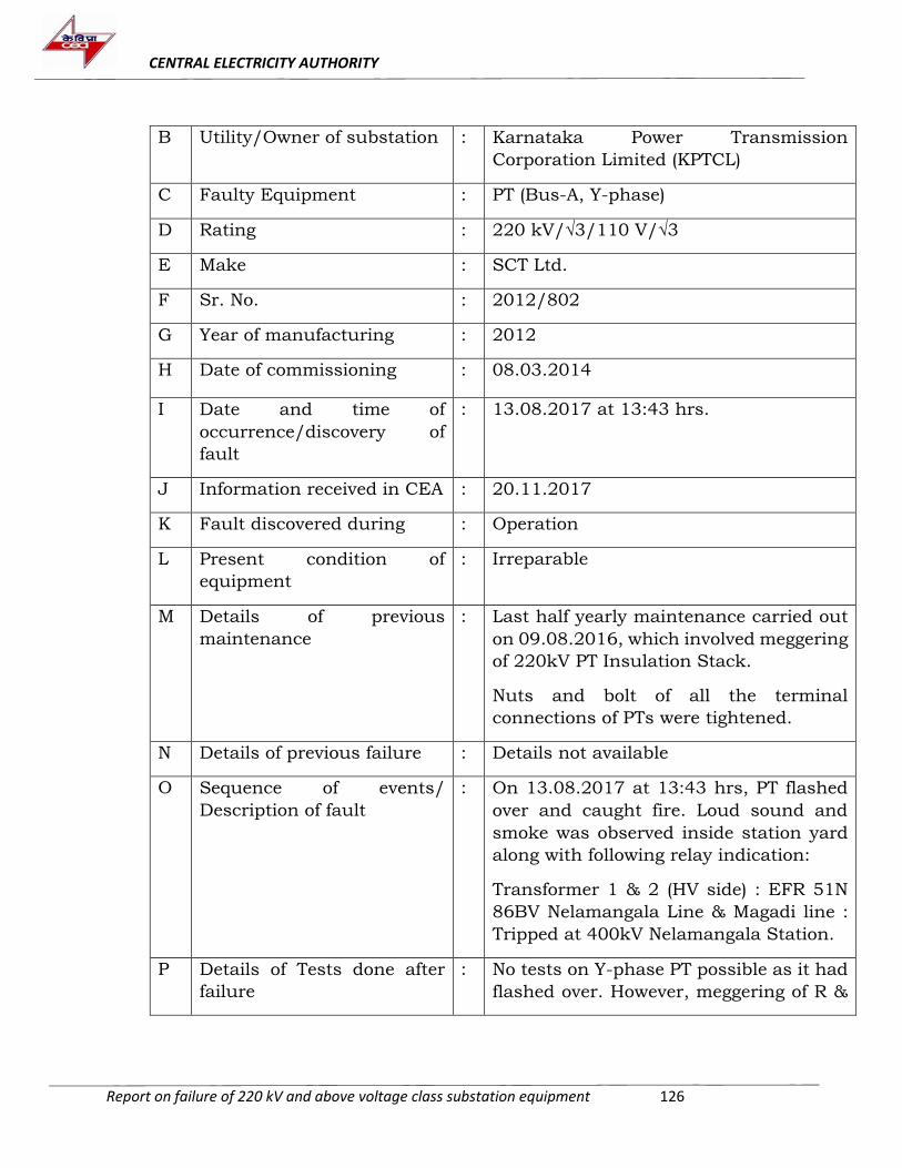
CENTRAL ELECTRICITY AUTHORITY
Report on failure of 220 kV and above voltage class substation equipment 126
B Utility/Owner of substation : Karnataka Power Transmission
Corporation Limited (KPTCL)
C Faulty Equipment : PT (Bus-A, Y-phase)
D Rating : 220 kV/√3/110 V/√3
E Make : SCT Ltd.
F Sr. No. : 2012/802
G Year of manufacturing : 2012
H Date of commissioning : 08.03.2014
I Date and time of
occurrence/discovery of
fault
: 13.08.2017 at 13:43 hrs.
J Information received in CEA : 20.11.2017
K Fault discovered during : Operation
L Present condition of
equipment
: Irreparable
M Details of previous
maintenance
: Last half yearly maintenance carried out
on 09.08.2016, which involved meggering
of 220kV PT Insulation Stack.
Nuts and bolt of all the terminal
connections of PTs were tightened.
N Details of previous failure : Details not available
O Sequence of events/
Description of fault
: On 13.08.2017 at 13:43 hrs, PT flashed
over and caught fire. Loud sound and
smoke was observed inside station yard
along with following relay indication:
Transformer 1 & 2 (HV side) : EFR 51N
86BV Nelamangala Line & Magadi line :
Tripped at 400kV Nelamangala Station.
P Details of Tests done after
failure
: No tests on Y-phase PT possible as it had
flashed over. However, meggering of R &
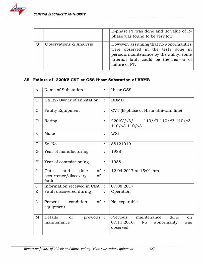
CENTRAL ELECTRICITY AUTHORITY
Report on failure of 220 kV and above voltage class substation equipment 127
B-phase PT was done and IR value of R-
phase was found to be very low.
Q Observations & Analysis : However, assuming that no abnormalities
were observed in the tests done in
periodic maintenance by the utility, some
internal fault could be the reason of
failure of PT.
35. Failure of 220kV CVT at GSS Hisar Substation of BBMB
A Name of Substation : Hisar GSS
B Utility/Owner of substation : BBMB
C Faulty Equipment : CVT (B-phase of Hisar-Bhiwani line)
D Rating : 220kV/√3/ 110/√3-110/√3-110/√3-
110/√3-110/√3
E Make : WSI
F Sr. No. : 88121019
G Year of manufacturing : 1988
H Year of commissioning : 1988
I Date and time of
occurrence/discovery of
fault
: 12.04.2017 at 15:01 hrs.
J Information received in CEA : 07.08.2017
K Fault discovered during : Operation
L Present condition of
equipment
: Not reparable
M Details of previous
maintenance
: Previous maintenance done on
07.11.2016. No abnormality was
observed.
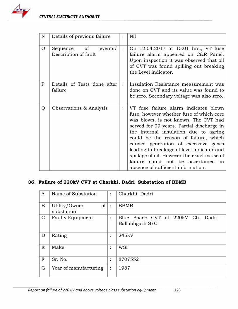
CENTRAL ELECTRICITY AUTHORITY
Report on failure of 220 kV and above voltage class substation equipment 128
N Details of previous failure : Nil
O Sequence of events/
Description of fault
: On 12.04.2017 at 15:01 hrs., VT fuse
failure alarm appeared on C&R Panel.
Upon inspection it was observed that oil
of CVT was found spilling out breaking
the Level indicator.
P Details of Tests done after
failure
: Insulation Resistance measurement was
done on CVT and its value was found to
be zero. Secondary voltage was also zero.
Q Observations & Analysis
: VT fuse failure alarm indicates blown
fuse, however whether fuse of which core
was blown, is not known. The CVT had
served for 29 years. Partial discharge in
the internal insulation due to ageing
could be the reason of failure, which
caused generation of excessive gases
leading to breakage of level indicator and
spillage of oil. However the exact cause of
failure could not be ascertained in
absence of sufficient information.
36. Failure of 220kV CVT at Charkhi, Dadri Substation of BBMB
A Name of Substation : Charkhi Dadri
B Utility/Owner of
substation
: BBMB
C Faulty Equipment : Blue Phase CVT of 220kV Ch. Dadri –
Ballabhgarh S/C
D Rating : 245kV
E Make : WSI
F Sr. No. : 8707552
G Year of manufacturing : 1987
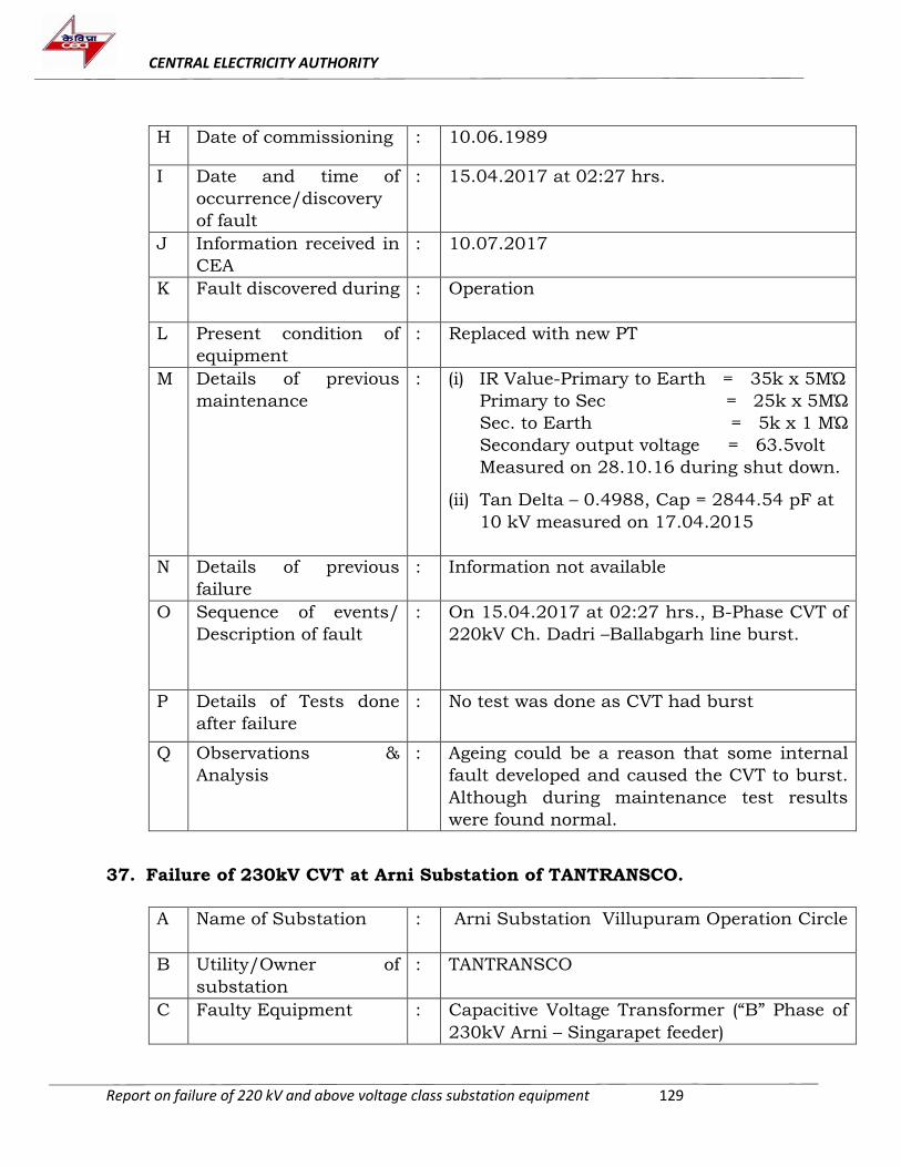
CENTRAL ELECTRICITY AUTHORITY
Report on failure of 220 kV and above voltage class substation equipment 129
H Date of commissioning : 10.06.1989
I Date and time of
occurrence/discovery
of fault
: 15.04.2017 at 02:27 hrs.
J Information received in
CEA
: 10.07.2017
K Fault discovered during : Operation
L Present condition of
equipment
: Replaced with new PT
M Details of previous
maintenance
: (i) IR Value-Primary to Earth = 35k x 5MΏ
Primary to Sec = 25k x 5MΏ
Sec. to Earth = 5k x 1 MΏ
Secondary output voltage = 63.5volt
Measured on 28.10.16 during shut down. (ii) Tan Delta – 0.4988, Cap = 2844.54 pF at
10 kV measured on 17.04.2015
N Details of previous
failure
: Information not available
O Sequence of events/
Description of fault
: On 15.04.2017 at 02:27 hrs., B-Phase CVT of
220kV Ch. Dadri –Ballabgarh line burst.
P Details of Tests done
after failure
: No test was done as CVT had burst
Q Observations &
Analysis
: Ageing could be a reason that some internal
fault developed and caused the CVT to burst.
Although during maintenance test results
were found normal.
37. Failure of 230kV CVT at Arni Substation of TANTRANSCO.
A Name of Substation : Arni Substation Villupuram Operation Circle
B Utility/Owner of
substation
: TANTRANSCO
C Faulty Equipment : Capacitive Voltage Transformer (“B” Phase of
230kV Arni – Singarapet feeder)
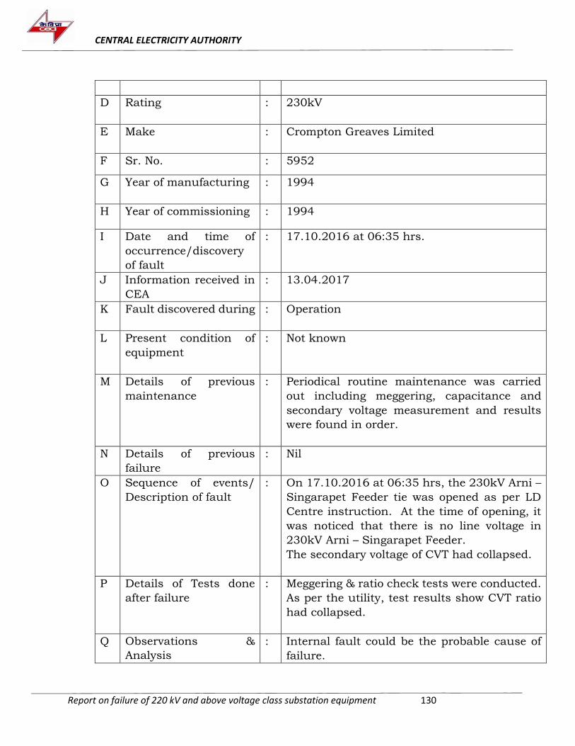
CENTRAL ELECTRICITY AUTHORITY
Report on failure of 220 kV and above voltage class substation equipment 130
D Rating : 230kV
E Make : Crompton Greaves Limited
F Sr. No. : 5952
G Year of manufacturing : 1994
H Year of commissioning : 1994
I Date and time of
occurrence/discovery
of fault
: 17.10.2016 at 06:35 hrs.
J Information received in
CEA
: 13.04.2017
K Fault discovered during : Operation
L Present condition of
equipment
: Not known
M Details of previous
maintenance
: Periodical routine maintenance was carried
out including meggering, capacitance and
secondary voltage measurement and results
were found in order.
N Details of previous
failure
: Nil
O Sequence of events/
Description of fault
: On 17.10.2016 at 06:35 hrs, the 230kV Arni –
Singarapet Feeder tie was opened as per LD
Centre instruction. At the time of opening, it
was noticed that there is no line voltage in
230kV Arni – Singarapet Feeder.
The secondary voltage of CVT had collapsed.
P Details of Tests done
after failure
: Meggering & ratio check tests were conducted.
As per the utility, test results show CVT ratio
had collapsed.
Q Observations &
Analysis
: Internal fault could be the probable cause of
failure.
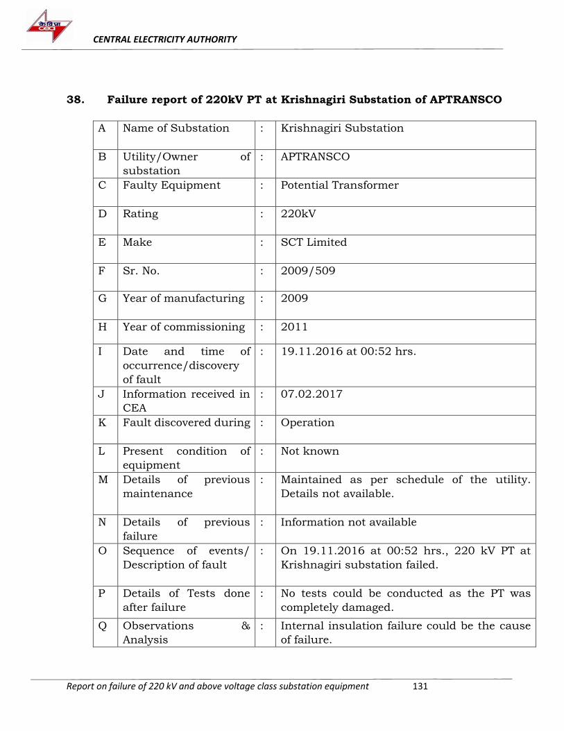
CENTRAL ELECTRICITY AUTHORITY
Report on failure of 220 kV and above voltage class substation equipment 131
38. Failure report of 220kV PT at Krishnagiri Substation of APTRANSCO
A Name of Substation : Krishnagiri Substation
B Utility/Owner of
substation
: APTRANSCO
C Faulty Equipment : Potential Transformer
D Rating : 220kV
E Make : SCT Limited
F Sr. No. : 2009/509
G Year of manufacturing : 2009
H Year of commissioning : 2011
I Date and time of
occurrence/discovery
of fault
: 19.11.2016 at 00:52 hrs.
J Information received in
CEA
: 07.02.2017
K Fault discovered during : Operation
L Present condition of
equipment
: Not known
M Details of previous
maintenance
: Maintained as per schedule of the utility.
Details not available.
N Details of previous
failure
: Information not available
O Sequence of events/
Description of fault
: On 19.11.2016 at 00:52 hrs., 220 kV PT at
Krishnagiri substation failed.
P Details of Tests done
after failure
: No tests could be conducted as the PT was
completely damaged.
Q Observations &
Analysis
: Internal insulation failure could be the cause
of failure.
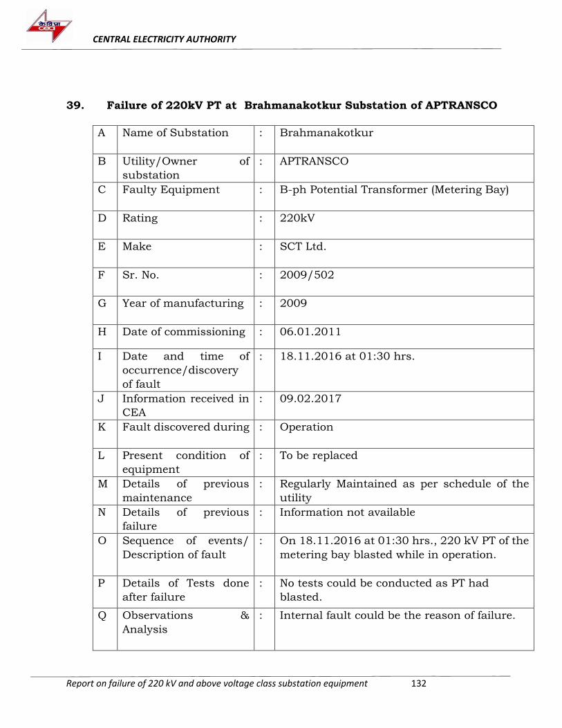
CENTRAL ELECTRICITY AUTHORITY
Report on failure of 220 kV and above voltage class substation equipment 132
39. Failure of 220kV PT at Brahmanakotkur Substation of APTRANSCO
A Name of Substation : Brahmanakotkur
B Utility/Owner of
substation
: APTRANSCO
C Faulty Equipment : B-ph Potential Transformer (Metering Bay)
D Rating : 220kV
E Make : SCT Ltd.
F Sr. No. : 2009/502
G Year of manufacturing : 2009
H Date of commissioning : 06.01.2011
I Date and time of
occurrence/discovery
of fault
: 18.11.2016 at 01:30 hrs.
J Information received in
CEA
: 09.02.2017
K Fault discovered during : Operation
L Present condition of
equipment
: To be replaced
M Details of previous
maintenance
: Regularly Maintained as per schedule of the
utility
N Details of previous
failure
: Information not available
O Sequence of events/
Description of fault
: On 18.11.2016 at 01:30 hrs., 220 kV PT of the
metering bay blasted while in operation.
P Details of Tests done
after failure
: No tests could be conducted as PT had
blasted.
Q Observations &
Analysis
: Internal fault could be the reason of failure.
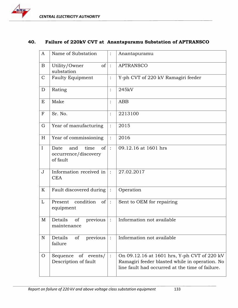
CENTRAL ELECTRICITY AUTHORITY
Report on failure of 220 kV and above voltage class substation equipment 133
40. Failure of 220kV CVT at Anantapuramu Substation of APTRANSCO
A Name of Substation : Anantapuramu
B Utility/Owner of
substation
: APTRANSCO
C Faulty Equipment : Y-ph CVT of 220 kV Ramagiri feeder
D Rating : 245kV
E Make : ABB
F Sr. No. : 2213100
G Year of manufacturing : 2015
H Year of commissioning : 2016
I Date and time of
occurrence/discovery
of fault
: 09.12.16 at 1601 hrs
J Information received in
CEA
: 27.02.2017
K Fault discovered during
: Operation
L Present condition of
equipment
: Sent to OEM for repairing
M Details of previous
maintenance
: Information not available
N Details of previous
failure
: Information not available
O Sequence of events/
Description of fault
: On 09.12.16 at 1601 hrs, Y-ph CVT of 220 kV
Ramagiri feeder blasted while in operation. No
line fault had occurred at the time of failure.
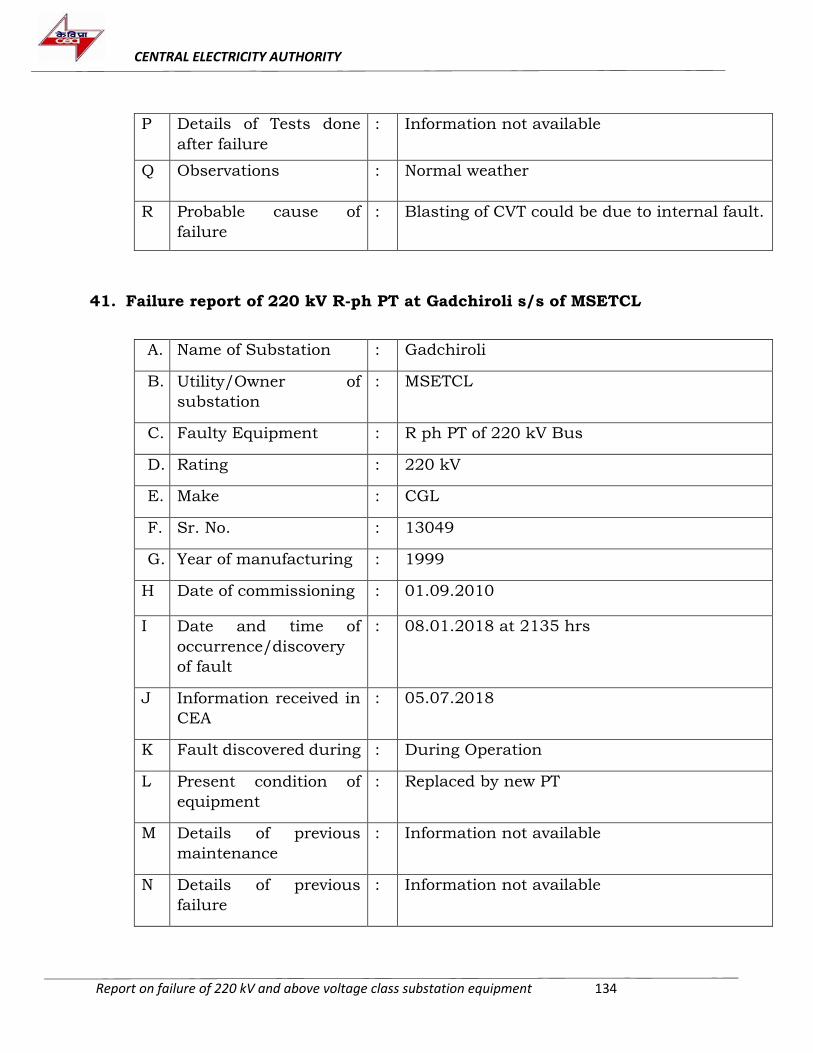
CENTRAL ELECTRICITY AUTHORITY
Report on failure of 220 kV and above voltage class substation equipment 134
P Details of Tests done
after failure
: Information not available
Q Observations
: Normal weather
R Probable cause of
failure
: Blasting of CVT could be due to internal fault.
41. Failure report of 220 kV R-ph PT at Gadchiroli s/s of MSETCL
A. Name of Substation : Gadchiroli
B. Utility/Owner of
substation
: MSETCL
C. Faulty Equipment : R ph PT of 220 kV Bus
D. Rating : 220 kV
E. Make : CGL
F. Sr. No. : 13049
G. Year of manufacturing : 1999
H Date of commissioning : 01.09.2010
I Date and time of
occurrence/discovery
of fault
: 08.01.2018 at 2135 hrs
J Information received in
CEA
: 05.07.2018
K Fault discovered during : During Operation
L Present condition of
equipment
: Replaced by new PT
M Details of previous
maintenance
: Information not available
N Details of previous
failure
: Information not available
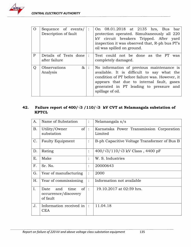
CENTRAL ELECTRICITY AUTHORITY
Report on failure of 220 kV and above voltage class substation equipment 135
O Sequence of events/
Description of fault
: On 08.01.2018 at 2135 hrs, Bus bar
protection operated. Simultaneously all 220
kV circuit breakers Tripped. After yard
inspection it was observed that, R-ph bus PT’s
oil was spilled on ground.
P Details of Tests done
after failure
: Test could not be done as the PT was
completely damaged.
Q Observations &
Analysis
: No information of previous maintenance is
available. It is difficult to say what the
condition of PT before failure was. However, it
appears that due to internal fault, gases
generated in PT leading to pressure and
spillage of oil.
42. Failure report of 400/√3 /110/√3 kV CVT at Nelamangala substation of
KPTCL
A. Name of Substation : Nelamangala s/s
B. Utility/Owner of
substation
: Karnataka Power Transmission Corporation
Limited
C. Faulty Equipment : B-ph Capacitive Voltage Transformer of Bus B
D. Rating : 400/√3/110/√3 kV Class , 4400 pF
E. Make : W. S. Industries
F. Sr. No. : 20000643
G. Year of manufacturing : 2000
H. Year of commissioning : Information not available
I. Date and time of
occurrence/discovery
of fault
: 19.10.2017 at 02:59 hrs.
J. Information received in
CEA
: 11.04.18
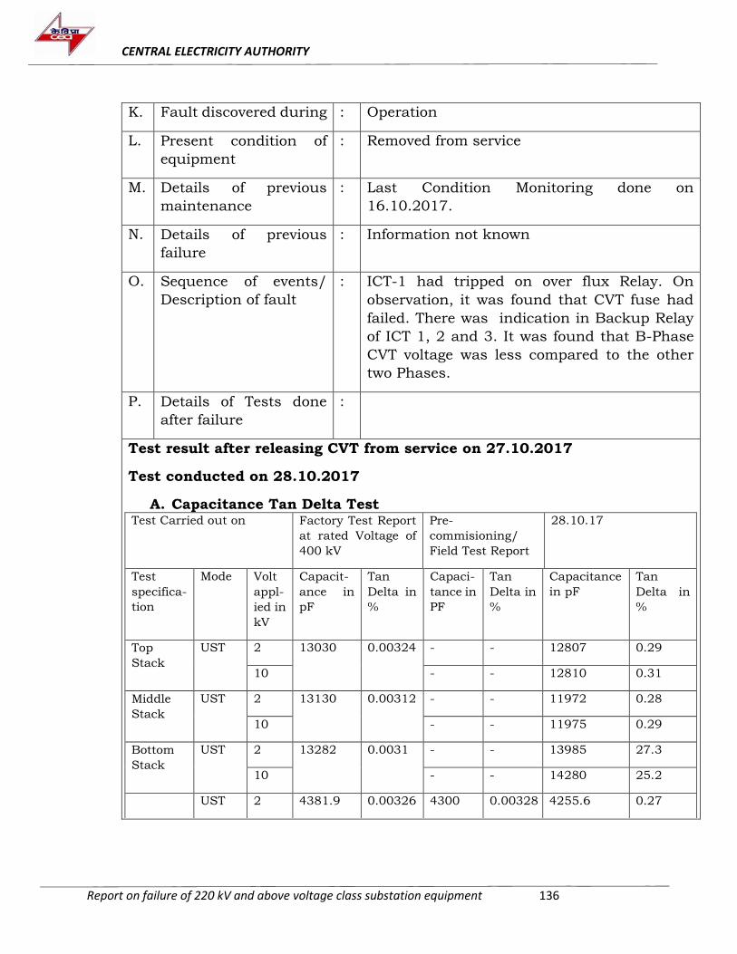
CENTRAL ELECTRICITY AUTHORITY
Report on failure of 220 kV and above voltage class substation equipment 136
K. Fault discovered during : Operation
L. Present condition of
equipment
: Removed from service
M. Details of previous
maintenance
: Last Condition Monitoring done on
16.10.2017.
N. Details of previous
failure
: Information not known
O. Sequence of events/
Description of fault
: ICT-1 had tripped on over flux Relay. On
observation, it was found that CVT fuse had
failed. There was indication in Backup Relay
of ICT 1, 2 and 3. It was found that B-Phase
CVT voltage was less compared to the other
two Phases.
P. Details of Tests done
after failure
:
Test result after releasing CVT from service on 27.10.2017
Test conducted on 28.10.2017
A. Capacitance Tan Delta Test Test Carried out on Factory Test Report
at rated Voltage of
400 kV
Pre-
commisioning/
Field Test Report
28.10.17
Test
specifica-
tion
Mode Volt
appl-
ied in
kV
Capacit-
ance in
pF
Tan
Delta in
%
Capaci-
tance in
PF
Tan
Delta in
%
Capacitance
in pF
Tan
Delta in
%
Top
Stack
UST 2 13030 0.00324 - - 12807 0.29
10 - - 12810 0.31
Middle
Stack
UST 2 13130 0.00312 - - 11972 0.28
10 - - 11975 0.29
Bottom
Stack
UST 2 13282 0.0031 - - 13985 27.3
10 - - 14280 25.2
UST 2 4381.9 0.00326 4300 0.00328 4255.6 0.27
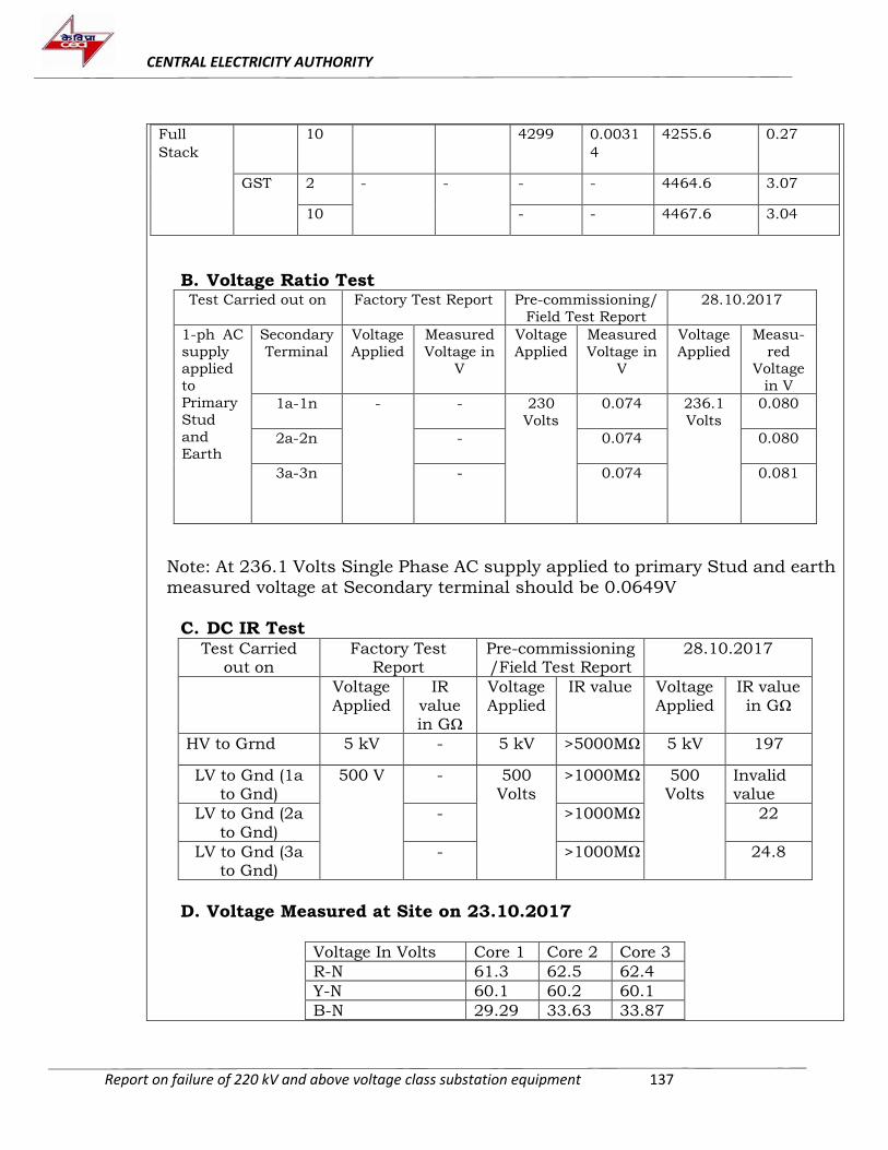
CENTRAL ELECTRICITY AUTHORITY
Report on failure of 220 kV and above voltage class substation equipment 137
Full
Stack
10 4299 0.0031
4
4255.6 0.27
GST 2 - - - - 4464.6 3.07
10 - - 4467.6 3.04
B. Voltage Ratio Test Test Carried out on Factory Test Report Pre-commissioning/
Field Test Report
28.10.2017
1-ph AC
supply applied
to
Primary
Stud
and
Earth
Secondary
Terminal
Voltage
Applied
Measured
Voltage in V
Voltage
Applied
Measured
Voltage in V
Voltage
Applied
Measu-
red Voltage
in V
1a-1n
- - 230
Volts
0.074 236.1
Volts
0.080
2a-2n
- 0.074 0.080
3a-3n - 0.074 0.081
Note: At 236.1 Volts Single Phase AC supply applied to primary Stud and earth
measured voltage at Secondary terminal should be 0.0649V
C. DC IR Test Test Carried
out on Factory Test
Report Pre-commissioning /Field Test Report
28.10.2017
Voltage Applied
IR value in GΩ
Voltage Applied
IR value Voltage Applied
IR value in GΩ
HV to Grnd 5 kV - 5 kV >5000MΩ 5 kV 197
LV to Gnd (1a to Gnd)
500 V - 500 Volts
>1000MΩ 500 Volts
Invalid value
LV to Gnd (2a to Gnd)
- >1000MΩ 22
LV to Gnd (3a to Gnd)
- >1000MΩ 24.8
D. Voltage Measured at Site on 23.10.2017
Voltage In Volts Core 1 Core 2 Core 3
R-N 61.3 62.5 62.4
Y-N 60.1 60.2 60.1
B-N 29.29 33.63 33.87
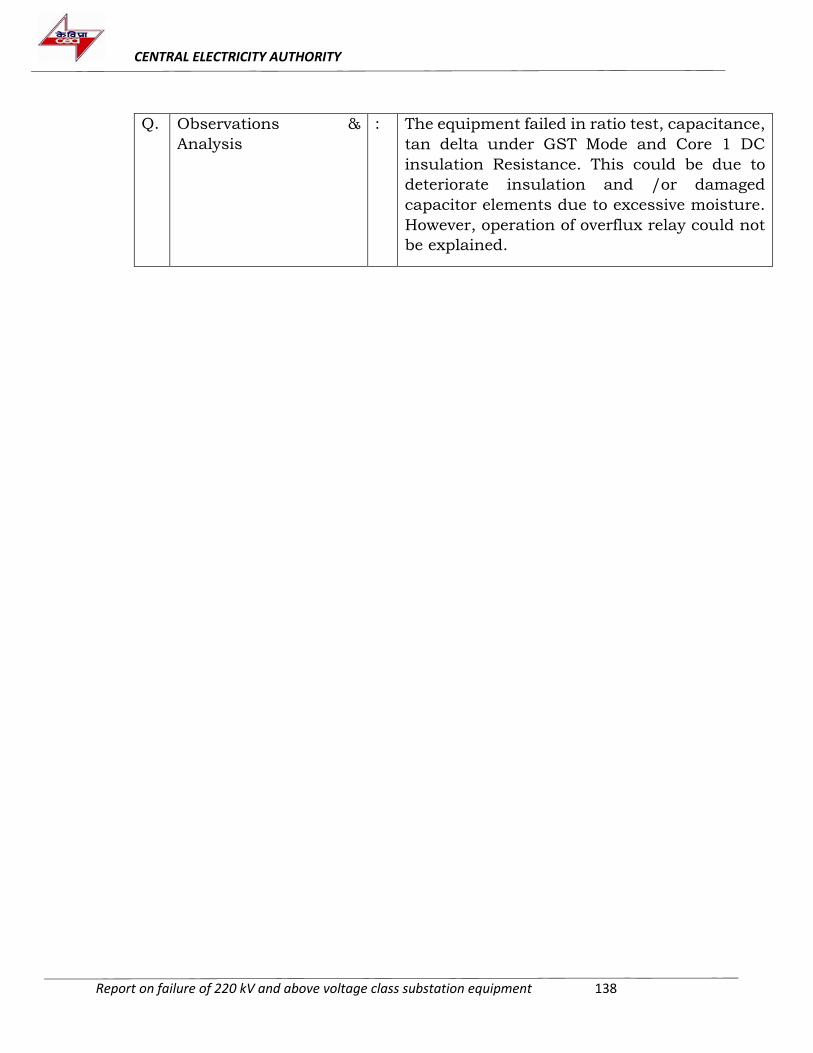
CENTRAL ELECTRICITY AUTHORITY
Report on failure of 220 kV and above voltage class substation equipment 138
Q. Observations &
Analysis
: The equipment failed in ratio test, capacitance,
tan delta under GST Mode and Core 1 DC
insulation Resistance. This could be due to
deteriorate insulation and /or damaged
capacitor elements due to excessive moisture.
However, operation of overflux relay could not
be explained.
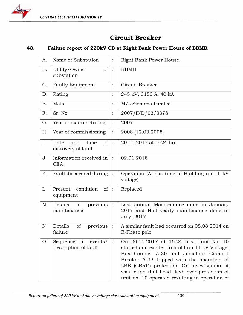
CENTRAL ELECTRICITY AUTHORITY
Report on failure of 220 kV and above voltage class substation equipment 139
Circuit Breaker
43. Failure report of 220kV CB at Right Bank Power House of BBMB.
A. Name of Substation : Right Bank Power House.
B. Utility/Owner of
substation
: BBMB
C. Faulty Equipment : Circuit Breaker
D. Rating : 245 kV, 3150 A, 40 kA
E. Make : M/s Siemens Limited
F. Sr. No. : 2007/IND/03/3378
G. Year of manufacturing : 2007
H Year of commissioning : 2008 (12.03.2008)
I Date and time of
discovery of fault
: 20.11.2017 at 1624 hrs.
J Information received in
CEA
: 02.01.2018
K Fault discovered during : Operation (At the time of Building up 11 kV
voltage)
L Present condition of
equipment
: Replaced
M Details of previous
maintenance
: Last annual Maintenance done in January
2017 and Half yearly maintenance done in
July, 2017
N Details of previous
failure
: A similar fault had occurred on 08.08.2014 on
R-Phase pole.
O Sequence of events/
Description of fault
: On 20.11.2017 at 16:24 hrs., unit No. 10
started and excited to build up 11 kV Voltage.
Bus Coupler A-30 and Jamalpur Circuit-I
Breaker A-32 tripped with the operation of
LBB (CBRD) protection. On investigation, it
was found that head flash over protection of
unit no. 10 operated resulting in operation of
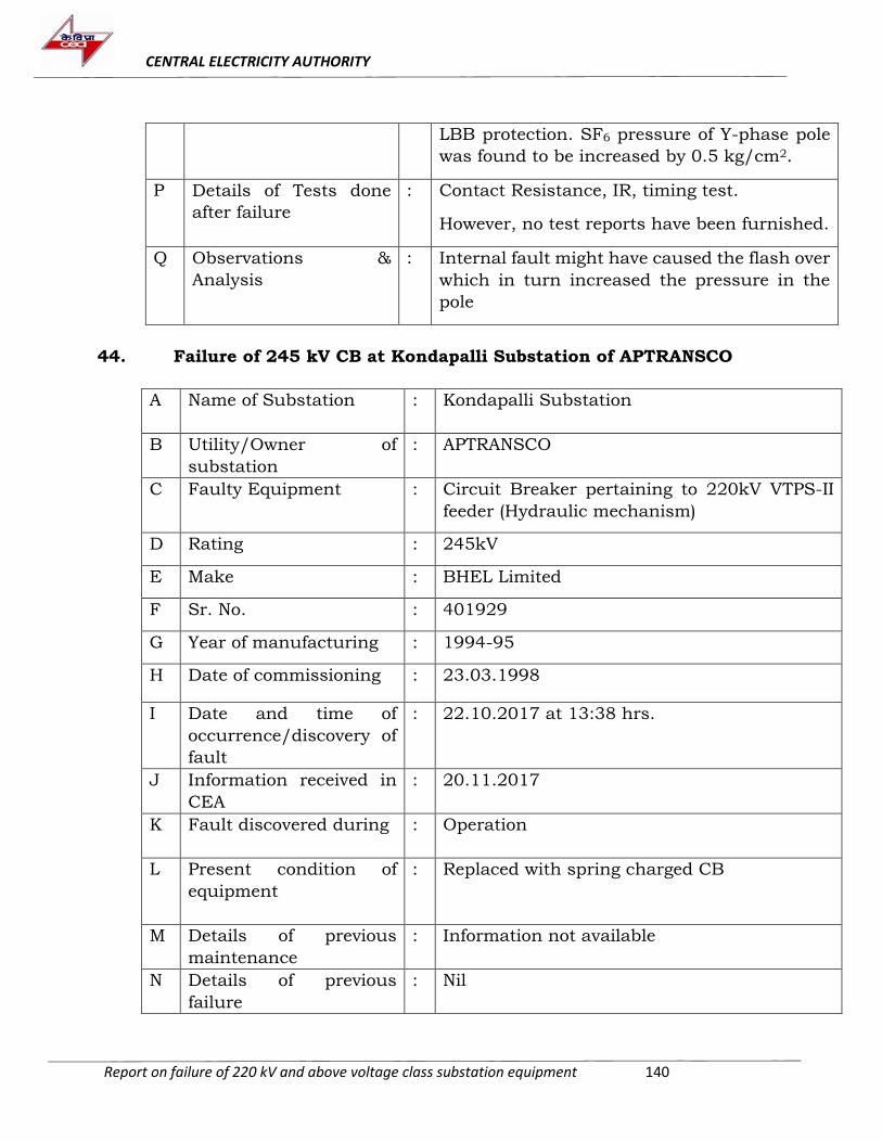
CENTRAL ELECTRICITY AUTHORITY
Report on failure of 220 kV and above voltage class substation equipment 140
LBB protection. SF6 pressure of Y-phase pole
was found to be increased by 0.5 kg/cm2.
P Details of Tests done
after failure
: Contact Resistance, IR, timing test.
However, no test reports have been furnished.
Q Observations &
Analysis
: Internal fault might have caused the flash over
which in turn increased the pressure in the
pole
44. Failure of 245 kV CB at Kondapalli Substation of APTRANSCO
A Name of Substation : Kondapalli Substation
B Utility/Owner of
substation
: APTRANSCO
C Faulty Equipment : Circuit Breaker pertaining to 220kV VTPS-II
feeder (Hydraulic mechanism)
D Rating : 245kV
E Make : BHEL Limited
F Sr. No. : 401929
G Year of manufacturing : 1994-95
H Date of commissioning : 23.03.1998
I Date and time of
occurrence/discovery of
fault
: 22.10.2017 at 13:38 hrs.
J Information received in
CEA
: 20.11.2017
K Fault discovered during : Operation
L Present condition of
equipment
: Replaced with spring charged CB
M Details of previous
maintenance
: Information not available
N Details of previous
failure
: Nil
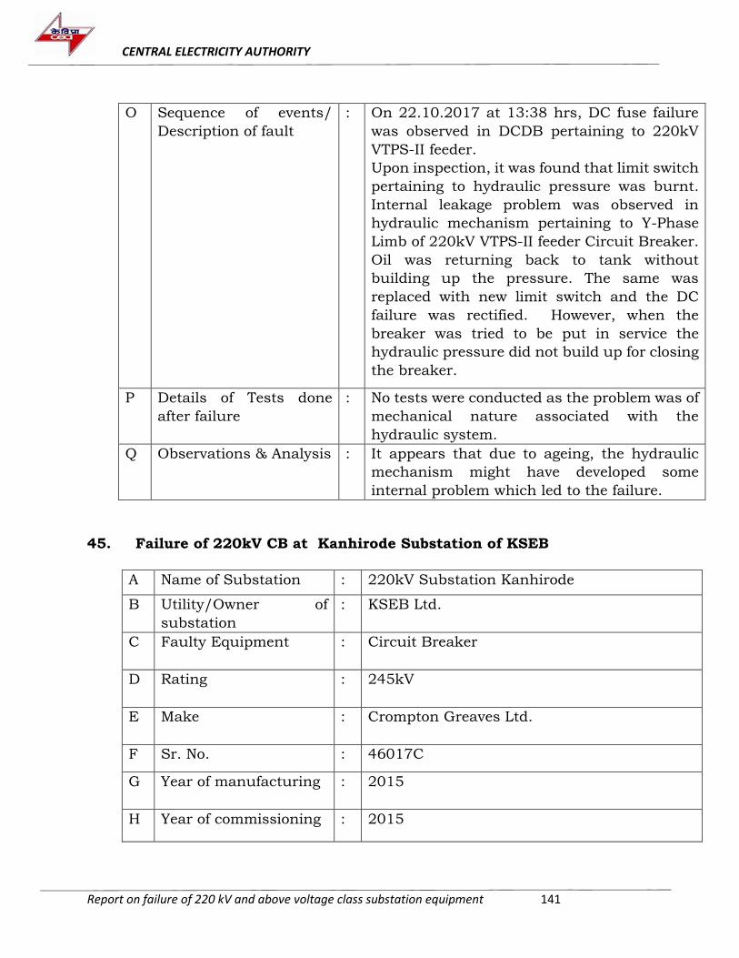
CENTRAL ELECTRICITY AUTHORITY
Report on failure of 220 kV and above voltage class substation equipment 141
O Sequence of events/
Description of fault
: On 22.10.2017 at 13:38 hrs, DC fuse failure
was observed in DCDB pertaining to 220kV
VTPS-II feeder.
Upon inspection, it was found that limit switch
pertaining to hydraulic pressure was burnt.
Internal leakage problem was observed in
hydraulic mechanism pertaining to Y-Phase
Limb of 220kV VTPS-II feeder Circuit Breaker.
Oil was returning back to tank without
building up the pressure. The same was
replaced with new limit switch and the DC
failure was rectified. However, when the
breaker was tried to be put in service the
hydraulic pressure did not build up for closing
the breaker.
P Details of Tests done
after failure
: No tests were conducted as the problem was of
mechanical nature associated with the
hydraulic system.
Q Observations & Analysis
: It appears that due to ageing, the hydraulic
mechanism might have developed some
internal problem which led to the failure.
45. Failure of 220kV CB at Kanhirode Substation of KSEB
A Name of Substation : 220kV Substation Kanhirode
B Utility/Owner of
substation
: KSEB Ltd.
C Faulty Equipment : Circuit Breaker
D Rating : 245kV
E Make : Crompton Greaves Ltd.
F Sr. No. : 46017C
G Year of manufacturing : 2015
H Year of commissioning : 2015
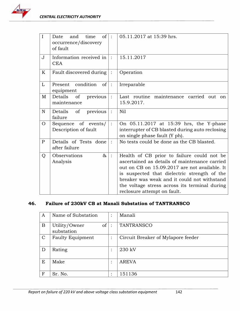
CENTRAL ELECTRICITY AUTHORITY
Report on failure of 220 kV and above voltage class substation equipment 142
I Date and time of
occurrence/discovery
of fault
: 05.11.2017 at 15:39 hrs.
J Information received in
CEA
: 15.11.2017
K Fault discovered during : Operation
L Present condition of
equipment
: Irreparable
M Details of previous
maintenance
: Last routine maintenance carried out on
15.9.2017.
N Details of previous
failure
: Nil
O Sequence of events/
Description of fault
: On 05.11.2017 at 15:39 hrs, the Y-phase
interrupter of CB blasted during auto reclosing
on single phase fault (Y ph).
P Details of Tests done
after failure
: No tests could be done as the CB blasted.
Q Observations &
Analysis
: Health of CB prior to failure could not be
ascertained as details of maintenance carried
out on CB on 15.09.2017 are not available. It
is suspected that dielectric strength of the
breaker was weak and it could not withstand
the voltage stress across its terminal during
reclosure attempt on fault.
46. Failure of 230kV CB at Manali Substation of TANTRANSCO
A Name of Substation : Manali
B Utility/Owner of
substation
: TANTRANSCO
C Faulty Equipment : Circuit Breaker of Mylapore feeder
D Rating : 230 kV
E Make : AREVA
F Sr. No. : 151136
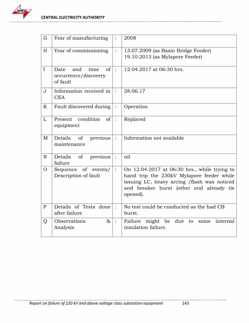
CENTRAL ELECTRICITY AUTHORITY
Report on failure of 220 kV and above voltage class substation equipment 143
G Year of manufacturing : 2008
H Year of commissioning : 13.07.2009 (as Basin Bridge Feeder)
19.10.2013 (as Mylapore Feeder)
I Date and time of
occurrence/discovery
of fault
: 12.04.2017 at 06:30 hrs.
J Information received in
CEA
: 28.06.17
K Fault discovered during : Operation
L Present condition of
equipment
: Replaced
M Details of previous
maintenance
: Information not available
N Details of previous
failure
: nil
O Sequence of events/
Description of fault
: On 12.04.2017 at 06:30 hrs., while trying to
hand trip the 230kV Mylapore feeder while
issuing LC, heavy arcing /flash was noticed
and breaker burst (other end already tie
opened).
P Details of Tests done
after failure
: No test could be conducted as the had CB
burst.
Q Observations &
Analysis
: Failure might be due to some internal
insulation failure.
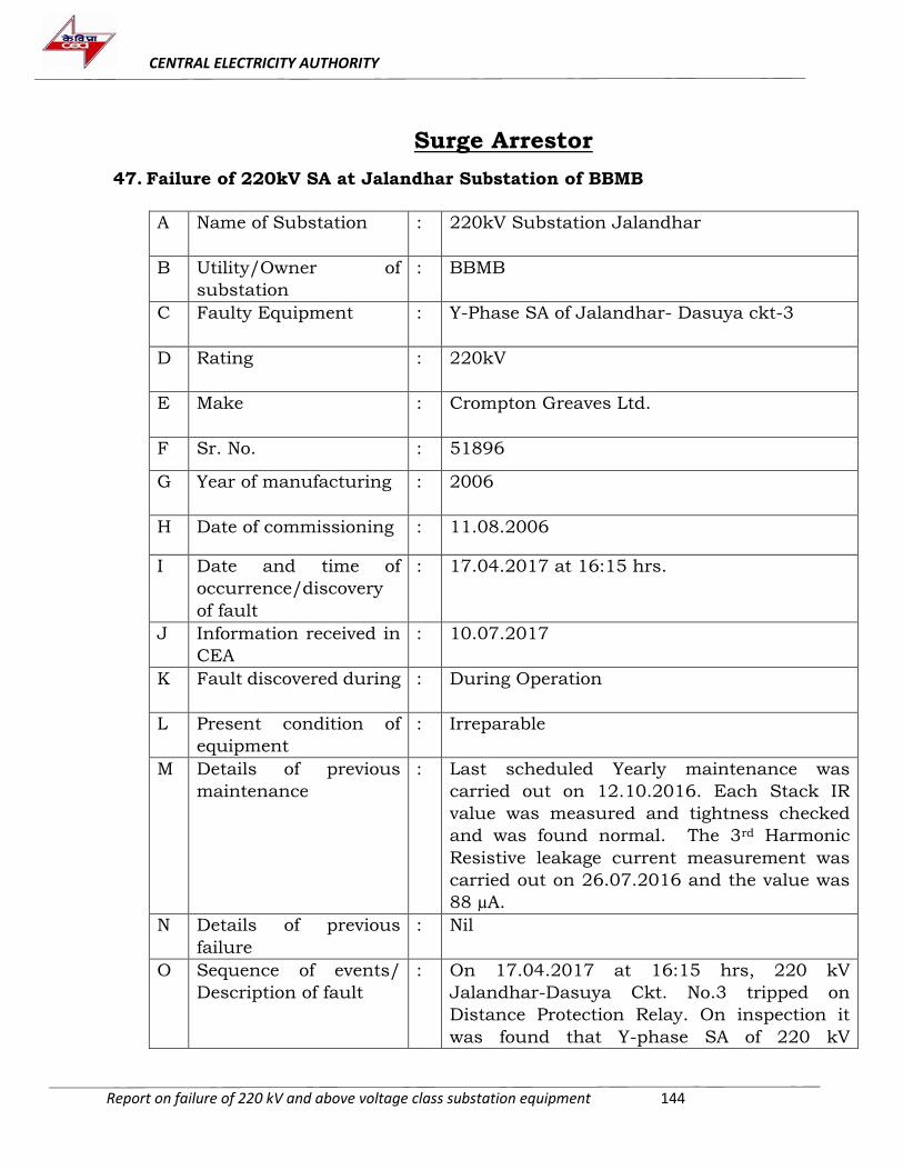
CENTRAL ELECTRICITY AUTHORITY
Report on failure of 220 kV and above voltage class substation equipment 144
Surge Arrestor
47. Failure of 220kV SA at Jalandhar Substation of BBMB
A Name of Substation : 220kV Substation Jalandhar
B Utility/Owner of
substation
: BBMB
C Faulty Equipment : Y-Phase SA of Jalandhar- Dasuya ckt-3
D Rating : 220kV
E Make : Crompton Greaves Ltd.
F Sr. No. : 51896
G Year of manufacturing : 2006
H Date of commissioning : 11.08.2006
I Date and time of
occurrence/discovery
of fault
: 17.04.2017 at 16:15 hrs.
J Information received in
CEA
: 10.07.2017
K Fault discovered during : During Operation
L Present condition of
equipment
: Irreparable
M Details of previous
maintenance
: Last scheduled Yearly maintenance was
carried out on 12.10.2016. Each Stack IR
value was measured and tightness checked
and was found normal. The 3rd Harmonic
Resistive leakage current measurement was
carried out on 26.07.2016 and the value was
88 µA.
N Details of previous
failure
: Nil
O Sequence of events/
Description of fault
: On 17.04.2017 at 16:15 hrs, 220 kV
Jalandhar-Dasuya Ckt. No.3 tripped on
Distance Protection Relay. On inspection it
was found that Y-phase SA of 220 kV
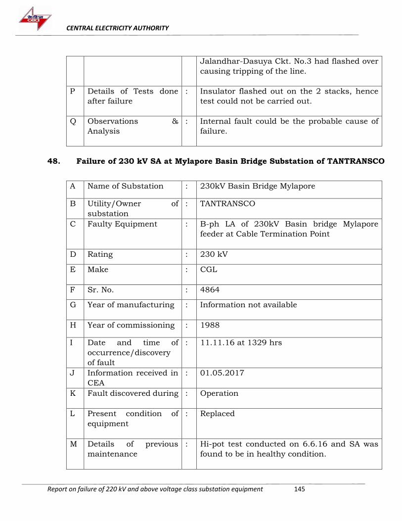
CENTRAL ELECTRICITY AUTHORITY
Report on failure of 220 kV and above voltage class substation equipment 145
Jalandhar-Dasuya Ckt. No.3 had flashed over
causing tripping of the line.
P Details of Tests done
after failure
: Insulator flashed out on the 2 stacks, hence
test could not be carried out.
Q Observations &
Analysis
: Internal fault could be the probable cause of
failure.
48. Failure of 230 kV SA at Mylapore Basin Bridge Substation of TANTRANSCO
A Name of Substation : 230kV Basin Bridge Mylapore
B Utility/Owner of
substation
: TANTRANSCO
C Faulty Equipment : B-ph LA of 230kV Basin bridge Mylapore
feeder at Cable Termination Point
D Rating : 230 kV
E Make : CGL
F Sr. No. : 4864
G Year of manufacturing : Information not available
H Year of commissioning : 1988
I Date and time of
occurrence/discovery
of fault
: 11.11.16 at 1329 hrs
J Information received in
CEA
: 01.05.2017
K Fault discovered during : Operation
L Present condition of
equipment
: Replaced
M Details of previous
maintenance
: Hi-pot test conducted on 6.6.16 and SA was
found to be in healthy condition.
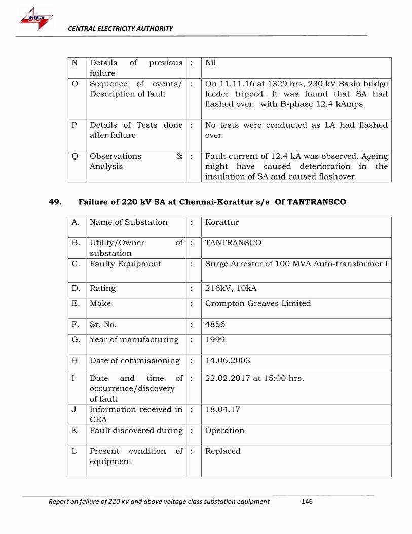
CENTRAL ELECTRICITY AUTHORITY
Report on failure of 220 kV and above voltage class substation equipment 146
N Details of previous
failure
: Nil
O Sequence of events/
Description of fault
: On 11.11.16 at 1329 hrs, 230 kV Basin bridge
feeder tripped. It was found that SA had
flashed over. with B-phase 12.4 kAmps.
P Details of Tests done
after failure
: No tests were conducted as LA had flashed
over
Q Observations &
Analysis
: Fault current of 12.4 kA was observed. Ageing
might have caused deterioration in the
insulation of SA and caused flashover.
49. Failure of 220 kV SA at Chennai-Korattur s/s Of TANTRANSCO
A. Name of Substation : Korattur
B. Utility/Owner of
substation
: TANTRANSCO
C. Faulty Equipment : Surge Arrester of 100 MVA Auto-transformer I
D. Rating : 216kV, 10kA
E. Make : Crompton Greaves Limited
F. Sr. No. : 4856
G. Year of manufacturing : 1999
H Date of commissioning : 14.06.2003
I Date and time of
occurrence/discovery
of fault
: 22.02.2017 at 15:00 hrs.
J Information received in
CEA
: 18.04.17
K Fault discovered during : Operation
L Present condition of
equipment
: Replaced
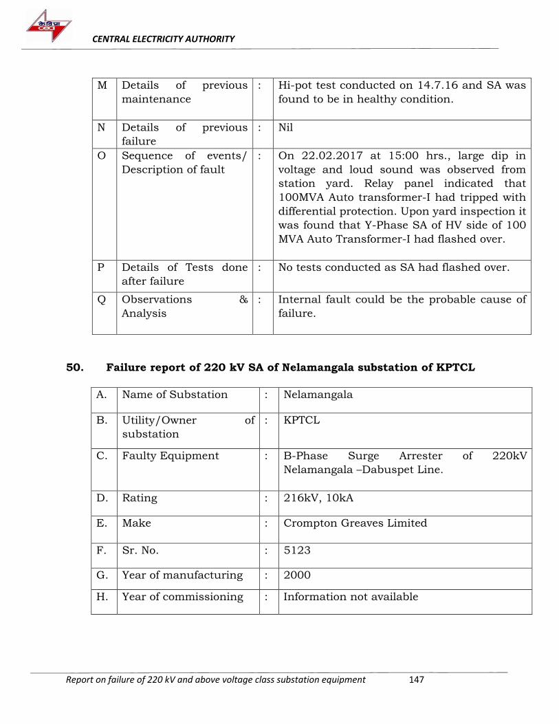
CENTRAL ELECTRICITY AUTHORITY
Report on failure of 220 kV and above voltage class substation equipment 147
M Details of previous
maintenance
: Hi-pot test conducted on 14.7.16 and SA was
found to be in healthy condition.
N Details of previous
failure
: Nil
O Sequence of events/
Description of fault
: On 22.02.2017 at 15:00 hrs., large dip in
voltage and loud sound was observed from
station yard. Relay panel indicated that
100MVA Auto transformer-I had tripped with
differential protection. Upon yard inspection it
was found that Y-Phase SA of HV side of 100
MVA Auto Transformer-I had flashed over.
P Details of Tests done
after failure
: No tests conducted as SA had flashed over.
Q Observations &
Analysis
: Internal fault could be the probable cause of
failure.
50. Failure report of 220 kV SA of Nelamangala substation of KPTCL
A. Name of Substation : Nelamangala
B. Utility/Owner of
substation
: KPTCL
C. Faulty Equipment : B-Phase Surge Arrester of 220kV
Nelamangala –Dabuspet Line.
D. Rating : 216kV, 10kA
E. Make : Crompton Greaves Limited
F. Sr. No. : 5123
G. Year of manufacturing : 2000
H. Year of commissioning : Information not available
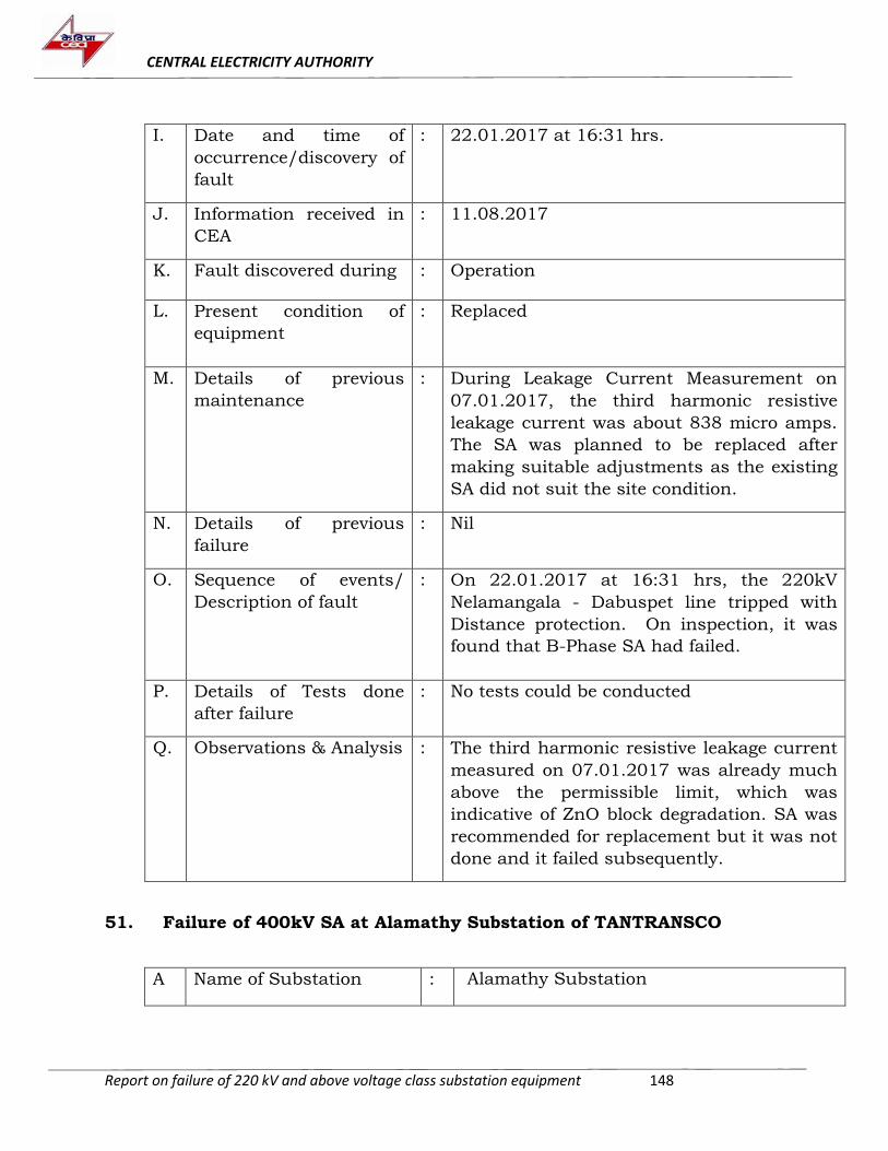
CENTRAL ELECTRICITY AUTHORITY
Report on failure of 220 kV and above voltage class substation equipment 148
I. Date and time of
occurrence/discovery of
fault
: 22.01.2017 at 16:31 hrs.
J. Information received in
CEA
: 11.08.2017
K. Fault discovered during : Operation
L. Present condition of
equipment
: Replaced
M. Details of previous
maintenance
: During Leakage Current Measurement on
07.01.2017, the third harmonic resistive
leakage current was about 838 micro amps.
The SA was planned to be replaced after
making suitable adjustments as the existing
SA did not suit the site condition.
N. Details of previous
failure
: Nil
O. Sequence of events/
Description of fault
: On 22.01.2017 at 16:31 hrs, the 220kV
Nelamangala - Dabuspet line tripped with
Distance protection. On inspection, it was
found that B-Phase SA had failed.
P. Details of Tests done
after failure
: No tests could be conducted
Q. Observations & Analysis : The third harmonic resistive leakage current
measured on 07.01.2017 was already much
above the permissible limit, which was
indicative of ZnO block degradation. SA was
recommended for replacement but it was not
done and it failed subsequently.
51. Failure of 400kV SA at Alamathy Substation of TANTRANSCO
A Name of Substation : Alamathy Substation
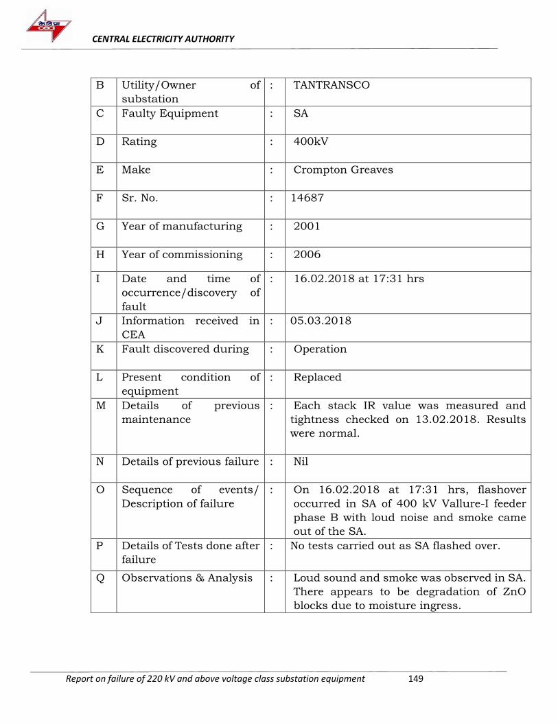
CENTRAL ELECTRICITY AUTHORITY
Report on failure of 220 kV and above voltage class substation equipment 149
B Utility/Owner of
substation
: TANTRANSCO
C Faulty Equipment : SA
D Rating : 400kV
E Make : Crompton Greaves
F Sr. No. : 14687
G Year of manufacturing : 2001
H Year of commissioning : 2006
I Date and time of
occurrence/discovery of
fault
: 16.02.2018 at 17:31 hrs
J Information received in
CEA
: 05.03.2018
K Fault discovered during : Operation
L Present condition of
equipment
: Replaced
M Details of previous
maintenance
: Each stack IR value was measured and
tightness checked on 13.02.2018. Results
were normal.
N Details of previous failure : Nil
O Sequence of events/
Description of failure
: On 16.02.2018 at 17:31 hrs, flashover
occurred in SA of 400 kV Vallure-I feeder
phase B with loud noise and smoke came
out of the SA.
P Details of Tests done after
failure
: No tests carried out as SA flashed over.
Q Observations & Analysis : Loud sound and smoke was observed in SA.
There appears to be degradation of ZnO
blocks due to moisture ingress.
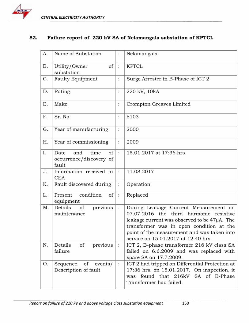
CENTRAL ELECTRICITY AUTHORITY
Report on failure of 220 kV and above voltage class substation equipment 150
52. Failure report of 220 kV SA of Nelamangala substation of KPTCL
A. Name of Substation : Nelamangala
B. Utility/Owner of
substation
: KPTCL
C. Faulty Equipment : Surge Arrester in B-Phase of ICT 2
D. Rating : 220 kV, 10kA
E. Make : Crompton Greaves Limited
F. Sr. No. : 5103
G. Year of manufacturing : 2000
H. Year of commissioning : 2009
I. Date and time of
occurrence/discovery of
fault
: 15.01.2017 at 17:36 hrs.
J. Information received in
CEA
: 11.08.2017
K. Fault discovered during : Operation
L. Present condition of
equipment
: Replaced
M. Details of previous
maintenance
: During Leakage Current Measurement on
07.07.2016 the third harmonic resistive
leakage current was observed to be 47µA. The
transformer was in open condition at the
point of the measurement and was taken into
service on 15.01.2017 at 12:40 hrs.
N. Details of previous
failure
: ICT 2, B-phase transformer 216 kV class SA
failed on 6.6.2009 and was replaced with
spare SA on 17.7.2009.
O. Sequence of events/
Description of fault
: ICT 2 had tripped on Differential Protection at
17:36 hrs. on 15.01.2017. On inspection, it
was found that 216kV SA of B-Phase
Transformer had failed.
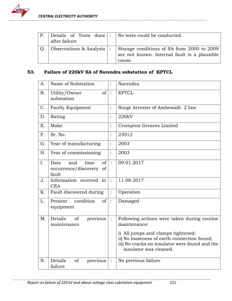
CENTRAL ELECTRICITY AUTHORITY
Report on failure of 220 kV and above voltage class substation equipment 151
P. Details of Tests done
after failure
: No tests could be conducted.
Q. Observations & Analysis
: Storage conditions of SA from 2000 to 2009
are not known. Internal fault is a plausible
cause.
53. Failure of 220kV SA of Narendra substation of KPTCL
A. Name of Substation : Narendra
B. Utility/Owner of
substation
: KPTCL
C. Faulty Equipment : Surge Arrester of Ambewadi- 2 line
D. Rating : 220kV
E. Make : Crompton Greaves Limited
F. Sr. No. : 23912
G. Year of manufacturing : 2003
H. Year of commissioning : 2003
I. Date and time of
occurrence/discovery of
fault
: 09.01.2017
J. Information received in
CEA
: 11.08.2017
K. Fault discovered during : Operation
L. Present condition of
equipment
: Damaged
M. Details of previous
maintenance
: Following actions were taken during routine
maintenance:
i) All jumps and clamps tightened; ii) No looseness of earth connection found; iii) No cracks on insulator were found and the
insulator was cleaned.
N. Details of previous
failure
: No previous failure
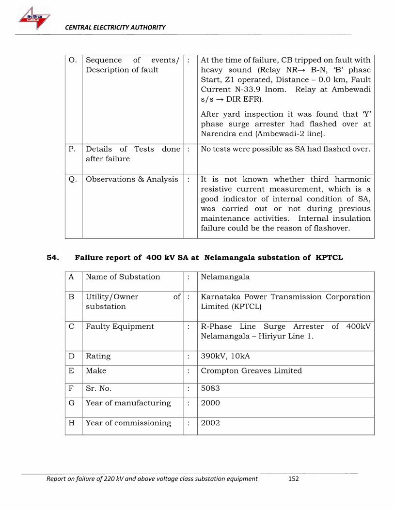
CENTRAL ELECTRICITY AUTHORITY
Report on failure of 220 kV and above voltage class substation equipment 152
O. Sequence of events/
Description of fault
: At the time of failure, CB tripped on fault with
heavy sound (Relay NR→ B-N, ‘B’ phase
Start, Z1 operated, Distance – 0.0 km, Fault
Current N-33.9 Inom. Relay at Ambewadi
s/s → DIR EFR).
After yard inspection it was found that ‘Y’
phase surge arrester had flashed over at
Narendra end (Ambewadi-2 line).
P. Details of Tests done
after failure
: No tests were possible as SA had flashed over.
Q. Observations & Analysis
: It is not known whether third harmonic
resistive current measurement, which is a
good indicator of internal condition of SA,
was carried out or not during previous
maintenance activities. Internal insulation
failure could be the reason of flashover.
54. Failure report of 400 kV SA at Nelamangala substation of KPTCL
A Name of Substation : Nelamangala
B Utility/Owner of
substation
: Karnataka Power Transmission Corporation
Limited (KPTCL)
C Faulty Equipment : R-Phase Line Surge Arrester of 400kV
Nelamangala – Hiriyur Line 1.
D Rating : 390kV, 10kA
E Make : Crompton Greaves Limited
F Sr. No. : 5083
G Year of manufacturing : 2000
H Year of commissioning : 2002
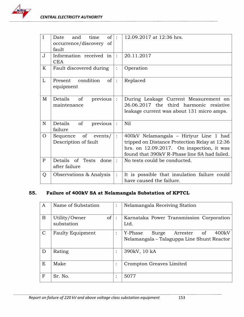
CENTRAL ELECTRICITY AUTHORITY
Report on failure of 220 kV and above voltage class substation equipment 153
I Date and time of
occurrence/discovery of
fault
: 12.09.2017 at 12:36 hrs.
J Information received in
CEA
: 20.11.2017
K Fault discovered during : Operation
L Present condition of
equipment
: Replaced
M Details of previous
maintenance
: During Leakage Current Measurement on
26.06.2017 the third harmonic resistive
leakage current was about 131 micro amps.
N Details of previous
failure
: Nil
O Sequence of events/
Description of fault
: 400kV Nelamangala – Hiriyur Line 1 had
tripped on Distance Protection Relay at 12:36
hrs. on 12.09.2017. On inspection, it was
found that 390kV R-Phase line SA had failed.
P Details of Tests done
after failure
: No tests could be conducted.
Q Observations & Analysis
: It is possible that insulation failure could
have caused the failure.
55. Failure of 400kV SA at Nelamangala Substation of KPTCL
A Name of Substation : Nelamangala Receiving Station
B Utility/Owner of
substation
: Karnataka Power Transmission Corporation
Ltd.
C Faulty Equipment : Y-Phase Surge Arrester of 400kV
Nelamangala – Talaguppa Line Shunt Reactor
D Rating : 390kV, 10 kA
E Make : Crompton Greaves Limited
F Sr. No. : 5077
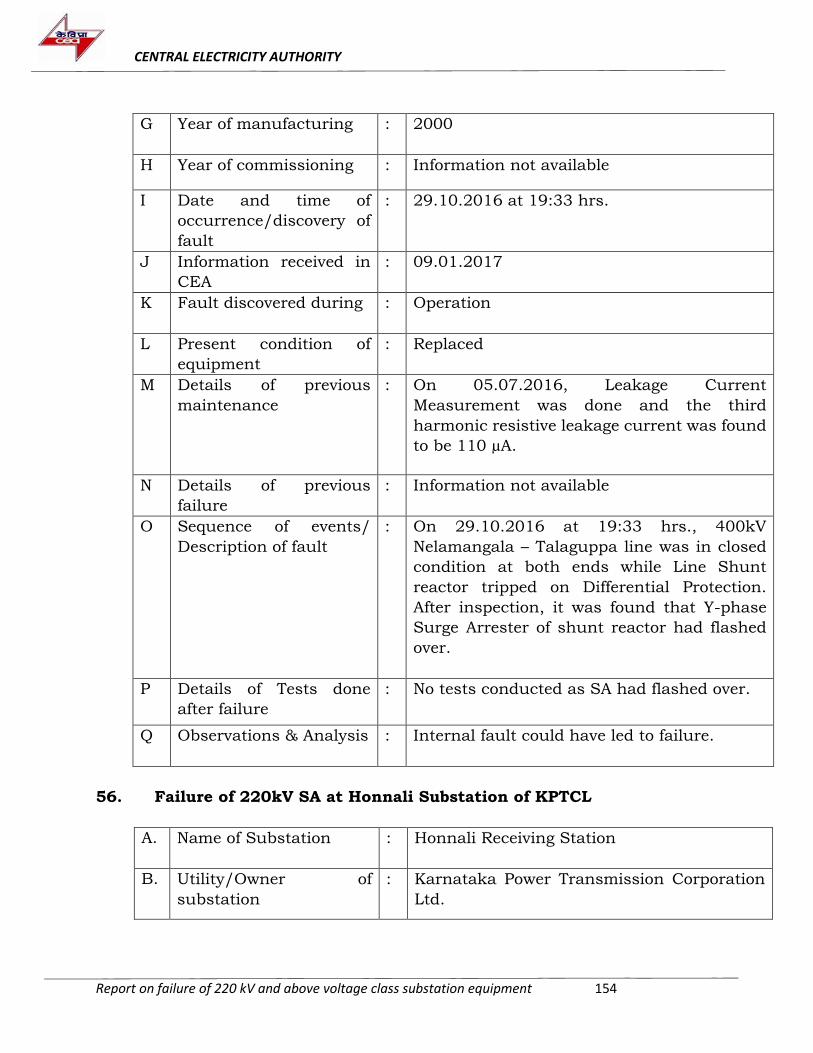
CENTRAL ELECTRICITY AUTHORITY
Report on failure of 220 kV and above voltage class substation equipment 154
G Year of manufacturing : 2000
H Year of commissioning : Information not available
I Date and time of
occurrence/discovery of
fault
: 29.10.2016 at 19:33 hrs.
J Information received in
CEA
: 09.01.2017
K Fault discovered during : Operation
L Present condition of
equipment
: Replaced
M Details of previous
maintenance
: On 05.07.2016, Leakage Current
Measurement was done and the third
harmonic resistive leakage current was found
to be 110 µA.
N Details of previous
failure
: Information not available
O Sequence of events/
Description of fault
: On 29.10.2016 at 19:33 hrs., 400kV
Nelamangala – Talaguppa line was in closed
condition at both ends while Line Shunt
reactor tripped on Differential Protection.
After inspection, it was found that Y-phase
Surge Arrester of shunt reactor had flashed
over.
P Details of Tests done
after failure
: No tests conducted as SA had flashed over.
Q Observations & Analysis
: Internal fault could have led to failure.
56. Failure of 220kV SA at Honnali Substation of KPTCL
A. Name of Substation : Honnali Receiving Station
B. Utility/Owner of
substation
: Karnataka Power Transmission Corporation
Ltd.
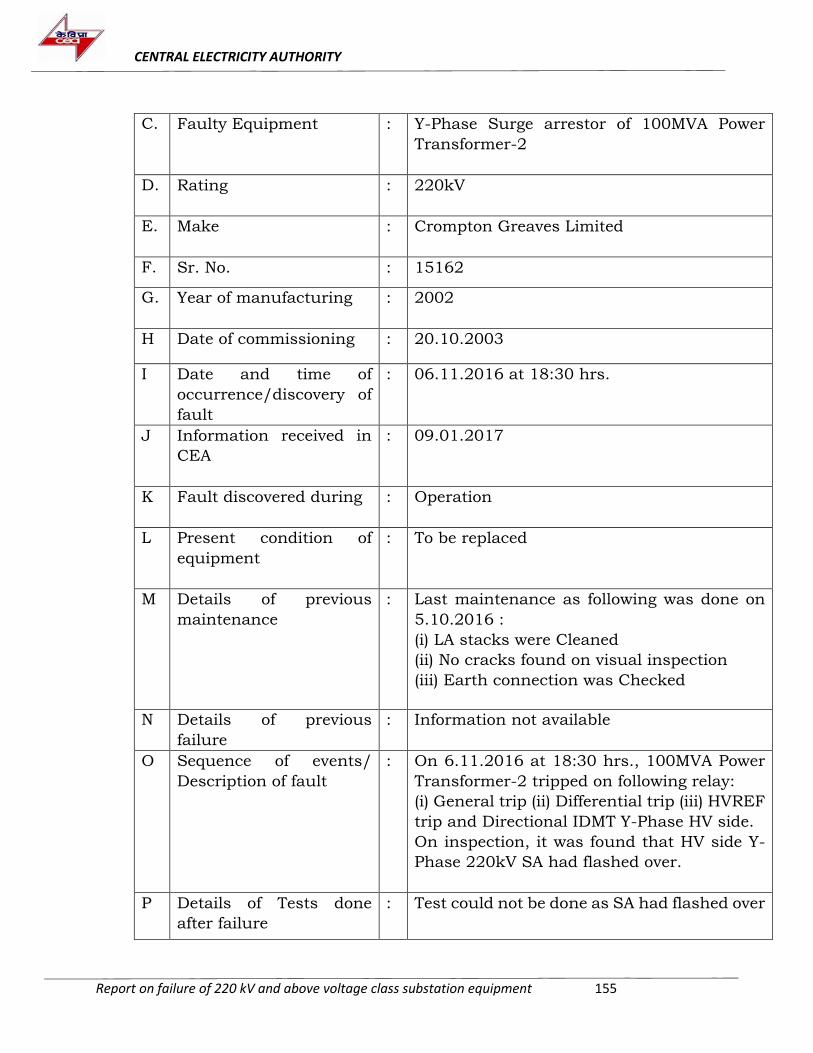
CENTRAL ELECTRICITY AUTHORITY
Report on failure of 220 kV and above voltage class substation equipment 155
C. Faulty Equipment : Y-Phase Surge arrestor of 100MVA Power
Transformer-2
D. Rating : 220kV
E. Make : Crompton Greaves Limited
F. Sr. No. : 15162
G. Year of manufacturing : 2002
H Date of commissioning : 20.10.2003
I Date and time of
occurrence/discovery of
fault
: 06.11.2016 at 18:30 hrs.
J Information received in
CEA
: 09.01.2017
K Fault discovered during : Operation
L Present condition of
equipment
: To be replaced
M Details of previous
maintenance
: Last maintenance as following was done on
5.10.2016 :
(i) LA stacks were Cleaned
(ii) No cracks found on visual inspection
(iii) Earth connection was Checked
N Details of previous
failure
: Information not available
O Sequence of events/
Description of fault
: On 6.11.2016 at 18:30 hrs., 100MVA Power
Transformer-2 tripped on following relay:
(i) General trip (ii) Differential trip (iii) HVREF
trip and Directional IDMT Y-Phase HV side.
On inspection, it was found that HV side Y-
Phase 220kV SA had flashed over.
P Details of Tests done
after failure
: Test could not be done as SA had flashed over
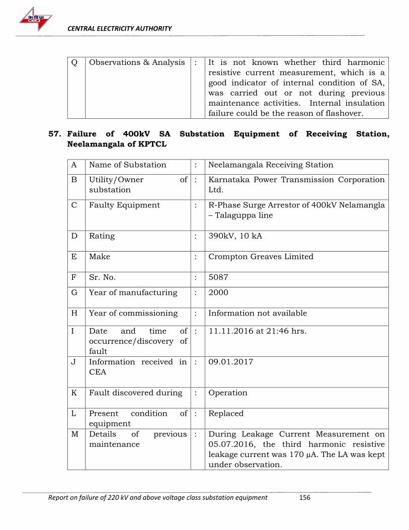
CENTRAL ELECTRICITY AUTHORITY
Report on failure of 220 kV and above voltage class substation equipment 156
Q Observations & Analysis
: It is not known whether third harmonic
resistive current measurement, which is a
good indicator of internal condition of SA,
was carried out or not during previous
maintenance activities. Internal insulation
failure could be the reason of flashover.
57. Failure of 400kV SA Substation Equipment of Receiving Station,
Neelamangala of KPTCL
A Name of Substation : Neelamangala Receiving Station
B Utility/Owner of
substation
: Karnataka Power Transmission Corporation
Ltd.
C Faulty Equipment : R-Phase Surge Arrestor of 400kV Nelamangla
– Talaguppa line
D Rating : 390kV, 10 kA
E Make : Crompton Greaves Limited
F Sr. No. : 5087
G Year of manufacturing : 2000
H Year of commissioning : Information not available
I Date and time of
occurrence/discovery of
fault
: 11.11.2016 at 21:46 hrs.
J Information received in
CEA
: 09.01.2017
K Fault discovered during : Operation
L Present condition of
equipment
: Replaced
M Details of previous
maintenance
: During Leakage Current Measurement on
05.07.2016, the third harmonic resistive
leakage current was 170 µA. The LA was kept
under observation.
CENTRAL ELECTRICITY AUTHORITY
Report on failure of 220 kV and above voltage class substation equipment 157
N Details of previous
failure
: Information not available
O Sequence of events/
Description of fault
: On 11.11.2016 at 21:46 hrs., the R-Phase
Surge Arrestor of 400kV Nelamangla –
Talaguppa line flashed over.
400kV Nelamangala – Talaguppa Line Main 1
& 2 protection operated and autoreclosing
was unsuccessful.
P Details of Tests done
after failure
: No test could be conducted as SA flashed
over.
Q Observations & Analysis
: During previous maintenance, after 3rd
harmonic component of resistive current was
found to be is more than 150 μA, Insulation
Resistance (IR) value test should have been
conducted to assess internal condition of the
SA.
Degradation of ZnO block seems to be cause
of failure of SA.
58. Failure of 220kV SA at Honnali Substation of KPTCL
A Name of Substation : Honnali Receiving Station
B Utility/Owner of
substation
: Karnataka Power Transmission Corporation
Ltd.
C Faulty Equipment : Y-Phase Surge Arrestor of 220 kV Shimoga
line
D Rating : 220 kV
E Make : Crompton Greaves Limited
F Sr. No. : 15157
G Year of manufacturing : 2002
H Date of commissioning : 20.10.2003
CENTRAL ELECTRICITY AUTHORITY
Report on failure of 220 kV and above voltage class substation equipment 158
I Date and time of
occurrence/discovery of
fault
: 18.11.2016 at 15:09 hrs.
J Information received in
CEA
: 09.01.2017
K Fault discovered during : Operation
L Present condition of
equipment
: To be replaced.
M Details of previous
maintenance
: Last maintenance carried out on 31.08.2016
(i) SA stacks were cleaned and no cracks were
found;
(ii) Earth connections were checked.
N Details of previous
failure
: Information not available
O Sequence of events/
Description of fault
: On 18.11.2016 at 15:09 hrs. 220kV Shimoga
Line tripped on distance relay. Distance
4.1km, Y-Phase to N, Zone-1 fault current
6.43kA. On inspection, it was found that Y-
Phase SA had flashed over.
P Details of Tests done
after failure
: No test could be done as SA had flashed over.
Q Observations & Analysis
: Internal fault might be the probable cause of
failure.
59. Failure of 220kV SA at Kemar, Karkala Substation of KPTCL
A Name of Substation : Kemar Receiving Station, Karkala
B Utility/Owner of
substation
: Karnataka Power Transmission Corporation
Ltd.
C Faulty Equipment : Surge Arrestor
D Rating : 198kV
E Make : Crompton Greaves Limited
CENTRAL ELECTRICITY AUTHORITY
Report on failure of 220 kV and above voltage class substation equipment 159
F Sr. No. : 9507303
G Year of manufacturing : 1995
H Year of commissioning : 1999
I Date and time of
occurrence/discovery of
fault
: 19.11.2016 at 16:53 hrs.
J Information received in
CEA
: 09.01.2017
K Fault discovered during : Operation
L Present condition of
equipment
: Replaced
M Details of previous
maintenance
: During maintenance of the bay equipment on
17.09.2016, leakage current of the Surge
arresters was measured and found within
limits.
N Details of previous
failure
: Information not available
O Sequence of events/
Description of fault
: On 19.11.2016 at 16:53 hrs., the 100MVA
Power Transformer tripped with a loud
sound. On Inspection/checking the yard, the
burn marks were found at the bottom of the
“Y” Phase Surge Arrester with smoke
emanating from it.
P Details of Tests done
after failure
: No tests could be conducted as SA had burnt.
Q Observations & Analysis
: Weakened insulation due to ageing could be
the probable cause of failure.
60. Failure report of 220kV SA at Sangrur Substation of BBMB
A Name of Substation : Sangrur
B Utility/Owner of
substation
: BBMB
CENTRAL ELECTRICITY AUTHORITY
Report on failure of 220 kV and above voltage class substation equipment 160
C Faulty Equipment : SA (B-phase of Sangrur –Barnala line)
D Rating : 198kV
E Make : CGL
F Sr. No. : 51889
G Year of manufacturing : 2006
H Date of commissioning : 04.10.2006
I Date and time of
occurrence/discovery
of fault
: 18.12.2016 at 00:48 hrs.
J Information received in
CEA
: 31.01.17
K Fault discovered during : Operation
L Present condition of
equipment
: Not known
M Details of previous
maintenance
: Last annual maintenance done on 23.11.16.
Details or results of any tests done during
maintenance are not available.
N Details of previous
failure
: Nil
O Sequence of events/
Description of fault
: On 18.12.16 at 0048 hrs, B-ph SA of 220 kV
Sangrur-Barnala S/C burst during normal
operation at 220 kV GSS BBMB, Sangrur.
P Details of Tests done
after failure
: No tests done as the SA had burst.
Q Observations &
Analysis
: Internal fault could be the probable cause of
failure.
61. Failure of 220kV SA at Tallapalli Substation of APTRANSCO
A Name of Substation : Tallapalli
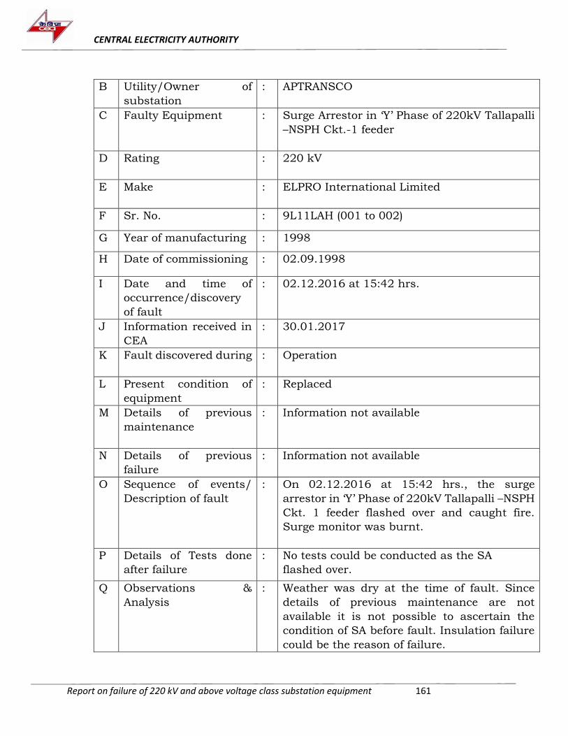
CENTRAL ELECTRICITY AUTHORITY
Report on failure of 220 kV and above voltage class substation equipment 161
B Utility/Owner of
substation
: APTRANSCO
C Faulty Equipment : Surge Arrestor in ‘Y’ Phase of 220kV Tallapalli
–NSPH Ckt.-1 feeder
D Rating : 220 kV
E Make : ELPRO International Limited
F Sr. No. : 9L11LAH (001 to 002)
G Year of manufacturing : 1998
H Date of commissioning : 02.09.1998
I Date and time of
occurrence/discovery
of fault
: 02.12.2016 at 15:42 hrs.
J Information received in
CEA
: 30.01.2017
K Fault discovered during : Operation
L Present condition of
equipment
: Replaced
M Details of previous
maintenance
: Information not available
N Details of previous
failure
: Information not available
O Sequence of events/
Description of fault
: On 02.12.2016 at 15:42 hrs., the surge
arrestor in ‘Y’ Phase of 220kV Tallapalli –NSPH
Ckt. 1 feeder flashed over and caught fire.
Surge monitor was burnt.
P Details of Tests done
after failure
: No tests could be conducted as the SA
flashed over.
Q Observations &
Analysis
: Weather was dry at the time of fault. Since
details of previous maintenance are not
available it is not possible to ascertain the
condition of SA before fault. Insulation failure
could be the reason of failure.
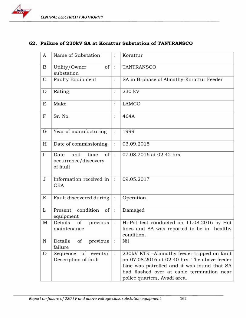
CENTRAL ELECTRICITY AUTHORITY
Report on failure of 220 kV and above voltage class substation equipment 162
62. Failure of 230kV SA at Korattur Substation of TANTRANSCO
A Name of Substation : Korattur
B Utility/Owner of
substation
: TANTRANSCO
C Faulty Equipment : SA in B-phase of Almathy-Korattur Feeder
D Rating : 230 kV
E Make : LAMCO
F Sr. No. : 464A
G Year of manufacturing : 1999
H Date of commissioning : 03.09.2015
I Date and time of
occurrence/discovery
of fault
: 07.08.2016 at 02:42 hrs.
J Information received in
CEA
: 09.05.2017
K Fault discovered during : Operation
L Present condition of
equipment
: Damaged
M Details of previous
maintenance
: Hi-Pot test conducted on 11.08.2016 by Hot
lines and SA was reported to be in healthy
condition.
N Details of previous
failure
: Nil
O Sequence of events/
Description of fault
: 230kV KTR –Alamathy feeder tripped on fault
on 07.08.2016 at 02.40 hrs. The above feeder
Line was patrolled and it was found that SA
had flashed over at cable termination near
police quarters, Avadi area.
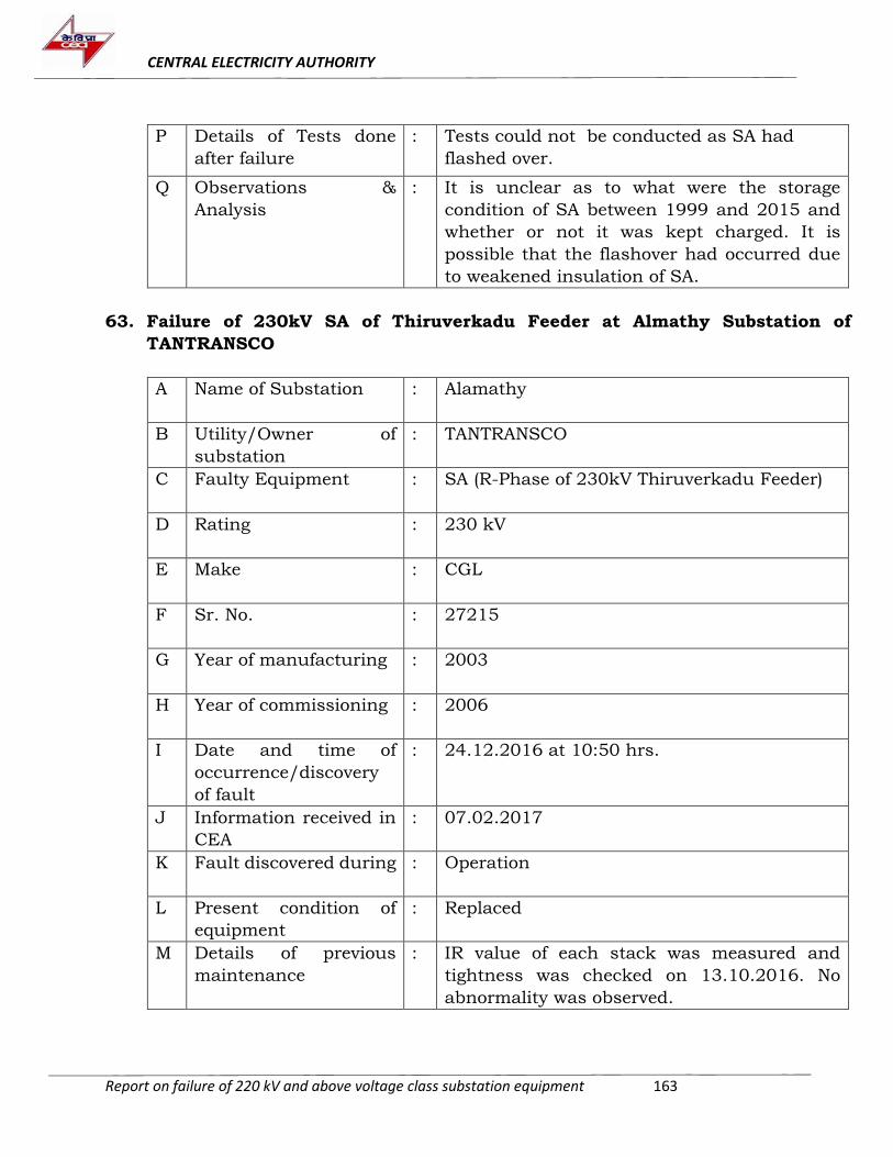
CENTRAL ELECTRICITY AUTHORITY
Report on failure of 220 kV and above voltage class substation equipment 163
P Details of Tests done
after failure
: Tests could not be conducted as SA had
flashed over.
Q Observations &
Analysis
: It is unclear as to what were the storage
condition of SA between 1999 and 2015 and
whether or not it was kept charged. It is
possible that the flashover had occurred due
to weakened insulation of SA.
63. Failure of 230kV SA of Thiruverkadu Feeder at Almathy Substation of
TANTRANSCO
A Name of Substation : Alamathy
B Utility/Owner of
substation
: TANTRANSCO
C Faulty Equipment : SA (R-Phase of 230kV Thiruverkadu Feeder)
D Rating : 230 kV
E Make : CGL
F Sr. No. : 27215
G Year of manufacturing : 2003
H Year of commissioning : 2006
I Date and time of
occurrence/discovery
of fault
: 24.12.2016 at 10:50 hrs.
J Information received in
CEA
: 07.02.2017
K Fault discovered during : Operation
L Present condition of
equipment
: Replaced
M Details of previous
maintenance
: IR value of each stack was measured and
tightness was checked on 13.10.2016. No
abnormality was observed.
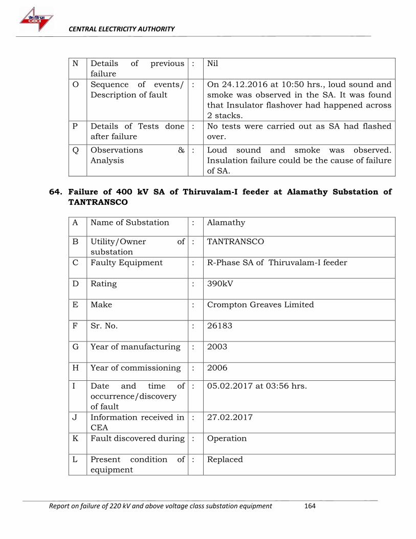
CENTRAL ELECTRICITY AUTHORITY
Report on failure of 220 kV and above voltage class substation equipment 164
N Details of previous
failure
: Nil
O Sequence of events/
Description of fault
: On 24.12.2016 at 10:50 hrs., loud sound and
smoke was observed in the SA. It was found
that Insulator flashover had happened across
2 stacks.
P Details of Tests done
after failure
: No tests were carried out as SA had flashed
over.
Q Observations &
Analysis
: Loud sound and smoke was observed.
Insulation failure could be the cause of failure
of SA.
64. Failure of 400 kV SA of Thiruvalam-I feeder at Alamathy Substation of
TANTRANSCO
A Name of Substation : Alamathy
B Utility/Owner of
substation
: TANTRANSCO
C Faulty Equipment : R-Phase SA of Thiruvalam-I feeder
D Rating : 390kV
E Make : Crompton Greaves Limited
F Sr. No. : 26183
G Year of manufacturing : 2003
H Year of commissioning : 2006
I Date and time of
occurrence/discovery
of fault
: 05.02.2017 at 03:56 hrs.
J Information received in
CEA
: 27.02.2017
K Fault discovered during : Operation
L Present condition of
equipment
: Replaced
CENTRAL ELECTRICITY AUTHORITY
Report on failure of 220 kV and above voltage class substation equipment 165
M Details of previous
maintenance
: IR value of each stack was measured and
tightness was checked on 10.08.2016. No
abnormality was observed.
N Details of previous
failure
: Nil
O Sequence of events/
Description of fault
: On 05.02.2017 at 03:56 hrs., loud sound and
smoke was observed in the SA. It was found
that Insulator flashover had occurred over 2
stacks.
P Details of Tests done
after failure
: No tests were carried out as SA had flashed
over.
Q Observations &
Analysis
: Insulation failure may be the reason of failure
of SA.
65. Failure report of 220 kV R-ph SA of Shimoga line at Honnali s/s of KPTCL
A. Name of Substation : 220 kV R/S Honnali
B. Utility/Owner of
substation
: Karnataka Power Transmission Corporation
Limited
C. Faulty Equipment : Surge arrester in R-Phase of 220 kV Shimoga
line
D. Rating : 220 kV
E. Make : Crompton Greaves
F. Sr. No. : 15163
G. Year of manufacturing : 2002
H Date of commissioning : 20.10.2003
I Date and time of
occurrence/discovery
of fault
: 11.12.2017 at 16:39 Hrs.
J Information received in
CEA
: 11.04.18
K Fault discovered during : Operation
CENTRAL ELECTRICITY AUTHORITY
Report on failure of 220 kV and above voltage class substation equipment 166
L Present condition of
equipment
: Damaged
M Details of previous
maintenance
: On 14.09.2017, following routine maintenance
was done:
SA stacks were cleaned. No cracks were found.
Leakage current was checked and the values
were found to be within limits. Earth
connection was checked.
IR values were measured:
Top to G - 2GΩ
Middle to G-3GΩ
Across stack1-800MΩ
Across stack 2 -1GΩ.
N Details of previous
failure
: Information not available
O Sequence of events/
Description of fault
: On 11.12.2017 at 16:39 hrs , R-ph Surge
arrestor of 220 kV Shimoga line flashed over.
No relay operated. Line was tripped manually.
P Details of Tests done
after Failure
: No tests could be conducted as SA had flashed
over.
Q Observations &
Analysis
: Insulation failure could be the probable cause
of failure of SA.
66. Failure report of 220 kV R-ph SA of 100 MVA Power Transformer -1 at Honnali
s/s of KPTCL
A. Name of Substation : 220 kV Receiving s/s Honnali
B. Utility/Owner of
substation
: Karnataka Power Transmission Corporation
Limited
C. Faulty Equipment : Y-Phase SA of 100 MVA Power Transformer -1
D. Rating : 220 kV
E. Make : CGL
CENTRAL ELECTRICITY AUTHORITY
Report on failure of 220 kV and above voltage class substation equipment 167
F. Sr. No. : 15155
G. Year of manufacturing : 2002
H Date of commissioning : 20.10.2003
I Date and time of
occurrence/discovery
of fault
: 23.02.2018 at 16:35 Hrs.
J Information received in
CEA
: 11.04.18
K Fault discovered during : Operation
L Present condition of
equipment
: To be replaced
M Details of previous
maintenance
: Following maintenance activity was carried
out on 04.01.18:
SA stack was cleaned. No cracks were found.
Earth connection was checked and IR values
were measured.
Top-G-1GΩ
Middle-G-2GΩ
Across stack1- 500 MΩ
Across stack2-800MΩ
N Details of previous
failure
: Information not available
O Sequence of events/
Description of fault
: On 23.02.2018 at 16:35 hrs., 100 MVA Power
transformer-I (CGL make) tripped on the REF
relay MTR 86. On inspection, it was found that
HV side Y-Phase 220 kV SA had flashed over.
P Details of Tests done
after failure
: Insulation Measured :
Top-G -500 MΩ
Middle-G - 600 MΩ
Across Stack-1- 200MΩ
Across Stack-2 - 5MΩ
CENTRAL ELECTRICITY AUTHORITY
Report on failure of 220 kV and above voltage class substation equipment 168
Q Observations &
Analysis
: Insulation resistance measurement carried
out after failure of SA indicated insulation
failure of SA probably due to moisture ingress.
67. Failure report of 220 kV SA at Nelamangala s/s of KPTCL
A. Name of Substation : 400 kV, Nelamangala Receiving Station
B. Utility/Owner of
substation
: Karnataka Power Transmission Corporation
Limited
C. Faulty Equipment : Surge Arrester of R-ph of 220 kV Nel –
Anchepalya line.
D. Rating : 216 kV , 10kA
E. Make : CGL
F. Sr. No. : 5113
G. Year of manufacturing : 2000
H Date of commissioning : 10.06.2002
I Date and time of
occurrence/discovery
of fault
: 07.03.2018 at 1700 hrs.
J Information received in
CEA
: 11.04.2018
K Fault discovered during : Operation
L Present condition of
equipment
: Replaced with OBLUM make SA
M Details of previous
maintenance
: During Leakage Current Measurement on
04.06.2017 the third harmonic resistive
leakage current was about 295 micro amps
which was in increasing trend. It was planned
to replace the SA. However, the replacement
got delayed due to some inadvertent reasons.
CENTRAL ELECTRICITY AUTHORITY
Report on failure of 220 kV and above voltage class substation equipment 169
N Details of previous
failure
: No previous failures
O Sequence of events/
Description of fault
: 220 kV Nelamangala – Anchepalya Line
tripped on distance protection Relays Main 1
and 2 at 17:00 hrs. on 07.03.2018. On
inspection, it was found that 216 kV Surge
Arrester provided for R-Phase of 220 kV Nel –
Anchepalya line had failed.
P Details of Tests done
after failure
: No tests were conducted.
Q Observations &
Analysis
: High leakage current measured during routine
maintenance was indicative of deteriorated
insulation of SA. However, the same could not
be replaced on time and failed subsequently.
68. Failure report of 400 kV R-ph SA of Hoody-1 line at Nelamangala s/s of KPTCL
A. Name of Substation : 400 kV Nelamangala Receiving Station
B. Utility/Owner of
substation
: Karnataka Power Transmission
Corporation Limited
C. Faulty Equipment : Surge Arrester of R-ph of 400 kV
Nelamangala– Hoody Line 1
D. Rating : 390 kV, 10kA
E. Make : CGL
F. Sr. No. : 5075
G. Year of manufacturing : 2000
H. Year of commissioning : 2002
I. Date and time of
occurrence/discovery of
fault
: 21.01.2018 at 18:35 hrs.
J. Information received in
CEA
: 11.04.2018
CENTRAL ELECTRICITY AUTHORITY
Report on failure of 220 kV and above voltage class substation equipment 170
K. Fault discovered during : Operation
L. Present condition of
equipment
: Replaced with available spare of OBLUM
Make bearing S. No.124.
M. Details of previous
maintenance
: During Leakage Current Measurement on
04.01.2018 the third harmonic resistive
leakage current was about 458 micro amps
which was in increasing trend. The SA was
scheduled to be replaced during the week
when the failure occurred.
N. Details of previous
failure
: No information available
O. Sequence of events/
Description of fault
: 400 kV Nelamangala – Hoody Line 1 had
tripped on Single pole. Later 3 pole trip was
generated due to direct trip received from
Hoody end (Distance Protection Relay) at
18:35 hrs. on 21.01.2018. On inspection, it
was found that 390 kV R-Phase Line SA had
failed.
P. Details of Tests done
after failure
: No tests were conducted
Q. Observations & Analysis
: The third harmonic resistive leakage
current value was 458 µA in January 2018,
was indicative of deteriorated insulation of
SA and it needed to be replaced, as was
decided by the utility. However, the same
could not be replaced on time and failed
subsequently.
69. Failure report of 220 kV B-ph SA of Anchepalya Line at Nelamangala s/s of
KPTCL
A. Name of Substation : 400 kV, Nelamangala Receiving Station
B. Utility/Owner of
substation
: Karnataka Power Transmission Corporation
Limited
CENTRAL ELECTRICITY AUTHORITY
Report on failure of 220 kV and above voltage class substation equipment 171
C. Faulty Equipment : B-Phase Surge Arrester of 220 kV
Nelamangala– Anchepalya Line.
D. Rating : 216 kV Class , 10 kA
E. Make : Crompton Greaves Limited
F. Sr. No. : 5111
G. Year of manufacturing : 2000
H. Year of commissioning : 2002 (10.06.2002)
I. Date and time of
occurrence/discovery
of fault
: 07.03.2018 at 1700 hrs
J. Information received in
CEA
: 11.04.2018
K. Fault discovered during : Operation
L. Present condition of
equipment
: Replaced with OBLUM make spare with S.No.
105.
M. Details of previous
maintenance
: During Leakage Current Measurement on
04.01.2018, the third harmonic resistive
leakage current was about 324 micro amps
which was in increasing trend. The SA was
scheduled to be replaced during the week
when the failure occurred.
N. Details of previous
failure
: Information not available
O. Sequence of events/
Description of fault
: 220 kV Nelamangala –Anchepalya Line had
tripped on Distance Protection Relays Main 1
and 2 at 1700 Hrs. on 07.03.2018. On
inspection, it was found that 216 kV Surge
Arrester provide for B-Phase had failed.
P. Details of Tests done
after failure
:
CENTRAL ELECTRICITY AUTHORITY
Report on failure of 220 kV and above voltage class substation equipment 172
Test conducted after releasing the faulty B Phase Line Surge Arrester provided
for 220 kV Nelmangala- Anchepalya Line on 08.03.2018
DC insulation Resistance Test:
Test carried out on Factory
Test Report
at rated
Voltage of
400 kV
Pre-
commissioning
Field Test
Report
08.03.2018
Test
Specification
Voltage
applied
in kV
Duration
@
Insulation Resistance
Full stack 5 20 Sec NA 82.9 GΩ
1 Min. 92.4 GΩ
Top Stack 5 20 Sec 81.3 GΩ
1 Min. 92.4 GΩ
Bottom Stack 5 20 Sec 6.18 MΩ
1 Min. 6.52 MΩ
Q. Observations &
Analysis
: Higher leakage current values indicated poor
insulation of SA and the decision of
replacement was already taken by the utility.
Insulation Resistance test carried out after
failure of SA was also indicative of poor
insulation of the bottom stack. However, the
SA could not be replaced on time and failed
subsequently.
70. Failure report of 220 kV Y-Phase SA at Oni Substation of MSETCL
A. Name of Substation : Oni s/s
B. Utility/Owner of
substation
: MSETCL
CENTRAL ELECTRICITY AUTHORITY
Report on failure of 220 kV and above voltage class substation equipment 173
C. Faulty Equipment : Y-ph SA of 25 MVA T/F-1
D. Rating : 198 kV
E. Make : CGL
F. Sr. No. : 24128
G. Year of manufacturing : 2003
H Date of commissioning : 19.07.2008
I Date and time of
occurrence/discovery
of fault
: 25.07.2017 at 16:25 Hrs.
J Information received in
CEA
: 12.07.2018
K Fault discovered during : Operation
L Present condition of
equipment
: Replaced by new SA on 27.12.2017
M Details of previous
maintenance
: Cold washing of insulators for SA was carried
out on 20.11.2017. LCM test was carried out
on 14.03.2017 and results were found within
limit (Ircorr =75µA).
N Details of previous
failure
: No previous failures
O Sequence of events/
Description of fault
: 25 MVA BBL Transformer tripped on
differential protection. Protection operation
was in order. It was found that Y-phase SA had
burst.
P Details of Tests done
after failure
: No tests were possible as SA had burst.
Q Observations &
Analysis
: Storage condition of SA during 2003 to 2008 is
not known. Insulation failure might be the
probable cause of failure of SA.
CENTRAL ELECTRICITY AUTHORITY
Report on failure of 220 kV and above voltage class substation equipment 174
71. Failure report of 400 kV SA at Talandage s/s of MSETCL
A. Name of Substation : Talandage (Kolhapur)
B. Utility/Owner of
substation
: MSETCL
C. Faulty Equipment : Surge Arrestor
D. Rating : 390 kV
E. Make : CGL
F. Sr. No. : 22264A
G. Year of manufacturing : 2002
H. H Date of commissioning : 31.03.2002
I. I Date and time of
occurrence/discovery of
fault
: 30.03.2018 at 1448 hrs.
J. J Information received in
CEA
: 22.05.18
K. K Fault discovered during : Operation
L. L Present condition of
equipment
: Replaced
M. M Details of previous
maintenance
: Last maintenance was done on 23.03.2018
and LCM value was 126 µA.
N. N Details of previous
failure
: No previous failures
O. O Sequence of events/
Description of fault
: On 30.03.2018 at 1448 hrs, the SA burst while
in operation. ICT tripped on differential
protection. Protection operation was in order.
P. P Details of Tests done
after failure
: SA could not be tested as it had burst.
Q. Q Observations & Analysis : Insulation failure might be the probable cause
of failure of SA.
CENTRAL ELECTRICITY AUTHORITY
Report on failure of 220 kV and above voltage class substation equipment 175
XLPE CABLE
72. Failure of 220 kV XLPE Cable of Maharani Bagh-Electric Lane (Harish Chandra
Mathur Lane) circuit-I of DTL
A. Name of line : Maharani Bagh-Electric Lane circuit-I
B. Utility/Owner : DTL
C. Faulty Equipment : XLPE Cable (Location: DMRC construction site
at Sarai-Kale Khan )
D. Rating : 220 kV Single core 1200 sq.mm
E. Method of Laying : Directly buried in most parts and through
HDPE pipes in some areas such as road
crossings etc.
F. Make : M/s L.S.Cable & System Ltd., Korea
G. Year of manufacturing : 2010
H. H Date of commissioning : 2012
I. I Date and time of
occurrence/discovery of
fault
: 22.02.2018 at 1:26 AM
J. J Information received in
CEA
: 08.06.2018
K. K Fault discovered during : Operation
L. N Details of previous
failure
: No previous failure
M. O Sequence of events/
Description of fault
:
On 22.05.2018 at 1:26 AM, Maharani Bagh-Electric Lane circuit-I
tripped on distance protection, zone -I. Fault distance indicated by relay was 1.6 km from Maharani Bagh substation. Fault current of approx. 32 kA in B-phase cable was registered in disturbance recorder. Excavation
was done to find exact location of the fault and it was traced to the portion of the cable passing through DMRC construction site at Sarai Kale Khan.
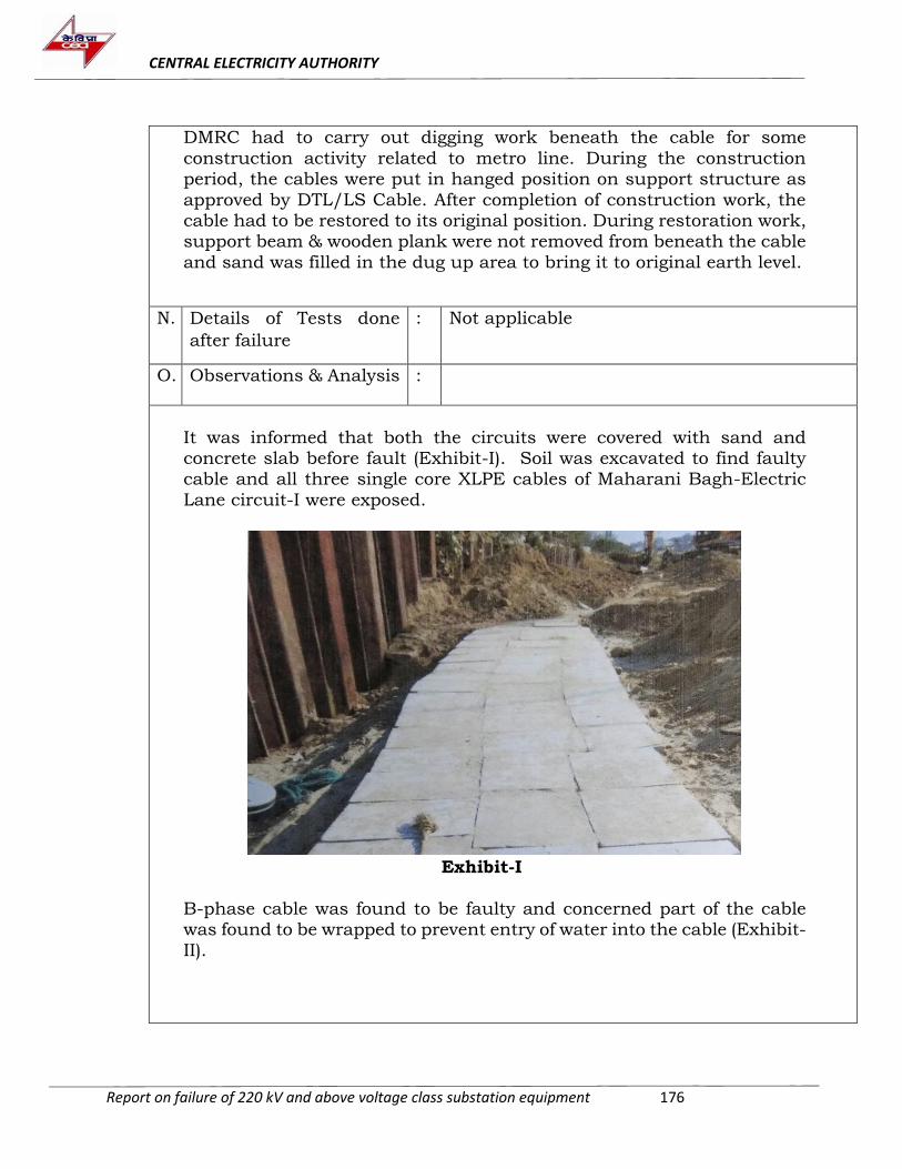
CENTRAL ELECTRICITY AUTHORITY
Report on failure of 220 kV and above voltage class substation equipment 176
DMRC had to carry out digging work beneath the cable for some
construction activity related to metro line. During the construction period, the cables were put in hanged position on support structure as
approved by DTL/LS Cable. After completion of construction work, the cable had to be restored to its original position. During restoration work, support beam & wooden plank were not removed from beneath the cable
and sand was filled in the dug up area to bring it to original earth level.
N. P Details of Tests done
after failure
: Not applicable
O. Q Observations & Analysis :
1.
2. It was informed that both the circuits were covered with sand and concrete slab before fault (Exhibit-I). Soil was excavated to find faulty cable and all three single core XLPE cables of Maharani Bagh-Electric
Lane circuit-I were exposed. 3.
Exhibit-I
4. B-phase cable was found to be faulty and concerned part of the cable was found to be wrapped to prevent entry of water into the cable (Exhibit-
II).
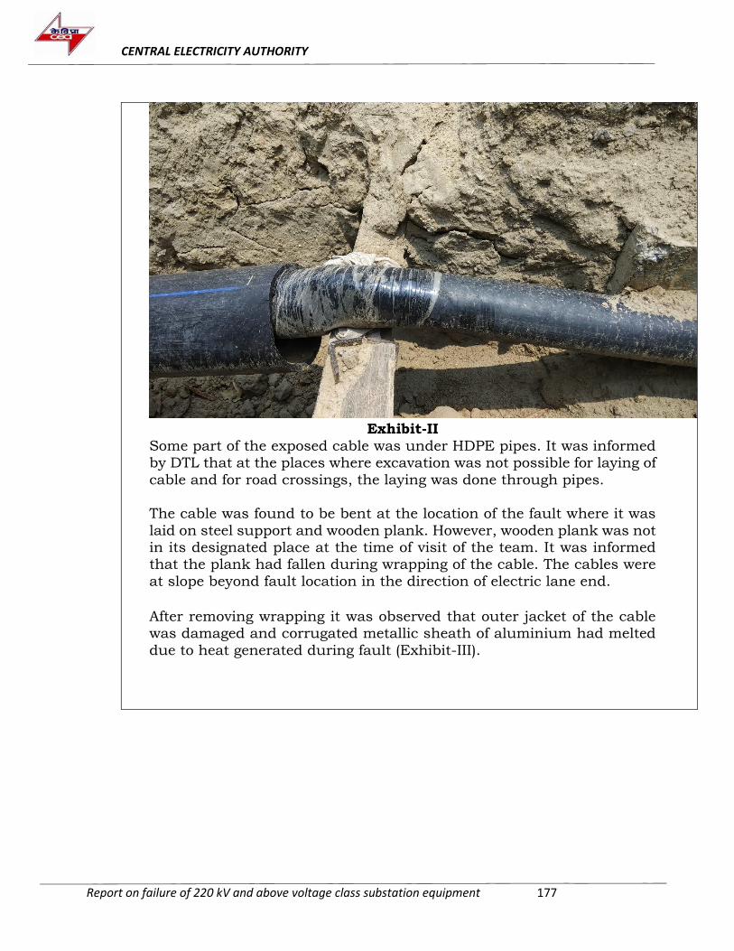
CENTRAL ELECTRICITY AUTHORITY
Report on failure of 220 kV and above voltage class substation equipment 177
Exhibit-II
5. Some part of the exposed cable was under HDPE pipes. It was informed by DTL that at the places where excavation was not possible for laying of
cable and for road crossings, the laying was done through pipes.
6. The cable was found to be bent at the location of the fault where it was
laid on steel support and wooden plank. However, wooden plank was not in its designated place at the time of visit of the team. It was informed that the plank had fallen during wrapping of the cable. The cables were
at slope beyond fault location in the direction of electric lane end.
7. After removing wrapping it was observed that outer jacket of the cable was damaged and corrugated metallic sheath of aluminium had melted
due to heat generated during fault (Exhibit-III).
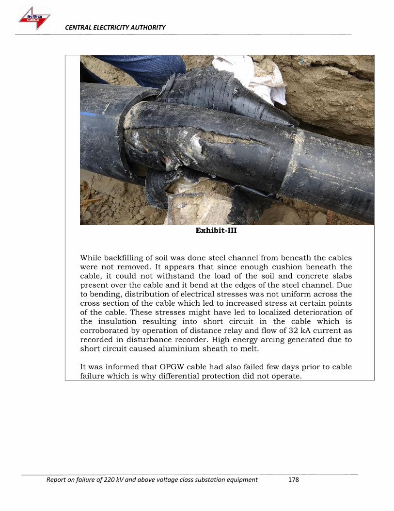
CENTRAL ELECTRICITY AUTHORITY
Report on failure of 220 kV and above voltage class substation equipment 178
Exhibit-III
While backfilling of soil was done steel channel from beneath the cables were not removed. It appears that since enough cushion beneath the cable, it could not withstand the load of the soil and concrete slabs
present over the cable and it bend at the edges of the steel channel. Due to bending, distribution of electrical stresses was not uniform across the cross section of the cable which led to increased stress at certain points
of the cable. These stresses might have led to localized deterioration of the insulation resulting into short circuit in the cable which is
corroborated by operation of distance relay and flow of 32 kA current as recorded in disturbance recorder. High energy arcing generated due to short circuit caused aluminium sheath to melt.
It was informed that OPGW cable had also failed few days prior to cable
failure which is why differential protection did not operate.
CENTRAL ELECTRICITY AUTHORITY
Report on failure of 220 kV and above voltage class substation equipment 179
ANNEXURE-II
Failure Report as Provided by PGCIL
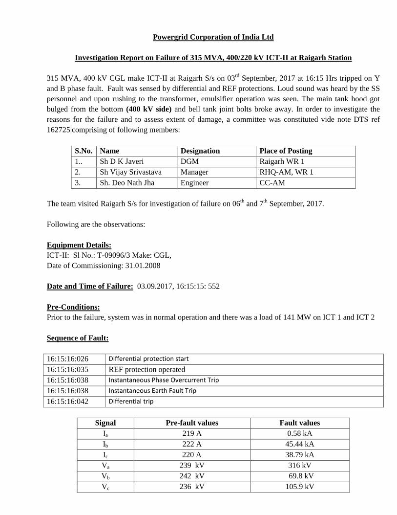
Powergrid Corporation of India Ltd
Investigation Report on Failure of 315 MVA, 400/220 kV ICT-II at Raigarh Station
315 MVA, 400 kV CGL make ICT-II at Raigarh S/s on 03rd
September, 2017 at 16:15 Hrs tripped on Y
and B phase fault. Fault was sensed by differential and REF protections. Loud sound was heard by the SS
personnel and upon rushing to the transformer, emulsifier operation was seen. The main tank hood got
bulged from the bottom (400 kV side) and bell tank joint bolts broke away. In order to investigate the
reasons for the failure and to assess extent of damage, a committee was constituted vide note DTS ref
162725 comprising of following members:
S.No. Name Designation Place of Posting
1.. Sh D K Javeri DGM Raigarh WR 1
2. Sh Vijay Srivastava Manager RHQ-AM, WR 1
3. Sh. Deo Nath Jha Engineer CC-AM
The team visited Raigarh S/s for investigation of failure on 06th
and 7th
September, 2017.
Following are the observations:
Equipment Details:
ICT-II: Sl No.: T-09096/3 Make: CGL,
Date of Commissioning: 31.01.2008
Date and Time of Failure: 03.09.2017, 16:15:15: 552
Pre-Conditions:
Prior to the failure, system was in normal operation and there was a load of 141 MW on ICT 1 and ICT 2
Sequence of Fault:
16:15:16:026 Differential protection start
16:15:16:035 REF protection operated
16:15:16:038 Instantaneous Phase Overcurrent Trip
16:15:16:038 Instantaneous Earth Fault Trip
16:15:16:042 Differential trip
Signal Pre-fault values Fault values
Ia 219 A 0.58 kA
Ib 222 A 45.44 kA
Ic 220 A 38.79 kA
Va 239 kV 316 kV
Vb 242 kV 69.8 kV
Vc 236 kV 105.9 kV
180
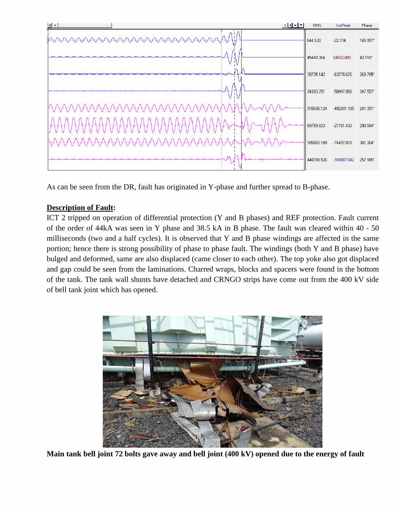
As can be seen from the DR, fault has originated in Y-phase and further spread to B-phase.
Description of Fault:
ICT 2 tripped on operation of differential protection (Y and B phases) and REF protection. Fault current
of the order of 44kA was seen in Y phase and 38.5 kA in B phase. The fault was cleared within 40 - 50
milliseconds (two and a half cycles). It is observed that Y and B phase windings are affected in the same
portion; hence there is strong possibility of phase to phase fault. The windings (both Y and B phase) have
bulged and deformed, same are also displaced (came closer to each other). The top yoke also got displaced
and gap could be seen from the laminations. Charred wraps, blocks and spacers were found in the bottom
of the tank. The tank wall shunts have detached and CRNGO strips have come out from the 400 kV side
of bell tank joint which has opened.
Main tank bell joint 72 bolts gave away and bell joint (400 kV) opened due to the energy of fault
181
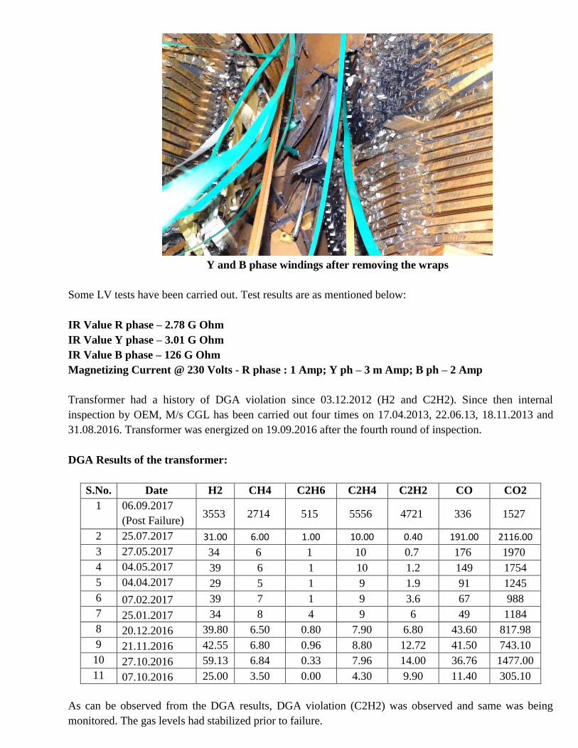
Y and B phase windings after removing the wraps
Some LV tests have been carried out. Test results are as mentioned below:
IR Value R phase – 2.78 G Ohm
IR Value Y phase – 3.01 G Ohm
IR Value B phase – 126 G Ohm
Magnetizing Current @ 230 Volts - R phase : 1 Amp; Y ph – 3 m Amp; B ph – 2 Amp
Transformer had a history of DGA violation since 03.12.2012 (H2 and C2H2). Since then internal
inspection by OEM, M/s CGL has been carried out four times on 17.04.2013, 22.06.13, 18.11.2013 and
31.08.2016. Transformer was energized on 19.09.2016 after the fourth round of inspection.
DGA Results of the transformer:
S.No. Date H2 CH4 C2H6 C2H4 C2H2 CO CO2
1 06.09.2017
(Post Failure) 3553 2714 515 5556 4721 336 1527
2 25.07.2017 31.00 6.00 1.00 10.00 0.40 191.00 2116.00
3 27.05.2017 34 6 1 10 0.7 176 1970
4 04.05.2017 39 6 1 10 1.2 149 1754
5 04.04.2017 29 5 1 9 1.9 91 1245
6 07.02.2017 39 7 1 9 3.6 67 988
7 25.01.2017 34 8 4 9 6 49 1184
8 20.12.2016 39.80 6.50 0.80 7.90 6.80 43.60 817.98
9 21.11.2016 42.55 6.80 0.96 8.80 12.72 41.50 743.10
10 27.10.2016 59.13 6.84 0.33 7.96 14.00 36.76 1477.00
11 07.10.2016 25.00 3.50 0.00 4.30 9.90 11.40 305.10
As can be observed from the DGA results, DGA violation (C2H2) was observed and same was being
monitored. The gas levels had stabilized prior to failure. 182
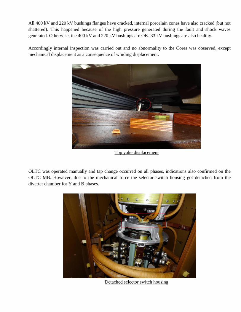
All 400 kV and 220 kV bushings flanges have cracked, internal porcelain cones have also cracked (but not
shattered). This happened because of the high pressure generated during the fault and shock waves
generated. Otherwise, the 400 kV and 220 kV bushings are OK. 33 kV bushings are also healthy.
Accordingly internal inspection was carried out and no abnormality to the Cores was observed, except
mechanical displacement as a consequence of winding displacement.
Top yoke displacement
OLTC was operated manually and tap change occurred on all phases, indications also confirmed on the
OLTC MB. However, due to the mechanical force the selector switch housing got detached from the
diverter chamber for Y and B phases.
Detached selector switch housing
183
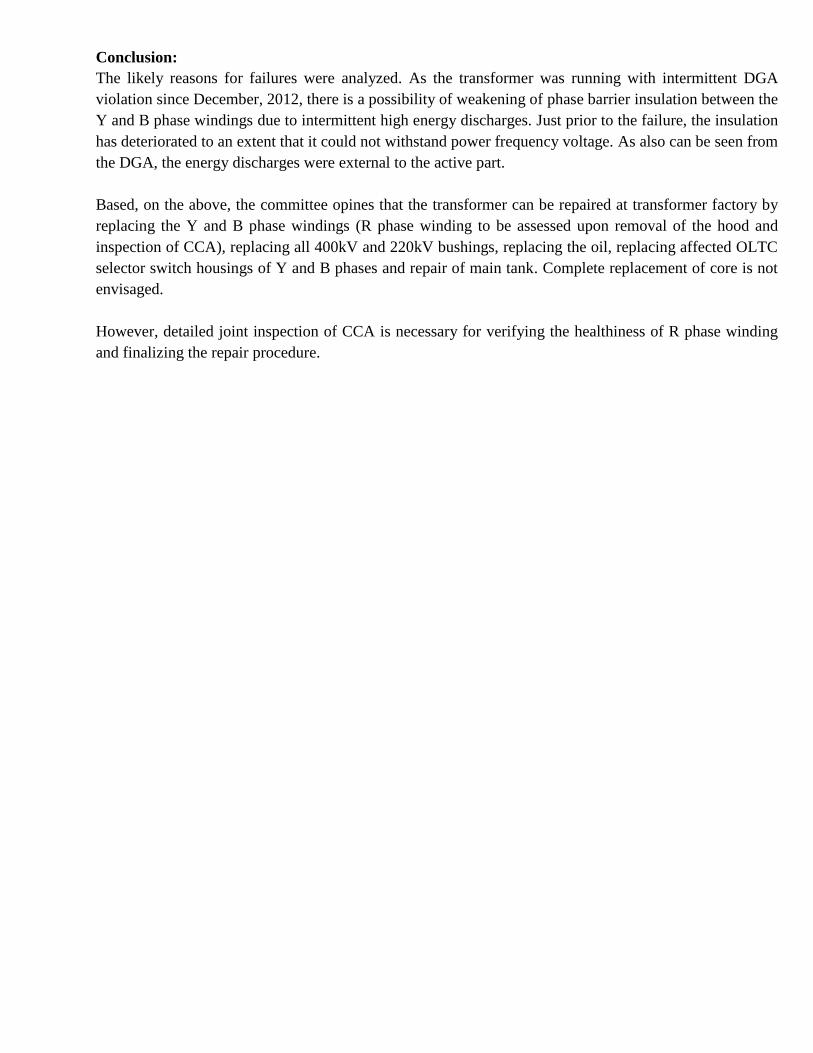
Conclusion:
The likely reasons for failures were analyzed. As the transformer was running with intermittent DGA
violation since December, 2012, there is a possibility of weakening of phase barrier insulation between the
Y and B phase windings due to intermittent high energy discharges. Just prior to the failure, the insulation
has deteriorated to an extent that it could not withstand power frequency voltage. As also can be seen from
the DGA, the energy discharges were external to the active part.
Based, on the above, the committee opines that the transformer can be repaired at transformer factory by
replacing the Y and B phase windings (R phase winding to be assessed upon removal of the hood and
inspection of CCA), replacing all 400kV and 220kV bushings, replacing the oil, replacing affected OLTC
selector switch housings of Y and B phases and repair of main tank. Complete replacement of core is not
envisaged.
However, detailed joint inspection of CCA is necessary for verifying the healthiness of R phase winding
and finalizing the repair procedure.
184
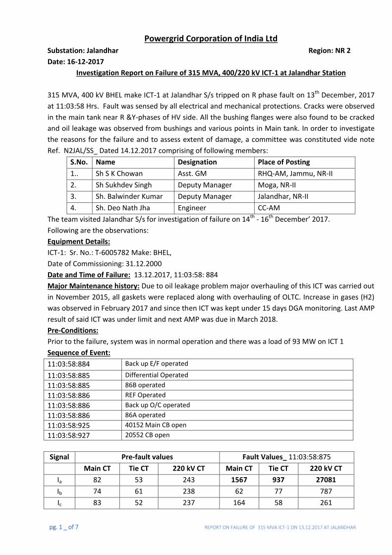
pg. 1 _ of 7 REPORT ON FAILURE OF 315 MVA ICT-1 ON 13.12.2017 AT JALANDHAR
Powergrid Corporation of India Ltd
Substation: Jalandhar Region: NR 2
Date: 16-12-2017
Investigation Report on Failure of 315 MVA, 400/220 kV ICT-1 at Jalandhar Station
315 MVA, 400 kV BHEL make ICT-1 at Jalandhar S/s tripped on R phase fault on 13th December, 2017
at 11:03:58 Hrs. Fault was sensed by all electrical and mechanical protections. Cracks were observed
in the main tank near R &Y-phases of HV side. All the bushing flanges were also found to be cracked
and oil leakage was observed from bushings and various points in Main tank. In order to investigate
the reasons for the failure and to assess extent of damage, a committee was constituted vide note
Ref. N2JAL/SS_ Dated 14.12.2017 comprising of following members:
S.No. Name Designation Place of Posting
1.. Sh S K Chowan Asst. GM RHQ-AM, Jammu, NR-II
2. Sh Sukhdev Singh Deputy Manager Moga, NR-II
3. Sh. Balwinder Kumar Deputy Manager Jalandhar, NR-II
4. Sh. Deo Nath Jha Engineer CC-AM
The team visited Jalandhar S/s for investigation of failure on 14th - 16th December’ 2017.
Following are the observations:
Equipment Details:
ICT-1: Sr. No.: T-6005782 Make: BHEL,
Date of Commissioning: 31.12.2000
Date and Time of Failure: 13.12.2017, 11:03:58: 884
Major Maintenance history: Due to oil leakage problem major overhauling of this ICT was carried out
in November 2015, all gaskets were replaced along with overhauling of OLTC. Increase in gases (H2)
was observed in February 2017 and since then ICT was kept under 15 days DGA monitoring. Last AMP
result of said ICT was under limit and next AMP was due in March 2018.
Pre-Conditions:
Prior to the failure, system was in normal operation and there was a load of 93 MW on ICT 1
Sequence of Event:
11:03:58:884 Back up E/F operated
11:03:58:885 Differential Operated
11:03:58:885 86B operated
11:03:58:886 REF Operated
11:03:58:886 Back up O/C operated
11:03:58:886 86A operated
11:03:58:925 40152 Main CB open
11:03:58:927 20552 CB open
Signal Pre-fault values Fault Values_ 11:03:58:875
Main CT Tie CT 220 kV CT Main CT Tie CT 220 kV CT
Ia 82 53 243 1567 937 27081
Ib 74 61 238 62 77 787
Ic 83 52 237 164 58 261
185
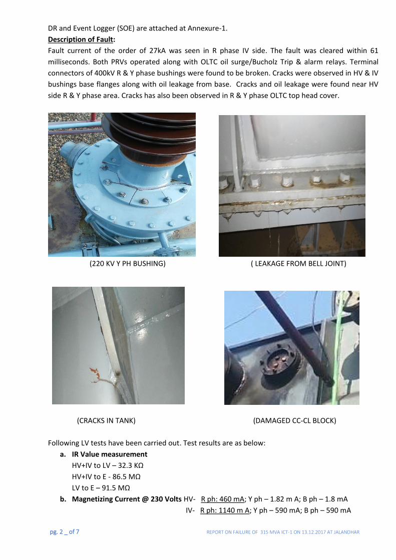
pg. 2 _ of 7 REPORT ON FAILURE OF 315 MVA ICT-1 ON 13.12.2017 AT JALANDHAR
DR and Event Logger (SOE) are attached at Annexure-1.
Description of Fault:
Fault current of the order of 27kA was seen in R phase IV side. The fault was cleared within 61
milliseconds. Both PRVs operated along with OLTC oil surge/Bucholz Trip & alarm relays. Terminal
connectors of 400kV R & Y phase bushings were found to be broken. Cracks were observed in HV & IV
bushings base flanges along with oil leakage from base. Cracks and oil leakage were found near HV
side R & Y phase area. Cracks has also been observed in R & Y phase OLTC top head cover.
(220 KV Y PH BUSHING) ( LEAKAGE FROM BELL JOINT)
(CRACKS IN TANK) (DAMAGED CC-CL BLOCK)
Following LV tests have been carried out. Test results are as below:
a. IR Value measurement
HV+IV to LV – 32.3 KΩ
HV+IV to E - 86.5 MΩ
LV to E – 91.5 MΩ
b. Magnetizing Current @ 230 Volts HV- R ph: 460 mA; Y ph – 1.82 m A; B ph – 1.8 mA
IV- R ph: 1140 m A; Y ph – 590 mA; B ph – 590 mA
186
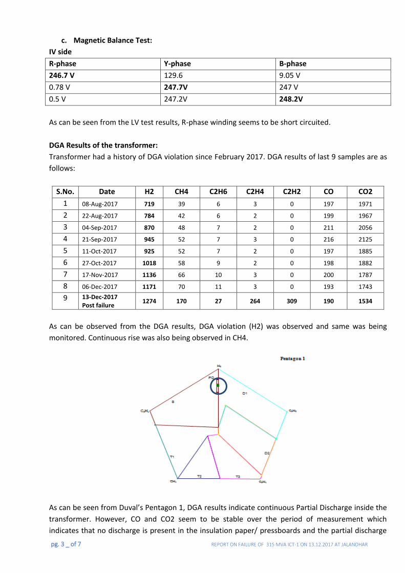
pg. 3 _ of 7 REPORT ON FAILURE OF 315 MVA ICT-1 ON 13.12.2017 AT JALANDHAR
c. Magnetic Balance Test:
IV side
R-phase Y-phase B-phase
246.7 V 129.6 9.05 V
0.78 V 247.7V 247 V
0.5 V 247.2V 248.2V
As can be seen from the LV test results, R-phase winding seems to be short circuited.
DGA Results of the transformer:
Transformer had a history of DGA violation since February 2017. DGA results of last 9 samples are as
follows:
S.No. Date H2 CH4 C2H6 C2H4 C2H2 CO CO2
1 08-Aug-2017 719 39 6 3 0 197 1971
2 22-Aug-2017 784 42 6 2 0 199 1967
3 04-Sep-2017 870 48 7 2 0 211 2056
4 21-Sep-2017 945 52 7 3 0 216 2125
5 11-Oct-2017 925 52 7 2 0 197 1885
6 27-Oct-2017 1018 58 9 2 0 198 1882
7 17-Nov-2017 1136 66 10 3 0 200 1787
8 06-Dec-2017 1171 70 11 3 0 193 1743
9 13-Dec-2017 Post failure
1274 170 27 264 309 190 1534
As can be observed from the DGA results, DGA violation (H2) was observed and same was being
monitored. Continuous rise was also being observed in CH4.
As can be seen from Duval’s Pentagon 1, DGA results indicate continuous Partial Discharge inside the
transformer. However, CO and CO2 seem to be stable over the period of measurement which
indicates that no discharge is present in the insulation paper/ pressboards and the partial discharge
187
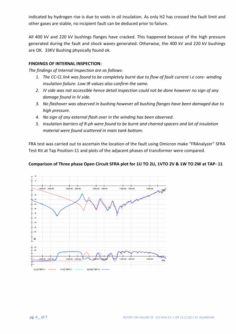
pg. 4 _ of 7 REPORT ON FAILURE OF 315 MVA ICT-1 ON 13.12.2017 AT JALANDHAR
indicated by hydrogen rise is due to voids in oil insulation. As only H2 has crossed the fault limit and
other gases are stable, no incipient fault can be deduced prior to failure.
All 400 kV and 220 kV bushings flanges have cracked. This happened because of the high pressure
generated during the fault and shock waves generated. Otherwise, the 400 kV and 220 kV bushings
are OK. 33KV Bushing physically found ok.
FINDINGS OF INTERNAL INSPECTION:
The findings of Internal Inspection are as follows:
1. The CC-CL link was found to be completely burnt due to flow of fault current i.e core- winding
insulation failure. Low IR values also confirm the same.
2. IV side was not accessible hence detail inspection could not be done however no sign of any
damage found in IV side.
3. No flashover was observed in bushing however all bushing flanges have been damaged due to
high pressure.
4. No sign of any external flash over in the winding has been observed.
5. Insulation barriers of R-ph were found to be burnt and charred spacers and lot of insulation
material were found scattered in main tank bottom.
FRA test was carried out to ascertain the location of the fault using Omicron make “FRAnalyzer” SFRA
Test Kit at Tap Position-11 and plots of the adjacent phases of transformer were compared.
Comparison of Three phase Open Circuit SFRA plot for 1U TO 2U, 1VTO 2V & 1W TO 2W at TAP- 11
188
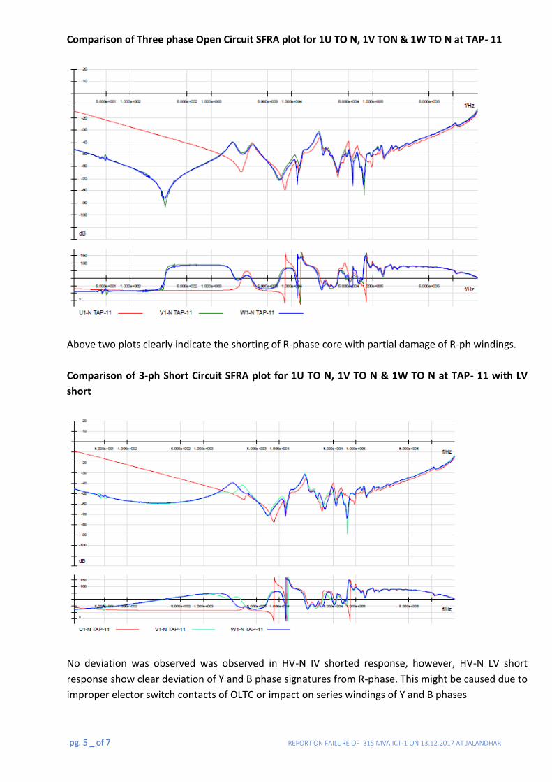
pg. 5 _ of 7 REPORT ON FAILURE OF 315 MVA ICT-1 ON 13.12.2017 AT JALANDHAR
Comparison of Three phase Open Circuit SFRA plot for 1U TO N, 1V TON & 1W TO N at TAP- 11
Above two plots clearly indicate the shorting of R-phase core with partial damage of R-ph windings.
Comparison of 3-ph Short Circuit SFRA plot for 1U TO N, 1V TO N & 1W TO N at TAP- 11 with LV
short
No deviation was observed was observed in HV-N IV shorted response, however, HV-N LV short
response show clear deviation of Y and B phase signatures from R-phase. This might be caused due to
improper elector switch contacts of OLTC or impact on series windings of Y and B phases
189
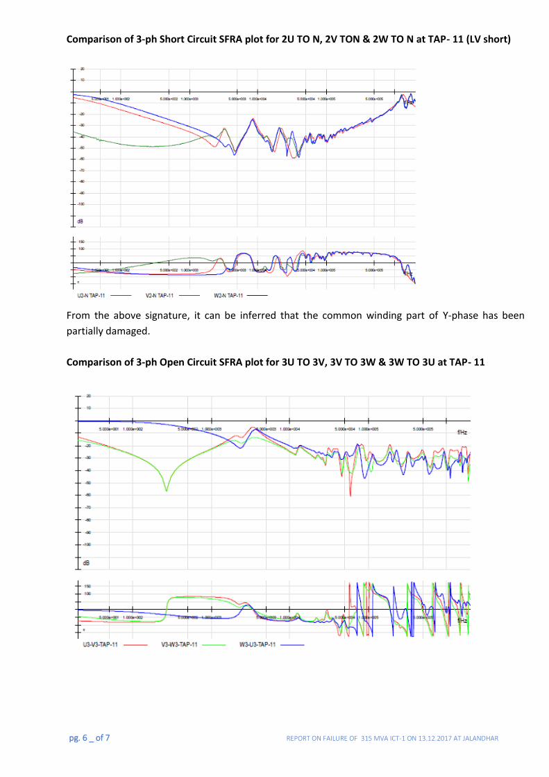
pg. 6 _ of 7 REPORT ON FAILURE OF 315 MVA ICT-1 ON 13.12.2017 AT JALANDHAR
Comparison of 3-ph Short Circuit SFRA plot for 2U TO N, 2V TON & 2W TO N at TAP- 11 (LV short)
From the above signature, it can be inferred that the common winding part of Y-phase has been
partially damaged.
Comparison of 3-ph Open Circuit SFRA plot for 3U TO 3V, 3V TO 3W & 3W TO 3U at TAP- 11
190
pg. 7 _ of 7 REPORT ON FAILURE OF 315 MVA ICT-1 ON 13.12.2017 AT JALANDHAR
As can be seen, the response of interphase R-B tertiary connection is in deviation from other two
responses in the low frequency (core) region. It can be inferred that the barrier insulation and
spacers between core and tertiary of R-phase have been shorted.
Conclusion:
The likely reasons for failures were analyzed. DGA results do not indicate presence of any incipient
fault in the transformer. Partial Discharge indicated in the unit seems to be confined to oil insulation
and degradation of paper insulation is not envisaged prior to failure. Further, as indicated by LV test
results and FRA, the R-phase winding seems to be completely damaged with impact on other other
two phases.
As fault current of the order of 27kA was detected in IV side R phase (about 33 times rated FL
current), hence the fault location is envisaged to be near the IV tapping point. However, same can be
confirmed only through detailed inspection after dismantling of windings.
Recommendation:
The inspection results clearly indicate that the repair would involve replacement of all three windings,
R-phase core and repairing of main tank. The transformer has already been in service for 17 years. As
decided during 15th O&M conference at Jaipur in November, 2017, it was decided to scrap the failed
transformers which had failed after 15 years of service and involving winding repair/ replacement.
Hence, it is proposed to scrap the failed ICT-1 at Jalandhar (BHEL make sl. No. 6005782). Region has
already initiated the replacement of the failed unit with 1 no. 315 MVA, 400/220 kV spare ICT
available at Moga (ALSTOM make) which was available as SIS spare.
Hence, to replenish the spare ICT, region to take further action for procurement of a new 315 MVA,
400/220 kV ICT under SIS scheme.
191
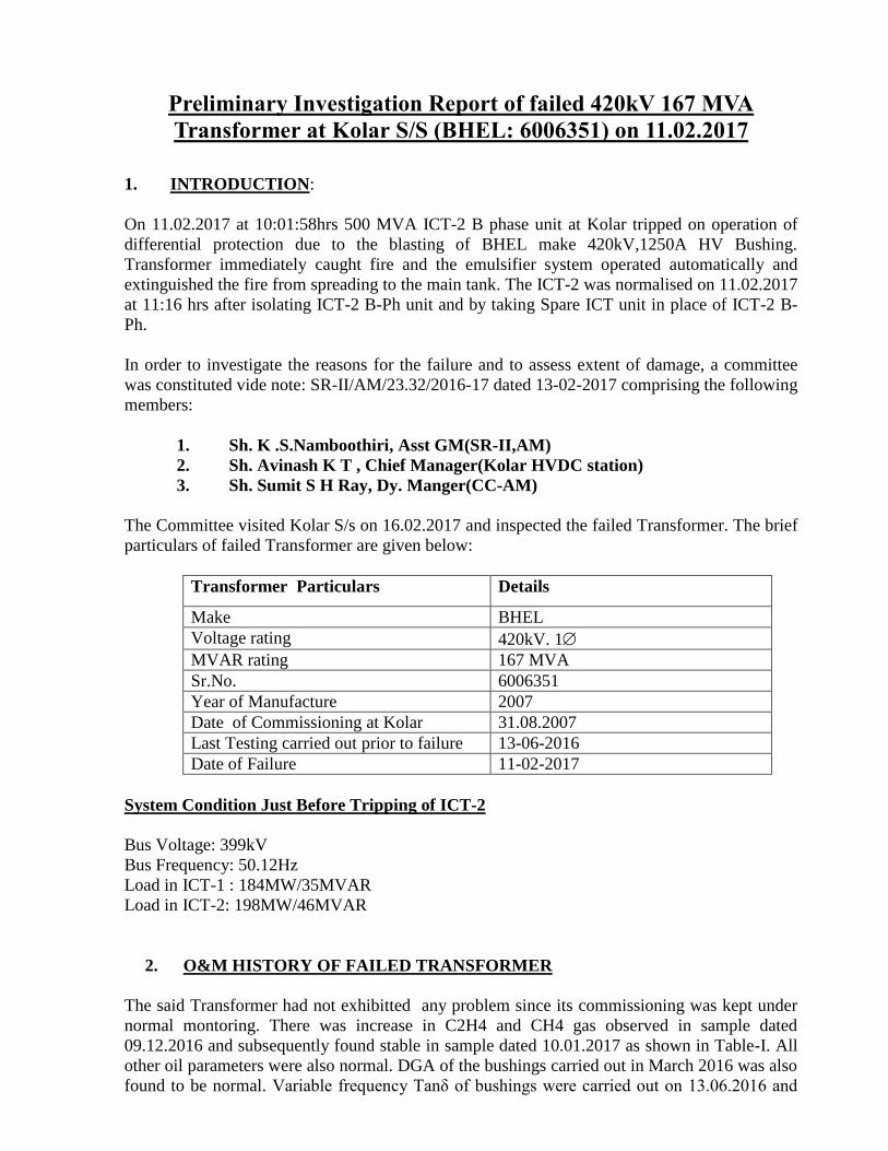
Preliminary Investigation Report of failed 420kV 167 MVA
Transformer at Kolar S/S (BHEL: 6006351) on 11.02.2017
1. INTRODUCTION:
On 11.02.2017 at 10:01:58hrs 500 MVA ICT-2 B phase unit at Kolar tripped on operation of
differential protection due to the blasting of BHEL make 420kV,1250A HV Bushing.
Transformer immediately caught fire and the emulsifier system operated automatically and
extinguished the fire from spreading to the main tank. The ICT-2 was normalised on 11.02.2017
at 11:16 hrs after isolating ICT-2 B-Ph unit and by taking Spare ICT unit in place of ICT-2 B-
Ph.
In order to investigate the reasons for the failure and to assess extent of damage, a committee
was constituted vide note: SR-II/AM/23.32/2016-17 dated 13-02-2017 comprising the following
members:
1. Sh. K .S.Namboothiri, Asst GM(SR-II,AM)
2. Sh. Avinash K T , Chief Manager(Kolar HVDC station)
3. Sh. Sumit S H Ray, Dy. Manger(CC-AM)
The Committee visited Kolar S/s on 16.02.2017 and inspected the failed Transformer. The brief
particulars of failed Transformer are given below:
Transformer Particulars Details
Make BHEL
Voltage rating 420kV. 1
MVAR rating 167 MVA
Sr.No. 6006351
Year of Manufacture 2007
Date of Commissioning at Kolar 31.08.2007
Last Testing carried out prior to failure 13-06-2016
Date of Failure 11-02-2017
System Condition Just Before Tripping of ICT-2
Bus Voltage: 399kV
Bus Frequency: 50.12Hz
Load in ICT-1 : 184MW/35MVAR
Load in ICT-2: 198MW/46MVAR
2. O&M HISTORY OF FAILED TRANSFORMER
The said Transformer had not exhibitted any problem since its commissioning was kept under
normal montoring. There was increase in C2H4 and CH4 gas observed in sample dated
09.12.2016 and subsequently found stable in sample dated 10.01.2017 as shown in Table-I. All
other oil parameters were also normal. DGA of the bushings carried out in March 2016 was also
found to be normal. Variable frequency Tanδ of bushings were carried out on 13.06.2016 and
192
PC
Textbox
25
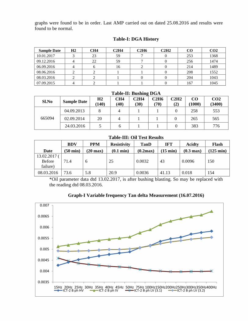
graphs were found to be in order. Last AMP carried out on dated 25.08.2016 and results were
found to be normal.
Table-I: DGA History
Sample Date H2 CH4 C2H4 C2H6 C2H2 CO CO2
10.01.2017 3 23 59 7 0 253 1368
09.12.2016 4 22 59 7 0 256 1474
06.09.2016 4 6 16 2 0 214 1489
08.06.2016 2 2 1 1 0 208 1552
08.03.2016 2 2 1 0 0 204 1043
07.09.2015 4 2 1 1 0 167 1045
Table-II: Bushing DGA
Sl.No Sample Date H2
(140)
CH4
(40)
C2H4
(30)
C2H6
(70)
C2H2
(2)
CO
(1000)
CO2
(3400)
665094
04.09.2013 8 4 1 1 0 258 553
02.09.2014 20 4 1 1 0 265 565
24.03.2016 5 6 1 1 0 383 776
Table-III: Oil Test Results
Date
BDV PPM Resistivity TanD IFT Acidty Flash
(50 min) (20 max) (0.1 min) (0.2max) (15 min) (0.3 max) (125 min)
13.02.2017 (
Before
failure)
71.4 6 25 0.0032 43 0.0096 150
08.03.2016 73.6 5.8 20.9 0.0036 41.13 0.018 154
*Oil parameter data dtd 13.02.2017, is after bushing blasting. So may be replaced with
the reading dtd 08.03.2016.
Graph-I Variable frequency Tan delta Measurement (16.07.2016)
0.0035
0.004
0.0045
0.005
0.0055
0.006
0.0065
0.007
15Hz 20Hz 25Hz 30Hz 35Hz 40Hz 45Hz 50Hz 75Hz 100Hz150Hz200Hz250Hz300Hz350Hz400HzICT-2 B ph HV ICT-2 B ph IV ICT-2 B ph LV (3.1) ICT-2 B ph LV (3.2)
193
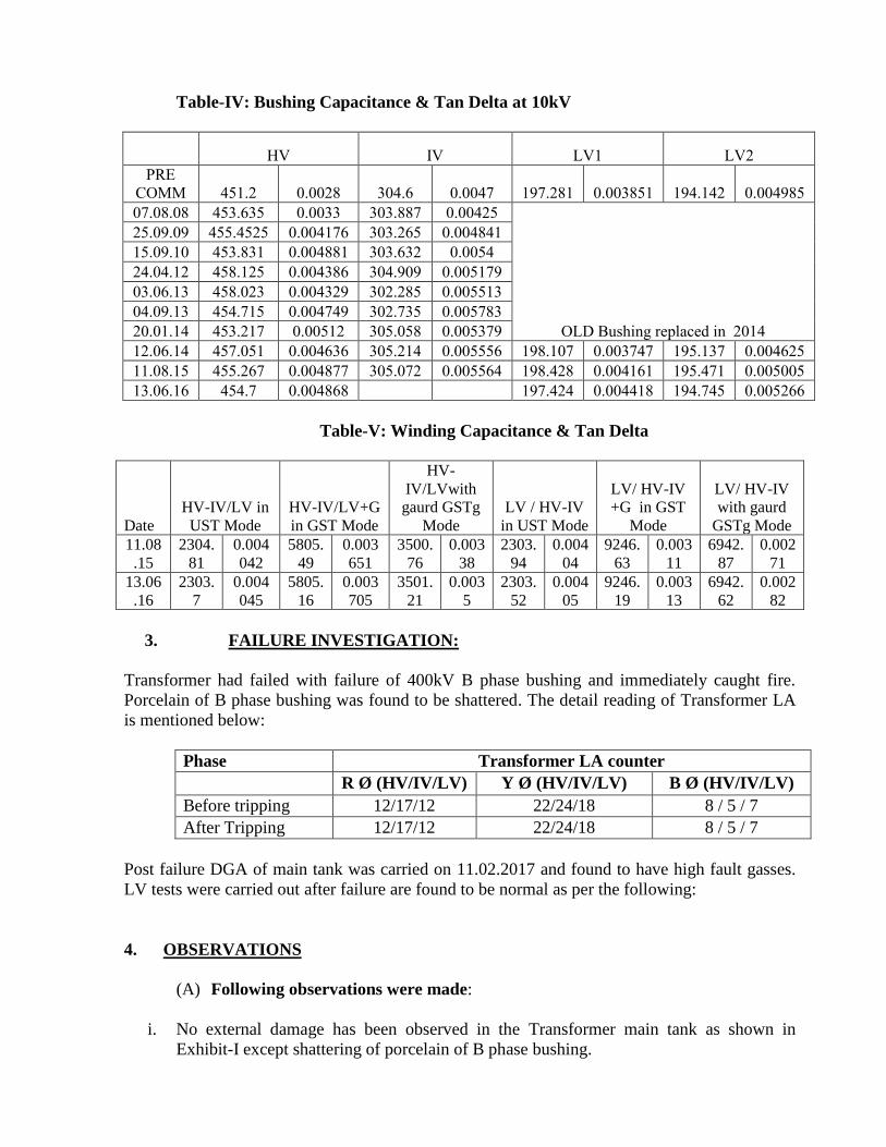
Table-IV: Bushing Capacitance & Tan Delta at 10kV
HV IV LV1 LV2
PRE
COMM 451.2 0.0028 304.6 0.0047 197.281 0.003851 194.142 0.004985
07.08.08 453.635 0.0033 303.887 0.00425
OLD Bushing replaced in 2014
25.09.09 455.4525 0.004176 303.265 0.004841
15.09.10 453.831 0.004881 303.632 0.0054
24.04.12 458.125 0.004386 304.909 0.005179
03.06.13 458.023 0.004329 302.285 0.005513
04.09.13 454.715 0.004749 302.735 0.005783
20.01.14 453.217 0.00512 305.058 0.005379
12.06.14 457.051 0.004636 305.214 0.005556 198.107 0.003747 195.137 0.004625
11.08.15 455.267 0.004877 305.072 0.005564 198.428 0.004161 195.471 0.005005
13.06.16 454.7 0.004868 197.424 0.004418 194.745 0.005266
Table-V: Winding Capacitance & Tan Delta
Date
HV-IV/LV in
UST Mode
HV-IV/LV+G
in GST Mode
HV-
IV/LVwith
gaurd GSTg
Mode
LV / HV-IV
in UST Mode
LV/ HV-IV
+G in GST
Mode
LV/ HV-IV
with gaurd
GSTg Mode
11.08
.15
2304.
81
0.004
042
5805.
49
0.003
651
3500.
76
0.003
38
2303.
94
0.004
04
9246.
63
0.003
11
6942.
87
0.002
71
13.06
.16
2303.
7
0.004
045
5805.
16
0.003
705
3501.
21
0.003
5
2303.
52
0.004
05
9246.
19
0.003
13
6942.
62
0.002
82
3. FAILURE INVESTIGATION:
Transformer had failed with failure of 400kV B phase bushing and immediately caught fire.
Porcelain of B phase bushing was found to be shattered. The detail reading of Transformer LA
is mentioned below:
Phase Transformer LA counter
R Ø (HV/IV/LV) Y Ø (HV/IV/LV) B Ø (HV/IV/LV)
Before tripping 12/17/12 22/24/18 8 / 5 / 7
After Tripping 12/17/12 22/24/18 8 / 5 / 7
Post failure DGA of main tank was carried on 11.02.2017 and found to have high fault gasses.
LV tests were carried out after failure are found to be normal as per the following:
4. OBSERVATIONS
(A) Following observations were made:
i. No external damage has been observed in the Transformer main tank as shown in
Exhibit-I except shattering of porcelain of B phase bushing.
194
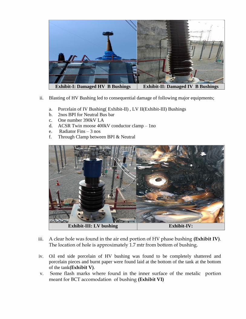
Exhibit-I: Damaged HV B Bushings Exhibit-II: Damaged IV B Bushings
ii. Blasting of HV Bushing led to consequential damage of following major equipments;
a. Porcelain of IV Bushing( Exhibit-II) , LV II(Exhibit-III) Bushings
b. 2nos BPI for Neutral Bus bar
c. One number 390kV LA
d. ACSR Twin moose 400kV conductor clamp – 1no
e. Radiator Fins – 3 nos
f. Through Clamp between BPI & Neutral
Exhibit-III: LV bushing Exhibit-IV:
iii. A clear hole was found in the air end portion of HV phase bushing (Exhibit IV). The location of hole is approximately 1.7 mtr from bottom of bushing.
iv. Oil end side porcelain of HV bushing was found to be completely shattered and
porcelain pieces and burnt paper were found laid at the bottom of the tank at the bottom
of the tank(Exhibit V). v. Some flash marks where found in the inner surface of the metalic portion
meant for BCT accomodation of bushing (Exhibit VI)
195
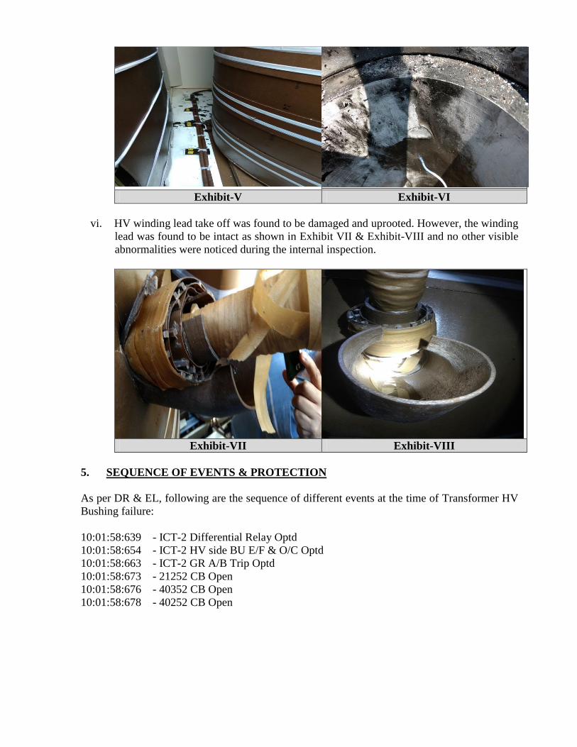
Exhibit-V Exhibit-VI
vi. HV winding lead take off was found to be damaged and uprooted. However, the winding
lead was found to be intact as shown in Exhibit VII & Exhibit-VIII and no other visible
abnormalities were noticed during the internal inspection.
Exhibit-VII Exhibit-VIII
5. SEQUENCE OF EVENTS & PROTECTION
As per DR & EL, following are the sequence of different events at the time of Transformer HV
Bushing failure:
10:01:58:639 - ICT-2 Differential Relay Optd
10:01:58:654 - ICT-2 HV side BU E/F & O/C Optd
10:01:58:663 - ICT-2 GR A/B Trip Optd
10:01:58:673 - 21252 CB Open
10:01:58:676 - 40352 CB Open
10:01:58:678 - 40252 CB Open
196
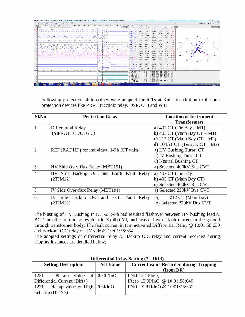
Following protection philosophies were adopted for ICTs at Kolar in addition to the unit
protection devices like PRV, Buccholz relay, OSR, OTI and WTI.
Sl.No Protection Relay Location of Instrument
Transformers
1 Differential Relay
(SIPROTEC 7UT613)
a) 402 CT (Tie Bay – M1)
b) 403 CT (Main Bay CT – M1)
c) 212 CT (Main Bay CT – M2)
d) L04A1 CT (Tertiary CT – M3)
2 REF (RADHD) for individual 1-Ph ICT units a) HV Bushing Turret CT
b) IV Bushing Turret CT
c) Neutral Bushing CT
3 HV Side Over-flux Relay (MBT191) a) Selected 400kV Bus CVT
4 HV Side Backup O/C and Earth Fault Relay
(2TJM12)
a) 402 CT (Tie Bay)
b) 403 CT (Main Bay CT)
c) Selected 400kV Bus CVT
5 IV Side Over-flux Relay (MBT191) a) Selected 220kV Bus CVT
6 IV Side Backup O/C and Earth Fault Relay
(2TJM12)
a) 212 CT (Main Bay)
b) Selected 220kV Bus CVT
The blasting of HV Bushing in ICT-2 B-Ph had resulted flashover between HV bushing lead &
BCT metallic portion, as evident in Exhibit VI, and heavy flow of fault current to the ground
through transformer body. The fault current in turn activated Differential Relay @ 10:01:58:639
and Back-up O/C relay of HV side @ 10:01:58:654.
The adopted settings of differential relay & Backup O/C relay and current recorded during
tripping instances are detailed below;
Differential Relay Setting (7UT613)
Setting Description Set Value Current value Recorded during Tripping
(from DR)
1221 – Pickup Value of
Differential Current (Diff>)
0.20I/InO IDiff-13.1I/InO,
IRest- 13.0I/InO @ 10:01:58:640
1231 – Pickup value of High
Set Trip (Diff>>)
9.6I/InO IDiff – 9.81I/InO @ 10:01:58:632
197
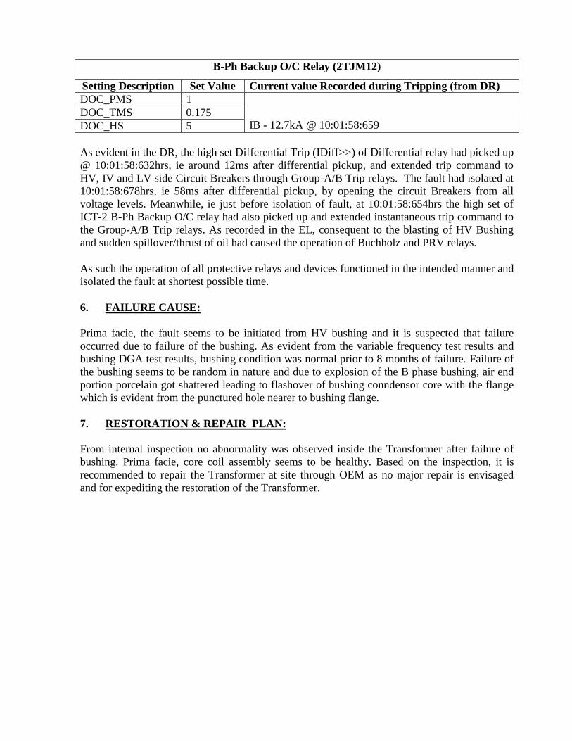
B-Ph Backup O/C Relay (2TJM12)
Setting Description Set Value Current value Recorded during Tripping (from DR)
DOC_PMS 1
IB - 12.7kA @ 10:01:58:659 DOC_TMS 0.175
DOC_HS 5
As evident in the DR, the high set Differential Trip (IDiff>>) of Differential relay had picked up
@ 10:01:58:632hrs, ie around 12ms after differential pickup, and extended trip command to
HV, IV and LV side Circuit Breakers through Group-A/B Trip relays. The fault had isolated at
10:01:58:678hrs, ie 58ms after differential pickup, by opening the circuit Breakers from all
voltage levels. Meanwhile, ie just before isolation of fault, at 10:01:58:654hrs the high set of
ICT-2 B-Ph Backup O/C relay had also picked up and extended instantaneous trip command to
the Group-A/B Trip relays. As recorded in the EL, consequent to the blasting of HV Bushing
and sudden spillover/thrust of oil had caused the operation of Buchholz and PRV relays.
As such the operation of all protective relays and devices functioned in the intended manner and
isolated the fault at shortest possible time.
6. FAILURE CAUSE:
Prima facie, the fault seems to be initiated from HV bushing and it is suspected that failure
occurred due to failure of the bushing. As evident from the variable frequency test results and
bushing DGA test results, bushing condition was normal prior to 8 months of failure. Failure of
the bushing seems to be random in nature and due to explosion of the B phase bushing, air end
portion porcelain got shattered leading to flashover of bushing conndensor core with the flange
which is evident from the punctured hole nearer to bushing flange.
7. RESTORATION & REPAIR PLAN:
From internal inspection no abnormality was observed inside the Transformer after failure of
bushing. Prima facie, core coil assembly seems to be healthy. Based on the inspection, it is
recommended to repair the Transformer at site through OEM as no major repair is envisaged
and for expediting the restoration of the Transformer.
198
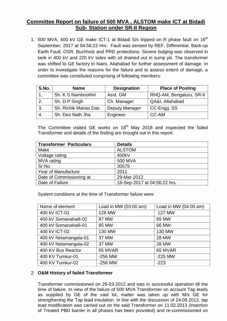
Committee Report on failure of 500 MVA , ALSTOM make ICT at Bidadi Sub- Station under SR-II Region
1. 500 MVA, 400 kV GE make ICT-1 at Bidadi S/s tripped on R phase fault on 16th
September, 2017 at 04:56:22 Hrs. Fault was sensed by REF, Differential, Back-up
Earth Fault, OSR, Buchholz and PRD protections. Severe bulging was observed in
tank in 400 kV and 220 kV sides with oil drained out in sump pit. The transformer
was shifted to GE factory in Naini, Allahabad for further assessment of damage. In
order to investigate the reasons for the failure and to assess extent of damage, a
committee was constituted comprising of following members:
S.No. Name Designation Place of Posting
1. Sh. K S Namboothiri Asst. GM RHQ-AM, Bengaluru, SR-II
2. Sh. D P Singh Ch. Manager QA&I, Allahabad
3. Sh. Richik Manas Das Deputy Manager CC-Engg. SS
4. Sh. Deo Nath Jha Engineer CC-AM
The Committee visited GE works on 18th May 2018 and inspected the failed Transformer and details of the finding are brought out in this report.
Transformer Particulars Details
Make ALSTOM
Voltage rating 400kV
MVA rating 500 MVA
Sr.No. 30575
Year of Manufacture 2011
Date of Commissioning at 29-Mar-2012
Date of Failure 16-Sep-2017 at 04:56:22 hrs.
System conditions at the time of Transformer failure were
2. O&M History of failed Transformer
Transformer commissioned on 29-03-2012 and was in successful operation till the time of failure. In view of the failure of 500 MVA Transformer on account Tap leads as supplied by GE of the said lot, matter was taken up with M/s GE for strengthening the Tap lead insulation. In line with the discussion of 24.09.2012, tap lead modification was carried out on the said Transformer on 11.02.2013 (Insertion of Treated PBD barrier in all phases has been provided) and re-commissioned on
Name of element Load in MW (03:00 am) Load in MW (04:00 am)
400 kV ICT-01 128 MW 127 MW
400 kV Somanahalli-02 87 MW 65 MW
400 kV Somanahalli-01 85 MW 66 MW
400 kV ICT-02 130 MW 130 MW
400 kV Nelamangala-01 37 MW 28 MW
400 kV Nelamangala-02 37 MW 28 MW
400 KV Bus Reactor 65 MVAR 65 MVAR
400 KV Tumkur-01 -256 MW -225 MW
400 KV Tumkur-02 -256 MW -223
199
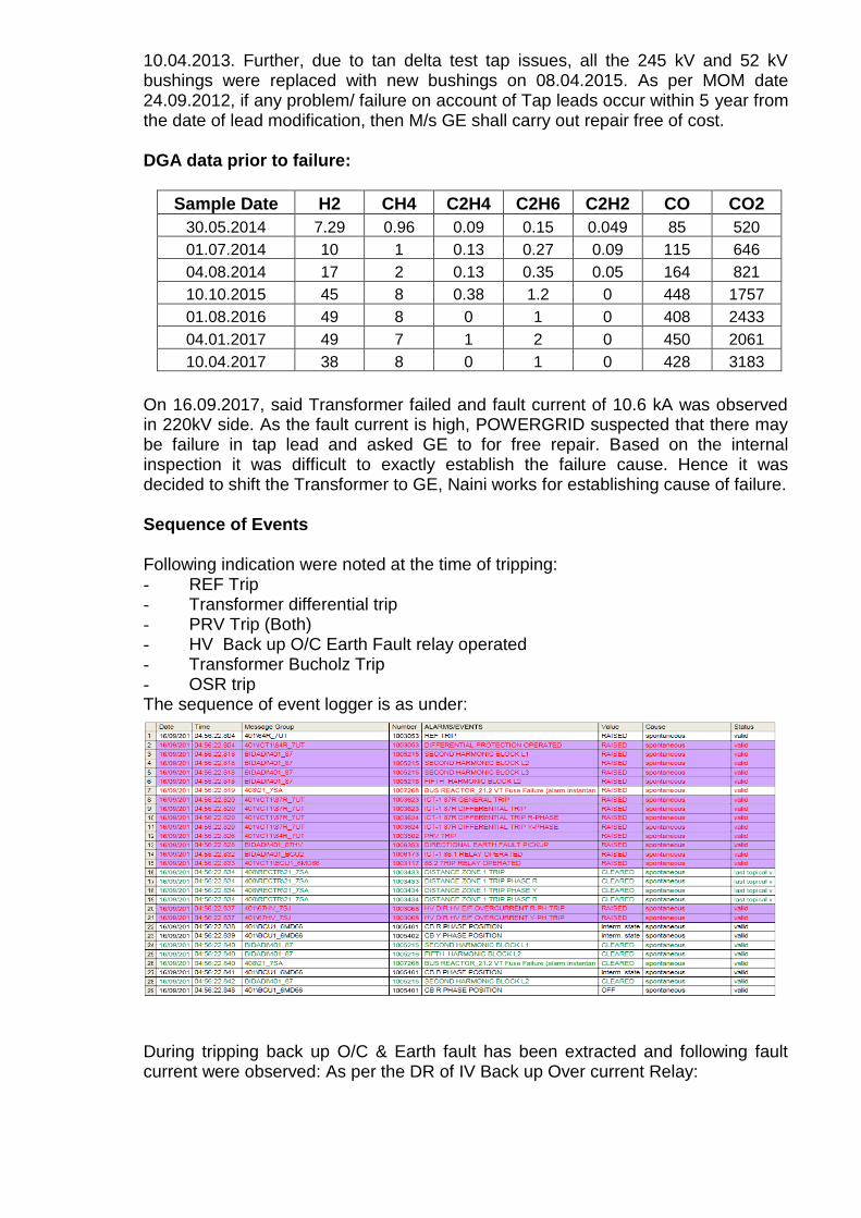
10.04.2013. Further, due to tan delta test tap issues, all the 245 kV and 52 kV bushings were replaced with new bushings on 08.04.2015. As per MOM date 24.09.2012, if any problem/ failure on account of Tap leads occur within 5 year from the date of lead modification, then M/s GE shall carry out repair free of cost.
DGA data prior to failure:
Sample Date H2 CH4 C2H4 C2H6 C2H2 CO CO2
30.05.2014 7.29 0.96 0.09 0.15 0.049 85 520
01.07.2014 10 1 0.13 0.27 0.09 115 646
04.08.2014 17 2 0.13 0.35 0.05 164 821
10.10.2015 45 8 0.38 1.2 0 448 1757
01.08.2016 49 8 0 1 0 408 2433
04.01.2017 49 7 1 2 0 450 2061
10.04.2017 38 8 0 1 0 428 3183
On 16.09.2017, said Transformer failed and fault current of 10.6 kA was observed in 220kV side. As the fault current is high, POWERGRID suspected that there may be failure in tap lead and asked GE to for free repair. Based on the internal inspection it was difficult to exactly establish the failure cause. Hence it was decided to shift the Transformer to GE, Naini works for establishing cause of failure. Sequence of Events Following indication were noted at the time of tripping: - REF Trip - Transformer differential trip - PRV Trip (Both) - HV Back up O/C Earth Fault relay operated - Transformer Bucholz Trip - OSR trip The sequence of event logger is as under:
During tripping back up O/C & Earth fault has been extracted and following fault current were observed: As per the DR of IV Back up Over current Relay:
200
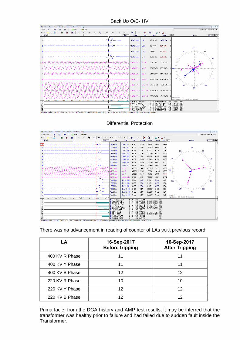
There was no advancement in reading of counter of LAs w.r.t previous record.
LA 16-Sep-2017 Before tripping
16-Sep-2017 After Tripping
400 KV R Phase 11 11
400 KV Y Phase 11 11
400 KV B Phase 12 12
220 KV R Phase 10 10
220 KV Y Phase 12 12
220 KV B Phase 12 12
Prima facie, from the DGA history and AMP test results, it may be inferred that the transformer was healthy prior to failure and had failed due to sudden fault inside the Transformer.
Back Up O/C- HV
Differential Protection
201
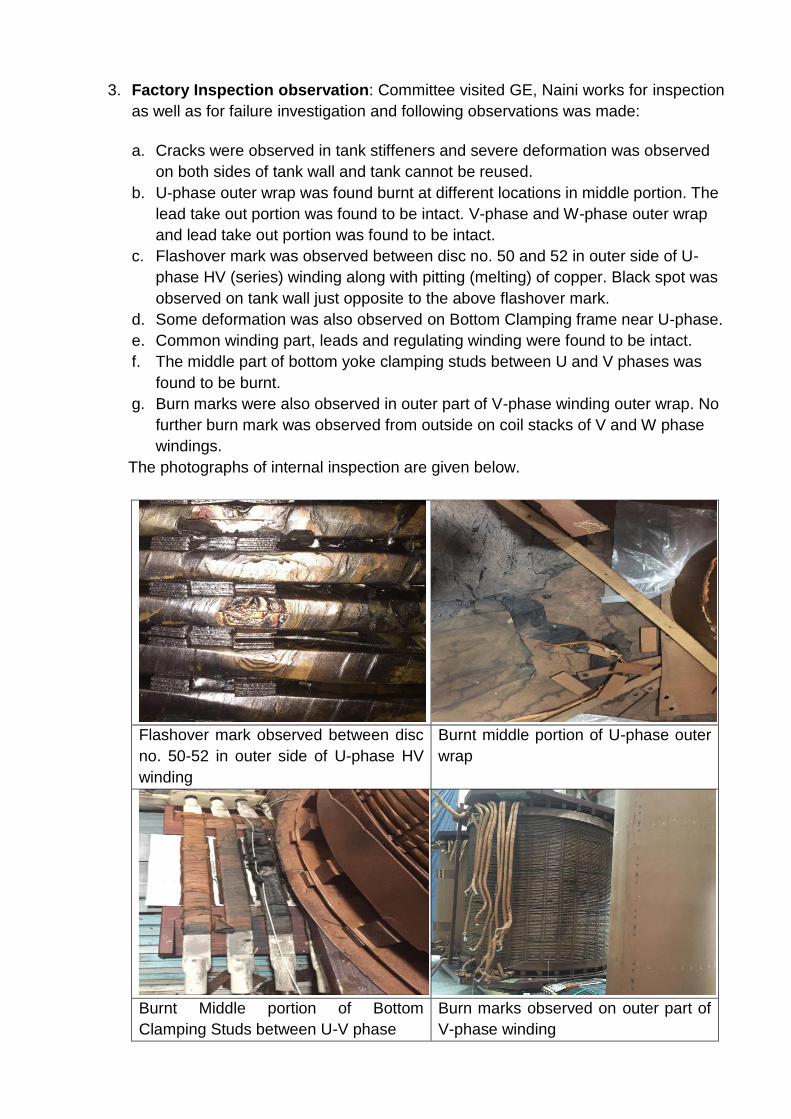
3. Factory Inspection observation: Committee visited GE, Naini works for inspection
as well as for failure investigation and following observations was made:
a. Cracks were observed in tank stiffeners and severe deformation was observed
on both sides of tank wall and tank cannot be reused.
b. U-phase outer wrap was found burnt at different locations in middle portion. The
lead take out portion was found to be intact. V-phase and W-phase outer wrap
and lead take out portion was found to be intact.
c. Flashover mark was observed between disc no. 50 and 52 in outer side of U-
phase HV (series) winding along with pitting (melting) of copper. Black spot was
observed on tank wall just opposite to the above flashover mark.
d. Some deformation was also observed on Bottom Clamping frame near U-phase.
e. Common winding part, leads and regulating winding were found to be intact.
f. The middle part of bottom yoke clamping studs between U and V phases was
found to be burnt.
g. Burn marks were also observed in outer part of V-phase winding outer wrap. No
further burn mark was observed from outside on coil stacks of V and W phase
windings.
The photographs of internal inspection are given below.
Flashover mark observed between disc
no. 50-52 in outer side of U-phase HV
winding
Burnt middle portion of U-phase outer
wrap
Burnt Middle portion of Bottom
Clamping Studs between U-V phase
Burn marks observed on outer part of
V-phase winding
202
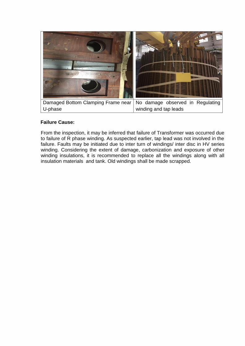
Damaged Bottom Clamping Frame near
U-phase
No damage observed in Regulating
winding and tap leads
Failure Cause:
From the inspection, it may be inferred that failure of Transformer was occurred due to failure of R phase winding. As suspected earlier, tap lead was not involved in the failure. Faults may be initiated due to inter turn of windings/ inter disc in HV series winding. Considering the extent of damage, carbonization and exposure of other winding insulations, it is recommended to replace all the windings along with all insulation materials and tank. Old windings shall be made scrapped.
203
Powergrid Corporation of India Ltd
Corporate Asset Management
Investigation Report on Failure of pole II East reactor at Vizag Station
There has been a failure of 80 MVAR, 400 kV CGL make Shunt Reactor at Vizag S/s on 28th
April, 2017
at 09:07 Hrs. Subsequent to failure, a failure investigation committee was constituted comprising of
following members:
S.No. Name Designation Place of Posting
1. K Srihari Chief Manager Vizag, SR-1
2. V K Chandrasen Chief Manager CIOTL, Hyderabad, SR-1
3. Deo Nath Jha Engineer CC-AM
The team visited Vizag S/s for investigation of failure causes on 3rd
and 4th
May, 2017. Following are the
observations
Equipment Details:
Pole 2 East Reactor: Sl No.: T8975/2 Make: CGL,
Date of Commissioning: 01.03.2005
Date and Time of Failure: 28.04.2017 09:07:30:435.
Pre-Conditions:
System was in normal operation with both Jeypore- Gazuwaka Line – 1 & 2 in service in Eastern Bus and
Gazuwaka -Vemagiri, Gazuwaka -Simhadri Line- 1& 2 and Gazuwaka – Kalpaka Line - 1& 2 in service
in Southern Bus.
Total Power Flow: 650 MW East to South
Pole - 1: 300 MW E→S
Pole - 2: 350 MW E→S
Description of Fault:
The auxiliary supply of both Pole 1 and Pole 2 of HVDC Vizag is fed through the 400 KV, 315 MVA
ICT#2. The auxiliary supply failed at 08:44 Hrs (Y phase fuse of tertiary -33 KV was found blown). Pole
2 auxiliary supply auto changeover to DG set was successful but the same was unsuccessful in Pole 1
resulting in tripping of the Pole 1 at 08:44 Hrs. Meanwhile at 09:07 hrs Pole 2 tripped on activation of
Pole Y block activation-WA1 Protective Y-Block Executed. This protection gets activated in case of any
major fault in ac side. It was further found that Pole 2 East Shunt Reactor (80 MVAR, CGL make) had
tripped sue to operation of differential and PRD protection. Further, heavy oil leakage was observed from
the Y-ph bushing of the shunt reactor.
204
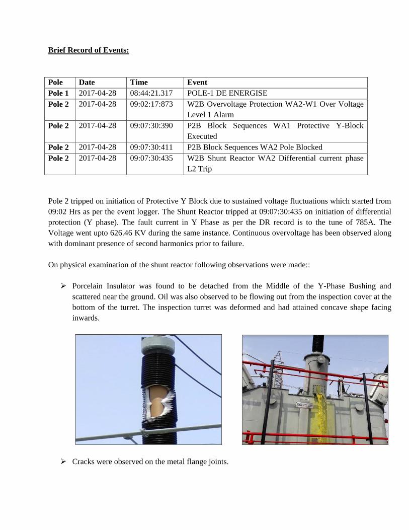
Brief Record of Events:
Pole Date Time Event
Pole 1 2017-04-28 08:44:21.317 POLE-1 DE ENERGISE
Pole 2 2017-04-28 09:02:17:873 W2B Overvoltage Protection WA2-W1 Over Voltage
Level 1 Alarm
Pole 2 2017-04-28 09:07:30:390 P2B Block Sequences WA1 Protective Y-Block
Executed
Pole 2 2017-04-28 09:07:30:411 P2B Block Sequences WA2 Pole Blocked
Pole 2 2017-04-28 09:07:30:435 W2B Shunt Reactor WA2 Differential current phase
L2 Trip
Pole 2 tripped on initiation of Protective Y Block due to sustained voltage fluctuations which started from
09:02 Hrs as per the event logger. The Shunt Reactor tripped at 09:07:30:435 on initiation of differential
protection (Y phase). The fault current in Y Phase as per the DR record is to the tune of 785A. The
Voltage went upto 626.46 KV during the same instance. Continuous overvoltage has been observed along
with dominant presence of second harmonics prior to failure.
On physical examination of the shunt reactor following observations were made::
Porcelain Insulator was found to be detached from the Middle of the Y-Phase Bushing and
scattered near the ground. Oil was also observed to be flowing out from the inspection cover at the
bottom of the turret. The inspection turret was deformed and had attained concave shape facing
inwards.
Cracks were observed on the metal flange joints.
205
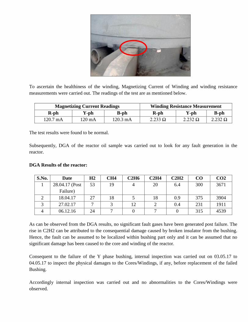
To ascertain the healthiness of the winding, Magnetizing Current of Winding and winding resistance
measurements were carried out. The readings of the test are as mentioned below.
Magnetizing Current Readings Winding Resistance Measurement
R-ph Y-ph B-ph R-ph Y-ph B-ph
120.7 mA 120 mA 120.3 mA 2.233 Ω 2.232 Ω 2.232 Ω
The test results were found to be normal.
Subsequently, DGA of the reactor oil sample was carried out to look for any fault generation in the
reactor.
DGA Results of the reactor:
S.No. Date H2 CH4 C2H6 C2H4 C2H2 CO CO2
1 28.04.17 (Post
Failure)
53 19 4 20 6.4 300 3671
2 18.04.17 27 18 5 18 0.9 375 3904
3 27.02.17 7 3 12 2 0.4 231 1911
4 06.12.16 24 7 0 7 0 315 4539
As can be observed from the DGA results, no significant fault gases have been generated post failure. The
rise in C2H2 can be attributed to the consequential damage caused by broken insulator from the bushing.
Hence, the fault can be assumed to be localized within bushing part only and it can be assumed that no
significant damage has been caused to the core and winding of the reactor.
Consequent to the failure of the Y phase bushing, internal inspection was carried out on 03.05.17 to
04.05.17 to inspect the physical damages to the Cores/Windings, if any, before replacement of the failed
Bushing.
Accordingly internal inspection was carried out and no abnormalities to the Cores/Windings were
observed.
206
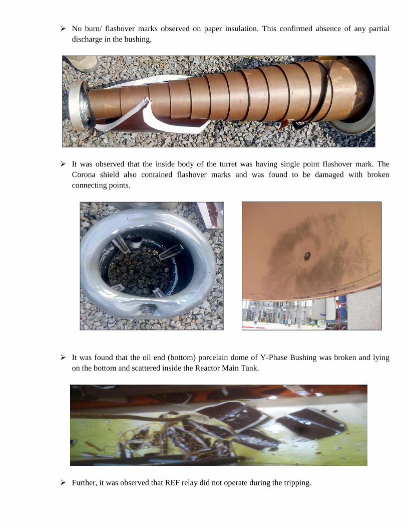
No burn/ flashover marks observed on paper insulation. This confirmed absence of any partial
discharge in the bushing.
It was observed that the inside body of the turret was having single point flashover mark. The
Corona shield also contained flashover marks and was found to be damaged with broken
connecting points.
It was found that the oil end (bottom) porcelain dome of Y-Phase Bushing was broken and lying
on the bottom and scattered inside the Reactor Main Tank.
Further, it was observed that REF relay did not operate during the tripping.
207
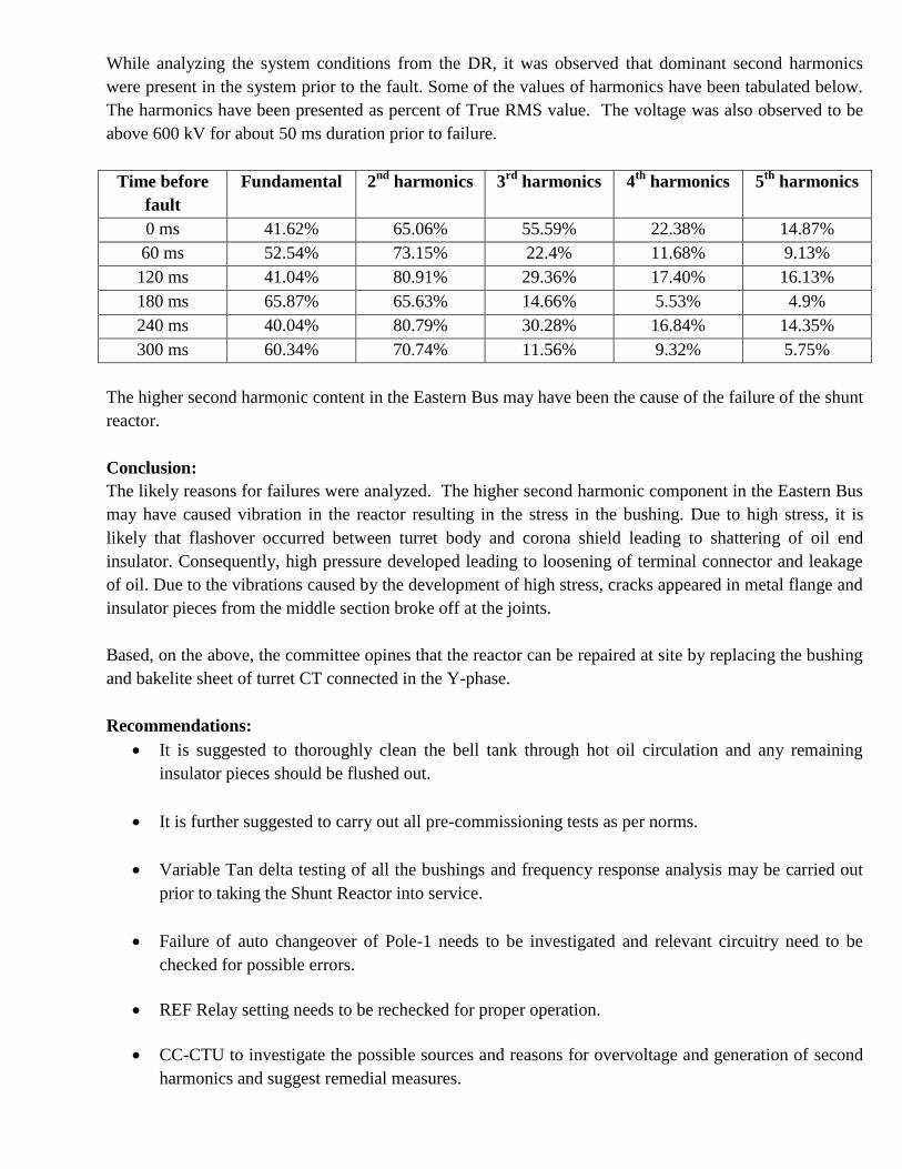
While analyzing the system conditions from the DR, it was observed that dominant second harmonics
were present in the system prior to the fault. Some of the values of harmonics have been tabulated below.
The harmonics have been presented as percent of True RMS value. The voltage was also observed to be
above 600 kV for about 50 ms duration prior to failure.
Time before
fault
Fundamental 2nd
harmonics 3rd
harmonics 4th
harmonics 5th
harmonics
0 ms 41.62% 65.06% 55.59% 22.38% 14.87%
60 ms 52.54% 73.15% 22.4% 11.68% 9.13%
120 ms 41.04% 80.91% 29.36% 17.40% 16.13%
180 ms 65.87% 65.63% 14.66% 5.53% 4.9%
240 ms 40.04% 80.79% 30.28% 16.84% 14.35%
300 ms 60.34% 70.74% 11.56% 9.32% 5.75%
The higher second harmonic content in the Eastern Bus may have been the cause of the failure of the shunt
reactor.
Conclusion:
The likely reasons for failures were analyzed. The higher second harmonic component in the Eastern Bus
may have caused vibration in the reactor resulting in the stress in the bushing. Due to high stress, it is
likely that flashover occurred between turret body and corona shield leading to shattering of oil end
insulator. Consequently, high pressure developed leading to loosening of terminal connector and leakage
of oil. Due to the vibrations caused by the development of high stress, cracks appeared in metal flange and
insulator pieces from the middle section broke off at the joints.
Based, on the above, the committee opines that the reactor can be repaired at site by replacing the bushing
and bakelite sheet of turret CT connected in the Y-phase.
Recommendations:
It is suggested to thoroughly clean the bell tank through hot oil circulation and any remaining
insulator pieces should be flushed out.
It is further suggested to carry out all pre-commissioning tests as per norms.
Variable Tan delta testing of all the bushings and frequency response analysis may be carried out
prior to taking the Shunt Reactor into service.
Failure of auto changeover of Pole-1 needs to be investigated and relevant circuitry need to be
checked for possible errors.
REF Relay setting needs to be rechecked for proper operation.
CC-CTU to investigate the possible sources and reasons for overvoltage and generation of second
harmonics and suggest remedial measures.
208
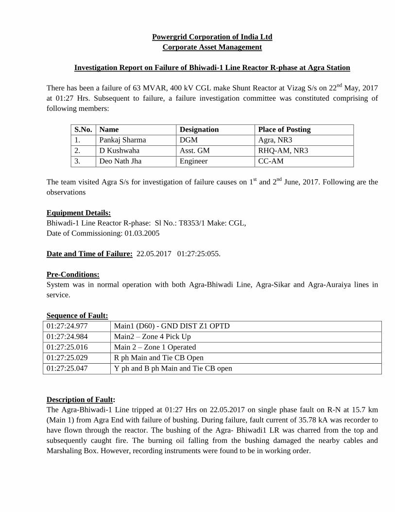
Powergrid Corporation of India Ltd
Corporate Asset Management
Investigation Report on Failure of Bhiwadi-1 Line Reactor R-phase at Agra Station
There has been a failure of 63 MVAR, 400 kV CGL make Shunt Reactor at Vizag S/s on 22nd
May, 2017
at 01:27 Hrs. Subsequent to failure, a failure investigation committee was constituted comprising of
following members:
S.No. Name Designation Place of Posting
1. Pankaj Sharma DGM Agra, NR3
2. D Kushwaha Asst. GM RHQ-AM, NR3
3. Deo Nath Jha Engineer CC-AM
The team visited Agra S/s for investigation of failure causes on 1st and 2
nd June, 2017. Following are the
observations
Equipment Details:
Bhiwadi-1 Line Reactor R-phase: Sl No.: T8353/1 Make: CGL,
Date of Commissioning: 01.03.2005
Date and Time of Failure: 22.05.2017 01:27:25:055.
Pre-Conditions:
System was in normal operation with both Agra-Bhiwadi Line, Agra-Sikar and Agra-Auraiya lines in
service.
Sequence of Fault:
01:27:24.977 Main1 (D60) - GND DIST Z1 OPTD
01:27:24.984 Main2 – Zone 4 Pick Up
01:27:25.016 Main 2 – Zone 1 Operated
01:27:25.029 R ph Main and Tie CB Open
01:27:25.047 Y ph and B ph Main and Tie CB open
Description of Fault:
The Agra-Bhiwadi-1 Line tripped at 01:27 Hrs on 22.05.2017 on single phase fault on R-N at 15.7 km
(Main 1) from Agra End with failure of bushing. During failure, fault current of 35.78 kA was recorder to
have flown through the reactor. The bushing of the Agra- Bhiwadi1 LR was charred from the top and
subsequently caught fire. The burning oil falling from the bushing damaged the nearby cables and
Marshaling Box. However, recording instruments were found to be in working order.
209
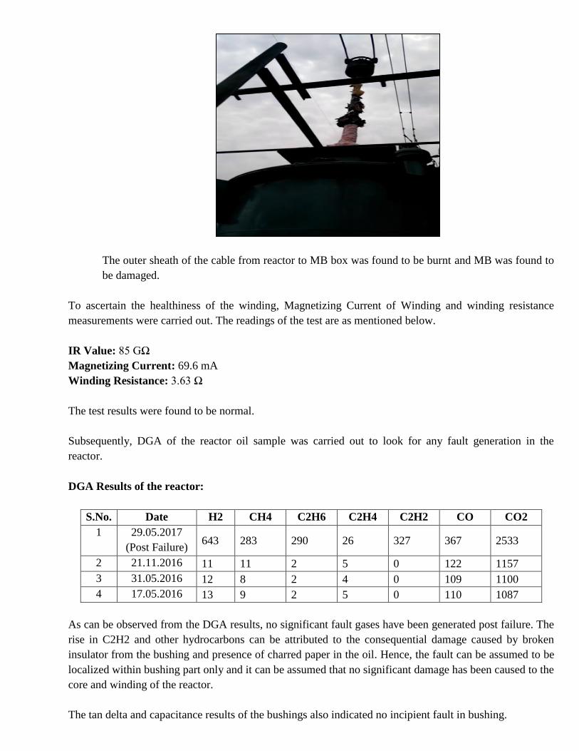
The outer sheath of the cable from reactor to MB box was found to be burnt and MB was found to
be damaged.
To ascertain the healthiness of the winding, Magnetizing Current of Winding and winding resistance
measurements were carried out. The readings of the test are as mentioned below.
IR Value: 85 GΩ
Magnetizing Current: 69.6 mA
Winding Resistance: 3.63 Ω
The test results were found to be normal.
Subsequently, DGA of the reactor oil sample was carried out to look for any fault generation in the
reactor.
DGA Results of the reactor:
S.No. Date H2 CH4 C2H6 C2H4 C2H2 CO CO2
1 29.05.2017
(Post Failure) 643 283 290 26 327 367 2533
2 21.11.2016 11 11 2 5 0 122 1157
3 31.05.2016 12 8 2 4 0 109 1100
4 17.05.2016 13 9 2 5 0 110 1087
As can be observed from the DGA results, no significant fault gases have been generated post failure. The
rise in C2H2 and other hydrocarbons can be attributed to the consequential damage caused by broken
insulator from the bushing and presence of charred paper in the oil. Hence, the fault can be assumed to be
localized within bushing part only and it can be assumed that no significant damage has been caused to the
core and winding of the reactor.
The tan delta and capacitance results of the bushings also indicated no incipient fault in bushing.
210
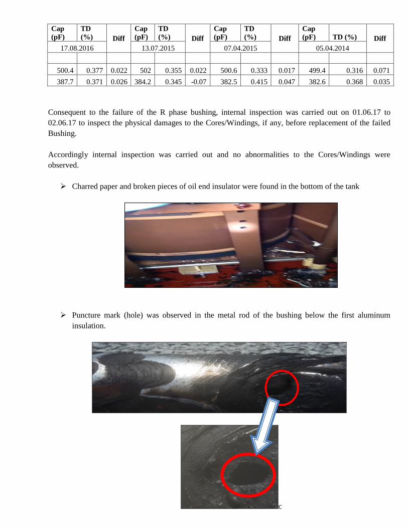
Cap
(pF)
TD
(%) Diff
Cap
(pF)
TD
(%) Diff
Cap
(pF)
TD
(%) Diff
Cap
(pF) TD (%) Diff
17.08.2016 13.07.2015 07.04.2015 05.04.2014
500.4 0.377 0.022 502 0.355 0.022 500.6 0.333 0.017 499.4 0.316 0.071
387.7 0.371 0.026 384.2 0.345 -0.07 382.5 0.415 0.047 382.6 0.368 0.035
Consequent to the failure of the R phase bushing, internal inspection was carried out on 01.06.17 to
02.06.17 to inspect the physical damages to the Cores/Windings, if any, before replacement of the failed
Bushing.
Accordingly internal inspection was carried out and no abnormalities to the Cores/Windings were
observed.
Charred paper and broken pieces of oil end insulator were found in the bottom of the tank
Puncture mark (hole) was observed in the metal rod of the bushing below the first aluminum
insulation.
c
211
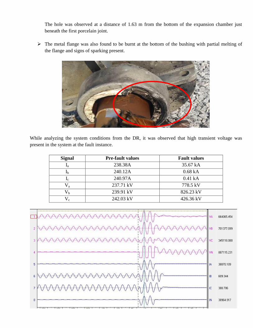
The hole was observed at a distance of 1.63 m from the bottom of the expansion chamber just
beneath the first porcelain joint.
The metal flange was also found to be burnt at the bottom of the bushing with partial melting of
the flange and signs of sparking present.
While analyzing the system conditions from the DR, it was observed that high transient voltage was
present in the system at the fault instance.
Signal Pre-fault values Fault values
Ia 238.38A 35.67 kA
Ib 240.12A 0.68 kA
Ic 240.97A 0.41 kA
Va 237.71 kV 778.5 kV
Vb 239.91 kV 826.23 kV
Vc 242.03 kV 426.36 kV
212
As can be seen from the DR, distortion has been observed in the voltage waveform about 20ms prior to
fault. Complete phase shift has been observed in the B-phase and partial phase shift in the Y-phase and R-
phase. The bushing being aged (about 31 years old) had weaker insulation and thus could not sustain this
high voltage. Spark developed in the bushings causing its failure.
Conclusion:
The likely reasons for failures were analyzed. The higher transient voltage may have caused spark
generation in the bushing causing high stress. Due to high stress, it is likely that internal flashover
occurred below the top porcelain joint of the bushing (weakest mechanical part of the bushing).
Consequently, high leakage current caused melting of the rod below the joint. Fire developed in the
bushing oil and the insulation paper was completely charred. The spark travelled to the bottom flange
(providing ground point to the current) causing its partial melt on the sides. The insulation was completely
charred. Any other significant damage was not found.
Based, on the above, the committee opines that the reactor can be repaired at site by replacing the bushing.
CC-TD and CC-HVDC is also requested to investigate the possible causes for generation of high transient
voltage and suggest remedial measures.
213
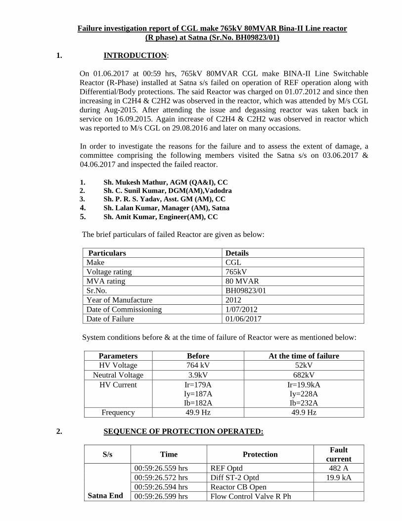
Failure investigation report of CGL make 765kV 80MVAR Bina-II Line reactor
(R phase) at Satna (Sr.No. BH09823/01)
1. INTRODUCTION:
On 01.06.2017 at 00:59 hrs, 765kV 80MVAR CGL make BINA-II Line Switchable
Reactor (R-Phase) installed at Satna s/s failed on operation of REF operation along with
Differential/Body protections. The said Reactor was charged on 01.07.2012 and since then
increasing in C2H4 & C2H2 was observed in the reactor, which was attended by M/s CGL
during Aug-2015. After attending the issue and degassing reactor was taken back in
service on 16.09.2015. Again increase of C2H4 & C2H2 was observed in reactor which
was reported to M/s CGL on 29.08.2016 and later on many occasions.
In order to investigate the reasons for the failure and to assess the extent of damage, a
committee comprising the following members visited the Satna s/s on 03.06.2017 &
04.06.2017 and inspected the failed reactor.
1. Sh. Mukesh Mathur, AGM (QA&I), CC
2. Sh. C. Sunil Kumar, DGM(AM),Vadodra
3. Sh. P. R. S. Yadav, Asst. GM (AM), CC
4. Sh. Lalan Kumar, Manager (AM), Satna
5. Sh. Amit Kumar, Engineer(AM), CC
The brief particulars of failed Reactor are given as below:
Particulars Details
Make CGL
Voltage rating 765kV
MVA rating 80 MVAR
Sr.No. BH09823/01
Year of Manufacture 2012
Date of Commissioning 1/07/2012
Date of Failure 01/06/2017
System conditions before & at the time of failure of Reactor were as mentioned below:
Parameters Before At the time of failure
HV Voltage 764 kV 52kV
Neutral Voltage 3.9kV 682kV
HV Current Ir=179A
Iy=187A
Ib=182A
Ir=19.9kA
Iy=228A
Ib=232A
Frequency 49.9 Hz 49.9 Hz
2. SEQUENCE OF PROTECTION OPERATED:
S/s Time Protection Fault
current
Satna End
00:59:26.559 hrs REF Optd 482 A
00:59:26.572 hrs Diff ST-2 Optd 19.9 kA
00:59:26.594 hrs Reactor CB Open
00:59:26.599 hrs Flow Control Valve R Ph
214
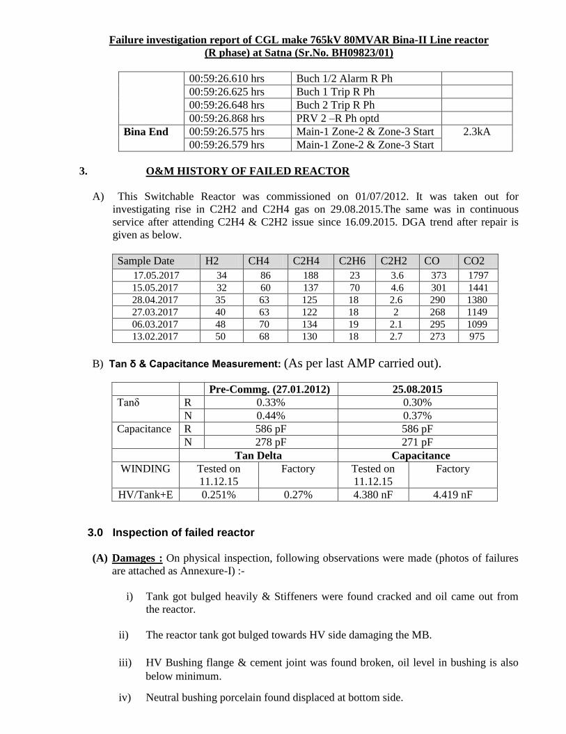
Failure investigation report of CGL make 765kV 80MVAR Bina-II Line reactor
(R phase) at Satna (Sr.No. BH09823/01)
00:59:26.610 hrs Buch 1/2 Alarm R Ph
00:59:26.625 hrs Buch 1 Trip R Ph
00:59:26.648 hrs Buch 2 Trip R Ph
00:59:26.868 hrs PRV 2 –R Ph optd
Bina End 00:59:26.575 hrs Main-1 Zone-2 & Zone-3 Start 2.3kA
00:59:26.579 hrs Main-1 Zone-2 & Zone-3 Start
3. O&M HISTORY OF FAILED REACTOR
A) This Switchable Reactor was commissioned on 01/07/2012. It was taken out for
investigating rise in C2H2 and C2H4 gas on 29.08.2015.The same was in continuous
service after attending C2H4 & C2H2 issue since 16.09.2015. DGA trend after repair is
given as below.
Sample Date H2 CH4 C2H4 C2H6 C2H2 CO CO2
17.05.2017 34 86 188 23 3.6 373 1797
15.05.2017 32 60 137 70 4.6 301 1441
28.04.2017 35 63 125 18 2.6 290 1380
27.03.2017 40 63 122 18 2 268 1149
06.03.2017 48 70 134 19 2.1 295 1099
13.02.2017 50 68 130 18 2.7 273 975
B) Tan δ & Capacitance Measurement: (As per last AMP carried out).
Pre-Commg. (27.01.2012) 25.08.2015
Tanδ R 0.33% 0.30%
N 0.44% 0.37%
Capacitance R 586 pF 586 pF
N 278 pF 271 pF
Tan Delta Capacitance
WINDING Tested on
11.12.15
Factory Tested on
11.12.15
Factory
HV/Tank+E 0.251% 0.27% 4.380 nF 4.419 nF
3.0 Inspection of failed reactor
(A) Damages : On physical inspection, following observations were made (photos of failures
are attached as Annexure-I) :-
i) Tank got bulged heavily & Stiffeners were found cracked and oil came out from
the reactor.
ii) The reactor tank got bulged towards HV side damaging the MB.
iii) HV Bushing flange & cement joint was found broken, oil level in bushing is also
below minimum.
iv) Neutral bushing porcelain found displaced at bottom side.
215
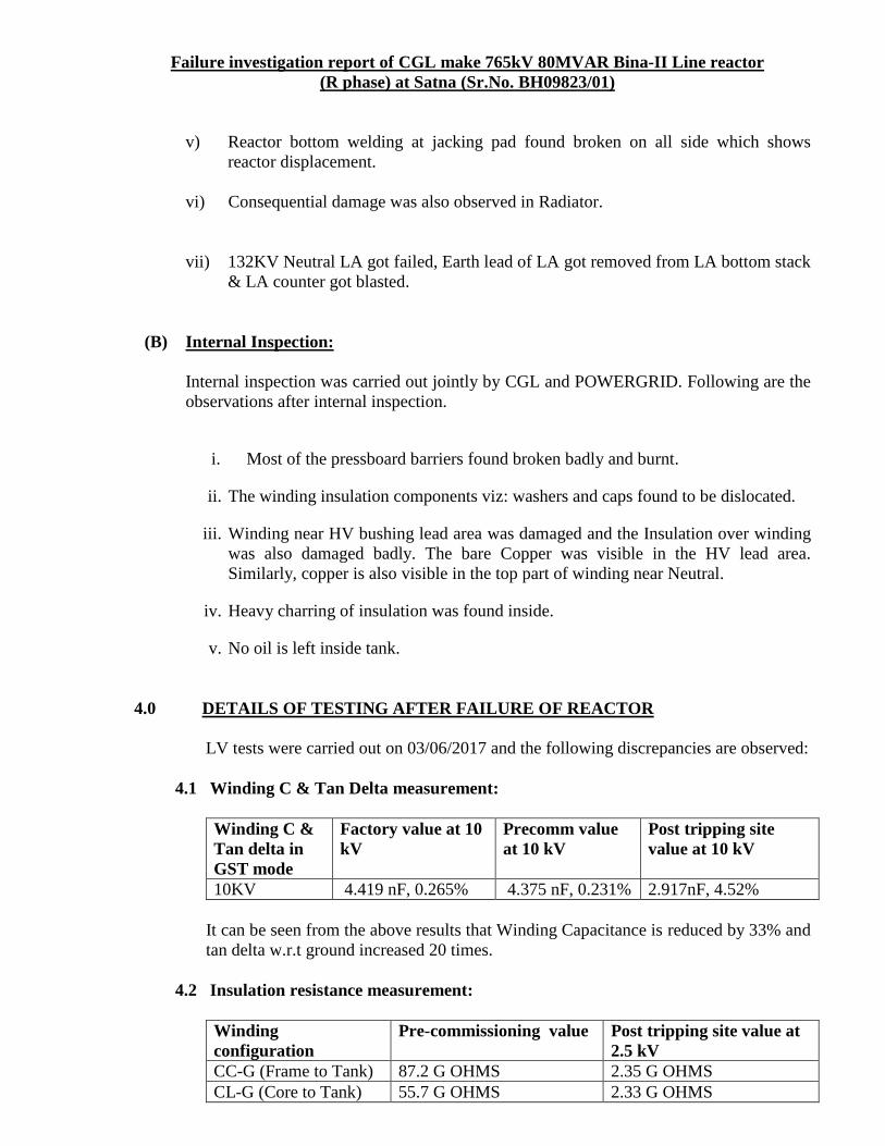
Failure investigation report of CGL make 765kV 80MVAR Bina-II Line reactor
(R phase) at Satna (Sr.No. BH09823/01)
v) Reactor bottom welding at jacking pad found broken on all side which shows
reactor displacement.
vi) Consequential damage was also observed in Radiator.
vii) 132KV Neutral LA got failed, Earth lead of LA got removed from LA bottom stack
& LA counter got blasted.
(B) Internal Inspection:
Internal inspection was carried out jointly by CGL and POWERGRID. Following are the
observations after internal inspection.
i. Most of the pressboard barriers found broken badly and burnt.
ii. The winding insulation components viz: washers and caps found to be dislocated.
iii. Winding near HV bushing lead area was damaged and the Insulation over winding
was also damaged badly. The bare Copper was visible in the HV lead area.
Similarly, copper is also visible in the top part of winding near Neutral.
iv. Heavy charring of insulation was found inside.
v. No oil is left inside tank.
4.0 DETAILS OF TESTING AFTER FAILURE OF REACTOR
LV tests were carried out on 03/06/2017 and the following discrepancies are observed:
4.1 Winding C & Tan Delta measurement:
Winding C &
Tan delta in
GST mode
Factory value at 10
kV
Precomm value
at 10 kV
Post tripping site
value at 10 kV
10KV 4.419 nF, 0.265% 4.375 nF, 0.231% 2.917nF, 4.52%
It can be seen from the above results that Winding Capacitance is reduced by 33% and
tan delta w.r.t ground increased 20 times.
4.2 Insulation resistance measurement:
Winding
configuration
Pre-commissioning value Post tripping site value at
2.5 kV
CC-G (Frame to Tank) 87.2 G OHMS 2.35 G OHMS
CL-G (Core to Tank) 55.7 G OHMS 2.33 G OHMS
216
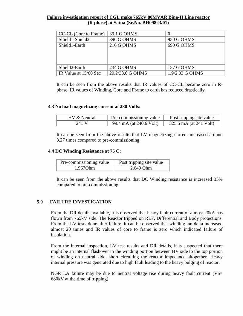
Failure investigation report of CGL make 765kV 80MVAR Bina-II Line reactor
(R phase) at Satna (Sr.No. BH09823/01)
CC-CL (Core to Frame) 39.1 G OHMS 0
Shield1-Shield2 396 G OHMS 950 G OHMS
Shield1-Earth 216 G OHMS 690 G OHMS
Shield2-Earth 234 G OHMS 157 G OHMS
IR Value at 15/60 Sec 29.2/33.6 G OHMS 1.9/2.03 G OHMS
It can be seen from the above results that IR values of CC-CL became zero in R-
phase. IR values of Winding, Core and Frame to earth has reduced drastically.
4.3 No load magnetizing current at 230 Volts:
HV & Neutral Pre-commissioning value Post tripping site value
241 V 99.4 mA (at 240.6 Volt) 325.5 mA (at 241 Volt)
It can be seen from the above results that LV magnetizing current increased around
3.27 times compared to pre-commissioning.
4.4 DC Winding Resistance at 75 C:
Pre-commissioning value Post tripping site value
1.967Ohm 2.649 Ohm
It can be seen from the above results that DC Winding resistance is increased 35%
compared to pre-commissioning.
5.0 FAILURE INVESTIGATION
From the DR details available, it is observed that heavy fault current of almost 20kA has
flown from 765kV side. The Reactor tripped on REF, Differential and Body protections.
From the LV tests done after failure, it can be observed that winding tan delta increased
almost 20 times and IR values of core to frame is zero which indicated failure of
insulation.
From the internal inspection, LV test results and DR details, it is suspected that there
might be an internal flashover in the winding portion between HV side to the top portion
of winding on neutral side, short circuiting the reactor impedance altogether. Heavy
internal pressure was generated due to high fault leading to the heavy bulging of reactor.
NGR LA failure may be due to neutral voltage rise during heavy fault current (Vn=
680kV at the time of tripping).
217
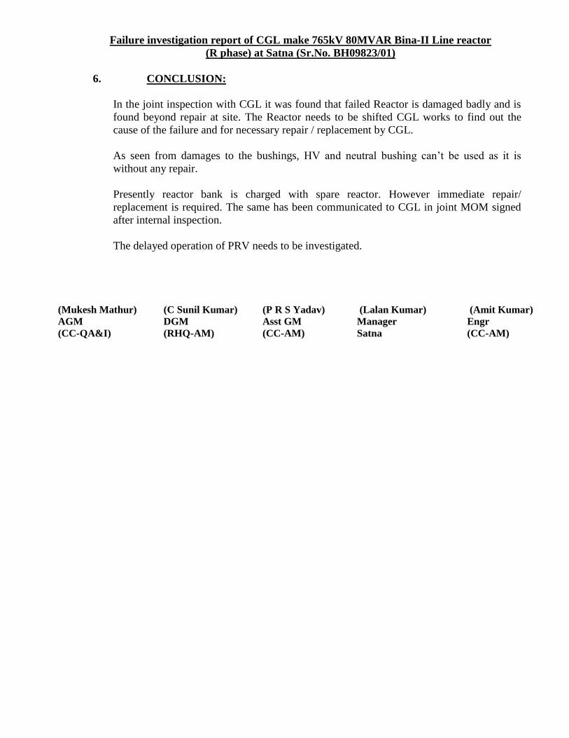
Failure investigation report of CGL make 765kV 80MVAR Bina-II Line reactor
(R phase) at Satna (Sr.No. BH09823/01)
6. CONCLUSION:
In the joint inspection with CGL it was found that failed Reactor is damaged badly and is
found beyond repair at site. The Reactor needs to be shifted CGL works to find out the
cause of the failure and for necessary repair / replacement by CGL.
As seen from damages to the bushings, HV and neutral bushing can’t be used as it is
without any repair.
Presently reactor bank is charged with spare reactor. However immediate repair/
replacement is required. The same has been communicated to CGL in joint MOM signed
after internal inspection.
The delayed operation of PRV needs to be investigated.
(Mukesh Mathur) (C Sunil Kumar) (P R S Yadav) (Lalan Kumar) (Amit Kumar)
AGM
(CC-QA&I)
DGM
(RHQ-AM)
Asst GM
(CC-AM)
Manager
Satna
Engr
(CC-AM)
218
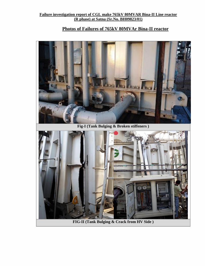
Failure investigation report of CGL make 765kV 80MVAR Bina-II Line reactor
(R phase) at Satna (Sr.No. BH09823/01)
Photos of Failures of 765kV 80MVAr Bina-II reactor
Fig-I (Tank Bulging & Broken stiffeners )
FIG-II (Tank Bulging & Crack from HV Side )
219
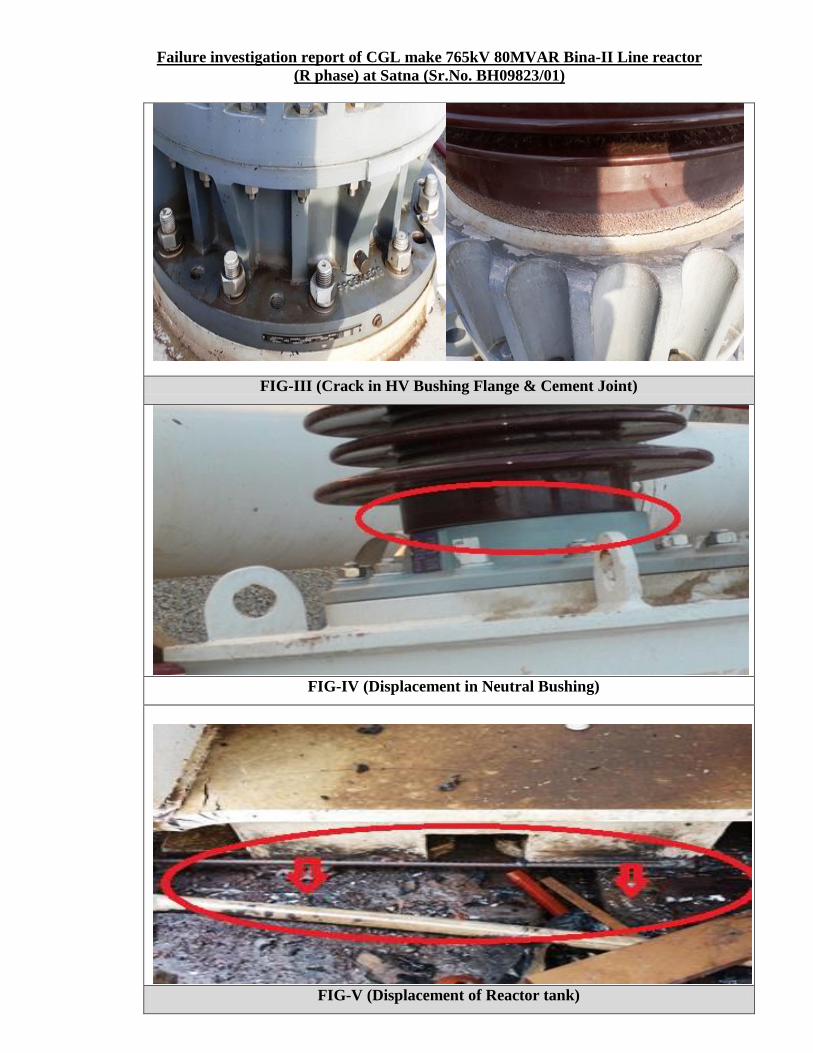
Failure investigation report of CGL make 765kV 80MVAR Bina-II Line reactor
(R phase) at Satna (Sr.No. BH09823/01)
FIG-III (Crack in HV Bushing Flange & Cement Joint)
FIG-IV (Displacement in Neutral Bushing)
FIG-V (Displacement of Reactor tank)
220
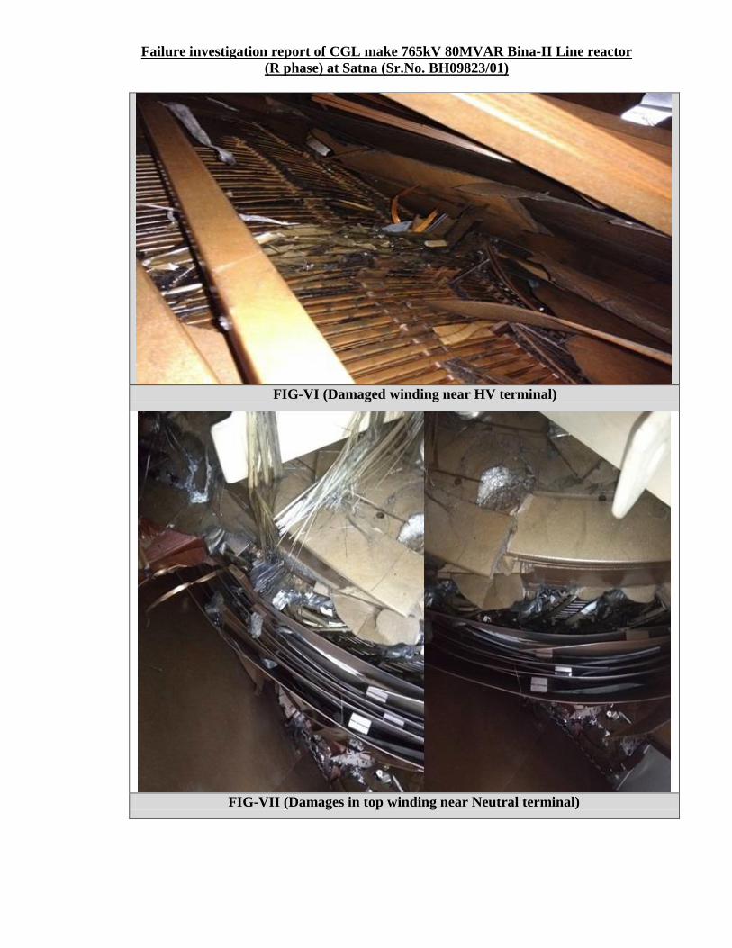
Failure investigation report of CGL make 765kV 80MVAR Bina-II Line reactor
(R phase) at Satna (Sr.No. BH09823/01)
FIG-VI (Damaged winding near HV terminal)
FIG-VII (Damages in top winding near Neutral terminal)
221
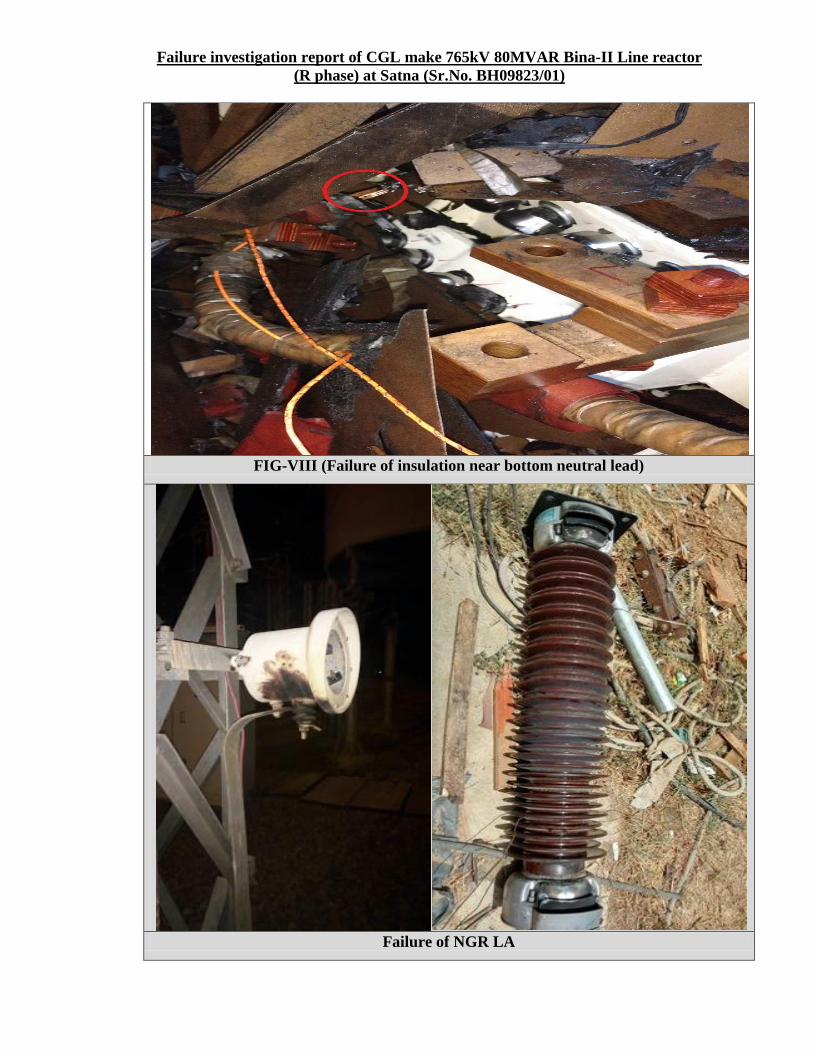
Failure investigation report of CGL make 765kV 80MVAR Bina-II Line reactor
(R phase) at Satna (Sr.No. BH09823/01)
FIG-VIII (Failure of insulation near bottom neutral lead)
Failure of NGR LA
222
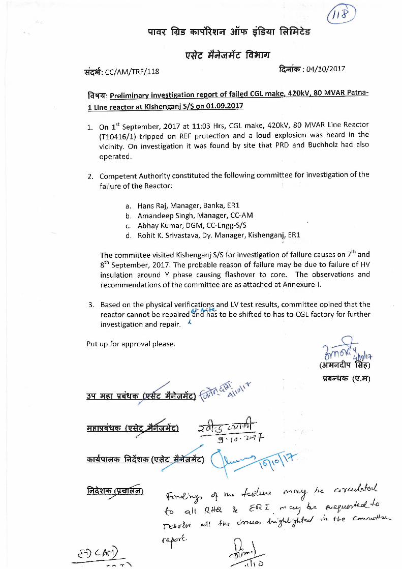
223
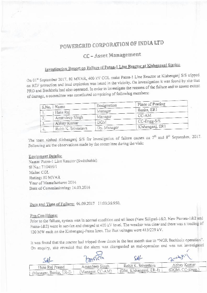
224
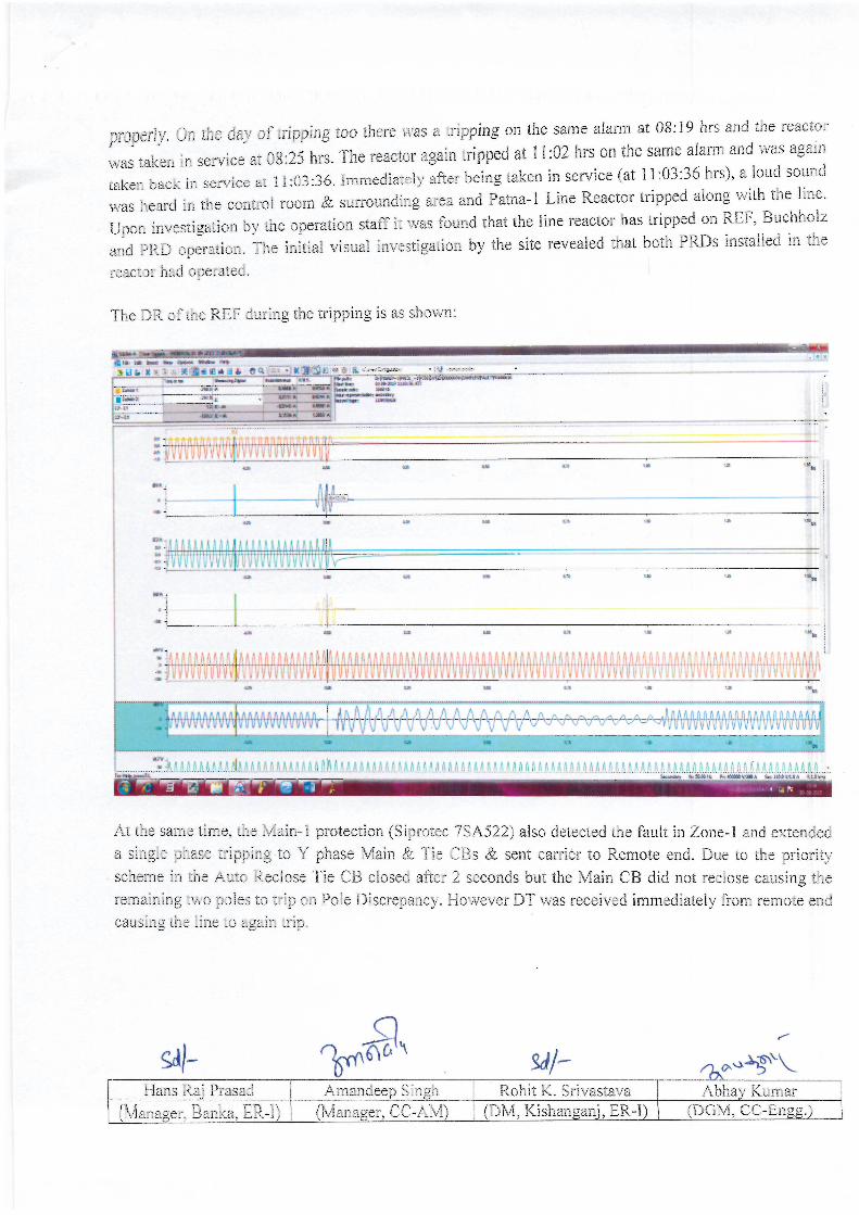
225
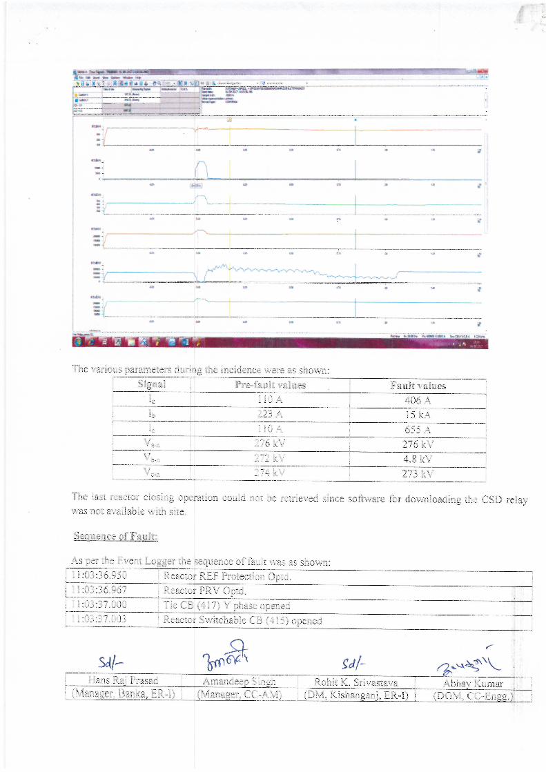
226
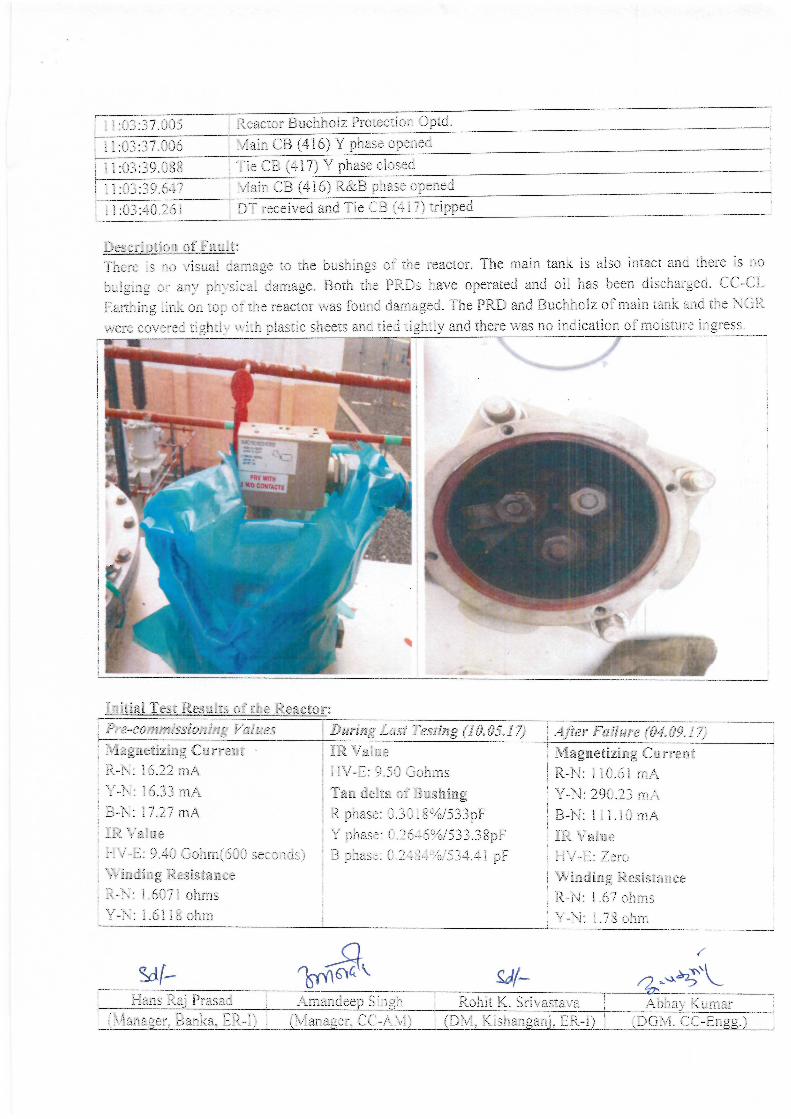
227
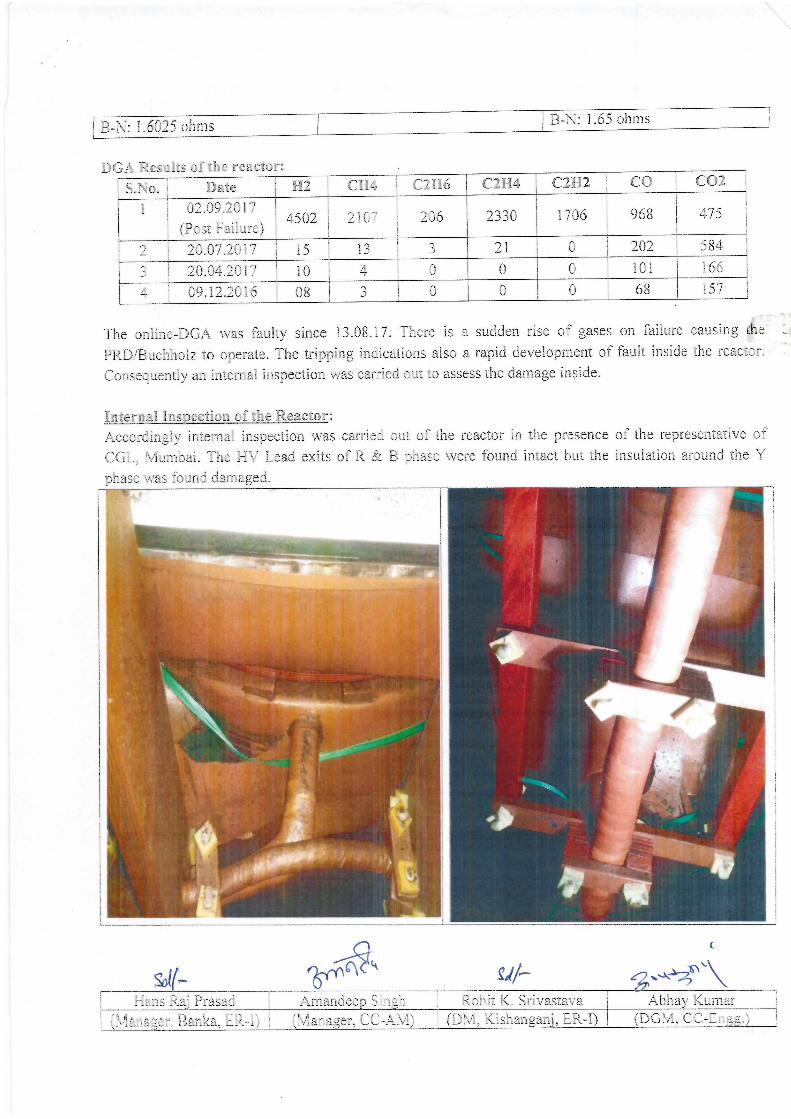
228
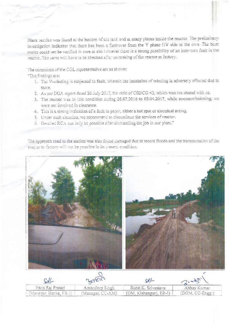
229
230
Raghavendra Verma Amandeep Singh J.V. Singh Richik Manas Das
(Manager, RHQ-AM) (Manager, CC-AM) (Chief Manager, Varanasi) (Dy. Manager, CC-Engg)
POWERGRID CORPORATION OF INDIA LTD
CC – Asset Management
Committee Report on Failure of Kanpur-2 Line Reactor B phase at Varanasi Station
On 27th
December 2017, 80 MVAR, 765 kV TBEA make Kanpur-2 Line Reactor (B phase) at Varanasi
S/S tripped on REF indication. In order to investigate the reasons of the failure and to assess extent of
damage, a committee was constituted comprising of following members:
S.No. Name Designation Place of Posting
1. Amandeep Singh Manager CC-AM
2. Richik Manas Das Dy. Manager CC-Engg
3. Raghavendra Verma Manager RHQ-AM, NR3
4. J.V. Singh Chief Manager Varanasi, NR3
The team visited Varanasi S/S for investigation of probable failure causes on 29th
December, 2017.
Following are the observations
Equipment Details:
Name: Kanpur-2 Line Reactor (B phase)
Sl No.: 14B09098
Make: TBEA
Rating: 80 MVAR, 765kV
Year of Manufacture: 2014
Date of Commissioning: 14.07.2016
Date and Time of Failure: 27.12.2017 01:38:11 hrs
Pre-Conditions:
Prior to the failure, system was in normal condition and all 765 kV & 400 kV lines were in service. The
weather was dense foggy and there was a loading of 225 MW each on the two 765 kV Varanasi-Kanpur
lines. The Bus voltages were 790/422 kV.
At 00:59 hrs, Buchholz alarm appeared in the 765 kV B phase reactor of Kanpur-2 Line Reactor. Upon
observing the same the station operator alerted the maintenance staff regarding it. The operator was
advised by the maintenance staff to physically observe the Buchholz GCD for presence of gas and to open
the reactor in co-ordination with CPCC. The station operator checked the reactor and did not find any
231
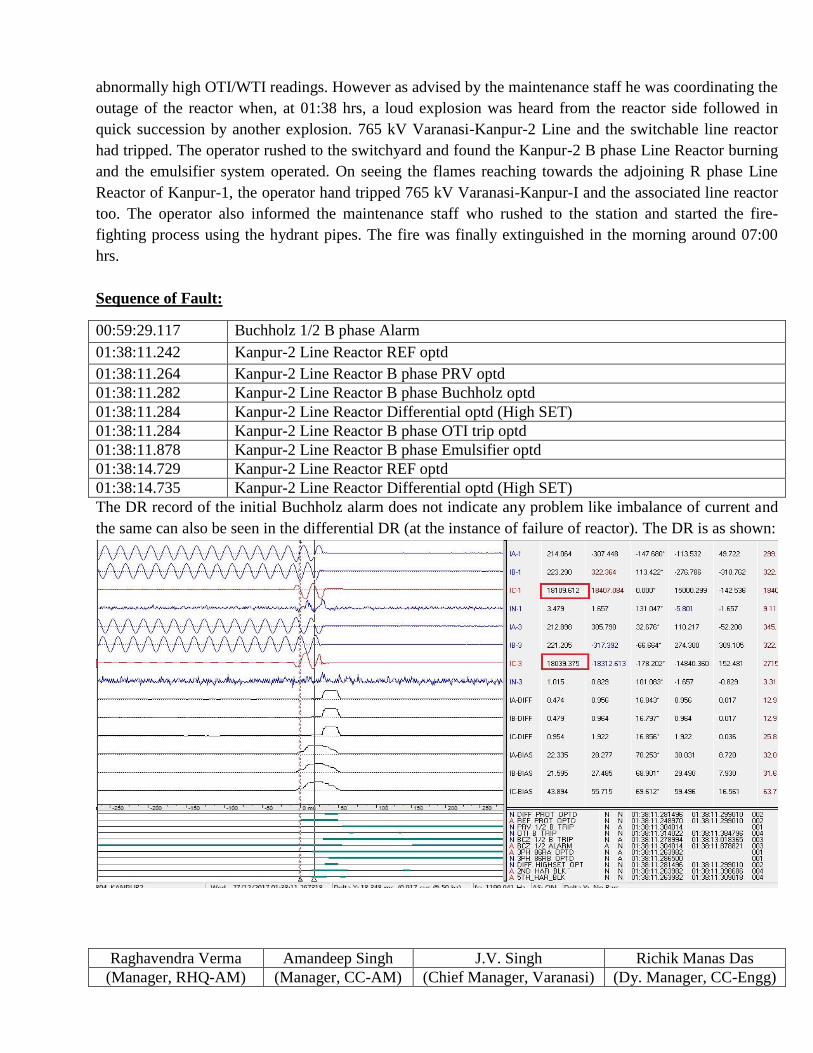
Raghavendra Verma Amandeep Singh J.V. Singh Richik Manas Das
(Manager, RHQ-AM) (Manager, CC-AM) (Chief Manager, Varanasi) (Dy. Manager, CC-Engg)
abnormally high OTI/WTI readings. However as advised by the maintenance staff he was coordinating the
outage of the reactor when, at 01:38 hrs, a loud explosion was heard from the reactor side followed in
quick succession by another explosion. 765 kV Varanasi-Kanpur-2 Line and the switchable line reactor
had tripped. The operator rushed to the switchyard and found the Kanpur-2 B phase Line Reactor burning
and the emulsifier system operated. On seeing the flames reaching towards the adjoining R phase Line
Reactor of Kanpur-1, the operator hand tripped 765 kV Varanasi-Kanpur-I and the associated line reactor
too. The operator also informed the maintenance staff who rushed to the station and started the fire-
fighting process using the hydrant pipes. The fire was finally extinguished in the morning around 07:00
hrs.
Sequence of Fault:
00:59:29.117 Buchholz 1/2 B phase Alarm
01:38:11.242 Kanpur-2 Line Reactor REF optd
01:38:11.264 Kanpur-2 Line Reactor B phase PRV optd
01:38:11.282 Kanpur-2 Line Reactor B phase Buchholz optd
01:38:11.284 Kanpur-2 Line Reactor Differential optd (High SET)
01:38:11.284 Kanpur-2 Line Reactor B phase OTI trip optd
01:38:11.878 Kanpur-2 Line Reactor B phase Emulsifier optd
01:38:14.729 Kanpur-2 Line Reactor REF optd
01:38:14.735 Kanpur-2 Line Reactor Differential optd (High SET)
The DR record of the initial Buchholz alarm does not indicate any problem like imbalance of current and
the same can also be seen in the differential DR (at the instance of failure of reactor). The DR is as shown:
232
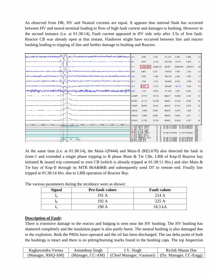
Raghavendra Verma Amandeep Singh J.V. Singh Richik Manas Das
(Manager, RHQ-AM) (Manager, CC-AM) (Chief Manager, Varanasi) (Dy. Manager, CC-Engg)
As observed from DR, HV and Neutral currents are equal. It appears that internal flash has occurred
between HV and neural terminal leading to flow of high fault current and damages to bushing. However in
the second instance (i.e. at 01:38:14), Fault current appeared in HV side only after 3.5s of first fault.
Reactor CB was already open at that instant. Flashover might have occurred between line and reactor
bushing leading to tripping of line and further damage to bushing and Reactor.
At the same time (i.e. at 01:38:14), the Main-1(P444) and Main-II (REL670) also detected the fault in
Zone-1 and extended a single phase tripping to B phase Main & Tie CBs. LBB of Knp-II Reactor bay
initiated & issued trip command to own CB (which is already tripped at 01:38:11 Hrs.) and also Main &
Tie bay of Knp-II through its MTR 86A&86B and subsequently send DT to remote end. Finally line
tripped at 01:38:14 Hrs. due to LBB operation of Reactor Bay.
The various parameters during the incidence were as shown:
Signal Pre-fault values Fault values
Ia 191 A 214 A
Ib 192 A 225 A
Ic 190 A 18.3 kA
Description of Fault:
There is extensive damage to the reactor and bulging is seen near the HV bushing. The HV bushing has
shattered completely and the insulation paper is also partly burnt. The neutral bushing is also damaged due
to the explosion. Both the PRDs have operated and the oil has been discharged. The tan delta point of both
the bushings is intact and there is no pitting/burning marks found in the bushing caps. The top Inspection
233
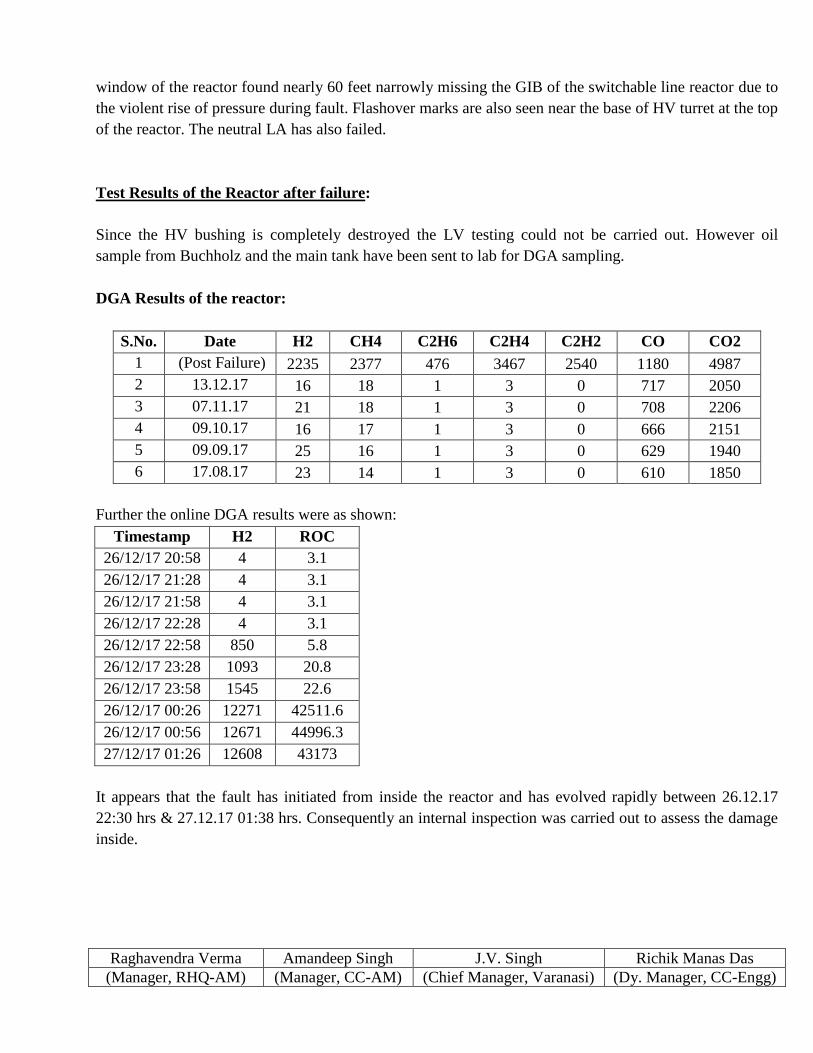
Raghavendra Verma Amandeep Singh J.V. Singh Richik Manas Das
(Manager, RHQ-AM) (Manager, CC-AM) (Chief Manager, Varanasi) (Dy. Manager, CC-Engg)
window of the reactor found nearly 60 feet narrowly missing the GIB of the switchable line reactor due to
the violent rise of pressure during fault. Flashover marks are also seen near the base of HV turret at the top
of the reactor. The neutral LA has also failed.
Test Results of the Reactor after failure:
Since the HV bushing is completely destroyed the LV testing could not be carried out. However oil
sample from Buchholz and the main tank have been sent to lab for DGA sampling.
DGA Results of the reactor:
S.No. Date H2 CH4 C2H6 C2H4 C2H2 CO CO2
1 (Post Failure) 2235 2377 476 3467 2540 1180 4987
2 13.12.17 16 18 1 3 0 717 2050
3 07.11.17 21 18 1 3 0 708 2206
4 09.10.17 16 17 1 3 0 666 2151
5 09.09.17 25 16 1 3 0 629 1940
6 17.08.17 23 14 1 3 0 610 1850
Further the online DGA results were as shown:
Timestamp H2 ROC
26/12/17 20:58 4 3.1
26/12/17 21:28 4 3.1
26/12/17 21:58 4 3.1
26/12/17 22:28 4 3.1
26/12/17 22:58 850 5.8
26/12/17 23:28 1093 20.8
26/12/17 23:58 1545 22.6
26/12/17 00:26 12271 42511.6
26/12/17 00:56 12671 44996.3
27/12/17 01:26 12608 43173
It appears that the fault has initiated from inside the reactor and has evolved rapidly between 26.12.17
22:30 hrs & 27.12.17 01:38 hrs. Consequently an internal inspection was carried out to assess the damage
inside.
234
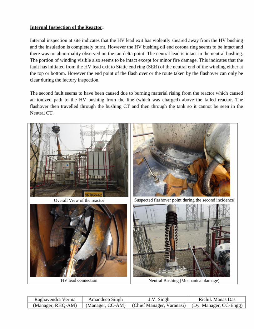
Raghavendra Verma Amandeep Singh J.V. Singh Richik Manas Das
(Manager, RHQ-AM) (Manager, CC-AM) (Chief Manager, Varanasi) (Dy. Manager, CC-Engg)
Internal Inspection of the Reactor:
Internal inspection at site indicates that the HV lead exit has violently sheared away from the HV bushing
and the insulation is completely burnt. However the HV bushing oil end corona ring seems to be intact and
there was no abnormality observed on the tan delta point. The neutral lead is intact in the neutral bushing.
The portion of winding visible also seems to be intact except for minor fire damage. This indicates that the
fault has initiated from the HV lead exit to Static end ring (SER) of the neutral end of the winding either at
the top or bottom. However the end point of the flash over or the route taken by the flashover can only be
clear during the factory inspection.
The second fault seems to have been caused due to burning material rising from the reactor which caused
an ionized path to the HV bushing from the line (which was charged) above the failed reactor. The
flashover then travelled through the bushing CT and then through the tank so it cannot be seen in the
Neutral CT.
Overall View of the reactor
Suspected flashover point during the second incidence
HV lead connection
Neutral Bushing (Mechanical damage)
235
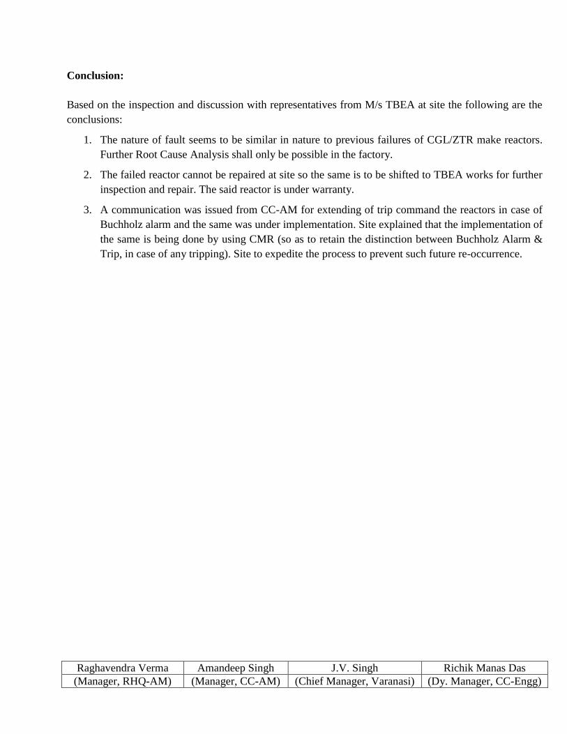
Raghavendra Verma Amandeep Singh J.V. Singh Richik Manas Das
(Manager, RHQ-AM) (Manager, CC-AM) (Chief Manager, Varanasi) (Dy. Manager, CC-Engg)
Conclusion:
Based on the inspection and discussion with representatives from M/s TBEA at site the following are the
conclusions:
1. The nature of fault seems to be similar in nature to previous failures of CGL/ZTR make reactors.
Further Root Cause Analysis shall only be possible in the factory.
2. The failed reactor cannot be repaired at site so the same is to be shifted to TBEA works for further
inspection and repair. The said reactor is under warranty.
3. A communication was issued from CC-AM for extending of trip command the reactors in case of
Buchholz alarm and the same was under implementation. Site explained that the implementation of
the same is being done by using CMR (so as to retain the distinction between Buchholz Alarm &
Trip, in case of any tripping). Site to expedite the process to prevent such future re-occurrence.
236
CENTRAL ELECTRICITY AUTHORITY
Report on failure of 220 kV and above voltage class substation equipment 237
ANNEXURE-III
Format for reporting of failure of the substation
equipment
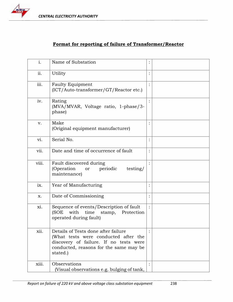
CENTRAL ELECTRICITY AUTHORITY
Report on failure of 220 kV and above voltage class substation equipment 238
Format for reporting of failure of Transformer/Reactor
i. Name of Substation
:
ii. Utility
:
iii. Faulty Equipment
(ICT/Auto-transformer/GT/Reactor etc.)
:
iv. Rating
(MVA/MVAR, Voltage ratio, 1-phase/3-phase)
:
v. Make
(Original equipment manufacturer)
:
vi. Serial No.
:
vii. Date and time of occurrence of fault
:
viii. Fault discovered during
(Operation or periodic testing/
maintenance)
:
ix. Year of Manufacturing :
x. Date of Commissioning :
xi. Sequence of events/Description of fault
(SOE with time stamp, Protection
operated during fault)
:
xii. Details of Tests done after failure
(What tests were conducted after the discovery of failure. If no tests were
conducted, reasons for the same may be stated.)
:
xiii. Observations
(Visual observations e.g. bulging of tank,
:
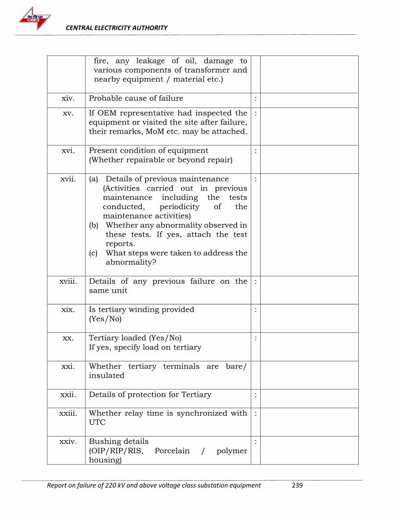
CENTRAL ELECTRICITY AUTHORITY
Report on failure of 220 kV and above voltage class substation equipment 239
fire, any leakage of oil, damage to
various components of transformer and nearby equipment / material etc.)
xiv. Probable cause of failure :
xv. If OEM representative had inspected the equipment or visited the site after failure,
their remarks, MoM etc. may be attached.
:
xvi. Present condition of equipment
(Whether repairable or beyond repair)
:
xvii. (a) Details of previous maintenance
(Activities carried out in previous maintenance including the tests
conducted, periodicity of the maintenance activities)
(b) Whether any abnormality observed in
these tests. If yes, attach the test reports.
(c) What steps were taken to address the abnormality?
:
xviii. Details of any previous failure on the
same unit
:
xix. Is tertiary winding provided
(Yes/No)
:
xx. Tertiary loaded (Yes/No)
If yes, specify load on tertiary
:
xxi. Whether tertiary terminals are bare/ insulated
xxii. Details of protection for Tertiary :
xxiii. Whether relay time is synchronized with UTC
:
xxiv. Bushing details
(OIP/RIP/RIS, Porcelain / polymer housing)
:
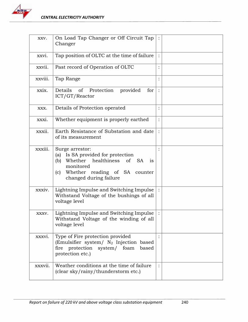
CENTRAL ELECTRICITY AUTHORITY
Report on failure of 220 kV and above voltage class substation equipment 240
xxv. On Load Tap Changer or Off Circuit Tap
Changer
:
xxvi. Tap position of OLTC at the time of failure :
xxvii. Past record of Operation of OLTC :
xxviii. Tap Range :
xxix. Details of Protection provided for
ICT/GT/Reactor
:
xxx. Details of Protection operated :
xxxi. Whether equipment is properly earthed
:
xxxii. Earth Resistance of Substation and date
of its measurement
:
xxxiii. Surge arrestor:
(a) Is SA provided for protection
(b) Whether healthiness of SA is monitored
(c) Whether reading of SA counter changed during failure
:
xxxiv. Lightning Impulse and Switching Impulse
Withstand Voltage of the bushings of all voltage level
:
xxxv. Lightning Impulse and Switching Impulse
Withstand Voltage of the winding of all voltage level
:
xxxvi. Type of Fire protection provided
(Emulsifier system/ N2 Injection based
fire protection system/ foam based protection etc.)
:
xxxvii. Weather conditions at the time of failure
(clear sky/rainy/thunderstorm etc.)
:
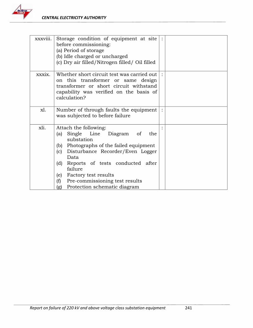
CENTRAL ELECTRICITY AUTHORITY
Report on failure of 220 kV and above voltage class substation equipment 241
xxxviii. Storage condition of equipment at site
before commissioning:
(a) Period of storage
(b) Idle charged or uncharged
(c) Dry air filled/Nitrogen filled/ Oil filled
:
xxxix. Whether short circuit test was carried out
on this transformer or same design transformer or short circuit withstand capability was verified on the basis of
calculation?
:
xl. Number of through faults the equipment was subjected to before failure
:
xli. Attach the following:
(a) Single Line Diagram of the substation
(b) Photographs of the failed equipment
(c) Disturbance Recorder/Even Logger
Data
(d) Reports of tests conducted after failure
(e) Factory test results
(f) Pre-commissioning test results
(g) Protection schematic diagram
:
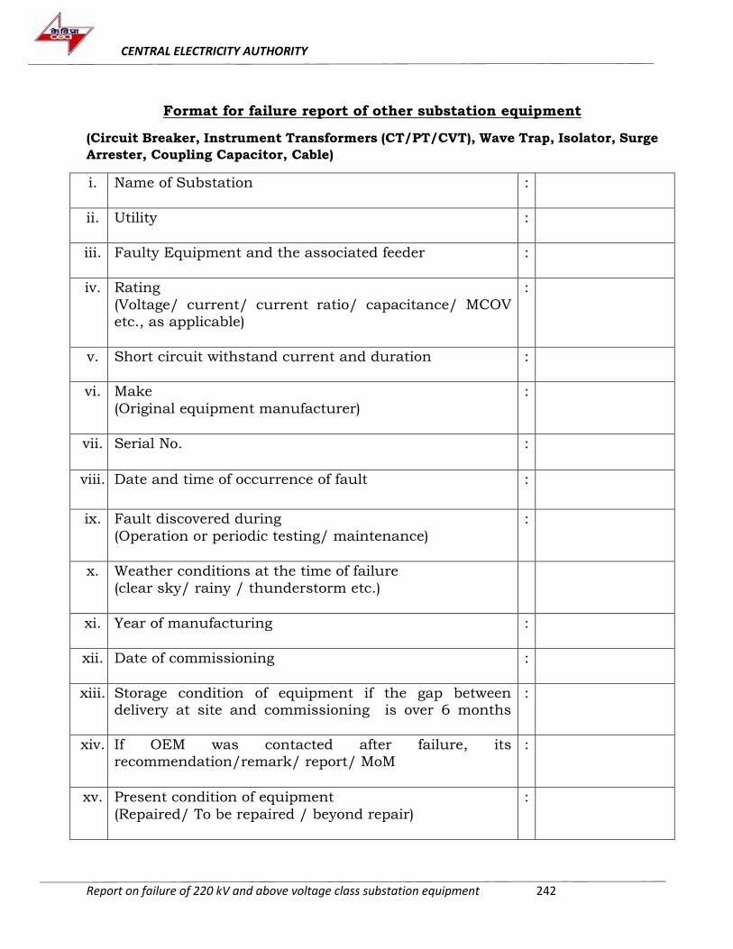
CENTRAL ELECTRICITY AUTHORITY
Report on failure of 220 kV and above voltage class substation equipment 242
Format for failure report of other substation equipment
(Circuit Breaker, Instrument Transformers (CT/PT/CVT), Wave Trap, Isolator, Surge
Arrester, Coupling Capacitor, Cable)
i. Name of Substation
:
ii. Utility
:
iii. Faulty Equipment and the associated feeder
:
iv. Rating
(Voltage/ current/ current ratio/ capacitance/ MCOV
etc., as applicable)
:
v. Short circuit withstand current and duration :
vi. Make
(Original equipment manufacturer)
:
vii. Serial No.
:
viii. Date and time of occurrence of fault :
ix. Fault discovered during
(Operation or periodic testing/ maintenance)
:
x. Weather conditions at the time of failure
(clear sky/ rainy / thunderstorm etc.)
xi. Year of manufacturing
:
xii. Date of commissioning
:
xiii. Storage condition of equipment if the gap between delivery at site and commissioning is over 6 months
:
xiv. If OEM was contacted after failure, its
recommendation/remark/ report/ MoM
:
xv. Present condition of equipment
(Repaired/ To be repaired / beyond repair)
:
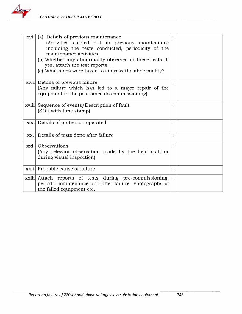
CENTRAL ELECTRICITY AUTHORITY
Report on failure of 220 kV and above voltage class substation equipment 243
xvi. (a) Details of previous maintenance
(Activities carried out in previous maintenance including the tests conducted, periodicity of the
maintenance activities)
(b) Whether any abnormality observed in these tests. If
yes, attach the test reports.
(c) What steps were taken to address the abnormality?
:
xvii. Details of previous failure
(Any failure which has led to a major repair of the
equipment in the past since its commissioning)
:
xviii. Sequence of events/Description of fault
(SOE with time stamp)
:
xix. Details of protection operated :
xx. Details of tests done after failure :
xxi. Observations
(Any relevant observation made by the field staff or during visual inspection)
:
xxii. Probable cause of failure :
xxiii. Attach reports of tests during pre-commissioning, periodic maintenance and after failure; Photographs of
the failed equipment etc.
:
CENTRAL ELECTRICITY AUTHORITY
Report on failure of 220 kV and above voltage class substation equipment 244
ANNEXURE-IV
Minutes of the Meeting of the Standing Committee of
Experts to Investigate the Failure of 220 kV and above
Voltage Class Substation Equipment held on 24th
September 2018 in CEA
Minutes of the Meeting of Standing Committee of Experts to investigatethe failure of equipment at 220 kV and above substation (January 2017to March 2018) on 24th Sept. 2018 in CEA, New Delhi
List of participants is attached in Annexure-I
1. Chief Engineer(PSE&TD) welcomed all the representatives of CPSUsand State Utilities and various OEMs present and gave backgroundand purpose of the Committee. He informed that total 79 nos. offailures has been reported during January 2017 and March 2018 byPGCIL, DTL, OPTCL, KPTCL, TANTRANSCO, APTRANSCO, BBMB,MSETCL & KSEB. Out of these, there have been failures of 12 nos. oftransformers, 5 nos. reactors, 4 nos. CB, 28 nos. CT/PT/CVT and 30nos. SA during this period. He urged all participants to participateactively and express their views on the failures and suggest measuresto prevent such failures.
2. Director (PSE&TD) requested all the utilities to furnish their failurereports indiscriminately and not selectively, so that realisticassessment of failures in the country could be made. The failure reportshould be complete in all regards along with test reports, O&M reportsand photographs. He informed that the proforma for reporting offailure is available on CEA website.
3. Presentations, on the various failures that had occurred betweenJanuary 2017 to March 2018 and were reported to CEA (Annexure-II),were given by PGCIL, DTL, BBMB, KPTCL, OPTCL, TANTRANSCO,MSETCL, MPTCL and KSEB on their respective equipment failures.The failure incidents and the subsequent findings were deliberatedupon in the meeting by the experts in the Committee. The problemareas in the subject matter at hand were brought to the fore andvarious helpful suggestions from the participating members were madeto address the prevalent issues that the utilities are facing regardingthe failures of the substation equipment. Based on the deliberationsmade in the meeting, the recommendations will be appropriated in thefinal report of the Standing Committee.
4. Member Secretary, WRPC, suggested to include 66kV Generatorsfailures in the purview of the Standing Committee as well, as itimpacts the entire plant. He also said that the state utilities are notwell aware of the Regulations and they also have problems on thefronts of workmanship and maintenance. He also commented that theinspection done in state owned substations are not upto the standard.In this regard, it was observed that the CPSUs are generally followingthe standard practices, but some state utilities fall short and needsupdation.
5. Member Secretary, NRPC, suggested the utilities to avoid unnecessarydelay in the reporting in the event of equipment failure and takenecessary measures to communicate the same promptly so thatinspection, if necessary, could be made possible. He further suggested
File No.CEA-PS-14-97/3/2018-PSETD Division
245
that in case of any equipment failure, photographic and video graphicdocumentation shall also be done in addition to the written failurereport, so that the failure incident could be properly analysed by theCommittee. NRPC suggested that Electrical Inspectorate should alsoshare their findings with CEA in the event of discovering anyabnormalities during their field inspections. Utilities were also advisedto take necessary measures to ensure proper maintenance of theirsubstations and to adhere to the Regulations/Guidelines provided byCEA. Care must be taken while placing the cables in the switchyardand they should be properly laid in the trenches or ducts and shouldbe properly isolated. He suggested that Standard Operating Procedure(SOP) for storage of equipment at site may be specified for the utilities.Director (PSE&TD) suggested that BHEL, being a major OEM, mayprovide necessary input for SOP for storage.
6. Chief Engineer (PSE&TD) suggested that spillage of oils fromtransformers should be checked regularly, only trained operatorsshould be appointed and CCTV cameras should be installed atsubstations so that in the event of any failure/accident/sabotaging,complete sequence could be made available to investigator.
7. Chief Engineer (PSPA-II) said that many utilities tend to report failuresof only transformers and reactors, and the failures of other equipmentare not reported. He suggested to practice condition-basedmaintenance instead of time-based maintenance. The utilities shouldmaintain the record of all the relevant test results including the factorytest reports, pre-commissioning test reports and the same should beavailable at substations. While determining the health of theequipment, the trend of the values of the test results should beanalyzed instead of the absolute values alone. He also recommendeduse of modern diagnostic tools for tests so that minimum humaninterference and inadvertent tampering occurs.
8. OPTCL informed that watt loss test is carried out by them to checkhealthiness of Surge Arresters (SA) and if it is found to be more than150 mW, the arrester is replaced. During discussion on failure oftransformer of OPTCL it was informed that no fire fighting system wasinstalled for protection of the transformer. It was also noticed by thecommittee that since the transformer failed immediately afterreplacement of bushing, poor storage condition of bushings may alsobe a cause of failure.
9. PGCIL said that proper care should be taken in cases where bushing isstored for long duration at the site and its condition should be checkedbefore commissioning. It is not enough to merely have the tan Rδ valueunder 0.7%, but it should also be ensured that the increase in tan δvalue of stored bushing from the factory result is not more than 0.1%which is indicative of moisture ingress. It was suggested that the tan δvalue should be measured at different frequencies, and that in healthycondition, the value should increase with the increase in frequency. Incase of SAs trend of the values of leakage current should be observedand if the variation in two subsequent readings, taken six monthsapart, is more than 20µA, Insulation Resistance (IR) should be
File No.CEA-PS-14-97/3/2018-PSETD Division
246
conducted to assess the health of SA. BBMB also stated that the rateof change of tan δ is indicative of the health of SA. WRPC suggestedthermal scanning as a good indicator of the condition of SA and itsconnectors.
10.NRPC stated that many substations of various utilities are foundlacking in the areas like fire fighting system, proper storage ofequipment, proper testing before installation, and even the reliability ofthe test kits. PGCIL recommended that demo of test kits should beconducted to ensure its reliability and repeatability of measurement.
11.Regarding transformer failures, BHEL proposed that the utilities mayconsider making an assessment of the health of all of its transformersbased on the diagnostic tests and consider overhauling of transformerswherever deemed necessary. It was also suggested that tertiarywindings should be avoided as far as possible.
12.WRPC stated that after few years when short circuit fault level of thesubstation goes up the transformer will be at risk despite propertesting and maintenance. To which CE(PSPA-II) informed that faultcurrent limiters or bus splitting should be adopted to take care ofincreased fault level.
13.CE (PSETD) suggested that the utilities have every right to repeat anyof the type tests including short circuit test at their own cost and thebidder may be asked to quote price for the same at the time of bidding.He said that this will help improve the quality of the product and actas an additional quality assurance from the manufacturer’s side.
14.PGCIL shared with the Committee that it has over 2400 in-servicetransformers and reactors of 220 kV and above level, and has a annualfailure rate of 0.5% for reactors and 0.6% for transformers, which iswell below the international annual rate of failure of 1% -1.5%. PGCILinformed that they had recently faced problems in the particular makebushings and had the cases of bursting of bushings. After this, theycarried out DGA & variable frequency tan δ of all the bushings of thesame make in all their stations and many bushings were found faulty.Variable frequency tan δ test is a very good indicator of moisturecontent in bushings. Every year 40-50 bushings in PGCIL substationsare replaced based on variable frequency tan δ test. PGCIL also statedthat if the bushing is of good quality and proper care is taken by theOEM during the manufacturing process, there shall not be any need ofcorrection factor for tan δ tests. The faulty bushings are, in general,replaced by RIP bushings.
15.WRPC recommended to introduce RIP bushings in Make in Indiaprogram. He highlighted that even if a RIP bushing will fail, it will notlead to any fire in the transformer. NRPC said that care should betaken while taking the oil sample for DGA and standard procedureshould be followed. BHEL informed that as a corrective measure toaddress the cases of failures of bushings they have renovated theentire plant of bushings at Bhopal and assured that proper care isbeing taken so that such incidences could be minimised.
16.PGCIL also reported that they were facing problems with somereactors. After consultation with OEM, they had decided to get some
File No.CEA-PS-14-97/3/2018-PSETD Division
247
design modification in the windings of the reactors. It was said that theprocess of replacement with modified deign reactors is ongoing. Thereactors were reportedly working satisfactorily after the replacement.NRPC suggested PGCIL to replace the remaining reactors as soon aspossible, so that any untoward incident may be avoided.
17.BBMB suggested faster methods for detection of earth faults in circuitbreakers, which they claimed had successfully prevented many casesof pole bursting. They also informed about breaker head flashoverproblem wherein insufficient gap after opening of the breaker wasobserved. This happened while synchronizing or immediately afterdesynchronizing and resulted in the bursting of the pole of CB. Theinternal chamber of the pole, in such cases, was found to becarbonised rendering the SF6 in the chamber useless. WRPCsuggested that after 4-5 fault current trippings, full maintenance ofthe contacts of CB should be carried out. PGCIL suggested that if theCB has tripped the rated breaking current three times, the entirecontact mechanism should be replaced. However, if the interruptedcurrent is lesser, accordingly the permissible increased number ofinterruptions before the replacement of contact mechanism, may beallowed. CE (PSETD) suggested that only Circuit Breaker capable ofbreaking higher time constant currents should be used in switchyardsassociated with generating plants. BBMB was requested to submit thedetailed failure reports of all the failures in the subject period in theirstations to CEA & NRPC.
18.KPTCL told the Committee that 12 out of 17 cases of failures of SAwere discovered during leakage current measurement. The Committeedecided that these cases will not be treated as failures and as such willnot be included in the report of the Committee.
19.WRPC highlighted that TANTRANSCO does not connect shield wirebetween gantry and the dead-end tower leaving the portionunprotected from lightning. TANTRANSCO confirmed the same. Thecommittee suggested that if substation is protected from lightningthrough shield wire, it should be connected to cover all areas of thesubstation including area between dead end tower and gantry.
20.BHEL recommended the use of Controlled Switching Devices (CSD) forswitching of transformers and reactors as it will reduce the stress onthe equipment, especially GTs, thus improving its life. It was suggestedthat the operation of fire-fighting system should be linked to SCADAand the same shall be communicated to the OEM, as it will help inassessing its condition and performance pattern.
21.The Committee opined that erection & commissioning of all majorequipment should be done by OEM so that problems arising due toignorance and lack of attentiveness by inexperienced personnel may becurtailed.
22.MSETCL said that the connection between bus and transformer atsubstations through overhead conductor should be avoided as far aspossible; instead single-core cable should be used for such connection.
23.RRVNL said that the neutral of the transformer should be connectedto the earthing mat through a separate electrode. PGCIL suggested
File No.CEA-PS-14-97/3/2018-PSETD Division
248
that the neutral of transformers should be connected to earth throughtwo conductors to avoid any problems of hotspot in the neutral. CE(PSETD) said that the neutral of 1-ph hot spare transformer shouldalso be connected to ground to avoid any fault in the event of anysurge current.
24.Based on data & information provided by the utilities anddeliberations held during the meeting a final report incorporatingrecommendations made during the meeting shall be prepared andshall be circulated to all stakeholders.
The meeting ended with a vote of thanks to the Chair.
File No.CEA-PS-14-97/3/2018-PSETD Division
249
Annexure -I
List of Participants:
CEA:
1. Shri Sanjay Srivastava, Chief Engineer and Chairman of the Committee (PSE&TD) 2. Shri Y. K. Swarnkar, Director (PSE&TD) 3. Shri R. K. Meena, Deputy Director (CEI) 4. Smt. Kavita Jha, Deputy Director (PSE&TD) 5. Shri Faraz, Deputy. Director (PSE&TD) 6. Ms. Bhaavya Pandey, Assistant Director (PSE&TD) 7. Shri Karan Sareen Assistant Director (PSE&TD) 8. Shri Mohit Mudgal, Assistant Director (PSE&TD) 9. Ms. Sippy Srivastava, Engineer (WAPCOS, Deputed in PSE&TD)
NRPC:
1. Shri M.A. K. P. Singh , Member Secretary 2. Shri Upendra Kumar, Senior Engineer
WRPC:
1. Shri A. Balan, Member Secretary
Powergrid Corporation of India Ltd.:
1. Shri R. K. Tyagi, General Manager 2. Shri Sumit S. Harichandanray, Deputy Manager 3. Shri Richik Manas Das, Deputy Manger
BHEL:
1. Shri Rajeev Sharma, General Manager 2. Shri Vivek Goel, Sr. Engg. 3. Shri Horam Singh 4. Shri Harish Kumar Sharma 5. Shri Vivek Kapil, Director General Manger
MPPTCL:
1. Shri R. K. Malviya
2. Shri P. K. Gargava
MPPGCL:
1. Shri P. K. Khare
KPTCL:
1. Shri B. V. Girish
250
TANTRANSCO:
1. Shri R. Regunarayanan, Executive Engineer
OPTCL:
1. Shri Sudhansu Sekhar Nanda, Director General Manger (Elect.)
MSETCL:
1. Shri Sanjeev G. Bhole, Senior Engineer
KSEBL:
1. Shri Rajan Joseph, Chief Engineer (TN)
GET & D India Ltd.:
1. Shri Santosh Kumar K. 2. Ms. Sandhya Lakhera 3. Shri Atul Rastogi
BBMB:
1. Shri Brajesh Kr. Yadav 2. Shri Rakesh Kumar Sharma, Addl. Senior Engineer
CGPISL (CGL):
1. Shri Naveen Bhatia, Senior Manger
DTL:
1. Shri Shyamal Sutradhar, Director General Manger 2. Shri S. K. Sinha, Director General Manger 3. Shri Kamal Gandhi, Assistant Manager (T) 4. Shri Loveleen Singh
RVPN:
1. Shri Mukesh Singhal 2. Shri A. K. Gupta
251
CENTRAL ELECTRICITY AUTHORITY
Report on failure of 220 kV and above voltage class substation equipment 252
ANNEXURE-V
Office Order Constituting the Standing Committee