Design and Analysis - Windu
117
Analyst, Design and Development System W|I|N| D|U 1
-
Upload
windu-gata -
Category
Documents
-
view
58 -
download
0
description
Tujuan : Mengenalkan dan menggunakan berbagai model pengembangan sistem perangkat lunak, analisa terstruktur, analisa berorientasi objek, serta testing dan implementasiTarget :Pemula dan MenengahPeralatan :- Komputer dengan Sistem Operasi Windows atau Linux- Netbeans 6.5- Enterise Architect- Redmine Project ManagementNo Materi Tujuan Keterangan1. Metode Pengembangan Sistem Perangkat Lunaka. Waterfall Modelb. Spiral Modelc. RAD (Rapid Application Development )d. Prototyping e. Agile Development Peserta dapat mengenal dan menggunakan berbagai model pengembangan sistem perangkat lunak 2. Analisa Terstruktura. DFD (Data Flow Diagram)b. ERD (Entity Relation Diagram)c. LRS (Logical Structure Record)d. Flowcharte. Workflow Peserta dapat mengenal dan menggunakan analisa terstruktur 3. Analisa Berorientasi Objek (UML)a. Use Case Diagramb. Activity Diagramc. Sequence Diagram d. Deployment Diagram Peserta dapat mengenal dan menggunakan UML (Unified Modeling Languange) 4. Testing Dan Implementasia. Black Boxb. White Boxc. Web Project Management Peserta dapat mengenal dan menggunakan cara melakukan testing dan implementasi serta aplikasi project management
Transcript of Design and Analysis - Windu
1
Analyst, Design and Development System
W|I|N|D|U
2
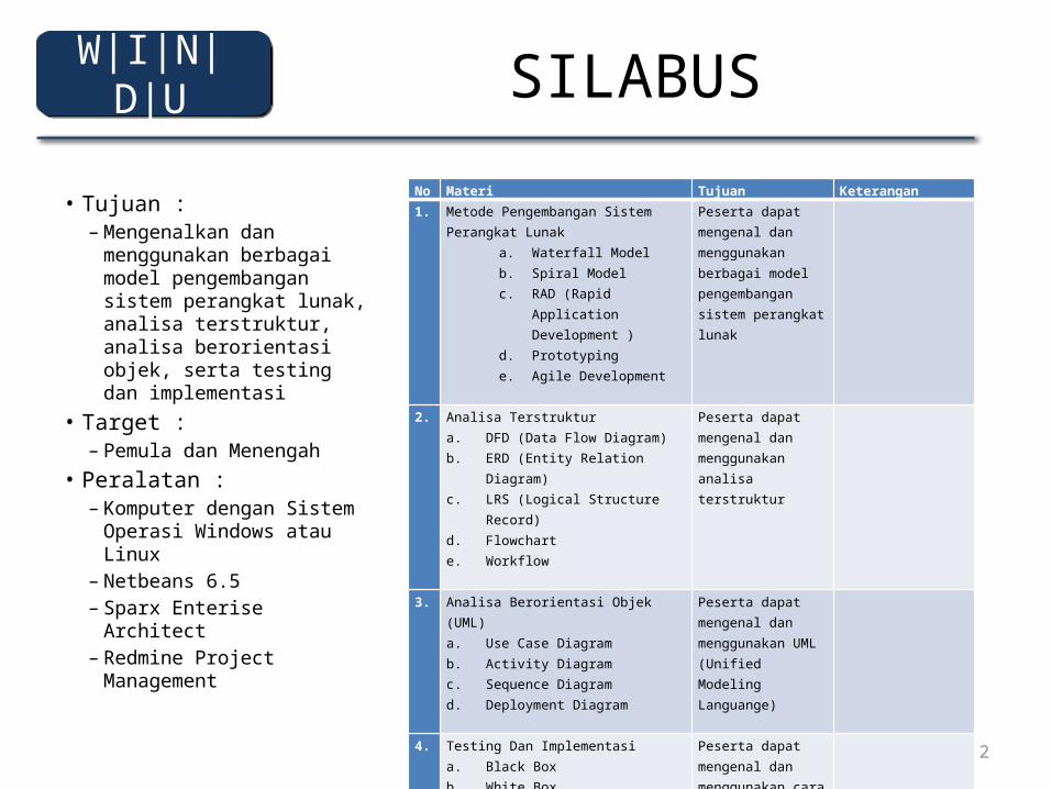
SILABUS
• Tujuan : – Mengenalkan dan
menggunakan berbagai model pengembangan sistem perangkat lunak, analisa terstruktur, analisa berorientasi objek, serta testing dan implementasi
• Target :– Pemula dan Menengah
• Peralatan :– Komputer dengan Sistem
Operasi Windows atau Linux
– Netbeans 6.5– Sparx Enterise Architect– Redmine Project
Management
W|I|N|D|U
No Materi Tujuan Keterangan1. Metode Pengembangan Sistem Perangkat
Lunaka. Waterfall Modelb. Spiral Modelc. RAD (Rapid Application
Development )d. Prototyping e. Agile Development
Peserta dapat mengenal dan menggunakan berbagai model pengembangan sistem perangkat lunak
2. Analisa Terstruktura. DFD (Data Flow Diagram)b. ERD (Entity Relation Diagram)c. LRS (Logical Structure Record)d. Flowcharte. Workflow
Peserta dapat mengenal dan menggunakan analisa terstruktur
3. Analisa Berorientasi Objek (UML)a. Use Case Diagramb. Activity Diagramc. Sequence Diagram d. Deployment Diagram
Peserta dapat mengenal dan menggunakan UML (Unified Modeling Languange)
4. Testing Dan Implementasia. Black Boxb. White Boxc. Web Project Management
Peserta dapat mengenal dan menggunakan cara melakukan testing dan implementasi serta aplikasi project management
3
1– Technological Obsolescence– Water Fall– SDLC– Spiral– Prototype– RAD– Agile
W|I|N|D|U
4
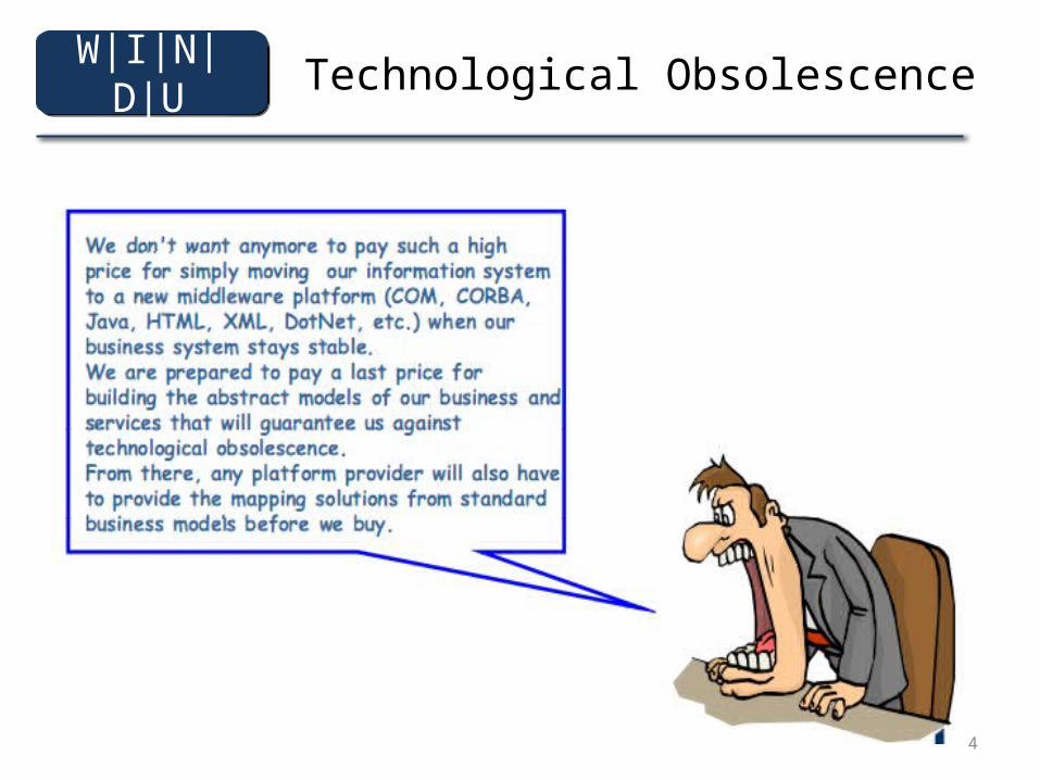
Technological ObsolescenceW|I|N|D|U
5
Analyst, Design and Development System
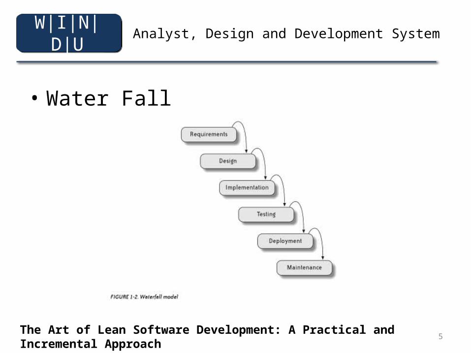
• Water Fall
The Art of Lean Software Development: A Practical and Incremental Approach By Curt Hibbs, Steve Jewett, Mike Sullivan
W|I|N|D|U
6
Analyst, Design and Development System
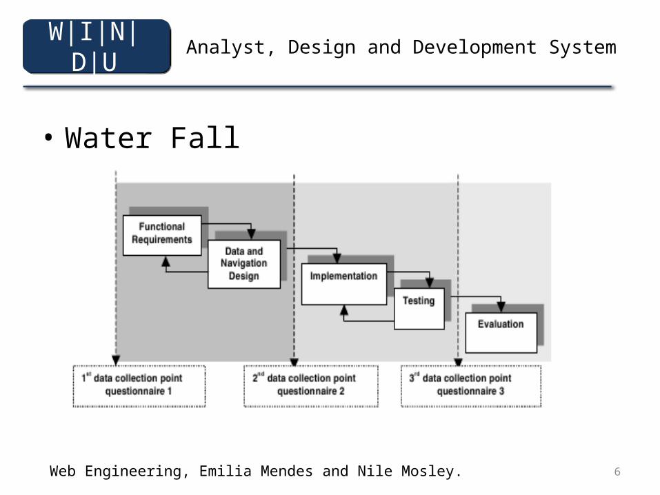
• Water Fall
Web Engineering, Emilia Mendes and Nile Mosley.
W|I|N|D|U
7
Analyst, Design and Development System
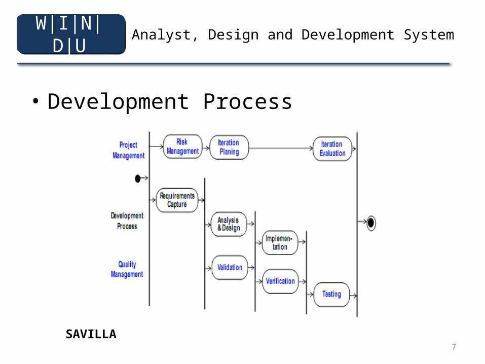
• Development Process
SAVILLA
W|I|N|D|U
8
Analyst, Design and Development System
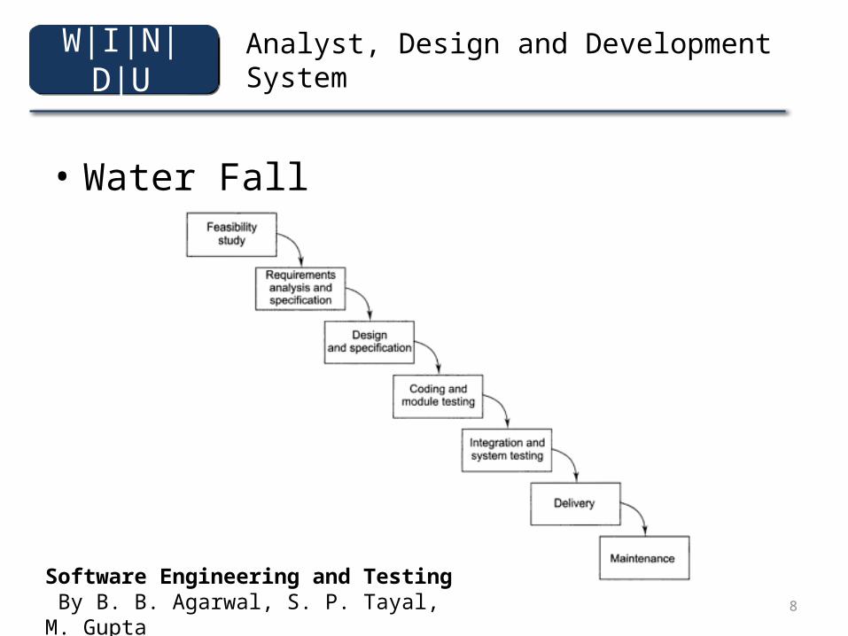
• Water Fall
Software Engineering and Testing By B. B. Agarwal, S. P. Tayal, M. Gupta
W|I|N|D|U
9
Analyst, Design and Development System
• Feasibility Study– A definition of the problem– Determination of technical and economic viability– Alternative solutions and their expected benefits– Required resources, costs, and delivery dates in
each proposed alternative solution
Software Engineering and Testing By B. B. Agarwal, S. P. Tayal, M. Gupta
W|I|N|D|U
10
Analyst, Design and Development System
• Requirement Analysis and SprecificationCalled Software Requirement Specification(SRS)– Detailed statement of problem– Possible alternative solution to problem– Functional requirements of the software system– Constraint on the software system
Software Engineering and Testing By B. B. Agarwal, S. P. Tayal, M. Gupta
W|I|N|D|U
11
Analyst, Design and Development System
• Design and Specification. The goal of the design phase is to transform the requirements specified in the SRS document into a structure that is suitable for implementation in some programming language.– Traditional Design Approach– Object-Oriented Design Approach
Software Engineering and Testing By B. B. Agarwal, S. P. Tayal, M. Gupta
W|I|N|D|U
12
Analyst, Design and Development System
• Coding and Module Testing.– This phase in which we actually write programs using a programming
language.– coding can be subject to company-wide standards, which may define
the entire layout of programs, such headers for comments in every unit, naming conventions for variables and sub-programs, the maximum number of lines in each component, and other aspects that company deems worthy of standardization.
– Module testing is also often subject to company standards, including a precise definition of a test plan (White Box or Black Box or Mix)
– Module testing is the main quality-control activity that is carried out in this phase.
Software Engineering and Testing By B. B. Agarwal, S. P. Tayal, M. Gupta
W|I|N|D|U
13
Analyst, Design and Development System
• Coding And Module TestingSystem is done in three phases
– Alpha Testing is conducted by the software-development team at the developer's site
– Beta Testing is performed by a group of friendly customers in the presence of the software-development team
– Acceptance Testing is performed by the customers themselves. if the software is successful in acceptance testing, the products is installed at the customer's site.
Software Engineering and Testing By B. B. Agarwal, S. P. Tayal, M. Gupta
W|I|N|D|U
14
Analyst, Design and Development System
• Delivery and Maintenance
– The Delivery of Software is often done in two stages. • in the first stage, the application is distributed among a selected group if customers prior to its
official rlease. • in the second stage, the product is distributed to the customers.
• Maintenenance– The set of activities that are performed after the system is delivered to the customer.– Consists of correcting any remaining errors in the system (corrective maintenance),
adapting the application to changes in the environment (adaptive maintenance), and improving, changing, or adding features and qualities to the application (perfective maintenance).
– 60% from costs• 20% Corrective and Adaptive Maintenance• 50% Perfective Maintenance
Software Engineering and Testing By B. B. Agarwal, S. P. Tayal, M. Gupta
W|I|N|D|U
15
Analyst, Design and Development System
• MAINTENANCE– Corrective Maintenance Activities
• triggered by software faults encountered during the use of the software.
– Preventive Maintenance Activities• Dealing with weakness and vulnerabilities identified by the development team during or after
deploying the software an that were nit dealt with in the installed software
– Perfective Maintenance Activities• Dealing with requests to improve the efficiency of the algorithms and data structures, as well as
user interface interactions in the design.
– Adaptive Maintenance Activities• Requests from software stakeholders to adapt the software to different operating
environments, user interface styles, social contexts, or new government regulations and standards.
Software Engineering By Kassem A. Saleh
W|I|N|D|U
16
Analyst, Design and Development System
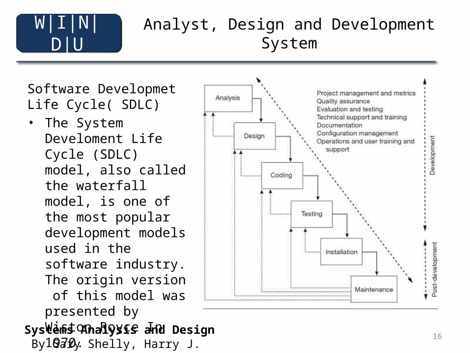
Software Developmet Life Cycle( SDLC)• The System Develoment
Life Cycle (SDLC) model, also called the waterfall model, is one of the most popular development models used in the software industry. The origin version of this model was presented by Wiston Royce In 1970.
Systems Analysis and Design By Gary Shelly, Harry J. Rosenblatt
W|I|N|D|U
17
Analyst, Design, an Development System
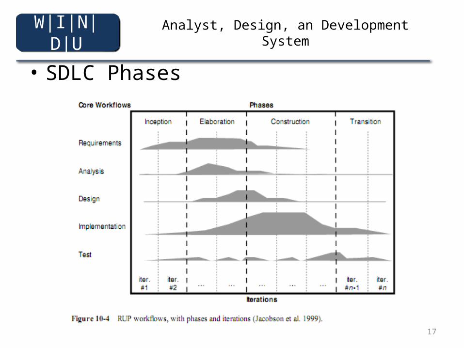
• SDLC Phases
W|I|N|D|U
18
Analyst, Design and Development System
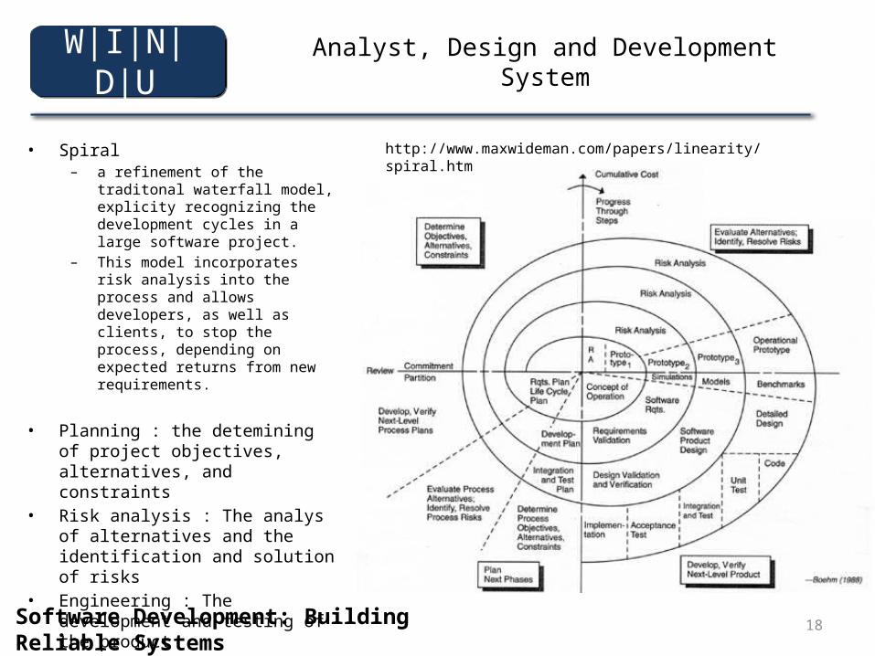
• Spiral– a refinement of the traditonal waterfall
model, explicity recognizing the development cycles in a large software project.
– This model incorporates risk analysis into the process and allows developers, as well as clients, to stop the process, depending on expected returns from new requirements.
• Planning : the detemining of project objectives, alternatives, and constraints
• Risk analysis : The analys of alternatives and the identification and solution of risks
• Engineering : The development and testing of the product
• Customer evaluation : The assessment of the results of the engineering.
http://www.maxwideman.com/papers/linearity/spiral.htm
W|I|N|D|U
Software Development: Building Reliable Systems By Marc Hamilton
19
Analyst, Design and Development System
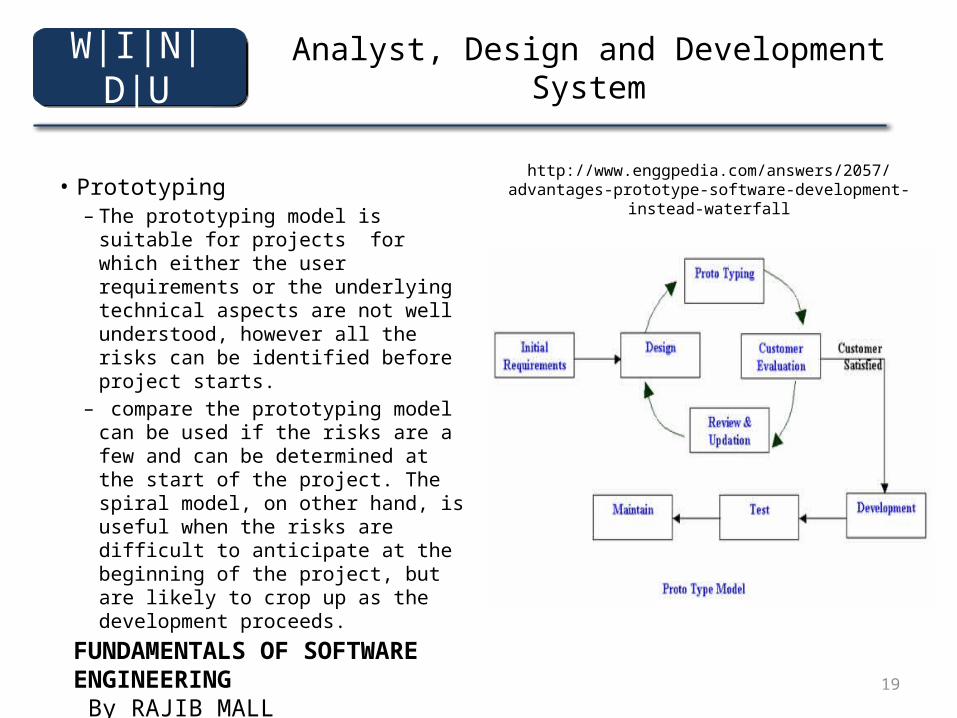
• Prototyping– The prototyping model is suitable
for projects for which either the user requirements or the underlying technical aspects are not well understood, however all the risks can be identified before project starts.
– compare the prototyping model can be used if the risks are a few and can be determined at the start of the project. The spiral model, on other hand, is useful when the risks are difficult to anticipate at the beginning of the project, but are likely to crop up as the development proceeds.
http://www.enggpedia.com/answers/2057/advantages-prototype-software-development-instead-waterfall
W|I|N|D|U
FUNDAMENTALS OF SOFTWARE ENGINEERING By RAJIB MALL
20
Analyst, Design, and Development System
• Rapid Application Development – methodologies in an effort to decrease
development times. – incorporates an umbrella of methodologies based
on spiral, iterative development technologies. – RAD techniques range from the simple use of GUI
development tools so quickly build prototypes, to process incorporating complete, cross functional business analyst.
Software Development: Building Reliable Systems By Marc Hamilto
W|I|N|D|U
21
Analyst, Design and Development System
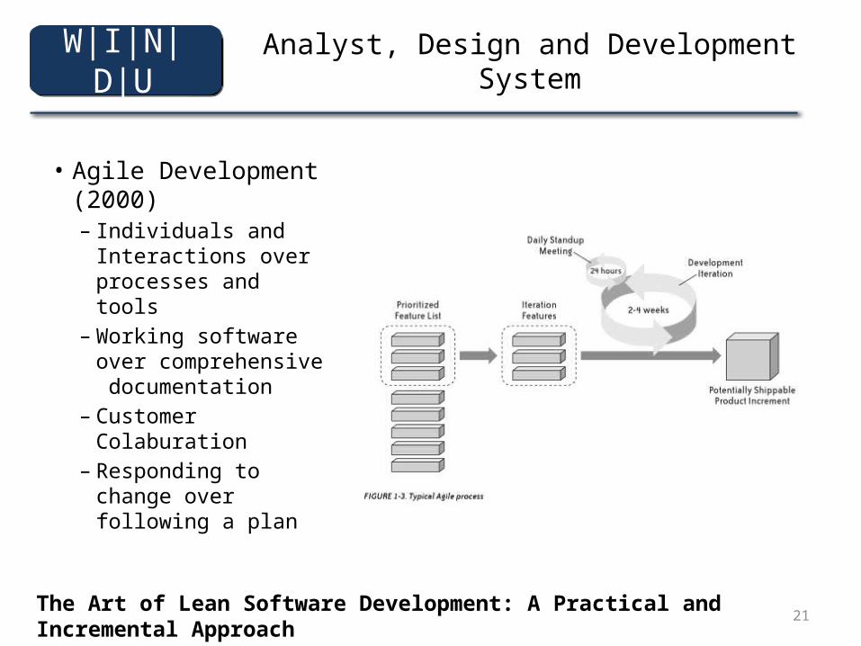
• Agile Development (2000)– Individuals and
Interactions over processes and tools
– Working software over comprehensive documentation
– Customer Colaburation
– Responding to change over following a plan
The Art of Lean Software Development: A Practical and Incremental Approach By Curt Hibbs, Steve Jewett, Mike Sullivan
W|I|N|D|U
22
Analyst, Design and Development System
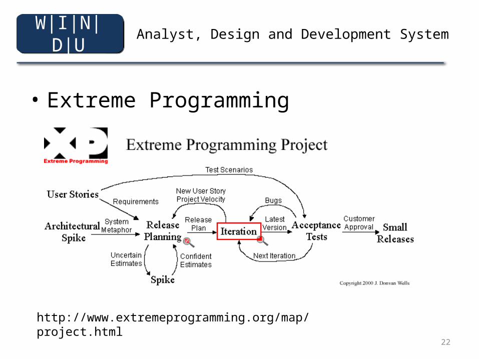
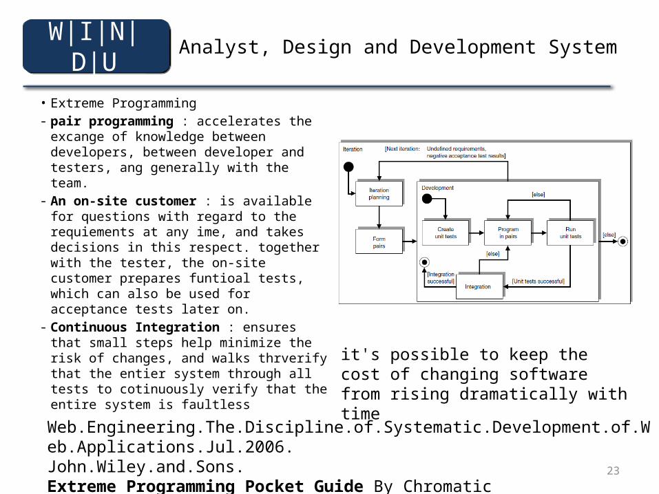
• Extreme Programming
http://www.extremeprogramming.org/map/project.html
W|I|N|D|U
23
Analyst, Design and Development System
• Extreme Programming- pair programming : accelerates the
excange of knowledge between developers, between developer and testers, ang generally with the team.
- An on-site customer : is available for questions with regard to the requiements at any ime, and takes decisions in this respect. together with the tester, the on-site customer prepares funtioal tests, which can also be used for acceptance tests later on.
- Continuous Integration : ensures that small steps help minimize the risk of changes, and walks thrverify that the entier system through all tests to cotinuously verify that the entire system is faultless
Web.Engineering.The.Discipline.of.Systematic.Development.of.Web.Applications.Jul.2006.John.Wiley.and.Sons.Extreme Programming Pocket Guide By Chromatic
W|I|N|D|U
it's possible to keep the cost of changing software from rising dramatically with time
24
Analyst, Design and Development System
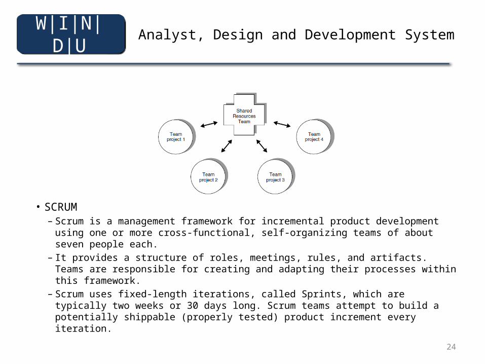
• SCRUM– Scrum is a management framework for incremental product development
using one or more cross-functional, self-organizing teams of about seven people each.
– It provides a structure of roles, meetings, rules, and artifacts. Teams are responsible for creating and adapting their processes within this framework.
– Scrum uses fixed-length iterations, called Sprints, which are typically two weeks or 30 days long. Scrum teams attempt to build a potentially shippable (properly tested) product increment every iteration.
W|I|N|D|U
25
Analyst, Design and Development System
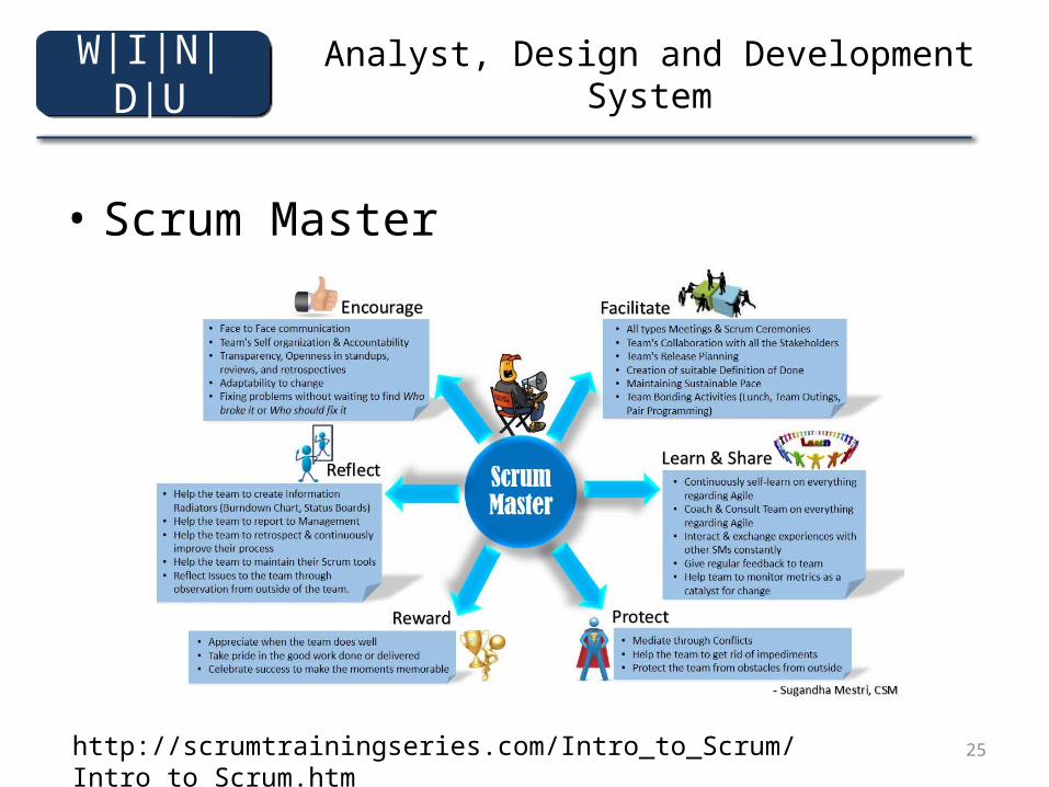
• Scrum Master
W|I|N|D|U
http://scrumtrainingseries.com/Intro_to_Scrum/Intro_to_Scrum.htm
26
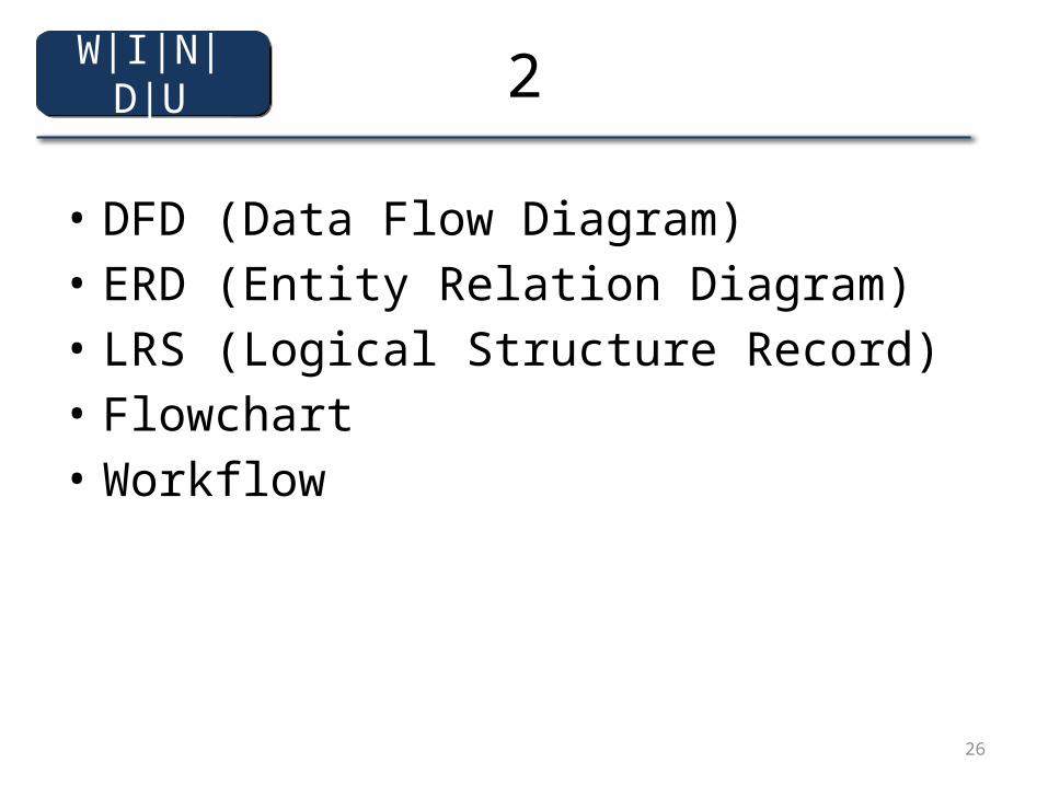
2
• DFD (Data Flow Diagram)• ERD (Entity Relation Diagram)• LRS (Logical Structure Record)• Flowchart• Workflow
W|I|N|D|U
27
Data Flow Diagrams
Supplementary material to support Bennett, McRobb and Farmer:
Object Oriented Systems Analysis and Design Using UML, (4th Edition), McGraw Hill, 2005.
W|I|N|D|U
28
In This Presentation You Will Learn:
• What data flow diagrams (DFDs) are• What DFDs can be used for• Why DFDs are not used in object-oriented
analysis and design• Variations in notation for DFDs
W|I|N|D|U
29
What are DFDs?
• Data flow diagrams (DFDs) are one of the diagramming techniques used in structured systems analysis and design
• Data flow diagrams show:– Data flowing through a system to or from users
(external entities)– The processes that transform the data– The data stores that hold the data
W|I|N|D|U
30
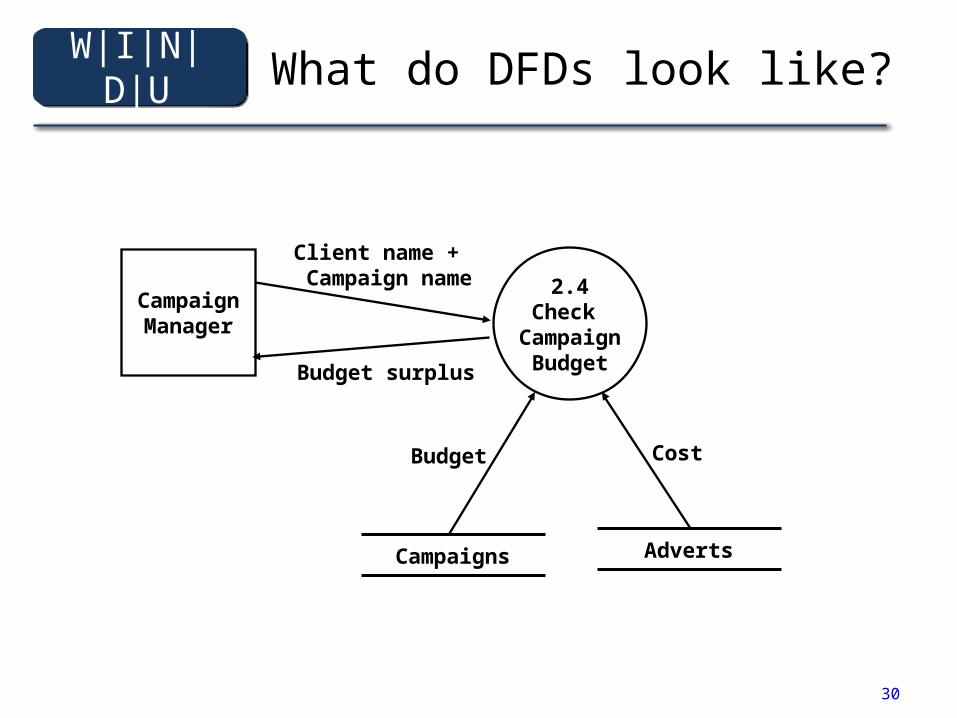
What do DFDs look like?
2.4Check
CampaignBudget
CampaignManager
Client name + Campaign name
Budget surplus
Campaigns Adverts
Budget Cost
W|I|N|D|U
31
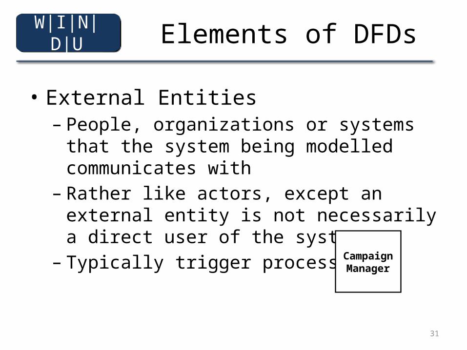
Elements of DFDs
• External Entities– People, organizations or systems that the system
being modelled communicates with– Rather like actors, except an external entity is not
necessarily a direct user of the system– Typically trigger processes
CampaignManager
W|I|N|D|U

32
Elements of DFDs
• Processes– Processes that transform data in some
way– Named and numbered– Normally require at least one input
and produce at least one output– Inputs / outputs (I/O) may flow to or
from other processes, data stores or external entities
2.4Check
CampaignBudget
W|I|N|D|U
33
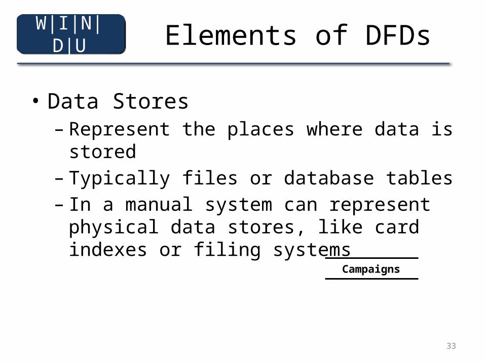
Elements of DFDs
• Data Stores– Represent the places where data is stored– Typically files or database tables– In a manual system can represent physical data
stores, like card indexes or filing systems
Campaigns
W|I|N|D|U
34
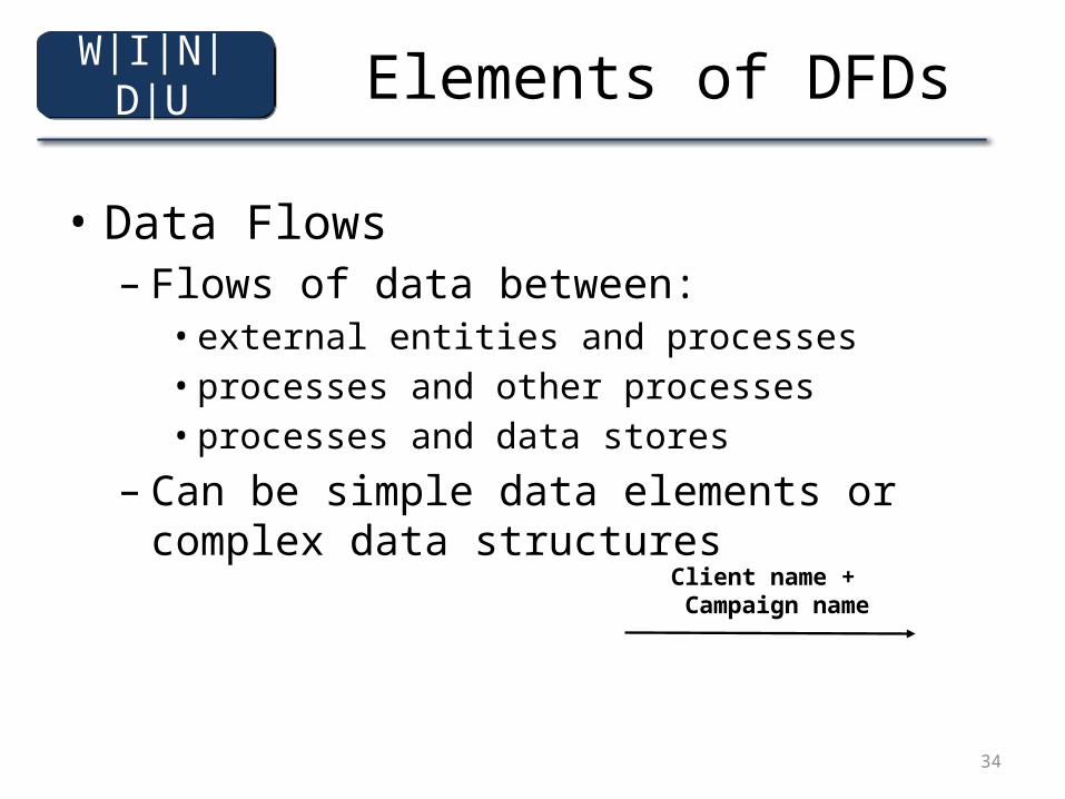
Elements of DFDs
• Data Flows– Flows of data between:
• external entities and processes• processes and other processes• processes and data stores
– Can be simple data elements or complex data structures
Client name + Campaign name
W|I|N|D|U
35
Data Dictionaries
• DFDs are supported by data dictionary entries• Each element is defined in a data dictionary
– Data elements - name and data type– Data structures - name and composition– Data flows - name and content– Data stores - name and data structures contained– Processes - name and specification of the process, for
example in Structured English
W|I|N|D|U
36
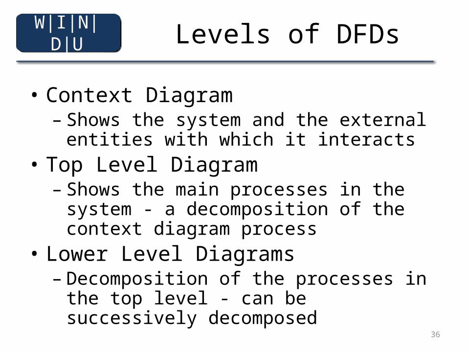
Levels of DFDs
• Context Diagram– Shows the system and the external entities with
which it interacts• Top Level Diagram
– Shows the main processes in the system - a decomposition of the context diagram process
• Lower Level Diagrams– Decomposition of the processes in the top level -
can be successively decomposed
W|I|N|D|U
37
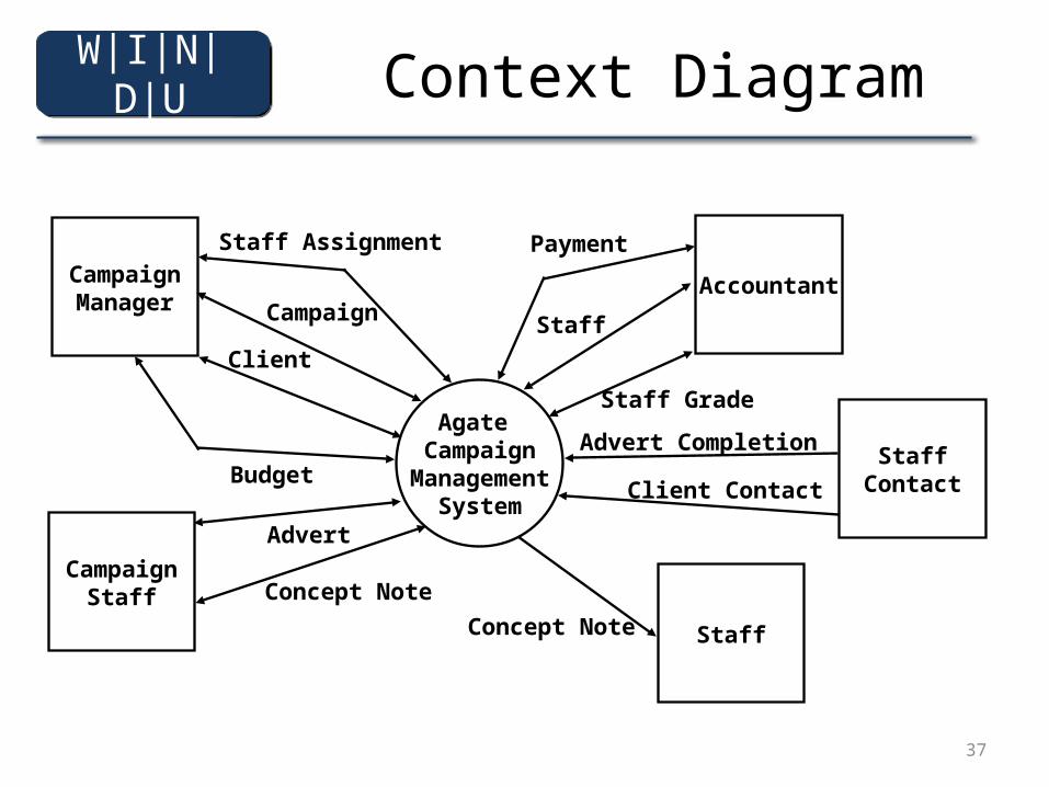
Context Diagram
Agate Campaign
ManagementSystem
CampaignManager
Client
Budget
CampaignStaff
Campaign
Advert
Staff Assignment
Accountant
Concept Note
StaffConcept Note
Staff
Staff Grade
StaffContact
Payment
Advert Completion
Client Contact
W|I|N|D|U
38
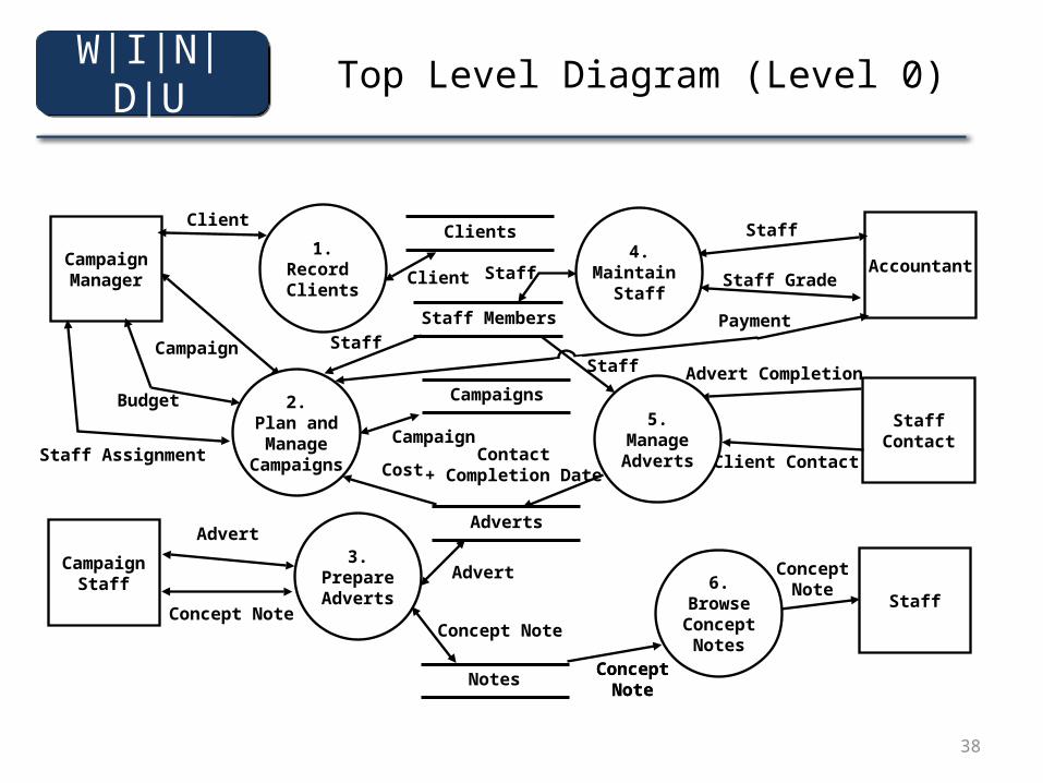
Top Level Diagram (Level 0)
1.Record Clients
CampaignManager
Client
Staff Assignment
CampaignStaff
Campaign
Advert
Accountant
Concept Note
Staff
ConceptNote
Staff
Staff Grade
StaffContact
Payment
Advert Completion
Client Contact
3.PrepareAdverts
Notes
6.BrowseConcept
NotesConcept
Note
Concept Note
4.Maintain
Staff
5.ManageAdverts
Adverts
Advert
Contact+ Completion Date
Clients
Client
2.Plan andManage
Campaigns
Staff Members
Staff
Budget
Cost
ConceptNote
Campaigns
Campaign
StaffStaff
W|I|N|D|U
39
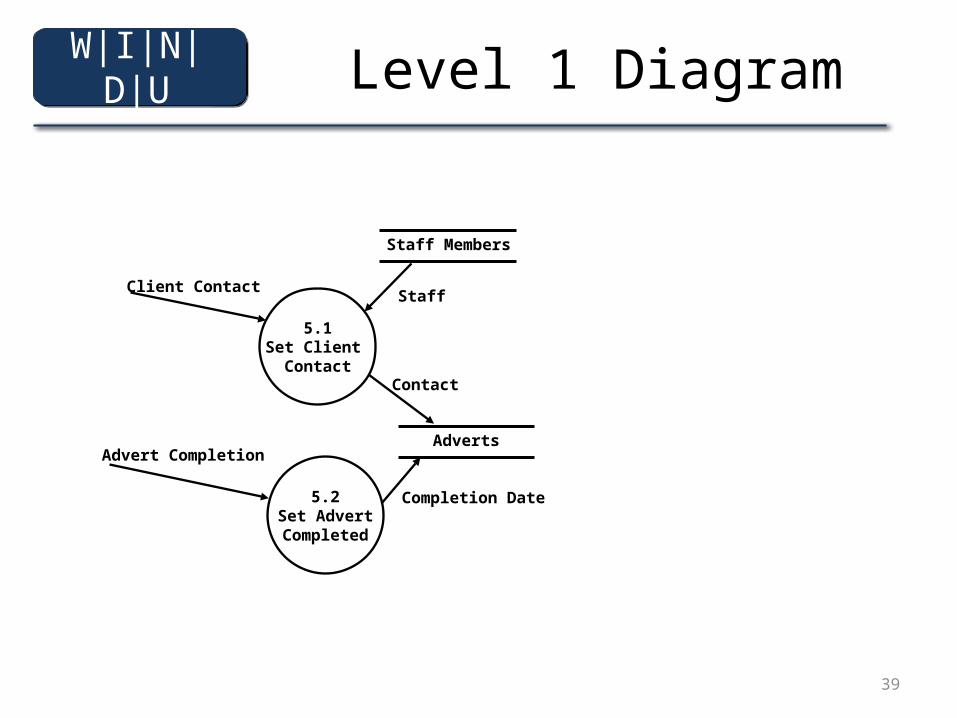
Level 1 Diagram
Advert Completion
Client Contact
5.1Set Client
Contact
Adverts
Contact
Staff Members
Staff
Completion Date5.2Set AdvertCompleted
W|I|N|D|U
40
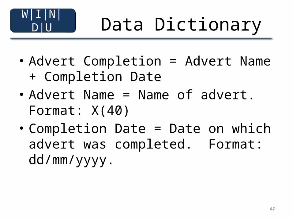
Data Dictionary
• Advert Completion = Advert Name + Completion Date
• Advert Name = Name of advert. Format: X(40)• Completion Date = Date on which advert was
completed. Format: dd/mm/yyyy.
W|I|N|D|U
41
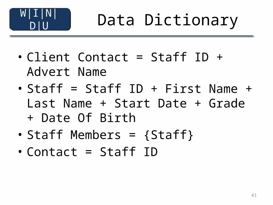
Data Dictionary
• Client Contact = Staff ID + Advert Name• Staff = Staff ID + First Name + Last Name +
Start Date + Grade + Date Of Birth• Staff Members = {Staff}• Contact = Staff ID
W|I|N|D|U
42
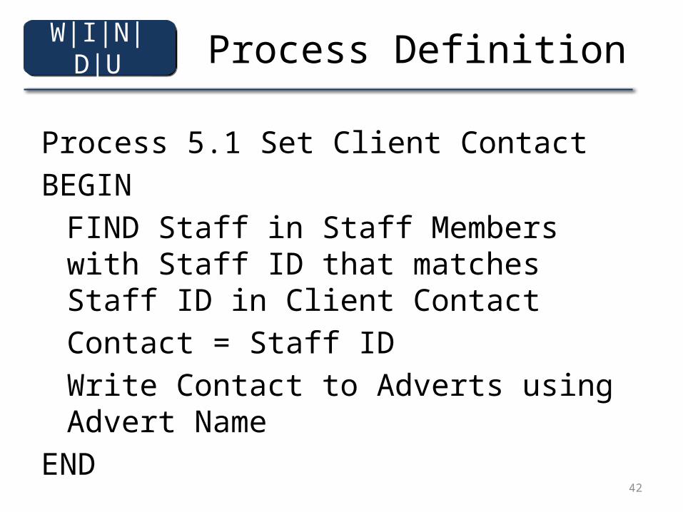
Process Definition
Process 5.1 Set Client ContactBEGIN
FIND Staff in Staff Members with Staff ID that matches Staff ID in Client ContactContact = Staff IDWrite Contact to Adverts using Advert Name
END
W|I|N|D|U
43
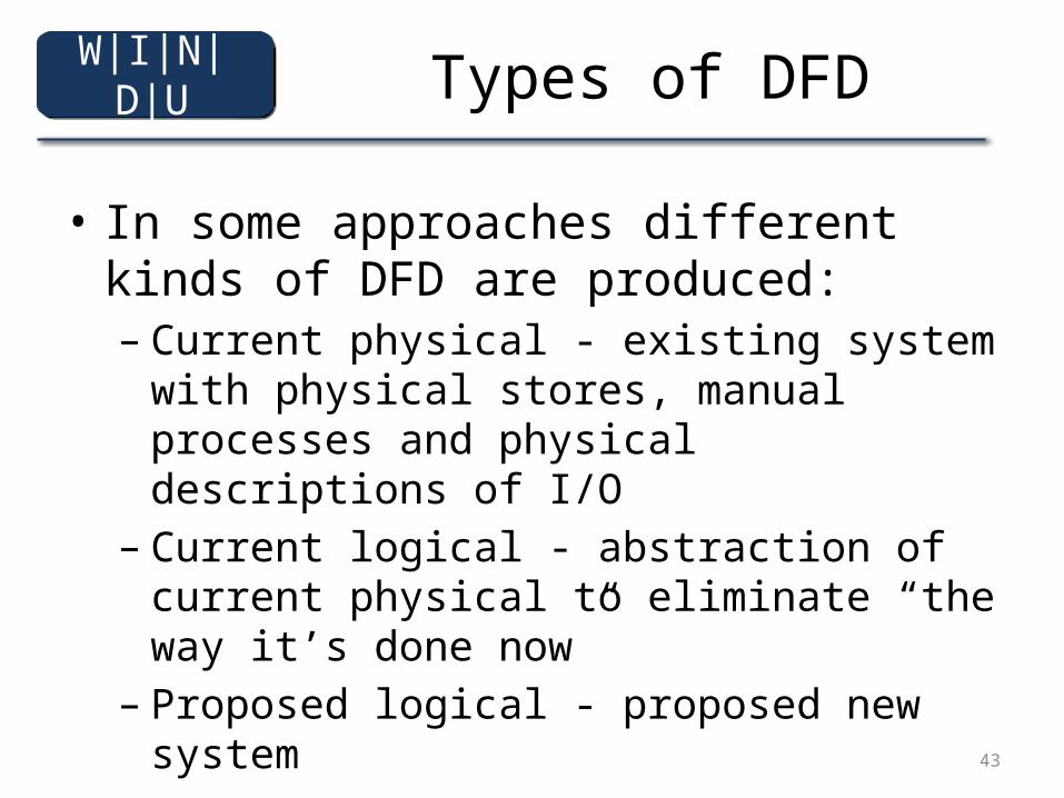
Types of DFD
• In some approaches different kinds of DFD are produced:– Current physical - existing system with physical
stores, manual processes and physical descriptions of I/O
– Current logical - abstraction of current physical to eliminate “the way it’s done now”
– Proposed logical - proposed new system
W|I|N|D|U
44
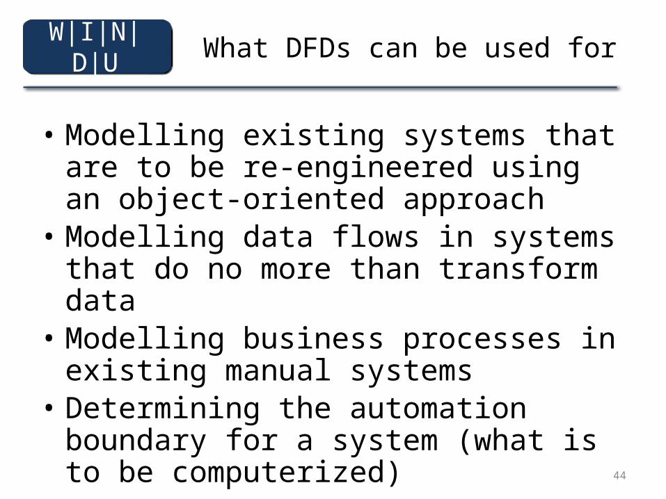
What DFDs can be used for
• Modelling existing systems that are to be re-engineered using an object-oriented approach
• Modelling data flows in systems that do no more than transform data
• Modelling business processes in existing manual systems
• Determining the automation boundary for a system (what is to be computerized)
W|I|N|D|U
45
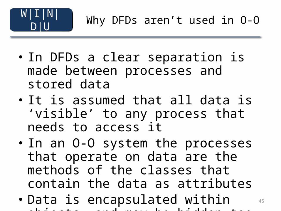
Why DFDs aren’t used in O-O
• In DFDs a clear separation is made between processes and stored data
• It is assumed that all data is ‘visible’ to any process that needs to access it
• In an O-O system the processes that operate on data are the methods of the classes that contain the data as attributes
• Data is encapsulated within objects, and may be hidden too
W|I|N|D|U
46
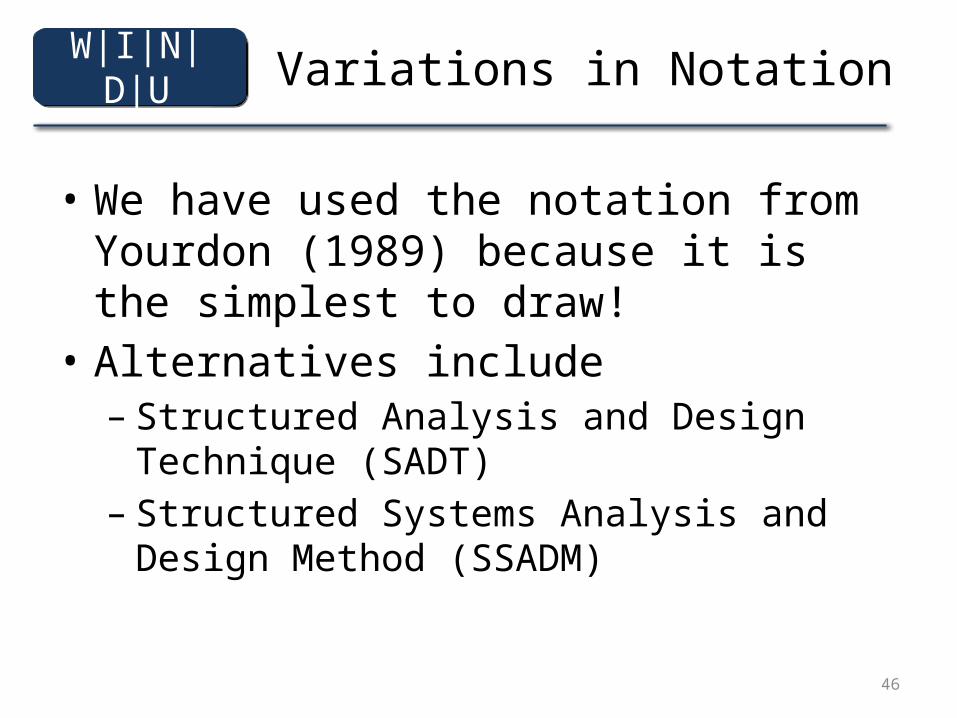
Variations in Notation
• We have used the notation from Yourdon (1989) because it is the simplest to draw!
• Alternatives include – Structured Analysis and Design Technique (SADT)– Structured Systems Analysis and Design Method
(SSADM)
W|I|N|D|U
47
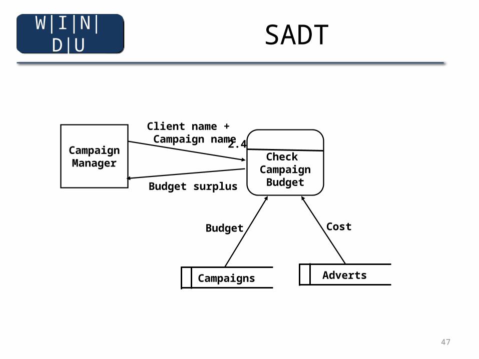
SADT
2.4 Check
CampaignBudget
CampaignManager
Client name + Campaign name
Budget surplus
Campaigns Adverts
Budget Cost
W|I|N|D|U
48
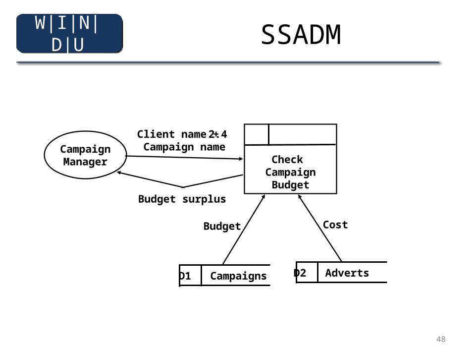
SSADM
2.4
Check Campaign
Budget
CampaignManager
Client name + Campaign name
Budget surplus
D1 Campaigns D2 Adverts
Budget Cost
W|I|N|D|U
49
SSADM
• SSADM probably has the most complex notation, which we have not covered here, including:– Flows and stores of physical materials– Notation for duplicate elements appearing in the
same diagram– Special numbering systems for manual and
transient data stores
W|I|N|D|U
50
Other Structured Techniques
• In a structured approach, data structures are usually modelled separately in an Entity-Relationship Diagram (ERD), but ERDs don’t show processes
• Entity Life Histories show the events that affect entities over time
• Structure Diagrams show program structure as a tree hierarchy of modules
W|I|N|D|U
51
Summary
In this presentation you have learned about:• What data flow diagrams (DFDs) are• What DFDs can be used for• Why DFDs are not used in object-oriented
analysis and design• Variations in notation for DFDs
W|I|N|D|U
52
References
• Yourdon (1989)• Skidmore, Mills and Farmer (1994)(For full bibliographic details, see Bennett, McRobb and
Farmer)
W|I|N|D|U
53
Entity Relation Diagram
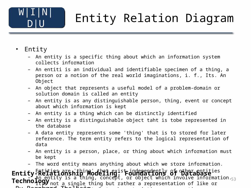
• Entity– An entity is a specific thing about which an information system collects information– An entiti is an individual and identifiable specimen of a thing, a person or a notion of the real world
imaginations, i. f., Its. An Object– An object that represents a useful model of a problem-domain or solution domain is called an entity– An entity is as any distinguishable person, thing, event or concept about which information is kept– An entity is a thing which can be distinctly identified– An entity is a distinguishable object taht is tobe represented in the database– A data entity represents some 'thing' that is to stored for later reference. The term entity refers to
the logical representation of data– An entity is a person, place, or thing about which information must be kept– The word entity means anything about which we store information.– Entities are 'thing' that exist independently of other entities– An entity is a thing, concept, or object which involve information. It;s not a single thing but rather a
representation of like or similiar things that dhstr characteristics or properties.– Well-distinguishable objects which exists in ther real world are called entities
Entity-Relationship Modeling: Foundations of Database Technology By Bernhard Thalheim
W|I|N|D|U
54
Entity Relation Diagram
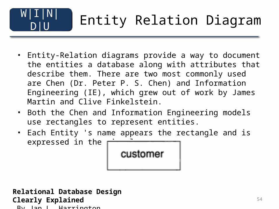
• Entity-Relation diagrams provide a way to document the entities a database along with attributes that describe them. There are two most commonly used are Chen (Dr. Peter P. S. Chen) and Information Engineering (IE), which grew out of work by James Martin and Clive Finkelstein.
• Both the Chen and Information Engineering models use rectangles to represent entities.
• Each Entity 's name appears the rectangle and is expressed in the singular
Relational Database Design Clearly Explained By Jan L. Harrington
W|I|N|D|U
55
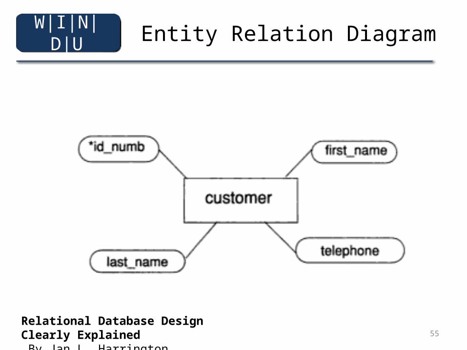
Entity Relation Diagram
Relational Database Design Clearly Explained By Jan L. Harrington
W|I|N|D|U
56
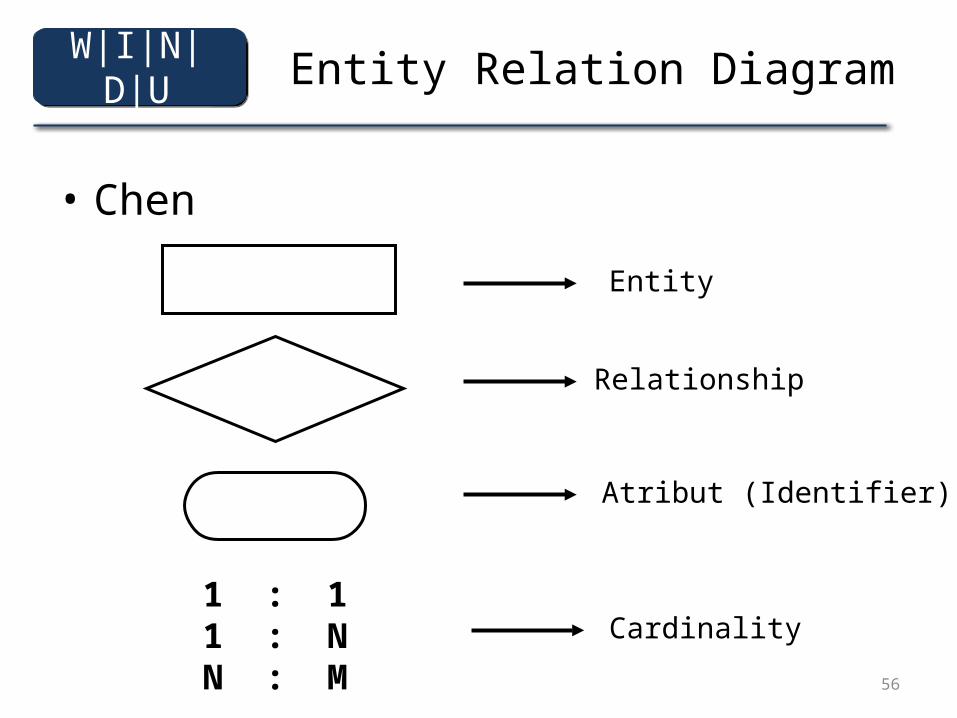
Entity Relation Diagram
• Chen
Entity
Relationship
Atribut (Identifier)
1 : 11 : NN : M
Cardinality
W|I|N|D|U
57
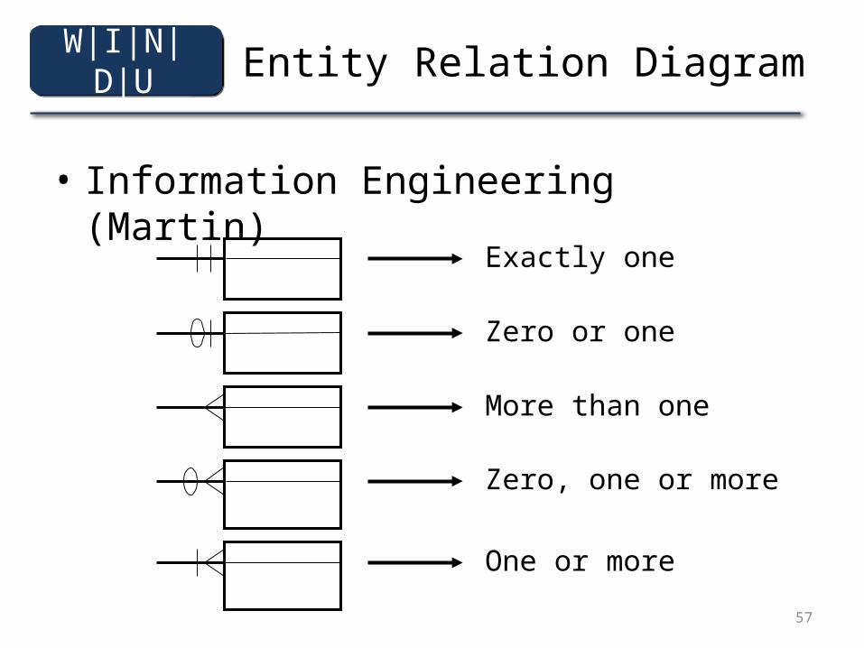
Entity Relation Diagram
• Information Engineering (Martin)
Exactly one
One or more
Zero, one or more
More than one
Zero or one
W|I|N|D|U
58
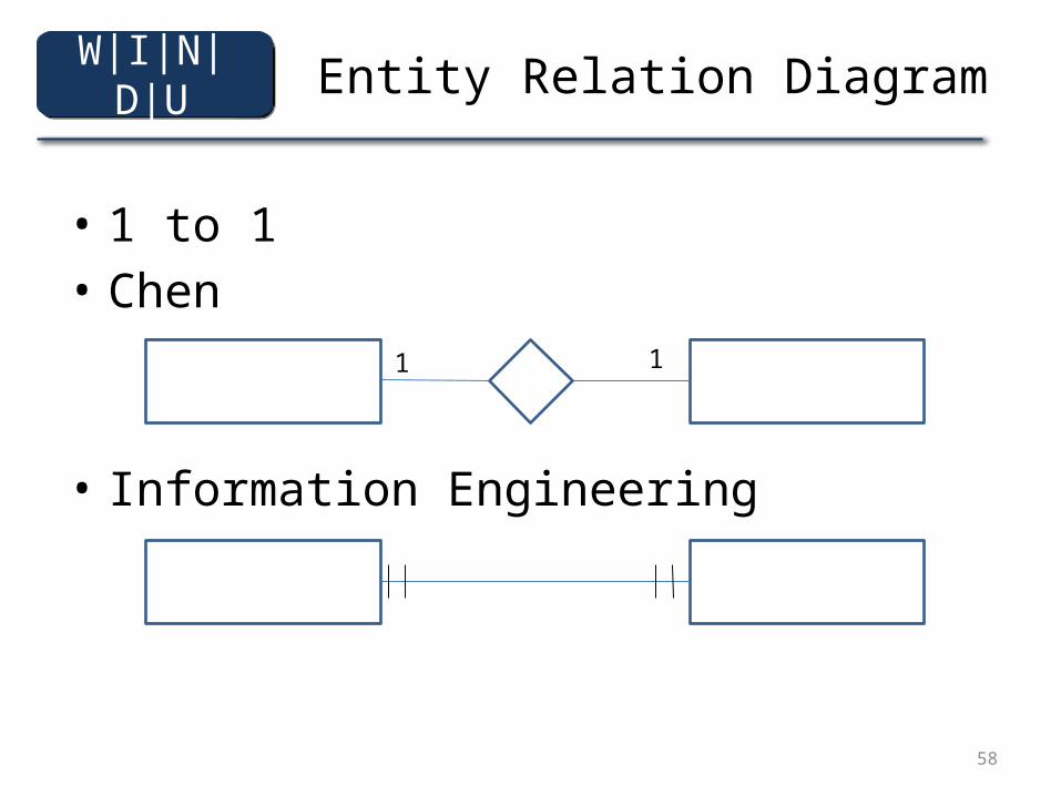
Entity Relation Diagram
• 1 to 1 • Chen
• Information Engineering
A B
A A1
1 1
W|I|N|D|U
59
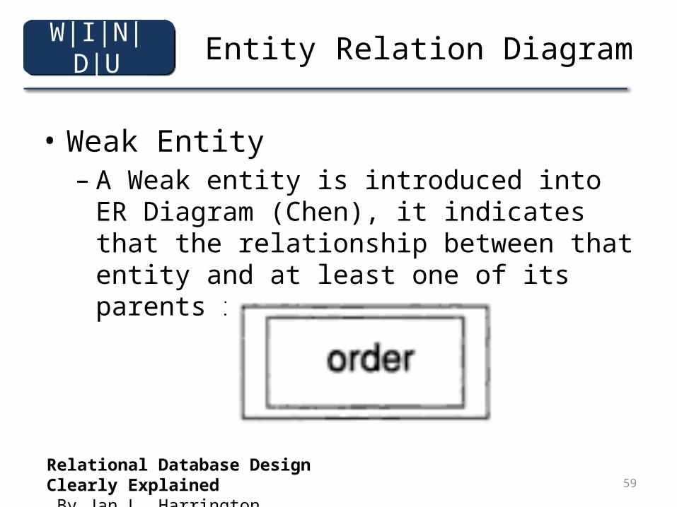
Entity Relation Diagram
• Weak Entity– A Weak entity is introduced into ER Diagram
(Chen), it indicates that the relationship between that entity and at least one of its parents is mandatory.
Relational Database Design Clearly Explained By Jan L. Harrington
W|I|N|D|U
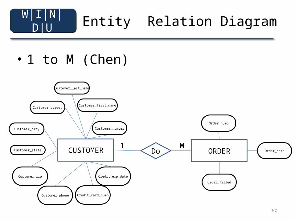
60
Entity Relation Diagram
• 1 to M (Chen)
CUSTOMER
Customer_number
Customer_first_name
Customer_last_name
Customer_street
Customer_city
Customer_state
Customer_zip
Customer_phone Credit_card_numb
Credit_exp_date
ORDER
Order_numb
Order_date
Order_filled
Do1 M
W|I|N|D|U
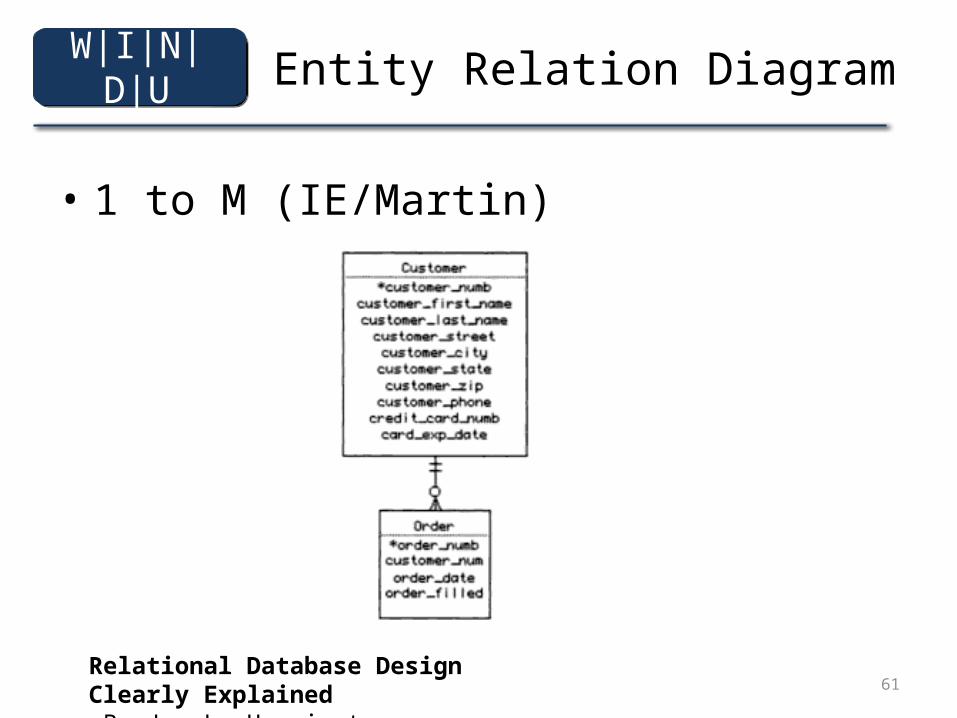
61
Entity Relation Diagram
• 1 to M (IE/Martin)
Relational Database Design Clearly Explained By Jan L. Harrington
W|I|N|D|U
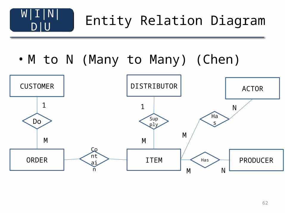
62
Entity Relation Diagram
• M to N (Many to Many) (Chen)
CUSTOMER
ORDER
Do
1
M
DISTRIBUTOR
ITEMContain PRODUCER
Supply
ACTOR
Has
Has
1
MM
N
M N
W|I|N|D|U
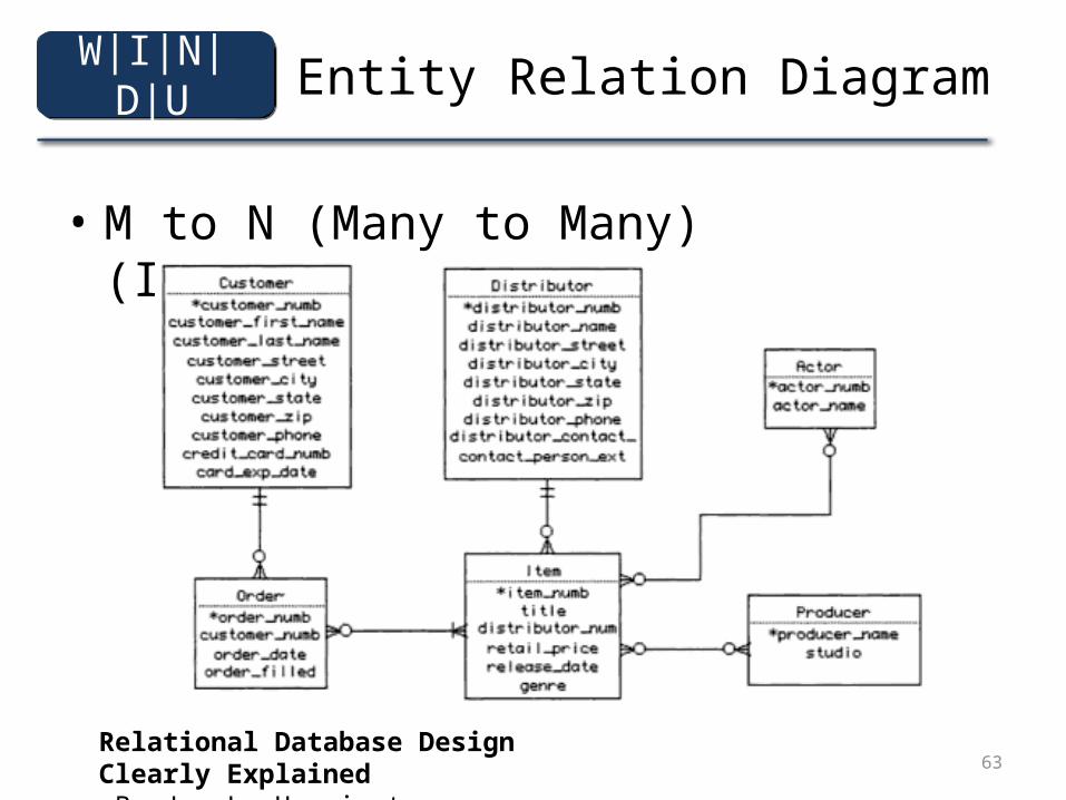
63
Entity Relation Diagram
• M to N (Many to Many) (IE/Martin)
Relational Database Design Clearly Explained By Jan L. Harrington
W|I|N|D|U
64
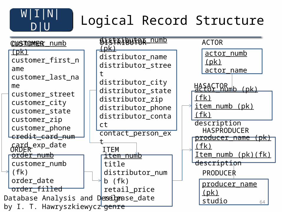
Logical Record Structure
Database Analysis and Designby I. T. Hawryszkiewycz
customer_numb (pk)customer_first_namecustomer_last_namecustomer_streetcustomer_citycustomer_statecustomer_zipcustomer_phonecredit_card_numcard_exp_date
CUSTOMER
order_numbcustomer_numb (fk)order_dateorder_filled
ORDER
distributor_numb (pk)distributor_namedistributor_streetdistributor_citydistributor_statedistributor_zipdistributor_phonedistributor_contactcontact_person_ext
DISTRIBUTOR
item_numbtitledistributor_numb (fk)retail_pricerelease_dategenre
ITEM
actor_numb (pk)actor_name
ACTOR
producer_name (pk)studio
PRODUCER
actor_numb (pk)(fk)item_numb (pk)(fk)description
HASACTOR
producer_name (pk) (fk)Item_numb (pk)(fk)description
HASPRODUCER
W|I|N|D|U
65
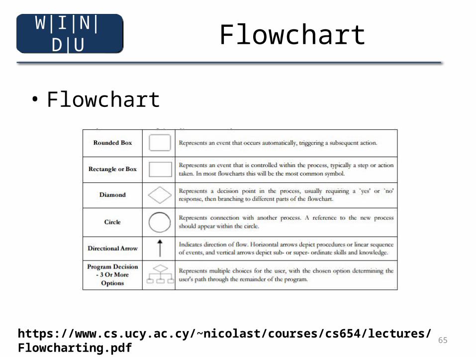
Flowchart
• Flowchart
https://www.cs.ucy.ac.cy/~nicolast/courses/cs654/lectures/Flowcharting.pdf
W|I|N|D|U
66
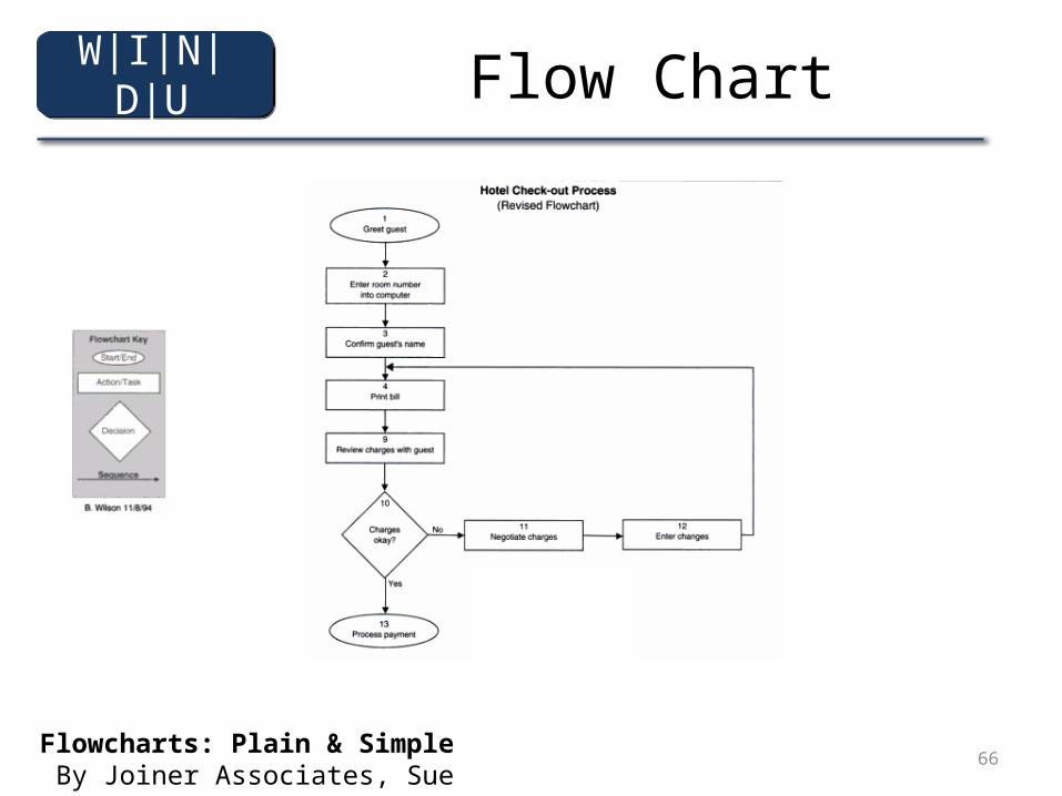
Flow Chart
Flowcharts: Plain & Simple By Joiner Associates, Sue Reynard
W|I|N|D|U
67
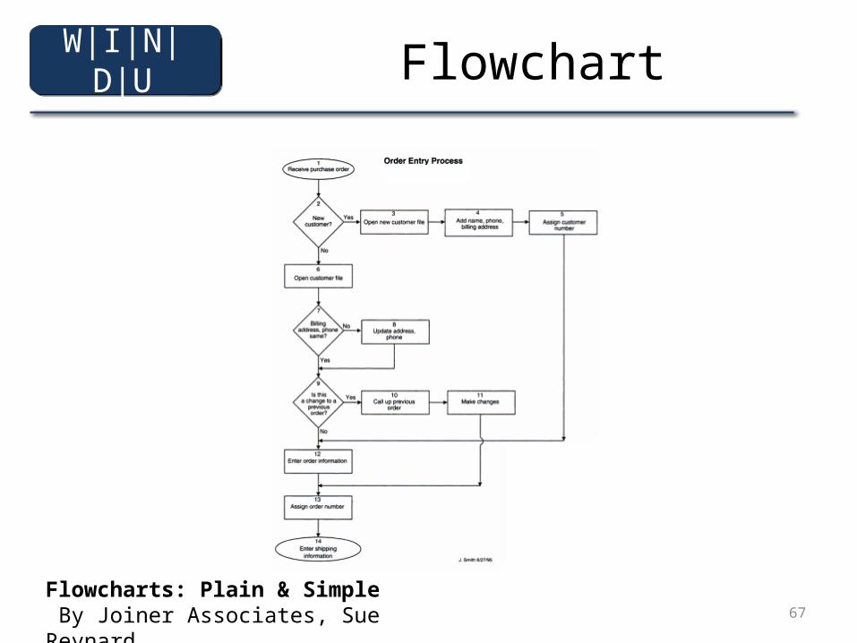
Flowchart
Flowcharts: Plain & Simple By Joiner Associates, Sue Reynard
W|I|N|D|U
68
Workflow
• Flowchart + Actor (Swimline)• a process workflow model supports
understanding and assesssing a progress design
Workflow Modeling: Tools for Process Improvement and Applications Development By Alec Sharp, Patrick McDermot
W|I|N|D|U
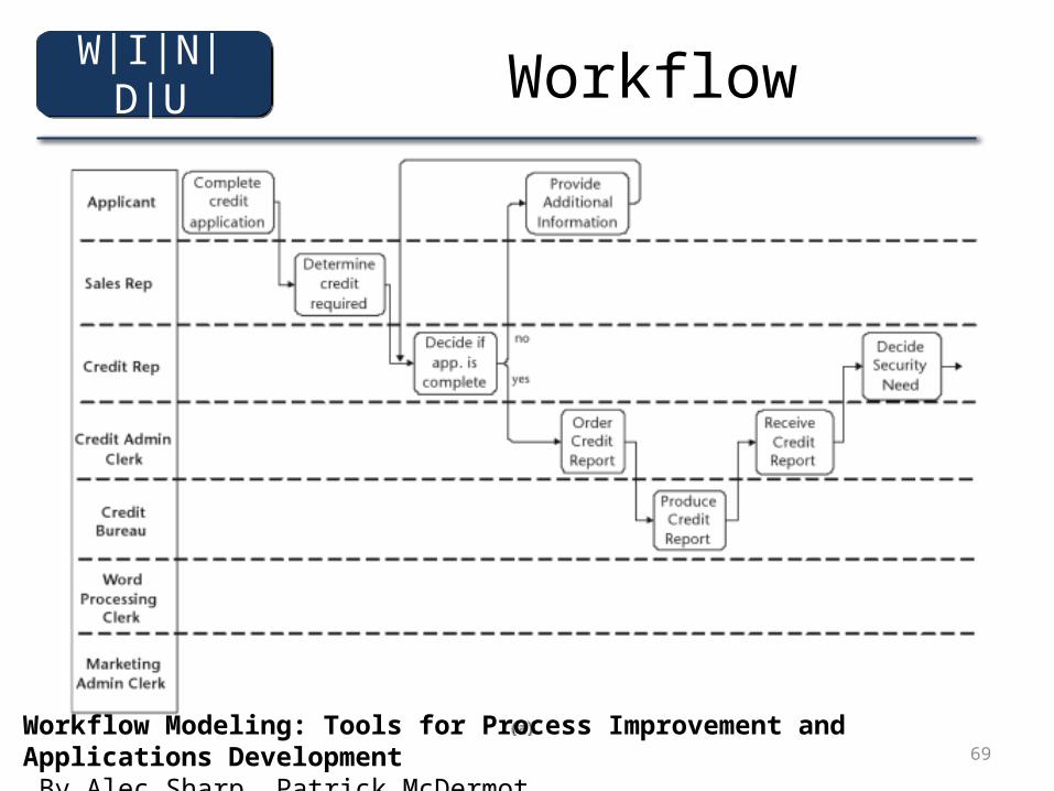
69
Workflow
Workflow Modeling: Tools for Process Improvement and Applications Development By Alec Sharp, Patrick McDermot
W|I|N|D|U
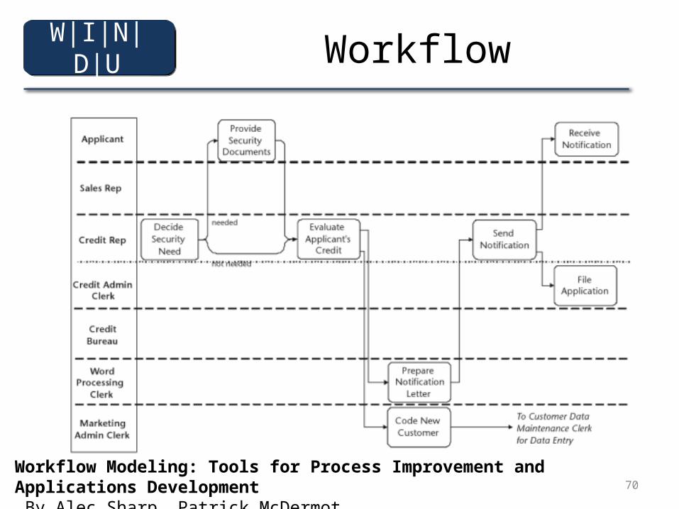
70
Workflow
Workflow Modeling: Tools for Process Improvement and Applications Development By Alec Sharp, Patrick McDermot
W|I|N|D|U
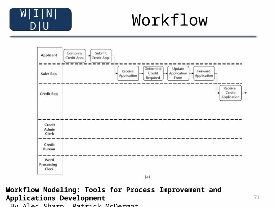
71
Workflow
Workflow Modeling: Tools for Process Improvement and Applications Development By Alec Sharp, Patrick McDermot
W|I|N|D|U
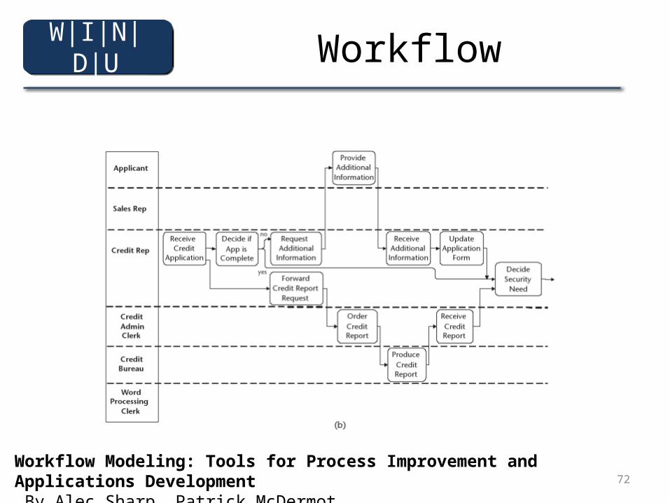
72
Workflow
Workflow Modeling: Tools for Process Improvement and Applications Development By Alec Sharp, Patrick McDermot
W|I|N|D|U
73
3
• Use Case Diagram• Activity Diagram• Sequence Diagram • Deployment Diagram
W|I|N|D|U
74
• “Can we build Skyscraper like build dog house?”
Modeling Application
Web Engineering, The Discipline of Systematic Development of Web Applications, edited by Gerti Kappel, Birgit Proll, Siegfried Reich, Werner Retschitzegger
W|I|N|D|U
75
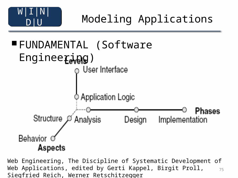
Modeling Applications
■ FUNDAMENTAL (Software Engineering)
Web Engineering, The Discipline of Systematic Development of Web Applications, edited by Gerti Kappel, Birgit Proll, Siegfried Reich, Werner Retschitzegger
W|I|N|D|U
76
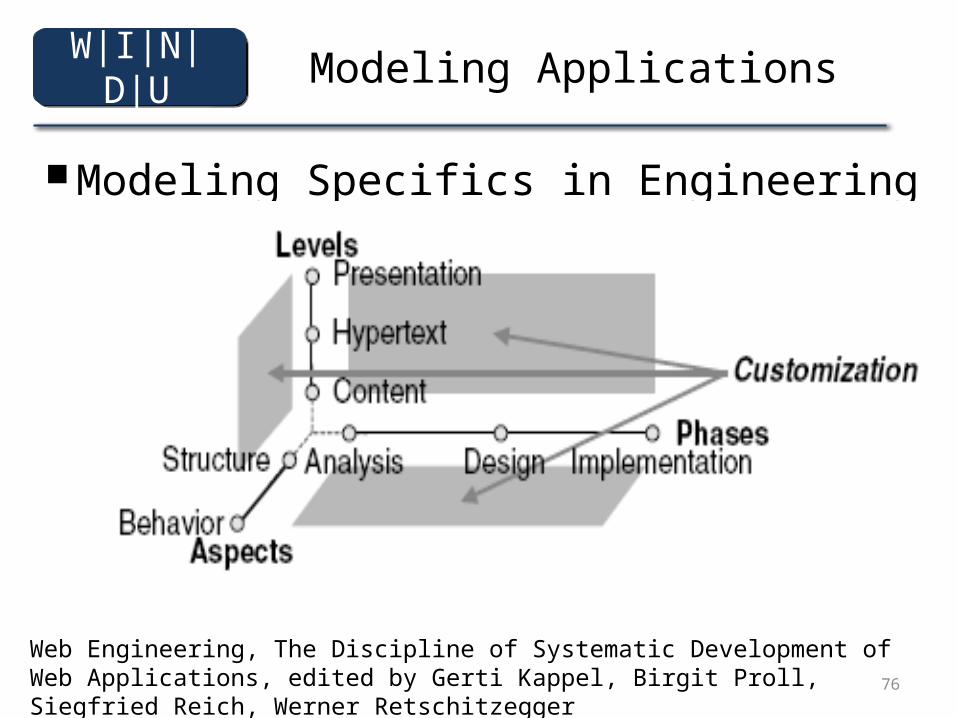
Modeling Applications
■ Modeling Specifics in Engineering
Web Engineering, The Discipline of Systematic Development of Web Applications, edited by Gerti Kappel, Birgit Proll, Siegfried Reich, Werner Retschitzegger
W|I|N|D|U
77
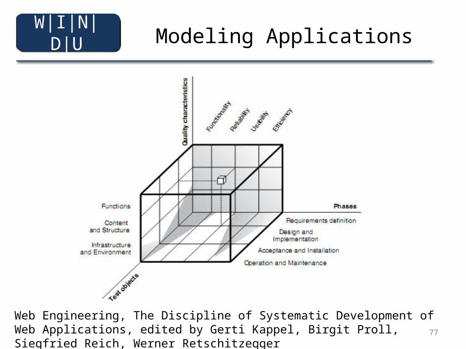
Modeling Applications
Web Engineering, The Discipline of Systematic Development of Web Applications, edited by Gerti Kappel, Birgit Proll, Siegfried Reich, Werner Retschitzegger
W|I|N|D|U
78
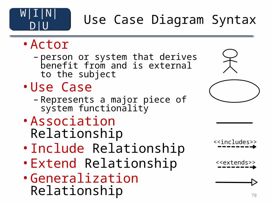
Use Case Diagram Syntax• Actor
– person or system that derives benefit from and is external to the subject
• Use Case– Represents a major piece of system
functionality• Association Relationship• Include Relationship• Extend Relationship• Generalization Relationship
<<extends>>
<<includes>>
W|I|N|D|U
79
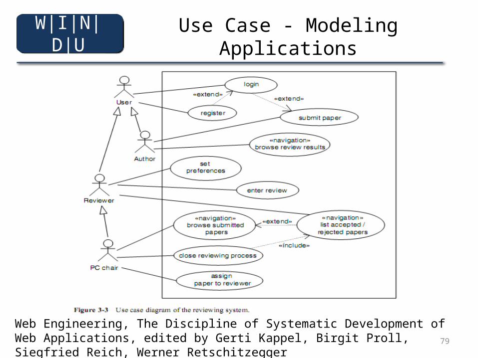
Use Case - Modeling Applications
Web Engineering, The Discipline of Systematic Development of Web Applications, edited by Gerti Kappel, Birgit Proll, Siegfried Reich, Werner Retschitzegger
W|I|N|D|U
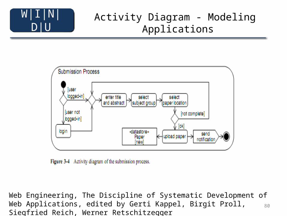
80
Activity Diagram - Modeling Applications
Web Engineering, The Discipline of Systematic Development of Web Applications, edited by Gerti Kappel, Birgit Proll, Siegfried Reich, Werner Retschitzegger
W|I|N|D|U
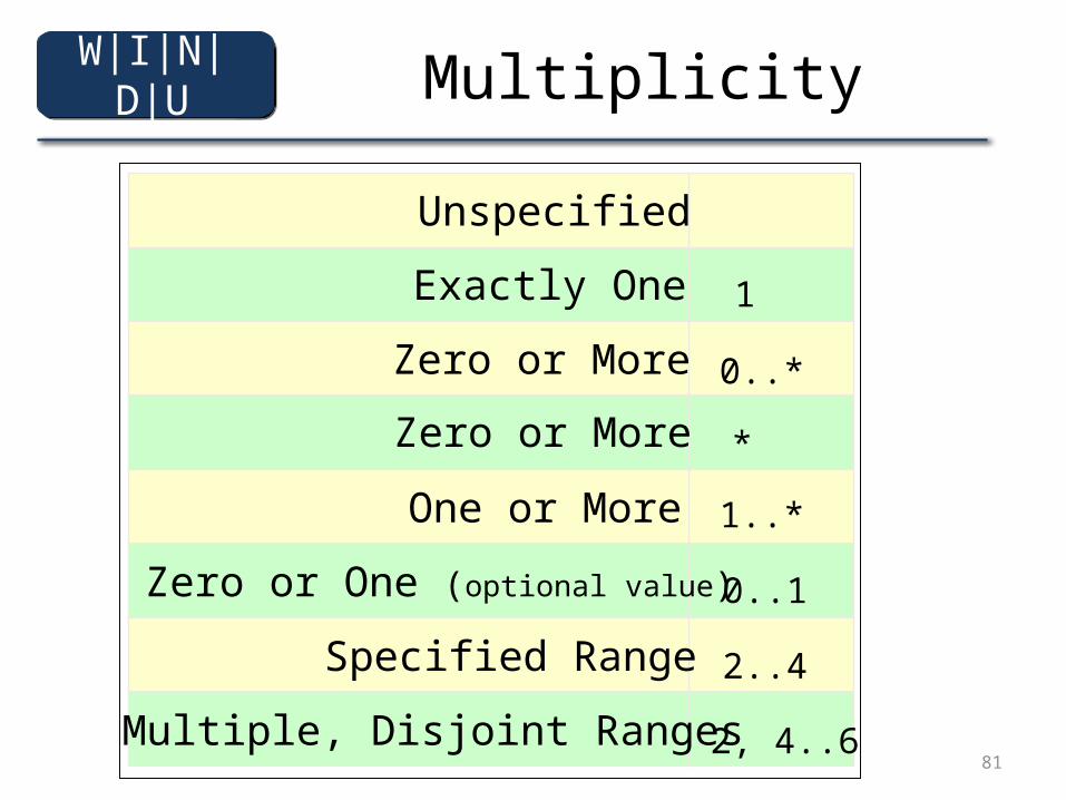
81
Multiplicity
2..4
0..1
1..*
0..*
1
*
2, 4..6
Unspecified
Exactly One
Zero or More
Zero or More
Zero or One (optional value)
One or More
Specified Range
Multiple, Disjoint Ranges
W|I|N|D|U
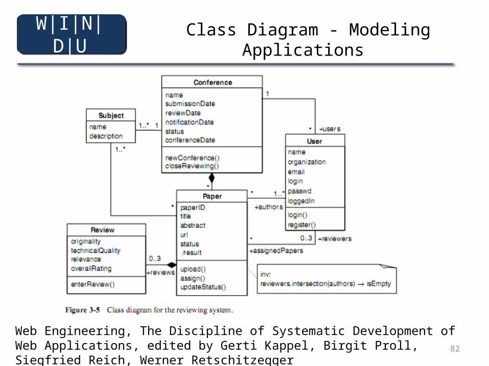
82
Class Diagram - Modeling Applications
Web Engineering, The Discipline of Systematic Development of Web Applications, edited by Gerti Kappel, Birgit Proll, Siegfried Reich, Werner Retschitzegger
W|I|N|D|U
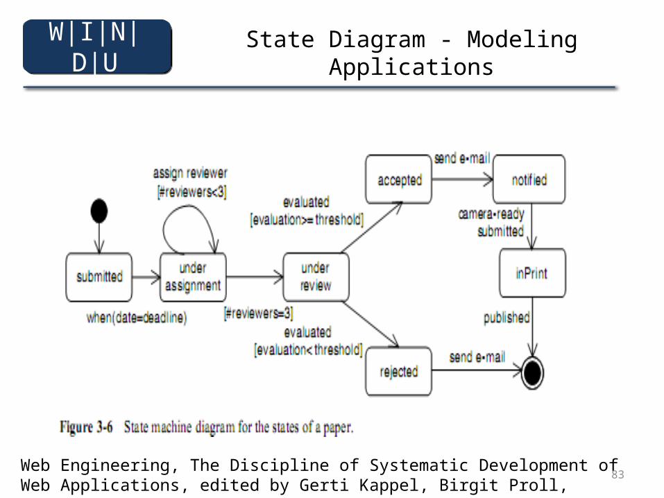
83
State Diagram - Modeling Applications
Web Engineering, The Discipline of Systematic Development of Web Applications, edited by Gerti Kappel, Birgit Proll, Siegfried Reich, Werner Retschitzegger
W|I|N|D|U
84
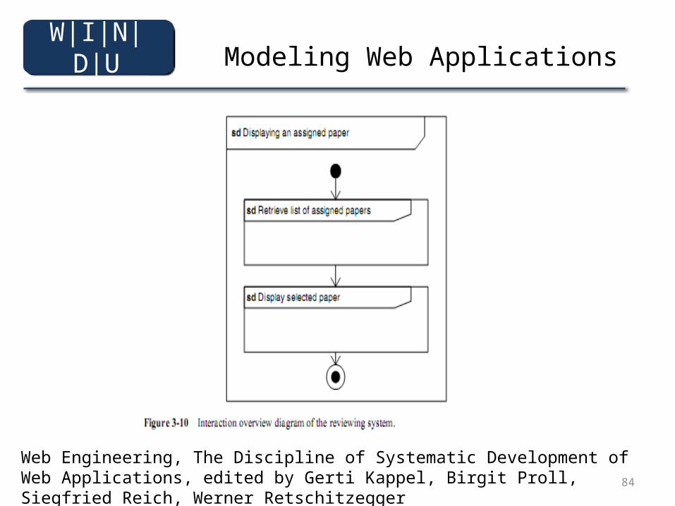
Modeling Web Applications
Web Engineering, The Discipline of Systematic Development of Web Applications, edited by Gerti Kappel, Birgit Proll, Siegfried Reich, Werner Retschitzegger
W|I|N|D|U
85
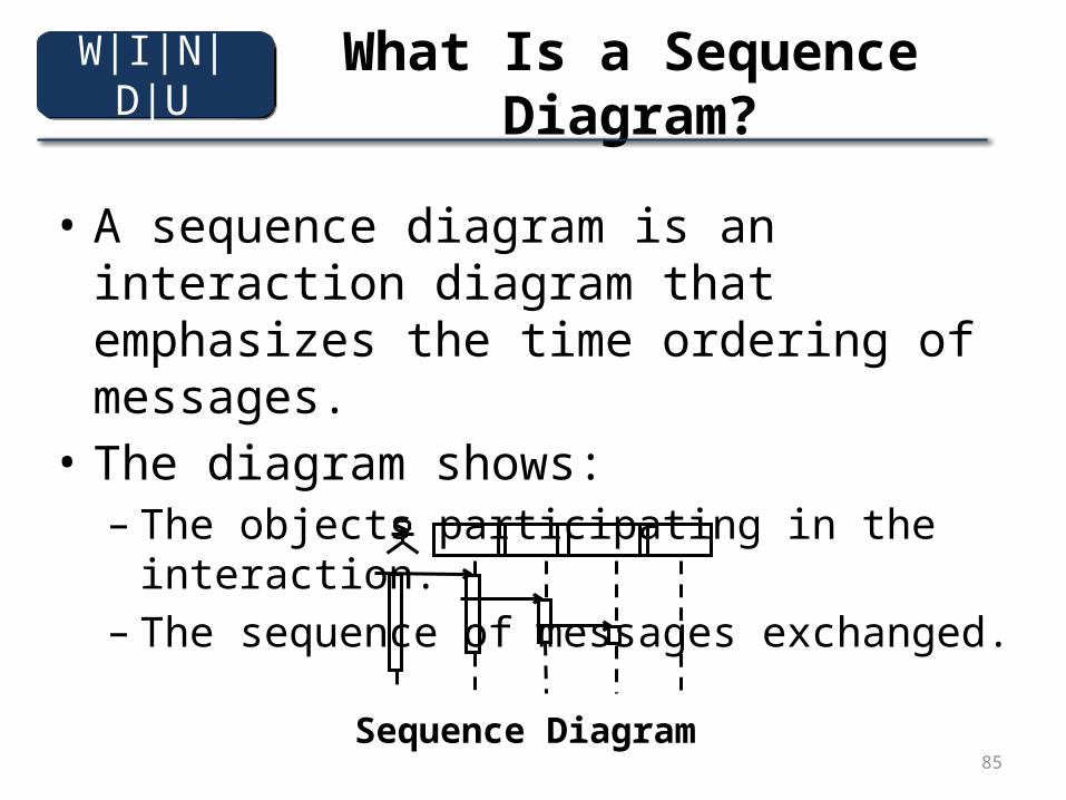
What Is a Sequence Diagram?
• A sequence diagram is an interaction diagram that emphasizes the time ordering of messages.
• The diagram shows:– The objects participating in the interaction.– The sequence of messages exchanged.
Sequence Diagram
W|I|N|D|U
86
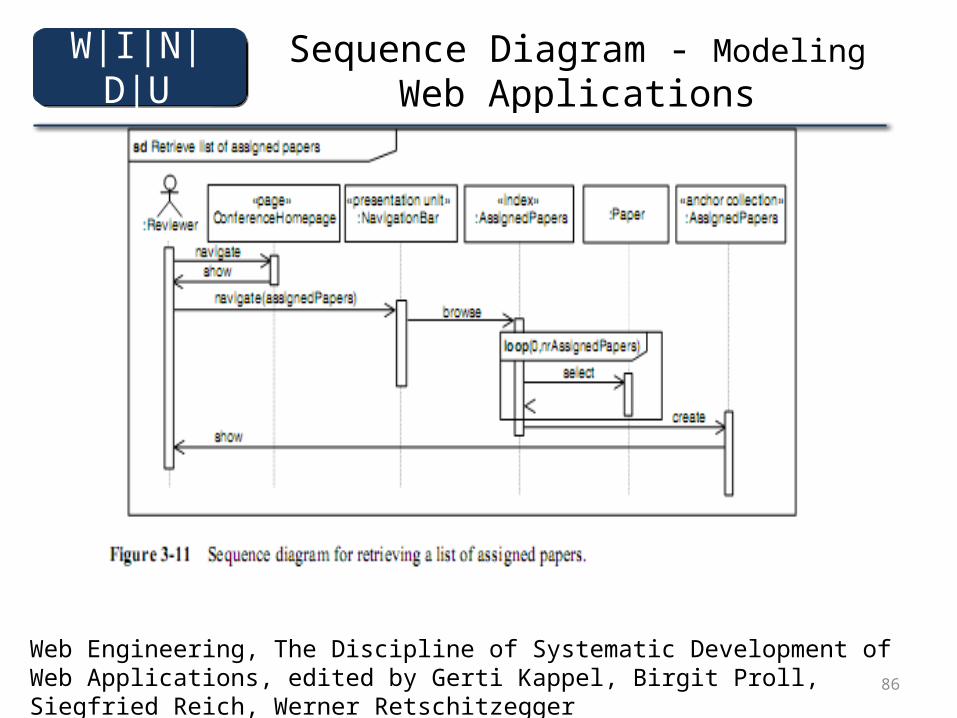
Sequence Diagram - Modeling Web Applications
Web Engineering, The Discipline of Systematic Development of Web Applications, edited by Gerti Kappel, Birgit Proll, Siegfried Reich, Werner Retschitzegger
W|I|N|D|U
87
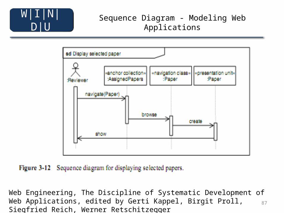
Sequence Diagram - Modeling Web Applications
Web Engineering, The Discipline of Systematic Development of Web Applications, edited by Gerti Kappel, Birgit Proll, Siegfried Reich, Werner Retschitzegger
W|I|N|D|U
88
4
• Black Box• White Box• Web Project Management
W|I|N|D|U
89
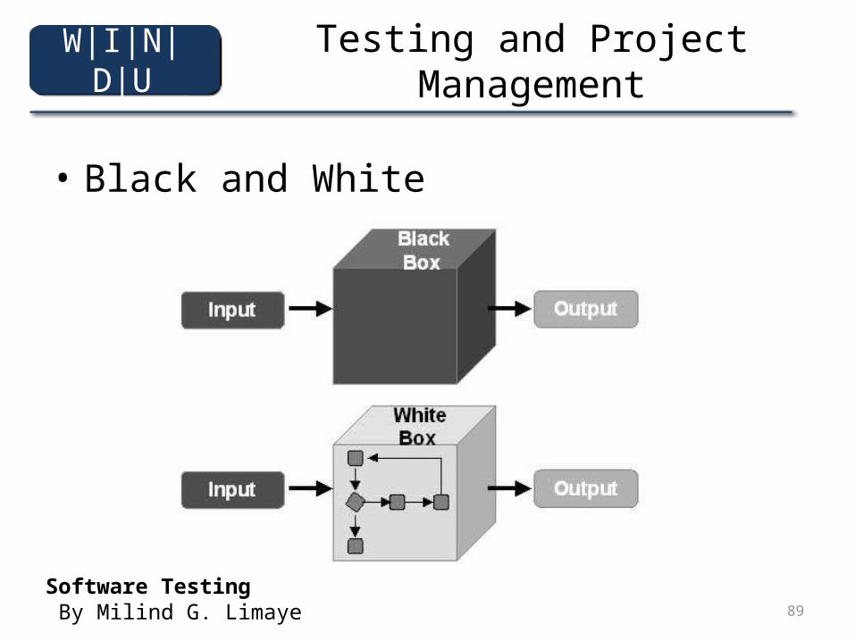
Testing and Project Management
• Black and White
Software Testing By Milind G. Limaye
W|I|N|D|U
90
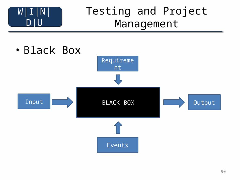
Testing and Project Management
• Black Box
BLACK BOXInput Output
Requirement
Events
W|I|N|D|U
91
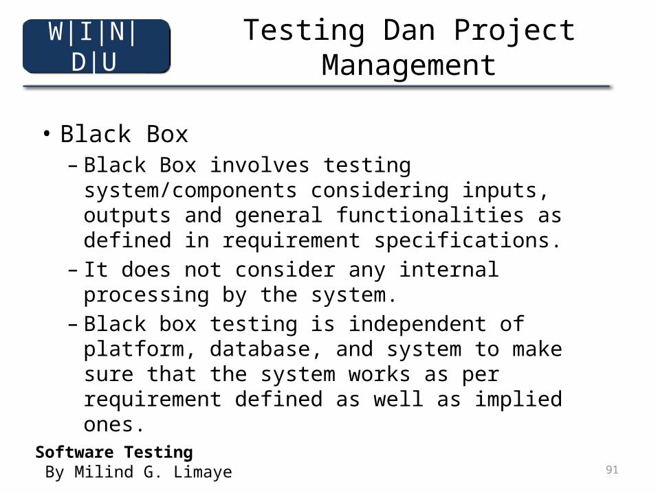
Testing Dan Project Management
• Black Box– Black Box involves testing system/components
considering inputs, outputs and general functionalities as defined in requirement specifications.
– It does not consider any internal processing by the system.
– Black box testing is independent of platform, database, and system to make sure that the system works as per requirement defined as well as implied ones.
Software Testing By Milind G. Limaye
W|I|N|D|U
92
Testing and Project Management
• Advantage– Blackbox testing is the only method to prove that
software does what it is supposed to do and it does not do something which can cause a problem to user/customer
– It is the only method to show that software is living and it really works
– Some types of testing can be done only by black box testing methodologies, for example, performance and security
Software Testing By Milind G. Limaye
W|I|N|D|U
93
Testing and Project Management
• Disadvantage– Some logical errors in coding can be missed in
black box testing.– Some redudant testing is possible as requirements
may execute the same branch of code again and again.
Software Testing By Milind G. Limaye
W|I|N|D|U
94
Testing and Project Management
• Black Box– TestCase Designing Methodologies
• Black Box testing methodology defines how the user is going to interact with the system without any assumption about how the system is built.
– Test Data definiton• Black Box is mainly driven by the test data used during
testing. It may not be feasible to test all possible data which user may be using while working with application.
Software Testing By Milind G. Limaye
W|I|N|D|U
95
Testing and Project Management
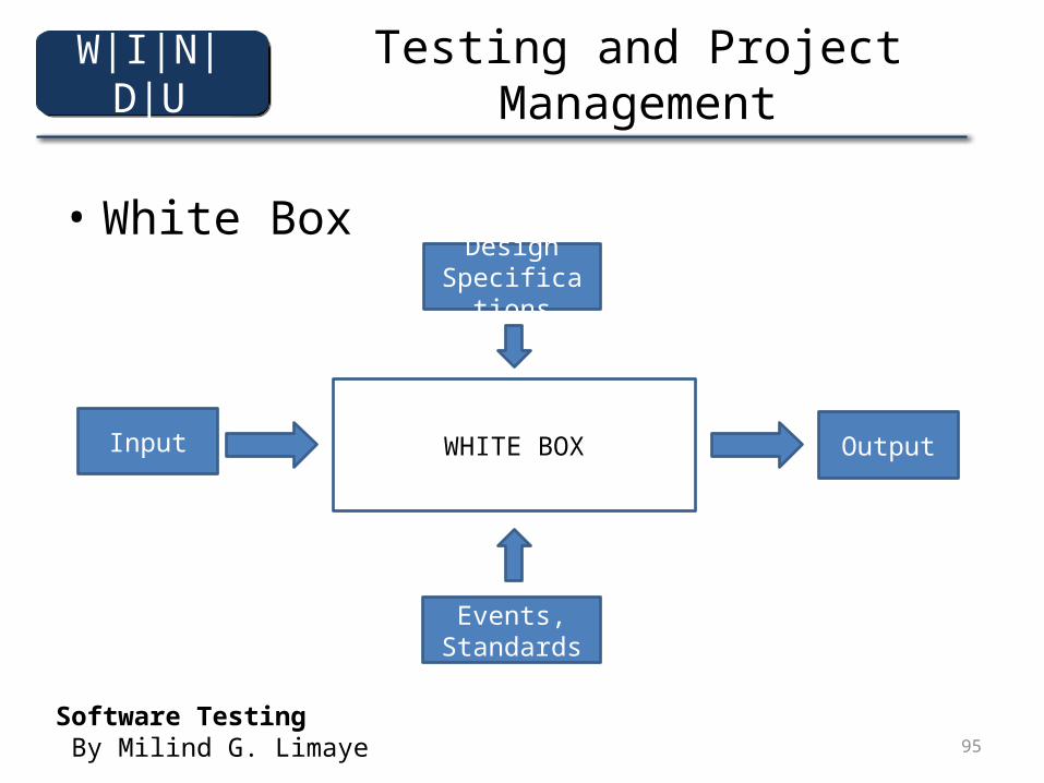
• White Box
WHITE BOXInput Output
Design Specifications
Events, Standards
Software Testing By Milind G. Limaye
W|I|N|D|U
96
Testing and Project Management
• White Box Advantages– Only white box testing can ensure that defined process,
procedures, and methods of development have really been followed during software testing
– White cos testing and verification can give early warning, if something is not done properly. Its the most cost effective way of finding defects as it helps in reducing stage contamination
– Some characteristics of software work product can be verified only. There is no chance of validating them. for Example, code complexity, commenting styles, and reuse.
Software Testing By Milind G. Limaye
W|I|N|D|U
97
Testing and Project Management
• White Box Disadvantages– It does not ensure that user requirements are met
correctly. There is no execution of code and one does not know whether it will really ork or not.
– It does not establish whether decisions, conditions, paths, and statements covered during reviews are sufficient or not for the given set requirements.
– Sometimes, white box testing is dominated by the use of checklists. Some defects in checklists may reflect directly in the work product. On must do a thorough analysis of all defects.
Software Testing By Milind G. Limaye
W|I|N|D|U
98
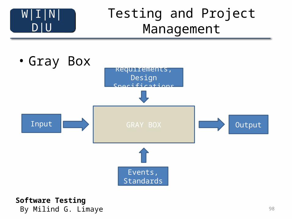
Testing and Project Management
• Gray Box
GRAY BOXInput Output
Requirements, Design Specifications
Events, Standards
Software Testing By Milind G. Limaye
W|I|N|D|U
99
Testing and Project Management
• Gray Box Testing– Gray Box testing is done on the basic of the
internal structures of software as defined by requirements, designs, coding standards, and guidelines as well as the functional and nonfunctional requirement specifications.
– Gray box testing combines verification techniques with validation techniques where one can ensure that software is built correctly, and also works.
Software Testing By Milind G. Limaye
W|I|N|D|U
100
Testing And Project Management
• Advantages– Gray box testing tries to combine the advantages
of white box testing and black box testing. It check whether the work product works in a correct manner, both functionally as well as structurally
• Disadvantages– Generally, gray box testing is conducted with some
automation tools. Knowledge of such tools along with their configuration is essential for performing gray box testing.
W|I|N|D|U
101
Web Project Management
Testing and Project Manajemen
Web Engineering, The Discipline of Systematic Development of Web Applications, edited by Gerti Kappel, Birgit Proll, Siegfried Reich, Werner Retschitzegger
W|I|N|D|U
102
Web Project Management
■ Project management is a human activity to shape the actions of other humans. This human centered perspective requires Web project managers to have enormous conflict-solving competency, and Web teams to have an interdisciplinary understanding. Consequently, the model used to developWeb applications has to be very flexible, allowing for a strongly iterative-incremental development, and involving the contractor frequently. This means that tools and techniques used in Web project management are particularly characterized by the current transition from traditional software development methods towards agile methods. Consistent use of integrated tools is just as essential as consequent risk management during the entire project cycle.
Web Engineering, The Discipline of Systematic Development of Web Applications, edited by Gerti Kappel, Birgit Proll, Siegfried Reich, Werner Retschitzegger
W|I|N|D|U
103
Web Project Management
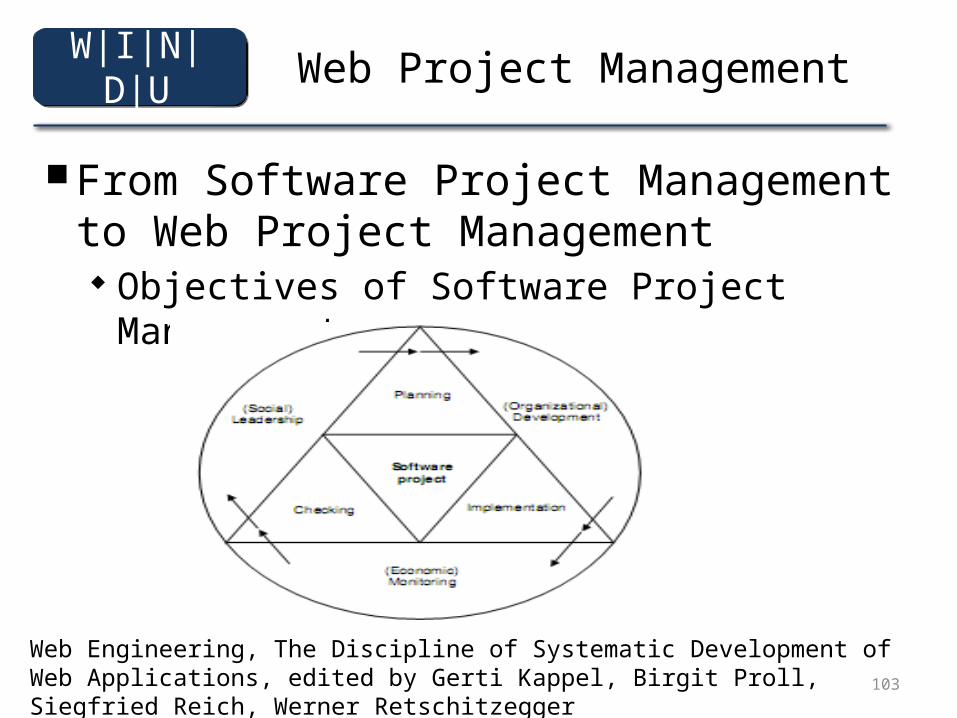
■ From Software Project Management to Web Project Management
Objectives of Software Project Management
Web Engineering, The Discipline of Systematic Development of Web Applications, edited by Gerti Kappel, Birgit Proll, Siegfried Reich, Werner Retschitzegger
W|I|N|D|U
104
Web Project Management
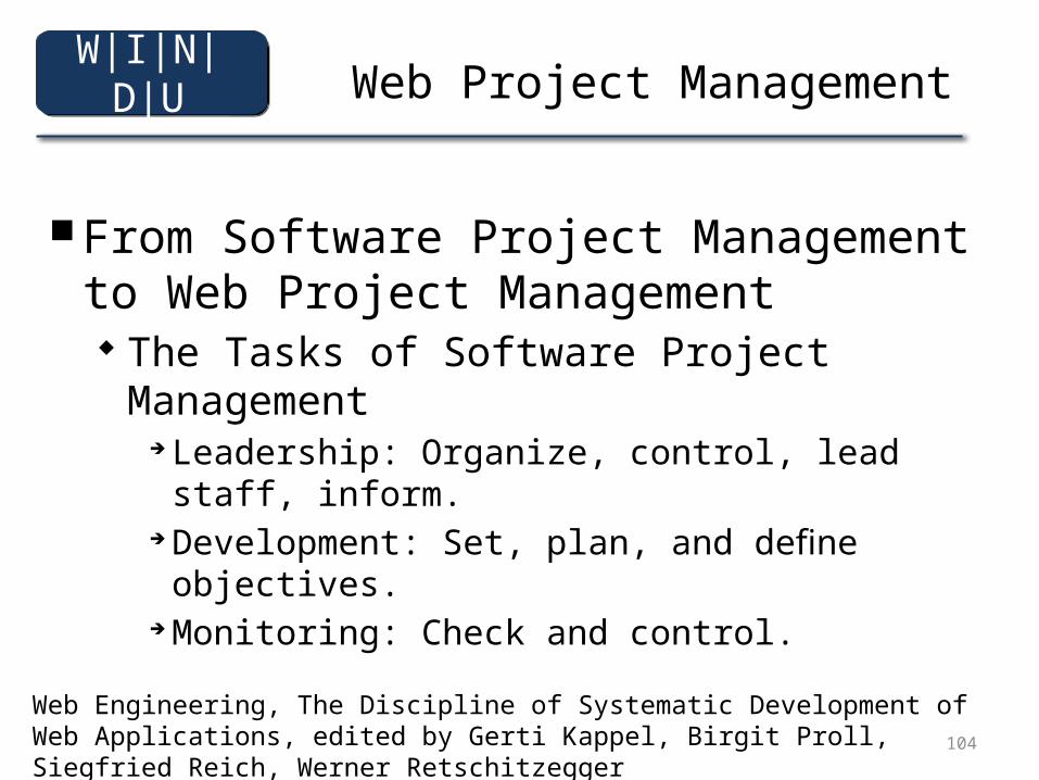
■ From Software Project Management to Web Project Management
The Tasks of Software Project Management Leadership: Organize, control, lead staff, inform. Development: Set, plan, and define objectives. Monitoring: Check and control.
Web Engineering, The Discipline of Systematic Development of Web Applications, edited by Gerti Kappel, Birgit Proll, Siegfried Reich, Werner Retschitzegger
W|I|N|D|U
105
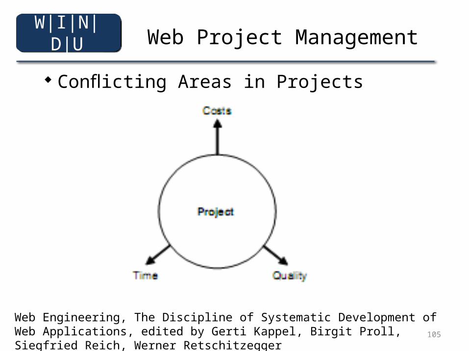
Web Project Management
Conflicting Areas in Projects
Web Engineering, The Discipline of Systematic Development of Web Applications, edited by Gerti Kappel, Birgit Proll, Siegfried Reich, Werner Retschitzegger
W|I|N|D|U
106
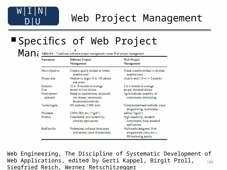
Web Project Management
■ Specifics of Web Project Management
Web Engineering, The Discipline of Systematic Development of Web Applications, edited by Gerti Kappel, Birgit Proll, Siegfried Reich, Werner Retschitzegger
W|I|N|D|U
107
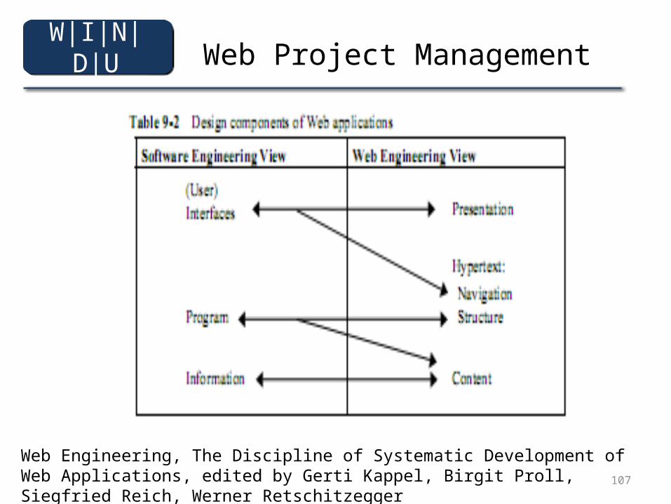
Web Project Management
Web Engineering, The Discipline of Systematic Development of Web Applications, edited by Gerti Kappel, Birgit Proll, Siegfried Reich, Werner Retschitzegger
W|I|N|D|U
108
Web Project Management
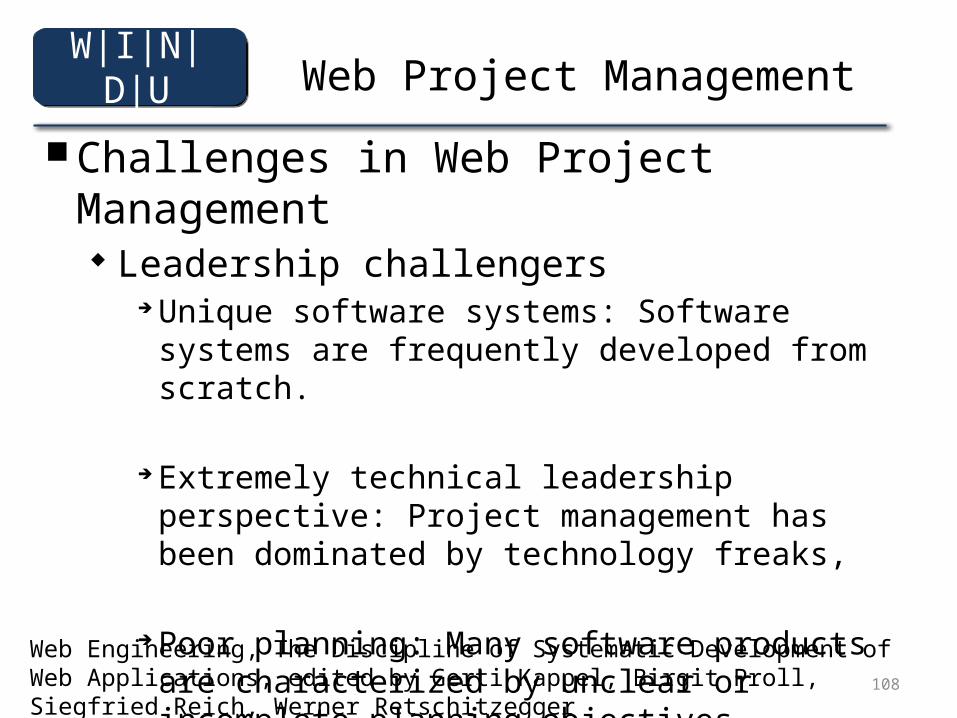
■ Challenges in Web Project Management Leadership challengers
Unique software systems: Software systems are frequently developed from scratch.
Extremely technical leadership perspective: Project management has been dominated by technology freaks,
Poor planning: Many software products are characterized by unclear or incomplete planning objectives,
Web Engineering, The Discipline of Systematic Development of Web Applications, edited by Gerti Kappel, Birgit Proll, Siegfried Reich, Werner Retschitzegger
W|I|N|D|U
109
Web Project Management
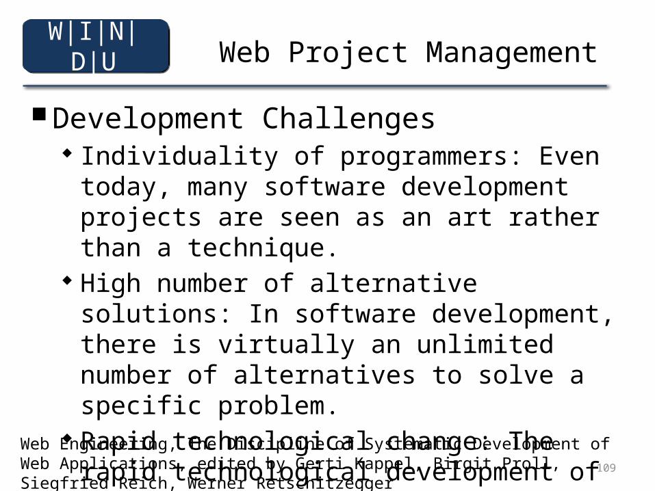
■ Development Challenges Individuality of programmers: Even today, many
software development projects are seen as an art rather than a technique.
High number of alternative solutions: In software development, there is virtually an unlimited number of alternatives to solve a specific problem.
Rapid technological change: The rapid technological development of hardware and software makes it more difficult to plan and organize software projects.
Web Engineering, The Discipline of Systematic Development of Web Applications, edited by Gerti Kappel, Birgit Proll, Siegfried Reich, Werner Retschitzegger
W|I|N|D|U
110
Web Project Management
■ Monitoring Challenges The immaterial state of software products: The “intangibility”
of software products makes them hard to control. It is very difficult to determine how much of a software product is actually completed, and the programmer has a wide range of possibilities to veil the actual development state. Since Web projects are characterized by parallel development of functionality and content, the product is more “tangible” for customers and the project manager. And since Web projects are subject to short iteration cycles, they are usually easier to check. For these reasons, this challenge is of less significance in Web projects.
Web Engineering, The Discipline of Systematic Development of Web Applications, edited by Gerti Kappel, Birgit Proll, Siegfried Reich, Werner Retschitzegger
W|I|N|D|U
111
Web Project Management
■ Development-related Challenges in Web Projects Novelty Dynamics Parallelism Continuity Juvenile Immaturity
Web Engineering, The Discipline of Systematic Development of Web Applications, edited by Gerti Kappel, Birgit Proll, Siegfried Reich, Werner Retschitzegger
W|I|N|D|U
112
Web Project Management
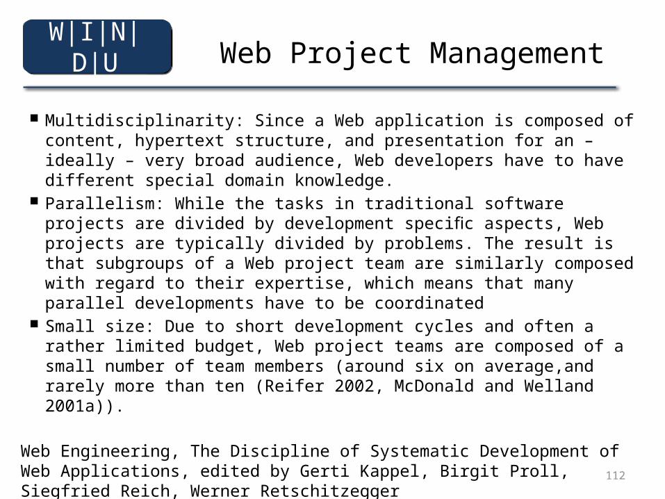
■ Multidisciplinarity: Since a Web application is composed of content, hypertext structure, and presentation for an – ideally – very broad audience, Web developers have to have different special domain knowledge.
■ Parallelism: While the tasks in traditional software projects are divided by development specific aspects, Web projects are typically divided by problems. The result is that subgroups of a Web project team are similarly composed with regard to their expertise, which means that many parallel developments have to be coordinated
■ Small size: Due to short development cycles and often a rather limited budget, Web project teams are composed of a small number of team members (around six on average,and rarely more than ten (Reifer 2002, McDonald and Welland 2001a)).
Web Engineering, The Discipline of Systematic Development of Web Applications, edited by Gerti Kappel, Birgit Proll, Siegfried Reich, Werner Retschitzegger
W|I|N|D|U
113
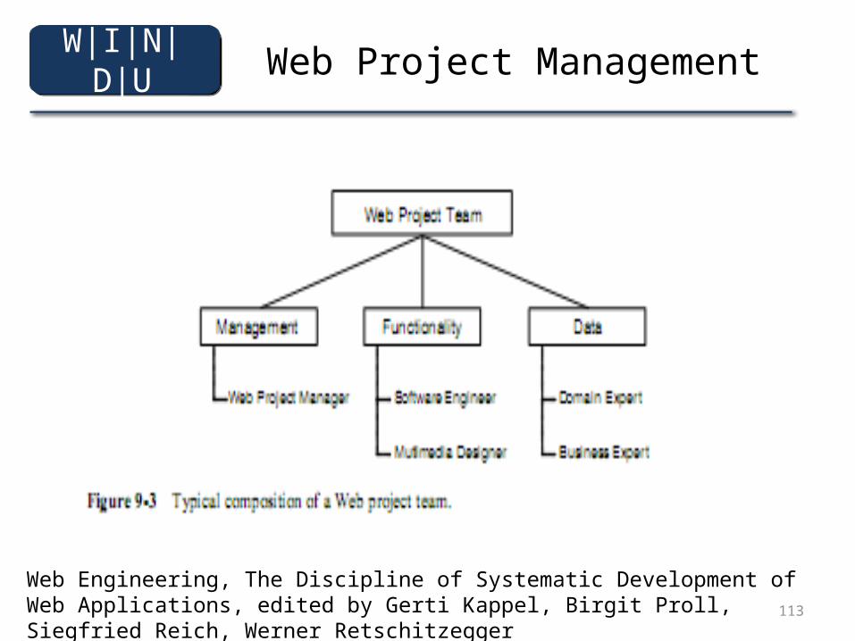
Web Project Management
Web Engineering, The Discipline of Systematic Development of Web Applications, edited by Gerti Kappel, Birgit Proll, Siegfried Reich, Werner Retschitzegger
W|I|N|D|U
114
Web Project Management
■ The Web Project Manager Inspire all project members with the project
objectives. Be capable of leading a multidisciplinary team. Create the willingness and readiness for (democratic)
cooperation. Constantly motivate the team and solve conflicts.
Web Engineering, The Discipline of Systematic Development of Web Applications, edited by Gerti Kappel, Birgit Proll, Siegfried Reich, Werner Retschitzegger
W|I|N|D|U
115
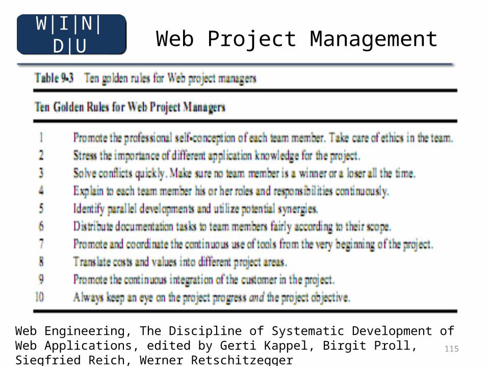
Web Project Management
Web Engineering, The Discipline of Systematic Development of Web Applications, edited by Gerti Kappel, Birgit Proll, Siegfried Reich, Werner Retschitzegger
W|I|N|D|U
116
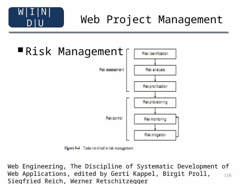
Web Project Management
■ Risk Management
Web Engineering, The Discipline of Systematic Development of Web Applications, edited by Gerti Kappel, Birgit Proll, Siegfried Reich, Werner Retschitzegger
W|I|N|D|U
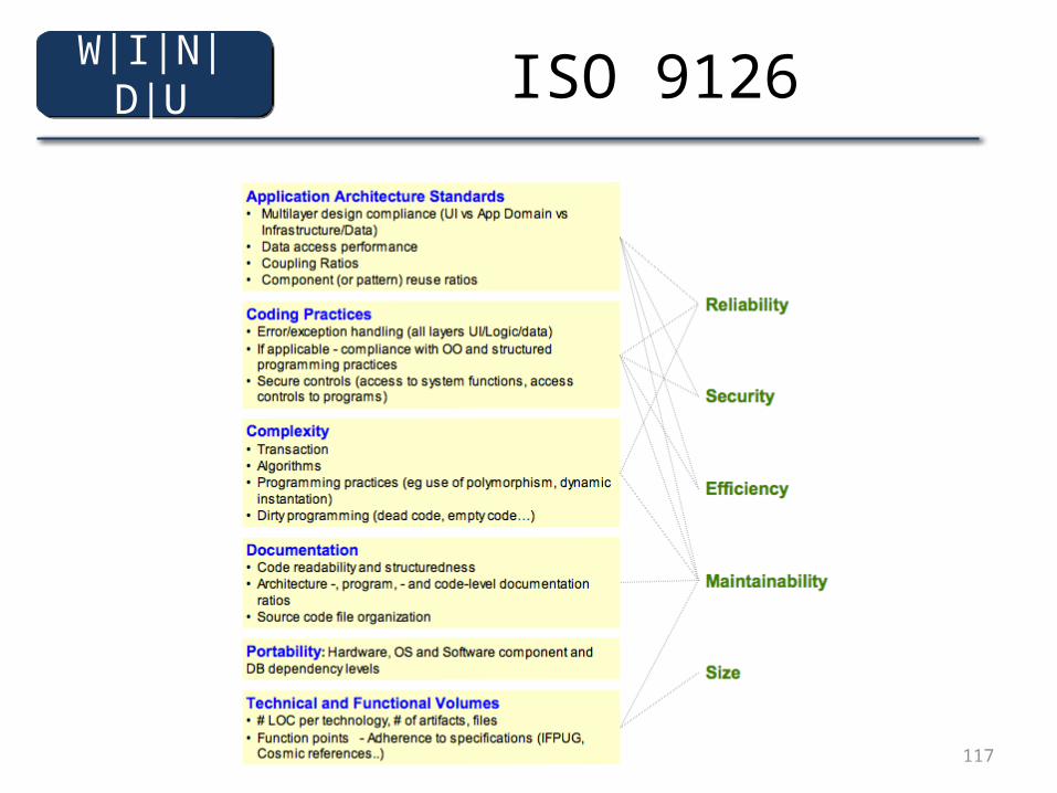
117
ISO 9126W|I|N|D|U