DANCING ROBOT SUZLI ELIMI BINTI ZULKEFLI This Report Is...
24
DANCING ROBOT SUZLI ELIMI BINTI ZULKEFLI This Report Is Submitted In Partial Fulfilment of Requirements for The Bachelor Degree of Electronic Engineering (Industrial Electronic) Fakulti Kejuruteraan Elektronik dan Kejuruteraan Komputer Universiti Teknikal Malaysia Melaka April2007
Transcript of DANCING ROBOT SUZLI ELIMI BINTI ZULKEFLI This Report Is...

DANCING ROBOT
SUZLI ELIMI BINTI ZULKEFLI
This Report Is Submitted In Partial Fulfilment of Requirements for
The Bachelor Degree of
Electronic Engineering (Industrial Electronic)
Fakulti Kejuruteraan Elektronik dan Kejuruteraan Komputer
Universiti Teknikal Malaysia Melaka
April2007

Tajuk Projek
Sesi Pengajian
Saya
UNIVERSTI TEKNIKAL MALAYSIA MELAKA FAKULTI KEJURUfERAAN ELEKTRONIK DAN KEJURUTERAAN KOMPUTER
BOR>\NG PENGESAHA~ STATUS LAPORA'\'
PROJEK SARJANA MUDA II
.. . ~~-~ft.~.<?.~ .................. .. ............. ................ .. .. .... ............ . .
(HURUF BESAR) mengaku membenarkan Laporan Projek Satjana Muda ini disimpan di Perpustakaan dengan syaratsyarat kegunaan seperti berikut:
1. Laporan adalah hakmilik Universiti Teknikal Malaysia Melaka.
2 . Perpustakaan dibenarkan membuat salinan untuk tujuan pengajian sahaja.
3. Perpustakaan dibenarkan membuat salinan laporan ini sebagai bahan pertukaran an tara institusi
pengajian tinggi.
4. Sila tanda.kan ( ) :
D
D 0
SULIT*
TERHAD*
TIDAK TERHAD
(Mengandungi maklumat yang berda!jah keselamatan atau kepentingan Malaysia seperti yang tennaktub di dalam AKT A RAHSIARASM11972)
(Mengandungi maklmnat terhad yang telah ditentukan oleh organisasilbadan di mana penyelidikan dijalankan)
-(T A..._.DA~~ PEI"liLIS)
a<~q , \..OIIOWGo ~ltl"' t4(o, Alarnat Tetap: .. .. . . .. .... . ... ..... . ... . . . .. . . . ... .. . FC, . ('(4 • 1 ~ l'JC. I \e ... N ... ,_J ,
~1;~00 1C. · ~""""""
. o-:rjo'f fo-:t Tankh: .. .. . . . ... .. .. . .(.' .. .. .... .
"Saya akui laporan ini adalah basil kerja saya sendiri kecuali ringkasan dan petikan
yang tiap-tiap satunya telah saya jelaskan sumbemya.
Tandatangan : ...... . ~ : .. .... .... .......... .
Nama Penulis : SUZLI ELil\.11 BT ZULKEFLI
Tarikh : APRIL 2007
ll1

IV
Sayafkami akui bahawa saya telah membaca karya ini pada pandangan sayafkami karya
ini adalah memadai dari skop dan kualiti untuk penganugerahan Ijazah Sarjana Muda
Kejuruteraan Elektronik (Elektronik Industri)."
Tandatangan
Nama Penyelia
Tarikh
: EN. ZULKARNAIN B ZAINUDIN
: .. . ?::r. .~ .~. ~ .. ~ ...

v
For my beloved Mama and Abah

Vl
ACKNOWLEDGEMENT
I would like to express my sincere appreciation to En. Zulkamain b. Zainudin,
my supervisor for his continuous support, guidance and encouragement towards the
completion of the project.
My deepest gratitude and appreciation to Pn Zahariah, the facilitator who is
responsible in providing guidance for the completion of this Bachelor Degree Project.
My appreciation to my family and my friends especially for the encouragement,
motivation and inspiration to complete this project
My appreciation to the rest of lecturer and technician for the knowledge and
inputs that were given.
Thank you.

Vll
ABSTRACT
This project was conducted between two tasks, which are hardware and software
preparation. This report represents the hardware task fulfilment. Dancing Robot was
design to be a mobile robot which it has wheels at its leg as movement method. This
Dancing Robot was designed to dance according to the programmed music within a
specific time frame. The methods used in developing this project including research on
previous project and studying PIC. This robot was designed in hardware and software
interfacing which will allow it to dance using motors as the driver and PIC
programming as the controller. This robot will be control with a start button and will be
moved according to the program in the PIC which will initialize the movement of the
hands and legs. The program will be bum in PIC 16F877 microprocessor which will
move the servo motors as the driver of the arms. Beside servo motor, DC motor with
gears was used to move the legs of the robot. With th~ interface of the circuit and
microprocessor, Dancing Robot will move as if it dances according the music played.
Vlll
ABSTRAK
Projek ini telah dijalankan dalam dua bahagian, iaitu dalam penyediaan perisian
(software) dan perkakasan (hardware). Laporan ini membentangkan penyediaan
perkakasan dalam menyiapkan Dancing Robot. Dancing Robot telah direka sebagai
sebuah robot bergerak dimana ia mempunyai roda di bahagian kakinya sebagai alat
pergerakan. Robot ini telah direka untuk menari mengikut musik saperti yg
diprogramkan dalam sela masa yang tertentu. Kaedah-kaedah yang digunakan untuk
membangunkan projek termasukalah melakukan kajian terhadap projek seumpamanya
dan juga mempelajari PIC. Robot ini direkabentuk di dalam bentuk perisian dan
perkakasan yang mana akan menghasilkan pergerakan tarian yang menggunakan motor
sebagai penggerak dan program PIC sebagai kawalan. Robot ini akan dikawal oleh satu
butang pemula dimana kemudiannya akan bergerak berdasarkan araban program di
dalam PIC yang akan menyatakan pergerakan pada tangan dan kaki robot. Program ini
akan di prograrnkan di dalam mikropemproses PIC16F877 A yang mana akan
menggerakkan motor servo pada lengan robot. Di samping motor servo, motor DC juga
akan digunakan untuk menggerakkan kaki robot. Dengan adanya perantaraan diantara
litar dan mikropemproses, Dancing Robot akan bergerak seperti menari mengikut lagu
yang dimainkan.

IX
TABLE OF CONTENT
CHAPTER CONTENT PAGE
PROJECT TITLE CONFESSION FORM lll
SUPERVISOR APPROVAL FORM lV
DEDICATION v ACKNOWLEDGEMENT Vl
ABSTRACT Vll
ABSTRAK Vlll
TABLE OF CONTENT lX
LIST OF FIGURES Xl
LIST OF TABLES Xlll
LIST OF APPEDICES XIV
I INTRODUCTION
1.1 INTRODUCTION 1
1.2 PROJECT OBJECTIVE 2 1.3 PROBLEM STATEMENT 2 1.4 SCOPE OF WORK 3 1. 5 REPORT STRUCTURE 3
II LITERATURE REVIEW
2.1 INTRODUCTION 4 2.2 SONY QRIO 5 2.3 UTM'S ROBODANCE 6 2.4 COMPONENT THEORY AND ITS USAGE 7
2.4. 1 PIC 16F877 A 8 2.4.2 LM7805 11 2.4.3 L293D 12 2.4.4 SERVO MOTOR 14

III
IV
v
2.4.5 DC MOTOR 2.5 SOLUTION :METHODS
PROJECT METHODOLOGY
3.1 INTRODUCTION 3.2 RESEARCH AND STUDY 3.3 DESIGNING 3.4 ASSEMBLY AND TESTING 3. 5 FINALIZING
RESULT AND DISCUSSION
4.1 INTRODUCTION 4.2 SIMULATION TEST
4.2. 1 SUPPLY CIRCUIT SIMULATION 4.2.2 FULL CIRCUIT SIMULATION
4.3 CIRCUIT BUILD-UP AND TESTING 4.3.1 SOLDERING AND TESTING 4.3 .2 TROUBLESHOOTING
4.4 RESULTS 4.5 DISCUSSION
CONCLUSION AND SUGGESTIONS
5.1 CONCLUSION 5.2 SUGGESTIONS
REFERENCES
16 17
19 21 24 28 34
35
36 37
38 39 44
45
46 47
51
X
Xl
LIST OF FIGURES
NO TITLE PAGE
2.1 Sony QRIO 5
2.2 UTM' s ROBODANCE 6
2.3 PIC16F877 A microcontroller 7
2.4 PIC16F877a Pin Description 9
2.5 LM7805 11
2.6 Block Diagram ofLM7805 11
2.7 L293D 12
2.8 Block Diagram of L293D 13
2.9 Servo motor separated component 14
2.1 Servo Motor Pulse signal 15
2.11 DC motor 16
3. 1 Project Methodology Flow Chart 20
3.2 Block Diagram 21
3.3 H-Bridge Operation 23
3.4 DC Motor with gears 24
3.5 Motor placement on the robot design 25
3.6 Simulation circuit for the project 26
3.7 Stripboard (Component Side) 28
3.8 Stripboard (Solder Side) 29
3.9 Circuit Mounted on Stripboard 32
3.1 Full Circuit Construction with Motors 33
Xll
4 .1 Supply simulation circuit 36
4.2 Full project simulation circuit 37
4.3 Troubleshooting Flow Chart 39
4.4 Soldering on The Stripboard 42
5.1 HM2007 Pin Description 48
XIII
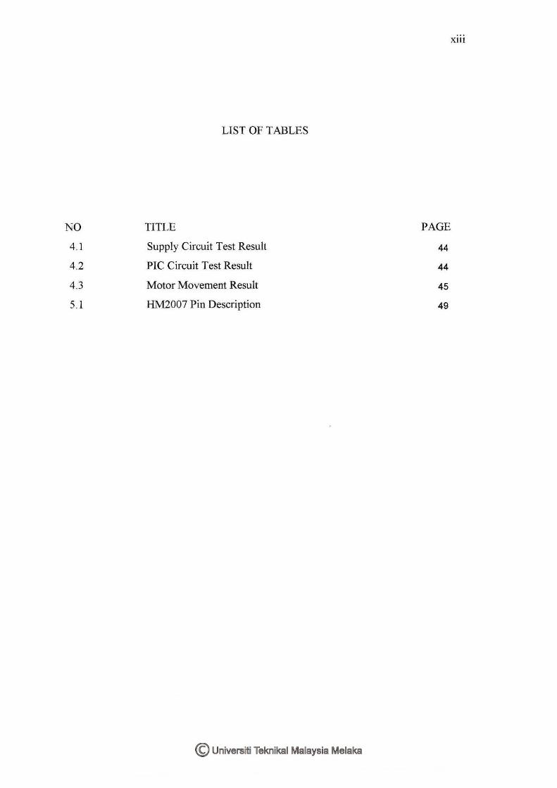
LIST OF TABLES
NO TITLE PAGE
4.1 Supply Circuit Test Result 44
4.2 PIC Circuit Test Result 44
4.3 Motor Movement Result 45
5.1 HM2007 Pin Description 49
NO
Al
A2
A3
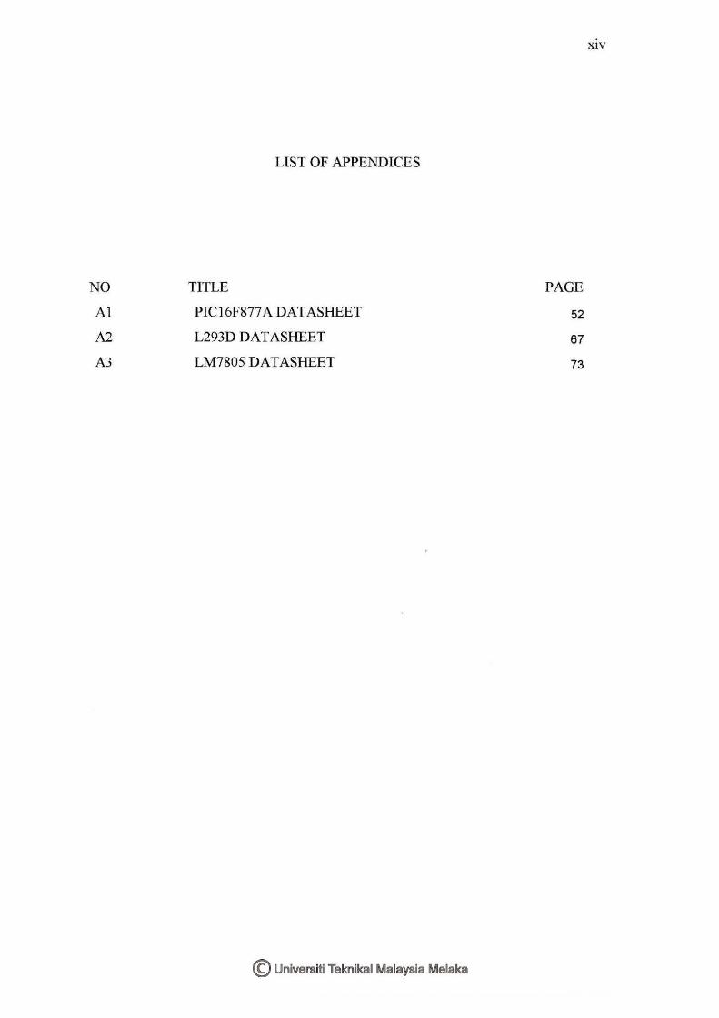
LIST OF APPENDICES
TITLE
PIC16F877 A DATASHEET
L293D DATASHEET
LM7805 DATASHEET
PAGE
52
67
73
XIV

1
CHAPTER I
1.1 INTRODUCTION
Lately, the field of cooperative mobile robotics has received a lot of attention
from various research institutes and industries. A focus of these research and
development activities is that of distributed motion coordination, since it allows the
robots to form certain patterns and move in formation towards cooperating for the
achievement of certain tasks. Motion planning algorithms for robotic systems made up
from robots that change their position in order to form a given pattern is very important
and may become challenging in the case of severe limitations, such as in
communication between the robots, hardware constraints, obstacles etc.
In the beginning, robots only used on a singular' function or purpose that is as an
aid to human. Nowadays, the robot not also assigned to do work but also entertain. As
part of it, dancing robots were created. Dancing robots grab people's attention with heir
ability to dance on the floor especially on their own feet. Sony QRIO surely one of the
lead example of world's robotic technologies. Its smooth movement when dancing
captures everyone's heart. These inventions increase people's interest on robotic world.
Many robot kits were design to let the public having them as a part of hobby. As for this
project, the robot will have two legs instead of moving platform, previously done by
UTM' s student, to let the robot have more humanoid looking. But still we cannot afford
to have it dance according any music played. But it still fun to have it moving while the
music played.

2
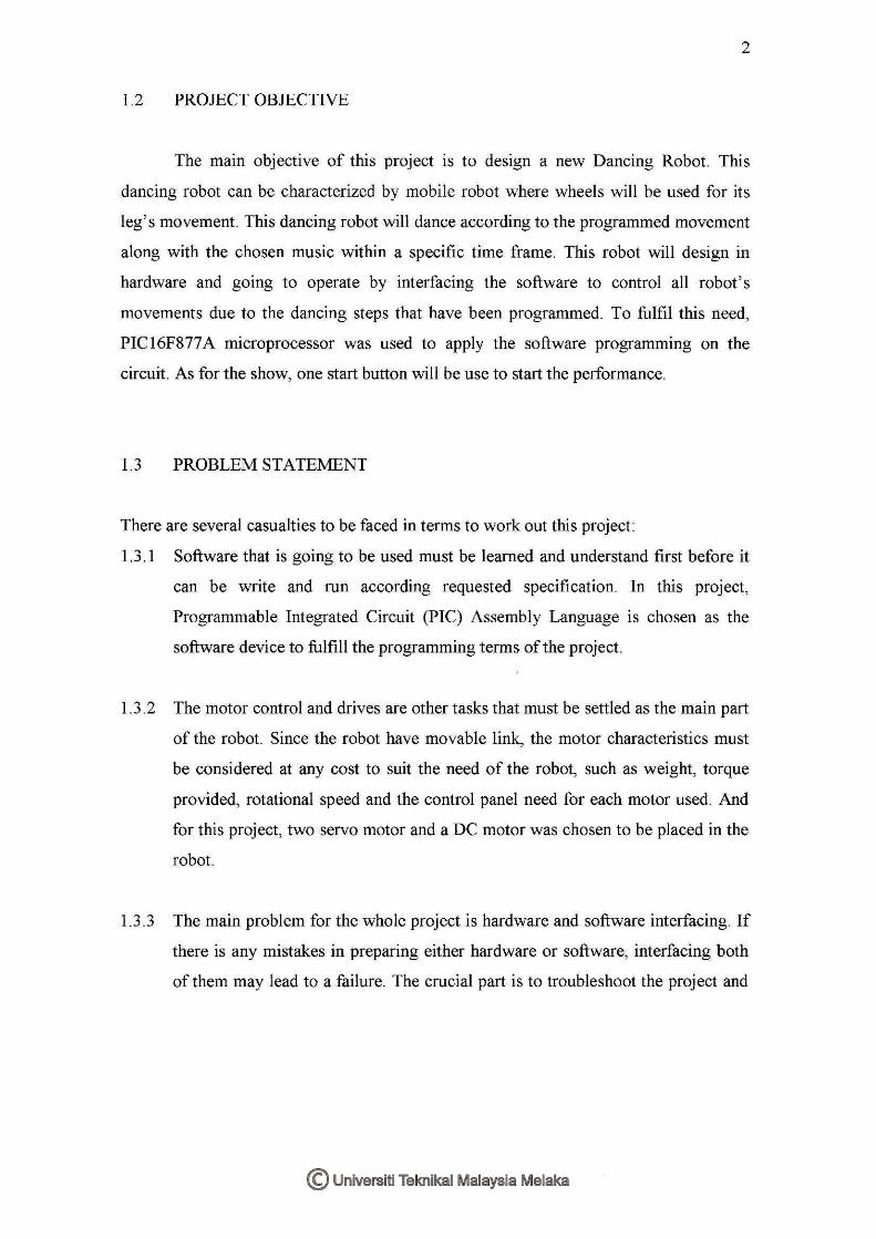
1.2 PROJECT OBJECTIVE
The main objective of this project is to design a new Dancing Robot. This
dancing robot can be characterized by mobile robot where wheels will be used for its
leg's movement. This dancing robot will dance according to the programmed movement
along with the chosen music within a specific time frame. This robot will design in
hardware and going to operate by interfacing the software to control all robot's
movements due to the dancing steps that have been programmed. To fulfil this need,
PIC16F877A microprocessor was used to apply the software programming on the
circuit. As for the show, one start button will be use to start the performance.
1.3 PROBLEM STATEMENT
There are several casualties to be faced in terms to work out this project:
1.3.1 Software that is going to be used must be learned and understand first before it
can be write and run according requested specification. In this project,
Programmable Integrated Circuit (PIC) Assembly Language is chosen as the
software device to fulfill the programming terms of the project.
1.3.2 The motor control and drives are other tasks that must be settled as the main part
of the robot. Since the robot have movable link, the motor characteristics must
be considered at any cost to suit the need of the robot, such as weight, torque
provided, rotational speed and the control panel need for each motor used. And
for this project, two servo motor and a DC motor was chosen to be placed in the
robot.
1.3.3 The main problem for the whole project is hardware and software interfacing. If
there is any mistakes in preparing either hardware or software, interfacing both
of them may lead to a failure. The crucial part is to troubleshoot the project and
2
1.2 PROJECT OBJECTIVE
The main objective of this project is to design a new Dancing Robot. This
dancing robot can be characterized by mobile robot where wheels will be used for its
leg's movement. This dancing robot will dance according to the programmed movement
along with the chosen music within a specific time frame. This robot will design in
hardware and going to operate by interfacing the software to control all robot's
movements due to the dancing steps that have been programmed. To fulfil this need,
PIC16F877 A microprocessor was used to apply the software programming on the
circuit. As for the show, one start button will be use to start the performance.
1.3 PROBLEM STATEMENT
There are several casualties to be faced in terms to work out this project:
1.3.1 Software that is going to be used must be learned and understand first before it
can be write and run according requested specification. In this project,
Programmable Integrated Circuit (PIC) Assembly Language is chosen as the
software device to fulfill the programming terms of the project.
1.3.2 The motor control and drives are other tasks that must be settled as the main part
of the robot. Since the robot have movable link, the motor characteristics must
be considered at any cost to suit the need of the robot, such as weight, torque
provided, rotational speed and the control panel need for each motor used. And
for this project, two servo motor and a DC motor was chosen to be placed in the
robot.
1.3 .3 The main problem for the whole project is hardware and software interfacing. If
there is any mistakes in preparing either hardware or software, interfacing both
of them may lead to a failure. The crucial part is to troubleshoot the project and
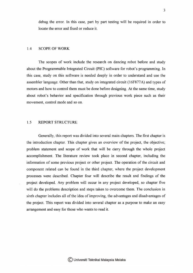
3
debug the error. In this case, part by part testing will be required in order to
locate the error and fixed or reduce it.
1.4 SCOPE OF WORK
The scopes of work include the research on dancing robot before and study
about the Programmable Integrated Circuit (PIC) software for robot's programming. In
this case, study on this software is needed deeply in order to understand and use the
assembler language. Other than that, study on integrated circuit (16F877 A) and types of
motors and how to control them must be done before designing. At the same time, study
about robot's behavior and specification through previous work piece such as their
movement, control mode and so on.
1.5 REPORT STRUCTURE
Generally, this report was divided into several main chapters. The first chapter is
the introduction chapter. This chapter gives an overview of the project, the objective;
problem statement and scope of work that will be carry through the whole project
accomplishment. The literature review took place in second chapter, including the
information of some previous project or other project. The operation of the circuit and
component related can be found in the third chapter, where the project development
processes were described. Chapter four will describe the result and findings of the
project developed. Any problem will occur in any project developed, so chapter five
will do the problems description and steps taken to overcome them. The conclusion in
sixth chapter includes all of the idea of improving, the advantages and disadvantages of
the project. This report was divided into several chapter as a purpose to make an easy
arrangement and easy for those who wants to read it.
4
CHAPTER II
LITERATURE REVIEW
2.1 INTRODUCTION
This project is a robot that has legs, considered as the walker robot. Different
from the other mobile robot, the movement of the robot uses 2 legs since it representing
human movement method in dancing. Essentially, walker robots use legs for
locomotion. Locomotion by legs is hundred million of years old. In contrast to this,
wheels are relatively a new science, being only 7,000 to 10,000 years old. Wheels are
good but they require a relatively smooth surface to ride upon. Just look at aerial
photograph of any city or suburb to see the highways and streets crisscrossing the
landscape.
5
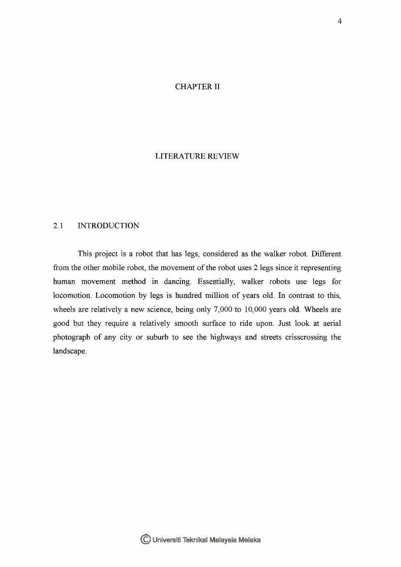
2.2 SONY QRIO
Figure 2.1: Sony QRIO
One of the best creations in robotic world! QRIO was developed in latest 3D
navigation system developed by the Information Technologies Laboratories at Sony
Corporation to open up new possibilities in robotics, the Sony QRIO robot is one of the
world ' s most sophisticated and intelligent humanoids. Being Sony's Corporate
Ambassador, QRIO is taking advantage of various opportunities around the world to
communicate Sony' s vision of a world of dreams, entertainment and curiosities as well
as introducing the technology that makes this vision a reality.
The main point that this robot was picked out as one of this project literature
review is THESE ROBOTS CAN DANCE. But despite of its intelligence, these robots
are hard to compare with seen at their technology, budget and engineers involve. But as
an example they are good to set look at.

6
2.3 ROBODANCE UTM
Figure 2.2: UTM's ROBODANCE
This is a project that the students of UTM produce. It is a good robodance that
fulfil all the criteria needed. This robot seem clearly can dance with the music even
though that the step of movement a bit faster but still have its own entertainment value.
But still it is not a two-leg robot even that the robot has leg movement. The robot was
placed on a moving platform as it moves on the dance floor.
This project of Dancing Robot that is going to develop actually builds in terms
to enter ROBOFEST competition. But since the competition was terminated, this
project will continue as another phase of robotic implementation project in KUTKM.
This project will be build as it fulfil the objective (maybe quite same with the UTM's)
but will be build on two legs, not platform. That is the main different with the UTM' s
but still can' t afford to achieve the technology as the QRIO' s. As long as the robot can
dance on its own legs, that's enough to satisfy this project's objective.
7
2.4 COMPONENT THEORY AND ITS USAGE
This dancing robot requires two integrated circuits that are PIC 16F877 A
microprocessor, voltage regulator LM7805 and L293D along with two servo motors and
a DC motor. The specific briefing will be described as below.
2.4.1 PIC16F877A
Figure 2.3: PIC16F877A microcontroller
The microcontroller ability is to store and a run umque program makes it
extremely versatile. For instance, one can program a microcontroller to make decisions
based on predetermine situations and sensor readings. Its ability to perform math and
logic function allows it to mimic sophisticated logic and electronic circuits. The
operation will be discussed below.

8
2.4.1.1 Circuit Operation
The output of the microcontroller can control direct current (DC) motor drives
(using DC or pulse-width modulation (PWM)), servo motor positioning, stepper motor
and etc. to program a microcontroller, all that are needed is a microcontroller
(PIC16F84/ PIC16F877 or others) and software relevant to what language we decide to
used on the IC. As for this project, we used the C language and the suitable software is
MPLab.
PIC 16F877 A is a powerful (200 nanosecond instruction execution) yet easy-to
program (only 35 single word instructions) CMOS FLASH-based 8-bit microcontroller
which packs Microchip's powerful PIC® architecture into a 40 pin package. The
PIC 16F877 A features 256 bytes of EEPROM data memory, self programming, an lCD,
2 Comparators, 8 channels of 10-bit Analog-to-Digital (AID) converter, 2
capture/compare/PWM functions, the synchronous serial port can be configured as
either 3-wire Serial Peripheral Interface (SPI™) or the 2-wire Inter-Integrated Circuit
(12CTM) bus and a Universal Asynchronous Receiver Transmitter (USART). The code
for the microcontroller can be written in either in C language or Basic in microcode
studio.

40~Pin PDIP
MCLR:VPP ___.... R.A£:t::AJJC! -RA1 :fi.N1-
R.t>.2''A.tl2Nr~rr- :C'...'nnR.tl.2,.-.AN3:VP. EF+
Rf\.4:TOCKiiC10Ul-RA.~,;AN4iSSiC20UT
R~OIRD::AN5 ___.... ~11WR.(ANf3-REZ·~1:A.N!-
\.'no -
V~·-0-5 C1 :CL Kl ----..
oscz:cLKoRCO:Tloso;ncKI -
RCH10.SifCCP2-RC2iCCP1-
RC:?iSCK·BCLRDO/P.SPORD1 !PSP1--...
- R87:'PGD - RB6:'PGC -RB:5 -RB4 - R83iPGr· .. 1 -RB2 -R8 1 - RBO:HH - \loo 4------ V~
-RD! tPSP7 - RD61PSP6 -RD5:PSP5 -RD4:PSP4 - RC7!P.X.'DT -RC6rTX•CK -RC5iSDO
- RC4/SDI:SD.A. - RD3:PSP3 - RD2:PSP2
Figure 2.4: PIC16F877 A Pin Description
2.4. 1. 2 The Features
Special Microcontroller Features
- 100,000 erase/write cycle Enhanced Flash program memory typical
- Self-reprogrammable under software control
- Single-supply 5V In-Circuit Serial Programming
-Watchdog Timer (WDT) with its own on-chip RC oscillator
- Programmable Code Protection
-Power-Saving Sleeping mode
Peripheral Features
- Two 8-bit (TMRO, TMR2) timer/counter with Prescalar
-One 16-bit timer/counter
- Brown-out detection circuitry
- Parallel Slave Port (PSP): 40/44 pin-device only
9