


Bahasa
Halaman
Hukum

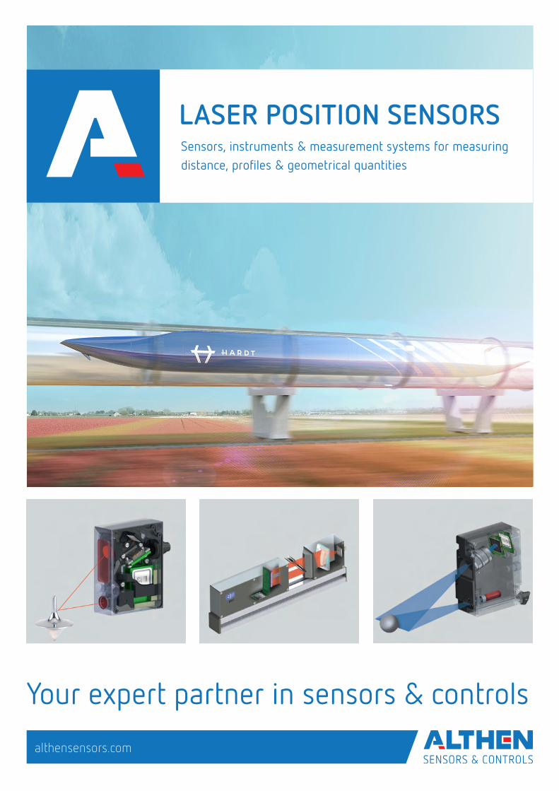
LASER POSITION SENSORS Sensors, instruments & measurement systems for measuring distance, profiles & geometrical quantities
Your expert partner in sensors & controls
althensensors.com
2
INFORMATION ABOUT ALTHEN SENSORS & CONTROLS
Althen Sensors & Controls stands for pioneering measurement and sensor solutions. Since we are constantly looking to innovate we accept every measurement challenge, our engineers are only satisfied when the perfect solution for your measurement task is found. We develop customer-specific solutions in our in-house production facilities. Althen is partner of many recognized universities and leading organizations. We find our-selves in an intensive knowledge transfer, developing future technologies. Althen is one of the first companies in its branch with a certification by the German technical inspection association in Hessen (TÜV PROFICERT) in accordance with DIN EN ISO 9001:2015.
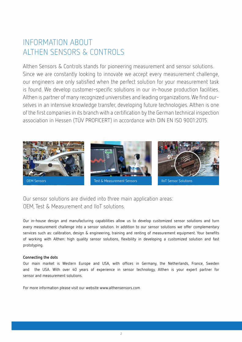
OEM Sensors Test & Measurement Sensors IIoT Sensor Solutions
Our sensor solutions are divided into three main application areas: OEM, Test & Measurement and IIoT solutions.
Our in-house design and manufacturing capabilities allow us to develop customized sensor solutions and turn
every measurement challenge into a sensor solution. In addition to our sensor solutions we offer complementary
services such as: calibration, design & engineering, training and renting of measurement equipment. Your benefits
of working with Althen: high quality sensor solutions, flexibility in developing a customized solution and fast
prototyping.
Connecting the dotsOur main market is Western Europe and USA, with offices in Germany, the Netherlands, France, Sweden
and the USA. With over 40 years of experience in sensor technology, Althen is your expert partner for
sensor and measurement solutions.
For more information please visit our website www.althensensors.com
3
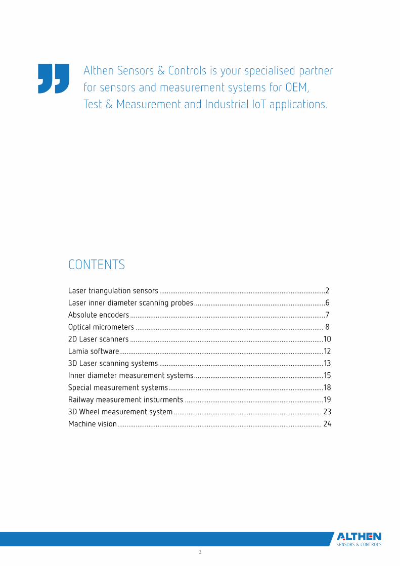
Althen Sensors & Controls is your specialised partnerfor sensors and measurement systems for OEM, Test & Measurement and Industrial IoT applications.
CONTENTS
Laser triangulation sensors ...........................................................................................2
Laser inner diameter scanning probes ........................................................................6
Absolute encoders ...........................................................................................................7
Optical micrometers ....................................................................................................... 8
2D Laser scanners ..........................................................................................................10
Lamia software ................................................................................................................12
3D Laser scanning systems ..........................................................................................13
Inner diameter measurement systems .......................................................................15
Special measurement systems .....................................................................................18
Railway measurement insturments ............................................................................19
3D Wheel measurement system ................................................................................. 23
Machine vision ................................................................................................................ 24
4
liquid level automotive object sorting dimensions thickness profiling
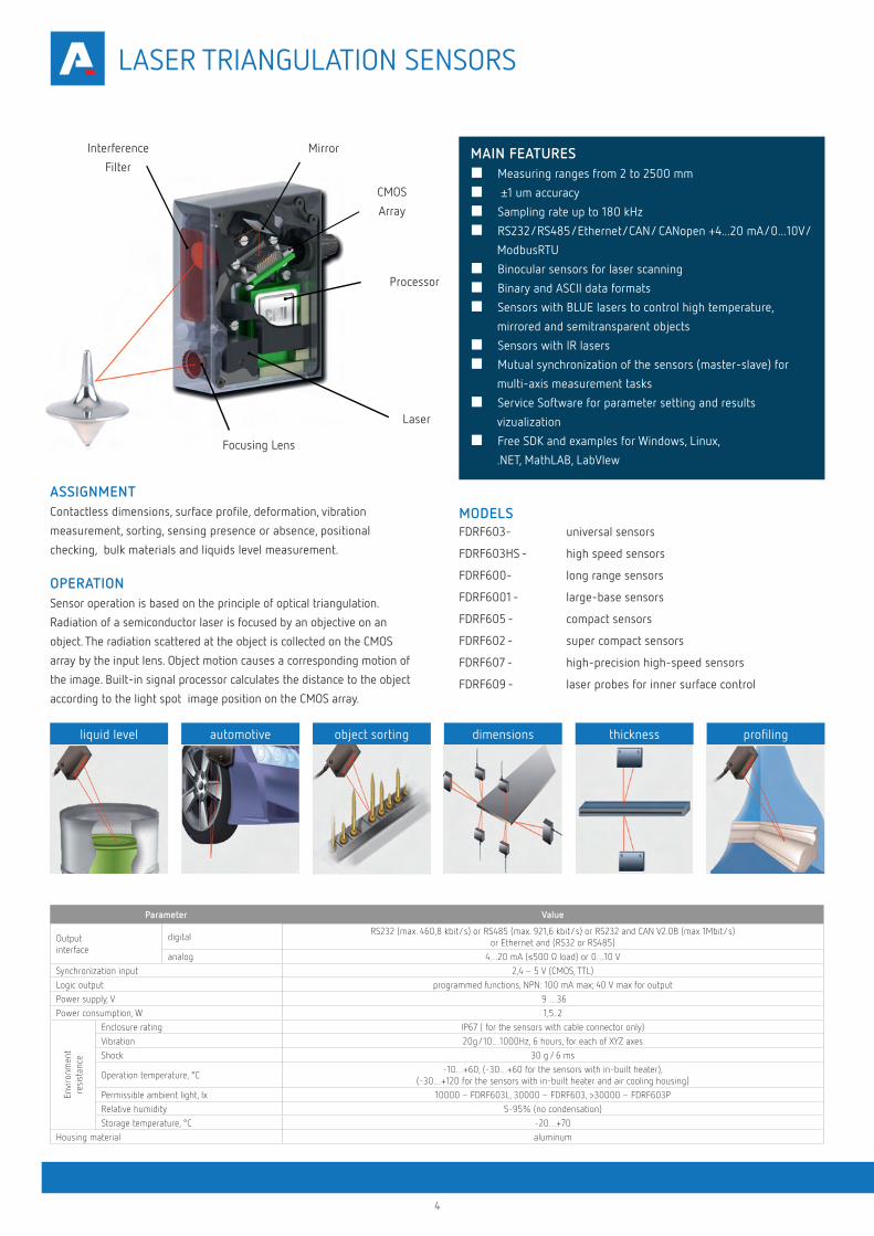
Interference
Filter
CMOS
Array
Processor
Laser
Focusing Lens
Mirror
ASSIGNMENTContactless dimensions, surface profile, deformation, vibration
measurement, sorting, sensing presence or absence, positional
checking, bulk materials and liquids level measurement.
OPERATIONSensor operation is based on the principle of optical triangulation.
Radiation of a semiconductor laser is focused by an objective on an
object. The radiation scattered at the object is collected on the CMOS
array by the input lens. Object motion causes a corresponding motion of
the image. Built-in signal processor calculates the distance to the object
according to the light spot image position on the CMOS array.
Parameter Value
Output interface
digitalRS232 (max. 460,8 kbit/s) or RS485 (max. 921,6 kbit/s) or RS232 and CAN V2.0B (max 1Mbit/s)
or Ethernet and (RS32 or RS485)
analog 4…20 mA (≤500 Ω load) or 0…10 V
Synchronization input 2,4 – 5 V (CMOS, TTL)
Logic output programmed functions, NPN: 100 mA max; 40 V max for output
Power supply, V 9 …36
Power consumption, W 1,5..2
Envi
ronm
ent
resi
stan
ce
Enclosure rating IP67 ( for the sensors with cable connector only)
Vibration 20g/10…1000Hz, 6 hours, for each of XYZ axes
Shock 30 g / 6 ms
Operation temperature, °C -10…+60, (-30…+60 for the sensors with in-built heater),
(-30…+120 for the sensors with in-built heater and air cooling housing)
Permissible ambient light, lx 10000 – FDRF603L, 30000 – FDRF603, >30000 – FDRF603P
Relative humidity 5-95% (no condensation)
Storage temperature, °C -20…+70
Housing material aluminum
MODELSFDRF603- universal sensors
FDRF603HS - high speed sensors
FDRF600- long range sensors
FDRF6001 - large-base sensors
FDRF605 - compact sensors
FDRF602 - super compact sensors
FDRF607 - high-precision high-speed sensors
FDRF609 - laser probes for inner surface control
■ Measuring ranges from 2 to 2500 mm
■ ±1 um accuracy
■ Sampling rate up to 180 kHz
■ RS232/RS485/Ethernet/CAN/ CANopen +4...20 mA/0...10V/
ModbusRTU
■ Binocular sensors for laser scanning
■ Binary and ASCII data formats
■ Sensors with BLUE lasers to control high temperature,
mirrored and semitransparent objects
■ Sensors with IR lasers
■ Mutual synchronization of the sensors (master-slave) for
multi-axis measurement tasks
■ Service Software for parameter setting and results
vizualization
■ Free SDK and examples for Windows, Linux,
.NET, MathLAB, LabVIew
MAIN FEATURES
LASER TRIANGULATION SENSORS
5
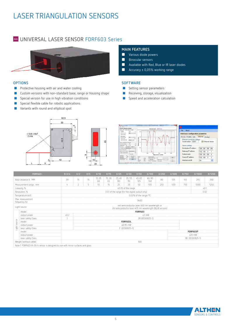
SOFTWARE■ Setting sensor parameters
■ Receiving, storage, visualization
■ Speed and acceleration calculation
■ Various diode powers
■ Binocular sensors
■ Available with Red, Blue or IR laser diodes
■ Accuracy ± 0,05% working range
OPTIONS■ Protective housing with air and water cooling
■ Custom versions with non-standard base, range or housing shape
■ Special version for use in high vibration conditions
■ Special flexible cable for robotic applications
■ Variants with round and elliptical spot
MAIN FEATURES
FDRF603- R-X/4 X/2 X/5 X/10 X/15 X/25 X/30 X/50 X/100 X/250 X/500 X/750 X/1000 X/1250
Base distance X, MM 39 15 1515, 25
6015, 30
6525, 45
8035, 55
9545, 65 105
60, 90 140
80 125 145 245 260
Measurement range, mm 4 2 5 10 15 25 30 50 100 250 500 750 1000 1250
Linearity, % ±0.05 of the range ±0.1
Resolution, % 0.01 of the range (for the digital output only) 0.02
Temperature drift 0,02% of the range/°C
Max. measurement frequency, Hz
9400
Light sourcered semiconductor laser, 660 nm wavelength or
UV semiconductor laser 405 nm wavelength (BLUE version)
Ligh
t sou
rce
model FDRF603output power ≤0,2 ≤3 mWlaser safety Class 1 3R (IEC60825-1)model FDRF603Loutput power ≤0,95 mWlaser safety Class 2 (IEC60825-1)model FDRF603Рoutput power ≤20 mWlaser safety Class 3B (IEC60825-1)
Weight (without cable) 100
Note 1: FDRF603-R-39/4 sensor is designed to use with mirror surfaces and glass.
UNIVERSAL LASER SENSOR FDRF603 Series
LASER TRIANGULATION SENSORS
6
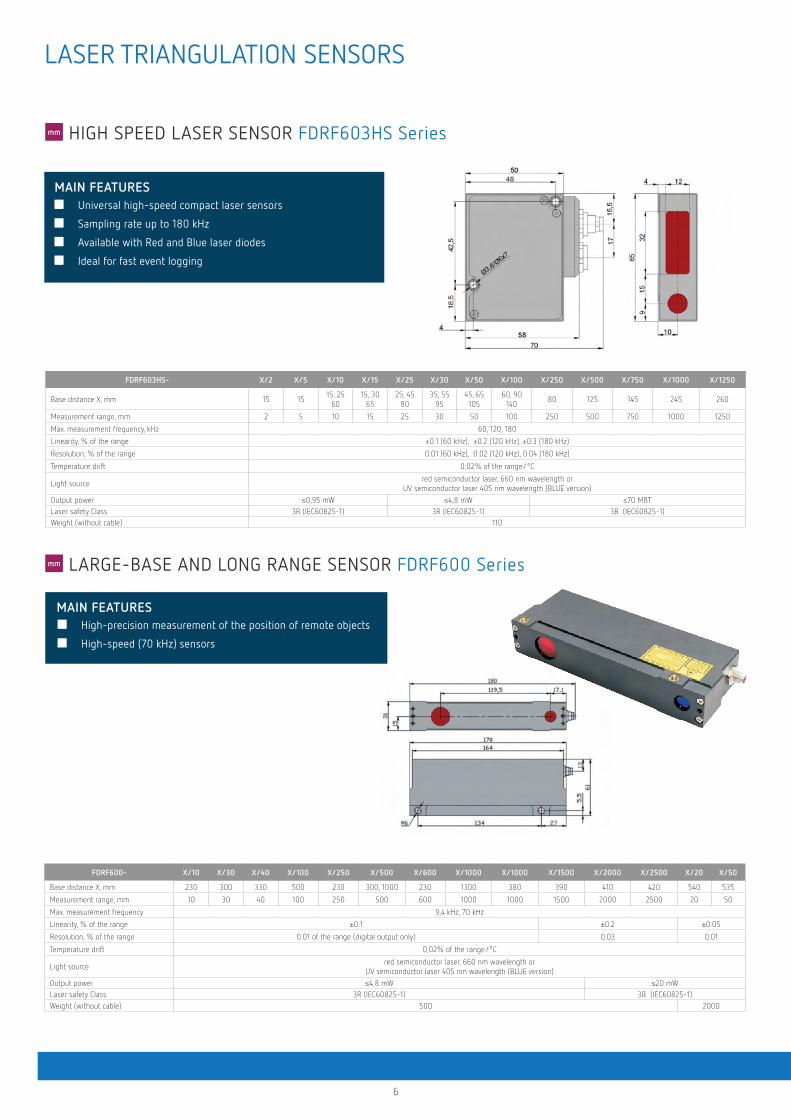
FDRF603HS- X/2 X/5 X/10 X/15 X/25 X/30 X/50 X/100 X/250 X/500 X/750 X/1000 X/1250
Base distance X, mm 15 1515, 25
6015, 30
6525, 45
8035, 55
9545, 65 105
60, 90 140
80 125 145 245 260
Measurement range, mm 2 5 10 15 25 30 50 100 250 500 750 1000 1250
Max. measurement frequency, kHz 60, 120, 180
Linearity, % of the range ±0.1 (60 kHz), ±0.2 (120 kHz), ±0.3 (180 kHz)
Resolution, % of the range 0.01 (60 kHz), 0.02 (120 kHz), 0.04 (180 kHz)
Temperature drift 0,02% of the range/°C
Light sourcered semiconductor laser, 660 nm wavelength or
UV semiconductor laser 405 nm wavelength (BLUE version)
Output power ≤0,95 mW ≤4,8 mW ≤70 MBTLaser safety Class 3R (IEC60825-1) 3R (IEC60825-1) 3B (IEC60825-1)Weight (without cable) 110
LARGE-BASE AND LONG RANGE SENSOR FDRF600 Series
HIGH SPEED LASER SENSOR FDRF603HS Series
■ High-precision measurement of the position of remote objects
■ High-speed (70 kHz) sensors
FDRF600- X/10 X/30 X/40 X/100 X/250 X/500 X/600 X/1000 X/1000 X/1500 X/2000 X/2500 X/20 X/50
Base distance X, mm 230 300 330 500 230 300, 1000 230 1300 380 390 410 420 540 535
Measurement range, mm 10 30 40 100 250 500 600 1000 1000 1500 2000 2500 20 50
Max. measurement frequency 9,4 kHz, 70 kHz
Linearity, % of the range ±0.1 ±0.2 ±0.05
Resolution, % of the range 0.01 of the range (digital output only) 0.03 0.01
Temperature drift 0,02% of the range/°C
Light sourcered semiconductor laser, 660 nm wavelength or
UV semiconductor laser 405 nm wavelength (BLUE version)
Output power ≤4,8 mW ≤20 mWLaser safety Class 3R (IEC60825-1) 3B (IEC60825-1)Weight (without cable) 500 2000
MAIN FEATURES
■ Universal high-speed compact laser sensors
■ Sampling rate up to 180 kHz
■ Available with Red and Blue laser diodes
■ Ideal for fast event logging
MAIN FEATURES
LASER TRIANGULATION SENSORS
7
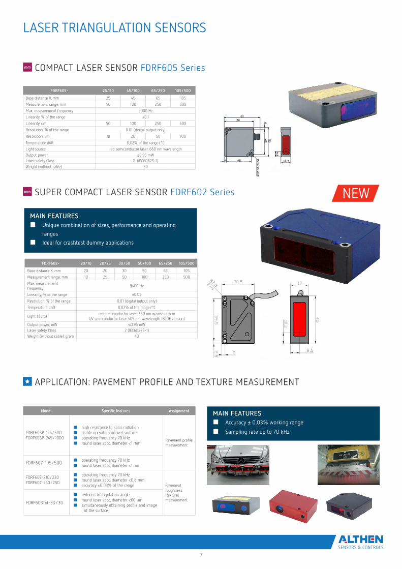
COMPACT LASER SENSOR FDRF605 Series
SUPER COMPACT LASER SENSOR FDRF602 Series
FDRF605- 25/50 45/100 65/250 105/500
Base distance X, mm 25 45 65 105
Measurement range, mm 50 100 250 500
Max. measurement frequency 2000 Hz
Linearity, % of the range ±0.1
Linearity, um 50 100 250 500
Resolution, % of the range 0.01 (digital output only)
Resolution, um 10 20 50 100
Temperature drift 0,02% of the range/°C
Light source red semiconductor laser, 660 nm wavelength
Output power ≤0,95 mWLaser safety Class 2 (IEC60825-1)Weight (without cable) 60
FDRF602- 20/10 20/25 30/50 50/100 65/250 105/500
Base distance X, mm 20 20 30 50 65 105
Measurement range, mm 10 25 50 100 250 500
Max. measurement frequency
9400 Hz
Linearity, % of the range ±0.05
Resolution, % of the range 0.01 (digital output only)
Temperature drift 0,02% of the range/°C
Light sourcered semiconductor laser, 660 nm wavelength or
UV semiconductor laser 405 nm wavelength (BLUE version)
Output power, mW ≤0.95 mWLaser safety Class 2 (IEC60825-1)Weight (without cable), gram 40
APPLICATION: PAVEMENT PROFILE AND TEXTURE MEASUREMENT
■ Accuracy ± 0,03% working range
■ Sampling rate up to 70 kHz
Model Specific features Assignment
FDRF603P-125/500 FDRF603P-245/1000
■ high resistance to solar radiation■ stable operation on wet surfaces■ operating frequency 70 kHz■ round laser spot, diameter <1 mm
Pavement profilemeasurement
FDRF607-195/500 ■ operating frequency 70 kHz■ round laser spot, diameter <1 mm
FDRF607-210/230FDRF607-230/250
■ operating frequency 70 kHz■ round laser spot, diameter <0,8 mm■ accuracy ±0.03% of the range Pavement
roughness (texture) measurement
FDRF603Txt-30/30
■ reduced triangulation angle■ round laser spot, diameter <60 um■ simultaneously obtaining profile and image
of the surface
MAIN FEATURES
MAIN FEATURES
■ Unique combination of sizes, performance and operating
ranges
■ Ideal for crashtest dummy applications
LASER TRIANGULATION SENSORS
NEW
5
COMPACT LASER SENSOR FDRF605 Series
SUPER COMPACT LASER SENSOR FDRF602 Series
FDRF605- 25/50 45/100 65/250 105/500
Base distance X, mm 25 45 65 105
Measurement range, mm 50 100 250 500
Max. measurement frequency 2000 Hz
Linearity, % of the range ±0.1
Linearity, um 50 100 250 500
Resolution, % of the range 0.01 (digital output only)
Resolution, um 10 20 50 100
Temperature drift 0,02% of the range/°C
Light source red semiconductor laser, 660 nm wavelength
Output power ≤0,95 mWLaser safety Class 2 (IEC60825-1)Weight (without cable) 60
FDRF602- 20/10 20/25 30/50 50/100 65/250 105/500
Base distance X, mm 20 20 30 50 65 105
Measurement range, mm 10 25 50 100 250 500
Max. measurement frequency
9400 Hz
Linearity, % of the range ±0.05
Resolution, % of the range 0.01 (digital output only)
Temperature drift 0,02% of the range/°C
Light sourcered semiconductor laser, 660 nm wavelength or
UV semiconductor laser 405 nm wavelength (BLUE version)
Output power, mW ≤0.95 mWLaser safety Class 2 (IEC60825-1)Weight (without cable), gram 40
APPLICATION: PAVEMENT PROFILE AND TEXTURE MEASUREMENT
■ Accuracy ± 0,03% working range
■ Sampling rate up to 70 kHz
Model Specific features Assignment
FDRF603P-125/500 FDRF603P-245/1000
■ high resistance to solar radiation■ stable operation on wet surfaces■ operating frequency 70 kHz■ round laser spot, diameter <1 mm
Pavement profilemeasurement
FDRF607-195/500 ■ operating frequency 70 kHz■ round laser spot, diameter <1 mm
FDRF607-210/230FDRF607-230/250
■ operating frequency 70 kHz■ round laser spot, diameter <0,8 mm■ accuracy ±0.03% of the range Pavement
roughness (texture) measurement
FDRF603Txt-30/30
■ reduced triangulation angle■ round laser spot, diameter <60 um■ simultaneously obtaining profile and image
of the surface
LASER TRIANGULATION SENSORS
MAIN FEATURES
MAIN FEATURES
■ Unique combination of sizes, performance and operating
ranges
■ Ideal for crashtest dummy applications
LASER TRIANGULATION SENSORS
NEW
8
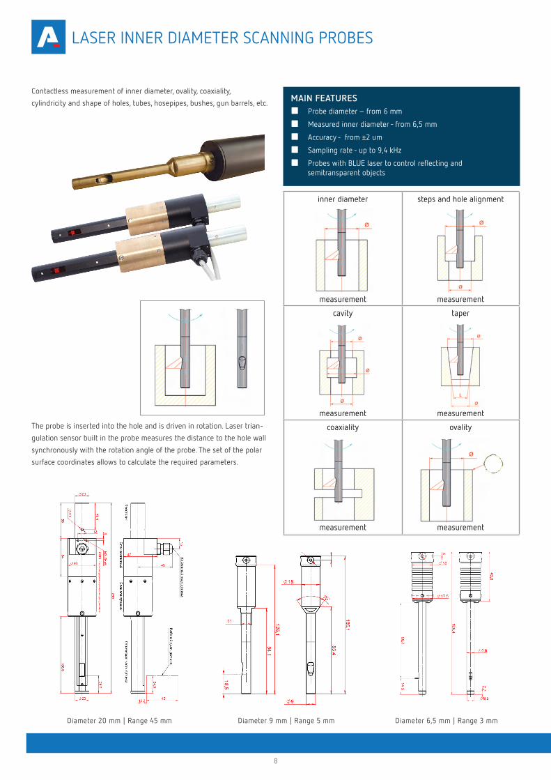
Diameter 9 mm | Range 5 mmDiameter 20 mm | Range 45 mm Diameter 6,5 mm | Range 3 mm
Contactless measurement of inner diameter, ovality, coaxiality,
cylindricity and shape of holes, tubes, hosepipes, bushes, gun barrels, etc.
The probe is inserted into the hole and is driven in rotation. Laser trian-
gulation sensor built in the probe measures the distance to the hole wall
synchronously with the rotation angle of the probe. The set of the polar
surface coordinates allows to calculate the required parameters.
■ Probe diameter – from 6 mm
■ Measured inner diameter - from 6,5 mm
■ Accuracy - from ±2 um
■ Sampling rate - up to 9,4 kHz
■ Probes with BLUE laser to control reflecting and semitransparent objects
inner diameter
measurement
steps and hole alignment
measurement
cavity
measurement
taper
measurement
coaxiality
measurement
ovality
measurement
LASER INNER DIAMETER SCANNING PROBES
MAIN FEATURES
9
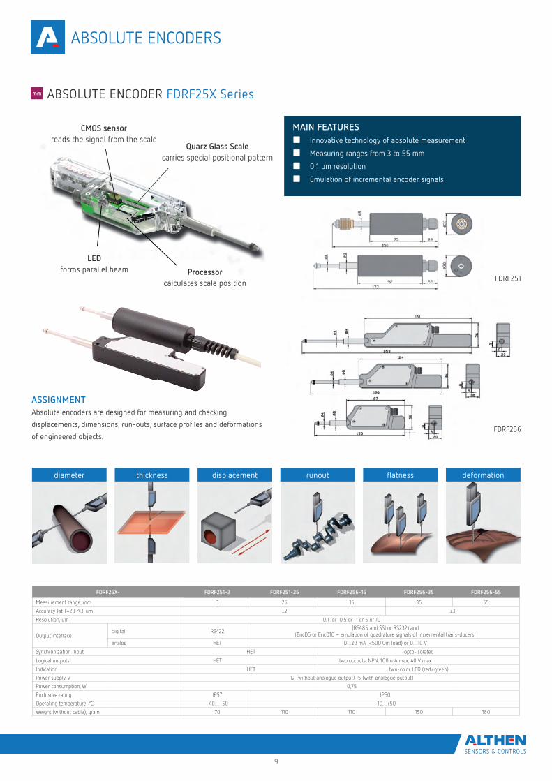
ABSOLUTE ENCODERS
■ Innovative technology of absolute measurement
■ Measuring ranges from 3 to 55 mm
■ 0.1 um resolution
■ Emulation of incremental encoder signals
ASSIGNMENTAbsolute encoders are designed for measuring and checking
displacements, dimensions, run-outs, surface profiles and deformations
of engineered objects.
diameter thickness displacement runout flatness deformation
FDRF25X- FDRF251-3 FDRF251-25 FDRF256-15 FDRF256-35 FDRF256-55
Measurement range, mm 3 25 15 35 55
Accuracy (at T=20 °C), um ±2 ±3
Resolution, um 0.1 or 0.5 or 1 or 5 or 10
Output interfacedigital RS422
(RS485 and SSI or RS232) and (EncD5 or EncD10 – emulation of quadrature signals of incremental trans-ducers)
analog HET 0…20 mA (<500 Om load) or 0…10 V
Synchronization input HET opto-isolated
Logical outputs HET two outputs, NPN: 100 mA max; 40 V max
Indication HET two-color LED (red/green)
Power supply, V 12 (without analogue output) 15 (with analogue output)
Power consumption, W 0,75
Enclosure rating IP57 IP50
Operating temperature, °C -40…+50 -10…+50
Weight (without cable), gram 70 110 110 150 180
CMOS sensorreads the signal from the scale
Processorcalculates scale position
LEDforms parallel beam
Quarz Glass Scalecarries special positional pattern
ABSOLUTE ENCODER FDRF25X Series
MAIN FEATURES
FDRF251
FDRF256
10
OPERATION
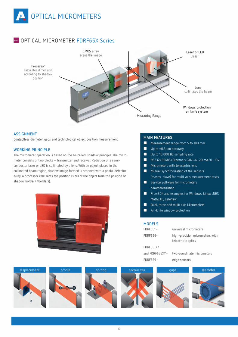
ASSIGNMENTContactless diameter, gaps and technological object position measurement.
WORKING PRINCIPLEThe micrometer operation is based on the so-called ‘shadow’ principle. The micro-
meter consists of two blocks – transmitter and receiver. Radiation of a semi-
conductor laser or LED is collimated by a lens. With an object placed in the
collimated beam region, shadow image formed is scanned with a photo-detector
array. A processor calculates the position (size) of the object from the position of
shadow border (/borders).
MODELSFDRF651 - universal micrometers
FDRF656- high-precision micrometers with
telecentric optics
FDRF651XY
and FDRF656XY - two-coordinate micrometers
FDRF659 - edge sensors
displacement profile sorting several axis gaps diameter
CMOS arrayscans the image
Processorcalculates dimension according to shadow
position
Laser of LEDClass 1
Lenscollimates the beam
Windows protectionair knife system
Measuring Range
OPTICAL MICROMETER FDRF65X Series
■ Measurement range from 5 to 100 mm
■ Up to ±0.3 um accuracy
■ Up to 10,000 Hz sampling rate
■ RS232/RS485/Ethernet/CAN +4...20 mA/0...10V
■ Micrometers with telecentric lens
■ Mutual synchronization of the sensors
(master-slave) for multi-axis measurement tasks
■ Service Software for micrometers
parameterization
■ Free SDK and examples for Windows, Linux, .NET,
MathLAB, LabVIew
■ Dual, three and multi axis Micrometers
■ Air-knife window protection
MAIN FEATURES
OPTICAL MICROMETERS
11
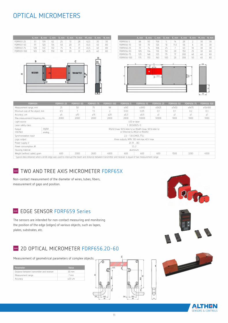
The sensors are intended for non-contact measuring and monitoring
the position of the edge (edges) of various objects, such as tapes,
plates, substrates, etc.
A, mm B, mm C, mm D, mm E, mm H, mm H1, mm K, mm N, mm
FDRF651-25 51 139 62 25 13 28 42,5 30 30FDRF651-50 91 120 134 50 20 31 45,5 40 80FDRF651-75 128 132 132 75 15 31 45,5 40 80FDRF651-100 165 165 150 98 20 31 45,5 40 80
A, mm B, mm C, mm D, mm E, mm K, mm R, mm M, mm N, mm
FDRF656-5 66 50 158 5 14 28 2 30 30FDRF656-10 50 70 126 10 11,5 56 6 30 30FDRF656-25 72 74 106 25 7 63 10 30 30FDRF656-50 105 134 110 50 20 150 25 30 60FDRF656-75 135 148 125 75 17 200 40 40 80FDRF656-100 175 170 160 100 20 300 50 40 80
FDRF65X- FDRF651-25 FDRF651-50 FDRF651-75 FDRF651-100 FDRF656-5 FDRF656-10 FDRF656-25 FDRF656-50 FDRF656-75 FDRF656-100
Measurement range, mm 25 50 75 98 ±1X5 ±3X10 ±5X25 ±7x50 ±9x75 ±10x100
Minimum size of the object, mm 0.5 1 1.5 2 0.03 0,05 0,1 0.1 0.2 0.3
Accuracy1, um ±5 ±10 ±15 ±20 ±0,3 ±0,5 ±1 ±1 ±1 ±1
Max measurement frequency, Hz 2000 2000 2000 2000 2000 10000 10000 1000 1000 1000
Light source LED or laser
Laser safety class 1 (IEC60825-1)
Output interface
digital RS232 (max. 921,6 kbit/s) or RS485 (max. 921,6 kbit/s) or Ethernet & (RS32 or RS485)analog
Synchronization input 2,4 – 5 B (CMOS, TTL)
Logic output three outputs, NPN: 100 mA max; 40 V max
Power supply, V 24 (9 …36)
Power consumption, W 1,5..2
Housing material aluminum
Weight (without cable), gram 600 2000 2600 4000 600 600 600 1500 3200 45001 typical data obtained when a knife edge was used to interrupt the beam and distance between transmitter and receiver is equal of two measurement range
Parameter Value
Distance between transmitter and receiver 30 mm
Measurement range 7 mm
Accuracy ±20 um
Non-contact measurement of the diameter of wires, tubes, fibers,
measurement of gaps and position.
Measurement of geometrical parameters of complex objects.
TWO AND TREE AXIS MICROMETER FDRF65X
2D OPTICAL MICROMETER FDRF656.2D-60
EDGE SENSOR FDRF659 Series
OPTICAL MICROMETERS
12
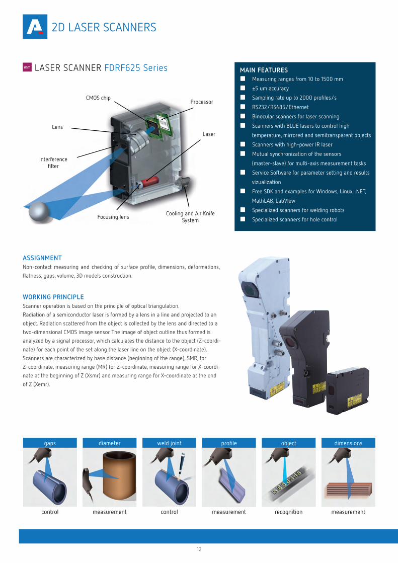
ASSIGNMENTNon-contact measuring and checking of surface profile, dimensions, deformations,
flatness, gaps, volume, 3D models construction.
WORKING PRINCIPLEScanner operation is based on the principle of optical triangulation.
Radiation of a semiconductor laser is formed by a lens in a line and projected to an
object. Radiation scattered from the object is collected by the lens and directed to a
two-dimensional CMOS image sensor. The image of object outline thus formed is
analyzed by a signal processor, which calculates the distance to the object (Z-coordi-
nate) for each point of the set along the laser line on the object (X-coordinate).
Scanners are characterized by base distance (beginning of the range), SMR, for
Z-coordinate, measuring range (MR) for Z-coordinate, measuring range for X-coordi-
nate at the beginning of Z (Xsmr) and measuring range for X-coordinate at the end
of Z (Xemr).
Focusing lens
Interferencefilter
CMOS chip
Cooling and Air KnifeSystem
Laser
Processor
Lens
gaps
control
diameter
measurement
weld joint
control
profile
measurement
object
recognition
dimensions
measurement
■ Measuring ranges from 10 to 1500 mm
■ ±5 um accuracy
■ Sampling rate up to 2000 profiles/s
■ RS232/RS485/Ethernet
■ Binocular scanners for laser scanning
■ Scanners with BLUE lasers to control high
temperature, mirrored and semitransparent objects
■ Scanners with high-power IR laser
■ Mutual synchronization of the sensors
(master-slave) for multi-axis measurement tasks
■ Service Software for parameter setting and results
vizualization
■ Free SDK and examples for Windows, Linux, .NET,
MathLAB, LabVIew
■ Specialized scanners for welding robots
■ Specialized scanners for hole control
MAIN FEATURES LASER SCANNER FDRF625 Series
2D LASER SCANNERS
13
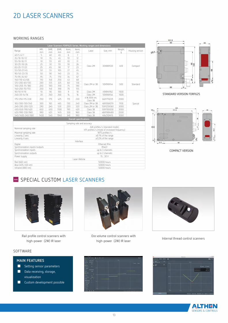
STANDARD VERSION FDRF625
COMPACT VERSION
Laser Scanners FDRF625 Series. Working ranges and dimensions
RangeMR, mm
SMR, mm
EMR, mm
Xsmr, mm
Xemr, mm
Laser Size, mmWeight,
gHousing version
40/5-6/7 5 40 45 6 7
Class 2M 30X88X120 400 Compact
35/10-10/12 10 35 45 10 1255/10-10/11 10 55 65 10 1130/25-18/26 25 30 55 18 2665/25-17/23 25 65 90 17 2355/50-27/45 50 55 105 27 4590/50-23/35 50 90 140 23 3575/95-34/67 95 75 170 34 67140/110-43/68 110 140 250 43 68
Class 2M or 3B 50X98X144 500 Standard125/200-60/130 200 125 325 60 130100/250-75/180 250 100 350 75 180140/250-70/155 250 140 390 70 15590/10-9/10 10 90 100 9 10 Class 2M 49X84X162 1000
Special
240/20-14/16 20 240 260 14 16 Class 2M 50X98X144 1000
175/250-115/230 250 175 425 115 2304 W, 808 nm,
Class 3B66X171X235 2000
165/300-130/240 300 165 465 130 240 Class 2M or 3B 48X106X219 1100240/290-200/320 290 240 530 200 320 Class 2M or 3B 50X125X360 3000450/650-190/420 650 450 1100 190 420 Class 3B 50X110X300 3000425/990-330/960 990 425 1415 330 960 Class 3B 48X198X480 2500540/1400-340/980 1400 540 1940 340 980 Class 3B 48x210X415 3000
Overall specifications
Sampling rate and accuracy
Nominal sampling rate248 profiles/s (standard mode),
491 profiles/s (mode of increased frequency)Maximal sampling rate 1875 profiles/sLinearity, Z axis ±0.1% of the rangeLinearity, X axis ±0.2% of the range
InterfaceDigital Ethernet IPv4Synchronization inputs/outputs RS422Synchronization inputs up to 3 channelsSynchronization outputs up to 2 channelsPower supply 15…30 V
Laser lifetimeRed (660 nm) 50000 hoursBlue (405, 450 nm) 50000 hoursInfrared (880 nm) 50000 hours
Rail profile control scanners with
high-power (2W) IR laser
Ore volume control scanners with
high-power (2W) IR laserInternal thread control scanners
■ Setting sensor parameters
■ Data receiving, storage,
visualization
■ Custom development possible
MAIN FEATURES
SPECIAL CUSTOM LASER SCANNERS
SOFTWARE
WORKING RANGES
2D LASER SCANNERS
14
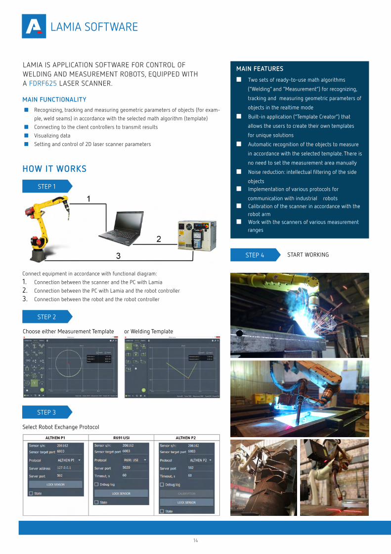
Connect equipment in accordance with functional diagram:
1. Connection between the scanner and the PC with Lamia
2. Connection between the PC with Lamia and the robot controller
3. Connection between the robot and the robot controller
Choose either Measurement Template or Welding Template
Select Robot Exchange Protocol
STEP 4 START WORKING
STEP 1
STEP 2
STEP 3
LAMIA IS APPLICATION SOFTWARE FOR CONTROL OF WELDING AND MEASUREMENT ROBOTS, EQUIPPED WITH A FDRF625 LASER SCANNER.
MAIN FUNCTIONALITY
■ Recognizing, tracking and measuring geometric parameters of objects (for exam-
ple, weld seams) in accordance with the selected math algorithm (template)
■ Connecting to the client controllers to transmit results
■ Visualizing data
■ Setting and control of 2D laser scanner parameters
HOW IT WORKS
MAIN FEATURES
■ Two sets of ready-to-use math algorithms
(“Welding” and “Measurement”) for recognizing,
tracking and measuring geometric parameters of
objects in the realtime mode
■ Built-in application (“Template Creator”) that
allows the users to create their own templates
for unique solutions
■ Automatic recognition of the objects to measure
in accordance with the selected template. There is
no need to set the measurement area manually
■ Noise reduction: intellectual filtering of the side
objects■ Implementation of various protocols for
communication with industrial robots ■ Calibration of the scanner in accordance with the
robot arm■ Work with the scanners of various measurement
ranges
LAMIA SOFTWARE
15
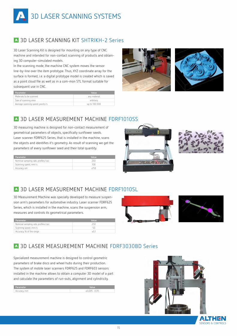
3D Laser Scanning Kit is designed for mounting on any type of CNC
machine and intended for non-contact scanning of products and obtain-
ing 3D computer-simulated models.
In the scanning mode, the machine CNC system moves the sensor
line-by-line over the item prototype. Thus, XYZ coordinate array for the
surface is formed, i.e. a digital prototype model is created which is saved
as a point cloud file as well as in a com-mon STL format suitable for
subsequent use in CNC.
Parameter Value
Materials to be scanned any material
Size of scanning area arbitrary
Average scanning speed, points/s up to 100 000
3D measuring machine is designed for non-contact measurement of
geometrical parameters of objects, specifically sunflower seeds.
Laser scanner FDRF625 Series, that is installed in the machine, scans
the objects and identifies it’s geometry. As result of scanning we get the
parameters of every sunflower seed and their total quantity.
Parameter Value
Nominal sampling rate, profiles/sec 250
Scanning speed, mm/s 100
Accuracy, um ±150
3D Measurement Machine was specially developed to measure suspen-
sion arm’s parameters for automotive industry. Laser scanner FDRF625
Series, which is installed in the machine, scans the suspension arm,
measures and controls its geometrical parameters.
Parameter Value
Nominal sampling rate, profiles/sec 250
Scanning speed, mm/s 50
Accuracy, % of the range ±0,1
3D LASER SCANNING KIT SHTRIKH-2 Series
3D LASER MEASUREMENT MACHINE FDRF1010SS
3D LASER MEASUREMENT MACHINE FDRF1010SL
3D LASER SCANNING SYSTEMS
Specialized measurement machine is designed to control geometric
parameters of brake discs and wheel hubs during their production.
The system of mobile laser scanners FDRF625 and FDRF603 sensors
installed in the machine allows to obtain a computer 3D model of a part
and calculate the parameters of run-outs, alignment and cylindricity.
Parameter Value
Accuracy, mm ±0,005…0,05
3D LASER MEASUREMENT MACHINE FDRF3030BD Series
16
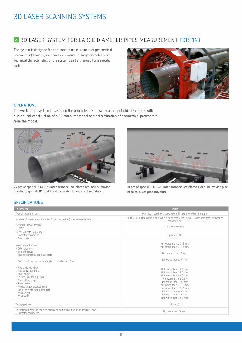
OPERATIONSThe work of the system is based on the principle of 3D laser scanning of object/ objects with subsequent construction of a 3D computer model and determination of geometrical parameters from the model.
SPECIFICATIONS
24 pcs of special RFMR625 laser scanners are placed around the moving pipe let to get full 3D model and calculate diameter and roundness.
10 pcs of special RFMR625 laser scanners are placed along the moving pipe
let to calculate pipe curvature.
The system is designed for non-contact measurement of geometrical
parameters (diameter, roundness, curvature) of large diameter pipes.
Technical characteristics of the system can be changed for a specific
task.
Parameter Value
Type of measurement Diameter, roundness, curvature of the pipe, length of the pipe.
Number of measurement points of the pipe profile (in transverse section)Up to 24,000 (the entire pipe profile is to be measured using 2D laser scanners), number of
scanners: 24.
Method of measurement • Profile
Laser triangulation
Measurements frequency • Diameter, roundness • Pipe profile
Up to 250 Hz
Measurement accuracy • Outer diameter • Inside diameter • Total straightness (pipe warping)
• Deviation from pipe ends straightness on basis of 1 m
• Pipe ends roundness • Pipe body roundness • Bevel angle • Thickness of the pipe wall • Pipe cutting edge • Bevel dulling • Welded edges displacement • Deviation from theoretical girth • Weld height • Weld width
Not worse than ± 0,15 mm Not worse than ± 0,15 mm
Not worse than ± 1 mm
Not worse than ± 0,1 mm
Not worse than ± 0,3 mm Not worse than ± 0,3 mm Not worse than ± 0,3 mm
Not worse than ± 0,5 º Not worse than ± 0,1 mm Not worse than ± 0,15 mm Not worse than ± 0,15 mm Not worse than ± 0,1 mm Not worse than ± 0,1 mm Not worse than ± 0,3 mm
Test speed, m/s Up to 1,5
Uncontrolled zones in the beginning and end of the pipe at a speed of 1 m/s • Diameter, roundness
Not more than 10 mm
3D LASER SYSTEM FOR LARGE DIAMETER PIPES MEASUREMENT FDRF143
3D LASER SCANNING SYSTEMS
17
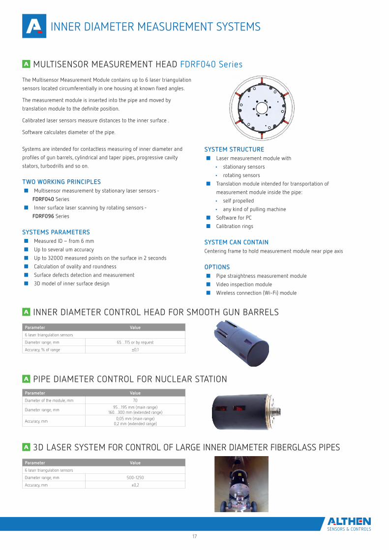
Systems are intended for contactless measuring of inner diameter and
profiles of gun barrels, cylindrical and taper pipes, progressive cavity
stators, turbodrills and so on.
TWO WORKING PRINCIPLES■ Multisensor measurement by stationary laser sensors -
FDRF040 Series
■ Inner surface laser scanning by rotating sensors -
FDRF096 Series
SYSTEMS PARAMETERS■ Measured ID – from 6 mm
■ Up to several um accuracy
■ Up to 32000 measured points on the surface in 2 seconds
■ Calculation of ovality and roundness
■ Surface defects detection and measurement
■ 3D model of inner surface design
SYSTEM STRUCTURE■ Laser measurement module with
• stationary sensors
• rotating sensors
■ Translation module intended for transportation of
measurement module inside the pipe:
• self propelled
• any kind of pulling machine
■ Software for PC
■ Calibration rings
SYSTEM CAN CONTAINCentering frame to hold measurement module near pipe axis
OPTIONS■ Pipe straightness measurement module
■ Video inspection module
■ Wireless connection (Wi-Fi) module
The Multisensor Measurement Module contains up to 6 laser triangulation
sensors located circumferentially in one housing at known fixed angles.
The measurement module is inserted into the pipe and moved by
translation module to the definite position.
Calibrated laser sensors measure distances to the inner surface .
Software calculates diameter of the pipe.
Parameter Value
Diameter of the module, mm 70
Diameter range, mm95…195 mm (main range)
160…300 mm (extended range)
Accuracy, mm0,05 mm (main range)
0,2 mm (extended range)
Parameter Value
6 laser triangulation sensors
Diameter range, mm 500-1250
Accuracy, mm ±0,2
Parameter Value
6 laser triangulation sensors
Diameter range, mm 65…115 or by request
Accuracy, % of range ±0,1
MULTISENSOR MEASUREMENT HEAD FDRF040 Series
INNER DIAMETER CONTROL HEAD FOR SMOOTH GUN BARRELS
PIPE DIAMETER CONTROL FOR NUCLEAR STATION
3D LASER SYSTEM FOR CONTROL OF LARGE INNER DIAMETER FIBERGLASS PIPES
INNER DIAMETER MEASUREMENT SYSTEMS
15
Systems are intended for contactless measuring of inner diameter and
profiles of gun barrels, cylindrical and taper pipes, progressive cavity
stators, turbodrills and so on.
TWO WORKING PRINCIPLES■ Multisensor measurement by stationary laser sensors -
FDRF040 Series
■ Inner surface laser scanning by rotating sensors -
FDRF096 Series
SYSTEMS PARAMETERS■ Measured ID – from 6 mm
■ Up to several um accuracy
■ Up to 32000 measured points on the surface in 2 seconds
■ Calculation of ovality and roundness
■ Surface defects detection and measurement
■ 3D model of inner surface design
SYSTEM STRUCTURE■ Laser measurement module with
• stationary sensors
• rotating sensors
■ Translation module intended for transportation of
measurement module inside the pipe:
• self propelled
• any kind of pulling machine
■ Software for PC
■ Calibration rings
SYSTEM CAN CONTAINCentering frame to hold measurement module near pipe axis
OPTIONS■ Pipe straightness measurement module
■ Video inspection module
■ Wireless connection (Wi-Fi) module
The Multisensor Measurement Module contains up to 6 laser triangulation
sensors located circumferentially in one housing at known fixed angles.
The measurement module is inserted into the pipe and moved by
translation module to the definite position.
Calibrated laser sensors measure distances to the inner surface .
Software calculates diameter of the pipe.
Parameter Value
Diameter of the module, mm 70
Diameter range, mm95…195 mm (main range)
160…300 mm (extended range)
Accuracy, mm0,05 mm (main range)
0,2 mm (extended range)
Parameter Value
6 laser triangulation sensors
Diameter range, mm 500-1250
Accuracy, mm ±0,2
Parameter Value
6 laser triangulation sensors
Diameter range, mm 65…115 or by request
Accuracy, % of range ±0,1
MULTISENSOR MEASUREMENT HEAD FDRF040 Series
INNER DIAMETER CONTROL HEAD FOR SMOOTH GUN BARRELS
PIPE DIAMETER CONTROL FOR NUCLEAR STATION
3D LASER SYSTEM FOR CONTROL OF LARGE INNER DIAMETER FIBERGLASS PIPES
INNER DIAMETER MEASUREMENTS SYSTEMS
18
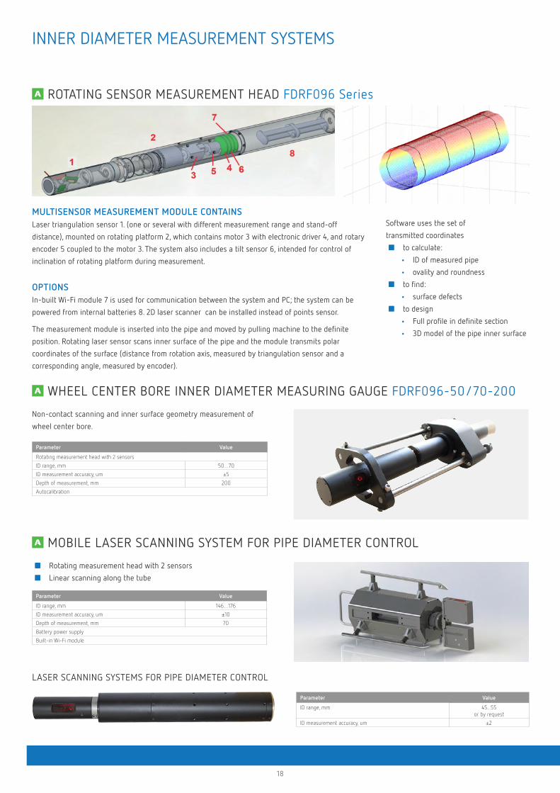
MULTISENSOR MEASUREMENT MODULE CONTAINS Laser triangulation sensor 1. (one or several with different measurement range and stand-off
distance), mounted on rotating platform 2, which contains motor 3 with electronic driver 4, and rotary
encoder 5 coupled to the motor 3. The system also includes a tilt sensor 6, intended for control of
inclination of rotating platform during measurement.
OPTIONSIn-built Wi-Fi module 7 is used for communication between the system and PC; the system can be
powered from internal batteries 8. 2D laser scanner can be installed instead of points sensor.
The measurement module is inserted into the pipe and moved by pulling machine to the definite
position. Rotating laser sensor scans inner surface of the pipe and the module transmits polar
coordinates of the surface (distance from rotation axis, measured by triangulation sensor and a
corresponding angle, measured by encoder).
Software uses the set of
transmitted coordinates
■ to calculate:
• ID of measured pipe
• ovality and roundness
■ to find:
• surface defects
■ to design
• Full profile in definite section
• 3D model of the pipe inner surface
Non-contact scanning and inner surface geometry measurement of
wheel center bore.
Parameter Value
Rotating measurement head with 2 sensors
ID range, mm 50…70
ID measurement accuracy, um ±5
Depth of measurement, mm 200
Autocalibration
LASER SCANNING SYSTEMS FOR PIPE DIAMETER CONTROL
Parameter Value
ID range, mm 45...55or by request
ID measurement accuracy, um ±2
WHEEL CENTER BORE INNER DIAMETER MEASURING GAUGE FDRF096-50/70-200
MOBILE LASER SCANNING SYSTEM FOR PIPE DIAMETER CONTROL
■ Rotating measurement head with 2 sensors
■ Linear scanning along the tube
Parameter Value
ID range, mm 146…176
ID measurement accuracy, um ±10
Depth of measurement, mm 70
Battery power supply
Built-in Wi-Fi module
ROTATING SENSOR MEASUREMENT HEAD FDRF096 Series
INNER DIAMETER MEASUREMENT SYSTEMS
16
INNER DIAMETER MEASUREMENT SYSTEMS
MULTISENSOR MEASUREMENT MODULE CONTAINS Laser triangulation sensor 1 (one or several with different measurement range and stand-off
distance), mounted on rotating platform 2, which contains motor 3 with electronic driver 4, and rotary
encoder 5 coupled to the motor 3. The system also includes a tilt sensor 6, intended for control of
inclination of rotating platform during measurement.
OPTIONSIn-built Wi-Fi module 7 is used for communication between the system and PC; the system can be
powered from internal batteries 8. 2D laser scanner can be installed instead of points sensor.
The measurement module is inserted into the pipe and moved by pulling machine to the definite
position. Rotating laser sensor scans inner surface of the pipe and the module transmits polar
coordinates of the surface (distance from rotation axis, measured by triangulation sensor and a
corresponding angle, measured by encoder).
Software uses the set of
transmitted coordinates
■ to calculate:
• ID of measured pipe
• ovality and roundness
■ to find:
• surface defects
■ to design
• Full profile in definite section
• 3D model of the pipe inner surface
Non-contact scanning and inner surface geometry measurement of
wheel center bore.
Parameter Value
Rotating measurement head with 2 sensors
ID range, mm 50…70
ID measurement accuracy, um ±5
Depth of measurement, mm 200
Autocalibration
LASER SCANNING SYSTEMS FOR PIPE DIAMETER CONTROL
Parameter Value
ID range, mm 45...55or by request
ID measurement accuracy, um ±2
WHEEL CENTER BORE INNER DIAMETER MEASURING GAUGE FDRF096-50/70-200
MOBILE LASER SCANNING SYSTEM FOR PIPE DIAMETER CONTROL
■ Rotating measurement head with 2 sensors
■ Linear scanning along the tube
Parameter Value
ID range, mm 146…176
ID measurement accuracy, um ±10
Depth of measurement, mm 70
Battery power supply
Built-in Wi-Fi module
ROTATING SENSOR MEASUREMENT HEAD FDRF096 Series
INNER DIAMETER MEASUREMENTS SYSTEMS
19
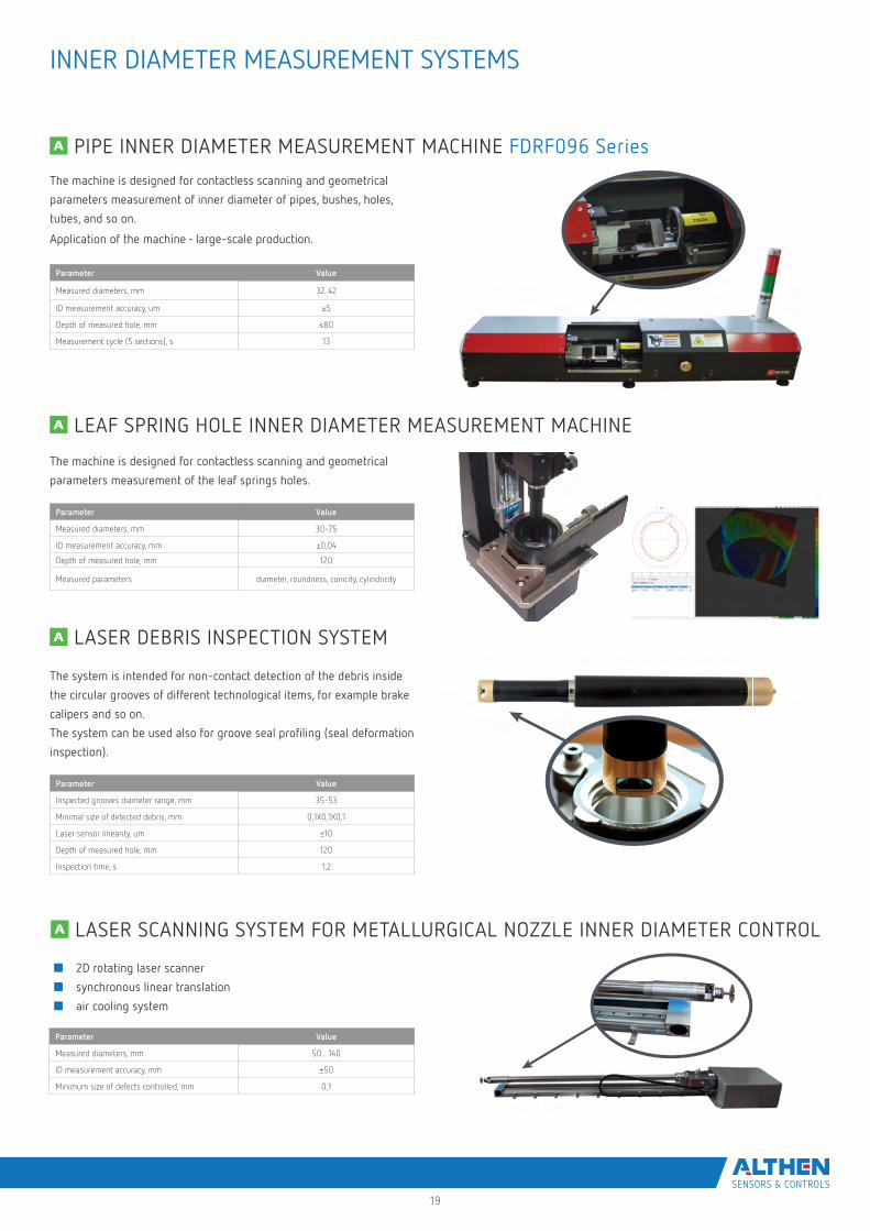
PIPE INNER DIAMETER MEASUREMENT MACHINE FDRF096 Series
The machine is designed for contactless scanning and geometrical
parameters measurement of inner diameter of pipes, bushes, holes,
tubes, and so on.
Application of the machine - large-scale production.
Parameter Value
Measured diameters, mm 32..42
ID measurement accuracy, um ±5
Depth of measured hole, mm ≤80
Measurement cycle (5 sections), s 13
The machine is designed for contactless scanning and geometrical
parameters measurement of the leaf springs holes.
The system is intended for non-contact detection of the debris inside
the circular grooves of different technological items, for example brake
calipers and so on.
The system can be used also for groove seal profiling (seal deformation
inspection).
Parameter Value
Inspected grooves diameter range, mm 35-53
Minimal size of detected debris, mm 0,1X0,1X0,1
Laser sensor linearity, um ±10
Depth of measured hole, mm 120
Inspection time, s 1,2
LEAF SPRING HOLE INNER DIAMETER MEASUREMENT MACHINE
LASER DEBRIS INSPECTION SYSTEM
Parameter Value
Measured diameters, mm 30-75
ID measurement accuracy, mm ±0,04
Depth of measured hole, mm 120
Measured parameters diameter, roundness, conicity, cylindricity
INNER DIAMETER MEASUREMENT SYSTEMS
Parameter Value
Measured diameters, mm 50…140
ID measurement accuracy, mm ±50
Minimum size of defects controlled, mm 0,1
■ 2D rotating laser scanner
■ synchronous linear translation
■ air cooling system
LASER SCANNING SYSTEM FOR METALLURGICAL NOZZLE INNER DIAMETER CONTROL
20
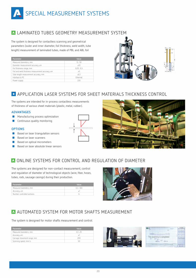
The system is designed for contactless scanning and geometrical
parameters (outer and inner diameter, foil thickness, weld width, tube
length) measurement of laminated tubes, made of PBL and ABL foil
Parameter Value
Measured diameters, mm 13...50
Diameter measurement accuracy, um ±10
Foil thickness range, mm 0,05...0,5
Foil and weld thickness measurement accuracy, um ±5
Tube length measurement accuracy, mm ±0,1
Interface to PC Ethernet
Power supply 220
LAMINATED TUBES GEOMETRY MEASUREMENT SYSTEM
APPLICATION LASER SYSTEMS FOR SHEET MATERIALS THICKNESS CONTROL The systems are intended for in-process contactless measurements
of thickness of various sheet materials (plastic, metal, rubber).
AUTOMATED SYSTEM FOR MOTOR SHAFTS MEASUREMENT
The system is designed for motor shafts measurement and control.
Parameter Value
Measured diameters, mm 0,1...25
Accuracy, um ±1
Carriage movement range, mm 200
Scanning speed, mm/s 50
ONLINE SYSTEMS FOR CONTROL AND REGULATION OF DIAMETER
ADVANTAGES■ Manufacturing process optimization
■ Continuous quality monitoring
OPTIONS■ Based on laser triangulation sensors
■ Based on laser scanners
■ Based on optical micrometers
■ Based on laser absolute linear sensors
Parameter Value
Measured diameters, mm 0,3...100
Accuracy, um ±1
Number controlled sections 6
The systems are designed for non-contact measurement, control and regulation of diameter of technological objects (wire, fiber, hoses,
tubes, rods, sausage casings) during their production.
SPECIAL MEASUREMENT SYSTEMS
21
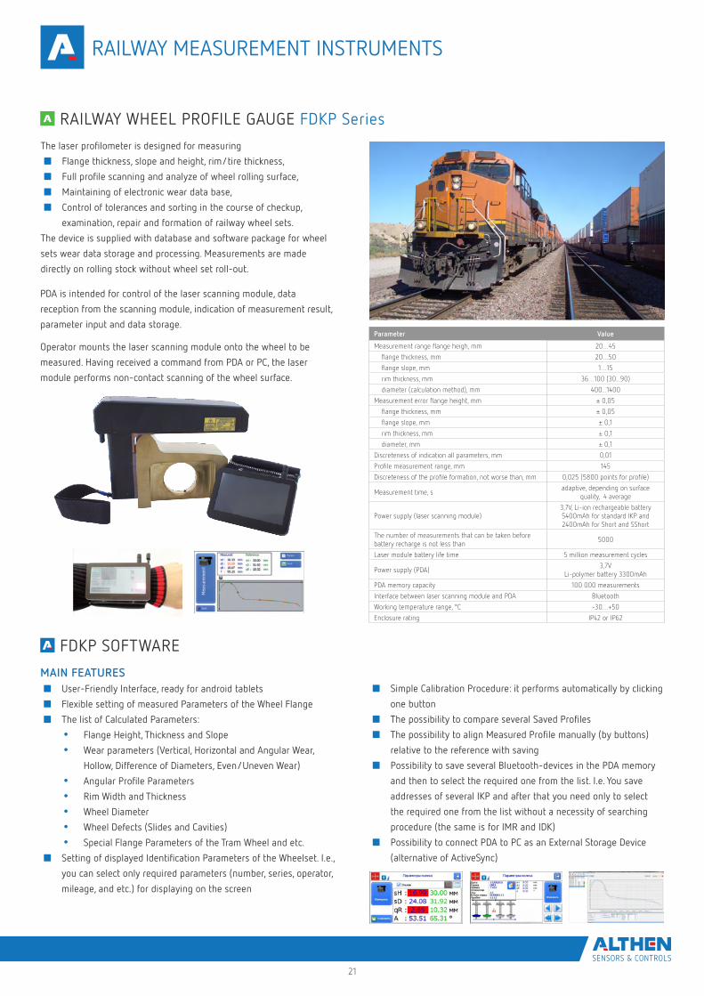
The laser profilometer is designed for measuring
■ Flange thickness, slope and height, rim/tire thickness,
■ Full profile scanning and analyze of wheel rolling surface,
■ Maintaining of electronic wear data base,
■ Control of tolerances and sorting in the course of checkup,
examination, repair and formation of railway wheel sets.
The device is supplied with database and software package for wheel
sets wear data storage and processing. Measurements are made
directly on rolling stock without wheel set roll-out.
Parameter Value
Measurement range flange heigh, mm 20…45
flange thickness, mm 20…50
flange slope, mm 1…15
rim thickness, mm 36…100 (30...90)
diameter (calculation method), mm 400...1400
Measurement error flange height, mm ± 0,05
flange thickness, mm ± 0,05
flange slope, mm ± 0,1
rim thickness, mm ± 0,1
diameter, mm ± 0,1
Discreteness of indication all parameters, mm 0,01
Profile measurement range, mm 145
Discreteness of the profile formation, not worse than, mm 0,025 (5800 points for profile)
Measurement time, sadaptive, depending on surface
quality, 4 average
Power supply (laser scanning module) 3,7V, Li-ion rechargeable battery5400mAh for standard IKP and2400mAh for Short and SShort
The number of measurements that can be taken before battery recharge is not less than
5000
Laser module battery life time 5 million measurement cycles
Power supply (PDA)3,7V
Li-polymer battery 3300mAh
PDA memory capacity 100 000 measurements
Interface between laser scanning module and PDA Bluetooth
Working temperature range, °C -30…+50
Enclosure rating IP42 or IP62
PDA is intended for control of the laser scanning module, data
reception from the scanning module, indication of measurement result,
parameter input and data storage.
Operator mounts the laser scanning module onto the wheel to be
measured. Having received a command from PDA or PC, the laser
module performs non-contact scanning of the wheel surface.
RAILWAY WHEEL PROFILE GAUGE FDKP Series
MAIN FEATURES ■ User-Friendly Interface, ready for android tablets
■ Flexible setting of measured Parameters of the Wheel Flange
■ The list of Calculated Parameters:
• Flange Height, Thickness and Slope
• Wear parameters (Vertical, Horizontal and Angular Wear,
Hollow, Difference of Diameters, Even/Uneven Wear)
• Angular Profile Parameters
• Rim Width and Thickness
• Wheel Diameter
• Wheel Defects (Slides and Cavities)
• Special Flange Parameters of the Tram Wheel and etc.
■ Setting of displayed Identification Parameters of the Wheelset. I.e.,
you can select only required parameters (number, series, operator,
mileage, and etc.) for displaying on the screen
■ Simple Calibration Procedure: it performs automatically by clicking
one button
■ The possibility to compare several Saved Profiles
■ The possibility to align Measured Profile manually (by buttons)
relative to the reference with saving
■ Possibility to save several Bluetooth-devices in the PDA memory
and then to select the required one from the list. I.e. You save
addresses of several IKP and after that you need only to select
the required one from the list without a necessity of searching
procedure (the same is for IMR and IDK)
■ Possibility to connect PDA to PC as an External Storage Device
(alternative of ActiveSync)
FDKP SOFTWARE
RAILWAY MEASUREMENT INSTRUMENTS
22
Electronic gauge is designed for measuring wheel rolling circle diameter.
Measurements are made directly on rolling stock without wheel set
roll-out. The measurement of the diameter is performed according to the
“three points” technique, without the complete wheel coverage.
The gauge contains numeric display to show the value of the wheel
diameter. IDK-BT gauge contains Bluetooth interface for transfer results
into wheel-set wear database management system.
Parameter Value
Measurement range, mm 400…1400 or on request
Measurement error, mm ±0.2
Indication discreteness 0.1mm, 0.01mm * or 0.01 inch **
Position of measurement, S, mm On request
Distance between axes of ball bearings (base), mm and diameters measurement range, mm
122±0.5 (400…750 mm) or200±0.5 (400…950 mm) or250±0.5 (600…1400 mm) or
300±0.5 (720…1400 mm)
Display build-in, LED
Operating temperature, °C -15…+55
Power supply rechargeable battery 2 x AAA 1.2V
Weight, kg 0.5
The number of measurements that can be taken before battery recharge is not less than
1000
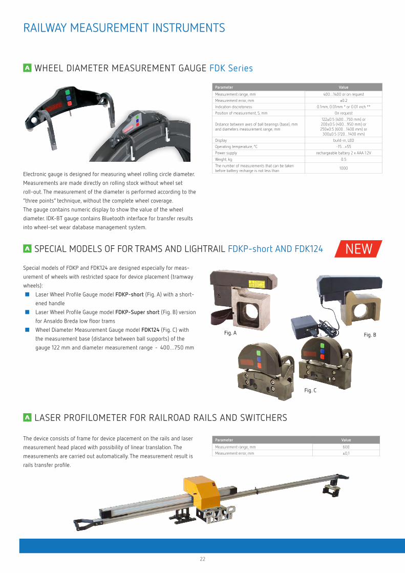
Special models of FDKP and FDK124 are designed especially for meas-
urement of wheels with restricted space for device placement (tramway
wheels):
■ Laser Wheel Profile Gauge model FDKP-short (Fig. A) with a short-
ened handle
■ Laser Wheel Profile Gauge model FDKP-Super short (Fig. B) version
for Ansaldo Breda low floor trams
■ Wheel Diameter Measurement Gauge model FDK124 (Fig. C) with
the measurement base (distance between ball supports) of the
gauge 122 mm and diameter measurement range - 400…750 mm
Fig. A Fig. B
Fig. C
The device consists of frame for device placement on the rails and laser
measurement head placed with possibility of linear translation. The
measurements are carried out automatically. The measurement result is
rails transfer profile.
Parameter Value
Measurement range, mm 600
Measurement error, mm ±0,1
WHEEL DIAMETER MEASUREMENT GAUGE FDK Series
SPECIAL MODELS OF FOR TRAMS AND LIGHTRAIL FDKP-short AND FDK124
LASER PROFILOMETER FOR RAILROAD RAILS AND SWITCHERS
RAILWAY MEASUREMENT INSTRUMENTS
NEW
23
Electronic gauge is designed for measuring back-to-back distance of railway, metro and tram wheels in the course of checkup, examination, repair and
formation of wheel sets. The method of measurement is based on direct measurement the distance by contactless laser sensor.
Measurements are made directly on rolling stock without wheel set roll-out.
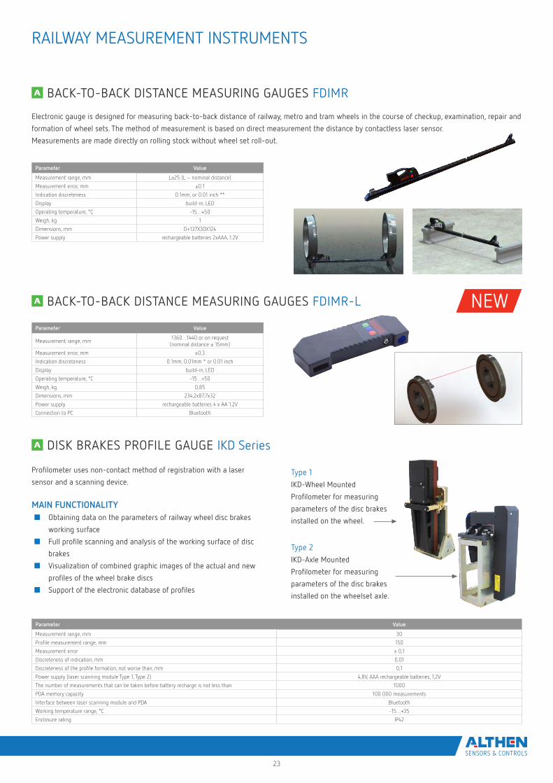
Type 1IKD-Wheel Mounted
Profilometer for measuring
parameters of the disc brakes
installed on the wheel.
Type 2IKD-Axle Mounted
Profilometer for measuring
parameters of the disc brakes
installed on the wheelset axle.
Profilometer uses non-contact method of registration with a laser
sensor and a scanning device.
MAIN FUNCTIONALITY■ Obtaining data on the parameters of railway wheel disc brakes
working surface
■ Full profile scanning and analysis of the working surface of disc
brakes
■ Visualization of combined graphic images of the actual and new
profiles of the wheel brake discs
■ Support of the electronic database of profiles
Parameter Value
Measurement range, mm L±25 (L – nominal distance)
Measurement error, mm ±0.1
Indication discreteness 0.1mm, or 0.01 inch **
Display build-in, LED
Operating temperature, °C -15…+50
Weigh, kg 1
Dimensions, mm D+137X30X124
Power supply rechargeable batteries 2xAAA, 1.2V
Parameter Value
Measurement range, mm1360…1440 or on request
(nominal distance ± 15mm)
Measurement error, mm ±0,3
Indication discreteness 0.1mm, 0.01mm * or 0.01 inch
Display build-in, LED
Operating temperature, °C -15…+50
Weigh, kg 0,85
Dimensions, mm 234,2x87,7x32
Power supply rechargeable batteries 4 x AA 1.2V
Connection to PC Bluetooth
Parameter Value
Measurement range, mm 30
Profile measurement range, mm 150
Measurement error ± 0,1
Discreteness of indication, mm 0,01
Discreteness of the profile formation, not worse than, mm 0,1
Power supply (laser scanning module Type 1, Type 2) 4,8V, AAA rechargeable batteries, 1,2V
The number of measurements that can be taken before battery recharge is not less than 1000
PDA memory capacity 100 000 measurements
Interface between laser scanning module and PDA Bluetooth
Working temperature range, °C -15…+35
Enclosure rating IP42
BACK-TO-BACK DISTANCE MEASURING GAUGES FDIMR
BACK-TO-BACK DISTANCE MEASURING GAUGES FDIMR-L
DISK BRAKES PROFILE GAUGE IKD Series
RAILWAY MEASUREMENT INSTRUMENTS
NEW
24
Portable laser rail profilometer (PRP) is designed for non-contact
registration of cross-section of the railhead acting face.
The profilometer uses non-contact method of registration with a laser
sensor and a scanning device.
MAIN FUNCTIONALITY■ obtaining the information on the cross-section profile of the
working railhead surface
■ full profile scanning and analyze of the railhead acting face
■ visualization of the combined graphical images of actual
and new cross-section
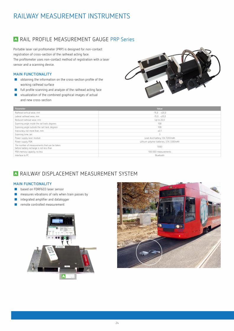
MAIN FUNCTIONALITY■ based on FDRF603 laser sensor
■ measures vibrations of rails when train passes by
■ integrated amplifier and datalogger
■ remote controlled measurement
Parameter Value
Railhead vertical wear, mm -15,0 …+20,0
Lateral railhead wear, mm -15,0…+20,0
Reduced railhead wear, mm Up to 20,0
Scanning angle inside the rail track, degrees 108
Scanning angle outside the rail track, degrees 108
Inaccuracy, not more than, mm ±0.1
Scanning time, sec 3
Power supply, laser module Lead-Acid battery, 12V, 7200mAh
Power supply, PDA Lithium-polymer batteries, 3,7V, 3300mAh
The number of measurements that can be taken before battery recharge is not less than
1000
PDA memory capacity, no less 100 000 measurements
Interface to PC Bluetooth
RAIL PROFILE MEASUREMENT GAUGE PRP Series
RAILWAY DISPLACEMENT MEASUREMENT SYSTEM
RAILWAY MEASUREMENT INSTRUMENTS
25
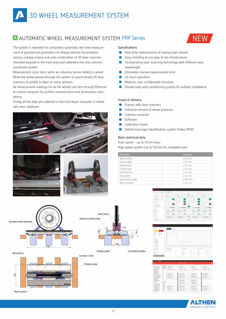
The system is intended for contactless automatic real-time measure-
ment of geometrical parameters of railway vehicles (locomotives,
railcars, subway, trams) and uses combination of 2D laser scanners
mounted wayside in the track area and calibrated into one common
coordinate system.
Measurement cycle starts when an inductive sensor detects a wheel.
While the wheel passes through the system of synchronized 2D laser
scanners its profile is taken at many sections.
All measurement readings for all the wheels are sent through Ethernet
to control computer for profiles reconstruction and dimensions calcu-
lations.
Finally, all the data are collected in the host depot computer in wheel
sets wear database.
Basic technical data
Train speed – up to 15 km/hour.
High speed system (up to 150 km/h). Available soon
Specifications
■ Real-time measurement of moving train wheels
■ Easy installing at any type of rail infrastructure
■ Incorporating laser scanning technology with different laser
wavelength
■ Eliminates manual measurement error
■ 24 hours operation
■ Modular, user-configurable structure
■ Double body with conditioning system for outdoor installation
Scope of delivery
■ Frames with laser scanners
■ Inductive sensors of wheel presence
■ Industry computer
■ Software
■ Calibration frame
■ Vehicle (carriage) identification system (Video, RFID)
Parameter Accuracy
Wheel profiles ± 0,1 mm
Flange height ± 0,1 mm
Flange width ± 0,1 mm
Flange angle ± 0,1 mm
Rim thickness ± 0,1 mm
Tread width ± 0,1 mm
Back to back gauge ± 0,05 mm
Wheel diameter ± 0,2 mm
AUTOMATIC WHEEL MEASUREMENT SYSTEM PRP Series
3D WHEEL MEASUREMENT SYSTEM
NEW
26
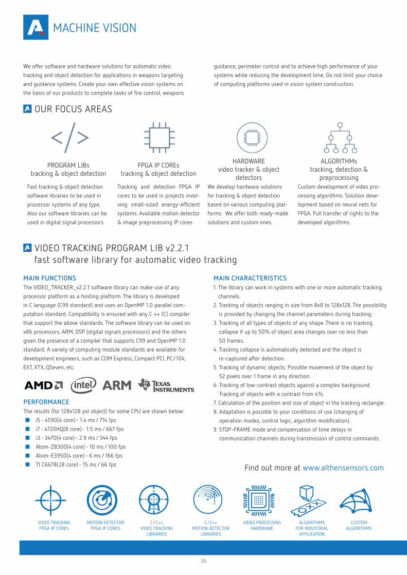
We offer software and hardware solutions for automatic video
tracking and object detection for applications in weapons targeting
and guidance systems. Create your own effective vision systems on
the basis of our products to complete tasks of fire control, weapons
PROGRAM LIBstracking & object detection
FPGA IP COREstracking & object detection
HARDWAREvideo tracker & object
detectors
ALGORITHMstracking, detection &
preprocessingFast tracking & object detection
software libraries to be used in
processor systems of any type.
Also our software libraries can be
used in digital signal processors.
Tracking and detection FPGA IP
cores to be used in projects invol-
ving small-sized energy-efficient
systems. Available motion detector
& image preprocessing IP cores.
We develop hardware solutions
for tracking & object detection
based on various computing plat-
forms. We offer both ready-made
solutions and custom ones.
Custom development of video pro-
cessing algorithms. Solution deve-
lopment based on neural nets for
FPGA. Full transfer of rights to the
developed algorithms.
MAIN FUNCTIONSThe VIDEO_TRACKER_v2.2.1 software library can make use of any
processor platform as a hosting platform. The library is developed
in C language (C99 standard) and uses an OpenMP 1.0 parallel com-
putation standard. Compatibility is ensured with any C ++ (C) compiler
that support the above standards. The software library can be used on
x86 processors, ARM, DSP (digital signals processors) and the others
given the presence of a compiler that supports C99 and OpenMP 1.0
standard. A variety of computing module standards are available for
development engineers, such as COM Express, Compact PCI, PC/104,
EXT, XTX, QSeven, etc.
PERFORMANCEThe results (for 128x128 pxl object) for some CPU are shown below:
■ i5 - 4590(4 core) - 1.4 ms / 714 fps
■ i7 - 4720HQ(8 core) - 1.5 ms / 667 fps
■ i3 - 3470(4 core) - 2.9 ms / 344 fps
■ Atom-Z8300(4 core) - 10 ms / 100 fps
■ Atom-E3950(4 core) - 6 ms / 166 fps
■ TI C6678L(8 core) - 15 ms / 66 fps
MAIN CHARACTERISTICS1. The library can work in systems with one or more automatic tracking
channels.
2. Tracking of objects ranging in size from 8x8 to 128x128. The possibility
is provided by changing the channel parameters during tracking.
3. Tracking of all types of objects of any shape. There is no tracking
collapse if up to 50% of object area changes over no less than
50 frames.
4. Tracking collapse is automatically detected and the object is
re-captured after detection.
5. Tracking of dynamic objects. Possible movement of the object by
52 pixels over 1 frame in any direction.
6. Tracking of low-contrast objects against a complex background.
Tracking of objects with a contrast from 4%.
7. Calculation of the position and size of object in the tracking rectangle.
8. Adaptation is possible to your conditions of use (changing of
operation modes, control logic, algorithm modification).
9. STOP-FRAME mode and compensation of time delays in
communication channels during transmission of control commands.
Find out more at www.althensensors.com
VIDEO TRACKINGFPGA IP CORES
MOTION DETECTORFPGA IP CORES
C/C++ VIDEO TRACKING
LIBRARIES
C/C++ MOTION DETECTOR
LIBRARIES
VIDEO PROCESSINGHARDRAWE
CUSTOMALGORITHMS
ALGORITHMSFOR INDUSTRIAL
APPLICATION
guidance, perimeter control and to achieve high performance of your
systems while reducing the development time. Do not limit your choice
of computing platforms used in vision system construction.
OUR FOCUS AREAS
VIDEO TRACKING PROGRAM LIB v2.2.1 fast software library for automatic video tracking
MACHINE VISION
27
PROGRAM LIBstracking & object detection
FPGA IP COREstracking & object detection
HARDWAREvideo tracker & object
detectors
ALGORITHMstracking, detection &
preprocessingFast tracking & object detection
software libraries to be used in
processor systems of any type.
Also our software libraries can be
used in digital signal processors.
Tracking and detection FPGA IP
cores to be used in projects invol-
ving small-sized energy-efficient
systems. Available motion detector
& image preprocessing IP cores.
We develop hardware solutions
for tracking & object detection
based on various computing plat-
forms. We offer both ready-made
solutions and custom ones.
Custom development of video pro-
cessing algorithms. Solution deve-
lopment based on neural nets for
FPGA. Full transfer of rights to the
developed algorithms.
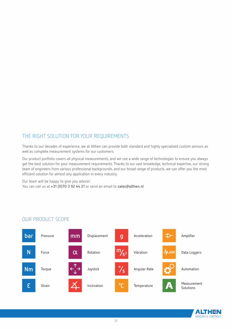
OUR PRODUCT SCOPE
Pressure Displacement Acceleration Amplifier
Force Rotation Vibration Data Loggers
Torque Joystick Angular Rate Automation
Strain Inclination Temperature Measurement Solutions
THE RIGHT SOLUTION FOR YOUR REQUIREMENTS
Thanks to our decades of experience, we at Althen can provide both standard and highly specialized custom sensors as well as complete measurement systems for our customers.
Our product portfolio covers all physical measurements, and we use a wide range of technologies to ensure you always get the best solution for your measurement requirements. Thanks to our vast knowledge, technical expertise, our strong team of engineers from various professional backgrounds, and our broad range of products, we can offer you the most efficient solution for almost any application in every industry.
Our team will be happy to give you advice! You can call us at +31 (0)70 3 92 44 21 or send an email to [email protected]

Further information can be found at www.althensensors.com
ALTHEN SENSORS & CONTROLS
Netherlands | Belgium | Luxembourg
USA | Canada Germany | Switzerland | Austria
France
Sweden | Norway | Denmark | Finland
Sweden | Norway | Denmark | FinlandALTHEN Sensors & Controls AB
Stora Torget 6C
761 30 Norrtälje
Sweden
Tel: +46 8 7 95 24 90
E-Mail: [email protected]
USA | CanadaALTHEN Sensors & Controls Inc
2340 Littler Lane
Oceanside CA 92056
USA
Phone: +1 858 6 33 35 72
Email: [email protected]
FranceALTHEN / MIDIF
26, avenue de la Méditerranée
34110 Frontignan
France
Phone: +33 4 67 78 61 66
Email: [email protected]
Netherlands | Belgium | LuxembourgALTHEN Sensors & Controls B.V.
Verrijn Stuartlaan 40
2288 EL Rijswijk
Netherlands
Phone: +31 70 3 92 44 21
Email: [email protected]
Germany | Switzerland | AustriaALTHEN GmbH Mess- und Sensortechnik
Dieselstraße 2
65779 Kelkheim
Germany
Phone: +49 6195 7 00 60
Email: [email protected]
21-1
1-00
01
Copyright © 2022 FDOKUMEN

