


Bahasa
Halaman
Hukum

Vision-Based Text Segmentation System for
Generic Display Units
Jose Carlos Castillo, Marıa T. Lopez, and Antonio Fernandez-Caballero
Universidad de Castilla-La Mancha, Departamento de Sistemas Informaticos& Instituto de Investigacion en Informatica de Albacete
Campus Universitario s/n, 02071-Albacete, [email protected]
Abstract. The increasing use of display units in avionics motivate theneed for vision-based text recognition systems to assist humans. The sys-tem for generic displays proposed in this paper includes some of the usualtext recognition steps, namely localization, extraction and enhancement,and optical character recognition. The proposal has been fully developedand tested on a multi-display simulator. The commercial OCR modulefrom Matrox Imaging Library has been used to validate the textual dis-plays segmentation proposal.
1 Introduction
There is an increasing use of displays in avionics. A very recent study [9] hasinvestigated how vibration affects the reading performance and visual fatigue inan identification task of numeric characters shown on a visual display terminal.It was found that under vibration, the two display factors - font size and num-ber of digits - significantly affect the human reaction time and accuracy of thenumeric character identification task. Moreover, the vibrations in aircraft aremainly vertical and cause reading errors when the pilots read the instruments[2]. Therefore, automated vision-based systems seem to be good assistants tothe human. Optical character recognition (OCR) is one of the most studiedapplications of automatic pattern recognition.
The text recognition problem can be divided into the following sub-problems:(i) detection, (ii) localization, (iii) tracking, (iv) extraction and enhancement, and,(v) recognition (OCR)[6]. Text detection refers to the determination of the pres-ence of text in a given frame. Text localization is the process of determining thelocalization of text in the image and generating bounding boxes around the text.Text tracking is performed to reduce the processing time for text localization andto maintain the integrity of position across adjacent frames. Although the pre-cise localization of text in an image can be indicated by bounding boxes, the textstill needs to be segmented from the background to facilitate its recognition. Thismeans that the extracted text image has to be converted to a binary image and en-hanced before it is fed into an OCR engine. Text extraction is the stage where thetext components are segmented from the background. Thereafter, the extractedtext images can be transformed into plain text using OCR technology.
J. Mira et al. (Eds.): IWINAC 2009, Part II, LNCS 5602, pp. 225–234, 2009.c© Springer-Verlag Berlin Heidelberg 2009
226 J.C. Castillo, M.T. Lopez, and A. Fernandez-Caballero
In this paper, we introduce a vision-based text segmentation system to assisthumans in reading avionics displays. In these kinds of displays, be it of typeCRT (cathode ray tube), LCD (liquid crystal display) or TFT-LCD (thin filmtransistor-liquid crystal display), the characters use to be placed at fixed posi-tions. Therefore, our solution establishes a set of bitmaps - also called cells - inthe display, in accordance with the number of rows and columns that the displayis able to generate.
2 Usual Problems in Vision-Based Text Segmentation
Text segmentation strategies can be classified into two main categories: (1) dif-ference based (or top-down) and (2) similarity based (or bottom-up) methods.The first method is based on the difference in contrast between the foregroundand background, for example, the fixed thresholding method [13], global and localthresholding method [3], Niblack’s method [20], and the improved Niblack method[22]. Indeed, thresholding algorithms have been used for over forty years for the ex-traction of objects from background [12]. The effectiveness of these approaches de-pends on the bi-modality of image histogram. This unfortunately is not always thecase for real world images and as a result, the histogram-based image binarizationtechniques are not very effective. Thus, in general, these methods are simple andfast; however, they tend to fail when the foreground and background are similar.Alternative methods have been proposed in the literature to alleviate this prob-lem, such as clustering-based methods [10,7], object attribute-based [11,14] neuralnetworks-based binarization [21]. In [5] a binarization method for document im-ages of text on watermarked background is presented using hidden Markov models(HMM). Alternatively, the similarity-based method clusters pixels with similar in-tensities. For example, Lienhart [8] used the split and merge algorithm, and Wanget al. [18] used a method in which edge detection, watershed transform, and clus-tering were combined. However, these methods are unstable because they exploitmany intuitive rules for the text shape.
A big problem to be faced with vision-based text segmentation is cameracalibration. Indeed, lens distortion is one of the main factors affecting cameracalibration. A typical camera calibration algorithm uses one-to-one correspon-dence between the 3-D and 2-D control points of a camera [4,17]. The mostused calibration models are based on Tsai’s model [17] for a set of coplanarpoints or on the direct linear transformation (DLT) method originally reportedby Abdel-Aziz and Karara [1]. Camera calibration techniques considering thelens distortion have long been studied. Utilized was the known motion of thecamera [15] or the feature correspondences of a few images [16]. More recently, anew model of camera lens distortion has been presented [19]. The lens distortionis governed by the coefficients of radial distortion and a transform from idealimage plane to real sensor array plane. The transform is determined by two an-gular parameters describing the pose of the real sensor array plane with respectto the ideal image plane and two linear parameters locating the real sensor arraywith respect to the optical axis.
Vision-Based Text Segmentation System for Generic Display Units 227
3 OCR for Generic Display Units
In this section a proposal for optical character recognition in generic displays ispresented. In many cases, this kind of displays is only used for the presentationof alphanumeric characters. Also, in the majority of cases, the characters areplaced in predefined fixed positions of the display. Therefore, our solution has torecognize the characters in a pre-defined set of cells (or bitmaps) of the display.Each bitmap, B(i, j), contains a single character, ch(i, j), where (i, j) is the co-ordinate of the cells row and column. The number of rows, Nr, and columns, Nc,of bitmaps being able to be generated on a given display defines the maximumnumber of recognizable characters, Nr × Nc.
Generic display means that the system proposed has to recognize charactersin any type of display used in avionics. For this reason, the approach adjuststhe system to the dimensions of the display by definition. As the displays areprepared to be easily read by the pilots, it is assumed that the contrast betweenthe background and the character is high enough.
Now, different steps followed to face the challenges appeared during bitmaplocalization, character extraction and enhancement, and optical character recog-nition phases are described in detail. Remember that the objective is to accu-rately recognize the ASCII values of the characters, ch(i, j), contained in bitmapsB(i, j).
3.1 Image Calibration
One of the greatest difficulties for an optimal segmentation in fixed positions ofa textual display is the calculation of the exact starting and ending positions ofeach bitmap, (xinit, yinit) and (xend, yend), respectively, in the coordinate system(x, y) of the display. This it is an important challenge, as important screendeformations appear due to the camera lens used for the display acquisitionprocess. These deformations consist of a “ballooning” of the image, trimmedin the point to which the camera focuses. For this reason, it is essential toinitially perform a calibration of the image. Let us remind, once again, that thesegmentation in this type of displays is essentially based in an efficient bitmapslocalization. It is absolutely mandatory to scan any captured image with noswelling up, row by row, or column by column, to obtain the precise position ofeach bitmap (B(i, j)). On the contrary, pixels of a given row or column mightbelong to an adjacent bitmap.
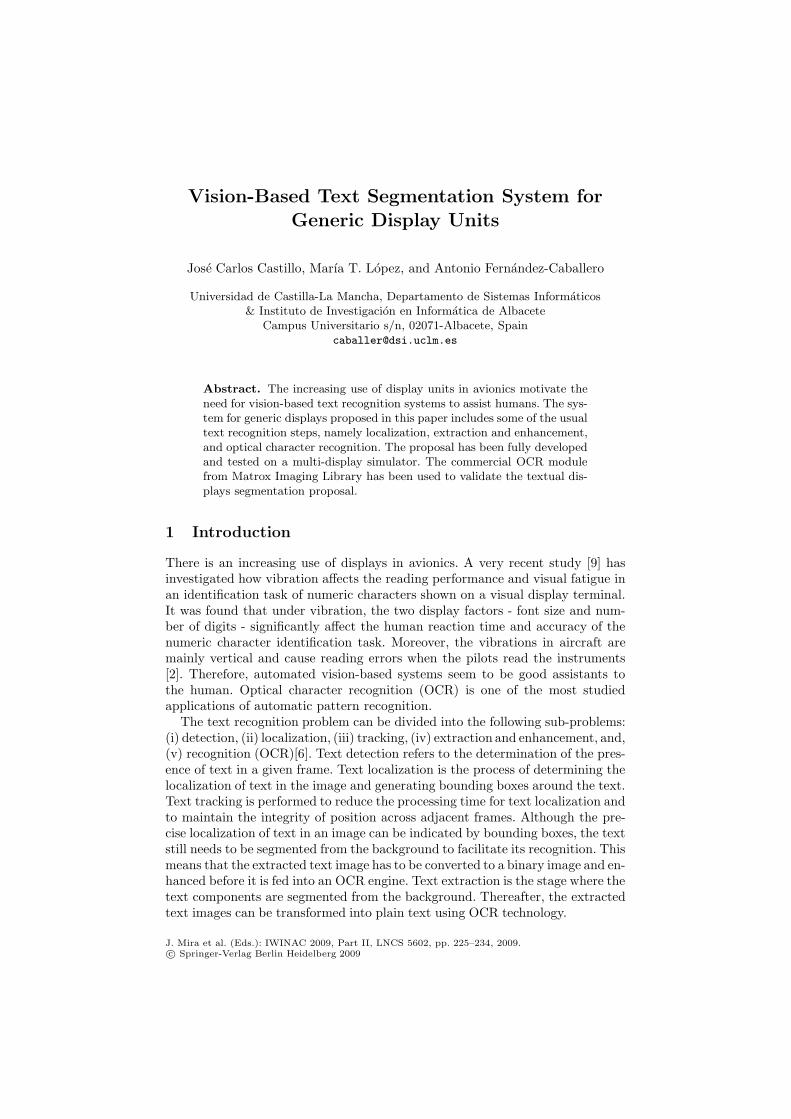
In order to solve this problem, a “dots grid”, Gdots(x, y), is used as a pattern(see Fig. 1a). Each grid dot corresponds to the central pixel of a bitmap (or cell)B(i, j) of the display. Once the grid points have been captured by the camera,the image ballooning and each dot deviation with respect to the others may bestudied (see Fig. 1b).
Thanks to this information, and by applying the piecewise linear interpolationcalibration method [4,17], any input image, I(x, y), is “de-ballooned”. Thus, thisswelling up is eliminated, providing a resulting new image IP (x, y). The centers ofthe dots are used to perform the calculations necessary to regenerate the original
228 J.C. Castillo, M.T. Lopez, and A. Fernandez-Caballero
Fig. 1. (a) Optimal dots grid. (b) Captured dots grid.
rectangular form of the input image. In addition, the average, Gdots(x, y), of acertain number nC of captured dots grids is used as input to the calibrationmethod to augment the precision of the process.
3.2 Bitmap Localization
After calibration, the algorithms for bitmap localization are started. This phase isin charge of obtaining the most accurate localization of all bitmaps present in thecalibrated image IP (x, y). In other words, the algorithm obtains, for each bitmapB(i, j) its initial and final pixels’ exact positions, (xinit, yinit) and (xend, yend),respectively. From the previous positions, also the bitmap’s height, Bh(i, j), andwidth, Bw(i, j) are calculated.
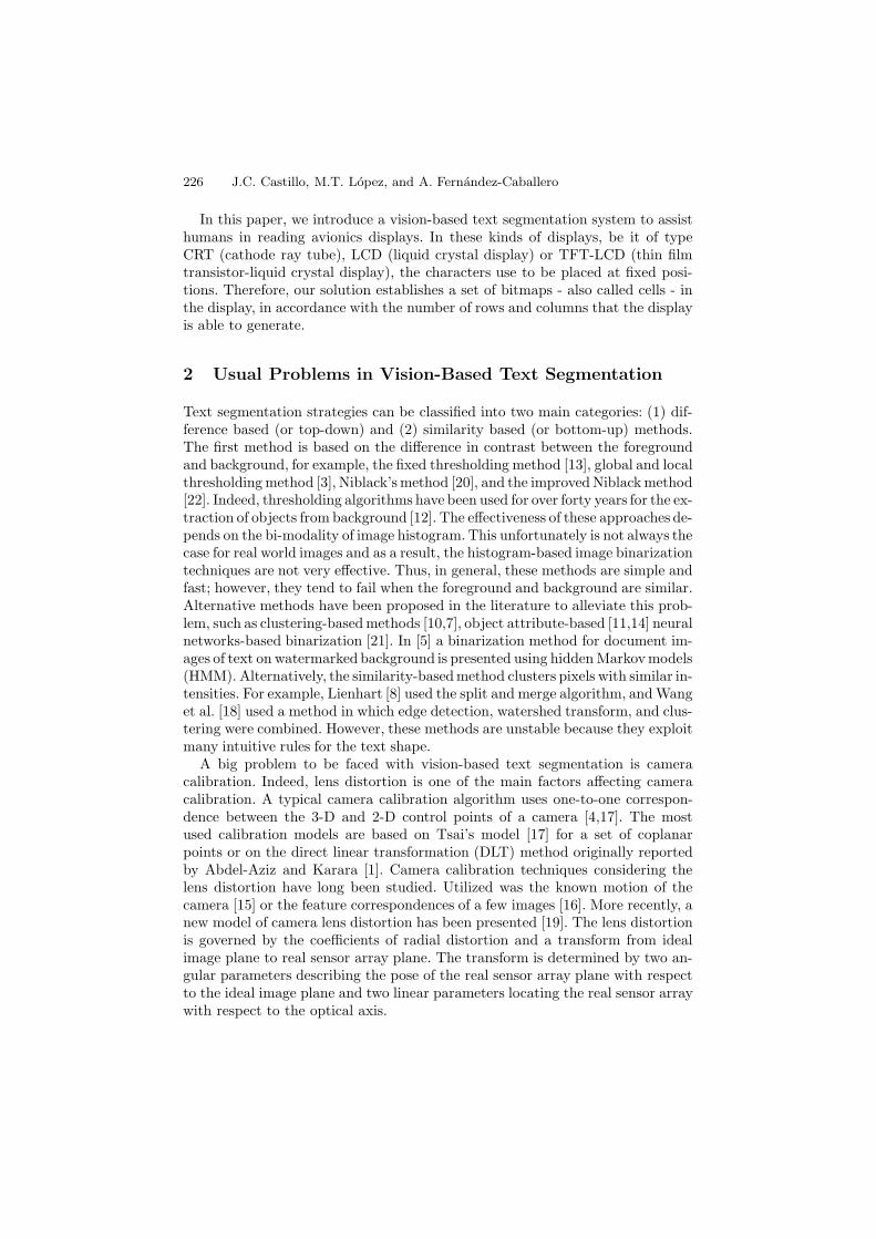
For performing the precise bitmap localization, another template (or pattern)is built up. This template consists of a “bitmaps grid” (see Fig. 2a), that is to say,a grid establishing the limits (borders) of each bitmap. The process consists incapturing this “bitmaps grid” , Gcells(x, y), which, obviously, also appears convexafter camera capture (see Fig. 2b). Again, a mean template image, Gcells(x, y),is formed by merging a determined number nC of bitmaps grids captures. Thisprocess is driven to reduce noise that appears when using a single capture.
On the resulting average image, Gcells(x, y), a series of image enhancementtechniques are applied. In first place, a binarization takes place to clearly separate
Fig. 2. a) Optimal bitmaps grid. (b) Captured bitmaps grid.
Vision-Based Text Segmentation System for Generic Display Units 229
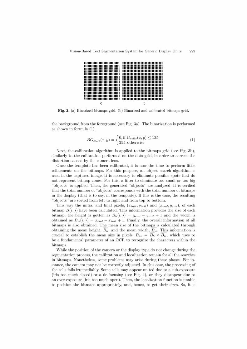
Fig. 3. (a) Binarized bitmaps grid. (b) Binarized and calibrated bitmaps grid.
the background from the foreground (see Fig. 3a). The binarization is performedas shown in formula (1).
BGcells(x, y) ={
0, if Gcells(x, y) ≤ 135255, otherwise
(1)
Next, the calibration algorithm is applied to the bitmaps grid (see Fig. 3b),similarly to the calibration performed on the dots grid, in order to correct thedistortion caused by the camera lens.
Once the template has been calibrated, it is now the time to perform littlerefinements on the bitmaps. For this purpose, an object search algorithm isused in the captured image. It is necessary to eliminate possible spots that donot represent bitmap zones. For this, a filter to eliminate too small or too big“objects” is applied. Then, the generated “objects” are analyzed. It is verifiedthat the total number of “objects” corresponds with the total number of bitmapsin the display (that is to say, in the template). If this is the case, the resulting“objects” are sorted from left to right and from top to bottom.
This way the initial and final pixels, (xinit, yinit) and (xend, yend), of eachbitmap B(i, j) have been calculated. This information provides the size of eachbitmap; the height is gotten as Bh(i, j) = yend − yinit + 1 and the width isobtained as Bw(i, j) = xend − xinit + 1. Finally, the overall information of allbitmaps is also obtained. The mean size of the bitmaps is calculated throughobtaining the mean height, Bh, and the mean width, Bw. This information iscrucial to establish the mean size in pixels, Bsz = Bh × Bw, which uses tobe a fundamental parameter of an OCR to recognize the characters within thebitmaps.
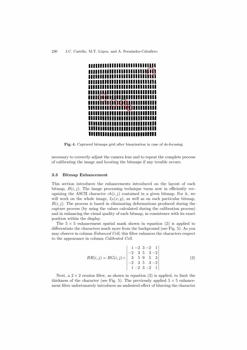
While the position of the camera or the display type do not change during thesegmentation process, the calibration and localization remain for all the searchesin bitmaps. Nonetheless, some problems may arise during these phases. For in-stance, the camera may not be correctly adjusted. In this case, the processing ofthe cells fails irremediably. Some cells may appear united due to a sub-exposure(iris too much closed) or a de-focusing (see Fig. 4), or they disappear due toan over-exposure (iris too much open). Then, the localization function is unableto position the bitmaps appropriately, and, hence, to get their sizes. So, it is
230 J.C. Castillo, M.T. Lopez, and A. Fernandez-Caballero
Fig. 4. Captured bitmaps grid after binarization in case of de-focusing
necessary to correctly adjust the camera lens and to repeat the complete processof calibrating the image and locating the bitmaps if any trouble occurs.
3.3 Bitmap Enhancement
This section introduces the enhancements introduced on the layout of eachbitmap, B(i, j). The image processing technique turns now in efficiently rec-ognizing the ASCII character ch(i, j) contained in a given bitmap. For it, wewill work on the whole image, IP (x, y), as well as on each particular bitmap,B(i, j). The process is based in eliminating deformations produced during thecapture process (by using the values calculated during the calibration process)and in enhancing the visual quality of each bitmap, in consistence with its exactposition within the display.
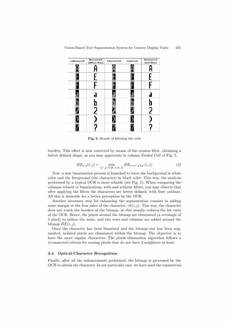
The 5 × 5 enhancement spatial mask shown in equation (2) is applied todifferentiate the characters much more from the background (see Fig. 5). As youmay observe in column Enhanced Cell, this filter enhances the characters respectto the appearance in column Calibrated Cell.
BR(i, j) = BG(i, j) ◦
∣∣∣∣∣∣∣∣∣∣
1 −2 3 −2 1−2 3 5 3 −2
3 5 9 5 3−2 3 5 3 −2
1 −2 3 −2 1
∣∣∣∣∣∣∣∣∣∣(2)
Next, a 2 × 2 erosion filter, as shown in equation (3) is applied, to limit thethickness of the character (see Fig. 5). The previously applied 5 × 5 enhance-ment filter unfortunately introduces an undesired effect of blurring the character
Vision-Based Text Segmentation System for Generic Display Units 231
Fig. 5. Result of filtering the cells
borders. This effect is now corrected by means of the erosion filter, obtaining abetter defined shape, as you may appreciate in column Eroded Cell of Fig. 5.
BEx,y(i, j) = min(x′,y′)∈[0..1,0..1]
BRx+x′,y+y′(i, j) (3)
Now, a new binarization process is launched to leave the background in whitecolor and the foreground (the character) in black color. This way, the analysisperformed by a typical OCR is more reliable (see Fig. 5). When comparing thecolumns related to binarizations, with and without filters, you may observe thatafter applying the filters the characters are better defined, with finer outlines.All this is desirable for a better perception by the OCR.
Another necessary step for enhancing the segmentation consists in addingsome margin at the four sides of the character, ch(i, j). This way, the characterdoes not touch the borders of the bitmap, as this usually reduces the hit ratioof the OCR. Hence, the pixels around the bitmap are eliminated (a rectangle of1 pixel) to reduce the noise, and two rows and columns are added around thebitmap BE(i, j).
Once the character has been binarized and the bitmap size has been aug-mented, isolated pixels are eliminated within the bitmap. The objective is tohave the more regular characters. The pixels elimination algorithm follows a4-connected criteria for erasing pixels that do not have 2 neighbors at least.
3.4 Optical Character Recognition
Finally, after all the enhancements performed, the bitmap is processed by theOCR to obtain the character. In our particular case, we have used the commercial
232 J.C. Castillo, M.T. Lopez, and A. Fernandez-Caballero
OCR module from Matrox Imaging Library (MIL). One of the principal param-eter of this OCR - also of other commercial OCRs - is the size of the characterwithin the bitmap. Our experience has taken us to run the OCR with threedifferent sizes:
– Firstly, the character size is set to the mean size of all the display’s bitmaps,Bsz = Bh × Bw.
– Secondly, the character size is augmented in 1 pixel in height and widthrespect to the mean size of the display’s bitmaps, namely, Bh +1 and Bw +1,respectively.
– Lastly, the character size is set to the exact height and width calculated forthe concrete bitmap, that is, Bw(i, j) and Bh(i, j).
Obviously, the hit percentage obtained for each call is studied, and the recog-nition result is the character with the highest matching score.
4 Data and Results
This section shows the results of the implementation of our algorithms. Thetests performed have demonstrated the capabilities of the system in relation tothe optical character recognition task. In order to get the necessary displays forperforming the tests, a simulator has been developed. The simulator is generic,enabling to configure the characteristics of any kind of display, CRT, LCD, and
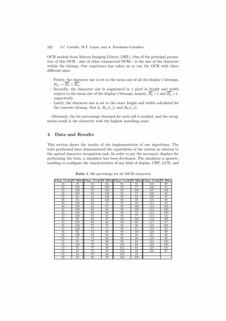
Table 1. Hit percentage for all ASCII characters
Char Code % Hits Char Code % Hits Char Code % Hits Char Code % Hits33 10 57 94 81 35 105 9934 100 58 100 82 77 106 8135 100 59 100 83 100 107 10036 100 60 100 84 71 108 8637 95 61 100 85 52 109 8738 84 62 100 86 99 110 9939 100 63 13 87 99 111 8340 100 64 67 88 100 112 10041 100 65 94 89 100 113 10042 100 66 86 90 78 114 10043 100 67 53 91 77 115 8444 89 68 67 92 100 116 10045 100 69 40 93 60 117 8746 100 70 73 94 99 118 10047 100 71 71 95 81 119 9248 92 72 98 96 100 120 9949 100 73 68 97 90 121 9950 73 74 69 98 86 122 8951 95 75 99 99 88 123 10052 100 76 66 100 88 124 10053 76 77 98 101 83 125 9454 83 78 95 102 98 126 9755 83 79 30 103 9456 52 80 78 104 100
Vision-Based Text Segmentation System for Generic Display Units 233
TFT-LCD. Due to the generality of the simulator, the size of a simulated dis-play (rows and columns) may be easily modified for generating a wide range ofdisplays.
Due to limitation in space, in this article we only offer the results of testing thecharacter segmentation on a complete set of ASCII characters (from charactercode 33 to 126). The mean results of the recognition may be observed on Table1, where the mean hit percentage overcomes an 86%, throwing a hit of 100% for32 different characters, and a hit greater than an 80% for 71 different characters.There are only two characters offering a very poor hit percentage, namely, ASCIIcharacters 33 and 66, corresponding to ? and ! symbols, respectively. This is aproblem of the commercial OCR, as the library handles very badly the charactersthat present unconnected elements (formed by more than one shape).
5 Conclusions
A vision-based text segmentation system able to assist humans has been de-scribed in this paper. The proposed system for generic displays includes someof the usual text recognition steps, namely localization, extraction and enhance-ment, and optical character recognition. In avionics displays the characters use tobe placed at fixed positions. Therefore, our solution establishes a set of bitmapsin the display, in accordance with the number of rows and columns that thedisplay is able to generate. The proposal has been tested on a multi-displaysimulator and a commercial OCR system, throwing good initial results.
As future work, we are engaged in introducing some learning algorithms re-lated to the type and size of the character sets in order to enhance the classifi-cation of the optical character recognizer.
Acknowledgements
This work was partially supported by Spanish Junta de Comunidades de Castilla-La Mancha under projects PII2I09-0069-0994 and PEII09-0054-9581.
References
1. Abdel-Aziz, Y.I., Karara, H.M.: Direct linear transformation into object spacecoordinates in close-range photogrammetry. In: Proceedings of the Symposium onClose-Range Photogrametry, pp. 1–18 (1971)
2. Andersson, P., von Hofsten, C.: Readability of vertically vibrating aircraft displays.Displays 20, 23–30 (1999)
3. Chang, F., Chen, G.C., Lin, C.C., Lin, W.H.: Caption analysis and recognition forbuilding video indexing system. Multimedia Systems 10(4), 344–355 (2005)
4. Faugeras, O.: Three-dimensional computer vision: A geometric viewpoint. MITPress, Cambridge (1993)
5. Huang, S., Ahmadi, M., Sid-Ahmed, M.A.: A hidden Markov model-based charac-ter extraction method. Pattern Recognition (2008),doi:10.1016/j.patcog.2008.03.004
234 J.C. Castillo, M.T. Lopez, and A. Fernandez-Caballero
6. Jung, K., Kim, K.I., Jain, A.K.: Text information extraction in images and video:A survey. Pattern Recognition 37, 977–997 (2004)
7. Kittler, J., Illingworth, J.: Minimum error thresholding. Pattern Recognition 19,41–47 (1986)
8. Lienhart, R.: Automatic text recognition in digital videos. In: Proceedings SPIE,Image and Video Processing IV, pp. 2666–2675 (1996)
9. Lin, C.J., Hsieh, Y.-H., Chen, H.-C., Chen, J.C.: Visual performance and fatiguein reading vibrating numeric displays. Displays (2008),doi:10.1016/j.displa.2007.12.004
10. Otsu, N.: A threshold selection method from gray-level histogram. IEEE Transac-tions on Systems, Man, and Cybernetics 9, 62–66 (1979)
11. Pikaz, A., Averbuch, A.: Digital image thresholding based on topological stablestate. Pattern Recognition 29, 829–843 (1996)
12. Prewitt, J.M.S., Mendelsohn, M.L.: The analysis of cell images. Annals of the NewYork Academy of Sciences 128(3), 1035–1053 (1965)
13. Sato, T., Kanade, T., Hughes, E.K., Smith, M.A., Satoh, S.: Video OCR: indexingdigital news libraries by recognition of superimposed caption. ACM MultimediaSystems Special Issue on Video Libraries 7(5), 385–395 (1998)
14. Sezgin, M., Sankur, B.: Survey over image thresholding techniques and quantitativeperformance evaluation. Journal of Electronic Imaging 13(1), 146–165 (2004)
15. Stein, G.P.: Accurate internal camera calibration using rotation with analysis ofsources of error. In: Proceedings of the Fifth International Conference on ComputerVision, p. 230 (1995)
16. Stein, G.P.: Lens distortion calibration using point correspondences. In: IEEE Com-puter Society Conference on Computer Vision and Pattern Recognition, pp. 602–608 (1997)
17. Tsai, R.Y.: A versatile camera calibration technique for high accuracy 3-d mach-ing vision metrology using off-the-shelf TV cameras and lenses. IEEE Journal ofRobotics & Automation 3, 323–344 (1987)
18. Wang, K., Kangas, J.A., Li, W.: Character segmentation of color images from digi-tal camera. In: Proceedings of the International Conference on Document Analysisand Recognition, pp. 210–214 (2001)
19. Wang, J., Shi, F., Zhang, J., Liu, Y.: A new calibration model of camera lensdistortion. Pattern Recognition 41(2), 607–615 (2008)
20. Wolf, C., Jolion, J.: Extraction and recognition of artificial text in multimediadocuments. Pattern Analysis and Applications 6, 309–326 (2003)
21. Yan, H., Wu, J.: Character and line extraction from color map images using amulti-layer neural network. Pattern Recognition Letters 15, 97–103 (1994)
22. Zhu, K., Qi, F., Jiang, R., Xu, L., Kimachi, M., Wu, Y., Aizawa, T.: Using adaboostto detect and segment characters from natural scenes. In: Proceedings of the In-ternational Workshop on Camera-based Document Analysis and Recognition, pp.52–58 (2005)
Copyright © 2022 FDOKUMEN

