


Bahasa
Halaman
Hukum

Schaffner Group | Nordstrasse 11e | 4542 Luterbach | Switzerland T +41 32 681 66 26 | [email protected] | www.schaffner.com
User and installation manual Output filter FN5420 and RWK5420
www.schaffner.com
English version (original instructions)

1/52 schaffner.com
Copyright ©2021 Schaffner International Ltd. All Rights Reserved. All rights of this User and Installa-tion Manual (“Manual”) including but not limited to the contents, information, and figures are solely owned and reserved by Schaffner International Ltd. (“Schaffner”). The Manual can only be applied to the operation or the use of Schaffner output filters. Any disposition, duplication, dissemination, repro-duction, modification, translation, extraction, or usage of this Manual in whole or in part is prohibited without the prior written permission of Schaffner. Given that Schaffner will continuously improve and develop the product, changes may be made to the information in this Manual at any time without obli-gation to notify any person of such revision or changes. Schaffner will make all possible efforts to se-cure the accuracy and the integrity of this Manual. Schaffner disclaims any kinds or forms of warranty, guarantee, or undertaking, either expressly or implicitly, including but not limited to the completeness, faultlessness, accuracy, non-infringement, merchantability or fitness for a particular purpose of the Manual.
Schaffner Group User and Installation Manual Output filter FN5420 and RWK5420
schaffner.com 2/52
Revision: 02 (December 2021)
The most current edition of this document (PDF format) and official translations can be obtained from your contact of the Schaffner organization or online at schaffner.com
Other technical documentation of our products is also available in the download area of our website schaffner.com/downloads
Document name:
User and Installation Manual output filter FN5420 and RWK5420 Rev02.pdf
Valid for:
sine wave filter FN5420 (all versions) dv/dt filter RWK5420 (all versions)
Version history
Revision Date Description 01 October 2021 Initial version
02 December 2021 Section 2, step 2: mistake in the type of filter to remove common mode interference; differential mode filter -> common mode filter
Figure 23 corrected, capacitors connected in delta and not star.
Schaffner Group User and Installation Manual Output filter FN5420 and RWK5420
3/52 schaffner.com
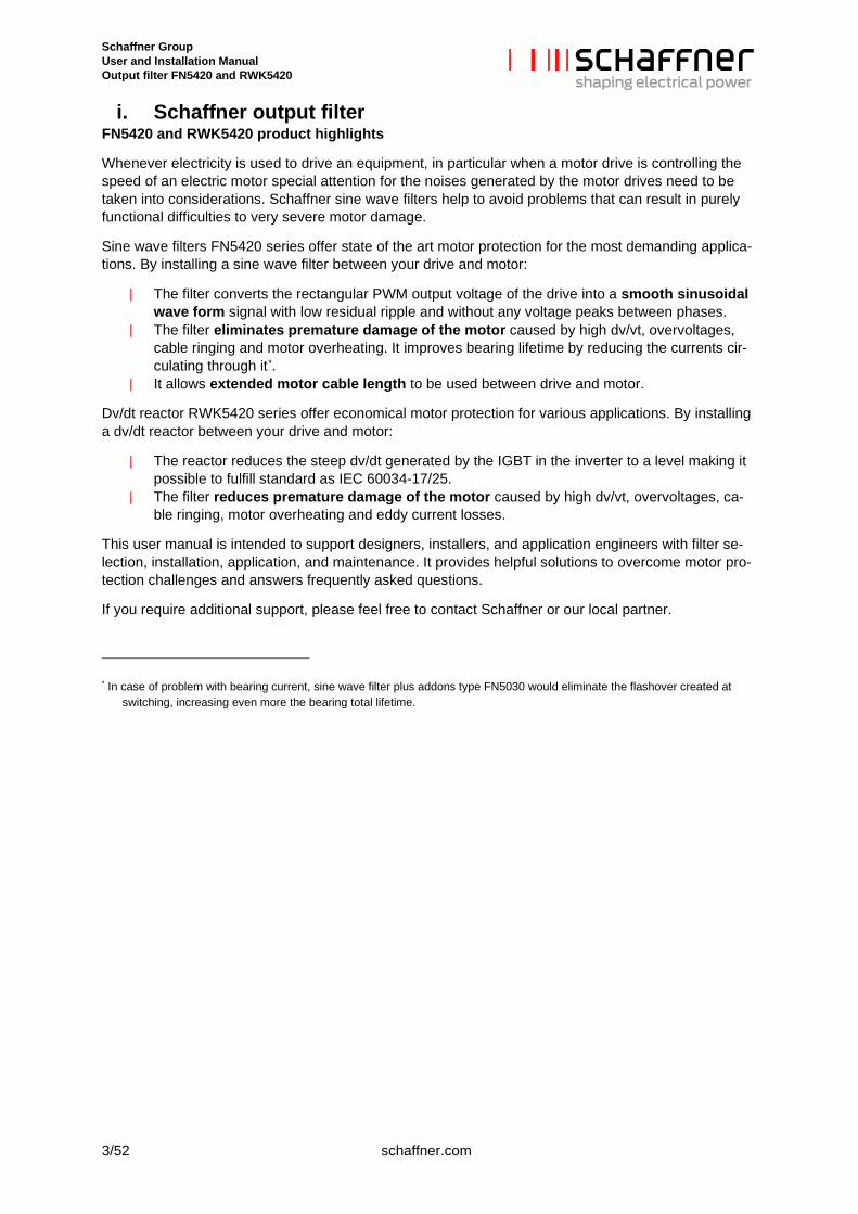
i. Schaffner output filter FN5420 and RWK5420 product highlights
Whenever electricity is used to drive an equipment, in particular when a motor drive is controlling the speed of an electric motor special attention for the noises generated by the motor drives need to be taken into considerations. Schaffner sine wave filters help to avoid problems that can result in purely functional difficulties to very severe motor damage.
Sine wave filters FN5420 series offer state of the art motor protection for the most demanding applica-tions. By installing a sine wave filter between your drive and motor:
| The filter converts the rectangular PWM output voltage of the drive into a smooth sinusoidal wave form signal with low residual ripple and without any voltage peaks between phases.
| The filter eliminates premature damage of the motor caused by high dv/vt, overvoltages, cable ringing and motor overheating. It improves bearing lifetime by reducing the currents cir-culating through it*.
| It allows extended motor cable length to be used between drive and motor.
Dv/dt reactor RWK5420 series offer economical motor protection for various applications. By installing a dv/dt reactor between your drive and motor:
| The reactor reduces the steep dv/dt generated by the IGBT in the inverter to a level making it possible to fulfill standard as IEC 60034-17/25.
| The filter reduces premature damage of the motor caused by high dv/vt, overvoltages, ca-ble ringing, motor overheating and eddy current losses.
This user manual is intended to support designers, installers, and application engineers with filter se-lection, installation, application, and maintenance. It provides helpful solutions to overcome motor pro-tection challenges and answers frequently asked questions.
If you require additional support, please feel free to contact Schaffner or our local partner.
* In case of problem with bearing current, sine wave filter plus addons type FN5030 would eliminate the flashover created at
switching, increasing even more the bearing total lifetime.
Schaffner Group User and Installation Manual Output filter FN5420 and RWK5420
schaffner.com 4/52
Performance Guarantee The remaining voltage and current ripple at motor terminals is reduced to values <5% according to EN 61000-2-2.
ii. Minimum system Requirements The highest performance levels of the selected filter will be achieved when the following system condi-tions are met:
| Motor frequency: up to 60Hz without derating and up to 200Hz with derating (see section 2.4.2)
| Maximum surrounding air temperature: 70°C for filter sizes 26 to 1'100A and 100°C for filter sizes 2.3 to 18A, always with derating above 45°C.
| Nominal voltage: ±10% | Voltage unbalance (at filter input): <3% | Maximum DC link voltage: 750VDC
iii. Important user notice Schaffner sine wave filters are designed for the operation on the output (motor) side of converters, such as AC or DC motor drives. Filter suitability for a given application must be determined by the user on a case by case basis. Schaffner will not assume liability for any consequential downtimes or dam-ages resulting from use or application of Schaffner sine wave filters beyond their specifications. Schaffner sine wave filters are not designed for single-phase or split-phase applications.
Schaffner Group User and Installation Manual Output filter FN5420 and RWK5420
5/52 schaffner.com
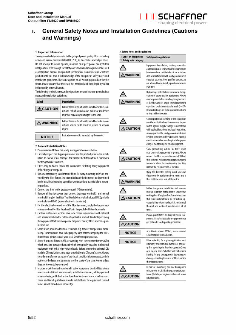
i. General Safety Notes and Installation Guidelines (Cautions and Warnings)
Schaffner Group User and Installation Manual Output filter FN5420 and RWK5420
schaffner.com 6/52
Content
1 Sine wave filter FN5420 designation .................................................................. 8
1.1 Sine wave filter designation ...................................................................................................... 8
1.1.1 Example of sine wave filter designations .............................................................................. 8
1.2 Dv/dt reactor designation .......................................................................................................... 9
1.2.1 Example of sine wave filter designations .............................................................................. 9
1.3 Additional Resources ................................................................................................................. 9
1.4 Naming convention .................................................................................................................... 9
2 Filter selection ................................................................................................... 10
2.1 Filter selection table FN5420 IP00 ........................................................................................... 13
2.2 Filter selection table FN5420 IP20 ........................................................................................... 14
2.3 Filter selection table RWK5420 ............................................................................................... 15
2.4 Derating ..................................................................................................................................... 16
2.4.1 Temperature derating .......................................................................................................... 16
2.4.2 Motor frequency derating..................................................................................................... 17
2.4.3 Calculation example of derating .......................................................................................... 17
3 Filter description ................................................................................................ 18
3.1 General electrical specifications FN5420 ............................................................................... 18
3.2 General electrical specifications RWK5420 ........................................................................... 19
3.3 Power losses ............................................................................................................................. 20
3.3.1 Power loss calculation example .......................................................................................... 20
3.4 Additional electrical specifications ........................................................................................ 21
3.5 Screw size, torque and cable cross-section requirement .................................................... 22
3.5.1 Power terminals ................................................................................................................... 22
3.5.2 Auxiliary signal and earth terminals ..................................................................................... 24
3.6 Thermal protection switch specifications .............................................................................. 25
3.7 Cooling requirement ................................................................................................................. 25
3.8 Mechanical data ........................................................................................................................ 26
Schaffner Group User and Installation Manual Output filter FN5420 and RWK5420
7/52 schaffner.com
3.8.1 Dimensions FN5420 IP00.................................................................................................... 26
3.8.2 Dimensions FN5420 IP20.................................................................................................... 31
3.8.3 Dimensions RWK5420 ........................................................................................................ 32
3.9 Functional diagram ................................................................................................................... 37
4 Filter appearance and elements ....................................................................... 38
5 Filter installation ................................................................................................ 43
5.1 Step 1: Visual inspection ......................................................................................................... 43
5.2 Step 2: Mounting ....................................................................................................................... 43
5.2.1 Prepare the fixation ............................................................................................................. 46
5.2.2 Screw selection ................................................................................................................... 46
5.2.3 Filter placement ................................................................................................................... 46
5.3 Step 3: Wiring ............................................................................................................................ 48
5.3.1 Verify safe disconnection of all line side power ................................................................... 48
5.3.2 Carefully connect protective earth (PE) wire to adequate earth potential close to the device 48
5.3.3 Connect PE wire on the device ........................................................................................... 48
5.3.4 Connect shielding for shielded cables ................................................................................. 48
5.3.5 Connect shielding for shielded cables ................................................................................. 49
5.3.6 Connect the device on drive side ........................................................................................ 49
5.3.7 Connect output filter motor side .......................................................................................... 49
5.3.8 Connect monitor switch TS- TS’ .......................................................................................... 49
6 Filter maintenance ............................................................................................. 50
6.1 Maintenance schedule ............................................................................................................. 50
6.2 Fan .............................................................................................................................................. 50
6.3 Power capacitors ...................................................................................................................... 51
6.4 Electrical connections .............................................................................................................. 51
7 Troubleshooting ................................................................................................ 52
Schaffner Group User and Installation Manual Output filter FN5420 and RWK5420
schaffner.com 8/52
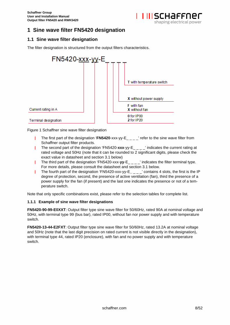
1 Sine wave filter FN5420 designation 1.1 Sine wave filter designation The filter designation is structured from the output filters characteristics.
Figure 1 Schaffner sine wave filter designation
| The first part of the designation ‘FN5420-xxx-yy-E_ _ _ _’ refer to the sine wave filter from Schaffner output filter products.
| The second part of the designation ‘FN5420-xxx-yy-E_ _ _ _’ indicates the current rating at rated voltage and 50Hz (note that it can be rounded to 2 significant digits, please check the exact value in datasheet and section 3.1 below)
| The third part of the designation ‘FN5420-xxx-yy-E_ _ _ _’ indicates the filter terminal type. For more details, please consult the datasheet and section 3.1 below.
| The fourth part of the designation ‘FN5420-xxx-yy-E_ _ _ _’ contains 4 slots, the first is the IP degree of protection, second, the presence of active ventilation (fan), third the presence of a power supply for the fan (if present) and the last one indicates the presence or not of a tem-perature switch.
Note that only specific combinations exist, please refer to the selection tables for complete list.
1.1.1 Example of sine wave filter designations
FN5420-90-99-E0XXT: Output filter type sine wave filter for 50/60Hz, rated 90A at nominal voltage and 50Hz, with terminal type 99 (bus bar), rated IP00, without fan nor power supply and with temperature switch.
FN5420-13-44-E2FXT: Output filter type sine wave filter for 50/60Hz, rated 13.2A at nominal voltage and 50Hz (note that the last digit precision on rated current is not visible directly in the designation), with terminal type 44, rated IP20 (enclosure), with fan and no power supply and with temperature switch.
Schaffner Group User and Installation Manual Output filter FN5420 and RWK5420
9/52 schaffner.com
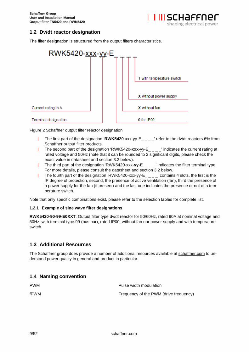
1.2 Dv/dt reactor designation The filter designation is structured from the output filters characteristics.
Figure 2 Schaffner output filter reactor designation
| The first part of the designation ‘RWK5420-xxx-yy-E_ _ _ _’ refer to the dv/dt reactors 6% from Schaffner output filter products.
| The second part of the designation ‘RWK5420-xxx-yy-E_ _ _ _’ indicates the current rating at rated voltage and 50Hz (note that it can be rounded to 2 significant digits, please check the exact value in datasheet and section 3.2 below).
| The third part of the designation ‘RWK5420-xxx-yy-E_ _ _ _’ indicates the filter terminal type. For more details, please consult the datasheet and section 3.2 below.
| The fourth part of the designation ‘RWK5420-xxx-yy-E_ _ _ _’ contains 4 slots, the first is the IP degree of protection, second, the presence of active ventilation (fan), third the presence of a power supply for the fan (if present) and the last one indicates the presence or not of a tem-perature switch.
Note that only specific combinations exist, please refer to the selection tables for complete list.
1.2.1 Example of sine wave filter designations
RWK5420-90-99-E0XXT: Output filter type dv/dt reactor for 50/60Hz, rated 90A at nominal voltage and 50Hz, with terminal type 99 (bus bar), rated IP00, without fan nor power supply and with temperature switch.
1.3 Additional Resources The Schaffner group does provide a number of additional resources available at schaffner.com to un-derstand power quality in general and product in particular.
1.4 Naming convention PWM Pulse width modulation
fPWM Frequency of the PWM (drive frequency)
Schaffner Group User and Installation Manual Output filter FN5420 and RWK5420
schaffner.com 10/52
2 Filter selection Schaffner output filters need to be selected according to the applications specifications and needs.
Step 1: motor frequency
Sine wave filter FN5420 series and dv/dt reactor RKW5420 series work at rated current up to a motor frequency of 60Hz and with a derating up to 200Hz, see derating in section 2.4.2.
Table 1 motor frequency
Filter series Network frequency Maximum motor fre-quency at rated cur-rent
Maximum motor fre-quency with a derating
FN5420 50/60Hz 60Hz 200Hz
RWK5420 50/60Hz 60Hz 200Hz
Step 2: motor cable characteristics
The motor cable length between sine wave filter and the motor, is an important metric for the proper working of the drive, sine wave filter and motor. The maximum cable length is either limited by the drive or the filter. Schaffner sine wave filter FN5420 series bring very few limitations in this regard with a maximum cable length of at least 1000m for all filter size and up to 2000m for larger filters at the minimum fPWM. It is often the case that the drive is more restrictive on the cable length, furthermore the total voltage-drop of the filter plus cable is to be considered, please consult the drive user manual for more information.
The type of cable, whenever it is shielded or unshielded has also an influence on the performance. Us-ing an unshielded cable without addition common mode filter cause common mode inteferances on the line. Results and behavior might vary for each specific application. Schaffner recommend using shielded cable between the sine wave filter and the motor or unshielded cable with an additional com-mon mode filter, i.e. Schaffner sine wave filter plus FN5030 series (not part of this user manual). For more information, please consult the Schaffner output filter product page at schaffner.com or contact your Schaffner representative.
Table 2 motor cable at minimum fPWM
Filter series Maximum unshielded cable length*
Maximum shielded cable length
FN5420 up to 250A 1000m 1000m
FN5420 from 300A to 630A 1500m 1500m
FN5420 from 710A to 1000A 2000m 2000m
RWK5420 100m** 100m**
* Usage of shielded cable is still recommended. Drive and system compatibility to be checked. ** See limitation according to drive switching frequency in step 3
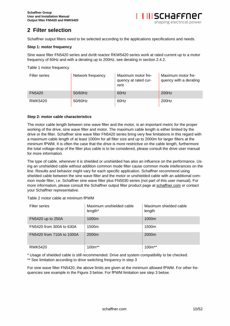
For sine wave filter FN5420, the above limits are given at the minimum allowed fPWM. For other fre-quencies see example in the Figure 3 below. For fPWM limitation see step 3 below.
Schaffner Group User and Installation Manual Output filter FN5420 and RWK5420
11/52 schaffner.com
Figure 3 FN5420 maximum cable length by fitler size and fPWM
Step 3: drive switching frequency
The usage of sine wave filter imposes some limit on the switching frequency of the drive (fPWM). The minimum fPWM is dependant on the filter size and the maximum fPWM is the same for the whole se-ries, see Table 3 below.
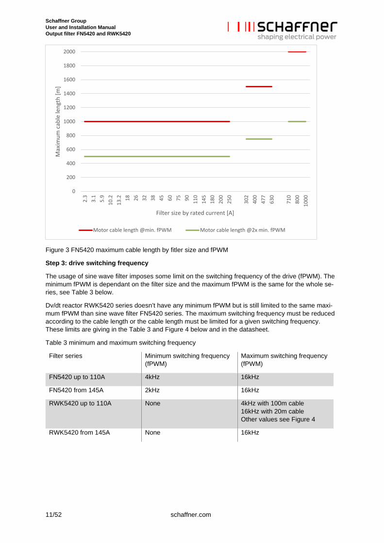
Dv/dt reactor RWK5420 series doesn’t have any minimum fPWM but is still limited to the same maxi-mum fPWM than sine wave filter FN5420 series. The maximum switching frequency must be reduced according to the cable length or the cable length must be limited for a given switching frequency. These limits are giving in the Table 3 and Figure 4 below and in the datasheet.
Table 3 minimum and maximum switching frequency
Filter series Minimum switching frequency (fPWM)
Maximum switching frequency (fPWM)
FN5420 up to 110A 4kHz 16kHz
FN5420 from 145A 2kHz 16kHz
RWK5420 up to 110A None 4kHz with 100m cable 16kHz with 20m cable Other values see Figure 4
RWK5420 from 145A None 16kHz
0
200
400
600
800
1000
1200
1400
1600
1800
2000
2.3
3.1
5.9
10.2
13.2 18 26 32 38 45 60 75 90 110
145
180
200
250
302
400
477
630
710
800
1000
Max
imum
cab
le le
ngth
[m]
Filter size by rated current [A]
Motor cable length @min. fPWM Motor cable length @2x min. fPWM
Schaffner Group User and Installation Manual Output filter FN5420 and RWK5420
schaffner.com 12/52
Figure 4 RWK5420 limitation in switching frequency and cable length
Step 4: motor protection and acoustic noise
Output filters are mean to filter the signal coming out of the drive feeding the motor. Filter type dv/dt reactor, like RWK5420 series, allow to reduce the voltage rise (dv/dt) visible by the motor. This re-duces the stress on the motor insulation, reduce the temperature of the motor and thus increase its total lifetime.
Sine wave filter offers more in terms of motor protection by providing a sinusoidal phase to phase volt-age to the motor, this will bring the stress on the insulation and the temperature rise to the minimum physically possible level. In addition, the usage of sine wave filter reduces the current flowing between the rotor and the stator through the motor bearing (i.e. bearing current)*, increasing further more the service life time of the motor. Finally, sine wave filter reduces motor acoustic noise, improving the comfort at the facility where the motor is installed.
* In case of problem with bearing current, sine wave filter plus addons type FN5030 would eliminate the flashover created at
switching, increasing even more the bearing total lifetime.
0123456789
10111213141516
0 20 40 60 80 100
Switc
hing
freq
uenc
y (fP
WM
) [kH
z]
Cable length [m]
fPWM at 400V
fPWM at 480V
Schaffner Group User and Installation Manual Output filter FN5420 and RWK5420
13/52 schaffner.com
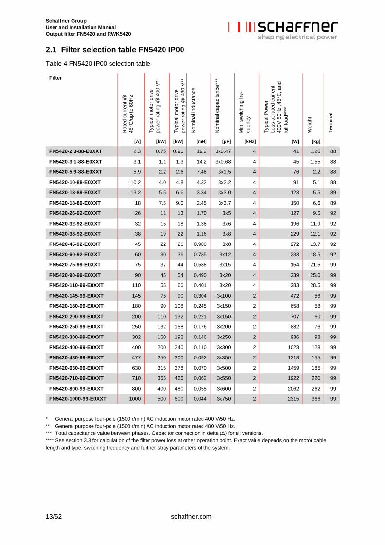
2.1 Filter selection table FN5420 IP00 Table 4 FN5420 IP00 selection table
Filter
Rat
ed c
urre
nt @
45
°C/u
p to
60H
z
Typi
cal m
otor
driv
e po
wer
ratin
g @
400
V*
Typi
cal m
otor
driv
e po
wer
ratin
g @
480
V**
Nom
inal
indu
ctan
ce
Nom
inal
cap
acita
nce*
**
Min
. sw
itchi
ng fr
e-qu
ency
Typi
cal P
ower
Lo
ss a
t rat
ed c
urre
nt
400V
50H
z ,4
5°C
, and
fu
ll lo
ad**
**
Wei
ght
Term
inal
[A] [kW] [kW] [mH] [µF] [kHz] [W] [kg]
FN5420-2.3-88-E0XXT 2.3 0.75 0.90 19.2 3x0.47 4 41 1.20 88
FN5420-3.1-88-E0XXT 3.1 1.1 1.3 14.2 3x0.68 4 45 1.55 88
FN5420-5.9-88-E0XXT 5.9 2.2 2.6 7.48 3x1.5 4 76 2.2 88
FN5420-10-88-E0XXT 10.2 4.0 4.8 4.32 3x2.2 4 91 5.1 88
FN5420-13-89-E0XXT 13.2 5.5 6.6 3.34 3x3.0 4 123 5.5 89
FN5420-18-89-E0XXT 18 7.5 9.0 2.45 3x3.7 4 150 6.6 89
FN5420-26-92-E0XXT 26 11 13 1.70 3x5 4 127 9.5 92
FN5420-32-92-E0XXT 32 15 18 1.38 3x6 4 196 11.9 92
FN5420-38-92-E0XXT 38 19 22 1.16 3x8 4 229 12.1 92
FN5420-45-92-E0XXT 45 22 26 0.980 3x8 4 272 13.7 92
FN5420-60-92-E0XXT 60 30 36 0.735 3x12 4 283 18.5 92
FN5420-75-99-E0XXT 75 37 44 0.588 3x15 4 154 21.5 99
FN5420-90-99-E0XXT 90 45 54 0.490 3x20 4 239 25.0 99
FN5420-110-99-E0XXT 110 55 66 0.401 3x20 4 283 28.5 99
FN5420-145-99-E0XXT 145 75 90 0.304 3x100 2 472 56 99
FN5420-180-99-E0XXT 180 90 108 0.245 3x150 2 658 58 99
FN5420-200-99-E0XXT 200 110 132 0.221 3x150 2 707 60 99
FN5420-250-99-E0XXT 250 132 158 0.176 3x200 2 882 76 99
FN5420-300-99-E0XXT 302 160 192 0.146 3x250 2 936 98 99
FN5420-400-99-E0XXT 400 200 240 0.110 3x300 2 1023 128 99
FN5420-480-99-E0XXT 477 250 300 0.092 3x350 2 1318 155 99
FN5420-630-99-E0XXT 630 315 378 0.070 3x500 2 1459 185 99
FN5420-710-99-E0XXT 710 355 426 0.062 3x550 2 1922 220 99
FN5420-800-99-E0XXT 800 400 480 0.055 3x600 2 2062 262 99
FN5420-1000-99-E0XXT 1000 500 600 0.044 3x750 2 2315 366 99
**** General purpose four-pole (1500 r/min) AC induction motor rated 400 V/50 Hz. **** General purpose four-pole (1500 r/min) AC induction motor rated 480 V/50 Hz. **** Total capacitance value between phases. Capacitor connection in delta (Δ) for all versions. **** See section 3.3 for calculation of the filter power loss at other operation point. Exact value depends on the motor cable length and type, switching frequency and further stray parameters of the system.
Schaffner Group User and Installation Manual Output filter FN5420 and RWK5420
schaffner.com 14/52
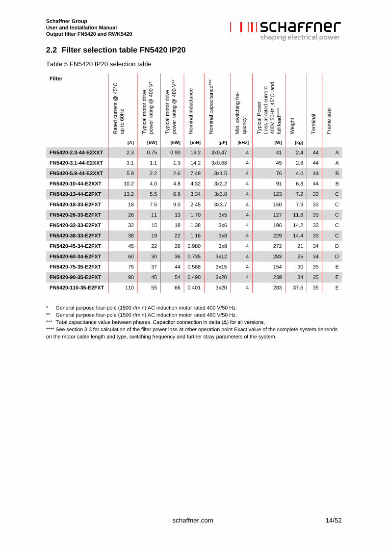
2.2 Filter selection table FN5420 IP20 Table 5 FN5420 IP20 selection table
Filter
Rat
ed c
urre
nt @
45°
C
up to
60H
z
Typi
cal m
otor
driv
e po
wer
ratin
g @
400
V*
Typi
cal m
otor
driv
e po
wer
ratin
g @
480
V**
Nom
inal
indu
ctan
ce
Nom
inal
cap
acita
nce*
**
Min
. sw
itchi
ng fr
e-qu
ency
Typi
cal P
ower
Lo
ss a
t rat
ed c
urre
nt
400V
50H
z ,4
5°C
, and
fu
ll lo
ad**
**
Wei
ght
Term
inal
Fram
e si
ze
[A] [kW] [kW] [mH] [µF] [kHz] [W] [kg]
FN5420-2.3-44-E2XXT 2.3 0.75 0.90 19.2 3x0.47 4 41 2.4 44 A
FN5420-3.1-44-E2XXT 3.1 1.1 1.3 14.2 3x0.68 4 45 2.8 44 A
FN5420-5.9-44-E2XXT 5.9 2.2 2.6 7.48 3x1.5 4 76 4.0 44 B
FN5420-10-44-E2XXT 10.2 4.0 4.8 4.32 3x2.2 4 91 6.8 44 B
FN5420-13-44-E2FXT 13.2 5.5 6.6 3.34 3x3.0 4 123 7.2 33 C
FN5420-18-33-E2FXT 18 7.5 9.0 2.45 3x3.7 4 150 7.9 33 C
FN5420-26-33-E2FXT 26 11 13 1.70 3x5 4 127 11.8 33 C
FN5420-32-33-E2FXT 32 15 18 1.38 3x6 4 196 14.2 33 C
FN5420-38-33-E2FXT 38 19 22 1.16 3x8 4 229 14.4 33 C
FN5420-45-34-E2FXT 45 22 26 0.980 3x8 4 272 21 34 D
FN5420-60-34-E2FXT 60 30 36 0.735 3x12 4 283 25 34 D
FN5420-75-35-E2FXT 75 37 44 0.588 3x15 4 154 30 35 E
FN5420-90-35-E2FXT 90 45 54 0.490 3x20 4 239 34 35 E
FN5420-110-35-E2FXT 110 55 66 0.401 3x20 4 283 37.5 35 E
**** General purpose four-pole (1500 r/min) AC induction motor rated 400 V/50 Hz. **** General purpose four-pole (1500 r/min) AC induction motor rated 480 V/50 Hz. **** Total capacitance value between phases. Capacitor connection in delta (Δ) for all versions. **** See section 3.3 for calculation of the filter power loss at other operation point Exact value of the complete system depends on the motor cable length and type, switching frequency and further stray parameters of the system.
Schaffner Group User and Installation Manual Output filter FN5420 and RWK5420
15/52 schaffner.com
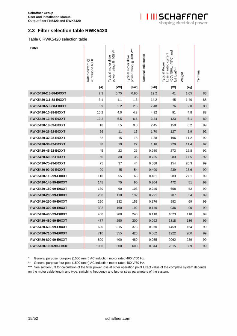
2.3 Filter selection table RWK5420 Table 6 RWK5420 selection table
Filter
Rat
ed c
urre
nt @
45
°C/u
p to
60H
z
Typi
cal m
otor
driv
e po
wer
ratin
g @
400
V*
Typi
cal m
otor
driv
e po
wer
ratin
g @
480
V**
Nom
inal
indu
ctan
ce
Typi
cal P
ower
Lo
ss a
t rat
ed c
urre
nt
400V
50H
z ,4
5°C
, and
fu
ll lo
ad**
*
Wei
ght
Term
inal
[A] [kW] [kW] [mH] [W] [kg]
RWK5420-2.3-88-E0XXT 2.3 0.75 0.90 19.2 41 1.05 88
RWK5420-3.1-88-E0XXT 3.1 1.1 1.3 14.2 45 1.40 88
RWK5420-5.9-88-E0XXT 5.9 2.2 2.6 7.48 76 2.0 88
RWK5420-10-88-E0XXT 10.2 4.0 4.8 4.32 91 4.8 88
RWK5420-13-89-E0XXT 13.2 5.5 6.6 3.34 123 5.1 89
RWK5420-18-89-E0XXT 18 7.5 9.0 2.45 150 6.2 89
RWK5420-26-92-E0XXT 26 11 13 1.70 127 8.9 92
RWK5420-32-92-E0XXT 32 15 18 1.38 196 11.2 92
RWK5420-38-92-E0XXT 38 19 22 1.16 229 11.4 92
RWK5420-45-92-E0XXT 45 22 26 0.980 272 12.8 92
RWK5420-60-92-E0XXT 60 30 36 0.735 283 17.5 92
RWK5420-75-99-E0XXT 75 37 44 0.588 154 20.3 99
RWK5420-90-99-E0XXT 90 45 54 0.490 239 23.6 99
RWK5420-110-99-E0XXT 110 55 66 0.401 283 27.1 99
RWK5420-145-99-E0XXT 145 75 90 0.304 472 51 99
RWK5420-180-99-E0XXT 180 90 108 0.245 658 52 99
RWK5420-200-99-E0XXT 200 110 132 0.221 707 54 99
RWK5420-250-99-E0XXT 250 132 158 0.176 882 69 99
RWK5420-300-99-E0XXT 302 160 192 0.146 936 90 99
RWK5420-400-99-E0XXT 400 200 240 0.110 1023 118 99
RWK5420-480-99-E0XXT 477 250 300 0.092 1318 136 99
RWK5420-630-99-E0XXT 630 315 378 0.070 1459 164 99
RWK5420-710-99-E0XXT 710 355 426 0.062 1922 200 99
RWK5420-800-99-E0XXT 800 400 480 0.055 2062 239 99
RWK5420-1000-99-E0XXT 1000 500 600 0.044 2315 339 99
**** General purpose four-pole (1500 r/min) AC induction motor rated 400 V/50 Hz. **** General purpose four-pole (1500 r/min) AC induction motor rated 480 V/50 Hz. **** See section 3.3 for calculation of the filter power loss at other operation point Exact value of the complete system depends on the motor cable length and type, switching frequency and further stray parameters of the system.
Schaffner Group User and Installation Manual Output filter FN5420 and RWK5420
schaffner.com 16/52
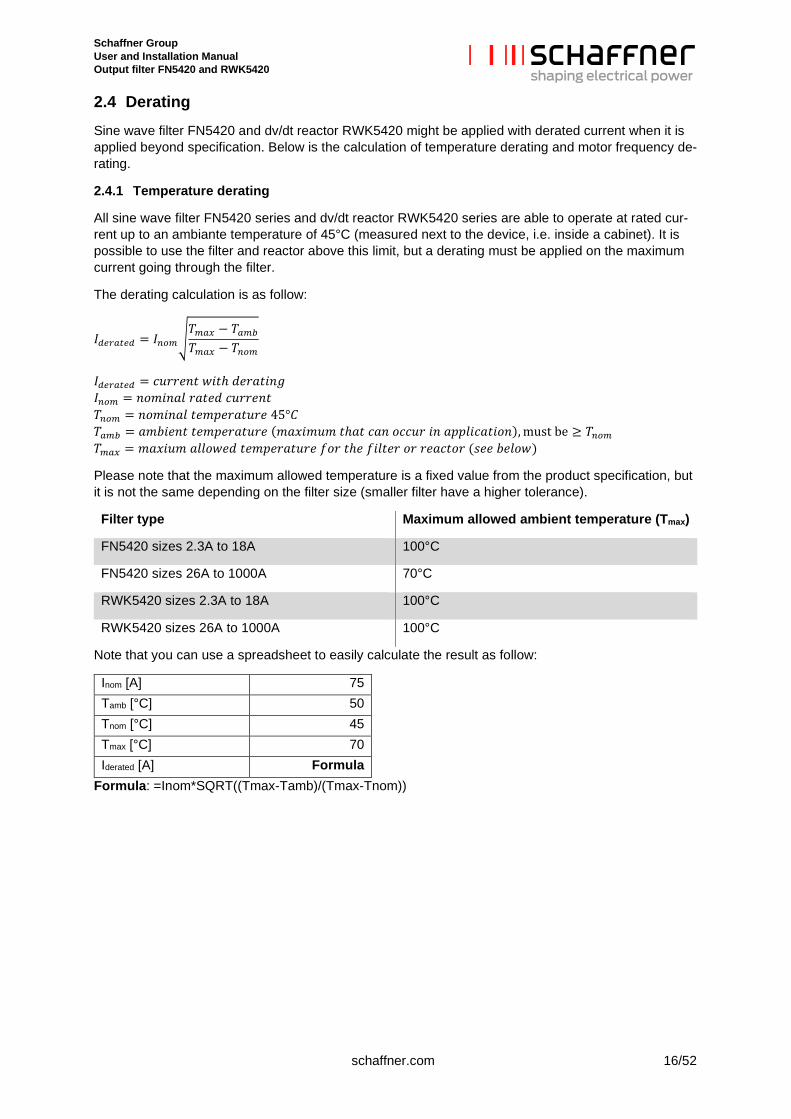
2.4 Derating Sine wave filter FN5420 and dv/dt reactor RWK5420 might be applied with derated current when it is applied beyond specification. Below is the calculation of temperature derating and motor frequency de-rating.
2.4.1 Temperature derating
All sine wave filter FN5420 series and dv/dt reactor RWK5420 series are able to operate at rated cur-rent up to an ambiante temperature of 45°C (measured next to the device, i.e. inside a cabinet). It is possible to use the filter and reactor above this limit, but a derating must be applied on the maximum current going through the filter.
The derating calculation is as follow:
𝐼𝐼𝑑𝑑𝑑𝑑𝑑𝑑𝑑𝑑𝑑𝑑𝑑𝑑𝑑𝑑 = 𝐼𝐼𝑛𝑛𝑛𝑛𝑛𝑛�𝑇𝑇𝑛𝑛𝑑𝑑𝑚𝑚 − 𝑇𝑇𝑑𝑑𝑛𝑛𝑎𝑎
𝑇𝑇𝑛𝑛𝑑𝑑𝑚𝑚 − 𝑇𝑇𝑛𝑛𝑛𝑛𝑛𝑛
𝐼𝐼𝑑𝑑𝑑𝑑𝑑𝑑𝑑𝑑𝑑𝑑𝑑𝑑𝑑𝑑 = 𝑐𝑐𝑐𝑐𝑐𝑐𝑐𝑐𝑐𝑐𝑐𝑐𝑐𝑐 𝑤𝑤𝑤𝑤𝑐𝑐ℎ 𝑑𝑑𝑐𝑐𝑐𝑐𝑑𝑑𝑐𝑐𝑤𝑤𝑐𝑐𝑑𝑑 𝐼𝐼𝑛𝑛𝑛𝑛𝑛𝑛 = 𝑐𝑐𝑛𝑛𝑛𝑛𝑤𝑤𝑐𝑐𝑑𝑑𝑛𝑛 𝑐𝑐𝑑𝑑𝑐𝑐𝑐𝑐𝑑𝑑 𝑐𝑐𝑐𝑐𝑐𝑐𝑐𝑐𝑐𝑐𝑐𝑐𝑐𝑐 𝑇𝑇𝑛𝑛𝑛𝑛𝑛𝑛 = 𝑐𝑐𝑛𝑛𝑛𝑛𝑤𝑤𝑐𝑐𝑑𝑑𝑛𝑛 𝑐𝑐𝑐𝑐𝑛𝑛𝑡𝑡𝑐𝑐𝑐𝑐𝑑𝑑𝑐𝑐𝑐𝑐𝑐𝑐𝑐𝑐 45°𝐶𝐶 𝑇𝑇𝑑𝑑𝑛𝑛𝑎𝑎 = 𝑑𝑑𝑛𝑛𝑎𝑎𝑤𝑤𝑐𝑐𝑐𝑐𝑐𝑐 𝑐𝑐𝑐𝑐𝑛𝑛𝑡𝑡𝑐𝑐𝑐𝑐𝑑𝑑𝑐𝑐𝑐𝑐𝑐𝑐𝑐𝑐 (𝑛𝑛𝑑𝑑𝑚𝑚𝑤𝑤𝑛𝑛𝑐𝑐𝑛𝑛 𝑐𝑐ℎ𝑑𝑑𝑐𝑐 𝑐𝑐𝑑𝑑𝑐𝑐 𝑛𝑛𝑐𝑐𝑐𝑐𝑐𝑐𝑐𝑐 𝑤𝑤𝑐𝑐 𝑑𝑑𝑡𝑡𝑡𝑡𝑛𝑛𝑤𝑤𝑐𝑐𝑑𝑑𝑐𝑐𝑤𝑤𝑛𝑛𝑐𝑐), must be ≥ 𝑇𝑇𝑛𝑛𝑛𝑛𝑛𝑛 𝑇𝑇𝑛𝑛𝑑𝑑𝑚𝑚 = 𝑛𝑛𝑑𝑑𝑚𝑚𝑤𝑤𝑐𝑐𝑛𝑛 𝑑𝑑𝑛𝑛𝑛𝑛𝑛𝑛𝑤𝑤𝑐𝑐𝑑𝑑 𝑐𝑐𝑐𝑐𝑛𝑛𝑡𝑡𝑐𝑐𝑐𝑐𝑑𝑑𝑐𝑐𝑐𝑐𝑐𝑐𝑐𝑐 𝑓𝑓𝑛𝑛𝑐𝑐 𝑐𝑐ℎ𝑐𝑐 𝑓𝑓𝑤𝑤𝑛𝑛𝑐𝑐𝑐𝑐𝑐𝑐 𝑛𝑛𝑐𝑐 𝑐𝑐𝑐𝑐𝑑𝑑𝑐𝑐𝑐𝑐𝑛𝑛𝑐𝑐 (𝑠𝑠𝑐𝑐𝑐𝑐 𝑎𝑎𝑐𝑐𝑛𝑛𝑛𝑛𝑤𝑤)
Please note that the maximum allowed temperature is a fixed value from the product specification, but it is not the same depending on the filter size (smaller filter have a higher tolerance).
Filter type Maximum allowed ambient temperature (Tmax)
FN5420 sizes 2.3A to 18A 100°C
FN5420 sizes 26A to 1000A 70°C
RWK5420 sizes 2.3A to 18A 100°C
RWK5420 sizes 26A to 1000A 100°C
Note that you can use a spreadsheet to easily calculate the result as follow:
Inom [A] 75 Tamb [°C] 50 Tnom [°C] 45 Tmax [°C] 70 Iderated [A] Formula
Formula: =Inom*SQRT((Tmax-Tamb)/(Tmax-Tnom))
Schaffner Group User and Installation Manual Output filter FN5420 and RWK5420
17/52 schaffner.com
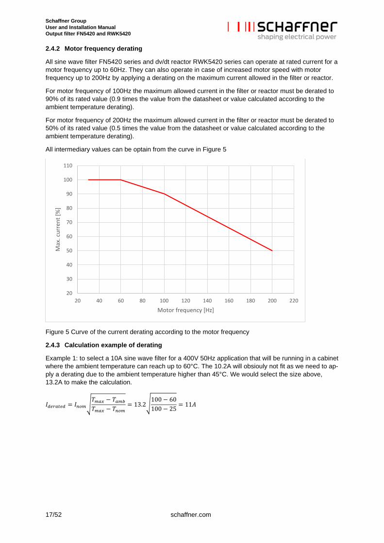
2.4.2 Motor frequency derating
All sine wave filter FN5420 series and dv/dt reactor RWK5420 series can operate at rated current for a motor frequency up to 60Hz. They can also operate in case of increased motor speed with motor frequency up to 200Hz by applying a derating on the maximum current allowed in the filter or reactor.
For motor frequency of 100Hz the maximum allowed current in the filter or reactor must be derated to 90% of its rated value (0.9 times the value from the datasheet or value calculated according to the ambient temperature derating).
For motor frequency of 200Hz the maximum allowed current in the filter or reactor must be derated to 50% of its rated value (0.5 times the value from the datasheet or value calculated according to the ambient temperature derating).
All intermediary values can be optain from the curve in Figure 5
Figure 5 Curve of the current derating according to the motor frequency
2.4.3 Calculation example of derating
Example 1: to select a 10A sine wave filter for a 400V 50Hz application that will be running in a cabinet where the ambient temperature can reach up to 60°C. The 10.2A will obsiouly not fit as we need to ap-ply a derating due to the ambient temperature higher than 45°C. We would select the size above, 13.2A to make the calculation.
𝐼𝐼𝑑𝑑𝑑𝑑𝑑𝑑𝑑𝑑𝑑𝑑𝑑𝑑𝑑𝑑 = 𝐼𝐼𝑛𝑛𝑛𝑛𝑛𝑛�𝑇𝑇𝑛𝑛𝑑𝑑𝑚𝑚 − 𝑇𝑇𝑑𝑑𝑛𝑛𝑎𝑎
𝑇𝑇𝑛𝑛𝑑𝑑𝑚𝑚 − 𝑇𝑇𝑛𝑛𝑛𝑛𝑛𝑛= 13.2�
100 − 60100 − 25
= 11𝐴𝐴
20
30
40
50
60
70
80
90
100
110
20 40 60 80 100 120 140 160 180 200 220
Max
. cur
rent
[%]
Motor frequency [Hz]
Schaffner Group User and Installation Manual Output filter FN5420 and RWK5420
schaffner.com 18/52
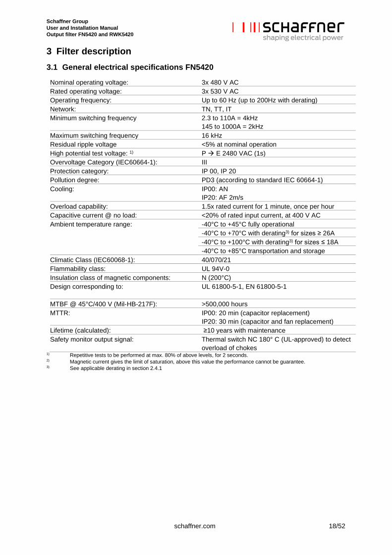
3 Filter description 3.1 General electrical specifications FN5420
Nominal operating voltage: 3x 480 V AC Rated operating voltage: 3x 530 V AC Operating frequency: Up to 60 Hz (up to 200Hz with derating) Network: TN, TT, IT Minimum switching frequency 2.3 to 110A = 4kHz
145 to 1000A = 2kHz Maximum switching frequency 16 kHz Residual ripple voltage <5% at nominal operation High potential test voltage: 1) P E 2480 VAC (1s) Overvoltage Category (IEC60664-1): III Protection category: IP 00, IP 20 Pollution degree: PD3 (according to standard IEC 60664-1) Cooling: IP00: AN
IP20: AF 2m/s Overload capability: 1.5x rated current for 1 minute, once per hour Capacitive current @ no load: <20% of rated input current, at 400 V AC Ambient temperature range:
-40°C to +45°C fully operational -40°C to +70°C with derating3) for sizes ≥ 26A -40°C to +100°C with derating3) for sizes ≤ 18A -40°C to +85°C transportation and storage
Climatic Class (IEC60068-1): 40/070/21 Flammability class: UL 94V-0 Insulation class of magnetic components: N (200°C) Design corresponding to: UL 61800-5-1, EN 61800-5-1
MTBF @ 45°C/400 V (Mil-HB-217F): >500,000 hours MTTR: IP00: 20 min (capacitor replacement)
IP20: 30 min (capacitor and fan replacement) Lifetime (calculated): ≥10 years with maintenance Safety monitor output signal: Thermal switch NC 180° C (UL-approved) to detect
overload of chokes 1) Repetitive tests to be performed at max. 80% of above levels, for 2 seconds. 2) Magnetic current gives the limit of saturation, above this value the performance cannot be guarantee. 3) See applicable derating in section 2.4.1
Schaffner Group User and Installation Manual Output filter FN5420 and RWK5420
19/52 schaffner.com
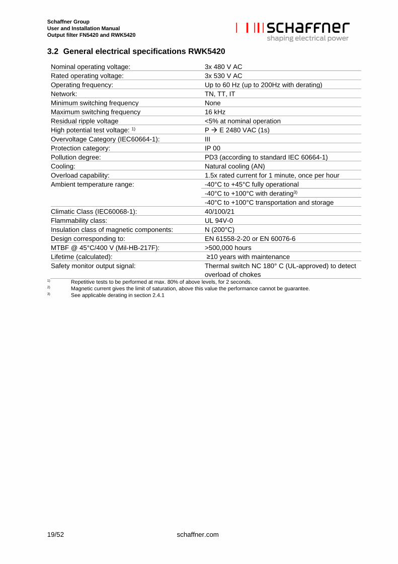
3.2 General electrical specifications RWK5420
Nominal operating voltage: 3x 480 V AC Rated operating voltage: 3x 530 V AC Operating frequency: Up to 60 Hz (up to 200Hz with derating) Network: TN, TT, IT Minimum switching frequency None Maximum switching frequency 16 kHz Residual ripple voltage <5% at nominal operation High potential test voltage: 1) P E 2480 VAC (1s) Overvoltage Category (IEC60664-1): III Protection category: IP 00 Pollution degree: PD3 (according to standard IEC 60664-1) Cooling: Natural cooling (AN) Overload capability: 1.5x rated current for 1 minute, once per hour Ambient temperature range:
-40°C to +45°C fully operational -40°C to +100°C with derating3) -40°C to +100°C transportation and storage
Climatic Class (IEC60068-1): 40/100/21 Flammability class: UL 94V-0 Insulation class of magnetic components: N (200°C) Design corresponding to: EN 61558-2-20 or EN 60076-6 MTBF @ 45°C/400 V (Mil-HB-217F): >500,000 hours Lifetime (calculated): ≥10 years with maintenance Safety monitor output signal: Thermal switch NC 180° C (UL-approved) to detect
overload of chokes 1) Repetitive tests to be performed at max. 80% of above levels, for 2 seconds. 2) Magnetic current gives the limit of saturation, above this value the performance cannot be guarantee. 3) See applicable derating in section 2.4.1
Schaffner Group User and Installation Manual Output filter FN5420 and RWK5420
schaffner.com 20/52
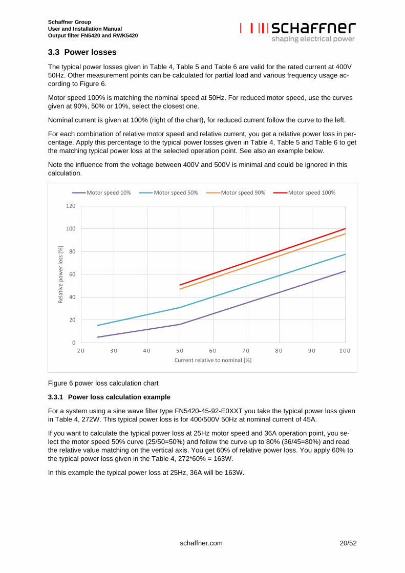
3.3 Power losses The typical power losses given in Table 4, Table 5 and Table 6 are valid for the rated current at 400V 50Hz. Other measurement points can be calculated for partial load and various frequency usage ac-cording to Figure 6.
Motor speed 100% is matching the nominal speed at 50Hz. For reduced motor speed, use the curves given at 90%, 50% or 10%, select the closest one.
Nominal current is given at 100% (right of the chart), for reduced current follow the curve to the left.
For each combination of relative motor speed and relative current, you get a relative power loss in per-centage. Apply this percentage to the typical power losses given in Table 4, Table 5 and Table 6 to get the matching typical power loss at the selected operation point. See also an example below.
Note the influence from the voltage between 400V and 500V is minimal and could be ignored in this calculation.
Figure 6 power loss calculation chart
3.3.1 Power loss calculation example
For a system using a sine wave filter type FN5420-45-92-E0XXT you take the typical power loss given in Table 4, 272W. This typical power loss is for 400/500V 50Hz at nominal current of 45A.
If you want to calculate the typical power loss at 25Hz motor speed and 36A operation point, you se-lect the motor speed 50% curve (25/50=50%) and follow the curve up to 80% (36/45=80%) and read the relative value matching on the vertical axis. You get 60% of relative power loss. You apply 60% to the typical power loss given in the Table 4, 272*60% = 163W.
In this example the typical power loss at 25Hz, 36A will be 163W.
0
20
40
60
80
100
120
2 0 3 0 4 0 5 0 6 0 7 0 8 0 9 0 1 0 0
Rela
tive
pow
er lo
ss [%
]
Current relative to nominal [%]
Motor speed 10% Motor speed 50% Motor speed 90% Motor speed 100%
Schaffner Group User and Installation Manual Output filter FN5420 and RWK5420
21/52 schaffner.com
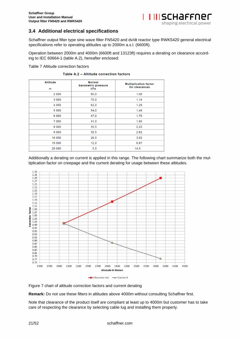
3.4 Additional electrical specifications Schaffner output filter type sine wave filter FN5420 and dv/dt reactor type RWK5420 general electrical specifications refer to operating altitudes up to 2000m a.s.l. (6600ft).
Operation between 2000m and 4000m (6600ft and 13123ft) requires a derating on clearance accord-ing to IEC 60664-1 (table A.2), hereafter enclosed:
Table 7 Altitude correction factors
Additionally a derating on current is applied in this range. The following chart summarize both the mul-tiplication factor on creepage and the current derating for usage between these altitudes.
Figure 7 chart of altitude correction factors and current derating
Remark: Do not use these filters in altitudes above 4000m without consulting Schaffner first.
Note that clearance of the product itself are compliant at least up to 4000m but customer has to take care of respecting the clearance by selecting cable lug and installing them properly.
Schaffner Group User and Installation Manual Output filter FN5420 and RWK5420
schaffner.com 22/52
3.5 Screw size, torque and cable cross-section requirement 3.5.1 Power terminals
The cable cross-section must be selected according to the rated filter current, the maximum current, the environment and other special requirement of the application. It should be stranded copper wire cable with a temperature rating of ≥75°C. Recommended cable cross-section is given in Table 8 and Table 9.
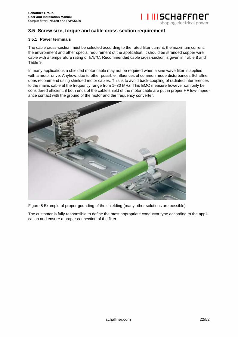
In many applications a shielded motor cable may not be required when a sine wave filter is applied with a motor drive. Anyhow, due to other possible influences of common mode disturbances Schaffner does recommend using shielded motor cables. This is to avoid back-coupling of radiated interferences to the mains cable at the frequency range from 1–30 MHz. This EMC measure however can only be considered efficient, if both ends of the cable shield of the motor cable are put in proper HF low-imped-ance contact with the ground of the motor and the frequency converter.
Figure 8 Example of proper gounding of the shielding (many other solutions are possible)
The customer is fully responsible to define the most appropriate conductor type according to the appli-cation and ensure a proper connection of the filter.
Schaffner Group User and Installation Manual Output filter FN5420 and RWK5420
23/52 schaffner.com
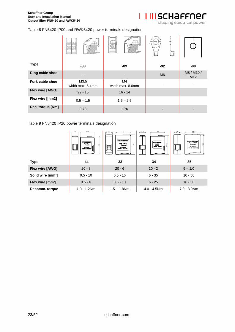
Table 8 FN5420 IP00 and RWK5420 power terminals designation
Type -88 -89 -92 -99
Ring cable shoe - - M6 M8 / M10 / M12
Fork cable shoe M3.5 width max. 6.4mm
M4 width max. 8.0mm - -
Flex wire [AWG] 22 - 16 16 - 14
Flex wire [mm2] 0.5 – 1.5 1.5 – 2.5
Rec. torque [Nm] 0.78 1.76 - -
Table 9 FN5420 IP20 power terminals designation
Type -44 -33 -34 -35
Flex wire [AWG] 20 - 8 20 - 6 10 - 2 6 – 1/0
Solid wire [mm²] 0.5 - 10 0.5 - 16 6 - 35 10 - 50
Flex wire [mm²] 0.5 - 6 0.5 - 10 6 - 25 16 - 50
Recomm. torque 1.0 - 1.2Nm 1.5 – 1.8Nm 4.0 - 4.5Nm 7.0 - 8.0Nm
Schaffner Group User and Installation Manual Output filter FN5420 and RWK5420
schaffner.com 24/52
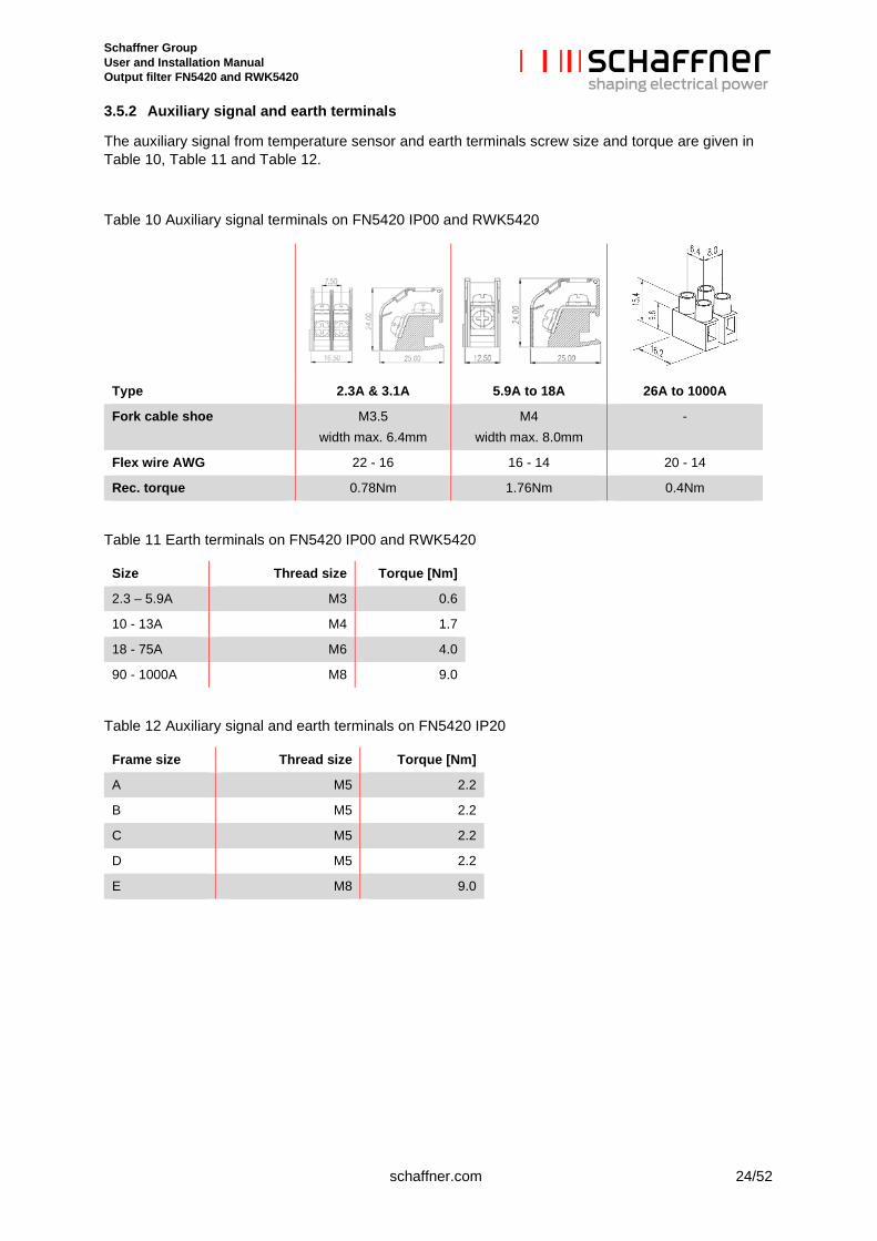
3.5.2 Auxiliary signal and earth terminals
The auxiliary signal from temperature sensor and earth terminals screw size and torque are given in Table 10, Table 11 and Table 12.
Table 10 Auxiliary signal terminals on FN5420 IP00 and RWK5420
Table 11 Earth terminals on FN5420 IP00 and RWK5420
Size Thread size Torque [Nm]
2.3 – 5.9A M3 0.6
10 - 13A M4 1.7
18 - 75A M6 4.0
90 - 1000A M8 9.0
Table 12 Auxiliary signal and earth terminals on FN5420 IP20
Frame size Thread size Torque [Nm]
A M5 2.2
B M5 2.2
C M5 2.2
D M5 2.2
E M8 9.0
Type 2.3A & 3.1A 5.9A to 18A 26A to 1000A
Fork cable shoe M3.5 width max. 6.4mm
M4 width max. 8.0mm
-
Flex wire AWG 22 - 16 16 - 14 20 - 14
Rec. torque 0.78Nm 1.76Nm 0.4Nm
Schaffner Group User and Installation Manual Output filter FN5420 and RWK5420
25/52 schaffner.com
3.6 Thermal protection switch specifications The central choke (phase V) is equipped with a thermal protection switch (temperature switch). The switch is connected in series to the auxiliary terminal TS-TS’. If the temperature switch reaches the nominal switching temperature (NST), the switch will open.
Table 13 thermal protection switch specifications
Contact type Normally closed (NC)
Nominal switching temperature (NST) 180°C
Resetting temperature (RST) 145°C (indication only)
Operating voltage Up to 250V AC
Rated current AC Inom 2.5A cosϕ = 1.0 1.6A cosϕ = 0.6 1.8A cosϕ = 0.4-0.5
3.7 Cooling requirement Sine wave filter FN5420 IP20 come with embedded ventilation when needed. Thus, it is important to install the filter in a way that the air channels are not blocked and within an ambient temperature ac-cording to the specifications from section 2.2.
Important: Blocking of air channel might cause overheating of filter compo-nents.
Schaffner Group User and Installation Manual Output filter FN5420 and RWK5420
schaffner.com 26/52
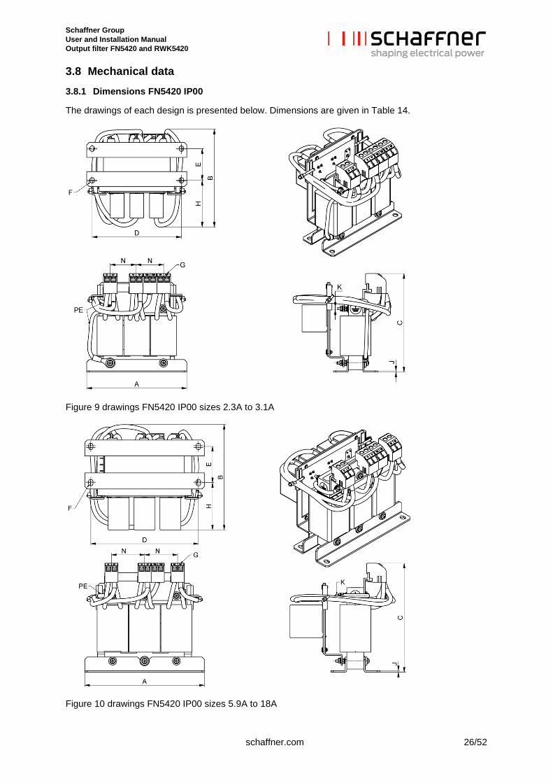
3.8 Mechanical data 3.8.1 Dimensions FN5420 IP00
The drawings of each design is presented below. Dimensions are given in Table 14.
Figure 9 drawings FN5420 IP00 sizes 2.3A to 3.1A
Figure 10 drawings FN5420 IP00 sizes 5.9A to 18A
Schaffner Group User and Installation Manual Output filter FN5420 and RWK5420
27/52 schaffner.com
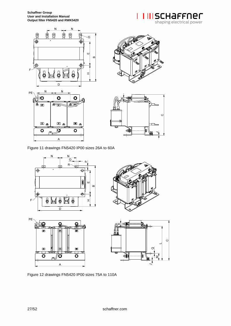
Figure 11 drawings FN5420 IP00 sizes 26A to 60A
Figure 12 drawings FN5420 IP00 sizes 75A to 110A
Schaffner Group User and Installation Manual Output filter FN5420 and RWK5420
schaffner.com 28/52
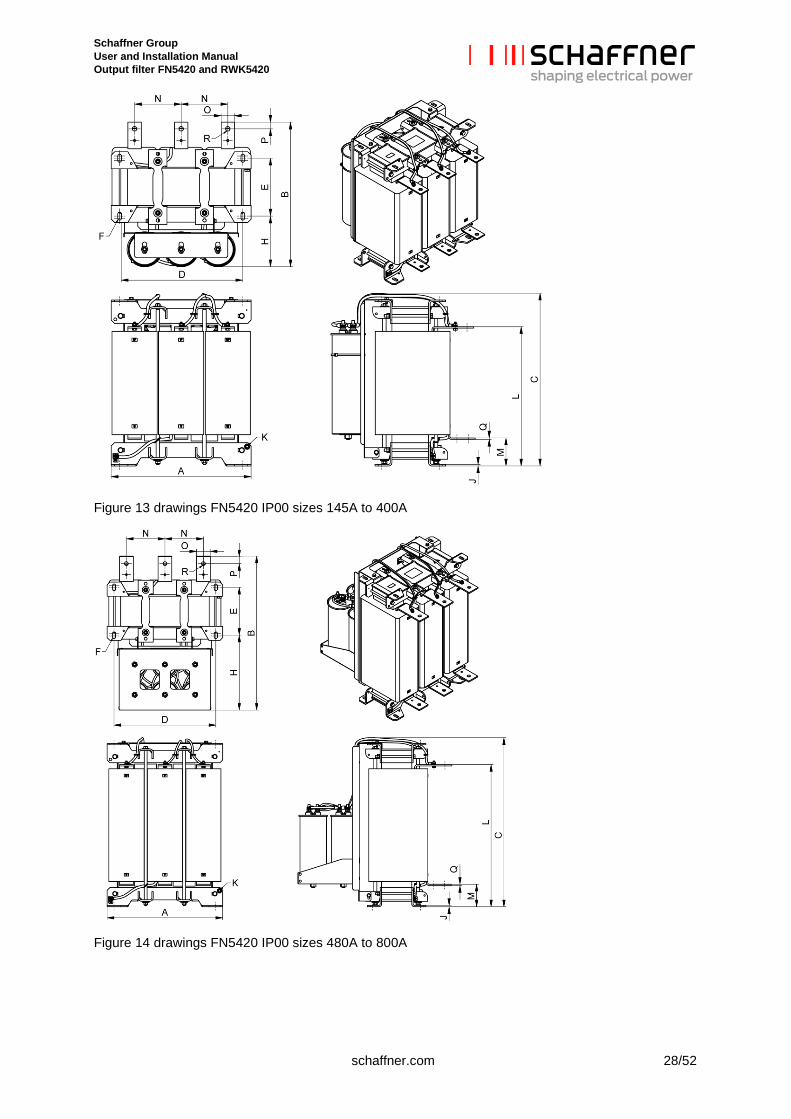
Figure 13 drawings FN5420 IP00 sizes 145A to 400A
Figure 14 drawings FN5420 IP00 sizes 480A to 800A
Schaffner Group User and Installation Manual Output filter FN5420 and RWK5420
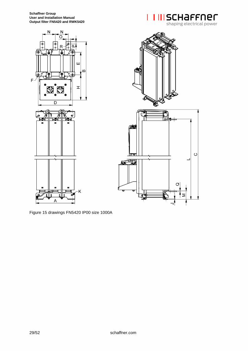
29/52 schaffner.com
Figure 15 drawings FN5420 IP00 size 1000A
Schaffner Group User and Installation Manual Output filter FN5420 and RWK5420
schaffner.com 30/52
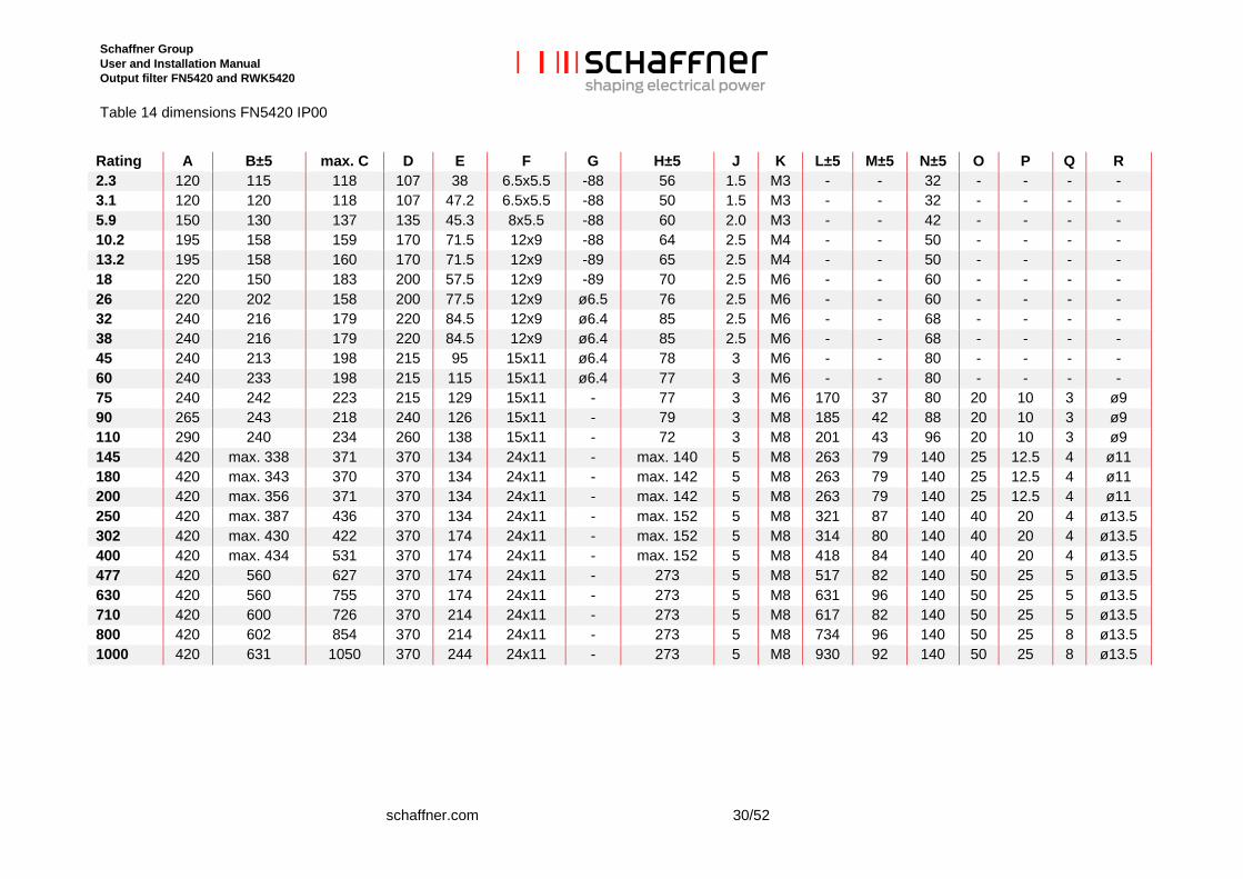
Table 14 dimensions FN5420 IP00
Rating A B±5 max. C D E F G H±5 J K L±5 M±5 N±5 O P Q R 2.3 120 115 118 107 38 6.5x5.5 -88 56 1.5 M3 - - 32 - - - - 3.1 120 120 118 107 47.2 6.5x5.5 -88 50 1.5 M3 - - 32 - - - - 5.9 150 130 137 135 45.3 8x5.5 -88 60 2.0 M3 - - 42 - - - - 10.2 195 158 159 170 71.5 12x9 -88 64 2.5 M4 - - 50 - - - - 13.2 195 158 160 170 71.5 12x9 -89 65 2.5 M4 - - 50 - - - - 18 220 150 183 200 57.5 12x9 -89 70 2.5 M6 - - 60 - - - - 26 220 202 158 200 77.5 12x9 ø6.5 76 2.5 M6 - - 60 - - - - 32 240 216 179 220 84.5 12x9 ø6.4 85 2.5 M6 - - 68 - - - - 38 240 216 179 220 84.5 12x9 ø6.4 85 2.5 M6 - - 68 - - - - 45 240 213 198 215 95 15x11 ø6.4 78 3 M6 - - 80 - - - - 60 240 233 198 215 115 15x11 ø6.4 77 3 M6 - - 80 - - - - 75 240 242 223 215 129 15x11 - 77 3 M6 170 37 80 20 10 3 ø9 90 265 243 218 240 126 15x11 - 79 3 M8 185 42 88 20 10 3 ø9 110 290 240 234 260 138 15x11 - 72 3 M8 201 43 96 20 10 3 ø9 145 420 max. 338 371 370 134 24x11 - max. 140 5 M8 263 79 140 25 12.5 4 ø11 180 420 max. 343 370 370 134 24x11 - max. 142 5 M8 263 79 140 25 12.5 4 ø11 200 420 max. 356 371 370 134 24x11 - max. 142 5 M8 263 79 140 25 12.5 4 ø11 250 420 max. 387 436 370 134 24x11 - max. 152 5 M8 321 87 140 40 20 4 ø13.5 302 420 max. 430 422 370 174 24x11 - max. 152 5 M8 314 80 140 40 20 4 ø13.5 400 420 max. 434 531 370 174 24x11 - max. 152 5 M8 418 84 140 40 20 4 ø13.5 477 420 560 627 370 174 24x11 - 273 5 M8 517 82 140 50 25 5 ø13.5 630 420 560 755 370 174 24x11 - 273 5 M8 631 96 140 50 25 5 ø13.5 710 420 600 726 370 214 24x11 - 273 5 M8 617 82 140 50 25 5 ø13.5 800 420 602 854 370 214 24x11 - 273 5 M8 734 96 140 50 25 8 ø13.5 1000 420 631 1050 370 244 24x11 - 273 5 M8 930 92 140 50 25 8 ø13.5
Schaffner Group User and Installation Manual Output filter FN5420 and RWK5420
31/52 schaffner.com
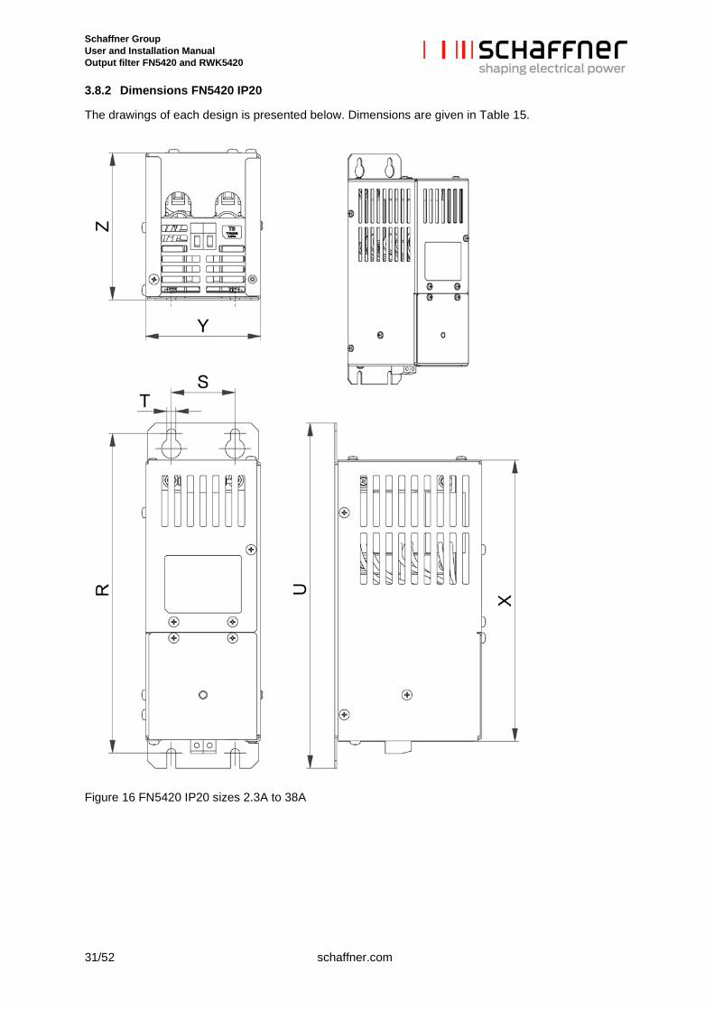
3.8.2 Dimensions FN5420 IP20
The drawings of each design is presented below. Dimensions are given in Table 15.
Figure 16 FN5420 IP20 sizes 2.3A to 38A
Schaffner Group User and Installation Manual Output filter FN5420 and RWK5420
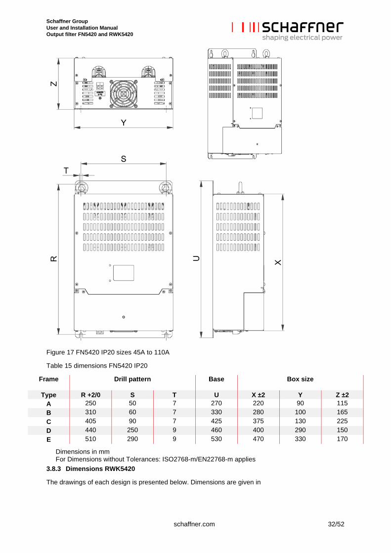
schaffner.com 32/52
Figure 17 FN5420 IP20 sizes 45A to 110A
Table 15 dimensions FN5420 IP20
Frame Drill pattern
Base Box size
Type R +2/0 S T U X ±2 Y Z ±2 A 250 50 7 270 220 90 115 B 310 60 7 330 280 100 165 C 405 90 7 425 375 130 225 D 440 250 9 460 400 290 150 E 510 290 9 530 470 330 170
Dimensions in mm For Dimensions without Tolerances: ISO2768-m/EN22768-m applies
3.8.3 Dimensions RWK5420
The drawings of each design is presented below. Dimensions are given in
Schaffner Group User and Installation Manual Output filter FN5420 and RWK5420
33/52 schaffner.com
Table 16.
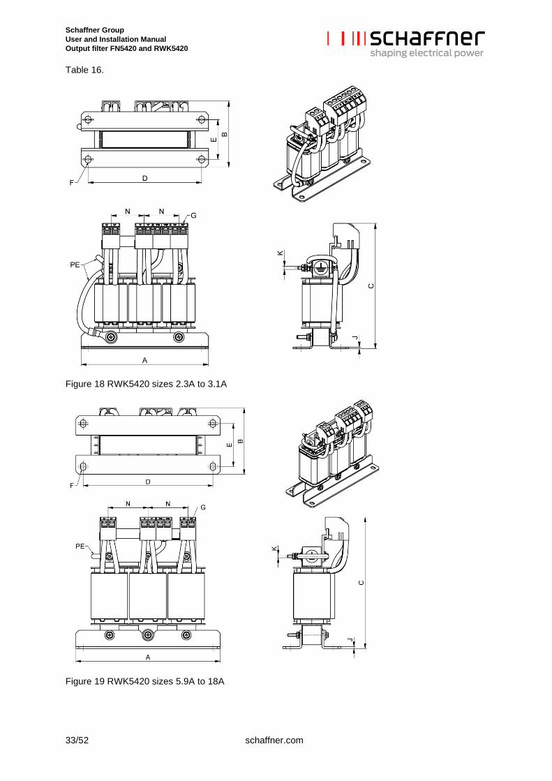
Figure 18 RWK5420 sizes 2.3A to 3.1A
Figure 19 RWK5420 sizes 5.9A to 18A
Schaffner Group User and Installation Manual Output filter FN5420 and RWK5420
schaffner.com 34/52
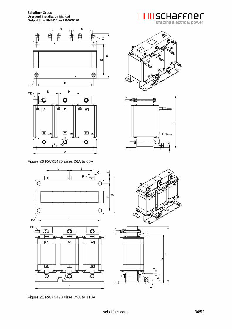
Figure 20 RWK5420 sizes 26A to 60A
Figure 21 RWK5420 sizes 75A to 110A
Schaffner Group User and Installation Manual Output filter FN5420 and RWK5420
35/52 schaffner.com
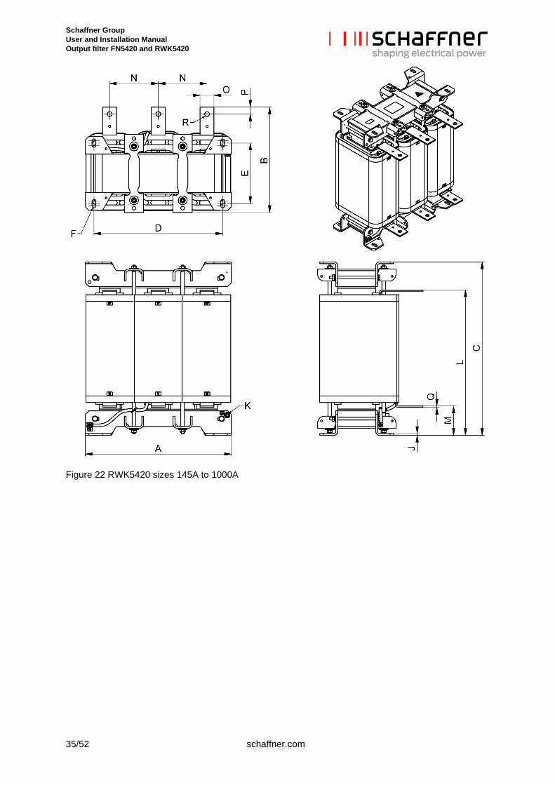
Figure 22 RWK5420 sizes 145A to 1000A
Schaffner Group User and Installation Manual Output filter FN5420 and RWK5420
schaffner.com 36/52
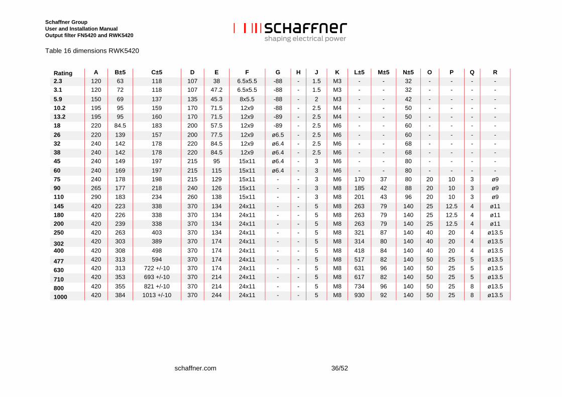
Table 16 dimensions RWK5420
Rating A B±5 C±5 D E F G H J K L±5 M±5 N±5 O P Q R 2.3 120 63 118 107 38 6.5x5.5 -88 - 1.5 M3 - - 32 - - - - 3.1 120 72 118 107 47.2 6.5x5.5 -88 - 1.5 M3 - - 32 - - - - 5.9 150 69 137 135 45.3 8x5.5 -88 - 2 M3 - - 42 - - - - 10.2 195 95 159 170 71.5 12x9 -88 - 2.5 M4 - - 50 - - - - 13.2 195 95 160 170 71.5 12x9 -89 - 2.5 M4 - - 50 - - - - 18 220 84.5 183 200 57.5 12x9 -89 - 2.5 M6 - - 60 - - - - 26 220 139 157 200 77.5 12x9 ø6.5 - 2.5 M6 - - 60 - - - - 32 240 142 178 220 84.5 12x9 ø6.4 - 2.5 M6 - - 68 - - - - 38 240 142 178 220 84.5 12x9 ø6.4 - 2.5 M6 - - 68 - - - - 45 240 149 197 215 95 15x11 ø6.4 - 3 M6 - - 80 - - - - 60 240 169 197 215 115 15x11 ø6.4 - 3 M6 - - 80 - - - - 75 240 178 198 215 129 15x11 - - 3 M6 170 37 80 20 10 3 ø9 90 265 177 218 240 126 15x11 - - 3 M8 185 42 88 20 10 3 ø9 110 290 183 234 260 138 15x11 - - 3 M8 201 43 96 20 10 3 ø9 145 420 223 338 370 134 24x11 - - 5 M8 263 79 140 25 12.5 4 ø11 180 420 226 338 370 134 24x11 - - 5 M8 263 79 140 25 12.5 4 ø11 200 420 239 338 370 134 24x11 - - 5 M8 263 79 140 25 12.5 4 ø11 250 420 263 403 370 134 24x11 - - 5 M8 321 87 140 40 20 4 ø13.5
302 420 303 389 370 174 24x11 - - 5 M8 314 80 140 40 20 4 ø13.5 400 420 308 498 370 174 24x11 - - 5 M8 418 84 140 40 20 4 ø13.5
477 420 313 594 370 174 24x11 - - 5 M8 517 82 140 50 25 5 ø13.5
630 420 313 722 +/-10 370 174 24x11 - - 5 M8 631 96 140 50 25 5 ø13.5
710 420 353 693 +/-10 370 214 24x11 - - 5 M8 617 82 140 50 25 5 ø13.5
800 420 355 821 +/-10 370 214 24x11 - - 5 M8 734 96 140 50 25 8 ø13.5
1000 420 384 1013 +/-10 370 244 24x11 - - 5 M8 930 92 140 50 25 8 ø13.5
Schaffner Group User and Installation Manual Output filter FN5420 and RWK5420
37/52 schaffner.com
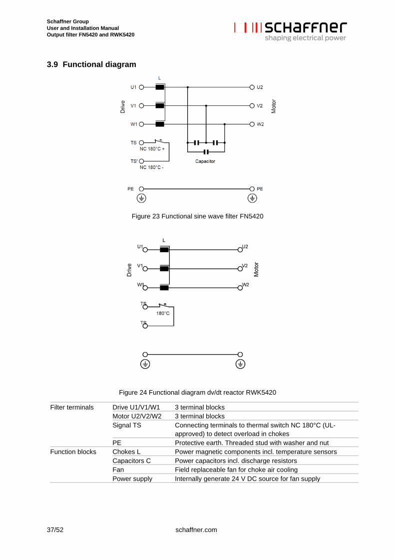
3.9 Functional diagram
Figure 23 Functional sine wave filter FN5420
Figure 24 Functional diagram dv/dt reactor RWK5420
Filter terminals Drive U1/V1/W1 3 terminal blocks Motor U2/V2/W2 3 terminal blocks Signal TS Connecting terminals to thermal switch NC 180°C (UL-
approved) to detect overload in chokes PE Protective earth. Threaded stud with washer and nut Function blocks Chokes L Power magnetic components incl. temperature sensors Capacitors C Power capacitors incl. discharge resistors Fan Field replaceable fan for choke air cooling Power supply Internally generate 24 V DC source for fan supply
Schaffner Group User and Installation Manual Output filter FN5420 and RWK5420
schaffner.com 38/52
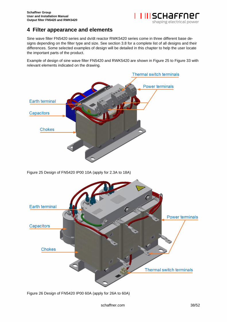
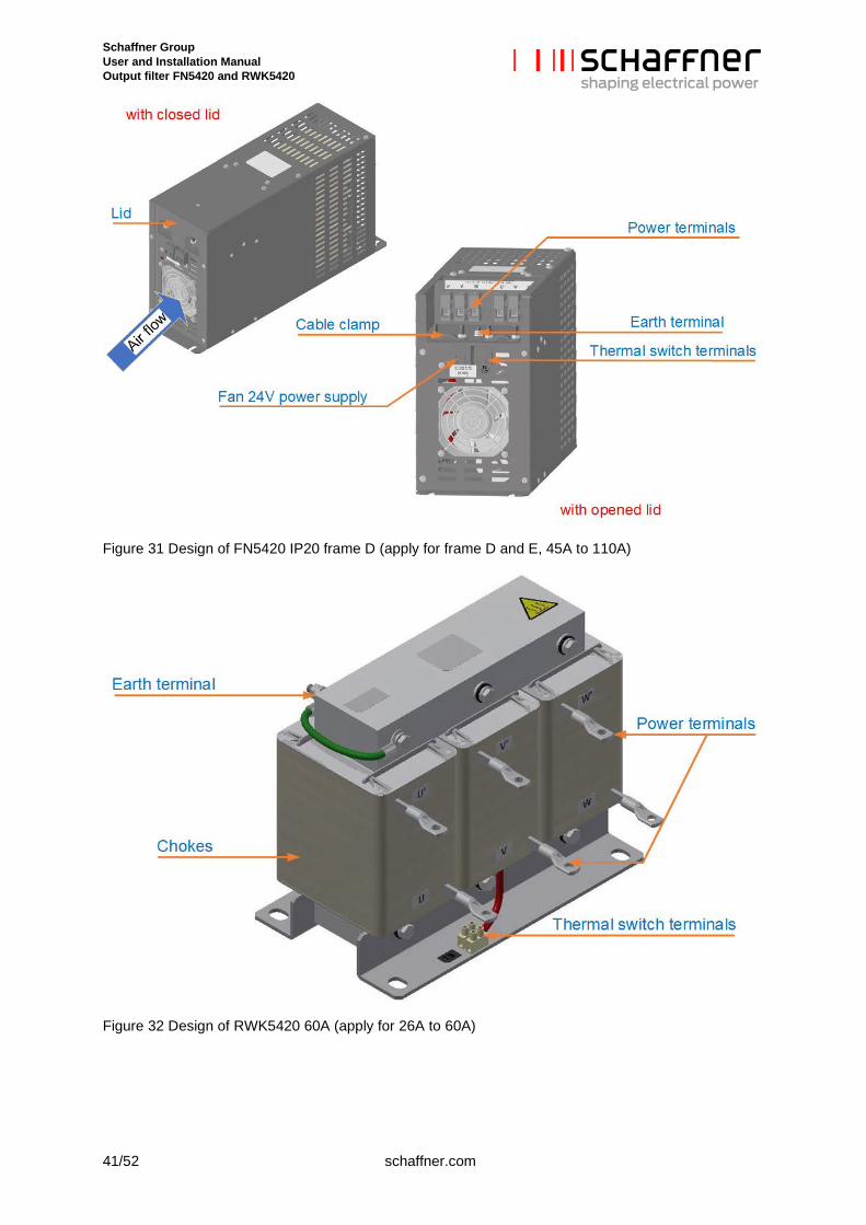
4 Filter appearance and elements Sine wave filter FN5420 series and dv/dt reactor RWK5420 series come in three different base de-signs depending on the filter type and size. See section 3.8 for a complete list of all designs and their differences. Some selected examples of design will be detailed in this chapter to help the user locate the important parts of the product.
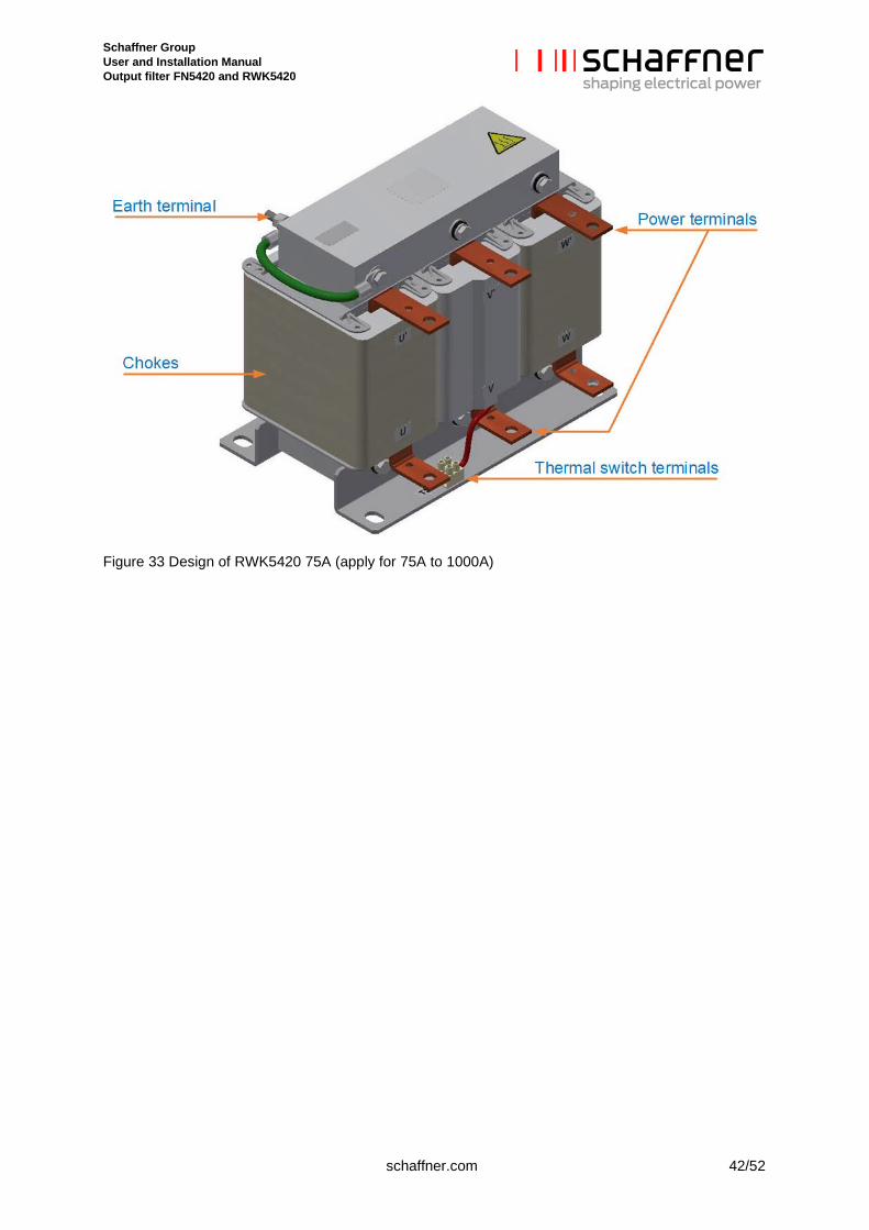
Example of design of sine wave filter FN5420 and RWK5420 are shown in Figure 25 to Figure 33 with relevant elements indicated on the drawing.
Figure 25 Design of FN5420 IP00 10A (apply for 2.3A to 18A)
Figure 26 Design of FN5420 IP00 60A (apply for 26A to 60A)
Schaffner Group User and Installation Manual Output filter FN5420 and RWK5420
39/52 schaffner.com
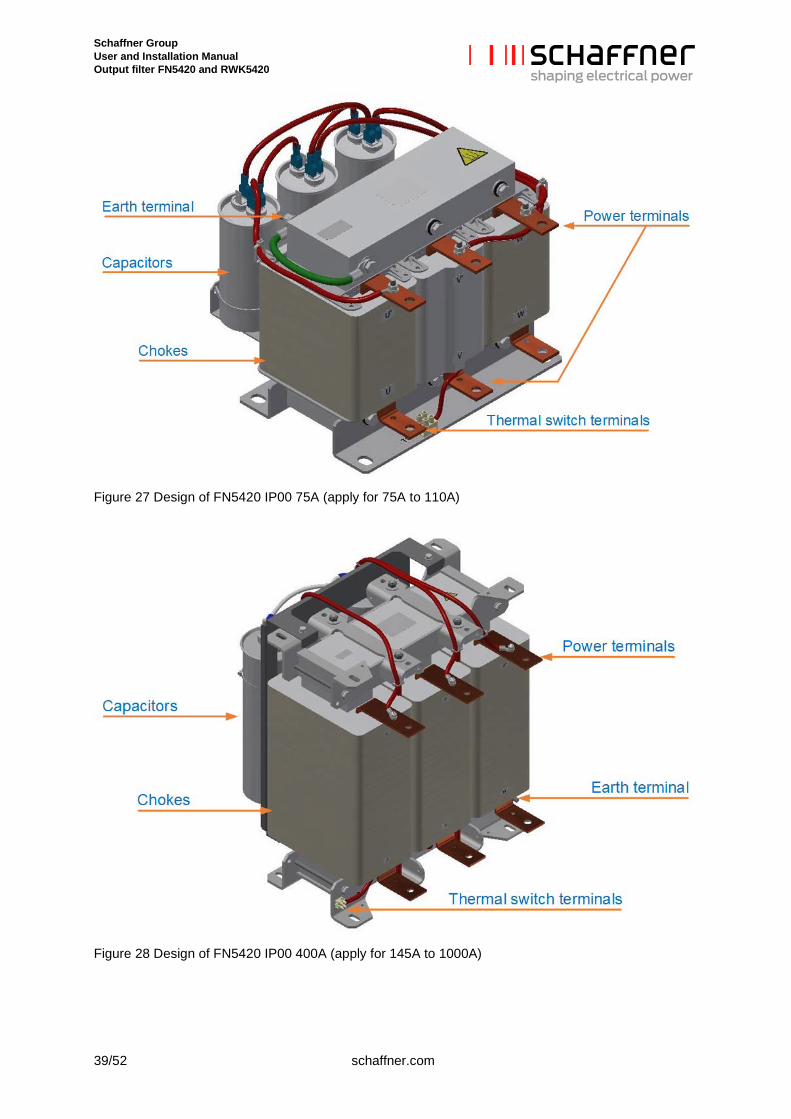
Figure 27 Design of FN5420 IP00 75A (apply for 75A to 110A)
Figure 28 Design of FN5420 IP00 400A (apply for 145A to 1000A)
Schaffner Group User and Installation Manual Output filter FN5420 and RWK5420
schaffner.com 40/52
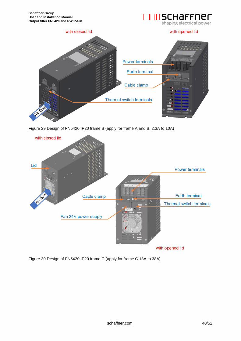
Figure 29 Design of FN5420 IP20 frame B (apply for frame A and B, 2.3A to 10A)
Figure 30 Design of FN5420 IP20 frame C (apply for frame C 13A to 38A)
Schaffner Group User and Installation Manual Output filter FN5420 and RWK5420
41/52 schaffner.com
Figure 31 Design of FN5420 IP20 frame D (apply for frame D and E, 45A to 110A)
Figure 32 Design of RWK5420 60A (apply for 26A to 60A)
Schaffner Group User and Installation Manual Output filter FN5420 and RWK5420
schaffner.com 42/52
Figure 33 Design of RWK5420 75A (apply for 75A to 1000A)
Schaffner Group User and Installation Manual Output filter FN5420 and RWK5420
43/52 schaffner.com
5 Filter installation Please follow the simple steps below to ensure a safe and reliable filter function for many years. Please do also always follow the general safety and installation guidelines provided within this docu-ment as well as relevant local, national or international standards that are applicable. Please note that the following installation steps are applicable for sine wave filter FN5420 series IP00 and IP20 as well as dv/dt reator RWK5420 series.
5.1 Step 1: Visual inspection All Schaffner output filters have undergone rigorous testing before they left our ISO 9001:2008 certified factories. They are packaged with great care in a sturdy container for international shipment.
However, carefully inspect the shipping container for damage that may have occurred in transit. Then unpack the filter and carefully inspect for any signs of damage. Keep the shipping container for future transportation of the filter.
In the case of damage, please file a claim with the freight forwarder involved immediately and contact your local Schaffner partner for support. Under no circumstances install and energize a filter with visi-ble transportation damage.
If the filter is not going to be put in service upon receipt, store within the original container in a clean, dry location, free of dust and chemicals and with respect to named temperature limits, see section 3.1 and 3.2.
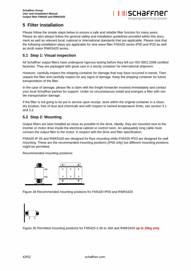
5.2 Step 2: Mounting Output filters are best installed as close as possible to the drive. Ideally, they are mounted next to the inverter or motor drive inside the electrical cabinet or control room. An adequately long cable must connect the output filter to the motor, in respect with the drive and filter specification.
FN5420 IP 00 and RWK5420 are designed for floor mounting while FN5420 IP20 are designed for wall mounting. These are the recommanded mounting positions (IP00 only) but different mounting positions might be permitted.
Recommended mounting positions:
Figure 34 Recommended mounting positions fro FN5420 IP00 and RWK5420
Figure 35 Permitted mounting positions for FN5420 2.3A to 18A and RWK5420 up to 25kg only
Schaffner Group User and Installation Manual Output filter FN5420 and RWK5420
schaffner.com 44/52
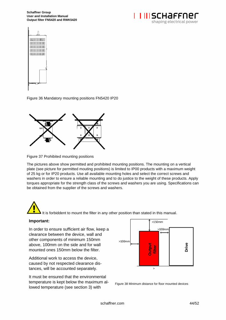
Figure 36 Mandatory mounting positions FN5420 IP20
Figure 37 Prohibited mounting positions
The pictures above show permitted and prohibited mounting positions. The mounting on a vertical plate (see picture for permitted mouting positions) is limited to IP00 products with a maximum weight of 25 kg or for IP20 products. Use all available mounting holes and select the correct screws and washers in order to ensure a reliable mounting and to do justice to the weight of these products. Apply torques appropriate for the strength class of the screws and washers you are using. Specifications can be obtained from the supplier of the screws and washers.
It is forbiddent to mount the filter in any other position than stated in this manual.
Important:
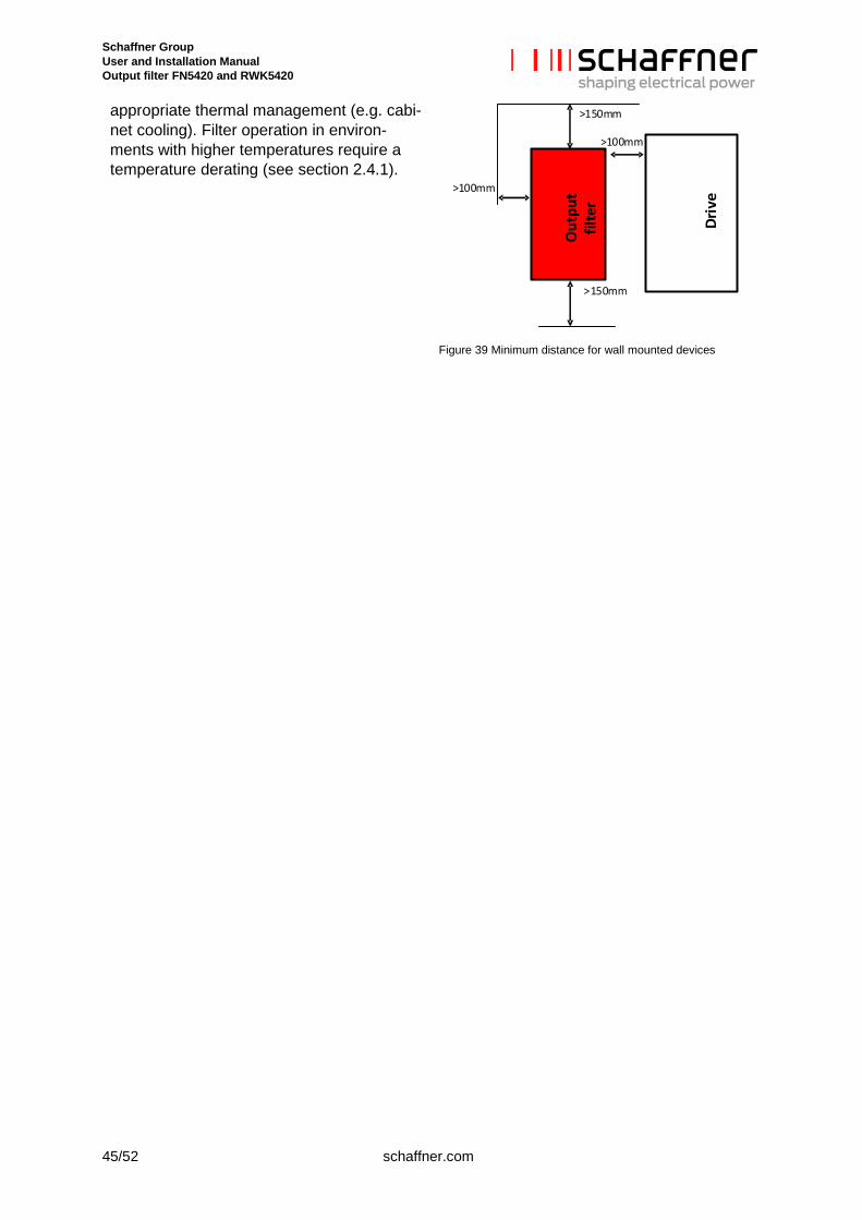
In order to ensure sufficient air flow, keep a clearance between the device, wall and other components of minimum 150mm above, 100mm on the side and for wall mounted ones 150mm below the filter.
Additional work to access the device, caused by not respected clearance dis-tances, will be accounted separately.
It must be ensured that the environmental temperature is kept below the maximum al-lowed temperature (see section 3) with
O
utpu
t fil
ter
Driv
e
>150mm
>
>100mm
>100mm
Figure 38 Minimum distance for floor mounted devices
Schaffner Group User and Installation Manual Output filter FN5420 and RWK5420
45/52 schaffner.com
appropriate thermal management (e.g. cabi-net cooling). Filter operation in environ-ments with higher temperatures require a temperature derating (see section 2.4.1).
O
utpu
t fil
ter
Driv
e
>150mm
>150mm
>100mm
>100mm
Figure 39 Minimum distance for wall mounted devices
Schaffner Group User and Installation Manual Output filter FN5420 and RWK5420
schaffner.com 46/52
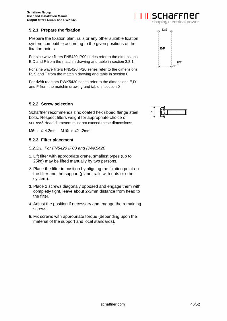
5.2.1 Prepare the fixation
Prepare the fixation plan, rails or any other suitable fixation system compatible according to the given positions of the fixation points.
For sine wave filters FN5420 IP00 series refer to the dimensions E,D and F from the matchin drawing and table in section 3.8.1
For sine wave filters FN5420 IP20 series refer to the dimensions R, S and T from the matchin drawing and table in section 0
For dv/dt reactors RWK5420 series refer to the dimensions E,D and F from the matchin drawing and table in section 0
5.2.2 Screw selection
Schaffner recommends zinc coated hex ribbed flange steel bolts. Respect filters weight for appropriate choice of screws! Head diameters must not exceed these dimensions:
M6: d ≤14.2mm, M10: d ≤21.2mm
5.2.3 Filter placement
5.2.3.1 For FN5420 IP00 and RWK5420
1. Lift filter with appropriate crane, smallest types (up to 25kg) may be lifted manually by two persons.
2. Place the filter in position by aligning the fixation point on the filter and the support (plane, rails with nuts or other system).
3. Place 2 screws diagonaly opposed and engage them with completly tight, leave about 2-3mm distance from head to the filter.
4. Adjust the position if necessary and engage the remaining screws.
5. Fix screws with appropriate torque (depending upon the material of the support and local standards).
E/R
D/S
F/T
d
Schaffner Group User and Installation Manual Output filter FN5420 and RWK5420
47/52 schaffner.com
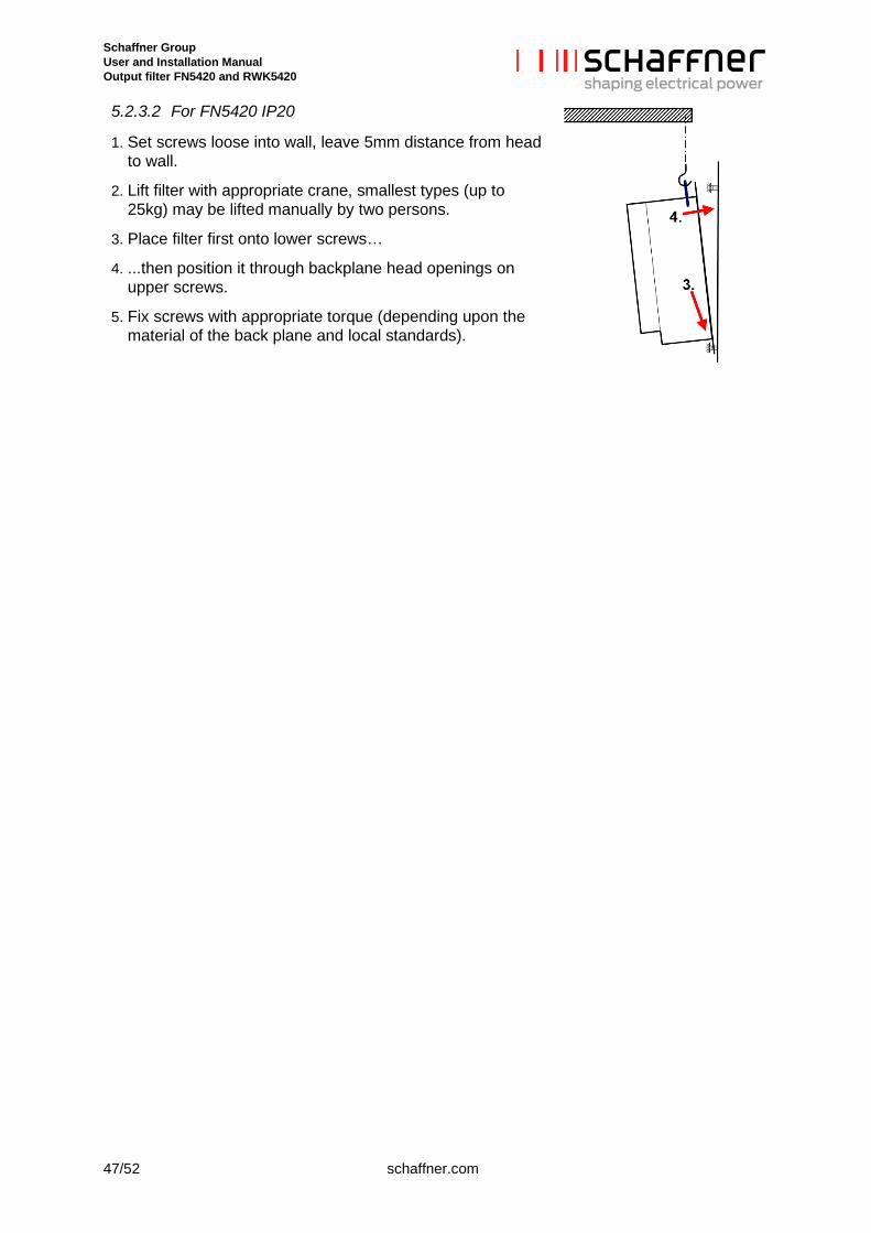
5.2.3.2 For FN5420 IP20
1. Set screws loose into wall, leave 5mm distance from head to wall.
2. Lift filter with appropriate crane, smallest types (up to 25kg) may be lifted manually by two persons.
3. Place filter first onto lower screws…
4. ...then position it through backplane head openings on upper screws.
5. Fix screws with appropriate torque (depending upon the material of the back plane and local standards).
Schaffner Group User and Installation Manual Output filter FN5420 and RWK5420
schaffner.com 48/52
5.3 Step 3: Wiring
5.3.1 Verify safe disconnection of all line side power
Consult your local safety instructions.
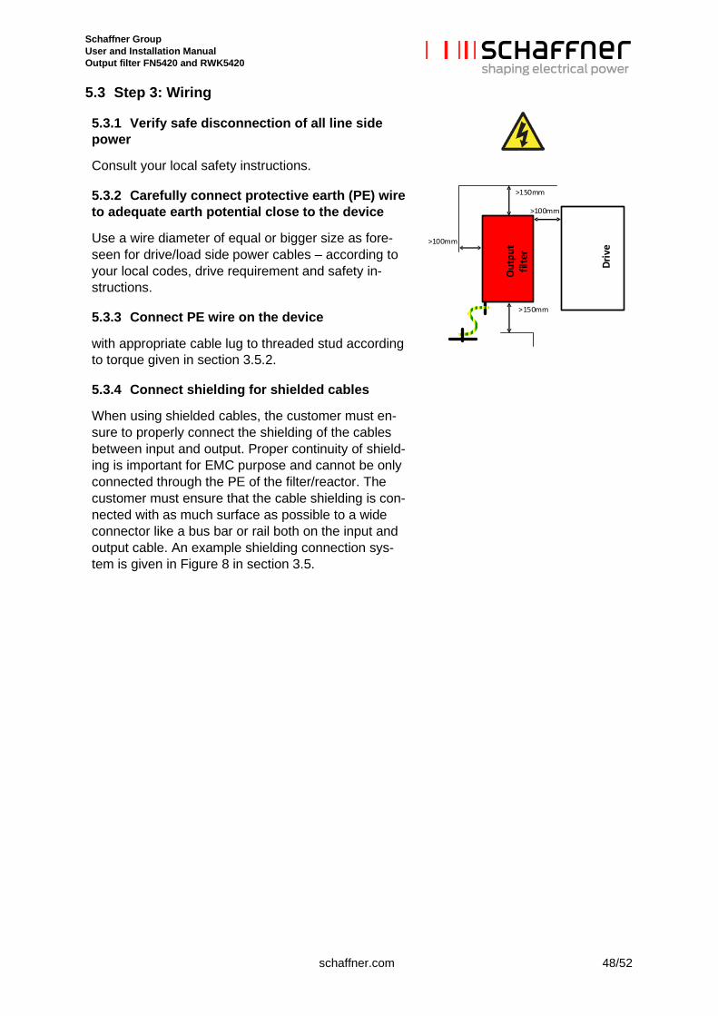
5.3.2 Carefully connect protective earth (PE) wire to adequate earth potential close to the device
Use a wire diameter of equal or bigger size as fore-seen for drive/load side power cables – according to your local codes, drive requirement and safety in-structions.
O
utpu
t fil
ter
Driv
e
>150mm
>150mm
>100mm
>100mm
5.3.3 Connect PE wire on the device
with appropriate cable lug to threaded stud according to torque given in section 3.5.2.
5.3.4 Connect shielding for shielded cables
When using shielded cables, the customer must en-sure to properly connect the shielding of the cables between input and output. Proper continuity of shield-ing is important for EMC purpose and cannot be only connected through the PE of the filter/reactor. The customer must ensure that the cable shielding is con-nected with as much surface as possible to a wide connector like a bus bar or rail both on the input and output cable. An example shielding connection sys-tem is given in Figure 8 in section 3.5.
Schaffner Group User and Installation Manual Output filter FN5420 and RWK5420
49/52 schaffner.com
5.3.5 Connect shielding for shielded cables
When using shielded cables, the customer must en-sure to properly connect the shielding of the cables between input and output. Proper continuity of shield-ing is important for EMC purpose and cannot be only connected through the PE of the filter/reactor. The customer must ensure that the cable shielding is con-nected with as much surface as possible to a wide connector like a bus bar or rail both on the drive side cable and motor side cable. An example shielding connection system is given in Figure 8 in section 3.5, other EMC compliant system are possible.
5.3.6 Connect the device on drive side
Connect the device on drive side terminals U, V, W to respective motor drive or rectifier outputs. The third part of the output filter/reactor designation is a number contains two digits, i.e. FN5420-10-88-E0XXT, which indicates power terminal type.
See section 3.5.1 for the recommended wire size and torque. Use stranded copper wire with a tem-pera-ture rating of 75°C or higher.
5.3.7 Connect output filter motor side
Connect output filter motor side terminals U2, V2, W2 to respective motor inputs. Output filter input and out-put terminals are the same type.
See section 3.5.1 for the recommended wire size and torque. Use stranded copper wire with a temperature rating of 75°C or higher.
5.3.8 Connect monitor switch TS- TS’
The monitor switch is a relay contact, which is open in ALARM state. It is constituted by a thermal switch NC 180°C (UL-approved) to detect overload of chokes. It may either be used to remotely disconnect the drive’s load via respective input of drive control (check drive manual) or as alarm sensor for system control unit.
AN ENGAGED MONITOR SWITCH MUST LEAD TO IMMEDIATE LOAD SHUTDOWN AND INVESTIGATION OF THE PROBLEM.
Schaffner Group User and Installation Manual Output filter FN5420 and RWK5420
schaffner.com 50/52
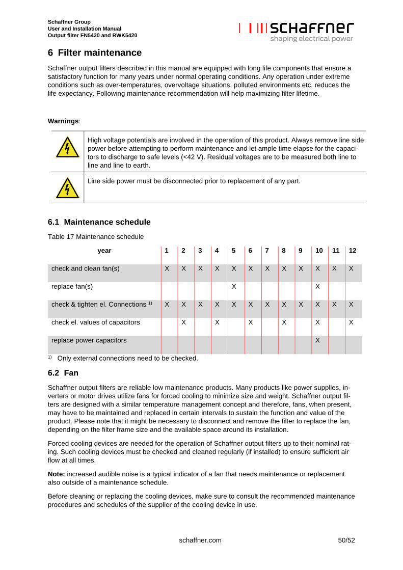
6 Filter maintenance Schaffner output filters described in this manual are equipped with long life components that ensure a satisfactory function for many years under normal operating conditions. Any operation under extreme conditions such as over-temperatures, overvoltage situations, polluted environments etc. reduces the life expectancy. Following maintenance recommendation will help maximizing filter lifetime.
Warnings:
High voltage potentials are involved in the operation of this product. Always remove line side power before attempting to perform maintenance and let ample time elapse for the capaci-tors to discharge to safe levels (<42 V). Residual voltages are to be measured both line to line and line to earth.
Line side power must be disconnected prior to replacement of any part.
6.1 Maintenance schedule Table 17 Maintenance schedule
year 1 2 3 4 5 6 7 8 9 10 11 12
check and clean fan(s) X X X X X X X X X X X X
replace fan(s) X X
check & tighten el. Connections 1) X X X X X X X X X X X X
check el. values of capacitors X X X X X X
replace power capacitors X
1) Only external connections need to be checked.
6.2 Fan Schaffner output filters are reliable low maintenance products. Many products like power supplies, in-verters or motor drives utilize fans for forced cooling to minimize size and weight. Schaffner output fil-ters are designed with a similar temperature management concept and therefore, fans, when present, may have to be maintained and replaced in certain intervals to sustain the function and value of the product. Please note that it might be necessary to disconnect and remove the filter to replace the fan, depending on the filter frame size and the available space around its installation.
Forced cooling devices are needed for the operation of Schaffner output filters up to their nominal rat-ing. Such cooling devices must be checked and cleaned regularly (if installed) to ensure sufficient air flow at all times.
Note: increased audible noise is a typical indicator of a fan that needs maintenance or replacement also outside of a maintenance schedule.
Before cleaning or replacing the cooling devices, make sure to consult the recommended maintenance procedures and schedules of the supplier of the cooling device in use.
Schaffner Group User and Installation Manual Output filter FN5420 and RWK5420
51/52 schaffner.com
6.3 Power capacitors The power capacitors supplied with the filters are high quality components with an expected lifetime of up to 100’000 hours (11 years). Nevertheless, their useful service life can be shortened by electrical or thermal stress beyond their specification.
Power capacitor damage may also be caused by severe abnormal supply voltage peaks (i.e. lightning – depending upon system protection), but may only be recognizable through the measurement of line side harmonics distortion. This may be checked with a modern energy meter or by regular checkup with a power quality analyzer. According to the above considerations, a 2 year inspection interval is advisable.
Note: an inspection should as well be performed after extreme overvoltage situations in the system.
Note: Storage of capacitors
Up to 3 years-long storage, electrolitic capacitors can be operated without any restriction and the nom-inal voltage can be applied without any preliminary preparation. System reliability and life-time expec-tancy are not affected.
On the other side, a longer ( >3 yrs) storage of electrolitic capacitors without applying any voltage can weaken the dielectric properties because of disslution processes. The electrolitic solution is aggressive and it can affect and weaken the dielectric in the timeframe between production and product commis-sioning. The weak points are responsible for the higher leakage current shortly after the device turn-on on site.
The residual current of electrolitic capacitors depends upon time, voltage and temperature. The resid-ual current increases after long storage without applying voltage.
The amplitude of resulting residual current during unit commissioning can be up to 10 times larger on short term. The capacitor’s residual current assumes the typical expected value at steady state for nominal voltage.
During comissioning after long storage, it is recommended to restore the dielectric characteristics by applying voltage progressively and with respect to the time frame the filters have been stored.
6.4 Electrical connections Depending upon the environment and application, electrical connections, in particular threaded bolts and nuts, can degrade over time by means of losing their initial tightening torque. This holds true not only for the filter, but for any such joint within an electrical installation.
Therefore, Schaffner recommends checking and tighten all electrical connections on the occasion of a regular scheduled maintenance of the entire device that incorporates the filter. Check of internal connections within the filters is not needed or should be conducted by a Schaffner service representative.
Schaffner Group User and Installation Manual Output filter FN5420 and RWK5420
schaffner.com 52/52
7 Troubleshooting Schaffner output filters are high quality products and have undergone rigorous testing and qualification procedures. Every unit runs through suitable tests in our ISO 9001:2000 factories. Due to this reason no major issues need to be expected if the filter is installed, operated, and maintained as described in this document.
In the unlikely event of a problem, please contact your local Schaffner partner for assistance.

Schaffner Group User and Installation Manual Output filter FN5420 and RWK5420
Schaffner Group | Nordstrasse 11e | 4542 Luterbach | Switzerland T +41 32 681 66 26 | [email protected] | www.schaffner.com
Top Related
Copyright © 2022 FDOKUMEN

