


Bahasa
Halaman
Hukum

CS8602-Compiler Design Department of CSE
1
2020 – 2021 Jeppiaar Institute of Technology
UNIT IV RUN-TIME ENVIRONMENT AND CODE GENERATION 8
Storage Organization, Stack Allocation Space, Access to Non-local Data on the Stack, Heap
Management - Issues in Code Generation - Design of a simple Code Generator.
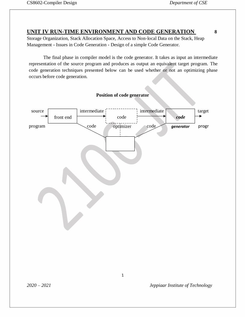
The final phase in compiler model is the code generator. It takes as input an intermediate
representation of the source program and produces as output an equivalent target program. The
code generation techniques presented below can be used whether or not an optimizing phase
occurs before code generation.
Position of code generator
source
front end
intermediate
code
intermediate
code
target
program code optimizer code generator progr
2
STORAGE ORGANISATION
The executing target program runs in its own logical address space in which each program
value has a location. The management and organization of this logical address space is shared between the complier,
operating system and target machine. The operating system maps the logical address into
physical addresses, which are usually spread throughout memory.
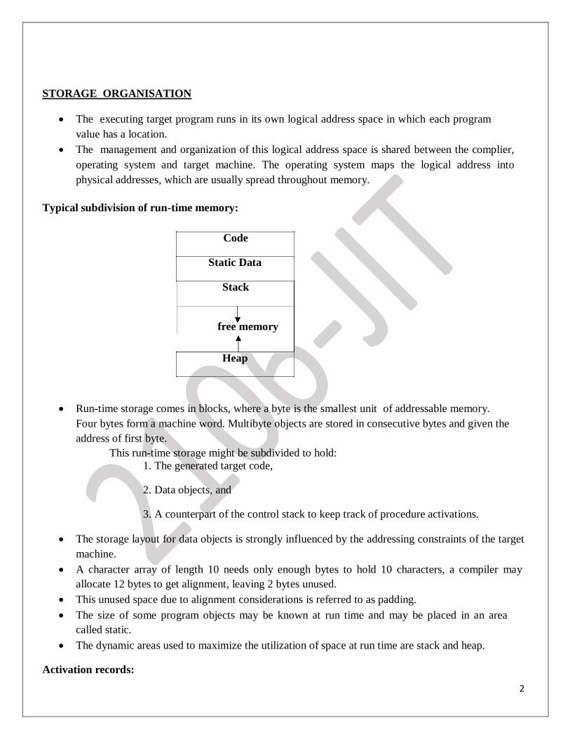
Typical subdivision of run-time memory:
Code
Static Data
Stack
free memory
Heap
Run-time storage comes in blocks, where a byte is the smallest unit of addressable memory.
Four bytes form a machine word. Multibyte objects are stored in consecutive bytes and given the
address of first byte.
This run-time storage might be subdivided to hold:
1. The generated target code,
2. Data objects, and
3. A counterpart of the control stack to keep track of procedure activations.
The storage layout for data objects is strongly influenced by the addressing constraints of the target
machine. A character array of length 10 needs only enough bytes to hold 10 characters, a compiler may
allocate 12 bytes to get alignment, leaving 2 bytes unused. This unused space due to alignment considerations is referred to as padding. The size of some program objects may be known at run time and may be placed in an area
called static. The dynamic areas used to maximize the utilization of space at run time are stack and heap.
Activation records:
3
Procedure calls and returns are usually managed by a run time stack called the control stack. Each live activation has an activation record on the control stack, with the root of the activation
tree at the bottom, the latter activation has its record at the top of the stack.
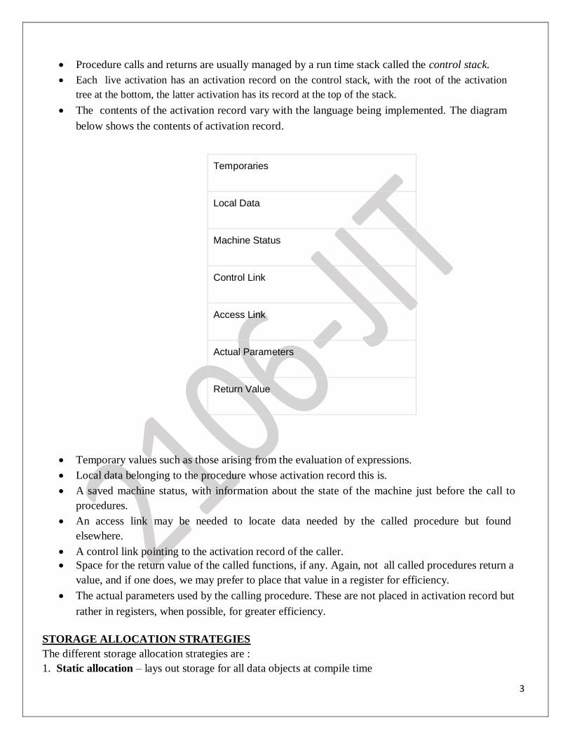
The contents of the activation record vary with the language being implemented. The diagram
below shows the contents of activation record.
Temporaries
Local Data
Machine Status
Control Link
Access Link
Actual Parameters
Return Value
Temporary values such as those arising from the evaluation of expressions. Local data belonging to the procedure whose activation record this is. A saved machine status, with information about the state of the machine just before the call to
procedures. An access link may be needed to locate data needed by the called procedure but found
elsewhere. A control link pointing to the activation record of the caller.
Space for the return value of the called functions, if any. Again, not all called procedures return a
value, and if one does, we may prefer to place that value in a register for efficiency.
The actual parameters used by the calling procedure. These are not placed in activation record but
rather in registers, when possible, for greater efficiency.
STORAGE ALLOCATION STRATEGIES The different storage allocation strategies are : 1. Static allocation – lays out storage for all data objects at compile time
4
2. Stack allocation – manages the run-time storage as a stack. 3. Heap allocation – allocates and deallocates storage as needed at run time from a data area known as
heap.
Static allocation
In static allocation, names are bound to storage as the program is compiled, so there is no need for
a run-time support package. Since the bindings do not change at run-time, everytime a procedure is activated, its names
are bound to the same storage locations.
Therefore values of local names are retained across activations of a procedure. That is, when
control returns to a procedure the values of the locals are the same as they were when control left
the last time.
From the type of a name, the compiler decides the amount of storage for the name and decides
where the activation records go. At compile time, we can fill in the addresses at which the target
code can find the data it operates on.
Some limitations of using static allocation:
1. The size of a data object and constraints on its position in memory must be known at
compile time.
2. Recursive procedures are restricted, because all activations of a procedure use the same
bindings for local names.
3. Data structures cannot be created dynamically, since there is no mechanism for storage
allocation at run time.
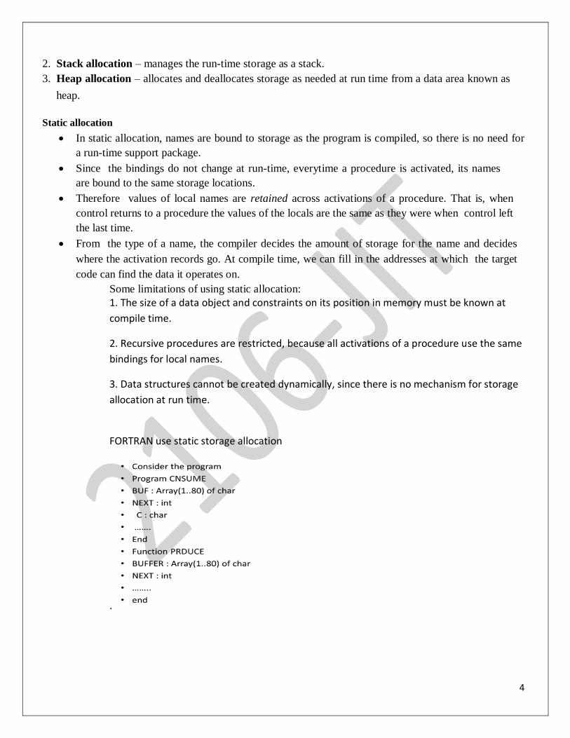
FORTRAN use static storage allocation
.
5
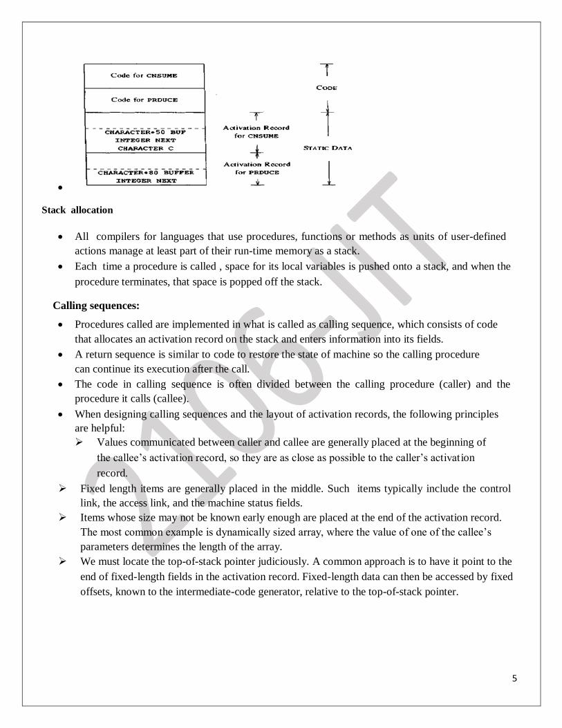
Stack allocation
All compilers for languages that use procedures, functions or methods as units of user-defined
actions manage at least part of their run-time memory as a stack. Each time a procedure is called , space for its local variables is pushed onto a stack, and when the
procedure terminates, that space is popped off the stack.
Calling sequences:
Procedures called are implemented in what is called as calling sequence, which consists of code
that allocates an activation record on the stack and enters information into its fields.
A return sequence is similar to code to restore the state of machine so the calling procedure
can continue its execution after the call. The code in calling sequence is often divided between the calling procedure (caller) and the
procedure it calls (callee). When designing calling sequences and the layout of activation records, the following principles
are helpful: Values communicated between caller and callee are generally placed at the beginning of
the callee’s activation record, so they are as close as possible to the caller’s activat ion
record.
Fixed length items are generally placed in the middle. Such items typically include the control
link, the access link, and the machine status fields.
Items whose size may not be known early enough are placed at the end of the activation record.
The most common example is dynamically sized array, where the value of one of the callee’s
parameters determines the length of the array.
We must locate the top-of-stack pointer judiciously. A common approach is to have it point to the
end of fixed-length fields in the activation record. Fixed-length data can then be accessed by fixed
offsets, known to the intermediate-code generator, relative to the top-of-stack pointer.
6
Parameters and returned values
caller’s
control link
activation
links and saved status
record
temporaries and local data
caller’s
responsibility
Parameters and returned values
callee’s
activation control link
record
links and saved status
top_sp
callee’s temporaries and local data
responsibility
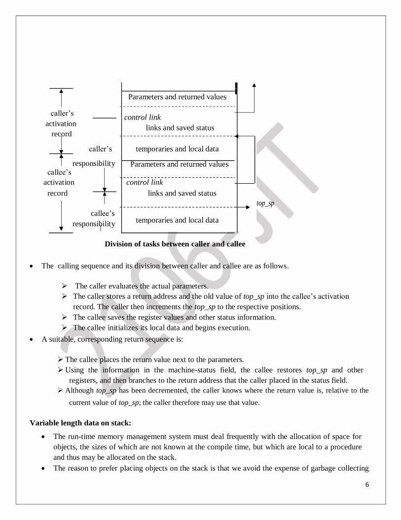
Division of tasks between caller and callee
The calling sequence and its division between caller and callee are as follows.
The caller evaluates the actual parameters.
The caller stores a return address and the old value of top_sp into the callee’s activation
record. The caller then increments the top_sp to the respective positions.
The callee saves the register values and other status information.
The callee initializes its local data and begins execution.
A suitable, corresponding return sequence is:
The callee places the return value next to the parameters.
Using the information in the machine-status field, the callee restores top_sp and other
registers, and then branches to the return address that the caller placed in the status field.
Although top_sp has been decremented, the caller knows where the return value is, relative to the
current value of top_sp; the caller therefore may use that value.
Variable length data on stack:
The run-time memory management system must deal frequently with the allocation of space for
objects, the sizes of which are not known at the compile time, but which are local to a procedure
and thus may be allocated on the stack.
The reason to prefer placing objects on the stack is that we avoid the expense of garbage collecting
7
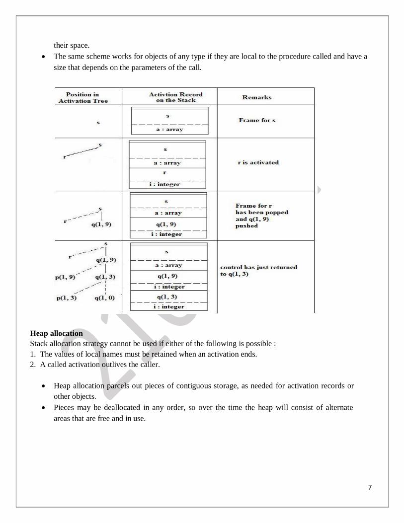
their space. The same scheme works for objects of any type if they are local to the procedure called and have a
size that depends on the parameters of the call.
Heap allocation Stack allocation strategy cannot be used if either of the following is possible : 1. The values of local names must be retained when an activation ends. 2. A called activation outlives the caller.
Heap allocation parcels out pieces of contiguous storage, as needed for activation records or
other objects. Pieces may be deallocated in any order, so over the time the heap will consist of alternate
areas that are free and in use.
8
Position in the Activation records in the heap Remarks
activation tree
s Retained activation
s record for r
r q ( 1 , 9) control link
r
control link
q(1,9)
control link
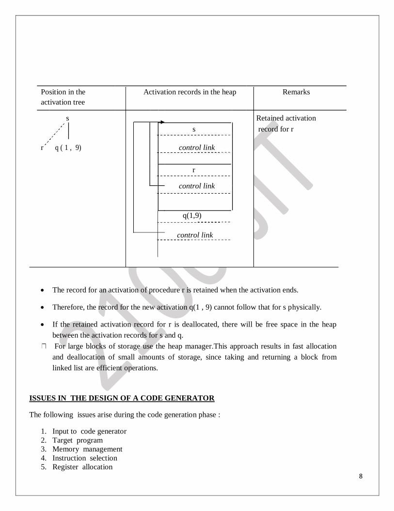
The record for an activation of procedure r is retained when the activation ends.
Therefore, the record for the new activation q(1 , 9) cannot follow that for s physically.
If the retained activation record for r is deallocated, there will be free space in the heap
between the activation records for s and q.
For large blocks of storage use the heap manager.This approach results in fast allocation
and deallocation of small amounts of storage, since taking and returning a block from
linked list are efficient operations.
ISSUES IN THE DESIGN OF A CODE GENERATOR The following issues arise during the code generation phase :
1. Input to code generator
2. Target program
3. Memory management
4. Instruction selection
5. Register allocation
9
6. Evaluation order
1. Input to code generator: The input to the code generation consists of the intermediate representation of the source program
produced by front end , together with information in the symbol table to determine run-time
addresses of the data objects denoted by the names in the intermediate representation.
Intermediate representation can be :
a. Linear representation such as postfix notation
b. Three address representation such as quadruples
c. Virtual machine representation such as stack machine code
d. Graphical representations such as syntax trees and dags.
Prior to code generation, the front end must be scanned, parsed and translated into intermediate
representation along with necessary type checking. Therefore, input to code generation is assumed
to be error-free. 2. Target program:
The output of the code generator is the target program. The output may be : a. Absolute machine language
- It can be placed in a fixed memory location and can be executed immediately.
b. Relocatable machine language - It allows subprograms to be compiled separately.
c. Assembly language
- Code generation is made easier. 3. Memory management:
Names in the source program are mapped to addresses of data objects in run-time memory by
the front end and code generator.
It makes use of symbol table, that is, a name in a three-address statement refers to a symbol-
table entry for the name.
Labels in three-address statements have to be converted to addresses of instructions. For example,
j :gotoigenerates jump instruction as follows :
ifi<j, a backward jump instruction with target address equal to location of code for
quadruple i is generated.
ifi>j, the jump is forward. We must store on a list for quadruplei the location of the
first machine instruction generated for quadruplej. When iis processed, the machine
locations for all instructions that forward jumps to i are filled.
4. Instruction selection: The instructions of target machine should be complete and uniform.
Instruction speeds and machine idioms are important factors when efficiency of target program
10
is considered.
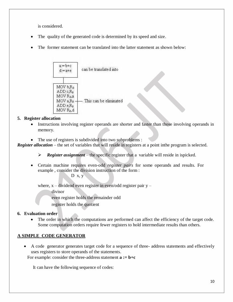
The quality of the generated code is determined by its speed and size.
The former statement can be translated into the latter statement as shown below: 5. Register allocation
Instructions involving register operands are shorter and faster than those involving operands in
memory.
The use of registers is subdivided into two subproblems :
Register allocation – the set of variables that will reside in registers at a point inthe program is selected.
Register assignment – the specific register that a variable will reside in ispicked.
Certain machine requires even-odd register pairs for some operands and results. For example , consider the division instruction of the form :
D x, y
where, x – dividend even register in even/odd register pair y –
divisor even register holds the remainder odd
register holds the quotient 6. Evaluation order
The order in which the computations are performed can affect the efficiency of the target code.
Some computation orders require fewer registers to hold intermediate results than others.
A SIMPLE CODE GENERATOR
A code generator generates target code for a sequence of three- address statements and effectively
uses registers to store operands of the statements.
For example: consider the three-address statement a := b+c
It can have the following sequence of codes:
11
ADD Rj, Ri Cost = 1 // if Ri contains b and Rj contains c
(or)
ADD c, Ri Cost = 2 // if c is in a memory location
(or)
MOV c, Rj Cost = 3 // move c from memory to Rj and add
ADD Rj, Ri
Register and Address Descriptors:
A register descriptor is used to keep track of what is currently in each registers. The register
descriptors show that initially all the registers are empty. An address descriptor stores the location where the current value of the name can be found at run
time.
A code-generation algorithm:
The algorithm takes as input a sequence of three -address statements constituting a basic block. For each
three-address statement of the form x : = y op z, perform the following actions: 1. Invoke a function getreg to determine the location L where the result of the computation y op z should
be stored. 2. Consult the address descriptor for y to determine y’, the current location of y. Prefer the register for
y’ if the value of y is currently both in memory and a register. If the value of y is not already in L,
generate the instruction MOV y’ , L to place a copy of y in L. 3. Generate the instruction OP z’ , L where z’ is a current location of z. Prefer a register to a
memory location if z is in both. Update the address descriptor of x to indicate that x is in location
L. If x is in L, update its descriptor and remove x from all other descriptors. 4. If the current values of y or z have no next uses, are not live on exit from the block, and are in
registers, alter the register descriptor to indicate that, after execution of x : = y op z , those registers
will no longer contain y or z.
The algorithmic sequence of getreg function can be,
1. if x value is in register that register is returned.
2. If (1) fails, new register is returned.
3. If (2) fails, and the operation needs a special register, that register value is temporarily moved to
the memory and the register is returned.
4. If (3) fails, finally memory location is returned.
12
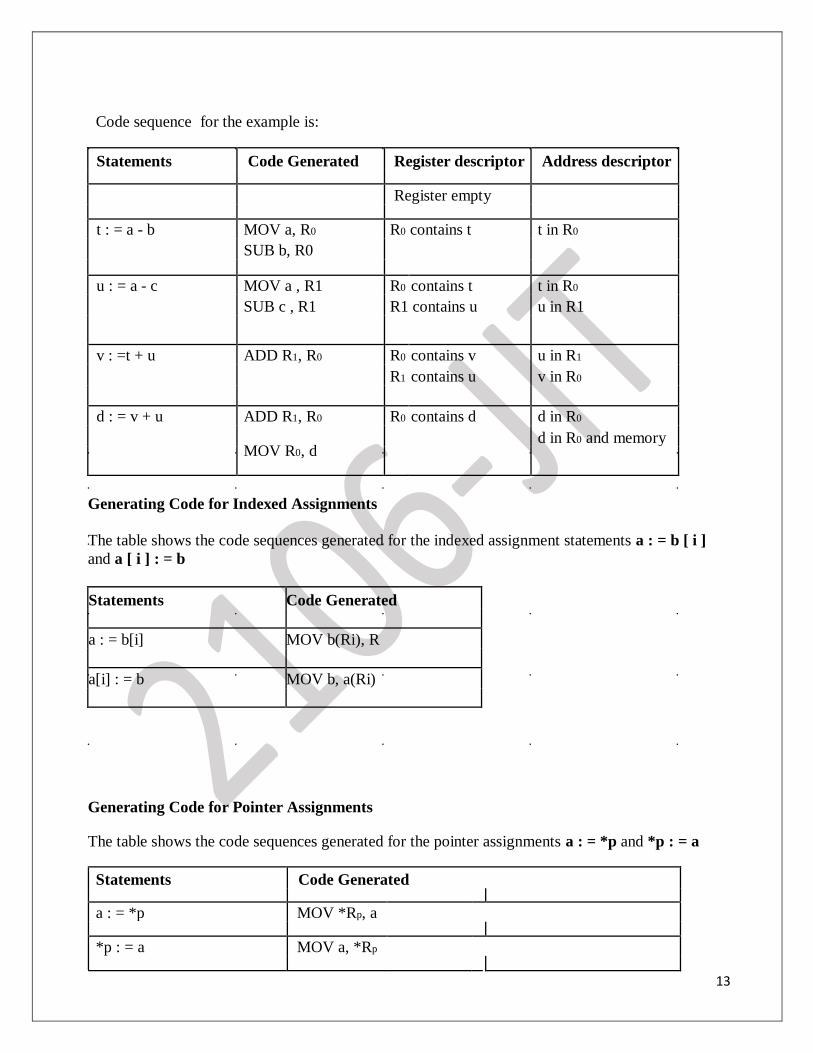
Generating Code for Assignment Statements:
The assignment d : = (a-b) + (a-c) + (a-c) might be translated into the following three-address code sequence:
t : = a – b u : =
a – c v : = t + u
d : = v + u
with d live at the end.
13
Code sequence for the example is:
Statements Code Generated Register descriptor Address descriptor
Register empty
t : = a - b MOV a, R0 R0 contains t t in R0
SUB b, R0
u : = a - c MOV a , R1 R0 contains t t in R0
SUB c , R1 R1 contains u u in R1
v : =t + u ADD R1, R0 R0 contains v u in R1
R1 contains u v in R0
d : = v + u ADD R1, R0 R0 contains d d in R0
MOV R0, d
d in R0 and memory
Generating Code for Indexed Assignments
The table shows the code sequences generated for the indexed assignment statements a : = b [ i ]
and a [ i ] : = b
Statements Code Generated
a : = b[i] MOV b(Ri), R
a[i] : = b MOV b, a(Ri)
Generating Code for Pointer Assignments
The table shows the code sequences generated for the pointer assignments a : = *p and *p : = a
Statements Code Generated
a : = *p MOV *Rp, a
*p : = a MOV a, *Rp
14
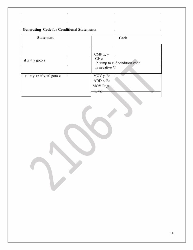
Generating Code for Conditional Statements
Statement
Code
if x < y goto z
CMP x, y
CJ<z
/* jump to z if condition code
is negative */
x : = y +z if x <0 goto z MOV y, R0 ADD z, R0
MOV R0,x
CJ<Z
15
Copyright © 2022 FDOKUMEN

