


Bahasa
Halaman
Hukum

PAPER www.rsc.org/materials | Journal of Materials Chemistry
Dow
nloa
ded
by S
HA
NX
I IN
STIT
UT
E O
F C
OA
L o
n 19
Mar
ch 2
011
Publ
ishe
d on
22
Oct
ober
200
8 on
http
://pu
bs.r
sc.o
rg |
doi:1
0.10
39/B
8049
67J
View Online
Tuning pore size and hydrophobicity of macroporous hybrid silica filmswith high optical transmittance by a non-template route†
Dongjiang Yang,a Yao Xu,*b Wujun Xu,b Dong Wu,b Yuhan Sunb and Huaiyong Zhu*a
Received 25th March 2008, Accepted 16th September 2008
First published as an Advance Article on the web 22nd October 2008
DOI: 10.1039/b804967j
Macroporous silica films with methyl groups grafted on their surface were prepared from
polymethylhydrosiloxane (PMHS) and tetraethylorthosilicate (TEOS) without templates. Compared
to the conventional template syntheses, this approach has several advantages. First, it avoids the
removal of templates, which is sometimes an environmentally unfriendly procedure. Second, it does not
require a post-synthesis grafting to form the hybrid structures with methyl groups on the silica surface.
Third, the pore size and hydrophobicity (expressed by the water contact angle) of the film can be tuned
readily. By adjusting the amount of PMHS used in the synthesis and introducing hexamethyldisilazane
(HMDS) we can tune the pore size in a wide range from 50 nm to 500 nm. The hydrophobicity increases
substantially as the pore size decreases. Evidently, the reaction mechanism of this synthesis is different
from the conventional template synthesis. A tentative mechanism is proposed: the hydrogen gas
released from PMHS results in the formation of the macropores in the films. With excellent
hydrophobicity, optical transmittance and thermal stability, the obtained silica films have
potential applications in the semiconductor industry.
Introduction
Recently, macroporous materials, having pore sizes larger than
50 nm, with well-defined and tunable pore structures have
attracted much attention because of their potential applications
(both structural and functional) in various areas. These materials
exhibit a full photonic band-gap effect, and have large specific
surface area and low thermal conductivity,1–7 and therefore can
be used as photonic crystals for optical communication devices,
supports for catalysts, separation and electronic industry mate-
rials for sensor devices and electrodes. Similar to the fabrication
of micro- and mesoporous materials using surfactants as
templates,8–11 the synthesis of macroporous materials relies
mostly on the use of a polymeric or inorganic template, usually in
the form of spheres packed in a periodic fashion.4,7 Several
methods for the synthesis of three-dimensional macroporous
inorganic materials have been reported, including sol–gel,12–15
salt preparation,16 nanocrystal infiltration 17,18 and polymeriza-
tion.19 Among the reported preparation approaches, the
template-based sol–gel process has gained popularity, because
materials in various configurations (films, monoliths, and
particles) can be readily prepared and utilized.4,7 In the sol–gel
process, metal alkoxides dissolved in alcohol are impregnated
into the voids of the colloidal sphere arrays, and they hydrolyze
aSchool of Physical and Chemical Sciences, Queensland University ofTechnology, Brisbane, QLD, 4001, Australia. E-mail: mailto:[email protected]; Fax: + 61 73138 1804; Tel: + 61 73138 1581bState Key Laboratory of Coal Conversion, Institute of Coal Chemistry,Chinese Academy of Sciences, Taiyuan, 030001, China. E-mail: [email protected]; Fax: + 86 351 4041153; Tel: + 86 351 4049859
† Electronic supplementary information (ESI) available: AFM 2D imageand arbitrary hole scanning plot of F3; photograph of H2 bubblesgenerated from the hydrolysis of PMHS. See DOI: 10.1039/b804967j
This journal is ª The Royal Society of Chemistry 2008
and condense on the sphere surfaces, forming an inorganic
framework. Subsequent removal of the template, by heat treat-
ment for polymeric spheres (e.g. polystyrene sphere) or etch
treatment for inorganic spheres (e.g. SiO2 sphere), results in an
ordered macroporous structure of metal oxide. Recently,
macroporous thin films and membranes have been successfully
prepared via the sol–gel method. Turner et al.20 reported the
synthesis of macroporous TiO2 films using silica spheres as
a template. The obtained thin films have highly ordered macro-
pores and intense optical diffraction properties, and they could
be used in photocatalysis and photonics. Khramov et al.21
reported macroporous silicate films prepared by condensing
a silica sol within a matrix of polystyrene latex spheres. These
silica films can selectively discriminate different probe
compounds based on their charge and exhibit potential for
chemical sensing applications. Furthermore, supported porous
silica films have low dielectric constant and good mechanical
strength and thermal stability.22,23 They are compatible with
silicon wafers and related materials used in integrated circuit (IC)
process technologies. Therefore, porous silica films are consid-
ered to be the most promising materials for the sub-100 nm
technology node and future IC process technologies.
In the present study, we synthesized hybrid macroporous silica
films using PMHS and TEOS as silica sources but employed no
template as pore formation directing agent. Therefore, our
method avoids an etch treatment or calcination operation to
remove the templates as in a conventional synthesis; the template
removal methods are usually environment-unfriendly proce-
dures. Moreover, we tune the pore size of the films in a wide
range, from 50 nm to 500 nm in diameter, simply by varying the
PMHS concentration or introducing another silica source,
HMDS. All obtained hybrid structures exhibit hydrophobicity,
high thermal stability and excellent optical transmittance.
J. Mater. Chem., 2008, 18, 5557–5562 | 5557
Dow
nloa
ded
by S
HA
NX
I IN
STIT
UT
E O
F C
OA
L o
n 19
Mar
ch 2
011
Publ
ishe
d on
22
Oct
ober
200
8 on
http
://pu
bs.r
sc.o
rg |
doi:1
0.10
39/B
8049
67J
View Online
Experimental
Synthesis of samples
The hybrid macroporous silica films were prepared via the
following procedures. 0.47 mL (0.468 g) of poly-
methylhydrosiloxane (PMHS, �MW z 2300, Aldrich) was drip-
ped into 70 mL ethanol in the presence of strong base (NaOH,
pH ¼ 10) as catalyst and was kept at room temperature for 24 h.
During this period the hydrogen atoms of PMHS were replaced
by –OC2H5 groups. To this solution 5 mL (4.676 g) of tetrae-
thylorthosilicate (TEOS, 99%, Acros) and deionized H2O were
added. The TEOS:H2O molar ratio and the PMHS:TEOS mass
ratio of this system were 1:4 and 1:5, respectively. This mixture
was vigorously stirred for 3 h, and aged under ambient condi-
tions for 24 h. A sol with a light blue color formed during the
aging. The homogeneous sol was deposited onto clean single
crystal silicon wafers and glass substrates by spin-coating at 3000
rpm. Before spin-coating, the substrates were washed carefully
with pure water and acetone. The samples prepared with the
PMHS:TEOS mass ratios of 1:10, 1:5 and 1:2, were F1, F2 and
F3, respectively. Hexamethyldisilazane (HMDS, 99%, Acros)
was introduced into the sol with the PMHS:TEOS mass ratio of
1:5 to study its role in tuning the pore size. The films prepared
with the HMDS:TEOS molar ratios of 1:20, 1:10, 1:5 and 1:3
were F21, F22, F23 and F24, respectively. The obtained films
were moved to a vacuum oven and dried at 353 K for 8 h.
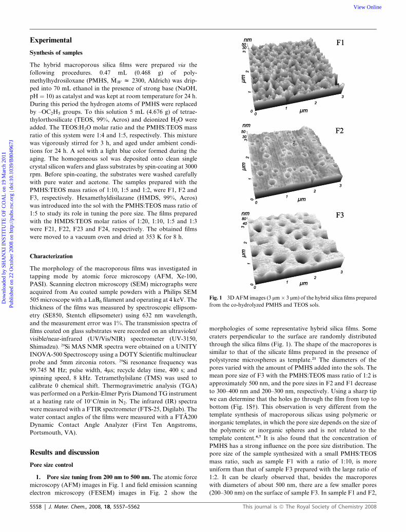
Fig. 1 3D AFM images (3 mm � 3 mm) of the hybrid silica films prepared
from the co-hydrolyzed PMHS and TEOS sols.
Characterization
The morphology of the macroporous films was investigated in
tapping mode by atomic force microscopy (AFM, Xe-100,
PASI). Scanning electron microscopy (SEM) micrographs were
acquired from Au coated sample powders with a Philips SEM
505 microscope with a LaB6 filament and operating at 4 keV. The
thickness of the films was measured by spectroscopic ellipsom-
etry (SE850, Stentch ellipsometer) using 632 nm wavelength,
and the measurement error was 1%. The transmission spectra of
films coated on glass substrates were recorded on an ultraviolet/
visible/near-infrared (UV/Vis/NIR) spectrometer (UV-3150,
Shimadzu). 29Si MAS NMR spectra were obtained on a UNITY
INOVA-500 Spectroscopy using a DOTY Scientific multinuclear
probe and 5mm zirconia rotors. 29Si resonance frequency was
99.745 M Hz; pulse width, 4ms; recycle delay time, 400 s; and
spinning speed, 8 kHz. Tetramethylsilane (TMS) was used to
calibrate 0 chemical shift. Thermogravimetric analysis (TGA)
was performed on a Perkin-Elmer Pyris Diamond TG instrument
at a heating rate of 10�C/min in N2. The infrared (IR) spectra
were measured with a FTIR spectrometer (FTS-25, Digilab). The
water contact angles of the films were measured with a FTA200
Dynamic Contact Angle Analyzer (First Ten Angstroms,
Portsmouth, VA).
Results and discussion
Pore size control
1. Pore size tuning from 200 nm to 500 nm. The atomic force
microscopy (AFM) images in Fig. 1 and field emission scanning
electron microscopy (FESEM) images in Fig. 2 show the
5558 | J. Mater. Chem., 2008, 18, 5557–5562
morphologies of some representative hybrid silica films. Some
craters perpendicular to the surface are randomly distributed
through the silica films (Fig. 1). The shape of the macropores is
similar to that of the silicate films prepared in the presence of
polystyrene microspheres as template.21 The diameters of the
pores varied with the amount of PMHS added into the sols. The
mean pore size of F3 with the PMHS:TEOS mass ratio of 1:2 is
approximately 500 nm, and the pore sizes in F2 and F1 decrease
to 300–400 nm and 200–300 nm, respectively. Using a sharp tip
we can determine that the holes go through the film from top to
bottom (Fig. 1S†). This observation is very different from the
template synthesis of macroporous silicas using polymeric or
inorganic templates, in which the pore size depends on the size of
the polymeric or inorganic spheres and is not related to the
template content.4,7 It is also found that the concentration of
PMHS has a strong influence on the pore size distribution. The
pore size of the sample synthesized with a small PMHS:TEOS
mass ratio, such as sample F1 with a ratio of 1:10, is more
uniform than that of sample F3 prepared with the large ratio of
1:2. It can be clearly observed that, besides the macropores
with diameters of about 500 nm, there are a few smaller pores
(200–300 nm) on the surface of sample F3. In sample F1 and F2,
This journal is ª The Royal Society of Chemistry 2008
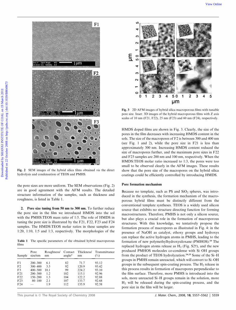
Fig. 2 SEM images of the hybrid silica films obtained via the direct
hydrolysis and condensation of TEOS and PMHS.
Fig. 3 2D AFM images of hybrid silica macroporous films with tunable
pore size. Inset: 3D images of the hybrid macroporous films with Z axis
scales of 10 nm (F21, F22), 25 nm (F23) and 60 nm (F24), respectively.
Dow
nloa
ded
by S
HA
NX
I IN
STIT
UT
E O
F C
OA
L o
n 19
Mar
ch 2
011
Publ
ishe
d on
22
Oct
ober
200
8 on
http
://pu
bs.r
sc.o
rg |
doi:1
0.10
39/B
8049
67J
View Online
the pore sizes are more uniform. The SEM observations (Fig. 2)
are in good agreement with the AFM results. The detailed
structure information of the samples, such as thickness and
roughness, is listed in Table 1.
2. Pore size tuning from 50 nm to 300 nm. To further reduce
the pore size in the film we introduced HMDS into the sol
with the PMHS:TEOS mass ratio of 1:5. The role of HMDS in
tuning the pore size is illustrated by the F21, F22, F23 and F24
samples. The HMDS:TEOS molar ratios in these samples are
1:20, 1:10, 1:5 and 1:3, respectively. The morphologies of the
Table 1 The specific parameters of the obtained hybrid macroporousfilms
SamplePoresize/nm
Roughness/nm
Contactangle/�
Thickness/nm
Transmittance(%)
F1 200–300 6.1 82 71.7 93.12F2 300–400 3.5 92 120.9 93.42F3 400–500 10.1 99 224.2 93.10F21 200–300 1.2 102 115.1 92.96F22 150–200 1.3 104 122.2 92.88F23 80–100 2.1 107 133.7 92.68F24 — 1.9 112 135.9 92.58
This journal is ª The Royal Society of Chemistry 2008
HMDS doped films are shown in Fig. 3. Clearly, the size of the
pores in the film decreases with increasing HMDS content in the
sols. The size of the macropores of F2 is between 300 and 400 nm
(see Fig. 1 and 2), while the pore size in F21 is less than
approximately 300 nm. Increasing HMDS content reduced the
size of macropores further, and the maximum pore sizes in F22
and F23 samples are 200 nm and 100 nm, respectively. When the
HMDS:TEOS molar ratio increased to 1:3, the pores were too
small to be observed clearly in the AFM images. These results
show that the pore size of the macropores on the hybrid silica
coatings could be efficiently controlled by introducing HMDS.
Pore formation mechanism
Because no template, such as PS and SiO2 spheres, was intro-
duced in the synthesis, the formation mechanism of the macro-
porous hybrid films must be distinctly different from the
conventional template syntheses. TEOS is a widely used silicon
source that exhibits no structure directing function for forming
macrostructures. Therefore, PMHS is not only a silicon source,
but also plays a crucial role in the formation of macroporous
structures. With this knowledge, we tentatively propose the
formation process of macropores as illustrated in Fig. 4: in the
presence of NaOH as catalyst, ethoxy groups and hydroxys
can replace the active hydrogen atoms in PMHS, leading to the
formation of new polymethylhydroxysiloxane (PMHOS).24 The
replaced hydrogen atoms release as H2 (Fig. S2†), and the new
produced PMHOS molecules co-condense with Si–OH groups
from the product of TEOS hydrolyzation.24,25 Some of the Si–H
groups in PMHS remain unreacted, which will convert to Si–OH
groups in the subsequent spin-coating process. The H2 release in
this process results in formation of macropores perpendicular to
the film surface. Therefore, more PMHS is introduced into the
sols, more unreacted Si–H groups remain in the solution, more
H2 will be released during the spin-coating process, and the
pore size in the film will be larger.
J. Mater. Chem., 2008, 18, 5557–5562 | 5559
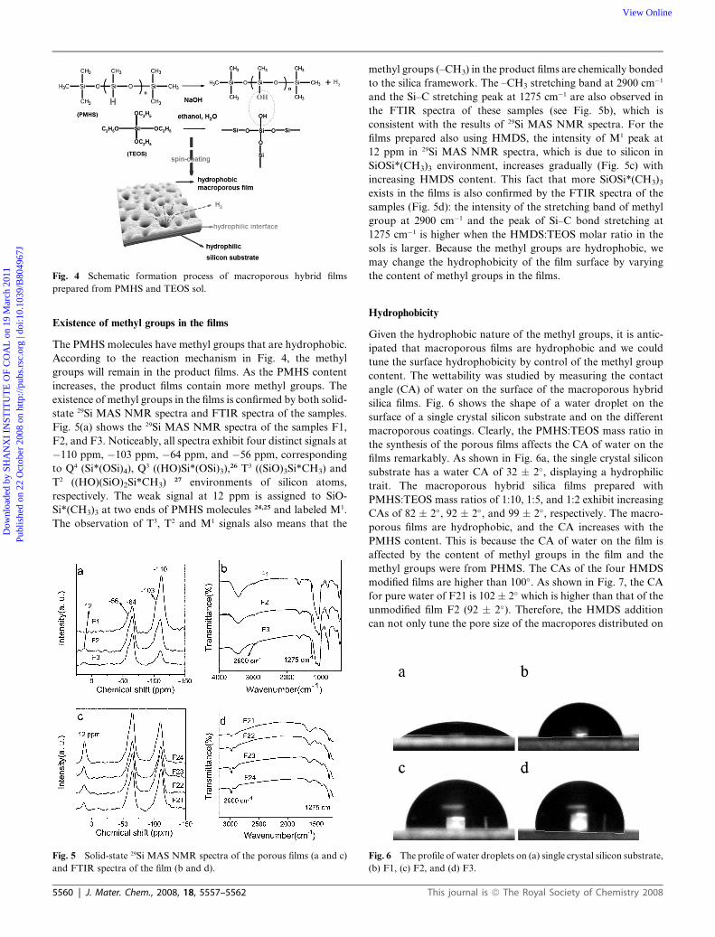
Fig. 4 Schematic formation process of macroporous hybrid films
prepared from PMHS and TEOS sol.
Dow
nloa
ded
by S
HA
NX
I IN
STIT
UT
E O
F C
OA
L o
n 19
Mar
ch 2
011
Publ
ishe
d on
22
Oct
ober
200
8 on
http
://pu
bs.r
sc.o
rg |
doi:1
0.10
39/B
8049
67J
View Online
Existence of methyl groups in the films
The PMHS molecules have methyl groups that are hydrophobic.
According to the reaction mechanism in Fig. 4, the methyl
groups will remain in the product films. As the PMHS content
increases, the product films contain more methyl groups. The
existence of methyl groups in the films is confirmed by both solid-
state 29Si MAS NMR spectra and FTIR spectra of the samples.
Fig. 5(a) shows the 29Si MAS NMR spectra of the samples F1,
F2, and F3. Noticeably, all spectra exhibit four distinct signals at
�110 ppm, �103 ppm, �64 ppm, and �56 ppm, corresponding
to Q4 (Si*(OSi)4), Q3 ((HO)Si*(OSi)3),26 T3 ((SiO)3Si*CH3) and
T2 ((HO)(SiO)2Si*CH3) 27 environments of silicon atoms,
respectively. The weak signal at 12 ppm is assigned to SiO-
Si*(CH3)3 at two ends of PMHS molecules 24,25 and labeled M1.
The observation of T3, T2 and M1 signals also means that the
Fig. 5 Solid-state 29Si MAS NMR spectra of the porous films (a and c)
and FTIR spectra of the film (b and d).
5560 | J. Mater. Chem., 2008, 18, 5557–5562
methyl groups (–CH3) in the product films are chemically bonded
to the silica framework. The –CH3 stretching band at 2900 cm�1
and the Si–C stretching peak at 1275 cm�1 are also observed in
the FTIR spectra of these samples (see Fig. 5b), which is
consistent with the results of 29Si MAS NMR spectra. For the
films prepared also using HMDS, the intensity of M1 peak at
12 ppm in 29Si MAS NMR spectra, which is due to silicon in
SiOSi*(CH3)3 environment, increases gradually (Fig. 5c) with
increasing HMDS content. This fact that more SiOSi*(CH3)3
exists in the films is also confirmed by the FTIR spectra of the
samples (Fig. 5d): the intensity of the stretching band of methyl
group at 2900 cm�1 and the peak of Si–C bond stretching at
1275 cm�1 is higher when the HMDS:TEOS molar ratio in the
sols is larger. Because the methyl groups are hydrophobic, we
may change the hydrophobicity of the film surface by varying
the content of methyl groups in the films.
Hydrophobicity
Given the hydrophobic nature of the methyl groups, it is antic-
ipated that macroporous films are hydrophobic and we could
tune the surface hydrophobicity by control of the methyl group
content. The wettability was studied by measuring the contact
angle (CA) of water on the surface of the macroporous hybrid
silica films. Fig. 6 shows the shape of a water droplet on the
surface of a single crystal silicon substrate and on the different
macroporous coatings. Clearly, the PMHS:TEOS mass ratio in
the synthesis of the porous films affects the CA of water on the
films remarkably. As shown in Fig. 6a, the single crystal silicon
substrate has a water CA of 32 � 2�, displaying a hydrophilic
trait. The macroporous hybrid silica films prepared with
PMHS:TEOS mass ratios of 1:10, 1:5, and 1:2 exhibit increasing
CAs of 82 � 2�, 92 � 2�, and 99 � 2�, respectively. The macro-
porous films are hydrophobic, and the CA increases with the
PMHS content. This is because the CA of water on the film is
affected by the content of methyl groups in the film and the
methyl groups were from PHMS. The CAs of the four HMDS
modified films are higher than 100�. As shown in Fig. 7, the CA
for pure water of F21 is 102 � 2� which is higher than that of the
unmodified film F2 (92 � 2�). Therefore, the HMDS addition
can not only tune the pore size of the macropores distributed on
Fig. 6 The profile of water droplets on (a) single crystal silicon substrate,
(b) F1, (c) F2, and (d) F3.
This journal is ª The Royal Society of Chemistry 2008
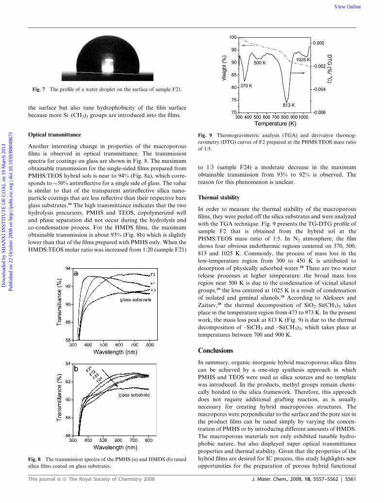
Fig. 7 The profile of a water droplet on the surface of sample F21.
Dow
nloa
ded
by S
HA
NX
I IN
STIT
UT
E O
F C
OA
L o
n 19
Mar
ch 2
011
Publ
ishe
d on
22
Oct
ober
200
8 on
http
://pu
bs.r
sc.o
rg |
doi:1
0.10
39/B
8049
67J
View Online
the surface but also tune hydrophobicity of the film surface
because more Si–(CH3)3 groups are introduced into the films.
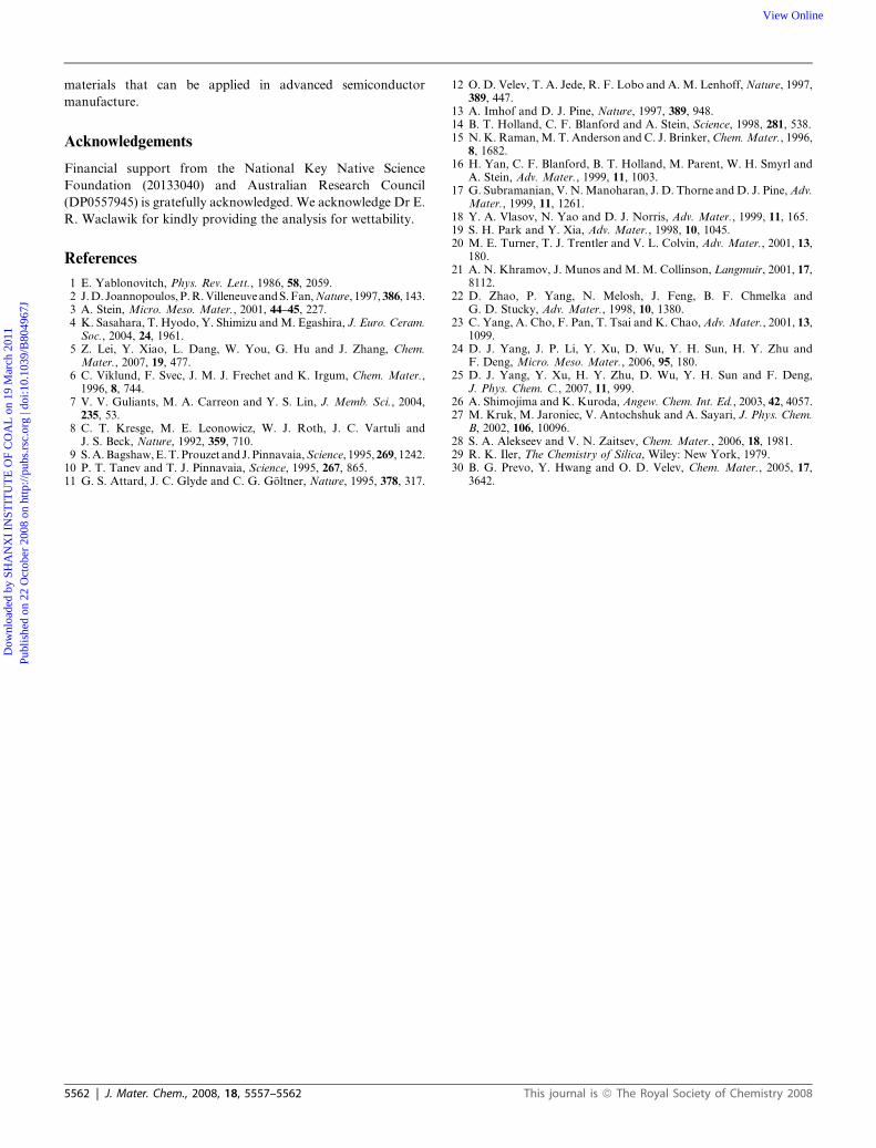
Fig. 9 Thermogravimetric analysis (TGA) and derivative thermog-
ravimetry (DTG) curves of F2 prepared at the PHMS:TEOS mass ratio
of 1:5.
Optical transmittance
Another interesting change in properties of the macroporous
films is observed in optical transmittance. The transmission
spectra for coatings on glass are shown in Fig. 8. The maximum
obtainable transmission for the single-sided films prepared from
PMHS:TEOS hybrid sols is near to 94% (Fig. 8a), which corre-
sponds to �50% antireflective for a single side of glass. The value
is similar to that of the transparent antireflective silica nano-
particle coatings that are less reflective than their respective bare
glass substrates.30 The high transmittance indicates that the two
hydrolysis precursors, PMHS and TEOS, copolymerized well
and phase separation did not occur during the hydrolysis and
co-condensation process. For the HMDS films, the maximum
obtainable transmission is about 93% (Fig. 8b) which is slightly
lower than that of the films prepared with PMHS only. When the
HMDS:TEOS molar ratio was increased from 1:20 (sample F21)
Fig. 8 The transmission spectra of the PMHS (a) and HMDS (b) tuned
silica films coated on glass substrates.
This journal is ª The Royal Society of Chemistry 2008
to 1:3 (sample F24) a moderate decrease in the maximum
obtainable transmission from 93% to 92% is observed. The
reason for this phenomenon is unclear.
Thermal stability
In order to measure the thermal stability of the macroporous
films, they were peeled off the silica substrates and were analyzed
with the TGA technique. Fig. 9 presents the TG-DTG profile of
sample F2 that is obtained from the hybrid sol at the
PHMS:TEOS mass ratio of 1:5. In N2 atmosphere, the film
shows four obvious endothermic regions centered on 370, 500,
813 and 1025 K. Commonly, the process of mass loss in the
low-temperature region from 300 to 450 K is attributed to
desorption of physically adsorbed water.28 There are two water
release processes at higher temperature: the broad mass loss
region near 500 K is due to the condensation of vicinal silanol
groups,29 the loss centered at 1025 K is a result of condensation
of isolated and geminal silanols.28 According to Alekseev and
Zaitsev,28 the thermal decomposition of SiO2–Si(CH3)3 takes
place in the temperature region from 473 to 973 K. In the present
work, the mass loss peak at 813 K (Fig. 9) is due to the thermal
decomposition of –SiCH3 and –Si(CH3)3, which takes place at
temperatures between 700 and 900 K.
Conclusions
In summary, organic–inorganic hybrid macroporous silica films
can be achieved by a one-step synthesis approach in which
PMHS and TEOS were used as silica sources and no template
was introduced. In the products, methyl groups remain chemi-
cally bonded to the silica framework. Therefore, this approach
does not require additional grafting reaction, as is usually
necessary for creating hybrid macroporous structures. The
macropores were perpendicular to the surface and the pore size in
the product films can be tuned simply by varying the concen-
tration of PMHS or by introducing different amounts of HMDS.
The macroporous materials not only exhibited tunable hydro-
phobic nature, but also displayed super optical transmittance
properties and thermal stability. Given that the properties of the
hybrid films are desired for IC process, this study highlights new
opportunities for the preparation of porous hybrid functional
J. Mater. Chem., 2008, 18, 5557–5562 | 5561
Dow
nloa
ded
by S
HA
NX
I IN
STIT
UT
E O
F C
OA
L o
n 19
Mar
ch 2
011
Publ
ishe
d on
22
Oct
ober
200
8 on
http
://pu
bs.r
sc.o
rg |
doi:1
0.10
39/B
8049
67J
View Online
materials that can be applied in advanced semiconductor
manufacture.
Acknowledgements
Financial support from the National Key Native Science
Foundation (20133040) and Australian Research Council
(DP0557945) is gratefully acknowledged. We acknowledge Dr E.
R. Waclawik for kindly providing the analysis for wettability.
References
1 E. Yablonovitch, Phys. Rev. Lett., 1986, 58, 2059.2 J. D. Joannopoulos, P. R. Villeneuve and S. Fan,Nature, 1997,386, 143.3 A. Stein, Micro. Meso. Mater., 2001, 44–45, 227.4 K. Sasahara, T. Hyodo, Y. Shimizu and M. Egashira, J. Euro. Ceram.Soc., 2004, 24, 1961.
5 Z. Lei, Y. Xiao, L. Dang, W. You, G. Hu and J. Zhang, Chem.Mater., 2007, 19, 477.
6 C. Viklund, F. Svec, J. M. J. Frechet and K. Irgum, Chem. Mater.,1996, 8, 744.
7 V. V. Guliants, M. A. Carreon and Y. S. Lin, J. Memb. Sci., 2004,235, 53.
8 C. T. Kresge, M. E. Leonowicz, W. J. Roth, J. C. Vartuli andJ. S. Beck, Nature, 1992, 359, 710.
9 S. A. Bagshaw, E. T. Prouzet and J. Pinnavaia,Science, 1995,269, 1242.10 P. T. Tanev and T. J. Pinnavaia, Science, 1995, 267, 865.11 G. S. Attard, J. C. Glyde and C. G. Goltner, Nature, 1995, 378, 317.
5562 | J. Mater. Chem., 2008, 18, 5557–5562
12 O. D. Velev, T. A. Jede, R. F. Lobo and A. M. Lenhoff, Nature, 1997,389, 447.
13 A. Imhof and D. J. Pine, Nature, 1997, 389, 948.14 B. T. Holland, C. F. Blanford and A. Stein, Science, 1998, 281, 538.15 N. K. Raman, M. T. Anderson and C. J. Brinker, Chem.Mater., 1996,
8, 1682.16 H. Yan, C. F. Blanford, B. T. Holland, M. Parent, W. H. Smyrl and
A. Stein, Adv. Mater., 1999, 11, 1003.17 G. Subramanian, V. N. Manoharan, J. D. Thorne and D. J. Pine, Adv.
Mater., 1999, 11, 1261.18 Y. A. Vlasov, N. Yao and D. J. Norris, Adv. Mater., 1999, 11, 165.19 S. H. Park and Y. Xia, Adv. Mater., 1998, 10, 1045.20 M. E. Turner, T. J. Trentler and V. L. Colvin, Adv. Mater., 2001, 13,
180.21 A. N. Khramov, J. Munos and M. M. Collinson, Langmuir, 2001, 17,
8112.22 D. Zhao, P. Yang, N. Melosh, J. Feng, B. F. Chmelka and
G. D. Stucky, Adv. Mater., 1998, 10, 1380.23 C. Yang, A. Cho, F. Pan, T. Tsai and K. Chao, Adv. Mater., 2001, 13,
1099.24 D. J. Yang, J. P. Li, Y. Xu, D. Wu, Y. H. Sun, H. Y. Zhu and
F. Deng, Micro. Meso. Mater., 2006, 95, 180.25 D. J. Yang, Y. Xu, H. Y. Zhu, D. Wu, Y. H. Sun and F. Deng,
J. Phys. Chem. C., 2007, 11, 999.26 A. Shimojima and K. Kuroda, Angew. Chem. Int. Ed., 2003, 42, 4057.27 M. Kruk, M. Jaroniec, V. Antochshuk and A. Sayari, J. Phys. Chem.
B, 2002, 106, 10096.28 S. A. Alekseev and V. N. Zaitsev, Chem. Mater., 2006, 18, 1981.29 R. K. Iler, The Chemistry of Silica, Wiley: New York, 1979.30 B. G. Prevo, Y. Hwang and O. D. Velev, Chem. Mater., 2005, 17,
3642.
This journal is ª The Royal Society of Chemistry 2008
Top Related
Copyright © 2022 FDOKUMEN

