


Bahasa
Halaman
Hukum


Theoretical and Experimental Studies on a Cylinder Containing
Granules Rolling Down an Inclined Plane
Short title: Cylinder containing granules rolling down an incline
Edy Wibowo, Sutisna, Mamat Rokhmat, Elfi Yuliza, Khairurrijal, and Mikrajuddin Abdullah(a)
Department of Physics
Bandung Institute of Technology
Jalan Ganeca 10, Bandung 40132, Indonesia (a)Corresponding author, E-mail: [email protected]
Abstract The dynamics of a hollow cylinder containing granules and rolling down an inclined
plane was investigated. A theoretical approach for investigating the behaviour of such a cylinder was proposed. The critical angle of the plane that allows the system to roll downward is presented. A simple experiment using six types of granules consistently confirmed the theoretical predictions. We showed that the critical angle is independent of the size distribution of the granules. We observed that the sliding angle of granules inside the cylinder is constant and, surprisingly, similar to the avalanche angle of the granules. Our theoretical prediction can be used to determine the critical angle without considering the shape, surface roughness and size distribution of the granules. Additionally, we derived the oscillation frequency of the system when it is slightly deviated from equilibrium, showing the frequency initially increases and then decreases with increasing granular volume. The oscillation is absent when the cylinder is empty or fully filled with granules. Furthermore, the dissipation of energy as a function of the fractional volume and fractional mass of the cylinder system were determined. This work might help students understand rolling motions other than the standard rolling motion commonly taught in the classroom.
1. Background
In a course on fundamental physics, the discussion on the rotation of rigid bodies usually
focuses on the rotation of objects having symmetrical shapes such as a cylinder, sphere, ring, bar
and plate [1]. All objects are rigid and their moments of inertia are usually tabulated. When
describing the dynamic behaviour of these objects, we simply look up the table to obtain the
formula of the moment of inertia.
More difficult problems are faced when the mass density of the object is distributed in-
homogeneously. In this case, an integral attempt must be made to obtain the moment of inertia
around a specific reference axis. However, the objects considered are mostly rigid ones. We
therefore ask what the dynamics of a non-rigid object will appear like. For example, how will the
dynamics appear when a container such as a ball or cylinder is filled with a fluid or granules? Of
course, the situation will be different from the rigid body dynamics because the filling materials
tend to stay at the bottom when the object rotates. For instance, when a container is partly filled
with a fluid, the fluid stays at the bottom and maintains its surface horizontally. When the filling
material is granular, the surface will have a certain slope [2–5]. If the system rotates so that the
slope of the granular surface steepens, an avalanche occurs to return the initial slope. There is a
maximum slope allowed for the granules, and this slope is specific to the certain granules [2–8].
Because of this behaviour, it seems interesting to explore the rotation of a container containing
granules.
The dynamic behaviours of granular motion inside various containers under diverse
conditions have been reported [2–17]. This topic has been gaining extensive interest among
scientists and engineers, who have conducted theoretical [2, 3], experimental [4–9] and
simulation studies [10–16]. In this paper, we do not directly discuss the dynamic motion of
granules inside a container; we instead emphasize another, much less studied, case of the rolling
dynamics of a container filled with granules. This is one case of the dynamics of a non-rigid
object. The dynamic motion of the container filled with spherical granules has been reported
[17]. In the present work, however, we are not restricted to investigating the rolling dynamics of
the container filled with spherical granules. The granules used in this study are different in shape,
size, size distribution, surface roughness and mass. We investigated the rolling dynamics of a
container filled with various granules down an inclined plane. The aim is to enrich the
understanding of students in science and engineering on the rolling motion of bodies. As
mentioned previously, the teaching of rolling bodies in a fundamental physics course is mostly
restricted to a rigid body having a symmetrical shape and a homogeneous mass distribution.
Consequently, many interesting phenomena are not addressed. In this work, experiments were
conducted for several types of granules with different shapes and size distributions. Spherical,
non-spherical and dissimilar shapes of granules were considered. We focused on a thin
cylindrical container made of plastic material. We derived theoretically and verified

experime
inclined
tend to s
The expe
to allow t
2. Mod
2.1 Criti
F
motionle
surface a
torque or
and an o
clockwis
downwar
F
entally the r
plane. The b
stay at the b
eriment verif
the system t
eling
ical Elevatio
igure 1 sho
ss on an inc
as the instant
riginates from
opposite torq
e rotation. T
rd or remain
Figure 1. Phy
rolling of a
behaviour is
ottom of the
fied precisel
o roll.
on Angle
ows the co
clined plane.
taneous orig
m the cylind
que originat
The resultan
ns unrotated.
ysical variab
hollow cyl
strictly diff
e container
ly the existe
ondition of
If we select
in, two torqu
der weight pr
tes from the
nt of these tw
bles of a cylin
linder partly
ferent from t
[2–16]. We
nce of a crit
a cylinder
t the contact
ues work sim
retending to
e granular w
wo torques
nder contain
y filled with
that of a rigi
identified m
tical elevatio
containing
t line betwee
multaneously
rotate the sy
weight inside
determines
ning granule
h various gr
id body beca
many interes
on angle of
granules w
en the cylind
y in the cylin
ystem downw
e the cylind
whether the
s on an incli
ranules dow
ause the gra
sting phenom
an inclined p
when it rem
der and the p
nder system
ward (clockw
der hinderin
e cylinder ro
ined plane
wn an
anules
mena.
plane
mains
plane
. One
wise)
g the
otates
Let us determine the expression for all variables in Figure 1. Using simple vector
analysis, we can prove
)cosˆsinˆ( jiRR
, (1)
where R is the cylinder radius and R
is the radius vector from the contact line (between the
cylinder and inclined plane) to the cylinder center. The vector from the cylinder center to the
center of mass of the granules has the form
cosˆsinˆ jixx cmcm
. (2)
We obtain from Fig. 1 that
cmxRr
. (3)
In this paper, the angle direction is clockwise and the leftward direction corresponds to zero
angles.
The weights of the empty cylinder and granules inside the cylinder are
jgmW ˆ11
(4)
and
jgmW ˆ22
, (5)
respectively, where m1 is the mass of the empty cylinder, m2 is the mass of the granules and g is
the acceleration due to gravitation. The torques induced by the two weights are respectively

kgRmWR ˆsin111
, (6)
kgxmgRmWxWRWr cmcmˆsinsin 222222
. (7)
Let us normalize these torques by dividing with gRm1 to obtain
kgRm
ˆsin1
11
, (8)
kR
x
m
m
gRmcm ˆsinsin
1
2
1
22
. (9)
The normalized total torque working on the cylinder system is then
21
t
kR
x
m
m cm ˆsinsinsin1
2
. (10)
We define the avalanche angle, 0, as the maximum slope angle formed by the granules.
When is small, the angle made by the granular slope might be smaller than 0. At the
avalanche angle, the opposite torque is a maximum, or
kR
x
m
m cm ˆsinsin 01
2max,2
. (11)
The cylinder will rotate downward only if 0max,21
. This condition produces the inequality
0ˆsinsinˆsin 01
2
k
R
x
m
mk cm
or
021
1 sinsin R
x
mm
m cm
. (12)

Equation (12) indicates that there is a critical elevation angle of the plane, c , for the cylinder
system to rotate downward. The critical elevation angle is given by
021
1 sinsin R
x
mm
m cmc
. (13)
To calculate the critical elevation angle as given by Eq. (13), we need the expression for
the granular center of mass. The location of the granular center of mass depends on the volume
of granules inside the cylinder. Figure 2 shows a cylinder of length L containing granules. The
distance from the granular surface to the cylinder center is R1. The distance from the granular
center of mass to the cylinder center is
R
R
R
R
R
R
R
R
R
R
R
R
R
R
R
Rcm
dxxR
dxxRx
ydx
xydx
dxyL
dxyLx
dm
xdm
x
1
1
1
1
1
1
1
1
22
22
)2(
)2(
. (14)
Using simple calculus, we easily obtain the solution of Eq. (14) as
21
2/32
1cos
1
3
2
Rxcm
, (15)
where
R
R1. (16)

Substitut
s
2.2 Oscil
If
the cylin
What is t
If a smal
.
From Eq
ting Eq. (15)
3
2in
mc
llation
f the elevatio
der is unable
the oscillatio
ll deviation i
Therefore, t
t sin'
. (18), we ob
Figure 2
) into Eq. (13
21
2
cos
mm
m
on angle of
e to rotate it
on frequency
is applied to
the normaliz
R
x
m
m cm sin1
2
btain the add
. Location o
3), we obtain
1
2/32
1s
1
the plane is
. Instead, the
y? The total
o the cylinde
zed total torq
s)n(
ditional torqu
f the granula
n the final ex
02sin
.
s smaller tha
e cylinder w
torque work
er, the angle
que working
k̂sin
.
ue working o
ar center of m
xpression for
an the critica
will oscillate
king on the c
of the granu
on the cylin
on the cylind
mass.
r the critical
al angle, the
around the e
cylinder is g
ular slope ch
nder system
der system a
elevation an
(17)
e small forcin
equilibrium
given by Eq.
hanges sligh
becomes
(18)
as
ngle,
ng of
state.
(10).
htly to

kR
x
m
m cm ˆsin)sin(1
2
kR
x
m
m cm ˆcos1
2 . (19)
Suppose the total moment of inertia of the cylinder system measured from the contact
line is I. The normalized moment of inertia is then
gRm
IIn
1
. (20)
If d2/dt2 is the angular acceleration of oscillation, we have Newton’s second law as
cos
1
22
2
R
x
m
m
dt
dI cm
n
. (21)
From Eqs. (20) and (21), we obtain the frequency of oscillation, , as
cos22
I
gxm cm. (22)
Looking at Eq. (22), the oscillation frequency can be calculated when I is known. This
moment of inertia is the summation of the moments of inertia of the empty cylinder and
granules. If the moment of inertia of the empty cylinder measured from the cylinder center of
mass is Is,cm, the moment of inertia of the cylinder measured from the contact line with the plane
can be calculated using the theorem of the parallel axis and we obtain

21, RmII cmss
. (23)
If the moment of inertia of the granules with respect to the center of mass is Ig,cm, the moment of
inertia of the granules measured from the contact line with the plane is also calculated using the
theorem of the parallel axis and we obtain
22, rmII cmgg
. (24)
The total moment of inertia of the cylinder system measured from the contact line is then
gs III . (25)
To determine the moment of inertia of the empty cylinder relative to its center of mass,
we make the following calculation. The cylinder comprises a base, a top and a circumference.
The area of each part is
2RAA topbase ,
RLAcircum 2 .
The total mass of the base and top is
112
2
/1
1
22
2m
RLm
RLR
Rm topbase
.

The mass of the circumference is
112 /1
/
22
2m
RL
RLm
RLR
RLmcircum
.
The moment of inertia of the empty cylinder with respect to its center of mass is
22, 2
1RmRmI circumtopbasecmc
212
1Rm
LR
R
R
L
. (26)
Therefore, the moment of inertia of the empty cylinder measured from the contact line is
212
11 Rm
LR
R
R
LIc
. (27)
The moment of inertia of the granules measured from the contact line (see Appendix) is
32
2
221
2
24
28861cos3612
2 R
x
R
x
R
x
R
xRLI cmcmcmcm
g
sin1cos211cos2
2 22
2221
2
R
x
R
xR
RL cmcm
,
and the normalized form is

32
2
221
2
2
428861cos36
12
1
2
R
x
R
x
R
x
R
x
LR
Icmcmcmcmg
sin1cos211cos
2
1 22
221
R
x
R
x cmcm
. (28)
Substituting Eqs. (27) and (28) into Eq. (25), we obtain the total moment of inertia of the
cylinder system relative to the contact line as
32
2
221
2
2
428861cos36
12
1
2
R
x
R
x
R
x
R
x
LR
I cmcmcmcm
sin1cos211cos
2
1 22
221
R
x
R
x cmcm
21
22
11
LR
m
LR
R
R
L
. (29)
2.3 Energy Dissipation
To determine the dissipation of energy of the rolling cylindrical system containing
granules, the acceleration and moment of inertia of the cylindrical system need to be known. The
formula can be obtained from the nonslip motion of the rigid body [1]. If there is no energy
dissipation during rolling, the initial and final mechanical energies must be equal. The
occurrence of energy dissipation reduces the mechanical energy at the final position. The amount
of energy dissipation can be determined by measuring the rotation speed of the cylinder at the
bottom of the inclined plane. By considering both rotation and translation motions of the
cylinder, we obtain the expression for energy dissipation as

)R
Im(vmghE cm
22
2
1
, (30)
where h is the vertical distance of the initial position relative to the final position, and v is the
translation speed of the cylinder.
3. Experiment
We performed an experiment to inspect the prediction of the critical angle of the plane.
We used a plastic cylinder with diameter of 7 cm and height of 6 cm. The wall thickness was 1
mm and the cylinder mass was 74.45 g. The cylinder was placed on a plane that was inclined
gradually from horizontal until the cylinder started to rotate downward. The minimum angle of
elevation for rotating the cylinder is the critical angle. We used six types of granules with
different size distributions, shape configurations, surface roughness and mass as shown in Fig. 3.
To determine the size distribution, 200 granules of each type were randomly selected for the
measurement of the longest axis of a granule using a micrometer. The avalanche angle of the
granules was measured by pouring the granules on a plane and measuring the slope after
achieving the stable condition shown in Fig. 4, while the sliding angle was determined by
measuring the maximum slope of the granular surface relative to the horizon before the cylinder
began to rotate downward.

Figure
e 3. Six type
zeolite gra
es of granule
anules, (C) pl
es used in the
lastic kernel
e experiment
ls, (D) rice, (
t. (A) Small
(E) mung be
zeolite gran
eans, (F) soy
nules, (B) lar
y beans.
rge

4. Resu
T
C, D, E a
theoretic
nearly ze
reaches a
achieving
cylinder
Furtherm
It is seen
size distr
trend in t
trend sim
are very
Figu
ults and Di
The measured
and F are co
al prediction
ero. The cr
a maximum
g the maxim
is full of gr
more, the cor
n that for a s
ribution. Gra
the graph of
milar to that
different as
ure 4. Metho
iscussion
d critical ang
ompared in F
ns. It is seen
itical angle
at > 0 (the
mum value, t
ranules). Un
rrelation of t
similar type
anules with
f critical angl
of the graph
shown in Fig
od for measu
gle and critic
Fig. 5. There
n that when
increases s
e volume of g
the critical a
nder this con
the size distr
of granules
a large size
le. For instan
h in Fig. 5(B
g. 6(A) and
uring the aval
cal angle cal
e is great con
n the cylinde
sharply whe
granules is l
angle decrea
ndition, the
ribution of g
s, the critica
distribution
nce, the grap
B) even thou
6(B).
lanche angle
lculated usin
nsistency be
er is empty
en adding g
less than hal
ases and bec
cylinder sy
granules to th
al angle is no
or small siz
ph of the cri
ugh the size
e of granules
ng Eq. (17) f
etween the m
( = 1), the
granules to t
lf the cylinde
omes zero w
ystem becom
he critical an
ot dependen
ze distributio
itical angle i
distribution
s.
for granules
measurement
e critical ang
the cylinder
er volume).
when = –1
mes a solid b
ngle was stu
nt on the gra
on have a si
in Fig. 5(A)
ns of the gra
A, B,
ts and
gle is
r and
After
1 (the
body.
udied.
anular
imilar
has a
anules

Figure 5. Comparison between the measured and calculated critical angles for granules A, B, C,
D, E and F in Fig. 3. Squares indicate measurements while curves present the theoretical
calculations for the same values. In the calculations, we used 0 = 40o for granules A, B, C and
D and 30o for granules E and F according to the measurement.
Figure 5(A)–(D) shows the curves of the critical angle of granules with a similar
avalanche angle (40) but different mass. F is the granules with the heaviest of mass followed by
A, D and C. It is seen that the location of the critical-angle peak depends on the granular mass
and the avalanche angle. Heavy granules have a higher peak than light granules. This means that
light granules reach the maximum critical angle quickly as shown in Fig. 5(C). Conversely, the

heaviest granules achieve the maximum critical angle slowly as shown in Fig. 5(B). In addition,
Fig. 5(E) and Fig. 5(F) shows the critical-angle curve of granules with an avalanche angle of 30.
It is seen that the granules with a smaller avalanche angle reach the maximum critical angle more
rapidly than granules with a greater avalanche angle (Fig. 5(A) and Fig. 5(B)).
Additionally, we note that the avalanche angle depends on the shape and surface
roughness of the granules as shown in Fig. 3. Spherical granules (E and F) have a smaller
avalanche angle than non-spherical granules (A–D). This is because spherical granules have a
low surface contact when they are in contact with each other, and produce a weak surface force
as a result [17]. Because of this condition, granules with spherical form and smooth surface have
a smaller avalanche angle as they are poured into the cylinder until they attain a stable condition.
Conversely, non-spherical granules have a higher surface contact and therefore produce a strong
surface force when they touch each other. As a result, they have a larger avalanche angle under a
stable condition. We note that these experimental results confirm the theoretical prediction that
the critical angle is proportional to the granular mass and avalanche angle of the granules as
expressed by Eq. (17). Moreover, the experimental results demonstrate that the theoretical
prediction can be used to determine the critical angle without considering the granular
configuration, roughness, mass and size distribution correctly.
Figure 6 shows the size distribution of granules A–F in Fig. 3. It is qualitatively seen that
granules B have the largest size distribution followed by granules A, F, D, E and C. On the basis
of Fig. 6, the diameter of granules at the maximum peak, the average diameter and standard
deviation of geometry were determined quantitatively and are presented in Table 1. The standard
deviation of geometry, δ, is proportional to the range of the size distribution. A smaller value of δ
indicates that the granules are more uniform. Table 1 reveals that size distribution of granules
does not affect the avalanche angle. Identical granules but of different size and size distribution
as shown in Fig. 3(A) and 3(B) have similar avalanche angles. Furthermore, the size distribution
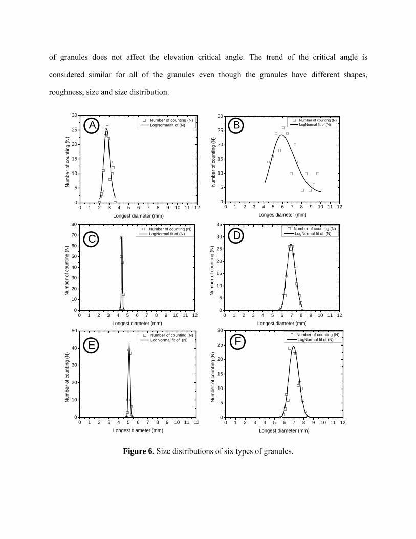
of granules does not affect the elevation critical angle. The trend of the critical angle is
considered similar for all of the granules even though the granules have different shapes,
roughness, size and size distribution.
Figure 6. Size distributions of six types of granules.
0 1 2 3 4 5 6 7 8 9 10 11 120
5
10
15
20
25
30 Number of counting (N) LogNormalfit of (N)
Num
ber
of c
ount
ing
(N)
Longest diameter (mm)
0 1 2 3 4 5 6 7 8 9 10 11 120
5
10
15
20
25
30 Number of counting (N) LogNormal fit of (N)
Num
ber
of c
ount
ing
(N)
Longes diameter (mm)
0 1 2 3 4 5 6 7 8 9 10 11 120
10
20
30
40
50
60
70
80 Number of counting (N) LogNormal fit of (N)
Num
ber
of c
ount
ing
(N)
Longest diameter (mm)
0 1 2 3 4 5 6 7 8 9 10 11 120
5
10
15
20
25
30
35Number of counting (N) LogNormal fit of (N)
Num
ber
of c
ount
ing
(N)
Longest diameter (mm)
0 1 2 3 4 5 6 7 8 9 10 11 120
10
20
30
40
50 Number of counting (N) LogNormal fit of (N)
Num
ber
of c
ount
ing
(N)
Longest diameter (mm)
0 1 2 3 4 5 6 7 8 9 10 11 120
5
10
15
20
25
30Number of counting (N) LogNormal fil of (N)
Num
ber
of c
ount
ing
(N)
Longest diameter (mm)
A
C
E
B
D
F

Table 1. Average diameter, standard deviation and avalanche angle of granules
Granular Diameter of granular at
the maximum peak (mm) Average
diameter (mm) Standard deviation of geometry (mm)
Avalanche angle (°)
A 2.77 2.79 0.11 40 B 6.17 6.30 0.20 40 C 4.40 4.40 0.01 40 D 6.95 6.97 0.06 40 E 5.08 5.09 0.02 30 F 6.99 7.01 0.07 30
Figure 7 shows the sliding angle of granules. It is seen that the sliding angle is unique. It
does not depend on the volume of granules inside the cylinder; as the granular volume inside the
cylinder increases, the sliding angle of granules does not change. Surprisingly, the sliding angle
of a type of granule is similar to the avalanche angle of those granules. The sliding angle is thus
also independent of the size and size distribution. This means that the avalanche angle and
sliding angle of a certain type of granule is constant even if we modify the size, size distribution
and volume inside the container. However, the avalanche and sliding angle can be adjusted by
controlling the spherical degree of the granular profile.
Figure 7. Method for measuring the sliding angle of granules.
40°
40°40°
40°
A B C D

The location of the critical-angle peak depends on the ratio of the cylinder mass and the
granular mass. If the cylinder mass is very small, the critical angle reaches its maximum quickly.
In addition, the maximum critical angle increases as the cylinder mass decreases. Figure 8 shows
the curves of critical angles at different masses of the cylinder. The location of the maximum
critical angle at different values of cylinder mass (m1) can be obtained by solving the equation
0sin
d
d c
. (31)
We derived Eq. (17) according to http://www.wolframalpha.com, and Eq. (31) reduces to
0223sin661 2412
12
LR
m
. (32)
Figure 8. Effect of cylinder mass on the critical angle.
0sin/sin c
)2/( 21 LRm
0.010.20.3
0.4
2.0
0
0.2
0.4
0.6
0.8
1
‐1.5 ‐1 ‐0.5 0 0.5 1 1.5

T
rice and
rice varie
g. It is se
and the g
agreemen
Figur
W
shows th
sin0/sin
both 0 a
the granu
To verify this
mung beans
ed from 49.8
een that the
granular mas
nt with the th
e 9. Effect o
We found the
he dependenc
0 at 0 on
and sin 0 b
ular mass, th
s theoretical
s. The cylind
862 to 698.0
location of t
ss as shown
heoretical pr
of the ratio o
an
e root of Eq
ce of givin
cylinder ma
ecome zero.
he critical ang
prediction, w
der mass us
068 g and tha
the critical-a
in Fig. 9. Bo
rediction pro
f the granula
ngle: (A) rice
q. (32) using
ng the maxi
ass. Both 0
. Note that w
gle is nearly
we used two
ed in this st
at of the mu
angle peak d
oth granules
oposed.
ar mass to th
e and (B) mu
g Excel softw
mum sin o
and sin 0
when the cyl
y zero.
o types of gr
tudy was 75
ung beans va
depends on t
had a simila
he cylinder-s
ung beans.
ware at diffe
(or 0) and
decrease wi
linder mass
ranules with
5.450 g, whe
aried from 5
the ratio of t
ar trend and
system mass
erent values
d the corresp
ith increasin
is very larg
different ma
ereas the ma
2.294 to 732
the cylinder
d there was s
on the critic
of m1. Figu
ponding valu
g m1. As m1
ge compared
asses:
ass of
2.116
mass
strong
cal
ure 10
ues of
1,
d with

Figure 10. Effect of cylinder mass on the location of the maximum critical angle (0) and the
corresponding maximum critical angle.
Figure 11 shows the moments of inertia of granules measured from their center of mass
(A3) and measured from the contact line (A6). Both moments of inertia increase rapidly as the
volume of granules increases from zero ( around unity). The moment of inertia measured from
the center of mass reaches a maximum before half of the cylinder is filled and then decreases to a
minimum after three-quarters of the volume of the cylinder is filled, and increases again until the
cylinder is full with granules. However, the moment of inertia measured from the contact line
monotonically increases with increasing volume of granules.
0
0.2
0.4
0.6
0.8
1
0 2 4 6 8 10
)2/( 21 LRm
0
max00 sin/sin

Figure 11. Moments of inertia of granules, in units of (2LR4), with respect to the center of mass
(Ig,cm) and with respect to the contact line with the plane (Ig). The slope of the granules is 40o.
When the cylinder is full of granules ( = –1), the predicted normalized moment of
inertia of the granules is 0.7854. Thus, at full filling, Ig,cm/(2LR4) = 0.7855. The total mass of
granules when the cylinder is full is M2 = (R2L) so that the true value of the granular moment
of inertia when the cylinder is full is Ig,cm = (2 0.7854/)M2R2 = 0.5 M2R
2. This expression is
exactly the same as the expression for the solid cylinder [1].
According to Fig. 11, the normalized moment of inertia of granules measured from the
contact line when the cylinder is full with granules is 2.3562. Using the theorem of the parallel
axis, the moment of inertia of the solid cylinder with respect to its edge is three times the
moment of inertia measured from the center of mass [1]. From the above moment of inertia, we
have 2.3562/0.7855 = 3, which is consistent with the theoretical acceptance.
0
0.5
1
1.5
2
2.5
‐1.5 ‐1 ‐0.5 0 0.5 1 1.5
cmgI ,
gI
I (kg.m2)

Figure 12. Moment of inertia of the cylinder system, in units of (2LR4), with respect to the
contact line with the plane and the total moment of inertia with respect to the contact line. The
slope of the granules is 40o.
In the experiment, we used a cylinder with dimensions R = 7 cm and L = 6 cm and mass
m1 = 74.45 g. When the granules occupied half of the cylinder, we measured the granular mass as
383.81 g. Therefore, the mass density of granules, , satisfies 0.5R2 L = 383.81 g. Using this
value, we obtained the normalized moment of inertia of the empty cylinder with respect to the
contact line as 0.264. The moment of inertia of the empty cylinder is independent of the granular
mass. Figure 12 is an example of the calculated moment of inertia of the granules and cylinder
system measured from the contact line.
Figure 13 shows the dependence of the oscillation frequency of the cylinder system for a
slight deviation from equilibrium. The frequency initially increases with increasing volume of
granules, reaches a maximum before half of the cylinder is filled with granules, and then
0
0.5
1
1.5
2
2.5
3
‐1.5 ‐1 ‐0.5 0 0.5 1 1.5
gI
I
I (kg.m2)

decreases with further increasing granular volume. There is no oscillation when the cylinder is
empty or the cylinder is full with granules.
Figure 13. Dependence of the frequency of oscillation of the cylinder system for a slight
deviation from the equilibrium position.
Figure 14 shows that the velocity of the cylinder containing granules and rolling down
the incline is not constant. The motion of the cylinder system shows certain acceleration.
Acceleration of the cylinder system varies once granules are poured into the cylinder. The
accelerations of the cylinder systems were determined and then compared with the accelerations
of the empty cylinder and solid cylinder. The acceleration of the solid cylinder rolling down the
incline can be determined theoretically as sin)3/2( ga , while the acceleration of the empty
cylinder is approximated as sin)2/1( ga [1]. For instance, the accelerations of the solid
cylinder and empty cylinder are 0.265 and 0.121 m/s2 for the cylinder containing granules A.
These values match the acceleration determined from the graph of time versus displacement of
each cylinder system as shown in Fig 14. Employing the graphical method, the accelerations of
the cylinder fully filled with granules A and the empty cylinder are determined as 0.264 and
0
0.04
0.08
0.12
0.16
0.2
‐1.5 ‐1 ‐0.5 0 0.5 1 1.5
)//(2 Rg

0.118 m/s2, respectively. Moreover, experimental results show that the moment of inertia of the
cylinder fully filled with granules is similar to the moment of inertia of the solid cylinder. The
moment of inertia of the solid cylinder with a mass of 87.547 g and a radius of 7 cm is 2.145
10–3 kg/m2, while that for the cylinder fully filled with granules A is 2.175 10–3 kg/m2.The
experiment results confirm that a fully filled cylinder system behaves as a solid cylinder.
Figure 14. Graph of the displacement of the cylinder system as function of time. (A) Empty
cylinder, (B) cylinder half filled with granules B and (C) cylinder fully filled with granules B.
Figure 15 shows the dissipation of energy of the cylinder containing various granules and
rolling down an incline as a function of the fractional volume of the cylinder system. It is seen
that the dissipation of energy of the cylinder system increases with increasing granular volume
inside the cylinder and attains a maximum value when the cylinder is half filled with granules.
This dissipation of energy then decreases with increasing granular volume to a minimum value
0.5 1.0 1.5 2.0 2.5 3.0 3.5 4.0 4.50
10
20
30
40
50
60
70
Dis
tanc
e (c
m)
Time (s)
0.0 0.5 1.0 1.5 2.0 2.5 3.0 3.5 4.0 4.50
10
20
30
40
50
60
70
Dis
tanc
e (c
m)
Time (s)
0.0 0.5 1.0 1.5 2.0 2.5 3.0 3.5 4.0 4.50
10
20
30
40
50
60
70
Dis
tanc
e (c
m)
Time (s)
A B
C

corresponding to the cylinder being fully filled. By increasing the volume of granules inside the
cylinder, the friction acting among granules and between granules and the cylinder wall
increases. This friction is considered to lead to dissipation of energy through heat loss, thus
reducing the energy of the system. Such friction reaches a maximum value when the cylinder is
half filled. If the cylinder is more than half filled with granules, there is reduced motion of
granules inside the cylinder. Hence, the friction acting among granules and between granules and
the cylinder wall also decreases. Such a decrease in friction is proportional to the increase in the
granular volume beyond half the volume of the cylinder. When the cylinder is fully filled, there
is no more space for granular motion and the granules are therefore confined to the cylinder
shape and the cylinder system behaves as a solid cylinder. As a result, the friction among
granules and between granules and the cylinder wall becomes so small that the dissipation of
energy reaches a minimum value; the value is smaller than that for an empty cylinder rolling
down an incline. Moreover, because the dissipation of energy is caused by granular friction, it is
seen that rough granules have higher dissipation than smooth granules. The cylinder has lower
dissipation of energy when containing granules C, E and F than when containing granules A, B
and D. This is because granules A, B, and D having higher surface roughness than granules C, E
and F. Besides the surface roughness, the dissipation of energy also depends on the granular
form. Granules with spherical form and a smooth surface have a lower dissipation of energy than
non-spherical granules with rough surfaces as shown in Fig. 15.

Figure 15. Dissipation of energy versus the fractional volume (η) of the cylinder system
-1.5 -1.0 -0.5 0.0 0.5 1.0 1.50.00
0.05
0.10
0.15
0.20
0.25
0.30E
i-E
f(J
)
-1.5 -1.0 -0.5 0.0 0.5 1.0 1.5
0.00
0.05
0.10
0.15
0.20
0.25
0.30
Ei-
Ef(
J)
-1.5 -1.0 -0.5 0.0 0.5 1.0 1.50.00
0.05
0.10
0.15
0.20
0.25
0.30
Ei-
Ef(
J)
-1.5 -1.0 -0.5 0.0 0.5 1.0 1.50.00
0.05
0.10
0.15
0.20
0.25
0.30
Ei-
Ef(
J)
-1.5 -1.0 -0.5 0.0 0.5 1.0 1.50.00
0.05
0.10
0.15
0.20
0.25
0.30
Ei-
Ef(
J)
-1.5 -1.0 -0.5 0.0 0.5 1.0 1.50.00
0.05
0.10
0.15
0.20
0.25
0.30
Ei-
Ef(
J)
A B
C D
E F

Figure 16. Dissipation of energy versus the fractional mass (β) of the cylinder system.
Figure 16 shows the dissipation of energy of the cylinder containing various granules and
rolling down an incline as a function of the fractional mass of the cylinder system. It is seen that
the dissipation of energy versus fractional mass reaches a maximum value at a certain point that
is specific to each type of granule. Before this maximum value is achieved, the dissipation of
energy slowly increases with an increase in the fractional mass of the cylinder system. The
0.0 0.2 0.4 0.6 0.8 1.00.00
0.05
0.10
0.15
0.20
0.25
0.30E
i-E
f(J)
0.0 0.2 0.4 0.6 0.8 1.00.00
0.05
0.10
0.15
0.20
0.25
0.30
Ei-
Ef(
J)
0.0 0.2 0.4 0.6 0.8 1.00.00
0.05
0.10
0.15
0.20
0.25
0.30
Ei-
Ef(
J)
0.0 0.2 0.4 0.6 0.8 1.00.00
0.05
0.10
0.15
0.20
0.25
0.30
Ei-
Ef(
J)
0.0 0.2 0.4 0.6 0.8 1.00.00
0.05
0.10
0.15
0.20
0.25
0.30
Ei-
Ef(
J)
0.0 0.2 0.4 0.6 0.8 1.0
0.00
0.05
0.10
0.15
0.20
0.25
0.30
Ei-
Ef(
J)
A
C
E
B
D
F

fractional mass is a maximum when the cylinder is half filled, and then drastically decreases with
an increasing in the fractional mass till the cylinder is fully filed. Furthermore, it is noted that a
cylinder containing light granules such as granules C, E and F has a lower peak of dissipation of
energy than a cylinder filled with heavy granules (A, B and D). These experimental results verify
that, in addition to the form and surface roughness of granules, the dissipation of energy for a
cylinder containing granules and rolling down an inclined plane is affected also by the mass of
the granules.
5. Conclusion
We showed the existence of a critical elevation angle of an inclined plane that allows a
cylinder containing granules to roll down the plane. The critical angle depends on the avalanche
angle of the granules, while the avalanche angle of the granules is similar to the sliding angle. A
simple experiment using six types of granules confirmed the theoretical predictions. Our
theoretical prediction can be used to determine the critical angle without considering the granular
configuration, roughness, mass and size distribution. We also showed that below the critical
angle, the system will oscillate around the equilibrium position when it is slightly deviated. We
derived the oscillation frequency as a function of the granular volume in the container.
Additionally, we determined the dissipation of energy in the cylinder system. The dissipation of
energy depends on the granular form, surface roughness, fractional volume and fractional mass
inside the cylinder. Although the investigation focused on a cylindrical container, similar
behaviour will be observed for a spherical container.
Appendix
Derivation of the moment of inertia of granules measured from the contact line
First, let us derive the moment of inertia of granules measured from the center of mass of the
granules. For this purpose, let us consider Fig. 17. We want to determine the moment of inertia
of a thin plate with respect to a parallel axis at a distance s from the plate. The width of the plate
is 2y. Suppose the mass of the plate per unit length is so that the total mass is 2y.

Figure 17. Variables for determining the center of mass of a thin plate with respect to a parallel
axis at distance s from the plate.
The moment of inertia of the thin plate relative to an axis at a distance s from the plate is
yyy
y
p dxxsxsdmxsdmI0
22
0
2222 22
33)2(
32
3
12
22
22
32
0
32 ysm
ysy
yysxxs
y
. (A1)
Next, we look at Fig. 18. We slice the granules inside the cylinder into many parallel thin
plates. The width of a plate depends on the position (distance from the cylinder center). Suppose
the length of the cylinder is L. Now, let us select a plate of height 2y. The distance of this plate
from the cylinder center is x, and the distance from the granular center of mass is s = xcm – x. The
moment of inertia of this piece with respect to the center of mass of the granules is
axis22 xs xdx
y
y

d
where
Figure
T
I
sdmdI
2
is the mass d
18. Granules
The total mom
R
R
cmg LI1
2,
R
R
cmxL1
(2
312
12 RL
4
122 R
L
y
2(
3
2
density (mas
s inside the c
ment of inert
cm yxx )( 2
Rx) 22
222 2 RxR cm
2
2
c36R
xcm
xLdxy cm
()
ss per unit vo
cylinder are
tia of the gra
dx
yy
3
3
Rx
3
( 22
112 cosR
R
1 1cos
yx
3)
22
olume) of gr
considered a
plates.
anules measu
dx
x
3
) 2/32
2
21 61 x
R
R
2
22 6
R
xcm
xL
()2(
ranules.
as the compo
ured from th
12 8 RxRx cmcm
88R
xcm
yxxcm )2
osition of m
he granular c
21
2 8 RxR cm
2 R
xcm
dxy
3
3
, (A
many parallel
center of mas
12 2RRR
32
. (A
A2)
thin
ss is
31
A3)

The mass of granules inside the cylinder is given by
R
R
R
R
ydxLdmm11
22
R
RRRRRL 1122
12
1 cos2
12
212
1cos2
2 RL
. (A4)
From Fig. (1) and Eq. (3), we can show
)cos(2222 cmcm RxxRr sin1cos2 222 cmcm RxxR
sin1cos21 2
2
22
R
x
R
xR cmcm
. (A5)
Therefore, the moment of inertia of granules measured from the contact line is obtained by
substituting Eqs. (A3)–(A5) into Eq. (24):
32
2
221
2
24
28861cos3612
2 R
x
R
x
R
x
R
xRLI cmcmcmcm
g
sin1cos211cos2
2 22
2221
2
R
x
R
xR
RL cmcm
,
and the normalized form is
32
2
221
2
2
428861cos36
12
1
2
R
x
R
x
R
x
R
x
LR
Icmcmcmcmg

sin1cos211cos
2
1 22
221
R
x
R
x cmcm
. (A6)
Substituting Eqs. (27) and (A6) into Eq. (25), we obtain the total moment of inertia of the
cylinder system relative to the contact line as
32
2
221
2
2
428861cos36
12
1
2
R
x
R
x
R
x
R
x
LR
I cmcmcmcm
sin1cos211cos
2
1 22
221
R
x
R
x cmcm
21
22
11
LR
m
LR
R
R
L
. (A7)
From Eqs. (A5) and (A7), we can predict the frequency of oscillation as a function of the
granular volume.
References
[1] Halliday D, Resnick R and Walker J 2006 Fundamental of Physics, 8th edition, New York:
John Wiley, Chapter 11.
[2] Hajra S.K., Bhattacharya T, McCarthy J.J., Improvement of granular mixing of dissimilar
materials in rotating cylinders, Powder Technology 198 (2010) 175–182.
[3] Ward T, Hourigan W, Granular segregation in a tilted-rotating drum, Powder Technology
215-216 (2012) 227–234.
[4] Dubé O, Alizadeh E, Chaouki J, Bertrand F, Dynamics of non-spherical particles in a rotating
drum, Chemical Engineering Science 101 (2013) 486–502.
[5] Liao C-C., Hsiau S-S., Tsai T-H., Tai C-H., Segregation to mixing in wet granular matter
under vibration, Chemical Engineering Science 65 (2010) 1109–1116.

[6] Chou S.H., Hsiau S.S., Experimental analysis of the dynamic properties of wet granular
matter in a rotating drum, Powder Technology 214 (2011) 491–499.
[7] Chou S.H., Hsiau S.S., Dynamic properties of immersed granular matter in different flow
regimes in a rotating drum, Powder Technology 226 (2012) 99–106.
[8] Lee C-F., Chou H-T., Capart H, Granular segregation in narrow rotational drums with
different wall roughness: Symmetrical and asymmetrical patterns, Powder Technology 233
(2013) 103–115.
[9] Yada H, Kawaguchi T, Tanaka T, Relation between segregation patterns and granular flow
modes in conical rotating drum, Flow Measurement and Instrumentation 21 (2010) 207-211.
[10] Pӧschel T and Buchholtz V, Complex flow of granular Material in a rotating cylinder,
Chaos, Solitons & Fractls, 5, 10 (1995) 1901-1912.
[11] Third J.R., Scott D.M., Scott S.A., Axial dispersion of granular material in horizontal
rotating cylinders, Powder Technology 203 (2010) 510–517.
[12] Pereira G.G., Pucilowski S, Liffman K, Cleary P.W., Streak patterns in binary granular
media in a rotating drum, Applied Mathematical Modelling 35 (2011) 1638–1646.
[13] Lu G, Third J.R., Müller C.R., Effect of wall roughness on cross-sectional flow
characteristics fornon-spherical particles in a horizontal rotating cylinder, Particuology xxx
(2013) xxx–xxx.
[14] Chand R, Khaskheli M.A., Qadir A, Ge B, Shi Q, Discrete particle simulation of radial
segregation in horizontally rotating drum: Effects of drum-length and non-rotating end-
plates, Physica A 391 (2012) 4590–4596.
[15] Third J.R., Scott D.M., Scott S. A., Müller C.R., Tangential velocity profiles of granular
material within horizontal rotating cylinders modelled using the DEM, Granular Matter 12
(2010) 587–595.
[16] Monetti R, Hurd A, Kenkre V.M., Simulations for dynamics of granular mixtures in a
rotating drum, Granular Matter 3 (2001) 113–116.
[17]Albert R, Albert I, Hornbaker D, Schiffer P, Baraba´si A-L, Maximum angle of stability in
wet and dry spherical granular media, Physical Review E 56 (6), 6271-6274 (1997).

Top Related
Copyright © 2022 FDOKUMEN

