
Bahasa
Halaman
Hukum

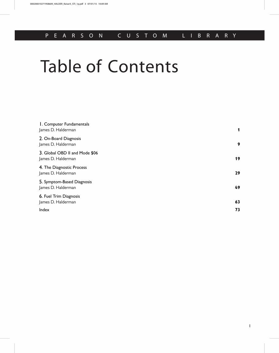
Table of Contents
P E A R S O N C U S T O M L I B R A R Y
I
1. Computer Fundamentals
1
1James D. Halderman
2. On-Board Diagnosis
9
9James D. Halderman
3. Global OBD II and Mode $06
19
19James D. Halderman
4. The Diagnostic Process
29
29James D. Halderman
5. Symptom-Based Diagnosis
49
49James D. Halderman
6. Fuel Trim Diagnosis
63
63James D. Halderman
73
73Index
000200010271958609_HALDER_Keiser5_STI_1p.pdf 3 07/01/15 10:09 AM
COMPUTER FUNDAMENTALS
PARTS OF A COMPUTER The software consists of the pro-grams and logic functions stored in the computer’s circuitry. The hardware is the mechanical and electronic parts of a computer.
� Central processing unit. The microprocessor is the central processing unit (CPU) of a computer. Because it performs the essential mathematical operations and logic decisions that make up its processing function, the CPU can be con-sidered the brain of a computer. Some computers use more than one microprocessor, called a coprocessor. The digital computer can process thousands of digital signals per sec-ond because its circuits are able to switch voltage signals
on and off in billionths of a second. It is called a digital computer because it processes zeros and ones (digits) and needs to have any variable input signals, called analog in-puts, converted to digital form before it can function. � SEE FIGURE 4 .
� Computer memory. Other integrated circuit (IC) devices store the computer operating program, system sensor input data, and system actuator output data—information that is necessary for CPU operation.
� Computer programs. By operating a vehicle on a dynamom-eter and manually adjusting the variable factors such as speed, load, and spark timing, it is possible to determine the optimum output settings for the best driveability, economy, and emission control. This is called engine mapping. � SEE FIGURE 5 . Engine mapping creates a three-dimensional performance
graph that applies to a given vehicle and powertrain combination. Each combination is mapped in this manner to produce a PROM or EEPROM calibration. This allows an automaker to use one basic computer for all models.
Many older-vehicle computers used a single PROM that plugged into the computer.
2. Temporary memory is called random-access memory (RAM), because the computer can write or store new data into it as directed by the computer program, as well as read the data already in it. Automotive computers use two types of RAM memory.
� Volatile RAM memory is lost whenever the ignition is turned off. However, a type of volatile RAM called keep-alive memory (KAM) can be wired directly to battery power. This prevents its data from being erased when the ignition is turned off. One example of RAM and KAM is the loss of station settings in a programmable radio when the battery is disconnected. Because all the set-tings are stored in RAM, they have to be reset when the battery is reconnected. System trouble codes are com-monly stored in RAM and can be erased by disconnect-ing the battery.
� Nonvolatile RAM memory can retain its information even when the battery is disconnected. One use for this type of RAM is the storage of odometer informa-tion in an electronic speedometer. The memory chip retains the mileage accumulated by the vehicle. When speedometer replacement is necessary, the odometer chip is removed and installed in the new speedometer unit. KAM is used primarily in conjunction with adaptive strategies.
OUTPUT FUNCTIONS After the computer has processed the input signals, it sends voltage signals or commands to other devices in the system, such as system actuators. An actuator is an electrical or mechanical output device that converts electrical energy into a mechanical action, such as:
� Adjusting engine idle speed
� Operating fuel injectors
� Ignition timing control
� Altering suspension height
COMPUTER COMMUNICATION A typical vehicle can have many computers, also called modules or controllers. Computers also can communicate with, and control, each other through their output and input functions. This means that the output signal from one computer system can be the input signal for another computer system through a data network.
DIGITAL COMPUTERS
CAPACITORS CAPACITORS
RESISTORS RESISTORS
DUAL INLINE PIN (DIP) CHIPS DUAL INLINE PIN (DIP) CHIPS
FIGURE 4 Many electronic components are used to construct a typical vehicle computer including chips, resistors, and capacitors.
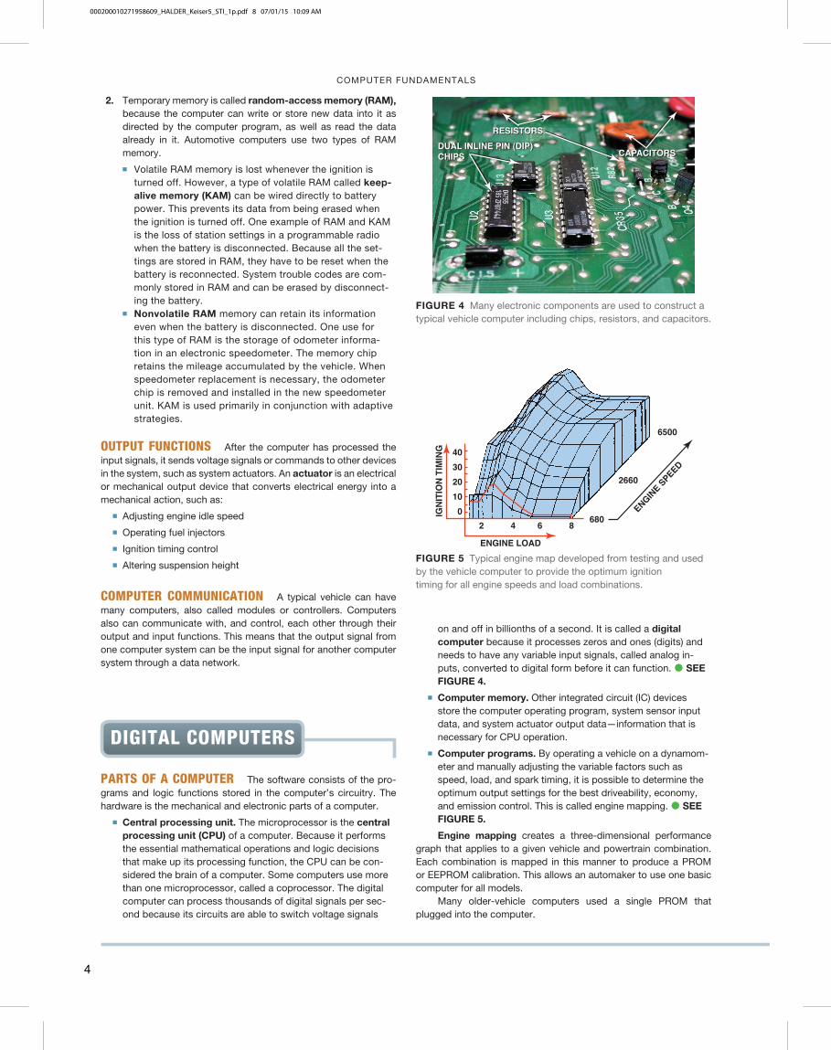
ENGINE LOAD
IGN
ITIO
N T
IMIN
G
ENGINE S
PEED
2
40
30
20
10
0 680
2660
6500
4 6 8
FIGURE 5 Typical engine map developed from testing and used by the vehicle computer to provide the optimum ignition timing for all engine speeds and load combinations.
4
000200010271958609_HALDER_Keiser5_STI_1p.pdf 8 07/01/15 10:09 AM
COMPUTER FUNDAMENTALS
networks. The speed of data transmission is an important factor both in system operation and in system troubleshooting.
CONTROL MODULE LOCATIONS The computer hardware is all mounted on one or more circuit boards and installed in a metal case to help shield it from electromagnetic interference (EMI). The wiring harnesses that link the computer to sensors and actuators connect to multipin connectors or edge connectors on the circuit boards.
Onboard computers range from single-function units that con-trol a single operation to multifunction units that manage all of the separate (but linked) electronic systems in the vehicle. They vary in size from a small module to a notebook-size box. Most other engine computers are installed in the passenger compartment either un-der the instrument panel or in a side kick panel where they can be shielded from physical damage caused by temperature extremes, dirt, and vibration, or interference by the high currents and voltages of various underhood systems. � SEE FIGURES 7 AND 8 .
NOTE: If the computer needs to be replaced, the PROM or calibration module must be removed from the defective unit and installed in the replacement computer. Since the mid-1990s, PCMs do not have removable calibration PROMs, and must be programmed or flashed using a scan tool before being put into service.
CLOCK RATES AND TIMING The microprocessor receives sensor input voltage signals, processes them by using information from other memory units, and then sends voltage signals to the appropriate actuators. The microprocessor communicates by trans-mitting long strings of 0s and 1s in a language called binary code; but the microprocessor must have some way of knowing when one signal ends and another begins. That is the job of a crystal oscillator called a clock generator. � SEE FIGURE 6 .
The computer’s crystal oscillator generates a steady stream of one-bit-long voltage pulses. Both the microprocessor and the memories monitor the clock pulses while they are communicating. Because they know how long each voltage pulse should be, they can distinguish between a 01 and a 0011. To complete the process, the input and output circuits also watch the clock pulses.
COMPUTER SPEEDS Not all computers operate at the same speed; some are faster than others. The speed at which a com-puter operates is specified by the cycle time, or clock speed, required to perform certain measurements. Cycle time or clock speed is measured in megahertz (4.7 MHz, 8 MHz, 15 MHz, 18 MHz, and 32 Hz, which is the clock speed of most vehicle computers today).
BAUD RATE The computer transmits bits of a serial data-stream at precise intervals. The computer’s speed is called the baud rate, or bits per second. The term baud was named after J. M. Emile Baudot (1845–1903), a French telegraph operator who developed a five-bit-per-character code of telegraph. Just as mph helps in estimating the length of time required to travel a certain distance, the baud rate is useful in estimating how long a given computer will need to transmit a specified amount of data to another computer.
Automotive computers have evolved from a baud rate of 160 used in the early 1980s to a baud rate as high as 500,000 for some
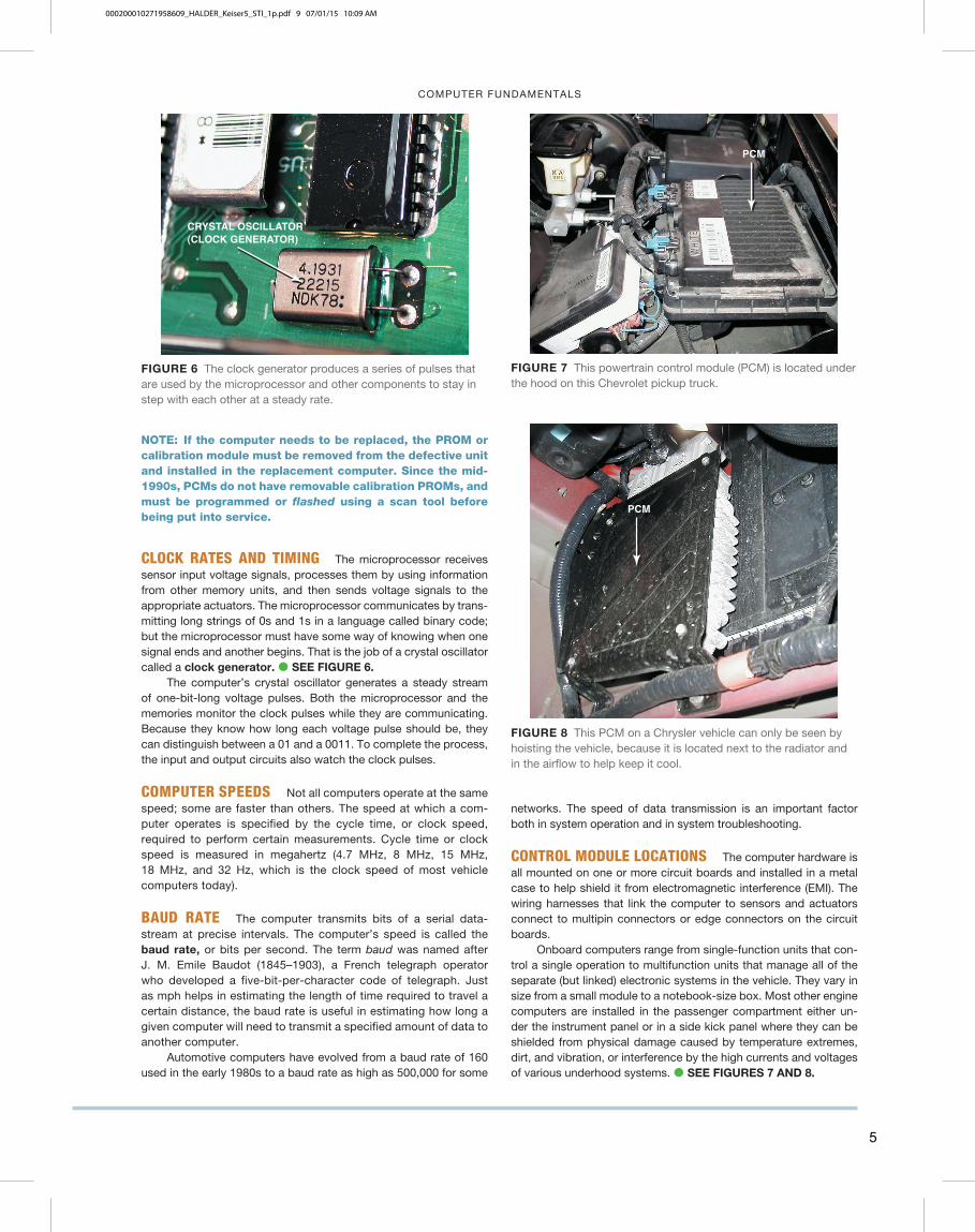
CRYSTAL OSCILLATOR(CLOCK GENERATOR)
FIGURE 6 The clock generator produces a series of pulses that are used by the microprocessor and other components to stay in step with each other at a steady rate.
PCM
FIGURE 7 This powertrain control module (PCM) is located under the hood on this Chevrolet pickup truck.
PCM
FIGURE 8 This PCM on a Chrysler vehicle can only be seen by hoisting the vehicle, because it is located next to the radiator and in the airflow to help keep it cool.
5
000200010271958609_HALDER_Keiser5_STI_1p.pdf 9 07/01/15 10:09 AM
THE DIAGNOSTIC PROCESS
the voltmeter needle to pulse once, and then pause for another 6 to 9 seconds. This is the normal separation between current trouble codes and continuous memory codes (for intermittent problems). Code 11 is the normal pass code, which means that no fault has been stored in memory. Therefore, normal opera-tion of the diagnostic procedure using a voltmeter should indi-cate the following if no codes are set: 1 pulse (2-second pause), 1 pulse (6- to 9-second pause), 1 pulse (6- to 9-second pause), 1 pulse (2-second pause), and finally, 1 pulse. These last two pulses that are separated by a 2-second interval represent a code 11, which is the code used between current and intermit-tent trouble codes.
CONTINUOUS MEMORY CODES (SOFT CODES) Con-tinuous memory codes are set based on information stored while the vehicle was in normal operation. These codes repre-sent an intermittent problem and should only be used for diag-nosis if the KOEO test results in code 11 (no faults detected). Therefore, any codes displayed after the separation pulse rep-resent failures that have been detected but may no longer be present.
KEY ON–ENGINE RUNNING (KOER) TEST During the KOER self-test, the sensors are checked by the computer under actual operating conditions and the output devices (actuators) are operated and checked for expected results. Start the engine and raise the speed to 2500 to 3000 RPM to warm the oxygen sensor within 20 seconds of starting. Hold a steady high engine
RETRIEVING FORD
DIAGNOSTIC CODES
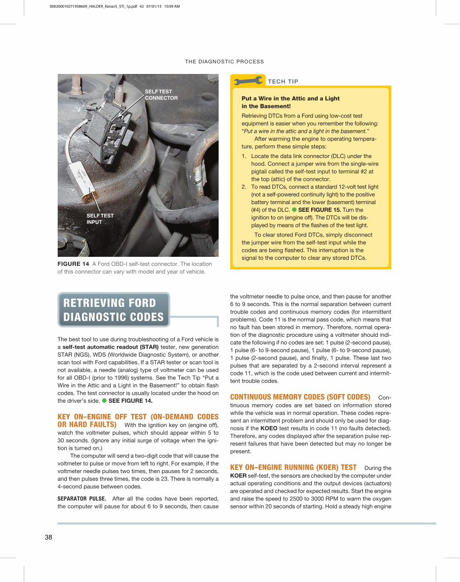
The best tool to use during troubleshooting of a Ford vehicle is a self-test automatic readout (STAR) tester, new generation STAR (NGS), WDS (Worldwide Diagnostic System), or another scan tool with Ford capabilities. If a STAR tester or scan tool is not available, a needle (analog) type of voltmeter can be used for all OBD-I (prior to 1996) systems. See the Tech Tip “Put a Wire in the Attic and a Light in the Basement!” to obtain flash codes. The test connector is usually located under the hood on the driver’s side. � SEE FIGURE 14.
KEY ON–ENGINE OFF TEST (ON-DEMAND CODES OR HARD FAULTS) With the ignition key on (engine off), watch the voltmeter pulses, which should appear within 5 to 30 seconds. (Ignore any initial surge of voltage when the igni-tion is turned on.)
The computer will send a two-digit code that will cause the voltmeter to pulse or move from left to right. For example, if the voltmeter needle pulses two times, then pauses for 2 seconds, and then pulses three times, the code is 23. There is normally a 4-second pause between codes.
SEPARATOR PULSE. After all the codes have been reported, the computer will pause for about 6 to 9 seconds, then cause
SELF TESTCONNECTOR
SELF TESTINPUT
FIGURE 14 A Ford OBD-I self-test connector. The location of this connector can vary with model and year of vehicle.
Put a Wire in the Attic and a Light in the Basement!
Retrieving DTCs from a Ford using low-cost test equipment is easier when you remember the following: “ Put a wire in the attic and a light in the basement. ”
After warming the engine to operating tempera-ture, perform these simple steps:
1. Locate the data link connector (DLC) under the hood. Connect a jumper wire from the single-wire pigtail called the self-test input to terminal #2 at the top (attic) of the connector.
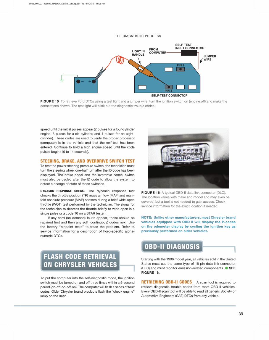
2. To read DTCs, connect a standard 12-volt test light (not a self-powered continuity light) to the positive battery terminal and the lower (basement) terminal (#4) of the DLC. � SEE FIGURE 15 . Turn the ignition to on (engine off). The DTCs will be dis-played by means of the flashes of the test light. To clear stored Ford DTCs, simply disconnect
the jumper wire from the self-test input while the codes are being flashed. This interruption is the signal to the computer to clear any stored DTCs.
TECH TIP
38
000200010271958609_HALDER_Keiser5_STI_1p.pdf 42 07/01/15 10:09 AM
THE DIAGNOSTIC PROCESS
LIGHT INHANDLE
FROMCOMPUTER
SELF-TESTINPUT CONNECTOR
JUMPERWIRE
SELF-TEST CONNECTOR
PIN 2
PIN 4
� �
FIGURE 15 To retrieve Ford DTCs using a test light and a jumper wire, turn the ignition switch on (engine off) and make the connections shown. The test light will blink out the diagnostic trouble codes.
FLASH CODE RETRIEVAL
ON CHRYSLER VEHICLES
To put the computer into the self-diagnostic mode, the ignition switch must be turned on and off three times within a 5-second period (on-off-on-off-on). The computer will flash a series of fault codes. Older Chrysler brand products flash the “check engine” lamp on the dash.
FIGURE 16 A typical OBD-II data link connector (DLC). The location varies with make and model and may even be covered, but a tool is not needed to gain access. Check service information for the exact location if needed.
OBD-II DIAGNOSIS
Starting with the 1996 model year, all vehicles sold in the United States must use the same type of 16-pin data link connector (DLC) and must monitor emission-related components. � SEE FIGURE 16.
RETRIEVING OBD-II CODES A scan tool is required to retrieve diagnostic trouble codes from most OBD-II vehicles. Every OBD-II scan tool will be able to read all generic Society of Automotive Engineers (SAE) DTCs from any vehicle.
speed until the initial pulses appear (2 pulses for a four-cylinder engine, 3 pulses for a six-cylinder, and 4 pulses for an eight-cylinder). These codes are used to verify the proper processor (computer) is in the vehicle and that the self-test has been entered. Continue to hold a high engine speed until the code pulses begin (10 to 14 seconds).
STEERING, BRAKE, AND OVERDRIVE SWITCH TEST To test the power steering pressure switch, the technician must turn the steering wheel one-half turn after the ID code has been displayed. The brake pedal and the overdrive cancel switch must also be cycled after the ID code to allow the system to detect a change of state of these switches.
DYNAMIC RESPONSE CHECK. The dynamic response test checks the throttle position (TP) mass air flow (MAF) and mani-fold absolute pressure (MAP) sensors during a brief wide-open throttle (WOT) test performed by the technician. The signal for the technician to depress the throttle briefly to wide open is a single pulse or a code 10 on a STAR tester.
If any hard (on-demand) faults appear, these should be repaired first and then any soft (continuous) codes next. Use the factory “pinpoint tests” to trace the problem. Refer to service information for a description of Ford-specific alpha-numeric DTCs.
NOTE: Unlike other manufacturers, most Chrysler brand vehicles equipped with OBD II will display the P-codes on the odometer display by cycling the ignition key as previously performed on older vehicles.
39
000200010271958609_HALDER_Keiser5_STI_1p.pdf 43 07/01/15 10:09 AM
FUEL TRIM DIAGNOSIS
great effect on the air-fuel mixture at idle and, like a vacuum leak, tends to have less of an effect at higher engine speeds.
3. PCV airflow. The airflow through the PCV system is not meas-ured by the MAF sensor. Therefore, all openings to the crank-case must be sealed to prevent unmeasured air from entering.
4. Airflow disturbance (disruption). If the incorrect air filter is installed or the air inlet system is modified, airflow through the MAF sensor may not be straight. If air turbulence passes through the MAF sensor, the accuracy of the amount of airflow will not be correct. � SEE FIGURE 4 .
FIGURE 4 Any fault in the air cleaner assembly can disrupt the airflow through the MAF sensor.
What Is the Alpha PID?
Alpha is the air-fuel ratio parameter displayed on Nissan/Infinity vehicles.
100 � 14.7:1
Higher than 100 � PCM is adding fuel
Lower than 100 � PCM is subtracting fuel
Alpha is used as a single parameter that replaces both long-term fuel trim and short-term fuel trim.
? FREQUENTLY ASKED QUESTION
VOLUMETRIC EFFICIENCY
DEFINITION OF VOLUMETRIC EFFICIENCY Vol-umetric efficiency (VE) is the percentage of air entering the engine compared to the theoretical airflow. Typical normally aspirated engines will test having a VE of 75% to 90%. Older two-valve cylinder head engines will test lower than newer engines equipped with four valves per cylinder. Percentages above 100% are possible on supercharged or turbocharged engines. A VE calculator can be downloaded here (free):
www.lindertech.com/guru3
User name: GURU3
Password: LTS2004
Negative Fuel Trim Bank #1; Positive Fuel Trim Bank #2
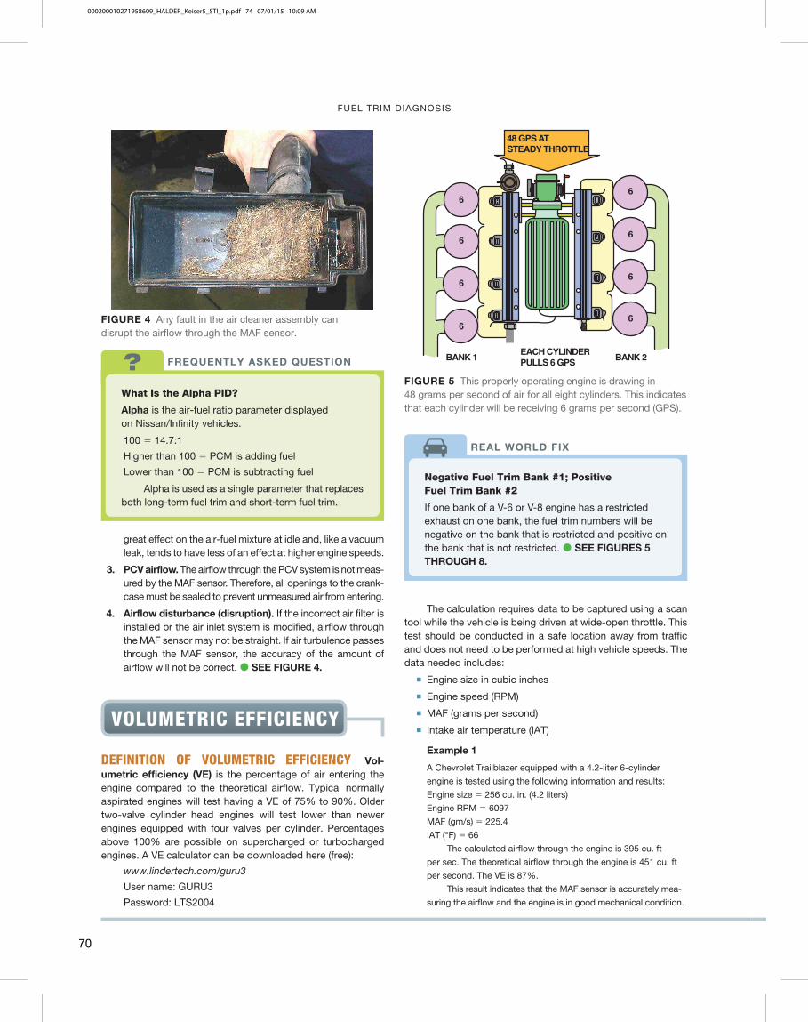
If one bank of a V-6 or V-8 engine has a restricted exhaust on one bank, the fuel trim numbers will be negative on the bank that is restricted and positive on the bank that is not restricted. � SEE FIGURES 5 THROUGH 8 .
REAL WORLD FIX
48 GPS ATSTEADY THROTTLE
EACH CYLINDERPULLS 6 GPS
6
66
6
6
6
6
6
BANK 1 BANK 2
FIGURE 5 This properly operating engine is drawing in 48 grams per second of air for all eight cylinders. This indicates that each cylinder will be receiving 6 grams per second (GPS).
The calculation requires data to be captured using a scan tool while the vehicle is being driven at wide-open throttle. This test should be conducted in a safe location away from traffic and does not need to be performed at high vehicle speeds. The data needed includes:
� Engine size in cubic inches
� Engine speed (RPM)
� MAF (grams per second)
� Intake air temperature (IAT)
Example 1
A Chevrolet Trailblazer equipped with a 4.2-liter 6-cylinder
engine is tested using the following information and results:
Engine size � 256 cu. in. (4.2 liters)
Engine RPM � 6097
MAF (gm/s) � 225.4
IAT (°F) � 66
The calculated airflow through the engine is 395 cu. ft
per sec. The theoretical airflow through the engine is 451 cu. ft
per second. The VE is 87%.
This result indicates that the MAF sensor is accurately mea-
suring the airflow and the engine is in good mechanical condition.
70
000200010271958609_HALDER_Keiser5_STI_1p.pdf 74 07/01/15 10:09 AM

FUEL TRIM DIAGNOSIS
40 GPS ATSTEADY THROTTLE
4
46
6
6
6
4
4
BANK 1 BANK 2
LEFT EXHAUST IS PARTIALLY RESTRICTED
FIGURE 6 If the exhaust system on the left bank (bank #1) were to become restricted, the total airflow through the MAF sensor would also decrease. The cylinders on the right bank (bank #2) would draw the same 6 GPS as before and the cylinders on bank #1, which have a restricted exhaust, would draw just 4 GPS.
BANK 1 BANK 2EACH CYLINDER40 / 8 = 5GPS
MAF SENSOR READS ONLY40 GRAMS PER SECOND
4/5
4/56/5
6/5
6/5
6/5
4/5
4/5
FIGURE 7 If all cylinders were equal and showed the 40 grams per second, then each cylinder will be drawing 5 grams per second (5 � 8 cylinders � 40 GPS). Bank 1 is being supplied 4/5ths of the air needed whereas bank 2 is being supplied 6/5ths of the air needed causing bank 1 to operate too rich and bank 2 to operate too lean.
4/5
4/56/5
6/5
6/5
6/5
4/5
4/5
BANK 1(RICH)
BANK 2(LEAN)
FIGURE 8 As a result of the restricted exhaust on bank #1, the restricted bank will operate too rich and bank #2 will operate too lean. The long-term fuel trim will be negative for bank #1 and positive for bank #2.
MAF Sensor or Airflow Problem?
If a MAF sensor reading is lower than normal, such as at wide-open throttle, it could be an engine breathing problem or a defective/contaminated MAF sensor. To determine which is the case, check the following:
• If the fuel trim numbers follow the airflow, then there is an airflow measurement error (MAF sensor-related problem).
• If the fuel trim numbers are okay, the MAF is okay. • If the BARO reading is lower than normal, then
there is an engine breathing issue, such as a restricted intake or exhaust.
TECH TIP
Possible Restricted Exhaust? Check the IAT.
If the exhaust system is restricted, all of the exhaust will be unable to exit the engine, especially at wide-open throttle. Using a scan tool, look at the values displayed for the intake air temperature (IAT) sensor. The IAT tem-perature should decrease slightly at WOT normally due to the increased airflow. If the IAT temperature reading increases, this is an indication of a restricted exhaust.
TECH TIP
Example 2
A Cadillac Deville is equipped with a 4.6-liter V-8. The cus-
tomer’s concern is poor performance. Fuel trim numbers are
within � 2% from idle to cruise. A check of the VE indicates the
following:
Engine size � 281 cu. in. (4.6 liters)
Engine RPM � 3400
MAF (gm/s) � 80
IAT (°F) � 95
The calculated volumetric efficiency is 53%. A clogged catalytic
converter is discovered to be the cause.
71
000200010271958609_HALDER_Keiser5_STI_1p.pdf 75 07/01/15 10:09 AM
Copyright © 2022 FDOKUMEN

