


Bahasa
Halaman
Hukum

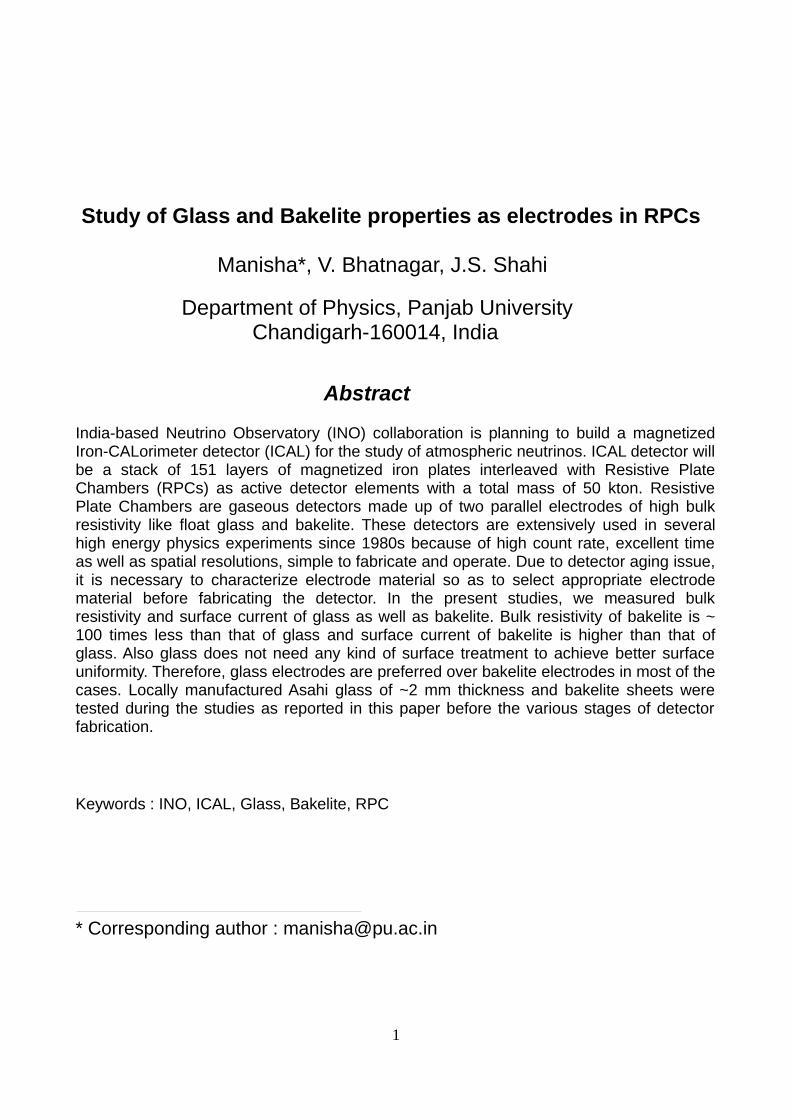
Study of Glass and Bakelite properties as electrodes in RPCs Manisha*, V. Bhatnagar, J.S. Shahi
Department of Physics, Panjab University Chandigarh-160014, India
Abstract
India-based Neutrino Observatory (INO) collaboration is planning to build a magnetizedIron-CALorimeter detector (ICAL) for the study of atmospheric neutrinos. ICAL detector willbe a stack of 151 layers of magnetized iron plates interleaved with Resistive PlateChambers (RPCs) as active detector elements with a total mass of 50 kton. ResistivePlate Chambers are gaseous detectors made up of two parallel electrodes of high bulkresistivity like float glass and bakelite. These detectors are extensively used in severalhigh energy physics experiments since 1980s because of high count rate, excellent timeas well as spatial resolutions, simple to fabricate and operate. Due to detector aging issue,it is necessary to characterize electrode material so as to select appropriate electrodematerial before fabricating the detector. In the present studies, we measured bulkresistivity and surface current of glass as well as bakelite. Bulk resistivity of bakelite is ~100 times less than that of glass and surface current of bakelite is higher than that ofglass. Also glass does not need any kind of surface treatment to achieve better surfaceuniformity. Therefore, glass electrodes are preferred over bakelite electrodes in most of thecases. Locally manufactured Asahi glass of ~2 mm thickness and bakelite sheets weretested during the studies as reported in this paper before the various stages of detectorfabrication.
Keywords : INO, ICAL, Glass, Bakelite, RPC
* Corresponding author : [email protected]
1
1. Introduction
India-based Neutrino Observatory (INO) [1] is a proposed underground multi experimentfacility aimed to study atmospheric neutrino physics extensively i.e. to reconfirmoccurrence of oscillation in atmospheric neutrinos already confirmed by Super Kexperiment, precision measurements of oscillation parameters related to atmosphericneutrinos [2,3]. Detector required for such an experiment is supposed to have large targetmass to achieve statistically significant number of neutrino interactions for reconfirmationof atmospheric neutrino oscillations [4], also good energy resolution and identification ofelectric charge of muons so as to distinguish between neutrinos and anti-neutrinos. ICALnot only satisfies the criteria required for such a detector in such an experiment, alsocompared to other detectors ICAL have a large range in sensitivity to path length (L) andneutrino energy (E) as they appear in the probability relation for oscillation [5]. ICAL willhave modular structure consisting of 3 modules, one ICAL module will be a stack of ironabsorbers interleaved with an air gap of 4 cm housing RPCs [6,7] as active elements.Therefore, it is necessary to choose an appropriate electrode material for RPC fabrication[8]. We perform bulk resistivity as well as surface current studies of IEL bakelite, Formicabakelite, Hylam bakelite, Italian bakelie and Asahi glass of ~ 2 mm thickness procuredfrom local market. Based on the studies performed for bulk resistivity and surface currentof Asahi glass sample and various bakelite samples (as mentioned above), we chooseAsahi glass as electrode for RPC fabrication.
2. Bulk resistivity and surface current measurements
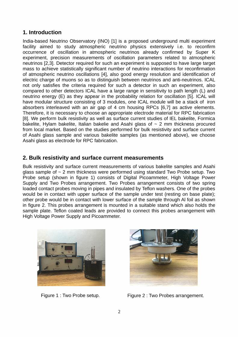
Bulk resistivity and surface current measurements of various bakelite samples and Asahiglass sample of ~ 2 mm thickness were performed using standard Two Probe setup. TwoProbe setup (shown in figure 1) consists of Digital Picoammeter, High Voltage PowerSupply and Two Probes arrangement. Two Probes arrangement consists of two springloaded contact probes moving in pipes and insulated by Teflon washers. One of the probeswould be in contact with upper surface of the sample under test (resting on base plate);other probe would be in contact with lower surface of the sample through Al foil as shownin figure 2. This probes arrangement is mounted in a suitable stand which also holds thesample plate. Teflon coated leads are provided to connect this probes arrangement withHigh Voltage Power Supply and Picoammeter.
2
Figure 1 : Two Probe setup. Figure 2 : Two Probes arrangement.
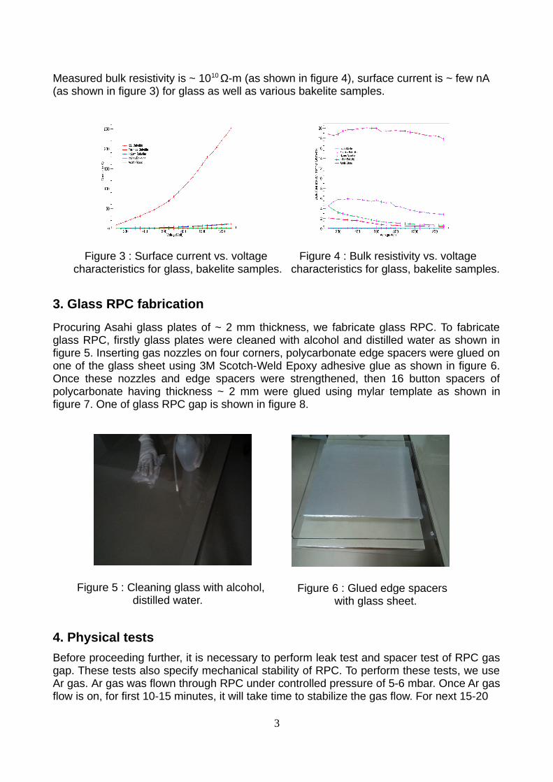
Measured bulk resistivity is ~ 1010 Ω-m (as shown in figure 4), surface current is ~ few nA (as shown in figure 3) for glass as well as various bakelite samples.
3. Glass RPC fabrication
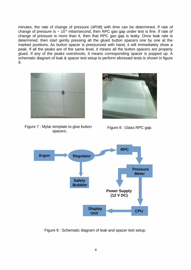
Procuring Asahi glass plates of ~ 2 mm thickness, we fabricate glass RPC. To fabricateglass RPC, firstly glass plates were cleaned with alcohol and distilled water as shown infigure 5. Inserting gas nozzles on four corners, polycarbonate edge spacers were glued onone of the glass sheet using 3M Scotch-Weld Epoxy adhesive glue as shown in figure 6.Once these nozzles and edge spacers were strengthened, then 16 button spacers ofpolycarbonate having thickness ~ 2 mm were glued using mylar template as shown infigure 7. One of glass RPC gap is shown in figure 8.
4. Physical tests
Before proceeding further, it is necessary to perform leak test and spacer test of RPC gasgap. These tests also specify mechanical stability of RPC. To perform these tests, we useAr gas. Ar gas was flown through RPC under controlled pressure of 5-6 mbar. Once Ar gasflow is on, for first 10-15 minutes, it will take time to stabilize the gas flow. For next 15-20
3
Figure 3 : Surface current vs. voltage characteristics for glass, bakelite samples.
Figure 4 : Bulk resistivity vs. voltage characteristics for glass, bakelite samples.
Figure 5 : Cleaning glass with alcohol, distilled water.
Figure 6 : Glued edge spacers with glass sheet.
minutes, the rate of change of pressure (dP/dt) with time can be determined. If rate ofchange of pressure is ~ 10-5 mbar/second, then RPC gas gap under test is fine. If rate ofchange of pressure is more than it, then that RPC gas gap is leaky. Once leak rate isdetermined, then start gently pressing all the glued button spacers one by one at themarked positions. As button spacer is pressurized with hand, it will immediately show apeak. If all the peaks are of the same level, it means all the button spacers are properlyglued. If any of the peaks overshoots, it means corresponding spacer is popped up. Aschematic diagram of leak & spacer test setup to perform aforesaid tests is shown in figure9.
4
Figure 7 : Mylar template to glue button spacers.
Figure 8 : Glass RPC gap.
Argon Regulator
RPC
Pressure Meter
Power Supply (12 V DC)
CPUDisplay Unit
SafetyBubbler
Figure 9 : Schematic diagram of leak and spacer test setup.
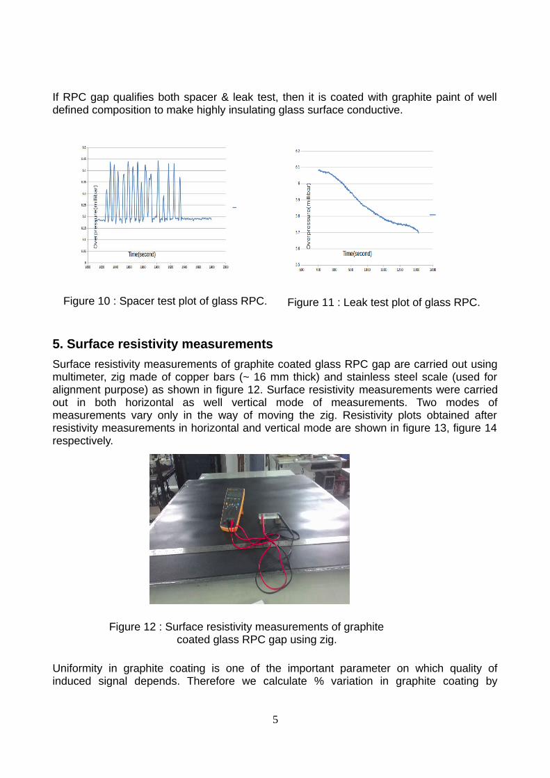
If RPC gap qualifies both spacer & leak test, then it is coated with graphite paint of welldefined composition to make highly insulating glass surface conductive.
5. Surface resistivity measurements
Surface resistivity measurements of graphite coated glass RPC gap are carried out usingmultimeter, zig made of copper bars (~ 16 mm thick) and stainless steel scale (used foralignment purpose) as shown in figure 12. Surface resistivity measurements were carriedout in both horizontal as well vertical mode of measurements. Two modes ofmeasurements vary only in the way of moving the zig. Resistivity plots obtained afterresistivity measurements in horizontal and vertical mode are shown in figure 13, figure 14respectively.
Uniformity in graphite coating is one of the important parameter on which quality ofinduced signal depends. Therefore we calculate % variation in graphite coating by
5
Figure 10 : Spacer test plot of glass RPC. Figure 11 : Leak test plot of glass RPC.
Figure 12 : Surface resistivity measurements of graphite coated glass RPC gap using zig.
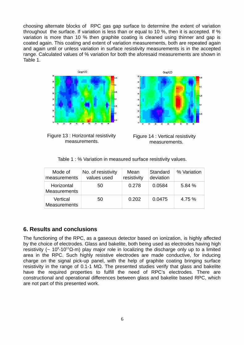
choosing alternate blocks of RPC gas gap surface to determine the extent of variationthroughout the surface. If variation is less than or equal to 10 %, then it is accepted. If %variation is more than 10 % then graphite coating is cleaned using thinner and gap iscoated again. This coating and extent of variation measurements, both are repeated againand again until or unless variation in surface resistivity measurements is in the acceptedrange. Calculated values of % variation for both the aforesaid measurements are shown inTable 1.
Mode ofmeasurements
No. of resistivity values used
Meanresistivity
Standarddeviation
% Variation
HorizontalMeasurements
50 0.278 0.0584 5.84 %
VerticalMeasurements
50 0.202 0.0475 4.75 %
6. Results and conclusions
The functioning of the RPC, as a gaseous detector based on ionization, is highly affectedby the choice of electrodes. Glass and bakelite, both being used as electrodes having highresistivity (~ 109-1011Ω-m) play major role in localizing the discharge only up to a limitedarea in the RPC. Such highly resistive electrodes are made conductive, for inducingcharge on the signal pick-up panel, with the help of graphite coating bringing surfaceresistivity in the range of 0.1-1 MΩ. The presented studies verify that glass and bakelitehave the required properties to fulfill the need of RPC’s electrodes. There areconstructional and operational differences between glass and bakelite based RPC, whichare not part of this presented work.
6
Figure 13 : Horizontal resistivity measurements.
Figure 14 : Vertical resistivity measurements.
Table 1 : % Variation in measured surface resistivity values.
Acknowledgements
We would like to thank Department of Science and Technology (DST)/Department ofAtomic Energy (DAE) to provide financial support for R&D work. We also thank staff ofEHEP group and Department of Physics, Panjab University, Chandigarh.
References
[1] The ICAL Collaboration, Physics Potential of the ICAL detector at the India-based
Neutrino Observatory (INO), arXiv: 1505.07380v1, 2015.
[2] B. Satyanarayan, PhD Thesis, IIT Bombay; entitled: “Design and Characterization
Studies of Resistive Plate Chambers” (unpublished- 2009).
[3] R.N. Mohapatra et al., Theory of Neutrinos : A White Paper, Rept.Prog.Phys. 2007, 70,
1757-1867.
[4] S. Biswas, PhD Thesis, University of Calcutta; entitled: “Development of High
Resolution Gas Filled Detector for High Energy Physics Experiments”
(unpublished- 2010).
[5] Kai Zuber, Neutrino Physics (Series in High energy, Cosmology and Gravitation),
Taylor & Francis Group: New York, 2004.
[6] R. Santonico et al., Nucl. Instr. And Meth. 1981, 187, 377.
[7] S.D. Kalmani et al., Development of glass Resistive Plate Chambers for INO
experiment, NIM A 2009, 602.
[8] Daljeet Kaur et al., Characterization of 3 mm Glass Electrodes and Development of
RPC Detectors for INO-ICAL, arXiv: 1412.4998v1, 2014, NIM A (2015).
7
Top Related
Copyright © 2022 FDOKUMEN

