

Bahasa
Halaman
Hukum

October 2020 AN4908 Rev 2 1/221
AN4908Application note
STM32 USART automatic baud rate detection
IntroductionCorrect USART communication requires the transmission and reception baud rates to be matched reasonably closely, otherwise communication errors may occur.
Automatic baud rate detection is useful when establishing a communication link between two devices, where the slave device is able to detect the baud rate of the master controller and self-adjust accordingly. This requires an automatic mechanism to determine the baud rate.
The USART peripheral embedded in some STM32 devices offers many features, including automatic baud rate detection hardware.
The purpose of this application note is to present the automatic baud rate detection feature of STM32 microcontrollers and to give an alternative software approach for STM32 devices that do not implement this feature in hardware.
This application note applies to the products listed in Table 1.
Table 1. Applicable productsType Product series
MicrocontrollersSTM32F0 Series, STM32F1 Series, STM32F3 Series, STM32F2 Series, STM32F4 Series, STM32F7 Series, STM32H7 Series, STM32L0 Series, STM32L1 Series, STM32L4 Series.
www.st.com
Contents AN4908
2/22 AN4908 Rev 2
Contents
1 General information . . . . . . . . . . . . . . . . . . . . . . . . . . . . . . . . . . . . . . . . . 5
2 Hardware automatic baud rate detection . . . . . . . . . . . . . . . . . . . . . . . . 52.1 Feature overview . . . . . . . . . . . . . . . . . . . . . . . . . . . . . . . . . . . . . . . . . . . . 5
2.2 Automatic baud rate detection modes . . . . . . . . . . . . . . . . . . . . . . . . . . . . 7
2.3 Error calculation for ABR . . . . . . . . . . . . . . . . . . . . . . . . . . . . . . . . . . . . . . 8
3 Software automatic baud rate detection . . . . . . . . . . . . . . . . . . . . . . . . . 9
4 Setups for software and hardware approaches . . . . . . . . . . . . . . . . . . 104.1 USART1 configuration example . . . . . . . . . . . . . . . . . . . . . . . . . . . . . . . . 10
4.2 Hardware auto baud rate detection . . . . . . . . . . . . . . . . . . . . . . . . . . . . . .11
4.3 Software automatic baud rate detection . . . . . . . . . . . . . . . . . . . . . . . . . 13
4.4 Analysis of results . . . . . . . . . . . . . . . . . . . . . . . . . . . . . . . . . . . . . . . . . . 164.4.1 Error calculation . . . . . . . . . . . . . . . . . . . . . . . . . . . . . . . . . . . . . . . . . . . 16
4.4.2 Comparison of software and hardware approaches . . . . . . . . . . . . . . . 17
5 Conclusion . . . . . . . . . . . . . . . . . . . . . . . . . . . . . . . . . . . . . . . . . . . . . . . . 20
6 Revision history . . . . . . . . . . . . . . . . . . . . . . . . . . . . . . . . . . . . . . . . . . . 21
AN4908 Rev 2 3/22
AN4908 List of figures
3
List of figures
Figure 1. Software automatic baud rate detection overview . . . . . . . . . . . . . . . . . . . . . . . . . . . . . . . . 9Figure 2. Error calculation for ABR at fCK = 72 MHz, 115200 bits/s desired baud rate . . . . . . . . . . 16Figure 3. ABR error comparison (fCK = HSI clock, Mode 2 for HW detection) . . . . . . . . . . . . . . . . . 17Figure 4. ABR error comparison (fCK = 72 MHz, Mode 2 for HW detection). . . . . . . . . . . . . . . . . . . 18Figure 5. Baud rate comparison (fCK = 72 MHz, desired baud rate = 9 Mbits/s, Mode 2
for hardware detection . . . . . . . . . . . . . . . . . . . . . . . . . . . . . . . . . . . . . . . . . . . . . . . . . . . . 19
List of tables AN4908
4/22 AN4908 Rev 2
List of tables
Table 1. Applicable products . . . . . . . . . . . . . . . . . . . . . . . . . . . . . . . . . . . . . . . . . . . . . . . . . . . . . . . 1Table 2. USART hardware automatic baud rate detection on STM32 Series devices . . . . . . . . . . . . 5Table 3. Hardware automatic baud rate detection on STM32 USART interfaces. . . . . . . . . . . . . . . . 6Table 4. Automatic baud rate detection modes . . . . . . . . . . . . . . . . . . . . . . . . . . . . . . . . . . . . . . . . . 7Table 5. Software automatic baud rate detection details . . . . . . . . . . . . . . . . . . . . . . . . . . . . . . . . . 13Table 6. Document revision history . . . . . . . . . . . . . . . . . . . . . . . . . . . . . . . . . . . . . . . . . . . . . . . . . 21
AN4908 Rev 2 5/22
AN4908 General information
21
1 General information
STM32 Series microcontrollers are Arm®(a)-based devices.
2 Hardware automatic baud rate detection
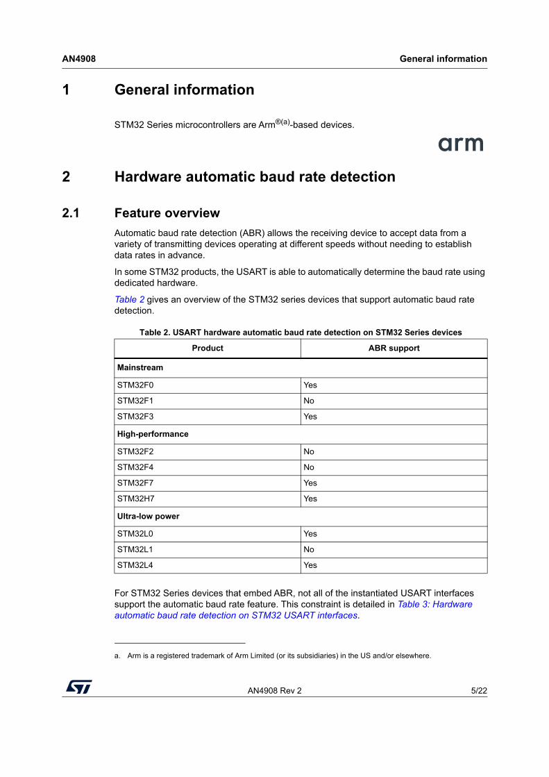
2.1 Feature overviewAutomatic baud rate detection (ABR) allows the receiving device to accept data from a variety of transmitting devices operating at different speeds without needing to establish data rates in advance.
In some STM32 products, the USART is able to automatically determine the baud rate using dedicated hardware.
Table 2 gives an overview of the STM32 series devices that support automatic baud rate detection.
For STM32 Series devices that embed ABR, not all of the instantiated USART interfaces support the automatic baud rate feature. This constraint is detailed in Table 3: Hardware automatic baud rate detection on STM32 USART interfaces.
a. Arm is a registered trademark of Arm Limited (or its subsidiaries) in the US and/or elsewhere.
Table 2. USART hardware automatic baud rate detection on STM32 Series devices
Product ABR support
Mainstream
STM32F0 Yes
STM32F1 No
STM32F3 Yes
High-performance
STM32F2 No
STM32F4 No
STM32F7 Yes
STM32H7 Yes
Ultra-low power
STM32L0 Yes
STM32L1 No
STM32L4 Yes
Hardw
are automatic baud rate detection
AN
4908
6/22AN
4908 Rev 2
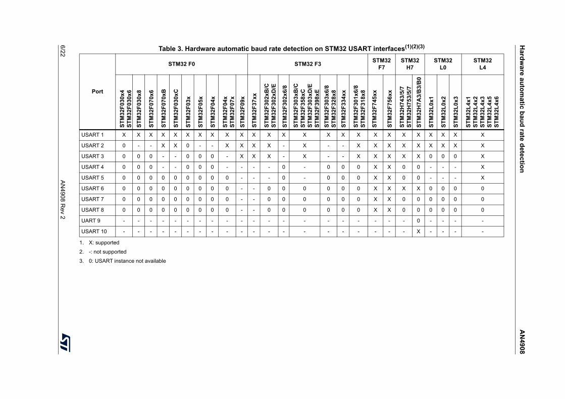
Table 3. Hardware automatic baud rate detection on STM32 USART interfaces(1)(2)(3)
1. X: supported
2. -: not supported
3. 0: USART instance not available
Port
STM32 F0 STM32 F3 STM32F7
STM32H7
STM32L0
STM32L4
STM
32F0
30x4
ST
M32
F030
x6ST
M32
F030
x8
STM
32F0
70x6
STM
32F0
70xB
STM
32F0
30xC
STM
32F0
3x
STM
32F0
5x
STM
32F0
4x
STM
32F0
4x
STM
32F0
7x
STM
32F0
9x
STM
32F3
7xx
STM
32F3
02xB
/C
STM
32F3
02xD
/E
STM
32F3
02x6
/8
STM
32F3
03xB
/C
STM
32F3
58xC
ST
M32
F303
xD/E
ST
M32
F398
xEST
M32
F303
x6/8
ST
M32
F328
x8ST
M32
F334
xx
STM
32F3
01x6
/8
STM
32F3
18x8
STM
32F7
45xx
STM
32F7
56xx
STM
32H
743/
5/7
STM
32H
753/
5/7
STM
32H
7A3/
B3/
B0
STM
32L0
x1
STM
32L0
x2
STM
32L0
x3
STM
32L4
x1
STM
32L4
x2
STM
32L4
x3
STM
32L4
x5
STM
32L4
x6
USART 1 X X X X X X X X X X X X X X X X X X X X X X X X X
USART 2 0 - - X X 0 - - X X X X - X - - X X X X X X X X X
USART 3 0 0 0 - - 0 0 0 - X X X - X - - X X X X X 0 0 0 X
USART 4 0 0 0 - - 0 0 0 - - - - 0 - 0 0 0 X X 0 0 - - - X
USART 5 0 0 0 0 0 0 0 0 0 - - - 0 - 0 0 0 X X 0 0 - - - X
USART 6 0 0 0 0 0 0 0 0 0 - - 0 0 0 0 0 0 X X X X 0 0 0 0
USART 7 0 0 0 0 0 0 0 0 0 - - 0 0 0 0 0 0 X X 0 0 0 0 0 0
USART 8 0 0 0 0 0 0 0 0 0 - - 0 0 0 0 0 0 X X 0 0 0 0 0 0
UART 9 - - - - - - - - - - - - - - - - - - - - 0 - - - -
USART 10 - - - - - - - - - - - - - - - - - - - - X - - - -
AN4908 Rev 2 7/22
AN4908 Hardware automatic baud rate detection
21
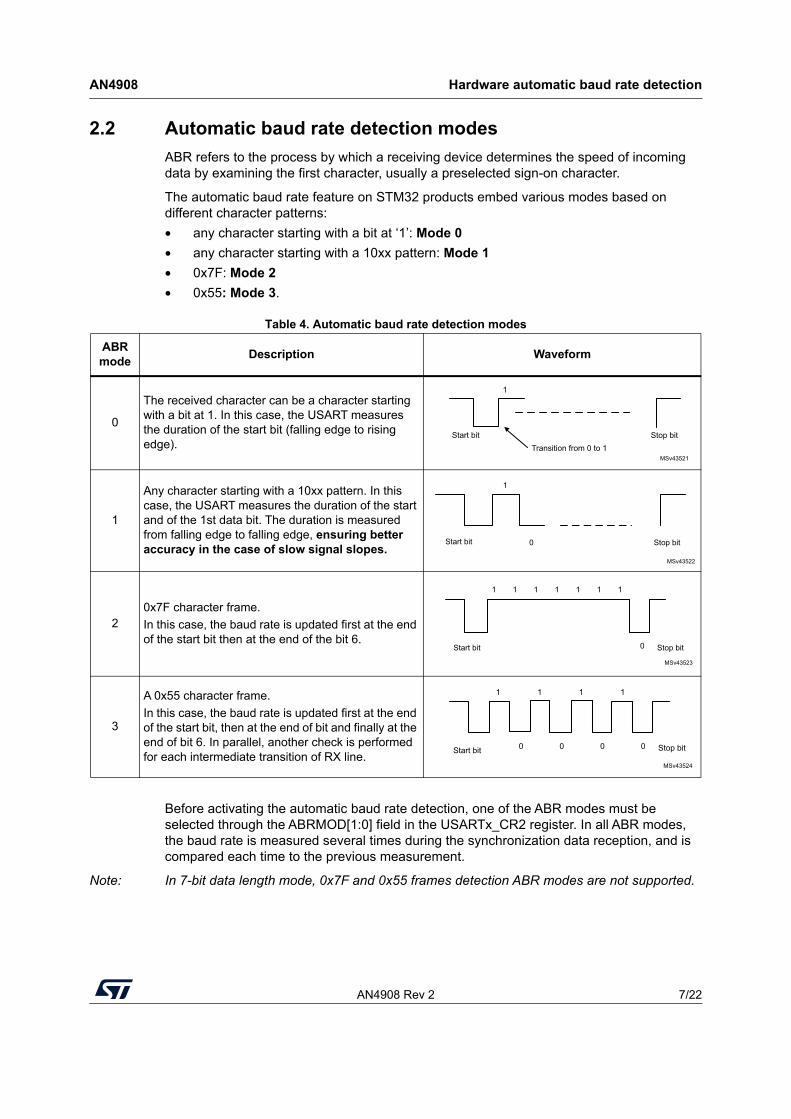
2.2 Automatic baud rate detection modesABR refers to the process by which a receiving device determines the speed of incoming data by examining the first character, usually a preselected sign-on character.
The automatic baud rate feature on STM32 products embed various modes based on different character patterns:• any character starting with a bit at ‘1’: Mode 0• any character starting with a 10xx pattern: Mode 1• 0x7F: Mode 2• 0x55: Mode 3.
Before activating the automatic baud rate detection, one of the ABR modes must be selected through the ABRMOD[1:0] field in the USARTx_CR2 register. In all ABR modes, the baud rate is measured several times during the synchronization data reception, and is compared each time to the previous measurement.
Note: In 7-bit data length mode, 0x7F and 0x55 frames detection ABR modes are not supported.
Table 4. Automatic baud rate detection modes
ABR mode Description Waveform
0
The received character can be a character starting with a bit at 1. In this case, the USART measures the duration of the start bit (falling edge to rising edge).
1
Any character starting with a 10xx pattern. In this case, the USART measures the duration of the start and of the 1st data bit. The duration is measured from falling edge to falling edge, ensuring better accuracy in the case of slow signal slopes.
20x7F character frame. In this case, the baud rate is updated first at the end of the start bit then at the end of the bit 6.
3
A 0x55 character frame.In this case, the baud rate is updated first at the end of the start bit, then at the end of bit and finally at the end of bit 6. In parallel, another check is performed for each intermediate transition of RX line.
MSv43521
Start bitTransition from 0 to 1
Stop bit
1
MSv43522
Start bit Stop bit0
1
MSv43523
1 1 1 1 1 1 1
Start bit Stop bit0
MSv43524
1 1 1 1
0000Start bit Stop bit
Hardware automatic baud rate detection AN4908
8/22 AN4908 Rev 2
2.3 Error calculation for ABRThe communication speed range (specifically the maximum communication speed) is determined by the USART clock source (fCK). The receiver implements different user-configurable oversampling techniques for data recovery by discriminating between valid incoming data and noise. This allows a trade-off between the maximum communication speed and immunity to noise / clock inaccuracy.
The oversampling method is selected by programming the OVER8 bit in the USARTx_CR1 register, and can be either 16 or 8 times the baud-rate clock.
The USART clock source frequency must be compatible with the expected communication speed:• When oversampling by 16, the baud rate is between fCK/65535 and fCK/16• When oversampling by 8, the baud rate is between fCK/65535 and fCK/8.
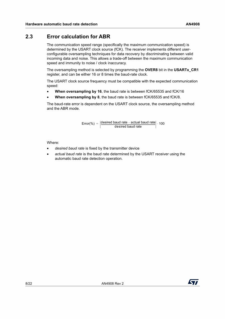
The baud-rate error is dependent on the USART clock source, the oversampling method and the ABR mode.
Where:• desired baud rate is fixed by the transmitter device• actual baud rate is the baud rate determined by the USART receiver using the
automatic baud rate detection operation.
Error(%) desired baud rate actual baud rate–desired baud rate------------------------------------------------------------------------------------------------ 100⋅=
AN4908 Rev 2 9/22
AN4908 Software automatic baud rate detection
21
3 Software automatic baud rate detection
When hardware auto baud rate detection is not supported, the software approach described in this section can be adopted.
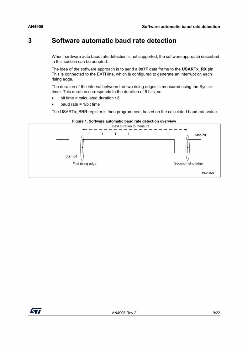
The idea of the software approach is to send a 0x7F data frame to the USARTx_RX pin. This is connected to the EXTI line, which is configured to generate an interrupt on each rising edge.
The duration of the interval between the two rising edges is measured using the Systick timer. This duration corresponds to the duration of 8 bits, so • bit time = calculated duration / 8• baud rate = 1/bit time
The USARTx_BRR register is then programmed, based on the calculated baud rate value.
Figure 1. Software automatic baud rate detection overview
MSv43525
8-bit duration to measure
First rising edge Second rising edge
Start bit
Stop bit1111111
Setups for software and hardware approaches AN4908
10/22 AN4908 Rev 2
4 Setups for software and hardware approaches
The STM32F303xD/E embedding the hardware automatic baud rate feature, is used for this set-up example.
The HyperTerminal PC application is used to send and receive data frames to and from the STM32F303. Consequently, standard baud rates in the range 600 bits/s to 115200 bits/s are tested.The highest baud-rate value that can be reached (9 Mbits/s) is tested using another STM32F3 device as a transmitter.
4.1 USART1 configuration exampleIn both examples, the STM32 USART1 is configured as follows:
/*##-1- Configure the UART peripheral ######################################*/
/* Put the USART peripheral in the Asynchronous mode (UART Mode) */
/* UART configured as follows:
- Word Length = 8 Bits
- Stop Bit = One Stop bit
- Parity = NONE parity
- BaudRate = 115200 baud It can be any other value as the USARTx_BRR register will be reprogrammed
- Hardware flow control disabled (RTS and CTS signals)
- The oversampling mode is 8 or 16 (Both are tested)
*/
UartHandle.Instance = USARTx;
UartHandle.Init.BaudRate = 115200;
UartHandle.Init.WordLength = UART_WORDLENGTH_8B;
UartHandle.Init.StopBits = UART_STOPBITS_1;
UartHandle.Init.Parity = UART_PARITY_NONE;
UartHandle.Init.HwFlowCtl = UART_HWCONTROL_NONE;
UartHandle.Init.Mode = UART_MODE_TX_RX;
UartHandle.Init.OverSampling = UART_OVERSAMPLING_16;
Note: The USART1 clock source is a system clock at 72 MHz, using the HSE PLL clock source. (Some tests are made using the HSI clock as USART1 clock source. This is to check the impact of the HSI inaccuracy on the results.)
AN4908 Rev 2 11/22
AN4908 Setups for software and hardware approaches
21
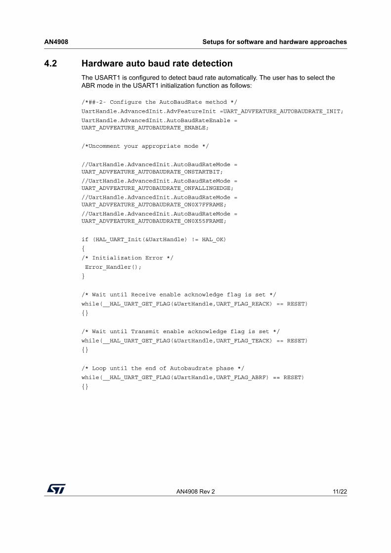
4.2 Hardware auto baud rate detection The USART1 is configured to detect baud rate automatically. The user has to select the ABR mode in the USART1 initialization function as follows:
/*##-2- Configure the AutoBaudRate method */
UartHandle.AdvancedInit.AdvFeatureInit =UART_ADVFEATURE_AUTOBAUDRATE_INIT;
UartHandle.AdvancedInit.AutoBaudRateEnable = UART_ADVFEATURE_AUTOBAUDRATE_ENABLE;
/*Uncomment your appropriate mode */
//UartHandle.AdvancedInit.AutoBaudRateMode = UART_ADVFEATURE_AUTOBAUDRATE_ONSTARTBIT;
//UartHandle.AdvancedInit.AutoBaudRateMode = UART_ADVFEATURE_AUTOBAUDRATE_ONFALLINGEDGE;
//UartHandle.AdvancedInit.AutoBaudRateMode = UART_ADVFEATURE_AUTOBAUDRATE_ON0X7FFRAME;
//UartHandle.AdvancedInit.AutoBaudRateMode = UART_ADVFEATURE_AUTOBAUDRATE_ON0X55FRAME;
if (HAL_UART_Init(&UartHandle) != HAL_OK)
{
/* Initialization Error */
Error_Handler();
}
/* Wait until Receive enable acknowledge flag is set */
while(__HAL_UART_GET_FLAG(&UartHandle,UART_FLAG_REACK) == RESET)
{}
/* Wait until Transmit enable acknowledge flag is set */
while(__HAL_UART_GET_FLAG(&UartHandle,UART_FLAG_TEACK) == RESET)
{}
/* Loop until the end of Autobaudrate phase */
while(__HAL_UART_GET_FLAG(&UartHandle,UART_FLAG_ABRF) == RESET)
{}
Setups for software and hardware approaches AN4908
12/22 AN4908 Rev 2
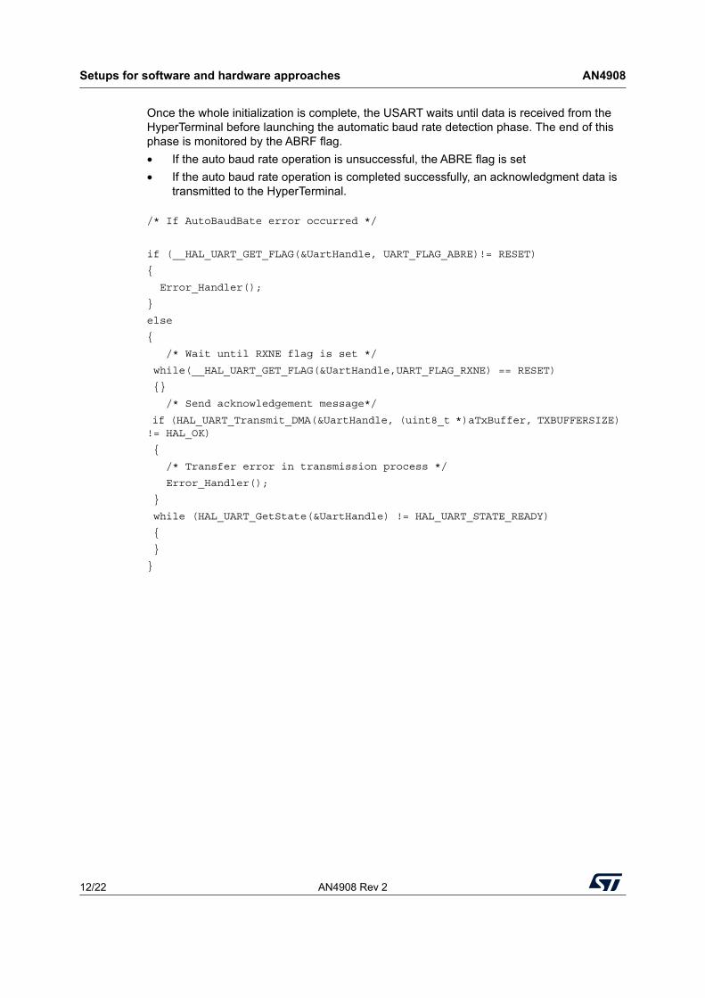
Once the whole initialization is complete, the USART waits until data is received from the HyperTerminal before launching the automatic baud rate detection phase. The end of this phase is monitored by the ABRF flag.• If the auto baud rate operation is unsuccessful, the ABRE flag is set • If the auto baud rate operation is completed successfully, an acknowledgment data is
transmitted to the HyperTerminal.
/* If AutoBaudBate error occurred */
if (__HAL_UART_GET_FLAG(&UartHandle, UART_FLAG_ABRE)!= RESET)
{
Error_Handler();
}
else
{
/* Wait until RXNE flag is set */
while(__HAL_UART_GET_FLAG(&UartHandle,UART_FLAG_RXNE) == RESET)
{}
/* Send acknowledgement message*/
if (HAL_UART_Transmit_DMA(&UartHandle, (uint8_t *)aTxBuffer, TXBUFFERSIZE) != HAL_OK)
{
/* Transfer error in transmission process */
Error_Handler();
}
while (HAL_UART_GetState(&UartHandle) != HAL_UART_STATE_READY)
{
}
}
AN4908 Rev 2 13/22
AN4908 Setups for software and hardware approaches
21
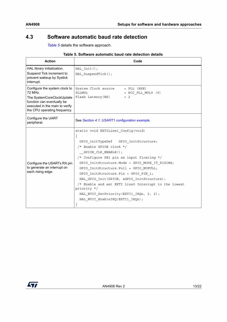
4.3 Software automatic baud rate detection Table 5 details the software approach.
Table 5. Software automatic baud rate detection details Action Code
HAL library initialization.Suspend Tick increment to prevent wakeup by Systick interrupt.
HAL_Init();
HAL_SuspendTick();
Configure the system clock to 72 MHz.The SystemCoreClockUpdate function can eventually be executed in the main to verify the CPU operating frequency.
System Clock source = PLL (HSE) PLLMUL = RCC_PLL_MUL9 (9) Flash Latency(WS) = 2
Configure the UART peripheral. See Section 4.1: USART1 configuration example.
Configure the USARTx RX pin to generate an interrupt on each rising edge.
static void EXTILine1_Config(void)
{
GPIO_InitTypeDef GPIO_InitStructure;
/* Enable GPIOE clock */
__GPIOE_CLK_ENABLE();
/* Configure PE1 pin as input floating */
GPIO_InitStructure.Mode = GPIO_MODE_IT_RISING;
GPIO_InitStructure.Pull = GPIO_NOPULL;
GPIO_InitStructure.Pin = GPIO_PIN_1;
HAL_GPIO_Init(GPIOE, &GPIO_InitStructure);
/* Enable and set EXTI Line0 Interrupt to the lowest priority */
HAL_NVIC_SetPriority(EXTI1_IRQn, 2, 2);
HAL_NVIC_EnableIRQ(EXTI1_IRQn);
}
Setups for software and hardware approaches AN4908
14/22 AN4908 Rev 2
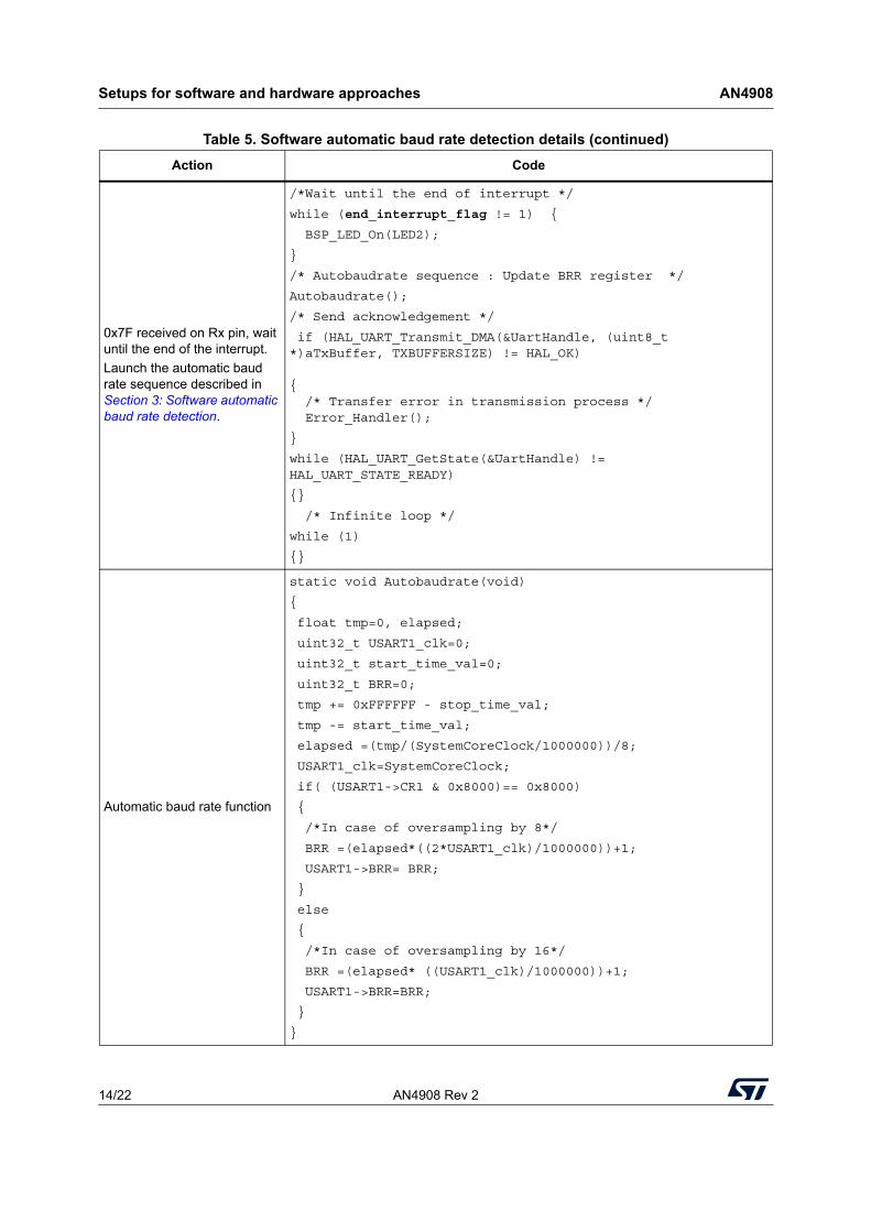
0x7F received on Rx pin, wait until the end of the interrupt.Launch the automatic baud rate sequence described in Section 3: Software automatic baud rate detection.
/*Wait until the end of interrupt */
while (end_interrupt_flag != 1) {
BSP_LED_On(LED2);
}
/* Autobaudrate sequence : Update BRR register */
Autobaudrate();
/* Send acknowledgement */
if (HAL_UART_Transmit_DMA(&UartHandle, (uint8_t *)aTxBuffer, TXBUFFERSIZE) != HAL_OK) { /* Transfer error in transmission process */ Error_Handler();
}
while (HAL_UART_GetState(&UartHandle) != HAL_UART_STATE_READY)
{}
/* Infinite loop */
while (1)
{}
Automatic baud rate function
static void Autobaudrate(void)
{
float tmp=0, elapsed;
uint32_t USART1_clk=0;
uint32_t start_time_val=0;
uint32_t BRR=0;
tmp += 0xFFFFFF - stop_time_val;
tmp -= start_time_val;
elapsed =(tmp/(SystemCoreClock/1000000))/8;
USART1_clk=SystemCoreClock;
if( (USART1->CR1 & 0x8000)== 0x8000)
{
/*In case of oversampling by 8*/
BRR =(elapsed*((2*USART1_clk)/1000000))+1;
USART1->BRR= BRR;
}
else
{
/*In case of oversampling by 16*/
BRR =(elapsed* ((USART1_clk)/1000000))+1;
USART1->BRR=BRR;
}
}
Table 5. Software automatic baud rate detection details (continued)Action Code
AN4908 Rev 2 15/22
AN4908 Setups for software and hardware approaches
21
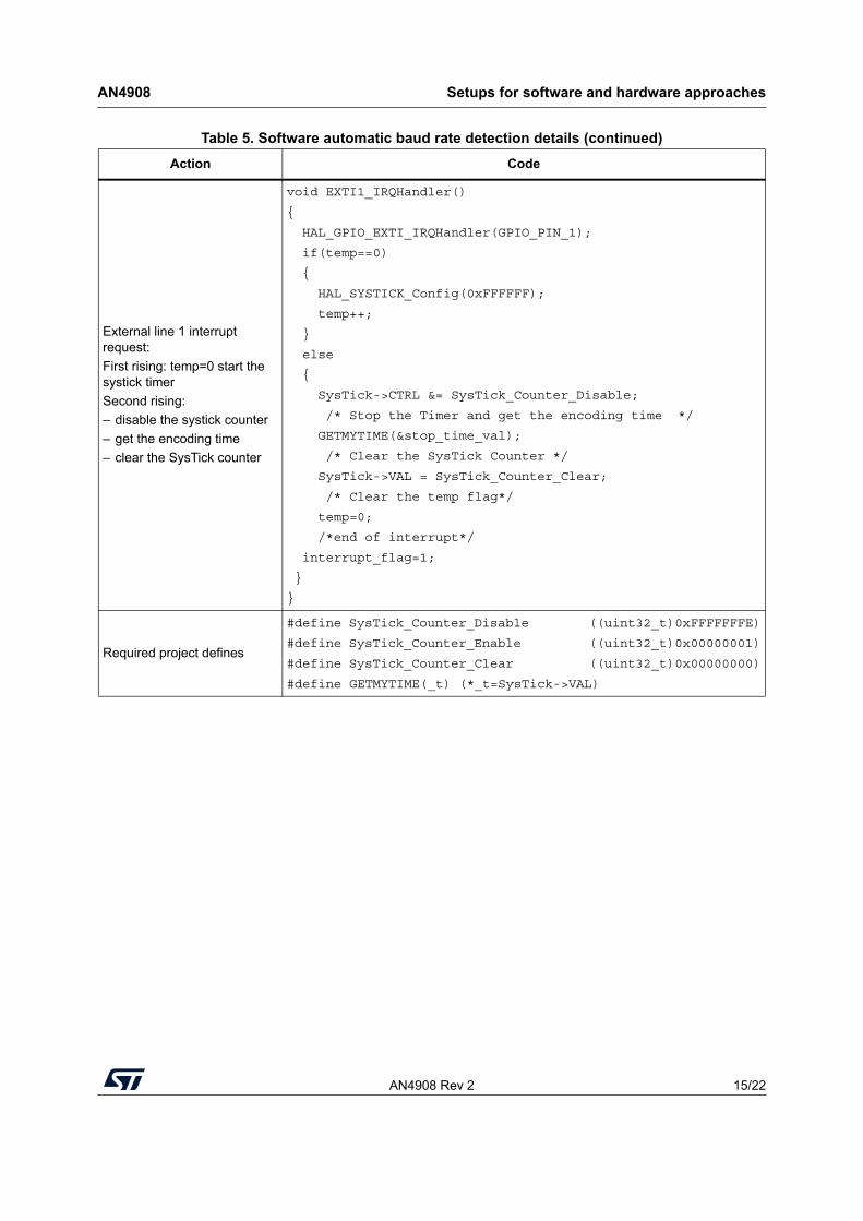
External line 1 interrupt request:First rising: temp=0 start the systick timerSecond rising: – disable the systick counter– get the encoding time – clear the SysTick counter
void EXTI1_IRQHandler()
{
HAL_GPIO_EXTI_IRQHandler(GPIO_PIN_1);
if(temp==0)
{
HAL_SYSTICK_Config(0xFFFFFF);
temp++;
}
else
{
SysTick->CTRL &= SysTick_Counter_Disable;
/* Stop the Timer and get the encoding time */
GETMYTIME(&stop_time_val);
/* Clear the SysTick Counter */
SysTick->VAL = SysTick_Counter_Clear;
/* Clear the temp flag*/
temp=0;
/*end of interrupt*/
interrupt_flag=1;
}
}
Required project defines
#define SysTick_Counter_Disable ((uint32_t)0xFFFFFFFE)
#define SysTick_Counter_Enable ((uint32_t)0x00000001)
#define SysTick_Counter_Clear ((uint32_t)0x00000000)
#define GETMYTIME(_t) (*_t=SysTick->VAL)
Table 5. Software automatic baud rate detection details (continued)Action Code
Setups for software and hardware approaches AN4908
16/22 AN4908 Rev 2
4.4 Analysis of results
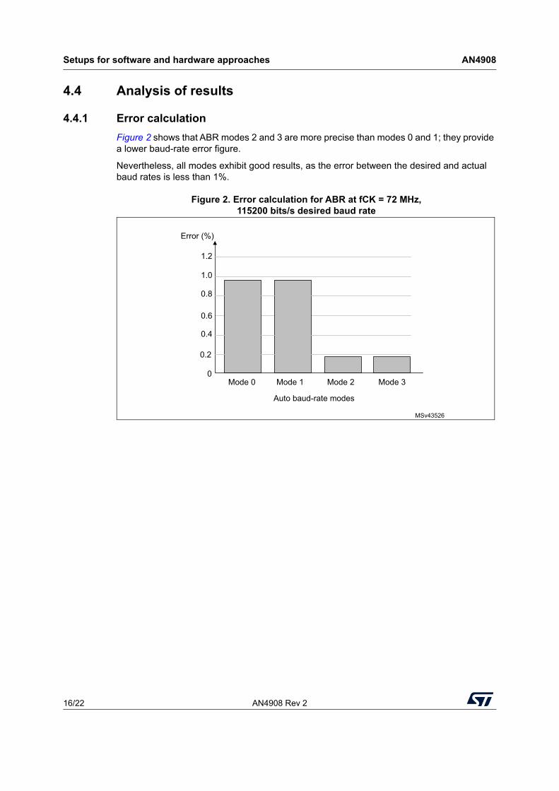
4.4.1 Error calculationFigure 2 shows that ABR modes 2 and 3 are more precise than modes 0 and 1; they provide a lower baud-rate error figure.
Nevertheless, all modes exhibit good results, as the error between the desired and actual baud rates is less than 1%.
Figure 2. Error calculation for ABR at fCK = 72 MHz, 115200 bits/s desired baud rate
MSv43526
Auto baud-rate modes
1.2
1.0
0.8
0.6
0.4
0.2
0Mode 0 Mode 1 Mode 2 Mode 3
Error (%)
AN4908 Rev 2 17/22
AN4908 Setups for software and hardware approaches
21
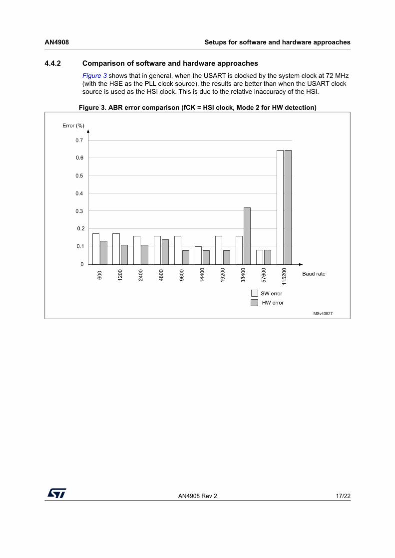
4.4.2 Comparison of software and hardware approachesFigure 3 shows that in general, when the USART is clocked by the system clock at 72 MHz (with the HSE as the PLL clock source), the results are better than when the USART clock source is used as the HSI clock. This is due to the relative inaccuracy of the HSI.
Figure 3. ABR error comparison (fCK = HSI clock, Mode 2 for HW detection)
MSv43527
0.7
0.6
0.5
0.4
0.3
0.2
0.1
0
600
1200
2400
4800
9600
1440
0
1920
0
3840
0
5760
0
1152
00 Baud rate
Error (%)
HW error
SW error
Setups for software and hardware approaches AN4908
18/22 AN4908 Rev 2
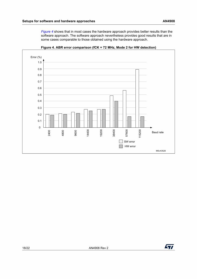
Figure 4 shows that in most cases the hardware approach provides better results than the software approach. The software approach nevertheless provides good results that are in some cases comparable to those obtained using the hardware approach.
Figure 4. ABR error comparison (fCK = 72 MHz, Mode 2 for HW detection)
MSv43528
1.0
0.9
0.8
0.7
0.6
0.5
0.4
0
2400
4800
9600
1440
0
1920
0
3840
0
5760
0
1152
00 Baud rate
Error (%)
0.1
0.3
0.2
HW error
SW error
AN4908 Rev 2 19/22
AN4908 Setups for software and hardware approaches
21
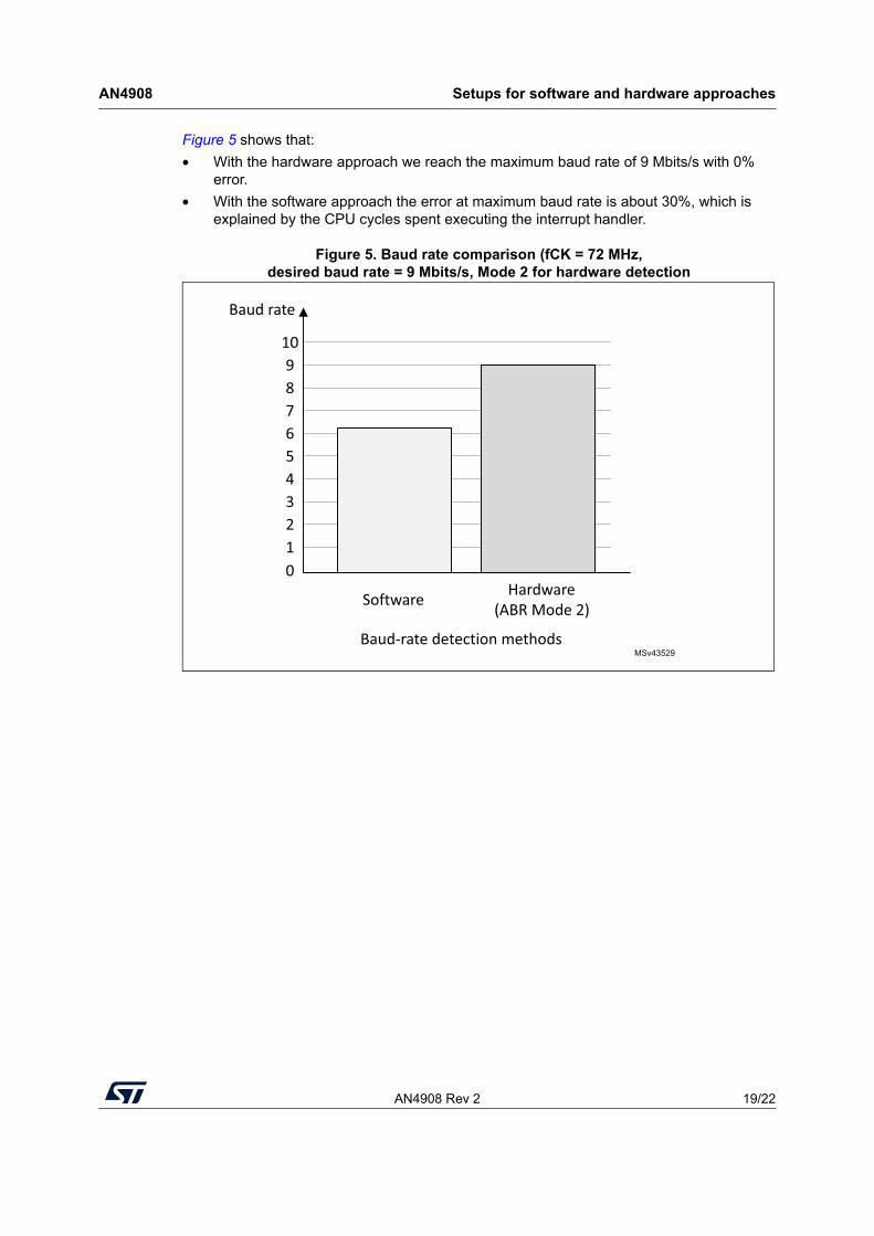
Figure 5 shows that:• With the hardware approach we reach the maximum baud rate of 9 Mbits/s with 0%
error.• With the software approach the error at maximum baud rate is about 30%, which is
explained by the CPU cycles spent executing the interrupt handler.
Figure 5. Baud rate comparison (fCK = 72 MHz, desired baud rate = 9 Mbits/s, Mode 2 for hardware detection
MSv43529
Baud rate
Software Hardware(ABR Mode 2)
10987654321
Baud-rate detection methods
0
Conclusion AN4908
20/22 AN4908 Rev 2
5 Conclusion
This application note describes the hardware automatic baud rate detection feature embedded in some STM32 devices. It also provides a technique for implementing this feature in software, as a solution for STM32 devices not implementing this feature in hardware.
Although the automatic baud rate detection is applied at the beginning of the examples, it could be extended and used whenever the transmitter and receiver devices detect communication errors. This allows a robust application where the host varies its baud rate between communications.
AN4908 Rev 2 21/22
AN4908 Revision history
21
6 Revision history
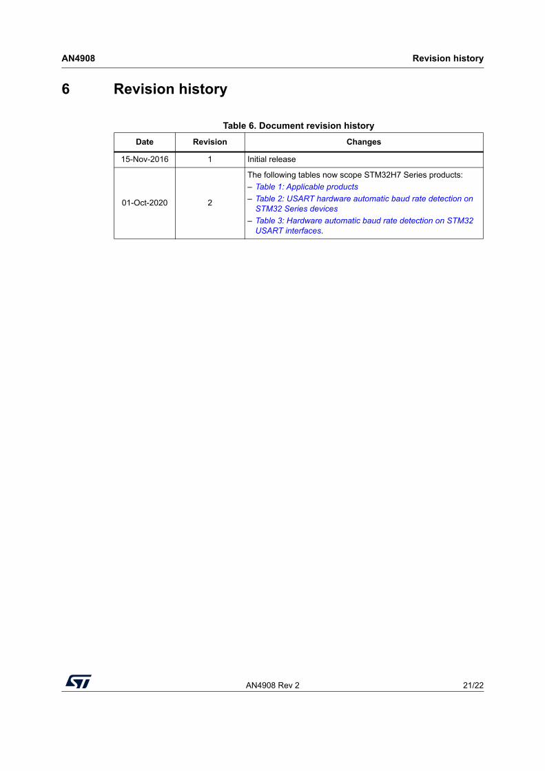
Table 6. Document revision historyDate Revision Changes
15-Nov-2016 1 Initial release
01-Oct-2020 2
The following tables now scope STM32H7 Series products:– Table 1: Applicable products– Table 2: USART hardware automatic baud rate detection on
STM32 Series devices– Table 3: Hardware automatic baud rate detection on STM32
USART interfaces.
AN4908
22/22 AN4908 Rev 2
IMPORTANT NOTICE – PLEASE READ CAREFULLY
STMicroelectronics NV and its subsidiaries (“ST”) reserve the right to make changes, corrections, enhancements, modifications, and improvements to ST products and/or to this document at any time without notice. Purchasers should obtain the latest relevant information on ST products before placing orders. ST products are sold pursuant to ST’s terms and conditions of sale in place at the time of order acknowledgement.
Purchasers are solely responsible for the choice, selection, and use of ST products and ST assumes no liability for application assistance or the design of Purchasers’ products.
No license, express or implied, to any intellectual property right is granted by ST herein.
Resale of ST products with provisions different from the information set forth herein shall void any warranty granted by ST for such product.
ST and the ST logo are trademarks of ST. For additional information about ST trademarks, please refer to www.st.com/trademarks. All other product or service names are the property of their respective owners.
Information in this document supersedes and replaces information previously supplied in any prior versions of this document.
© 2020 STMicroelectronics – All rights reserved
Top Related
Copyright © 2022 FDOKUMEN

