


Bahasa
Halaman
Hukum

HAL Id: hal-01348763https://hal.archives-ouvertes.fr/hal-01348763
Submitted on 25 Jul 2016
HAL is a multi-disciplinary open accessarchive for the deposit and dissemination of sci-entific research documents, whether they are pub-lished or not. The documents may come fromteaching and research institutions in France orabroad, or from public or private research centers.
L’archive ouverte pluridisciplinaire HAL, estdestinée au dépôt et à la diffusion de documentsscientifiques de niveau recherche, publiés ou non,émanant des établissements d’enseignement et derecherche français ou étrangers, des laboratoirespublics ou privés.
Distributed under a Creative Commons Attribution| 4.0 International License
Safety in Supervisory Control for Critical SystemsReinaldo Squillante Jr., Diolino Fo, Jeferson Souza, Fabrício Junqueira, Paulo
Miyagi
To cite this version:Reinaldo Squillante Jr., Diolino Fo, Jeferson Souza, Fabrício Junqueira, Paulo Miyagi. Safety inSupervisory Control for Critical Systems. 4th Doctoral Conference on Computing, Electrical andIndustrial Systems (DoCEIS), Apr 2013, Costa de Caparica, Portugal. pp.261-270, �10.1007/978-3-642-37291-9_28�. �hal-01348763�

Safety in Supervisory Control for Critical Systems
Reinaldo Squillante Jr1, Diolino J. Santos Fo1, Jeferson A. L.de Souza1,
Fabrício Junqueira1, Paulo E. Miyagi1
1University of São Paulo, São Paulo, Brazil
{reinaldo.squillante, diolinos, jeferson.souza, fabri, pemiyagi}@usp.br
Abstract. Recent studies show the designs of automated systems are becoming
increasingly complex to meet the global competitive market. Additionally,
organizations have focused on policies to achieve people’s safety and health,
environmental management system, and controlling of risks, based on
standards. In this context, any industrial system in the event of a fault that is not
diagnosed and treated correctly could be considered to pose a serious risk to
people’s health, to the environment and to the industrial equipment. According
to experts, the concept of Safety Instrumented Systems (SIS) is a practical
solution to these types of issues. They strongly recommend layers for risk
reduction based on control systems organized hierarchically in order to manage
risks, preventing or mitigating faults, or to bringing the process to a safe state.
Additionally, the concept of Risk and Hazard Control can be applied to
accomplish the required functionalities. It is based on problem solving
components and considers a cooperative way to find a control solution. In this
context, the software architecture can be based on a service-oriented
architecture (SOA) approach. This paper initially proposes a new architecture
for design of safety control systems for critical systems, based on Safety
Supervisory Control Architecture, in accordance with standards IEC 61508 and
IEC 61511. Furthermore, a method is also proposed for design the control layer
of risk prevention within Safety Supervisory Control Architecture.
Keywords: Safety Supervisory Control Architecture, Safety Instrumented
System, Critical Fault diagnosis, Critical Fault Treatment, Service-oriented
architecture.
1 Introduction
Recent studies show that automation is highly influenced by the advance of
technologies such as mechatronics and Internet, moreover, the design of automated
systems are becoming increasingly complex to meet the global competitive market.
Industrial processes must considerer an increasing number of functionalities
associated with customized products and concepts such as design for manufacturing,
design for quality, etc. and their control solutions must frequently consider
contradictory specifications. Additionally, organizations have focused on policies to
achieve people’s safety and health, environmental management system, and
258 R. J. Squillante et al.
controlling of risks, based on standards like Occupational Health and Safety
Assessment Services – OSHAS 18001[1], and ISO14001[2], respectively.
In this context, any industrial system in the event of a fault that is not diagnosed and
treated correctly could be considered to pose a serious risk to people’s health, to the
environment and to the industrial equipment [3].Thus, several approaches for fault-
tolerant reconfigurable control system have been proposed [4].However, although the
development of techniques for diagnosis and treatment of faults exists, accidents still
occur. These issues are fully explained because there is no zero risk in industrial
processes since: (i) physical devices do not have zero risk of failure; (ii) human
operators do not have zero risk of error; and (iii) there is no control programs
developed that can predict all the possibilities. Thus, studies that aim to diagnose and
treat faults rely on restricting its state space for the control and treatment of a
particular class of faults.
According to experts, the concept of Safety Instrumented Systems (SIS) is a practical
solution to these types of issues. They strongly recommend layers for risk reduction
based on control systems organized hierarchically in order to manage risks,
preventing or mitigating failures, or bringing the process to a safe state. In this sense,
some safety standards such as IEC 61508 [5], IEC 61511 [6], among others, guide
different activities related to a SIS Safety Life Cycle (SLC),such as design,
installation, operation, maintenance, tests and others [7].
The term “risk” defines a metric for quantifying injury, environmental damage and
economic losses; in reference to both probability of a fault occurrence and magnitude
of the injury or loss [8]. According to IEC 61508 [5], the term “fault” is defined as an
abnormal condition that can cause a reduction or loss of the ability of a functional
unit. In this work, faults are classified into two groups: (a) non-critical faults that
define risks to be tolerated and therefore automatically recovered by the Basic Process
Control System (BPCS); and (b) critical faults that define unacceptable magnitude of
risks and must be either prevented or mitigated in order to avoid a catastrophic
scenario. The principal is that industrial processes should always be placed into a safe
state via the degeneration of the processes by layers of risk reduction of SIS.
One of the challenges is the development of safety control systems, based on SIS. The
initials basic questions are: (a) how to design safety control systems based on Safety
Supervisory Control Architecture (SSCA) in accordance with standards IEC 61508
and IEC 61511; (b) how to design a layer of risk prevention based on control system,
which will be incorporated in the SSCA, according to standards. Therefore, this paper
initially proposes the design of safety control systems, based on Safety Supervisory
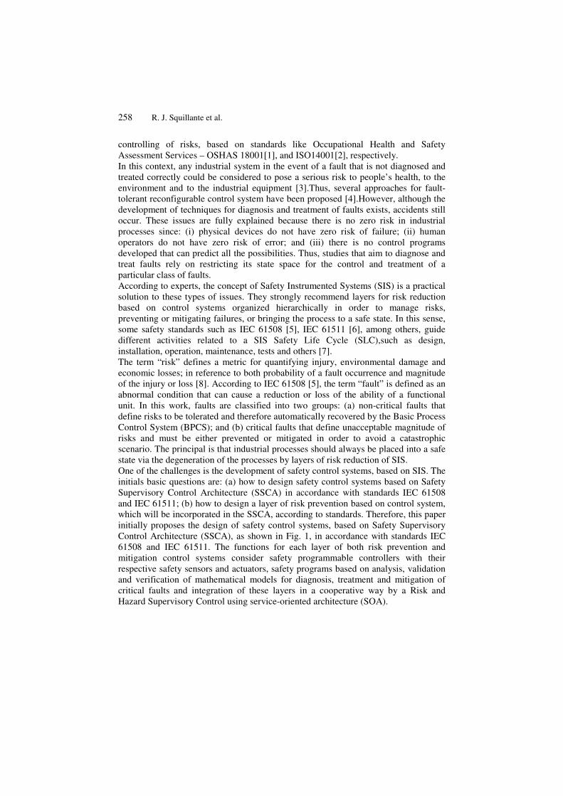
Control Architecture (SSCA), as shown in Fig. 1, in accordance with standards IEC
61508 and IEC 61511. The functions for each layer of both risk prevention and
mitigation control systems consider safety programmable controllers with their
respective safety sensors and actuators, safety programs based on analysis, validation
and verification of mathematical models for diagnosis, treatment and mitigation of
critical faults and integration of these layers in a cooperative way by a Risk and
Hazard Supervisory Control using service-oriented architecture (SOA).
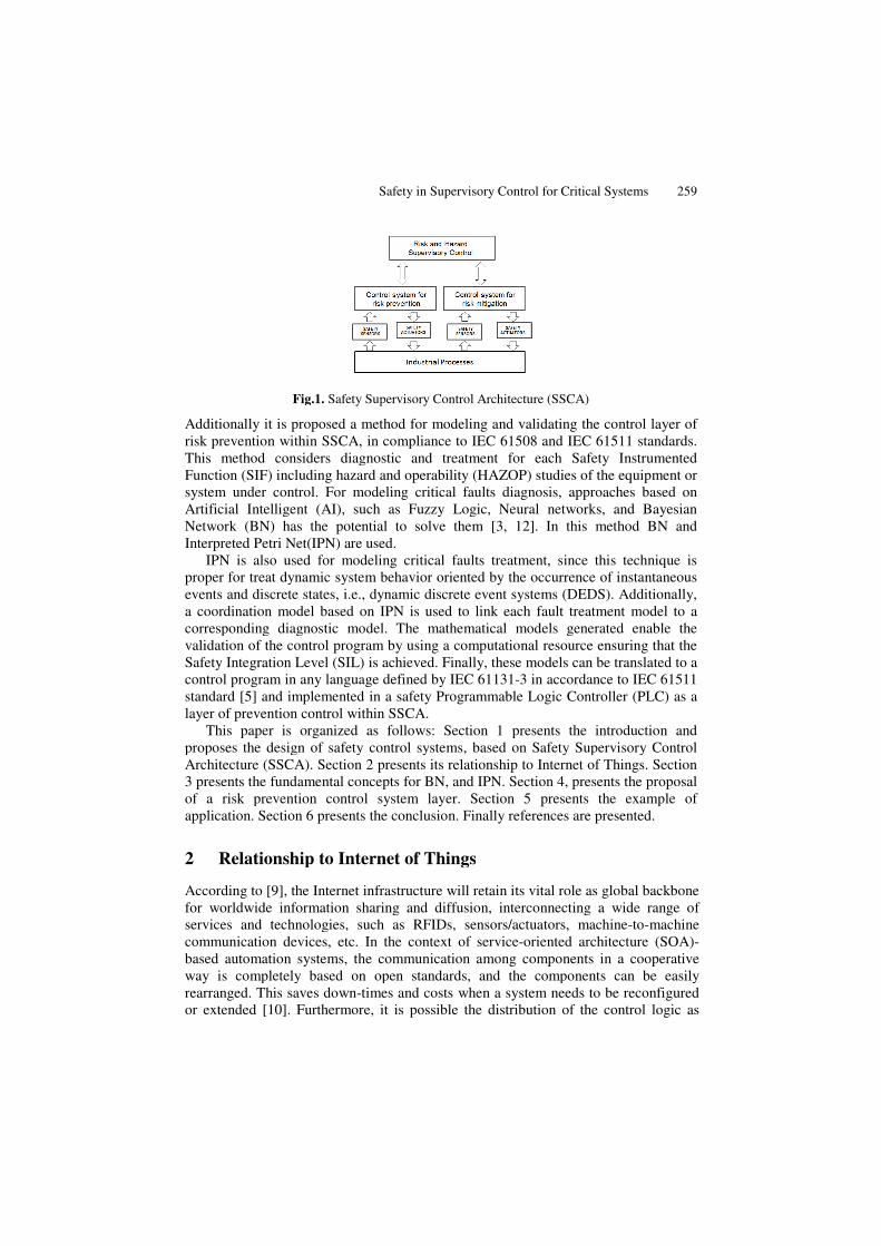
Fig.1
Additionally it is proposed a method
risk prevention within SSCA, in compliance to IEC 61508 and IEC 61511 standards.
This method considers diagnostic and treatment for each
Function (SIF) including hazard and operability (HAZOP) studies
system under control.
Artificial Intelligent (AI), such as Fuzzy Logic, Neural networks, and
Network (BN) has the potential to solve them
Interpreted Petri Net(IPN)
IPN is also used f
proper for treat dynamic system behavior
events and discrete states, i.e.,
a coordination model based on IPN is
corresponding diagnostic model. The mathematical
validation of the control
Safety Integration Level (SIL
control program in any language defined by IEC 61131
standard [5] and implemented
layer of prevention control
This paper is organized as follows:
proposes the design of safety control systems, based on Safety Supervisory Control
Architecture (SSCA). Section 2 presents its relationship to
3 presents the fundamental concepts for
of a risk prevention
application. Section 6 presents the conclusion
2 Relationship to Internet of Things
According to [9], the Internet infrastructure will
for worldwide information sharing and diffusion, interconnecting a wide ran
services and technologies,
communication devices, etc.
based automation systems, the communication among components
way is completely based on open standards, and the components can be easily
rearranged. This saves down
or extended [10]. Furthermore,
Safety in Supervisory Control for Critical Systems
Fig.1. Safety Supervisory Control Architecture (SSCA)
proposed a method for modeling and validating the control
prevention within SSCA, in compliance to IEC 61508 and IEC 61511 standards.
considers diagnostic and treatment for each Safety Instrumented
unction (SIF) including hazard and operability (HAZOP) studies of the equipment or
system under control. For modeling critical faults diagnosis, approaches based on
Artificial Intelligent (AI), such as Fuzzy Logic, Neural networks, and
has the potential to solve them [3, 12]. In this method BN
et(IPN) are used.
for modeling critical faults treatment, since this technique is
dynamic system behavior oriented by the occurrence of instantaneous
states, i.e., dynamic discrete event systems (DEDS). Additionally,
a coordination model based on IPN is used to link each fault treatment model to a
corresponding diagnostic model. The mathematical models generated enable
validation of the control program by using a computational resource ensuring
evel (SIL) is achieved. Finally, these models can be translated to
any language defined by IEC 61131-3 in accordance to IEC 61511
and implemented in a safety Programmable Logic Controller (PLC) as a
prevention control within SSCA.
s paper is organized as follows: Section 1 presents the introductio
proposes the design of safety control systems, based on Safety Supervisory Control
Section 2 presents its relationship to Internet of Things. Section
3 presents the fundamental concepts for BN, and IPN. Section 4, presents the
risk prevention control system layer. Section 5 presents the example of
ection 6 presents the conclusion. Finally references are presented.
Relationship to Internet of Things
the Internet infrastructure will retain its vital role as global backbone
for worldwide information sharing and diffusion, interconnecting a wide ran
services and technologies, such as RFIDs, sensors/actuators, machine-to
communication devices, etc. In the context of service-oriented architecture (
based automation systems, the communication among components in a cooperative
is completely based on open standards, and the components can be easily
rearranged. This saves down-times and costs when a system needs to be reconfigured
]. Furthermore, it is possible the distribution of the control logic as
Critical Systems 259
control layer of
prevention within SSCA, in compliance to IEC 61508 and IEC 61511 standards.
nstrumented
the equipment or
approaches based on
Bayesian
. In this method BN and
technique is
stantaneous
. Additionally,
treatment model to a
models generated enable the
a computational resource ensuring that the
. Finally, these models can be translated to a
3 in accordance to IEC 61511
afety Programmable Logic Controller (PLC) as a
Section 1 presents the introduction and
proposes the design of safety control systems, based on Safety Supervisory Control
hings. Section
presents the proposal
example of
are presented.
retain its vital role as global backbone
for worldwide information sharing and diffusion, interconnecting a wide range of
to-machine
oriented architecture (SOA)-
in a cooperative
is completely based on open standards, and the components can be easily
be reconfigured
distribution of the control logic as
260 R. J. Squillante et al.
independent software-blocks is possible. Therefore, the concept of SSCA can be
applied considering a cooperative way to find a control solution by using SOA-based
automation system. Works adopted SOA, in which Web Service (WS) is a popular
instance of this architecture [11].Finally, SOA architecture approach will be used to
allow Risk and Hazard Supervisory Control to obtain information from risk
prevention and mitigation control systems in order to generate a data repository that
will be used as input for Artificial Intelligence (AI) algorithms and also for continuous
improvement of safety control systems [12].
3 Fundamental Concepts
This section introduces fundamental concepts of Bayesian Network (BN) and
interpreted Petri net (IPN) for critical faults diagnosis. Moreover, it introduces IPN for
coordination and treatment of critical faults.
3.1 Bayesian network (BN)
The BN provides a method to represent partial beliefs under conditions of uncertainty
[13]. Its graphical structure models relationships of probabilistic dependence of cause-
effect considering a group of variables. Bayesian networks have been extensively
applied for fault diagnosis [14]. BN allow the combination of human expert
knowledge of the process under observation and probability theory for building a
diagnostic structure, based on algorithms, like K2 [15].
3.2 Interpreted Petri net (IPN)
Presented in 1962 by Carl A. Petri, the Petri net (PN) is a powerful tool for modeling,
analysis and design of DEDS. PN can represent processes with synchronism,
concurrent, causality, conflict, share resources and normal situations in DEDS. It is
especially useful in applications in which security is a relevant factor. As mentioned in
section 1, the proposal of this work is to use PN as a tool for modeling coordination
and treatment of critical faults in a SSCA design. Interpreted Petri net (IPN) is defined
as a tool which is associated with either an interpretation or meaning to their places
and transitions; representing something real which aims to modeling (i.e.: safety
sensors and safety actuators).
4 Proposal of risk prevention Control System Layer
The proposal of a method for modeling and validating control programs is based on
BN, and IPN. The initial idea was introduced in [16], and is presented in Fig.2.
Safety in Supervisory Control for Critical Systems 261
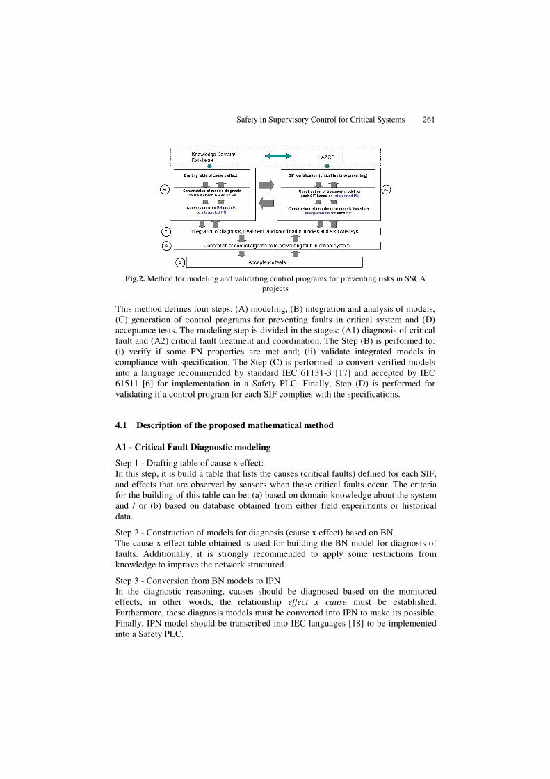
Fig.2. Method for modeling and validating control programs for preventing risks in SSCA
projects
This method defines four steps: (A) modeling, (B) integration and analysis of models,
(C) generation of control programs for preventing faults in critical system and (D)
acceptance tests. The modeling step is divided in the stages: (A1) diagnosis of critical
fault and (A2) critical fault treatment and coordination. The Step (B) is performed to:
(i) verify if some PN properties are met and; (ii) validate integrated models in
compliance with specification. The Step (C) is performed to convert verified models
into a language recommended by standard IEC 61131-3 [17] and accepted by IEC
61511 [6] for implementation in a Safety PLC. Finally, Step (D) is performed for
validating if a control program for each SIF complies with the specifications.
4.1 Description of the proposed mathematical method
A1 - Critical Fault Diagnostic modeling
Step 1 - Drafting table of cause x effect:
In this step, it is build a table that lists the causes (critical faults) defined for each SIF,
and effects that are observed by sensors when these critical faults occur. The criteria
for the building of this table can be: (a) based on domain knowledge about the system
and / or (b) based on database obtained from either field experiments or historical
data.
Step 2 - Construction of models for diagnosis (cause x effect) based on BN
The cause x effect table obtained is used for building the BN model for diagnosis of
faults. Additionally, it is strongly recommended to apply some restrictions from
knowledge to improve the network structured.
Step 3 - Conversion from BN models to IPN
In the diagnostic reasoning, causes should be diagnosed based on the monitored
effects, in other words, the relationship effect x cause must be established.
Furthermore, these diagnosis models must be converted into IPN to make its possible.
Finally, IPN model should be transcribed into IEC languages [18] to be implemented
into a Safety PLC.
262 R. J. Squillante et al.
A2 - Critical Fault Treatment and Coordination modeling
Step 1 - SIF identification
From HAZOP studies, SIF and SIL are identified. For each SIF, that represent critical
fault to prevent, important data are obtained as SIL; that includes initialization events
(sensors) and actions(actuators) to be performed by SSCA to prevent such critical
faults.
Step 2 - Construction of Treatment Model for each SIF
An IPN model is built based on information obtained from each SIF, as shown in the
previous step. It ensures that the Safety PLC takes appropriate actions to prevent
undesirable risks in the critical system. The aim of each SIF is verified based on
dynamic behavior of IPN models at the end of this step.
Step 3 - Construction of Coordination models
A coordination model for each SIF is built based on IPN. Once a critical fault is
identified by the diagnose model, the coordinator model is responsible for calling their
respective treatment model to be run, taking actions to prevent risks. These models
should be designed to be robust against the occurrence of spurious faults that may
unduly de-energize final elements and produce unwanted system downtimes.
B – Integration and Analysis of models
In this step, the models of critical fault diagnosis, treatment, and coordination are
integrated to compose the SIF general model. The integration is made from logical
connections, since no flow of tokens should occur among IPN models. After
integration, SIF general model should be simulated based on computational tools (e.g.:
HPSim [19]) for validating control programs for each SIF complies with the
specifications. For the proceeding of simulation of SIF general models, the models of
devices for sensing and actuation are considered to close the control loop.
C – Generation of control programs to prevent fault in critical system
The SIF general model obtained in the previous step should be converted into control
program based on the IEC 61131-3 [16] language and accepted by IEC 61511 [6] such
as (a) Ladder Diagram, (b) Function Block Diagram and (c) SFC (Sequential Function
Chart). Many works have been published about methods for converting PN models
into algorithms based on IEC 61131-3 languages. An example is showed in [18].
D – Acceptance tests
In according with the IEC 61508 / IEC 61511 standards, one of the Safety Life Cycle
(SLC) steps is related to final testing for commissioning and start-up procedures.
5 Example of Application
A natural gas compression station is presented to illustrate the proposed method. To
evaluate this approach, it is considered one SIF, identified as SIF-01; obtained from
HAZOP.
Safety in Supervisory Control for Critical Systems 263
5.1 Process Description
The natural gas compression station has at least a natural gas supply line, called
suction, from a gas pipeline which transports this natural gas. At the station entrance,
natural gas goes through filters before it being compressed by the turbo-compressor
machine. A portion of this gas is directed to the utility unit. The utility unit accounts
for controlling the gas temperature and pressure for use in the compression station,
such as fuel gas for the turbo-compressor machine, gas heaters, and gas power
generators. Then it is sent back to the gas pipeline through discharge lines.
5.2 Application of the proposed method
A1 - Critical Fault Diagnostic modeling Step 1 - Drafting table of cause x effect
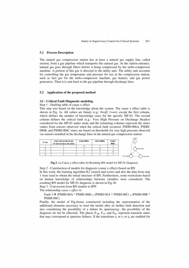
This step was based on the knowledge about the system. The cause x effect table is
shown in Fig. 3a. All values are binary (e.g.: 0=off, 1=on); except the first column,
which defines the number of knowledge cases for the specific SIF-01. The second
column defines the critical fault (e.g.: Very High Pressure on Discharge Header)
considered for the SIF-01 under study and the remaining columns represent the states
values from sensors observed when the critical fault occurred. PSHH-006A, PSHH-
006B, and PSHH-006C states are based on thresholds for very high pressure observed
via sensors installed in the discharge lines in the natural gas compression station.
CASE VERY HIGH PRESSURE
ON DISCHARGE HEADER
PSHH-006A PHSS-006B PSHH-
006C
1 1 0 1 1
2 1 1 0 1
3 1 1 1 0
4 1 1 1 1
Fig.3. (a) Cause x effect table (b) Resulting BN model for SIF-01 Diagnosis.
Step 2 - Construction of models for diagnosis (cause x effect) based on BN
In this work, the learning algorithm K2 (search and score) and also the data from step
1 were used to obtain the initial structure of BN. Furthermore, some restrictions based
on human knowledge of relationships between variables were considered. The
resulting BN model for SIF-01 diagnosis is shown in Fig.3b.
Step 3 - Conversion from BN models to IPN
The relationship cause x effect is:
Fault 1� (PSHH-06A ^ PSHH-06B) ᵥ (PSHH-06A ^ PSHH-06C) ᵥ (PSHH-06B ^
PSHH-06C)
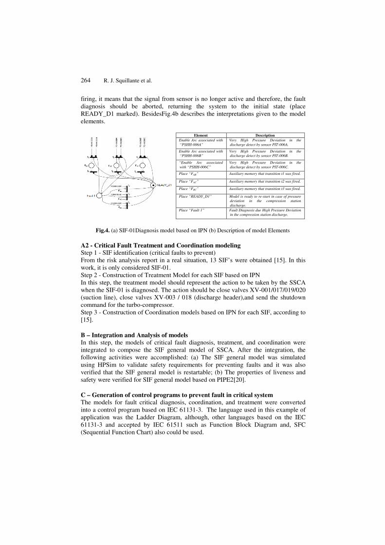
Finally, the model of Fig.4awas constructed including the representation of the
additional elements necessary to reset the model after no further fault detection and
also considering the possibility of a failure be spurious(eg.: the possibility of the
diagnosis do not be effected). The places FAB, FAC and FBC represent transient states
that may correspond to spurious failures. If the transitions t4 or t5 or t6 are enabled for
264 R. J. Squillante et al.
firing, it means that the signal from sensor is no longer active and therefore, the fault
diagnosis should be aborted, returning the system to the initial state (place
READY_D1 marked). BesidesFig.4b describes the interpretations given to the model
elements.
Element Description
Enable Arc associated with
“PSHH-006A"
Very High Pressure Deviation in the
discharge detect by sensor PIT-006A.
Enable Arc associated with
“PSHH-006B”
Very High Pressure Deviation in the
discharge detect by sensor PIT-006B.
“Enable Arc associated
with “PSHH-006C”
Very High Pressure Deviation in the
discharge detect by sensor PIT-006C.
Place “FAB” Auxiliary memory that transition t1 was fired.
Place “FAC” Auxiliary memory that transition t2 was fired.
Place “FBC” Auxiliary memory that transition t3 was fired.
Place “READY_D1” Model is ready to re-start in case of pressure
deviation in the compression station
discharge.
Place “Fault 1” Fault Diagnosis due High Pressure Deviation
in the compression station discharge.
Fig.4. (a) SIF-01Diagnosis model based on IPN (b) Description of model Elements
A2 - Critical Fault Treatment and Coordination modeling Step 1 - SIF identification (critical faults to prevent)
From the risk analysis report in a real situation, 13 SIF’s were obtained [15]. In this
work, it is only considered SIF-01.
Step 2 - Construction of Treatment Model for each SIF based on IPN
In this step, the treatment model should represent the action to be taken by the SSCA
when the SIF-01 is diagnosed. The action should be close valves XV-001/017/019/020
(suction line), close valves XV-003 / 018 (discharge header),and send the shutdown
command for the turbo-compressor.
Step 3 - Construction of Coordination models based on IPN for each SIF, according to
[15].
B – Integration and Analysis of models
In this step, the models of critical fault diagnosis, treatment, and coordination were
integrated to compose the SIF general model of SSCA. After the integration, the
following activities were accomplished: (a) The SIF general model was simulated
using HPSim to validate safety requirements for preventing faults and it was also
verified that the SIF general model is restartable; (b) The properties of liveness and
safety were verified for SIF general model based on PIPE2[20].
C – Generation of control programs to prevent fault in critical system
The models for fault critical diagnosis, coordination, and treatment were converted
into a control program based on IEC 61131-3. The language used in this example of
application was the Ladder Diagram, although, other languages based on the IEC
61131-3 and accepted by IEC 61511 such as Function Block Diagram and, SFC
(Sequential Function Chart) also could be used.
Safety in Supervisory Control for Critical Systems 265
D – Acceptance tests
In the first instance, the control programs were tested on-line in a simulation tool
based on Siemens PLC technology (e.g.: Simatic S7-300F, where "F" means Fail
Safe), and then they were validated in compliance with technical requirements.
6 Conclusions
In the first, a new architecture for the design of safety control system, based on
Supervisory Safety Control Architecture (SSCA), was proposed in accordance with
standards IEC 61508 and IEC 61511, concerning cooperative and hierarchical layers
of control prevention and mitigation of critical faults. In the second, a method for
design the layer of risk prevention control system was presented and validated to an
application example of a gas compression station, showing to be an efficient method.
Furthermore, SSCA will use SOA [12] to work with the new Risk and Hazard control
module responsible for the acquisition and maintenance of data for synthesis needs in
safety programmable controllers. Finally, some issues must be solved: (a) how to
design a layer of risk mitigation based on control system that will be incorporated in
the SSCA; (b) how to proceed the dynamic commissioning to ensure effective tests of
safety devices in accordance with SIS SLC of IEC 61508. Research is being
developed to address these issues.
Acknowledgments. The authors would like to thank the Brazilian governmental
agencies CNPq, FAPESP, and CAPES for their financial support to this work.
References
1. OSHAS18001.International standard of occupational health and safety assessment
services, 2007.
2. ISO14001.International standard for environmental management systems, 2004.
3. Sallak, M.; Simon, C.; Aubry, J. A fuzzy probabilistic approach for determining safety
integrity level, IEEE Transaction on Fuzzy Systems, vol. 16, n. 1, pp. 239-248, 2008.
4. Zhang, Y; Jiang, J. Bibliographical review on reconfigurable fault-tolerant control
systems, Annual Reviews in Control, vol. 32, pp. 229-252, 2008.
5. IEC. Functional safety of electrical/electronic/programmable electronic safety-related
systems (IEC 61508), 2010.
6. IEC.Functional safety - safety instrumented systems for the process industry sector - part
1 (IEC 61511), 2003.
7. Lundteigen, M.-A.; Rausand, M. Architectural constraints in IEC 61508: Do they have the
intended effect? Reliability Engineering and System Safety, pp. 520-525, 2009.
8. Bell, R. Introduction to IEC 61508.In: Proceedings of ACS Workshop on Tools and
Standards, Sydney, Australia, 2005.
9. Miorandi, D.; Sicari, S.; De Pellegrini, F.; Chlamtac, I. Internet of things: vision,
applications and research challenges. Ad Hoc Networks, 2012.
10. Feldhorst, S.; Libert S.; Hompel M.T.; Krumm, H. Integration of a Legacy Automation
System into a SOA for Devices. IEEE Conference on Emerging Technologies & Factory
Automation, ETFA, pp. 1-8, ISSN 1946-0759, 2009.
266 R. J. Squillante et al.
11. Garcia Melo, J.I.; Junqueira, F.; Morales, R.A.G.; Miyagi, P.E.A procedure for modeling
and analysis of service-oriented and distributed productive systems. In: Proceedings of 4th
IEEE Conf. on Automation Science and Engineering (CASE), pp. 941-946, Washington,
DC, USA, 2008.
12. Florea, G.;Ocheana, L.;Popescu, D.;Rohat Oana. Emerging technologies- the base for the
next goal of process control -risk and hazard control. In Proceedings of Recent Advances
in Signal Processing, Computational Geometry and Systems Theory, Bucharest, ISBN:
978-1-61804-027-5, 2011.
13. Pearl, J. Causality: Models Reasoning and Inference. Cambridge University Press, 2000.
14. Chien, C.F.; Chen, S.L.; Lin, Y.S. Using Bayesian network for fault location on
distribution feeder. IEEE Transactions Power Deliv., vol. 17, IS pp. 785-793, 2002.
15. Cooper, G.F.; Herskovitz, E. A Bayesian method for the induction of probabilistic
networks from data. Machine Learning, vol. 9, pp. 309-347.
16. Squillante Jr, R.; Santos Filho, D.J,; Riascos, L.A.M., Junqueira, F., Miyagi, P.E., 2011.
Mathematical method for modeling and validating of safety instrumented system designed
according to IEC 61508 and IEC 61511. In: Proceedings of International Congress of
Mechanical Engineering (COBEM), Natal, RN, Brazil, 2011.
17. IEC, Programmable controllers IEC 61131- part 3: Programming languages, 2003.
18. Mello, A. T. F.; Barbosa, M. C.; Santos Filho, D. J. ; Miyagi, P. E.; Junqueira, F.A
Transcription Tool From Petri Net to PLC Programming Languages. In Proceedings of
the 21th International Congress of Mechanical Engineering. Rio de Janeiro: ABCM, 2011.
19. Anschuetz, H. HpSim. Available in http://www.winpesim.de., accessed 12/01/2012.
20. Bonet, P.; Llado, C.M.; Puijaner, R.; Knottenbelt, W.J. PIPE2. Available in
http://pipe2.sourceforge.net/, acessed12/01/2012.
Top Related
Copyright © 2022 FDOKUMEN

