


Bahasa
Halaman
Hukum


Nematic-like Organization of Magnetic Mesogen-Hybridized Nanoparticles
Hybrid nanoparticles
Nematic-like Organization of Magnetic Mesogen-Hybridized NanoparticlesArnaud Demortiere, Saıwan Buathong, Benoıt P. Pichon, Pierre Panissod,Daniel Guillon, Sylvie Begin-Colin,* and Bertrand Donnio*
Keywords:� hybrid materials
� liquid crystals
� magnetic properties
� nanoparticles
� nematic materials
A fluid nematic-like phase is induced in monodisperse iron oxide nano-
particles with a diameter of 3.3 nm. This supramolecular arrangement is
governed by the covalent functionalization of the nanoparticle surface with
cyanobiphenyl-based ligands as mesogenic promoters. The design and
synthesis of these hybrid materials and the study of their mesogenic
properties are reported. In addition, the modifications of the magnetic
properties of the hybridized nanoparticles are investigated as a function of
the different grafted ligands. Owing to the rather large interparticular
distances (about 7 nm), the dipolar interaction between nanoparticles is
shown to play only a minor role. Conversely, the surface magnetic aniso-
tropy of the particles is significantly affected by the surface derivatization.
1. Introduction
Ordered assemblies of monodisperse nanoparticles (e.g.,
metallic, alloy, or oxide NPs) that provide two-dimensional
(2D) or 3D superlattices[1] constitute an attractive class of
nanostructured functional materials for a wide range of
applications from high-density recording media,[2] single-
electron microelectronic[3] and charge transport[4] devices, to
nanoscale plasmon waveguides[5] and metamaterials.[6] The
control of the spatial assemblies in ordered structures of NPs
and the expected synergistic collective behaviors[7–9] and
emergence of new physical properties[10] are some of the
exciting challenges of this early century. In the field of
magnetism, collective effects such as superspin glass or
superferromagnetic behavior have been reported and were
found to depend strongly on interparticle distances, symmetry
environment, and relative orientations.[7,11]
[�] Dr. B. Donnio, Prof. S. Begin-Colin, Dr. A. Demortiere,
Dr. S. Buathong, Dr. B. P. Pichon, Dr. P. Panissod, Dr. D. Guillon
Institut de Physique et Chimie des Materiaux de Strasbourg
(IPCMS)
CNRS-Universite de Strasbourg (UMR7504)
23, rue du Loess, BP 43, 67034 Strasbourg Cedex 2 (France)
E-mail: [email protected]
: Supporting Information is available on the WWW under http://www.small-journal.com.
DOI: 10.1002/smll.201000285
small 2010, 6, No. 12, 1341–1346 � 2010 Wiley-VCH Verlag Gmb
More and more attention is recently being paid to the
development of novel approaches for organizing NPs. Various
strategies have been used to induce periodic arrangements on
micrometers scale of NPs,[12] usually ‘‘passivated’’ by an
aliphatic inert outer shell, including controlled solvent
evaporation,[13,14] Langmuir–Blodgett,[15] and layer-by-layer
techniques.[16] Recently, another concept has been developed
using mobile liquid-crystalline (LC) phases.[17] Compared to
the aforementioned self-assembly methods, notably to the slow
evaporation technique mostly leading to body-centered cubic
(bcc), hexagonal close-packed (hcp), or face-centered cubic
(fcc) arrays of pseudo-spheres as in single, binary, and ternary
superlattices,[1,13,18] which are primarily governed by close-
packing and geometrical criteria[19] and dipolar interactions,[20]
a higher modularity in the organization of LC–NP hybrids is
allowed due to the softening of interparticle boundaries.
Furthermore, it is expected that the various superlattices
formed by this promising route to be tuned by external stimuli
(thermal, magnetic, electric, optical) and the number of defects
reduced by the self-healing ability of the fluid, low-dimensional
LC mesophases.
The majority of studies on this type of hybrid material have
focused on lyotropic LC phases as structuring templates for the
arrangement of NPs[21] and the impact of NPs, as doping agent,
on the mesomorphic properties.[22,23] An alternative strategy
consists of self-assembling quasi-spherical NPs in mesophases
using thermotropic LC-forming capping agents either in
composite forms[24] or as single-component materials.[17,25]
H & Co. KGaA, Weinheim 1341

full papers S.Begin-Colin, B.Donnio et al.
1342
Recently, it was shown for the latter that the nature of the
organic ligands, not necessarily mesomorphic, used to deriva-
tize gold NP surfaces, gives rise to specific organizations and
orientations of related hybrids into nematic,[26,27] smectic,
columnar,[28] cubic,[29] and more complex mesophases.[30]
In this study, we report on the induction of a fluid nematic-
like phase, close to room temperature, of some iron oxide NPs
of 3.3 nm in diameter whose arrangement is governed by their
surface hybridization with pro-mesogenic cyanobiphenyl-
based ligands. Hence, this is the first report of thermotropic
nematic phase exhibited by hybridized, quasi-spherical ferrite
NPs. In addition, the nanoparticle magnetic behavior exhibits
clear changes after surface derivatization that suggest mod-
ifications of the surface magneto-crystalline anisotropy and
surface state of the NPs for the different anchoring functions.
2. Results and discussion
The formation of a thermotropic LC phase in hybrids often
requires building units with an anisotropic shape, which is
mandated by mesomorphic molecules adsorbed on the surface
of the anti-mesogenic NPs.[17,25–30] However, in order to obtain
an efficient anisotropic effect, the sizes of the soft molecular
parts (ligands) and the hard polyhedral cores (NPs) have to be
comparable. Thus, the hybrid materials studied here consist of
magnetic iron oxide core particle with a mean diameter of
3.3� 0.7 nm, as measured by transmission electron microscopy
(TEM; Figures S1–S3 of the Supporting Information), with the
surface derivatized by pro-mesogenic cyanobiphenyl-based
ligands, referred to hereafter as pro-mesogens LC1 and LC2,
each bearing a different anchoring function (Figure 1). In order
to efficiently stimulate mesomorphism induction in the hybrids,
Figure 1. Schematic representation of the solvent-mediated ligand-
exchange reaction and chemical structures of the pro-mesogenic ligands
(LC1 and LC2).
www.small-journal.com � 2010 Wiley-VCH Verlag Gm
proto-dendritic ligands, LC1 and LC2, that is, low-generation
branched molecules bearing two or more mesogenic pending
groups, were elaborated (Supporting Information) according to
a strategy successfully applied for the insertion of non-
mesogenic cores such as fullerenes,[31] SMM polymetallic
clusters,[32] rotaxanes[33] and catenanes,[34] into liquid-crystal-
line mesophases. Iron oxide NPs coated with oleate chains
(NP@OA) were synthesized with controlled sizes by thermal
decomposition of an iron oleate precursor complex in high
boiling point solvents.[35] The control of the parameters of the
nucleation and growth processes such as temperature rates and
organic solvents allows obtaining NPs with tailored diameters
and nearly uniform polyhedral shapes (i.e. quasi-spherical).
Adsorbed oleic acid (OA) fragments ensured the stability of the
as-synthesized NPs in organic solutions and avoided aggrega-
tion. The partial substitution of the OA surfactants by LC1 and
LC2 on the NP surface was carried out by solvent-mediated
(CH2Cl2) exchange reaction containing an excess of LC1 or
LC2. After 48 h at 50 8C, the resulting solids were purified by
chromatography (Supporting Information).
The covalent attachment of the organic molecules onto the
NPssurfacevia the carboxylate(LC1)or the phosphonate(LC2)
function, respectively, was unequivocally confirmed by IR
spectroscopy, with the disappearance of the vibrations corre-
sponding to C¼O (1700 cm�1) and C�OH (1225 cm�1) bonds
for NP@LC1 and P¼O (1000 cm�1) and P-OH (940 cm�1) bonds
for NP@LC2 (Figure S4, SI). IR also indicated the absence of
any unbounded molecules. 1H-NMR spectra of LC1 and
NP@LC1 (Figure S5, Supporting Information) are similar and
with little variations in chemical shifts but, however, show a
substantial broadening of the signals for the hybrid materials,
expected due to the paramagnetic inorganic core, and therefore
were not further exploitable. Thermogravimetric analysis and
thermal differential analysis (TGA-TDA) measurements con-
firmed the formation of the hybrids, but also permitted the ratio
of the organic shell and inorganic core to be appreciatively
evaluated, and thus to estimate roughly the average number of
adsorbed molecules on the oxide surface and the respective
proportions of OA and LCi ligands (Figure S6, Supporting
Information). As previously reported,[36–38] the higher grafting
efficiency (i.e., approximately threefold) was observed for
phosphonated molecules at the expense of the carboxylate ones.
Quantitatively, it was found that NP@LC1 was homogeneously
derivatized by �30� 10 LC1 and 95� 10 OA and NP@LC2 by
�100� 10 LC2 and 50� 10 OA (Table S1, Supporting
Information). The mean surface coverage (average total
number of ligands on NP surface) remained therefore fairly
constant for the three NPs, despite the ligands’ nature change
(�160� 10 OA were calculated for NP@OA), leading to an
average ligand cross-sectional area of 20, 27, and 23 A2 for
NP@OA, NP@LC1, and NP@LC2, respectively (Table S1 of the
Supporting Information). These values are in good agreement
with the bulkiness of the organic moieties structures. Under the
current ligand-exchange procedure applied here, the OA/LCi
ratio was maintained at equilibrium, and was found constant and
reproducible.
The formation of the hybrids was ultimately confirmed by
the drastic change of their thermal behavior with respect to that
of the organic acidic precursors. LC1 and LC2 are not
bH & Co. KGaA, Weinheim small 2010, 6, No. 12, 1341–1346

Nematic-like Organization of Magnetic Mesogen-Hybridized Nanoparticles
Table 1. Summary of the thermal behavior of LC1, LC2, NP@LC1, and NP@LC2 as deduced from DSC, POM, and XRD. Cr: crystalline, Iso: isotropicliquid, N: nematic, g: glass; DSC data, 2 8C min�1, T: transition temperature; DH: enthalpy of transition; DS: entropy of transition. The glass-transition temperatures, as the DSC thermograms were silent in this range, were estimated by POM on the basis of the softening of the texture.
Compounds LC1 NP@LC1 LC2 NP@LC2
Transition Cr! Iso g!N N! Iso Cr! Iso g!N N! Iso
T [8C] 140.85 40–60 180.2 123.3 30–50 174.2
DH [J g�1] 47.02 – 1.75 26.2 – 0.15
DS [mJ g�1 K�1] 115 – 3.87 64.6 – 0.33
mesomorphic despite the presence of the strongly LC-
promoting cyanobiphenyl units and clear in the isotropic liquid
at 140.5 8C (LC1) and 123.2 8C (LC2). Differential scanning
calorimetry (DSC) analyses indicated an increase of the
clearing temperatures to �180 8C for NP@LC1 and 174 8Cfor NP@LC2, without any transition peak corresponding to the
melting of free unbounded molecules (Supporting Information,
Figures S7 and S8). The values of the clearing transition
enthalpies were low (1.75 J g�1 and 0.15 J g�1) but on the
same order of those found for other LC-hybrid materials
(Table 1), and in agreement with low-dimensional ordered
structures.[26–30] By polarized optical microscopy (POM), the
hybrids develop a low birefringent and fluid texture on heating,
homogeneous throughout the sample, although not character-
istic to a specific LC phase, compromising definite mesophase
assignment (Supporting Information, Figure S9). Below 50–
60 8C, the mesophase is frozen in a glassy state (Supporting
Information). The thermal behavior of the hybrids is fully
reversible (POM, DSC).
X-ray diffractograms of NP@LC1 and NP@LC2 recorded at
various temperatures from room temperature up to the
isotropic liquid transition revealed diffuse scatterings in the
small-angle part corresponding to periodic molecular fluctua-
tions (Figure 2 and Supporting Information, Figure S10). The
peak at the smallest angle corresponds to the average
interparticle periodicity, with d values equal to 7.5� 0.5 nm
and 6.9� 0.1 nm for NP@LC1 and NP@LC2, respectively. The
estimated thickness of the organic coats, 2.1� 0.2 nm
for NP@LC1 and 1.8� 0.2 nm for NP@LC2, are realistic,
Figure 2. XRD diffractograms of NP@LC1 and NP@LC2 at T¼100 8C(L: persistence length).
small 2010, 6, No. 12, 1341–1346 � 2010 Wiley-VCH Verlag Gmb
considering 3.3� 0.7 nm for the NP diameter. Additionally,
the correlation length calculated for NP@LC2 is about 3 times
that of NP@LC1, as expressed by the concomitant intensity
increase and signal sharpening of the diffraction peak; this is
consistent with a higher degree of cohesion resulting from a
more efficient interdigitation of the cyanobiphenyl groups
(‘‘zipperlike’’ packing), which, depending on the ligands’
grafting density and bulkiness, extends more or less far
(Supporting Information Figure S12). The second, weak
diffusion (dmol) occurring at around 1.5 nm (NP@LC1) and
1.8 nm (NP@LC2) is assigned to weakly correlated cybotactic
clusters as in classical nematic phases; the discrepancy found in
these periodicities may also be connected to the different
grafting densities and to the ligands’ nature. In the wide-angle
part, the characteristic peak at�0.45 nm, although the intensity
of the diffusion is very low, featuring the liquidlike state of the
molten aliphatic chains and of the mesogenic pending groups, is
observed, confirming the fluidlike nature of the mesophase.
This diffuse scattering further evidences the dense packing of
alkyl chains and ligands around the NP core (and thus their
grafting).
Combining DSC, POM, and XRD experiments, the
mesophase can therefore be assigned as a nematiclike phase
and may be pictured as a quasi-regular isotropic distribution of
oxide nuclei within the organic matrix characterized by a local
nematic order (Supporting Information, Figure S12), imposed
by the NP ordering. This representation is in fairly good
accordance with the TEM images obtained for the hybrids
(Supporting Information, Figures S2 and S3). As far as the
organization is concerned and under the current grafting
conditions, the nature of the anchoring functions (CO2H versus
PO3H2) has no direct influence on the organization.
The magnetic properties of NP@OA, NP@LC1, and
NP@LC2 were investigated by a SQUID magnetometer in
DC and AC modes. It has been demonstrated here that the use
of LC ligands allows us to reach a 3D organization of magnetic
NPs and to modulate the interparticle distances and thus the
dipolar magnetic interactions.[26–30] Most studies on the
collective behavior of assemblies of magnetic NPs involve
investigations of dipolar interactions in ordered arrays or
polymer-based composites, but few studies report on the use of
structuring molecules.[7b,39,40,41,42] The ZFC/FC curves
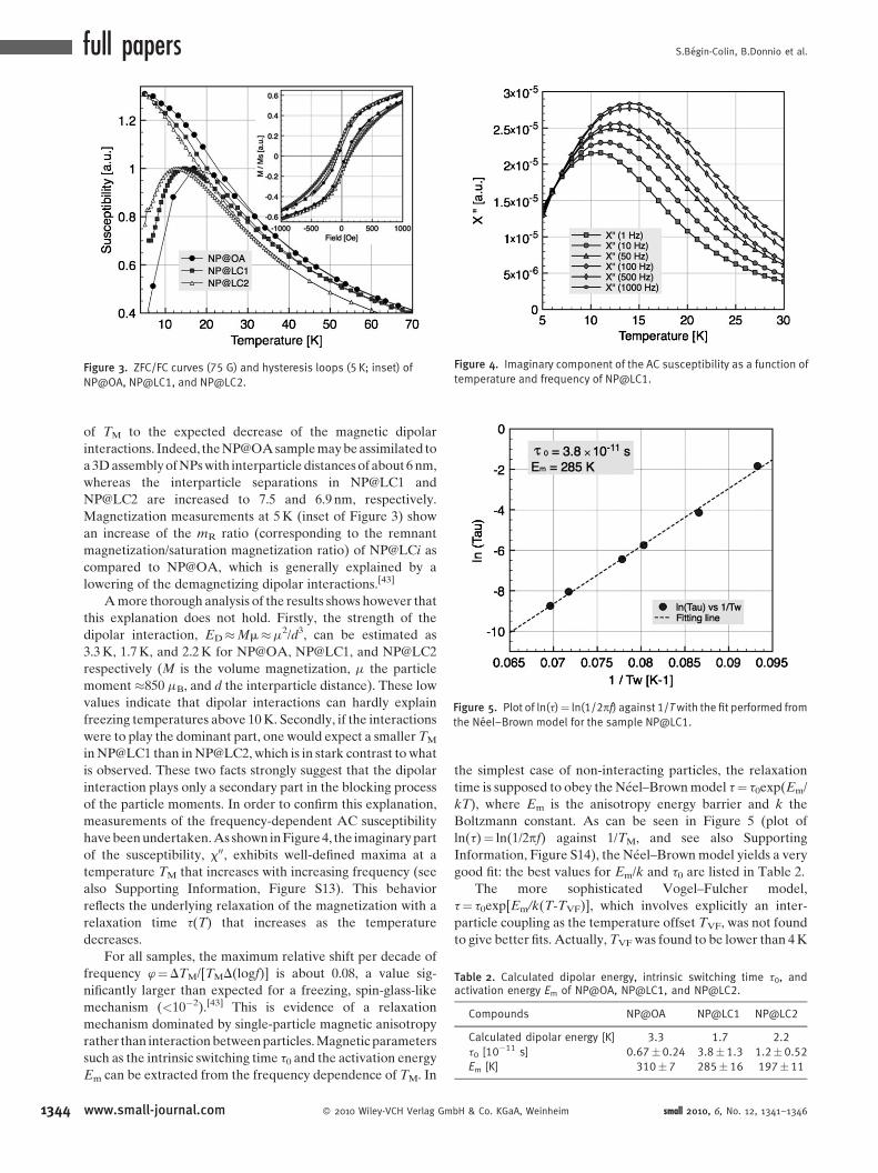
(Figure 3) show that the temperatures (TM) below which the
magnetic moments of the hybrids are blocked, NP@LC1
(TM� 15 K) and NP@LC2 (TM� 12 K), are unexpectedly
lower (�25 to 50% decrease from NP@LCi!NP@OA) than
that of NP@OA (TM� 18 K). As it was not anticipated that the
properties of the individual particles of the different samples
were modified, it was at first tempting to assign the lowering
H & Co. KGaA, Weinheim www.small-journal.com 1343
full papers S.Begin-Colin, B.Donnio et al.
Figure 3. ZFC/FC curves (75 G) and hysteresis loops (5 K; inset) of
NP@OA, NP@LC1, and NP@LC2.
Figure 4. Imaginary component of the AC susceptibility as a function of
temperature and frequency of NP@LC1.
Figure 5. Plot of ln(t)¼ ln(1/2pf) against 1/Twith the fit performed from
the Neel–Brown model for the sample NP@LC1.
Table 2. Calculated dipolar energy, intrinsic switching time t0, andactivation energy Em of NP@OA, NP@LC1, and NP@LC2.
Compounds NP@OA NP@LC1 NP@LC2
Calculated dipolar energy [K] 3.3 1.7 2.2
t0 [10�11 s] 0.67�0.24 3.8�1.3 1.2�0.52
Em [K] 310�7 285� 16 197�11
1344
of TM to the expected decrease of the magnetic dipolar
interactions. Indeed, the NP@OA sample may be assimilated to
a 3D assembly of NPs with interparticle distances of about 6 nm,
whereas the interparticle separations in NP@LC1 and
NP@LC2 are increased to 7.5 and 6.9 nm, respectively.
Magnetization measurements at 5 K (inset of Figure 3) show
an increase of the mR ratio (corresponding to the remnant
magnetization/saturation magnetization ratio) of NP@LCi as
compared to NP@OA, which is generally explained by a
lowering of the demagnetizing dipolar interactions.[43]
A more thorough analysis of the results shows however that
this explanation does not hold. Firstly, the strength of the
dipolar interaction, ED�Mm�m2/d3, can be estimated as
3.3 K, 1.7 K, and 2.2 K for NP@OA, NP@LC1, and NP@LC2
respectively (M is the volume magnetization, m the particle
moment �850 mB, and d the interparticle distance). These low
values indicate that dipolar interactions can hardly explain
freezing temperatures above 10 K. Secondly, if the interactions
were to play the dominant part, one would expect a smaller TM
in NP@LC1 than in NP@LC2, which is in stark contrast to what
is observed. These two facts strongly suggest that the dipolar
interaction plays only a secondary part in the blocking process
of the particle moments. In order to confirm this explanation,
measurements of the frequency-dependent AC susceptibility
have been undertaken. As shown in Figure 4, the imaginary part
of the susceptibility, x00, exhibits well-defined maxima at a
temperature TM that increases with increasing frequency (see
also Supporting Information, Figure S13). This behavior
reflects the underlying relaxation of the magnetization with a
relaxation time t(T) that increases as the temperature
decreases.
For all samples, the maximum relative shift per decade of
frequency w¼DTM/[TMD(logf)] is about 0.08, a value sig-
nificantly larger than expected for a freezing, spin-glass-like
mechanism (<10�2).[43] This is evidence of a relaxation
mechanism dominated by single-particle magnetic anisotropy
rather than interaction between particles. Magnetic parameters
such as the intrinsic switching time t0 and the activation energy
Em can be extracted from the frequency dependence of TM. In
www.small-journal.com � 2010 Wiley-VCH Verlag Gm
the simplest case of non-interacting particles, the relaxation
time is supposed to obey the Neel–Brown model t¼ t0exp(Em/
kT), where Em is the anisotropy energy barrier and k the
Boltzmann constant. As can be seen in Figure 5 (plot of
ln(t)¼ ln(1/2pf) against 1/TM, and see also Supporting
Information, Figure S14), the Neel–Brown model yields a very
good fit: the best values for Em/k and t0 are listed in Table 2.
The more sophisticated Vogel–Fulcher model,
t¼ t0exp[Em/k(T-TVF)], which involves explicitly an inter-
particle coupling as the temperature offset TVF, was not found
to give better fits. Actually, TVF was found to be lower than 4 K
bH & Co. KGaA, Weinheim small 2010, 6, No. 12, 1341–1346

Nematic-like Organization of Magnetic Mesogen-Hybridized Nanoparticles
in all samples, in agreement with the above estimation of the
dipolar interaction ED. Therefore, it can be definitely
concluded that the blocking of the particle moments is mostly
due to the particle magnetic anisotropy. It should be noted that
the anisotropy energy barrier Em takes significantly different
values depending on the chemical function used to graft to the
particles. From the values of Em and the nanoparticle volume,
the magneto-crystalline anisotropy constants,K¼Em/V, can be
calculated in the three samples: 5.6, 5.1 and 3.5� 105 erg cm�3
for NP@OA, NP@LC1, and NP@LC2, respectively. These
values are clearly larger than the anisotropy constant of bulk
magnetite (�105 erg cm�3), which shows a large influence of the
surface on the magnetic properties. Correspondingly, the
results also show that the modifications of the magnetic state of
the surface depend on the nature of the grafting function. The
modification of the surface state is particularly visible in our
case because of the small diameter and therefore the large
surface-to-volume ratio of the NPs. An important modification
of the anisotropy constant is observed between NP@OA and
NP@LC2 with ligands grafted through a carboxylate and
phosphonate coupling agents, respectively. The K value of
NP@LC2 is closer to the bulk value than that of NP@OA. This
behavior can be explained by the difference of grafting agents in
which the phosphonate induces a higher polarity of the surface.
This is consistent with earlier results showing a modification of
other NPs’ magnetic properties induced by the grafting
phosphonate-group-containing organic moieties.[37,38] In the
case of NP@LC1, the modification of the anisotropy constant
(as compared to that of NP@OA) can be explained either by the
decrease of the carboxylate functions onto the surface (around
25%) or by a modification of the electronic environment near
the surface due to the decrease of the ligand density.[44]
All these results infer that the surface state of magnetic NPs
has to be taken into account to study the magnetic properties of
very small particles. Since the magnetic dipolar interactions in
these systems are weak, the grafting of LC ligands induces a
clear modification in the magneto-crystalline anisotropy energy
of magnetic hybrid NPs.
3. Conclusions
LC magnetic NPs have been prepared by hybridizing the
surface of small iron oxide nanocrystals with pro-mesogenic
molecules. The resulting hybrid materials exhibit a fluid
nematic-like phase behavior close to room temperature and
the overall magnetic behavior of the precursory NP@OA is
notably modified by mesogen adsorption. A higher mod-
ularity in the organization of covalent LC-NP hybrids is thus
allowed due to the softening of interparticle boundaries, and
the use of LC ligands to derivatize NPs surfaces appears a
very promising route to organize and control magnetic NPs
into periodic and high-order superlattices. Furthermore, the
LC grafting density may be a critical parameter to modulate
the mesomorphism of such hybrid materials. Finally, it was
demonstrated that the grafting of these ligands clearly
influences the magnetocrystalline anisotropy energy of the
magnetic hybrid NPs, considering that magnetic dipolar
interactions are weak in such systems.
small 2010, 6, No. 12, 1341–1346 � 2010 Wiley-VCH Verlag Gmb
Acknowledgements
The authors thank the CNRS, the University of Strasbourg, and
the National Agency for Research (ANR DENDRIMAT) for
funding, and Didier Burger (TGA), Alain Derory (SQUID), and
Dr. Benoıt Heinrich (DSC and XRD) for technical support.
[1] a) C. B. Murray, C. R. Kagan, M. G. Bawendi, Annu. Rev. Mater.
Sci. 2000, 30, 545–610; b) C. Burda, X. Chen, R. Narayanan,
M. A. El-Sayed, Chem. Rev. 2005, 105, 1025–1102; c) S. A. Claridge,
A. W. Castleman, Jr, S. N. Khanna, C. B. Murray, A. Sen, P. S. Weiss,
ACS Nano 2009, 3, 244–255.
[2] a) J. Shi, S. Gider, K. Babcock, D. D. Awschalom, Science 1996, 271,
937–941; b) S. Sun, C. B. Murray, D. Weller, L. Folks, A. Moser,
Science 2000, 287, 1989–1992 .
[3] D. Greshnykh, A. Fromsdorf, H. Weller, C. Klinke, Nano Lett. 2009,
9, 473–478.
[4] A. Zabet-Khosousi, A.-A. Dhirani, Chem. Rev. 2008, 108, 4072–
4124.
[5] S. A. Maier, M. L. Brongersma, P. G. Kik, S. Meltzer,
A. A. G. Requicha, H. A. Atwater, Adv. Mater. 2001, 13, 1501–1505.
[6] a) E. V. Shevchenko, D. V. Talapin, S. O’Brien, C. B. Murray, J. Am.
Chem. Soc. 2005, 127, 8741–8747; b) C. Rockstuhl, F. Lederer,
C. Etrich, T. Pertsch, T. Scharf, Phys. Rev. Lett. 2007, 99, 017401.
[7] a) M.-P. Pileni, J. Phys. Chem. B 2001, 105, 3358–3371;
b) S. Bedanta, W. Kleemann, J. Phys. D: Appl. Phys. 2009, 42,
013001.
[8] F. Dumestre, S. Martinez, D. Zitoun, M.-C. Fromen, M.-J. Casanove,
P. Lecante, M. Respaud, A. Serres, R. E. Benfield, C. Amiens,
B. Chaudret, Faraday Discuss. 2004, 125, 265–278.
[9] a) J. Cheon, J.-I. Park, J.-S. Choi, Y.-W. Jun, S. Kim, M. G. Kim,
Y.-M. Kim, Y. J. Kim, PNAS 2006, 103, 3023–3027; b) I. Lisiecki,
V. Halte, C. Petit, M.-P. Pileni, J.-Y. Bigot, Adv. Mat. 2008, 20,
4176–4179; c) R. P. Tan, J. Carrey, C. Desvaux, L.-M. Lacroix,
P. Renaud, B. Chaudret, M. Respaud, Phys. Rev. B 2009, 79,
174428.
[10] a) M.-P. Pileni, Y. Lalatonne, D. Ingert, I. Lisiecki, A. Courty, Faraday
Discuss. 2004, 125, 251–264; b) M.-P. Pileni, Acc. Chem. Res.
2007, 40, 685–693; c) M.-P. Pileni, Acc. Chem. Res. 2008, 41,
1799–1809.
[11] S. A. Majetich, M. Sachan, J. Phys. D: Appl. Phys. 2006, 39, R407–
R422.
[12] Z. L. Wang, Adv. Mater. 1998, 10, 13–30.
[13] a) C. J. Kiely, J. Fink, M. Brust, D. Bethell, D. J. Schiffrin, Nature
1998, 396, 444–446; b) F. X. Redl, K.-S. Cho, C. B. Murray,
S. O’Brien, Nature 2003, 423, 968–971; c) J. J. Urban,
T. V. Talapin, E. V. Shevchenko, C. B. Murray, J. Am. Chem. Soc.
2006, 128, 3248–3255; d) E. V. Shevchenko, D. V. Talapin,
C. B. Murray, S. O’Brien, J. Am. Chem. Soc. 2006, 128, 3620–
3637; e) Z. Chen, J. Moore, G. Radtke, H. Sirringhaus, S. O’Brien,
J. Am. Chem. Soc. 2007, 129, 15702–15709.
[14] A. Demortiere, P. Launois, N. Goubet, P.-A. Albouy, C. Petit, J. Phys.
Chem. B 2008, 112, 14583–14592.
[15] a) M. Pauly, B. P. Pichon, A. Demortiere, J. Delahaye, C. Leuvrey,
G. Pourroy, S. Begin-Colin, Superlattices and Microstruct. 2009,
46, 195–204; b) F. Mammeri, Y. Le Bras, T.-J. Daou, J.-L. Gallani,
S. Colis, G. Pourroy, B. Donnio, D. Guillon, S. Begin-Colin, J. Phys.
Chem. B 2009, 113, 734–738.
[16] a) S. Anders, M. F. Toney, T. Thomson, J.-U. Thiele, B. D. Terris,
S. Sun, C. B. Murray, J. Appl. Phys. 2003, 93, 7343–7345;
b) G. Schneider, G. Decher, Nano Lett. 2004, 4, 1833–1839;
H & Co. KGaA, Weinheim www.small-journal.com 1345

full papers S.Begin-Colin, B.Donnio et al.
1346
c) S. Srivastava, N. A. Kotov, Acc. Chem. Res. 2008, 41, 1831–
1841.
[17] a) N. Kanayama, O. Tsutsumi, A. Kanazawa, T. Ikeda, Chem.
Commun. 2001, 2640–2641; b) I. In, Y.-W. Jun, Y. J. Kim,
S. Y. Kim, Chem. Commun. 2005, 800–801; c) K. Kanie,
A. Muramatsu, J. Am. Chem. Soc. 2005, 127, 11578–11579;
d) F. Li, O. Buchnev, C. I. Cheon, A. Glushchenko,
V. Reshetnyak, Y. Reznikov, T. J. Sluckin, J. L. West, Phys. Rev.
Lett. 2006, 97, 147801.
[18] a) S. Sun, Adv. Mater. 2006, 18, 393–403; b) E. V. Shevchenko,
D. V. Talapin, N. A. Kotov, S. O’Brien, C. B. Murray, Nature 2006,
439, 55–59; c) E. V. Shevchenko, J. B. Kortright, D. V. Talapin,
S. Aloni, P. A. Alivisatos, Adv. Mater. 2007, 19, 4183–4188;
d) D. V. Talapin, ACS Nano 2008, 2, 1097–1100; e) Z. Chen,
S. O’Brien, ACS Nano 2008, 2, 1219–1229; f) D. K. Smith,
B. Goodfellow, D.-M. Smilgies, B. A. Korgel, J. Am. Chem. Soc.
2009, 131, 3281–3290.
[19] a) R. L. Whetten, M. N. Shafigullin, J. T. Khoury, T. G. Schaaff,
L. Vezmar, M. M. Alvarez, A. Wilkinson, Acc. Chem. Res. 1999, 32,
397–406; b) U. Landman, W. D. Luedtke, Faraday Discuss. 2004,
125, 1–22.
[20] D. V. Talapin, E. V. Shevchenko, C. B. Murray, A. V. Titov, P. Kral,
Nano Lett. 2007, 7, 1213–1219.
[21] a) D. A. Doshi, A. Gibaud, V. Goletto, M. Lu, H. Gerung, B. Ocko,
S. M. Han, C. J. Brinker, J. Am. Chem. Soc. 2003, 125, 11646–
11655; b) G. Toquer, G. Porte, M. Nobili, J. Appell, C. Blanc,
Langmuir 2007, 23, 4081–4087.
[22] I. Gascon, J.-D. Marty, T. Gharsa, C. Mingotaud, Chem.Mater. 2005,
17, 5228–5230.
[23] C. Da Cruz, O. Sandre, V. Cabuil, J. Phys. Chem. B 2005, 109,
14292–14299.
[24] a) H. Qi, T. Hegmann, J. Mater. Chem. 2006, 16, 4197–4205;
b) T. Hegmann, H. Qi, V. M. Marx, J. Inorg. Organomet. Polym.
Mater. 2007, 17, 483–508; c) V. M. Marx, H. Girgis, P. A. Heiney,
T. Hegmann, J. Mater. Chem. 2008, 18, 2983–2994; d) H. Qi,
T. Hegmann, Adv. Funct. Mater. 2008, 18, 212–221; e) H. Qi,
B. Kinkead, V. N. Marx, H. R. Zhang, T. Hegmann, ChemPhysChem.
2009, 10, 1211–1218.
[25] S. Frein, J. Boudon, M. Vonlanthen, T. Scharf, J. Barbera,
G. Suss-Fink, T. Burgi, R. Deschenaux, Helv. Chim. Acta
2008, 91, 2321–2337.
[26] L. Cseh, G. H. Mehl, J. Mater. Chem. 2007, 17, 311–315.
[27] J. W. Goodby, I. M. Saez, S. J. Cowling, V. Gortz, M. Draper, A. W.
Hall, S. Sia, G. Cosquer, S.-E. Lee, E. P. Raynes, Angew. Chem.
2008, 120, 2794–2828; Angew. Chem. Int. Ed. 2008, 47,
2754–2787.
www.small-journal.com � 2010 Wiley-VCH Verlag Gm
[28] M. Wojcik, W. Lewandowski, J. Matraszek, J. Mieczkowski, J.
Borysiuk, D. Pociecha, E. Gorecka, Angew. Chem. 2009, 121,
5269–5271; Angew. Chem. Int. Ed. 2009, 48, 5167–5169.
[29] B. Donnio, P. Garcıa-Vazquez, J.-L. Gallani, D. Guillon, E. Terazzi,
Adv. Mater. 2007, 19, 3534–3539.
[30] X. Zeng, F. Liu, A. G. Fowler, G. Ungar, L. Cseh, G. H. Mehl,
J. E. Macdonald, Adv. Mater. 2009, 21, 1746–1750.
[31] a) T. Chuard, R. Deschenaux, A. Hirsch, H. Schonberger, Chem.
Commun. 1999, 2103–2104; b) D. Felder-Flesch, L. Rupnicki,
C. Bourgogne, B. Donnio, D. Guillon, J. Mater. Chem. 2006, 16,
304–309; c) R. Deschenaux, B. Donnio, D. Guillon, New J. Chem.
2007, 31, 1064–1073.
[32] E. Terazzi, C. Bourgogne, R. Welter, J.-L. Gallani, D. Guillon,
G. Rogez, B. Donnio, Angew. Chem. 2008, 120, 500–505; Angew.
Chem. Int. Ed. 2008, 47, 490–495.
[33] E. D. Baranoff, J. Voignier, T. Yasuda, V. Heitz, J.-P. Sauvage,
T. Kato, Angew. Chem. 2007, 119, 4764–4767; Angew. Chem.
Int. Ed. 2007, 46, 4680–4683.
[34] I. Aprahamian, T. Yasuda, T. Ikeda, S. Saha, W. R. Dichtel, K. Isoda,
T. Kato, J. F. Stoddart, Angew. Chem. 2007, 119, 4759–4763;
Angew. Chem. Int. Ed. 2007, 46, 4675–4679.
[35] J. Park, K. An, Y. Hwang, J.-G. Park, H.-J. Noh, J.-Y. Kim, J.-H. Park,
N.-M. Hwang, T. Hyeon, Nat. Mater. 2004, 3, 891–895.
[36] S. Buathong, D. Ung, T.-J. Daou, C. Ulhaq-Bouillet, G. Pourroy,
D. Guillon, L. Ivanova, I. Bernhardt, S. Begin-Colin, B. Donnio,
J. Phys. Chem. C 2009, 113, 12201–12212.
[37] T.-J. Daou, J.-M. Greneche, G. Pourroy, S. Buathong, A. Derory,
C. Ulhaq-Bouillet, B. Donnio, D. Guillon, S. Begin-Colin, Chem.
Mater. 2008, 20, 5869–5875.
[38] T.-J. Daou, S. Buathong, D. Ung, B. Donnio, G. Pourroy, D. Guillon,
S. Begin, Sens. Actuator B 2007, 126, 159–162.
[39] B. L. Frankamp, A. K. Boal, M. T. Tuominen, V. M. Rotello, J. Am.
Chem. Soc. 2003, 127, 9731–9735.
[40] J. L. Dormann, D. Fiorani, E. Tronc, Adv. Chem. Phys. 1997, 98,
283–494.
[41] G. A. Held, G. Grinstein, H. Doyle, S. Sun, C. B. Murray, Phys. Rev. B
2001, 64, 012408.
[42] D. Farrel, Y. Cheng, R. W. McCallum, M. Sachan, S. A. Majetich,
J. Phys. Chem. B 2005, 109, 13409–13419.
[43] J. A. Mydosh, Spin Glasses: An Experimental Introduction, Taylor &
Francis, London 1993, p64.
[44] R. Mikami, M. Taguchi, K. Yamada, K. Suzuki, O. Sato, Y. Einaga,
Angew. Chem. 2004, 116, 6261–6265; Angew. Chem. Int. Ed.
2004, 43, 6135 –6139.
bH & Co. KGaA, Weinheim
Received: February 23, 2010Revised: March 15, 2010Published online: May 19, 2010
small 2010, 6, No. 12, 1341–1346
Top Related
Copyright © 2022 FDOKUMEN

