


Bahasa
Halaman
Hukum

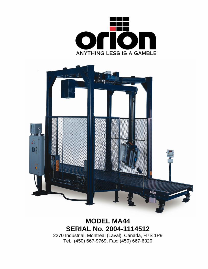
MODEL MA44
SERIAL No. 2004-1114512 2270 Industrial, Montreal (Laval), Canada, H7S 1P9
Tel.: (450) 667-9769, Fax: (450) 667-6320

INSTRUCTION MANUAL
FOR ALL INQUIRIES PLEASE CONTACT
OUR LOCAL DISTRIBUTOR
FOR UNITED STATE ONLY 1-800-333-6556
Thank you for choosing ORION stretch-wrapping equipment. It is a wise choice, which will benefit your company now and in the future. ORION uses a unique combination of functional, rugged steel structure and sophisticated control systems to offer equipment high in durability and low in maintenance requirements. Our advance control systems mean that Orion equipment can be operated safely and efficiently without the need for special operator expertise. Please read this manual carefully and keep it handy. Following these simple operating instructions will insure the safe and efficient performance of this machine while simple maintenance procedures will guarantee a long and productive life of the equipment.

Notice: Our manual covers standard features of the machine. Certain options may not be fully covered due to their unique application. In order to acquire more information about custom made features of your machine and to provide quicker service, the following information is required when making an inquiry: 1)Model
2)Serial Number 2004-1114512 3)Subassembly ( see PART LIST ) SAFETY: ORION'S stretch wrappers should be operated with caution and common sense as any other industrial equipment. To prevent injury and/or electrical shocks, careful operation of the machine and awareness of its many automatic functions is required. NOTE: All electrical power and compressed air must to be disconnected prior to all inspection, maintenance or repair work.
ORION PACKAGING INC.

ORION PACKAGING SYSTEMS INC. FULLY AUTOMATIC EQUIPMENT SPECIFICATIONS - EFFECTIVE MARCH 15,200O
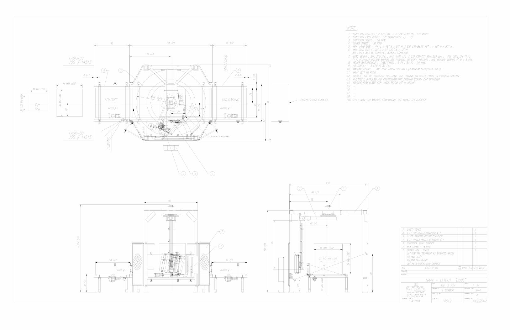
ORION MODEL MA-44 Heavy Duty Conveyorized Automatic Four Len Free Standing Rotary Tower System Maximum Load Size 48”w x 48”L x 80”H Minimum Load Size 30”W x 30”L x 26”H* Weight Capacity 5,000 Ibs. Dynamic, 20,000 Ibs. Static** Production Capacity Contact Orion for a Throughput Calculation Specific to Your Application Utilities 20813160 (5 Wire Incl. 3 Lines, Neutral, Ground) 20 Amps 3 CFM Compressed Air @ 80 PSI Rotary Tower 25” Diameter Ring Bearing Tower Support Structural Steel Tube Design Tower Drive Heavy Duty ANSI Chain & Sprocket Drive 0 - 18 RPM Variable Tower Speed 3 Speed Tower Drive System (PLC Controlled) Electronically Adjustable Acceleration/Deceleration (Soft Start) AC Variable Frequency Drive Positive Home Position Alignment Feature Control Features Free Standing, CSA Approved, NEMA 12 Control Panel State-of the-Art Allen Bradley Programmable Logic Control for Maximum Flexibility User Friendly Controls with Non-Proprietary Pushbuttons, and Switches Load/Personnel Safety Stop Photocell System Electrical Interlock on Personnel Entry Gate to Process Area Electronic Film Tension Control Adjustment on the Panel End of Cycle Film Force Release Separate Top and Bottom Wrap Count Selectors Variable Speed & Separate Film Carriage Up/Down Controls Photocell for Automatic Load Height Detection Rewrap Pushbutton for Rewrapping Load After Film Roll Replacement, E-Stop, Etc. Bypass Mode Selector Switch for Bypassing Loads Through the Wrapper Tower Jog Pushbutton Conveyor Jog Pushbuttons Current Overload Protection Film Delivery 20” Orion Insta-ThreadTM Powered Prestretch Film Delivery System Precision Ground, Polyeurethane Pre-Stretch Rollers for Consistent, Maximum Film Yield 245% Standard Pre-Stretch Ratio (Adjustable from 100% to 425%) Easy & Safe to Operate Self-Threading Carriage Design Electronic Film Tension Control Adjustment on the Panel Full Authority Film Dancer Bar with Variable Speed Output (Non-Wearing Sensor) Heavy Duty ANSI Chain & Sprocket Ratio Control Insta-SenseTM Film Out/Broken Sensing Logic with Indicator Light Ultra-Low Wrap (Film Web to within 2” of TOR Dependent Upon Film Type/Tension) Visit our Distributor Support Website at www.suppoRorionpackaging.com

ORION PACKAGING SYSTEMS INC. FULLY AUTOMATIC EQUIPMENT SPECIFICATIONS - EFFECTIVE MARCH 15,200O
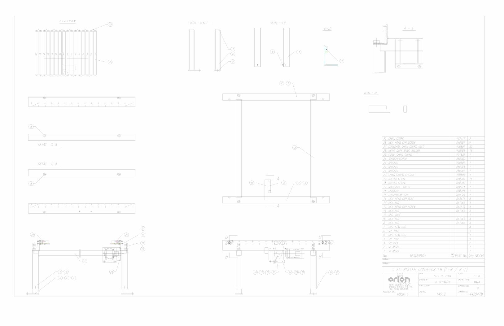
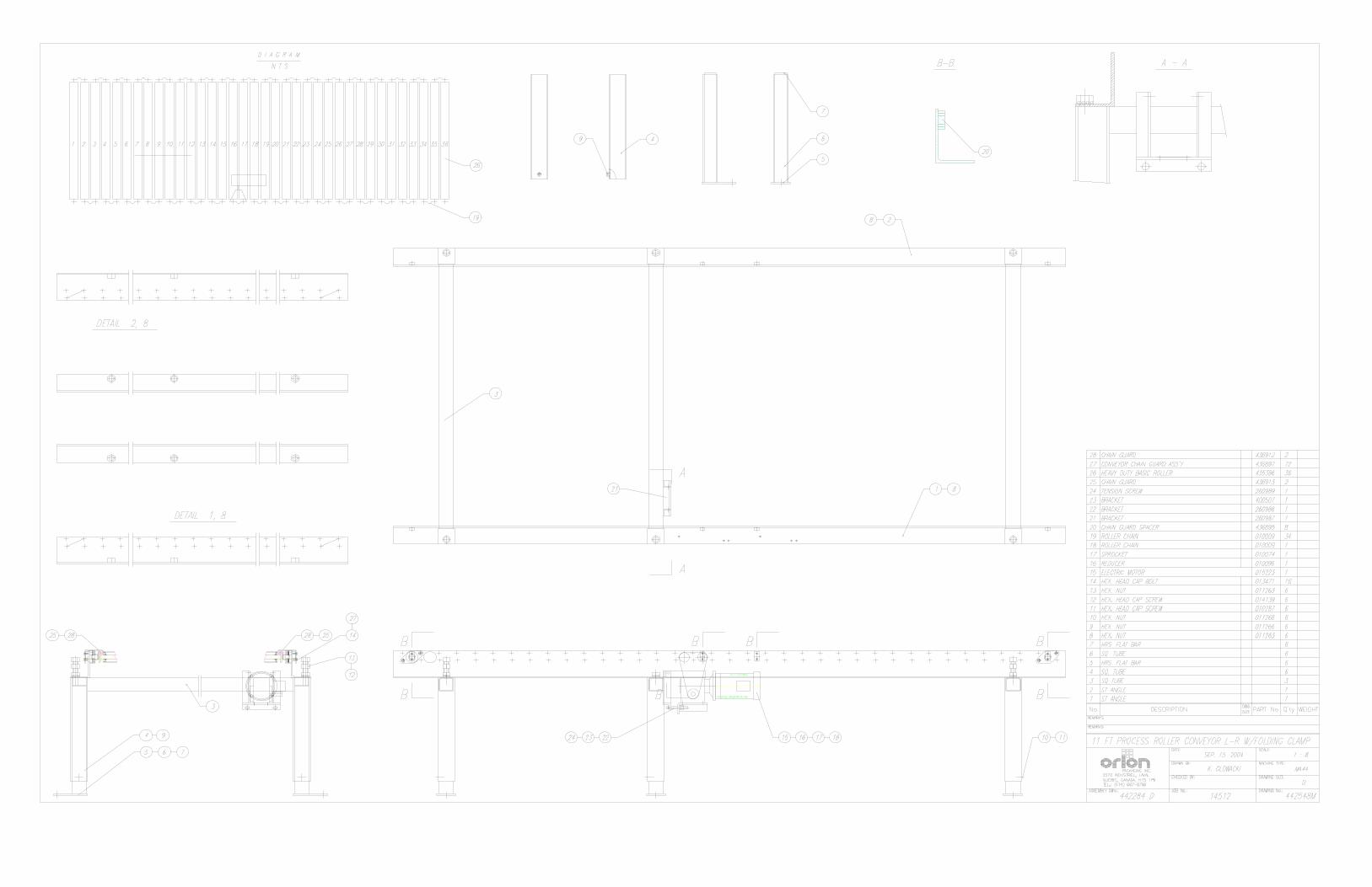
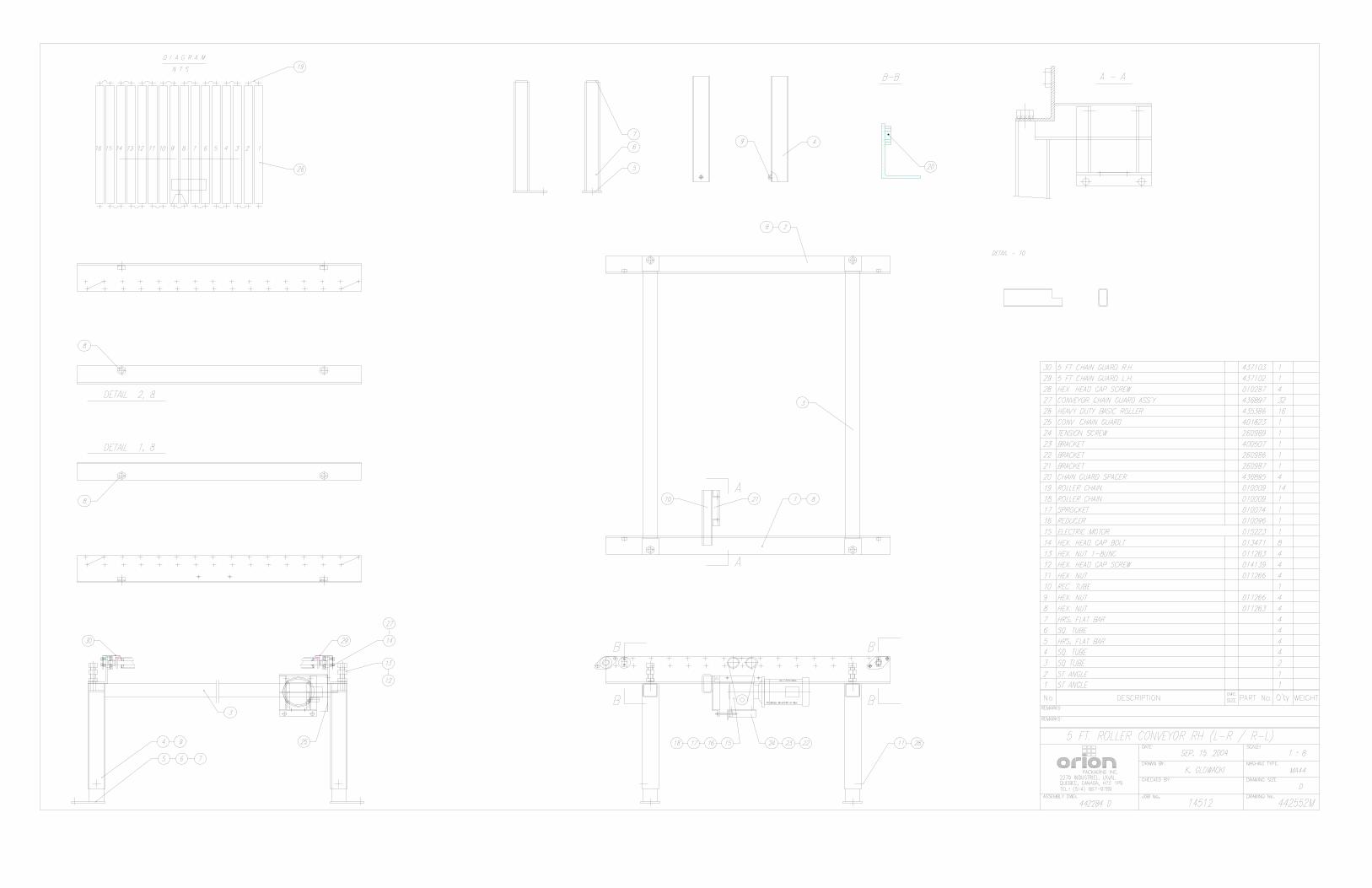
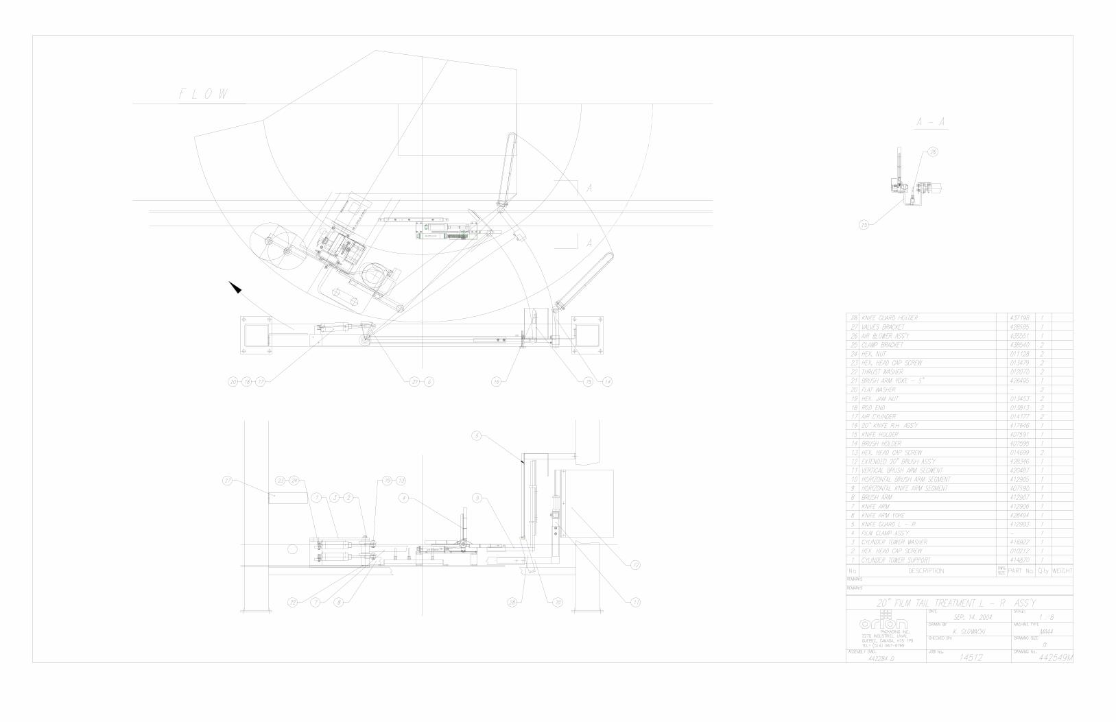
ORION MODEL MA-44 CONTINUED Film Carriage Drive Heavy Duty ANSI Chain Carriage Lift AC Variable Frequency Drive Multi-Point UHMW Precision Carriage Guidance System Structural Features 100% Structural Steel Construction Non-Proprietary, Locally Obtainable Components Throughout Easy Access to All Components Open Mechanical Design for Ease of Maintenance Free Standing Four Leg Design Expanded Metal Safety Fencing Around Process Area Electrically Interlocked Personnel Entry Gate Conveyor Features 5’ Infeed, 12’ Process, and 5’ Exit Conveyor Included (All Powered) 100% Orion Manufactured 100% Structural Steel Construction 5,000 lb. Max Load Weight Capacity 18” Height to Top of Rollers 52” Effective Conveyor Width 2.5” Diameter Rollers on 3.75” Centers All Rollers Driven Via Heavy Duty ANSI Chain Loop to Loop Full Length Solid Steel Conveyor Roller Axles Individual Bearings with Cast Housings for Each Roller Fully Automatic Sequencing Logic 50 fpm Standard Conveyor Speed AC Variable Frequency Drive Reversing Process Conveyor Drive Film Tail Treatment Pneumatic Film Clamp Pneumatic Thermobar Film Cutting System (Thermostatically Controlled) Pneumatic Load Seeking Brush Down System Estimated Shipping Weight 9,000 Ibs. * Minimum load height capability is based on 20” film carriage. For 30” carriage, minimum load height capability is 36” ** In applications in which the pallet bottom boards are parallel to conveyor rollers, the minimum bottom board width is 4”, and the minimum number of bottom boards is 3. Visit our Distributor Support Website at www.suppoRorionpackaging.com

MACHINE UNLOADING INSPECTION & INSTALLATION
UNLOADING Machine can be easily unloaded and transported by a forklift with a minimum capacity of 2500 lbs. 1. Carefully insert the forks into the lifting tubes to the maximum possible depth. Depending on the model, a forklift access may be either at the turntable end of the machine frame, the tower end or both. In case of the mongoose machine or the conveyor, enter the forks under the frame. 2. Lift the machine (or other part of system) only to the necessary height to move it with no bouncing or friction on the floor. 2a. On the mongoose machines use the brackets welded on the top part of the machine. 3. Sit the machine down assuring uniform contact with the floor, which is necessary to ensure correct and smooth operation. INSPECTION 1. Remove all packing and supporting additions - these may include the blocks under the carriage and the restraining bar over the table. NOTE: when removing the stretchwrap film covering the machine, care must be taken not to cut any of the electrical wires and rubber covering on the multistretch rollers. 2. Perform a visual inspection of the electrical and mechanical parts for loosened joints and / or broken connections. Any suspected shipping damage must be reported immediately to the freight carrier. Items that are vulnerable to damage and must be inspected are as follows: - Motors and transmissions - Junction boxes - Electrical conduits - Proximity and limit switches - Photocells 3. Check under the turntable (H–series models only) to ensure that there is no crippling of the movable parts i.e. casters, center axle or drive assembly. 4.Verify the following: - Turntable or rotary arm drive system to confirm that the reducer to drive the chain is snug and properly aligned. - Verify the wires tight conduits for crushed sections or loose fittings. - Verify the carriage to be sure that it is correctly aligned with the tower and verify the tension on the lift chain. - Verify all the dials and knobs on the control panel for smooth action.

MACHINE INSTALLATION After the visual inspection has been completed the electrical power and the compressed air may be connected as specified on the diagrams supplied with the machine. An electrical diagram is provided with each machine in the envelope attached to the panel box. ASSEMBLY PROCEDURE The structural frames of the machine have to be installed on a leveled floor. Locate the main wrapper section into its final position, keeping the tower assembly* away from any traffic. The wrapper mainframe section must be bolted to the floor by the l/2” concrete floor anchors (leg & shield or expandable type). Conveyor sections (where applicable) have to be positioned, leveled** and bolted to the floor. Any wiring that has been disconnected to facilitate transport is marked with a number located on the junction box to which the wiring must be reconnected. It allows identification of the proper position of the infeed and outfeed conveyor sections. Any wire run that appears too short or long may indicate that the position of the mechanical components is incorrect. Verify the status of all assemblies before proceeding. CAUTION: improper placement and alignment of the conveyor section(s)and/or electric photocells may lead to equipment malfunction and damage. * The tower deviation from vertical must not exceed l/4” on the distance of 10 feet (angle: 0 degrees 6’).
** In the case of the conveyors, the roller deviation from the horizontal must not exceed l/l6” on the distance 52” (angle: 0 degrees 4’).
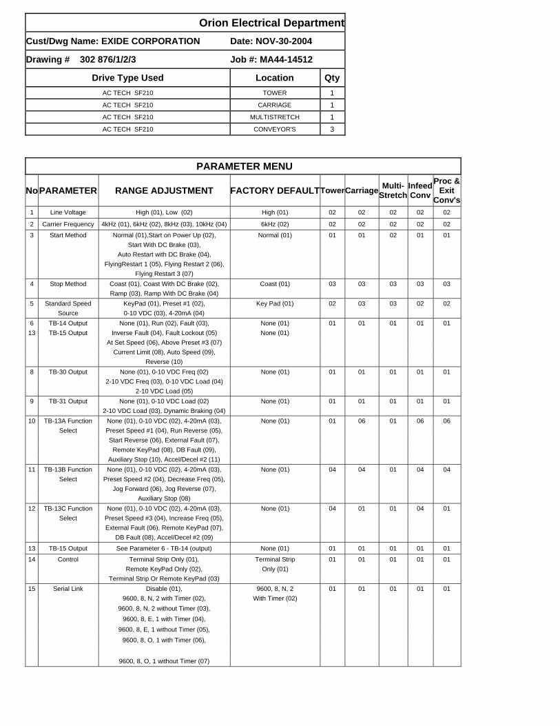
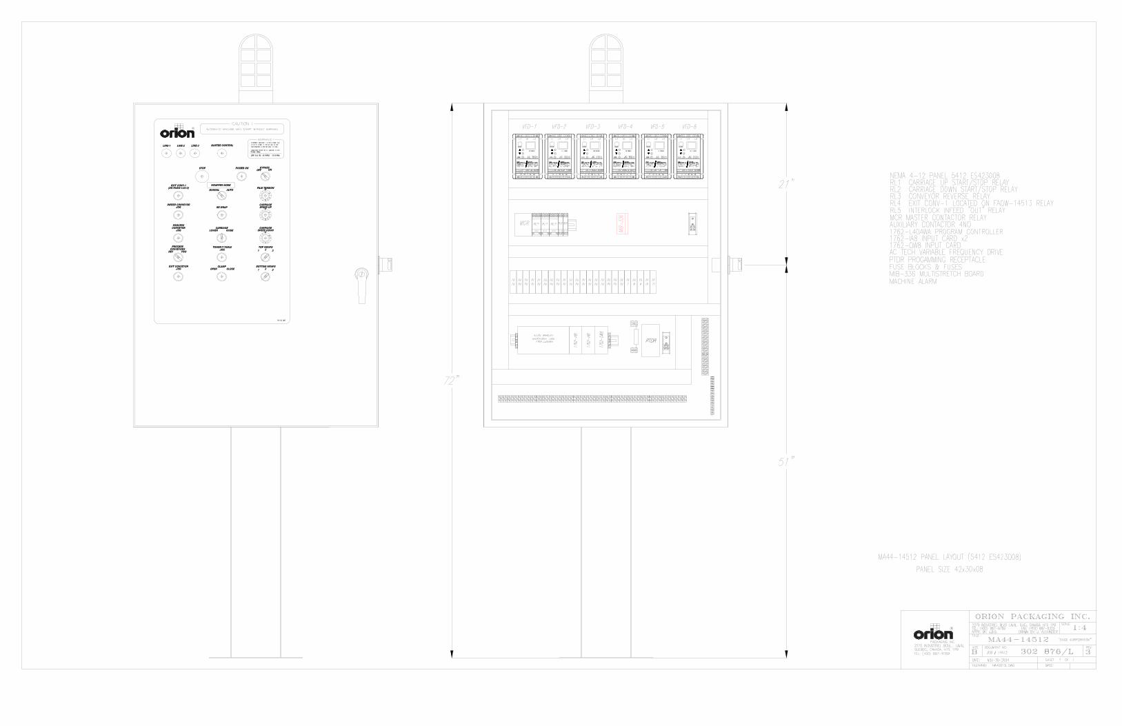
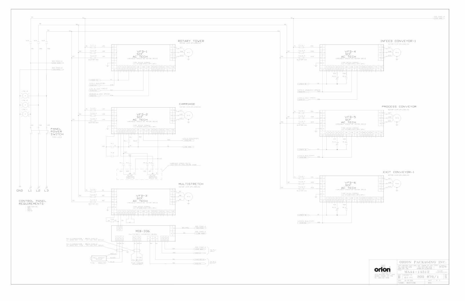
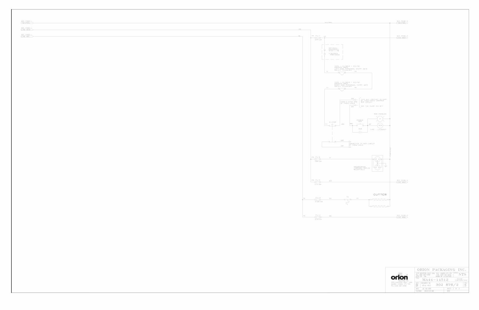
Orion Electrical Department
Cust/Dwg Name: EXIDE CORPORATION Date: NOV-30-2004
Drawing # 302 876/1/2/3 Job #: MA44-14512
Drive Type Used Location Qty
AC TECH SF210 TOWER 1
AC TECH SF210 CARRIAGE 1
AC TECH SF210 MULTISTRETCH 1
AC TECH SF210 CONVEYOR'S 3
PARAMETER MENU
NoPARAMETER RANGE ADJUSTMENT FACTORY DEFAULTTowerCarriageMulti-
Stretch Infeed Conv
Proc & Exit
Conv's
1 Line Voltage High (01), Low (02) High (01) 02 02 02 02 02
2 Carrier Frequency 4kHz (01), 6kHz (02), 8kHz (03), 10kHz (04) 6kHz (02) 02 02 02 02 02
3 Start Method Normal (01),Start on Power Up (02), Normal (01) 01 01 02 01 01
Start With DC Brake (03),
Auto Restart with DC Brake (04),
FlyingRestart 1 (05), Flying Restart 2 (06),
Flying Restart 3 (07)
4 Stop Method Coast (01), Coast With DC Brake (02), Coast (01) 03 03 03 03 03
Ramp (03), Ramp With DC Brake (04)
5 Standard Speed KeyPad (01), Preset #1 (02), Key Pad (01) 02 03 03 02 02
Source 0-10 VDC (03), 4-20mA (04) 6 TB-14 Output None (01), Run (02), Fault (03), None (01) 01 01 01 01 01
13 TB-15 Output Inverse Fault (04), Fault Lockout (05) None (01) At Set Speed (06), Above Preset #3 (07) Current Limit (08), Auto Speed (09), Reverse (10) 8 TB-30 Output None (01), 0-10 VDC Freq (02) None (01) 01 01 01 01 01
2-10 VDC Freq (03), 0-10 VDC Load (04) 2-10 VDC Load (05) 9 TB-31 Output None (01), 0-10 VDC Load (02) None (01) 01 01 01 01 01
2-10 VDC Load (03), Dynamic Braking (04) 10 TB-13A Function None (01), 0-10 VDC (02), 4-20mA (03), None (01) 01 06 01 06 06
Select Preset Speed #1 (04), Run Reverse (05), Start Reverse (06), External Fault (07), Remote KeyPad (08), DB Fault (09), Auxiliary Stop (10), Accel/Decel #2 (11)
11 TB-13B Function None (01), 0-10 VDC (02), 4-20mA (03), None (01) 04 04 01 04 04
Select Preset Speed #2 (04), Decrease Freq (05), Jog Forward (06), Jog Reverse (07),
Auxiliary Stop (08) 12 TB-13C Function None (01), 0-10 VDC (02), 4-20mA (03), None (01) 04 01 01 04 01
Select Preset Speed #3 (04), Increase Freq (05), External Fault (06), Remote KeyPad (07),
DB Fault (08), Accel/Decel #2 (09)
13 TB-15 Output See Parameter 6 - TB-14 (output) None (01) 01 01 01 01 01
14 Control Terminal Strip Only (01), Terminal Strip 01 01 01 01 01
Remote KeyPad Only (02), Only (01)
Terminal Strip Or Remote KeyPad (03) 15 Serial Link Disable (01), 9600, 8, N, 2 01 01 01 01 01
9600, 8, N, 2 with Timer (02), With Timer (02)
9600, 8, N, 2 without Timer (03), 9600, 8, E, 1 with Timer (04), 9600, 8, E, 1 without Timer (05), 9600, 8, O, 1 with Timer (06), 9600, 8, O, 1 without Timer (07)
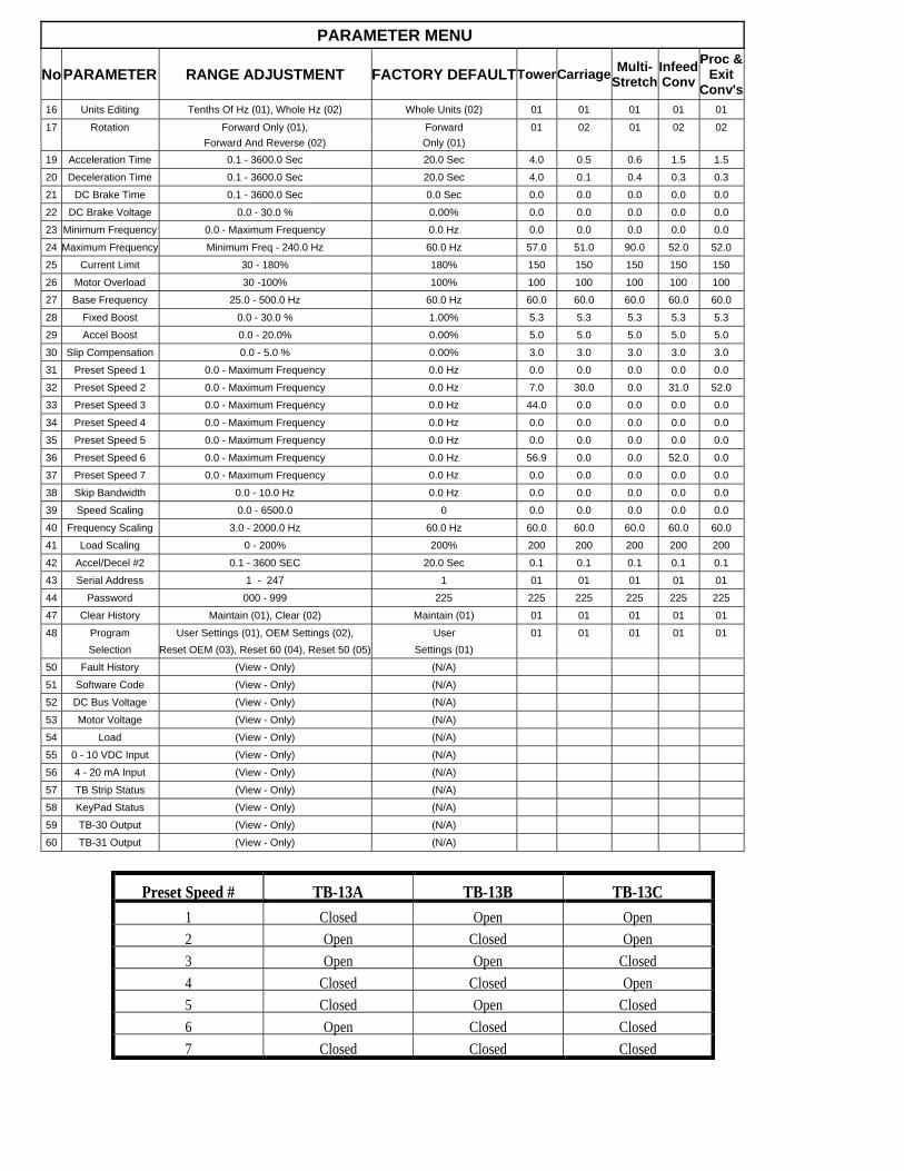
PARAMETER MENU
NoPARAMETER RANGE ADJUSTMENT FACTORY DEFAULTTowerCarriageMulti-
Stretch Infeed Conv
Proc & Exit
Conv's
16 Units Editing Tenths Of Hz (01), Whole Hz (02) Whole Units (02) 01 01 01 01 01
17 Rotation Forward Only (01), Forward 01 02 01 02 02
Forward And Reverse (02) Only (01)
19 Acceleration Time 0.1 - 3600.0 Sec 20.0 Sec 4.0 0.5 0.6 1.5 1.5
20 Deceleration Time 0.1 - 3600.0 Sec 20.0 Sec 4.0 0.1 0.4 0.3 0.3
21 DC Brake Time 0.1 - 3600.0 Sec 0.0 Sec 0.0 0.0 0.0 0.0 0.0
22 DC Brake Voltage 0.0 - 30.0 % 0.00% 0.0 0.0 0.0 0.0 0.0
23 Minimum Frequency 0.0 - Maximum Frequency 0.0 Hz 0.0 0.0 0.0 0.0 0.0
24 Maximum Frequency Minimum Freq - 240.0 Hz 60.0 Hz 57.0 51.0 90.0 52.0 52.0
25 Current Limit 30 - 180% 180% 150 150 150 150 150
26 Motor Overload 30 -100% 100% 100 100 100 100 100
27 Base Frequency 25.0 - 500.0 Hz 60.0 Hz 60.0 60.0 60.0 60.0 60.0
28 Fixed Boost 0.0 - 30.0 % 1.00% 5.3 5.3 5.3 5.3 5.3
29 Accel Boost 0.0 - 20.0% 0.00% 5.0 5.0 5.0 5.0 5.0
30 Slip Compensation 0.0 - 5.0 % 0.00% 3.0 3.0 3.0 3.0 3.0
31 Preset Speed 1 0.0 - Maximum Frequency 0.0 Hz 0.0 0.0 0.0 0.0 0.0
32 Preset Speed 2 0.0 - Maximum Frequency 0.0 Hz 7.0 30.0 0.0 31.0 52.0
33 Preset Speed 3 0.0 - Maximum Frequency 0.0 Hz 44.0 0.0 0.0 0.0 0.0
34 Preset Speed 4 0.0 - Maximum Frequency 0.0 Hz 0.0 0.0 0.0 0.0 0.0
35 Preset Speed 5 0.0 - Maximum Frequency 0.0 Hz 0.0 0.0 0.0 0.0 0.0
36 Preset Speed 6 0.0 - Maximum Frequency 0.0 Hz 56.9 0.0 0.0 52.0 0.0
37 Preset Speed 7 0.0 - Maximum Frequency 0.0 Hz 0.0 0.0 0.0 0.0 0.0
38 Skip Bandwidth 0.0 - 10.0 Hz 0.0 Hz 0.0 0.0 0.0 0.0 0.0
39 Speed Scaling 0.0 - 6500.0 0 0.0 0.0 0.0 0.0 0.0
40 Frequency Scaling 3.0 - 2000.0 Hz 60.0 Hz 60.0 60.0 60.0 60.0 60.0
41 Load Scaling 0 - 200% 200% 200 200 200 200 200
42 Accel/Decel #2 0.1 - 3600 SEC 20.0 Sec 0.1 0.1 0.1 0.1 0.1
43 Serial Address 1 - 247 1 01 01 01 01 01
44 Password 000 - 999 225 225 225 225 225 225
47 Clear History Maintain (01), Clear (02) Maintain (01) 01 01 01 01 01
48 Program User Settings (01), OEM Settings (02), User 01 01 01 01 01
Selection Reset OEM (03), Reset 60 (04), Reset 50 (05) Settings (01)
50 Fault History (View - Only) (N/A)
51 Software Code (View - Only) (N/A)
52 DC Bus Voltage (View - Only) (N/A)
53 Motor Voltage (View - Only) (N/A)
54 Load (View - Only) (N/A)
55 0 - 10 VDC Input (View - Only) (N/A)
56 4 - 20 mA Input (View - Only) (N/A)
57 TB Strip Status (View - Only) (N/A)
58 KeyPad Status (View - Only) (N/A)
59 TB-30 Output (View - Only) (N/A)
60 TB-31 Output (View - Only) (N/A)
Preset Speed # TB-13A TB-13B TB-13C
1 Closed Open Open
2 Open Closed Open
3 Open Open Closed
4 Closed Closed Open
5 Closed Open Closed
6 Open Closed Closed
7 Closed Closed Closed


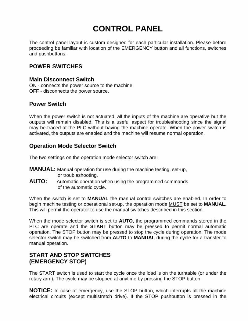
CONTROL PANEL
The control panel layout is custom designed for each particular installation. Please before proceeding be familiar with location of the EMERGENCY button and all functions, switches and pushbuttons. POWER SWITCHES Main Disconnect Switch ON - connects the power source to the machine. OFF - disconnects the power source. Power Switch When the power switch is not actuated, all the inputs of the machine are operative but the outputs will remain disabled. This is a useful aspect for troubleshooting since the signal may be traced at the PLC without having the machine operate. When the power switch is activated, the outputs are enabled and the machine will resume normal operation. Operation Mode Selector Switch The two settings on the operation mode selector switch are: MANUAL: Manual operation for use during the machine testing, set-up, or troubleshooting. AUTO: Automatic operation when using the programmed commands of the automatic cycle. When the switch is set to MANUAL the manual control switches are enabled. In order to begin machine testing or operational set-up, the operation mode MUST be set to MANUAL. This will permit the operator to use the manual switches described in this section. When the mode selector switch is set to AUTO, the programmed commands stored in the PLC are operate and the START button may be pressed to permit normal automatic operation. The STOP button may be pressed to stop the cycle during operation. The mode selector switch may be switched from AUTO to MANUAL during the cycle for a transfer to manual operation. START AND STOP SWITCHES (EMERGENCY STOP) The START switch is used to start the cycle once the load is on the turntable (or under the rotary arm). The cycle may be stopped at anytime by pressing the STOP button. NOTICE: In case of emergency, use the STOP button, which interrupts all the machine electrical circuits (except multistretch drive). If the STOP pushbutton is pressed in the
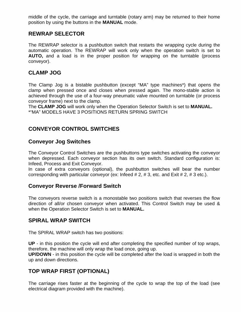
middle of the cycle, the carriage and turntable (rotary arm) may be returned to their home position by using the buttons in the MANUAL mode. REWRAP SELECTOR The REWRAP selector is a pushbutton switch that restarts the wrapping cycle during the automatic operation. The REWRAP will work only when the operation switch is set to AUTO, and a load is in the proper position for wrapping on the turntable (process conveyor). CLAMP JOG The Clamp Jog is a bistable pushbutton (except “MA” type machines*) that opens the clamp when pressed once and closes when pressed again. The mono-stable action is achieved through the use of a four-way pneumatic valve mounted on turntable (or process conveyor frame) next to the clamp. The CLAMP JOG will work only when the Operation Selector Switch is set to MANUAL. *“MA” MODELS HAVE 3 POSITIONS RETURN SPRING SWITCH CONVEYOR CONTROL SWITCHES Conveyor Jog Switches The Conveyor Control Switches are the pushbuttons type switches activating the conveyor when depressed. Each conveyor section has its own switch. Standard configuration is: Infeed, Process and Exit Conveyor. In case of extra conveyors (optional), the pushbutton switches will bear the number corresponding with particular conveyor (ex: Infeed # 2, # 3, etc. and Exit # 2, # 3 etc.). Conveyor Reverse /Forward Switch The conveyors reverse switch is a monostable two positions switch that reverses the flow direction of all/or chosen conveyor when activated. This Control Switch may be used & when the Operation Selector Switch is set to MANUAL. SPIRAL WRAP SWITCH The SPIRAL WRAP switch has two positions: UP - in this position the cycle will end after completing the specified number of top wraps, therefore, the machine will only wrap the load once, going up. UP/DOWN - in this position the cycle will be completed after the load is wrapped in both the up and down directions. TOP WRAP FIRST (OPTIONAL) The carriage rises faster at the beginning of the cycle to wrap the top of the load (see electrical diagram provided with the machine).
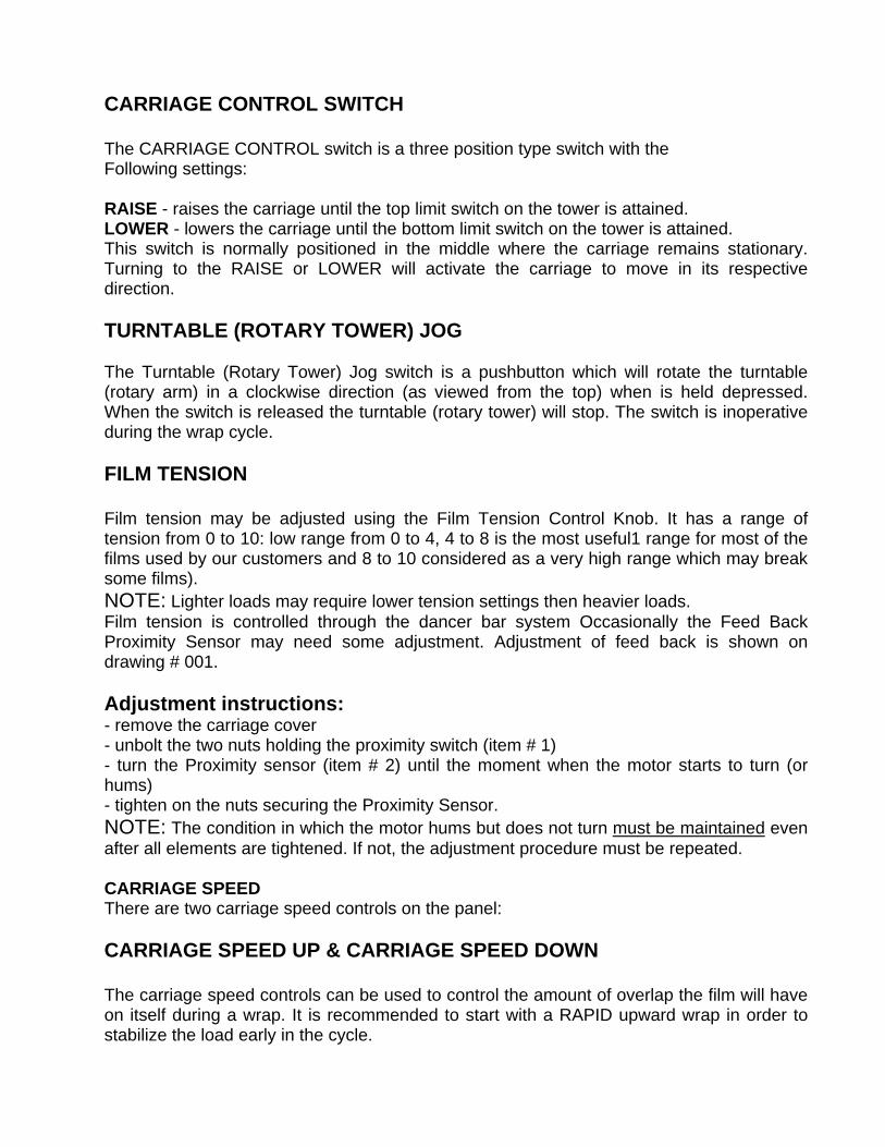
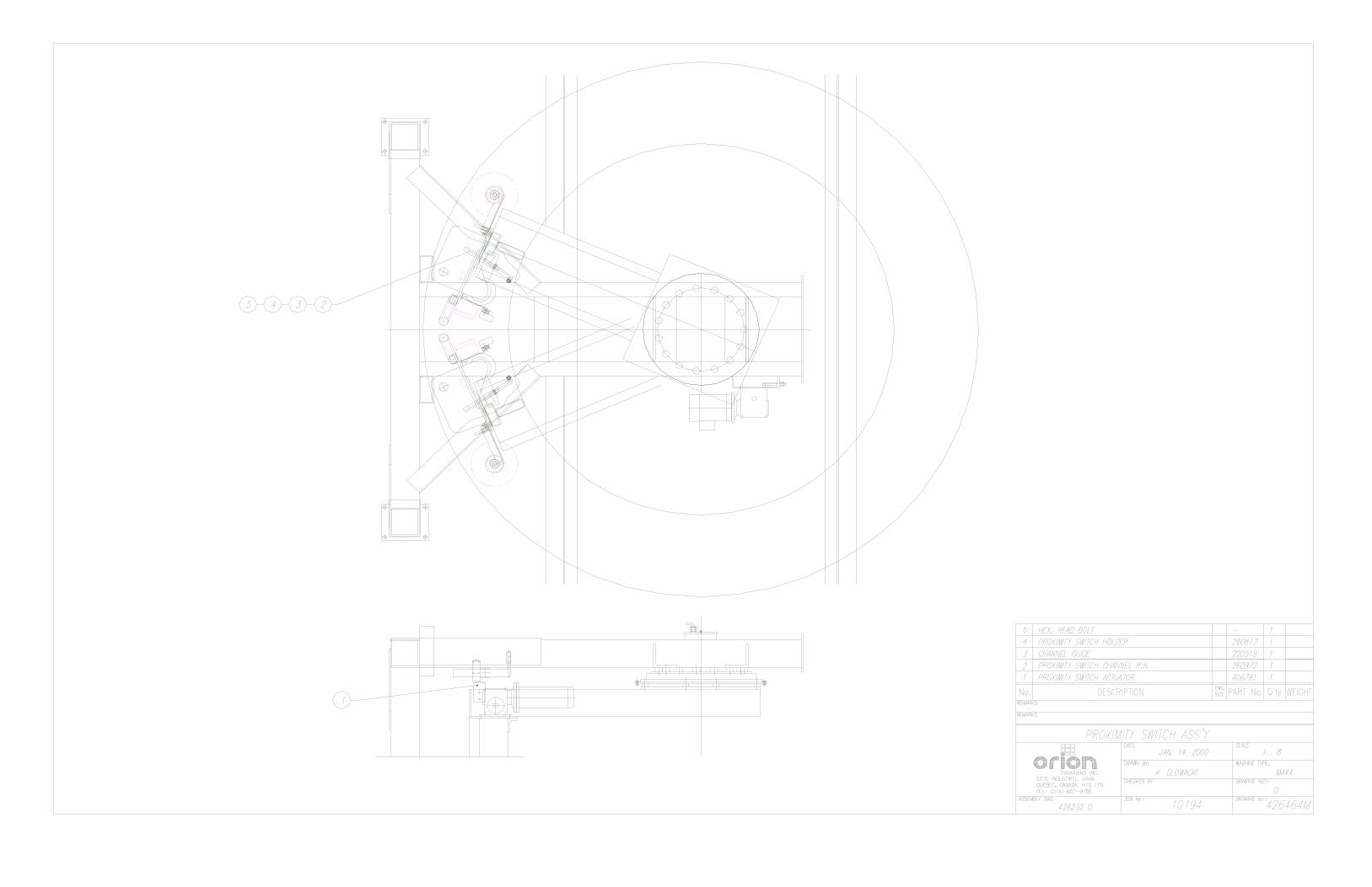
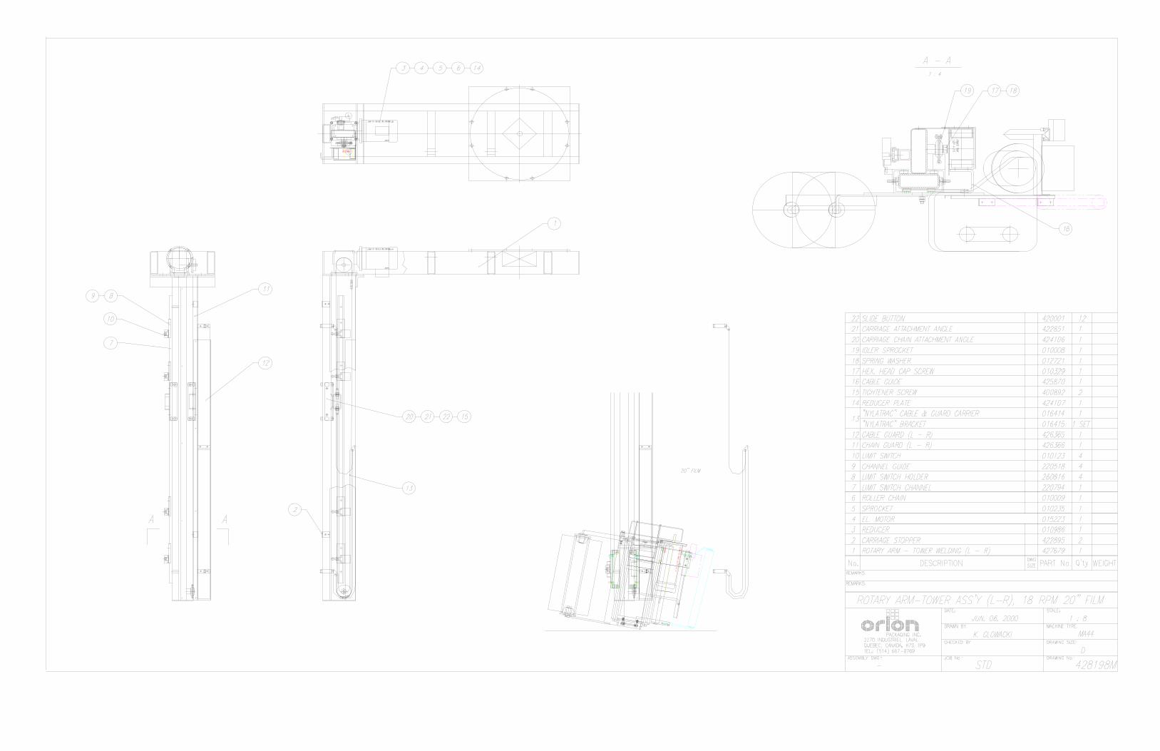
CARRIAGE CONTROL SWITCH The CARRIAGE CONTROL switch is a three position type switch with the Following settings: RAISE - raises the carriage until the top limit switch on the tower is attained. LOWER - lowers the carriage until the bottom limit switch on the tower is attained. This switch is normally positioned in the middle where the carriage remains stationary. Turning to the RAISE or LOWER will activate the carriage to move in its respective direction. TURNTABLE (ROTARY TOWER) JOG The Turntable (Rotary Tower) Jog switch is a pushbutton which will rotate the turntable (rotary arm) in a clockwise direction (as viewed from the top) when is held depressed. When the switch is released the turntable (rotary tower) will stop. The switch is inoperative during the wrap cycle. FILM TENSION Film tension may be adjusted using the Film Tension Control Knob. It has a range of tension from 0 to 10: low range from 0 to 4, 4 to 8 is the most useful1 range for most of the films used by our customers and 8 to 10 considered as a very high range which may break some films). NOTE: Lighter loads may require lower tension settings then heavier loads. Film tension is controlled through the dancer bar system Occasionally the Feed Back Proximity Sensor may need some adjustment. Adjustment of feed back is shown on drawing # 001. Adjustment instructions: - remove the carriage cover - unbolt the two nuts holding the proximity switch (item # 1) - turn the Proximity sensor (item # 2) until the moment when the motor starts to turn (or hums) - tighten on the nuts securing the Proximity Sensor. NOTE: The condition in which the motor hums but does not turn must be maintained even after all elements are tightened. If not, the adjustment procedure must be repeated. CARRIAGE SPEED There are two carriage speed controls on the panel: CARRIAGE SPEED UP & CARRIAGE SPEED DOWN The carriage speed controls can be used to control the amount of overlap the film will have on itself during a wrap. It is recommended to start with a RAPID upward wrap in order to stabilize the load early in the cycle.

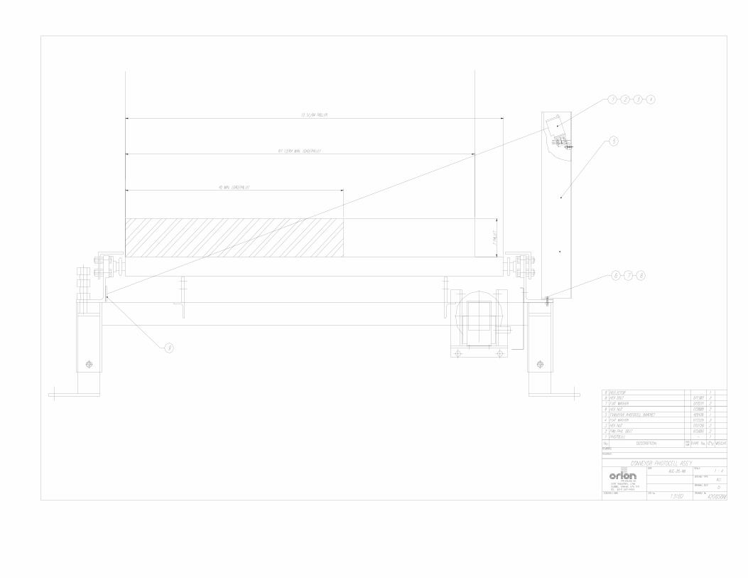
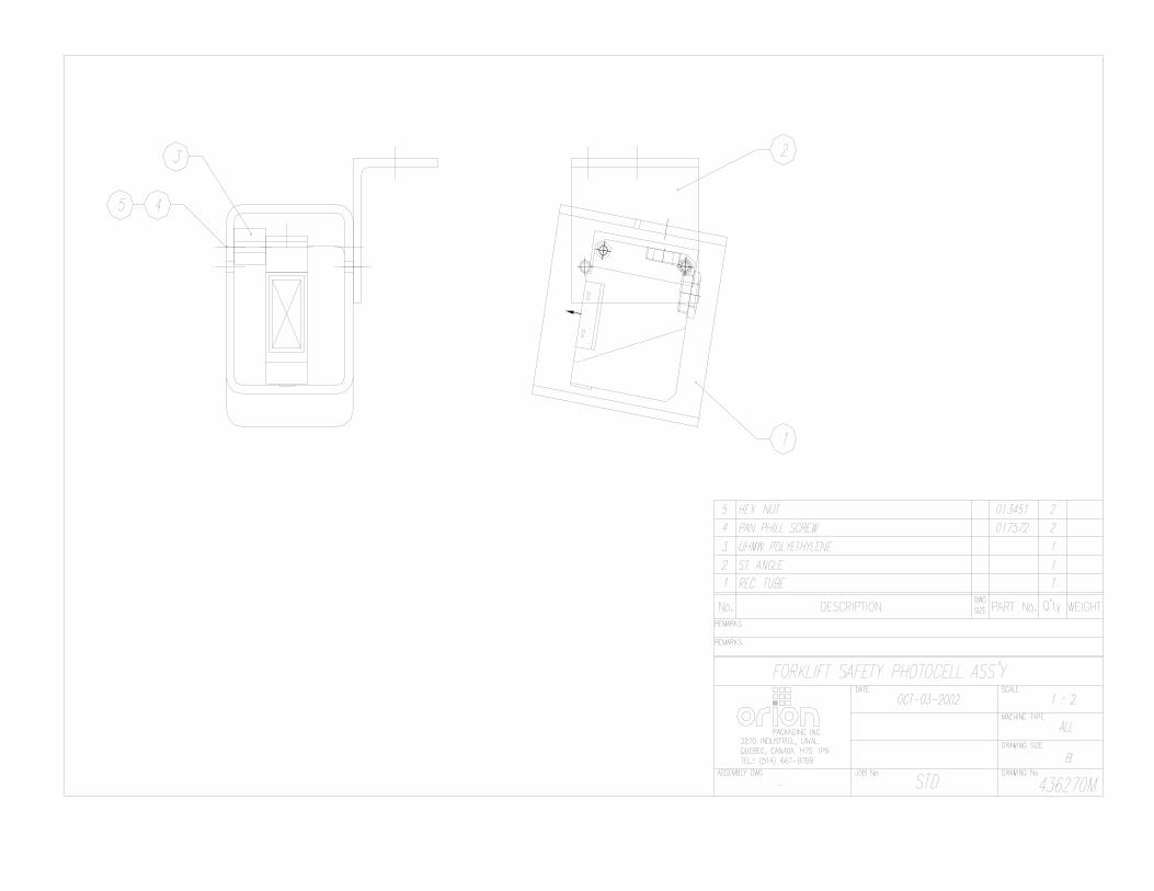
The control potentiometers have settings from 0 to 10, the higher settings being the fastest. High settings will mean less film overlap because of faster carriage speed, and low settings will mean more film overlap because of lower carriage speed. TOP AND BOTTOM WRAPS There are two bistable, three position type switches controlling the number of wraps that may be put at the top and bottom of the load. TOP WRAPS: 1,2,3 BOTTOM WRAPS: 1,2,3 These switches may be set before the automatic cycle begins, and in their different positions will wrap respectively 1,2 or 3 turns of the film on the top or on the bottom of the load. PHOTOSWITCHES Photoswitches are placed on the machine to monitor the motion and location of the loads on the conveyors. For each optional, additional conveyor on the machine an additional photoswitch will be added. The photoswitches are located as follows (shown on the machine layout) : Load Height Sensing Photoswitch: located on the carriage and stops it from moving higher than the highest point on the load. The photoswitch position on the track can be adjusted in order to make the carriage pass the top of the load and make the film overlap the top. Turntable Load Location Photoswitch: is the middle one of the three photoswitches that are pointed at the turntable from behind the tower. Its purpose is to stop the load on the turntable/process conveyor in a suitable position for wrapping. The turntable conveyor or process conveyor is programmed to stop approximately 1.5 seconds after this photoswitch is activated. Turntable or Process Conveyor Safety Photoswitches: these are the three photoswitches pointed at the turntable or process conveyor from behind the tower. Their purpose is to prevent the cycle from starting if the load is not properly positioned on the turntable or process conveyor. Infeed and Outfeed Photoswitches: these are located approximately one foot from the side of each conveyor in the middle of the section. Their purpose is to monitor the position of the loads as load transfers are occurring. When the photoswitch is activated there is a delay of approximately 1.5 seconds before the conveyor stops. NOTE: When testing the conveyor without the load the photoswitch must be kept activated for at least 1.5 seconds in order to have the conveyor stop. For a downstream conveyor, when the load is moved out the photoswitches range there will be delay of about 5 seconds before an upstream conveyor is activated to move load. LIMIT SWITCHES. There are three limit switches located on the tower. The top-most and bottom-most switches limits the motion of carriage determinate by location of the elevator’s drive and

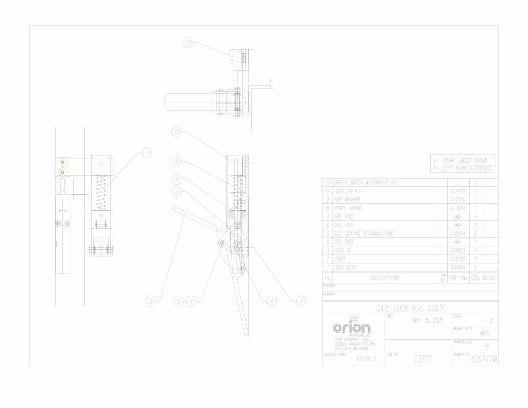
idler sprocket. The middle limit switch purpose is to activate the clamp to open, once the carriage reaches its level. CAUTION: These limit switches are factory adjusted. When setting the machine, please double check their proper position. PROXIMITY SWITCH Proximity Switch is located under the turntable next to the lock, or on the perch (“MA” type machine). Its purpose is to monitor the turntable or rotary arm position, and to signal the controller every time the turntable or rotary arm passes the home position. The proximity switches proper adjustment ensures that turntable or rotary tower will stop in the correct position for the lock to be activated (only turntable machine). CAUTION: The Proximity Switch is factory adjusted and should not need any further adjustment unless it has been disturbed. SYSTEM START-UP Notice: It is advisable to test-run the equipment with several pallet loads before make the attempt to wrap with film. Please position a worker at the EMERGENCY STOP push button. Start up of the machine (system) may determine the need for the adjustment O f - pallet sensor eyes (automatic systems only) - load height stop photoswitch (on the carriage) - conveyor acceleration/deceleration - turntable speed &jog speed - turntable speed acceleration/deceleration - turntable home position (rotary tower home position) - film tail treatment devices (automatic systems).
MACHINE WRAPPING TEST Before the test procedure adjust the wrapping cycle parameters i.e. top wraps, bottom wraps, height photocell on/off, film tension, carriage speed (those two parameters may be adjusted during the wrapping cycle). When there is no photocell, verify the top limit switch position.
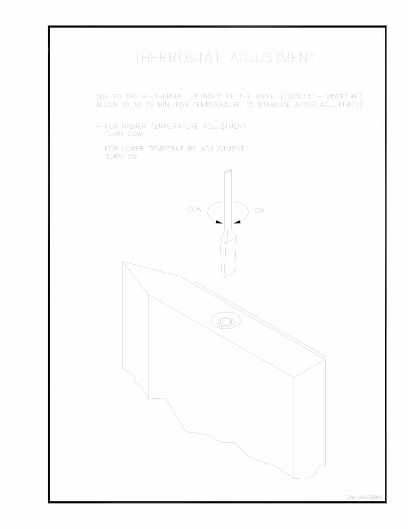
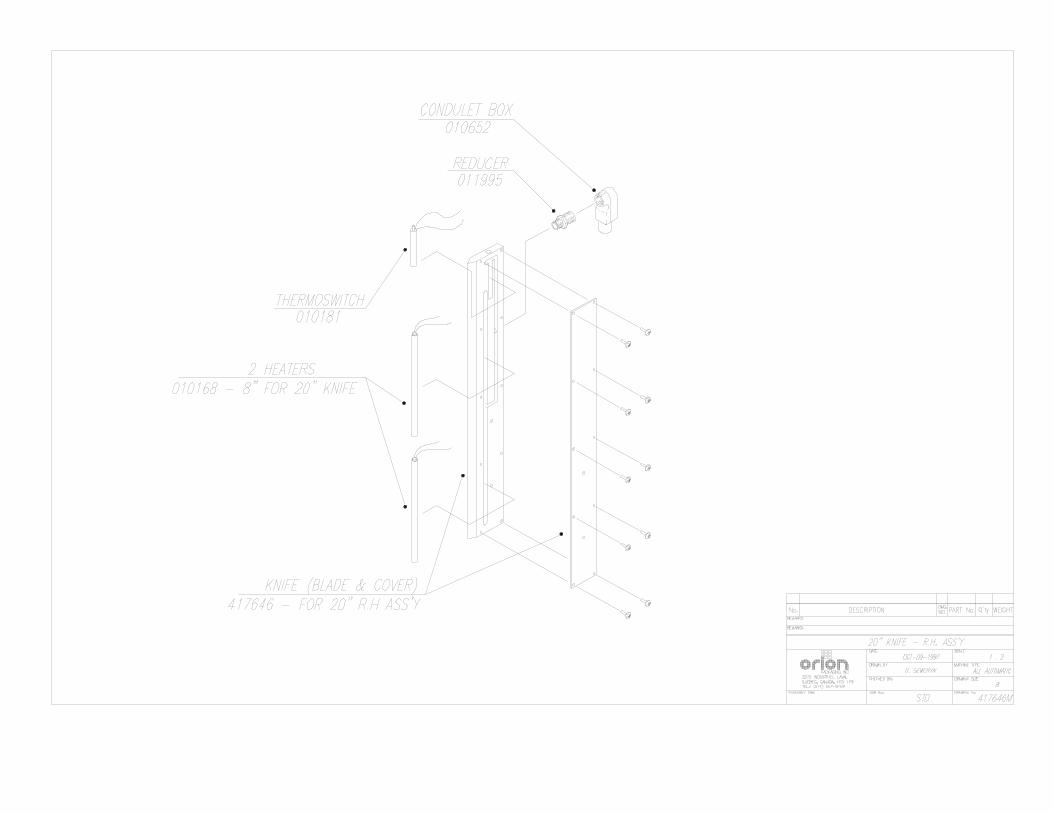
Film Cutter Film Cutter Temperature Adjustment Note: The temperature of the Film Cutter is factory preset at -250°F (12O’C). Under normal conditions, the temperature of the Film Cutter should not require field adjustment. However, when additional adjustment is needed the following should be observed:
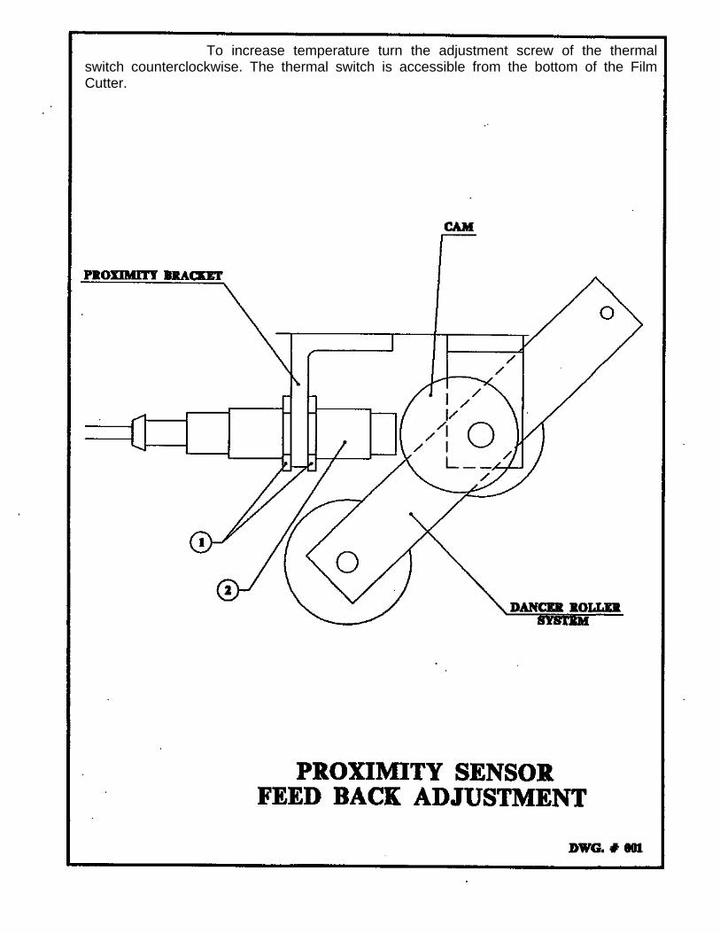
To increase temperature turn the adjustment screw of the thermal switch counterclockwise. The thermal switch is accessible from the bottom of the Film Cutter.

LOADING THE FILM
The film roll can be loaded on the carriage mandrel from either end of the roll. When using tacky film, please verify that the inward tacky surface of the film is inward on the load. 1. Disconnect power (turn off power switch). 2. Swing up the top mandrel spool. 3. Put the roll of film on the bottom mandrel. 4. Install the top mandrel on top of the roll to prevent upward movement. 5. Pull the handle marked PULL TO OPEN to open film distributor cradle. 6. Pass the roped tail of the film through opening (as shown on the film quick threading pattern DWG. # 418180 Fig.1). 7. Close the film distributor cradle by pushing bar marked PUSH TO CLOSE. 8. When the film feeding is completed (fig. 2) – turn the power switch on. 9. Peel off the first few winds of the film (multistrech will run due to displacement of the dancer roller) and fix the film end onto the load. The system is now ready to begin the first wrapping cycle.

MACHINE MAINTENANCE All general information about machine maintenance is based on normal machine working conditions: indoors, moderate dust and low moisture environment, and maximum rotation of 32 RPM of turntable/rotary arm. They should be regarded as guidelines, reviewed and corrected according to requirements of actual use and conditions. MOTOR MAINTENANCE An occasional inspection of the brushes should be made in order to establish a wear rate. Replacement brushes should be installed before old brushes wear to 9/16” long, measured on the long side. After replacing brushes run the motor near rated speed for at least l/2 hour with no load to seat the new brushes. Failure to properly seat the new brushes may cause commutator damage and rapid wear of the new brushes. If the commutator becomes rough, scored or out of shape, a competent motor shop should disassemble it and resurface the commutator. With every third brush change, have a competent motor shop resurface the commutator and blow the carbon dust out of the motor. REDUCER OIL CHANGE All external cap screws and plugs on the reducing transmission should be checked for tightness after the first week. It is recommended to change the oil every six months or at least 1800 hours of operation, whichever comes first. When adding or changing oil, the transmission should never be filled above the oil level mark indicated, because leakage and overheating may occur. Below is the list of the type of lubricant that should be used. List of recommended reducer oils Manufacturer Lubricant American Oil Co.. American Cyl Oil no: 196-L Cities Service Oil Co. Citgo Cyl Oil 100-5 Gulf Oil Corp. Gulf Senate 155 Mobil Oil Corp. Mobil 600 W Suer-r Cyl. Oil Philips Oil Corp. Andes S 180 Texaco Inc. 624 + 650T Cyl.Oil Shell Oil Co. Velvata Oil J82 Union Oil of Cal. Red Line Worm Gear Lube 140 RING BEARING MAINTENANCE (when applicable) The ring bearing (located under the turntable) should be re-lubricated internally and externally. Internally: by injecting grease into all the lubrication nipples in succession until a collar of fresh grease appears around the perimeter of the ring. The re-lubrication interval suggested for these bearings, used in Stretch Wrapping Machinery is 750 hours, with a maximum period of 6 months. The lubricant should be fresh and applied in sufficient quantities to make sure all surfaces are lubricated.
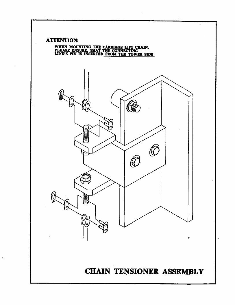
Externally: by lubricating and wiping the chain drive with oily cloth. The frequency of lubrication depends on entirely upon the usage of the machine and environment in which the machine is placed (dust, moisture etc.). Machines working under extremely dirty conditions should be lubricated every 400 operating hours but at minimum, every 2 months. Longer lubrication intervals may occur only when machine is working under very clean and dry conditions but should be not be longer than 6 months. List of recommended lubricants for the ring bearing lubrication Manufacturer Lubricant BP Energrease LS2 Castrol Speeroll AP2 Esso Beacon 2 Gulf Crown Grease 2 Mobil Mobilus 2 Shell Avania Grease R2 Texaco Glissando FT 2 Valvoline LB-2 TOWER RACEWAYS MAINTENANCE The film distributor (carriage) is sliding on the plastic guides attached behind its back plate. The section of the tower on which the plastic guides move (raceways) should be cleaned and re-greased approximately every 600 hours of machine operation. NOTICE: If the machine works in a dusty and corrosive environment, the raceways should be re-greased more often (at least every 100 hours). CHAIN MAINTENANCE To clean the chain, wipe it with an oily cloth every month. When machine is working in a dusty and damp environment, it may be necessary to repeat the cleaning operation more often. As the chain lubricants please use the most common chain lubricants on the market. With time, the chain will tend to stretch. A loose chain should be tightened at the chain tensioner, or by moving the reducer on its mounting plate. NOTICE: Chain tension first adjustment must be done after the first two weeks of machine usage. PNEUMATIC SYSTEM MAINTENANCE (when applicable) The air supply system must be checked weekly and must be free from the moisture. In cold environments, it may be necessary to drain the air supply system daily. CAM FOLLOWER MAINTENANCE (when applicable) The cam followers have deep grease pockets and do not need frequent relubrication. The portion of the tower on which the cam followers run, should be cleaned and regreased every 300 hours of operation. If the machine operates in a dusty or corrosive environment the tower should be relubricated more often.

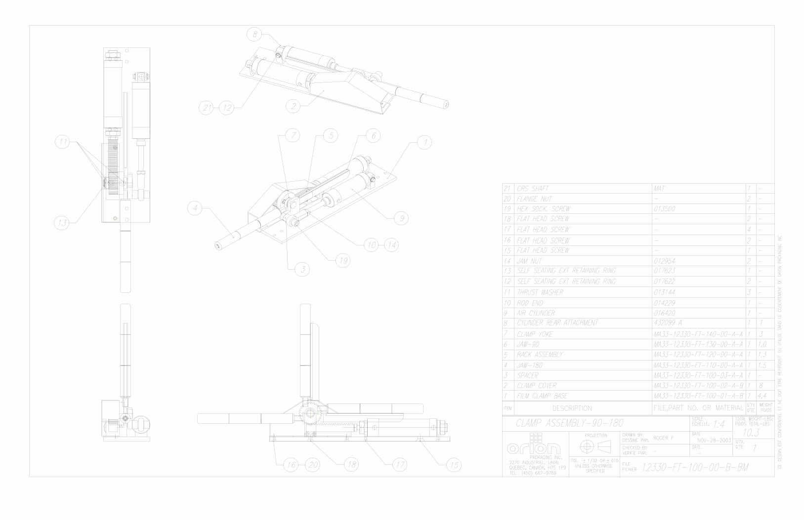
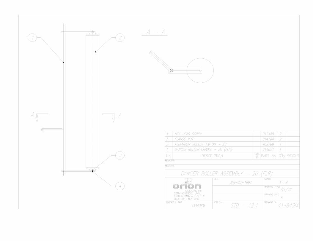
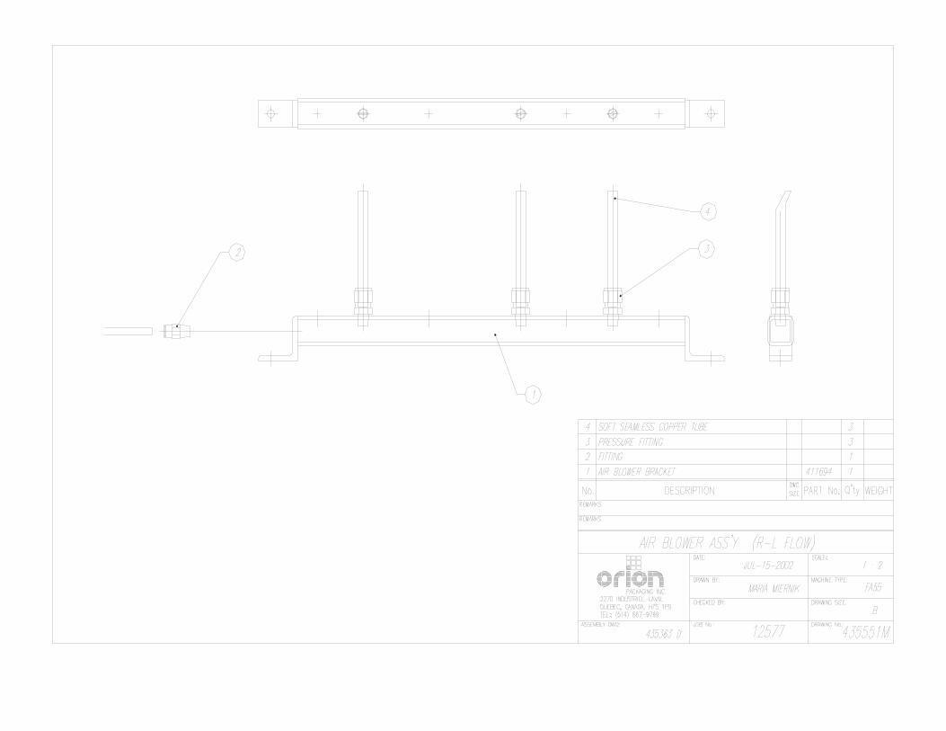
FULLY AUTOMATIC STANDARD ASSEMBLY
PART LIST
Note : * Quantity listed in order of part number ** The names given to the parts are generic


APPENDIX
Multistretch Interface Board Calibration Instructions
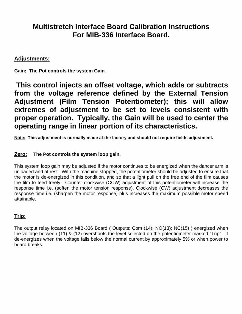
For MIB-336 Interface Board. Adjustments: Gain; The Pot controls the system Gain.
This control injects an offset voltage, which adds or subtracts from the voltage reference defined by the External Tension Adjustment (Film Tension Potentiometer); this will allow extremes of adjustment to be set to levels consistent with proper operation. Typically, the Gain will be used to center the operating range in linear portion of its characteristics.
Note: This adjustment is normally made at the factory and should not require fields adjustment. Zero: The Pot controls the system loop gain. This system loop gain may be adjusted if the motor continues to be energized when the dancer arm is unloaded and at rest. With the machine stopped, the potentiometer should be adjusted to ensure that the motor is de-energized in this condition, and so that a light pull on the free end of the film causes the film to feed freely. Counter clockwise (CCW) adjustment of this potentiometer will increase the response time i.e. (soften the motor tension response). Clockwise (CW) adjustment decreases the response time i.e. (sharpen the motor response) plus increases the maximum possible motor speed attainable.
Trip: The output relay located on MIB-336 Board ( Outputs: Com (14); NO(13); NC(15) ) energized when the voltage between (11) & (12) overshoots the level selected on the potentiometer marked “Trip”. It de-energizes when the voltage falls below the normal current by approximately 5% or when power to board breaks.
Top Related
Copyright © 2022 FDOKUMEN

