


Bahasa
Halaman
Hukum


Page 1 of 25
Knowledge Organiser: Engineering Design
Contents
R105 Design Briefs, Design Specifications and
User Requirements ....................................... 3
LO1 The Design Cycle ................................ 3
Basic Concepts ...................................... 3
Identification of Needs ......................... 3
Designing ............................................... 3
Optimising the Design ........................... 3
Validating the Design ............................ 3
LO2 Understanding Requirements ........... 4
User Needs ............................................ 4
Product Requirements .......................... 4
Manufacturing Considerations ............. 4
Production Costs ................................... 5
Regulations & Safeguards ..................... 5
LO3 Wider Influences on Design ............... 6
Market Pull and Technological Push ..... 6
Cultural and Fashion Trends .................. 6
Links to Successful Existing Products .... 6
Legislative Requirements ...................... 6
Sustainable Design................................. 7
How Materials and Technology
Influence Designs................................... 7
Ethical Design ........................................ 7
R106 Product Analysis and Research ............ 8
Production Methods .................................. 8
One off Production ................................ 8
Batch Production ................................... 8
Mass Production .................................... 8
Manufacturing Aids ............................... 8
Manufacturing Processes .......................... 9
Moulding ............................................... 9
Punch Press ........................................... 9
Press Brake ............................................ 9
Forging ................................................. 10
Machining ............................................ 10
CNC Machining .................................... 10
Thread Cutting .................................... 10
Surface Finishes ....................................... 11
Paint .................................................... 11
Varnish / Lacquer ................................ 11
Anodising ............................................. 11
Dip Coating .......................................... 11
Plating ................................................. 11
End of Product Life .................................. 12
Safe Disposal of Hazardous ................. 12
Materials ............................................. 12
Research Techniques .............................. 13
Primary / Secondary Research ............ 13
Types of Data ...................................... 13
Sample Size ......................................... 13
Comparison of Research Methods ...... 14

Page 2 of 25
Summarising Research ............................ 15
Charts .................................................. 15
Diagrams ............................................. 15
Tables .................................................. 15
Digital Evidence ................................... 15
Sketches .............................................. 15
Annotations ......................................... 15
R107 Developing and Presenting Engineering
Designs ........................................................ 16
LO1 Be able to generate design proposals
using a range of techniques .................... 16
Hand drawn 2D & 3D sketches ........... 16
Annotation and Labelling .................... 16
Use of ICT software to produce, modify
and enrich design proposals ............... 16
Common sketching styles ................... 17
LO2 Know how to develop designs using
engineering drawing techniques and
annotation ............................................... 18
Why designs are developed ................ 18
Communicating the Final Design ......... 18
3D Styles of Engineering Drawing ....... 19
2D Styles of Engineering Drawing ....... 20
LO3 Be able to use Computer Aided Design
(CAD) software ........................................ 21
LO3 Techniques to produce and
communicate design proposals ............... 21
R108 3D Design Realisation ......................... 22
LO1: Know How to Plan the Making of a
Prototype ................................................. 22
Suitable manufacturing processes must
be selected: ......................................... 22
Production must be planned: .............. 22
Resources must be chosen and
obtained: ............................................. 22
LO2: Understand Safe Working Practices
Used When Making A Prototype ............. 23
Key Words............................................ 23
Common Workshop Hazards .............. 23
Risk assessment .................................. 23
Working safely .................................... 23
LO3: Be Able to Produce A Prototype ..... 24
Students must explain: ....................... 24
A good explanation will include: ......... 24
Students are assessed on the use of
preparation and assembly methods ... 24
Recording key stages in making the
prototype ............................................ 24
LO4: Be Able to Evaluate the Success of a
Prototype ................................................ 25
What goes into an evaluation? ........... 25
Evaluating a Prototype ........................ 25
Evaluating Your Own Performance ..... 25

Page 3 of 25
R105 Design Briefs, Design Specifications and User Requirements
LO1 The Design Cycle
Basic Concepts
The process of designing follows a standard
method.
The design process is not always liner; a
‘finished’ product is often analysed and re-
designed into an improve d version.
Identification of Needs
Before designing can start, the designer must
work out what the requirements for the
design are.
A design brief is written by the client.
A design brief is a summary of what will be
designed.
Further research is done to work out the
specific requirements for the design.
Requirements are shown in a design
specification.
A design specification must be agreed
between the client and designer.
Designing
The designer creates a range of ideas to
solve the brief.
Designs are evaluated by using the design
specification.
The best designs are developed further.
Optimising the Design
One or more designed are prototyped.
A prototype is a real-life version of the
design.
A prototype may not be complete.
A prototype is not usually made using mass
production methods, even if the final
version would be mass produced.
Validating the Design
The prototype is used to test the design.
The prototype is evaluated.
The evaluation decides what is good about
the design and what should be improved.

Page 4 of 25
LO2 Understanding Requirements
The design specification needs to consider a
wide range of requirements for the design.
Each of the areas listed below should be
considered.
This is like ACCESS FM which is sometimes
used in lower year groups but with a lot
more detail.
User Needs
These are the things that are important to
the person who will use the design.
Aesthetics – looks.
Ergonomics - how easy it is to interact with.
Anthropometrics - how well it fits the
human body.
Benefits and features - how it will help the
user.
Product safety.
Product Requirements
These are the technical requirements for the
design.
Function – what it will do.
Features – distinctive parts of the design.
Performance – how effectively it must
perform.
Working environment – where it will be
used.
Limitations to the design – e.g. size, weight
etc.
Lifecycle – How long it must last and what
will happen to it at the end of its life.
Manufacturing Considerations
These are the technical requirements for the
manufacturing and maintenance.
Materials availability – Selecting a material
which is available at the right price.
Design for disassembly - at the end of the
products life.
Manufacturing tolerances – how accurately
it must be made.
Sustainability – minimising environmental
impact.
Maintenance – so that the product can be
looked after and repaired.
Scale of manufacture – prototype to start
with but then, the design must be suitable
for one of:
One-off production.
Batch production.
Mass production.

Page 5 of 25
Ease of manufacture
Making manufacture quicker, cheaper and
more reliable by:
Using standard components that are used in
other designs.
Using pre-manufactured components which
suppliers keep in stock and are inexpensive.
Production Costs
Considering how much the product will cost
to manufacture.
Labour
Materials
Overheads – lighting, rent etc.
Regulations & Safeguards
The designer must check that the law allows
their design to be manufactured.
Copyright - artwork cannot be copied
without permission.
Patents - the way in which something works
may ‘belong’ to someone else and cannot be
copied without permission.
Registered Designs – The shape of
something may ‘belong’ to someone else
and cannot be copied without permission.
European Conformity – Products sold in the
European Economic Area must comply with
a variety of laws.
British Standards – The client may want the
design to meet the tough British Standards
as well as European standards.

Page 6 of 25
LO3 Wider Influences on Design
Market Pull and Technological Push
This is to do with why new designs are
created.
Market pull is when a design is made because
people have an existing need.
Reusable water bottles are an example of
market pull.
Technological push is when a design is created
to use a new development or invention.
Touchscreens are an example of technological
push1.
1 Mr Miles thinks that the reality is that there are no successful products which are a result of just
Cultural and Fashion Trends
Some designs are more fashionable than
others and become more commercially
successful.
Trainers and headphones are often good
examples.
Links to Successful Existing
Products
Successful products often influence new
designs.
The development of Apple’s AirPods has
resulted in several cheaper copies of that idea
by other manufacturers.
technological push and he is more than happy to discuss this idea with you!
Legislative Requirements
Designs must be legal to manufacture and sell.
Some products can only be made with a
licence e.g. firearms and fireworks.
Some may be illegal if used as intended e.g.
‘hoverboards’.
Some products must meet specific laws.
Bicycles must have certain safety features.

Page 7 of 25
Sustainable Design
Consumption of materials and power is said to
be sustainable if we can continue to use it at
the current rate without it ever running out.
Using fuel usually creates pollution.
Consumption of Resources
Materials used in manufacture.
Use of fuel to make the electricity used in
manufacture.
Use of fuel to distribute the product.
Fuel used by the product in use e.g. electrical
and internal combustion engines.
Energy or land-fill ‘dumps’ used at the end of
the products’ life.
Life Cycle Analysis
The total impact of the design from the start of
manufacture to eventual disposal.
Environmental Pressures
Using up resources such as coal, gas, metal ore.
Pollution caused by burning fossil fuels such as
oil and coal.
Global warming caused by pollution.
Waste created such as plastics and nuclear
waste.
Destruction of natural environment e.g. by
mining and roads.
How Materials and Technology
Influence Designs
New materials are being created e.g. Kevlar
and carbon fibre.
New materials have better properties than
traditional materials.
New materials may allow designs to be
engineered for the first time e.g. electrically
powered drones.
Technological innovation is about new ways of
making or doing things.
Surface mount electronic components have
allowed electronics to become tiny.
Improved battery technology has made
electric cars possible.
Ethical Design
Designs should be created that have a positive
effect. For example:
Causing less pollution than older designs.
Using fewer resources than older designs.
Encourage cooperation between people.
Are not unnecessarily offensive to others.
Help people to learn.
Page 8 of 25
R106 Product Analysis and Research
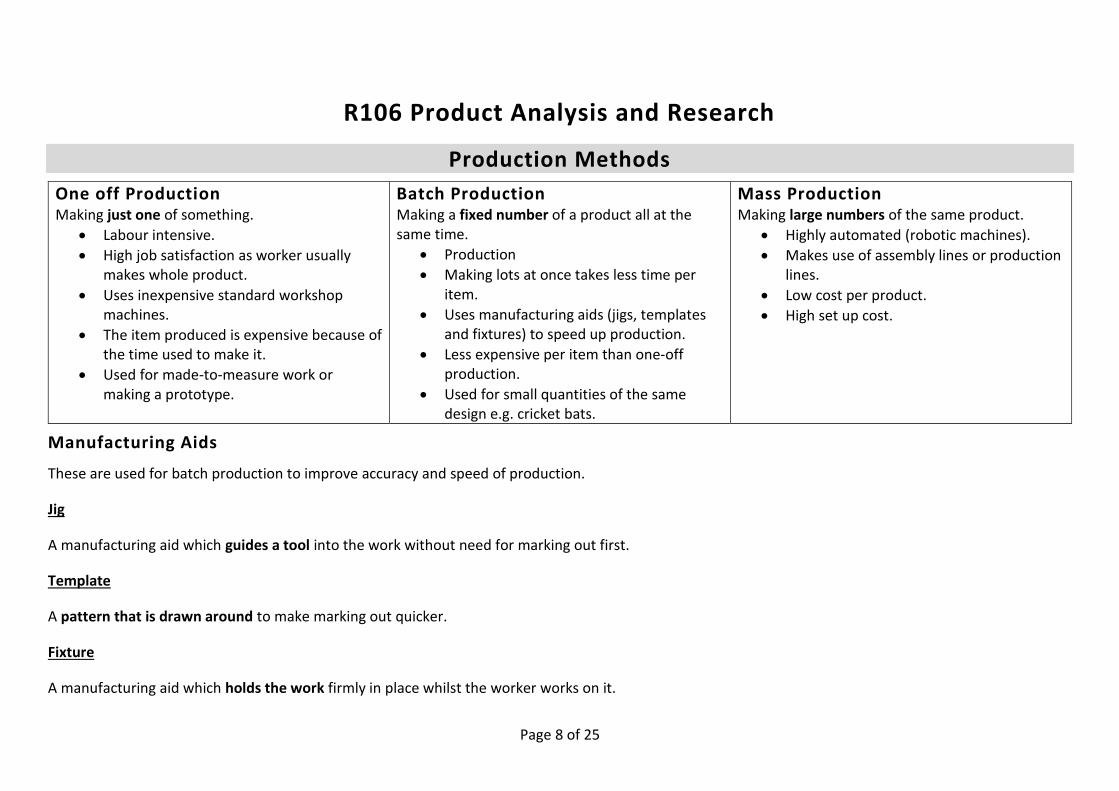
Production Methods
One off Production Making just one of something.
Labour intensive.
High job satisfaction as worker usually makes whole product.
Uses inexpensive standard workshop machines.
The item produced is expensive because of the time used to make it.
Used for made-to-measure work or making a prototype.
Batch Production Making a fixed number of a product all at the same time.
Production
Making lots at once takes less time per item.
Uses manufacturing aids (jigs, templates and fixtures) to speed up production.
Less expensive per item than one-off production.
Used for small quantities of the same design e.g. cricket bats.
Mass Production Making large numbers of the same product.
Highly automated (robotic machines).
Makes use of assembly lines or production lines.
Low cost per product.
High set up cost.
Manufacturing Aids
These are used for batch production to improve accuracy and speed of production.
Jig
A manufacturing aid which guides a tool into the work without need for marking out first.
Template
A pattern that is drawn around to make marking out quicker.
Fixture
A manufacturing aid which holds the work firmly in place whilst the worker works on it.

Page 9 of 25
Manufacturing Processes
Moulding
Moulding can create quite accurate complex
shapes. Little material is wasted.
Often several copies of a part are moulded on a
single runner.
When accuracy is important, the part will need
to be machined to an exact size after moulding.
Injection Moulding & Die Casting
This can made detailed parts with very little
waste quite accurately.
Called ‘Injection moulding’ for plastics.
Called ‘Die casting’ for metals
Hot material is injected (squirted) into a mould
called a die. Sometimes the mould is cooled by
water. When the material has solidified, the
part is removed, and waste trimmed off.
Investment casting
This is used with metals.
1. A wax model of the part is made.
2. The wax model is coated with ceramic
materials (clay).
3. The ceramic material is hardened, and
the wax melted out.
4. Molten metal is poured into the space
where the wax once was.
5. When the metal has hardened, the
ceramic material is removed.
6. The casting usually needs some
machining to an exact size.
Punch Press
This is used with sheet metals.
1. Sheet metal is placed between dies in a
powerful press.
2. The sheet material is pressed between
the dies.
3. The dies can be designed to punch (cut
out) or bend the material.
4. Often a part will move through several
stages, getting shaped further with each
stage.
Press Brake
This is used to fold metal sheet.

Page 10 of 25
Forging
Hot forging and cold forging can both be used
with metals. Hot forging can create very strong
shapes.
Hot Forging
1. Metal is heated to make it malleable.
2. The malleable metal is pressed between
a pair of shaped dies.
3. Sometimes a series of dies are used to
refine a part stage by stage.
4. The final forging usually needs trimming
and sometimes machining to exact
dimensions.
Machining
Sometimes, parts need to be made to a
tolerance of a fraction of a millimetre. This can
be hard or impossible to achieve by casting or
pressing.
Machining is used to remove material (usually
metals) very accurately.
Milling Machine
The work is moved under a rotating cutter to
create an accurate surface or slot.
Lathe
Cylindrical work is rotated, and a tool is moved
across the work to accurately remove material.
CNC Machining
It can be very time consuming to machine a
part by hand and mistakes are easy to make.
CNC machines do the same jobs but are
computer controlled.
CNC machines are more expensive.
CNC machines can work without an
operator. This makes production
cheaper.
Thread Cutting
Screw threads can be cut on a lathe as part of
machining or can be cut with a tap (internal
thread) or die (external thread).

Page 11 of 25
Surface Finishes
Paint Varnish / Lacquer Anodising Dip Coating Plating Covering with a protective and coloured layer.
Covering with a protective clear layer.
Creating a thick protective oxide layer on the surface of metals. Sometimes this is dyed for an attractive appearance.
Coating metals with a layer of thermoplastic polymer (plastic).
Coating an inexpensive metal with a different one to improve its surface. Often an inexpensive metal is coated with an expensive one.
Timber Metals Plastics (unusually)
Timber Metals
Aluminium and some other metals.
Metals Metals Plastics (unusually)
Parts dipped in paint.
Paint sprayed on.
Details may be hand painted with a brush.
Parts dipped in varnish / laquer
Sprayed on.
1. Treated in an electrified acid bath.
2. Oxide layer thickens. 3. Oxide can be dyed for a
better appearance.
Parts heated up then
dipped in a fluidized bed
of powdered
thermoplastic.
Plastic powder melts into
a smooth surface.
A metal part is suspended in an electroplating bath.
‘Donor’ matal also suspended.
Bath is filled with liquid.
Electricity causes some metal (ions) to move onto the part coating it.

Page 12 of 25
End of Product Life
Recycling Materials
Many materials can be recycled but often
aren’t.
By law, all electrical products must be
recycled.
A good designer will:
Use materials that can be easily recycled if renewable materials are not appropriate.
Make the materials in their design easy to take apart for recycling.
Materials that are easy to recycle
Thermoplastics
Metals
Glass
Reusing Parts
It is even better to reuse a part than to
recycle it.
A used part can be used to replace a broken
part.
A good designer will create designs that are
easy to disassemble and repair.
Example: Car alternators have bearings that
wear out, but the other parts are routinely
cleaned and re-used in a reconditioned part.
Safe Disposal of Hazardous
Materials
Some materials are damaging to the
environment.
Damage to the environment can include
polluting the water and poisoning the land
so nothing will grow.
Hazardous materials must be specially
recycled
Batteries
Batteries contain acids or alkalis and
poisonous metals.
Some batteries contain very reactive metals
which can catch fire or explode.
Designers must make sure batteries are
removable.
Consumers must recycle batteries.
Fluorescent Tube Lamps
Fluorescent tubes contain mercury which is a
very poisonous metal.
Designers must make sure fluorescent tubes
are removable.
Consumers must recycle fluorescent tubes.
Lead & Copper
Almost all wiring is copper.
Almost all circuit boards use lead in solder.
Copper and lead are poisonous.
A designer should make sure that their
product is easy to take apart at the end of its
life.
Consumers are required by law to recycle
their electrical goods safely.

Page 13 of 25
Research Techniques
Primary / Secondary Research
You should show that you can use both
approaches in your work.
Choose methods based on the information
you want to find out.
Primary Methods
This involves you doing the actual research:
Physical analysis of products
Questioning users
Surveying users
Secondary Methods
This is identifying relevant information that
has been compiled by others:
Web sites
Books & other literature
Manuals
Drawings & diagrams
Images
Secondary research must be referenced;
you need to show where you got the
information. Failure to do this may be
cheating.
Types of Data
Quantitative data is measurements. E.g. the
amount of memory in a phone or the
capacity of a battery.
Qualitative data is opinions, impressions
and points of view. E.g. how comfortable a
handle is or how attractive a bath tap is.
Sample Size
When we research products, we are usually
comparing them. We might also get
information from more than one person.
How many we compare is the sample size.

Page 14 of 25
Comparison of Research Methods
Method Type of Data Available Sample Size Example of Use
Pri
mar
y R
ese
arch
Physical analysis of products Examining and testing real life products. Usually they are compared using criteria.
Qualitative information about products according to criteria that you decide.
A few (as many examples as you can find).
Comparing bike saddles for comfort. Comparing phone chargers for speed of charging.
Questioning Users Users are interviewed usually with a pre-prepared set of questions.
Qualitative information about user needs according to criteria that you decide.
A few (as many people as you can interview).
Finding user needs for a refrigerator. Understanding the impact of someone’s disability.
Surveying Users Many users are asked straightforward questions and the results are then analysed e.g. using graphs.
Quantitative information from lots of people.
Many (as many as will complete your survey).
Asking 40 people how much they would pay for a school bag. Asking a class about their favourite leisure activities.
Seco
nd
ary
Res
ear
ch
Web sites Finding information you need on the internet needs care – be clear about what information you need and watch out for bias.
Images. Opinions (qualitative). Reviews (qualitative). Technical data (quantitative). Comparisons (quantitative). Prices (quantitative).
Several (as many as you can find on websites).
Finding out what sizes of paper different printers use. Researching different solutions to bike security.
Books & other literature Similar to web sites but books tend to be more accurate if they’re not out of date.
Magazines sometimes have qualitative reviews of products.
A few. Gaining opinions about current hair straighteners.
Manuals Manuals can show you technical details of a product.
Maintenance manuals can show how things work and how to repair them.
One product per manual usually.
Finding out how food mixers work.
Images, Drawings & Diagrams Images can help you judge aesthetic appeal and might give clues about ease of use etc.
The parts that make up a product. How a product is operated.
As many as you can find.
Making judgements about the aesthetic appeal of headphones. Identifying all the parts that make up a power drill.

Page 15 of 25
Summarising Research Once you have done your detailed research,
you should summarise it to show what you
have learned by comparing products.
There are several ways of summarising your
findings but in each on you should explain
what is shown in your own words.
You should use a range of these in your
work but you do not have to use them all.
Charts
Good for comparing numerical data.
Diagrams
A diagram is a visual representation of
information. They can be used to
summarise:
Processes
Relationships
Tables
Tables are good for comparing information.
Digital Evidence
This can include:
Photos
Video#
Photos are particularly useful for showing
aesthetic information.
Sketches
Useful to help explain a mechanisms or
other design features.
Sketches must be annotated.
Annotations
Annotations are much more than labels. A
label is a statement of fact. Annotation
should include explanations.

Page 16 of 25
R107 Developing and Presenting Engineering Designs
LO1 Be able to generate design proposals using a range of techniques
Hand drawn 2D & 3D sketches
At the start of the design process the
designer aims to produce as many varied
design ideas as they possibly can.
Design ideas are imagined in the designer’s
brain.
Designers show their ideas by using drawn
sketches or quick ‘sketch’ models.
A variety of 2D and 3D drawing styles are
used.
Rendering a design in colour:
Makes the design look 3 dimensional.
Shows colour.
Can show the material it is made of.
Makes it more attractive.
Annotation and Labelling
Designs are always annotated:
To explain anything that is not
obvious from the drawing.
To explain the choice of materials.
To state manufacturing methods.
To explain the designers reasoning.
To comment on the positive aspects
of that design idea.
To note weaknesses and ideas for
improvement.
Use of ICT software to produce,
modify and enrich design
proposals
Sometimes quick virtual models all made
using software such as SketchUp.
Often paper designs are photographed or
scanned and imported into a computer
document.
ICT software can then be used to improve
the appearance of the design by:
Changing brightness and contrast.
Adding colour.
Adding annotation.
Arranging various designs on a single
page.
Presentation documents such as PowerPoint
can be used to show designs to clients to get
their feedback.

Page 17 of 25
Common sketching styles
Front elevation (2D)
Detailed view of the front
Cross section (2d)
Shows inside workings
Isometric sketch (3D)
A realistic view showing three sides at once

Page 18 of 25
LO2 Know how to develop designs using engineering drawing techniques and annotation
Why designs are developed
At the start of the design process, the
designer’s aim is to produce as many varied
designs as possible.
These designs are then evaluated and the
best one or best few are developed further.
The purpose of developing designs is to add
enough detail to allow them to be
manufactured and to make improvements
to the design based on evaluation of each
new version.
Designs are developed by:
Adding detail.
Gaining feedback from others.
Resolving problems.
Redesigning to allow for how they
will be manufactured.
The design of components will be
appropriate for the manufacturing process
chosen.
Communicating the Final Design
In the end one design is chosen and fully
completed.
The design is communicated using a
manufacturing specification.
The manufacturing specification contains all
the details needed for another person to
manufacture that product.
A manufacturing specification
will include:
Technical drawings of all the
components.
A parts list.
An assembly drawing showing how
the components fit together.
Standard engineering drawing techniques
are used so that all engineers can
understand them.
Engineering drawings are always accurately
drawn to scale and have dimensions shown.
An assembly drawing shows how all
components fit together.
Assembly drawings are usually 3D exploded
drawings or 2D cross-sectional drawings.

Page 19 of 25
3D Styles of Engineering Drawing
Exploded view
Shows all the components of an product or assembly.
Looks like it was ‘blown’ apart.
Shows how components fit together.
Is often used for an assembly drawing.
Isometric (3D)
A realistic view showing three sides at once
Used to show the complete component or product.

Page 20 of 25
2D Styles of Engineering Drawing
These will always be drawn accurately.
They are often drawn to scale.
Orthographic Projection
Detailed view from each side.
Always shows dimensions.
This example also shows a 3D isometric view.
Cross-section
Shows inside workings

Page 21 of 25
LO3 Be able to use Computer Aided Design (CAD) software
CAD stands for Computer Aided Design.
CAD software is expensive and takes time and skill to learn.
CAD has the following advantages:
Designs can be changed easily.
Designs can be worked on collaboratively with others even if
they're not in the same building.
Designs can be quickly emailed to manufacturing facilities.
Working drawings can be created easily once the component
has been modelled in the software.
The software can work out facts such as the total weight when
made in a certain material.
Software can produce a photo realistic 3D image before the
product is even made.
CAD software links with rapid prototyping facilities such as 3D
printers.
LO3 Techniques to produce and communicate design proposals
The final design must be communicated to the client.
The client must accept and approve the final design.
Display boards can be used to present photographs of models,
working drawings and photo realistic images from CAD software.
PowerPoint can be used to allow a speaker to show this information in
a presentation.
Models do not necessarily function but can be useful to show clients
how will the final component or product will look and allow them to
handle it.
Models can be handmade, can be 3D printed, laser cut, or can be a
combination of both.

Page 22 of 25
R108 3D Design Realisation
LO1: Know How to Plan the Making of a Prototype The creator must decide how to interpret a
working drawing and the tools and
techniques that they will use to create a
prototype.
The creator must be able to interpret the
product specification that they are given.
Suitable manufacturing processes
must be selected:
Use of hand tools.
Use of rapid prototyping techniques
such as laser cutter or 3D printer.
Use of machine tools.
Production must be planned:
Gantt charts.
Tables.
Flow charts.
Resources must be chosen and
obtained:
Materials.
Component parts.
Tools and equipment.
Risk assessments.
Cutting lists are used to prepare and check
materials.

Page 23 of 25
LO2: Understand Safe Working Practices Used When Making A Prototype Potential hazards must be assessed, and
controls put in place in order to minimise
risk.
Key Words
A hazard is something that can cause harm.
A risk is the chances that the hazard will
cause harm.
Control measures are put in place to
minimise the risk of a person becoming
injured by the hazard.
Common Workshop Hazards
Cuts from tools or sharp edges of
materials.
Becoming entangled in a machine.
Breathing in dust or fumes.
Slips or trips.
Material ejected from a machine for
example from a polishing machine.
Live exposed electrical conductors.
E.g. in a damaged cable.
Risk assessment
There is a standard process for assessing
risk.
Risks are assessed on a standard risk
assessment form.
1. List process is to be undertaken.
2. List the hazards.
3. Decide on how each hazard could be
controlled.
Sometimes a scoring system is used:
1. The severity of a hazards is given a
score. The worse the injury, the
higher the score.
2. The likelihood of the injury is given a
score. The more likely it is to happen,
the higher the score.
3. Overall risk is calculated by
multiplying the severity score with
the likelihood score.
Working safely
Students must be seen to work safely by:
Creating risk assessments.
Wearing appropriate personal
protective equipment (PPE).
Use safe working procedures.

Page 24 of 25
LO3: Be Able to Produce A Prototype
Students must explain:
The materials that they have chosen
to use.
How they will use those materials at.
The methods they will use too create
each part.
Which tools they will use.
How they will assemble the parts
together.
A good explanation will include:
A written discussion of the options
available.
A choice being made.
Reasons why that choice was made.
Reasons why other options are
rejected.
Students are assessed on the use
of preparation and assembly
methods
Examples:
Jigs.
Formers.
Templates.
Patterns.
Moulds.
Adhesives.
Fixings.
Recording key stages in making
the prototype
Students must keep a record of how the
prototype was made.
The record must include evidence such as
photographs.
This could include:
Taking notes.
Creating a production diary.
Photographing every stage of
production.
Recording problems and how they
were solved.

Page 25 of 25
LO4: Be Able to Evaluate the Success of a Prototype
What goes into an evaluation?
And evaluation includes:
1. An explanation of the strengths.
2. An explanation of weaknesses.
3. Ideas for improvement.
Evaluating a Prototype
The prototype is evaluated against each
point in the product specification
individually.
Improvements to be considered:
features
function
materials
aesthetics
ergonomics
modelling and prototyping processes
alternative manufacturing techniques
Evaluating Your Own
Performance
Each student must evaluate how well they
worked in this unit.
This must include evaluation of:
Management of time and resources.
Planning and preparation.
Precision and accuracy achieved in
making processes.
Quality of the final prototype.
Top Related
Copyright © 2022 FDOKUMEN

