


Bahasa
Halaman
Hukum

ISSN: 2320-5407 Int. J. Adv. Res. 7(12), 923-934
923
Journal Homepage: -www.journalijar.com
Article DOI:10.21474/IJAR01/10234
DOI URL: http://dx.doi.org/10.21474/IJAR01/10234
RESEARCH ARTICLE
THE PRACTICALITY OF ENGINEERING PRINCIPLES IN SOFTWARE ENGINEERING
Patrick Obilikwu PhD1, Kenneth Dekera Kwaghtyo
1 and Edward N. Udo
2
1. Department of Mathematics and Computer Science, Benue State University, Makurdi, Nigeria.
2. Department of Computer Science, University of Uyo, Uyo, Nigeria.
……………………………………………………………………………………………………....
Manuscript Info Abstract
……………………. ……………………………………………………………… Manuscript History
Received: 12 October 2019 Final Accepted: 14 November 2019
Published: December 2019
Key words:- Software, Principles, Engineering,
Software Development Process,
Engineering Principles, Software
Engineering
In the early days of computing, software development was all about
automating complex scientific calculations requiring several iterations.
But with advances in technology resulting in the drastic reduction in the
cost of computers, computer programs were designed to automate
enterprise activities that required storing large data and developing
complex codes to process the same. Unlike the structured scientific
problems that computers solved earlier, the application of computers in
automating enterprise activities involved problems that were not as
structured as in the sciences. The users of enterprise applications were
also not technically skilled as scientists. This increased the complexity
of software development projects. The complexity associated with
software development increased to a level that necessitated the
adoption of principles that have been applied in the traditional
engineering fields to solve complex problems such as building
skyscrapers, highways, electrically wiring a large building among
others. Previous studies have documented and categorized the
engineering principles that apply to software engineering. This paper
goes a step further to illustrate the practical applications of these
principles to the software development process using design
methodologies. In this way, the study also closes the knowledge gap as
to why the name software engineering.
Copy Right, IJAR, 2019,. All rights reserved.
……………………………………………………………………………………………………....
Introduction:- Software development started as a process whereby computers were programmed to automate complex scientific
calculations that required several iterations. The iterations involved in such computations were beyond the manual
methods. The user community then was made up of science-oriented professionals who could easily cope with the
complexities of the computer programs that had to be written. With advances in technology resulting in the drastic
reduction in the cost of computers, computer programs were designed to automate enterprise activities that required
storing large data and implementing complex algorithms to process the same. In a University, for example, an
enterprise application can be deployed to automate both academic and administrative activities. Unlike the
structured problems that computers were used to solve by the scientists, the application of computers in automating
enterprise activities involved problems that were not as structured as in the sciences and this increased the
complexity of software development projects.
Corresponding Author:-Patrick Obilikwu
Address:-Department of Mathematics and Computer Science, Benue State University, Makurdi, Nigeria.
ISSN: 2320-5407 Int. J. Adv. Res. 7(12), 923-934
924
The resulting large and complex software development projects required large teams and no longer a single
developer. The management of such project teams required a higher level of management techniques to deal with
the associated logistics and people issues. Examples of people issues include unauthorized absence from work and
truancy on flimsy excuses, lateness to and laziness at work, engagement in extraneous activities completely
unrelated to staff job descriptions while at work and insubordination among others. The resulting complex software
development projects were characterized by non-completion, excessive cost, bugs and errors that made its
operations epileptic and in many cases project completion became unachievable. For instance, several large software
projects embarked upon have been reported as having failed (Ebad, 218). The wider application of computers also
created a wider user base that was no longer made up of scientists but accountants, secretaries, students among
others who had little or no technical knowledge of how computers work.
Comparing the failure rate of software development projects with the successes recorded on large engineering
projects such as the building of skyscrapers, electrical wirings of buildings, construction of highways, among others
prompted the early programmers to consider applying engineering principles that were successfully used in the
physical engineering discipline to the development of software to address software failures and associated issues.
Review of Related Works:
The field of Software Engineering (SE) has evolved since the 1960s and has therefore amassed a substantial amount
of knowledge (Picha and Brada, 2014). This study focuses on the practical application of engineering principles and
certainly does not constitute the first attempt in the research community to assess the state and context of
Engineering Principles (EP) in Software Engineering.
Fitzgerald and Stol (2015) attempted to provide a roadmap of the overall territory, an important step in its way, since
there is much confusion as terms are used interchangeably and synonymously without rigorous definition, similar to
early research on agile methods. The study identified some continuous activities tagged together as "Continuous
Star" which they presented as part of an overall roadmap for continuous software engineering. However, delivering
the continuous star agenda rather highlighted many significant challenges which need to be addressed if the concept
is to be successful. They, however, failed to provide a clear view of terms in software engineering principles. Pícha
and Brada (2014) summarized the goals and history of the SE field and focused on the empirical research area
within it. Their research highlighted the most frequent problems affecting empirical SE research efforts and the most
promising suggested solutions. Both the problems and suggested solutions were collected from a carefully selected
sample of research publications. However, the study did not cover the full breadth of the studied material and
findings.
Abran et al., (2004) presented a survey and an analysis of the work carried out beginning from the early 70s on the
search for fundamental principles of software engineering in terms of both methodology used and the status of
results to date. The paper also illustrated that there is a clear lack of consensus about which of the proposed
principles are indeed fundamental. However, the paper failed to establish the foundation of SE as intended.
Krishna et al., (2012) explored the set of fundamental principles and these contributed to a better understanding,
possibly because the discussion was from an engineering perspective. They, however, reported on a series of efforts
undertaken to identify a set of fundamental principles of software engineering.
Brhel et al., (2015) aimed at capturing and analyzing the current state of the art in User-Centered Agile Software
Development (UCASD). More specifically, the paper investigated the following research question: Which principles
constitute a user-centred agile software development approach? Thus, following an approach similar to the agile
manifesto, the study derived a set of grounded principles for UCASD from the literature.
Valerdi and Boehm (2010) provided an insight into the development of COSYSMO, its parameter definitions, and
an example estimate. Their efforts confirmed that systems engineers and program managers desire models that can
be used in developing accurate estimates or systems engineering effort. Considering its contribution, COSYSMO,
represented such a model. Its parametric formulation differs from others currently available which are heuristic-
based. Being based on actual project data enables engineers and managers to use COSYSMO to justify forecasted
expenditures and reduce risk. They had tremendous support in the research area but still have some significant
challenges. Continued collaboration with systems engineering practitioners is expected so as to produce a more
accurate and flexible model.
ISSN: 2320-5407 Int. J. Adv. Res. 7(12), 923-934
925
Séguin et al., (2010) presented a survey and an analysis of the literature on software engineering principles. The
literature survey, covering thirty years, came up with 14 different papers and books, which have proposed a total of
313 distinct principles for software engineering. A further analysis of these works was carried out based on a
rigorous definition of the term ‗principle' and on the identification of a set of explicit criteria to assess whether or not
any of the proposed principles qualify as fundamental principles of software engineering. The analytical approach
employed filtered a set of 24 candidate software engineering principles based on certain criteria. However, the
analytical approach adopted was based on a rigorous definition of terms and the lack of practical involvement to
support or back up the findings has been the major setback in the work. Thus, this paper addresses this gap using a
combination of pseudocodes, use cases, structure charts, and database design methodologies to further illustrate
more practically some of the 24 candidate software engineering principles as screened by Séguin et al., (2014).
Methodology:- Several authors have come up with their list of software engineering principles. There is, therefore, no attempt in
this work to identify additional principles; instead, this work filters and synthesizes practically, certain principles
emanating from Séguin et al., (2010) whose work came up with 24 principles screened out of 313 principles based
on documented criteria. The practicality of these principles as regards their usage in producing quality and cost-
effective software is demonstrated using software design methodologies, notably flowcharts, pseudo-codes, data
flow diagrams, entity-relationship diagrams and use case diagram for illustrative purposes.
Flow Chart:
The first design using flowchart dates back to 1945 by John Von Neumann. Unlike an algorithm, a flowchart uses
different symbols to design a solution to a problem. It is a commonly used programming tool. Looking at a
flowchart, it is easy to discern the operations and sequence of operations performed in a system. A flowchart is often
considered as a blueprint of a design used for solving a specific problem (Parmar, 2018). By definition, a flowchart
is a pictorial representation depicting the flow of steps in a program, people in an organization, or pages in a
presentation. According to Shakil et al., (2013) a flowchart is a simple mapping tool that shows the sequence of
actions within a process, in a form that is easy to read and communicate. Flowcharts have become a significant
method used to explain different kinds of information using different types of figures. In some documents,
flowcharts are used to illustrate details thus making such documents easier to understand. Certain complex problems
cannot be solved directly without explaining them using flowcharts. The most significant role flowcharts play is in
the design of projects. As a design tool, flowcharts help to divide a problem into smaller parts which are easier to
manage (Arrish, 2014). In summary, flowcharts are an excellent way of communicating the logic of a program; it is
easy and efficient to use in analysing problems; flowcharts play the role of a blueprint during program development,
making the program development process easier; flowcharts make a program or system maintenance easier just the
way it is easy to convert its logic to any programming language code.
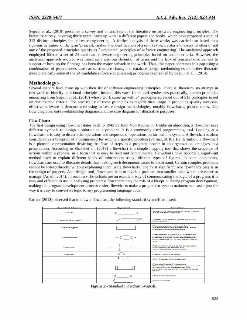
Parmar (2018) observed that to draw a flowchart, the following standard symbols are used:
Figure 1:- Standard Flowchart Symbols.
ISSN: 2320-5407 Int. J. Adv. Res. 7(12), 923-934
926
Pseudocodes:
Writing pseudocodes before the executable source codes eases the software development process, and helps to fix
certain kinds of errors before any source code is written and produces easily maintainable documentation. Studies
show that pseudocodes are superior to visual approaches for routine coding in most programming environments,
Pseudocodes in the context of Doersing (2015) consists of precise, natural-language descriptions of specific actions.
From the perspective of algorithms, pseudocodes are understood as a way of writing down programs at a relatively
low level without adhering to the specific rules of any programming language. According to Oda et al., (2015)
pseudocodes are important sources of information for developing and analysing various applications. Pseudocodes
are used by academicians, researchers, developers, scientists, innovators from various technology domains.
Pseudocodes are an effective method, containing a finite set of instructions that produces the desired output within
finite time and space complexity. In real programming environments, pseudocodes corresponding to source codes,
rarely exists, because pseudocodes are not necessary once a programmer has a good grasp of the programming
language and project (Oda et al., 2015). For this reason, good pseudocodes avoid code-like statements: it tries to stay
at a higher level than source code to increase the efficiency during the design phase and to avoid getting restricted
by specific limitations or features of the target programming language. This allows the programmer to capture the
intent of an action inside a routine. Pseudocodes should describe what a design is doing, not how exactly it is going
to be implemented (Doersing, 2015). However, the level of the pseudocodes should be low enough to enable the
programmer to refine it into source code very quickly (almost automatically). Given below is an example of
pseudocode:
Keep track of the current number of resources in useIf another resource is availableAllocate a dialogue box
structureIf a dialogue box structure could be allocatedNote that one more resource is in useInitialize the
resourceStore the resource number at the location provided by the callerEndifReturn true if a new resource was
created; else return false
Data Flow Diagrams:
Data Flow diagrams (DFDs) were developed in the 1970s as a method of modelling data flow when developing
information systems, often used in the preliminary design stages to provide an overview of the system. Today there
are several advanced modelling tools including UML which was developed by Grady Booch, Ivar Jacobson and Jim
Rumbaugh at Rational Software in the 1990s and other tools that not only describe the data flow but also specify the
processing steps involved. These tools (in some cases) facilitate code development as viewed by Coleman (2013).
Ibrahim and Yen (2011) stated that DFDs are used because they are an approach for specifying, constructing and
visualizing the model of a system graphically and are in practical use on a very wide basis. They, however, lack
formal and precise specification that would have enabled them to be used to check the correctness and consistency
among diagrams. Aleryani (2016) asserts that the most important diagram used when a structured approach is used
for design is the Data Flow Diagram. Other diagrams like Structure chart, State machine, ER Diagrams are less
useful. DFD‘s have certain advantages over all the others. The hierarchal structure of DFD provides different
abstraction level which is very useful in system designing. As a result, Aleryani (2016) concluded that DFDs are a
powerful tool used through the system analysis and design process, and can be included in the object-oriented
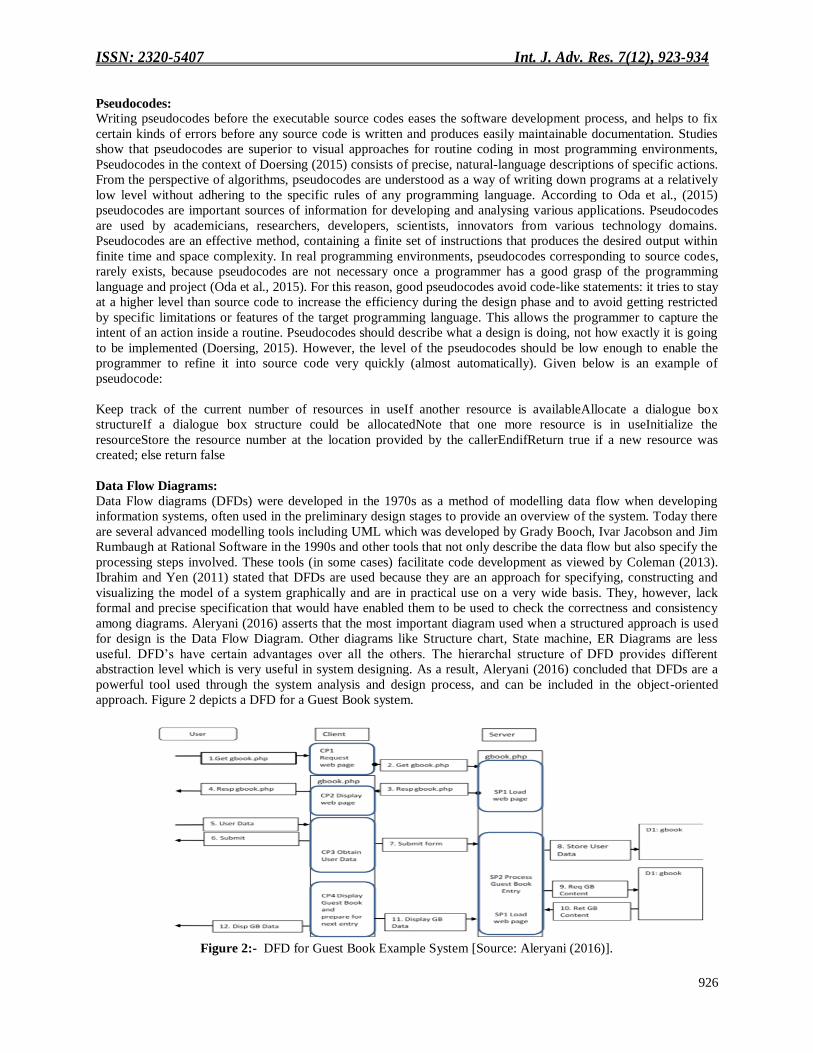
approach. Figure 2 depicts a DFD for a Guest Book system.
Figure 2:- DFD for Guest Book Example System [Source: Aleryani (2016)].
ISSN: 2320-5407 Int. J. Adv. Res. 7(12), 923-934
927
ER-diagrams:
An Entity-Relationship (ER) data model is a high-level conceptual model that describes information as entities,
attributes, and relationships. Entity-relationship models are used for database designs. ER models have played a
central role in systems specification, analysis and development. Above all, ER models are used to control and
monitor the system's databases. In ER modelling, a system's data is modelled as a set of entities, which is composed
of a set of attributes, with their relationships. Btoush and Hammad (2015) stressed that entities, attributes, and
relationships are the basic elements of ER models. An entity is an object that exists in the real world and it is
distinguishable from other objects. An entity type is a collection of similar entities with its attributes. Entity type‘s
attributes show detail structures of entities data and can be derived from adjectives and adverbs. Therefore, nouns in
the system's requirements can be identified as entities. A relationship is an association among two or more entities.
According to Gaikwad et al., (2017), Entity Relationship Diagram (ERD) is the first step in database design and
hence it is an important step for the database designers, users, analyst, researchers and managers in software
engineering. The Entity-Relationship Diagram (ERD) shows that the real world consists of a collection of entities,
the relationships between them, and the attributes that describe them. An entity is an object about which data is
stored. A relationship defines connections allowed between instances of entities. An attribute is a characteristic
common to all or most instances of a particular entity. Since the ER approach is easy to understand, a designer can
focus on conceptual modelling of an organization, making decisions of what to use from entity sets, relationship sets
and constraints. The ER-Diagram tool provides a mechanism for quickly and easily modelling data structures
required by a software system.
Use cases:
Use cases are used for documenting system requirements in terms of a system‘s behaviour. Use cases may also be
used for communication between various participants in a software project, namely system developers, its future
users as well as owners. Klimek and Szwed (2010) believe that use cases are relatively easy-to-understand, even for
people not familiar with information technology jargon. Use cases enable understanding of the system though they
do not align so much with the implementation details. Use cases can also describe the system requirements and,
therefore, formal verification of these requirements at the initial phase of the system modelling reduces production
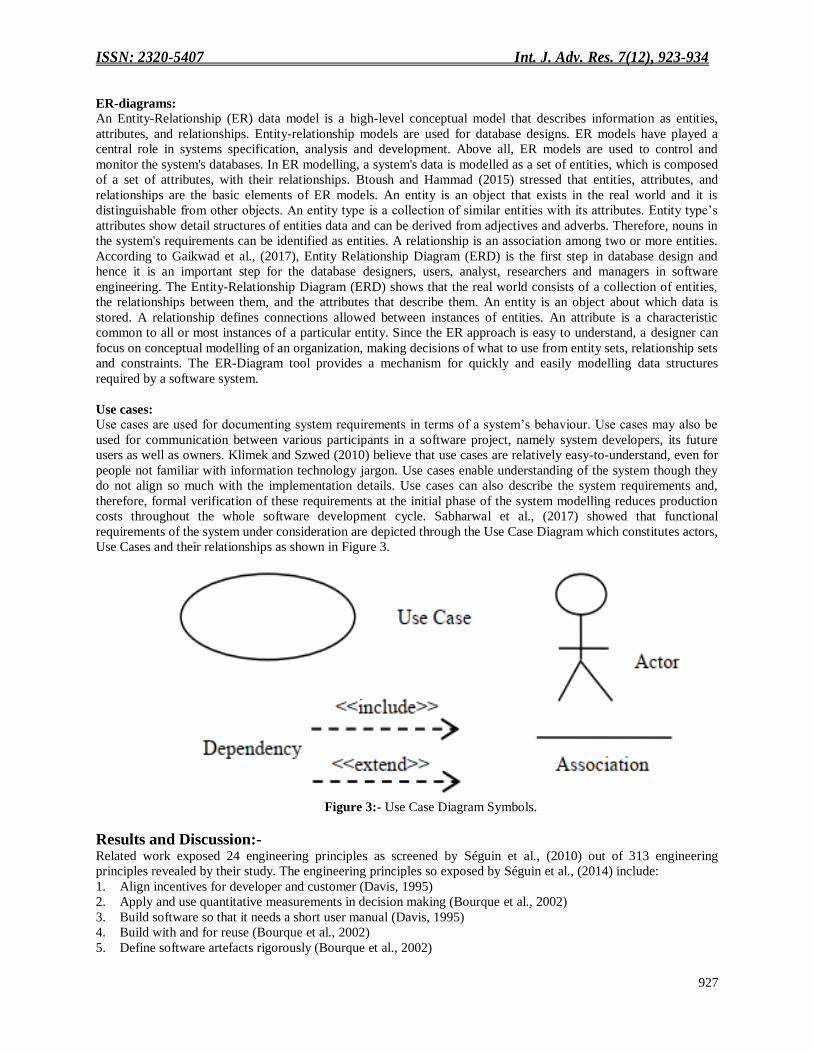
costs throughout the whole software development cycle. Sabharwal et al., (2017) showed that functional
requirements of the system under consideration are depicted through the Use Case Diagram which constitutes actors,
Use Cases and their relationships as shown in Figure 3.
Figure 3:- Use Case Diagram Symbols.
Results and Discussion:- Related work exposed 24 engineering principles as screened by Séguin et al., (2010) out of 313 engineering
principles revealed by their study. The engineering principles so exposed by Séguin et al., (2014) include:
1. Align incentives for developer and customer (Davis, 1995)
2. Apply and use quantitative measurements in decision making (Bourque et al., 2002)
3. Build software so that it needs a short user manual (Davis, 1995)
4. Build with and for reuse (Bourque et al., 2002)
5. Define software artefacts rigorously (Bourque et al., 2002)
ISSN: 2320-5407 Int. J. Adv. Res. 7(12), 923-934
928
6. Don‘t overstrain your hardware (Davis, 1995)
7. Don‘t try to retrofit quality (Davis, 1995)
8. Establish a software process that provides flexibility (Bourque et al., 2002)
9. Grow systems incrementally (Davis, 1995)
10. Implement a disciplined approach and improve it continuously (Bourque et al., 2002)
11. Invest in understanding the problem (Bourque et al., 2002)
12. Involve the customer (Royce, 1970)
13. Quality is the top priority; long-term productivity is a natural consequence of high quality (Wiegers, 1996)
14. Rotate (high performing) people through product assurance (Davis, 1995)
15. Since change is inherent to software, plan for it and manage it (Bourque et al., 2002)
16. Strive to have a peer, not a customer, find a defect (Wiegers, 1996)
17. Tailor cost estimation methods (Davis, 1995)
18. To improve design, study previous solutions to similar problems (Bourque et al., 2002)
19. Use better and fewer people (Boehm, 1983)
20. Use documentation standards (Davis, 1995)
21. Write programs for people first (Davis, 1995)
22. Know software engineering techniques before using development tools (Davis, 1995)
23. Select tests based on the likelihood that they will find faults (Davis, 1995)
24. Choose a programming language to ensure maintainability (Davis, 1995)
The twenty-four principles screened out of the crowd are summarized according to authors as follows:
S/N Author No of principles
1 Winston W. Royce (1970) 1
2 Barry W. Boehm (1983) 1
3 Alan Davis (1995) 12
4 Karl Wiegers (1996) 2
5 Bourque et al., (2002) 8
Total 24
Six (6) out of the 24 engineering principles are subsequently examined critically using design methodologies earlier
discussed. The practicality of each of the engineering principles selected is illustrated using typical software
development scenarios.
Strive to have a peer, not a customer find a defect
Project deliverables undergo requirements specifications, design modeling, coding, test plans, system
documentation, and production of user manuals. Despite these activities, errors still occur and it is a common
experience to hear of customers complaining that bugs in programs wasted their time, gave them wrong results, or
otherwise aggravated (provoked) them. It is therefore important that products are formally inspected by peers to
identify faults (defects) before they cause failures most times discovered by the customers. A defect in software
results from some type of mistakes. Usually, these mistakes are as a result of human error but sometimes they are
caused by systemic errors in the development process. Fortunately, not every mistake leads to a defect, but almost
all defects are traced back to some type of mistakes as can be seen in Table 1.
Table 1:- Typical Mistakes and Resulting Software Defects.
S/N Mistake Software Defect
1 Communication difficulties between customers and
software developers
Desired software functionality is missing
2 Developer overlooks a logic error in the code Clicking on the button does nothing
3 Developer forgets error checking in the file copy code A corrupted file is copied, and the software
crashes
4 Developer does not understand the customer scenario The software does not meet the customer‘s
needs
5 Developer only tests the software using a fast computer
and the performance seems fine
The software responds too slowly from the
perspective of a user with an older and slower
computer

ISSN: 2320-5407 Int. J. Adv. Res. 7(12), 923-934
929
6 Developer does not review the code for software
vulnerabilities
Hackers can exploit vulnerabilities and attack
the software
7 Developer does not recognize a fatal error condition, so
no return code is sent
Software does not return a code indicating a
fatal error condition
There are several testing techniques that can be deployed during peer review to enable peers rather than customers
detect errors in codes. The use of an output statement to echo the values of variables at critical sections of a program
is one such technique that has proved very useful during peer review. Data output this way convey technical
information that constitutes a nuisance to customers but can be used by peers to ascertain the correctness of
programs. The bubble sort algorithm is used to illustrate this concept. Assume a list is an array of n elements. Let it
be further assumed that a swap function swaps the values of the given array elements when two elements are in the
wrong order. Then the following pseudocodes apply:
Begin BubleSort(list)For all elements of list If list[i] >list[i+1]Swap(list[i], list[i+1])end ifend forreturn list end
BubleSort
The behaviour of this algorithm is such that comparison takes place even when the pair of elements are in their right
order. This unnecessarily increases the time complexity of the algorithm to O (n2) in the best-case scenario. In the
case of sorting a large database, the resulting query time may be intolerable by customers. To trap this phenomenon
in the pseudocode, codes can be inserted by a peer review team to establish the instances where swapping will be
unnecessary such that comparison is also avoided. Based on physical observations, the problem can be eased by the
use of a flag variable that enables a peer to see if any swap operation has occurred or not. If no swap has occurred in
an iteration, then the array requires no more processing to be sorted and the codes break out of the loop. Based on
this peer review process, the pseudocode of the Bubble Sort algorithm with swap operation can then be re-written as
follows:
procedure BubleSort(list:: array of items )
loopn == list..count;
for i == 0 to loop--1 do:
swap == false
for j == 0 to loop--1 do:
/* compare the adjacent elements */
if list[i] > list[i+1] then
/* swap them */
swap( list[j], list[j+1] )
swap == true
end if
end for
/* if no number was swapped that means array is sorted now, break the loop.*/
if(not swapped) then echo ―SWAP OPERATION NOT APPLICABLE INTHIS ITERATION‖
end if
end for
end procedure return list
The phenomenon being trapped by peer review may not necessarily be an error but it hurts the customer in terms of
turn around time.
Grow systems incrementally:
This engineering principle suggests that a complex task should be broken down into smaller and less complex tasks
that can be achieved with a small-size team. The objective of this principle is to identify parts which can be
developed from specification to executable codes independently. For software development projects, incremental
development means dividing the requirements into suitable parts during the specification allowing for independent
development of the different increments unlike the monolithic codes that are written without any form of
modularistion. The design and coding of one increment is followed by testing of each increment, making it possible
for code developers to start implementing the next increment while the peers validate, verify or certify the first
developed increment. The incremental approach implements modularity as well as allows for a good deal of
ISSN: 2320-5407 Int. J. Adv. Res. 7(12), 923-934
930
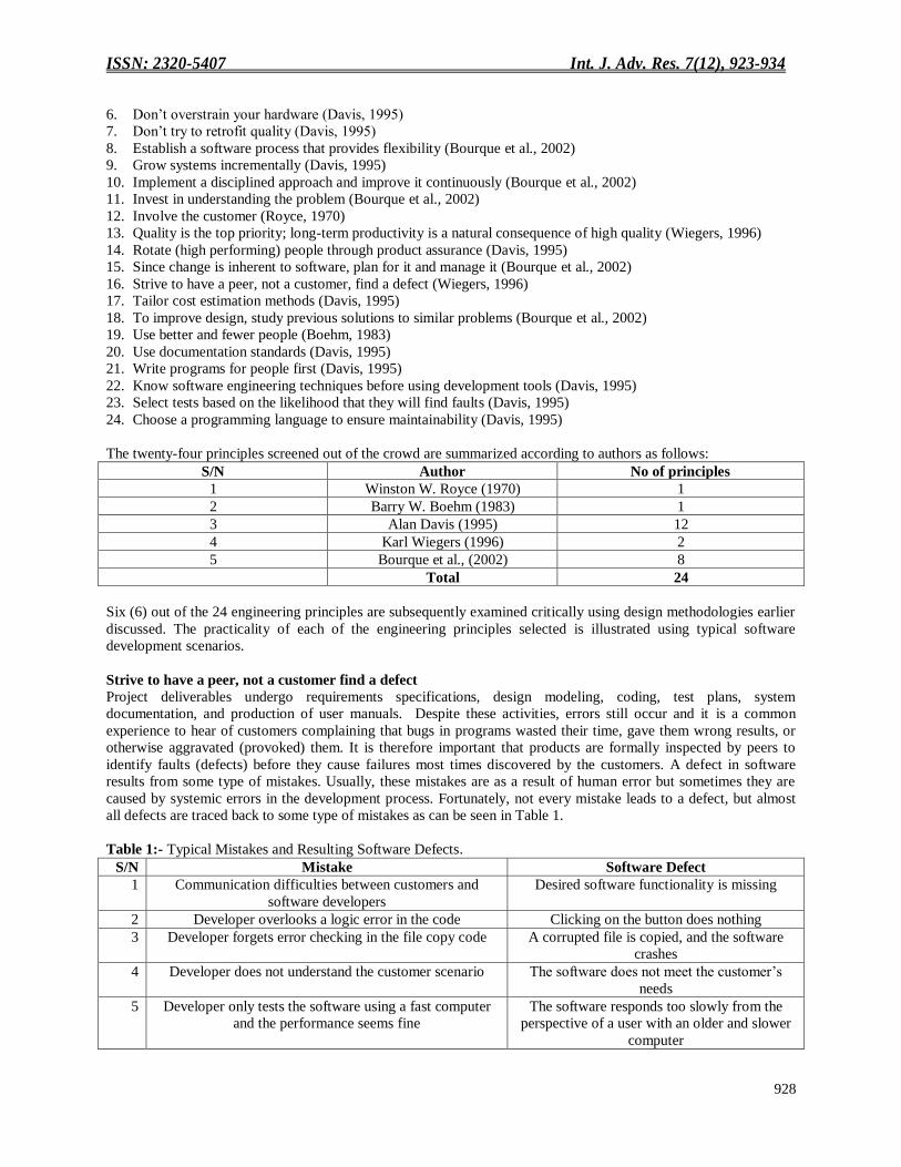
parallelism between development and testing. The benefit from this parallelism is not only the possibility to work in
parallel, but also that the testers start testing the software to be delivered at an early stage. In Figure 4a and b, each
design illustrates in a practical way how a product can be handled incrementally during its development process.
(a) (b)
Figure 4:- Implementation of Incremental Development of a Product.
Growing systems incrementally has been demonstrated using the incremental software development lifecycle model.
The general engineering principle of breaking down complex tasks into smaller tasks which is the basis of the
incremental model also form the basis of the other software development models, namely the waterfall model, spiral
model to mention a few (Al-Badareen et al., 2011)
Define software artefacts rigorously:
An artefact, in software development, is work that has been documented and stored in a repository so it can be
retrieved upon demand. Artefact is one of many kinds of tangible by-products of the software development process.
Artefacts such as use cases, class diagrams, and other Unified Modeling Language (UML) models, requirements and
design documents help describe the function, architecture, and design of software. Other artefacts are concerned
with the process of development itself—such as project plans, business cases, and risk assessments. The term
artefact in connection with software development is largely associated with specific development methods or
processes for example, the Unified Process. Following is a concrete example depicting a basic scenario to practically
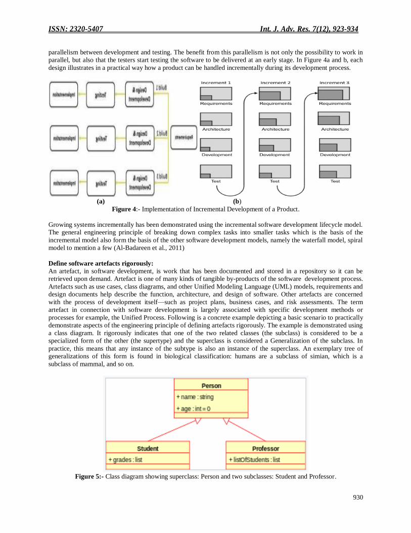
demonstrate aspects of the engineering principle of defining artefacts rigorously. The example is demonstrated using
a class diagram. It rigorously indicates that one of the two related classes (the subclass) is considered to be a
specialized form of the other (the supertype) and the superclass is considered a Generalization of the subclass. In
practice, this means that any instance of the subtype is also an instance of the superclass. An exemplary tree of
generalizations of this form is found in biological classification: humans are a subclass of simian, which is a
subclass of mammal, and so on.
Figure 5:- Class diagram showing superclass: Person and two subclasses: Student and Professor.
ISSN: 2320-5407 Int. J. Adv. Res. 7(12), 923-934
931
To improve design, study previous solutions to similar problems:
Often, the purpose of designing a new system is to replace an existing system. When this is the case, a lot of benefits
are derivable from analyzing the existing system because the existing system represents a previous solution to the
same problem. The analysis of previous solutions to the same or similar problem gives a better idea of what
problems exist in the existing system. The study of a similar product is very useful if what is being done is an
upgrade or improvement of an existing product or system. A proper analysis will ensure that the right parts of the
system are being upgraded to address the issues uncovered from the study or analysis. This principle is practically
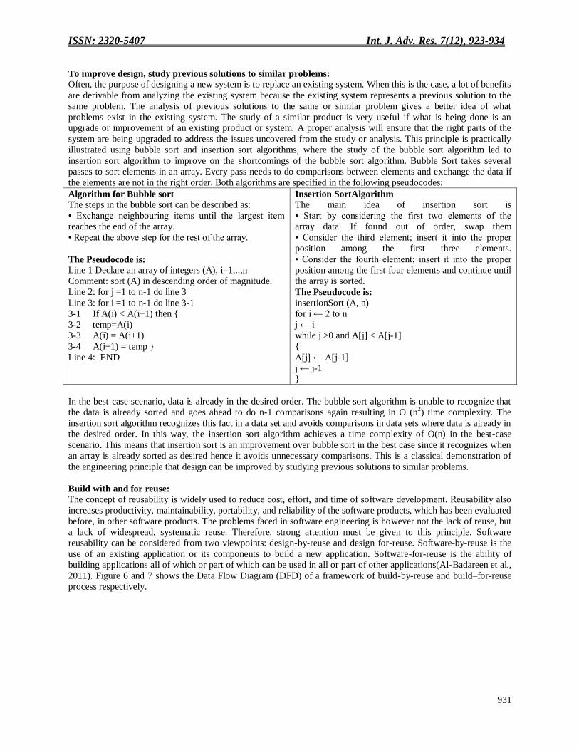
illustrated using bubble sort and insertion sort algorithms, where the study of the bubble sort algorithm led to
insertion sort algorithm to improve on the shortcomings of the bubble sort algorithm. Bubble Sort takes several
passes to sort elements in an array. Every pass needs to do comparisons between elements and exchange the data if
the elements are not in the right order. Both algorithms are specified in the following pseudocodes:
Algorithm for Bubble sort
The steps in the bubble sort can be described as:
• Exchange neighbouring items until the largest item
reaches the end of the array.
• Repeat the above step for the rest of the array.
The Pseudocode is: Line 1 Declare an array of integers (A), i=1,..,n
Comment: sort (A) in descending order of magnitude.
Line 2: for j =1 to n-1 do line 3
Line 3: for i =1 to n-1 do line 3-1
3-1 If A(i) < A(i+1) then {
3-2 temp=A(i)
3-3 A(i) = A(i+1)
3-4 A(i+1) = temp }
Line 4: END
Insertion SortAlgorithm
The main idea of insertion sort is
• Start by considering the first two elements of the
array data. If found out of order, swap them
• Consider the third element; insert it into the proper
position among the first three elements.
• Consider the fourth element; insert it into the proper
position among the first four elements and continue until
the array is sorted.
The Pseudocode is:
insertionSort (A, n)
for i ← 2 to n
j ← i
while j >0 and A[j] < A[j-1]
{
A[j] ← A[j-1]
j ← j-1
}
In the best-case scenario, data is already in the desired order. The bubble sort algorithm is unable to recognize that
the data is already sorted and goes ahead to do n-1 comparisons again resulting in O (n2) time complexity. The
insertion sort algorithm recognizes this fact in a data set and avoids comparisons in data sets where data is already in
the desired order. In this way, the insertion sort algorithm achieves a time complexity of O(n) in the best-case
scenario. This means that insertion sort is an improvement over bubble sort in the best case since it recognizes when
an array is already sorted as desired hence it avoids unnecessary comparisons. This is a classical demonstration of
the engineering principle that design can be improved by studying previous solutions to similar problems.
Build with and for reuse:
The concept of reusability is widely used to reduce cost, effort, and time of software development. Reusability also
increases productivity, maintainability, portability, and reliability of the software products, which has been evaluated
before, in other software products. The problems faced in software engineering is however not the lack of reuse, but
a lack of widespread, systematic reuse. Therefore, strong attention must be given to this principle. Software
reusability can be considered from two viewpoints: design-by-reuse and design for-reuse. Software-by-reuse is the
use of an existing application or its components to build a new application. Software-for-reuse is the ability of
building applications all of which or part of which can be used in all or part of other applications(Al-Badareen et al.,
2011). Figure 6 and 7 shows the Data Flow Diagram (DFD) of a framework of build-by-reuse and build–for-reuse
process respectively.

ISSN: 2320-5407 Int. J. Adv. Res. 7(12), 923-934
932
Figure 6:- Build by Reuse [Source: Al-Badareen et al., (2011)].
Figure 7:- Build for Reuse [Source: Al-Badareen et al.,( 2011)].
Use better and fewer people:
This engineering principle of using better and fewer people is anchored on an effective staff performance appraisal
that identifies the performers from among the staff who are tricksters. This principle has the advantage of reducing
the growing army of hardworking and dedicated staff in organizations who are disgruntled due to unfairness in the
current performance appraisal system that accommodates tricksters who do virtually nothing to contribute to
productivity but are adept in influencing remunerations and promotions to their advantage (Long et al., 2013).
Automated staff performance appraisal practically helps in combating this phenomenon by identifying staff with the
following tendencies: Unauthorized absence from work and truancy on flimsy excuses; Engagement in extraneous
activities completely unrelated to their job descriptions while at work; Unauthorized leave and proceeding on leave
ISSN: 2320-5407 Int. J. Adv. Res. 7(12), 923-934
933
without a substitute relief staff; Lateness to and laziness at work; Insubordination, making the inherent control
mechanisms in the hierarchical organizational structure of the organization ineffective among others. An effective
appraisal system exposes weak staff while identifying staff who are good at their job. The weak ones whose
productivity is questionable can be relieved of their appointments. In this way, the workforce is reduced to the barest
minimum while not sacrificing effectiveness. This helps reduce the workforce to the few staff who are good and
self-motivated to put their best into the job thus realizing the engineering principle of using better and fewer people.
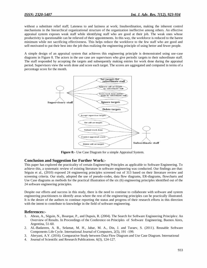
A simple design of an appraisal system that achieves this engineering principle is demonstrated using use-case
diagrams in Figure 8. The actors in the use case are supervisors who give periodic targets to their subordinate staff.
The staff responded by accepting the targets and subsequently making entries for work done during the appraisal
period. Supervisors view the work done and score each target. The scores are aggregated and computed in terms of a
percentage score for the month.
Figure 8:- Use Case Diagram for a simple Appraisal System.
Conclusion and Suggestion for Further Work:- This paper has explored the practicality of certain Engineering Principles as applicable to Software Engineering. To
achieve this, a systematic review of existing literature in software engineering was conducted. Our findings are that:
Séguin et al., (2010) exposed 24 engineering principles screened out of 313 based on their literature review and
screening criteria. Our study, adopted the use of pseudo-codes, data flow diagrams, ER-diagrams, flowcharts and
Use Case diagrams as methods for the practical illustration of the six (6) engineering principles identified out of the
24 software engineering principles.
Despite our efforts and success in this study, there is the need to continue to collaborate with software and system
engineering practitioners to identify areas where the rest of the engineering principles can be practically illustrated.
It is the desire of the authors to continue reporting the status and progress of their research efforts in this direction
with the intent to contribute to knowledge in the field of software engineering.
References:- 1. Abran, A., Séguin, N., Bourque, P., and Dupuis, R. (2004). The Search for Software Engineering Principles: An
Overview of Results. In Proceedings of the Conference on Principles of Software Engineering, Buenos Aires,
Argentina, 51-60.
2. AL-Badareen, A. B., Selamat, M. H., Jabar, M. A., Din, J. and Turaev, S. (2011). Reusable Software
Components Life Cycle. International Journal of Computers, 2(5), 191 -199.
3. Aleryani, A.Y. (2016). Comparative Study between Data Flow Diagram and Use Case Diagram. International
4. Journal of Scientific and Research Publications. 6(3), 124-127.
ISSN: 2320-5407 Int. J. Adv. Res. 7(12), 923-934
934
5. Arrish, S., Afif, F.N., Maidorawa, A., and Salim, N. (2014). Shape-Based Plagiarism Detection for Flowchart
Figures in Texts. International Journal of Computer Science and Information Technology, 6(1), 113-124.
6. Brhel, M., Meth, H., Maedche, A., and Werder, K. (2015). Exploring Principles of User-Centered Agile
Software
7. Development: A Literature Review. Information and Software Technology, Volume 61, 163 -181.
8. Btoush, E. and Hammad, M. (2015). Generating ER Diagrams from Requirement Specifications Based On
Natural Language Processing. International Journal of Database Theory and Application, 8(2), 61-70.
9. Coleman, J. P. H. (2013). Data Flow Sequences: A Revision of Data Flow Diagrams for Modelling
Applications using XML. International Journal of Advanced Computer Science and Applications, 4(5), 28 –
31
10. Doersing, N. (2015). Pseudocode, the Pseudocode Programming Process, and Alternatives to the
PPP.Britannica Knowledge Systems. 1 – 10.
11. Ebad, S. (2018). An Exploratory Study of ICT Projects Failure in Emerging Markets. Journal of Global
Information Technology Management, 21(2), 139 -160.
12. Fitzgerald, B., and Stol, K.J. (2015). Continuous Software Engineering: A Roadmap and Agenda. The Journal
of Systems and Software, 123, 176 - 189.
13. Gaikwad, A. S., Kadri, F. A., Khandagle, S. S. and Tava, N. I. (2017). Review on Automation Tool for ERD
Normalization. International Research Journal of Engineering and Technology, 4(2), 1323 – 1325.
14. Ibrahim, R. and Yen, S.Y. (2011). A Formal Model for Data Flow Diagram Rules. ARPN Journal of Systems
and Software, 1(2), 60-69.
15. Khirari, J., Barthate, N., Wani, Y., and Zine, A. (2017). Algorithm Procedure and Pseudo Code Mining.
International Research Journal of Engineering and Technology, 4(3), 1921-1924.
16. Klimek, R., and Szwed, P. (2010). Formal Analysis of Use Case Diagrams. Computer Science, Vol. 11, 115 -
131.
17. Krishna, S.T., Sreekanth, S., Bhaskar, B., and Kumar, N.P. (2012). Explore Ten Different Types of Software
Engineering Principles. International Journal of Network Security and Its Applications, 4(5), 191 - 201
18. Long, C. S., Kowang, T. O., Ismail, W. K., Rasid, S. Z. A. (2013). A Review on Performance Appraisal
System: An Ineffective and Destructive Practice? Middle East Journal of Scientific Research, 14(7), 887-891.
19. Oda, Y., Fudaba, H., Neubig, G., Hata, H., Sakti, S., Toda, T., and Nakamura, S. (2015). Learning to Generate
Pseudo-code from Source Code using Statistical Machine Translation. In Proceedings of 30th IEEE/ACM
International Conference on Automated Software Engineering, Lincoln, NE, USA, 574 - 484Parmar, Y. S.
(2018). Algorithm and Flowchart Manual for Students. Computer and Instrumentation CentreUniversity of
Horticulture and Forestry, Nauni Solan, India, 1 - 25
20. Pícha, P., and Brada, P. (2014). Empirical Research in Software Engineering: A Literature Review. In
Proceedings of 9th International Conference on Software Engineering Advances, Nice, France, 209 - 214
21. Sabharwal, S., Kaur, P., and Sibal, R. (2017). Empirical and Theoretical Validation of a Use Case Diagram
Complexity Metric. International Journal of Information Technology and Computer Science, 11(9), 35-47.
22. Séguin, N., Abran, A., and Dupuis, E.R. (2010). Software Engineering Principles: A Survey and an Analysis. In
Proceeding of the 3rd
Canadian Conference on Computer Science and Software Engineering, Montreal, Quebec,
Canada, 59 – 65.
23. Shakil, M., Ullah, R., and Lutfi, M. (2013). Process Flow Chart and Factor Analysis in Production of a Jute
Mills. Journal of Industrial and Intelligent Information, 1(4), 247-254
24. Valerdi, R., and Boehm, B. W. (2010). COSYSMO: A Systems Engineering Cost Model. Genie Logiciel,
Meudon, France, 2 – 6.
Top Related
Copyright © 2022 FDOKUMEN

