


Bahasa
Halaman
Hukum

417
Investigating the effect of remodelling signal type onthe finite element based predictions of bone remodellingaround the thrust plate prosthesis: a patient-specificcomparison
M J Schmitz1*, S E Clift1, W R Taylor2, D Hertig2, M D Warner1, H L Ploeg2† and H Bereiter31Department of Mechanical Engineering, University of Bath, Bath, UK2Centerpulse Orthopedics Limited, Winterthur, Switzerland3Kantonsspital, Chur, Switzerland
Abstract: The resorption of bone in the human femur following total hip arthroplasty is recognizedto be related to the loading in the bone surrounding the prosthesis. However, the precise nature ofthe mechanical signal that influences the biological remodelling activity of the bone is not completelyunderstood. In this study, a validated finite element modelling methodology was combined with anumerical algorithm to simulate the biological changes over time. This was used to produce boneremodelling predictions for an implanted thrust plate prosthesis (Centerpulse Orthopedics Limited)in a patient specific bone model. The analysis was then repeated using different mechanical signalsto drive the remodelling algorithm. The results of these simulations were then compared to thepatient-specific clinical data, to distinguish which of the candidate signals produced predictions con-sistent with the clinical evidence. Good agreement was found for a range of strain energy basedsignals and also deviatoric remodelling signals. The results, however, did not support the use ofcompressive dilatational strain as a candidate remodelling signal.
Keywords: hip, bone, remodelling, finite element, signal
1 INTRODUCTION Bone loss can present long-term implant stability prob-lems since the bone can resorb away from the implantor may cause unforeseen loading on the implant, leadingTwo modes of long-term aseptic loosening have been
widely associated with hip replacement. The first is to implant failure [6 ]. This can necessitate revisionsurgery, which is known to be less reliable and satisfac-osteolysis, an adverse bone tissue response linked with
the presence of wear debris from polyethylene acetabular tory than the primary procedure [7]. Thus, a greaterunderstanding of the implant/bone interaction is re-cup prostheses (e.g. reference [1]). This is a very widely
acknowledged problem and a number of different quired to facilitate the long-term success of total hiparthroplasty (THA).approaches have been proposed to improve performance
by limiting the generation of wear debris. These include The mechanical signal to which bone responds biologi-cally, by either a decrease in density from too little stimu-the use of metal-on-metal (e.g. reference [2]) and
ceramic-on-ceramic (e.g. reference [3]) bearing surface lation (atrophy) or an increase in bone density from anincrease in stimulation (hypertrophy), has been postu-combinations, and also attempt to improve the wear
resistance of the polyethylene itself (e.g. reference [4]). lated to be related to strain [5]. However, the precisenature of this signal has yet to be characterized. PreviousThe second mode of loosening, and the focus of this
study, is the resorption of bone related to the change in bone remodelling studies have used arbitrary, but physi-cally defendable, strain-related measures (e.g. referenceloading conditions following prosthesis implantation [5].[8]).
The thrust plate prosthesis (TPP) was developed inThe MS was received on 23 September 2003 and was accepted afterrevision for publication on 16 July 2004. response to the high failure rates of intramedullary* Corresponding author: Department of Mechanical Engineering,
designs observed in the 1970s [9]. Fundamental toUniversity of Bath, Bath BA2 7AY, UK. email: [email protected]†Now at University of Wisconsin–Madison, USA. its design was the requirement to transmit load in as
H06803 © IMechE 2004 Proc. Instn Mech. Engrs Vol. 218 Part H: J. Engineering in Medicine
418 M J SCHMITZ, S E CLIFT, W R TAYLOR, D HERTIG, M D WARNER, H L PLOEG AND H BEREITER
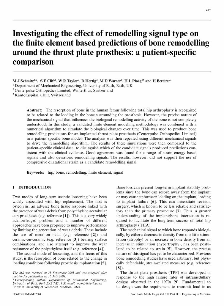
physiological a manner as possible. An additional benefit Detailed muscle loading was then applied to the FE model(Fig. 1) based on the 45 per cent gait position [16 ].of this type of implant is the conservative nature of the
associated surgical procedure in that it preserves proxi- Bone remodelling was simulated by calculating densitychanges using the HKS/ABAQUS finite element packagemal bone stock. Thus any failed implants can be revised
with a conventional stemmed implant without many together with purpose-written subroutines [14]. A two-stage analysis procedure was employed. In the first stage,of the difficulties commonly associated with revision
surgery. Published short- and mid-term clinical results the FE model of the pre-operative femur was analysedin order to establish the reference state, assumed to befor a study of 19 implanted TPPs showed just less than
a third of the implanted devices developed radiolucencies the physiological normal condition. In the second stage,the model of the femur implanted with the TPP wasat the resected neck of the femur [10].
Continual advances in the understanding of the bone analysed. The difference between the original referencestate and the new implanted state was then used as theremodelling process and in the availability of cheap com-
puter power have enabled progressively more detailed driving force for the site-specific remodelling algorithm.The algorithm was applied iteratively over multiple stepsnumerical modelling of the implant and bone construct.
This, combined with theories developed to model the to simulate the time-dependent behaviour of the system.The interface between the implant and bone wasbehaviour of bone [5], has enabled simulations of bone
remodelling to be explored (e.g. reference [11]). This assumed to be rigidly fixed. Only the proximal femurwas allowed to remodel in order to reduce the processinglatter approach is useful as part of the pre-clinical devel-
opment of new implants. time (upper 150 mm of the FE model ). This was con-sidered appropriate, as negligible remodelling wouldAn earlier investigation indicated the potential of the
finite element (FE) based approach to predict clinically occur at the distal end of the femoral shaft due to themain load path being relatively unaltered by the presencerelevant patterns of bone remodelling around the TPP
[12] using an in vitro model. The approach was validated of the TPP. A geometrically linear analysis was utilizedas non-linear trials produced differences in only theexperimentally [13] but not clinically.
The study reported in this manuscript investigated a third significant figure. The time step and number ofincrements used for the remodelling process was chosennumber of mechanical signals and compared the predic-
tions from bone remodelling simulations with clinical to be six steps of 1.5 months. This was chosen so thatthe last increment of the analysis coincided with the lastdata to identify which of the candidate signals was most
consistent with the clinical response for a particular available X-ray, which was at 9 months post-operatively,and so that sufficient intermediate results were availablepatient implanted with a TPP.to distinguish any trends appearing while keeping theresults files and processing time to a manageable size.
Patterns of bone density were predicted using six2 METHODdifferent candidate strain-based remodelling signals(minimum principal strain, equivalent strain, maximumIn this study, the FE method has been used, together
with a purpose-written bone remodelling code [14], to shear strain, strain energy per unit mass, strain energyper unit volume and dilatational strain). The results ofexplore the effect of different remodelling signals on bone
remodelling patterns using a patient-specific model the FE investigation were then compared with thepatient specific clinical data.implanted with a TPP. The femoral bone geometry and
bone densities were determined based on computertomography (CT) scan data of the patient obtained prior
2.1 Algorithm detailsto surgery (patient details: date of birth 20.02.1928,male, 89 kg, clinical presentation: pain, reduced range of It has been postulated that bone remodelling occurs in
discrete units called basic multicellular units (BMUs) [17].motion, short walking distance). Semi-automatic edgedetection software was used to generate periosteal con- These BMUs are responsible for the resorption and
deposition of bone. They are made up of several osteo-tours to create the patient specific femoral geometry. TheMSC/PATRAN pre-processing package was then used clasts and several hundred osteoblasts in a tube-like struc-
ture that tunnels through bone. It is thought that BMUto create the meshes used for the study (48 695 ten-nodedtetrahedral elements in the femoral model ). Orthotropic activation only occurs on the osteonal surface [18].
Therefore, the number of activated BMUs in any givenmaterials property data were assigned using a custom-written routine, according to the density and position of volume was related to the surface area available. In recog-
nition of the effect that surface area has on the rate ofeach element, assuming a quadratic relationship betweenthe Young’s moduli and the bone apparent density [15]. remodelling, the remodelling rate was made a function
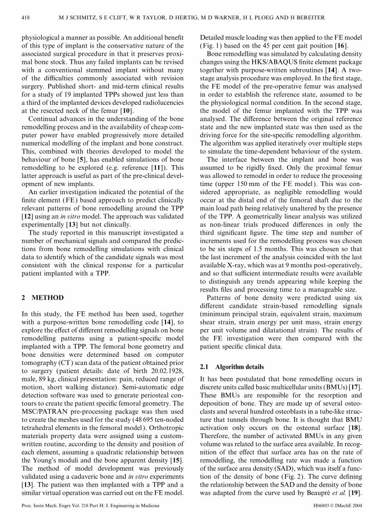
of the surface area density (SAD), which was itself a func-The method of model development was previouslyvalidated using a cadaveric bone and in vitro experiments tion of the density of bone (Fig. 2). The curve defining
the relationship between the SAD and the density of bone[13]. The patient was then implanted with a TPP and asimilar virtual operation was carried out on the FE model. was adapted from the curve used by Beaupre et al. [19].
H06803 © IMechE 2004Proc. Instn Mech. Engrs Vol. 218 Part H: J. Engineering in Medicine
419BONE REMODELLING AROUND THE THRUST PLATE PROSTHESIS
Fig. 1 Muscle loading applied to the FE model
Fig. 2 Surface area available for remodelling for any given bone density. (Adapted from Beaupre et al. [19])
The changes in bone density were made proportional to where the change in density took the following form:the SAD (i.e. an SAD of 2 mm2/mm3 would remodel
D=nwktwice as quickly as an SAD of 1 mm2/mm3).For the purposes of numerical modelling, the bone Where
was represented as a continuous medium with varyingdensity, a simplification of the actual complex trabecular D=change in density (which affects stiffness) (g/mm s)
n=SAD ratio (related to the number of activatedstructure with varying degrees of porosity. The boneremodelling was of the ‘adaptive elasticity’ type [5], BMUs) (mm−1)
H06803 © IMechE 2004 Proc. Instn Mech. Engrs Vol. 218 Part H: J. Engineering in Medicine
420 M J SCHMITZ, S E CLIFT, W R TAYLOR, D HERTIG, M D WARNER, H L PLOEG AND H BEREITER
w=remodelling velocity (represents the activity of the 4:1 to enable comparison with the patient under con-sideration.BMU ) (mm3/s)
k=maximum amount of bone remodelled per unit The most convenient measure of a physical re-modelling rate is the maximum resorption rate in thevolume (for an average SAD) (g/mm3)completely unloaded state. For this study, data from a
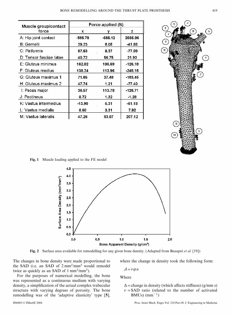
A trilinear remodelling curve was used to calculate thestudy of astronauts undergoing microgravity were used
change in density (Fig. 3). This incorporates a ‘dead[22]. bone mineral density (BMD) data from an astro-
zone’ (e.g. reference [5]) where the bone does notnaut’s proximal femur, both pre and post space flight,
undergo any net remodelling, such that a significantwere used to calculate the maximum rate of resorption.
change in the signal is required before there is any effectThe space flight under investigation had a duration of
on the remodelling velocity. For this study, it was20 days. The maximum decrease in density was found
assumed that the dead zone width was 35 per cent (i.e.to occur 28 days after launch. This was approximately
at least a 35 per cent change from the site-specific physio-the length of a resorption cycle and should represent
logical normal signal is required for remodelling toapproximately the maximum loss in the completely
occur), as realistic results had been achieved with thisunloaded state. The astronaut’s BMD data were used to
value in other studies [20]. The relative rates of resorp-generate the maximum resorption rate of 0.8 per cent
tion and deposition were determined from informationloss in BMD per week, which was used for this study.
regarding the BMU tunnelling process [21]. From thisThis figure compares reasonably well with the maximum
the complete BMU tunnelling process was assumed tolosses found in a longer, 17 week, bed rest study of 0.6
take 33 days, whereas the complete refilling process tookper cent loss in BMD per week [23]. The maximum rate
approximately 93 days. This gave a ratio of rates ofof deposition after the space flight was observed to be
resorption to deposition of approximately 3:1 for aapproximately three times lower than the maximum rate
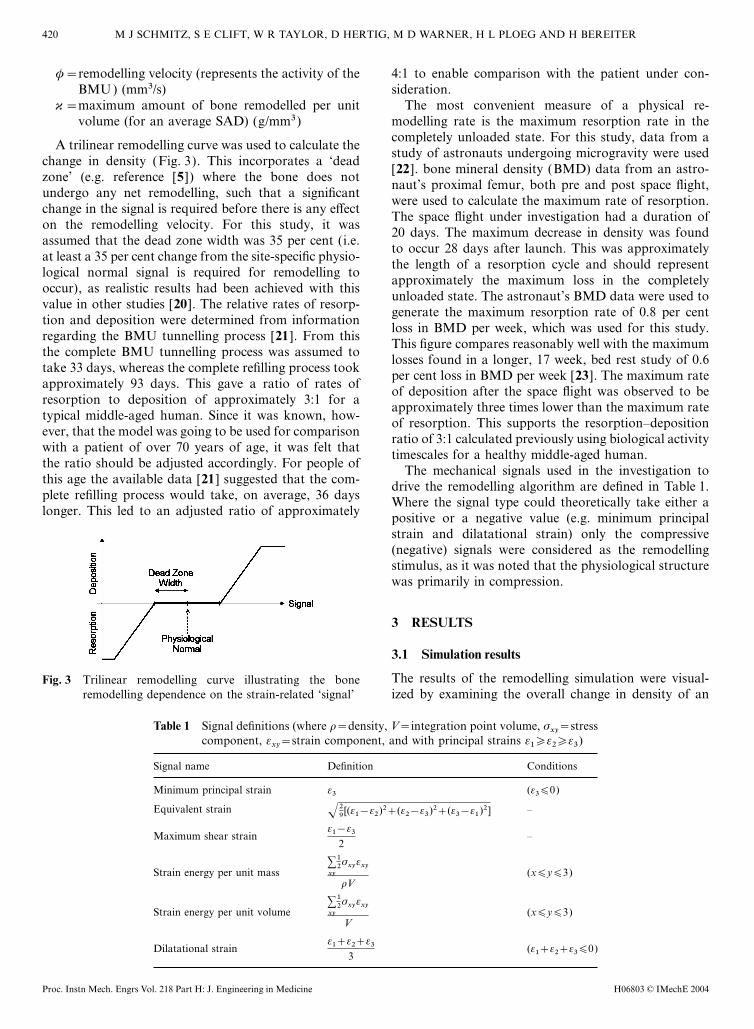
typical middle-aged human. Since it was known, how- of resorption. This supports the resorption–depositionever, that the model was going to be used for comparison ratio of 3:1 calculated previously using biological activitywith a patient of over 70 years of age, it was felt that timescales for a healthy middle-aged human.the ratio should be adjusted accordingly. For people of The mechanical signals used in the investigation tothis age the available data [21] suggested that the com- drive the remodelling algorithm are defined in Table 1.plete refilling process would take, on average, 36 days Where the signal type could theoretically take either alonger. This led to an adjusted ratio of approximately positive or a negative value (e.g. minimum principal
strain and dilatational strain) only the compressive(negative) signals were considered as the remodellingstimulus, as it was noted that the physiological structurewas primarily in compression.
3 RESULTS
3.1 Simulation results
The results of the remodelling simulation were visual-Fig. 3 Trilinear remodelling curve illustrating the boneremodelling dependence on the strain-related ‘signal’ ized by examining the overall change in density of an
Table 1 Signal definitions (where r=density, V=integration point volume, sxy=stress
component, exy=strain component, and with principal strains e1�e2�e3)
Signal name Definition Conditions
Minimum principal strain e3 (e3∏0)
Equivalent strain –√29[(e1−e2)2+(e2−e3)2+(e3−e1)2]
Maximum shear strain –e1−e3
2
Strain energy per unit mass (x∏y∏3)∑xy
12sxyexy
rV
Strain energy per unit volume (x∏y∏3)∑xy
12sxyexy
V
Dilatational strain (e1+e2+e3∏0)e1+e2+e3
3
H06803 © IMechE 2004Proc. Instn Mech. Engrs Vol. 218 Part H: J. Engineering in Medicine
421BONE REMODELLING AROUND THE THRUST PLATE PROSTHESIS
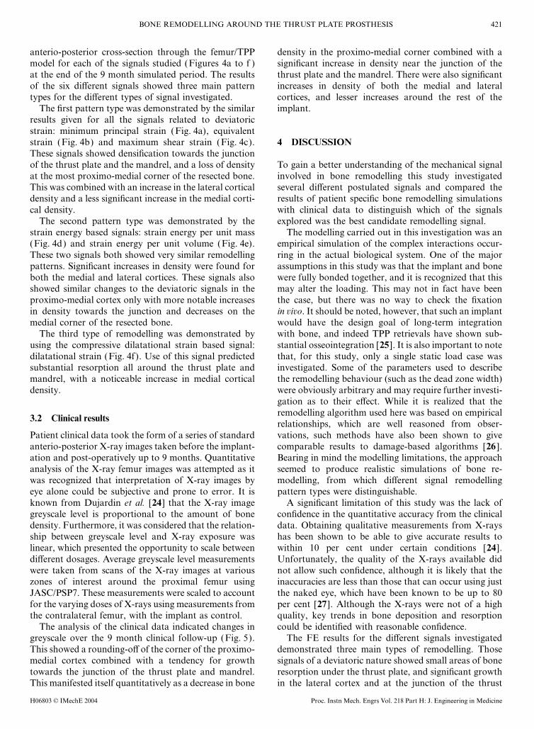
anterio-posterior cross-section through the femur/TPP density in the proximo-medial corner combined with asignificant increase in density near the junction of themodel for each of the signals studied (Figures 4a to f )
at the end of the 9 month simulated period. The results thrust plate and the mandrel. There were also significantincreases in density of both the medial and lateralof the six different signals showed three main pattern
types for the different types of signal investigated. cortices, and lesser increases around the rest of theimplant.The first pattern type was demonstrated by the similar
results given for all the signals related to deviatoricstrain: minimum principal strain (Fig. 4a), equivalentstrain (Fig. 4b) and maximum shear strain (Fig. 4c). 4 DISCUSSIONThese signals showed densification towards the junctionof the thrust plate and the mandrel, and a loss of density To gain a better understanding of the mechanical signal
involved in bone remodelling this study investigatedat the most proximo-medial corner of the resected bone.This was combined with an increase in the lateral cortical several different postulated signals and compared the
results of patient specific bone remodelling simulationsdensity and a less significant increase in the medial corti-cal density. with clinical data to distinguish which of the signals
explored was the best candidate remodelling signal.The second pattern type was demonstrated by thestrain energy based signals: strain energy per unit mass The modelling carried out in this investigation was an
empirical simulation of the complex interactions occur-(Fig. 4d) and strain energy per unit volume (Fig. 4e).These two signals both showed very similar remodelling ring in the actual biological system. One of the major
assumptions in this study was that the implant and bonepatterns. Significant increases in density were found forboth the medial and lateral cortices. These signals also were fully bonded together, and it is recognized that this
may alter the loading. This may not in fact have beenshowed similar changes to the deviatoric signals in theproximo-medial cortex only with more notable increases the case, but there was no way to check the fixation
in vivo. It should be noted, however, that such an implantin density towards the junction and decreases on themedial corner of the resected bone. would have the design goal of long-term integration
with bone, and indeed TPP retrievals have shown sub-The third type of remodelling was demonstrated byusing the compressive dilatational strain based signal: stantial osseointegration [25]. It is also important to note
that, for this study, only a single static load case wasdilatational strain (Fig. 4f). Use of this signal predictedsubstantial resorption all around the thrust plate and investigated. Some of the parameters used to describe
the remodelling behaviour (such as the dead zone width)mandrel, with a noticeable increase in medial corticaldensity. were obviously arbitrary and may require further investi-
gation as to their effect. While it is realized that theremodelling algorithm used here was based on empirical
3.2 Clinical resultsrelationships, which are well reasoned from obser-vations, such methods have also been shown to givePatient clinical data took the form of a series of standard
anterio-posterior X-ray images taken before the implant- comparable results to damage-based algorithms [26 ].Bearing in mind the modelling limitations, the approachation and post-operatively up to 9 months. Quantitative
analysis of the X-ray femur images was attempted as it seemed to produce realistic simulations of bone re-modelling, from which different signal remodellingwas recognized that interpretation of X-ray images by
eye alone could be subjective and prone to error. It is pattern types were distinguishable.A significant limitation of this study was the lack ofknown from Dujardin et al. [24] that the X-ray image
greyscale level is proportional to the amount of bone confidence in the quantitative accuracy from the clinicaldata. Obtaining qualitative measurements from X-raysdensity. Furthermore, it was considered that the relation-
ship between greyscale level and X-ray exposure was has been shown to be able to give accurate results towithin 10 per cent under certain conditions [24].linear, which presented the opportunity to scale between
different dosages. Average greyscale level measurements Unfortunately, the quality of the X-rays available didnot allow such confidence, although it is likely that thewere taken from scans of the X-ray images at various
zones of interest around the proximal femur using inaccuracies are less than those that can occur using justthe naked eye, which have been known to be up to 80JASC/PSP7. These measurements were scaled to account
for the varying doses of X-rays using measurements from per cent [27]. Although the X-rays were not of a highquality, key trends in bone deposition and resorptionthe contralateral femur, with the implant as control.
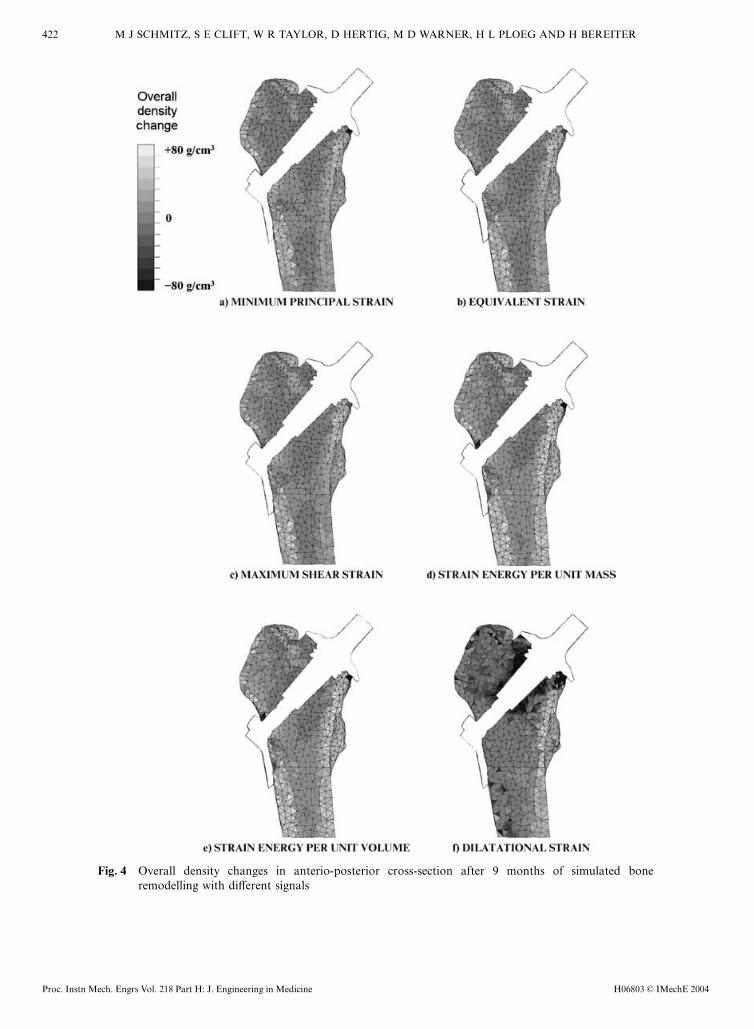
The analysis of the clinical data indicated changes in could be identified with reasonable confidence.The FE results for the different signals investigatedgreyscale over the 9 month clinical follow-up (Fig. 5).
This showed a rounding-off of the corner of the proximo- demonstrated three main types of remodelling. Thosesignals of a deviatoric nature showed small areas of bonemedial cortex combined with a tendency for growth
towards the junction of the thrust plate and mandrel. resorption under the thrust plate, and significant growthin the lateral cortex and at the junction of the thrustThis manifested itself quantitatively as a decrease in bone
H06803 © IMechE 2004 Proc. Instn Mech. Engrs Vol. 218 Part H: J. Engineering in Medicine
422 M J SCHMITZ, S E CLIFT, W R TAYLOR, D HERTIG, M D WARNER, H L PLOEG AND H BEREITER
Fig. 4 Overall density changes in anterio-posterior cross-section after 9 months of simulated boneremodelling with different signals
H06803 © IMechE 2004Proc. Instn Mech. Engrs Vol. 218 Part H: J. Engineering in Medicine
423BONE REMODELLING AROUND THE THRUST PLATE PROSTHESIS
range of strain energy and deviatoric signals. The resultsdid not, however, support the use of compressive dila-tational strain as a remodelling signal.
ACKNOWLEDGEMENTS
Useful discussions with Dr H. Jacob are gratefullyacknowledged. This study was funded by CenterpulseOrthopedics Limited.
REFERENCES
1 Hirakawa, K. et al., Mechanisms of failure in total hipreplacements: lessons learnt from retrieval studies. Clin.Orthop., 2004, 420, 10–17.
2 Dorr, L. et al. Total hip arthroplasty with the use of theMetasul metal-on-metal articulation. Four to seven yearresults. J. Bone Jt Surg. (Am.), 2000, 82-A, 789–798.
3 Bierbaum, B. et al. Ceramic-on-ceramic bearings in totalhip arthroplasty. Clin. Orthop., 2002, 405, 158–163.
4 Endo, M. et al. Comparison of wear, wear debris and func-Fig. 5 Changes in the X-ray greyscale level over a 9 month tional biological activity of moderately crosslinked and
period following prosthesis implantation non-crosslinked polyethylenes in hip prostheses. Proc. InstnMech. Engrs, Part H: J. Engineering in Medicine, 2002,216, 111–122.plate and mandrel. The strain energy signals showed
5 Cowin, S. Bone Mechanics, 1989 (CRC Press, Bocabehaviour similar in nature to the deviatoric signals withRaton, Florida).additional growth in the medial cortex. The dilatational
6 Huiskes, R. Failed innovation in total hip replacement.signal investigated showed significant resorption aroundDiagnosis and proposals for a cure. Acta. Orthop. Scand.,
the whole of the prosthesis. 1993, 64(6): 699–716.Comparison of clinical and FE results showed that 7 Total Hip Replacement, 1994 (National Institute of Health),
the magnitudes of density changes in the clinical data Consens Statement Online, 12(5), 1–31.(around 30 per cent) were significantly larger than those 8 Huiskes, R. et al. Adaptive bone-remodelling theory appliedseen in the FE results (around 3 per cent). A recent to prosthetic-design analysis. J. Biomechanics, 1987, 20,
1135–1150.clinical study into remodelling found changes in BMD9 Huggler, A. H. and Jacob, H. A. C. (Eds). The Thrust Plateof the order of 10 per cent over a 5 year period [28],
Prosthesis, 1997 (Springer-Verlag, Berlin, Germany).after typical cementless total hip arthroplasty. This10 Steens, W. et al. Clinical and functional outcome of theindicates that the orders of remodelling seen in the FE
thrust plate prosthesis: short- and medium-term results.modelling are more reasonable than the clinical analysis.Clin. Biomechanics, 2003, 18, 647–654.Comparing patterns of remodelling alone, strain
11 Huiskes, R., Weinans, H. and Reitbergen, B. van Theenergy signals seemed to yield the most realistic re- relationship between stress shielding and bone resorptionmodelling patterns compared with the clinical evidence around total hip stems and the effects of flexible materials.available. The other deviatoric signals also performed Clin. Orthop. Related Res., 1992, 274, 124–134.reasonably well in predicting the outcome, although the 12 Taylor, W., Ploeg, H., Hertig, D., Warner, M. and Clift, S.limitations of the clinical data prevented more definite Bone remodelling of a proximal femur with the thrust plate
prosthesis: an in vitro case. Computer Meth. Biomechanicsisolation of the best signal. The dilatational signaland Biomed. Engng, 2004, 7(3), 131–137.seemed to produce the least clinically comparable results
13 Taylor, W. R., Roland, E., Ploeg, H., Hertig, D., Klabunde,for this case. These findings are consistent with those ofR., Warner, M. D., Hobatho, M. C., Rakotomanana, L. andBrown et al. [29], where the strain energy density wasClift, S. E. Determination of orthotropic bone elastic con-one of the few parameters that correlated with re-stants using FEA and modal analysis. J. Biomechanics,modelling, along with the first principal stress and longi-2002, 35(6), 767–773.
tudinal shear stress. Dilatational stress was also found 14 Ploeg, H., Taylor, W., Warner, M., Hertig, D. and Clift, S.to correlate initially, but the correlation deteriorated Finite element analysis and bone remodelling after totalover the long term [29]. replacement. In The Evolution of Product Simulation, 2001,
In conclusion, the comparison of FE-based patient- Vol. 2, pp. 811–822 (National Agency for Finite Elementspecific bone remodelling predictions with patient- Methods and Standards, Glasgow, UK).
15 Rubin, P., Rakotomanana, R., Leyvraz, P., Zysset, P.,specific X-ray data has shown good agreement for a
H06803 © IMechE 2004 Proc. Instn Mech. Engrs Vol. 218 Part H: J. Engineering in Medicine
424 M J SCHMITZ, S E CLIFT, W R TAYLOR, D HERTIG, M D WARNER, H L PLOEG AND H BEREITER
Carnier, A. and Heegard, J. Frictional interface micromo- after 17 weeks of bed rest. J. Bone Miner. Res., 1990,5(8), 843–850.tions and anisotropic stress distribution in a femoral total
hip component. J. Biomechanics, 1993, 26, 725–739. 24 Dujardin, F., Bocquet, G., Ertaud, J. and Thomine, J.Quantitative assessment of cortical bone remodelling from16 Duda, G. N., Heller, M., Albinger, J., Schultz, O.,
Schneide, E. and Claes, C. Influence of muscle forces on routine radiographs of total hip arthroplasty. Med. EngngPhysics, 1995, 18, 489–494.femoral strain distribution. J. Biomechanics, 1998, 31,
841–846. 25 Huggler, A. and Jacob, H. The development of the thrustplate prosthesis. In Endoprosthetics (Ed. E. Morscher),17 Frost, H. Bone ‘mass’ and the ‘mechanostat’: a proposal.
Anatomical Rec., 1987, 219, 1–9. 1995, pp. 248–257 (Springer-Verlag, Berlin and Heidelberg,Germany).18 Martin, R. B. Porosity and specific surface of bone. CRC
Crit. Rev. Biomed. Engng, 1984, 10, 179–222. 26 McNamara, B. P., Taylor, D. and Prendergast, P. J.Computer prediction of adaptive bone remodelling around19 Beaupre, G., Orr, T. and Carter, D. An approach for time-
dependent bone modeling and remodeling — theoretical noncemented femoral prostheses: the relationship betweendamaged-based and strain-based algorithms. Med. Engngdevelopment. J. Orthop. Res., 1990, 8, 651–661.
20 Rietbergen, B. van, Huiskes, R., Weinans, H., Sumner, D. R., Physics, 1997, 19(5), 454–463.27 Brand, R., Yoder, S. and Pedersen, D. Interobserver varia-Turner, T. M. and Galante, J. O. The mechanics of bone
remodeling and resorption around press-fitted THA stems. bility in interpreting radiographic lucencies about THR.Clin. Orthop. Related Res., 1985, 192, 237–239.J. Biomechanics, 1993, 26(4/5), 369–382.
21 Martin, R. B., Burr, D. B. and Sharkey, N. A. Skeletal 28 Brodner, W., Bitzan, P., Lomoschitz, F., Krepler, P.,Jankovsky, R., Lehr, S., Kainberger, F. and Gottsauner-Tissue Mechanics, 1st edition, 1998 (Springer-Verlag,
Berlin, Germany). Wolf, F. Changes in bone mineral density in the proximalfemur after cementless total hip arthroplasty. J. Bone Jt22 McCarthy, I., Goodship, R., Herzog, R., Oganov, V.,
Stussi, E. and Vahlensieck, M. Investigation of bone Surg. (B.), 2004, 86-B, 20–26.29 Brown, T. D., Pedersen, D. R., Gray, M. L., Brand, R. A.changes in microgravity during long and short duration
space flight: comparison of techniques. Euro. J. Clin. and Rubin, C. T. Toward an identification of the mechanicalparameters initiating periosteal remodeling: a combinedInvest., 2000, 30, 1044–1054.
23 LeBlanc, A. D., Schneider, V. S., Evans, H. J., Engelbretson, experimental and analytical approach. J. Biomechanics,1990, 23(9), 893–905.D. A. and Krebs, J. M. Bone mineral loss and recovery
H06803 © IMechE 2004Proc. Instn Mech. Engrs Vol. 218 Part H: J. Engineering in Medicine
Top Related
Copyright © 2022 FDOKUMEN

