


Bahasa
Halaman
Hukum


Advanced Design of steel and Composite
structures
INTRODUCTION TO FATIGUE
Professor Dan Dubina
Introduction to fatigue
EN 1993 Framerwork

Introduction to Fatigue
� Fatigue may occur when a member is subjected to repeated cyclic
loadings (due to action of fluctuating stress, according to the terminology used in the EN 1993-1-9)
� The fatigue phenomenon shows itself in the form of cracks developing at
particular locations in the structure.
� Cracks can appear in diverse types of structures such as: planes, boats,
bridges, frames ,cranes, overhead cranes, machines parts, turbines,
reactors vessels, canal lock doors, offshore platforms, transmission
towers, pylons, masts and chimneys
� Structures subjected to repeated cyclic loadings can undergo progressive
damage which shows itself by the propagation of cracks. This damage is
called fatigue and is represented by a loss of resistance with time.

Introduction to Fatigue
� The physical effect of a repeated load on a
material is different from the static load.
� Failure always being brittle fracture regardless
of whether the material is brittle or ductile.
� Mostly fatigue failure occur at stress well
below the static elastic strength of the
material.

Introduction to Fatigue
Introduction to Fatigue
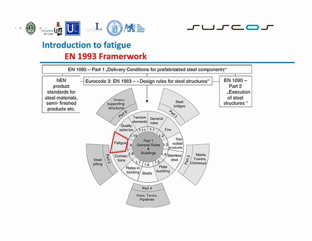
Main parameters influencing fatigue life
The fatigue life of a member or of a structural detail subjected to
repeated cyclic loadings is defined as the number of stress cycles it can
stand before failure.
Depending upon the member or structural detail geometry, its
fabrication or the material used, four main parameters can influence the
fatigue strength (or resistance, both used in EN 1993-1-9):
� the stress difference, or as most often called stress range,
� the structural detail geometry,
� the material characteristics,
� the environment

Types of Fatigue Loading
minmax σσσ −=∆
2
σσ
∆=a
2
minmax σσσ
+=m
m
aA
σ
σ=
max
min
σ
σ=R
stress range
alternating component
mean component
stress ratio
amplitude ratio
Fully Reversed Repeated Fluctuating
Introduction to Fatigue _____________________________________________________________________

Introduction to Fatigue
Introduction to Fatigue
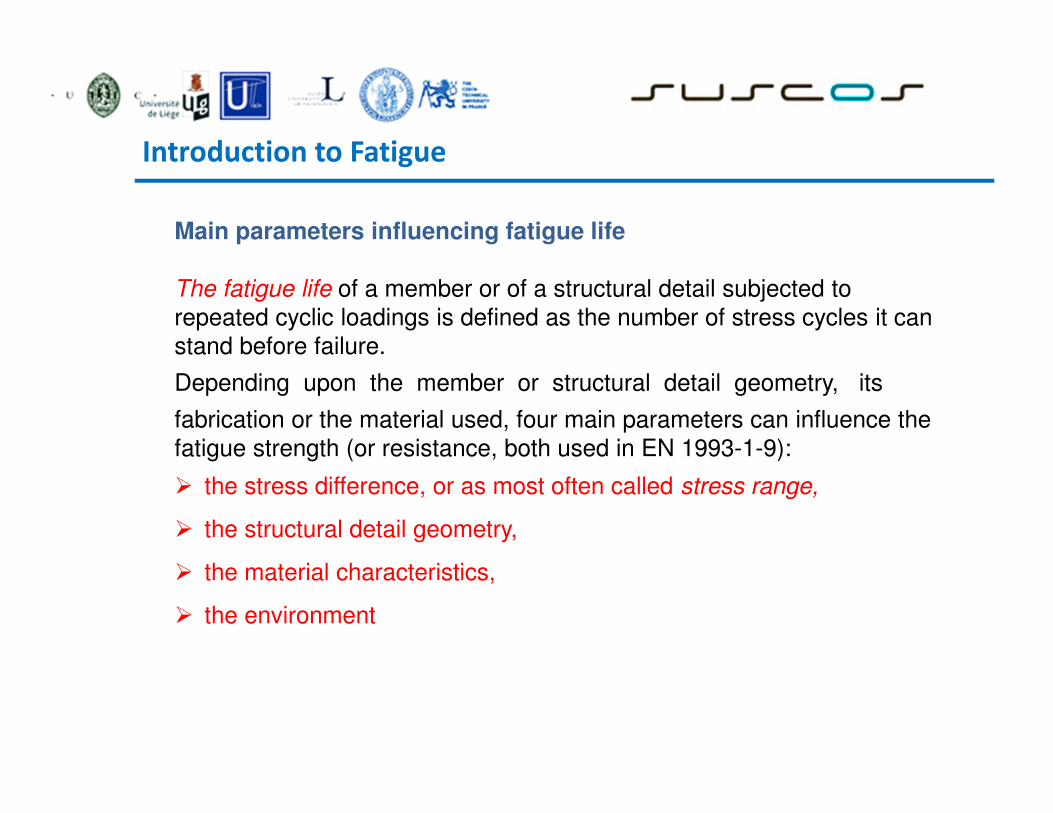
Fatigue: Failure under fluctuating stress
� Under fluctuating / cyclic stresses, failure
can occur at lower loads than under a static
load.
� 90% of all failures of metallic structures
(bridges, aircraft, machine components,
etc.)
� Fatigue failure is brittle-like –
even in normally ductile materials.
Thus sudden and catastrophic!

Introduction to Fatigue
Fatigue: S—N curves I
Rotating-bending test ���� S-N curves
S (stress) vs. N (number of cycles to failure)
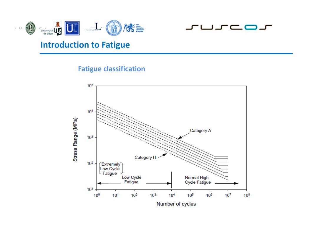
� Low cycle fatigue: small no. of cycles (N < 105) high loads
- plastic and elastic deformation
� High cycle fatigue: large # of cycles low loads
- elastic deformation (N > 105)

Introduction to Fatigue
High Cycle Fatigue
S-N Curves
� Apply controlled ∆σ∆σ∆σ∆σ
σσσσapplied < ~ 2/3 σσσσyield
� Stress is elastic
on gross scale.
� Locally the metal deforms
plastically.
50
40
30
10
0
105 106 107 108 109
Nfailure
Al alloys
Mild Steel
Fatigue limit

Introduction to Fatigue
Fatigue: S—N curves II
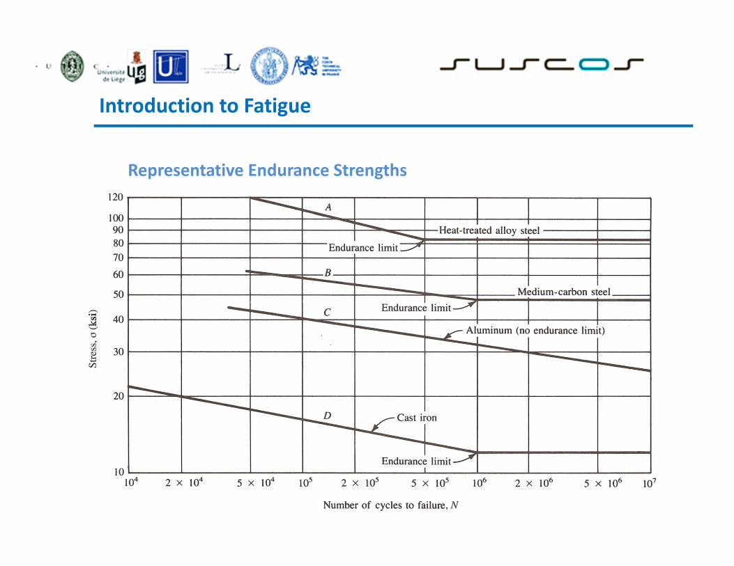
� Fatigue limit (some Fe and Ti alloys)
S—N curve becomes horizontal at large N
� Stress amplitude below which the material never fails, no
matter how large the number of cycles is ( Endurance
Limit)

Introduction to Fatigue
Fatigue: S—N curves III
Most alloys : S decreases with N.
� Fatigue strength: Stress at which fracture occurs after specified
number of cycles (e.g. 107)(Endurance Strength)
� Fatigue life: Number of cycles to fail at specified stress level

Introduction to Fatigue
Fatigue Testing
Number of Cycles to Failure, N

Introduction to Fatigue
Fatigue Strength
Introduction to Fatigue
Representative Endurance Strengths
Introduction to Fatigue
Fatigue classification

Introduction to Fatigue
Methods to assess fatigue resistance
Endurance limit is the stress level that a material can survive for an infinite number of load
cycles; Endurance strength is the stress level that a material can survive for a given number of
load cycles

Introduction to Fatigue
Low Cycle Fatigue
� Apply controlled amounts of ∆ε∆ε∆ε∆εtotal
∆εtotal = ∆εelastic + ∆εplastic
� Empirical Observations and Rules
� Coffin-Manson Law
� Miner’s Rule

Introduction to Fatigue
Low Cycle Fatigue
Coffin Manson Law
log ∆εpl
εy=σy/E
104 log Nfailure
∆εplastic Nfailure1/2 = Const.

Introduction to Fatigue
__________________________________________________
Low Cicle Fatigue : Miner’s Rule Rule of Accumulative damage:
N1 N2 N3 Σ = 1 Ni
Nfailure @ i
Fraction of life time @ i

Introduction to Fatigue
Low cycle fatigue damages

Introduction to Fatigue

Introduction to Fatigue
The Fatigue Process
� Crack initiation
o early development of damage
� Stage I crack growth
o deepening of initial crack on shear planes
� Stage II crack growth
o growth of well defined crack on planes normal
to maximum tensile stress
� Ultimate Failure

Introduction to Fatigue
Fatigue: Crack initiation+ propagation (I)
Three stages:
1. crack initiation in the areas of stress concentration (near stress
raisers, inclusions, exsiting vracks)
2. incremental crack propagation
3. rapid crack propagation after crack reaches critical size
The total number of cycles to failure is the sum of cycles at the first and the
second stages:
Nf = Ni + Np
Nf : Number of cycles to failure
Ni : Number of cycles for crack initiation
Np : Number of cycles for crack propagation
High cycle fatigue (low loads): Ni is relatively high. With increasing stress level, Ni
decreases and Np dominates

Introduction to Fatigue
Fatigue: Crack initiation and propagation (II)
� Crack initiation: Quality of surface and sites of stress
concentration (microcracks, scratches, indents,
interior corners, dislocation slip steps, etc.).
� Alternate stresses-> slip bands -> surface rumpling
� Crack propagation
� I: Slow propagation along crystal planes
with high resolved shear stress. Involves a
few grains.
Flat fracture surface
� II: Fast propagation perpendicular to
applied stress.
Crack grows by repetitive blunting and
sharpening process at crack tip. Rough
fracture surface
� Crack eventually reaches critical dimension and propagates very rapidly

Introduction to Fatigue
Crack initiation and progress with number of cycles

Introduction to Fatigue
Crack development Fracture surfaces
Striation indicating
steps in crack
advancement.
Initiation
site

Introduction to Fatigue
Brittle vs. Ductile Fracture
• Ductile materials - extensive plastic
deformation and energy absorption
(“toughness”) before fracture
• Brittle materials - little plastic
deformation and low energy
absorption before fracture
A B C
A. Moderately ductile fracture
typical for metals
A. Very ductile: soft metals (e.g. Pb, Au) at
room T, polymers, glasses at high T
B. Brittle fracture: ceramics, cold metals,
Introduction to Fatigue
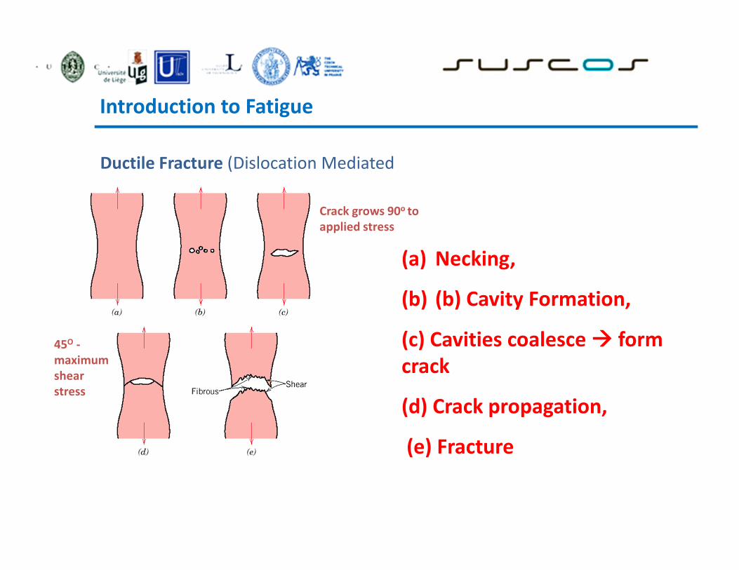
Ductile Fracture (Dislocation Mediated
(a) Necking,
(b) (b) Cavity Formation,
(c) Cavities coalesce ���� form
crack
(d) Crack propagation,
(e) Fracture
45O -
maximum
shear
stress
Crack grows 90o to
applied stress

Introduction to Fatigue
Ductile Fracture (Dislocation Mediated
Cup-and-cone fracture in Al)
Scanning Electron Microscopy. Spherical
“dimples” ���� micro-cavities that initiate crack
formation ( University of Virginia , Dept. of materials Science
Engineering )

Introduction to Fatigue
Brittle Fracture (Low Dislocation Mobility
�Crack propagation is fast
�Propagates nearly perpendicular to direction of
applied stress
�Often propagates by cleavage - breaking of atomic
bonds along specific crystallographic planes
�No appreciable plastic deformation
A.Transgranular fracture: Cracks pass through
grains. Fracture surface: faceted texture because of
different orientation of cleavage planes in grains.
B.Intergranular fracture: Crack propagation is
along grain boundaries (grain boundaries are
weakened/ embrittled by impurity segregation
etc.)
( University of Virginia , Dept. of materials Science Engineering )

Introduction to Fatigue
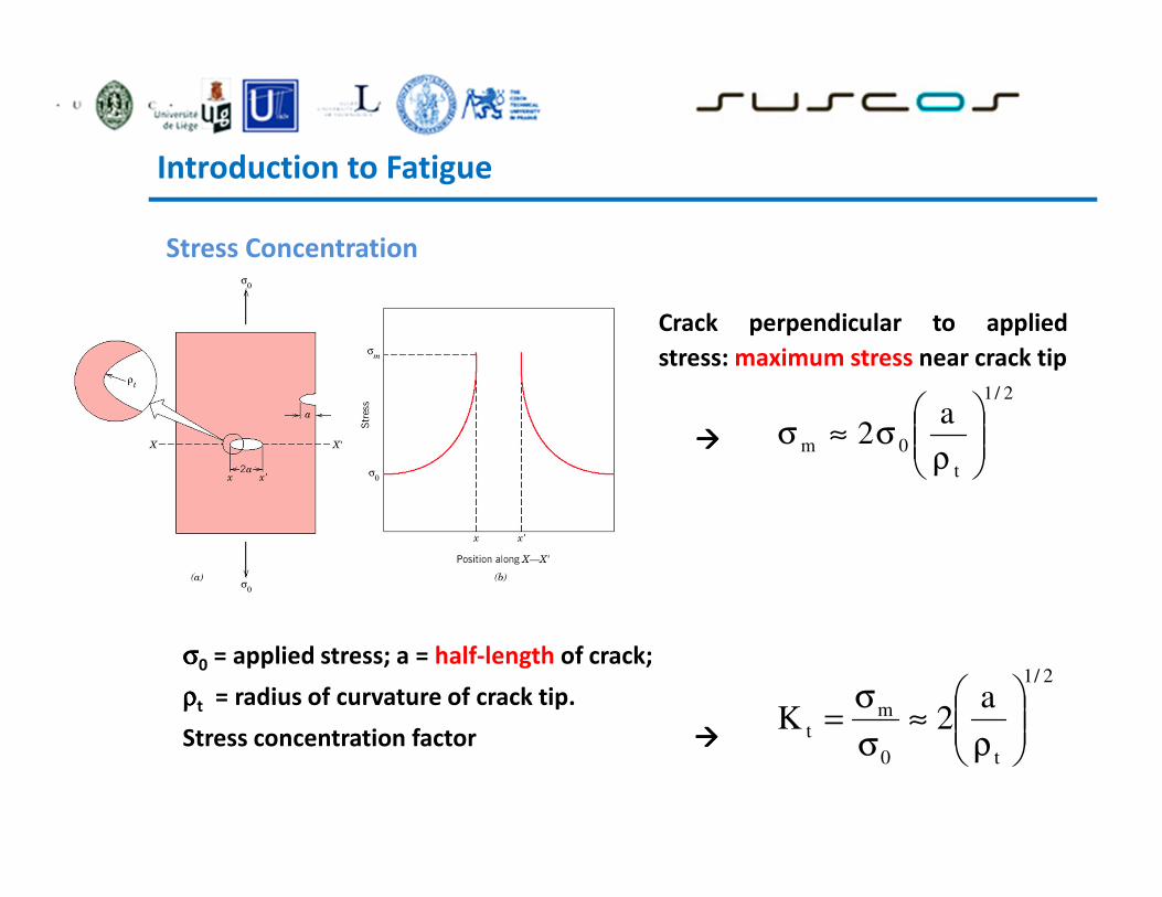
Stress Concentration
Fracture strength of a brittle solid:
related to cohesive forces between atoms.
Theoretical strength: ~E/10
Experimental strength ~ E/100 - E/10,000
s Difference due to:
Stress concentration at microscopic
flaws
Stress amplified at tips of micro-cracks
etc., called stress raisers
Figure by
N. Bernstein &
D. Hess, NRL
( University of Virginia , Dept. of materials Science Engineering )
Introduction to Fatigue
Stress Concentration
Crack perpendicular to applied
stress: maximum stress near crack tip
����
2/1
t
0m
a2
ρσ≈σ
σσσσ0 = applied stress; a = half-length of crack;
ρρρρt = radius of curvature of crack tip.
Stress concentration factor ����
2/1
t0
m
t
a2K
ρ≈
σ
σ=

Introduction to Fatigue
Ductile-to-Brittle Transition
� As temperature decreases a ductile material can become brittle

Introduction to Fatigue
Low temperatures can severely embrittle steels.
Ex. The Liberty ships. Produced during the WWII were the first all-welded ships. A
significant number of ships failed by catastrophic fracture. Fatigue cracks
nucleated at the corners of square hatches and propagated rapidly by brittle
fracture.

Introduction to Fatigue
Factors that affect fatigue life : Application; Environment; Loads: Types of Stresses; Material; confidence
� Magnitude of stress
� Quality of the surface
Solutions:
� Polish surface
� Introduce compressive stresses (compensate for applied tensile
stresses) into surface layer.
Shot Peening -- fire small shot into surface
High-tech - ion implantation, laser peening.
� Case Hardening: Steel - create C- or N- rich outer layer by atomic
diffusion from surface
Harder outer layer introduces compressive
stresses
� Optimize geometry
Avoid internal corners, notches etc.

Introduction to Fatigue
� Thermal Fatigue. Thermal cycling causes expansion and contraction,
hence thermal stress.
Solutions:
� change design!
� use materials with low thermal expansion coefficients
� Corrosion fatigue. Chemical reactions induce pits which act as stress
raisers. Corrosion also enhances crack propagation.
Solutions:
� decrease corrosiveness of medium
� add protective surface coating
� add residual compressive stresses
Environmental effects
Design checking against fatigue
__________________________________________________
• Fatigue strength
The quantitative relationship between the stress range and number of stress
cycles to fatigue failure, used for the fatigue assessment of a particular
category of structural detail
• Deratail category The numerical designation given to a particular detail for a given direction of
stress fluctuation, in order to indicate which fatigue strength curve is
applicable for the fatigue assessment (The detail category number
indicates the reference fatigue strength ΔσC in N/mm²
• Constant amplitude fatigue limit
The limiting direct or shear stress range value below which no fatigue
damage will occur in tests under constant amplitude stress conditions.
Under variable amplitude conditions all stress ranges have to be below
this limit for no fatigue damage to occur

Design checking against fatigue
__________________________________________________
Cut-of-limit
Limit below which stress ranges of the design spectrum do not
contribute to the calculated cumulative damamage
Endurance The life to failure expressed in cycles, under the action of a constant
amplitude stress history.
Reference fatigue strength
The life to failure expressed in cycles, under the action of a constant
amplitude stress history

Introduction to Fatigue : Design according to EN 1993-1-9
+

Introduction to Fatigue : design according To EN 1993-1-9
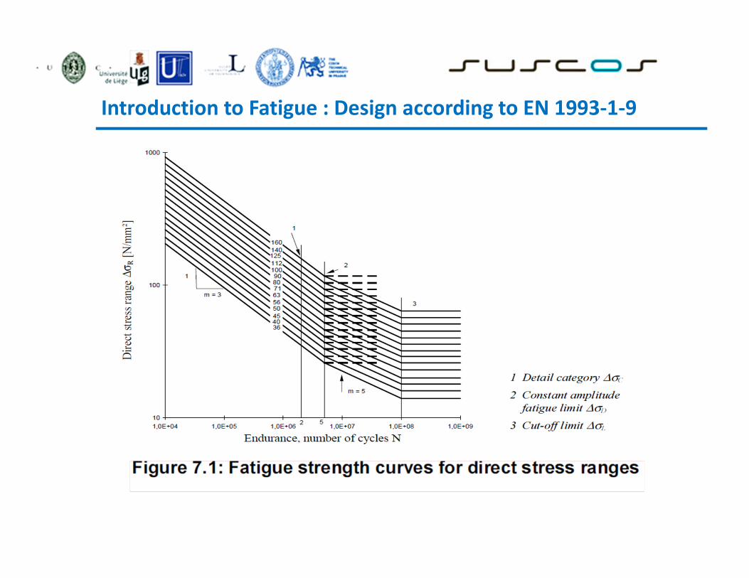
Introduction to Fatigue : Design according to EN 1993-1-9
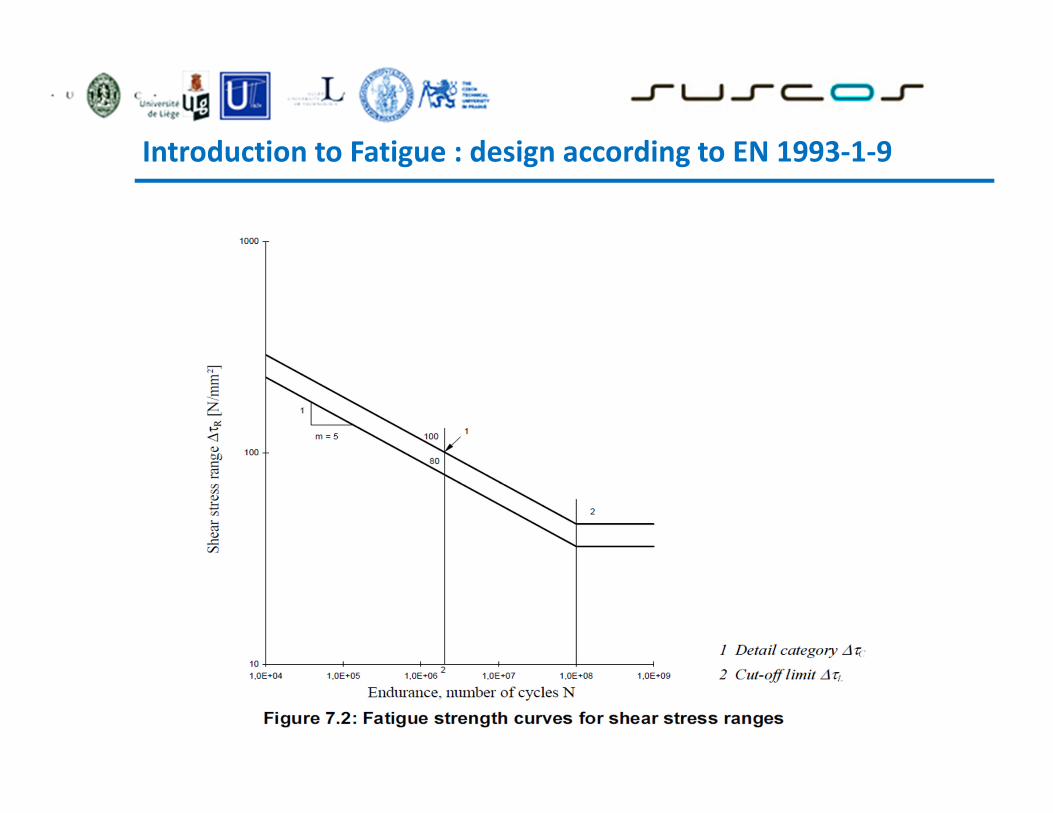
Introduction to Fatigue : design according to EN 1993-1-9

Introduction to Fatigue : Design Checking

Introduction to Fatigue : Design Checking
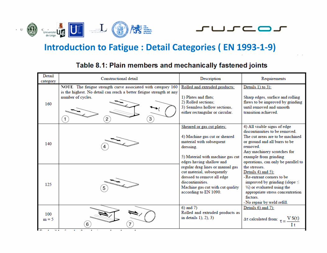
Introduction to Fatigue : Detail Categories ( EN 1993-1-9)

Introduction to Fatigue : Detail Categories ( EN 1993-1-9)

Introduction to Fatigue : Detail Categories ( EN 1993-1-9)

Introduction to Fatigue : Detail Categories ( EN 1993-1-9)

Introduction to Fatigue : Detail Categories ( EN 1993-1-9)
Copyright © 2022 FDOKUMEN

