


Bahasa
Halaman
Hukum

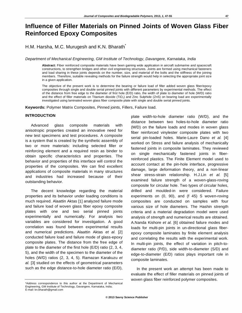
Journal of Composites and Biodegradable Polymers, 2013, 1, 47-55 47
© 2013 Savvy Science Publisher
Influence of Filler Materials on Pinned Joints of Woven Glass Fiber Reinforced Epoxy Composites
H.M. Harsha, M.C. Murugesh and K.N. Bharath*
Department of Mechanical Engineering, GM Institute of Technology, Davangere, Karnataka, India
Abstract: Fiber reinforced composite materials have been gaining wide application in aircraft submarine and spacecraft constructions, to strengthen bridges and other civil engineering structures. Joints are formed using mechanical fasteners
and load sharing in these joints depends on the number, size, and material of the bolts and the stiffness of the joining members. Therefore, suitable revealing methods for the failure strength would help in selecting the appropriate joint size in a given application.
The objective of the present work is to determine the bearing or failure load of filler added woven glass fiber/epoxy composites through single and double serial pinned joints with different parameters by experimental methods. The effect of the distance from free edge to the diameter of first hole (E/D) ratio, the width of plate to diameter of hole (W/D) ratio
and the effect of filler materials on Titanium dioxide (TiO2) and Zinc Sulphide (ZnS) on bearing load are experimentally investigated using laminated woven glass fiber composite plate with single and double serial pinned joints.
Keywords: Polymer Matrix Composites, Pinned joints, Fillers, Failure load.
INTRODUCTION
Advanced glass composite materials with
anisotropic properties created an innovative need for
new test specimens and test procedures. A composite
is a system that is created by the synthetic assembly of
two or more materials: including selected filler or
reinforcing element and a required resin as binder to
obtain specific characteristics and properties. The
behavior and properties of this interface will control the
properties of the composites. We can find excellent
applications of composite materials in many structures
and industries had increased because of their
outstanding behavior.
The decent knowledge regarding the material
properties and its behavior under loading conditions is
much required. Alaattin Aktas [1] analyzed failure mode
and failure load of woven glass fiber epoxy composite
plates with one and two serial pinned joints
experimentally and numerically. For analysis two
variables are considered for investigation. A good
correlation was found between experimental results
and numerical predictions. Alaattin Aktas et al. [2]
conducted failure load and failure mode of glass-epoxy
composite plates. The distance from the free edge of
plate to the diameter of the first hole (E/D) ratio (2, 3, 4,
5), and the width of the specimen to the diameter of the
holes (W/D) ratios (2, 3, 4, 5). Ramazan Karakuzu et
al. [3] studied on the effects of geometrical parameters
such as the edge distance-to-hole diameter ratio (E/D),
*Address correspondence to this author at the Department of Mechanical Engineering, GM Institute of Technology, Davangere, Karnataka, India; E-mail: [email protected]
plate width-to-hole diameter ratio (W/D), and the
distance between two holes-to-hole diameter ratio
(M/D) on the failure loads and modes in woven glass
fiber reinforced vinylester composite plates with two
serial pin-loaded holes. Marie-Laure Dano et al. [4]
worked on Stress and failure analysis of mechanically
fastened joints in composite laminates. They reviewed
on single mechanically fastened joints in fiber-
reinforced plastics. The Finite Element model used to
account contact at the pin-hole interface, progressive
damage, large deformation theory, and a non-linear
shear stress-strain relationship. H.J.Lin et al. [5]
examined failure strength of a woven-glass-roving
composite for circular hole. Two types of circular holes,
drilled and moulded-in were considered. Failure
experiments on (0, 90), and (f 45) S woven-roving
composites are conducted on samples with four
various size of hole diameters. The Hashin strength
criteria and a material degradation model were used
analysis of strength and numerical results are obtained.
A.Nanda Kishore et al. [6] obtained failure modes and
loads for multi-pin joints in un-directional glass fiber-
epoxy composite laminates by finite element analysis
and correlating the results with the experimental work.
In multi-pin joints, the effect of variation in pitch-to-
diameter ratio (P/D), side width-to-diameter (S/D) and
edge-to-diameter (E/D) ratios plays important role in
composite laminates.
In the present work an attempt has been made to
evaluate the effect of filler materials on pinned joints of
woven glass fiber reinforced polymer composites.

48 Journal of Composites and Biodegradable Polymers, 2013 Vol. 1, No. 1 Harsha et al.
MATERIALS AND EXPERIMENTATION
Materials
The type of Glass Fiber mat selected was Mat – 2
(330GSM). The matrix material used was a medium
viscosity epoxy resin (LAPOX L-12) and a room
temperature curing polyamine hardener (K-6). This
epoxy resin was selected since it provides good
resistance to alkalis and has excellent adhesive
properties. In the present work, two fillers materials
have been used i.e. Titanium dioxide (TiO2) and Zinc
Sulphide (ZnS). These fillers can improve mechanical
properties including fire and smoke performance by
reducing organic content in composite laminates.
Table 1: Composite Combinations
Sl. No. Filler Volume fraction Representation
1 Glass Fabric 60% + Epoxy 40% GE
2 Glass Fabric 59%+ Epoxy 40% + ZnS 1% GEZ1
3 Glass Fabric 58%+ Epoxy 40% + ZnS2% GEZ2
4
ZnS
Glass Fabric 57%+ Epoxy 40% + ZnS3% GEZ3
5 Glass Fabric 59%+ Epoxy 40% + TiO2 1% GET1
6 Glass Fabric 58%+ Epoxy 40% + TiO2 2% GET2
7
TiO2
Glass Fabric 57%+ Epoxy 40% + TiO2 3% GET3
Figure 1: Dimensions of single pinned specimens (E/D ratio varied).
Figure 2: Dimensions of serial pinned specimens (E/D ratio varied).

Influence of Filler Materials on Pinned Joints of Woven Glass Journal of Composites and Biodegradable Polymers, 2013 Vol. 1, No. 1 49
Figure 3: Dimensions of single pinned specimens (W/D ratio varied).
Figure 4: Dimensions of serial pinned specimens (W/D ratio varied).
Figure 5: (A) shows Universal testing machine (B) Experimental setup.

50 Journal of Composites and Biodegradable Polymers, 2013 Vol. 1, No. 1 Harsha et al.
Figure 6: Load v/s Deformation for single pinned specimens by varying W/D & E/D ratios (without filler material).
Figure 7: Load v/s Deformation for single pinned specimens by varying W/D & E/D ratios (with 1% ZnS filler material).
Figure 8: Load v/s Deformation for single pinned specimens by varying W/D & E/D ratios (with 2% ZnS filler material).
Figure 9: Load v/s Deformation for single pinned specimens by varying W/D & E/D ratios (with 3% ZnS filler material).

Influence of Filler Materials on Pinned Joints of Woven Glass Journal of Composites and Biodegradable Polymers, 2013 Vol. 1, No. 1 51
Figure 10: Load v/s Deformation for single pinned specimens by varying W/D & E/D ratios (with 1% TiO2 filler material).
Figure 11: Load v/s Deformation for single pinned specimens by varying W/D & E/D ratios (with 2% TiO2 filler material).
Figure 12: Load v/s Deformation for single pinned specimens by varying W/D & E/D ratios (with 3% TiO2 filler material).
Figure 13: Load v/s Deformation for single pinned specimens by varying W/D & E/D ratios (without filler material).

52 Journal of Composites and Biodegradable Polymers, 2013 Vol. 1, No. 1 Harsha et al.
Figure 14: Load v/s Deformation for single pinned specimens by varying W/D & E/D ratios (with 1% ZnS filler material).
Figure 15: Load v/s Deformation for single pinned specimens by varying W/D & E/D ratios (with 2% ZnS filler material).
Figure 16: Load v/s Deformation for single pinned specimens by varying W/D & E/D ratios (with 3% ZnS filler material).
Figure 17: Load v/s Deformation for single pinned specimens by varying W/D & E/D ratios (with 1% TiO2 filler material).

Influence of Filler Materials on Pinned Joints of Woven Glass Journal of Composites and Biodegradable Polymers, 2013 Vol. 1, No. 1 53
Figure 18: Load v/s Deformation for single pinned specimens by varying W/D & E/D ratios (with 2% TiO2 filler material).
Figure 19: Load v/s Deformation for single pinned specimens by varying W/D & E/D ratios (with 3% TiO2 filler material).
Specimen Preparation
Fabrication of the composites is done through the
Hand-lay-up technique. The required proportion of
constituents were added to attain required volume
fraction. The constituent involves the woven fabric E-
Glass fibers, epoxy of L-12 grade, K6 hardener and
filler materials. The various proportions are as shown in
following Table 1. Experimentations were carried-out
on all varieties of specimens in accordance with ASTM
D953 standards. The dimensions of the specimens are
shown in Figures 1, 2, 3 & 4. Figure 5A shows the
universal testing machine which is used for testing and
Figure 5B shows the experimental set up to carry out
the test.
Figure 21: Comparison of failure load for different compositions of serial pinned specimens with varied W/D ratio.
DISCUSSIONS
The failure strength of ZnS and TiO2 filled
composite is compared with that of unfilled composite
separately. From the above figures the following
discussions can be obtained,
1) As shown in Figure 20, For single pinned joint
when (E/D)=4, the failure strength increases as
Figure 20: Comparison of failure load for different compositions of single pinned specimens with varied W/D ratio.

54 Journal of Composites and Biodegradable Polymers, 2013 Vol. 1, No. 1 Harsha et al.
(W/D) ratio is equal to 2, 3, 4 & 5 and ZnS filler is
equal to 0%, 1%, 2% & 3%. Also the failure
strength increases as (W/D) ratio is equal to 2, 3,
4& 5 and TiO2 filler is equal to 0% & 1%.
a) Maximum value (5.5 kN) of failure strength is
observed for composite with single pin, (E/D)
= 4, (W/D) = 2 and 1% TiO2.
b) Maximum value (5 kN) of failure strength is
observed for composite with single pin, (E/D)
= 4, (W/D) = 3 and 2% ZnS.
c) Maximum value (4.5 kN) of failure strength is
observed for composite with single pin, (E/D)
= 4, (W/D) = 4, and 1% ZnS.
d) Maximum value (5.5 kN) of failure strength is
observed for composite with single pin, (E/D)
= 4, (W/D) = 5, and 1% & 2% ZnS.
2) For single pinned joint when (W/D)=4, the
bearing or failure strength increases as (E/D)
ratio is equal to 2, 3, 4 & 5 and ZnS filler is equal
to 0%, 1% & 2%.. Also the bearing/failure
strength increases as (E/D) ratio is equal to 2, 3,
4& 5 and TiO2 filler is equal to 0%, 1% & 2%.
a) Maximum value (2.7 kN) of failure strength is
observed for composite with single pin, (W/D)
= 4, (E/D) = 2 and 1% ZnS & 2% TiO2.
b) Maximum value (4 kN) of failure strength is
observed for composite with single pin, (W/D)
= 4, (E/D) = 3 and 2% ZnS.
c) Maximum value (4.7 kN) of failure strength is
observed for composite with single pin, (W/D)
= 4, (E/D) = 4, and 1% TiO2.
d) Maximum value (4.2 kN) of failure strength is
observed for composite with single pin, (W/D)
= 4, (E/D) = 5, and 1% ZnS.
3) For double serial pinned joint when (E/D)=4, the
bearing/failure strength increases as (W/D) ratio
is equal to 2 & 3 and ZnS filler is equal to 0% &
1%. Also the bearing/failure strength increases
as (W/D) ratio is equal to 2 & 3 and TiO2 filler is
equal to 0% & 1%.
a) Maximum value (8.3 kN) of failure strength is
observed for composite with double serial
pinned joint with (E/D) = 4, (W/D) = 2 and 1%
ZnS.
b) Maximum value (8.5 kN) of failure strength is
observed for composite with double serial
pinned joint with (E/D) = 4, (W/D) = 3 and 1%
TiO2.
4) For double serial pinned joint when (W/D)=4, the
bearing/failure strength increases as (E/D) ratio
is equal to 2 & 3 and ZnS filler is equal to 0% &
1%,. Also the failure strength increases as (E/D)
ratio is equal to 2 & 3 and TiO2 filler is equal to
0% & 1%.
a) Maximum value (8 kN) of failure strength is
observed for composite with double serial
pinned joint with (W/D) = 4, (E/D) = 2 and 1%
ZnS.
b) Maximum value (6.5 kN) of failure strength is
observed for composite with double serial
pinned joint with (W/D) = 4, (E/D) = 3 and 1%
TiO2.
Figure 22: Comparison of failure load for different compositions of single pinned specimens with varied E/D ratio.
Figure 23: Comparison of failure load for different compositions of serial pinned specimens with varied E/D ratio.

Influence of Filler Materials on Pinned Joints of Woven Glass Journal of Composites and Biodegradable Polymers, 2013 Vol. 1, No. 1 55
c) Maximum value (7.5 kN) of failure strength is
observed for composite with double serial
pinned joint with (W/D) = 4, (E/D) = 5 and 1%
ZnS.
CONCLUSION
From the experimental results, and observations
made during experimentation, the following conclusions
are obtained -
• Since TiO2 is harder than ZnS, TiO2 filled
composite behaves as more brittle compared to
ZnS filled composite. Hence we can observe that
the failure strength of TiO2 filled composite is
greater than that of ZnS filled composites.
• In single pinned joints, the failure strength
increases as (W/D) or (E/D) ratio increases.
• In double serial pinned joints, the failure strength
increases as (W/D) or (E/D) ratio is equal to 2 &
3.
• As the secondary filler (ZnS or TiO2) increases,
the number of layers of glass fiber decreases.
Due to this, failure strength decreases as ZnS &
TiO2 increases as 1%, 2% & 3%.
REFERENCES
[1] Aktas A. Failure analysis of serial pinned joints in composite materials. IJEMS 2011; 18: 102-10.
[2] Aktas A, Imrek H, Cunedioglu Y. Experimental and numerical failure analysis of pinned-joints in composite materials. J Compos Mater 2009; 89: 459-66.
[3] Karakuzu R, Caliskan CR, Aktas M, Icten BM. Failure behavior of laminated composite plates with two serial pin-loaded holes. Compos Struct 2008; 82: 225-34. http://dx.doi.org/10.1016/j.compstruct.2007.01.002
[4] Dano M-L, Gendron G, Picard A. Stress and failure analysis
of mechanically fastened joints in composite laminates. Compos Struct 2000; 50: 287-96. http://dx.doi.org/10.1016/S0263-8223(00)00119-7
[5] Lin HJ, Tsai CC, Shie JS. Failure analysis of woven-fabric
composites with moulded-in holes. Compos Sci Tech 1995; 55: 231-39. http://dx.doi.org/10.1016/0266-3538(95)00091-7
[6] Nanda Kishore A, Malhotra SK, Siva Prasad N. Failure analysis of multi-pin joints in glass fiber/epoxy composite laminates. J Compos Mater 2009; 91: 266-77.
[7] Icten BM, Okutan B, Karakuzn R. Failure strength of Woven glass fiber-epoxy composite pinned joints. J Compos Master 2003; 37(15): 1337-51. http://dx.doi.org/10.1177/0021998303034307
[8] Okutan B. The effects of geometric parameters on the failure
strength for pin-loaded multi-directional fiberglass reinforced epoxy laminate. Compos: Part B 2002; 33: 567-78. http://dx.doi.org/10.1016/S1359-8368(02)00054-9
Received on 04-11-2013 Accepted on 13-11-2013 Published on 25-12-2013
© 2013 Harsha et al.; Licensee Savvy Science Publisher. This is an open access article licensed under the terms of the Creative Commons Attribution Non-Commercial License (http://creativecommons.org/licenses/by-nc/3.0/) which permits unrestricted, non-commercial use, distribution and reproduction in any medium, provided the work is properly cited.
Top Related
Copyright © 2022 FDOKUMEN

