


Bahasa
Halaman
Hukum


WORKSHOP MANUAL633338
Vespa GT 125-200

WORKSHOPMANUAL
Vespa GT 125-200
The descriptions and illustrations given in this publication are not binding. While the basic specificationsas described and illustrated in this manual remain unchanged, PIAGGIO-GILERA reserves the right, at
any time and without being required to update this publication beforehand, to make any changes tocomponents, parts or accessories, which it considers necessary to improve the product or which are
required for manufacturing or construction reasons.Not all versions/models shown in this publication are available in all countries. The availability of single
versions should be checked at the official Piaggio sales network."© Copyright 2007 - PIAGGIO & C. S.p.A. Pontedera. All rights reserved. Reproduction of this publication
in whole or in part is prohibited."PIAGGIO & C. S.p.A. - After-Sales
V.le Rinaldo Piaggio, 23 - 56025 PONTEDERA (Pi)

WORKSHOP MANUALVespa GT 125-200
This workshop manual has been drawn up by Piaggio & C. Spa to be used by the workshops of Piaggio-Gilera dealers. This manual is addressed to Piaggio service mechanics who are supposed to have abasic knowledge of mechanics principles and of vehicle fixing techniques and procedures. Any importantchanges made to the vehicles or to specific fixing operations will be promptly reported by updates to thismanual. Nevertheless, no fixing work can be satisfactory if the necessary equipment and tools areunavailable. It is therefore advisable to read the sections of this manual relating to specific tools, alongwith the specific tool catalogue.
N.B. Provides key information to make the procedure easier to understand and carry out.
CAUTION Refers to specific procedures to carry out for preventing damages to the vehicle.
WARNING Refers to specific procedures to carry out to prevent injuries to the repairer.
Personal safety Failure to completely observe these instructions will result in serious risk of personalinjury.
Safeguarding the environment Sections marked with this symbol indicate the correct use of the vehicleto prevent damaging the environment.
Vehicle intactness The incomplete or non-observance of these regulations leads to the risk of seriousdamage to the vehicle and sometimes even the invalidity of the guarantee.

INDEX OF TOPICS
CHARACTERISTICS CHAR
TOOLING TOOL
MAINTENANCE MAIN
TROUBLESHOOTING TROUBL
ELECTRICAL SYSTEM ELE SYS
ENGINE FROM VEHICLE ENG VE
ENGINE ENG
SUSPENSIONS SUSP
BRAKING SYSTEM BRAK SYS
COOLING SYSTEM COOL SYS
CHASSIS CHAS
PRE-DELIVERY PRE DE
TIME TIME

INDEX OF TOPICS
CHARACTERISTICS CHAR

This section describes the general specifications of the vehicle.
Rules
This section describes general safety rules for any maintenance operations performed on the vehicle.
Safety rules
- If work can only be done on the vehicle with the engine running, make sure that the premises are well-
ventilated, using special extractors if necessary; never let the engine run in an enclosed area. Exhaust
fumes are toxic.
- The battery electrolyte contains sulphuric acid. Protect your eyes, clothes and skin. Sulphuric acid is
highly corrosive; in the event of contact with your eyes or skin, rinse thoroughly with abundant water
and seek immediate medical attention.
- The battery produces hydrogen, a gas that can be highly explosive. Do not smoke and avoid sparks
or flames near the battery, especially when charging it.
- Fuel is highly flammable and it can be explosive given some conditions. Do not smoke in the working
area, and avoid naked flames or sparks.
- Clean the brake pads in a well-ventilated area, directing the jet of compressed air in such a way that
you do not breathe in the dust produced by the wear of the friction material. Even though the latter
contains no asbestos, inhaling dust is harmful.
Maintenance rules
- Use original PIAGGIO spare parts and lubricants recommended by the Manufacturer. Non-original or
non-conforming spares may damage the vehicle.
- Use only the appropriate tools designed for this vehicle.
- Always use new gaskets, sealing rings and split pins upon refitting.
- After removal, clean the components using non-flammable or low flash-point solvents. Lubricate all
the work surfaces, except tapered couplings, before refitting these parts.
- After refitting, make sure that all the components have been installed correctly and work properly.
- For removal, overhaul and refit operations use only tools with metric measures. Metric bolts, nuts and
screws are not interchangeable with coupling members with English sizes. Using unsuitable coupling
members and tools may damage the scooter.
- When carrying out maintenance operations on the vehicle that involve the electrical system, make
sure the electric connections have been made properly, particularly the ground and battery connections.
Vehicle identification
Granturismo 125
Chassis prefix: ZAPM311000000 ÷ 1001
Characteristics Vespa GT 125-200
CHAR - 6

Engine prefix: M311M1001
Granturismo 200
Chassis prefix: ZAPM312000000 ÷ 1001
Engine prefix: M312M1001
Dimensions and mass
MASS AND DIMENSIONSSpecification Desc./Quantity
Total loadless weight 140 KgWidth (to hand grips) 755 mm
Length 1940 mmWheelbase 1395 mm
Saddle height 800 mm
Vespa GT 125-200 Characteristics
CHAR - 7

Engine
DATA 125Specification Desc./Quantity
Type single-cylinder, four-stroke and four liquid-cooled valvesTiming system single overhead camshaft chain driven on the left-hand side, 3-
arm rocking levers set up with set screwBore 125 57 mm
Stroke 48.6 mmPiston displacement 125 124,015 cm3Compression ratio 125 12 ÷ 13 : 1Walbro Carburettor 125 WVF-7GKeihin Carburettor 125 CVK 30
Engine idle speed 1650 ± 50 rpmCO value 3,8 ± 0,7 %Air filter sponge, impregnated with mixture (50% petrol and 50% oil)
Start-up system electric starter motor (engine 200 cc with torque limiter)Lubrication with lobe pump (inside the crankcase) controlled by a chain and
double filter: mesh and paperFuel supply petrol, with vacuum pump and through carburettor
Max power (shaft) 125 11 kW (15 cv) at 9,700 rpmMax speed 125 104 Km/h
DATA 200Specification Desc./Quantity
Type single-cylinder, four-stroke and four liquid-cooled valvesTiming system single overhead camshaft chain driven on the left-hand side, 3-
arm rocking levers set up with set screwBore 200 72 mm
Stroke 48.6 mmPiston displacement 200 197,775 cm3Compression ratio 200 11 ÷ 12 : 1Walbro Carburettor 200 WVF-7PKeihin Carburettor 200 CVK 30
Engine idle speed 1650 ± 50 rpmCO value 3,8 ± 0,7 %Air filter sponge, impregnated with mixture (50% petrol and 50% oil)
Start-up system electric starter motor (engine 200 cc with torque limiter)Lubrication with lobe pump (inside the crankcase) controlled by a chain and
double filter: mesh and paperFuel supply petrol, with vacuum pump and through carburettor
Max power (shaft) 200 15.4 kW (21 cv) at 8,500 rpmMax speed 200 125 Km/h
Characteristics Vespa GT 125-200
CHAR - 8

Transmission
TRANSMISSIONSpecification Desc./QuantityTransmission Automatic expandable pulley variator with torque server, V belt,
automatic clutch, gear reduction unit and transmission housingwith forced air circulation cooling
Capacities
CAPACITYSpecification Desc./Quantity
Engine oil ~ 1000 cc (recommended oil: Selenia HI Scooter 4 Tech)Fuel tank (including a ~ 2 l reserve) ~ 9.5 l
Rear hub 150 cc (recommended oil: TUTELA ZC 90)Cooling system fluid approx. 2.100 ÷ 2.150 l PARAFLU 11FE (Diluted)
Electrical system
ELECTRIC COMPONENTS 125Specification Desc./Quantity
Type of ignition Electronic capacitive discharge ignition, with variable timingand separate HV coil
Variable spark advance (before T.D.C.) 125 from 10° ± 1° to 2,000 rpm at 34° ± 1° to 6,000 rpmSpark plug 125 Champion RG 4 HC
Battery 12V/ 12 AhFuses N° 1 15A, N° 1 10A, N° 3 7,5A, N° 2 5A
Generator alternating current
ELECTRIC COMPONENTS 200Specification Desc./Quantity
Type of ignition Electronic capacitive discharge ignition, with variable timingand separate HV coil
Variable ignition advance (before TDC) 200 from 10° ± 1° at 2000 rpm to 32° ± 1° at 6500 rpmSpark plug 200 CHAMPION RG 6 YC
Battery 12V/ 12 AhFuses N° 1 15A, N° 1 10A, N° 3 7,5A, N° 2 5A
Generator alternating current
Frame and suspensions
FRAME AND SUSPENSIONSSpecification Desc./Quantity
Type Unitised body made of stamped plateFront suspension Single arm suspension (cantilever wheel) fitted with a double-
acting hydraulic shock absorber with coaxial springFront shock absorber axial travel 86.5 mm
Rear suspension Engine with swinging fork articulated to frame by means of anarm with 2 degrees of freedom Pair of double-acting hydraulicshock absorbers and coaxial springs with preloading adjust-
ment in 4 positions.Rear shock absorber axial travel 89.5 mm
Vespa GT 125-200 Characteristics
CHAR - 9

Brakes
BRAKESSpecification Desc./Quantity
Front Ø 220 disc brake and floating calliper with Ø 25 mm twin plung-ers and hydraulic control (lever on the far right end of the
handlebar)Rear Ø 220 disc brake and calliper with two Ø 30 mm counteracting
plungers and hydraulic control (lever on the far left end of thehandlebar)
Wheels and tyres
WHEELS AND TYRESSpecification Desc./Quantity
Front wheels - light alloy rims 3.00x12Rear wheels - light alloy rims 3.00x12
Front tyres 120/70-12" TubelessRear tyres 130/70-12" Tubeless
TYRE PRESSURESpecification Desc./Quantity
Front tyre pressure (when cold) 1.8 barRear tyre pressure (when cold) 2 bar
Tyre pressure (when cold) with passenger 2.2 barN.B.
CHECK AND ADJUST TYRE PRESSURE WITH TYRES AT AMBIENT TEMPERATURE. REGU-LATE PRESSURE ACCORDING TO THE WEIGHT OF THE RIDER AND ACCESSORIES
Carburettor
125cc Version
Kehin
KEHIN CARBURETTOR 125Specification Desc./Quantity
Depression carburettor CVEK-30Body stamping CVEK
CUT-OFF device Not presentMax. jet 98
Minimum jet 38Max.air jet 150
Minimum air jet 130Throttle valve spring 100 ÷ 160 g
Minimum mixture set screw initial opening 2 ± ¼Tapered pin NDVA
Tapered pin notches from top Single-notch pinDiffuser nozzle Ø 5.0Petrol inlet hole -
Starter air jet Ø 1.5Starter diffuser nozzle -
Starter jet 42Diameter of starter pin -
Starter device resistance ~ 20 Ω
Characteristics Vespa GT 125-200
CHAR - 10

Specification Desc./QuantityVenturi diffuser Ø 29 (47x30.9)Throttle valve Ø 30.5
Diffuser maximum cone -N.B.
* THE IDENTIFICATION LETTER MAY VARY WITH EACH CARBURETTOR UPDATE.
Walbro
WALBRO CARBURETTOR 125Specification Desc./Quantity
Depression type WVF-7R*Printing on the body 7R1
CUT-OFF device Not. pres.Max jet 103
Minimum jet 38Max air jet 60
Minimum air jet 110Throttle valve spring 100 g
Idle mixture adjustment screw initial opening 2 7/8 ± 1/2Conical pin 653
Conical pin top notches 2Diffuser nozzle Ø 2.7
Gasoline inlet hole Ø 1.5Starter air jet 200
Starter diffuser jet 130Starter jet 48
Starter pin diameter Ø 1,78Starter device resistance ~ 40 Ω
Venturi diffuser Ø 29 (30.3x27)Throttle valve Ø 33
Choke maximum cone Ø 48,0N.B.
* THE IDENTIFICATION LETTER MAY VARY WITH EACH CARBURETTOR UPDATE.
200cc Version
Kehin
KEHIN CARBURETTOR 200Specification Desc./Quantity
Depression type CVEK 30Body stamping CVK
CUT-OFF device PresentMax jet 92
Minimum jet 38Max air jet 70
Minimum air jet 115Gas valve spring 0,150 - 0,250 Kgf
Idle mixture adjustment screw initial opening 2 1/4 ± 1/4Conical pin NDAA
Conical pin top notches Single notch pinDiffuser nozzle Ø 5.0Fuel inlet hole -Starter air jet Ø 1.5
Starter emulsifier jet -Starter jet 42
Starter pin diameter -Starter device resistance ~ 20 Ω
Vespa GT 125-200 Characteristics
CHAR - 11

Specification Desc./QuantityVenturi choke Ø 29 (47x30,9)Throttle valve Ø 30,5
Choke maximum cone -N.B.
THE IDENTIFICATION LETTER CAN VARY WITH EACH CARBURETTOR UPDATE
Walbro
WALBRO CARBURETTOR 200Specification Desc./Quantity
Depression type WVF-7P*Printing on the body 7P
CUT-OFF device PresentMax jet 95
Minimum jet 33Max air jet 120
Minimum air jet 55Gas valve spring 120 gr
Idle mixture adjustment screw initial opening 2 ± 1/2Conical pin 495
Conical pin top notches 2Diffuser nozzle Ø 2.7
Gasoline inlet hole Ø 1.5Starter air jet 200
Starter emulsifier jet 110Starter nozzle 45
Starter pin diameter Ø 1,78Starter device resistance ~ 40 Ω
Venturi diffuser Ø 29 (30.3x27)Throttle valve Ø 33
Choke maximum cone Ø 48,0N.B.
THE IDENTIFICATION LETTER CAN VARY WITH EACH CARBURETTOR UPDATE
Tightening Torques
STEERING ASSEMBLYName Torque in Nm
Upper steering ring nut 30 ÷ 40Lower steering ring nut 8 ÷ 10Handlebar fixing screw 45 ÷ 50 (The two screws must be tightened to the prescribed
torque after having done so with the rear wheel axle nut. Safetylocks: see «Pre-delivery Operations» )
Fixing screws for handlebar control assembly U-bolts 7 ÷ 10
FRAME ASSEMBLYName Torque in Nm
Engine-swinging arm bolt 64 - 72swinging arm bolt - body shell 76 ÷ 83
Engine and vehicle side swinging arm junction bolt 33 ÷ 41Bolt of the Silent block support plate 42 ÷ 52
Centre stand bolt 25 - 30Side stand fixing bolt 40 ÷ 45
FRONT SUSPENSIONName Torque in Nm
Screw fixing the shock absorber to the shock absorber - calliperattachment plate
20 ÷ 27
Wheel axle nut 75 ÷ 90
Characteristics Vespa GT 125-200
CHAR - 12

Name Torque in NmWheel screw 20 ÷ 25
Screw fixing rear mudguard to steering 5 ÷ 6.5
FRONT BRAKEName Torque in Nm
Brake fluid pump-hose fitting 20 ÷ 25Brake fluid hose-calliper fitting 20 ÷ 25
Screw fixing calliper to the shock absorber - calliper plate at-tachment
20 ÷ 25
Disc tightening screw 6 (Apply LOCTITE 242 threadlock, medium strength)Oil bleed screw 12 - 16
Pad fastening pin 19.6 ÷ 24.5Brake pump reservoir screws 15 ÷ 20
REAR SUSPENSIONName Torque in Nm
Retainer for left shock absorber to crankcase support plate 20 ÷ 25Shock absorber upper fitting 20 ÷ 25Shock absorber lower fitting 33 ÷ 41
Rear wheel axle 104 ÷ 126Screw fixing wheel to hub 20 ÷ 25
Screws for muffler - shock absorber support arm on engine 20 ÷ 25 (The two screws must be tightened to the prescribedtorque after having done so with the rear wheel axle nut. Safety
locks: see «Pre-delivery Operations» )
REAR BRAKEName Torque in Nm
Brake fluid pump-hose fitting 20 ÷ 25Brake fluid pipe-calliper fitting 20 ÷ 25
Rear disc tightening bolt 11 ÷ 13Oil bleed screw 12÷16
Calliper to engine tightening screw 20 ÷ 25Brake pump reservoir screws 15 ÷ 20
Calliper coupling screws 30 ÷ 33
MUFFLERName Torque in Nm
Muffler heat guard clamping screw 5 - 6Exhaust fumes inlet screw 13 ÷ 15
Screw for fixing muffler to the support arm 20 ÷ 25
LUBRICATIONName Torque in Nm
Hub oil drainage plug 15 ÷ 17Oil filter on crankcase fitting 27 ÷ 33
Engine oil drainage plug/mesh filter 24 ÷ 30Oil filter 8 ÷ 10
Oil pump cover screws 7 ÷ 9Screws fixing oil pump to crankcase 5 - 6
Oil pump control crown screw 10 ÷ 14Oil pump cover plate screws 4 ÷ 6
Oil sump screws 10 ÷ 14Minimum oil pressure sensor 12 ÷ 14
CYLINDER HEADName Torque in Nm
Spark plug 12 ÷ 14Head cover screws 6 ÷ 7
Nuts for head fastening to the cylinder 7± 1 + 180° (2x90°) (Fasten nuts in two crossed passes) (Be-fore fitting the nuts, lubricate them with engine oil.)
Head fixing side screws 11 ÷ 13Starter ground screw 7 ÷ 8.5
Vespa GT 125-200 Characteristics
CHAR - 13
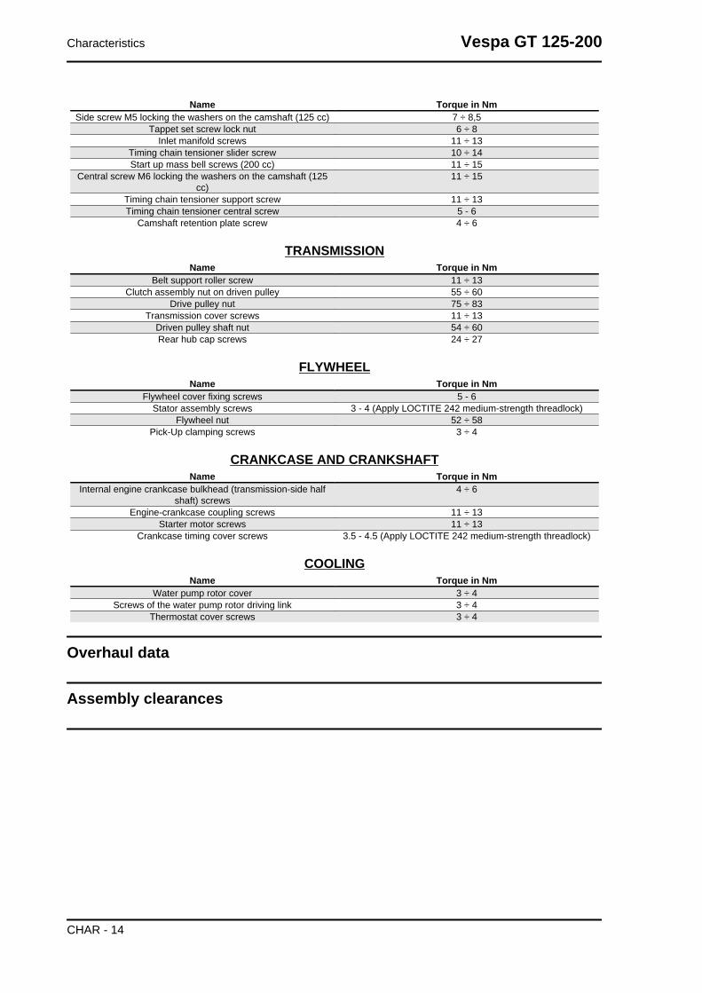
Name Torque in NmSide screw M5 locking the washers on the camshaft (125 cc) 7 ÷ 8,5
Tappet set screw lock nut 6 ÷ 8Inlet manifold screws 11 ÷ 13
Timing chain tensioner slider screw 10 ÷ 14Start up mass bell screws (200 cc) 11 ÷ 15
Central screw M6 locking the washers on the camshaft (125cc)
11 ÷ 15
Timing chain tensioner support screw 11 ÷ 13Timing chain tensioner central screw 5 - 6
Camshaft retention plate screw 4 ÷ 6
TRANSMISSIONName Torque in Nm
Belt support roller screw 11 ÷ 13Clutch assembly nut on driven pulley 55 ÷ 60
Drive pulley nut 75 ÷ 83Transmission cover screws 11 ÷ 13
Driven pulley shaft nut 54 ÷ 60Rear hub cap screws 24 ÷ 27
FLYWHEELName Torque in Nm
Flywheel cover fixing screws 5 - 6Stator assembly screws 3 - 4 (Apply LOCTITE 242 medium-strength threadlock)
Flywheel nut 52 ÷ 58Pick-Up clamping screws 3 ÷ 4
CRANKCASE AND CRANKSHAFTName Torque in Nm
Internal engine crankcase bulkhead (transmission-side halfshaft) screws
4 ÷ 6
Engine-crankcase coupling screws 11 ÷ 13Starter motor screws 11 ÷ 13
Crankcase timing cover screws 3.5 - 4.5 (Apply LOCTITE 242 medium-strength threadlock)
COOLINGName Torque in Nm
Water pump rotor cover 3 ÷ 4Screws of the water pump rotor driving link 3 ÷ 4
Thermostat cover screws 3 ÷ 4
Overhaul data
Assembly clearances
Characteristics Vespa GT 125-200
CHAR - 14

Cylinder - piston assy.
ENGINE 125 COUPLING CATEGORIESName Initials Cylinder Piston Play on fitting
Cylinder A 56.997 ÷ 57.004 56.945 ÷ 56.952 0.045 - 0.059Cylinder B 57.004 ÷ 57.011 56.952 ÷ 56.959 0.045 - 0.059Piston C 57.011 ÷ 57.018 56.959 ÷ 56.966 0.045 - 0.059Piston D 57.018 ÷ 57.025 56.966 ÷ 56.973 0.045 - 0.059
Cylinder 1st Oversize A1 57.197 ÷ 57.204 57.145 ÷ 57.152 0.045 - 0.059Cylinder 1st Oversize B 1 57.204 ÷ 57.211 57.152 ÷ 57.159 0.045 - 0.059Piston 1st Oversize C 1 57.211 ÷ 57.218 57.159 ÷ 57.166 0.045 - 0.059Piston 1st Oversize D 1 57.218 ÷ 57.225 57.166 ÷ 57.173 0.045 - 0.059
Cylinder 2nd Oversize A2 57.397 ÷ 57.404 57.345 ÷ 57.352 0.045 - 0.059Cylinder 2nd Oversize B 2 57.404 ÷ 57.411 57.352 ÷ 57.359 0.045 - 0.059Piston 2nd Oversize C 2 57.411 ÷ 57.418 57.359 ÷ 57.366 0.045 - 0.059Piston 2nd Oversize D 2 57.418 ÷ 57.425 57.366 ÷ 57.373 0.045 - 0.059
Cylinder 3rd Oversize A 3 57.597 ÷ 57.604 57.545 ÷ 57.552 0.045 - 0.059Cylinder 3rd Oversize B 3 57.604 ÷ 57.611 57.552 ÷ 57.559 0.045 - 0.059Piston 3rd Oversize C 3 57.611 ÷ 57.618 57.559 ÷ 57.566 0.045 - 0.059Piston 3rd Oversize D 3 57.618 ÷ 57.625 57.566 ÷ 57.573 0.045 - 0.059
Vespa GT 125-200 Characteristics
CHAR - 15

ENGINE 200 COUPLING CATEGORIESName Initials Cylinder Piston Play on fitting
Cylinder / piston A 71.990 ÷ 71.997 71.953 ÷ 71.960 0.030 - 0.044Cylinder / piston B 71.997 ÷ 72.004 71.960 ÷ 71.967 0.030 - 0.044Cylinder / piston C 72.004 ÷ 72.011 71.967 ÷ 71.974 0.030 - 0.044Cylinder / piston D 72.011 ÷ 72.018 71.974 ÷ 71.981 0.030 - 0.044
Crankcase - crankshaft - connecting rod
CRANKSHAFTTitolo Durata/Valore Testo Breve (< 4000 car.) Indirizzo Immagine
Crankshaft Crankshaft to crankcase axialclearance
Crankshaft to crankcase axial clearance
Characteristics Vespa GT 125-200
CHAR - 16

CRANKSHAFT/ CRANKCASE AXIAL CLEARANCEName Description Dimensions Initials Quantity
Half-shaft, transmissionside
16.6 +0-0.05 A D = 0.20 - 0.50
Flywheel-side half-shaft 16.6 +0-0.05 B D = 0.20 - 0.50Connecting rod 18 -0.10 -0.15 C D = 0.20 - 0.50
Spacer tool 51.4 +0.05 E D = 0.20 - 0.50
Slot packing system
CharacteristicShimming system for limiting the compressionratio 125Rc = 12 ÷ 13 : 1
Measurement "A" to be taken is a value of piston protrusion. It indicates by how much the plane formed
by the piston crown protrudes from the plane formed by the upper part of the cylinder. The further the
piston protrudes from the cylinder, the bigger the base gasket to be used (to recover the compression
ratio) and vice versa.N.B.
DISTANCE "A" MUST BE MEASURED WITHOUT ANY GASKET FITTED BETWEEN CRANKCASEAND CYLINDER
Vespa GT 125-200 Characteristics
CHAR - 17

THICKNESS 125Name Measure A Thickness
Gasket thickness 125 2,2 ÷ 2,4 0,4 ± 0,05Gasket thickness 125 2,4 ÷ 2,6 0,6 ± 0,05
CharacteristicCompression ratio, 200 modelsCr: 11÷12 :1
Measurement "A" to be taken is a value of piston re-entry, it indicates by how much the plane formed
by the piston crown falls below the plane formed by the top of the cylinder. The further the piston falls
inside the cylinder, the less the base gasket to be applied (to recover the compression ratio) and vice
versa.N.B.
MEASUREMENT "A" MUST BE TAKEN WITHOUT ANY GASKET FITTED BETWEEN THE CRANK-CASE AND CYLINDER AND AFTER RESETTING THE GAUGE, EQUIPPED WITH A SUPPORT, ONA GROUND PLANE
THICKNESS 200Name Measure A Thickness
Gasket thickness 200 1,7 ÷ 1,6 0,4 ± 0,05Gasket thickness 200 1,6 ÷ 1,4 0,6 ± 0,05Gasket thickness 200 1,4 ÷ 1,3 0,8 ± 0,05
Characteristics Vespa GT 125-200
CHAR - 18

Oversizes
ENGINE 125 OVERSIZEName Description Dimensions Initials Quantity
Compression ring 57 x 1 A 0.15 ÷ 0.30Oil scraper ring 57 x 1 A 0.10 ÷ 0.30Oil scraper ring 57 x 2.5 A 0.15 ÷ 0.35
Compression ring 1stoversize
57.2 x 1 A 0.15 ÷ 0.30
Oil scraper ring 1stOversize
57.2 x 1 A 0.10 ÷ 0.30
Oil scraper ring 1stOversize
57.2 x 2.5 A 0.15 ÷ 0.35
Compression ring 2ndOversize
57.4 x 1 A 0.15 ÷ 0.30
Oil scraper ring 2ndOversize
57.4 x 1 A 0.10 ÷ 0.30
Oil scraper ring 2ndOversize
57.4 x 2.5 A 0.15 ÷ 0.35
Compression ring 3rdOversize
57.6 x 1 A 0.15 ÷ 0.30
Oil scraper ring 3rdOversize
57.6 x 1 A
Oil scraper ring 3rdOversize
57.6 x 2.5 A 0.15 ÷ 0.35
ENGINE 200 OVERSIZEName Description Dimensions Initials Quantity
Oil scraper ring 72 x 2.5 A 0.20 ÷ 0.40Oil scraper ring 72 x 1 A 0.20 ÷ 0.40
Compression ring 72 x 1.5 A 0.15 ÷ 0.30
Vespa GT 125-200 Characteristics
CHAR - 19

Products
RECOMMENDED PRODUCTSProduct Description Specifications
AGIP ROTRA 80W-90 Rear hub oil SAE 80W/90 Oil that exceeds the re-quirements of API GL3 specifications
AGIP FILTER OIL Oil for air filter sponge Mineral oil with specific additives for in-creased adhesiveness
AGIP GP 330 Calcium complex soap-based greasewith NLGI 2; ISO-L-XBCIB2
Grease (brake control levers, throttlegrip)
AGIP CITY HI TEC 4T Four-stroke engine oil Lubricating oil for flexible shafts (throttlecontrol)
AGIP BRAKE 4 Brake fluid FMVSS DOT 4 Synthetic fluidAGIP PERMANENT PLUS Coolant Monoethylene glycol antifreeze fluid, CU-
NA NC 956-16MONTBLANC MOLYBDENUM
GREASEGrease for driven pulley shaft adjustingring and movable driven pulley housing
Grease with molybdenum disulphide
AGIP GREASE PV2 Grease for the steering bearings, pinseats and swinging arm
White anhydrous-calcium based greaseto protect roller bearings; temperature
range between -20 C and +120 C; NLGI2; ISO-L-XBCIB2.
Characteristics Vespa GT 125-200
CHAR - 20

INDEX OF TOPICS
TOOLING TOOL

APPROPRIATE TOOLSStores code Description
001330Y Tool for fitting steering seats
001467Y009 Driver for OD 42-mm bearings
001467Y017 Bell for bearings, OD 39 mm
001467Y014 Pliers to extract ø 15-mm bearings
005095Y Engine support
002465Y Pliers for circlips
006029Y Punch for fitting fifth wheel seat on steer-ing tube
Tooling Vespa GT 125-200
TOOL - 22

Stores code Description008564Y Flywheel extractor
020004Y Punch for removing fifth wheels fromheadstock
020021Y Front suspension service tool
020036Y Punch
020037Y Punch
Vespa GT 125-200 Tooling
TOOL - 23
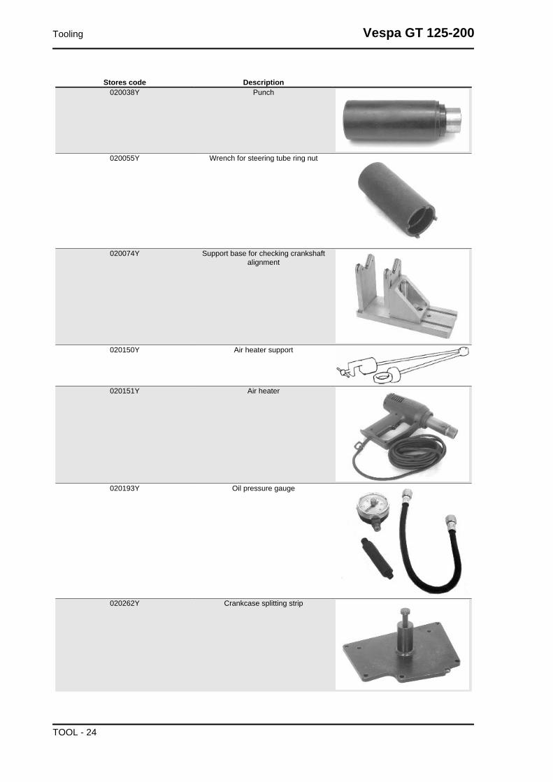
Stores code Description020038Y Punch
020055Y Wrench for steering tube ring nut
020074Y Support base for checking crankshaftalignment
020150Y Air heater support
020151Y Air heater
020193Y Oil pressure gauge
020262Y Crankcase splitting strip
Tooling Vespa GT 125-200
TOOL - 24

Stores code Description020263Y Sheath for driven pulley fitting
020287Y Clamp to assemble piston on cylinder
020306Y Punch for assembling valve seal rings
020319Y Immobilizer check tester
020329Y MityVac vacuum-operated pump
020330Y Stroboscopic light to check timing
Vespa GT 125-200 Tooling
TOOL - 25

Stores code Description020331Y Digital multimeter
020332Y Digital rev counter
020333Y Single battery charger
020334Y Multiple battery charger
Tooling Vespa GT 125-200
TOOL - 26

Stores code Description020335Y Magnetic support for dial gauge
020357Y 32 x 35 mm adaptor020359Y 42x47-mm adaptor
020360Y Adaptor 52 x 55 mm
020363Y 20 mm guide
020364Y 25-mm guide
Vespa GT 125-200 Tooling
TOOL - 27

Stores code Description020365Y 22 mm guide
020368Y driving pulley lock wrench
020375Y Adaptor 28 x 30 mm
020376Y Adaptor handle
020382Y Valve cotters equipped with part 012 re-moval tool
020382Y011 adapter for valve removal tool
Tooling Vespa GT 125-200
TOOL - 28

Stores code Description020393Y Piston fitting band
020409Y Multimeter adaptor - Peak voltage detec-tion
020412Y 15 mm guide
020414Y 28-mm guide
020423Y driven pulley lock wrench
Vespa GT 125-200 Tooling
TOOL - 29

Stores code Description020424Y Driven pulley roller casing fitting punch
020425Y Punch for flywheel-side oil seal
020426Y Piston fitting fork
020430Y Pin lock fitting tool
020431Y Valve oil seal extractor
020434Y Oil pressure control fitting
Tooling Vespa GT 125-200
TOOL - 30

Stores code Description020439Y 17 mm guide
020440Y Water pump service tool
020441Y 26 x 28 mm adaptor
020442Y Pulley lock wrench
020444Y Tool for fitting/ removing the driven pulleyclutch
Vespa GT 125-200 Tooling
TOOL - 31

Stores code Description020455Y 10-mm guide
020456Y Ø 24 mm adaptor020477Y Adaptor 37 mm
020483Y 30 mm guide
020488Y Pin stops fitting tool (200 cm³ engines)
020489Y Hub cover support stud bolt set
Tooling Vespa GT 125-200
TOOL - 32

Stores code Description020565Y Flywheel lock calliper spanner
494929Y Exhaust fumes analyser
Vespa GT 125-200 Tooling
TOOL - 33

INDEX OF TOPICS
MAINTENANCE MAIN

Maintenance chart
EVERY 2 YEARSAction
Secondary air filter (external / internal) - CleanCoolant - changeBrake fluid - change
EVERY 3,000 KM10'
ActionEngine oil - level check/ top-up
AT 1000 KM OR 4 MONTHS70'
ActionHub oil level - Check / ReplaceIdle speed (*) - adjustmentThrottle lever - adjustmentSteering - adjustmentBrake control levers - greasingBrake pads - check condition and wearBrake fluid level - checkSafety locks - checkElectrical system and battery - checkVehicle and brake test - road test
Safety locks: see Before delivery chapter.(*) See rules
AT 6000 KM OR 12 MONTHS130'
ActionEngine oil - replacementHub oil level - Check / ReplaceSpark plug / electrode gap - check / replacementAir filter - cleaningEngine oil - changeValve clearance - checkValve clearance 200 - checkVariable speed rollers - check or replacementDriving belt - Check / ReplacementCoolant level - checkBrake pads - check condition and wearBrake fluid level - checkElectrical system and battery - checkTyre pressure and wear - checkVehicle and brake test - road test
AT 12000 KM OR 24 MONTHS AND AT 60000 KM135'
ActionEngine oil - replacementHub oil level - Check / ReplaceSpark plug / electrode gap - check / replacementAir filter - cleaningEngine oil - changeIdle speed (*) - adjustmentThrottle lever - adjustmentVariable speed rollers - check or replacement
Vespa GT 125-200 Maintenance
MAIN - 35
ActionDriving belt - Check / ReplacementCoolant level - checkSteering - adjustmentBrake control levers - greasingBrake pads - check condition and wearBrake fluid level - checkTransmission elements - lubricationSafety locks - checkSuspensions - checkElectrical system and battery - checkHeadlight - adjustment checkTyre pressure and wear - checkVehicle and brake test - road test
Safety locks: see Before delivery chapter.(*) See rules
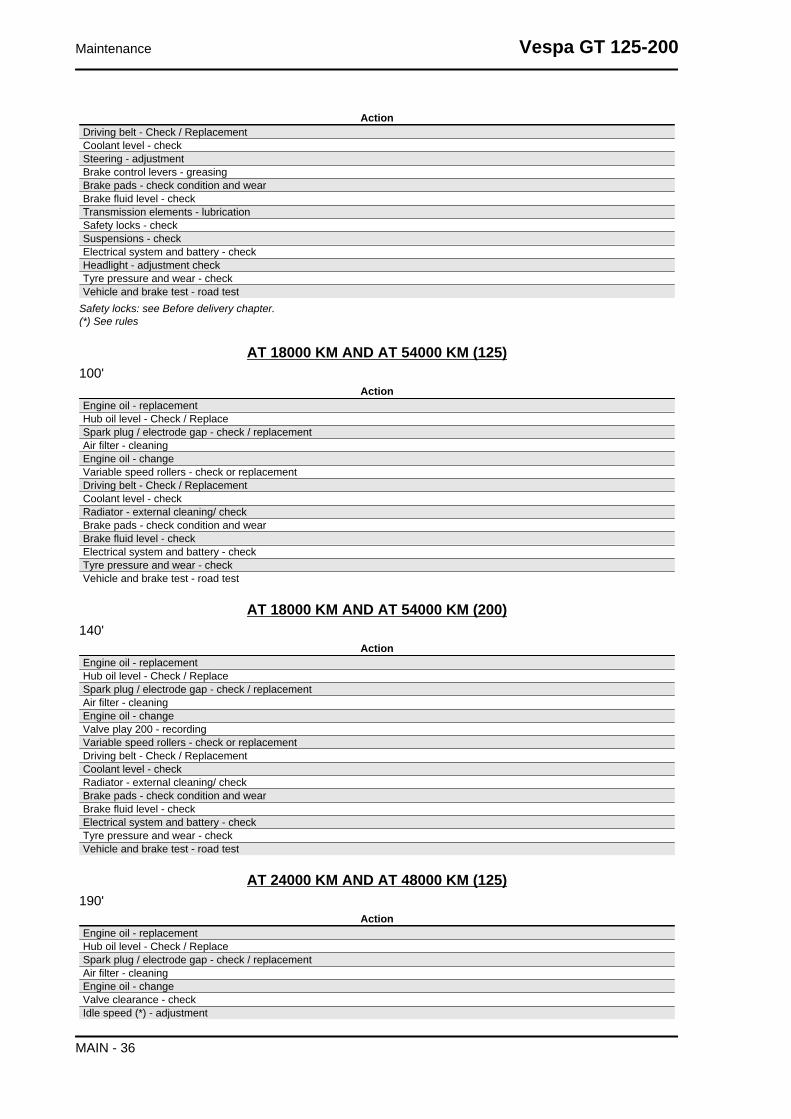
AT 18000 KM AND AT 54000 KM (125)100'
ActionEngine oil - replacementHub oil level - Check / ReplaceSpark plug / electrode gap - check / replacementAir filter - cleaningEngine oil - changeVariable speed rollers - check or replacementDriving belt - Check / ReplacementCoolant level - checkRadiator - external cleaning/ checkBrake pads - check condition and wearBrake fluid level - checkElectrical system and battery - checkTyre pressure and wear - checkVehicle and brake test - road test
AT 18000 KM AND AT 54000 KM (200)140'
ActionEngine oil - replacementHub oil level - Check / ReplaceSpark plug / electrode gap - check / replacementAir filter - cleaningEngine oil - changeValve play 200 - recordingVariable speed rollers - check or replacementDriving belt - Check / ReplacementCoolant level - checkRadiator - external cleaning/ checkBrake pads - check condition and wearBrake fluid level - checkElectrical system and battery - checkTyre pressure and wear - checkVehicle and brake test - road test
AT 24000 KM AND AT 48000 KM (125)190'
ActionEngine oil - replacementHub oil level - Check / ReplaceSpark plug / electrode gap - check / replacementAir filter - cleaningEngine oil - changeValve clearance - checkIdle speed (*) - adjustment
Maintenance Vespa GT 125-200
MAIN - 36

ActionThrottle lever - adjustmentVariable speed rollers - check or replacementDriving belt - Check / ReplacementCoolant level - checkSteering - adjustmentBrake control levers - greasingBrake pads - check condition and wearBrake fluid level - checkTransmission elements - lubricationSafety locks - checkSuspensions - checkElectrical system and battery - checkHeadlight - adjustment checkTyre pressure and wear - checkVehicle and brake test - road test
Safety locks: see Before delivery chapter.(*) See rules
AT 24000 KM AND AT 48000 KM (200)150'
ActionEngine oil - replacementHub oil level - Check / ReplaceSpark plug / electrode gap - check / replacementAir filter - cleaningEngine oil - changeValve clearance - checkIdle speed (*) - adjustmentThrottle lever - adjustmentVariable speed rollers - check or replacementDriving belt - Check / ReplacementCoolant level - checkSteering - adjustmentBrake control levers - greasingBrake pads - check condition and wearBrake fluid level - checkTransmission elements - lubricationSafety locks - checkSuspensions - checkElectrical system and battery - checkHeadlight - adjustment checkTyre pressure and wear - checkVehicle and brake test - road test
Safety locks: see Before delivery chapter.(*) See rules
AT 30000 KM AT 42000 KM AND AT 66000 KM90'
ActionEngine oil - replacementHub oil level - Check / ReplaceSpark plug / electrode gap - check / replacementAir filter - cleaningEngine oil - changeVariable speed rollers - check or replacementDriving belt - Check / ReplacementCoolant level - checkBrake pads - check condition and wearBrake fluid level - checkElectrical system and battery - checkTyre pressure and wear - checkVehicle and brake test - road test
Vespa GT 125-200 Maintenance
MAIN - 37

AT 36000 KM (125)205'
ActionEngine oil - replacementHub oil level - Check / ReplaceSpark plug / electrode gap - check / replacementAir filter - cleaningEngine oil - changeValve clearance - adjustmentIdle speed (*) - adjustmentThrottle lever - adjustmentVariable speed rollers - check or replacementDriving belt - Check / ReplacementCoolant level - checkRadiator - external cleaning/ checkSteering - adjustmentBrake control levers - greasingBrake pads - check condition and wearBrake fluid hoses - replacementBrake fluid level - checkTransmission elements - lubricationSafety locks - checkSuspensions - checkElectrical system and battery - checkHeadlight - adjustment checkTyre pressure and wear - checkVehicle and brake test - road test
Safety locks: see Before delivery chapter.(*) See rules
AT 36000 KM (200)245'
ActionEngine oil - replacementHub oil level - Check / ReplaceSpark plug / electrode gap - check / replacementAir filter - cleaningEngine oil - changeValve play 200 - recordingIdle speed (*) - adjustmentThrottle lever - adjustmentVariable speed rollers - check or replacementDriving belt - Check / ReplacementCoolant level - checkRadiator - external cleaning/ checkSteering - adjustmentBrake control levers - greasingBrake pads - check condition and wearBrake fluid hoses - replacementBrake fluid level - checkTransmission elements - lubricationSafety locks - checkSuspensions - checkElectrical system and battery - checkHeadlight - adjustment checkTyre pressure and wear - checkVehicle and brake test - road test
Safety locks: see Before delivery chapter.(*) See rules
AT 72000 KM260'
Maintenance Vespa GT 125-200
MAIN - 38

ActionEngine oil - replacementHub oil level - Check / ReplaceSpark plug / electrode gap - check / replacementAir filter - cleaningEngine oil - changeValve clearance - checkValve play 200 - recordingIdle speed (*) - adjustmentThrottle lever - adjustmentVariable speed rollers - check or replacementDriving belt - Check / ReplacementCoolant level - checkRadiator - external cleaning/ checkSteering - adjustmentBrake control levers - greasingBrake pads - check condition and wearBrake fluid hoses - replacementBrake fluid level - checkTransmission elements - lubricationSafety locks - checkElectrical system and battery - checkHeadlight - adjustment checkTyre pressure and wear - checkVehicle and brake test - road test
Safety locks: see Before delivery chapter.(*) See rules
Carburettor
- Disassemble the carburettor in its parts, wash all
of them with solvent, dry all body grooves with
compressed air to ensure adequate cleaning.
- Check carefully that the parts are in good condi-
tion.
- The throttle valve should move freely in the
chamber. Replace it in case of excessive clear-
ance due to wear.
- If there are wear marks in the chamber causing
inadequate tightness or a free valve slide (even if
it is new), replace the carburettor.
- It is advisable to replace the gaskets at every refitWARNINGPETROL IS HIGHLY EXPLOSIVE ALWAYS REPLACE THEGASKETS TO AVOID PETROL LEAKS
1. Diaphragm cover
Vespa GT 125-200 Maintenance
MAIN - 39

2. Gas valve spring
3. Tapered pin support
4. Tapered pin spring
5. Tapered pin
6. Throttle valve diaphragm
7. Automatic starter
8. Idle speed adjustment screw
9. Accelerating pump rocking lever
10.Idle mixture adjustment screw
11.Float pin
12.Acceleration pump unit
13.Float
14.Tank
15.Minimum jet
16.Maximum jet
17.Diffuser
18.Tank drainage screw.
Checking the spark advance
- To check ignition advance, use the stroboscopic
light with induction pincers connected to the spark
plug power wire.
- Connect the induction pincers being careful to
respect the proper polarity (the arrow stamped on
the pincers must be pointing at the spark plug).
- Place the light selector in central position (1 spark
= 1 crankshaft revolution as in 2 T engines).
- Start the engine and check that the light works
properly and the rpm indicator can read also the
high rpm (e.g. 8000 rpm).
- If flash unsteadiness or revolution reading error
is detected (e.g. half values), increase the resistive
load on the spark plug power line (10 ÷ 15 KΩ in
series to AT cable).
- Remove the plastic cover from the slot on the fly-
wheel cover.
Maintenance Vespa GT 125-200
MAIN - 40

- Operating on the flash corrector displacement of
the bulb, make the reference on the flywheel cover
coincide with level on the water pump drive. Read
the advance degrees indicated by the stroboscop-
ic light.
- Check that the advance degrees corresponds
with the rotation rpm as indicated in the table.
- If there are anomalies, check the Pick-Up and the
control unit power supply (positive-negative), re-
place the control unit if necessary.
- The brand new control unit prevents that the en-
gine rotation exceeds 2000 rpm.
- The programmed control unit allows the engine
to rotate within the prescribed limits.
CharacteristicCheck ignition advance 12510° ± 1° at 2000 rpm - 34° ± 1° at 6000 rpm
variable ignition advance (before T.D.C.) 20010°±1 at 2000 rpm - 32°±1 at 6500 rpm
Spark advance variation
VERSION 200Specification Desc./Quantity
Spark elimination First threshold : 1 spark on 7 Second threshold : 2 sparks on 3Version 200 : Operation threshold First threshold : 9900 ±50 Second threshold : 10100 ±50
Version 200 : Reactivation threshold First threshold : 9800 ±50 Second threshold: 10000 ±50
Vespa GT 125-200 Maintenance
MAIN - 41

VERSION 125Specification Desc./Quantity
Operation threshold First threshold : 10700 ±50Second threshold : 11000 ±50
Reactivation threshold First threshold : 10600±50Second threshold : 10900±50
Spark elimination First threshold : 1 spark on 7Second threshold : 2 sparks on 3
Maintenance Vespa GT 125-200
MAIN - 42

Spark plug
- Rest the vehicle on the central stand.
-Open the saddle and extract the helmet compart-
ment
- Disconnect the spark plug H.V. cable cap.
- Unscrew the spark plug, using the spanners sup-
plied.
- Inspect the spark plug, the insulator's integrity,
too worn or sooty electrodes, sealing washer state,
and measure the distance between the electrodes
using the special thickness gauge.
Vespa GT 125-200 Maintenance
MAIN - 43

- Adjust the distance, if required, by bending the
side electrode carefully. In case of irregularity, re-
place the spark plug with one of the recommended
type.
- Insert the spark plug with the proper inclination,
and screw it thoroughly by hand, then tighten it
using the special wrench.
- Insert the cap over the spark plug thoroughly and
proceed to re-assemblyCAUTIONTHE SPARK PLUG MUST BE REMOVED WHEN THE MO-TOR IS COLD. THE SPARK PLUG MUST BE REPLACEDEVERY 12,000 KM. THE USE OF NON CONFORMING IGNI-TION CONTROL UNITS OR SPARK PLUGS OTHER THANTHOSE PRESCRIBED CAN SERIOUSLY DAMAGE THE EN-GINE.
CharacteristicSpark plug 125Champion RG 4 HC
Spark plug 200CHAMPION RG 6 YC
Electrode gap0.7-0.8 mm
Locking torques (N*m)Spark plug 12 ÷ 14
Hub oil
Check
-Stand the vehicle on its centre stand on flat
ground;
-Remove the oil dipstick "A", dry it with a clean
cloth and put it back into its hole tightening it
completely;
-Take out the dipstick checking that the oil level
reaches the dipstick lower notch; if the level is un-
der the MAX. mark, it needs to be filled with the
right amount of hub oil.
-Screw up the oil dipstick again and make sure it
is locked properly into place.
Maintenance Vespa GT 125-200
MAIN - 44

Replacement
-Remove the oil cap «A».
- Unscrew the oil drainage cap "B" and drain out
all the oil.
- Screw in the drainage cap again and fill the hub
with the prescribed oil.
Recommended productsAGIP ROTRA 80W-90 Rear hub oilSAE 80W/90 Oil that exceeds the requirements of
API GL3 specifications
CharacteristicRear hub oilCapacity ~ 150 cm³
Locking torques (N*m)Hub oil drainage screw 15 ÷ 17 Nm
Air filter
Cleaning (Every 12,000 km):
- Wash with water and car shampoo.
- Dry with short blasts of compressed air and a clean cloth.
- Soak with a 50% mixture of gasoline and oil.
- Drip dry the filtering element and then squeeze it with your hands without wringing.
- Refit the filtering element.CAUTIONNEVER RUN THE ENGINE WITHOUT THE AIR FILTER, THIS WILL RESULT IN AN EXCESSIVECYLINDER AND PISTON WEAR AND ALSO IN CARBURETTOR DAMAGE.CAUTIONWHEN TRAVELLING ON DUSTY ROADS, THE AIR FILTER MUST BE CLEANED MORE OFTENTHAN SHOWN IN THE SCHEDULED MAINTENANCE CHART.
Recommended products
Vespa GT 125-200 Maintenance
MAIN - 45

AGIP FILTER OIL Oil for air filter sponge
Mineral oil with specific additives for increased adhesiveness
- Remove the left side panel.
- Remove the air cleaner cover after unscrewing
the 9 fixing screws.
- Take out the filtering element.
- Replace the air filter with a new one.N.B.EVERY 6,000 KM CHECK THE AIR FILTER AND IF RE-QUIRED, CLEAN IT WITH COMPRESSED AIR. THE AIR JETMUST BE DIRECTED FROM THE INSIDE TO THE OUTSIDEOF THE FILTER (I.E. OPPOSITE TO THE SENSE THE AIRFLOWS AT REGULAR ENGINE RUNNING). EVERY 6,000KM, UPON SERVICING, REMOVE THE RETAINER ANDRUBBER COVER UNDER THE FILTER HOUSING ASSHOWN IN THE FIGURE AND DRAIN ALL POSSIBLE OILDEPOSITS.
Maintenance Vespa GT 125-200
MAIN - 46

Engine oil
In 4T engines, the engine oil is used to lubricate the distribution elements, the bench bearings and the
thermal group. An insufficient quantity of oil can cause serious damage to the engine.
In all 4T engines, the deterioration of the oil characteristics, or a certain consumption should be con-
sidered normal, especially if during the run-in period. Consumption levels in particular can be influenced
by the conditions of use (e.g.: oil consumption increases when driving at "full throttle".
Replacement
Replace oil and filter every 6,000 km. The engine
must be drained by running off the oil from drain-
age cap "B" of the flywheel side mesh pre-filter;
furthermore to facilitate oil drainage, loosen the
cap/dipstick "A". Once all the oil has drained
through the drainage hole, unscrew the oil car-
tridge filter "C" and remove it.
Make sure the pre-filter and discharge tap O-rings
are in good condition.
Vespa GT 125-200 Maintenance
MAIN - 47

Lubricate them and refit the gauze filter and oil
drainage tap, screwing them up to the specified
torque.
Refit the new cartridge filter being careful to lubri-
cate the O-ring before fitting it.
Change the engine oil.
Since a certain quantity of oil still remains in the
circuit, oil must be filled from cap "A". Then start
up the scooter, leave it running for a few minutes
and switch it off: after five minutes check the level
and if necessary top up without exceeding the
MAX level. The cartridge filter must be replaced
every time the oil is changed. Use new oil of the
recommended type for topping up and changing
purposes.N.B.THE ENGINE MUST BE HOT WHEN THE OIL IS CHANGED.
Recommended productsAGIP CITY HI TEC 4T Engine oilSAE 5W-40 Synthetic oil that exceed the require-
ments of API SL, ACEA A3, JASO MA specifica-
tions
CharacteristicEngine oil top-up600 ÷ 650 cc
Check
This operation must be carried out with the engine cold and following the procedure below:
1. Place the vehicle on its centre stand and on flat ground.
2. Undo cap/dipstick "A", dry it off with a clean cloth and replace it, screwing down completely.
3. Remove the cap/dipstick again and check that the level is between the min and max. marks; top
up if necessary.
The MAX level mark indicates a quantity of around 1100 cc of oil in the engine. If the check is carried
out after the vehicle has been used, and therefore with a hot engine, the level line will be lower; in order
to carry out a correct check it is necessary to wait at least 10 minutes after the engine has been stopped,
so as to get the correct level.
Maintenance Vespa GT 125-200
MAIN - 48

Oil top up
The oil should be topped up after having checked
the level and in any case by adding oil without
ever exceeding the MAX. level.
The restoration level between the MIN and MAX
levels implies a quantity of oil of approx. 400 cc.
Oil pressure warning light
The vehicle is equipped with a warning light on the instrument panel that lights up when the key is turned
to the «ON» position. However, this light should switch off once the engine has been started.
If the light turns on during braking, at idling speed or while turning a corner, it is necessary to
check the oil level and the lubrication system.
Checking the ignition timing
-Remove the 4 fixing screws and move away from
the engine the flywheel cover fitted with a water
pump and cooling manifolds.
-Rotate the flywheel until the reference matches
the crankcase operation end as shown in the figure
(TDC). Make sure that the 4V reference point on
the camshaft control pulley is aligned with the ref-
erence point on the head as shown in the second
figure. If the reference mark is opposite the indi-
cator on the head, make the crankshaft turn once
more.
-The TDC reference mark is repeated also be-
tween the flywheel cooling fan and the flywheel
cover.
To use this reference mark, remove the spark plug
and turn the engine in the opposite direction to the
normal direction using a calliper spanner applied
to the camshaft command pulley casing.N.B.TIME THE TIMING SYSTEM UNIT IF IT IS NOT IN PHASE.
Vespa GT 125-200 Maintenance
MAIN - 49

Cooling system
Introduction of the engine coolant.
The fluid level inspection should be carried out ev-
ery 6,000 km when the motor is cold, following the
methods indicated below:
Place the scooter on its centre stand and on flat
ground.
- Undo the screw shown in the figure and remove
the expansion tank cap on RHS.
- Top up if the fluid level is near or below the MIN
level edge. The liquid level must always be be-
tween the MIN and MAX level.
-The coolant consists of an ethylene glycol and
corrosion inhibitor based 50% de-ionised water-
antifreeze solution mix.CAUTIONDO NOT EXCEED THE MAX. LEVEL WHEN FILLING SO ASTO AVOID THE COOLANT ESCAPING FROM THE EXPAN-SION TANK WHEN THE vehicle IS IN USE.
Braking system
Level check
The brake fluid tanks for the front and rear brakes
are located on the pumps under the handlebar
cover. Proceed as follows:
- Remove the brake pump cover
- Rest the vehicle on its centre stand with the han-
dlebars perfectly horizontal;
- Check the fluid level through the sight glass as
shown in the figure. A certain lowering of the level
is caused by wear on the pads.
Maintenance Vespa GT 125-200
MAIN - 50

Top-up
- Position the vehicle on a flat surface and on the
centre stand
- Remove the brake pump cover as indicated in the
photo
Check the brake fluid level through the sight glass
on the pump as shown in the photograph
- If the level is below the minimum, fill using the two
screws shown in the figure
- Remove the gasket and fill with DOT 4 until the spyglass is completely covered
Vespa GT 125-200 Maintenance
MAIN - 51

For refitting purposes carry out the operations in
the reverse order from the removal operation and
respect the tightening torque of the tank cover
screws.CAUTION
AVOID CONTACT OF THE BRAKE FLUID WITH YOUREYES, SKIN, AND CLOTHING. IN CASE OF ACCIDENTALCONTACT, WASH WITH WATER.CAUTION
THE BRAKING CIRCUIT FLUID IS HIGHLY CORROSIVE.THEREFORE, WHEN TOPPING IT UP, AVOID LETTING ITCOME INTO CONTACT WITH THE PAINTED PARTS OFTHE VEHICLE. THE BRAKING CIRCUIT FLUID IS HYGRO-SCOPIC, THAT IS, IT ABSORBS HUMIDITY FROM THESURROUNDING AIR. IF MOISTURE CONTAINED IN THEBRAKE FLUID EXCEEDS A CERTAIN VALUE, THIS WILLRESULT IN INEFFICIENT BRAKING.CAUTIONNEVER USE BRAKE FLUID COMING FROM OPEN OR PAR-TIALLY USED CONTAINERS. UNDER NORMAL CLIMATICCONDITIONS, BRAKE FLUID MUST BE CHANGED EVERY20,000 KM OR ANYWAY EVERY 2 YEARS.
Locking torques (N*m)Brake pump reservoir screws 15 ÷ 20
Headlight adjustment
- Position the unloaded vehicle, in running condi-
tions and with the tyres inflated to the prescribed
pressure, onto a flat surface 10 m away from a
white screen in a half-lit room, and make sure the
vehicle longitudinal axis is perpendicular to the
screen.
- Draw a horizontal line on the screen at a height
of 67 ÷ 70 cm from the ground.
- Remove the front radiator grille working on the
screw indicated in the photograph
- Switch on the low-beam headlight and check that
the horizontal borderline between the projected
light beam and the dark area is not higher than the
horizontal line drawn on the screen. To remove the
headlight, act on the screw indicated in the figure.
Maintenance Vespa GT 125-200
MAIN - 52

CO check
Remove the side, then remove the transmission side cooling air inlet so as to easily reach the flow
adjustment screw
- Remove the gas cap on the exhaust pipe.
- Using the original washer, install the exhaust gas
collection Kit union.
- Suitably orientate the components.
- Close the gas outlet terminal of the tool.
- Start the engine and let it warn until the electric
fan starts.
- Stop the engine.
Vespa GT 125-200 Maintenance
MAIN - 53

- Disconnect the SAS check valve vacuum pipe
from the «T» branch shown in the figure.
- Close the branch using a cap or a pipe portion
with conical cap.
- Connect the Mitivac vacuum pump to the control
pipe and to the SAS valve.
- Start the vacuum up to - 0.6 - 0.8 Bar so as to
close the valve and cut off the SAS system.
Remove the exhaust gas collection Kit closing cap and connect the analyser properly pre-heated.
Check the conditions displayed by the analyser and the engine rpm and adjust the CO value at 3.8 ±
0.7 at 1,650 ± 50 rpmN.B.
CHECK THAT THE RESULT IS OBTAINED WITH THE GAS VALVE IN THE CLOSEST POSITION.ALSO CHECK THAT THE CARBURETION ADJUSTMENT IS OBTAINED WITH THE FLOW SCREWOPEN BY 2 TO 4 TURNS.IF NOT, CHECK THE FUEL LEVEL ADJUSTMENT IN THE BASIN AND CHECK THE FUEL CIRCUIT.IN CASE OF UNSTEADY CO, CHECK THE CARBURETTOR CLEANING, THE FEEDING SYSTEMEFFICIENCY AND THE VACUUM SEALS.IN CASE OF UNBURNT HYDROCARBONS (HC) > OF 1,000 P.P.M., CHECK THE IGNITION SYS-TEM, THE TIMING, THE VALVE CLEARANCE AND THE DRAINAGE VALVE SEAL.
Specific tooling020329Y MityVac vacuum-operated pump
020332Y Digital rev counter
494929Y Exhaust fumes analyser
Maintenance Vespa GT 125-200
MAIN - 54

SAS filters inspection and cleaning
the SAS for leader engines 125 cm³ - 200 cm³ Euro
2 operates in a similar manner to the SAS for 2T
engines.
The differences are the following:
instead of entering through the muffler as for 2T
engine, the secondary air enters directly in the dis-
charge pipe on the head.
The 2T reed valve has a diaphragm. The unit, in-
dicated by an arrow in the figure, has a cut-off
connected to the depression intake on the inlet
manifold that cuts the air inlet in deceleration, to
avoid explosions in the muffler.
System description:
Air is drawn through the opening "A", goes through
the first filter and is channelled through the open-
ing "B"
Air gets to the second filter "B" through the opening
indicated in the figure.
Now, the filtered air enters the diaphragm device,
and then is channelled to the head.
Vespa GT 125-200 Maintenance
MAIN - 55

The air passes through a rigid pipe connected to
the head and reaches a discharge joint in order to
supply oxygen to the unburned gases before the
catalytic converter, thus favouring an improved re-
action of the catalytic converter.
- Remove the muffler.
- Remove the right-hand side fairing
- Remove the coolant inlet and outlet couplings
from the pump cover. Then, drain the system
- Remove the upper clamp of the SAS valve con-
nection coupling to the drainage as indicated in the
photograph
Maintenance Vespa GT 125-200
MAIN - 56

- Remove the 2 fixing screws, the gasket and the
pipe connecting the SAS valve to the head. Then
remove the pipe.
- Release the electrical cable from the flywheel
cover clamp as indicated in the photograph
- Disconnect the depression pipe from the SAS
valve
Vespa GT 125-200 Maintenance
MAIN - 57

- Remove the pump support bracket and fuel filter.
- Remove the flywheel cover together with the SAS
valve acting on the 4 hexagonal-head screws as
indicated in the photograph
- Remove the SAS valve two fixing screws and re-
move the SAS valve together with the O-ring from
the support
- Remove the plastic support together with the
gasket
Maintenance Vespa GT 125-200
MAIN - 58

- Check that the SAS valve plastic support is not
dented or distorted
- Check that the gasket is in good conditions
- Carefully clean the inside and outside filters. Re-
place them if damaged or abnormally distorted.
- Make sure the coupling connecting the secon-
dary air to the head is not dented, overheated or
distorted. If there is, replace it.
- Check that the metal pipe does not have any
dentsCAUTIONINADEQUATE TIGHTNESS BETWEEN THE SAS VALVEAND ITS SUPPORT INCREASES NOISE IN THE SAS SYS-TEM.
To refit, follow the removal procedure in reverse order being careful to respect the direction of the rubber
coupling connecting the SAS valve and the discharge system
Vespa GT 125-200 Maintenance
MAIN - 59

INDEX OF TOPICS
TROUBLESHOOTING TROUBL

This section makes it possible to find what solutions to apply when troubleshooting.
For each failure, a list of the possible causes and pertaining operations is given.
Engine
Poor performance
POOR PERFORMANCEPossible Cause Operation
The carburettor is dirty; fuel pump or vacuum valve damaged Remove, wash with solvent and dry with compressed air or re-place
Incorrect timing or worn timing system elements Time the system again or replace the worn partsMuffler obstructed Replace
Air filter blocked or dirty. Dismantle the sponge, wash with water and shampoo, thensoak it in a mixture of 50% petrol and 50% of specific oil (Se-lenia Air Filter Oil), then hand dry without squeezing, allow to
drip dry and then reassemble.Automatic starter failure Check: mechanical movement, electric connection and fuel
supply, replace if required.Oil level exceeds maximum Check for causes and fill to reach the correct level
Lack of compression: parts, cylinder and valves worn Replace the worn partsTransmission belt worn Replace
Inefficient automatic transmission Check the rollers and the pulley movement, replace the dam-aged parts and lubricate the driven pulley moveable guide with
Montblanc Molybdenum GreaseClutch slipping Check the clutch system and/or the bell and replace if neces-
saryCarburettor nozzles clogged Dismantle, wash with solvent and dry with compressed air
Rear wheel spins at idle
REAR WHEEL TURNING WITH IDLE ENGINEPossible Cause Operation
Idling rpms too high Adjust the engine idle speed and the CO%, if necessary.Clutch fault Check the springs / clutch masses
Intake coupling cracked or clamps incorrectly tightened Replace the intake coupling and check the clamps are tight-ened
Starting difficulties
DIFFICULT STARTINGPossible Cause Operation
Altered fuel characteristics Drain off the fuel no longer up to standard; then, refillRpm too low at start-up or engine and start-up system dam-
agedCheck the starter motor, the system and the torque limiter
Incorrect valve sealing or valve adjustment Inspect the head and/or restore the correct clearance- Engine flooded. Try starting-up with the throttle fully open. If the engine fails to
start, remove the spark plug, dry it and before refitting, makethe motor turn so as to expel the fuel excess taking care to
connect the cap to the spark plug, and this in turn to the ground.If the fuel tank is empty, refuel and start up.
Automatic starter failure Check: mechanical movement, electric connection and fuelsupply, replace if required.
Air filter blocked or dirty. Dismantle the sponge, wash with water and shampoo, thensoak it in a mixture of 50% petrol and 50% of specific oil (Se-
Vespa GT 125-200 Troubleshooting
TROUBL - 61

Possible Cause Operationlenia Air Filter Oil), then hand dry without squeezing, allow to
drip dry and then reassemble.Faulty spark plug or incorrect ignition advance Replace the spark plug or check the ignition circuit components
The carburettor is dirty; fuel pump or vacuum valve damaged Remove, wash with solvent and dry with compressed air or re-place
Battery flat Check the charge of the battery, if there are any sulphur marks,replace and use the new battery following the instructions
shown in the chapterIntake coupling cracked or clamps incorrectly tightened Replace the intake coupling and check the clamps are tight-
enedDefective floating valve Check the proper sliding of the float and the functioning of the
valveCarburettor nozzles clogged Dismantle, wash with solvent and dry with compressed air
Excessive oil consumption/Exhaust smoke
EXCESSIVE CONSUMPTIONPossible Cause Operation
Wrong valve adjustment Adjust the valve clearance properlyOverheated valves Remove the head and the valves, grind or replace the valves
Misshapen/worn valve seats Replace the head assemblyWorn cylinder, Worn or broken piston rings Replace the piston cylinder assembly or piston rings
Worn or broken piston rings or piston rings that have not beenfitted properly
Replace the piston cylinder unit or just the piston rings
Oil leaks from the couplings or from the gaskets Check and replace the gaskets or restore the coupling sealWorn valve oil guard Replace the valve oil guardWorn valve guides Check and replace the head unit if required
Insufficient lubrication pressure
POOR LUBRICATION PRESSUREPossible Cause Operation
By-Pass remains open Check the By-Pass and replace if required. Carefully clean theBy-Pass area.
Oil pump with excessive clearance Perform the dimensional checks on the oil pump componentsOil filter too dirty Replace the cartridge filterOil level too low Restore the level using the recommended oil type (Selenia HI
Scooter 4 Tech)
Engine tends to cut-off at full throttle
THE MOTOR TENDS TO STOP AT MAXIMUM THROTTLEPossible Cause Operation
Level in tank too low Restore the level in the tank by bending on the float the thrust-ing reed of the petrol inlet rod so as to have the float parallel to
the tank level with the carburettor inverted.Tank breather hole obstructed Restore the proper tank aeration
Fuel supply pipes choked or clogged Restore the adequate fuel supplyMaximum nozzle dirty - lean mixture Wash the nozzle with solvent and dry with compressed air
Water in the carburettor Empty the tank through the appropriate bleed nipple.Incorrect float level Restore the level in the tank by bending on the float the thrust-
ing reed of the petrol inlet rod so as to have the float parallel tothe tank level with the carburettor inverted.
Faulty fuel supply Check or replace the fuel pump, and check the vacuum intakeand the pipe sealing
Troubleshooting Vespa GT 125-200
TROUBL - 62

Engine tends to cut-off at idle
THE ENGINE TENDS TO STOP AT IDLEPossible Cause Operation
Air calibrated holes in carburettor blocked Dismantle, wash with solvent and dry with compressed airDefective floating valve Check the proper sliding of the float and the functioning of the
valveLevel in chamber too high Restore the level of the float chamber bending on the float the
thrusting reed of the petrol inlet pin so as to have the float par-allel to the float chamber level, with the carburettor inverted.
The starter remains on Check the electric connection, fuel supply and mechanicalmovement. Replace if required.
Air filter blocked or dirty. Dismantle the sponge, wash with water and shampoo, thensoak it in a mixture of 50% petrol and 50% of specific oil (Se-lenia Air Filter Oil), then hand dry without squeezing, allow to
drip dry and then reassemble.Incorrect timing Time the system and check the timing system components
Cut off device failure Check that the following parts work properly: valve; diaphragm;spring; and that the air calibration elements are clean; check if
the sponge filter is clean tooIncorrect idle adjustment Adjust using the rpm indicator
Pressure too low at the end of compression Check the thermal group seals and replace worn componentsFaulty spark plug or incorrect ignition advance Replace the spark plug or check the ignition circuit components
The starter remains on Check: electric wiring, circuit not interrupted, mechanicalmovement and power supply; replace if necessary
Minimum nozzle dirty Wash the nozzle with solvent and dry with compressed air
High fuel consumption
HIGH CONSUMPTIONPossible Cause OperationLoose nozzles Check the maximum and minimum nozzles are adequately
fixed in their fittingsFuel pump failure Check the low-pressure duct sealingStarter inefficient Check: electric wiring, circuit continuity, mechanical sliding and
power supplyAir filter obstructed or dirty. Dismantle the sponge, wash with water and shampoo, then
soak it in a mixture of 50% petrol and 50% of specific oil (Se-lenia Air Filter Oil), then hand dry without squeezing, allow to
drip dry and then reassemble.Incorrect float level Restore the level in the tank by bending on the float the thrust-
ing reed of the petrol inlet rod so as to have the float parallel tothe tank level with the carburettor inverted.
Transmission and brakes
Clutch grabbing or performing inadequately
IRREGULAR CLUTCH PERFORMANCE OR SLIPPAGEPossible Cause Operation
Faulty clutch Check that there is no grease on the masses. Check that theclutch mass contact surface with the casing is mainly in thecentre with equivalent characteristics on the three masses.
Check that the clutch casing is not scored or worn in an anom-alous way
Vespa GT 125-200 Troubleshooting
TROUBL - 63

Insufficient braking
INEFFICIENT BRAKING SYSTEMPossible Cause Operation
Inefficient braking system Check the pad wear (1.5 min). Check that the brake discs arenot worn, scored or warped. Check the correct level of fluid inthe pumps and change brake fluid if necessary. Check there isno air in the circuits; if necessary, bleed the air. Check that the
front brake calliper moves in axis with the disc.Fluid leakage in hydraulic braking system Failing elastic fittings, plunger or brake pump seals, replace
Brake disc slack or distorted Check the brake disc screws are locked; measure the axial shiftof the disc with a dial gauge and with wheel mounted on the
scooter.
Brakes overheating
BRAKES OVERHEATINGPossible Cause Operation
Defective sliding of pistons Check calliper and replace any damaged part.Brake disc slack or distorted Check the brake disc screws are locked; use a dial gauge and
a wheel mounted on the vehicle to measure the axial shift ofthe disc.
Clogged compensation holes on the pump Clean carefully and blast with compressed airSwollen or stuck rubber gaskets Replace gaskets.
Electrical system
Battery
BATTERYPossible Cause Operation
Battery This is the device in the system that requires the most frequentattention and the most thorough maintenance. If the vehicle isnot used for some time (1 month or more) the battery needs tobe recharged periodically. The battery runs down completely inthe course of 3 months. If the battery is fitted on a motorcycle,be careful not to invert the connections, keeping in mind thatthe black ground wire is connected to the negative terminal
while the red wire is connected to the terminal marked+.
Turn signal lights malfunction
TURN INDICATOR NOT WORKINGPossible Cause Operation
Electronic ignition device failure With the key switch set to "ON" jump the contacts 1 (Blue -Black) and 5 (Red/Blue) on the control unit connector. If by
operating the turn indicator control the lights are not steadilyon, replace the control unit; otherwise, check the cable harness
and the switch.
Steering and suspensions
Troubleshooting Vespa GT 125-200
TROUBL - 64

Heavy steering
STEERING HARDENINGPossible Cause Operation
Steering hardening Check the tightening of the top and bottom ring nuts. If irregu-larities in turning the steering continue even after making theabove adjustments, check the seats on which the ball bearingsrotate: replace them if they are recessed or if the balls are flat-
tened.
Excessive steering play
EXCESSIVE STEERING CLEARANCEPossible Cause Operation
Torque not conforming Check the tightening of the top and bottom ring nuts. If irregu-larities in turning the steering continue even after making theabove adjustments, check the seats on which the ball bearingsrotate: replace them if they are recessed or if the balls are flat-
tened.
Noisy suspension
NOISY SUSPENSIONPossible Cause Operation
Malfunctions in the suspension system If the front suspension is noisy, check: the efficiency of the frontshock absorbers; the condition of the ball bearings and relevant
lock-nuts, the limit switch rubber buffers and the movementbushings. In conclusion, check the tightening torque of the
wheel hub, the brake calliper, the shock absorber disk in theattachment to the hub and the steering tube.
Suspension oil leakage
OIL LEAKAGE FROM SUSPENSIONPossible Cause Operation
Seal fault or breakage Replace the shock absorber Check the condition of wear of thesteering covers and the adjustments.
Vespa GT 125-200 Troubleshooting
TROUBL - 65

INDEX OF TOPICS
ELECTRICAL SYSTEM ELE SYS

ELECTRICAL SYSTEMSpecification Desc./Quantity
1 Front left-hand direction indicator with 2 bulbs2 Rear stop light switch3 Light switch4 Turn indicator switch5 Horn button6 Intercom fitting7 Saddle opening button8 Thermal switch9 Electric fan10 Saddle opening actuator11 Voltage regulator12 Rear left-hand direction indicator with bulb13 Number plate light with bulb14 Complete tail light with position light with 8 stop bulbs15 Rear right-hand direction indicator with bulb16 Fuel level sender17 Engine earth18 Starter motor19 Oil pressure sensor20 Flywheel magneto21 Automatic starter22 Thermistor23 HV coil24 Starter remote control25 Fuse holder with 2 fuses26 Battery 12V - 4Ah27 Anti-theft alarm fitting28 Immobilizer aerial
Vespa GT 125-200 Electrical system
ELE SYS - 67

Specification Desc./Quantity29 Key switch30 Starter button31 Horn32 Front right-hand direction indicator with 2 bulbs33 Instrument group with 9 bulbs, warning lights, fuel re-
serve warning light, oil pressure warning light, upperbeam indicator, RH flashing light indicator, LH flashinglight indicator, LED for immobilizer, 3 bulbs for instru-
ment illumination34 Remote control switch35 Complete right or left-hand asymmetric headlight with
bulb for headlight and 1 bulb for position36 Fuse holder box37 Anti-theft alarm fitting38 Electronic ignition device39 Engine stop switch40 Front brake stop button
Key
Ar: Orange Az: Sky blue Bi: White Bl: Blue Gi: Yellow Gr:Grey
Ma:Brown Ne: Black Ro: Pink Rs: Red Ve: Green Vi: Purple
Conceptual diagrams
Ignition
Electrical system Vespa GT 125-200
ELE SYS - 68

IGNITIONSpecification Desc./Quantity
1 Pick - up2 Magneto flywheel3 Fuse 15A (No. 7)4 Electronic ignition device5 Spark plug6 HV coil7 Voltage regulator8 Battery 12V-12Ah
H.T. coil
This is to inform you that, starting from frame no. ZAPM3120000022142, a protective cap has been
introduced for the H.T. coil cable; this is aimed at preventing the cable from rubbing against other
components.
Headlights and automatic starter section
HEADLIGHTS AND AUTOMATIC START-ER
Specification Desc./Quantity1 Remote control switch2 Light switch3 Dipped beam/upper bulb 12V-55/60W4 Upper beam indicator 12V-1,2W5 No. 3 bulbs for instrument
lighting + side/taillights in-dicator
12V-2W
6 No. 3 number plate posi-tion bulbs
12V - 5W
7 Fuse 8A8 Key switch contacts9 Automatic starter10 Fuse 15A11 Battery 12V-12Ah12 Electronic ignition device
Vespa GT 125-200 Electrical system
ELE SYS - 69

Battery recharge and starting
BATTERY RECHARGE AND START-UPSpecification Desc./Quantity
1 Engine stop switch2 Key switch contacts3 Fuse 5A4 Stop button5 Start up button6 Starter motor7 Remote starter switch8 No. 8 bulbs for stop light 12V-2,3W9 Fuse 15 A10 Electronic ignition11 Battery 12V-12Ah12 Electronic ignition device13 Voltage regulator14 Magneto flywheel15 Pick - up
Electrical system Vespa GT 125-200
ELE SYS - 70

Level indicators and enable signals section
LEVEL INDICATORS AND ENABLE SIG-NALS
Specification Desc./Quantity1 Cooling fluid temperature
indicator2 Fuel gauge3 Fuel level sender4 Thermistor5 Fuel indicator 12V - 1.2W6 Low oil pressure warning
light12V - 2W
7 Oil pressure sensor8 Fuse 7,5A9 Key switch contacts10 Battery 12V-12Ah11 Fuse 15A12 Electronic ignition device
Turn signal lights
DIRECTION INDICATORSSpecification Desc./Quantity
1 Direction indicators 12V- 2W2 4 Turn indicator bulbs 12V-10W3 No. 2 rear flashing light
bulbs12V - 10W
4 Horn 12V5 Saddle opening button6 Horn button7 Turn indicator switch8 Saddle opening actuator9 7.5A10 Fuse 7,5A11 Anti-theft alarm fitting12 Key switch contacts13 Key switch contacts14 Fuse 7.5 A15 Anti-theft alarm fitting16 Intercom fitting17 Fuse 10A18 Immobilizer LED19 Battery 12V-12Ah20 Fuse 15A21 Immobilizer aerial22 Electronic ignition device
Checks and inspections
This section is devoted to the checks on the electrical system components.
Vespa GT 125-200 Electrical system
ELE SYS - 71

Immobiliser
The electronic ignition system is realised with di-
rect current power supply and is equipped with
immobilizer antitheft device built in the control unit.
The ignition system is made up of:
- control unit
- immobilizer antenna
- master and service key with built-in transponder
- H.V. coil
- diagnostic LED
The diagnostic LED also has the function of de-
terrent flashing. This function is obtained every
time the key switch is set to «OFF» or if the emer-
gency stop switch is set to «OFF» and it stays on
for 48 hours to avoid discharging the battery.
When the key switch is set to «ON» the deterrent
flash stops and there is a confirmation flash of the
switching to «ON».
This flash lasts according to the control unit pro-
gramming (see figure).If the led stays off even
when switching to «ON», proceed to the following
checks:
- battery voltage presence
- main fuse 15A (No 7) efficiency
If the led remains off, check the control unit power
supply as follows:
- Disconnect the control unit connector and check
the following conditions:
- Presence of battery voltage between terminal no.
4 (Red/Black) and earth
- Presence of battery voltage between terminal no.
4 (Red/Black) and no. 8 (Negative) as shown in the
figure.- Presence of battery voltage between ter-
minal no. 5 and no. 8 with the key switch set to
«ON», the side stand raised and the emergency
stop switch set to «RUN».
Electrical system Vespa GT 125-200
ELE SYS - 72

If no faults are found, replace the control unit; oth-
erwise, check the wiring and the following compo-
nents:
- Engine stop remote control switch;
- Emergency stop switch;
- Side stand switch;
- Key switch contacts.
Virgin circuit
When the ignition system is not coded, it allows the
engine operation but with a limit of 2,000 rpm; miss
is evident when trying to accelerate
To code the system, besides having the side stand
raised and the emergency stop switch set to
«RUN» it is necessary to use the MASTER
(brown) and SERVICE keys (black) as follows:
- Insert the MASTER key, set to «ON» and keep
this position for 2 seconds (limit values: 1 - 3 sec-
onds).
- Alternately introduce all black keys available
switching each key to «ON» for 2 seconds.
- Insert the MASTER key again and set to «ON»
for 2 seconds.
The maximum time to change keys is of 10 sec-
onds.
Three service keys (Black coloured) can be pro-
grammed within the same storage operation.
Sequence and times must be respected; other-
wise, repeat the procedures from the beginning.
Once the control unit has been coded, an insepa-
rable matching between control unit and the trans-
ponder of the MASTER key is created.This
matching allows performing further service key
storage in case of loss, replacement, etc.
Each storage deletes the former one. In case of
loss of the service key storage, carefully check the
Vespa GT 125-200 Electrical system
ELE SYS - 73

high voltage system shielding: In any case it is ad-
visable to use resistive spark plugs.
CharacteristicShielded cap resistance~ 5000 Ω.
Diagnostic codes
The flash indicating the switching to "ON" can be followed by a phase of programmed failure warnings.
That is, the led is off for 2 seconds, and then diagnosis codes are transmitted with 0.5-second flashes.
After the failure code indication, a steadily on LED signals that ignition is disabled; see the table:
2-FLASH CODE - Example with programmed control unit, no transponder and/or malfunctioning aerial.
Ignition disabled-Vehicle immobilised
3-FLASH CODE - Example with programmed control unit, aerial working properly and unknown trans-
ponder code. Ignition disabled-Vehicle immobilised
Diagnostic code - 2 flashes
Diagnosis code: 2-flashes
When the 2-flash code is detected, carry out the following checks:
- Check if the failure continues after changing key (MASTER key included). If the failure persists with
any key, disconnect the aerial connector from the control unit and check the aerial continuity with the
020331Y multimeter.
If non-conforming values are measured, replace the aerial.
If no failures are found in the aerial, replace the control unit.CAUTIONBEFORE PROGRAMMING THE NEW ELECTRONIC CONTROL UNIT CHECK THAT NO FAILURECODE IS INDICATED. THIS IS NECESSARY TO AVOID SPOILING A NEW CONTROL UNIT
Electric characteristicimmobilizer aerial
Electrical system Vespa GT 125-200
ELE SYS - 74

~ 7 ÷ 9 Ohm
Diagnostic code - 3 flashes
If the 3-flash code is detected, check if the failure
occurs when the MASTER key in inserted into the
key switch.
- If the failure disappears when the MASTER key
is used, encode the service keys (Blue) again.
- If the failure persists, it means that the MASTER
key and the control unit are not linked; in this case,
replace the control unit and then encode the keys.
The immobilizer system is efficient when, after
switching over to "ON", only a 0.7-second flash is
detected (see diagram).
In this case, the engine can be started.
Example with programmed control unit, trans-
ponder, programmed key and aerial working prop-
erly.
Ignition is enabled (regular conditions of use)
Ignition circuit
Once the immobilizer system is enabled, the HV coil and the signals from the Pick-Up will produce a
spark in the spark plug.
The battery provides the basic power supply. The system is adjusted so that the start-up system im-
mediately detects an eventual battery voltage drop, but this is practically irrelevant for the ignition
system.
The Pick-Up is connected to the control unit by a single cable; then, for the ground circuit, the control
unit is connected to the Pick-Up by the chassis and the engine ground lead.
To avoid disturbances in the ignition system during start-up, it is very important that the engine-chassis
ground connection bonding is efficient.
No spark plug
Once the lack of power to the spark plug has been detected and the LED indicates it can be ignited,
follow this procedure:
- Pick-Up check.
Disconnect the control unit connector and check that the cable between terminal No. 2 (Green) and
terminal No. 8 (Black) is not interrupted. Check the Pick-Up and its power line:
Vespa GT 125-200 Electrical system
ELE SYS - 75

Electric characteristicPick-up resistance value
Pick-up resistance value: 105 ÷ 124 Ohm
If a break in the circuit is found, check again the
flywheel and the engine ground connectors (see
engine manual). If non-conforming values are
measured, replace the Pick-Up; otherwise, repair
the cable harness.
In case conforming values are measured, try re-
placing the control unit (without programming) and
make sure the failure has been solved by checking
sparks are produced in the spark plug; only then
program the control unit.
- HV coil primary check
Disconnect the control unit connector and check
that the cable between terminal No. 3 and terminal
No. 8 is not interrupted (see figure).
If non-conforming values are measured, check
again the HV coil primary directly on the positive
and negative terminals.
If non-conforming values are measured, repair the
cables or replace the HV coil.N.B.THE MULTIMETER MUST BE SELECTED TO DETECTCONTINUOUS VOLTAGE.
Electric characteristicResistance value:0.4 ÷ 0.5 Ohm
- HV coil secondary check
Disconnect the spark plug cap from the HV cable
and measure the resistance between the HV cable
terminal and the HV coil negative terminal (see
figure).
If non-conforming values are measured, replace
the HV coil. To carry out a more complete diagno-
sis, check the peak voltage with the multimeter
adaptor.
Specific tooling
Electrical system Vespa GT 125-200
ELE SYS - 76

020409Y Multimeter adaptor - Peak voltage de-tection
Electric characteristicResistance value:~ 3000 ± 300 Ohm
- Pick-Up
Disconnect the control unit connector and connect
the positive wire to connector No. 2 and the neg-
ative wire to connector No. 8 (see figure).
Use the start-up system to run the engine and
measure the voltage produced by the Pick-Up.
Replace Pick-Up if non-conforming values are
measured.N.B.THE MULTIMETER MUST BE SELECTED TO DETECTCONTINUOUS VOLTAGE.
Electric characteristicResistance value:> 2 Volt
- HV coil
With the control unit and HV coil connected, meas-
ure the voltage of the coil primary during the start-
up test with the voltage peak adaptor and con-
necting the positive terminal to the ground one and
the negative to the coil positive connector.
If non-conforming values are measured, replace
the control unit.N.B.THE PLASTIC CAP OF THE POSITIVE TERMINAL ON THEHV COIL PRIMARY IS BLACK AND THE NEGATIVE TER-MINAL ONE IS GREEN.
Electric characteristicResistance value:> 100 Volt
Battery recharge circuitThe recharge system is provided with a three phase alternator with permanent flywheel.
The alternator is directly connected to the voltage regulator.
In turn, the latter is directly connected to earth and to the battery positive passing through the 15A safety
fuse.
This system therefore requires no connection to the key switch.
Vespa GT 125-200 Electrical system
ELE SYS - 77

The three- phase generator provides good recharge power and at low revs a good compromise is
achieved between generated power and idle stability.
For this reason, it is very important that the idle speed is adjusted as prescribed.
Specific tooling020333Y Single battery charger
020334Y Multiple battery charger
Stator check
Disconnect the connector from the voltage regulator and check there is continuity between any yellow
cable and the other two cables.
Electric characteristicOhm value:
0.7 ÷ 0.9 Ohm
Also check that all yellow cables are insulated from
the ground connection.
If non-conforming values are detected, repeat the
checks directly to the stator. In case of further rep-
etitions of incorrect values replace the stator or
repair the wiring.
Electrical system Vespa GT 125-200
ELE SYS - 78

- With a tester, check the circuit between connec-
tions 5-3 and 5-1 is not interrupted.
- Check the earth isolation on the three phases of
stators 5-earth, 3-earth, 1-earth.
Stage indicative resistance: 0.7 - 0.9 Ω
Minimum oil pressure switch check
- With a tester, check the circuit between connec-
tions 4 and ground (with engine off) is not inter-
rupted.
Pick-Up check
- Check that there is a resistance of about 105 ÷
124 Ω at 20° C between connection 2 and ground.
- In case of values different from the ones stated,
replace the defective parts.N.B.VALUES ARE STATED AT AMBIENT TEMPERATURE. ACHECK WITH THE STATOR AT OPERATING TEMPERA-TURE MAY RESULT IN VALUES HIGHER THAN THOSESTATED.
Voltage regulator check
With a perfectly charged battery and lights off,
measure voltage at the battery poles with a high
running engine.
The voltage should not exceed 15.2 Volt.
In case higher voltages are detected, replace the
regulator.
In case of voltage values lower than 14 Volt, check
the stator and the corresponding cable harness.
Vespa GT 125-200 Electrical system
ELE SYS - 79
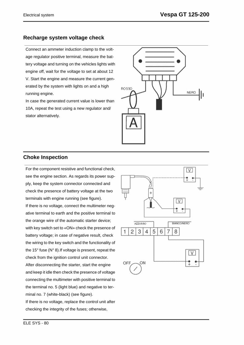
Recharge system voltage check
Connect an ammeter induction clamp to the volt-
age regulator positive terminal, measure the bat-
tery voltage and turning on the vehicles lights with
engine off, wait for the voltage to set at about 12
V. Start the engine and measure the current gen-
erated by the system with lights on and a high
running engine.
In case the generated current value is lower than
10A, repeat the test using a new regulator and/
stator alternatively.
Choke Inspection
For the component resistive and functional check,
see the engine section. As regards its power sup-
ply, keep the system connector connected and
check the presence of battery voltage at the two
terminals with engine running (see figure).
If there is no voltage, connect the multimeter neg-
ative terminal to earth and the positive terminal to
the orange wire of the automatic starter device;
with key switch set to «ON» check the presence of
battery voltage; in case of negative result, check
the wiring to the key switch and the functionality of
the 15° fuse (N° 8).If voltage is present, repeat the
check from the ignition control unit connector.
After disconnecting the starter, start the engine
and keep it idle then check the presence of voltage
connecting the multimeter with positive terminal to
the terminal no. 5 (light blue) and negative to ter-
minal no. 7 (white-black) (see figure).
If there is no voltage, replace the control unit after
checking the integrity of the fuses; otherwise,
Electrical system Vespa GT 125-200
ELE SYS - 80

check the wiring between starter and control unit,
or finally, as last option replace the starter.
Turn signals system check
- If the turn indicators do not work, proceed as follows:
-Disconnect the control unit connector and check that there is battery voltage between terminal No.4
(Red/Black) and the ground lead.
-Check that the same happens between terminal No. 4 and terminal No. 8 (Black).
-Repeat the check between terminal No. 5 (Sky blue) and terminal No. 8 (Black) with the key switch set
to "ON", with the emergency switch set to "RUN".
If no voltage is detected, check the cable harness, the connections and make sure the 15A main fuse
is in good conditions; otherwise, proceed as follows:
- Jump terminals No.1 (Black/Blue) and No. 4 (Red/Black) (see figure), and set the turn indicator switch
alternately to the left and to the right and check that the lights turn on.
If they do, replace the control unit because it is faulty.
If they do not turn on, check the control unit-turn indicator switch connection cable harness; then, repeat
the test.
If the cable harness is in good conditions and the turn indicators still do not turn on, replace the turn
indicator switch because it is faulty.
Vespa GT 125-200 Electrical system
ELE SYS - 81

Fuses
The electrical system is equipped with:
1. six protection fuses «A» located in the glove
compartment to the left
2. one 15A fuse «B» located under the helmet
compartment under the saddle hinge latch.
The chart shows the position and characteristics
of the fuses in the vehicle.CAUTION
BEFORE REPLACING THE BLOWN FUSE,SEARCH AND SOLVE THE PROBLEM THATCAUSED IT TO BLOW.NEVER TRY TO REPLACE A BLOWN FUSEWITH A FUSE OF A DIFFERENT RATING THANTHAT SPECIFIED OR USING OTHER MATERI-AL (FOR EXAMPLE, A PIECE OF ELECTRICALWIRE).
FUSESSpecification Desc./Quantity
1 Rear side/taillight, numberplate holder, instrumentlighting and instrument
light indicator.
Order on terminal hold-er: 1
Fuse: 5AProtected circuits: Rearside/taillight, number plateholder, instrument lightingand instrument light indi-
cator.2 Stop light bulb, remote
control start switch enablesignal
Order on terminal hold-er: 2
Fuse: 5AProtected circuits: Stoplight bulb, remote controlstart switch enable signal
3 Intercom fitting, antitheftfitting, water temperatureindicator, fuel reserve indi-cator, oil pressure indica-tor and fuel reserve light
Order on terminal hold-er: 3
Fuse: 7,5AProtected circuits: Inter-com fitting, antitheft fitting,
Electrical system Vespa GT 125-200
ELE SYS - 82

Specification Desc./Quantitywater temperature indica-tor, fuel reserve indicator,oil pressure indicator and
fuel reserve light4 Horn Order on terminal hold-
er: 4Fuse: 7,5A
Protected circuits: Horn5 Intercom fitting, antitheft
fitting, immobilizer ledOrder on terminal hold-
er: 5Fuse: 7,5A
Protected circuits: Inter-com fitting, antitheft fitting,
immobilizer led6 Electric saddle opener,
dipped/full headlights, fullheadlight indication light
Order on terminal hold-er: 6
Fuse: 10AProtected circuits: Elec-tric saddle opener, dipped/full headlights, full head-
light indication light7 General Order on terminal hold-
er: 7Fuse: 15A
Protected circuits: Gen-eral
Dashboard
A = Digital clock with calendar
B = Cooling liquid temperature gauge
C = Right turn indicator warning light
D = Fuel gauge
E = Headlight warning light
F = High-beam warning light
G = Low oil pressure warning light
H = Low fuel warning light
I = Speedometer
L = Odometer
M = Left turn indicator warning light
N = Antitheft device LED (immobilizer)
ASpecification Desc./Quantity
1 Fuel gauge signal2 High-beam warning light3 Oil warning light4 Fuel supply (+)5 Low fuel warning light6 Lighting
BSpecification Desc./Quantity
1 Ground lead2 Left turn indicator
Vespa GT 125-200 Electrical system
ELE SYS - 83

Specification Desc./Quantity3 Right turn indicator4 Temperature signal
Dry-charge battery
Battery recharge
Normal bench charging must be carried out using the special (single or multiple) battery charger, setting
the battery charge selector to the type of battery that needs recharging (i.e., at a current equal to 1/10
of the battery rated capacity). Connections to the power supply source must be implemented by con-
necting corresponding poles (+ to + and - to - ).WARNING
BEFORE RECHARGING THE BATTERY, REMOVE THE CAPS OF EACH CELL.KEEP THE BATTERY AWAY FROM NAKED FLAMES OR SPARKS WHILE IT IS CHARGED.FIRST DETACH THE NEGATIVE LEAD BEFORE REMOVING THE BATTERY FROM THE VEHICLE.
Specific tooling020333Y Single battery charger
020334Y Multiple battery charger
Charging status check
After topping-up the electrolyte level, check the density using special densimeter
When the battery is charged, you should detect a density of 30 to 32 Bé corresponding to a specific
weight of 1.26 to 1.28 at a temperature of no lower than 15° C.
A density reading of less than 20° Bé indicates that the battery is completely flat and it must therefore
be recharged.
If the scooter is not used for a given time (1 month or more) it will be necessary to periodically recharge
the battery.
The battery runs down completely in the course of three months. If it is necessary to refit the battery in
the vehicle, be careful not to reverse the connections, remembering that the ground wire (black) marked
(-) must be connected to the -negative clamp while the other two red wires marked (+) must be con-
nected to the clamp marked with the +positive sign.
Electrical system Vespa GT 125-200
ELE SYS - 84

Battery cleaning
The battery should always be kept clean, especially on its top side, and the terminals should be coated
with Vaseline.CAUTION
NEVER USE FUSES WITH A CAPACITY HIGHER THAN THAT RECOMMENDED.USING A FUSE OF UNSUITABLE RATING MAY SERIOUSLY DAMAGE THE VEHICLE OR EVENCAUSE A FIRE.CAUTION
DRINKING WATER CONTAINS MINERALS THAT CAN BE EXTREMELY HARMFUL TO THE BAT-TERY: USE DISTILLED WATER ONLY.CAUTION
TO ENSURE MAXIMUM PERFORMANCE THE BATTERY MUST BE CHARGED BEFORE USE.INADEQUATE CHARGING OF THE BATTERY WITH A LOW ELECTROLYTE LEVEL BEFORE ITIS FIRST USED SHORTENS THE LIFE OF THE BATTERY.
Checking the electrolyte level
The electrolyte level must be checked frequently and must reach the upper level. Only use distilled
water, to restore this level. If it is necessary to add water too frequently, check the vehicle's electrical
system: the battery works overcharged and is subject to quick wear.
- Remove the short closed tube and the caps, then
pour sulphuric acid into the cells using the type
specified for batteries with a specific gravity of
1.26, corresponding to 30 Bé at a minimum tem-
perature of 15°C until the upper level is reached.
- Allow to stand for at least 2 hours, then top up the
level with sulphuric acid.
- Within the following 24 hours, recharge with the
specific (single) or (multiple) battery charger at an
intensity approx. to 1/10 of the battery rated ca-
pacity and until the acid density is approximately
1.27, corresponding to 31º Bé, and these values
are stabilised.
- After charging, level the acid (adding distilled
water). Close and clean carefully.
- Once the above operations have been per-
formed, install the battery in the vehicle ensuring
that it is wired up properly.
Specific tooling020333Y Single battery charger
Vespa GT 125-200 Electrical system
ELE SYS - 85

020334Y Multiple battery charger
1 Hold the vertical tube
2 Look at the level
3 The float must be freed
Battery installation
• Remove the battery cover after undoing the 4
screws shown in the photograph.
- Remove the strap fastening the battery
- Insert the battery breather pipe through the hole
shown in the photograph.
Electrical system Vespa GT 125-200
ELE SYS - 86

- Fit the battery as shown in the photograph.N.B.IN ORDER TO FIT THE CABLES ON THE BATTERY TER-MINALS CORRECTLY, REST THE LOWER END OF THETERMINAL SIDE OF THE BATTERY ON THE EDGE OF THEBATTERY WELL.
- Using the screwdriver, tighten up the battery ter-
minal cables as far as they will go, placing the
special Grover washer between the screw head
and the cable terminal.N.B.DO NOT USE WRENCHES TO TIGHTEN UP THE SCREWSFOR FIXING THE TERMINALS TO THE BATTERY TERMI-NALS
- Mount permanently the battery in the battery
chamber
- Refit the strap fastening the battery
Vespa GT 125-200 Electrical system
ELE SYS - 87

- Refit the battery cover
Electrical system Vespa GT 125-200
ELE SYS - 88

INDEX OF TOPICS
ENGINE FROM VEHICLE ENG VE

This section describes the operations to be carried out when removing the engine from the vehicle.
Exhaust assy. Removal
- Undo the two exhaust manifold fixings on the
head.
- Undo the three screws that fix the muffler to the
support arm.
- Remove the full muffler unit.
Removal of the engine from the vehicle
-Carry out the removal operations but in reverse order and respect the locking torques indicated in the
Characteristics Chapter.
Check that there is a small clearance when the valve is in abutment against the set screw.
-Check the engine oil level and if necessary top it up with the recommended type.
- Top-up the cooling circuit.
- Check the functioning of the accelerator and the electrical devices.CAUTION
PAY PARTICULAR ATTENTION TO POSITIONING THE THROTTLE CONTROL TRANSMISSIONPROPERLY.
Engine from vehicle Vespa GT 125-200
ENG VE - 90
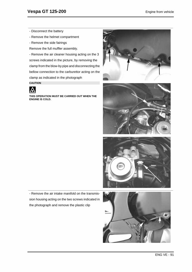
- Disconnect the battery
- Remove the helmet compartment
- Remove the side fairings
Remove the full muffler assembly.
- Remove the air cleaner housing acting on the 3
screws indicated in the picture, by removing the
clamp from the blow-by pipe and disconnecting the
bellow connection to the carburettor acting on the
clamp as indicated in the photographCAUTION
THIS OPERATION MUST BE CARRIED OUT WHEN THEENGINE IS COLD.
- Remove the air intake manifold on the transmis-
sion housing acting on the two screws indicated in
the photograph and remove the plastic clip
Vespa GT 125-200 Engine from vehicle
ENG VE - 91

- Remove the coolant inlet pipe to the pump as in-
dicated in the photograph.
- Remove the fuel valve vacuum intake pipe from
"T" joint indicated in the photograph
- Remove the fuel supply pipe from the carburettor
- Remove the coolant outlet pipe from the engine
and the bleed pipe indicated in the photograph
Engine from vehicle Vespa GT 125-200
ENG VE - 92

- Remove the spark plug cap
- Remove the coolant temperature sensor con-
nector indicated in the photo
- Remove the throttle control cable from the car-
burettor acting on the nut shown in the photo
- Remove the automatic starter connector from the
system located inside the protection sheath shown
in the photo
Vespa GT 125-200 Engine from vehicle
ENG VE - 93

- Remove the positive and negative wires from the
starter motor as shown in the photograph
- Remove the connector from the flywheel wiring
shown in the photograph.
- Remove the cable from the retainer clamp on the
flywheel cover
- Remove the rear shock absorbers.
- Remove the hydraulic piping from the rear cal-
liper by undoing the screw indicated in the photo-
graph. Then remove the retainers fixing the piping
to the engine crankcase, indicated in the photo-
graph.
Engine from vehicle Vespa GT 125-200
ENG VE - 94

- Use a jack to support the vehicle properly. Re-
move the engine-swinging arm fixing pin by acting
on the nut and the head of the pin indicated in the
photograph
- The engine is now free.
Vespa GT 125-200 Engine from vehicle
ENG VE - 95

INDEX OF TOPICS
ENGINE ENG

This section describes the operations to be carried out on the engine and the tools to be used.
Automatic transmission
Transmission cover
- To remove the transmission cover it is necessary
to remove the plastic cover first, by inserting a
screwdriver in the slotted holes. Using the clutch
bell lock wrench shown in the figure, remove the
driven pulley shaft locking nut and washer.
Specific tooling020423Y driven pulley lock wrench
- Remove the cap/dipstick from the engine oil filling
hole.
- Remove the ten screws.
- Remove the transmission cover.
If this operation is carried out directly on the vehi-
cle, remove the cooling air supply coupling of the
transmission housing.
Air duct
Version 125
- Remove the 4 screws and the housing.
Vespa GT 125-200 Engine
ENG - 97

- Remove the five screws on two different levels
as well as the small casing.
- To remove the intake throat on the transmission
cover, just remove the 2 fixing screws indicated in
the figure.
Removing the driven pulley shaft bearing
- Remove the clip from the inside of the cover.
- Remove the bearing from the crankcase by
means of:
Specific tooling020376Y Adaptor handle
020375Y Adaptor 28 x 30 mm
020412Y 15 mm guide
Engine Vespa GT 125-200
ENG - 98
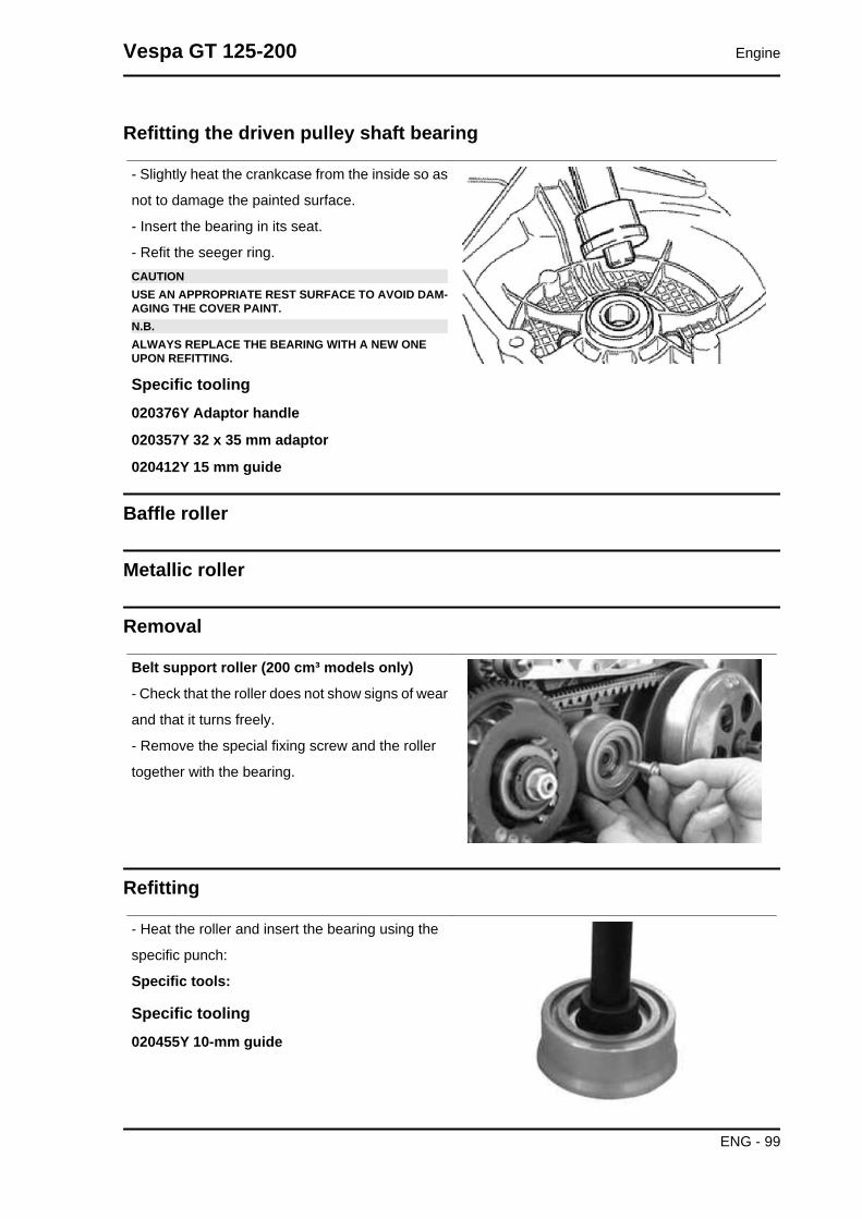
Refitting the driven pulley shaft bearing
- Slightly heat the crankcase from the inside so as
not to damage the painted surface.
- Insert the bearing in its seat.
- Refit the seeger ring.CAUTIONUSE AN APPROPRIATE REST SURFACE TO AVOID DAM-AGING THE COVER PAINT.N.B.ALWAYS REPLACE THE BEARING WITH A NEW ONEUPON REFITTING.
Specific tooling020376Y Adaptor handle
020357Y 32 x 35 mm adaptor
020412Y 15 mm guide
Baffle roller
Metallic roller
Removal
Belt support roller (200 cm³ models only)
- Check that the roller does not show signs of wear
and that it turns freely.
- Remove the special fixing screw and the roller
together with the bearing.
Refitting
- Heat the roller and insert the bearing using the
specific punch:
Specific tools:
Specific tooling020455Y 10-mm guide
Vespa GT 125-200 Engine
ENG - 99

- Refit the roller with the special screw.
- Tighten to the specified torque.
- Refit the intake throat with the O-ring, the sump
sealing gasket and a the fan housing.
Locking torques (N*m)Anti-flapping roller 12 - 16
Removing the driven pulley
- Remove the spacer, the clutch bell and the whole
driven pulley unit.N.B.THE UNIT CAN ALSO BE REMOVED WITH THE DRIVINGPULLEY MOUNTED.
Inspecting the clutch drum
- Check that the clutch bell is not worn or damaged.
- Measure the clutch bell inside diameter.
CharacteristicMax. value clutch bellMax. value: Ø 134.5 mm
Clutch bell standard valueStandard value: Ø 134 - 134.2 mm
Checking the bell working surface eccentricity
- Install the bell on a driven pulley shaft using 2
bearings (inner diameter 15 and 17 mm).
- Lock with the original spacer and nut.
- Place the bell/shaft assembly on the support to
check the crankshaft alignment.
Engine Vespa GT 125-200
ENG - 100

- Using a feeler pin gauge and the magnetic base,
measure the bell eccentricity.
- Repeat the measurement in 3 positions (Central,
internal, external).
- If faults are found, replace the bell.
Specific tooling020074Y Support base for checking crankshaftalignment
020335Y Magnetic support for dial gauge
Characteristicclutch bell inspection: Limit eccentricity.Admissible limit eccentricity: 0.15 mm
Removing the clutch
Clutch removal (125 cm³ H2O)
Fit the driven pulley spring compressor specific
tool with medium length pins screwed in position
F from the tool internal side.
- Insert the adapter ring 8 in the pins.
- Assemble the driven pulley unit on the tool intro-
ducing the rivets heads in the adapter ring.
- Make sure that the clutch is perfectly inserted into
the adapter ring before proceeding to loosen/tight-
en the clutch nut.
- Use the special 46x55 wrench component n°9 to
remove the nut fixing the clutch in place.
- Separate the driven pulley components (Clutch,
fan and spring with plastic fitting).CAUTIONTHE TOOL MUST BE FIRMLY FIXED IN THE CLAMP ANDTHE CENTRAL SCREW MUST BE BROUGHT INTO CON-TACT WITH THE TOOL. EXCESSIVE TORQUE CAN CAUSETHE SPECIFIC TOOL TO BUCKLE.
Specific tooling020444Y009 46x55 Wrench
020444Y010 adapter ring
Vespa GT 125-200 Engine
ENG - 101

- Fit the special driven pulley spring compressor
tool with the medium-length pins in position "C"
screwed up from the inner side of the tool.
- Introduce the adapter ring 11 with the chamfering
facing the inside of the tool.
- Fit the driven pulley unit on the tool with the in-
sertion of the 3 pins in the ventilation holes in the
mass holder support.
- Make sure that the clutch is perfectly inserted into
the adapter ring before proceeding to loosen/tight-
en the clutch nut.
- Use the special 46x55 wrench component 9 to
remove the nut fixing the clutch in place.
- Separate the driven pulley into its components
(Clutch and spring with its plastic holder)CAUTIONTHE TOOL MUST BE FIRMLY FIXED IN THE CLAMP ANDTHE CENTRAL SCREW MUST BE BROUGHT INTO CON-TACT WITH THE TOOL. EXCESSIVE TORQUE CAN CAUSETHE SPECIFIC TOOL TO BUCKLE.
Specific tooling020444Y009 46x55 Wrench
020444Y011 adapter ring
Inspecting the clutch
- Check the thickness of the clutch mass friction
material.
- The masses must not show traces of lubricants;
otherwise, check the driven pulley unit seals.N.B.UPON RUNNING-IN, THE MASSES MUST EXHIBIT A CEN-TRAL CONTACT SURFACE AND MUST NOT BE DIFFER-ENT FROM ONE ANOTHER.VARIOUS CONDITIONS CAN CAUSE THE CLUTCH TOTEAR.CAUTIONDO NOT OPEN THE MASSES USING TOOLS TO PREVENTA VARIATION IN THE RETURN SPRING LOAD.
CharacteristicCheck minimum thickness1 mm
Engine Vespa GT 125-200
ENG - 102

Pin retaining collar
- Simultaneously turn and pull the collar manually
to remove it.N.B.USE TWO SCREWDRIVERS IF YOU HAVE DIFFICULTY.N.B.BE CAREFUL NOT TO PUSH THE SCREW DRIVERS INTOO FAR TO AVOID DAMAGE THAT COULD ENDANGERTHE O-RING SEAL.
- Remove the four torque server pins and pull the
pulley halves apart.
Removing the driven half-pulley bearing
- Check there are no signs of wear and/or noisi-
ness; - Replace with a new one if there are.
- Remove the retaining ring using two flat blade
screwdrivers.
- Support the pulley bushing adequately from the
threaded side using a wooden surface.
- Using a hammer and pin, knock the ball bearing
out as shown in the figure.
- Support the pulley properly using the bell as shown in the figure.
Specific tooling001467Y035 Belle for OD 47-mm bearings
Vespa GT 125-200 Engine
ENG - 103

- Remove the roller bearing using the modular
punch.
Specific tooling020376Y Adaptor handle
020456Y Ø 24 mm adaptor
020363Y 20 mm guide
Inspecting the driven fixed half-pulley
Version 125
- Measure the outer diameter of the pulley bushing.
- Check the contact surface with the belt to make
sure there are no flaws.
CharacteristicHalf-pulley standard diameterStandard diameter: Ø 40.985 mm
Half-pulley minimum diameterMinimum admissible diameter Ø 40.96 mm
- Measure the outer diameter of the pulley bushing.
- Check the contact surface with the belt to make
sure there are no flaws.
- Check the riveted joints are functional.
- Check the evenness of the belt contact surface.
CharacteristicHalf-pulley minimum diameterMinimum admissible diameter Ø 40.96 mm
Half-pulley standard diameterStandard diameter: Ø 40.985 mm
Wear limit0.3 mm
Engine Vespa GT 125-200
ENG - 104

Inspecting the driven sliding half-pulley
125 - 200 version
- Remove the two internal grommets and the two
O-rings.
- Measure the movable half-pulley bushing inside
diameter.
CharacteristicMovable driven half-pulley max. diameterMax. diameter admitted: Ø 41.08 mm
Movable driven half-pulley standard diameterStandard diameter: Ø 41.000 ÷ 41.035 mm
- Remove the two internal grommets and the two
O-rings.
- Measure the movable half-pulley bushing inside
diameter.
- Check that the faying surface with the belt is not
abnormally worn.
- Check the riveted joints are functional.
- Check the evenness of the belt faying surface.
Vespa GT 125-200 Engine
ENG - 105

MOVABLE DRIVEN HALF-PULLEY DIMENSIONSSpecification Desc./Quantity
Wear limit 0.3 mmstandard diameter Diameter 41.000 - 41.035 mm
maximum allowable diameter Ø 41.08 mm
- Remove the belt and slide the movable half-pulley with the relevant bush, taking care of the falling
free assembled rollers.
- Remove the return rollers plate with the relative guide pads.
Refitting the driven half-pulley bearing
- Support the pulley bushing adequately from the
threaded side using a wooden surface.
- Fit a new roller sleeve as in the figure.
- For the fitting of the new ball bearing, follow the
example in the figure using a modular punch.
Fit the snap ringWARNINGN.B.FIT THE BALL BEARING WITH THE VISIBLE SHIELD
Specific tooling020376Y Adaptor handle
020375Y Adaptor 28 x 30 mm
020424Y Driven pulley roller casing fittingpunch
Engine Vespa GT 125-200
ENG - 106
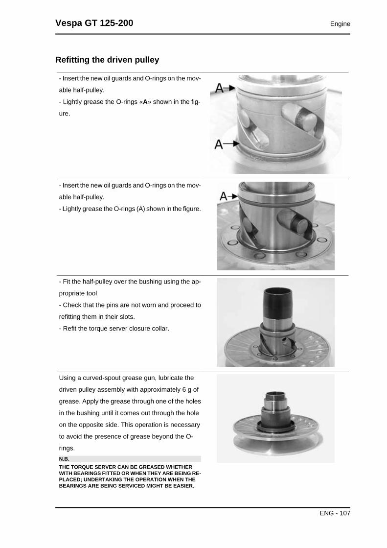
Refitting the driven pulley
- Insert the new oil guards and O-rings on the mov-
able half-pulley.
- Lightly grease the O-rings «A» shown in the fig-
ure.
- Insert the new oil guards and O-rings on the mov-
able half-pulley.
- Lightly grease the O-rings (A) shown in the figure.
- Fit the half-pulley over the bushing using the ap-
propriate tool
- Check that the pins are not worn and proceed to
refitting them in their slots.
- Refit the torque server closure collar.
Using a curved-spout grease gun, lubricate the
driven pulley assembly with approximately 6 g of
grease. Apply the grease through one of the holes
in the bushing until it comes out through the hole
on the opposite side. This operation is necessary
to avoid the presence of grease beyond the O-
rings.N.B.THE TORQUE SERVER CAN BE GREASED WHETHERWITH BEARINGS FITTED OR WHEN THEY ARE BEING RE-PLACED; UNDERTAKING THE OPERATION WHEN THEBEARINGS ARE BEING SERVICED MIGHT BE EASIER.
Vespa GT 125-200 Engine
ENG - 107

Specific tooling020263Y Sheath for driven pulley fitting
Recommended productsAGIP GREASE SM 2 Grease for the tone wheelrevolving ringSoap-based lithium grease containing NLGI 2 Mo-
lybdenum disulphide; ISO-L-XBCHB2, DIN
KF2K-20
Inspecting the clutch spring
- Measure the free length of the mobile driven half-
pulley spring.
CharacteristicStandard length (125)106 mm
limit after use (125)101 mm
Standard length (200 - 250)123 mm
Limit after use (200 - 250)118 mm
Refitting the clutch
- Support the driven pulley spring compressor ap-
propriate tool with the control screw in vertical axis.
- Arrange the tool with the medium length pins
screwed in position "C" on the inside.
- Introduce the adapter ring 11 with the chamfering
facing upwards.
- Insert the clutch on the adapter ring.
- Lubricate the end of the spring that abuts against
the servo-system closing collar.
- Insert the spring with its plastic holder in contact
with the clutch.
- Insert the driving belt into the pulley unit accord-
ing to their direction of rotation.
- Insert the pulley unit with the belt into the tool.
Engine Vespa GT 125-200
ENG - 108

- Slightly preload the spring.
- Make sure that the clutch is perfectly inserted into
the adapter ring before proceeding to tighten the
clutch nut.
- Place the tool in the clamp with the control screw
on the horizontal axis.
- Fully preload the spring.
- Apply the clutch fixing nut and tighten it to the
prescribed torque using the special 46x55 wrench.
- Loosen the tool clamp and insert the belt accord-
ing to its direction of rotation.
- Lock the driven pulley again using the specific
tool.
- Preload the clutch return spring with a traction/
rotation combined action and place the belt in the
smaller diameter rolling position.
- Remove the driven pulley /belt unit from the tool.N.B.DURING THE SPRING PRELOADING PHASE, BE CARE-FUL NOT TO DAMAGE THE PLASTIC SPRING STOP ANDTHE BUSHING THREADING.N.B.FOR DESIGN REASONS, THE NUT IS SLIGHTLY ASYM-METRIC; THE FLATTEST SURFACE SHOULD BE MOUN-TED IN CONTACT WITH THE CLUTCH.
Specific tooling020444Y Tool for fitting/ removing the drivenpulley clutch
020444Y011 adapter ring
020444Y009 46x55 Wrench
Locking torques (N*m)Nut locking clutch unit on pulley 55 ÷ 60 Nm
Vespa GT 125-200 Engine
ENG - 109

Version 125
- Support the driven pulley spring compressor ap-
propriate tool with the control screw in vertical axis.
- Arrange the tool with the medium length pins
screwed in position «F» on the inside.
- Insert the adapter ring 8 in the pins.
- Preassemble the cooling fan to the clutch in such
a way that the keying facets are aligned and the 3
pin heads (A) of the mass axis can be seen in full.
- Insert the clutch on the adapter ring.
- Lubricate the end of the spring that abuts against
the servo-system closing collar.
- Insert the spring with its plastic holder in contact
with the clutch.
- Insert the driving belt into the pulley unit accord-
ing to their direction of rotation.
- Insert the pulley unit with the belt into the tool.
- Slightly preload the spring.
- Make sure that the clutch is perfectly inserted into
the adapter ring before proceeding to tighten the
clutch nut.
- Place the tool in the clamp with the control screw
on the horizontal axis.
- Fully preload the spring.
- Apply the clutch lock nut and tighten it to the
specified torque using the specific 46x55 spanner.
- Loosen the tool clamp and insert the belt accord-
ing to its direction of rotation.
- Lock the driven pulley again using the specific
tool.
- Preload the clutch return spring with a traction/
rotation combined action until it reaches the pul-
leys maximum opening and place the belt on the
minimum rolling diameter.
- Remove the driven pulley /belt unit from the tool.N.B.FOR DESIGN REASONS, THE NUT IS SLIGHTLY ASYM-METRIC; THE FLATTEST SURFACE SHOULD BE MOUN-TED IN CONTACT WITH THE CLUTCH.
Engine Vespa GT 125-200
ENG - 110

N.B.DURING THE SPRING PRELOADING PHASE, BE CARE-FUL NOT TO DAMAGE THE PLASTIC SPRING STOP ANDTHE BUSHING THREADING.N.B.AN EXCESSIVE QUANTITY CAN DAMAGE THE CLUTCHOPERATION.
Specific tooling020444Y011 adapter ring
020444Y009 46x55 Wrench
Locking torques (N*m)Clutch unit nut on driven pulley 55 ÷ 60
Refitting the driven pulley
- Reassemble the clutch bell and spacer.
Drive-belt
During the wear checks foreseen in the scheduled
maintenance services at 6,000 km; 18,000 km;
etc., check that the rim bottom of the toothing does
not show signs of incisions or cracking (see figure):
The rim bottom of the tooth must not have incisions
or cracking; if it does, change the belt.
Vespa GT 125-200 Engine
ENG - 111

• Check that the driving belt is not dam-
aged.
• Check the belt width.
Characteristic125 4T driving belt - standard width:22.5 ± 0.2 mm125 4T driving belt - minimum width:21.5 mmDriving belt standard width20.5 ± 0.2 mm
Driving belt minimum width19.5 mm
Removing the driving pulley
Driving pulley removal
- With the appropriate tool placed into the internal
slots, remove the nut with the built-in Belleville
washer.
Appropriate tools:
Specific tooling020442Y Pulley lock wrench
- Remove the entire start-up crown unit with the
torque limiter.
- Remove the fixed driving half-pulley together with
the O-ring and the steel washer touching the bush-
ing.
Engine Vespa GT 125-200
ENG - 112

Driving pulley removal (125)
- With the appropriate tool, remove the nut with the
built-in Belleville washer, the drive common to the
kick-starter version, and the steel washer.
- Remove the fixed driving half-pulley.
- Remove the steel washer separating from the
bushing.
Appropriate tools:
Specific tooling020368Y driving pulley lock wrench
Inspecting the rollers case
- Check that the internal bushing shown in the fig-
ure is not abnormally worn and measure inner
diameter A.
- Measure the pulley sliding bushing outside di-
ameter shown in the figure.
- Check that the rollers are not damaged or worn.
- Check the guide shoes for the variator back-plate
are not worn.
- Check the wear of the roller housings and of the
belt contact surfaces on both pulley halves.
- Check that stationary driving pulley does not
show signs of abnormal wear on the grooved edge
and on the surface in contact with the belt.
- Check that the O-ring is not pushed out of shape.CAUTIONDO NOT LUBRICATE OR CLEAN SINTERED BUSHINGS
Characteristicroller (200): Minimum diameter allowedØ 20 mm
roller (125): Minimum diameter allowedØ 18.5 mm
Sliding bushing: Minimum admissible diame-terØ 25.95 mm
Movable driving half-pulley bushing: Maxi-mum allowable diameter
Vespa GT 125-200 Engine
ENG - 113
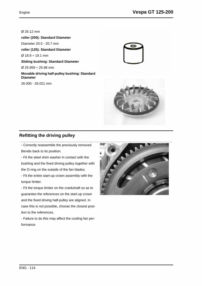
Ø 26.12 mm
roller (200): Standard DiameterDiameter 20.5 - 20.7 mm
roller (125): Standard DiameterØ 18.9 ÷ 19.1 mm
Sliding bushing: Standard DiameterØ 25.959 ÷ 25.98 mm
Movable driving half-pulley bushing: StandardDiameter26.000 - 26.021 mm
Refitting the driving pulley
- Correctly reassemble the previously removed
Bendix back to its position.
- Fit the steel shim washer in contact with the
bushing and the fixed driving pulley together with
the O-ring on the outside of the fan blades.
- Fit the entire start-up crown assembly with the
torque limiter.
- Fit the torque limiter on the crankshaft so as to
guarantee the references on the start-up crown
and the fixed driving half-pulley are aligned. In
case this is not possible, choose the closest posi-
tion to the references.
- Failure to do this may affect the cooling fan per-
formance
Engine Vespa GT 125-200
ENG - 114

The lock wrench operates on the start-up crown.
- If the torque limiter is worn, the failure can be de-
tected when locking the nut on the crankshaft.
- The torque limiter cannot be serviced.
- In case of failures, replace the start-up crown and
the limiter.
Specific tooling020442Y Pulley lock wrench
Recommended productsLoctite "Super Rapido" Loctite "Super Rapido"243Apply Loctite "Super Rapido" 243 on the threads
and screw the nut with washer to the prescribed
torque.
Locking torques (N*m)Drive pulley nut 75 ÷ 83
- Correctly refit the previously removed Bendix
back to its position.
- Reassemble the parts of the unit (internal lining,
fixed half-pulley, external lining, drive and nut),
spread Loctite 243 Quick Set threadlock on the
thread and tighten the nut to the prescribed torque.
- Avoid the half-pulley rotation with the appropriate
stop key tool..
- Rotate the engine manually until the belt is slight-
ly taut.CAUTIONIT IS EXTREMELY IMPORTANT THAT THE BELT IS PER-FECTLY FREE WHEN THE FIXED DRIVING HALF-PULLEYIS ASSEMBLED. THIS IS TO AVOID CARRYING OUT AWRONG TIGHTENING OF THE DRIVING HALF-PULLEY.
Specific tooling020368Y driving pulley lock wrench
Locking torques (N*m)Drive pulley nut 75 ÷ 83
Vespa GT 125-200 Engine
ENG - 115

- Preassemble the movable half-pulley with the
roller contrast plate by putting the rollers in their
housings with the larger support surface touching
the pulley according to the direction of rotation.
- Check that the roller contact plate does not have
flaws and is not damaged on the grooved edge.
- Mount the complete bushing unit on the driving
shaft.
- Fit the driven pulley/Clutch/belt unit on the en-
gine.
Refitting the transmission cover
- Check the presence of the 2 centring dowels and
the correct installation of the sealing gasket for the
oil sump on the transmission cover.
- Replace the cover tightening the 10 screws at the
specified torque.
- Refit the oil loading cap/bar.
- refit the steel washer and the driven pulley nut.
- Tighten the nut to the prescribed torque using the
lock wrench and the torque wrench tools.
- Replace the plastic cover.
Engine Vespa GT 125-200
ENG - 116

Specific tooling020423Y driven pulley lock wrench
Locking torques (N*m)Transmission cover screws 11 ÷ 13 Driven pul-ley shaft nut 54 ÷ 60
End gear
Removing the hub cover
- Empty the rear hub through the oil drainage plug.
- Remove the 7 flanged screws indicated in the
figure.
- Remove the hub cover and its gasket.
Removing the wheel axle
- Remove the wheel axis complete with gear.
- Remove the intermediate gear.
Vespa GT 125-200 Engine
ENG - 117

Removing the hub bearings
- Check the state of the bearings being examined
(wear, clearance and noisiness). If faults are de-
tected, do the following.
- Use the specific bearing extractor to remove the
three 15 mm bearings (2 in the crankcase and 1 in
the hub cover).
Specific tooling001467Y013 Pliers to extract ø 15-mm bearings
Removing the wheel axle bearings
Hold up the hub cover and take out the bearing.
Specific tooling020376Y Adaptor handle
020477Y Adaptor 37 mm
020483Y 30 mm guide
Engine Vespa GT 125-200
ENG - 118
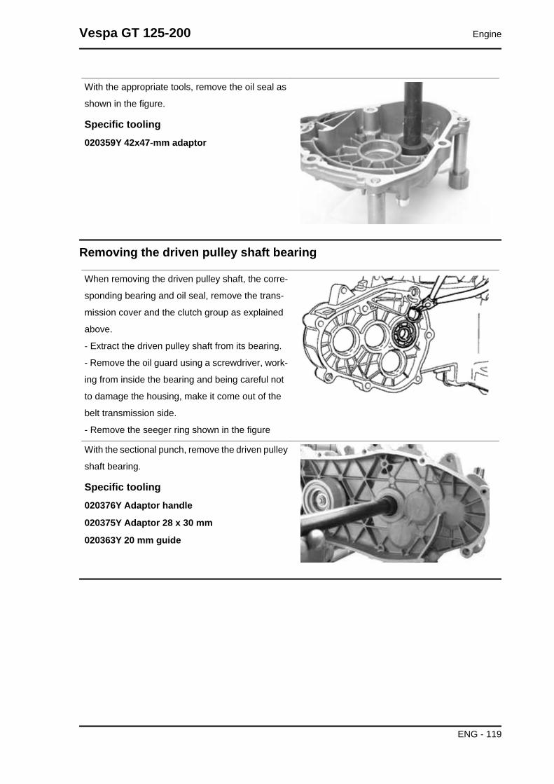
With the appropriate tools, remove the oil seal as
shown in the figure.
Specific tooling020359Y 42x47-mm adaptor
Removing the driven pulley shaft bearing
When removing the driven pulley shaft, the corre-
sponding bearing and oil seal, remove the trans-
mission cover and the clutch group as explained
above.
- Extract the driven pulley shaft from its bearing.
- Remove the oil guard using a screwdriver, work-
ing from inside the bearing and being careful not
to damage the housing, make it come out of the
belt transmission side.
- Remove the seeger ring shown in the figure
With the sectional punch, remove the driven pulley
shaft bearing.
Specific tooling020376Y Adaptor handle
020375Y Adaptor 28 x 30 mm
020363Y 20 mm guide
Vespa GT 125-200 Engine
ENG - 119

Inspecting the hub shaft
- Check the three shafts for wear or distortion of
the toothed surfaces, the bearing housings, and
the oil seal housings.
- In case of anomalies, replace the damaged com-
ponents.
Inspecting the hub cover
- Check that the fitting surface is not dented or distorted.
- Check the bearing bearings.
- In case of anomalies, replace the damaged components.
Refitting the wheel axle bearing
Support the hub cover on a wooden surface.
- Heat the cover crankcase with special heat gun.
- Fit the wheel shaft bearing with a modular punch
as shown in the figure.
Specific tooling020150Y Air heater support
020151Y Air heater
020376Y Adaptor handle
020360Y Adaptor 52 x 55 mm
020483Y 30 mm guide
Assemble the seeger ring.
Engine Vespa GT 125-200
ENG - 120

- Fit the oil guard with seal lip towards the inside
of the hub and place it flush with the internal sur-
face by means of the appropriate tool used from
the 52 mm side.
The 52 mm side of the adapter must be turned to-
wards the bearing.
Refitting the hub cover bearings
For the fitting of the hub box bearings the engine
crankcase and the cover must be heated with the
special heat gun.
- The three 15 mm bearings must be fitted using
the appropriate tools.
- The 42-mm side of the adapter must be turned
towards the bearing.
Specific tooling020150Y Air heater support
020151Y Air heater
020376Y Adaptor handle
020359Y 42x47-mm adaptor
020412Y 15 mm guide
N.B.
TO FIT THE BEARING ON THE COVER, SUPPORT THE COVER WITH THE STUD BOLT SET.
Vespa GT 125-200 Engine
ENG - 121

- Refit the driven pulley shaft bearing with a mod-
ular punch as shown in the figure.N.B.IF THE BEARING HAS AN ASYMMETRICAL BALL RETAIN-ER, PLACE IT SO THAT THE BALLS ARE VISIBLE FROMTHE HUB INNER SIDE.
Specific tooling020376Y Adaptor handle
020359Y 42x47-mm adaptor
020363Y 20 mm guideN.B.
WHEN FITTING THE BEARINGS ON THE ENGINE CRANKCASE, SUPPORT THE CRANKCASEPREFERABLY ON A SURFACE TO ALLOW THE BEARINGS TO BE DRIVEN VERTICALLY.
- Refit the seeger ring with the opening facing the bearing and fit a new oil guard flush with the crankcase
from the pulley side.
Refitting the hub bearings
- Install the three shafts in the engine crankcase as shown in the figure.
Refitting the ub cover
- Fit a new gasket together with the centring dowels.
- Seal the gasket of the breather pipe using black silicone sealant.
- Fit the gearbox cover, making sure the breather pipe is in the correct position.
- Place the 3 shortest screws, identifiable by their different colour, as shown in the figure.
- Fasten the breather pipe support bracket with the lower short screw.
- Assemble the remaining 4 screws and tighten the 7 screws to the prescribed torque.
Locking torques (N*m)Rear hub cover screws 24 ÷ 27
Engine Vespa GT 125-200
ENG - 122

Flywheel cover
Removing the hub cover
- Remove the two clamps, the two couplings and
empty the cooling system.
- Remove the 4 retainers and the flywheel cover
Vespa GT 125-200 Engine
ENG - 123

Removing the stator
- Remove the electric terminal of the minimum oil
pressure switch.
- Remove the two Pick-Up screws and the one for
the wiring harness bracket as well as the two stator
fixing screws shown in the figure.
- Remove the stator and its wiring.
Refitting the stator
- Refit the stator and flywheel carrying out the re-
moval procedure in reverse, tightening the retain-
ers to the specified torque.
- Place the cable harness as shown in the figure.
- Stator screws and Pick-UpN.B.THE PICK-UP WIRE SHOULD BE POSITIONED BETWEENTHE UPPER SCREW AND THE REFERENCE PIN ASSHOWN IN THE DETAIL DRAWING.
Locking torques (N*m)Stator assembly screws (°) 3 ÷ 4
Refitting the flywheel cover
- Place the flywheel with the top dead centre mark
aligned with the crankcase.
- Place the flywheel cover by aligning the reference
marks of the drive and the crankcase cover.
- Reassemble the cover on the engine, placing the
three connectors in the drive for the water pump.
- Carry out the steps in the reverse order from the
dismantling procedure.CAUTIONTAKE CARE TO CORRECTLY POSITION THE FLYWHEELCONNECTOR. MAKE SURE THE CENTRING DOWELS AREPRESENT.
Engine Vespa GT 125-200
ENG - 124

Flywheel and starting
- Check the integrity of the internal plastic parts of the flywheel and the Pick-Up control plate.
Removing the flywheel magneto
- Lock the rotation of the Flywheel with the calliper
spanner tool.
- Remove the nut.
- Take out the flywheel.CAUTIONTHE USE OF A CALLIPER SPANNER OTHER THAN THEONE SUPPLIED COULD DAMAGE THE STATOR COILSN.B.THE FLYWHEEL OF THE 200 CM³ MODELS FEATURESENHANCED INERTIAL MASS.
Inspecting the flywheel components
- Check the integrity of the internal plastic parts of the flywheel and the Pick-Up control plate.
Vespa GT 125-200 Engine
ENG - 125

Refitting the flywheel magneto
- Fit the flywheel being careful to insert the key
properly.
- Lock the flywheel nut to the prescribed torque
- Check that the Pick-Up air gap is between 0.34
÷ 0.76 mm.
The air gap cannot be modified when assembling
the Pick-Up.
Different values result from deformations visible
on the Pick-Up support.N.B.A VARIATION IN THE AIR GAP DISTANCE MODIFIES THEIGNITION SYSTEM IDLE SPEED
Specific tooling020565Y Flywheel lock calliper spanner
Locking torques (N*m)Flywheel nut 54 ÷ 60
Refitting the starter motor
- Fit a new O-ring on the starter motor and lubricate
it.
- Fit the starter on the crankcase, locking the two
screws to the prescribed torque.
Locking torques (N*m)Starter motor screws 11 ÷ 13
Cylinder assy. and timing system
Engine Vespa GT 125-200
ENG - 126

Removing the intake manifold
- Remove the flywheel cover completely as de-
scribed in the flywheel cover section.
- Loosen the 3 crews and remove the intake mani-
fold.N.B.TAMPERPROOF SCREWS ARE SUPPLIED WITH 125 CCMODELS.
Removing the rocker-arms cover
- Remove the 5 screws indicated in the figure
Removing the timing system drive
- Remove the parts listed below first: transmission
cover, drive pulley with belt, oil sump with spring
and by-pass piston, oil pump pulley cover, O-ring
on the crankshaft and the sprocket wheel separa-
tion washer.
- Remove the tappet cover.
- Remove the central screw fastener and the au-
tomatic valve-lifter retaining cover, as shown in the
figure.
Vespa GT 125-200 Engine
ENG - 127

- Remove the return spring of the automatic valve
lifter unit and the automatic valve lifter unit and its
end of stroke washer.
- Loosen the central screw on the tensioner first.
- Remove the two fixings shown in the figure.
- Remove the tensioner with its gasket.
- Remove the internal hex screw and the counter-
weight shown in the figure.
- Remove the camshaft control pulley with its
washer.
Engine Vespa GT 125-200
ENG - 128

- Remove the command sprocket wheel and the
timing chain.
- Remove the screws indicated in the figure, the
spacer bar and the tensioner slider.
The chain tensioning pad must be removed from
the transmission side. As regards the lower chain
guide pad, it may only be removed after the head
has been removed.N.B.IT IS ADVISABLE TO MARK THE CHAIN IN ORDER TO EN-SURE THAT THE INITIAL DIRECTION OF ROTATION ISMAINTAINED.
Removing the cam shaft
- Remove the two screws and the cam shaft re-
tainer shown in the diagram.
- Remove the cam shaft.
- Remove the pins and the rocker arms from the
flywheel side holes.N.B.IN CASE OF NEED, THE HEAD MAY BE REMOVED WITHTHE CAMSHAFT, PINS, ROCKING LEVERS AND FIXINGBRACKET. THE HEAD CAN ALSO BE REMOVED WITH-OUT REMOVING THE CHAIN AND THE DRIVING SHAFTCHAIN TIGHTENER.
Vespa GT 125-200 Engine
ENG - 129

Removing the cylinder head
- Remove the spark plug.
- Remove the 2 side fixings shown in the figure.
- Loosen the 4 head-cylinder fastening nuts in two
or three stages and in criss-cross fashion.
- Remove the head, the two centring dowels and
the gasket.N.B.IN CASE OF NEED, THE HEAD MAY BE REMOVED WITHTHE CAMSHAFT, PINS, ROCKING LEVERS AND FIXINGBRACKET. THE HEAD CAN ALSO BE REMOVED WITH-OUT REMOVING THE CHAIN AND THE DRIVING SHAFTCHAIN TIGHTENER.
Removing the valves
- Using the appropriate tool fitted with an adaptor,
remove the cotters, caps, springs and valves.
- Remove the oil guards with the appropriate tool.
- Remove the lower spring supports.CAUTIONREPLACE THE VALVES IN SUCH A WAY AS TO RECOG-NISE THEIR ORIGINAL POSITION ON THE HEAD.
Specific tooling020382Y011 adapter for valve removal tool
020382Y Valve cotters equipped with part 012removal tool
020306Y Punch for assembling valve sealrings
Engine Vespa GT 125-200
ENG - 130

Removing the cylinder - piston assy.
- Remove the chain guide pad.
- Pull out the cylinder.
- Remove the cylinder base gasket.
- Remove the two stop rings, the wrist pin and the piston.
- Remove the piston seals.CAUTION
TO AVOID DAMAGING THE PISTON, SUPPORT IT WHILE REMOVING THE CYLINDER.N.B.
BE CAREFUL NOT TO DAMAGE THE SEALING RINGS DURING REMOVAL.
Vespa GT 125-200 Engine
ENG - 131

Engine Vespa GT 125-200
ENG - 132

Inspecting the small end
- Measure the internal diameter of the small end
using an internal micrometer.N.B.REPLACE THE CRANKSHAFT IF THE DIAMETER OF THEROD SMALL END EXCEEDS THE STANDARD DIAMETEROR IT SHOWS SIGNS OF WEAR OR OVERHEATING.
CharacteristicRod small end check-up: Maximum diameter15.030 mm
Rod small end check-up: Standard diameter15 +0.015+0.025 mm
Inspecting the wrist pin
- Check the pin outside diameter.
- Calculate the coupling clearance between pin
and connecting rod end.
- Measure the capacity diameter on the piston.
- Calculate the coupling clearance between pin
and piston.
- Measure the piston outside diameter according
to a direction orthogonal to the pin axis.
- Take the measurement in the position shown in
the figure.
125 cc: 41.1 mm (from top) 200 cc: 5 mm (from
base)
- Using a bore gauge, measure the cylinder inside
diameter according to the directions shown in the
figure at three different heights.
- Check that the head matching surface exhibits no
deformations or wear.
Maximum admissible out of plane: 0,05 mm
- Pistons and cylinders are classified into catego-
ries based on their diameter. Coupling is made in
pairs (A-A, B-B, C-C, D-D).
- The cylinder adjustment operation must be car-
ried out with a finishing complying with the original
angle.
Vespa GT 125-200 Engine
ENG - 133

- The cylinder surface must exhibit a roughness of
0.9 micron.
- This is required for ensuring a good settling of the
sealing rings, thereby ensuring a low oil consump-
tion and excellent performance.
For engine 125 cc
- There are uprated pistons for the cylinder adjust-
ment, divided into three categories 1°, 2°, 3° equal
to 0.2-0.4-0.6 mm of uprating. These are classified
in the 4 categories A-A, B-B, C-C, D-D.N.B.THE PIN HOUSINGS HAVE 2 LUBRICATION CHANNELS.FOR THIS REASON MEASUREMENT OF THE DIAMETERMUST BE CARRIED OUT ACCORDING TO THE AXIS OFTHE PISTON.
CharacteristicPiston pin diameter: Standard diameter: 200 -250 cc68,990 ÷ 69,018
Pin diameter Standard diameter: 125 cc56.997 ÷ 57.025
Piston pin diameter: Piston 200 - 25068,933 ÷ 68,961 mm
piston diameter56.945 ÷ 56.973 mm
Pin diameter: Standard clearance0.015 ÷ 0.029 mm
Pin diameter Standard diameter14.996 - 15.000 mm
Wrist pin seat on the piston: Standard diameter15.001 ÷ 15.006 mm
Diameter of the wrist pin seat on the piston:Standard clearance0.001 ÷ 0.010 mm
Engine Vespa GT 125-200
ENG - 134
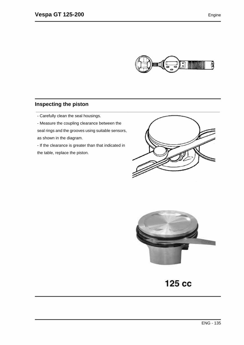
Inspecting the piston
- Carefully clean the seal housings.
- Measure the coupling clearance between the
seal rings and the grooves using suitable sensors,
as shown in the diagram.
- If the clearance is greater than that indicated in
the table, replace the piston.
Vespa GT 125-200 Engine
ENG - 135

Inspecting the piston rings
- Alternately insert the three sealing rings into the cylinder, in the area where it retains its original di-
ameter. Using the piston, insert the rings perpendicularly to the cylinder axis.
- Measure the opening (see figure) of the sealing rings using a feeler gauge.
- If any measurements are greater than specified, replace the piston rings.N.B.
BEFORE REPLACING ONLY THE PISTON RINGS, ENSURE THAT THE CLEARANCE BETWEENTHE PISTON RINGS AND THE PISTON RING GROOVES, AND BETWEEN THE PISTON AND THECYLINDER, IS AS SPECIFIED. IN ANY CASE, NEW PISTON RINGS USED IN COMBINATION WITHA USED CYLINDER MAY HAVE DIFFERENT BEDDING CONDITIONS THAN THE STANDARD.
Removing the piston
- Install piston and wrist pin onto the connecting rod, aligning the piston arrow the arrow facing towards
the exhaust.
- Fit the pin stop ring onto the appropriate tool.
- With opening in the position indicated on the tool
S = left
D = right
- Place the wrist pin stop ring into position using a punch
- Fit the wrist pin stop using the plug as shown in the figureCAUTION
USING A HAMMER MIGHT DAMAGE THE STOPS' HOUSING.N.B.
THE TOOL FOR INSTALLING THE STOP RINGS MUST BE USED MANUALLY.
Specific tooling020430Y Pin lock fitting tool
020454Y Tool for fitting piston pin stops (200 - 250)
Engine Vespa GT 125-200
ENG - 136

Choosing the gasket
- Provisionally fit the piston into the cylinder, with-
out any base gasket.
- Assemble a dial gauge on the specific tool
Support to check piston position 020428Y
- Set the dial gauge to zero placing the tool on a
contrasting surface. Keeping the zero position, as-
semble the tool on the cylinder and lock it with 2
supplied nuts as shown in the figure.
- Rotate the crankshaft until TDC (the inverted
point of the dial gauge rotation)
- Position the dial gauge on the piston as shown in
the figure and measure how much the piston pro-
trudes.
- By means of the table shown in the specifications
chapter identify the cylinder base gasket thickness
to be used for refitting. Correctly identify the cylin-
Vespa GT 125-200 Engine
ENG - 137

der base gasket thickness to keep the correct
compression ratio.
- Remove the specific tool and the cylinder.N.B.PISTON PROTRUSION IS MEASURED IN 125 ENGINESWHILE INTRODUCTION IS MEASURED IN 200 ENGINES.
See alsoSlot packing system
Refitting the piston rings
- Place the oil scraper spring on the piston.
- Refit the oil scraper ring with the join of spring
ends on the opposite side from the ring gap and
the word 'TOP' towards the crown of the piston.
The chamfered side of the oil scraper ring should
always be facing the piston crown.
- Fit the middle piston ring with the identification
letter facing the crown of the piston. In any case,
the step must be facing opposite the piston top.
- Fit the top piston ring with the word 'TOP' or the
reference mark facing the crown of the piston.
- Offset the piston ring gaps on the three rings by
120° to each other as shown in the figure.
- Lubricate the components with engine oil.
- The 200 engine takes the 1st segment with L
section.N.B.THE TWO PISTON RINGS ARE MADE WITH A TAPEREDCYLINDRICAL CONTACT CROSS-SECTION. THIS IS TOACHIEVE A BETTER BEDDING.
Refitting the cylinder
- Insert the cylinder base gasket with the thickness determined above.
- Using the fork support and the piston ring retaining band, refit the cylinder as shown in the figure.
Engine Vespa GT 125-200
ENG - 138
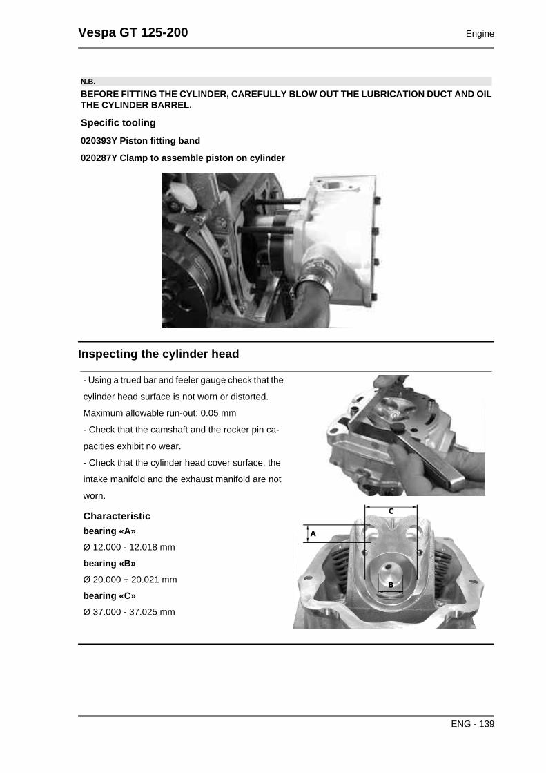
N.B.
BEFORE FITTING THE CYLINDER, CAREFULLY BLOW OUT THE LUBRICATION DUCT AND OILTHE CYLINDER BARREL.
Specific tooling020393Y Piston fitting band
020287Y Clamp to assemble piston on cylinder
Inspecting the cylinder head
- Using a trued bar and feeler gauge check that the
cylinder head surface is not worn or distorted.
Maximum allowable run-out: 0.05 mm
- Check that the camshaft and the rocker pin ca-
pacities exhibit no wear.
- Check that the cylinder head cover surface, the
intake manifold and the exhaust manifold are not
worn.
Characteristicbearing «A»Ø 12.000 - 12.018 mm
bearing «B»Ø 20.000 ÷ 20.021 mm
bearing «C»Ø 37.000 - 37.025 mm
Vespa GT 125-200 Engine
ENG - 139

Inspecting the timing system components
- Check that the guide shoe and the tensioner shoe
are not worn out.
- Ensure that the camshaft control pulley chain as-
sembly and the sprocket wheel are not worn.
- If you encounter wear, replace the parts or, if the
chain, sprocket wheel and pulley are worn replace
the whole assembly.
- Remove the centre screw with the washer and
the tensioner spring. Check that the one-way
mechanism is not worn.
- Check the condition of the tensioner spring.
- If examples of wear are found, replace the whole
assembly.
Inspecting the valve sealings
- Insert the valves into the cylinder head.
- Alternatively check the intake and exhaust
valves.
- The test is carried out by filling the manifold with
petrol and checking that the head does not ooze
through the valves when these are just pressed
with the fingers.
Engine Vespa GT 125-200
ENG - 140

Inspecting the valve housings
- Check the width of the imprint on the valve
seat«V» wear limit max. 1.6 mm.
- Remove any carbon formation from the valve
guides.
- Measure the inside diameter of each valve guide.
- Take the measurement at three different heights
in the rocker arm push direction.
- If the width of the impression on the valve seat or
the diameter of the valve guide exceed the speci-
fied limits, replace the cylinder head.
CharacteristicValve seat wear Intake guidelimit accepted: 5.022
Valve seat wear Intake guideStandard diameter: 5.000 ÷ 5.012 mm
Valve seat wear Exhaust guideAccepted limit 5.022
Valve seat wear Exhaust guideStandard diameter: 5.000 ÷ 5.012 mm
Inspecting the valves
- Measure the diameter of the valve stems in the
three positions indicated in the diagram.
- Calculate the clearance between valve and valve
guide.
- Check that there are no signs of wear on the sur-
face of contact with the articulated register termi-
nal.
- If the checks above give no failures, you can use
the same valves. For best sealing results, it is ad-
visable to grind the valves. Grind the valves gently
with a fine-grained lapping compound. During the
grinding, keep the cylinder head with the valve ax-
es in a horizontal position. This will prevent the
lapping compound residues from penetrating be-
tween the valve stem and the guide (see figure).
Vespa GT 125-200 Engine
ENG - 141

CAUTIONTO AVOID SCORING THE FAYING SURFACE, DO NOTKEEP ROTATING THE VALVE WHEN NO LAPPING COM-POUND IS LEFT. CAREFULLY WASH THE CYLINDERHEAD AND THE VALVES WITH A SUITABLE PRODUCTFOR THE TYPE OF LAPPING COMPOUND BEING USED.N.B.DO NOT CHANGE THE POSITIONS THE VALVES ARE FIT-TED IN
CharacteristicValve check standard lengthOutlet: 94.4 mm
Valve check standard lengthInlet: 94.6 mm
Valve check Maximum admissible clearanceOutlet: 0.072 mm
Valve check Maximum admissible clearanceInlet: 0.062 mm
Valve check standard clearanceOutlet: 0.025 ÷ 0.052 mm
Valve check standard clearanceInlet: 0.013 ÷ 0.040 mm
Valve check Minimum admissible diameterOutlet: 4.95 mm
Valve check Minimum admissible diameterInlet: 4.96 mm
Valve check Standard diameter:Inlet: 4.972 ÷ 4.987 mm
Valve check Standard diameter:Outlet: 4.96 ÷ 4.975 mm
Engine Vespa GT 125-200
ENG - 142
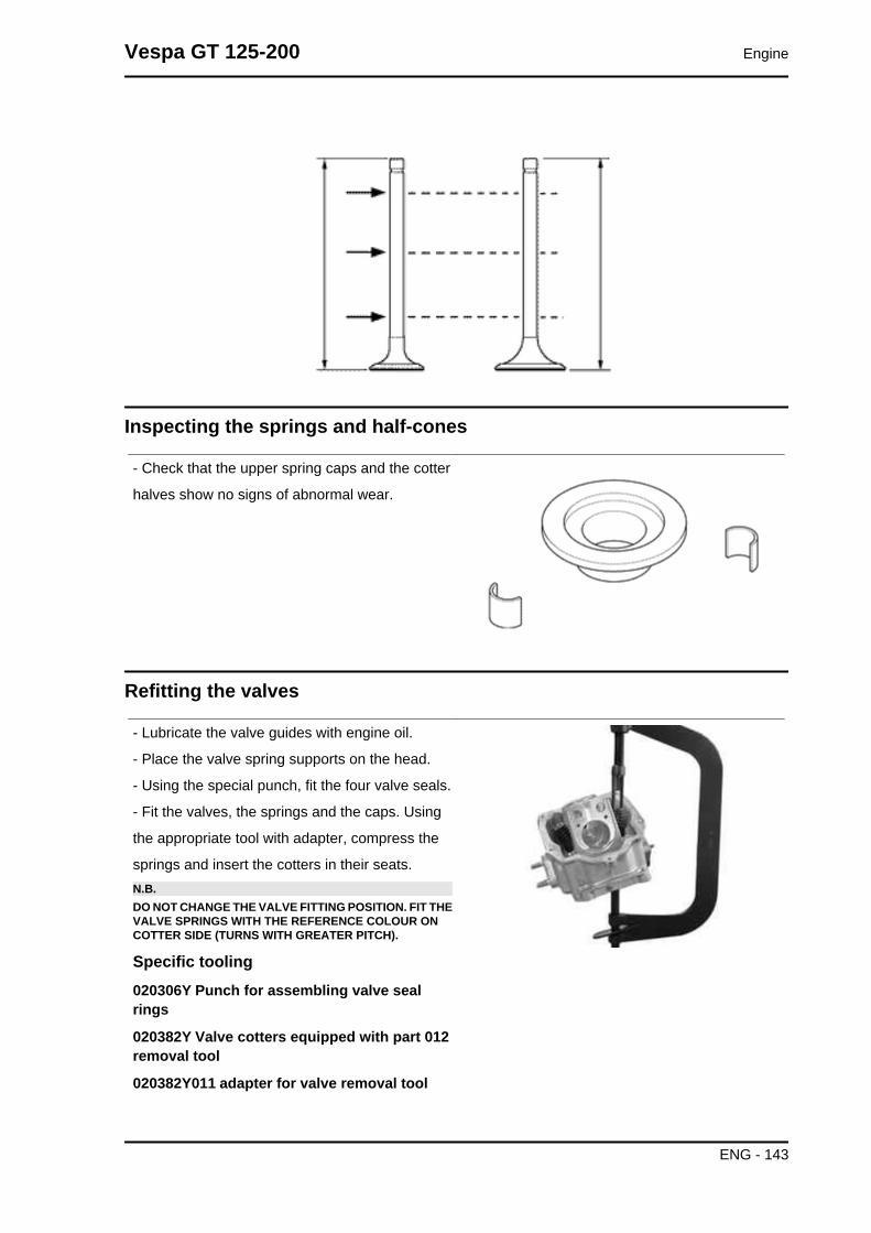
Inspecting the springs and half-cones
- Check that the upper spring caps and the cotter
halves show no signs of abnormal wear.
Refitting the valves
- Lubricate the valve guides with engine oil.
- Place the valve spring supports on the head.
- Using the special punch, fit the four valve seals.
- Fit the valves, the springs and the caps. Using
the appropriate tool with adapter, compress the
springs and insert the cotters in their seats.N.B.DO NOT CHANGE THE VALVE FITTING POSITION. FIT THEVALVE SPRINGS WITH THE REFERENCE COLOUR ONCOTTER SIDE (TURNS WITH GREATER PITCH).
Specific tooling020306Y Punch for assembling valve sealrings
020382Y Valve cotters equipped with part 012removal tool
020382Y011 adapter for valve removal tool
Vespa GT 125-200 Engine
ENG - 143

Inspecting the cam shaft
- Inspect the cam shaft for signs of abnormal wear
on the cams.
- Check the cam height.
- Check there is no wear on the cam shaft retaining
plate and its associated groove on the cam shaft.
- If any of the above dimensions are outside the
specified limits, or there are signs of excessive
wear, replace the defective components with new
ones.
- Check there are no signs of wear on the auto-
matic valve-lifter cam, or the end-of stroke roller,
or the rubber buffer on the automatic valve-lifter
retaining cover.
- Check that the valve lifting spring has not yielded.
- Replace any defective or worn components.
- Check the rocker pins do not show signs of wear
or scoring.
- Measure the internal diameter of each rocker
arm.
Check there are no signs of wear on the pad from
contact with the cam and on the jointed adjustment
plate.
CharacteristicInternal rocker arm diameter: Standard diame-terDiameter 12.000 - 12.011 mm
Rocking lever pin diameter: Standard diameterDiameter 11.977 - 11.985 mm
Engine Vespa GT 125-200
ENG - 144

Cam shaft check: Maximum admissible axialclearance0.42 mm
Cam shaft check: Standard axial clearance:0.11 - 0.41 mm
Cam shaft check: Standard heightOutlet: 29.209 mm
Cam shaft check: Standard heightInlet: 30.285 mm
Cam shaft check: Minimum admissible diame-terBearing B diameter: 19.950 mm
Cam shaft check: Minimum admissible diame-terBearing A Ø: 36.94 mm
Cam shaft check: Standard diameterBearing B diameter: 19.959 ÷ 19.98 mm
Cam shaft check: Standard diameterBearing A Ø: 36.95 ÷ 36.975 mm
Refitting the head and timing system components
- Fit the timing chain guide pad.
- Insert the centring dowel between the cylinder
head to the cylinder, fit the cylinder head gasket
and the cylinder head.
- Lubricate the stud bolt threading.
- Tighten up the nuts to a pre-torque of 7±1 N·m
- Rotate by a 180° angle (2 rotations of 90° each)
- To carry out the operations described above, fol-
low the tightening sequence in the figure.
- Fit the two screws on the outside of the timing
chain side and tighten them to the specified torque.N.B.BEFORE INSTALLING THE HEAD, MAKE SURE THAT THELUBRICATION CHANNEL IS CLEAN USING A COM-PRESSED AIR JET.
Locking torques (N*m)Timing chain tensioner support screw 11 ÷ 13
Vespa GT 125-200 Engine
ENG - 145

Assemble the lower timing chain sprocket wheel
on the crankshaft, with the chamfer facing the in-
sertion side.
- Loop the timing chain around the sprocket on the
crankshaft.
- Fit the chain tensioner slider from the cylinder
head side.
- Fit the spacer and the screw fastener.
- Tighten the screws to the prescribed torque.
Locking torques (N*m)Slider screw 10 ÷ 14 Nm
Fit the pins and rocking levers.
- Lubricate the two rocking levers through the
holes at the top.
- Lubricate the 2 bearings and insert the cam shaft
in the cylinder head with the cams corresponding
to the rockers.
Engine Vespa GT 125-200
ENG - 146

- Insert the retention plate and tighten the two
screws shown in the figure to the prescribed tor-
que.
Locking torques (N*m)Plate screws 4 ÷ 6 Nm
Insert the spacer on the cam shaft.
- Rotate the engine so that the piston is at top dead
centre, using the reference marks on the flywheel
and the crankcase.
- Holding this position insert the chain on the cam-
shaft control pulley.
- Insert the pulley on the cam shaft while keeping
the reference 4V in correspondence with the ref-
erence mark on the head.
- Assemble the counterweight with the corre-
sponding fixing screw and tighten to the prescribed
torque.
Locking torques (N*m)Counterweight screw 7 ÷ 8.5
Fit the end-of stroke ring on the valve-lifting mass
and fit the automatic valve-lifting cam to the cam-
shaft.N.B.LUBRICATE WITH GREASE THE END-OF-STROKE RINGIN ORDER TO AVOID ACCIDENTAL LEAKS THAT MAYFALL INTO THE ENGINE. ASSEMBLE THE AUTOMATICVALVE-LIFTER RETURN SPRING. DURING THIS OPERA-TION THE SPRING MUST BE LOADED AT APPROXIMATE-LY 180°.
Assemble the limiting bell using the counterweight
fixing screw as a reference.
- Tighten the clamping screw to the prescribed tor-
que.
Locking torques (N*m)Limiting bell screw 11 ÷ 15 Nm
Vespa GT 125-200 Engine
ENG - 147
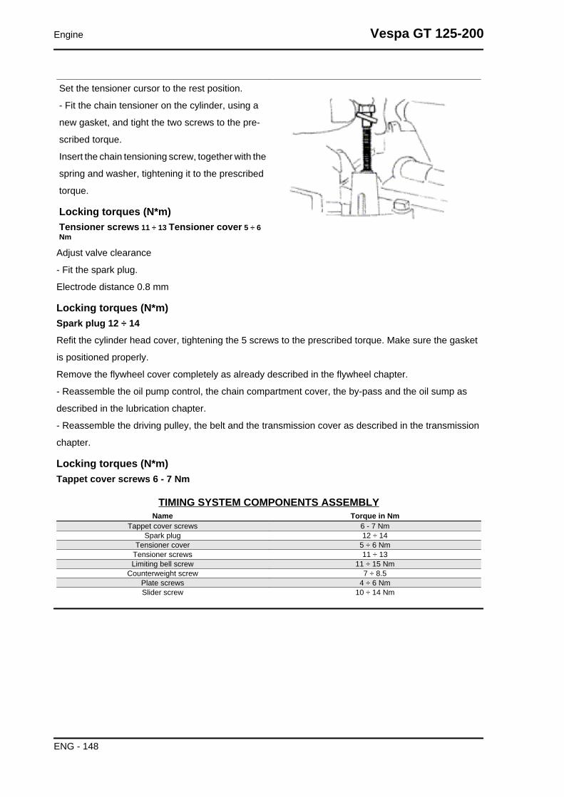
Set the tensioner cursor to the rest position.
- Fit the chain tensioner on the cylinder, using a
new gasket, and tight the two screws to the pre-
scribed torque.
Insert the chain tensioning screw, together with the
spring and washer, tightening it to the prescribed
torque.
Locking torques (N*m)Tensioner screws 11 ÷ 13 Tensioner cover 5 ÷ 6Nm
Adjust valve clearance
- Fit the spark plug.
Electrode distance 0.8 mm
Locking torques (N*m)Spark plug 12 ÷ 14
Refit the cylinder head cover, tightening the 5 screws to the prescribed torque. Make sure the gasket
is positioned properly.
Remove the flywheel cover completely as already described in the flywheel chapter.
- Reassemble the oil pump control, the chain compartment cover, the by-pass and the oil sump as
described in the lubrication chapter.
- Reassemble the driving pulley, the belt and the transmission cover as described in the transmission
chapter.
Locking torques (N*m)Tappet cover screws 6 - 7 Nm
TIMING SYSTEM COMPONENTS ASSEMBLYName Torque in Nm
Tappet cover screws 6 - 7 NmSpark plug 12 ÷ 14
Tensioner cover 5 ÷ 6 NmTensioner screws 11 ÷ 13Limiting bell screw 11 ÷ 15 Nm
Counterweight screw 7 ÷ 8.5Plate screws 4 ÷ 6 NmSlider screw 10 ÷ 14 Nm
Engine Vespa GT 125-200
ENG - 148

Refitting the rocker-arms cover
- Refit the cylinder head cover, tightening the 5
clamping screws to the prescribed torque.
- Make sure the gasket is positioned properly.
Locking torques (N*m)Tappet cover screws 6 - 7 Nm
Refitting the intake manifold
Fit the intake manifold and do up the three screws.N.B.USE COMMERCIALLY AVAILABLE INSERTS AND INSERTHOLDERS FOR THE SPECIAL SCREWS FOR 125 CM³MODELS.
Crankcase - crankshaft
Splitting the crankcase halves
First remove the following units:
transmission cover, driving pulley, driven pulley
and belt, rear hub cover, gears, bearings and oil
seals as described in the transmission chapter.
- Remove the oil sump, the by-pass, the chain
compartment cover and the oil pump as in the lu-
brication chapter.
- Remove the flywheel cover together with the water pump, the flywheel and the stator as described in
the magneto flywheel chapter.
- Remove the oil filter and the oil pressure switch.
- Remove the cylinder/piston/head unit as described in the cylinder head timing system chapter.
Vespa GT 125-200 Engine
ENG - 149

- Remove the two retainers indicated in the figure and the starter motor.
Before opening the engine crankcase, it is advis-
able to check axial clearance of the crankshaft. To
do this, use a plate and a support with appropriate
tool dial gauge.
Higher clearances are signs of wear on the sup-
porting surfaces of the crankshaft casing.
Standard clearance: 0.15 ÷ 0.40 mm
Remove the 11 crankcase coupling screws.
- Split the crankcases while keeping the driving
shaft inserted on one of the 2 half-crankcases.
Remove the driving shaft.N.B.The crankshaft of the 200 cm³ version has two steel shimwashers. Take note of their fitting position.CAUTIONKEEP THE CRANKSHAFT IN ONE OF THE TWO HALVESOF THE CRANKCASE WHEN SEPARATING IT. IF YOU FAILTO DO THIS, THE CRANKSHAFT MIGHT ACCIDENTALLYFALL.
- Remove the coupling gasket of the crankcase
halves.
- Remove the two screws and the internal cover
shown in the diagram.CAUTIONWHILE OPENING THE CRANKCASES AND REMOVINGTHE DRIVING SHAFT, CHECK THAT THE THREADEDSHAFT ENDS DO NOT INTERFERE WITH THE MAIN BUSH-INGS. FAILURE TO OBSERVE THIS PRECAUTION CANDAMAGE THE MAIN BUSHINGS.
- Remove the oil guard on the flywheel side.
- Remove the oil filter fitting shown in the diagram
Engine Vespa GT 125-200
ENG - 150

Fitting clearanceConnecting rod axial clearance 0.20 - 0.50
Check the radial clearance on the connecting rod.
Standard clearance: 0.036 ÷ 0.054 mm
-Check the surfaces that limit the axial free-play
are not scored and measure the width of the crank-
shaft between these surfaces, as shown in the
diagram.
Standard dimensions:
55.75 ÷ 55.90 mm (125 cc)
51.40 ÷ 51.45 mm (200 cc)N.B.WHEN MEASURING THE WIDTH OF THE CRANKSHAFT,MAKE SURE THAT THE MEASUREMENTS ARE NOTMODIFIED BY THE RADIUSES OF FITTINGS WITH THECRANKSHAFT BEARINGS.
The crankshaft can be reused when the width is
within the standard values and the surfaces show
no signs of scoring.
Shim washers (only 200 cc)
- Check the thickness of the shim washers.
Standard thickness: 2.175 ÷ 2.225 mm
- Check that the shim washers are not stripped.N.B.IN CASE OF NEW UTILISATION, MAINTAIN THE FIRST FIT-TING POSITION.
If the axial clearance between crankshaft and crankcase exceeds the standard and the crankshaft does
not have any defect, the problem must be due to either excessive wear or wrong machining on the
engine crankcase.
Vespa GT 125-200 Engine
ENG - 151

Check the diameters of both the driving shaft ends
according to the axes and planes shown in the fig-
ure. Half-shafts are classified into two categories,
Cat. 1 and Cat. 2. The table is shown below.
CharacteristicStandard diameter (125 - 200) Cat. 229.004 ÷ 29.010
Cat. 1 - Standard diameter (125-200) evo28.994 ÷ 29.000
STANDARD DIAMETERSpecification Desc./Quantity
Standard diameter (125 - 200) Cat. 2 29.004 ÷ 29.010Cat. 1 - Standard diameter (125-200) evo 28.994 ÷ 29.000
Inspecting the crankshaft alignment
Measure the capacity of both axes X-Y
Specific tooling020074Y Support base for checking crankshaft alignment
CRANKSHAFT ALIGNMENTTitolo Durata/Valore Testo Breve (< 4000 car.) Indirizzo Immagine
Crankshaft alignment
Engine Vespa GT 125-200
ENG - 152

To install the drive shaft on the support and to
measure the misalignment in the 4 points indicated
in figure.
- Check that the driving shaft cone, the tab seat,
the oil seal capacity, the toothed gear and the
threaded tangs are in good working order.
- In case of failures, replace the crankshaft.
The connecting rod head bushings cannot be re-
placed. For the same reason, the connecting rod
may not be replaced and, when cleaning the
crankshaft, be very careful that no impurities get in
through the shaft's lubrication holes.
In order to prevent damaging the connecting rod
bushings, do not attempt cleaning the lubrication
duct with compressed air.
- Make sure that the 2 caps on the crankpin are
properly fitted.
- A wrong installation of a cap can seriously affect
the bushing lubrication pressure.N.B.THE MAIN BEARINGS ARE NOT GRINDABLE
Specific tooling020074Y Support base for checking crankshaftalignment
CharacteristicOff-line maximum admittedA = 0.15 mmB = 0.01 mmC = 0.01 mmD = 0.10 mm
Vespa GT 125-200 Engine
ENG - 153

Inspecting the crankcase halves
- Before proceeding to check the crankcase
halves, thoroughly clean all surfaces and oil ducts.
- On the transmission-side crankcase half, take
particular care when handling the oil pump com-
partment and the oil ducts, the by-pass duct, the
main bushings and the cooling jet on the trans-
mission side (see diagram).
- Take particular care, also, that there are no signs
wear in the oil by-pass valve housing (see Chapter
Lubrication), as this could prevent a good seal in
the valve, which regulates the oil pressure.
- On the flywheel side crankcase half, take partic-
ular care cleaning the oil ducts for the main bush-
ings, the oil duct for the jet that lubricates the
cylinder head and the oil drainage duct at the fly-
wheel side oil seal.
- Inspect the coupling surfaces on the crankcase
halves for scratches or deformation, taking partic-
ular care with the cylinder/crankcase surfaces and
the crankcase halves surfaces.
- Defects in the crankcase coupling gasket be-
tween the crankcase halves or the mating surfaces
shown in the diagram, could cause a drop in the
oil pressure lubricating the main bearings and con-
nection rod.
- Check the main bearing seats that limit axial
clearance in the crankshaft show no signs of wear.
The dimension between these seats is measured
by way of the procedure described previously for
measuring the crankshaft axial clearance and di-
mensions.N.B.THE JET IS FED THROUGH THE MAIN BUSHINGS. PROP-ER OPERATION OF THIS COMPONENT IMPROVES THEPISTON TOP COOLING. CLOGGING HAS EFFECTS THATARE DIFFICULT TO DETECT (PISTON TEMPERATURE IN-CREASE). FAILURE OR LEAK CAN CONSIDERABLY DE-CREASE THE MAIN BUSHING AND CONNECTING RODLUBRICATION PRESSURE.N.B.
Engine Vespa GT 125-200
ENG - 154

THE HEAD LUBRICATION CHANNEL IS PROVIDED WITHA SHUTTER JET; THIS GIVES A "LOW PRESSURE" HEADLUBRICATION; THIS CHOICE WAS MADE TO REDUCETHE OIL TEMPERATURE IN THE SUMP. THE JET CLOG-GING IMPAIRS THE HEAD LUBRICATION AND THE TIM-ING MECHANISMS. A JET FAILURE CAUSES A DE-CREASE OF THE MAIN BUSHING AND CONNECTING RODLUBRICATION PRESSURE.
Inspecting the crankshaft plain bearings
- T
o obtain a good bushing lubrication it is necessary
to have both an optimal lubricating pressure (3,2
bar) and a good oil flow rate; the bushings must be
correctly positioned so as not to obstruct the oil
supply channels.
- The main bushings are comprised of two half-
bearings, one with holes and channels for lubrica-
tion whereas the other is solid.
- The solid half-bearing is intended to stand the
thrusts caused by combustion, and for this reason
it is arranged opposite the cylinder.
- To prevent obstructions in the oil feeding chan-
nels, the matching surface of the two half-bearings
must be perfectly perpendicular to the cylinder ax-
is, as shown in the figure.
- The oil feeding channel section is also affected
by the bushings driving depth compared with the
crankshaft axial clearance of the limiting surface.
- Check the inside diameter of the main bushings
in the three directions indicated in the diagram.
- Repeat the measurements for the other bushing
half. see diagram.
- There are three crankcase versions: with RED
main bushings, with BLUE main bushings and with
YELLOW main bushings.
- There is only one type of main bushing housing
hole in the crankcase
The standard bushing diameter after driving is var-
iable on the basis of a coupling selection.
Vespa GT 125-200 Engine
ENG - 155

- The bushing housings in the crankcase are avail-
able in two categories, Cat. 1 and Cat. 2, as are
the crankshafts.
- The main bushings are available in three thick-
ness categories, identified by colour markings, as
shown in the table below.
TYPE IDENTIFICATION
A RED
B BLUE
C YELLOW
Type "A" -
RED
Type "B" -
BLUE
Type "C" -
YELLOW
Crankshaft
half-bearing
1.970 ÷
1.973
1.9703 ÷
1.976
1.976 ÷
1.979
Bushing
category
Crankcase
halves cat-
egory
Internal bushing
diameter after fit-
ting
Possible fit-
ting
A 1 29.025 ÷ 29.040 Original
B 1 29.019 ÷ 29.034 Original and
spare2 29.028 ÷ 29.043
C 2 29.022 ÷ 29.037 Original
Match the shaft with two category 1 crank webs
with the category 1 crankcase (or cat. 2 with cat.
2) Furthermore a spare crankcase cannot be
matched with a crankshaft with mixed categories.
The spare crankshaft has half shafts of the same
category.
Crankcase halves Engine half
shaft
Bushing
Cat. 1 Cat. 1 B
Cat. 2 Cat. 2 B
Cat. 1 Cat. 2 A
Cat. 2 Cat. 1 C
N.B.TO KEEP THIS POSITION OF THE BUSHINGS ON THECRANKCASE, FITTING IS FORCED ON STEEL RINGS IN-SERTED IN THE CASTING OF BOTH CRANKCASEHALVES.N.B.DO NOT TAKE THE MEASUREMENT ON THE TWO HALF-SHELL COUPLING SURFACE SINCE THE ENDS ARE RE-
Engine Vespa GT 125-200
ENG - 156

LIEVED TO ALLOW BENDING DURING THE DRIVINGOPERATION.N.B.CRANKCASES FOR REPLACEMENTS ARE SELECTEDWITH CRANKCASE HALVES OF THE SAME CATEGORYAND ARE FITTED WITH CATEGORY B BUSHINGS (BLUE)
CharacteristicStandard driving depth1.35 ÷ 1.6
Diameter of crankcase without bushing32.953 ÷ 32.963
Lubrication
Conceptual diagrams
LUBRICATION CIRCUIT
Vespa GT 125-200 Engine
ENG - 157

Engine Vespa GT 125-200
ENG - 158

Oil pressure check
- After removing the flywheel cover as described
in the "Flywheel" chapter, remove the electric con-
nexion of the minimum oil pressure switch and
then remove the switch.
- With the engine idling at 1650 rpm and the oil
temperature at ~90°C, check that the oil pressure
is between 0.5 ÷ 1.2 atm.
- With the engine idling at 6000 rpm and the oil
temperature at ~90°C, check that the oil pressure
is between 3.2 ÷ 4.2 atm.
- Remove the appropriate tools once the meas-
urement is complete, refit the oil pressure switch
and washer, tightening it to the specified torque
and fit the fan cover.
- If the oil pressure is not within the specified limits,
in the following order, check: the oil filter, the oil
by-pass valve, the oil pump and the crankshaft
seals.N.B.THE CHECK MUST BE CARRIED OUT WITH OIL AT THECORRECT LEVEL AND WITH AN OIL FILTER IN GOODCONDITION.
CharacteristicOil pressureMinimum pressure admitted at 6000 rpm: 3.2 atm.
Locking torques (N*m)Minimum oil pressure sensor 12 ÷ 14
Vespa GT 125-200 Engine
ENG - 159

Crankshaft oil seals
Refitting
- Fit the internal bulkhead by locking the two
screws to the prescribed torque.
- Fit the oil filter fitting and tighten it to the specified
torque.
- Place a new gasket on one of the crankcase
halves, preferably on the transmission side, to-
gether with the locating dowels.
- Lubricate the main bushings and insert the crank-
shaft in the transmission side crankcase half.
- Reassemble the two crankcase halves.
For the 200 models reposition the shim washers
as in the original fitting.
- Fit the 11 screws and tighten them to the pre-
scribed torque.
- Lubricate the flywheel oil seal.
- Using the appropriate tool, assemble the oil seal.
- Fit a new O-ring on the pre-filter and lubricate it.
- Insert the filter on the engine with the relative cap.
Tighten to the specified torque.N.B.FAILURE TO USE THE SPECIFIC TOOL CAN RESULT INAN INCORRECT DEPTH POSITION AND AS A CONSE-QUENCE IN INADEQUATE OIL SEALING.
Specific tooling020425Y Punch for flywheel-side oil seal
Locking torques (N*m)Internal engine crankcase bulkhead (transmis-sion-side half shaft) screws 4 ÷ 6 Oil filter oncrankcase fitting 27 ÷ 33 Engine-crankcase cou-pling screws 11 ÷ 13 Engine oil drainage plug/mesh filter 24 ÷ 30
Engine Vespa GT 125-200
ENG - 160

Oil pump
- Check there are no signs of wear on the oil pump
shaft or body.
- Check there are no signs of scoring or wear on
the oil pump cover.
- If you detect non-conforming measurements or
scoring, replace the faulty parts or the unit.
- Fit the pump cover in the position that permits the
crankcase fixing screws to be aligned.
- Make sure the gasket is positioned properly and
refit the pump on the engine crankcase. The pump
can only be fitted in one position. - Tighten the
screws to the prescribed torque.
- Fit the sprocket wheel with a new O-ring.
- Fit the chain.
- Fit the central screw and the belleville washer.
Tighten to the prescribed torque.
- Fit the oil pump cover by tightening the two
screws to the prescribed torque.N.B.FIT THE BELLEVILLE WASHER SO THAT ITS OUTER RIMTOUCHES THE PULLEY. MAKE SURE THAT THE PUMPTURNS FREELY.
Locking torques (N*m)Screws fixing oil pump to crankcase 5 - 6 Oilpump control crown screw 10 ÷ 14 Oil pump cov-er screws 0.7 ÷ 0.9
Removing the oil sump
- Remove the oil filler plug, the transmission cover,
the complete driving pulley assembly with belt and
the sprocket wheel, as described in the "Trans-
mission" chapter.
- Drain the oil as described previously.
- Remove the seven screws, shown in the dia-
gram, and the two rear brake fluid pipe fixing
brackets.
- Remove the screw, the by-pass piston, the gas-
ket and centring dowels shown in the figure.
Vespa GT 125-200 Engine
ENG - 161

Inspecting the by-pass valve
- Check the unloaded spring length.
- Check that the small piston is not scored.
- Ensure that it slides freely on the crankcase and that it guarantees a good seal.
- If not, eliminate any impurities or replace defective parts.
CharacteristicBy-pass check up: Standard length
54.2 mm
Refitting the oil sump
- Refit the by-pass valve plunger in its housing.
- Insert the pressure-regulating spring.
- Fit a new sump seal.
- Refit the two centring dowels.
- Refit the sump, taking care to locate the spring in
the appropriate recess machined into the inside of
the sump.
- Refit the rear brake cable brackets and the
screws in the reverse order from which they were
removed.
- Tighten the screws to the prescribed torque.
- Refit the drive pulley assembly, the drive belt, the
sprocket wheel and the transmission cover, as de-
scribed in the "Transmissions" chapter.
Engine Vespa GT 125-200
ENG - 162

- When testing the lubrication system, refer to
chapter "Crankcase and Crankshaft", regard-
ing lubrication of the crankshaft and connect-
ing rod
Locking torques (N*m)Oil sump screws 10 ÷ 14
SAS valve
Inspecting the one-way valve
- Remove the SAS valve.
- Provisionally assemble the rubber coupling of the
SAS valve outlet to ensure tightness.
- Connect the MITYVAC vacuum pump to the rub-
ber coupling as shown in the photograph.
- Set the pump to the low-pressure position (VAC-
UUM).
- Operate the pump slowly.
- Check that the one way valve allows the air to
pass through causing a slight vibration.
- Switch the pump to pressure mode (PRES-
SURE).
- Operate the pump slowly and check if there is an
increase of pressure. A small leakage is consid-
ered to be normal.
If anomalies are detected, replace the pump.N.B.A MALFUNCTIONING ONE-WAY VALVE CAN RESULT INRUBBER COUPLING AND FILTER OVERHEATINGN.B.ABSENCE OF VIBRATION INDICATES INEFFICIENT SEAL-ING
Specific tooling020329Y MityVac vacuum-operated pump
Vespa GT 125-200 Engine
ENG - 163

Inspecting the cut-off
- Remove the SAS valve.
- Connect the MITYVAC pump in low-pressure
mode (VACUUM) to the CUT-OFF valve vacuum
intake.
- Apply a vacuum value higher than 0.5 BAR.
- Check that this value is kept all the time.
- If a worn seal is detected, replace it.
- With a "T" bypass and flexible rubber hoses make
a parallel connection between the rubber coupling
and the vacuum intake of the CUT-OFF valve.
- Connect the bypass to the MITYVAC pump.
- Set the pump set to the low-pressure mode
(VACUUM).
- Using a pair of long flat pliers, choke the rubber
hose next to the valve.
- Operate the pump until vacuum is higher than 0.5
BAR.
- Release the hose and check how the vacuum re-
acts. - Under normal functioning conditions the
vacuum undergoes a slight fall and then readjusts.
There follows a slow and continuous loss of de-
pression up to approximately 0.4 BAR. At this point
the valve opens and the depression is suddenly
set to zero.
Lack of tightness or the fact that the valve opens
at different vacuum values should be regarded as
anomalies. In this case, replace it.N.B.LACK OF TIGHTNESS IN THE CUT-OFF VALVE RESULTSIN EXHAUST NOISE (EXPLOSIONS IN THE MUFFLER). IN-CORRECT CUT-OFF VALVE CALIBRATION CAN RESULTIN CATALYTIC CONVERTER MALFUNCTIONINGN.B.A FAULTY CUT-OFF VALVE DIAPHRAGM, BESIDESJEOPARDISING THE CORRECT OPERATION OF THECUT-OFF VALVE, ALSO DAMAGES IDLE FUNCTIONING
Specific tooling020329Y MityVac vacuum-operated pump
Engine Vespa GT 125-200
ENG - 164

Fuel supply
- To clean the filtering element proceed as follows:
remove the 4 filter cover fixing screws indicated in
the figure; remove the cover and take out the pa-
per filtering element, clean with compressed air
and refit.
- Make sure the filtering element is in the correct
position.
- Check that the air passage sections are not dam-
aged or deformed.
- Check the correct sealing of the coupling be-
tween the filter housing and the cover.N.B.FAILURE TO OBSERVE THESE INSTRUCTIONS MAY RE-SULT IN WRONG VACUUM INSIDE THE FILTER HOUSING,WHICH IN TURN MAY PRODUCE VARIATIONS IN CARBU-RETION.
Removing the carburettor
Kehin
- To detach the carburettor from the engine, it is
necessary to move the air filter and remove the
transmission throttle control, the automatic starter
connection, the clamps anchoring the carburettor
to the filter housing and to the inlet manifold, the
air delivery pipe to the diaphragm, and the intake
fitting.
- Take out the carburettor and rotate it so as to
remove the screw with the water joint and the
pipes.N.B.THIS LAST OPERATION IS NECESSARY SO AS NO TOEMPTY THE COOLING SYSTEM.
Vespa GT 125-200 Engine
ENG - 165

- Remove the protection, the bracket and the start-
er acting on the screw shown in the figure.
- Remove the 2 screws and the starter support with
the gasket.
- Remove the clamp and cover with the airing filter
of the diaphragm chamber.
- Remove the 4 fixing screws shown in the figure
and the vacuum chamber cover.WARNINGDURING THE REMOVAL OF THE CARBURETTOR COVERTAKE SPECIAL CARE NOT TO RELEASE THE SPRINGACCIDENTALLY.
Engine Vespa GT 125-200
ENG - 166

- Remove the vacuum valve together with the di-
aphragm.
- Unscrew the bayonet joint 1/8 of a turn and re-
move, take out the spring and vacuum valve nee-
dle
- Remove the 4 screws indicated in the figure.
Vespa GT 125-200 Engine
ENG - 167

- Remove the chamber with the accelerating
pump, its control and gasket.
- Remove the oil pump seal.
- Remove the intake and outlet valves of the intake
pump from the tankN.B.CAUTION, THE ACCELERATION PUMP VALVES AREMADE UP OF NOZZLES, SPRING AND BALL.N.B.AVOID REMOVING THE PISTON OF THE PUMP AND ITSCONTROL.
Adequately support the carburettor and using a
rod and hammer remove the float pin acting from
the throttle control side.
- Remove the float and the plunger.
- Remove the maximum nozzle
Engine Vespa GT 125-200
ENG - 168

-Remove the maximum nozzle.
-Remove diffuser.
Vespa GT 125-200 Engine
ENG - 169

- Remove the sprayer.N.B.WHEN CLEANING THE CARBURETTOR BODY REMOVETHE SPRAYER TO AVOID LOSING PARTS. IF THE SPRAY-ER IS FORCED IN ITS HOUSING DO NOT ATTEMPT TOREMOVE IT AS THIS WILL ONLY DAMAGE IT.
-Remove the minimum nozzle.
- Remove the minimum flow set screw and the
spring.CAUTIONDO NOT ATTEMPT REMOVING PARTS EMBEDDED IN THECARBURETTOR BODY SUCH AS: FUEL SUPPLY PIPE,PLUNGER HOUSING, STARTER NOZZLE, PIT COVER FORPROGRESSIONS AND INLET NOZZLE, MINIMUM ANDMAXIMUM AIR GAUGE, THROTTLE VALVE CONTROLSHAFT. DO NOT REMOVE THROTTLE-SHAFT CONNEC-TION SCREWS. THE FIXING SCREWS ARE CAULKED AF-TER ASSEMBLY AND THEIR REMOVAL DAMAGES THESHAFT.
Engine Vespa GT 125-200
ENG - 170

Walbro
To detach the carburettor from the engine, it is
necessary to move the air filter and remove the
transmission throttle control, the automatic starter
connexion, the clamps anchoring the carburettor
to the filter housing and to the inlet manifold, the
air delivery pipe to the diaphragm, and the intake
fitting.
- Take out the carburettor and rotate it so as to
remove the screw with the water joint and the
pipesN.B.THIS OPERATION IS NECESSARY TO AVOID LOSINGSPRAYER PARTS WHEN CLEANING THE CARBURETTORBODY. IF THE SPRAYER IS FORCED IN ITS HOUSING DONOT ATTEMPT TO REMOVE IT AS THIS WILL ONLY DAM-AGE IT.
Remove the protection, the bracket and the starter
acting on the screw shown in the figure.
Remove the clamp and cover with the airing filter
of the diaphragm chamber.
Vespa GT 125-200 Engine
ENG - 171

Remove the 4 fixing screws indicated in the figure
and the vacuum chamber cover.N.B.DURING THE REMOVAL OF THE COVER TAKE SPECIALCARE NOT TO RELEASE THE SPRING ACCIDENTALLY.
Remove the vacuum valve together with the dia-
phragm.
Engine Vespa GT 125-200
ENG - 172
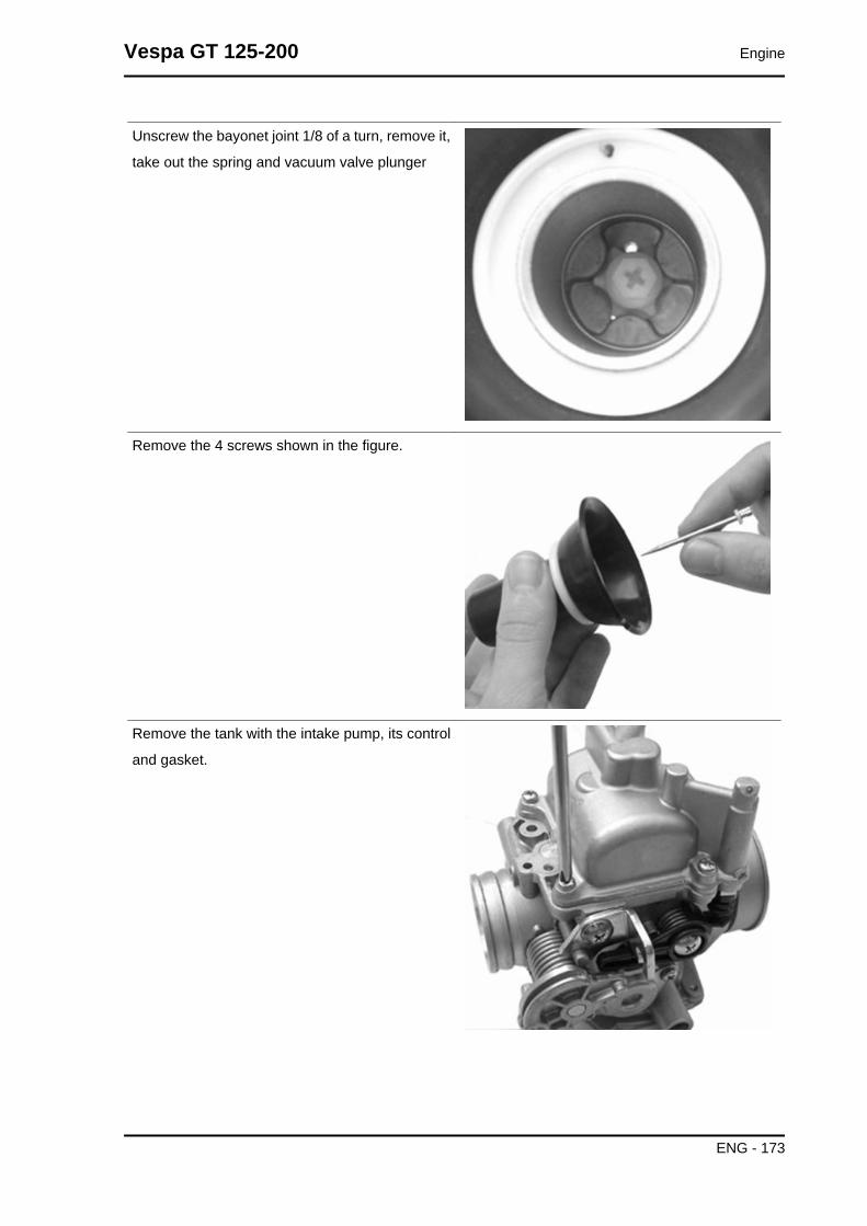
Unscrew the bayonet joint 1/8 of a turn, remove it,
take out the spring and vacuum valve plunger
Remove the 4 screws shown in the figure.
Remove the tank with the intake pump, its control
and gasket.
Vespa GT 125-200 Engine
ENG - 173

Remove the acceleration pump piston with the ring
nut, the hood, the O-Ring and the spring from the
tank as shown in the figure.
Adequately support the carburettor and using a
rod and hammer remove the float pin acting from
the throttle control side.
Remove the float and the plunger.
Engine Vespa GT 125-200
ENG - 174

Remove the cover of the duct from the carburettor
to the starter nozzle as shown in the figure.
-Remove the maximum nozzle.
-Remove diffuser.
Remove the sprayer.N.B.THIS OPERATION IS NECESSARY TO AVOID LOSINGSPRAYER PARTS WHEN CLEANING THE CARBURETTORBODY. IF THE SPRAYER IS FORCED IN ITS HOUSING DONOT ATTEMPT TO REMOVE IT AS THIS WILL ONLY DAM-AGE IT.
-Remove the minimum nozzle.
Vespa GT 125-200 Engine
ENG - 175

Remove the minimum flow screw with the O-ring,
the washer and the spring.
-Remove the 2 fixing screws, the cover, the spring,
and the cut-off device diaphragm.CAUTIONDO NOT ATTEMPT REMOVING PARTS EMBEDDED IN THECARBURETTOR BODY SUCH AS: FUEL SUPPLY PIPE,PLUNGER HOUSING, STARTER NOZZLE, PIT COVER FORPROGRESSIONS AND INLET NOZZLE, MINIMUM ANDMAXIMUM AIR GAUGE, THROTTLE VALVE CONTROLSHAFT. DO NOT REMOVE THROTTLE-SHAFT CONNEC-TION SCREWS. THE FIXING SCREWS ARE CAULKED AF-TER THE ASSEMBLY AND THEIR REMOVAL DAMAGESTHE SHAFT.
Refitting the carburettor
Engine Vespa GT 125-200
ENG - 176

Kehin
- Before refitting, wash the carburettor body accu-
rately with petrol and compressed air.
- Pay special attention to the fuel supply pipe and
the plunger seat.
- For maximum circuit, check the air adjustment is
correct as shown in the figure.
- For the minimum circuit, make sure the following
points are properly cleaned: air gauging, outlet
section controlled by flow screw, progression
holes near the throttle valve.
- For the starter circuit, blow the connection pipe properly with the jet. This is necessary because the
nozzle support hides other inaccessible internal calibrations.
- Blow the intake nozzle properly.N.B.THE ACCELERATION NOZZLE OUTLET IS EXTREMELY SMALL AND IS ORIENTED TO THETHROTTLE VALVE. NOZZLE INCORRECT ORIENTATION RESULTS IN INADEQUATE SPRAY-ING.- Check that there are 5 closing ball joints for the operating pipes on the carburettor body.
Vespa GT 125-200 Engine
ENG - 177

- Check that the coupling surfaces, the tank and the diaphragm are not dented.
-Check that the depression valve housing pipe is not scratched.
- Check that the throttle valve and the shaft do not show abnormal wear.
- Check that the plunger seat does not show abnormal wear.
- Replace the carburettor in case of irregularities.
- Check that the return spring of the accelerating pump rocking lever is not deformed by over-stretching.N.B.TO AVOID DAMAGES, DO NOT INTRODUCE METAL OBJECTS IN THE ADJUSTED SECTIONS.- Wash and blow the minimum nozzle properly and
reassemble it.
- Properly wash and blow the components of the
sprayer maximum circuit, the diffuser and the noz-
zle.
- Introduce the sprayer in the carburettor body with
the shortest cylindrical part directed to the diffuser.
- Assemble the diffuser making sure the sprayer is
being adequately inserted and lock it.
-Assemble the maximum nozzle.
- Check that the tapered pin does not show signs
of wear on the sealing surfaces of the shock ab-
sorber pin and the return clamp.
- Replace the rod if worn out.
- Check that the float is not worn on the pin housing or on the contact plate with the plunger and that
there are no fuel infiltration.
- Replace it in case of anomalies.
Engine Vespa GT 125-200
ENG - 178

- Introduce the float with the rod on the fuel feeding tube side.N.B.
INTRODUCE THE RETURN SPRING ON THE FLOAT PLATE ADEQUATELY
- Remove the drainage screw from the tank, wash
and blow it properly and make sure the accelera-
tion pump pipes are clean.
- Operate the acceleration pump piston repeatedly
and blow with compressed air.
- Reassemble the acceleration pump valves fol-
lowing this order:
INTAKE VALVE (A)
• Spring
• Ball
• Nozzle
IN VALVE (M)
• Ball
• Spring
• NozzleN.B.THE IN VALVE NOZZLE, CORRESPONDING TO THE AC-CELERATION PUMP, IS MILLED.
-Check the screw tightness introducing a small
amount of fuel in the tank.
- Assemble a new gasket on the tank.
- Assemble the tank on the carburettor body fas-
tening the 4 screws.
- Check that the control roller is free to rotate in its
own seat.N.B.MAKE SURE THE TANK GASKET IS CORRECTLY INTRO-DUCEDN.B.AVOID DEFORMING THE ACCELERATION PUMP CON-TROL ROCKING LEVER.
- Wash and blow the flow screw properly.
- Check that screw is not deformed and/or rusty.
- Assemble the spring on the screw.
- Screw the flow screw on the carburettor body.
Vespa GT 125-200 Engine
ENG - 179

- The screw final position should be determined by an exhaust fume analysis.
- Adjust the carburettor by turning the screw twice from the close position.
Walbro
- Before refitting, wash the carburettor body accu-
rately with petrol and compressed air.
- Pay special attention to the fuel supply pipe and
the plunger seat.
- For maximum circuit, check the air adjustment is
correct as shown in the figure.
- Carefully clean the air holes indicated in the fig-
ure.
- For the minimum circuit, make sure the following points are properly cleaned: air gauging, outlet section
controlled by flow screw, progression holes near the throttle valve.N.B.
THE MINIMUM AIR IS CONTROLLED BY TWO ADJUSTMENTS. THE CUT-OFF ONE IS INDICATEDDIRECTLY IN THE CARBURETTOR BODY.
Engine Vespa GT 125-200
ENG - 180

- For the starter circuit, blow the connection pipe
properly with the jet.This is necessary because the
nozzle support hides other inaccessible internal
calibrations.
- Blow the intake nozzle properly.N.B.THE ACCELERATION NOZZLE OUTLET IS EXTREMELYSMALL AND IS ORIENTED TO THE THROTTLE VALVE.NOZZLE INCORRECT ORIENTATION RESULTS IN INADE-QUATE SPRAYING.
- Check that there are 5 closing ball joints for the operating pipes on the carburettor body.
- Check that the coupling surfaces, the tank and the diaphragm are not dented.
-Check that the depression valve housing pipe is not scratched.
- Check that the throttle valve and the shaft do not show abnormal wear.
- Check that the plunger seat does not show abnormal wear.
- Replace the carburettor in case of irregularities.N.B.
TO AVOID DAMAGES, DO NOT INTRODUCE METAL OBJECTS IN THE ADJUSTED SECTIONS.
- Wash and blow the minimum nozzle properly and
reassemble it.
- Properly wash and blow the components of the
sprayer maximum circuit, the diffuser and the noz-
zle.
- Introduce the sprayer in the carburettor body with
the shortest cylindric part directed to the diffuser.
- Assemble the diffuser making sure the sprayer is
being adequately inserted and lock it.
-Assemble the maximum nozzle.
- Check that the tapered pin does not show signs
of wear on the sealing surfaces of the shock ab-
sorber pin and the return clamp.
- Replace the rod if worn out.
- Check that the float is not worn on the pin housing or on the contact plate with the plunger and that
there are no fuel infiltration.
- Replace it in case of anomalies.
- Assemble the float with the plunger introducing the pin on the carburettor feeding tube side.N.B.
INTRODUCE THE RETURN SPRING ON THE FLOAT PLATE ADEQUATELY
Vespa GT 125-200 Engine
ENG - 181

Level check
Kehin
- Place the carburettor inclined as shown in the
figure.
- Check that the float reference is parallel to the tank coupling surface
- If different positions are detected, change the plunger control metal plate direction to obtain the position
described above.
Walbro
- Make sure the float coupling surface is parallel to the tank surface with the carburettor in inverted
position.
- If different positions are detected, change the plunger control metal plate direction to obtain the position
described above.
- If the plate gets deformed, make sure it remains parallel to the float pin.N.B.
WITH INVERTED CARBURETTOR, THE FLOAT WEIGHT SHOULD NOT EXCEED THE TAPEREDPIN SPRING THRUST. OTHERWISE, CHECK THAT THE FLOAT IS NOT HEAVY DUE TO FUELINFILTRATION. REPLACE THE FLOAT AND THE TAPERED PIN, IF NECESSARY.
- Wash and blow the carburettor duct cover prop-
erly and introduce it in the starter nozzle.N.B.INCORRECT ASSEMBLY OF CARBURETTOR DUCT COV-ER ON THE STARTER NOZZLE CAUSES A NEGATIVECOLD START-UP SITUATION: THE STARTER NOZZLETAKES UP THE OLD FUEL FROM THE BOTTOM OF THETANK.
Engine Vespa GT 125-200
ENG - 182

- Remove the drainage screw from the tank, wash
and blow the tank properly and make sure the ac-
celeration pump intake and supply valve are clean.
- Being the valves unidirectional, blow them care-
fully with compressed air, at the inner side of the
tank for the intake valve and at the pump piston
housing for the supply valve.
- Check that there are no signs of wear in the ac-
celeration pump piston and its corresponding seat
in the tank.
- In case of wear, replace the defective parts.
- Check that the acceleration pump piston contrast
spring is not worn.
- Assemble a new O-Ring and a new bellows gas-
ket. Reassemble the piston unit on the tank.
- Assemble a new O-Ring on the tank drainage
screw and lock it.
-Check the screw tightness introducing a small
amount of fuel in the tank.
- Assemble a new gasket on the tank.
- Assemble the tank on the carburettor body fas-
tening the 4 screws.
- Wash and blow the flow screw properly and as-
semble a new O-Ring.
- Preassemble the components on the screw as
follows: spring, washer and O-ring.
- Screw the flow screw on the carburettor body.
- The screw final position should be determined by
an exhaust fumes analysis.
Vespa GT 125-200 Engine
ENG - 183

- Prepare the carburettor for adjustment by rotating
the screw 3 turns from the close position.
- Check that the rocking lever control of the accel-
erating pump does not show abnormal wear.
- Check that the end of stroke screw of the rocking
lever protrudes 3.2 mm.
Check that the return spring of the rocking lever is
not loaded.
- Preassemble the spring and rocking lever as
shown in the figure.
- Assemble the rocking lever on the carburettor
keeping the throttle valve open.
- Lock the fixing screw of the rocking lever.
- Make sure that the mechanism works correctly.
Inspecting the valve and needle
Kehin
- Check that the tapered pin of the vacuum valve
does not show wear.
- Check that the depression valve does not show
threads on the external surfaces.
- Check that the vacuum intake hole is not clogged.
- Check that the diaphragm is not damaged or has
hardened, otherwise replacement the whole valve.
- Insert the tapered pin into the vacuum valve
housing.
- Reassemble the vacuum valve on the carburettor
body taking care that the tapered pin is inserted
into the sprayer.
Engine Vespa GT 125-200
ENG - 184

N.B.THE VALVE CAN BE INSERTED IN ONLY ONE POSSIBLEPOSITION.
- Reassemble the spring with the pin lock.
- Remove the cover of the vacuum chamber being
careful to correctly insert the spring in its place on
the cover.
- Tighten the screws.
- Wash and blow dry the filter sponge of the am-
bient pressure intake.
Vespa GT 125-200 Engine
ENG - 185

- Reassemble the filter with its clamp.
- Wash and blow dry the starter support.
Assemble a new gasket on the carburettor body
and tighten the 2 fixing screws.
Walbro
- Check that the pin does not show signs of wear
and that the lock is in the 3rd of the 3 notches.
- Check that the valve does not show threads
around its external diameter.
- Check that the 2 vacuum supply holes are not
clogged.N.B.THE 2 VACUUM SUPPLY HOLES ARE OF DIFFERENT DI-AMETERS.
Engine Vespa GT 125-200
ENG - 186

- Check that the diaphragm is not worn or has
hardened.
If it does, replace it.
- Refit the tapered pin on the vacuum valve.
- Make sure the spring is in the correct position on
the plunger and inserted in its housing.
- Assemble the coupling by rotating it 1/8 of a turn.
- Reassemble the vacuum gas valve on the car-
burettor body being careful that the tapered pin is
inserted into the sprayer.
- Time the vacuum valve rotation inserting the di-
aphragm tab in its place.
When the diaphragm is correctly assembled to the
valve, the main vacuum supply hole is positioned
axially with the diffuser, on the throttle valve side.
- Refit the spring on the valve.
- Refit the vacuum chamber cover matching the
reference mark with the orientation of the dia-
phragm.
- Tighten the screws to the prescribed torque.
- Check the cut-off valve correct functioning. -
Check that the diaphragm is not worn or has hard-
ened. Check the free length of the spring.
CharacteristicWalbro: Standard length of cut-off spring24 mm
- Reassemble the diaphragm and the metal pin placed on the valve.
- Reassemble the spring and the cover. The vacuum intake should be facing upwards.
Vespa GT 125-200 Engine
ENG - 187

Inspecting the automatic choke device
- Check that the piston of the automatic starter is
not deformed or rusty.
- Check that the piston slides freely from the seat
to the support.
- Check that the sealing gasket of the piston is not
deformed.
- The starter must be more or less functional de-
pending on the ambient temperature.
- Measure the protrusion of the piston as shown in
the figure and check the corresponding value.
- Make sure that the starter is adjusted for the am-
bient temperature.
- The starter should disconnect progressively by
means of electrical heating.
- Check the starter resistance when adjusted to the
ambient temperature.
With a 12V battery power the automatic starter and
check that piston protrudes as much as possible.
- The correct warm up time depends on the ambi-
ent temperature.
- If protrusion, resistance or timing values are dif-
ferent from the ones prescribed, replace the start-
er.
- Assemble the starter to the carburettor being
careful to position the O-Ring correctly, insert the
plate with the machined side contacting the starter,
tighten the 2 fixing screws.
- Position the starter as shown in the figure.
- Assemble the protection casing.
CharacteristicCheck the auto starter: Protrusion Value forWalbro12.5 ÷ 13 mm at approx. 20°C
Check the automatic starter: maximum protru-sion18.5 ÷ 19 mm
Check the automatic starter: Max. time:
Engine Vespa GT 125-200
ENG - 188

5 min
Electric characteristicCheck the automatic starter: Resistancearound 30 Ω
Kehin
- Check that the automatic starter piston is not de-
formed or rusty.
- Check that the piston slides freely from the seat
to the support.
- Check that the piston sealing gasket is not de-
formed.
- The starter must be more or less functional de-
pending on the ambient temperature.
- Measure the protrusion of the piston as shown in
the figure and check its corresponding value.
- Make sure that the starter is adjusted for the am-
bient temperature.
- The starter should disconnect progressively by
means of electrical heating.
- Check the starter resistance when adjusted to the
ambient temperature.
With a 12V battery power the automatic starter and
check that the piston protrudes as much as possi-
ble.
- The correct warm up time depends on the ambi-
ent temperature.
- If protrusion, resistance or timing values are dif-
ferent from the ones prescribed, replace the start-
er.
- Assemble the starter to the carburettor being
careful to position the O-Ring correctly, insert the
plate with the machined side contacting the starter,
tighten the fixing screws.
- Position the starter as shown in the figure.
- Assemble the protection casing.N.B.
Vespa GT 125-200 Engine
ENG - 189

TO CARRY OUT THIS CHECK PAY SPECIAL ATTENTIONNOT TO GENERATE SHORT CIRCUITS USE A CABLESECTION WITH A TERMINAL SUITABLE TO BE CONNEC-TED TO THE STARTER.
CharacteristicCheck the automatic starter: Kehin: ProtrusionvalueXX ÷ XX mm at approx. 20°C
Check the automatic starter: Kehin maximumprotrusionXXX ÷ XXX mm
Check the automatic starter: Keihin maximumtime5 min
Walbro
- Check that the automatic starter piston is not de-
formed or rusty.
- Check that the piston slides freely from the seat
to the support.
- Check that the piston sealing gasket is not de-
formed.
- The starter must be more or less functional de-
pending on the ambient temperature.
- Measure the protrusion of the piston as shown in
the figure and check its corresponding value.
- Make sure that the starter is adjusted for the am-
bient temperature.
- The starter should disconnect progressively by
means of electrical heating.
- Check the starter resistance when adjusted to the
ambient temperature (20 - 25° C).
With a 12V battery power the automatic starter and
check that the piston protrudes as much as possi-
ble.
- The correct warm up time depends on the ambi-
ent temperature.
- If protrusion, resistance or timing values are dif-
ferent from the ones prescribed, replace the start-
er.
Engine Vespa GT 125-200
ENG - 190

CharacteristicCheck the auto starter: Protrusion Value forWalbro12.5 ÷ 13 mm at approx. 20°C
Check the automatic starter: Walbro maximumprotrusion18.5 ÷ 19 mm
Check the automatic starter: Walbro max. time5 min
Electric characteristicWalbro Resistanceapprox. 40 Ω
Adjusting the idle
- The engine does not need frequent idle adjust-
ments, however it is very important to make any
adjustments fully respecting some standards.
- Before adjusting the carburettor make sure to re-
spect the lubrication requirements, valve clear-
ance, and complying timing, spark plug should be
in optimum conditions, air filter clean and sealed,
and the exhaust system tight.
- Warm up the engine by running it at least 5 mi-
nutes at approximately 50 kph.
- Connect the vehicle to the exhaust fumes analy-
ser inserting the probe into a sealed extension pipe
placed at the muffler exit end.
- Connect a millimetre thermometer (020331y) on
the sump, using a cover with oil expressly pre-
pared for probes.
- Start the motor and before adjusting the idle
speed make sure that the oil temperature is be-
tween 70 ÷ 80°C.
- Using the rpm indicator or any other instrument
(020332y), adjust the idle screw to obtain 1600
rpm ÷ 1700 rpm
- Adjust the flow screw until the carbon monoxide
(CO) percentage is 3.1 ÷ 4.5%, when the screw is
Vespa GT 125-200 Engine
ENG - 191

loosened the CO value rises (rich mix). Tightening
the screw decreases the CO (lean mix).
- If the adjustment of the flow screw causes a rpm
increase readjust the revs again and if necessary,
the flow screw to reach stable values.
- When the oil temperature, the numbers of revs
and the percentage of carbon monoxide are re-
spected the idle carburetion is considered correct.
From the analyser we can draw further informa-
tion:
- carbon dioxide percentages (CO2), the percent-
age of carbon dioxide has an inverted course com-
pared to the percentage of(CO), values over
12.5% are considered correct. Non complying val-
ues indicate lack of tightness in the exhaust sys-
tem.
- Unburned hydrocarbons (HC) are measured in
parts per million (PPM). The HC value decreases
while the rpm increases; with the engine at idle it
is normal to detect 200 ÷ 400 PPM, these emission
values are deemed normal for an engine with a
diagram of distribution for motorcycles. Higher val-
ues can cause loss of engine blows as the mixture
is too lean (low CO), ignition failure or, incorrect
timing or a clogged or unsealed exhaust valve.
- If it were difficult to ???? adjustment CO check
accurately:
- That the carburettor is clean
- That the automatic starter is efficient
- Tapered pin housing efficiency
- Tank level adjustmentsN.B.THE EXTENSION TUBE IS INDISPENSABLE SO AS NOTTO SEND POLLUTED EXHAUST FUMES TO THE AMBIENTOXYGEN. IT IS INDISPENSABLE TO USE AN EXHAUSTFUMES ANALYSER PREVIOUSLY HEATED AND PRE-PARED TO GUARANTEE THE RESET OF THE READINGOF GASES AND THE CORRECT GAS CAPACITY. FAILURETO RESPECT THESE REGULATIONS RESULTS IN INAC-CURATE READINGS.N.B.THE WASTED SPARK IGNITION SYSTEM OFFERS RE-MARKABLE POWER. READINGS MAY NOT BE ACCU-RATE IF INADEQUATE RPM INDICATORS ARE USED.
Engine Vespa GT 125-200
ENG - 192

CORRECT COUPLING OF THE RPM INDICATOR WILL BEINDICATED WHEN IT CAN READ RPM OVER 6000 ÷ 8000
CharacteristicIdle adjustment: Pipe sizesØ 40 mm
Idle adjustment: length500 ÷- 600 mm
Vespa GT 125-200 Engine
ENG - 193

INDEX OF TOPICS
SUSPENSIONS SUSP

This section is devoted to operations that can be carried out on the suspension.
Front
Removing the front wheel
- Remove the 5 fixing screws indicated in the pho-
tograph.
Locking torques (N*m)Wheel fixing screw 20 ÷ 25
Front wheel hub overhaul
- Remove the ball bearing check seeger ring indi-
cated in the photograph
Extract the ball bearing using the specific tool
Specific tooling001467Y014 Pliers to extract ø 15-mm bearings
001467Y017 Bell for bearings, OD 39 mm
Vespa GT 125-200 Suspensions
SUSP - 195

- Remove the oil seal on the roller bearing side
using a screwdriver.
- Remove the roller bearing using the specific tool
Specific tooling020376Y Adaptor handle
020456Y Ø 24 mm adaptor
020363Y 20 mm guide
- Heat the roller bearing seat with a heat gun
- Use the specific tool to introduce and push the
bearing until it stops, with the shielded side facing
out
- Refit the ball bearing check seeger ring
Specific tooling020151Y Air heater
020376Y Adaptor handle
020359Y 42x47-mm adaptor
020412Y 15 mm guide
- Use the specific tool to fit and push the roller cas-
ing until it stops
- Refit the oil seal on the roller bearing side
- Lubricate the area between the roller bearing and
the ball bearing
Specific tooling020038Y Punch
Recommended productsAGIP GREASE MU3 Grease for odometertransmission gear case
Suspensions Vespa GT 125-200
SUSP - 196

Soap-based lithium grease with NLGI 3; ISO-L-
XBCHA3, DIN K3K-20
Refitting the front wheel
- To refit, carry out the removal operations but in reverse order and comply with the specified locking
torque.
Locking torques (N*m)Wheel fixing screw 20 ÷ 25
Steering column
Removal
- Remove the front wheel
- Remove the brake calliper
- Loosen the screw fixing the odometer cable plate
and take out the cable.
- Remove the suspension arm housing by un-
screwing the three screws indicated in the photo-
graph.
Vespa GT 125-200 Suspensions
SUSP - 197
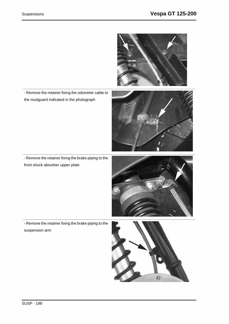
- Remove the retainer fixing the odometer cable to
the mudguard indicated in the photograph
- Remove the retainer fixing the brake piping to the
front shock absorber upper plate
- Remove the retainer fixing the brake piping to the
suspension arm
Suspensions Vespa GT 125-200
SUSP - 198

- Pre-loosen the 3 nuts fixing the mudguard to the
suspension
- Remove the rear handlebar cover.
- Remove the screw fixing the handlebar to the
steering tube
- Tilt the handlebar towards the shield back plate
being careful not to scratch the plastic parts
- Remove the steering tube ring nut cover
- Use a specific tool to remove the counter-ring nut,
the spacer washer and the ring nut of the upper
disk of the fifth wheel fitting
- Slide off the steering tube and remove perma-
nently the mudguard from the suspension
Specific tooling020055Y Wrench for steering tube ring nut
Vespa GT 125-200 Suspensions
SUSP - 199
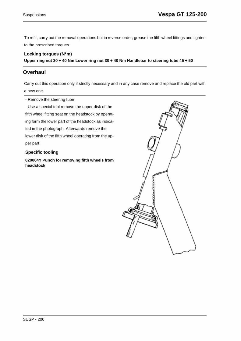
To refit, carry out the removal operations but in reverse order; grease the fifth wheel fittings and tighten
to the prescribed torques.
Locking torques (N*m)Upper ring nut 30 ÷ 40 Nm Lower ring nut 30 ÷ 40 Nm Handlebar to steering tube 45 ÷ 50
Overhaul
Carry out this operation only if strictly necessary and in any case remove and replace the old part with
a new one.
- Remove the steering tube
- Use a special tool remove the upper disk of the
fifth wheel fitting seat on the headstock by operat-
ing form the lower part of the headstock as indica-
ted in the photograph. Afterwards remove the
lower disk of the fifth wheel operating from the up-
per part
Specific tooling020004Y Punch for removing fifth wheels fromheadstock
Suspensions Vespa GT 125-200
SUSP - 200

- Remove the fifth wheel fitting and the dust guard
on the steering tube as shown in figure, using the
specific tool. Proceed giving a few taps with the
mallet.
Specific tooling020004Y Punch for removing fifth wheels fromheadstock
- Refit the fifth wheel fitting and the dust guard on
the steering tube until they stop, using the specific
tool.
Specific tooling006029Y Punch for fitting fifth wheel seat onsteering tube
- Use the specific tool to fit the fifth wheel fitting on
the headstock as indicated in the figure
Specific tooling020037Y Punch
- Remove the steering tube
- Remove the attachment bracket
- Use the specific tool with the part 1 and operate
the handgrip until removing temporarily the pin and
the Nadella opposite the tool thrusting direction.
- To extract the second Nadella, use the tool with
the part 2, instead of part 1, on opposite side to the
one indicated in the figure.
Specific tooling020021Y Front suspension service tool
Vespa GT 125-200 Suspensions
SUSP - 201

- Fit both dust guard rings «C» on the swinging hub
as shown in the detail drawing «A».
- Connect the swinging hub to the steering tube
with the guiding pin, part 5.
- Use the specific tool fitted with part 3 on the stem
and part 4 on the tool base.
- Lubricate the pin with recommended grease and
insert it temporarily on the swinging hub, move the
tool handgrip until part 3 is fully inserted on the
steering tube.
- Once the pin has been fitted, insert the two
spacers part 17 slightly hitting with a mallet (see
next figure).CAUTIONUSE NEW ROLLER CASINGS, PIN, SEALING RINGS ANDDUST GUARDS FOR REFITTING.
Specific tooling020021Y Front suspension service tool
Recommended productsAGIP GREASE PV2 Grease for the steeringbearings, pin seats and swinging armSoap-based lithium and zinc oxide grease con-
taining NLGI 2; ISO-L-XBCIB2 of the swinging arm
To fit sealing rings, roller casings and wedging
washers proceed as follows
- Lubricate the sealing rings with mineral oil and
half-fill the roller casings with recommended
grease.
- Insert the sealing ring on the pin and the roller
bushing with wedging washers at the same time.
- Remove the specific tool and then the part 5
(guide) partially ejected in the previous assembly
stage; part 4 must be always fitted.
- Replace part 3 with part 16 on the stem.
- Push, from the handgrip, the wedging washer -
roller casing - sealing ring unit, placing part 16 until
it stops on the swinging hub
- Repeat the operation described above using the
tool fitted with part 16 and part 22* instead of part
Suspensions Vespa GT 125-200
SUSP - 202

4 on the stem, on the side opposite the one shown
in the figure to refit the second wedging washer -
roller casing - sealing ring unit.
To position roller casings on the pin (pin end in
contact with the internal bottom of the roller cas-
ings) proceed as follows:
- Use the tool with part 20 and 21 fitted to the stem
as indicated in the figure.
- Push the two roller casings with the handgrip until
their bottoms make contact with the pin end.
- Use the specific tool fitted with parts 3 and 4 as
indicated for fitting the spin and push with the
handgrip until the washer is wedged in the swing-
ing hub.
- Remove the spacers, part 17; fill with recommen-
ded grease the area between the steering tube
and the swinging hub, and place the dust guard
rings in that place.
Recommended productsAGIP GREASE PV2 Grease for the steeringbearings, pin seats and swinging armSoap-based lithium and zinc oxide grease con-
taining NLGI 2; ISO-L-XBCIB2 of the swinging arm
Carry out this operation only if strictly necessary and in any case remove and replace the old part with
a new one.
- Remove the steering tube
- Use a special tool remove the upper disk of the
fifth wheel fitting seat on the headstock by operat-
ing form the lower part of the headstock as indica-
ted in the photograph. Afterwards remove the
lower disk of the fifth wheel operating from the up-
per part
Specific tooling020004Y Punch for removing fifth wheels fromheadstock
Vespa GT 125-200 Suspensions
SUSP - 203

- Remove the fifth wheel fitting and the dust guard
on the steering tube as shown in figure, using the
specific tool. Proceed giving a few taps with the
mallet.
Specific tooling020004Y Punch for removing fifth wheels fromheadstock
- Refit the fifth wheel fitting and the dust guard on
the steering tube until they stop, using the specific
tool.
Specific tooling006029Y Punch for fitting fifth wheel seat onsteering tube
- Use the specific tool to fit the fifth wheel fitting on
the headstock as indicated in the figure
Specific tooling020037Y Punch
- Remove the steering tube
- Remove the attachment bracket
- Use the specific tool with the part 1 and operate
the handgrip until removing temporarily the pin and
the Nadella opposite the tool thrusting direction.
- To extract the second Nadella, use the tool with
the part 2, instead of part 1, on opposite side to the
one indicated in the figure.
Specific tooling020021Y Front suspension service tool
Suspensions Vespa GT 125-200
SUSP - 204

Refitting
To refit, carry out the removal operations but in reverse order; grease the fifth wheel fittings and tighten
at the specified locking torques
Locking torques (N*m)Handlebar to steering tube 45 ÷ 50 Upper steering ring nut 30 ÷ 40 Lower steering ring nut 8 ÷10
Front shock absorber
Removal
- Remove the steering tube
- Remove the shock absorber lower clamps
- Remove the shock absorber upper clamps
Refitting
To refit, carry out the removal operations in reverse order, observing the prescribed tightening torques.
Locking torques (N*m)shock absorber lower clamp 20 - 27 shock absorber upper clamp 20 ÷ 30
Shock-absorber - calliper bracket
- Remove the front wheel hub with the brake disc
- Remove the front shock absorber lower clamps
Vespa GT 125-200 Suspensions
SUSP - 205

- Remove the bracket locking seeger ring
- Unscrew the bracket
- Before refitting the bracket in the wheel axle,
place the O-ring as shown in the photograph so
that it is correctly placed after fitting the bracket.
- Refit the washer and the Seeger ring.
- Refit the lower screws fixing the shock absorber
to the bracket and tighten at the prescribed torque
Locking torques (N*m)Lower shock absorber clamp 20 ÷ 27
Overhaul
- The bracket for the shock absorber -calliper at-
tachment has two roller bearings separated one
from the other as shown in the photograph
- Remove the two roller bearings from the bracket
with the specific tool operating on the shock ab-
sorber attachment side as shown in the photo-
graph
Specific tooling020376Y Adaptor handle
020441Y 26 x 28 mm adaptor
020365Y 22 mm guide
Suspensions Vespa GT 125-200
SUSP - 206

- Remove the oil seal on the wheel hub side with
the screwdriver as shown in the photograph
- Suitably hold the brake calliper - shock absorber
attachment bracket
- Fit a new oil seal and move it until it stops using
the specific tool
Specific tooling020376Y Adaptor handle
020360Y Adaptor 52 x 55 mm
- Assemble a new roller bearing on the shock ab-
sorber side and move it until it stops using the
specific tool
Specific tooling020036Y Punch
- Suitably hold the brake calliper - shock absorber
attachment bracket
- Assemble a new roller bearing on the wheel hub
side and move it until it stops using the specific tool
Specific tooling020037Y Punch
Rear
Vespa GT 125-200 Suspensions
SUSP - 207

Removing the rear wheel
- Remove the bracket supporting the rear shock
absorber and the muffler;
- Remove the rear wheel by unscrewing the 5
screws indicated in the photograph
Refitting the rear wheel
To refit, carry out the removal operations but in reverse order, observing the prescribed torques.
Locking torques (N*m)Wheel fixing screws: 20 - 25
Swing-arm
Removal
- Place the scooter on its centre stand;
- Remove the engine housing
- Remove the swinging arm/engine fitting shown in
the photo
- Move the engine back
- remove the spring anchoring the swinging arm to
the frame as shown in the photo
Suspensions Vespa GT 125-200
SUSP - 208

- Remove the two screws fixing the buffer support
bracket to the frame
- Remove the left and right caps located under the
footrest to reach the pin fixing the swinging arm to
the body.
- Remove the pin. Then remove the swinging arm.
Vespa GT 125-200 Suspensions
SUSP - 209

- Check the entire swinging arm assembly.
- Check all the centring bushing components and
silent block rubber buffers.
- Replace the work components that cause exces-
sive clearance on the rear suspension.
Overhaul
- Check there is no sticking in the movement of the
connection of the swinging arm on the engine side
to the swinging arm on the frame side.
- Check the axial clearance between the two
swinging arms using a feeler thickness gauge
CharacteristicStandard clearance0.40 ÷ 0.60 mm
Allowable limit after use:1.5 mm
- To check the clearance on the frame-side arm,
mount the retainer using the pin fixing the swinging
arm to the frame and two adaptor rings of the ap-
propriate tool 020229Y. Alternatively use two
washers with inner diameter for 12-mm pins, min.
outer diameter: 30 mm: min. thickness: 4 mm.
- Check there is no sticking in the rotation.
- Check the axial clearance of the swinging arm on
the frame side
CharacteristicStandard clearance0.40 ÷ 0.60 mm
Allowable limit after use:1.5 mm
Suspensions Vespa GT 125-200
SUSP - 210

- Separate the swinging arm on the engine side
from the vehicle side arm.
- Remove the plastic bushings and the internal
spacer shown in the photo.
- Using a suitable pin remove the roller casings as
shown in the photographs
- Using an appropriate tool plant new roller cas-
ings, being careful to position the bearings with the
O-rings facing outwards
Specific tooling020244Y 15 mm diameter punch
020115Y Ø 18 punch
CharacteristicLength of the swinging arm tube on the engineside:L 175.3 + 0.3 0
Length of the internal swinging arm spacer onthe engine side:L 183 + 0.3 0
Engine side swinging arm plastic bushingshim:3.5 ± 0.05 mm
Frame-side swinging arm plastic bushingshim:3.5 ± 0.05 mm
Length of the internal swinging arm spacer onthe frame side:290 ± 0.1 mm
Vespa GT 125-200 Suspensions
SUSP - 211

Length of the swinging arm tube on the frameside:283 ± 0.1 mm
- Lubricate roller casings and the plastic bushings
with grease
- Insert the spacers
- Assemble the two arms with the relative bolt in
the position shown in the photograph
- Adjust the bolt as shown in the photograph
- Position the frame side swinging arm with the
most protruding part pointing towards the silent
block side as shown in the photograph
Recommended productsAGIP GREASE PV2 Grease for the steeringbearings, pin seats and swinging armSoap-based lithium and zinc oxide grease con-
taining NLGI 2; ISO-L-XBCIB2 of the swinging arm
- Make sure the silent bloc is not broken. If there
is, replace it.
- Remove the seeger ring shown in the photograph
- Remove the full silent bloc bracket
- Undo the silent bloc ring shown in the photograph
Suspensions Vespa GT 125-200
SUSP - 212

- Hold the full silent bloc bracket in the clamp
- Using the appropriate tool, remove the silent bloc
from the bracket from the side corresponding to
the inside of the vehicle. This is to guarantee the
tool is centred properly on the support
- Install a new silent bloc, making sure it aligns
properly with the reference tooth.
- Fit the silent blocs, making sure the chamfered
part of the silent bloc matches the chamfered part
of the bracket
- Using the appropriate tool, fit the silent bloc as
shown in the photo
Refitting
- To refit, perform the removal operations in reverse.
- Grease the bearings and the rolling parts with the recommended grease.
Vespa GT 125-200 Suspensions
SUSP - 213

-Complete the fitting by tightening the nuts on the relative bolts to the proper tightening torque.
Locking torques (N*m)Engine and vehicle side swinging arm junction bolt 33 ÷ 41 Nm Swinging arm pin - Engine 64 -72 Body shell - Swinging arm pin 76 ÷ 83 Screw fixing the silent-block support plate to thebody 42 ÷ 52
Shock absorbers
Removal
Proceed as follows:
- place the scooter on its centre stand;
- remove the luggage rack
- lift the engine a little with a jack so as to free the
two shock absorbers;
- remove the muffler assembly;
- undo the shock absorber spring assembly clamp-
ing screw from the support fixed to the engine on
the one side and from that fixed to the muffler on
the other;
- unscrew the two upper nuts (one on each side)
fixing the shock absorber spring assembly to the
frame and remove the shock absorbers.
Refitting
To refit, carry out the above removal operations in reverse order, observing the prescribed torques.
Locking torques (N*m)
Suspensions Vespa GT 125-200
SUSP - 214

Lower shock absorber clamping screw 33 ÷ 41 Nm Upper shock absorber fixing screws 20 ÷ 25Nm
Exhaust bracket
Removal
Remove the full muffler unit.
- Remove the two fixing screws of the bracket to
the engine crankcase
- Remove the split pin, the cover and the fixing nut
of the rear wheel axle and its spacer
- Remove the shock absorber lower clamp
Refitting
- The refitting procedure is in the reverse order of the removal operation being careful to respect the
torques indicated and the spacer assembly layout as shown in the photo.
Locking torques (N*m)Bracket fixing screws to the engine crankcase: 20 ÷ 25 Lower shock absorber clamp 33 ÷ 41Wheel axle clamping 104 ÷ 126
Centre-stand
REMOVAL
- Use a jack to support the vehicle properly.
- Remove the two return springs from the centre
stand.
- Undo the nut shown in the figure.
- Remove the bolt from the right side.
- Remove the centre stand.
FITTING
- On refitting tighten the nut to the specified torque.
Locking torques (N*m)Centre stand fixing bolt 25 ÷ 30 Nm
Vespa GT 125-200 Suspensions
SUSP - 215

Side stand
REMOVAL
- Uncouple the centre stand return spring;
Remove the screw shown in the photograph
FITTING
To refit, carry out the removal operations in re-
verse order and comply with the specified torque.
Locking torques (N*m)Side stand fastening bolt 40 - 45 Nm
Suspensions Vespa GT 125-200
SUSP - 216

INDEX OF TOPICS
BRAKING SYSTEM BRAK SYS

This section è is devoted to the description of the braking system components.
Rear brake calliper
Removal
- Remove the rear wheel.
- Remove the pad retention pin snap ring.
- Using a pin partially remove the brake pad re-
tention pin.
- Remove the screws fixing the brake calliper to
the crankcase then remove the brake calliper com-
plete with pipe.
- Complete the extraction of the pad retention pin,
the spring and the pads.N.B.SHOULD THE BRAKE CALLIPER BE REPLACED ORSERVICED, BEFORE REMOVING THE FITTINGS FIXINGTHE CALLIPER TO THE SUPPORT BRACKET, LOOSENTHE OIL HOSE FITTING AFTER HAVING EMPTIED THESYSTEM OF THE CIRCUIT BEING EXAMINED.
Overhaul
- Remove the rear brake calliper.
- Suitably hold the brake calliper in a clamp
- Remove the two calliper coupling screws as
shown in the photo
- Remove the two pistons from the calliper body
with the aid of short blasts of compressed air
through the brake fluid holes
- Remove the dust ring and the O-ring of each half
calliper.
- Remove the O-rings in the half calliper.N.B.WHEN REMOVING THE O-RINGS, BE CAREFUL NOT TOSCRATCH THE HALF CALLIPER SEATS
Braking system Vespa GT 125-200
BRAK SYS - 218

- Check that the pistons and their seats show no
scratches.
- Wash and blow all the components carefully
- Fit the O-rings and new dust guards
- Refit the pistons in their seats being careful to
lubricate with brake fluid
- Re-couple the half callipers and lock the two
screws at the specified torque
Locking torques (N*m)Calliper coupling screw 22 ÷ 27
Refitting
- Insert the brake pads in the calliper.
- Insert the pad fixing pin and the retention screw
being careful to position the terminals of it pointing
towards the bleed screw as shown in the photo.
- Insert the clip on the pad fixing pinN.B.FAILURE TO RESPECT THE PAD POSITIONING REQUIRE-MENTS WITH RESPECT TO THE DIRECTION OF ROTA-TION COULD COMPROMISE PROPER BRAKE FUNCTION-ING AND NOISELESSNESS.
Vespa GT 125-200 Braking system
BRAK SYS - 219

- Keep the brake pads in contact with the pistons
and insert the calliper in the brake disc.
- Fix the calliper to the crankcase with the two
screws with elastic washer at the prescribed tor-
que as shown in the photograph
- Fix the brake pipe joint to the calliper and tighten
at the prescribed torque
- Bleed the system and refit the rear wheel
Locking torques (N*m)Brake calliper support clamping 20 ÷ 25 NmBrake pipe connection 20 to 25 N•m
Front brake calliper
Braking system Vespa GT 125-200
BRAK SYS - 220

Removal
- Remove the front wheel
- Pre-loosen the two fixing pins of the brake pads
- Remove the two front brake calliper devices fas-
tening them to the support as shown in the photo-
graph.N.B.WHEN A PROCEDURE IS PLANNED INCLUDING THESERVICE OR REPLACEMENT OF THE CALLIPER, FIRSTLOOSEN THE FITTING CONNECTING THE PIPE TO THEBRAKE CALLIPER
Overhaul
Proceed as follows:
1) remove the two male hexagonal screws (1) and
take out the two pads (10);
2) remove the two male hexagonal screws (2) and
remove the reaction plate (3);
3) take out the fixed plate (4) from the guide;
4) remove the internal elements from the floating
body (5) with the help of short blows of com-
pressed air through the brake fluid pipe in order to
facilitate the expulsion of pistons (6).
5) Check:
- that the plates and the body are whole and in
good condition;
- that the cylinder and the floating body of the cal-
liper do not show signs of scratches or erosion,
otherwise replace the entire calliper;
- that the guides of the fixed plate are not scratched
or eroded, otherwise replace the entire plate;
Vespa GT 125-200 Braking system
BRAK SYS - 221

- that the brake pad check spring works properly.CAUTIONALL THE INTERNAL COMPONENTS MUST BE REPLACEDEVERY TIME THE CALLIPER IS SERVICED.
The brake pad check spring
1. pad fixing screws
2. reaction plate fixing screws
3. reaction plate
4. fixed plate
5. floating body
6. piston
7. piston sealing rings
8. guide protection rubbers
9. brake pad check spring
10. pads
Refitting
Insert the following on the front brake body:
-The sealing rings and the pistons (1).
-Refit the plate (2).
- Arrange the pad holding clamp (3).
-Refit the pads and bleed air.
-Place the calliper on the disk and lock it to the
support by tightening the bolts at the prescribed
torque.
-Lock the pipe joint to the calliper at the prescribed
torque.
-Follow the same procedure for the rear brake cal-
liper.
Locking torques (N*m)Screws fixing the front calliper to the sup-port: 20 ÷ 25 Nm Screw fixing the oil connectionto the calliper: 20 ÷ 25 Nm
Rear brake disc
Braking system Vespa GT 125-200
BRAK SYS - 222

Removal
- Remove the rear brake calliper.
- Remove the brake disc and the hub from the
wheel axle
- To remove the brake disc from the hub, hold the
unit firmly with a vice and operate on the 5 fixing
screws indicated in the photograph
Refitting
- To reassemble the brake disc on the hub, carry out the removal operations in the reverse order ar-
ranging the brake disc on the hub on the side opposite the wheel keying
- Follow the direction of rotation shown by the arrow and tighten to the prescribed torque.
- Fit the hub unit
- disc in the wheel axle
Locking torques (N*m)Disk to the hub 11 ÷ 13
Disc Inspection
- Remove the rear brake calliper.
- Check the disc thickness with a micrometer
CharacteristicMinimum thickness allowed after use:
3.5 mm
Standard thickness:
4 +0.2-0.2 mm
- Repeat the measurement at no fewer than six points on the disc.
- Check the regular nature of the rotation of the brake disc assembly using the appropriate tool fixed
onto the brake calliper as shown in the photo.
- In order to be able to anchor the appropriate tool properly use a metal plate with M8 threaded hole
and fix it to one of the two rear brake calliper attachment points.
- Suitably fix the flange to the wheel axle with the original nut and spacer and a Æ 17 mm bearing.N.B.
SO AS NOT TO GET A DISTORTED READING, CAUSE THE DRIVEN PULLEY SHAFT TO TURNIN ORDER TO ROTATE THE DISC.
Specific tooling
Vespa GT 125-200 Braking system
BRAK SYS - 223

020335Y Magnetic support for dial gauge
CharacteristicMax. deviation allowed:
0.1 mm
- If you detect incorrect values, replace the disc. If
the anomaly persists, replace the hub.
Front brake disc
Removal
- Remove the front wheel
- Remove the front brake calliper
- Remove the hub and the disc operating on the
wheel axle nut
- Hold the hub and the disc firmly and remove the
brake disc undoing the six screws indicated in the
photograph
Braking system Vespa GT 125-200
BRAK SYS - 224

Refitting
- Carry out the operations in the reverse order from
the removal being careful to respect the direction
of disc rotation shown by the arrow printed on it
- Tighten the six screws to the specified torque.
Locking torques (N*m)Brake disc screws: 6 +0.5 -1 Nm
Disc Inspection
- Remove the front wheel
- Use a micrometer to check the disc thickness as
shown in the photograph
- Repeat the measurement in at least 6 points on
the disk
- Remove the front brake calliper
- In order to secure the appropriate tool adequately
use a metal plate with M8 threaded hole and fix it
to one of the two front brake calliper attachment
points
- Place the dial gauge on the disk outer edge
- Make the wheel hub turn and check the disk de-
viation
Specific tooling020335Y Magnetic support for dial gauge
CharacteristicStandard thickness:4 +0.2-0.2 mm
Max. deviation allowed:0.1 mm
Front brake pads
Vespa GT 125-200 Braking system
BRAK SYS - 225

Removal
- Remove the front wheel
- Pre-loosen the two fixing pins of the brake pads
- Remove the brake calliper
- Remove permanently the two pad fixing screws
- Check that there are no flaws or warping. If there
is, replace it.
- Check the thickness of the friction material is
more than 1.5 mm. If it is not , replace it
- The replacement must be made with greater re-
sidual thickness if the pad has not worn evenly. A
0.5 mm thickness difference in the residual friction
material is permitted
Refitting
To fit, proceed as follows:
- Insert the two pads in the callipers.
Braking system Vespa GT 125-200
BRAK SYS - 226

- Screw the two pad lock pins to the correct torque, and apply the recommended product.
- Fit the calliper on its support, tightening the two screws to the prescribed torque.N.B.
IF IT IS NOT POSSIBLE TO CORRECTLY POSITION THE CALLIPER ON THE DISC DURING FIT-TING, GENTLY EXPAND THE PADS.
Recommended productsLoctite 243 Medium strength threadlock
Loctite 243 medium-strength threadlock
Locking torques (N*m)Screw tightening calliper to the support 20 ÷ 25 Pad fastening pin 19.6 ÷ 24.5
Rear brake pads
Removal
- Remove the rear brake calliper.
- Remove the brake pad and check there are no
faults or warping. If there is, replace it.
- Check the thickness of the friction material is
more than 1.5 mm. If it is not , replace it
- The replacement must be made with greater re-
sidual thickness if the pad has not worn evenly. A
0.5 mm thickness difference in the residual friction
material is permitted
Vespa GT 125-200 Braking system
BRAK SYS - 227

See alsoRemoval
Refitting
- Insert the brake pads
- Insert the fixing pin being careful to position the
clip with the ends towards the bleed screw as in
the photo.
- Insert the clip on the pin
- Fix the rear brake calliper to the bracket and
tighten the two screws to the specified torque.
Locking torques (N*m)Rear brake calliper tightening screw 20 ÷ 25 Nm
Fill
Front
- Remove the rubber hood from the bleed screw.
- Insert a rubber pipe in the bleed screw to permit
the brake fluid to be recovered.
- With the left-had brake lever, load the system and
bring it up to the required pressure.
- Keeping the left-hand brake lever pulled, loosen
the bleed screw to permit the air in the system to
escape. Then tighten the bleed screw
- Repeat the operation until only brake fluid comes out of the rubber pipe.
- Remove the fluid recovery pipe and refit the rubber hood over the bleed screw.
- Top up the brake fluid to the right level in the tank.
If necessary, bleeding can be done using a special vacuum pumpN.B.DURING THE BLEEDING OPERATIONS, MAKE SURE THE BRAKE FLUID DOES NOT COME INTOCONTACT WITH THE BODYWORK SO AS NOT TO DAMAGE IT. FURTHERMORE, DURING THE
Braking system Vespa GT 125-200
BRAK SYS - 228

BLEEDING OPERATIONS REGARDING THE BRAKE CALLIPERS, MAKE SURE THE BRAKEFLUID DOES NOT COME INTO CONTACT WITH THE DISC BRAKES AND WITH THE BRAKEPADS. FAILURE TO COMPLY WITH THIS NORM WILL ENDANGER THE PROPER WORKING ANDEFFICIENCY OF THE BRAKING SYSTEM
Specific tooling020329Y MityVac vacuum-operated pump
Locking torques (N*m)System bleed calliper fitting: 20 ÷ 25 Nm
Brake fluid level check
- Position the vehicle on a flat surface and on the
centre stand
- Remove the brake pump cover as indicated in the
photo
- Use the appropriate spyglass on the pump to
check the level of the brake fluid, as shown in the
photograph
- If the level is below the minimum, fill using the two
screws shown in the figure
- Remove the gasket and fill with DOT 4 until the
spyglass is completely coveredCAUTION
AVOID CONTACT OF THE BRAKE FLUID WITH YOUREYES, SKIN, AND CLOTHING. IN CASE OF ACCIDENTALCONTACT, WASH WITH WATER.CAUTION
THE BRAKING CIRCUIT FLUID IS HIGHLY CORROSIVE.THEREFORE, WHEN TOPPING IT UP, AVOID LETTING ITCOME INTO CONTACT WITH THE PAINTED PARTS OFTHE VEHICLE. THE BRAKING CIRCUIT FLUID IS HYGRO-
Vespa GT 125-200 Braking system
BRAK SYS - 229

SCOPIC, THAT IS, IT ABSORBS HUMIDITY FROM THESURROUNDING AIR. IF MOISTURE CONTAINED IN THEBRAKE FLUID EXCEEDS A CERTAIN VALUE, THIS WILLRESULT IN INEFFICIENT BRAKING.CAUTIONTHE BRAKE FLUID IS HYGROSCOPIC, THAT IS, IT AB-SORBS MOISTURE FROM THE SURROUNDING AIR. IFTHE LEVEL OF HUMIDITY IN THE BRAKE FLUID EXCEEDSA GIVEN VALUE, BRAKING EFFICIENCY WILL BE RE-DUCED.
Locking torques (N*m)Float chamber screws 15 ÷ 20 Nm
Never use brake liquid in open or partially used
containers.
Under standard climatic conditions, replace cool-
ant as indicated in the scheduled maintenance
table.
For refitting purposes carry out the removal oper-
ations but in reverse order and respect the tight-
ening torques of the tank cover screws.
Locking torques (N*m)Brake pump reservoir screws 1.5 ÷ 2
Front brake pump
Removal
- Remove the rear handlebar cover.
- Remove the two screws fixing the brake pump to the handlebar indicated in the photograph
- Remove the oil pipe joint from the pump
- Remove the connector to the stop light switch
BRAKE PUMP TECHNICAL DATA:Specification Desc./Quantity
Pump right piston diameter Ø 12.7Pump left piston diameter Ø 11
Braking system Vespa GT 125-200
BRAK SYS - 230

Overhaul
Proceed as follows:
1) Remove the brake lever by loosening the retaining screw; open the cover (2) and take out the dia-
phragm (3);
2) remove the cap (4) and take out the internal parts in order;
3) Check that:
- The body of the pump shows no signs of internal damage or corrosion;
- The plunger shows no sign of damage or abnormal wear;
- The plunger return spring is in good condition.CAUTIONALL THE SEALS AND GASKETS MUST BE REPLACED EVERY TIME THE PUMP IS SERVICED.
1. Reservoir cap screw
2. Reservoir cap.
Vespa GT 125-200 Braking system
BRAK SYS - 231

3. Diaphragm.
4. Bellows.
5. Sealing ring
6. Piston.
7. Gasket.
8. Spring.
9. Reservoir
Refitting
To refit, carry out the removal operations but in reverse order, observing the specified torques.
Locking torques (N*m)Oil pipe joint to the pump: 20 - 25 Brake pump fixing screws to the handle bar: 7 ÷ 10 Nm
Braking system Vespa GT 125-200
BRAK SYS - 232
INDEX OF TOPICS
COOLING SYSTEM COOL SYS

Water pump - overhaulWater pump assembly
With a hot air gun heat the inner side of the fly-
wheel cover.AVOID OVERHEATING AS THIS MAY ALTER THE PAIN-TED SURFACE.
Specific tooling020151Y Air heater
- Place the flywheel cover on the ring base following the same procedure as for removal.
- Place the two bearings on the specific punch.N.B.
USE A NEW BEARING WHEN REFITTING
- Use grease to keep the bearings on the appropriate tool.
- Use a plastic mallet to insert the bearings on the housing up to the stop.
- Assembly the ceramic ring and the correspond-
ing rubber gasket. The ceramic ring chamfering
should always face towards the gasket.
- Lubricate the rubber gasket and insert the unit on
the flywheel cover.
Use the punch of the appropriate tool manually if
necessary.ALWAYS USE NEW CERAMIC RING AND GASKETS. AS-SEMBLING THE CERAMIC SEALING RING IN A MANNEROTHER THAN MANUALLY MAY DAMAGE THE RING.
Specific tooling020440Y Water pump service tool
- Insert the drive on the guide pin of the support
base which is part of the appropriate tool. Check
that the convex part faces upwards.
Cooling system Vespa GT 125-200
COOL SYS - 234

- Insert the flywheel cover with bearings on the ap-
propriate tool.
- Insert the shaft together with the mechanical gas-
kets on the bearings.
- With the appropriate punch and socket, insert the
shaft in the bearings and the drive until the end of
stroke of the appropriate tool cannot be seen.N.B.CENTRE THE PUNCH CORRECTLY ON THE ROTOR.PUSH THE SHAFT IN AND CHECK THAT THE FLYWHEELCOVER ROTATES SMOOTHLY. FAILURE TO RESPECTTHIS PROCEDURE DAMAGES THE DRIVE.
- Reassemble the rotor cover with a new O-Ring.
-Tighten the 3 fixing screws to the torque below:N.B.DO NOT LUBRICATE THE O-RING. FAILURE TO RESPECTTHIS RULE RESULTS IN RING DISTORTION.
Locking torques (N*m)Water pump cover screws 3 ÷ 4
Component check
- Check that the rotor does not show abnormal wear or dents;
- Check that the rotor shaft is not rusty;
- Check that there is no rust on the bearing seats or the ceramic seal;
- Check that the drive does not show dents and that it is perfectly integral with the steel hub.
Removal
- Check the water pump if noise in the bearings or liquid leaking from the drainage hole inside the cover
is detected.
-Remove the flywheel cover together with the water pump from the engine.
- Remove the rotor cover by unscrewing the 3 retainers indicated in the figure.
Vespa GT 125-200 Cooling system
COOL SYS - 235

-Place the flywheel cover on the ring base which is part of the toolN.B.TO AVOID DAMAGING THE COVER SURFACE THAT SEALS THE COOLANT, USE THE RINGBASE WITH THE ACCURATELY MACHINED SURFACE FACING THE FLYWHEEL COVER.
Specific tooling020440Y Water pump service tool
-With an appropriate socket and punch, forming part of the specific tool 020440y, extract the shaft
together with the rotor from the drive and the bearings.
Cooling system Vespa GT 125-200
COOL SYS - 236

- Use a screwdriver to remove the static part of the ceramic seal from the flywheel cover.
- Place the flywheel cover below the socket making
sure it is perfectly levelled.
- Use the punch in the inverted position to extract
the two ball bearings.
Water pump ceramic seal
Our Leader, Quasar, and Master liquid cooled engines are equipped with water pumps fitted with the
ceramic seal in the subject. This component is intended to guarantee the leak tightness of the coolant
in relation to the pump shaft. The seal achieved via two special ceramics, a static one and a spinning
one, kept in contact by the thrust of a spring, coaxially mounted onto the pump shaft. The efficiency of
this system is guaranteed by the accurate machining and cleaning of the components as they are fitted;
in any case, ceramic seals are subjected to a running in period. During this period (1,000 ± 1,500 km),
there may be small leaks through draining holes, which remain visible on the aluminium crankcase.
This phenomenon is particularly visible there where the hole is more exposed (Quasar and Master). In
such cases we recommend cleaning the casing in order to be able to check again for leaks after a
distance of more than 1500 km. If leaks continue or in the event of real losses, the ceramic seal should
be replaced. For these operations, observe the tools and instructions given in the relevant service
station manuals.
Note: The ceramic seal may be overhauled according to the following couplings:
• Coupling "A": seal ring no. 485084 with ceramic seal no. 486216
• Coupling "B": seal ring no. 841329 with ceramic seal no. 841330
The couplings above may be selected according to their availability, as they are interchangeable.
Vespa GT 125-200 Cooling system
COOL SYS - 237

Check
1) Look to see that the thermostat is not damaged.
2) Fill a metal container with approx. 1 litre of wa-
ter.
Immerse the thermostat, and keep it in the centre
of the container.
Immerse the multimeter temperature probe, and
keep it close to the thermostat.
Heat up the container using the thermal gun.
Check the temperature when the thermostat starts
to open:
Heat up until the thermostat is completely open.
3) Replace the thermostat if it is not working prop-
erly.CAUTIONTO EXECUTE THE TEST CORRECTLY, MAKE SURE NEI-THER THE THERMOSTAT NOR THE THERMOMETERTOUCHES THE CONTAINER.
Specific tooling020331Y Digital multimeter
020151Y Air heater
CharacteristicThermostat check: Opening start temperature69.5 ÷ 72.5°C
Cooling system Vespa GT 125-200
COOL SYS - 238

INDEX OF TOPICS
CHASSIS CHAS

This section è is devoted to the operations that can be carried out on the vehicle's bodywork.
Seat
- Remove the helmet compartment
- Remove the two screws shown in the photograph
- Remove the saddle
- Remove the helmet compartment
- Remove the 2 nuts indicated in the photograph
- Free the electric cables form the retaining clamps
indicated in the photograph
- Remove the saddle opening transmission cable
- Remove the saddle manual opening transmis-
sion cable.
Chassis Vespa GT 125-200
CHAS - 240

- Remove the electric connector from the saddle
opening actuator
- Remove the two screws shown in the photograph
- Remove the clip from the transmission
- Remove the actuator from the supporting bracket
Rear rack
- Remove the helmet compartment
- Undo the two screws shown in the figure and re-
move the luggage rack cover.
- Undo the six screws shown in the figure, remove
the passenger handgrips and the luggage racks
Vespa GT 125-200 Chassis
CHAS - 241

Rear handlebar cover
- Remove the front handlebar cover
- Undo the 4 screws indicated in the photograph
-Disconnect the odometer cable
-After disconnecting the wiring remove the rear
handlebar.
Instrument panel
- Remove the rear handlebar cover;
- Remove the four screws indicated in the figure
- Remove the instrument panel.
Chassis Vespa GT 125-200
CHAS - 242

Front handlebar cover
- Remove the front grille
- Remove the front screw indicated in the figure
-Undo the 2 screws indicated in the figure;
- Remove the front handlebar cover
- Disconnect the front headlamp connectors
Headlight assy.
- Operate the screw indicated in the figure to re-
move the front turn indicator
Vespa GT 125-200 Chassis
CHAS - 243

Knee-guard
- Remove the rear handlebar cover.
- Remove the two screws indicated in the photo-
graph and located on the shield under the grille
- Remove the expansion tank cover and then its
cap
- Remove the central screw inside the glove-box,
indicated in the photograph
- Remove the two screws indicated in the photo-
graph and located below the expansion tank cover
and the left cover respectively
- Remove the shield back plate lower screws, to
the right and left side of the shield back plate, as
indicated in the photograph
Chassis Vespa GT 125-200
CHAS - 244

- Remove the electric saddle opening switch, the
fuse box and the manual saddle opening cable as
shown in the photograph
Removing the ignition key-switch when on *off*
- Remove the shield back plate.
- Remove the immobilizer aerial as shown in the
figure.
- Detach the electrical wiring.
- Remove the ignition key-switch, by removing the
spring retainer shown in the figure.
Vespa GT 125-200 Chassis
CHAS - 245

- Lightly push the master-cylinder and extract the
lock from the notch shown in the figure.
- Hence extract the master-cylinder complete with
the key-switch.
- For the reassembly proceed in the reverse order.
Removing the ignition key-switch when on *lock*
In position "Lock", it is not possible to access the
cylinder retaining spring. The spring must then be
removed as shown in the figure, allowing the lock
spring to be pressed out.N.B.FOR REASSEMBLY FROM THIS POSITION, RELEASE THESTEERING WHEEL AND SET THE LOCK BODY (INSIDEAND OUTSIDE PART) TO "OFF". THEN, PROCEED AS DE-SCRIBED IN PARAGRAPH REMOVAL, LOCK IN OFF PO-SITION.
Chassis Vespa GT 125-200
CHAS - 246

Front wheel housing
• Remove the front fork;
• Unscrew the central stud of the wheel
well at the frame;
• Disconnect the brake pipe to the pump
and pull it out;;
• Remove the odometer transmission..
Taillight assy.
- Operate the screw indicated in the figure to re-
move the rear turn indicator
- Remove the two screws fixing the license plate
light shown in the figure
- Loosen the two fixing screws and remove the rear
light unit.
Vespa GT 125-200 Chassis
CHAS - 247

Footrest
- Remove the shield back plate
- Remove the battery compartment cover
- Remove the side fairings
- Remove the central screw located under the bat-
tery compartment cover as indicated in the figure
- Remove the passenger footrests undoing the two
screws indicated in the figure
- Remove the right and left screws fixing the foot-
rest indicated in the figure
Chassis Vespa GT 125-200
CHAS - 248

- Remove the right and left lower covers as shown
in the figure
- Remove the screws under the non-slip rubber
mat of the footrest as indicated in the photograph
Side fairings
- Remove side fairings, right and left, by undoing
the 2 screws shown in the figure
Rear mudguard
- Remove the air filter
- Remove the screw indicated in the photograph
- Remove the mudguard
Vespa GT 125-200 Chassis
CHAS - 249

Helmet bay
- Lift the saddle and remove the helmet compart-
ment
Fuel tank
- Remove the helmet compartment
- Remove the side fairings
- Remove the muffler
- Remove the luggage rack
- Remove the shock absorber upper clamps
- Remove the two screws, indicated in the figure,
that fix the tank to the body
- Remove the connector from the fuel gauge
- Remove the screw indicated in the figure that fix-
es the tank to the body after removing the rear
headlight assembly
- Remove the straps retaining the pipes to the fuel
valve as shown in the figure
- Remove the two turn indicators
- Use a jack to lift the body so that there is enough
space between the vehicle rear side and the en-
gine to slide off the tank
To refit, perform the steps in the reverse direction
to disassembly
Chassis Vespa GT 125-200
CHAS - 250

Rear central cover
- Remove the four screws indicated in the figure
Front mudguard
- First remove the steering tube and uncouple the
front brake pipes from the calliper in order to re-
move the front mudguard
- Remove the three mudguard-steering tube
clamps indicated in the figure
Vespa GT 125-200 Chassis
CHAS - 251

Radiator fan
- In order to carry out any operation on the radiator
unit, flow out the coolant in the coolant delivery
pipe in the pump, indicated in the photograph.
- Remove the shield back plate;
- Remove the coolant feed and return hoses from
the right radiator;
- Unscrew the 4 screws fixing the radiator to the
body;
- Detach the radiator
- Detach the pipe from the plastic duct by removing
the plastic clip shown in the photograph. Then re-
move the duct.
- The same procedure also applies to the left ra-
diator for which it is necessary to remove the elec-
trical fan first by undoing the 3 screws indicated in
the photograph.
To refit, perform the removal operations but in reverse order being careful when positioning the news
clips for the fluid hoses and when filling the cooling system.
Chassis Vespa GT 125-200
CHAS - 252

Front central cover
- Remove the "PIAGGIO" clip-on badge
- Unscrew the screw indicated in the figure
- Remove the grille
Vespa GT 125-200 Chassis
CHAS - 253

INDEX OF TOPICS
PRE-DELIVERY PRE DE

Carry out the listed tests before delivering the vehicle.
Warning- be very careful when handling fuel.
Aesthetic inspection
Appearance check:
- Paintwork
- Fitting of plastics
- Scratches
- Dirt
Tightening torques inspection
• Safety Locks • Cover retaining screws
SAFETY LOCKSName Torque in Nm
Shock absorber upper fixing: rear 20 to 25 N•mShock absorber bottom fixing: rear 33 to 41 N•m
Left shock absorber lower support bolts 20 ÷ 25Front wheel axle nut 75 ÷ 90Rear wheel axle nut 104 ÷ 126Rear brake disc bolts 11 ÷ 13
swinging arm bolt - chassis 76 ÷ 83 NmEngine swinging arm bolt 64 ÷ 72 NmHandlebar clamping bolts 45 ÷ 50 NmUpper steering ring nut 30 ÷ 40Lower steering ring nut 8 ÷ 10
Electrical system
• Main switch
• Lights: high beams, low beams, side/taillights (front and rear) and relevant warning lights
- Regulating the headlights according to the regulations currently in force
• Front and rear stop light buttons and relative light •Turn indicators and relative telltales
• Instrument lighting
• instruments: fuel and temperature indicator
•Instrument panel lights
• Horn
• Electrical start up
• Engine stop by emergency stop switch and side stand
• Electrical saddle opening buttonCAUTIONTO ENSURE MAXIMUM PERFORMANCE, THE BATTERY MUST BE CHARGED BEFORE USE.INADEQUATE CHARGING OF THE BATTERY WITH A LOW LEVEL OF ELECTROLYTE BEFOREIT IS FIRST USED SHORTENS BATTERY LIFE.CAUTION
Vespa GT 125-200 Pre-delivery
PRE DE - 255

WHEN INSTALLING THE BATTERY, ATTACH THE POSITIVE LEAD FIRST AND THEN THE NEG-ATIVE LEAD.WARNINGBATTERY ELECTROLYTE IS TOXIC AND IT MAY CAUSE SERIOUS BURNS. IT CONTAINS SUL-PHURIC ACID. AVOID CONTACT WITH EYES, SKIN AND CLOTHING.IN CASE OF CONTACT WITH EYES OR SKIN, RINSE WITH ABUNDANT WATER FOR ABOUT 15MINUTES AND SEEK MEDICAL ATTENTION AT ONCE.IF IT IS SWALLOWED, IMMEDIATELY DRINK LARGE QUANTITIES OF WATER OR VEGETABLEOIL. SEEK IMMEDIATE MEDICAL ATTENTION.BATTERIES PRODUCE EXPLOSIVE GAS; KEEP THEM AWAY FROM NAKED FLAMES, SPARKSAND CIGARETTES. IF THE BATTERY IS CHARGED IN A CLOSED PLACE, TAKE CARE TO EN-SURE ADEQUATE VENTILATION. ALWAYS PROTECT YOUR EYES WHEN WORKING CLOSE TOBATTERIES.KEEP OUT OF THE REACH OF CHILDRENCAUTIONNEVER USE FUSES WITH A CAPACITY HIGHER THAN THE RECOMMENDED CAPACITY. USINGA FUSE OF UNSUITABLE RATING MAY SERIOUSLY DAMAGE THE VEHICLE OR EVEN CAUSEA FIRE.
Levels check
Level check:
- Hydraulic brake system liquid level.
- Rear hub oil level
- Engine coolant level
- Engine oil level
Road test
Test ride
- Cold start
- Instrument operations
- Response to the throttle control
- Stability on acceleration and braking
- Rear and front brake efficiency
- Rear and front suspension efficiency
- Abnormal noise
Static test
Static control after the test ride:
• Hot engine restart
• Starter operation
• Minimum seal (turning the handlebar)
• Uniform steering rotation
• Possible losses
Pre-delivery Vespa GT 125-200
PRE DE - 256

• Electrical radiator fan operationCAUTION
CHECK AND ADJUST TYRE PRESSURE WITH TYRES AT AMBIENT TEMPERATURE.CAUTION
NEVER EXCEED THE RECOMMENDED INFLATION PRESSURES OR TYRES MAY BURST.
Functional inspection
Functional check up:
• Hydraulic braking system: lever travel
• Clutch: proper functioning check
• Engine: proper general functioning and no abnormal noise check
• Other: papers check, frame and engine number check, tools and equipment, licence plate fitting, lock
check, tyre pressure check, rear-view mirror and any accessory fitting
Vespa GT 125-200 Pre-delivery
PRE DE - 257

INDEX OF TOPICS
TIME TIME

This section is devoted to the time necessary to carry out repairs.
For each operation, the description, code and time envisages are specified.
Engine
ENGINECode Action Duration
1 001001 Engine from frame - Removal and re-fit.
2 003064 Engine oil - Change3 003057 Engine retainer - Tighten nuts
Crankcase
CRANKCASECode Action Duration
1 001153 Crankcase halves gasket - Replace-ment
2 001133 Engine crankcase- Replacement
Vespa GT 125-200 Time
TIME - 259

Crankshaft
CRANKSHAFTCode Action Duration
1 001099 Oil seal, flywheel side - Replacement2 001117 Crankshaft - Replacement
Cylinder assy.
Time Vespa GT 125-200
TIME - 260

CYLINDER- PISTONCode Action Duration
1 001002 Cylinder-Piston - Replacement2 001154 Pin-ring-piston assembly - Service
Cylinder head assy.
VALVE HEADCode Action Duration
1 001126 Head - Replacement2 001045 Valves - Replacement3 001049 Valves - Adjustment4 001056 Head gasket - Replacement5 001083 Thermistor - Replacement6 001057 Thermostat - Replacement
Vespa GT 125-200 Time
TIME - 261

Rocker arms support assy.
CAMSHAFTCode Action Duration
1 001148 Rocking lever valve - Replacement2 001044 Camshaft - Replacement
Cylinder head cover
Time Vespa GT 125-200
TIME - 262

HEAD COVERCode Action Duration
1 001093 Spark plug - Replacement2 001089 Head cover - Replacement3 001088 Head cover gasket - Replacement4 001074 Oil vapour recovery pipe - Replace-
ment
Chain tensioner
CHAIN TIGHTENERCode Action Duration
1 001129 Chain tightener - Overhaul and re-placement
2 001124 Lubrication by-pass - Replacement
Vespa GT 125-200 Time
TIME - 263

Oil filter
OIL FILTERCode Action Duration
1 001123 Oil filter -Replacement2 001160 Oil pressure sensor - Replacement
Driven pulley
DRIVEN PULLEYCode Action Duration
1 001022 Clutch - Replacement2 001012 Driven pulley - Service3 001110 Driven pulley - Replacement4 001155 Clutch bell - Replacement
Time Vespa GT 125-200
TIME - 264
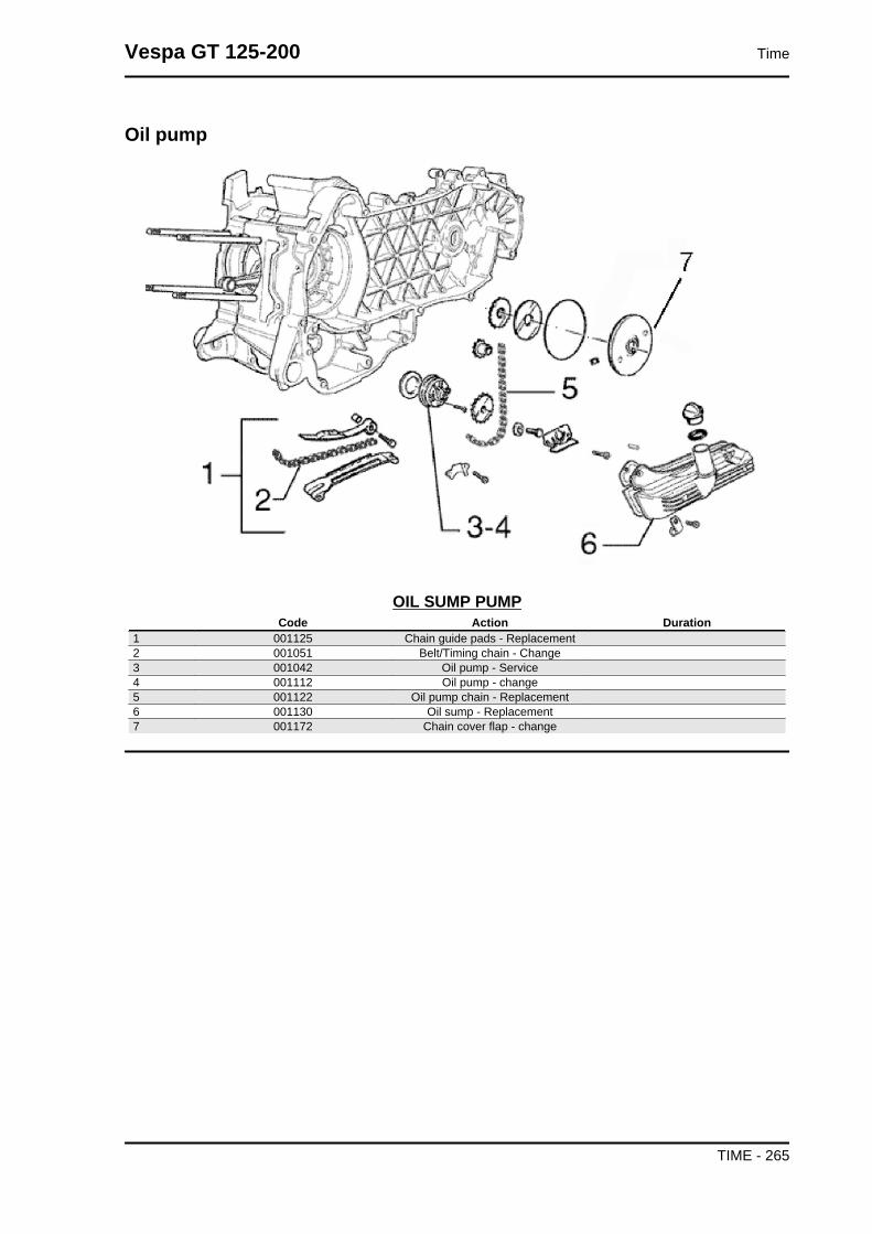
Oil pump
OIL SUMP PUMPCode Action Duration
1 001125 Chain guide pads - Replacement2 001051 Belt/Timing chain - Change3 001042 Oil pump - Service4 001112 Oil pump - change5 001122 Oil pump chain - Replacement6 001130 Oil sump - Replacement7 001172 Chain cover flap - change
Vespa GT 125-200 Time
TIME - 265

Final gear assy.
FINAL REDUCTIONCode Action Duration
1 001010 Reduction gear - Replacement2 003065 Gear box oil - Replacement3 001156 Geared reduction unit cover - Re-
placement4 004125 Rear wheel axle - Replacement
Time Vespa GT 125-200
TIME - 266

Driving pulley
DRIVING PULLEYCode Action Duration
1 001086 Driving half-pulley - Replacement2 001011 Driving belt - Replacement3 001066 Driving pulley - Removal and refitting4 001006 rear-view pulley - Service
Vespa GT 125-200 Time
TIME - 267

Transmission cover
TRANSMISSION COVERCode Action Duration
1 001135 Transmission cover bearing - Re-placement
2 001096 Transmission crankcase cover - Re-placement
3 001131 Transmission air intake - Replace-ment
Time Vespa GT 125-200
TIME - 268

Starter motor
ELECTRICAL START UPCode Action Duration
1 001020 Starter motor - Replacement2 001017 Start-up pinion - Replacement3 001141 Belt anti-flapping roller - Replace-
ment
Vespa GT 125-200 Time
TIME - 269

Flywheel magneto
MAGNETO FLYWHEELCode Action Duration
1 001087 Flywheel cover - Replacement2 001113 Water pump / Pump rotor - Replace-
ment3 001067 Stator - Removal and Refitting4 001058 Complete flywheel - Replacement5 001161 Secondary air filter - Replacement6 001162 Secondary air filter box - Replace-
ment7 001173 Rotor - Replacement
Time Vespa GT 125-200
TIME - 270

Carburettor
CARBURETTORCode Action Duration
1 001013 Intake manifold - Replacement2 007020 Carburettor heating tubing - replace-
ment3 001008 Carburettor - Inspection4 001063 Carburettor - Replacement5 001081 Automatic choke - Replacement6 003058 Carburettor - Adjustment7 001136 Exhaust emissions - Adjustment
Vespa GT 125-200 Time
TIME - 271

Exhaust pipe
MUFFLERCode Action Duration
1 001009 Muffler - Replacement2 001095 Muffler guard - Replacement
Time Vespa GT 125-200
TIME - 272

Air cleaner
AIR CLEANERCode Action Duration
1 001015 Air filter box - Replacement2 001014 Air filter - Replacement / cleaning3 004122 Air cleaner/ carburettor union - Re-
placement
Vespa GT 125-200 Time
TIME - 273

Frame
CHASSISCode Action Duration
1 004001 Chassis - Replacement2 004085 Fairing (1) - Replacement3 004149 Shield central cover - Replacement4 004053 Spoiler - Replacement5 004015 Footrest - Removal and Refitting6 004023 Shield rim - Replacement7 004159 Plates / Stickers - Replacement
Time Vespa GT 125-200
TIME - 274

Centre-stand
STANDCode Action Duration
1 004102 Side stand - Replacement2 004004 Stand - Replacement
Footrests
Vespa GT 125-200 Time
TIME - 275

MATS AND COVERSCode Action Duration
1 005007 Battery - Replacement2 004079 Footrest - replacement3 004071 Battery compartment - replacement4 005046 Battery cover - change5 004078 Front/rear footrest rubber - Replace-
ment
Rear cover
REAR SHIELDCode Action Duration
1 004083 Glove box - Replacement2 004081 Glove box door - Replacement
Time Vespa GT 125-200
TIME - 276

Underseat compartment
HELMET COMPARTMENTCode Action Duration
1 004136 License plate support - Replacement2 004016 Helmet compartment - Removal and
Refitting3 005048 Licence plate holder - Replacement
Mudguard
Vespa GT 125-200 Time
TIME - 277

MUDGUARDSCode Action Duration
1 004002 Front mudguard - Replacement2 004009 Rear mudguard - Replacement3 003044 Shock absorber cover - Replace-
ment
Fuel tank
FUEL TANKCode Action Duration
1 004005 Fuel tank - Replacement2 005010 Tank float - Replacement3 004109 Fuel tank breather - Replacement4 004007 Fuel valve - Replacement
Time Vespa GT 125-200
TIME - 278

Expansion tank
EXPANSION TANKCode Action Duration
1 007002 Water cooling radiator - Replace-ment
2 007016 Fan complete with support - Re-placement
3 007001 Expansion tank - Replacement4 007014 Radiator thermal switch - Replace-
ment5 007013 Expansion tank / radiator connecting
hose - Replacement6 007003 Delivery line and coolant return - Re-
placement7 001052 Coolant and air bleed - Replacement
Vespa GT 125-200 Time
TIME - 279

Rear shock-absorber
REAR SHOCK ABSORBERCode Action Duration
1 003007 Rear shock ab-sorber - Removal
and Refitting
Steering column bearings
Time Vespa GT 125-200
TIME - 280

STEERING FIFTH WHEELSCode Action Duration
1 003002 Steering fifth wheel - Replacement2 003073 Steering clearance - Adjustment
Handlebar covers
HANDLEBAR COVERSCode Action Duration
1 004018 Front handlebar covers - Replace-ment
2 004019 Rear handlebar cover - Replacement
Vespa GT 125-200 Time
TIME - 281

Handlebar components
HANDLEBAR COMPONENTSCode Action Duration
1 003001 Handlebar - Removal and refitting2 002067 Rear brake pump - Replacement3 002024 Front brake pump - Removal and re-
fitting4 005017 Stop switch - Replacement5 002059 Right-hand knob - Replacement6 002071 Left hand grip - Replacement7 003059 Counterweight - Replacement8 002060 Throttle grip - Replacement9 002063 Throttle control transmission - Re-
placement10 003061 Accelerator transmission - Adjust-
ment11 002037 Brake or clutch lever - Replacement
Time Vespa GT 125-200
TIME - 282

Swing-arm
SWINGING ARMCode Action Duration
1 001072 Swinging arm - Engine-chassis con-nection - Replacement
2 004058 Silent block - Replacement
Vespa GT 125-200 Time
TIME - 283

Brake hoses
CALLIPER BRAKE PIPINGCode Action Duration
1 003071 Rear brake pads/shoes - Check forwear
2 003070 Front brake pads / Shoes - Checkwear
3 002040 Front brake calliper - Check4 002048 Rear brake calliper - Replacement5 002068 Rear brake calliper - Check6 002021 Front brake piping - Replacement7 002020 Rear brake pipes - Removal and re-
fitting8 002007 Front brake pads/shoes - Remov.
and Refit.9 002002 Rear brake pad/s shoes - removal
and refitting10 002047 Front brake fluid and air bleeding
system - Replacement11 002080 Rear brake oil bleeding system - Re-
placement
Time Vespa GT 125-200
TIME - 284

Seat
SADDLECode Action Duration
1 004136 License plate support - Replacement2 004016 Helmet compartment - Removal and
Refitting3 005048 Licence plate holder - Replacement
Vespa GT 125-200 Time
TIME - 285

Instrument panel
INSTRUMENT PANELCode Action Duration
1 004066 Driving mirror - Replacement2 005014 Odometer - Replacement3 005041 Starter button - Replacement4 005077 Emergency stop switch - Replace-
ment5 005006 Light switch or turn indicators - Re-
placement6 005040 Horn button - Replacement7 005121 Saddle opening button - Replace-
ment8 005039 Headlight switch - Replacement9 005078 Odometer glass - Replacement10 005038 Instrument panel warning light bulbs
- Replacement11 005076 Clock / Cell - Replacement
Time Vespa GT 125-200
TIME - 286
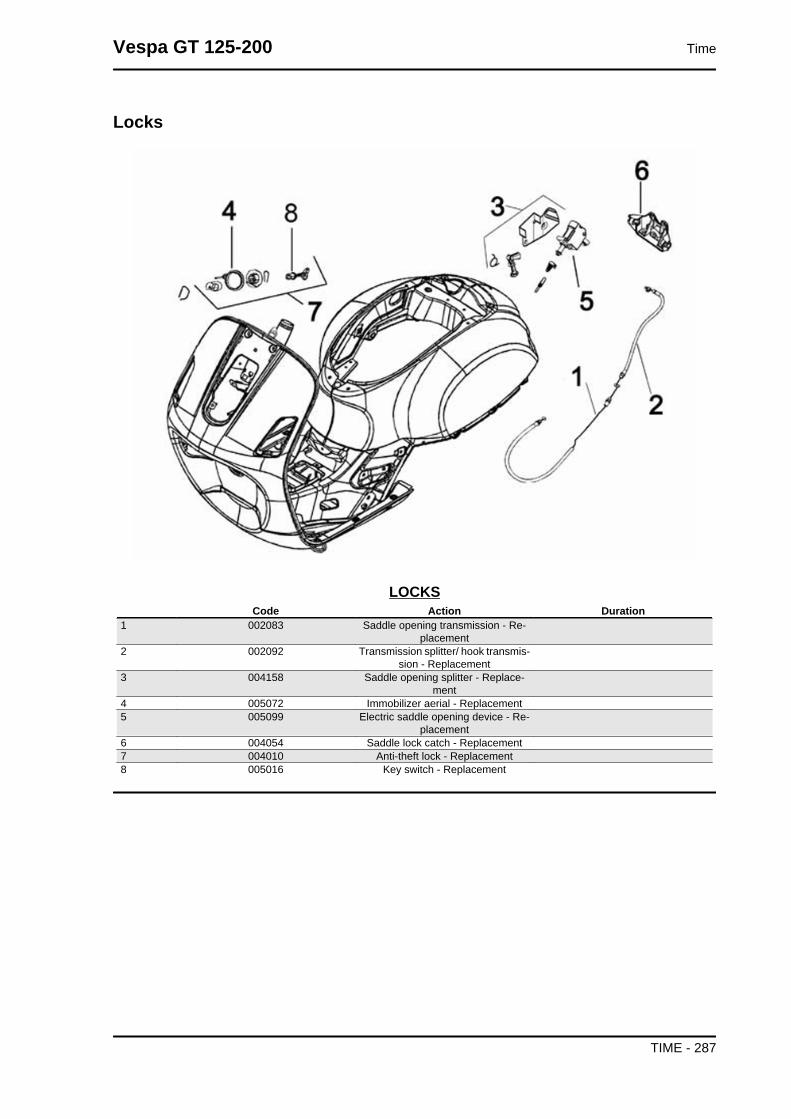
Locks
LOCKSCode Action Duration
1 002083 Saddle opening transmission - Re-placement
2 002092 Transmission splitter/ hook transmis-sion - Replacement
3 004158 Saddle opening splitter - Replace-ment
4 005072 Immobilizer aerial - Replacement5 005099 Electric saddle opening device - Re-
placement6 004054 Saddle lock catch - Replacement7 004010 Anti-theft lock - Replacement8 005016 Key switch - Replacement
Vespa GT 125-200 Time
TIME - 287

Turn signal lights
TURN INDICATOR LIGHTSCode Action Duration
1 005002 Front headlamp - Replacement2 005005 Taillight - Replacement3 005032 Licence plate light glass - Replace-
ment4 005067 Front turn indicator bulb - Replace-
ment5 005008 Front headlamp bulbs - Replacement6 005066 Rear light bulbs - Replacement7 005031 Licence plate light bulb - Replace-
ment8 005090 Stop light bulb - Replacement9 005068 Rear turn indicator bulb - Replace-
ment10 005022 Rear turn indicators - Replacement11 005012 Front turn indicator - Replacement12 005091 Turn indicator glass - Replacement
Time Vespa GT 125-200
TIME - 288

Front wheel
FRONT WHEELCode Action Duration
1 002041 Brake disc - Replacement2 003033 Front wheel hub- Replacement3 004123 Front wheel - Replacement4 003037 Front wheel rim- Replacement5 003047 Front tyre - replace6 003063 Tyre pressure - Check
Grease tone wheel or drive
Please take note that the code has been intro-
duced:
900001 - Tone wheel / drive greasing - 15'.
Never mistake the codes 002011 (movement sen-
sor replacement) and 005089 (tone wheel replace-
ment) in the event of noise of the indicated
components. The grease recommended is TUTE-
LA MRM 2 (soap-based lithium grease with Mo-
lybdenum disulphide).
In the following points we indicate with an arrow
the area to be greased (1 - Drive, 2 - Tone wheel)
Vespa GT 125-200 Time
TIME - 289

Rear wheel
REAR WHEELCode Action Duration
1 001016 Rear wheel - Replacement2 004126 Rear wheel tyre - Replacement3 001071 Front wheel rim - Removal and refit-
ting4 002070 Rear brake disc - Replacement5 003077 muffler/rear shock absorber support
arm - Service6 002028 Rear wheel hub - Replacement7 003063 Tyre pressure - Check
Time Vespa GT 125-200
TIME - 290

Fuel pump
FUEL PUMPCode Action Duration
1 004073 Fuel pump - Replacement2 004089 Tank / petrol pump pipe - Replace-
ment3 004072 Fuel filter - Replacement4 004086 Petrol pump depression tube - Re-
placement5 004086 Petrol pump depression tube - Re-
placement
Vespa GT 125-200 Time
TIME - 291

Electric devices
ELECTRIC DEVICESCode Action Duration
1 001094 Spark plug cap - Replacement2 001069 HV coil - Replacement3 005003 Horn - Replacement4 002049 Odometer cable - Replacement5 001023 Control unit - Replacement6 005009 Voltage regulator - Replacement7 005001 Electrical system - Removal and re-
fitting8 005114 Electrical system - Service9 005035 Headlight remote control - Replace-
ment10 005011 Start-up remote control switch - Re-
placement11 005054 Fuse holder - Replacement12 005019 Fuse terminal block - Replacement13 002051 Odometer transmission assembly -
Replacement14 005024 Battery fuse - Replacement15 002025 Brake piping - Replacement
Time Vespa GT 125-200
TIME - 292

Front suspension
FRONT SUSPENSIONCode Action Duration
1 003011 Front shock absorber - Removal andRefitting
2 003045 Steering tube - Replacement3 003010 Front suspension - Service4 003035 Shock absorber support and brake
calliper - Replacement5 003034 Front wheel hub bearing - Replace-
ment6 001064 Odometer reel - Replacement
Vespa GT 125-200 Time
TIME - 293

AAir filter: 45
BBattery: 64, 70, 77, 84, 86Brake: 218, 220, 222, 224, 225, 227, 229, 230, 284Brake fluid: 229
CCarburettor: 10, 39, 165, 176, 271
EEngine oil: 47
FFuel: 63, 165, 250, 278, 291Fuses: 82
HHeadlight: 52, 243Hub oil: 44
IIdentification: 6Instrument panel: 242, 286
MMaintenance: 6, 35
OOil filter: 264
SSaddle: Shock absorbers: 214Spark plug: 43, 75Stand: 216Start-up:
TTank: 250, 278, 279Transmission: 9, 63, 97, 116, 268Tyre pressure: Tyres: 10
Copyright © 2022 FDOKUMEN

