


Bahasa
Halaman
Hukum

Technical University ofMadridSchool of Civil Engineering
Funicularity and Equilibrium forHigh-PerformanceConceptual
StructuralDesign
LeonardoTodisco
this dissertation is submitted for the degree ofDoctor of Philosophy in
Engineering of Structures, Materials and Foundations
2016

Leonardo TodiscoPhDDissertation, © 2016
Supervisor:Professor Hugo Corres Peiretti
Location:Madrid, Spain

Abstract
Curved structures are characterized by the critical relationship between theirgeometry and structural behaviour, and selecting an appropriate shape inthe conceptual design of such structures is important for achieving material-efficiency. However, the set of bending-free geometries are limited and, often,non-structural design criteria (e.g., usability, architectural needs, aesthetics)prohibit the selection of purely funicular or antifunicular shapes.
In response to this issue, this thesis studies the possibility of achieving anaxial-only behaviour even if the geometry departs from the ideally bending-freeshape.
This dissertation presents a new design approach, based on graphic statics thatshows how bending moments in a two-dimensional geometry can be eliminatedby adding forces through an external post-tensioning system. This results inbending-free structures that provide innovative answers to combined demandson versatility and material optimization.
The graphical procedure has been implemented in a free-downloadabledesign-driven software (EXOEQUILIBRIUM) where structural performanceevaluations and geometric variation are embedded within an interactive andparametric working environment. This provides greater versatility in finding newefficient structural configurations during the first design stages, bridging the gapbetween architectural shaping and structural analysis.
The thesis includes the application of the developed graphical procedure toshapes with random curvature and distribution of loads. Furthermore, the effectof different design criteria on the internal force distribution has been analyzed.
iii
Finally, the construction of reduced- and large-scale models provides furtherphysical validation of the method and insights about the structural behaviour ofthese structures.
In summary, this work strongly expands the range of possible forms thatexhibit a bending-free behaviour and, de facto, opens up new possibilities fordesigns that combine high-performing solutions with architectural freedom.
iv

Resumen
Las estructuras que trabajan por forma se caracterizan por la íntima e indisociablerelación entre geometría y comportamiento estructural. Por consiguiente, laelección de una apropiada geometría es el paso previo indispensable en el diseñoconceptual de dichas estructuras.
En esa tarea, la selección de las posibles geometrías antifuniculares para lasdistribuciones de cargas permanentes más habituales son más bien limitadasy, muchas veces, son criterios no estructurales (adaptabilidad funcional,estética, proceso constructivo, etc.) los que no permiten la utilización de dichasgeometrías que garantizarían el máximo aprovechamiento del material.
En este contexto, esta tesis estudia la posibilidad de obtener una estructurasinmomentos flectores incluso si la geometría no es antifunicular para sus cargaspermanentes.
En efecto, esta tesis presenta un procedimiento, basado en la estática gráfica,que demuestra cómo un conjunto de cargas adicionales, introducidas a travésde un sistema de pretensado exterior con elementos post-tesos, puede eliminarlos momentos flectores debidos a cargas permanentes en cualquier geometríaplana. Esto se traduce enuna estructura antifunicular queproporciona respuestasinnovadoras a demandas conjuntas de versatilidad arquitectónica y optimizacióndel material.
Dicha metodología gráfica ha sido implementada en un software distribuidolibremente (EXOEQUILIBRIUM), donde el análisis estructural y la variacióngeométrica están incluidos en el mismo entorno interactivo y paramétrico. Lautilización de estas herramientas permite más versatilidad en la búsqueda de
v
nuevas formas eficientes, lo cual tiene gran importancia en el diseño conceptualde estructuras, liberando al ingeniero de la limitación del propio cálculo y de laincomprensióndel comportamiento estructural, facilitandoextraordinariamenteel hecho creativo a la luz de una metodología de este estilo.
Esta tesis incluye la aplicación de estos procedimientos a estructuras decualquier geometría y distribución inicial de cargas, así como el estudio dediferentes posibles criterios de diseño para optimizar la posición del sistemade post-tesado. Además, la metodología ha sido empleada en el proyectode maquetas a escala reducida y en la construcción de un pabellón hechoenteramente de cartón, lo que ha permitido obtener una validación física delprocedimiento desarrollado.
En definitiva, esta tesis expande de manera relevante el rango de posiblesgeometrías antifuniculares y abre enormes posibilidades para el diseño deestructuras que combinan eficiencia estructural y flexibilidad arquitectónica.
vi
Acknowledgments
I wish to thank my supervisor, Professor Hugo Corres Peiretti, for inspiringand guiding my research. I appreciated his infinite insistence on intellectualclarity and the opportunity of conducting research on such fascinating topic.Furthermore, I truly enjoyed the possibility of assisting him with the courseof “Conceptual Design of Structures” at UPM during the last four years.His endless desire to understand how structures work, probably, is the mostimportant learning which I have inherited over the last years. I wish to thank theStructural Concrete (HE) Research Group for offeringme a scholarship to carryout this dissertation.
Furthermore, I would like to express my gratitude to other members of theHEResearchGroup: Professor JavierLeón, ProfessorAlejandroPérezCaldenteyand Professor José Romo Martín. From Professor León I received a constantencouragement as well as valuable help due to his formidable knowledge ofHistory. He is responsible of my incessant desire of studying the past to conceivea better future. Furthermore, I truly enjoyed the opportunity of assisting himwith the course of “Maintenance and assessment of historic structures”. I wish tothank Professor Pérez for his personal assistance and advices at various stages inmy research, and for sharing his extraordinary expertise in structural design andanalysis. Finally, I amgrateful toProfessorRomo for supportingmy researchwithhis few, but essential, insights into the current cutting-edge practice of structuraldesign within the office of Fhecor Consulting Engineers.
vii

A very important part of this research has been carried out at theMassachusetts Institute of Technology. I wish to thank Professor JohnOchsendorf for welcoming me as a visiting researcher in the Department ofArchitecture, andProfessorCaitlinMueller for being an inspiring andmotivatingadvisor during my stay at Cambridge. Professor Mueller offered her valuableknowledge on design and computation as well as a constant encouragementduring my stay at MIT. This thesis would not have been possible without herexpertise. In addition, I wish to thank Professor Corentin Fivet for welcomingme to the world of graphic statics and for providing important feedback on myresearch. I am extremely grateful for his assistance and friendship. I wish tothank Juney Lee for his help regarding graphics, and Professor Jerome Connorfor discussing future directions of my research. I extend my thanks also to theentire Structural Design Lab and Digital Structures Group for offering ideasand support during my stay. Finally, I am grateful to Francesca Liuni, a masterstudent of architecture at MIT, for sharing an infinite number of discussions anddelicious muffins during the cold Bostonian winter.
This thesis would not have been possible without the assistance of thearchivists of the Library of our School. I wish to thank Concepción García andher team for their extraordinary aid in satisfying my infinite requests for sources.I am grateful to students who worked with me during these years: AlbéricTrancart “the president”, Borja Regúlez, Angela Addante, Marco Dore, AntonioLandolfa “Cip”, Marco Pepe “Ciop”, Alberto Sanchez and Bastian Ninino.Thanks, I have learnt something from each one of you. I also wish to thank mycolleagues Alejandro Giraldo, Francesco Marchetto, Freddy Ariñez, GiancarloGroli, Rodrigo Martínez, Miguel Ángel Peña and Isidro García. A warm thanksto Beatriz Gutiérrez for her kindness and sweetness.
I am truly grateful to Javier Monsalvo and Luis Carlos Mayoral for being myfamily in Spain. Most of all, I would like to thank my family for their endlesssupport and encouragement. Finally, Iwould like to thankGiusy for her enduringsupport. Her encouragement, enthusiasm and smiles made this thesis possible.
viii
Publications
The author, together with other colleagues, has published a number of peer-reviewed papers dealing with aspects of the work herein:
• Todisco, L.; Corres, H.; Mueller, C.; (2015) “Funicularity throughExternal Post-Tensioning: Design Philosophy and Computational Tool,”Journal of Structural Engineering (ASCE), Vol. 142, No. 2.
• Todisco, L.; Fivet, C.; Corres, H.; Mueller, C.; (2015) “Design andOptimization of Externally Post-Tensioned Structures using GraphicStatics,” In Proceedings of IASS Symposium, Amsterdam.
• Todisco, L.; Fivet, C.; Corres, H.; Mueller, C.; (2015) “Design andOptimization of Externally Post-Tensioned Structures using GraphicStatics,” Journal of the IASS, Vol. 56, No. 4, 249-258.
• Todisco, L.; Corres, H.; (2016) “Il concetto di funicolarità. L’applicazioneper il conceptual design di strutture efficienti e versatili,” Structural, Vol.201, No. 1.
• Todisco, L.; Mueller, C.; (2016) “Externally post-tensioned structures:validation through physical models,” Proc. of the ICSA Symposium,Guimarães (accepted).
Finally, the author of this dissertation, with the paper submitted to the IASSSymposium 2015, has been awarded with the Hangai Prize [50].
vii

viii
Contents
I State of the Art 9
1 Introduction 111.1 Introduction . . . . . . . . . . . . . . . . . . . . . . . . . . 111.2 Research Significance . . . . . . . . . . . . . . . . . . . . . . 141.3 Dissertation Outline . . . . . . . . . . . . . . . . . . . . . . 16
2 Literature Review 192.1 Introduction . . . . . . . . . . . . . . . . . . . . . . . . . . 192.2 The concept of funicularity . . . . . . . . . . . . . . . . . . . 20
2.2.1 Brief historical analysis . . . . . . . . . . . . . . . . . 202.2.2 The funicular curve . . . . . . . . . . . . . . . . . . 282.2.3 Effects of material and load variation . . . . . . . . . 292.2.4 An alternative design approach . . . . . . . . . . . . 312.2.5 Final comments . . . . . . . . . . . . . . . . . . . . 32
2.3 Design methods . . . . . . . . . . . . . . . . . . . . . . . . . 332.3.1 Introduction . . . . . . . . . . . . . . . . . . . . . . 332.3.2 Physical methods . . . . . . . . . . . . . . . . . . . 332.3.3 Graphical methods . . . . . . . . . . . . . . . . . . . 372.3.4 Computational methods . . . . . . . . . . . . . . . . 432.3.5 Final comments . . . . . . . . . . . . . . . . . . . . 45
2.4 Computational tools . . . . . . . . . . . . . . . . . . . . . . 482.4.1 Introduction . . . . . . . . . . . . . . . . . . . . . . 48
1
2.4.2 Geometry-based tools . . . . . . . . . . . . . . . . . 482.4.3 Analysis-based tools . . . . . . . . . . . . . . . . . . 502.4.4 Design-oriented tools . . . . . . . . . . . . . . . . . 502.4.5 Final comments . . . . . . . . . . . . . . . . . . . . 53
2.5 Summary . . . . . . . . . . . . . . . . . . . . . . . . . . . . 55
II Post-Tensioned Antifunicular Structures 57
3 Background 593.1 Introduction . . . . . . . . . . . . . . . . . . . . . . . . . . 593.2 Background . . . . . . . . . . . . . . . . . . . . . . . . . . . 603.3 Organization of the Part II . . . . . . . . . . . . . . . . . . . 653.4 Summary . . . . . . . . . . . . . . . . . . . . . . . . . . . . 66
4 Methodology and Implementation 674.1 Methodology . . . . . . . . . . . . . . . . . . . . . . . . . . 67
4.1.1 Introduction . . . . . . . . . . . . . . . . . . . . . . 674.1.2 Graphical construction . . . . . . . . . . . . . . . . 714.1.3 Managing indeterminacies . . . . . . . . . . . . . . . 78
4.2 Implementation . . . . . . . . . . . . . . . . . . . . . . . . . 834.3 Summary . . . . . . . . . . . . . . . . . . . . . . . . . . . . 85
5 Applications andDesignCriteria 875.1 Applications . . . . . . . . . . . . . . . . . . . . . . . . . . 87
5.1.1 Random geometries . . . . . . . . . . . . . . . . . . 875.1.2 Extension to non-uniform distribution of loads . . . . 925.1.3 Extension to twisted 2d geometries . . . . . . . . . . 925.1.4 Behaviour for additional uniform load . . . . . . . . . 945.1.5 Material-efficiency of the system . . . . . . . . . . . . 95
5.2 Design criteria . . . . . . . . . . . . . . . . . . . . . . . . . 985.2.1 Introduction . . . . . . . . . . . . . . . . . . . . . . 985.2.2 Notations . . . . . . . . . . . . . . . . . . . . . . . 995.2.3 Design criteria . . . . . . . . . . . . . . . . . . . . . 99
2
5.2.4 Parametric analysis and implementation . . . . . . . . 1025.2.5 Results . . . . . . . . . . . . . . . . . . . . . . . . . 103
5.3 Summary . . . . . . . . . . . . . . . . . . . . . . . . . . . . 117
6 Reduced- and large-scale physicalmodels 1196.1 Reduced-scale physical models . . . . . . . . . . . . . . . . . 119
6.1.1 Introduction . . . . . . . . . . . . . . . . . . . . . . 1196.1.2 Review of physical models . . . . . . . . . . . . . . . 1206.1.3 Manufacturing process . . . . . . . . . . . . . . . . . 1216.1.4 Experimental results . . . . . . . . . . . . . . . . . . 1246.1.5 Conclusions . . . . . . . . . . . . . . . . . . . . . . 128
6.2 Pavilion at the 2015 IASS Symposium . . . . . . . . . . . . . 1286.2.1 Introduction . . . . . . . . . . . . . . . . . . . . . . 1286.2.2 Project specifications . . . . . . . . . . . . . . . . . . 1296.2.3 Material . . . . . . . . . . . . . . . . . . . . . . . . 1296.2.4 Design . . . . . . . . . . . . . . . . . . . . . . . . . 1306.2.5 Fabrication and construction process . . . . . . . . . 1366.2.6 Acknowledgments to the Project Team . . . . . . . . 1366.2.7 Conclusions . . . . . . . . . . . . . . . . . . . . . . 140
6.3 Summary . . . . . . . . . . . . . . . . . . . . . . . . . . . . 140
III Conclusions 143
7 Conclusions and future studies 1457.1 Summary of results . . . . . . . . . . . . . . . . . . . . . . . 1457.2 Future studies . . . . . . . . . . . . . . . . . . . . . . . . . . 1477.3 Final remarks . . . . . . . . . . . . . . . . . . . . . . . . . . 152
A Appendix 1 153A.1 Timeline . . . . . . . . . . . . . . . . . . . . . . . . . . . . 153
References 164
3

List of figures
1.1 U.S. Energy consumption by sector . . . . . . . . . . . . . . . 121.2 Bridges resulting of improper design approach . . . . . . . . . 141.3 Structures satisfying various requirements . . . . . . . . . . . 15
2.1 Examples of primordial axial-only structures . . . . . . . . . . 212.2 Thrust lines under different load conditions . . . . . . . . . . 222.3 Mausoleum of Centcelles . . . . . . . . . . . . . . . . . . . . 242.4 Actio=Rectio principle . . . . . . . . . . . . . . . . . . . . . . 252.5 Catenaries and parabolas . . . . . . . . . . . . . . . . . . . . 272.6 Bending-free shapes for three sets of loads . . . . . . . . . . . 292.7 Design of St. Paul’s Cathedral, London . . . . . . . . . . . . . 342.8 Poleni’s safety assessment of San Peter’s dome . . . . . . . . . 342.9 Physical models used by Gaudí and Isler . . . . . . . . . . . . 352.10 Physical models of the Musmeci’s bridge . . . . . . . . . . . . 362.11 Funicular polygons by Varignon . . . . . . . . . . . . . . . . 382.12 Reciprocal relationship between form and force polygons . . . 392.13 Application of graphic statics to buildings . . . . . . . . . . . 412.14 Application of graphic statics to bridges . . . . . . . . . . . . 422.15 Comparison of design methods . . . . . . . . . . . . . . . . . 462.16 Front view and cross section of the Tiemblo bridge . . . . . . 492.17 Graphic statics applied to the Tiemblo bridge. . . . . . . . . . 492.18 Resulting antifunicular arches for curved decks . . . . . . . . 54
3.1 Photo of the Façade of the Pavilion of the Future. . . . . . . . 60
5
3.2 Façade of the Pavilion of the Future. . . . . . . . . . . . . . . 623.3 Externally post-tensioned bridge . . . . . . . . . . . . . . . . 64
4.1 Graphical construction for finding the point loads. . . . . . . . 694.2 Graphical construction for generating the point loads. . . . . . 704.3 Graphical construction (1 of 2). . . . . . . . . . . . . . . . . 744.4 Graphical construction (2 of 2). . . . . . . . . . . . . . . . . 754.5 Reactions withH2 ̸= 0 . . . . . . . . . . . . . . . . . . . . . 774.6 Reactions withH2 = 0 . . . . . . . . . . . . . . . . . . . . . 774.7 Examples of different tendon layouts for a circular arch. . . . . 794.8 Examples of different tendon layouts for an elliptical shape. . . 804.9 Solutions with same prestress at one end. . . . . . . . . . . . . 824.10 Algorithm of the tool implemented in Grasshopper. . . . . . . 84
5.1 Antifunicular three-pointed arch with vertical struts. . . . . . . 885.2 Resulting post-tensioned forms for arbitrary geometries (1 of 3) 895.3 Resulting post-tensioned forms for arbitrary geometries (2 of 3). 905.4 Resulting post-tensioned forms for arbitrary geometries (3 of 3) 915.5 Design for non-uniform load distribution . . . . . . . . . . . 935.6 Design of a footbridge with Y-shape in plan . . . . . . . . . . 945.7 Behaviour for additional distributed loads. . . . . . . . . . . . 955.8 Comparison between bending and post-tensioned solutions . . 975.9 Notations . . . . . . . . . . . . . . . . . . . . . . . . . . . . 1005.10 Application of DC to a circular arch (offset=5%). . . . . . . . 1055.11 Application of DC to a circular arch (offset=10%) . . . . . . . 1065.12 Application of DC to a circular arch (offset=15%) . . . . . . . 1075.13 Application of DC to a basket arch (offset=5%) . . . . . . . . 1085.14 Application of DC to a basket arch (offset=10%) . . . . . . . . 1095.15 Application of DC to a basket arch (offset=15%) . . . . . . . . 1105.16 Application of DC to a free-form shape (offset=4%) . . . . . . 1115.17 Application of DC to a free-form shape (offset=6%) . . . . . . 1125.18 Application of DC to a free-form shape (offset=8%) . . . . . . 1135.19 Indeterminacies vs strain energy (perspective view) . . . . . . 115
6

LIST OF FIGURES
5.20 Indeterminacies vs strain energy (lateral views) . . . . . . . . 116
6.1 Connection details for compressive and tensioned elements . . 1236.2 Collapse sequence of a free-form asymmetrical shape . . . . . 1256.3 Collapse sequence of a basket arch . . . . . . . . . . . . . . . 1266.4 Collapse sequence of a circular arch . . . . . . . . . . . . . . 1276.5 Materials employed for building the pavilion . . . . . . . . . . 1306.6 Design proposal . . . . . . . . . . . . . . . . . . . . . . . . . 1316.7 Graphical construction (1 of 3) . . . . . . . . . . . . . . . . . 1336.8 Graphical construction (2 of 3) . . . . . . . . . . . . . . . . . 1346.9 Graphical construction (3 of 3) . . . . . . . . . . . . . . . . . 1356.10 Fabrication Process . . . . . . . . . . . . . . . . . . . . . . . 1376.11 Construction Process . . . . . . . . . . . . . . . . . . . . . . 1386.12 After construction . . . . . . . . . . . . . . . . . . . . . . . 139
7.1 Optimal shapes for symmetrical and asymmetrical loading . . 1497.2 Graphical overview of the process . . . . . . . . . . . . . . . 150
7


Part I
State of the Art
9

Architecture is too important to be left to architects.
Giancarlo De Carlo
1Introduction
1.1 Introduction
“Globally, more people live in urban areas than in rural areas, with 54% of the world’spopulation residing in urban areas in 2014. In 1950, 30% of the world’s populationwas urban, and by 2050, 66% of the world’s population is projected to be urban”
[114].
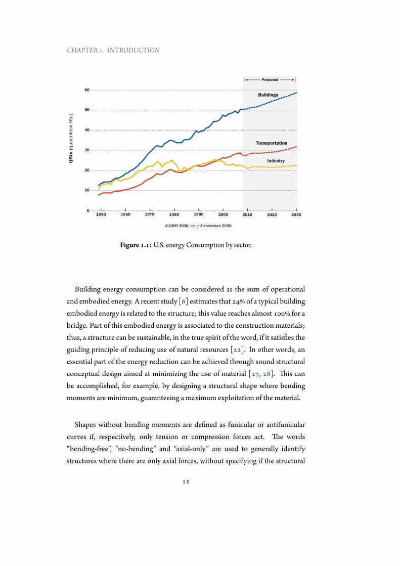
With this premise, buildings and civil infrastructures are going to playa strategic role in the urbanization process during the incoming decades.Buildings, referred to the whole construction sector, already represent the majorresource consumer among different sectors (Figure 1.1). In this context, theyare expected to have an increasing impact on resources consumption during thenext decades.
11
CHAPTER 1. INTRODUCTION
Figure 1.1: U.S. energy Consumption by sector.
Building energy consumption can be considered as the sum of operationaland embodied energy. A recent study [6] estimates that 24% of a typical buildingembodied energy is related to the structure; this value reaches almost 100% for abridge. Part of this embodied energy is associated to the construction materials;thus, a structure can be sustainable, in the true spirit of the word, if it satisfies theguiding principle of reducing use of natural resources [22]. In other words, anessential part of the energy reduction can be achieved through sound structuralconceptual design aimed at minimizing the use of material [27, 28]. This canbe accomplished, for example, by designing a structural shape where bendingmoments are minimum, guaranteeing a maximum exploitation of the material.
Shapes without bending moments are defined as funicular or antifunicularcurves if, respectively, only tension or compression forces act. The words“bending-free”, “no-bending” and “axial-only” are used to generally identifystructures where there are only axial forces, without specifying if the structural
12

1.1. INTRODUCTION
members work in compression or in tension.
The simple concept of funicularity has been scientifically defined between theXV and the XVII century and the use of bending-free shapes has been a commonadopted design approach throughout the ages. It consists in defining the overallform of the structure as one no-bending shape corresponding, generally, to thepermanent loads, and then to determine its thickness based on the variation ofthe funicular shapes related to the variable loads.
However, a bending-free curve often is not employed because of the lowtechnical knowledge of the designer about equilibrium, or when non-structuraldesign criteria (such as function, program, and aesthetics) prohibit the selectionof purely axial-only shapes.
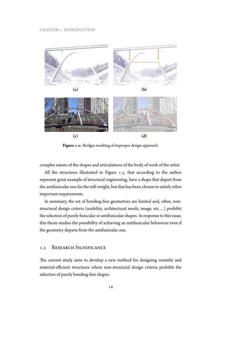
The first case is described by the two bridges shown in Figures 1.2a and 1.2c,respectively located in Germany and Australia. Both of these structures arecharacterized by an inappropriate structural behaviour. In fact, despite theircurved shape these bridges cannot be referred as antifunicular arch bridgesbecause axial forces in the curved structural members are not predominant withrespect to bending moments. Figures 1.2b and 1.2d illustrate the expectedantifunicular geometries of these structures, if the arch weight is neglected.The previous examples point out that: i) architectural processes (form-finding)are sometimes disconnected from structural evaluations, and ii) the concept offunicularity and its implications are often ignored or not employed in a properway.
The second case, luckily more frequent than the first, occurs when otherimportant requirements (from aesthetics, to usability, to environmental issues)do not allow the employment of a bending-free curve. The following examplesbetter illustrate this concept. Figure 1.3 shows: (a) the Alcántara Bridge, aRoman semi-circular arch bridge built at Alcántara (Spain)more than 2000 yearsago; (b) an ellipsoid-shaped roof employed to cover a new mall in Chiasso(Switzerland); (c) an asymmetrical roof covering the train station of Waterloo(UK); (d) the Zentrum Paul Klee, a museum dedicated to the artist Paul Klee,located in Bern (Switzerland) which roof geometry takes inspiration from the
13
CHAPTER 1. INTRODUCTION
(a) (b)
(c) (d)
Figure 1.2: Bridges resulting of improper design approach.
complex nature of the shapes and articulations of the body of work of the artist.All the structures illustrated in Figure 1.3, that according to the author
represent great example of structural engineering, have a shape that depart fromthe antifunicular one for the self-weight, but that has been chosen to satisfy otherimportant requirements.
In summary, the set of bending-free geometries are limited and, often, non-structural design criteria (usability, architectural needs, image, etc…) prohibitthe selection of purely funicular or antifunicular shapes. In response to this issue,this thesis studies the possibility of achieving an antifunicular behaviour even ifthe geometry departs from the antifunicular one.
1.2 Research Significance
The current study aims to develop a new method for designing versatile andmaterial-efficient structures where non-structural design criteria prohibit theselection of purely bending-free shapes.
14

1.2. RESEARCH SIGNIFICANCE
(a) (b)
(c) (d)
Figure 1.3: Structures satisfying various requirements.
The proposed approach consists in changing the internal force distributioninstead of the structural shape, for achieving the required axial-only behaviour.This can be accomplished by using a hybrid structure that combines rigidcompressive members, prestressed members and connection elements. Thissolution allows to maintain the starting shape and, at the same time, to achievematerial-efficiency.
In addition to a graphical methodology developed for solving the describedproblem, this study includes the implementation of a new design-orientedsoftware which goes beyond the limit of the traditional tools, by bridging thegap between architectural shaping and structural analysis. This software, namedEXOEQUILIBRIUM, works in an interactive and parametric framework, whichcombines geometric alteration with structural predictions. These features makesit suitable for being used during the conceptual design stage because facilitate theexploration of axial-only design alternatives. Furthermore, the implemented toolcan be freely downloaded from author’s website [4].
15
CHAPTER 1. INTRODUCTION
In summary, this thesis presents a research aimed at achieving an axial-onlybehaviour when a bending-free shape cannot be adopted. This is achieved byusing an hybrid structure that through prestressing modifies the internal forcedistribution. Although they are not object of this work, it is important toremind that many other requirements (e.g., geometric limitations, robustness,constructability, resiliency, long-term behaviour), over the material-efficiency,have to be considered during the early stage design of a structure.
1.3 DissertationOutline
This dissertation presents a novel procedure that takes advantage of the principleof funicularity to design versatile and material-efficient structures within adesign-oriented environment. It is organized as described in the following.
Part I. State of the ArtThe first part of this thesis includes the statement of the problem and researchsignificance (Chapter 1), and literature review (Chapter 2). The latter is dividedin three sections:
1. The concept of funicularity (Section 2.2). In the first section the conceptof funicularity is presented, focusing on its historical development and onthemain features of funicular and antifunicular curves. Next, the effects ofmaterial properties and load variation on structural behaviour are brieflydescribed. The concepts, here illustrated, are valid for the design of newstructures and for the safety assessment of the existing ones.
2. Designmethods (Section 2.3). The second section focuses on the existingprocedures aimed at finding bending-free shapes. Methodologies,more orless contemporary, are illustrated and critically analysed.
3. Computational tools (Section 2.4). The third section analyses softwarein which the described procedures can be implemented. Thesecomputational tools, depending on their features, are divided intothree main groups: geometry-based, analysis-based and design-orientedtools.
16
1.3. DISSERTATIONOUTLINE
Part II. Post-Tensioned Antifunicular StructuresPart II of this work illustrates the application of the antifunicularity concept tostructures whose shapes, due to several circumstances, have a non-antifuniculargeometry for permanent loads. A new design approach, based on graphic statics,is presented. It shows how bending moments in any two-dimensional curvedgeometry can be eliminated by adding forces through an external post-tensioningsystem. An interactive parametric tool (EXOEQUILIBRIUM) is introducedfor finding the layout of a post-tensioning system for any structural geometry(Chapter 4). The versatility and the potential of the proposed procedure areillustrated with many new design proposals (Chapter 5). In addition, themethodology has been employed for the construction of reduced physicalmodels (Section 6.1). Finally, the design and the construction process of aPavilion, adopting the developed approach, is in-depth illustrated in Section 6.2.The contents of this Part have been published in several peer-reviewed papers[108–112].
Part III. ConclusionsThe third part of the dissertation remarks general conclusions and specificcontributions of this work (Section 7.1). Additionally, important directions forfuture studies are illustrated in Section 7.2.
17

The resistant virtues of the structure that we make depend ontheir form; it is through their form that they are stable and notbecause of an awkward accumulation of materials. There isnothing more noble and elegant from an intellectual viewpointthan this; resistance through form.
Eladio Dieste
2Literature Review
2.1 Introduction
The literature review presented in Chapter 2 is divided in three main sections:
1. The concept of funicularity (Section 2.2). This section presents the definitionof the concept of funicularity and its implications on the internal forcedistribution. Furthermore, a review of the historical development of thisconcept is described.
2. Design methods (Section 2.3). In this section the most importantmethodologies to find bending-free shapes are illustrated. Theseprocedures are organized in three main groups: methods based onphysical models, graphical techniques and numerical procedures. Thesemethodologies are critically reviewed and, for each one of them, benefitsand disadvantages are pointed out.
19

CHAPTER 2. LITERATURE REVIEW
3. Computational tools (Section 2.4). This section presents an overview of theexisting software aimed at performing form-finding analysis. Dependingon their different features, they can be classified in: analysis-based tools,geometry-based tools and design-oriented tools. The section also touchesupon the limitations when using these software to the early design stageand the possibility of using toolsmore oriented to the first stages of design.
2.2 The concept of funicularity
2.2.1 Brief historical analysis
Before the 15th century the use of funicular and antifunicular structures wasbased on the empirical acceptation of their good structural performance withoutan explicit analytical formulation of their mechanical behaviour. Stability wasensured by following geometrical and numerical rules obtained by previousexperiences from similar structures [7, 49].
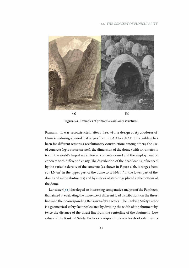
Primordial examples of funicular and antifunicular structures are represented,respectively, by suspended bridges (Figure 2.1a [101]) and corbelled domes(Figure 2.1b [20]). Funicular shapes frequently were adopted to cross longvalleys, while antifunicular geometries were generally employed as shelters fromweather.
Roman constructions (typically arch bridges and domes) were based ona circular shape, which is not a funicular curve for its self-weight. However,Roman builders applied different techniques (e.g., filler materials, step-rings,concrete with graded density) for changing the load distribution, and indirectlyto achieve a better structural stability. Today, there is no knowledge about themathematical and/or the physical models employed by Romans, but the authorbelieves that there was something more than intuition. The following examplesaim at better explaining this concept.
The Pantheon of Rome (Figure 2.2a), the building dedicated to all the gods,represents the peak of the architectural and structural revolution promoted by
20
2.2. THE CONCEPT OF FUNICULARITY
(a) (b)
Figure 2.1: Examples of primordial axial-only structures.
Romans. It was reconstructed, after a fi re, wi th a de sign of Apollodorus of Damascus during a period that ranges from 118 AD to 128 AD. This building has been for different reasons a revolutionary c onstruction: among others, the use of concrete (opus caementicium), the dimension of the dome (with 43.3 meter it is still the world’s largest unreinforced concrete dome) and the employment of concrete with different d ensity. The distribution of the dead load is influenced by the variable density of the concrete (as shown in Figure 2.2b, it ranges from 13.5 kN/m³ in the upper part of the dome to 16 kN/m³ in the lower part of the dome and in the abutments) and by a series of step-rings placed at the bottom of the dome.
Lancaster [62] developed an interesting comparative analysis of the Pantheon that aimed at evaluating the influence of different load distributions on the thrust lines and their corresponding Rankine Safety Factors. The Rankine Safety Factor is a geometrical safety factor calculated by dividing the width of the abutment by twice the distance of the thrust line from the centerline of the abutment. Low values of the Rankine Safety Factors correspond to lower levels of safety and a
21

CHAPTER 2. LITERATURE REVIEW
factor of 1 indicates the collapse point of the structure.
The analysis was carried out by dividing the dome in slices of 45°, with variabledepth, as shown in Figure 2.2a. This hypothesis neglects the existence of hoopforces and it is representative of the actual state of the dome that appears crackedalong meridians [94]. Furthermore, as there are infinite possible load paths ofthe compression forces within the thickness of the dome, the chosen thrust lineis obtained by minimizing the horizontal thrust.
Model Model
13,5 kN/m3
16,0 kN/m3
Model 3
21
(a) (b)
Figure 2.2: Thrust lines under different load conditions.
The aim of these analysis was to examine the effects of the graded concrete and the step-rings on the Rankine Safety Factor. This was achieved by studying three different load conditions:
• Model 1: it takes into account the real distribution of loads and the existence of step-rings. This leads to a Rankine Safety Factor of 4.23.
22
2.2. THE CONCEPT OF FUNICULARITY
• Model 2: it considers a constant density of 16 kN/m³ of the concrete in the dome and the existence of step-rings. This leads to a Rankine Safety Factor of 3.60.
• Model 3: it takes into account a constant density of 16 kN/m³ of the concrete in the dome and neglects the existence of step-rings. In this case the Rankine Safety Factor decreases to 2.60.
The three thrust lines, under different load conditions, are representedin Figure 2.2b. This simplified analysis reveals the importance of the loaddistribution on the structural stability and the great efficiency of employingstep-rings that, similar to pinnacles, verticalize the thrust line and contribute toincrease the stability of the building.
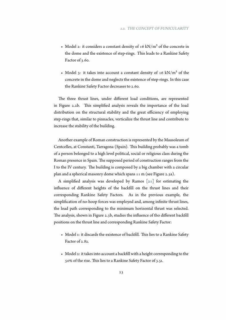
Another example of Roman construction is represented by theMausoleum ofCentcelles, at Constanti, Tarragona (Spain). This building probably was a tombof a person belonged to a high level political, social or religious class during theRoman presence in Spain. The supposed period of construction ranges from theI to the IV century. The building is composed by a big chamber with a circularplan and a spherical masonry dome which spans 11 m (see Figure 2.3a).
A simplified analysis was developed by Ramos [21] for estimating theinfluence of different heights of the backfill on the thrust lines and theircorresponding Rankine Safety Factors. As in the previous example, thesimplification of no-hoop forces was employed and, among infinite thrust lines,the load path corresponding to the minimum horizontal thrust was selected.The analysis, shown in Figure 2.3b, studies the influence of tho different backfillpositions on the thrust line and corresponding Rankine Safety Factor:
• Model 1: it discards the existence of backfill. This lies to a Rankine SafetyFactor of 2.82.
• Model 2: it takes into account a backfill with a height corresponding to the50% of the rise. This lies to a Rankine Safety Factor of 3.51.
23
CHAPTER 2. LITERATURE REVIEW
(a)
Model 2Model 1
(b)
Figure 2.3:Mausoleum of Centcelles.
24
2.2. THE CONCEPT OF FUNICULARITY
This results point out the fact that backfill, common employed by Romans intheir construction, plays a key role for increasing the stability of the building.
The analysis of the previous two examples clearly illustrate that Romanbuilders had a great experience in the construction of circular arch and domesand they were aware of the great importance of addingmore weight on the lowerpart of the structure to get a better structural behaviour. The arrangement ofexternal weight above elements addressed to receive horizontal thrusts with thegoal of verticalize the thrust line is an example of prestress. The main difference,with the modern prestressed system, is that in the latter case the system isauto-equilibrated, while the in first case the reaction are increased.
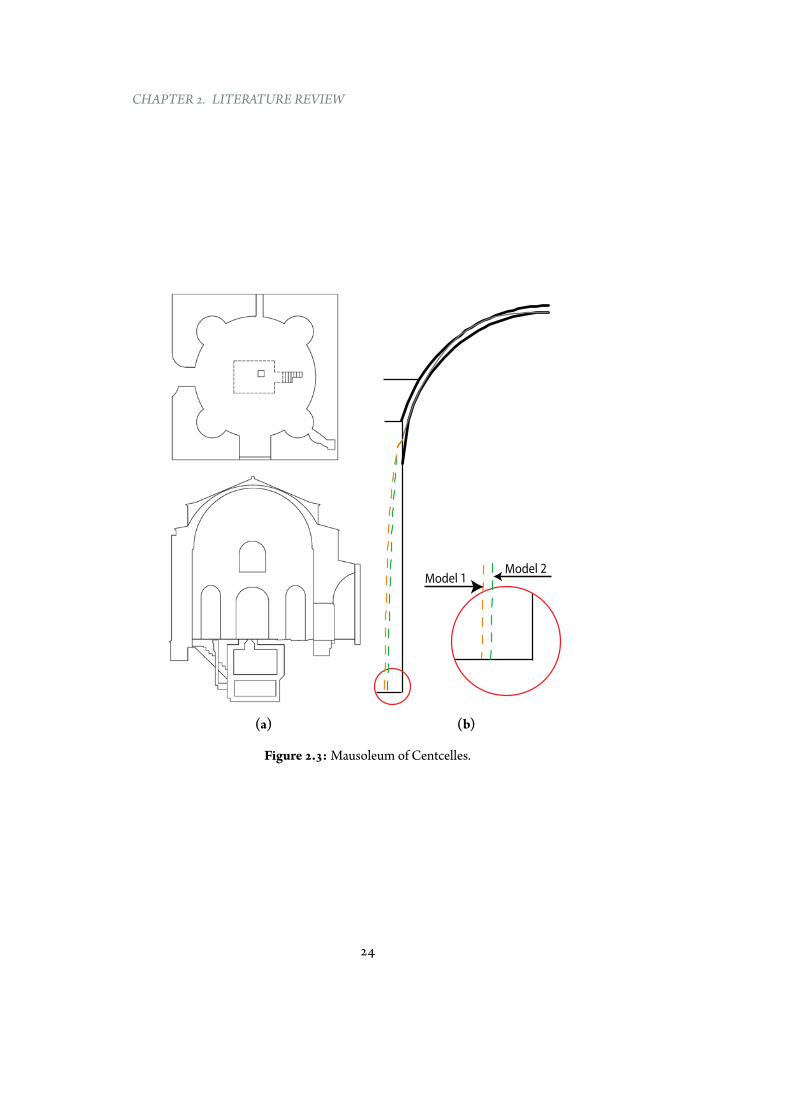
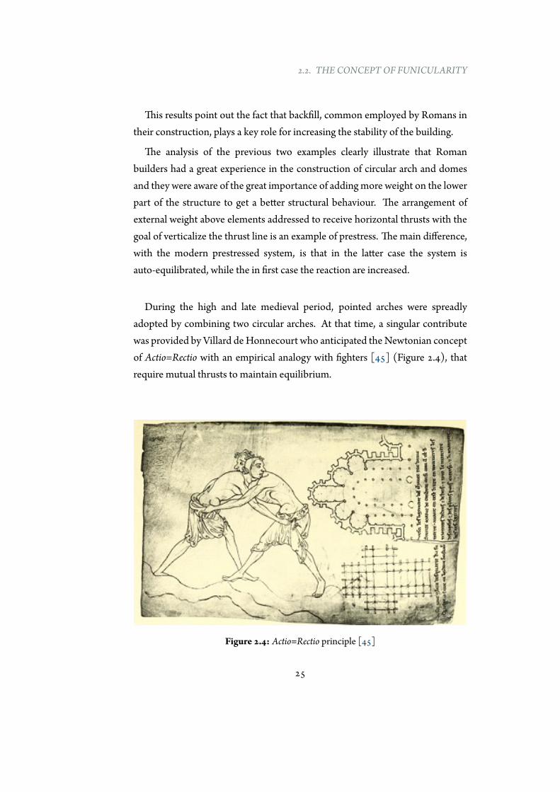
During the high and late medieval period, pointed arches were spreadlyadopted by combining two circular arches. At that time, a singular contributewas provided by Villard deHonnecourt who anticipated theNewtonian conceptof Actio=Rectio with an empirical analogy with fighters [45] (Figure 2.4), thatrequire mutual thrusts to maintain equilibrium.
Figure 2.4: Actio=Rectio principle [45]
25
CHAPTER 2. LITERATURE REVIEW
Starting from the 15th century, the first documents on investigations aboutthe structural mechanics behind the behaviour of chains and arches arise: atheoretical approximationbegan to combine the experimental evidence. Thefirstattempts defining the structural behaviour of curved structures resulted to thestudies of Leon Battista Alberti (1404-1472), Andrea Palladio (1508-1580) andLeonardo da Vinci (1452-1519). Da Vinci established the basis of the scientificanalysis attempting to develop a theory with the concept of statics and realizedthe foundation of the arch mechanics stating:
“The arch is nothing else than a force originated by two weaknesses, for the arch inbuildings is composed of two segments of a circle, each of which being very weak initself tends to fall; but as each opposes this tendency in the other, the two weaknesses
combine to form one strength ” (Leonardo da Vinci [30]).
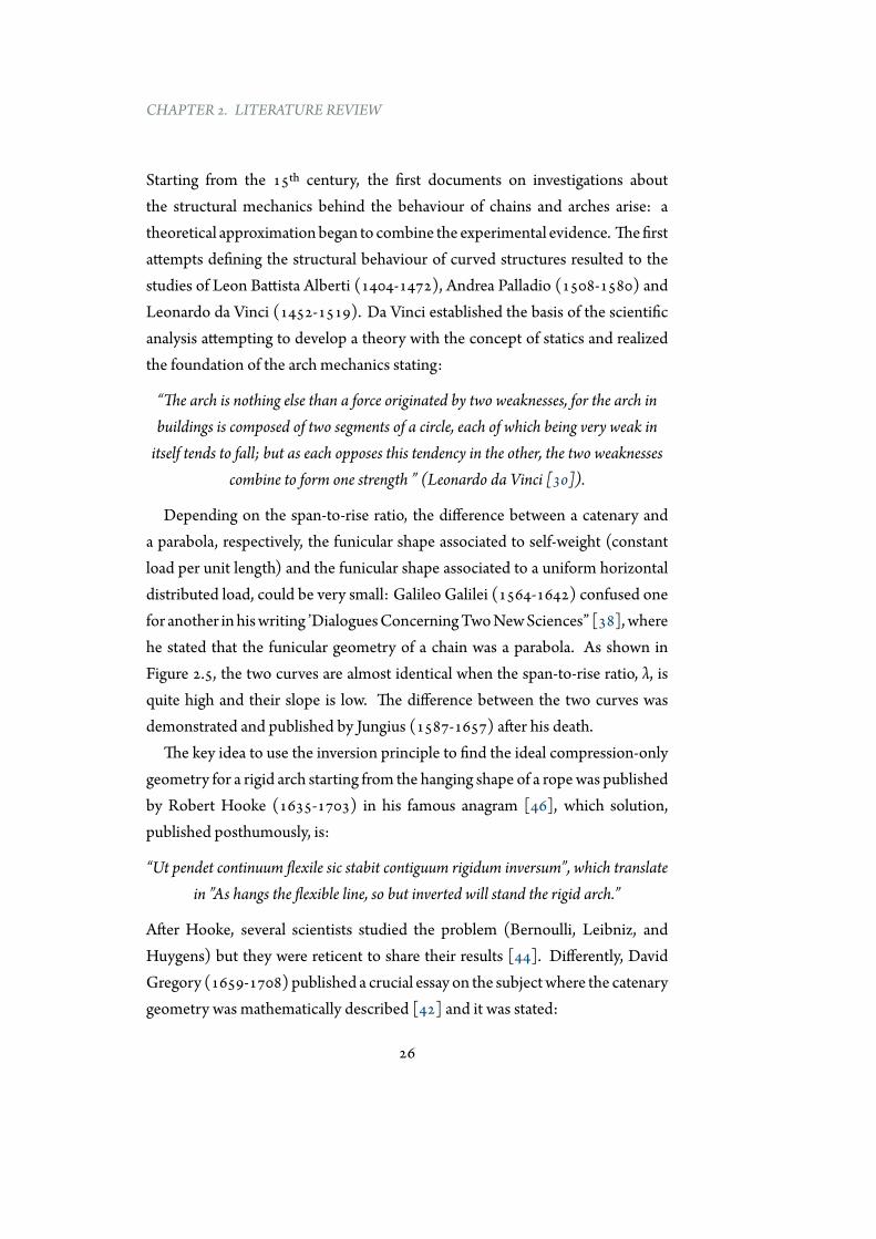
Depending on the span-to-rise ratio, the difference between a catenary anda parabola, respectively, the funicular shape associated to self-weight (constantload per unit length) and the funicular shape associated to a uniform horizontaldistributed load, could be very small: Galileo Galilei (1564-1642) confused onefor another inhiswriting ’DialoguesConcerningTwoNewSciences” [38], wherehe stated that the funicular geometry of a chain was a parabola. As shown inFigure 2.5, the two curves are almost identical when the span-to-rise ratio, λ, isquite high and their slope is low. The difference between the two curves wasdemonstrated and published by Jungius (1587-1657) after his death.
The key idea to use the inversion principle to find the ideal compression-onlygeometry for a rigid arch starting from the hanging shape of a ropewas publishedby Robert Hooke (1635-1703) in his famous anagram [46], which solution,published posthumously, is:
“Ut pendet continuum flexile sic stabit contiguum rigidum inversum”, which translatein ”As hangs the flexible line, so but inverted will stand the rigid arch.”
After Hooke, several scientists studied the problem (Bernoulli, Leibniz, andHuygens) but they were reticent to share their results [44]. Differently, DavidGregory (1659-1708) published a crucial essay on the subjectwhere the catenarygeometry was mathematically described [42] and it was stated:
26
2.2. THE CONCEPT OF FUNICULARITY
λ=10
λ=5
λ=3.3
λ=2.5
λ=2
Figure 2.5: Catenaries (dotted line) and parabolas (solid lines).
27
CHAPTER 2. LITERATURE REVIEW
“...when an arch of any other figure is supported, it is because in its thickness somecatenaria is included...“ (Translation from Latin)
Despite this statement is not literally correct (the word ”catenaria” should bereplaced with ”thrust line” as the theoretical line representing the path of theresultants of the forces through an existing estructure [11]), it represents thebasic concept behind the structural assessment of masonry arches and it appearsin most essays on the subject until the 19th century [7]. As in depth shown inSection 2.3.2, the first application of Gregory’s statement can be found in thestability assessment of St. Peter’s Dome in Rome. The extraordinary intuitionof Gregory, together with the theory of plasticity developed in the 20th century,laid the basis for the common adopted procedures for the structural assessmentof masonry. The historical analysis of the concepts of equilibrium, funicularity,thrust line, etc… is extremely fascinating. In this section a very quick overviewhas been presented, readers more interested in the historical analysis can referto Kurrer [57], Heyman [44], Timoshenko [105] and Addis [8]. Additionally,together with the information collected in Section 2.3, a timeline with thehistorical analysis of the funicularity concept and its most prominent employers,from the 15th century to nowadays, is illustrated in Appendix A.
2.2.2 The funicular curve
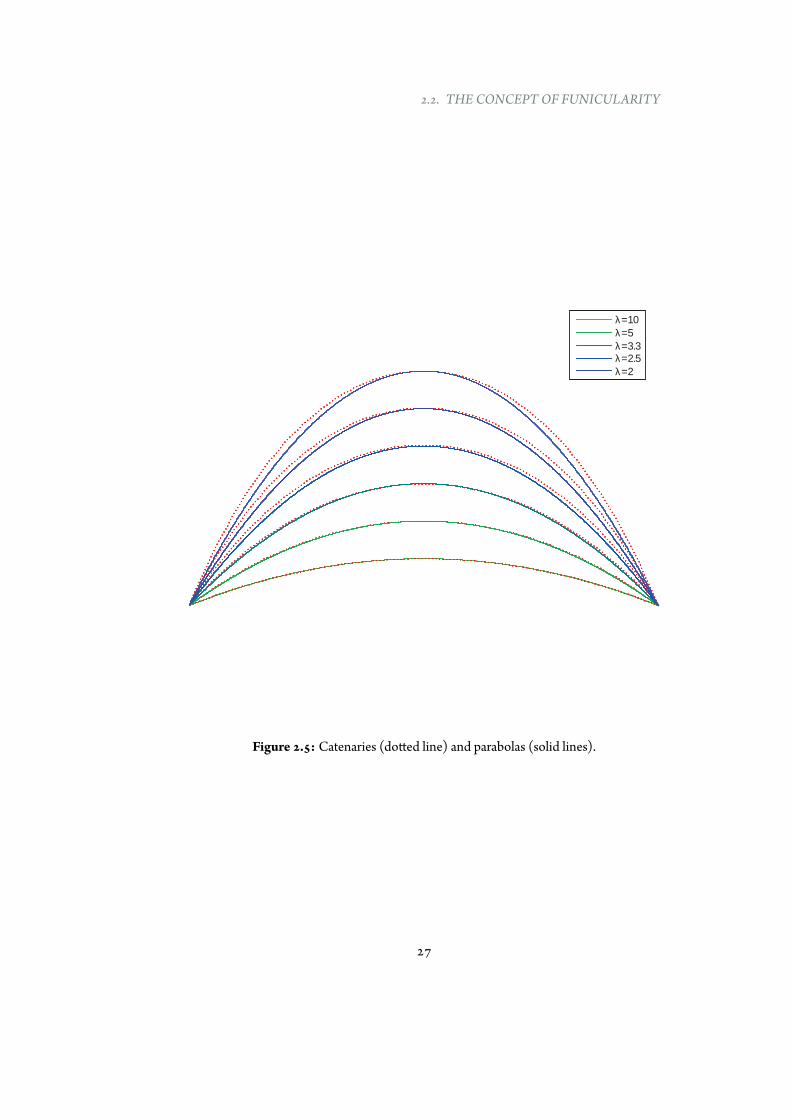
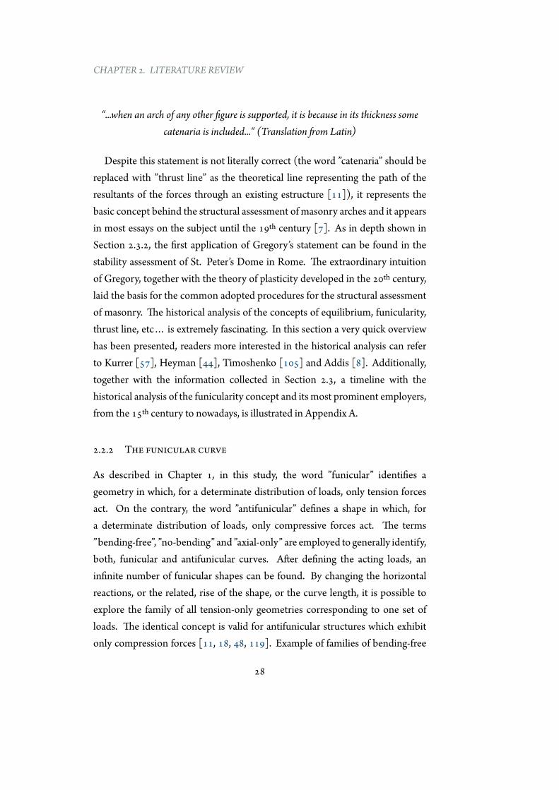
As described in Chapter 1, in this study, the word ”funicular” identifies ageometry in which, for a determinate distribution of loads, only tension forcesact. On the contrary, the word ”antifunicular” defines a shape in which, fora determinate distribution of loads, only compressive forces act. The terms”bending-free”, ”no-bending” and ”axial-only” are employed to generally identify,both, funicular and antifunicular curves. After defining the acting loads, aninfinite number of funicular shapes can be found. By changing the horizontalreactions, or the related, rise of the shape, or the curve length, it is possible toexplore the family of all tension-only geometries corresponding to one set ofloads. The identical concept is valid for antifunicular structures which exhibitonly compression forces [11, 18, 48, 119]. Example of families of bending-free
28
2.2. THE CONCEPT OF FUNICULARITY
Figure 2.6: Bending-free shapes for three sets of loads.
shapes for three determinate sets of loads are shown in Figure 2.6.
2.2.3 Effects of material and load variation
According to the definition, the funicular (or antifunicular) behaviour is atemporary and an ideal one, because shape and loads inevitably change duringthe structure life-time. The discrepancy between antifunicular shape (or thrustline) and line of centroids can generates different effects within the structure,depending on its bending stiffness and support typology.
In the following, effects on the structures due to load variation and non-idealmaterial properties are described separately.
Effects related to permanent loadsDeformations related to shortening or elongations due to permanent loadscan be easily eliminated by employing elements with, respectively, shorter orlonger lengths than the theoretical ones [82]. Another alternative consists inemploying temporary hinges during decentering and then to remove those afterthe shortening due to permanent loads is completed [106].
Effects related to increase of permanent loads (after construction)An increase of permanent loads, after completing the construction, producesa growth of internal forces within the structure and consequent deformations,which cannot be eliminated making the structure shorter or longer because it
29
CHAPTER 2. LITERATURE REVIEW
has been already constructed. These internal forces inevitably produce verticaldisplacements. Effects consequent to an increase of permanent loads dependon the flexural stiffness of the structure and its degree of indeterminacy. Thisstatement is better explained in the following.
Structures with negligible flexural stiffness (e.g., cables), after an increase ofpermanent loads continue to be funicular with a geometry similar to the startingone but higher rise, because it is the only way to be in equilibrium.
Structures with no-negligible flexural stiffness (e.g., arches) behave differentlydepending on support conditions and their degree of indeterminacy. Archeshinged at the supports and at the crown (statically determinate) are not affectedby a linear increase of permanent loads, and if the starting geometry has anantifunicular shape, the bending moments still remain null after the increase ofpermanent loads [33]. Differently, in case of two hinged arches (one degreeof indeterminacy), bending moments arise in order to satisfy the condition ofcompatibility and the thrust line is always above the line of centroids [71].
Finally, if the arch is fully restrained, in addition to the previous describedbending moments, other bending moments appear in proximity of supports.Ultimately, effects related to the increase of permanent loads grow with highdegree of structural indeterminacy.
In order to decrease the deformations resultant from the growth of permanentloads, two main expedients can be employed to mitigate the problem. The firstconsists in designing the arch taking into account the deformations due to theincrease of axial deformation: this implies that the arch is not funicular for itsstarting permanent loads. The second, invented by Freyssinet, and adopted inseveral notable bridges, consists in inducing external forces in the arch crown byemploying jacks to neutralize the deformations due to shortening.
Effects related to temperature variation and rheological propertiesThe effects derived from a lowering of the temperature or shrinkage of thematerial are similar to the consequences produced by an increase of permanentloads, in fact, both, produce shortening of the axis of the arch [106]. Theprevious described conclusions for increasing permanent loads are still valid.
30
2.2. THE CONCEPT OF FUNICULARITY
Effects related to variable loads
All the distributions of loads that differ from which has been used to find thebending-free geometry inevitably generate bending moments in structures withno-negligible bending stiffness. If the structure is made of discrete elements(e.g., masonry structures) its thickness has to be sized in order to contain theenvelope of thrust lines related to all the possible load combinations. On theother hand, if the structure has bending capacity, the thickness of the arch canbe reduced. Structures with negligible bending stiffness result in a differentgeometry because it represents the only way to be in equilibrium.
2.2.4 An alternative design approach
The previous section has pointed out that the coincidence between line ofcentroids and antifunicular shape is impossible to be guaranteed continuallyduring the life time of real structureswherematerial properties and variable loadsaffect the structure. Construction process contributes to make the choice morecomplicated. Despite several efforts have been carried out to find the optimalgeometry of an arch, the question is still open.
An interesting procedure has been adopted for the construction of the Tilos’Arch in the Canary Island of La Palma, Spain, where the shape of the reinforcedconcrete arch has been designed to be antifunicular for permanent loads after 10years the conclusion of the construction [87]. A decade represents a range oftime necessary to complete great part of the processes of shrinkage and creep.Generally all procedures adopted for finding the most convenient geometry arebased on the use of the permanent loads as loads to find the shape of the arch[71, 76].
An alternative procedure has been studied by the author together withNinino[84]. It consists in investigating alternative distributions of loads, which differfrom the common adopted one, for finding a more material-efficient shape ofthe arch. This concept follows an intuition of Fernández Casado, who statedthat the most material-efficient arch shape should be found within the envelopeof all antifunicular shapes obtained employing all the combinations between
31
CHAPTER 2. LITERATURE REVIEW
permanent and live loads [33]. This procedure would change the classical designapproach, which consists in [82]:
1. to find the overall form based on the antifunicular of permanent loads,
2. to determine the thickness based on the variation of the funicular shapesrelated to variable loads.
Preliminary results demonstrate the existence of even more efficient shapesthan the antifunicular found for permanent loads, de facto confirming theintuition of Fernández Casado. The gap between the antifunicular curve forpermanent loads and the optimal shape found after a complex optimizationprocedure increases for higher differences, in magnitude and in distribution,between permanent and variable loads. Nevertheless, if a comparison in termsof material is performed, the differences result relatively small. In fact, themaximum vertical distance between the two curves is around 2% of the rise, andthis result, for practical applications, can be negligible.
2.2.5 Final comments
In this section the basic concepts of funicularity and antifunicularity have beendescribed, and the effects on the structure due to variable material characteristicand loads have been briefly illustrated. It has been pointed out that, ifthe structure has bending stiffness, the bending-free behaviour is temporary.Furthermore, a new approach for designing more material-efficient arches hasbeen proposed. Next section is focused on describing and critically reviewingclassical and more recent methodologies for finding axial-only shapes.
32
2.3. DESIGNMETHODS
2.3 Design methods
2.3.1 Introduction
The aim of this section is to present a brief overview of different methodologiesfor finding bending-free shapes in two and three dimensions. The search of axial-only curves can follow principally three approaches. The first is based on the useof physical hanging models in which elements without bending stiffness are freeto find an equilibrated shape in the space (Section 2.3.2). The second approachis founded on the use of graphical techniques for exploring bending-free forms,mainly in 2-D (Section 2.3.3). Finally, the third approach is the most recent one,and it is based on the application of numerical form-finding techniques (Section2.3.4). For each procedure advantages and limits are briefly illustrated.
2.3.2 Physical methods
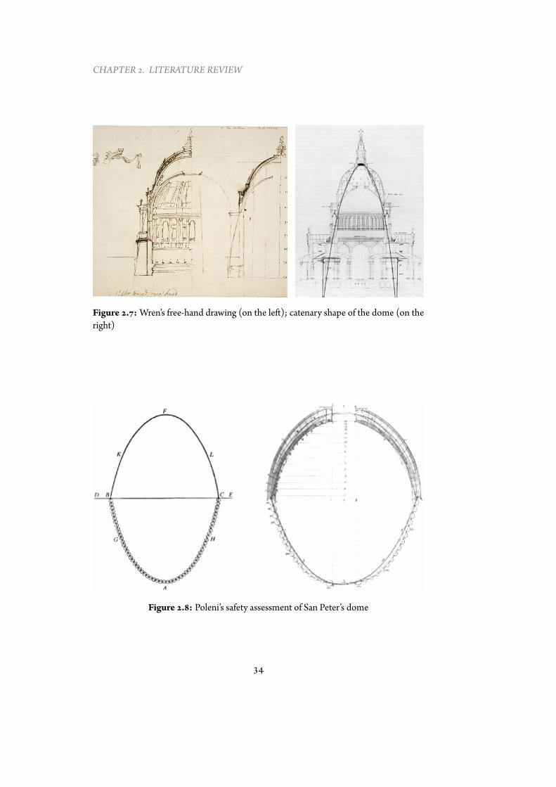
As mentioned in Section 2.2.1, the idea of employing the inversion principleto find a compression-only geometry was proposed for the first time by RobertHooke in 1676. As stated by Huerta [47], it has been one of the most brilliantideas in the history of structural analysis. Hooke suggested toChristopherWren,architect of the St. Paul’s Cathedral in London, to design the shape of the domeusing a chain model loaded with the corresponding weights at the respectivecentres of gravity [44]. Figure 2.7 illustrates, on the left, the first sketches ofthe architect and, on the right, the coincidence between the shape of the interiordome and the catenary.
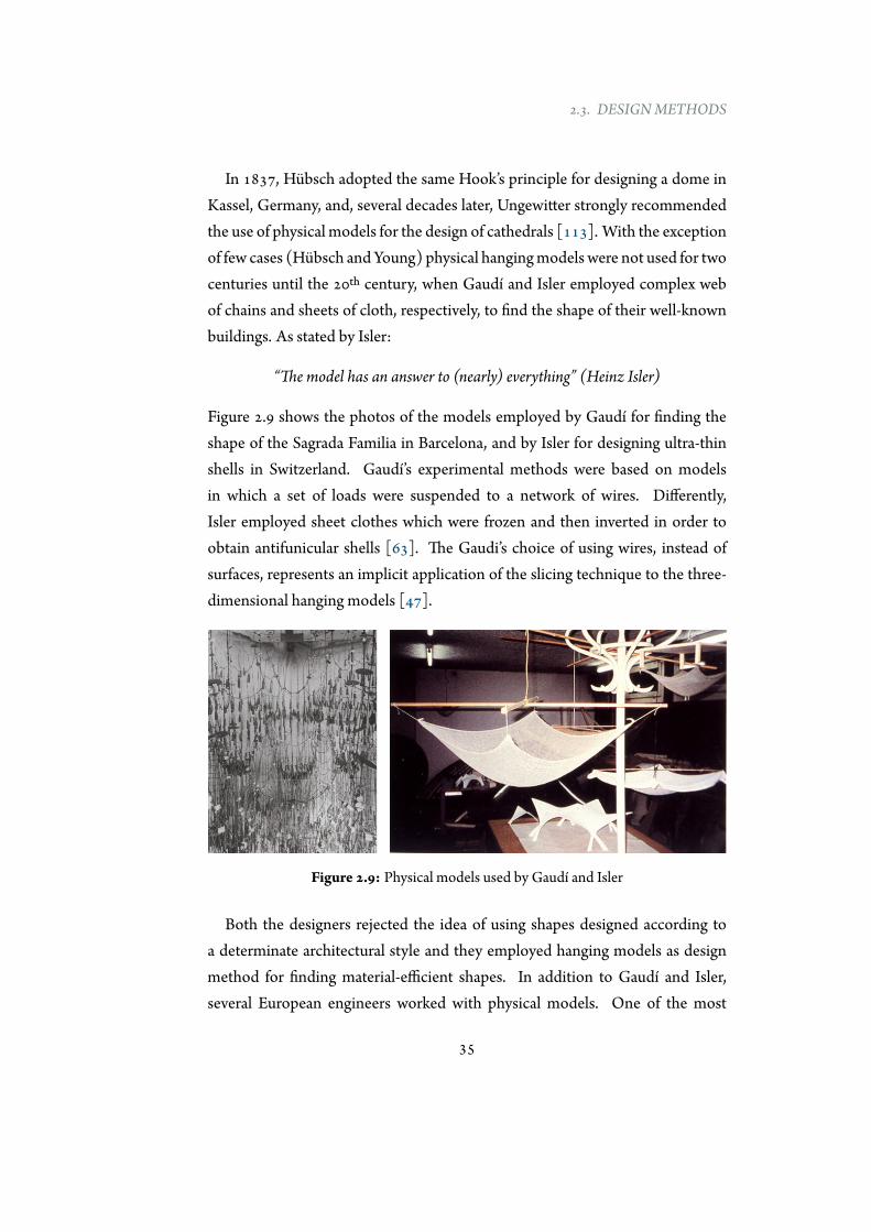
Around sixty years later, in the 1740s, a hanging physical reduced model wasemployedbyPoleni for assessing the stability of St. Peter’s dome inRome(Figure2.8). Differently from Hooke, Poleni used different weights along the curve. Inthis structural assessment, Poleni employed the slicing techniques which allowsto analyse a tree-dimensional dome by dividing it in slices (simple arches). Inthe case of the St. Peter’s Dome it was divided in 50 segments. As reported inHuerta [47], after the intuition of Poleni, the use of hanging models for safetyassessments was not used frequently in the following centuries.
33
CHAPTER 2. LITERATURE REVIEW
Figure 2.7: Wren’s free-hand drawing (on the left); catenary shape of the dome (on theright)
Figure 2.8: Poleni’s safety assessment of San Peter’s dome
34
2.3. DESIGNMETHODS
In 1837, Hübsch adopted the same Hook’s principle for designing a dome inKassel, Germany, and, several decades later, Ungewitter strongly recommendedthe use of physical models for the design of cathedrals [113]. With the exceptionof few cases (Hübsch and Young) physical hangingmodels were not used for twocenturies until the 20th century, when Gaudí and Isler employed complex webof chains and sheets of cloth, respectively, to find the shape of their well-knownbuildings. As stated by Isler:
“The model has an answer to (nearly) everything” (Heinz Isler)
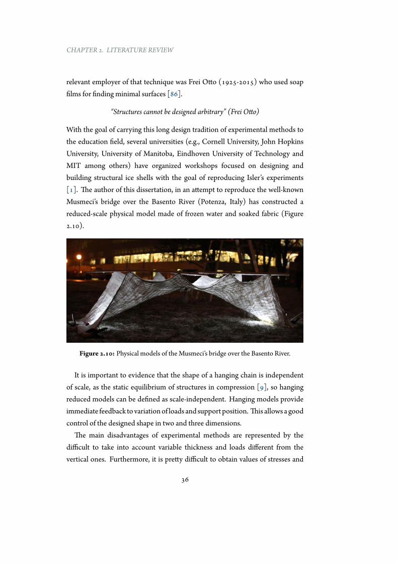
Figure 2.9 shows the photos of the models employed by Gaudí for finding theshape of the Sagrada Familia in Barcelona, and by Isler for designing ultra-thinshells in Switzerland. Gaudí’s experimental methods were based on modelsin which a set of loads were suspended to a network of wires. Differently,Isler employed sheet clothes which were frozen and then inverted in order toobtain antifunicular shells [63]. The Gaudi’s choice of using wires, instead ofsurfaces, represents an implicit application of the slicing technique to the three-dimensional hanging models [47].
Figure 2.9: Physical models used by Gaudí and Isler
Both the designers rejected the idea of using shapes designed according toa determinate architectural style and they employed hanging models as designmethod for finding material-efficient shapes. In addition to Gaudí and Isler,several European engineers worked with physical models. One of the most
35
CHAPTER 2. LITERATURE REVIEW
relevant employer of that technique was Frei Otto (1925-2015) who used soapfilms for finding minimal surfaces [86].
“Structures cannot be designed arbitrary” (Frei Otto)
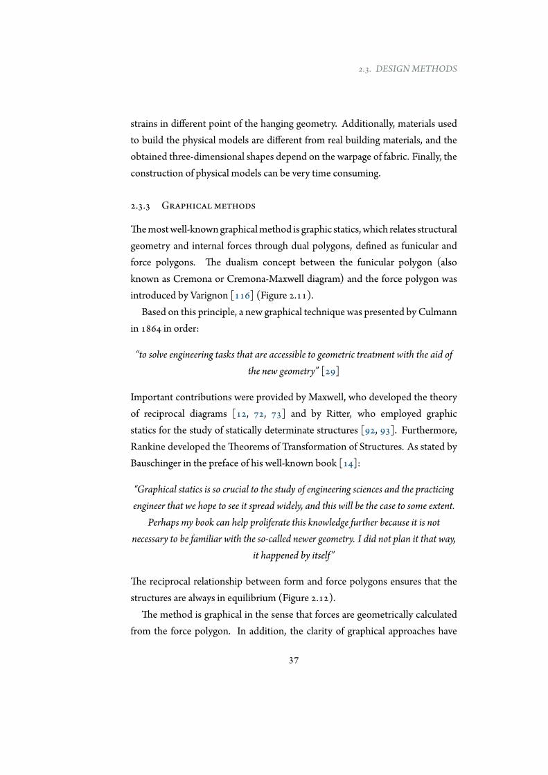
With the goal of carrying this long design tradition of experimental methods tothe education field, several universities (e.g., Cornell University, John HopkinsUniversity, University of Manitoba, Eindhoven University of Technology andMIT among others) have organized workshops focused on designing andbuilding structural ice shells with the goal of reproducing Isler’s experiments[1]. The author of this dissertation, in an attempt to reproduce the well-knownMusmeci’s bridge over the Basento River (Potenza, Italy) has constructed areduced-scale physical model made of frozen water and soaked fabric (Figure2.10).
Figure 2.10: Physical models of the Musmeci’s bridge over the Basento River.
It is important to evidence that the shape of a hanging chain is independentof scale, as the static equilibrium of structures in compression [9], so hangingreduced models can be defined as scale-independent. Hanging models provideimmediate feedback tovariationof loads and support position. This allows agoodcontrol of the designed shape in two and three dimensions.
The main disadvantages of experimental methods are represented by thedifficult to take into account variable thickness and loads different from thevertical ones. Furthermore, it is pretty difficult to obtain values of stresses and
36
2.3. DESIGNMETHODS
strains in different point of the hanging geometry. Additionally, materials usedto build the physical models are different from real building materials, and theobtained three-dimensional shapes depend on the warpage of fabric. Finally, theconstruction of physical models can be very time consuming.
2.3.3 Graphical methods
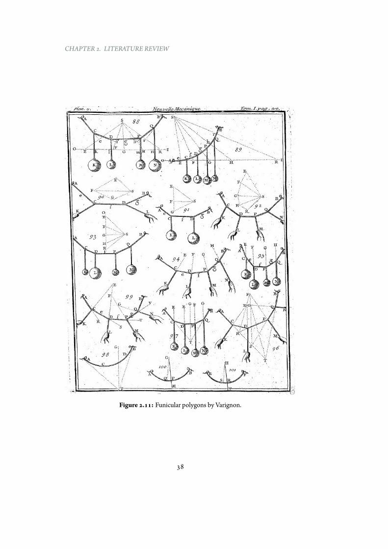
Themostwell-knowngraphicalmethod is graphic statics, which relates structuralgeometry and internal forces through dual polygons, defined as funicular andforce polygons. The dualism concept between the funicular polygon (alsoknown as Cremona or Cremona-Maxwell diagram) and the force polygon wasintroduced by Varignon [116] (Figure 2.11).
Based on this principle, a new graphical technique was presented by Culmannin 1864 in order:
“to solve engineering tasks that are accessible to geometric treatment with the aid ofthe new geometry” [29]
Important contributions were provided by Maxwell, who developed the theoryof reciprocal diagrams [12, 72, 73] and by Ritter, who employed graphicstatics for the study of statically determinate structures [92, 93]. Furthermore,Rankine developed theTheorems of Transformation of Structures. As stated byBauschinger in the preface of his well-known book [14]:
“Graphical statics is so crucial to the study of engineering sciences and the practicingengineer that we hope to see it spread widely, and this will be the case to some extent.
Perhaps my book can help proliferate this knowledge further because it is notnecessary to be familiar with the so-called newer geometry. I did not plan it that way,
it happened by itself”
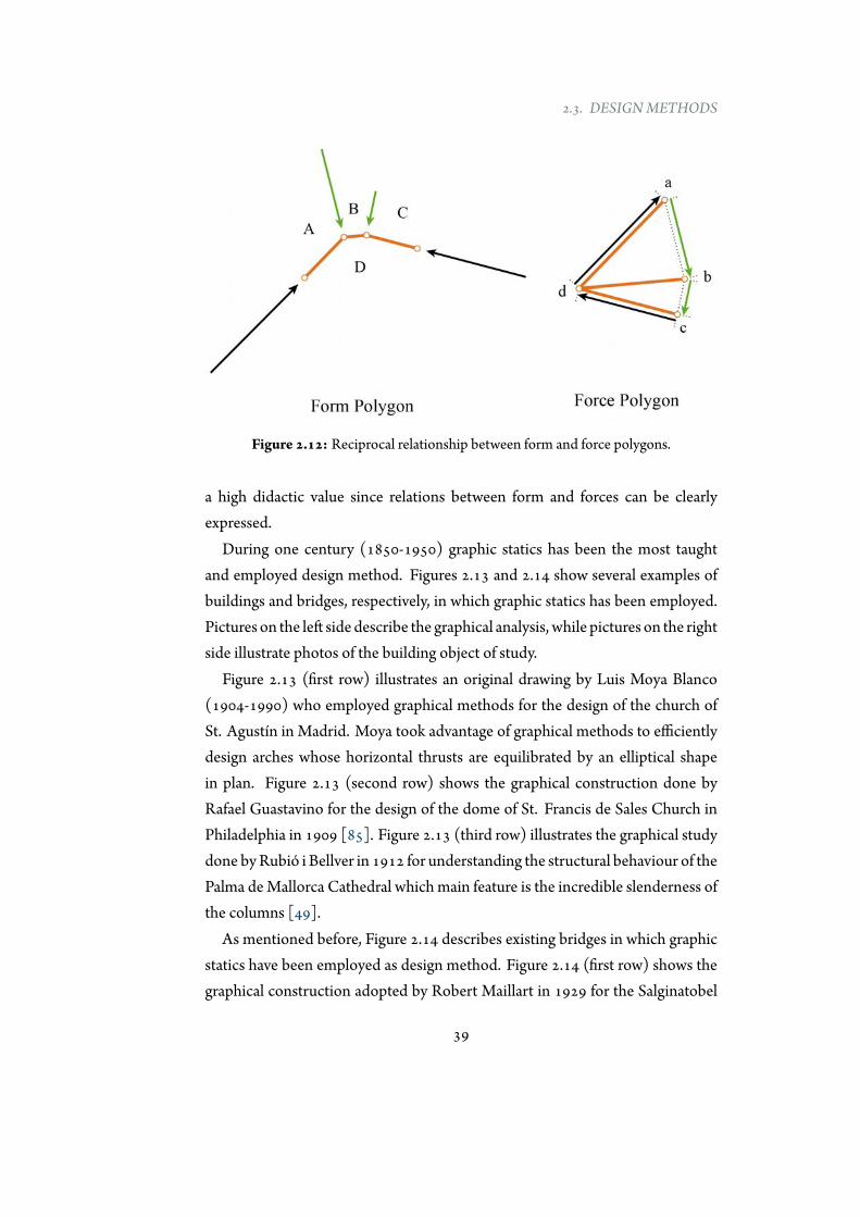
The reciprocal relationship between form and force polygons ensures that thestructures are always in equilibrium (Figure 2.12).
The method is graphical in the sense that forces are geometrically calculatedfrom the force polygon. In addition, the clarity of graphical approaches have
37
CHAPTER 2. LITERATURE REVIEW
Figure 2.11: Funicular polygons by Varignon.
38
2.3. DESIGNMETHODS
Figure 2.12: Reciprocal relationship between form and force polygons.
a high didactic value since relations between form and forces can be clearlyexpressed.
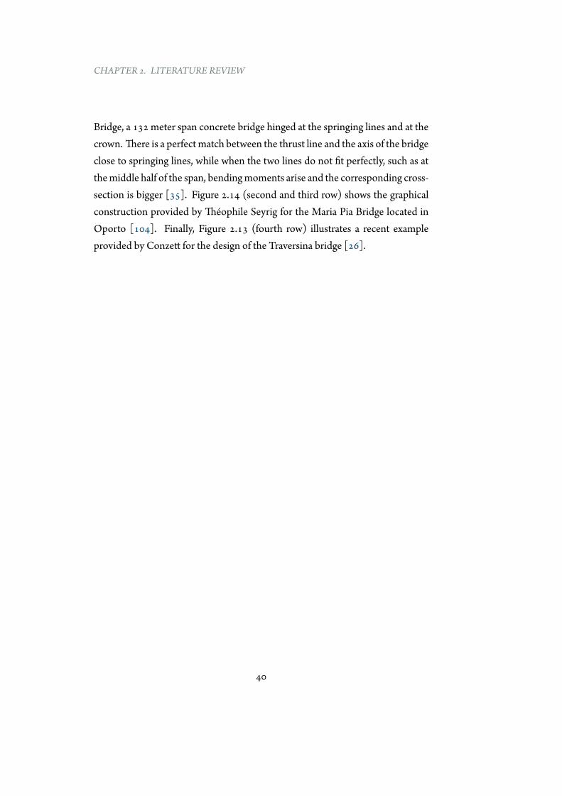
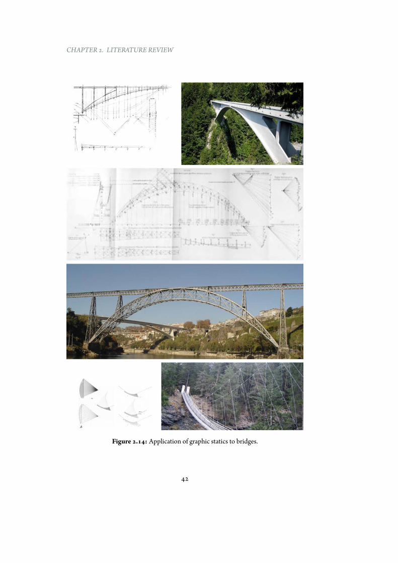
During one century (1850-1950) graphic statics has been the most taughtand employed design method. Figures 2.13 and 2.14 show several examples ofbuildings and bridges, respectively, in which graphic statics has been employed.Pictures on the left side describe the graphical analysis, while pictures on the rightside illustrate photos of the building object of study.
Figure 2.13 (first row) illustrates an original drawing by Luis Moya Blanco(1904-1990) who employed graphical methods for the design of the church ofSt. Agustín in Madrid. Moya took advantage of graphical methods to efficientlydesign arches whose horizontal thrusts are equilibrated by an elliptical shapein plan. Figure 2.13 (second row) shows the graphical construction done byRafael Guastavino for the design of the dome of St. Francis de Sales Church inPhiladelphia in 1909 [85]. Figure 2.13 (third row) illustrates the graphical studydone byRubió i Bellver in 1912 for understanding the structural behaviour of thePalma deMallorca Cathedral which main feature is the incredible slenderness ofthe columns [49].
As mentioned before, Figure 2.14 describes existing bridges in which graphicstatics have been employed as design method. Figure 2.14 (first row) shows thegraphical construction adopted by Robert Maillart in 1929 for the Salginatobel
39
CHAPTER 2. LITERATURE REVIEW
Bridge, a 132 meter span concrete bridge hinged at the springing lines and at thecrown. There is a perfectmatch between the thrust line and the axis of the bridgeclose to springing lines, while when the two lines do not fit perfectly, such as atthemiddle half of the span, bendingmoments arise and the corresponding cross-section is bigger [35]. Figure 2.14 (second and third row) shows the graphicalconstruction provided by Théophile Seyrig for the Maria Pia Bridge located inOporto [104]. Finally, Figure 2.13 (fourth row) illustrates a recent exampleprovided by Conzett for the design of the Traversina bridge [26].
40
2.3. DESIGNMETHODS
Figure 2.13: Application of graphic statics to buildings.
41
CHAPTER 2. LITERATURE REVIEW
Figure 2.14: Application of graphic statics to bridges.
42
2.3. DESIGNMETHODS
2.3.4 Computational methods
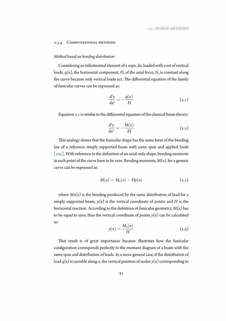
Method based on bending distribution
Considering an infinitesimal element of a rope, dx, loadedwith a set of verticalloads, q(x), the horizontal component,H, of the axial force,N, is constant alongthe curve because only vertical loads act. The differential equation of the familyof funicular curves can be expressed as:
d2ydx2
= −q(x)H
(2.1)
Equation 2.1 is similar to the differential equation of the classical beam theory:
d2ydx2
= −M(x)EI
(2.2)
This analogy shows that the funicular shape has the same form of the bendinglaw of a reference simply supported beam with same span and applied loads[105]. With reference to the definition of an axial-only shape, bendingmomentsin each point of the curve have to be zero. Bendingmoments,M(x), for a genericcurve can be expressed as:
M(x) = Mo(x)− Hy(x) (2.3)
whereMo(x) is the bending produced by the same distribution of load for asimply supported beam, y(x) is the vertical coordinate of points and H is thehorizontal reaction. According to the definition of funicular geometry,M(x) hasto be equal to zero, thus the vertical coordinate of points y(x) can be calculatedas:
y(x) =Mo(x)H
(2.4)
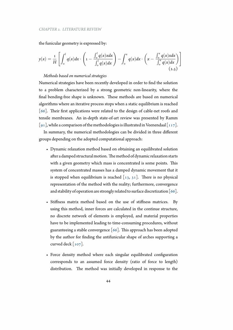
That result is of great importance because illustrates how the funicularconfiguration corresponds perfectly to the moment diagram of a beam with thesame span and distribution of loads. In a more general case, if the distribution ofload q(x) is variable along x, the vertical position of nodes y(x) corresponding to
43
CHAPTER 2. LITERATURE REVIEW
the funicular geometry is expressed by:
y(x) =1H
[∫ l
0q(x)dx ·
(1−
∫ l0 q(x)xdx∫ l0 q(x)dx
)−∫ x
0q(x)dx ·
(x−
∫ x0 q(x)xdx∫ x0 q(x)dx
)](2.5)
Methods based on numerical strategiesNumerical strategies have been recently developed in order to find the solutionto a problem characterized by a strong geometric non-linearity, where thefinal bending-free shape is unknown. These methods are based on numericalalgorithms where an iterative process stops when a static equilibrium is reached[66]. Their first applications were related to the design of cable-net roofs andtensile membranes. An in-depth state-of-art review was presented by Ramm[91], while a comparisonof themethodologies is illustrated inVeenendaal [117].
In summary, the numerical methodologies can be divided in three differentgroups depending on the adopted computational approach:
• Dynamic relaxation method based on obtaining an equilibrated solutionafter adamped structuralmotion. Themethodofdynamic relaxation startswith a given geometry which mass is concentrated is some points. Thissystem of concentrated masses has a damped dynamic movement that itis stopped when equilibrium is reached [13, 31]. There is no physicalrepresentation of the method with the reality; furthermore, convergenceand stability of operation are strongly related to surfacediscretization [66].
• Stiffness matrix method based on the use of stiffness matrices. Byusing this method, inner forces are calculated in the continue structure,no discrete network of elements is employed, and material propertieshave to be implemented leading to time-consuming procedures, withoutguaranteeing a stable convergence [66]. This approach has been adoptedby the author for finding the antifunicular shape of arches supporting acurved deck [107].
• Force density method where each singular equilibrated configurationcorresponds to an assumed force density (ratio of force to length)distribution. The method was initially developed in response to the
44
2.3. DESIGNMETHODS
need for computational modelling the Munich Olympic complex [66].Pre-stressed cable nets need non-linear system of equations but theemployment of force to length ratios, instead of forces, allows to solve theproblem of equilibrium by a system of linear equations [69, 99]. Resultsare strongly related to the mesh density and difficult to predict.
Computational approaches to form-finding are commonly implemented insoftware for structural analysis purposes. However their complex algorithmsdo not allow an easy control of the shape definition. In addition, if numericapproaches are essential for the design of three-dimensional structures, theiruse can be replaced by other methodologies for the design of two-dimensionalstructures, to which this study is mainly addressed.
2.3.5 Final comments
The previous sections have provided a brief overview of the different approachesaimed at finding two and three dimensional geometries inwhich only axial forcesact. These methodologies are somehow conceptually equivalent, in fact by usingmaterials with different properties in physical hanging models, by moving thepole in graphic statics, by changing the horizontal reaction in the method basedon bending distribution, by varying the material properties in stiffness matrixmethod, by changing the starting prestress in the force density method and byvarying the stiffness between nodes in dynamic relaxationmethods, it is possibleto explore all the different possible configurations of bending-free geometries forone distribution of loads.
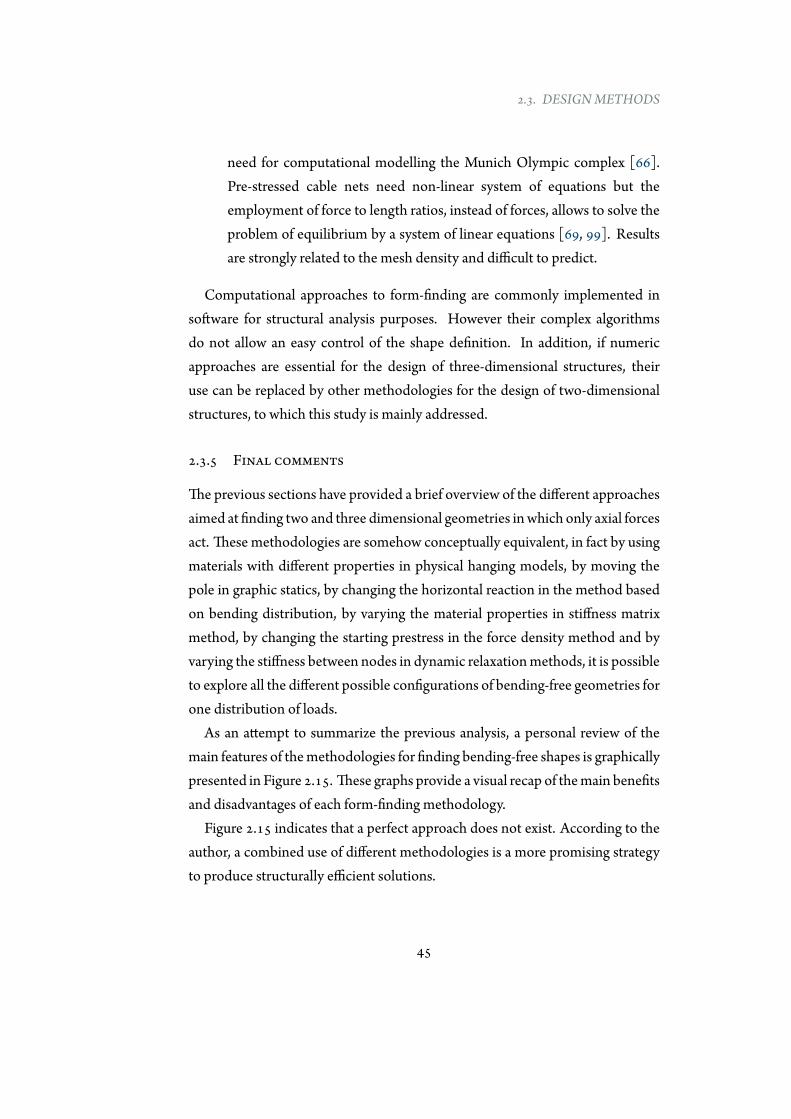
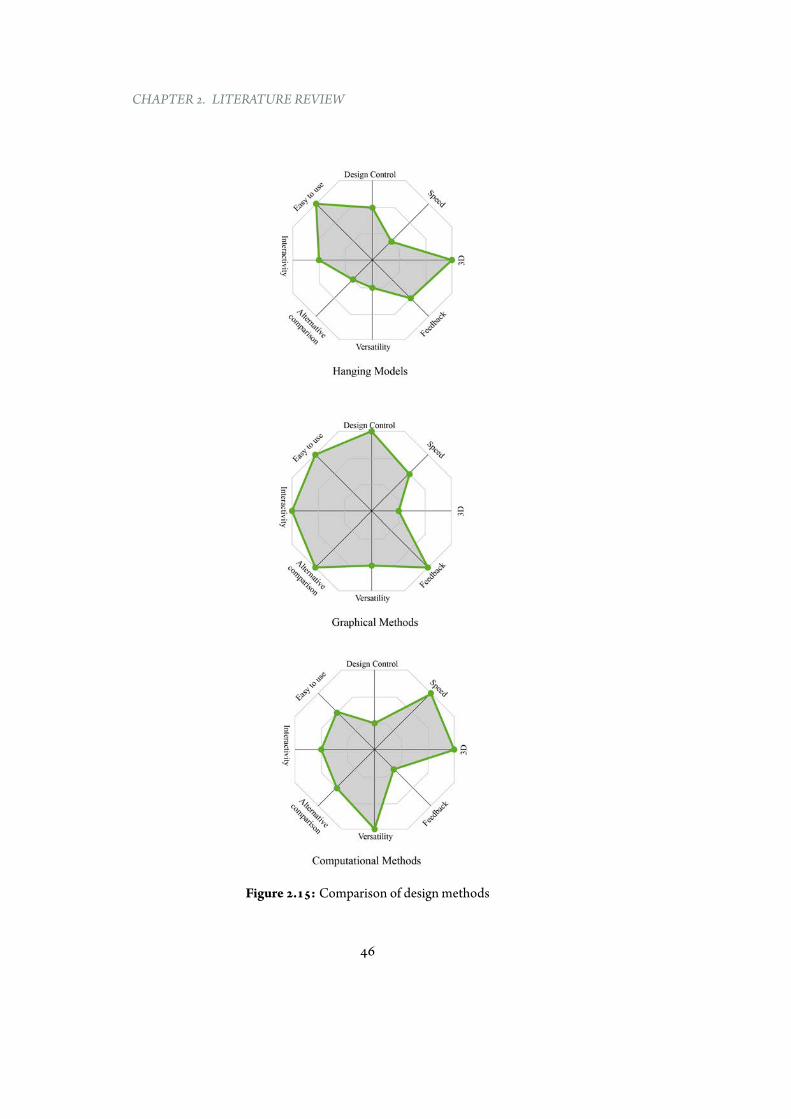
As an attempt to summarize the previous analysis, a personal review of themain features of themethodologies for finding bending-free shapes is graphicallypresented in Figure 2.15. These graphs provide a visual recap of themain benefitsand disadvantages of each form-finding methodology.
Figure 2.15 indicates that a perfect approach does not exist. According to theauthor, a combined use of different methodologies is a more promising strategyto produce structurally efficient solutions.
45
CHAPTER 2. LITERATURE REVIEW
Figure 2.15: Comparison of design methods
46
2.3. DESIGNMETHODS
This section, together with the previous one, has provided a criticallyreview of the concept of funicularity, its historical development and the mainmethodologies to find funicular shapes. In order to visually summarize theseinformation, and other data not reported in this thesis, a timeline has beensketched in Appendix 1.
The timeline, based on author’s readings and understanding, providesgraphically an historical overview of the funicularity concept and its mostprominent employers. It is interesting to point out that:
• Theconcept of funicularity has beendeveloped in approximately 250 years(from1450 to 1700). After the contribute ofGregory no relevant advanceshave been produced.
• Hanging models have been used before for assessing structures and then,to design them. Thismethodology has been forgotten for centuries beforeits revival by Gaudí and Isler.
• Graphical methods lived their “golden age” during 19th century, butthen with the exception of few contemporary designers, they have beenabandoned.
• Recently, more numerical approaches appeared in parallel with thedevelopment of computers. Advanced computational form-findingmethods have practically replaced hanging models and graphicaltechniques, saving time but, in the other hands, decreasing understandingof structural behaviour and design attitude.
Finally, it is important to point out that the selection of a methodology isstrictly related to the tools in which that approach is implemented. The nextsection provides an overview of the available computational tools, evidencinghow, today, new software can provide a fertile soil for the revival of abandonedmethodologies [79].
47

CHAPTER 2. LITERATURE REVIEW
2.4 Computational tools
2.4.1 Introduction
This section is addressed to present a brief review of the computational tools thatcan be employed to find axial-only shapes. Depending on their distinguishingfeatures, these software can be divided in three main groups: geometry-based,analysis-based and design-oriented tools.
2.4.2 Geometry-based tools
Geometry-based tools usually are computer-aided design (CAD) software,which allow the user to vary easily the geometry. That freedom in geometryalteration is counterbalanced by the lack of physical simulation. During last yearsnew geometry-based computational tools, which implement graphic statics, havebeen developed. The result is a software in which it is possible to observe howinternal forces change through the forcepolygon, giving theuser thepossibility ofexploring different equilibrated solution. Most interesting examples of this kindof tools are representedbyActiveStatics [24], Equilibrium[3] andRhinoVAULT[3].
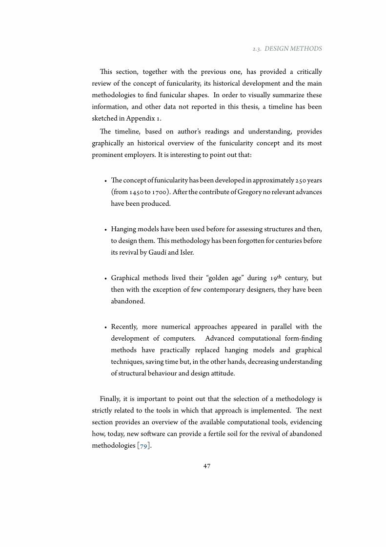
In order to evaluate the benefits of employing geometry-driven tools, theauthor has implemented graphic statics within Geogebra [39], a well-knowndynamic mathematics software, and the analysis of a real structure has beenperformed in order to explore the thrust lines related to the permanent loads. Thestructure object of the analysis is the Tiemblo Bridge above the Burguillo River,a 165 meter concrete arch bridge supporting a roadway. The total length of thebridge is 268 meters and it has been designed by Fhecor Consulting Engineers.The geometry of the arch evidences some singularities (Figure 2.16): variablecross section with depth between 3.10 meters (l/53) at the springing lines and1.75 meters (l/94) at the crown and a constant width of 4.00 meters. The rise ofthe bridge, f, is 22 meters and the span-to-rise ratio, λ=l/f, is 7.5.
The use of graphic statics, shown in Figure 2.17, allows to evaluate thediscrepancy between thrust line (obtained for permanent loads related to arch,
48
2.4. COMPUTATIONAL TOOLS
Figure 2.16: Front view and cross section of the Tiemblo bridge.
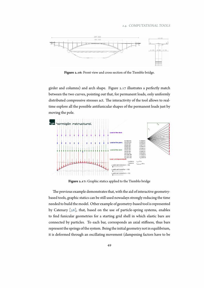
girder and columns) and arch shape. Figure 2.17 illustrates a perfectly matchbetween the two curves, pointing out that, for permanent loads, only uniformlydistributed compressive stresses act. The interactivity of the tool allows to real-time explore all the possible antifunicular shapes of the permanent loads just bymoving the pole.
Figure 2.17: Graphic statics applied to the Tiemblo bridge
Theprevious example demonstrates that, with the aid of interactive geometry-based tools, graphic statics can be still used nowadays strongly reducing the timeneeded to build themodel. Other example of geometry-based tool is representedby Catenary [56], that, based on the use of particle-spring systems, enablesto find funicular geometries for a starting grid shell in which elastic bars areconnected by particles. To each bar, corresponds an axial stiffness, thus barsrepresent the springs of the system. Being the initial geometry not in equilibrium,it is deformed through an oscillating movement (dampening factors have to be
49
CHAPTER 2. LITERATURE REVIEW
assigned to the bars). Once oscillation stops, an equilibrated shape has beenreached. This method represents, somehow, the computational implementationof physical models. As an important difference with physical hanging modelscan be reported that using particle-spring approaches the computed springsnear supports elongate more than those at mid-span, while the cable lengths inphysical models remain constant [15]. Additionally another form-finding tool,based on the use of dynamic relaxation, has been developed by the Form findingLAB at Princeton University and it can be used in Google Chrome.
In summary, the use of geometry-driven tools has facilitated the back invogue of historical methodologies as graphic statics, and the implementationof more computational ones as dynamic relaxation and particle-spring system.However, these geometry-driven tools lack of physical simulation andultimate orserviceability limit state checks cannot be performed. Data have to be exportedto other software with the aim of performing more refined structural analysis.Finally, the great geometric freedom and, sometimes, the simultaneous lack ofimmediate structural response can led to the development of intricate and non-sense forms.
2.4.3 Analysis-based tools
Analysis-oriented tools are software more focused on performance predictionthan geometric alteration. In fact, these tools make easy the determination ofstresses, deflections, deformations, etc… acting in the structures, and, usually,they are based on Finite ElementModelling. Several commercial Finite Elementpackages implement form-finding analysis, but the lack of geometry alterationlimits the possibility of using these software during the first stage design. Thepossible range of optimization is very low because the starting geometry can bevaried in a limited way. Furthermore, these tools miss of interactivity control ofdesign and immediate feedback.
2.4.4 Design-oriented tools
Previous sections have illustrated the main features of existing computationaltools classified as geometry-driven or analysis-driven. This sharp separation
50
2.4. COMPUTATIONAL TOOLS
is not beneficial for conceptual design [78, 80]. Thus, more unified andintegrated design-oriented tools for finding efficient shapes are strongly needed.Summarizing the advantages of both, geometry- and analysis-driven tools, themain requirements of a design-oriented tool are:
1. Geometrical flexibility intended as the possibility to quickly generate,explore and evaluate different alternatives.
2. Immediate structural feedback to variation of shape, loads and boundaryconditions.
3. Integrated numerical analysis where there is no need to transferinformation from the geometric modeller to the structural analysissoftware [40, 41].
4. Graphical output and interactive user experience.
5. Parametric environment to better manage data approximations typical inthe first stage of a project.
6. Optimization solvers for adjusting variables involved in the conceptualdesign process.
7. Customization for providing to the user the possibility to create its ownscript.
A software that incorporate all these features does not exist, but it is possibleto assemble different tools/plug-in existing on the market to provide a uniqueframework in which all required features are satisfied. The core of this frameworkis represented byGrasshopper [74], a graphical algorithm editor, integrated withRhinoceros’s 3-Dmodeling tool [75] employed to build generative procedures.
Rhinoceros, a commercial NURBS-based 3-D modelling software, providesthe required graphical output and the interactive user experience. Grasshopperworks into a parametric and interactive environment, which allows the userto change parameters involved into the design and to quick evaluate differentstructural solutions. Furthermore, Grasshopper permits to concatenate
51
CHAPTER 2. LITERATURE REVIEW
parametric design with structural analysis in a dynamic and interactive way byusing its embedded plug-in FE solver Karamba [89] or other similar extensions.
The structural analysis and the form-finding processes represent a jointprocedure because are both implemented in the same environment. Karambais suitable for early stage design, but if more advanced structural analyses areneeded, a custom plug-in, karambaToSofistik, allowing the direct exchange ofdata between Karamba and Sofistik, has been developed within the StructuralConcrete Research Group of the Technical University of Madrid. The tool canbe freely downloaded from the research group’s website [4].
Basic use ofGrasshopper requires no knowledge of programming or scripting,but it still allows designers to build their own components, being totallycustomizable and extending incredibly the potentiality of the tool. Finally,optimization solvers for modifying variables involved in the design can beemployed.
An application of a design-oriented tool was implemented by the author tofind an antifunicular arch configuration for a deck with any geometry in the 3-dimensional space. Methodology, tool and results have been presented in histhesis submitted for the master degree in Engineering of Structures, Materialsand Foundations [107].
It is not unusual that the footbridge deck has to adapt to a complex geometryin plan as well as in elevation, due to regulations regarding handicapped accesswhich entail the use of long ramps. Usually designers incorporate external rampslocated on the obstacle’s margins to decrease the slope in order to fulfil theseregulations. An alternative to this solution is represented by the increase of thedeck length, bymaking it curved in plan. Thus, spatial arch footbridges representan innovative answer to demands on functionality, structural optimization andaesthetics for curved decks, quite popular in urban contexts.
Thedesign ofmaterial-efficient spatial arch bridges requires the same conceptsused for planar arch bridges, but the fact that hangers are not contained in thesame vertical plane makes the problemmore complicated.
The analysis of the existing literature on the topic illustrated that the structuralbehaviour of spatial arch bridges was studied in depth by several researchers
52

2.4. COMPUTATIONAL TOOLS
[52, 58, 61, 98] and the form finding of an antifunicular arch for a curved deckwas obtained by adopting different approaches [53, 58, 60]. The common resultis an efficient geometry that resist loads, for the predominant load case, onlywith axial compressive forces. However, there was room for a more generalizeddesign-oriented approach that had to be parametric and versatile for finding thecorresponding antifunicular shape for any geometry of the deck and had to beintegrated with a finite element solver to take into account other effects, such asthe material stiffness and different loading conditions.
The author implemented a tool named SOFIA (Shaping Optimal Forms withan Interactive Approach), based on incremental analysis, that starting from ageneric arch geometry allows to obtain its three-dimensional antifunicular shapefor a curved deck [107].
SOFIA is interactive because the modification of the deck input geometryresults in the automatic and real-time generation of the related antifunicular archshape with display of forces and displacements. This provides instant feedback,in fact user interaction, visualization of the model and structural response occursimultaneously, without the need for the user to explicitly run the analysis [24,25]. This leads to an intuitive understanding of the spatial arch bridges’ structuralbehaviour. In summary, geometry input, form-finding and consequent structuralanalysis are integrated in the same tool, thus greatly simplifying the work-flow.
The above described tool allows to explore antifunicular arches for anygeometry of the deck. Examples of antifunicular geometries for bridges withC- and S-shaped decks are shown in Figure 2.18. The antifunicular arches, fora generally curved deck, are not only curved in elevation, but also double-curvedin plan.
2.4.5 Final comments
The previously presented review of computational tools has shown that softwareimplementing form-finding methods are mainly analysis-driven tools addressedtogenerate static designoptions, rather than the explorationof solution spaces, orgeometry-driven tools, mainly addressed to geometric variation, than structuralprediction. Despite that, some progresses have been made with tools can
53

CHAPTER 2. LITERATURE REVIEW
(a)C-shaped deck
(b) S-shaped deck
Figure 2.18: Resulting antifunicular arches for curved decks
54

2.5. SUMMARY
be used for conceptual design of efficient shapes [80]. In fact during lastdecades several interesting software have been developed in order to performform-finding analysis, saving computational cost, within friendly and innovativeenvironments.
The combination of some tools, based on the core Grasshopper, can allow toassemble a design-oriented software more focused on the exploration of spacedesign, and able to bridge the gap between geometrical definition and structuralconsiderations. These modern tools can be a great resource to support thedesigner for thinking about the structural behaviour while exploring the designspace.
2.5 Summary
The literature review presented in this Chapter has been addressed to brieflyanalyse the concept of funicularity, methodologies to find bending-freegeometries and software in which these approaches can be implemented.
Despite the funicularity principle and its implications represent anindispensable part of the structural designer expertise, traditional form-finding approaches, based on hanging models and graphical constructions, havebeen replaced by numerical procedures. In this computational approach thegeometrical definition and its structural analysis correspond to different stagesof a project. Furthermore, a more frequently use of analysis-driven tools hasdecreased the control of design. Thus, the current design process is characterizedfor being unidirectional and with strong lack of interoperability.
However, today there are new interactive and integrated environment wheregeometric modeling and structural evaluation are blended to take advantageof their combined potential. In fact, Part II presents a new approach, wherethe combined use of well-know design-methods and novel design-driven tools,allows to overcome the limited interoperability between structural analysisand geometric freedom for the design of more versatile and material-efficientstructures.
55


Part II
Post-Tensioned AntifunicularStructures
57

Engineering is the art of directing the great sources ofpower in nature for the use and convenience of man.
Thomas Tredgold
3Background
3.1 Introduction
As illustrated in Chapter 2, curved structures are characterized by the criticalrelationship between geometry and structural behaviour, and selecting anappropriate shape in the conceptual design of such structures is important forachieving material-efficiency.
However, non-structural conditions, such as aesthetics, functionality, andgeotechnical issues, often prohibit the selection of a structurally ideal funicularshape: in contrast to a free hanging chain, forces cannot act in pure axialcompression or tension under self-weight and gravity loads, decreasing thestructural efficiency of the design through the introduction of bendingmoments.
In contrast with form-finding problems, where a bending-free shape is foundstarting from a given set of loads, Part II of this thesis studies the oppositeproblem: how to introduce additional loads that convert a non-antifunicularshape into an antifunicular one without changing its base geometry.
59
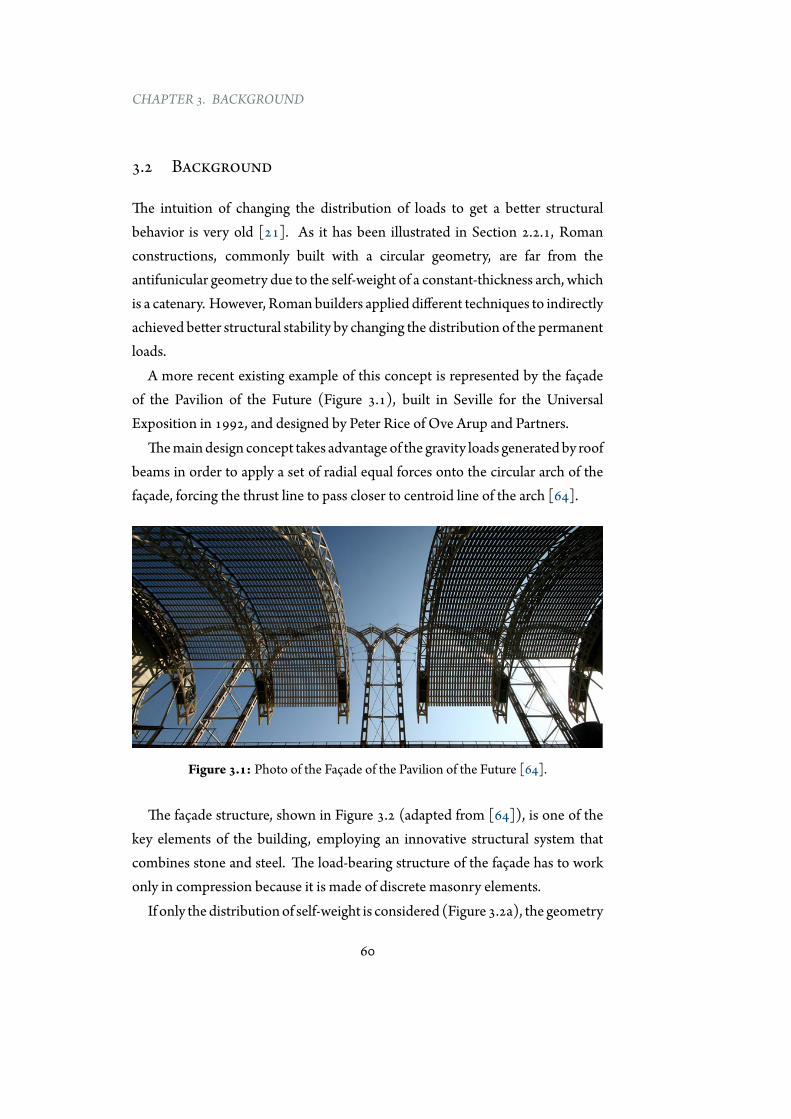
CHAPTER 3. BACKGROUND
3.2 Background
The intuition of changing the distribution of loads to get a better structuralbehavior is very old [21]. As it has been illustrated in Section 2.2.1, Romanconstructions, commonly built with a circular geometry, are far from theantifunicular geometry due to the self-weight of a constant-thickness arch, whichis a catenary. However, Romanbuilders applied different techniques to indirectlyachieved better structural stability by changing the distribution of the permanentloads.
A more recent existing example of this concept is represented by the façadeof the Pavilion of the Future (Figure 3.1), built in Seville for the UniversalExposition in 1992, and designed by Peter Rice of Ove Arup and Partners.
Themaindesign concept takes advantageof the gravity loads generatedby roofbeams in order to apply a set of radial equal forces onto the circular arch of thefaçade, forcing the thrust line to pass closer to centroid line of the arch [64].
Figure 3.1: Photo of the Façade of the Pavilion of the Future [64].
The façade structure, shown in Figure 3.2 (adapted from [64]), is one of thekey elements of the building, employing an innovative structural system thatcombines stone and steel. The load-bearing structure of the façade has to workonly in compression because it is made of discrete masonry elements.
If only thedistributionof self-weight is considered (Figure 3.2a), the geometry
60
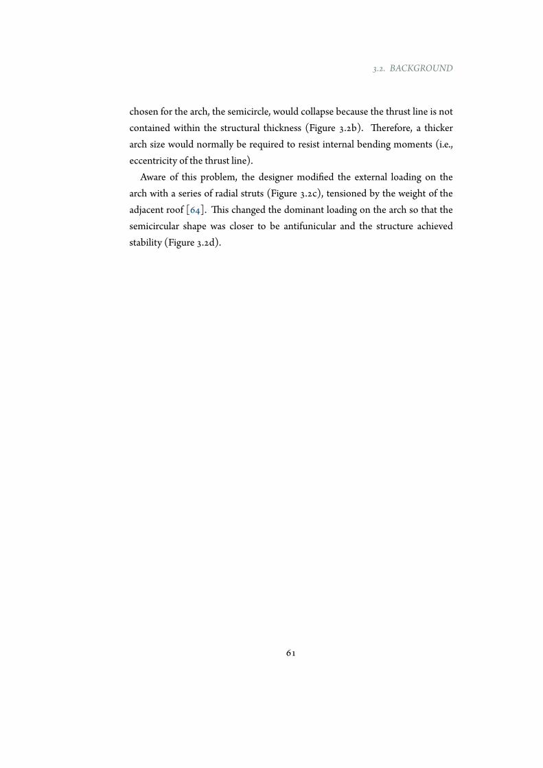
3.2. BACKGROUND
chosen for the arch, the semicircle, would collapse because the thrust line is notcontained within the structural thickness (Figure 3.2b). Therefore, a thickerarch size would normally be required to resist internal bending moments (i.e.,eccentricity of the thrust line).
Aware of this problem, the designer modified the external loading on thearch with a series of radial struts (Figure 3.2c), tensioned by the weight of theadjacent roof [64]. This changed the dominant loading on the arch so that thesemicircular shape was closer to be antifunicular and the structure achievedstability (Figure 3.2d).
61
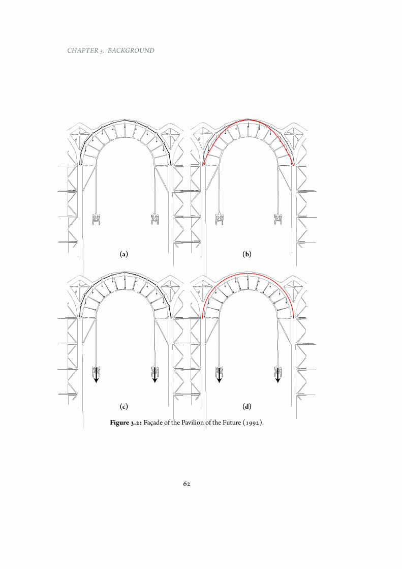
CHAPTER 3. BACKGROUND
(a) (b)
(c) (d)
Figure 3.2: Façade of the Pavilion of the Future (1992).
62

3.2. BACKGROUND
However, the application of external loads as hanged weights, often, it is nota possible solution. An alternative option consists in intelligently employingexternal post-tensioning for generating the required external loads. Prestressingallows to redirect the force of gravity for achieving the required internal forcedistribution [5, 34, 65, 88, 118].
The concept of prestressing become reality through the development of a newmaterial (high-strength steel) and novel construction techniques during the firstdecades of the 20th century [67, 70].
The historical development of external post-tensioning is even more recent,and most applications are related to bridges which are straight in elevation[77, 96]. Prestressed tendons, depending on their position with respect to thedeck, can generate different types of bridges [77, 81, 95].
Figure 3.3 illustrates the use of external post-tensioning applied to theZabalgana footbridge designed by Fhecor Consulting Engineers. The footbridgehas a span of 60 meters and employes an U-shaped cross-section.
The two pinned elements (Figure 3.3a), which connect the deck and theprestressed cable, add vertical point loads to the structure equilibrating totallythe dead load of the bridge. Figure 3.3b illustrates the connection detail betweenprestressing and connecting element.
The application of external forces decreases the effective span of the bridgeby introducing two ”invisible columns” (as Eduardo Torroja did in the TempulAqueduct [23]).
63
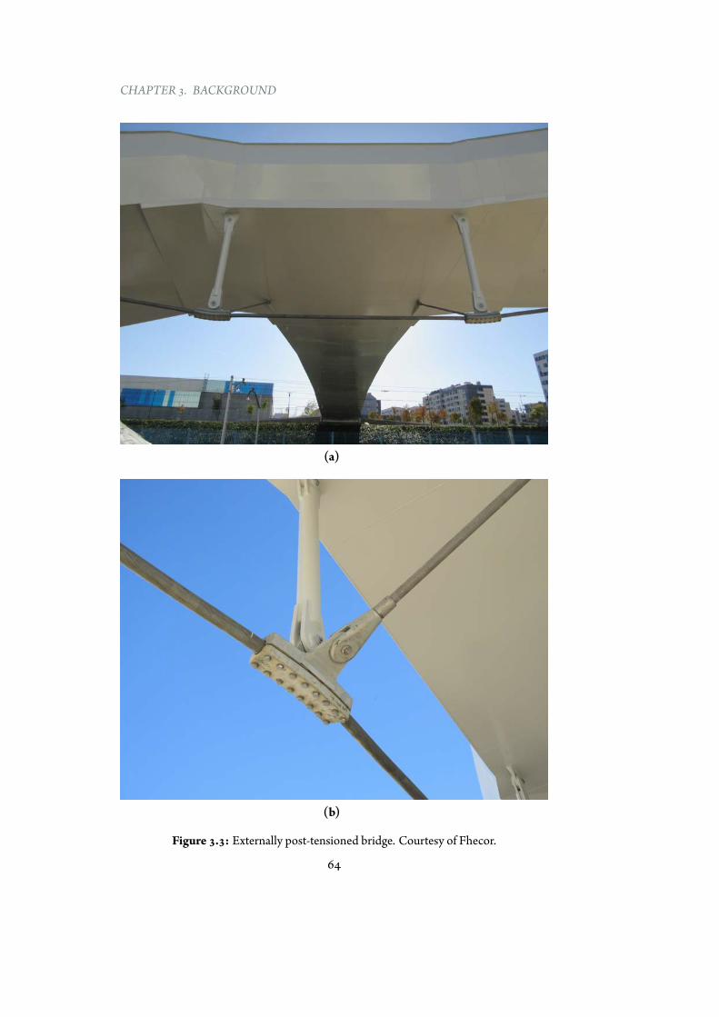
CHAPTER 3. BACKGROUND
(a)
(b)
Figure 3.3: Externally post-tensioned bridge. Courtesy of Fhecor.
64

3.3. ORGANIZATIONOF THE PART II
However, the post-tensioning technology is not restricted to only bridgesand it can be applied to many other structural typologies, enabling designersto control the structural behaviour of curved structures, e.g., shells, arches,roofs, etc... [102, 103]. An example of application of post-tensioning to aplanar curved structures is represented by the glass roof of the Berlin MainTrain Station. Tensioned cables follow the bending moment law and transformthe basket arch into the thrust line [2]. The engineer is familiar with thetechnical aspects of prestressing, but he seldomhas the architectural backgroundto exploit the structure’s possibilities in layout and form[68]. In fact, anymaterialwith reasonable compression characteristics can be efficiently combined withprestressed tendons to achieve an efficient structural solution: prestressing canmake bending structures behave like axial-only geometries.
Inspired by the Pavilion of the Future and by the recent examples of externallypost-tensioned structures, this study explores the use of a generalized designapproach that converts any planar curve into an antifunicular shape withoutchanging its base geometry; instead, a bending-free behaviour is achievedthrough the introduction of new forces using external post-tensioning.
3.3 Organization of the Part II
Part II of this dissertationpresents anoriginal general theory and implementationfor eliminating bending moments in two-dimensional curved geometriesthrough external post-tensioning systems.
Part II is structured as follows: first, a graphicalmethodology for the geometricdefinition of the post-tensioning system and its implementation in a design-oriented tool (EXOEQUILIBRIUM) are described in detail (Chapter 4). Thischapter, presenting a generalized theoretical methodology, shows how thisconcept can be applied to designs in a broad sense.
Next, the developed software is employed for achieving funicularity for a greatnumber of geometries (Chapter 5). In the same chapter, possible design criteria,and their effect on internal force distribution, are evaluated.
Finally, real applications related to reduced physical models and to a builttemporary pavilion are illustrated and critically analyzed in Chapter 6.
65
CHAPTER 3. BACKGROUND
3.4 Summary
The choice of an appropriate bending-free shape in curved geometries is animportant decision for designing materially efficient structures. However,optimal shapes from a structural point of view are often at odds with otherrequirements, and non-antifunicular geometries must be used.
The idea behind this research is to add external forces to a general curved shapeand to convert it into an antifunicular geometry. This can be accomplished byusing a post-tensioning system that, following a determinate shape, generates achange in forces within the base structure and makes it bending-free.
This would allow to take full advantage of the structural efficiency while alsoallowing for architectural and geometric flexibility.
66
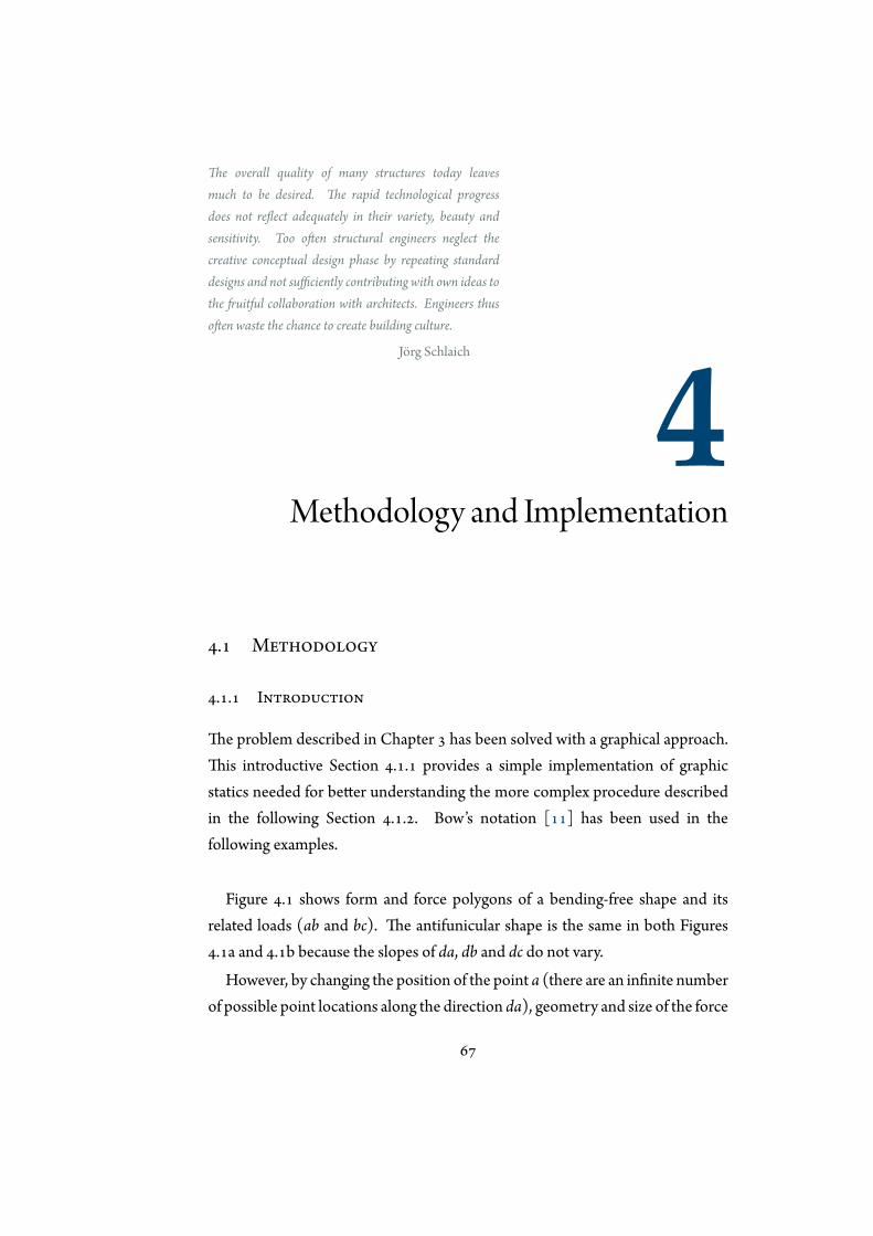
The overall quality of many structures today leavesmuch to be desired. The rapid technological progressdoes not reflect adequately in their variety, beauty andsensitivity. Too often structural engineers neglect thecreative conceptual design phase by repeating standarddesigns and not sufficiently contributing with own ideas tothe fruitful collaboration with architects. Engineers thusoften waste the chance to create building culture.
Jörg Schlaich
4Methodology and Implementation
4.1 Methodology
4.1.1 Introduction
The problem described in Chapter 3 has been solved with a graphical approach.This introductive Section 4.1.1 provides a simple implementation of graphicstatics needed for better understanding the more complex procedure describedin the following Section 4.1.2. Bow’s notation [11] has been used in thefollowing examples.
Figure 4.1 shows form and force polygons of a bending-free shape and itsrelated loads (ab and bc). The antifunicular shape is the same in both Figures4.1a and 4.1b because the slopes of da, db and dc do not vary.
However, by changing the position of the point a (there are an infinite numberof possible point locations along the direction da), geometry and size of the force
67
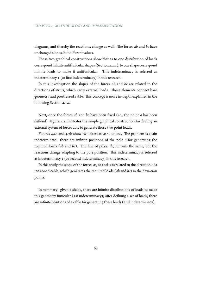
CHAPTER 4. METHODOLOGY AND IMPLEMENTATION
diagrams, and thereby the reactions, change as well. The forces ab and bc haveunchanged slopes, but different values.
These two graphical constructions show that as to one distribution of loadscorrespond infinite antifunicular shapes (Section2.2.2), toone shape correspondinfinite loads to make it antifunicular. This indeterminacy is referred asindeterminacy 1 (or first indeterminacy) in this research.
In this investigation the slopes of the forces ab and bc are related to thedirections of struts, which carry external loads. Those elements connect basegeometry and prestressed cable. This concept is more in-depth explained in thefollowing Section 4.1.2.
Next, once the forces ab and bc have been fixed (i.e., the point a has beendefined), Figure 4.2 illustrates the simple graphical construction for finding anexternal system of forces able to generate those two point loads.
Figures 4.2a and 4.2b show two alternative solutions. The problem is againindeterminate: there are infinite positions of the pole e for generating therequired loads (ab and bc). The line of poles, de, remains the same, but thereactions change adapting to the pole position. This indeterminacy is referredas indeterminacy 2 (or second indeterminacy) in this research.
In this study the slope of the forces ae, eb and ec is related to the direction of atensioned cable, which generates the required loads (ab and bc) in the deviationpoints.
In summary: given a shape, there are infinite distributions of loads to makethis geometry funicular (1st indeterminacy); after defining a set of loads, thereare infinite positions of a cable for generating these loads (2nd indeterminacy).
68
4.1. METHODOLOGY
A
B
D
a
bd
c
C
Form Polygon Force Polygon
(a)
Form Polygon Force Polygon
A
B
D
C
a
b
d
c
(b)
Figure 4.1: Graphical construction for finding the point loads.
69
CHAPTER 4. METHODOLOGY AND IMPLEMENTATION
AB
E
D
e
a
db
c
C
Form Polygon Force Polygon
(a)
A
B
E
D
e
a
db
c
C
Form Polygon Force Polygon
(b)
Figure 4.2: Graphical construction for generating the point loads.
70
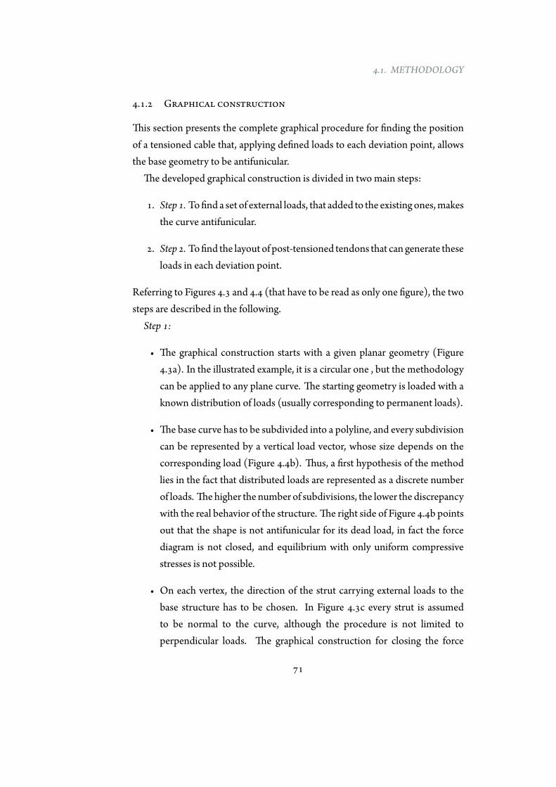
4.1. METHODOLOGY
4.1.2 Graphical construction
This section presents the complete graphical procedure for finding the positionof a tensioned cable that, applying defined loads to each deviation point, allowsthe base geometry to be antifunicular.
The developed graphical construction is divided in two main steps:
1. Step 1. Tofind a set of external loads, that added to the existing ones,makesthe curve antifunicular.
2. Step 2. Tofind the layout of post-tensioned tendons that can generate theseloads in each deviation point.
Referring to Figures 4.3 and 4.4 (that have to be read as only one figure), the twosteps are described in the following.
Step 1:
• The graphical construction starts with a given planar geometry (Figure4.3a). In the illustrated example, it is a circular one , but the methodologycan be applied to any plane curve. The starting geometry is loaded with aknown distribution of loads (usually corresponding to permanent loads).
• The base curve has to be subdivided into a polyline, and every subdivisioncan be represented by a vertical load vector, whose size depends on thecorresponding load (Figure 4.4b). Thus, a first hypothesis of the methodlies in the fact that distributed loads are represented as a discrete numberof loads. Thehigher the number of subdivisions, the lower the discrepancywith the real behavior of the structure. The right side of Figure 4.4b pointsout that the shape is not antifunicular for its dead load, in fact the forcediagram is not closed, and equilibrium with only uniform compressivestresses is not possible.
• On each vertex, the direction of the strut carrying external loads to thebase structure has to be chosen. In Figure 4.3c every strut is assumedto be normal to the curve, although the procedure is not limited toperpendicular loads. The graphical construction for closing the force
71

CHAPTER 4. METHODOLOGY AND IMPLEMENTATION
diagram is shown in Figure 4.3c where new forces, combined with theexisting ones, are needed at each vertex in order to close the force polygon.These forces are parallel to the directions of the struts. As stated before,infinite sets of loads exist tomake a single geometry antifunicular. In otherwords, the direction of the internal forces is fixed but their magnitudeis variable. This assumption represents the first indeterminacy of theproblem. The solution is unique if one parameter is fixed (e.g., themaximum compressive force in the curve).
• Figure 4.4d shows another equilibrated solution obtained with a differentmagnitude of loads by moving the point i. In this case the forces tobe introduced in each vertex have the same direction but have highermagnitude.
Step 2:
• Once one distribution of external forces inducing a state of uniformlydistributed compressive stresses has been identified, the graphicalconstruction for finding the external post-tensioning shape generatingthe forces identified in Figure 4.4e must be performed. The start andend points of the tension curve should be defined. In the describedexamples, these points coincide with the supports in order to evaluatetheir contribution to the horizontal reactions. The force polygon canbe graphically constructed, guaranteeing the equilibrium at each jointof the structure. First an arbitrary pole q is selected, and then linesconnecting this point to the force vector can be drawn, as shown in Figure4.3e. The position of the pole q is arbitrary because to one set of loadscorresponds infinite cable layout in order to generate that loaddistribution(second indeterminacy of the problem). Fixing one parameter (e.g., themaximum value of post-tensioning force or the starting inclination of thetendon) yields a unique solution; there is a unique relationship betweenpost-tensioning force and geometry of the external system.
• Figure 4.4f shows another equilibrated solution for generating the requiredloads and to make the starting curve antifunicular. In this case the pole q
72
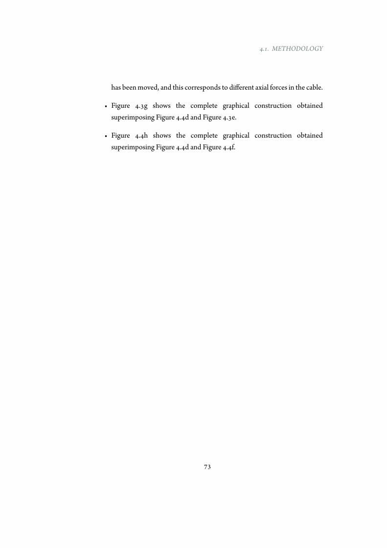
4.1. METHODOLOGY
has beenmoved, and this corresponds to different axial forces in the cable.
• Figure 4.3g shows the complete graphical construction obtainedsuperimposing Figure 4.4d and Figure 4.3e.
• Figure 4.4h shows the complete graphical construction obtainedsuperimposing Figure 4.4d and Figure 4.4f.
73
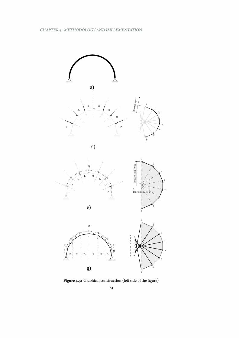
CHAPTER 4. METHODOLOGY AND IMPLEMENTATION
q
Indeterminacy 2Indeterminacy 2
i
pre
stre
ssin
g f
orc
e j
k
l
m
n
o
p
Q
q
i
j
k
l
m
n
o
p
q
I P
J O
K N
L M
Q
J O
K N
L M
B
I
C D E F G
A
P
H
a)
e)
g)
Inder
min
acy 1
I
i
j
k
l
m
n
o
p
J
K
L M
N
O
P
c)
a
g
f
e
d
c
b
h
Figure 4.3: Graphical construction (left side of the figure)74
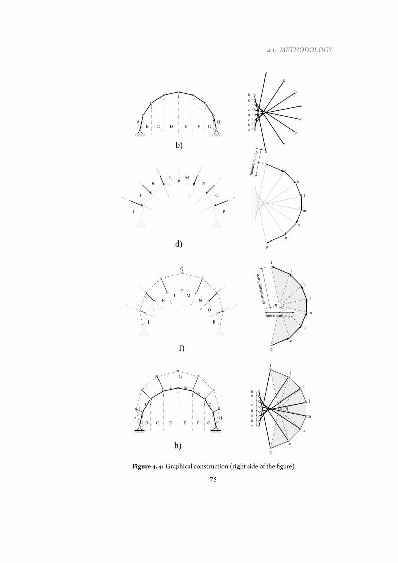
4.1. METHODOLOGY
Indet
erm
inac
y 1
I
BA
C D E F Ga
g
f
e
d
c
b
h
i
j
k
l
m
n
o
p
J
K
L M
N
O
P
H
d)
i
j
k
l
m
n
o
p
q
Q
J O
K N
L M
B
I
C D E F G
A
P
H
h)
i
j
k
l
m
n
o
p
q
Indeterminacy 2Indeterminacy 2
Q
I P
J O
K N
L M
f)
b)
P
a
g
f
e
d
c
b
h
pre
stre
ssin
g f
orc
e
Figure 4.4: Graphical construction (right side of the figure)
75
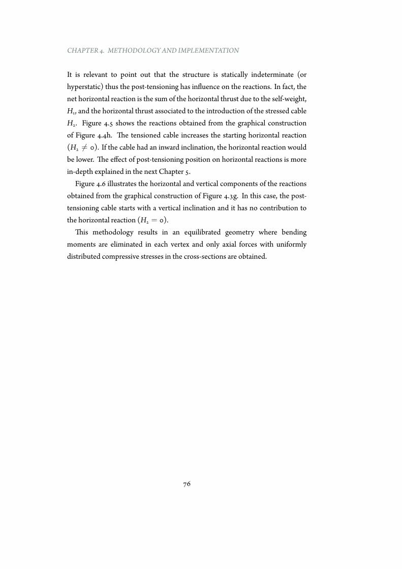
CHAPTER 4. METHODOLOGY AND IMPLEMENTATION
It is relevant to point out that the structure is statically indeterminate (orhyperstatic) thus the post-tensioning has influence on the reactions. In fact, thenet horizontal reaction is the sum of the horizontal thrust due to the self-weight,H1, and the horizontal thrust associated to the introduction of the stressed cableH2. Figure 4.5 shows the reactions obtained from the graphical constructionof Figure 4.4h. The tensioned cable increases the starting horizontal reaction(H2 ̸= 0). If the cable had an inward inclination, the horizontal reaction wouldbe lower. The effect of post-tensioning position on horizontal reactions is morein-depth explained in the next Chapter 5.
Figure 4.6 illustrates the horizontal and vertical components of the reactionsobtained from the graphical construction of Figure 4.3g. In this case, the post-tensioning cable starts with a vertical inclination and it has no contribution tothe horizontal reaction (H2 = 0).
This methodology results in an equilibrated geometry where bendingmoments are eliminated in each vertex and only axial forces with uniformlydistributed compressive stresses in the cross-sections are obtained.
76
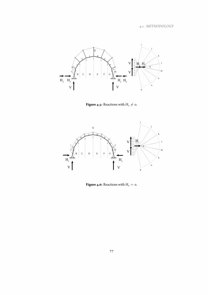
4.1. METHODOLOGY
H1
V
H1
H2
H2
V
i
j
k
l
m
n
o
p
q
Q
J O
K N
L M
B
I
C D E F G
A
P
H V
V H1H2
Figure 4.5: Reactions withH2 ̸= 0.
H1
V V
H1
q
i
j
k
l
m
n
o
p
q
Q
J O
K N
L M
B
I
C D E F G
A
P
HV
V H1
Figure 4.6: Reactions withH2 = 0.
77
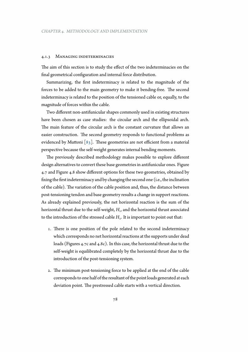
CHAPTER 4. METHODOLOGY AND IMPLEMENTATION
4.1.3 Managing indeterminacies
The aim of this section is to study the effect of the two indeterminacies on thefinal geometrical configuration and internal force distribution.
Summarizing, the first indeterminacy is related to the magnitude of theforces to be added to the main geometry to make it bending-free. The secondindeterminacy is related to the position of the tensioned cable or, equally, to themagnitude of forces within the cable.
Two different non-antifunicular shapes commonly used in existing structureshave been chosen as case studies: the circular arch and the ellipsoidal arch.The main feature of the circular arch is the constant curvature that allows aneasier construction. The second geometry responds to functional problems asevidenced by Muttoni [83]. These geometries are not efficient from a materialperspective because the self-weight generates internal bending moments.
The previously described methodology makes possible to explore differentdesign alternatives to convert these base geometries in antifunicular ones. Figure4.7 and Figure 4.8 show different options for these two geometries, obtained byfixing thefirst indeterminacy andby changing the secondone (i.e., the inclinationof the cable). The variation of the cable position and, thus, the distance betweenpost-tensioning tendon and base geometry results a change in support reactions.As already explained previously, the net horizontal reaction is the sum of thehorizontal thrust due to the self-weight,H1, and the horizontal thrust associatedto the introduction of the stressed cableH2. It is important to point out that:
1. There is one position of the pole related to the second indeterminacywhich corresponds no net horizontal reactions at the supports under deadloads (Figures 4.7c and 4.8c). In this case, the horizontal thrust due to theself-weight is equilibrated completely by the horizontal thrust due to theintroduction of the post-tensioning system.
2. The minimum post-tensioning force to be applied at the end of the cablecorresponds toonehalf of the resultant of the point loads generated at eachdeviation point. The prestressed cable starts with a vertical direction.
78
4.1. METHODOLOGY
(a)
(b)
(c)
Figure 4.7: Examples of different tendon layouts for a circular arch.
79
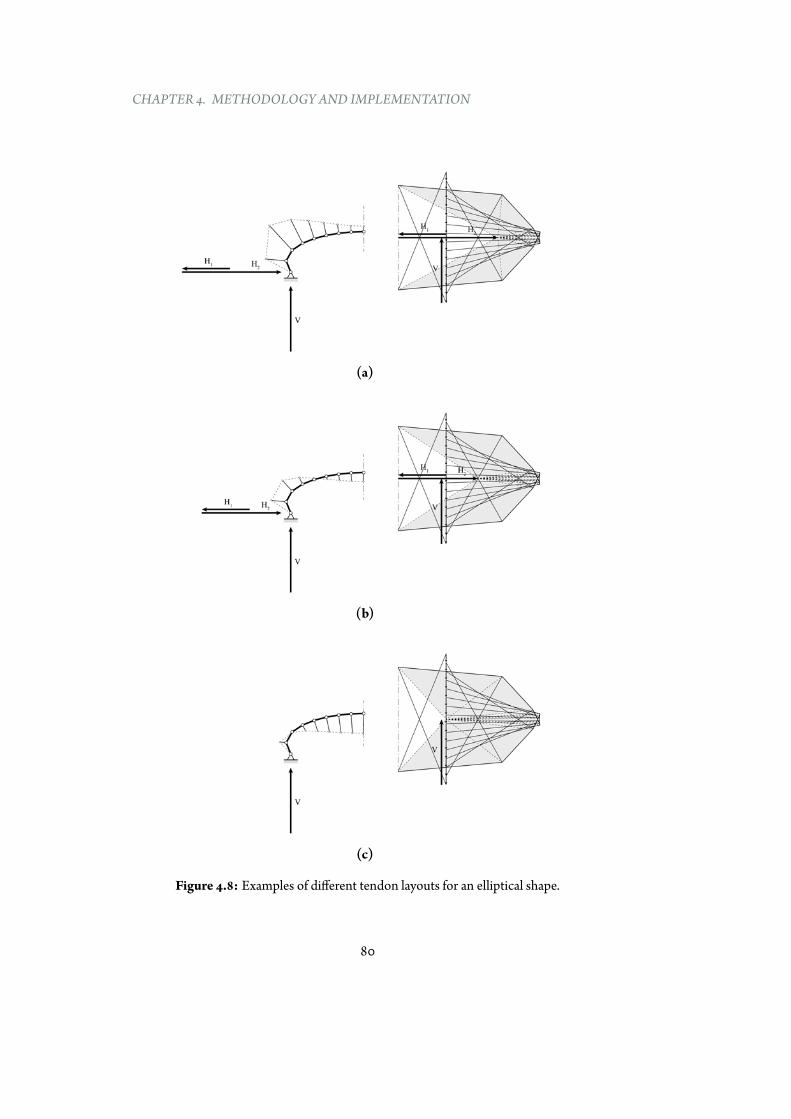
CHAPTER 4. METHODOLOGY AND IMPLEMENTATION
(a)
(b)
(c)
Figure 4.8: Examples of different tendon layouts for an elliptical shape.
80

4.1. METHODOLOGY
3. By fixing the first indeterminacy and themagnitude of the post-tensioningforce to be applied at the end of the cable, there are two possible layouts ofthe prestressed cable. Figure 4.9 demonstrates this statement: the vectoriq has a variable magnitude, depending on the position of the pole q thatcan freelymove horizontally. If the prestress value at one end is fixed, thereare two possible layouts of the post-tensioning, corresponding to differentposition of the pole q (Figure 4.9a and Figure 4.9b). These pole locationsare symmetrical with respect to the direction ip.
As pointed out in the previous paragraph, themain difference between thetwo options lies in the horizontal reactions, that in the case of Figure 4.9adecrease, while in the case of Figure 4.9b increase. Furthermore, the forceswithin the post-tensioning system shown in Figure 4.9a are considerablyhigher compared to the forces in the post-tensioning system illustrated inFigure 4.9b
81
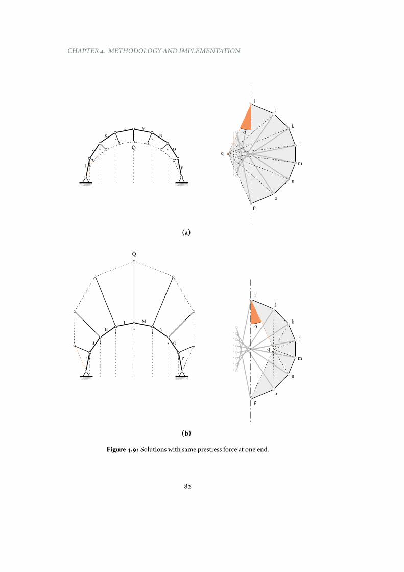
CHAPTER 4. METHODOLOGY AND IMPLEMENTATION
QJ O
K N
L M
IP
i
j
k
l
m
n
o
p
q
α
(a)
i
j
k
l
m
n
o
p
Q
J O
K N
L
I P
M
q
α
(b)
Figure 4.9: Solutions with same prestress force at one end.
82
4.2. IMPLEMENTATION
4.2 Implementation
As explained inChapter 2, the use of graphic statics for design purposes has beenlimited until recently, in part because a variation of the geometry or the loadschanges the model and the graphical construction, which must be updated, istime-consuming to complete manually. Today new computational tools havebeen developed to implement graphic statics in a very intuitive and user-friendlyway [36, 98]. In addition, an interactive tool for finding the geometry of trussesusing graphic statics has already been developed [59].
The author of this dissertation has developed a new design-oriented software,EXOEQUILIBRIUM, which implements the methodology described in Section4.1. This tool is also interactive, in that a change of the starting shape resultsautomatically in a new post-tensioning system configuration. Equilibriumis always ensured due to the dual reciprocity between force diagram andform polygon. The tool has been implemented using the parametric plug-inGrasshopper [74] for the softwareRhinoceros [75] creating customcomponentsinPython. The tool is available for freedownload [4]. Figure 4.10 shows thebasicalgorithm implemented in the tool. Themodel definition has four inputs:
1. Starting geometry of a two-dimensional structure
2. Number of segment in which the curve has to be divided
3. Direction of the struts connecting the compressive curve with the post-tensioning. Currently, vertical and radial directions for struts have beenimplemented, although others are possible as well.
4. Magnitude and distribution of existing loads
As described in the previous section, the problem has a two indeterminacies,so the user can explore the infinite range of equilibrated solutions using twoparameter sliders. The first slider changes the starting point of the graphicalconstruction for closing the force polygon (point i referring to Figure 4.3 and4.4), fixing the internal forces in the original geometry. The second slider changes
83
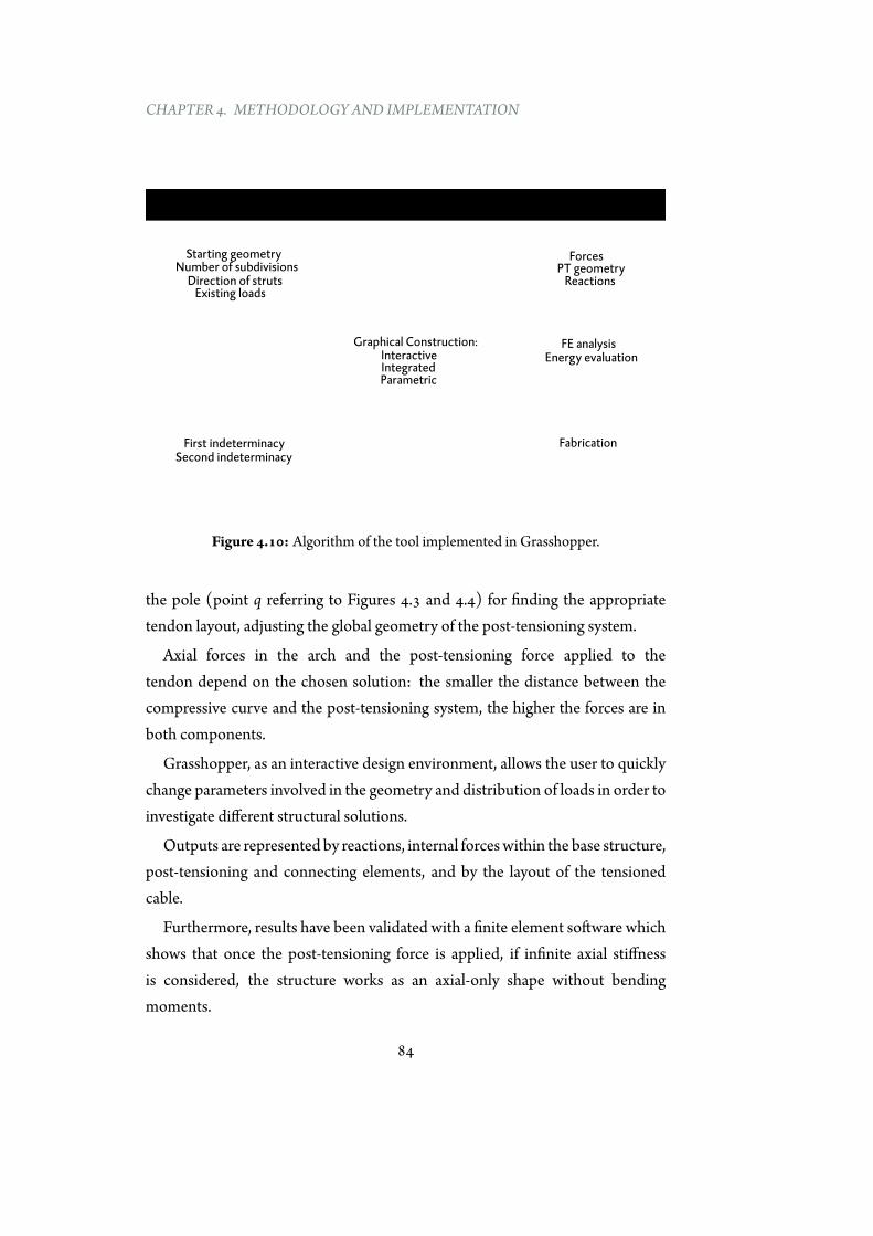
CHAPTER 4. METHODOLOGY AND IMPLEMENTATION
INPUTS ANALYSIS OUTPUTS
Starting geometryNumber of subdivisions
Direction of strutsExisting loads
ForcesPT geometry
Reactions
FE analysisEnergy evaluation
Fabrication
Graphical Construction:Interactive Integrated Parametric
First indeterminacySecond indeterminacy
Figure 4.10: Algorithm of the tool implemented in Grasshopper.
the pole (point q referring to Figures 4.3 and 4.4) for finding the appropriatetendon layout, adjusting the global geometry of the post-tensioning system.
Axial forces in the arch and the post-tensioning force applied to thetendon depend on the chosen solution: the smaller the distance between thecompressive curve and the post-tensioning system, the higher the forces are inboth components.
Grasshopper, as an interactive design environment, allows the user to quicklychange parameters involved in the geometry and distribution of loads in order toinvestigate different structural solutions.
Outputs are represented by reactions, internal forceswithin the base structure,post-tensioning and connecting elements, and by the layout of the tensionedcable.
Furthermore, results have been validated with a finite element software whichshows that once the post-tensioning force is applied, if infinite axial stiffnessis considered, the structure works as an axial-only shape without bendingmoments.
84
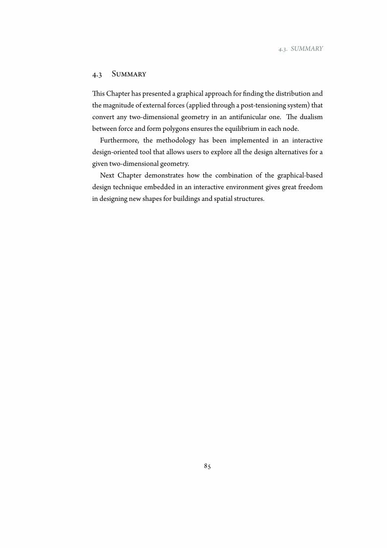
4.3. SUMMARY
4.3 Summary
This Chapter has presented a graphical approach for finding the distribution andthemagnitude of external forces (applied through a post-tensioning system) thatconvert any two-dimensional geometry in an antifunicular one. The dualismbetween force and form polygons ensures the equilibrium in each node.
Furthermore, the methodology has been implemented in an interactivedesign-oriented tool that allows users to explore all the design alternatives for agiven two-dimensional geometry.
Next Chapter demonstrates how the combination of the graphical-baseddesign technique embedded in an interactive environment gives great freedomin designing new shapes for buildings and spatial structures.
85

Good buildings come from good people, and all problemsare solved by good design.
Stephen Gardiner
5Applications andDesign Criteria
5.1 Applications
5.1.1 Random geometries
The parametric tool developed in this thesis, EXOEQUILIBIRUM, enablesthe interactive exploration of antifunicular alternatives for any two-dimensionalgeometry. As previously described, the methodology and the implemented toolare not limited to radial struts connecting the main geometry and the post-tensioning tendon. In fact, Figure 5.1 shows the graphical construction of onepossible tendon layout for generating vertical loads that makes a three-pointedgeometry works in pure compression.
Next, Figure 5.2, Figure 5.3 and Figure 5.4 illustrate the application of themethodology to arbitrary shapes.
87
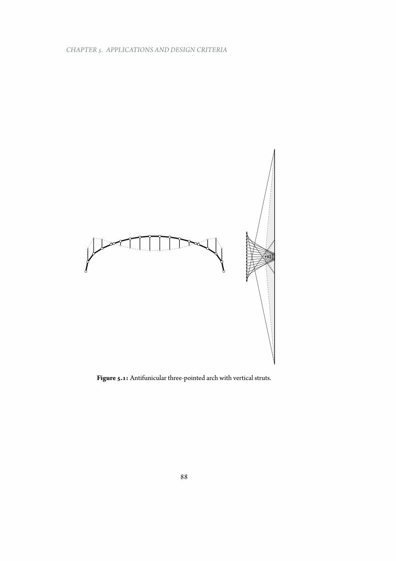
CHAPTER 5. APPLICATIONS ANDDESIGN CRITERIA
Figure 5.1: Antifunicular three-pointed arch with vertical struts.
88
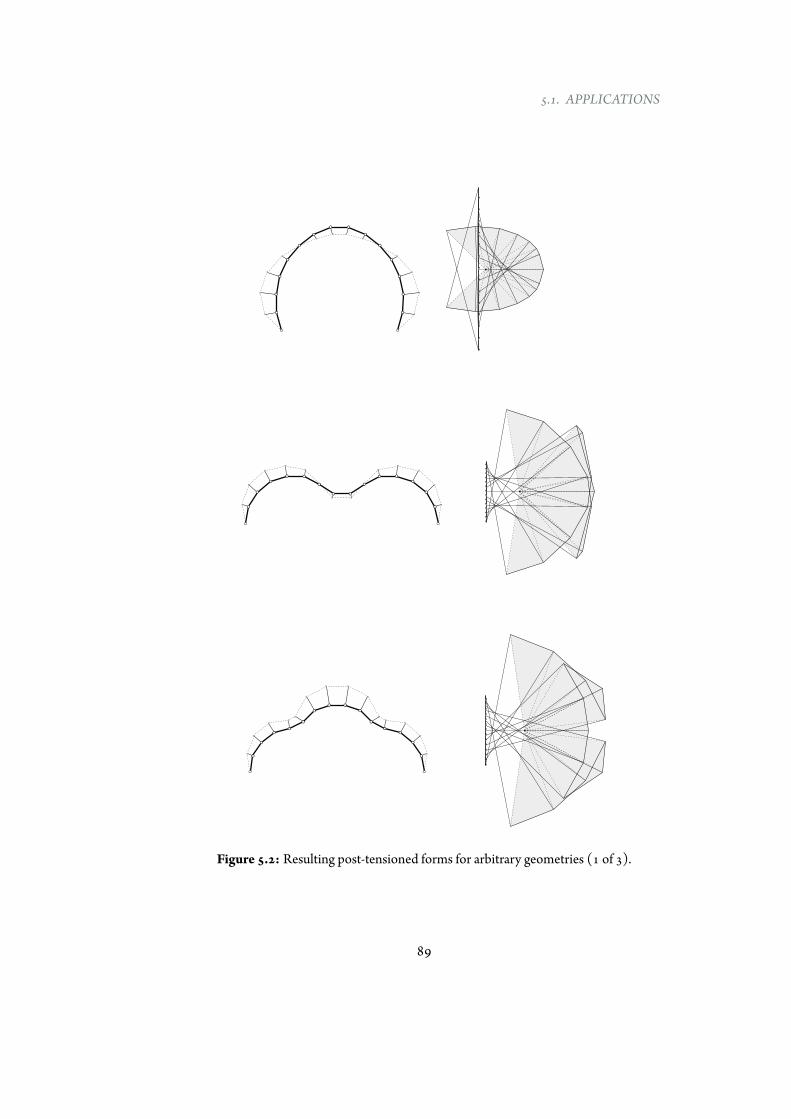
5.1. APPLICATIONS
Figure 5.2: Resulting post-tensioned forms for arbitrary geometries (1 of 3).
89
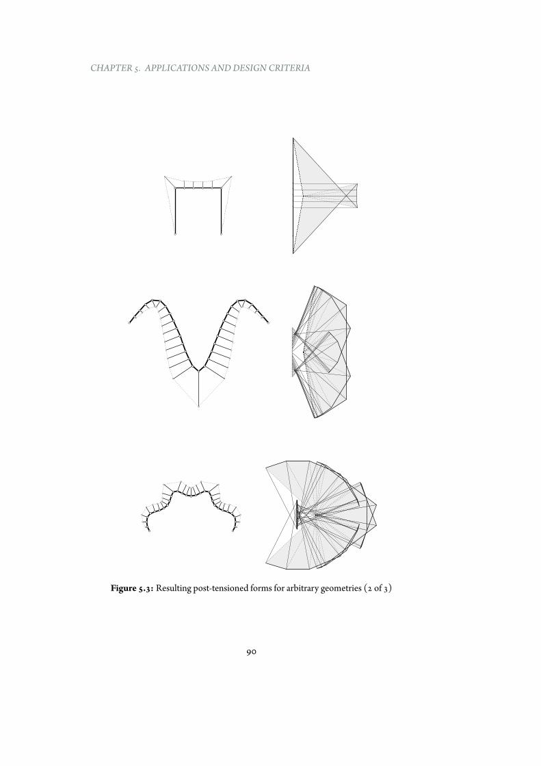
CHAPTER 5. APPLICATIONS ANDDESIGN CRITERIA
Figure 5.3: Resulting post-tensioned forms for arbitrary geometries (2 of 3)
90
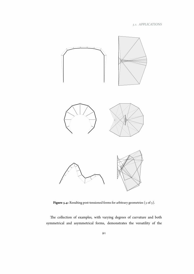
5.1. APPLICATIONS
Figure 5.4: Resulting post-tensioned forms for arbitrary geometries (3 of 3).
The collection of examples, with varying degrees of curvature and bothsymmetrical and asymmetrical forms, demonstrates the versatility of the
91

CHAPTER 5. APPLICATIONS ANDDESIGN CRITERIA
methodology and of the implemented tool for any two-dimensional geometry.Forces in all structural members can be read in the force diagram, giving tothe designer the possibility of evaluating the performance of the whole systemconsisting of the compressive geometry, the post-tensioning system and theconnecting struts.
5.1.2 Extension to non-uniform distribution of loads
The developed methodology has been, until now, applied to structures loadedwith uniformly distributedweight along the curve. However, themethod ismoregeneral and it is not limited to a uniform distributed load. In addition, a non-uniform set of loads is frequent in common structures (e.g., arches supportingroofs or decks).
Figures 5.5a and 5.5b show the application of the graphical procedure for astarting non-antifunicular shape where non-uniform loads act. The constructionis exactly the same of the previous cases, and, again, it provides the geometry ofa post-tensioning cable to transform the starting geometry into a bending-freeone. In both figures, the forces to be applied to the structure in order to achieveantifunicularity are the same; the difference lies on the post-tensioning position,in fact, the pole q changes its position, moving horizontally. As main result, themethodology can be generalized to any starting load distribution.
5.1.3 Extension to twisted 2d geometries
In the previous examples the graphical procedure has been employed to designgeometries contained in a plane. However, it can be easily extended to two-dimensional structures that are contained in different planes.
This is the case of a footbridge with a Y-shape in plan illustrated in Figure 5.6.The footbridge has a circular base geometry (in elevation) and it bifurcates inthe middle with an angle of 30°. Depending on functionality issues, the deck,after the bifurcation, can assume a variable width. In this example, the load of thedeck after the bifurcation is assumed to be the 50% of the deck load before thebifurcation.
92
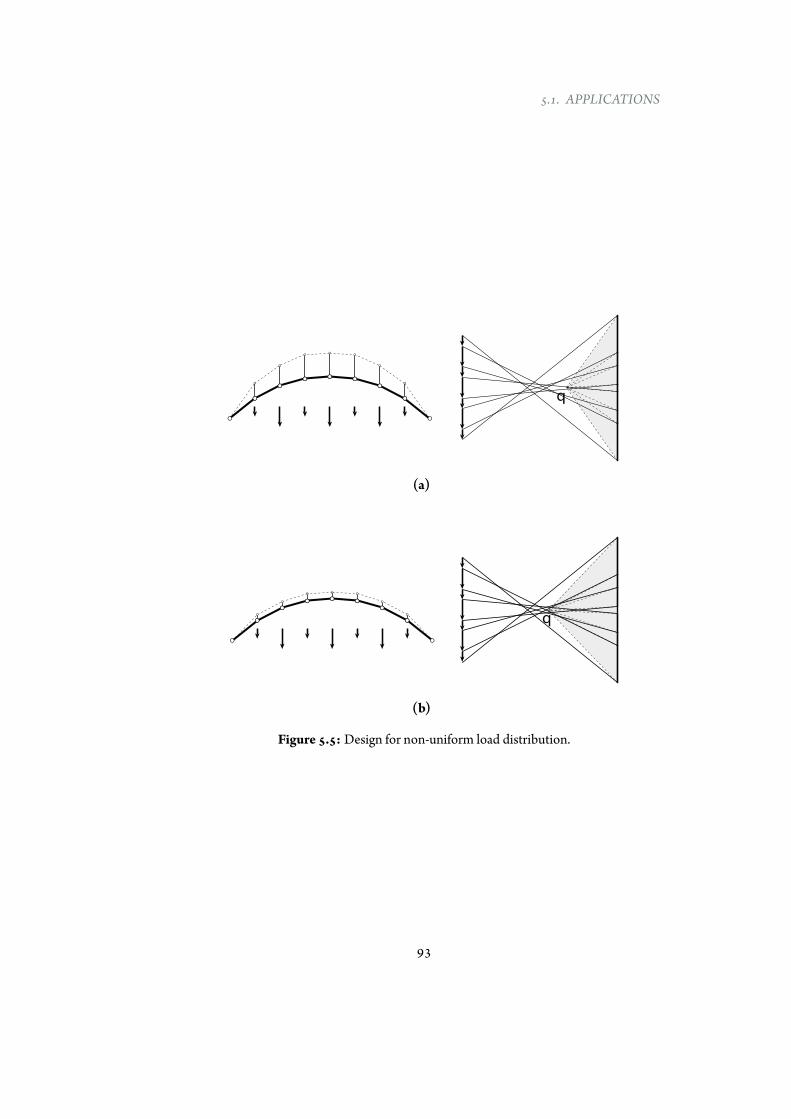
5.1. APPLICATIONS
q
(a)
q
(b)
Figure 5.5: Design for non-uniform load distribution.
93
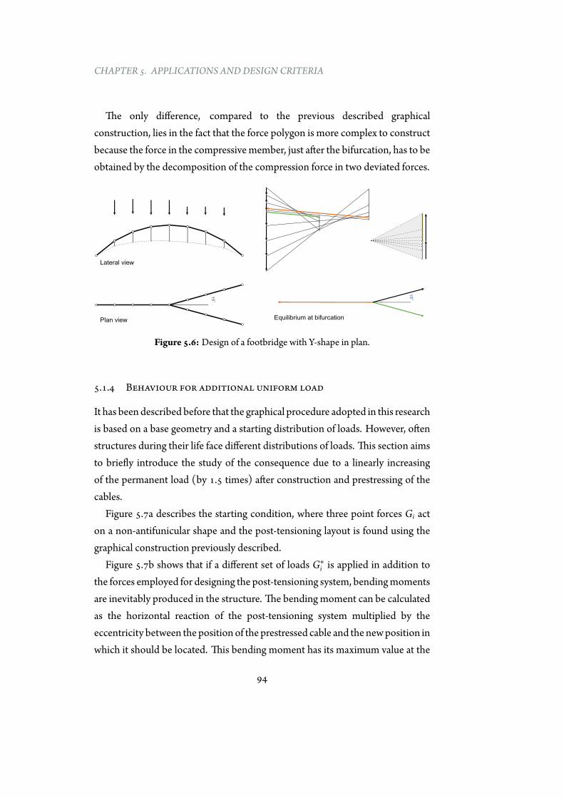
CHAPTER 5. APPLICATIONS ANDDESIGN CRITERIA
The only difference, compared to the previous described graphicalconstruction, lies in the fact that the force polygon is more complex to constructbecause the force in the compressivemember, just after the bifurcation, has to beobtained by the decomposition of the compression force in two deviated forces.
15°
15°
Equilibrium at bifurcationPlan view
Lateral view
Figure 5.6: Design of a footbridge with Y-shape in plan.
5.1.4 Behaviour for additional uniform load
It has been described before that the graphical procedure adopted in this researchis based on a base geometry and a starting distribution of loads. However, oftenstructures during their life face different distributions of loads. This section aimsto briefly introduce the study of the consequence due to a linearly increasingof the permanent load (by 1.5 times) after construction and prestressing of thecables.
Figure 5.7a describes the starting condition, where three point forces Gi acton a non-antifunicular shape and the post-tensioning layout is found using thegraphical construction previously described.
Figure 5.7b shows that if a different set of loads G∗i is applied in addition to
the forces employed for designing the post-tensioning system, bendingmomentsare inevitably produced in the structure. The bending moment can be calculatedas the horizontal reaction of the post-tensioning system multiplied by theeccentricity between the position of the prestressed cable and the newposition inwhich it should be located. This bending moment has its maximum value at the
94
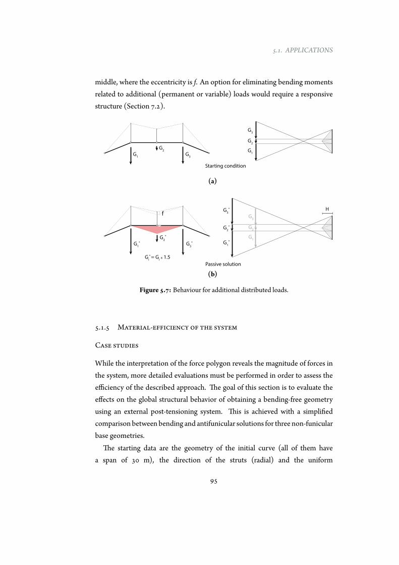
5.1. APPLICATIONS
middle, where the eccentricity is f. An option for eliminating bending momentsrelated to additional (permanent or variable) loads would require a responsivestructure (Section 7.2).
Starting condition
G1
G2
G3
G1
G2
G3
(a)
Gi
* = Gi x 1.5
fH
G1
*
G2
*
G3
* G1
*
G2
*
G3
*
G1
G2
G3
Passive solution
(b)
Figure 5.7: Behaviour for additional distributed loads.
5.1.5 Material-efficiency of the system
Case studies
While the interpretation of the force polygon reveals the magnitude of forces inthe system, more detailed evaluations must be performed in order to assess theefficiency of the described approach. The goal of this section is to evaluate theeffects on the global structural behavior of obtaining a bending-free geometryusing an external post-tensioning system. This is achieved with a simplifiedcomparison between bending and antifunicular solutions for three non-funicularbase geometries.
The starting data are the geometry of the initial curve (all of them havea span of 30 m), the direction of the struts (radial) and the uniform
95
CHAPTER 5. APPLICATIONS ANDDESIGN CRITERIA
distributed dead load magnitude (12 kN/m). Concrete circular hollowprofiles (thickness/diameter=0.05, fc=30 N/mm2) have been adopted for thecompressive curve. The cross section design, computed within the elastic range,depends on the forces in the structural elements, and the minimum sectionsatisfying both global buckling of the structure and yield stresses is taken.
The result, consequent to the application of the previous described post-tensioning method, for a known geometry is not determinate (i.e., there areinfinite solutions for each starting geometry). The user can explore the infiniterange of equilibrated solutions by varying related parameters, as the horizontalreactions, the magnitude of axial forces in the compressive curve and the post-tensioning force applied to the tendon.
The external forces to be added to the starting geometry, to make itantifunicular, are related to the maximum allowable offset between thecompressive curve and the post-tensioned tendon. This distance between thetwo curves is described by a percentage of the span and it is a relevant parameterfor evaluating the efficiency of the system. As a general rule, the smaller thedistance between the compressive curve and the post-tensioning system, thehigher the forces in both components.
Analysis of results
The design of the bending solution, which considers combined axial forces andbending moments, is governed by the allowable stress and uses an hollow crosssection which total mass for the non-funicular structure isM*.
The design of the antifunicular solution, which considers only axial forces(higher compared to the bending solution), is governed by the allowable stressand requires a hollow cross section; the total mass of the compressive curve isM.
Figure 5.8 shows the comparison in term of required mass of the startinggeometry (M/M*) for, respectively, three-pointed arch, circular arch and free-formasymmetrical curve. Each computed comparison is related to themaximumoffset between post-tensioning system and compressive curve. Defined a targetmaximumoffset, theminimumset of forces to be added to the existing loads havebeen selected for the comparison.
96

5.1. APPLICATIONS
0
5
10
15
20
25
30
35
40
0 2 4 6 8 10 12 14 16
)%(
*M
/M
O!set (%L)
Scaled at 50%
Scaled at 50%
A1
A2
B1
B2
C1
C2
A1
A2
B1
C1
C2
B2
M: mass of the non-an!funicular structure
M*: mass of the an!funicular structure through post-tensioning
Offset: maximum distance between compressive geometry and post-tensioning (as percentage of the span)
Figure 5.8: Comparison between bending and post-tensioned solutions.
97
CHAPTER 5. APPLICATIONS ANDDESIGN CRITERIA
Results obtained for different offsets illustrate how the position of the post-tensioned tendon strongly influences the structural performance for all theanalyzed shapes. If the cable has a minimum offset (i.e., it is closer to thecompressive curve) high values of external forces are needed, compressive forcesin the curved geometry are higher, inevitably decreasing the efficiency of theproposed system. Furthermore, the reading of the force polygons reveals thedifference between dead loads and forces to be added for making the geometryfunicular and shows how far a shape is from being funicular for its loads. Inthis example, the asymmetrical shape results the one with highest forces to beintroduced.
However, independently of the offset, the overall structural behavior ofthe post-tensioned solution results in savings of 60% to 85% of the wholemass compared with the bending solution. Results illustrate that despite theintroduction of higher axial forces, the act of removing bendingmoments allowsto design more cost-effective structures.
While this simplified analysis is not sufficient for a complete design, theapproach is consistent with the aim of the assessment: a first simplifiedcomparison between different solutions for a preliminary evaluation of theirstructural performances. Further analytical and experimental research has to becarried in the future (see Section 7.2).
5.2 Design criteria
5.2.1 Introduction
It has been illustrated before that, given a starting geometry and its relateddesign loads, the problem to solve is indeterminate: an infinite number of forcedistributions make the geometry antifunicular (Section 4.1.3).
This section presents an original procedure that enables the mastery of thisinfinite domain of solutions by means of specific design criteria (DC). Severaldesign criteria can be adopted for the design of curved externally post-tensionedstructures. The DC described in the following are related to geotechnical,mechanical andaesthetic issues. Theselected criteria arenot exhaustive andmore
98
5.2. DESIGN CRITERIA
criteria can be used, depending on the boundary conditions and specific needs.All the possible solutions can be explored by varying the two indeterminacies
related to the magnitude of the forces to be added to the compressive geometryand of the forces within the prestressed cable, respectively.
This section, first, presents the analysis of six different design criteria and, then,their implementation in EXOEQUILIBRIUMto parametric explore their effectson the internal force distribution.
5.2.2 Notations
With reference to Figure 5.9, the following notations have been employed:
• LNi : length of the elements of the compressive structure
• LSj : length of radial struts between compressive structure and cable
• LPi : length of the prestressed segments
• Ni: axial forces in the compressive geometry (measured as a length in theforce diagram)
• Fj: axial forces in radial struts (measured as a length in the force diagram)
• Pi: prestress forces in the cable (measured as a length in the force diagram)
Where i is the number of element in which the compressive shape is divided, andj, number of connecting elements, is equal to i-1.
5.2.3 Design criteria
1. DC1: no horizontal reactions
One of the most important drawback of the “arch behaviour” is thehorizontal thrust generated by the structure that has to be equilibratedby the soil. The post-tensioning system, depending on its positionwith respect to the vertical direction, can increase or decrease the totalhorizontal thrust. Generally speaking, if the cable has an inward directionit contributes to decrease the horizontal thrust.
99
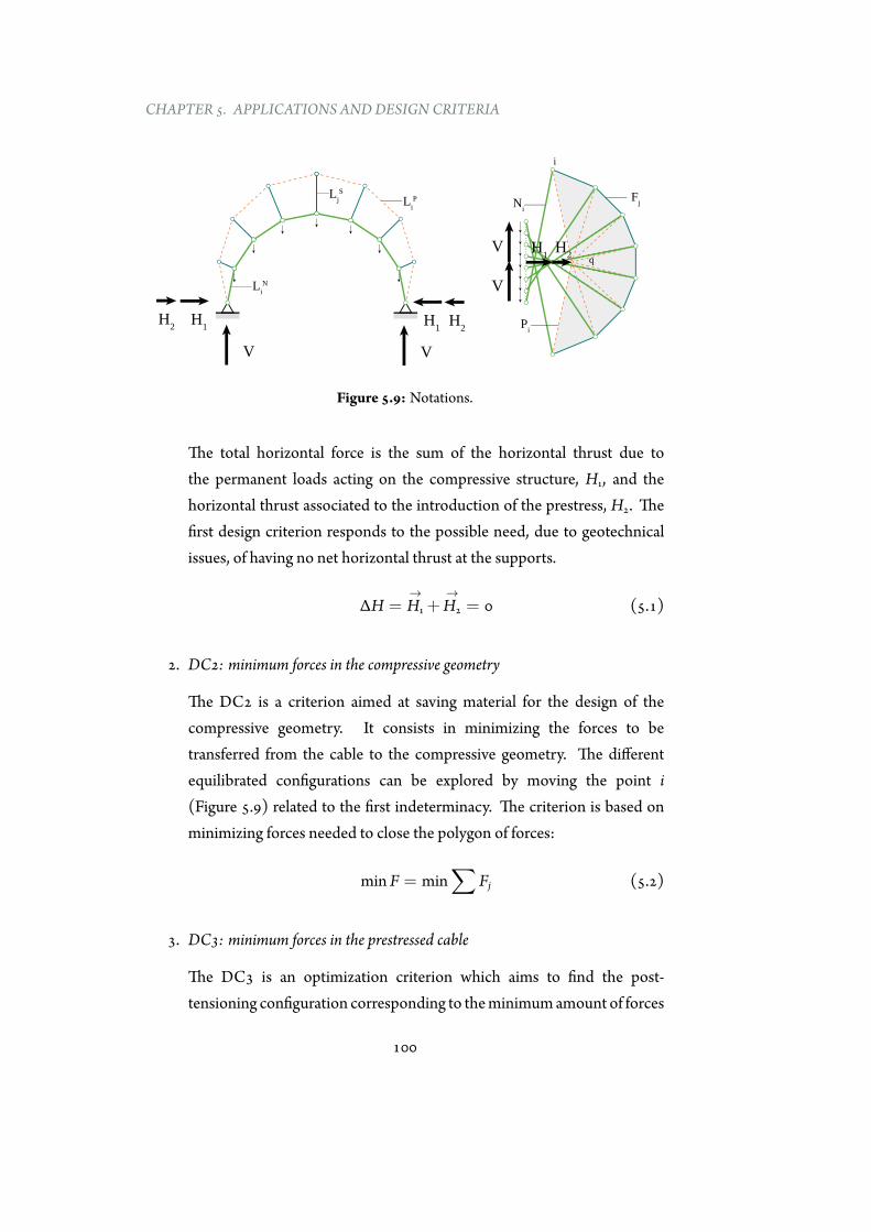
CHAPTER 5. APPLICATIONS ANDDESIGN CRITERIA
H1
H2
V
V
H1H2
V V
i
q
Li
N
Li
PLj
S
FjN
i
Pi
H1H2
Figure 5.9: Notations.
The total horizontal force is the sum of the horizontal thrust due tothe permanent loads acting on the compressive structure, H1, and thehorizontal thrust associated to the introduction of the prestress, H2. Thefirst design criterion responds to the possible need, due to geotechnicalissues, of having no net horizontal thrust at the supports.
ΔH =→H1 +
→H2 = 0 (5.1)
2. DC2: minimum forces in the compressive geometry
The DC2 is a criterion aimed at saving material for the design of thecompressive geometry. It consists in minimizing the forces to betransferred from the cable to the compressive geometry. The differentequilibrated configurations can be explored by moving the point i(Figure 5.9) related to the first indeterminacy. The criterion is based onminimizing forces needed to close the polygon of forces:
min F = min∑
Fj (5.2)
3. DC3: minimum forces in the prestressed cable
The DC3 is an optimization criterion which aims to find the post-tensioning configuration corresponding to theminimumamount of forces
100
5.2. DESIGN CRITERIA
within the prestressed cable. In graphic statics this goal is achieved byminimizing the lengths of the segment in the force diagram.
min P = min∑
Pi (5.3)
4. DC4: minimum strain energy in the prestressed cable
The DC4 is another optimization criterion that aims at minimizing thestrain energy related to the cable because it should correspond to its mostefficient position. If the linear elastic behaviour applies the strain energyof the cable,DP, can be expressed as [100]:
DP =∑ 1
2Pi2LP
i
EPi AP
i(5.4)
Where EPi and AP
i are young modulus and area, respectively, of each i-segment of the cable. Assuming a constant young modulus and area, thiscriterion of minimum strain can be expressed as:
minDP = min∑
Pi2LPi (5.5)
5. DC5: minimum strain energy in the whole system
The DC5 is an optimization criterion that aims at minimizing the strainenergy of the whole structure. This solution should be globally the mostmaterial-efficient option because it takes into account all the structuralmembers. If the linear elastic constitutive laws are assumed, the total strainenergyD can be expressed as:
D =∑ 1
2N2
iLNi
ENi AN
i+∑ 1
2P2iLP
i
EPi AP
i+∑ 1
2F2jLF
j
EFj AP
j(5.6)
Assuming a constant modulus of elasticity E (e.g., steel is employed in all
101
CHAPTER 5. APPLICATIONS ANDDESIGN CRITERIA
structural members), the strain energy can be expressed as:
D =12E
∑ N2iLN
i
ANi
+∑ P2iLP
i
APi
+∑ F2jLF
j
APj
(5.7)
Assuming that all structural members are designed for the maximumallowable stress value (no constant cross-section areas), the total strainenergy can be expressed as:
D =12E
(∑
NiLNi σ
Ni +
∑PiL
Pi σ
Pi +
∑FjL
Fj σ
Fj ) (5.8)
If the allowable stresses of cable (σPi ) and compressive members (σNi andσFi ) are, respectively, 1500MPa and 300MPa, it follows that:
D =σNi2E
(∑
NiLNi + 5
∑PiL
Pi +
∑FjL
Fj ) (5.9)
Assuming constant modulus of elasticity (E) and allowable stress (σNi ), itfollows that this criterion can be expressed as:
minD = min(∑
NiLNi + 5
∑PiL
Pi +
∑FjL
Fj ) (5.10)
6. DC6: prestressed cable above the compressive geometry
This criterion provides the most material-efficient solution with theprestressed cable always above the structure. This criterion responds toa double need:
• to have always compressive struts (this would imply a simplerconnection detail, see Section 6.1.3)
• to leave free the inner space.
5.2.4 Parametric analysis and implementation
This section illustrates a parametric analysis based on the design criteria beforedescribed in order to understand their effects on the structural efficiency of the
102
5.2. DESIGN CRITERIA
structure. Three different starting geometries have been used: a circular arch, abasket arch and an asymmetrical free-form shape. The number of subdivisions isconstant for all cases, as the total weight of the compressive geometry.
As it has been pointed out in from Section 5.1.5, internal force distributionis strongly related to the relative position between compressive structure andprestressed cable. For this reason a key parameter is the offset (as a percentageof the span) which represent the maximum length of the struts connectingcompressive shape and tensioned cable. The offsets adopted for the circular andbasket arches are 5%, 10% and 15% of the span. The offsets employed for theasymmetrical shape are 4%, 6% and 8% of the span.
A design-oriented tool, EXOEQUILIBRIUM, has been already developedfor the parametric exploration of various design solutions. It has been furtherextended for including the design criteria described before. The use ofinteractive and parametric tools allows to exploit the benefits of using graphicalconstructions.
The procedure is based on the manipulation of the two indeterminacies untila target criterion is achieved. Forces are measured in the force diagram, whilesegment lengths are measured in the form diagram.
5.2.5 Results
Before starting with the in-depth analysis of the results obtained with theparametric analysis, it is important to point out that the design criteria from 2to 5 are accomplished by the same form diagram. The theoretical reason behindthis result is related to the fact that the second indeterminacy (forces within theprestressed cable) is affected from the first one (forces within the struts). Thismeans that high forces to be introduced in the structure, inevitably generate lowstructural performance of the whole structure, independently on the positionof the prestressed cable. As consequence of this fact, in the following analysis,criteria from 2 to 5 are represented by one graphical construction.
Figures 5.10 to 5.18 show the graphical results after the application of thedesign criteria to a circular arch, a basket arch and a free-form asymmetricalshape. The graphical constructions in the same row are characterized by the same
103
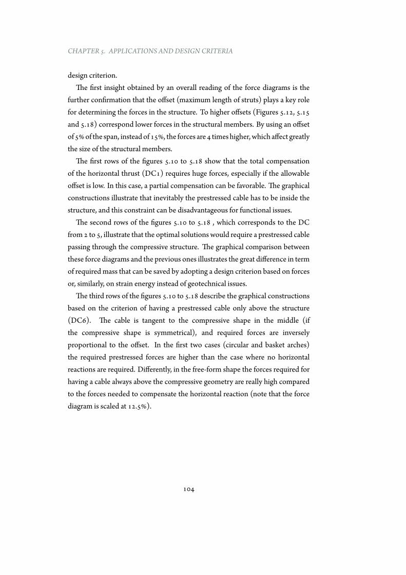
CHAPTER 5. APPLICATIONS ANDDESIGN CRITERIA
design criterion.The first insight obtained by an overall reading of the force diagrams is the
further confirmation that the offset (maximum length of struts) plays a key rolefor determining the forces in the structure. To higher offsets (Figures 5.12, 5.15and 5.18) correspond lower forces in the structural members. By using an offsetof 5%of the span, insteadof 15%, the forces are 4 timeshigher, which affect greatlythe size of the structural members.
The first rows of the figures 5.10 to 5.18 show that the total compensationof the horizontal thrust (DC1) requires huge forces, especially if the allowableoffset is low. In this case, a partial compensation can be favorable. The graphicalconstructions illustrate that inevitably the prestressed cable has to be inside thestructure, and this constraint can be disadvantageous for functional issues.
The second rows of the figures 5.10 to 5.18 , which corresponds to the DCfrom 2 to 5, illustrate that the optimal solutions would require a prestressed cablepassing through the compressive structure. The graphical comparison betweenthese force diagrams and the previous ones illustrates the great difference in termof requiredmass that can be saved by adopting a design criterion based on forcesor, similarly, on strain energy instead of geotechnical issues.
The third rows of the figures 5.10 to 5.18 describe the graphical constructionsbased on the criterion of having a prestressed cable only above the structure(DC6). The cable is tangent to the compressive shape in the middle (ifthe compressive shape is symmetrical), and required forces are inverselyproportional to the offset. In the first two cases (circular and basket arches)the required prestressed forces are higher than the case where no horizontalreactions are required. Differently, in the free-form shape the forces required forhaving a cable always above the compressive geometry are really high comparedto the forces needed to compensate the horizontal reaction (note that the forcediagram is scaled at 12.5%).
104
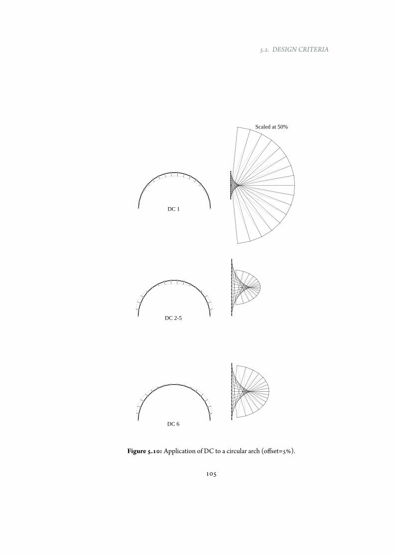
5.2. DESIGN CRITERIA
DC 1
DC 2-5
DC 6
Scaled at 50%
Figure 5.10: Application of DC to a circular arch (offset=5%).
105
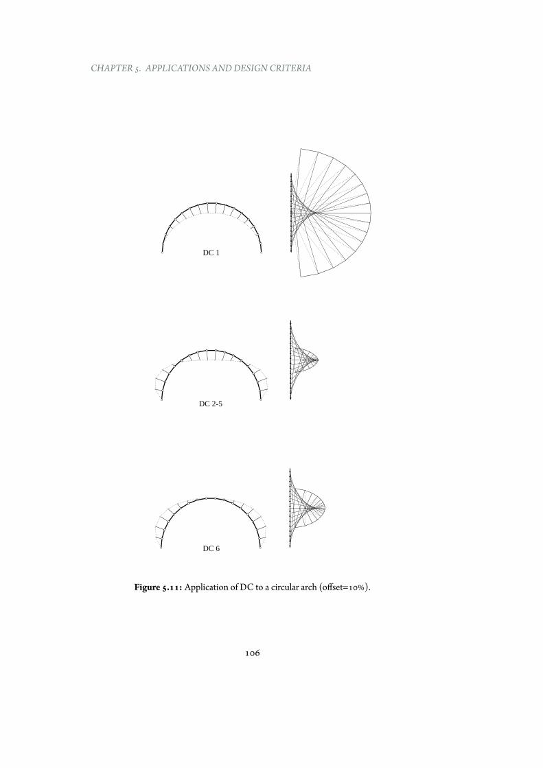
CHAPTER 5. APPLICATIONS ANDDESIGN CRITERIA
DC 1
DC 2-5
DC 6
Figure 5.11: Application of DC to a circular arch (offset=10%).
106
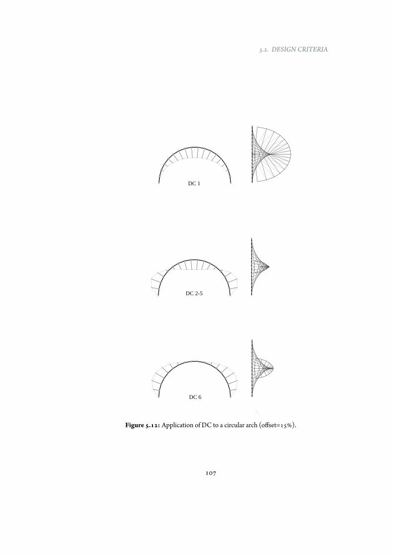
5.2. DESIGN CRITERIA
DC 1
DC 2-5
DC 6
Figure 5.12: Application of DC to a circular arch (offset=15%).
107
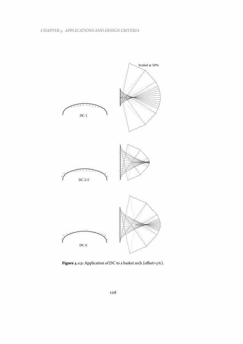
CHAPTER 5. APPLICATIONS ANDDESIGN CRITERIA
Scaled at 50%
DC 1
DC 2-5
DC 6
Figure 5.13: Application of DC to a basket arch (offset=5%).
108

5.2. DESIGN CRITERIA
DC 1
DC 2-5
DC 6
Figure 5.14: Application of DC to a basket arch (offset=10%).
109
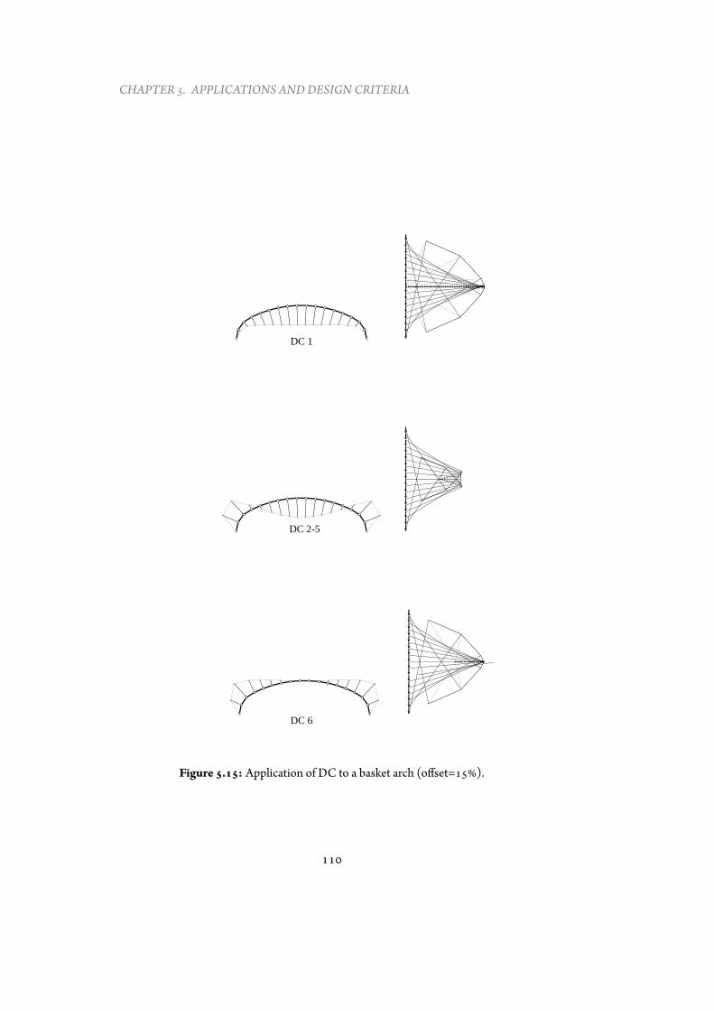
CHAPTER 5. APPLICATIONS ANDDESIGN CRITERIA
DC 1
DC 2-5
DC 6
Figure 5.15: Application of DC to a basket arch (offset=15%).
110
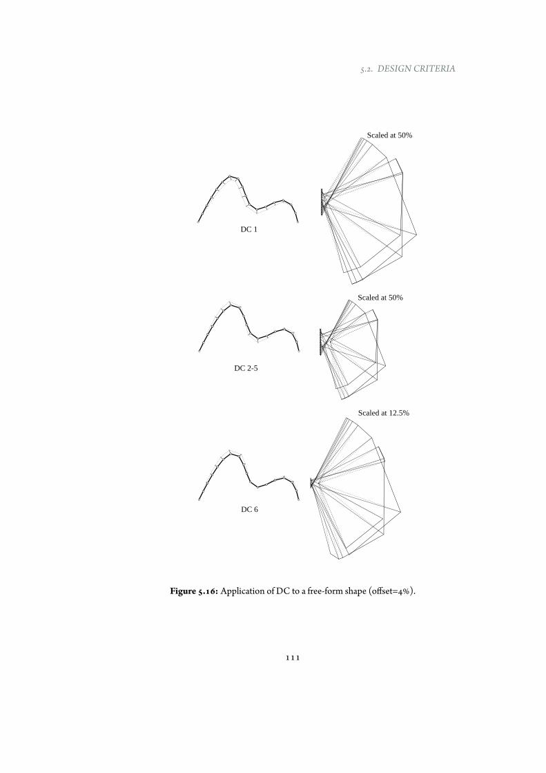
5.2. DESIGN CRITERIA
Scaled at 50%
Scaled at 50%
Scaled at 12.5%
DC 1
DC 2-5
DC 6
Figure 5.16: Application of DC to a free-form shape (offset=4%).
111
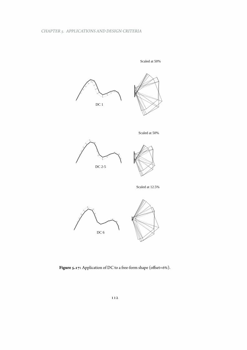
CHAPTER 5. APPLICATIONS ANDDESIGN CRITERIA
Scaled at 50%
Scaled at 50%
Scaled at 12.5%
DC 1
DC 2-5
DC 6
Figure 5.17: Application of DC to a free-form shape (offset=6%).
112

5.2. DESIGN CRITERIA
Scaled at 50%
Scaled at 50%
Scaled at 12.5%
DC 1
DC 2-5
DC 6
Figure 5.18: Application of DC to a free-form shape (offset=8%).
113
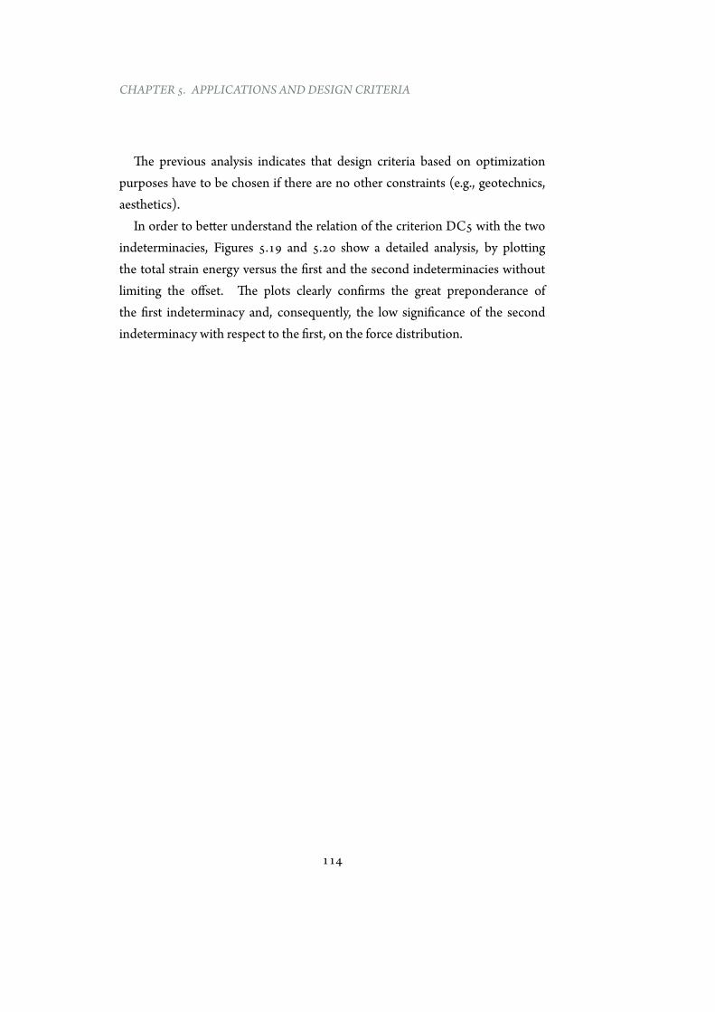
CHAPTER 5. APPLICATIONS ANDDESIGN CRITERIA
The previous analysis indicates that design criteria based on optimizationpurposes have to be chosen if there are no other constraints (e.g., geotechnics,aesthetics).
In order to better understand the relation of the criterion DC5 with the twoindeterminacies, Figures 5.19 and 5.20 show a detailed analysis, by plottingthe total strain energy versus the first and the second indeterminacies withoutlimiting the offset. The plots clearly confirms the great preponderance ofthe first indeterminacy and, consequently, the low significance of the secondindeterminacy with respect to the first, on the force distribution.
114
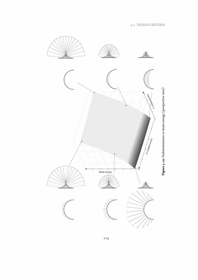
5.2. DESIGN CRITERIA
Figu
re5.19:Ind
eterminaciesvsstra
inenergy
(perspectivev
iew)
115
CHAPTER 5. APPLICATIONS ANDDESIGN CRITERIA
Figure5.20:Indeterminaciesvsstrain
energy(lateralviews)
116

5.3. SUMMARY
5.3 Summary
This Chapter has illustrated many applications of the developed graphicalprocedure. Those examples include randomgeometries, twisted shapes andnon-uniform distribution of loads. Furthermore, different design criteria (relatedto geotechnical, mechanical and aesthetic issues) have been implemented inEXOEQUILIBRIUM and their effect, in term of force distribution, has beenstudied. These design criteria are achieved by manipulating the force diagram,instead of the form diagram, thus equilibrium is always ensured [16, 17].
Results point out that:
• The graphical methodology is general and versatile. It can be used for anycurved geometry, any distribution of starting loads, and it can be extendedto twisted 2D structures.
• A simplified structural analysis has pointed out the great efficiency of thisapproach in terms of mass saving.
• Theoffset (maximumdistancebetween the compressive geometry and theprestressed cable) plays a key role in optimizing the material-efficiency ofthe whole structure. Higher offsets correspond to lowermaterial volumes,thus, higher cost-effective structures.
• The design criteria related to the need of having no horizontal thrust(DC1) or a cable always above the compressive geometry (DC6) requirehigh amount of forces.
• Different design criteria (DC2 to DC5) based on the structural elementoptimization provide the same optimal cable layout. The key role isplayed by the first indeterminacy, which is responsible of internal forcedistribution.
• The implementation of graphical procedures in a parametric tool providesawell-suited environment for the interactive computational exploration ofequilibrate solutions within the structural design space.
117

One should not calculate a structure he cannot draw.Formulae should not be used if their physical meaning isnot understood. A structure should not be designed bycomputer if we do not know how to calculate it by hand.
Javier Rui-Wamba
6Reduced- and large-scale physical models
6.1 Reduced-scale physical models
6.1.1 Introduction
This section focusesonphysicalmodeling, testing andvalidationof reduced-scalemodels where, as described in Section 4, a system of external forces transformsan initial non-antifunicular shape into an antifunicular one.
The reduced-scale structures are modelled with a combination of: i) basegeometries fabricated through additive manufacturing (3d printing), and ii) apost-tensioning system constructed with thin wire and precise laser-cut struts.
First, the section presents a brief historical review of physical models; next, itillustrates the employment of physical reduced models to test and validate thedescribed method. Finally, conclusions and closing remarks are pointed out.
119
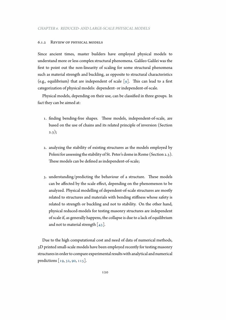
CHAPTER 6. REDUCED- AND LARGE-SCALE PHYSICALMODELS
6.1.2 Review of physical models
Since ancient times, master builders have employed physical models tounderstand more or less complex structural phenomena. Galileo Galilei was thefirst to point out the non-linearity of scaling for some structural phenomenasuch as material strength and buckling, as opposite to structural characteristics(e.g., equilibrium) that are independent of scale [9]. This can lead to a firstcategorization of physical models: dependent- or independent-of-scale.
Physical models, depending on their use, can be classified in three groups. Infact they can be aimed at:
1. finding bending-free shapes. These models, independent-of-scale, arebased on the use of chains and its related principle of inversion (Section2.3);
2. analyzing the stability of existing structures as the models employed byPoleni for assessing the stability of St. Peter’s dome inRome (Section 2.3).These models can be defined as independent-of-scale;
3. understanding/predicting the behaviour of a structure. These modelscan be affected by the scale effect, depending on the phenomenon to beanalyzed. Physical modelling of dependent-of-scale structures are mostlyrelated to structures and materials with bending stiffness whose safety isrelated to strength or buckling and not to stability. On the other hand,physical reduced-models for testing masonry structures are independentof scale if, as generally happens, the collapse is due to a lack of equilibriumand not to material strength [43].
Due to the high computational cost and need of data of numerical methods,3D printed small-scale models have been employed recently for testing masonrystructures in order to compare experimental resultswith analytical andnumericalpredictions [19, 32, 90, 115].
120
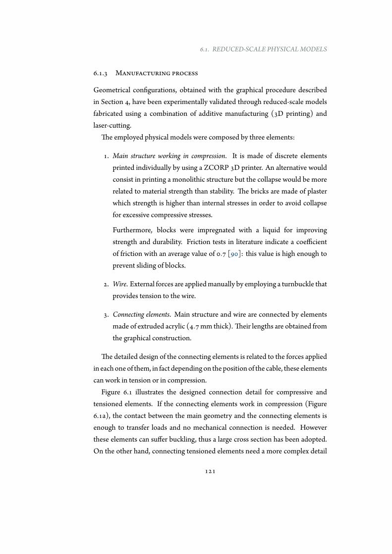
6.1. REDUCED-SCALE PHYSICALMODELS
6.1.3 Manufacturing process
Geometrical configurations, obtained with the graphical procedure describedin Section 4, have been experimentally validated through reduced-scale modelsfabricated using a combination of additive manufacturing (3D printing) andlaser-cutting.
The employed physical models were composed by three elements:
1. Main structure working in compression. It is made of discrete elementsprinted individually by using a ZCORP 3D printer. An alternative wouldconsist in printing a monolithic structure but the collapse would be morerelated to material strength than stability. The bricks are made of plasterwhich strength is higher than internal stresses in order to avoid collapsefor excessive compressive stresses.
Furthermore, blocks were impregnated with a liquid for improvingstrength and durability. Friction tests in literature indicate a coefficientof friction with an average value of 0.7 [90]: this value is high enough toprevent sliding of blocks.
2. Wire. External forces are appliedmanually by employing a turnbuckle thatprovides tension to the wire.
3. Connecting elements. Main structure and wire are connected by elementsmade of extruded acrylic (4.7mm thick). Their lengths are obtained fromthe graphical construction.
The detailed design of the connecting elements is related to the forces appliedin eachoneof them, in fact dependingon thepositionof the cable, these elementscan work in tension or in compression.
Figure 6.1 illustrates the designed connection detail for compressive andtensioned elements. If the connecting elements work in compression (Figure6.1a), the contact between the main geometry and the connecting elements isenough to transfer loads and no mechanical connection is needed. Howeverthese elements can suffer buckling, thus a large cross section has been adopted.On the other hand, connecting tensioned elements need a more complex detail
121
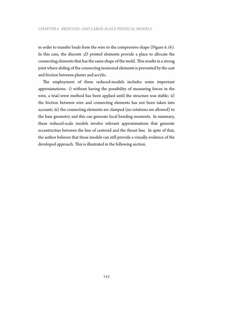
CHAPTER 6. REDUCED- AND LARGE-SCALE PHYSICALMODELS
in order to transfer loads from the wire to the compressive shape (Figure 6.1b).In this case, the discrete 3D printed elements provide a place to allocate theconnecting elements that has the same shape of themold. This results in a strongjoint where sliding of the connecting tensioned elements is prevented by the castand friction between plaster and acrylic.
The employment of these reduced-models includes some importantapproximations: i) without having the possibility of measuring forces in thewire, a trial/error method has been applied until the structure was stable; ii)the friction between wire and connecting elements has not been taken intoaccount; iii) the connecting elements are clamped (no rotations are allowed) tothe base geometry and this can generate local bending moments. In summary,these reduced-scale models involve relevant approximations that generateeccentricities between the line of centroid and the thrust line. In spite of that,the author believes that these models can still provide a visually evidence of thedeveloped approach. This is illustrated in the following section.
122
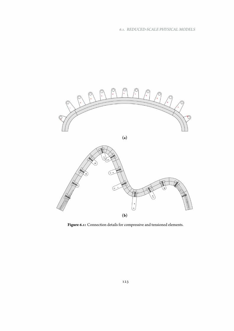
6.1. REDUCED-SCALE PHYSICALMODELS
(a)
(b)
Figure 6.1: Connection details for compressive and tensioned elements.
123
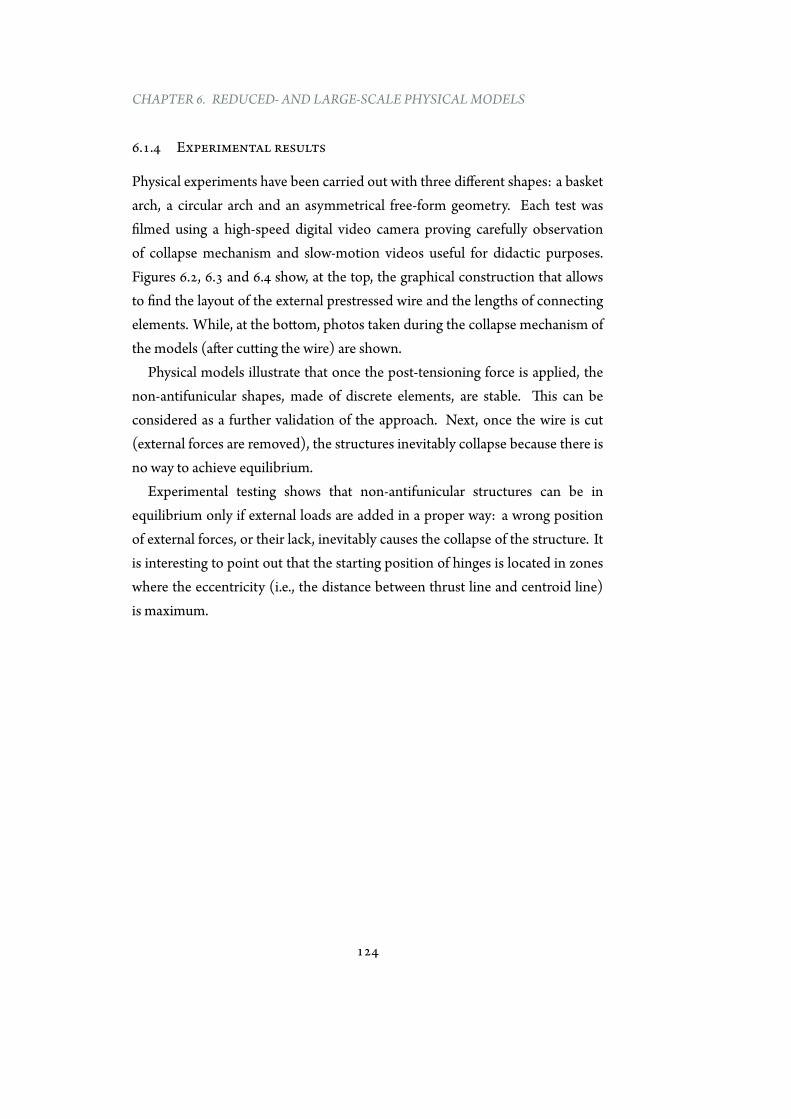
CHAPTER 6. REDUCED- AND LARGE-SCALE PHYSICALMODELS
6.1.4 Experimental results
Physical experiments have been carried out with three different shapes: a basketarch, a circular arch and an asymmetrical free-form geometry. Each test wasfilmed using a high-speed digital video camera proving carefully observationof collapse mechanism and slow-motion videos useful for didactic purposes.Figures 6.2, 6.3 and 6.4 show, at the top, the graphical construction that allowsto find the layout of the external prestressed wire and the lengths of connectingelements. While, at the bottom, photos taken during the collapse mechanism ofthe models (after cutting the wire) are shown.
Physical models illustrate that once the post-tensioning force is applied, thenon-antifunicular shapes, made of discrete elements, are stable. This can beconsidered as a further validation of the approach. Next, once the wire is cut(external forces are removed), the structures inevitably collapse because there isno way to achieve equilibrium.
Experimental testing shows that non-antifunicular structures can be inequilibrium only if external loads are added in a proper way: a wrong positionof external forces, or their lack, inevitably causes the collapse of the structure. Itis interesting to point out that the starting position of hinges is located in zoneswhere the eccentricity (i.e., the distance between thrust line and centroid line)is maximum.
124

6.1. REDUCED-SCALE PHYSICALMODELS
Figure 6.2: Graphical construction and collapse sequence of a free-form asymmetricalshape.
125
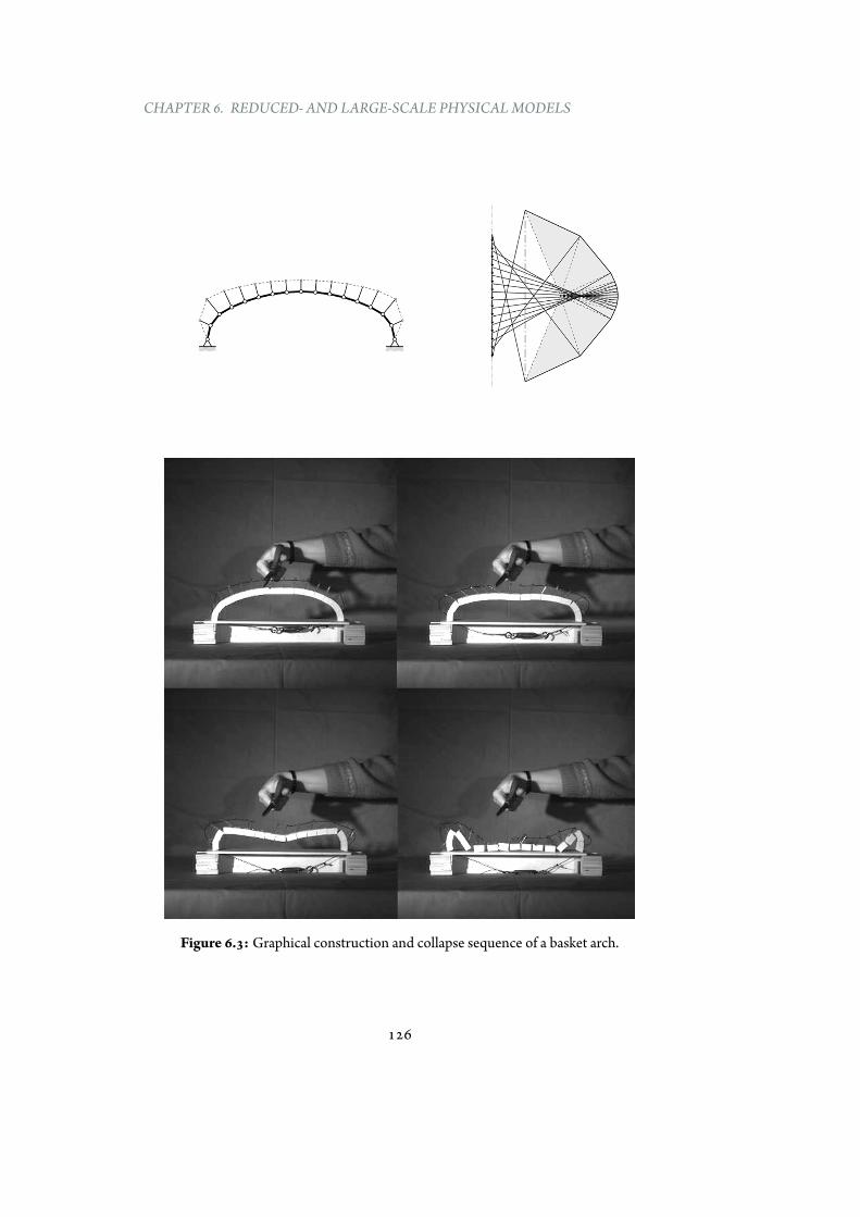
CHAPTER 6. REDUCED- AND LARGE-SCALE PHYSICALMODELS
Figure 6.3: Graphical construction and collapse sequence of a basket arch.
126
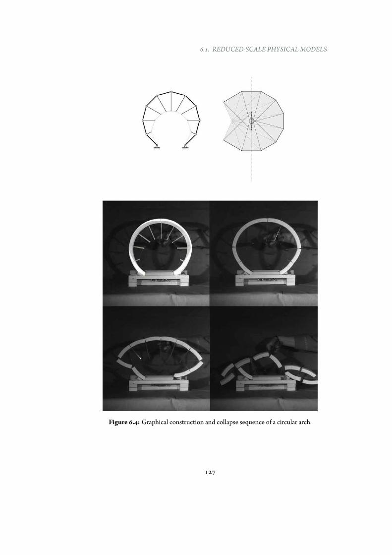
6.1. REDUCED-SCALE PHYSICALMODELS
Figure 6.4: Graphical construction and collapse sequence of a circular arch.
127
CHAPTER 6. REDUCED- AND LARGE-SCALE PHYSICALMODELS
6.1.5 Conclusions
Despite the large and common use of computational methods, physical modelsremain an important support in the early stage design and for teaching purposes.The use of physical models, is informative but also didactic, illustrating thepossibilities and trade-offs in funicular explorations for architectural design.
Small-scale models are less expensive and invasive compared to the real scaleones, but they are able to provide the same feedback if the structural behaviour isindependent-of-scale. The use of reduced models for complex two-dimensionalstructures is now easier compared to the past with the support of the improvedrapid prototyping technologies.
This section has shown the successful further validation of the author’s theory,by producing stable scale models of discrete elements with non-antifunicularshapes. These models allow for a first experimental validation of the theoryand provide new insights about the structural behaviour of such novel non-antifunicular forms.
Furthermore reduced physical models visually demonstrate the importanceof adding external forces to non-antifunicular structures in order to make themstable, and provide slow-motion videos that can be used for didactic purposes.
6.2 Pavilion at the 2015 IASS Symposium
6.2.1 Introduction
The 2015 IASS Symposium organizers invited universities and/or companies toparticipate in a contest and an exhibition of structurally innovative pavilions. Thepavilions had to give a future vision on structural design and innovation, and hadto be the outcome of (excellent) structural research (http://www.iass2015.org). The pavilions had to be exhibited in the summer of 2015 and during the2015 IASS Symposium in theMuziekgebouw in Amsterdam.
The author, together with other colleagues (Section 6.2.6) of the DigitalStructures Research Group at MIT (https://digitalstructures.mit.edu/), was involved in this contest. Their pavilion proposal was calledPaperwave.
128
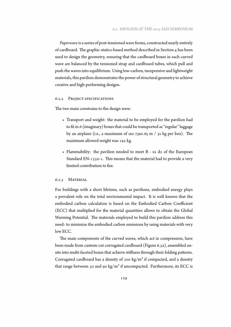
6.2. PAVILION AT THE 2015 IASS SYMPOSIUM
Paperwave is a series of post-tensionedwave forms, constructed nearly entirelyof cardboard. The graphic-statics-based method described in Section 4 has beenused to design the geometry, ensuring that the cardboard boxes in each curvedwave are balanced by the tensioned strap and cardboard tubes, which pull andpush the waves into equilibrium. Using low-carbon, inexpensive and lightweightmaterials, this pavilion demonstrates the power of structural geometry to achievecreative and high-performing designs.
6.2.2 Project specifications
The twomain constrains to the design were:
• Transport and weight: the material to be employed for the pavilion hadto fit in 6 (imaginary) boxes that could be transported as “regular” luggageby an airplane (i.e., a maximum of 1x0.75x0.65 m / 32 kg per box). Themaximum allowed weight was 192 kg.
• Flammability: the pavilion needed to meet B - s2 d2 of the EuropeanStandard EN-1350-1. This means that the material had to provide a verylimited contribution to fire.
6.2.3 Material
For buildings with a short lifetime, such as pavilions, embodied energy playsa prevalent role on the total environmental impact. It is well known that theembodied carbon calculation is based on the Embodied Carbon Coefficient(ECC) that multiplied for the material quantities allows to obtain the GlobalWarming Potential. The materials employed to build this pavilion address thisneed: to minimize the embodied carbon emissions by using materials with verylow ECC.
The main components of the curved waves, which act in compression, havebeen made from custom-cut corrugated cardboard (Figure 6.5a), assembled on-site into multi-faceted boxes that achieve stiffness through their folding patterns.Corrugated cardboard has a density of 300 kg/m³ if compacted, and a densitythat range between 30 and 90 kg/m³ if uncompacted. Furthermore, its ECC is
129
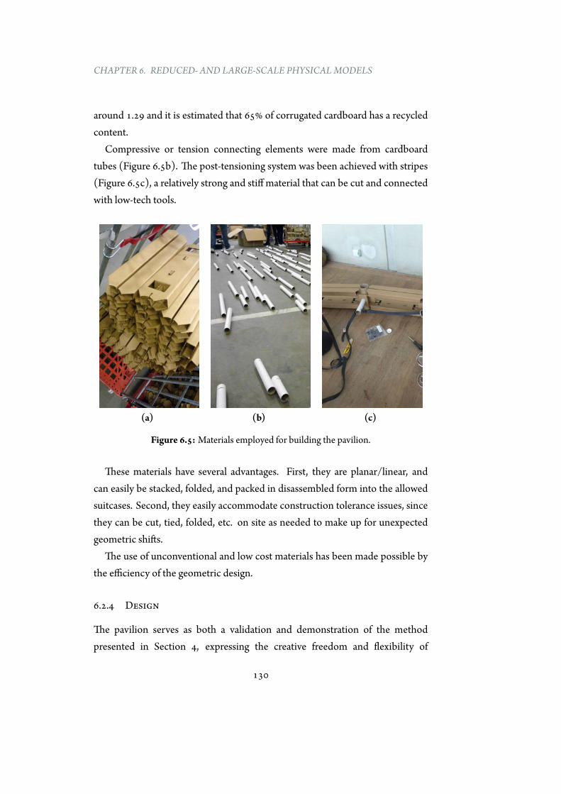
CHAPTER 6. REDUCED- AND LARGE-SCALE PHYSICALMODELS
around 1.29 and it is estimated that 65% of corrugated cardboard has a recycledcontent.
Compressive or tension connecting elements were made from cardboardtubes (Figure 6.5b). The post-tensioning system was been achieved with stripes(Figure 6.5c), a relatively strong and stiff material that can be cut and connectedwith low-tech tools.
(a) (b) (c)
Figure 6.5:Materials employed for building the pavilion.
These materials have several advantages. First, they are planar/linear, andcan easily be stacked, folded, and packed in disassembled form into the allowedsuitcases. Second, they easily accommodate construction tolerance issues, sincethey can be cut, tied, folded, etc. on site as needed to make up for unexpectedgeometric shifts.
The use of unconventional and low cost materials has been made possible bythe efficiency of the geometric design.
6.2.4 Design
The pavilion serves as both a validation and demonstration of the methodpresented in Section 4, expressing the creative freedom and flexibility of
130

6.2. PAVILION AT THE 2015 IASS SYMPOSIUM
designers.The proposed design was an array of nine two-dimensional waves, starting
with a funicular parabolic arch. Progressing from this rational starting point, thesubsequent shapes undulate increasingly toward an expressive but structurallyarbitrary shape that is impossible to achieve in pure compression. The externalpost-tensioning system contributes increasingly from one curve to the next,finally allowing the terminal free-form shape to be achievedwith axial forces only.The result is visually exuberant but also didactic, illustrating the possibilities andtrade-offs in funicular explorations for architectural design. Figure 6.6 shows thedesign proposal from different views.
Figure 6.6: Design proposal. Image courtesy of Juney Lee.
As explained in detail before, to one non-antifunicular shape correspondinfinite positions of the external post-tensioned cable that transforms the
131

CHAPTER 6. REDUCED- AND LARGE-SCALE PHYSICALMODELS
geometry into an antifunicular one. Among the infinite possibilities there is oneoption that guaranteesnonethorizontal reaction. This solutionhasbeenadoptedin the pavilion for finding the position of the prestressed cable. Figures 6.7, 6.8and 6.9 illustrate the graphical construction adopted for finding the layout of theexternal post-tensioned stripes and the forces within the structure.
132
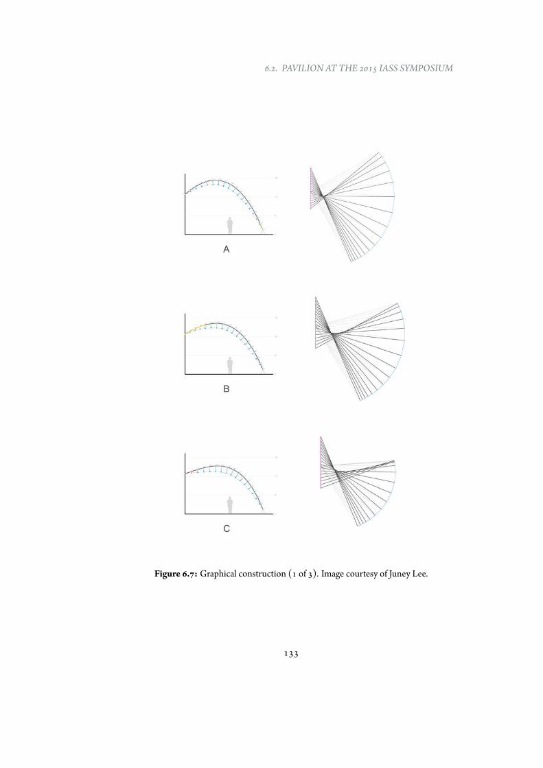
6.2. PAVILION AT THE 2015 IASS SYMPOSIUM
Figure 6.7: Graphical construction (1 of 3). Image courtesy of Juney Lee.
133
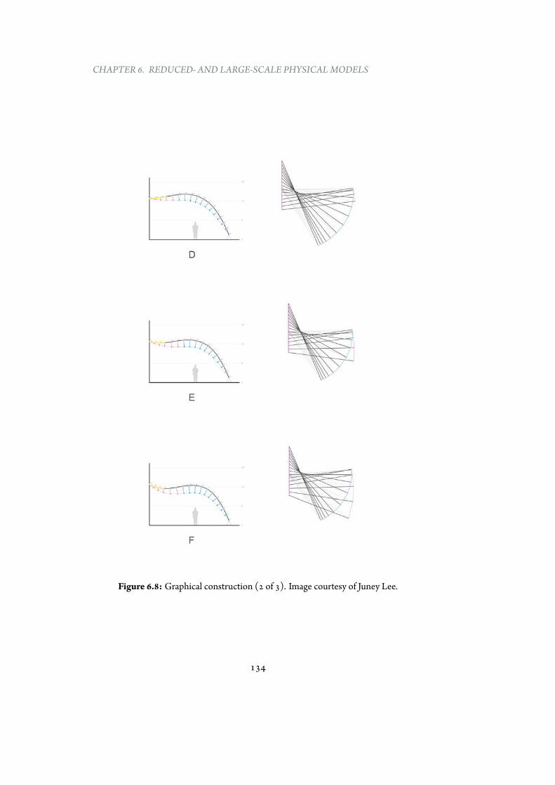
CHAPTER 6. REDUCED- AND LARGE-SCALE PHYSICALMODELS
Figure 6.8: Graphical construction (2 of 3). Image courtesy of Juney Lee.
134
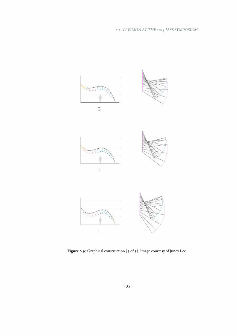
6.2. PAVILION AT THE 2015 IASS SYMPOSIUM
Figure 6.9: Graphical construction (3 of 3). Image courtesy of Juney Lee.
135
CHAPTER 6. REDUCED- AND LARGE-SCALE PHYSICALMODELS
6.2.5 Fabrication and construction process
The fabrication process (Figure 6.10) was based on the following assembly line:laser-cutting, creasing and fireproofing with fire retardant spray. The Pavilionhas been designed with 9 diverse waves, each one of them has 15 different joint.Around 150 joints, 150 pipes and 160 compressive elements have been packed infour boxes and shipped to Amsterdam.
Once arrived at the final destination, the construction process started (Figure6.11): all the pieces have been folded and the waves have been built on theground. Next, they have been rotated and placed in their final position (Figure6.12) using cables from the roof and a crane. Finally, some lightening has beenadded to the pavilion.
The folding process required more time that the expected and due to the veryshort time available for the construction only three of nine waves have beenplaced in their final position.
6.2.6 Acknowledgments to the Project Team
Theauthor’s personal involvement included theoretical development beyond theproject and collaboration in the final construction of the pavilion.
The Paperwave Project has been only possible with the great work provided bya largenumberof people,manyof themarepart of theDigital StructuresResearchGroup at MIT led by Professor Caitlin Mueller.
This team was composed by: Prof. Caitlin Mueller (responsible for thescientific development of the pavilion), Juney Lee, Leonardo Todisco, OrnellaIuorio, Catherine De Wolf, Corentin Fivet, Andrew Smith, Samuel Schneider,Mark Tam, Stavros Tserandins, Chrystal Chern, Mitchell Gu, Jonathan Felipeand Nathan Brown.
136

6.2. PAVILION AT THE 2015 IASS SYMPOSIUM
Figure 6.10: Fabrication process.
137
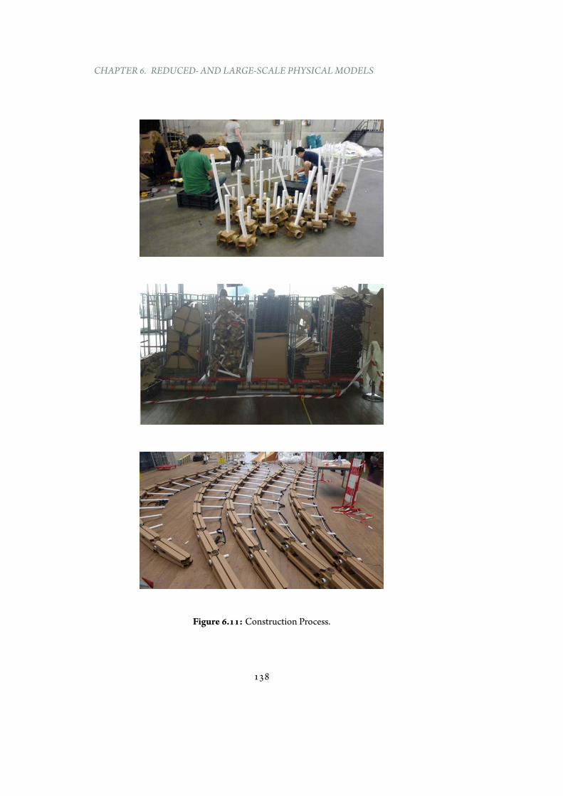
CHAPTER 6. REDUCED- AND LARGE-SCALE PHYSICALMODELS
Figure 6.11: Construction Process.
138
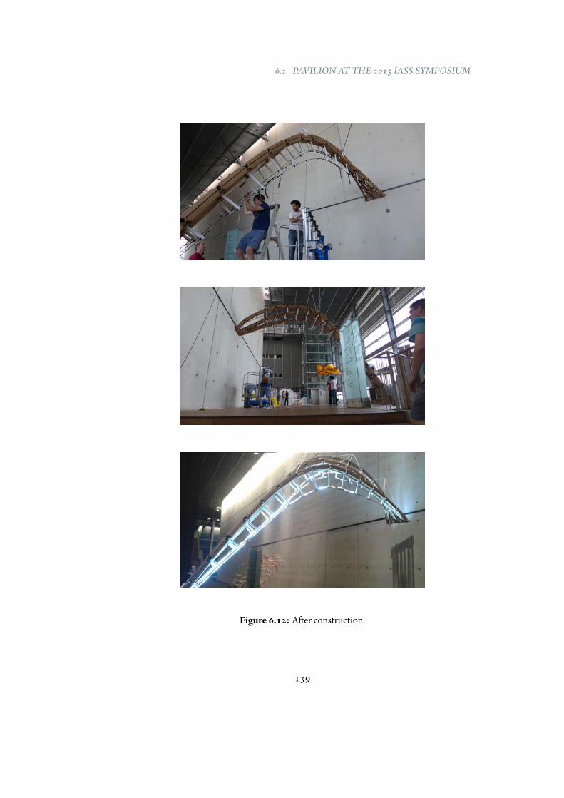
6.2. PAVILION AT THE 2015 IASS SYMPOSIUM
Figure 6.12: After construction.
139
CHAPTER 6. REDUCED- AND LARGE-SCALE PHYSICALMODELS
6.2.7 Conclusions
Structural behaviour: The overall structural behaviour of the pavilion was goodand the application of external forces was very favorable. All the calculationswereperformed for a two-dimensional behaviour of thewavebecause the restrainprovided by the contiguous structures was taken into account. However, the factthat the waves had slightly different shapes did not allow for this collaboration.For this reason the structure suffered out-of-plane buckling. In the future thisaspect should be carefully taken into account.
Material: The construction of a pavilion with unconventional materials facednew and unexpected problems. The structure resulted too much deformable. Inthe future, probably, the use of more stiff joints would be advisable. Existingexamples, such as the cardboard geodetic dome byMixuro and the bridge acrossthe Gardon River by Shigeru Ban, employed, respectively, wood and steel for thejoints.
Construction: The construction of nine waves was a too much ambitiousgoal to be achieved in the very limited available time for the building process.Furthermore, the structural behaviour during the construction process was notstudied enough and more attention has to be paid on that topic in the future.Finally, the application of the prestress forces, based on a trial/errormethod, wascomplicated to achieve with low-tech technologies.
6.3 Summary
This Chapter has described the construction of reduced-scale models and atemporary pavilion for illustrating the possibilities given by the methodologydeveloped in Chapter 4 for the design of versatile and material-efficientstructures.
First, this Chapter has presented the production of stable reduced-scalemodelsmade of discrete elementswith non-antifunicular shapes. This representsa further physical validation of the theory. The beneficial role of physical modelshas been pointed out especially in early stage design and for teaching purposes.Small-scale models, less expensive and invasive compared to the real scale ones,
140
6.3. SUMMARY
are able to provide the same feedback if the structural behaviour is independentof scale.
Next, the conceptual and material design of a pavilion (Paperwave) builtentirely with cardboard has been in-depth described. It visually demonstratesthe possibility of combining low-cost material with high-performance design.
In summary, this Chapter has presented the materialization of themethodology proposed in Chapter 4 in a research which aim consists inallowing architects and structural engineers a way to achieve high-performance,efficient and versatile designs, even when the global geometry departs fromclassical antifunicular shapes.
141

Part III
Conclusions
143

Themost powerful way that an engineer can contribute to thework of architects is by exploring the nature of the materialsand using that knowledge to produce a special quality (...).Exploration and innovation are the keys.
Peter Rice
7Conclusions and future studies
7.1 Summary of results
Thechoice of an appropriate shape in curved geometries is an important decisionfor designing materially efficient structures. However, engineers often facethe challenge of designing shapes that reflect a broad range of requirements;frequently, these geometries are optimal shapes from a functional point of view,but less efficient in terms of structural performance.
The main contribution of this research has been to address this problem, byintroducing a new methodology for transforming the load internal distributionof general geometries, and to make them act in pure compression. Bendingmoments, which would otherwise occur, are eliminated by applying additionalforces through the rational design of a post-tensioning system.
The developed approach, based on graphic statics, has been implementedin an interactive and integrated tool (EXOEQUILIBRIUM). This allows usersto explore different alternatives and design-criteria for any two-dimensional
145
CHAPTER 7. CONCLUSIONS AND FUTURE STUDIES
geometry.In addition, the employment of reduced-scale physical models has provided
further validations of the effectiveness of themethod and, at the same time, toolsfor didactic purposes.
Finally, the construction of a temporary pavilion has demonstrated thatlow-cost materials in combination with basic structural concepts can providecreative, inexpensive and high-performing designs.
The following specific conclusions can be drawn:
1. Any base non-antifunicular geometry can be converted into a bending-free shape by adding external loads. The proposed graphical procedurecan be applied to a great number of problems, without limitations relatedto starting geometry, loads and support positions. Furthermore, theapproach can be employed for structures contained in different planes.
2. Given an initial shape and its related loads, the problem is indeterminate:an infinite number of solutions exist to make the starting geometrybending-free.
3. The employment of a graphical-based design technique embedded inan interactive environment provides a well-suited environment for thecomputational exploration of equilibrate solutions for buildings andspatial structures.
4. A preliminary structural analysis points out the great efficiency of thissystem in terms of mass saving, by reducing the required mass comparedto the bending solution in which axial and bending coexist.
5. Any change of acting loads after construction inevitably generate bendingmoments that decrease the structural efficiency of the system.
6. The distance between the base geometry and the prestressed cableplays a key role for optimizing the material-efficiency of the wholestructure. Higher offsets correspond to lower material volumes, thus,greater structural efficiency.
146
7.2. FUTURE STUDIES
7. The need of no net horizontal thrusts or a cable always placed above thecompressive geometry requires high amount of forces.
8. If there are no constrains with regards to the cable position, a designcriterion for achieving mass optimization has to be adopted. It can bebased on minimizing the energy of deformation. Generally, this wouldresult in a cable that crosses the base structure.
9. The employment of reduced-scale physical models has provided a furtherexperimental validation of the theory by producing stable models ofdiscrete elements with non-antifunicular base shapes. Furthermore,reduced physical models have offered new insights about the structuralbehaviour of such forms.
10. The construction of a temporary pavilion served as a demonstration ofthe method by using low-cost materials. Despite the good results onthe global structural behaviour, lessons learned include the importanceof 3d-behaviour (when lateral stiffness is missing), unexpected problems(deformability) related to the choice of unconventional materials andconstruction issues.
7.2 Future studies
This research has introduced a generalized theory for designing bending-freeexternal post-tensioning structures and provided a number of case studies, butthere are several important directions for further research in this area.
Analytic and experimental research
There is significant research to be carried out for identifying and analyzing(analytically and experimentally) the gaps in knowledge that can prevent theutilization of externally post-tensioned structures.
First, more detailed evaluations of the whole system performance should beperformed in order to find limitations of the described design philosophy. Inthese analyses asymmetrical loads, different materials, support displacements
147
CHAPTER 7. CONCLUSIONS AND FUTURE STUDIES
should be taken into account. Not only the mass, but the global cost of thestructure (including post-tensioning system and connecting struts) should becomputed for a more precise performance evaluation of the whole system. Morerefined comparisons between classical solutions and the new structural systemhave to be performed.
Second, the passive and active effects of the cable (e.g., in-plane stiffening,control of displacements, etc...) have to be analyzed, with special focus forasymmetrical loads.
Furthermore, the performance of these structures have to studied to take intoaccount many other requirements (e.g., robustness, resiliency, ductility), whichhave not been included in this work.
In addition, effects of creep on delayed deformations have not beenconsidered, but some materials are strongly characterized by rheologicalbehaviour which implies long-term delayed deformations. These phenomenahave to be investigated because they can play a fundamental role in prestressedstructures, influencing structural behavior and durability for a long time inservice life.
Finally, constructability challenges related to the introduction of differentpost-tensioning forces in varied sections of the cable should be studied followingthe preliminary research by Saitoh [97]. The construction of full-scale structureshave to be planned for validating the design concepts through construction,monitoring and testing.
Environmental responsive hybrid structures
The methodology illustrated in this thesis guarantees a bending-free behaviouronly for one distribution of loads. Thus, the structure has to be sized for ensuringthat strength and deformations meet the required limits to cope with the worstload cases.
However, a new design approach, that could take advantage of a responsivepost-tensioning system, can be studied. It is based on structures that are ableto sense and respond appropriately to changing loads for always guaranteeingmaterial-efficiency (i.e., bending-free behaviour), independently on the external
148
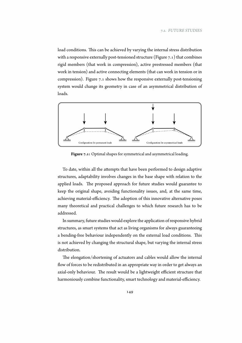
7.2. FUTURE STUDIES
load conditions. This can be achieved by varying the internal stress distributionwith a responsive externally post-tensioned structure (Figure 7.1) that combinesrigid members (that work in compression), active prestressed members (thatwork in tension) and active connecting elements (that can work in tension or incompression). Figure 7.1 shows how the responsive externally post-tensioningsystem would change its geometry in case of an asymmetrical distribution ofloads.
Figure 7.1: Optimal shapes for symmetrical and asymmetrical loading.
To date, within all the attempts that have been performed to design adaptivestructures, adaptability involves changes in the base shape with relation to theapplied loads. The proposed approach for future studies would guarantee tokeep the original shape, avoiding functionality issues, and, at the same time,achieving material-efficiency. The adoption of this innovative alternative posesmany theoretical and practical challenges to which future research has to beaddressed.
In summary, future studies would explore the application of responsive hybridstructures, as smart systems that act as living organisms for always guaranteeinga bending-free behaviour independently on the external load conditions. Thisis not achieved by changing the structural shape, but varying the internal stressdistribution.
The elongation/shortening of actuators and cables would allow the internalflow of forces to be redistributed in an appropriate way in order to get always anaxial-only behaviour. The result would be a lightweight efficient structure thatharmoniously combine functionality, smart technology and material-efficiency.
149
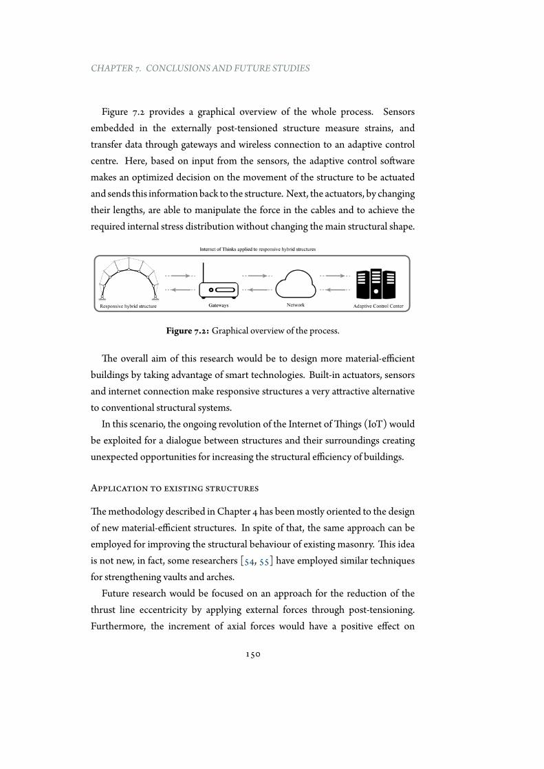
CHAPTER 7. CONCLUSIONS AND FUTURE STUDIES
Figure 7.2 provides a graphical overview of the whole process. Sensorsembedded in the externally post-tensioned structure measure strains, andtransfer data through gateways and wireless connection to an adaptive controlcentre. Here, based on input from the sensors, the adaptive control softwaremakes an optimized decision on the movement of the structure to be actuatedand sends this informationback to the structure. Next, the actuators, by changingtheir lengths, are able to manipulate the force in the cables and to achieve therequired internal stress distribution without changing the main structural shape.
Figure 7.2: Graphical overview of the process.
The overall aim of this research would be to design more material-efficientbuildings by taking advantage of smart technologies. Built-in actuators, sensorsand internet connection make responsive structures a very attractive alternativeto conventional structural systems.
In this scenario, the ongoing revolution of the Internet ofThings (IoT) wouldbe exploited for a dialogue between structures and their surroundings creatingunexpected opportunities for increasing the structural efficiency of buildings.
Application to existing structures
Themethodology described in Chapter 4 has beenmostly oriented to the designof new material-efficient structures. In spite of that, the same approach can beemployed for improving the structural behaviour of existing masonry. This ideais not new, in fact, some researchers [54, 55] have employed similar techniquesfor strengthening vaults and arches.
Future research would be focused on an approach for the reduction of thethrust line eccentricity by applying external forces through post-tensioning.Furthermore, the increment of axial forces would have a positive effect on
150
7.2. FUTURE STUDIES
masonry behaviour against asymmetric loads. In addition, the interventions onmasonry based on the use of external systems would provide several advantageswith respect to more traditional techniques:
• The seismic behaviour is strongly improved by a stiffer structure with anegligible increment of weight.
• Themasonry (if it has good quality) does not need to be replaced.
• The strengthening would provide a double positive effect for both, staticand seismic loads.
• The strengthening techniques, based on post-tensioning, would bereplaceable, reversible and not invasive.
Extension to 3d
The design methodology has been described for two-dimensional geometries,but it can be extended to the three-dimensional space. This would allow totransform non-antifunicular surfaces into antifunicular ones.
Thecomplexityof themethodology tobe studied is related to thedevelopmentof graphic statics in 3d, which provides more difficulties with respect to the 2done [10, 51]. An alternative approach would follow the studies carried out byGalafel [37].
151
CHAPTER 7. CONCLUSIONS AND FUTURE STUDIES
7.3 Final remarks
Novel developments in material science, computing and industrial processeshave the potential to radically change the construction sector, leading to morematerial-efficient structures. Nevertheless, these achievements have been onlypartially transferred to the practice of structural design. This results in standardconstructions that do not clearly exploit the technological improvements.
Differently, this thesis promotes innovation in structural design by takingadvantage of recent developments in material technology (post-tensioning) andcomputation (design-driven tools) for the conceptual design of a structuraltypology that combine functionality and structural optimization.
This work strongly expands the range of possible forms that exhibit a bending-free behaviour and, de facto, opens up new possibilities for designs that combinehigh-performing solutions with architectural freedom.
152
AAppendix 1
A.1 Timeline
This Appendix presents an attempt from the author to summarize theinformation described in Chapter 2, and other data collected during thisresearch that are not reported in this thesis.
This is achieved by sketching a timeline of the historical analysis of theequilibrium concept and its prominent employers. The review is notcomprehensive, but it aims to historically contextualize the evolution ofthe funicularity concept and its main employers.
153
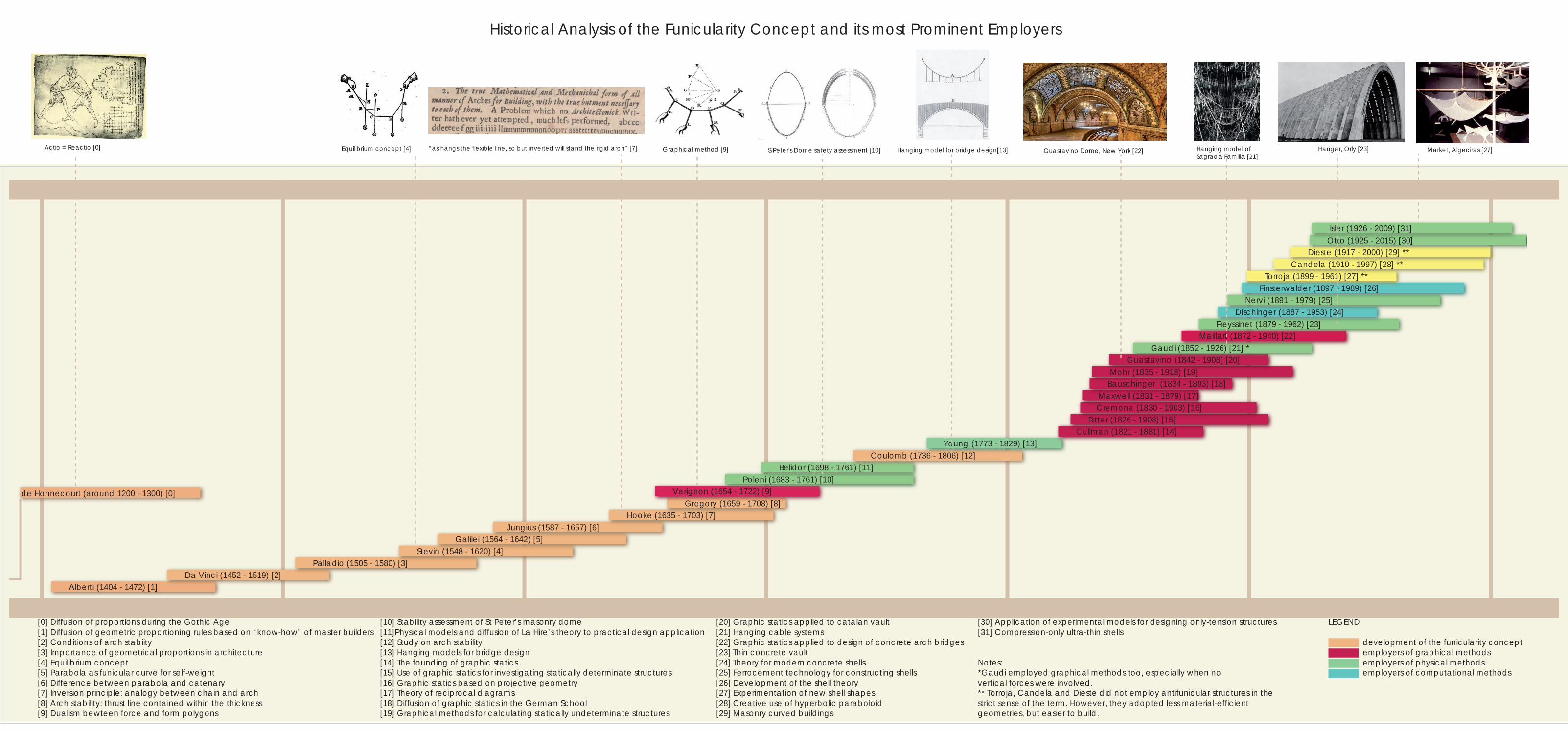
Alberti (1404 - 1472) [1] Da Vinci (1452 - 1519) [2]
Palladio (1505 - 1580) [3] Stevin (1548 - 1620) [4]
Galilei (1564 - 1642) [5] Jungius (1587 - 1657) [6]
Hooke (1635 - 1703) [7]Gregory (1659 - 1708) [8]
Varignon (1654 - 1722) [9] Poleni (1683 - 1761) [10]
Belidor (1698 - 1761) [11] Coulomb (1736 - 1806) [12]
Young (1773 - 1829) [13] Cullman (1821 - 1881) [14]
Ritter (1826 - 1908) [15] Cremona (1830 - 1903) [16]Maxwell (1831 - 1879) [17]
Bauschinger (1834 - 1893) [18] Mohr (1835 - 1918) [19]
Guastavino (1842 - 1908) [20] Gaudí (1852 - 1926) [21] *
Maillart (1872 - 1940) [22] Freyssinet (1879 - 1962) [23]
Dischinger (1887 - 1953) [24] Nervi (1891 - 1979) [25]
Finsterwalder (1897 - 1989) [26] Torroja (1899 - 1961) [27] **
Candela (1910 - 1997) [28] ** Dieste (1917 - 2000) [29] **
Otto (1925 - 2015) [30] Isler (1926 - 2009) [31]
1400 1500 1600 1700 1800 1900 2000
[0] Diffusion of proportions during the Gothic Age[1] Diffusion of geometric proportioning rules based on “know-how” of master builders[2] Conditions of arch stabiity[3] Importance of geometrical proportions in architecture[4] Equilibrium concept[5] Parabola as funicular curve for self-weight[6] Difference between parabola and catenary[7] Inversion principle: analogy between chain and arch[8] Arch stability: thrust line contained within the thickness[9] Dualism bewteen force and form polygons
[10] Stability assessment of St Peter’s masonry dome[11]Physical models and diffusion of La Hire’s theory to practical design application [12] Study on arch stability[13] Hanging models for bridge design[14] The founding of graphic statics[15] Use of graphic statics for investigating statically determinate structures[16] Graphic statics based on projective geometry[17] Theory of reciprocal diagrams[18] Diffusion of graphic statics in the German School[19] Graphical methods for calculating statically undeterminate structures
[20] Graphic statics applied to catalan vault[21] Hanging cable systems[22] Graphic statics applied to design of concrete arch bridges[23] Thin concrete vault[24] Theory for modern concrete shells[25] Ferrocement technology for constructing shells[26] Development of the shell theory[27] Experimentation of new shell shapes[28] Creative use of hyperbolic paraboloid[29] Masonry curved buildings
[30] Application of experimental models for designing only-tension structures[31] Compression-only ultra-thin shells
Notes:*Gaudi employed graphical methods too, especially when no vertical forces were involved.** Torroja, Candela and Dieste did not employ antifunicular structures in the strict sense of the term. However, they adopted less material-efficient geometries, but easier to build.
Equilibrium concept [4] Graphical method [9] S.Peter's Dome safety assessment [10] Hanging model for bridge design[13] Hangar, Orly [23] Market, Algeciras [27]
Historical Analysis of the Funicularity Concept and its most Prominent Employers
Guastavino Dome, New York [22]“as hangs the flexible line, so but inverted will stand the rigid arch” [7]Actio = Reactio [0] Hanging model ofSagrada Familia [21]
development of the funicularity conceptemployers of graphical methodsemployers of physical methodsemployers of computational methods
LEGEND
de Honnecourt (around 1200 - 1300) [0]
References
[1] Website of forces frozen. http://monograph.io/caitlinm/forces-frozen. Accessed: 2016-04-02.
[2] Website of schlaich bergermann und partner. http://sbp.de, 2014.Accessed: 2014-07-12.
[3] Website of the block research group. http://block.arch.ethz.ch/,2014. Accessed: 2014-05-05.
[4] Website of the structural concrete research group at upm. www.he-upm.com, 2015. Accessed: 2015-08-10.
[5] ACI-Committee-347. SP-120: External Prestressing in Bridges. AmericanConcrete Institute, Michigan, USA, 1990.
[6] Adams, E., Connor, J., Ochsendorf, J., andNicolin, R. 1.964 designfor sustainability, fall 2006. http://ocw.mit.edu, 2006. Accessed:2014-03-12.
[7] Addis,W. Structural and civil engineering design. Ashgate, Aldershot, 1999.
[8] Addis, W. Building: 3000 years of design engineering and construction.Phaidon Press, London, 2007.
[9] Adriaenssens, S., Block, P., Veenendaal, D., and Williams, C.Shell structures for architecture: form finding and optimization. Routledge,London, 2014.
[10] Akbarzadeh, M., Van Mele, T., and Block, P. On the equilibriumof funicular polyhedral frames and convex polyhedral force diagrams.Computer-Aided Design 63 (2015), 118–128.
[11] Allen, E., and Zalewski, W. Form and Forces Designing Efficient,Expressive Structures. JohnWiley and Sons, New York, 2009.
155
REFERENCES
[12] Baker,W. F., Beghini, L. L., Mazurek, A., Carrion, J., and Beghini,A. Maxwell’s reciprocal diagrams and discrete michell frames. Structuraland Multidisciplinary Optimization 48, 2 (2013), 267–277.
[13] Barnes, M. R. Dynamic relaxation analysis of tension networks.In Proceedings of the International Conference Tension Roof Structures(London, 1974).
[14] Bauschinger, J. Elemente der graphischen Statik. Oldenbourg,München,1871.
[15] Bechthold,M. Innovative surface structures : technology and applications.Taylor and Francis, New York, 2008.
[16] Beghini, A., Beghini, L. L., and Baker, W. F. On the layout ofa least weight single span structure with uniform load. Structural andMultidisciplinary Optimization 50, 1 (2014), 49–64.
[17] Beghini, L. L., Carrion, J., Beghini, A., Mazurek, A., and Baker,W. F. Structural optimization using graphic statics. Structural andMultidisciplinary Optimization 49, 3 (2014), 351–366.
[18] Block, P., Dejong, M., andOchsendorf, J. As hangs the flexible line:Equilibrium of masonry arches. Nexus Network Journal 8, 2 (2006), 13–24.
[19] Block, P., Lachauer, L., and Rippmann, M. Validating thrustnetwork analysis using 3d-printed, structural models. In Proceedings of theInternational Association for Shell and Spatial Structures (IASS) Symposium(2010), pp. 1–10.
[20] Casado, C. F. La arquitectura del ingeniero. Colegio de Ingenieros deCaminos, Canales y Puertos, Madrid, 2006.
[21] Casquero, A. R. Caracterización estructural de los rellenos situados en eltrasdós de bóvedas de edificios históricos. PhD thesis, Technical Universityof Madrid, Spain, 2015.
[22] Chaudhary, T., P.-A. Examining the role of structural engineers ingreen building ratings and sustainable development. Australian Journalof Structural Engineering 14, 3 (2013), 217–228.
[23] Chías-Navarro, P., and Abad-Balboa, T. Eduardo Torroja: obrasy proyectos. Instituto de Ciencias de la Construcción Eduardo Torroja,Madrid, 2005.
156
REFERENCES
[24] Clune, R., Connor, J. J., Ochsendorf, J. A., and Kelliher, D.An object-oriented architecture for extensible structural design software.Computers and Structures 100-101 (2012), 1–17.
[25] Clune, R. P. Explorative structural design. PhD thesis, MassachusettsInstitute of Technology, Cambridge, USA, 2010.
[26] Conzett, J., and Mostafavi, M. Structure as space: engineering andarchitecture in the works of Jürg Conzett and his partners, vol. 3. AAPublications, London, 2006.
[27] Corres-Peiretti, H. Conceptual design. the only way to create soundstructural concrete solutions. Structural Concrete 10, 3 (2009), 107–108.
[28] Corres-Peiretti, H. Sound engineering through conceptual designaccording to the fib model code 2010. Structural Concrete 14, 2 (2013),89–98.
[29] Culmann, K. Die graphische Statik. Verlag vonMeyer and Zeller, Zürich,1864.
[30] DaVinci, L., and Richter, J. P. The notebooks of Leonardo da Vinci.Dover Publications, New York, 1970.
[31] Day, A. S. An introduction to dynamic relaxation. The Engineer 219(1965), 220–221.
[32] DeJong, M. J. Seismic Assessment Strategies for Masonry Structures. PhDthesis, Massachusetts Institute of Technology, Cambridge, MA, 2009.
[33] Fernández-Casado, C. Cálculo de arcos. Dossat, Madrid, 1955.
[34] FIP. Prestressed concrete : safety precautions in post-tensioning. Telford,London, 1989.
[35] Fivet, C., and Zastavni, D. Robert maillart’s key methods from thesalginatobel bridge design process (1928). Journal of the InternationalAssociation for Shell and Spatial Structures 53, 171 (2012), 39–47.
[36] Fivet, C., and Zastavni, D. A fully geometric approach for interactiveconstraint-based structural equilibrium design. CAD Computer AidedDesign 61 (2015), 42–57.
157
REFERENCES
[37] Galafel-González, J. Estudio de elementos de fábrica por superficiesantifuniculares. Master’s thesis, Technical University of Madrid, Spain,2011.
[38] Galilei, G. Discorsi e dimostrazioni matematiche intorno à due nuouescienze attenenti alla mecanica i movimenti locali. Appresso gli Elsevirii,Leida, 1638.
[39] GeoGebra. Geogebra: Computer software. www.geogebra.org,2013. Version 5.0.166.0.
[40] Georgiou, O. Interactive structural analysis and form finding. InProceedings of the IASS Annual Symposium (2011), IASS.
[41] Georgiou, O., Richens, P., and Shepherd, P. Performance basedinteractive analysis. InDesign Modelling Symposium Berlin (Berlin, 2011).
[42] Gregory, D. Catenaria. Philosophical Transaction of the Royal Society 19,231 (1697), 637–652.
[43] Heyman, J. The stone skeleton : structural engineering of masonryarchitecture. Cambridge University Press, Cambridge; New York, 1995.
[44] Heyman, J. Structural analysis: a historical approach. CambridgeUniversity Press, Cambridge; New York, 1998.
[45] Honnecourt, V. D. Album de dessins et croquis. Bibliothèque nationalede France, Paris, 1300.
[46] Hooke, R. A description of helioscopes and some other instruments. T.R. forJohnMartyn, London, 1676.
[47] Huerta-Fernandéz, S. Structural design in the work of gaudí.Architectural Science Review 49, 4 (2006), 324–339.
[48] Huerta-Fernandéz, S. The analysis of masonry architecture: Ahistorical approach. Architectural Science Review 51, 4 (2008), 297–328.
[49] Huerta-Fernández, S. Arcos, bóvedas y cúpulas : geometría y equilibrioen el cálculo tradicional de estructuras de fábrica. Instituto Juan de Herrera,Madrid, 2004.
[50] IASS. Website of the hangai prize. http://www.iass-structures.org/index.cfm/page/HA/HP.htm, 2016. Accessed: 2016-02-02.
158
REFERENCES
[51] Jasienski, J., Fivet, C., and Zastavni, D. Various perspectives on theextension of graphic statics to the third dimension. In Proceedings of theIASS-SLTE 2014 Symposium (2014).
[52] Jorquera-Lucerga, J. J. Estudio del comportamiento resistente de lospuentes de arco espaciales. PhD thesis, Technical University of Madrid,Spain, 2007.
[53] Jorquera-Lucerga, J. J., and Manterola-Armisen, J. An iterativeform-finding method for antifunicular shapes in spatial arch bridges.Computers and Structures 108-109 (2012), 42–60.
[54] Jurina, L. Strengthening ofmasonry arch bridgeswith ”ram” - reinforcedarchmethod. In Proceedings of the Sixth International Conference on BridgeMaintenance, Safety and Management (2012), pp. 1063–1070.
[55] Jurina, L., Mantegazza, G., and Radaelli, E. O. Frcm -strenghtening ofmasonry vaults: The ”duomo di colorno” and ”braidenselibrary” cases in italy. Key Engineering Materials 624 (2015), 494–501.
[56] Kilian, A., and Ochsendorf, J. Particle-spring systems for structuralform finding. Journal of the International Association for Shell and SpatialStructures, 148 (2005), 77–84.
[57] Kurrer, K.-E. The history of the theory of structures from arch analysis tocomputational mechanics. Ernst and Sohn, Berlin, 2008.
[58] Lachauer, L., and Block, P. Interactive equilibrium modelling.International Journal of Space Structures 29, 1 (2014), 25–38.
[59] Lachauer, L., and Kotnik, T. Geometry of structural form. InAdvances in Architectural Geometry 2010 (2010), Springer, pp. 193–203.
[60] Lachauer, L., andKotnik, T. Curved bridge design. InComputationalDesign Modelling (2012), Springer, pp. 145–152.
[61] Laffranchi, M., andMarti, P. Robert maillart’s curved concrete archbridges. Journal of Structural Engineering 123, 10 (1997), 1280–1286.
[62] Lancaster, L. C. Concrete Vaulted Construction in Imperial Rome.Cambridge University Press, New York, 2005.
[63] Larsen, O. P., andTyas, A. Conceptual structural design: bridging the gapbetween architects and engineers. Thomas Telford, London, 2003.
159
REFERENCES
[64] Lenczner, E. The design of the stone facade to the pavilion of the future,expo ’92, seville. The Structural Engineer 72, 11 (1994).
[65] Leonhardt, F. Prestressed concrete; design and construction. Translated byC. van Amerongen. W. Ernst, Berlin, 1964.
[66] Lewis, W. J. Tension structures: form and behaviour. Thomas Telford,London, 2003.
[67] Lin, T. Revolution in concrete. Architectural Forum May (1961), 121–127.
[68] Lin,T. Revolution in concrete. Architectural Forum June (1961), 116–122.
[69] Linkwitz, K., and Schek, H. J. Einige bemerkungen zur berechnungvon vorgespannten seilnetzkonstruktionen. Ingenieur-Archiv 40, 3 (1971),145–158.
[70] Llorente-Zurdo, M. P. El Pretensado. La disolución de las tipologíasconstructivas en la arquitectura del SXX. PhD thesis, Technical Universityof Madrid, Spain, 2016.
[71] Manterola-Armisen, J. Puentes: apuntes para su diseño, cálculo yconstrucción. Colegio de Ingenieros de Caminos, Canales y Puertos,Madrid, 2006.
[72] Maxwell, J. On reciprocal figures and diagrams of forces. PhilosophyMagazine 26 (1864), 250–261.
[73] Maxwell, J. On reciprocal figures, frames, and diagrams of forces.Edinburgh Royal Society Proceedings 7 (1870), 160–208.
[74] McNeel, R. Grasshopper generative modeling for rhino. computersoftware. www.rhino3d.com, 2014. Version 0.9.0076.
[75] McNeel, R. Rhinoceros nurbs modeling for windows. computersoftware. www.rhino3d.com, 2014. Version 5.12.
[76] Menn, C. Prestressed concrete bridges. Birkhäuser Verlag, Basel,Switzerland; Boston, 1990.
[77] Misiunaite, I. Structural Behaviour and Stability of Steel Beam-ColumnElements in Under-Deck Cable-Stayed Bridge. PhD thesis, VGTU leidyklaTechnika, Vilnius, 2013.
160
REFERENCES
[78] Mueller, C. Computational exploration of the structural design space. PhDthesis, Massachusetts Institute of Technology, Cambridge, USA, 2014.
[79] Mueller, C., Fivet, C., and Ochsendorf, J. Graphic statics andinteractive optimization for engineering education. In Proceedings of the2015 Structures Congress (2015), American Society of Civil Engineers.
[80] Mueller, C. T., and Ochsendorf, J. A. Combining structuralperformance and designer preferences in evolutionary design spaceexploration. Automation in Construction 52 (2015), 70–82.
[81] Muttoni, A. Brücken mit einem innovativen statischen system.Schweizer Ingenieur und Architekten 26 (1997), 28 – 31.
[82] Muttoni, A. The art of structures ; introduction to the functioning ofstructures in architecture. EPFL Press/Routledge, Abingdon, Oxford, UK;New York, NY, 2011.
[83] Muttoni, A., Lurati, F., and Fernández-Ruiz, M. Concrete shells –towards efficient structures: Construction of an ellipsoidal concrete shellin switzerland. Structural Concrete 14, 1 (2013), 43–50.
[84] Ninino, B. Optimal shape of arch bridges by using graphic statics.Internship report, Technical University of Madrid, Spain, 2015.
[85] Ochsendorf, J. A., and Freeman, M. Guastavino vaulting : the art ofstructural tile. Princeton Architectural Press, New York, 2010.
[86] Otto, F., and Rasch, B. Frei Otto, Bodo Rasch: finding form: towards anarchitecture of the minimal. Edition of Axel Menges, 1995.
[87] Perez-Fadon, S., Herrero-Benéitez, J. E., Sanchéz-Ramírez, J. J.,and Sanchéz, M. S. El arco de los tilos en la isla de la palma (canarias).Cemento Hormigón 886 (2006), 76–92.
[88] Post-Tensioning-Institute. Post-Tensioning Manual, sixth edition ed.Post-Tensioning Institute, Farmington Hills, MI, 2006.
[89] Preisinger, C., and Heimrath, M. Karamba - a toolkit for parametricstructural design. Structural Engineering International 24, 2 (2014), 217–221.
[90] Quinonez, A., Zessin, J., Nutzel, A., andOchsendorf, J. Small-scalemodels for testing masonry structures. Advanced Materials Research 133-134 (2010), 497–502.
161
REFERENCES
[91] Ramm, E. Shape finding of concrete shell roofs. Journal of the InternationalAssociation for Shell and Spatial Structures, 144 (2004), 29–40.
[92] Rankine, W. AManual of Applied Mechanics. Griffin, London, 1958.
[93] Rankine, W. AManual of Civil Engineering. Griffin, London, 1962.
[94] Robert, M., and Hutchinson, P. On the structure of the romanpantheon. The Art Bulletin 68, 1 (1986), 24–34.
[95] Ruiz-Teran, A. M. Unconventional cable-stayed bridges: structuralbehaviour and design criteria. Structural Concrete 11, 1 (2010), 25–34.
[96] Ruiz-Teran, A. M., and Aparicio, A. C. Two new types of bridges:under-deck cable-stayed bridges and combined cable-stayed bridges - thestate of the art. Canadian Journal of Civil Engineering 34, 8 (2007), 1003–1015.
[97] Saitoh,M., andOkada, A. The role of string in hybrid string structure.Engineering Structures 21, 8 (1999), 756–769.
[98] Sarmiento-Comesias, M., Aparicio, A. C., and Ruiz-Teran, A. M.State-of-the-art of spatial arch bridges. Proceedings of the Institution of CivilEngineers: Bridge Engineering 166, 3 (2013), 163–176.
[99] Schek, H. J. The force densitymethod for form finding and computationof general networks. Computer Methods in Applied Mechanics andEngineering 3, 1 (1974), 115–134.
[100] Schlaich, J., Schafer, K., and Jennewein, M. Toward a consistentdesign of structural concrete. Journal of the Prestressed Concrete Institute32 (1987), 74–150.
[101] Squier, E. G. Peru; incidents of travel and exploration in the land of theIncas,. Harper and Brothers, New York, 1877.
[102] Strasky, J. The power of prestressing. Structural Concrete 4, 1 (2003),25–43.
[103] Strasky, J. Stress ribbon and cable-supported pedestrian bridges. ThomasTelford, London, 2005.
[104] Thrall, A. P., Billington, D. P., andBréa, K. L. Themaria pia bridge:Amajor work of structural art. Engineering Structures 40 (2012), 479–486.
162
REFERENCES
[105] Timoshenko, S. History of strength of materials : with a brief account ofthe history of theory of elasticity and theory of structures. McGraw-Hill, NewYork, 1953.
[106] Timoshenko, S., and Young, D. H. Theory of structures. McGraw-Hill,New York, 1965.
[107] Todisco, L. An integrated approach to conceptual design of arch bridgeswith curved deck. Master’s thesis, Technical University ofMadrid, Spain,2014.
[108] Todisco, L., and Corres-Peiretti, H. Il concetto di funicolarità.l’applicazione per il conceptual design di strutture efficienti e versatili.Magazine 201, 1 (2016), 1–10.
[109] Todisco, L., Corres-Peiretti, H., and Mueller, C. Funicularitythrough external posttensioning: Design philosophy and computationaltool. Journal of Structural Engineering (ASCE) 142, 2 (2015).
[110] Todisco, L., Fivet, C., Corres-Peiretti,H., andMueller, C. Designand exploration of externally post-tensioned structures using graphicstatics. Journal of the International Association for Shell and SpatialStructures 56, 4 (2015), 249–258.
[111] Todisco, L., Fivet, C., Corres-Peiretti,H., andMueller, C. Designand exploration of externally post-tensioned structures using graphicstatics. In Proceedings of the IASS Symposium (2015).
[112] Todisco, L., and Mueller, C. Externally post-tensioned structures:validation through physicalmodels. InProceedings of the ICSA Symposium(2016). Article accepted.
[113] Ungewitter, K. Lehrbuch der gotischen konstruktionen. Weigel, Leipzig,1890.
[114] United-Nations. World Urbanization Prospects: The 2014 Revision,vol. ST/ESA/SER.A/352. 2014.
[115] Van Mele, T., McInerney, J., DeJong, M., and Block, P. Physicaland computational discrete modeling of masonry vault collapse. InProceedings of the 8th International Conference on Structural Analysis ofHistorical Constructions (2012).
[116] Varignon, P. Nouvelle mécanique ou statique 1. Jombert, Paris, 1725.
163
REFERENCES
[117] Veenendaal, D., and Block, P. Design process for prototype concreteshells using a hybrid cable-net and fabric formwork. Engineering Structures75 (2014), 39–50.
[118] VSL. External post-tensioning. VSL Rep. Series, Switzerland, 1992.
[119] Wolfe, W. S. Graphical analysis; a text book on graphic statics. McGraw-Hill, New York, 1921.
164
Colophon
This thesis was typeset usingLATEX, originally developed by LeslieLamport and based on Donald Knuth’s
TEX.The body text is set in 11 point ArnoPro, designed by Robert Slimbach in thestyle of book types from the Aldine Press inVenice, and issued by Adobe in 2007. Atemplate, which can be used to format a PhDthesis with this look and feel, has beenreleased under the permissive mit (x11)license, and can be found online atgithub.com/suchow/ or from the author [email protected].
165
Top Related
Copyright © 2022 FDOKUMEN

