


Bahasa
Halaman
Hukum

Fundamentals of Thermodynamic
for Pressure-Based
Low-Temperature Premixed Diesel
Combustion Control
Von der Fakultät Konstruktions-, Produktions- und Fahrzeugtechnik
der Universität Stuttgart
zur Erlangung der Würde eines Doktor- Ingenieurs (Dr. Ing.)
genehmigte Abhandlung
Vorverlegt von
PATRICK REBECCHI
Dipl. Masch.-Ing. ETH
aus Lugano
Hauptberichter: Prof. Dr. Ing. M. Bargende
Mitberichter: Prof. Dr. G. Rizzoni
Tag der mündlichen Prüfung: 20.11.2012
Institut für Verbrennungsmotoren und Kraftfahrwesen der Universität
Stuttgart
2013

This work is the result of a three years PhD reseach program between 2009
and 2012 that took place at the Institute of Internal Combustion Engines and
Automotive Engineering at the University of Stuttgart under the guidance of
Prof. Dr.-Ing.M.Bargende.
I started my association with Prof. Bargende during my time as a visiting scholar
at the Ohio State University Center of Automotive Research, where between
2007 and 2008 I had the possibility to work as a research assistant in the group
of Prof. Dr.G.Rizzoni. I would like to express my thanks to Prof. Bargende
for giving me the opportunity to work in a modern and competent research
environment, providing me with all the support needed for the accomplishment
of this project. I am also grateful to Prof. Rizzoni for welcoming me at the CAR
and for the assumption of the co-examiner.
Many thanks go to all my colleagues at the IVK for the scienti�c and moral
support. In particular I would like to thank Hans-Jürgen Berner for providing
me with an excellent supervision and valuable suggestions. I would also like to
thank Sebastian Seewaldt for the excellent cooperation during these years and
the many interesting discussions.
Special thanks go to my family and particularly to my mother Marina and
Giovanni for sustaining me in every decision. Final thanks go to all the nice
people I met during my experiences in Columbus and Stuttgart for welcoming
me and for the good times spent together.

Abstract
This thesis shows the results of investigations about the combustion mechanisms
of low-temperature premixed processes, in particular those in which only a par-
tial homogenization of the fuel mixture is achieved, since they represent a realis-
tic solution for commercial engine applications. Measurements has been carried
out on a modern 6-cylinder diesel engine equipped with a rapid-prototyping
ECU and in-cylinder pressure sensors. The engine has been operated on a
dynamic test bench. On the base of thorough combustion analysis a new closed-
loop combustion control strategy has been de�ned. This has been completed by
a procedure for allowing to switch the combustion mode to conventional di�usive
combustion extending the drivability range up to engine full-load.
In a �rst step a sensitivity analysis of the system has been carried out in order
to identify engine constrains and mayor system limitations. A �rst selection
between useful actuating and target parameters has been made. The most rele-
vant combustion mechanisms have been also highlighted. Matching these infor-
mation, targeted measurements has been done under the variation of multiple
parameters. In this way a clear target application area in the EGR-injection
timing map could be de�ned. Optimal combustion phasing has been found for
combustion beginning at TDC and large rates of EGR. This has been done for
low engine operation mode where charge dilution did not represent a limitation.
However, increasing the engine load, because of the larger injection mass by
almost constant fresh air quantity, it was necessary to limit the EGR rate for
avoiding soot production and a deterioration of the fuel conversion. Therefore,
the combustion process has been phased later in the expansion.
After the identi�cation of the combustion mechanisms and the application tar-
get, a new combustion control strategy has been de�ned. The goal is the accom-
plishment of the de�ned requirements concerning engine protection, i.e. rate
of pressure rise and stability, fuel consumption and emissions. The proposed
control strategy foresaw a control of the engine load over the injection duration,
a control of the maximum rate of pressure rise over the injection timing (using a
block-injection) and a control of the oxygen concentration in the charge over the
5
EGR valve. In this way a clear separation of the controller tasks was possible.
When the engine load and the engine protection have been continuously provided
by the �rst two controllers, which has been done indivudually for each cylinder,
the charge quality could be varied in order to increase combustion e�ciency and
reducing emissions.
The control system has been completed by a switching strategy to and from
conventional combustion, which was needed for extending the drivability range.
Rapid changes of the charge dilution, the injection pressure and the injection
strategy has been identi�ed to be mainly responsible for high rates of pressure
rise or, inversely, for the deterioration of the combustion process. On the base
of measurements, dynamic parameters correction functions are proposed. This
solution provided an e�ective switching procedure characterized by a monotonic
engine torque signal and low combustion noise.
The proposed closed-loop control strategy has been tested under stationary and
transient engine operation. The NEDC has been splitted into characteristics
parts and adapted for test bench measurements. For a reliable comparison of
the measured data, special attention has been given to a high reproducibility
of the test cycle. The urban part of the cycle could be driven using solely the
closed-loop controlled alternative combustion, whereas a switch to alternative
combustion was needed in the extra-urban part of the cycle. The proposed
strategy showed high robustness and optimal response even under high dynamic
load changes.
6
Kurzfassung
Die vorliegende Arbeit zeigt die Ergebnisse einer Untersuchung der Verbren-
nungsmechanismen von homogenisierten Niedertemperatur-Prozessen, insbeson-
dere in Bereichen in denen eine Teilhomogenisierung des Kraftsto�gemisches
erreicht wird und darum einen realistischen Lösungsansatz für kommerzielle
Motoren darstellen. Messungen wurden am einem modernen vollindizierten
6-Zylinder Dieselmotor, ausgerüstet mit einem Rapid-Prototyping Steuerg-
erät, durchgeführt. Der Motor wurde mit einem dynamischen Prüfstandsys-
tem betrieben. Auf der Basis einer gründlichen Analyse wurde eine neue
Regelungsstrategie der Verbrennung de�niert, welche, durch die De�nition eines
Umschaltvorgangs zur konventionellen di�usiven Verbrennung, vervollständigt
wurde. Damit wurde der Ausbau des möglichen Applikationsbereiches bis zur
Volllast erweitert.
In einem ersten Schritt wurde eine Sensitivitätsanalyse des untersuchten Systems
durchgeführt. Dabei wurden motorspezi�sche Applikationsgrenzen und Lim-
itierungen des Brennverfahrens identi�ziert. Zusätzlich wurde eine Selektion
der nutzbaren Regel- und Zielgröÿen durchgeführt und die relevanten Mecha-
nismen der Verbrennung beleuchtet. Auf Grund dieser Informationen wurden
spezi�sche Untersuchungen durchgeführt, bei denen mehrere Gröÿen gleichzeitig
variiert wurden. Die Kombination der Ergebnisse in der Form von Isolinien,
dargestellt in einem AGR-Einspritzzeitpunkt Diagramm, erlaubte die De�ni-
tion eines klaren Applikationszielbereiches. Eine Wirkungsgrad optimale Lage
der Verbrennung wurde bei einem Verbrennungsbeginn um den oberen Totpunkt
und bei hohe Abgasrückführungsraten gefunden. Dieser Bereich ist bei niedri-
gen Motorlasten erreichbar, da hier die starke Ladungsverdünnung keine Lim-
itierung darstellt. Bei höheren Lasten muss hingegen, auf Grund der erhöhten
Kraftsto�masse bei praktisch konstant bleibender Frischluftmenge, die AGR-
Rate limitiert werden, um starke Ruÿ-Emissionen und eine Verschlechterung
der Kraftsto�umsetzung zu vermeiden. Darum �ndet die Verbrennung später
im Expansionstakt statt.
Nach Identi�kation der Verbrennungsmechanismen und des Applikationsziel-
7
bereiches wurde eine neue Regelstrategie de�niert. Anforderung an diese Strate-
gie war, Grenzen bezüglich Motorschutz, d.h. maximale Druckgradiente und
Verbrennungsstabilität, Kraftsto�verbrauch und Emissionen einzuhalten. Die
vereinbarte Strategie sieht eine Regelung der Motorlast über die Einspritz-
dauer, eine Regelung des maximalen Druckgradienten über die Lage der Ein-
spritzung (Blockeinspritzung) und eine Regelung der Sauersto�-Konzentration
der Frischladung über das AGR Ventil vor. Dieser Lösungsansatz erlaubt eine
klare Trennung der Aufgaben der Regler. Während die Einhaltung der Last und
die Motorschutzfunktion von den ersten beiden Reglern gewährleistet wurde,
konnte die Qualität der Ladung variiert werden, um den Wirkungsgrad der Ver-
brennung zu verbessern und die Emissionen zu senken. Auÿerdem erlaubte diese
Strategie eine zylinderindividuelle Anpassung des Verbrennungsvorgangs.
Die Regelung der Verbrennung wurde um eine Umschaltung der Betriebsarten
erweitert, welche einen Ausbau des möglichen Applikationsbereiches bis zur Vol-
llast erlaubt. Schnelle Variationen der Ladungsqualität, des Rail-Druckes und
des Einspritzmusters wurden als verantwortlich für das Auftreten von starken
Druckgradienten oder, umgekehrt, für das Erlöschen der Verbrennung identi-
�ziert. Deshalb wurden aufgrund gezielter Prüfstandmessungen, Korrekturfunk-
tionen entwickelt. Diese Korrekturfunktionen erlaubten eine wirkungsvolle Um-
schaltung der Betriebsarten, welche durch einen stetigen Momentenverlauf und
niedriges Motorgeräusch gekennzeichnet ist.
Die vereinbarte Regelstrategie wurde im stationären und transienten Motor-
betrieb getestet. Der NEFZ wurde in für dynamische Messungen am Mo-
torprüfstand relevanten Abschnitte aufgeteilt. Dabei wurde besonders auf die
Reproduzierbarkeit des Testzyklus geachtet,um eine möglichst gute Vergleich-
barkeit der Ergebnisse zu erzielen. Der Stadtteil des Zyklus konnte ausschlieÿlich
im geregelten teilhomogenen Betrieb gefahren werden, während für den auÿer-
städtischen Teil eine Umschaltung in die di�usive Verbrennung notwendig war.
Die Robustheit und das gute Führungsverhalten der vorgeschlagenen Regel-
strategie konnten auch im stark dynamischen Betrieb bestätigt werden.
8
Contents
Nomenclature 11
1 Introduction 15
1.1 Motivation . . . . . . . . . . . . . . . . . . . . . . . . . . . . . 15
1.2 Objectives . . . . . . . . . . . . . . . . . . . . . . . . . . . . . 16
2 State of the Art 19
2.1 Diesel alternative combustion processes . . . . . . . . . . 19
2.2 Pressure based diesel engine closed-loop control . . . . . 29
2.3 Alternative-conventional combined mode . . . . . . . . . 33
3 Theoretical Background 35
3.1 Piston dynamic . . . . . . . . . . . . . . . . . . . . . . . . . . 35
3.2 Mixture formation . . . . . . . . . . . . . . . . . . . . . . . . 40
3.3 Combustion process . . . . . . . . . . . . . . . . . . . . . . . 47
3.4 Emissions . . . . . . . . . . . . . . . . . . . . . . . . . . . . . 54
3.5 Exhaust gas recirculation . . . . . . . . . . . . . . . . . . . 60
4 Experimental Setup and Engine Manage-ment System 63
4.1 Engine and measurement equipment . . . . . . . . . . . . 63
4.2 Real-time combustion analysis system . . . . . . . . . . . 67
4.3 Engine management system . . . . . . . . . . . . . . . . . . 68
5 System analysis and de�nition of the com-bustion control strategy 71
5.1 Engine constrains . . . . . . . . . . . . . . . . . . . . . . . . 73
9
5.2 System limitations . . . . . . . . . . . . . . . . . . . . . . . . 78
5.3 Combined parameter variation . . . . . . . . . . . . . . . . 95
5.4 De�nition of a new closed-loop control strategy . . . . . 96
6 Combustion Mode Switch 107
6.1 Di�usive combustion mode . . . . . . . . . . . . . . . . . . 108
6.2 Principles of the combustion mode switch . . . . . . . . . 110
6.3 Switching from premixed to di�usive combustion . . . . 112
6.4 Switching from di�usive to premixed combustion . . . . 116
7 Results 121
7.1 Application range of the low-temperature premixedcombustion . . . . . . . . . . . . . . . . . . . . . . . . . . . . 121
7.2 De�nition of the dynamic driving cycle . . . . . . . . . . . 123
7.3 Measurements in ECE-15 . . . . . . . . . . . . . . . . . . . 124
7.4 Measurements in entire NEDC . . . . . . . . . . . . . . . . 134
8 Summary and Conclusions 135
8.1 Summary . . . . . . . . . . . . . . . . . . . . . . . . . . . . . . 135
8.2 Conclusions . . . . . . . . . . . . . . . . . . . . . . . . . . . . 137
References 139
List of �gures 151
List of tables 155
Appendix 157
A.1 Contour maps low-temperature premixed combustion . 157
A.2 Contour maps di�usive combustion . . . . . . . . . . . . . 159
10
Nomenclature
Acronyms
ACTION Advanced Combustion Technology to Improve
engine-Out NOx, RicardoLtd.
ADEC Advanced Diesel Engine Control, RicardoLtd.
ATDC After Top Death Center
BTDC Before Top Death Center
CA Crank Angle
CCS Combined Combustion System, VolkswagenAG
CI Compression Ignited
CO Carbon Monoxide
CO2 Carbon Dioxide
DCCS Dilution Controlled Combustion System
DI Direct Injection
DPF Diesel Particulate Filter
DOC Diesel Oxidation Catalyst
ECE-15 Urban Driving Cycle
ECU Electronic Control Unit
EDC Electronic Diesel Control
EGR Exhaust Gas Recirculation
EV C Exhaust Valve Closing
EUDC Extra-Urban Driving Cycle
HCCI Homogeneous Charge Compression Ignition
HCLI Homogeneous Charge Late Injection
HPCC Highly Pre-mixed Cool Combustion
HPLI Highly Premixed Late Injection
HRR Heat Release Rate
11
ICE Internal Combustion Engine
ILC Iterative Learn Control
IV O Intake Valve Opening
LTO Low Temperature Oxidation
MIMO Multiple Input Multiple Output
MK Modulated Kinetics, NissanMotorCO. Ltd.
NEDC New European Driving Cycle
NOx Nitrogen oxide1
NTC Negative Temperature Coe�cient
PAH Polycyclic Aromatic Hydrocarbon
PCCI Premixed Charge Compression Ignition
PID Proportional-Integral-Derivative controller
PM Particulate Matter
PSG Pressure Sensor Glow Plug, BorgWarnerBERUSystemsGmbH
RPC Rail Pressure Control
RPM Revolution Per Minute
SI Spark Ignited
SISO Single-Input Single-Output
SULEV Super Ultra Low Emission Vehicle
UHC Unburned Hydrocarbons
V GT Variable-Geometry Turbocharger
V V A Variable Valve Actuation
Latin symbols
CA10 10% of integral heat release, combustion beginning ◦CA
CA50 50% of integral heat release, center of combustion ◦CA
cp Heat capacity at constant pressure J/kgK
1Can refer to a binary compound of oxygen and nitrogen, or a mixture of such compounds
12
Nomenclature
cv Heat capacity at constant volume J/kgK
EA Apparent activation energy J/mol
dp/dθmax Maximum rate of cylinder pressure rise bar/◦CA
imep Indicated mean e�ective pressure bar
l Connecting rod length mm
nmep Net mean e�ective pressure bar
pCylinder Cylinder pressure bar
pExh Exhoust pressure upstream the turbine bar
pInt Intake manifold pressure bar
pmax Maximum cylinder pressure bar
pθ Cylinder pressure at de�ned piston position bar
R̃ Universal gas constant J/molK
r Crankshaft radius mm
sϕ Piston position as a function of the crank angle mm
Sp Mean piston speed m/s
TCylinder Cylinder temperature K
TInt Intake manifold temperature K
Greek symbols
ε Engine compression ratio −λ Air to fuel equivalence ratio −κ Isentropic index −ϕ Crank angle variable ◦CA
τid Ignition delay ms
θ Crank angle ◦CA
13

1
Introduction
1.1 Motivation
Modern diesel engines has been shown to be a feasible solution for the light-duty
and passenger car sectors. With the introduction and continuous improvement
of the common-rail (CR), the direct injection (DI) system, and the use of
multiple-stage turbo-charging in combination with cooled exhaust gas recircula-
tion (EGR), diesel engines o�er a greater e�ciency compared to spark ignited
(SI) gasoline engines by comparable comfort and drivability. A major drawback
of this technology are the high particulate matter (PM) and nitrogen oxides
(NOx) emissions, which mainly result from the di�usive combustion process.
Future legislative regulations require a reduction of the emissions produced by
automotive combustion applications, and in particular, a signi�cant reduction
of the nitrogen oxides and soot emissions must be accomplished in the com-
ing engine generation. Using conventional combustion processes however, such
as the diesel di�usive combustion, this can be done only using cost expensive
exhaust gas aftertreatment systems. In fact, the di�usive combustion process
is characterized by a trade-o� mechanism between these two pollutants and a
simultaneous reduction of both components is not possible. Moreover, using ex-
haust gas aftertreatment systems, the complexity of the electronic control unit
(ECU) software structures and the time needed for their application increases
signi�cantly, resulting in additional costs.
Low-temperature premixed combustion processes has been demonstrated to be
a feasible solution for reducing NOx and PM engine-out emissions. Increasing
the mixture homogenization and reducing the combustion temperatures provide
a NOx and smoke-less combustion. This is the case of completely homogenous
15
processes. However, the large attentions that have been given to this solution
during the end of the last century has been lowered by drawbacks such as high
combustion instability and poor fuel conversion. Large di�culties has been also
encountered in the application of these processes in commercial engine applica-
tions. A compromise has been found by providing only a partial homogenization
of the fuel mixture, timing the injecting event towards the end of the compression
stroke. This solution has shown greater potential for series engine applications,
but problems related to the control of the combustion process still remains the
major drawback of this technology. This is mainly due to the high system sen-
sitivity to small changes in the charge composition. Moreover the use of this
combustion process is limited in the low to middle load range and a solution for
switching to conventional combustion must be found. Particularly during tran-
sient engine operation is the realization of a torque-neutral switching procedure
a di�cult task.
The recent introduction of low-cost in-cylinder measurement sensors, together
with the increased computation capacity of modern ECUs, has opened new
perspectives for the application of alternative combustion processes. On the base
of the pressure data measured in the combustion chamber, usually carried out
with a resolution of one degree crank angle(◦CA ), valuable information about
the combustion process can be determined, such as the combustion beginning
and the indicated mean e�ective pressure (imep). These information can be
implemented in a closed-loop control. This feature o�ers a solution to the most
part of the above mentioned drawbacks related to the high sensitivity of the
low-temperature premixed combustion.
1.2 Objectives
In the last decade, many authors have proposed new closed-loop pressure-based
combustion control systems. However, most part of the described solutions rely
on combustion models and statistical analysis of the system, and are not based
on a thorough understanding of the combustion mechanisms. The object of
this work is to show that a closed-loop combustion control strategy, based on
a detailed investigation of the thermodynamic mechanisms taking place during
the combustion process, can be a feasible solution for the application of low-
16
Introduction
temperature premixed combustion in modern diesel engines.
Based on an extensive system sensitivity analysis performed on a multi-cylinder
turbo-charged diesel engine equipped with a rapid prototyping ECU and in-
cylinder pressure sensors, the most relevant mechanisms of the combustion pro-
cess must be indenti�ed. On the base of these mechanisms, actuating and target
variables as well as a new closed-loop control strategy must be de�ned. The
strategy must take targets such as high fuel conversion and combustion stabil-
ity, and low emissions and noise into consideration. To complete the control
strategy, a procedure for allowing the combustion mode to be switched from
alternative to conventional diesel combustion and inversely must be designed.
This should provide a steady monotonic increase (or decrease) of the engine
torque. Finally, the proposed strategy must be evaluated under stationary and
transient engine operation.
17

2
State of the Art
New legislative emission requirements can be achieved in-
creasing the quality of the combustion process as well by re-
ducing engine tolerances. Near the possibility of drastically
lowering engine-out emissions exploiting diesel alternative
combustion processes, closed-loop combustion control seems
to be a promising solution for the next engine generation.
Aim of this chapter is to give an overview of the works that
can be found in the literature about these topics.
2.1 Diesel alternative combustion processes
2.1.1 From di�usive to low-temperature premixed
combustion
Nowadays, di�usive combustion, here called DI combustion1, is still playing
a dominant role in the diesel engine combustion process. Thanks to consis-
tent improvements during the last decades, DI combustion is now characterized
by high e�ciency, a stable combustion, low emissions and low noise. Despite
that, modern diesel engine are still trapped in the trade-o� mechanism between
NOx and PM emissions, which result from the combustion of high-temperature
lean-mixture regions, and from cold and fuel-rich areas of the injection spray re-
spectively.
1Direct Injection Compression Ignited DI-CI to di�erentiate from Direct Injection Spark
Ignited DI-SI
19
Characteristic for DI combustion is a multiple injection strategy for the low-
load operation range and a single injection event at higher loads. In the low-load
range the main injection is anticipated by one or more short fuel injections, so
called pilot injections, which are mainly responsible for increasing the combus-
tion chamber temperature prior to the main injection event. The fuel, injected
in small quantities, has enough time to mix with the gases in the combustion
chamber and is than compression ignited. Therefore, a small premixed com-
bustion take place. Due to the resulting temperature increase the combustion
delay of the main injection, which is responsible for the pressure increase and
thus the engine torque, can be drastically reduced. There is short or no time for
the mixing process and the combustion of the main injection takes place almost
completely di�usive. Main advantages of this solution are a low combustion
noise and low engine vibrations. At higher loads this strategy is not adopted
since the combustion chamber conditions by injection event, i.e. temperature
and pressure, are su�cient to ignite the fuel spray rapidly. Also in this case,
due to the lack of time for the mixture formation, the combustion has mainly a
di�usive character.
The fuel/air distribution in a fuel spray is strongly heterogeneous. While in the
core of the fuel spray any oxygen can be found, i.e. the air/fuel ratio (λ) is
equal to 0, other regions of the combustion chamber are just �lled with air, thus
λ→∞. In the edge regions of the spray cone, where the drops2 are smaller and
fuel is partially evaporated, there is a wide range of fuel/air concentrations, going
from 0 to ∞. If this mixture is ignited, e.g. by di�usive compression ignited
processes, it results a very heterogeneous temperature distribution as well. This
two phenomena, i.e. regions with a wide range of λ and the large temperatures
distribution, are the main source for emissions in DI combustion. In fuel poor
areas in the combustion chamber, where λ → ∞, the temperature is too low
for thorough oxidation causing UHC emissions. The highest temperatures are
measured in the areas surrounding the spray, where λ > 1, and are mainly
responsible for NOx formation. In fuel rich areas inside the spay cone, where
λ < 1, CO and soot formation takes place [2].
The purpose by the development of modern diesel engines is to avoid NOx and
PM emissions formation during the combustion processes. In the past years,
2As the liquid jet leaves the nozzle it becomes turbulent and spread out as it entrains and
mixes with the surrounding air. The outer surface of the jet breaks up into drops [3].
20
State of the Art
di�erent technical solutions has already proved their potential. The fuel mix-
ing process can be signi�cantly improved by increasing the injection pressure,
reducing injector hole diameter and increasing the injector hole number. Beside
a better distribution of the fuel in the combustion chamber the local λ range by
combustion onset can be reduced between 0.8 and 0.9 with a signi�cant decrease
of the soot formation [4]. A large portion of the generated soot can be reduced
toward the end of the combustion by late oxidation processes, which can be
promoted increasing the turbulence in the combustion chamber during the ex-
pansion stroke. Soot oxidation up to 95% is possible [2]. An increased mixture
homogenization has also bene�ts regarding lower NOx formation. A further
signi�cant reduction of NOx emissions can be achieved by lowering the com-
bustion temperature. This can be done recirculating large amounts of exhaust
gases or reducing the compression ratio. This last solution is always related to
a reduction of the combustion e�ciency. However, as long as the diesel combus-
tion process takes place under (di�usive) heterogenous conditions, a trade-o�
mechanism between NOx and PM emissions can not be completely avoided.
Alternative solutions to the di�usive diesel combustion process have been a ma-
jor topic in the engine combustion research and development of the last 40 years.
Homogeneous and partial-homogeneous combustion processes have been found
to be a promising solution in reducing NOx and PM emissions without sig-
ni�cantly increasing fuel consumption, or even improving it. In consideration
of what mentioned above, new combustion processes have to be based on the
following two mechanisms:
• increased charge homogenization
• low combustion temperature
Injection strategy is the key factor for promoting mixture homogenization. The
choice of a correct strategy mainly depends on the properties of the used injection
system and the engine con�guration, such as the piston bowl geometry for an
instance. Large magnitude charge �ow in the combustion chamber, such as
high swirl or squish, may also promote homogenization if applied correctly. A
longer ignition delay results in an increased time for mixture preparation. This
can be achieved recirculating exhaust gas and cooling down the charge prior
to enter the combustion chamber. In fact, reducing the oxygen content the
21
mixture reactivity can be lowered prolonging ignition delay. On the same time
EGR, which does not take part in the combustion reactions and has a larger
heat capacity compared to fresh air, plays an important role in reducing the
combustion temperature. Finally, both mechanisms can be further promoted by
reducing the compression ratio.
Nowadays investigated alternative combustion processes mainly di�er from the
kind of fuel injection system and thus from the fuel/air distribution at ignition
time. There exist two main categories. In the �rst one, a near homogeneous
mixture is obtained exploiting an early fuel injection event. Combustion phasing
is dominated by the kinetics of the chemical reactions. This mainly depends
from the charge composition and is decoupled from the injection timing. The
equivalence ratio λ at combustion onset is everywhere larger than 1. In the
latter, the injection event is closely coupled to the combustion phasing, but only
a partial homogenization of the mixture is achieved prior to combustion. In both
cases, low combustion temperatures and low rates of heat release are obtained
by charge dilution using EGR. Therefore, in this work a di�erentiation is made
between full homogeneous and partial homogeneous combustion processes. An
exhaustive explanation is given in the following sections. An overview of the
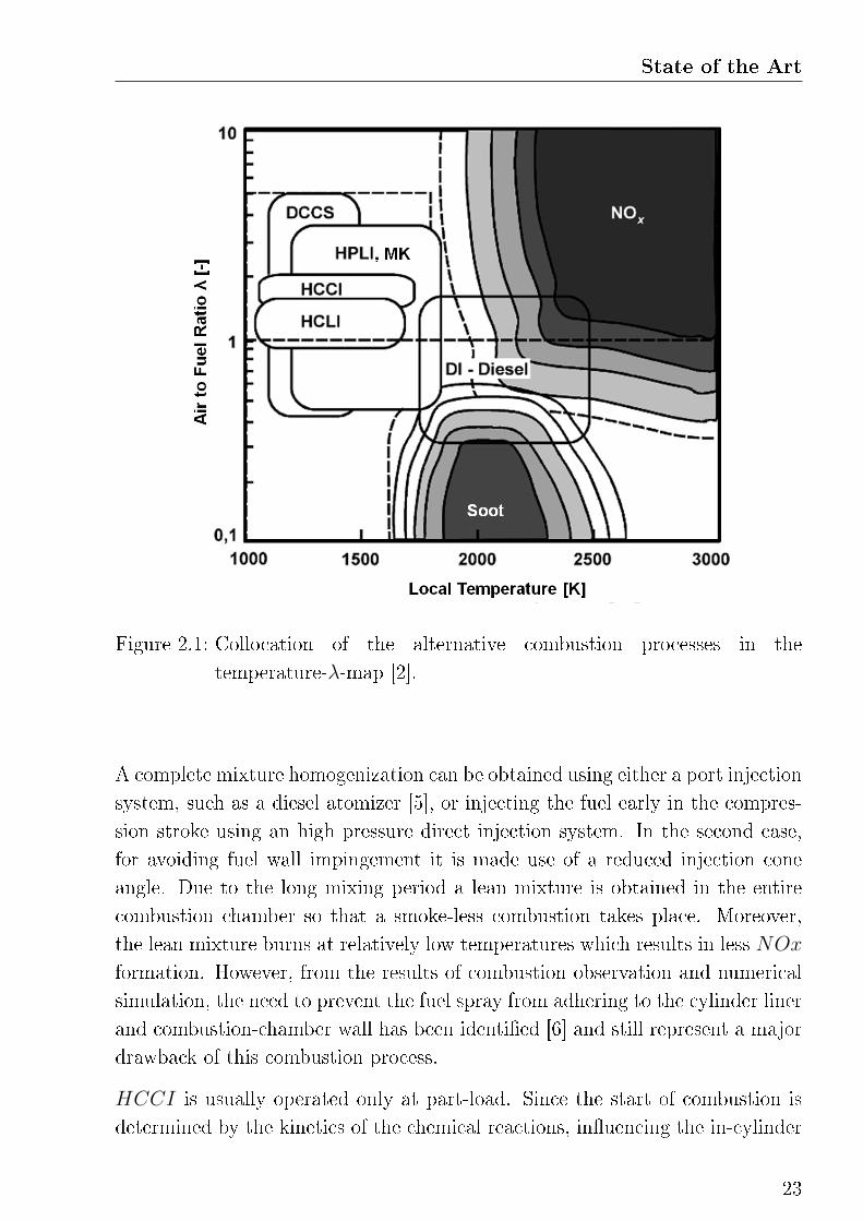
most renowned combustion processes and their collocation in a temperature/λ
map is shown in Figure 2.1.
2.1.2 Homogeneous combustion processes
Combustion processes in which thorough mixture homogenization is achieved
prior to ignition are known under the names of Homogeneous Compression
Charge Ignition (HCCI) and Premixed Charge Compression Ignition (PCCI).
Characteristic is the simultaneous ignition of multiple areas within the com-
bustion chamber, which are triggered by compression. The main objective of
HCCI combustion is to reduce NOx and PM emissions. The potential of
a zero-emission concept using HCCI combustion has been demonstrated under
laboratory conditions (using stationary and controlled boundary conditions).
However, the realization of this concept in modern engines is not possible, yet,
and for this reason, this work is not focusing on this kind of combustion process.
For the sake of completeness, only a brief description is given in this section.
22
State of the Art
Figure 2.1: Collocation of the alternative combustion processes in the
temperature-λ-map [2].
A complete mixture homogenization can be obtained using either a port injection
system, such as a diesel atomizer [5], or injecting the fuel early in the compres-
sion stroke using an high pressure direct injection system. In the second case,
for avoiding fuel wall impingement it is made use of a reduced injection cone
angle. Due to the long mixing period a lean mixture is obtained in the entire
combustion chamber so that a smoke-less combustion takes place. Moreover,
the lean mixture burns at relatively low temperatures which results in less NOx
formation. However, from the results of combustion observation and numerical
simulation, the need to prevent the fuel spray from adhering to the cylinder liner
and combustion-chamber wall has been identi�ed [6] and still represent a major
drawback of this combustion process.
HCCI is usually operated only at part-load. Since the start of combustion is
determined by the kinetics of the chemical reactions, in�uencing the in-cylinder
23
conditions is the only way to control combustion phasing. Therefore, engine
compression ratio, fuel properties and the degrees of freedom of the air path
become the main limiting factors for achieving higher loads. Beside the need
of assuring an appropriate auto-ignition timing over a large range of operation
conditions, increasing the load, thus approaching stoichiometry, the combustion
becomes unstable and knock-like cylinder pressure oscillations occur [7]. This
is particularly di�cult in transient operations, where the control of the desired
cylinder charge compostition becomes an even greater challenge.
Another obstacle of HCCI engine operations are the relative high emissions of
unburned hydrocarbon UHC and carbon monoxide CO which result from fuel
wall impingement and the low combustion temperatures of the lean combustion,
and are symptomatic for a low fuel conversion. Moreover, in HCCI processes
combustion may occur completely during the compression stroke, because of the
very short combustion duration, with a consequent e�ciency reduction and a
higher combustion roughness.
2.1.3 Partial homogeneous combustion processes
A description of LTC processes in which only a partial mixture homogenization
is attained is presented in this section. Partial homogenization mainly means
that even if an equal fuel/air distribution is promoted, the mixture still shows a
wide λ distribution at combustion onset. In other words, the combustion takes
place under heterogeneous conditions but the occurrence of extreme fuel rich
and lean areas is avoided.
Di�erently to HCCI, the fuel is injected towards the end of the compression
stroke. Since the use of pilot injection is not made, the in-cylinder conditions
by injection event are not su�cient to ignite the fuel and a mixing process takes
place prior to combustion. Main advantage of this strategy is the possibility of
phasing the combustion simply shifting the injection timing. Therefore, together
with the air path, the fuel path can be used for controlling the combustion pro-
cess. Another advantage of partial homogeneous combustion processes compared
to the full homogeneous ones is the reduced need of engine hardware modi�ca-
tions. In fact, in the most cases, a conventional high pressure injection system
can be utilized as well as a conventional air path. Fuel wall impingement is
24
State of the Art
avoided injecting the fuel into the piston bowl3.
Very low NOx and almost zero PM emissions can be achieved by the correct
application of partial homogeneous combustion processes. To this aim, large
exhaust gas recirculation is needed. Since high EGR and low combustion tem-
peratures lead to combustion deterioration and higher UHC emissions, it results
a target con�ict which a�ects the application of these processes. Many di�erent
solutions has been found in the past years in order to overcome this problem.
An overview of the most signi�cant ones is given in the following paragraphs.
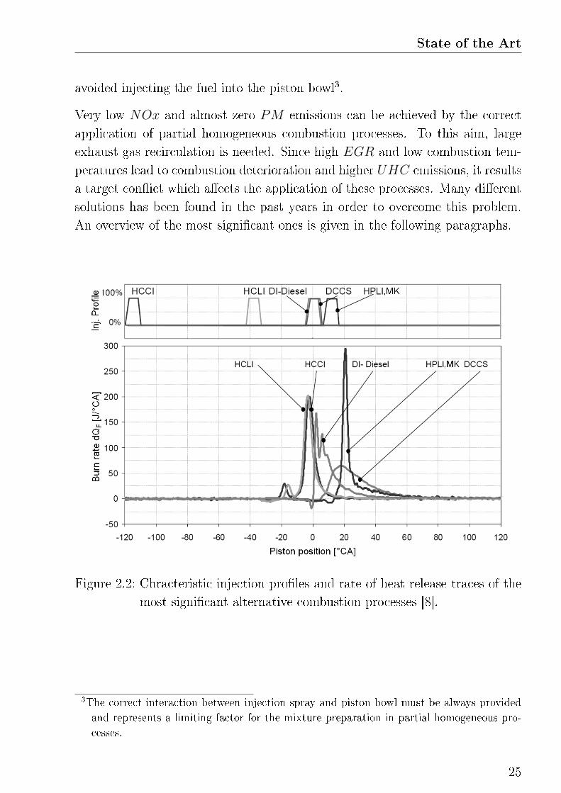
Figure 2.2: Chracteristic injection pro�les and rate of heat release traces of the
most signi�cant alternative combustion processes [8].
3The correct interaction between injection spray and piston bowl must be always provided
and represents a limiting factor for the mixture preparation in partial homogeneous pro-
cesses.
25
Homogeneous Charge Late Injection
Characteristic for Homogenous Charge Late Injaction (HCLI) combustion pro-
cesses is a high rate of mixture homogenization, which can be realized promoting
long combustion delay timing the injection event late in the compression phase
and using high rates of exhaust gas recirculation. Similar to the HCCI com-
bustion process, the mixture charge is well homogenized prior to ignition and
the combustion takes place almost simultaneously everywhere in the combustion
chamber [8]. A two phases heat release with cold and hot fuel reactions can be
also observed. However, di�erently to HCCI, since the fuel is injected using a
conventional high pressure injection system, wall wetting can be avoided.
Soot formation is avoided thanks to the high mixture homogenization. The
typical λ distribution is enclosed between 0.9 and 2. High rates of EGR up to
80% are responsible for low combustion temperatures and the suppression of
NOx formation. On the other side, the high rate of mixture homogenization
is the reason why the operation range of HCLI combustion is usually limited
at imep below 4 bar. Since the stoichimetric mixture is characterized by fast
fuel converstion, increasing the fuel quantity, thus approaching stoichiometry,
the rate of heat release becomes too high.
In [9] is shown how combustion phasing can be varied increasing combustion
e�ciency. Measurements on a one-cylinder engine, supported by CFD simula-
tion of the mixture formation, show an optimum between 35◦CA and 15◦CA
before TDC, depending on the operation load. A sensitivity analysis of di�er-
ent engine parameters in�uencing HCLI combustion using a 30 holes central
injector in a one-cylinder light-duty diesel engine has been carried out in [10].
A similar approach is proposed by AVLListGmbH in [11], where, under labora-
tory conditions, the potential of reducing engine out NOx and PM emissions
using HCLI combustion is showed. A very similar approach is proposed by
RICARDO under the name of Highly Pre-mixed Cool Combustion (HPCC).
This is the result of an investigation named ACTION (Advanced Combustion
Technology to Improve engine-Out NOx) which target is a cost e�ective reduc-
ing of NOx emissions to achieve Euro 5 legislative requirements [16]. Using an
advanced water coolant circuit to reduce EGR temperature and a twin stage
turbocharger, optimized for low pumping losses, in a low compression ratio en-
gine (ε 15.5:1) aNOx reduction of 85% relative to Euro 4 limitations is achieved.
26
State of the Art
An injection event near TDC by high injection pressure up to 1800 bar is used.
Combustion phasing is optimized for improving e�ciency and promoting long
ignition delay.
Highly Premixed Late Injection
Increasing the load, and therefore the fuel injection quantity, it is required to
retard the injection event phasing the combustion later in the expansion phase.
This is necessary for avoiding high rates of pressure rise. Since the air to fuel
ratio λ is already reduced by the large injected fuel mass, charge dilution using
EGR can only be used moderately for promoting ignition delay and thus the
mixing process. It results a di�erent combustion process, the so called Highly
Premixed Late Injection (HPLI). The mixing time is shorter compared to
the HCLI process and regions with λ lower stoichiometry are still present by
combustion onset.
Optical investigation of the combustion process has shown that in HPLI com-
bustion soot formation is not avoided during mixture formation but a strong
oxidation of the soot takes place in the second part of the combustion, which is
still characterized by high temperatures [8]. However, phasing the combustion
late in the expansion it results in a poor fuel conversion and higher CO and
UHC emissions compared to DI combustion. NOx-less and smokeless combus-
tion is still possible, but the importance of correct combustion phasing increases
drastically. The high exhaust gas temperatures may also become a limitation
for this process.
Using a commercial passenger-car diesel engine an optimal injection timing close
to TDC has been found in [9]. In [11] it is shown how injecting after TDC it is
possible to expand the operation range of LTC combustion up to 8 bar of imep.
Mudulated Kinetics
One of the �rst realizations of a partial homogeneous combustion processes has
been published by NissanMotorCO. Ltd. in [12]. The proposed concept is a
low-temperature premixed combustion system that aims at simultaneously re-
ducing NOx and PM emissions. The combustion temperature is lowered by
27
applying heavy EGR rate, which also result in a slower combustion velocity and
thus lower rates of pressure rise. Thorough premixed combustion is obtained
prolonging the ignition delay by retarding the fuel injection short before or after
the TDC. Essential condition is a complete injection of all fuel prior to ignition.
Additionally, high swirl ratio improves fuel dispersion reducing both smoke and
HC emissions.
Further investigation of the so called Modulated Kinetics (MK) concept, also
known under the name of late PCCI, are shown in [13]. Using cooled EGR,
increased injection pressure and a reduced engine compression ratio, a reduction
of the NOx emissions up to 90% compared to DI combustion is achieved si-
multaneously with a drastic reduction of the smoke level. Moreover, the process
can be expanded to the entire load range of everyday driving.
Dilution Controlled Combustion System
By Dilution Controlled Combustion System (DCCS) NOx and soot formation
are suppressed by applying up to 80% of cooled EGR to a conventional DI
combustion multiple injection strategy. Already by EGR rates of 40%, which
limits the combustion temperature below 2000K, NOx emissions can be eas-
ily avoided. By a further increase of the charge dilution, reducing the oxygen
content down to 9-10% and limiting the combustion temperature by 1500K,
smokeless combustion can be realized regardless of injection timing or injection
pressure [14], in other words, NOx and soot formation is suppressed indepen-
dent of mixture quality by combustion onset (over-retarded injection may results
in mis�re). However, under near stoichiometric or even under fuel rich operat-
ing conditions, CO and UHC emissions increase drastically and the thermal
e�ciency is deteriorated.
By the combustion process developed by Toyota [15], the so called Low Tempera-
ture Oxidation (LTO), in a restricted operating range low noise combustion and
su�cient exhaust gas temperature to activate catalyst reactions are obtained,
even under idling conditions. Moreover, by introducing this high temperature
and rich exhaust gas to a NOx storage reduction catalyst, NOx generated at
higher load can be completely puri�ed.
28
State of the Art
2.2 Pressure based diesel engine closed-loop
control
For the accomplishment of the new legislative emission limits, substantial im-
provements in the engine control system are necessary. Together with the in-
creasing complexity of new exhaust gas aftertreatment systems and their man-
agement, future engine control system must be capable of ensuring application
targets and combustion stability over a long engine lifetime regardless of fuel
quality.
Pressure based closed-loop combustion control represents a feasible solution for
the coming ECU generation. With an evaluation of the indicated pressure,
using dedicated algorithms, the combustion process can be adjusted in response
of variations of disturbance variables, such as charge composition or temperature,
in order to attain emissions, noise and e�ciency targets. Moreover, closed-loop
combustion control has the potential of enabling the use of NOx-smoke-less
alternative combustion processes, which, as explained in the previous section,
are a�ected by combustion stability problems due to the high sensitivity to the
charge composition. For this reason, many di�erent approaches for controlling
LTC combustion have been published in the last decade. Thanks to the recent
development of cost a�ordable pressure sensors which are integrated in the glow
plug (PSG, BorgWarnerBERUSystemsGmbH) and are able to feed commercial
ECUs with in-cylinder pressure inofrmation [17], the interest in a closed-loop
combustion control is grown signi�cantly for alternative as well as for standard
diesel combustion applications.
Coherently to the aim of this work, i.e. the realisation of a pressure based
closed-loop control strategy for the low temperature pre-mixed combustion, the
following paragraphs mainly focus on the state of the art regarding closed-loop
combustion control of lot-temperature premixed processes in which in-cylinder
pressure sensors are used. For more information about other solutions, e.g. emis-
sions based, noise based ore generally model based combustion control strategy,
it is referred to [1].
To the best knowledge of the author, the �rst realization of a pressure based
closed-loop combustion control focused on balancing the indicated torque be-
29
tween the cylinders adjusting the fuel injection quantity and has been presented
in [18]. Since there is a direct physical correlation between indicated cylinder
pressure and injection quantity, or simply the injection duration, this control
can be realized using a single-input single-output (SISO) system. Together with
a reduction of the engine vibrations, this solution provides a continuous com-
pensation of engine aging processes. More complicated is however the control of
other relevant combustion criteria, e.g. the combustion beginning, the center of
energy-conversion or the maximum rate of pressure rise.
In [19], the authors propose a closed-loop control based on a pressure trace eval-
uation method called Pressure Ratio Management. Dividing the actual pressure
trace of a �red cylinder by the stored motored pressure, the amount of heat
release per unit charge mass is obtained. Information about the combustion
phasing and the air/fuel ratio can be obtained and implemented in a closed-loop
system for controlling the spark timing and the rate of EGR. This method has
been demonstrated on a SI engine with lean combustion but can be also applied
to DI or LTC combustion.
Exploiting the di�erent autoignition properties of iso-octane, which is self-
ignition resistant, and n-heptane, which on the contrary easily self ignites, and
creating a mixture with a speci�c rate of these fuels adjusting the injected
amount respectively, a closed-loop control of the CA50 in a HCCI multi cylin-
der engine is shown in [20]. The same authors propose a concept which exploit
the potential of a variable compression ratio (from 9:1 to 21:1) to phase the
CA50 in a HCCI prototype engine [21]. Since the compression ratio can not
be adjusted individually for each cylinder, the CA50 is additionally corrected
by means of λ, thus an equal distribustion of the imep can not be provided. An
further improvement of this concept using Fast Thermal Management is shown
in [22]. Rapidly changing the charge temperature using an electrical inlet air
pre-heater, the system response of the combustion phasing by step changes is re-
duced to only 8 engine cycles, 57% faster compared to the previous achievements.
However, the intention of these works is mainly to demonstrate a functioning
control system for HCCI engines operated under laboratory conditions rather
than to propose a concept for the use in commercial engines.
Under the name of EmIQ, for Intelligent Emission Reduction, AVLListGmbH
proposes a combined DI-LTC strategy which aims in reducing emissions while
30

State of the Art
maintaining good drivability [23][24]. Fundament of this concept is the pressure
based closed-loop combustion control which provides targeted combustion phas-
ing for both DI and LTC mode by shifting the injection timing, and maintains
engine noise in a acceptable range by tuning the EGR rate and thus the max-
imum pressure rise. This solution has been �rst tested and validated using a
one-cylinder engine equipped with a fully electro-hydraulic valve train, which is
capable of rapidly change the rate of EGR, but is realized in the full engine only
using the cooled EGR loop and the throttle valve. Although a cross-sensitivity
between the control parameters and the non-respective disturbing variables is
observed, a su�cient control quality is achieved via two independend SISO con-
trollers. A signi�cant NOx and PM emissions reduction is achieved by applying
HCLI and HPLI combustion at low-load and switching to DI combustion for
higher torque requirements. In LTC mode consistently higher CO and UHC
emissions are measured.
Rapid adjustments of the charge composition, i.e. pressure, temperature and
rate of dilution, are not possible using a standard EGR loop with cooling bypass.
A fully �exible Variable Valve Actuation (V V A) system has been demonstrated
to be a feasible solution to this aim. In [25], using a single-cylinder research
engine equipped with a V V A system and run by a 99% propane fuel blend, the
potential of controlling HCCI combustion by means of exhaust residual gas has
been demonstrated. Near the possibility of controlling combustion phasing over
the air/fuel equivalence ratio, an increase of the initial mixture temperature,
for promoting the auto-ignition process at low-load, is also possible. Another
concept exploiting the potential of the V V A technology is shown in [26] under
the name of Combined Combustion System (CCS), VolkswagenAG. In LTC
combustion mode, the mixture reactivity, and so the rate of pressure rise, is con-
trolled setting the e�ective compression ratio and the residual gas fraction. Op-
timal combustion e�ciency, by a CA50 short after TDC, is obtained controlling
the injection timing of a single injection event late in the compression. High rates
of EGR are obtained using both high and low pressure EGR. A similar concept
has been proposed by the BMWGroup on a gasoline engine equipped with dual
VANOS (variable valve timing) and Valvetronic (variable valve lift) systems,
water cooled EGR loop and direct injection [27]. The proposed closed-loop con-
trol provides a cylinder balancing of the imep over the injection mass, and of
the CA50 by means of residual gas fraction. To ensure auto-ignition, torque
31
balancing and a low combustion noise during transients, an online adaptation of
the controller output takes place in a neural network of type LOLIMOT4 which
combines the information from the pressure measurement with a cylinder charge
model for optimal valve timing. Finally, to overcome the problems related to the
high costs of a fully V V A system and its realization in commercial applications,
RobertBoschGmbH proposes a closed-loop control concept that works with a
partly �exible valve train with cam phasers [28]. Di�erently to a fully V V A
system, were charge composition can be adjusted individually for each cylinder,
the cam phaser has a global e�ect on all cylinders. Based on this technology, a
Multiple Input Multiple Output (MIMO) control strategy for gasoline HCCI
combustion is proposed. In a cascade control structure, the imep and the CA50
(target value is set at 8◦CA after TDC) are controlled using injection quantity
and timing respectively. The residual gas fraction is than adjusted over the cam
phaser in a secondary inner loop in order to additionally phase the combustion.
Aim of the inner loop is to minimize the deviation of the averaged injection
timing from its feed-forward value. Alternatively, to the aim of an exhaust af-
tertreatment strategy, exhaust λ can be also adopted as target parameter for
the inner loop. The high temperatures required for the auto-ignition process are
obtained by a marked negative valve overlapping (early EVC and late IVO).
Through the ACTION project, presented in the previous section, RicardoLtd.
has demonstrated the potential of highly low-temperature premixed combustion
as a practical approach to signi�cantly reduce engine-out NOx emissions. In
a further collaboration with GM, which aims in achieving US Super Ultra-Low
Emission (SULEV ) and Tier 2 Bin 5 requirements without the use of NOx
aftertreatment systems, which is designated under the name ADEC (Advanced
Diesel Engine Control), a closed-loop control of the combustion process is de-
veloped [29]. Using in-cylinder pressure sensors, the ADEC coordinates fuel
injection quantity and timing with the air path providing a CA50 balance be-
tween the cylinders, a limitation of the maximum pressure and combustion sta-
bility. This control strategy has been demonstrated on a 1.9-liter diesel engine
with advanced air handling system, a two-stage turbocharger and an advanced
exhaust gas recirculation with cooling bypass. The closed-loop control of the
low temperature pre-mixed diesel combustion is also object of a study presented
4Local linear model tree (LOLIMOT) is a type of Takagi-Sugeno-Kang neural network fuzzy
algorithm.
32
State of the Art
by DelphiCorporation in [30]. Using a rapid prototyping unit connected to a
combustion analysis system on a multi-cylinder engine, the in-cylinder pressure
traces are evaluated for the estimation of the imep and the CA50. A reduction
of the cylinder-to-cylinder variations of these combustion parameters is shown
under transient conditions. However, due to the pressure evaluation execution
structure, which takes 720◦CA for the calculations, real time control is not pos-
sible.
In recent works, [31], [32] and [33], the potential of an Iterative Learning Control
(ILC) algorithm is demonstrated in a combined LTC-DI combustion strategy.
In the CA50 control, the feed-forward value for the injection timing is extended
by a physical model of the ignition delay. Input parameter for the model are
charge dilution, cylinder pressure and intake manifold temperature. Moreover,
model prediction accuracy is improved storing the actual value of the actuat-
ing variable in a so called o�set-map. The CA50 control is than extended for
attaining combustion noise and stability targets through �exible shaping of the
injection characteristics and self-sustaining en- and disabling of the pilot injec-
tions. A similar approach is published in [34] and [35]. The response of the
CA50 control is improved by a non-linear model-based correction of the feed-
forward map which compensates changes in the ignition delay due to deviations
of the charge composition. Information about the in-cylinder air mass and the
rate of EGR are obtained evaluating the indicated pressure trace. Also in this
case, system learning is done storing the actuating variable values in a map.
2.3 Alternative-conventional combined mode
Since the application of alternative combustion systems is limited in the part-
load range, the ability of switching to conventional combustion becomes a rel-
evant task of the control strategy. This has been also the topic of some recent
publication.
The CCS concept of VolkswagenAG is able of switching the combustion mode
in order to provide a wide range of engine drivability and optimal e�ciency (8%
improvement in NEDC) [26]. The switching procedure must provide a neutral
torque signal. In this process, the switch between di�erent injection strategies
33
and especially the large charge dilution di�erence is recognized as the greatest
challenge. However, further details about the implemented switching strategy
are not given. Stationary and dynamic switching procedures between PCCI
and conventional di�usive combustion are shown in [75]. In this work a limit
fuel quantity has been chosen as mode switching criterion. It can be seen how,
due to the di�erent system response of the air and the fuel path, an improper
strategy may result in poor combustion e�ciency. The imep signal is not steady
and an increased engine noise is measured during the switching procedure, as
well as a signi�cant increase in UHC emissions.
More reliable is the solution proposed in [28]. The combustion mode is switched
from HCCI to SI mode when the net mean e�ective pressure (nmep) reaches
the limit value of 3.5 bar. To overcome the problematic of the di�erent EGR
rates between the two combustion modes, dynamic corrections of the closed-loop
controllers have been implemented. In this way, the transition can be better
synchronized and oscillations of the torque signal can be avoided.
In [36], only stationary measurements are shown. The switching procedures
starts with an EGR rate increase or decrease depending on the switching di-
rection. The injection pressure and the desired maxdp/dphi value are changed
only when the injection timing has been shifted of 3◦CA by the controller. At
6◦CA after the beginning of the switching procedure the injection strategy is
commuted. However, also this solution does not provide a steady imep signal
and phases characterized by poor combustion quality or, inversely, high rates of
pressure rise are measured.
34
3
Theoretical Background
The combustion process in an ICE is in�uenced by a large
variety of parameters. An exhaustive explanation of all of
them would be an enormous task. In order to better under-
stand the investigation done in this work a selection of the
most relevant ones is proposed in this chapter.
3.1 Piston dynamic
Among the mechanisms in�uencing the combustion process in a reciprocating
ICE particular attention has to be given to the piston kinematics. The piston
is not only the device needed to convert the energy released during the fuel
combustion into mechanical motion but, another fundamental task of this device
is to preset the conditions needed in order to induce the chemical combustion
process. It must be considered that, di�erently to other ICEs (turbines, jet or
rocket engines), in piston engines the combustion process is intermitted and has
to be initiated by every new cycle. This and other mechanisms makes an ICE
a very complex system. A selection of the most signi�cant ones, which will be
discussed in the present chapter, is shown in Figure 3.1.
The piston is connected to the engine crankshaft using a connecting rod. Its
cyclical motion is guided by the cylinder walls and can be described by the
following trigonometrical function:
sϕ = r
(1 +
l
r− cosϕ− l
r
√1−
(rl
)2sin2 ϕ
)(3.1)
35
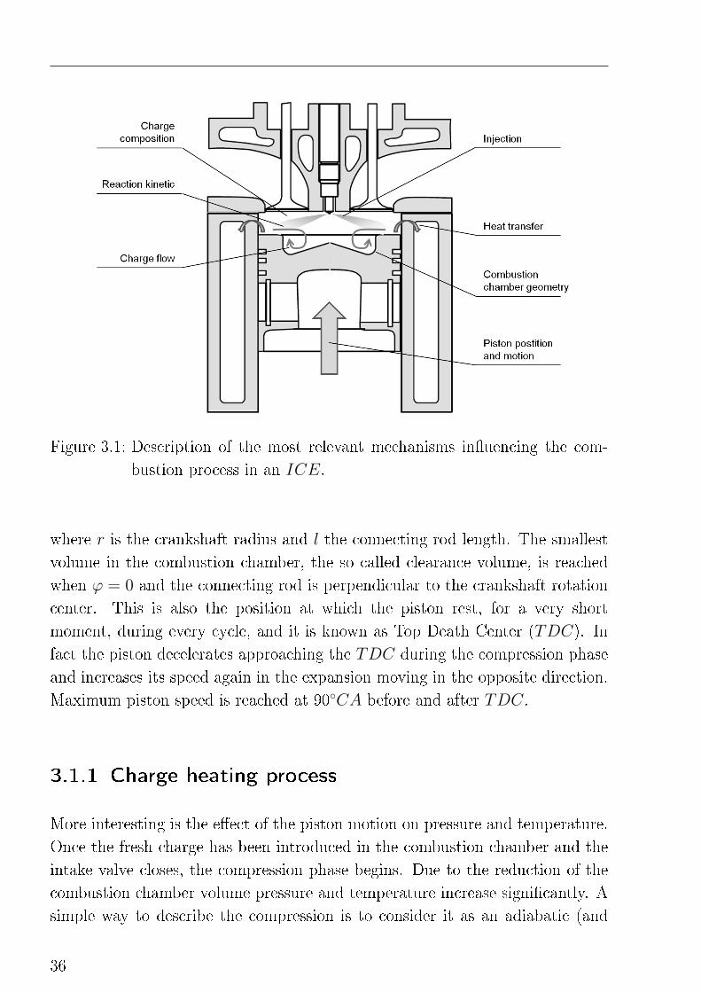
Figure 3.1: Description of the most relevant mechanisms in�uencing the com-
bustion process in an ICE.
where r is the crankshaft radius and l the connecting rod length. The smallest
volume in the combustion chamber, the so called clearance volume, is reached
when ϕ = 0 and the connecting rod is perpendicular to the crankshaft rotation
center. This is also the position at which the piston rest, for a very short
moment, during every cycle, and it is known as Top Death Center (TDC). In
fact the piston decelerates approaching the TDC during the compression phase
and increases its speed again in the expansion moving in the opposite direction.
Maximum piston speed is reached at 90◦CA before and after TDC.
3.1.1 Charge heating process
More interesting is the e�ect of the piston motion on pressure and temperature.
Once the fresh charge has been introduced in the combustion chamber and the
intake valve closes, the compression phase begins. Due to the reduction of the
combustion chamber volume pressure and temperature increase signi�cantly. A
simple way to describe the compression is to consider it as an adiabatic (and
36
Theoretical Background
isentropic) process. This means that, following the �rst law of thermodynamic,
there is no heat exchange with the system boundary and the complete energy
resulting from the piston work W is transformed into internal energy of the
charge U .
dU = dW where dU = m · cv · dT and dW = p · dV (3.2)
Solving this equation using the ideal gas law P · V = m ·R · T the dependency
of pressure and temperature from the combustion chamber volume can be easily
found:
pend = pstart
(VstartVend
)κTend = Tstart
(VstartVend
)κ−1(3.3)
where κ is the adiabatic index which results from the ratio of the heat capacity at
constant pressure cp to heat capacity at constant volume cv. κ has, under stan-
dard conditions, a value of 1.4 for air and approximatively 1.36 for exhaust gas.
The volumetric ratio between start and end of the compression can be approx-
imated with the engine compression ratio ε. Considering this equation and the
piston motion described by equation 3.1 pressure and temperature traces for the
motored engine can be easily calculated. Following this idealized dependency,
the maximum value for pressure and temperature is reached at TDC.
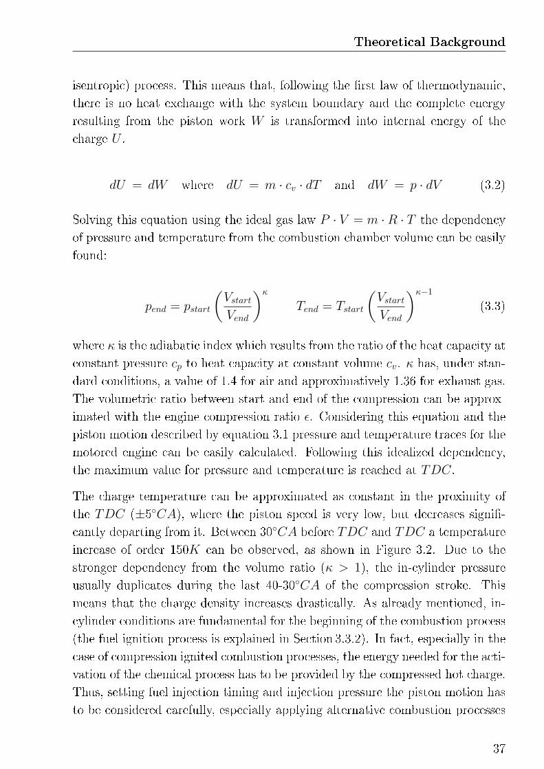
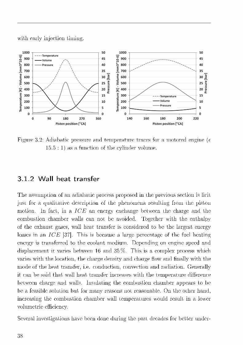
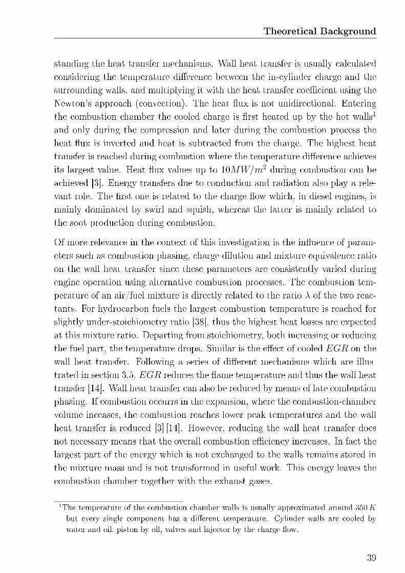
The charge temperature can be approximated as constant in the proximity of
the TDC (±5◦CA), where the piston speed is very low, but decreases signi�-
cantly departing from it. Between 30◦CA before TDC and TDC a temperature
increase of order 150K can be observed, as shown in Figure 3.2. Due to the
stronger dependency from the volume ratio (κ > 1), the in-cylinder pressure
usually duplicates during the last 40-30◦CA of the compression stroke. This
means that the charge density increases drastically. As already mentioned, in-
cylinder conditions are fundamental for the beginning of the combustion process
(the fuel ignition process is explained in Section 3.3.2). In fact, especially in the
case of compression ignited combustion processes, the energy needed for the acti-
vation of the chemical process has to be provided by the compressed hot charge.
Thus, setting fuel injection timing and injection pressure the piston motion has
to be considered carefully, especially applying alternative combustion processes
37
with early injection timing.
Figure 3.2: Adiabatic pressure and temperature traces for a motored engine (ε
15.5 : 1) as a function of the cylinder volume.
3.1.2 Wall heat transfer
The assumption of an adiabatic process proposed in the previous section is licit
just for a qualitative description of the phenomena resulting from the piston
motion. In fact, in a ICE an energy exchange between the charge and the
combustion chamber walls can not be avoided. Together with the enthalpy
of the exhaust gases, wall heat transfer is considered to be the largest energy
losses in an ICE [37]. This is because a large percentage of the fuel heating
energy is transferred to the coolant medium. Depending on engine speed and
displacement it varies between 16 and 35%. This is a complex process which
varies with the location, the charge density and charge �ow and �nally with the
mode of the heat transfer, i.e. conduction, convection and radiation. Generally
it can be said that wall heat transfer increases with the temperature di�erence
between charge and walls. Insulating the combustion chamber appears to be
be a feasible solution but for many reasons not reasonable. On the other hand,
increasing the combustion chamber wall temperatures would result in a lower
volumetric e�ciency.
Several investigations have been done during the past decades for better under-
38
Theoretical Background
standing the heat transfer mechanisms. Wall heat transfer is usually calculated
considering the temperature di�erence between the in-cylinder charge and the
surrounding walls, and multiplying it with the heat transfer coe�cient using the
Newton's approach (convection). The heat �ux is not unidirectional. Entering
the combustion chamber the cooled charge is �rst heated up by the hot walls1
and only during the compression and later during the combustion process the
heat �ux is inverted and heat is subtracted from the charge. The highest heat
transfer is reached during combustion where the temperature di�erence achieves
its largest value. Heat �ux values up to 10MW/m2 during combustion can be
achieved [3]. Energy transfers due to conduction and radiation also play a rele-
vant role. The �rst one is related to the charge �ow which, in diesel engines, is
mainly dominated by swirl and squish, whereas the latter is mainly related to
the soot production during combustion.
Of more relevance in the context of this investigation is the in�uence of param-
eters such as combustion phasing, charge dilution and mixture equivalence ratio
on the wall heat transfer since these parameters are consistently varied during
engine operation using alternative combustion processes. The combustion tem-
perature of an air/fuel mixture is directly related to the ratio λ of the two reac-
tants. For hydrocarbon fuels the largest combustion temperature is reached for
slightly under-stoichiometry ratio [38], thus the highest heat losses are expected
at this mixture ratio. Departing from stoichiometry, both increasing or reducing
the fuel part, the temperature drops. Similar is the e�ect of cooled EGR on the
wall heat transfer. Following a series of di�erent mechanisms which are illus-
trated in section 3.5, EGR reduces the �ame temperature and thus the wall heat
transfer [14]. Wall heat transfer can also be reduced by means of late combustion
phasing. If combustion occurrs in the expansion, where the combustion-chamber
volume inceases, the combustion reaches lower peak temperatures and the wall
heat transfer is reduced [3] [14]. However, reducing the wall heat transfer does
not necessary means that the overall combustion e�ciency increases. In fact the
largest part of the energy which is not exchanged to the walls remains stored in
the mixture mass and is not transformed in useful work. This energy leaves the
combustion chamber together with the exhaust gases.
1The temperature of the combustion chamber walls is usually approximated around 350K
but every single component has a di�erent temperature. Cylinder walls are cooled by
water and oil, piston by oil, valves and injector by the charge �ow.
39
A characterization of the wall heat transfer in alternative combustion processes is
carried out in [40]. Experiments shows a nearly steady and uniform distributed
increase of the wall temperatures for highly premixed combustion whereas in
DI mode a large inhomogeneity of the temperature increase is measured. This
di�erence results in a lower heat transfer for the premixed combustion process.
Another interesting aspect related to the wall heat transfer is the so called ther-
modynamic loss angle which a�ects the measurement of the in-cylinder pressure.
Due to the heat losses (and leakages) the pressure peak of a motored engine does
not correlate with the piston position at TDC, as shown by the simpli�ed cor-
relations between piston motion and in-cylinder pressure shown in the previous
section, but it is shifted a couple of degrees CA earlier in the compression. The
thermodynamic loss angle has to be taken into account by the analysis of the
indicated pressure data, �rst by calibrating the TDC reference respect to the
motored pressure curve2 and later by the interpretation of the data, such as
emissions and combustion e�ciency, in order to avoid interpretation errors.
3.2 Mixture formation
The goal by designing the mixture formation process is to achieve a large distri-
bution of the fuel in the combustion chamber while simultaneously reducing the
droplet size, in order to increase the exchange surface area. This is necessary for
ensuring the fuel evaporation, which is an essential requirement for the onset of
the chemical processes.
In high speed modern diesel engines the fuel is introduced into the combustion
chamber using an injector nozzle. Exiting the injector through one ore more
holes the fuel jet forms a cone-shaped spray. In the proximity of the nozzle the
spray is mainly dominated by large drops and �uid ligaments, whereas in the
outer regions disintegrated fuel structures can be found and evaporation takes
place. The distribution of the fuel in the spray, the spray cone angle and the
spray tip penetration are very important for the quality of the mixing process.
Also the position of the injector in the combustion chamber and the spatial
2There are two methods for de�ning the exact TDC shift, using a capacitative TDC sensor
or analyzing the pressure trace in the motored mode. In the second case a correction by
the thermodynamic loss angle is needed.
40
Theoretical Background
arrangement of the sprays play an important role. These have to be chosen
in accordance with the combustion chamber and piston geometry (bowl) for
avoiding fuel wall impingement and providing maximum combustion e�ciency.
The mixture formation process has a limited time which duration is limited
by the ignition delay. As soon as combustion takes places a reaction of fast
chemical processes occurs and the local mixture formation process is interrupted.
Therefore, for avoiding poor mixing quality long ignition delay is favored.
Mixture formation can be also promoted by shaping the charge �ow in the
combustion chamber. This can be done designing the intake channels in order
to create a rotational �ow or exploiting the piston movement during compression
which pushes the charge into the cylinder bowl. However these solutions may
lead to increased heat losses or, if not applied correctly, to a deterioration of the
mixing process such as over-swirl, for an instance.
3.2.1 Fuel injection
Nowadays, high pressure direct injection systems can be found in almost every
passenger car diesel engine. Modern injection systems are capable of multiple
injection events with di�erent duration and injection pressures up to 2000 bar.
This is realized using solenoid or piezoelectric valves controlled by an ECU . The
fuel is stored under high pressure in a distribution pipe, also known as common
rail3, which is directly connected to the injection valves. The high pressure is
provided by a piston pump driven by the engine camshaft [41]. Using these
systems, a �ne adjustment of the fuel injection time and quantity is possible
independent of engine load and speed.
In the nozzle the fuel is accelerated before entering the combustion chamber.
The pressure stored in the common rail is so converted into kinetic energy.
During this phase cavitation4 and turbulence take place in the nozzle internal
3The common rail system prototype was developed in the late 1960s by Robert Huber of
Switzerland and further developed by Dr. Marco Ganser at the Swiss Federal Institute
of Technology in Zurich. After research and development by the FiatGroup, the design
was acquired by the RobertBoschGmbH for completion of development and re�nement
for mass-production.4When a liquid is subjected to rapid changes of pressure, e.g. due to constrictions and
41
�ow. These phenomena play an important role in the breakup process of the
fuel spray. Generally it can be said, that cavitation in the nozzle increases fuel
atomization [42]. The geometry of the injector holes also determines the shape
of the injection fuel cone and its penetration depth in the combustion chamber.
During injection the fuel is transported in the outer regions of the combustion
chamber and is mixed with the charge. Liquid fuel is injected, usually late in the
compression stroke, in a high-density mixture of air and exhaust gases. There-
fore, high injection pressure is fundamental for achieving the required kinetic
energy, which is the most important parameter for the mixture formation [2].
Exchange momentum and droplet size mainly depend from this parameter. An-
other advantage of using high injection pressures is the reduced need of swirl
and squish movements of the charge, with a signi�cant reduction of heat losses
through the combustion chamber walls.
3.2.2 Spray penetration
Spray penetration has an important in�uence on the mixture formation. Imping-
ment of liquid fuel on cool surfaces inside the combustion chamber may results
from over-penetration of the spray and leads to undesired emissions due to un-
burned or partially burned fuel. On the other side, under-penetration reduces
the air utilization and results in poor mixture homogenization.
Fuel spray penetration in the combustion chamber does not only depend from the
injection pressure and the fuel properties. The number of injection holes and
their geometry are also very important for achieving good mixture formation
and high combustion e�ciency, and they must be accurately designed in order
to accomplish combustion geometry requirements. Together with the injection
pressure, the number of injection holes has been continuously increased in the
past years. Prerequisite for maintaining same injection duration is a reduction of
the nozzle diameter [2]. Finally, charge movements may also in�uence the spray
penetration. In fact, swirl does not only improve fuel spreading by deviating the
spray cone but reduces the fuel penetration as well [3].
bends in the nozzle, the formation of vapor bubbles may occour. This phenomenon, called
cavitation, can lead to excessive surface stress and material erosion.
42
Theoretical Background
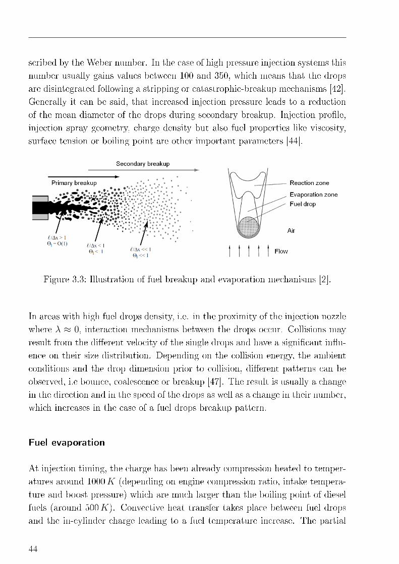
3.2.3 Fuel spray breakup and evaporation
The ignition delay, i.e. the time between start of injection and start of combus-
tion, can be divided in a physical and a chemical phase. The physical delay is
the time needed for the preparation of the fuel into a reactive mixture. During
this phase, fuel atomization (fuel spray breakup) and evaporation take place.
The chemical delay is the time needed for the pre-combustion reactions between
evaporated fuel and the charge components.
Fuel spray breakup
Fuel spray breakup is divided in two consecutive steps, a primary breakup phase,
in which ligaments and both large and small drops are formed from the fuel jet
and sheets, and a secondary phase, in which fuel atomization occurs as a result
of aerodynamic e�ects. These processes are required for increasing the exchange
surface between fuel and air and thus promoting fuel evaporation. The smaller
the mean droplet diameter the larger will be this surface.
Primary fuel spray break up describes the initial disaggregation of the fuel stream
into ligaments and primary drops. This process can begin already in the injector
nozzle due to e�ects of cavitation and turbulence or once the fuel exits the
injector holes and is subjected to the aerodynamic forces resulting from the
speed di�erence between fuel spray and in-cylinder charge. There exist di�erent
breakup patterns which depend from the injection pressure, the nozzle geometry
and the fuel properties. However, for a high pressure injection system like the
one used in this work (injection pressures larger than 300 bar), a disintegration
pattern of the fuel jet into drops, which diameter is smaller than the one of the
injector hole, can be assumed [43].
A further breakup of the primary drops is mainly determined by aerodynamic
forces. As a consequence of the high injection pressure, the speed di�erence
of the fuel drops relative to the in-cylinder charge is very high. This leads to
a deformation of the drops shape, caused by the asymmetrical pressure distri-
bution around the surface, and a further disintegration in even smaller units.
Also in this case di�erent breakup patterns are possible, which depend from
the relationship of mass inertia force and surface-tension force for a drop, de-
43
scribed by the Weber number. In the case of high pressure injection systems this
number usually gains values between 100 and 350, which means that the drops
are disintegrated following a stripping or catastrophic-breakup mechanisms [42].
Generally it can be said, that increased injection pressure leads to a reduction
of the mean diameter of the drops during secondary breakup. Injection pro�le,
injection spray geometry, charge density but also fuel properties like viscosity,
surface tension or boiling point are other important parameters [44].
Figure 3.3: Illustration of fuel breakup and evaporation mechanisms [2].
In areas with high fuel drops density, i.e. in the proximity of the injection nozzle
where λ ≈ 0, interaction mechanisms between the drops occur. Collisions may
result from the di�erent velocity of the single drops and have a signi�cant in�u-
ence on their size distribution. Depending on the collision energy, the ambient
conditions and the drop dimension prior to collision, di�erent patterns can be
observed, i.e bounce, coalescence or breakup [47]. The result is usually a change
in the direction and in the speed of the drops as well as a change in their number,
which increases in the case of a fuel drops breakup pattern.
Fuel evaporation
At injection timing, the charge has been already compression heated to temper-
atures around 1000K (depending on engine compression ratio, intake tempera-
ture and boost pressure) which are much larger than the boiling point of diesel
fuels (around 500K). Convective heat transfer takes place between fuel drops
and the in-cylinder charge leading to a fuel temperature increase. The partial
44
Theoretical Background
pressure on the drop surface rises and a di�usive transport of fuel mass outside
the drop boundaries takes place, i.e. the fuel evaporates [45]. Fuel evaporation
is an essential mechanism for the onset of the chemical reactions.
Promoting heat transfer is fundamental for achieving high fuel evaporation. This
can be done increasing the kinetic energy of the drops, e.g. increasing injection
pressure. As already mentioned, high kinetic energy leads to smaller drop diam-
eter and thus a larger surface area for the exchange process. Moreover, induced
convection5 can be promoted as well as a larger dispersion of the drops in the
charge (so called air entrainment). Near the kinetic energy and the dimension of
the drops, also the fuel properties and the charge composition play an important
role in the fuel evaporation process.
During fuel evaporation a decrease of the charge temperature can be observed.
In fact, the energy needed for heating the fuel at �rst, and for overcoming the
enthalpy of evaporation at next, leads to a marked local cooling of the charge.
This cooling e�ect has a signi�cant in�uence on the chemical reactions that take
place by combustion onset (see Section 3.3).
3.2.4 Charge movement
In-cylinder charge movement is an e�ective way for improving the mixture for-
mation. Two solutions are known to be particularly interesting for diesel com-
bustion processes, i.e. swirl, which is induced by the intake channel, and squish,
which results from the forced charge �ow into the piston bowl generated dur-
ing compression. Charge �ow improves the mixing process but, at the same
time, may lead to increased heat losses and reduced volumetric e�ciency, if not
applied properly.
Swirl
Swirl is usually de�ned as an organized rotation of the charge about the cylinder
axis [3]. A swirl motion results from the angular momentum impressed in the
5If there exists a positive speed di�erence between drops and charge the evaporated fuel can
be transported away from the drop surface and new fuel can evaporate.
45
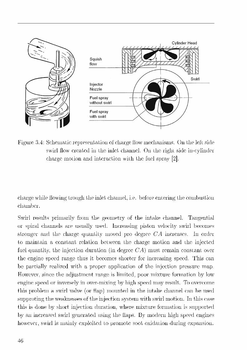
Figure 3.4: Schematic representation of charge �ow mechanisms. On the left side
swirl �ow created in the inlet channel. On the right side in-cylinder
charge motion and interaction with the fuel spray [2].
charge while �owing trough the inlet channel, i.e. before entering the combustion
chamber.
Swirl results primarily from the geometry of the intake channel. Tangential
or spiral channels are usually used. Increasing piston velocity swirl becomes
stronger and the charge quantity moved pro degree CA increases. In order
to maintain a constant relation between the charge motion and the injected
fuel quantity, the injection duration (in degree CA) must remain constant over
the engine speed range thus it becomes shorter for increasing speed. This can
be partially realized with a proper application of the injection pressure map.
However, since the adjustment range is limited, poor mixture formation by low
engine speed or inversely in over-mixing by high speed may result. To overcome
this problem a swirl valve (or �ap) mounted in the intake channel can be used
supproting the weaknesses of the injection system with swirl motion. In this case
this is done by short injection duration, where mixture formation is supported
by an increased swirl generated using the �aps. By modern high speed engines
however, swirl is mainly exploited to promote soot oxidation during expansion.
46
Theoretical Background
Squish
During the compression stroke, the swirl produced using the intake channel is
gradually replaced by a squish movement. Squish is the gas motion which re-
sults when the piston is approaching the cylinder head an pushes the charge
portion placed in the circumference of the combustion chamber towards the
middle creating a radial inward gas motion. By the presence of a ω-bowl in
the piston, such as by modern passenger car diesel engines, this motion results
in a toroidal-shaped �ow. Moving from the combustion chamber into the pis-
ton bowl the charge �ows in the opposite direction to that of the injected fuel
spray. This circumstance increases the exchange-momentum improving mixture
homogenization.
During cylinder expansion the �ow direction is inverted. Also in this phase,
squish is important for sustaining the combustion and helps late oxidation pro-
cesses [2]. Squish increases with the engine speed. A larger cylinder bore diam-
eter promotes swirl, on the contrary a wider piston bowl reduces it [3]. Swirl
achieve its maximum short before TDC.
3.3 Combustion process
In alternative low-temperature premixed combustion processes the chemical ki-
netics plays a dominant role during the ignition and combustion phases. The
heat release is characterized by a two step process in which the main combus-
tion is preceded by a low-temperature reaction, the so called cool-�ame. The
oxidation of hydrocarbon fuels such as diesel occurs according to two rami�-
cation mechanisms which relevance depends from the ambient conditions. The
formation and accumulation of metastable hydroperoxide intermediates at low
temperatures delay the onset of the high-temperature reaction. Increasing the
temperature the chemical equilibrium is shifted to the production of reactive
radicals and a fast high exothermal oxidative reaction takes place.
47
3.3.1 Ignition delay
Once the fuel is mixed with the charge and evaporation has occurred some time
is still needed till combustion can be detected. This time (or CA) interval is
de�ned as chemical ignition delay. During this period pre-combustion reactions
between the fuel and the charge components (air and exhaust gas) take place.
These processes depend on the fuel characteristics, the charge composition and
the ambient conditions, i.e. in-cylinder temperature and pressure, as well as
their distribution in the combustion chamber. Among these parameters auto-
ignition properties of the fuel plays a large role. This are usually de�ned by the
cetane number, which describes the ignition delay of a fuel compared to the one
of a reference fuel mixture, as described in [3]. A low cetane number correspond
to a higher resistance to ignition, thus a longer ignition delay. For engine op-
eration strategies in which the combustion process is controlled by the rate of
injection, i.e. by di�usive diesel combustion, a high catane number is favored.
On the contrary, in alternative combustion processes fuel homogenization can
be prolonged using low cetane fuels.
For given fuel composition however, in-cylinder temperature and pressure are
the most important variables in�uencing the ignition delay. This dependency
can be described by the empirical equation developed by Hardenberg and Hase
in [48]:
τid = (0.36 + 0.22Sp) exp
[EA
(1
R̃TCylinder− 1
17.19
)(21.2
pCylinder − 12.4
)0.63]
(3.4)
where τid is the ignition delay in CA, EA is the activation energy for auto-
ignition, R̃ is the universal gas constant and Sp the mean piston speed. Dif-
ferently to the usual Arrhenius correlation, this equation takes into account the
cooling e�ect induced by the fuel evaporation as well as the change in temper-
ature and pressure due to the piston movement during the delay. τid refers to
the entire ignition delay, i.e. the time interval between injection and combus-
tion beginning. During this time physical and chemical processes run almost
simultaneously and a clear separation is not possible. However, research into
48
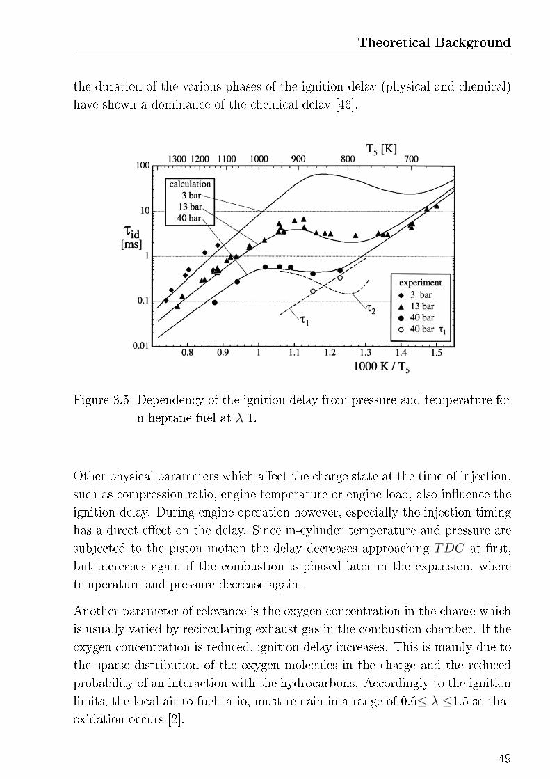
Theoretical Background
the duration of the various phases of the ignition delay (physical and chemical)
have shown a dominance of the chemical delay [46].
Figure 3.5: Dependency of the ignition delay from pressure and temperature for
n-heptane fuel at λ 1.
Other physical parameters which a�ect the charge state at the time of injection,
such as compression ratio, engine temperature or engine load, also in�uence the
ignition delay. During engine operation however, especially the injection timing
has a direct e�ect on the delay. Since in-cylinder temperature and pressure are
subjected to the piston motion the delay decreases approaching TDC at �rst,
but increases again if the combustion is phased later in the expansion, where
temperature and pressure decrease again.
Another parameter of relevance is the oxygen concentration in the charge which
is usually varied by recirculating exhaust gas in the combustion chamber. If the
oxygen concentration is reduced, ignition delay increases. This is mainly due to
the sparse distribution of the oxygen molecules in the charge and the reduced
probability of an interaction with the hydrocarbons. Accordingly to the ignition
limits, the local air to fuel ratio, must remain in a range of 0.6≤ λ ≤1.5 so that
oxidation occurs [2].
49
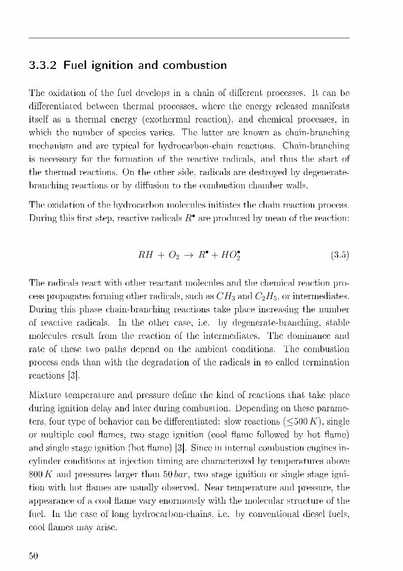
3.3.2 Fuel ignition and combustion
The oxidation of the fuel develops in a chain of di�erent processes. It can be
di�erentiated between thermal processes, where the energy released manifests
itself as a thermal energy (exothermal reaction), and chemical processes, in
which the number of species varies. The latter are known as chain-branching
mechanism and are typical for hydrocarbon-chain reactions. Chain-branching
is necessary for the formation of the reactive radicals, and thus the start of
the thermal reactions. On the other side, radicals are destroyed by degenerate-
branching reactions or by di�usion to the combustion chamber walls.
The oxidation of the hydrocarbon molecules initiates the chain reaction process.
During this �rst step, reactive radicals R• are produced by mean of the reaction:
RH + O2 → R• +HO•2 (3.5)
The radicals react with other reactant molecules and the chemical reaction pro-
cess propagates forming other radicals, such as CH3 and C2H5, or intermediates.
During this phase chain-branching reactions take place increasing the number
of reactive radicals. In the other case, i.e. by degenerate-branching, stable
molecules result from the reaction of the intermediates. The dominance and
rate of these two paths depend on the ambient conditions. The combustion
process ends than with the degradation of the radicals in so called termination
reactions [3].
Mixture temperature and pressure de�ne the kind of reactions that take place
during ignition delay and later during combustion. Depending on these parame-
ters, four type of behavior can be di�erentiated: slow reactions (≤500K), single
or multiple cool �ames, two stage ignition (cool �ame followed by hot �ame)
and single stage ignition (hot �ame) [3]. Since in internal combustion engines in-
cylinder conditions at injection timing are characterized by temperatures above
800K and pressures larger than 50 bar, two stage ignition or single stage igni-
tion with hot �ames are usually observed. Near temperature and pressure, the
appearance of a cool �ame vary enormously with the molecular structure of the
fuel. In the case of long hydrocarbon-chains, i.e. by conventional diesel fuels,
cool �ames may arise.
50
Theoretical Background
Figure 3.6: Explosion p-T-diagram showing the ignition limits of hydrocarbon
fuels on the left and the pressure increase during self-ignition process
on the right [51].
Cool-�ame
Figure 3.6 shows a representation of the ignition limits for hydrocarbon fuels. In
the low-temperature region ignition takes place in a multiple-step process that
can be divided in a cool-�ame, a blue-�ame and a hot-�ame (explosion). The
production of metastable hydroperoxide intermediates with the form ROOH,
as a result of the chain-branching reactions mentioned above, plays here an im-
portant role retarding the self-ignition process and splitting it in many stages.
In fact, only after having reached a critical concentration (end of τ1), the hy-
droperoxides degenerate in an exothermal reaction building new radicals and
in particular formaldehyde. This reaction is usually know under the name of
cool-�ame (τ2). The energy released during this phase usually corresponds to
5-15% of to the total injected fuel energy. Due to the temperature increase, the
chain reaction proceeds with the oxidation of the hydrocarbons, which is now
sustained by the formaldehydes, and the creation of carbon monoxides as an
intermediate product. This phase, which correspond to τ3 in the diagram, is
usually of very short duration and it is characterized by blue radiation (blue-
�ame). Only after this multiple-step chain reaction the main combustion takes
51
place. The carbon monoxides react with the oxygen in a high exothermal process
know as hot-�ame. During this phase the main part of the energy is released
[42].
The total chemical ignition delay results from the sum of τ1, τ2 and τ3. As
explained in the previous section, the delay usually decreases with increesing
ambient temperature. In the combustion of long chains hydrocarbons, however,
a phenomenon called Negative Temperature Coe�cient, short NTC, can be ob-
served. In a certain temperature region the correlation between delay duration
and temperature is inverted. This phenomenon occurs when, due to a temper-
ature increase, the formation of the hydroperoxide intermediates is reduced in
favor of the production of reactive radicals. This results in a mitigation of the
cool-�ame process. The time τ2, needed for the temperature increase during the
cool-�ame, is prolonged resulting in a longer ignition process. Indeed, by the
discussed temperature range, the energy level needed for the activation of the
chain-branching reaction of the radicals can not be achieved and the process
speed is limited by the rate of the cool-�ame reaction. This phenomenon can be
observed in Figure 3.5.
Cool-�ame phenomena are usually observed in alternative combustion processes
where the ignition temperature is reduced by means of early combustion phasing
or strong charge dilution.
Multiple-step and single-step self ignition
Increasing the temperature in the combustion chamber, more radicals are pro-
duced in the beginning phase of the chain-branching reaction and ROOH is no
longer the major products of the process. Instead it is hydrogen peroxide, H2O2,
which reacts building OH radicals following the chemical equations:
HO•2 +RH → R• +H2O2 (3.6)
H2O•2 +M → HO• +HO• +M (3.7)
where M is an inert impact partner. By temperatures above 900K the ignition
process occurs in a single-step path. The energy is enough to immediately acti-
vate the disintegration of the reactive radicals R• into small alkyl radicals with
52
Theoretical Background
the form CH3 and C2H5. The chain branching occurs primarily by way of the
reaction:
H• + O2 → O• +HO• (3.8)
Conventional di�usive diesel combustion is predominated by the high-
temperature single-step reaction. Multiple-steps reaction occurs only in the
premixed burning part of the injected fuel which, however, represents only a
small portion of the total. For this reason, the detection of cool-�ames during
this phase is very di�cult.
3.3.3 Combustion temperature
The �ame temperature of an air/fuel mixture mainly depends on the concen-
tration of the reactants (charge dilution) and the rate over which the system
conditions change, i.e. temperature and pressure. Generally it can be said
that for an adiabatic combustion process6 at constant ambient conditions the
maximum �ame temperature occurs slightly rich of stoichiometry. If λ >1 the
excess of oxygen must be heated and the product temperature drops. For rich
combustion, i.e. λ <1, the system is under-oxidized and the fuel conversion is
reduced, this results in a temperature drop as well [38]. This circumstance is
illustrated in Figure 3.7. Also important is the amount of nitrogen present in
the mixture, which increases together with the air/fuel ratio, and it is character-
ized by a large heat storing capacity. The H/C ratio of the fuel determines the
formation of water vapor, CO2, and their formed dissociation products during
the combustion process. For given chemical enthalpy content of reactants, the
larger the H/C ratio, the higher the �ame temperature. Finally, because of the
higher �nal pressure and the lower rate of dissociation, adiabatic combustion
at constant volume is usually characterized by higher maximum temperatures
compared to constant pressure combustion [3].
6The adiabatic �ame temperate is the temperature reached when al the energy released
during the combustion process is solely employed to raise the products temperature.
53
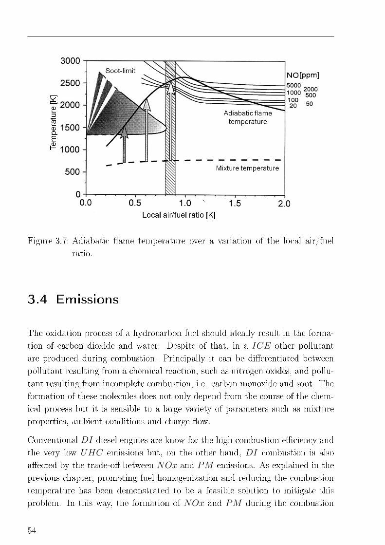
Figure 3.7: Adiabatic �ame temperature over a variation of the local air/fuel
ratio.
3.4 Emissions
The oxidation process of a hydrocarbon fuel should ideally result in the forma-
tion of carbon dioxide and water. Despite of that, in a ICE other pollutant
are produced during combustion. Principally it can be di�erentiated between
pollutant resulting from a chemical reaction, such as nitrogen oxides, and pollu-
tant resulting from incomplete combustion, i.e. carbon monoxide and soot. The
formation of these molecules does not only depend from the course of the chem-
ical process but it is sensible to a large variety of parameters such as mixture
properties, ambient conditions and charge �ow.
Conventional DI diesel engines are know for the high combustion e�ciency and
the very low UHC emissions but, on the other hand, DI combustion is also
a�ected by the trade-o� between NOx and PM emissions. As explained in the
previous chapter, promoting fuel homogenization and reducing the combustion
temperature has been demonstrated to be a feasible solution to mitigate this
problem. In this way, the formation of NOx and PM during the combustion
54
Theoretical Background
process can be avoided. However, even if the combustion of the air/fuel mixture
does not occur by �ame propagation, the combustion of alternative processes
shows conformities to that of gasoline engines with indirect injection, which are
known to su�er from higher UHC and CO emissions resulting from a poor fuel
conversion.
The following sections present the mechanisms which lead to the formation of
the most relevant pollutant. Particular attention is given to those mechanisms
present in low-temperature premixed combustion processes.
3.4.1 Nitrogen oxide
Diatomic nitrogen N2 is the natural component of the Earth's atmosphere wiht
the largest volume fraction, i.e. 78%. Avoiding it to take part by the combustion
process is nearly impossible. During the complex chemical reactions which take
place in a ICE, nitrogen reacts with the oxygen forming NO, NO2 or N2O
molecules. These compounds are usually identi�ed as NOx. NOx emissions
are responsible for the formation of atmospheric smog and acid rains but can
also be the cause of respiratory diseases. Moreover, N2O is known to play a role
in the greenhouse e�ect.
Two chemical reaction pathways are considered to be responsible for the most
part of the NOx emissions formation, the thermal (Zeldovich) and the prompt
(Fenimore) mechanisms. Investigations on the conventionalDI combustion have
shown a preponderance of the thermal mechanism (90 to 95%) over the prompt
one.
To break a N2 molecule a large amount of energy in form of temperature is re-
quired. A combustion temperature above 1900-2000K must be reached to start
molecule dissociation. When it happens, atomic nitrogen reacts very fast with
the oxygen present in the charge forming NO molecules. The higher the �ame
temperature and the oxygen concentration, the more the chemical equilibrium
of the reactions favors the formation of NO. For an adiabatic constant-pressure
combustion the NO formation peaks at the stoichiometry composition and de-
creases rapidly as the mixture becomes leaner or richer [3]. Due to the fast
temperature drop at the end of the combustion, which is promoted by the vol-
55
ume expansion, the NO chemistry is frozen and the decomposition of the NO
molecules is interrupted.
The prompt pathway can be observed in low-temperature fuel-rich mixture ar-
eas. In this areas, reactive intermediate species HCN or NHx are formed and,
depending on the ambient conditions, they are either oxidized to form NO or
re-formed to molecular nitrogen. This mechanisms has a lower relevance in ICE
systems [52].
A third formation mechanism occurs by the high-pressure low-temperature com-
bustion of fuel-lean mixtures. Under these conditions, NO is builted by the
oxidation of N2O, formed in a previous reaction step. The energy needed to
overcome the activation energy of the chemical reaction is provided by the high
pressure. This process is usually negligible in di�usive combustion where tem-
peratures are high, but becomes important as the combustion temperature re-
mains under 2200K and the thermal formation mechanism is suppressed. This
is the case of alternative combustion processes, which are characterized by low
temperatures and high pressure peaks [44].
Reduction of NOx emissions is usually done by means of exhaust gas recircu-
lation. Main e�ects are the reduction of the �ame temperature and the oxygen
concentration in the charge, which are the main causes of NO formation. Aim of
alternative combustion systems is to avoid the formation of NOx emissions mak-
ing large use of EGR and limiting the combustion temperature below 2000K.
The mechanisms behind this circumstance are explained at the end of this chap-
ter.
3.4.2 Particulate matter
Particulate matter (PM) mainly consists of carbonaceus material (soot) and
aerosols, such as ash particulates, metallic abrasion particles, sulfates, and sil-
icates, and mainly results from an incomplete combustion of the hydrocarbon
fuel. The main particulate fraction of diesel exhaust PM consists of �ne par-
ticles. Because of their small dimensions, usually between 10 and 100nm [3],
particulates emissions can be absorbed in the human body during respiration.
A long-term exposure has been demonstrated to increase the risk of vascular
56
Theoretical Background
disfunctions, heart diseases and lung cancer.
Nowadays, the formation mechanisms of combustion related particulate matter
are well known. Di�erent types of species and combustion intermediates formed
during the fuel pyrolysis and the oxidation processes are ranged as potential
precursors, leading to soot particle inception, i.e. polyacetylenes or polyynes,
ions, and polycyclic aromatic hydrocarbons (also known as PAH). Recently,
PAH has been identi�ed as the most probable soot particles precursor. A
detailed description of the particulate formation mechanisms can be found in
[53]. Summarized in few words, the fuel molecules are �rst broken into smaller
hydrocarbon molecules and free radicals either by pyrolysis or oxidation reac-
tions. In a second phase, the �rst aromatic rings are formed, usually benzene or
phenyl. These serve as nucleus for the formation and growth of PAHs by the
H-abstraction-C2H2-addition pathway (HACA) in forming larger soot particles.
More generally, fuel-rich areas (λ <0.65) together with combustion temperatures
between 1600 and 1900K are considered to be ideal conditions for soot formation
[44]. The rich mixture has less oxygen to completely burn the fuel which turns
into a carbon deposit. This is the case of fuel-rich areas of the fuel spray resulting
by insu�cient mixture formation. The types and quantities of soot particles can
vary according to the operating conditions, such as temperatures and pressures,
fuel and charge properties.
Soot formation can be avoided improving mixture formation by means of pro-
longed ignition delay and charge �ow or limiting the combustion temperature
below 1600K. These conditions are provided in low-temperature premixed
combustion systems. In processes with thorough mixture homogenization, i.e.
HCCI and HCLI, soot formation is completely avoided, whereas in late injec-
tion processes, such as HPLI or MK, soot formation can be observed during
combustion but a strong soot oxidation takes place in the second part of the
combustion [8]. Finally, up to 90% of the produced soot can be reduced in the
late combustion phase. Required conditions are su�cient oxygen concentration,
e.g. by lean combustion processes, and gas temperatures above 1300K.
57
3.4.3 Unburned hydrocarbons
Under the acronym UHC, unburned hydrocarbons, a large variety of chemical
compounds composed by carbon and hydrogen atoms is meant. As the name
reveals, these pollutants result from incomplete combustion of the injected fuel.
This means that in some part of the mixture the combustion process do not take
place or it is interrupted before completeness. Even if UHC can be partially
reduced by post-oxidation late in the combustion process or in the exhaust pipe
by means of a diesel Oxidation Catalist (DOC), high enigne-out UHC emissions
are a sign for bad combustion e�ciency. Once in the atmosphere, hydrocarbons
may react with nitrogen oxides by the action of the sunlight generating smog.
Moreover, a more stable hydrocarbon compound, i.e. methane (CH4) is kwon
to be one of the pollutants responsible for the greenhouse e�ect.
Five mechanisms are known to be a possible source for UHC emissions in ICE,
these are:
• �ame-quenching, due to cold regions of the combustion chamber (wall
quenching)
• under-mixing and presence of over-rich zones
• over-leaning and excessively low local air/fuel ratio and low temperatures
(bulk quenching)
• fuel deposit on the walls, adsorption and desorption in engine oil (fuel �lm)
• combustion chamber crevices
An experimental analysis of these mechanisms in LTC combustion is presented
in [54]. Using di�erent cylinder bowl geometries and di�erent injectors on a
single cylinder engine the authors demonstrate bulk quenching to be the main
source of UHC emissions. The long mixing process leads to over-leaning of
the mixture. In these regions local temperature, equivalence ratio and charge
dilution are inadequate for completing the oxidation process. EGR rate and
intake temperature has a direct correlation to the formation of UHC emissions
since they in�uence the mixture temperature. On the other hand, the injection
pressure and the swirl are mainly responsible for the local mixture quality but
has less impact on the UCH emissions. A correlation between unburned hy-
58
Theoretical Background
drocarbons and the duration of the mixing time is con�rmed in [55]. Finally,
the global equivalence ratio plays a secondary role in the formation of UHC
emission.
Another important aspect that results from these investigations, but that can
be also found in many others works, e.g. [36] [49] [14] [10], is the importance
of avoiding fuel spray to be injected on the top surface of the piston crown.
Otherwise wall impingement occurs with a rapid increase of the UHC emissions.
Early fuel injection timing must be limited so that the fuel spray lands into the
piston bowl. This must be done considering engine speed and injection pressure.
Finally, results of mass spectrometry measurements of the exhaust gas pub-
lished in [36] and [50] show low-temperature premixed combustion to be a po-
tential source of methane emissions. CH4 molecules may results from the low-
temperature oxidation of fuel-rich areas and, because of their high stability,
survive during the combustion. Since the activation temperature of methane is
larger than 900K the reduction of this molecules in the DOC may be prob-
lematic even at part-load engine operation. For this reason, it is suggested to
avoid the formation of this pollutant during the combustion process increasing
the air/fuel ratio of the charge either reducing the EGR or increasing the boost
pressure.
3.4.4 Carbon monoxide
Carbon monoxide (CO) is an intermediate product of the oxidation reaction of
hydrocarbon fuels. High concentrations of CO are toxic. In the atmosphere it
reacts spontaneously with the oxygen creating carbon dioxide (CO2) or ozone.
CO emissions in ICE are directly correlated to the air/fuel ratio of the mixture
and to the fuel homogenization with the charge. For an instance, signi�cant CO
emissions can be measured in DI engines at full-load where there is only short
time for thorough mixture formation or in the fuel-rich areas of the fuel spray.
In fuel-rich areas, thus by insu�cient oxygen concentration, the reaction of car-
bon monoxide in forming carbon dioxide cannot take place. In this case CO
emissions are dominated by the mixing process and concentrations increases
steadily with decreasing λ. High injection pressure and an extended ignition de-
59
lay are suggested for avoiding this problem. Post oxidation processes by means
of charge motion (swirl) are also useful in reducing engine-out CO emissions.
By lean combustion CO emissions are usually negligible, as long as the air
excess does not result in excessively low combustion temperatures, which also
interrupt the reaction mechanism in the formation of carbon dioxide. In fact,
below 1500K the oxidation rate of CO decreases rapidly. This may be the case of
low-temperature premixed combustion processes where long ingnition delay and
low combustion temperatures are promoted recirculating large rates of EGR.
In the premixed burn of a DI process or generally in premixed combustion
processes CO emissions are dominated by the chemical kinetics [55].
3.5 Exhaust gas recirculation
The use of exhaust gas recirculation in ICEs has been introduced in the late
1960s as a response to the increasing problems related to the pollutant emissions
of the road tra�c. Investigations showed NOx emissions to be a critical compo-
nent of smog, acid rain and to be even responsible for respiratory diseases. The
potential of reducing NOx using EGR was already known since longer time but
has always been related to an undesired e�ciency reduction. During the last
decades, legislative regulations has become more and more selective and EGR
has been a main topic of a variety of investigations. Nowadays, EGR is widely
used in many ICE applications as a common way to control NOx emissions by
mantaining comparable combustion e�ciency.
The most important e�ect of EGR is the possibility of reducing the �ame tem-
perature and thus the formation of thermalNOx during the combustion process.
Increasing charge dilution by means of EGR the air content (and especially O2)
is replaced with inert gas (by non-stoichiometric combustion, i.e. diesel combus-
tion, the reactivity of the exhaust gas depends on the equivalence ratio) and the
reactivity of the charge is lowered. The partial pressure reduction of the oxygen
in the charge reduces the combustion kinetics. In addition the burned gas has
a larger speci�c thermal capacity compared to fesh air (due to the high CO2
and H2O fraction) and it is capable of storing more energy during combustion
lowering the temperature [39].
60
Theoretical Background
At constant boost pressure increasing EGR reduces the equivalence ratio of
the charge and NOx emissions are mainly reduced by means of lowered charge
reactivity. In this case a negative e�ect on the speci�c fuel consumption can
be measured. Increasing EGR but maintaining a constant λ (same amount of
fresh air) the thermal e�ect becomes more important. The NOx reduction is
less signi�cant compared to the �rst strategy but there is less or no combustion
e�ciency deterioration.
Other secondary e�ects can be related to use of EGR [39]. The composition
of the charge is altered by the presence of exhaust gas components. This has
an e�ect on the chemical reaction process, in particular due because of the
endothermic dissociation of the water vapor which leads to a �ame temperature
reduction. Moreover, as a consequence of the charge dilution, the ignition delay
increases giving more time for the mixture formation process and promoting
premix combustion.
The main negative aspect related to the use of EGR is the so called "thermal
throttling". Exhaust gases are characterized by temperatures in a range between
350 and 1000K depending on the engine load. Thus, the fresh air temperature,
which is around 300K, increases substantially after mixing with the recirculated
gases. This results in a reduction of the charge density and a reduction of the
charge mass trapped in the combustion chamber. Moreover, the increase of the
charge inlet temperature also leads to increased combustion temperature and
wall heat transfer, although this e�ect is usually compensated by the mitigation
of high temperatures during the combustion. Thermal throttling can be limited
by cooling the EGR before it mixes with the fresh air. This is usually done
cooling the recirculated gases using the water from the engine cooling system.
Another negative aspect is related to the increased combustion instability which
results from a large use of EGR. In this case, an increase in the covariance of
the imep can be observed. A massive use of EGR may results in mis�re [62].
Finally, the use of EGR becomes fundamental in the application of alternative
combustion processes, as illustrated in the previous chapter. The thermal ad-
vantage of large amounts of EGR and the reduced combustion reactivity can be
exploited for avoiding the formation of NOx emissions. Moreover, the mixture
preparation process is promoted, by the longer ignition delay, and the formation
of soot is suppressed. In the case of homogenous combustion processes, which
61

are solely kinetically controlled, a precise control of the EGR rate plays an even
larger role. Typical EGR rates for low-temperature premixed combustion mode
varies in a range between 30 and 60%.
62
4
Experimental Setup and Engine
Management System
The experimental activity has been performed at the Institute
of Internal Combustion Engines and Automotive Engineer-
ing at the University of Stuttgart. In this chapter, a brief
description of the test facilities is presented.
4.1 Engine and measurement equipment
4.1.1 Engine and test bench speci�cations
Measurements have been conducted on a Daimler 6-cylinder 3.0 l turbocharged
diesel engine of type OM642 [56][57]. The engine is equipped with a
RobertBoschGmbH third generation common rail injection system, capable of a
maximum injection pressure of 1600 bar and up to �ve injections per cycle. In or-
der to provide a long ignition delay, the engine con�guration with a compression
ratio of 15.5:1 has been chosen for this investigation. Moreover, the engine dis-
poses of a variable-geometry turbocharger (V GT ), a high-pressure cooled EGR
loop, a throttle valve to support high EGR routing and inlet manifold �aps to
increase intake gas swirl. Further engine speci�cations are summarized in Table
4.1
Engine load is set using an asynchronous machine dynamometer controlled by a
D2TMorphee 2 automation system. This con�guration is capable of operating
transient load conditions and test cycles. Exhaust gases are extracted down-
63
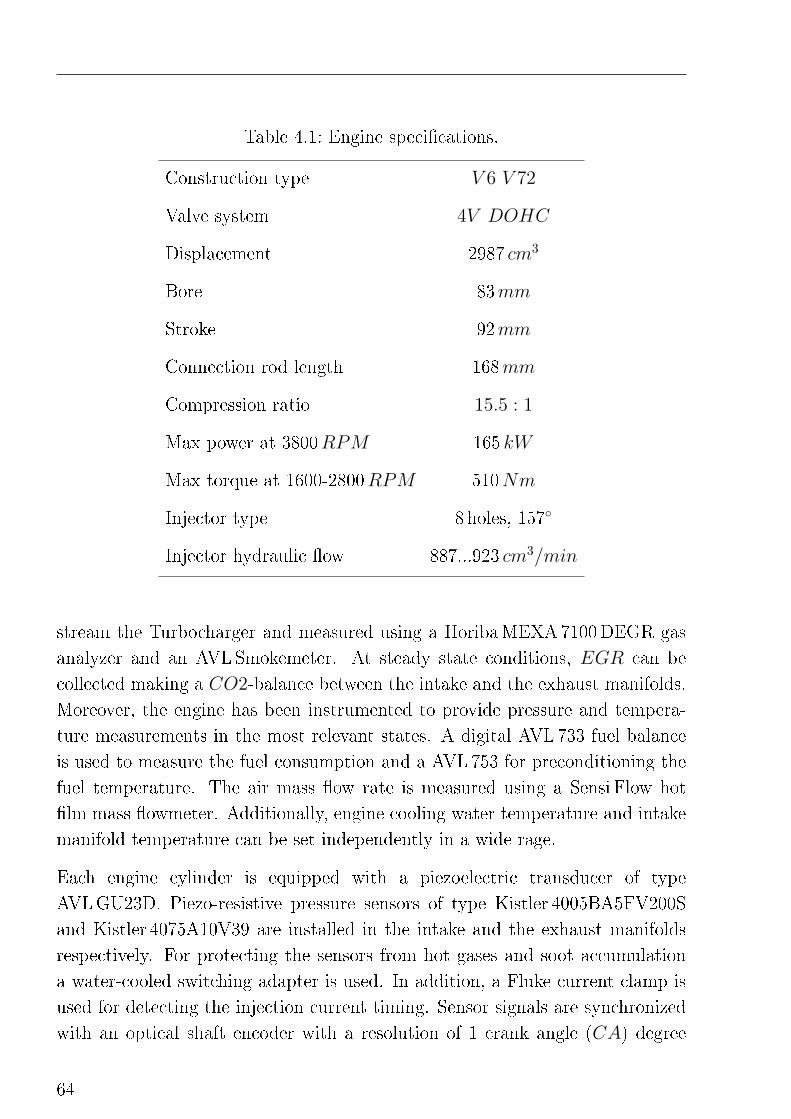
Table 4.1: Engine speci�cations.
Construction type V 6 V 72
Valve system 4V DOHC
Displacement 2987 cm3
Bore 83mm
Stroke 92mm
Connection rod length 168mm
Compression ratio 15.5 : 1
Max power at 3800RPM 165 kW
Max torque at 1600-2800RPM 510Nm
Injector type 8 holes, 157◦
Injector hydraulic �ow 887...923 cm3/min
stream the Turbocharger and measured using a HoribaMEXA7100DEGR gas
analyzer and an AVLSmokemeter. At steady state conditions, EGR can be
collected making a CO2-balance between the intake and the exhaust manifolds.
Moreover, the engine has been instrumented to provide pressure and tempera-
ture measurements in the most relevant states. A digital AVL733 fuel balance
is used to measure the fuel consumption and a AVL753 for preconditioning the
fuel temperature. The air mass �ow rate is measured using a Sensi Flow hot
�lm mass �owmeter. Additionally, engine cooling water temperature and intake
manifold temperature can be set independently in a wide rage.
Each engine cylinder is equipped with a piezoelectric transducer of type
AVLGU23D. Piezo-resistive pressure sensors of type Kistler 4005BA5FV200S
and Kistler 4075A10V39 are installed in the intake and the exhaust manifolds
respectively. For protecting the sensors from hot gases and soot accumulation
a water-cooled switching adapter is used. In addition, a Fluke current clamp is
used for detecting the injection current timing. Sensor signals are synchronized
with an optical shaft encoder with a resolution of 1 crank angle (CA) degree
64
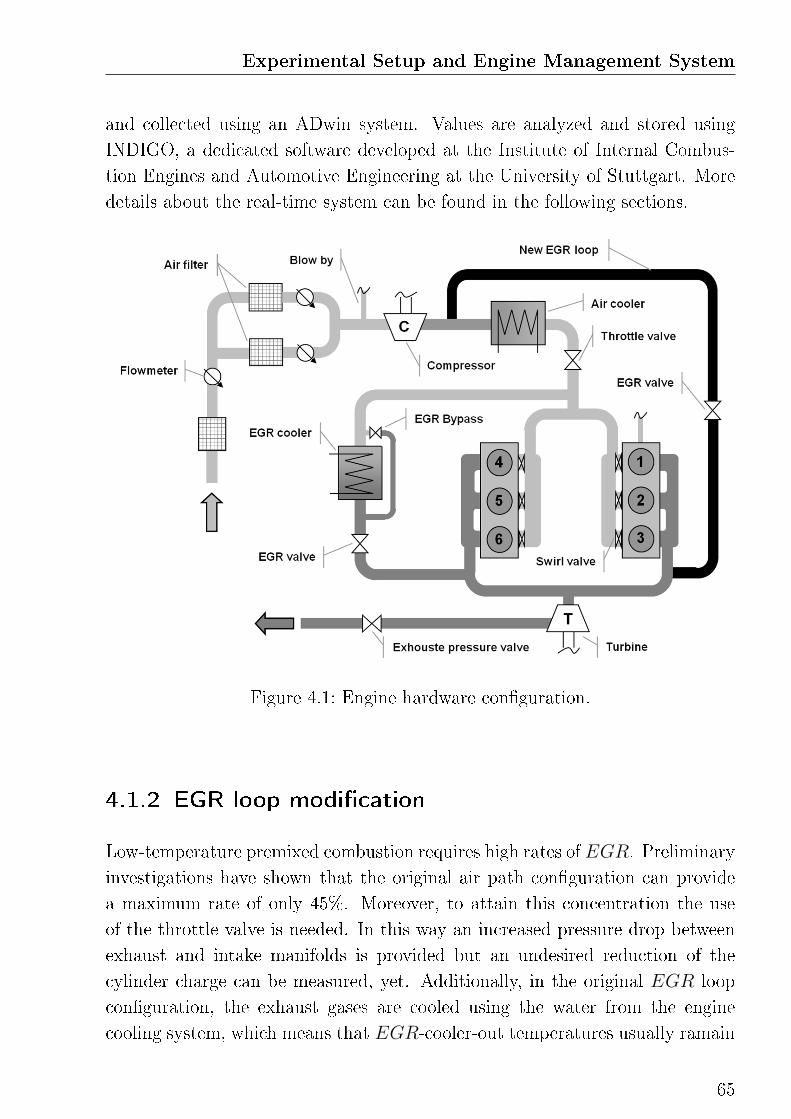
Experimental Setup and Engine Management System
and collected using an ADwin system. Values are analyzed and stored using
INDIGO, a dedicated software developed at the Institute of Internal Combus-
tion Engines and Automotive Engineering at the University of Stuttgart. More
details about the real-time system can be found in the following sections.
Figure 4.1: Engine hardware con�guration.
4.1.2 EGR loop modi�cation
Low-temperature premixed combustion requires high rates of EGR. Preliminary
investigations have shown that the original air path con�guration can provide
a maximum rate of only 45%. Moreover, to attain this concentration the use
of the throttle valve is needed. In this way an increased pressure drop between
exhaust and intake manifolds is provided but an undesired reduction of the
cylinder charge can be measured, yet. Additionally, in the original EGR loop
con�guration, the exhaust gases are cooled using the water from the engine
cooling system, which means that EGR-cooler-out temperatures usually ramain
65
above 350K. Consequently, by the large ammounts of EGR needed for the low-
temperature premixed combustion process, an undesired increase of the intake
charge temperatures can be measured. For the reasons mentioned, a new EGR
loop has been designed. Following criteria has been taken into account:
• Avoiding of throttling
• Increased gas cooling
• Good mixing with intake fresh air
• Compatibility of the valve with the engine management system
• Robustness and accessibility
• Maintain the original con�guration as backup
By the state of the art two feasible solutions can be considered. The �rst one is a
secondary high-pressure EGR loop maintaining the actual connection between
exhaust manifold and the intake pipe down-stream the throttle valve. Because
of the compact geometry of the engine this solution can not be realized. More-
over, this solution requires the use of an additional cooler and thus additional
resistance to the gas �ow. On the other hand, a low-pressure EGR, which means
an extraction of the exhaust gas after the turbine and recirculation into the in-
take pipe up-stream the compressor, has also some drawbacks. In fact, since the
engine is operated without using any particulate �lter in the exhaust pipe, the
physical exposure of the compressor to the un�ltered gases could lead to sever
damages. Moreover, only using a complex system for mixing the exhaust gas
with the fresh air the thermal stress for the compressor can be reduced to sus-
tainable level [59][60]. Finally, a mixed solution of high and low-pressure EGR
would increment the e�ort for a reliable control system considerably [61].
The realized solution is a high-pressure EGR loop with extraction of the gases
from the exhaust manifold upstream the turbine and recirculation before the
charge-air intercooler, as shown in Figure 4.1. The advantage of this solution is
the strong cooling power provided by the intercooler which can be exploited with-
out additional pressure losses. Moreover, since the intercooler is water cooled,
arbitrary output temperatures can be set. Because in the drivable load range
of LTC combustion the engine is operated at low boost pressure, a pressure
drop between exhaust and intake is always provided even without the use of the
66
Experimental Setup and Engine Management System
throttle valve.
4.1.3 Lambda sensor in the intake manifold
To the aim of an engine closed-loop control precise information about the cylin-
der charge composition are necessary. In modern diesel engines, these infor-
mation are usually obtained using complex physical models of the air path,
which are known to be reliable only to a certain extent. A direct and thus
better determination of the charge composition can be done using a broadband
Lambda sensor in the intake manifold, e.g. a BoschLSU4.2. Connected to a
ETASLA4LambdaMeter this sensor allows determining the oxygen content in
the charge1. More informations about the calibration of the sensor can be found
in [1]. The oxygen content is of particular interest for the rate of reactivity of
the air/fuel mixture. Later in this work it will be shown how to make use of it
in controlling the combustion process. Furthermore, since the combustion pro-
cess takes place under lean conditions, the oxygen balance between intake and
exhaust gases can be exploited for a direct and continuous determination of the
EGR rate.
4.2 Real-time combustion analysis system
For the closed-loop combustion control a real-time in-cylinder pressure analysis
system has been used. Pressure traces are collected using an ADwin-PRO-
system which disposes of one ADSP21162 80MHz processor for each single
signal source. The algorithms for the evaluation of the thermodynamic parame-
ters are implemented in an ADbasic code and have been optimized for real-time
use at the Institute of Internal Combustion Engines and Automotive Engineering
at the University of Stuttgart during many years of development. The combus-
tion process is characterized using the equation of Bargende [58], which is based
on a inverse �rst-law thermodynamic model and is capable of calculating the
gross heat release rate (HRR) in real-time. This simpli�ed model is based on
1A broadband Lambda sensor delivers a signal which is proportional to the oxygen partial
pressure of the analyzed gas. This signal can be converted either by means of an analytical
method that considers ambient conditions or by characteristic curves.
67
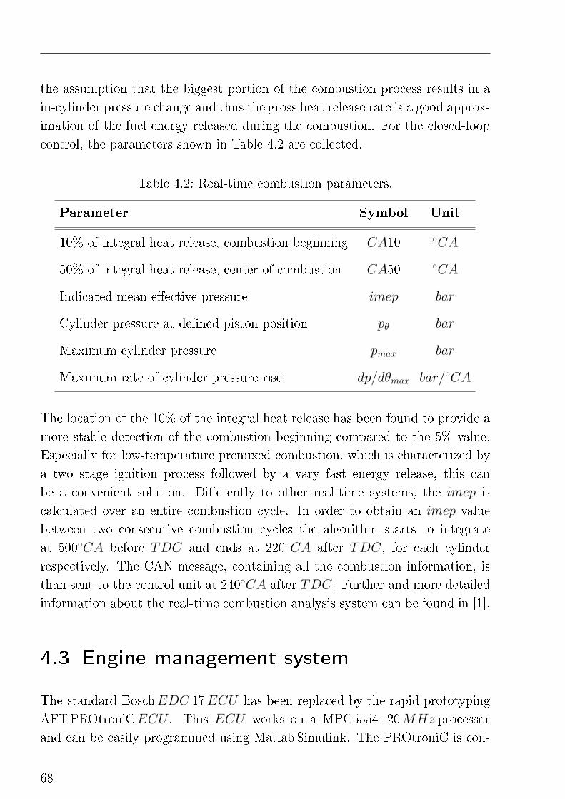
the assumption that the biggest portion of the combustion process results in a
in-cylinder pressure change and thus the gross heat release rate is a good approx-
imation of the fuel energy released during the combustion. For the closed-loop
control, the parameters shown in Table 4.2 are collected.
Table 4.2: Real-time combustion parameters.
Parameter Symbol Unit
10% of integral heat release, combustion beginning CA10 ◦CA
50% of integral heat release, center of combustion CA50 ◦CA
Indicated mean e�ective pressure imep bar
Cylinder pressure at de�ned piston position pθ bar
Maximum cylinder pressure pmax bar
Maximum rate of cylinder pressure rise dp/dθmax bar/◦CA
The location of the 10% of the integral heat release has been found to provide a
more stable detection of the combustion beginning compared to the 5% value.
Especially for low-temperature premixed combustion, which is characterized by
a two stage ignition process followed by a vary fast energy release, this can
be a convenient solution. Di�erently to other real-time systems, the imep is
calculated over an entire combustion cycle. In order to obtain an imep value
between two consecutive combustion cycles the algorithm starts to integrate
at 500◦CA before TDC and ends at 220◦CA after TDC, for each cylinder
respectively. The CAN message, containing all the combustion information, is
than sent to the control unit at 240◦CA after TDC. Further and more detailed
information about the real-time combustion analysis system can be found in [1].
4.3 Engine management system
The standard BoschEDC 17ECU has been replaced by the rapid prototyping
AFTPROtroniCECU . This ECU works on a MPC5554 120MHz processor
and can be easily programmed using Matlab Simulink. The PROtroniC is con-
68
Experimental Setup and Engine Management System
nected to the engine using a breakout box which makes all the engine functional-
ity easily accessible. Moreover, a switch with the BoschEDC 17 can be realized
in very short time without any further modi�cation of the engine hardware.
The high voltage TTL signals for operating the piezoelectric injection system
are delivered by a Continental PiezoDriver, which is programmed to deliver the
injectors with the suitable voltage and current curves and gets the trigger signals
from the ECU over an optocoupler. For the calibration and diagnostic of the
ECU functionalities the software AFTMARC is used.
For this project, a completely new engine control software architecture has been
developed. The structure is divided in �input�, �function� and �output� compo-
nents which makes the information �ux particularly easy to understand and to
administrate. In the �rst one, signals coming form the engine sensors and the
real-time combustion analysis system are metered and converted into physical
values. In the �function� part, engine maps and control algorithms are imple-
mented. This part is also responsible for the combustion closed-loop control. In
the latter, new control target values are �rst converted in current signals and
than sent to the engine actuators.
Engine load requirements are set using the gas pedal which signal is directly
commutated into a desired imep. In this way, the imep becomes a main control
parameter that characterize the engine load together with the engine speed.
In fact, using cylinder pressure transducers which provide real-time imep, fuel
injection quantity, which is commonly used in commercial ECUs and is rather
based on injection models, becomes obsolete. Detailed information about the
software architecture can be found in [1].
69

5
System analysis and de�nition of
the combustion control strategy
Despite the large amount of investigations about the in-
�uence of operating parameters on the application of low-
temperature premixed combustion, most part of the closed-
loop control systems published in the last years does not rely
on the thermodynamic mechanisms and the physical correla-
tions between actuating and target variables. To the point of
view of the author, the de�nition of a solid control strategy
can only result from a deeper understanding of the combus-
tion process and its mechanisms. This approach is illus-
trated in the following chapter. After the identi�cation of
the most relevant mechanisms and the correlations between
actuating and target variables, a new control strategy is pro-
posed.
A modern diesel engine is a very complex system in which the variation of a sin-
gle parameter usually a�ects a large variety of di�erent mechanisms. This strong
interaction between the actuating and the measuring parameter, or target pa-
rameters, makes the investigation and the control of a diesel engine a particular
di�cult task. As illustrated in Chapter 2 many di�erent solutions have been pro-
posed in the last years for the control of low-temperature premixed combustion
systems. In order to propose a new closed-loop combustion control strategy an
experimental analysis of the combustion system is carried out on the 6-cylinder
engine presented in the previous chapter. Main goal is the identi�cation of clear
and direct physical correlations between the actuating and the target variables,
which de�nition is also part of the present chapter.
71
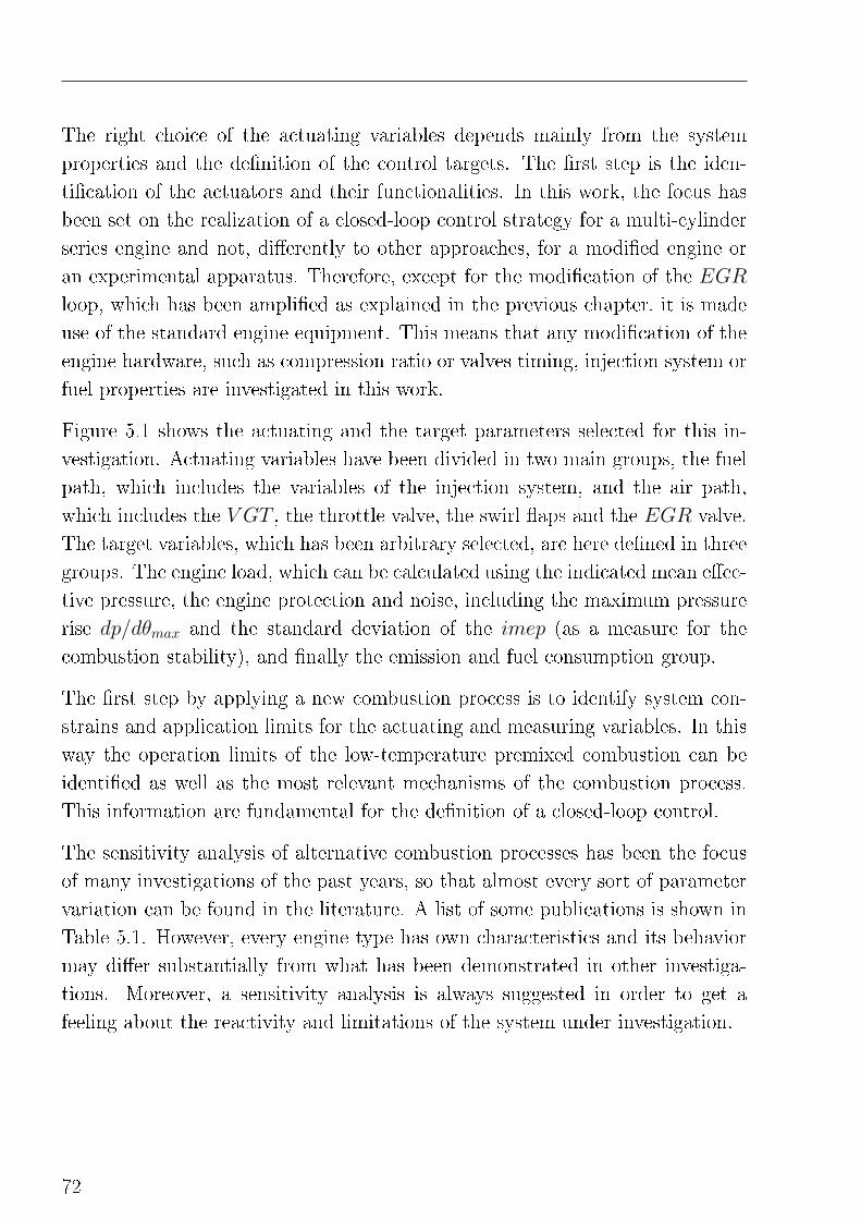
The right choice of the actuating variables depends mainly from the system
properties and the de�nition of the control targets. The �rst step is the iden-
ti�cation of the actuators and their functionalities. In this work, the focus has
been set on the realization of a closed-loop control strategy for a multi-cylinder
series engine and not, di�erently to other approaches, for a modi�ed engine or
an experimental apparatus. Therefore, except for the modi�cation of the EGR
loop, which has been ampli�ed as explained in the previous chapter, it is made
use of the standard engine equipment. This means that any modi�cation of the
engine hardware, such as compression ratio or valves timing, injection system or
fuel properties are investigated in this work.
Figure 5.1 shows the actuating and the target parameters selected for this in-
vestigation. Actuating variables have been divided in two main groups, the fuel
path, which includes the variables of the injection system, and the air path,
which includes the V GT , the throttle valve, the swirl �aps and the EGR valve.
The target variables, which has been arbitrary selected, are here de�ned in three
groups. The engine load, which can be calculated using the indicated mean e�ec-
tive pressure, the engine protection and noise, including the maximum pressure
rise dp/dθmax and the standard deviation of the imep (as a measure for the
combustion stability), and �nally the emission and fuel consumption group.
The �rst step by applying a new combustion process is to identify system con-
strains and application limits for the actuating and measuring variables. In this
way the operation limits of the low-temperature premixed combustion can be
identi�ed as well as the most relevant mechanisms of the combustion process.
This information are fundamental for the de�nition of a closed-loop control.
The sensitivity analysis of alternative combustion processes has been the focus
of many investigations of the past years, so that almost every sort of parameter
variation can be found in the literature. A list of some publications is shown in
Table 5.1. However, every engine type has own characteristics and its behavior
may di�er substantially from what has been demonstrated in other investiga-
tions. Moreover, a sensitivity analysis is always suggested in order to get a
feeling about the reactivity and limitations of the system under investigation.
72
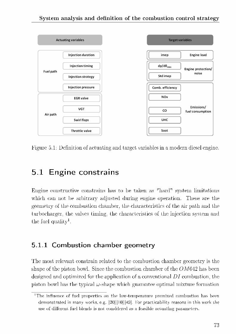
System analysis and de�nition of the combustion control strategy
Figure 5.1: De�nition of actuating and target variables in a modern diesel engine.
5.1 Engine constrains
Engine constructive constrains has to be taken as "hard" system limitations
which can not be arbitrary adjusted during engine operation. These are the
geometry of the combustion chamber, the characteristics of the air path and the
turbocharger, the valves timing, the characteristics of the injection system and
the fuel quality1.
5.1.1 Combustion chamber geometry
The most relevant constrain related to the combustion chamber geometry is the
shape of the piston bowl. Since the combustion chamber of the OM642 has been
designed and optimized for the application of a conventionalDI combustion, the
piston bowl has the typical ω-shape which guarantee optimal mixture formation
1The in�uence of fuel properties on the low-temperature premixed combustion has been
demonstrated in many works, e.g. [20] [10] [49]. For practicability reasons in this work the
use of di�erent fuel blends is not considered as a feasible actuating parameters.
73
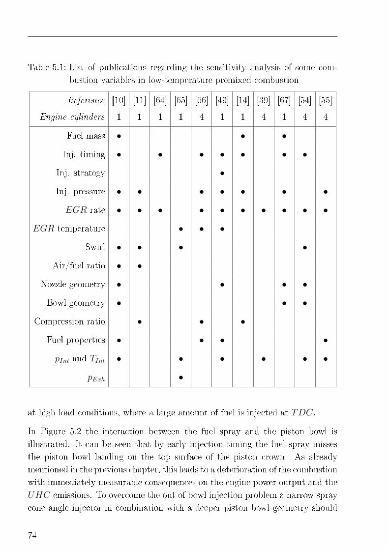
Table 5.1: List of publications regarding the sensitivity analysis of some com-
bustion variables in low-temperature premixed combustion
Reference [10] [11] [64] [65] [66] [49] [14] [39] [67] [54] [55]
Engine cylinders 1 1 1 1 4 1 1 4 1 4 4
Fuel mass • • •
Inj. timing • • • • • • •
Inj. strategy •
Inj. pressure • • • • • • •
EGR rate • • • • • • • • • •
EGR temperature • • •
Swirl • • • •
Air/fuel ratio • •
Nozzle geometry • • • •
Bowl geometry • • •
Compression ratio • • •
Fuel properties • • • •
pInt and TInt • • • • • •
pExh •
at high load conditions, where a large amount of fuel is injected at TDC.
In Figure 5.2 the interaction between the fuel spray and the piston bowl is
illustrated. It can be seen that by early injection timing the fuel spray misses
the piston bowl landing on the top surface of the piston crown. As already
mentioned in the previous chapter, this leads to a deterioration of the combustion
with immediately measurable consequences on the engine power output and the
UHC emissions. To overcome the out of bowl injection problem a narrow spray
cone angle injector in combination with a deeper piston bowl geometry should
74
System analysis and de�nition of the combustion control strategy
Figure 5.2: Schematic diagram of the interaction of the fuel spray with the piston
bowl.
be used [63]. Otherwise, prolonged mixture formation will be limited by this
constrain.
This limit depends from many operation parameters, i.e. injection pressure, en-
gine speed, charge composition and intake pressure and temperature. In other
words, all the parameters which a�ect the spray penetration in the combustion
chamber or the piston speed, sicne the injection process is characterized by a
physical time delay. Measurements on the OM642 has shown injection events
earlier than 25◦CA at low engine speed and earlier 35◦CA at higher speed to
su�er from this constrain. In this work a limitation of 30◦CA before TDC is
suggested. This limit has been identi�ed measuring the engine-out UHC emis-
sions by varying the injection timing for di�erent engine operation conditions
as shown in Figure 5.3. The increase in the UHC emissions by early injection
events can be easily recognized. As expected, an increased injection pressure
leads to a reduction of the injection timing range.
5.1.2 Injection system
The wide injection angle, which, as explained above, limits the application of
early injection events, and the maximum injection pressure, limited at 1600 bar,
represent the most relevant injection system constrains. However, in the system
under investigation, the injection pressure does not represent an application
limit since the maximum pressure needed for the low-temperature premixed
combustion is of only 1100 bar.
75
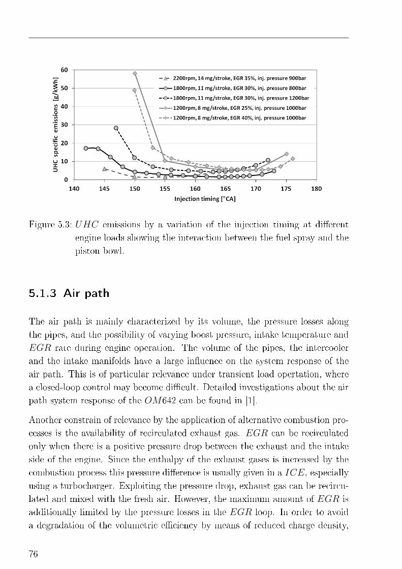
Figure 5.3: UHC emissions by a variation of the injection timing at di�erent
engine loads showing the interaction between the fuel spray and the
piston bowl.
5.1.3 Air path
The air path is mainly characterized by its volume, the pressure losses along
the pipes, and the possibility of varying boost pressure, intake temperature and
EGR rate during engine operation. The volume of the pipes, the intercooler
and the intake manifolds have a large in�uence on the system response of the
air path. This is of particular relevance under transient load opertation, where
a closed-loop control may become di�cult. Detailed investigations about the air
path system response of the OM642 can be found in [1].
Another constrain of relevance by the application of alternative combustion pro-
cesses is the availability of recirculated exhaust gas. EGR can be recirculated
only when there is a positive pressure drop between the exhaust and the intake
side of the engine. Since the enthalpy of the exhaust gases is increased by the
combustion process this pressure di�erence is usually given in a ICE, especially
using a turbocharger. Exploiting the pressure drop, exhaust gas can be recircu-
lated and mixed with the fresh air. However, the maximum amount of EGR is
additionally limited by the pressure losses in the EGR loop. In order to avoid
a degradation of the volumetric e�ciency by means of reduced charge density,
76
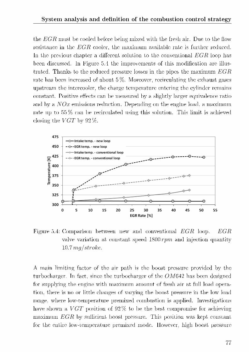
System analysis and de�nition of the combustion control strategy
the EGR must be cooled before being mixed with the fresh air. Due to the �ow
resistance in the EGR cooler, the maximum available rate is further reduced.
In the previous chapter a di�erent solution to the conventional EGR loop has
been discussed. In Figure 5.4 the improvements of this modi�cation are illus-
trated. Thanks to the reduced pressure losses in the pipes the maximum EGR
rate has been increased of about 5%. Moreover, recirculating the exhaust gases
upstream the intercooler, the charge temperature entering the cylinder remains
constant. Positive e�ects can be measured by a slightly larger equivalence ratio
and by a NOx emissions reduction. Depending on the engine load, a maximum
rate up to 55% can be recirculated using this solution. This limit is achieved
closing the V GT by 92%.
Figure 5.4: Comparison between new and conventional EGR loop. EGR
valve variation at constant speed 1800 rpm and injection quantity
10.7mg/stroke.
A main limiting factor of the air path is the boost pressure provided by the
turbocharger. In fact, since the turbocharger of the OM642 has been designed
for supplying the engine with maximum amount of fresh air at full load opera-
tion, there is no or little changes of varying the boost pressure in the low load
range, where low-temperature premixed combustion is applied. Investigations
have shown a V GT position of 92% to be the best compromise for achieving
maximum EGR by su�cient boost pressure. This position was kept constant
for the entire low-temperature premixed mode. However, high boost pressure
77
at low load would have a greater potential in extending the operating limits of
alternative combustion processes and improving the trade-o� between emissions
and combustion e�ciency [73] [74]. Moreover, increasing the boost pressure there
would be the possibility of varying EGR rate and fresh air mass independently,
thus increasing the degrees of freedom of the closed-loop control.
5.2 System limitations
Di�erently to the engine constrains, system limitations, or "soft" limitations,
are related to the interaction between engine actuating variables and system
behavior. These can be identi�ed by means of system sensitivity analysis.
5.2.1 Injection strategy
The potential of using multiple injection strategies in low-temperature premixed
combustion has been reported in many publications. An improved fuel homog-
enization resulting form a multiple injection strategy is shown in [49]. However
the author reports over-mixing problems related to fast heat release and high
rates of pressure rise as the mixture approaches stoichiometry. In this case,
multiple injection has any remarkable emission improvement compared to the
single injection. On the contrary, fuel wall impingement and degradation of the
oil �lm may result. In [69] the pilot injection, which is separated by the main
injection event, takes place at the begin of the expansion stroke. In this way the
fuel burns for the two injections in apremixed split-combustion process. Thanks
to low-temperature resulting from the late combustion phasing both NOx and
PM formation are suppressed. Also in [70], problematics related to the multiple
injection strategy are highlighted. At low load, early injection events may result
in fuel over-mixing. The distribution of the fuel quantity between the �rst and
the second injection plays an important role. Moreover, the fuel injected during
the second event may burn di�usive with signi�cant increase of soot emissions.
On the other hand, at part and medium load a split combustion results in re-
duced engine noise, lower UHC and CO emissions. Of particular interest is
in this case the increased sensitivity of the combustion from engine operating
conditions, i.e. speed and load, using multiple injection strategy. In [74] and
78
System analysis and de�nition of the combustion control strategy
[68] any signi�cant advantage of multiple injection at low load can be identi�ed.
Using multiple injections at higher engine load the leanness and homogeneity of
the mixture is improved with bene�ts for CO, UHC and PM emissions with
little expense of NOx emissions. Furthermore, there is the possibility to ex-
tend the operation range of the low-temperature premixed combustion to higher
loads.
Preliminary investigations on the OM642 have shown very little potential in im-
proving mixture formation using multiple injection, by signi�cantly increasing
the risk of di�usive combustion. In the short range of possible injection timing,
limited from the one side by the necessity of injecting the fuel in the piston bowl
(as explained in the previous section) and from the other side by the combustion
deterioration resulting from a late combustion phasing, there is only short time
for multiple injections. As a result of this investigation and in consideration of
the increased complexity highlighted in the publications cited above, it was de-
cided to use a block injection strategy. This means, the in the entire application
range of the low-temperature premixed combustion mode the fuel is completely
injected during a single event.
5.2.2 Injection duration
Injection duration is an extent for the fuel quantity injected during an engine
cycle. The correlation between these two parameters mainly depends from the
injection pressure and the injection timing. In the �rst case, increasing injection
pressure, the fuel injection rate per time unit increases and a shorter injection
timing is needed in order to maintain a constant injected fuel mass. By large
variations of the injection timing a correction over the injection duration is also
needed. In fact, departing from the TDC the in-cylinder pressure and charge
density decrease and the fuel jet encounters less resistance. Finally, the fuel
quantity is directed related to the indicated piston work. Even if the rate of the
fuel conversion varies with most part of the engine operation parameters, this
correlation can be assumed to be monotonically increasing.
79
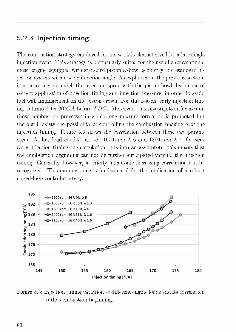
5.2.3 Injection timing
The combustion strategy employed in this work is characterized by a late single
injection event. This strategy is particularly suited for the use of a conventional
diesel engine equipped with standard piston ω-bowl geometry and standard in-
jection system with a wide injection angle. As explained in the previous section,
it is necessary to match the injection spray with the piston bowl, by means of
correct application of injection timing and injection pressure, in order to avoid
fuel wall impingement on the piston crown. For this reason, early injection tim-
ing is limited by 30◦CA before TDC. Moreover, this investigation focuses on
those combustion processes in which long mixture formation is promoted but
there still exists the possibility of controlling the combustion phasing over the
injection timing. Figure 5.5 shows the correlation between these two param-
eters. At low load conditions, i.e. 1600 rpm λ 6 and 1800 rpm λ 4, for very
early injection timing the correlation runs into an asymptote, this means that
the combustion beginning can not be further anticipated varyind the injection
timing. Generally, however, a strictly monotonic increasing correlation can be
racognized. This circumstance is fundamental for the application of a robust
closed-loop control strategy.
Figure 5.5: Injection timing variation at di�erent engine loads and its correlation
to the combustion beginning.
80
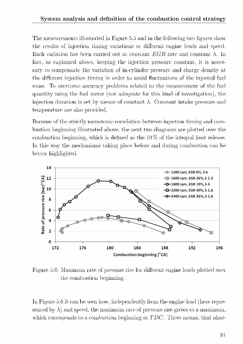
System analysis and de�nition of the combustion control strategy
The measurements illustrated in Figure 5.5 and in the following two �gures show
the results of injection timing variations at di�erent engine loads and speed.
Each variation has been carried out at constant EGR rate and constant λ. In
fact, as explained above, keeping the injection pressure constant, it is neces-
sary to compensate the variation of in-cylinder pressure and charge density at
the di�erent injection timing in order to avoid �uctuations of the injected fuel
mass. To overcome accuracy problems related to the measurement of the fuel
quantity using the fuel meter (not adequate for this kind of investigation), the
injection duration is set by means of constant λ. Constant intake pressure and
temperature are also provided.
Because of the strictly monotonic correlation between injection timing and com-
bustion beginning illustrated above, the next two diagrams are plotted over the
combustion beginning, which is de�ned as the 10% of the integral heat release.
In this way the mechanisms taking place before and during combustion can be
better highlighted.
Figure 5.6: Maximum rate of pressure rise for di�erent engine loads plotted over
the combustion beginning.
In Figure 5.6 it can be seen how, independently from the engine load (here repre-
sented by λ) and speed, the maximum rate of pressure rise grows to a maximum,
which corresponds to a combustion beginning at TDC. These means, that phas-
81
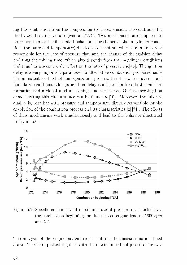
ing the combustion from the compression to the expansion, the conditions for
the fastest heat release are given at TDC. Two mechanisms are supposed to
be responsible for the illustrated behavior. The change of the in-cylinder condi-
tions (pressure and temperature) due to piston motion, which are in �rst order
responsible for the rate of pressure rise, and the change of the ignition delay
and thus the mixing time, which also depends from the in-cylinder conditions
and thus has a second order e�ect on the rate of pressure rise[48]. The ignition
delay is a very important parameter in alternative combustion processes, since
it is an extent for the fuel homogenization process. In other words, at constant
boundary conditions, a longer ignition delay is a clear sign for a better mixture
formation and a global mixture leaning, and vice versa. Optical investigation
demonstrating this circumstance can be found in [10]. Moreover, the mixture
quality is, together with pressure and temperature, directly responsible for the
devolution of the combustion process and its characteristics [2] [71]. The e�ects
of these mechanisms work simultaneously and lead to the behavior illustrated
in Figure 5.6.
Figure 5.7: Speci�c emissions and maximum rate of pressure rise plotted over
the combustion beginning for the selected engine load at 1800 rpm
and λ 4.
The analysis of the engine-out emissions con�rms the mechanisms identi�ed
above. These are plotted together with the maximum rate of pressure rise over
82
System analysis and de�nition of the combustion control strategy
the combustion beginning in Figure 5.7, for the representative load point at
1800 rpm λ 4. Easy to recognize is the good correlation between NOx emis-
sions and the dp/dθmax. This is because the conditions which lead to the highest
rate of pressure rise, i.e. high pressure, high temperature and shorter time for
fuel homogenization, also promote the formation of nitrogen oxides. The reason
behind the di�erent peak position of the traces has probably to be found in the
e�ects of the combustion process on the emissions, whereas the maximum pres-
sure rise is mainly related to the conditions at combustion beginning. UHC and
CO emissions show an opposite trend. Where the highest rates of pressure rise
are measured, high temperatures and short time for mixture formation inhibit
their formation [54].
The results of this investigation show a strict correlation between the maximum
rate of pressure rise and the combustion beginning, and thus the injection tim-
ing. This correlation is strictly monotonic increasing as long as the combustion
beginning is phased in the compression stroke and becomes strictly monotonic
decreasing when the combustion beginning moves in the expansion. A peak of
the maximum rate of pressure rise is reached approximatively at TDC. NOx
emissions shows a very similar behavior in contrast to UHC and CO emissions.
The realization of a closed-loop control system that take care of this discontinuity
is a di�cult task. Since combustion during compression is not possible under
every load condition, as shown in Figure 5.6, and the injection beginning range
is limited at 30◦CA before TDC for early injections, for a robust closed-loop
control system it is suggested to limit the combustion in the expansion. In
this phase is the correlation indipendent from the engine load and there is the
possibility of controling of the maximum rate of pressure rise over the injection
beginning (with consideration of the combustion beginning). This solution would
provide a constant engine protection, which is one of the target variables de�ned
at the beginning of this chapter. Similar results has been found in [36], where
a closed-loop control of the maximum rate of pressure rise over the injection
timing has been implemented.
83
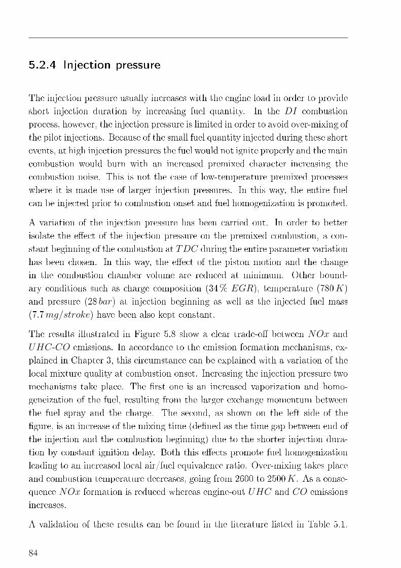
5.2.4 Injection pressure
The injection pressure usually increases with the engine load in order to provide
short injection duration by increasing fuel quantity. In the DI combustion
process, however, the injection pressure is limited in order to avoid over-mixing of
the pilot injections. Because of the small fuel quantity injected during these short
events, at high injection pressures the fuel would not ignite properly and the main
combustion would burn with an increased premixed character increasing the
combustion noise. This is not the case of low-temperature premixed processes
where it is made use of larger injection pressures. In this way, the entire fuel
can be injected prior to combustion onset and fuel homogenization is promoted.
A variation of the injection pressure has been carried out. In order to better
isolate the e�ect of the injection pressure on the premixed combustion, a con-
stant beginning of the combustion at TDC during the entire parameter variation
has been chosen. In this way, the e�ect of the piston motion and the change
in the combustion chamber volume are reduced at minimum. Other bound-
ary conditions such as charge composition (34% EGR), temperature (780K)
and pressure (28 bar) at injection beginning as well as the injected fuel mass
(7.7mg/stroke) have been also kept constant.
The results illustrated in Figure 5.8 show a clear trade-o� between NOx and
UHC-CO emissions. In accordance to the emission formation mechanisms, ex-
plained in Chapter 3, this circumstance can be explained with a variation of the
local mixture quality at combustion onset. Increasing the injection pressure two
mechanisms take place. The �rst one is an increased vaporization and homo-
geneization of the fuel, resulting from the larger exchange momentum between
the fuel spray and the charge. The second, as shown on the left side of the
�gure, is an increase of the mixing time (de�ned as the time gap between end of
the injection and the combustion beginning) due to the shorter injection dura-
tion by constant ignition delay. Both this e�ects promote fuel homogenization
leading to an increased local air/fuel equivalence ratio. Over-mixing takes place
and combustion temperature decreases, going from 2600 to 2500K. As a conse-
quence NOx formation is reduced whereas engine-out UHC and CO emissions
increases.
A validation of these results can be found in the literature listed in Table 5.1.
84
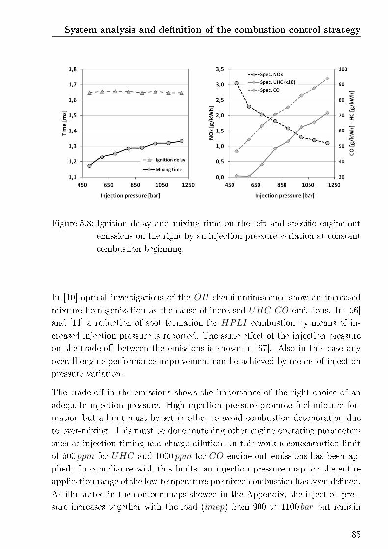
System analysis and de�nition of the combustion control strategy
Figure 5.8: Ignition delay and mixing time on the left and speci�c engine-out
emissions on the right by an injection pressure variation at constant
combustion beginning.
In [10] optical investigations of the OH-chemiluminescence show an increased
mixture homegenization as the cause of increased UHC-CO emissions. In [66]
and [14] a reduction of soot formation for HPLI combustion by means of in-
creased injection pressure is reported. The same e�ect of the injection pressure
on the trade-o� between the emissions is shown in [67]. Also in this case any
overall engine performance improvement can be achieved by means of injection
pressure variation.
The trade-o� in the emissions shows the importance of the right choice of an
adequate injection pressure. High injection pressure promote fuel mixture for-
mation but a limit must be set in other to avoid combustion deterioration due
to over-mixing. This must be done matching other engine operating parameters
such as injection timing and charge dilution. In this work a concentration limit
of 500 ppm for UHC and 1000 ppm for CO engine-out emissions has been ap-
plied. In compliance with this limits, an injection pressure map for the entire
application range of the low-temperature premixed combustion has been de�ned.
As illustrated in the contour maps showed in the Appendix, the injection pres-
sure increases together with the load (imep) from 900 to 1100 bar but remain
85
constant over the speed.
In conclusion, the injection pressure can be utilized for the �ne tuning of the
combustion process but can not be considered as a feasible parameter for con-
trolling the combustion process.
5.2.5 Throttle valve
In the application of DI combustion processes, throttling is usually exploited
in only few engine operating conditions, such as during the regeneration of the
DPF , where combustion takes place under fuel-rich conditions. In this case, the
pressure drop behind the valve does not only decrease the total air mass entering
the engine, but it increases the recirculation of the exhaust gas reducing the fresh
air content of the charge. An increase of the EGR rate by means of throttling is
not considered to be a feasible solution in low-temperature premixed combustion,
since maximum cylinder �lling is desired. As explained in Chapter 4, with the
proposed extension of the EGR loop, where the exhaust gases are mixed with
the fresh air upstream the intercooler, the use of the throttle valve is no more
necessary for the recirculation of high rates of EGR.
5.2.6 Swirl �aps
Through actuation of the swirl �aps (also known as duct cuto�s) one of the two
inlet channels of one cylinder can be partially or completely closed creating a
swirling of the fresh air. This solution has been developed for DI combustion
processes to overcome the poor mixture formation problematic at low engine
speed, in particular because of the large formation of PM a�ecting this load
reagion. Swirl helps primarely in increasing the fuel homogenization prior to
combustion onset, avoiding so fuel-rich areas, or in promoting fuel oxidation
in the late combustion phase. Moreover, as explained in Chapter 3, swirl may
reduce fuel wall impingement by deviating the spray cone.
Investigations of the swirl e�ect on the low-temperature premixed combustion
has been carried out at two di�erent load points. The swirl has been varied
closing the �aps progressively. Since the actual swirl number in the combustion
86
System analysis and de�nition of the combustion control strategy
chamber is not known, the data are plotted over the �aps opening position,
where 100% means the valve is completely closed and maximum swirl is achieved
whereas 0% means that both inlet channels are fully opened.
The results for the HCLI mode are illustrated in Figure 5.9. The load point at
1800 rpm is characterized by an early injection timing of 25◦CA before TDC
and an EGR rate of 50%. The entire fuel mass of 9mg/stroke has large time
for mixture formation, which is also promoted by the high rate of EGR. Also
in this case, a constant combustion beginning by TDC has been kept constant
over the entire variation in order to better highlight the e�ect of charge swirling.
Figure 5.9: Ignition delay, imep and rate of pressure rise on the left, speci�c
engine-outNOx and UHC emissions, smoke number and decrease of
the volumetric e�ciency on the right, by a swirl variation at constant
combustion beginning in HCLI mode.
All the parameters plotted point to an increased fuel homogenization by higher
swirl. Similar to the results seen by the variation of the injection pressure,
a trade-o� between UHC (and CO, which is not plotted) and NOx can be
recognized on the right side. The slightly increase in the ignition delay and the
reduction of the maximum rates of pressure rise on the left side con�rm the
prolonged mixing time. Because of the high charge dilution, NOx emissions are
globally low and soot formation does not take place. Generally, it can be said
that the use of the swirl valve in HCLI mode has little or no positive e�ects
87
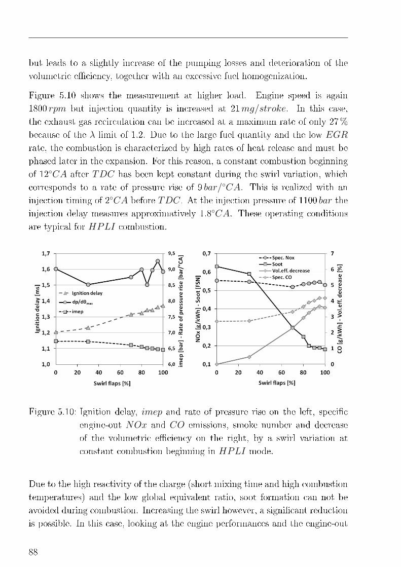
but leads to a slightly increase of the pumping losses and deterioration of the
volumetric e�ciency, together with an excessive fuel homogenization.
Figure 5.10 shows the measurement at higher load. Engine speed is again
1800 rpm but injection quantity is increased at 21mg/stroke. In this case,
the exhaust gas recirculation can be increased at a maximum rate of only 27%
because of the λ limit of 1.2. Due to the large fuel quantity and the low EGR
rate, the combustion is characterized by high rates of heat release and must be
phased later in the expansion. For this reason, a constant combustion beginning
of 12◦CA after TDC has been kept constant during the swirl variation, which
corresponds to a rate of pressure rise of 9 bar/◦CA. This is realized with an
injection timing of 2◦CA before TDC. At the injection pressure of 1100 bar the
injection delay measures approximatively 1.8◦CA. These operating conditions
are typical for HPLI combustion.
Figure 5.10: Ignition delay, imep and rate of pressure rise on the left, speci�c
engine-out NOx and CO emissions, smoke number and decrease
of the volumetric e�ciency on the right, by a swirl variation at
constant combustion beginning in HPLI mode.
Due to the high reactivity of the charge (short mixing time and high combustion
temperatures) and the low global equivalent ratio, soot formation can not be
avoided during combustion. Increasing the swirl however, a signi�cant reduction
is possible. In this case, looking at the engine performances and the engine-out
88
System analysis and de�nition of the combustion control strategy
emissions, it cannot be clearly said if this reduction results either from a better
fuel homogenization prior to combustion or from an improved oxidation of the
soot oxidation in the late combustion phase. In [8], optical investigation of
late injection homogeneous combustion processes has pointed out late oxidation
mechanisms to be the reason behind the soot reduction. However, the soot
emissions improvement has to be weighted with the increase in pumping losses
(4%) and CO emissions (in this case UHC emissions remained constant over
the entire parameter variation).
The trade-o� in the emissions related to the magnitude of the fuel homogeniza-
tion and the decrease in volumetric e�ciency resulting by the throttling e�ect
of the swirl �aps has been also indenti�ed in [11] and [65]. The use of the
swirl �aps can e�ectively increase the mixture homogenization at higher loads
but a compromise between premixed level and e�ciency losses must be found.
Moreover, due to the reduced volumetric e�ciency, the use of the swirl �aps may
reduce the application range of low-temperature premixed combustion processes.
Therefore, even if there exists the possibility of �ne tuning of the combustion
process, in this work the integration of the swirl �aps in a closed-loop control
system is not suggested.
5.2.7 Rate of exhaust gas recirculation
Because of its large in�uence on the combustion, which mechanisms are ex-
plained in Chapter 3, the EGR rate is considered to be, together with the injec-
tion timing, the most important engine parameter in low-temperature premixed
processes. Especially at low load, i.e. in HCLI mode, the EGR rate can be
varied in a very wide range. In Figure 5.11, at constant engine speed, injection
timing and quantity, the EGR has been increased from 0 to 50%. The intake
temperature has been kept constant cooling the charge (EGR is mixed with
the fresh air upstream the intercooler) at 313K. The results show a signi�cant
e�ect of the EGR on the entire combustion process. Di�erently to the injection
beginning, the e�ects of EGR begin already with the reduction of compression-
end pressure and temperature, due to the increased heat capacity of the charge,
and ends with lower exhaust temperatures. During the combustion process the
reduction of the �ame temperature and the mixture reactivity results in a longer
89
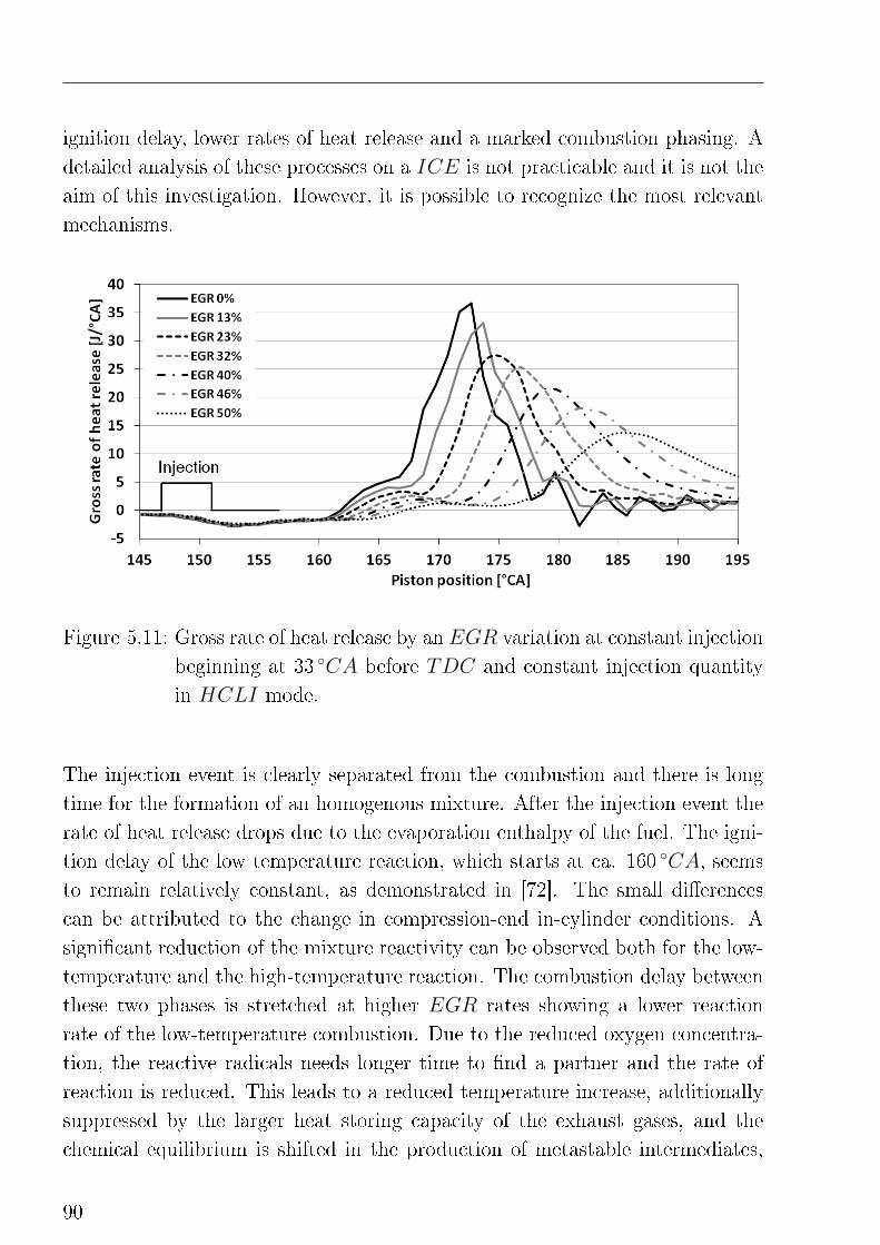
ignition delay, lower rates of heat release and a marked combustion phasing. A
detailed analysis of these processes on a ICE is not practicable and it is not the
aim of this investigation. However, it is possible to recognize the most relevant
mechanisms.
Figure 5.11: Gross rate of heat release by an EGR variation at constant injection
beginning at 33 ◦CA before TDC and constant injection quantity
in HCLI mode.
The injection event is clearly separated from the combustion and there is long
time for the formation of an homogenous mixture. After the injection event the
rate of heat release drops due to the evaporation enthalpy of the fuel. The igni-
tion delay of the low temperature reaction, which starts at ca. 160 ◦CA, seems
to remain relatively constant, as demonstrated in [72]. The small di�erences
can be attributed to the change in compression-end in-cylinder conditions. A
signi�cant reduction of the mixture reactivity can be observed both for the low-
temperature and the high-temperature reaction. The combustion delay between
these two phases is stretched at higher EGR rates showing a lower reaction
rate of the low-temperature combustion. Due to the reduced oxygen concentra-
tion, the reactive radicals needs longer time to �nd a partner and the rate of
reaction is reduced. This leads to a reduced temperature increase, additionally
suppressed by the larger heat storing capacity of the exhaust gases, and the
chemical equilibrium is shifted in the production of metastable intermediates,
90
System analysis and de�nition of the combustion control strategy
which are less reactive. These two mechanisms, i.e. the reduction of the �ame
temperature and the mixture reactivity, take place simultaneously and their ef-
fect is prolonged over the entire combustion. Similar results are illustrated and
discussed in [36] [10] [64].
In order to investigate the e�ect of the exhaust gas recirculation under more
realistic engine operating conditions, measurements at constant maximum rate
of pressure rise and constant imep has been carried out. In consideration of the
results illustrated in the previous sections, a constant maximum rate of pressure
rise has been provided by means of injection timing variation. The imep has
been kept constant adjusting the injection duration. Intake charge temperature
was kept constant at 313K but the pressure varied slightly, as well as the charge
quality and its quantity, depending on the rate of EGR.
In Figure 5.12 the results for a representative HCLI load point at 1800 rpm
and 4 bar imep are plotted over the combustion beginning. On the right side of
the �gure the charge is characterized by an air/fuel ratio of 2.3 and a low rate
of EGR of about 27%. The injection event takes place at ca. 2 ◦CA before
TDC. Starting from this point, the EGR rate is systematically increased and
the charge subsequently diluted. As shown in Figure 5.11, this results in a longer
ignition delay and a lower mixture reactivity, thus a later combustion beginning
and a lower peak of pressure rise. In order to keep this last parameter con-
stant, the combustion beginning must be anticipated injecting the fuel earlier.
Approaching the TDC, in fact, the higher pressures and temperatures resulting
from the piston motion can be exploited for increasing the mixture reactivity
and overcome the dilution e�ect, which results both form the higher EGR rate
and from the increase in ignition delay. This can be done until the combustion
beginning has reached the TDC, since after that point in-cylinder temperature
and pressure decrease again. Shifting the combustion beginning in the compres-
sion, the EGR can not be further increased but on the countrary, in order to
maintain the same level of pressure rise, it must be reduced. It can be seen that
the investigated range with combustion beginning in the compression phase is
signi�cantly shorter if compared with the range with a combustion beginning in
the expansion. This is because the very left point in the diagram corresponds to
an injection timing of 30 ◦CA before TDC, which is considered to be the limit
for piston bowl-in combustion.
91
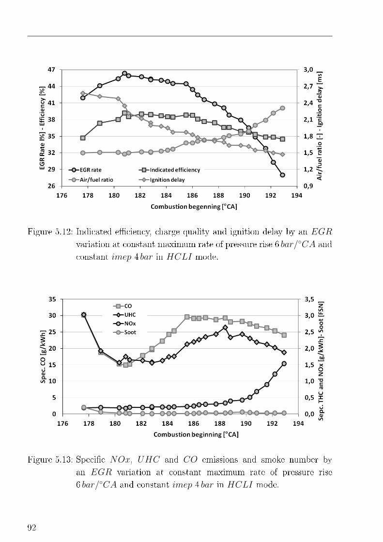
Figure 5.12: Indicated e�ciency, charge quality and ignition delay by an EGR
variation at constant maximum rate of pressure rise 6 bar/◦CA and
constant imep 4 bar in HCLI mode.
Figure 5.13: Speci�c NOx, UHC and CO emissions and smoke number by
an EGR variation at constant maximum rate of pressure rise
6 bar/◦CA and constant imep 4 bar in HCLI mode.
92
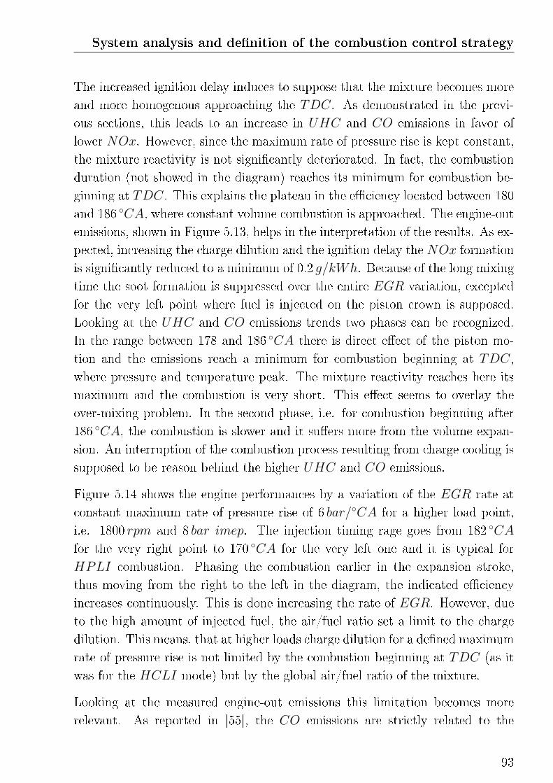
System analysis and de�nition of the combustion control strategy
The increased ignition delay induces to suppose that the mixture becomes more
and more homogenous approaching the TDC. As demonstrated in the previ-
ous sections, this leads to an increase in UHC and CO emissions in favor of
lower NOx. However, since the maximum rate of pressure rise is kept constant,
the mixture reactivity is not signi�cantly deteriorated. In fact, the combustion
duration (not showed in the diagram) reaches its minimum for combustion be-
ginning at TDC. This explains the plateau in the e�ciency located between 180
and 186 ◦CA, where constant volume combustion is approached. The engine-out
emissions, shown in Figure 5.13, helps in the interpretation of the results. As ex-
pected, increasing the charge dilution and the ignition delay the NOx formation
is signi�cantly reduced to a minimum of 0.2 g/kWh. Because of the long mixing
time the soot formation is suppressed over the entire EGR variation, excepted
for the very left point where fuel is injected on the piston crown is supposed.
Looking at the UHC and CO emissions trends two phases can be recognized.
In the range between 178 and 186 ◦CA there is direct e�ect of the piston mo-
tion and the emissions reach a minimum for combustion beginning at TDC,
where pressure and temperature peak. The mixture reactivity reaches here its
maximum and the combustion is very short. This e�ect seems to overlay the
over-mixing problem. In the second phase, i.e. for combustion beginning after
186 ◦CA, the combustion is slower and it su�ers more from the volume expan-
sion. An interruption of the combustion process resulting from charge cooling is
supposed to be reason behind the higher UHC and CO emissions.
Figure 5.14 shows the engine performances by a variation of the EGR rate at
constant maximum rate of pressure rise of 6 bar/◦CA for a higher load point,
i.e. 1800 rpm and 8 bar imep. The injection timing rage goes from 182 ◦CA
for the very right point to 170 ◦CA for the very left one and it is typical for
HPLI combustion. Phasing the combustion earlier in the expansion stroke,
thus moving from the right to the left in the diagram, the indicated e�ciency
increases continuously. This is done increasing the rate of EGR. However, due
to the high amount of injected fuel, the air/fuel ratio set a limit to the charge
dilution. This means, that at higher loads charge dilution for a de�ned maximum
rate of pressure rise is not limited by the combustion beginning at TDC (as it
was for the HCLI mode) but by the global air/fuel ratio of the mixture.
Looking at the measured engine-out emissions this limitation becomes more
relevant. As reported in [55], the CO emissions are strictly related to the
93
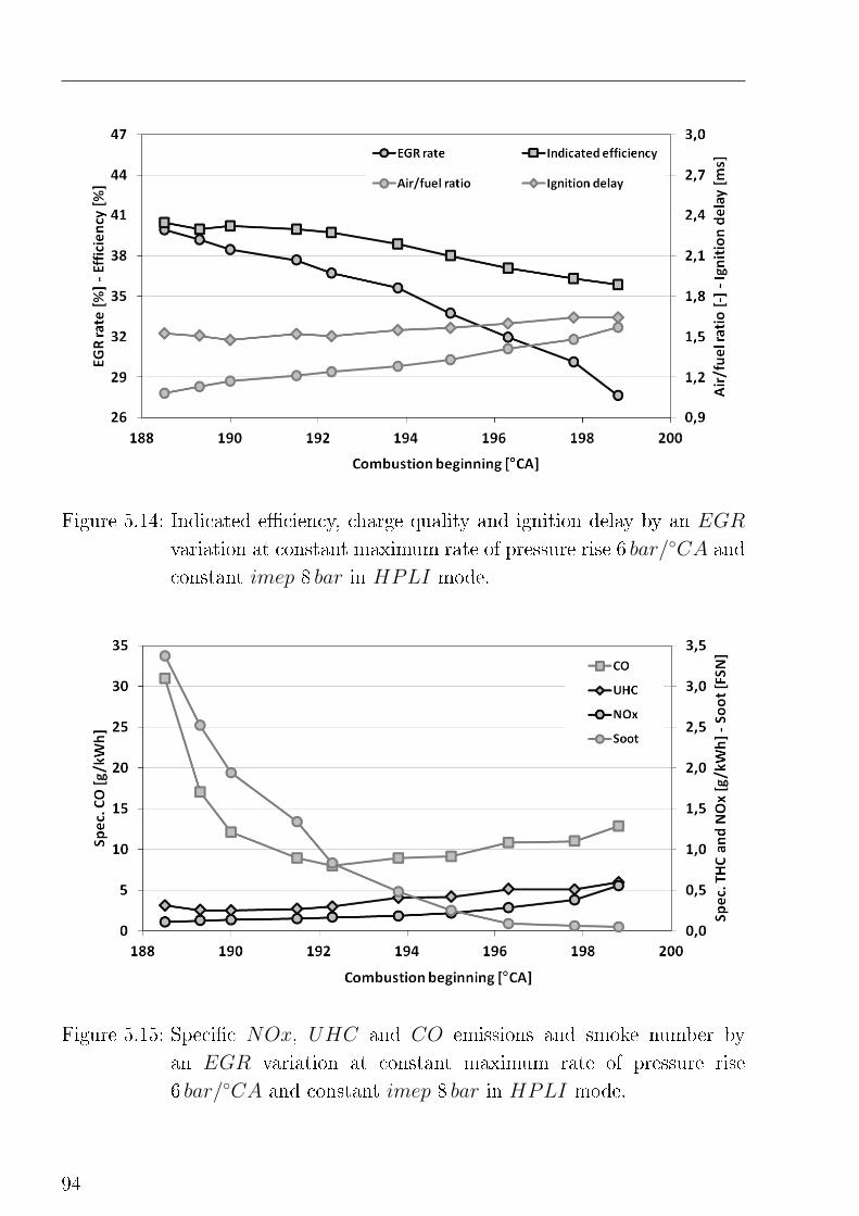
Figure 5.14: Indicated e�ciency, charge quality and ignition delay by an EGR
variation at constant maximum rate of pressure rise 6 bar/◦CA and
constant imep 8 bar in HPLI mode.
Figure 5.15: Speci�c NOx, UHC and CO emissions and smoke number by
an EGR variation at constant maximum rate of pressure rise
6 bar/◦CA and constant imep 8 bar in HPLI mode.
94
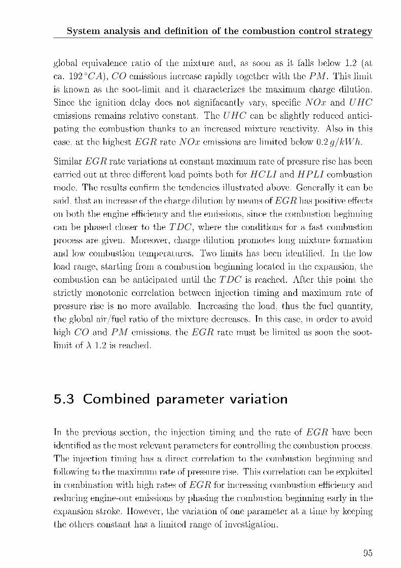
System analysis and de�nition of the combustion control strategy
global equivalence ratio of the mixture and, as soon as it falls below 1.2 (at
ca. 192 ◦CA), CO emissions increase rapidly together with the PM . This limit
is known as the soot-limit and it characterizes the maximum charge dilution.
Since the ignition delay does not signifacantly vary, speci�c NOx and UHC
emissions remains relative constant. The UHC can be slightly reduced antici-
pating the combustion thanks to an increased mixture reactivity. Also in this
case, at the highest EGR rate NOx emissions are limited below 0.2 g/kWh.
Similar EGR rate variations at constant maximum rate of pressure rise has been
carried out at three di�erent load points both for HCLI and HPLI combustion
mode. The results con�rm the tendencies illustrated above. Generally it can be
said, that an increase of the charge dilution by means of EGR has positive e�ects
on both the engine e�ciency and the emissions, since the combustion beginning
can be phased closer to the TDC, where the conditions for a fast combustion
process are given. Moreover, charge dilution promotes long mixture formation
and low combustion temperatures. Two limits has been identi�ed. In the low
load range, starting from a combustion beginning located in the expansion, the
combustion can be anticipated until the TDC is reached. After this point the
strictly monotonic correlation between injection timing and maximum rate of
pressure rise is no more available. Increasing the load, thus the fuel quantity,
the global air/fuel ratio of the mixture decreases. In this case, in order to avoid
high CO and PM emissions, the EGR rate must be limited as soon the soot-
limit of λ 1.2 is reached.
5.3 Combined parameter variation
In the previous section, the injection timing and the rate of EGR have been
identi�ed as the most relevant parameters for controlling the combustion process.
The injection timing has a direct correlation to the combustion beginning and
following to the maximum rate of pressure rise. This correlation can be exploited
in combination with high rates of EGR for increasing combustion e�ciency and
reducing engine-out emissions by phasing the combustion beginning early in the
expansion stroke. However, the variation of one parameter at a time by keeping
the others constant has a limited range of investigation.
95
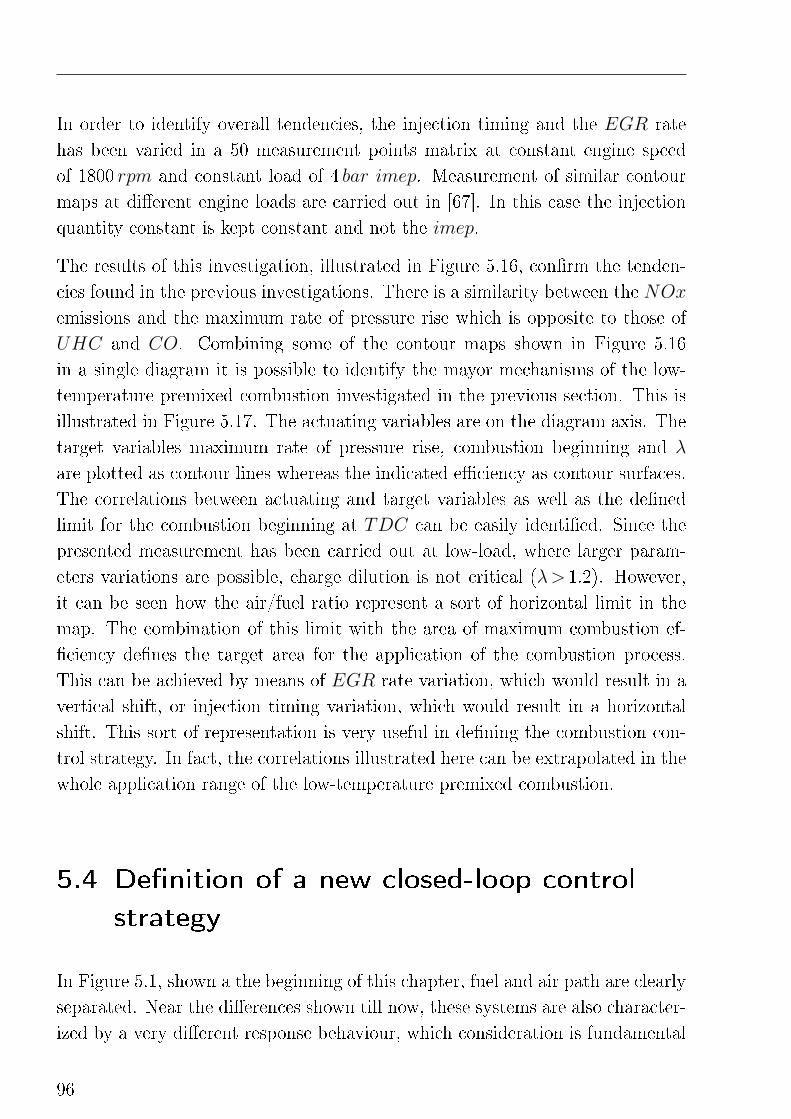
In order to identify overall tendencies, the injection timing and the EGR rate
has been varied in a 50 measurement points matrix at constant engine speed
of 1800 rpm and constant load of 4 bar imep. Measurement of similar contour
maps at di�erent engine loads are carried out in [67]. In this case the injection
quantity constant is kept constant and not the imep.
The results of this investigation, illustrated in Figure 5.16, con�rm the tenden-
cies found in the previous investigations. There is a similarity between the NOx
emissions and the maximum rate of pressure rise which is opposite to those of
UHC and CO. Combining some of the contour maps shown in Figure 5.16
in a single diagram it is possible to identify the mayor mechanisms of the low-
temperature premixed combustion investigated in the previous section. This is
illustrated in Figure 5.17. The actuating variables are on the diagram axis. The
target variables maximum rate of pressure rise, combustion beginning and λ
are plotted as contour lines whereas the indicated e�ciency as contour surfaces.
The correlations between actuating and target variables as well as the de�ned
limit for the combustion beginning at TDC can be easily identi�ed. Since the
presented measurement has been carried out at low-load, where larger param-
eters variations are possible, charge dilution is not critical (λ> 1.2). However,
it can be seen how the air/fuel ratio represent a sort of horizontal limit in the
map. The combination of this limit with the area of maximum combustion ef-
�ciency de�nes the target area for the application of the combustion process.
This can be achieved by means of EGR rate variation, which would result in a
vertical shift, or injection timing variation, which would result in a horizontal
shift. This sort of representation is very useful in de�ning the combustion con-
trol strategy. In fact, the correlations illustrated here can be extrapolated in the
whole application range of the low-temperature premixed combustion.
5.4 De�nition of a new closed-loop control
strategy
In Figure 5.1, shown a the beginning of this chapter, fuel and air path are clearly
separated. Near the di�erences shown till now, these systems are also character-
ized by a very di�erent response behaviour, which consideration is fundamental
96
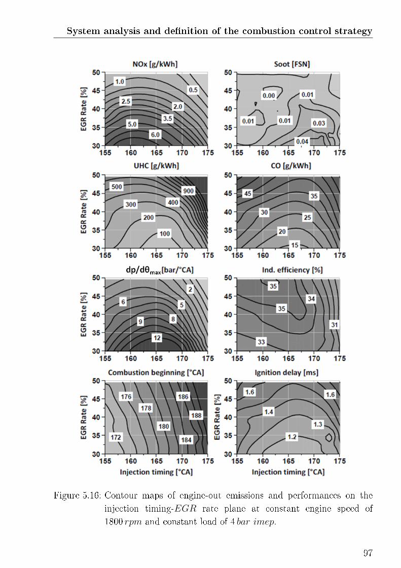
System analysis and de�nition of the combustion control strategy
Figure 5.16: Contour maps of engine-out emissions and performances on the
injection timing-EGR rate plane at constant engine speed of
1800 rpm and constant load of 4 bar imep.
97
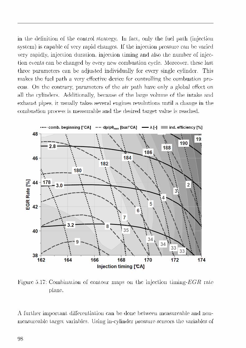
in the de�nition of the control strategy. In fact, only the fuel path (injection
system) is capable of very rapid changes. If the injection pressure can be varied
very rapidly, injection duration, injection timing and also the number of injec-
tion events can be changed by every new combustion cycle. Moreover, these last
three parameters can be adjusted individually for every single cylinder. This
makes the fuel path a very e�ective device for controlling the combustion pro-
cess. On the contrary, parameters of the air path have only a global e�ect on
all the cylinders. Additionally, because of the large volume of the intake and
exhaust pipes, it usually takes several engines revolutions until a change in the
combustion process is measurable and the desired target value is reached.
Figure 5.17: Combination of contour maps on the injection timing-EGR rate
plane.
A further important di�erentiation can be done between measureable and non-
measureable target variables. Using in-cylinder pressure sensors the variables of
98
System analysis and de�nition of the combustion control strategy
the �rst two target groups can be calculated immediately by means of real-time
pressure traces analysis. On the other hand, the determination of the variables of
the last target group, i.e. emissions and e�ciency, is usually done using complex
empirical correlations which calculation e�ort is very time costing for the ECU
and thus not suitable for real-time calculation.
The goals set by the de�nition of a new control system for the low-temperature
premixed combustion are
• ensure a long time for fuel homogenization
• but still providing a direct control of the combustion beginning,
• high combustion e�ciency
• and no mis�re,
• NOx and smoke-less combustion
• by maintaining low UHC-CO emissions,
• low engine noise (low rates of pressure rise)
• and good transient behavior.
The system sensitivity analysis proposed in the �rst part of this chapter has
been useful for identifying mayor constrains ans system limitations, and for
highlighting the most relevant mechanisms of the low-temperature premixed
combustion. Deriving from these information a combustion control strategy can
be �nally de�ned. This is schematic illustrated in Figure 5.18.
5.4.1 Engine load
In commercial ECUs the engine load is usually characterized as a "desired"
torque which is derived from the actuation of the gas pedal. In the standard
vehicle equipment there are no sensors capable of measuring the e�ective torque
delivered by the engine. Introducing in-cylinder pressure sensors however, the
engine load can be directly measured in form of indicated piston work, i.e. imep.
With good approximation, the imep is directly correlated to the amount of
fuel injected per engine stroke, which results from the injection duration and
99
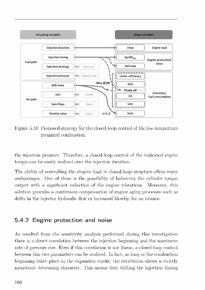
Figure 5.18: Proposed strategy for the closed-loop control of the low-temperture
premixed combustion.
the injection pressure. Therefore, a closed-loop control of the indicated engine
torque can be easily realized over the injection duration.
The ability of controlling the eingine load in closed-loop structure o�ers many
andvantages. One of these is the possibility of balancing the cylinder torque
output with a signi�cant reduction of the engine vibrations. Moreover, this
solution provides a continuous compensation of engine aging processes such as
drifts in the injector hydraulic �ow or increased blowby, for an istance.
5.4.2 Engine protection and noise
As resulted from the sensitivity analysis performed during this investigation
there is a direct correlation between the injection beginning and the maximum
rate of pressure rise. Even if this correlation is not linear, a closed-loop control
between this two parameters can be realized. In fact, as long as the combustion
beginning takes place in the expansion stroke, the correlation shows a strictly
monotonic decreasing character. This means that shifting the injection timing
100
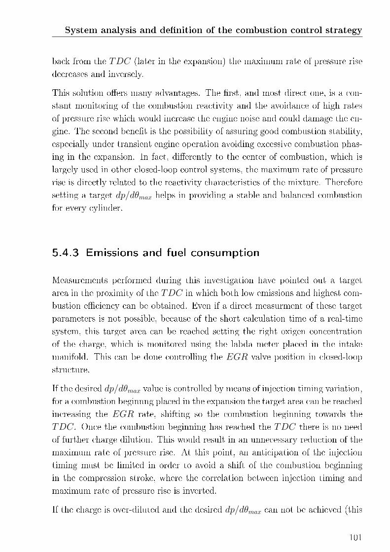
System analysis and de�nition of the combustion control strategy
back from the TDC (later in the expansion) the maximum rate of pressure rise
decreases and inversely.
This solution o�ers many advantages. The �rst, and most direct one, is a con-
stant monitoring of the combustion reactivity and the avoidance of high rates
of pressure rise which would increase the engine noise and could damage the en-
gine. The second bene�t is the possibility of assuring good combustion stability,
especially under transient engine operation avoiding excessive combustion phas-
ing in the expansion. In fact, di�erently to the center of combustion, which is
largely used in other closed-loop control systems, the maximum rate of pressure
rise is directly related to the reactivity characteristics of the mixture. Therefore
setting a target dp/dθmax helps in providing a stable and balanced combustion
for every cylinder.
5.4.3 Emissions and fuel consumption
Measurements performed during this investigation have pointed out a target
area in the proximity of the TDC in which both low emissions and highest com-
bustion e�ciency can be obtained. Even if a direct measurment of these target
parameters is not possible, because of the short calculation time of a real-time
system, this target area can be reached setting the right oxigen concentration
of the charge, which is monitored using the labda meter placed in the intake
manifold. This can be done controlling the EGR valve position in closed-loop
structure.
If the desired dp/dθmax value is controlled by means of injection timing variation,
for a combustion beginnng placed in the expansion the target area can be reached
increasing the EGR rate, shifting so the combustion beginning towards the
TDC. Once the combustion beginning has reached the TDC there is no need
of further charge dilution. This would result in an unnecessary reduction of the
maximum rate of pressure rise. At this point, an anticipation of the injection
timing must be limited in order to avoid a shift of the combustion beginning
in the compression stroke, where the correlation between injection timing and
maximum rate of pressure rise is inverted.
If the charge is over-diluted and the desired dp/dθmax can not be achieved (this
101
situation cuold results for an instance from a fast load reduction), the controller
must reduce the EGR rate, closing the valve, as long as the target oxygen
concentration and the desired maximum rate of pressure rise can be provided.
Also in this case, a solution for limiting the combustion beginning at TDC must
be provided.
At part load, soot formation can be avoided monitoring the λ value of the exhaust
gases. Increasing the load, the EGR can be increased until the soot-limit of λ 1.2
is reached. In this case the combustion beginning can not be phased at TDC
but, for the given con�guration of target maximum rate of pressure rise and
maximum EGR rate for λ at soot-limit, the best possible combustion e�ciency
is provided.
Virtual emission sensor
The choice of the desired maximum rate of pressure rise mostly depends on the
desired engine noise level and the allowed engine-out emissions concentrations.
As shown in Figure 5.17, the combustion e�ciency seems to be less dependent
from this parameter, when the combustion beginning is kept constant. The
emissions, on the contrary, are directly related to it. As shown in Figure 5.19
a clear trade-o� in the emissions is obtained setting di�erent target maximum
rates of pressure rise. The reason behind this has been discussed many times in
the system sensitivity analysis. The in-cylinder conditions which lead to high
rates of pressure rise, i.e. near-stoichiometric mixture (short ignition delay),
in which the oxidation reactions have high speed and the �ame temperature is
high, also promote the formation of NOx emissions. Inversely, high EGR rates
combined with long ignition delay reduces the mixture reactivity and the �ame
temperature resulting in combustion deterioration and higher UHC and CO
emissions. Therefore, the maximum rate of pressure rise can be exploited as a
virtual emissions sensor. Implementing a weighting function in the application
of the combustion process an optimum position in the emission/noise trade-o�
can be calculated in order to set the target dp/dθmax value.
The proposed closed-loop combustion control strategy can be summarized as
follows. Starting from arbitrary in-cylinder conditions the maximum rate of
pressure rise is rapidly set, by means of injection timing variation, under the
102
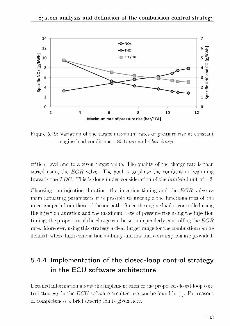
System analysis and de�nition of the combustion control strategy
Figure 5.19: Variation of the target maximum rates of pressure rise at constant
engine load conditions, 1800 rpm and 4 bar imep.
critical level and to a given target value. The quality of the charge rate is than
varied using the EGR valve. The goal is to phase the combustion beginning
towards the TDC. This is done under consideration of the lambda limit of 1.2.
Choosing the injection duration, the injection timing and the EGR valve as
main actuating parameters it is possible to uncouple the functionalities of the
injection path from those of the air path. Since the engine load is controlled using
the injection duration and the maximum rate of pressure rise using the injection
timing, the properties of the charge can be set independetly controlling the EGR
rate. Moreover, using this strategy a clear target range for the combustion can be
de�ned, where high combustion stability and low fuel consumption are provided.
5.4.4 Implementation of the closed-loop control strategy
in the ECU software architecture
Detailed information about the implementation of the proposed closed-loop con-
trol strategy in the ECU software architecture can be found in [1]. For reasons
of completeness a brief description is given here.
103
The control strategy of the low-temperature premixed combustion is imple-
mented using three independent SISO closed-loop circuits. The desired imep is
set controlling the fuel injection duration. Targeted maximum rates of pressure
rise are achieved by means of injection timing control and the EGR valve has
been chosen as actuating variable for setting the desired oxygen concentration in
charge, which is measured using an additional lambda sensor in the intake man-
ifold. The circuits are based on simple proportional-integral-derivative (PID)
controllers supported by feed-forward maps for the actuating variables. These
maps have been �tted on the base of stationary measurements. For the load and
engine protection controllers it is made use of a single PID parameter set for
the entire range of engine operation, whereas for the charge quality controller,
because of the strong dipendecy of the air path response from the engine torque
and speed, maps are used for the P and I factors.
Investigations in transient engine operation mode have shown the need of im-
proving the robustness of the control strategy for avoiding a deterioration of the
combustion process. This may results from a strong deviation of the charge qual-
ity as a consequence of the low system response of the air path. Two e�ective
solution has been realized.
Inverted PID controller
In transient engine operation �uctuations of the charge quality occur. By in-
su�cient charge dilution the engine protection controller phases the combustion
later in the expansion maintaining constant maximum rates of pressure rise. In
the other case, i.e. by large rates of EGR, the mixture reactivity is reduced and
the controller reacts anticipating the injection timing. As shown in Figure 5.17,
this strategy works until the combustion beginning has reached TDC. In order
to avoid the combustion beginning to be phased in the compression stroke, the
desired maximum rate of pressure rise must be reduced. This has been realized
using the actual values of the PID controller factors in an inverted PID con-
troller structure. This structure is capable of calculating a new, lower, desired
dp/dθmax value. The reduction of the dp/dθmax target value is proportional to
the needed injection timing correction for shifting the combustion beginning at
or after TDC. In this way a dynamic injection timing limitation is obtained
without disturbing the controller functionality.
104
System analysis and de�nition of the combustion control strategy
Injection timing feed-forward dynamic adaptation over the oxygen
concentration
An additional side-e�ect related to the poor transient response of the air path
is the occurrence of undesired oscillations in the dp/dθmax signal. These could
be reduced increasing the PID factors value of the engine protection controller,
which however would also result in an increased system instability. A solu-
tion has been found comparing the dp/dθmax signal with the measured oxygen
concentration of the charge. Not the actual oxygen concentration value but the
di�erence to the desired one is in fact proportional to the increase in the mixture
reactivity and thus to the maximum rate of pressure rise. Exploiting this mech-
anism, a dynamic correction of the feed-forward value of the injection timing
has been realized. This solution provides an e�ective reduction of the dp/dθmaxsignal oscillation and the avoidance of high peaks of pressure rise.
105

6
Combustion Mode Switch
The ability to switch the combustion mode between alter-
native and conventional di�usive combustion is necessary
to overcome the operation limit of the low-temperature pre-
mixed combustion and represent a fundamental task of a the
combustion control strategy. An e�ective mode switch pro-
cedure, based on targeted engine measurements, is proposed
in this chapter.
The application range of the low-temperature premixed combustion is mainly
limited by the trade-o� between high mixture reactivity and charge dilution.
In order to avoid fuel-rich mixture and the formation of soot, increasing the
engine load and thus the required fuel mass the EGR rate must be reduced.
The fuel/EGR mass ratio increases and the mixture becomes more reactive. In
order to limit the desired maximum rate of pressure rise the combustion muss
be phased later in the expansion stroke with a deterioration of the combustion
e�ciency. For this reason, switching to di�usive combustion mode once the
soot-limit is achieved is suggested. The limit can be de�ned using the λ value of
the exhaust gases or setting an upper load limit, which in this case is assumed
at 4.5 bar imep.
The goals by the de�nition of the mode switch strategy are:
• short duration of the switching procedure
• maintain the engine noise unvaried
• ensure a steady monotonic increase of the engine load under dynamic
engine operation
107
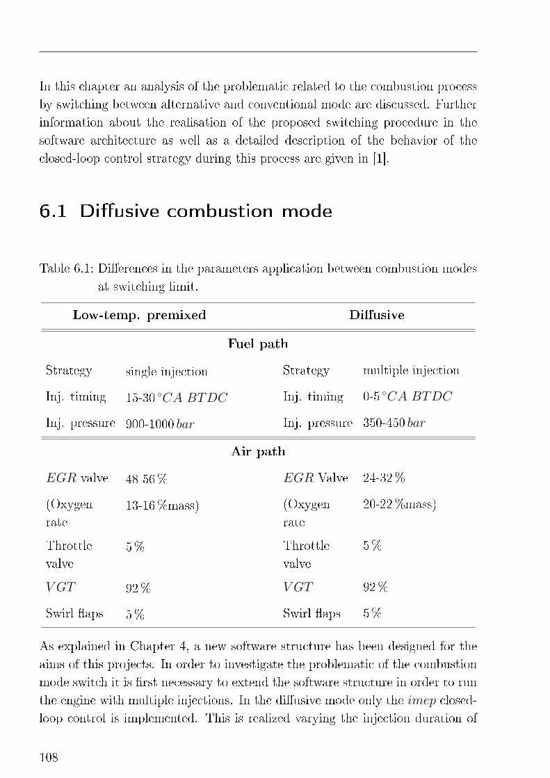
In this chapter an analysis of the problematic related to the combustion process
by switching between alternative and conventional mode are discussed. Further
information about the realisation of the proposed switching procedure in the
software architecture as well as a detailed description of the behavior of the
closed-loop control strategy during this process are given in [1].
6.1 Di�usive combustion mode
Table 6.1: Di�erences in the parameters application between combustion modes
at switching limit.
Low-temp. premixed Di�usive
Fuel path
Strategy single injection Strategy multiple injection
Inj. timing 15-30 ◦CA BTDC Inj. timing 0-5 ◦CA BTDC
Inj. pressure 900-1000 bar Inj. pressure 350-450 bar
Air path
EGR valve 48-56% EGR Valve 24-32%
(Oxygen
rate13-16%mass) (Oxygen
rate
20-22%mass)
Throttle
valve5% Throttle
valve
5%
V GT 92% V GT 92%
Swirl �aps 5% Swirl �aps 5%
As explained in Chapter 4, a new software structure has been designed for the
aims of this projects. In order to investigate the problematic of the combustion
mode switch it is �rst necessary to extend the software structure in order to run
the engine with multiple injections. In the di�usive mode only the imep closed-
loop control is implemented. This is realized varying the injection duration of
108
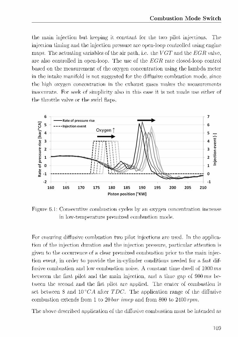
Combustion Mode Switch
the main injection but keeping it constant for the two pilot injections. The
injection timing and the injection pressure are open-loop controlled using engine
maps. The actuating variables of the air path, i.e. the V GT and the EGR valve,
are also controlled in open-loop. The use of the EGR rate closed-loop control
based on the measurement of the oxygen concentration using the lambda meter
in the intake manifold is not suggested for the di�usive combustion mode, since
the high oxygen concentration in the exhaust gases makes the measurements
inaccurate. For seek of simplicity also in this case it is not made use either of
the throttle valve or the swirl �aps.
Figure 6.1: Consecutive combustion cycles by an oxygen concentration increase
in low-temperature premixed combustion mode.
For ensuring di�usive combustion two pilot injections are used. In the applica-
tion of the injection duration and the injection pressure, particular attention is
given to the occurrence of a clear premixed combustion prior to the main injec-
tion event, in order to provide the in-cylinder conditions needed for a fast dif-
fusive combustion and low combustion noise. A constant time dwell of 1000ms
between the �rst pilot and the main injection, and a time gap of 900ms be-
tween the second and the �st pilot are applied. The center of combustion is
set between 8 and 10 ◦CA after TDC. The application range of the di�usive
combustion extends from 1 to 20 bar imep and from 800 to 2400 rpm.
The above described application of the di�usive combustion must be intended as
109
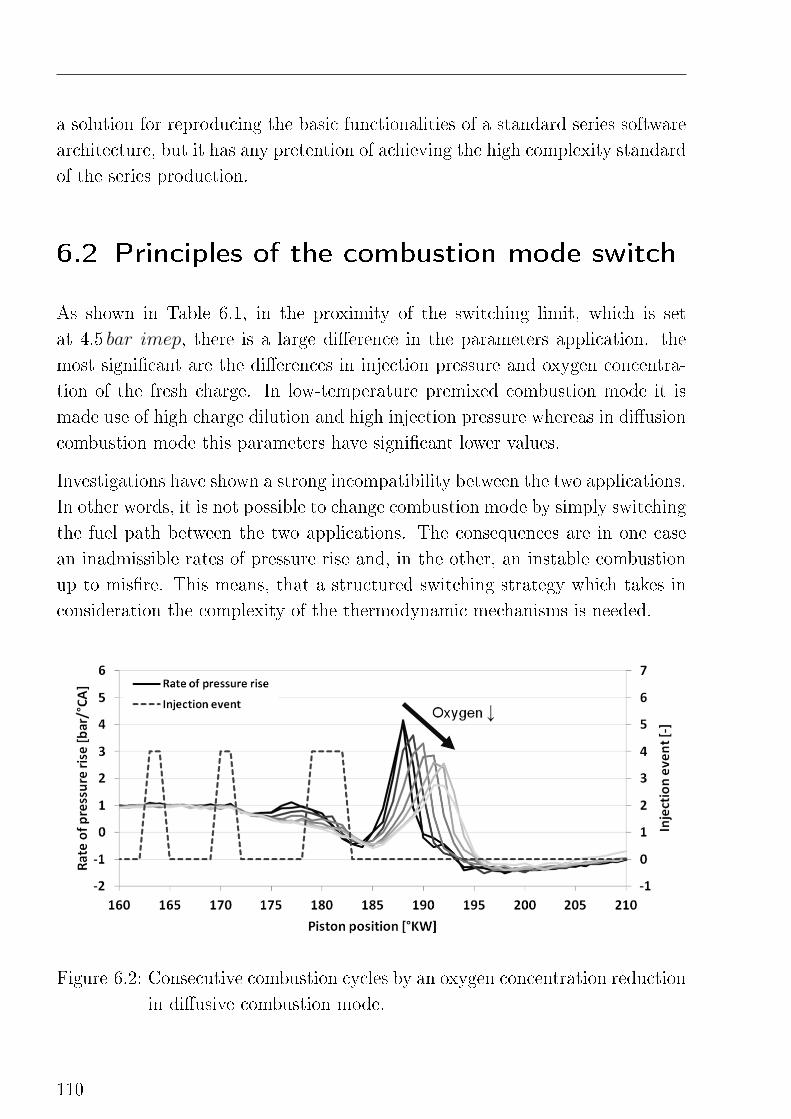
a solution for reproducing the basic functionalities of a standard series software
architecture, but it has any pretention of achieving the high complexity standard
of the series production.
6.2 Principles of the combustion mode switch
As shown in Table 6.1, in the proximity of the switching limit, which is set
at 4.5 bar imep, there is a large di�erence in the parameters application. the
most signi�cant are the di�erences in injection pressure and oxygen concentra-
tion of the fresh charge. In low-temperature premixed combustion mode it is
made use of high charge dilution and high injection pressure whereas in di�usion
combustion mode this parameters have signi�cant lower values.
Investigations have shown a strong incompatibility between the two applications.
In other words, it is not possible to change combustion mode by simply switching
the fuel path between the two applications. The consequences are in one case
an inadmissible rates of pressure rise and, in the other, an instable combustion
up to mis�re. This means, that a structured switching strategy which takes in
consideration the complexity of the thermodynamic mechanisms is needed.
Figure 6.2: Consecutive combustion cycles by an oxygen concentration reduction
in di�usive combustion mode.
110
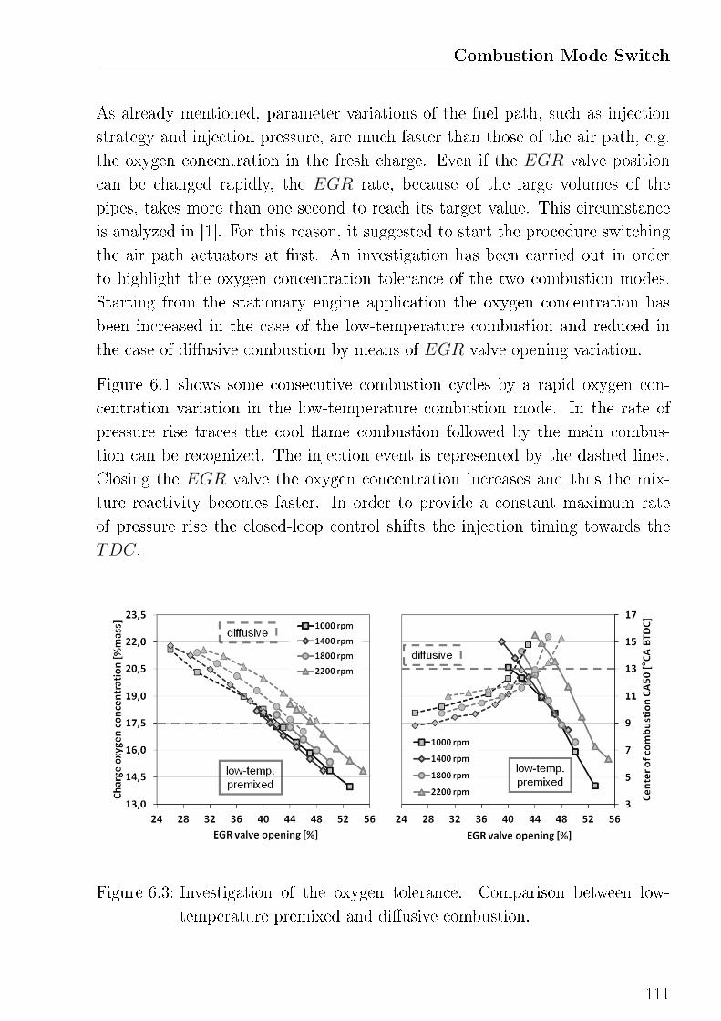
Combustion Mode Switch
As already mentioned, parameter variations of the fuel path, such as injection
strategy and injection pressure, are much faster than those of the air path, e.g.
the oxygen concentration in the fresh charge. Even if the EGR valve position
can be changed rapidly, the EGR rate, because of the large volumes of the
pipes, takes more than one second to reach its target value. This circumstance
is analyzed in [1]. For this reason, it suggested to start the procedure switching
the air path actuators at �rst. An investigation has been carried out in order
to highlight the oxygen concentration tolerance of the two combustion modes.
Starting from the stationary engine application the oxygen concentration has
been increased in the case of the low-temperature combustion and reduced in
the case of di�usive combustion by means of EGR valve opening variation.
Figure 6.1 shows some consecutive combustion cycles by a rapid oxygen con-
centration variation in the low-temperature combustion mode. In the rate of
pressure rise traces the cool �ame combustion followed by the main combus-
tion can be recognized. The injection event is represented by the dashed lines.
Closing the EGR valve the oxygen concentration increases and thus the mix-
ture reactivity becomes faster. In order to provide a constant maximum rate
of pressure rise the closed-loop control shifts the injection timing towards the
TDC.
Figure 6.3: Investigation of the oxygen tolerance. Comparison between low-
temperature premixed and di�usive combustion.
111
In di�usive combustion mode, the injection timing of the main and pilot injec-
tions is open-loop controlled and does not vary by reducing the oxygen concen-
tration. This is illustrated in Figure 6.2. A signi�cant reduction of the mixture
reactivity can be recognized for both the pilot and the main injection. The
premixed ratio becomes smaller and the ignition delay of the main combustion
longer. The main combustion shows a lowered heat release and a slower fuel
conversion. A further decrease of the oxygen concentration would lead to mis-
�re.
In both cases, the combustion is phased later in the expansion until quenching
occurs. In the �rst case as a consequence of the de�ned combustion control strat-
egy, in the latter due to the reduced reactivity of the charge. Before quencing
takes place, it is necessary to switch the fuel path.
In Figure 6.3 the oxygen tolerance of the two combustion modes at di�ent engine
loads is illustrated. Also in this case, starting from the default parameters
con�guration of Table 6.1, the oxygen mass rate in the fresh charge and the center
of combustion have been measured varying the EGR valve opening position at
4.5 bar imep and di�erent engine speed. Interestingly, for all the traces there
exist an overlap region between alternative and conventional combustion. The
oxygen concetration of 17.5% can be adopted as switching criterion for the fuel
path. This limit is independent from the engine speed and corresponds to a
center of combustion of approximatevely 13 ◦CA after TDC.
6.3 Switching from premixed to di�usive
combustion
A schematic step by step description of the proposed mode switching strategy
from alternative to conventional combustion is shown in Figure 6.4. In the
diagram a combustion mode switching procedure as a result of a load increase
is illustrated.
Once the imep value achieves 4.5 bar the switching process is triggered. The
EGR valve is rapidly closed to the value stored in the di�usive combustion
application map. After a short delay, the oxygen concentration in the charge
112
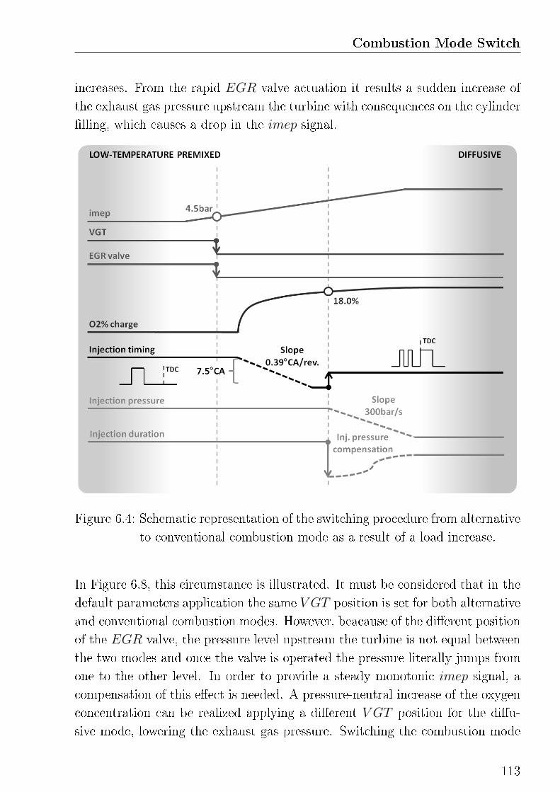
Combustion Mode Switch
increases. From the rapid EGR valve actuation it results a sudden increase of
the exhaust gas pressure upstream the turbine with consequences on the cylinder
�lling, which causes a drop in the imep signal.
Figure 6.4: Schematic representation of the switching procedure from alternative
to conventional combustion mode as a result of a load increase.
In Figure 6.8, this circumstance is illustrated. It must be considered that in the
default parameters application the same V GT position is set for both alternative
and conventional combustion modes. However, beacause of the di�erent position
of the EGR valve, the pressure level upstream the turbine is not equal between
the two modes and once the valve is operated the pressure literally jumps from
one to the other level. In order to provide a steady monotonic imep signal, a
compensation of this e�ect is needed. A pressure-neutral increase of the oxygen
concentration can be realized applying a di�erent V GT position for the di�u-
sive mode, lowering the exhaust gas pressure. Switching the combustion mode
113
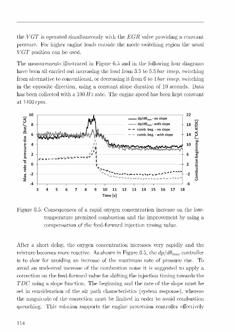
the V GT is operated simultaneously with the EGR valve providing a constant
pressure. For higher engine loads outside the mode switching region the usual
V GT position can be used.
The measurements illustrated in Figure 6.5 and in the following four diagrams
have been all carried out increasing the load from 3.5 to 5.5 bar imep, switching
from alternative to conventional, or decreasing it from 6 to 4 bar imep, switching
in the opposite direction, using a constant slope duration of 10 seconds. Data
has been collected with a 100Hz rate. The engine speed has been kept constant
at 1400 rpm.
Figure 6.5: Consequences of a rapid oxygen concentration increase on the low-
temperature premixed combustion and the improvement by using a
compensation of the feed-forward injection timing value.
After a short delay, the oxygen concentration increases very rapidly and the
mixture becomes more reactive. As shown in Figure 6.5, the dp/dθmax controller
is to slow for avoiding an increase of the maximum rate of pressure rise. To
avoid an undesired increase of the combustion noise it is suggested to apply a
correction on the feed-forward value for shifting the injection timing towards the
TDC using a slope function. The beginning and the rate of the slope must be
set in consideration of the air path characteristics (system response), whereas
the magnitude of the correction must be limited in order to avoid combustion
quenching. This solution supports the engine protection controller e�ectively
114
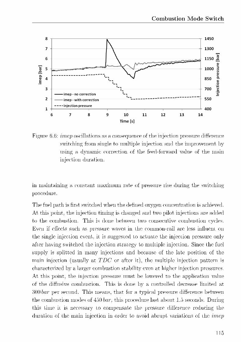
Combustion Mode Switch
Figure 6.6: imep oscillations as a consequence of the injection pressure di�erence
switching from single to multiple injection and the improvement by
using a dynamic correction of the feed-forward value of the main
injection duration.
in maintaining a constant maximum rate of pressure rise during the switching
procedure.
The fuel path is �rst switched when the de�ned oxygen concentration is achieved.
At this point, the injection timing is changed and two pilot injections are added
to the combustion. This is done between two consecutive combustion cycles.
Even if e�ects such as pressure waves in the common-rail are less in�uent on
the single injection event, it is suggested to actuate the injection pressure only
after having switched the injection strategy to multiple injection. Since the fuel
supply is splitted in many injections and because of the late position of the
main injection (usually at TDC or after it), the multiple injection pattern is
characterized by a larger combustion stability even at higher injection pressures.
At this point, the injection pressure must be lowered to the application value
of the di�usive combustion. This is done by a controlled decrease limited at
300 bar per second. This means, that for a typical pressure di�erence between
the combustion modes of 450 bar, this procedure last about 1.5 seconds. During
this time it is necessary to compensate the pressure di�erence reducing the
duration of the main injection in order to avoid abrupt variations of the imep
115
signal. Depending on the di�erence between the actual and the target injection
pressure, the feed-forward value of the imep controller, i.e. the injection duration
applyied in stationary mode, is corrected using a speci�c shaped function. In
Figure 6.6 a comparison between this strategy and a combustion switch without
injection pressure based dynamic feed-forward correction is shown. A linear
correction of the injection duration over the injection pressure is not su�cient
and only applying a S-shaped multi parameter function a steady monotonic
imep signal is obtained. Otherwise a signi�cant increase of the imep can be
observed. A detailed description of this function can be found in [1].
6.4 Switching from di�usive to premixed
combustion
The combustion mode switching procedure from di�usive to alterantive is similar
to the one discussed in the previous section. This is illustrated in Figure 6.7.
Also in this case, when the engine load drops below 4 bar imep, the air path is
switched at �rst. The EGR valve position is actuated to the feed-forward value
of the low-temperature premixed combustion controller, which is than reacti-
vated. The oxygen concentration drops, after a short delay, to a lower value. As
previously discussed, the in�uence of the EGR valve on the exhaust pressure
upstream the turbine must be compensated closing the V GT simultaneously.
Figure 6.8 shows the advantages of a steady exhaust pressure pro�le achieved
using this solution.
Di�erently to the mode switching procedure from alternative to conventional, in
this case the injection pressure is switched together with the air path. As already
mentioned, the di�usive combustion is more stable and thus suitable for an
injection pressure variation. With a rate of 300 bar per second the target pressure
is reached before the injection strategy is commuted. As shown in Figure 6.9
also in this case a correction of the feed-forward value of the main injection
duration, proportional to the actual pressure di�erence, is needed. A solution
has been found designing a G-shaped multi parameter correction function, which
is described in [1].
116
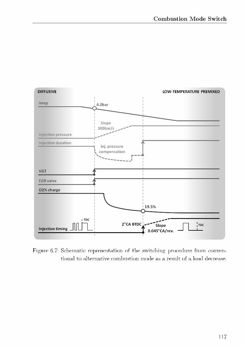
Combustion Mode Switch
Figure 6.7: Schematic representation of the switching procedure from conven-
tional to alternative combustion mode as a result of a load decrease.
117
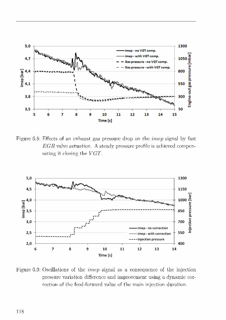
Figure 6.8: E�ects of an exhaust gas pressure drop on the imep signal by fast
EGR valve actuation. A steady pressure pro�le is achieved compen-
sating it closing the V GT .
Figure 6.9: Oscillations of the imep signal as a consequence of the injection
pressure variation di�erence and improvement using a dynamic cor-
rection of the feed-forward value of the main injection duration.
118
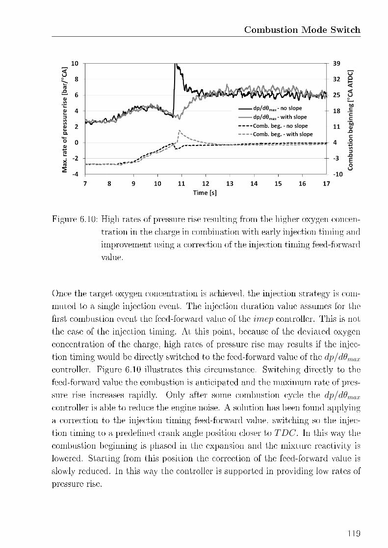
Combustion Mode Switch
Figure 6.10: High rates of pressure rise resulting from the higher oxygen concen-
tration in the charge in combination with early injection timing and
improvement using a correction of the injection timing feed-forward
value.
Once the target oxygen concentration is achieved, the injection strategy is com-
muted to a single injection event. The injection duration value assumes for the
�rst combustion event the feed-forward value of the imep controller. This is not
the case of the injection timing. At this point, because of the deviated oxygen
concentration of the charge, high rates of pressure rise may results if the injec-
tion timing would be directly switched to the feed-forward value of the dp/dθmaxcontroller. Figure 6.10 illustrates this circumstance. Switching directly to the
feed-forward value the combustion is anticipated and the maximum rate of pres-
sure rise increases rapidly. Only after some combustion cycle the dp/dθmaxcontroller is able to reduce the engine noise. A solution has been found applying
a correction to the injection timing feed-forward value, switching so the injec-
tion timing to a prede�ned crank angle position closer to TDC. In this way the
combustion beginning is phased in the expansion and the mixture reactivity is
lowered. Starting from this position the correction of the feed-forward value is
slowly reduced. In this way the controller is supported in providing low rates of
pressure rise.
119

7
Results
In this chapter advantages and drawbacks of the proposed
closed-loop combustion control system are illustrated and
commented. After the de�nition of the application range for
the low-temperature premixed combustion in the speed-torque
map, the control strategy is tested under both stationary and
transient engine operation mode. For measurements on the
engine dynomometer, a simpli�ed NEDC has been designed
in accordance with the legislative guidelines. Finally, the re-
sults of the combustion mode switch are shown.
7.1 Application range of the low-temperature
premixed combustion
The �rst result of this investigation is the identi�cation of the drivability range of
the low temperature premixed combustion mode in the speed-torque map. The
engine is run in stationary mode using the proposed closed-loop combustion
control strategy. The speed is increased starting from 1000 in 200 rpm steps
whereas the load from 1 bar imep in 1 bar steps. This is done until the occurrence
of combustion instability problems. Engine maps for target parameters and
feed-forward values has been previously set operating the engine in a open-loop
procedure. The desired maximum rate of pressure rise has been set overall
at 6 bar/◦CA, whereas other actuating parameters has been applyied following
the information collected during the system sensitivity analysis, described in
Chapter 5. Special attention has been given in providing a good combustion
quality and stability and avoiding NOx and PM emissions.
121
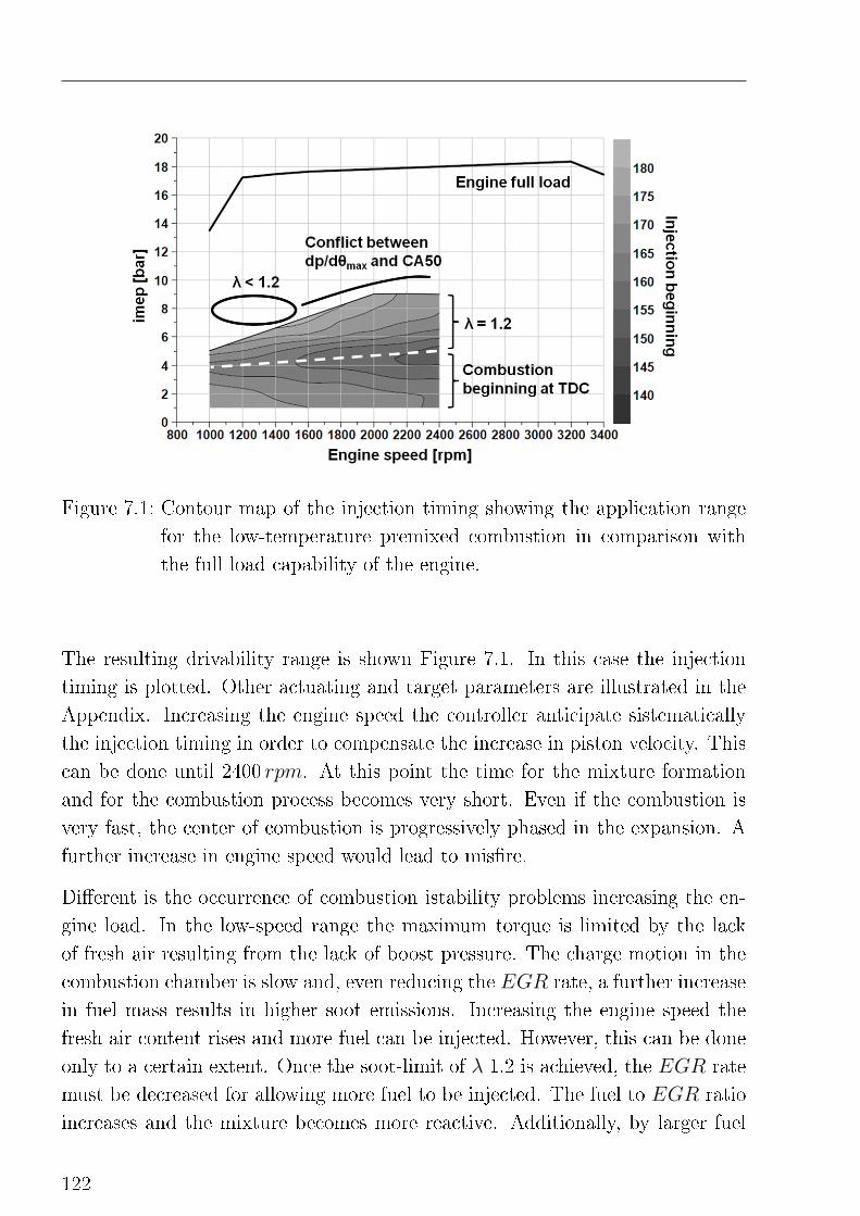
Figure 7.1: Contour map of the injection timing showing the application range
for the low-temperature premixed combustion in comparison with
the full load capability of the engine.
The resulting drivability range is shown Figure 7.1. In this case the injection
timing is plotted. Other actuating and target parameters are illustrated in the
Appendix. Increasing the engine speed the controller anticipate sistematically
the injection timing in order to compensate the increase in piston velocity. This
can be done until 2400 rpm. At this point the time for the mixture formation
and for the combustion process becomes very short. Even if the combustion is
very fast, the center of combustion is progressively phased in the expansion. A
further increase in engine speed would lead to mis�re.
Di�erent is the occurrence of combustion istability problems increasing the en-
gine load. In the low-speed range the maximum torque is limited by the lack
of fresh air resulting from the lack of boost pressure. The charge motion in the
combustion chamber is slow and, even reducing the EGR rate, a further increase
in fuel mass results in higher soot emissions. Increasing the engine speed the
fresh air content rises and more fuel can be injected. However, this can be done
only to a certain extent. Once the soot-limit of λ 1.2 is achieved, the EGR rate
must be decreased for allowing more fuel to be injected. The fuel to EGR ratio
increases and the mixture becomes more reactive. Additionally, by larger fuel
122
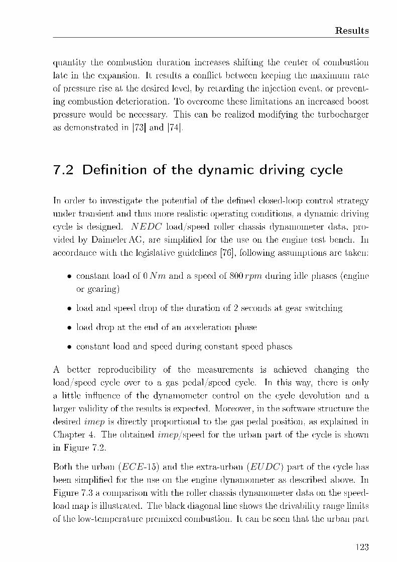
Results
quantity the combustion duration increases shifting the center of combustion
late in the expansion. It results a con�ict between keeping the maximum rate
of pressure rise at the desired level, by retarding the injection event, or prevent-
ing combustion deterioration. To overcome these limitations an increased boost
pressure would be necessary. This can be realized modifying the turbocharger
as demonstrated in [73] and [74].
7.2 De�nition of the dynamic driving cycle
In order to investigate the potential of the de�ned closed-loop control strategy
under transient and thus more realistic operating conditions, a dynamic driving
cycle is designed. NEDC load/speed roller chassis dynamometer data, pro-
vided by DaimelerAG, are simpli�ed for the use on the engine test bench. In
accordance with the legislative guidelines [76], following assumptions are taken:
• constant load of 0Nm and a speed of 800 rpm during idle phases (engine
or gearing)
• load and speed drop of the duration of 2 seconds at gear switching
• load drop at the end of an acceleration phase
• constant load and speed during constant speed phases
A better reproducibility of the measurements is achieved changing the
load/speed cycle over to a gas pedal/speed cycle. In this way, there is only
a little in�uence of the dynamometer control on the cycle devolution and a
larger validity of the results is expected. Moreover, in the software structure the
desired imep is directly proportional to the gas pedal position, as explained in
Chapter 4. The obtained imep/speed for the urban part of the cycle is shown
in Figure 7.2.
Both the urban (ECE-15) and the extra-urban (EUDC) part of the cycle has
been simpli�ed for the use on the engine dynamometer as described above. In
Figure 7.3 a comparison with the roller chassis dynamometer data on the speed-
load map is illustrated. The black diagonal line shows the drivability range limits
of the low-temperature premixed combustion. It can be seen that the urban part
123
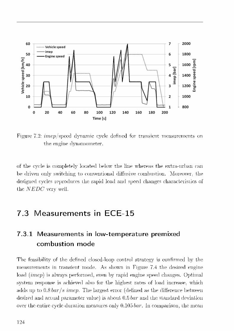
Figure 7.2: imep/speed dynamic cycle de�ned for transient measurements on
the engine dynamometer.
of the cycle is completely located below the line whereas the extra-urban can
be driven only switching to conventional di�usive combustion. Moreover, the
designed cycles reproduces the rapid load and speed changes characteristics of
the NEDC very well.
7.3 Measurements in ECE-15
7.3.1 Measurements in low-temperature premixed
combustion mode
The feasibility of the de�ned closed-loop control strategy is con�rmed by the
measurements in transient mode. As shown in Figure 7.4 the desired engine
load (imep) is always performed, even by rapid engine speed changes. Optimal
system response is achieved also for the highest rates of load increase, which
adds up to 0.8 bar/s imep. The largest error (de�ned as the di�erence between
desired and actual parameter value) is about 0.5 bar and the standard deviation
over the entire cycle duration measures only 0.105 bar. In comparison, the mean
124
Results
Figure 7.3: Comparison between the roller chassis dynamometer measured data
and the simpli�ed dynamic driving cycles.
standard deviation between the six cylinders is about 0.036 bar (with active
impe controller). At the end of the sharp load reductions, such as at 20 and 130
seconds, oscillations of the imep signal can be observed. These are attributed
to the slow system response of the air path and the resulting oscillations in the
charge oxygen concentration.
More interesting are the results about the maximum rate of pressure rise closed-
loop control, which serves as engine protection controller. These are illustrated
in Figure 7.5. It can be seen how high rates of pressure rise can be e�ectively
avoided controlling the injection timing. In fact, adopting this strategy, local
increases of the dp/dθmax value are immediately corrected. The largest error
is about 3.03 bar/◦CA and its standard deviation over the 200 seconds of the
ECE-15 duration is 0.534 bar/◦CA, which is in the same order of magnitude of
the statistical dp/dθmax spread among the six cylinders.
Due to the high cycle dynamic, phases characterized by rates of EGR larger than
expected (if compared to the stationary application) occur. In these phases
the injection timing limitation, described at the end of Chapter 5, is active.
125
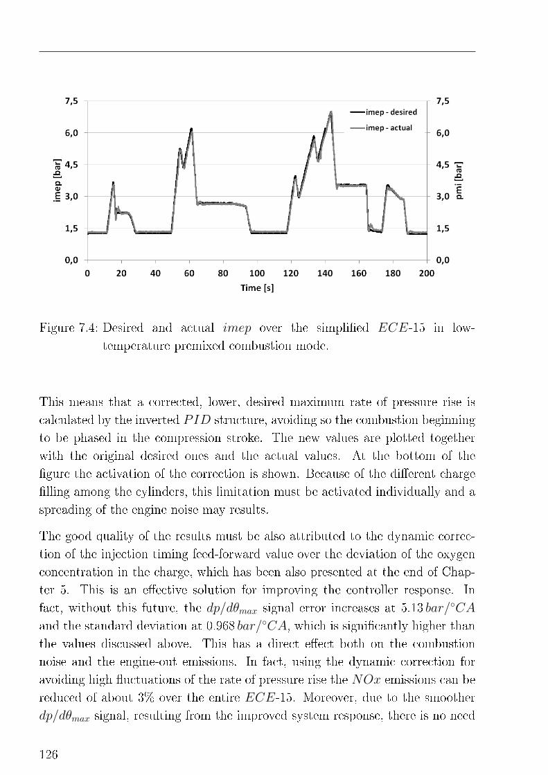
Figure 7.4: Desired and actual imep over the simpli�ed ECE-15 in low-
temperature premixed combustion mode.
This means that a corrected, lower, desired maximum rate of pressure rise is
calculated by the inverted PID structure, avoiding so the combustion beginning
to be phased in the compression stroke. The new values are plotted together
with the original desired ones and the actual values. At the bottom of the
�gure the activation of the correction is shown. Because of the di�erent charge
�lling among the cylinders, this limitation must be activated individually and a
spreading of the engine noise may results.
The good quality of the results must be also attributed to the dynamic correc-
tion of the injection timing feed-forward value over the deviation of the oxygen
concentration in the charge, which has been also presented at the end of Chap-
ter 5. This is an e�ective solution for improving the controller response. In
fact, without this future, the dp/dθmax signal error increases at 5.13 bar/◦CA
and the standard deviation at 0.968 bar/◦CA, which is signi�cantly higher than
the values discussed above. This has a direct e�ect both on the combustion
noise and the engine-out emissions. In fact, using the dynamic correction for
avoiding high �uctuations of the rate of pressure rise the NOx emissions can be
reduced of about 3% over the entire ECE-15. Moreover, due to the smoother
dp/dθmax signal, resulting from the improved system response, there is no need
126
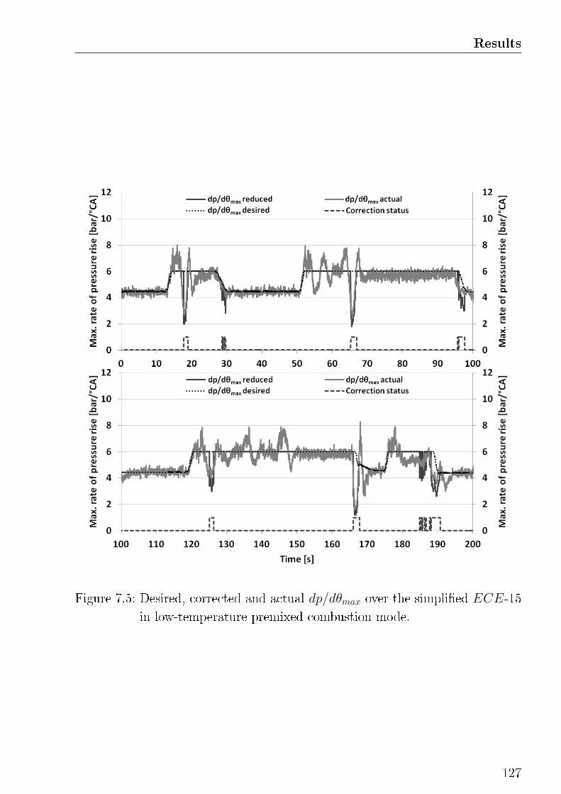
Results
Figure 7.5: Desired, corrected and actual dp/dθmax over the simpli�ed ECE-15
in low-temperature premixed combustion mode.
127
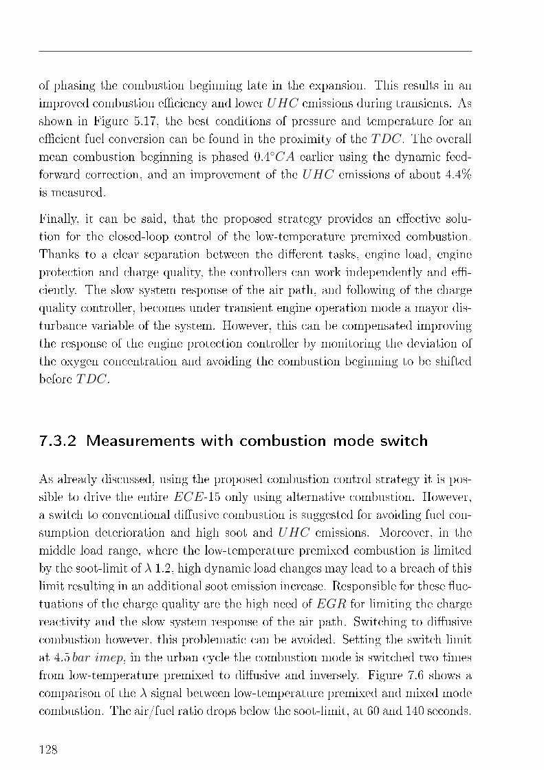
of phasing the combustion beginning late in the expansion. This results in an
improved combustion e�ciency and lower UHC emissions during transients. As
shown in Figure 5.17, the best conditions of pressure and temperature for an
e�cient fuel conversion can be found in the proximity of the TDC. The overall
mean combustion beginning is phased 0.4◦CA earlier using the dynamic feed-
forward correction, and an improvement of the UHC emissions of about 4.4%
is measured.
Finally, it can be said, that the proposed strategy provides an e�ective solu-
tion for the closed-loop control of the low-temperature premixed combustion.
Thanks to a clear separation between the di�erent tasks, engine load, engine
protection and charge quality, the controllers can work independently and e�-
ciently. The slow system response of the air path, and following of the charge
quality controller, becomes under transient engine operation mode a mayor dis-
turbance variable of the system. However, this can be compensated improving
the response of the engine protection controller by monitoring the deviation of
the oxygen concentration and avoiding the combustion beginning to be shifted
before TDC.
7.3.2 Measurements with combustion mode switch
As already discussed, using the proposed combustion control strategy it is pos-
sible to drive the entire ECE-15 only using alternative combustion. However,
a switch to conventional di�usive combustion is suggested for avoiding fuel con-
sumption deterioration and high soot and UHC emissions. Moreover, in the
middle load range, where the low-temperature premixed combustion is limited
by the soot-limit of λ 1.2, high dynamic load changes may lead to a breach of this
limit resulting in an additional soot emission increase. Responsible for these �uc-
tuations of the charge quality are the high need of EGR for limiting the charge
reactivity and the slow system response of the air path. Switching to di�usive
combustion however, this problematic can be avoided. Setting the switch limit
at 4.5 bar imep, in the urban cycle the combustion mode is switched two times
from low-temperature premixed to di�usive and inversely. Figure 7.6 shows a
comparison of the λ signal between low-temperature premixed and mixed mode
combustion. The air/fuel ratio drops below the soot-limit, at 60 and 140 seconds.
128
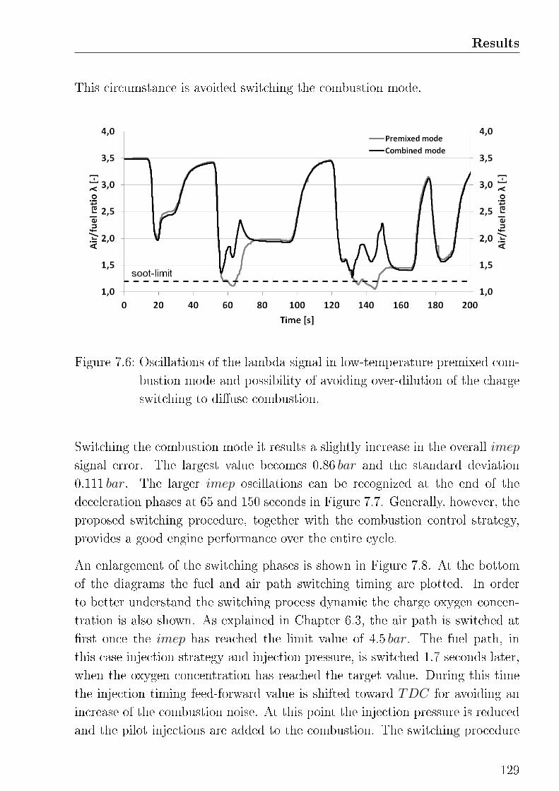
Results
This circumstance is avoided switching the combustion mode.
Figure 7.6: Oscillations of the lambda signal in low-temperature premixed com-
bustion mode and possibility of avoiding over-dilution of the charge
switching to di�use combustion.
Switching the combustion mode it results a slightly increase in the overall imep
signal error. The largest value becomes 0.86 bar and the standard deviation
0.111 bar. The larger imep oscillations can be recognized at the end of the
deceleration phases at 65 and 150 seconds in Figure 7.7. Generally, however, the
proposed switching procedure, together with the combustion control strategy,
provides a good engine performance over the entire cycle.
An enlargement of the switching phases is shown in Figure 7.8. At the bottom
of the diagrams the fuel and air path switching timing are plotted. In order
to better understand the switching process dynamic the charge oxygen concen-
tration is also shown. As explained in Chapter 6.3, the air path is switched at
�rst once the imep has reached the limit value of 4.5 bar. The fuel path, in
this case injection strategy and injection pressure, is switched 1.7 seconds later,
when the oxygen concentration has reached the target value. During this time
the injection timing feed-forward value is shifted toward TDC for avoiding an
increase of the combustion noise. At this point the injection pressure is reduced
and the pilot injections are added to the combustion. The switching procedure
129
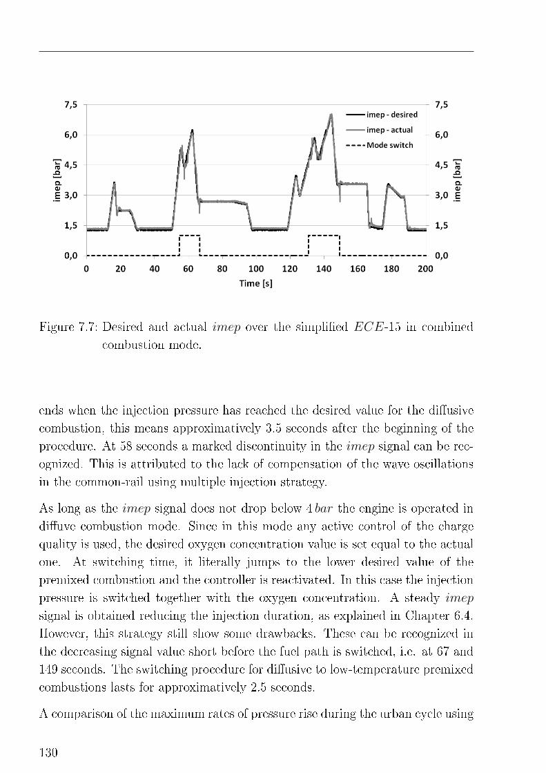
Figure 7.7: Desired and actual imep over the simpli�ed ECE-15 in combined
combustion mode.
ends when the injection pressure has reached the desired value for the di�usive
combustion, this means approximatively 3.5 seconds after the beginning of the
procedure. At 58 seconds a marked discontinuity in the imep signal can be rec-
ognized. This is attributed to the lack of compensation of the wave oscillations
in the common-rail using multiple injection strategy.
As long as the imep signal does not drop below 4 bar the engine is operated in
di�uve combustion mode. Since in this mode any active control of the charge
quality is used, the desired oxygen concentration value is set equal to the actual
one. At switching time, it literally jumps to the lower desired value of the
premixed combustion and the controller is reactivated. In this case the injection
pressure is switched together with the oxygen concentration. A steady imep
signal is obtained reducing the injection duration, as explained in Chapter 6.4.
However, this strategy still show some drawbacks. These can be recognized in
the decreasing signal value short before the fuel path is switched, i.e. at 67 and
149 seconds. The switching procedure for di�usive to low-temperature premixed
combustions lasts for approximatively 2.5 seconds.
A comparison of the maximum rates of pressure rise during the urban cycle using
130
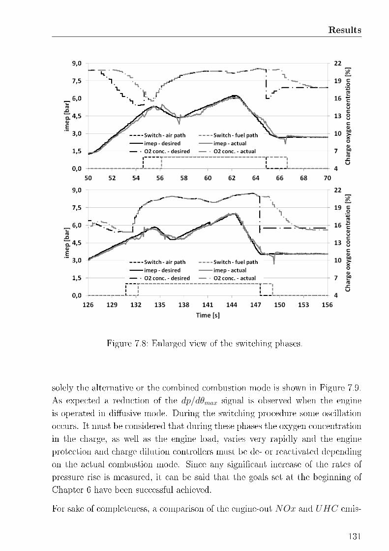
Results
Figure 7.8: Enlarged view of the switching phases.
solely the alternative or the combined combustion mode is shown in Figure 7.9.
As expected a reduction of the dp/dθmax signal is observed when the engine
is operated in di�usive mode. During the switching procedure some oscillation
occurs. It must be considered that during these phases the oxygen concentration
in the charge, as well as the engine load, varies very rapidly and the engine
protection and charge dilution controllers must be de- or reactivated depending
on the actual combustion mode. Since any signi�cant increase of the rates of
pressure rise is measured, it can be said that the goals set at the beginning of
Chapter 6 have been successful achieved.
For sake of completeness, a comparison of the engine-out NOx and UHC emis-
131
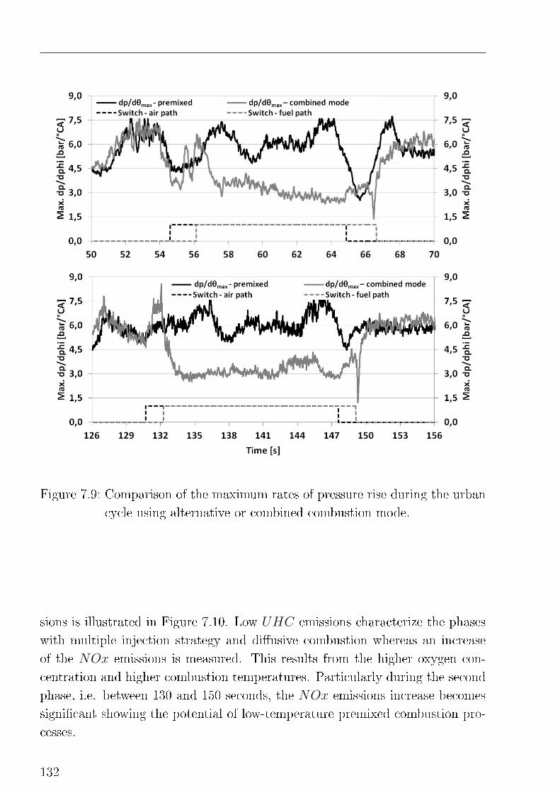
Figure 7.9: Comparison of the maximum rates of pressure rise during the urban
cycle using alternative or combined combustion mode.
sions is illustrated in Figure 7.10. Low UHC emissions characterize the phases
with multiple injection strategy and di�usive combustion whereas an increase
of the NOx emissions is measured. This results from the higher oxygen con-
centration and higher combustion temperatures. Particularly during the second
phase, i.e. between 130 and 150 seconds, the NOx emissions increase becomes
signi�cant showing the potential of low-temperature premixed combustion pro-
cesses.
132
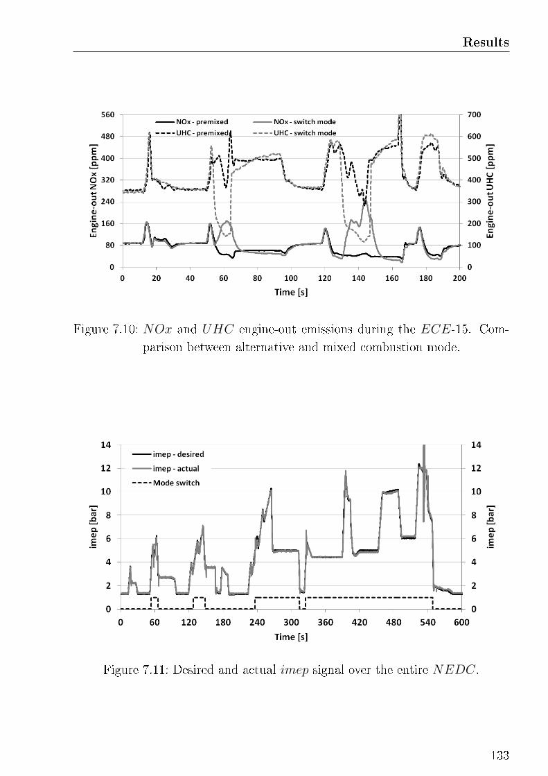
Results
Figure 7.10: NOx and UHC engine-out emissions during the ECE-15. Com-
parison between alternative and mixed combustion mode.
Figure 7.11: Desired and actual imep signal over the entire NEDC.
133
7.4 Measurements in entire NEDC
Switching from low-temperature premixed to di�usive combustion mode the en-
gine can be operated also outside the limited drivability range of the alternative
combustion. This is demonstrated driving the entire NEDC at the test bench.
The results are shown in Figure 7.11. In the extra-urban part of the cycle the
engine is mainly operated using di�usion combustion, however four additional
mode switching events take place.
134
8
Summary and Conclusions
In this chapter a summary of the research activities con-
ducted during this work is given. Following, the success of
the presented investigation is discussed.
8.1 Summary
In the present work an investigation of the thermodynamic mechanisms ruling
the combustion in a low-temperature premixed process has been carried out.
The investigation has been based on an extensive literature search covering the
main aspects related to alternative combustion processes for automotive engines
applications. A sensitivity analysis of the system under investigation has been
than carried out. Dependencies and correlations between actuating and target
parameters could be so identi�ed. On the base of these, a new closed-loop control
strategy has been proposed.
A strict correlation between the injection timing and the maximum rate of pres-
sure rise has been identi�ed. This has been found to be monotonic increasing as
long the combustion beginning is phased before TDC, and becomes monotonic
decreasing for combustion beginning in the expansion stroke. This correlation is
independent from the engine speed and load. Moreover, it is suggested to phase
the combustion process during the expansion stroke, where the system �exibility
is larger and the performances are better. Based on this correlation a closed-
loop controller of the maximum rate of pressure rise is proposed. This should
provide an engine protection function avoiding the maximum rate of pressure
rise to exceed mechanical stress limits of the engine hardware. At the same time,
driving the engine at constant maximum rate of pressure rise, it also avoids the
135
deterioration of the combustion process resulting by inappropriate combustion
phasing.
A closed-loop control of the combustion phasing over the injection timing and of
the imep over the injection duration has been realized. The charge quality, i.e.
the oxygen concentration or the rate of EGR, has been set independently oper-
ating the EGR valve. The control loop has been closed using a lambda sensor
in the intake manifold which is capable of measuring the oxygen concentration
in the charge, consisting of a mixture of fresh air and recirculated exhaust gas.
This strategy allowed a clear separation of the controllers tasks.
A target area for the closed-loop control strategy has been found measuring an
EGR rate/injection timing map at constant engine load. Combining the contour
plots of di�erent parameters on a single diagram, a target area characterized by
high combustion e�ciency and low emissions has been identi�ed. This area can
be achieved increasing the EGR rate maintaining the maximum rate of pressure
rise constant, shifting so the combustion beginning towards the TDC.
The control strategy of the low-temperature combustion is mainly limited by
two factors. For a desired maximum rate of pressure rise, the EGR rate can be
increased until the the combustion beginning has reached the TDC. After this
point a further increase of the EGR would result in a reduction of the maximum
rate of pressure rise. This is usually the case for low-load einge operation.
Increasing the load, an additional limitation must be taken into account. Since
the fresh air quantity does not increase signi�cantly, the air/fuel ratio decreses
with increasing fuel quantity. The rate of recirculated exhauste gas must be
limited for avoiding the charge quality to drop below the soot-limit of λ 1.2. It
resulted a clear separation between a low-torque combustion beginning limited
operation range and a mid-torque λ-limited range. The border between this two
modes measures approximatively 4.5 bar imep. Looking at the injection timing
two di�erent patterns could be identi�ed, i.e. HCLI and HPLI combustion.
The proposed closed-loop control strategy has been �rst tested under station-
ary engine operation and laboratory conditions. A speed-load drivability range
which extends between 1000 and 2400 rpm and between 1 and 9 bar imep has
been measured. This range is mainly limited by the low boost pressure and the
lack of fresh air at low speed and by combustion instability at higher speed.
136
Summary and Conclusions
In order to overcome the limited application range of the low-temperature pre-
mixed combustion, a switching procedure to and from conventional di�usive
combustion has been designed. The proposed solution is based on engine mea-
surements which allowed the characterization of the most relevant problematics
related to this topic. These mainly result from fast actuations of the EGR valve
or the injection pressure. Dynamic corrections for supporting the controllers has
been de�ned. These provide a steady monotonic increase (or decrease) of the
engine load under stationary and transient engine operation.
Finally, a high dynamic NEDC-based cycle for the engine dynamometer has
been de�ned in order to test the closed-loop control strategy under realistic
and repeatable transient conditions. The results show a good response of the
controllers and con�rm the robustness of the de�ned strategy.
8.2 Conclusions
This work demonstrates the potential of a thorough investigation of the combus-
tion process as fundament for the de�nition of a new closed-loop control strategy.
Understanding the mechanisms ruling the combustion, system limitations (to-
gether with the hardware constrains) and clear dependencies between actuating
and target parameters can be identi�ed and implemented in a robust control
strategy of the combustion process. The validity of this approach is demon-
strated by the good system response under stationary but particularly under
transient engine operation. This methodology can be further employed in the
de�nition of a closed-loop control strategy for the di�usive diesel combustion,
which, because of the multiple injection strategy, is characterized by an even
higher complexity. In this case a deeper understanding of the thermodynamic
mechanisms related to the manipulation of the pilot injections is needed.
The proposed pressure-based closed-loop combustion control provides a feasible
solution for implementing low-temperature combustion processes in the coming
series engine generation. Since the conventional injection system, as well as a
standard combustion chamber geometry can be utilized, the need of hardware
modi�cations is very little. However, an appropriate boost pressure strategy
supported by a low pressure EGR loop and twin-stage turbo-charging would
137
provide further improvements. Near the possibility of extending the divability
range of the low-temperature premixed combustion, the implementation of a
further actuating parameter, i.e. the variable boost pressure, would increase the
�exibility of the proposed strategy.
The switching procedure to and from di�usive combustion completes the strategy
and expand the drivability range up to engine full load. In this case a re�nement
of the proposed dynamic corrections is suggested.
138
Bibliography
[1] Seewaldt, S.
Entwicklung einer Funktionsstruktur für die zylinderdruckbasierte
Regelung der teilhomogenen Dieselverbrennung,
Institute of Internal Combustion Engines and Automotive Engineering,
University of Stuttgart, Phd Thesis, Stuttgart, 2012.
[2] Mollenhauer, K.; Tschöke, H.
Handbuch Dieselmotoren,
3. neubearbeitete Au�age, Springer Verlag, ISBN 978-3-540-72164-2, 2007.
[3] Heywood, J.B.
Internal Combustion Engine Fundamentals,
McGraw-Hill Book Company, ISBN 0-07-100499-8, 1988.
[4] Pischinger, S.; Busch, H.; Lamping, M.; Körfer, T.; Kolbeck, A.
Teilhomogene Dieselverbrennung - Der Weg zum HCCI,
Controlled Auto Ignition, Haus der Technik, Essen, 2005.
[5] Chiara, F.
Experimental Analysis of Mixed-Mode HCCI-DI,
Dipartimento di Ingegneria dell'Innovazione, University of Lecce, Ph.D
Thesis, Lecce, 2007.
[6] Yoshinori, I.; Kenji ,K.; Takeshi ,S.; Yoshinaka ,T.
Trial of New Concept Diesel Combustion System - Premixed Compression-
Ignited Combustion,
SAE Technical Paper, 1999-01-0185, 1999.
[7] Rudolf, H.S.; Charles E.R.
Homogeneous Charge Compression Ignition (HCCI): Bene�ts, Compro-
mises, and Future Engine Applications,
SAE Technical Paper, 1999-01-3682, 1999.
139
[8] Figer, G.; Pirker, G.; Wimmer, A.; Jauk, T.; Eichlseder, H.; Fuchs, C.;
Shutting, E.
Analysis of HCCI Combustion Process on DI Diesel Engine,
9th Symposium, The Working Process of the Internal Combustion Engine,
275-289, Graz, 2003.
[9] Haas, S.; Bargende, M.; Berner, H.J.
Ideal Homogeneous Combustion versus Partly Homogeneous Combustion
for PC Diesel Engines,
SAE Technical Paper, 2007-24-0016, 2007.
[10] Schloz, E.
Untersuchungen zur homogenen Dieselverbrennung bei innerer Gemis-
chbildung,
Institut für Kolbenmaschinen, Karlsruhe Institute of Technology, Ph.D
Thesis, Karlsruhe, 2003.
[11] Weissbaeck, M.; Csató, J.; Glensvig, M.; Sams, T.; Herzog, P.
Alternative Brennverfahren - Ein Ansatz für den zukünftigen Pkw-
Dieselmotor,
Motortechnische Zeitschrift, MTZ 09/2003, 718-727, 2003.
[12] Mase, Y.; Kawashima, J.; Sato, T.; Eguchi, M.
Nissan's New Multivalve DI Diesel Engine Series,
SAE Technical Paper, 981039, 1998.
[13] Kimura, S.; Aoki, O.; Ogawa, H.; Murakana, S.; Enomoto, Y.
New Combustion Concept for Ultra-Clean and High-E�ciency Small DI
Diesel Engines,
SAE Technical Paper, 1999-01-3681, 1999.
[14] Ogawa, H.; Li, T.; Niyamoto, N.
Characteristics of low temperature and low oxygen diesel combustion with
ultra-high exhaust gas recirculation,
International Journal of Engine Research, Vol. 8, 365-378, 2007.
140
Bibliography
[15] Sasaki, S.; Ito, T.; Iguchi, S.
Smoke-less Rich Combustion by Low Temperature Oxidation in Diesel En-
gines,
9th annual Automobile and Engine Technology Colloquium, 767-782,
Aachen, 2000.
[16] Cooper, B.; Bar, F.; Beasley, M.; Penny, I.
The Challenge of CO2 and Emission Targets for Diesel Engines: Can
Both Be Combined?,
9th Stuttgart International Symposium, Automotive and Engine Technol-
ogy, 131-143, Stuttgart, 2009.
[17] Houben, H.; Marto, A.; Pechhold, F.; Haussner, M.; Borgers, M.
Drucksensor-Glühkerze (PSG) für Dieselmotoren,
Motortechnische Zeitschrift, MTZ 11/2004, Sonderausgabe, 2004.
[18] Jost, O.; Isermann, R.
Dieselmotorregelung mit Zylinderdruckmessung,
9. Internationaler Kongress Elektronik im Kraftfahrzeuge, VDI-Verlag Re-
port 1547, 1185-1202, Baden-Baden, 2000.
[19] Sellnau, M.C.; Matekunas, F.A.; Battiston, P.B.; Chang, C.; Lancaster,
D.R.
Cylinder -Pressure-Based Engine Control Using Pressure-Ratio-
Management and Low-Cost Non-Intrusive Cylinder Pressure Sensors,
SAE Technical Paper, 2000-01-0932, 2000.
[20] Olsson, J.O.; Tunestal, P.; Johansson, B.
Closed-Loop Control of an HCCI Engine,
SAE Technical Paper, 2001-01-1031, 2001.
[21] Haraldsson, G.; Tunestal, P.; Johansson, B.; Hyveonen, J.
HCCI Combustion Phasing with Closed-Loop Combustion Control Using
Variable Compression Ratio in a Multi Cylinder Engine,
SAE Technical Paper, 2003-01-1830, 2003.
[22] Haraldsson, G.; Tunestal, P.; Johansson, B.; Hyvoenen, J.
HCCI Closed-Loop Combustion Control Using Fast Thermal Management,
SAE Technical Paper, 2004-01-0943, 2003.
141
[23] Bürgler, L.; Cartus, T.; Herzog, P.; Neunteu�, K.; Wissbaeck, M.
Brennverfahren, Abgasnachbehandlung, Regelung - Kennelemente der mo-
torischen HSDI Diesel Emissionsentwicklung,
13. Aachener Kolloquium, 821-845, Aachen, 2004.
[24] Hülser, H.; Neunteu�, K.; Roduner, C.; Weissbäck, M.; Bürgler, L.;
Glensvig, M.
EmIQ: Intelligent Combustion and Control for Tier2 Bin5 Diesel Engines,
SAE Technical Paper, 2006-01-1146, 2006.
[25] Caton, P.A.; Song, H.H.; Kaahaaina, N.B.; Edwards, C.F.
Strategies for Achieving Residual- E�ected Homogeneous Charge Compres-
sion Ignition Using Variable Valve Actuation,
SAE Technical Paper, 2005-01-0165, 2005.
[26] Steiger, W.; Stolte, U.; Scholz, I.; Schmerbeck, S.
Das CCS-Brennverfahren von Volkswagen,
Motortechnische Zeitschrift, MTZ 03/2008, 184-192, 2008.
[27] Franz, J.; Schwarz, F.; Guenthener, M.; Reissing, J.; Mueller, A., Donn,
C.
Closed Loop Control of an HCCI Multi-Cylinder Engine and Correspond-
ing Adaptation Strategies,
SAE Technical Paper, 2009-24-0079, 2009.
[28] Karrelmeyer, R.; Graf, G.; Scherrer, D.; Fischer, W.; Hathout, J.P.
Control Concepts for a Gasoline HCCI Combustion Engine,
Oldenbourg Wissenschaftsverlag, Automatisierungstechnik, Volume 57, 3-
13, 2009.
[29] Beasley, M.; Cornwell, R.; Fussey, P.; King, R.; noble, A.; Salomon, T.;
Truscott, A.; Landsmann, G.
Reducing Emissions Dispersion by Coordinated Combustion Feedback Con-
trol,
SAE Technical Paper, 2006-01-0186, 2006.
[30] Husted, H.; Kruger, D.; Fattic, G.; Ripley, G.; Kelly, E.
Cylinder Pressure-Based Control of Pre-Mixed Diesel Combustion,
SAE Technical Paper, 2007-01-0773, 2007.
142
Bibliography
[31] Schnorbus, T.; Pischinger, S.; Köfer, T.; Lamping, M.; Tomazic, D.; Tatur,
M.
Diesel Combustion Control with Closed-Loop Control of the Injection
Strategy,
SAE Technical Paper, 2008-01-0651, 2008.
[32] Hinkelbein, J.; Sandikcioglu, C.; Pischinger, S.; Lamping, M.; Körfer, T.
Control of the Diesel Combustion Process via Advanced Closed Loop Com-
bustion Control and a Flexible Injection Rate Shaping Tool,
SAE 9th International Conference on Engines and Vehicles, 09ICE-0007,
Capri, 2009.
[33] Schnorbus, T.G.
Zylinderdruckgeführtes Einspritzmanagement beim Dieselmotor,
Institute for Combustion Engines, RWTHAachen University, Ph.D Thesis,
Aachen, 2010.
[34] Kohlhase, M.
Brennraumdruckregelung von Dieselmotoren mit homogener Kompres-
sionszündung (HCCI),
Elektronisches Management motorischer Fahrzeugantriebe, Vieweg-
Teubner Verlag, 259-287, ISBN 978-3-8348-0855-4, 2010.
[35] Kohlhase, M.
Brennraumdruckbasiertes Motormanagement für Otto- und Dieselmotoren
zur Verbrauchs- und Emissionsreduktion,
Institut for Control Systems and Process Automation, TU Darmstadt,
Ph.D Thesis, Darmstadt, 2011.
[36] Mueller, J.
Entwicklung eines Niedrig-Nox-Brennverfahrens für Pkw-Dieselmotoren,
Faculty of Mechanical Engineering, TU Munich, Ph.D Thesis, Munich,
2009.
[37] Lechmann, A.
Simulation und Au�adung von Verbrennungsmotoren,
Springer Verlag, ISBN 978-3-540-79285-7, 2008.
143
[38] Glassman, I.
Combustion,
Academic Press, ISBN 0-12-285851-4, 1987.
[39] Maiboom, A.; Tauzia, X.; Hétet, J.F.
Experimental study of various e�ects of exhaust gas recirculation (EGR)
on combustion and emissions of an automotive direct injection diesel en-
gine,
ELSEVIER, Energy 33, 22-34, 2008.
[40] Emmrich, T.
Beitrag zur Ermittlung der Wärmeübergänge in Brennräumen von Ver-
brennungsmotoren mit homogener und teilhomogener Energieumsetzung,
Institute of Internal Combustion Engines and Automotive Engineering,
University of Stuttgart, Ph.D Thesis, Stuttgart, 2010.
[41] Ho�mann, K.H.; Hummel, K.; Maderstein T.; Peters, A.
Das Common-Rail-Einspritzsystem - ein neues Kapitel der Dieseleis-
pritztechnik,
Motortechnische Zeitschrift, MTZ 10/1997, 572-582, 1997.
[42] Reinhardt, H.
Modellierung des Zündverzuges bei Mehrfacheinspritzungen aufgeladener
Dieselmotoren mit Direkteinspritzung innerhalb der thermodynamischen
Prozessrechnung,
FVV Abschlussbericht, Vorhaben Nr. 876, Stuttgart, 2007.
[43] Ofner, B.
Dieselmotorische Kraftsto�zerstäubung und Gemischbildung mit
Common-Rail Einspritzsystemen,
Faculty of Mechanical Engineering, TU Munich, Ph.D Thesis, Munich,
2001.
[44] Alberti, P.
Von der Gemischbildung zu den Schadsto�emissionen im Dieselmotor auf
direktem Weg,
Institute for Mobile Systems, Otto-von-Guericke-University Magdeburg,
Ph.D Thesis, Magdeburg, 2010.
144
Bibliography
[45] Schmalzing, C.O.
Theoretische und experimentelle Untersuchung zum Strahlausbreitungs-
und Verdampfungsverhalten aktueller Diesel-Einspritzsysteme,
Institute of Thermal Turbomachinery and Machinery Laboratory, Univer-
sity of Stuttgart, Ph.D Thesis, Stuttgart, 2001.
[46] Barba, C.
Erarbeitung von Verbrennungskennwerten aus Indizierdaten zur
verbesserten Prognose und rechnerischen Simulation des Ver-
brennungsablaufes bei Pkw-DE-Dieselmotoren mit Common-Rail-
Einspritzung,
Aerothermochemistry and Combustion Systems Laboratory, ETH, Ph.D
Thesis, Zürich, 2001.
[47] Pfeifer, C.
Experimentelle Untersuchungen von Ein�uÿfaktoren auf die Selbstzün-
dung von gasförmigen und �üssigen Brennsto�freistrahlen,
Department of Mechanical Engineering, Karlsruhe Institute of Technology,
KIT ScIeNTIfIc RepoRTS 7555, Karlsruhe, 2010.
[48] Hardenberg, H.O.; Hase F.W.
An Empirical Formula for Computing the Pressure Rise Delay of a Fuel
from Ist Cetane Number and from the Relevant Parameters of Direct-
Injection Diesel Engines,
SAE Technical Paper, 790493, 1979.
[49] Haas, S.
Experimentelle und theoretische Untersuchung homogener und teilhomo-
gener Dieselbrennverfahren,
Institute of Internal Combustion Engines and Automotive Engineering,
University of Stuttgart, Ph.D Thesis, Stuttgart, 2007.
[50] Bohac, S.V.; Han, M.; Jacobs, T.J.; Lopez, A.J.; Assanis, D.N.; Szymkow-
icz, P.G.
Speciated Hydrocarbon Emissions from an Automotive Diesel Engine and
DOC Utilizing Conventional and PCI Combustion,
SAE Technical Paper, 2006-01-0201, 2006.
145
[51] Pischinger, F.
Motorische Verbrennung,
RWTH Aachen University, Sonderforschungsbericht 224, Aachen, 2007.
[52] Musculus, M.P.B.
On the Correlation between NOx Emissions and the Diesel Premixed Burn,
SAE Technical Paper, 2004-01-1401, 2004.
[53] Naydenova, I.I.
Soot Formation Modeling during Hydrocarbon Pyrolysis and Oxidation be-
hind Shock Waves,
Combined Faculties for the Natural Sciences and for Mathematics, Ruper-
tus Carola University of Heidelberg, Ph.D Thesis, Heidelberg, 2007.
[54] Mendez, S.; Kashdan, J.T.; Bruneaux, G.; Thirouard, B.; Vangraefschepe,
F.
Formation of Unburned Hydrocarbons in low Temperarture Diesel Com-
bustion,
SAE Technical Paper, 2009-01-2729, 2009.
[55] Han, D.; Ickes, A.M.; Bohac, S.V.; Assanis, D.N.
HC and CO emissions of premixed low-temperature combustion fueled by
blends of diesel and gasoline,
ELSEVIER, Fuel Volume 99, 13-19 2012.
[56] Doll, G.; Fausten, H.; Noell, R.; Schommers, J.; Spengel, C.; Werner, P.
Der neue V6-Dieselmotor von Merchedes-Benz,
Motortechnische Zeitschrift, MTZ 05/2009, 624-634, 2005.
[57] Doll, G.; Schommers, J.; Lingens, A.; Düsmann, M.; Fausten, H.; Noell,
R.; Schommers, J.; Spengel, C.; Finkbeiner, H.
Der Motor OM 642 - Ein kompaktes, leichtes und universelles Hochleis-
tungsaggregat von Mercedes Benz,
26. Internationales Wiener Motorensymposium, 195-228, Wien, 2005.
146
Bibliography
[58] Bargende, M.
Ein Gleichungsansatz zur Berechnung der instationären Wandwärmever-
luste im Hochdruckteil von Ottomotoren,
Institut for Mechanical and Process Engineering , TU Darmstadt, Ph.D
Thesis, Darmstadt, 1991.
[59] Münz, S.; Römuss, C.; Schmidt, P.; Brune K.H.; Schi�er, H.P.
Dieselmotoren mit Niederdruck-Abgasrückführung Herausforderungen an
den Turbolader,
Motortechnische Zeitschrift, MTZ 02/20008, 124-130, 2008.
[60] Tüber, K.; Ambros, P.
Thermodynamischer Vergleich zwischen einer Hochdruck- und einer
Niederdruck-Abgasrückführung,
Diesel- und Benzin-Direkteinspritzung IV, Haus der Technik, Fachbuch
Band 77, Berlin, 2006.
[61] Müller, V.; Christmann, R.; Münz, S; Gheorghiu, V.
System und Regelungskonzept für zukünftige Turbolader-
Abgasrückführsysteme für turboaufgeladene Diesel Pkw,
10. au�adetechnische Konferenz , Dresden, 2005.
[62] Shyani, R.G.; Caton, J.A.
A thermodynamic analysis of the use of exhaust gas recirculation in spark
ignition engines including the second law of thermodynamics,
Proceedings of the Institution of Mechanical Engineers, Part D: Journal
of Automobile Engineering, Vol. 223, 131-149, 2009.
[63] Tanaka, Kim, M.Y.; Lee, C.S.
E�ect of a narrow fuel spray angle and a dual injection con�guration on
the improvement of exhaust emissions in a HCCI diesel engine,
ELSEVIER, Fuel 86, 2007.
[64] Kook, S.; Bae, C.; Miles, P.C:; Choi, D.; Pickett, L.M.
The In�uence of Charge Dilution and Injection Timing on Low-
Temperature Diesel Combustion and Emissions,
SAE Technical Paper, 2005-01-3837, 2005.
147
[65] Beatrice, C.; Avolio, C.; Guido, C.
Experimental Analysis of the Operating Parameter In�uence on the appli-
cation of Low Temperature Combustion in teh Modern Diesel Engines,
SAE Technical Paper, 2007-01-1839, 2007.
[66] Weall, A.; Collings, N.
Highly Homogeneous Compression Ignition in a Direct Injection Diesel
Engine Fuelled With Diesel and Biodiesel,
SAE Technical Paper, 2007-01-2020, 2007.
[67] Horibe, N.; Ishiyama, T.
Relations among NOx, Pressure Rise Rate, HC and CO in LTC Operation
of a Diesel Engine,
SAE Technical Paper, 2009-01-1443, 2009.
[68] Juttu, S.; Mishra, P.; Thips, S.S.; Marathe, N.V.; Gajendra Babu, M.K.
Combined PCCI-DI Combustion to Meet EURO-IV Norms on LCV En-
gine - Experimental and Visualisation Study,
SAE Technical Paper, 2011-26-0031, 2011.
[69] Fang, T.; Coverdill, R.E.; Lee, C.F.; White, R.A.
Low-Temperature Combustion Within a HSDI Diesel Engine Using
Multiple-Injection Strategies,
ASME, Journal of Engineering for Gas Turbines and Power, Vol. 131,
062803, 2009.
[70] Anselmi, P.; Kashdan, J.; Bression, G.; Ferrero-Lesur, E.; Thirouard, B.;
Walter, B.
Inproving Emissions, Noise and Fuel Economy Trade-O� by using Mul-
tiple Injection Strategies in Diesel Low Temperature Combustion (LTC)
Mode,
SAE Technical Paper, 2010-01-2162, 2010.
[71] Chong, C.T.; Hochberg, S.
Measurements of laminar �ame speeds of liquid fuels: Jet-A1, diesel, palm
methyl esters and blends using particle imaging velocimetry (PIV),
ELSEVIER, Proceedings of the Combustion Institute 33, 979-986, 2010.
148
Bibliography
[72] Rether, D.; Lämmle, C.
Modell zur Berechnung der Brennrate bei homogener und teilhomogener
Dieselverbrennung,
FVV Abschlussbericht, Vorhaben Nr. 996, Stuttgart, 2011.
[73] Han, S.; Shim, E.; Jang, J.; Park, J.; Bae, C; Park, J.; Kim, J.
Operating Range of Low Temperature Diesel Combustion with Supercharg-
ing,
SAE Technical Paper, 2009-01-1440, 2009.
[74] Lu, Y; Yu, W.; Su, W.
Using Multiple Injection Strategies in Diesel PCCI Combustion: Potential
to Extend Engine Load, Improve Trade-o� of Emissions and E�ciency,
SAE Technical Paper, 2011-01-1396, 2011.
[75] Burton, J.L.; Williams, R.; Glewen, W.J.
Investigation of Transient Emissions and Mixed Mode Combustion for a
Light Duty Diesel Engine,
SAE Technical Paper, 2009-01-1347, 2009.
[76] Europäische Union
Richtlinie des Rates zur Angleichung der Rechtsvorschirften der Mitglied-
staaten über Maÿnahmen gegen die Verunreinigung der Luft durch Emis-
sionen von Kraftfahrzeugen,
Amstblatt der Europäische Union, 70/220/EWG, 2007.
149

List of Figures
2.1 Collocation of the alternative combustion processes in the
temperature-λ-map [2]. . . . . . . . . . . . . . . . . . . . . . . . 23
2.2 Chracteristic injection pro�les and rate of heat release traces of
the most signi�cant alternative combustion processes [8]. . . . . . 25
3.1 Description of the most relevant mechanisms in�uencing the com-
bustion process in an ICE. . . . . . . . . . . . . . . . . . . . . . 36
3.2 Adiabatic pressure and temperature traces for a motored engine
(ε 15.5 : 1) as a function of the cylinder volume. . . . . . . . . . 38
3.3 Illustration of fuel breakup and evaporation mechanisms [2]. . . . 44
3.4 Schematic representation of charge �ow mechanisms. On the left
side swirl �ow created in the inlet channel. On the right side
in-cylinder charge motion and interaction with the fuel spray [2]. 46
3.5 Dependency of the ignition delay from pressure and temperature
for n-heptane fuel at λ 1. . . . . . . . . . . . . . . . . . . . . . . 49
3.6 Explosion p-T-diagram showing the ignition limits of hydrocar-
bon fuels on the left and the pressure increase during self-ignition
process on the right [51]. . . . . . . . . . . . . . . . . . . . . . . 51
3.7 Adiabatic �ame temperature over a variation of the local air/fuel
ratio. . . . . . . . . . . . . . . . . . . . . . . . . . . . . . . . . . 54
4.1 Engine hardware con�guration. . . . . . . . . . . . . . . . . . . . 65
5.1 De�nition of actuating and target variables in a modern diesel
engine. . . . . . . . . . . . . . . . . . . . . . . . . . . . . . . . . 73
5.2 Schematic diagram of the interaction of the fuel spray with the
piston bowl. . . . . . . . . . . . . . . . . . . . . . . . . . . . . . 75
5.3 UHC emissions by a variation of the injection timing at di�erent
engine loads showing the interaction between the fuel spray and
the piston bowl. . . . . . . . . . . . . . . . . . . . . . . . . . . . 76
151
5.4 Comparison between new and conventional EGR loop. EGR
valve variation at constant speed 1800 rpm and injection quantity
10.7mg/stroke. . . . . . . . . . . . . . . . . . . . . . . . . . . . 77
5.5 Injection timing variation at di�erent engine loads and its corre-
lation to the combustion beginning. . . . . . . . . . . . . . . . . 80
5.6 Maximum rate of pressure rise for di�erent engine loads plotted
over the combustion beginning. . . . . . . . . . . . . . . . . . . . 81
5.7 Speci�c emissions and maximum rate of pressure rise plotted over
the combustion beginning for the selected engine load at 1800 rpm
and λ 4. . . . . . . . . . . . . . . . . . . . . . . . . . . . . . . . 82
5.8 Ignition delay and mixing time on the left and speci�c engine-
out emissions on the right by an injection pressure variation at
constant combustion beginning. . . . . . . . . . . . . . . . . . . 85
5.9 Ignition delay, imep and rate of pressure rise on the left, spe-
ci�c engine-out NOx and UHC emissions, smoke number and
decrease of the volumetric e�ciency on the right, by a swirl vari-
ation at constant combustion beginning in HCLI mode. . . . . . 87
5.10 Ignition delay, imep and rate of pressure rise on the left, speci�c
engine-out NOx and CO emissions, smoke number and decrease
of the volumetric e�ciency on the right, by a swirl variation at
constant combustion beginning in HPLI mode. . . . . . . . . . . 88
5.11 Gross rate of heat release by an EGR variation at constant in-
jection beginning at 33 ◦CA before TDC and constant injection
quantity in HCLI mode. . . . . . . . . . . . . . . . . . . . . . . 90
5.12 Indicated e�ciency, charge quality and ignition delay by an EGR
variation at constant maximum rate of pressure rise 6 bar/◦CA
and constant imep 4 bar in HCLI mode. . . . . . . . . . . . . . 92
5.13 Speci�c NOx, UHC and CO emissions and smoke number by
an EGR variation at constant maximum rate of pressure rise
6 bar/◦CA and constant imep 4 bar in HCLI mode. . . . . . . . 92
5.14 Indicated e�ciency, charge quality and ignition delay by an EGR
variation at constant maximum rate of pressure rise 6 bar/◦CA
and constant imep 8 bar in HPLI mode. . . . . . . . . . . . . . 94
5.15 Speci�c NOx, UHC and CO emissions and smoke number by
an EGR variation at constant maximum rate of pressure rise
6 bar/◦CA and constant imep 8 bar in HPLI mode. . . . . . . . 94
152
List of Figures
5.16 Contour maps of engine-out emissions and performances on the
injection timing-EGR rate plane at constant engine speed of
1800 rpm and constant load of 4 bar imep. . . . . . . . . . . . . 97
5.17 Combination of contour maps on the injection timing-EGR rate
plane. . . . . . . . . . . . . . . . . . . . . . . . . . . . . . . . . . 98
5.18 Proposed strategy for the closed-loop control of the low-
temperture premixed combustion. . . . . . . . . . . . . . . . . . 100
5.19 Variation of the target maximum rates of pressure rise at constant
engine load conditions, 1800 rpm and 4 bar imep. . . . . . . . . . 103
6.1 Consecutive combustion cycles by an oxygen concentration in-
crease in low-temperature premixed combustion mode. . . . . . . 109
6.2 Consecutive combustion cycles by an oxygen concentration reduc-
tion in di�usive combustion mode. . . . . . . . . . . . . . . . . . 110
6.3 Investigation of the oxygen tolerance. Comparison between low-
temperature premixed and di�usive combustion. . . . . . . . . . 111
6.4 Schematic representation of the switching procedure from alterna-
tive to conventional combustion mode as a result of a load increase.113
6.5 Consequences of a rapid oxygen concentration increase on the
low-temperature premixed combustion and the improvement by
using a compensation of the feed-forward injection timing value. . 114
6.6 imep oscillations as a consequence of the injection pressure di�er-
ence switching from single to multiple injection and the improve-
ment by using a dynamic correction of the feed-forward value of
the main injection duration. . . . . . . . . . . . . . . . . . . . . 115
6.7 Schematic representation of the switching procedure from con-
ventional to alternative combustion mode as a result of a load
decrease. . . . . . . . . . . . . . . . . . . . . . . . . . . . . . . . 117
6.8 E�ects of an exhaust gas pressure drop on the imep signal by
fast EGR valve actuation. A steady pressure pro�le is achieved
compensating it closing the V GT . . . . . . . . . . . . . . . . . . 118
6.9 Oscillations of the imep signal as a consequence of the injection
pressure variation di�erence and improvement using a dynamic
correction of the feed-forward value of the main injection duration.118
153
6.10 High rates of pressure rise resulting from the higher oxygen con-
centration in the charge in combination with early injection tim-
ing and improvement using a correction of the injection timing
feed-forward value. . . . . . . . . . . . . . . . . . . . . . . . . . 119
7.1 Contour map of the injection timing showing the application
range for the low-temperature premixed combustion in compari-
son with the full load capability of the engine. . . . . . . . . . . . 122
7.2 imep/speed dynamic cycle de�ned for transient measurements on
the engine dynamometer. . . . . . . . . . . . . . . . . . . . . . . 124
7.3 Comparison between the roller chassis dynamometer measured
data and the simpli�ed dynamic driving cycles. . . . . . . . . . . 125
7.4 Desired and actual imep over the simpli�ed ECE-15 in low-
temperature premixed combustion mode. . . . . . . . . . . . . . 126
7.5 Desired, corrected and actual dp/dθmax over the simpli�ed ECE-
15 in low-temperature premixed combustion mode. . . . . . . . . 127
7.6 Oscillations of the lambda signal in low-temperature premixed
combustion mode and possibility of avoiding over-dilution of the
charge switching to di�use combustion. . . . . . . . . . . . . . . 129
7.7 Desired and actual imep over the simpli�ed ECE-15 in combined
combustion mode. . . . . . . . . . . . . . . . . . . . . . . . . . . 130
7.8 Enlarged view of the switching phases. . . . . . . . . . . . . . . 131
7.9 Comparison of the maximum rates of pressure rise during the
urban cycle using alternative or combined combustion mode. . . . 132
7.10 NOx and UHC engine-out emissions during the ECE-15. Com-
parison between alternative and mixed combustion mode. . . . . 133
7.11 Desired and actual imep signal over the entire NEDC. . . . . . 133
A.1 Actuating parameters values under stationary operation mode. . 157
A.2 Target parameters values under stationary operation mode. . . . 158
A.3 Actuating parameter values under stationary operation mode. . . 159
154
List of Tables
4.1 Engine speci�cations. . . . . . . . . . . . . . . . . . . . . . . . . 64
4.2 Real-time combustion parameters. . . . . . . . . . . . . . . . . . 68
5.1 List of publications regarding the sensitivity analysis of some com-
bustion variables in low-temperature premixed combustion . . . . 74
6.1 Di�erences in the parameters application between combustion
modes at switching limit. . . . . . . . . . . . . . . . . . . . . . . 108
155

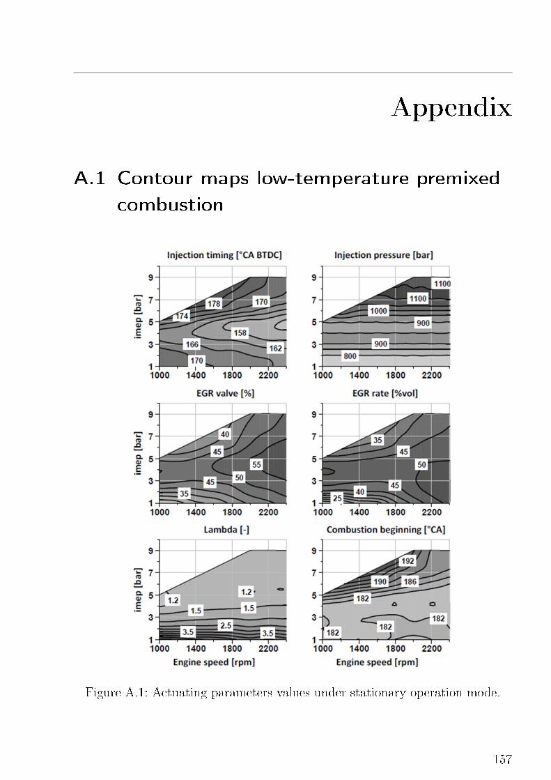
Appendix
A.1 Contour maps low-temperature premixed
combustion
Figure A.1: Actuating parameters values under stationary operation mode.
157
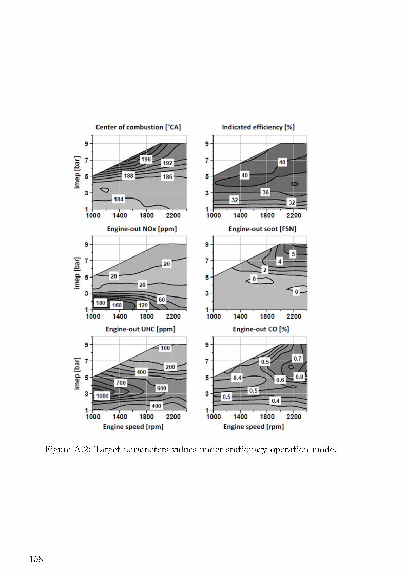
Figure A.2: Target parameters values under stationary operation mode.
158
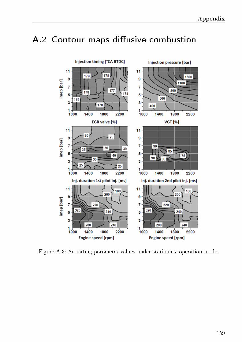
Appendix
A.2 Contour maps di�usive combustion
Figure A.3: Actuating parameter values under stationary operation mode.
159
Top Related
Copyright © 2022 FDOKUMEN

