


Bahasa
Halaman
Hukum


Flat Die ExtrusionCast Film, Coating & Laminating
Andy ChristiePrincipal Engineer
Optex Process Solutions, LLCwww.optexprocesssolutions.com
2009 Consumer Packaging Solutions for Barrier Performance Course

Outline
• Flexible Packaging – Structures• Flat Die Co-extrusion• Film Formation• Web Handling, Conditioning, Winding• Troubleshooting

Why Flexible ?• Serves multi-functions
– Containment – Portion– Protection – Barrier– Presentation – Promotion– Identification – Instruction– Convenience – Preparation– Security – Tamper Evidence– Branding - Recognition

Why Flexible ?• Performance by design
– Mono Layer Film– Co-extruded Film– Coated / Metalized Film– Lamination – Paper / Film / Foil / Adhesive

Examples• CPP – Single Candy Twist Wrap• HDPE/Sealant – Dry Mix / Cereal• PP/PP+Recycle/LDPE – Cheese Film• LDPE/Tie/Nylon/Tie/LDPE – Meat Pack• BOPET/Nylon/Ionomer – Frozen Veg• Paper/LDPE/Foil/Sealant – Dry Mix• BOPET/LDPE/Foil/Sealant – Condiment• PP/Tie/EVOH/Tie/PP – Juice• BOPET/LDPE/metalized/Sealant – Coffee• LDPE/Board/LDPE/Foil/EAA/LDPE/Sealant - Juice

Why Cast Film?• Optical characteristics• Production capacity• Gauge uniformity• Unit conversion costs• Structure versatility (feedblock)

Why extrusion coating?
• Substrate versatility• Production capacity• Print protection• Unit conversion cost

Why extrusion laminating?
• Substrate versatility• Production capacity• Print protection• Unit conversion cost• Ultimate barrier / package performance

Flat Die Co-extrusion• Common process and arrangement for
cast film, extrusion coating, and extrusion laminating
• Differences in materials processed, typically lower MI for cast film
• Differences in die manifold geometry, typically T-slot for extrusion coating & laminating vs “coathanger” for cast film

Common Film Forming
Vacuum Box Air Knife
Flat Cast Film
Melt Embossed Cast Film
Extrusion Coating
Coextrusion Coating
Coextrusion Laminating

Typical Cast Film Co-extrusion Arrangement
Photo Courtesy SML

Cast Film Die
Photo Courtesy EDI

Tandem Extrusion Laminating
Photo Courtesy Sung An Machinery

Coex Coating – Moveable Extruder
Photo Courtesy Sung An Machinery

Coex Coating – Fixed Extruder
Photo Courtesy SML

Typical C/L Die
Photo Courtesy EDI
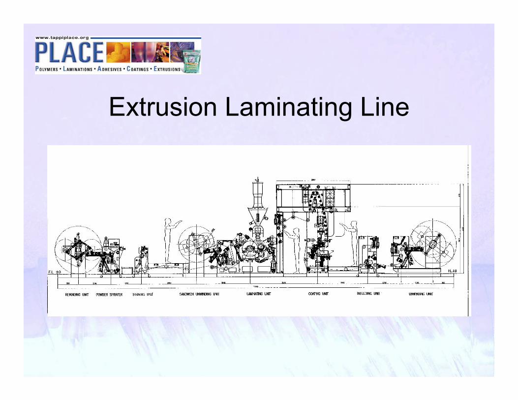
Extrusion Laminating Line

Multi Function Lab LinePhoto Courtesy Dr. Collin GmbH

Multi Function Lab Line

Basic Extrusion System• Resin Handling & Blending• Single Screw Extruder• Polymer Filtration• Pressure Control• Polymer Flow Pipes• Feedblock• Single Manifold Die
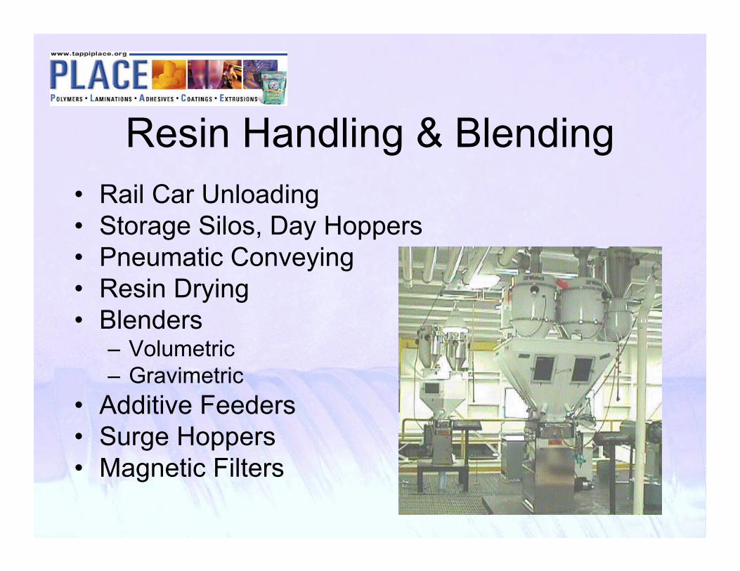
Resin Handling & Blending• Rail Car Unloading• Storage Silos, Day Hoppers• Pneumatic Conveying• Resin Drying• Blenders
– Volumetric– Gravimetric
• Additive Feeders• Surge Hoppers• Magnetic Filters

Resin Handling System
Single Screw Extruder• Fabricated Base• Drive Motor• Gear Reduction Unit w/ Thrust Bearing• Cooling Jacketed Feed Throat• Bimetallic Barrel• Hard Faced Feedscrew• Barrel Heating & Cooling• Instrumentation• Drive & Temperature Controls

Basic Extruder Schematic
Base
Blowers
Barrel w/ heaters & covers
Feed Throat
Magnet
Hopper
Speed Reducer
Drive Motor
Die
Screen,Valve &Pipes
Feedscrew

Polymer Filtration• Manual Screen Changers• Slide Plate Screen Changers• Continuous Screen Changers
– Dual Slide Plate– Rotary– Advancing Screen
• Extended Area Filters

Pressure Control
• Orifice Plates• Back Pressure Valves• Polymer Melt Pumps

Polymer Flow Pipes
Compuplast VEL Calculation

Feedblocks - Function• Arrange polymers in structure order• Reshape the polymer streams for
combining– Velocity compensation– Viscosity compensation
• Join the polymers together

Feedblocks - Styles• Dow Patent• Insert style• Externally adjustable type

Dow Style FeedblocksEgan design

Dow Style FeedblocksBlack Clawson design

Insert Style Feedblock
EDI design

External Adjustable Feedblock
Photo’s Courtesy Cloeren Inc.
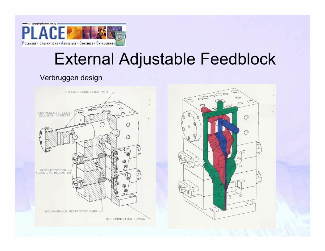
External Adjustable FeedblockVerbruggen design

Cast Film
Simulation Using Compuplast VEL

Extrusion Coating
Simulation Using Compuplast VEL

Co-extrusion Issues• Encapsulation
– Viscosity mismatch• Interface Instability
– Relative velocities– Interface shear rate– Shear viscosity– Elongational viscosity

“ENCAPSULATON”
WHEN THE RELATIVE VISCOSITY BETWEEN THE POLYMERS ARE
LARGE THE LESS VISCOUS POLYMER WILL SURROUND THE MORE VISCOUS

Resin Encapsulation Problem• Migration and Encapsulation Phenomenon
Start of flow through pipe
End of flow through pipe – “A”encapsulates “B”
Resin A
Resin B
The material seeks the path of minimum resistance and pressure drop. The degree of interfacial distortion (migration and encapsulation) depends on the magnitude of the viscosity difference, shear rate and length of the flow path. Low viscosity material flows around high viscosity material.

Feed Block Exit Profile
• Resin A – 20% EVA• Resin B – 80% LLDPE
A
B

Die Exit Profile
• Resin A – 20% EVA• Resin B – 80% LLDPE
A
B
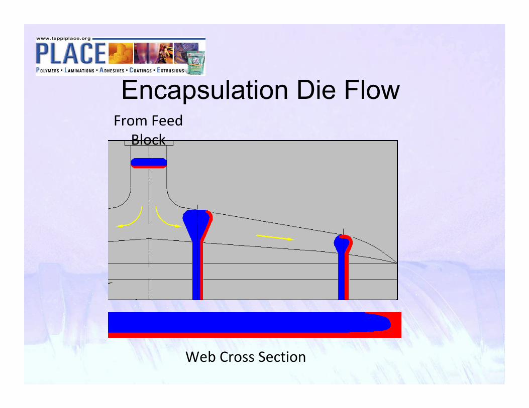
Encapsulation Die Flow
Web Cross Section
From Feed Block

VISCOSITY COMPENSATION
Feedblock geometry can be designed to shape the flow of the polymer at the feedblock exit to compensate for the viscous encapsulation phenomenon

Feedblock Profiling
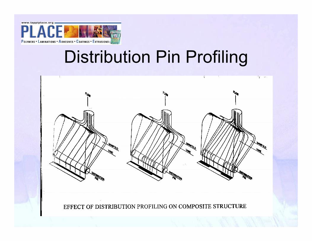
Distribution Pin Profiling

Distribution Pin Function
Video ModelCourtesy Cloeren Inc.

Coextrusion IR Scan
315310306301297292288
Die Bolt Position
314312310308305303301299297294292290288

IR Scan Showing Response To Feedblock Adjustment
InstantaneousResponse
315310306301297292288
Die Bolt Position
314312310308305303301299297294292290288

Interface InstabilityResponse due to critical stress at interface
– Velocity at combining– Shear rate at interface– Relative viscosities
• Shear• Extensional

Interface Instability
• Applesauce• Fuzzy Edges• Sharkskin• Zig-zag• Orange peel

Velocity At Combining

Velocity Compensation
3D Simulation Courtesy Compuplast

Viscosity Effects
Simulation Using Compuplast VEL

Temperature Effects
Simulation Using Compuplast VEL

Output (≠ Velocity) Effects
Simulation Using Compuplast VEL

To Reduce Instabilities• Increase skin layer thickness
– Via output (actual)– Via temperature (effective)
• Reduce skin layer viscosity• Increase the die gap• Decrease total output• Match combining velocities (edges)

Film Forming
Vacuum Box Air Knife
Flat Cast Film
Melt Embossed Cast Film
Extrusion Coating
Coextrusion Coating
Coextrusion Laminating

Major Factors in Extruded Film Properties
• Extrudate temperature• Die gap• Air gap (Quench Point, Nip Point)• Draw ratio• Output• Chill roll temperature• Air knife, vacuum box, nip load

Increase Melt Temperature
• Decrease density• Increase C.O.F.• Raise gloss• Lower haze• Lower tensile strength• Reduce viscosity• Decrease neck-in

Die Slot CalculationsDS=FW + (2 x N) + (2 x E) + RDS is normally 6” to 24” greater than FW.
Where:DS= Die slot (in)FW= Finished width (in)E= Edge trim (in)R= Randomization (in)B= Bleed trim (in)N= Neck-in per side

Decrease Die Lip Gap
• Increase die swell• Increase roughness • Increase draw orientation• Increase haze• Decrease gloss• Decrease impact strength

Increase Air Gap
• Slower cooling for more crystallinity• Increase density• Increase W.V.T.R.• Increase stiffness• Increase haze• Decrease C.O.F.• Reduce impact strength

Methods of ImpingementVacuum Box:•negative pressure
•Contacting non-contacting seal
Static & Air Pinning:•positive pressure to overcome film stresses and maintain edges

Methods of ImpingementAir Knife:•positive high pressure
•additional cooling
•3 degrees of adjustment
Static & Air Pinning:positive pressure to
overcome film stresses and maintain edges
Photo Courtesy Cloeren Inc.

Methods of ImpingementSoft Box:•Positive low pressure, large film area
•Additional cooling
•3 degrees of adjustment
•Easy set up & removal
Photo Courtesy Cloeren Inc.

Cast Film Unit
•Chill roll - DSSF
•Extrudate temp
•Chill roll finish: matte and mirror
•Plate out removal
•Secondary cooling roll - DSSF
•Auto profile control
•Frost line adjustment
•Idler rolls

Melt Emboss Film System•Extrude into nip
•High pressure nip
•Embossed pattern on rubber roll
•Water pan &/or fountain
•Squeegee roll prevents carryover
•MDO for breathability
Photo Courtesy BC-Egan

Emboss Pattern Set In Nip
Photo Courtesy BC-Egan

Extrusion Laminator
Photo Courtesy Sung An Machinery

Process Water System
•Divided water tank
•Process loops: high flow, low delta T
•Chiller loop: low flow, high delta T
•Monitor temp at exit
•Modulating valve

Increasing Quench Temperature
• Increase quench time• Increases crystallization • Increase density• Increase stiffness• Increase barrier• Decrease optics• Decrease C.O.F.• Decrease impact

Water Flow Calculations(Cast Film)
GPM= ((Qx.75x(T2-T1))/(TRWx500))x1.1Q= (GPMxTRWx500)/(0.75x(T2-T1)x1.1)
Where:GPM= Gallons per minute of cooling mediumQ= Total extruder output (lb/hour)T2= Melt Temperature (F degrees)T1= Strip temperatureTRW= Temperature rise of the cooling water through the chill roll(3 degree F normally used for LDPE, 1-2 degree F normally used for PP & Nylon)
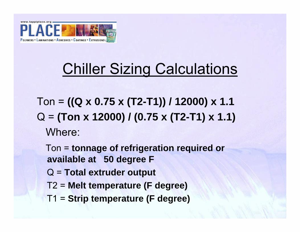
Chiller Sizing Calculations
Ton = ((Q x 0.75 x (T2-T1)) / 12000) x 1.1Q = (Ton x 12000) / (0.75 x (T2-T1) x 1.1)
Where:Ton = tonnage of refrigeration required or available at 50 degree FQ = Total extruder outputT2 = Melt temperature (F degree)T1 = Strip temperature (F degree)

Web Handling
Provide Isolation Of Tension Between Various Process Functions From Winding
Tension
For Web Tension Isolation Must Have Grip On Web!
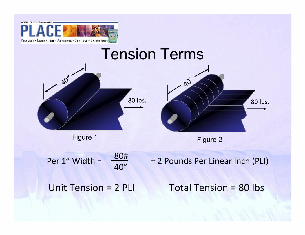
Tension Terms
80 lbs.
40”
Unit Tension = 2 PLI Total Tension = 80 lbs
Per 1” Width = = 2 Pounds Per Linear Inch (PLI)80#40”
80 lbs.
40”
Figure 1 Figure 2

Typical Tension Values for FilmsFILMS TENSION LEVELSPolyester 0.5 to 1.5 lbs./inch/milPolypropylene 0.25 to 0.30 lbs./inch/milPolyethylene 0.25 to 0.30 lbs./inch/milPolystyrene 1.0 lbs./inch/milVinyl 0.05 to 0.2 lbs./inch/milAluminum Foils 0.5 to 1.5 lbs./inch/milCellophane 0.5 to 1.0 lbs./inch/milNylon 0.10 to 0.25 lbs./inch/mil

Typical Dancer Tension ControlVent
Motor
DancerControl
I to PConverter
AirCylinder
Air
Regulator
Dancer PositionSensor

Dancer Assembly
Photo Courtesy Fulton Machinery

Transducer Load Cells
•Used instead of a dancer •Strain gauge senses tension•Direct readout of tension•Precision roll balance for best accuracy

Tension Zones• Between driven
sections on the line• Different tensions can
be run between sections
• Must have a grip on the web (see next slide)
• Usually separated with a nip
• Isolate key sections:– Primary unwind– Treater– Laminator– Interleaf Unwind– Winder

Pull Rolls
Nip Pull RollSuggested Nip = 3 x Tension
Check Loaded Deflection
Pivot Cylinder
Outgoing Nip
“S” Wrap Pull RollT1/T2= f(wrap, coef.of friction)
“S” Wrap Will Not Isolate Tension Waves
Nip Pull Rolls Rubber Covered Rolls
Figure 6 Figure 7

Differential TensionOutgoing Tension
T2 = 1 PLI
T1 = 1 PLIIngoing Tension
T1 = 2 PLIIngoing Tension
T = T1 ‐ T2=1 ‐ 2T = ‐1 PLI
(Regenerating)
T = T1 ‐ T2= 2 ‐ 1
T = +1 PLI (Motoring)
Figure 8
Figure 9
Outgoing TensionT2 = 2 PLI

Web Handling Basics
• Rolls in contact with the web must be in proper alignment.
• Non-driven rolls should turn as friction free as possible.
• There are times when idlers may be covered to provide turning friction.
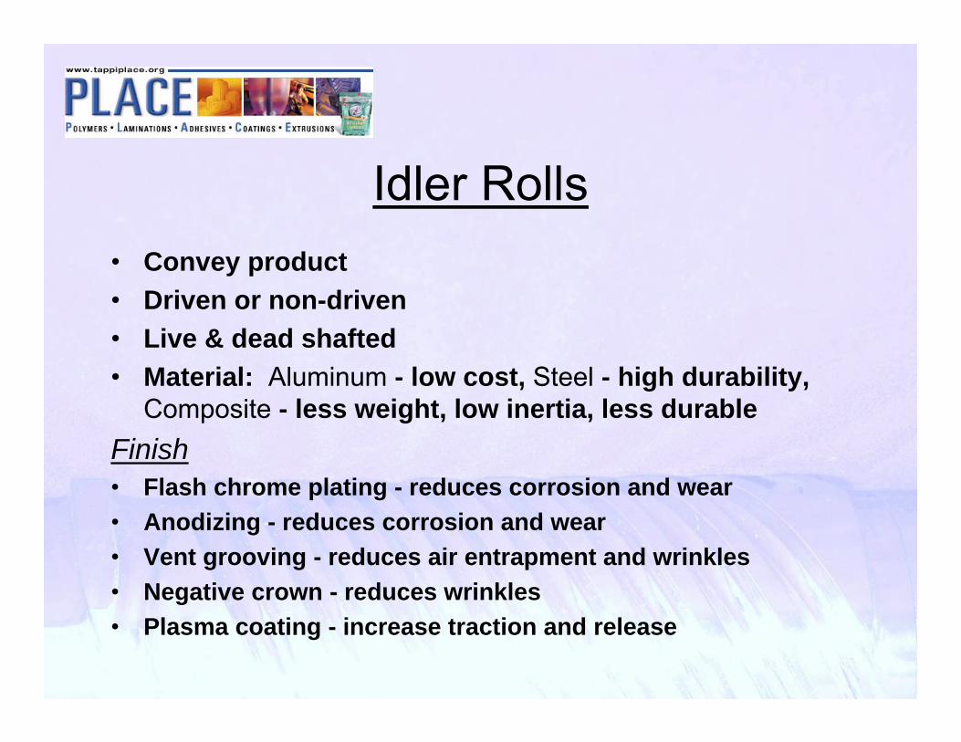
Idler Rolls• Convey product• Driven or non-driven• Live & dead shafted• Material: Aluminum - low cost, Steel - high durability,
Composite - less weight, low inertia, less durableFinish• Flash chrome plating - reduces corrosion and wear• Anodizing - reduces corrosion and wear• Vent grooving - reduces air entrapment and wrinkles• Negative crown - reduces wrinkles• Plasma coating - increase traction and release

Web Spreader RollsSmooth web out at entry into critical machine sections: pull rolls, coater, laminator, winder.
Types:
• Bowed rolls, fixed & variable
• Reverse crowned rolls
• Herringbone grooved spreader rolls (foils)
• Flex spreader rolls

Web Guiding
•Distributes gauge bands
•Aligns webs for coating or lamination
•Z or U configuration
•Normally floor mounted

Unwinder
• Continuously unwinds web products, roll to roll transfer by an automatic cut and past system
• Dancer for tension control and compensation
• Regenerative drive for speed match and tension hold back

Unwind w/ Auto Splice

Laminate (Sandwich) Unwind
Photo Courtesy Sung An Machinery

Roll Prepared To Splice

Winders
• Continuously winds film by means of automatic transfer roll changing
• In-line slitting and trim removal (Film)• Gap or contact• Shafted or Shaftless• Transfers with or without adhesives

Winder w/ Auto Transfer

Winder w/ Auto Transfer

Surface Winder (Reel)
Photo Courtesy BC-Egan

Film Winder TransfersStationary Knife
TAPE
KNIFE
•Tape core
•Index to contact
•No knife fire
•Dual direction
•No speed limits
Static TransferCONDUCTIVE PLANE(CORE SHAFT)
KNIFESTATIC BAR
•No tape required
•Index to charge core
•No knife fire
Speed limitations (500mpm)

Film Winder Trim Haul-Off
Photo Courtesy SML

High Speed Film Winder
Photo Courtesy SML

Troubleshooting 101
• State the problem• Identify possible solutions
– Hypothesis• Test the hypothesis• Evaluate the test results• Implement corrective action or• Repeat the process

State the problem
• Write it down• All need to agree on problem• Problem statement must be unbiased• Problem statement must be factual

Identify possible solutions
• Generate as many ideas as possible• Do not critique at this point• Write down all suggestions

Test a hypothesis
• Select one hypothesis to test– Prioritize – most likely– Prioritize – easiest to test
• Test results should be un-ambiguous• Now you critique

Troubleshooting• Follow the process
– State the problem– Brainstorm hypotheses– Test hypotheses– Evaluate results– Implement corrective action– Repeat as necessary
• Document and record • Verify instrumentation and equipment• Focus on unambiguous tests / results• Do not sacrifice speed for accuracy

Resources
• TAPPI Film Extrusion Manual 2nd Ed.–Chapter 9: Table 9-1
• TAPPI Extrusion Coating Manual• TAPPI Roll and Web Defect Terminology
2nd Edition• Resin Manufacturers Processing
Guidelines

Troubleshooting Suggestions
Following is a compilation of common convertingproblems. Each problem has a list of possiblecauses (hypotheses) with suggested remedies(tests). This is a good starting point for brain-storming your particular problem

Gels in extrudate
Divert trim scrapInconsistent sizing and re-feed of trim scrap13
Clean chill roll, re-runChill roll contamination12
Clean die lips, run with video observationDie lip build up11
Dis-assemble, clean, and re-runHang up in die or feedblock10
Run at significantly reduced tempsOver heating in die or feedblock9
Add color to layer, run, dis-assemble, inspectCross contamination in combining system8
Dis-assemble, clean, and re-runHang up in melt flow path7
Run at significantly reduced downstream tempsOver heating in downstream equipment6
Run at reduced speedOver shearing / over heating in extruder5
Analyze on hot stage microscopeIncomplete melting in the extruder4
Bypass blending systemCross contamination in blending system3
Feed material direct to extruder manuallyIngress of contaminants in resin delivery2
Run same lot of resin on other film lineHigh gel count / off spec resin1

Poor clarity
Blend in clarifying agent2
Evaluate alternate materials1Inappropriate polymer for application5
Evaluate alternate finishesPoor finish on chill roll4
Reduce quenching temperatureQuenching temperature too high3
Adjust relative extruder outputsCoextrusion interface instability2
Raise run temperatureExtrusion temperature too low1

Wrinkling
Adjust deckles to center web in machine
Web not centered on spreading rolls7
Clean and align pinning deviceNon-uniform pinning6
Adjust and observePoor tension control5
Check level and tramTransport rolls mis-aligned4
Monitor melt temperature by CD position
Non-uniform melting (shear history)3
Monitor web temperature by CD position Non-uniform quenching2
Measure samples with alternate gauge (off-line)Poor gauge control1

Unable to reach output
Conduct rate checks with and without downstream components connected
Restriction in downstream system4
Conduct rate checks at various speeds and pressures, confer with screw designer
Improper feedscrew design3
Inspect feed throat and supply lines for obstructionRestriction in feed2
Disconnect feed from extruder and verify max rate
Resin supply system unable to keep up1

Poor mixing of melt
Add stationary mixing deviceStratification of melt components in flow path7
Increase head pressure / specific residence time
Specific residence time inadequate for optimum mixing 6
Adjust set points to increase shear input
Operating temperature improper for optimum mixing5
Conduct rate checks at various speeds and pressures, confer with screw designer
Improper feedscrew design4
Monitor dosing size and frequency, check random sample consistency
Inconsistent dosing from blenders 3
Compare rheology at processing conditionsMis-match of masterbatch rheology2
Confirm compatability, run in alternate systemResins incompatible1

Melt temperature too low
Conduct rate checks at various speeds and pressures, confer with screw designer
Improper feedscrew design4
Increase head pressure / specific residence time
Specific residence time inadequate for temperature development
3
Adjust to higher set temperatures
Improper barrel set temperatures2
Check temperature uniformity across flow with exposed junction melt T/C - see item 5
Wide melt temperature variation1

Melt temperature high
Conduct rate checks at various speeds and pressures, confer with screw designer
Improper feedscrew design3
Reduce head pressure / specific residence time
Specific residence time excessive for temperature development
2
Adjust to lower set temperatures
Improper barrel set temperatures1

Extruder power issues
Review application with feedscrew designerImproper feedscrew design3
Adjust to higher set temperaturesBarrel set points too low2
Verify drive power inputsDrive not developing design power1

Streaks or lines
Check vacuum box for leaks in seals and high air velocitiesVacuum box out of adjustment5
Check air knife gap adjustmentsAir knife out of adjustment4
Check die gap, check bolt powers and backlashDie lip out of adjustment3
Split die & inspectImperfections in die2
Clean die (shim) in location of streak, re-run, or split and clean die
Die is dirty1

Melt appearance issues
See item 1Resin contamination6
Dis-assemble, clean, and re-runPoor purging technique5
Adjust relative viscosities through material selection or temperature adjustment
3
Adjust relative manifold shape at combining point (requires adjustable feedblock or die)
2
Adjust relative extruder outputs1Mis-matched velocities / shear stress at interface4
See item 5Poor melt temperature uniformity3
See items 6 & 7Extrusion temperature too low or too high2
See item 5Poor mixing1

Thickness Variation - CD
Introduce color in alternate layers, check uniformity (note: typical gauges will not compensate for layer density variations)
Interlayer non-uniformity3
Run in manual modeImproper operation of automatic gauge2
See item 9Die lines or gauge bands1

Thickness Variation - MD
Monitor frost line position stability during steady state
Unstable vacuum box or air knife pressure3
Verify drive speed uniformity and controlPoor tension control2
See item 16Unstable extruder outputs1
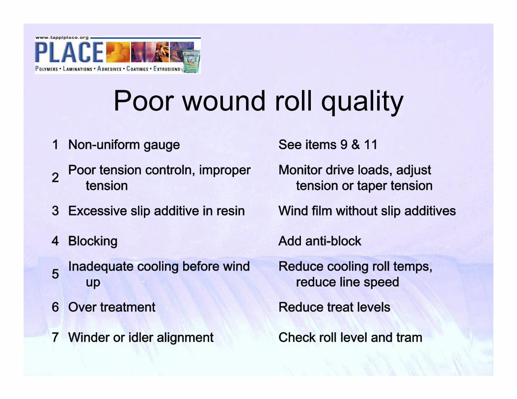
Poor wound roll quality
Check roll level and tramWinder or idler alignment7
Reduce treat levelsOver treatment6
Reduce cooling roll temps, reduce line speed
Inadequate cooling before wind up5
Add anti-block Blocking 4
Wind film without slip additivesExcessive slip additive in resin3
Monitor drive loads, adjust tension or taper tension
Poor tension controln, improper tension2
See items 9 & 11Non-uniform gauge1

Edge tear – unstable edge
Adjust deckles or die boltsLeakage (weapage) around deckles5
Adjust decklesDeckles set too narrow (too wide)4
Adjust to higher melt temperaturesMaterial too cold3
Adjust pinning, die, chill roll relation
Improper setting of edge pinners2
Use alternate material, use edge encapsulationInadequate resin draw strength 1
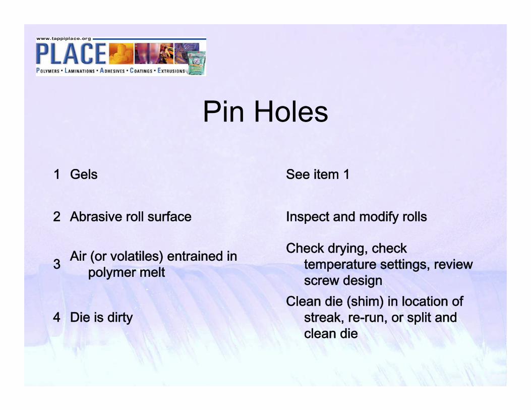
Pin Holes
Clean die (shim) in location of streak, re-run, or split and clean die
Die is dirty4
Check drying, check temperature settings, review screw design
Air (or volatiles) entrained in polymer melt3
Inspect and modify rollsAbrasive roll surface2
See item 1Gels1

Extruder Surging
Conduct rate checks at various speeds and pressures, confer with screw designer
Improper feedscrew design4
Monitor root cooling temperature, adjust cooling supply
Over heating on screw root3
Monitor feed jacket temperature, adjust cooling supply
Over heating in feed throat2
Monitor resin supply to feed throatInconsistent material feeding1

Draw Resonance
Adjust air impingement draw resonance eliminator
Balance of extensional response with rate of cooling5
Adjust die gapImproper die gap4
Add polymer processing aidInconsistent polymer release from die surface3
Adjust melt temperatureImproper melt temperature2
Increase air gapImproper air gap1

Discoloration
Purge or dis-assemble and clean
Degraded material from improper shut down3
See item 1Resin contamination2
Reduce melt temperature, screw speedMelt temperature too high1

Poor heatseal
Discontinue use of silicone sprays
Contamination with air borne silicone5
Use alternate resin or additiveImproper additive levels4
Reduce treat levelsExcessive corona treatment3
See item 7High melt temperature2
Use alternate resinInappropriate resin 1

Odor – flavor scalping
See item 7High melt temperature2
Use alternate resinInappropriate resin 1

Poor Strength
Adjust nip pressures and temperatures
Excessive pressures or temperatures at nip rolls4
Use alternate resinInappropriate resin 3
See items 11 & 12Poor gauge control2
Adjust processing temperatureInappropriate processing temperature1

Blocking
Adjust anti-block levelsInadequate levels of anti-block5
Reduce treat levelsOver treatment4
Add static eliminationStatic build up3
Reduce winding tensionWinding tension too high2
Reduce cooling roll temps, reduce line speedInadequate cooling1

Poor Printability
See items 11 & 12Non-uniform gauge3
Increase treat levels, reduce line speedInadequate treat levels2
Check treater gap, corona appearanceNon-uniform treatment1

Camber
Reduce unsupported web spans, pre-trim edge beadsNon-uniform transport forces3
Review die designNon-uniform stress / thermal history2
Reduce cooling roll temps, reduce line speedInadequate quenching1

Scratches
Inspect and modify rollsAbrasive roll surface2
Check all roller speedsIdler rolls not turning at web speed1

Thank YouPRESENTED BY
NameTitleCompanyemail address (optional)
Please remember to turn in your evaluation sheet...
Top Related
Copyright © 2022 FDOKUMEN

