


Bahasa
Halaman
Hukum


Fire Damper
FIRE SAFETY
CX-5
air
han
dli
ng
inte
llig
ence
open in
www.gryfit.com - e-mail: [email protected] - tel. +48 91 432 35 00 - fax: +48 91 432 35 36
EI 120 (v
in libraries of
1488-CPD-0280/W
Certificate of Constancy of Perfomance
EN 13501-3+A1:2010EN 15650:2010
The CX-5 consists of:– circular casing made of galvanized steel sheet alternatively stainless or acid proof steel,– movable damper blade made of fire resistant board,– combination of smoke and fire proof seals of damper blade,– control mechanism and optional EMS module enabling fire damper assessment with the TZ tester,– optional access door provided with a gasket and a cover with quick clamp lever.
DESCRIPTION
FUNCTION
The CX-5 fire dampers are designed for buildings where in the event of a fire the affected zone should be isolatedfrom the other zones, by among others, closing fire dampers, while the ventilation and air conditioningsystems should operate normally in the other non-affected zones of the building. The performance criteria aresatisfied in case of fire from inside to outside as well as outside to inside or both, respectively.
APPLICATIONThe CX-5 fire dampers installation is allowed within a duct passing through a vertical and horizontalbuilding partition or directly in building partition. Once the blade of the damper has been closed,the fire-affected zone is isolated - fire resistance of partition is maintained what prevents the spread of fireinto the adjoining compartments. Fire damper closes as a result of rise in temperature in ventilation ductabove 72°C or 95°C and activation of fuse or by control signal transmitted from the fire alarmcontrol panel if damper is equipped with remote control mechanism.
e-ho-i o) S
FIRE S
AFET
Y
1

Fire Safety
CX-5
www.gryfit.com - e-mail: [email protected] - tel. +48 91 432 35 00 - fax: +48 91 432 35 36
DIMENSIONS
HYDRAULIC AND ACOUSTIC CHARACTERISTICS
SELECTION & DIMENSION
Lw[dB(A)]30
3540
4550
5560
100005000100050030020010050251
5
10
50
100 D100
D125
D160
D200
D250
D315
D355
D400
D 0450
D50D560
D630
Air flow [m3/h]
Pres
ure
drop
[Pa]
Table of dimensions for brick or concrete partition wall G=110 mm
It is possible to order a damper with a non-standard casing length from the range:P < P < 1040 mmrequiredstandard
D [mm] [mm]
P B[mm] [kg]
S[dm2]0,485-3501000,836-3501251,507-3501602,157-3902003,678-4502506,23994503158,131028450355
10,58115145040012,67137545045017,1515100450500
17 21,8413045056028,0419165450630
Weight
D=200-630 mm
255P
50
min
200
G
Dr
D-2
B
2

Fire Safety
CX-5
www.gryfit.com - e-mail: [email protected] - tel. +48 91 432 35 00 - fax: +48 91 432 35 36
SELECTION
GRYFIT CX-5 D100-D160
GRYFIT CX-5 D200
GRYFIT CX-5 D250-D630
Damper with FDG-WT-5 actuator Optional position of the actuator Damper with FDG-WT-8 actuator
Damper with FDG-WT-5 actuator Damper with FDG-WT-8 actuator
Mortaring border
MORTARING BORDER
200 225
P
50
G
Mortaring border
MORTARING BORDER
200 225
P
50
G Masonry mortar
D –
2D
+ 5
0
Masonry mortar
D –
2D
+ 5
0
Attention: Optional position of actuator should be specified as: "actuator - 90 degrees".
Mortaring border
MORTARING BORDER
200
225P
50
G
B
Masonry mortar
D –
2D
+ 5
0
200 185
P
50
D –
2
G
D +
50
MORTARING BORDER
Mortaring border
Masonry mortar
200 185
P
50
D –
2
G
D +
50
MORTARING BORDER
Mortaring border
Masonry mortar
200 185
P
50
G
D –
2D
+ 5
0
Mortaring border
Masonry mortar
MORTARING BORDER
3
Fire Safety
CX-5
www.gryfit.com - e-mail: [email protected] - tel. +48 91 432 35 00 - fax: +48 91 432 35 36
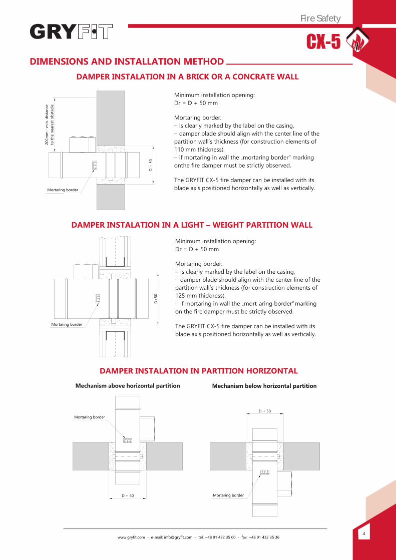
DIMENSIONS AND INSTALLATION METHODDAMPER INSTALATION IN A BRICK OR A CONCRATE WALL
Minimum installation opening:Dr = D + 50 mm
Mortaring border:– is clearly marked by the label on the casing,– damper blade should align with the center line of thepartition wall’s thickness (for construction elements of110 mm thickness),– if mortaring in wall the „mortaring border“ markingonthe fire damper must be strictly observed.
The GRYFIT CX-5 fire damper can be installed with itsblade axis positioned horizontally as well as vertically.
DAMPER INSTALATION IN A LIGHT – WEIGHT PARTITION WALL
Minimum installation opening:Dr = D + 50 mm
Mortaring border:– is clearly marked by the label on the casing,– damper blade should align with the center line of thepartition wall’s thickness (for construction elements of125 mm thickness),– if mortaring in wall the „mort aring border“ markingon the fire damper must be strictly observed.
The GRYFIT CX-5 fire damper can be installed with its blade axis positioned horizontally as well as vertically.
DAMPER INSTALATION IN PARTITION HORIZONTAL
MORTARING BORDER
D +
50
200m
m -
min
. dist
ance
to th
e ne
ares
t obs
tacl
e
Mortaring border
D+5
0MORTARING BORDER
Mortaring border
Mechanism above horizontal partition Mechanism below horizontal partition
MORTARING BORDER
D + 50
MORTARING BORDER
D + 50
Mortaring border
Mortaring border
4

Fire Safety
CX-5
www.gryfit.com - e-mail: [email protected] - tel. +48 91 432 35 00 - fax: +48 91 432 35 36
ACCESSORIESACCESSORIES
EMS Module
Easy Maintenance System module guarantee quick and correct connection of the portable TZ tester that enables delivery of suitable control – impulse or deenergizing of a selected voltage – 24 V or 230 V, in purpose of functionality assessment during the installation work, commissioning process of the installation and during normal management of the building. Use of the EMS system together with the TZ tester speeds up commissioning of the installation considerably and leaves no doubt as regards to its correct performance.
– set of installation brackets UM,– access door AD,– T-type EPDM gaskets,
– electromagnet de-energized EP,– electromagnet impulse EI,– actuator FDG-5,– actuator FDG-8.
– microswitch indicating "closed"position 1WKK,
– microswitch indicating "open"position 1 WKP,
– microswitches indicating "open"and "closed" position 1WKKP,
Installation brackets, access door Microswitches Microswitches, electromagnetand T-type EPDM gaskets and actuator
ELECTRICAL WIRING DIAGRAM
Sound power level – spring dB(A)
CHARACTERISTICS OF ACTUATOR FDG-WT-5-230 FDG-WT-5-24Supply voltage [V] 230V AC 24V AC/DC
Power input during tensioning the spring [W] 4 WPower input during stand-by [W] 1 WTime of movement – engine [s] <40 sTime of movement – spring [s] <20 s
Torque motor [Nm] >3 NmProtection class IP IP54
Sound power level – actuator dB(A) <45 dB(A)<65 dB(A)
CHARACTERISTICS OF ELECTRO-MAGNET
Supply voltage
Power input
24 lub 48 V DC impulse3,5 W
230 V AC impulse5,5 VA
24 lub 48 V DCde-energized
1,6 W
230 V ACde-energized
4 VA
4 W1 W
<40 <20 s
s
>3 NmIP54
<45 dB(A)<65 dB(A)
Sound power level – spring dB(A)
CHARACTERISTICS OF ACTUATOR FDG-WT-8-230 FDG-WT-8-24Supply voltage [V] 230V AC 24V AC/DC
Power input during tensioning the spring [W] 9,2 VA 3,5 WPower input during stand-by [W] 6,9 VA 0,5 WTime of movement – engine [s] 55-71 s 55-71 sTime of movement – spring [s] 21 s 21 s
Torque motor [Nm] 8 Nm 8 NmProtection class IP IP54 IP54
Sound power level – actuator dB(A) 47 dB(A) 47 dB(A)52 dB(A) 52 dB(A)
5

Fire Safety
CX-5
www.gryfit.com - e-mail: [email protected] - tel. +48 91 432 35 00 - fax: +48 91 432 35 36
ELECTRICAL WIRING DIAGRAM
Des
ign
chan
ges
rese
rved
. All
right
s re
serv
ed.©
GRY
FIT
air h
andl
ing
inte
llige
nce
- CX-
5-17
.06-
B.5-
ENG
D-2
Enquiry:Fire damper EIS120 GRYFIT CX-5, D=400 + Actuator 24/48V AC/DC FDG-WT-8-24 + Module EMS +EPDM gaskets
GRYFIT quotation:GRYFIT CX-5, D=400 + FDG-WT-8-24 + EMS + EPDM gaskets T
Enquiry:Fire damper EIS120 GRYFIT CX-5, D=400 + Compact microswitches indicating open and closed position + EPDM gaskets
GRYFIT quotation:GRYFIT CX-5, D=400 + 1WKKP + EPDM gaskets T
EXAMPLE OF SPECIFICATION AND PURCHASE ORDERD-2
Damper with mechanism H Optional actuators: FDG-8-24, FDG-8-230,
optional electromagnets: EI24, EI230, EP24 or EP230.Optional actuators: FDG-WT-8-24, FDG-WT-8-230,FDG-WT-5-24* and FDG-WT-5-230*.
Damper with mechanism H and EMS
Optional actuators: FDG-8-24, FDG-8-230,optional electromagnets: EI24, EI230, EP24 or EP230.
or FDG-WT-5* and EMS Optional actuators: FDG-WT-8-24, FDG-WT-8-230,FDG-WT-5-24* and FDG-WT-5-230*.
Damper with FDG-WT-8 actuator or FDG-WT-5*
Damper with FDG-WT-8 actuator and EMSYe
llow
- gr
een
wire
- 23
0 V
only
EM
EMS
Yello
w -
gree
n w
ire -
230
V on
ly
21 22 23 24 2625
53 4 6 7 8 109
+ - MICROSWITCHES
<5° <80°
11 22
21
M
-N L1
+~ 24 V AC/DC
230 V AC24/48 V DC230 V AC
M
MICROSWITCHES
21
Thermo-electrictripping device
~~ 24 V AC/D- +N L1
21 22 23 262524
230 V AC
EMS
<5° <80°
*FDG-WT-5-24 and FDG-WT-5-230 actuators are applicable for all sizes of CX-5 fire dampers.
M
21
21 22 23 24 25 26
<80°<5°
~ 24 V AC/DC- +N L1
230 V AC
EM M <5° <80°
213 4 1 2
+ ���� -
22 23 24 25 26
24/48 V DC230 V AC +
~ 24 V AC/DC
-N L1
230 V AC
6
MICROSWITCHESMICROSWITCHES
Thermo-electrictripping device
Top Related
Copyright © 2022 FDOKUMEN

