


Bahasa
Halaman
Hukum


E.ON Offshore Wind Energy Factbook E.ON Climate & Renewables – September 2012
2 Picture taken at E.ON Offshore Project - Robin Rigg (United Kingdom, 2009)
Introduction 3
Offshore Wind Industry 5
Challenges of Offshore Wind 9
Technical Solutions 14
E.ON´s Approach 37
Factsheets of E.ON´s Offshore Wind Projects 41
Key Learnings 59

3
Mike Winkel, CEO E.ON Climate & Renewables GmbH
Dear Reader, Offshore wind is one of the most fascinating industries in the renewable energy sector and is experiencing a remarkable growth. By mid of 2012, around 4,300 MW of installed offshore wind capacity was operating in Europe. By 2020 around 40,000 MW should be installed, a 10-fold increase. E.ON is committed to being a leading player in the offshore wind industry. In 2010, we commissioned 46% of all new offshore wind installations in Europe. We have already invested around €2 billion into our offshore wind farms. This includes five operational offshore wind farms across the North and Baltic Sea, and the ongoing construction, with partners Dong and Masdar, of the London Array which will be the world´s largest offshore wind project when fully completed.
This unique experience enables us to move our offshore wind activities from a project-by-project basis to a portfolio approach, thereby leveraging E.ON’s skills and procurement capabilities. Using our extensive and diversified project pipeline, we will commission an offshore wind farm every 18 months while significantly reducing costs by 40% by 2015. By 2015, E.ON will invest another €2 billion in three further offshore wind farms in Germany, UK and Sweden. In total these projects will have an installed capacity of around 550 MW. Our long-term lease of a specialist construction vessel will support the construction of these projects. In this Factbook we would like to give you some insights into the offshore wind industry, its challenges, growth prospects, and our own projects. We hope that you find it useful, and we would welcome your comments and feedback. Kind regards,

4 Picture taken at Offshore Project London Array ((United Kingdom, 2012) - a Joint Venture of E.ON (30%), DONG (50%) and Masdar (20%)
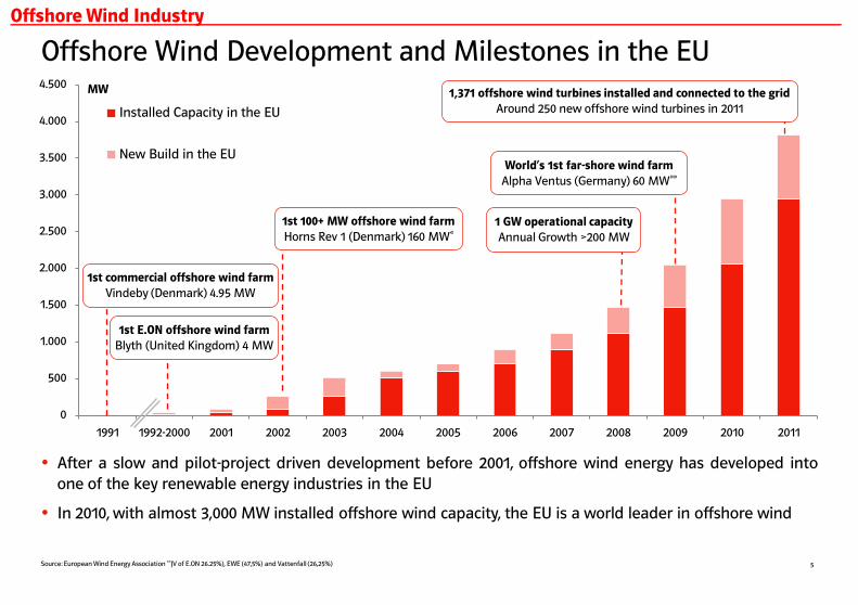
Offshore Wind Development and Milestones in the EU
5
0
500
1.000
1.500
2.000
2.500
3.000
3.500
4.000
4.500
1991 1992-2000 2001 2002 2003 2004 2005 2006 2007 2008 2009 2010 2011
Installed Capacity in the EU
New Build in the EU
1st 100+ MW offshore wind farm
Horns Rev 1 (Denmark) 160 MW* 1 GW operational capacity
Annual Growth >200 MW
MW
1st commercial offshore wind farm
Vindeby (Denmark) 4.95 MW
1st E.ON offshore wind farm
Blyth (United Kingdom) 4 MW
Source: European Wind Energy Association **JV of E.ON 26.25%), EWE (47,5%) and Vattenfall (26,25%)
After a slow and pilot-project driven development before 2001, offshore wind energy has developed into one of the key renewable energy industries in the EU
In 2010, with almost 3,000 MW installed offshore wind capacity, the EU is a world leader in offshore wind
1,371 offshore wind turbines installed and connected to the grid
Around 250 new offshore wind turbines in 2011
World‘s 1st far-shore wind farm
Alpha Ventus (Germany) 60 MW**
Offshore Wind Industry

Snapshot of the EU Offshore Wind Industry
6
Over 95% of global operational offshore wind installations are located in European waters
More than 55% of the total offshore wind installed capacity in the EU is located in the United Kingdom, and another 40% in Denmark, the Netherlands, Germany, Belgium and Sweden
In 2011 a total of 886 MW of offshore wind capacity was brought online mostly in UK and Germany
Utilities have realized about 90% of EU offshore wind projects.
E.ON commissioned 46% of new installed European offshore wind capacity in 2010
The first offshore wind farms outside Europe were commissioned in 2010 in China and Japan
European Installed Offshore Wind Capacity (2011) Good to know…
Sources: European Wind Energy Association, Emerging Energy Research
United Kingdom 55% 2,094 MW
Denmark 23% 857 MW
Netherlands 6% 247 MW
Germany 5% 200 MW
Belgium 5% 195 MW
Sweden 4% 164 MW
Finland 0.6% 26 MW
Ireland 0.6% 25 MW
Norway, Portugal 0.1% 4 MW
Total 100 % 3,813 MW
DK
UK
UK
DK

European Outlook on Offshore Wind Energy
7
Following a rather slow growth until 2010, offshore wind energy in Europe is supposed to grow strongly over the next decade:
from 3,000 MW in 2010
to about 21,500 MW in 2015
to about 40,000 MW in 2020
Many European countries aim to build up offshore wind energy, especially in the North Sea and Atlantic:
UK: 13,000 MW by 2020; 33,000 MW by 2030
Germany: 10,000 MW by 2020; 25,000 MW by 2030
France: 6,000 MW by 2020
Netherlands: 5,000 MW by 2020
Denmark: 1,300 MW by 2020
Development and forecast of installed capacity Good to know…
Sources: National Renewable Energy Action Plans of EU Member States, European Wind Energy Association,, Emerging Energy Research,
0
5.000
10.000
15.000
20.000
25.000
30.000
35.000
40.000
2000 2002 2004 2006 2008 2010 2015 2020
MW ~ 40,000 MW
3,000 MW
Installed Capacity
New Build Capacity
21,500 MW
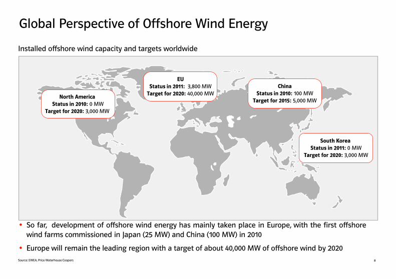
Global Perspective of Offshore Wind Energy
8
So far, development of offshore wind energy has mainly taken place in Europe, with the first offshore wind farms commissioned in Japan (25 MW) and China (100 MW) in 2010
Europe will remain the leading region with a target of about 40,000 MW of offshore wind by 2020
China
Status in 2010: 100 MW Target for 2015: 5,000 MW
North America
Status in 2010: 0 MW Target for 2020: 3,000 MW
South Korea
Status in 2011: 0 MW Target for 2020: 3,000 MW
EU
Status in 2011: 3,800 MW Target for 2020: 40,000 MW
Installed offshore wind capacity and targets worldwide
Source: EWEA, Price Waterhouse Coopers

9
The creation of wind is a simple physical process: The sun radiation heats the earth thereby creating temperature differences which lead to pressure differences causing the air to move
Wind conditions onshore and offshore differ essentially. While the landscape, trees and buildings distort the flow of onshore wind, offshore wind flow can develop without obstacles with higher wind speeds and a more even flow close to the surface which also allows lower tower heights
In order to use wind at its best, offshore wind farms are laid out in a specific way:
The wind farm layout depends on the main wind direction and the conditions of the seabed
To avoid turbulence from other wind turbines, wind farms are designed with a minimum distance between individual turbines of 5-8 times rotor diameter in main wind direction
“Offshore wind is different from onshore wind”
Sun heats earth
Temperature differences
Pressure differences
Air movement/wind
Challenges of Offshore Wind
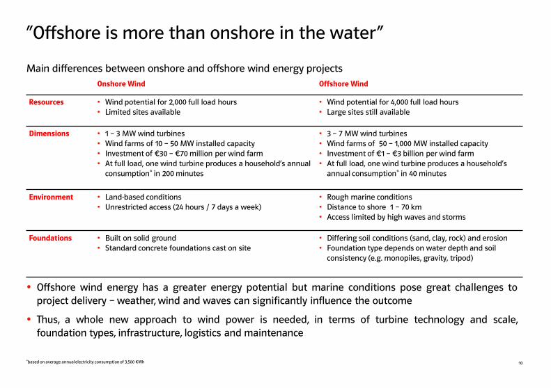
Offshore wind energy has a greater energy potential but marine conditions pose great challenges to project delivery – weather, wind and waves can significantly influence the outcome
Thus, a whole new approach to wind power is needed, in terms of turbine technology and scale, foundation types, infrastructure, logistics and maintenance
Main differences between onshore and offshore wind energy projects
*based on average annual electricity consumption of 3,500 KWh 10
Onshore Wind Offshore Wind
Resources • Wind potential for 2,000 full load hours • Limited sites available
• Wind potential for 4,000 full load hours • Large sites still available
Dimensions • 1 – 3 MW wind turbines • Wind farms of 10 – 50 MW installed capacity • Investment of €30 – €70 million per wind farm • At full load, one wind turbine produces a household‘s annual
consumption* in 200 minutes
• 3 – 7 MW wind turbines • Wind farms of 50 – 1,000 MW installed capacity • Investment of €1 – €3 billion per wind farm • At full load, one wind turbine produces a household‘s
annual consumption* in 40 minutes
Environment • Land-based conditions • Unrestricted access (24 hours / 7 days a week)
• Rough marine conditions • Distance to shore 1 – 70 km • Access limited by high waves and storms
Foundations • Built on solid ground • Standard concrete foundations cast on site
• Differing soil conditions (sand, clay, rock) and erosion • Foundation type depends on water depth and soil
consistency (e.g. monopiles, gravity, tripod)
“Offshore is more than onshore in the water“

11
Distance to shore
Water depth
Coast
Each offshore wind energy project has its individual characteristics depending on factors such as wind conditions, the consistency of the seabed, water depth and the distance to shore:
Project developers choose their foundations and wind turbines considering the individual wind conditions, the consistency of the sea bed and the particular water depth
Logistics, Operations & Maintenance (O&M) concepts and the accessibility of the turbines are strongly influenced by the distance to the shore
Far-shore projects with a greater water depth need larger wind turbines and a higher energy output in order to balance costs and revenue
“Offshore is not offshore“
Distance to shore
Water depth
Seabed
COSTS Wind resources REVENUE
Power
Generation
Wind farm design:
Size of wind farm Wind turbines Foundations
Logistics

12
Different offshore conditions require different solutions
North Sea Baltic Sea Impact on
Tide • High difference of water level of 2 m to 10 m
• Low tide below 50 cm • Installation • O&M activities
Waves • High waves • Partly breaking waves
• Lower waves • Installation • O&M activities
Water depth • Up to 40 m • Up to 25 m • Foundation design
Seabed
conditions
• Mostly sand with some rocks • Variety of seabed conditions: e.g. flint stones, clay, foundlings, chalk layers
• Location • Foundation design
Distance to
shore
• Near-shore in many countries • German projects in North Sea
more than 40 km away
• Near-shore • Installation • O&M activities • Grid connection
Ice • No sea ice • Partial sea ice in winter • Foundation design (e.g. use of ice cones)
Current • Strong currents • Medium currents • Installation • O&M activities
Apart from the wind conditions, the natural site conditions in European waters differ significantly which requires different project planning and technical solutions to cope with varying sea bed conditions, water depth, accessibility and ice formation
Different offshore conditions in the North and Baltic Sea and their impact on offshore wind projects

Offshore projects require extensive long-term planning
Pictures taken at E.ON Offshore Project Robin Rigg (United Kingdom, 2009)
Mil
est
on
es
Development Construction Origination Operation
Initial screening of potential sites
Preliminary evaluation of seabed and wind conditions
Securing of project and property rights
Application for permission
Wind Assessment/ Ground Survey
Environmental Impact Assessment (EIA)
Technical planning Securing of grid
connection Receiving of
construction permit
Component contracts signed
Installation of foundations and wind turbines
Connection to onshore grid
Commissioning and start of operation
Hands-on and pro-active operation
Regular check and maintenance of technical equipment
Repairs, overhauls and upgrades
At end of lifetime: decommissioning or repowering
The realization time of an offshore wind park, from the first idea to the start of the project, might require up to 10 years of continuous work and a complex project management
13

Re-enforced concrete
Max. water depth = 30m
Suitable for 5 MW turbines
Good experience
Heavy steel structure
Max. water depth = 35m
Suitable for 5 MW turbines
Little experience
Steel structure
Max. water depth = 25m
Limited to 3.6 MW turbines
Mostly used foundation
Laterace steel structure
Max. water depth = 45m
Suitable for 5 MW turbines
Little experience
Offshore Wind Foundations - Overview Gravity Foundation Monopile Foundation Jacket Foundation Tripod Foundation
Water depth and consistency of the seabed determine the choice of foundation. So far, there is no universal foundation type suitable for all kinds of seabed conditions
With a share of 75% in 2011, monopile foundations were the most commonly used foundation type, followed by gravity foundations with a share of 21%
Significant research and development are still necessary to develop a cost-efficient concept for production at industrial scale. New concepts, e.g. floating foundations, are being tested
14 Source: European Wind Energy Association,
Technical Solutions for Offshore Wind

Gravity foundations are preferably used in waters with a maximum depth of 30 meters
Made of reinforced concrete, one gravity foundation can weigh up to 1,400 tons at a height of 15 meters
To increase weight and stability, gravity foundations are often filled with gravel and stones
From arrival at site, the complete cycle of installation of a foundation takes less than 24 hours
E.ON has gained experience with gravity foundations in its Danish project Rødsand 2
To date, E.ON has successfully installed 162 gravity foundations
Gravity Foundation – Manufacturing and Delivery
15
Assembly of the steel formwork Completed gravity foundation Foundations are cast in concrete
Pictures taken at E.ON Offshore Project Rødsand II (Denmark, 2009)
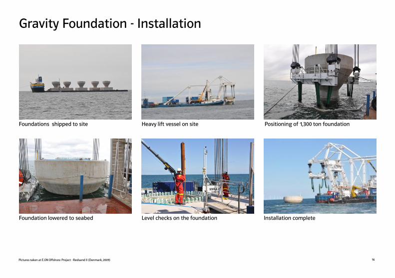
Gravity Foundation - Installation
16
Foundations shipped to site Heavy lift vessel on site Positioning of 1,300 ton foundation
Foundation lowered to seabed Level checks on the foundation Installation complete
Pictures taken at E.ON Offshore Project - Rødsand II (Denmark, 2009)

Monopile Foundation – Manufacturing and Delivery
17
Monopile delivered to harbor Monopiles loaded out on jack-up barge Monopile being up-ended for installation
Monopile foundations can be used in waters with a maximum depth of 25 meters
Made of steel, one monopile foundation weighs up to 800 tons
About 30 meters of the monopile is driven into the seabed
Monopiles are the most common foundations so far, especially for projects in the sandy North Sea seabed
Pictures taken at E.ON Offshore Project Scroby Sands (United Kingdom, 2003)
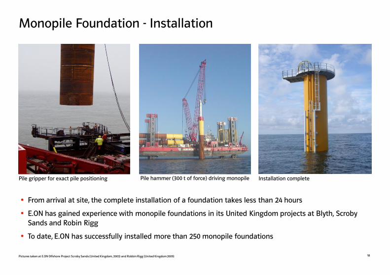
Monopile Foundation - Installation
18
Pile gripper for exact pile positioning Pile hammer (300 t of force) driving monopile Installation complete
From arrival at site, the complete installation of a foundation takes less than 24 hours
E.ON has gained experience with monopile foundations in its United Kingdom projects at Blyth, Scroby Sands and Robin Rigg
To date, E.ON has successfully installed more than 250 monopile foundations
Pictures taken at E.ON Offshore Project Scroby Sands (United Kingdom, 2003) and Robbin Rigg (United Kingdom 2009)

Tripod Foundation - Manufacturing and Delivery
19
Tripods being welded in Norway Tripod up-ended for shipping Tripods arriving at Wilhelmshaven port
Tripod foundations can be used in deeper waters with a maximum depth of 35 meters
Made of steel, one tripod foundation weighs up to 700 tons with a total height of up to 50 meters
In an extensive manufacturing process, all different pieces of the tripods have to be welded together
Tripods are still in the development phase and are rarely put to use in offshore wind installations
Pictures taken at E.ON Offshore Project Alpha Ventus (Germany, 2009, Source: DOTI)

Tripod Foundation - Installation
20
Heavy-lift crane ship on site Installation complete Tripod foundation lowered to seabed
For the installation of a tripod foundation, three securing steel piles, each 30 meters long and weighing 100 tons, are needed to fix the tripod to the ground
From arrival at site, the complete installation of a foundation takes 2-3 days but the installation process will benefit from larger capacity jack-up crane vessels
E.ON has gained experience with the successful installation of six tripod foundations in the German offshore wind project Alpha Ventus
Pictures taken at E.ON Offshore Project Alpha Ventus (Germany, 2009, Source: DOTI)

Jacket Foundation - Manufacturing and Delivery
21
Jackets at Burntisland Fabrication, Scotland Jackets at Eemshaven port, Netherlands
Jacket foundations can be used in water depths of more than 40 meters
Made of steel, one jacket foundation weighs up to 500 tons with a total height of up to 45 meters
In the manufacturing of the jackets, many single steel beams need to be welded together
Next to monopile and gravity foundations, jacket foundations are the third most common type of foundation, quite often also used for transformer stations
Jackets being shipped to site
Pictures taken at E.ON Offshore Project Alpha Ventus (Germany, 2009, Source: DOTI)
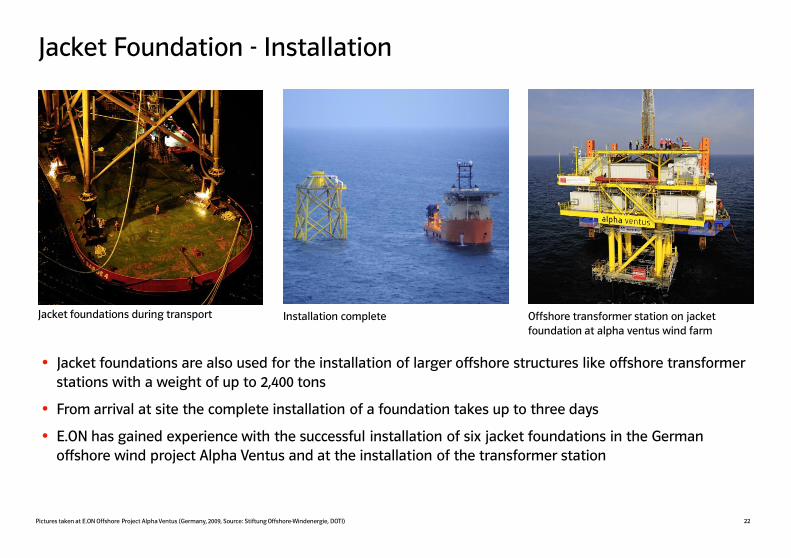
Jacket Foundation - Installation
22
Installation complete Offshore transformer station on jacket foundation at alpha ventus wind farm
Jacket foundations during transport
Jacket foundations are also used for the installation of larger offshore structures like offshore transformer stations with a weight of up to 2,400 tons
From arrival at site the complete installation of a foundation takes up to three days
E.ON has gained experience with the successful installation of six jacket foundations in the German offshore wind project Alpha Ventus and at the installation of the transformer station
Pictures taken at E.ON Offshore Project Alpha Ventus (Germany, 2009, Source: Stiftung Offshore-Windenergie, DOTI)
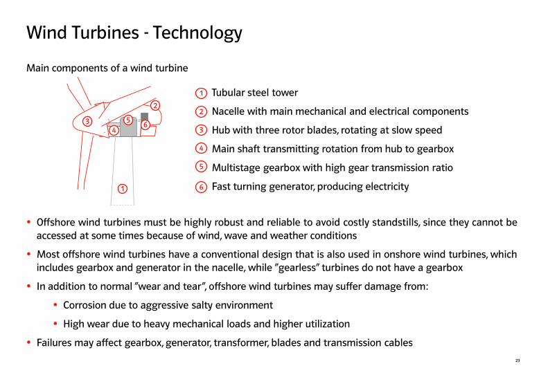
Wind Turbines - Technology
Tubular steel tower
Nacelle with main mechanical and electrical components
Hub with three rotor blades, rotating at slow speed
Main shaft transmitting rotation from hub to gearbox
Multistage gearbox with high gear transmission ratio
Fast turning generator, producing electricity
1
2
3
4
5
6
Offshore wind turbines must be highly robust and reliable to avoid costly standstills, since they cannot be accessed at some times because of wind, wave and weather conditions
Most offshore wind turbines have a conventional design that is also used in onshore wind turbines, which includes gearbox and generator in the nacelle, while “gearless” turbines do not have a gearbox
In addition to normal “wear and tear“, offshore wind turbines may suffer damage from:
Corrosion due to aggressive salty environment
High wear due to heavy mechanical loads and higher utilization
Failures may affect gearbox, generator, transformer, blades and transmission cables
23
1
2
3 6 5
4
Main components of a wind turbine

Wind Turbines - Development
24
Size and capacity of offshore wind turbines have increased considerably. At the moment, wind turbines with a capacity of up to 7 MW are being tested
While at onshore sites the size of wind turbines is often limited by restrictions on height and rotor diameter, offshore wind turbines do not encounter these limits in the open sea
In 2011, the average capacity of offshore wind turbines was about 3.6 MW
Project
Turbine Type
Hub Height
Rotor Diameter
Capacity
Number of Turbines
Scroby Sands
Vestas V80
60 m
80 m
2 MW
30
Rødsand II
Siemens 2.3-93
68 m
93 m
2.3 MW
90
Robin Rigg
Vestas V90
80 m
90 m
3 MW
60
Alpha Ventus
REpower/Multibrid
90 m
126 m / 116 m
5 MW
12
Size and capacity of wind turbines have significantly increased
Source: European Wind Energy Association

Wind Turbines - Pre-Assembly
25
Pre-assembled turbine parts in the harbor
Pictures taken at E.ON Offshore Project Robin Rigg (United Kingdom, 2009)
Wind turbine components need to be pre-assembled onshore to allow quick installation offshore. The most important pre-assembly works are the stacking of tower segments
Vessels with high cranes are needed to finally install the nacelle and the blades. This process needs a high level of precision and can only be fulfilled in good weather and with low wind speeds
From arrival at site the installation of a wind turbine takes a minimum of 24 hours
To date, E.ON is operating and installing more than 365 offshore wind turbines in three different countries
Pre-assembled turbine ready to be ship to the site
Storage of wind turbine blades

Wind Turbines - Installation
26
Pictures taken at E.ON Offshore Projects Robin Rigg (United Kingdom, 2009) and Rødsand 2 (Denmark, 2010)
Special vessels to install wind turbines A wind turbine is installed in several steps Once the tower is fully installed, the crane will pick up the nacelle and the blades
Bunny ear method: Installation of the preassembled nacelle with two blades
Rotor star method: Installation of a pre-assembled hub with three blades
Installation complete
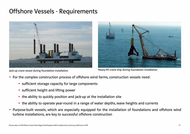
Offshore Vessels - Requirements
27
For the complex construction process of offshore wind farms, construction vessels need:
sufficient storage capacity for large components
sufficient height and lifting power
the ability to quickly position and jack-up at the installation site
the ability to operate year-round in a range of water depths, wave heights and currents
Purpose-built vessels, which are especially equipped for the installation of foundations and offshore wind turbine installations, are key to successful offshore construction
Jack-up crane vessel during foundation installation Heavy-lift crane ship during foundation installation
Pictures taken at E.ON Offshore Project Robin Rigg (United Kingdom, 2009) and Alpha Ventus (Germany, 2009) Source: DOTI
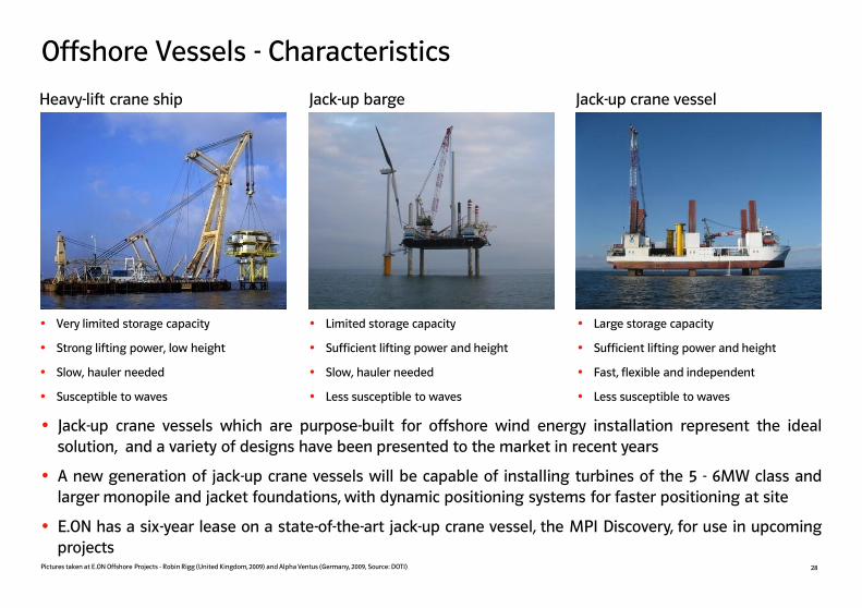
Offshore Vessels - Characteristics
28
Very limited storage capacity
Strong lifting power, low height
Slow, hauler needed
Susceptible to waves
Limited storage capacity
Sufficient lifting power and height
Slow, hauler needed
Less susceptible to waves
Large storage capacity
Sufficient lifting power and height
Fast, flexible and independent
Less susceptible to waves
Heavy-lift crane ship Jack-up barge Jack-up crane vessel
Pictures taken at E.ON Offshore Projects - Robin Rigg (United Kingdom, 2009) and Alpha Ventus (Germany, 2009, Source: DOTI)
Jack-up crane vessels which are purpose-built for offshore wind energy installation represent the ideal solution, and a variety of designs have been presented to the market in recent years
A new generation of jack-up crane vessels will be capable of installing turbines of the 5 - 6MW class and larger monopile and jacket foundations, with dynamic positioning systems for faster positioning at site
E.ON has a six-year lease on a state-of-the-art jack-up crane vessel, the MPI Discovery, for use in upcoming projects

Grid Connection and Array Cabling
29
Cable plowing onshore Cable pulling to foundation Installation complete
Offshore transformer station
Onshore grid connection point
AC
cab
le
Array cabling
Within the offshore wind farm, array cabling (AC) connects rows of wind turbines to the offshore transformer station
The offshore sea-cable (AC or DC) connects the offshore transformer station to the onshore grid
For larger distances from shore, High Voltage DC (HVDC) transformer stations are used to transmit the electricity via DC cable to the shore
For safe operations, offshore cables are buried up to three meters deep into the seabed
Pictures taken at E.ON Offshore Project Scroby Sands (United Kingdom, 2004)
Op
tio
nal
HV
DC
off
sho
re
tran
sfo
rmer
sta
tio
n
DC
cab
le

Offshore Transformer Stations
30
Transport of a jacket foundation of 500 tons Transformer topside installation (London Array) Installation complete (Alpha Ventus)
Transformer substations need to be assembled onshore and installed as a single unit offshore
Heavy lift crane ships are required for the installation of both foundation and transformer station
For long distance power transport e.g. at German projects, DC cables are used, which require an additional AC/DC transformer station offshore and at the grid connection onshore
At Alpha Ventus, the transformer station has a height of 30 meters above sea level and, together with the jacket foundation, weighs more than 1,300 tons
Pictures taken at E.ON Offshore Project - Alpha Ventus (Germany, 2009, Source: DOTI) and London Array (UK, 2011)

Port Infrastructure
31
Offshore wind energy success comes from doing as much as possible onshore - every step completed onshore saves time and money during offshore installation and does not depend on offshore wind and wave conditions
During the installation of offshore wind farms, port facilities have to allow for storage and pre-assembly of foundations and wind turbine components
During the operation of offshore wind farms, the service parks have to allow quick loading of spare parts and 24/7 departure to offshore wind farms
Port storage for towers and nacelles Offshore components awaiting shipment Port storage for monopiles
Pictures taken at E.ON Offshore Project Robin Rigg (United Kingdom, 2009)

Operations and Maintenance (O&M)
32
• Quick O&M site access is crucial to avoid costly stand-stills
• Offshore access is constrained by weather and waves and can be impossible in winter or during storms
• Travel time is a big issue: small boat access to far-shore wind farms can take up to six hours
New O&M concepts for far-shore projects need to be developed, including manned platforms and daily helicopter or speed boat transfer
Preparing boat landing at transformer station Accessing the offshore wind turbine Transfer of O&M equipment
Pictures taken at E.ON Offshore Projects Robin Rigg (United Kingdom, 2009)

Health and Safety: Safety is first Priority!
33
The last 2 meters to the rest platform
Wind turbine specialist fully protected in offshore survival suit
Access to a 5 MW wind turbine
Safety is the first priority for working offshore, since any minor accident may cause major harm with medical help being far away
Construction and maintenance work at offshore wind energy sites is very challenging and risky
The staff has to face tough environmental conditions and work in great heights and in a remote environment – dressed in special offshore suits all the time
Pictures taken at E.ON Offshore Project Alpha Ventus (Germany, 2009, Source: DOTI)

Health and Safety: Ensuring a high Standard
34
To allow, safe, fast and efficient execution, every work and safety routine has to be planned and trained thoroughly
A systematic HSSE (Health, Safety, Security and Environment) approach helps to minimize risks associated with working offshore
E.ON has successfully established and audited an HSSE Management System and is engaging proactively to set global harmonized industry standards for offshore safety
To be independent from sea conditions… …the team is practising accessing a wind turbine by helicopter
Offshore wind specialists on platform on top of the nacelle of a wind turbine
Pictures taken at E.ON Offshore Project - Alpha Ventus (Germany, 2009) – Source: DOTI

35 Source: IUCN (International Union for Conservation of Nature)
E.ON is committed to the sustainable implementation of offshore wind energy by actively supporting research and development of suitable solutions to mitigate the impacts on ecosystems
As part of the consenting process, an Environmental Impact Assessment (EIA) is carried out to evaluate possible impacts of an offshore project on the marine ecology
To learn more about the impacts of offshore energy on the environment, IUCN in cooperation with E.ON carried out the study “Greening Blue Energy” with essential findings:
Wind farms create safe habitats due to the exclusion of trawling and limitations to fishing
These new habitats become potential breeding areas
Wind farms, especially foundations, can provide artificial reefs which enhance biodiversity
Piling noise is a major issue that requires further technical improvements
Animals tend to avoid wind farms during piling in the construction phase, but usually return afterwards
Sustainable development of offshore wind energy
Algae, mussels and fish settling at offshore foundation
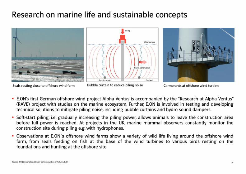
Research on marine life and sustainable concepts
36
Cormorants at offshore wind turbine Bubble curtain to reduce piling noise Seals resting close to offshore wind farm
E.ON’s first German offshore wind project Alpha Ventus is accompanied by the “Research at Alpha Ventus” (RAVE) project with studies on the marine ecosystem. Further, E.ON is involved in testing and developing technical solutions to mitigate piling noise, including bubble curtains and hydro sound dampers.
Soft-start piling, i.e. gradually increasing the piling power, allows animals to leave the construction area before full power is reached. At projects in the UK, marine mammal observers constantly monitor the construction site during piling e.g. with hydrophones.
Observations at E.ON´s offshore wind farms show a variety of wild life living around the offshore wind farm, from seals feeding on fish at the base of the wind turbines to various birds resting on the foundations and hunting at the offshore site
Source: IUCN (International Union for Conservation of Nature), E.ON

E.ON has a leading competence in offshore wind energy
37 *Joint Venture of E.ON (26.25%), EWE (47.5%) and Vattenfall Europe (26.25%), **Phase 1 (630 MW), Joint Venture of E.ON (30%), DONG (50%) and Masdar (20%)
E.ON is a leading player in offshore wind industry
In 2010, E.ON commissioned about 46% of the European offshore wind farms
Currently, around 470 MW of offshore wind farms in operation in UK, Denmark and Germany
Four projects with about 750 MW under construction
Project pipeline of more than 3,100 MW in European waters
E.ON´s strategy for offshore wind energy foresees large investments into projects while simultaneously reducing costs
Realizing one offshore wind project every 18 months
Reducing installation costs by 40% by 2015
E.ON´s offshore wind projects
E.ON´s Approach
0
5
10
15
20
25
30
35
40
80 70 60 50 40 30 20 10
Robin Rigg
Rampion
London Array I 1
Kårehamn
Humber Gateway
Delta Nordsee
Blyth
Arkona
Amrumbank West
alpha ventus 2
0
Utgrunden II Södra
Midjösbanken
Scroby Sands
Rødsand 2
Water depth [m]
Under development Under construction In operation
Size of this circle corresponds to 200 MW wind farm size

E.ON‘s Offshore Wind Energy Projects
38
Aa In operation Ab In development Aa Under construction

E.ON will commission an offshore wind project every 18 months
39
Country Project Status Start of Operation Capacity E.ON Share
UK Blyth Operational 2001 4 MW 100%
UK Scroby Sands Operational 2004 60 MW 100%
Germany Alpha Ventus* Operational 2009 60 MW 26.25%
UK Robin Rigg Operational 2010 180 MW 100%
Denmark Rødsand 2 Operational 2010 207 MW 100%
UK London Array** (phase 1) Construction 2013 630 MW 30%
Sweden Kårehamn Construction 2013 48 MW 100%
Germany Amrumbank West Construction 2015 288 MW 100%
UK Humber Gateway Construction 2015 219 MW 100%
Year to date, E.ON has already invested more than €2 billion into offshore wind projects, including London Array**, the world´s largest offshore wind project currently under construction
E.ON will invest around €2 billion into the offshore wind projects Amrumbank West, Humber Gateway and Kårehamn. This represents the largest investment into offshore wind by a single company so far
E.ON´s offshore wind growth is supported by a six year long-term charter of a purpose-built specialist vessel for efficient and reliable installation at E.ON´s projects
*Joint Venture of E.ON (26.25%), EWE (47.5%) and Vattenfall Europe (26.25%), **Phase 1 (630 MW), Joint Venture of E.ON (30%), DONG Energy (50%) and Masdar (20%)

E.ON target: 40% reduction of installation costs by 2015
40
Drivers to reduce costs of offshore wind projects
Wind turbines Foundations Logistics Grid connection
Offshore wind is still at the beginning of its development, with more providers of wind turbines, foundations, logistics and offshore vessels stepping into the market and new innovative concepts
E.ON´s offshore wind strategy targets at a significant reduction of costs of 40% by 2015 by realizing major savings potential in hardware costs, a standardized, integrated design approach to wind turbine generators and the optimization of installation and operations
Examples
Wider choice of concepts
Larger wind turbines Special design for
offshore installation, operations and maintenance
New, industrial-scale foundation concepts
Lower material costs Shorter installation
time and lower installation costs
Purpose-built vessels Suitable ports Optimized processes
allowing shorter installations times and better access to offshore sites
Foresighted planning Building up of
offshore grid infrastructure
Efficient bundling of grid connections of offshore wind farms
Examples Examples Examples

Blyth (United Kingdom, North Sea)
41 Picture taken at E.ON Offshore Project Blyth (United Kingdom, 2004)
Factsheets of E.ON´s Offshore Wind Projects

Blyth (United Kingdom, North Sea)
42
Foundations
Type Monopile
Material Steel
Weight 110 t
Height 25 m
Diameter 4 m
Wind Turbines
Type Vestas V66
Capacity 2 MW
No. of Turbines 2
Hub Height 60 m
Rotor Diameter 66 m
Built in 2001, Blyth marked the start of E.ON‘s activities in the offshore wind sector
Blyth was a prototype build and the first offshore wind project in United Kingdom waters
Monopiles at Blyth were drilled 10 meters deep into a rock seabed
The total investment in Blyth amount to about €6 million
Good to know
Wind Farm
Capacity 4 MW
Status Operational
Start of Operation 2001
Distance to Shore 1 km
Max. Water Depth 8 m

Scroby Sands (United Kingdom, North Sea)
43 Picture taken at E.ON Offshore Project Scroby Sands (United Kingdom, 2005)

Scroby Sands (United Kingdom, North Sea)
44
Scroby Sands was E.ON‘s first commercial offshore wind farm
Through the project E.ON gained valuable experience in installing a large series of offshore wind turbines with monopile foundations, even in the unfavourable winter season
Operational improvements have led to a continuously high generation performance
With an annual production of 171 million kWh, the wind farm is capable of supplying around 41,000 homes with electricity each year
The total investment for the completion of Scroby Sands amount to €109 million
Foundations
Type Monopile
Material Steel
Weight 200 t
Height 50*m
Diameter 4.2 m
Wind Turbines
Type Vestas V80
Capacity 2 MW
No. of Turbines 30
Hub Height 60 m
Rotor Diameter 80 m
Wind Farm
Capacity 60 MW
Status Operational
Start of Operation 2004
Distance to Shore 3 km
Max. Water Depth 15 m * Up to 8m above sea level; buried up to 30m into ground
Good to know

Alpha Ventus (Germany, North Sea)
Picture taken at E.ON Offshore Project Alpha Ventus (Germany, 2010, Source: DOTI) 45
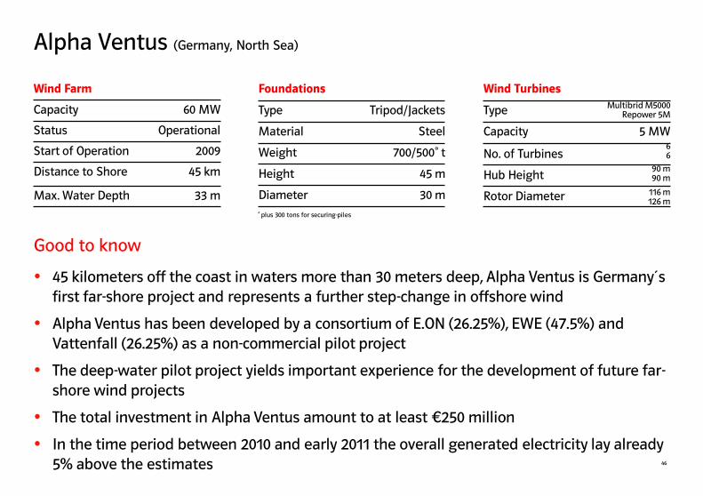
Alpha Ventus (Germany, North Sea)
46
45 kilometers off the coast in waters more than 30 meters deep, Alpha Ventus is Germany´s first far-shore project and represents a further step-change in offshore wind
Alpha Ventus has been developed by a consortium of E.ON (26.25%), EWE (47.5%) and Vattenfall (26.25%) as a non-commercial pilot project
The deep-water pilot project yields important experience for the development of future far-shore wind projects
The total investment in Alpha Ventus amount to at least €250 million
In the time period between 2010 and early 2011 the overall generated electricity lay already 5% above the estimates
Foundations
Type Tripod/Jackets
Material Steel
Weight 700/500* t
Height 45 m
Diameter 30 m
Wind Turbines
Type
Capacity 5 MW
No. of Turbines
Hub Height
Rotor Diameter
Wind Farm
Capacity 60 MW
Status Operational
Start of Operation 2009
Distance to Shore 45 km
Max. Water Depth 33 m
* plus 300 tons for securing-piles
Multibrid M5000 Repower 5M
6 6
116 m 126 m
90 m 90 m
Good to know

Robin Rigg (United Kingdom, Irish Sea)
47 Picture taken at E.ON Offshore Project Robin Rigg (United Kingdom, 2009)

Robin Rigg (United Kingdom, Irish Sea)
48
The project built on the experience gained at Scroby Sands, employing similar monopile foundations and wind turbines
Realization of Robin Rigg benefited from the use of jack-up crane vessels that allowed to install foundations all year-round
With an annual production of 550 million kWh, the wind farm is capable of supplying around 155,000 homes with electricity each year
The total investment for the completion of Robin Rigg amount to around €420 million
Foundations
Type Monopile
Material Steel
Weight 260 t
Height 50* m
Diameter 4.3 m
Wind Turbines
Type Vestas V90
Capacity 3 MW
No. of Turbines 60
Hub Height 80 m
Rotor Diameter 90 m
Wind Farm
Capacity 180 MW
Status Operational
Start of Operation 2010
Distance to Shore 10 km
Max. Water Depth 9 m
* about 30m burried in the sea bed
Good to know

Rødsand 2 (Denmark, Baltic Sea)
49 Picture taken at E.ON Offshore Project Rødsand II (Denmark, 2010)
Neues Bild oder Ausschnittvergrößerung
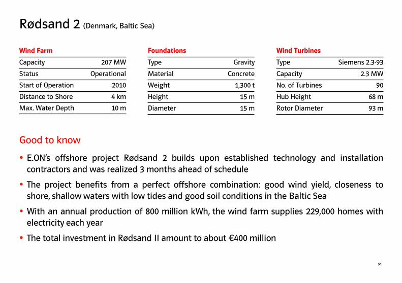
Rødsand 2 (Denmark, Baltic Sea)
50
E.ON’s offshore project Rødsand 2 builds upon established technology and installation contractors and was realized 3 months ahead of schedule
The project benefits from a perfect offshore combination: good wind yield, closeness to shore, shallow waters with low tides and good soil conditions in the Baltic Sea
With an annual production of 800 million kWh, the wind farm supplies 229,000 homes with electricity each year
The total investment in Rødsand II amount to about €400 million
Foundations
Type Gravity
Material Concrete
Weight 1,300 t
Height 15 m
Diameter 15 m
Wind Turbines
Type Siemens 2.3-93
Capacity 2.3 MW
No. of Turbines 90
Hub Height 68 m
Rotor Diameter 93 m
Wind Farm
Capacity 207 MW
Status Operational
Start of Operation 2010
Distance to Shore 4 km
Max. Water Depth 10 m
Good to know
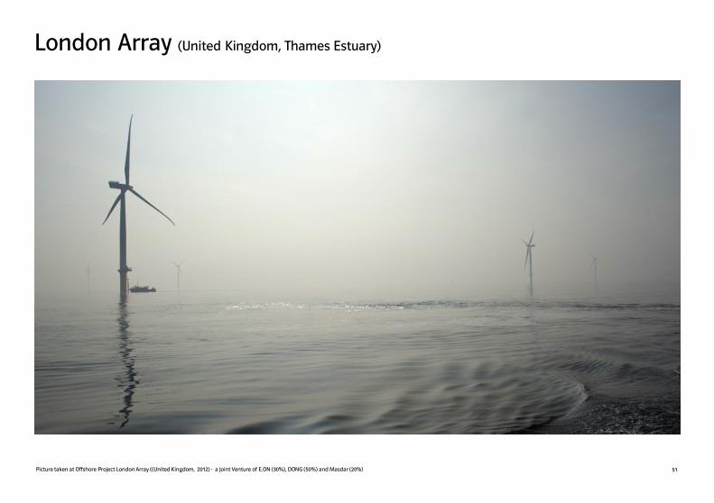
London Array (United Kingdom, Thames Estuary)
51 Picture taken at Offshore Project London Array ((United Kingdom, 2012) - a Joint Venture of E.ON (30%), DONG (50%) and Masdar (20%)

London Array (United Kingdom, Thames Estuary)
52
London Array will be built in two phases (phase 1 = 630 MW; phase 2 up to 370 MW) and will, upon completion, be the world‘s largest offshore wind farm
The project is being developed jointly by Dong Energy (50%), E.ON (30%) and Masdar (20%)
After full completion**, London Array will provide enough power for up to 750,000 homes
The total investment cost of Phase 1 of London Array amount to around €2.2 billion
Good progress is being made on the construction of the wind farm: by September 2012, 158 of 177 foundations and two offshore substations had been installed
Wind Farm*
Capacity 630 MW
Status Construction
Start of Operation 2013
Distance to Shore 22 km
Max. Water Depth 25 m
* Phase 1 (630 MW) * Phase 1 (630 MW)
*Phase 1 (630 MW) **Including phase 1 and phase 2 of the project
Good to know
Foundations*
Type Monopile
Material Steel
Weight 600** t
Height 60** m
Diameter 4.7-5.7* m
Wind Turbines*
Type Siemens
Capacity 3.6 MW
No. of Turbines 175
Hub Height 87 m
Rotor Diameter 120 m
*Phase 1 (630 MW), ** without the transitional piece

53
Kårehamn (Sweden, Baltic Sea)
Artist impression of E.ON Offshore Project Kårehamn seen from Kårehamn (Öland, Sweden, 2011)

Kårehamn (Sweden, Baltic Sea)
54
Kårehamn represents E.ON´s first offshore wind project in Sweden
The location near to shore reduces costs, logistic efforts and allows direct connection to the onshore electricity grid
Kårehamn is one of three E.ON offshore wind projects which will be built in a coordinated way, using state of the art installation vessels shared across the projects
The total investment in Kårehamn amount to around €120 million
With an annual production of over 175 million kWh, Kårehamn will supply over 50,000 households with electricity*
*based on average annual consumption of 3,500 KWh
Wind Farm
Capacity 48 MW
Status Construction
Start of Operation 2013
Distance to Shore 5 km
Max. Water Depth 21 m
Foundations
Type Gravity
Material Concrete
Weight 1,800 t
Height 14 - 24 m
Diameter 18 m
Wind Turbines
Type Vestas V112
Capacity 3.0 MW
No. of Turbines 16
Hub Height 80 m
Rotor Diameter 112 m
Good to know

Amrumbank West (Germany, North Sea)
Artist impression of E.ON Offshore Project Amrumbank West, Germany, 2011 (copyright motum) 55
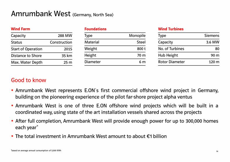
56
Amrumbank West represents E.ON´s first commercial offshore wind project in Germany, building on the pioneering experience of the pilot far-shore project alpha ventus
Amrumbank West is one of three E.ON offshore wind projects which will be built in a coordinated way, using state of the art installation vessels shared across the projects
After full completion, Amrumbank West will provide enough power for up to 300,000 homes each year*
The total investment in Amrumbank West amount to about €1 billion
Wind Farm
Capacity 288 MW
Status Construction
Start of Operation 2015
Distance to Shore 35 km
Max. Water Depth 25 m
Good to know
Foundations
Type Monopile
Material Steel
Weight 800 t
Height 70 m
Diameter 6 m
Wind Turbines
Type Siemens
Capacity 3.6 MW
No. of Turbines 80
Hub Height 90 m
Rotor Diameter 120 m
Amrumbank West (Germany, North Sea)
*based on average annual consumption of 3,500 KWh

Humber Gateway (United Kingdom, North Sea)
57 Artist Impression of E.ON Offshore Project Humber Gateway (United Kingdom, 2011)
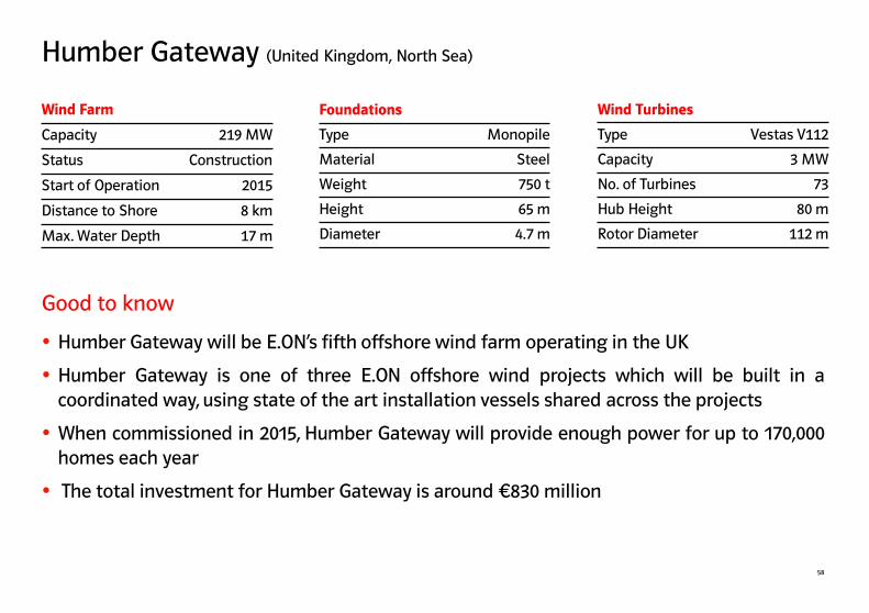
58
Humber Gateway will be E.ON’s fifth offshore wind farm operating in the UK
Humber Gateway is one of three E.ON offshore wind projects which will be built in a coordinated way, using state of the art installation vessels shared across the projects
When commissioned in 2015, Humber Gateway will provide enough power for up to 170,000 homes each year
The total investment for Humber Gateway is around €830 million
Wind Farm
Capacity 219 MW
Status Construction
Start of Operation 2015
Distance to Shore 8 km
Max. Water Depth 17 m
Good to know
Foundations
Type Monopile
Material Steel
Weight 750 t
Height 65 m
Diameter 4.7 m
Wind Turbines
Type Vestas V112
Capacity 3 MW
No. of Turbines 73
Hub Height 80 m
Rotor Diameter 112 m
Humber Gateway (United Kingdom, North Sea)

Offshore Wind - Key Learnings
Offshore wind energy success comes from doing as much as possible onshore Every step carried out on land saves time and money in the offshore installation process
“WWW” - weather, wind and waves are the dominating factors in offshore wind Access to offshore sites is strongly restricted or even impossible in times of bad weather, strong winds and high waves
”Offshore is not offshore” Every offshore site has its own specifications and requirements, especially when moving from near-shore to far-shore
“Offshore wind energy is more than onshore in the water” Offshore wind energy requires substantially different technologies and processes compared to onshore wind energy
E.ON has a leading competence in offshore wind energy Around 700 MW of offshore projects in operation or under construction, give E.ON an outstanding expertise in offshore wind energy.
Offshore wind energy plays a key role in E.ON’s Renewables strategy E.ON has already invested €2 billion in offshore wind projects and will invest another € 2 billion into three projects by 2015, commissioning one offshore wind project every 18 months
59
“Using the right tool for the right job” Experience shows that installation times can be shortened by the right combination of purpose-built vessels, skilled crews and installation tools
E.ON is targeting at a significant growth and cost reductions for future offshore wind projects E.ON has an extensive offshore wind project pipeline of 3,000 MW for further development and is aiming to drive costs of projects down by 40% until 2015
Key Learnings
60
This Factbook may contain forward-looking statements based on current assumptions and forecasts made by E.ON management and other information currently available to E.ON. Various known and unknown risks, uncertainties and other factors could lead to material differences between the actual future results, financial situation, development or performance of the company and the estimates given here. E.ON does not intend, and does not assume any liability whatsoever, to update these forward-looking statements or to conform them to future events or developments.
E.ON Offshore Wind Energy Factbook
Contact:
E.ON Climate & Renewables GmbH Brüsseler Platz 1 45131 Essen Germany [email protected] www.eon.com/renewables
Top Related
Copyright © 2022 FDOKUMEN

