


Bahasa
Halaman
Hukum

UDC 669.184 : 669.046.554 : 669.187.26 : 669.14.018 .8
Development of a New Stainless Steel Melting and Refining
Process (LD-RHOB Process)*
By Norimasa KAMII,** Shiz uo OKUBO*** and Bunji ETO**
Synopsis
At }\lJurorall "Vorks, Nippon S teel CO/poration , a research has been
started to produce stainless steel by LD cOllverter ill 1965. After various
difficulties were overcome in the COU TSe of the research, a new process to
melt and refill e stainless steel (LD-RHO B process) was successfully de
veloped. Since 1972 aLL the stainless s teel has been favorably produced
by the LD-RHOB process and the products were more than 90000 t in
1976. The LD-RHOB process consists of the f oLLowing five steps .
1 ) D esulpll1lrizatiol1 treatment:
D esulphuri zatiol! qj·hot metal by KR treatment
2 ) B ase metal refining period:
D e/Jlwsphoriza tion in LD converter
3 ) Se/Jara tion of slag from metal :
T apping aud slagging off and then charging into the LD converter
again
4 ) Chromium melting period:
H igh carbon ferro chromium melting into base metal
5 ) RHOB treatment:
D ecarburization under reduced IJ ressure
The special f eatures of LD-RHO B process in elude the followings :
(1 ) Chromium. yield and /Jroductivity are equal to or better than
those qf other /Jrocesses (A OD, VOD process) .
(2 ) Chemical com/Jositioll can be freely controlled and tram/J elements
are lower than those ill electric jilT/wce s teels . It is remarkable that high
pure stainless steels such as ultra-Iow-carbon- nitrogen stainless steel call
be easily produced.
(3) The /Jroducts are very soft and ensure good workability.
I. Introduct ion
Sta inless steel was conven tiona lly produced by the electri c furnace process unti l the 1960's . H owever, the d em a nd of sta inless stee l has remarka bly increased in the 1960's . T herefore, the development of highprod uctivity with the low-cos t has been required in m anufac turing processes o f sta inless stee l. The new deve lopmen ts in the 1960 's include the A OD processl )
which uses a n electric fu rnace a nd Ar- 0 2 bottom refining furn ace in combin a tion a nd th e VOD process2 ) a nd AVR process,3) in which a n electric furnace o r LD conver ter is combined wi th a vacuum refining vessel.
In 1965 , the Murora n W orks of Nippon Steel CorpOl-ation started a research on ma nufacturing of stainless steels in a 50 t LD converter .
Muroran Works overcame numerous technical problem s during the course of research a nd successfully d eveloped a new stainless steel m anufacturing practice, na med as the LD-RHOB p rocess . In this process, a n LD converter is combined w ith the oxygen blowing to a n RH d egassing vessel (hereinafter
refer red to as the RHOB process for RH-oxygen blowing) .
Since its extensive adoption in 1972, the LDRHOB process has been satisfactoril y opera ted with chromium yield , steelmaking time a nd other performance equa l to o r better tha n those obta inable with the AOD or the VOD process.
This report outlines the development of the LDRHOB process a nd describes the features of the LDRHOB process.
II. Development oj LD-RHOB Process
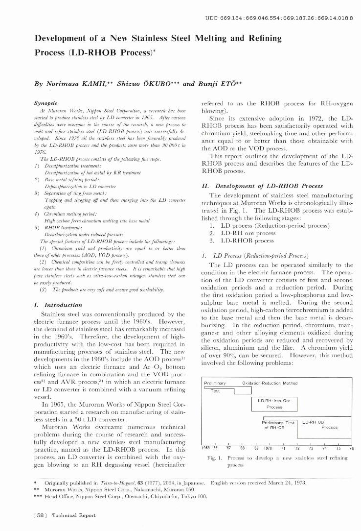
The development of sta inless steel m a nufacturing techniques a t Muroran Works is chronologically illustrated in Fig . 1. The LD-RHOB process was established through the following stages :
1. LD process (R eduction-period process) 2. LD-RH ore process 3. LD-RHOB process
1. LD Process (Reduction-period Process)
The LD process can be operated simil a rly to the condition in the elec tric furn ace process . The operation of the LD converter consists of first a nd second oxida tion periods a nd a redu ction period . During the first oxida tion period a low-phosphoru s and lowsulphur base m e ta l is m elted. During the second oxida tion period , high-carbon ferrochromium is added to the base meta l a nd then the base meta l is d ecarburizing. In the reduction period , chromium, m anganese and o ther a lloying elemen ts oxidized during the ox ida tion periods a re reduced a nd recovered by sili con , a luminium a nd the like. A chromium yield of over 90% can be secured . H owever, thi s m e thod involved the fo llowing problem s :
P reliminary Oxidation-Reduct ion M ethod
'C:::::;;;:::::====::;-il---' T est L---.J
I
r--L-D--R-H-.-Ir-on-o-re-'I
Process
of RH · 08 Process P reliminary T est I LD-RH · 08
1965 '66 ·67 ·68 '69 19 70 '7 1 '7 2 '73 '74 '75 '76
Fig. I . P rocess to d evelop a new sta inless steel refin ing
process
* O riginally published in T etsu-to-Hagane, 63 (I977 ), 2064, in j apanese. E nglish version received M arch 24, 1978. ** M uroran Works, N ippon S teel Corp., Na kamachi , iVl urora n 050 . *** H ead Offi ce, Nippon Steel Corp., O tema chi , C hiyod a-ku, T okyo 100.
( 58 ) Technical Report
(1) Long steelmaking time and high-temperature refining greatly wore refractories.
(2) It was difficult to produce low-carbon stainless steel.
2. LD-RH Ore Process
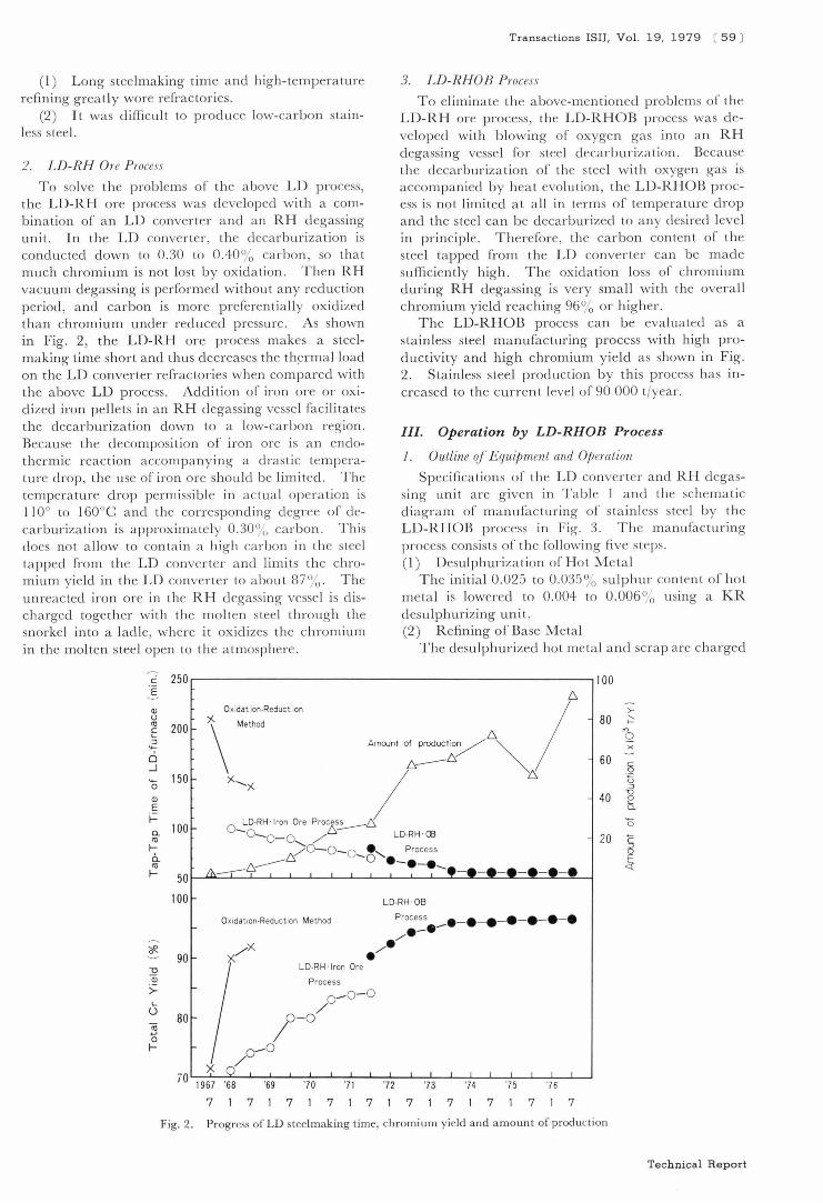
To so lve th e problems of the above LD process, the LD-RH ore process was developed with a combination of an LD converter a nd an RH degassing unit. In the LD converter, the decarburization is conducted down to 0.30 to 0.40 % carbon , so that much chromium is not lost by oxidation. Then RH vacuum degassing is performed without any reduction period , and carbon is more preferentiall y oxidized than chromium under reduced pressure . As shown in Fig. 2, the LD-RH ore process makes a steelmaking time short and thus decreases the th~rma l load
on the LD converter refrac tories when compared with the above LD process. Addition of iron ore or oxidized iron pellets in an RH degassing vesse l facilitates the decarburization down to a low-carbon region. Because the d ecomposition of iron ore is a n endothermic reaction accom pa ny ing a dras tic temperature drop, the use of iron ore should be limited. The temperature drop permissib le in ac tu a l operation is 110° to 160°C a nd the corresponding degree of decarburi zation is a pproximately 0.30 % carbon. This does not a llow to conta in a hig h carbon in the steel tapped from the LD converter a nd limits the chromium yield in the LD converter to a bout 87 % . The unreacted iron ore in the RH degassing vessel is discharged together with the molten steel through the snorkel into a ladle, where it oxidizes the chromium in the molten stee l open to the atmosphere.
Transactions ISH, Vol. 19, 1979 ( 59 )
3. LD-RHOB Process
To eliminate the above-mentioned problems of the LD-RH ore process, the LD-RHOB process was developed with blowing of oxygen gas into an RH degassing vesse l fo r steel decarburization. Because the decarburization of the stee l wi th oxygen gas is accompanied by heat evo lution , the LD-RHOB process is not limited at a ll in terms of temperature drop a nd the steel can be decarburi zed to a ny desired leve l in principl e . Therefore, the carbon content of the stee l tapped from the LD converter can be made sufficiently high . The oxidation loss of chromium during RH d egassing is very small with the overall chromium yield reaching 96 % or higher.
The LD-RHOB process can be evaluated as a stainless steel manufacturing process with high productivity and high chromium y ield as shown in Fig. 2. Stainless steel production by this process has increased to the curren t level of 90 000 tfyear.
III. Operation by LD-RHOB Process
1. OutLine of Equipment and Operation
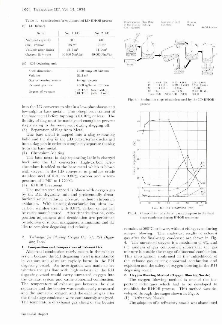
Specifications of the LD converte r a nd RH degassing unit are g iven in T ab le I a nd the schem atic diagram of ma nufac turing of stainl ess stee l by the LD-RHOB process in Fig. 3. The manufacturing process consists of the following five steps . (I) Desulphurization of Hot Metal
The initial 0 .025 to 0.035 % sulphur content of hot metal is lowered to 0.004 to 0.006 % using a KR desulphurizing unit. (2) R efining of Base M etal
The desulphurized hot metal a nd scrap are cha rged
c 250 r-------------------------------------------~IOO E Cl) U t1l
E :J
'+-
0 ..J '+-0
Cl)
E f.= a. t1l I-6.. t1l I-
I..
o 'Ei o I-
200
150
100
50
100
90
80
X OXldat lon·Reduct lon /6 \ ",., -"' :;::;y'\", '-, / " a-:-D RH Iron Ore Proz~~
0 _ 0-0.., /' LD·RH CB /0-0- 0 _ . , Process
A~G 0 . - . - e -.w --
Oxidation·Reduction Method
LD·RH ·OB
Process _e- e - e - e - e - e - e e- e ./ e/
LD·RH . Iron Ore
Process
0 - 0 - 0 / 1-0
0 _ 0 /
70~~~--L-~'69--~-'7~O--L-.~71--L-~.7~2 ~--'7L3--L-~' 74--L--'7L5~L-.~76--L-..J
7 7 1 7717 171 7 1 7 7 1 7
80
60
40
20
Fig. 2. Progress of LD steelmaking t ime, chromium yield and amount of production
>-~
'" Q x -.5 u :J
u §. '0 C
~
Technical Report
( 60 ) Transactions ISIJ, Vol. 19, 1979
Table I . Specificat ions for equi pment of LD-RHOB process
(i) LD furnace
Items No. I LD No.2 LD
50 t 60 t
85 m 3 94 ma
38.5 m 3 4 1.0m3
Nomina l capac ity
Shell vo lume
Volume a fter lini ng
O xygen Row ra te to 000 Nm"/ hr 10000 N m3/ hr
(ii ) RH degassing u nit
Shell d imension
Volume
Gas ex ha usting system
Ex ha ust gas ra te
Degree of vacuum
2 150 mm~& x 9 550 mm
28 .2 rn a
4-stage ejec tor
2 300 kg/hI' at 10 Torr
{ 2 Torr (a ta ina ble)
to Torr (a fte r 2 min)
into the LD converter to obta in a low-phosphorus and low-sulp h ur base m etal. The phosphorus content of the base m eta l before ta pping is 0 .010 % or less . The fluid ity of slag must be m ad e good enough to prevent slag sticking to the vessel wall during slagging off. (3) Separation of Slag from M eta l
The base m eta l is tapped into a slag separating la d le and the slag in the L D converter is d ischa rged into a slag pa n in order to com pletely separa te the slag from the base metal. (4) C hromium Melting
The base m eta l in slag sepa ra ting la d le is cha rged back into the LD converter. High-carbon ferrochromium is added to th e base m e ta l wh ich is b lown with oxygen in the LD conver ter to produ ce crude sta in less steel of 0.50 to 0.80 % carbon and a tem pera ture of 1 740° to 1 n o°c . (5) RHOB Treatmen t
The m olten steel tapped is blown with oxygen gas by the RH degassing un it a nd preferentia lly d ecarburized under reduced p ress ure withou t chromium oxida tion . With a strong d ecarburization , ultra lowcarbon sta inless steel wi th 0 .01 % carbon o r less can be easily ma nufactured. After decarburiza tion , composition adjustmen t and d eoxida tio n a re performed by addi tion of silicon , manganese, a luminium and the like to comple te degassing a nd refining .
2. T echniques for Blowing Ox),gen Gas into RH D egassing Vessel
1. COinpos ition and Tempe rature of Exhaust Gas
Abnorma l combustion r a rely occurs in the exha ust system because the RH d egassing vesse l is m a intai ned in vacuum a nd gases a re rapid ly burnt in the RH d egassing vessel. An inves tiga tion was m ad e to see whe ther the gas flow with high velocity in the R H degassing vessel would carry u n reacted oxygen into the exhaust system and cause a bnorma l combustion . The temperature of exha ust gas between the dust sepa rato r a nd the boos ter was continuously m easured a nd the unreacted oxygen a nd the exhaust gas a fter t he fina l-stage condenser were continuously a na lysed. The tempera ture of exhaust gas ahead of the booster
Technical Report
Desulphunza t,on Base Metal Separation of Slag
from Metal Chromium
Meltmg of Hot Metal by Refining K.R. Treatment RH-OB Process
C : abo O. 10% 0.50 0.80% 0. 04 0.06 % p 0.010 " 0.020 0. 035% 0.020 0.035 " 5 0. 010 " 0. 009 " 0. 009 " Cr . tr . abo 16 . 50 " 16.30 16. 50 " T emp: 1680 1700 C 1740 1770 C 1590 C
Fig . 3. Produc ti on steps o f' stainless s tee l b y the LD-RHOB
process
c .Q
<J)
o 4 0-E o ()
0 - ><--
;/ ~ 0 j \ 0 . 0 l'1
~~j'; 0
1/\ \ pN.
0 ,'lA'
i I~ II 0
~ V tL ~.co .-0 ------- J ... -.. b;: /'~ 'tl~~~ ------- 0 ,
I /'
O~ _ ...."....L. __
-- o o ~ ;- --.- " ~ /
10 20 30 40 50 60 I 70 end
T ime fo r RH Treatmen t (min )
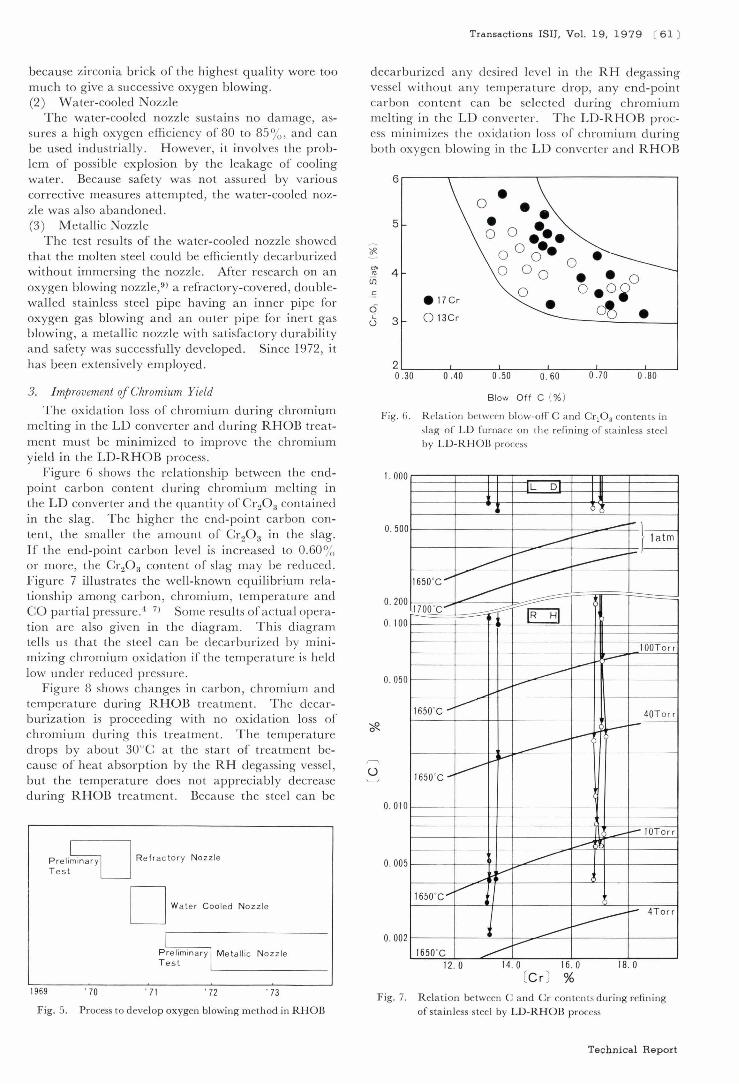
Fig. 4. Composit ion of exhaus t gas su bsequen t to the fin a l stage condenser duri ng RHOB trea tmen t
o·
rem a ins at 500°C or lower, without rising, even during oxygen blowing. The ana ly ti ca l resul ts of exhau st gas a fter the fin a l-sta ge condenser a re shown in Fig. 4. The unreacted oxygen is a m aximum of 4 % a nd the a na lysis of gas composition shows tha t the gas mix ture is outside the ra nge of a bnormal combustion . This inves tigation confirmed in the unlikel ihood of the exha ust gas causing a bnorma l combustion a nd exp losion a nd the safe ty of oxygen blowing in the R H d egass ing vessel. 2. Oxy gen Blowing Method (Oxygen Blowing Nozzle)
The oxygen blowing me thod is one of the impOl" ta nt techn iques w hich had to be developed to es ta blish the RHOB process. This m e thod was d eveloped through th e stages show n in Fig. 5. (1) R efractory N ozzle
The adoption of a refrac tory nozzle was a bandon ed
because zirconia brick of the highest quality wore too much to give a successive oxygen blowing. (2) Water-cooled Nozzle
The water-cooled nozzle sustains no damage, assures a high oxygen e ffi ciency of 80 to 85%, a nd can be used industrially . However, it involves the problem of possible explosion by the leakage of cooling water. Because safety was not assu red by vario us corrective measures attempted , the water-cooled nozzle was a lso abandoned. (3) M etallic Nozzle
The test resu lts of the water-cooled nozzle showed that the molten steel cou ld be efficiently decarburi zed without immersing the nozz le. After research on a n oxygen blowing nozzle,9) a refractory-covered , doublewalled stainless steel pipe having an inner pipe for oxygen gas blowing and a n outer pipe for inert gas blowing, a metallic nozzle with satisfactory durabili ty and safe ty was successfully developed. Since 1972, it has been ex tensively employed.
3. I mprovement of Chromium Yield
The oxida tion loss of chromium during chromium melting in the LD converter and during RHOB treatm ent must be minimized to improve the chromium yie ld in the LD-RHOB process.
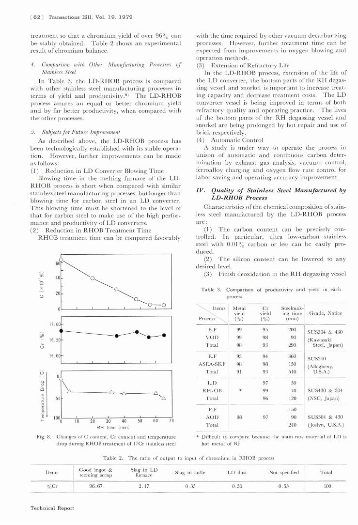
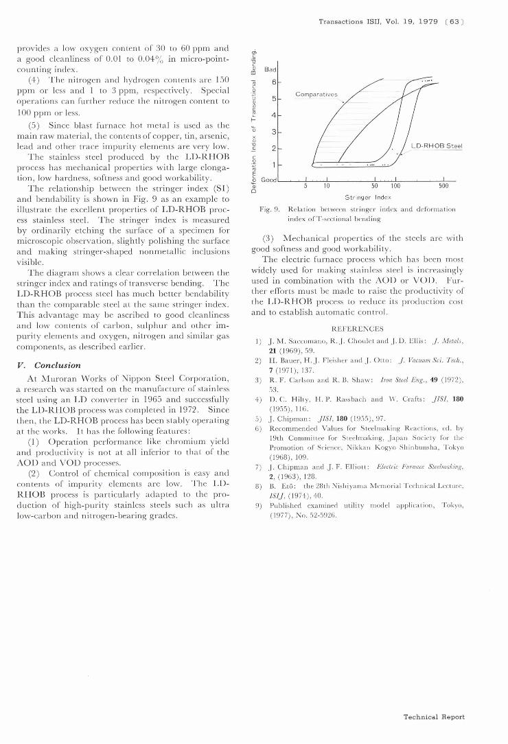
Figure 6 shows the relationship between the endpoint carbon content during chromium m elting in the LD converler and the quantity of (;r20 3 contained in the slag. The higher the end-point carbon content, the smaller the amount of Cr20 3 in the slag. If t he end-point carbon leve l is increased to 0.60 % or more, the Cr20 3 content of slag may be reduced. Figure 7 illustrates the well-known equilibrium relationship among carbon , chromium, temperature and CO partia l pressure.4 - 7) Some resul ts of actual operation are a lso given in the diagram. This diagram tells us that the steel can be decarburized by minimizing chromium oxidation if the tempera ture is held low under reduced pressure.
Figure 8 shows changes in carbon, chromium a nd temperature during RHOB trea tment. The decarburization is proceeding with no oxidation loss of chromium during this treatment. The temperature drops by about 30°C at the start of trea lment because of heat absorption by the RH degassing vessel, but the temperature does nol appreciably decrease during RHOB treatment. Because the steel can be
Transactions ISIJ, Vol. 19, 1979 ( 61 )
decarburized any desired level in the RH degassing vessel withou t any temperature drop, any end-point carbon content can be selected during chromium melting in the LD converter. The LD-RHOB process minimizes the ox idation loss of chrom ium during both oxygen blowing in the LD converter a nd RHOB
"<f!-
"" '" if)
.S
6 c u
u
6,-----.----------.-----------------,
• 0 •• 5 • • o 0 ••• 0 00·· • 0 0 0
0 4
• • 0 . 17 Cr
0 o . O~ • ~ . 3 o 13Cr
2~----~~--~~----~~--~~--~~~~ 0.30 0.40 0.50 0.60 0 .70 0.80
Blow Off C (%)
Fig. 6. R ela tion between blow·off C and Cre0 3 contents in slag of LD furnace on the refining of sta inless steel by LD-RHOB process
1.000 L 0 II
_i ~ .. 6...Q
~ r }.~ ~ ~ latm
~ r- ~
t- J-
r--1650°C ..... ..... j....--""
-------1700°C .... ::;::;~ ;-- ~
0. 500
0. 200
O. 100
100To rr ;--
~ --O. 050
1650°C ...... .............
40To r r
~ -~
f.--";
......
1650°C ..... ----0.010
-- t---__ r- IOTorr
pre li~ Refractory Nozz le 0. 005 TestmlnarYLJ
~
~
1969
Fig. 5.
D Water Cooled Nozzle
Metallic Nozzle
. 70 . 71 , 72 , 73
Process to d evelop oxygen blowing meth od in RHOB
~
1650°C ...... V
~ :.- 4Torr
t --1650°C ~ f-'""
0. 002
12 . 0 14 . 0 16 .0 18.0 [C r) %
Fig. 7. R elat ion between C a nd Cr conten ts during refining of stainless steel by LD-RHOB process
Technical Report
( 62 ) Transac tions ISIJ, Vol. 19, 1979
treatment so th a t a chromium y ield of over 96 % can b e stably obta ined. T ab le 2 shows a n experimenta l result of chromium ba la nce.
4 . Comparison with Other Manufacturing Processes of Stainless Steel
In T a ble 3, the LD-RHOB process is compared with other stainless stee l manufacturing processes in terms of yield and productivity.S) The LD-RHOB process assures an equa l or be tter chromium yield a nd by far better productivity, when compared with the other processes.
5 . SubJects for Future Improvement
As described above, the LD-RHOB process has been technologica ll y established with its stable operation . However , furth er improvem ents can be m ade as follows: (l) R eduction in LD Converter Blowing Time
Blowing time in the me lting furn ace of the LDRHOB process is short when compared with simi la r stainless steel manufacturing processes, bu t longer than b lowing time for carbon steel in a n LD converter. This b lowing time must be shortened to the level o f that for carbon steel to m ake use of the high performance and productivity of LD converters. (2) R eduction in RHOB Treatment Time
RHOB treatment time can be compared favora bly
'= x u
* 0
P
a. ~ 0
~ 3 l" OJ a. E OJ f-
6J )~ 40 0
20
17 .00
16 .50
16. 00
0
\ 50
~O ~O
~O-O
• -.-- ........... . - .
6.~6. 6. "f:,
1000 lO 20 30 40 50 60
RH time (min)
70
Fig. 8. Changes of C content, Cr content a nd tempera ture
d rop during RHOB treatment of 17Cr sta inless steel
with the time required by other vacu um d ecarburi zing processes . However , further treatment time can be expec ted from improvem ents in oxygen b lowing a nd opel'ation methods. (3) Extension of R efractory Life
I n the LD-RHOB process, extension of the life of the LD converter, the bottom pa rts of the RH degassing vessel a nd snorke l is importa nt to increase treating capacity and decrease treatment costs. The LD conver te r vessel is be ing improved in terms of both refrac to ry quali ty a nd operating prac tice . The lives of the bo ttom parts of the RH degassing vessel and snorke l a re being prolonged by hot repa ir and use of brick respectively. (4) Automatic Control
A study is under way to operate the process in unison of automa tic and con tinuous carbon determina tion by exha ust gas analysis, vacuum contro l, ferroa lloy cha rging and oxygen flow rate control for labo r saving a nd opera ting accuracy improvem ent.
IV. Quality oj Stainless Steel ManuJactured by LD-RHOB Process
Charac teri stics of the chemical composition of sta inIe s steel ma nufactured by the LD-RHOB process are:
( I ) T he carbon content can be precisely contro lled. In particu la r, u ltra low-carbon stainless stee l with 0.01 % carbon or less can be easi ly produced.
(2) The silicon content can be lowered to any desired level.
(3) Finish deoxid a tion in the RH degassing ve el
T a ble 3. Comparison of productivity and yield in each process
~ Items Meta l yield
Process~ (%)
Cr Steelmak-I y ie ld mg tIme Grade, Not ice (% ) (m in)
E.F 99 95 200 SUS304 & 430 VO O 99 98 90 (Kawasaki Tota l 98 93 290 Steel, J apan)
E.F 93 94 360 SUS340 ASEA-SKF 98 98 150 (Allegheny,
Total 9 1 93 5 10 U.S.A.)
L.D 97 50
RH · OB * 99 70 SUS430 & 304
Total 96 120 (NSC, J a pan)
E.17 150
97 90 SUS304 & 430
240 I (Joslyn, U.S.A.)
AOO 98
Total
* Difficu lt to compa re because the ma in raw materia l of LO is hot metal of BF
Table 2. The ratio of output to inpu t of chromium in RHOB process
Items
% Cr
Technical Re port
Good ingot & teeming scrap
96.67
Slag in LD furnace
2. 17
Slag in lad le LD dust Not specified Total
0.33 0 .30 0 .53 100
provides a low oxygen content of 30 to 60 ppm and a good cleanliness of 0.01 to 0.04 % in micro-pointcounting index .
(4) The nitrogen a nd hydrogen contents a re 150 ppm or less a nd I to 3 ppm , respectively. Special operations can further reduce the nitrogen content to
100 ppm or les .
(5) Since blast furnace ho t meta l is used as the m ain raw material , the con tents of copper, tin , arsenic, lead a nd other trace impurity elements are very low.
The stainless steel prod uced b y the LD-RHOB process has mechanical properties with large elongation , low hardness, softness and good worka bility.
The relationship between the stringer index (S I ) and bendability is shown in Fig. 9 as a n example to illustrate the exce llent properties of LD-RHOB process stain less stee l. The stringer index is measured by ordinarily etching the surface of a specimen for microscopic observation, slightly polishing the surface a nd making stringer-shaped nonmeta llic inclusions v isible.
The diagram shows a clear correlation between the stringer index and ratings of transverse bending. The LD-RHOB process stee l has much better bendability than the comparable steel a t the same stringer index . This advantage may be ascribed to good cl eanliness and low conten ts of carbon , su lphur and other impurity elements a nd oxygen, nitrogen a nd simi lar gas componen ts, as described earlier.
V. Conclusion
At Muroran W orks of Ni ppon Steel Corporation , a research was started on the manufacture of sta in less stee l using an LD converter in 1965 and successfu lly the LD-RHOB process was completed in 1972 . Sin ce then , the LD-RHOB process has been stably operating at the works . It has the following features:
(l ) Operation performance like chromium yield a nd prod uctivi t y is not at a ll inferior to that of the AOD a nd VOD processes.
(2) Control of chemical composition is easy and contents of impurity elements are low. The LDRHOB process is particularly adapted to the production of high-purity stainless steels such as ultra low-carbon and nitrogen-bearing g rades.
'" c '6 c
Transactions ISIJ, Vol. 19, 1979 ( 63 )
~ Bad
"iii c o . ., u
'" <1l C
~ f-
'0 x
'" "0 C
6
5 Comparatives
4
3
2 LD·RH·OB Steel
String er Index
Fig. 9. R elation between stringer index a nd d eformati on ind ex ofT-sectiona l bending
(3) Mechanical properties of the steels a re with good softness and good workability.
The electric furnace process which has been most widely used for making stainl ess steel is increasingly used in combina tion with the AOD or VOD. Further efforts must be m ade to ra ise the productivity of the LD-RHOB process to red uce its prod uction cost and to estab lish au tomat ic contro l.
REFERENCES
I) J. M . Saccomano, R.J. Choulet a nd J.D. Ellis: j. Metals.
21 ( 1969),59. 2) H . Bauer, H. J. Fl eisher a nd J. Olto: j. Vacuum Sci. Tech. ,
7 (197 1), 137. 3) R. F. Carlso n and R . B. Shaw: IrOIl Steel Eng. , 49 ( 1972 ),
53. 4) D. C. H il ty, H. P. R assbach and \\ '. Crafts: JIS!, 180
( 1955) , 116 .
5) J. Chipman: j!S!, 180 ( 1955),97. 6) Recommended Va lues for Steelmaking React ion s, cd. by
19th Committee for Stee lmaking, J apan Society for the Promotion of Science. :"ikkan Kogyo Shinbunsha, Tokyo
( 1968), 109. 7) J . Chipman a nd J. F . Elliott: Electric Furnace Steelmaking,
2, ( 1963), 128. 8 ) B. Eta: the 2Uth Nish iyama M emoria l Technical Lecture,
IS!], ( 1974) , 40. 9) Published examiner! utility model application, Tokyo,
( 1977), No. 52-5926.
Technical Report
Top Related
Copyright © 2022 FDOKUMEN

