


Bahasa
Halaman
Hukum

00400077
Common Rail System for
SERVICE MANUAL
OPERATION
TOYOTA HILUX / KIJYANG INNOVA /
July, 2004
Diesel Injection Pump
INNOVA 1KD/2KD
© 2004 DENSO CORPORATION
All Rights Reserved. This book may not be reproducedor copied, in whole or in part, without the writtenpermission of the publisher.
TABLE OF CONTENTS
1. PRODUCT APPLICATION LIST . . . . . . . . . . . . . . . . . . . . . . . . . . . . . . . . . . . . . . . . . . . . . . . . . . . . . . . . . . . . . . . . . . . . . . . . . . . 1
1-1. PRODUCT APPLICATION LIST . . . . . . . . . . . . . . . . . . . . . . . . . . . . . . . . . . . . . . . . . . . . . . . . . . . . . . . . . . . . . . . . . . . . . . . 1
2. OUTLINE . . . . . . . . . . . . . . . . . . . . . . . . . . . . . . . . . . . . . . . . . . . . . . . . . . . . . . . . . . . . . . . . . . . . . . . . . . . . . . . . . . . . . . . . . . . . . 3
2-1. OUTLINE OF SYSTEM . . . . . . . . . . . . . . . . . . . . . . . . . . . . . . . . . . . . . . . . . . . . . . . . . . . . . . . . . . . . . . . . . . . . . . . . . . . . . . 3
2-2. SYSTEM CONFIGURATION . . . . . . . . . . . . . . . . . . . . . . . . . . . . . . . . . . . . . . . . . . . . . . . . . . . . . . . . . . . . . . . . . . . . . . . . . . 5
3. CONSTRUCTION AND OPERATION . . . . . . . . . . . . . . . . . . . . . . . . . . . . . . . . . . . . . . . . . . . . . . . . . . . . . . . . . . . . . . . . . . . . . . . 9
3-1. DESCRIPTION OF MAIN COMPONENTS . . . . . . . . . . . . . . . . . . . . . . . . . . . . . . . . . . . . . . . . . . . . . . . . . . . . . . . . . . . . . . . 9
3-2. DESCRIPTION OF CONTROL SYSTEM COMPONENTS . . . . . . . . . . . . . . . . . . . . . . . . . . . . . . . . . . . . . . . . . . . . . . . . . . 23
3-3. EGR CONTROL SYSTEM . . . . . . . . . . . . . . . . . . . . . . . . . . . . . . . . . . . . . . . . . . . . . . . . . . . . . . . . . . . . . . . . . . . . . . . . . . . 37
3-4. DIESEL THROTTLE (ELECTRONICALLY CONTROLLED INTAKE AIR THROTTLE MECHANISM) . . . . . . . . . . . . . . . . 39
3-5. FUEL FILTER WARNING . . . . . . . . . . . . . . . . . . . . . . . . . . . . . . . . . . . . . . . . . . . . . . . . . . . . . . . . . . . . . . . . . . . . . . . . . . . 40
4. DIAGNOSIS SYSTEM . . . . . . . . . . . . . . . . . . . . . . . . . . . . . . . . . . . . . . . . . . . . . . . . . . . . . . . . . . . . . . . . . . . . . . . . . . . . . . . . . . 43
4-1. DESCRIPTION . . . . . . . . . . . . . . . . . . . . . . . . . . . . . . . . . . . . . . . . . . . . . . . . . . . . . . . . . . . . . . . . . . . . . . . . . . . . . . . . . . . . 43
4-2. DTC CHECK/CLEAR . . . . . . . . . . . . . . . . . . . . . . . . . . . . . . . . . . . . . . . . . . . . . . . . . . . . . . . . . . . . . . . . . . . . . . . . . . . . . . . 45
4-3. CHECK MODE PROCEDURE . . . . . . . . . . . . . . . . . . . . . . . . . . . . . . . . . . . . . . . . . . . . . . . . . . . . . . . . . . . . . . . . . . . . . . . . 47
4-4. DTC (DIAGNOSTIC TROUBLE CODE) CHART . . . . . . . . . . . . . . . . . . . . . . . . . . . . . . . . . . . . . . . . . . . . . . . . . . . . . . . . . 48
4-5. FAIL-SAFE CHART . . . . . . . . . . . . . . . . . . . . . . . . . . . . . . . . . . . . . . . . . . . . . . . . . . . . . . . . . . . . . . . . . . . . . . . . . . . . . . . . 54
4-6. EXTERNAL WIRING DIAGRAM . . . . . . . . . . . . . . . . . . . . . . . . . . . . . . . . . . . . . . . . . . . . . . . . . . . . . . . . . . . . . . . . . . . . . . 58
-1-
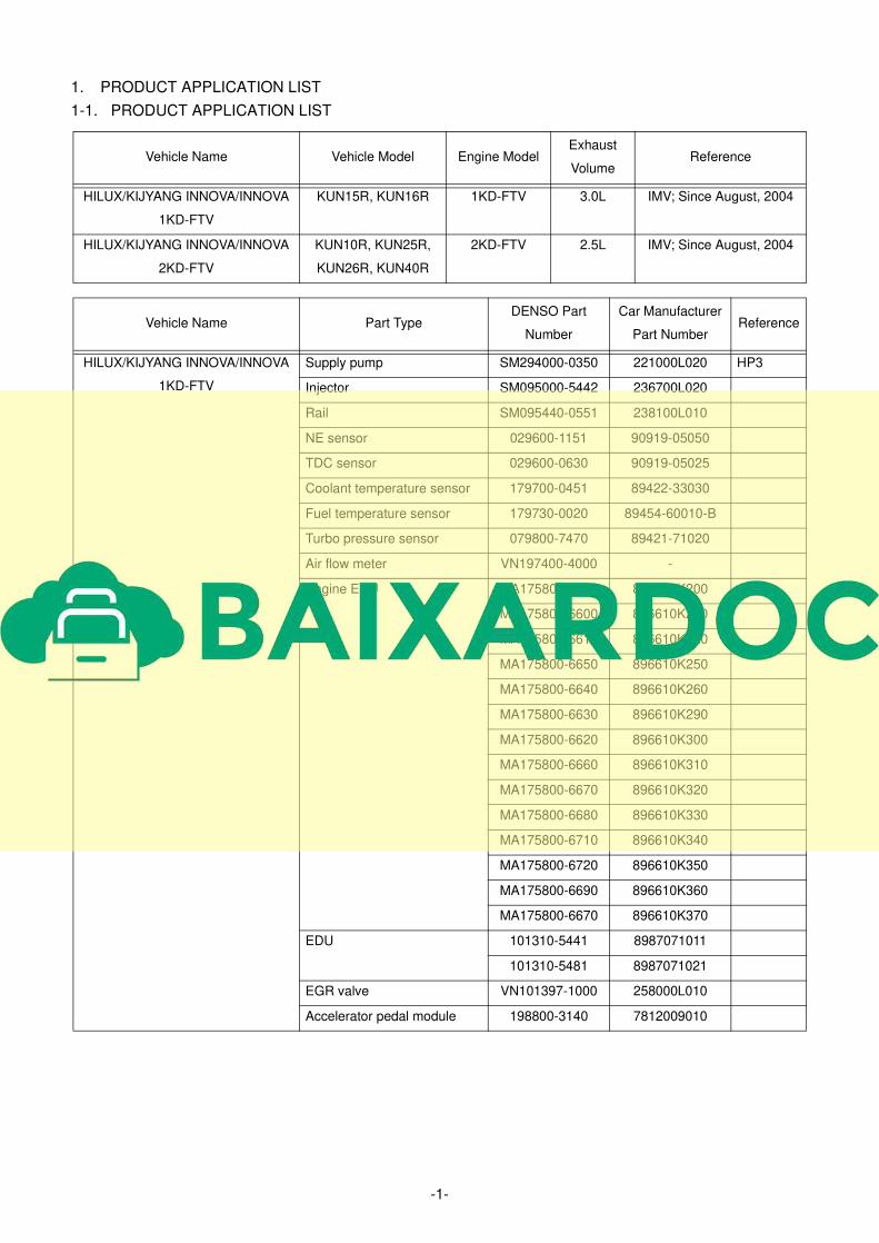
1. PRODUCT APPLICATION LIST
1-1. PRODUCT APPLICATION LIST
Vehicle Name Vehicle Model Engine ModelExhaust
VolumeReference
HILUX/KIJYANG INNOVA/INNOVA
1KD-FTV
KUN15R, KUN16R 1KD-FTV 3.0L IMV; Since August, 2004
HILUX/KIJYANG INNOVA/INNOVA
2KD-FTV
KUN10R, KUN25R,
KUN26R, KUN40R
2KD-FTV 2.5L IMV; Since August, 2004
Vehicle Name Part TypeDENSO Part
Number
Car Manufacturer
Part NumberReference
HILUX/KIJYANG INNOVA/INNOVA
1KD-FTV
Supply pump SM294000-0350 221000L020 HP3
Injector SM095000-5442 236700L020
Rail SM095440-0551 238100L010
NE sensor 029600-1151 90919-05050
TDC sensor 029600-0630 90919-05025
Coolant temperature sensor 179700-0451 89422-33030
Fuel temperature sensor 179730-0020 89454-60010-B
Turbo pressure sensor 079800-7470 89421-71020
Air flow meter VN197400-4000 -
Engine ECU MA175800-6590 896610K200
MA175800-6600 896610K210
MA175800-6610 896610K220
MA175800-6650 896610K250
MA175800-6640 896610K260
MA175800-6630 896610K290
MA175800-6620 896610K300
MA175800-6660 896610K310
MA175800-6670 896610K320
MA175800-6680 896610K330
MA175800-6710 896610K340
MA175800-6720 896610K350
MA175800-6690 896610K360
MA175800-6670 896610K370
EDU 101310-5441 8987071011
101310-5481 8987071021
EGR valve VN101397-1000 258000L010
Accelerator pedal module 198800-3140 7812009010
-2-
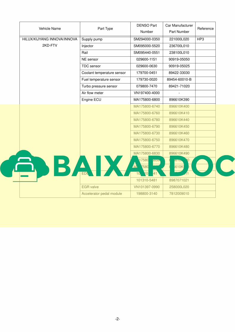
HILUX/KIJYANG INNOVA/INNOVA
2KD-FTV
Supply pump SM294000-0350 221000L020 HP3
Injector SM095000-5520 236700L010
Rail SM095440-0551 238100L010
NE sensor 029600-1151 90919-05050
TDC sensor 029600-0630 90919-05025
Coolant temperature sensor 179700-0451 89422-33030
Fuel temperature sensor 179730-0020 89454-60010-B
Turbo pressure sensor 079800-7470 89421-71020
Air flow meter VN197400-4000 -
Engine ECU MA175800-6800 896610K390
MA175800-6740 896610K400
MA175800-6760 896610K410
MA175800-6780 896610K440
MA175800-6790 896610K450
MA175800-6730 896610K460
MA175800-6750 896610K470
MA175800-6770 896610K480
MA175800-6830 896610K490
MA175800-6850 896610K500
MA175800-6870 896610K530
EDU 101310-5441 8987071011
101310-5481 8987071021
EGR valve VN101397-0990 258000L020
Accelerator pedal module 198800-3140 7812009010
Vehicle Name Part TypeDENSO Part
Number
Car Manufacturer
Part NumberReference
-3-
2. OUTLINE
2-1. OUTLINE OF SYSTEM
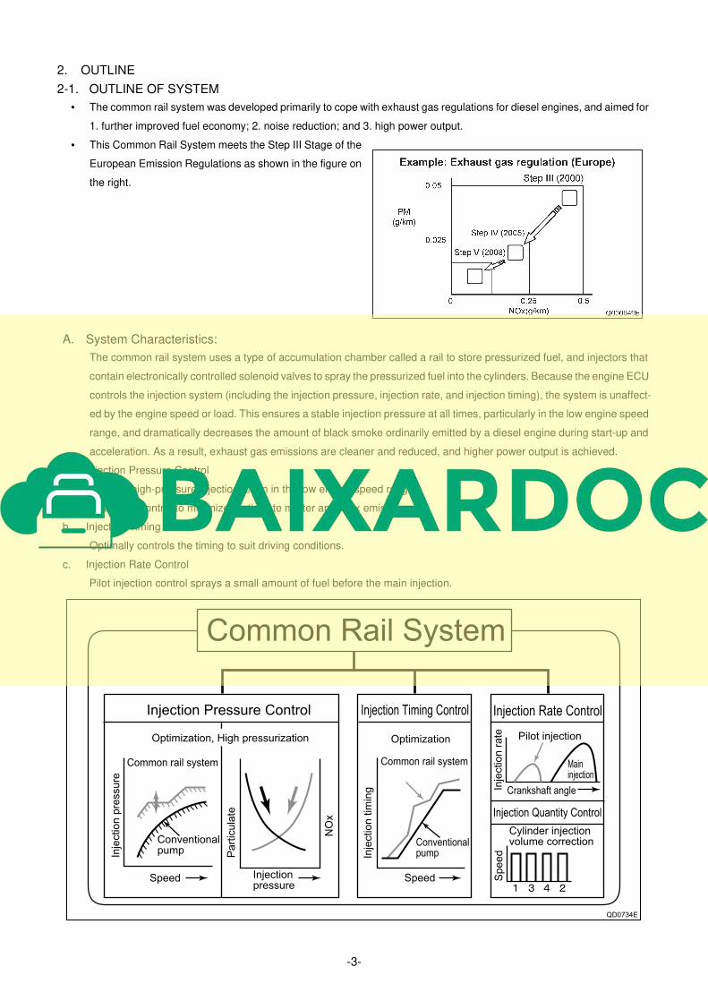
• The common rail system was developed primarily to cope with exhaust gas regulations for diesel engines, and aimed for
1. further improved fuel economy; 2. noise reduction; and 3. high power output.
• This Common Rail System meets the Step III Stage of the
European Emission Regulations as shown in the figure on
the right.
A. System Characteristics:
The common rail system uses a type of accumulation chamber called a rail to store pressurized fuel, and injectors that
contain electronically controlled solenoid valves to spray the pressurized fuel into the cylinders. Because the engine ECU
controls the injection system (including the injection pressure, injection rate, and injection timing), the system is unaffect-
ed by the engine speed or load. This ensures a stable injection pressure at all times, particularly in the low engine speed
range, and dramatically decreases the amount of black smoke ordinarily emitted by a diesel engine during start-up and
acceleration. As a result, exhaust gas emissions are cleaner and reduced, and higher power output is achieved.
a. Injection Pressure Control
• Enables high-pressure injection, even in the low engine speed range.
• Optimizes control to minimize particulate matter and NOx emissions.
b. Injection Timing Control
Optimally controls the timing to suit driving conditions.
c. Injection Rate Control
Pilot injection control sprays a small amount of fuel before the main injection.
Common Rail System
Optimization Pilot injection
Maininjection
Injection Pressure Control Injection Timing Control Injection Rate Control
Injection Quantity Control
Injectionpressure
Speed Speed
Crankshaft angle
Conventionalpump
Common rail system
Conventionalpump
Common rail system
Cylinder injectionvolume correction
Optimization, High pressurization
Inje
ctio
n p
ressu
re
Inje
ctio
n t
imin
g
Pa
rtic
ula
te
Sp
ee
dIn
jectio
n r
ate
QD0734E
NO
x
-4-
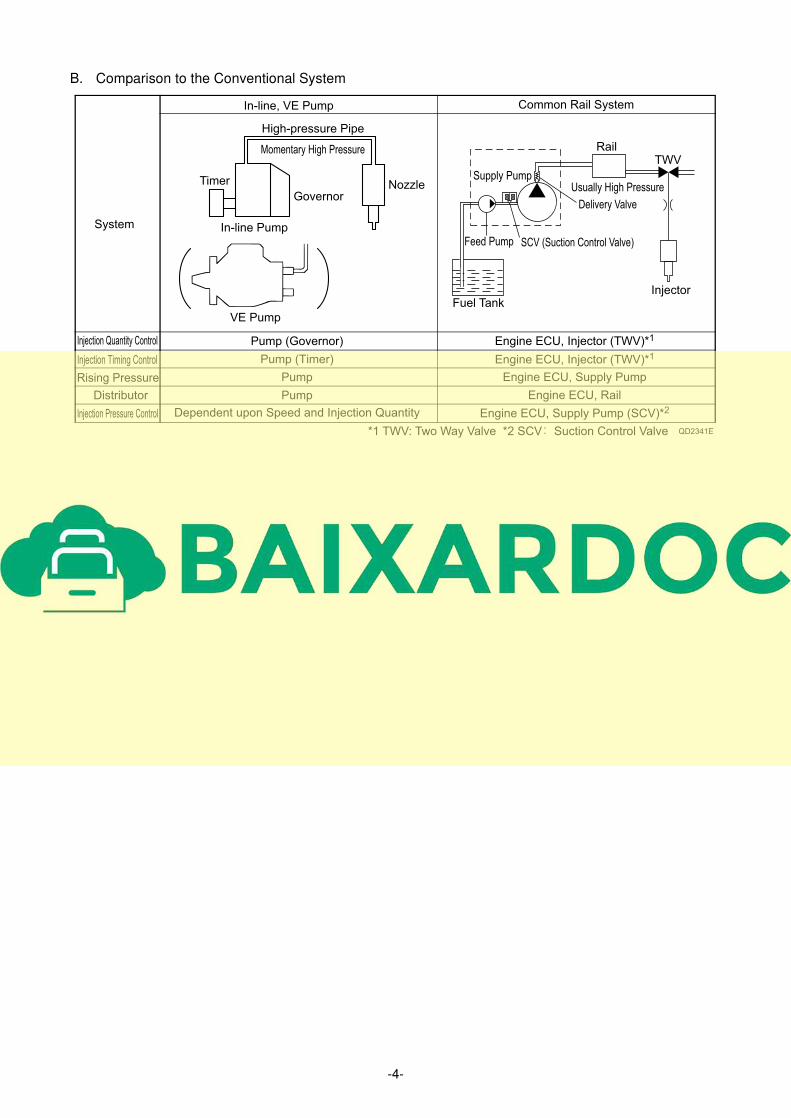
B. Comparison to the Conventional System
System
Common Rail System
Injection Quantity Control Pump (Governor)
Injection Timing Control Pump (Timer)
Rising Pressure Pump
Distributor Pump
Injection Pressure Control Dependent upon Speed and Injection Quantity
High-pressure Pipe
Momentary High Pressure
NozzleGovernor
Timer
In-line Pump
VE Pump
Rail
Usually High PressureSupply Pump
Injector
*1 TWV: Two Way Valve *2 SCV Suction Control Valve QD2341E
Feed Pump SCV (Suction Control Valve)
Delivery Valve
Fuel Tank
TWV
In-line, VE Pump
Engine ECU, Injector (TWV)*1
Engine ECU, Injector (TWV)*1
Engine ECU, Supply Pump
Engine ECU, Rail
Engine ECU, Supply Pump (SCV)*2
-5-
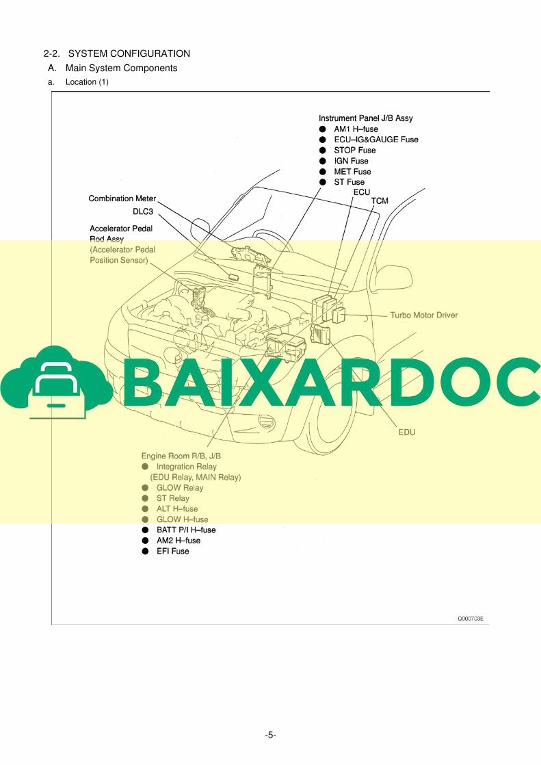
2-2. SYSTEM CONFIGURATION
A. Main System Components
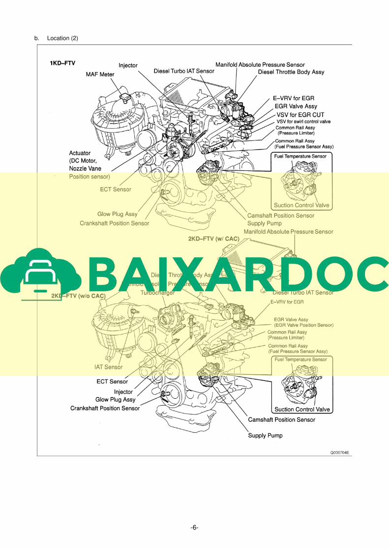
a. Location (1)
-6-
b. Location (2)
-7-
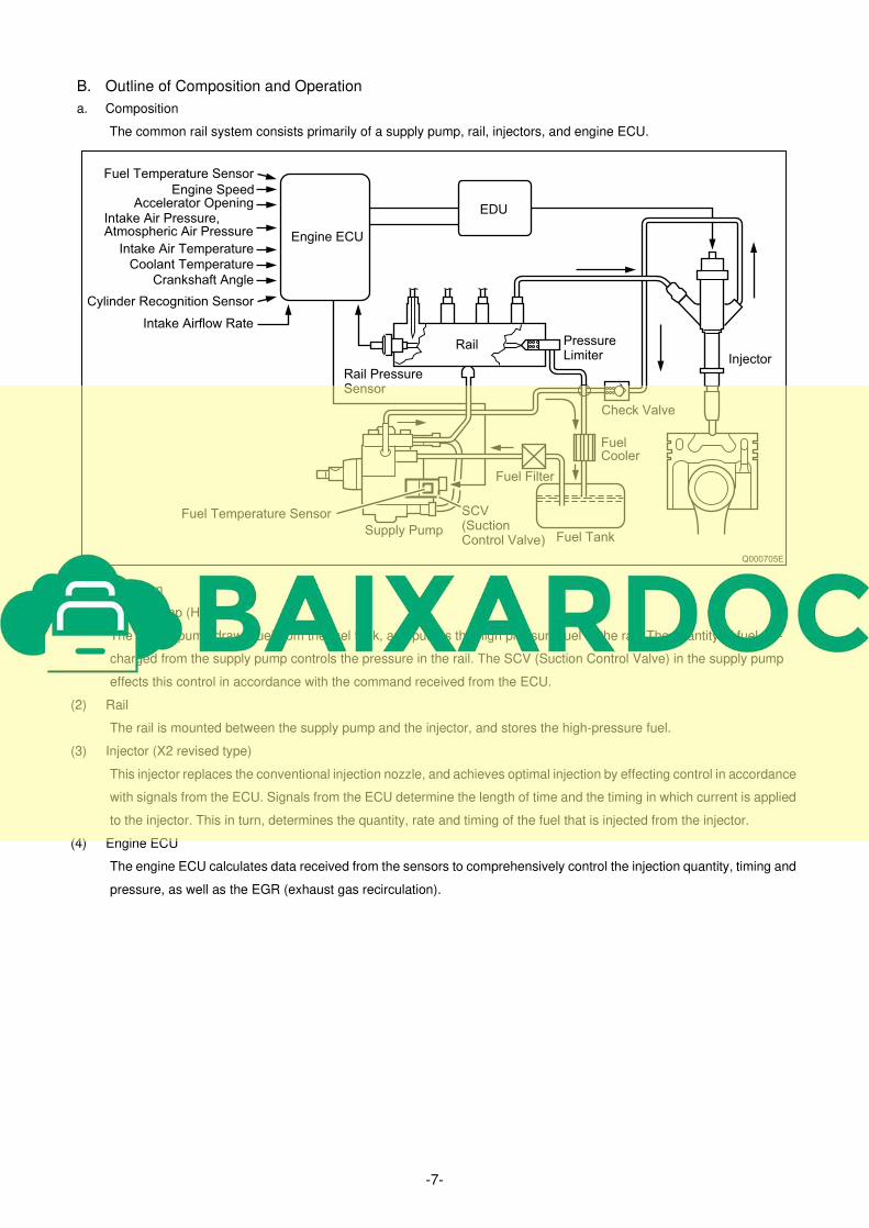
B. Outline of Composition and Operation
a. Composition
The common rail system consists primarily of a supply pump, rail, injectors, and engine ECU.
b. Operation
(1) Supply pump (HP3)
The supply pump draws fuel from the fuel tank, and pumps the high pressure fuel to the rail. The quantity of fuel dis-
charged from the supply pump controls the pressure in the rail. The SCV (Suction Control Valve) in the supply pump
effects this control in accordance with the command received from the ECU.
(2) Rail
The rail is mounted between the supply pump and the injector, and stores the high-pressure fuel.
(3) Injector (X2 revised type)
This injector replaces the conventional injection nozzle, and achieves optimal injection by effecting control in accordance
with signals from the ECU. Signals from the ECU determine the length of time and the timing in which current is applied
to the injector. This in turn, determines the quantity, rate and timing of the fuel that is injected from the injector.
(4) Engine ECU
The engine ECU calculates data received from the sensors to comprehensively control the injection quantity, timing and
pressure, as well as the EGR (exhaust gas recirculation).
Fuel Temperature Sensor
Accelerator OpeningIntake Air Pressure,Atmospheric Air Pressure
Intake Airflow Rate
Rail PressureSensor
Rail
EDU
Engine ECU
Fuel Temperature Sensor
Supply PumpFuel Tank
Fuel Filter
Fuel Cooler
Check Valve
Injector
PressureLimiter
SCV(SuctionControl Valve)
Intake Air Temperature
Coolant Temperature
Crankshaft Angle
Cylinder Recognition Sensor
Q000705E
Engine Speed
Copyright © 2022 FDOKUMEN

