


Bahasa
Halaman
Hukum

Data sheetH-2000-2289-13-B
NEWS BULLETIN
AVAILABLE NOW
● EasyProbe basic software
● Non-contact tool setting
● Software packages for a wide
range of controllers, please
see current list H-2000-2298 at
www.renishaw.comMachine tool productsBrowseMachine tool probing softwareDocumentsProbe software for machinetools - program selection list
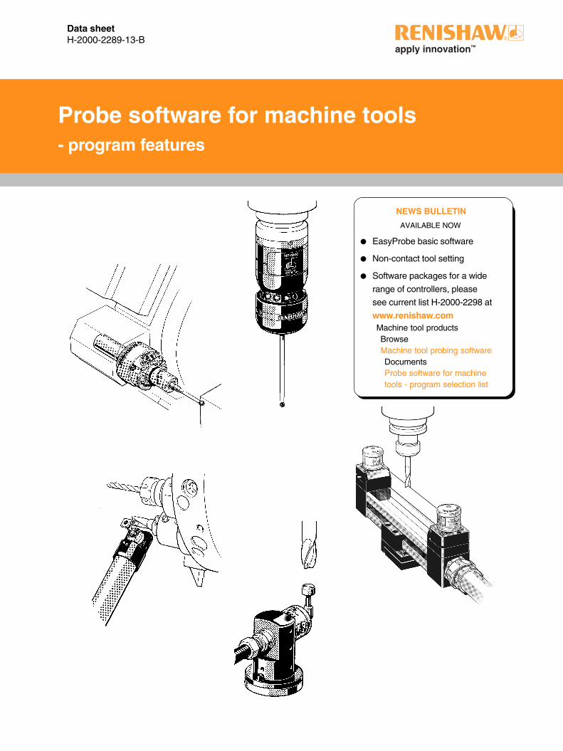
Probe software for machine tools- program features
2
Software features
Illustrations in this publication demonstrate typical applications and features.
They are not a complete specification for all software packages. Please refer
to the program manual supplied with each software package for specific details.
User documentation
Program manuals are supplied in the English language, but other languages
are available for some packages. When ordering, please state the language
of your choice. If available the additional documentation will also be supplied.
Tool setting software for lathes (including Y axis capability). 3
Inspection software for lathes (including Y axis capability). 4
EasyProbe inspection software for machining centres 6
EasyProbe software for machining centres provides simple and fast job
setup and measuring routines, for operators with minimal programming skill.
Standard inspection software for machining centres 8
Basic inspection/job setup software with the ability to set work offsets,
update tool offsets and print inspection results (where this control option
is available). Suitable for use by an operator or part programmer.
Additions to standard inspection software for machining centres 9
Several packages to enhance and extend the capabilities of the standard
inspection software. Includes vector measuring and angle measure, plus
a 5-axis option.
Inspection Plus software for machining centres 12
A totally integrated package of software that includes vector and angle
measure options, print options (where this control option is available)
and an extended range of cycles. Including an SPC cycle, 1 or 2 touch
probing option, tool offset compensation by percentage of error and
output data stored in an accessible variable stack.
Multi-axis inspection software for machining centres (NOT ILLUSTRATED) —
Orientate in alternative planes.
Rotating tool setting software for machining centres 17
Uses the industry standard TS27R probe, which suits the majority of
applications.
Non-contact tool setting software for machining centres 18
Preferred for applications using delicate tools, and other applications
where the probe must not obstruct the machine's working envelope.
Non-standard applications are available on request, subject to confirmation.
Page
Software overview
3
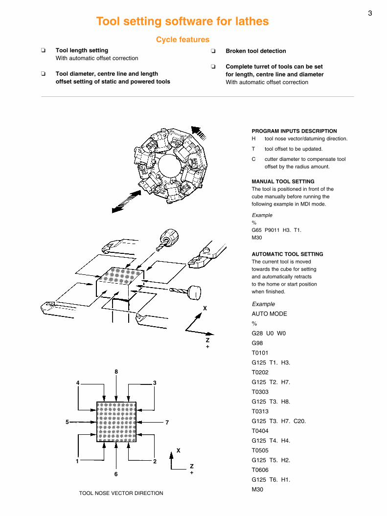
TOOL NOSE VECTOR DIRECTION
❏ Tool length settingWith automatic offset correction
❏ Tool diameter, centre line and lengthoffset setting of static and powered tools
❏ Broken tool detection
❏ Complete turret of tools can be setfor length, centre line and diameterWith automatic offset correction
Tool setting software for lathesCycle features
PROGRAM INPUTS DESCRIPTIONH tool nose vector/datuming direction.
T tool offset to be updated.
C cutter diameter to compensate tooloffset by the radius amount.
MANUAL TOOL SETTINGThe tool is positioned in front of thecube manually before running thefollowing example in MDI mode.
Example%G65 P9011 H3. T1.M30
AUTOMATIC TOOL SETTINGThe current tool is movedtowards the cube for settingand automatically retractsto the home or start positionwhen finished.
Example
AUTO MODE
%
G28 U0 W0
G98
T0101
G125 T1. H3.
T0202
G125 T2. H7.
T0303
G125 T3. H8.
T0313
G125 T3. H7. C20.
T0404
G125 T4. H4.
T0505
G125 T5. H2.
T0606
G125 T6. H1.
M30
5
1
3
8
4
6
2
7
Z+
X
Z+
X
4
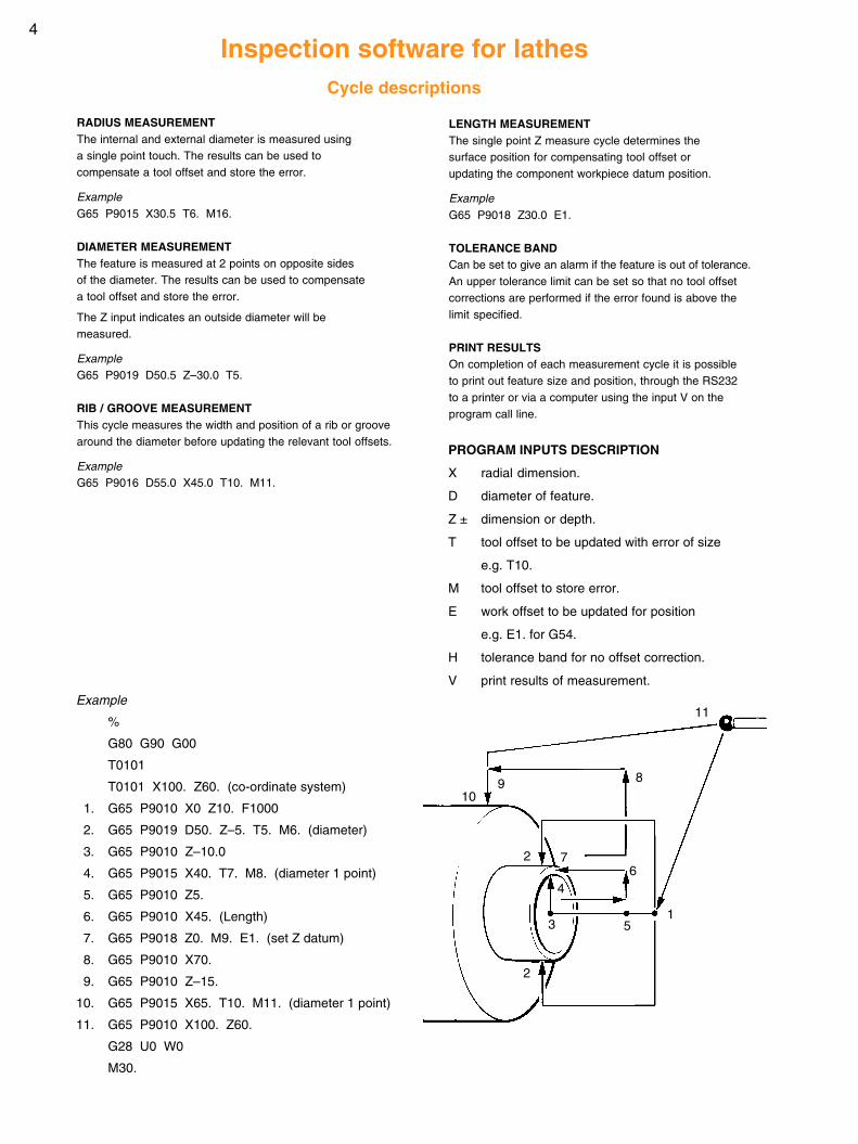
Example
%
G80 G90 G00
T0101
T0101 X100. Z60. (co-ordinate system)
1. G65 P9010 X0 Z10. F1000
2. G65 P9019 D50. Z–5. T5. M6. (diameter)
3. G65 P9010 Z–10.0
4. G65 P9015 X40. T7. M8. (diameter 1 point)
5. G65 P9010 Z5.
6. G65 P9010 X45. (Length)
7. G65 P9018 Z0. M9. E1. (set Z datum)
8. G65 P9010 X70.
9. G65 P9010 Z–15.
10. G65 P9015 X65. T10. M11. (diameter 1 point)
11. G65 P9010 X100. Z60.
G28 U0 W0
M30.
LENGTH MEASUREMENTThe single point Z measure cycle determines thesurface position for compensating tool offset orupdating the component workpiece datum position.
ExampleG65 P9018 Z30.0 E1.
TOLERANCE BANDCan be set to give an alarm if the feature is out of tolerance.An upper tolerance limit can be set so that no tool offsetcorrections are performed if the error found is above thelimit specified.
PRINT RESULTSOn completion of each measurement cycle it is possibleto print out feature size and position, through the RS232to a printer or via a computer using the input V on theprogram call line.
RADIUS MEASUREMENTThe internal and external diameter is measured usinga single point touch. The results can be used tocompensate a tool offset and store the error.
ExampleG65 P9015 X30.5 T6. M16.
DIAMETER MEASUREMENTThe feature is measured at 2 points on opposite sidesof the diameter. The results can be used to compensatea tool offset and store the error.
The Z input indicates an outside diameter will bemeasured.
ExampleG65 P9019 D50.5 Z–30.0 T5.
RIB / GROOVE MEASUREMENTThis cycle measures the width and position of a rib or groovearound the diameter before updating the relevant tool offsets.
ExampleG65 P9016 D55.0 X45.0 T10. M11.
Inspection software for lathesCycle descriptions
PROGRAM INPUTS DESCRIPTION
X radial dimension.
D diameter of feature.
Z ± dimension or depth.
T tool offset to be updated with error of size
e.g. T10.
M tool offset to store error.
E work offset to be updated for position
e.g. E1. for G54.
H tolerance band for no offset correction.
V print results of measurement.
11
8910
2
2
3
4
5
67
1
5
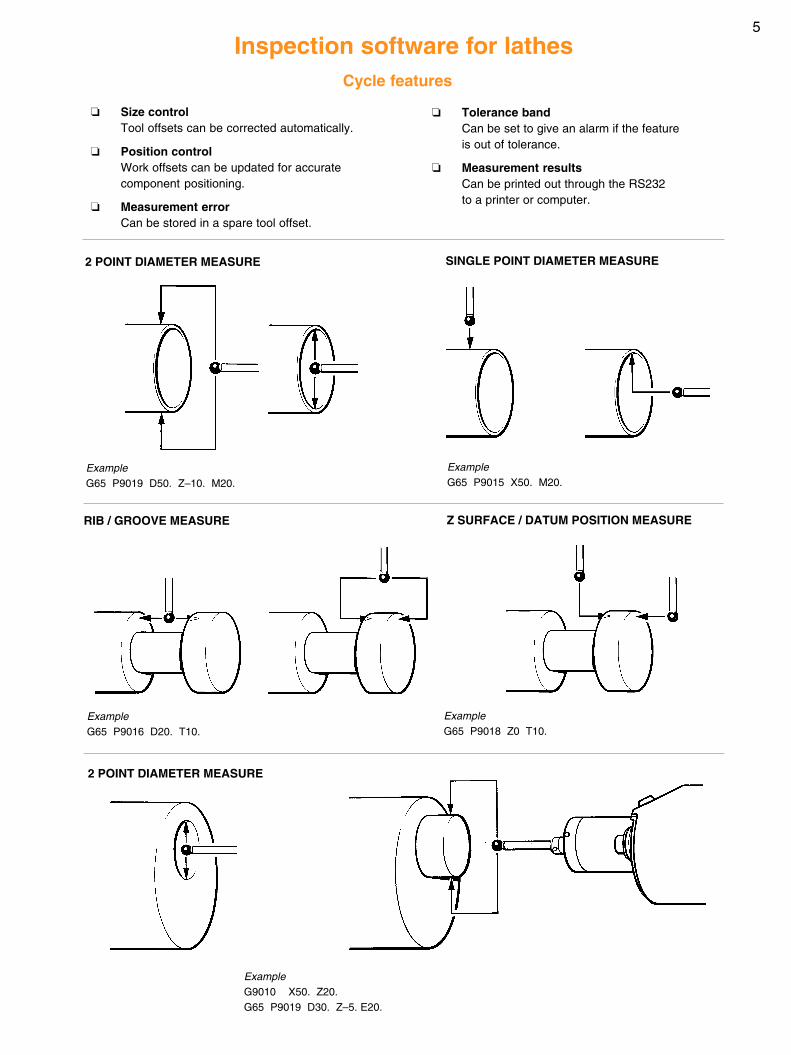
Inspection software for lathes
❏ Size controlTool offsets can be corrected automatically.
❏ Position controlWork offsets can be updated for accuratecomponent positioning.
❏ Measurement errorCan be stored in a spare tool offset.
RIB / GROOVE MEASURE
2 POINT DIAMETER MEASURE SINGLE POINT DIAMETER MEASURE
Z SURFACE / DATUM POSITION MEASURE
2 POINT DIAMETER MEASURE
Cycle features
ExampleG65 P9019 D50. Z–10. M20.
ExampleG9010 X50. Z20.G65 P9019 D30. Z–5. E20.
ExampleG65 P9016 D20. T10.
ExampleG65 P9018 Z0 T10.
ExampleG65 P9015 X50. M20.
❏ Tolerance bandCan be set to give an alarm if the featureis out of tolerance.
❏ Measurement resultsCan be printed out through the RS232to a printer or computer.
6
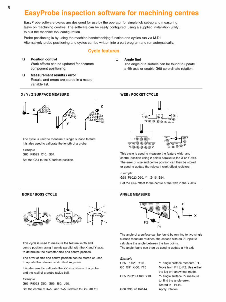
EasyProbe inspection software for machining centres
Cycle features
❏ Position controlWork offsets can be updated for accuratecomponent positioning.
❏ Measurement results / errorResults and errors are stored in a macrovariable list.
❏ Angle findThe angle of a surface can be found to updatea 4th axis or enable G68 co-ordinate rotation.
WEB / POCKET CYCLE
BORE / BOSS CYCLE
This cycle is used to measure the feature width andcentre position using 4 points parallel with the X and Y axis,to determine the diameter size and centre position.
The error of size and centre position can be stored or usedto update the relevant work offset registers.
It is also used to calibrate the XY axis offsets of a probeand the radii of a probe stylus ball.
ExampleG65 P9023 D50. S59. I50. J50.
Set the centre at X=50 and Y=50 relative to G59 X0 Y0
This cycle is used to measure the feature width andcentre position using 2 points parallel to the X or Y axis.The error of size and centre position can then be storedor used to update the relevant work offset registers.
ExampleG65 P9023 D50. Y1. Z-15. S54.
Set the G54 offset to the centre of the web in the Y axis.
X / Y / Z SURFACE MEASURE
The cycle is used to measure a single surface feature.It is also used to calibrate the length of a probe.
ExampleG65 P9023 X10. S54.
Set the G54 to the X surface position.
X
Y
Z
ANGLE MEASURE
Aa
X
Y
EasyProbe software cycles are designed for use by the operator for simple job set-up and measuringtasks on machining centres. The software can be easily configured, using a supplied installation utility,to suit the machine tool configuration.
Probe positioning is by using the machine handwheel/jog function and cycles run via M.D.I.Alternatively probe positioning and cycles can be written into a part program and run automatically.
The angle of a surface can be found by running to two singlesurface measure routines, the second with an 'A' input tocalculate the angle between the two points.The angle found can then be used to update a 4th axis
ExampleG65 P9023 Y10. Y- single surface measure P1.G0 G91 X-50. Y15 Move from P1 to P2. Use either
the jog or handwheel mode.G65 P9023 A160. Y10. Y- single surface P2 measure
to find the angle error.Stored in #144.
G68 G90 X0.R#144 Apply rotation
P2P1
7
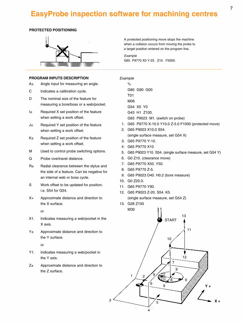
Example
%
G80 G90 G00
T01
M06
G54 X0 Y0
G43 H1 Z100.
G65 P9023 M1. (switch on probe)
1. G65 P9770 X-10.0 Y10.0 Z-5.0 F1000 (protected move)
2. G65 P9023 X10.0 S54.
(single surface measure, set G54 X)
3. G65 P9770 Y-10.
4. G65 P9770 X10
5. G65 P9023 Y10. S54. (single surface measure, set G54 Y)
6. G0 Z10. (clearance move)
7. G65 P9770 X50. Y50.
8. G65 P9770 Z-5.
9. G65 P9023 D40. H0.2 (bore measure)
10. G0 Z20.0.
11. G65 P9770 Y90.
12. G65 P9023 Z-20. S54. K5.
(single surface measure, set G54 Z)
13. G28 Z100
M30
EasyProbe inspection software for machining centres
START
11
13
10
12
3
1 2
4
99
8
9
9
Y +
X +
7
A protected positioning move stops the machinewhen a collision occurs from moving the probe toa target position entered on the program line.
ExampleG65 P9770 X0 Y-25. Z10. F5000.
PROTECTED POSITIONING
PROGRAM INPUTS DESCRIPTION
A± Angle input for measuring an angle.
C Indicates a calibration cycle.
D The nominal size of the feature for
measuring a bore/boss or a web/pocket.
I± Required X set position of the feature
when setting a work offset.
J± Required Y set position of the feature
when setting a work offset.
K± Required Z set position of the feature
when setting a work offset.
M Used to control probe switching options.
Q Probe overtravel distance.
R± Radial clearance between the stylus and
the side of a feature. Can be negative for
an internal web or boss cycle.
S Work offset to be updated for position.
i.e. S54 for G54.
X+ Approximate distance and direction to
the X surface.
or
X1. Indicates measuring a web/pocket in the
X axis.
Y± Approximate distance and direction to
the Y surface.
or
Y1. Indicates measuring a web/pocket in
the Y axis.
Z± Approximate distance and direction to
the Z surface.
5
6
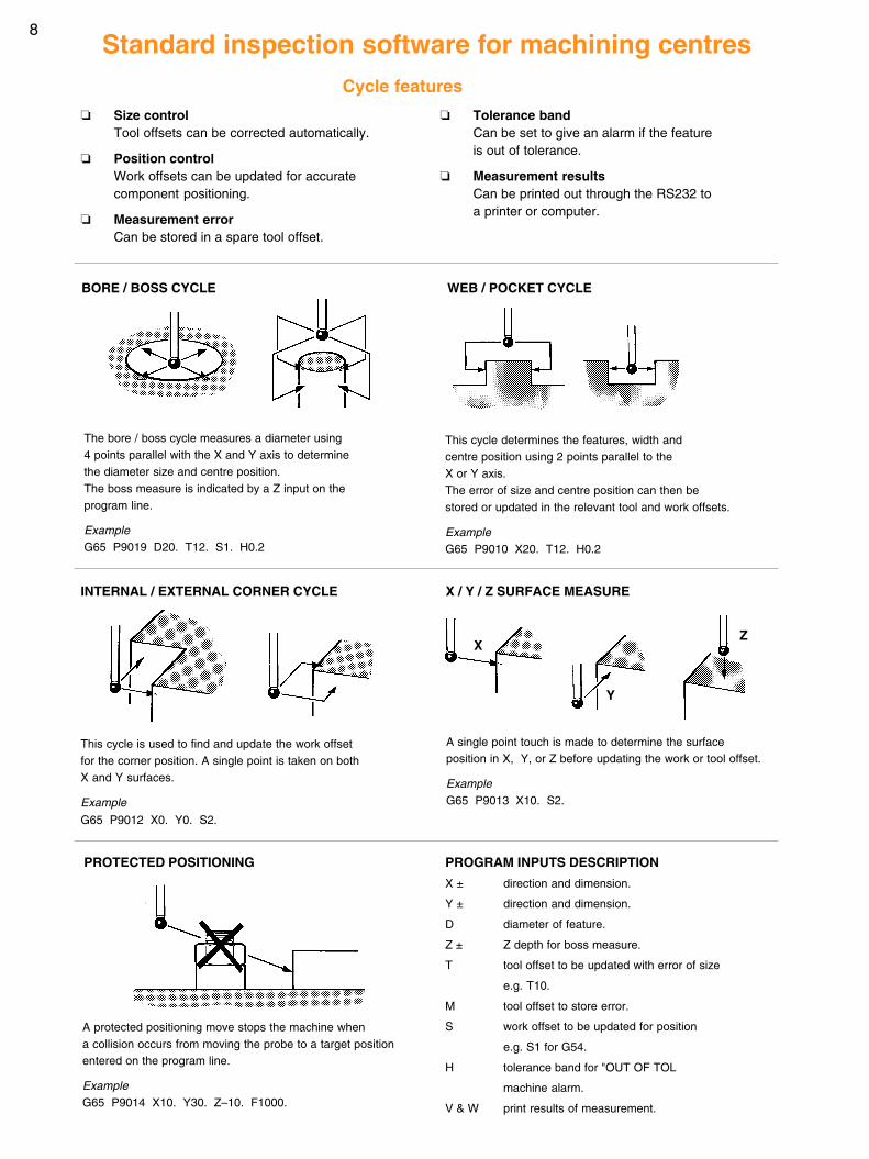
8Standard inspection software for machining centres
Cycle features
❏ Size controlTool offsets can be corrected automatically.
❏ Position controlWork offsets can be updated for accuratecomponent positioning.
❏ Measurement errorCan be stored in a spare tool offset.
❏ Tolerance bandCan be set to give an alarm if the featureis out of tolerance.
❏ Measurement resultsCan be printed out through the RS232 toa printer or computer.
A protected positioning move stops the machine whena collision occurs from moving the probe to a target positionentered on the program line.
ExampleG65 P9014 X10. Y30. Z–10. F1000.
WEB / POCKET CYCLE
PROTECTED POSITIONING
BORE / BOSS CYCLE
The bore / boss cycle measures a diameter using4 points parallel with the X and Y axis to determinethe diameter size and centre position.The boss measure is indicated by a Z input on theprogram line.
ExampleG65 P9019 D20. T12. S1. H0.2
This cycle determines the features, width andcentre position using 2 points parallel to theX or Y axis.The error of size and centre position can then bestored or updated in the relevant tool and work offsets.
ExampleG65 P9010 X20. T12. H0.2
PROGRAM INPUTS DESCRIPTION
X ± direction and dimension.
Y ± direction and dimension.
D diameter of feature.
Z ± Z depth for boss measure.
T tool offset to be updated with error of size
e.g. T10.
M tool offset to store error.
S work offset to be updated for position
e.g. S1 for G54.
H tolerance band for "OUT OF TOL
machine alarm.
V & W print results of measurement.
INTERNAL / EXTERNAL CORNER CYCLE X / Y / Z SURFACE MEASURE
This cycle is used to find and update the work offsetfor the corner position. A single point is taken on bothX and Y surfaces.
Example
G65 P9012 X0. Y0. S2.
A single point touch is made to determine the surfaceposition in X, Y, or Z before updating the work or tool offset.
ExampleG65 P9013 X10. S2.
X
Y
Z
9
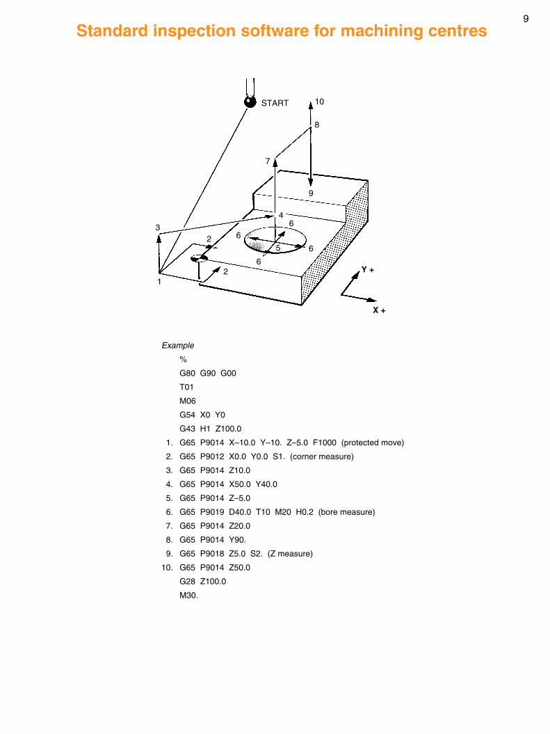
Example
%
G80 G90 G00
T01
M06
G54 X0 Y0
G43 H1 Z100.0
1. G65 P9014 X–10.0 Y–10. Z–5.0 F1000 (protected move)
2. G65 P9012 X0.0 Y0.0 S1. (corner measure)
3. G65 P9014 Z10.0
4. G65 P9014 X50.0 Y40.0
5. G65 P9014 Z–5.0
6. G65 P9019 D40.0 T10 M20 H0.2 (bore measure)
7. G65 P9014 Z20.0
8. G65 P9014 Y90.
9. G65 P9018 Z5.0 S2. (Z measure)
10. G65 P9014 Z50.0
G28 Z100.0
M30.
Standard inspection software for machining centres
START
8
10
7
9
3
1
2
2
66
5
6
6
Y +
X +
4
10
Aa
X
Y
X
Z
Y
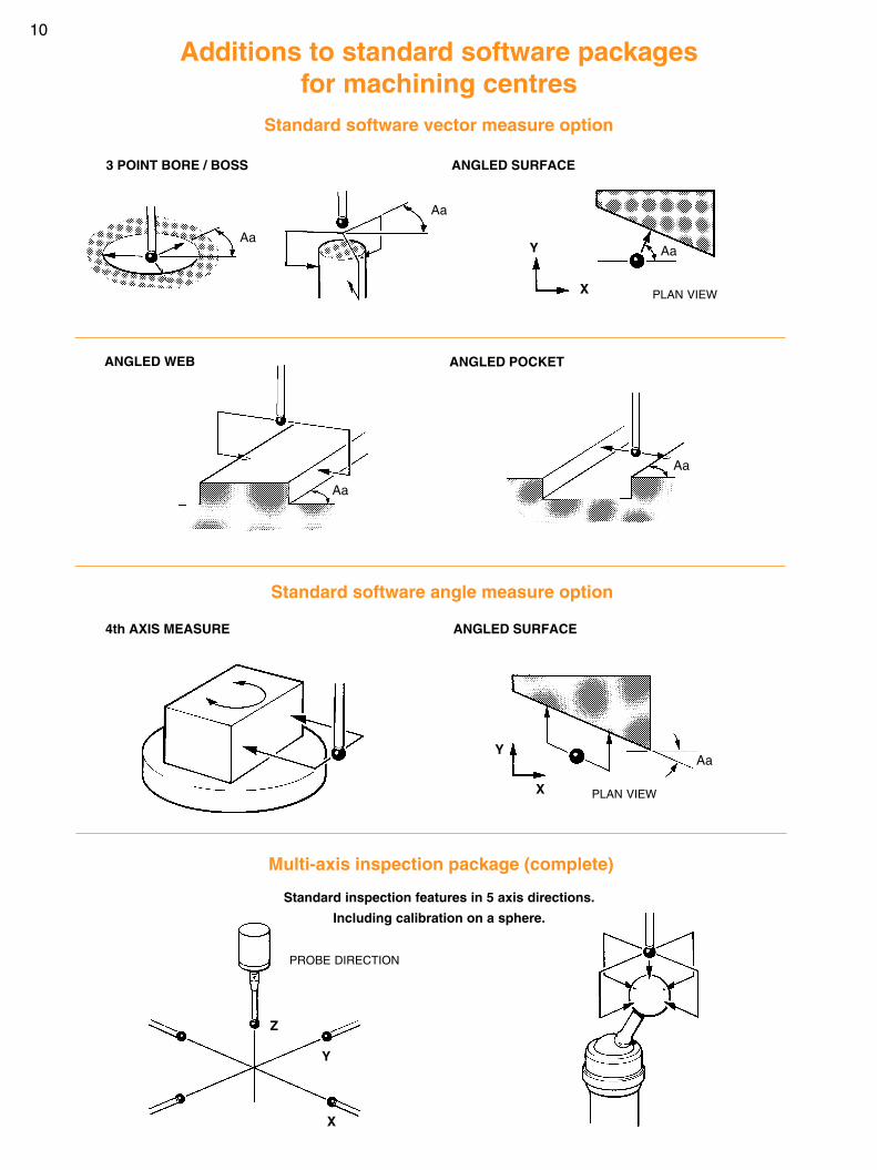
Standard software vector measure option
Standard inspection features in 5 axis directions.
Including calibration on a sphere.
3 POINT BORE / BOSS ANGLED SURFACE
Additions to standard software packagesfor machining centres
PLAN VIEW
PLAN VIEW
PROBE DIRECTION
ANGLED WEB ANGLED POCKET
Standard software angle measure option
4th AXIS MEASURE ANGLED SURFACE
Multi-axis inspection package (complete)
Aa
Aa
Aa
Y
X
Aa
Aa
11
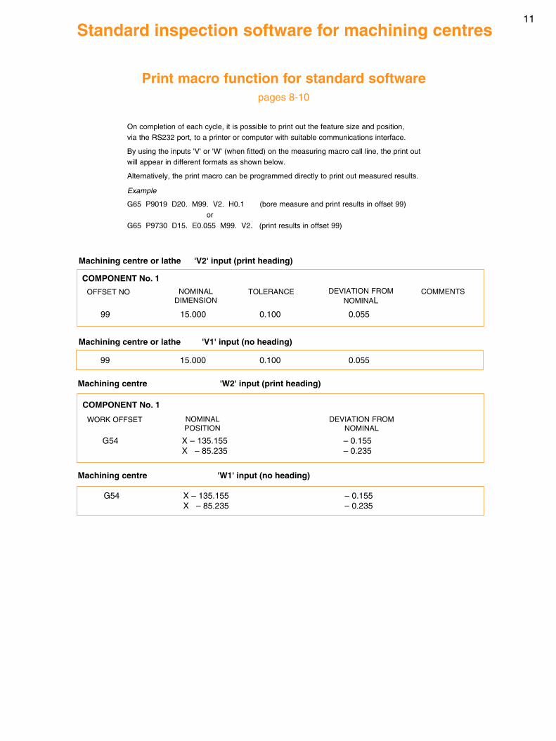
G54 X – 135.155 – 0.155X – 85.235 – 0.235
COMPONENT No. 1
OFFSET NO
99 15.000 0.100 0.055
NOMINALDIMENSION
TOLERANCE DEVIATION FROMNOMINAL
COMMENTS
Standard inspection software for machining centres
Print macro function for standard softwarepages 8-10
Machining centre or lathe 'V2' input (print heading)
Machining centre 'W1' input (no heading)
On completion of each cycle, it is possible to print out the feature size and position,via the RS232 port, to a printer or computer with suitable communications interface.
By using the inputs 'V' or 'W' (when fitted) on the measuring macro call line, the print outwill appear in different formats as shown below.
Alternatively, the print macro can be programmed directly to print out measured results.
Example
G65 P9019 D20. M99. V2. H0.1 (bore measure and print results in offset 99)or
G65 P9730 D15. E0.055 M99. V2. (print results in offset 99)
99 15.000 0.100 0.055
Machining centre or lathe 'V1' input (no heading)
COMPONENT No. 1
WORK OFFSET NOMINALPOSITION
DEVIATION FROMNOMINAL
G54 X – 135.155 – 0.155X – 85.235 – 0.235
Machining centre 'W2' input (print heading)
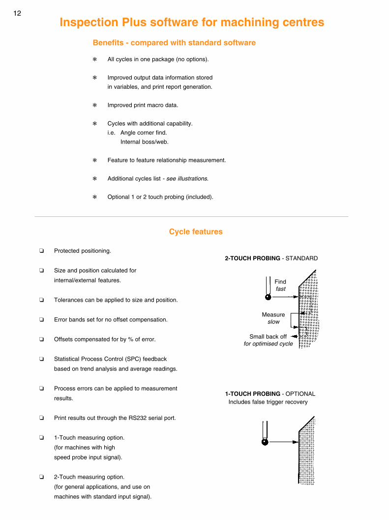
12
Inspection Plus software for machining centres
❃ All cycles in one package (no options).
❃ Improved output data information stored
in variables, and print report generation.
❃ Improved print macro data.
❃ Cycles with additional capability.
i.e. Angle corner find.
Internal boss/web.
❃ Feature to feature relationship measurement.
❃ Additional cycles list - see illustrations.
❃ Optional 1 or 2 touch probing (included).
Benefits - compared with standard software
1-TOUCH PROBING - OPTIONAL
2-TOUCH PROBING - STANDARD❏ Protected positioning.
❏ Size and position calculated for
internal/external features.
❏ Tolerances can be applied to size and position.
❏ Error bands set for no offset compensation.
❏ Offsets compensated for by % of error.
❏ Statistical Process Control (SPC) feedback
based on trend analysis and average readings.
❏ Process errors can be applied to measurement
results.
❏ Print results out through the RS232 serial port.
❏ 1-Touch measuring option.
(for machines with high
speed probe input signal).
❏ 2-Touch measuring option.
(for general applications, and use on
machines with standard input signal).
Cycle features
Includes false trigger recovery
Small back offfor optimised cycle
Measureslow
Findfast
13
Inspection Plus software for machining centres
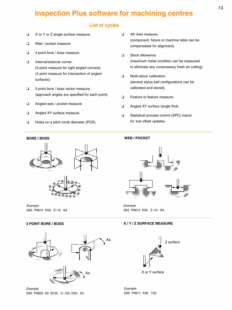
❏ X or Y or Z single surface measure.
❏ Web / pocket measure.
❏ 4 point bore / boss measure.
❏ Internal/external corner.
(3 point measure for right angled corners).
(4 point measure for intersection of angled
surfaces).
❏ 3 point bore / boss vector measure.
(approach angles are specified for each point).
❏ Angled web / pocket measure.
❏ Angled XY surface measure.
❏ Holes on a pitch circle diameter (PCD).
❏ 4th Axis measure.
(component, fixture or machine table can be
compensated for alignment).
❏ Stock allowance.
(maximum metal condition can be measured
to eliminate any unnecessary fresh air cutting).
❏ Multi-stylus calibration.
(several stylus ball configurations can be
calibrated and stored).
❏ Feature to feature measure.
❏ Angled XY surface (angle find).
❏ Statistical process control (SPC) macro
for tool offset updates.
List of cycles
3 POINT BORE / BOSS
BORE / BOSS
ExampleG65 P9814 D50. Z–10. S4.
ExampleG65 P9823 A0 B120. C–120. D50. S4.
WEB / POCKET
X / Y / Z SURFACE MEASURE
ExampleG65 P9812 X50. Z–10. S4.
ExampleG65 P9811 X30. T20.
Aa
AaZ surface
X or Y surface
14
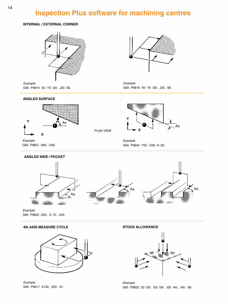
ANGLED WEB / POCKET
ExampleG65 P9822 D50. Z–10. A45.
4th AXIS MEASURE CYCLE STOCK ALLOWANCE
ExampleG65 P9817 X100. Z50. S1.
ExampleG65 P9820 Z0 I20. I20 I30. J30 I40. J40. S6.
INTERNAL / EXTERNAL CORNER
ANGLED SURFACE
ExampleG65 P9816 X0 Y0 I20. J20. S6.
ExampleG65 P9815 X0 Y0 I20. J20. S6.
ExampleG65 P9821 A60. D30.
Example
G65 P9843 Y50. D30. A–30.
Aa
X
Y Aa
PLAN VIEW
Inspection Plus software for machining centres
Aa
Aa
Aa
Y
X

15
Inspection Plus software for machining centres
BORE / BOSS ON P.C.D. CYCLE FEATURE TO FEATURE
ExampleG65 P9810 X0 Y0 F5000.G65 P9814 D20.G65 P9834G65 P9810 X50.G65 P9814 D20.G65 P9834 X50.
ExampleG65 P9819 C200. D25. K–10. B4. A45.
Aa
Dd
Xx
Yy
P.C.D.
Inspection Plus software for MP700 probeInspection Plus software for the MP700 probe comprises
the cycles and features described on pages 5, 6, 7 and 8
with the additional cycles and features shown below.
❏ Calibration on a sphere.
❏ XYZ single surface measurement(3D measure).
❏ 3D measuring application capability.
❏ Simplified calibration and calculationroutines based on a constant stylusball radius for all directions.
This feature is unique to the MP700 probe.
Additional featuresAdditional cycles
SPHERE CALIBRATION X / Y / Z SINGLE SURFACE MEASURE - 3D MEASURE
ExampleG65 P9821 X50. Y30. Z50. C1.
ExampleG65 P9804 X200. Y100. Z50. D30. S6. T20.
ZY
X
X Y and Z
Aa
16
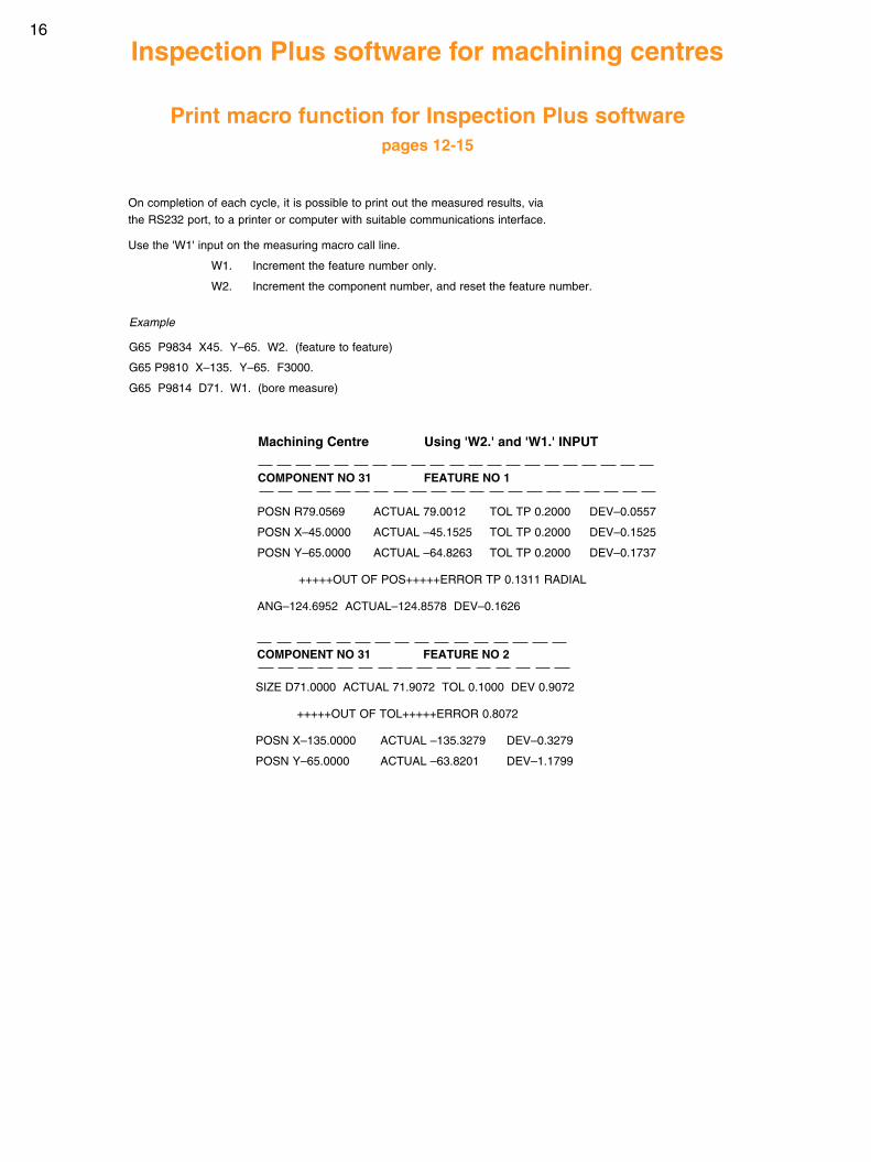
SIZE D71.0000 ACTUAL 71.9072 TOL 0.1000 DEV 0.9072
+++++OUT OF TOL+++++ERROR 0.8072
POSN X–135.0000 ACTUAL –135.3279 DEV–0.3279
POSN Y–65.0000 ACTUAL –63.8201 DEV–1.1799
POSN R79.0569 ACTUAL 79.0012 TOL TP 0.2000 DEV–0.0557
POSN X–45.0000 ACTUAL –45.1525 TOL TP 0.2000 DEV–0.1525
POSN Y–65.0000 ACTUAL –64.8263 TOL TP 0.2000 DEV–0.1737
+++++OUT OF POS+++++ERROR TP 0.1311 RADIAL
ANG–124.6952 ACTUAL–124.8578 DEV–0.1626
Example
G65 P9834 X45. Y–65. W2. (feature to feature)
G65 P9810 X–135. Y–65. F3000.
G65 P9814 D71. W1. (bore measure)
On completion of each cycle, it is possible to print out the measured results, viathe RS232 port, to a printer or computer with suitable communications interface.
Use the 'W1' input on the measuring macro call line.
W1. Increment the feature number only.
W2. Increment the component number, and reset the feature number.
Print macro function for Inspection Plus softwarepages 12-15
Machining Centre Using 'W2.' and 'W1.' INPUT
COMPONENT NO 31 FEATURE NO 1
COMPONENT NO 31 FEATURE NO 2
Inspection Plus software for machining centres
17
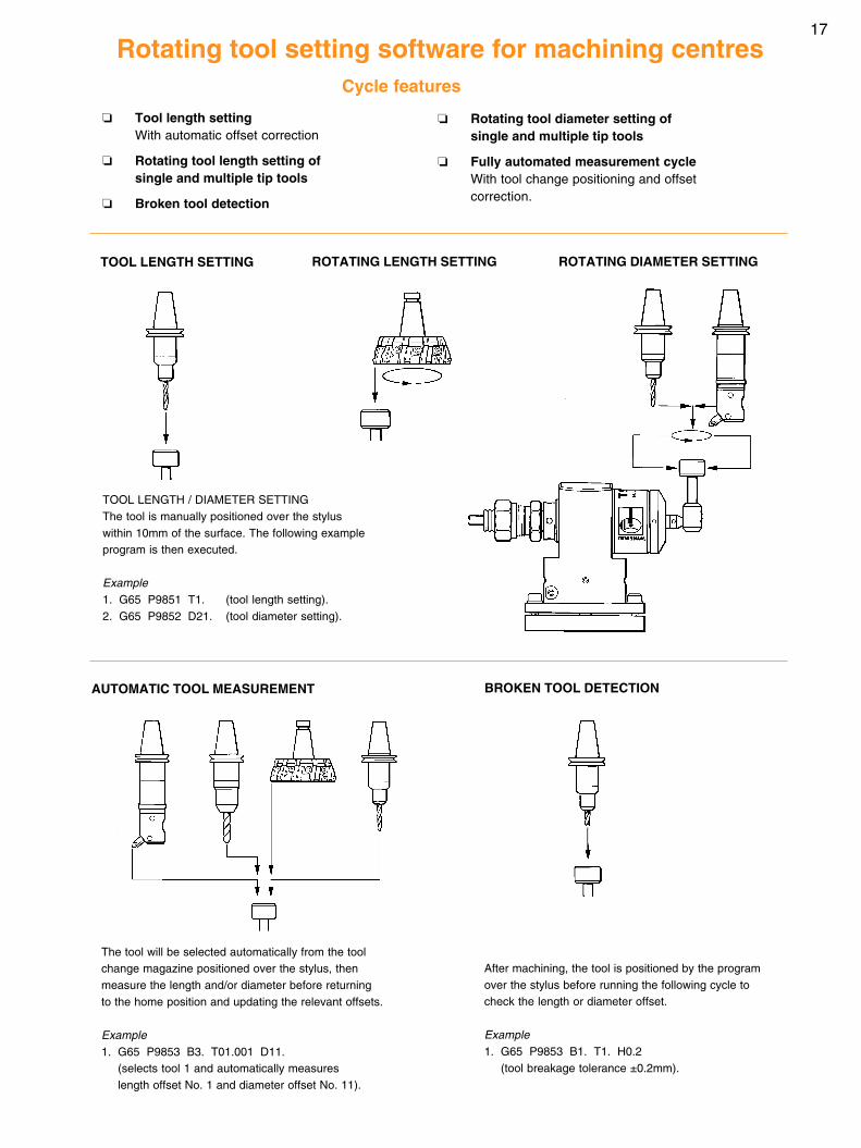
After machining, the tool is positioned by the programover the stylus before running the following cycle tocheck the length or diameter offset.
Example1. G65 P9853 B1. T1. H0.2
(tool breakage tolerance ±0.2mm).
❏ Rotating tool diameter setting ofsingle and multiple tip tools
❏ Fully automated measurement cycleWith tool change positioning and offsetcorrection.
❏ Tool length settingWith automatic offset correction
❏ Rotating tool length setting ofsingle and multiple tip tools
❏ Broken tool detection
Cycle features
ROTATING LENGTH SETTING ROTATING DIAMETER SETTINGTOOL LENGTH SETTING
Rotating tool setting software for machining centres
TOOL LENGTH / DIAMETER SETTINGThe tool is manually positioned over the styluswithin 10mm of the surface. The following exampleprogram is then executed.
Example1. G65 P9851 T1. (tool length setting).2. G65 P9852 D21. (tool diameter setting).
BROKEN TOOL DETECTION
The tool will be selected automatically from the toolchange magazine positioned over the stylus, thenmeasure the length and/or diameter before returningto the home position and updating the relevant offsets.
Example1. G65 P9853 B3. T01.001 D11.
(selects tool 1 and automatically measureslength offset No. 1 and diameter offset No. 11).
AUTOMATIC TOOL MEASUREMENT
18
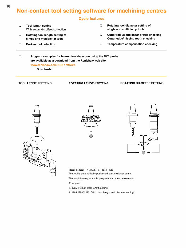
Cycle features
ROTATING LENGTH SETTING ROTATING DIAMETER SETTINGTOOL LENGTH SETTING
Non-contact tool setting software for machining centres
TOOL LENGTH / DIAMETER SETTINGThe tool is automatically positioned over the laser beam.
The two following example programs can then be executed.
Examples
1. G65 P9862 (tool length setting).
2. G65 P9862 B3. D31. (tool length and diameter setting).
❏ Rotating tool diameter setting ofsingle and multiple tip tools
❏ Cutter radius and linear profile checkingCutter edge/missing tooth checking
❏ Temperature compensation checking
❏ Tool length settingWith automatic offset correction
❏ Rotating tool length setting ofsingle and multiple tip tools
❏ Broken tool detection
❏ Program examples for broken tool detection using the NC2 probeare available as a download from the Renishaw web site
www.renishaw.com/NC2 software
Downloads
19
Non-contact tool setting software for machining centres
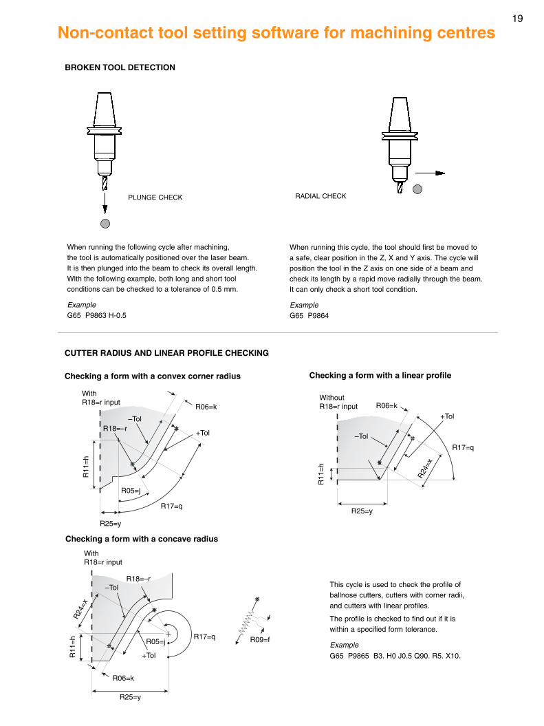
BROKEN TOOL DETECTION
When running the following cycle after machining,the tool is automatically positioned over the laser beam.It is then plunged into the beam to check its overall length.With the following example, both long and short toolconditions can be checked to a tolerance of 0.5 mm.
ExampleG65 P9863 H-0.5
CUTTER RADIUS AND LINEAR PROFILE CHECKING
RADIAL CHECK
When running this cycle, the tool should first be moved toa safe, clear position in the Z, X and Y axis. The cycle willposition the tool in the Z axis on one side of a beam andcheck its length by a rapid move radially through the beam.It can only check a short tool condition.
ExampleG65 P9864
PLUNGE CHECK
This cycle is used to check the profile ofballnose cutters, cutters with corner radii,and cutters with linear profiles.
The profile is checked to find out if it iswithin a specified form tolerance.
Example
G65 P9865 B3. H0 J0.5 Q90. R5. X10.
Checking a form with a convex corner radius
Checking a form with a concave radius
Checking a form with a linear profile
+Tol
WithoutR18=r input
R11
=h
R25=y
–Tol
R06=k
R17=q
R24
=x
R09=f
WithR18=r input
R24
=x
R11
=h
R06=k
R25=y
+Tol
–TolR18=–r
R17=qR05=j
WithR18=r input
R25=y
R17=q
+Tol
–Tol
R05=j
R18=–r
R11
=h
R06=k

Renishaw plcNew Mills, Wotton-under-Edge,Gloucestershire GL12 8JRUnited Kingdom
T +44 (0)1453 524524F +44 (0)1453 524901E [email protected]
www.renishaw.com
*H-2000-2289-13*© 2004 Renishaw plc Renishaw reserves the right to change specifications without notice Issued 1104 Part no. H-2000-2289-13-B
For worldwide contact details,please visit our main web site at
www.renishaw.com/contact
Copyright © 2022 FDOKUMEN

