


Bahasa
Halaman
Hukum


Model AT-C2.5 Machine Code: D086/D087
Field Service Manual
1 November, 2010


Important Safety Notices
Prevention of Physical Injury
1. Before disassembling or assembling parts of the copier and peripherals, make sure that the copierpower cord is unplugged.
2. The wall outlet should be near the copier and easily accessible.
3. If any adjustment or operation check has to be made with exterior covers off or open while the mainswitch is turned on, keep hands away from electrified or mechanically driven components.
4. The copier drives some of its components when it completes the warm-up period. Be careful to keephands away from the mechanical and electrical components as the copier starts operation.
5. The inside and the metal parts of the fusing unit become extremely hot while the copier is operating.Be careful to avoid touching those components with your bare hands.
Health Safety Conditions
1. Toner and developer are non-toxic, but if you get either of them in your eyes by accident, it may causetemporary eye discomfort. Immediately wash eyes with plenty of water. If unsuccessful, get medicalattention.
2. The copier, which use high voltage power source, can generate ozone gas. High ozone density isharmful to human health. Therefore, the machine must be installed in a well-ventilated room.
Observance of Electrical Safety Standards
The copier and its peripherals must be serviced by a customer service representative who has completedthe training course on those models.
• Keep the machine away from flammable liquids, gases, and aerosols. A fire or an explosion mightoccur.
• The Controller board on this machine contains a lithium battery. The danger of explosion exists if abattery of this type is incorrectly replaced. Replace only with the same or an equivalent typerecommended by the manufacturer. Discard batteries in accordance with the manufacturer'sinstructions and local regulations.
• The optional fax and memory expansion units contain lithium batteries, which can explode if replacedincorrectly. Replace only with the same or an equivalent type recommended by the manufacturer. Do
1

not recharge or burn the batteries. Used batteries must be handled in accordance with localregulations.
Safety and Ecological Notes for Disposal
1. Do not incinerate toner bottles or used toner. Toner dust may ignite suddenly when exposed to anopen flame.
2. Dispose of used toner, the maintenance unit which includes developer or the organic photoconductorin accordance with local regulations. (These are non-toxic supplies.)
3. Dispose of replaced parts in accordance with local regulations.
4. When keeping used lithium batteries in order to dispose of them later, do not put more than 100batteries per sealed box. Storing larger numbers or not sealing them apart may lead to chemicalreactions and heat build-up.
Laser Safety
The Center for Devices and Radiological Health (CDRH) prohibits the repair of laser-based optical unitsin the field. The optical housing unit can only be repaired in a factory or at a location with the requisiteequipment. The laser subsystem is replaceable in the field by a qualified Customer Engineer. The laserchassis is not repairable in the field. Customer engineers are therefore directed to return all chassis andlaser subsystems to the factory or service depot when replacement of the optical subsystem is required.
• Use of controls, or adjustment, or performance of procedures other than those specified in this manualmay result in hazardous radiation exposure.
• WARNING: Turn off the main switch before attempting any of the procedures in the Laser OpticsHousing Unit section. Laser beams can seriously damage your eyes.
• CAUTION MARKING:
2

Warnings, Cautions, Notes
In this manual, the following important symbols and notations are used.
• A Warning indicates a potentially hazardous situation. Failure to obey a Warning could result indeath or serious injury.
• A Caution indicates a potentially hazardous situation. Failure to obey a Caution could result in minoror moderate injury or damage to the machine or other property.
• Obey these guidelines to avoid problems such as misfeeds, damage to originals, loss of valuabledata and to prevent damage to the machine.
• This information provides tips and advice about how to best service the machine.
3

Symbols, Abbreviations and TrademarksThis manual uses several symbols and abbreviations. The meaning of those symbols and abbreviations areas follows:
See or Refer to
Clip ring
Screw
Connector
Clamp
E-ring
SEF Short Edge Feed
LEF Long Edge Feed
Trademarks
Microsoft®, Windows®, and MS-DOS® are registered trademarks of Microsoft Corporation in the UnitedStates and /or other countries.
PostScript® is a registered trademark of Adobe Systems, Incorporated.
PCL® is a registered trademark of Hewlett-Packard Company.
Ethernet® is a registered trademark of Xerox Corporation.
PowerPC® is a registered trademark of International Business Machines Corporation.
Other product names used herein are for identification purposes only and may be trademarks of theirrespective companies. We disclaim any and all rights involved with those marks.
4

TABLE OF CONTENTSImportant Safety Notices...................................................................................................................................1
Prevention of Physical Injury..........................................................................................................................1
Health Safety Conditions...............................................................................................................................1
Observance of Electrical Safety Standards.................................................................................................1
Safety and Ecological Notes for Disposal...................................................................................................2
Laser Safety.....................................................................................................................................................2
Warnings, Cautions, Notes...........................................................................................................................3
Symbols, Abbreviations and Trademarks.........................................................................................................4
Trademarks.....................................................................................................................................................4
1. Product Information
Specifications....................................................................................................................................................17
Product Overview.............................................................................................................................................18
Component Layout.......................................................................................................................................18
Paper Path....................................................................................................................................................20
Drive Layout..................................................................................................................................................21
Machine Configuration....................................................................................................................................23
Guidance for Those Who are Familiar with Predecessor Products..............................................................27
2. Installation
Installation Requirements.................................................................................................................................29
Environment..................................................................................................................................................29
Machine Level..............................................................................................................................................30
Machine Space Requirements....................................................................................................................30
Machine Dimensions...................................................................................................................................31
Power Requirements....................................................................................................................................31
Optional Unit Combinations............................................................................................................................33
Machine Options.........................................................................................................................................33
Controller Options.......................................................................................................................................34
Other Options..............................................................................................................................................35
Fax Options..................................................................................................................................................35
Copier Installation............................................................................................................................................36
Power Sockets for Peripherals....................................................................................................................36
Installation Flow Chart.................................................................................................................................36
Installation Procedure..................................................................................................................................37
5

Moving the Machine...................................................................................................................................48
Transporting the Machine...........................................................................................................................48
Paper Feed Unit PB3080 (D387)...................................................................................................................49
Accessory Check..........................................................................................................................................49
Installation Procedure..................................................................................................................................49
Caster Table Type A (D446)...........................................................................................................................52
Component Check.......................................................................................................................................52
Installation Procedure..................................................................................................................................52
Paper Feed Unit PB3010 (D537)...................................................................................................................54
Accessory Check..........................................................................................................................................54
Installation Procedure..................................................................................................................................54
Envelope Feeder EF3000 (D547)..................................................................................................................57
Accessory Check..........................................................................................................................................57
Installation Procedure..................................................................................................................................57
LCIT RT3010 (D539).......................................................................................................................................59
Component Check.......................................................................................................................................59
Installation Procedure..................................................................................................................................59
Side Fence Position Change.......................................................................................................................62
LCIT PB3110 (D538).......................................................................................................................................64
Accessory Check..........................................................................................................................................64
Installation Procedure..................................................................................................................................64
ARDF DF3050 (D541)....................................................................................................................................67
Component Check.......................................................................................................................................67
Installation Procedure..................................................................................................................................67
ADF Handle Type B (D366)............................................................................................................................71
Component Check.......................................................................................................................................71
Installation Procedure..................................................................................................................................72
1 Bin Tray BN3080 (D536)...........................................................................................................................78
Component Check.......................................................................................................................................78
Installation Procedure..................................................................................................................................78
Internal Shift Tray SH3040 (D388)...............................................................................................................81
Component Check.......................................................................................................................................81
Installation Procedure..................................................................................................................................81
6

Side Tray Type C5501 (D542)......................................................................................................................84
Component Check.......................................................................................................................................84
Installation Procedure..................................................................................................................................85
Bridge Unit BU3030 (D386)..........................................................................................................................88
Component Check.......................................................................................................................................88
Installation Procedure..................................................................................................................................88
Finisher SR3050 (D372).................................................................................................................................92
Accessory Check..........................................................................................................................................92
Installation Procedure..................................................................................................................................93
SR790 (B408)..................................................................................................................................................95
Accessory Check..........................................................................................................................................95
Installation Procedure..................................................................................................................................96
Booklet Finisher SR3000 (B793)....................................................................................................................99
Accessory Check..........................................................................................................................................99
Installation Procedure................................................................................................................................100
Punch Kit PU3000 (B807)............................................................................................................................104
Component Check....................................................................................................................................104
Installation..................................................................................................................................................105
Key Counter Bracket Type H (A674)...........................................................................................................112
Installation Procedure................................................................................................................................112
Optional Counter Interface Unit Type A (B870).........................................................................................114
Installation Procedure................................................................................................................................114
USB2.0/SD Slot Type F (D546)..................................................................................................................116
Accessory Check.......................................................................................................................................116
Installation Procedure................................................................................................................................116
Testing the SD Card/USB Slot.................................................................................................................120
Card Reader Bracket Type C5501 (D547)................................................................................................122
Component Check....................................................................................................................................122
Installation Procedure................................................................................................................................123
Anti-Condensation Heater (Scanner)...........................................................................................................125
Installation Procedure................................................................................................................................125
Anti-Condensation Heater Type A...............................................................................................................127
Component Check....................................................................................................................................127
7

Installation Procedure................................................................................................................................127
Controller Options.........................................................................................................................................138
Overview....................................................................................................................................................138
SD Card Appli Move................................................................................................................................139
PostScript3 Unit Type C5501..................................................................................................................141
IPDS Unit Type C5501.............................................................................................................................142
File Format Converter Type E...................................................................................................................143
IEEE 1284 Interface Board Type A.........................................................................................................144
IEEE 802.11a/g Interface Unit Type J....................................................................................................145
Bluetooth Interface Unit Type 3245........................................................................................................149
Camera Direct Print Card Type I..............................................................................................................150
Browser Unit Type E..................................................................................................................................151
Gigabit Ethernet Type B............................................................................................................................153
Check All Connections..............................................................................................................................154
3. Preventive Maintenance
Maintenance Tables......................................................................................................................................155
PM Parts Settings............................................................................................................................................156
Before Removing the Old PM Parts.........................................................................................................156
After installing the new PM parts..............................................................................................................157
Preparation before operation check........................................................................................................157
Operation check........................................................................................................................................157
4. Replacement and Adjustment
Beforehand.....................................................................................................................................................159
Special Tools..................................................................................................................................................160
Image Adjustment..........................................................................................................................................161
Scanning....................................................................................................................................................161
ARDF...........................................................................................................................................................162
Registration................................................................................................................................................164
Erase Margin Adjustment..........................................................................................................................165
Color Registration......................................................................................................................................166
Printer Gamma Correction........................................................................................................................167
Exterior Covers...............................................................................................................................................172
Front Door..................................................................................................................................................172
8

Controller Cover........................................................................................................................................173
Left Cover...................................................................................................................................................173
Rear Cover.................................................................................................................................................174
Right Rear Cover.......................................................................................................................................174
Operation Panel........................................................................................................................................175
Paper Exit Cover........................................................................................................................................176
Inner Tray...................................................................................................................................................176
Ozone Filter and Dust Filter......................................................................................................................177
Scanner Unit...................................................................................................................................................180
Exposure Glass..........................................................................................................................................180
Original Length Sensors............................................................................................................................180
Exposure Lamp..........................................................................................................................................181
Scanner Motor...........................................................................................................................................184
Sensor Board Unit (SBU)..........................................................................................................................184
Exposure Lamp Stabilizer.........................................................................................................................185
SIO (Scanner In/Out) Board...................................................................................................................186
Scanner HP Sensor....................................................................................................................................186
Platen Cover Sensor..................................................................................................................................187
Front Scanner Wire...................................................................................................................................188
Rear Scanner Wire....................................................................................................................................192
Touch Panel Position Adjustment..............................................................................................................193
Laser Optics....................................................................................................................................................195
Caution Decal Location............................................................................................................................195
LD Safety Switch........................................................................................................................................196
Laser Optics Housing Unit........................................................................................................................196
Polygon Mirror Motor and Drive Board..................................................................................................202
Airflow Fans...............................................................................................................................................203
Image Creation..............................................................................................................................................205
PCDU..........................................................................................................................................................205
Drum Unit and Development Unit............................................................................................................206
Toner Collection Bottle..............................................................................................................................211
Second Duct Fan.......................................................................................................................................212
Third Duct Fan............................................................................................................................................213
9

Toner Pump Unit........................................................................................................................................214
Toner End Sensor......................................................................................................................................220
Image Transfer...............................................................................................................................................221
Image Transfer Belt Unit............................................................................................................................221
Image Transfer Belt Cleaning Unit...........................................................................................................222
Image Transfer Belt....................................................................................................................................222
Paper Transfer................................................................................................................................................228
Paper Transfer Roller Unit.........................................................................................................................228
Paper Transfer Unit....................................................................................................................................228
ID Sensor Board........................................................................................................................................230
Temperature and Humidity Sensor..........................................................................................................232
Drive Unit........................................................................................................................................................233
Gear Unit...................................................................................................................................................234
Registration Motor.....................................................................................................................................239
Paper Feed Motor.....................................................................................................................................240
Drum/Development Motors for M, C, and Y.........................................................................................241
Drum/Development Motor-K...................................................................................................................242
ITB Drive Motor.........................................................................................................................................242
Fusing/Paper Exit Motor..........................................................................................................................243
Image Transfer Belt Contact Motor..........................................................................................................243
Duplex Inverter Motor...............................................................................................................................244
Pressure Roller Contact Motor..................................................................................................................246
Duplex/By-pass Motor.............................................................................................................................246
Paper Transfer Contact Motor..................................................................................................................248
Toner Transport Motor..............................................................................................................................250
Toner Collection Unit.................................................................................................................................250
Paper Feed Clutches.................................................................................................................................251
Development Clutch-Y..............................................................................................................................253
Development Clutches for M and C........................................................................................................254
Development Clutch-K..............................................................................................................................255
Fusing..............................................................................................................................................................257
Fusing Unit Maintenance Parts.................................................................................................................257
Fusing Unit..................................................................................................................................................257
10

Fusing Entrance Guide Plate.....................................................................................................................258
Fusing Exit Guide Plate Cleaning Procedure...........................................................................................259
Heating Roller and Heating Roller Bearing.............................................................................................260
Fusing Cleaning Felt..................................................................................................................................266
Fusing Lamp...............................................................................................................................................267
Pressure Roller and Pressure Roller Bearing............................................................................................268
Stripper Plates............................................................................................................................................272
Heating Roller Thermistor..........................................................................................................................273
Pressure Roller Thermostat........................................................................................................................275
Pressure Roller Thermistors........................................................................................................................276
Fusing Fan..................................................................................................................................................277
Paper Exit Fan............................................................................................................................................278
IH (Induction Heating) Inverter Fan.........................................................................................................278
Thermopile.................................................................................................................................................279
Pressure Roller HP Sensor.........................................................................................................................282
IH Coil Fan.................................................................................................................................................282
IH Coil Unit................................................................................................................................................283
Paper Feed.....................................................................................................................................................286
Paper Feed Unit.........................................................................................................................................286
Separation Roller, Feed Roller and Pick-Up Belt Unit............................................................................287
Tray Lift Motor............................................................................................................................................288
Vertical Transport, Paper Overflow, Paper End and Paper Feed Sensor.............................................288
Registration Sensor....................................................................................................................................289
By-pass Paper Size Sensor and By-pass Paper Length Sensor.............................................................290
By-pass Bottom Tray..................................................................................................................................292
By-pass Paper End Sensor........................................................................................................................294
By-pass Pick-up, Feed and Separation Roller, Torque Limiter...............................................................295
By-pass Feed Clutch..................................................................................................................................296
Paper Exit Unit...........................................................................................................................................297
Fusing Exit, Paper Overflow, Junction Paper Jam and Paper Exit Sensor............................................298
Duplex Unit.....................................................................................................................................................301
Duplex Unit................................................................................................................................................301
Duplex Door Sensor..................................................................................................................................302
11

Duplex Entrance Sensor............................................................................................................................303
Duplex Exit Sensor....................................................................................................................................304
Electrical Components...................................................................................................................................305
Boards........................................................................................................................................................305
Controller Unit...........................................................................................................................................307
Controller Box Right Cover.......................................................................................................................308
Controller Box............................................................................................................................................309
IOB (In/Out Board)..................................................................................................................................312
BICU...........................................................................................................................................................312
PSU.............................................................................................................................................................314
Power Relay Switch...................................................................................................................................315
ITB Power Supply Board...........................................................................................................................315
High Voltage Supply Board.....................................................................................................................316
High Voltage Supply Board Bracket.......................................................................................................316
IH Inverter..................................................................................................................................................317
Controller Board........................................................................................................................................317
HDD Fan....................................................................................................................................................319
HDD............................................................................................................................................................319
NVRAM Replacement Procedure............................................................................................................321
Using Dip Switches........................................................................................................................................323
Controller Board........................................................................................................................................323
BICU Board................................................................................................................................................323
5. System Maintenance
Service Program Mode.................................................................................................................................325
SP Tables....................................................................................................................................................325
Enabling and Disabling Service Program Mode....................................................................................325
Types of SP Modes....................................................................................................................................325
Remarks......................................................................................................................................................329
Main SP Tables-1..........................................................................................................................................331
SP1-XXX (Feed).........................................................................................................................................331
Main SP Tables-2..........................................................................................................................................357
SP2-XXX (Drum).........................................................................................................................................357
Main SP Tables-3..........................................................................................................................................427
12

SP3-XXX (Process).....................................................................................................................................427
Main SP Tables-4..........................................................................................................................................457
SP4-XXX (Scanner)....................................................................................................................................457
Main SP Tables-5..........................................................................................................................................475
SP5-XXX (Mode).......................................................................................................................................475
Main SP Tables-6..........................................................................................................................................538
SP6-XXX (Peripherals)...............................................................................................................................538
Main SP Tables-7..........................................................................................................................................548
SP7-XXX (Data Log)..................................................................................................................................548
Main SP Tables-8..........................................................................................................................................582
SP8-xxx: Data Log2..................................................................................................................................582
Main SP Tables-9..........................................................................................................................................627
Input Check Table.....................................................................................................................................627
Output Check Table..................................................................................................................................638
Printer Service Mode.................................................................................................................................648
Scanner SP Mode.....................................................................................................................................656
Firmware Update...........................................................................................................................................658
Type of Firmware.......................................................................................................................................658
Before You Begin.......................................................................................................................................659
Updating Firmware...................................................................................................................................659
Updating the LCDC for the Operation Panel..........................................................................................661
Update Procedure for App2Me Provider...............................................................................................662
Browser Unit Update Procedure..............................................................................................................664
Handling Firmware Update Errors...........................................................................................................665
Installing Another Language.........................................................................................................................667
Reboot/System Setting Reset.......................................................................................................................670
Software Reset...........................................................................................................................................670
System Settings and Copy Setting Reset..................................................................................................670
Downloading Stamp Data............................................................................................................................672
NVRAM Data Upload/Download..............................................................................................................673
Uploading Content of NVRAM to an SD card.......................................................................................673
Downloading an SD Card to NVRAM....................................................................................................673
Address Book Upload/Download..............................................................................................................675
13
Information List...........................................................................................................................................675
Download..................................................................................................................................................675
Upload.......................................................................................................................................................676
Using the Debug Log.....................................................................................................................................677
Overview....................................................................................................................................................677
Switching ON and Setting UP Save Debug Log.....................................................................................677
Retrieving the Debug Log from the HDD.................................................................................................681
Recording Errors Manually.......................................................................................................................681
Debug Log Codes.....................................................................................................................................682
Card Save Function.......................................................................................................................................683
Overview....................................................................................................................................................683
Procedure...................................................................................................................................................683
Error Messages..........................................................................................................................................687
6. Troubleshooting
SC Tables.......................................................................................................................................................689
Service Call Conditions.............................................................................................................................689
SC1xx: Scanning.......................................................................................................................................692
SC 2xx: Exposure......................................................................................................................................696
SC3xx: Image Processing – 1..................................................................................................................701
SC3xx: Image Processing – 2..................................................................................................................702
SC4xx: Image Processing - 3...................................................................................................................705
SC5xx: Paper Feed and Fusing................................................................................................................709
SC6xx: Device Communication...............................................................................................................727
SC7xx: Peripherals....................................................................................................................................736
SC8xx: Overall System.............................................................................................................................748
SC9xx: Miscellaneous..............................................................................................................................759
Process Control Error Conditions..................................................................................................................765
Developer Initialization Result..................................................................................................................765
Process Control Self-Check Result............................................................................................................766
Line Position Adjustment Result.................................................................................................................768
Troubleshooting Guide..................................................................................................................................770
Image Quality............................................................................................................................................770
Line Position Adjustment............................................................................................................................772
14
Stain on the Outputs..................................................................................................................................778
Stack Problem in the 1-Bin Tray...............................................................................................................779
Problem at Regular Intervals.....................................................................................................................779
Toner End Recovery Error.........................................................................................................................780
Solid Image or Halftone Image Error......................................................................................................783
Faulty Cleaning..........................................................................................................................................784
Jam Detection.................................................................................................................................................786
Paper Jam Display.....................................................................................................................................786
Jam Codes and Display Codes................................................................................................................786
Electrical Component Defects.......................................................................................................................794
Sensors.......................................................................................................................................................794
Blown Fuse Conditions..............................................................................................................................799
Scanner Test Mode........................................................................................................................................801
SBU Test Mode..........................................................................................................................................801
7. Energy Saving
Energy Save...................................................................................................................................................803
Energy Saver Modes................................................................................................................................803
Energy Save Effectiveness........................................................................................................................804
Paper Save.....................................................................................................................................................806
Effectiveness of Duplex/Combine Function............................................................................................806
INDEX...........................................................................................................................................................809
15

16

1. Product Information
SpecificationsSee "Appendices" for the following information:
• General Specifications
• Supported Paper Sizes
• Software Accessories
• Optional Equipment
17
1

Product Overview
Component Layout
1. Product Information
18
1

1. Scanner HP sensor
2. ADF exposure glass
3. 2nd scanner (2nd carriage)
4. Exposure glass
5. 1st scanner (1st carriage)
6. Scanner lamp
7. Original width sensor
8. Original length sensor
9. Scanner motor
10. Lens block
11. Sensor board unit (SBU)
12. Decurler roller
13. Duplex unit
14. Fusing unit
15. Paper transfer roller
16. Registration roller
17. By-pass feed table
18. Tray 2
19. Tray 1
20. Toner collection bottle
21. Laser optics housing unit
22. PCDU (4 colors)
23. Image transfer belt cleaning unit
24. Image transfer belt unit
25. Toner bottle (4 colors)
26. ID sensor
27. IH coil unit
Product Overview
19
1

Paper Path
1. Original tray
2. Original exit tray
3. Duplex inverter
4. Duplex feed
5. By-pass tray feed
6. Tray 1 feed
7. Tray 2 feed
8. Tray 3: Optional paper feed unit/LCT
9. Tray 5: Optional LCT 1200
10. Tray 4: Optional paper feed unit
11. Finisher stapler (Optional)
12. Finisher punch (Optional)
13. Finisher lower tray (Optional)
14. Finisher proof tray (Optional)
15. Inner Tray
The 1000-sheet finisher and 1000-sheet booklet finisher require the bridge unit and one from the two-traypaper feed unit or the LCT.
1. Product Information
20
1

Drive Layout
1. Scanner motor: Drives the scanner unit.
2. Toner supply clutch-K and -CMY:Turns on/off the drive power to the toner supply unit (K and -CMY).
3.ITB (Image Transfer Belt) contactmotor:
Moves the ITB into contact and away from the color PCUs.
4. Toner transport motor:Drives the toner attraction pumps and the toner collection coilsfrom the PCUs, from the transfer belt unit, and inside the tonercollection bottle. Also rotates the toner bottles.
5. Development clutch (K, Y, M, C):Turns on/off the drive power to the development unit (K, Y, M,C).
Product Overview
21
1

6. Drum/Development drive motor(K, Y, M, C)
Drives the color drum unit and development unit (K, Y, M, C).
7. Paper feed clutch Switches the drive power between tray 1 and tray 2.
8. Paper feed motor: Drives the paper feed mechanisms (tray 1/tray 2).
9. By-pass feed clutch:Turns on/off the drive power to the by-pass pick-up, feed andseparation rollers.
10. Registration motor: Drives the registration roller.
11. By-pass/duplex feed motor:Drives the by-pass pick-up, feed and separation roller, andduplex transport rollers.
12. Paper transfer contact motor:Moves the paper transfer roller in contact with the image transferbelt.
13. ITB drive motor: Drives the image transfer belt unit.
14. Duplex inverter motor Drives the duplex inverter rollers and duplex transport rollers.
15. Fusing/paper exit motor: Drives the fusing unit and paper exit section.
1. Product Information
22
1

Machine Configuration
ItemMachine
CodeCallout
Remarks
Mainframe D086/D087 [1] -
Platen cover G329 [2]One from the two
ARDF D541 [3]
500-sheet finisher D372 [16] Requires [14]
1000-sheet bookletfinisher
B793 [12]One from [11], [12] and [16]; Requires [14] andone from [7] and [8].
Punch unit: 3/2 holes B807-17 -
Requires [12].Punch unit: 4/2 holes B807-27 -
Punch unit: 4 holes B807-30 -
Machine Configuration
23
1

ItemMachine
CodeCallout
Remarks
1000-sheet finisher B408 [11]One from [11], [12] and [16]; Requires [14] andone from [7] and [8].
2000-sheet LCTD538-57/6
7[7]
One from the three;
The one-tray PFU requires [10].Two-tray paper feed unit D537-57 [8]
One-tray paper feedunit
D387 [9]
Envelope feeder D547 [5] Requires Tray 2 of the Mainframe or [8]
Caster table D446 [10] -
1200-sheet LCTD539-57/6
7[6] Requires [7] or [8].
1-bin tray D536 [4] -
Shift tray D388 [15]
One from the threeBridge unit D386 [14]
Side tray D542 [13]
Scanner accessibilityoption
D423 - -
ADF handle B862 - -
Card reader bracket D547 - -
Optional counterinterface unit
B870 - -
Key counter bracket A674 - -
1. Product Information
24
1

Item Machine code Call out Remark
USB2.0/SD Slot D422-01 [B] In USB A (front)
Gigabit Ethernet D546-23 [G] -
IEEE 1284 B679-17 [D]
You can only install one of theseat a time.
Wireless LAN
(IEEE 802.11a/g)
D377-01 (NA)
D377-02 (EU/AA)[E]
Bluetooth B826-17 [F]
File Format Converter D377-04 [C] -
Machine Configuration
25
1

PostScript 3
D546-09 (NA)
D546-10 (EU)
D546-11 (AA)
[A]
You can only install one fromthe five (SD card slot 1)
Security SD Card (DataOverwrite Security and HDDEncryption) is in SD card slot 1by default. If multipleapplications are required,merge all applications in oneSD card with SP mode. (p.139 "SD Card Appli Move")
Security SD Card (Standard) -
PictBridge D546-21
IPDS Unit
D546-05 (NA)
D546-06 (EU)
D546-07 (AA)
PDF DirectThis card is included in
[B] D546-23.
Browser Unit
D403-05 (NA)
D403-06 (EU)
D403-07 (AA)
-
In SD card slot 2
Remove it from slot 2 afterinstalling.
VM Card (Standard) - -
SD card slot 2
This SD card is not installed inSD slot 2 by factory default. Thiscard should be installed in SDslot 2 at machine installation.
1. Product Information
26
1

Guidance for Those Who are Familiar withPredecessor ProductsMachine D086/D087 is a successor model to Machine D023/D025. If you have experience with thepredecessor products, the following information will be of help when you read this manual.
Different Points from Predecessor Products
D086/D087 D023/D025
Security Card Standard Optional
VM Card Standard Optional
Safety shutdown function Available Not available
Fusing method Induction Heating system Fusing belt and fusing lamp
Guidance for Those Who are Familiar with Predecessor Products
27
1

1. Product Information
28
1

2. Installation
Installation Requirements
Environment
1. Temperature Range: 10°C to 32°C (50°F to 89.6°F)
2. Humidity Range: 15% to 80% RH
3. Ambient Illumination: Less than 1500 lux (do not expose to direct sunlight)
4. Ventilation: 3 times/hr/person or more
5. Do not let the machine get exposed to the following:
1) Cool air from an air conditioner
2) Heat from a heater
6. Do not install the machine in areas that are exposed to corrosive gas.
7. Install the machine at locations lower than 2,000 m (6,560 ft.) above sea level.
8. Install the machine on a strong, level base. (Inclination on any side must be no more than 5 mm.)
9. Do not install the machine in areas that get strong vibrations.
• Do not leave the toner bottle in a place directly exposed to sunlight.
29
2

• The toner bottle must be kept at a temperature of 35°C (95°F) or less. Be careful not to leave thetoner bottle in a hot place when transporting or storing it.
Machine Level
Front to back: Within 5 mm (0.2")
Right to left: Within 5 mm (0.2")
Machine Space Requirements
• This machine, which uses high voltage power sources, can generate ozone gas. High ozone densityis harmful to human health. Therefore, the machine must be installed in a well-ventilated room.
A: Over 100 mm (3.9")
B: Over 100 mm (3.9")
C: Over 100 mm (3.9")
D: Over 750 mm (29.5")
Put the machine near the power source with the clearance shown above.
2. Installation
30
2

Machine Dimensions
[A]: 670 mm (mainframe) + 260 mm (PFU) + 120 mm (ARDF)
[B]: 580 mm
[C]: 670 mm
[D]: 1107 mm
[E]: 535 mm
Power Requirements
• Insert the plug firmly in the outlet.
• Do not use an outlet extension plug or cord.
• Ground the machine.
1. Input voltage level:
120 to 127 V, 60 Hz: More than 12 A
220 V to 240 V, 50 Hz/60 Hz: More than 8 A
2. Permissible voltage fluctuation: +8.66 %/ -10 %
Installation Requirements
31
2

3. Do not put things on the power cord.
2. Installation
32
2

Optional Unit Combinations
Machine Options
No. Options Remarks
1 Main machine (D086/D087) -
2 Platen coverOne from No.2 or No.3
3 ARDF
4 1-bin tray unit -
5 Envelope feeder*1 Requires Tray 2 of the Mainframe or No.8
6 1200-sheet LCT Requires No.7 or No.8
Optional Unit Combinations
33
2

7 Large capacity trayOne from No.7, No.8 or No.9
No.9 requires No. 108 Two-tray paper feed unit
9 One-tray paper feed unit
10 Caster table -
11 1000-sheet finisher One from No.11, No.12 or No.16;
Requires No.14 and one from No.7 or No.812 1000-sheet booklet finisher
13 Side tray
One from No.13, No.14 or No.1514 Bridge unit
15 Shift tray
16 500-sheet finisher Requires No.14
*1: The Envelope Feeder EF3000 (D547) cannot be used in the one-tray paper feed unit (D387).
Controller Options
No. Options Remarks
1 Bluetooth
One from the three (I/F Slot A)2 IEEE 802.11a/g
3 IEEE 1284
4 File Format Converter I/F Slot B
5 Gigabit Ethernet I/F Slot C
6 Security SD Card (Standard)
One from the five (SD card slot 1)
• Security SD Card (Data Overwrite Securityand HDD Encryption) is in SD card slot 1 bydefault. If multiple applications are required,merge all applications in one SD card with SPmode. ( p.139 "SD Card Appli Move")
7 PostScript 3
8 PictBridge Option
9 IPDS Unit Type C5501
10PDF Direct (child option for USB2.0/SDSlot)
11 Browser Unit Type E SD card slot 2 (during installation only)
2. Installation
34
2

12 VM Card (Standard)
SD card slot 2
This SD card is not installed in SD slot 2 by factorydefault. This card should be installed in SD slot 2 atmachine installation.
For details about the slot locations, see Controller Options.
Other Options
No. Options Remarks
1 Optional Counter Interface Unit -
2 USB2.0/SD Slot -
3 ADF Handle Type BOne from No.3 or No.4
4 Key Counter Bracket Type H
5 Card Reader Bracket Type C5501 -
Fax Options
No. Options Remarks
1 Fax Option Type C5501 -
2 G3 Interface Unit Type C5000 -
3 Memory Unit Type B Requires No.1
4 *Handset Type 1018 Requires No.1.
Optional Unit Combinations
35
2

Copier Installation
• Make sure that the image transfer belt is in its correct position (away from the PCDUs) before youmove the machine. Otherwise, the image transfer belt and the black PCDU can be damaged.
Power Sockets for Peripherals
• Rating voltage for peripherals.
• Make sure to plug the cables into the correct sockets.
Installation Flow Chart
This flow chart shows the best procedure for installation.
2. Installation
36
2

You need the optional paper tray unit or the LCT if you want to install the finisher (B408 or B793) or 1200-sheet LCT (D539).
The punch unit is for the booklet finisher (B793).
Installation Procedure
• Remove the tape from the development units before you turn the main switch on. The developmentunits can be severely damaged if you do not remove the tape.
Put the machine on the paper tray unit or the LCT first if you install an optional paper tray unit or the optionalLCT at the same time. Then install the machine and other options.
Copier Installation
37
2

• Keep the shipping retainers after you install the machine. You may need them in the future if youtransport the machine to another location.
Tapes and Retainers
1. Remove all the tapes and retainers on the machine.
2. Remove all the tapes and retainers in trays 1 and 2, and then take out the power cord from tray 1 (ifapplicable).
3. Remove the scanner unit stay [A].
4. Open the front door [B], and then remove the jam location sheet [C].
5. Keep the scanner unit stay [A] inside the front door [B].
6. Reattach the jam location sheet.
7. Close the front door.
2. Installation
38
2

Developer and Toner Bottles
1. Open the front door [A].
• GSA model (-57) and EU models (-27) do not require steps from 2 to 7. Skip to step 8 if youinstall these models.
2. Remove the stopper [B] ( x 1).
• This stopper locks the drum positioning plate lever.
3. Release the image transfer unit lock lever [C], and turn the drum positioning plate lever [D]counterclockwise.
4. Open the drum positioning plate [E].
5. Remove all tapes [F] from the four development units.
• When you remove the tape from the development unit, hold the development unit with yourhand, and then pull the tape.
6. Close the drum positioning plate. Then lock the image transfer unit lock and turn the drum positioningplate lever clockwise.
7. Lock the drum positioning plate lever with the stopper [B] ( x 1).
8. Shake each toner bottle five or six times.
Copier Installation
39
2

9. Install each toner bottle [G] in the machine.
• The black toner bottle is unique for the D086/D087 models. The black toner bottle for theprevious models (D023/D025) cannot be used in the D086/D087 models.
• The other color toner bottles are common with the previous models.
10. Close the front door.
Paper Trays
1. Pull each paper tray out. Then adjust the side guides and end guide to match the paper size.
• To move the side guide, first pull out the tray fully. Then push down the green lock at the rearinside the tray.
2. Installation
40
2

2. Pull out the feeler [A] for the output tray full detection mechanism.
Emblem and Decals
1. Attach the correct emblem [A] and the cover [B] to the front door [C] of the machine, if the emblemis not attached.
2. Attach the correct paper tray number and size decals to the paper trays [D].
• Paper tray number and size decals are also used for the optional paper tray or the optional LCT.Keep these decals for use with these optional units.
Copier Installation
41
2

Initialize the Developer
1. Plug in the machine.
2. Make sure that the platen or ARDF is closed and the main power is turned off.
3. Turn the main power switch on. The machine automatically starts the initialization procedure. The Startbutton LED ( ) turns green when this procedure has finished.
4. Make copies of image samples (text, photo, and text/photo modes).
5. Do the Automatic Color Calibration process (ACC) as follows:
1). Print the ACC test pattern (User tools > Maintenance > ACC > Start).
2). Put the printout on the exposure glass.
3). Put 10 sheets of white paper on top of the test chart.
4). Close the ARDF or the platen cover.
5). Press “Start Scanning” on the LCD panel. The machine starts the ACC.
6. Check that the sample image has been copied normally.
Settings Relevant to the Service Contract
Change the necessary settings for the following SP modes if the customer has made a service contract.
• You must select one of the counter methods (developments/prints) in accordance with the contract(* SP5-045-001).
• The SP operation sound can be turned on or off. For details, see "SP Operation Sound On/Off Setting"below.
Item SP No. Function Default
Countingmethod
SP5-045-001Specifies if the counting method used inmeter charge mode is based ondevelopments or prints.
“0”: Developments
A3/11" x 17"doublecounting
SP5-104-001
Specifies whether the counter is doubledfor A3/11" x 17" paper. When you haveto change this setting, contact yoursupervisor.
“No”: Singlecounting
Service Tel.No. Setting
SP5-812-001through 004
5812-002 programs the service stationfax number. The number is printed on thecounter list when the meter charge modeis selected. This lets the user fax the counterdata to the service station.
2. Installation
42
2

SP Operation Sound On/Off Setting
To turn off the SP Operation Sound
1. Enter the SP mode.
2. On the top menu screen [A], hold down the "Clear/Stop" button until you hear a beep sound. Thisturns off the SP operation sound.
3. No SP operation sound can be heard in all levels [B] (SPx, SPx-xxx and SPx-xxx-xxx) of the SP mode.
To turn on the SP Operation Sound
1. Enter the SP mode.
2. On the top menu screen [A], hold down the "Clear/Stop" button again until you hear a beep sound.This turns on the SP operation sound.
3. SP operation sound can be heard in all levels [B] (SPx, SPx-xxx and SPx-xxx-xxx) of the SP mode.
Settings for @Remote Service
• Prepare and check the following check points before you visit the customer site. For details, ask the@Remote key person.
Check points before making @Remote settings
1. The setting of SP5816-201 in the mainframe must be "0".
2. Device ID2 (SP5811-003) must be correctly programmed.
• 6 spaces must be put between the 3-digit prefix and the following 8-digit number (e.g.xxx______xxxxxxxx).
• ID2 (SP5811-003) and the serial number (SP5811-001) must be the same (e.g. ID2:A01______23456789 = serial No. A0123456789)
3. The following settings must be correctly programmed.
• Proxy server IP address (SP5816-063)
• Proxy server Port number (SP5816-064)
Copier Installation
43
2

• Proxy User ID (SP5816-065)
• Proxy Password (SP5816-066)
4. Get a Request Number
Execute the @Remote Settings
1. Enter the SP mode.
2. Input the Request number which you have obtained from @Remote Center GUI, and then enter [OK]with SP5816-202.
3. Confirm the Request number, and then click [EXECUTE] with SP5816-203.
4. Check the confirmation result with SP5816-204.
Value Meaning Solution/ Workaround
0 Succeeded -
1 Request number error Check the request number again.
3 Communication error (proxy enabled) Check the network condition.
4 Communication error (proxy disabled) Check the network condition.
5Proxy error (Illegal user name orpassword)
Check Proxy user name and password.
6 Communication error Check the network condition.
8 Other error See "SP5816-208 Error Codes" below this.
9Request number confirmationexecuting
Processing… Please wait.
5. Make sure that the screen displays the Location Information with SP5816-205 only when it has beeninput at the Center GUI.
6. Click [EXECUTE] to execute the registration with SP5816-206.
7. Check the registration result with SP5816-207.
Value Meaning Solution/ Workaround
0 Succeeded -
1 Request number error Check the request number again.
2 Already registered Check the registration status.
3 Communication error (proxy enabled) Check the network condition.
2. Installation
44
2

Value Meaning Solution/ Workaround
4 Communication error (proxy disabled) Check the network condition.
5Proxy error (Illegal user name orpassword)
Check Proxy user name and password.
8 Other error See "SP5816-208 Error Codes" below this.
9Request number confirmationexecuting
Processing… Please wait.
8. Exit the SP mode.
SP5816-208 Error Codes
Cause Code Meaning Solution/ Workaround
Operation Error,Incorrect Setting
-12002Inquiry, registration attemptedwithout acquiring Request No.
Obtain a Request Numberbefore attempting the Inquiry orRegistration.
-12003 Attempted registration withoutexecution of a confirmation and noprevious registration.
Perform Confirmation beforeattempting the Registration.
-12004 Attempted setting with illegal entriesfor certification and ID2.
Check ID2 of the mainframe.
-12005 @Remote communication isprohibited. The device has anEmbedded RC gate-relatedproblem.
Make sure that "RemoteService" in User Tools is set to"Do not prohibit".
-12006 A confirmation request was madeafter the confirmation had beenalready completed.
Execute registration.
Copier Installation
45
2

Cause Code Meaning Solution/ Workaround
Operation Error,Incorrect Setting
-12007 The request number used atregistration was different from theone used at confirmation.
Check Request No.
-12008Update certification failed becausemainframe was in use.
Check the mainframe condition.If the mainframe is in use, tryagain later.
-12009ID2 mismatch between an individualcertification and NVRAM
Write a common certification,and then execute theconfirmation request to the@Remote Center.
-12010
Certification area is not initialized.
Write a common certificationafter initializing the certificationarea, and then execute theconfirmation request to the@Remote Center.
Error Caused byResponse fromGW URL
-2385 Other error
-2387 Not supported at the Service Center
-2389 Database out of service
-2390 Program out of service
-2391Two registrations for the samemainframe
Check the registration conditionof the mainframe
-2392 Parameter error
-2393 External RCG not managed
-2394 Mainframe not managed
-2395 Box ID for external RCG is illegal.
-2396Mainframe ID for external RCG isillegal.
-2397 Incorrect ID2 format Check the ID2 of the mainframe.
-2398 Incorrect request number format Check the Request No.
2. Installation
46
2

VM Card Installation
The App2Me application must be enabled before it can be used. The VM SD card including App2Me isprovided with the main machine.
Do the following procedure if a customer wants to use "App2Me".
1. Turn off the machine if it is in use.
2. Remove the SD slot cover [A] ( x 1).
3. Insert the VM SD card [B] in slot 2.
4. Attach the SD slot cover [A] ( x 1).
5. Turn on the machine.
Enabling App2Me
The following procedure basically should be done by a customer.
1. Press the [User Tools] key on the operation panel.
2. Touch the "Extended Feature Settings" button twice.
3. Touch the "App2Me" line under the Startup Setting tab.
4. Touch the "Extended Feature Info" tab on the LCD.
5. Touch the "App2Me" line.
6. Set "Auto Start" to "On".
7. Touch the "Exit" button.
Copier Installation
47
2

8. Exit the "User Tools" settings.
• Do not remove the VM card from Slot 2 (lower slot). The VM card must remain in the machine.
Moving the Machine
This section shows you how to manually move the machine from one floor to another floor. See the section“Transporting the Machine” if you have to pack the machine and move it a longer distance.
1. Remove all trays from the optional paper feed unit or LCT.
Transporting the Machine
Main Frame
1. Do SP 4806-001 to move the scanner carriage from the home position. This prevents dust from fallinginto the machine during transportation.
2. Remove the toner cartridges. This prevents toner flow into the toner supply tube, which is caused byvibration during transport. This can also cause the tube to be clogged with toner.
3. Make sure there is no paper left in the paper trays. Then fix down the bottom plates with a sheet ofpaper and tape.
4. Empty the toner collection bottle. Then attach securing tape to stop the toner bottle from coming out.
5. Do one of the following:
• Attach shipping tape to the covers and doors.
• Shrink-wrap the machine tightly.
• After you move the machine, make sure you do the "Auto Color Registration" as follows. This optimizescolor registration.
• 1. Do the "Forced Line Position Adj. Mode c" (SP2-111-3).
• 2. Then do the "Forced Line Position Adj. Mode a" (SP2-111-1).To check if SP 2-111-1 was successful, watch the screen during the process. A message is displayedat the end. Also, you can check the result with SP 2-194-10 to -12.
• Make sure that the side fences in the trays are correctly positioned to prevent color registration errors.
2. Installation
48
2

Paper Feed Unit PB3080 (D387)
Accessory Check
Check the quantity and condition of the accessories against the following list.
No. Description Q’ty
1 Securing bracket 2
2 Screw (M4x10) 2
3 Spring washer screw 1
4 Knob screw 3
Installation Procedure
• Turn off the main switch of the copier and unplug the power cord before you start the installationprocedure.
• You need two or more persons to lift the copier. The copier is highly unstable when lifted by oneperson, and may cause human injury or property damage.
• Do not lift the copier with the paper feed unit installed. The handle and grips may be damaged.
• The one-tray paper feed unit must be installed on the caster table (D446). Prepare the caster tablefirst before installing this unit.
• The Envelope Feeder EF3000 (D547) cannot be used in this unit. Do not install the Envelope FeederEF3000 (D547) in this unit.
Paper Feed Unit PB3080 (D387)
49
2

1. Remove all tape on the paper feed unit.
2. Remove the paper tray and remove all tapes and padding.
3. Grasp the handle [A] and grips [B] of the machine.
4. Lift the copier and install it on the paper feed unit [C].
• Hold the handle and grips of the machine when you lift and move the machine.
2. Installation
50
2

5. Remove tray 1 and 2 of the machine.
6. Fasten the spring washer screw [D].
7. Reinstall all trays.
8. Attach the securing brackets [E] (M4x10; x 1 each).
• One of the securing brackets is used as a securing tool (the cutout [F] is used in step 6). But thecutout [G] is for attaching the tray heater. Therefore, attach the securing brackets [E] afterinstalling the tray heater if you install the tray heater.
9. Load paper into the paper feed unit.
10. Turn on the main power switch of the machine.
11. Check the paper feed unit operation and copy quality.
Paper Feed Unit PB3080 (D387)
51
2

Caster Table Type A (D446)
Component Check
No. Description Q’ty
1 Caster Table 1
2 Stud Screw 1
Installation Procedure
1. Put the caster table on a flat place.
2. Installation
52
2

2. Grasp the handle [A] and grips [B] of the machine, if the copier is to be installed on the caster table.
3. Lift the copier or one-tray paper feed unit [C], and then install it on the caster table [D].
• Hold the handle and grips of the machine when you lift and move the machine.
4. Pull out tray 2 of the mainframe or the tray of the one-tray paper feed unit.
5. Secure the machine or one-tray paper feed unit to the caster table (stud screw x 1)
6. Reinstall the tray in the mainframe or one-tray paper feed unit.
7. Adjust the five leveling adjustors of the caster table.
Caster Table Type A (D446)
53
2

Paper Feed Unit PB3010 (D537)
Accessory Check
Check the quantity and condition of the accessories against the following list.
No. Description Q’ty
1 Securing bracket 2
2 Screw (M4x10) 2
3 Spring Washer Screw 1
Installation Procedure
• Turn off the main switch of the copier and unplug the power cord before you start the installationprocedure.
• You need two or more persons to lift the copier. The copier is highly unstable when lifted by oneperson, and may cause injury or property damage.
• Do not lift the copier with the paper feed unit installed. The handle and grips may be damaged.
2. Installation
54
2

1. Remove all tape on the paper feed unit.
2. Remove the paper trays and remove all tape and padding.
3. Grasp the handle [A] and grips [B] of the machine.
4. Lift the copier and install it on the paper feed unit [C].
• Hold the handle and grips of the machine when you lift and move the machine.
Paper Feed Unit PB3010 (D537)
55
2

5. Remove trays 1 and 2 of the machine.
6. Fasten the spring washer screw [D].
7. Reinstall all trays.
8. Attach the securing brackets [E] ( x 1 each; M4x10).
• One of the securing brackets is used as a securing tool (the cutout [F] is used in step 6). But thecutout [G] is for attaching the tray heater. Therefore, attach the securing brackets [E] afterinstalling the tray heater if you install the tray heater.
9. Load paper into the paper feed unit.
10. Turn on the main power switch of the machine.
11. Check the paper feed unit operation and copy quality.
2. Installation
56
2

Envelope Feeder EF3000 (D547)
Accessory Check
Check the quantity and condition of the accessories against the following list.
No. Description Q’ty
1 Envelope feeder 1
2 Paper size decal 1
Installation Procedure
• This tray can be installed in tray 2 of the copier, or tray 3 or tray 4 of the paper feed unit (D537).
• There is no automatic paper size detection in the envelope feeder (D547). Adjust the paper size forthe tray where the envelope feeder is to be installed with User Tools.
1. Remove all tape from the envelope feeder.
Envelope Feeder EF3000 (D547)
57
2

2. Pull out tray 2 [A] from the main machine.
3. Install the envelope feeder [A] into tray 2 of the main machine.
4. Press the "User/Tools" key on the operation panel.
5. Enter "Small Paper Size Tray" under "General Features".
• Initial Settings > General Features > Small Paper Size Tray
6. Select "On" for the tray where the envelope feeder is installed.
7. Turn the main machine off and on.
2. Installation
58
2
LCIT RT3010 (D539)
Component Check
Check the quantity and condition of the components against the following list.
No. Description Q’ty
1 Front Bracket 1
2 Rear Bracket 1
3 Stud Screw 4
4 Joint Pin 2
5 LCT 1
Installation Procedure
• Unplug the main machine power cord before starting the following procedure.
LCIT RT3010 (D539)
59
2

• The Paper Tray Unit (D537) or LCT 2000-sheet (D538) must be installed before installing this 1200-sheet LCT.
1. Unpack the LCT and remove the tapes.
2. Remove the stand covers [A].
3. Release the locks [B] of the front and rear caster stands.
4. Remove the caster stands [C].
5. Remove the paper path cover [A], connector cover [B] and six hole covers [C].
2. Installation
60
2

6. Insert the joint pins [A].
7. Attach the front [B] and rear brackets [C] ( x 2 each).
8. Pull out the front and rear rails [A], and then hang them on each bracket [B].
9. Connect the LCT cable [C] to the main machine.
10. Slide the LCT [D] into the main machine.
11. Make sure that the front and rear sides of the LCT are closely attached to the main machine.
LCIT RT3010 (D539)
61
2

Side Fence Position Change
1. Open the right door of the LCT.
2. Push the down switch to lower the tray bottom plate until it reaches its lowest position.
3. Remove the front and rear side fences [A, B] ( x 1 each).
4. Install the side fences in the correct position (A4 LEF/ LT LEF/ B5 LEF).
5. Pull the end fence [A] for B5 size paper as shown ( x 1) if the side fences are adjusted for B5 sizepaper.
2. Installation
62
2

6. Close the right door.
7. Turn on the main power switch, and then go into the SP mode.
8. Input the correct paper size for the1200-sheet LCT with SP5181-018.
LCIT RT3010 (D539)
63
2
LCIT PB3110 (D538)
Accessory Check
Check the quantity and condition of the accessories against the following list.
No. Description Q’ty
1 Securing bracket 2
2 Screw (M4x10) 2
3 Spring washer screw 1
Installation Procedure
• Turn off the main switch of the copier and unplug the power cord before you start the installationprocedure.
• You need two or more persons to lift the copier. The copier is highly unstable when lifted by oneperson, and may cause injury or property damage.
• Do not lift the copier with the paper feed unit installed. The handle and grips may be damaged.
2. Installation
64
2

1. Remove all tapes and retainers in the LCT.
2. Grasp the handle [A] and grips [B] of the machine.
3. Lift the copier and install it on the LCT [C].
• Hold the handle [A] and grips [B] of the machine when you lift and move the machine.
LCIT PB3110 (D538)
65
2
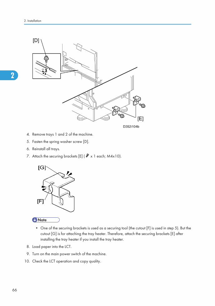
4. Remove trays 1 and 2 of the machine.
5. Fasten the spring washer screw [D].
6. Reinstall all trays.
7. Attach the securing brackets [E] ( x 1 each; M4x10).
• One of the securing brackets is used as a securing tool (the cutout [F] is used in step 5). But thecutout [G] is for attaching the tray heater. Therefore, attach the securing brackets [E] afterinstalling the tray heater if you install the tray heater.
8. Load paper into the LCT.
9. Turn on the main power switch of the machine.
10. Check the LCT operation and copy quality.
2. Installation
66
2

ARDF DF3050 (D541)
Component Check
Check the quantity and condition of the components against the following list.
No. Description Q’ty
1 ARDF 1
2 Stamp Cartridge 1
3 Knob Screw 2
4 Stud Screw 2
5 Attention Decal – Top Cover 1
Installation Procedure
• Unplug the copier power cord before starting the following procedure.
ARDF DF3050 (D541)
67
2

1. Remove all tapes and shipping retainers.
2. Remove the two screws already installed at the top rear of the machine.
3. Insert the two stud screws [A] on the top of the machine.
4. Mount the ARDF [B] by aligning the screw keyholes [C] in the ARDF support plate over the stud screws.
5. Slide the ARDF toward the front of the machine.
6. Secure the ARDF with the two knob screws [D].
2. Installation
68
2

7. Install the stamp cartridge [F] in the ARDF.
8. Peel off the platen sheet [G] and place it on the exposure glass.
9. Align the rear left corner of the platen sheet with the corner [H] on the exposure glass.
10. Close the ARDF.
11. Open the ARDF and check that the platen sheet is correctly attached.
ARDF DF3050 (D541)
69
2

12. Attach the decal [I] to the top cover as shown. Choose the language you want.
13. Plug in and turn on the main power switch of the machine, and then check the ARDF operation.
14. Make a full size copy. Check that the registrations (side-to-side and leading edge) and image skeware correct. If they are not, adjust the registrations and image skew referring to "Copy Adjustments"in the "Replacements and Adjustments” section.
2. Installation
70
2

ADF Handle Type B (D366)
Component Check
Check the quantity and condition of the accessories against the following list.
No. Description Q’ty
1 Handle Unit 1
2 Holder 1
3 Stud Bracket 1
4 Securing Bracket 1
5 Handle Bracket 1
6 Hinge Stopper - Right 1
7 Hinge Stopper - Left 1
8 Spacer 1
9 Bushing: M6 1
10 Bushing: 6MM 1
11 Tapping Screw: M3 x 12 2
12 Tapping Screw (Self Binding): M3 x 12 2
13 Screw: M3 x 8 3
14 Tapping Screw: M4 x 8 4
15 Operation Decal 1
16 Stud Decal 1
ADF Handle Type B (D366)
71
2

Installation Procedure
• Turn off the main switch of the copier and unplug the power cord before you start the installationprocedure.
Preparing before Installing the DF Handle
1. Open the ADF unit.
2. Installation
72
2

2. Hold the securing bracket [A] at the location [B], inside the ADF cover.
3. Secure the stud bracket [C] to the outside of the ADF cover at location [D] with two screws ( x 2:M3x8).
• The two screws must go through the ADF cover and the securing bracket [A].
ADF Handle Type B (D366)
73
2

4. Make two screw holes [E] in the scanner right cover with an M3x12 tapping screw from theaccessories.
Installing the DF Handle
1. Attach the holder [A] to the scanner right cover (Tapping Screw - M3x12: x 2).
• At first, secure the screw at the rear side (away from the operation panel) temporarily and thenat the front side temporarily. After that, secure them fully.
2. Install the bushing: 6MM [B] in the inside of the handle unit.
3. Attach the handle unit to the stud bracket on the left side of the ADF.
2. Installation
74
2

4. In the outside of the handle unit, install the bushing - M6 [C] first, and then the spacer [D].
5. Secure the handle unit with a screw ( x 1: M3x8).
6. Clean the handle unit with alcohol. Then attach the stud decal [E] at the location that was cleaned.
ADF Handle Type B (D366)
75
2

7. Attach the handle bracket [F] at the front right side on the bottom of the ADF unit (Tapping Screw [SelfBinding] x 2: M3x12).
8. Close the ADF unit.
9. Attach the hinge stoppers (left [G] and right [H]) to the left and right hinges (Tapping screw x 2: M4x8each).
2. Installation
76
2

10. Clean the front side of the duplex unit with alcohol. Then attach the operation decal [I] at the locationthat was cleaned.
11. Check the operation of the handle unit [J].
ADF Handle Type B (D366)
77
2

1 Bin Tray BN3080 (D536)
Component Check
Check the quantity and condition of the components against the following list.
No. Description Q’ty
1 1 Bin Tray Unit 1
2 End-fence 1
3 Tray Support Bar 1
4 Screws (M3 x 16) 2
5 Tray 1
Installation Procedure
• Unplug the copier power cord before starting the following procedure.
If the bridge unit (D386) or side tray (D542) has already been installed in the machine, remove it beforeinstalling 1 bin tray unit (D536). This will make it easier for you to do the following procedure.
1. Remove all tapes.
2. Open the right door of the machine.
2. Installation
78
2

3. Remove the front right cover [A] ( x 1).
4. Remove the inner cover [B] ( x 1).
• Keep this screw for step 5.
5. Install the 1 bin tray unit [C] ( x 1, x 1, x 1 [This screw was removed in step 4]).
1 Bin Tray BN3080 (D536)
79
2

6. Attach the tray support bar [D] to the tray [E] as shown, and then attach the end-fence [F].
7. Install the tray [G] (with the tray support bar) in the machine (M3 x 16: x 2).
8. Reinstall the front right cover in the machine, and then close the right door of the machine.
9. Turn on the main power switch of the machine.
10. Check the 1 bin tray unit operation.
2. Installation
80
2

Internal Shift Tray SH3040 (D388)
Component Check
Check the quantity and condition of the components against the following list.
No. Description Q’ty
1 Shift Tray Unit 1
2 Paper Guide - Small 2
3 Connector Cover 1
Installation Procedure
• Unplug the copier power cord before starting the following procedure.
Internal Shift Tray SH3040 (D388)
81
2

1. Remove all tapes.
2. Remove the standard tray [A].
3. Remove the inner cover [B] ( x 1).
4. Install the small paper guides [C].
2. Installation
82
2

5. Attach the connector cover [D] to the shift tray unit [E].
6. Install the shift tray unit [E] to the machine.
7. Push down the left edge [F] of the shift tray.
8. Turn on the main power switch of the machine.
9. Check the shift tray unit operation.
Internal Shift Tray SH3040 (D388)
83
2

Side Tray Type C5501 (D542)
Component Check
Check the quantity and condition of the accessories against the following list.
No. Description Q’ty
1 Side Tray Unit 1
2 Sub Output Tray 1
3 Main Output Tray 1
4 Screw 1
5 Knob screw 1
6 Frame Cover 1
7 Holder bracket 1
2. Installation
84
2

Installation Procedure
• Turn off the main switch of the copier and unplug the power cord before you start the installationprocedure.
• If you will install the 1-bin tray (D536) on the machine, install the 1-bin tray first before installing theside tray (D542). This makes it easier to do the following procedure.
1. Remove all tapes.
2. If the sensor feeler [A] is out, fold it into the machine.
3. Open the right door of the machine.
4. Remove the inner tray [B].
5. Remove the front right cover [C] ( x 1).
6. Remove the connector cover [D] ( x 1).
Side Tray Type C5501 (D542)
85
2

7. Attach the main output tray [A] and sub output tray [B] to the side tray unit.
8. Install the side tray unit [A] in the machine.
2. Installation
86
2

9. Open the side tray cover [A].
10. Secure the side tray unit with the knob screw [B].
11. Attach the frame cover [C].
12. Reinstall the front right cover to the machine, and then close the right door of the machine.
• Open the side tray cover [A] when installing the front right cover. Otherwise, you cannot reinstallit.
13. Install the holder bracket [D] ( x 1)
14. Turn on the main power switch of the machine.
15. Check the side tray operation.
Side Tray Type C5501 (D542)
87
2

Bridge Unit BU3030 (D386)
Component Check
Check the quantity and condition of the components against the following list.
No. Description Q’ty
1 Bridge Unit 1
2 Frame Cover 1
3 Knob screw 1
4 Long knob screw 1
5 Holder bracket 1
6 Guide 2
Installation Procedure
• Unplug the copier power cord before starting the following procedure.
2. Installation
88
2

• 1. If you will install the 1-bin tray (D536) in the machine, install the 1-bin tray before you install thebridge unit (D386). This will make it easier for you to do the following procedure.
• 2. If you will install a finisher (B408, B804 or B805) in the machine, install the finisher after you installthe bridge unit (D386).
1. Remove all tapes.
2. If the sensor feeler [A] is out, fold it into the machine.
3. Open the right door of the machine.
4. Remove the inner tray [B].
5. Remove the front right cover [C] ( x 1).
6. Remove the connector cover [D] ( x 1).
Bridge Unit BU3030 (D386)
89
2
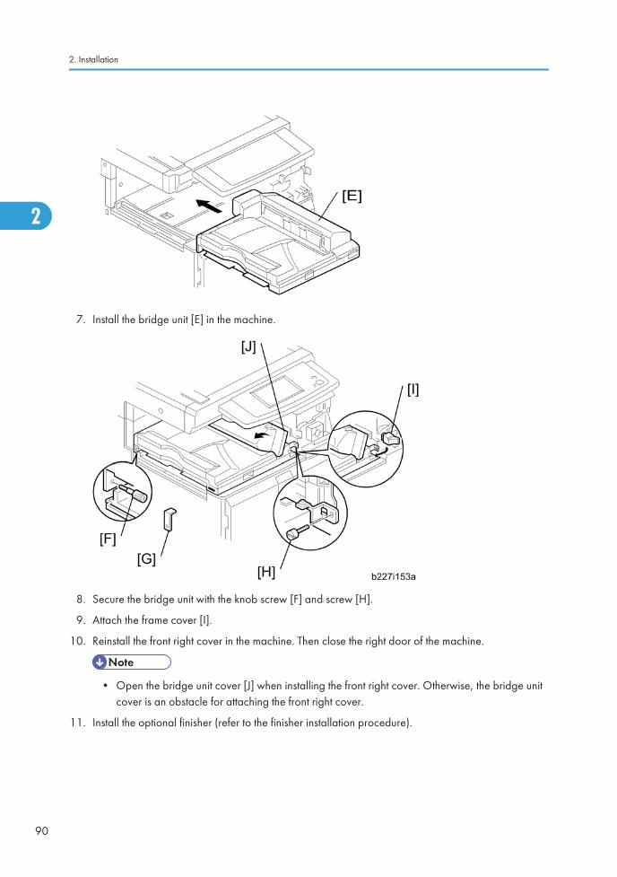
7. Install the bridge unit [E] in the machine.
8. Secure the bridge unit with the knob screw [F] and screw [H].
9. Attach the frame cover [I].
10. Reinstall the front right cover in the machine. Then close the right door of the machine.
• Open the bridge unit cover [J] when installing the front right cover. Otherwise, the bridge unitcover is an obstacle for attaching the front right cover.
11. Install the optional finisher (refer to the finisher installation procedure).
2. Installation
90
2

• If you will not install the finisher at this time, install the holder bracket [G]. Otherwise, the customerwill damage the bridge unit if they pull up the bridge unit tray. When you install the finisher, youwill need this bracket during the installation procedure.
12. Pull the extension tray [K] only if the 1000-sheet finisher (B408) is to be installed in the main machine.
13. Turn on the main power switch of the machine.
14. Check the bridge unit operation.
Bridge Unit BU3030 (D386)
91
2

Finisher SR3050 (D372)
Accessory Check
Check the quantity and condition of the accessories against the following list.
No Description Q’ty
1 Unit Holder 1
2 Shift Tray 1
3 Holder Bracket 1
4 Screw: M3 x 8 4
5 Screw: M3 x 6 1
6 Screw: M4 x 14 4
7 Screw: M4 x 20 4
8 Support Bracket 2
9 Support Bracket Cover 2
2. Installation
92
2

Installation Procedure
• Unplug the main machine power cord before starting the following procedure.
• Before you install the 500-sheet finisher, the optional bridge unit (D386) must be installed.
1. Unpack the finisher and remove the tapes.
Finisher SR3050 (D372)
93
2

2. Install the unit holder [A] ( x 3 - M4 x 14).
3. Install the support brackets [B] ( x 2 each: M4 x 20)
4. Install the support bracket covers [C] ( x 1 each: M3 x 8)
5. Install the 500-sheet finisher [A].
6. Install the holder bracket [B] ( x 1; M3 x 6).
7. Connect the finisher cable [C].
8. Install the shift tray [A] ( x 2 - M3 x 8).
9. Turn on the main power switch and check the finisher operation.
2. Installation
94
2

SR790 (B408)
Accessory Check
Check the quantity and condition of the accessories against the following list.
No. Description Q’ty
1 Front Joint Bracket 1
2 Rear Joint Bracket (Not used) 1
3 Rear Joint Bracket 1
4 Grounding Plate 1
5 Copy Tray 1
6 Staple Position Decal 1
7 Screw - M4 x 14 4
8 Knob Screw - M4 x 10 1
9 Screw - M3 x 8 1
10 Knob Screw - M3 x 8 1
SR790 (B408)
95
2

Installation Procedure
• Unplug the main machine power cord before starting the following procedure.
If this finisher will be installed on the D086 or D087 copier, the following options must be installed beforeinstalling this finisher.
- Bridge Unit (D386)
- Paper Feed Unit (D537) or LCT (D538)
1. Unpack the finisher, and then remove the stopper [A] and tapes ( x 1).
2. Install the front joint bracket [B], holder bracket [C] ( x 2 - M4 x 14), and rear joint bracket [D]( x 2 - M4 x 14).
2. Installation
96
2

• The holder bracket [C] must be placed outside the front joint bracket [B]. The holder bracket isprovided with the bridge unit (D386).
1. Install the grounding plate [E] on the finisher ( x 2 - M3 x 8).
• Use the screw removed in step 1 and the screw from the accessory box.
2. Open the front door [F] of the finisher, and then pull the locking lever [G] (1 knob screw - M3 x 8).
3. Align the finisher on the joint brackets, and lock it in place by pushing the locking lever.
4. Secure the locking lever (1 knob screw - M3 x 8).
5. Close the front door.
6. Install the copy tray [H] (1 knob screw - M4 x 10).
7. Connect the finisher cable [I] to the main machine below the right rear handle.
SR790 (B408)
97
2

8. Attach the staple position decal [J] to the ARDF as shown.
9. Turn on the main power switch and check the finisher operation.
2. Installation
98
2

Booklet Finisher SR3000 (B793)
Accessory Check
Check the quantity and condition of the accessories against the following list.
No. Description Q’ty
1 Rear Joint Bracket 1
2 Front Joint Bracket 1
3 Grounding Plate 1
4 Upper Output Tray 1
5 Cushion 2
6 Lower Output Tray 1
7 Short Knob Screw 1
8 Long Knob Screw 1
9 Screw (M3 x 8) 2
10 Screw (M4 x 14) 4
Booklet Finisher SR3000 (B793)
99
2
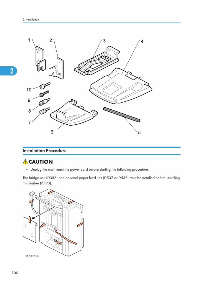
Installation Procedure
• Unplug the main machine power cord before starting the following procedure.
The bridge unit (D386) and optional paper feed unit (D537 or D538) must be installed before installingthis finisher (B793).
2. Installation
100
2

1. Unpack the finisher and remove all tapes and packing materials from the finisher.
2. Open the front door [A] of the 1000-sheet booklet finisher, and then pull out the jogger unit [B].
3. Remove all tapes and packing materials from the inside of the finisher.
4. Attach the cushions [C] to the finisher.
• Make sure that the cushions are placed within 0 to 1 mm [D] from the edge of the cover or frame.
5. Install the ground plate [E] on the finisher ( x 2; M3 x 8).
Booklet Finisher SR3000 (B793)
101
2

6. Attach the rear joint bracket [F] ( x 2, M4 x 14).
7. Attach the front joint bracket [G] and the holder bracket [H] ( x 2; M4 x 14).
• The holder bracket [H] must be placed outside the front joint bracket [G]. The holder bracket isprovided with the bridge unit (D386).
8. Pull the lock lever [I] (Long knob screw x 1).
9. Slowly push the finisher to the left side of the machine, keeping its front door open until the brackets[J] [K] go into their slots.
10. Push the lock lever [I], and then secure it (Long knob screw x 1).
2. Installation
102
2

11. Close the front door of the finisher.
12. Connect the finisher connector [L] to the machine.
13. Install the upper output tray [M] (Short knob screw x 1).
14. Install the lower output tray [N].
15. Turn on the main power switch of the machine.
16. Check the 1000-sheet booklet finisher operation.
Booklet Finisher SR3000 (B793)
103
2

Punch Kit PU3000 (B807)
Component Check
Check the quantity and condition of the components against the following list.
No. Description Q’ty
1 Punch Unit 1
2 Punch Drive Motor 1
3 Hopper Full Sensor Arm 1
4 Sub-scan Registration Sensor Unit 1
5 Punch Unit Stay 1
6 Sub-scan Registration Sensor Guide 1
7 Hopper 1
8 Screw 8
9 Step Screw 1
10 Spring 1
2. Installation
104
2

Installation
• Unplug the main machine power cord before starting the following procedure. If the 1000-sheetbooklet finisher has been installed, disconnect it and pull it away from the machine.
Punch Kit PU3000 (B807)
105
2

1. If the finisher is connected to the machine, disconnect it.
2. Open the top cover [A] and then release the guide arm [B] ( x 1).
3. Open the front door [C].
4. Pull the hook [D] up then remove the knob [E].
5. Timing belt cover [F].
6. Rear cover of the 1000-sheet booklet finisher [G] ( x 2).
2. Installation
106
2

7. Cover bracket [H] ( x 1)
8. Remove the paper guide plate [I] from the rear side ( x 4).
9. Install the punch unit stay [J] from the front side ( x 3).
10. Install the sub-scan registration sensor guide [K] from the top ( x 1).
Punch Kit PU3000 (B807)
107
2

11. Remove the bracket [L] from the punch unit ( x 1).
12. Install the punch unit [M] along the punch unit stay from the rear side.
13. Make sure to put the punch unit stay pin [N] through the hole [O].
2. Installation
108
2

14. Connect the harnesses [P] to the main PCB.
15. Put the harnesses [Q] through the hole [R] in the rear frame ( x 1).
16. Install the punch drive motor [S] on the rear frame ( x 2).
17. Connect the drive motor harness [T] to the harness from the punch unit ( x 1).
18. Connect the home position sensor harness from the punch unit to the home position sensor [U].
Punch Kit PU3000 (B807)
109
2
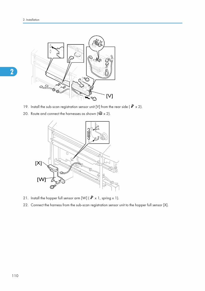
19. Install the sub-scan registration sensor unit [V] from the rear side ( x 2).
20. Route and connect the harnesses as shown ( x 2).
21. Install the hopper full sensor arm [W] ( x 1, spring x 1).
22. Connect the harness from the sub-scan registration sensor unit to the hopper full sensor [X].
2. Installation
110
2

23. Install the hopper [Y] from the front side.
24. Reinstall the timing belt cover and knob.
25. Reinstall the rear cover ( x 2).
26. Close the front door and top cover.
27. Install the 1000-sheet booklet finisher on the copier.
28. Plug in and turn on the main power switch.
29. Check the 1000-sheet booklet finisher operation.
Punch Kit PU3000 (B807)
111
2

Key Counter Bracket Type H (A674)
Installation Procedure
1. Hold the key counter plate nuts [A] on the inside of the key counter bracket [B] and insert the keycounter holder [C].
2. Secure the key counter holder to the bracket ( x 2).
3. Install the key counter cover [D] ( x 2).
4. Rear cover ( p.174)
5. Cut off the part [E] of the rear cover.
2. Installation
112
2
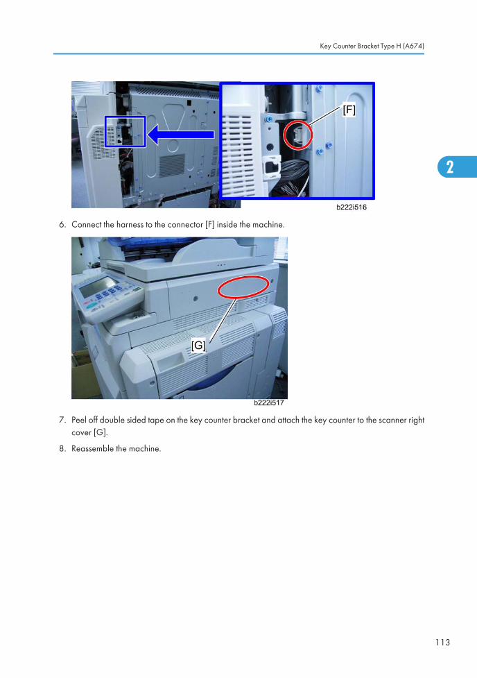
6. Connect the harness to the connector [F] inside the machine.
7. Peel off double sided tape on the key counter bracket and attach the key counter to the scanner rightcover [G].
8. Reassemble the machine.
Key Counter Bracket Type H (A674)
113
2

Optional Counter Interface Unit Type A (B870)
Installation Procedure
1. Rear cover ( p.174)
2. IOB bracket ( p.309 "Controller Box")
3. Install the four stud stays in the location [A] in the controller box.
4. Install the key counter interface board on the four stud stays in the controller box.
5. Connect the harness to CN3 on the key counter interface board.
6. Close the IOB bracket and connect the other terminal to CN215 [B] on the IOB.
2. Installation
114
2
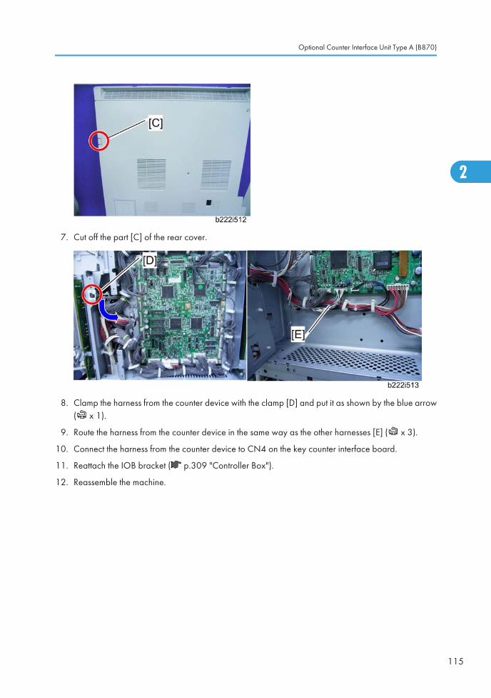
7. Cut off the part [C] of the rear cover.
8. Clamp the harness from the counter device with the clamp [D] and put it as shown by the blue arrow( x 1).
9. Route the harness from the counter device in the same way as the other harnesses [E] ( x 3).
10. Connect the harness from the counter device to CN4 on the key counter interface board.
11. Reattach the IOB bracket ( p.309 "Controller Box").
12. Reassemble the machine.
Optional Counter Interface Unit Type A (B870)
115
2

USB2.0/SD Slot Type F (D546)
Accessory Check
Check the quantity and condition of the accessories against the following list.
No. Description Q’ty
1 USB2.0/SD Slot 1
2 Ground Plate 1
3 USB Cable 1
4 Screw: M3 x 6 blue 1
5 Screw: M3 x 8 4
6 Screw: M3 x 6 1
7 Bracket 1
8 PDF Direct Card*1 1
*1: If the PostScript 3 option is used in this machine, this card is not necessary.
Installation Procedure
1. Connect the USB cable [B] to the USB slot [A] in the USB2.0/SD Slot as shown above.
2. Attach the ground plate [C] to the bracket of the USB2.0/SD Slot ( x 1: M3x6 blue).
2. Installation
116
2

3. Rear cover of the machine ( x 8)
4. Remove the scanner left cover [A] ( x 2).
5. Remove the left frame cover [B] ( x 1).
6. Remove the part [A] of the left frame cover with pliers or a similar tool.
7. Reinstall the left frame cover ( x 1).
8. Remove the part [A] on the scanner left cover.
USB2.0/SD Slot Type F (D546)
117
2

9. Make four holes in the scanner left cover with a screwdriver as shown [A].
• Smooth the four holes in the scanner left cover as shown [B].
10. Route the USB cable [A] through the gaps in the left scanner cover.
11. Secure the USB2.0/SD Slot [B] with the left scanner cover as shown above ( x 4: M3x8).
• Use the screw holes [C] as shown above.
2. Installation
118
2
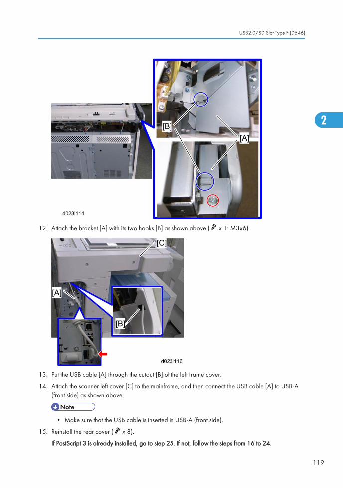
12. Attach the bracket [A] with its two hooks [B] as shown above ( x 1: M3x6).
13. Put the USB cable [A] through the cutout [B] of the left frame cover.
14. Attach the scanner left cover [C] to the mainframe, and then connect the USB cable [A] to USB-A(front side) as shown above.
• Make sure that the USB cable is inserted in USB-A (front side).
15. Reinstall the rear cover ( x 8).
If PostScript 3 is already installed, go to step 25. If not, follow the steps from 16 to 24.
USB2.0/SD Slot Type F (D546)
119
2

16. Remove the SD slot cover ( x 1), and move the SD card from slot 1 to slot 2.
17. Insert the PDF direct card in slot 1.
18. Plug in and turn on the mainframe.
19. Enter the System SP mode.
20. Move HDD Security Applications (HDD Encryption unit and Data Overwrite Security Unit) from theSD card in slot 2 to the SD card in slot 1 with SP5-873-001 "Move Exec".
21. Enter the Scanner SP mode, and then change the setting of SP1013-001 from “0” to “1”.
22. Enter the Printer SP mode, and then change the setting of SP1110-001 from “0” to “1”.
23. Exit the SP mode, and then turn off the machine.
24. Remove the SD card in slot 2, and then attach the SD slot cover ( x 1).
• Keep this card in the safe place ( p.139 "SD Card Appli Move").
25. Check the operation of the USB2.0/SD Slot.
26. Attach the decal [A] to the USB2.0/SD Slot as shown above.
Testing the SD Card/USB Slot
1. Insert an SD card or USB memory device in the slot.
You can connect only one removable memory device at a time.
2. Close the media slot cover.
If you leave the cover open, static electricity conducted through an inserted SD card could cause themachine to malfunction.
3. Make sure that no previous settings remain.
If a previous setting remains, press the [Clear Modes] key.
4. Place an original on the exposure glass.
5. Press [Store File].
2. Installation
120
2

6. Press [Store to Memory Device].
7. Press [OK].
8. Press the [Start] key.
When writing is complete, a confirmation message appears.
9. Press [Exit].
10. Remove the memory device from the media slot.
Do not remove the memory device while writing is in process.
USB2.0/SD Slot Type F (D546)
121
2

Card Reader Bracket Type C5501 (D547)
Component Check
Check the quantity and condition of the accessories against the following list.
No. Description Q’ty
1 Screw: M3 x 8 2
2 Screw: M3 x 14 1
3 Screw: M3 x 25*1 1
4 Tapping Screw: M3 x 10 3
5 Upper Tray 1
6 Lower Tray 1
7 Tray Bracket 1
8 Clamp 5
*1: Not used in this machine
2. Installation
122
2

Installation Procedure
1. Remove the screw [A] on the scanner right cover.
2. Attach the tray bracket [B] to the scanner right cover ( [C] x 2: M3x10, [D] x 1: M3x14).
• For this model, use the screw holes marked "2" on the table bracket.
3. Attach the lower tray [A] to the tray bracket ( x 2: M3x8).
4. Attach the upper tray [B] to the tray bracket ( x 1: M3x8).
5. Use the clamps as necessary to clamp the cable of the card read/writer device.
Card Reader Bracket Type C5501 (D547)
123
2

• The smart card reader must be placed on this card reader table. If not, some antenna or transmitterin the main machine may be interrupted.
2. Installation
124
2

Anti-Condensation Heater (Scanner)
• This option is provided as a service part.
Installation Procedure
1. Rear cover ( p.174 in the "Replacement and Adjustment" section)
2. Open the ARDF or platen cover.
3. Glass cover [A] ( x 4)
4. ARDF exposure glass [B]
5. Rear scale [C] ( x 3)
6. Exposure glass with left scale [D]
Anti-Condensation Heater (Scanner)
125
2

7. Move the scanner carriage to the right side by rotating the scanner motor [E].
8. Install the heater [F] in the scanner unit ( x 1, hook)
9. Put the connector [G] through the cutout.
10. Connect it to the connector [H] (blue and red cords) in the frame of the machine.
11. Reassemble the machine.
2. Installation
126
2

Anti-Condensation Heater Type A
• This option is provided as a service part.
Component Check
No. Description Q’ty
1 Tray heater 1
2 On-standby decal 1 (-90) or 2 (-91)
3 Harness 2 (For D387) 1
4 Harness 1 (For D537/D538) 1
5 Screw M4 x 10 2
- Installation procedure 1
Installation Procedure
• Unplug the machine power cord before starting the following procedure.
Anti-Condensation Heater Type A
127
2

• Do the following procedure not to damage any harnesses.
• Check that all harnesses are not damaged nor pinched after installation.
For installing the tray heater in the main machine
1. Remove trays 1 and 2 from the machine.
2. Remove the connector cover [A] ( x 1).
3. Connect the connector [B] of the heater to the connector of the main machine.
4. Install the heater [C] inside the machine ( x 1).
5. Reassemble the machine.
2. Installation
128
2

For installing the tray heater in D537
1. Rear cover [A] ( x 8)
2. Pull out the two trays in the optional paper feed unit.
3. Install the tray heater [B] in the optional paper feed unit ( x 1).
Anti-Condensation Heater Type A
129
2

4. Remove the two securing brackets [C] ( x 1 each), and then the rear cover [D] of the optional paperfeed unit ( x 2).
5. Remove the harness cover bracket [E] ( x 1).
6. Pull out tray 2 from the mainframe.
7. Replace the shoulder screw [F] with the washer screw [G], using securing bracket [H] ( x 1).
2. Installation
130
2

8. Connect the harness [I] to the connector [J] of the tray heater.
9. Route the harness [I] as shown and clamp it with four clamps ( x 4).
10. Connect the harness [I] to the connector [K] of the mainframe.
11. Reassemble the mainframe and optional paper feed unit.
12. Attach the on/standby decal [L] to the right-hand side of the main power switch.
For Installing the Tray Heater in D538
1. Remove the rear cover of the mainframe ( step 1 in For Installing the Tray Heater in D537).
2. Pull out the LCT drawer.
• If the right tray comes out with the left tray, push the right tray into the LCT.
Anti-Condensation Heater Type A
131
2
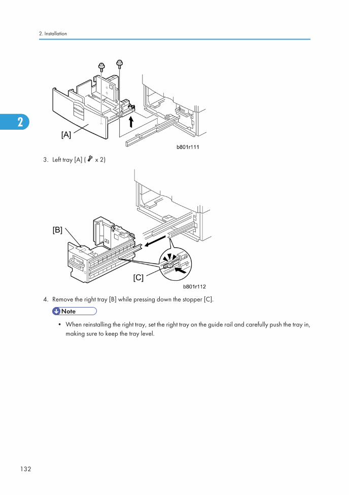
3. Left tray [A] ( x 2)
4. Remove the right tray [B] while pressing down the stopper [C].
• When reinstalling the right tray, set the right tray on the guide rail and carefully push the tray in,making sure to keep the tray level.
2. Installation
132
2
5. Install the tray heater [D] in the optional LCT ( x 1).
6. Remove the two securing brackets [E] ( x 1 each), and the then rear cover [F] of the optional LCT( x 2).
7. Remove the harness cover bracket [G] ( x 1).
Anti-Condensation Heater Type A
133
2

8. Pull out tray 2 from the mainframe.
9. Replace the shoulder screw [H] with the washer screw [I], using the securing bracket [J] ( x 1).
10. Connect the harness [K] to the connector [L] of the tray heater.
11. Route the harness [K] as shown and clamp it with four clamps ( x 4).
12. Connect the harness [K] to the connector [M] of the mainframe.
13. Reassemble the mainframe and optional LCT.
14. Reassemble the mainframe and optional paper feed unit.
15. Attach the on/standby decal [N] to the right-hand side of the main power switch.
For Installing the Tray Heater in D387
1. Remove the rear cover of the mainframe ( step 1 in For Installing the Tray Heater in D537).
2. Pull out the tray in the optional paper tray.
2. Installation
134
2

3. Install the tray heater [A] in the optional paper tray ( x 1).
4. Remove the two securing brackets [B] ( x 1 each), and then the rear cover [C] of the optional papertray ( x 2).
5. Remove the harness cover bracket [D] ( x 1).
Anti-Condensation Heater Type A
135
2

6. Pull out tray 2 from the mainframe.
7. Replace the shoulder screw [E] with the washer screw [F], using securing bracket [G] ( x 1).
1. Connect the harness [H] to the connector [I] of the tray heater.
2. Route the harness [H] as shown and clamp it with four clamps ( x 4).
• Make sure that the harness [H] is placed below the harness [J].
3. Connect one harness [K] of the two-way harness to the connector [L] of the mainframe.
• The harness [K] of the two-way harness, which has two binds, is for the connector of themainframe. The harness [M], which has one bind, is for another optional paper feed unit.
4. Clamp the other harness [M] of the two-way harness as shown [N] if you do not install another optionalpaper feed unit.
5. Reassemble the mainframe and optional paper tray.
2. Installation
136
2

6. Attach the on/standby decal [O] to the right-hand side of the main power switch.
Anti-Condensation Heater Type A
137
2

Controller Options
Overview
This machine has I/F card slots for optional I/F connections and SD card slots applications.
After you install an option, check that the machine can recognize it (see "Check All Connections" at theend of this section).
I/F Card Slots
• Slot A is used for one of the optional I/F connections (only one can be installed): IEEE1284,IEEE802.11a/g (Wireless LAN), Bluetooth or Remote Communication Gate.
• Slot B is used for the File Format Converter or Remote Communication Gate.
• Slot C is used for Gigabit Ethernet.
SD Card Slots
• Slot 1 is already occupied by the Security SD Card by factory default, and is also used for optionalapplications (e.g.: PostScript 3, PictBridge, IPDS unit, PDF direct, etc).
• Slot 2 is used for installing the Browser Unit, VM card or for service only (for example, updating thefirmware).
2. Installation
138
2

SD Card Appli Move
Overview
The service program "SD Card Appli Move" (SP5-873) lets you move application programs from one SDcard to another SD card.
If more than one application is required, the applications must be moved to one SD card with SP5873-1(PostScript 3, Security Application, PictBridge, IPDS unit, PDF Direct, etc.).
Be very careful when you do the SD Card Appli Move procedure:
• The data necessary for authentication is transferred with the application program from an SD card toanother SD card. Authentication fails if you try to use the SD card after you move the applicationprogram from one card to another card.
• Do not use the SD card if it has been used before for other purposes. Normal operation is notguaranteed when such an SD card is used.
• Remove the cover [A] ( x 2), and then keep the SD card in the place [B] after you move theapplication program from one card to another card. This is done for the following reasons:
• The SD card can be the only proof that the user is licensed to use the application program.
• You may need to check the SD card and its data to solve a problem in the future.
• You cannot move the PostScript or PDF Direct application to another SD card. You have to move theother application (PictBridge, Security Applications, IPDS unit) to the SD card that stores the PostScriptor PDF Direct application.
Move Exec
The menu "Move Exec" (SP5-873-001) lets you move application programs from the original SD card toanother SD card.
Controller Options
139
2

• Do not turn ON the write protect switch of the system SD card or application SD card on the machine.If the write protect switch is ON, a download error (e.g. Error Code 44) occurs during a firmwareupgrade or application merge.
1. Turn the main switch off.
2. Make sure that a target SD card is in SD Card Slot 1. The application program is moved to this SDcard.
3. Insert the source SD card with the application program in SD Card Slot 2.The application programis copied from this source SD card.
4. Turn the main switch on.
5. Start the SP mode.
6. Select SP5-873-001 "Move Exec".
7. Follow the messages shown on the operation panel.
8. Turn the main switch off.
9. Remove the source SD card from SD Card Slot 2.
10. Turn the main switch on.
11. Check that the application programs run normally.
Undo Exec
"Undo Exec" (SP5-873-002) lets you move back application programs from an SD card in SD Card Slot1 to the original SD card in SD Card Slot 2. You can use this program when, for example, you havemistakenly copied some programs by using Move Exec (SP5-873-001).
• Do not turn ON the write protect switch of the system SD card or application SD card on the machine.If the write protect switch is ON, a download error (e.g. Error Code 44) occurs during a firmwareupgrade or application merge.
1. Turn the main switch off.
2. Insert the original SD card in SD Card Slot 2. The application program is copied back into this card.
3. Insert the SD card with the application program in SD Card Slot 1.The application program is copiedback from this SD card.
4. Turn the main switch on.
5. Start the SP mode.
6. Select SP5-873-002 "Undo Exec."
7. Follow the messages shown on the operation panel.
8. Turn the main switch off.
2. Installation
140
2

9. Remove the SD card from SD Card Slot 2.
10. Turn the main switch on.
11. Check that the application programs run normally.
12. Make sure that the machine can recognize the option (see ‘Check All Connections’ at the end of thissection).
PostScript3 Unit Type C5501
The PostScript3 application and fonts cannot be moved to another SD card. However, other applicationscan be moved onto the PostScript3 SD card.
• Unplug the main machine power cord before you do the following procedure.
1. Remove the SD-card slot cover [A] from the SD card slots ( x 1).
2. Move the SD card (security applications) [B] from SD slot 1 to SD slot 2.
• If the VM card is already in SD slot 2, first remove the VM card in SD slot 2.
3. Insert the SD card [C] (PostScript 3) in SD slot 1 with its label face towards the front of the machine.Then push it slowly into SD slot 1 until you hear a click.
Controller Options
141
2

4. Attach the "Adobe PostScript 3" decal [A] to the front door.
5. Plug in, and then turn on the machine.
6. Move security applications from the SD card in SD slot 2 to the SD card in SD slot 1 with SP5-873-001.
7. Turn off the machine.
8. Remove the SD card from SD slot 2, and then keep it in a safe place ( SD Card Appli Move).
9. Insert the VM card in SD slot 2.
10. Attach the SD-card slot cover, and then turn on the machine ( x 1).
11. Make sure that the machine can recognize the option (see ‘Check All Connections’ at the end of thissection).
IPDS Unit Type C5501
• Unplug the main machine power cord before you do the following procedure.
2. Installation
142
2

1. Remove the SD-card slot cover [A] from the SD card slots ( x 1).
2. Move the SD card (security applications) [B] from slot 1 to slot 2.
• If the VM card is already in slot 2, first remove the VM card in SD slot 2.
3. Insert the SD card [C] (IPDS Unit) in SD slot 1 with its label face towards the front of the machine.
4. Plug in, and then turn on the machine.
5. Move security applications from the SD card in SD slot 2 to the SD card in SD slot 1 with SP5-873-001.
6. Turn off the machine.
7. Remove the SD card from SD slot 2, and then keep it in a safe place ( p.139 "SD Card AppliMove").
8. Insert the VM card in SD slot 2.
9. Attach the SD-card slot cover, and then turn on the machine ( x 1).
File Format Converter Type E
• Unplug the main machine power cord before you do the following procedure.
Controller Options
143
2

1. Remove the slot B cover [A] ( x 2).
2. Install the file format converter [B] into slot B and then fasten it with screws.
3. Plug in and turn on the main power switch.
4. Check or set the following SP codes with the values shown below.
SP No. Title Setting
SP5-836-001 Capture Function (0:Off 1:On) "1"
SP5-836-002 Panel Setting "0"
5. Check the operation.
6. Make sure that the machine can recognize the option (see ‘Check All Connections’ at the end of thissection).
IEEE 1284 Interface Board Type A
Installation Procedure
• Unplug the main machine power cord before you do the following procedure.
You can only install one of the following network interfaces at a time: (IEEE 802.11 a/g, (Wireless LAN),IEEE1284, Bluetooth).
2. Installation
144
2

1. Remove the slot A cover [A] ( x 2).
2. Install the interface board [B] (Knob-screw x 2) into the slot A.
3. Make sure that the machine can recognize the option (see ‘Check All Connections’ at the end of thissection).
IEEE 802.11a/g Interface Unit Type J
Installation Procedure
• Unplug the main machine power cord before you do the following procedure.
You can only install one of the following network interfaces at one time: (IEEE 802.11 a/g, (Wireless LAN),IEEE1284, Bluetooth).
Controller Options
145
2

1. Remove the slot cover [A] from the board slot ( x 2).
2. Install the wireless LAN board [B] (Knob-screw x 2) into the board slot.
3. Make sure that the machine can recognize the option (see ‘Check All Connections’ at the end of thissection).
4. Peel off the double-sided tapes on the Velcro fasteners [A], and then attach them [A] at the front leftand rear left of the machine.
5. Attach "ANT1" (having a black ferrite core) [B] to the front left of the machine.
6. Attach "ANT2" (having a white ferrite core) [C] to the rear right of the machine.
2. Installation
146
2

• "ANT1" is a transmission/reception antenna and "ANT2" is a reception antenna. Do not attachthem at the wrong places.
7. Attach the clamps as shown above.
8. Wire the cables and clamp them ( x 7).
• Make sure that the cables are not slack. Keep them wired tightly along the covers.
You may have to move the machine if the reception is not clear.
• Make sure that the machine is not located near an appliance or any type of equipment that generatesstrong magnetic fields.
• Put the machine as close as possible to the access point.
Installing Various Hardware Combinations
• Refer to the above picture [A] when installing the handset.
• Refer to the above picture [B] when installing the handset and the USB2.0/SD.
UP Mode Settings for Wireless LAN
Enter the UP mode. Then do the procedure below to perform the initial interface settings for IEEE 802.11a/g. These settings take effect every time the machine is powered on.
• You cannot use the wireless LAN if you use Ethernet.
1. Press the "User Tools/Counter" key.
2. On the touch panel, press "System Settings".
• The Network I/F (default: Ethernet) must be set for either Ethernet or wireless LAN.
Controller Options
147
2

3. Select "Interface Settings".
4. Press "Wireless LAN". Only the wireless LAN options show.
5. Communication Mode. Select either "802.11 Ad hoc", "Ad hoc" or "Infrastructure".
6. SSID Setting. Enter the SSID setting. (The setting is case sensitive.)
7. Channel. You need this setting when Ad Hoc Mode is selected.
Range: 1 to 14 (default: 11)
• The allowed range for the channel settings may vary for different countries.
8. WEP (Encryption) Setting. The WEP (Wired Equivalent Privacy) setting is designed to protect wirelessdata transmission. The same WEP key is required on the receiving side in order to unlock encodeddata. There are 64 bit and 128 bit WEP keys.
WEP:
Selects "Active" or "Inactive" ("Inactive" is default.).
Range of Allowed Settings:
64 bit: 10 characters
128 bit: 26 characters
9. Transmission Speed. Press the Next button to show more settings. Then select the transmission speedfor the mode: Auto, 11 Mbps, 5.5 Mbps, 2 Mbps, 1 Mbps (default: Auto). This setting should matchthe distance between the closest machine or access point. This depends on which mode is selected.
• For the Ad Hoc Mode, this is the distance between the machine and the closest PC in the network.For the Infrastructure Mode, this is the distance between the machine and the closest accesspoint.
11 Mbps: 140 m (153 yd.)
5.5 Mbps: 200 m (219 yd.)
2 Mbps: 270 m (295 yd.)
1 Mbps: 400 m (437 yd.)
10. Press "Return to Default" to initialize the wireless LAN settings.
Press "Yes" to initialize the following settings:
• Transmission mode
• Channel
• Transmission Speed
• WEP
• SSID
2. Installation
148
2

• WEP Key
SP Mode and UP Mode Settings for IEEE 802.11 a/g Wireless LAN
The following SP commands and UP modes can be set for IEEE 802.11 a/g.
SP No. Name Function
5840-006 Channel MAX Sets the maximum range of the channel settings for the country.
5840-007 Channel MINSets the minimum range of the channels settings allowed for yourcountry.
5840-011 WEP Key Select Used to select the WEP key (Default: 00).
UP mode Name Function
SSID Used to confirm the current SSID setting.
WEP Key Used to confirm the current WEP key setting.
WEP ModeUsed to show the maximum length of the string that can be usedfor the WEP Key entry.
Bluetooth Interface Unit Type 3245
• Unplug the main machine power cord before you do the following procedure.
You can only install one of the following network interfaces at a time: (IEEE 802.11 a/g (Wireless LAN),IEEE1284, Bluetooth).
Controller Options
149
2

1. Remove the slot cover [A] ( x 2).
2. Install the Bluetooth board [B] (Knob-screw x 2) into the slot A.
3. Insert the Bluetooth card into the Bluetooth card adaptor.
4. Install the Bluetooth card adaptor on the Bluetooth board.
5. Attach the antenna cap to the Bluetooth board.
6. Make sure that the machine can recognize the option (see ‘Check All Connections’ at the end of thissection).
Camera Direct Print Card Type I
• Unplug the main machine power cord before you do the following procedure.
2. Installation
150
2

1. Remove the SD-card slot cover [A] from the SD card slots ( x 1).
2. Move the SD card (security applications) [B] from SD slot 1 to SD slot 2.
• If the VM SD card is already in SD slot 2, first remove the VM card in SD slot 2.
3. Insert the SD card [C] (PictBridge) in SD slot 1 with its label face to the front of the machine.
4. Plug in, and then turn on the machine.
5. Move security applications from the SD card in SD slot 2 to the SD card in SD slot 1 with SP5-873-001.
6. Turn off the machine.
7. Remove the SD card from slot SD 2, and then keep it in a safe place.
8. Insert the VM card in SD slot 2.
9. Attach the SD-card slot cover, and then turn on the machine ( x 1).
10. Make sure that the machine can recognize the option (see ‘Check All Connections’ at the end of thissection).
Browser Unit Type E
Installation Procedure
• Unplug the main machine power cord before you do the following procedure.
Controller Options
151
2

1. Remove the slot cover [A] for SD cards ( x 1).
2. Remove the VM card [B] from SD slot 2.
3. Turn the SD-card label face [C] of the browser unit to the front of the machine. Then push it slowly intoSD slot 2 until you hear a click.
4. Plug in and turn on the main power switch.
5. Push the "User Tools" key.
• If an administrator setting is registered for the machine, step 5 and 6 are required. Otherwise,skip to the step 7
6. Push the "Login/ Logout" key.
7. Login with the administrator user name and password.
8. Touch "Extended Feature Settings" twice on the LCD.
9. Touch "Install" on the LCD.
10. Touch "SD Card".
11. Touch the "Browser" line.
12. Under "Install to" touch "Machine HDD" and touch "Next".
13. When you see "Ready to Install", check the information on the screen to confirm your previousselection.
14. Touch "OK". You will see "Installing the extended feature... Please wait.", and then "Completed".
15. Touch "Exit" to go back to the setting screen.
2. Installation
152
2

16. Touch "Change Allocation".
17. Touch the "Browser" line.
18. Press one of the hard keys, which you want to use for the Browser Unit. In default, this function isassigned to the "Other Functions" key (bottom key of function keys).
19. Touch "OK".
20. Touch "Exit" twice to go back to the copy screen.
21. Turn off the main power switch.
22. Install the key for "Browser Unit" to the place, where you want.
23. Remove the SD card of the browser unit from SD slot 2.
24. Reinstall the VM card in SD slot 2.
25. Attach the slot cover [A] ( x 1).
26. Keep the SD card in the place ( p.139 "SD Card Appli Move") after you install the applicationprogram from the card to HDD. This is because: The SD card can be the only proof that the user islicensed to use the application program. You may need to check the SD card and its data to solve aproblem in the future.
Gigabit Ethernet Type B
• Unplug the main machine power cord before you do the following procedure.
Controller Options
153
2
1. Remove the controller cover [A] ( x 3).
2. Pull out the controller board [B] ( x 5).
3. Remove the slot cover [A] ( x 1).
4. Attach the Gigabit Ethernet controller [A] into the slot [B] ( x 2).
5. Reassemble the machine.
6. Check the operation of the Gigabit Ethernet
Check All Connections
1. Plug in the power cord. Then turn on the main switch.
2. Enter the printer user mode. Then print the configuration page.
User Tools > Printer Settings > List Test Print > Config. Page
All installed options are shown in the "System Reference" column.
2. Installation
154
2

3. Preventive Maintenance
Maintenance TablesSee "Appendices" for the following information:
• Preventive Maintenance Items
• Other Yield Parts
155
3

PM Parts Settings
Before Removing the Old PM Parts
1. Enter the SP mode.
2. Output the SMC logging data with SP5-990-004.
3. Set the following SPs to "1" before you turn the power off. Then, the machine will reset the PM countersautomatically. In the case of developer, the developer initialization will also be done automatically.
4. Exit the SP mode.
Item SP
Developer
Black: 3902-005
Yellow: 3902-006
Cyan: 3902-007
Magenta: 3902-008
Drum Unit
Black: 3902-009
Yellow: 3902-010
Cyan: 3902-011
Magenta: 3902-012
Heating Roller and Pressure Roller (not necessaryfor complete fusing units; see below)
Heating roller: 3902-018
Pressure roller: 3902-019
Image Transfer Belt Cleaning Unit 3902-015
PTR Unit 3902-016
Toner Collection Bottle (if not full or near-full) 3902-017
For the following units, there is a new unit detection mechanism. It is not necessary to reset PM counters.
• PCDU
• Development unit
• Toner Collection Bottle (if full or near-full)
• Fusing unit
3. Preventive Maintenance
156
3

After installing the new PM parts
1. Turn on the main power switch.
2. Output the SMC logging data with SP5-990-004 and check the counter values.
3. Make sure that the PM counters for the replaced units are "0" with SP7-803. If the PM counter for aunit was not reset, then reset that counter with SP 7-804.
4. Make sure that the exchange counter counts up with SP7-853.
5. Make sure that the counters for the previous units (SP7-906) on the new SMC logging data list (fromstep 2 above) are equal to the counters (SP7-803) for these units on the previous SMC logging datalist (the list that was output in the "Before removing the old parts" section).
6. Make sure that the unit replacement date is updated with SP7-950.
Preparation before operation check
1. Clean the exposure glasses (for DF and book scanning).
2. Enter the user tools mode.
3. Do the "Automatic Color Calibration(ACC)" for the copier mode & printer mode as follows:
• Print the ACC test pattern (User Tools > Maintenance > ACC > Start).
• Put the printout on the exposure glass.
• Put 10 sheets of white paper on the test chart. This ensures the precise ACC adjustment.
• Close the ARDF or the platen cover.
• Press "Start Scanning" on the LCD. Then, the machine starts the ACC.
4. Exit the User Tools mode, and then enter the SP mode.
5. Do the "Forced line position adjustment" as follows.
• First do SP2-111-3 (Mode c).
• Then do SP2-111-1 (Mode a).
• To check if SP 2-111-1 was successful, watch the screen during the process. A message isdisplayed at the end. Also, you can check the result with SP 2-194-10 to -12.
6. Exit the SP mode.
Operation check
Check if the sample image has been copied normally.
PM Parts Settings
157
3

3. Preventive Maintenance
158
3

4. Replacement and Adjustment
Beforehand
• Before installing options, please do the following:
• If there is a fax unit in the machine, print out all messages stored in the memory, the lists of user-programmed items, and the system parameter list.
• If there are printer jobs in the machine, print out all jobs in the printer buffer.
• Turn off the main switch and disconnect the power cord, the telephone line, and the network cable.
• Always touch a grounded surface to discharge static electricity from your hands before you handleSD cards, printed circuit boards, or memory boards.
159
4
Special ToolsPart Number Description Q'ty
B645 5010 SD Card 1
B645 6705 PCMCIA Card Adapter 1
B645 6820 USB Reader/Writer 1
VSSM9000 Digital Multimeter – FLUKE87 1
G021 9350 Loop-back Connector – Parallel *NOTE 1
C401 9503 20X Magnification Scope 1
A257 9300 Grease Barrierta – S552R 1
5203 9502 Silicone Grease G-501 1
A092 9503 C4 Color Test Chart (3 pcs/set) 1
A184 9501 Optics Adjustment Tool (2 pcs / set) 2
B679 5100 Plug - IEEE1284 Type A 1
B132 9700 Lubricant Powder 1
• The "Loop-back Connector–Parallel" requires the "Plug-IEEE1284 Type A", and the optionalIEEE1284 interface option must also be installed.
4. Replacement and Adjustment
160
4

Image Adjustment
Scanning
Check the printing registration/side-to-side adjustment and the blank margin adjustment before you dothe following scanner adjustments.
• Use S-2-1 test chart to do the following adjustments.
Scanner sub-scan magnification
A: Sub-scan magnification
1. Put the test chart on the exposure glass. Then make a copy from one of the feed stations.
2. Check the magnification ratio. Adjust with SP4-008 if necessary.
Standard: ±1.0%.
Image Adjustment
161
4

Scanner leading edge and side-to-side registration
A: Leading Edge Registration
1. Put the test chart on the exposure glass. Then make a copy from one of the feed stations.
2. Check the leading edge and side-to-side registration. Adjust the following SP modes if necessary.
Standard: 0 ± 2mm for the leading edge registration, 0 ± 2.5mm for the side-to-side registration.
SP mode
Leading Edge Registration SP4-010-001
Side-to-Side Registration SP4-011-001
ARDF
ARDF side-to-side, leading edge registration and trailing edge
4. Replacement and Adjustment
162
4

A: Leading edge registration
Use A3/DLT paper to make a temporary test chart as shown above.
1. Put the temporary test chart on the ARDF. Then make a copy from one of the feed stations.
2. Check the registration. Check the leading edge and side-to-side registration. Adjust the following SPmodes if necessary.
Standard: 4.2 ± 2 mm for the leading edge registration, 2 ± 1 mm for the side-to-side registration.Use the following SP modes to adjust if necessary.
SP Code What It Does Adjustment Range
SP6-006-001 Side-to-Side Regist: Front ± 3.0 mm
SP6-006-003 Leading Edge Registration ± 5.0 mm
SP6-006-005 Buckle: Duplex Front ± 3.0 mm
SP6-006-006 Buckle: Duplex Rear ± 2.5 mm
SP6-006-007 Rear Edge Erase (Trailing Edge) ± 10.0 mm
ARDF sub-scan magnification
1. Put the temporary test chart on the ARDF. Then make a copy from one of the feed stations.
2. Check the magnification ratio. Adjust with SP6-017-001 if necessary.
• Standard: ±5.0%
• Reduction mode: ±1.0%
• Enlargement mode: ±1.0%
Image Adjustment
163
4

Registration
Image Area
A = C = 5.2 mm (0.2"), B = 2.0 mm
Make sure that the registration is adjusted within the adjustment standard range as shown below.
Leading Edge
Adjusts the leading edge registration for each paper type and process line speed.
Side to Side
Adjusts the side-to-side registration for each paper feed station. Use SP mode (SP1-002) to adjust the side-to-side registration for the optional paper feed unit, LCT, and duplex unit.
Adjustment Standard
• Leading edge (sub-scan direction): 5.2 ± 2 mm
• Side to side (main-scan direction): 2 ± 1 mm
Paper Registration Standard
The registration in both main- and sub-scan directions can change within the following tolerance.
• Sub-scan direction: 0 ± 9 mm
• Main-scan direction: 0 ± 4 mm
4. Replacement and Adjustment
164
4

Adjustment Procedure
1. Enter SP2-109-003.
2. Print out the test pattern (14: 1-dot trimming pattern) with SP2-109-003.
• Registration can change slightly as shown on the previous page. Print some pages of the 1-dottrimming pattern for step 3 and 4. Then average the leading edge and side-to-side registrationvalues, and adjust each SP mode.
3. Do the leading edge registration adjustment.
1) Check the leading edge registration and adjust it with SP1-001.
2) Select the adjustment conditions (paper type and process line speed).
3) Input the value. Then press the key.
4) Generate a trim pattern to check the leading edge adjustment.
4. Do the side-to-side registration adjustment.
1) Check the side-to-side registration and adjust it with SP1-002.
2) Select the adjustment conditions (paper feed station).
3) Input the value. Then press the key.
4) Generate a trim pattern to check the leading edge adjustment.
Erase Margin Adjustment
• Adjust the erase margin C and D only if the registration (main scan and sub scan) cannot be adjustedwithin the standard values. Do the registration adjustment after adjusting the erase margin C and D,and then adjust the erase margin A and B.
Image Adjustment
165
4

1. Enter SP2-109-003.
2. Print out the test pattern (14: 1-dot trimming pattern) with SP2-109-003.
3. Check the erase margin A and B. Adjust them with SP2-103-001 to -015 if necessary.
• Leading edge: 0.0 to 9.0 mm (default: 4.2 mm)
• Side-to-side: 0.0 to 9.0 mm (default: 2.0 mm)
• Trailing edge: 0.0 to 9.0 mm (default: 4.2 mm)
Color Registration
Line Position Adjustment
The automatic line position adjustment usually is done for a specified condition to get the best color prints.
Do the following if color registration shifts:
• Do "Auto Color Registration" as follows to do the forced line position adjustment.
1. First do SP2-111-3.
2. Then do SP2-111-1.
To check if SP 2-111-1 was successful, watch the screen during the process. A message is displayedat the end. Also, you can check the result with SP 2-194-10 to -12.
• You should also do the line position adjustment at these times:
4. Replacement and Adjustment
166
4

• After you transport or move the machine (you should do the forced line position adjustment ifyou install the machine at the user location.) if the machine is pre-installed at the workshop andmoved to the user location,
• When you open the drum positioning plate
• When you remove or replace the motors, clutches, and/or gears related to the drum/development/transfer sections
• When you remove or replace the image transfer belt, image transfer belt unit or laser opticalhousing unit
Printer Gamma Correction
• The ACC is usually sufficient to adjust the color balance to get the best print output. You only needthe printer gamma correction to fine-tune to meet user requirements.
Use SP modes if you want to modify the printer gamma curve created with ACC. You can adjust the gammadata for the following:
• Highlight
• Middle
• Shadow areas
• IDmax.
The adjustable range is from 0 to 30 (31 steps).
Copy Mode
- KCMY Color Balance Adjustment -
The adjustment uses only "Offset" values.
• Never change "Option" values (default value is 0).
Highlight (Low ID) Levels 2 through 5 in the C4 chart 10-level scale
Middle (Middle ID) Levels 3 through 7 in the C4 chart 10-level scale
Shadow (High ID) Levels 6 through 9 in the C4 chart 10-level scale
ID max Level 10 in the C4 chart 10-level scale (affects the entire image density.)
OffsetThe higher the number in the range associated with the low ID, middle ID,high ID, and ID max, the greater the density.
Image Adjustment
167
4

There are four adjustable modes (can be adjusted with SP4-918-009):
• Copy Photo mode
• Copy Letter mode
• Copy Letter (Single Color) mode
• Copy Photo (Single Color) mode
- Adjustment Procedure -
1. Copy the C-4 chart in the mode that you want to adjust.
2. Enter the SP mode.
3. Select "System SP."
4. Select SP4-918-009.
5. Adjust the offset values until the copy quality conforms to the standard (see the table below).
• 1. Never change "Option" value (default value is "0").
• 2. Adjust the density in this order: "ID Max", "Middle", "Shadow", "Highlight".
- Photo Mode, Full Color -
Item to Adjust Level on the C-4 chart Adjustment Standard
1ID max:
(K, C, M, and Y)
Adjust the offset value so that thedensity of level 10 matches thatof level 10 on the C-4 chart.
4. Replacement and Adjustment
168
4

2Middle (Middle ID)
(K, C, M, and Y)
Adjust the offset value so that thedensity of level 6 matches that oflevel 6 on the C-4 chart.
3Shadow (High ID)
(K, C, M, and Y)
Adjust the offset value so that thedensity of level 8 matches that oflevel 8 on the C-4 chart.
4Highlight (Low ID)
(K, C, M, and Y)
Adjust the offset value so that dirtybackground does not show onthe copy and the density of level3 is slightly lighter than that oflevel 3 on the C-4 chart.
5
K Highlight (Low ID)(C,M, and Y)
<on the full color copy>
Adjust the offset value so that thecolor balance of black scalelevels 3 through 5 in the copy isseen as gray (no C, M, or Yshould be visible). If the blackscale contains C, M, or Y, dosteps 1 to 4 again.
- Photo Mode, Single Color -
Item to Adjust Level on the C-4 chart Adjustment Standard
1 ID max: (K)Adjust the offset value so that thedensity of level 10 matches thatof level 10 on the C-4 chart.
2 Middle (Middle ID) (K)Adjust the offset value so that thedensity of level 6 matches that oflevel 6 on the C-4 chart.
3 Shadow (High ID) (K)Adjust the offset value so that thedensity of level 8 matches that oflevel 8 on the C-4 chart.
4 Highlight (Low ID) (K)
Adjust the offset value so that dirtybackground does not show onthe copy and the density of level3 is slightly lighter than that oflevel 3 on the C-4 chart.
- Text (Letter) Mode, Full Color -
Image Adjustment
169
4

Item to Adjust Level on the C-4 chart (K) Adjustment Standard
1ID max: (K, C, M, andY)
Adjust the offset value so that thedensity of level 10 matches thatof level 10 on the C-4 chart.
2Middle (Middle ID)
(K, C, M, and Y)
Adjust the offset value so that thedensity of level 6 matches that oflevel 6 on the C-4 chart.
3Shadow (High ID)
(K, C, M, and Y)
Adjust the offset value so that thedensity of level 8 matches that oflevel 8 on the C-4 chart.
4Highlight (Low ID)
(K, C, M, and Y)
Adjust the offset value so that dirtybackground does not show onthe copy and the density of level3 is slightly lighter than that oflevel 3 on the C-4 chart.
- Text (Letter) Mode, Single Color -
Item to Adjust Level on the C-4 chart (K) Adjustment Standard
1 ID max: (K)Adjust the offset value so that thedensity of level 10 matches thatof level 10 on the C-4 chart.
2 Middle (Middle ID) (K)Adjust the offset value so that thedensity of level 6 matches that oflevel 6 on the C-4 chart.
3 Shadow (High ID) (K)Adjust the offset value so that thedensity of level 8 matches that oflevel 8 on the C-4 chart.
4 Highlight (Low ID) (K)
Adjust the offset value so that dirtybackground does not show onthe copy and the density of level3 is slightly lighter than that oflevel 3 on the C-4 chart.
4. Replacement and Adjustment
170
4

• Text parts of the test pattern cannot be printed clearly after you adjust "shadow" as shown above. Atthis time, check if the 5 line/mm pattern at each corner is printed clearly. If it is not, adjust the offsetvalue of "shadow" again until it is.
Printer Mode
There are six adjustable modes (select these modes with printer SP1-102-001):
• 1200 x 1200 photo mode
• 1200 x 1200 text mode
• 2400 x 600 photo mode
• 2400 x 600 text mode
• 1800 x 600 photo mode
• 1800 x 600 text mode
• 600 x 600 photo mode
• 600 x 600 text mode
K C M Y
HighlightShadowMiddleIDmax
SP1-104-1
SP1-104-2
SP1-104-3
SP1-104-4
SP1-104-21
SP1-104-22
SP1-104-23
SP1-104-24
SP1-104-41
SP1-104-42
SP1-104-43
SP1-104-44
SP1-104-61
SP1-104-62
SP1-104-63
SP1-104-64
- Adjustment Procedure -
1. Do ACC for the printer mode.
2. Turn the main power off and on.
3. Enter SP mode.
4. Select "Printer SP".
5. Select SP1-102-001. Then select the necessary print mode to adjust.
6. Choose SP1-103-1 to print out a tone control test sheet if you want to examine the image quality forthese settings.
7. Adjust the color density with SP1-104. Compare the tone control test sheet with the C4 test chart.
• Adjust the density in this order: "ID Max", "Shadow", "Middle", "Highlight".
8. Use SP1-105-001 to keep the adjusted settings.
Image Adjustment
171
4

Exterior Covers
Front Door
1. Open the front door [A].
2. Remove the two pins [B], and then remove the front cover.
4. Replacement and Adjustment
172
4

Controller Cover
1. Controller cover [A] ( x 3)
Left Cover
1. Controller cover ( p.173)
2. Left cover [A] ( x 6)
Exterior Covers
173
4

Rear Cover
1. Rear cover [A] ( x 8)
Right Rear Cover
1. Rear cover ( p.174)
2. Scanner right cover ( p.177 "Ozone Filter and Dust Filter")
3. Right top cover ( p.177 "Ozone Filter and Dust Filter")
4. Replacement and Adjustment
174
4

4. Open the right door [A].
5. Right rear cover [B] ( x 3)
Operation Panel
Exterior Covers
175
4

1. Top left front cover [A] ( x 2)
2. Open the right door.
3. Front right cover [B] ( x 1)
4. Clip table cover [C] ( x 1)
5. Top front cover [D] ( x 3)
6. Operation panel [A] ( x 2, x 1, x 1)
Paper Exit Cover
1. Front right cover ( p.175 "Operation Panel")
2. Paper exit cover [A] ( x 1)
Inner Tray
1. Image transfer belt unit ( p.221)
4. Replacement and Adjustment
176
4

2. Paper exit cover ( p.176)
3. Left cover ( p.173)
4. Toner cartridge cover [A] ( x 2)
5. Inner tray [B]
Ozone Filter and Dust Filter
Ozone filters for the scanner unit
1. Scanner right cover [A] ( x 2)
• Loosen the top-right screw of the rear cover.
2. Right top cover [B] ( x 1)
Exterior Covers
177
4

3. Ozone filters [A] in the right top cover.
Ozone filter and dust filter for the IH inverter
1. IH inverter fan cover [A] (hook)
4. Replacement and Adjustment
178
4

2. Dust filter [A]
3. Ozone filter [B]
Exterior Covers
179
4

Scanner Unit
Exposure Glass
1. Glass cover [A] ( x 4)
2. ARDF exposure glass [B]
3. Rear scale [C] ( x 3)
4. Exposure glass with left scale [D]
• Position the white marker [E] at the rear-left corner and the black or blue marker at the front-leftcorner when you reattach the ARDF exposure glass.
Original Length Sensors
1. Exposure glass with left scale ( p.180)
4. Replacement and Adjustment
180
4

2. Original length sensor bracket [A] ( x 1, x1, x 2)
3. Original length sensors [A] (hooks)
Exposure Lamp
1. Rear cover ( p.174)
2. Operation panel ( p.175)
3. Exposure glass ( p.180)
Scanner Unit
181
4

4. Scanner rear cover [A] ( x 1)
5. Scanner left cover [B] ( x 2)
6. Scanner right cover [C] ( x 2)
7. Disconnect the connector [A] from the lamp stabilizer [B].
8. SIO [C] ( x 4, x All)
4. Replacement and Adjustment
182
4

9. Release three clamps.
10. Release the clamp [A] ( x 1).
11. Remove the pulley [B].
12. Hold down the snap [C], and then slide the exposure lamp [D] to the front side.
13. Exposure lamp [D]
Reassembling
Run the cable so there is no slack. Slide the clamp [A] to adjust the cable slack.
Scanner Unit
183
4

Scanner Motor
1. Rear cover ( p.174)
2. Scanner motor assembly [A] ( x 2, spring x 1)
3. Scanner motor [B] ( x 2, x 1,)
Sensor Board Unit (SBU)
1. Exposure glass ( p.180)
2. Original length sensor bracket ( p.180 "Original Length Sensors")
3. SBU cover bracket [A] ( x 9)
4. Replacement and Adjustment
184
4

4. Sensor board unit [A] ( x 4, Grand screw x 1, x 2, x 2)
When reassembling
Adjust the following SP modes after you replace the sensor board unit:
• SP4–008 (Sub Scan Mag): See "Image Adjustment: Scanning".
• SP4–010 (Sub Mag Reg.): See "Image Adjustment: Scanning".
• SP4–011 (Main Scan Reg): See "Image Adjustment: Scanning".
• SP4–688 (DF: Density Adjustment): Use this to adjust the density level if the ID of outputs made in theDF and Platen mode is different.
Exposure Lamp Stabilizer
1. Rear cover ( p.174)
Scanner Unit
185
4

2. Exposure lamp stabilizer [A] ( x 2, x 2)
SIO (Scanner In/Out) Board
1. Rear cover ( p.174)
2. SIO [A] ( x 4, x All)
Scanner HP Sensor
1. Scanner left cover and scanner rear cover ( p.181 "Exposure Lamp")
2. Exposure glass ( p.180)
4. Replacement and Adjustment
186
4

3. Move the 1st scanner carriage [A] to the right side.
4. Remove the mylar [A]
5. Remove the scanner HP sensor [B] ( x 1, three snaps)
Platen Cover Sensor
1. Scanner left cover and scanner rear cover ( p.181 "Exposure Lamp")
Scanner Unit
187
4

2. Platen cover sensor [A] ( x 1, x 1)
Front Scanner Wire
1. Exposure glass ( p.180)
2. Scanner left stay [A] ( x 3)
3. Front frame [B] ( x 5)
4. Replacement and Adjustment
188
4

4. Front scanner wire clamp [A]
5. Front scanner wire bracket [B] ( x 1)
6. Front scanner wire and scanner drive pulley [C] ( x 1)
Reinstalling the Front Scanner Wire
1. Position the center ball [A] in the middle of the forked holder.
2. Pass the right end (with the ball) [B] through the square hole. Pass the left end (with the ring) [C] throughthe notch.
Scanner Unit
189
4

3. Wind the right end counterclockwise (shown from the machine’s front) five times. Wind the left endclockwise twice.
• The two red marks [D] come together when you have done this. Stick the wire to the pulley withtape. This lets you easily handle the assembly at the time of installation.
4. Install the drive pulley on the shaft [A].
• Do not attach the pulley to the shaft with the screw at this time.
5. Insert the left end into the slit [B]. The end should go via the rear track of the left pulley [C] and therear track of the movable pulley [D].
4. Replacement and Adjustment
190
4

6. Hook the right end onto the front scanner wire bracket [A]. The end should go via the front track ofthe right pulley [B] and the front track of the movable pulley [C].
• Do not attach the scanner wire bracket with the screw at this time.
7. Remove the tape from the drive pulley.
8. Insert a scanner-positioning pin [A] through the 2nd carriage hole [B] and the left holes [C] in the frontrail. Insert another scanner positioning pin [D] through the 1st carriage hole [E] and the right holes inthe front rail [F].
Scanner Unit
191
4

9. Insert two more scanner positioning pins through the holes in the rear rail.
10. Screw the drive pulley to the shaft [G].
11. Screw the scanner wire bracket to the front rail [H].
12. Install the scanner wire clamp [I].
13. Pull out the positioning pins.
• Make sure the 1st and 2nd carriages move smoothly after you remove the positioning pins. Dosteps 8 through 13 again if they do not.
Rear Scanner Wire
1. Exposure glass ( p.180)
2. Scanner left stay ( p.188 "Front Scanner Wire")
3. Scanner rear frame [A] ( x 9, ground screw x 2, x All)
4. Follow the steps 3 through 5 in the “Reinstalling the Front Scanner Wire” Section. You can removethe rear scanner wire with the same manner for replacing the front scanner wire.
4. Replacement and Adjustment
192
4

Reinstalling the Rear Scanner Wire
1. Position the center ball [A] in the middle of the forked holder.
2. Pass the left end (with the ball) [B] through the drive pulley notch. Pass the right end (with the ring) [C]through the drive pulley hole.
3. Wind the left end [B] clockwise (shown from the machine’s front) five times. Wind the right end [C]counterclockwise three times.
• The two red marks [D] come together when you do this. Attach the wire to the pulley with tape.This lets you easily handle the assembly at the time of installation.
4. Install the drive pulley on the shaft.
• Do not attach the pulley on the shaft with the screw at this time.
5. Install the wire.
• The winding of the wire on the three pulleys at the rear of the scanner should be the same as thewinding on the three pulleys at the front. This must show as a mirror image.
Example: At the front of the machine, the side of the drive pulley with the three windings must face thefront of the machine. At the rear of the machine, it must face the rear.
6. Do steps 7 through 13 again in the “Reinstalling the Front Scanner Wire” Section.
Touch Panel Position Adjustment
• It is necessary to calibrate touch panel at the following times:
Scanner Unit
193
4

• When you replace the operation panel.
• When you replace the controller board.
• When the touch panel detection function does not operate correctly
Do not use items [2] to [9] on the Self-Diagnostic Menu. These items are for design use only.
1. Press , press "1", "9", "9", "3", then press 5 times to open the Self-Diagnostics menu.
2. On the touch screen press “Touch Screen Adjust” (or press "1").
3. Use a pointed (not sharp) tool to press the upper left mark " ".
4. Press the lower right mark when " " shows.
5. Press [#] OK on the screen (or press ) when you are finished.
6. Touch [#] Exit on the screen to close the Self-Diagnostic menu. Save the calibration settings.
4. Replacement and Adjustment
194
4

Laser Optics
• Turn off the main switch and unplug the machine before beginning any of the procedures in this section.Laser beams can cause serious eye injury.
Caution Decal Location
Caution decals are placed as shown below.
• Be sure to turn off the main switch and disconnect the power plug from the power outlet beforebeginning any disassembly or adjustment of the laser unit. This copier uses a class IIIb laser beamwith a wavelength of 655 nm and an output of 7 mW. The laser can cause serious eye injury.
Laser Optics
195
4

LD Safety Switch
A relay on the PSU ensures technician and user safety. It also prevents the laser beam from turning onduring servicing. This relay turns off when the front cover, upper left cover, or right door is opened. At thistime it cuts the power (+5V) supplied to the LD board for each color through the BICU.
Two safety switches are turned on or off by the front door or right door, and this opens the relay.
• LD Driver: Precise Pulse Modulation ASIC on C-MOS technology
• LDB: LD Drive Board (included in the LD Unit)
Error Messages
Along with other switches, the LD safety switches help show error messages related to external covers.When one or more covers are open, the messages, "Cover is open." and "Close the indicated cover," showwith a diagram. The diagram shows which cover is open.
Laser Optics Housing Unit
• Before installing a new laser optics housing unit, remove the sponge padding and the tag from thenew unit.
4. Replacement and Adjustment
196
4

• A new laser optics housing unit has a bracket to protect the LD units. When you install the new unit,do not remove the bracket until near the end of the installation procedure (the correct time is statedin the manual).
• This bracket protects a capacitor on the unit. If the bracket is removed too early, you could break thecapacitor on the corner of the main frame when you install the new unit.
Preparing the new laser optics housing unit
1. Polygon motor cover [A] of the laser optics housing unit ( x 4)
2. Sponge padding [B]
3. Tag [C]
4. Reinstall the polygon motor cover [A].
Before removing the old laser optics housing unit
Do the following settings before removing the laser optics housing unit. These are adjustments for skewadjustment motors in the laser optics housing unit.
1. Plug in and turn on the main power switch of the copier.
2. Enter the SP mode.
3. Execute SP2220-001 to clear the L2 lens positioning motor setting for Magenta.
4. Execute SP2220-002 to clear the L2 lens positioning motor setting for Cyan.
5. Execute SP2220-003 to clear the L2 lens positioning motor setting for Yellow.
6. Exit the SP mode.
Laser Optics
197
4

7. Turn off the main power switch and disconnect the power cord of the copier.
Recovery procedure for no replacement preparation of laser optics housing unit
If you did not do the procedure in ‘Before removing the old laser optics housing’ before removing the oldlaser optics housing unit, you must do the following.
1. Turn off the main power switch and disconnect the power cord of the copier.
2. Remove the left cover and harness cover bracket (see the following "Removing the old laser opticshousing unit")
3. Disconnect the harness [A] of the skew correction motor.
4. Do steps 1 to 7 of "Before removing the old laser optics housing unit".
5. Connect the harness [A] and reinstall the harness bracket and left cover.
6. Plug in and turn on the main power switch.
4. Replacement and Adjustment
198
4

Removing the old laser optics housing unit
1. Controller cover [A] ( x 3)
2. Left cover [B] ( x 6)
3. Airflow fan bracket [A] for the laser housing optics unit ( x 4, x 2)
Laser Optics
199
4

4. Remove the old laser optics housing unit [A] ( x 2, All 's, x 3)
Installing a new Laser Optics Housing Unit
• A new laser optics housing unit has a bracket to protect the LD units. When you install the new unit,do not remove the bracket until near the end of the installation procedure (the correct time is statedin the manual).
• This bracket protects a capacitor on the unit. If the bracket is removed too early, you could break thecapacitor on the corner of the main frame when you install the new unit.
1. Push the new laser optics housing unit [A] slowly into the copier until the bracket [B] bumps againstthe frame of the copier.
2. Remove the bracket [B], and then push the new laser optics housing unit fully into the copier ( x 2,All 's, x 3).
3. Reassemble the machine.
4. Replacement and Adjustment
200
4

After installing the new laser optics housing unit
Do the following adjustment after installing the new laser optics housing unit.
1. Plug in and turn on the main power switch.
2. Adjust the main scan magnification for K, M, C, Y.
• Input the standard values [C] provided with a new laser optics housing unit for the main scanmagnification adjustment with SP2-102-013, 014, 015, 016.
• The values [C] are different for each laser optics housing unit.
3. Adjust the main scan magnification only for black (K).
• Input the standard value [A] provided with a new laser optics housing unit for the main scanmagnification adjustment with SP2-185-001.
• The value [A] is different for each laser optics housing unit.
• Print the test pattern (14: 1-dot trimming pattern in the SP2-109-003).
• Check that the left and right trim margin is within 4 ± 1 mm. If not, change the standard value forthe main scan magnification adjustment.
4. Adjust the main scan registration only for black (K).
• Input the registration value [B] provided with a new laser optics housing unit for the main scanregistration adjustment with SP2101-001.
• The value [B] is different for each laser optics housing unit.
Laser Optics
201
4

• Print the test pattern (14: 1-dot trimming pattern in the SP2-109-003).
• Check that the left trim margin is within 2 ± 1 mm. If not, change the registration value for themain scan registration adjustment.
5. Select "0" with SP2-109-003 after printing the "1-dot trimming pattern.
6. Do the line position adjustment.
• First do SP2-111-3.
• Then do SP2-111-1.
To check if SP 2-111-1 was successful, watch the screen during the process. A message isdisplayed at the end. Also, you can check the result with SP 2-194-10 to -12.
7. Exit the SP mode.
After you replace the housing unit, do the adjustments in the following section of the manual: ImageAdjustment – Registration.
Polygon Mirror Motor and Drive Board
1. Laser optics housing unit [A] ( p.196)
4. Replacement and Adjustment
202
4

2. Polygon mirror motor cover [A] of the laser optics housing unit ( x 4)
3. Polygon mirror motor holder [A] ( x 2)
4. Polygon mirror motor [B] ( x 4, x 1)
After installing the polygon mirror motor:
• 1) Do the "Forced Line Position Adj. Mode c" (SP2-111-3).
• 2) Then do the "Forced Line Position Adj. Mode a" (SP2-111-1).
To check if SP 2-111-1 was successful, watch the screen during the process. A message is displayed atthe end. Also, you can check the result with SP 2-194-10 to -12.
After you replace the motor, do the adjustments in the following section of the manual: Image Adjustment– Registration.
Airflow Fans
1. Controller cover ( p.173)
Laser Optics
203
4

2. Left cover ( p.173)
3. Airflow fan bracket [A] for the laser housing optics unit ( x 4, x 2)
4. Airflow fans [A]
• There are two airflow fans on the baracket.
4. Replacement and Adjustment
204
4

Image Creation
PCDU
• Do not touch the OPC drum. Do not let metal objects touch the development sleeve.
1. Open the front door.
2. Lever lock [A] ( x 1)
3. Turn the drum positioning plate lever [B] and the image transfer unit lock lever [C] counter-clockwise.
4. Open the drum positioning plate [D].
5. Pull out the PCDU (hold the grip while you pull it out).
Image Creation
205
4

Drum Unit and Development Unit
The new drum unit has a front cover and a front joint. When you attach the new drum unit to the developmentunit, remove a front cover and a front joint at first.
And use them for reassembling the new drum unit and development unit.
1. If you install a new drum unit, set SP 3902-xxx to "1".
• Black: 3902-009
• Yellow: 3902-010
• Cyan: 3902-011
• Magenta: 3902-012
• If you do this, then the machine will reset the PM counter for the drum unit automatically, afteryou turn the power on again.
2. Turn the machine power off.
3. PCDU ( p.205)
4. Front cover [A] ( x 2)
4. Replacement and Adjustment
206
4

• Do not touch the bearing [A] after removing the front cover. The bearing is properly applied withlubricant.
5. Remove the bushing [A] of the development roller at the rear of the PCDU ( x 1).
• Do not put too much weight on the PCDU. Otherwise, the plastic frame [B] of the developmentunit may be damaged.
Image Creation
207
4

6. Remove the front joint [A] ( x 2, x 1).
• The front joint [A] is firmly set. Remove it with a flat screwdriver.
7. Drum unit [A] and Development Unit [B]
• When the development unit is removed from the drum unit, clean the entrance mylar [C] with avacuum.
4. Replacement and Adjustment
208
4

8. Rotate the development roller [A] five or six times in the counterclockwise direction.
• This step removes developer that has stuck to the development roller, which would cause colorunevenness.
9. If you change the development unit, do the ACC procedure.
10. Execute the drum phase adjustment with SP1902-001 twice.
When reassembling the PCDU:
• Make sure that the harness [A] is hooked as shown.
Developer
1. Set SP 3902-xxx to "1".
Black: 3902-005
Yellow: 3902-006
Cyan: 3902-007
Image Creation
209
4

Magenta: 3902-008
2. Turn the machine power off.
3. Development unit ( p.206)
4. Hopper cover [A] (4 hooks)
• Release the three hooks first in the correct order (from ¬ to ®).
• Put the head of a screwdriver in the groove gap [B] as shown, and then release the hook .
• Follow the correct order to . Otherwise, the hopper cover may be damaged. The hook breaks easily.
5. Shake a bag of developer and pour it into the development hopper [A].
6. Reattach the hopper cover (hook x 3).
• Keep the developer off at both ends of the development unit enclosed in red lines in the diagram.
4. Replacement and Adjustment
210
4

7. Turn the machine power on. The machine initializes the developer and resets the PM counter for thedeveloper. (For details of the developer initialization result, see "Developer Initialization Result" in the"Appendix: Process Control Error Conditions" chapter.
8. Do the ACC procedure.
Toner Collection Bottle
If you will install a new bottle, and the old bottle is not in a full or near-full condition, then set SP 3902-017to 1.
• If you do this, then the machine will reset the PM counter for the bottle automatically, after you turnthe power on again.
• If the bottle is in a full or near-full condition, it is not necessary to do this.
1. Turn off the main power switch.
2. Open the front door and remove the screw [A].
3. Close the front door.
4. Pull out tray 1 [B].
5. Open the toner collection bottle door [C].
6. Pull out the toner collection bottle [D].
Image Creation
211
4

Second Duct Fan
1. Rear cover ( p.174)
2. Right rear cover ( p.174)
3. Open the controller box ( p.309 "Controller Box")
4. Second duct [A] ( x 2, x 1, x 2)
5. Split the second duct (4 hooks).
4. Replacement and Adjustment
212
4

6. Second duct fan [A]
When reinstalling the second duct fan
Make sure that the second duct fan is installed with its decal facing to the front of the machine.
Third Duct Fan
1. Rear cover ( p.174)
2. Right rear cover ( p.174)
3. Open the controller box ( p.309 "Controller Box")
4. Third duct [A] ( x 2, x 1)
Image Creation
213
4

5. Third duct fan [A] (3 hooks)
When reinstalling the third duct fan
Make sure that the third duct fan is installed with its decal facing to the upper side of the machine.
Toner Pump Unit
There are four pump units inside the machine. This procedure describes the replacement procedure onlyfor one unit. If you need to replace another unit, do the same as this procedure.
• Put some sheets of paper on the floor before doing this procedure. Toner may fall on the floor.
1. Rear cover ( p.174)
2. Image transfer belt unit ( p.221)
3. All PCDUs ( p.205)
4. Replacement and Adjustment
214
4

4. Put a sheet of paper (A3/DLT) inside the machine as shown and on the floor.
• The sheet of paper on the floor is used in a later step.
5. Release the harness [A] from the clamp ( x 1 for YCM, x 2 for K) and hook, and then disconnectthe harness.
• Avoid touching these spring terminals [B].
6. Release the toner supply tube [C].
7. Remove the toner pump unit [A] ( x 2)
Image Creation
215
4

• Make sure that a sheet of paper is attached to the frame of the rear side. The picture on the leftshows a sheet of paper that is correctly set, but the picture on the right shows a sheet of paperthat is not correctly set. This sheet of paper prevents toner and screws from falling into the laseroptics housing unit through cutouts.
8. Slowly remove the toner supply tube [A] from the toner pump unit by pulling the tube right and left.
9. Turn up the openings of the toner pump unit and toner supply tube just after removing the tube.
• If not, the toner may scatter away and fall down.
4. Replacement and Adjustment
216
4

10. Put the toner pump unit on the sheet of paper, which has been put in step 4, with its opening [A] up.
11. Keep the opening [A] of the toner supply tube up, and then clip the opening of the toner supply.
When you install the new toner pump unit
Before installing the new toner pump unit, mask the opening of the old toner pump unit with tape. Disposeof it following local rules.
Image Creation
217
4

1. Put a sheet of paper (A3/DLT) inside the machine.
2. Turn up the opening of the toner supply tube, and then remove the object that was used to clip theopening of the toner supply tube.
3. Insert the opening of the toner pump unit [A] into the opening of the toner supply tube [B] as far aspossible.
4. Connect the harness [A] to the connector of the machine.
4. Replacement and Adjustment
218
4

• On the above picture, the magnified picture of the connector shows the easiest way to connectit.
5. Clamp the harness [A] ( x 1 for YCM, x 2 for K).
• Avoid touching these spring terminals [B].
6. Pass the harness of the toner pump unit behind the hook [A], while pressing at [B].
7. Secure the toner supply tube with the holder [C], lifting up the edge of the holder "very gently".
• Be careful when you lift the edge of the holder, because the holder is easily broken.
8. Insert the toner pump unit [A] into the rear frame of the machine ( x 2).
Image Creation
219
4

Toner End Sensor
1. Rear cover ( p.174)
2. Open the controller box ( p.309 "Controller Box")
3. Toner end sensor [A] ( x 1, 2 hooks each)
• A toner end sensor is not installed in the entrance of the toner supply tube for black.
4. Replacement and Adjustment
220
4

Image Transfer
Image Transfer Belt Unit
1. Open the right door.
2. Open the front door.
3. Open the drum positioning plate. ( p.205 "PCDU")
4. Turn the image transfer belt unit lock lever [A] counterclockwise.
5. Pull out the image transfer belt unit [B] halfway.
Image Transfer
221
4

6. Grasp the handles [A], and then pull out the image transfer belt unit fully.
Image Transfer Belt Cleaning Unit
1. If you will install a new belt cleaning unit, then set SP 3902-015 to 1.
• If you do this, then the machine will reset the PM counter for the belt cleaning unit automatically,after you turn the power on again.
• Do not use SP3902-015 or 013 if you replace the complete ITB unit.
2. Turn off the main power switch.
3. Open the right door.
4. Open the front door.
5. Open the drum positioning plate. ( p.205)
6. Loosen the screw [A].
7. Turn the lock lever [B] clockwise
8. Pull out the image transfer belt cleaning unit [C].
Image Transfer Belt
1. Image transfer belt cleaning unit ( p.222)
2. Image transfer belt unit ( p.221)
4. Replacement and Adjustment
222
4

3. Turn the image transfer unit contact lever [A] counterclockwise (as seen from the rear).
4. Gear [B] (hook x 1)
5. Turn the gear cover [C] clockwise (as seen from the rear) ( x 1).
6. Three stays [A] ( x 6)
Image Transfer
223
4

7. Guide plate [A] (as seen from the right side of the machine) ( x 2)
8. Remove the two screws and then the rear holder bracket [A] (as seen from the rear).
4. Replacement and Adjustment
224
4

9. Remove the two screws and then the front holder bracket [A] (as seen from the front).
10. Put the front side of the image transfer belt unit on a corner of the table or a box as shown.
11. Pull the tension roller [A] as shown.
Image Transfer
225
4

12. Image transfer belt [A]
When reinstalling the image transfer belt
• Clean all rollers with dry cloth before installing the image transfer belt.
• There is a rim [A] at each edge of the transfer belt. The ends of all the rollers ([B] for example) in thetransfer belt unit must be between the two rims.
• There are two rims (width [C]: about 5 mm) on the underside of the front and rear edges of theimage transfer belt.
4. Replacement and Adjustment
226
4

• This belt must be installed the correct way around. When you reinstall the image transfer belt unit,install it with the number [A] on the belt at the rear side of the unit.
• Put "Lubricant Powder" (B132 9700) on the surface of the image transfer belt [A], while you turn thedrive gear [B] at a constant speed, as shown. (The straight arrow in the picture shows belt movementdirection.) Lubricant powder prevents the image transfer cleaning blade from turning up.
• Do not put the lubricant powder at the right side of the image transfer belt unit (the above pictureis taken from the rear). Otherwise, lubricant powder may damage the encoder sensor.
Image Transfer
227
4
Paper Transfer
Paper Transfer Roller Unit
If you will install a new paper transfer unit, then set SP 3902-016 to 1.
• If you do this, then the machine will reset the PM counter for the paper transfer unit automatically,after you turn the power on again.
1. Open the right door.
2. Release the white hook.
3. Paper transfer roller unit [A]
Paper Transfer Unit
If you will install a new paper transfer unit, then set SP3-902-016 to 1.
• If you do this, then the machine will reset the PM counter for the paper transfer unit automatically,after you turn the power on again.
1. Turn off the main power switch.
4. Replacement and Adjustment
228
4

2. Open the duplex door [A].
3. Open the by-pass tray [B]
4. Right door cover [C] ( x 4)
5. Open the right door.
6. Right door inner cover [A] ( x 1)
Paper Transfer
229
4

7. Pivot bracket [A] ( x 1)
8. Paper transfer unit [B] ( x 1, 2 springs)
ID Sensor Board
1. K PCDU ( p.205)
2. Open the right door.
3. Fusing unit ( p.257)
4. Image transfer belt unit ( p.221)
5. ID sensor unit [A] ( x 2, x 2, x 1)
4. Replacement and Adjustment
230
4

6. ID sensor cover [A] ( x 4)
7. ID sensor board [B] ( x 2)
Cleaning for ID sensors
ID sensors require a cleaning procedure every EM. Do the following steps for ID sensor cleaning.
1. K PCDU ( p.205)
2. Fusing unit ( p.257)
3. Image transfer belt unit ( p.221)
4. Slide the ID sensor shutter [A] to the left side.
5. Clean the ID sensors keeping the ID sensor shutter to the left.
After installing a new ID sensor unit/board
Do the following adjustment after installing a new ID sensor unit/board.
Paper Transfer
231
4

1. Plug in and turn on the main power switch of the copier.
2. Enter the SP mode.
3. Input two correction coefficients [A] for the ID sensor with SP3-362-013 and SP3-362-016 on thebarcode sheet provided with the new ID sensor unit/board.
• For example, input "1.03" with SP3-362-013.
• SP numbers other than SP3-362-013 and -016 are not required for this procedure.
4. Exit the SP mode.
Temperature and Humidity Sensor
1. Rear cover ( p.174)
2. Right rear cover ( p.174)
3. Temperature and humidity sensor [A] ( x 1, x 1)
4. Replacement and Adjustment
232
4

Drive Unit
The drawing above shows the drive unit layout.
1. Fusing/paper exit motor
2. Development clutches
3. Image transfer belt contact motor
4. Toner transport motor
5. Drum/Development drive motors
6. Paper feed clutch – Tray 1
7. Paper feed clutch – Tray 2
8. Paper feed motor
9. Registration motor
10. Paper transfer contact motor
11. ITB drive motor
There are some motors and clutches that are not shown in the above drawing:
• Tray lift motor 1 and 2
• Duplex inverter motor
• Duplex/By-pass Motor
• Junction gate 1 motor
• Shutter motor
• By-pass clutch
Drive Unit
233
4

Gear Unit
1. All PCU's
2. Image transfer belt unit ( p.221)
3. Rear cover ( p.174)
4. Controller box ( p.309)
5. Toner sump cover [A] (hooks)
6. Third duct ( p.213)
7. Left cover ( p.173)
8. PSU bracket ( p.314 "PSU")
9. Remove the rear stay [A] ( x 3).
4. Replacement and Adjustment
234
4

10. Remove ten clamps (blue arrows).
11. Release seven clamps and turn each harness aside.
12. Disconnect four connectors (red arrows).
Drive Unit
235
4

13. Disconnect two connectors (red arrows) and put these harnesses inside the machine.
14. Disconnect each connector (red circles) from the drum/development drive motors ( x 1, x 1each).
15. Disconnect each connector (blue circles) from the development clutches ( x 1 each).
16. Cover [A] ( x 2)
4. Replacement and Adjustment
236
4

17. Disconnect eight connectors from the high voltage supply board ( x 8, x 2).
18. Release four clamps (red circles) and turn the harnesses aside.
19. Disconnect five connectors (red circles) ( x 5).
20. Toner transport motor [A] ( x 3)
Drive Unit
237
4

21. Pulley [A] (timing belt)
22. Gear unit [A] ( x 8)
4. Replacement and Adjustment
238
4

When installing the drive unit
Make sure that the bushing [A] is fully set in the frame of the gear unit before installing the timing belt andpulley to the shaft [B].
Adjustment after replacing the gear unit
Do the following procedures after replacing the gear unit.
1. Turn on the main power switch.
2. Enter "System SP" in the SP mode.
3. Do “Amplitude Control" with SP1-902-001.
4. Check the result of the Amplitude Control with SP1-902-002.
0: Success, 2: Failure due to no sampling data,
3: Failure due to insufficient number of pattern detections
When the result of this adjustment is "2" or "3":
• Check that all the PCUs are correctly set and that the image transfer belt unit is correctly set.
• Do "Amplitude Control " again after checking the PCUs and image transfer belt unit.
When the result is still "2" or "3" after checking the PCUs and image transfer belt unit:
• Check that the gear unit is installed correctly.
5. Exit the SP mode.
Registration Motor
1. Rear cover ( p.174)
Drive Unit
239
4

2. Right rear cover ( p.174)
3. Ventilation duct ( p.314 "PSU")
4. Turn the harnesses aside ( x 5)
5. Fusing power supply board fan bracket [A] ( x 2, x 1)
6. Registration motor assembly [B] ( x 3, x 1)
7. Registration motor [C] ( x 2, timing belt)
Paper Feed Motor
1. Rear cover ( p.174)
2. Right rear cover ( p.174)
3. Release the two clamps ( x 2)
4. Replacement and Adjustment
240
4

4. Paper feed motor [A] ( x 1, x 2, timing belt)
Drum/Development Motors for M, C, and Y
1. Rear cover ( p.174)
2. PSU bracket ( p.314 "PSU")
3. Open the controller box ( p.309 "Controller Box").
4. Drum/Development motors (three motors, one each for MCY) [A] ( x 4, x 1 each)
Drive Unit
241
4

Drum/Development Motor-K
1. Rear cover ( p.174)
2. PSU bracket ( p.314 "PSU")
3. Controller box ( p.309 "Controller Box")
4. Third duct [A] ( x 2, x 1)
5. Drum/Development motor-K [B] ( x 4, x 1)
ITB Drive Motor
1. Rear cover ( p.174)
2. Controller box ( p.309 "Controller Box")
4. Replacement and Adjustment
242
4

3. ITB drive motor [A] ( x 4, x 1)
Fusing/Paper Exit Motor
1. Rear cover ( p.174)
2. Controller box ( p.309 "Controller Box")
3. Fusing/paper exit motor [A] ( x 3, x 1)
Image Transfer Belt Contact Motor
1. Rear cover ( p.174)
2. Controller box ( p.309 "Controller Box")
Drive Unit
243
4

3. Transfer belt contact motor [A] ( x 2, x 2)
Duplex Inverter Motor
1. Open the right door.
2. Right door cover ( p.292 "By-pass Bottom Tray")
3. Duplex door [A] (2 hooks)
4. Duplex guide plate [B] ( x 3, 2 hooks)
4. Replacement and Adjustment
244
4

5. Duplex inverter motor bracket cover [A] ( x 2, x 2)
6. Duplex inverter motor bracket [A] ( x 3, x 1, x 1)
7. Gear [A] ( x 1, belt x 1)
8. Duplex inverter motor [B] ( x 4)
Drive Unit
245
4

Pressure Roller Contact Motor
1. Rear cover ( p.174)
2. PSU bracket ( p.314 "PSU")
3. Open the controller box ( p.309 "Controller Box").
4. Disconnect the connector [A] ( x 1).
5. Pressure roller contact motor [A] ( x 4)
Duplex/By-pass Motor
1. Rear cover ( p.174)
2. PSU bracket ( p.314 "PSU")
3. Open the controller box ( p.309 "Controller Box").
4. Pressure roller contact motor ( p.246)
4. Replacement and Adjustment
246
4

5. Disconnect the connector [A] ( x 1, x 1)
6. Duplex/by-pass motor bracket [A] ( x 2)
Drive Unit
247
4

7. Duplex/by-pass motor [A] ( x 4, belt x 1)
Paper Transfer Contact Motor
1. Rear cover ( p.174)
2. PSU bracket ( p.314 "PSU")
3. Open the controller box ( p.309 "Controller Box").
4. Stay [A] ( x 4)
5. Pressure roller contact motor ( p.246)
6. Duplex/by-pass motor bracket ( p.246)
4. Replacement and Adjustment
248
4

7. Disconnect the connector [A] ( x 1)
8. Paper transfer contact motor [A] ( x 2)
NOTE:
The picture below shows how to use the screwdriver to remove the screws of the paper transfercontact motor.
Drive Unit
249
4

Toner Transport Motor
1. Rear cover ( p.174)
2. Open the controller box ( p.309 "Controller Box").
3. Toner transport motor [A] ( x 3, x 1)
Toner Collection Unit
1. Gear Unit ( p.234)
4. Replacement and Adjustment
250
4

2. Toner collection unit [A] ( x 6, x 1)
Paper Feed Clutches
1. Rear cover ( p.174)
2. PSU bracket ( p.314 "PSU")
3. Release five clamps, and then turn the harness [A] aside.
Drive Unit
251
4

4. Paper feed clutch 1 bracket [A] ( x 2, x 1, x 1, x 1)
5. Paper feed clutch 1 [A]
6. Paper feed clutch 2 bracket [A] ( x 2, x 1, x 1)
4. Replacement and Adjustment
252
4

7. Paper feed clutch 2 [A]
Development Clutch-Y
1. Rear cover ( p.174)
2. PSU bracket ( p.314 "PSU")
3. Open the controller box. ( p.309 "Controller Box").
4. Drum/development motor-Y ( p.241)
5. Disconnect the connector [A] ( x 1).
Drive Unit
253
4

6. Remove the pulley and bushing [A].
7. Turn the development clutch unit [A] counter-clockwise and then pull it out ( x 1).
8. Development clutch-Y [B] ( x 1)
Development Clutches for M and C
1. Rear cover ( p.174)
2. PSU bracket ( p.314 "PSU")
3. Open the controller box. ( p.309 "Controller Box").
4. Drum/development motors for M and C ( p.241)
5. Disconnect the connector for each development clutch ( x 1).
4. Replacement and Adjustment
254
4

6. Turn the development clutch unit [A] counter-clockwise and then pull it out ( x 1).
7. Development clutches for M and C [B] ( x 1)
Development Clutch-K
1. Rear cover ( p.174)
2. PSU bracket ( p.314 "PSU")
3. Controller box ( p.309 "Controller Box")
4. Drum/development motor-K ( p.242)
5. Turn the development clutch unit [A] counter-clockwise and then pull it out ( x 1).
Drive Unit
255
4

6. Development clutch-K [A] ( x 1)
4. Replacement and Adjustment
256
4

Fusing
Fusing Unit Maintenance Parts
In the fusing unit, there are some maintenance parts. However, these parts are defined as EM parts. Referto the following list to check the maintenance parts.
Maintenance Parts Replacement Procedure
Heating Roller p.260
-Bearing p.260
Pressure Roller p.268
-Bearing p.268
Fusing Unit
• Turn off the main switch and wait until the fusing unit cools down before beginning any of theprocedures in this section. The fusing unit can cause serious burns.
1. If you will replace the heating roller or pressure roller in the fusing unit (at PM for example), then reseteach counter.
• Set SP 3902-018 to "1" for the heating roller replacement.
• Set SP 3902-019 to "1" for the pressure roller replacement.
• If you do this, then the machine will reset the PM counter for the heating roller or pressure rollerautomatically, after you turn the power on again.
• It is not necessary to clear the PM counter for the fusing unit with SP mode when you replace thefusing unit. This is because the fusing unit has a new unit detection mechanism.
2. Turn off the main power switch.
3. Open the right door.
Fusing
257
4

4. Front fusing stopper [A] ( x 1)
5. Rear fusing stopper [B] ( x 1)
6. Release the lock levers [A].
7. Hold the fusing unit handles [B], and then pull out the fusing unit.
Fusing Entrance Guide Plate
1. Fusing unit ( p.257)
4. Replacement and Adjustment
258
4

2. Fusing entrance guide plate [A] ( x 2)
Cleaning Requirement
The fusing entrance guide plate requires cleaning maintenance every fusing unit maintenance interval.Clean the fusing entrance guide plate at the place shown above with a dry cloth, and then clean the fusingentrance guide plate again with a cloth moistened with alcohol.
Fusing Exit Guide Plate Cleaning Procedure
The fusing exit guide plate requires cleaning maintenance every fusing unit maintenance interval.
1. Fusing unit ( p.257)
Fusing
259
4

2. Open the exit guide plate [A].
3. Clean the exit guide plate with a dry cloth, and then clean the exit guide plate again with a clothmoistened with alcohol at the points shown above.
Heating Roller and Heating Roller Bearing
1. Fusing unit ( p.257)
2. Open the jam removal door [A].
4. Replacement and Adjustment
260
4

3. Front fusing cover [B] ( x 2; Stepped screws)
4. Rear fusing cover [C] ( x 2; Stepped screws)
5. Fusing right cover [A] ( x 2; Stepped screws)
6. Pressure roller contact shaft actuator [A] and pressure roller contact shaft gear [B] ( x 1, x 1)
7. Turn both pressure levers [A] [B], and pull out pins [C] [D].
Fusing
261
4

• If the pins [C] [D] are not pulled out in this step, the fusing unit frames may become bent.
8. Front bracket [A] ( x 4)
9. Rear bracket [A] ( x 4)
4. Replacement and Adjustment
262
4

10. Top stay [A] ( x 4)
11. Heating roller bearing [A] at the front side (C-ring x 1)
12. Fusing drive gear [A]
Fusing
263
4

13. Heating roller gear [A] (C-ring x 1)
14. Heating roller bearing [A] at the rear side
15. Keep the heating roller stripper plate [A] open, and then remove the heating roller [B].
16. Heating roller [A]
4. Replacement and Adjustment
264
4

• The surface of the heating roller is fragile, so the heating roller must be covered with a sheet ofpaper when it is placed on a table or floor.
When re-installing the heating roller
1. Apply three spots of "Barrierta S552R" (the diameter of each spot must be about 3 mm in diameter,and approximately 0.1 g in weight) to the front shaft of the heating roller at 2 - 3 mm from the notch[A].
2. Apply three spots of "Barrierta S552R" (the diameter of each spot must be about 3 mm in diameter,and approximately 0.1 g in weight) to the rear shaft of the heating roller at 2 - 3 mm from the edge[B] (rear side of the heating roller).
• Do not wipe off the grease of the new fusing drive gear when replacing the fusing drive gear[A].
Fusing
265
4

Heating Roller Stripper Plate Installation
The heating roller stripper plate may come off the fusing unit frame after removing the heating roller.
When reinstalling the heating roller stripper plate:
1. Set the heating roller stripper plate [A] on the fusing frame first.
2. Attach the springs [B] (front and rear) correctly as shown above.
3. Turn the springs as shown above so that the springs hook the fusing unit frame and heating rollerstripper plate.
4. Hold the heating roller stripper plate, and then install the heating roller.
• The heating roller stripper plate is not supported before installing the heating roller in the fusingunit frame. If you stop holding, the heating roller stripper plate can fall down.
Fusing Cleaning Felt
1. Fusing unit ( p.257)
2. Heating roller ( p.260)
4. Replacement and Adjustment
266
4

3. Remove the fusing cleaning felt [A].
When attaching a new fusing cleaning felt
Attach the fusing cleaning felt [A], aligning both edges of the fusing cleaning felt with the red lines on thebottom cover.
• Make sure that the fusing cleaning felt is correctly attached to the frame. Otherwise, dust from the IHcoil unit may fall on the paper in the fusing unit and the output becomes dirty.
Fusing Lamp
1. Fusing unit ( p.257)
2. Front bracket ( p.260)
3. Rear bracket ( p.260)
Fusing
267
4

4. Front terminal of the fusing lamp ( x 1)
5. Rear terminal of the fusing lamp ( x 1, x 3)
6. Fusing lamp rear bracket [A] ( x 1)
7. Fusing lamp [A]
• Remove the fusing lamp without touching the glass part [B].
• Pay attention to the direction of the fusing lamp during the re-installation.
Pressure Roller and Pressure Roller Bearing
1. Heating roller( p.260)
2. Fusing lamp ( p.267)
4. Replacement and Adjustment
268
4

3. One-way clutch gear [A]
4. Pressure roller gear [B] at the rear side
5. Pressure roller bearing [A] at the rear side (C-ring x 1)
6. Front terminal [A] ( x 1)
7. Lamp holder front bracket [B] ( x 1)
Fusing
269
4

8. Pressure roller bearing [C] at the front side (C-ring x 1)
9. Keep the pressure roller stripper plate [A] open.
10. Pressure roller [B]
When re-installing the pressure roller
4. Replacement and Adjustment
270
4

1. Apply "Barrierta S552R" to the front shaft of the pressure roller at 2 mm from the notch [A], and tothe rear shaft of the pressure roller at 2 mm from the edge [B]. (Apply the lubricant to half of thecircumference of the pressure roller, as shown in the lower of the three above diagrams.)
2. Make sure that pressure roller bearing [C] at the front side is set as shown above.
Pressure Roller Stripper Plate Installation
When reinstalling the pressure roller stripper plate:
1. Set the springs [A] (front and rear) correctly as shown above.
2. Install the pressure roller stripper plate [B] in the fusing unit frame as shown above.
Fusing
271
4

3. Turn the pressure roller stripper plate [B].
4. Hold the pressure roller stripper plate, and then install the pressure roller.
• The pressure roller stripper plate is not supported before installing the pressure roller in the fusingunit frame. If you stop holding, the pressure roller stripper plate can fall down.
Stripper Plates
1. Fusing unit ( p.257)
2. Heating roller ( p.260)
3. Heating roller stripper plate [A] (spring x 2)
4. Pressure roller ( p.268)
4. Replacement and Adjustment
272
4

5. Pressure roller stripper plate [A] (spring x 2)
Cleaning Requirement
The stripper plates require cleaning maintenance every fusing unit maintenance interval. Clean the stripperplates with a dry cloth, and then clean the stripper plates again with a cloth moistened with alcohol at thepoints shown above.
Heating Roller Thermistor
1. Fusing unit ( p.257)
2. Fusing right cover ( p.267 "Fusing Lamp")
Fusing
273
4

3. Fusing bottom cover [A] ( x 5)
4. Heating roller thermistor with bracket [A] ( x 1, x 1)
5. Heating roller thermistor [A] ( x 1)
4. Replacement and Adjustment
274
4

Pressure Roller Thermostat
1. Fusing unit ( p.257)
2. Fusing right cover ( p.260 "Heating Roller and Heating Roller Bearing")
3. Fusing bottom cover ( p.273 "Heating Roller Thermistor")
4. Entrance guide plate [A] ( x 2)
• The entrance guide plate must be removed with the orientation of the fusing unit as shown above,to protect the surface of the heating roller from damage.
5. Pressure roller thermostats [A] ( x 4)
Fusing
275
4

Pressure Roller Thermistors
Pressure Roller Thermistor: Center
1. Fusing unit ( p.257)
2. Fusing bottom cover ( p.273 "Heating Roller Thermistor")
3. Thermistor base [A] ( x 1)
4. Pressure roller thermistor: center [A] (hooks)
Pressure Roller Thermistor: End
1. Fusing unit ( p.257)
2. Fusing right cover ( p.260 "Heating Roller and Heating Roller Bearing")
3. Fusing bottom cover ( p.273 "Heating Roller Thermistor")
4. Replacement and Adjustment
276
4

4. Pressure roller thermistor: end bracket [A] ( x 1, x 1)
Fusing Fan
1. Rear cover ( p.174)
2. Right rear cover ( p.174)
3. Fusing duct [A] ( x 1, x 1)
Fusing
277
4

4. Fusing fan [A] (hook x 5)
When installing the fusing fan
Make sure that the fusing fan is installed with its decal facing the right side of the machine.
Paper Exit Fan
1. Open the right door.
2. Front right cover ( p.175 "Operation Panel")
3. Paper exit fan [A] ( x 1, hook x 3)
When installing the paper exit fan
• Make sure that the paper exit fan is installed with its decal facing the rear of the machine.
IH (Induction Heating) Inverter Fan
1. Rear cover ( p.174)
2. Right rear cover ( p.174)
4. Replacement and Adjustment
278
4

3. IH inverter fan bracket [A] ( x 2, x 1)
4. IH inverter fan [B] ( x 2)
When installing the IH inverter fan
Make sure that the IH inverter fan is installed with its decal facing the upper side of the machine.
Thermopile
1. Open the right door.
2. Front right cover ( p.175 "Operation Panel")
3. Pull out trays 1 and 2, and the image transfer belt unit.
Fusing
279
4

4. Right front cover [A] and front inner cover [B]
5. Bracket [A] ( x 1)
6. IH coil unit [A]
• First, release the front side of the IH coil unit.
4. Replacement and Adjustment
280
4

7. Thermopile bracket [A] ( x 2, x 1, x 3)
8. Thermopile ( x 2)
When cleaning the lens of the thermopile
• Do this cleaning procedure after the fusing unit has completely cooled down. Otherwise, you mayget a serious burn.
• Do not push the thermostats on the IH coil unit. If you do, the thermostats will be opened. In that case,the IH coil unit must be replaced.
1. Fusing unit ( p.257)
Fusing
281
4

2. Clean with a cotton-swab dipped in alcohol.
Pressure Roller HP Sensor
1. Open the right door.
2. Fusing unit ( p.257)
3. Pressure roller HP sensor ( x 1, x 1)
IH Coil Fan
1. Open the right door.
2. Front right cover ( p.175 "Operation Panel")
3. Pull out trays 1 and 2, and the image transfer belt unit ( p.279)
4. Right front cover and front inner cover ( p.279)
4. Replacement and Adjustment
282
4

5. IH coil fan bracket [A] ( x 1, x 1, x 1)
6. IH coil fan ( x 2)
IH Coil Unit
• Do not push the thermostats on the IH coil unit. If you do, the thermostats will be opened. In that case,the IH coil unit must be replaced.
1. Fusing unit ( p.257)
2. Rear cover ( p.174)
3. Right rear cover ( p.174)
4. Open the controller box ( p.309 "Controller Box").
5. Fusing duct ( p.277)
6. IH inverter ( p.317)
Fusing
283
4

7. IH inverter bracket [A] x 3)
8. Ground cable [B] ( x 1, x 1)
9. Remove the connector [A].
10. Pull the Harness [A] in the arrow direction.
4. Replacement and Adjustment
284
4

11. Bracket [A] ( x 1)
12. IH coil unit [A] (First, release the front side of the IH coil unit.)
Fusing
285
4

Paper Feed
Paper Feed Unit
1. Rear cover ( p.174)
2. Right rear cover ( p.174)
3. Duplex unit ( p.301)
4. Pull out tray 1 and tray 2.
5. Paper guide plate [A] (tab x 2)
6. Harness cover [A] ( x 1)
4. Replacement and Adjustment
286
4

7. Paper feed unit [A] ( x 2, x 1)
Separation Roller, Feed Roller and Pick-Up Belt Unit
Tray 1 and Tray 2
1. Paper feed unit ( p.286)
2. Separation roller [A] ( x 1)
3. Roller holder [B] ( x 1)
Paper Feed
287
4

4. Feed roller [A]
5. Pick-up belt unit [B]
Tray Lift Motor
1. Rear cover ( p.174)
2. PSU bracket ( p.314 "PSU")
3. High voltage supply board bracket ( p.316)
4. Tray lift motor 1 [A] or 2 [B] ( x 2, x 3, x 1 each)
Vertical Transport, Paper Overflow, Paper End and Paper Feed Sensor
1. Rear cover ( p.174)
4. Replacement and Adjustment
288
4

2. Right rear cover ( p.174)
3. Paper feed unit ( p.286)
4. Paper overflow sensor [A]
5. Paper end feeler [B] and paper end sensor [C] (hook, x 1 each)
6. Vertical transport sensor bracket [D] ( x 1, x 1)
7. Vertical transport sensor [E] ( x 1, hook)
8. Paper feed sensor bracket [F] ( x 1)
9. Paper feed sensor [G] ( x 1, hook)
Registration Sensor
1. Rear cover ( p.174)
2. Right rear cover ( p.174)
Paper Feed
289
4

3. Paper guide plate 1 [A] and 2 [B] ( x 2 each)
4. Registration sensor [C] ( x 1, hook)
By-pass Paper Size Sensor and By-pass Paper Length Sensor
1. Open the by-pass tray [A].
2. Move the side fences to the center.
3. By-pass tray cover [B] ( x 4)
4. Replacement and Adjustment
290
4

4. By-pass paper size sensor [A] ( x 1).
5. By-pass paper length sensor [B] ( x 1)
When reinstalling the by-pass paper size sensor
1. Adjust the projection [A] of the left side fence bar (it must be centered).
2. Install the by-pass paper size detection switch so that the hole [B] in this switch faces the projection[C] of the left side fence bar.
3. Reassemble the copier.
4. Plug in and turn on the main power switch.
5. Check this switch operation with SP5803-011 (By-pass paper size < Input Check).
- Display on the LCD -
Paper Size Display Paper Size Display
A3 SEF 00001110 A5 SEF 00001011
Paper Feed
291
4

B4 SEF 00001100 B6 SEF 00000011
A4 SEF 00001101 A6 SEF 00000111
B5 SEF 00001001 Smaller A6 SEF 00001111
By-pass Bottom Tray
1. Open the right door.
2. By-pass tray cover ( p.290 "By-pass Paper Size Sensor and By-pass Paper Length Sensor")
3. Open the duplex door [A].
4. Right door cover [B] ( x 4)
4. Replacement and Adjustment
292
4

5. Right door rear cover [A] ( x 3)
6. Remove the screw at the front side ( x 1).
7. Remove the cover [A] (2 hooks).
Paper Feed
293
4

8. Remove the screw at the rear side.
9. Release the front [A] and rear [B] arms ( x 1 each).
10. By-pass bottom tray [A]
By-pass Paper End Sensor
1. Right door cover ( p.292 "By-pass Bottom Tray")
4. Replacement and Adjustment
294
4

2. By-pass feed unit cover [A] ( x 2).
3. By-pass paper end sensor [B] ( x 1, hook)
By-pass Pick-up, Feed and Separation Roller, Torque Limiter
1. Right door cover ( p.292 "By-pass Bottom Tray")
2. By-pass pick-up roller [A] (hook)
Paper Feed
295
4

3. By-pass feed roller [A] ( x 1)
4. By-pass feed unit cover ( p.294 "By-pass Paper End Sensor")
5. By-pass separation roller [A] ( x 1)
6. Torque limiter [B]
By-pass Feed Clutch
1. Open the right door.
2. Right door rear cover ( p.292 "By-pass Bottom Tray")
4. Replacement and Adjustment
296
4

3. By-pass feed clutch holder [A] ( x 2)
4. By-pass feed clutch [B] ( x 1, x 1)
Paper Exit Unit
1. Fusing Unit ( p.257)
2. Front right cover ( p.175 "Operation Panel")
3. Image transfer belt unit ( p.221)
4. Inner Tray ( p.176)
5. Thermopile ( p.279)
6. Rear cover ( p.174)
7. Right rear cover ( p.174)
8. Fusing duct ( p.277 "Fusing Fan")
9. Open the controller box ( p.309 "Controller Box").
Paper Feed
297
4

10. Gear cover [A] ( x 1)
11. Paper exit unit [B] ( x 2, x 2)
Fusing Exit, Paper Overflow, Junction Paper Jam and Paper Exit Sensor
1. Paper exit unit ( p.297)
4. Replacement and Adjustment
298
4

2. Fusing exit sensor bracket [A] ( x 1, x 1)
3. Remove the fusing exit sensor from the fusing exit sensor bracket ( x 1)
4. Paper overflow sensor [A] ( x 1, hook)
5. Junction paper jam sensor bracket [A] ( x 1, x 1)
Paper Feed
299
4

6. Remove the junction paper jam sensor from the junction paper jam sensor bracket (hook)
7. Paper exit sensor bracket [B] ( x 1, x 1)
8. Remove the paper exit sensor from the paper exit sensor bracket (hook)
4. Replacement and Adjustment
300
4

Duplex Unit
Duplex Unit
1. Rear cover ( p.174)
2. Right rear cover ( p.174)
3. Right door cover ( p.228 "Paper Transfer Unit")
4. Close the right door [A].
5. Remove the spring [B].
6. Open the right door [A].
7. Release the front link [A] ( x 1).
8. Keep the right door fully open.
Duplex Unit
301
4

9. Hold the right door, and then release the wire [A] ( x 1).
• Keep holding the right door before removing the right door completely. Otherwise, the rightdoor can fall down and injure you.
10. Press the projection [B] to pull the right door shaft into the unit, and then remove the duplex unit [C]( x 1, x 1, x 4, ground cable x 1).
Duplex Door Sensor
1. Right door cover ( p.228 "Paper Transfer Unit")
2. Open the right door.
4. Replacement and Adjustment
302
4

3. Duplex door sensor [A] ( x 1, hook)
Duplex Entrance Sensor
1. Right door cover ( p.228 "Paper Transfer Unit")
2. Open the right door.
3. Duplex entrance guide [A] ( x1, stepped screw x 2)
4. Duplex entrance sensor bracket [B] ( x 1, x 1)
Duplex Unit
303
4

5. Duplex entrance sensor [C] (hook)
Duplex Exit Sensor
1. Paper transfer unit ( p.228)
2. Guide plate [A] (two hooks)
3. Duplex exit sensor [B] ( x 1, hook)
4. Replacement and Adjustment
304
4

Electrical Components
Boards
Controller Box closed
[A] IOB
[B] FCU (Option)
[C] G3 Interface Unit (Option)
[D] PSU
[E] High Voltage Supply Board (Behind the PSU [D] )
Electrical Components
305
4

Behind the IOB, FCU and G3 Interface Unit
[F] BICU
[G] Controller Board
[H] HDD
4. Replacement and Adjustment
306
4

Controller Box Open
[I] ITB Power Supply Board
Controller Unit
1. Control cover ( p.173)
Electrical Components
307
4

2. Controller unit [A] ( x 5)
Controller Box Right Cover
1. Rear cover ( p.174)
2. Scanner rear cover ( p.181 "Exposure Lamp")
4. Replacement and Adjustment
308
4

3. Controller box right cover [A] ( x 8)
Controller Box
When opening the controller box
1. Rear cover ( p.174)
2. Scanner rear cover ( p.181 "Exposure Lamp")
3. Remove seven screws.
Electrical Components
309
4

4. Open the controller box [A].
When removing the controller box
1. Rear cover ( p.174)
2. Scanner rear cover ( p.181 "Exposure Lamp")
3. Right rear cover ( p.174)
4. Controller box right cover ( p.308)
4. Replacement and Adjustment
310
4

5. Remove the controller box stay [A] ( x 4).
6. Move the IOB bracket [A] aside ( x 4, x All).
7. Disconnect the scanner interface cable [A] (ground cable)
8. Release all clamps on the controller box frame.
9. Disconnect all connectors on the BICU [B] board.
10. Disconnect the connector [C] at the outer controller box and at the inner controller box.
Electrical Components
311
4

11. Lift up the controller box [A], and then remove it.
IOB (In/Out Board)
1. Rear cover ( p.174)
2. Scanner rear cover ( p.181 "Exposure Lamp")
3. Controller box right cover ( p.308)
4. IOB [A] ( x 6, All s)
BICU
1. Rear cover ( p.174)
2. Scanner rear cover ( p.181 "Exposure Lamp")
4. Replacement and Adjustment
312
4

3. Controller box right cover ( p.308)
4. Disconnect the harness (CN225) on the IOB board.
5. Move the IOB bracket aside ( p.309 "Controller Box")
6. BICU [A] ( x 5, x All)
• Make sure the NVRAM is correctly installed on the BICU. Insert the NVRAM in the NVRAM slotwith the "half-moon" pointing [B] to the upward side.
When installing the new BICU
Remove the NVRAM from the old BICU. Then install it on the new BICU after you replace the BICU. Replacethe NVRAM ( "NVRAM Replacement Procedure" in the Appendices) if the NVRAM on the old BICU isdefective.
• Make sure you print out the SMC reports ("SP Mode Data" and "Logging Data") before you replacethe NVRAM.
• Keep NVRAMs away from any objects that can cause static electricity. Static electricity can damageNVRAM data.
• Make sure that the DIP-switch settings on the old BICU are the same for the new BICU when. Do notchange the DIP switches on the BICU in the field.
• Make sure the serial number is input in the machine for the NVRAM data; if not, SC 995-001 occurs.
Electrical Components
313
4

PSU
PSU bracket
1. Rear cover ( p.174)
2. Ventilation duct [A] ( x 2)
3. PSU bracket [B] ( x 6, x All, x All)
PSU board
1. Rear cover ( p.174)
2. Ventilation duct (see "PSU bracket")
3. PSU board [A] ( x 11, all s, all s)
4. Replacement and Adjustment
314
4

Power Relay Switch
1. PSU bracket ( p.314 "PSU")
1. Pull out tray 2.
2. Tray left rail cover [A] ( x 1)
3. Take aside the cords and ferrite core [B] ( x 2).
4. Power relay switch [A] ( x 2)
ITB Power Supply Board
1. Rear cover ( p.174)
2. Scanner rear cover ( p.181 "Exposure Lamp")
3. Open the controller box ( p.309 "Controller Box")
Electrical Components
315
4

4. ITB power supply board [A] ( x 5, x 6)
High Voltage Supply Board
1. Rear cover ( p.174)
2. PSU bracket ( p.314 "PSU")
3. High voltage supply board [A] ( x 8, All s, x 2)
High Voltage Supply Board Bracket
1. Rear cover ( p.174)
2. PSU bracket ( p.314 "PSU")
4. Replacement and Adjustment
316
4

3. High voltage supply board bracket [A] ( x 3, x All, x 2)
IH Inverter
1. Rear cover ( p.174)
2. Right rear cover ( p.174)
3. Fusing duct ( p.277 "Fusing Fan")
4. IH inverter [A] ( x 6, x 5)
Controller Board
1. Controller unit ( p.307)
Electrical Components
317
4

2. Controller board [A] ( x 7, x 3)
3. Interface rails [A], NV-RAM [B], RAM-DIMM [C]
4. Replacement and Adjustment
318
4

When installing the new controller board
Remove the NVRAM from the old controller board. Then install it on the new controller board after youreplace the controller board. Replace the NVRAM if the NVRAM on the old controller board is defective.
• Make sure you print out the SMC reports ("SP Mode Data" and "Logging Data") before you replacethe NVRAM.
• Keep NVRAMs away from any objects that can cause static electricity. Static electricity can damageNVRAM data.
• Make sure the NVRAM is correctly installed on the controller board.
• Make sure that the DIP-switch settings on the old controller board are the same for the new controllerboard. Do not change the DIP switches on the controller board in the field.
HDD Fan
1. Controller unit ( p.307)
2. HDD fan [A] ( x 2, x 1)
HDD
1. Controller unit ( p.307)
Electrical Components
319
4

2. Remove the HDD [A] with the bracket ( x 4, x 2).
3. Remove the HDD from the bracket [A] ( x 4).
When installing a new HDD unit
1. Turn the main power switch on. The disk is automatically formatted.
2. Install the stamp data using "SP5853".
3. Switch the machine off and on to enable the fixed stamps for use.
Disposal of HDD Units
• Never remove an HDD unit from the work site without the consent of the client.
• If the customer has any concerns about the security of any information on the HDD, the HDD mustremain with the customer for disposal or safe keeping.
• The HDD may contain proprietary or classified (Confidential, Secret) information. Specifically, theHDD contains document server documents and data stored in temporary files created automatically
4. Replacement and Adjustment
320
4

during copy job sorting and jam recovery. Such data is stored on the HDD in a special format so itcannot normally be read but can be recovered with illegal methods.
Reinstallation
Explain to the customer that the following information stored on the HDD is lost when the HDD is replaced:
• Document server documents
• Custom-made stamps
• Document server address book
The address book and document server documents (if needed) must be input again.
If you previously backed up the address book to an SD card with SP5846 051, you can use SP 5846052 to copy the data from the SD card to the hard disk.
If the customer is using the Data Overwrite Security feature, the DOS function must be set up again. Formore, see Section 1 (Installation).
If the customer is using the optional Browser Unit, this unit must be installed again. For more, see Section1 (Installation).
NVRAM Replacement Procedure
NVRAM on the BICU
1. Make sure that you have the SMC report (factory settings). This report comes with the machine.
2. Output the SMC data ( SP5-990-001) if possible.
3. Turn the main switch off.
4. Install an SD card into SD card slot 3. Then turn the main power on.
5. Copy the NVRAM data to an SD card ( SP5-824-001) if possible.
6. Turn off the main switch. Then unplug the power cord.
7. Replace the NVRAM on the BICU and reassemble the machine.
8. Plug in the power cord. Then turn the main switch on.
9. Select a paper-size type ( SP5-131-001).
10. Specify the serial number and destination code of the machine.
• Contact your supervisor for details on how to enter the serial number and destination code.
• SC 999 or "Fusing Unit Setting Error" can be shown until the serial number and destination codeare correctly programmed.
Electrical Components
321
4

11. Turn the main switch off and on.
12. Copy the data from the SD card to the NVRAM ( SP5-825-001) if you have successfully copiedthem to the SD card.
13. Turn the main switch off. Then remove the SD card from SD card slot 3.
14. Turn the main switch on.
15. Specify the SP and UP mode settings.
16. Do the process control self-check.
17. Do ACC for the copier application program.
18. Do ACC for the printer application program.
4. Replacement and Adjustment
322
4

Using Dip Switches
Controller Board
DIP SW No. OFF ON
1 Boot-up from Flash Memory Boot-up from SD card
2 to 8 Factory Use Only: Do not change the switch settings.
BICU Board
DIP SW No. OFF ON
1 and 2 Factory Use Only: Do not change the switch settings.
Using Dip Switches
323
4

4. Replacement and Adjustment
324
4

5. System Maintenance
Service Program Mode
• Make sure that the data-in LED ( ) is not on before you go into the SP mode. This LED indicates thatsome data is coming to the machine. When the LED is on, wait for the copier to process the data.
SP Tables
See "Appendices" for the following information:
• System SP Tables
• Printer SP Tables
• Scanner SP Tables
Enabling and Disabling Service Program Mode
• The Service Program Mode is for use by service representatives only. If this mode is used by anyoneother than service representatives for any reason, data might be deleted or settings might be changed.In such case, product quality cannot be guaranteed any more.
Entering SP Mode
For details, ask your supervisor.
Exiting SP Mode
• Press "Exit" on the LCD twice to return to the copy window.
Types of SP Modes
• System SP: SP modes related to the engine functions
• Printer SP: SP modes related to the controller functions
• Scanner SP: SP modes related to the scanner functions
• Fax SP: SP modes related to the fax functions
325
5

Select one of the Service Program modes (System, Printer, Scanner, or Fax) from the touch panel as shownin the diagram below after you access the SP mode. This section explains the functions of the System/Printer/Scanner SP modes. Refer to the Fax service manual for the Fax SP modes.
SP Mode Button Summary
Here is a short summary of the touch-panel buttons.
1 Opens all SP groups and sublevels.
2 Closes all open groups and sublevels and restores the initial SP mode display.
5. System Maintenance
326
5

3Opens the copy window (copy mode) so you can make test copies. Press SP Mode (highlighted)in the copy window to return to the SP mode screen,
4Enter the SP code directly with the number keys if you know the SP number. Then press . (Therequired SP Mode number will be highlighted when pressing . If not, just press the requiredSP Mode number.)
5 Press two times to leave the SP mode and return to the copy window to resume normal operation.
6 Press any Class 1 number to open a list of Class 2 SP modes.
7 Press to scroll the show to the previous or next group.
8 Press to scroll to the previous or next display in segments the size of the screen display (page).
9 Press to scroll the show the previous or next line (line by line).
10 Press to move the highlight on the left to the previous or next selection in the list.
Switching Between SP Mode and Copy Mode for Test Printing
1. In the SP mode, select the test print. Then press "Copy Window".
2. Use the copy window (copier mode), to select the appropriate settings (paper size, etc.) for the testprint.
3. Press Start to start the test print.
4. Press SP Mode (highlighted) to return to the SP mode screen and repeat from step 1.
Selecting the Program Number
Program numbers have two or three levels.
1. Refer to the Service Tables to find the SP that you want to adjust before you begin.
2. Press the Group number on the left side SP Mode window that contains the SP that you want to adjust.
3. Use the scrolling buttons in the center of the SP mode window to show the SP number that you wantto open. Then press that number to expand the list.
4. Use the center touch-panel buttons to scroll to the number and title of the item that you want to set andpress it. The small entry box on the right activates and shows the below default or the current settings.
Service Program Mode
327
5
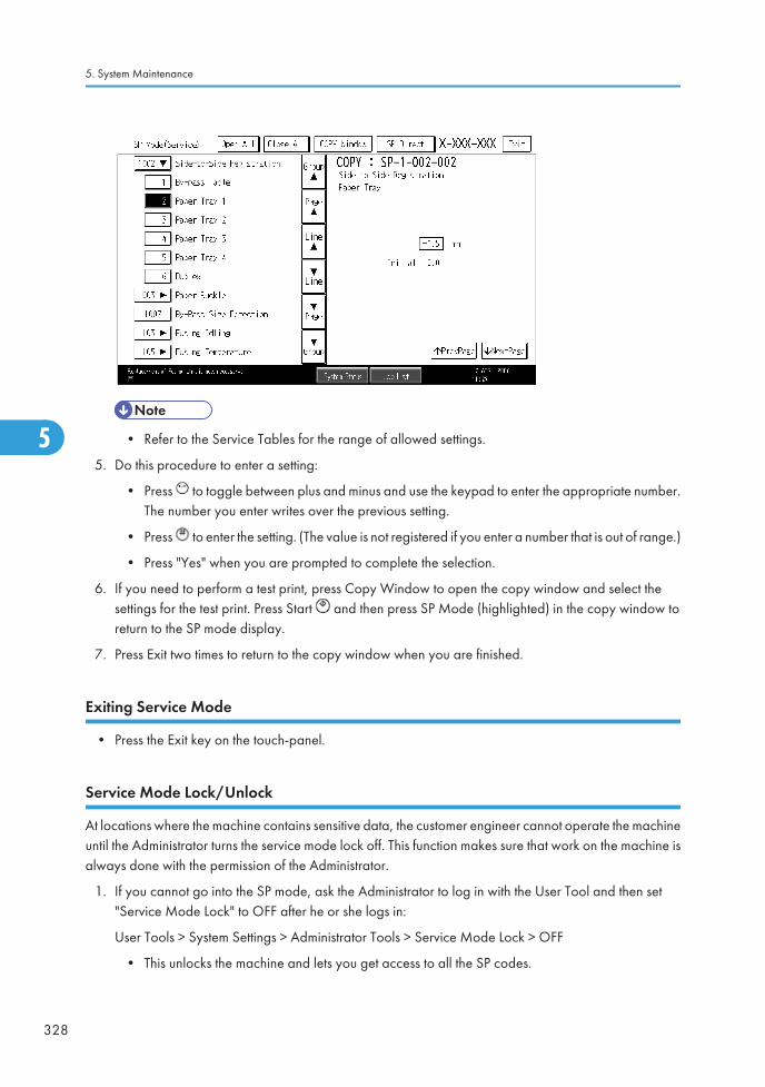
• Refer to the Service Tables for the range of allowed settings.
5. Do this procedure to enter a setting:
• Press to toggle between plus and minus and use the keypad to enter the appropriate number.The number you enter writes over the previous setting.
• Press to enter the setting. (The value is not registered if you enter a number that is out of range.)
• Press "Yes" when you are prompted to complete the selection.
6. If you need to perform a test print, press Copy Window to open the copy window and select thesettings for the test print. Press Start and then press SP Mode (highlighted) in the copy window toreturn to the SP mode display.
7. Press Exit two times to return to the copy window when you are finished.
Exiting Service Mode
• Press the Exit key on the touch-panel.
Service Mode Lock/Unlock
At locations where the machine contains sensitive data, the customer engineer cannot operate the machineuntil the Administrator turns the service mode lock off. This function makes sure that work on the machine isalways done with the permission of the Administrator.
1. If you cannot go into the SP mode, ask the Administrator to log in with the User Tool and then set"Service Mode Lock" to OFF after he or she logs in:
User Tools > System Settings > Administrator Tools > Service Mode Lock > OFF
• This unlocks the machine and lets you get access to all the SP codes.
5. System Maintenance
328
5
• The CE can service the machine and turn the machine off and on. It is not necessary to ask theAdministrator to log in again each time the machine is turned on.
2. Go into the SP mode and set SP5169 to "1" if you must use the printer bit switches.
3. After machine servicing is completed:
• Change SP5169 from "1" to "0".
• Turn the machine off and on. Tell the administrator that you have completed servicing themachine.
• The Administrator will then set the "Service Mode Lock" to ON.
Remarks
Display on the Control Panel Screen
The maximum number of characters which can show on the control panel screen is limited to 30 characters.For this reason, some of the SP modes shown on the screen need to be abbreviated. The following areabbreviations used for the SP modes for which the full description is over 20 characters.
Paper Weight
Thin paper: 52-59 g/m2
Plain Paper: 60-90 g/m2, 16-24lb.
Middle Thick: 91-105 g/m2, 24-28lb.
Thick Paper 1: 106-169 g/m2, 28.5-44.9lb.
Thick Paper 2: 170-220 g/m2, 45-58lb.
Thick Paper 3: 221-256 g/m2, 59lb-68lb
Thick 4: 257 g/m2-300 g/m2, 68.4-79.8lb
Paper Type
N: Normal paper
MTH: Middle thick paper
TH: Thick paper
Paper Feed Station
P: Paper tray
B: By-pass table
Service Program Mode
329
5
Color Mode [Color]
[K]: Black in B&W mode
[Y], [M], or [C]: Yellow, Magenta, or Cyan in Full Color mode
[YMC]: Only for Yellow, Magenta, and Cyan
[FC]: Full Color mode
[FC, K], [FC, Y], [FC, M], or [FC, C]: Black, Yellow, Magenta, or Cyan in full color mode
Print Mode
S: Simplex
D: Duplex
Process Speed
L: Low speed (77 mm/s)
M: Middle speed (154 mm/s)
Others
The following symbols are used in the SP mode tables.
FA: Factory setting
(Data may be adjusted from the default setting at the factory. Refer to the factory setting sheets enclosed.You can find it under the jammed paper removal decal.)
DFU: Design/Factory Use only
Do not touch these SP modes in the field.
A sharp (#) to the right hand side of the mode number column means that the main switch must be turnedoff and on to effect the setting change.
An asterisk (*) to the right hand side of the mode number column means that this mode is stored in theNVRAM. If you do a RAM clear, this SP mode will be reset to the default value. "ENG" and "CTL" showwhich NVRAM contains the data.
• ENG: NVRAM on the BICU board
• CTL: NVRAM on the controller board
The settings of each SP mode are explained in the right-hand column of the SP table in the following way.
[Adjustable range / Default setting / Step] Alphanumeric
• If "Alphanumeric" is written to the right of the bracket as shown above, the setting of the SP modeshows on the screen using alphanumeric characters instead of only numbers. However, the settingsin the bracket in the SP mode table are explained by using only the numbers.
SSP: This denotes a "Special Service Program" mode setting.
5. System Maintenance
330
5

Main SP Tables-1
SP1-XXX (Feed)
1001
[Leading Edge Registration] Leading Edge Registration Adjustment
(Tray Location, Paper Type, Color Mode), Paper Type -> Plain, Thick 1or Thick 2
Adjusts the leading edge registration by changing the registration motor operation timing foreach mode.
002 Tray: Plain *ENG
[–9 to 9 / 0.0 / 0.1 mm/step]
003 Tray: Middle Thick *ENG
004 Tray: Thick 1 *ENG
005 Tray: Thick 2 *ENG
007 By-pass: Plain *ENG
008 By-pass: Middle Thick *ENG
009 By-pass: Thick 1 *ENG
010 By-pass: Thick 2 *ENG
011 By-pass: Thick 3 *ENG
013 Duplex: Plain *ENG
014 Duplex: Middle Thick *ENG
015 Duplex: Thick 1 *ENG
Main SP Tables-1
331
5

016 Tray: Thick 3 *ENG
[–9 to 9 / 0.0 / 0.1 mm/step]
017 Tray: Plain:1200 *ENG
018 Tray: Middle Thick:1200 *ENG
019 Tray: Thick 1:1200 *ENG
020 By-pass: Plain:1200 *ENG
021 By-pass: Middle Thick:1200 *ENG
022 By-pass: Thick 1:1200 *ENG
023 Duplex: Plain:1200 *ENG
024 Duplex: Middle Thick:1200 *ENG
025 Duplex: Thick 1:1200 *ENG
1002
[Side to Side Reg.] Side-to-Side Registration Adjustment
Adjusts the side-to-side registration by changing the laser main scan start position for eachmode.
001 By-pass Table *ENG
[–4 to 4 / 0.0 / 0.1 mm/step]
002 Paper Tray 1 *ENG
003 Paper Tray 2 *ENG
004 Paper Tray 3 *ENG
005 Paper Tray 4 *ENG
006 Duplex *ENG
007 Paper Tray 5 *ENG
008 Large Capacity Tray *ENG
1003
[Paper Buckle] Paper Buckle Adjustment
(Tray Location, Paper Type), Paper Type: N: Normal, TH: Thick
Adjusts the amount of paper buckle at the registration roller by changing the paper feedtiming.
002 Paper Tray1: Plain *ENG [–9 to 5 / -2 / 1 mm/step]
5. System Maintenance
332
5

003 Tray1: Middle Thick *ENG [–9 to 5 / -1 / 1 mm/step]
004 Paper Tray1: Thick1 *ENG[–9 to 5 / -2 / 1 mm/step]
007 Paper Tray2/3/4/5/LCT: Plain *ENG
008 Tray 2/3/4/5/LCT: Middle Thick *ENG [–9 to 5 / -1 / 1 mm/step]
009 Paper Tray2/3/4/5/LCT: Thick 1 *ENG [–9 to 5 / -2 / 1 mm/step]
012 By-pass: Plain *ENG[–9 to 5 / 0 / 1 mm/step]
013 By-pass: Middle Thick *ENG
014 By-pass: Thick 1 *ENG [–9 to 5 / -2 / 1 mm/step]
018 Duplex: Plain *ENG[–9 to 5 / 0 / 1 mm/step]
019 Duplex: Middle Thick *ENG
020 Duplex: Thick 1 *ENG [–9 to 5 / -2 / 1 mm/step]
021 Paper Tray1: Plain: 1200 *ENG
[–9 to 5 / 0 / 1 mm/step]
022 Tray1: Middle Thick: 1200 *ENG
023 Tray 2/3/4/5LCT: Plain: 1200 *ENG
024 Tray 2/3/4/5LCT: Mid: 1200 *ENG
025 By-pass: Plain: 1200 *ENG
026 By-pass: Middle Thick: 1200 *ENG
027 Paper Tray1: Thick1: 1200 *ENG
[–9 to 5 / -2 / 1 mm/step]028 Paper Tray2/3/4/5/LCT: Thick 1:1200 *ENG
029 By-pass: Thick 1: 1200 *ENG
030 Duplex: Plain: 1200 *ENG[–9 to 5 / 0 / 1 mm/step]
031 Duplex: Middle Thick: 1200 *ENG
032 Duplex: Thick 1: 1200 *ENG [–9 to 5 / -2 / 1 mm/step]
1007 [By-Pass Size Detection] By-Pass Size Detection Display
Main SP Tables-1
333
5

001
LG *ENG [0 or 1 / 0 / - ] 0: OFF, 1: ON
Enables or disables the automatic paper size detection function of the by-pass tray.
This SP determines what paper size the machine detects if the detected size is less than 8.5”.
0: OFF (Letter/SEF), 1: ON (Legal/SEF)
1101[Reload Permit Setting]
Specifies the settings of the reload permit for cold temperature in color mode.
001 Pre-rotation Start Temp. *ENG [0 to 200 / 0 / 1 deg/step]
002 Reload Target Temp.:Center *ENG [120 to 180 / 150 / 1 deg/step]
003 Reload Target Temp.:Press *ENG [0 to 200 / 120 / 1 deg/step]
004 Temp.:Delta:Cold:Center *ENG [0 to 200 / 5 / 1 deg/step]
005 Temp.:Delta:Cold:End *ENG [40 to 200 / 100 / 1 deg/step]
006 Temp.:Delta:Cold:Press *ENG [0 to 200 / 65 / 1 deg/step]
[Forced Ready Set]
Specifies the setting of the forced reload permit for cold temperature in color mode.
007 Time:Cold *ENG [0 to 100 / 30 / 1 sec/step]
[Reload Permit Setting]
Specifies the settings of the reload permit for warm temperature in color mode.
008 Temp.:Delta:Warm:Center *ENG [0 to 200 / 5 / 1 deg/step]
009 Temp.:Delta:Warm:End *ENG [40 to 200 / 100 / 1 deg/step]
010 Temp.:Delta:Warm:Press *ENG [0 to 200 / 65 / 1 deg/step]
[Forced Ready Set]
Specifies the setting of the forced reload permit for warm temperature in color mode.
011 Time:Warm *ENG [0 to 100 / 30 / 1 sec/step]
[Reload Permit Setting]
Specifies the settings of the reload permit for hot temperature in color mode.
012 Temp.:Delta:Hot:Center *ENG [0 to 200 / 5 / 1 deg/step]
5. System Maintenance
334
5

013 Temp.:Delta:Hot:End *ENG [40 to 200 / 100 / 1 deg/step]
014 Temp.:Delta:Hot:Press *ENG [0 to 200 / 65 / 1 deg/step]
[Forced Ready Set]
Specifies the setting of the forced reload permit for hot temperature in color mode.
015 Time:Hot *ENG [0 to 100 / 30 / 1 sec/step]
[Reload Permit Setting Temp.]
Specifies the settings of the reload permit for cold temperature in BW mode.
016 Temp.:Delta:Cold:BW:Center *ENG [0 to 200 / 15 / 1 deg/step]
017 Temp.:Delta:Cold:BW:End *ENG [40 to 200 / 100 / 1 deg/step]
018 Temp.Delta:Cold:BW:Press *ENG [0 to 200 / 70 / 1 deg/step]
[Forced Ready Set]
Specifies the setting of the forced reload permit for cold temperature in BW mode.
019 Time:Cold:BW *ENG [0 to 100 / 30 / 1 sec/step]
[Reload Permit Setting]
Specifies the settings of the reload permit for cold temperature in BW mode 2.
020Temp.:Delta:Cold:BW2:Center
*ENG [0 to 200 / 15 / 1 deg/step]
021 Temp.:Delta:Cold:BW2:End *ENG [40 to 200 / 100 / 1 deg/step]
022 Temp.Delta:Cold:BW2:Press *ENG [0 to 200 / 100 / 1 deg/step]
[Forced Ready Set]
Specifies the setting of the forced reload permit for cold temperature in BW mode 2.
023 Time:Cold:BW2 *ENG [0 to 100 / 30 / 1 sec/step]
1102[Feed Permit Setting]
Specified the settings of the paper feeding timing.
001 Temp.:Lower Delta:Center *ENG [0 to 200 / 15 / 1 deg/step]
002 Temp.:Lower Delta:End *ENG [0 to 200 / 100 / 1 deg/step]
003 Temp.:Upper Delta:Center *ENG [0 to 200 / 100 / 1 deg/step]
Main SP Tables-1
335
5

004 Temp.:Upper Delta:End *ENG [0 to 200 / 100 / 1 deg/step]
005 Temp.:Lower Delta:Press *ENG [0 to 200 / 100 / 1 deg/step]
006 Rotation Time *ENG [0 to 100 / 0 / 1 sec/step]
007Temp.:LowerDelta:Center:Sp.1
*ENG [0 to 200 / 5 / 1 deg/step]
008 Temp.:Lower Delta:End:Sp.1 *ENG [0 to 200 / 100 / 1 deg/step]
009Temp.:UpperDelta:Center:Sp.1
*ENG [0 to 200 / 100 / 1 deg/step]
010 Temp.:Upper Delta:End:Sp.1 *ENG [0 to 200 / 100 / 1 deg/step]
011 Temp.:Lower Delta:Press:Sp.1 *ENG [0 to 200 / 60 / 1 deg/step]
012 Rotation Time:Sp.1 *ENG [0 to 200 / 0 / 1 sec/step]
013Temp.:LowerDelta:Center:Sp.2
*ENG [0 to 200 / 5 / 1 deg/step]
014 Temp.:Lower Delta:End:Sp.2 *ENG [0 to 200 / 100 / 1 deg/step]
015Temp.:UpperDelta:Center:Sp.2
*ENG [0 to 200 / 15 / 1 deg/step]
016 Temp.:Upper Delta:End:Sp.2 *ENG [0 to 200 / 100 / 1 deg/step]
017 Temp.:Lower Delta:Press:Sp.2 *ENG [0 to 200 / 100 / 1 deg/step]
018 Rotation Time:Sp2 *ENG [0 to 100 / 0 / 1 sec/step]
019 Feed Permit Time *ENG [0 to 200 / 120 / 1 sec/step]
1105 [Print Target Temp]
(Printing Mode, Roller Type, [Color], Simplex/Duplex)
Roller Type –> Center and Ends: Heating roller, Pressure –> Pressure roller
Paper Type -> Plain, Thin, Thick, OHP, Middle Thick, Special
001Plain1:FC:Center *ENG [120 to 200 / 155 / 1 deg/step]
Specifies the heating roller target temperature for the ready condition in full color printing.
5. System Maintenance
336
5

002Plain1:FC:Press *ENG [100 to 200 / 120 / 1 deg/step]
Specifies the pressure roller target temperature for the ready condition in full color printing..
003Plain1:BW:Center *ENG [120 to 200 / 145 / 1 deg/step]
Specifies the heating roller target temperature for the ready condition in BW printing.
004Plain1:BW:Press *ENG [100 to 200 / 120 / 1 deg/step]
Specifies the pressure roller target temperature for the ready condition in BW printing.
005Plain2:FC:Center *ENG [120 to 200 / 160 / 1 deg/step]
Specifies the heating roller target temperature for the ready condition in full color printing.
006Plain2:FC:Press *ENG [100 to 200 / 120 / 1 deg/step]
Specifies the pressure roller target temperature for the ready condition in full coloe printing.
007Plain2:BW:Center *ENG [120 to 200 / 150 / 1 deg/step]
Specifies the heating roller target temperature for the ready condition in BW printing.
008Plain2:BW:Press *ENG [100 to 200 / 120 / 1 deg/step]
Specifies the pressure roller target temperature for the ready condition in BW printing.
009 Thin:FC:Center *ENG [120 to 200 / 150 / 1 deg/step]
010 Thin:FC:Press *ENG [100 to 200 / 120 / 1 deg/step]
011 Thin:BW:Center *ENG [120 to 200 / 140 / 1 deg/step]
012 Thin:BW:Press *ENG [100 to 200 / 120 / 1 deg/step]
013 M-thick:FC:Center *ENG [120 to 200 / 165 / 1 deg/step]
014 M-thick:FC:Press *ENG [100 to 200 / 120 / 1 deg/step]
015 M-thick:BW:Center *ENG [120 to 200 / 155 / 1 deg/step]
016 M-thick:BW:Press *ENG [100 to 200 / 120 / 1 deg/step]
017 Thick1:FC:Center *ENG [120 to 200 / 155 / 1 deg/step]
018 Thick1:FC:Press *ENG [100 to 200 / 120 / 1 deg/step]
019 Thick1:BW:Center *ENG [120 to 200 / 145 / 1 deg/step]
020 Thick1:BW:Press *ENG [100 to 200 / 120 / 1 deg/step]
Main SP Tables-1
337
5

021 Thick2:FC:Center *ENG [120 to 200 / 165 / 1 deg/step]
022 Thick2:FC:Press *ENG [100 to 200 / 120 / 1 deg/step]
023 Thick2:BW:Center *ENG [120 to 200 / 155 / 1 deg/step]
024 Thick2:BW:Press *ENG [100 to 200 / 120 / 1 deg/step]
025 Thick3:FC:Center *ENG [120 to 200 / 170 / 1 deg/step]
026 Thick3:FC:Press *ENG [100 to 200 / 120 / 1 deg/step]
027 Thick3:BW:Center *ENG [120 to 200 / 160 / 1 deg/step]
028 Thick3:BW:Press *ENG [100 to 200 / 120 / 1 deg/step]
029 Special1:FC:Center *ENG [120 to 200 / 160 / 1 deg/step]
030 Special1:FC:Press *ENG [100 to 200 / 120 / 1 deg/step]
031 Special1:BW:Center *ENG [120 to 200 / 150 / 1 deg/step]
032 Special1:BW:Press *ENG [100 to 200 / 120 / 1 deg/step]
033 Special2:FC:Center *ENG [120 to 200 / 155 / 1 deg/step]
034 Special2:FC:Press *ENG [100 to 200 / 120 / 1 deg/step]
035 Special2:BW:Center *ENG [120 to 200 / 145 / 1 deg/step]
036 Special2:BW:Press *ENG [100 to 200 / 120 / 1 deg/step]
037 Special3:FC:Center *ENG [120 to 200 / 165 / 1 deg/step]
038 Special3:FC:Press *ENG [100 to 200 / 120 / 1 deg/step]
039 Special3:BW:Center *ENG [120 to 200 / 155 / 1 deg/step]
040 Special3:BW:Press *ENG [100 to 200 / 120 / 1 deg/step]
041 Envelop:Center *ENG [120 to 200 / 180 / 1 deg/step]
042 Envelop:Press *ENG [100 to 200 / 120 / 1 deg/step]
101 Plain1:FC:Center:Low Speed *ENG [120 to 200 / 135 / 1 deg/step]
102 Plain1:FC:Press:Low Speed *ENG [100 to 200 / 120 / 1 deg/step]
103Plain1:BW:Center:LowSpeed
*ENG [120 to 200 / 135 / 1 deg/step]
5. System Maintenance
338
5

104 Plain1:BW:Press:Low Speed *ENG [100 to 200 / 120 / 1 deg/step]
105 Plain2:FC:Center:Low Speed *ENG [120 to 200 / 140 / 1 deg/step]
106 Plain2:FC:Press:Low Speed *ENG [100 to 200 / 120 / 1 deg/step]
107Plain2:BW:Center:LowSpeed
*ENG [120 to 200 / 135 / 1 deg/step]
108 Plain2:BW:Press:Low Speed *ENG [100 to 200 / 120 / 1 deg/step]
109M-thick:FC:Center:LowSpeed
*ENG [120 to 200 / 145 / 1 deg/step]
110 M-thick:FC:Press:Low Speed *ENG [100 to 200 / 120 / 1 deg/step]
111M-thick:BW:Center:LowSpeed
*ENG [120 to 200 / 140 / 1 deg/step]
112 M-thick:BW:Press:Low Speed *ENG [100 to 200 / 120 / 1 deg/step]
113 Thick1:FC:Center:Low Speed *ENG [120 to 200 / 150 / 1 deg/step]
114 Thick1:FC:Press:Low Speed *ENG [100 to 200 / 120 / 1 deg/step]
115Thick1:BW:Center:LowSpeed
*ENG [120 to 200 / 145 / 1 deg/step]
116 Thick1:BW:Press:Low Speed *ENG [100 to 200 / 120 / 1 deg/step]
117Special1:FC:Center:LowSpeed
*ENG [120 to 200 / 135 / 1 deg/step]
118Special1:FC:Press:LowSpeed
*ENG [100 to 200 / 120 / 1 deg/step]
119Special1:BW:Center:LowSpeed
*ENG [120 to 200 / 130 / 1 deg/step]
120Special1:BW:Press:LowSpeed
*ENG [100 to 200 / 120 / 1 deg/step]
121Special2:FC:Center:LowSpeed
*ENG [120 to 200 / 150 / 1 deg/step]
122Special2:FC:Press:LowSpeed
*ENG [100 to 200 / 120 / 1 deg/step]
Main SP Tables-1
339
5
123Special2:BW:Center:LowSpeed
*ENG [120 to 200 / 145 / 1 deg/step]
124Special2:BW:Press:LowSpeed
*ENG [100 to 200 / 120 / 1 deg/step]
125 Plain1:Glossy:Center *ENG [120 to 200 / 140 / 1 deg/step]
126 Plain1:Glossy:Press *ENG [100 to 200 / 120 / 1 deg/step]
127 Plain2:Glossy:Center *ENG [120 to 200 / 145 / 1 deg/step]
128 Plain2:Glossy:Press *ENG [100 to 200 / 120 / 1 deg/step]
129 M-thick:Glossy:Center *ENG [120 to 200 / 150 / 1 deg/step]
130 M-thick:Glossy:Press *ENG [100 to 200 / 120 / 1 deg/step]
131 OHP:Center *ENG [120 to 200 / 150 / 1 deg/step]
132 OHP:Press *ENG [100 to 200 / 120 / 1 deg/step]
133 Envelop:Center:Low Speed *ENG [120 to 200 / 170 / 1 deg/step]
134 Envelop:Press:Low Speed *ENG [100 to 200 / 120 / 1 deg/step]
135 Thin:FC:Center:Low Speed *ENG [120 to 200 / 135 / 1 deg/step]
136 Thin:FC:Press:Low Speed *ENG [100 to 200 / 120 / 1 deg/step]
137 Thin:BW:Center:Low Speed *ENG [120 to 200 / 130 / 1 deg/step]
138 Thin:BW:Press:Low Speed *ENG [100 to 200 / 120 / 1 deg/step]
139 Thick4:FC:Center *ENG [120 to 200 / 175 / 1 deg/step]
140 Thick4:FC:Press *ENG [100 to 200 / 120 / 1 deg/step]
141 Thick4:BW:Center *ENG [120 to 200 / 165 / 1 deg/step]
142 Thick4:BW:Press *ENG [100 to 200 / 120 / 1 deg/step]
1106 [Fusing Temp. Display]
001 Center - [-10 to 250 / - / 1 deg/step]
Displays the temperature of the heating roller.002 End -
5. System Maintenance
340
5

003 Pressure - [-10 to 250 / - / 1 deg/step]
Displays the temperature of the heating roller.004 Pressure End -
1107 [Standby Target Temp. Setting]
001
Standby Heater Off Time *ENG [0 to 100 / 15 / 1 sec/step]
Specifies the time that the fusing heater turns off after the fusing unit temperature has reachedits target temperature.
002Stanby/Preheat1: Press *ENG [0 to 125 / 90 / 1 deg/step]
Specifies the temperature of the pressure roller for the ready or energy save 1 mode.
004Preheat2:Press *ENG [0 to 125 / 90 / 1 deg/step]
Specifies the temperature of the pressure roller for the energy save 2 mode.
006Low Power:Press *ENG [0 to 125 / 60 / 1 deg/step]
Specifies the temperature of the pressure roller for the low power mode.
007Print Ready:Center *ENG [120 to 180 / 150 / 1 deg/step]
Specifies the temperature of the heating roller for the print ready condition.
008Print Ready:Press *ENG [100 to 200 / 120 / 1 deg/step]
Specifies the temperature of the pressure roller for the print ready condition.
1108 [After Reload/Job Target Temp.]
001Center *ENG [120 to 180 / 150 / 1 deg/step]
Specifies the temperature of the heating roller after re-load or job.
002Press *ENG [100 to 200 / 120 / 1 deg/step]
Specifies the temperature of the pressure roller after re-load or job.
1111 [Environment Correction:Fusing]
001
Temp.: Threshold: Low *ENG [0 to 100 / 17 / 1 deg/step]
Specifies the threshold temperature for low temperature. If the fusing temperature is 17°Cor less, the machine executes the fusing mode for low temperature.
Main SP Tables-1
341
5

002
Temp.: Threshold: High *ENG [0 to 100 / 30 / 1 deg/step]
Sepcifies the threshold temperature for high temperature. If the fusing temperature is 30°Cor more, the machine executes the fusing mode for high temperature.
003
Low Temp. Correction *ENG [0 to 15 / 5 / 1 deg/step]
Specifies the additional temperature for the target temperature. If the fusing temperature isin low temperature condition, this temperature is added to the taraget temperature.
004
High Temp. Correction *ENG [0 to 15 / 0 / 1 deg/step]
Specifies the additional temperature for the target temperature. If the fusing temperature isin high temperature condition, this temperature is added to the taraget temperature.
005 Job Low Temp. Correction *ENG [0 to 100 / 5 / 0.1 deg/step]
006 Job High Temp. Correction *ENG [0 to 100 / 0 / 0.1 deg/step]
007 Job Low Temp. Correction:Sp. *ENG [0 to 100 / 10 / 0.1 deg/step]
008Job High Temp.Correction:Sp.
*ENG [0 to 100 / 0 / 0.1 deg/step]
1113 [Curl Correction]
001Execute Pattern *ENG
[0 to 2 / 0 / 1 /step]
0: Off, 1: On (No Decurl), 2: On
Selects the curl correction type.
002Humidity:Threshold:M-humid *ENG [0 to 100 / 1 / 1 %/step]
Specifies the threshold between low and middle humidity.
003Humidity:Threshold:H-humid *ENG [0 to 100 / 65 / 1 %/step]
Specifies the threshold between middle and high humidity.
004
Permit Temp.:Delta:Press:M-humid
*ENG [0 to 200 / 60 / 1 deg/step]
Specifies the threshold temperature for the curl control in middle humidity.
005
Permit Temp.:Delta:Press:H-humid
*ENG [0 to 200 / 50 / 1 deg/step]
Specifies the threshold temperature for the curl control in high humidity.
5. System Maintenance
342
5

006Permit Temp.:Delta:Press:M-humid:No Decurl
*ENG [0 to 200 / 50 / 1 deg/step]
Specifies the threshold temperature for the no curl control in middle humidity.
007
Permit Temp.:Delta:Press:H-humid:No Decurl
*ENG [0 to 200 / 40 / 1 deg/step]
Specifies the threshold temperature for the no curl control in high humidity.
008
CPM:M-humid *ENG [0 to 100 / 80 / 1 %/step]
Specifies the CPM ratio of the decurl control against to the normal operation in middlehumidity.
009CPM:H-humid *ENG [0 to 100 / 65 / 1 %/step]
Specifies the CPM ratio of the decurl control against to the normal operation in high humidity.
010
CPM:M-humid:No Decurl *ENG [0 to 100 / 80 / 1 %/step]
Specifies the CPM ratio against of the no decurl control to the normal operation in middlehumidity.
011
CPM:H-humid:No Decurl *ENG [0 to 100 / 65 / 1 %/step]
Specifies the CPM ratio against of the no decurl control to the normal operation in highhumidity.
1115 [Target Temp. Correction]
001Temp.:Delta:End *ENG [-100 to 100 / 0 / 1 deg/step]
Specifies the different temperature between end and center of the heating roller.
1124[CPM Down Setting]
Specifies the settings for the CPM down mode.
001 Low:Down Temp. *ENG [-50 to 0 / -20 / 1 deg/step]
Specifies the CPM down threshold temperature for the low temperature condition. If the fusingtemperature decreases -20°C (adjustable) below the target temperature, the machine entersthe CPM down mode.
002 Low:Up Temp. *ENG [-50 to 0 / -15 / 1 deg/step]
Main SP Tables-1
343
5

Specifies the CPM up threshold temperature for the low temperature condition. If the fusingtemperature increases -15°C (adjustable) below the target temperature, the machine entersthe CPM up mode.
003 Low :1st CPM *ENG [10 to 100 / 80 / 5 %/step]
Specifies the 1st CPM down ration against the normal CPM in the low temperature condition.
004 Low :2nd CPM *ENG [10 to 100 / 65 / 5 %/step]
Specifies the 2nd CPM down ration against the normal CPM in the low temperature condition.
005 Low :3rd CPM *ENG [10 to 100 / 50 / 5 %/step]
Specifies the 3rd CPM down ration against the normal CPM in the low temperature condition.
006 High :1st CPM *ENG [10 to 100 / 75 / 5 %/step]
Specifies the 1st CPM down ration against the normal CPM in the high temperature condition.
007 High:2nd CPM *ENG [10 to 100 / 50 / 5 %/step]
Specifies the 3rd CPM down ration against the normal CPM in the high temperature condition.
008 High:3rd CPM *ENG [10 to 100 / 25 / 5 %/step]
Specifies the 1st CPM down ration against the normal CPM in the high temperature condition.
009High:1st CPM DownTemp.:A3
*ENG [100 to 250 / 230 / 1 deg/step]
Specifies the heating roller temperature for 1st CPM down of A3 paper size.
010High:2nd CPM DownTemp.:A3
*ENG [100 to 250 / 233 / 1 deg/step]
Specifies the heating roller temperature for 2nd CPM down of A3 paper size.
011High:3rd CPM DownTemp.:A3
*ENG [100 to 250 / 235 / 1 deg/step]
Specifies the heating roller temperature for 3rd CPM down of A3 paper size.
012High:1st CPM DownTemp.:A4
*ENG [100 to 250 / 180 / 1 deg/step]
Specifies the heating roller temperature for 1st CPM down of A4 paper size.
5. System Maintenance
344
5

013High:2nd CPM DownTemp.:A4
*ENG [100 to 250 / 183 / 1 deg/step]
Specifies the heating roller temperature for 2nd CPM down of A4 paper size.
014High:3rd CPM DownTemp.:A4
*ENG [100 to 250 / 185 / 1 deg/step]
Specifies the heating roller temperature for 3rd CPM down of A4 paper size.
015High:1st CPM DownTemp.:B5:Press
*ENG [100 to 250 / 175 / 1 deg/step]
Specifies the pressure roller temperature for 1st CPM down of B5 paper size.
016High:2nd CPM DownTemp.:B5:Press
*ENG [100 to 250 / 180 / 1 deg/step]
Specifies the pressure roller temperature for 2nd CPM down of B5 paper size.
017High:3rd CPM DownTemp.:B5:Press
*ENG [100 to 250 / 185 / 1 deg/step]
Specifies the pressure roller temperature for 3rd CPM down of B5 paper size.
018High:1st CPM DownTemp.:A5:Press
*ENG [100 to 250 / 180 / 1 deg/step]
Specifies the pressure roller temperature for 1st CPM down of A5 paper size.
019High:2nd CPM DownTemp.:A5:Press
*ENG [100 to 250 / 185 / 1 deg/step]
Specifies the pressure roller temperature for 2nd CPM down of A5 paper size.
020High:3rd CPM DownTemp.:A5:Press
*ENG [100 to 250 / 190 / 1 deg/step]
Specifies the pressure roller temperature for 3rd CPM down of A5 paper size.
021High:1st CPM DownTemp.:A6:Press
*ENG [100 to 250 / 160 / 1 deg/step]
Specifies the pressure roller temperature for 1st CPM down of A6 paper size.
022High:2nd CPM DownTemp.:A6:Press
*ENG [100 to 250 / 165 / 1 deg/step]
Specifies the pressure roller temperature for 2nd CPM down of A6 paper size.
Main SP Tables-1
345
5

023High:3rd CPM DownTemp.:A6:Press
*ENG [100 to 250 / 170 / 1 deg/step]
Specifies the pressure roller temperature for 3rd CPM down of A6 paper size.
024 Judging Interval *ENG [0 to 250 / 5 / 1 sec/step]
Specifies the interval for CPM down judgement.
1141 [Fusing SC Issue Time Info]
001 SC Number *ENG Displays the issued SC number.
002 SC Cause *ENG [0 to 9 / - / 1/step]
101 Htg Roller:Ctr Diff1 *ENG[0 to 260 / - / 1 deg/step]
Displays the temperature at the center ofthe heating roller when an SC was issued.
102 Htg Rolloer:Ctr Det1 *ENG
103 Htg Roller:Ctr Corr1 *ENG
104 Htg Roller:End Diff1 *ENG[0 to 260 / - / 1 deg/step]
Displays the temperature at the end of theheating roller when an SC was issued.
105 Htg Roller:End Det1 *ENG
106 Htg Roller:End Corr1 *ENG
107 Press Roller Temp Value1 *ENG
[0 to 260 / - / 1 deg/step]
Displays the temperature at the pressureroller when an SC was issued.
151 Htg Roller:Ctr Diff2 *ENG
[0 to 260 / - / 1 deg/step]152 Htg Rolloer:Ctr Det2 *ENG
153 Htg Roller:Ctr Corr2 *ENG
154 Htg Roller:End Diff2 *ENG
[0 to 260 / - / 1 deg/step]155 Htg Roller:End Det2 *ENG
156 Htg Roller:End Corr2 *ENG
157 Press Roller Temp Value2 *ENG [0 to 260 / - / 1 deg/step]
5. System Maintenance
346
5

201 Htg Roller:Ctr Diff3 *ENG
[0 to 260 / - / 1 deg/step]202 Htg Rolloer:Ctr Det3 *ENG
203 Htg Roller:Ctr Corr3 *ENG
204 Htg Roller:End Diff3 *ENG
[0 to 260 / - / 1 deg/step]205 Htg Roller:End Det3 *ENG
206 Htg Roller:End Corr3 *ENG
207 Press Roller Temp Value3 *ENG [0 to 260 / - / 1 deg/step]
1142 [Fusing Jam Detection]
001
SC Display *ENG [0 or 1 / 0 / -]
Enables or disables the fusing consecutive jam (three times) SC detection.
0: No detection, 1: Detection
1151 [Pressure Setting]
001
Pressure Change ON/OFF *ENG [0 or 1 / 1 / -]
Enables or disables the pressure switching control for the fusing unit.
0: OFF , 1: ON
002Pressure Position1 *ENG [0 to 10,000 / 420 / 10 msec/step]
Specifies the rotation time of the pressure roller contact motor for the pressure position 1.
003Pressure Position2 *ENG [0 to 10,000 / 660 / 10 msec/step]
Specifies the rotation time of the pressure roller contact motor for the pressure position 2.
004Pressure Position3 *ENG [0 to 10,000 / 2130 / 10 msec/step]
Specifies the rotation time of the pressure roller contact motor for the pressure position 3.
005
Depressure Position *ENG [0 to 10,000 / 220 / 10 msec/step]
Specifies the rotation time of the pressure roller contact motor for the depression position (nopressure).
Main SP Tables-1
347
5

010
Shift Time *ENG [0 to 3600 / 5 / 1 sec/step]
Specifies the timing for depressing the fusing unit. If the machine does not get any jobs forspecified time by this SP after copying or printing, the machine depresses the fusing unit.
101 Pressure:Plain1/2 *ENG [0 to 3 / 3 / 1 /step]
Sets the default pressure position of the fusing unit for each paper type in normal speed.
0: Depression position (no pressure)
1: Position 1 (less pressure)
2: Position 2
3: Position 3 (strongest pressure)
102 Pressure:Thin *ENG [0 to 3 / 3 / 1 /step]
103 Pressure:M-thick *ENG [0 to 3 / 3 / 1 /step]
104 Pressure:Thick1 *ENG [0 to 3 / 3 / 1 /step]
105 Pressure:Thick2 *ENG [0 to 3 / 3 / 1 /step]
106 Pressure:Thick3 *ENG [0 to 3 / 3 / 1 /step]
107 Pressure:Special1 *ENG [0 to 3 / 3 / 1 /step]
108 Pressure:Special2 *ENG [0 to 3 / 3 / 1 /step]
109 Pressure:Special3 *ENG [0 to 3 / 3 / 1 /step]
110 Pressure:Envelope *ENG [0 to 3 / 1 / 1 /step]
151 Pressure:Plain1/2:Low Speed *ENG [0 to 3 / 3 / 1 /step]
Sets the default pressure position of the fusing unit for each paper type in low speed.
0: Depression position (no pressure)
1: Position 1 (less pressure)
2: Position 2
3: Position 3 (strongest pressure)
152 Pressure:M-thick:Low Speed *ENG [0 to 3 / 3 / 1 /step]
153 Pressure:Thick1:Low Speed *ENG [0 to 3 / 3 / 1 /step]
154 Pressure:Special1:Low Speed *ENG [0 to 3 / 3 / 1 /step]
155 Pressure:Special2:Low Speed *ENG [0 to 3 / 3 / 1 /step]
5. System Maintenance
348
5

156 Pressure:Plain1/2:Glossy *ENG [0 to 3 / 3 / 1 /step]
157 Pressure:M-thick:Glossy *ENG [0 to 3 / 3 / 1 /step]
158 Pressure:OHP *ENG [0 to 3 / 3 / 1 /step]
159 Pressure:Envelope:Low Speed *ENG [0 to 3 / 1 / 1 /step]
160 Pressure:Thin:Low Speed *ENG [0 to 3 / 3 / 1 /step]
161
Pressure:Thick4 *ENG [0 to 3 / 3 / 1 /step]
Sets the default pressure position of the fusing unit for thick 4 paper.
0: Depression position (no pressure)
1: Position 1 (less pressure)
2: Position 2
3: Position 3 (strongest pressure)
201Filler Edge Detection Counter ENG [0 to 9,000,000 / - / 1 /step]
Displays the detection time for the edge of the pressure roller actuator.
1152 [Fusing Nip Band Check]
001 Execute - [0 or 1 / 0 / 1]
Executes the nip band measurement between heating roller and pressure roller.
If the nip band width is not 8 mm, and fusing is not good, replace the pressure roller or installa new fusing unit.
002Pre-Idling Time *ENG [0 to 255 / 240 / 1 sec/step]
Specifies the fusing rotation time before executing SP1109-001.
003Stop Time * ENG [5 to 30 / 20 / 1 sec/step]
Specifies the time for measuring the nip.
004Pressure Position * ENG [1 to 3 / 3 / 1 ]
Specifies the pressure position for measuring the nip.
1153 [Fuser Cleaning]
001 Compulsion execution - Execute the fusing cleaning mode.
Main SP Tables-1
349
5

002
Operation interval *ENG [1 to 300 / 0 / 1 K/step]
Adjusts the execution interval for the fusing cleaning mode.
1K= 100 sheets
003Control Temp. *ENG [0 to 200 / 180 / 1°C/step]
Specifies the heating roller temperature for the fusing cleaning mode.
004Page Count *ENG [1 to 300000 / - / 1 page/step]
Displays the page counter for the fusing cleaning mode.
1801 [Motor Speed Adj.] FA
001 Registration:Plain:Low *ENG [–2 to 2 / –1.1 / 0.1 %/step]
002 Registration:Plain:High *ENG [–2 to 2 / –0.1 / 0.1 %/step]
003 Registration:Middle Thick:Low *ENG [–2 to 2 / –1.1 / 0.1 %/step]
004 Registration:Middle Thick:Mid *ENG[–2 to 2 / –0.1 / 0.1 %/step]
005 Registration:Middle Thick:High *ENG
006 Registration:Thick 1:Low *ENG [–2 to 2 / –1.1 / 0.1 %/step]
007 Registration:Thick1:Mid *ENG [–2 to 2 / –0.1 / 0.1 %/step]
008 Registration:Thick 2:Low *ENG[–2 to 2 / –1.1 / 0.1 %/step]
009 Registration:Thick 3:Low *ENG
5. System Maintenance
350
5

010 Duplex CW:Plane:Low *ENG
[–4 to 4 / 0.0 / 0.1 %/step]
011 Duplex CW:Normal:High *ENG
012 Duplex CW:Middle Thick:Low *ENG
013 Duplex CW:Middle Thick:Mid *ENG
014 Duplex CW:Middle Thick:High *ENG
015 Duplex CW:Thick1:Low *ENG
016 Duplex CW:Thick1:Mid *ENG
017 Duplex CW:Thick2:Low *ENG
018 Duplex CW:Thick3:Low *ENG
019 Duplex CCW:Normal:High *ENG
[–4 to 4 / 0.0 / 0.1 %/step]020 Duplex CCW:Middle Thick:Mid *ENG
021 Duplex CCW:Middle Thick:high *ENG
023 Duplex CCW:Thick1:Mid *ENG
024 Reverse CW:Normal:High *ENG [–4 to 4 / –0.5 / 0.1%/step]
025 Reverse CW:Middle Thick:Mid *ENG [–4 to 4 / 0 / 0.1 %/step]
026 Reverse CW:Middle Thick:High *ENG [–4 to 4 / –0.5 / 0.1%/step]
028 Reverse CW:Thick1:Mid *ENG
[–4 to 4 / 0 / 0.1 %/step]
029 Reverse CCW:Normal:High *ENG
030 Reverse CCW:Middle Thick:Mid *ENG
031 Reverse CCW:Middle Thick:High *ENG
033 Reverse CCW:Thick1:Mid *ENG
034 Feed:Plain:Low *ENG [–2 to 2 / –1.1 / 0.1 %/step]
035 Feed:Plain:High *ENG [–2 to 2 / –0.1 / 0.1 %/step]
036 Feed:Middle thick:Low *ENG [–2 to 2 / –1.1 / 0.1 %/step]
037 Feed:Middle thick:Mid *ENG[–2 to 2 / –0.1 / 0.1 %/step]
038 Feed:Middle thick:High *ENG
Main SP Tables-1
351
5
039 Feed:Thick 1:Low *ENG [–2 to 2 / –1.1 / 0.1 %/step]
040 Feed:Thick 1:Mid *ENG [–2 to 2 / –0.1 / 0.1 %/step]
041 Feed:Thick 2:Low *ENG[–2 to 2 / –1.1 / 0.1 %/step]
042 Feed:Thick 3:Low *ENG
043 Bridge Motor:Low *ENG
[–4 to 4 / 0 / 0.1 %/step]044 Bridge Motor:Mid *ENG
045 Bridge Motor:High *ENG
060 KOpcDevMot:High *ENG
[–4 to 4 / –0.6 / 0.01 %/step]061 KOpcDevMot:Mid *ENG
062 KOpcDevMot:Low *ENG
063 MOpcDevMot:High *ENG [–10 to 10 / 0 / 1 step/step]
064 MOpcDevMot:Mid *ENG [–9 to 9 / 0 / 1 step/step]
065 MOpcDevMot:Low *ENG [–14 to 14 / 0 / 1 step/step]
066 COpcDevMot:High *ENG [–10 to 10 / 0 / 1 step/step]
067 COpcDevMot:Mid *ENG [–9 to 9 / 0 / 1 step/step]
068 COpcDevMot:Low *ENG [–14 to 14 / 0 / 1 step/step]
069 YOpcDevMot:High *ENG [–10 to 10 / 0 / 1 step/step]
070 YOpcDevMot:Mid *ENG [–9 to 9 / 0 / 1 step/step]
071 YOpcDevMot:Low *ENG [–14 to 14 / 0 / 1 step/step]
072 Fusing: High *ENG [–4 to 4 / 1.9 / 0.01 %/step]
073 Fusing: Mid *ENG [–4 to 4 / 1.4 / 0.01 %/step]
074 Fusing: Low *ENG [–4 to 4 / 1.7 / 0.01 %/step]
075 TransferMot:High *ENG
[–4 to 4 / –0.2 / 0.01 %/step]076 TransferMot:Mid *ENG
077 TransferMot:Low *ENG
078 TonerMot *ENG [–30 to 30 / 10 / 5 %/step]
5. System Maintenance
352
5

079 Fusing Exit Motor: 1200 *ENG [–4 to 4 / 2.1 / 0.01 %/step]
100Drum Adjust *ENG
[0 or 1 / 1 / 1]
0: Off, 1: On
Enables or disables the drum amplitude adjustment.
101 MOpcDevMot:High *ENG
[–7 to 7 / 0 / 1 step/step]102 COpcDevMot:High *ENG
103 YOpcDevMot:High *ENG
104 MOpcDevMot:Mid *ENG
[–7 to 7 / 0 / 1 step/step]105 COpcDevMot:Mid *ENG
106 YOpcDevMot:Mid *ENG
107 MOpcDevMot:Low *ENG
[–14 to 14 / 0 / 1 step/step]108 COpcDevMot:Low *ENG
109 YOpcDevMot:Low *ENG
110 MOpcDevMot:1200 *ENG
[– 7 to 7 / 0 / 1 step/step]111 COpcDevMot:1200 *ENG
112 YOpcDevMot:1200 *ENG
120 Long:Registration:Plain:High *ENG [–2 to 2 / -0.1 / 0.1 %/step]
121 Long:Registration:Plain:Low *ENG [–2 to 2 / -1.1 / 0.1 %/step]
122 Long:Registration:Middle Thick:High *ENG
[–2 to 2 / -0.1 / 0.1 %/step]123
Long:Registration:MiddleThick:Middle
*ENG
124 Long:Registration:Middle Thick:Low *ENG [–2 to 2 / -1.1 / 0.1 %/step]
125 Long:Registration:Thick 1:Middle *ENG [–2 to 2 / -1 / 0.1 %/step]
126 Long:Registration:Thick 1:Low *ENG [–2 to 2 / -1.1 / 0.1 %/step]
127 Long:Registration:Thick 2:Low *ENG [–2 to 2 / -1.1 / 0.1 %/step]
128 Long:Registration:Thick 3:Low *ENG [–2 to 2 / -1.1 / 0.1 %/step]
Main SP Tables-1
353
5

129 Long:Fusing:Plain:High *ENG [–4 to 4 / 1.9 / 0.01 %/step]
130 Long:Fusing:Plain:Low *ENG [–4 to 4 / 2.1 / 0.01 %/step]
131 Long:Fusing:Middle Thick:High *ENG [–4 to 4 / 1.9 / 0.01 %/step]
132 Long:Fusing:Middle Thick:Middle *ENG [–4 to 4 / 1.4 / 0.01 %/step]
133 Long:Fusing:Middle Thick:Low *ENG [–4 to 4 / 2.1 / 0.01 %/step]
134 Long:Fusing:Thick 1:Middle *ENG [–4 to 4 / 2.0 / 0.01 %/step]
135 Long:Fusing:Thick 1:Low *ENG [–4 to 4 / 1.7 / 0.01 %/step]
136 Long:Fusing:Thick 2:Low *ENG [–4 to 4 / 1.7 / 0.01 %/step]
137 Long:Fusing:Thick 3:Low *ENG [–4 to 4 / 1.7 / 0.01 %/step]
1902 [Amplitude Control]
001 Execute - Execute the drum phase adjustment.
002 Result *ENG
[0 to 3 / 0 / 1]
Displays the result of the drum phase adjustment.
0: Successfully done
2: Sampling failure
3: Insufficient detection number
003 Auto Execution *ENG
[0 or 1 / 1 / -]
Turns the automatic drum phase adjustment on or off.
0: Off, 1: On
1950[Fan Cooling Time Set]
Adjust the rotation time for each fan motor after a job end.
5. System Maintenance
354
5

002 Fusing Exit Fan *ENG
[0 to 120 / 0 / 0.1 min./step]
006 Main Suction Fan *ENG
007 Paper Exit Fan *ENG
008 PSU Fan *ENG
009 Fusing IH Coil Fan *ENG
010 IH Power Supply Fan *ENG
011 Second Duct Fan *ENG
012 Third Duct Fan *ENG
1951[Fan Start Time Set]
Adjust the start time for each fan motor after a job end.
002 Fusing Exit Fan *ENG [0 to 900 / 0 / 1 sec/step]
006 Main Suction Fan *ENG [0 to 900 / 120 / 1 sec/step]
007 Paper Exit Fan *ENG [0 to 900 / 0 / 1 sec/step]
008 PSU Fan *ENG [0 to 900 / 120 / 1 sec/step]
009 Fusing IH Coil Fan *ENG
[0 to 900 / 0 / 1 sec/step]010 IH Power Supply Fan *ENG
011 Second Duct Fan *ENG
012 Third Duct Fan *ENG
1952[Fan Control Off Mode Time Set]
Specifies the time for fan control off mode.
001 - *ENG [0 to 60 / 10 / 1 min./step]
1953[Extra Fan Control]
Configures the settings of extra fan control.
Main SP Tables-1
355
5

001Extra Fan Cooling State *ENG
[0 or 1 / 0 / 1 /step]
0: Off, 1: On
Displays the extra fan cooling is On or Off.
002Extra Fan Cooling: Time:Threshold
*ENG[0 to 180 / C2.5a: 110, C2.5b: 100 / 1 min./step]
003Extra Fan Cooling: Rotat:Threshold
*ENG [0 to 999999999 / 0 / 1 min./step]
004 Extra Fan Cooling: Start Date *ENGDisplays the execution time and date of the extrafan cooling.
005Extra Fan Cooling Time *ENG [0 to 120 / 30 / 0.1 min./step]
Specifies the execution time for the extra fan cooling.
1954[Extra Fan Control]
Configures the settings of extra fan control.
002Fan Cooling Time:Fusing ExitFan:Initial
*ENG [0 to 120 / 0 / 0.1 min./step]
006Fan Cooling Time:MainSuction Fan:Initial
*ENG [0 to 120 / 0 / 0.1 min./step]
007Fan Cooling Time:Paper ExitFan:Initial
*ENG [0 to 120 / 0 / 0.1 min./step]
008Fan Cooling Time:PSUFan:Initial
*ENG [0 to 120 / 0 / 0.1 min./step]
009Fan Cooling Time:Fusing IHCoil Fan:Initial
*ENG [0 to 120 / 0 / 0.1 min./step]
010Fan Cooling Time:IH PowerSupply Fan:Initial
*ENG [0 to 120 / 0 / 0.1 min./step]
011Fan Cooling Time:SecondDuct Fan:Initial
*ENG [0 to 120 / 0 / 0.1 min./step]
012Fan Cooling Time:Third DuctFan:Initial
*ENG [0 to 120 / 0 / 0.1 min./step]
5. System Maintenance
356
5

Main SP Tables-2
SP2-XXX (Drum)
2005
[Charge DC Voltage] Charge Roller DC Voltage Adjustment
(Paper Type, Process Speed, Color)
Paper Type –> Plain, Thick 1, Thick 2
Plain: High speed, Thick 1: Middle speed, Thick 2&FINE: Low speed
Adjusts the DC component of the charge roller bias in the various print modes.
Charge bias (DC component) is automatically adjusted during process control; therefore,adjusting these settings does not effect while process control mode (SP3-041-1 Default: ON)is activated. When deactivating process control mode with SP3-041-1, the values in theseSP modes are used for printing.
001 Plain: Bk *ENG
[0 to 1000 / 690 / 10 –V/step]
002 Plain: M *ENG
003 Plain: C *ENG
004 Plain: Y *ENG
005 Thick 1: Bk *ENG
006 Thick 1: M *ENG
007 Thick 1: C *ENG
008 Thick 1: Y *ENG
009 Thick 2&FINE: Bk *ENG
010 Thick 2&FINE: M *ENG
011 Thick 2&FINE: C *ENG
012 Thick 2&FINE: Y *ENG
[Charge DC: Correction]
013 PCU:Plain *ENG [–100 to 100 / -29 / 1 –V/step]
014 PCU:Thick 1 *ENG [–100 to 100 / -28 / 1 –V/step]
Main SP Tables-2
357
5

015 PCU:Thick 2&FINE *ENG [–100 to 100 / -28 / 1 –V/step]
016 HVP:Plain *ENG [–100 to 100 / 20 / 1 –V/step]
017 HVP:Thick 1 *ENG [–100 to 100 / 20 / 1 –V/step]
018 HVP: Thick 2&FINE *ENG [–100 to 100 / 29 / 1 –V/step]
2006
[Charge AC Voltage] Charge Roller AC Voltage Adjustment
(Paper Type, Process Speed, Color)
Paper Type –> Plain, Thick 1, Thick 2
Plain: High speed, Thick 1: Middle speed, Thick 2&FINE: Low speed
Adjusts the AC component of the charge roller bias in the various print modes.
Charge bias (AC component) is adjusted by environment correction (SP2-007-xxx toSP2-011-xxx). These SPs are activated only when SP2-012-1 is set to "1: manual control".
001 Plain: Bk *ENG [0 to 3 / 1.9 / 0.01 KV/step]
002 Plain: M *ENG [0 to 3 / 2.2 / 0.01 KV/step]
003 Plain: C *ENG [0 to 3 / 2.2 / 0.01 KV/step]
004 Plain: Y *ENG [0 to 3 / 2.2 / 0.01 KV/step]
005 Thick 1: Bk *ENG [0 to 3 / 1.9 / 0.01 KV/step]
006 Thick 1: M *ENG [0 to 3 / 2.2 / 0.01 KV/step]
007 Thick 1: C *ENG [0 to 3 / 2.2 / 0.01 KV/step]
008 Thick 1: Y *ENG [0 to 3 / 2.2 / 0.01 KV/step]
009 Thick 2&FINE: Bk *ENG [0 to 3 / 1.9 / 0.01 KV/step]
010 Thick 2&FINE: M *ENG [0 to 3 / 2.2 / 0.01 KV/step]
011 Thick 2&FINE: C *ENG [0 to 3 / 2.2 / 0.01 KV/step]
012 Thick 2&FINE: Y *ENG [0 to 3 / 2.2 / 0.01 KV/step]
2012 [Charge Output Control]
5. System Maintenance
358
5

001 AC Voltage *ENG
Selects the AC voltage control type.
[0 or 1 / 0 / 1 /step]
0: Process control
1: Manual control (AC voltages are decidedwith SP2006.)
2013 [Environmental Correction: PCU]
001Current Environmental:Display
*ENG
Displays the environmental condition, which ismeasured in absolute humidity.
[1 to 5 / – / 1 /step]
1: LL (LL <= 4.3 g/m3)
2: ML (4.3 < ML <= 11.3 g/m3)
3: MM (11.3 < MM <= 18.0 g/m3)
4: MH (18.0 < MH <= 24.0 g/m3)
5: HH (24.0 g/m3 < HH)
002 Forced Setting *ENG
Selects the environmental condition manually.
[0 to 5 / 0 / 1 /step]
0: The environmental condition is determinedautomatically.
1: LL, 2: ML, 3: MM, 4: MH, 5: HH
003Absolute Humidity: Threshold1
*ENG
Changes the humidity threshold between LL andML.
[0 to 100 / 3.0 / 0.01 g/m3/step]
004Absolute Humidity: Threshold2
*ENG
Changes the humidity threshold between MLand MM.
[0 to 100 / 8.0 / 0.01 g/m3/step]
005Absolute Humidity: Threshold3
*ENG
Changes the humidity threshold between MMand MH.
[0 to 100 / 15.0 / 0.01 g/m3/step]
006Absolute Humidity: Threshold4
*ENG
Changes the humidity threshold between MHand HH.
[0 to 100 / 15.0 / 0.01 g/m3/step]
Main SP Tables-2
359
5

007 Current Temp.: Display *ENGDisplays the current temperature.
[0 to 100 / 0 / 1 deg/step]
008Current Relative Humidity:Display
*ENGDisplays the current relative humidity.
[0 to 100 / 0 / 1%RH/step]
009Current Absolute Humidity:Display
*ENGDisplays the absolute humidity.
[0 to 100 / 0 / 0.01 g/m3/step]
010Previous Environmental:Display
*ENG
Displays the previous environmental condition,which is measured in absolute humidity.
[1 to 5 / – / 1 /step]
1: LL, 2: ML, 3: MM, 4: MH, 5: HH
011 Previous Temp.: Display *ENGDisplays the previous temperature.
[0 to 100 / 0 / 1 deg/step]
012Previous Relative Humidity:Display
*ENGDisplays the previous relative humidity.
[0 to 100 / 0 / 1%RH/step]
013Previous Absolute Humidity:Display
*ENGDisplays the previous absolute humidity.
[0 to 100 / 0 / 0.01 g/m3/step]
2015 [Charge AC Adj: Result]
001 Bk *ENG [0 to 9 / 0 / 1 /step]
0: Success
1: Out of tolerance range
2: Out of adjustable range
3: Adjustment incompleted
002 M *ENG
003 C *ENG
004 Y *ENG
2101
[Color Registration Correction] FA
These values are the parameters for the automatic line position adjustment and are adjustedat the factory. However, you must input a value for SP2101-001 after replacing the laseroptics housing unit. For details, see "Laser Optics Housing Unit" in the "Replacement andAdjustment" section. The value should be provided with the new laser optics housing unit.
5. System Maintenance
360
5

001 Main Dot: Bk *ENG
[–512 to 511 / 0 / 1 dot/step]002 Main Dot: Ma *ENG
003 Main Dot: Cy *ENG
004 Main Dot: Ye *ENG
005 Sub Line: Bk *ENG
[–16384 to 16383 / 0 / 1 line/step]006 Sub Line: Ma *ENG
007 Sub Line: Cy *ENG
008 Sub Line: Ye *ENG
2103 [Erase Margin Adjustment] (Area, Paper Size)
Adjusts the erase margin by deleting image data at the margins.
001 Lead Edge Width *ENG[0 to 9.9 / 4.2 / 0.1 mm/step]
002 Trail. Edge Width *ENG
003 Left *ENG[0 to 9.9 / 2 / 0.1 mm/step]
004 Right *ENG
006 Duplex Trail. L Size *ENG [0 to 4 / 1 / 0.1 mm/step]
007 Duplex Trail. M Size *ENG [0 to 4 / 0.8 / 0.1 mm/step]
008 Duplex Trail. S Size *ENG [0 to 4 / 0.6 / 0.1 mm/step]
009 Duplex Left Edge *ENG[0 to 1.5 / 0.3 / 0.1 mm/step]
010 Duplex Right Edge *ENG
011 Duplex Trail. L Size:Thick *ENG [0 to 4 / 1 / 0.1 mm/step]
012 Duplex Trail. M Size:Thick *ENG [0 to 4 / 0.8 / 0.1 mm/step]
013 Duplex Trail. S Size:Thick *ENG [0 to 4 / 0.6 / 0.1 mm/step]
014 Duplex Left Edge:Thick *ENG[0 to 1.5 / 0.3 / 0.1 mm/step]
015 Duplex Right Edge:Thick *ENG
2105 [LD Power Adj.] (Process Speed, Color)
Main SP Tables-2
361
5

Adjusts the LD power of each color for each process speed.
Each LD power setting is decided by process control.
001 High Speed: Bk *ENG [50 to 120 / 100 / 1%/step]
Decreasing a value makes lines thinner on theoutput.
Increasing a value makes lines thicker on theoutput.
002 High Speed: Ma *ENG
003 High Speed: Cy *ENG
004 High Speed: Ye *ENG
005 Middle Speed: Bk *ENG [50 to 120 / 100 / 1%/step]
Decreasing a value makes lines thinner on theoutput.
Increasing a value makes lines thicker on theoutput.
006 Middle Speed: Ma *ENG
007 Middle Speed: Cy *ENG
008 Middle Speed: Ye *ENG
009 Low Speed: Bk *ENG [50 to 120 / 100 / 1%/step]
Decreasing a value makes lines thinner on theoutput.
Increasing a value makes lines thicker on theoutput.
010 Low Speed: Ma *ENG
011 Low Speed: Cy *ENG
012 Low Speed: Ye *ENG
2109[Test Pattern]
Generates the test pattern using "COPY Window" tab in the LCD.
003 Pattern Selection - [0 to 23 / 0 / 1/step]
5. System Maintenance
362
5

0 None
1: Vertical Line (1dot)
2: Vertical Line (2dot)
3: Horizontal (1dot)
4: Horizontal (2dot)
5: Grid Vertical Line
6: Grid Horizontal Line
7: Grid pattern Small
8: Grid pattern Large
9: Argyle Pattern Small
10: Argyle Pattern Large
11. Independent Pattern (1dot)
12. Independent Pattern (2dot)
13. Independent Pattern (4dot)
14. Trimming Area
16: Hound’s Tooth Check (Horizontal)
17: Band (Horizontal)
18: Band (Vertical)
19: Checker Flag Pattern
20: Grayscale Vertical Margin
21: Grayscale Horizontal Margin
23: Full Dot Pattern
005 Color Selection -
Specifies the color for the test pattern.
[1 to 4 / 1 / 1/step]
1: All colors, 2: Magenta, 3: Yellow, 4: Cyan
006 Density: Bk -Specifies the color density for the test pattern.
[0 to 15 / 15 / 1 /step]
0: Lightest density
15: Darkest density
007 Density: Ma -
008 Density: Cy -
009 Density: Ye -
2111 [Forced Line Position Adj.]
001 Mode a -
Executes the fine line position adjustment twice.
If this SP is not completed (NG is displayed), doSP2111-003 first and then try this SP again.
002 Mode b -
Executes the fine line position adjustment once.
If this SP is not completed, do SP2111-003 first andthen try this SP again.
003 Mode c -
Executes the rough line position adjustment once.
After doing this SP, make sure to executeSP2111-001 or -002. Otherwise, the line positionadjustment is not perfectly done.
Main SP Tables-2
363
5

2112 [TM/ID Sensor Check] ID Sensor Check FA
001 Execute
[0 or 1 / 0 / 1 /step]
This SP is used to check the ID sensors at the factory.The results of this SP are displayed in SP2140 toSP2145.
2117
[Skew Adjustment]
Specifies a skew adjustment value for the skew motor M, C or Y.
These SPs must be used when a new laser optics housing unit is installed or when SC2.585occurs. For details, see "Laser Optics Housing Unit" in the "Replacement and Adjustment"section.
001 Pulse: M *ENG
[–50 to 50 / 0 / 1 pulse/step]002 Pulse: C *ENG
003 Pulse: Y *ENG
2118 [Skew Adjustment]
001 Execute: M *ENG Changes the current skew adjustment values to thevalues specified with SP2117.
These SPs must be used when a new laser opticshousing unit is installed or when SC2.585 occurs.For details, see "Laser Optics Housing Unit" in the"Replacement and Adjustment" section.
002 Execute: C *ENG
003 Execute: Y *ENG
2119[Skew Adjustment Display]
Displays the current skew adjustment value for each skew motor.
001 M *ENG
[–50 to 50 / 0 / 1 pulse/step]002 C *ENG
003 Y *ENG
5. System Maintenance
364
5

2150
[Area Mag. Correction] LD Pulse Area Correction (Color, Area) FA
Adjusts the magnification for each area. The main scan (297 mm) is divided into 8 areas.Area 1 is at the front side of the machine (left side of the image) and area 8 is at the rearside of the machine (right side of the image).
Decreasing a value makes the image shift to the left side on the print.
Increasing a value makes the image shift to the right side on the print.
1 pulse = 1/16 dot
027 Area 0: Bk *ENG [-256 to 255 / 0 / 1sub-dot/step]
028 Area 1: Bk *ENG
Adjusts the area magnification for LD 0.
[–256 to 255 / 0 / 1 sub-dot/step ]
029 Area 2: Bk *ENG
030 Area 3: Bk *ENG
031 Area 4: Bk *ENG
032 Area 5: Bk *ENG
033 Area 6: Bk *ENG
034 Area 7: Bk *ENG
035 Area 8: Bk *ENG
036 Area 9: Bk *ENG
Not used037 Area 10: Bk *ENG
038 Area 11: Bk *ENG
039 Area 12: Bk *ENG
079 Area 0: Ma *ENG Not used
080 Area 1: Ma *ENGAdjusts the area magnification for LD 0. [–255to255 / 0 / 1 sub-dot/step]
Main SP Tables-2
365
5

081 Area 2: Ma *ENG
[–256to 255 / 0 / 1 sub-dot/step]
082 Area 3: Ma *ENG
083 Area 4: Ma *ENG
084 Area 5: Ma *ENG
085 Area 6: Ma *ENG
086 Area 7: Ma *ENG
087 Area 8: Ma *ENG
088 Area 9: Ma *ENG
Not used089 Area 10: Ma *ENG
090 Area 11: Ma *ENG
091 Area 12: Ma *ENG
131 Area 0: Cy *ENG Not used
132 Area 1: Cy *ENG
Adjusts the area magnification for LD 0.
[–256 to 255 / 0 / 1 sub-dot/step]
133 Area 2: Cy *ENG
134 Area 3: Cy *ENG
135 Area 4: Cy *ENG
136 Area 5: Cy *ENG
137 Area 6: Cy *ENG
138 Area 7: Cy *ENG
139 Area 8: Cy *ENG
140 Area 9: Cy *ENG
Not used141 Area 10: Cy *ENG
142 Area 11: Cy *ENG
143 Area 12: Cy *ENG
183 Area 0: Ye *ENG Not used
5. System Maintenance
366
5

184 Area 1: Ye *ENG
Adjusts the area magnification for LD 0.
[–256 to 255 / 0 / 1 sub-dot/step]
185 Area 2: Ye *ENG
186 Area 3: Ye *ENG
187 Area 4: Ye *ENG
188 Area 5: Ye *ENG
189 Area 6: Ye *ENG
190 Area 7: Ye *ENG
191 Area 8: Ye *ENG
192 Area 9: Ye *ENG
Not used193 Area 10: Ye *ENG
194 Area 11: Ye *ENG
195 Area 12: Ye *ENG
2152
[Area Shad. Correct. Setting] FA
Adjusts the area correction value for each LD power.
The main scan is divided into 16 areas. However, the image areas are limited from area 1to area 14.
For BK and Magenta, area 1 is at the rear side of the machine (left side of the image) andarea 14 is at the front side of the machine (right side of the image).
For Cyan and Yellow, area 1 is at the front side of the machine (right side of the image) andarea 14 is at the rear side of the machine (left side of the image).
Main SP Tables-2
367
5

001 Area 0: Bk *ENG
This is for the synchronizing detection board.
[50 to 150 / 100 / 1 %/step]
002 Area 1: Bk *ENG
003 Area 2: Bk *ENG
004 Area 3: Bk *ENG
005 Area 4: Bk *ENG
006 Area 5: Bk *ENG
007 Area 6: Bk *ENG
008 Area 7: Bk *ENG
009 Area 8: Bk *ENG
010 Area 9: Bk *ENG
011 Area 10: Bk *ENG
012 Area 11: Bk *ENG
013 Area 12: Bk *ENG
014 Area 13: Bk *ENG
015 Area 14: Bk *ENG
016 Area 15: Bk *ENGThis is out of the image area.
[50 to 150 / 100 / 1 %/step]
033 Area 0: M *ENG This is for the synchronizing detection board.
5. System Maintenance
368
5

034 Area 1: M *ENG
[50 to 150 / 100 / 1 %/step]
035 Area 2: M *ENG
036 Area 3: M *ENG
037 Area 4: M *ENG
038 Area 5: M *ENG
039 Area 6: M *ENG
040 Area 7: M *ENG
041 Area 8: M *ENG
042 Area 9: M *ENG
043 Area 10: M *ENG
044 Area 11: M *ENG
045 Area 12: M *ENG
046 Area 13: M *ENG
047 Area 14: M *ENG
048 Area 15: M *ENGThis is out of the image area.
[50 to 150 / 100 / 1 %/step]
065 Area 0: C *ENGThis is for the synchronizing detection board.
[50 to 150 / 100 / 1 %/step]
Main SP Tables-2
369
5

066 Area 1: C *ENG
[50 to 150 / 100 / 1 %/step]
067 Area 2: C *ENG
068 Area 3: C *ENG
069 Area 4: C *ENG
070 Area 5: C *ENG
071 Area 6: C *ENG
072 Area 7: C *ENG
073 Area 8: C *ENG
074 Area 9: C *ENG
075 Area 10: C *ENG
076 Area 11: C *ENG
077 Area 12: C *ENG
078 Area 13: C *ENG
079 Area 14: C *ENG
080 Area 15: C *ENGThis is out of the image area.
[50 to 150 / 100 / 1 %/step]
097 Area 0: Y *ENGThis is for the synchronizing detection board.
[50 to 150 / 100 / 1 %/step]
5. System Maintenance
370
5

098 Area 1: Y *ENG
[50 to 150 / 100 / 1 %/step]
099 Area 2: Y *ENG
100 Area 3: Y *ENG
101 Area 4: Y *ENG
102 Area 5: Y *ENG
103 Area 6: Y *ENG
104 Area 7: Y *ENG
105 Area 8: Y *ENG
106 Area 9: Y *ENG
107 Area 10: Y *ENG
108 Area 11: Y *ENG
109 Area 12: Y *ENG
110 Area 13: Y *ENG
111 Area 14: Y *ENG
112 Area 15: Y *ENG This is out of the image area.
2160[Vertical Line Width] DFU
Adjusts the width of the vertical line.
001 600dpi:Bk *ENG
[10 to 15 / 15 / 1 /step]
002 600dpi:Ma *ENG
003 600dpi:Cy *ENG
004 600dpi:Ye *ENG
005 1200dpi:Bk *ENG
006 1200dpi:Ma *ENG
007 1200dpi:Cy *ENG
008 1200dpi:Ye *ENG
Main SP Tables-2
371
5

2181 [Line Position Adj. Result]
Displays the values for each correction.
• "Paper Int. Mag: Subdot" indicates the magnification correction value between twosheets of paper.
• "Mag.Cor. Subdot" indicates the magnification correction value.
• "M. Scan Erro." indicates the shift correction value in the main scan direction.
• "S. Scan Erro." Indicates the shift correction value in the sub scan direction.
• "M. Cor.: Dot" indicates the dot correction value in the main scan direction.
• "M. Cor.: Subdot" indicates the sub dot correction value in the main scan direction.
• Bk: Black, M: Magenta, C: Cyan, Y: Yellow
001 Paper Int. Mag: Subdot: Bk *ENG [–32768 to 32767 / 0 / 1 pulse/step]
002 Mag.Cor. Subdot: Bk *ENG [–32768 to 32767 / 0 / 1 pulse/step]
003 Skew: M *ENG [–5000 to 5000 / 0 / 0.001 um/step]
005 M. Scan Erro.: Left: M *ENG
[–5000 to 5000 / 0 / 0.001 um/step]
006 M. Scan Erro.: Center: M *ENG
007 M. Scan Erro.: Right: M *ENG
008 S. Scan Erro.: Left: M *ENG
009 S. Scan Erro.: Center: M *ENG
010 S. Scan Erro.: Right: M *ENG
011 M. Cor.: Dot: M *ENG [–512 to 511 / 0 / 1 dot/step]
012 M. Cor.: Subdot: M *ENG [–15 to 15 / 0 / 1 pulse/step]
013 Paper Int. Mag: Subdot: M *ENG
[–32768 to 32767 / 0 / 1 pulse/step]014 Mag.Cor. Subdot: M *ENG
015 M. Left Mag.: Subdot: M *ENG
016 M. Right Mag.: Subdot: M *ENG
017 S. Cor.: 600 Line: M *ENG [–16384 to 16383 / 0 / 1 line/step]
018 S. Cor.: 600 Sub: M *ENG [–1 to 1 / 0 / 0.001 line/step]
019 S. Cor.: 1200 Line: M *ENG [–16384 to 16383 / 0 / 1 line/step]
5. System Maintenance
372
5
020 S. Cor.: 1200 Sub: M *ENG [–1 to 1 / 0 / 0.001 line/step]
021 Skew: C *ENG [–5000 to 5000 / 0 / 0.001 um/step]
023 M. Scan Erro.: Left: C *ENG
[–5000 to 5000 / 0 / 0.001 um/step]
024 M. Scan Erro.: Center: C *ENG
025 M. Scan Erro.: Right: C *ENG
026 S. Scan Erro.: Left: C *ENG
027 S. Scan Erro.: Center: C *ENG
028 S. Scan Erro.: Right: C *ENG
029 M. Cor.: Dot: C *ENG [–512 to 511 / 0 / 1 dot/step]
030 M. Cor.: Subdot: C *ENG [–15 to 15 / 0 / 1 pulse/step]
031 Paper Int. Mag: Subdot: C *ENG
[–32768 to 32767 / 0 / 1 pulse/step]032 Mag.Cor. Subdot: C *ENG
033 M. Left Mag.: Subdot: C *ENG
034 M. Right Mag.: Subdot: C *ENG
035 S. Cor.: 600 Line: C *ENG [–16384 to 16383 / 0 / 1 line/step]
036 S. Cor.: 600 Sub: C *ENG [–1 to 1 / 0 / 0.001 line/step]
037 S. Cor.: 1200 Line: C *ENG [–16384 to 16383 / 0 / 1 line/step]
038 S. Cor.: 1200 Sub: C *ENG [–1 to 1 / 0 / 0.001 line/step]
039 Skew: Y *ENG
[–5000 to 5000 / 0 / 0.001 um/step]
041 M. Scan Erro.: Left: Y *ENG
042 M. Scan Erro.: Center: Y *ENG
043 M. Scan Erro.: Right: Y *ENG
044 S. Scan Erro.: Left: Y *ENG
045 S. Scan Erro.: Center: Y *ENG
046 S. Scan Erro.: Right: Y *ENG
047 M. Cor.: Dot: Y *ENG [–512 to 511 / 0 / 1 dot/step]
Main SP Tables-2
373
5

048 M. Cor.: Subdot: Y *ENG [–15 to 15 / 0 / 1 pulse/step]
049 Paper Int. Mag: Subdot: Y *ENG
[–32768 to 32767 / 0 / 1 pulse/step]050 Mag.Cor. Subdot: Y *ENG
051 M. Left Mag.: Subdot: Y *ENG
052 M. Right Mag.: Subdot: Y *ENG
053 S. Cor.: 600 Line: Y *ENG [–16384 to 16383 / 0 / 1 line/step]
054 S. Cor.: 600 Sub: Y *ENG [–1 to 1 / 0 / 0.001 line/step]
055 S. Cor.: 1200 Line: Y *ENG [–16384 to 16383 / 0 / 1 line/step]
056 S. Cor.: 1200 Sub: Y *ENG [–1 to 1 / 0 / 0.001 line/step]
2182[Line Position Adj. Offset]
(Color) M. Scan: Main scan, S. Scan: Sub-scan
001 M Magnification *ENGAdjusts the line position manually.
[-1 to 1 / 0 / 0.001%/step]002 C Magnification *ENG
003 Y Magnification *ENG
When line shifts are not corrected by the automatic line position adjustment, do this SP.
Increasing a value reduces the image in the main scan direction.
Decreasing a value enlarges the image in the main scan direction.
004 M. Scan: High: Dot: M *ENG [-512 to 511 / 0 / 1 dot/step]
005 M. Scan: High: Subdot: M *ENG [-15 to 15 / 0 / 1 pulse/step]
006 M. Scan: Medium: Dot: M *ENG [-512 to 511 / 0 / 1 dot/step]
007 M. Scan: Medium: Subdot: M *ENG [-15 to 15 / 0 / 1 pulse/step]
008 M. Scan: Low: Dot: M *ENG [-512 to 511 / 0 / 1 dot/step]
009 M. Scan: Low: Subdot: M *ENG [-15 to 15 / 0 / 1 pulse/step]
010 M. Scan: High: Dot: C *ENG [-512 to 511 / 0 / 1 dot/step]
011 M. Scan: High: Subdot: C *ENG [-15 to 15 / 0 / 1 pulse/step]
012 M. Scan: Medium: Dot: C *ENG [-512 to 511 / 0 / 1 dot/step]
5. System Maintenance
374
5

013 M. Scan: Medium: Subdot: C *ENG [-15 to 15 / 0 / 1 pulse/step]
014 M. Scan: Low: Dot: C *ENG [-512 to 511 / 0 / 1 dot/step]
015 M. Scan: Low: Subdot: C *ENG [-15 to 15 / 0 / 1 pulse/step]
016 M. Scan: High: Dot: Y *ENG [-512 to 511 / 0 / 1 dot/step]
017 M. Scan: High: Subdot: Y *ENG [-15 to 15 / 0 / 1 pulse/step]
018 M. Scan: Medium: Dot: Y *ENG [-512 to 511 / 0 / 1 dot/step]
019 M. Scan: Medium: Subdot: Y *ENG [-15 to 15 / 0 / 1 pulse/step]
020 M. Scan: Low: Dot: Y *ENG [-512 to 511 / 0 / 1 dot/step]
021 M. Scan: Low: Subdot: Y *ENG [-15 to 15 / 0 / 1 pulse/step]
022 S. Scan: High: Line: M *ENG [-16384 to 16383 / 0 / 1 line/step]
023 S. Scan: High: Subline: M *ENG [–1 to 1 / 0 / 0.001 /line]
024 S. Scan: Medium: Line: M *ENG [-16384 to 16383 / 0 / 1 line/step]
025 S. Scan: Medium: Subline: M *ENG [–1 to 1 / 0 / 0.001 /line]
026 S. Scan: Low: Line: M *ENG [-16384 to 16383 / 0 / 1 line/step]
027 S. Scan: Low: Subline: M *ENG Not used
028 S. Scan: High: Line: C *ENG [-16384 to 16383 / 0 / 1 line/step]
029 S. Scan: High: Subline: C *ENG [–1 to 1 / 0 / 0.001 /line]
030 S. Scan: Medium: Line: C *ENG [-16384 to 16383 / 0 / 1 line/step]
031 S. Scan: Medium: Subline: C *ENG [–1 to 1 / 0 / 0.001 /line]
032 S. Scan: Low: Line: C *ENG [-16384 to 16383 / 0 / 1 line/step]
033 S. Scan: Low: Subline: C *ENG Not used
034 S. Scan: High: Line: Y *ENG [-16384 to 16383 / 0 / 1 line/step]
035 S. Scan: High: Subline: Y *ENG [–1 to 1 / 0 / 0.001 /line]
036 S. Scan: Medium: Line: Y *ENG [-16384 to 16383 / 0 / 1 line/step]
037 S. Scan: Medium: Subline: Y *ENG [–1 to 1 / 0 / 0.001 /line]
038 S. Scan: Low: Line: Y *ENG [-16384 to 16383 / 0 / 1 line/step]
Main SP Tables-2
375
5

039 S. Scan: Low: Subline: Y *ENG Not used
2185
[Main Scan Length Detection Disp.]
Displays/adjusts the target value for the main scan magnification correction of the lineposition adjustment.
After replacing the laser optics housing unit, input the standard value for Bk provided withthe new unit. For details, see "Laser Optics Housing Unit" in the "Replacement Adjustment"section. It is not necessary to input the values for the other colors; these are automaticallyadjusted after doing the line position adjustment.
001 Bk *ENG
[0 to 266667 / 249449 / 1 sub-dot/step]002 M *ENG
003 C *ENG
004 Y *ENG
2193 [MUSIC Condition Set] Line Position Adjustment: Condition Setting
001Auto Execution *ENG
[0 or 1 / 1 / 1 ]
0: OFF, 1: ON
Enables/disables the automatic line position adjustment
002
Page: Job End: BW+FC *ENG [0 to 999 / 500 / 1 page/step]
Adjusts the threshold of the line position adjustment for BW and color printing mode after jobend.
003Page: Job End: FC *ENG [0 to 999 / 200 / 1 page/step]
Adjusts the threshold of the line position adjustment for color printing mode after job end.
004
Page: Interrupt: BW+FC *ENG [0 to 999 / 200 / 1 page/step]
Adjusts the threshold of the line position adjustment for BW and color printing mode duringjob.
005Page: Interrupt: FC *ENG [0 to 999 / 200 / 1 page/step]
Adjusts the threshold of the line position adjustment for color printing mode during jobs.
5. System Maintenance
376
5

006
Page: Stand-By: BW *ENG [0 to 999 / 100 / 1 page/step]
Adjusts the threshold of the line position adjustment for BW printing mode in stand-by mode.The line position adjustment is done when the number of outputs in BW printing mode reachesthe value specified with this SP and the condition of SP2-193-008 or SP2-193-009 issatisfied.
007
Page: Stand-By: FC *ENG [0 to 999 / 100 / 1 page/step]
Adjusts the threshold of the line position adjustment for FC printing mode in stand-by mode.The line position adjustment is done when the number of outputs in color printing modereaches the value specified with this SP and the condition of SP2-193-008 or SP2-193-009is satisfied.
008
Temp. *ENG [0 to 100 / 5 / 1deg/step]
Adjust the temperature change threshold for the line position adjustment (Mode b: adjustmentonce). The timing for line position adjustment depends on the combinations of severalconditions.
009
Time *ENG [1 to 1440 / 300 / 1 minute/step]
Adjust the time threshold for the line position adjustment (Mode b: adjustment once). Thetiming for line position adjustment depends on the combinations of several conditions.
010
Magnification *ENG [0 to 10 / 0.1 / 0.01%/step]
Adjusts the magnification threshold for line position adjustment. If the length of the main scanis changed by this amount since the previous MUSIC, then MSUIC is done again.
011
Temp. 2 *ENG [0 to 100 / 10 / 1deg/step]
Adjust the temperature change threshold for the line position adjustment (Mode a: adjustmenttwice). The timing for line position adjustment depends on the combinations of severalconditions.
012
Time 2 *ENG [1 to 9999 / 600 / 1 minute/step]
Adjust the time threshold for the line position adjustment (Mode a: adjustment twice). Thetiming for line position adjustment depends on the combinations of several conditions.
013
Page: Power ON:BW+FC *ENG [0 to 999 / 200 / 1 page/step]
Adjusts the threshold of the line position adjustment for BW and FC printing mode at power-on. The line position adjustment is done when the number of outputs in BW and color printingmode reaches the value specified with this SP and the condition of SP2-193-008 orSP2-193-009 is satisfied.
Main SP Tables-2
377
5

2194 [MUSIC Execution Result] Line Position Adjustment: Execution Result
001Year *ENG [0 to 99 / 0 / 1 year/step]
Displays the year of the last MUSIC execution.
002Month *ENG [1 to 12 / 1 / 1 month/step]
Displays the month of the last MUSIC execution.
003Day *ENG [1 to 31 / 1 / 1 day/step]
Displays the date of the last MUSIC execution.
004Hour *ENG [0 to 23 / 0 / 1 hour/step]
Displays the time (hour) of the last MUSIC execution.
005Minute *ENG [0 to 59 / 0 / 1 minute/step]
Displays the time (minute) of the last MUSIC execution.
006Temperature *ENG [0 to 100 / 0 / 1 deg/step]
Displays the temperature of the last MUSIC execution.
007 Execution Result *ENG[0 or 1 / 0 / 1 /step]
0: Completed successfully, 1: Failed
008 Number of Execution *ENG [0 to 999999 / 0 / 1 times/step]
009 Number of Failure *ENG [0 to 999999 / 0 / 1 times/step]
010 Error Result: M *ENG [0 to 9 / 0 / 1 /step]
0: Not done
1: Completed successfully
2: Cannot detect patterns
3: Fewer lines on the pattern than the target
4: Not used
5: Out of the adjustment range
6 to 9: Not used
011 Error Result: C *ENG
012 Error Result: Y *ENG
2198[Music A/D Interval]
ADC Trigger Counter
5. System Maintenance
378
5

001 ADC Trigger Counter *ENG [7.5 to 20 / 10 / 0.1 s/step]
2220[Skew Origin Set]
Executes the skew motor initialization in the laser optics unit.
001 M: Skew Motor - -
002 C: Skew Motor - -
003 Y: Skew Motor - -
2221
[LD Power] LD Power Control
Adjusts the fixed LD power for each line speed and color.
These SPs are activated only when SP3-041-002 is set to "0".
Plain: High speed, Thick 1: Middle speed, Thick 2&Fine: Low speed
001 Plain: Bk *ENG
[0 to 200 / 100 / 1%/step]
Increasing this value makes the image densitydarker.
002 Plain: M *ENG
003 Plain: C *ENG
004 Plain: Y *ENG
005 Thick 1: Bk *ENG
006 Thick 1: M *ENG
007 Thick 1: C *ENG
008 Thick 1: Y *ENG
009 Thick 2&FINE: Bk *ENG
010 Thick 2&FINE: M *ENG
011 Thick 2&FINE: C *ENG
012 Thick 2&FINE: Y *ENG
Main SP Tables-2
379
5

2229
[Development DC Vias] Development DC Bias Adjustment
Adjusts the development bias.
Development bias is automatically adjusted during process control; therefore, adjusting thesesettings has no effect while Process Control (SP3-041-001 Default: ON) is activated.
After deactivating Process Control with SP3-041-001, the values in these SP modes are usedfor printing.
Plain: High speed, Thick 1: Middle speed, Thick 2&Fine: Low speed
001 Plain: Bk *ENG
[0 to 800 / 550 / 10 –V/step]
002 Plain: M *ENG
003 Plain: C *ENG
004 Plain: Y *ENG
005 Thick 1: Bk *ENG
006 Thick 1: M *ENG
007 Thick 1: C *ENG
008 Thick 1: Y *ENG
009 Thick 2&FINE:Bk *ENG
010 Thick 2&FINE:M *ENG
011 Thick 2&FINE:C *ENG
012 Thick 2&FINE:Y *ENG
2241[Temperature/Humidity: Display]
Displays the environment temperature and humidity.
001 Temperature - [–1280 to 1270 / - / 0.1deg/step]
002 Relative Humidity - [0 to 1000 / - / 0.1 %RH/step]
003 Absolute Humidity - [0 to 100 / - / 0.01 g/m3/step]
2302[Environmental Correction: Transfer]
Environmental Correction: Image Transfer Belt Unit
5. System Maintenance
380
5

001Current EnvironmentalDisplay
- Displays the current environment condition.
002 Forced Setting *ENG
Sets the environment condition manually.
[0 to 6 / 0 / 1 /step]
0: Automatic environment control
1: LL (Low temperature/ Low humidity)
2: ML (Middle temperature/ Low humidity)
3: MM (Middle temperature/ Middle humidity)
4: MH (Middle temperature/ High humidity)
5: HH (High temperature/ High humidity)
003Absolute Humidity:Threshold 1
*ENGAdjusts the threshold value between LL and ML.
[0 to 100 / 4 / 0.01 g/m3/step]
004Absolute Humidity:Threshold 2
*ENGAdjusts the threshold value between ML and MM.
[0 to 100 / 8 / 0.01 g/m3/step]
005Absolute Humidity:Threshold 3
*ENGAdjusts the threshold value between MM and MH.
[0 to 100 / 16 / 0.01 g/m3/step]
006Absolute Humidity:Threshold 4
*ENGAdjusts the threshold value between MH and HH.
[0 to 100 / 24 / 0.01 g/m3/step]
007 Temp Threshold *ENG [–5 to 30 / 5 / 1 deg/step]
2308[Paper Size Correction]
Adjusts the threshold value for the paper size correction.
001 Threshold 1 *ENG
[0 to 350 / 297 / 1 mm/step]
Threshold 1 ≤ paper:
Paper is detected as "S1" size.
002 Threshold 2 *ENG
[0 to 350 / 257 / 1 mm/step]
Threshold 2 ≤ paper ≤ Threshold 1:
Paper is detected as "S2" size.
Main SP Tables-2
381
5

003 Threshold 3 *ENG
[0 to 350 / 210 / 1 mm/step]
Threshold 3 ≤ paper ≤ Threshold 2:
Paper is detected as "S3" size.
004 Threshold 4 *ENG
[0 to 350 / 148 / 1 mm/step]
Threshold 4 ≤ paper ≤ Threshold 3:
Paper is detected as "S4" size.
Paper ≤ Threshold 4:
Paper is detected as "S5" size.
2311 [Non Image Area: Bias]
001 Image Transfer *ENG
Adjusts the bias of the image transfer belt betweenimages. This value is added to the value of theimage transfer belt bias.
[10 to 250 / 100 / 5 %/step]
002 Paper Transfer *ENG
Adjusts the bias of the paper transfer roller betweenimages.
[0 to 2000 / 500 / 1 V/step]
2326 [Transfer Roller CL: Bias] Transfer Roller Cleaning: Bias Adjustment
001Positive *ENG [0 to 2100 / 500 / 100 V /step]
Adjusts the positive voltage of the paper transfer roller for cleaning the paper transfer roller.
002Negative *ENG [10 to 400 / 100 / 10 %/step]
Adjusts the negative current of the paper transfer roller for cleaning the paper transfer roller.
003
Positive *ENG [0 to 2100 / 2000 / 100 V/step]
Adjusts the negative current limit of the paper transfer roller for cleaning the paper transferroller.
004 Negative *ENG [10 to 400 / 100 / 10 %/step]
2351[Common: BW: Bias] Image Transfer Belt: B/W: Bias Adjustment
Plain: High speed, Thick 1: Middle speed, Thick 2&Fine: Low speed
5. System Maintenance
382
5

001ITB unit: Plain *ENG [0 to 80 / 25 / 1 A]
Adjusts the current for the image transfer belt in B/W mode for plain paper.
002ITB unit: Thick 1 *ENG [0 to 80 / 12 / 1 A]
Adjusts the current for the image transfer belt in B/W mode for thick 1 paper.
003ITB unit: Thick 2 & FINE *ENG [0 to 80 / 12 / 1 A]
Adjusts the current for the image transfer belt in B/W mode for thick 2 paper or FINE mode.
2357[Common: FC: Bias] Image Transfer Belt: Full Color: Bias Adjustment
Plain: High speed, Thick 1: Middle speed, Thick 2&Fine: Low speed
001ITB unit: Plain: Bk *ENG [0 to 80 / 22 / 1 A]
Adjusts the current for the image transfer belt for Black in full color mode for plain paper.
002ITB unit: Plain: M *ENG [0 to 80 / 25 / 1 A]
Adjusts the current for the image transfer belt for Magenta in full color mode for plain paper.
003ITB unit: Plain: C *ENG [0 to 80 / 22 / 1 A]
Adjusts the current for the image transfer belt for Cyan in full color mode for plain paper.
004ITB unit: Plain: Y *ENG [0 to 80 / 28 / 1 A]
Adjusts the current for the image transfer belt for Yellow in full color mode for plain paper.
005ITB unit: Thick 1: Bk *ENG [0 to 80 / 11 / 1 A]
Adjusts the current for the image transfer belt for Black in full color mode for thick 1 paper.
006ITB unit: Thick 1: M *ENG [0 to 80 / 12 / 1 A]
Adjusts the current for the image transfer belt for Magenta in full color mode for thick 1 paper.
007ITB unit: Thick 1: C *ENG [0 to 80 / 11 / 1 A]
Adjusts the current for the image transfer belt for Cyan in full color mode for thick 1 paper.
008ITB unit: Thick 1: Y *ENG [0 to 80 / 14 / 1 A]
Adjusts the current for the image transfer belt for Yellow in full color mode for thick 1 paper.
Main SP Tables-2
383
5

009ITB unit: Thick 2 & FINE: Bk *ENG [0 to 80 / 11 / 1 A]
Adjusts the current for the image transfer belt for Black in full color mode for Thick 2 and fine.
010
ITB unit: Thick 2 & FINE: M *ENG [0 to 80 / 12 / 1 A]
Adjusts the current for the image transfer belt for Magenta in full color mode for Thick 2 andfine.
011ITB unit: Thick 2 & FINE: C *ENG [0 to 80 / 11 / 1 A]
Adjusts the current for the image transfer belt for Cyan in full color mode for Thick 2 and fine.
012
ITB unit: Thick 2 & FINE: Y *ENG [0 to 80 / 14 / 1 A]
Adjusts the current for the image transfer belt for Yellow in full color mode for Thick 2 andfine.
2360 [Common: BW Environment Correction]
001 ITB unit: Plain *ENG
[1 to 60 / 1 / 1 /step]002 ITB unit: Thick 1 *ENG
003 ITB unit: Thick 2 *ENG
004 ITB unit: Plain: Bk *ENG [1 to 60 / 13/ 1 /step]
005 ITB unit: Plain: M *ENG
[1 to 60 / 2 / 1 /step]006 ITB unit: Plain: C *ENG
007 ITB unit: Plain: Y *ENG
008 ITB unit: Thick 1: Bk *ENG [1 to 60 / 31 / 1 /step]
009 ITB unit: Thick 1: M *ENG
[1 to 60 / 2 / 1 /step]010 ITB unit: Thick 1: C *ENG
011 ITB unit: Thick 1: Y *ENG
012 ITB unit: Thick 2: Bk *ENG [1 to 60 / 31 / 1 /step]
013 ITB unit: Thick 2: M *ENG [1 to 60 / 2 / 1 /step]
014 ITB unit: Thick 2: C *ENG [1 to 60 / 1 / 1 /step]
015 ITB unit: Thick 2: Y *ENG [1 to 60 / 2 / 1 /step]
5. System Maintenance
384
5

2401
[Plain: Bias]
Adjusts the DC voltage of the discharge plate for plain paper.
Plain: High speed, Thick 1: Middle speed, Thick 2&Fine: Low speed
001 Separation DC: Plain: 1st Side *ENG [0 to 4000 / 0 / 10 –V/step]
002 Separation DC: Plain: 2nd Side *ENG [0 to 4000 / 0 / 10 –V/step]
003 Separation DC: 1200: 1st Page *ENG [0 to 4000 / 0 / 10 –V/step]
004 Separation DC: 1200: 2nd side *ENG [0 to 4000 / 0 / 10 –V/step]
2403
[Plain: Bias: BW]
Adjusts the current for the paper transfer roller for plain paper in black-and-white mode.
Plain: High speed, Thick 1: Middle speed, Thick 2&Fine: Low speed
001 Paper Transfer: Plain: 1st Side *ENG
[0 to 250 / 22 / 1 – A /step]002
Paper Transfer: Plain: 2ndSide
*ENG
003Paper Transfer: 1200: 1stSide
*ENG [0 to 250 / 7 / 1 – A /step]
004Paper Transfer: 1200: 2ndside
*ENG [0 to 250 / 12 / 1 – A /step]
2407
[Plain: Bias: FC]
Adjusts the current for the paper transfer roller for plain paper in full color mode.
Plain: High speed, Thick 1: Middle speed, Thick 2&Fine: Low speed
001 Paper Transfer: Plain: 1st Side *ENG [0 to 250 / 27 / 1 – A /step]
002Paper Transfer: Plain: 2ndSide
*ENG [0 to 250 / 33 / 1 – A /step]
003Paper Transfer: 1200: 1stSide
*ENG [0 to 250 / 10 / 1 – A /step]
004Paper Transfer: 1200: 2ndside
*ENG [0 to 250 / 12 / 1 – A /step]
Main SP Tables-2
385
5

2411
[Plain: Paper Size Correction]
Adjusts the size correction coefficient for the paper transfer roller current for each paper size.SP2403 and SP2407 are multiplied by these SP values.
Plain: High speed, Thick 1: Middle speed, Thick 2&Fine: Low speed
001Paper Transfer: Plain : 1stSide: S1
*ENG
[100 to 600 / 100 / 5%/step]
S1 size > 297 mm (Paper width)
002Paper Transfer: Plain: 2ndSide: S1
*ENG
003Separation DC: 1200: 1stSide
*ENG
004Separation DC: 1200: 2ndSide
*ENG
005Paper Transfer: Plain: 1st Side:S2
*ENG[100 to 600 / 105 / 5%/step]
297 mm > S2 size > 275 mm (Paper width)
006Paper Transfer: Plain: 2ndSide: S2
*ENG[100 to 600 / 120 / 5%/step]
297 mm > S2 size > 275 mm (Paper width)
007Paper Transfer: 1200: 1stSide: S2
*ENG[100 to 600 / 120 / 5%/step]
297 mm > S2 size > 275 mm (Paper width)
008Paper Transfer: 1200: 2ndSide: S2
*ENG [100 to 600 / 150 / 5%/step]
009Paper Transfer: Plain: 1st Side:S3
*ENG[100 to 600 / 110 / 5%/step]
275 mm > S3 size > 210 mm (Paper width)
010Paper Transfer: Plain: 2ndSide: S3
*ENG[100 to 600 / 140 / 5%/step]
275 mm > S3 size > 210 mm (Paper width)011
Paper Transfer: 1200: 1stSide: S3
*ENG
012Paper Transfer: 1200: 2ndSide: S3
*ENG [100 to 600 / 300 / 5%/step]
013Paper Transfer: Plain: 1st Side:S4
*ENG[100 to 600 / 115 / 5%/step]
210 mm > S4 size > 148 mm (Paper width)
5. System Maintenance
386
5

014Paper Transfer: Plain: 2ndSide: S4
*ENG[100 to 600 / 160 / 5%/step]
210 mm > S4 size > 148 mm (Paper width)
015Paper Transfer: 1200: 1stSide: S4
*ENG[100 to 600 / 240 / 5%/step]
210 mm > S4 size > 148 mm (Paper width)
016Paper Transfer: 1200: 2ndSide: S4
*ENG [100 to 600 / 340 / 5%/step]
017Paper Transfer: Plain: 1st Side:S5
*ENG[100 to 600 / 120 / 5%/step]
148 mm > S5 size (Paper width)
018Paper Transfer: Plain: 2ndSide: S5
*ENG[100 to 600 / 180 / 5%/step]
148 mm > S5 size (Paper width)
019Paper Transfer: 1200: 1stSide: S5
*ENG[100 to 600 / 300 / 5%/step]
148 mm > S5 size (Paper width)
020Paper Transfer: 1200: 2ndSide: S5
*ENG [100 to 600 / 400 / 5%/step]
2421
[Plain: Leading Edge Correction] Plain Paper: Leading Edge Correction
Adjusts the correction to the paper transfer roller current at the paper leading edge in eachmode. SP2403 and SP2407 are multiplied by these SP values.
• The paper leading edge area can be adjusted with SP2422.
001Paper Transfer: Plain: 1stSide
*ENG [0 to 400 / 100 / 5%/step]
002Paper Transfer: Plain: 2ndSide
*ENG [0 to 400 / 100 / 5%/step]
003Paper Transfer: 1200: 1stSide
*ENG
[0 to 400 / 100 / 5%/step]
004Paper Transfer: 1200: 2ndside
*ENG
Main SP Tables-2
387
5

2421
005-008
Adjusts the correction to the discharge plate current at the paper leading edge in eachmode. SP2401 is multiplied by these SPs values.
• The paper leading edge area can be adjusted with SP2422.
005Separation DC: Plain: 1stSide
*ENG
[0 to 400 / 100 / 5%/step]
006Separation DC: Plain: 2ndSide
*ENG
007Separation DC: 1200: 1stSide
*ENG
008Separation DC: 1200: 2ndSide
*ENG
2422
[Plain: Switch Timing: Lead. Edge]
Adjusts the bias/ voltage switch timing of the paper transfer roller/ discharge plate at thepaper leading edge between the erase margin area and the image area.
Plain: High speed, Thick 1: Middle speed, Thick 2&Fine: Low speed
001 Paper Transfer: Plain: 1st Side *ENG
[0 to 50 / 0 / 2 mm/step]
002Paper Transfer: Plain: 2ndSide
*ENG
003Paper Transfer: 1200: 1stSide
*ENG
004Paper Transfer: 1200: 2ndside
*ENG
005 Separation DC: Plain: 1st Side *ENG
006Separation DC: Plain: 2ndSide
*ENG
007Separation DC: 1200: 1stSide
*ENG
008Separation DC: 1200: 2ndSide
*ENG
5. System Maintenance
388
5

2423
[Plain: Trailing Edge Correction] Plain Paper: Trailing Edge Correction
Adjusts the correction coefficient to the paper transfer roller current for the paper trailingedge in each mode. SP2403 and SP2407 are multiplied by these SP values.
• The paper trailing edge area can be adjusted with SP2424.
001 Paper Transfer: Plain: 1st Side *ENG
[0 to 400 / 100 / 5%/step]
002Paper Transfer: Plain: 2ndSide
*ENG
003Paper Transfer: 1200: 1stSide
*ENG
004Paper Transfer: 1200: 2ndside
*ENG
005 Separation DC: Plain: 1st Side *ENG
006Separation DC: Plain: 2ndSide
*ENG
007Separation DC: 1200: 1stSide
*ENG
008Separation DC: 1200: 2ndSide
*ENG
2424
[Plain: Switch Timing: Trail. Edge]
Adjusts the bias/voltage switch timing of the paper transfer roller/discharge plate at thepaper trailing edge between the erase margin area and the image area.
Plain: High speed, Thick 1: Middle speed, Thick 2&Fine: Low speed
Main SP Tables-2
389
5

001 Paper Transfer: Plain: 1st Side *ENG
[0 to 50 / 0 / 2 mm/step]
002 Paper Transfer: Plain: 2nd Side *ENG
003 Paper Transfer: 1200: 1st Side *ENG
004 Paper Transfer: 1200: 2nd side *ENG
005 Separation DC: Plain: 1st Side *ENG
006 Separation DC: Plain: 2nd Side *ENG
007 Separation DC: 1200: 1st Side *ENG
008 Separation DC: 1200: 2nd Side *ENG
2451
[Thin: Bias]
Adjusts the DC voltage of the discharge plate for thin paper.
Plain: High speed, Thick 1: Middle speed, Thick 2&Fine: Low speed
001 Separation DC: Plain: 1st Side *ENG [0 to 4000 / 2000 / 10 –V/step]003 Separation DC: 1200: 1st Side *ENG
2453
[Thin: Bias: BW]
Adjusts the current for the paper transfer roller for thin paper in black-and-white mode.
Plain: High speed, Thick 1: Middle speed, Thick 2&Fine: Low speed
001 Paper Transfer: Plain: 1st Side *ENG [0 to 250 / 22 / 1 – A /step]
003 Paper Transfer: 1200: 1st Side *ENG [0 to 250 / 11 / 1 – A /step]
2457
[Thin: Bias: FC]
Adjusts the current for the paper transfer roller for thin paper in full color mode.
Plain: High speed, Thick 1: Middle speed, Thick 2&Fine: Low speed
001 Paper Transfer: Plain: 1st Side *ENG [0 to 250 / 30 / 1 – A /step]
003 Paper Transfer: 1200: 1st Side *ENG [0 to 250 / 15 / 1 – A /step]
5. System Maintenance
390
5

2461
[Thin: Paper Size Correction]
Adjusts the size correction coefficient for the paper transfer roller current for each paper size.SP2453 and SP2457 are multiplied by these SP values.
Plain: High speed
001 Paper Transfer: Plain: 1st Side: S1 *ENG[100 to 600 / 100 / 5%/step]
S1 size > 297 mm (Paper width)
005 Paper Transfer: Plain: 1st Side: S2 *ENG
[100 to 600 / 120 / 5%/step]
297 mm > S2 size > 275 mm (Paperwidth)
009 Paper Transfer: Plain: 1st Side: S3 *ENG
[100 to 600 / 140 / 5%/step]
297 mm > S2 size > 275 mm (Paperwidth)
013 Paper Transfer: Plain: 1st Side: S4 *ENG
[100 to 600 / 160 / 5%/step]
297 mm > S2 size > 275 mm (Pape rwidth)
017 Paper Transfer: Plain: 1st Side: S5 *ENG [100 to 600 / 180 / 5%/step]
2471
[Thin: Leading Edge Correction] Thin Paper: Leading Edge Correction
Adjusts the correction to the paper transfer roller current at the paper leading edge in eachmode. SP2453 and SP2457 are multiplied by these SP values.
Plain: High speed, 1200: Low speed
• The paper leading edge area can be adjusted with SP2472.
001 Paper Transfer: Plain: 1st Side *ENG[0 to 400 / 100 / 5%/step]
003 Paper Transfer: 1200: 1st Side *ENG
2471
Adjusts the correction to the discharge plate current at the paper leading edge in each mode.SP2451 is multiplied by these SP values.
• The paper leading edge area can be adjusted with SP2472.
Main SP Tables-2
391
5

005 Separation DC: Plain: 1st Side *ENG[0 to 400 / 100 / 5%/step]
007 Separation DC: 1200: 1st Side *ENG
2472
[Thin: Switch Timing: Lead. Edge]
Adjusts the bias/ voltage switch timing of the paper transfer roller/ discharge plate at thepaper leading edge between the erase margin area and the image area.
Plain: High speed, 1200: Low speed,
001 Paper Transfer: Plain: 1st Side *ENG
[0 to 50 / 0 / 2 mm/step]003 Paper Transfer: 1200: 1st Side *ENG
005 Separation DC: Plain: 1st Side *ENG
007 Separation DC: 1200: 1st Side *ENG
2473
[Thin: Trailing Edge Correction] Thin Paper: Trailing Edge Correction
Adjusts the correction coefficient to the paper transfer roller current for the paper trailingedge in each mode. SP2453 and SP2457 are multiplied by these SP values.
Plain: High speed, 1200: Low speed
• The paper trailing edge area can be adjusted with SP2474.
001 Paper Transfer: Plain: 1st Side *ENG [0 to 400 / 100 / 5%/step]
003 Paper Transfer: 1200: 1st Side *ENG [0 to 400 / 100 / 5%/step]
005 Separation DC: Plain: 1st Side *ENG [0 to 400 / 100 / 5%/step]
007 Separation DC: 1200: 1st Side *ENG [0 to 400 / 100 / 5%/step]
2474
[Thin: Switch Timing: Trail. Edge]
Adjusts the bias/voltage switch timing of the paper transfer roller/discharge plate at thepaper trailing edge between the erase margin area and the image area.
Plain: High speed, 1200: Low speed
001 Paper Transfer: Plain: 1st Side *ENG[0 to 50 / 0 / 2 mm/step]
003 Paper Transfer: 1200: 1st Side *ENG
5. System Maintenance
392
5

005 Separation DC: Plain: 1st Side *ENG[0 to 50 / 0 / 1 mm/step]
007 Separation DC: 1200: 1st Side *ENG
2480[Thin: Environment Correction]
Plain: High speed, 1200: Low speed
001 Separation DC: Plain: 1st Side *ENG [1 to 60 / 26 / 1 /step]
003 Paper Transfer: Plain: BW: 1st Side *ENG [1 to 60 / 11 / 1 /step]
005 Paper Transfer: Plain: FC: 1st Side *ENG [1 to 60 / 1 / 1 /step]
007 Separation DC: 1200: 1st Side *ENG [1 to 60 / 26 / 1 /step]
009 Paper Transfer: 1200: BW: 1st Side *ENG [1 to 60 / 11 / 1 /step]
011 Paper Transfer: 1200: FC: 1st Side *ENG [1 to 60 / 1 / 1 /step]
2481 [Glossy: Bias]
001Separation DC: 1st Side *ENG [0 to 4000 / 2000 / 10 –V/step]
Adjusts the DC voltage of the discharge plate for glossy paper.
2482 [Glossy: Bias: BW]
001Paper Transfer: 1st Side *ENG [0 to 250 / 12 / 1 – A /step]
Adjusts the current for the paper transfer roller for glossy paper in black-and-white mode.
2483 [Glossy: Bias: FC]
001Paper Transfer: 1st Side *ENG [0 to 250 / 15 / 1 – A /step]
Adjusts the current for the paper transfer roller for glossy paper in full color mode.
2484 [Glossy: Paper Size Correction]
001 Paper Transfer: 1st Side: S1 *ENG [100 to 600 / 100 / 5%/step]
005 Paper Transfer: 1st Side: S2 *ENG [100 to 600 / 120 / 5%/step]
009 Paper Transfer: 1st Side: S3 *ENG [100 to 600 / 140 / 5%/step]
Main SP Tables-2
393
5

013 Paper Transfer: 1st Side: S4 *ENG [100 to 600 / 160 / 5%/step]
017 Paper Transfer: 1st Side: S5 *ENG [100 to 600 / 180 / 5%/step]
2485 [Glossy: Leading Edge Correction]
001 Paper Transfer: 1st Side *ENG [10 to 400 / 100 / 5%/step]
005 Separation DC: 1st Side *ENG [10 to 400 / 100 / 5%/step]]
2486 [Glossy: Switch Timing: Lead. Edge]
001 Paper Transfer: 1st Side *ENG[0 to 50 / 0 / 2 mm/step]
005 Separation DC: 1st Side *ENG
2487 [Glossy: Trailing Edge Correction]
001 Paper Transfer: 1st Side *ENG[0 to 400 / 100 / 5 %/step]
005 Separation DC: 1st Side *ENG
2488 [Glossy: Switch Trail. Edge]
001 Paper Transfer: 1st Side *ENG[0 to 50 / 0 / 2 mm/step]
005 Separation DC: 1st Side *ENG
2489 [Glossy: Environment Correction]
001 Separation DC: 1st Side *ENG [1 to 60 / 26 / 1 /step]
003 Paper Transfer: BW: 1st Side *ENG [1 to 60 / 11 / 1 /step]
005 Paper Transfer: FC: 2nd Side *ENG [1 to 60 / 1 / 1 /step]
2501
[Thick 1: Bias]
Adjusts the DC voltage of the discharge plate for thick 1 paper.
Plain: High speed, 1200: Low speed
5. System Maintenance
394
5

001 Separation DC: Plain: 1st Side *ENG
[0 to 4000 / 1000 / 10 –V/step]002 Separation DC: Plain: 2nd Side *ENG
003 Separation DC: 1200: 1st Side *ENG
2502
[Thick 1: Bias: BW]
Adjusts the current for the paper transfer roller for thick 1 paper in black-and-white mode.
Plain: High speed, 1200: Low speed
001 Paper Transfer: Plain: 1st Side *ENG[0 to 250 / 24 / 1 – A /step]
002 Paper Transfer: Plain: 2nd Side *ENG
003 Separation DC: 1200: 1st Side *ENG [0 to 250 / 12 / 1 – A /step]
2507
[Thick 1: Bias: FC]
Adjusts the current for the paper transfer roller for thick 1 paper in full color mode.
Plain: High speed, 1200: Low speed
001 Paper Transfer: Plain: 1st Side *ENG[0 to 250 / 30 / 1 – A /step]
002 Paper Transfer: Plain: 2nd Side *ENG
003 Separation DC: 1200: 1st Side *ENG [0 to 250 / 15 / 1 – A /step]
2511
[Thick 1: Paper Size Correction]
Adjusts the size correction coefficient for the paper transfer roller current for each paper size.SP2502 and SP2507 are multiplied by these SP values.
Plain: High speed, 1200: Low speed
001 Paper Transfer: Plain: 1st Side: S1 *ENG [100 to 600 / 100 / 5%/step]
S1 size > 297 mm (Paper width)002 Paper Transfer: Plain: 2nd Side: S1 *ENG
003 Paper Transfer: 1200: 1st Side: S1 *ENG[100 to 600 / 100 / 5%/step]
S1 size > 297 mm (Paper width)
005 Paper Transfer: Plain: 1st Side: S2 *ENG
[100 to 600 / 105 / 5%/step]
297 mm > S2 size > 275 mm (Paperwidth)
Main SP Tables-2
395
5

006 Paper Transfer: Plain: 2nd Side: S2 *ENG
[100 to 600 / 130 / 5%/step]
297 mm > S2 size > 275 mm (Paperwidth)
007 Paper Transfer: 1200: 1st Side: S2 *ENG
[100 to 600 / 120 / 5%/step]
297 mm > S2 size > 275 mm (Paperwidth)
009 Paper Transfer: Plain: 1st Side: S3 *ENG
[100 to 600 / 110 / 5%/step]
275 mm > S3 size > 210 mm (Paperwidth)
010 Paper Transfer: Plain: 2nd Side: S3 *ENG
[100 to 600 / 160 / 5%/step]
275 mm > S3 size > 210 mm (Paperwidth)
011 Paper Transfer: 1200: 1st Side: S3 *ENG
[100 to 600 / 140 / 5%/step]
275 mm > S3 size > 210 mm (Paperwidth)
013 Paper Transfer: Plain 1: 1st Side: S4 *ENG
[100 to 600 / 115 / 5%/step]
210 mm > S4 size > 148 mm (Paperwidth)
014 Paper Transfer: Plain: 2nd Side: S4 *ENG
[100 to 600 / 190 / 5%/step]
210 mm > S4 size > 148 mm (Paperwidth)
015 Paper Transfer: 1200: 1st Side: S4 *ENG
[100 to 600 / 160 / 5%/step]
210 mm > S4 size > 148 mm (Paperwidth)
017 Paper Transfer: Plain 1: 1st Side: S5 *ENG[100 to 600 / 120 / 5%/step]
148 mm > S5 size (Paper width)
018 Paper Transfer: Plain: 2nd Side: S5 *ENG[100 to 600 / 220 / 5%/step]
148 mm > S5 size (Paper width)
019 Paper Transfer: 1200: 1st Side: S5 *ENG[100 to 600 / 180 / 5%/step]
148 mm > S5 size (Paper width)
5. System Maintenance
396
5

2521
[Thick 1: Leading Edge Correction] Thick 1 Paper: Leading Edge Correction
Adjusts the correction to the paper transfer roller current at the paper leading edge in eachmode. SP2502 and SP2507 are multiplied by these SP values.
Thick 1: Middle speed, 1200: Low speed
• The paper leading edge area can be adjusted with SP2522.
001 Paper Transfer: Plain: 1st Side *ENG[0 to 400 / 100 / 5%/step]
002 Paper Transfer: Plain: 2nd Side *ENG
003 Paper Transfer: 1200: 1st Side *ENG [0 to 400 / 100 / 5%/step]
005 Separation DC: Plain: 1st Side *ENG[0 to 400 / 100 / 5%/step]
006 Separation DC: Plain: 2nd Side *ENG
007 Separation DC: 1200: 1st Side *ENG [0 to 400 / 100 / 5%/step]
2522
[Thick 1: Switch Timing: Lead. Edge]
Adjusts the bias/ voltage switch timing of the paper transfer roller/ discharge plate at thepaper leading edge between the erase margin area and the image area.
Thick 1: Middle speed, 1200: Low speed
001 Paper Transfer: Plain 1: 1st Side *ENG
[0 to 50 / 0 / 2 mm/step]002 Paper Transfer: Plain: 2nd Side *ENG
003 Paper Transfer: 1200: 1st Side *ENG
005 Separation DC: Plain 1: 1st Side *ENG
[0 to 50 / 0 / 2 mm/step]006 Separation DC: Plain 1: 2nd Side *ENG
007 Separation DC: 1200: 1st Side *ENG
Main SP Tables-2
397
5

2523
[Thick 1: Trailing Edge Correction] Thick 1 Paper: Trailing Edge Correction
Adjusts the correction coefficient to the paper transfer roller current for the paper trailingedge in each mode. SP2502 and SP2507 are multiplied by these SP values.
Thick 1: Middle speed, 1200: Low speed
• The paper trailing edge area can be adjusted with SP2524.
001 Paper Transfer: Plain: 1st Side *ENG
[0 to 400 / 100 / 5%/step]002 Paper Transfer: Plain: 2nd Side *ENG
003 Paper Transfer: 1200: 1st Side *ENG
005 Paper Transfer: Plain: 1st Side *ENG
006 Paper Transfer: Plain: 2nd Side *ENG[0 to 400 / 100 / 5%/step]
007 Paper Transfer: 1200: 1st Side *ENG
2524
[Thick 1: Switch Timing: Trail. Edge]
Adjusts the bias/voltage switch timing of the paper transfer roller/discharge plate at thepaper trailing edge between the erase margin area and the image area.
Plain: High speed, 1200: Low speed
001 Paper Transfer: Plain: 1st Side *ENG
[0 to 50 / 0 / 1 mm/step]
002 Paper Transfer: Plain: 2nd Side *ENG
003 Paper Transfer: 1200: 1st Side *ENG
005 Paper Transfer: Plain: 1st Side *ENG
006 Paper Transfer: Plain: 2nd Side *ENG
007 Paper Transfer: 1200: 1st Side *ENG
2530[Thick 1: Environment Correction]
Plain: High speed, 1200: Low speed
001 Separation DC: Plain: 1st Side *ENG[1 to 60 / 22 / 1 /step]
002 Separation DC: Plain: 2nd Side *ENG
5. System Maintenance
398
5

003 Paper Transfer: Plain: BW: 1st Side *ENG[1 to 60 / 11 / 1 /step]
004 Paper Transfer: Plain: BW:2nd Side *ENG
005 Paper Transfer: Plain: FC: 1st Side *ENG [1 to 60 / 1 / 1 /step]
006 Paper Transfer: Plain: FC:2nd Side *ENG [1 to 60 / 11 / 1 /step]
007 Separation DC: 1200: 1st Side *ENG [1 to 60 / 22 / 1 /step]
009 Paper Transfer: 1200: BW: 1st Side *ENG [1 to 60 / 11 / 1 /step]
011 Paper Transfer: 1200: FC: 1st Side *ENG [1 to 60 / 1 / 1 /step]
2551[Thick 2: Bias]
Adjusts the DC voltage of the discharge plate for thick 2 paper.
001 Separation DC: 1st Side *ENG[0 to 4000 / 0 / 10 –V/step]
002 Separation DC: 2nd Side *ENG
2553[Thick 2: Bias: BW]
Adjusts the current for the paper transfer roller for thick 2 paper in black-and-white mode.
001 Paper Transfer: 1st Side *ENG [0 to 250 / 7 / 1 – A /step]
002 Paper Transfer: 2nd Side *ENG [0 to 250 / 12 / 1 – A /step]
2558[Thick 2: Bias: FC]
Adjusts the current for the paper transfer roller for thick 2 paper in full color mode.
001 Paper Transfer: 1st Side *ENG [0 to 250 / 16 / 1 – A /step]
002 Paper Transfer: 2nd Side *ENG [0 to 250 / 15 / 1 – A /step]
2561
[Thick 2: Paper Size Correction]
Adjusts the size correction coefficient for the paper transfer roller current for each paper size.SP2553 and SP2558 are multiplied by these SP values.
001 Paper Transfer: 1st Side: S1 *ENG [100 to 600 / 100 / 5%/step]
S1 size > 297 mm (Paper width)002 Paper Transfer: 2nd Side: S1 *ENG
Main SP Tables-2
399
5

003 Paper Transfer: 1st Side: S2 *ENG
[100 to 600 / 105 / 5%/step]
297 mm > S2 size > 275 mm (Paperwidth)
004 Paper Transfer: 2nd Side: S2 *ENG
[100 to 600 / 160 / 5%/step]
297 mm > S2 size > 275 mm (Paperwidth)
005 Paper Transfer: 1st Side: S3 *ENG
[100 to 600 / 110 / 5%/step]
275 mm > S3 size > 210 mm (Paperwidth)
006 Paper Transfer: 2nd Side: S3 *ENG
[100 to 600 / 260 / 5%/step]
275 mm > S3 size > 210 mm (Paperwidth)
007 Paper Transfer: 1st Side: S4 *ENG
[100 to 600 / 120 / 5%/step]
210 mm > S4 size > 148 mm (Paperwidth)
008 Paper Transfer: 2nd Side: S4 *ENG
[100 to 600 / 430 / 5%/step]
210 mm > S4 size > 148 mm (Paperwidth)
009 Paper Transfer: 1st Side: S5 *ENG[100 to 600 / 140 / 5%/step]
148 mm > S5 size (Paper width)
010 Paper Transfer: 2nd Side: S5 *ENG[100 to 600 / 600 / 5%/step]
148 mm > S5 size (Paper width)
2571
[Thick 2: Leading Edge Correction] Thick 2 Paper: Leading Edge Correction
Adjusts the correction to the paper transfer roller current at the paper leading edge in eachmode. SP2553 and SP2558 are multiplied by these SP values.
• The paper leading edge area can be adjusted with SP2572.
001 Paper Transfer: 1st Side *ENG[0 to 400 / 100 / 5%/step]
002 Paper Transfer: 2nd Side *ENG
5. System Maintenance
400
5
2571
Adjusts the correction to the discharge plate current at the paper leading edge in each mode.SP2551 is multiplied by these SP values.
• The paper leading edge area can be adjusted with SP2572.
003 Separation DC: 1st Side *ENG[0 to 400 / 100 / 5%/step]
004 Separation DC: 2nd Side *ENG
2572
[Thick 2: Switch Timing: Lead. Edge]
Adjusts the bias/ voltage switch timing of the paper transfer roller/ discharge plate at thepaper leading edge between the erase margin area and the image area.
001 Paper Transfer: 1st Side *ENG
[0 to 50 / 0 / 2mm/step]002 Paper Transfer: 2nd Side *ENG
003 Separation DC: 1st Side *ENG
004 Separation DC: 2nd Side *ENG
2573
[Thick 2: Trailing Edge Correction] Thick 2 Paper: Trailing Edge Correction
Adjusts the correction to the paper transfer roller current for the paper trailing edge in eachmode. SP2553 and SP2558 are multiplied by these SP values.
• The paper trailing edge area can be adjusted with SP2574.
001 Paper Transfer: 1st Side *ENG[0 to 400 / 100 / 5%/step]
002 Paper Transfer: 2nd Side *ENG
003 Separation DC: 1st Side *ENG [0 to 400 / 100 / 5%/step]
004 Separation DC: 2nd Side *ENG [0 to 400 / 100 / 5%/step]
2574
[Thick 2: Switch Trailing Edge Correction]
Adjusts the bias/voltage switch timing of the paper transfer roller/discharge plate at thepaper trailing edge between the erase margin area and the image area.
Main SP Tables-2
401
5

001 Paper Transfer: 1st Side *ENG
[0 to 50 / 0 / 2 mm/step]002 Paper Transfer: 2nd Side *ENG
003 Separation DC: 1st Side *ENG
004 Separation DC: 2nd Side *ENG
2580 [Thick 2 Environment Correction]
001 Separation DC: 1st Side *ENG[1 to 60 / 22 / 1 /step]
002 Separation DC: 2nd Side *ENG
003 Paper Transfer: BW: 1st Side *ENG[0 to 60 / 11 / 1 /step]
004 Paper Transfer: BW: 2nd Side *ENG
005 Paper Transfer: FC: 1st Side *ENG [1 to 60 / 53 / 1 /step]
006 Paper Transfer: FC: 2nd Side *ENG [1 to 60 / 11 / 1 /step]
2601[OHP: Bias]
Adjusts the DC voltage of the discharge plate for OHP.
001 Separation DC *ENG [0 to 4000 / 0 / 10 –V/step]
2603[OHP: Bias: BW]
Adjusts the current for the paper transfer roller for OHP in black-and-white mode.
001 Paper Transfer *ENG [0 to 250 / 12 / 1 – A /step]
2608[OHP: Bias: FC]
Adjusts the current for the paper transfer roller for OHP in full color mode.
001 Paper Transfer *ENG [0 to 250 / 15 / 1 – A /step]
2611
[OHP: Paper Size Correction]
Adjusts the size correction coefficient for the paper transfer roller current for each paper size.SP2603 and SP2608 are multiplied by these SP values.
5. System Maintenance
402
5
001 Paper Transfer: S1 *ENG[100 to 600 / 100 / 5%/step]
S1 size > 297 mm (Paper width)
002 Paper Transfer: S2 *ENG[100 to 600 / 140 / 5%/step]
297 mm > S2 size > 275 mm (Paper width)
003 Paper Transfer: S3 *ENG[100 to 600 / 200 / 5%/step]
275 mm > S3 size > 210 mm (Paper width)
004 Paper Transfer: S4 *ENG[100 to 600 / 260 / 5%/step]
210 mm > S4 size > 148 mm (Paper width)
005 Paper Transfer: S5 *ENG[100 to 600 / 330 / 5%/step]
148 mm > S5 size (Paper width)
2621
[OHP: Leadin Edge Correction] OHP: Leading Edge Correction
Adjusts the correction to the paper transfer roller current at the paper leading edge in eachmode. SP2603 and SP2608 are multiplied by these SP values.
• The paper leading edge area can be adjusted with SP2622.
001 Paper Transfer *ENG [0 to 400 / 100 / 5%/step]
2621
Adjusts the correction to the discharge plate current at the paper leading edge in each mode.SP2601 is multiplied by these SP values.
• The paper leading edge area can be adjusted with SP2622.
002 Separation DC *ENG [0 to 400 / 100 / 5%/step]
2622
[OHP: Switch Timing: Leadn. Edge]
Adjusts the bias/ voltage switch timing of the paper transfer roller/ discharge plate at thepaper leading edge between the erase margin area and the image area.
001 Paper Transfer *ENG[0 to 50 / 0 / 2 mm/step]
002 Separation DC *ENG
Main SP Tables-2
403
5

2623
[OHP: Trailing Edge Correction] OHP: Trailing Edge Correction
Adjusts the correction to the paper transfer roller current for the paper trailing edge in eachmode. SP2603 and SP2608 are multiplied by these SP values.
• The paper trailing edge area can be adjusted with SP2624.
001 Paper Transfer *ENG[0 to 400 / 100 / 5%/step]
002 Separation DC *ENG
2624
[OHP: Trailing Edge Correction]
Adjusts the bias/voltage switch timing of the paper transfer roller/discharge plate at thepaper trailing edge between the erase margin area and the image area.
001 Paper Transfer *ENG [–100 to 0 / 0 / 1 mm/step]
002 Separation DC *ENG [0 to 50 / 0 / 2 mm/step]
2630 [OHP: Environment Correction]
001 Separation DC *ENG [1 to 60 / 22 / 1 /step]
002 Paper Transfer: BW *ENG [1 to 60 / 11 / 1 /step]
003 Paper Transfer: FC *ENG [1 to 60 / 1 / 1 /step]
2650[Thick3: Bias]
Adjusts the DC voltage of the discharge plate for thick paper 3.
001 Separation DC: 1st Side *ENG[0 to 4000 / 1000 / 10 –V/step]
002 Separation DC: 2nd Side *ENG
2651[Thick3: Bias: BW]
Adjusts the current for the paper transfer roller for thick paper 3 in black-and-white mode.
001 Paper Transfer: 1st Side *ENG [0 to 250 / 10 / 1 – A /step]
002 Paper Transfer: 2nd Side *ENG [0 to 250 / 12 / 1 – A /step]
5. System Maintenance
404
5

2652[Thick3: Bias: FC]
Adjusts the current for the paper transfer roller for thick paper 3 in full color mode.
001 Paper Transfer: 1st Side *ENG [0 to 250 / 11 / 1 – A /step]
002 Paper Transfer: 2nd Side *ENG [0 to 250 / 15 / 1 – A /step]
2653
[Thick3: Paper Size Correction]
Adjusts the size correction coefficient for the paper transfer roller current for each papersize. SP2651 and SP2652 are multiplied by these SP values.
001 Paper Transfer: 1st Side: S1 *ENG[100 to 600 / 100 / 5%/step]
S1 size > 297 mm (Paper width)
002 Paper Transfer: 1st Side: S2 *ENG
[100 to 600 / 100 / 5%/step]
297 mm > S2 size > 275 mm (Paperwidth)
003 Paper Transfer: 1st Side: S3 *ENG
[100 to 600 / 100 / 5%/step]
275 mm > S3 size > 210 mm (Paperwidth)
004 Paper Transfer: 1st Side: S4 *ENG
[100 to 600 / 160 / 5%/step]
210 mm > S4 size > 148 mm (Paperwidth)
005 Paper Transfer: 1st Side: S5 *ENG[100 to 600 / 100 / 5%/step]
148 mm > S5 size (Paper width)
006 Paper Transfer: 2nd Side: S1 *ENG[100 to 600 / 260 / 5%/step]
S1 size > 297 mm (Paper width)
007 Paper Transfer: 2nd Side: S2 *ENG
[100 to 600 / 100 / 5%/step]
297 mm > S2 size > 275 mm (Paperwidth)
008 Paper Transfer: 2nd Side: S3 *ENG
[100 to 600 / 430 / 5%/step]
275 mm > S3 size > 210 mm (Paperwidth)
Main SP Tables-2
405
5

009 Paper Transfer: 2nd Side: S4 *ENG
[100 to 600 / 100 / 5%/step]
210 mm > S4 size > 148 mm (Paperwidth)
010 Paper Transfer: 2nd Side: S3 *ENG[100 to 600 / 600 / 5%/step]
148 mm > S5 size (Paper width)
2654
[Thick 3: Leading Edge Correction] Thick 3 Paper: Leading Edge Correction
Adjusts the correction to the paper transfer roller current at the paper leading edge in eachmode. SP2651 and SP2652 are multiplied by these SP values.
• The paper leading edge area can be adjusted with SP2655.
001 Paper Transfer: 1st Side *ENG[0 to 400 / 100 / 5%/step]
002 Separation DC: 1st Side *ENG
2654
Adjusts the correction to the discharge plate current at the paper leading edge in each mode.SP2650 is multiplied by these SP values.
• The paper leading edge area can be adjusted with SP2655.
003 Paper Transfer: 2nd Side *ENG[0 to 400 / 100 / 5%/step]
004 Separation DC: 2nd Side *ENG
2655
[Thick 3: Switch Timing: Lead. Edge]
Adjusts the bias/ voltage switch timing of the paper transfer roller/ discharge plate at thepaper leading edge between the erase margin area and the image area.
001 Paper Transfer: 1st Side *ENG
[0 to 50 / 0 / 2 mm/step]002 Separation DC: 1st Side *ENG
003 Paper Transfer: 2nd Side *ENG
004 Separation DC: 2nd Side *ENG
5. System Maintenance
406
5

2656
[Thick 3: Trailing Edge Correction] Thick 3 Paper: Trailing Edge Correction
Adjusts the correction to the paper transfer roller current for the paper trailing edge in eachmode. SP2651 and SP2652 are multiplied by these SP values.
• The paper trailing edge area can be adjusted with SP2657.
001 Paper Transfer: 1st Side *ENG
[0 to 400 / 100 / 5%/step]002 Paper Transfer: 2nd Side *ENG
003 Separation DC: 1st Side *ENG
004 Separation DC: 2nd Side *ENG
2657
[Thick 3: Trailing Edge Correction]
Adjusts the bias/voltage switch timing of the paper transfer roller/discharge plate at thepaper trailing edge between the erase margin area and the image area.
001 Paper Transfer: 1st Side *ENG
[0 to 50 / 0 / 2 mm/step]002 Paper Transfer: 2nd Side *ENG
003 Separation DC: 1st Side *ENG
004 Separation DC: 2nd Side *ENG
2660
[Thick 3: Environment Correction] Thick 3 Paper: MM Environment Coefficient Adjustment
Adjusts the environment coefficient for each mode. When the environment is detected asMM, SP2651 and SP2652 are multiplied by these SP values.
001 Separation DC: 1st Side *ENG[1 to 60 / 22 / 1 /step]
002 Separation DC: 2nd Side *ENG
Adjusts the environment coefficient for each mode. When the environment is detected asMM, SP2650 is multiplied by these SP values.
003 Paper Transfer: BW: 1st Side *ENG[1 to 60 / 11 / 1 /step]
004 Paper Transfer: BW: 2nd Side *ENG
005 Paper Transfer: FC: 1st Side *ENG [1 to 60 / 55 / 1 /step]
Main SP Tables-2
407
5

006 Paper Transfer: FC: 2st Side *ENG [1 to 60 / 11 / 1 /step]
2670[Thick4: Bias]
Adjusts the DC voltage of the discharge plate for thick paper 4.
001 Separation DC: 1st Side *ENG[0 to 4000 / 0 / 10 –V/step]
002 Separation DC: 2nd Side *ENG
2671[Thick4: Bias: BW]
Adjusts the current for the paper transfer roller for thick paper 4 in black-and-white mode.
001 Paper Transfer: 1st Side *ENG [0 to 250 / 10 / 1 – A /step]
002 Paper Transfer: 2nd Side *ENG [0 to 250 / 11 / 1 – A /step]
2672[Thick4: Bias: FC]
Adjusts the current for the paper transfer roller for thick paper 4 in full color mode.
001 Paper Transfer: 1st Side *ENG [0 to 250 / 11 / 1 – A /step]
002 Paper Transfer: 2nd Side *ENG [0 to 250 / 15 / 1 – A /step]
2673
[Thick4: Paper Size Correction]
Adjusts the size correction coefficient for the paper transfer roller current for each papersize. SP2671 and SP2672 are multiplied by these SP values.
001 Paper Transfer: 1st Side: S1 *ENG[100 to 600 / 100 / 5%/step]
S1 size > 297 mm (Paper width)
002 Paper Transfer: 1st Side: S2 *ENG
[100 to 600 / 100 / 5%/step]
297 mm > S2 size > 275 mm (Paperwidth)
003 Paper Transfer: 1st Side: S3 *ENG
[100 to 600 / 100 / 5%/step]
275 mm > S3 size > 210 mm (Paperwidth)
5. System Maintenance
408
5
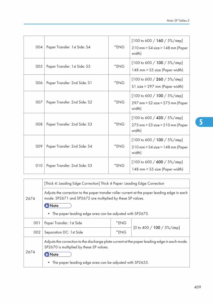
004 Paper Transfer: 1st Side: S4 *ENG
[100 to 600 / 160 / 5%/step]
210 mm > S4 size > 148 mm (Paperwidth)
005 Paper Transfer: 1st Side: S5 *ENG[100 to 600 / 100 / 5%/step]
148 mm > S5 size (Paper width)
006 Paper Transfer: 2nd Side: S1 *ENG[100 to 600 / 260 / 5%/step]
S1 size > 297 mm (Paper width)
007 Paper Transfer: 2nd Side: S2 *ENG
[100 to 600 / 100 / 5%/step]
297 mm > S2 size > 275 mm (Paperwidth)
008 Paper Transfer: 2nd Side: S3 *ENG
[100 to 600 / 430 / 5%/step]
275 mm > S3 size > 210 mm (Paperwidth)
009 Paper Transfer: 2nd Side: S4 *ENG
[100 to 600 / 100 / 5%/step]
210 mm > S4 size > 148 mm (Paperwidth)
010 Paper Transfer: 2nd Side: S3 *ENG[100 to 600 / 600 / 5%/step]
148 mm > S5 size (Paper width)
2674
[Thick 4: Leading Edge Correction] Thick 4 Paper: Leading Edge Correction
Adjusts the correction to the paper transfer roller current at the paper leading edge in eachmode. SP2671 and SP2672 are multiplied by these SP values.
• The paper leading edge area can be adjusted with SP2675.
001 Paper Transfer: 1st Side *ENG[0 to 400 / 100 / 5%/step]
002 Separation DC: 1st Side *ENG
2674
Adjusts the correction to the discharge plate current at the paper leading edge in each mode.SP2670 is multiplied by these SP values.
• The paper leading edge area can be adjusted with SP2655.
Main SP Tables-2
409
5

003 Paper Transfer: 2nd Side *ENG[0 to 400 / 100 / 5%/step]
004 Separation DC: 2nd Side *ENG
2675
[Thick 4: Switch Timing: Lead. Edge]
Adjusts the bias/ voltage switch timing of the paper transfer roller/ discharge plate at thepaper leading edge between the erase margin area and the image area.
001 Paper Transfer: 1st Side *ENG
[0 to 50 / 0 / 2 mm/step]002 Separation DC: 1st Side *ENG
003 Paper Transfer: 2nd Side *ENG
004 Separation DC: 2nd Side *ENG
2676
[Thick 4: Trailing Edge Correction] Thick 4 Paper: Trailing Edge Correction
Adjusts the correction to the paper transfer roller current for the paper trailing edge in eachmode. SP2671 and SP2672 are multiplied by these SP values.
• The paper trailing edge area can be adjusted with SP2677.
001 Paper Transfer: 1st Side *ENG
[0 to 400 / 100 / 5%/step]002 Paper Transfer: 2nd Side *ENG
003 Separation DC: 1st Side *ENG
004 Separation DC: 2nd Side *ENG
2677
[Thick 4: Trailing Edge Correction]
Adjusts the bias/voltage switch timing of the paper transfer roller/discharge plate at thepaper trailing edge between the erase margin area and the image area.
001 Paper Transfer: 1st Side *ENG
[0 to 50 / 0 / 2 mm/step]002 Paper Transfer: 2nd Side *ENG
003 Separation DC: 1st Side *ENG
004 Separation DC: 2nd Side *ENG
5. System Maintenance
410
5

2680
[Thick 4: Environment Correction] Thick 4 Paper: MM Environment Coefficient Adjustment
Adjusts the environment coefficient for each mode. When the environment is detected asMM, SP2671 and SP2672 are multiplied by these SP values.
001 Separation DC: 1st Side *ENG[1 to 60 / 22 / 1 /step]
002 Separation DC: 2nd Side *ENG
Adjusts the environment coefficient for each mode. When the environment is detected asMM, SP2670 is multiplied by these SP values.
003 Paper Transfer: BW: 1st Side *ENG[1 to 60 / 11 / 1 /step]
004 Paper Transfer: BW: 2nd Side: *ENG
005 Paper Transfer: FC: 1st Side *ENG [1 to 60 / 55 / 1 /step]
006 Paper Transfer: FC: 2st Side *ENG [1 to 60 / 11 / 1 /step]
2751
[Special1: Bias]
Adjusts the DC voltage of the discharge plate for special paper 1.
Plain: High speed, Thick 1: Middle speed
001 Separation DC: Plain: 1st Side *ENG
[0 to 4000 / 0 / 10 –V/step002 Separation DC: Plain: 2nd Side *ENG
003 Paper Transfer: Thick 1: 1st Side *ENG
2753
[Special1: Bias: BW]
Adjusts the current for the paper transfer roller for special paper 1 in black-and-white mode.
P Plain: High speed, Fine: Low speed
001 Paper Transfer: Plain: 1st Side *ENG[0 to 250 / 22 / 1 – A /step]
002 Paper Transfer: Plain: 2nd Side *ENG
003 Paper Transfer: Plain: 1st Side *ENG [0 to 250 / 11 / 1 – A /step]
Main SP Tables-2
411
5

2757
[Special1: Bias: FC]
Adjusts the current for the paper transfer roller for special paper 1 in full color mode.
Plain: High speed, Fine: Low speed
001 Paper Transfer: Plain: 1st Side *ENG [0 to 250 / 30 / 1 – A /step]
002 Paper Transfer: Plain: 2nd Side *ENG [0 to 250 / 33 / 1 – A /step]
003 Paper Transfer: Plain: 1st Side *ENG [0 to 250 / 15 / 1 – A /step]
2761
[Special1: Paper Size Correction]
Adjusts the size correction coefficient for the paper transfer roller current for each paper size.SP2753 and SP2757 are multiplied by these SP values.
Plain: High speed, Fine: Low speed
001 Paper Transfer: Plain: 1st Side: S1 *ENG [100 to 600 / 100 / 5%/step]
S1 size > 297 mm (Paper width)002 Paper Transfer: Plain: 2nd Side: S1 *ENG
005 Paper Transfer: Plain: 1st Side: S2 *ENG [100 to 600 / 120 / 5%/step]
297 mm > S2 size > 275 mm (Paperwidth)006 Paper Transfer: Plain: 2nd Side: S2 *ENG
009 Paper Transfer: Plain: 1st Side: S3 *ENG [100 to 600 / 140 / 5%/step]
275 mm > S3 size > 210 mm (Paperwidth)010 Paper Transfer: Plain: 2nd Side: S3 *ENG
013 Paper Transfer: Plain: 1st Side: S4 *ENG
[100 to 600 / 160 / 5%/step]
210 mm > S4 size > 148 mm (Paperwidth)
014 Paper Transfer: Plain: 2nd Side: S4 *ENG
[100 to 600 / 160 / 5%/step]
210 mm > S4 size > 148 mm (Paperwidth)
017 Paper Transfer: Plain: 1st Side: S5 *ENG[100 to 600 / 180 / 5%/step]
148 mm > S5 size (Paper width)
018 Paper Transfer: Plain: 2nd Side: S5 *ENG[100 to 600 / 180 / 5%/step]
148 mm > S5 size (Paper width)
5. System Maintenance
412
5

2771
[Special 1: Leading Edge Correction] Special 1 Paper: Leading Edge Correction
Adjusts the correction to the paper transfer roller current at the paper leading edge in eachmode. SP2753 and SP2757 are multiplied by these SP values.
Plain: High speed, 1200: Low speed
• The paper leading edge area can be adjusted with SP2772.
001 Paper Transfer: Plain: 1st Side *ENG [0 to 400 / 100 / 5%/step]
002 Paper Transfer: Plain: 2nd Side *ENG [0 to 400 / 100 / 5%/step]
003 Paper Transfer: 1200: 1st Side *ENG [0 to 400 / 100 / 5%/step]
2771
Adjusts the correction to the discharge plate current at the paper leading edge in each mode.SP2751 is multiplied by these SP values.
• The paper leading edge area can be adjusted with SP2772.
005 Separation DC: Plain: 1st Side *ENG[0 to 400 / 100 / 5%/step]
006 Separation DC: Plain: 2nd Side *ENG
007 Separation DC: 1200: 1st Side *ENG [0 to 400 / 100 / 5%/step]
2772
[Special 1: Switch Timing: Lead. Edge]
Adjusts the bias/ voltage switch timing of the paper transfer roller/ discharge plate at thepaper leading edge between the erase margin area and the image area.
Plain: High speed, 1200: Low speed
001 Paper Transfer: Plain: 1st Side *ENG[0 to 50 / 0 / 2 mm/step]
002 Paper Transfer: Plain: 2nd Side *ENG
003 Paper Transfer: 1200: 1st Side *ENG [0 to 50 / 0 / 1 mm/step]
005 Separation DC: Plain: 1st Side *ENG
[0 to 50 / 0 / 2 mm/step]006 Separation DC: Plain: 2nd Side *ENG
007 Separation DC: 1200: 1st Side *ENG
Main SP Tables-2
413
5
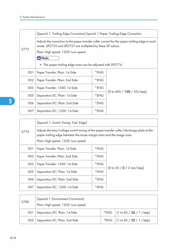
2773
[Special 1: Trailing Edge Correction] Special 1 Paper: Trailing Edge Correction
Adjusts the correction to the paper transfer roller current for the paper trailing edge in eachmode. SP2753 and SP2757 are multiplied by these SP values.
Plain: High speed, 1200: Low speed
• The paper trailing edge area can be adjusted with SP2774.
001 Paper Transfer: Plain: 1st Side *ENG
[0 to 400 / 100 / 5%/step]
002 Paper Transfer: Plain: 2nd Side *ENG
003 Paper Transfer: 1200: 1st Side *ENG
005 Separation DC: Plain: 1st Side *ENG
006 Separation DC: Plain: 2nd Side *ENG
007 Separation DC: 1200: 1st Side *ENG
2774
[Special 1: Switch Timing: Trail. Edge]
Adjusts the bias/voltage switch timing of the paper transfer roller/discharge plate at thepaper trailing edge between the erase margin area and the image area.
Plain: High speed, 1200: Low speed
001 Paper Transfer: Plain: 1st Side *ENG
[0 to 50 / 0 / 2 mm/step]
002 Paper Transfer: Plain: 2nd Side *ENG
003 Paper Transfer: 1200: 1st Side *ENG
005 Separation DC: Plain: 1st Side *ENG
006 Separation DC: Plain: 2nd Side *ENG
007 Separation DC: 1200: 1st Side *ENG
2780[Special 1: Environment Correction]
Plain: High speed, 1200: Low speed
001 Separation DC: Plain: 1st Side *ENG [1 to 60 / 26 / 1 /step]
002 Separation DC: Plain: 2nd Side *ENG [1 to 60 / 32 / 1 /step]
5. System Maintenance
414
5
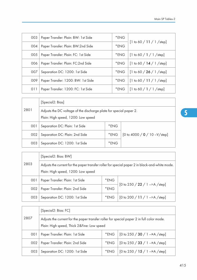
003 Paper Transfer: Plain: BW: 1st Side *ENG[1 to 60 / 11 / 1 /step]
004 Paper Transfer: Plain: BW:2nd Side *ENG
005 Paper Transfer: Plain: FC: 1st Side *ENG [1 to 60 / 1 / 1 /step]
006 Paper Transfer: Plain: FC:2nd Side *ENG [1 to 60 / 14 / 1 /step]
007 Separation DC: 1200: 1st Side *ENG [1 to 60 / 26 / 1 /step]
009 Paper Transfer: 1200: BW: 1st Side *ENG [1 to 60 / 11 / 1 /step]
011 Paper Transfer: 1200: FC: 1st Side *ENG [1 to 60 / 1 / 1 /step]
2801
[Special2: Bias]
Adjusts the DC voltage of the discharge plate for special paper 2.
Plain: High speed, 1200: Low speed
001 Separation DC: Plain: 1st Side *ENG
[0 to 4000 / 0 / 10 –V/step]002 Separation DC: Plain: 2nd Side *ENG
003 Separation DC: 1200: 1st Side *ENG
2803
[Special2: Bias: BW]
Adjusts the current for the paper transfer roller for special paper 2 in black-and-white mode.
Plain: High speed, 1200: Low speed
001 Paper Transfer: Plain: 1st Side *ENG[0 to 250 / 22 / 1 – A /step]
002 Paper Transfer: Plain: 2nd Side *ENG
003 Separation DC: 1200: 1st Side *ENG [0 to 200 / 11 / 1 – A /step]
2807
[Special2: Bias: FC]
Adjusts the current for the paper transfer roller for special paper 2 in full color mode.
Plain: High speed, Thick 2&Fine: Low speed
001 Paper Transfer: Plain: 1st Side *ENG [0 to 250 / 30 / 1 – A /step]
002 Paper Transfer: Plain: 2nd Side *ENG [0 to 250 / 33 / 1 – A /step]
003 Separation DC: 1200: 1st Side *ENG [0 to 250 / 15 / 1 – A /step]
Main SP Tables-2
415
5

2811
[Special2: Paper Size Correction]
Adjusts the size correction coefficient for the paper transfer roller current for each paper size.SP2803 and SP2807 are multiplied by these SP values.
001 Paper Transfer: Plain: 1st Side: S1 *ENG [100 to 600 / 100 / 5%/step]
S1 size > 297 mm (Paper width)002 Paper Transfer: Plain: 2nd Side: S1 *ENG
005 Paper Transfer: Plain: 1st Side: S2 *ENG
[100 to 600 / 120 / 5%/step]
297 mm > S2 size > 275 mm (Paperwidth)
006 Paper Transfer: Plain: 2nd Side: S2 *ENG
[100 to 600 / 120 / 5%/step]
297 mm > S2 size > 275 mm (Paperwidth)
009 Paper Transfer: Plain: 1st Side: S3 *ENG
[100 to 600 / 140 / 5%/step]
275 mm > S3 size > 210 mm (Paperwidth)
010 Paper Transfer: Plain: 2nd Side: S3 *ENG
[100 to 600 / 140 / 5%/step]
275 mm > S3 size > 210 mm (Paperwidth)
013 Paper Transfer: Plain: 1st Side: S4 *ENG
[100 to 600 / 160 / 5%/step]
210 mm > S4 size > 148 mm (Paperwidth)
014 Paper Transfer: Plain: 2nd Side: S4 *ENG
[100 to 600 / 160 / 5%/step]
210 mm > S4 size > 148 mm (Paperwidth)
017 Paper Transfer: Plain: 1st Side: S5 *ENG[100 to 600 / 180 / 5%/step]
148 mm > S5 size (Paper width)
018 Paper Transfer: Plain: 2nd Side: S5 *ENG[100 to 600 / 180 / 5%/step]
148 mm > S5 size (Paper width)
5. System Maintenance
416
5

2821
[Special 2: Leading Edge Correction] Special 2 Paper: Leading Edge Correction
Adjusts the correction to the paper transfer roller current at the paper leading edge in eachmode. SP2803 and SP2807 are multiplied by these SP values.
Plain: High speed, 1200: Low speed
• The paper leading edge area can be adjusted with SP2822.
001 Paper Transfer: Plain: 1st Side *ENG [0 to 400 / 100 / 5%/step]
002 Paper Transfer: Plain: 2nd Side *ENG [0 to 400 / 100 / 5%/step]
003 Paper Transfer: 1200: 1st Side *ENG [0 to 400 / 100 / 5%/step]
2821
Adjusts the correction to the discharge plate current at the paper leading edge in each mode.SP2801 is multiplied by these SP values.
• The paper leading edge area can be adjusted with SP2822.
005 Separation DC: Plain: 1st Side *ENG
[0 to 400 / 100 / 5%/step]006 Separation DC: Plain: 2nd Side *ENG
007 Separation DC: 12001st Side *ENG
2822
[Special 2: Switch Timing: Lead. Edge]
Adjusts the bias/ voltage switch timing of the paper transfer roller/ discharge plate at thepaper leading edge between the erase margin area and the image area.
Plain: High speed, 1200: Low speed
001 Paper Transfer: Plain: 1st Side *ENG
[0 to 50 / 0 / 2 mm/step]
002 Paper Transfer: Plain: 2nd Side *ENG
003 Paper Transfer: 1200: 1st Side *ENG
005 Separation DC: Plain: 1st Side *ENG
006 Separation DC: Plain: 2nd Side *ENG
007 Separation DC: 1200: 1st Side *ENG
Main SP Tables-2
417
5

2823
[Special 2: Trailing Edge Correction] Special 2 Paper: Trailing Edge Correction
Adjusts the correction to the paper transfer roller current for the paper trailing edge in eachmode. SP2803 and SP2807 are multiplied by these SP values.
Plain: High speed, 1200: Low speed
• The paper trailing edge area can be adjusted with SP2824.
001 Paper Transfer: Plain: 1st Side *ENG
[0 to 400 / 100 / 5%/step]
002 Paper Transfer: Plain: 2nd Side *ENG
003 Paper Transfer: 1200: 1st Side *ENG
005 Separation DC: Plain: 1st Side *ENG
006 Separation DC: Plain: 2nd Side *ENG
007 Separation DC: 1200: 1st Side *ENG
2824
[Special 2: Switch Timing: Trail. Edge]
Adjusts the bias/voltage switch timing of the paper transfer roller/discharge plate at thepaper trailing edge between the erase margin area and the image area.
Plain: High speed, 1200: Low speed
001 Paper Transfer: Plain: 1st Side *ENG
[0 to 50 / 0 / 2 mm/step]
002 Paper Transfer: Plain: 2nd Side *ENG
003 Paper Transfer: 1200: 1st Side *ENG
005 Separation DC: Plain: 1st Side *ENG
006 Separation DC: Plain: 2nd Side *ENG
007 Separation DC: 1200: 1st Side *ENG
2830[Special 2: Environment Correction]
Plain: High speed, 1200: Low speed
001 Paper Transfer: Plain: 1st Side *ENG [1 to 60 / 26 / 1 /step]
002 Paper Transfer: Plain: 2nd Side *ENG [1 to 60 / 32 / 1 /step]
5. System Maintenance
418
5

003 Paper Transfer: Plain: BW: 1st Side *ENG [1 to 60 / 1 / 1 /step]
004 Paper Transfer: Plain: BW:2nd Side *ENG [1 to 60 / 11 / 1 /step]
005 Paper Transfer: Plain: FC: 1st Side *ENG [1 to 60 / 1 / 1 /step]
006 Paper Transfer: Plain: FC:2nd Side *ENG [1 to 60 / 14 / 1 /step]
007 Paper Transfer: 1200: 1st Side *ENG [1 to 60 / 26 / 1 /step]
009 Paper Transfer: 1200: BW: 1st Side *ENG [1 to 60 / 11 / 1 /step]
011 Paper Transfer: 1200: FC: 1st Side *ENG [1 to 60 / 1 / 1 /step]
2851
[Special 3: Bias]
Adjusts the DC voltage of the discharge plate for special paper 3.
Plain: High speed, 1200: Low speed
001 Separation DC: Plain: 1st Side *ENG
[0 to 4000 / 0 / 10 –V/step]002 Separation DC: Plain: 2nd Side *ENG
003 Separation DC: 1200: 1st Side *ENG
2852
[Special 3: Bias: BW]
Adjusts the current for the paper transfer roller for special paper 3 in black-and-white mode.
Plain: High speed, 1200: Low speed
001 Paper Transfer: Plain: 1st Side *ENG[0 to 250 / 22 / 1 – A /step]
002 Paper Transfer: Plain: 2nd Side *ENG
003 Paper Transfer: 1200: 1st Side *ENG [0 to 250 / 11 / 1 – A /step]
2857
[Special 3: Bias: FC]
Adjusts the current for the paper transfer roller for special paper 3 in full color mode.
Plain: High speed, 1200: Low speed
001 Paper Transfer: Plain: 1st Side *ENG [0 to 250 / 30 / 1 – A /step]
002 Paper Transfer: Plain: 2nd Side *ENG [0 to 250 / 33 / 1 – A /step]
003 Paper Transfer: 1200: 1st Side *ENG [0 to 250 / 15 / 1 – A /step]
Main SP Tables-2
419
5

2861
[Special 3: Paper Size Correction]
Adjusts the size correction coefficient for the paper transfer roller current for each paper size.SP2852 and SP2857 are multiplied by these SP values.
Thick 1: Middle speed
001 Paper Transfer: Thick 1: 1st Side: S1 *ENG [100 to 600 / 100 / 5%/step]
S1 size > 297 mm (Paper width)002 Paper Transfer: Thick 1: 2nd Side: S1 *ENG
005 Paper Transfer: Thick 1: 1st Side: S2 *ENG
[100 to 600 / 120 / 5%/step]
297 mm > S2 size > 275 mm (Paperwidth)
006 Paper Transfer: Thick 1: 2nd Side: S2 *ENG
[100 to 600 / 120 / 5%/step]
297 mm > S2 size > 275 mm (Paperwidth)
009 Paper Transfer: Thick 1: 1st Side: S3 *ENG
[100 to 600 / 140 / 5%/step]
275 mm > S3 size > 210 mm (Paperwidth)
010 Paper Transfer: Thick 1: 2nd Side: S3 *ENG
[100 to 600 / 140 / 5%/step]
275 mm > S3 size > 210 mm (Paperwidth)
013 Paper Transfer: Thick 1: 1st Side: S4 *ENG
[100 to 600 / 160 / 5%/step]
210 mm > S4 size > 148 mm (Paperwidth)
014 Paper Transfer: Thick 1: 2nd Side: S4 *ENG
[100 to 600 / 160 / 5%/step]
210 mm > S4 size > 148 mm (Paperwidth)
017 Paper Transfer: Thick 1: 1st Side: S5 *ENG[100 to 600 / 180 / 5%/step]
148 mm > S5 size (Paper width)
018 Paper Transfer: Thick 1: 2nd Side: S5 *ENG[100 to 600 / 180 / 5%/step]
148 mm > S5 size (Paper width)
5. System Maintenance
420
5

2871
[Special 3: Leading Edge Correction] Special 3 Paper: Leading Edge Correction
Adjusts the correction to the paper transfer roller current at the paper leading edge in eachmode. SP2852 and SP2857 are multiplied by these SP values.
Plain: High speed, 1200: Low speed
• The paper leading edge area can be adjusted with SP2872.
001 Paper Transfer: Plain: 1st Side *ENG
[0 to 400 / 100 / 5%/step]002 Paper Transfer: Plain: 2nd Side *ENG
003 Paper Transfer: 1200: 1st Side *ENG
2871
Adjusts the correction to the discharge plate current at the paper leading edge in each mode.SP2851 is multiplied by these SP values.
• The paper leading edge area can be adjusted with SP2872.
005 Separation DC: Plain: 1st Side *ENG
[0 to 400 / 100 / 5%/step]006 Separation DC: Plain: 2nd Side *ENG
007 Separation DC: 1200: 1st Side *ENG
2872
[Special 3: Switch Timing: Lead. Edge]
Adjusts the bias/ voltage switch timing of the paper transfer roller/ discharge plate at thepaper leading edge between the erase margin area and the image area.
Plain: High speed, 1200: Low speed
001 Paper Transfer: Plain: 1st Side *ENG
[0 to 50 / 0 / 2 mm/step]
002 Paper Transfer: Plain: 2nd Side *ENG
003 Paper Transfer: 1200: 1st Side *ENG
005 Separation DC: Plain: 1st Side *ENG
006 Separation DC: Plain: 2nd Side *ENG
007 Separation DC: 1200: 1st Page *ENG
Main SP Tables-2
421
5

2873
[Special 3: Trailing Edge Correction] Special 3 Paper: Trailing Edge Correction
Adjusts the correction to the paper transfer roller current for the paper trailing edge in eachmode. SP2852 and SP2857 are multiplied by these SP values.
Plain: High speed, 1200: Low speed
• The paper trailing edge area can be adjusted with SP2874.
001 Paper Transfer: Plain: 1st Side *ENG
[0 to 400 / 100 / 5%/step]
002 Paper Transfer: Plain: 2nd Side *ENG
003 Paper Transfer: 1200: 1st Side *ENG
005 Separation DC: Plain: 1st Side *ENG
006 Separation DC: Plain: 2nd Side *ENG
007 Separation DC: 1200: 1st Page *ENG
2874
[Special 3: Switch Timing: Trail. Edge]
Adjusts the bias/voltage switch timing of the paper transfer roller/discharge plate at thepaper trailing edge between the erase margin area and the image area.
Plain: High speed, 1200: Low speed
001 Paper Transfer: Plain: 1st Side *ENG
[0 to 50 / 0 / 2 mm/step]
002 Paper Transfer: Plain: 2nd Side *ENG
003 Paper Transfer: 1200: 1st Side *ENG
005 Separation DC: Plain: 1st Side *ENG
006 Separation DC: Plain: 2nd Side *ENG
007 Separation DC: 1200: 1st Page *ENG
2880[Special 3: Environment Correction]
Plain: High speed, 1200: Low speed
001 Separation DC: Plain: 1st Side *ENG [1 to 60 / 26 / 1 /step]
002 Separation DC: Plain: 2nd Side *ENG [1 to 60 / 32 / 1 /step]
5. System Maintenance
422
5

003 Paper Transfer: Plain: BW: 1st Side *ENG[1 to 60 / 11 / 1 /step]
004 Paper Transfer: Plain: BW:2nd Side *ENG
005 Paper Transfer: Plain: FC: 1st Side *ENG[1 to 60 / 11 / 1 /step]
006 Paper Transfer: Plain: FC:2nd Side *ENG
007 Separation DC: 1200: 1st Side *ENG [1 to 60 / 26 / 1 /step]
009 Paper Transfer: 1200: BW: 1st Side *ENG [1 to 60 / 11 / 1 /step]
011 Paper Transfer: 1200: FC: 1st Side *ENG [1 to 60 / 1 / 1 /step]
2905
[Dev Rvs Time] Development Roller Reverse Time
Specified the time of the development roller reverse rotation after the development unit hasstopped. The reverse rotation of the development roller is used for removing dust from thedevelopment roller.
001 K *ENG
[0 to 200 / 80 / 10 msec/step]002 M *ENG
003 C *ENG
004 Y *ENG
005
[Dev Rvs Threshold Counter]
All *ENG [0 to 400000 / 4000/ 10 mm/step]
Specified the threshold distance for the development roller reverse mode. This sp refers tothe counters for SP2905-006 to -009.
[Dev Rvs Counter]
006 K *ENG
[0 to 999999999 / - / 1 mm/step]007 M *ENG
008 C *ENG
009 Y *ENG
Main SP Tables-2
423
5
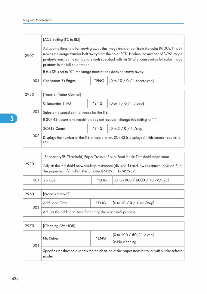
2907
[ACS Setting (FC to Bk)]
Adjusts the threshold for moving away the image transfer belt from the color PCDUs. This SPmoves the image transfer belt away from the color PCDUs when the number of B/W imageprintouts reaches the number of sheets specified with this SP after consecutive full color imageprintouts in the full color mode.
If this SP is set to "0", the image transfer belt does not move away.
001 Continuous Bk Pages *ENG [0 to 10 / 0 / 1 sheet/step]
2920 [Transfer Motor Control]
001
0: Encorder 1 :FG *ENG [0 or 1 / 0 / 1 /step]
Selects the speed control mode for the ITB.
If SC443 occurs and machine does not recover, change this setting to "1".
002
SC443 Count *ENG [0 to 3 / 0 / 1 /step]
Displays the number of the ITB encodre error. SC443 is displayed if this counter counts to"3".
2930
[SecondaryFB: Threshold] Paper Transfer Roller Feed-back: Threshold Adjustment
Adjusts the threshold between high resistance (division 1) and low resistance (division 2) atthe paper transfer roller. This SP affects SP2931 to SP2939.
001 Voltage *ENG [0 to 7000 / 6000 / 10 –V/step]
2960 [Process Interval]
001Additional Time *ENG [0 to 10 / 0 / 1 sec/step]
Adjusts the additional time for ending the machine's process.
2970 [Cleaning After JOB]
001
No Refresh *ENG[0 to 100 / 50 / 1 /step]
0: No cleaning
Specifies the threshold sheets for the cleaning of the paper transfer roller without the refreshmode.
5. System Maintenance
424
5

002 Refresh *ENG[0 or 1 / 1 / 1 /step]
0: No cleaning, 1: Cleaning
2971 T1 Non Image Area ON Timing
001Standard Speed *ENG [–400 to 290 / 0 / 10 msec/step]
Adjusts the timing for the non-image area bias of the image transfer roller.
002 Medium Speed *ENG [–790 to 410 / 0 / 10 msec/step]
003 Low Speed *ENG [–790 to 410 / 0 / 10 msec/step]
2972 B/W Image Request Timing
001 Standard Speed *ENG [0 to 4000 / 0 / 10 msec/step]
002 Medium Speed *ENG [0 to 4000 / 0 / 10 msec/step]
003 Low Speed *ENG [0 to 4000 / 0 / 10 msec/step]
2973 Forced Process Down Threshold
001 - *ENG [0 to 5000 / 0 / 10 page/step]
2974 OPC PreCharge Time Control
001 Standard Speed *ENG [0 to 940 / 0 / 10 msec/step]
002 Medium Speed *ENG [0 to 940 / 0 / 10 msec/step]
003 Low Speed *ENG [0 to 940 / 0 / 10 msec/step]
2980 -
001 Continuous Job Page *ENG [0 to 300 / 100 / 10 page/step]
002 OPC Drum Idling Time BW *ENG [0 to 600 / 30 / 10 sec/step]
003 OPC Drum Idling Time FC *ENG [0 to 600 / 30 / 10 sec/step]
2990 Print Duty Control
Main SP Tables-2
425
5

001 Duty Control State *ENG[0 or 1 / 0 / 1 /step]
0: No limit, 1: Limit
002 Duty Control Thresh Time *ENG [0 to 195 / 30 / 10 min./step]
003 Duty Control Thresh *ENG [0 to 999999999 / 0 / 1 mm/step]
004Forced CPM Down Thresh:No Duty Control
*ENG [0 to 5000 / 0 / 1 page/step]
005Drum Stop Time: No DutyControl
*ENG [300 to 1500 / 500 / 10 msec/step]
006ITB Stop Time: No DutyControl
*ENG [300 to 1500 / 500 / 10 msec/step]
007Forced CPM Down Thresh:Duty Control
*ENG [0 to 5000 / 1 / 1 page/step]
008 Drum Stop Time: Duty Control *ENG [300 to 1500 / 1500 / 10 msec/step]
009 ITB Stop Time: Duty Control *ENG [300 to 1500 / 1500 / 10 msec/step]
010 Duty Control: Start Time *ENG Displays the time of the duty control execution.
5. System Maintenance
426
5

Main SP Tables-3
SP3-XXX (Process)
3011 [Process Cont. Manual Execution]
001 Normal -
Executes the normal process control manually(potential control).
Check the result with SP3-325-001 and3-012-001 after executing this SP.
002 Density Adjustment - Executes the toner density adjustment manually.
003 Pre-ACC -
Executes the process control that is normally donebefore ACC.
The type of process control is selected withSP3-041-004.
004 Full MUSIC -Executes the process control that is normally doneat the same time as MUSIC. This SP does theMUSIC (line position adjustment) twice.
005 Normal MUSIC -Executes the process control that is normally doneat the same time as MUSIC. This SP does theMUSIC (line position adjustment) once.
3012
[Process Cont. Check Result] Process Control Self-check Result
Displays the result of the latest process control self-check.
All colors are displayed. The results are displayed in the order “Y C M K”
e.g., 11 (Y) 99 (C) 11 (M) 11 (K): The self-check for Cyan failed but the others weresuccessful.
See the "Error Condition Tables" in the "Appendix: Process Control Error Conditions" sectionfor details.
Main SP Tables-3
427
5

001 History: Latest *ENG
[1111 to 99999999 / 99999999 / 1/step]
002 Result: Latest 1 *ENG
003 Result: Latest 2 *ENG
004 Result: Latest 3 *ENG
005 Result: Latest 4 *ENG
006 Result: Latest 5 *ENG
007 Result: Latest 6 *ENG
008 Result: Latest 7 *ENG
009 Result: Latest 8 *ENG
010 Result: Latest 9 *ENG
3013 [T Sensor Initial Set: Execution] Developer Initialization Setting
001 Execution: ALL -
Executes the developer initialization for each color.
002 Execution: COL -
003 Execution: Bk -
004 Execution: M -
005 Execution: C -
006 Execution: Y -
3014[T Sensor Initial Set Result: Display]
Developer Initialization Result: Display
001
Display: YCMK *ENG[0 to 9999 / 9999 / 1 /step ]
1: Success, 2 to 9: Failure
Displays the developer initialization result. See section "Developer Initialization Result" in the"Appendix: Process Control Error Conditions" section for details on the meaning of eachcode.
All colors are displayed. Values are displayed in the order Y C M Bk.
e.g., 1 (Y) 2 (C) 1 (M) 1 (Bk): Initialization of Cyan failed but the others succeeded.
5. System Maintenance
428
5

3015 [Forced Toner Supply: Execute] Forced Toner Supply ([Color])
001 Execution: ALL -
Executes the manual toner supply to thedevelopment unit.
002 Execution: COL -
003 Execution: Bk -
004 Execution: M -
005 Execution: C -
006 Execution: Y -
3016[Forced Toner Supply: Setting] Forced Toner Supply Setting ([Color])
Specifies the manual toner supply time for each color.
001 Supply Time: Bk *ENG
[0 to 30 / 4 / 1 sec/step]002 Supply Time: M *ENG
003 Supply Time: C *ENG
004 Supply Time: Y *ENG
3041 [Process Control Type]
001Voltage Control *ENG
[0 or 1 / 1 / 1/step ] Alphanumeric
0: FIXED (Use the fixed values for the charge DC biasand development DC bias set with SP2-005 andSP2-229.)
1: CONTROL
Enables or disables potential control.
002LD Power Control *ENG
[0 or 1 / 1 / 1/step] Alphanumeric
0: FIXED (at the value in SP2221-xxx)
1: CONTROL (adjusted by process control)
Selects the LD power control mode.
Main SP Tables-3
429
5

003
AutoControl ProhibitionSet
*ENG[0 or 1 / 0 / -]
0: Permit, 1: Forbid
Enables or disables the automatic process control prohibition.
004Pre-ACC *ENG
[0 to 2 / 2 / 1/step]
0: Not Executed
1: Process Control
2: TC Control (TD Adjustment)
3: Not used
Selects the process control mode that is done before ACC.
005
Pattern CalculationMethod
*ENG
[0 to 2 / 2 / 1/step]
0: FIXED
1: INITIALIZED
2: CALCULATED
Selects the process control method.
3043 [TD Adjustment Mode]
001
Repeat Number: Power ON *ENG [0 to 9 / 4 / 1 time/step]
Specifies the maximum number of repeats of the toner density adjustment at power on.
0: Disabled, 1 to 3: Repeat number,
4: Repeat three times (No consumption mode)
5: Repeat three times (Toner is supplied only when the toner density is too low, and toner isconsumed only when the toner density is too dark.)
6 to 9: Disabled
002
Repeat Number: Initialization *ENG [0 to 9 / 3 / 1 time/step]
Specifies the maximum number of repeats of the toner density adjustment at the developerinitialization.
0: Disabled, 1 to 3: Repeat number,
4: Repeat three times (No consumption mode)
5: Repeat three times (Toner is supplied only when the toner density is too low, and toner isconsumed only when the toner density is too dark.)
6 to 9: Disabled
5. System Maintenance
430
5

003
Repeat Number: Non-use *ENG [0 to 9 / 0 / 1 time/step]
Specifies the maximum number of repeats of the toner density adjustment in stand by mode.
0: Disabled, 1 to 3: Repeat number,
4: Repeat three times (No consumption mode)
5: Repeat three times (Toner is supplied only when the toner density is too low, and toner isconsumed only when the toner density is too dark.)
6 to 9: Disabled
004
Repeat Number: ACC *ENG [0 to 9 / 3 / 1 time/step]
Specifies the maximum number of repeats of the toner density adjustment at ACC.
0: Disabled, 1 to 3: Repeat number,
4: Repeat three times (No consumption mode)
5: Repeat three times (Toner is supplied only when the toner density is too low, and toner isconsumed only when the toner density is too dark.)
6 to 9: Disabled
005Repeat Number: Recovery *ENG [0 to 9 / 0 / 1 time/step]
Not used
006
Repeat Number: Job End *ENG [0 to 9 / 4 / 1 time/step]
Specifies the maximum number of repeats of the toner density adjustment at job end.
0: Disabled, 1 to 3: Repeat number,
4: Repeat three times (No consumption mode)
5: Repeat three times (Toner is supplied only when the toner density is too low, and toner isconsumed only when the toner density is too dark.)
6 to 9: Disabled
007
Repeat: Interrupt *ENG [0 to 9 / 0 / 1 time/step]
Specifies the maximum number of repeats of the toner density adjustment during printing.DFU
008Toner Supply Coefficient *ENG [0 to 25.5 / 10 / 0.1 sec/step]
Adjusts the time for the toner supply mode when a toner density is detected to be low.
Main SP Tables-3
431
5

009
Consumption pattern: Bk *ENG [0 to 255 / 5 / 1 time/step]
Specifies the belt mark generating time for checking the black toner density when toner densityis detected to be low at the toner density adjustment.
010
Consumption pattern: M *ENG [0 to 255 / 5 / 1 time/step]
Specifies the belt mark generating time for checking the magenta toner density when tonerdensity is detected to be low at the toner density adjustment.
011
Consumption pattern: C *ENG [0 to 255 / 5 / 1 time/step]
Specifies the belt mark generating time for checking the cyan toner density when toner densityis detected to be low at the toner density adjustment.
012
Consumption pattern: Y *ENG [0 to 255 / 5 / 1 time/step]
Specifies the belt mark generating time for checking the yellow toner density when tonerdensity is detected to be low at the toner density adjustment.
013T1 Bias: Bk *ENG [0 to 80 / 22 / 1 A/step]
Adjusts the image transfer belt bias for Black.
014T2 Bias: M *ENG [0 to 80 / 25 / 1 A/step]
Adjusts the image transfer belt bias for Magenta.
015T3 Bias: C *ENG [0 to 80 / 22 / 1 A/step]
Adjusts the image transfer belt bias for Cyan.
016T4 Bias: Y *ENG [0 to 80 / 28 / 1 A/step]
Adjusts the image transfer belt bias for Yellow.
017Developer Mixing Time *ENG [0 to 250 / 10 / 1 sec/step]
Specifies the developer mixing time at the toner density adjustment.
018
Consumption Pattern: LD: DUTY: Bk *ENG [0 to 15 / 15 / 1 /step]
Adjusts the LD duty for the toner consumption mode at the toner density adjustment.
In toner consumption mode, toner is discharged when the detected development gammavalues (SP3611-001) exceed the target values (SP3611-005) by more than the specifiedthresholds (SP3239-009).
5. System Maintenance
432
5

019
Consumption Pattern: LD: DUTY: M *ENG [0 to 15 / 15 / 1 /step]
Adjusts the LD duty for the toner consumption mode at the toner density adjustment.
In toner consumption mode, toner is discharged when the detected development gammavalues (SP3611-002) exceed the target values (SP3611-006) by more than the specifiedthresholds (SP3239-009).
020
Consumption Pattern: LD: DUTY: C *ENG [0 to 15 / 15 / 1 /step]
Adjusts the LD duty for the toner consumption mode at the toner density adjustment.
In toner consumption mode, toner is discharged when the detected development gammavalues (SP3611-003) exceed the target values (SP3611-007) by more than the specifiedthresholds (SP3239-009).
021
Consumption Pattern: LD: DUTY: Y *ENG [0 to 15 / 15 / 1 /step]
Adjusts the LD duty for the toner consumption mode at the toner density adjustment.
In toner consumption mode, toner is discharged when the detected development gammavalues (SP3611-004) exceed the target values (SP3611-008) by more than the specifiedthresholds (SP3239-009).
3044[Toner Supply Type] Toner Supply Type ([Color])
Selects the toner supply method type.
001 Bk *ENG [0 to 3 / 2 / 1/step] Alphanumeric
0: FIXED (with the supply rates stored with SP 3401)
1: PID (Vtref_Fixed)
2: PID (Vtref_Control)
3: Not used
002 M *ENG
003 C *ENG
004 Y *ENG
3045[Toner End Detection: Set]
Enables/disables the toner alert display on the LCD.
001 ON/OFF *ENG [0 or 1 / 0 / 1/step] 0: Detect, 1: Not Detect
3102
[Toner End Recovery]
Adjusts the number of times toner supply is attempted for each color when the TD sensorcontinues to detect toner end during toner recovery.
Main SP Tables-3
433
5

001 Repeat: Bk *ENG
[1 to 20 / 5 / 1 time/step]002 Repeat: M *ENG
003 Repeat: C *ENG
004 Repeat: Y *ENG
3131[TE Count m: Display]
Display the number of toner end detections for each color.
001 Bk *ENG
[0 to 99 / 0 / 1 time/step]002 M *ENG
003 C *ENG
004 Y *ENG
3201[TD Sensor: Vt Display]
Display the current voltage of the TD sensor for each color.
001 Current: Bk *ENG
[0 to 5.5 / 0.01 / 0.01 V/step]002 Current: M *ENG
003 Current: C *ENG
004 Current: Y *ENG
3211
[Vt Shift: Display/Set]
Adjusts the Vt correction value for each line speed.
Thick 1: Middle speed, Thick 2&Fine: Low speed
001 Thick 1 Shift: Bk *ENG [0 to 5 / 0.35 / 0.01 V/step]
002 Thick 1 Shift: M *ENG [0 to 5 / 0.33 / 0.01 V/step]
003 Thick 1 Shift: C *ENG [0 to 5 / 0.28 / 0.01 V/step]
004 Thick 1 Shift: Y *ENG [0 to 5 / 0.29 / 0.01 V/step]
005 Thick 2 & FINE Shift: Bk *ENG [0 to 5 / 0.35 / 0.01 V/step]
5. System Maintenance
434
5

006 Thick 2 & FINE Shift: M *ENG [0 to 5 / 0.33 / 0.01 V/step]
007 Thick 2 & FINE Shift: C *ENG [0 to 5 / 0.28 / 0.01 V/step]
008 Thick 2 & FINE Shift: Y *ENG [0 to 5 / 0.29 / 0.01 V/step]
009 Mid TCShift: Bk *ENG
[-0.5 to 0.5 / 0 / 0.01 V/step]010 Mid TCShift: M *ENG
011 Mid TCShift: C *ENG
012 Mid TCShift: Y *ENG
013 Low TCShift: Bk *ENG
[-0.5 to 0.5 / 0 / 0.01 V/step]014 Low TCShift: M *ENG
015 Low TCShift: C *ENG
016 Low TCShift: Y *ENG
3221[Vtcnt: Display/Set]
Displays or adjusts the current Vtcnt value for each color.
001 Current: Bk *ENG
[2 to 5 / 3.86 / 0.01 V/step]002 Current: M *ENG
003 Current: C *ENG
004 Current: Y *ENG
005-008 Displays or adjusts the Vtcnt value for each color at developer initialization. DFU
005 Initial: Bk *ENG
[2 to 5 / 3.86 / 0.01 V/step]006 Initial: M *ENG
007 Initial: C *ENG
008 Initial: Y *ENG
3222[Vtref: Display/Set]
Displays or adjusts the current Vtref value for each color.
Main SP Tables-3
435
5
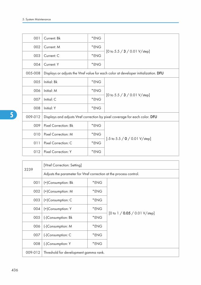
001 Current: Bk *ENG
[0 to 5.5 / 3 / 0.01 V/step]002 Current: M *ENG
003 Current: C *ENG
004 Current: Y *ENG
005-008 Displays or adjusts the Vtref value for each color at developer initialization. DFU
005 Initial: Bk *ENG
[0 to 5.5 / 3 / 0.01 V/step]006 Initial: M *ENG
007 Initial: C *ENG
008 Initial: Y *ENG
009-012 Displays and adjusts Vtref correction by pixel coverage for each color. DFU
009 Pixel Correction: Bk *ENG
[-5 to 5.5 / 0 / 0.01 V/step]010 Pixel Correction: M *ENG
011 Pixel Correction: C *ENG
012 Pixel Correction: Y *ENG
3239[Vtref Correction: Setting]
Adjusts the parameter for Vtref correction at the process control.
001 (+)Consumption: Bk *ENG
[0 to 1 / 0.05 / 0.01 V/step]
002 (+)Consumption: M *ENG
003 (+)Consumption: C *ENG
004 (+)Consumption: Y *ENG
005 (-)Consumption: Bk *ENG
006 (-)Consumption: M *ENG
007 (-)Consumption: C *ENG
008 (-)Consumption: Y *ENG
009-012 Threshold for development gamma rank.
5. System Maintenance
436
5

009 P Rank 1 Threshold *ENG [0 to 2 / 0.2 / 0.1 /step]
010 P Rank 2 Threshold *ENG [0 to 2 / 0.05 / 0.1 /step]
011 P Rank 3 Threshold *ENG [-2 to 0 / -0.05 / 0.1 /step]
012 P Rank 4 Threshold *ENG [-2 to 0 / -0.2 / 0.1 /step]
013-014 Threshold for image density rank on the image transfer belt.
013 T Rank 1 Threshold *ENG [-1 to 0 / -0.2 / 0.01 V/step]
014 T Rank 2 Threshold *ENG [0 to 1 / 0.2 / 0.01 V/step]
3241 [Background Potential Setting]
001 Coefficient: Bk *ENG These are parameters for calculating the chargebias referring to the development bias at processcontrol.
[-1000 to 1000 / 0 / 1 /step]
DC charge bias = Development bias x (1 + 0.001x these vales) + SP3-241-005 to -008
002 Coefficient: M *ENG
003 Coefficient: C *ENG
004 Coefficient: Y *ENG
005 Offset: Bk *ENG These are additional values for calculating thecharge bias referring to the development bias atprocess control.
[0 to 255 / 140 / 1 V/step]
DC charge bias = Development bias x (1 + 0.001x SP3-241-001 to -004) + these values
006 Offset: M *ENG
007 Offset: C *ENG
008 Offset: Y *ENG
3242[LD Power Setting]
Adjusts the coefficient for LD power control value at the process control.
001 StdSpd:Coefficient: Bk *ENG [-1000 to 1000 / 101 / 1 /step]
002 StdSpd:Coefficient: M *ENG [-1000 to 1000 / 62 / 1 /step]
003 StdSpd:Coefficient: C *ENG [-1000 to 1000 / 99 / 1 /step]
004 StdSpd:Coefficient: Y *ENG [-1000 to 1000 / 74 / 1 /step]
005 StdSpd:Offset: Bk *ENG [-1000 to 1000 / 69 / 1 /step]
006 StdSpd:Offset: M *ENG [-1000 to 1000 / 95 / 1 /step]
Main SP Tables-3
437
5

007 StdSpd:Offset: C *ENG [-1000 to 1000 / 63 / 1 /step]
008 StdSpd:Offset: Y *ENG [-1000 to 1000 / 82 / 1 /step]
009 MidSpd:coef:Bk *ENG [-1000 to 1000 / 101 / 1 /step]
010 MidSpd:coef:M *ENG [-1000 to 1000 / 62 / 1 /step]
011 MidSpd:coef:C *ENG [-1000 to 1000 / 99 / 1 /step]
012 MidSpd:coef:Y *ENG [-1000 to 1000 / 74 / 1 /step]
013 MidSpd:offset:Bk *ENG [-1000 to 1000 / 69 / 1 /step]
014 MidSpd:offset:M *ENG [-1000 to 1000 / 95 / 1 /step]
015 MidSpd:offset:C *ENG [-1000 to 1000 / 63 / 1 /step]
016 MidSpd:offset:Y *ENG [-1000 to 1000 / 82 / 1 /step]
017 LowSpd:Coef:Bk *ENG [-1000 to 1000 / 81 / 1 /step]
018 LowSpd:Coef:M *ENG [-1000 to 1000 / 61 / 1 /step]
019 LowSpd:Coef:C *ENG [-1000 to 1000 / 86 / 1 /step]
020 LowSpd:Coef:Y *ENG [-1000 to 1000 / 67 / 1 /step]
021 LowSpd:offset:Bk *ENG [-1000 to 1000 / 82 / 1 /step]
022 LowSpd:offset:M *ENG [-1000 to 1000 / 92 / 1 /step]
023 LowSpd:offset:C *ENG [-1000 to 1000 / 68 / 1 /step]
024 LowSpd:offset:Y *ENG [-1000 to 1000 / 87 / 1 /step]
3251[Coverage]
These (-001 to -016) are coefficients for SP3-222-009 to -012.
001 Latest Pixel: Bk *ENG
Displays the latest coverage for each color.
[0 to 9999 / 0 / 1 cm2/step]
002 Latest Pixel: M *ENG
003 Latest Pixel: C *ENG
004 Latest Pixel: Y *ENG
5. System Maintenance
438
5

005-008
Displays the average coverage of each color for the Vtref correction.
"Average S" is defined when the number of developed pages does not reach the numberspecified with SP3251-017.
005 Average S: Bk *ENG
[0 to 100 / 5 / 0.01 %/step]006 Average S: M *ENG
007 Average S: C *ENG
008 Average S: Y *ENG
009-012
Displays the average coverage of each color for the Vtref correction.
"Average M" is defined when the number of developed pages does not reach the numberspecified with SP3251-018.
009 Average M: Bk *ENG
[0 to 100 / 5 / 0.01 %/step]010 Average M: M *ENG
011 Average M: C *ENG
012 Average M: Y *ENG
013-016
Displays the average coverage of each color for the Vtref correction.
"Average L" is defined when the number of developed pages does not reach the numberspecified with SP3-251-019.
013 Average L: Bk *ENG
[0 to 100 / 5 / 0.01 %/step]014 Average L: M *ENG
015 Average L: C *ENG
016 Average L: Y *ENG
017-019 Adjusts the threshold for SP3-251-005 to -016.
017 Total Page Setting: S *ENG [1 to 100 / 10 / 1 sheet/step]
018 Total Page Setting: M *ENG [1 to 500 / 10 / 1 sheet/step]
019 Total Page Setting: L *ENG [1 to 999 / 50 / 1 sheet/step]
020-023 Adjusts the threshold for SP3-251-024 to -027.
020 Total Page Setting: S2 *ENG [1 to 100 / 40 / 1 sheet/step]
Main SP Tables-3
439
5

021 Total Page Setting: M2 *ENG [1 to 500 / 10 / 1 sheet/step]
022 Total Page Setting: L2 *ENG [1 to 999 / 50 / 1 sheet/step]
024-027 Displays the latest coverage ratio for each color.
024 Latest Coverage: Bk *ENG
[0 to 100 / - / 0.01 %/step]025 Latest Coverage: M *ENG
026 Latest Coverage: C *ENG
027 Latest Coverage: Y *ENG
028Displays the threshold of whether to perform developer churning or not.
DevMix Threshold *ENG [0 to 100 / 20 / 1 %/step]
3311[ID Sensor Detection Value: Voffset]
Displays the ID sensor (regular) offset voltage for Vsg adjustments.
001 Voffset reg: Bk *ENG [0 to 5 / 0 / 0.01 V/step]
002 Voffset reg: M *ENG
[0 to 5.5 / 0 / 0.01 V/step]003 Voffset reg: C *ENG
004 Voffset reg: Y *ENG
005-007 Displays the ID sensor (diffusion) offset voltage for Vsg adjustments.
005 Voffset dif: M *ENG
[0 to 5.5 / 0 / 0.01 V/step]006 Voffset dif: C *ENG
007 Voffset dif: Y *ENG
008-010 Displays the ID sensor offset voltage for Vsg adjustments.
008 Voffset TM (Front) *ENG
[0 to 5.5 / 0 / 0.01 V/step]009 Voffset TM (Center) *ENG
010 Voffset TM (Rear) *ENG
3321 [Vsg Adjustment: Execution]
5. System Maintenance
440
5

010 P/TM Sensor All -Execute the ID sensor initialization setting forall sensors
3322[Vsg Adjustment Result: Vsg]
Displays the result value of the Vsg adjustment for each sensor.
001 Vsg reg: Bk *ENG
[0 to 5.5 / 0 / 0.01 V/step]
002 Vsg reg: M *ENG
003 Vsg reg: C *ENG
004 Vsg reg: Y *ENG
005 Vsg dif: M *ENG
006 Vsg dif: C *ENG
007 Vsg dif: Y *ENG
008 Vsg TM (Front) *ENG
009 Vsg TM (Center) *ENG
010 Vsg TM (Rear) *ENG
3325
[Vsg Adjustment Result]
Displays the result of the Vsg adjustment.
The displayed numbers mean the result of each sensor (sensor for Front, sensor for Bk, sensorfor Cyan, sensor for Center, sensor for Magenta, sensor for Yellow and sensor for Rear).
Main SP Tables-3
441
5

001 History: Latest *ENG
[111 to 999 / 999 / 1 /step]
9: Unexpected error
3: Offset voltage error
2: Vsg adjustment value error
1: O.K
002 Result: Latest 1 *ENG
003 Result: Latest 2 *ENG
004 Result: Latest 3 *ENG
005 Result: Latest 4 *ENG
006 Result: Latest 5 *ENG
007 Result: Latest 6 *ENG
008 Result: Latest 7 *ENG
009 Result: Latest 8 *ENG
010 Result: Latest 9 *ENG
3401[Fixed Supply Mode]
Adjusts the toner supply rate in the fixed toner supply mode.
001 Fixed Rate: Bk *ENG
[0 to 100 / 5 / 1 %/step]
These SPs are used only when SP3-044 is set to"1".
002 Fixed Rate: M *ENG
003 Fixed Rate: C *ENG
004 Fixed Rate: Y *ENG
3411[Toner Supply Rate: Display]
Displays the current toner supply rate.
001 Latest: Bk *ENG
[0 to 100 / - / 1 %/step]002 Latest: M *ENG
003 Latest: C *ENG
004 Latest: Y *ENG
3421 [Toner Supply Range]
5. System Maintenance
442
5
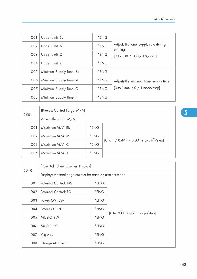
001 Upper Limit: Bk *ENG
Adjusts the toner supply rate duringprinting.
[0 to 100 / 100 / 1%/step]
002 Upper Limit: M *ENG
003 Upper Limit: C *ENG
004 Upper Limit: Y *ENG
005 Minimum Supply Time: Bk *ENG
Adjusts the minimum toner supply time.
[0 to 1000 / 0 / 1 msec/step]
006 Minimum Supply Time: M *ENG
007 Minimum Supply Time: C *ENG
008 Minimum Supply Time: Y *ENG
3501[Process Control Target M/A]
Adjusts the target M/A.
001 Maximum M/A: Bk *ENG
[0 to 1 / 0.444 / 0.001 mg/cm2/step]002 Maximum M/A: M *ENG
003 Maximum M/A: C *ENG
004 Maximum M/A: Y *ENG
3510[Pixel Adj. Sheet Counter: Display]
Displays the total page counter for each adjustment mode.
001 Potential Control: BW *ENG
[0 to 2000 / 0 / 1 page/step]
002 Potential Control: FC *ENG
003 Power ON: BW *ENG
004 Power ON: FC *ENG
005 MUSIC: BW *ENG
006 MUSIC: FC *ENG
007 Vsg Adj. *ENG
008 Charge AC Control *ENG
Main SP Tables-3
443
5

009 MUSIC: Power ON: BW *ENG
010 MUSIC: Power ON: FC *ENG
3511[Execution Interval: Setting]
Adjusts the threshold for each adjustment mode.
001 Job End: Potential Control: BW *ENG [0 to 2000 / 250 / 1 page/step]
002 Job End: Potential Control: FC *ENG [0 to 2000 / 100 / 1 page/step]
003 Interrupt: Potential Control: BW *ENG [0 to 2000 / 500 / 1 page/step]
004 Interrupt: Potential Control: FC *ENG [0 to 2000 / 200 / 1 page/step]
005 Initial: Potential Control: BW *ENG [0 to 2000 / 250 / 1 page/step]
006 Initial: Potential Control: FC *ENG [0 to 2000 / 100 / 1 page/step]
007 Vsg Adj. Counter *ENG[0 to 2000 / 0 / 1 page/step]
008 Charge AC Control Counter *ENG
019 Environmental Correction *ENG[0 or 1 / 1 / 1 /step]
0: Not Correct (OFF), 1: Correct (ON)
020 Gamma Correction *ENG[0 or 1 / 1 / 1 /step]
0: Not Correct (OFF), 1: Correct (ON)
021 Non-use Time Correction *ENG[0 or 1 / 1 / 1 /step]
0: Not Correct (OFF), 1: Correct (ON)
022 Correction Coefficient 1: JE: BW *ENG [0 to 1 / 0.2 / 0.01 page/step]
023 Correction Coefficient 2: JE: BW *ENG [0 to 1 / 1 / 0.01/step]
024 Correction Coefficient 1: JE: FC *ENG [0 to 1 / 0.5 / 0.01/step]
025 Correction Coefficient 2: JE: FC *ENG [0 to 1 / 1 / 0.01/step]
026Correction Coefficient 1: Interrupt:BW
*ENG [0 to 1 / 0.1 / 0.01/step]
027Correction Coefficient 2: Interrupt:BW
*ENG [0 to 1 / 1 / 0.01/step]
5. System Maintenance
444
5

028Correction Coefficient 1: Interrupt:FC
*ENG [0 to 1 / 0.25 / 0.01/step]
029Correction Coefficient 2: Interrupt:FC
*ENG [0 to 1 / 1 / 0.01/step]
030 Max. Number Correction Threshold *ENG [0 to 99 / 5 / 1/step]
031 Max. Number Correction Counter *ENG [0 to 255 / 0 / 1/step]
3512[Image Quality Adj.: Interval]
Adjusts the timing for execution of process control and line position adjustment.
001 During Job *ENG [0 to 100 / 30 / 1 page/step]
002 During Stand-by *ENG [0 to 100 / 10 / 1 minute/step]
3513
[PCU Motor Stop Time: Bk]
Displays the last time that the PCDU motors stopped.
These are used for process control execution timing.
001 Year *ENG [0 to 99 / 0 / 1/step]
002 Month *ENG [1 to 12 / 1 / 1/step]
003 Date *ENG [1 to 31 / 1 / 1/step]
004 Hour *ENG [0 to 23 / 0 / 1/step]
005 Minute *ENG [0 to 59 / 0 / 1/step]
3514
[Environmental Display: Job End]
Displays the environmental conditions for the last job.
These are used for process control execution timing.
001 Temperature *ENG [-1280 to 1270 / 0 / 0.1°C/step]
002 Relative Humidity *ENG [0 to 1000 / - / 0.1%RH/step]
003 Absolute Humidity *ENG [0 to 1000 / - / 0.1 g/cm3/step]
Main SP Tables-3
445
5

3515
[Execution Interval: Display]
Displays the current interval for process control execution.
When the machine calculates the timing for process control, it uses a number of conditions.These are the results after considering all the conditions.
001Job End: Potential Control:BW
*ENG [0 to 2000 / 500 / 1 page/step]
002 Job End: Potential Control: FC *ENG [0 to 2000 / 200 / 1 page/step]
003Interrupt: Potential Control:BW
*ENG [0 to 2000 / 500 / 1 page/step]
004 Interrupt: Potential Control: FC *ENG [0 to 2000 / 200 / 1 page/step]
3517
[Blade damage prevention mode]
Adjusts the threshold temperature for preventing the cleaning blade in the transfer beltcleaning unit from being damaged. If the temperature is above this value, toner is appliedto the transfer belt at set intervals during the job to prevent the blade from flipping over.
001 Execution Temp. Threshold *ENG [0 to 50 / 40 / 1°C/step]
3519[Toner End Prohibition Setting]
Enables or disables each adjustment at toner near end.
001 Process Control *ENG [0 or 1 / 1 / 1/step]
0: Permit (adjustment is done even toner nearend condition)
1: Forbid (adjustment is not done at toner nearend condition)
002 MUSIC *ENG
003 TC Adj. *ENG
3520[ITB Idling Number]
Specifies the number of the ITB idling rotation for each condition.
5. System Maintenance
446
5

001 Temperature: H *ENG
[0 or 3 / 0 / 1 revolution/step]002 Temperature: M *ENG
003 Temperature: L *ENG
004 Temperature: L: Power ON *ENG
3521
[Temperature Threshold]
Specifies the threshold temperature for each condition. These settings affect the conditionsof SP3-520.
t1: Threshold between L (low temp.) and M (medium temp.)
t2: Threshold between M (medium temp.) and H (high temps)
001 Threshold: t2 *ENG [20 or 30 / 25 / 1 deg/step]
002 Threshold: t1 *ENG [0 or 15 / 15 / 1 deg/step]
3522
[Initial Process Control Setting]
Adjusts the threshold for the process control at power on.
When the current condition has changed by more than the values of these SPs whencompared with the conditions at the previous operation, the process control at power on isexecuted.
002 Non-use Time Setting *ENG [0 to 1440 / 360 / 1 minute/step]
003 Temperature Range *ENG [0 to 99 / 10 / 1°C/step]
004 Relative Humidity Range *ENG [0 to 99 / 50 / 1 %RH/step]
005 Absolute Humidity Range *ENG [0 to 99 / 6 / 1 g/m3/step]
100
[Rapi_timer]
Time Setting *ENG [0 to 255 / 30 / 1 sec/step]
Adjusts the time-out time for the Rapi timer.
Main SP Tables-3
447
5

3531
[Non-use Time Process Control Setting]
Adjusts the threshold for the process control at stand-by.
When the current condition has changed by more than the values of these SPs whencompared with the conditions at the previous operation, the process control at stand-by isexecuted.
001 Non-use Time Setting *ENG [0 to 1440 / 360 / 1 minute/step]
002 Temperature Range *ENG [0 to 99 / 10 / 1°C/step]
003 Relative Humidity Range *ENG [0 to 99 / 50 / 1 %RH/step]
004 Absolute Humidity Range *ENG [0 to 99 / 6 / 1 g/m3/step]
005 Maximum Execution Number *ENG
Adjusts the maximum execution time for theprocess control at stand-by.
[0 to 99 / 10 / 1 time/step]
3611 [Development Gamma: Display/Set]
001 Bk (Current) *ENG
Displays the current development gamma foreach color.
[0 to 5 / - / 0.01 mg/cm2/kV /step]
002 M (Current) *ENG
003 C (Current) *ENG
004 Y (Current) *ENG
005 Bk (Target Display) *ENG
Displays the target development gamma foreach color.
[0 to 5 / 0.91 / 0.01 mg/cm2/kV /step]
006 M (Target Display) *ENG
007 C (Target Display) *ENG
008 Y (Target Display) *ENG
009 Bk (Standard Target Set) *ENG
Displays the standard target developmentgamma for each color.
[0 to 5 / 0.8 / 0.01 mg/cm2/kV /step]
010 M (Standard Target Set) *ENG
011 C (Standard Target Set) *ENG
012 Y (Standard Target Set) *ENG
5. System Maintenance
448
5

013 Environmental Correction *ENG
Turns on or off the environmental correction fortarget development gamma.
[0 or 1 / 1 / - ]
0: Not Correct, 1: Correct
014 K (Max Correction) *ENGAdjusts the maximum correction value for eachcolor. These SPs are effective only when thesetting of SP3-611-013 is set to "1".
[0 to 5 / 0.15 / 0.01 mg/cm2/kv/ step]
015 M (Max Correction) *ENG
016 C (Max Correction) *ENG
017 Y (Max Correction) *ENG
018 K (Max Abs Hum) *ENG Adjusts the maximum humidity correctionvalue for each color. These SPs are effectiveonly when the setting of SP3-611-013 is setto "1".
[1 to 99 / 20 / 1 g/m3/step]
019 M (Max Abs Hum) *ENG
020 C (Max Abs Hum) *ENG
021 Y (Max Abs Hum) *ENG
3612[Vk Display]
Displays Vk for each color.
001 Bk *ENG
[-300 to 300 / - / 1 V/step]002 M *ENG
003 C *ENG
004 Y *ENG
3621
[Development DC Control: Display]
Plain: High speed, Thick 1: Middle speed, Thick 2 & FINE: Low speed
Displays the development DC bias adjusted with the process control for each line speed andcolor.
001 Plain: Bk *ENG
[0 to 700 / 550 / 1 -V/step]002 Plain: M *ENG
003 Plain: C *ENG
004 Plain: Y *ENG
Main SP Tables-3
449
5

005 Thick 1: Bk *ENG
[0 to 700 / 550 / 1 -V/step]006 Thick 1: M *ENG
007 Thick 1: C *ENG
008 Thick 1: Y *ENG
009 Thick 2 & FINE: Bk *ENG
[0 to 700 / 550 / 1 -V/step]010 Thick 2 & FINE: M *ENG
011 Thick 2 & FINE: C *ENG
012 Thick 2 & FINE: Y *ENG
3631
[Charge DC Control: Display]
Plain: High speed, Thick 1: Middle speed, Thick 2 & FINE: Low speed
Displays the charge DC voltage adjusted with the process control for each line speed andcolor.
001 Plain: Bk *ENG
[0 to 2000 / 690 / 1 -V/step]002 Plain: M *ENG
003 Plain: C *ENG
004 Plain: Y *ENG
005 Thick 1 & FINE: Bk *ENG
[0 to 2000 / 690 / 1 -V/step]006 Thick 1 & FINE: M *ENG
007 Thick 1 & FINE: C *ENG
008 Thick 1& FINE: Y *ENG
009 Thick 2 & FINE: Bk *ENG
[0 to 2000 / 690 / 1 -V/step]010 Thick 2 & FINE: M *ENG
011 Thick 2 & FINE: C *ENG
012 Thick 2 & FINE: Y *ENG
5. System Maintenance
450
5

3641
[Charge AC Control: Display]
Plain: High speed
Displays the charge AC voltage adjusted with the process control for each color.
001 Plain: Bk *ENG
[0 to 3 / 1.75 / 0.01 kV/step]002 Plain: M *ENG
003 Plain: C *ENG
004 Plain: Y *ENG
3651
[LD Power Control: Display]
Plain: High speed, Thick 1: Middle speed, Thick 2 & FINE: Low speed
Displays the LD power adjusted for each environment.
001 Plain: Bk *ENG
[0 to 200 / 100 / 1 %/step]002 Plain: M *ENG
003 Plain: C *ENG
004 Plain: Y *ENG
005 Thick 1: Bk *ENG
[0 to 200 / 100 / 1 %/step]006 Thick 1: M *ENG
007 Thick 1: C *ENG
008 Thick 1: Y *ENG
009 Thick 2 & FINE: Bk *ENG
[0 to 200 / 100 / 1 %/step]010 Thick 2 & FINE: M *ENG
011 Thick 2 & FINE: C *ENG
012 Thick 2 & FINE: Y *ENG
3710
[HST Concentration Control: Set]
TD Sensor: Toner Concentration Control Setting
Selects the toner concentration control method by HST memory, which is in the TD sensor.
Main SP Tables-3
451
5

001 Control Method: Selection *ENG [0 or 1 / 1 / - ] 0: Not Use, 1: Use
3711[HST Concentration Control: Bk]
Displays the factory settings of the black PCDU.
001 Vcnt *ENG [0 to 5 / 4 / 0.1 V/step]
002 Vt *ENG [0 to 5 / 2.5 / 0.1 V/step]
003 Sensitivity: HL *ENG [1.22 to 3.77 / 2.1 / 0.01 V/step]
004 Sensitivity: HM *ENG[0 to 2.55 / 1.05 / 0.01 V/step]
005 Sensitivity: ML *ENG
006 Set Detection *ENG [0 to 5 / 1 / 0.1 V/step]
007 Without Developer *ENG [0 to 5 / 1.2 / 0.1 V/step]
008 With Developer *ENG [0 to 5 / 1.3 / 0.1 V/step]
009 Serial Number 1 *ENG[0 to 255 / - / 1 V/step]
010 Serial Number 2 *ENG
011 Adjustment: Vt *ENG [0 to 5 / 3 / 0.1 V/step]
012 Adjustment: Vtref *ENG [0 to 5 / 3 / 0.1 V/step]
013 Adjustment: Vtcnt *ENG [0 to 5 / 4 / 0.01 V/step]
014 Adjustment: Gamma *ENG [0 to 2.55 / 0 / 0.01 mg/cm2/kV /step]
015 Adjustment: Vcnt Result *ENG [0 to 9 / 9 / 1 /step]
3712[HST Concentration Control: M]
Displays the factory settings of the magenta PCDU.
001 Vcnt *ENG [0 to 5 / 4 / 0.1 V/step]
002 Vt *ENG [0 to 5 / 2.5 / 0.1 V/step]
003 Sensitivity: HL *ENG [1.22 to 3.77 / 2.1 / 0.01 V/step]
004 Sensitivity: HM *ENG[0 to 2.55 / 1.05 / 0.01 V/step]
005 Sensitivity: ML *ENG
5. System Maintenance
452
5

006 Set Detection *ENG [0 to 5 / 1 / 0.1 V/step]
007 Without Developer *ENG [0 to 5 / 1.2 / 0.1 V/step]
008 With Developer *ENG [0 to 5 / 1.3 / 0.1 V/step]
009 Serial Number 1 *ENG[0 to 255 / - / 1 V/step]
010 Serial Number 2 *ENG
011 Adjustment: Vt *ENG [0 to 5 / 3 / 0.1 V/step]
012 Adjustment: Vtref *ENG [0 to 5 / 3 / 0.1 V/step]
013 Adjustment: Vtcnt *ENG [0 to 5 / 4 / 0.01 V/step]
014 Adjustment: Gamma *ENG [0 to 2.55 / 0 / 0.01 mg/cm2/kV /step]
015 Adjustment: Vcnt Result *ENG [0 to 9 / 9 / 1 /step]
3713[HST Concentration Control: C]
Displays the factory settings of the cyan PCDU.
001 Vcnt *ENG [0 to 5 / 4 / 0.1 V/step]
002 Vt *ENG [0 to 5 / 2.5 / 0.1 V/step]
003 Sensitivity: HL *ENG [1.22 to 3.77 / 2.1 / 0.01 V/step]
004 Sensitivity: HM *ENG[0 to 2.55 / 1.05 / 0.01 V/step]
005 Sensitivity: ML *ENG
006 Set Detection *ENG [0 to 5 / 1 / 0.1 V/step]
007 Without Developer *ENG [0 to 5 / 1.2 / 0.1 V/step]
008 With Developer *ENG [0 to 5 / 1.3 / 0.1 V/step]
009 Serial Number 1 *ENG[0 to 255 / - / 1 V/step]
010 Serial Number 2 *ENG
011 Adjustment: Vt *ENG [0 to 5 / 3 / 0.1 V/step]
012 Adjustment: Vtref *ENG [0 to 5 / 3 / 0.1 V/step]
013 Adjustment: Vtcnt *ENG [0 to 5 / 4 / 0.01 V/step]
Main SP Tables-3
453
5

014 Adjustment: Gamma *ENG [0 to 2.55 / 0 / 0.01 mg/cm2/kV /step]
015 Adjustment: Vcnt Result *ENG [0 to 9 / 9 / 1 /step]
3714[HST Concentration Control: Y]
Displays the factory settings of the yellow PCDU.
001 Vcnt *ENG [0 to 5 / 4 / 0.1 V/step]
002 Vt *ENG [0 to 5 / 2.5 / 0.1 V/step]
003 Sensitivity: HL *ENG [1.22 to 3.77 / 2.1 / 0.01 V/step]
004 Sensitivity: HM *ENG[0 to 2.55 / 1.05 / 0.01 V/step]
005 Sensitivity: ML *ENG
006 Set Detection *ENG [0 to 5 / 1 / 0.1 V/step]
007 Without Developer *ENG [0 to 5 / 1.2 / 0.1 V/step]
008 With Developer *ENG [0 to 5 / 1.3 / 0.1 V/step]
009 Serial Number 1 *ENG[0 to 255 / - / 1 V/step]
010 Serial Number 2 *ENG
011 Adjustment: Vt *ENG [0 to 5 / 3 / 0.1 V/step]
012 Adjustment: Vtref *ENG [0 to 5 / 3 / 0.1 V/step]
013 Adjustment: Vtcnt *ENG [0 to 5 / 4 / 0.01 V/step]
014 Adjustment: Gamma *ENG [0 to 2.55 / 0 / 0.01 mg/cm2/kV /step]
015 Adjustment: Vcnt Result *ENG [0 to 9 / 9 / 1 /step]
3800[Toner Collection Bottle Full Detection]
Displays/ adjusts the toner collection bottle detection settings. These SPs are used for NRS.
001 Condition *CTL [0 to 4 / 0 / 1 /step]
002 Detection Times *CTL [0 to 50 / - / 1 /step]
003 Print Page After Near Full *CTL [0 to 1000 / 0 / 1 sheet/step]
004 Pixel Count After Near Full *CTL [0 to 200000 / - / 1 cm2/step]
5. System Maintenance
454
5

005 Pixel Count After Replacement *CTL
Displays the pixel counter after replacementof toner collection bottle.
[0 to 200000 / - / 1 cm2/step]
008 Coefficient *ENG [0.5 to 1.5 / 1 / 0.1 /step]
011
Notice Setting *ENG
Enables or disables the calling for @Remote.
[0 or 1 / 1 / - ]
0: Enable @Remote calling
1: Disable @Remote calling
NOTE:
If the toner collection bottle has been replaced before the machine detects used toner nearfull when this setting is set to "0", the machine cannot detect toner collection bottle near full.In that case, set SP3-902-017 to "1".
012
Day Threshold: TonerCollection bottle:NF
*ENG [1 to 30 / 5 / 1 day/step]
Sets the threshold days for the near-full display. The near-full of the toner collection bottle isdisplayed after the toner collection full sensor has detected the actuator in the toner collectionbottle.
013 Total:Toner Collection Bottle *ENGDisplays the total amount of the used toner.
[0 to 999999999 / - / 1]
014Mechanism Full DetectionDate
*ENGDisplays the date of the full detection fot thetoner collection bottle.
3900[Waste Toner Full Detection]
Turns toner collection bottle full detection on or off.
001 ON/OFF Setting *ENG[0 or 1 / 1 / - ]
0: OFF, 1: ON
3901[New PCU Detection]
Turns new PCDU detection on or off.
001 ON/OFF Setting *ENG[0 or 1 / 1 / - ]
0: OFF, 1: ON
Main SP Tables-3
455
5

3902
[Manual New Unit Set]
Turns the new unit detection flag for each PM unit on or off.The use of these counters is explained in the PM section and in the relevant parts of section3 (Replacement and Adjustment).
001 Development Unit: Bk *ENG
[0 or 1 / 0 / - ]
0: OFF, 1: ON
002 Development Unit: Y *ENG
003 Development Unit: C *ENG
004 Development Unit: M *ENG
005 Developer: Bk *ENG
[0 or 1 / 0 / - ]
0: OFF, 1: ON
006 Developer: Y *ENG
007 Developer: C *ENG
008 Developer: M *ENG
009 PCU (Drum Unit): Bk *ENG
[0 or 1 / 0 / - ]
0: OFF, 1: ON
010 PCU (Drum Unit): Y *ENG
011 PCU (Drum Unit): C *ENG
012 PCU (Drum Unit): M *ENG
013 Image Transfer Unit *ENG [0 or 1 / 0 / - ]
0: OFF, 1: ON
Do not use 3902-013 if you only change thecleaning unit.
3902-015: This is for the image transfer beltcleaning unit.
014 Fusing Unit *ENG
015 Cleaning Unit *ENG
016 Paper Transfer Unit *ENG
017 Toner Collection Bottle *ENG
018 Fusing Roller (Heating Roller) *ENG [0 or 1 / 0 / - ]
0: OFF, 1: ON
"Fusing Roller" is designated as "Heating Roller"in this manual.
019 Pressure Roller *ENG
5. System Maintenance
456
5

Main SP Tables-4
SP4-XXX (Scanner)
4008[Sub Scan Magnification Adjustment]
Adjusts the sub-scan magnification by changing the scanner motor speed.
001 *ENG [-1.0 to 1.0 / 0 / 0.1%/step] FA
4010
[L-Edge Regist Adjustment]
Adjusts the leading edge registration by changing the scanning start timing in the sub-scandirection.
001 - *ENG [-2.0 to 2.0 / 0 / 0.1 mm/step] FA
4011
[S-to-S Regist Adjustment]
Adjusts the side-to-side registration by changing the scanning start timing in the main scandirection.
001 - *ENG [-2.5 to 2.5 / 0 / 0.1 mm/step ] FA
4012
[Scanner Erase Margin: Scale] Scanner: Erase Margin: Scale
Sets the blank margin at each side for erasing the original shadow caused by the gapbetween the original and the scale.
001 Book: Leading Edge
*ENG [0 to 3.0 / 0 / 0.1 mm/step ] FA002 Book: Trailing Edge
003 Book: Left
004 Book: Right
005 ADF: Leading Edge
*ENG [0 to 3.0 / 0 / 0.1 mm/step ] FA007 ADF: Right
008 ADF: Left
Main SP Tables-4
457
5

4013
[Scanner Free Run]
Performs the scanner free run with the exposure lamp on or off in the following mode.
Full color mode / Full Size / A3 or DLT
001 Lamp: OFF*ENG
[0 or 1 / 0 / - ]
0: OFF, 1: ON002 Lamp: ON
4014[Scan]
Execute the scanner free fun with each mode.
001 HP Detection Enable - Scanner free run with HP sensor check.
002 HP Detection Disable - Scanner free run without HP sensor check.
4020 [Dust Check]
001 Detection: ON/OFF *ENG
Turns the ADF scan glass dust check on/ off.
[0 or 1 / 0 / 1 /step]
0: OFF, 1: ON
002 Detection: Level *ENG
Selects the detect level.
[0 to 8 / 4 / 1 /step]
0: lowest detection level
8: highest detection level
003 Correction Level *ENG
Selects the level of the sub scan line correctionwhen using the ARDF.
[0 to 4 / 0 / 1 /step]
0: Off
1: Weakest
2: Weak
3: Strong
4: Strongest
011 Dust Detect:On/Off:Rear *ENG Not used
012 Dust Detect:Lvl:Rear *ENG Not used
5. System Maintenance
458
5

4301
[APS Operation Check]
Displays a code that represents the original size detected by the original sensors. (See "InputCheck Table" in this section.)
001 APS Operation Check - -
4303[APS Min Size (A5/HLT/16K)]
Specifies the result of the detection when the outputs from the original sensors are all OFF.
001APS Min. Size (A5/HLT/16K)
*ENG
[0 to 2 / 0 / 1 /step]
0: No Original
1: A5-Lengthwise (16K SEF if 4305 is set to 3)
2: A5-Sideways (16K LEF if 4305 is set to 3)
4305 [8K/16K Detection] *ENG
[0 to 3 / 0 / 1 /step]
0: Normal Detection (the machine detects A4/LTsize as A4 or LT, depending on the paper sizesetting)
1: A4-Sideways LT-Lengthwise
2: LT-Sideways A4-Lengthwise
3: 8K 16K
001 This program enables the machine to automatically recognize the 8K/16K size.
4308 [Scan Size Detection]
001
Detection ON/OFF *ENG
[0 or 1 / 1 / -]
0: OFF
1: ON
Turns on or off the CCD original size detection. This detection is used only when an originalis scanned in book scanning mode.
4309 [Scan Size Detect:Setting]
Main SP Tables-4
459
5

001
Original Density Thresh *ENG [0 to 255 / 32 / 1 digit/step]
Specifies the threshold between an original area and non-original area for the scan originalsize detection in book scanning mode.
002 Detection Time *ENG [20 to 100 / 60 / 20 msec/step]
Specifies the detection time for the scan original size detection in book scanning mode.
003 Lamp ON:Delay Time *ENG [0 to 200 / 40 / 20 msec/step]
Specifies the lamp on timing for the scan original size detection in book scanning mode.
4310
[Scan Size Detect Value]
Displays the detected value by CCD. Each detection point for paper size and color isdisplayed on the LCD.
001 S1:R *ENG
[0 to 255 / - / 1 digit/step]
002 S1:G *ENG
003 S1:B *ENG
004 S2:R *ENG
005 S2:G *ENG
006 S2:B *ENG
007 S3:R *ENG
008 S3:G *ENG
009 S3:B *ENG
4400
[Scanner Erase Margin] *ENG
Set the Mask for Original.
These SPs set the area to be masked during platen (book) mode scanning.
5. System Maintenance
460
5

001 Book: Leading Edge
[0 to 3.0 / 0 / 0.1 mm/step]
002 Book: Trailing Edge
003 Book: Left
004 Book: Right
005 ADF: Leading Edge
007 ADF: Right
008 ADF: Left
4417[IPU Test Pattern]
Selects the IPU test pattern.
001 Test Pattern Selection [0 to 24 / 0 / 1/step ]
0: Scanned image
1: Gradation main scan A
2: Gradation main scan B
3: Gradation main scan C
4: Gradation main scan D
5: Gradation sub scan (1)
6: Grid pattern
7: Slant grid pattern
8: Gradation RGBCMYK
9: UCR pattern
10: Color patch 16 (1)
11: Color patch 16 (2)
12: Color patch 64
13: Grid pattern CMYK
14: Color patch CMYK
15: Gray pattern (1)
16: Gray pattern (2)
17: Gray Pattern (3)
18: Shading pattern
19: Thin line pattern
20: Scanned + Grid pattern
21: Scanned + Gray scale
22: Scanned + Color patch
23: Scanned + Slant Grid C
24: Scanned + Slant Grid D
4429 [Illegal Copy Output]
001 Copy
*ENG [0 to 3 / 3 / 1 /step]002 Scanner
003 Fax
Main SP Tables-4
461
5

4450 [Scan Image Path Selection]
001Black Subtraction ON/OFF [0 or 1 / 1 / - ] 0: OFF, 1: ON
Uses or does not use the black reduction image path.
002SH ON/OFF [0 or 1 / 0 / 1 /step] 0: ON, 1: OFF
Uses or does not use the shading image path.
4501[ACC Target Density]
Selects the ACC result.
001 Copy: K: Text *ENG
[0 to 10 / 5 / 1 /step]
10: Darkest density
002 Copy: C: Text *ENG
003 Copy: M: Text *ENG
004 Copy: Y: Text *ENG
005 Copy: K: Photo *ENG
006 Copy: C: Photo *ENG
007 Copy: M: Photo *ENG
008 Copy: Y: Photo *ENG
4505[ACC Cor:Bright]
Adjusts the offset correction for light areas of the ACC pattern.
001 Text:K *ENG
[-128 to 127 / 0 / 1 /step]002 Text:C *ENG
003 Text:M *ENG
004 Text:Y *ENG
005 Photo:K *ENG
[-128 to 127 / 0 / 1 /step]006 Photo:C *ENG
007 Photo:M *ENG
008 Photo:Y *ENG
5. System Maintenance
462
5

4506[ACC Cor:Dark]
Adjusts the offset correction for dark areas of the ACC pattern.
001 Text:K *ENG
[-128 to 127 / 0 / 1 /step]002 Text:C *ENG
003 Text:M *ENG
004 Text:Y *ENG
005 Photo:K *ENG
[-128 to 127 / 0 / 1 /step]006 Photo:C *ENG
007 Photo:M *ENG
008 Photo:Y *ENG
4540
[Printer Vector Correction]
This SP corrects the printer coverage of 12 hues (RY, YR, YG, etc. x 4 Colors [R, G, B,Option]) for a total of 48 parameters.
001-004 RY Phase: Option/R/G/B
*ENG
Specifies the printer vector correctionvalue.
[0 to 255 / 0 / 1 /step]
005-008 YR Phase: Option/R/G/B
009-012 YG Phase: Option/R/G/B
013-016 GY Phase: Option/R/G/B
017-020 GC Phase: Option/R/G/B
021-024 CG Phase: Option/R/G/B
025-028 CB Phase: Option/R/G/B
029-032 BC Phase: Option/R/G/B
033-036 BM Phase: Option/R/G/B
037-040 MB Phase: Option/R/G/B
041-044 MR Phase: Option/R/G/B
045-048 RM Phase: Option/R/G/B
Main SP Tables-4
463
5

4600 [SBU Version Display]
001 SBU_ID - Displays the ID of the SBU.
002 GASBU-N_ID - Displays the ID of the GASBU.
003 VSP5100_ID - Displays t he ID of the VSP5100.
4602 [Scanner Memory Access]
001 Scanner Memory Access -Enables the read and write check for the SBUregisters.
002 Address Set -Not used
003 Data Set -
4603 [AGC Execution]
001 HP Detection Enable - Executes the AGC.
002 HP Detection Disable - DFU
4609 [Gray Balance Set: R]
001 Book Read - [-512 to 511 / -46 / 1 digit/step]
002 DF Read - [-512 to 511 / -46 / 1 digit/step]
4610 [Gray Balance Set: G]
001 Book Read- [-512 to 511 / -20 / 1 digit/step]
002 DF Read
4611 [Gray Balance Set: B]
001 Book Read- [-512 to 511 / -28 / 1 digit/step]
002 DF Read
4623[Black Level Fine Adj. Display]
RE: Red Even signal, RO: Red Odd signal
5. System Maintenance
464
5
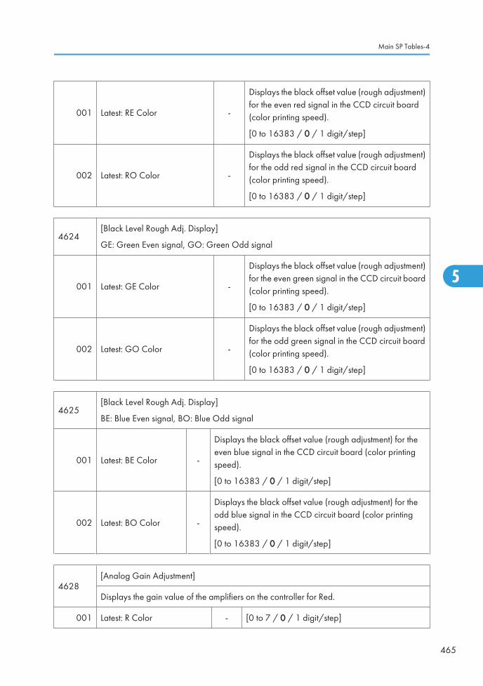
001 Latest: RE Color -
Displays the black offset value (rough adjustment)for the even red signal in the CCD circuit board(color printing speed).
[0 to 16383 / 0 / 1 digit/step]
002 Latest: RO Color -
Displays the black offset value (rough adjustment)for the odd red signal in the CCD circuit board(color printing speed).
[0 to 16383 / 0 / 1 digit/step]
4624[Black Level Rough Adj. Display]
GE: Green Even signal, GO: Green Odd signal
001 Latest: GE Color -
Displays the black offset value (rough adjustment)for the even green signal in the CCD circuit board(color printing speed).
[0 to 16383 / 0 / 1 digit/step]
002 Latest: GO Color -
Displays the black offset value (rough adjustment)for the odd green signal in the CCD circuit board(color printing speed).
[0 to 16383 / 0 / 1 digit/step]
4625[Black Level Rough Adj. Display]
BE: Blue Even signal, BO: Blue Odd signal
001 Latest: BE Color -
Displays the black offset value (rough adjustment) for theeven blue signal in the CCD circuit board (color printingspeed).
[0 to 16383 / 0 / 1 digit/step]
002 Latest: BO Color -
Displays the black offset value (rough adjustment) for theodd blue signal in the CCD circuit board (color printingspeed).
[0 to 16383 / 0 / 1 digit/step]
4628[Analog Gain Adjustment]
Displays the gain value of the amplifiers on the controller for Red.
001 Latest: R Color - [0 to 7 / 0 / 1 digit/step]
Main SP Tables-4
465
5

4629[Analog Gain Adjustment]
Displays the gain value of the amplifiers on the controller for Green.
001 Latest: G Color - [0 to 7 / 0 / 1 digit/step]
4630[Analog Gain Adjustment]
Displays the gain value of the amplifiers on the controller for Blue.
001 Latest: B Color - [0 to 7 / 0 / 1 digit/step]
4631[Digital Gain Adjustment]
Displays the gain value of the amplifiers on the controller for Red.
001 Latest: RE Color -[0 to 1023 / 0 / 1 digit/step]
002 Latest: RO Color -
4632[Digital Gain Adjustment]
Displays the gain value of the amplifiers on the controller for Green.
001 Latest: GE Color -[0 to 1023 / 0 / 1 digit/step]
002 Latest: GO Color -
4633[Digital Adjustment]
Displays the gain value of the amplifiers on the controller for Blue.
001 Latest: BE Color -[0 to 1023 / 0 / 1 digit/step]
002 Latest: BO Color -
4645 [Scan Adjust Error]
001 White level -[0 to 65535 / 0 / 1 digit/step]
002 Black level -
5. System Maintenance
466
5

4647[Read Hard Error]
Displays the result of the SBU connection check.
001 Power-ON -
[0 to 35535 / 0 / 1digit /step]
0: OK, Other: SBU connection check failure
If the SBU connection check fails, SC144 occurs.
4654[Black Level Adj. Display]
RE: Red Even signal, RO: Red Odd signal
001Last Correct Value: REColor
*ENG
Displays the black offset value for the even redsignal in the CCD circuit board (color printingspeed).
[0 to 16383 / 0 / 1 digit/step]
002Last Correct Value: ROColor
*ENG
Displays the black offset value for the odd redsignal in the CCD circuit board (color printingspeed).
[0 to 16383 / 0 / 1 digit/step]
4655[Black Level Adj. Display]
GE: Green Even signal, GO: Green Odd signal
001Last Correct Value: GEColor
*ENG
Displays the black offset value for the even greensignal in the CCD circuit board (color printingspeed).
[0 to 16383 / 0 / 1 digit/step]
002Last Correct Value: GOColor
*ENG
Displays the black offset value for the odd greensignal in the CCD circuit board (color printingspeed).
[0 to 16383 / 0 / 1 digit/step]
4656[Black Level Adj. Display]
BE: Blue Even signal, BO: Blue Odd signal
Main SP Tables-4
467
5

001Last Correct Value: BEColor
*ENG
Displays the black offset value for the even bluesignal in the CCD circuit board (color printingspeed).
[0 to 16383 / 0 / 1 digit/step]
002Last Correct Value: BOColor
*ENG
Displays the black offset value for the odd bluesignal in the CCD circuit board (color printingspeed).
[0 to 16383 / 0 / 1 digit/step]
4658[Analog Gain Adjustment]
Displays the previous gain value of the amplifiers on the controller for Red.
001 Last Correct Value: RE Color *ENG [0 to 7 / 0 / 1 digit/step]
4659[Analog Gain Adjustment]
Displays the previous gain value of the amplifiers on the controller for Green.
001 Last Correct Value: GE Color *ENG [0 to 7 / 0 / 1 digit/step]
4660[Analog Gain Adjustment]
Displays the previous gain value of the amplifiers on the controller for Blue.
001 Last Correct Value: BE Color *ENG [0 to 7 / 0 / 1 digit/step]
4661[Digital Gain Adjustment]
RE: Red Even signal, RO: Red Odd signal
001 Last Correct Value: RE Color *ENG[0 to 1023 / 0 / 1 digit/step]
002 Last Correct Value: RO Color *ENG
4662[Digital Gain Adjustment]
GE: Green Even signal, GO: Green Odd signal
001 Last Correct Value: GE Color *ENG[0 to 1023 / 0 / 1 digit/step]
002 Last Correct Value: GO Color *ENG
5. System Maintenance
468
5

4663[Digital Gain Adjustment]
BE: Blue Even signal, BO: Blue Odd signal
001 Last Correct Value: BE Color *ENG[0 to 1023 / 0 / 1 digit/step]
002 Last Correct Value: BO Color *ENG
4673[Black Level Adj. Display]
RE: Red Even signal, RO: Red Odd signal
001 Factory Setting: RE Color *ENG
Displays the factory setting values of the black leveladjustment for the even red signal in the CCD circuitboard (color printing speed)..
[0 to 16383 / 0 / 1 digit/step]
002 Factory Setting: RO Color *ENG
Displays the factory setting values of the black leveladjustment for the odd red signal in the CCD circuitboard (color printing speed).
[0 to 16383 / 0 / 1 digit/step]
4674[Black Level Adj. Display]
GE: Green Even signal, GO: Green Odd signal
001 Factory Setting: GE Color *ENG
Displays the factory setting values of the black leveladjustment for the even green signal in the CCDcircuit board (color printing speed).
[0 to 16383 / 0 / 1 digit/step]
002 Factory Setting: GO Color *ENG
Displays the factory setting values of the black leveladjustment for the odd green signal in the CCDcircuit board (color printing speed).
[0 to 16383 / 0 / 1 digit/step]
4675[Black Level Adj. Display]
BE: Blue Even signal, BO: Blue Odd signal
001 Factory Setting: BE Color *ENG
Displays the factory setting values of the black leveladjustment for the even blue signal in the CCDcircuit board (color printing speed).
[0 to 16383 / 0 / 1 digit/step]
Main SP Tables-4
469
5

002 Factory Setting: BO Color *ENG
Displays the factory setting values of the black leveladjustment for the odd blue signal in the CCD circuitboard (color printing speed).
[0 to 16383 / 0 / 1 digit/step]
4677[Analog Gain Adjustment]
Displays the factory setting values of the gain adjustment for Red.
001 Factory Setting: RE Color *ENG [0 to 7 / 0 / 1 digit/step]
4678[Analog Gain Adjustment]
Displays the factory setting values of the gain adjustment for Green.
001 Factory Setting: GE Color *ENG [0 to 7 / 0 / 1 digit/step]
4679[Analog Gain Adjustment]
Displays the factory setting values of the gain adjustment for Blue.
001 Factory Setting: BE Color *ENG [0 to 7 / 0 / 1 digit/step]
4680[Digital Gain Adjustment]
Displays the gain value of the amplifiers on the controller for Red.
001 Factory Setting: RE Color *ENG[0 to 1023 / 0 / 1 digit/step]
002 Factory Setting: RO Color *ENG
4681[Digital Gain Adjustment ]
Displays the gain value of the amplifiers on the controller for Green.
001 Factory Setting: GE Color *ENG[0 to 1023 / 0 / 1 digit/step]
002 Factory Setting: GO Color *ENG
4682[Digital Gain Adjustment]
Displays the gain value of the amplifiers on the controller for Blue.
5. System Maintenance
470
5

001 Factory Setting: BE Color *ENG[0 to 1023 / 0 / 1 digit/step]
002 Factory Setting: BO Color *ENG
4688
[Scan Image Density Adjustment]
Adjusts the white shading parameter when scanning an image with the ARDF or 1-pass DF.
Adjusts the density level if the ID of outputs made in the DF and Platen mode is different.
001 ARDF *ENG [50 to 150 / 98 / 1%/ step ]
002 1-pass DF *ENG [50 to 150 / 98 / 1%/ step ]
4690[White Level Peak Read]
Displays the peak level of the white level scanning.
001 RE -[0 to 1023 / 0 / 1 digit/step]
002 RO -
4691[White Level Peak Read]
Displays the peak level of the white level scanning.
001 GE -[0 to 1023 / 0 / 1 digit/step]
002 GO -
4692[White Level Peak Read]
Displays the peak level of the white level scanning.
001 BE -[0 to 1023 / 0 / 1 digit/step]
002 BO -
4693[Black Level Peak Read]
Displays the peak level of the black level scanning.
001 RE -[0 to 1023 / 0 / 1 digit/step]
002 RO -
Main SP Tables-4
471
5

4694[Black Level Peak Read]
Displays the peak level of the black level scanning.
001 GE -[0 to 1023 / 0 / 1 digit/step]
002 GO -
4695[Black Level Peak Read]
Displays the peak level of the black level scanning.
001 BE -[0 to 1023 / 0 / 1 digit/step]
002 BO -
4802 [DF Shading FreeRun]
001 Lamp OFF
-
Executes the scanner free run of shading movementwith exposure lamp on or off.
Press "OFF" to stop this free run. Otherwise, the freerun lasts.
002 Lamp ON
4804 [Home Position]
001 - - Executes the scanner HP detection.
4806 [Carriage Save]
001 - -
Moves the carriage from the scanner homeposition.
Dust may fall through the DF exposure glass.Therefore, do this SP when you transport themachine a long distance.
4807 [SBU Test Pattern Change]
5. System Maintenance
472
5

001 - -
[0 to 250 / 0 / 1 /step]
1: Grid pattern
2: Gradation main scan
3: Gradation sub scan
4 to 250: Default (Scanning Image)
4808 [Factory Setting Input]
002 Execution Flag - [0 or 1 / 0 / 1 /step]
4902
[ACC Data Display]
This SP outputs the final data read at the end of ACC execution.
A zero is returned if there was an error reading the data.
[0 to 255 / 0 / 1 /step]
001 R DATA1 *ENG Photo C Patch Level 1 (8-bit)
002 G DATA1 *ENG Photo M Patch Level 1 (8-bit)
003 B DATA1 *ENG Photo Y Patch Level 1 (8-bit)
004 R DATA2 *ENG Photo C Patch Level 17 (8-bit)
005 G DATA2 *ENG Photo M Patch Level 17(8-bit)
006 B DATA2 *ENG Photo Y Patch Level 17 (8-bit)
4918
[Manual Gamma Adj]
Adjusts the offset data of the printer gamma for yellow in Photo mode.
See “Printer Gamma Correction" in the Replacement and Adjustment for how to use.
009 - -
Enter the manual gamma adjustment screen (-001to 008). For details, see the "Printer GammaCorrection" in the section "Replace andAdjustment".
4954 [Read/Restore Std]
001 Read New Chart - Execute the scanning of the A4 chart.
Main SP Tables-4
473
5

002 Recall Prev Chart - Clear the data of the scanned A4 chart.
003 Read Std Chart - Execute the scanning of the A4 standard chart.
004 Set Std Chart - Overwrite the standard data.
4991
[IPU Image Path Selection ]
Selects the image path.
Enter the number to be selected using the 10-key pad.
001
RGB Frame Memory *ENG [0 to 11 / 2 / 1 /step ]
0: Scanner input RGB images
1: Scanner I/F RGB images
2: RGB images done by Shading correction (Shading ON, Black offset ON)
3: Shading data
4 to 11: Not used
4993 [High Light Correction]
001 Sensitivity Selection *ENG
Selects the Highlight correction level.
[0 to 9 / 4 / 1 /step]
0: weakest sensitivity
9: strongest sensitivity
002 Range Selection *ENG
Selects the range level of Highlight correction.
[0 to 9 / 4 / 1 /step]
0: weakest skew correction,
9: strongest skew correction
4994[Text/Photo Detection Level Adj.]
Selects the definition level between Text and Photo for high compression PDF.
001PDF Sensitivity Level text/photo
*ENG
[0 to 2 / 1 / 1 /step]
0: Text priority
1: Normal
2: Photo priority
5. System Maintenance
474
5

Main SP Tables-5
SP5-XXX (Mode)
5024[mm/inch Display Selection]
Display units (mm or inch) for custom paper sizes.
001 0:mm 1:inch *CTL0: mm (Europe/Asia)
1: inch (USA)
5045
[Accounting Counter]
Selects the counting method.
NOTE: The counting method can be changed only once, regardless of whether the countervalue is negative or positive.
001 Counter Method *CTL
[0 or 1 / 0 / - ]
0: Developments
1: Prints
5047[Paper Display]
Turns on or off the printed paper display on the LCD.
001 - *CTL[0 or 1 / 0 / - ]
0: OFF, 1: ON
5051[TonerRefillDetectionDisplay]
Enables or disables the toner refill detection display.
5051 1 Toner Refill Detection Display *CTL
[0 or 1 / 0 / - ] Alphanumeric
0: ON
1: OFF
5055[Display IP Address]
Display or does not display the IP address on the LCD.
Main SP Tables-5
475
5

001 - *CTL[0 or 1 / 0 / - ]
0: OFF 1: ON
5056[Coverage Counter Display]
Display or does not display the coverage counter on the LCD.
001 - *CTL[0 or 1 / 0 / - ]
0: Not display, 1: Display
5061[Toner Remaining Icon Display Change]
Display or does not display the remaining toner display icon on the LCD.
001 - *CTL[0 or 1 / 0 / - ]
0: Not display, 1: Display
5062[Parts Replacement Alert Display]
Display or does not display the PM part yield on the LCD.
001 Drum Unit: Bk *CTL
[0 or 1 / 1 / - ]
0: Not display, 1: Display
002 Drum Unit: M *CTL
003 Drum Unit: C *CTL
004 Drum Unit: Y *CTL
005 Development Unit: Bk *CTL
[0 or 1 / 1 / - ]
0: Not display, 1: Display
006 Development Unit: M *CTL
007 Development Unit: C *CTL
008 Development Unit: Y *CTL
009 Developer: Bk *CTL
[0 or 1 / 1 / - ]
0: Not display, 1: Display
010 Developer: M *CTL
011 Developer: C *CTL
012 Developer: Y *CTL
5. System Maintenance
476
5
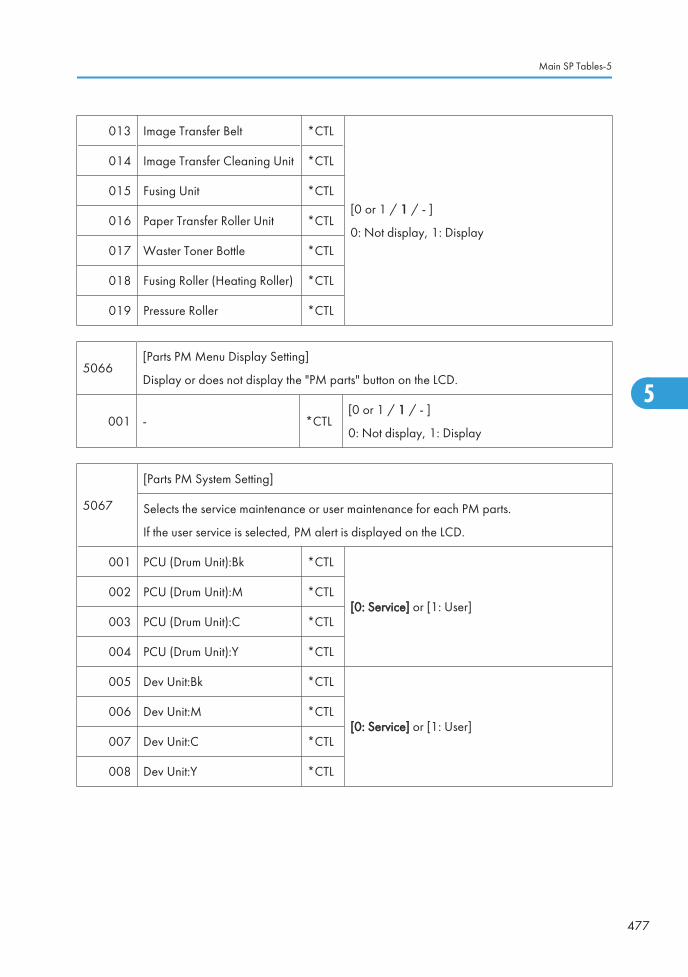
013 Image Transfer Belt *CTL
[0 or 1 / 1 / - ]
0: Not display, 1: Display
014 Image Transfer Cleaning Unit *CTL
015 Fusing Unit *CTL
016 Paper Transfer Roller Unit *CTL
017 Waster Toner Bottle *CTL
018 Fusing Roller (Heating Roller) *CTL
019 Pressure Roller *CTL
5066[Parts PM Menu Display Setting]
Display or does not display the "PM parts" button on the LCD.
001 - *CTL[0 or 1 / 1 / - ]
0: Not display, 1: Display
5067
[Parts PM System Setting]
Selects the service maintenance or user maintenance for each PM parts.
If the user service is selected, PM alert is displayed on the LCD.
001 PCU (Drum Unit):Bk *CTL
[0: Service] or [1: User]002 PCU (Drum Unit):M *CTL
003 PCU (Drum Unit):C *CTL
004 PCU (Drum Unit):Y *CTL
005 Dev Unit:Bk *CTL
[0: Service] or [1: User]006 Dev Unit:M *CTL
007 Dev Unit:C *CTL
008 Dev Unit:Y *CTL
Main SP Tables-5
477
5

009 Developer:Bk *CTL
[0: Service] or [1: User]010 Developer:M *CTL
011 Developer:C *CTL
012 Developer:Y *CTL
013 Int Trans Unit *CTL [0: Service] or [1: User]
014 Belt Cleaning Unit *CTL [0: Service] or [1: User]
015 Fusing Unit *CTL [0: Service] or [1: User]
016 Transfer Roller *CTL [0: Service] or [1: User]
017 WasteToner Bottle *CTL [0: Service] or [1: User]
018 Fusing Roller (Heating Roller) *CTL [0: Service] or [1: User]
019 Pressure Roller *CTL [0: Service] or [1: User]
5104* A3/DLT Double Count (SSP)
Specifies whether the counter is doubled for A3/DLT. "Yes" counts except from the bypasstray. When "Yes" is selected, A3 and DLT paper are counted twice, that is A4 x2 and LTx2 respectively.
5071 [Set Bypass Paper Size]
001
- *CTL[0 or 1 / 0 / -]
0: Off, 1: On
Turn on or off the paper size confirmation pop-up on the LED. This pop-up preventsmismatching between a paper size selected by the operation panel and an actual papersize on the by-pass tray.
5113 [Optional Counter Type]
5. System Maintenance
478
5

001Default Optional CounterType
*CTL
This program specifies the counter type.
0: None, 1: Key card (RK 3, 4)
2: Key card (down), 3: Prepaid card
4: Coin rack, 5: MF key card
8: Key counter + Vendor
9: Bar-code Printer
002External Optional CounterType
*CTL
This program specifies the external counter type.
0: None
1: Expansion Device 1
2: Expansion Device 2
3: Expansion Device 3
5114 [Optional Counter I/F]
001 MF Key Card Extension *CTL[0: Not installed/ 1: Installed (scanningaccounting)]
5118 [Disable Copying] *CTL [0: Not disabled/ 1: Disabled]
001 This program disables copying.
5120[Mode Clear Opt. CounterRemoval]
*CTL[0: Yes (removed)/ 1: Standby (installed but notused)/ 2: No (not removed)]
001This program updates the information on the optional counter. When you install or removean optional counter, check the settings.
5121 [Counter Up Timing] *CTL [0: Feed/ 1: Exit]
001This program specifies when the counter goes up. The settings refer to "paper feed" and"paper exit" respectively.
5126 [F Size Original Setting] *ENG
[0 to 2 / 0 / 1 /step]
0: 8 1/2" x 13" (Foolscap)
1: 8 1/4" x 13" (Folio)
2: 8" x 13" (F)
Main SP Tables-5
479
5

001 Selects F size original setting.
5127 [APS Mode] *CTL [0: Not disabled/ 1: Disabled]
001 This program disables the APS.
5131 [Paper Size Type Selection] *ENG [0: JP (Japan)/ 1: NA / 2: EU]
001The program selects a paper size system from the following alternatives: the AB system (0),the LT system (1), and the AF system (2).
5148 Size Detection Off *CTL [0: OFF/ 1: ON]
0: Detecte
1: Not Detecte
5150 [By-Pass Length Setting] *CTL [0: OFF/ 1: ON]
001
Determines whether the transfer sheet from the by-pass tray is used or not.
Normally the paper length for sub scanning paper from the by-pass tray is limited to 600mm, but this can be extended with this SP to 1260 mm.
5162 [App. Switch Method] *CTL [0: Soft Key Set/ 1: Hard Key Set]
001 This program specifies the switch that selects an application program.
5167
[Fax Printing Mode at Optional]
Enables or disables the automatic print out without an accounting device. This SP is usedwhen the receiving fax is accounted by an external accounting device.
001Fax Printing Mode at OptionalCounter Off
*CTL
[0 or 1 / 0 / - ]
0: Automatic printing
1: No automatic printing
5169
[CE Login]
If you will change the printer bit switches, you must ‘log in’ to service mode with this SP beforeyou go into the printer SP mode.
5. System Maintenance
480
5

001 CE Login *CTL
[0 or 1 / 0 / - ]
0: Disabled
1: Enabled
5181[Size Adjust]
Adjusts the paper size for each tray.
001 Paper TRAY 1 *ENG[0 to 3 / 0 (EU/ASIA), 1 (NA) / 1 /step]
0: A4 LEF, 1: LT LEF, 2: B5 LEF, 3: A5 LEF
002 TRAY 2: 1 *ENG[0 or 1 / 0 (EU/ASIA), 1 (NA) / - ]
0: A4 LEF, 1: LT LEF
003 TRAY 2: 2 *ENG[0 or 1 / 0 (EU/ASIA), 1 (NA) / - ]
0: A3, 1: DLT
004 TRAY 2: 3 *ENG[0 or 1 / 0 (EU/ASIA), 1 (NA) / - ]
0: B4, 1: LG
005 TRAY 2: 4 *ENG[0 or 1 / 0 (EU/ASIA), 1 (NA) / - ]
0: B5 LEF, 1: Exe LEF
006 TRAY 3/T-LCT: 1 *ENG[0 or 1 / 0 (EU/ASIA), 1 (NA) / - ]
0: A4 LEF, 1: LT LEF
007 TRAY 3: 2 *ENG[0 or 1 / 0 (EU/ASIA), 1 (NA) / - ]
0: A3, 1: DLT
008 TRAY 3: 3 *ENG[0 or 1 / 0 (EU/ASIA), 1 (NA) / - ]
0: B4, 1: LG
009 TRAY 3: 4 *ENG[0 or 1 / 0 (EU/ASIA), 1 (NA) / - ]
0: B5 LEF, 1: Exe LEF
010 TRAY 4: 1 *ENG[0 or 1 / 0 (EU/ASIA), 1 (NA) / - ]
0: A4 LEF, 1: LT LEF
011 TRAY 4: 2 *ENG[0 or 1 / 0 (EU/ASIA), 1 (NA) / - ]
0: A3, 1: DLT
Main SP Tables-5
481
5

012 TRAY 4: 3 *ENG[0 or 1 / 0 (EU/ASIA), 1 (NA) / - ]
0: B4, 1: LG
013 TRAY 4: 4 *ENG[0 or 1 / 0 (EU/ASIA), 1 (NA) / - ]
0: B5 LEF, 1: Exe LEF
018 LCT *ENG[0 to 2 / 0 (EU/ASIA), 1 (NA) / - ]
0: A4LEF, 1: LTLEF, 2: B5LEF
5186
[RK 4]
Enables or disables the prevention for RK4 (accounting device) disconnection.
If the RK4 is disconnected for 10 seconds when this SP is set to "1 (Enable)", the machineautomatically jams a sheet of paper and stops.
001 - *ENG
[0 or 1 / 0 / 1/step]
0: Disable
1: Enable
5188[Copy NvVersion]
Displays the version number of the NVRAM on the controller board.
001 - - -
5193 [External Controller Info. Settings]
001
- - -
Sets the external controller type. This setting is appropriately adjusted if an external controlleris installed in the machine.
[0 to 10 / 0 / 1/step]
0: No external controller installed
1: EFI controller
2: Ratio controller
3: Egret controller
4 to 10: Reserved
5199 [Paper Exit After Staple End.]
5. System Maintenance
482
5

001 - *CTL[ 0 or 1 / 0 / -]
0: OFF, 1: ON
Enables or disables the paper feeding out from the finisher without stapling.
• If this setting is "1: ON", paper is fed out without stapling at the maximum number ofthe finisher stapling when the machine gets a multiple printing job (over maximumnumber).
• If this setting is "0: OFF", paper is fed out with stapling at the maximum number of thefinisher stapling when the machine gets a multiple printing job (over maximum number).
5212 [Page Numbering] *CTL
This program adjusts the position of the second side page numbers.
A "– value" moves the page number positions to the left edge. A "+ value" moves the pagenumber positions to the right edge.
003Duplex Printout Right/LeftPosition
[–10 to 10 / 0 / 1 mm/step]
004Duplex Printout High/LowPosition
[–10 to 10 / 0 / 1 mm/step]
5302
[Set Time]
Adjusts the RTC (real time clock) time setting for the local time zone.
Examples: For Japan (+9 GMT), enter 540 (9 hours x 60 min.)
DOM: +540 (Tokyo)
NA: -300 (New York)
EU: + 60 (Paris)
CH: +480 (Peking)
TW: +480 (Taipei)
AS: +480 (Hong Kong)
002 Time Difference*CTL
#[-1440 to 1440 / Area / 1 min./step ]
5307 [Summer Time]
Main SP Tables-5
483
5

001
Setting
[ 0 to 1 / NA, EU, ASIA / 1 /step]
0: Disabled
1: Enabled
NA and EUR: 1, ASIA: 0
Enables or disables the summer time mode.
• Make sure that both SP5-307-3 and -4 are correctly set. Otherwise, this SP is notactivated even if this SP is set to "1".
003
Rule Set (Start)
Specifies the start setting for the summer time mode.
There are 8 digits in this SP. For months 1 to 9, the "0" cannot be input in the first digit, so theeight-digit setting for -2 or -3 becomes a seven-digit setting.
1st and 2nd digits: The month. [1 to 12]
3rd digit: The week of the month. [1 to 5]
4th digit: The day of the week. [0 to 6 = Sunday to Saturday]
5th and 6th digits: The hour. [00 to 23]
7th digit: The length of the advanced time. [0 to 9 / 1 hour /step]
8th digit: The length of the advanced time. [0 to 5 / 10 minutes /step]
• The digits are counted from the left.
• Make sure that SP5-307-1 is set to "1".
For example: 3500010 (EU default)
The timer is advanced by 1 hour at am 0:00 on the 5th Sunday in March
5. System Maintenance
484
5

004
Rule Set (End) - -
Specifies the end setting for the summer time mode.
There are 8 digits in this SP.
1st and 2nd digits: The month. [1 to 12]
3rd digit: The week of the month. [0 to 5]
4th digit: The day of the week. [0 to 7 = Sunday to Saturday]
5th and 6th digits: The hour. [00 to 23]
The 7th and 8 digits must be set to "00".
• The digits are counted from the left.
• Make sure that SP5-307-1 is set to "1".
5404 [User Code Count Clear]
001 UCodeCtrClr Clears all counters for users.
5411 [LDAP Certification]
004 Easy Certification *CTL
Determines whether easy LDAP certification isdone.
[0 or 1 / 1 / -] 1: On, 0: Off
005 Password Null Not Permit *CTL
This SP is referenced only when SP5411-4 is set to"1" (On).
[0 or 1 / 0 / -]
0: Password NULL not permitted.
1: Password NULL permitted.
006 Detail Option *CTL
Determines whether LDAP option (anonymouscertification) is turned on or off.
Bit0
0: OFF, 1: ON
5413 [Lockout Setting]
Main SP Tables-5
485
5

001 Lockout On/Off *CTL
Switches on/off the lock on the local address bookaccount.
[0 or 1 / 0 / -]
0: Off, 1: On
002 Lockout Threshold *CTL
Sets a limit on the frequency of lockouts for accountlockouts.
[1 to 10 / 5 / 1/step]
003 Cancellation On/Off *CTL
Determines whether the system waits the prescribedtime for input of a correct user ID and passwordafter an account lockout has occurred.
[0 or 1 / 0 / -]
0: Off (no wait time, lockout not cancelled)
1: On (system waits, cancels lockout if correct userID and password are entered.
004 Cancellation Time *CTL
Determines the length of time that the system waitsfor correct input of the user ID and password aftera lockout has occurred. This setting is used only ifSP5413-3 is set to "1" (on).
[1 to 999 / 60 / 1 min./step]
005 Counter Clear Time *CTL Not Used
5414 [Access Mitigation]
001 Mitigation On/Off *CTL
Switches on/off masking of continuously used IDsand passwords that are identical.
[0 or 1 / 0 / -]
0: Off, 1: On
002 Mitigation Time *CTL
Sets the length of time for excluding continuousaccess for identical user IDs and passwords.
[0 to 60 / 15 / 1 min./step]
5415 [Password Attack]
5. System Maintenance
486
5
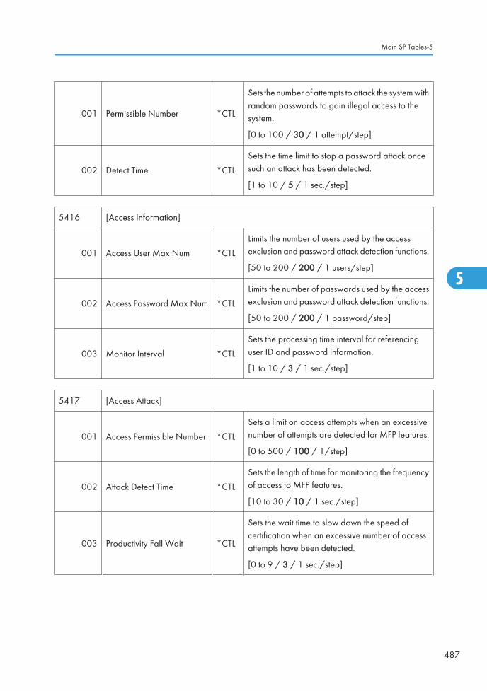
001 Permissible Number *CTL
Sets the number of attempts to attack the system withrandom passwords to gain illegal access to thesystem.
[0 to 100 / 30 / 1 attempt/step]
002 Detect Time *CTL
Sets the time limit to stop a password attack oncesuch an attack has been detected.
[1 to 10 / 5 / 1 sec./step]
5416 [Access Information]
001 Access User Max Num *CTL
Limits the number of users used by the accessexclusion and password attack detection functions.
[50 to 200 / 200 / 1 users/step]
002 Access Password Max Num *CTL
Limits the number of passwords used by the accessexclusion and password attack detection functions.
[50 to 200 / 200 / 1 password/step]
003 Monitor Interval *CTL
Sets the processing time interval for referencinguser ID and password information.
[1 to 10 / 3 / 1 sec./step]
5417 [Access Attack]
001 Access Permissible Number *CTL
Sets a limit on access attempts when an excessivenumber of attempts are detected for MFP features.
[0 to 500 / 100 / 1/step]
002 Attack Detect Time *CTL
Sets the length of time for monitoring the frequencyof access to MFP features.
[10 to 30 / 10 / 1 sec./step]
003 Productivity Fall Wait *CTL
Sets the wait time to slow down the speed ofcertification when an excessive number of accessattempts have been detected.
[0 to 9 / 3 / 1 sec./step]
Main SP Tables-5
487
5

004 Attack Max Num *CTL
Sets a limit on the number of requests received forcertification in order to slow down the certificationspeed when an excessive number of accessattempts have been detected.
[50 to 200 / 200 / 1 attempt/step]
5420
[User Authentication]
These settings should be done with the System Administrator.
Note: These functions are enabled only after the user access feature has been enabled.
001 Copy *CTL
Determines whether certification is required beforea user can use the copy applications.
[0 to 1 / 0 /1]
0: On, 1: Off
002
Color Security Setting *CTL -
Enables or disables the color copy limitation for each copy mode when the userauthentication is "ON".
0: Enable (default), 1: Disable
Bit0: B/W mode
Bit1: Mono color mode
Bit2: Two colors mode
Bit3: Full color mode
Bit4: Automatic color mode
Bit5 to 7: Reserved
011 DocumentServer *CTL
Determines whether certification is required beforea user can use the document server.
[0 or 1/ 0 /1]
0: On, 1: Off
021 Fax *CTL
Determines whether certification is required beforea user can use the fax application.
[0 or 1/ 0 /1]
0: On, 1: Off
5. System Maintenance
488
5

031 Scanner *CTL
Determines whether certification is required beforea user can use the scan applications.
[0 or 1/ 0 /1]
0: On, 1: Off
041 Printer *CTL
Determines whether certification is required beforea user can use the printer applications.
[0 or 1/ 0 /1]
0: On, 1: Off
051 SDK1
*CTL
[0 or 1 / 0 / 1] 0: ON. 1: OFF
Determines whether certification is required beforea user can use the SDK application.
061 SDK2
071 SDK3
5481[Authentication Error Code]
These SP codes determine how the authentication failures are displayed.
001 System Log Disp *CTL
Determines whether an error code appears in thesystem log after a user authentication failure occurs.
[0 or 1/ 0 /1]
0: Off, 1: On
002 Panel Disp *CTL
Determines whether an error code appears on theoperation panel after a user authentication failureoccurs.
[0 or 1/ 1 /1]
1: On, 0: Off
5490 [MF KeyCard (Japan only)]
001 Job Permit Setting *CTL
Sets up operation of the machine with a keycard.
[0 to 1 / 0 / 1]
0: Disabled. Cancels operation without a usercode.
1: Enabled. Allows operation without a user code.
002 Count Mode Setting *CTL -
Main SP Tables-5
489
5
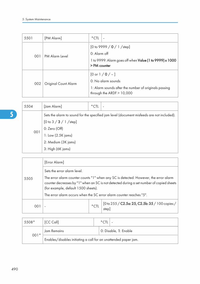
5501 [PM Alarm] *CTL -
001 PM Alarm Level
[0 to 9999 / 0 / 1 /step]
0: Alarm off
1 to 9999: Alarm goes off when Value (1 to 9999) x 1000> PM counter
002 Original Count Alarm
[0 or 1 / 0 / – ]
0: No alarm sounds
1: Alarm sounds after the number of originals passingthrough the ARDF > 10,000
5504 [Jam Alarm] *CTL -
001
Sets the alarm to sound for the specified jam level (document misfeeds are not included).
[0 to 3 / 3 / 1 /step]
0: Zero (Off)
1: Low (2.5K jams)
2: Medium (3K jams)
3: High (6K jams)
5505
[Error Alarm]
Sets the error alarm level.
The error alarm counter counts "1" when any SC is detected. However, the error alarmcounter decreases by "1" when an SC is not detected during a set number of copied sheets(for example, default 1500 sheets).
The error alarm occurs when the SC error alarm counter reaches "5".
001 - *CTL[0 to 255 / C2.5a: 25, C2.5b: 35 / 100 copies /step]
5508* [CC Call] *CTL -
001*Jam Remains 0: Disable, 1: Enable
Enables/disables initiating a call for an unattended paper jam.
5. System Maintenance
490
5

002*Continuous Jams 0: Disable, 1: Enable
Enables/disables initiating a call for consecutive paper jams.
003*Continuous Door Open 0: Disable, 1: Enable
Enables/disables initiating a call when the front door remains open.
011*
Jam Detection: Time Length [3 to 30 / 10 / 1 minute /step]
Sets the time a jam must remain before it becomes an "unattended paper jam". This settingis enabled only when SP5508-004 is set to "1".
012*
Jam Detection: Continuous Count [2 to 10 / 5 / 1 /step]
Sets the number of consecutive paper jams required to initiate a call. This setting is enabledonly when SP5508-004 is set to "1".
013*
Door Open: Time Length [3 to 30 / 10 / 1 /step]
Sets the length of time the door remains open before the machine initiates a call.
This setting is enabled only when SP5-508-004 is set to "1".
5515
[SC/Alarm Setting] *CTL -
With NRS (New Remote Service) in use, these SP codes can be set to issue an SC call whenan SC error occurs. If this SP is switched off, the SC call is not issued when an SC erroroccurs.
001 SC Call
[0 or 1 / 1 / - ]
0: Off
1: On
002 Service Parts Near End Call
003 Service Parts End Call
004 User Call
Main SP Tables-5
491
5

006 Communication Test Call
[0 or 1 / 1 / - ]
0: Off
1: On
007 Machine Information Notice
008 Alarm Notice
009 Non Genuine Tonner Alarm
010 Supply Automatic Ordering Call
011 Supply Management Report Call
012 Jam/Door Open Call
5516
[Individual PM Part AlarmCall]
*CTL -
With @Remote in use, these SP codes can be set to issue an PM alarm call when one of SPparts reaches its yield.
001Disable/Enable Setting (0: Not send, 1:Send)
[0 or 1 / 1 / - ]
0: Not send, 1: Send
004 Percent yield for triggering PM alert [1 to 255 / 75 / 1 %/step]
5610 [Base Gamma Control Point: Command]
004Factory Setting - -
Recalls the factory settings.
005Restore - -
Overwrites the current values onto the factory settings.
006Restore - -
Recalls the previous settings.
5611 [Toner Color in 2C]
001B-C *ENG
[0 to 128 / 100 / 1 /step]
128: Darkest density
Adjusts the Cyan correction value of the blue signal in two-color mode.
5. System Maintenance
492
5

002B-M *ENG
[0 to 128 / 100 / 1 /step]
128: Darkest density
Adjusts the Magenta correction value of the blue signal in two-color mode.
003G-C *ENG
[0 to 128 / 100 / 1 /step]
128: Darkest density
Adjusts the Cyan correction value of the blue signal in two-color mode.
004G-Y *ENG
[0 to 128 / 100 / 1 /step]
128: Darkest density
Adjusts the Yellow correction value of the blue signal in two-color mode.
005R-M *ENG
[0 to 128 / 100 / 1 /step]
128: Darkest density
Adjusts the Magenta correction value of the blue signal in two-color mode.
006R-Y *ENG
[0 to 128 / 100 / 1 /step]
128: Darkest density
Adjusts the Yellow correction value of the blue signal in two-color mode.
5618 [Color Mode Display Selection]
001- *CTL
[0 or 1 / 1 / - ]
0: ACS, Colour, Black & White, Two Colour, Singlecolour
1: ACD, Full Colour, Black & White
Selects the color selection display on the LCD.
• Memory Clear (SP5-801)
• The following tables list the items that are cleared. The serial number information, meter charge settingand meter charge counters (SP8-581, 582, 583, 584, and 586) are not cleared.
5801 [Memory Clear]
Main SP Tables-5
493
5

001 All ClearResets all correction data for process control and allsoftware counters, and returns all modes and adjustmentsto their default values.
002 Engine Clears the engine settings.
003 SCSInitializes default system settings, SCS (System ControlService) settings, operation display coordinates, and ROMupdate information.
004 IMH Memory Clr Initializes the IMH settings.
005 Mcs Initializes the Mcs settings.
006 Copier Application Initializes all copier application settings.
007 Fax ApplicationInitializes the fax reset time, job login ID, all TX/RX settings,local storage file numbers, and off-hook timer.
008 Printer Application
The following service settings:
• Bit switches
• Gamma settings (User & Service)
• Toner Limit
The following user settings:
• Tray Priority
• Menu Protect
• System Setting except for setting of Energy Saver
• I/F Setup (I/O Buffer and I/O Timeout)
• PCL Menu
009 Scanner ApplicationInitializes the scanner defaults for the scanner and all thescanner SP modes.
010 Web ServiceDeletes the network file application management files andthumbnails, and initializes the job login ID.
011 NCSAll setting of Network Setup (User Menu)
(NCS: Network Control Service)
012 R-FaxInitializes the job login ID, SmartDeviceMonitor for
Admin, job history, and local storage file numbers.
014 Clear DCS Setting Initializes the DCS (Delivery Control Service) settings.
5. System Maintenance
494
5

015 Clear UCS SettingInitializes the UCS (User Information Control Service)settings.
016 MIRS SettingInitializes the MIRS (Machine Information Report Service)settings.
017 CCSInitializes the CCS (Certification and Charge-controlService) settings.
018 SRM Memory Clr Initializes the SRM (System Resource Manager) settings.
019 LCS Initializes the LCS settings.
020 Web Uapli Initializes the web user application settings.
021 ECS Initializes the ECS settings.
5802
[FreeRun]
Performs a free run on the copier engine.
• The machine starts free run in the same condition as the sequence of A4/LT, A3 orA4 SEF printing from the 1st or 2nd tray. Therefore, the correct paper should beloaded in the 1st tray or 2nd tray, but paper is not fed.
• The main switch has to be turned off and on after using the free run mode for a test.
001 B/W A4 LEF -
-002 FC A4 LEF -
003 FC A3 LEF -
5803 [Input Check] - See p.627 "Main SP Tables-9" in this section.
5804 [Output Check] - See p.627 "Main SP Tables-9" in this section.
5805 [Anti-Condensation Heater]
002 0:OFF / 1:ON *ENG -
Main SP Tables-5
495
5

5810
[SC Reset]
Resets a type A service call condition.
• Turn the main switch off and on after resetting the SC code.
001 Fusing SC Reset - -
5811 [MachineSerial] Machine Serial Number Display
002 Display Displays the machine serial number.
004 BICU Inputs
5812 [Service Tel. No. Setting]
001
Service *CTL -
Sets the telephone number for a service representative. This number is printed on theCounter List, which can be printed with the user’s "Counter" menu.
This can be up to 20 characters (both numbers and alphabetic characters can be input).
002
Facsimile *CTL -
Sets the fax or telephone number for a service representative. This number is printed on theCounter List.
This can be up to 20 characters (both numbers and alphabetic characters can be input).
003
Supply *CTL -
Use this to input the telephone number of your supplier for consumables. Enter the numberand press #.
004
Operation *CTL -
Use this to input the telephone number of your sales agency. Enter the number and press#.
5816 [Remote Service] *CTL -
5. System Maintenance
496
5

001
I/F Setting
Selects the remote service setting.
[0 to 2 / 2 / 1 /step]
0: Remote service off
1: CSS remote service on
2: NRS remote service on
002
CE Call
Performs the CE Call at the start or end of the service.
[0 or 1 / 0 / 1 /step]
0: Start of the service
1: End of the service
NOTE: This SP is activated only when SP 5816-001 is set to "2".
003
Function Flag
Enables or disables the remote service function.
[0 to 1 / 0 / 1 /step]
0: Disabled
1: Enabled
007
SSL Disable
Controls if RCG (Remote Communication Gate) confirmation is done by SSL during anRCG send for the @Remote over a network interface.
[0 or 1 / 0 / 1 /step]
0: Yes. SSL not used.
1: No. SSL used.
008
RCG Connect Timeout
Sets the length of time (seconds) for the time-out when the RCG (Remote CommunicationGate) connects during a call via the @Remote network.
[1 to 90 / 30 / 1 second /step]
Main SP Tables-5
497
5

009
RCG Write Timeout
Sets the length of time (seconds) for the time-out when sent data is written to the RCG duringa call over the @Remote network.
[1 to 100 / 60 / 1 second /step]
010
RCG Read Timeout
Sets the length of time (seconds) for the timeout when sent data is written from the RCGduring a call over the @Remote network.
[1 to 100 / 60 / 1 second /step]
011
Port 80 Enable -
Controls if permission is given to get access to the SOAP method over Port 80 on the@Remote network.
[0 or 1 / 0 / – ]
0: No. Access denied
1: Yes. Access granted.
013
RFU Timing
Selects the timing for the remote firmware updating.
[0 or 1 / 1 / – ]
0: Any status of a target machine
1: Sleep or panel off mode only
021
RCG – C Registed
This SP displays the RCG-N installation end flag.
0: Installation not completed
1: Installation completed
022
RCG – C Regist Detail
This SP displays the RCG device installation status.
0: RCG device not registered
1: RCG device registered
2: Device registered
5. System Maintenance
498
5

023
Connect Type (N/M)
This SP displays and selects the RCG-N connection method.
[0 or 1 / 0 / 1 /step
0: Internet connection
1: Dial-up connection
061 Cert. Expire Timing DFU Proximity of the expiration of the certification.
062 Use ProxyThis SP setting determines if the proxy server is used when themachine communicates with the service center.
063
Proxy Host
This SP sets the address of the proxy server used for communication between the RCGdevice and the gateway. Use this SP to set up or display the customer proxy server address.
The address is necessary to set up the embedded RCG-N.
• The address display is limited to 128 characters. Characters beyond the 128character are ignored.
• This address is customer information and is not printed in the SMC report.
064
Proxy PortNumber
This SP sets the port number of the proxy server used for communication between theembedded RCG-N and the gateway. This setting is necessary to set up the embeddedRCG-N.
• This port number is customer information and is not printed in the SMC report.
065
Proxy User Name
This SP sets the HTTP proxy certification user name.
• The length of the name is limited to 31 characters. Any character beyond the 31stcharacter is ignored.
• This name is customer information and is not printed in the SMC report.
Main SP Tables-5
499
5

066
Proxy Password
This SP sets the HTTP proxy certification password.
• The length of the password is limited to 31 characters. Any character beyond the 31stcharacter is ignored.
• This name is customer information and is not printed in the SMC report.
067CERT:Up State
Displays the status of the certification update.
0 The certification used by RCG-N is set correctly.
1The certification request (setAuthKey) for update has been received from the GWURL and certification is presently being updated.
2The certification update is completed and the GW URL is being notified of thesuccessful update.
3 The certification update failed, and the GW URL is being notified of the failed update.
4The period of the certification has expired and new request for an update is beingsent to the GW URL.
11A rescue update for certification has been issued and a rescue certification settingis in progress for the rescue GW connection.
12The rescue certification setting is completed and the GW URL is being notified of thecertification update request.
13The notification of the request for certification update has completed successfully,and the system is waiting for the certification update request from the rescue GWURL.
14The notification of the certification request has been received from the rescue GWcontroller, and the certification is being stored.
15The certification has been stored, and the GW URL is being notified of the successfulcompletion of this event.
16The storing of the certification has failed, and the GW URL is being notified of thefailure of this event.
5. System Maintenance
500
5

17The certification update request has been received from the GW URL, the GW URLwas notified of the results of the update after it was completed, but an certificationerror has been received, and the rescue certification is being recorded.
18The rescue certification of No. 17 has been recorded, and the GW URL is beingnotified of the failure of the certification update.
068
CERT:Error
Displays a number code that describes the reason for the request for update of thecertification.
0 Normal. There is no request for certification update in progress.
1 Request for certification update in progress. The current certification has expired.
2 An SSL error notification has been issued. Issued after the certification has expired.
3 Notification of shift from a common authentication to an individual certification.
4 Notification of a common certification without ID2.
5 Notification that no certification was issued.
6 Notification that GW URL does not exist.
069 CERT:Up ID The ID of the request for certification.
083 FirmUp Status Displays the status of the firmware update.
085 Firm Up User Check
This SP setting determines if the operator can confirm theprevious version of the firmware before the firmware updateexecution. If the option to confirm the previous version isselected, a notification is sent to the system manager and thefirmware update is done with the firmware files from the URL.
086 Firmware SizeAllows the service technician to confirm the size of thefirmware data files during the firmware update execution.
087 CERT: Macro Version Displays the macro version of the @Remote certification.
088 CERT: PAC Version Displays the PAC version of the @Remote certification.
089 CERT: ID2 CodeDisplays ID2 for the @Remote certification. Spaces aredisplayed as underscores (_). Asteriskes (****) indicate thatno @Remote certification exists.
Main SP Tables-5
501
5

090 CERT: Subject
Displays the common name of the @Remote certificationsubject. CN = the following 17 bytes. Spaces are displayedas underscores (_). Asterisks (****) indicate that no DESSexists.
091 CERT: Serial NumberDisplays serial number for the NRS certification. Asterisks(****) indicate that no DESS exists.
092 CERT: IssuerDisplays the common name of the issuer of the @Remotecertification. CN = the following 30 bytes. Asteriskes (****)indicate that no DESS exists.
093 CERT: Valid StartDisplays the start time of the period for which the current@Remote certification is enabled.
094 CERT: Valid EndDisplays the end time of the period for which the current@Remote certification is enabled.
150
Selection Country
Select the country where embedded RCG-M is installed in the machine. After selecting thecountry, you must also set the following SP codes for embedded RCG-M:
• SP5816-153
• SP5816-154
• SP5816-161
0: Japan, 1: USA, 2: Canada, 3: UK, 4: Germany, 5: France, 6: Italy,
7: Netherlands, 8: Belgium, 9: Luxembourg, 10: Spain
151
Line Type AutomaticJudgment
Press [Execute].
Setting this SP classifies the telephone line where embedded RCG-M is connected as eitherdial-up (pulse dial) or push (DTMF tone) type, so embedded RCG-M can automaticallydistinguish the number that connects to the outside line.
• The current progress, success, or failure of this execution can be displayed withSP5816-152.
• If the execution succeeded, SP5816-153 will display the result for confirmation andSP5816-154 will display the telephone number for the connection to the outside line.
5. System Maintenance
502
5

152
Line Type Judgment Result
Displays a number to show the result of the execution of SP5816 151. Here is a list of whatthe numbers mean.
0: Success
1: In progress (no result yet). Please wait.
2: Line abnormal
3: Cannot detect dial tone automatically
4: Line is disconnected
5: Insufficient electrical power supply
6: Line classification not supported
7: Error because fax transmission in progress – ioctl() occurred.
8: Other error occurred
9: Line classification still in progress. Please wait.
153
Selection Dial/Push
This SP displays the classification (tone or pulse) of the telephone line to the access pointfor embedded RCG-M. The number displayed (0 or 1) is the result of the execution ofSP5816-151. However, this setting can also be changed manually.
[0 or 1 / 0 / 1 /step]
0: Tone Dialing Phone
1: Pulse Dialing Phone
Inside Japan "2" may also be displayed:
0: Tone Dialing Phone
1: Pulse Dialing Phone 10PPS
2: Pulse Dialing Phone 20PPS
Main SP Tables-5
503
5

154
Outside LineOutgoing Number
The SP sets the number that switches to PSTN for the outside connection for embeddedRCG-M in a system that employs a PBX (internal line).
• If the execution of SP5816-151 has succeeded and embedded RCG-M hasconnected to the external line, this SP display is completely blank.
• If embedded RCG-M has connected to an internal line, then the number of theconnection to the external line is displayed.
• If embedded RCG-M has connected to an external line, a comma is displayed withthe number. The comma is inserted for a 2 sec. pause.
• The number setting for the external line can be entered manually (including commas).
156
Dial Up User Name
Use this SP to set a user name for access to remote dial up. Follow these rules when settinga user name:
• Name length: Up to 32 characters
• Spaces and # allowed but the entire entry must be enclosed by double quotationmarks (").
157
Dial Up Password
Use this SP to set a password for access to remote dial up. Follow these rules when settinga user name:
• Name length: Up to 32 characters
• Spaces and # allowed but the entire entry must be enclosed by double quotationmarks (").
161
Local Phone Number
Use this SP to set the telephone number of the line where embedded RCG-M is connected.This number is transmitted to and used by the Call Center to return calls.
Limit: 24 numbers (numbers only)
162
Connection Timing Adjustment: Incoming
When the Call Center calls out to an embedded RCG-M modem, it sends a repeating IDtone (*#1#). This SP sets the time the line remains open to send these ID tones after thenumber of the embedded RCG-M modem is dialed up and connected.
[0 to 24 / 1 / 1 /step]
The actual amount of time is this setting x 2 sec. For example, if you set "2" the line willremain open for 4 sec.
5. System Maintenance
504
5

163
Access Point
This is the number of the dial-up access point for RCG-M. If no setting is done for this SPcode, then a preset value (determined by the country selected) is used.
Default: 0
Allowed: Up to 16 alphanumeric characters
164 Line Connecting
This SP sets the connection conditions for the customer. This setting dedicates the line toRCG-M only, or sets the line for sharing between RCG-M and a fax unit.
[0 to 1 / 0 / 1 /step]
0: Sharing Fax
1: No Sharing Fax
• If this setting is changed, the copier must be cycled off and on.
• SP5816 187 determines whether the off-hook button can be used to interrupt a RCG-M transmission in progress to open the line for fax transaction.
173 Modem Serial Number This SP displays the serial number registered for the RCG-M.
174
Retransmission Limit
Normally, it is best to allow unlimited time for certification and ID2 update requests, andfor the notification that the certification has been completed. However, RCG-M generatescharges based on transmission time for the customer, so a limit is placed upon the timeallowed for these transactions.
If these transactions cannot be completed within the allowed time, do this SP to cancel thetime restriction.
187
FAX TX Priority -
This SP determines whether pushing the off-hook button will interrupt a RCG-M transmissionin progress to open the line for fax transaction. This SP can be used only if SP5816 164 isset to "0".
[0 or 1/ 0 / - ]
0: Disable, 1: Enable
200 Manual Polling - Executes the manual polling.
Main SP Tables-5
505
5

201
Regist: Status
Displays a number that indicates the status of the @Remote service device.
0: Neither the registered device by the external nor embedded RCG device is set.
1: The embedded RCG device is being set. Only Box registration is completed. In this status,this unit cannot answer a polling request from the external RCG.
2. The embedded RCG device is set. In this status, the external RCG unit cannot answer apolling request.
3. The registered device by the external RCG is being set. In this status the embedded RCGdevice cannot be set.
4 The registered module by the external RCG has not started.
202 Letter NumberAllows entry of the number of the request needed for the RCG-N device.
203 Confirm Execute Executes the inquiry request to the @Remote GW URL.
204 Confirm Result
Displays a number that indicates the result of the inquiry executed with SP5816 203.
0: Succeeded
1: Inquiry number error
2: Registration in progress
3: Proxy error (proxy enabled)
4: Proxy error (proxy disabled)
5: Proxy error (Illegal user name or password)
6: Communication error
7: Certification update error
8: Other error
9: Inquiry executing
205
Confirm Place
Displays the result of the notification sent to the device from the GW URL in answer to theinquiry request. Displayed only when the result is registered at the GW URL.
206 Register Execute Executes "Embedded RCG Registration".
5. System Maintenance
506
5

207
Register Result
Displays a number that indicates the registration result.
0: Succeeded
2: Registration in progress
3: Proxy error (proxy enabled)
4: Proxy error (proxy disabled)
5: Proxy error (Illegal user name or password)
6: Communication error
7: Certification update error
8: Other error
9: Registration executing
208 Error Code
Displays a number that describes the error code that was issued when either SP5816-204or SP5816-207 was executed.
Cause Code Meaning
Illegal Modem Parameter
-11001 Chat parameter error
-11002 Chat execution error
-11003 Unexpected error
Operation Error, IncorrectSetting
-12002Inquiry, registration attempted withoutacquiring device status.
-12003Attempted registration without execution of aninquiry and no previous registration.
-12004Attempted setting with illegal entries forcertification and ID2.
-12005@Remote communication is prohibited. Thedevice has an Embedded RC gate-relatedproblem.
Main SP Tables-5
507
5

Operation Error, IncorrectSetting
-12006A confirmation request was made after theconfirmation had been already completed.
-12007The request number used at registration wasdifferent from the one used at confirmation.
-12008Update certification failed because mainframewas in use.
-12009ID2 mismatch between an individualcertification and NVRAM
-12010 Certification area is not initialized.
Error Caused by Responsefrom GW URL
-2385Attempted dial up overseas without the correctinternational prefix for the telephone number.
-2387 Not supported at the Service Center
-2389 Database out of service
-2390 Program out of service
-2391 Two registrations for same device
-2392 Parameter error
-2393 Basil not managed
-2394 Device not managed
-2395 Box ID for Basil is illegal
-2396 Device ID for Basil is illegal
-2397 Incorrect ID2 format
-2398 Incorrect request number format
209 Instal Clear Releases the machine from its embedded RCG setup.
250 CommLog Print Prints the communication log.
5821 [Remote Service Address]
002 RCG IP Address *CTLSets the IP address of the RCG (RemoteCommunication Gate) destination for callprocessing at the remote service center.
5. System Maintenance
508
5

5824
[NV-RAM Data Upload]
Uploads the UP and SP mode data (except for counters and the serial number) from theNVRAM to an SD card. For details, see the "NVRAM Data Upload/Download" in thissection.
001 NV-RAM Data Upload # -
5825
[NV-RAM Data Download]
Downloads the UP and SP mode data from an SD card to the NVRAM. For details, see the"NVRAM Data Upload/Download" in this section.
001 NV-RAM Download # -
5828 [Network Setting] *CTL -
0501284 Compatibility(Centro)
Enables or disables 1284 Compatibility.
[0 or 1 / 1 / 1 / step]
0: Disabled, 1: Enabled
052 ECP (Centro)
Enables or disables ECP Compatibility.
[0 or 1 / 1 / 1 / step]
0: Disabled, 1: Enabled
• This SP is activated only when SP5-828-50 is set to "1".
065 Job Spooling
Enables/disables Job Spooling.
[0 or 1 / 0 / 1 / step]
0: Disabled, 1: Enabled
066Job Spooling Clear: StartTime
Treatment of the job when a spooled job exists at power on.
0: ON (Data is cleared)
1: OFF (Automatically printed)
Main SP Tables-5
509
5
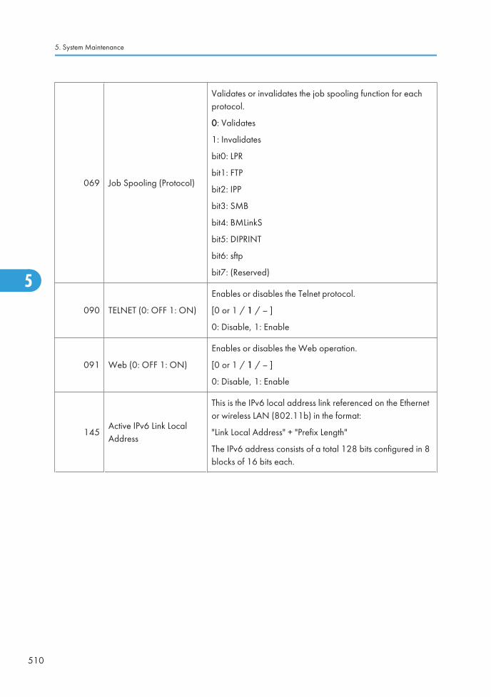
069 Job Spooling (Protocol)
Validates or invalidates the job spooling function for eachprotocol.
0: Validates
1: Invalidates
bit0: LPR
bit1: FTP
bit2: IPP
bit3: SMB
bit4: BMLinkS
bit5: DIPRINT
bit6: sftp
bit7: (Reserved)
090 TELNET (0: OFF 1: ON)
Enables or disables the Telnet protocol.
[0 or 1 / 1 / – ]
0: Disable, 1: Enable
091 Web (0: OFF 1: ON)
Enables or disables the Web operation.
[0 or 1 / 1 / – ]
0: Disable, 1: Enable
145Active IPv6 Link LocalAddress
This is the IPv6 local address link referenced on the Ethernetor wireless LAN (802.11b) in the format:
"Link Local Address" + "Prefix Length"
The IPv6 address consists of a total 128 bits configured in 8blocks of 16 bits each.
5. System Maintenance
510
5

147Active IPv6 StatelessAddress 1
These SPs are the IPv6 status addresses (1 to 5) referencedon the Ethernet or wireless LAN (802.11b) in the format:
"Status Address" + "Prefix Length"
The IPv6 address consists of a total 128 bits configured in 8blocks of 16 bits each.
149Active IPv6 StatelessAddress 2
151Active IPv6 StatelessAddress 3
153Active IPv6 StatelessAddress 4
155Active IPv6 StatelessAddress 5
156 IPv6 Manual Address
This SP is the IPv6 manually set address referenced on theEthernet or wireless LAN (802.11b) in the format:
"Manual Set Address" + "Prefix Length"
The IPv6 address consists of a total 128 bits configured in 8blocks of 16 bits each.
158 IPv6 Gateway AddressThis SP is the IPv6 gateway address referenced on the Ethernetor wireless LAN (802.11b). The IPv6 address consists of atotal 128 bits configured in 8 blocks of 16 bits each.
161 IPv6 Stateless Auto Setting
Enables or disables the automatic setting for IPv6 stateless.
[0 or 1 / 1 / 1 /step]
0: Disable, 1: Enable
236 Web Item visible
Displays or does not display the Web system items.
[0 x 0000 to 0 x ffff / 0 x ffff] 0: Not displayed, 1: Displayed
bit0: Net RICOH
bit1: Consumable Supplier
bit2-15: Reserved (all)
237 Web shopping link visible
Displays or does not display the link to Net RICOH on the toppage and link page of the web system.
[0 to 1 / 1 / 1]
0: Not display, 1:Display
Main SP Tables-5
511
5

238 Web supplies Link visible
Displays or does not display the link to Consumable Supplieron the top page and link page of the web system.
[0 to 1 / 1 / 1]
0: Not display, 1:Display
239 Web Link1 NameThis SP confirms or changes the URL1 name on the link pageof the web system. The maximum characters for the URL nameare 31 characters.
240 Web Link1 URLThis SP confirms or changes the link to URL1 on the link pageof the web system. The maximum characters for the URL are127 characters.
241 Web Link1 visible
Displays or does not display the link to URL1 on the top pageof the web system.
[0 to 1 / 1 / 1]
0: Not display, 1:Display
242 Web Link2 Name Same as "-239"
243 Web Link2 URL Same as "-240"
244 Web Link2 visible Same as "-241"
5832 [HDD] HDD Initialization *CTL -
5. System Maintenance
512
5

001 HDD Formatting (ALL)
Initializes the hard disk. Use this SP mode only if thereis a hard disk error.
002 HDD Formatting (IMH)
003 HDD Formatting (Thumbnail)
004 HDD Formatting (Job Log)
005 HDD Formatting (Printer Fonts)
006 HDD Formatting (User Info)
007 Mail RX Data
008 Mail TX Data
009HDD Formatting (Data for aDesign)
010 HDD Formatting (Log)
011 HDD Formatting (Ridoc I/F)
5836 [Capture Settings] *CTL -
001
Capture Function (0:Off 1:On) 0: Disable, 1: Enable
With this function disabled, the settings related to the capture feature cannot be initialized,displayed, or selected.
002Panel Setting 0: Displayed, 1: Not displayed
Displays or does not display the capture function buttons.
5836-71 to 5836-78, Copier and Printer Document Reduction
The following 6 SP modes set the default reduction for stored documents sent to thedocument management server via the MLB.
Enabled only when optional MLB (Media Link Board) is installed.
071 Reduction for Copy Color 0: 1to-1, 1: 1/2, 2: 1/3, 3: 1/4
072 Reduction for Copy B&W Text 0: 1to-1, 1: 1/2, 2: 1/3, 3: 1/4, 6: 2/3
073 Reduction for Copy B&W Other 0: 1to-1, 1: 1/2, 2: 1/3, 3: 1/4, 6: 2/3
074 Reduction for Printer Color 0: 1to-1, 1: 1/2, 2: 1/3, 3: 1/4
075 Reduction for Printer B&W 0: 1to-1, 1: 1/2, 2: 1/3, 3: 1/4, 6: 2/3
Main SP Tables-5
513
5

076 Reduction for Printer B&W HQ 0: 1to-1, 1: 1/2, 2: 1/3, 3: 1/4
077 Reduction for Printer Color 12001: 1/2, 3: 1/4, 4: 1/6, 5: 1/8 (2: skipped) ,6: 2/3
078 Reduction for Printer B&W 12001: 1/2, 3: 1/4, 4: 1/6, 5: 1/8 (2: skipped) ,6: 2/3
5836-81 to 5836-86, Stored document format
The following 6 SP modes set Sets the default format for stored documents sent to thedocument management server via the MLB.
Enabled only when optional MLB (Media Link Board) is installed.
081 Format for Copy Color
0: JFIF/JPEG, 1: TIFF/MMR,
2: TIFF/MH, 3: TIFF/MR
• This SP is not used in this model.
082 Format for Copy B&W Text0: JFIF/JPEG, 1: TIFF/MMR,
2: TIFF/MH, 3: TIFF/MR
083 Format Copy B&W Other0: JFIF/JPEG, 1: TIFF/MMR,
2: TIFF/MH, 3: TIFF/MR
084 Format for Printer Color
0: JFIF/JPEG, 1: TIFF/MMR,
2: TIFF/MH, 3: TIFF/MR
• This SP is not used in this model.
085 Format for Printer B&W0: JFIF/JPEG, 1: TIFF/MMR,
2: TIFF/MH, 3: TIFF/MR
086 Format for Printer B&W HQ0: JFIF/JPEG, 1: TIFF/MMR,
2: TIFF/MH, 3: TIFF/MR
091
Default for JPEG [5 to 95 / 50 / 1 /step]
Sets the JPEG format default for documents sent to the document management server viathe MLB with JPEG selected as the format.
Enabled only when optional MLB (Media Link Board) is installed.
5. System Maintenance
514
5

101 Primary srv IP addressSets the IP address for the primary capture server. This isbasically adjusted by the remote system.
102 Primary srv scheme This is basically adjusted by the remote system.
103 Primary srv port number This is basically adjusted by the remote system.
104 Primary srv URL path This is basically adjusted by the remote system.
111 Secondary srv IP addressSets the IP address for the secondary capture server. This isbasically adjusted by the remote system.
112 Secondary srv scheme This is basically adjusted by the remote system.
113 Secondary srv port number This is basically adjusted by the remote system.
114 Secondary srv URL path This is basically adjusted by the remote system.
120 Default Reso Rate Switch This is basically adjusted by the remote system.
121
Reso: Copy (Color) [0 to 3 / 2 / 1/step]
Selects the resolution for color copy mode. This is basically adjusted by the remote system.
0: 600dpi/ 1: 300dpi/ 2: 150dpi/ 3: 75dpi
122
Reso: Copy (Mono) [0 to 5 / 3 / 1/step]
Selects the resolution for BW copy mode. This is basically adjusted by the remote system.
0: 600dpi/ 1: 400dpi/ 2: 300dpi/ 3: 200dpi/ 4: 150dpi/ 5: 100dpi
123
Reso: Print (Color)This is basically adjusted by the remote system.
[0 to 3 / 2 / 1/step]
Selects the resolution for color print mode. This is basically adjusted by the remote system.
0: 600dpi/ 1: 300dpi/ 2: 150dpi/ 3: 75dpi
124
Reso: Print (Mono)This is basically adjusted by the remote system.
[0 to 5 / 3 / 1/step]
Selects the resolution for BW print mode. This is basically adjusted by the remote system.
0: 600dpi/ 1: 400dpi/ 2: 300dpi/ 3: 200dpi/ 4: 150dpi/ 5: 100dpi
Main SP Tables-5
515
5

125
Reso: Fax (Color)This is basically adjusted by the remote system.
[0 to 6 / 4 / 1/step]
Selects the resolution for color fax mode. This is basically adjusted by the remote system.
0: 600dpi/ 1: 400dpi/ 2: 300dpi/ 3: 200dpi/ 4: 150dpi/ 5: 100dpi/ 6: 75dpi
126 Reso: Fax (Mono)This is basically adjusted by the remote system.
[0 to 6 / 3 / 1/step]
Selects the resolution for BW fax mode. This is basically adjusted by the remote system.
0: 600dpi/ 1: 400dpi/ 2: 300dpi/ 3: 200dpi/ 4: 150dpi/ 5: 100dpi/ 6: 75dpi
127
Reso: Scan (Color)This is basically adjusted by the remote system.
[0 to 6 / 4 / 1/step]
Selects the resolution for color scanning mode. This is basically adjusted by the remotesystem.
0: 600dpi/ 1: 400dpi/ 2: 300dpi/ 3: 200dpi/ 4: 150dpi/ 5: 100dpi/ 6: 75dpi
128
Reso: Scan (Mono)This is basically adjusted by the remote system.
[0 to 6 / 3 / 1/step]
Selects the resolution for BW scanning mode. This is basically adjusted by the remotesystem.
0: 600dpi/ 1: 400dpi/ 2: 300dpi/ 3: 200dpi/ 4: 150dpi/ 5: 100dpi/ 6: 75dpi
5840 [IEEE 802.11]
006
Channel Max *CTL
[1 to 11 or 13 / 11 or 13 / 1 /step]
Europe/Asia: 1 to 13
NA/ Asia: 1 to 11
Sets the maximum number of channels available for data transmission via the wireless LAN.The number of channels available varies according to location. The default settings are setfor the maximum end of the range for each area. Adjust the upper 4 bits to set the maximumnumber of channels. DFU
• Do not change the setting.
5. System Maintenance
516
5

007
Channel Min *CTL
[1 to 11 or 13 / 1 / 1 /step]
Europe: 1 to 13
NA/ Asia: 1 to 11
Sets the minimum number of channels available for data transmission via the wireless LAN.The number of channels available varies according to location. The default settings are setfor the minimum end of the range for each area. Adjust the lower 4 bits to set the minimumnumber of channels. DFU
• Do not change the setting.
008 Transmission Speed *CTL
0 x 00 to 0 x FF / 0 x FF to Auto / -]
0 x FF to Auto [Default]
0 x 11 - 55M Fix
0 x 10 - 48M Fix
0 x 0F - 36M Fix
0 x 0E - 18M Fix
0 x 0D - 12M Fix
0 x 0B - 9M Fix
0 x 0A - 6M Fix
0 x 07 - 11M Fix
0 x 05 - 5.5M Fix
0 x 08 - 1M Fix
0 x 13 - 0 x FE (reserved)
0 x 12 - 72M (reserved)
0 x 09 - 22M (reserved)
011 WEP key Select *CTL
Selects the WEP key.
[00 to 11 / 00 / 1 binary]
00: Key #1
01: Key #2 (Reserved)
10: Key #3 (Reserved)
11: Key #4 (Reserved)
Main SP Tables-5
517
5

042 Fragment Thresh *CTL
Adjusts the fragment threshold for the IEEE802.11card.
[256 to 2346 / 2346 / 1]
This SP is displayed only when the IEEE802.11card is installed.
043 11g CTS to Self *CTL
Determines whether the CTS self function is turnedon or off.
[0 to 1 / 1 / 1] 0: Off, 1: On
This SP is displayed only when the IEEE802.11card is installed.
044 11g Slot Time *CTLSelects the slot time for IEEE802.11.
[0 to 1 / 0 / 1] 0: 20 m, 1: 9 m
045 WPA Debug Lvl *CTL
Selects the debug level for WPA authenticationapplication.
[1 to 3 / 3 / 1] 1: Info, 2: warning, 3: error
This SP is displayed only when the IEEE802.11card is installed.
5841 [Supply Name Setting]
5. System Maintenance
518
5

001 Toner Name Setting: Black
*CTLSpecifies supply names. These appear onthe screen when the user presses theInquiry button in the user tools screen.
002 Toner Name Setting: Cyan
003 Toner Name Setting: Yellow
004 Toner Name Setting: Magenta
007 OrgStamp
011 Staple Std1
012 Staple Std2
013 Staple Std3
014 Staple Std4
021 Staple Bind 1
022 Staple Blind2
023 Staple Blind 3
5844 [USB]
001Transfer Rate *CTL
0x01: Full speed
0x04: Auto Change
Adjusts the USB transfer rate.
002 Vendor ID *CTL Displays the vendor ID. DFU
003 Product ID *CTL Displays the product ID. DFU
004 Device Release Number *CTLDisplays the development release version number.DFU
5845[Delivery Server Setting] *CTL -
Provides items for delivery server settings.
001FTP Port No. [0 to 65535 / 3670 / 1 /step]
Sets the FTP port number used when image files to the Scan Router Server.
Main SP Tables-5
519
5

002
IP Address (Primary) Range: 000.000.000.000 to 255.255.255.255
Use this SP to set the Scan Router Server address. The IP address under the transfer tabcan be referenced by the initial system setting.
006
Delivery Error Display Time [0 to 999 / 300 / 1 second /step]
Use this setting to determine the length of time the prompt message is displayed when atest error occurs during document transfer with the NetFile application and an externaldevice.
008
IP Address (Secondary) Range: 000.000.000.000 to 255.255.255.255
Specifies the IP address assigned to the computer designated to function as the secondarydelivery server of Scan Router. This SP allows only the setting of the IP address withoutreference to the DNS setting.
009
Delivery Server Model [0 to 4/ 0 / 1 /step]
Allows changing the model of the delivery server registered by the I/O device.
0: Unknown
1: SG1 Provided
2: SG1 Package
3: SG2 Provided
4: SG2 Package
010 Delivery Svr. Capability [0 to 255 / 0 / 1 /step]
Bit7 = 1 Comment information exits
Changes the capability ofthe registered that the I/Odevice registered.
Bit6 = 1 Direct specification of mail address possible
Bit5 = 1 Mail RX confirmation setting possible
Bit4 = 1 Address book automatic update function exists
Bit3 = 1 Fax RX delivery function exists
Bit2 = 1 Sender password function exists
Bit1 = 1 Function to link MK-1 user and Sender exists
Bit0 = 1 Sender specification required (if set to 1, Bit6 is setto "0")
5. System Maintenance
520
5

011
Delivery Svr Capability (Ext) [0 to 255 / 0 / 1 /step]
Changes the capability of the registered that the I/O device registered.
Bit7 = 1 Address book usage limitation (Limitation for each authorized user)
Bit6 = 1 RDH authorization link
Bit5 to 0: Not used
013Server Scheme (Primary) DFU
This is used for the scan router program.
014Server Port Number (Primary) DFU
This is used for the scan router program.
015Server URL Path (Primary) DFU
This is used for the scan router program.
016Server Scheme (Secondary) DFU
This is used for the scan router program.
017Server Port Number (Secondary) DFU
This is used for the scan router program.
018Server URL Path (Secondary) DFU
This is used for the scan router program.
022
Rapid Sending Control
Enables or disables the prevention function for the continuous data sending error.
[0 to 1 / 0 / -]
0: Disable, 1: Enable
5846 [UCS Settings] *CTL -
001
Machine ID (For Delivery Server) Displays ID
Displays the unique device ID in use by the delivery server directory. The value is onlydisplayed and cannot be changed. This ID is created from the NIC MAC or IEEE 1394 EUI.The ID is displayed as either 6-byle or 8-byte binary.
Main SP Tables-5
521
5

002
Machine ID Clear (For Delivery Server) Clears ID
Clears the unique ID of the device used as the name in the file transfer directory. Executethis SP if the connection of the device to the delivery server is unstable. After clearing the ID,the ID will be established again automatically by cycling the machine off and on.
003
Maximum Entries [2000 to 20000/ 2000 /1 /step]
Changes the maximum number of entries that UCS can handle.
If a value smaller than the present value is set, the UCS managed data is cleared, and thedata (excluding user code information) is displayed.
006
Delivery Server Retry Timer [0 to 255 / 0 / 1 /step]
Sets the interval for retry attempts when the delivery server fails to acquire the delivery serveraddress book.
007
Delivery Server Retry Times [0 to 255 / 0 / 1 /step]
Sets the number of retry attempts when the delivery server fails to acquire the delivery serveraddress book.
008
Delivery Server Maximum Entries [2000 to 50000 / 2000 / 1/step]
Sets the maximum number account entries of the delivery server user information managedby UCS.
010LDAP Search Timeout [1 to 255 / 60 / 1 /step]
Sets the length of the timeout for the search of the LDAP server.
020WSD Maximum Entries [5 to 250 / 250 / 1 /step]
Sets the maximum entries for the address book of the WSD (WS-scanner).
040Addr Book Migration (USB => HDD)
Not used in this machine.
5. System Maintenance
522
5

041
Fill Addr Acl Info.
This SP must be executed immediately after installation of an HDD unit in a basic machinethat previously had no HDD. The first time the machine is powered on with the new HDDinstalled, the system automatically takes the address book from the NVRAM and writes itonto the new HDD. However, the new address book on the HDD can be accessed only bythe system administrator at this stage. Executing this SP by the service technician immediatelyafter power on grants full address book access to all users.
Procedure
1. Turn the machine off.
2. Install the new HDD.
3. Turn the machine on.
4. The address book and its initial data are created on the HDD automatically.
5. However, at this point the address book can be accessed by only the system administratoror key operator.
6. Enter the SP mode and do SP5846-041. After this SP executes successfully, any user canaccess the address book.
043 Addr Book Media
Displays the slot number where an address book data is in.
[0 to 30 / - /1]
0: Unconfirmed
1: SD Slot 1
2: SD Slot 2
4: USB Flash ROM
20: HDD
30: Nothing
047Initialize Local AddrBook
Clears the local address book information, including the usercode.
048Initialize Delivery AddrBook
Clears the distribution address book information, except the usercode.
049Initialize LDAP AddrBook
Clears the LDAP address book information, except the user code.
050 Initialize All Addr BookClears all directory information managed by UCS, including alluser codes.
051 Backup All Addr Book Uploads all directory information to the SD card.
Main SP Tables-5
523
5

052 Restore All Addr Book Downloads all directory information from the SD card.
053 Clear Backup Info
Deletes the address book data from the SD card in the service slot.
Deletes only the files that were uploaded from this machine.
This feature does not work if the card is write-protected.
• After you do this SP, go out of the SP mode, and then turnthe power off.
• Do not remove the SD card until the Power LED stops flashing.
060
Search option
This SP uses bit switches to set up the fuzzy search options for the UCS local address book.
Bit: Meaning
0: Checks both upper/lower case characters
1: Japan Only
2: Japan Only
3: Japan Only
4 to 7: Not Used
062
Complexity option 1
Use this SP to set the conditions for password entry to access the local address book.Specifically, this SP limits the password entry to upper case and sets the length of thepassword.
[0 to 32 / 0 / 1 /step]
• This SP does not normally require adjustment.
• This SP is enabled only after the system administrator has set up a group passwordpolicy to control access to the address book.
063 Complexity Option 2 DFU
064 Complexity Option 3 DFU
065 Complexity Option 4 DFU
091 FTP Auth Port Setting
Specifies the FTP port for getting a distribution serveraddress book that is used in the identification mode.
[0 to 65535 / 3671 / 1 /step]
5. System Maintenance
524
5

094 Encryption StatShows the status of the encryption function for theaddress book data.
5847
[Rep Resolution Reduction] *CTL -
SP5847-1 through SP5847-8 changes the default settings of image data transferredexternally by the Net File page reference function. [ 0 to 5 / 2 / 1 /step]
SP5847-21 sets the default for JPEG image quality of image files handled by NetFile.
"Net files" are jobs to be printed from the document server using a PC and theDeskTopBinder software.
001 Rate for Copy Color 0: 1x
1: 1/2x
2: 1/3x
3: 1/4x
4: 1/6x
5: 1/8x
002 Rate for Copy B&W Text
003 Rate for Copy B&W Other
004 Rate for Printer Color
005 Rate for Printer B&W
006 Rate for Printer Color 1200dpi
0: 1x
1: 1/2x
2: 1/3x
3: 1/4x
4: 1/6x
5: 1/8x
007 Rate for Printer B&W 1200dpi
0: 1x
1: 1/2x
2: 1/3x
3: 1/4x
4: 1/6x
5: 1/8x
021
Network Quality Default for JPEG
Sets the default value for the quality of JPEG images sent as NetFile pages. This functionis available only with the MLB (Media Link Board) option installed.
[5 to 95 / 50 / 1 /step]
Main SP Tables-5
525
5

5848
[Web Service] *CTL -
5848 2 sets the 4-bit switch assignment for the access control setting. Setting of 0001 hasno effect on access and delivery from Scan Router.
5848 100 sets the maximum size allowed for downloaded images. The default is equalto 1 gigabyte.
002Access Ctrl: Repository (onlyLower 4 bits)
0000: No access control
0001: Denies access to DeskTop Binder.
0010: No writing control
003Access Control: Doc. Svr. Print(Lower 4 bits)
Switches access control on and off.
0000: No access control
0001: Denies access to DeskTop Binder.
004Access Control: User Directory(Lower 4 bits)
007Access Ctrl: Comm. Log Fax(Lower 4 bits)
009 Access Ctrl: Job Ctrl (Lower 4 bits)
011 Access Ctrl: Device management
021 Access Ctrl: Delivery (Lower 4 bits)
022Access Ctrl: uAdministration(Lower 4bits)
99Repository: Download ImageSetting
DFU
100Repository: Download ImageMax. Size
Specifies the max size of the image data that themachine can download.
[1 to 1024 / 1024 / 1 MB /step]
5. System Maintenance
526
5
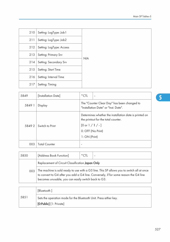
210 Setting: LogType: Job1
NIA
211 Setting: LogType: Job2
212 Setting: LogType: Access
213 Setting: Primary Srv
214 Setting: Secondary Srv
215 Setting: Start Time
216 Setting: Interval Time
217 Setting: Timing
5849 [Installation Date] *CTL -
5849 1 DisplayThe "Counter Clear Day" has been changed to"Installation Date" or "Inst. Date".
5849 2 Switch to Print
Determines whether the installation date is printed onthe printout for the total counter.
[0 or 1 / 1 / - ]
0: OFF (No Print)
1: ON (Print)
003 Total Counter -
5850 [Address Book Function] *CTL -
003
Replacement of Circuit Classification Japan Only
The machine is sold ready to use with a G3 line. This SP allows you to switch all at onceto convert to G4 after you add a G4 line. Conversely, if for some reason the G4 linebecomes unusable, you can easily switch back to G3.
5851
[Bluetooth ]
Sets the operation mode for the Bluetooth Unit. Press either key.
[0:Public] [1: Private]
Main SP Tables-5
527
5

5853
[Stamp Data Download]
Use this SP to download the fixed stamp data stored in the firmware of the ROM and copyit to the HDD. This SP can be executed as many times as required. This SP must be executedafter replacing or formatting the hard disks.
• This SP can be executed only with the hard disks installed.
5856
[Remote ROM Update]
Allows the technician to upgrade the firmware using a local port (IEEE1284) whenupdating the remote ROM.
002 Local Port *CTL
[0 to 1 / 0 / 1/step]
0: Disable
1: Enable
5857 [Save Debug Log] *CTL -
001
On/Off (1:ON 0:OFF) 0: OFF, 1: ON
Switches the debug log feature on and off. The debug log cannot be captured until thisfeature is switched on.
002
Target (2: HDD 3: SD) 2: HDD, 3: SD Card
Selects the storage device to save debug logs information when the conditions set withSP5-858 are satisfied.
[ 2 to 3 / 2 / 1 /step]
005
Save to HDD
Saves the debug log of the input SC number in memory to the HDD.
A unique file name is generated to avoid overwriting existing file names on the SD Card.Up to 4MB can be copied to an SD Card. 4 MB segments can be copied one by one toeach SD Card.
006Save to SD Card
Saves the debug log of the input SC number in memory to the SD card.
009 Copy HDD to SD Card (Latest 4 MB)
010 Copy HDD to SD Card (Latest 4 MB Any Key)
5. System Maintenance
528
5

011 Erase HDD Debug Data
012 Erase SD Card Debug Data
013 Free Space on SD Card
014 Copy SD to SD (Latest 4 MB)
015 Copy SD to SD (Latest 4 MB Any Key)
016 Make HDD Debug
017 Make SD Debug
5858
[Debug Save When] *CTL -
These SPs select the content of the debugging information to be saved to the destinationselected by SP5857-002.SP5858-3 stores one SC specified by number. Refer to Section 4 for a list of SC error codes.
001Engine SC Error
(0: OFF, 1: ON)
Turns on/off the debug save for SC codes generated bycopier engine errors.
[0 or 1 / 0 / 1/ step]
002Controller SC Error
(0: OFF, 1: ON)
Turns on/off the debug save for SC codes generated byGW controller errors.
[0 or 1 / 0 / 1/ step]
003 Any SC Error [0 to 65535 / 0 / 1 /step]
004 Jam (0: OFF, 1: ON) Turns on/off the debug save for jam errors.
5859 [Debug Save Key No.] *CTL -
Main SP Tables-5
529
5

001 Key 1
These SPs allow you to set up to 10 keys for log files forfunctions that use common memory on the controllerboard.
[–9999999 to 9999999 / 0 / – ]
002 Key 2
003 Key 3
004 Key 4
005 Key 5
006 Key 6
007 Key 7
008 Key 8
009 Key 9
010 Key 10
5860 [SMTP/POP3/IMAP4] *CTL -
020 Partial Mail Receive Timeout [1 to 168 / 72 / 1 hour/step]
Sets the amount of time to wait before saving a mail that breaks up during reception. Thereceived mail is discarded if the remaining portion of the mail is not received during thisprescribed time.
021 MDN Response RFC2.5298 Compliance [0 to 1 / 1 / – ]
Determines whether RFC2.5298 compliance is switched on for MDN reply mail.
0: No
1: Yes
022 SMTP Auth. From Field Replacement [0 to 1 / 0 / – ]
Determines whether the FROM item of the mail header is switched to the validated accountafter the SMTP server is validated.
0: No. "From" item not switched.
1: Yes. "From item switched.
025 SMTP Auth. Direct Setting [0 or 1 / 0 / – ]
5. System Maintenance
530
5

Selects the authentication method for SMPT.
Bit switch:
• Bit 0: LOGIN
• Bit 1: PLAIN
• Bit 2: CRAM MD5
• Bit 3: DIGEST MD5
• Bit 4 to 7: Not used
• This SP is activated only when SMTP authorization is enabled by UP mode.
026S/MIME: MIME HeaderSetting
-
Selects the MIME header type of an E-mail sent byS/MIME.
[0 to 2 / 0 / 1]
0: Microsoft Outlook Express standard
1: Internet Draft standard
2: RFC standard
5870 [Common Key Info Writing]
001 Writing *CTLWrites to flash ROM the common proof forvalidating the device for @Remote specifications.
003 Initialize *CTLInitializes the data area of the common proof forvalidating.
5873 [SD Card Appli Move]
001 Move ExecThis SP copies the application programs from the original SD card inSD card slot 2 to an SD card in SD card slot 1.
002 Undo Exec
This SP copies back the application programs from an SD card in SDCard Slot 2 to the original SD card in SD card slot 1. Use this menuwhen you have mistakenly copied some programs by using "MoveExec" (SP5873-1).
5875 [SC Auto Reboot]
Main SP Tables-5
531
5

001 Reboot Setting *CTL
Enables or disables the automatic reboot function whenan SC error occurs.
[0 or 1/ 0 / – ]
0: The machine reboots automatically when themachine issues an SC error and logs the SC error code.If the same SC occurs again, the machine does notreboot.
1: The machine does not reboot when an SC erroroccurs.
The reboot is not executed for Type A or C SC codes.
002 Reboot Type *CTL
Selects the reboot method for SC.
[0 or 1 / 0 / -]
0: Manual reboot, 1: Automatic reboot
5878 [Option Setup]
001 Data Overwrite Security -Enables the Data Overwrite Security unit. Press"EXECUTE" on the operation panel. Then turn themachine off and on.
002 HDD Encryption - Installs the HDD Encryption unit.
5881 [Fixed Phrase Block Erasing]
001 - - Deletes the fixed phrase.
5883[Line Speed Selection]
Selects the line speed for middle thick paper.
001 Middle Thick *ENG
[0 or 1 / 1 / 1 /step]
0: MID CARD: Half Speed (115 mm/sec)
1: MID CARD: Normal Speed (C2.5c: 154,C2.5d: 205 mm/sec)
5885[Set WIM Function] Web Image Monitor Settings
Close or disclose the functions of web image monitor.
5. System Maintenance
532
5
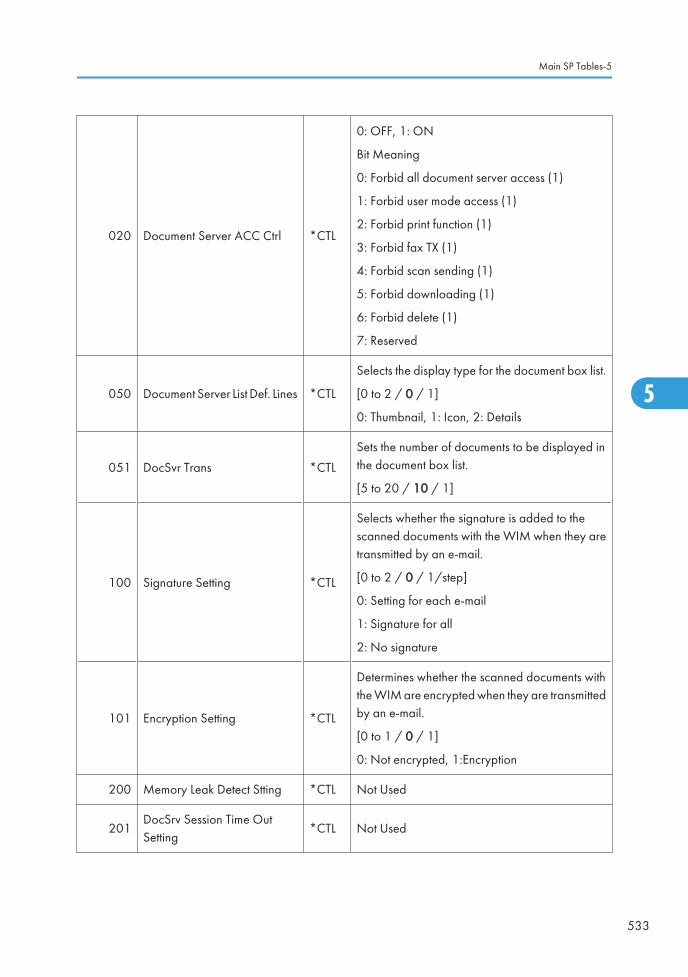
020 Document Server ACC Ctrl *CTL
0: OFF, 1: ON
Bit Meaning
0: Forbid all document server access (1)
1: Forbid user mode access (1)
2: Forbid print function (1)
3: Forbid fax TX (1)
4: Forbid scan sending (1)
5: Forbid downloading (1)
6: Forbid delete (1)
7: Reserved
050 Document Server List Def. Lines *CTL
Selects the display type for the document box list.
[0 to 2 / 0 / 1]
0: Thumbnail, 1: Icon, 2: Details
051 DocSvr Trans *CTL
Sets the number of documents to be displayed inthe document box list.
[5 to 20 / 10 / 1]
100 Signature Setting *CTL
Selects whether the signature is added to thescanned documents with the WIM when they aretransmitted by an e-mail.
[0 to 2 / 0 / 1/step]
0: Setting for each e-mail
1: Signature for all
2: No signature
101 Encryption Setting *CTL
Determines whether the scanned documents withthe WIM are encrypted when they are transmittedby an e-mail.
[0 to 1 / 0 / 1]
0: Not encrypted, 1:Encryption
200 Memory Leak Detect Stting *CTL Not Used
201DocSrv Session Time OutSetting
*CTL Not Used
Main SP Tables-5
533
5

5887[SD Get Counter]
This SP determines whether the ROM can be updated.
001 - *CTL
This SP sends a text file to an SD card inserted inSD card Slot 2 (lower slot). The operation stores.The file is stored in a folder created in the rootdirectory of the SD card called SD_COUNTER.The file is saved as a text file (*.txt) prefixed withthe number of the machine.
1. Insert the SD card in SD card Slot 2 (lowerslot).
2. Select SP5887 then touch [EXECUTE].
Touch [Execute] in the message when you areprompted.
5888 [Personal Information Protect]
001 - *CTL
Selects the protection level for logs.
[0 to 1 / 0 / 1}
0: No authentication, No protection for logs
1: No authentication, Protected logs (only anadministrator can see the logs)
5893[SDK Application Counter] *CTL -
Displays the counter name of each SDK application.
001 SDK-1
002 SDK-2
003 SDK-3
004 SDK-4
005 SDK-5
006 SDK-5
5894[Test Name1]
Test Name1_1
5. System Maintenance
534
5

001 Switch Charge Mode *ENG [0 to 2 / 0 / 1/step]
5895
[Application Invalidation]
Enables or disables the printer or scanner application.
These SPs are used only when an external controller is installed in the machine.
001 Printer *CTL [0 or 1 / 0 / -]
0: Enable
1: Disable002 Scanner *CTL
5907 [Plug & Play Maker/Model Name]
Selects the brand name and the production name for Windows Plug & Play. This informationis stored in the NVRAM. If the NVRAM is defective, these names should be registered again.
After selecting, press the "Original Type" key and "#" key at the same time. When the settingis completed, the beeper sounds five times.
5913 [Switchover Permission Time]
002
Print Application Timer *CTL [3 to 30 / 3 / 1 second /step]
Sets the amount of time to elapse while the machine is in standby mode (and the operationpanel keys have not been used) before another application can gain control of the display.
5967 [Copy Server Set Function] *CTL 0: ON, 1: OFF
Enables and disables the document server. This is a security measure that prevents imagedata from being left in the temporary area of the HDD. After changing this setting, you mustswitch the main switch off and on to enable the new setting.
5974[Cherry Server]
Specifies which version of ScanRouter, "Lite" or "Full", is installed.
001 Cherry Server *CTL [0 or 1 / 0 / – ] 0: Lite, 1: Full
Main SP Tables-5
535
5

5985
[Device Setting]
The NIC and USB support features are built into the GW controller. Use this SP to enableand disable these features. In order to use the NIC and USB functions built into the controllerboard, these SP codes must be set to "1".
001 On Board NIC
[0 to 2 / 0 / 1 /step]
0: Disable, 1: Enable, 2: Function limitation
When the "Function limitation" is set, "On board NIC" is limited onlyfor the NRS or LDAP/NT authentication.
• Other network applications than NRS or LDAP/NTauthentication are not available when this SP is set to "2". Eventhough you can change the initial settings of those networkapplications, the settings do not work.
002 On Board USB[0 or 1 / 0 / 1/step]
0: Disable, 1: Enable
5987 [Mech. Counter]
001 0: OFF / 1: ONThis SP detects that a mechanical counter device is removed. Ifit is detected, SC610 occurs.
5990[SP print mode]
Prints out the SMC sheets.
5. System Maintenance
536
5

001 All (Data List) -
-
002 SP (Mode Data List) -
003 User Program -
004 Logging Data -
005 Diagnostic Report -
006 Non-Default -
007 NIB Summary -
008 Capture Log -
021 Copier User Program -
022 Scanner SP -
023 Scanner User Program -
024 SDK/J Summary --
025 SDK/J Application Info -
5998[Fusing Cont mode] Fusing Control Mode
Turns the silent fusing warm-up mode on or off.
001 fast/silent *ENG
[0 or 1 / 1 / - ]
0: Silent (less noise)
1: Fast (less time)
Main SP Tables-5
537
5

Main SP Tables-6
SP6-XXX (Peripherals)
6006 [ADF Adj.] ADF Adjustment
Adjusts the side-to-side and leading registration of originals with the ARDF.
001 Side-to-Side Registration*ENG [-3.0 to 3.0 / 0 / 0.1 mm/step ]
002 Side-to-Side Registration
003 Leading Edge Registration *ENG [-5.0 to 5.0 / 0 / 0.1 mm/step ]
Adjusts the amount of paper buckle to correct original skew for the front and rear sides.
005 Buckle: Duplex Front*ENG
[-3.0 to 3.0 / 0 / 0.1 mm/step ]
006 Buckle: Duplex Rear [-2.5 to 2.5 / 0 / 0.1 mm/step ]
Adjusts the erase margin at the original trailing edge.
007 Rear Edge Erase *ENG [-10 to 10 / 0 / 0.1 mm/step ]
6007
[ADF INPUT Check]
Displays the signals received from the sensors and switches of the ARDF. Only Bit 0 is usedfor ADF input check ( p.627 "Main SP Tables-9" in this section).
6008
[ADF OUTPUT Check]
Activates the electrical components for functional check.
It is not possible to activate more than one component at the same time ( p.627 "MainSP Tables-9" in this section).
6009[ADF Free Run]
Performs a DF free run in simplex, duplex mode or stamp mode.
001 Free Run Simplex Motion -
-002 Free Run Duplex Motion -
003 Free Run Stamp Motion -
5. System Maintenance
538
5

6010[Stamp Position Adj.] Fax Stamp Position Adjustment
Adjusts the horizontal position of the stamp on the scanned originals.
6010 1 Stamp Position Adj. *ENG [-5.0 to 5.0 / 0 / 1 mm/step]
6016
[Original Size Detection Priority] Original Size Detection Priority
Specifies the original size for a size detected by the original sensor, since original sensorscannot recognize all sizes.
001Original Size DetectionPriority
*ENG[0 or 1 / 0 / - ]
0: Setting 1, 1: Setting 2
NA
Setting 1 Setting 2
DLT SEF Folio SEF 11" x 15"
LG SEF Foolscap SEF
LT SEF US EXE 8" x 10"
LT LEF US EXE LEF
EU/
ASIA
DLT SEF 8K 267 x 390 mm
LT SEF 16K 195 x 267 mm
LT LEF 16K 267 x 195 mm
6017[DF Magnification Adj.] DF Magnification Adjustment
Adjusts the magnification in the sub-scan direction for the ARDF.
001 DF Magnification Adj. *CTL [-5.0 to 5.0 / 0 / 0.1 %/step]
6020[Skew Correction Moving Setting]
Turns the original skew correction in the ARDF for all original sizes on or off.
001 - *ENG
[0 or 1 / 0 / - ]
0: Off (only for small original sizes)
1: On (for all original sizes)
Main SP Tables-6
539
5

6128[Punch Position: Sub Scan]
Adjusts the punching position in the sub scan direction.
0011.Domestic 2Hole (Europe2Hole)
*ENG
[-7.5 to 7.5 / 0 / 0.5 mm/step]
002 2.North America 3Hole *ENG
003 3.Europe 4Hole *ENG
004 4.North Europe 4Hole *ENG
005 5.North Europe 2Hole *ENG
6129[Punch Position: Main Scan]
Adjusts the punching position in the main scan direction.
0011.Domestic 2Hole (Europe2Hole)
*ENG
[-2.0 to 2.0 / 0 / 0.4 mm/step]
002 2.North America 3Hole *ENG
003 3.Europe 4Hole *ENG
004 4.North Europe 4Hole *ENG
005 5.North Europe 2Hole *ENG
6130[Skew Correction: Buckle Adj.]
Adjusts the paper buckle for each paper size.
5. System Maintenance
540
5

001 A3T *ENG
[-5.0 to 5.0 / 0 / 0.25 mm/step]
002 B4T *ENG
003 A4T *ENG
004 A4Y *ENG
005 B5T *ENG
006 B5Y *ENG
007 DLT-T *ENG
008 LG-T *ENG
009 LT-T *ENG
010 LT-Y *ENG
011 12" x 18" *ENG
012 Other *ENG
6131
[Skew Correction Control]
Selects the skew correction control for each paper size. These are only activated for B804/B805.
Main SP Tables-6
541
5

001 A3T *ENG
[0 or 1 / 1 / 1/step]
0: No (No skew correction)
1: Roller Stop Skew Correction
002 B4T *ENG
003 A4T *ENG
004 A4Y *ENG
005 B5T *ENG
006 B5Y *ENG
007 DLT-T *ENG
008 LG-T *ENG
009 LT-T *ENG
010 LT-Y *ENG
011 12" x 18" *ENG
012 Other *ENG
6132
[Jogger Fence Fine Adj]
This SP adjusts the distance between the jogger fences and the sides of the stack on thefinisher stapling tray in the (Booklet) Finisher B804/B805. The adjustment is doneperpendicular to the direction of paper feed.
5. System Maintenance
542
5

001 A3T *ENG
[-1.5 to 1.5 / 0 / 0.5 mm/step]
+ Value: Increases distance between joggerfences and the sides of the stack.
- Value: Decreases the distance between thejogger fences and the sides of the stack.
002 B4T *ENG
003 A4T *ENG
004 A4Y *ENG
005 B5T *ENG
006 B5Y *ENG
007 DLT-T *ENG
008 LG-T *ENG
009 LT-T *ENG
010 LT-Y *ENG
011 12" x 18" *ENG
012 Other *ENG
6133
[Staple Position Adjustment]
Adjusts the staple position for each finisher (B408/B804/B805).
+ Value: Moves the staple position to the rear side.
- Value: Moves the staple position to the front side.
001Finisher (B408/B804/B805)
*ENG
[-3.5 to 3.5 / 0 / 1/step]
6134 [Saddle Stitch Position Adjustment]
Use this SP to adjust the stapling position of the booklet stapler when paper is stapled andfolded in the Booklet Finisher B804.
Main SP Tables-6
543
5

001 A3T
[-3.0 to 3.0 / 0 / 0.2 mm/step]
+ Value: Shifts staple position toward the crease.
- Value: Shifts staple position away from the crease.
002 B4T
003 A4T
004 B5T
005 DLT-T
006 LG-T
007 LT-T
008 12" x 18"
009 Other
6135 [Folder Position Adj.]
This SP corrects the folding position when paper is stapled and folded in the Booklet FinisherB804.
001 A3T
[-3.0 to 3.0 / 0 / 0.2 mm/step]
+ Value: Shifts staple position toward the crease.
- Value: Shifts staple position away from the crease.
002 B4T
003 A4T
004 B5T
005 DLT-T
006 LG-T
007 LT-T
008 12" x 18"
009 Other
6136 [Folding Number]
Sets the number of times that folding is done in the Booklet Finisher B804.
001 - [2 to 30 / 2 / 1 time/step]
5. System Maintenance
544
5

6138 [FIN (TIG) INPUT Check] Finisher (B793) Input Check
Displays the signals received from sensors and switches of the booklet finisher. ( p.627"Main SP Tables-9" in this section)
6139 [FIN (KIN) INPUT Check] Finisher (B408) Input Check
Displays the signals received from sensors and switches of the booklet finisher. ( p.627"Main SP Tables-9" in this section)
6143 [FIN (TIG) OUPUT Check] Finisher (B793) Output Check
Displays the signals received from sensors and switches of the booklet finisher. ( p.627"Main SP Tables-9"in this section)
6144 [FIN (KIN) OUPUT Check] Finisher (B408) Output Check
Displays the signals received from sensors and switches of the booklet finisher. ( p.627"Main SP Tables-9" in this section)
6145 [FIN (ELB) INPUT Check] Finisher (D372) Input Check
Displays the signals received from sensors and switches of the 500-sheet finisher. (p.627 "Main SP Tables-9" in this section)
6146 [FIN (ELB) OUPUT Check] Finisher (D372) Output Check
Displays the signals received from sensors and switches of the 500-sheet finisher. (p.627 "Main SP Tables-9" in this section)
6149
[Max. Pre-Stack Sheet] *ENG Number of Pre-Stack Sheets
This SP sets the number of sheets sent to the pre-stack tray.
Note:
You may need to adjust this setting or switch it off when feeding thick or slick paper.
001 - [0 to 3 / 3 / 1 sheet/step]
Main SP Tables-6
545
5

6150
[INPUT Check]
Displays the signals received from sensors and switches of the bridge unit (D386)/ side tray(D542) ( p.627 "Main SP Tables-9" in this section).
6151
[OUTPUT Check]
Displays the signals received from sensors and switches of the bridge unit (D386)/ side tray(D542) ( p.627 "Main SP Tables-9" in this section).
6152
[INPUT Check]
Displays the signals received from sensors and switches of the shift tray (D388) (p.627 "Main SP Tables-9" in this section).
6153
[OUTPUT Check]
Displays the signals received from sensors and switches of the shift tray (D388) (p.627 "Main SP Tables-9" in this section).
6154
[INPUT Check]
Displays the signals received from sensors and switches of the 1 bin tray (D536) (p.627 "Main SP Tables-9" in this section).
6155
[OUTPUT Check]
Displays the signals received from sensors and switches of the 1 bin tray (D536) (p.627 "Main SP Tables-9" in this section)
001 1 bin: Junction Solenoid
6160
[INPUT Check]
Displays the signals received from sensors and switches of the two-tray paper feed unit(D537), LCT 2000 (D538) and LCT 1200 (D539) ( p.627 "Main SP Tables-9" in thissection)
5. System Maintenance
546
5

6161
[OUTPUT Check]
Displays the signals received from sensors and switches of the two-tray paper feed unit(D537), LCT 2000 (D538) and LCT 1200 (D539) ( p.627 "Main SP Tables-9" in thissection)
Main SP Tables-6
547
5

Main SP Tables-7
SP7-XXX (Data Log)
7401[Total SC Counter]
Displays the number of SC codes detected.
001 SC Counter *CTL [0 to 9999 / 0 / 1/step ]
7403
[SC History]
Logs the SC codes detected.
The 10 most recently detected SC Codes are not displayed on the screen, but can be seenon the SMC (logging) outputs.
001 Latest
*CTL -
002 Latest 1
003 Latest 2
004 Latest 3
005 Latest 4
006 Latest 5
007 Latest 6
008 Latest 7
009 Latest 8
010 Latest 9
7502[Total Paper Jam Counter]
Displays the total number of jams detected.
001 Total Jam * CTL [0 to 9999 / 0 / 1 sheet/step ]
5. System Maintenance
548
5

7503[Total Original Jam Counter]
Displays the total number of original jams.
001 Original Jam counter *CTL [0 to 9999 / 0 / 1 original/step ]
7504
[Paper Jam Location]
ON: On check, OFF: Off Check
Displays the number of jams according to the location where jams were detected.
NOTE: The LCT is counted as the 3rd feed station.
001 At Power On *CTL
For details, ( p.786 "JamDetection")
003 Tray 1: ON *CTL
004 Tray 2: ON *CTL
005 Tray 3: ON *CTL
006 Tray 4: ON *CTL
007 LCT : ON *CTL
008 Bypass: ON *CTL
009 Duplex: ON *CTL
011 Vertical Transport 1: ON *CTL
012 Vertical Transport 2: ON *CTL
Main SP Tables-7
549
5

013 Bank: Transport Sn1 *CTL
For details, ( p.786 "JamDetection")
014 Bank: Transport Sn2 *CTL
017 Registration: ON *CTL
018 Fusing Entrance: ON *CTL
019 Fusing Exit: ON *CTL
020 Paper Exit: ON *CTL
021 Bridge Exit: ON *CTL
022 Bridge Transport: ON *CTL
024 Junction Gate Sensor : On *CTL
025 Duplex Exit: ON *CTL
For details, ( p.786 "JamDetection")
026 Duplex Entrance: ON (Out) *CTL
027 Duplex Entrance: ON (Out) *CTL
051 Vertical Transport 1: Off *CTL
052 Vertical Transport 2: Off *CTL
053 Bank Transport 1: Off *CTL
054 Bank Transport 2: Off *CTL
057 Registration Sensor: Off *CTL
058 LCT Feed Sensor : Off
060 Paper Exit Off *CTL
061 Bridge Exit: Off *CTL
062 Bridge Transport: Off *CTL
5. System Maintenance
550
5

064 Junction Gate Sensor : Off *CTL
For details, ( p.786 "JamDetection")
065 Duplex Exit: Off *CTL
066 Duplex Entrance: Off (In) *CTL
067 Duplex entrance : Off (Out) *CTL
100 Finisher Entrance: KIN *CTL
101 Finisher Shift Tray Exit: KIN *CTL
102 Finisher Staple: KIN *CTL
103 Finisher Exit: KIN *CTL
105 Finisher Tray Lift Motor: KIN *CTL
106 Finisher Jogger Motor: KIN *CTL
107 Finisher Shift Motor: KIN *CTL
108 Finisher Staple Motor: KIN *CTL
109 Finisher Exit Motor: KIN *CTL
191 Finisher Entrance: EUP *CTL
For details, ( p.786 "JamDetection")
192 Finisher Proof Exit: EUP *CTL
193 Finisher Shift Tray Exit: EUP *CTL
194 Finisher Stapler Exit: EUP *CTL
195 Finisher Exit: EUP *CTL
198 Finisher Folder: EUP *CTL
199 Finisher Tray Motor: EUP *CTL
200 Finisher Jogger Motor: EUP *CTL
201 Finisher Shift Motor: EUP *CTL
202 Finisher Staple Moving Motor: EUP *CTL
203 Finisher Staple Motor: EUP *CTL
204 Finisher Folder Motor: EUP *CTL
206 Finisher Punch Motor: EUP *CTL
Main SP Tables-7
551
5

7505[Original Jam Detection]
Displays the total number of original jams by location.
001 At Power On
*CTL -
003 Skew Correction: On
004 Registration Sensor: On
005 Original Exit Sensor: On
053 Skew Correction: Off
054 Registration Sensor: Off
055 Original Exit Sensor: Off
7506[Jam Count by Paper Size]
Displays the number of jams according to the paper size.
005 A4 LEF *CTL
[0 to 9999 / 0 / 1 sheet/step ]
006 A5 LEF *CTL
014 B5 LEF *CTL
038 LT LEF *CTL
044 HLT LEF *CTL
132 A3 SEF *CTL
[0 to 9999 / 0 / 1 sheet/step ]
133 A4 SEF *CTL
134 A5 SEF *CTL
141 B4 SEF *CTL
142 B5 SEF *CTL
160 DLT SEF *CTL
164 LG SEF *CTL
166 LT SEF *CTL
172 HLT SEF *CTL
5. System Maintenance
552
5

255 Others *CTL [0 to 9999 / 0 / 1 sheet/step ]
7507[Plotter Jam History]
Displays the 10 most recently detected paper jams.
001 Latest
*CTL -
002 Latest 1
003 Latest 2
004 Latest 3
005 Latest 4
006 Latest 5
007 Latest 6
008 Latest 7
009 Latest 8
010 Latest 9
7508[Original Jam History]
Displays the 10 most recently detected original jams.
001 Latest
*CTL -
002 Latest-1
003 Latest-2
004 Latest-3
005 Latest-4
006 Latest-5
007 Latest-6
008 Latest-7
009 Latest-8
010 Latest-9
Main SP Tables-7
553
5

7624Part Replacement Operation ON/OFF
Selects the PM maintenance for each part.
001 K Drum Unit
[0 or 1 / 1 -]
0: Not PM maintenance
1: PM maintenance
002 M Drum Unit
003 C Drum Unit
004 Y Drum Unit
005 K Dev Unit
006 M Dev Unit
007 C Dev Unit
008 Y Dev Unit
009 K Developer
010 M Developer
011 C Developer
012 Y Developer
013 ITB Unit
[0 or 1 / 1 -]
0: Not PM maintenance
1: PM maintenance
014 Belt Cleaning Unit
015 Fusing Unit
016 PTR Unit
017 Waste Toner Bottle
018 Fusing Roller
019 Pressure Roller
7801 [ROM No/ Firmware Version]
255 Engine *CTLDisplays all versions and ROM numbers in themachine.
5. System Maintenance
554
5

7803[PM Counter Display]
(Page, Unit, [Color])
Displays the number of sheets printed for each current maintenance unit.
PM counters click up based on the number of A4 (LT) LEF size sheets printed. Therefore,the A3 (DLT) Double Count is activated. The Double Count cannot be deactivated.
When a unit is replaced, the machine automatically detects that the new unit is installed.Then, the current PM counter value is automatically moved to the PM Counter - Previous(SP7-906-1 to 10) and is reset to “0”.
The total number of sheets printed with the last unit replaced can be checked withSP7-906-1 to 10.
NOTE: The LCT is counted as the 3rd feed station.
001 Paper *CTL -
002 Page: K Drum Unit
*ENG -
003 Page: M Drum Unit
004 Page: C Drum Unit
005 Page: Y Drum Unit
006 Page: K Dev Unit
007 Page: M Dev Unit
008 Page: C Dev Unit
009 Page: Y Dev Unit
Main SP Tables-7
555
5

010 Page: K Developer
*ENG -
011 Page: M Developer
012 Page: C Developer
013 Page: Y Developer
014 Page: ITB Unit
015 Page: Belt Cleaning Unit
016 Page: Fusing Unit
017 Page: PTR Unit
018 Page: Toner Collection Bottle
019 Page: Fusing Roller (Heating Roller)
020 Page: Pressure Roller
Displays the number of revolutions of motors or clutches for each current maintenance unit.
[ 0 to 9999999 / 0 / 1 revolution/step ]
When a unit is replaced, the machine automatically detects that the new unit is installed.Then, the current PM counter value is automatically moved to the PM Counter - Previous(SP7-906-11 to 20) and is reset to “0”. The total number of revolutions made with the lastunit replaced can be checked with SP7-906-11 to 20.
5. System Maintenance
556
5

031 Rotation: K Drum Unit
*ENG [0 to 999999999 / - / 1 mm/step ]
032 Rotation: M Drum Unit
033 Rotation: C Drum Unit
034 Rotation: Y Drum Unit
035 Rotation: K Dev Unit
036 Rotation: M Dev Unit
037 Rotation: C Dev Unit
038 Rotation: Y Dev Unit
039 Rotation: K Developer
040 Rotation: M Developer
041 Rotation: C Developer
042 Rotation: Y Developer
043 Rotation: ITB Unit *ENG
[0 to 999999999 / - / 1 mm/step ]
044 Rotation: Cleaning Unit *ENG
045 Rotation: Fusing Unit *ENG
046 Rotation: PTR Unit *ENG
047 Measurement: Toner Collection bottle *ENG
048 Rotation: Fusing Roller (Heating Roller) *ENG
049 Rotation: Pressure Roller *ENG
Displays the value given by the following formula:
(Current revolution ÷ Target revolution) × 100. This shows how much of the unit’s expectedlifetime has been used up.
The Rotation% counter is based on rotations, not prints. If the number of rotations reachesthe limit, the machine enters the end condition for that unit. If the print count lifetime is reachedfirst, the machine also enters the end condition, even though the R% counter is still less than100%.
Main SP Tables-7
557
5

061 Rotation (%): K Drum Unit
*ENG [0 to 255 / - / 1 %/step]
062 Rotation (%): M Drum Unit
063 Rotation (%): C Drum Unit
064 Rotation (%): Y Drum Unit
065 Rotation (%): K Dev Unit
066 Rotation (%): M Dev Unit
067 Rotation (%): C Dev Unit
068 Rotation (%): Y Dev Unit
069 Rotation (%): K Developer
070 Rotation (%): M Developer
071 Rotation (%): C Developer
072 Rotation (%): Y Developer
073 Rotation (%): ITB Unit
*ENG [0 to 255 / - / 1 %/step]
074 Rotation (%): Cleaning Unit
075 Rotation (%): Fusing Unit
076 Rotation (%): PTR Unit
077 Measurement (%): Toner Collection bottle
078 Rotation (%): Fusing Roller (Heating Roller)
079 Rotation (%): Pressure Roller
Displays the value given by the following formula:
(Current printouts ÷ Target printouts) × 100. This shows how much of the unit’s expectedlifetime has been used up.
The Page% counter is based on printouts, not revolutions. If the number of printouts reachesthe limit, the machine enters the end condition for that unit. If the revolution count lifetime isreached first, the machine also enters the end condition, even though the Page% counteris still less than 100%.
5. System Maintenance
558
5

091 Page (%): K PCU (Drum Unit)
*ENG [0 to 255 / - / 1 %/step]
092 Page (%): M PCU (Drum Unit)
093 Page (%): C PCU (Drum Unit)
094 Page (%): Y PCU (Drum Unit)
095 Page (%): K Dev Unit
096 Page (%): M Dev Unit
097 Page (%): C Dev Unit
098 Page (%): Y Dev Unit
099 Page (%): K Developer
*ENG [0 to 255 / - / 1 %/step]
100 Page (%): M Developer
101 Page (%): C Developer
102 Page (%): Y Developer
103 Page (%): ITB Unit
104 Page (%): Cleaning Unit
105 Page (%): Fusing Unit
106 Page (%): PTR Unit
107 Page (%): Fusing Roller (Heating Roller)
108 Page (%): Pressure Roller
7804[PM Counter Reset] PM Counter Clear
(Unit, [Color])
Clears the PM counter.
Press the Enter key after the machine asks “Execute?”, which will store the PM counter valuein SP7-906 (PM Counter - Previous) and reset the value of the current PM counter(SP7-803) to “0”.
002 PCU (Drum Unit): Bk - -
003 PCU (Drum Unit): M - -
Main SP Tables-7
559
5

004 PCU (Drum Unit): C - -
005 PCU (Drum Unit): Y - -
006 PCU (Drum Unit): All - -
007 Development Unit: Bk - -
008 Development Unit: M - -
009 Development Unit: C - -
010 Development Unit: Y - -
011 Development Unit: All - -
012 Developer: Bk - -
013 Developer: M - -
014 Developer: C - -
015 Developer: Y - -
016 Developer: All - -
017 ITB Unit - -
018 Cleaning Unit - -
019 Fusing Unit - -
020 PTR Unit - -
021 Toner Collection Bottle - -
023 Fusing Roller(Heating Roller) - -
024 Pressure Roller - -
100 All - -
7807[SC/Jam Counter Reset]
Clears the counters related to SC codes and paper jams.
001 SC/Jam Clear - -
5. System Maintenance
560
5

7832[Self-Diagnose Result Display]
Displays the result of the diagnostics.
001 Diag. Result *CTL -
7835 [ACC Counter]
001 Copy ACC *CTLDisplays the ACC exectuion times for each mode.
002 Printer ACC *CTL
7836Total Memory Size
Displays the memory capacity of the controller system.
7852
[DF Scan Glass Dust Check Counter]
Counts the number of occurrences (0 to 65,535) when dust was detected on the scanningglass of the ADF or resets the dust detection counter. Counting is done only if SP4-020-1(ADF Scan Glass Dust Check) is switched on.
001 Dust Detection Counter *CTL [0 to 9999 / - / 1 /step]
002 Dust Detection Clear Counter *CTL [0 to 9999 / - / 1 /step]
7853[Replacement Counter]
Displays the PM parts replacement number.
Main SP Tables-7
561
5

001 K Drum Unit *CTL
[0 to 255 / - / 1 /step]
002 M Drum Unit *CTL
003 C Drum Unit *CTL
004 Y Drum Unit *CTL
005 K Dev Unit *CTL
006 M Dev Unit *CTL
007 C Dev Unit *CTL
008 Y Dev Unit *CTL
009 K Developer *CTL
010 M Developer *CTL
011 C Developer *CTL
012 Y Developer *CTL
013 ITB Unit *CTL
[0 to 255 / - / 1 /step]
014 Belt Cleaning Unit *CTL
015 Fusing Unit *CTL
016 PTR Unit *CTL
017 Toner Collection Bottle *CTL
018 Fusing Roller(Heating Roller) *CTL
019 Pressure Roller *CTL
5. System Maintenance
562
5

7855
[Coverage Range]
Sets the color coverage threshold.
Coverage rate = Coverage per page / A4 full coverage (dots) x 100
There are three coverage counters: Color 1, Color 2, and Color 3
• [A] 5% (default) is adjustable with SP7855-001.
• [B] 20% (default) is adjustable with SP7855-002.
• The setting value [B] must be set larger than [A].
The total numbers of printouts (BW printing plus color printing) for each coverage rangeare displayed with the following SPs.
• Color1 counter: SP8601-021
• Color2 counter: SP8601-022
• Color3 counter: SP8601-023
001 Coverage Range 1 *CTL [1 to 200 / 5 /1]
002 Coverage Range 2 *CTL [1 to 200 / 20 /1]
7906
[Prev. Unit PM Counter]
(Page or Rotations, Unit, [Color]), Dev.: Development Unit
Displays the number of sheets printed with the previous maintenance units.
Main SP Tables-7
563
5
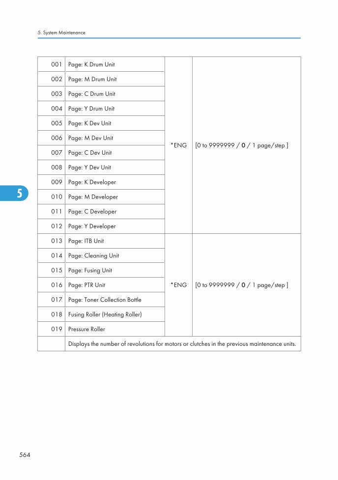
001 Page: K Drum Unit
*ENG [0 to 9999999 / 0 / 1 page/step ]
002 Page: M Drum Unit
003 Page: C Drum Unit
004 Page: Y Drum Unit
005 Page: K Dev Unit
006 Page: M Dev Unit
007 Page: C Dev Unit
008 Page: Y Dev Unit
009 Page: K Developer
010 Page: M Developer
011 Page: C Developer
012 Page: Y Developer
013 Page: ITB Unit
*ENG [0 to 9999999 / 0 / 1 page/step ]
014 Page: Cleaning Unit
015 Page: Fusing Unit
016 Page: PTR Unit
017 Page: Toner Collection Bottle
018 Fusing Roller (Heating Roller)
019 Pressure Roller
Displays the number of revolutions for motors or clutches in the previous maintenance units.
5. System Maintenance
564
5

031 Rotation: K Drum Unit
*ENG [0 to 9999999 / 0 / 1 mm/step ]
032 Rotation: M Drum Unit
033 Rotation: C Drum Unit
034 Rotation: Y Drum Unit
035 Rotation: K Dev Unit
036 Rotation: M Dev Unit
037 Rotation: C Dev Unit
038 Rotation: Y Dev Unit
039 Rotation: K Developer
040 Rotation: M Developer
041 Rotation: C Developer
042 Rotation: Y Developer
043 Rotation: ITB Unit
*ENG [0 to 9999999 / 0 / 1 mm/step ]
044 Rotation: Cleaning Unit
045 Rotation: Fusing Unit
046 Rotation: PTR Unit
047 Measurement: Toner Collection bottle
048Rotation: Fusing Roller (HeatingRoller)
049 Rotation: Pressure Roller
Displays the number of sheets printed with the previous maintenance unit or toner cartridge.
Main SP Tables-7
565
5

061 Rotation (%): K Drum Unit
*ENG [0 to 255 / 0 / 1 %/step ]
062 Rotation (%): M Drum Unit
063 Rotation (%): C Drum Unit
064 Rotation (%): Y Drum Unit
065 Rotation (%): K Dev Unit
066 Rotation (%): M Dev Unit
067 Rotation (%): C Dev Unit
068 Rotation (%): Y Dev Unit
069 Rotation (%): K Developer
*ENG [0 to 255 / 0 / 1 %/step ]
070 Rotation (%): M Developer
071 Rotation (%): C Developer
072 Rotation (%): Y Developer
073 Rotation (%): ITB Unit
074 Rotation (%): Cleaning Unit
075 Rotation (%): Fusing Unit
076 Rotation (%): PTR Unit
077Measurement (%): Toner Collectionbottle
078Rotation: Fusing Roller (HeatingRoller)
079 Rotation: Pressure Roller
Displays the value given by the following formula:
(Current count ÷ Yield count) x 100, where “Current count” is the current values in the counterfor the part, and “Yield count” is the recommended yield.
5. System Maintenance
566
5
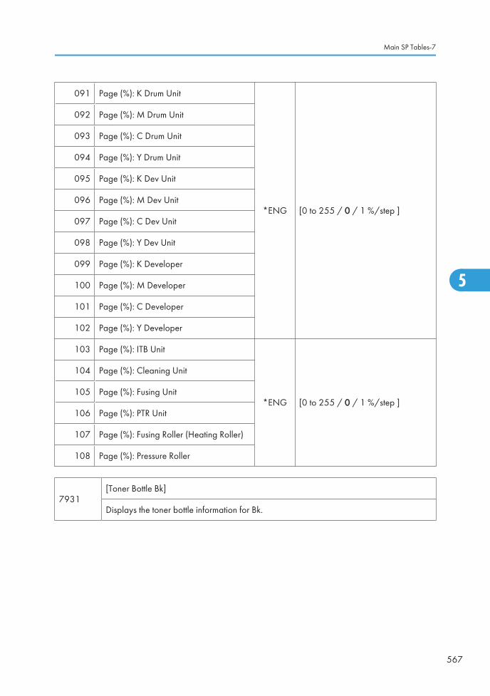
091 Page (%): K Drum Unit
*ENG [0 to 255 / 0 / 1 %/step ]
092 Page (%): M Drum Unit
093 Page (%): C Drum Unit
094 Page (%): Y Drum Unit
095 Page (%): K Dev Unit
096 Page (%): M Dev Unit
097 Page (%): C Dev Unit
098 Page (%): Y Dev Unit
099 Page (%): K Developer
100 Page (%): M Developer
101 Page (%): C Developer
102 Page (%): Y Developer
103 Page (%): ITB Unit
*ENG [0 to 255 / 0 / 1 %/step ]
104 Page (%): Cleaning Unit
105 Page (%): Fusing Unit
106 Page (%): PTR Unit
107 Page (%): Fusing Roller (Heating Roller)
108 Page (%): Pressure Roller
7931[Toner Bottle Bk]
Displays the toner bottle information for Bk.
Main SP Tables-7
567
5

001 Machine Serial ID
*ENG
002 Cartridge Ver
003 Brand ID
004 Area ID
005 Product ID
006 Color ID
007 Maintenance ID
008 New Product Information
009 Recycle Counter
010 Date
011 Serial No.
012 Toner Remaining
013 EDP Code
014 End History
015 Refill Information
016 Attachment: Total Counter
017 Attachment: Color Counter
018 End: Total Counter
019 End: Color Counter
020 Attachment Date
021 End Date
7932[Toner Bottle M]
Displays the toner bottle information for M.
5. System Maintenance
568
5

001 Machine Serial ID
*ENG -
002 Cartridge Ver
003 Brand ID
004 Area ID
005 Product ID
006 Color ID
007 Maintenance ID
008 New Product Information
009 Recycle Counter
010 Date
011 Serial No.
012 Toner Remaining
*ENG -
013 EDP Code
014 End History
015 Refill Information
016 Attachment: Total Counter
017 Attachment: Color Counter
018 End: Total Counter
019 End: Color Counter
020 Attachment Date
021 End Date
7933[Toner Bottle C]
Displays the toner bottle information for C.
Main SP Tables-7
569
5

001 Machine Serial ID
*ENG -
002 Cartridge Ver
003 Brand ID
004 Area ID
005 Product ID
006 Color ID
007 Maintenance ID
008 New Product Information
009 Recycle Counter
010 Date
011 Serial No.
012 Toner Remaining
*ENG -
013 EDP Code
014 End History
015 Refill Information
016 Attachment: Total Counter
017 Attachment: Color Counter
018 End: Total Counter
019 End: Color Counter
020 Attachment Date
021 End Date
7934[Toner Bottle Y]
Displays the toner bottle information for Y.
5. System Maintenance
570
5

001 Machine Serial ID
*ENG -
002 Cartridge Ver
003 Brand ID
004 Area ID
005 Product ID
006 Color ID
007 Maintenance ID
008 New Product Information
009 Recycle Counter
010 Date
011 Serial No.
012 Toner Remaining
*ENG -
013 EDP Code
014 End History
015 Refill Information
016 Attachment: Total Counter
017 Attachment: Color Counter
018 End: Total Counter
019 End: Color Counter
020 Attachment Date
021 End Date
7935 [Toner Bottle Log 1: Bk]
Main SP Tables-7
571
5

001 Serial No.
*ENGDisplays the toner bottle informationlog 1 for Bk.
002 Attachment Date
003 Attachment: Total Counter
004 Refill Information
011 Serial No.
*ENGDisplays the toner bottle informationlog 2 for Bk.
012 Attachment Date
013 Attachment: Total Counter
014 Refill Information
021 Serial No.
*ENGDisplays the toner bottle informationlog 3 for Bk.
022 Attachment Date
023 Attachment: Total Counter
024 Refill Information
031 Serial No.
*ENGDisplays the toner bottle informationlog 4 for Bk.
032 Attachment Date
033 Attachment: Total Counter
034 Refill Information
041 Serial No.
*ENGDisplays the toner bottle informationlog 5 for Bk.
042 Attachment Date
043 Attachment: Total Counter
044 Refill Information
7936 [Toner Bottle Log 1: M]
001 Serial No.
*ENGDisplays the toner bottle informationlog 1 for M.
002 Attachment Date
003 Attachment: Total Counter
004 Refill Information
5. System Maintenance
572
5

011 Serial No.
*ENGDisplays the toner bottle informationlog 2 for M.
012 Attachment Date
013 Attachment: Total Counter
014 Refill Information
021 Serial No.
*ENGDisplays the toner bottle informationlog 3 for M.
022 Attachment Date
023 Attachment: Total Counter
024 Refill Information
031 Serial No.
*ENGDisplays the toner bottle informationlog 4 for M.
032 Attachment Date
033 Attachment: Total Counter
034 Refill Information
041 Serial No.
*ENGDisplays the toner bottle informationlog 5 for M.
042 Attachment Date
043 Attachment: Total Counter
044 Refill Information
7937 [Toner Bottle Log 1: C]
001 Serial No.
*ENGDisplays the toner bottle informationlog 1 for C.
002 Attachment Date
003 Attachment: Total Counter
004 Refill Information
011 Serial No.
*ENGDisplays the toner bottle informationlog 2 for C.
012 Attachment Date
013 Attachment: Total Counter
014 Refill Information
Main SP Tables-7
573
5

021 Serial No.
*ENGDisplays the toner bottle informationlog 3 for C.
022 Attachment Date
023 Attachment: Total Counter
024 Refill Information
031 Serial No.
*ENGDisplays the toner bottle informationlog 4 for C.
032 Attachment Date
033 Attachment: Total Counter
034 Refill Information
041 Serial No.
*ENGDisplays the toner bottle informationlog 5 for C.
042 Attachment Date
043 Attachment: Total Counter
044 Refill Information
7938 [Toner Bottle Log 1: Y]
001 Serial No.
*ENGDisplays the toner bottle informationlog 1 for Y.
002 Attachment Date
003 Attachment: Total Counter
004 Refill Information
011 Serial No.
*ENGDisplays the toner bottle informationlog 2 for Y.
012 Attachment Date
013 Attachment: Total Counter
014 Refill Information
021 Serial No.
*ENGDisplays the toner bottle informationlog 3 for Y.
022 Attachment Date
023 Attachment: Total Counter
024 Refill Information
5. System Maintenance
574
5

031 Serial No.
*ENGDisplays the toner bottle informationlog 4 for Y.
032 Attachment Date
033 Attachment: Total Counter
034 Refill Information
041 Serial No.
*ENGDisplays the toner bottle informationlog 5 for Y.
042 Attachment Date
043 Attachment: Total Counter
044 Refill Information
7950[Unit Replacement Date]
Displays the replacement date of each PM unit.
001 Image Transfer Belt
*ENG -
002 Cleaning Unit
003 Paper Transfer Unit
004 Fusing Unit
005 Toner Collection Bottle
006 K PCU (Drum Unit)
007 M PCU (Drum Unit)
008 C PCU (Drum Unit)
009 Y PCU (Drum Unit)
010 Fusing Roller (Heating Roller)
011 Pressure Roller
7951[Remaining Day Counter]
Displays the remaining unit life of each PM unit.
Main SP Tables-7
575
5

001 Page: K Drum Unit
*ENG [0 to 255 / 255 / 1 day/step]
002 Page: M Drum Unit
003 Page: C Drum Unit
004 Page: Y Drum Unit
005 Page: K Dev Unit
006 Page: M Dev Unit
007 Page: C Dev Unit
008 Page: Y Dev Unit
009 Page: K Developer
010 Page: M Developer
011 Page: C Developer
012 Page: Y Developer
013 Page: ITB Unit
*ENG [0 to 255 / 255 / 1 day/step]
014 Page: Cleaning Unit
015 Page: Fusing Unit
016 Page: PTR Unit
017 Page: Fusing Roller (Heating Roller)
018 Page: Pressure Roller
5. System Maintenance
576
5

031 Rotation: K Drum Unit
*ENG [0 to 255 / 255 / 1 day/step]
032 Rotation: M Drum Unit
033 Rotation: C Drum Unit
034 Rotation: Y Drum Unit
035 Rotation: K Dev Unit
036 Rotation: M Dev Unit
037 Rotation: C Dev Unit
038 Rotation: Y Dev Unit
039 Rotation: K Developer
040 Rotation: M Developer
041 Rotation: C Developer
042 Rotation: Y Developer
043 Rotation: ITB Unit
*ENG [0 to 255 / 255 / 1 day/step]
044 Rotation: Cleaning Unit
045 Rotation: Fusing Unit
046 Rotation: PTR Unit
047Measurement: Toner Collectionbottle
048Rotation: Fusing Roller (HeatingRoller)
049 Rotation: Pressure Roller
7952[PM Yield Setting]
Adjusts the unit yield of each PM unit.
001 Rotation: ITB Unit *CTL [0 to 999999999 / 256597000 / 1 mm/step]
002 Rotation: Cleaning Unit *CTL [0 to 999999999 / 128299000 / 1 mm/step]
003 Rotation: Fusing Unit *CTL [0 to 999999999 / 155595000 / 1 mm/step]
Main SP Tables-7
577
5

004 Rotation: Paper Transfer Unit *CTL [0 to 999999999 / 192448000/ 1 mm/step]
011 Page: ITB Unit *CTL [0 to 999999 / 320000 / 1 sheet/step]
012 Page: Cleaning Unit *CTL [0 to 999999 / 160000 / 1 sheet/step]
013 Page: Fusing Unit *CTL [0 to 999999 / 160000 / 1 sheet/step]
014 Page: Paper Transfer Unit *CTL [0 to 999999 / 240000/ 1 sheet/step]
021 Day: K Drum Unit
*CTL
Adjusts the threshold day for the near end fro eachPM unit.
[1 to 30 / 15 / 1 day/step]
These threshold days are used for @Remote alarms.
022 Day: M Drum Unit
023 Day: C Drum Unit
024 Day: Y Drum Unit
025 Day: K Dev Unit
026 Day: M Dev Unit
027 Day: C Dev Unit
028 Day: Y Dev Unit
029 Day: K Developer
030 Day: M Developer
031 Day: C Developer
032 Day: Y Developer
033 Day: ITB Unit
*CTL
Adjusts the threshold day for the near end fro eachPM unit.
[1 to 30 / 15 / 1 day/step]
These threshold days are used for @Remote alarms.
034 Day:Cleaning Unit
035 Day: Fusing Unit
036 Day: PTR Unit
037 Day: Toner Collection Botte
038 Rotation: PCU (Drum Unit): Bk
*CTL [0 to 999999999 / 0 / 1 mm/step]039 Rotation: PCU (Drum Unit): M
040 Rotation: PCU (Drum Unit): C
041 Rotation: PCU (Drum Unit): Y
5. System Maintenance
578
5

042 Rotation: Development Unit: Bk
*CTL [0 to 999999999 / 0 / 1 mm/step]043 Rotation: Development Unit: M
044 Rotation: Development Unit: C
045 Rotation: Development Unit: Y
046 Rotation: Developer: Bk
*CTL [0 to 999999999 / 0 / 1 mm/step]047 Rotation: Developer: M
048 Rotation: Developer: C
049 Rotation: Developer: Y
050 Page: PCU (Drum Unit): Bk
*CTL [0 to 999999 / 0 / 1 sheet/step]051 Page: PCU (Drum Unit): M
052 Page: PCU (Drum Unit): C
053 Page: PCU (Drum Unit): Y
054 Page: Development Unit: Bk
*CTL [0 to 999999 / 0 / 1 sheet/step]055 Page: Development Unit: M
056 Page: Development Unit: C
057 Page: Development Unit: Y
058 Page: Developer: Bk
*CTL [0 to 999999 / 0 / 1 sheet/step]059 Page: Developer: M
060 Page: Developer: C
061 Page: Developer: Y
7953 [Operation Env. Log: PCU: Bk]
Displays the PCDU rotation distance in each specified operation environment.
T: Temperature (°C), H: Relative Humidity (%)
Main SP Tables-7
579
5

001 T<=0
*CTL [0 to 99999999 / - / 1 mm/step]
002 0<T<=5:0<=H<30
003 0<T<=5: 30<=H<70
004 0<T<=5: 70<=H<=100
005 5<T<15: 0<=H<30
006 5<T<15: 30<=H<55
007 5<T<15: 55<=H<80
008 5<T<15: 80<=H<=100
009 15<=T<25: 0<=H<30
010 15<=T<25: 30<=H<55
011 15<=T<25: 55<=H<80
*CTL [0 to 99999999 / - / 1 mm/step]
012 15<=T<25: 80<=H<=100
013 25<=T<30: 0<=H<30
014 25<=T<30: 55<=H<55
015 25<=T<30: 55<=H<80
016 25<=T<30: 80<=H<=100
017 30<=T: 0<=H<30
018 30<=T: 30<=H<55
019 30<=T: 55<=H<80
020 30<=T: 80<=H<=100
7954[Operation Env. Log Clear]
Clears the operation environment log.
001 -
7955 Fusing Stop
5. System Maintenance
580
5

001Near End: Page - [1 to 999999 / 318000 / 1 sheet/step]
Displays the threshold sheet for the heating roller near end.
002End: Page - [1 to 999999 / 330000 / 1 sheet/step]
Displays the threshold sheet for the heating roller end.
003Near End: Rotation - [0 to 999999999 / 999999999 / 1 mm/step]
Displays the threshold distance for the heating roller near end.
004End: Rotation - [0 to 999999999 / 999999999 / 1 mm/step]
Displays the threshold distance for the heating roller end.
Main SP Tables-7
581
5

Main SP Tables-8
SP8-xxx: Data Log2
Many of these counters are provided for features that are currently not available, such as sending colorfaxes, and so on. However, here are some Group 8 codes that when used in combination with others, canprovide useful information.
SP Numbers What They Do
SP8211 to SP8216 The number of pages scanned to the document server.
SP8401 to SP8406 The number of pages printed from the document server
SP8691 to SP8696 The number of pages sent from the document server
Specifically, the following questions can be answered:
• How is the document server actually being used?
• What application is using the document server most frequently?
• What data in the document server is being reused?
Most of the SPs in this group are prefixed with a letter that indicates the mode of operation (the mode ofoperation is referred to as an "application"). Before reading the Group 8 Service Table, make sure thatyou understand what these prefixes mean.
Prefixes What it means
T: Total: (Grand Total).Grand total of the items counted for all applications (C, F, P,etc.).
C: Copy application.
Totals (pages, jobs, etc.) executed for each application whenthe job was not stored on the document server.
F: Fax application.
P: Print application.
S: Scan application.
5. System Maintenance
582
5

L:Local storage (documentserver)
Totals (jobs, pages, etc.) for the document server. The L:counters work differently case by case. Sometimes, theycount jobs/pages stored on the document server; this can bein document server mode (from the document serverwindow), or from another mode, such as from a printer driveror by pressing the Store File button in the Copy modewindow. Sometimes, they include occasions when the useruses a file that is already on the document server. Eachcounter will be discussed case by case.
O:
Other applications(external networkapplications, forexample)
Refers to network applications such as Web Image Monitor.Utilities developed with the SDK (Software Development Kit)will also be counted with this group in the future.
The Group 8 SP codes are limited to 17 characters, forced by the necessity of displaying them on the smallLCDs of printers and faxes that also use these SPs. Read over the list of abbreviations below and refer to itagain if you see the name of an SP that you do not understand.
Key for Abbreviations
Abbreviation What it means
/ "By", e.g. "T:Jobs/Apl" = Total Jobs "by" Application
> More (2> "2 or more", 4> "4 or more"
AddBook Address Book
Apl Application
B/W Black & White
Bk Black
C Cyan
ColCr Color Create
ColMode Color Mode
Comb Combine
Comp Compression
Deliv Delivery
Main SP Tables-8
583
5

Abbreviation What it means
DesAplDesignated Application. The application (Copy, Fax, Scan, Print) used tostore the job on the document server, for example.
Dev Counter Development Count, no. of pages developed.
Dup, Duplex Duplex, printing on both sides
Emul Emulation
FC Full Color
FIN Post-print processing, i.e. finishing (punching, stapling, etc.)
Full Bleed No Margins
GenCopy Generation Copy Mode
GPC
Get Print Counter. For jobs 10 pages or less, this counter does not countup. For jobs larger than 10 pages, this counter counts up by the numberthat is in excess of 10 (e.g., for an 11-page job, the counter counts up11-10 =1)
IFax Internet Fax
ImgEdtImage Edit performed on the original with the copier GUI, e.g. borderremoval, adding stamps, page numbers, etc.
K Black (YMCK)
LS Local Storage. Refers to the document server.
LSize Large (paper) Size
Mag Magnification
MC One color (monochrome)
NRSNew Remote Service, which allows a service center to monitor machinesremotely. "NRS" is used overseas, "CSS" is used in Japan.
Org Original for scanning
OrgJam Original Jam
Palm 2Print Job Manager/Desk Top Editor: A pair of utilities that allows print jobsto be distributed evenly among the printers on the network, and allows filesto moved around, combined, and converted to different formats.
5. System Maintenance
584
5

Abbreviation What it means
PC Personal Computer
PGSPages. A page is the total scanned surface of the original. Duplex pagescount as two pages, and A3 simplex count as two pages if the A3/DLTcounter SP is switched ON.
PJob Print Jobs
Ppr Paper
PrtJam Printer (plotter) Jam
PrtPGS Print Pages
RRed (Toner Remaining). Applies to the wide format model A2 only. Thismachine is under development and currently not available.
Rez Resolution
SC Service Code (Error SC code displayed)
Scn Scan
Sim, Simplex Simplex, printing on 1 side.
S-to-Email Scan-to-E-mail
SMCSMC report printed with SP5990. All of the Group 8 counters are recordedin the SMC report.
Svr Server
TonEnd Toner End
TonSave Toner Save
TXJob Send, Transmission
YMC Yellow, Magenta, Cyan
YMCK Yellow, Magenta, Cyan, Black
• All of the Group 8 SPs are reset with SP5 801 1 Memory All Clear.
Main SP Tables-8
585
5

8 001
T:Total Jobs *CTLThese SPs count the number of times each application is usedto do a job.
[0 to 9999999/ 0 / 1]
Note: The L: counter is the total number of times the otherapplications are used to send a job to the document server,plus the number of times a file already on the document serveris used.
8 002 C:Total Jobs *CTL
8 003 F:Total Jobs *CTL
8 004 P:Total Jobs *CTL
8 005 S:Total Jobs *CTL
8 006 L:Total Jobs *CTL
• These SPs reveal the number of times an application is used, not the number of pages processed.
• When an application is opened for image input or output, this counts as one job.
• Interrupted jobs (paper jams, etc.) are counted, even though they do not finish.
• Only jobs executed by the customer are counted. Jobs executed by the customer engineer using theSP modes are not counted.
• When using secure printing (when a password is required to start the print job), the job is counted atthe time when either "Delete Data" or "Specify Output" is specified.
• A job is counted as a fax job when the job is stored for sending.
• When a fax is received to fax memory, the F: counter increments but the L: counter does not (thedocument server is not used).
• A fax broadcast counts as one job for the F: counter (the fax destinations in the broadcast are notcounted separately).
• A fax broadcast is counted only after all the faxes have been sent to their destinations. If onetransmission generates an error, then the broadcast will not be counted until the transmission has beencompleted.
• A printed fax report counts as one job for the F: counter.
• The F: counter does not distinguish between fax sending or receiving.
• When a copy job on the document server is printed, SP8022 also increments, and when a print jobstored on the document server is printed, SP8024 also increments.
• When an original is both copied and stored on the document server, the C: and L: counters bothincrement.
• When a print job is stored on the document server, only the L: counter increments.
• When the user presses the Document Server button to store the job on the document server, only theL: counter increments.
• When the user enters document server mode and prints data stored on the document server, only theL: counter increments.
5. System Maintenance
586
5

• When an image received from Palm 2 is received and stored, the L: counter increments.
• When the customer prints a report (user code list, for example), the O: counter increments. However,for fax reports and reports executed from the fax application, the F: counter increments.
8 011 T:Jobs/LS *CTL
These SPs count the number of jobs stored to the documentserver by each application, to reveal how local storage isbeing used for input.
[0 to 9999999/ 0 / 1]
The L: counter counts the number of jobs stored from withinthe document server mode screen at the operation panel.
8 012 C:Jobs/LS *CTL
8 013 F:Jobs/LS *CTL
8 014 P:Jobs/LS *CTL
8 015 S:Jobs/LS *CTL
8 016 L:Jobs/LS *CTL
8 017 O:Jobs/LS *CTL
• When a scan job is sent to the document server, the S: counter increments. When you enter documentserver mode and then scan an original, the L: counter increments.
• When a print job is sent to the document server, the P: counter increments.
• When a network application sends data to the document server, the O: counter increments.
• When an image from Palm 2 is stored on the document server, the O: counter increments.
• When a fax is sent to the document server, the F: counter increments.
8 021 T:Pjob/LS *CTL
These SPs reveal how files printed from the documentserver were stored on the document server originally.
[0 to 9999999/ 0 / 1]
The L: counter counts the number of jobs stored fromwithin the document server mode screen at theoperation panel.
8 022 C:Pjob/LS *CTL
8 023 F:Pjob/LS *CTL
8 024 P:Pjob/LS *CTL
8 025 S:Pjob/LS *CTL
8 026 L:Pjob/LS *CTL
8 027 O:Pjob/LS *CTL
• When a copy job stored on the document server is printed with another application, the C: counterincrements.
• When an application like DeskTopBinder merges a copy job that was stored on the document serverwith a print job that was stored on the document server, the C: and P: counters both increment.
• When a job already on the document server is printed with another application, the L: counterincrements.
Main SP Tables-8
587
5
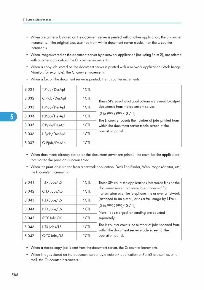
• When a scanner job stored on the document server is printed with another application, the S: counterincrements. If the original was scanned from within document server mode, then the L: counterincrements.
• When images stored on the document server by a network application (including Palm 2), are printedwith another application, the O: counter increments.
• When a copy job stored on the document server is printed with a network application (Web ImageMonitor, for example), the C: counter increments.
• When a fax on the document server is printed, the F: counter increments.
8 031 T:Pjob/DesApl *CTL
These SPs reveal what applications were used to outputdocuments from the document server.
[0 to 9999999/ 0 / 1]
The L: counter counts the number of jobs printed fromwithin the document server mode screen at theoperation panel.
8 032 C:Pjob/DesApl *CTL
8 033 F:Pjob/DesApl *CTL
8 034 P:Pjob/DesApl *CTL
8 035 S:Pjob/DesApl *CTL
8 036 L:Pjob/DesApl *CTL
8 037 O:Pjob/DesApl *CTL
• When documents already stored on the document server are printed, the count for the applicationthat started the print job is incremented.
• When the print job is started from a network application (Desk Top Binder, Web Image Monitor, etc.)the L: counter increments.
8 041 T:TX Jobs/LS *CTL These SPs count the applications that stored files on thedocument server that were later accessed fortransmission over the telephone line or over a network(attached to an e-mail, or as a fax image by I-Fax).
[0 to 9999999/ 0 / 1]
Note: Jobs merged for sending are countedseparately.
The L: counter counts the number of jobs scanned fromwithin the document server mode screen at theoperation panel.
8 042 C:TX Jobs/LS *CTL
8 043 F:TX Jobs/LS *CTL
8 044 P:TX Jobs/LS *CTL
8 045 S:TX Jobs/LS *CTL
8 046 L:TX Jobs/LS *CTL
8 047 O:TX Jobs/LS *CTL
• When a stored copy job is sent from the document server, the C: counter increments.
• When images stored on the document server by a network application or Palm2 are sent as an e-mail, the O: counter increments.
5. System Maintenance
588
5

8 051 T:TX Jobs/DesApl *CTLThese SPs count the applications used to send files fromthe document server over the telephone line or over anetwork (attached to an e-mail, or as a fax image byI-Fax). Jobs merged for sending are countedseparately.
[0 to 9999999/ 0 / 1]The L: counter counts the number of jobs sent fromwithin the document server mode screen at theoperation panel.
8 052 C:TX Jobs/DesApl *CTL
8 053 F:TX Jobs/DesApl *CTL
8 054 P:TX Jobs/DesApl *CTL
8 055 S:TX Jobs/DesApl *CTL
8 056 L:TX Jobs/DesApl *CTL
8 057 O:TX Jobs/DesApl *CTL
• If the send is started from Desk Top Binder or Web Image Monitor, for example, then the O: counterincrements.
8 061T:FIN Jobs *CTL [0 to 9999999/ 0 / 1]
These SPs total the finishing methods. The finishing method is specified by the application.
8 062
C:FIN Jobs *CTL [0 to 9999999/ 0 / 1]
These SPs total finishing methods for copy jobs only. The finishing method is specifiedby the application.
8 063
F:FIN Jobs *CTL [0 to 9999999/ 0 / 1]
These SPs total finishing methods for fax jobs only. The finishing method is specified bythe application.
Note: Finishing features for fax jobs are not available at this time.
8 064
P:FIN Jobs *CTL [0 to 9999999/ 0 / 1]
These SPs total finishing methods for print jobs only. The finishing method is specified bythe application.
8 065
S:FIN Jobs *CTL [0 to 9999999/ 0 / 1]
These SPs total finishing methods for scan jobs only. The finishing method is specifiedby the application.
Note: Finishing features for scan jobs are not available at this time.
Main SP Tables-8
589
5

8 066
L:FIN Jobs *CTL [0 to 9999999/ 0 / 1]
These SPs total finishing methods for jobs output from within the document server modescreen at the operation panel. The finishing method is specified from the print windowwithin document server mode.
8 067
O:FIN Jobs *CTL [0 to 9999999/ 0 / 1]
These SPs total finishing methods for jobs executed by an external application, over thenetwork. The finishing method is specified by the application.
8 06x 1 SortNumber of jobs started in Sort mode. When a stored copy job is set for Sortand then stored on the document server, the L: counter increments. (See SP8066 1)
8 06x 2 Stack Number of jobs started out of Sort mode.
8 06x 3 Staple Number of jobs started in Staple mode.
8 06x 4 BookletNumber of jobs started in Booklet mode. If the machine is in staple mode,the Staple counter also increments.
8 06x 5 Z-FoldNumber of jobs started In any mode other than the Booklet mode and setfor folding (Z-fold).
8 06x 6 PunchNumber of jobs started in Punch mode. When Punch is set for a print job,the P: counter increments. (See SP8 064 6.)
8 06x 7 Other Reserved. Not used.
8 071
T:Jobs/PGS *CTL [0 to 9999999/ 0 / 1]
These SPs count the number of jobs broken down by the number of pages in the job,regardless of which application was used.
8 072
C:Jobs/PGS *CTL [0 to 9999999/ 0 / 1]
These SPs count and calculate the number of copy jobs by size based on the numberof pages in the job.
8 073
F:Jobs/PGS *CTL [0 to 9999999/ 0 / 1]
These SPs count and calculate the number of fax jobs by size based on the number ofpages in the job.
5. System Maintenance
590
5

8 074
P:Jobs/PGS *CTL [0 to 9999999/ 0 / 1]
These SPs count and calculate the number of print jobs by size based on the numberof pages in the job.
8 075
S:Jobs/PGS [0 to 9999999/ 0 / 1]
These SPs count and calculate the number of scan jobs by size based on the numberof pages in the job.
8 076
L:Jobs/PGS *CTL [0 to 9999999/ 0 / 1]
These SPs count and calculate the number of jobs printed from within the documentserver mode window at the operation panel, by the number of pages in the job.
8 077
O:Jobs/PGS *CTL [0 to 9999999/ 0 / 1]
These SPs count and calculate the number of "Other" application jobs (Web ImageMonitor, Palm 2, etc.) by size based on the number of pages in the job.
8 07x 1 1 Page 8 07x 8 21 to 50 Pages
8 07x 2 2 Pages 8 07x 9 51 to 100 Pages
8 07x 3 3 Pages 8 07x 10 101 to 300 Pages
8 07x 4 4 Pages 8 07x 11 301 to 500 Pages
8 07x 5 5 Pages 8 07x 12 501 to 700 Pages
8 07x 6 6 to 10 Pages 8 07x 13 701 to 1000 Pages
8 07x 7 11 to 20 Pages 8 07x 14 1001 to Pages
• For example: When a copy job stored on the document server is printed in document server mode,the appropriate L: counter (SP8076 0xx) increments.
• Printing a fax report counts as a job and increments the F: counter (SP 8073).
• Interrupted jobs (paper jam, etc.) are counted, even though they do not finish.
• If a job is paused and re-started, it counts as one job.
• If the finisher runs out of staples during a print and staple job, then the job is counted at the time theerror occurs.
• For copy jobs (SP 8072) and scan jobs (SP 8075), the total is calculated by multiplying the numberof sets of copies by the number of pages scanned. (One duplex page counts as 2.)
• The first test print and subsequent test prints to adjust settings are added to the number of pages of thecopy job (SP 8072).
Main SP Tables-8
591
5

• When printing the first page of a job from within the document server screen, the page is counted.
8 111
T:FAX TX Jobs *CTL [0 to 9999999/ 0 / 1]
These SPs count the total number of jobs (color or black-and-white) sent by fax, eitherdirectly or using a file stored on the document server, on a telephone line.
Note: Color fax sending is not available at this time.
8 113
F: FAX TX Jobs *CTL [0 to 9999999/ 0 / 1]
These SPs count the total number of jobs (color or black-and-white) sent by fax directlyon a telephone line.
Note: Color fax sending is not available at this time.
8 11x 1 B/W
8 11x 2 Color
• These counters count jobs, not pages.
• This SP counts fax jobs sent over a telephone line with a fax application, including documents storedon the document server.
• If the mode is changed during the job, the job will count with the mode set when the job started.
• If the same document is faxed to both a public fax line and an I-Fax at a destination where both areavailable, then this counter increments, and the I-Fax counter (8 12x) also increments.
• The fax job is counted when the job is scanned for sending, not when the job is sent.
8 121
T:IFAX TX Jobs *CTL [0 to 9999999/ 0 / 1]
These SPs count the total number of jobs (color or black-and-white) sent, either directlyor using a file stored on the document server, as fax images using I-Fax.
Note: Color fax sending is not available at this time.
8 123
F: IFAX TX Jobs *CTL [0 to 9999999/ 0 / 1]
These SPs count the number of jobs (color or black-and-white) sent (not stored on thedocument server), as fax images using I-Fax.
Note: Color fax sending is not available at this time.
8 12x 1 B/W
8 12x 2 Color
• These counters count jobs, not pages.
5. System Maintenance
592
5

• The counters for color are provided for future use; the color fax feature is not available at this time.
• The fax job is counted when the job is scanned for sending, not when the job is sent.
8 131
T:S-to-Email Jobs *CTL [0 to 9999999/ 0 / 1]
These SPs count the total number of jobs (color or black-and-white) scanned andattached to an e-mail, regardless of whether the document server was used or not.
8 135
S: S-to-Email Jobs *CTL [0 to 9999999/ 0 / 1]
These SPs count the number of jobs (color or black-and-white) scanned and attachedto e-mail, without storing the original on the document server.
8 13x 1 B/W
8 13x 2 Color
8 13x 3 ACS
• These counters count jobs, not pages.
• If the job is stored on the document server, after the job is stored it is determined to be color or black-and-white then counted.
• If the job is cancelled during scanning, or if the job is cancelled while the document is waiting to besent, the job is not counted.
• If the job is cancelled during sending, it may or may not be counted, depending on what stage of theprocess had been reached when the job was cancelled.
• If several jobs are combined for sending to the Scan Router, Scan-to-Email, or Scan-to-PC, or if onejob is sent to more than one destination. each send is counted separately. For example, if the samedocument is sent by Scan-to-Email as well as Scan-to-PC, then it is counted twice (once for Scan-to-Email and once for Scan-to-PC).
8 141
T:Deliv Jobs/Svr *CTL [0 to 9999999/ 0 / 1]
These SPs count the total number of jobs (color or black-and-white) scanned and sentto a Scan Router server.
8 145
S: Deliv Jobs/Svr *CTL [0 to 9999999/ 0 / 1]
These SPs count the number of jobs (color or black-and-white) scanned in scanner modeand sent to a Scan Router server.
8 14x 1 B/W
8 14x 2 Color
Main SP Tables-8
593
5

8 14x 3 ACS
• These counters count jobs, not pages.
• The jobs are counted even though the arrival and reception of the jobs at the Scan Router servercannot be confirmed.
• If even one color image is mixed with black-and-white images, then the job is counted as a "Color"job.
• If the job is cancelled during scanning, or if the job is cancelled while the document is waiting to bedelivered, the job is not counted.
• If the job is cancelled during sending, it may or may not be counted, depending on what stage of theprocess had been reached when the job was cancelled.
• Even if several files are combined for sending, the transmission counts as one job.
8 151
T:Deliv Jobs/PC *CTL [0 to 9999999/ 0 / 1]
These SPs count the total number of jobs (color or black-and-white) scanned and sentto a folder on a PC (Scan-to-PC). Note: At the present time, 8 151 and 8 155 perform identical counts.
8 155
S:Deliv Jobs/PC *CTL [0 to 9999999/ 0 / 1]
These SPs count the total number of jobs (color or black-and-white) scanned and sentwith Scan-to-PC.
8 15x 1 B/W
8 15x 2 Color
8 15x 3 ACS
• These counters count jobs, not pages.
• If the job is cancelled during scanning, it is not counted.
• If the job is cancelled while it is waiting to be sent, the job is not counted.
• If the job is cancelled during sending, it may or may not be counted, depending on what stage of theprocess had been reached when the job was cancelled.
• Even if several files are combined for sending, the transmission counts as one job.
5. System Maintenance
594
5

8 161 T:PCFAX TX Jobs *CTL These SPs count the number of PC Fax transmissionjobs. A job is counted from when it is registered forsending, not when it is sent.
[0 to 9999999/ 0 / 1]
Note: At the present time, these counters performidentical counts.
8 163 F:PCFAX TX Jobs *CTL
• This counts fax jobs started from a PC using a PC fax application, and sending the data out to thedestination from the PC through the copier.
8 171 T:Deliv Jobs/WSD *CTL These SPs count the pages scanned by WS.
[0 to 9999999/ 0 / 1]8 175 S:Deliv Jobs/WSD *CTL
-001 B/W
-002 Color
-003 ACS
8 181 T:Scan to Media Jobs *CTL These SPs count the scanned pages in a media by thescanner application.
[0 to 9999999/ 0 / 1]8 185 S:Scan to Media Jobs *CTL
-001 B/W
-002 Color
-003 ACS
8 191 T:Total Scan PGS *CTL
These SPs count the pages scanned by eachapplication that uses the scanner to scan images.
[0 to 9999999/ 0 / 1]
8 192 C:Total Scan PGS *CTL
8 193 F:Total Scan PGS *CTL
8 195 S:Total Scan PGS *CTL
8 196 L:Total Scan PGS *CTL
• SP 8 191 to 8 196 count the number of scanned sides of pages, not the number of physical pages.
• These counters do not count reading user stamp data, or reading color charts to adjust color.
• Previews done with a scanner driver are not counted.
Main SP Tables-8
595
5

• A count is done only after all images of a job have been scanned.
• Scans made in SP mode are not counted.
Examples
• If 3 B5 pages and 1 A3 page are scanned with the scanner application but not stored, the S: countis 4.
• If both sides of 3 A4 sheets are copied and stored to the document server using the Store File buttonin the Copy mode window, the C: count is 6 and the L: count is 6.
• If both sides of 3 A4 sheets are copied but not stored, the C: count is 6.
• If you enter document server mode then scan 6 pages, the L: count is 6.
8 201
T:LSize Scan PGS *CTL [0 to 9999999/ 0 / 1]
These SPs count the total number of large pages input with the scanner for scan and copyjobs. Large size paper (A3/DLT) scanned for fax transmission are not counted.
Note: These counters are displayed in the SMC Report, and in the User Tools display.
8 203
F: LSize Scan PGS *CTL [0 to 9999999/ 0 / 1]
These SPs count the total number of large pages input with the scanner for fax transmission.
Note: These counters are displayed in the SMC Report, and in the User Tools display.
8 205
S:LSize Scan PGS *CTL [0 to 9999999/ 0 / 1]
These SPs count the total number of large pages input with the scanner for scan jobs only.Large size paper (A3/DLT) scanned for fax transmission are not counted.
Note: These counters are displayed in the SMC Report, and in the User Tools display.
8 211 T:Scan PGS/LS *CTL These SPs count the number of pages scanned into thedocument server .
[0 to 9999999/ 0 / 1]The L: counter counts the number of pages stored fromwithin the document server mode screen at theoperation panel, and with the Store File button fromwithin the Copy mode screen
8 212 C:Scan PGS/LS *CTL
8 213 F:Scan PGS/LS *CTL
8 215 S:Scan PGS/LS *CTL
8 216 L:Scan PGS/LS *CTL
• Reading user stamp data is not counted.
• If a job is cancelled, the pages output as far as the cancellation are counted.
• If the scanner application scans and stores 3 B5 sheets and 1 A4 sheet, the S: count is 4.
• If pages are copied but not stored on the document server, these counters do not change.
5. System Maintenance
596
5

• If both sides of 3 A4 sheets are copied and stored to the document server, the C: count is 6 and theL: count is 6.
• If you enter document server mode then scan 6 pages, the L: count is 6.
8 221ADF Org Feeds *CTL [0 to 9999999/ 0 / 1]
These SPs count the number of pages fed through the ADF for front and back side scanning.
8 221 1 Front
Number of front sides fed for scanning:
With an ADF that can scan both sides simultaneously, the Front side count isthe same as the number of pages fed for either simplex or duplex scanning.
With an ADF that cannot scan both sides simultaneously, the Front side countis the same as the number of pages fed for duplex front side scanning. (Thefront side is determined by which side the user loads face up.)
8 221 2 Back
Number of rear sides fed for scanning:
With an ADF that can scan both sides simultaneously, the Back count is thesame as the number of pages fed for duplex scanning.
With an ADF that cannot scan both sides simultaneously, the Back count isthe same as the number of pages fed for duplex rear-side scanning.
• When 1 sheet is fed for duplex scanning the Front count is 1 and the Back count is 1.
• If a jam occurs during the job, recovery processing is not counted to avoid double counting. Also, thepages are not counted if the jam occurs before the first sheet is output.
8 231
Scan PGS/Mode *CTL [0 to 9999999/ 0 / 1]
These SPs count the number of pages scanned by each ADF mode to determine thework load on the ADF.
8 231 1 Large VolumeSelectable. Large copy jobs that cannot be loaded in theADF at one time.
8 231 2 SADF Selectable. Feeding pages one by one through the ADF.
8 231 3 Mixed Size Selectable. Select "Mixed Sizes" on the operation panel.
8 231 4 Custom Size Selectable. Originals of non-standard size.
8 231 5 PlatenBook mode. Raising the ADF and placing the originaldirectly on the platen.
8 231 6 Mixed 1side/ 2side Simplex and Duplex mode.
Main SP Tables-8
597
5
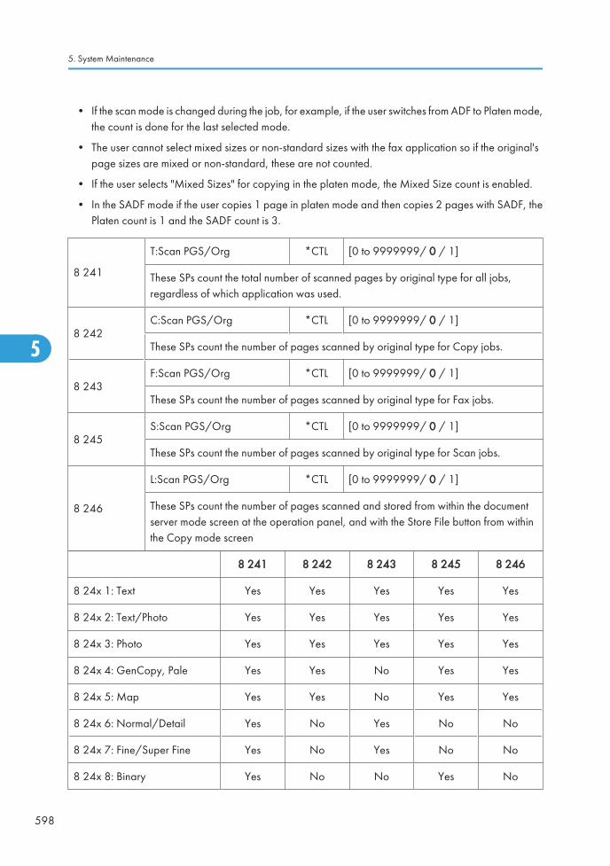
• If the scan mode is changed during the job, for example, if the user switches from ADF to Platen mode,the count is done for the last selected mode.
• The user cannot select mixed sizes or non-standard sizes with the fax application so if the original'spage sizes are mixed or non-standard, these are not counted.
• If the user selects "Mixed Sizes" for copying in the platen mode, the Mixed Size count is enabled.
• In the SADF mode if the user copies 1 page in platen mode and then copies 2 pages with SADF, thePlaten count is 1 and the SADF count is 3.
8 241
T:Scan PGS/Org *CTL [0 to 9999999/ 0 / 1]
These SPs count the total number of scanned pages by original type for all jobs,regardless of which application was used.
8 242C:Scan PGS/Org *CTL [0 to 9999999/ 0 / 1]
These SPs count the number of pages scanned by original type for Copy jobs.
8 243F:Scan PGS/Org *CTL [0 to 9999999/ 0 / 1]
These SPs count the number of pages scanned by original type for Fax jobs.
8 245S:Scan PGS/Org *CTL [0 to 9999999/ 0 / 1]
These SPs count the number of pages scanned by original type for Scan jobs.
8 246
L:Scan PGS/Org *CTL [0 to 9999999/ 0 / 1]
These SPs count the number of pages scanned and stored from within the documentserver mode screen at the operation panel, and with the Store File button from withinthe Copy mode screen
8 241 8 242 8 243 8 245 8 246
8 24x 1: Text Yes Yes Yes Yes Yes
8 24x 2: Text/Photo Yes Yes Yes Yes Yes
8 24x 3: Photo Yes Yes Yes Yes Yes
8 24x 4: GenCopy, Pale Yes Yes No Yes Yes
8 24x 5: Map Yes Yes No Yes Yes
8 24x 6: Normal/Detail Yes No Yes No No
8 24x 7: Fine/Super Fine Yes No Yes No No
8 24x 8: Binary Yes No No Yes No
5. System Maintenance
598
5

8 24x 9: Grayscale Yes No No Yes No
8 24x 10: Color Yes No No Yes No
8 24x 11: Other Yes Yes Yes Yes Yes
• If the scan mode is changed during the job, for example, if the user switches from ADF to Platen mode,the count is done for the last selected mode.
8 251 T:Scan PGS/ImgEdt *CTL These SPs show how many times Image Edit featureshave been selected at the operation panel for eachapplication. Some examples of these editing featuresare:
• Erase> Border
• Erase> Center
• Image Repeat
• Centering
• Positive/Negative
[0 to 9999999/ 0 / 1]
Note: The count totals the number of times the editfeatures have been used. A detailed breakdown ofexactly which features have been used is not given.
8 252 C:Scan PGS/ImgEdt *CTL
8 254 P:Scan PGS/ImgEdt *CTL
8 255 S : Scan PGS/ImgEdr *CTL
8 256 L:Scan PGS/ImgEdt *CTL
8 257 O:Scan PGS/ImgEdt *CTL
The L: counter counts the number of pages stored from within the document server mode screen at theoperation panel, and with the Store File button from within the Copy mode screen.
8 261 T:Scan PGS/ColCr *CTL -
8 262 C:Scan PGS/ ColCr *CTL -
8 265 S:Scn PGS/Color *CTL -
8 266 L:Scn PGS/ColCr *CTL -
8 26x 1 Color Conversion
These SPs show how many times color creation featureshave been selected at the operation panel.
8 26x 2 Color Erase
8 26x 3 Background
8 26x 4 Other
Main SP Tables-8
599
5

8 281 T:Scan PGS/TWAIN *CTL These SPs count the number of pages scanned using aTWAIN driver. These counters reveal how the TWAINdriver is used for delivery functions.
[0 to 9999999/ 0 / 1]Note: At the present time, these counters performidentical counts.
8 285 S:Scan PGS/TWAIN *CTL
8 291 T:Scan PGS/Stamp *CTL These SPs count the number of pages stamped with thestamp in the ADF unit.
[0 to 9999999/ 0 / 1]The L: counter counts the number of pages stored fromwithin the document server mode screen at theoperation panel, and with the Store File button fromwithin the Copy mode screen
8 293 F:Scan PGS/Stamp *CTL
8 295 S:Scan PGS/Stamp *CTL
8 301
T:Scan PGS/Size *CTL [0 to 9999999/ 0 / 1]
These SPs count by size the total number of pages scanned by all applications. Usethese totals to compare original page size (scanning) and output (printing) page size[SP 8-441].
8 302
C:Scan PGS/Size *CTL [0 to 9999999/ 0 / 1]
These SPs count by size the total number of pages scanned by the Copy application.Use these totals to compare original page size (scanning) and output (printing) pagesize [SP 8-442].
8 303
F:Scan PGS/Size *CTL [0 to 9999999/ 0 / 1]
These SPs count by size the total number of pages scanned by the Fax application. Usethese totals to compare original page size (scanning) and output page size [SP 8-443].
8 305
S:Scan PGS/Size *CTL [0 to 9999999/ 0 / 1]
These SPs count by size the total number of pages scanned by the Scan application.Use these totals to compare original page size (scanning) and output page size [SP8-445].
8 306
L:Scan PGS/Size *CTL [0 to 9999999/ 0 / 1]
These SPs count by size the total number of pages scanned and stored from within thedocument server mode screen at the operation panel, and with the Store File buttonfrom within the Copy mode screen. Use these totals to compare original page size(scanning) and output page size [SP 8-446].
5. System Maintenance
600
5

8 30x 1 A3
-
8 30x 2 A4
8 30x 3 A5
8 30x 4 B4
8 30x 5 B5
8 30x 6 DLT
8 30x 7 LG
8 30x 8 LT
8 30x 9 HLT
8 30x 10 Full Bleed
8 30x 254 Other (Standard)
8 30x 255 Other (Custom)
8 311
T:Scan PGS/Rez *CTL [0 to 9999999/ 0 / 1]
These SPs count by resolution setting the total number of pages scanned by applicationsthat can specify resolution settings.
8 315
S: Scan PGS/Rez *CTL [0 to 9999999/ 0 / 1]
These SPs count by resolution setting the total number of pages scanned by applicationsthat can specify resolution settings.
Note: At the present time, SP8-311 and SP8-315 perform identical counts.
8 31x 1 1200dpi <
8 31x 2 600dpi to 1199dpi
8 31x 3 400dpi to 599dpi
8 31x 4 200dpi to 399dpi
8 31x 5 < 199dpi
• Copy resolution settings are fixed so they are not counted.
• The Fax application does not allow finely-adjusted resolution settings so no count is done for the Faxapplication.
Main SP Tables-8
601
5

8 381 T:Total PrtPGS *CTL
These SPs count the number of pages printed by thecustomer. The counter for the application used forstoring the pages increments.
[0 to 9999999/ 0 / 1]The L: counter counts the number of pages stored fromwithin the document server mode screen at theoperation panel. Pages stored with the Store File buttonfrom within the Copy mode screen go to the C: counter.
8 382 C:Total PrtPGS *CTL
8 383 F:Total PrtPGS *CTL
8 384 P:Total PrtPGS *CTL
8 385 S:Total PrtPGS *CTL
8 386 L:Total PrtPGS *CTL
8 387 O:Total PrtPGS *CTL
• When the A3/DLT double count function is switched on with SP5104, 1 A3/DLT page is counted as2.
• When several documents are merged for a print job, the number of pages stored are counted for theapplication that stored them.
• These counters are used primarily to calculate charges on use of the machine, so the following pagesare not counted as printed pages:
- Blank pages in a duplex printing job.
- Blank pages inserted as document covers, chapter title sheets, and slip sheets.
- Reports printed to confirm counts.
- All reports done in the service mode (service summaries, engine maintenance reports, etc.)
- Test prints for machine image adjustment.
- Error notification reports.
- Partially printed pages as the result of a copier jam.
8 391
LSize PrtPGS *CTL [0 to 9999999/ 0 / 1]
These SPs count pages printed on paper sizes A3/DLT and larger.
Note: In addition to being displayed in the SMC Report, these counters are alsodisplayed in the User Tools display on the copy machine.
5. System Maintenance
602
5

8 401 T:PrtPGS/LS *CTLThese SPs count the number of pages printed from thedocument server. The counter for the application usedto print the pages is incremented.The L: counter counts the number of jobs stored fromwithin the document server mode screen at theoperation panel.
[0 to 9999999/ 0 / 1]
8 402 C:PrtPGS/LS *CTL
8 403 F:PrtPGS/LS *CTL
8 404 P:PrtPGS/LS *CTL
8 405 S:PrtPGS/LS *CTL
8 406 L:PrtPGS/LS *CTL
• Print jobs done with Web Image Monitor and Desk Top Binder are added to the L: count.
• Fax jobs done with Web Image Monitor and Desk Top Binder are added to the F: count.
8 411 Prints/Duplex *CTL
This SP counts the amount of paper (front/backcounted as 1 page) used for duplex printing. Lastpages printed only on one side are not counted.
[0 to 9999999/ 0 / 1]
8 421
T:PrtPGS/Dup Comb *CTL [0 to 9999999/ 0 / 1]
These SPs count by binding and combine, and n-Up settings the number of pagesprocessed for printing. This is the total for all applications.
8 422
C:PrtPGS/Dup Comb *CTL [0 to 9999999/ 0 / 1]
These SPs count by binding and combine, and n-Up settings the number of pagesprocessed for printing by the copier application.
8 423
F:PrtPGS/Dup Comb *CTL [0 to 9999999/ 0 / 1]
These SPs count by binding and combine, and n-Up settings the number of pagesprocessed for printing by the fax application.
8 424
P:PrtPGS/Dup Comb *CTL [0 to 9999999/ 0 / 1]
These SPs count by binding and combine, and n-Up settings the number of pagesprocessed for printing by the printer application.
8 425
S:PrtPGS/Dup Comb *CTL [0 to 9999999/ 0 / 1]
These SPs count by binding and combine, and n-Up settings the number of pagesprocessed for printing by the scanner application.
Main SP Tables-8
603
5

8 426
L:PrtPGS/Dup Comb *CTL [0 to 9999999/ 0 / 1]
These SPs count by binding and combine, and n-Up settings the number of pagesprocessed for printing from within the document server mode window at the operationpanel.
8 427
O:PrtPGS/Dup Comb *CTL [0 to 9999999/ 0 / 1]
These SPs count by binding and combine, and n-Up settings the number of pagesprocessed for printing by Other applications
8 42x 1 Simplex> Duplex
8 42x 2 Duplex> Duplex
8 42x 3 Book> Duplex
8 42x 4 Simplex Combine
8 42x 5 Duplex Combine
8 42x 6 2> 2 pages on 1 side (2-Up)
8 42x 7 4> 4 pages on 1 side (4-Up)
8 42x 8 6> 6 pages on 1 side (6-Up)
8 42x 9 8> 8 pages on 1 side (8-Up)
8 42x 10 9> 9 pages on 1 side (9-Up)
8 42x 11 16> 16 pages on 1 side (16-Up)
8 42x 12 Booklet
8 42x 13 Magazine
• These counts (SP8 421 to SP8 427) are especially useful for customers who need to improve theircompliance with ISO standards for the reduction of paper consumption.
• Pages that are only partially printed with the n-Up functions are counted as 1 page.
• Here is a summary of how the counters work for Booklet and Magazine modes:
Booklet Magazine
Original Pages Count Original Pages Count
1 1 1 1
5. System Maintenance
604
5

2 2 2 2
3 2 3 2
4 2 4 2
5 3 5 4
6 4 6 4
7 4 7 4
8 4 8 4
8 431
T:PrtPGS/ImgEdt *CTL [0 to 9999999/ 0 / 1]
These SPs count the total number of pages output with the three features below,regardless of which application was used.
8 432
C:PrtPGS/ImgEdt *CTL [0 to 9999999/ 0 / 1]
These SPs count the total number of pages output with the three features below with thecopy application.
8 434
P:PrtPGS/ImgEdt *CTL [0 to 9999999/ 0 / 1]
These SPs count the total number of pages output with the three features below with theprint application.
8 436
L:PrtPGS/ImgEdt *CTL [0 to 9999999/ 0 / 1]
These SPs count the total number of pages output from within the document server modewindow at the operation panel with the three features below.
8 437
O:PrtPGS/ImgEdt *CTL [0 to 9999999/ 0 / 1]
These SPs count the total number of pages output with the three features below withOther applications.
8 43x 1 Cover/Slip SheetTotal number of covers or slip sheets inserted. The count for acover printed on both sides counts 2.
8 43x 2 Series/BookThe number of pages printed in series (one side) or printed asa book with booklet right/left pagination.
8 43x 3 User StampThe number of pages printed where stamps were applied,including page numbering and date stamping.
Main SP Tables-8
605
5

8 441T:PrtPGS/Ppr Size *CTL [0 to 9999999/ 0 / 1]
These SPs count by print paper size the number of pages printed by all applications.
8 442
C:PrtPGS/Ppr Size *CTL [0 to 9999999/ 0 / 1]
These SPs count by print paper size the number of pages printed by the copyapplication.
8 443F:PrtPGS/Ppr Size *CTL [0 to 9999999/ 0 / 1]
These SPs count by print paper size the number of pages printed by the fax application.
8 444
P:PrtPGS/Ppr Size *CTL [0 to 9999999/ 0 / 1]
These SPs count by print paper size the number of pages printed by the printerapplication.
8 445
S:PrtPGS/Ppr Size *CTL [0 to 9999999/ 0 / 1]
These SPs count by print paper size the number of pages printed by the scannerapplication.
8 446
L:PrtPGS/Ppr Size *CTL [0 to 9999999/ 0 / 1]
These SPs count by print paper size the number of pages printed from within thedocument server mode window at the operation panel.
8 447O:PrtPGS/Ppr Size *CTL [0 to 9999999/ 0 / 1]
These SPs count by print paper size the number of pages printed by Other applications.
5. System Maintenance
606
5
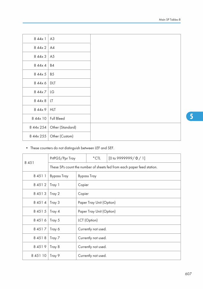
8 44x 1 A3
8 44x 2 A4
8 44x 3 A5
8 44x 4 B4
8 44x 5 B5
8 44x 6 DLT
8 44x 7 LG
8 44x 8 LT
8 44x 9 HLT
8 44x 10 Full Bleed
8 44x 254 Other (Standard)
8 44x 255 Other (Custom)
• These counters do not distinguish between LEF and SEF.
8 451PrtPGS/Ppr Tray *CTL [0 to 9999999/ 0 / 1]
These SPs count the number of sheets fed from each paper feed station.
8 451 1 Bypass Tray Bypass Tray
8 451 2 Tray 1 Copier
8 451 3 Tray 2 Copier
8 451 4 Tray 3 Paper Tray Unit (Option)
8 451 5 Tray 4 Paper Tray Unit (Option)
8 451 6 Tray 5 LCT (Option)
8 451 7 Tray 6 Currently not used.
8 451 8 Tray 7 Currently not used.
8 451 9 Tray 8 Currently not used.
8 451 10 Tray 9 Currently not used.
Main SP Tables-8
607
5

8 461
T:PrtPGS/Ppr Type *CTL [0 to 9999999/ 0 / 1]
These SPs count by paper type the number pages printed by all applications.
• These counters are not the same as the PM counter. The PM counter is based onfeed timing to accurately measure the service life of the feed rollers. However,these counts are based on output timing.
• Blank sheets (covers, chapter covers, slip sheets) are also counted.
• During duplex printing, pages printed on both sides count as 1, and a page printedon one side counts as 1.
8 462C:PrtPGS/Ppr Type *CTL [0 to 9999999/ 0 / 1]
These SPs count by paper type the number pages printed by the copy application.
8 463F:PrtPGS/Ppr Type *CTL [0 to 9999999/ 0 / 1]
These SPs count by paper type the number pages printed by the fax application.
8 464P:PrtPGS/Ppr Type *CTL [0 to 9999999/ 0 / 1]
These SPs count by paper type the number pages printed by the printer application.
8 466
L:PrtPGS/Ppr Type *CTL [0 to 9999999/ 0 / 1]
These SPs count by paper type the number pages printed from within the documentserver mode window at the operation panel.
8 46x 1 Normal
8 46x 2 Recycled
8 46x 3 Special
8 46x 4 Thick
8 46x 5 Normal (Back)
8 46x 6 Thick (Back)
8 46x 7 OHP
8 46x 8 Other
8 471PrtPGS/Mag *CTL [0 to 9999999/ 0 / 1]
These SPs count by magnification rate the number of pages printed.
5. System Maintenance
608
5

8 471 1 < 49%
8 471 2 50% to 99%
8 471 3 100%
8 471 4 101% to 200%
8 471 5 201% <
• Counts are done for magnification adjusted for pages, not only on the operation panel but performedremotely with an external network application capable of performing magnification adjustment aswell.
• Magnification adjustments done with printer drivers with PC applications such as Excel are alsocounted.
• Magnification adjustments done for adjustments after they have been stored on the document serverare not counted.
• Magnification adjustments performed automatically during Auto Reduce/Enlarge copying arecounted.
• The magnification rates of blank cover sheets, slip sheets, etc. are automatically assigned a rate of100%.
8 481 T:PrtPGS/TonSave *CTL
8 484 P:PrtPGS/TonSave *CTL
These SPs count the number of pages printed with the Toner Save feature switched on.
Note: These SPs return the same results as this SP is limited to the Print application.
[0 to 9999999/ 0 / 1]
8 491 T:PrtPGS/Col Mode *CTL
These SPs count the number of pages printed in theColor Mode by each application.
8 492 C:PrtPGS/Col Mode *CTL
8 493 F:PrtPGS/Col Mode *CTL
8 496 L:PrtPGS/Col Mode *CTL
8 497 O:PrtPGS/Col Mode *CTL
8 49x 1 B/W
8 49x 2 Single Color
Main SP Tables-8
609
5

8 49x 3 Two Color
8 49x 4 Full Color
8 501 T:PrtPGS/Col Mode *CTL
These SPs count the number of pages printed in theColor Mode by the print application.
8 504 P:PrtPGS/Col Mode *CTL
8 507 O:PrtPGS/Col Mode *CTL
8 50x 1 B/W
8 50x 2 Mono Color
8 50x 3 Full Color
8 50x 4 Single Color
8 50x 5 Two Color
8 511T:PrtPGS/Emul *CTL [0 to 9999999/ 0 / 1]
These SPs count by printer emulation mode the total number of pages printed.
8 514P:PrtPGS/Emul *CTL [0 to 9999999/ 0 / 1]
These SPs count by printer emulation mode the total number of pages printed.
5. System Maintenance
610
5

8 514 1 RPCS
8 514 2 RPDL
8 514 3 PS3
8 514 4 R98
8 514 5 R16
8 514 6 GL/GL2
8 514 7 R55
8 514 8 RTIFF
8 514 9 PDF
8 514 10 PCL5e/5c
8 514 11 PCL XL
8 514 12 IPDL-C
8 514 13 BM-Links Japan Only
8 514 14 Other
• SP8 511 and SP8 514 return the same results as they are both limited to the Print application.
• Print jobs output to the document server are not counted.
8 521T:PrtPGS/FIN *CTL [0 to 9999999 / 0 / 1]
These SPs count by finishing mode the total number of pages printed by all applications.
8 522
C:PrtPGS/FIN *CTL [0 to 9999999 / 0 / 1]
These SPs count by finishing mode the total number of pages printed by the Copyapplication.
8 523
F:PrtPGS/FIN *CTL [0 to 9999999 / 0 / 1]
These SPs count by finishing mode the total number of pages printed by the Faxapplication.
NOTE: Print finishing options for received faxes are currently not available.
Main SP Tables-8
611
5

8 524
P:PrtPGS/FIN *CTL [0 to 9999999 / 0 / 1]
These SPs count by finishing mode the total number of pages printed by the Printapplication.
8 525
S:PrtPGS/FIN *CTL [0 to 9999999 / 0 / 1]
These SPs count by finishing mode the total number of pages printed by the Scannerapplication.
8 526
L:PrtPGS/FIN *CTL [0 to 9999999 / 0 / 1]
These SPs count by finishing mode the total number of pages printed from within thedocument server mode window at the operation panel.
8 52x 1 Sort
8 52x 2 Stack
8 52x 3 Staple
8 52x 4 Booklet
8 52x 5 Z-Fold
8 52x 6 Punch
8 52x 7 Other
• If stapling is selected for finishing and the stack is too large for stapling, the unstapled pages are stillcounted.
• The counts for staple finishing are based on output to the staple tray, so jam recoveries are counted.
8 531 Staples *CTLThis SP counts the amount of staples used by the machine.
[0 to 9999999 / 0 / 1]
8 581
T:Counter *CTL [0 to 9999999 / 0 / 1]
These SPs count the total output broken down by color output, regardless of theapplication used. In addition to being displayed in the SMC Report, these counters arealso displayed in the User Tools display on the copy machine.
8 581 1 Total
8 581 2 Total: Full Color
5. System Maintenance
612
5

8 581 3 B&W/Single Color
8 581 4 Development: CMY
8 581 5 Development: K
8 581 6 Copy: Color
8 581 7 Copy: B/W
8 581 8 Print: Color
8 581 9 Print: B/W
8 581 10 Total: Color
8 581 11 Total: B/W
8 581 12 Full Color: A3
8 581 13 Full Color: B4 JIS or Smaller
8 581 14 Full Color Print
8 581 15 Mono Color Print
8 581 16 Full Color GPC
8 581 17 Twin Colour Mode Print
8 581 18 Full Colour Print (Twin)
8 581 19 Mono Colour Print (Twin)
8 581 20 Full Colour Total (CV)
8 581 21 Mono Colour Total (CV)
8 581 22 Full Colour Print (CV)
8 582 C:Counter *CTL [0 to 9999999/ 0 / 1]
These SPs count the total output of the copy application broken down by color output.
8 582 1 B/W
8 582 2 Single Color
8 582 3 Two Color
Main SP Tables-8
613
5

8 582 4 Full Color
8 583 F:Counter *CTL [0 to 9999999/ 0 / 1]
These SPs count the total output of the fax application broken down by color output.
8 583 1 B/W
8 583 2 Single Color
8 584 P:Counter *CTL [0 to 9999999/ 0 / 1]
These SPs count the total output of the print application broken down by color output.
8 584 1 B/W
8 584 2 Mono Color
8 584 3 Full Color
8 584 4 Single Color
8 584 5 Two Color
8 586 L:Counter *CTL [0 to 9999999/ 0 / 1]
These SPs count the total output of the local storage broken down by color output.
8 582 1 B/W
8 582 2 Single Color
8 582 3 Two Color
8 582 4 Full Color
8 591
O:Counter *CTL [0 to 9999999/ 0 / 1]
These SPs count the totals for A3/DLT paper use, number of duplex pages printed, andthe number of staples used. These totals are for Other (O:) applications only.
8 591 1 A3/DLT-
8 591 2 Duplex
5. System Maintenance
614
5

8 601
Coverage Counter *CTL [0 to 9999999/ 0 / 1]
These SPs count the total coverage for each color and the total printout pages for eachprinting mode.
8 601 1 B/W
-
8 601 2 Color
8 601 11 B/W Printing Pages
8 601 12 Color Printing Pages
8 601 21 Coverage Counter 1
8 601 22 Coverage Counter 2
8 601 23 Coverage Counter 3
8 617SDK Apli Counter *CTL [0 to 9999999/ 0 / 1]
These SPs count the total printout pages for each SDK applicaion.
8 617 1 SDK-1
-
8 617 2 SDK-2
8 617 3 SDK-3
8 617 4 SDK-4
8 617 5 SDK-5
8 617 6 SDK-6
8 631T:FAX TX PGS *CTL [0 to 9999999/ 0 / 1]
These SPs count by color mode the number of pages sent by fax to a telephone number.
8 633F:FAX TX PGS *CTL [0 to 9999999/ 0 / 1]
These SPs count by color mode the number of pages sent by fax to a telephone number.
8 63x 1 B/W
8 63x 2 Color
Main SP Tables-8
615
5

• If a document has color and black-and-white pages mixed, the pages are counted separately as B/W or Color.
• At the present time, this feature is provided for the Fax application only so SP8631 and SP8633 arethe same.
• The counts include error pages.
• If a document is sent to more than one destination with a Group transmission, the count is done foreach destination.
• Polling transmissions are counted but polling RX are not.
• Relay, memory, and confidential mailbox transmissions and are counted for each destination.
8 641
T:IFAX TX PGS *CTL [0 to 9999999/ 0 / 1]
These SPs count by color mode the number of pages sent by fax to as fax images usingI-Fax.
8 643
F:IFAX TX PGS *CTL [0 to 9999999/ 0 / 1]
These SPs count by color mode the number of pages sent by Fax as fax images usingI-Fax.
8 64x 1 B/W
8 64x 2 Color
• If a document has color and black-and-white pages mixed, the pages are counted separately as B/W or Color.
• At the present time, this feature is provided for the Fax application only so SP8641 and SP8643 arethe same.
• The counts include error pages.
• If a document is sent to more than one destination with a Group transmission, the count is done foreach destination.
• Polling transmissions are counted but polling RX are not.
• Relay, memory, and confidential mailbox transmissions and are counted for each destination.
8 651
T:S-to-Email PGS *CTL [0 to 9999999/ 0 / 1]
These SPs count by color mode the total number of pages attached to an e-mail for boththe Scan and document server applications.
5. System Maintenance
616
5

8 655
S:S-to-Email PGS *CTL [0 to 9999999/ 0 / 1]
These SPs count by color mode the total number of pages attached to an e-mail for theScan application only.
8 65x 1 B/W
8 65x 2 Color
• The count for B/W and Color pages is done after the document is stored on the HDD. If the job iscancelled before it is stored, the pages are not counted.
• If Scan-to-Email is used to send a 10-page document to 5 addresses, the count is 10 (the pages aresent to the same SMTP server together).
• If Scan-to-PC is used to send a 10-page document to 5 folders, the count is 50 (the document is sentto each destination of the SMB/FTP server).
• Due to restrictions on some devices, if Scan-to-Email is used to send a 10-page document to a largenumber of destinations, the count may be divided and counted separately. For example, if a 10-pagedocument is sent to 200 addresses, the count is 10 for the first 100 destinations and the count is also10 for the second 100 destinations, for a total of 20.).
8 661
T:Deliv PGS/Svr *CTL [0 to 9999999/ 0 / 1]
These SPs count by color mode the total number of pages sent to a Scan Router serverby both Scan and LS applications.
8 665
S:Deliv PGS/Svr *CTL [0 to 9999999/ 0 / 1]
These SPs count by color mode the total number of pages sent to a Scan Router serverby the Scan application.
8 66x 1 B/W
8 66x 2 Color
• The B/W and Color counts are done after the document is stored on the HDD of the Scan Routerserver.
• If the job is canceled before storage on the Scan Router server finishes, the counts are not done.
• The count is executed even if regardless of confirmation of the arrival at the Scan Router server.
Main SP Tables-8
617
5

8 671
T:Deliv PGS/PC *CTL [0 to 9999999/ 0 / 1]
These SPs count by color mode the total number of pages sent to a folder on a PC (Scan-to-PC) with the Scan and LS applications.
8 675
S: Deliv PGS/PC *CTL [0 to 9999999/ 0 / 1]
These SPs count by color mode the total number of pages sent with Scan-to-PC with theScan application.
8 67x 1 B/W
8 67x 2 Color
8 681 T:PCFAX TXPGS *CTL These SPs count the number of pages sent by PC Fax.These SPs are provided for the Fax application only, sothe counts for SP8 681 and SP8 683 are the same.
[0 to 9999999/ 0 / 1]8 683 F:PCFAX TXPGS *CTL
• This counts pages sent from a PC using a PC fax application, from the PC through the copier to thedestination.
• When sending the same message to more than one place using broadcasting, the pages are onlycounted once. (For example, a 10-page fax is sent to location A and location B. The counter goesup by 10, not 20.)
8 691 T:TX PGS/LS *CTLThese SPs count the number of pages sent from thedocument server. The counter for the application that wasused to store the pages is incremented.
[0 to 9999999/ 0 / 1]The L: counter counts the number of pages stored fromwithin the document server mode screen at the operationpanel. Pages stored with the Store File button from withinthe Copy mode screen go to the C: counter.
8 692 C:TX PGS/LS *CTL
8 693 F:TX PGS/LS *CTL
8 694 P:TX PGS/LS *CTL
8 695 S:TX PGS/LS *CTL
8 696 L:TX PGS/LS *CTL
• Print jobs done with Web Image Monitor and Desk Top Binder are added to the count.
• If several documents are merged for sending, the number of pages stored are counted for theapplication that stored them.
• When several documents are sent by a Fax broadcast, the F: count is done for the number of pagessent to each destination.
5. System Maintenance
618
5

8 701
TX PGS/Port *CTL [0 to 9999999/ 0 / 1]
These SPs count the number of pages sent by the physical port used to send them. Forexample, if a 3-page original is sent to 4 destinations via ISDN G4, the count for ISDN(G3, G4) is 12.
8 701 1 PSTN-1
8 701 2 PSTN-2
8 701 3 PSTN-3
8 701 4 ISDN (G3,G4)
8 701 5 Network
8 711 T:Scan PGS/Comp *CTL [0 to 9999999/ 0 / 1]
8 715S:Scan PGS/Comp *CTL [0 to 9999999/ 0 / 1]
These SPs count the number of pages sent by each compression mode.
8 715 1 JPEG/JPEG2000
8 715 2 TIFF(Multi/Single)
8 715 3 PDF
8 715 4 Other
8 715 5 PDF/Comp
8 721 T:Deliv PGS/WSD *CTL[0 to 9999999/ 0 / 1]
8 725S: Dvliv PGS/WSD *CTL
These SPs count the number of pages scanned by each scanner mode.
x 1 B/W -
x 2 Color -
Main SP Tables-8
619
5

8 731 T:Scan PGS/Media *CTL[0 to 9999999/ 0 / 1]
8 735
S:Scan PGS/Media *CTL
These SPs count the number of pages scanned and saved in a meia by each scannermode.
x 1 B/W -
x 2 Color -
8 741RX PGS/Port *CTL [0 to 9999999/ 0 / 1]
These SPs count the number of pages received by the physical port used to receive them.
8 741 1 PSTN-1 -
8 741 2 PSTN-2 -
8 741 3 PSTN-3 -
8 741 4 ISDN (G3,G4) -
8 741 5 Network -
8 771
Dev Counter *CTL [0 to 9999999/ 0 / 1]
These SPs count the frequency of use (number of rotations of the development rollers) forblack and other color toners.
8 771 1 Total
8 771 2 K
8 771 3 Y
8 771 4 M
8 771 5 C
8 781
Toner_Bottle_Info. *ENG [0 to 9999999/ 0 / 1]
These SPs display the number of already replaced toner bottles.
NOTE: Currently, the data in SP7-833-011 through 014 and the data in SP8-781-001through 004 are the same.
5. System Maintenance
620
5

8 781 1 Toner: BK The number of black-toner bottles
8 781 2 Toner: Y The number of yellow-toner bottles
8 781 3 Toner: M The number of magenta-toner bottles
8 781 4 Toner: C The number of cyan-toner bottles
8 791 LS Memory Remain *CTL
This SP displays the percent of space availableon the document server for storing documents.
[0 to 100 / 0 / 1]
8 801
Toner Remain *CTL [0 to 100/ 0 / 1]
These SPs display the percent of toner remaining for each color. This SP allows the userto check the toner supply at any time.
Note: This precise method of measuring remaining toner supply (1% steps) is better thanother machines in the market that can only measure in increments of 10 (10% steps).
8 801 1 K
8 801 2 Y
8 801 3 M
8 801 4 C
8 851
CVr Cnt: 0-10% *ENG [0 to 9999999/ 0 / 1]
These SPs display the number of scanned sheets on which the coverage of each coloris from 0% to 10%.
8 851 11 0 to 2%: BK 8 851 31 5 to 7%: BK
8 851 12 0 to 2%: Y 8 851 32 5 to 7%: Y
8 851 13 0 to 2%: M 8 851 33 5 to 7%: M
8 851 14 0 to 2%: C 8 851 34 5 to 7%: C
8 851 21 3 to 4%: BK 8 851 41 8 to 10%: BK
8 851 22 3 to 4%: Y 8 851 42 8 to 10%: Y
8 851 23 3 to 4%: M 8 851 43 8 to 10%: M
Main SP Tables-8
621
5

8 851 24 3 to 4%: C 8 851 44 8 to 10%: C
8 861
CVr Cnt: 11-20% *ENG [0 to 9999999/ 0 / 1]
These SPs display the number of scanned sheets on which the coverage of each coloris from 11% to 20%.
8 861 1 BK
8 861 2 Y
8 861 3 M
8 861 4 C
8 871
CVr Cnt: 21-30% *ENG [0 to 9999999/ 0 / 1]
These SPs display the number of scanned sheets on which the coverage of each coloris from 21% to 30%.
8 871 1 BK
8 871 2 Y
8 871 3 M
8 871 4 C
8 881
CVr Cnt: 31%- *ENG [0 to 9999999/ 0 / 1]
These SPs display the number of scanned sheets on which the coverage of each coloris 31% or higher.
8 881 1 BK
8 881 2 Y
8 881 3 M
8 881 4 C
8 891Page/Toner Bottle *ENG [0 to 9999999/ 0 / 1]
These SPs display the amount of the remaining current toner for each color.
8 891 1 BK
5. System Maintenance
622
5

8 891 2 Y
8 891 3 M
8 891 4 C
8 901Page/Toner_prev1 *ENG [0 to 9999999/ 0 / 1]
These SPs display the amount of the remaining previous toner for each color.
8 901 1 BK
8 901 2 Y
8 901 3 M
8 901 4 C
8 911Page/Toner_prev2 *ENG [0 to 9999999/ 0 / 1]
These SPs display the amount of the remaining 2nd previous toner for each color.
8 911 1 BK
8 911 2 Y
8 911 3 M
8 911 4 C
8 921Cvr Cnt/Total *CTL [0 to 9999999/ 0 / 1]
Displays the total coverage and total printout number for each color.
Main SP Tables-8
623
5

8 921 1 Coverage (%) Bk
8 921 2 Coverage (%) Y
8 921 3 Coverage (%) M
8 921 4 Coverage (%) C
8 921 11 Coverage /P: Bk
8 921 12 Coverage /P: Y
8 921 13 Coverage /P: M
8 921 14 Coverage /P: C
8 941
Machine Status *CTL [0 to 9999999/ 0 / 1]
These SPs count the amount of time the machine spends in each operation mode. TheseSPs are useful for customers who need to investigate machine operation forimprovement in their compliance with ISO Standards.
8 941 1 Operation TimeEngine operation time. Does not include time while controlleris saving data to HDD (while engine is not operating).
8 941 2 Standby TimeEngine not operating. Includes time while controller savesdata to HDD. Does not include time spent in Energy Save,Low Power, or Off modes.
8 941 3 Energy Save TimeIncludes time while the machine is performing backgroundprinting.
8 941 4 Low Power TimeIncludes time in Energy Save mode with Engine on. Includestime while machine is performing background printing.
8 941 5 Off Mode TimeIncludes time while machine is performing backgroundprinting. Does not include time machine remains powered offwith the power switches.
8 941 6 SC Total time when SC errors have been staying.
8 941 7 PrtJamTotal time when paper jams have been staying duringprinting.
8 941 8 OrgJamTotal time when original jams have been staying duringscanning.
5. System Maintenance
624
5

8 941 9 Supply PM Unit End Total time when toner end has been staying
8 951AddBook Register *CTL
These SPs count the number of events when the machine manages data registration.
8 951 1 User Code/User ID User code registrations.
[0 to 9999999/ 0 / 1]
8 951 2 Mail Address Mail address registrations.
8 951 3 Fax Destination Fax destination registrations.
8 951 4 Group Group destination registrations.
8 951 5 Transfer RequestFax relay destination registrationsfor relay TX.
8 951 6 F-Code F-Code box registrations.
8 951 7 Copy ProgramCopy application registrations withthe Program (job settings) feature.
[0 to 255 / 0 / 255]
8 951 8 Fax ProgramFax application registrations with theProgram (job settings) feature.
8 951 9 Printer ProgramPrinter application registrations withthe Program (job settings) feature.
8 951 10 Scanner ProgramScanner application registrationswith the Program (job settings)feature.
8 999Admin. Counter List *CTL [0 to 9999999/ 0 / 1]
Displays the total coverage and total printout number for each color.
Main SP Tables-8
625
5

8 999 1 Total
8 999 2 Copy: Full Color
8 999 3 Copy: BW
8 999 4 Copy: Single Color
8 999 5 Copy: Two Color
8 999 6 Printer Full Color
8 999 7 Printer BW
8 999 8 Printer Single Color
8 999 9 Printer Two Color
8 999 10 Fax Print: BW
8 999 12 A3/DLT
8 999 13 Duplex
8 999 14 Coverage: Color (%)
8 999 15 Coverage: BW (%)
8 999 16 Coverage: Color Print Page (%)
8 999 17 Coverage: BW Print Page (%)
8 999 101 Transmission Total: Color
8 999 102 Transmission Total: BW
8 999 103 FAX Transmission
8 999 104 Scanner Transmission: Color
8 999 105 Scanner Transmission: BW
5. System Maintenance
626
5

Main SP Tables-9
Input Check Table
When entering the Input Check mode, 8 digits display the result for a section. Each digit corresponds to adifferent device as shown in the table.
Bit No. 7 6 5 4 3 2 1 0
Result 0 or 1 0 or 1 0 or 1 0 or 1 0 or 1 0 or 1 0 or 1 0 or 1
Copier
5803 DescriptionReading
0 1
5803 1 2nd Tray Size Detection See table 2 following this table.
5803 2 1st Tray Set Detection Set Not set
5803 3 1st Tray Paper Height Sensor1 See table 1 following this table.
5803 4 1st Tray Paper Height Sensor2 See table 1 following this table.
5803 5 2nd Tray Paper Height Sensor1 See table 1 following this table.
5803 6 2nd Tray Paper Height Sensor2 See table 1 following this table.
5803 7 1st Tray Paper End Detection No paper Paper remaining
5803 8 2nd Tray Paper End Detection No paper Paper remaining
5803 9 1st Tray Upper Limit Sensor Not upper limit Upper limit
5803 10 2nd Tray Upper Limit Sensor Not upper limit Upper limit
5803 11 Bypass Paper Width Detection See table 3 following this table.
5803 12 Bypass Paper End Detection No paper Paper remaining
5803 13 Bypass Paper Length Detection See table 3 following this table.
5803 14 1st Paper Feed Sensor Paper detected Paper not detected
5803 15 2nd Paper Feed Sensor Paper detected Paper not detected
Main SP Tables-9
627
5

5803 16 Exit Sensor Paper detected Paper not detected
5803 17 Tray Full Exit Sensor Paper not full Paper full
5803 18 Fusing Exit Sensor Paper not detected Paper detected
5803 19 Fusing Entrance Sensor Paper detected Paper not detected
5803 20 1st Feed Sensor Paper detected Paper not detected
5803 21 2nd Feed Sensor Paper detected Paper not detected
5803 22 Duplex Exit Sensor Paper detected Paper not detected
5803 23 Registration Sensor Paper detected Paper not detected
5803 24 Duplex Entrance Sensor Paper detected Paper not detected
5803 25 Junction Sensor Paper detected Paper not detected
5803 26 2nd Tray Set Detection Set Not set
5803 30 Toner End Sensor: Bk Toner end Toner remaining
5803 31 Toner End Sensor: M Toner end Toner remaining
5803 32 Toner End Sensor: C Toner end Toner remaining
5803 33 Toner End Sensor: Y Toner end Toner remaining
5803 34 Drum Phase Sensor: BkActuator not
detectedActuator detected
5803 35 Drum Phase Sensor: MActuator not
detectedActuator detected
5803 36 Drum Phase Sensor: CActuator not
detectedActuator detected
5803 37 Drum Phase Sensor: YActuator not
detectedActuator detected
5803 38 Interlock Release Detection 1 Front door open Front door closed
5803 39 Interlock Release Detection 2 Front door open Front door closed
5803 40 Right Door Closed Open
5803 41 Duplex Cover Closed Open
5. System Maintenance
628
5

5803 42 Toner Collection Bottle Set Set Not set
5803 43 Toner Collection Full Sensor Not full Full
5803 46 ITB New Unit Detection Not new New
5803 50 Airflow Fan: Front: Lock Normal Lock
5803 51 Airflow Fan: Rear: Lock Normal Lock
5803 52 Fusing Exit Fan: Lock Normal Lock
5803 53 2nd Duct Fan: Lock Normal Lock
5803 54 3rd Duct Fan: Lock Normal Lock
5803 55 Paper Exit Fan:Lock Normal Lock
5803 56 Fusing Coil Fan: Lock Normal Lock
5803 57 IH Power Supply Cooling Fan: Lock Normal Lock
5803 60 ITB Contact Motor Position Not contact Contact
5803 61 Paper Transfer Contact Motor Position Not contact Contact
5803 62 Toner Relay Motor: Lock Normal Lock
5803 63 ITB Drive Motor: Lock Normal Lock
5803 64 K Drum/Development Drive Motor: Lock Normal Lock
5803 65 M Drum/Development Drive Motor: Lock Normal Lock
5803 66 C Drum/Development Drive Motor: Lock Normal Lock
5803 67 Y Drum/Development Drive Motor: Lock Normal Lock
5803 68 Fusing Exit Motor:Lock Normal Lock
5803 80 HVPS:TTS:SC Detection SC detected No SC
5803 81 HVPS:CB:SC Detection SC detected No SC
5803 82 HVPS:D:SC Detection SC detected No SC
5803 83 Fusing Destination Detection: DOM (Dom) Set Not set
5803 84 Fusing Destination Detection: NA Set Not set
5803 87 Fusing New Unit Detection New Not new
Main SP Tables-9
629
5

5803 90 Zero-cross Signal - -
5803 91 Fusing Rotation SensorActuator not
detectedActuator detected
5803 92 Fusing Pressue Release Sensor Not contact Contact
5803 94 GAVD Open/Close DetectionClosed
(LD5V ON)
Open
(LD5V OFF)
5803 100 Keycard: Set Set Not set
5803 101 Mechanical Counter Bk: Set Set Not set
5803 102 Mechanical Counter FC: Set Set Not set
5803 103 Key Counter: Set Set Not set
5803 110 IOB Version - -
5803 200 Scanner HP Sensor Not HP HP
5803 201 Platen Cover Sensor Open Closed
Table 1: Paper Height Sensor
0: Deactivated, 1: Activated (actuator inside sensor)
Remaining paper Paper height sensor 1 Paper height sensor 2
Full 0 0
Nearly full 1 0
Near end 1 1
Almost empty 0 1
Table 2: Paper Size Switch (Tray 2)
Switch 1 is used for tray set detection.
0: Pushed, 1: Not pushed
Models Switch Location
North America Europe/Asia 4 (bit0) 3 (bit1) 2 (bit2)
5. System Maintenance
630
5

11" x 17" SEF*1
(A3 SEF)
A3 SEF*1
(11" x 17" SEF)0 0 1
8.5" x 14" SEF*2
(B4 SEF)
B4 SEF*2
(8.5" x 14" SEF)0 0 0
A4 SEF A4 SEF 1 1 0
8.5" x 11" SEF 8.5" x 11" SEF 1 1 1
B5 SEF B5 SEF 0 1 1
11" x 81/2" LEF*3
(A4 LEF)
A4 LEF*3
(11" x 81/2" LEF)1 0 0
10.5" x 7.25" LEF*4
(B5 LEF)
B5 LEF*4
(10.5" x 7.25" LEF)0 1 0
A5 LEF A5 LEF 1 0 1
*1: The machine detects either 11" x 17" SEF or A3 SEF, depending on the setting of SP 5-181-003.
*2: The machine detects either 8.5" x 14" SEF or B4 SEF, depending on the setting of SP 5-181-004.
*3: The machine detects either 11" x 81/2" LEF or A4 LEF, depending on the setting of SP 5-181-002.
*4: The machine detects either B5 LEF or 10.5" x 7.25" LEF, depending on the setting of SP 5-181-005.
Table 3: Paper Size (By-pass Table)
0: ON, 1: OFF
By-pass Paper Size SensorLength Sensor NA EU/ASIA
bit3 Bit2 Bit1 Bit0
1 1 1 1 1 HLT SEF A6 SEF
0 1 1 1 1 HLT SEF A6 SEF
0 0 1 1 1 HLT SEF A5 SEF
1 0 1 1 1 HLT SEF A5 SEF
1 0 0 1 0 LT/LG SEF*1 A4 SEF
1 0 0 1 1 LT/LG SEF*1 A5 LEF
Main SP Tables-9
631
5

By-pass Paper Size SensorLength Sensor NA EU/ASIA
bit3 Bit2 Bit1 Bit0
1 1 0 1 0 LT/LG SEF*1 A4 SEF
1 1 0 1 1 LT/LG SEF*1 A5 LEF
1 1 0 0 0 DLT SEF A3 SEF
1 1 0 0 1 LT LEF A4 LEF
1 1 1 0 0 DLT SEF A3 SEF
1 1 1 0 1 LT LEF A4 LEF
*1: The paper size (LT or LG) can be selected with SP1-007-001.
ARDF (D540)
6007 DescriptionReading
0 1
6007 1 Original Length 1 (B5 Detection Sensor) Paper not detected Paper detected
6007 2 Original Length 2 (A4 Detection Sensor) Paper not detected Paper detected
6007 3 Original Length 3 (LG Detection Sensor) Paper not detected Paper detected
6007 4 Original Width 1 Paper not detected Paper detected
6007 5 Original Width 2 Paper not detected Paper detected
6007 6 Original Width 3 Paper not detected Paper detected
6007 7 Original Width 4 Paper not detected Paper detected
6007 8 Original Width 5 Paper not detected Paper detected
6007 9 Original Detection Paper not detected Paper detected
6007 10 Separation Sensor Paper not detected Paper detected
6007 11 Skew Correction Paper not detected Paper detected
6007 12 Scan Entrance Secsor Paper not detected Paper detected
5. System Maintenance
632
5

6007 13 Registration Sensor Paper not detected Paper detected
6007 14 Exit Sensor Paper not detected Paper detected
6007 15 Feed Cover Sensor ADF cover close ADF cover open
6007 16 Lift Up Sensor ADF cover close ADF cover open
6007 17 Inverter Sensor Paper not detected Paper detected
6007 18 Pick-Up Roller HP Sensor Not HP HP
6007 19 Original Set HP Sensor Original not detected Original detected
6007 23 Rear Edge Detection (Not used) - -
2000/3000-Sheet (Booklet) Finisher (B804, B805)
6140 Bit DescriptionReading
0 1
6140 1 Entrance Sensor Paper not detected Paper detected
6140 2 Proof Exit Sensor Paper not detected Paper detected
6140 3 Proof Full Detection Sensor Not Full Full
6140 4 Trailing Edge Detection: Shift Paper not detected*1 Paper detected*1
6140 5 Staple Exit Sensor Paper not detected Paper detected
6140 6 Shift HP Sensor Not HP HP
6140 7 Shift Exit Sensor Paper not detected Paper detected
6140 8 Exit Guide Plate HP Sensor Not HP HP
6140 9 Paper Detection Sensor: Staple Paper not detected Paper detected
6140 10 Paper Detection Sensor: Shift Paper not detected Paper detected
6140 11 Paper Full Sensor: 2000-Sheet Not Full Full
6140 12 Oscillating Back Roller HP Sensor Not HP HP
6140 13 Jogger HP Sensor Not HP HP
Main SP Tables-9
633
5
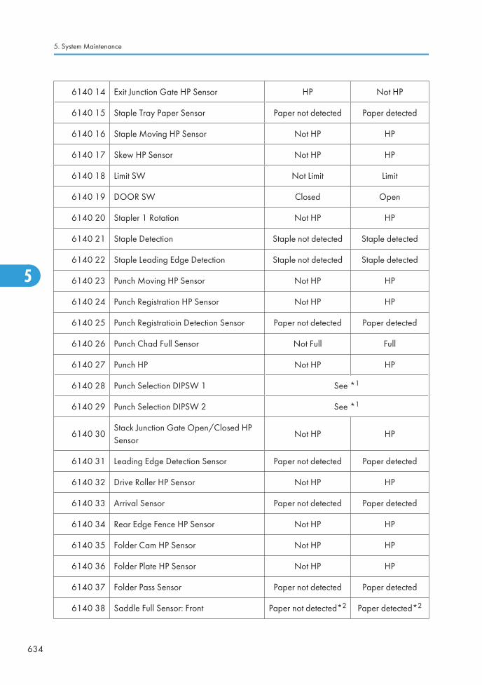
6140 14 Exit Junction Gate HP Sensor HP Not HP
6140 15 Staple Tray Paper Sensor Paper not detected Paper detected
6140 16 Staple Moving HP Sensor Not HP HP
6140 17 Skew HP Sensor Not HP HP
6140 18 Limit SW Not Limit Limit
6140 19 DOOR SW Closed Open
6140 20 Stapler 1 Rotation Not HP HP
6140 21 Staple Detection Staple not detected Staple detected
6140 22 Staple Leading Edge Detection Staple not detected Staple detected
6140 23 Punch Moving HP Sensor Not HP HP
6140 24 Punch Registration HP Sensor Not HP HP
6140 25 Punch Registratioin Detection Sensor Paper not detected Paper detected
6140 26 Punch Chad Full Sensor Not Full Full
6140 27 Punch HP Not HP HP
6140 28 Punch Selection DIPSW 1 See *1
6140 29 Punch Selection DIPSW 2 See *1
6140 30Stack Junction Gate Open/Closed HPSensor
Not HP HP
6140 31 Leading Edge Detection Sensor Paper not detected Paper detected
6140 32 Drive Roller HP Sensor Not HP HP
6140 33 Arrival Sensor Paper not detected Paper detected
6140 34 Rear Edge Fence HP Sensor Not HP HP
6140 35 Folder Cam HP Sensor Not HP HP
6140 36 Folder Plate HP Sensor Not HP HP
6140 37 Folder Pass Sensor Paper not detected Paper detected
6140 38 Saddle Full Sensor: Front Paper not detected*2 Paper detected*2
5. System Maintenance
634
5
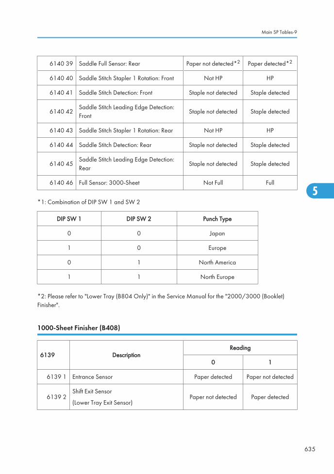
6140 39 Saddle Full Sensor: Rear Paper not detected*2 Paper detected*2
6140 40 Saddle Stitch Stapler 1 Rotation: Front Not HP HP
6140 41 Saddle Stitch Detection: Front Staple not detected Staple detected
6140 42Saddle Stitch Leading Edge Detection:Front
Staple not detected Staple detected
6140 43 Saddle Stitch Stapler 1 Rotation: Rear Not HP HP
6140 44 Saddle Stitch Detection: Rear Staple not detected Staple detected
6140 45Saddle Stitch Leading Edge Detection:Rear
Staple not detected Staple detected
6140 46 Full Sensor: 3000-Sheet Not Full Full
*1: Combination of DIP SW 1 and SW 2
DIP SW 1 DIP SW 2 Punch Type
0 0 Japan
1 0 Europe
0 1 North America
1 1 North Europe
*2: Please refer to "Lower Tray (B804 Only)" in the Service Manual for the "2000/3000 (Booklet)Finisher".
1000-Sheet Finisher (B408)
6139 DescriptionReading
0 1
6139 1 Entrance Sensor Paper detected Paper not detected
6139 2Shift Exit Sensor
(Lower Tray Exit Sensor)Paper not detected Paper detected
Main SP Tables-9
635
5

6139 3Staple Entrance Sensor
(Stapler Tray Entrance Sensor)Paper detected Paper not detected
6139 4Staple Moving HP Sensor
(Stapler HP Sensor)Not home position Home position
6139 5Jogger HP Sensor
(Jogger Fence HP Sensor)Not home position Home position
6139 6 Stack Feed-out Belt HP Sensor Home position Not home position
6139 7 Staple Tray Paper Sensor Paper not detected Paper detected
6139 8Staple Rotation Sensor
(Staple Rotation HP Sensor)Not home position Home position
6139 9 Staple Sensor Staple detected Staple not detected
6139 10 Staple READY Detection Staple detected Staple not detected
6139 11Exit Guide Plate HP
(Exit Guide Plate HP Sensor)Not home position Home position
6139 12 Shift HP Sensor Not home position Home position
6139 13Paper Sensor
(Stack Height Sensor)
Output tray notdetected
Output traydetected
6139 14Tray Lower Sensor
(Lower Tray Lower Limit Sensor)Lower limit Not lower limit
6139 15Proof Full Sensor
(Paper Limit Sensor)Not full Full
Bridge Unit (D386)/ Side Tray (D542)
6150 DescriptionReading
0 1
6150 1 Bridge/Left: Exit Sensor Paper detected Paper not detected
6150 2 Bridge/Left: Feed Sensor Paper detected Paper not detected
5. System Maintenance
636
5
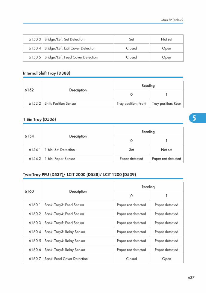
6150 3 Bridge/Left: Set Detection Set Not set
6150 4 Bridge/Left: Exit Cover Detection Closed Open
6150 5 Bridge/Left: Feed Cover Detection Closed Open
Internal Shift Tray (D388)
6152 DescriptionReading
0 1
6152 2 Shift: Position Sensor Tray position: Front Tray position: Rear
1 Bin Tray (D536)
6154 DescriptionReading
0 1
6154 1 1 bin: Set Detection Set Not set
6154 2 1 bin: Paper Sensor Paper detected Paper not detected
Two-Tray PFU (D537)/ LCIT 2000 (D538)/ LCIT 1200 (D539)
6160 DescriptionReading
0 1
6160 1 Bank: Tray3: Feed Sensor Paper not detected Paper detected
6160 2 Bank: Tray4: Feed Sensor Paper not detected Paper detected
6160 3 Bank: Tray5: Feed Sensor Paper not detected Paper detected
6160 4 Bank: Tray3: Relay Sensor Paper not detected Paper detected
6160 5 Bank: Tray4: Relay Sensor Paper not detected Paper detected
6160 6 Bank: Tray5: Relay Sensor Paper not detected Paper detected
6160 7 Bank: Feed Cover Detection Closed Open
Main SP Tables-9
637
5

6160 11 Bank: Palau: Paper Supply Switch Closed Open
6160 12 Bank: Palau: Slide Switch Closed Open
Output Check Table
Copier
5804 Display Description
5804 3 Drum/Dev Motor: K: HighSpeedDrum/Development Drive Motor-K: HighSpeed
5804 4 Drum/Dev Motor: K: MiddleSpeedDrum/Development Drive Motor-K:Middle Speed
5804 5 Drum/Dev Motor: K: LowSpeedDrum/Development Drive Motor-M: LowSpeed
5804 10 Drum/Dev Motor: M: HighSpeedDrum/Development Drive Motor- C: HighSpeed
5804 11 Drum/Dev Motor: M: MiddleSpeedDrum/Development Drive Motor-Y:Middle Speed
5804 12 Drum/Dev Motor: M: LowSpeedDrum/Development Drive Motor-Y: LowSpeed
5804 17 Drum/Dev Motor: C: HighSpeedDrum/Development Drive Motor- C: HighSpeed
5804 18 Drum/Dev Motor: C: MiddleSpeedDrum/Development Drive Motor-Y:Middle Speed
5804 19 Drum/Dev Motor: C: LowSpeedDrum/Development Drive Motor-Y: LowSpeed
5804 24 Drum/Dev Motor: Y: HighSpeedDrum/Development Drive Motor- C: HighSpeed
5804 25 Drum/Dev Motor: Y: MiddleSpeedDrum/Development Drive Motor-Y:Middle Speed
5. System Maintenance
638
5

5804 26 Drum/Dev Motor: Y: LowSpeedDrum/Development Drive Motor-Y: LowSpeed
5804 31 Fusing Exit Motor: HighSpeed Fusing/Paper Exit Motor: High Speed
5804 32 Fusing Exit Motor: MiddleSpeed Fusing/Paper Exit Motor: Middle Speed
5804 33 Fusing Exit Motor: LowSpeed Fusing/Paper Exit Motor: Low Speed
5804 35 Fusing Exit Motor: LLowSpeed Fusing/Paper Exit Motor: LLow Speed
5804 37 Toner Relay Motor Toner Transport Motor
5804 40 Image Transfer Motor: HighSpeed ITB Drive Motor: High Speed
5804 41 Image Transfer Motor: MiddleSpeed ITB Drive Motor: Middle Speed
5804 42 Image Transfer Motor: LowSpeed ITB Drive Motor: Low Speed
5804 50 Feed Motor: HighSpeed Paper Feed Motor: High Speed
5804 51 Feed Motor: IncreaseSpeed Paper Feed Motor: Increase Speed
5804 52 Feed Motor: MiddleSpeed Paper Feed Motor: Middle Speed
5804 53 Feed Motor: MiddleIncreaseSpeedPaper Feed Motor: Middle IncreaseSpeed
5804 54 Feed Motor: LowSpeed Paper Feed Motor: Low Speed
5804 55 Feed Motor: LowInceraseSpeed Paper Feed Motor: Low Incerase Speed
5804 60 Regist Motor: HighSpeed Registration Motor: High Speed
5804 61 Regist Motor: MiddleSpeed Registration Motor: Middle Speed
5804 62 Regist Motor: LowSpeed Registration Motor: Low Speed
5804 67 Duplex Feed M:CW:HighSpeed Duplex/By-pass Motor: CW: High Speed
5804 68 Duplex Feed M:CW:MiddleSpeedDuplex/By-pass Motor: CW: MiddleSpeed
5804 69 Duplex Feed Motor: CW: LowSpeed Duplex/By-pass Motor: CW: Low Speed
5804 74 Duplex Feed M:CCW:HighSpeedDuplex/By-pass Motor: CCW:
High Speed
Main SP Tables-9
639
5

5804 75 Duplex Feed M:CCW:MiddleSpeedDuplex/By-pass Motor: CCW:
Middle Speed
5804 76 Duplex Feed Motor: CCW: LowSpeedDuplex/By-pass Motor: CCW:
Low Speed
5804 81 Duplex Reverse M:CW:HighSpeed Duplex Inverter Motor: CW: High Speed
5804 82 Duplex Reverse M:CW:MiddleSpeedDuplex Inverter Motor: CW: MiddleSpeed
5804 83 Duplex Reverse Motor: CW: LowSpeed Duplex Inverter Motor: CW: Low Speed
5804 88 Duplex Reverse M:CCW:HighSpeedDuplex Inverter Motor: CCW:
High Speed
5804 89 Duplex Reverse M:CCW:MiddleSpeedDuplex Inverter Motor: CCW:
Middle Speed
5804 90 Duplex Reverse Motor: CCW: LowSpeedDuplex Inverter Motor: CCW:
Low Speed
5804 95 ITB Contact Motor Image Transfer Belt Contact Motor
5804 96 Paper Transfer Contact Motor Paper Transfer Contact Motor
5804 97 1st Tray Lift Motor: Up Tray Lift Motor 1: Lift Up
5804 98 1st Tray Lift Motor: Down Tray Lift Motor 1: Lift Down
5804 99 2nd Tray Lift Motor: Up Tray Lift Motor 2: Lift Up
5804 100 2nd Tray Lift Motor: Down Tray Lift Motor 2: Lift Down
5804 102 Fusing Pressue Release Motor Pressure Roller Contact Motor
5804 104 Polygon Moter: LL Polygon Motor: LL
5804 105 Polygon Moter: L Polygon Motor: L
5804 107 Polygon Moter: HH Polygon Motor: HH
5804 110 Air Flow Fan: Front Ventilation Fan - Front
5804 111 Air Flow Fan:Rear Ventilation Fan - Rear
5804 112 Fusing Fan:H Fusing Fan: High Speed
5. System Maintenance
640
5

5804 113 Fusing Fan:L Fusing Fan: Low Speed
5804 114 PSU Cooling Fan PSU Fan 1: High Speed
5804 115 2nd Duct Fan: H Duct Fan 2: High Speed
5804 117 3rd Duct Fan: H Duct Fan 3: High Speed
5804 119 Paper Exit Fan:H Paper Exit Fan: High Speed
5804 121 Fusing Coil Fan IH Coil Fan
5804 122 IH Power Supply Cooling Fan IH Inverter Fan
5804 126 Development Clutch: Bk Development Clutch-K
5804 127 Development Clutch: M Development Clutch-M
5804 128 Development Clutch: C Development Clutch-C
5804 129 Development Clutch: Y Development Clutch-Y
5804 130 Toner Bottle Clutch: Bk Toner Bottle Clutch-K
5804 131 Toner Bottle Clutch: M Toner Bottle Clutch-M
5804 132 Toner Bottle Clutch: C Toner Bottle Clutch-C
5804 133 Toner Bottle Clutch:Y Toner Bottle Clutch-Y
5804 134 Toner Supply Pump: Bk Toner Supply Clutch: Bk
5804 135 Toner Supply Pump: M Toner Supply Clutch: M
5804 136 Toner Supply Pump: C Toner Supply Clutch: C
5804 137 Toner Supply Pump: Y Toner Supply Clutch: Y
5804 138 1st Paper Feed Clutch Paper Feed Clutch 1
5804 139 2nd Paper Feed Clutch Paper Feed Clutch 2
5804 140 Bypass Feed Clutch By-pass Feed Clutch
5804 141 Bypass Pickup Solenoid Bypass Pickup Solenoid
5804 143 TD Sensor Shutter Solenoid ID Sensor Shutter Solenoid
5804 144 Exit Junction Solenoid Junction Gate 1 Solenoid
5804 145 1st Feed Pickup Solenoid 1st Pickup Solenoid
Main SP Tables-9
641
5

5804 146 2st Feed Pickup Solenoid 2nd Pickup Solenoid
5804 161 PCL: Bk
5804 162 PCL: M
5804 163 PCL: C
5804 164 PCL: Y
5804 166 HST Sensor:Bk TD Sensor:Bk
5804 167 HST Sensor: M TD Sensor: M
5804 168 HST Sensor: C TD Sensor: C
5804 169 HST Sensor: Y TD Sensor: Y
5804 170 Toner End Sensor: Bk Toner End Sensor: Bk
5804 171 Toner End Sensor: M Toner End Sensor: M
5804 172 Toner End Sensor: C Toner End Sensor: C
5804 173 Toner End Sensor: Y Toner End Sensor: Y
5804 174 TM Sensor: Front ID Sensor: Front
5804 175 TM Sensor: Center ID Sensor: Center
5804 176 TM Sensor: Rear ID Sensor: Rear
5804 177 TM Sensor: M ID Sensor: M
5804 178 TM Sensor: C ID Sensor: C
5804 179 TM Sensor: Y ID Sensor: Y
5804 181 PP:Charge AC:Y:HighSpeed -
5804 182 PP:Charge AC:Y:MiddleSpeed -
5804 183 PP:Charge AC:Y:LowSpeed -
5804 186 PP:Development:K -
5804 187 PP:Development:M -
5804 188 PP:Development:C -
5804 189 PP:Development:Y -
5. System Maintenance
642
5

5804 190 PP:Separation -
5804 192 RFID ON/OFF: K -
5804 193 RFID ON/OFF: Y -
5804 194 RFID ON/OFF: C -
5804 195 RFID ON/OFF: M -
5804 196 RFID COM ON:K -
5804 197 RFID COM ON: Y -
5804 198 RFID COM ON: C -
5804 199 RFID COM ON: M -
5804 202 Scanner Lamp -
5804 216 LD1: K -
5804 217 LD2: K -
5804 218 LD1: M -
5804 219 LD2: M -
5804 220 LD1: C -
5804 221 LD2: C -
5804 222 LD1: Y -
5804 223 LD2: Y -
5804 224 PP:ITB:K PP: Image Transfer Roller: K
5804 225 PP:ITB:M PP: Image Transfer Roller: M
5804 226 PP:ITB:C PP: Image Transfer Roller: C
5804 227 PP:ITB:Y PP: Image Transfer Roller: Y
5804 228 PP:PTR:+ PP: Paper Transfer Roller:+
5804 229 PP:PTR:- PP: Paper Transfer Roller:-
5804 231 HVPS: ChargeDC: K -
5804 232 HVPS: ChargeDC: M -
Main SP Tables-9
643
5

5804 233 HVPS: ChargeDC: C -
5804 234 HVPS: ChargeDC: Y -
5804 237 PP:Charge AC:K:HighSpeed -
5804 238 PP:Charge AC:K:MiddleSpeed -
5804 239 HVPS: ChargeAC: K: LowSpeed -
5804 244 PP:Charge AC:M:HighSpeed -
5804 245 PP:Charge AC:M:MiddleSpeed -
5804 246 HVPS: ChargeAC: M: LowSpeed -
5804 251 PP:Charge AC:C:HighSpeed -
5804 252 PP:Charge AC:C:MiddleSpeed -
5804 253 HVPS: ChargeAC: C: LowSpeed -
ARDF (D540)
6008 Display Description
6008 1 Pick-Up Motor Forward
6008 2 Pick-Up Motor Reverse
6008 3 Feed Motor Forward Feed Motor-Forward rotation
6008 4 Feed Motor Reverse Feed Motor-Reverse rotation
6008 5 Relay Motor Forward Transport Motor- Forward rotation
6008 7 Inverter Motor Reverse Transport Motor- Forward rotation
6008 8 Inverter Motor Reverse -
6008 11 Inverter Solenoid -
6008 12 Stamp Stamp Solenoid
6008 13 Fan Motor -
6008 14 Feed Clutch -
5. System Maintenance
644
5

6008 15 Feed Solenoid -
1000-Sheet Finisher (B408)
6144 Display Description
6144 1 Relay Up Motor Upper Transport Motor
6144 2 Relay Down Motor Lower Transport Motor
6144 3 Exit Motor -
6144 4 Proof Junction Gate SOL Tray Junction Gate Solenoid
6144 5 Tray Up Motor Lower Tray Lift Motor
6144 6 Jogger Motor Jogger Fence Motor
6144 7 Staple Moving Motor Stapler Motor
6144 8 Staple Motor Stapler Hammer
6144 9 Staple Junction Gate SOL Stapler Junction Gate Solenoid
6144 10 Positioning Roller Solenoid Positioning Roller Solenoid
6144 11 Stack Feed-out Motor -
6144 12 Shift Motor -
6144 13 Exit Guide Plate Motor -
2000/3000-Sheet (Booklet) Finisher (B804/B805)
6145 Display Description
6145 1 Entrance Motor Finisher Entrance Motor
6145 2 Upper Feed Motor Upper Transport Motor
6145 3 Lower Feed Motor Lower Transport Motor
6145 4 Exit Motor Upper/Proof Tray Exit Motor
6145 5 Knock Roller Motor Clamp Roller Retraction Motor
Main SP Tables-9
645
5

6145 6 Shift Motor Shift Roller Motor
6145 7 Exit Guide Plate Open/Close Motor Exit Guide Plate Motor
6145 8 Tray Lift Motor Upper Tray Lift Motor
6145 9 Oscillating Back Roller Motor Stacking Sponge Roller Motor
6145 10 Jogger Motor Jogger Fence Motor
6145 11 Stack Feed-out Motor Feed Out Belt Motor
6145 12 Staple Moving Motor Corner Stapler Movement Motor
6145 13 Staple Skew Motor Corner Stapler Rotation Motor
6145 14 Staple Motor Corner Stapler EH530
6145 15 Upper Junction Gate Solenoid Proof Junction Gate Solenoid
6145 16 Lower Junction Gate Solenoid Stapling Tray Junction Gate Solenoid
6145 17 Knock Solenoid Stapling Edge Pressure Plate Solenoid
6145 18 Trailing Edge Hold Solenoid Positioning Roller Solenoid
6145 19 Saddle Stitch Hold Solonoid Booklet Pressure Roller Solenoid
6145 20Stack Junction Gate Open/CloseMotor
Stack Junction Gate Motor
6145 21 Trailing Edge Fence Moving Motor Fold Unit Bottom Fence Lift Motor
6145 22 Saddle Stitch Staple Motor: Front Booklet Stapler EH185R: Front
6145 23 Saddle Stitch Staple Motor: Rear Booklet Stapler EH185R: Rear
6145 24 Folder Plate Motor Fold Plate Motor
6145 25 Folder Roller Motor Fold Roller Motor
6145 26 Drive Roller Oscillating Motor Positioning Roller Motor
6145 27 Punch Motor Punch Drive Motor
6145 28 Punch Moving Motor Punch Movement Motor
6145 29 Punch Registration Detection Motor Paper Position Sensor Slide Motor
5. System Maintenance
646
5

Bridge Unit (D386)/ Side Tray (D542)
6151 Display Description
6151 1Bridge/Left: Feed Motor: CurrentSelection
Bridge: Feed Motor: Current switching signal
6151 2 Bridge/Left: Feed Motor:Reset Bridge: Feed Motor:Reset
6151 3 Bridge/Left: Feed Motor:Enable Bridge: Feed Motor:Enable
6151 6 Bridge/Left: Feed Motor: High Speed Bridge: Feed Motor: High Speed
6151 7Bridge/Left: Feed Motor: MiddleSpeed
Bridge: Feed Motor: Middle Speed
6151 8 Bridge/Left: Feed Motor: Low Speed Bridge: Feed Motor: Low Speed
6151 11 Bridge/Left: Junction Solenoid Bridge: Junction Solenoid
Shift Tray (D388)
6153 Display Description
6153 1 Shift Tray: Motor -
1 Bin Tray (D536)
6155 Display Description
6155 1 1 bin: Junction Solenoid -
Two-Tray PFU (D537)/ LCIT 2000 (D538)/ LCIT 1200 (D539)
6161 Display Description
6161 5 Bank1: Feed Motor:300mm/sFeed Motor:High Speed
(D537/D538/D387)
6161 6 Bank1: Feed Motor:265mm/sFeed Motor: Increase Speed
(D537/D538/D387)
Main SP Tables-9
647
5

6161 8 Bank1: Feed Motor:230mm/sFeed Motor: Middle Speed
(D537/D538/D387)
6161 9 Bank1: Feed Motor:215mm/sFeed Motor: Low Speed
(D537/D538/D387)
6161 10 Bank1: Feed Motor:205mm/sFeed Motor:Low Increase Speed (D537/D538/D387)
6161 15 Bank2: Feed Motor:300mm/s Feed Motor:High Speed (D537)
6161 16 Bank2: Feed Motor:265mm/s Feed Motor: Increase Speed (D537)
6161 18 Bank2: Feed Motor:230mm/s Feed Motor: Middle Speed (D537)
6161 19 Bank2: Feed Motor:215mm/s Feed Motor: Low Speed (D537)
6161 20 Bank2: Feed Motor:205mm/s Feed Motor: Low Increase Speed (D537)
6161 30 Bank:Tray3: PU Solenoid Pick-up Solenoid (D537/ D538)
6161 31 Bank:Tray4: PU Solenoid Pick-up Solenoid (D537/ D539)
6161 32 Bank:Tray5: PU Solenoid Pick-up Solenoid (D539)
6161 35 Bank:Tray3: Feed Clutch Pick-up Solenoid (D537/ D538)
6161 36 Bank:Tray4: Feed Clutch Pick-up Solenoid (D537/ D539)
6161 37 Bank:Tray5: Feed Clutch Pick-up Solenoid (D539)
Printer Service Mode
SP1-XXX (Service Mode)
1001 Bit Switch
5. System Maintenance
648
5

001 Bit Switch 1 0 1
bit 0 DFU - -
bit 1 DFU - -
bit 2 DFU - -
bit 3 No I/O Timeout 0: Disable 1: Enable
Enable: The MFP I/O Timeout setting will have no effect. I/O Timeouts will never occur.
bit 4 SD Card Save Mode 0: Disable 1: Enable
Enable: Print jobs will be saved to an SD Card in the GW SD slot (* “Card SaveFunction” in "System Maintenance Reference" section of the Field Service Manual).
bit 5 DFU - -
bit 6 DFU - -
bit 7 [RPCS,PCL]: Printable area frame border 0: Disable 1: Enable
Enable: The machine prints all RPCS and PCL jobs with a border on the edges of theprintable area.
1001 Bit Switch
Main SP Tables-9
649
5

002 Bit Switch 2 0 1
bit 0 DFU - -
bit 1 DFU - -
bit 2 Applying a collation Type Shift Collate Normal Collate
A collation type (shift or normal) will be applied to all jobs that do not already have a‘Collate Type’ configured.
• If #5-0 is enabled, this Bit Switch has no effect.
bit 3 [PCL5e/c,PS]: PDL Auto Switching 0: Enable 1: Disable
Disable: The MFPs ability to change the PDL processor mid-job.
Some host systems submit jobs that contain both PS and PCL5e/c. If Auto PDL switchingis disabled, these jobs will not be printed properly.
bit 4 DFU - -
bit 5 DFU - -
bit 6 DFU - -
bit 7 DFU - -
1001 Bit Switch
5. System Maintenance
650
5

003 Bit Switch 3 0 1
bit 0 DFU - -
bit 1 DFU - -
bit 2 [PCL5e/c]: Legacy HP compatibility 0: Disable 1: Enable
Enable: Uses the same left margin as older HP models such as HP4000/HP8000.
In other words, the left margin defined in the job (usually "<ESC>*r0A") will be changedto "<ESC>*r1A"
bit 3 DFU - -
bit 4 DFU - -
bit 5 DFU - -
bit 6 DFU - -
bit 7 DFU - -
1001 Bit Switch
004 Bit Switch 4 DFU - -
1001 Bit Switch
Main SP Tables-9
651
5

005 Bit Switch 5 0 1
bit 0
Show "Collate Type", "Staple Type" and "PunchType" buttons on the operation panel.
Disable Enable
If enabled, users will be able to configure a Collate Type, Staple Type, and Punch Typefrom the operation panel. The available types will depend on the device and configuredoptions.
After enabling the function, the settings will appear under:
"User Tools > Printer Features > System"
bit 1 DFU - -
bit 2 DFU - -
bit 3 [PS] PS Criteria Pattern3 Pattern1
Change the number of PS criterion used by the PS interpreter to determine whether ajob is PS data or not.
Pattern3: includes most PS commands.
Pattern1: A small number of PS tags and headers
bit 4 Increase max number of the stored jobs to 1000jobs.
Disable(100)
Enable (1000)
Enable: Changes the maximum number of jobs that can be stored on the HDD via JobType settings to 1000. The default is 100.
bit 5 Face-up output Disable Enable
Enable: All print jobs will be output face-up in the destination tray.
bit 6 DFU - -
bit 7 DFU - -
1001 Bit Switch
006 Bit Switch 6 DFU - -
1001 Bit Switch
007 Bit Switch 7 DFU - -
5. System Maintenance
652
5

1001 Bit Switch
008 Bit Switch 8 0 1
bit 0 DFU - -
bit 1 DFU - -
bit 2 DFU - -
bit 3 [PCL,PS]: Allow BW jobs to print without requiringUser Code
Disable Enable
Enable: BW jobs submitted without a user code will be printed even if usercodeauthentication is enabled.
• Color jobs will not be printed without a valid user code.
bit 4 DFU - -
bit 5 DFU - -
bit 6 [PS]: Orientation Auto Detect Function Enable Disable
Disable: Automatically chooses page orientations of PostScript jobs (Landscape orPortrait) based on the content printed on the page.
bit 7 [PDF]: Orientation Auto Detect Function Enable Disable
Automatically chooses page orientations of PDF jobs (Landscape or Portrait) based onthe content printed on the page.
1003 [Clear Setting]
1003 1Initialize Printer System
Initializes settings in the “System” menu of the user mode.
1003 3 Delete Program
1004 [Print Summary]
1004 1Print Summary
Prints the service summary sheet (a summary of all the controller settings).
Main SP Tables-9
653
5

1005 [Display Version]
1005 1Disp. Version
Displays the version of the controller firmware.
1006 [Sample/Locked Print] *CTL 0: Linked, 1: On
1006 1Enables and disables the document server. When you select “0,” the document server isenabled or disabled in accordance with Copy Service Mode SP5-967. When you select“1,” the document server is enabled regardless of Copy Service Mode SP5-967.
1101
[Data Recall]
Recalls a set of gamma settings. This can be either a) the factory setting, b) the previoussetting, or c) the current setting.
1101 1 Factory
*CTL1101 2 Previous
1101 3 Current
1101 4 ACC
1102[Resolution Setting]
Selects the printing mode (resolution) for the printer gamma adjustment.
1102 12400x600 Photo, 1800x600 Photo, 600 x 600 Photo, 2400x600 Text, 1800x600, Text,600x600 Text
1103[Test Page]
Prints the test page to check the color balance before and after the gamma adjustment.
1103 1 Color Gray Scale
1103 2 Color Pattern
1104[Gamma Adjustment]
Adjusts the printer gamma for the mode selected in the “Mode Selection” menu.
5. System Maintenance
654
5

1104 1 Black: Highlight
*CTL [0 to 30 / 15 / 1/step ]
1104 2 Black: Shadow
1104 3 Black: Middle
1104 4 Black: IDmax
1104 21 Cyan: Highlight
1104 22 Cyan: Shadow
1104 23 Cyan: Middle
1104 24 Cyan: IDmax
1104 41 Magenta: Highlight
1104 42 Magenta: Shadow
1104 43 Magenta: Middle
1104 44 Magenta: IDmax
1104 61 Yellow: Highlight
1104 62 Yellow: Shadow
1104 63 Yellow: Middle
1104 64 Yellow: IDmax
1105
[Save Tone Control Value]
Stores the print gamma adjusted with the “Gamma Adj.” menu item as the current setting.Before the machine stores the new “current setting", it moves the data currently stored as the“current setting” to the “previous setting” memory storage location.
1105 1 Save Tone Control Value
1106[Toner Limit]
Adjusts the maximum toner amount for image development.
1106 1 Toner Limit Value *CTL [100 to 400 / 260 / 1 %/step ]
Main SP Tables-9
655
5

Scanner SP Mode
SP1-xxx (System and Others)
1004[Compression Type]
Selects the compression type for binary picture processing.
1004 1 Compression Type *CTL[1 to 3 / 1 / 1/step ]
1: MH, 2: MR, 3: MMR
1005
[Erase margin]
Creates an erase margin for all edges of the scanned image.
If the machine has scanned the edge of the original, create a margin. This SP is activatedonly when the machine uses TWAIN scanning.
1005 1 Range from 0 to 5 mm *CTL [0 to 5 / 0 / 1 mm/step ]
1009 [Remote scan disable] *CTL[0 or 1 / 0 / - ]
0: enable, 1: disable
1009 1 Enable or disable remote scan.
1010 [Non Display Clear Light PDF] *CTL[0 or 1 / 0 / - ]
0: Display, 1: No display
1010 1 Enable or disable remote scan.
SP2-XXX (Scanning-image quality)
2021
[Compression Level (Gray-scale)]
Selects the compression ratio for grayscale processing mode (JPEG) for the three settings thatcan be selected at the operation panel.
5. System Maintenance
656
5

2021 1 Level 3 (Middle Image Quality)
*CTL
[5 to 95 / 40 / 1 /step ]
2021 2 Level 2 (High Image Quality) [5 to 95 / 50 / 1 /step ]
2021 3 Level 4 (Low Image Quality) [5 to 95 / 30 / 1 /step ]
2021 4 Level 1 (Highest Image Quality) [5 to 95 / 60 / 1 /step ]
2021 5 Level 5 (Lowest Image Quality) [5 to 95 / 20 / 1 /step ]
2024
[Compression ratio of ClearLight PDF]
Selects the compression ratio for clearlight PDF for the two settings that can be selected atthe operation panel.
2024 1 Compression Ratio (Normal image)*CTL
[5 to 95 / 25 / 1 /step ]
2024 2 Compression Ratio (High comp image) [5 to 95 / 20 / 1 /step ]
Main SP Tables-9
657
5

Firmware UpdateTo update the firmware for this machine, you must have the new version of the firmware downloaded ontoan SD (Secure Digital) Card. The SD Card is inserted into SD Card Slot 2 on the left rear side of the controllerbox.
Type of Firmware
There are several types of firmware as shown below.
Type of firmware Function Location of firmware Message shown
Engine Printer engine control BICU Flash ROM Engine
System/CopyApplication
Operating systemFlash ROM on thecontroller board
System/Copy
Lcdc Panel control LCDC Lcdc
ADF ADF controlADF Main ControlBoard
ADF
NetworkSupport Controller Board NetworkSupport
Language 1 LCDC Language1
Language 2 LCDC Language2
RPCS Controller Board RPCS
MediaPrint:JPEG/TIFF Controller BoardMediaPrint:JPEG/TIFF
FONT Controller Board FONT
FONT1 Controller Board FONT1
NetworkDocBox Controller Board NetworkDocBox
Printer Controller Board Printer
Scanner Controller Board Scanner
Websupport Controller Board Websupport
WebUapl Controller Board WebUapl
5. System Maintenance
658
5

Before You Begin
An SD card is a precision device. Always observe the following precautions when you handle SD cards:
• Always switch the machine off before you insert an SD card. Never insert the SD card into the slotwith the power on.
• Do not remove the SD card from the service slot after the power has been switched on.
• Never switch the machine off while the firmware is downloading from the SD card.
• Keep SD cards in a safe location where they are not exposed to high temperature, high humidity, orexposure to direct sunlight.
• Always handle SD cards with care. Do not bend or scratch them. Do not let the SD card get exposedto shock or vibration.
• Make sure that the write protection of an SD card is unlocked when you download an application toit. If not, downloading fails and a download error (e.g. Error Code 44) occurs during a firmwareupgrade.
Keep the following points in mind when you use the firmware update software:
• "Upload" means to send data from the machine to the SD card. "Download" means to send data fromthe SD card to the machine.
• To select an item on the LCD, touch the appropriate button on the soft touch-screen of the LCD, or,press the appropriate number key on the 10-key pad of the operation panel. For example, when "Exit(0)" shows on the screen you can touch the Exit button on the screen, or, press the "0" button on theoperation panel of the copier.
• Make sure that the machine is disconnected from the network to prevent a print job for arriving whilethe firmware update is in progress before you start the firmware update procedure.
Updating Firmware
Preparation
• If the SD card is blank, copy the entire "romdata" folder onto the SD card.
• If the card already contains the "romdata" folder, copy the "D086" folder onto the card.
If the card already contains folders up to "D086", copy the necessary firmware files (e.g. D086xxxx.fwu)into this folder.
• Do not put multiple machine firmware programs on the same SD card. Copy the only model firmwareyou want.
Firmware Update
659
5

Updating Procedure
1. Turn the main power switch off.
2. Remove the slot cover ( x 1).
3. Insert the SD card into SD Card Slot 2. Make sure the label on the SD card faces the front side of themachine.
4. Slowly push the SD card into the slot so it locks in place. You will hear it click. Make sure the SD cardlocks in place.
• To remove the SD, push it in to unlock the spring lock. Then release it so it pops out of the slot.
5. Disconnect the network cable from the copier if the machine is connected to a network.
6. Switch the main power switch on. After about 45 seconds, the initial version update screen appearson the LCD in English.
7. On the screen, touch the button or press the corresponding number key on the operation panel toselect the item in the menu that you want to update.
ROM/NEW What it means
ROM:Tells you the number of the module and name of the version currently installed.The first line is the module number, the second line the version name.
NEW:Tells you the number of the module and name version on the SD card. The firstline is the module number, the second line the version name.
• Controller, engine and operation panel firmware cannot be updated at the same time. It isrecommended to update firmware modules one by one.
8. Touch "UpDate (#)" (or ) to start the update.
• The progress bar does not show for the operation panel firmware after you touch "OpPanel".The power on key flashes on and off at 0.5 s intervals when the LCDC firmware is updating. Thepower key flashes on and off at 3 s intervals when the update is finished.
9. The "Update is Done" message appears on the operation panel after completing the updating. Themessage differs depending on the firmware that has been updated.
10. Switch the copier main power switch off when you see the "Update is Done" message or follow theprocedure that is displayed on the operation panel.
11. Press in the SD card to release it. Then remove it from the slot.
12. Switch the copier on for normal operation.
5. System Maintenance
660
5

Error Messages
An error message shows in the first line if an error occurs during the download.
The error code consists of the letter "E" and a number. The example above shows error "E24" displayed.For details, refer to the Error Message Table. ( "Handling Firmware Update Error")
Firmware Update Error
If a firmware update error occurs, this means the update was cancelled during the update because themodule selected for update was not on the SD card.
Recovery after Power Loss
If the ROM update is interrupted as a result of accidental loss of power while the firmware is updating,then the correct operation of the machine cannot be guaranteed after the machine is switched on again.If the ROM update does not complete successfully for any reason, then in order to ensure the correctoperation of the machine, the ROM update error will continue to show until the ROM is updated successfully.
In this case, insert the card again and switch on the machine to continue the firmware downloadautomatically from the card without the menu display.
Updating the LCDC for the Operation Panel
Do the following procedure to update the LCDC (LCD Control Board).
1. Turn the copier main switch off.
2. Remove the SD slot cover ( x 1).
3. Insert the SD card into SD Card Slot 2.
Firmware Update
661
5

4. Switch the copier main switch on.
5. The initial screen opens in English after about 45 seconds.
6. Touch "Ope Panel.xx".
7. "xx" differs depending on the destination.
8. Touch "UpDate(#) or ( ) to start the update.
9. Downloading starts after about 9 seconds.
10. The operation panel goes off and the main power on key flashes in red at 0.5 s intervals when thedata is downloading. The same key starts flashing in green at 1 s intervals when the update is finished.
11. Switch the copier main power switch off and remove the SD card. Then switch the copier on.
Update Procedure for App2Me Provider
Follow this procedure to update App 2 Me if a new version is available.
1. Push the [User/Tools] key on the operation panel.
2. If an administrator setting is registered for the machine, Step 3 and Step 4 are required. Otherwise,skip to step 5.
3. Push [Login/Logout] on the operation panel.
4. Login with the administrator user name and password.
5. Touch "Extended Feature Settings" twice on the LCD.
6. Touch each of the applications until the status changes to "Stop".
7. Turn the machine off, and then remove the VM Card.
5. System Maintenance
662
5

8. Prepare the newer App2Me Provider zip file from the Firmware Download Center, and then unzipthe zip file. (The folder name is "337051920".)
9. Copy the App2Me Provider folder into the specified path for the VM card. The path is:
"SD_Card Drive\ sdk\dsdk\dist\337051920"
10. Turn the SD card label face to the front of the machine, and then push it slowly into Slot 2 (lower slot)until you hear a click.
11. Turn the main power switch on.
12. Press [User Tools] on the operation panel.
13. Touch the "Extended Feature Settings" button twice.
14. Touch the "Extended Feature Info" tab on the LCD.
15. Touch the "App2Me" line.
16. Set the setting of the "Auto Start" to "On".
17. Touch the "Exit" button.
18. Exit the [User Tools/Counter] settings.
• App2Me and all other running applications on the VM card must be shut down before removing theVM card in order to update the firmware, back up NVRAM, install the browser unit, or executeapplication move or undo with SP5873.
• After the VM card is re-inserted, App2Me (and any other VM card applications used by the customer)must be switched on after the machine is switched on.
Firmware Update
663
5

Browser Unit Update Procedure
1. Remove the slot cover [A] for SD cards ( x 1).
1. Remove the VM card [B] from slot 2.
2. Turn the SD-card label face of the browser unit to the front of the machine. Then push it slowly intoslot 2 [C] until you hear a click.
3. Plug in and turn on the main power switch.
4. Push the "User Tools" key.
• If an administrator setting is registered for the machine, step 5 and 6 are required. Otherwise,skip to the step 7
5. Push the "Login/ Logout" key.
6. Login with the administrator user name and password.
7. Touch "Extended Feature Settings" twice on the LCD.
8. Touch "Uninstall" on the LCD.
9. Touch the "Browser" line
10. Confirmation message appears on the LCD.
11. Touch "Yes" to proceed.
12. Reconfirmation message appears on the LCD.
13. Touch "Yes" to uninstall the browser unit.
5. System Maintenance
664
5

14. You will see "Uninstalling the extended feature... Please wait.", and then "Completed".
15. Touch "Exit" to go back to the setting screen.
16. Exit "User/Tools" setting, and then turn off the main power switch.
17. Remove the SD card of the browser unit from SD card slot 2.
18. Overwrite the updated program in the "sdk" folder of the browser unit application with PC.
19. Do the "Installation Procedure" to install the browser unit.
Handling Firmware Update Errors
An error message shows in the first line if an error occurs during a download. The error code consists ofthe letter "E" and a number ("E20", for example).
Error Message Table
Code Meaning Solution
20 Cannot map logical address Make sure the SD card is inserted correctly.
21 Cannot access memory HDD connection incorrect or replace hard disks.
22Cannot decompress compresseddata
Incorrect ROM data on the SD card, or data is corrupted.
23Error occurred when ROM updateprogram started
Controller program abnormal. If the second attempt fails,replace controller board.
24 SD card access errorMake sure SD card inserted correctly, or use another SDcard.
30No HDD available for stamp datadownload
HDD connection incorrect or replace hard disks.
31Data incorrect for continuousdownload
Insert the SD card with the remaining data required forthe download, the re-start the procedure.
32Data incorrect after downloadinterrupted
Execute the recovery procedure for the intended moduledownload, then repeat the installation procedure.
33 Incorrect SD card version Incorrect ROM data on the SD card, or data is corrupted.
34Module mismatch - Correctmodule is not on the SD card)
SD update data is incorrect. Acquire the correct data(Japan, Overseas, OEM, etc.) then install again.
Firmware Update
665
5

35Module mismatch – Module onSD card is not for this machine
SD update data is incorrect. The data on the SD card isfor another machine. Acquire correct update data theninstall again.
36Cannot write module – Causeother than E34, E35
SD update data is incorrect. The data on the SD card isfor another machine. Acquire correct update data theninstall again.
40 Engine module download failedReplace the update data for the module on the SD cardand try again, or replace the BICU board.
42Operation panel moduledownload failed
Replace the update data for the module on the SD cardand try again, or replace the LCDC.
43Stamp data module downloadfailed
Replace the update data for the module on the SD cardand try again, or replace the hard disks.
44Controller module downloadfailed
Replace the update data for the module on the SD cardand tray again, or replace controller board.
50Electronic confirmation checkfailed
SD update data is incorrect. The data on the SD card isfor another machine. Acquire correct update data theninstall again.
5. System Maintenance
666
5

Installing Another LanguageMany languages are available. But you can only switch between two languages at a time. Do the followingprocedure to select the two languages you want. You can select both of the languages you want from theuser interface on the operation panel.
1. Switch the copier main power switch off.
2. Remove the SD slot cover ( x 1).
3. Insert the SD card with the language data into SD Card Slot 2.
4. Switch the copier main power switch on. The initial screen opens after about 45 seconds.
5. Touch "Language Data (2)" on the screen (or press the "2" key).
6. Touch "LANG. 1(1)" or "LANG. 2(2)"
Key What it does
LANG. 1(1)Touch this button on the screen (or press the "1" key on the 10-key pad) toopen the next screen so you can select the 1st language.
LANG. 1(2)Touch this button on the screen (or press the "2" key on the 10-key pad) toopen the next screen so you can select the 2nd language.
Exit (0)Touch this key on the screen (or press the "0" key on the 10-key pad) toquit the update procedure and return to normal screen.
7. Touch "LANG 1(1)" to select the 1st Language. Touch "LANG (2)" to select the 2nd Language.
Installing Another Language
667
5

8. Touch the appropriate button on the screen (or press the number on the 10-keypad) to select alanguage as the 1st (or 2nd) language.
• If a language is already selected, it will show in reverse.
• Touching "Exit (0)" returns you to the previous screen.
9. If you do not see the language that you want to select, touch " (7)" or " (9)" on the screen (or pressthe "7" or "9" key) to show more choices.
The Download Screen opens after you select a language.
The 1st or 2nd language selected for updating shows.
The following show to right of the selection:
• 1. The first column shows the language currently selected.
• 2. The 2nd column shows the language selected to replace that language.
The example below shows that the download will replace "Japanese" with "Italian" as the 1stlanguage.
5. System Maintenance
668
5

10. Touch "Update(#)" on the screen (or press ) to start the download.
Another screen with a progress bar does not show when the language is downloading.
The following occur at the time the language is downloading:
• The operation panel switches off.
• The LED on the power on key flashes rapidly.
11. After the message of installation completed has shown on the LCD, switch the copier main powerswitch off. Then remove the SD card from the slot.
12. Switch the copier main power switch on to resume normal operation.
Installing Another Language
669
5

Reboot/System Setting Reset
Software Reset
You can reboot the software with one of the following two procedures:
1. Turn the main power switch off and on.
2. Press and hold down and together for over 10 seconds. When the machine beeps once, releaseboth buttons. After “Now loading. Please wait” shows for a few seconds, the copy window will open.The machine is ready for normal operation.
System Settings and Copy Setting Reset
System Setting Reset
The system settings in the UP mode can be reset to their defaults. Use the following procedure.
1. Press User Tools/Counter .
2. Hold down and then press System Settings.
• You must press first.
3. Press yes when the message prompts you to confirm that you want to reset the system settings.
4. Press exit when the message tells you that the settings have been reset.
Copier Setting Reset
Use the following procedure to reset the copy settings in the UP mode to their defaults.
1. Press User Tools/Counter .
2. Hold down and then press Copier/Document Server Settings.
5. System Maintenance
670
5

• You must press first.
3. Press “Yes” when the message prompts you to confirm that you want to reset the Copier DocumentServer settings.
4. Press exit when the message tells you that the settings have been reset.
Reboot/System Setting Reset
671
5

Downloading Stamp DataThe stamp data should be downloaded from the controller firmware to the hard disks at the following times:
• After the hard disks have been replaced.
The print data contains the controller software. Execute SP 5853 to download the fixed stamp data requiredby the hard disks.
1. Enter the SP mode.
2. Select SP5853 and then press "EXECUTE". The following screen opens while the stamp data isdownloading.
The download is finished when the message prompts you to close.
3. Press the "Exit" button. Then turn the copier off and on again.
5. System Maintenance
672
5

NVRAM Data Upload/Download
Uploading Content of NVRAM to an SD card
Do the following procedure to upload SP code settings from NVRAM to an SD card.
• This data should always be uploaded to an SD card before the NVRAM is replaced.
• Make sure that the write protection of an SD card is unlocked
1. Do SP5990-001 (SMC Print) before you switch the machine off. You will need a record of the NVRAMsettings if the upload fails.
2. Switch the copier main power switch off.
3. Remove the SD slot cover ( x 1).
4. Insert the SD card into SD card slot 2. Then switch the copier on.
5. Execute SP5824-001 (NVRAM Data Upload) and then press the “Execute” key.
6. The following files are coped to an NVRAM folder on the SD card when the upload procedure isfinished. The file is saved to the path and the following filename:
NVRAM\<serial number>.NV
Here is an example with Serial Number “K5000017114”:
NVRAM\K5000017114.NV
7. In order to prevent an error during the download, be sure to mark the SD card that holds the uploadeddata with the number of the machine from which the data was uploaded.
• You can upload NVRAM data from more than one machine to the same SD card.
Downloading an SD Card to NVRAM
Do the following procedure to download SP data from an SD card to the NVRAM in the machine.
• The NVRAM data down load may fail if the SD card with the NVRAM data is damaged, or if theconnection between the controller and BICU is defective.
• Do the download procedure again if the download fails.
• Do the following procedure if the second attempt fails:
Enter the NVRAM data manually using the SMC print you created before uploading the NVRAMdata.
1. Switch the copier main power switch off.
NVRAM Data Upload/Download
673
5

2. Remove the SD slot cover ( x 1).
3. Insert the SD card with the NVRAM data into SD Card Slot 2.
4. Switch the copier main power switch on.
5. Do SP5825-001 (NVRAM Data Download) and press the “Execute” key.
• The serial number of the file on the SD card must match the serial number of the machine for theNVRAM data to download successfully. The download fails if the serial numbers do not match.
This procedure does not download the following data to the NVRAM:
• Total Count
• C/O, P/O Count
5. System Maintenance
674
5

Address Book Upload/Download
Information List
The following information is possible to be uploaded and downloaded.
Information
• Registration No.
• User Code
• Protection Code
• Fax Destination
• Fax Option
• Group Name
• Key Display
• Select Title
• Folder
• Local Authentication
• Folder Authentication
• Account ACL
• New Document Initial ACL
• LDAP Authentication
Download
1. Prepare a formatted SD card.
2. Make sure that the write-protection on the SD card is off.
3. Turn off the main power switch of the main machine.
4. Remove the SD slot cover at the left rear side of the machine ( x 1).
5. Install the SD card into the SD card slot 2 (for service use).
6. Turn on the main power switch.
7. Enter the SP mode.
8. Do SP5-846-051 (Backup All Addr Book).
9. Exit the SP mode, and then turn off the main power switch.
10. Remove the SD card form the SD card slot 2.
11. Install the SD slot cover.
• If the capacity of SD card is not enough to store the local user information, an error message isdisplayed.
• Carefully handle the SD card, which contains user information. Do not take it back to yourlocation.
Address Book Upload/Download
675
5

Upload
1. Turn off the main power switch of the main machine.
2. Remove the SD slot cover at the left rear side of the machine ( x 1).
3. Install the SD card, which has already been uploaded, into the SD card slot 2.
4. Turn on the main power switch.
5. Enter the SP mode.
6. Do SP5-846-052 (Restore All Addr Book).
7. Exit the SP mode, and then turn off the main power switch.
8. Remove the SD card form the SD card slot 2.
9. Install the SD slot cover.
• The counter in the user code information is initialized after uploading.
• The information of an administrator and supervisor cannot be downloaded nor uploaded.
• If there is no data of address book information in the SD card, an error message is displayed.
5. System Maintenance
676
5

Using the Debug Log
Overview
This machine provides a Save Debug Log feature that allows the Customer Engineer to save and retrieveerror information for analysis.
Every time an error occurs, debug information is recorded in volatile memory. But this information is lostwhen the machine is switched off and on.
To capture this debug information, the Save Debug Log feature provides two main features:
• Switching on the debug feature so error information is saved directly to the HDD for later retrieval.
• Copying the error information from the HDD to an SD card.
Do the following procedure below to set up the machine so the error information is saved automatically tothe HDD when a user has problems with the machine. Then ask the user to reproduce the problem.
Switching ON and Setting UP Save Debug Log
The debug information cannot be saved until the “Save Debug Log” function has been switched on and atarget has been selected.
1. Enter the SP mode and switch the Save Debug Log feature on.
• Enter the SP mode.
• Touch “System SP”.
• On the LCD panel, open SP5857.
2. Under “5857 Save Debug Log”, touch “1 On/Off”.
3. On the control panel keypad, press “1”. Then press . This switches the Save Debug Log feature on.
Using the Debug Log
677
5

• The default setting is “0” (OFF). This feature must be switched on in order for the debuginformation to be saved.
4. Select the target destination where the debug information will be saved. Under “5857 Save DebugLog”, touch “2 Target”, enter “2” with the operation panel key to select the hard disk as the targetdestination. Then press .
• Select “3 SD Card” to save the debug information directly to the SD card if it is inserted in theservice slot.
5. Now touch “5858” and specify the events that you want to record in the debug log. SP5858 (DebugSave When) provides the following items for selection.
1 Engine SC ErrorSaves data when an engine-related SC code isgenerated.
2 Controller SC ErrorSaves debug data when a controller-related SC Codeis generated.
3 Any SC ErrorSaves data only for the SC code that you specify byentering code number.
4 Jam Saves data for jams.
• More than one event can be selected.
Example 1: To Select Items 1, 2, 4
Touch the appropriate items(s). Press “ON” for each selection. This example shows “Engine SC Error”selected.
5. System Maintenance
678
5
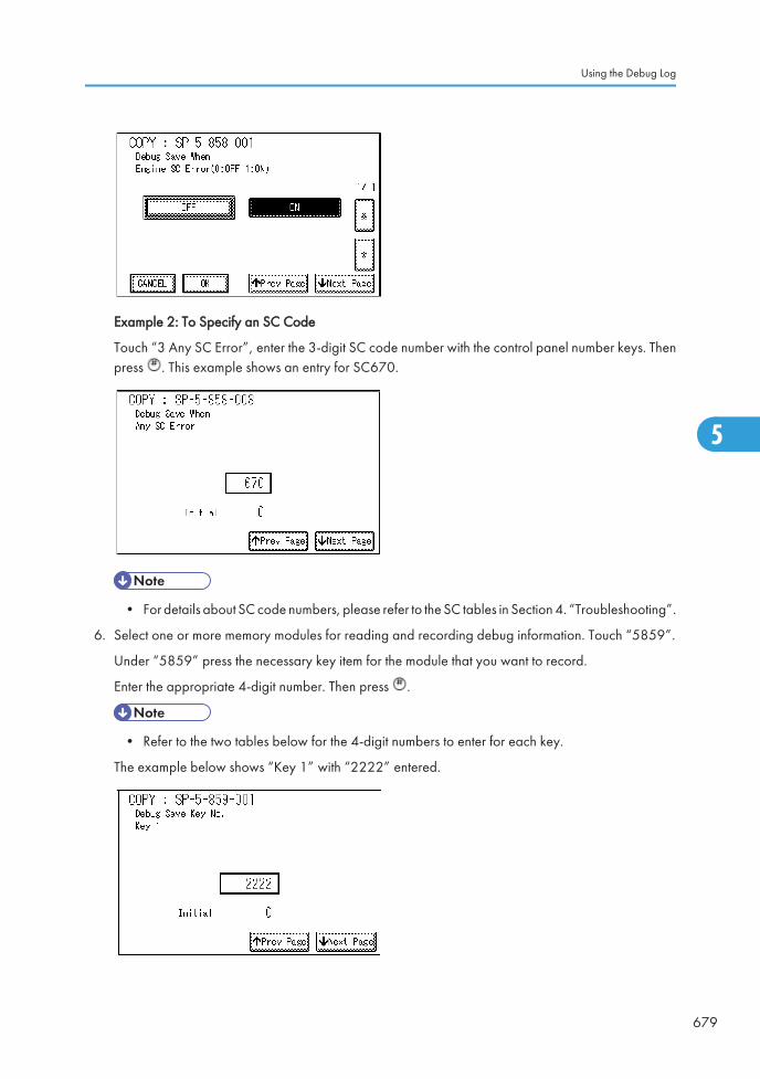
Example 2: To Specify an SC Code
Touch “3 Any SC Error”, enter the 3-digit SC code number with the control panel number keys. Thenpress . This example shows an entry for SC670.
• For details about SC code numbers, please refer to the SC tables in Section 4. “Troubleshooting”.
6. Select one or more memory modules for reading and recording debug information. Touch “5859”.
Under “5859” press the necessary key item for the module that you want to record.
Enter the appropriate 4-digit number. Then press .
• Refer to the two tables below for the 4-digit numbers to enter for each key.
The example below shows “Key 1” with “2222” entered.
Using the Debug Log
679
5

The following keys can be set with the corresponding numbers. (The initials in parentheses indicatethe names of the modules.)
4-Digit Entries for Keys 1 to 10
Key No. Copy Printer Scanner Web
1 2222 (SCS)
2 14000 (SRM)
3 256 (IMH)
4 1000 (ECS)
5 1025 (MCS)
6 4848 (COPY) 4400 (GPS) 5375 (Scan) 5682 (NFA)
7 2224 (BICU) 4500 (PDL) 5682 (NFA) 6600 (WebDB)
8 4600 (GPS-PM) 3000 (UCS) 3300 (PTS)
9 2000 (NCS) 2000 (NCS) 6666 (WebSys)
10 2224 (BICU) 4126 (DCS) 2000 (NCS)
• The default settings for Keys 1 to 10 are all zero (“0”).
Key to Acronyms
Acronym Meaning Acronym Meaning
ECS Engine Control Service NFA Net File Application
GPS GW Print Service PDL Printer Design Language
GSP-PM GW Print Service – Print Module PTS Print Server
IMH Image Memory Handler SCS System Control Service
MCS Memory Control Service SRMSystem ResourceManagement
NCS Network Control Service WebDBWeb Document Box(Document Server)
5. System Maintenance
680
5

7. The machine is now set to record the debugging information automatically on the HDD (the targetselected with SP5857-002) for the events that you selected with SP5858 and the memory modulesselected with SP5859.
Please keep the following important points in mind when you do this setting:
• Note that the number entries for Keys 1 to 5 are the same for the Copy, Printer, Scanner, and Webmemory modules.
• The initial settings are all zero.
• These settings remain in effect until you change them. Be sure to check all the settings, especially thesettings for Keys 6 to 10. To switch off a key setting, enter a zero for that key.
• You can select any number of keys from 1 to 10 (or all) by entering the corresponding 4-digit numbersfrom the table.
• You cannot mix settings for the groups (COPY, PRINTER, etc.) for 006 to 010. For example, if youwant to create a PRINTER debug log you must select the settings from the 9 available selections forthe “PRINTER” column only.
• One area of the disk is reserved to store the debug log. The size of this area is limited to 4 MB.
Retrieving the Debug Log from the HDD
Retrieve the debug log by copying it from the hard disk to an SD card.
1. Insert the SD card into slot 2 (service slot) of the copier.
2. Enter the SP mode and execute SP5857-009 (Copy HDD to SD Card (Latest 4 MB)) to write thedebugging data to the SD card.
3. Use a card reader to copy the file and send it for analysis to your local Ricoh representative by email.You can also send the SD card by regular mail if you want.
Recording Errors Manually
SC errors and jams only are recorded to the debug log automatically. Please instruct the user to do thefollowing immediately after occurrence to save the debug data for any other errors that occur while thecustomer engineer is not on site. Such problems also include a controller or panel freeze.
• You must previously switch on the Save Debug Feature (SP5857-001) and select the hard disk asthe save destination (SP5857-002) if you want to use this feature.
1. Press (Clear Modes).on the operation panel when the error occurs.
2. On the control panel, enter “01”. Then hold down for at least 3 seconds until the machine beepsand then release it. This saves the debug log to the hard disk for later retrieval with an SD card by theservice representatives.
Using the Debug Log
681
5

3. Switch the machine off and on to resume operation.
The debug information for the error is saved on the hard disk. This lets the service representative retrieveit on their next visit by copying it from the HDD to an SD card.
Debug Log Codes
SP5857-015 Copy SD Card-to-SD Card: Any Desired Key
This SP copies the log on an SD card (the file that contains the information written directly from sharedmemory) to a log specified by key number. The copy operation is executed in the log directory of the SDcard inserted in the same slot. (This function does not copy from one slot to another.) Each SD card canhold up to 4 MB of file data. Unique file names are created for the data during the copy operation toprevent overwriting files of the same name. This means that log data from more than one machine can becopied onto the same SD card. This command does not execute if there is no log on the HDD for the nameof the specified key.
SP5857-016 Create a File on HDD to Store a Log
This SP creates a 32 MB file to store a log on the HDD. However, this is not a completely empty file. Thecreated file will hold the number “2225” as the SCS key number and other non-volatile information. Evenif this SP is not executed, a file is created on the HDD when the first log is stored on the HDD (it takes sometime to complete this operation). This creates the possibility that the machine may be switched off and onbefore the log can be created completely. If you execute this SP to create the log file beforehand, this willgreatly reduce the amount of time required to acquire the log information and save onto the HDD. Withthe file already created on the HDD for the log file, the data only needs to be recorded. A new log filedoes not need to be created. To create a new log file, do SP5857-011 to delete the debug log data fromthe HDD. Then do SP5857-016.
SP5857-017 Create a File on SD Card to Store a Log
This SP creates a 4 MB file to store a log on an SD card. However, this is not a completely empty file. Thecreated file will hold the number “2225” as the SCS key number and other non-volatile information. Evenif this SP is not executed, a file is created on the SD card when the first log is stored on the SD card (it takessome time to complete this operation). This creates the possibility that the machine may be switched off andon before the log can be created completely. If you execute this SP to create the log file beforehand, thiswill greatly reduce the amount of time required to acquire the log information and save onto the SD card.With the file already created on the SD card for the log file, the data only needs to be recorded; a newlog file does not require creation. To create a new log file, do SP5857-012 to delete the debug log datafrom the SD card. Then do SP5857-017.
5. System Maintenance
682
5

Card Save Function
Overview
Card Save:
• The Card Save function is used to save print jobs received by the printer on an SD card with no printoutput. Card Save mode is toggled using printer Bit Switch #1 bit number 4. Card Save will remainenabled until the SD card becomes full, or until all file names have been used.
• Captures are stored on the SD card in the folder /prt/cardsave. File names are assigned sequentiallyfrom PRT00000.prn to PRT99999.prn. An additional file PRT.CTL will be created. This file contains alist of all files created on the card by the card save function.
• Previously stored files on the SD card can be overwritten or left intact. Card Save SD has “Add” and“New” menu items.
• Card Save (Add): Appends files to the SD Card. Does not overwrite existing files. If the cardbecomes full or if all file names are used, an error will be displayed on the operation panel.Subsequent jobs will not be stored.
• Card Save (New): Overwrites files in the card's /prt/cardsave directory.
Limitation:
• Card Save cannot be used with PJL Status Readback commands. PJL Status Readbacks will not work.In addition they will cause the Card Save to fail.
Procedure
1. Turn the main power switch OFF.
2. Insert the SD card into slot 2. Then turn the power ON.
3. Enter SP mode.
4. Select the “Printer Sp”.
5. Select SP-1001 "Bit Switch”.
Card Save Function
683
5
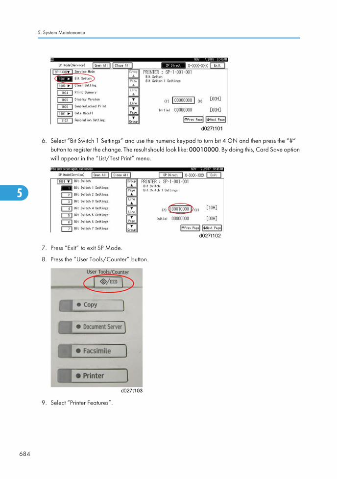
6. Select “Bit Switch 1 Settings” and use the numeric keypad to turn bit 4 ON and then press the “#”button to register the change. The result should look like: 00010000. By doing this, Card Save optionwill appear in the “List/Test Print” menu.
7. Press “Exit” to exit SP Mode.
8. Press the “User Tools/Counter” button.
9. Select “Printer Features”.
5. System Maintenance
684
5

10. Card Save (Add) and Card Save (New) should be displayed on the screen. Select Card Save (Add)or Card Save (New).
11. Press “OK” and then exit the “User Tools/Counter” menu.
12. Press the “Printer” button.
Card Save Function
685
5

13. Card Save should be displayed in the top left of the display panel.
14. Send a job to the printer. The Communicating light should start blinking as shown below.
15. As soon as the printer receives the data, it will be stored on the SD card automatically with no printoutput. Nothing is displayed on the screen, indicating that a Card Save operation was successful.
16. Press “Offline” and then the “Clear/Stop” button to exit Card Save mode.
5. System Maintenance
686
5

17. Change the Bit Switch Settings back to the default 00000000. Press the “#” button in the numerickeypad to register the changes.
18. Remove the SD card after the main power switch is turned off.
Error Messages
Card Save error messages:
• Init error: A card save process (e.g. card detection, change to kernel mode) failed to initialize.
• Card not found: Card cannot be detected in the slot.
• No memory: Insufficient working memory to process the job.
• Write error: Failed to write to the card.
• Other error: An unknown error occurred.
If an error occurs, pressing “OK” will cause the device to discard the job and return to the ready state.
Card Save Function
687
5

5. System Maintenance
688
5

6. Troubleshooting
SC Tables
Service Call Conditions
Summary
The ‘SC Table’ section shows the SC codes for controller errors and other errors. The latter (not controllererrors) are put into four types. The type is determined by their reset procedures. The table shows theclassification of the SC codes.
Key Definition Reset Procedure
Controllererrors
CTLThe error has occurred in thecontroller.
See "Troubleshooting Procedure" in thetable.
Other errors
AThe error involves the fusing unit. Themachine operation is disabled. Theuser cannot reset the error.
Turn the main switch off and on. Resetthe SC (set SP5-810-1). Turn the mainswitch off and on.
BThe error involves one or somespecific units. The machine operatesas usual, excluding the related units.
Turn the operation switch off and on.
CThe error is logged. The SC-codehistory is updated. The machineoperates as usual.
The SC will not show. Only the SChistory is updated.
D
The machine operation is disabled.You can reset the machine by turningthe operation switch or main switchoff and on. If the error occurs again,the same SC code is displayed.
Turn the operation switch or mainpower switch off and on.
After you turn the main power switch off, wait for one second or more before you turn the main powerswitch on ( SC 672). All SCs are logged. The print log data (SP5-990-004) in SP mode can check thelatest 10 SC codes detected and total counters when the SC code is detected.
• If the problem concerns electrical circuit boards, first disconnect then reconnect the connectors beforeyou replace the PCBs.
689
6

• If the problem concerns a motor lock, first check the mechanical load before you replace motors orsensors.
SC Code Classification
The table shows the classification of the SC codes:
Class 1 Section SC Code Detailed section
1XX Scanning100 - Scanner
190 - Unique for a specific model
2XX Laser exposure
200 - Polygon motor
220 - Synchronization control
230 - FGATE signal related
240 - LD control
280 - Unique for a specific model
290 - Shutter
3XX Image development 1
300 - Charge
330 - Drum potential
350 - Development
380 - Unique for a specific model
4XX Image development 2
400 - Image transfer
420 - Paper separation
430 - Cleaning
440 - Around drum
460 - Unit
480 - Others
6. Troubleshooting
690
6

Class 1 Section SC Code Detailed section
5XX Paper feed / Fusing
500 - Paper feed
515 - Duplex
520 - Paper transport
5XX Paper feed / Fusing
530 - Fan motor
540 - Fusing
560 - Others
570 - Unique for a specific model
6XX Communication
600 - Electrical counters
620 - Mechanical counters
630 - Account control
640 - CSS
650 - Network
670 - Internal data processing
680 - Unique for a specific model
7XX Peripherals
700 - Original handling
720 - Two-tray finisher
740 - Booklet finisher
8XX Controller
800 - Error after ready condition
820 - Diagnostics error
860 - Hard disk
880 - Unique for a specific model
9XX Others
900 - Counter
920 - Memory
990 - Others
SC Tables
691
6

SC1xx: Scanning
No. Type Details (Symptom, Possible Cause, Troubleshooting Procedures)
101 D
Exposure lamp error
The peak white level is less than 64/255 digits (8 bits) when scanning the shadingplate.
• Exposure lamp defective
• Lamp stabilizer defective
• Exposure lamp connector defective
• Standard white plate dirty
• Scanner mirror or scanner lens out of position or dirty
1. Check and clean the scanner mirror(s) and scanner lens.
2. Check and clean the shading plate.
3. Replace the exposure lamp.
4. Replace the lamp stabilizer.
5. Replace the scanner mirror(s) or scanner lens.
No. Type Details (Symptom, Possible Cause, Troubleshooting Procedures)
120 D
Scanner home position error 1
The scanner home position sensor does not detect the "OFF" condition duringoperation.
• Scanner motor driver defective
• Scanner motor defective
• Harness between SIO board and scanner motor disconnected
• Scanner HP sensor defective
• Harness between SIO and HP sensor disconnected
1. Check the cable connection between the SIO board and scanner motor.
2. Check the cable connection between the SIO and HP sensor.
3. Replace the scanner motor.
4. Replace the HP sensor.
6. Troubleshooting
692
6

No. Type Details (Symptom, Possible Cause, Troubleshooting Procedures)
121 D
Scanner home position error 2
The scanner home position sensor does not detect the "ON" condition duringoperation.
• Scanner motor driver defective
• Scanner motor defective
• Harness between SIO board and scanner motor disconnected
• Scanner HP sensor defective
• Harness between SIO and HP sensor disconnected
1. Check the cable connection between the SIO board and scanner motor.
2. Check the cable connection between the SIO and HP sensor.
3. Replace the scanner motor.
4. Replace the HP sensor.
No. Type Details (Symptom, Possible Cause, Troubleshooting Procedures)
141 D
Black level detection error
The black level cannot be adjusted within the target value during the zero clamp.
• Harness disconnected
• Defective SBU
1. Check the cable connection
2. Replace the SBU.
SC Tables
693
6

No. Type Details (Symptom, Possible Cause, Troubleshooting Procedures)
142 D
White level detection error
The white level cannot be adjusted within the target during auto gain control.
• Dirty exposure glass or optics section
• SBU board defective
• Exposure lamp defective
• Lamp stabilizer defective
• Scanner motor defective
1. Clean the exposure glass, white plate, mirrors, and lens.
2. Check if the exposure lamp is lit during initialization.
3. Check the harness connection between SBU and BICU.
4. Replace the exposure lamp.
5. Replace the scanner motor.
6. Replace the SBU board.
No. Type Details (Symptom, Possible Cause, Troubleshooting Procedures)
144 D
SBU communication error
The SBU connection cannot be detected at power on or recovery from the energysave mode.
• Defective SBU
• Defective harness
• Defective detection port on the BICU
1. Replace the harness.
2. Replace the SBU.
3. Replace the BICU.
No. Type Details (Symptom, Possible Cause, Troubleshooting Procedures)
161 D IPU error
6. Troubleshooting
694
6

No. Type Details (Symptom, Possible Cause, Troubleshooting Procedures)
001
The error result of self-diagnostic by the ASIC on the BICU is detected.
• Defective BICU
• Defective connection between BICU and SBU
1. Check the connection between BICU and SBU.
2. Replace the BICU.
002 D
The machine detects an error during an access to the Ri.
• Defective BICU board
Replace the BICU board.
No. Type Details (Symptom, Possible Cause, Troubleshooting Procedures)
165 D
Copy Data Security Unit error
• The copy data security board is not detected when the copy data securityfunction is set "ON" with the initial setting.
• A device check error occurs when the copy data security function is set "ON"with the initial setting.
• Incorrect installation of the copy data security board
• Defective copy data security board
1. Reinstall the copy data security board.
2. Replace the copy data security board.
No. Type Details (Symptom, Possible Cause, Troubleshooting Procedures)
195 D
Serial Number Mismatch
• Serial number stored in the memory does not have the correct code.
• NVRAM defective
• BICU replaced without original NVRAM
1. Check the serial number with SP5-811-002.
2. If the stored serial number is incorrect, contact your supervisor.
SC Tables
695
6

SC 2xx: Exposure
No. Type Details (Symptom, Possible Cause, Troubleshooting Procedures)
202 D
Polygon motor error 1: ON timeout
The polygon mirror motor does not reach the targeted operating speed within thespecified time after turning on or changing speed
• Defective or disconnected harness to polygon motor driver board
• Defective polygon motor driver board
• Defective polygon motor.
1. Replace the polygon motor.
2. Replace the laser optics housing unit.
3. Replace the harness.
4. Replace the BICU.
No. Type Details (Symptom, Possible Cause, Troubleshooting Procedures)
203 D
Polygon motor error 2: OFF timeout
The polygon mirror motor does leave the READY status within 3 seconds after thepolygon motor switches off.
• Disconnected or defective harness to polygon motor driver board
• Defective polygon motor driver board
• Defective polygon motor
1. Check or replace the harness.
2. Replace the polygon motor.
6. Troubleshooting
696
6

No. Type Details (Symptom, Possible Cause, Troubleshooting Procedures)
204 D
Polygon motor error 3: XSCRDY signal error
The SCRDY_N signal goes HIGH (inactive) while the laser diode is firing.
• Disconnected or defective harness to polygon motor driver board
• Defective polygon motor
• Defective polygon motor driver board
1. Check or replace the harness.
2. Replace the polygon motor.
No. Type Details (Symptom, Possible Cause, Troubleshooting Procedures)
210 C Laser synchronizing detection error: end position [K]
211 C Laser synchronizing detection error: end position [Y]
212 C Laser synchronizing detection error: end position [M]
213 C Laser synchronizing detection error: end position [C]
- -
The laser synchronizing detection signal for the end position of LDB [K], [Y], [M],[C] is not detected for one second after the LDB unit turned on when detecting themain scan magnification.
• Disconnected or defective harness to synchronizing detector for end position
• Defective synchronizing detector board
• Defective LD board or driver
• Defective BICU
1. Replace the harness of the LD board.
2. Replace the laser optics housing unit.
3. Replace the BICU.
No. Type Details (Symptom, Possible Cause, Troubleshooting Procedures)
220 D Laser synchronizing detection error: start position [K]: LD0
222 D Laser synchronizing detection error: start position [Y]: LD0
226 D Laser synchronizing detection error: start position [C]: LD0
SC Tables
697
6

No. Type Details (Symptom, Possible Cause, Troubleshooting Procedures)
- -
The laser synchronizing detection signal for the start position of the LDB [K], [Y], [C]is not output for two seconds after LDB unit turns on while the polygon motor isrotating normally.
• Disconnected cable from the laser synchronizing detection unit or defectiveconnection
• Defective laser synchronizing detector
• Defective LDB
• Defective BICU
1. Check the connectors.
2. Replace the laser-synchronizing detector.
3. Replace the LDB.
4. Replace the BICU.
No. Type Details (Symptom, Possible Cause, Troubleshooting Procedures)
230 D
FGATE ON error: K
The PFGATE ON signal does not assert within 5 seconds after processing the imagein normal job or MUSIC for start position [K].
• Defective ASIC (Lupus)
• Poor connection between controller and BICU.
• Defective BICU
1. Check the connection between the controller board and the BICU.
2. Replace the BICU.
3. Replace the controller board.
No. Type Details (Symptom, Possible Cause, Troubleshooting Procedures)
231 D
FGATE OFF error: K
• The PFGATE ON signal still asserts within 5 seconds after processing the imagein normal job or MUSIC for end position [K].
• The PFGATE ON signal still asserts when the next job starts.
See SC 230 for troubleshooting details.
6. Troubleshooting
698
6

No. Type Details (Symptom, Possible Cause, Troubleshooting Procedures)
232 D
FGATE ON error: Y
The PFGATE ON signal does not assert within 5 seconds after processing the imagein normal job or MUSIC for start position [Y].
See SC 230 for troubleshooting details.
No. Type Details (Symptom, Possible Cause, Troubleshooting Procedures)
233 D
FGATE OFF error: Y
• The PFGATE ON signal still asserts within 5 seconds after processing the imagein normal job or MUSIC for end position [Y].
• The PFGATE ON signal still asserts when the next job starts.
See SC 230 for troubleshooting details.
No. Type Details (Symptom, Possible Cause, Troubleshooting Procedures)
234 D
FGATE ON error: M
The PFGATE ON signal does not assert within 5 seconds after processing the imagein normal job or MUSIC for start position [M].
See SC 230 for troubleshooting details.
No. Type Details (Symptom, Possible Cause, Troubleshooting Procedures)
235 D
FGATE OFF error: M
• The PFGATE ON signal still asserts within 5 seconds after processing the imagein normal job or MUSIC for end position [M].
• The PFGATE ON signal still asserts when the next job starts.
See SC 230 for troubleshooting details.
SC Tables
699
6

No. Type Details (Symptom, Possible Cause, Troubleshooting Procedures)
236 D
FGATE ON error: C
The PFGATE ON signal does not assert within 5 seconds after processing the imagein normal job or MUSIC for start position [C].
See SC 230 for troubleshooting details.
No. Type Details (Symptom, Possible Cause, Troubleshooting Procedures)
237 D
FGATE OFF error: C
• The PFGATE ON signal still asserts within 5 seconds after processing the imagein normal job or MUSIC for end position [C].
• The PFGATE ON signal still asserts when the next job starts.
See SC 230 for troubleshooting details.
No. Type Details (Symptom, Possible Cause, Troubleshooting Procedures)
240 C LD error: K
241 C LD error: Y
242 C LD error: M
243 C LD error: C
- -
The BICU detects LDB error a few times consecutively when LDB unit turns on afterLDB initialization.
• Worn-out LD
• Disconnected or broken harness of the LD
1. Replace the harness of the LD.
2. Replace the laser optics housing unit.
3. Replace the BICU.
6. Troubleshooting
700
6

No. Type Details (Symptom, Possible Cause, Troubleshooting Procedures)
285 D
Line position adjustment (MUSIC) error
Line position adjustment fails four consecutive times.
• Pattern sampling error ( insufficient image density )
• Defective ID sensors for the line position adjustment
• Defective image transfer belt unit
• Defective PCDU(s)
• Defective laser optics housing unit
1. Check and reinstall the image transfer belt unit and PCDUs.
2. Check if each toner bottle has enough toner.
3. Replace the ID sensor.
4. Replace the image transfer belt unit.
5. Replace the PCDU(s).
6. Replace the laser optics housing unit.
SC3xx: Image Processing – 1
No. Type Details (Symptom, Possible Cause, Troubleshooting Procedures)
312 D Charge P.P. output error [K]
313 D Charge P.P. output error [M]
314 D Charge P.P. output error [C]
315 D Charge P.P. output error [Y]
- -
The feedback voltage of the charge AC for each color is 0.3 V or less for 0.2 secondsafter the charge AC has turned on.
• Disconnected or broken harnesses of the HVPS
• Defective PCDU
• Defective HVPS
1. Check or replace the harnesses of the HVPS.
2. Reinstall or replace the PCDU.
3. Replace the HVPS.
SC Tables
701
6

SC3xx: Image Processing – 2
No. Type Details (Symptom, Possible Cause, Troubleshooting Procedures)
360 D TD sensor (Vt high) error 1: K
361 D TD sensor (Vt high) error 1: M
362 D TD sensor (Vt high) error 1: C
363 D TD sensor (Vt high) error 1: Y
- -
• The Vt value of the black, magenta, cyan, or yellow TD sensor exceeds thespecified value (default: 4.7V) with SP3020-002 for twenty counts.
• The [Vt - Vtref] value of the black, magenta, cyan, or yellow TD sensor exceedsthe specified value (default: 5.0V) with SP3020-001.
• Black, magenta, cyan, or yellow TD sensor disconnected
• Harness between TD sensor and PCDU defective
• Defective TD sensor.
1. Check the black, magenta, cyan, or yellow TD sensor connector and harnessbetween the TD sensor and PCDU for damage.
2. Check the drawer connector.
3. Replace the defective PCDU.
No. Type Details (Symptom, Possible Cause, Troubleshooting Procedures)
364 D TD sensor (Vt low) error 2: K
365 D TD sensor (Vt low) error 2: M
366 D TD sensor (Vt low) error 2: C
367 D TD sensor (Vt low) error 2: Y
6. Troubleshooting
702
6

No. Type Details (Symptom, Possible Cause, Troubleshooting Procedures)
- -
The Vt value of the black, magenta, cyan, or yellow TD sensor is below the specifiedvalue with SP3020-004 (default: 0.5V) for 10 counts.
• TD sensor harness disconnected, loose, defective
• A drawer connector disconnected, loose, defective
• TD sensor defective
1. Check the black, magenta, cyan, or yellow TD sensor connector and harnessbetween the TD sensor and PCDU for damage.
2. Check the drawer connector.
3. Replace the defective PCDU.
No. Type Details (Symptom, Possible Cause, Troubleshooting Procedures)
372 D TD sensor adjustment error: K
373 D TD sensor adjustment error: M
374 D TD sensor adjustment error: C
375 D TD sensor adjustment error: Y
- -
During TD sensor initialization, the output value of the black, magenta, cyan, oryellow TD sensor is not within the range of the specified value with SP3238-001 to-004 (default: 2.5V) ± 0.2V
• Heat seal not removed from a new developer pack
• TD harness sensor disconnected, loose or defective
• TD sensor defective
• Harness between TD sensor and drawer disconnected, defective
1. Remove the heat seal from each PCDU.
2. Replace the defective PCDU.
No. Type Details (Symptom, Possible Cause, Troubleshooting Procedures)
380 C Drum gear position sensor error: K
381 C Drum gear position sensor error: M
382 C Drum gear position sensor error: C
SC Tables
703
6

No. Type Details (Symptom, Possible Cause, Troubleshooting Procedures)
383 C Drum gear position sensor error: Y
The machine does not detect the drum position signal for 3 seconds at the drumphase adjustment.
• Dirty or defective drum gear position sensor
1. Clean the drum gear position sensor.
2. Check the harness connection.
3. Replace the drum gear position sensor.
4. Replace the PCDU.
No. Type Details (Symptom, Possible Cause, Troubleshooting Procedures)
396 D Drum/Development motor error: K
397 D Drum/Development motor error: M
398 D Drum/Development motor error: C
399 D Drum/Development motor error: Y
- -
The machine detects a High signal from the drum/development motor for 2 secondsafter the drum/development motor turned on.
• Overload on the drum/development motor
• Defective drum/development motor
• Defective harness
• Shorted 24 V fuse on the PSU
• Defective interlock system
1. Check or replace the harness.
2. Replace the drum/development motor.
3. Replace the 24V fuse on the PSU.
6. Troubleshooting
704
6

SC4xx: Image Processing - 3
No. Type Details (Symptom, Possible Cause, Troubleshooting Procedures)
400 D
ID sensor adjustment error
When the Vsg error counter reaches "3", the machine detects "SC400".
The Vsg error counter counts "1" when the Vsg detected by ID sensor is more thanthe value (default: 4.5V) specified with SP3324-005 or less than the value (default:3.5V) specified with SP3324-006.
• Dirty or defective ID sensor
• Defective ID sensor shutter
1. Check the harness of the ID sensor.
2. Clean or replace the ID sensor.
• After replacing the ID sensor, input the ID sensor correction coefficientwith SP3362-013 to -018. For details, refer to "ID sensor board" in theReplacement and Adjustment section.
3. Replace the IOB.
4. Replace the image transfer belt unit.
No. Type Details (Symptom, Possible Cause, Troubleshooting Procedures)
441 D
Image transfer unit motor error
The motor LOCK signal is not detected for more than two seconds while the motorSTART signal is on.
• Motor overload
• Defective image transfer unit motor
1. Replace the image transfer belt unit.
2. Replace the IOB.
SC Tables
705
6
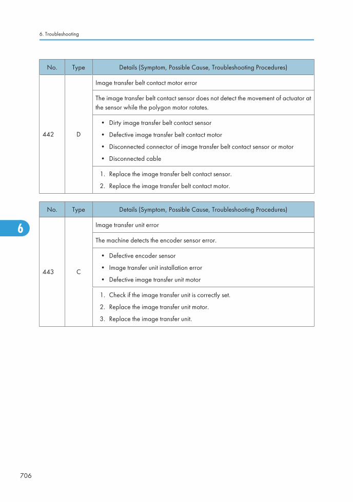
No. Type Details (Symptom, Possible Cause, Troubleshooting Procedures)
442 D
Image transfer belt contact motor error
The image transfer belt contact sensor does not detect the movement of actuator atthe sensor while the polygon motor rotates.
• Dirty image transfer belt contact sensor
• Defective image transfer belt contact motor
• Disconnected connector of image transfer belt contact sensor or motor
• Disconnected cable
1. Replace the image transfer belt contact sensor.
2. Replace the image transfer belt contact motor.
No. Type Details (Symptom, Possible Cause, Troubleshooting Procedures)
443 C
Image transfer unit error
The machine detects the encoder sensor error.
• Defective encoder sensor
• Image transfer unit installation error
• Defective image transfer unit motor
1. Check if the image transfer unit is correctly set.
2. Replace the image transfer unit motor.
3. Replace the image transfer unit.
6. Troubleshooting
706
6

No. Type Details (Symptom, Possible Cause, Troubleshooting Procedures)
452 D
Paper transfer unit contact error
The paper transfer unit contact sensor does not detect the movement of actuator atthe sensor while the polygon motor rotates.
• Defective paper transfer unit contact sensor
• Defective paper transfer unit contact motor
• Broken +24V fuse on PSU
• Defective IOB
1. Check the connection between the paper transfer unit and PSU.
2. Replace the paper transfer unit contact sensor.
3. Replace the paper transfer unit contact motor.
4. Replace the +24V fuse on the PSU.
5. Replace the IOB.
No. Type Details (Symptom, Possible Cause, Troubleshooting Procedures)
460 D
Separation power pack output error
An interrupt checks the status of the power pack every 20 ms. This SC is issued if theBICU detects a short in the power pack 10 times at D(ac).
• Damaged insulation on the high-voltage supply cable
• Damaged insulation around the high-voltage power supply.
1. Replace the high-voltage supply cable.
2. Replace the high-voltage power supply unit.
3. Replace the IOB.
SC Tables
707
6
No. Type Details (Symptom, Possible Cause, Troubleshooting Procedures)
490 D
Toner transport motor error
The LOCK signal is not detected for 2 seconds when the transport motor turns on.
• Toner transport motor overload
• Disconnected or broken harness
• Defective toner transport motor
• Opened +24V fuse on the PSU
• Defective interlock switch
1. Check or replace the harness.
2. Replace the toner transport motor.
3. Replace the +24V fuse on the PSU.
4. Replace the interlock switch.
No. Type Details (Symptom, Possible Cause, Troubleshooting Procedures)
491 D
High voltage power: Drum/ development bias output error
An error signal is detected for 0.2 seconds when charging the drum or development.
• High voltage leak
• Broken harness
• Defective drum unit or development unit
• Defective high voltage supply unit
1. Check or replace the harness.
2. Replace the drum unit or paper transfer unit.
3. Replace the high voltage supply unit.
6. Troubleshooting
708
6

No. Type Details (Symptom, Possible Cause, Troubleshooting Procedures)
492 C
High voltage power: Image transfer/ paper transfer bias output error
An error signal is detected for 0.2 seconds when charging the separation, imagetransfer bet or paper transfer roller.
• High voltage leak
• Broken harness
• Defective image transfer belt unit or paper transfer unit
• Defective high voltage supply unit
1. Check or replace the harness.
2. Replace the image transfer belt unit or paper transfer unit.
3. Replace the high voltage supply unit.
No. Type Details (Symptom, Possible Cause, Troubleshooting Procedures)
498 C
Temperature and humidity sensor error 2
• The thermistor output of the temperature sensor was not within the prescribedrange (0.2V to 3.5V).
• The thermistor output of the humidity sensor was not within the prescribed range(0.01V to 2.4V).
• Temperature and humidity sensor harness disconnected, loose, defective
• Temperature and humidity sensor defective
1. Check the connector and harness.
2. Replace the temperature/humidity sensor.
SC5xx: Paper Feed and Fusing
No. Type Details (Symptom, Possible Cause, Troubleshooting Procedures)
501 B Paper Tray 1 error
502 B Paper Tray 2 error
SC Tables
709
6

No. Type Details (Symptom, Possible Cause, Troubleshooting Procedures)
- -
• When the tray lift motor rotates counterclockwise, (if the upper limit is notdetected within 10 seconds), the machine asks the user to reset the tray.
• When the tray lift motor rotates clockwise, (if the upper limit is not detectedwithin 1.5 seconds), the machine asks the user to reset the tray.
If one of these conditions occurs three consecutive times, the SC is generated.
• Disconnected or defective paper lift sensor
• Disconnected or defective tray lift motor
• Defective bottom plate lift mechanism
• Too much paper in the tray
• Defective IOB
1. Check if the paper is not loaded too much.
2. Check if the bottom plate smoothly moves up and down manually.
3. Check and/or replace the tray lift motor/ paper lift sensor.
4. Replace the IOB.
6. Troubleshooting
710
6

No. Type Details (Symptom, Possible Cause, Troubleshooting Procedures)
503-01
B
Tray 3 error (Paper Feed Unit or LCT)
For the paper feed unit:
• When the tray lift motor is turned on, the upper limit is not detected within 10seconds
For the LCT:
• SC 503-01 occurs if the upper or lower limit is not detected within 8 secondswhen the tray lift motor is turned on to lift or lower the tray.
For the paper feed unit:
• Defective tray lift motor or connector disconnection
• Defective lift sensor or connector disconnection
For the LCT:
• Defective stack transport clutch or connector disconnection
• Defective tray motor or connector disconnection
• Defective end fence home position sensor or connector disconnection
• Defective upper limit sensor or connector disconnection
• Defective tray lift motor or connector disconnection
1. Check the cable connections.
2. Check and/or replace the defective component.
SC Tables
711
6

No. Type Details (Symptom, Possible Cause, Troubleshooting Procedures)
503-02
B
Tray 3 error (Paper Feed Unit or LCT)
This SC is generated if the following condition occurs 3 consecutive times.
For the paper feed unit:
• When the tray lowers, the tray lift sensor does not go off within 1.5 sec.
For the LCT:
• When the main switch is turned on or when the LCT is set, if the end fence isnot in the home position (home position sensor ON), the tray lift motor stops.
• If the upper limit does not go off for 1.5 seconds even the tray lift motor turnson to lower the tray after the upper limit has been detected at power on.
For the paper feed unit:
• Defective tray lift motor or connector disconnection
• Defective lift sensor or connector disconnection
For the LCT:
• Defective stack transport clutch or connector disconnection
• Defective tray motor or connector disconnection
• Defective end fence home position sensor or connector disconnection
1. Check the cable connections.
2. Check and/or replace the defective component.
6. Troubleshooting
712
6

No. Type Details (Symptom, Possible Cause, Troubleshooting Procedures)
504-01
B
Tray 4 error (Paper Feed Unit or LCT)
For the two-tray paper feed unit
When the tray lift motor is turned on, the upper limit is not detected within 10 seconds.If this condition occurs three consecutive times, the SC is generated.
For the LCT
If the upper or lower limit is not detected within 8 seconds when the tray lift motor isturned on to lift up or lower the tray
• Defective tray lift motor or connector disconnection
• Defective lift sensor or connector disconnection
1. Check the cable connections.
2. Check and/or replace the defective component.
No. Type Details (Symptom, Possible Cause, Troubleshooting Procedures)
504-02
B
Tray 4 error (3 Tray Paper Feed Unit)
This SC is generated if the following condition occurs 3 consecutive times.
For the two-tray paper feed unit
• When the tray lowers, the tray lift sensor does not go off within 1.5 sec.
For the LCT
• If the upper limit does not go off for 1.5 seconds even the tray lift motor turnson to lower the tray after the upper limit has been detected at power on.
• Defective tray lift motor or connector disconnection
• Defective lift sensor or connector disconnection
1. Check the cable connections.
2. Check and/or replace the defective component.
No. Type Details (Symptom, Possible Cause, Troubleshooting Procedures)
505 5th tray lift malfunction (optional LCT)
SC Tables
713
6

No. Type Details (Symptom, Possible Cause, Troubleshooting Procedures)
-01 B
This SC is generated if the following condition occurs:
• When the tray lift sensor of the LCT 1200-sheet does not go on after the traylift motor has turned on to lift the paper tray.
• When the tray lift sensor of the LCT 1200-sheet does not go off after the traylift motor has turned on to lower the paper tray.
• When the tray lift sensor of the LCT 1200-sheet does not go on after the pick-up roller solenoid has turned on at power on.
• Tray lift motor defective or disconnected
• Tray lift sensor defective or disconnected
1. Check the harness connections.
2. Replace the tray lift motor.
3. Replace the tray lift sensor.
-02 B
Both tray lift sensor and lower limit sensor are turned on at the same time when themain power is turned on or the right door is closed.
• Tray lift motor defective or disconnected
• Tray lift sensor defective or disconnected
• Lowe limit sensor defective or disconnected
1. Check the harness connections.
2. Replace the tray lift motor.
3. Replace the tray lift sensor.
4. Replace the lower limit sensor.
No. Type Details (Symptom, Possible Cause, Troubleshooting Procedures)
530 D
Fusing fan error
The IOB does not receive the lock signal 10 seconds after turning on the fusing fan.
• Defective fusing fan motor or connector disconnection
• Defective IOB
Check the connector and/or replace the fusing fan motor.
6. Troubleshooting
714
6

No. Type Details (Symptom, Possible Cause, Troubleshooting Procedures)
531 D
Ventilation fan (at the left side of the machine) motor-front/rear error
The IOB does not receive the lock signal for 10 seconds after turning on theventilation fan motor-front/rear.
• Defective ventilation fan motor-front or rear
• Defective IOB
1. Replace the ventilation fan (at the left side of the machine) motor-front or rear.
2. Replace the IOB.
No. Type Details (Symptom, Possible Cause, Troubleshooting Procedures)
532 D
IH coil fan error
The machine does not detect the fan motor lock signal for 10 seconds while the IHcoil fan turns on.
• Disconnected harness
• Overload on the IH coil fan motor
• Defective IH coil fan motor
• Defective IOB
1. Check or replace the harness.
2. Replace the IH coil fan.
3. Replace the IOB.
SC Tables
715
6

No. Type Details (Symptom, Possible Cause, Troubleshooting Procedures)
533 D
IH inverter fan error
The machine does not detect the fan motor lock signal for 10 seconds while the IHinverter fan turns on.
• Disconnected harness
• Overload on the IH inverter fan motor
• Defective IH inverter fan motor
• Defective IOB
1. Check or replace the harness.
2. Replace the IH inverter fan.
3. Replace the IOB.
No. Type Details (Symptom, Possible Cause, Troubleshooting Procedures)
534 D
Second duct fan error
The machine does not detect the fan motor lock signal for 10 seconds while thesecond duct fan turns on.
• Disconnected harness
• Overload on the second duct fan motor
• Defective second duct motor
• Defective IOB
1. Check or replace the harness.
2. Replace the second duct fan.
3. Replace the IOB.
6. Troubleshooting
716
6

No. Type Details (Symptom, Possible Cause, Troubleshooting Procedures)
535 D
Paper exit fan error
The machine does not detect the fan motor lock signal for 10 seconds while thepaper exit fan turns on.
• Disconnected harness
• Overload on the paper exit fan motor
• Defective paper exit motor
• Defective IOB
1. Check or replace the harness.
2. Replace the paper exit fan.
3. Replace the IOB.
No. Type Details (Symptom, Possible Cause, Troubleshooting Procedures)
536 D
Third duct fan error
The motor lock signal error is detected for 10 seconds after the motor lock signalwas first detected.
• Defective third duct fan motor
• Disconnected or defective harness
• Defective IOB
1. Replace the third duct fan motor.
2. Check or replace the harness.
3. Replace the IOB.
SC Tables
717
6

No. Type Details (Symptom, Possible Cause, Troubleshooting Procedures)
540 D
Fusing/Paper exit motor error
The IOB does not receive the lock signal 2 seconds after turning on the fusing/paperexit motor.
• Motor overload
• Defective fusing/paper exit motor
1. Check or replace the harness.
2. Replace the fusing/paper exit motor.
No. Type Details (Symptom, Possible Cause, Troubleshooting Procedures)
541 A
Heating roller thermopile error
The temperature detected by the heating roller thermopile does not reach 0°C for6 seconds.
• Loose connection of the heating roller thermopile
• Defective heating roller thermopile
• Defective thermopile
1. Check if the heating roller thermopile is firmly connected.
2. Replace the heating roller thermopile.
No. Type Details (Symptom, Possible Cause, Troubleshooting Procedures)
542 A
Heating roller warm-up error 1
• The heating roller temperature does not reach 80°C for 20 seconds after theIH inverter turned on.
• The center temperature of the heating roller does not reach the readytemperature for 90 seconds after the IH inverter turned on.
• Dirty or defective thermopile
• Defective IH coil unit
1. Check if the heating roller thermopile is firmly connected.
2. Replace the thermopile.
3. Replace the IH coil unit.
6. Troubleshooting
718
6

No. Type Details (Symptom, Possible Cause, Troubleshooting Procedures)
543 A
Heating roller fusing lamp overheat 1 (software error)
The temperature detected by the heating roller thermopile stays at 230°C for 1second.
• Defective PSU
• Defective IOB
• Defective BICU
Related SC code: SC 553
1. Replace the PSU.
2. Replace the IOB.
3. Replace the BICU.
No. Type Details (Symptom, Possible Cause, Troubleshooting Procedures)
544 A
Heating roller fusing lamp overheat 1 (hardware error)
During stand-by mode or a print job, the temperature detected by the heating rollerthermopile reaches 250 °C.
• Defective PSU
• Defective IOB
• Defective BICU
• Defective fusing control system
Related SC code: SC 543
1. Replace the PSU.
2. Replace the IOB.
3. Replace the BICU.
SC Tables
719
6

No. Type Details (Symptom, Possible Cause, Troubleshooting Procedures)
545 A
Heating roller fusing lamp consecutive full power 1
When the fusing unit is not running in the ready condition, the heating roller fusinglamp keeps on full power for 8 seconds.
• Broken heating roller fusing lamp
Related SC code: SC 555
1. Replace the heating roller fusing lamp.
2. Replace the PSU.
No. Type Details (Symptom, Possible Cause, Troubleshooting Procedures)
547 D
Zero cross error
• The zero cross signal is detected three times even though the heater relay is offwhen turning on the main power.
• The zero cross signal is not detected for 2 seconds even though the heater relayis on after turning on the main power or closing the front door.
• The detection error occurs twice or more in the 11 zero cross signal detections.This error is defined when the detected zero cross signal is less than 45.
• Defective fusing lamp relay
• Defective fusing lamp relay circuit
• Unstable power supply
1. Check the power supply source.
2. Replace the PSU
6. Troubleshooting
720
6

No. Type Details (Symptom, Possible Cause, Troubleshooting Procedures)
551 A
Heating roller thermistor error
The temperature at the end of the heating roller measured by the heating rollerthermistor does not reach 0°C for 7 seconds.
• Loose connection of pressure roller thermistor
• Defective heating roller thermistor
Related SC code: SC 541
1. Check that the heating roller thermistor is firmly connected.
2. Replace the heating roller thermistor.
No. Type Details (Symptom, Possible Cause, Troubleshooting Procedures)
552 A
Heating roller warm-up error 2
• The heating roller temperature does not reach 80°C for 20 seconds after theIH inverter on.
• The temperature at the end of the heating roller does not reach the readytemperature for 89 seconds after the IH inverter turned on.
• Defective heating roller thermistor
• Defective IH inverter
Related SC code: SC 542
1. Check if the heating roller thermistor is firmly connected.
2. Replace the IH inverter.
SC Tables
721
6

No. Type Details (Symptom, Possible Cause, Troubleshooting Procedures)
553 A
Heating roller fusing lamp overheat 2 (software error)
The temperature detected by the heating roller thermistor stays at 230°C or morefor 1 second.
• Defective PSU
• Defective IOB
• Defective BICU
1. Replace the PSU.
2. Replace the IOB.
3. Replace the BICU.
No. Type Details (Symptom, Possible Cause, Troubleshooting Procedures)
554 A
Heating roller fusing lamp overheat 2 (hardware error)
The temperature detected by the heating roller thermistor reaches 250°C or more.
• Defective PSU
• Defective IOB
• Defective BICU
• Defective fusing control system
1. Replace the PSU.
2. Replace the IOB.
3. Replace the BICU.
No. Type Details (Symptom, Possible Cause, Troubleshooting Procedures)
555 A
Heating roller lamp consecutive full power 2
The heating roller-fusing lamp stays ON for 15 seconds or more while the fusingunit is in the ready condition.
• Broken heating roller fusing lamp
1. Replace the heating roller fusing lamp.
2. Replace the PSU.
6. Troubleshooting
722
6

No. Type Details (Symptom, Possible Cause, Troubleshooting Procedures)
557 C
Zero cross frequency error
When the zero cross signal is 66 or more and it is detected 10 times or more in 11detections, the machine determines that input 60 Hz and SC557 occurs.
• Noise (High frequency)
• Defective PSU
1. Check the power supply source.
2. Replace the PSU.
No. Type Details (Symptom, Possible Cause, Troubleshooting Procedures)
559 A
Consecutive fusing jam
The paper jam counter for the fusing unit reaches 3 times. The paper jam counter iscleared if the paper is fed correctly.
This SC is activated only when SP1159-001 is set to "1" (default "0").
• Paper jam in the fusing unit.
Remove the paper that is jammed in the fusing unit. Then make sure that the fusingunit is clean and has no obstacles in the paper feed path.
No. Type Details (Symptom, Possible Cause, Troubleshooting Procedures)
561 A
Pressure roller thermistor error
The temperature detected by the pressure roller thermistor does not reach 0 °C for20 seconds.
• Loose connection of the pressure roller thermistor
• Defective thermopile
• Defective pressure roller thermistor
1. Check if the pressure roller thermistor is firmly connected.
2. Replace the thermopile.
3. Replace the pressure roller thermistor.
SC Tables
723
6

No. Type Details (Symptom, Possible Cause, Troubleshooting Procedures)
563 A
Pressure roller overheat (software error)
The temperature detected by the pressure roller thermistor stays at 230°C or morefor 1 second.
• Defective PSU
• Defective IOB
• Defective BICU
1. Replace the PSU.
2. Replace the IOB.
3. Replace the BICU.
No. Type Details (Symptom, Possible Cause, Troubleshooting Procedures)
564 A
Pressure roller overheat (hardware error)
The temperature detected by the pressure roller thermistor detects 250°C or more.
• Defective PSU
• Defective IOB
• Defective BICU
• Defective fusing control system
1. Replace the thermistor.
2. Replace the PSU.
3. Replace the IOB.
4. Replace the BICU.
6. Troubleshooting
724
6

No. Type Details (Symptom, Possible Cause, Troubleshooting Procedures)
565 A
Pressure roller fusing lamp consecutive full power
When the fusing unit is not running in the ready condition, the pressure roller fusinglamp keeps ON full power for 300 seconds or more.
• Broken pressure roller fusing lamp
• Defective pressure roller thermistor
1. Replace the pressure roller lamp.
2. Replace the pressure roller thermistor.
3. Replace the PSU.
No. Type Details (Symptom, Possible Cause, Troubleshooting Procedures)
569 D
Pressure roller contact sensor error
Pressure roller contact sensor does not detect the pressure roller position three times.
• Broken or defective pressure roller contact sensor
• Deformed or broken pressure roller contact sensor feeler
• Defective pressure roller contact motor
• Defective fusing unit
1. Check or replace the harness of the pressure roller contact sensor.
2. Replace the pressure roller contact sensor.
3. Replace the pressure roller contact motor.
No. Type Details (Symptom, Possible Cause, Troubleshooting Procedures)
571 A
Pressure roller thermistor error: Center
The temperature at the center of the pressure roller measured by the thermistor doesnot reach 0°C for 37 seconds.
• Loose connection of the thermistor
• Defective thermistor
1. Check if the thermistor is firmly connected.
2. Replace the center thermistor.
SC Tables
725
6

No. Type Details (Symptom, Possible Cause, Troubleshooting Procedures)
581 D
IH inverter input voltage error
The IH inverter detects 70 V or less/150 V or more for 10 seconds.
The IH inverter detects 160 V or less/300 V or more for 10 seconds.
• Unusual input voltage
• Defective IH inverter
1. Check if the power supply voltage of the customer site is within the properpower voltage range.
2. Check CN981 on the IH inverter.
3. Replace the IH inverter.
No. Type Details (Symptom, Possible Cause, Troubleshooting Procedures)
582 D
IH inverter current error at power on
The output current from the IH inverter does not reach the proper value when the IHinverter turns on.
• Disconnected power input terminal 1 and 2
• Defective IH inverter
• Defective IH coil unit
• Defective fusing unit
1. Check the power input terminals 1 and 2.
2. Replace the IH inverter.
3. Replace the IH coil unit.
4. Replace the fusing unit.
6. Troubleshooting
726
6

No. Type Details (Symptom, Possible Cause, Troubleshooting Procedures)
585 A
IH coil unit full power (1250W) error
The IH coil unit full power (1250W) continues for 200 seconds or more.
• Defective IH inverter
• Defective BICU
• Defective IOB
• Broken connection between IH inverter and IOB
• Defective thermopile
1. Replace the IH inverter.
2. Replace the BICU.
3. Replace the IOB.
4. Check the connection between IH inverter and IOB.
5. Replace the thermopile.
SC6xx: Device Communication
No. Type Details (Symptom, Possible Cause, Troubleshooting Procedures)
610 D Mechanical counter error: K
611 D Mechanical counter error: FC
- -
This SC is only for NA models.
The machine detects the mechanical counter error when SP5987-001 is set to "1".
• Disconnected mechanical counter
• Defective mechanical counter
Check or replace the mechanical counter.
SC Tables
727
6

No. Type Details (Symptom, Possible Cause, Troubleshooting Procedures)
620 D
ARDF communication error
After the ARDF is detected, the break signal occurs or communication timeout occurs.
• Incorrect installation of ARDF
• ARDF defective
• BICU board defective
• External noise
1. Check the cable connection of the ARDF.
2. Shut out the external noise.
3. Replace the ARDF.
4. Replace the BICU board.
No. Type Details (Symptom, Possible Cause, Troubleshooting Procedures)
621 D Finisher communication error
622 D Paper tray unit communication error
- -
While the IOB communicates with an optional unit, an SC code is displayed if oneof following conditions occurs.
• The IOB receives the break signal which is generated by the peripherals onlyjust after the main switch is turned on.
• When the IOB does not receive an OK signal from a peripheral 100ms aftersending a command to it. The IOB resends the command. The IOB does notreceive an OK signal after sending the command 3 times.
• Cable problems
• IOB problems
• BICU problems
• PSU problems in the machine
• Main board problems in the peripherals
1. Check if the cables of peripherals are correctly connected.
2. Replace the PSU if no power is supplied to peripherals.
3. Replace the IOB or main board of peripherals.
4. Replace the BICU.
6. Troubleshooting
728
6

No. Type Details (Symptom, Possible Cause, Troubleshooting Procedures)
623 D
2nd Paper Bank communication error
This SC is not issued for this machine.
When a communication error signal between the 1st paper bank and 2nd paperbank is received.
• Loose or disconnected connector
Check the connection between the main machine and paper feed unit.
No. Type Details (Symptom, Possible Cause, Troubleshooting Procedures)
632CTL
B
Counter device error 1
After 3 attempts to send a data frame to the optional counter device via the serialcommunication line, no ACK signal was received within 100 ms.
• Serial line between the optional counter device, the relay board and copiercontrol board is disconnected or damaged
• Make sure that SP5113 is set to enable the optional counter device.
Check the connection between the main machine and optional counter device.
No. Type Details (Symptom, Possible Cause, Troubleshooting Procedures)
633CTL
B
Counter device error 2
After communication is established, the controller receives the brake signal from theaccounting device.
• Serial line between the optional counter device, the relay board and copiercontrol board is disconnected or damaged
• Make sure that SP5113 is set to enable the optional counter device.
1. Check if the setting of the SP5113 is correctly set.
2. Check the connection between the main machine and optional counter device.
SC Tables
729
6

No. Type Details (Symptom, Possible Cause, Troubleshooting Procedures)
634CTL
B
Counter device error 3
A backup RAM error was returned by the counter device.
• Counter device control board defective
• Backup battery of counter device defective
Replace the counter device.
No. Type Details (Symptom, Possible Cause, Troubleshooting Procedures)
635CTL
B
Counter device error 4
A backup battery error was returned by the counter device.
• Counter device control board defective
• Backup battery of counter device defective
Replace the counter device.
No. Type Details (Symptom, Possible Cause, Troubleshooting Procedures)
636 CTL SD Card Error
-01 D
Expanded authentication module error
There is no expanded authentication module in the machine.
The SD card or the file of the expanded authentication module is broken.
There is no DESS module in the machine.
• No expanded authentication module
• Defective SD card
• No DESS module
1. Install the expanded authentication module.
2. Install the SD card.
3. Install the DESS module.
6. Troubleshooting
730
6

No. Type Details (Symptom, Possible Cause, Troubleshooting Procedures)
-02 D
Version error
The version of the expanded authentication module is not correct.
• Incorrect module version
Install the correct file of the expanded authentication module.
No. Type Details (Symptom, Possible Cause, Troubleshooting Procedures)
641CTL
D
BICU control data transfer abnormal
A sampling of the control data sent from the BICU reveals an abnormality.
• Controller board defective
• External noise
• BICU board defective
1. Replace the controller board.
2. Replace the BICU.
No. Type Details (Symptom, Possible Cause, Troubleshooting Procedures)
650CTL
BCommunication error of the remote service modem (Embedded RCG-M)
-001 -
Authentication error
The authentication for the Embedded RCG-M fails at a dial up connection.
• Incorrect SP settings
• Disconnected telephone line
• Disconnected modem board
Check and set the correct user name (SP5816-156) and password (SP5816-157).
-004 -
Incorrect modem setting
Dial up fails due to the incorrect modem setting.
Same as -001
Check and set the correct AT command (SP5819-160).
SC Tables
731
6

No. Type Details (Symptom, Possible Cause, Troubleshooting Procedures)
-005 -
Communication line error
The supplied voltage is not sufficient due to the defective communication line ordefective connection.
Same as -001
Consult with the user's local telephone company.
No. Type Details (Symptom, Possible Cause, Troubleshooting Procedures)
651CTL
C
Incorrect dial up connection
-001: Program parameter error
-002: Program execution error
An unexpected error occurs when the modem (Embedded RCG-M) tries to call thecenter with a dial up connection.
• Caused by a software bug
No action required because this SC does not interfere with operation of the machine.
No. Type Details (Symptom, Possible Cause, Troubleshooting Procedures)
669 D
EEPROM error
Retry of EEPROM communication fails three times after the machine has detectedthe EEPROM error.
• Caused by noise
Turn the main power switch off and on.
No. Type Details (Symptom, Possible Cause, Troubleshooting Procedures)
670CTL
D
Engine start up error
The ready signal from the engine board is not detected.
• Defective BICU.
Replace the BICU.
6. Troubleshooting
732
6

671CTL
D
Engine board mismatch error
Engine board and controller mismatch detected.
• Wrong engine board installed.
• Wrong controller board installed.
• Check the type of engine board and controller board.
1. Replace the BICU.
2. Replace the controller board.
No. Type Details (Symptom, Possible Cause, Troubleshooting Procedures)
672CTL
D
Controller-to-operation panel communication error at startup
After powering on the machine, the communication circuit between the controllerand the operation panel is not opened, or communication with controller isinterrupted after a normal startup.
• Controller stall
• Controller board installed incorrectly
• Controller board defective
• Operation panel connector loose or defective
1. Check the harness connection.
2. Replace the controller board.
SC Tables
733
6

No. Type Details (Symptom, Possible Cause, Troubleshooting Procedures)
681 D
RFID: Communication error
• Communication error occurs when the RFID starts to communicate with the RFIDreceptor.
• Retry of RFID communication fails three times after the machine has detectedthe RFID communication error.
• Defective RFID reader and writer
• Disconnected ASAP I/F
• No memory chip on the toner cartridge
• Noise
1. Replace the RFID controller board.
2. Replace the toner cartridge.
No. Type Details (Symptom, Possible Cause, Troubleshooting Procedures)
682 D
Memory chip at TD sensor: Communication error
Retry of memory chip communication fails three times after the machine has detectedthe memory chip communication error.
• Damaged memory chip data
• Disconnected inter face
• No memory chip on the development unit
• Noise
1. Replace the PCDU.
2. Replace the BICU.
No. Type Details (Symptom, Possible Cause, Troubleshooting Procedures)
683 B
RFID: Unit check error
The machine gets RFID communication error even the toner cartridges have not beeninstalled in the machine.
Caused by noise
Turn the main power switch off and on.
6. Troubleshooting
734
6
No. Type Details (Symptom, Possible Cause, Troubleshooting Procedures)
687 D
Memory address command error
The BICU does not receive a memory address command from the controller 120seconds after paper is in the position for registration.
• Loose connection
• Defective controller
• Defective BICU
1. Check if the controller is firmly connected to the BICU.
2. Replace the controller.
3. Replace the BICU.
No. Type Details (Symptom, Possible Cause, Troubleshooting Procedures)
690 D
GAVD communication error
• The I2C bus device ID is not identified during initialization.
• A device-status error occurs during I2C bus communication.
• The I2C bus communication is not established due to an error other than abuffer shortage.
• Loose connection
• Defective BICU
• Defective LD controller board
1. Turn the main switch off and on.
2. Check the cable connection.
3. Replace the laser optics-housing unit.
4. Replace the BICU board.
SC Tables
735
6

SC7xx: Peripherals
No. Type Details (Symptom, Possible Cause, Troubleshooting Procedures)
721 B
Finisher jogger motor error
The jogger fences move out of the home position but the HP sensor output does notchange within the specified number of pulses.
The 1st failure issues an original jam message, and the 2nd failure issues this SCcode.
• Jogger HP sensor disconnected, defective
• Jogger motor disconnected, defective
• Jogger motor overloaded due to obstruction
• Finisher main board and jogger motor
1. Check the connections and cables for the components mentioned above.
2. Check for blockages in the jogger motor mechanism.
3. Replace the jogger HP sensor and/or jogger motor.
4. Replace the finisher main board.
No. Type Details (Symptom, Possible Cause, Troubleshooting Procedures)
723 B
Stack feed-out motor error
• The stack feed-out HP sensor does not detect the home position of the stackfeed-out belt 3000ms after the stack feed-out belt has moved to its homeposition.
• The stack feed-out HP sensor does not turn off 200 ms after the stack feed-outbelt has moved from its home position.
• The 1st detection failure causes a jam error, and the 2nd failure causes this SCcode.
• Defective stack feed-out HP sensor
• Overload on the stack feed-out motor
• Defective stack feed-out motor
• Defective main board
• Disconnected or defective harness
6. Troubleshooting
736
6

No. Type Details (Symptom, Possible Cause, Troubleshooting Procedures)
1. Check the connections and cables for the components mentioned above.
2. Check for blockages in the stack feed-out motor mechanism.
3. Replace the stack feed-out HP sensor and/or stack feed-out motor.
4. Replace the finisher main board.
No. Type Details (Symptom, Possible Cause, Troubleshooting Procedures)
725 B
Finisher exit guide plate motor error
After moving away from the guide plate position sensor, the exit guide is notdetected at the home position within the prescribed time. The 1st detection failureissues a jam error, and the 2nd failure issues this SC code.
• Guide plate motor disconnected, defective
• Guide plate motor overloaded due to obstruction
• Guide plate position sensor disconnected, defective
1. Check the connections and cables for the components mentioned above.
2. Check for blockages in the guide plate motor mechanism.
3. Replace the guide plate position sensor and/or guide plate motor
4. Replace the finisher main board.
No. Type Details (Symptom, Possible Cause, Troubleshooting Procedures)
730 B
Finisher Tray 1 shift motor error
The shift roller HP sensor of the upper tray does not activate within the prescribedtime after the shift tray starts to move toward or away from the home position. The1st detection failure issues a jam error, and the 2nd failure issues this SC code.
• Shift tray HP sensor of the upper tray disconnected, defective
• Shift tray motor of the upper tray is disconnected, defective
• Shift tray motor of the upper tray overloaded due to obstruction
1. Check the connections and cables for the components mentioned above.
2. Check for blockages in shift motor mechanism.
3. Replace the shift tray HP sensor and/or shift motor
4. Replace the finisher main board.
SC Tables
737
6

No. Type Details (Symptom, Possible Cause, Troubleshooting Procedures)
740 B
Finisher corner stapler motor error
The 1st detection failure issues a jam error, and the 2nd failure issues this SC code.
For 1000-sheet (booklet) finisher
• The stapler motor does not switch off within the prescribed time after operating.
• The HP sensor of the staple unit does not detect the home position after thestaple unit moves to its home position.
• The HP sensor of the staple unit detects the home position after the staple unitmoves from its home position.
• Staple jam
• Motor overload
• Defective stapler motor
1. Check the connections and cables for the components mentioned above.
2. Replace the HP sensor and/or stapler motor
3. Replace the finisher main board.
No. Type Details (Symptom, Possible Cause, Troubleshooting Procedures)
742 B
Finisher stapler movement motor error
For 1000-sheet (booklet) finisher
• The stapler HP sensor is not activated within the specified time after the staplermotor turned on. (first detection: jam error, consecutive twice detection SCcode).
• Motor overload
• Loose connection of the stapler home position sensor
• Loose connection of the stapler movement motor
• Defective stapler home position sensor
• Defective stapler movement motor
1. Check the connection of the stapler movement motor.
2. Check the connection of the stapler home position sensor.
3. Replace the stapler home position sensor.
4. Replace the stapler movement motor.
6. Troubleshooting
738
6

No. Type Details (Symptom, Possible Cause, Troubleshooting Procedures)
746 B
1000-sheet booklet finisher: Stack feed motor error
• The stack feed HP sensor does not detect "ON" twice (once: jam error) forspecified time after the stack feed motor has turned on.
• The stack feed HP sensor does not detect "OFF" twice (once: jam error) forspecified time after the stack feed motor has turned on.
• Motor overload
• Loose connection of the stack feed motor
• Defective stack feed motor
1. Check the connections and cables for the stack feed motor and HP sensor.
2. Check for blockages in the stack feed motor mechanism.
3. Replace the stack feed HP sensor and/or stack feed motor
4. Replace the finisher main board.
No. Type Details (Symptom, Possible Cause, Troubleshooting Procedures)
750 B
1000-sheet (booklet) finisher: Tray lift motor error
• Motor overload
• Loose connection of the shift tray motor
• Defective shift tray motor
1. Check the connections to the shift tray motor.
2. Replace the shift tray motor.
SC Tables
739
6

No. Type Details (Symptom, Possible Cause, Troubleshooting Procedures)
760 B
Finisher punch motor error
The punch HP sensor is not activated within the specified time after the punch motorturned on. The 1st detection failure issues a jam error, and the 2nd failure issues thisSC code.
• Punch HP sensor disconnected, defective
• Punch motor disconnected or defective
• Punch motor overload due to obstruction
1. Check the connections and cables for the punch motor and HP sensor.
2. Check for blockages in the punch motor mechanism.
3. Replace the punch HP sensor and/or punch motor
4. Replace the finisher main board.
No. Type Details (Symptom, Possible Cause, Troubleshooting Procedures)
761 B
Finisher folder plate motor error
The folder plate moves but is not detected at the home position within the specifiedtime. The 1st detection failure issues a jam error, and the 2nd failure issues this SCcode.
• Folder plate HP sensor disconnected, defective
• Folder plate motor disconnected, defective
• Folder plate motor overloaded due to obstruction.
1. Check the connections and cables for the folder plate motor and HP sensor.
2. Check for blockages in the folder plate motor mechanism.
3. Replace the folder plate HP sensor and/or folder plate motor
4. Replace the finisher main board.
6. Troubleshooting
740
6

No. Type Details (Symptom, Possible Cause, Troubleshooting Procedures)
763 B
Punch movement motor error
The punch unit moves but is not detected at the home position within the specifiedtime. The 1st detection failure issues a jam error, and the 2nd failure issues this SCcode.
• Motor harness disconnected, loose, defective
• Defective motor
1. Check the connections to the punch movement motor.
2. Defective punch movement motor
No. Type Details (Symptom, Possible Cause, Troubleshooting Procedures)
764 B
Paper position sensor slide motor error
The paper position sensor moves but is not detected at the home position within thespecified time. The 1st detection failure issues a jam error, and the 2nd failure issuesthis SC code.
• Motor harness disconnected, loose, defective
• Defective motor
1. Check the connections to the paper position sensor slide motor.
2. Defective paper position sensor slide motor.
No. Type Details (Symptom, Possible Cause, Troubleshooting Procedures)
765 B
Paper position sensor slide motor error
The paper position sensor moves but is not detected at the home position within thespecified time. The 1st detection failure issues a jam error, and the 2nd failure issuesthis SC code.
• Motor harness disconnected, loose, defective
• Defective motor
1. Check the connections to the paper position sensor slide motor.
2. Defective paper position sensor slide motor.
SC Tables
741
6

No. Type Details (Symptom, Possible Cause, Troubleshooting Procedures)
766 B
Paper position sensor slide motor error
The paper position sensor moves but is not detected at the home position within thespecified time. The 1st detection failure issues a jam error, and the 2nd failure issuesthis SC code.
• Motor harness disconnected, loose, defective
• Defective motor
1. Check the connections to the paper position sensor slide motor.
2. Defective paper position sensor slide motor.
No. Type Details (Symptom, Possible Cause, Troubleshooting Procedures)
770 B
Shift motor error
The shift motor HP sensor does not detect any change for 1.86 seconds after theshift motor has turned on at power on or during its operation.
• Defective shift motor
• Defective shift motor HP sensor
1. Check the connections to the shift motor and the shift motor HP sensor.
2. Defective shift motor or the shift motor HP sensor.
No. Type Details (Symptom, Possible Cause, Troubleshooting Procedures)
791 D
Bridge unit error
The machine recognizes the finisher, but does not recognize the bridge unit.
• Defective connector
• Broken harness
1. Check the connections between the bridge unit and the machine.
2. Install a new bridge unit.
6. Troubleshooting
742
6

No. Type Details (Symptom, Possible Cause, Troubleshooting Procedures)
792 B
Finisher error
The machine does not recognize the finisher, but recognizes the bridge unit.
• Defective connector
• Defective harness
• Incorrect installation
1. Check the connections between the finisher and the machine.
2. Install a new finisher.
No. Type Details (Symptom, Possible Cause, Troubleshooting Procedures)
798
-1B
Upper limit switch error (D372)
The upper limit switch of the 500-sheet finisher (D372) is pushed due to tray lift erroror some problems.
• Upper limit switch pulled up
• Defective upper limit swtich
Check the harness.
1. Check for blockage around the upper limit switch.
2. Replace the upper limit switch.
SC Tables
743
6

No. Type Details (Symptom, Possible Cause, Troubleshooting Procedures)
798
-02B
Finisher jogger motor error (D372)
The jogger fences of the 500-sheet finisher (D372) move out of the home positionbut the HP sensor output does not change within the specified number of pulses.
The 1st failure issues an original jam message, and the 2nd failure issues this SCcode.
• Jogger HP sensor disconnected, defective
• Jogger motor disconnected, defective
• Jogger motor overloaded due to obstruction
• Finisher main board and jogger motor
1. Check or replace the harness.
2. Check for blockages in the jogger motor mechanism.
3. Replace the jogger HP sensor.
4. Replace the jogger motor.
5. Replace the finisher main board.
No. Type Details (Symptom, Possible Cause, Troubleshooting Procedures)
798
-03B
Rear fence motor error (D372)
The rear jogger fence motor of the 500-sheet finisher (D372) is not operating.
• Rear jogger motor drive is obstructed (jammed paper, paper scraps, etc.)
• The rear jogger fence motor harness loose or broken
• Rear jogger fence HP sensor dirty, loose, defective
• Rear jogger fence motor defective
1. Check or replace the harness.
2. Check for blockages in the rear jogger motor drive mechanism.
3. Replace the rear jogger fence HP sensor.
4. Replace the rear jogger fence motor.
6. Troubleshooting
744
6

No. Type Details (Symptom, Possible Cause, Troubleshooting Procedures)
798
-04B
Stack feed-out motor error
The stack feed-out HP sensor does not detect the home position of the stack feed-out belt for a certain time after the stack feed-out belt has moved to its home position.
The stack feed-out HP sensor does not turn off for a certain time after the stack feed-out belt has moved from its home position.
The 1st detection failure causes a jam error, and the 2nd failure causes this SC code.
• Defective stack feed-out HP sensor
• Overload on the stack feed-out motor
• Defective stack feed-out motor
• Defective main board
• Disconnected or defective harness
1. Check or replace the harness.
2. Check for blockages in the stack feed-out mechanism.
3. Replace the stack feed-out HP sensor.
4. Replace the stack feed-out motor.
5. Replace the main board.
SC Tables
745
6

No. Type Details (Symptom, Possible Cause, Troubleshooting Procedures)
798
-05B
Positioning roller arm motor error
The positioning roller HP sensor does not turn on or off for a certain time at power-on.
The positioning roller HP sensor does not turn on or off for a certain time when thepositioning roller returns to its home position from the lower position.
The 1st detection failure causes a jam error, and the 2nd failure causes this SC code.
• Disconnected or defective harness
• Overload on the positioning roller arm motor
• Defective positioning roller arm motor
• Defective positioning roller HP sensor
1. Check or replace the harness.
2. Check for blockages in the positioning roller arm mechanism.
3. Replace the positioning roller arm motor.
4. Replace the positioning roller HP sensor.
No. Type Details (Symptom, Possible Cause, Troubleshooting Procedures)
798
-06B
Finisher corner stapler motor error
The 1st detection failure issues a jam error, and the 2nd failure issues this SC code.
For 500-sheet finisher
• The stapler HP sensor does not detect "ON"/"OFF" signal even the staplermoves from the "OFF"/"ON" position for 0.6 seconds.
• The stapler HP sensor does not detect "ON" when a stapling job is commandedor the stapler moves.
• Staple jam
• Motor overload
• Defective stapler motor
1. Check the connections and cables for the components mentioned above.
2. Replace the HP sensor and/or stapler motor
3. Replace the finisher main board.
6. Troubleshooting
746
6

No. Type Details (Symptom, Possible Cause, Troubleshooting Procedures)
798
-07B
Finisher stapler movement motor error
For 500-sheet finisher
• The stapler HP sensor does not detect "OFF" signal even the stapler movesfrom the "ON" position for 0.35 seconds.
• The stapler HP sensor does not detect "ON" signal even the stapler moves fromthe "OFF" position for 5.5 seconds.
• Motor overload
• Loose connection of the stapler home position sensor
• Loose connection of the stapler movement motor
• Defective stapler home position sensor
• Defective stapler movement motor
1. Check the connection of the stapler movement motor.
2. Check the connection of the stapler home position sensor.
3. Replace the stapler home position sensor.
4. Replace the stapler movement motor.
No. Type Details (Symptom, Possible Cause, Troubleshooting Procedures)
798
-08B
500-sheet finisher: Tray lift motor error
• Motor overload
• Loose connection of the shift tray motor
• Defective shift tray motor
1. Check the connections to the tray lift motor.
2. Replace the tray lift motor.
SC Tables
747
6

No. Type Details (Symptom, Possible Cause, Troubleshooting Procedures)
798
-09B
Stack pressure solenoid error
The stack pressure solenoid in the finisher is not operating.
• Solenoid harness loose, broken
• Solenoid obstructed
• Stack height sensor dirty, harness loose, broke
• Solenoid defective
• Stack height sensor defective
1. Check or replace the solenoid harness.
2. Check for blockages in the stack pressure mechanism.
1. Replace the stack height sensor.
SC8xx: Overall System
No. Type Details (Symptom, Possible Cause, Troubleshooting Procedures)
816CTL
D
Energy saving I/O sub-system error
The energy saving I/O sub-system detects an error.
• Controller board defective
Replace the controller board.
No. Type Details (Symptom, Possible Cause, Troubleshooting Procedures)
819CTL
C
Fatal kernel error
Due to a control error, a RAM overflow occurred during system processing. Oneof the following messages was displayed on the operation panel.
[0x5032] HAIC-P2 error• System program defective
• Controller board defective
• Optional board defective
Replace controller firmware
[0x5245] vm_pageout: VM is full
[0x5355] L2 status time out
[554C] USB error
6. Troubleshooting
748
6

No. Type Details (Symptom, Possible Cause, Troubleshooting Procedures)
820CTL
D
Self-diagnostics error: CPU
[XXXX]: Detailed error code
[0612]
Cut-in in ASIC occurs.
• Defective ASIC
• Defective devices in which ASIC detects cut-in.
Replace the controller board.
No. Type Details (Symptom, Possible Cause, Troubleshooting Procedures)
833CTL
CSelf-diagnostic error 8: Engine I/F ASIC
[0F30]
[0F31]
• ASIC (Mandolin) for system control could not be detected. After the PCIconfiguration, the device ID for the ASIC could not be checked.
Replace the BICU.
[0F41]
• ASIC (Mandolin) for system control could not be detected. After the PCIconfiguration, the device ID for the ASIC could not be checked.
Replace the BICU
[50B1]
Could not initialize or read the bus connection.
• Check for loose connections at the mother board.
Replace the mother board
[50B2]
Value of the SSCG register is incorrect.
• Check for loose connections at the mother board.
Replace the mother board
SC Tables
749
6

No. Type Details (Symptom, Possible Cause, Troubleshooting Procedures)
851CTL
B
IEEE1394 interface error
The 1394 interface is unusable.
• Defective IEEE1394
• Defective controller.
1. Turn the main switch off and on.
2. Replace the IEEE1394 interface board.
3. Replace the controller.
No. Type Details (Symptom, Possible Cause, Troubleshooting Procedures)
853CTL
B
Wireless LAN card not detected
The wireless LAN card is not detected before communication is established, thoughthe wireless LAN board is detected.
• Loose connection
Check the connection.
No. Type Details (Symptom, Possible Cause, Troubleshooting Procedures)
854CTL
B
Wireless LAN/Bluetooth card not detected
The wireless LAN/Bluetooth card is not detected after communication is established,but the wireless LAN board is detected.
• Loose connection
Check the connection.
6. Troubleshooting
750
6

No. Type Details (Symptom, Possible Cause, Troubleshooting Procedures)
855
856
CTL
B
Wireless LAN/Bluetooth card error
An error is detected in the wireless LAN/Bluetooth card.
• Loose connection
• Defective wireless LAN/Bluetooth card
1. Check the connection.
2. Replace the wireless LAN/Bluetooth card.
No. Type Details (Symptom, Possible Cause, Troubleshooting Procedures)
857CTL
B
USB interface error
The USB interface cannot be used due to a driver error.
• Defective USB driver
• Loose connection
1. Check the connection.
2. Replace the controller board.
No. Type Details (Symptom, Possible Cause, Troubleshooting Procedures)
858CTL
C
HDD Encryption unit error 1
A serious error occurs when data is encrypted to update an encryption key with theHDD encryption unit.
[0]
Encryption key acquisition error:
The controller fails to get a new encryption key.
• Defective controller board
1. Replace the controller board.
[1]
Encryption key setting for HDD error:
The controller fails to copy a new encryption key to the HDD.
• Defective SATA chip on the controller board
1. Replace the controller board.
SC Tables
751
6

No. Type Details (Symptom, Possible Cause, Troubleshooting Procedures)
[2]
NVRAM data encryption error 1:
An error occurs while the NVRAM data is encrypted.
• Defective NVRAM on the controller board
1. Replace the NVRAM.
[30]
NVRAM data encryption error 2:
An error occurs before the NVRAM data is encrypted.
• Defective controller board
1. Replace the controller board.
[31]
Other error:
A serious error occurs while the data is encrypted.
• Same as SC991
6. Troubleshooting
752
6

No. Type Details (Symptom, Possible Cause, Troubleshooting Procedures)
859CTL
C
HDD Encryption unit error 2
A serious error occurs when the HDD data is encrypted to update an encryption keywith the HDD encryption unit.
[8]
HDD check error:
The HDD is not correctly installed.
• No HDD installed
• Unformatted HDD
• The encryption key on the controller is different from the one on theHDD
1. Install the HDD correctly.
1. Initialize the HDD.
[9]
Power failure during the data encryption:
The data encryption (NVRAM and HDD) has not been completed.
• Power failure during the data encryption
1. Initialize the HDD.
[10]
Data read/write error:
The DMAC error is detected twice or more.
• Same as SC863
No. Type Details (Symptom, Possible Cause, Troubleshooting Procedures)
860CTL
B
HDD: Initialization error
The controller detects that the hard disk fails.
• HDD not initialized
• Defective HDD
1. Reformat the HDD.
2. Replace the HDD.
SC Tables
753
6

No. Type Details (Symptom, Possible Cause, Troubleshooting Procedures)
861CTL
D
HDD: Reboot error
The HDD does not become ready within 30 seconds after the power is supplied tothe HDD.
• Loose connection
• Defective cables
• Defective HDD
• Defective controller
1. Check the connection between the HDD and controller.
2. Check and replace the cables.
3. Replace the HDD.
4. Replace the controller.
No. Type Details (Symptom, Possible Cause, Troubleshooting Procedures)
863CTL
D
HDD: Read error
The data stored in the HDD cannot be read correctly.
• Defective HDD
• Defective controller
1. Replace the HDD.
2. Replace the controller.
No. Type Details (Symptom, Possible Cause, Troubleshooting Procedures)
864CTL
D
HDD: CRC error
While reading data from the HDD or storing data in the HDD, data transmissionfails.
• Defective HDD
Replace the HDD.
6. Troubleshooting
754
6

No. Type Details (Symptom, Possible Cause, Troubleshooting Procedures)
865CTL
D
HDD: Access error
An error is detected while operating the HDD.
• Defective HDD
Replace the HDD.
No. Type Details (Symptom, Possible Cause, Troubleshooting Procedures)
866CTL
B
SD card authentication error
A correct license is not found in the SD card.
• SD-card data is corrupted.
Store correct data in the SD card.
No. Type Details (Symptom, Possible Cause, Troubleshooting Procedures)
867CTL
D
SD card error
The SD card is ejected from the slot.
1. Install the SD card.
2. Turn the main switch off and on.
No. Type Details (Symptom, Possible Cause, Troubleshooting Procedures)
868CTL
D
SD card access error
• -13 to -3: File system error
• Other number: Device error
An error report is sent from the SD card reader.
• An error is detected in the SD card.
1. For a file system error, format the SD card on your PC.
2. For a device error, turn the mains switch off and on.
3. Replace the SD card.
4. Replace the controller.
SC Tables
755
6

No. Type Details (Symptom, Possible Cause, Troubleshooting Procedures)
870CTL
B
Address book error
An error is detected in the data copied to the address book over a network.
• Defective software program
• Defective HDD
• Incorrect path to the server
1. Initialize the address book data (SP5-846-050).
2. Initialize the user information (SP5-832-006).
3. Replace the HDD.
No. Type Details (Symptom, Possible Cause, Troubleshooting Procedures)
872CTL
B
HDD mail data error
An error is detected in the HDD at machine initialization.
• Defective HDD
• Power failure during an access to the HDD
1. Turn the main switch off and on.
2. Initialize the HDD partition (SP5-832-007).
3. Replace the HDD.
No. Type Details (Symptom, Possible Cause, Troubleshooting Procedures)
873CTL
B
HDD mail transfer error
An error is detected in the HDD at machine initialization.
• Defective HDD
• Power failure during an access to the HDD
1. Initialize the HDD partition (SP5-832-008).
2. Replace the HDD.
6. Troubleshooting
756
6

No. Type Details (Symptom, Possible Cause, Troubleshooting Procedures)
874CTL
D
Delete All error 1: HDD
An error is detected while all of the HDD or NVRAM are formatted physically bythe Data Overwrite Security Unit (D377).
• Data Overwrite Security Unit (SD card) not installed
• Defective HDD
1. Install the Data Overwrite Security Unit (D377).
2. Replace the HDD.
No. Type Details (Symptom, Possible Cause, Troubleshooting Procedures)
875CTL
D
Delete All error 2: Data area
An error is detected while all of the HDD or NVRAM are formatted logically by theData Overwrite Security Unit (D377).
• The logical format for the HDD fails.
Turn the main switch off/on and try the operation again
No. Type Details (Symptom, Possible Cause, Troubleshooting Procedures)
876CTL
D
Log Data Error
An error was detected in the handling of the log data at power on or during machineoperation. This can be caused by switching the machine off while it is operating.
-001
Log Data Error 1
• Damaged log data file in the HDD
Initialize the HDD with SP5832-004.
-002
Log Data Error 2
• An encryption module not installed
1. Disable the log encryption setting with SP9730-004 ("0" is off.)
2. Install the DESS module.
SC Tables
757
6

No. Type Details (Symptom, Possible Cause, Troubleshooting Procedures)
-003
Log Data Error 3
• Invalid log encryption key due to defective NVRAM data
1. Initialize the HDD with SP5832-004.
2. Disable the log encryption setting with SP9730-004 ("0" is off.)
-004
Log Data Error 4
• Unusual log encryption function due to defective NVRAM data
Initialize the HDD with SP5832-004.
-005
Log Data Error 5
• Installed NVRAM or HDD which is used in another machine
1. Reinstall the previous NVRAM or HDD.
2. Initialize the HDD with SP5832-004.
-099
Log Data Error 99
• Other than the above causes
Ask your supervisor.
No. Type Details (Symptom, Possible Cause, Troubleshooting Procedures)
877CTL
D
HDD Data Overwrite Security SD card error
The 'all delete' function cannot be executed but the Data Overwrite Security Unit(D377) is installed and activated.
• Defective SD card (D377)
• SD card (D377) not installed
1. Replace the NVRAM and then install the new SD card (D377).
2. Check and reinstall the SD card (D377).
6. Troubleshooting
758
6

No. Type Details (Symptom, Possible Cause, Troubleshooting Procedures)
878CTL
D
TPM system authentication error
The system firmware is not authenticated by TPM (security chip).
• Incorrect updating for the system firmware
• Defective flash ROM on the controller board
Replace the controller board.
No. Type Details (Symptom, Possible Cause, Troubleshooting Procedures)
880CTL
D
File format converter error
The file format converter does not respond.
• Defective file format converter
Replace the file format converter.
SC9xx: Miscellaneous
No. Type Details (Symptom, Possible Cause, Troubleshooting Procedures)
900CTL
D
Electric counter error
Abnormal data in the counters.
• Defective NVRAM
• Defective controller
1. Check the connection between the NVRAM and controller.
2. Replace the NVRAM.
3. Replace the controller.
SC Tables
759
6

No. Type Details (Symptom, Possible Cause, Troubleshooting Procedures)
910
CTL
D
External Controller Error 1
911 External Controller Error 2
912 External Controller Error 3
913 External Controller Error 4
914 External Controller Error 5
- - The external controller alerted the machine about an error.
- - • Please refer to the instructions for the external controller (application).
No. Type Details (Symptom, Possible Cause, Troubleshooting Procedures)
919CTL
D
External Controller Error 6
While EAC (External Application Converter), the conversion module, was operatingnormally, the receipt of a power line interrupt signal from the FLUTE serial driver wasdetected, or BREAK signal from the other station was detected.
• Power outage at the EFI controller
• EFI controller was rebooted
• Connection to EFI controller loose
No. Type Details (Symptom, Possible Cause, Troubleshooting Procedures)
920CTL
D
Printer application error
An error is detected in the printer application program.
• Defective software
• Unexpected hardware resource (e.g., memory shortage)
1. Software defective; switch off/on, or change the controller firmware if theproblem is not solved
2. Insufficient memory
6. Troubleshooting
760
6

No. Type Details (Symptom, Possible Cause, Troubleshooting Procedures)
921CTL
D
Printer font error
A necessary font is not found in the SD card.
• A necessary font is not found in the SD card.
• The SD card data is corrupted.
Check that the SD card has the correct data.
No. Type Details (Symptom, Possible Cause, Troubleshooting Procedures)
990CTL
D
Software performance error
The software makes an unexpected operation.
• Defective software
• Defective controller
• Software error
1. Turn the main switch off and on.
2. Reinstall the controller and/or engine main firmware.
• See Note 1 at the end of the SC table.
No. Type Details (Symptom, Possible Cause, Troubleshooting Procedures)
991CTL
C
Software continuity error
The software has attempted to perform an unexpected operation. However, unlikeSC 990, the object of the error is continuity of the software.
• Software program error
• Internal parameter incorrect, insufficient working memory.
This SC is not displayed on the LCD (logging only).
SC Tables
761
6

No. Type Details (Symptom, Possible Cause, Troubleshooting Procedures)
992CTL
D
Undefined error
Defective software program
• An error undetectable by any other SC code occurred
No. Type Details (Symptom, Possible Cause, Troubleshooting Procedures)
994CTL
C
Operation panel management records exceeded
An error occurred because the number of records exceeded the limit for imagesmanaged in the service layer of the firmware. This can occur if there if there are toomany application screens open on the operation panel.
• No action required because this SC does not interfere with operation of themachine.
No. Type Details (Symptom, Possible Cause, Troubleshooting Procedures)
995 D CPM setting error
-001
• Defective BICU
• NVRAM Replacement error
1. Install the previous NVRAM.
2. Input the serial number with SP5811-004, and turn the main power switch off/on.
-002
• Defective NVRAM
• Defective controller
1. Update the controller firmware.
2. Install a new NVRAM, and turn off and on the main power switch afterSC995-002 has occurred.
-003
• Incorrect type controller installed
• Defective controller
1. Replace the controller with the correct type.
-004• Incorrect model controller installed.
1. Replace the controller with the correct model.
6. Troubleshooting
762
6
No. Type Details (Symptom, Possible Cause, Troubleshooting Procedures)
997CTL
B
Application function selection error
• The application selected by the operation panel key does not start or endsabnormally.
• Software (including the software configuration) defective
• An option required by the application (RAM, DIMM, board) is not installed
• Nesting of the fax group addresses is too complicated
1. Check the devices necessary for the application program. If necessary deviceshave not been installed, install them.
2. Check that application programs are correctly configured.
3. For a fax operation problem, simplify the nesting of the fax group addresses.
4. Take necessary countermeasures specific to the application program. If thelogs can be displayed on the operation panel, see the logs.
No. Type Details (Symptom, Possible Cause, Troubleshooting Procedures)
998CTL
D
Application start error
No applications start within 60 seconds after the power is turned on.
• Loose connection of RAM-DIMM, ROM-DIMM
• Defective controller
• Software problem
1. Check the setting of SP5875-001. If the setting is set to "1 (OFF)", change itto "0 (OFF)".
2. Check if the RAM-DIMM and ROM-DIMM are correctly connected.
3. Reinstall the controller system firmware.
4. Replace the controller.
Note 1
If a problem always occurs in a specific condition (for example. printer driver setting, image file), theproblem may be caused by a software error. In this case, the following data and information needs to besent back to your product specialist. Please understand that it may take some time to get a reply on howto solve the problem, because in some cases the design staff in Japan must analyze the data.
• Symptom / Possible Causes / Action taken
• Summary sheet (SP mode "Printer SP", SP1-004 [Print Summary])
SC Tables
763
6

• SMC - All (SP5-990-001)
• SMC - Logging (SP5-990-004)
• Printer driver settings used when the problem occurs
• All data displayed on the screen (SC code, error code, and program address where the problem islogged.)
• Image file which causes the problem, if possible
6. Troubleshooting
764
6

Process Control Error Conditions
Developer Initialization Result
SP-3-014-001 (Developer Initialization Result)
No. Result Description Possible Causes/Action
1Successfullycompleted
Developer initialization issuccessfully completed.
-
2Forcedtermination
Developer initializationwas forcibly terminated.
• A cover was opened or the main switch wasturned off during the initialization.
1. Do the developer initialization again whendone in SP mode. Reinstall the engine mainfirmware if the result is the same.
2. Turn the main switch off and on when doneat unit replacement.
6 Vt errorVt is more than 0.7V whenVcnt is 4.3V.
1. Make sure that the heat seal on thedevelopment unit is not removed.
2. Defective TD sensor
7 Vcnt error 1Vcnt is less than 4.7Vwhen Vcnt is Vt target±0.2V.
1. Defective TD sensor
2. Vt target settings are not correct.
3. Toner density error
8 Vcnt error 2
Vt is more than 0.7V whenVcnt is 4.3V and Vcnt isless than 4.7V when Vcntis Vt target ±0.2V.
1. Make sure that the heat seal on thedevelopment unit is not removed.
2. Defective TD sensor
9 Vcnt error 3 Vcnt is less than 4.7V.
1. Make sure that the heat seal on thedevelopment unit is not removed
1. Defective TD sensor
2. Vt target settings are not correct.
3. Toner density error
Process Control Error Conditions
765
6

• The machine starts developer initialization after you set “Enable” in SP3-902-005, 006, 007, or008. Developer initialization automatically resumes when you open and close the front door or turnthe main switch off and on if an error other than Error 8 occurs.
Process Control Self-Check Result
Displayed number shows results of each color sensor check.
00000000 = YYCCMMKK
SP3-012-001 to -010 (Process Control Self-check Result)
No. Result Description Possible Causes/Action
11Successfullycompleted
Process control self-checksuccessfully completed.
Check the Vsg adjustment. See the "VsgAdjustment Result" following this table.
41 Vt errorVt maximum or minimumerror is detected.
• Defective development unit
Vt maximum error and an image is faint:
1. Replace the toner supply pump unit.
Vt maximum error and an image is O.K:
1. Replace the development unit.
2. Replace the IOB board.
Vt minimum error:
1. Replace the development unit.
2. Replace the IOB board.
53ID sensorcoefficient (K5)detection error
Not enough data can besampled.
• Solid image is not sufficient density:
1. Retry the process control.
2. Replace the ID sensors.
3. Replace the IOB board.
• Solid image is O.K.
1. Replace the ID sensors.
2. Replace the IOB board.
• ID sensor is dirty:
1. Clean the ID sensors.
2. Retry the process control.
6. Troubleshooting
766
6

No. Result Description Possible Causes/Action
54
ID sensorcoefficient (K5)maximum/minimum error
When the K5 is more thanthe value ofSP3-362-003 or lessthan the value ofSP3-362-004, the error54 is displayed.
• ID sensor pattern density is too high or low.
• ID sensor or shutter is defective.
Same as 53
55Gamma error:Maximum
Gamma is out of range.5.0 < Gamma
• ID sensor pattern density is too high.
• Hardware defective.
Same as 53
56Gamma error:Minimum
Gamma is out of range.
Gamma < 0.15
• ID sensor pattern density is too low.
• Hardware defective.
1. Same as 53
2. Replace the toner supply pump unit.
57Vk error:Maximum
Vk is out of range.
150 < Vk
• ID sensor pattern density is too low.
• Hardware defective.
Same as 53
58Vk error:Minimum
Vk is out of range.
Vk < –150
• ID sensor pattern density is too high.
• Background dirty
• Hardware defective
Same as 53
59
Sampling dataerror duringgammacorrection
Not enough data can besampled during thegamma correction.
• ID sensor pattern density is too high or low.
• Hardware defective
Same as 53
99Unexpectederror
Process control fails.• Power Failure
Check the power source.
Process Control Error Conditions
767
6

Vsg Adjustment Result
SP3-325-001 to -010 (Vsg Adjustment Result)
No. Result Description Possible Causes/Action
1 O.KVsg adjustment iscorrectly done.
-
2ID sensoradjustmenterror
Vsg cannot beadjusted within 4.0±0.5V.
• Dirty ID sensor (toner, dust, or foreign material)
• Dirty transfer belt
• Scratched image transfer belt
• Defective ID sensor
• Poor connection
• Defective IOB
1. Clean the ID sensor.
2. Check the belt cleaning. Clean or replace the transferbelt.
3. Replace the image transfer belt.
4. Replace the ID sensor.
5. Check the connection.
6. Replace the IOB board.
3ID sensoroutput error
ID sensor output ismore than "VoffsetThreshold" (SP3-324-004)
• Defective ID sensor
• Poor connection
• Defective IOB
1. Replace the ID sensor.
2. Check the connection.
3. Replace the IOB board.
9VsgAdjustmenterror
Vsg adjustment hasnot beencompleted.
• Other cases
Retry SP3-321-010.
Line Position Adjustment Result
SP2-194-010 to -012 (Line Position Adjustment Result: M, C, Y)
This SP shows the number as a line position adjustment result on the LCD. It shows which color has an error(M, Y or C).
6. Troubleshooting
768
6

No. Result Description Note
0 Not done Line position adjustment has not been done. -
1Completedsuccessfully
Line position adjustment has correctly been done, -
2Cannot detectpatterns
ID sensors have not detected the patterns for line positionadjustment.
See Note
3Fewer lines on thepattern than thetarget
The patterns, which ID sensors have detected, are notenough for line position adjustment.
See Note
4More lines on thepattern than thetarget
Not used in this machine. -
5Out of theadjustment range
ID sensors have correctly detected the patterns for lineposition adjustment, but a shift of patterns is out ofadjustable range.
See Note
6-9 Not used - -
• For details, see the "Troubleshooting Guide - Line Position Adjustment" section.
Process Control Error Conditions
769
6

Troubleshooting Guide
Image Quality
The following work-flow shows the basic troubleshooting steps for the image quality problems on thisproduct.
6. Troubleshooting
770
6

Troubleshooting Guide
771
6

Line Position Adjustment
When there are color registration errors on the output, do the line position adjustment as follows.
• Use A3/DLT size paper for this adjustment.
Test
1. Do SP2-111-003 (Mode c: rough adjustment).
2. Use SP2-194-007 to check if the result of the line position adjustment is correct (0: Completedsuccessfully, 1: Not completed). If the result is "1", refer to ‘Countermeasure list for color registrationerrors’.
3. Do SP2-111-001 (Mode a: fine adjustment twice).
4. Use SP2-194-007 to check if the result of the line position adjustment is correct (0: Completedsuccessfully, 1: Not completed). If the result is "1", refer to ‘Countermeasure list for color registrationerrors’.
5. Put some A3/DLT paper on the by-pass tray.
• When you print a test pattern, use the by-pass tray to feed the paper.
6. Print out test pattern "7" with SP2-109-003.
7. Check the printed output with a loupe.
8. If there are no color registration errors on the output, the line position adjustment is correctly done. Ifnot, refer to the countermeasure list for color registration errors.
Countermeasure list for color registration errors
After Executing SP2-111-003
• Result: "1" in SP2-194-007
• Result: "2" or "3" (Line pattern detection failure) in SP2-194-010, -011, -012
6. Troubleshooting
772
6

Test pattern check Possible cause/Countermeasure
White image, Abnormal image, Lowdensity
• Defective laser optics housing unit shutter
• Defective image processing unit
• Low density of test pattern
• Defective BICU
1. Replace the shutter motor.
2. Replace the high voltage power supply unit.
3. Do the forced process control (SP3-011-001) or supplysome toner (SP3-015-xxx).
4. Replace the BICU.
Normal image, but with colorregistration errors
• Defective ID sensor shutter
• Defective ID sensor
• Defective BICU
1. Replace the ID sensor shutter solenoid.
2. Replace the ID sensor.
3. Replace the BICU.
After Executing SP2-111-003
• Result: "1" in SP2-194-007
• One of results: "5" (Out of adjustable range) in SP2-194-010, -011, -012.
Test pattern check Possible cause/Countermeasure
The main scan registrations of M, C, Yare shifted by more than ±15 mm fromthe main scan registration of K.
• Defective laser optics housing unit
• Defective BICU
1. Replace the laser optics housing unit.
2. Replace the BICU.
The sub scan registrations of M, C, Yare shifted by more than ±20 mm fromthe sub scan registration of K.
• Defective image transfer belt
• Defective drive units
• Defective BICU
1. Replace the image transfer belt.
2. Replace the drum motor.
3. Replace the BICU.
Troubleshooting Guide
773
6

Test pattern check Possible cause/Countermeasure
The main scan registration is shifted bymore than ±0.66 mm, but only at thecentral area of the image on the output.
• Defective ID sensor at center
• Deformed center area on the image transfer belt
• Defective BICU
1. Replace the ID sensor.
2. Replace the image transfer belt.
3. Replace the BICU.
The skew for M, C, Y is more than±0.75 mm from the main scanregistration of K
• Defective PCDU
• Defective laser optics housing unit
• Defective BICU
1. Reinstall or replace the PCDU.
2. Replace the laser optics housing unit.
3. Replace the BICU.
Others
• Skew correction upper limit error
• Defective BICU
• Defective laser optics housing unit
1. Replace the BICU.
2. Replace the laser optics housing unit.
After Executing SP2-111-003
• Result: "1" in SP2-194-007
• Result: "0" in SP2-194-010, -011, -012.
Test pattern check Possible cause/Countermeasure
Do SP2-111-001 or -002.
After Executing SP2-111-001
• Result: "1" in SP2-194-007
• Result: "2" or "3" (Line pattern detection failure) in SP2-194-010, -011, -012
6. Troubleshooting
774
6
Test pattern check Possible cause/Countermeasure
White image, Abnormal image,
Low density
• Defective laser optics housing unit shutter
• Defective image processing unit
• Low density of test pattern
• Defective BICU
1. Replace the shutter motor.
2. Replace the high voltage power supply unit.
3. Do the forced process control (SP3-011-001) or supplysome toner (SP3-015-xxx).
4. Replace the BICU.
Normal image, but with colorregistration errors
• Defective ID sensor shutter
• Defective ID sensor
• Defective BICU
1. Replace the ID sensor shutter solenoid.
2. Replace the ID sensor.
3. Replace the BICU.
After Executing SP2-111-001
• Result: "1" in SP2-194-007
• Result: "5" (Out of adjustable range) in SP2-194-010, -011, -012
Test pattern check Possible cause/Countermeasure
Low image density on the output • Low pattern density
Do the forced process control (SP3-011-001) or supply sometoner (SP3-015-xxx).
The main scan registrations of M, C, Yare shifted by more than ±1.4 mm fromthe main scan registration of K.
• No defective component
• Defective laser optics housing unit
• Defective BICU
1. Do SP2-111-003 again.
2. Replace the laser optics housing unit.
3. Replace the BICU.
Troubleshooting Guide
775
6
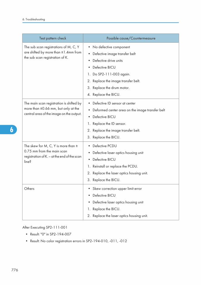
Test pattern check Possible cause/Countermeasure
The sub scan registrations of M, C, Yare shifted by more than ±1.4mm fromthe sub scan registration of K.
• No defective component
• Defective image transfer belt
• Defective drive units
• Defective BICU
1. Do SP2-111-003 again.
2. Replace the image transfer belt.
3. Replace the drum motor.
4. Replace the BICU.
The main scan registration is shifted bymore than ±0.66 mm, but only at thecentral area of the image on the output.
• Defective ID sensor at center
• Deformed center area on the image transfer belt
• Defective BICU
1. Replace the ID sensor.
2. Replace the image transfer belt.
3. Replace the BICU.
The skew for M, C, Y is more than ±0.75 mm from the main scanregistration of K. – at the end of the scanline?
• Defective PCDU
• Defective laser optics housing unit
• Defective BICU
1. Reinstall or replace the PCDU.
2. Replace the laser optics housing unit.
3. Replace the BICU.
Others • Skew correction upper limit error
• Defective BICU
• Defective laser optics housing unit
1. Replace the BICU.
2. Replace the laser optics housing unit.
After Executing SP2-111-001
• Result: "0" in SP2-194-007
• Result: No color registration errors in SP2-194-010, -011, -012
6. Troubleshooting
776
6

Test pattern check Possible cause/Countermeasure
The main scan registration of K isshifted.
• Abnormal SP setting value of main scan: K
Adjust the value with SP2-101-001.
The main scan length of K is shifted. • Abnormal SP setting value of main scan length detection:K
Adjust the value with SP2-185-001.
After Executing SP2-111-001
• Result: "0" in SP2-194-007
• Result: Color registration errors in SP2-194-010, -011, -012
Test pattern check Possible cause/Countermeasure
Low image density on the output • Low pattern density
Do the forced process control (SP3-011-001) or supply sometoner (SP3-015-xxx).
The main scan registration is shifted, butonly at the central area of the image onthe output.
• Defective ID sensor at center
• Deformed center area on the image transfer belt
• Defective BICU
1. Replace the ID sensor.
2. Replace the image transfer belt.
3. Replace the BICU.
The main scan registrations of M, C, Yare shifted.
• Defective laser optics housing unit
• Defective ID sensor
• Defective BICU
• Incorrect SP value
1. Replace the laser optics housing unit.
2. Replace the ID sensor.
3. Replace the BICU.
4. Adjust the value with SP2-182-004 to -021.
Troubleshooting Guide
777
6
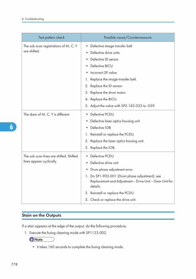
Test pattern check Possible cause/Countermeasure
The sub scan registrations of M, C, Yare shifted.
• Defective image transfer belt
• Defective drive units
• Defective ID sensor
• Defective BICU
• Incorrect SP value
1. Replace the image transfer belt.
2. Replace the ID sensor.
3. Replace the drum motor.
4. Replace the BICU.
5. Adjust the value with SP2-182-022 to -039.
The skew of M, C, Y is different. • Defective PCDU
• Defective laser optics housing unit
• Defective IOB
1. Reinstall or replace the PCDU.
2. Replace the laser optics housing unit.
3. Replace the IOB.
The sub scan lines are shifted. Shiftedlines appear cyclically.
• Defective PCDU
• Defective drive unit
• Drum phase adjustment error
1. Do SP1-902-001 (Drum phase adjustment); seeReplacement and Adjustment – Drive Unit – Gear Unit fordetails.
2. Reinstall or replace the PCDU.
3. Check or replace the drive unit.
Stain on the Outputs
If a stain appears at the edge of the output, do the following procedure.
1. Execute the fusing cleaning mode with SP1123-002.
• It takes 160 seconds to complete the fusing cleaning mode.
6. Troubleshooting
778
6

2. Make a sample copy, and then check if a stain appears on the output.
Stack Problem in the 1-Bin Tray
If a stack problem occurs on the 1-bin tray, raise the guide on the 1-bin tray.
If a stack problem occurs;
• Push the guide to lift the guide [A].
If another type or size of paper is used;
• Press down the guide [B].
Problem at Regular Intervals
Image problems may appear at regular intervals that depend on the circumference of certain components.
The following diagram shows the possible symptoms (black or white dots at regular intervals).
Troubleshooting Guide
779
6

[A]: Paper feed direction
[B]: Problems at regular intervals
• Colored spots at 47-mm intervals: Development roller
• Abnormal image at 51-mm intervals: ITB drive or bias roller
• Abnormal image at 85-mm intervals: Paper transfer roller
• Colored spots at 119-mm intervals: Drum
• Abnormal image at 101-mm intervals: Fusing unit (Pressure roller)
• Abnormal image at 107-mm intervals: Fusing unit (Heating roller)
Toner End Recovery Error
If the toner end message on the LCD is displayed in the following conditions, there are some possiblecauses. Check the machine referring to the flow chart for the toner end recovery error.
• After a new toner bottle has been installed in the machine
• When a displayed color toner bottle still has toner inside
6. Troubleshooting
780
6

Flow Chart for the Toner End Recovery Error
Troubleshooting Guide
781
6

Countermeasure 1
1. Check if the toner supply tube is bent or disconnected.
1. Straighten the toner supply tube or connect it correctly.
Countermeasure 2
1. Remove the target color toner bottle.
1. Disconnect the toner supply tube from the toner pump unit.
2. Remove the blocked toner in the toner supply tube with a vacuum cleaner.
Countermeasure 3
• Replace the toner pump unit ( p.214).
Countermeasure 4
• Replace the PCDU ( p.205).
6. Troubleshooting
782
6

Solid Image or Halftone Image Error
The toner density of a solid image or halftone image may not be uniform ([A]: problem output, [B]: normaloutput) if a large amount of sheets is printed at low coverage. If this occurs, follow the countermeasurebelow.
Recovery Procedure
1. Enter the SP mode.
1. Set SP3-044-xxx (Toner Supply Type) to "1: PID (Vref Fixed)".
• Chose a target color SP number from -001 (Bk), -002 (Magenta), -003 (Cyan), and -004(Yellow).
2. Set SP3-222-xxx (Vtref: Display/Set) to "4V".
• Chose a target color SP number from -001 (Bk), -002 (Magenta), -003 (Cyan), and -004(Yellow).
3. Set SP2-109-003 (Test Pattern; Pattern Selection) to "23: Full Dot Pattern".
4. Set SP2-109-005 (Test Pattern; Color Selection) to "1: All Color (black)", "2: Magenta", "3: Cyan",or "4: Yellow".
• Chose a target color selection number.
5. Press "Copy Window" on the LCD.
6. Copy 20 sheets for A4 size or 30 sheets for A3 size, and then check the setting of SP3-222-xxx (Vtref:Display/Set).
• If the setting of this SP is more than 4V, go to next step. If not, copy again until the setting of thisSP is more than 4V.
7. Return the setting of SP3-044-xxx (Toner Supply Type) to "4: MBD (Vref_Control)".
• Return the setting of the SP which you have changed in step 2 before.
Troubleshooting Guide
783
6

8. Execute SP3-015-xxx (Forced Toner Supply: Execute) twice.
• Chose a target color SP number from -003 (Bk), -004 (Magenta), -005 (Cyan) and -006(Yellow).
9. Execute the SP3-011-002 (Process Cont. Manual Execution; Density Adjustment).
Problem Prevention Procedure
• Set the setting of SP3-516-025 (Refresh Mode; Job End Area Coefficient) to "0.5".
Faulty Cleaning
Black or color lines (2-3mm)
Possible Cause:
Wear of the cleaning blade at a specific point by image creation in the same place many times.
Solution:
Replace the drum unit.
6. Troubleshooting
784
6

Band Image Between 20mm and 30mm
Possible Cause:
Developer wear with time
Solution:
Replace the developer or the development unit.
Troubleshooting Guide
785
6

Jam Detection
Paper Jam Display
SP7-507 shows the paper jam history.
• CODE: Indicates the jam code.
• SIZE: Indicates the paper Size Code.
• TOTAL: Indicates the total counter (SP7-502-001).
• DATE: indicates the date when the jam occurred.
Jam Codes and Display Codes
SP7-504 shows how many jams occurred at each location.
Jam Code SP Display DescriptionLCDDisplay
7504 3 Tray 1: ON Paper is not fed from tray 1. A
7504 4 Tray 2: ON Paper is not fed from tray 2. A
7504 5 Tray 3: ON Paper is not fed from tray 3 (LCT). Y
7504 6 Tray 4: ON Paper is not fed from tray 4. Y
7504 7 LCT: ON Paper is not fed from LCT. U
7504 8 Bypass: ON Paper is not fed from the by-pass tray. A
7504 9 Duplex: ON Paper is jammed at the duplex unit. Z
7504 10 - - -
7504 11 Vertical Transport 1: ONVertical transport sensor 1 does not detectpaper from tray 1.
A
6. Troubleshooting
786
6

Jam Code SP Display DescriptionLCDDisplay
7504 12 Vertical Transport 2: ONVertical transport sensor 2 does not detectpaper from tray 2.
A
7504 13 Bank Transport 1Vertical transport sensor 1 or relay sensor doesnot detect paper from tray 3 (LCT).
Y
7504 15 - - -
7504 16 - - -
7504 17 Registration: ON Registration sensor does not detect paper. B
7504 18 Fusing Entrance: ON Fusing entrance sensor does not detect paper. B
7504 19 Fusing Exit: ON Fusing exit sensor does not detect paper. B
7504 20 Paper Exit: ON Paper exit sensor does not detect paper. C
7504 21 Relay Exit: ONTray exit sensor (bridge unit) does not detectpaper.
D
7504 22 Relay Transport: ONRelay sensor (bridge unit) does not detectpaper.
D
7504 23 - - -
7504 24 Junction Gate Feed: ON Junction gate jam sensor does not detect paper. C
7504 25 Duplex Exit: ON Duplex exit sensor does not detect paper. Z
7504 26 Duplex Entrance: ON (In) Duplex entrance sensor does not detect paper. Z
7504 27Duplex Entrance: ON(Out)
Duplex entrance sensor does not detect paperagain after paper has passed this sensor.
Z
7504 28 - - -
7504 51 SEF Sensor 1 Vertical transport sensor 1 does not turn off. A
7504 52 SEF Sensor 2 Vertical transport sensor 2 does not turn off. A
7504 53 Bank SEF Sensor 1Vertical transport sensor or relay sensor 1 doesnot turn off.
Y
7504 54 Bank SEF Sensor 2 Vertical transport sensor 2 does not turn off. Y
Jam Detection
787
6

Jam Code SP Display DescriptionLCDDisplay
7504 55 - - -
7504 56 - - -
7504 57 Regist Sensor Registration sensor does not turn off. B
7504 58 LCT Sensor LCT sensor does not turn off. U
7504 59 - -
7504 60 Exit Sensor Paper exit sensor does not turn off. C
7504 61 Relay Exit Sensor Tray exit sensor (bridge unit) does not turn off. D
7504 62 Relay Sensor Relay sensor (bridge unit) does not turn off. D
7504 63 - - -
7504 64 Junction Gate Feed: OFF Junction gate jam sensor does not turn off. C
7504 65 Duplex Exit Sensor Duplex exit sensor does not turn off. Z
7504 66 Duplex Entrance: OFF (In) Duplex entrance sensor does not turn off. Z
7504 67Duplex Entrance: OFF(Out)
Duplex entrance sensor does not turn off afterpaper has passed this sensor.
Z
7504 68 - - -
7504 100 Finisher Entrance (B408)Paper does not reach to the entrance sensor orstay at the entrance sensor.
R1-R2
7504 101Finisher Shift Tray Exit(B408)
Paper does not reach to the lower tray exitsensor or stay at the lower tray exit sensor.
R1-R2
7504 102 Finisher Staple (B408)Paper does not reach to the staple tray entrancesensor or stay at the staple tray entrance sensor.
R3-R5
7504 103 Finisher Exit (B408)
Lower tray exit sensor does not detect paperafter the stack feed-out belt has fed paper.
Lower tray exit sensor still detects paper afterthe stack feed-out belt has returned to the homeposition.
R3-R5
7504 104 - - -
6. Troubleshooting
788
6

Jam Code SP Display DescriptionLCDDisplay
7504 105Finisher Tray Lift Motor(B408)
Stack height sensor does not detect paper afterthe lower tray has lifted up.
Stack height sensor still detects paper after thelower tray has lifted down.
R1-R2
7504 106Finisher Jogger Motor(B408)
Jogger fence HP sensor does not turn off afterthe jogger fence has moved from its homeposition.
Jogger fence HP sensor does not turn on afterthe jogger fence has returned to its homeposition.
R3-R5
7504 107Finisher Shift Motor(B408)
Shift roller HP sensor does not turn off after theshift roller has moved from its home position.
Shift roller HP sensor does not turn on after theshift roller has returned to its home position.
R1-R2
7504 108Finisher Staple Motor(B408)
Stapler HP sensor does not turn off after thestapler has moved from its home position.
Stapler HP sensor does not turn on after thestapler has returned to its home position.
R3-R5
7504 109 Finisher Exit Motor (B408)
Stack feed-out belt HP sensor does not turn offafter the stack feed-out belt has moved from itshome position.
Stack feed-out belt HP sensor does not turn onafter the stack feed-out belt has returned to itshome position.
R3-R5
7504 191Finisher Entrance: EUP(B804/B805)
Paper does not reach the finisher entrancesensor or stays at the finisher entrance sensor.
R1-R4
7504 192Finisher Proof Exit: EUP(B804/B805)
Paper does not reach the proof tray exit sensoror stays at the proof tray exit sensor.
R1-R4
7504 193Finisher Shift Tray Exit:EUP (B804/B805)
Paper does not reach the upper tray exit sensoror stays at the upper tray exit sensor.
R1-R4
Jam Detection
789
6

Jam Code SP Display DescriptionLCDDisplay
7504 194Finisher Stapler Exit: EUP(B804/B805)
Stapling tray paper sensor does not turn onafter the finisher entrance sensor has turned on.
Stapling tray paper sensor does not turn offafter it has turned on.
R5-R7
7504 195Finisher Exit: EUP (B804/B805)
Upper tray exit sensor does not turn on whilethe stack feed-out belt is turned on.
Upper tray exit sensor does not turn off after thestack feed-out belt has returned to its homeposition.
R8-R12
7504 196 - - -
7504 197 - - -
7504 198Finisher Folder: EUP(B804 only)
Fold bottom fence HP sensor does not turn onafter the fold roller motor has stopped.
Fold unit exit sensor does not turn on after thefold rollers have stopped.
Fold unit exit sensor does not turn off after thefold rollers have stopped.
R8-R12
7504 199Finisher Tray Motor: EUP(B804/B805)
Upper tray limit sensor does not turn on after theupper tray has lifted up.
Upper tray limit sensor does not turn off after theupper tray has moved down.
R1-R4
7504 200Finisher Jogger Motor:EUP (B804/B805)
Jogger fence HP sensor does not turn on/offafter the jogger motor has turned on.
Stack feed out belt HP sensor does not turn on/off after the feed out belt motor has turned on.
R8-R12
7504 201Finisher Shift Motor: EUP(B804/B805)
Shift roller HP sensor does not turn on/off afterthe shift roller motor has turned on.
Exit guide plate HP sensor does not turn on/offafter the exit guide plate motor has turned on.
Stacking roller HP sensor does not turn on/offafter the stacking sponge roller motor hasturned on.
R1-R4
6. Troubleshooting
790
6

Jam Code SP Display DescriptionLCDDisplay
7504 202Finisher Staple MovingMotor: EUP (B804/B805)
Corner stapler HP sensor does not turn on/offafter the corner stapler movement motor hasturned on.
Stapler rotation HP sensor does not turn on/offafter the corner stapler rotation motor hasturned on.
R8-R12
7504 203Finisher Staple Motor:EUP (B804/B805)
Corner stapler does not finish stapling after aspecified time.
Booklet stapler does not finish stapling after aspecified time.
R8-R12
7504 204Finisher Folder Motor:EUP (B804 only)
Fold plate HP sensor does not turn on/off afterthe fold plate motor has turned on.
Clamp roller HP sensor does not turn on/offafter the clamp roller retraction motor hasturned on.
Fold bottom fence HP sensor does not turn on/off after the fold unit bottom fence lift motor hasturned on.
Stack junction gate HP sensor does not turn on/off after the stack junction gate motor has turnedon.
R8-R12
7504 205 - - -
7504 206Finisher Punch Motor: EUP(B804/B805)
Punch encoder sensor does not turn on/off afterthe punch drive motor has turned on.
Punch movement HP sensor does not turn on/off after the punch movement motor has turnedon.
Paper position slide HP sensor does not turnon/off after the paper position sensor slidemotor has turned on.
R1-R4
Jam Detection
791
6

Paper Size Code
Size Code Paper Size Size Code Paper Size
05 A4 LEF 141 B4 SEF
06 A5 LEF 142 B5 SEF
14 B5 LEF 160 DLT SEF
38 LT LEF 164 LG SEF
44 HLT LEF 166 LT SEF
132 A3 SEF 172 HLT SEF
133 A4 SEF 255 Others
134 A5 SEF - -
6. Troubleshooting
792
6

Sensor Locations
Jam Detection
793
6

Electrical Component Defects
Sensors
• The CN numbers in the following table are the connector numbers on the IOB.
No.Sensor Name/
Sensor Board Name
Active
CN Condition Symptom
SW1 Right Door Open Switch L CN204/1
Open "Open Cover" is displayed.
Shorted"Open cover" cannot bedetected.
S9 Duplex Door L CN232/B9
Open "Open Cover" is displayed.
Shorted"Open cover" cannot bedetected.
S1
ID Sensor: M ACN211/
7, 11
Open/
Shorted
SC400ID Sensor: C ACN211/
8, 12
Open/
Shorted
ID Sensor: Y ACN211/
9, 13
Open/
Shorted
ID Sensor: Front A CN211/1Open/
ShortedSC258
ID Sensor: Center and K A CN211/2Open/
ShortedSC400 / SC258
ID Sensor: Rear A CN211/3Open/
ShortedSC258
S12 Registration Sensor L CN224/A2Open Jam A (Jam8, 17)
Shorted Jam A, B (Jam1)
6. Troubleshooting
794
6

No.Sensor Name/
Sensor Board Name
Active
CN Condition Symptom
S28Drum Gear PositionSensor-K
H CN222/A2Open/
ShortedSC380/SC396
S29Drum Gear PositionSensor-M
H CN222/ A5Open/
ShortedSC381/SC397
S30Drum Gear PositionSensor-C
H CN222/ A8Open/
ShortedSC382/SC398
S31Drum Gear PositionSensor-Y
H CN222/ A11Open/
ShortedSC383/SC399
S24
S25
S26
S27
Toner End Sensor - K
Toner End Sensor - Y
Toner End Sensor - C
Toner End Sensor - M
L
CN207/A1
CN207/B9
CN207/
B12
CN207/
B15
OpenToner end cannot bedetected.
ShortedToner end is detected whenthere is enough toner.
S32Image Transfer BeltRotation Sensor
H/L CN208/11Open/
ShortedSC443
S18Vertical Transport Sensor1
L CN230/A7Open Jam A (Jam3, 11)
Shorted Jam A, B (Jam1)
S21
S24
Paper End
Sensor 1, 2L
CN230/
A10, B10
OpenPaper end is not detectedwhen there is no paper inthe paper tray.
ShortedPaper end is detected whenthere is paper in the papertray.
S20
S23Paper Lift Sensor 1, 2 H
CN230/
A13, B13
Open/
ShortedSC501, SC502
S21Vertical Transport Sensor2
L CN230/B7Open Jam A (Jam4, 12)
Shorted Jam A, B (Jam1)
Electrical Component Defects
795
6

No.Sensor Name/
Sensor Board Name
Active
CN Condition Symptom
S14
S15
Tray 1 Paper HeightSensor 1, 2
LCN224/
B2, B5
Open/
Shorted
Remaining paper volumeon the LCD is wrong.
S16
S17
Tray 2 Paper HeightSensor 1, 2
LCN224/
B10, B13
Open/
Shorted
Remaining paper volumeon the LCD is wrong.
SW4 Tray 1 Set Switch L CN224/A9
OpenTray 1 is not detected whentray 1 is set.
ShortedTray 1 is detected when tray1 is not set.
S11By-pass Paper SizeSensor
L
CN232/
B16, B17,B19, B20
Open/
ShortedPaper size error
SW2By-pass Paper DetectionSensor
LCN232/
A15
OpenPaper on the by-pass tray isnot detected when paper isset.
ShortedPaper on the by-pass tray isdetected when paper is notset.
S10By-pass Paper LengthSensor
LCN232/
B12
OpenPaper size error
Shorted
S8 Fusing Entrance Sensor L CN232/B6Open Jam C (Jam 18)
Shorted Jam C (Jam 1)
S6 Duplex Entrance Sensor L CN232/A8Open Jam Z (Jam 26/27)
Shorted Jam Z (Jam 1)
S7 Duplex Exit Sensor LCN232/
A11
Open Jam Z (Jam 25)
Shorted Jam Z (Jam 1)
S35 TD Sensor - K A CN227/A7Open/
ShortedSC372
6. Troubleshooting
796
6

No.Sensor Name/
Sensor Board Name
Active
CN Condition Symptom
S36 TD Sensor - M ACN227/
A15
Open/
ShortedSC373
S37 TD Sensor - C A CN227/B7Open/
ShortedSC374
S38 TD Sensor - Y ACN227/
B15
Open/
ShortedSC375
S4 Fusing Exit Sensor L CN204/12Open Jam C (Jam 19)
Shorted Jam C (Jam 1)
S13 Waste Toner Sensor H CN224/A5
OpenWaste toner near fullindicated when it is not nearfull.
Shorted
Waste toner near fullcannot be detected whenthe waste toner bottle isnearly full.
SW4Waste Toner Bottle SetSwitch
L CN224/A7
OpenWaste toner bottle is notdetected when the wastetoner bottle is set.
ShortedWaste toner bottle isdetected when the wastetoner bottle is not set.
SW6 Tray 2 Paper Size Switch L
CN224/
A11, A12,A13, A15
Open/
ShortedPaper size error
S33Temperature/
Humidity SensorA
CN231/
25, 27
Open/
Shorted
SC498
Printed image has someproblems such as roughimage, dirty background,weak image or poor fusing.
Electrical Component Defects
797
6

No.Sensor Name/
Sensor Board Name
Active
CN Condition Symptom
S34 Thermopile A CN209/16Open/
ShortedSC541
TH2Thermistor
- Heating RollerA CN212/22
Open/
ShortedSC551
TH1Thermistor
- Pressure RollerA CN212/18
Open/
ShortedSC561
S3 Paper Exit Sensor L CN204/9Open Jam C (Jam 20)
Shorted Jam C (Jam 1)
S5 Paper Overflow Sensor L CN204/15
Open
Paper overflow message isnot displayed when thepaper overflow conditionstill remains.
Shorted
Paper overflow message isdisplayed when the paperoverflow condition does notremain.
S41
Original Width Sensor 1 ACN313/14
SIO
Open/
Shorted
Original paper size cannotbe detected.
Original Width Sensor 2 ACN313/11
SIO
Open/
Shorted
Original paper size cannotbe detected.
S42
Original Length Sensor 1 ACN313/8
SIO
Open/
Shorted
Original paper size cannotbe detected.
Original Length Sensor 2 ACN313/5
SIO
Open/
Shorted
Original paper size cannotbe detected.
S43 Original Length Sensor 3 ACN313/2
SIO
Open/
Shorted
Original paper size cannotbe detected.
S39 Scanner HP Sensor HCN318/2
SIO
Open SC120
Shorted SC121
6. Troubleshooting
798
6

No.Sensor Name/
Sensor Board Name
Active
CN Condition Symptom
S40 Platen Cover Sensor LCN318/5
SIO
Open/
Shorted
Platen cover open cannotbe detected.
S2Junction Paper JamSensor
L CN204/6Open/
ShortedJam C (Jam 24/64)
Blown Fuse Conditions
Power Supply Unit
FuseRating
Symptom when turning on the main switch115V 220V - 240V
FU1 15A/125V 8A/250V No response. (5V power to the PSU is not supplied.)
FU2 10A/125V 6.3A/250VNo response. (5V power to the BICU and controller is notsupplied.)
FU3 2A/250V 1A/250V5V power to the scanner heater and tray heater is notsupplied.
FU4 1A/250V 1A/250V 5V power to the SIO and heater is not supplied.
FU5 5A/250V 5A/250V 5V power to the IOB not supplied.
FU6 2A/250V 2A/125V 5VS power to the BICU not supplied.
FU7 10A/125V 10A/125V 24VS power to the IOB not supplied.
FU8 10A/125V 10A/125V 24VS power to the IOB not supplied.
FU9 6.3A/125V 6.3A/125V 24V power to the IOB not supplied.
FU10 6.3A/125V 6.3A/125V 24V power to the SIO not supplied.
FU11 6.3A/125V 6.3A/125V 24V power to the BICU and MB not supplied.
FU12 6.3A/125V 6.3A/125V 24V power to the PFU or LCT not supplied.
FU13 6.3A/125V 6.3A/125V 24V power to the finisher not supplied.
Electrical Component Defects
799
6
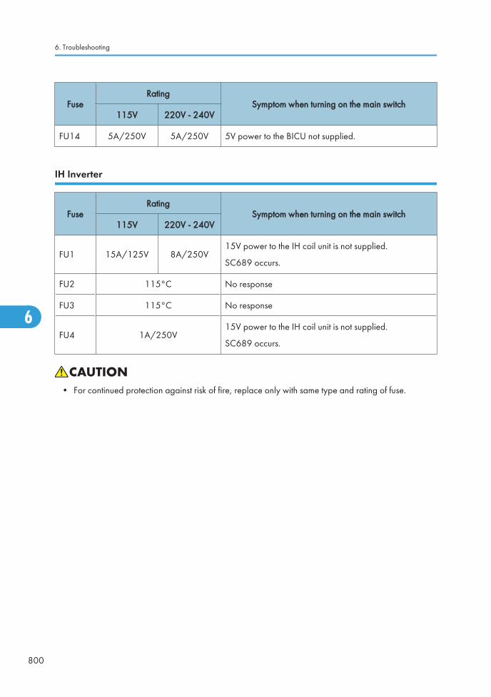
FuseRating
Symptom when turning on the main switch115V 220V - 240V
FU14 5A/250V 5A/250V 5V power to the BICU not supplied.
IH Inverter
FuseRating
Symptom when turning on the main switch115V 220V - 240V
FU1 15A/125V 8A/250V15V power to the IH coil unit is not supplied.
SC689 occurs.
FU2 115°C No response
FU3 115°C No response
FU4 1A/250V15V power to the IH coil unit is not supplied.
SC689 occurs.
• For continued protection against risk of fire, replace only with same type and rating of fuse.
6. Troubleshooting
800
6

Scanner Test Mode
SBU Test Mode
Output the SBU test pattern with SP4-807-001 to make sure the scanner SBU control operates correctly.The SBU test pattern prints out after you have set the SP mode settings and pressed the start key.
• The CCD on the SBU board may be defective if the copy is abnormal and the SBU test pattern isnormal.
• The followings can be the cause if the copy is normal and the SBU test pattern is abnormal:
• The harness may not be correctly connected between the SBU and the BICU.
• The BICU or SBU board may be defective.
Scanner Test Mode
801
6

6. Troubleshooting
802
6

7. Energy Saving
Energy Save
Energy Saver Modes
Customers should use energy saver modes properly, to save energy and protect the environment.
The area shaded grey in this diagram represents the amount of energy that is saved when the timers areat the default settings. If the timers are changed, then the energy saved will be different. For example, ifthe timers are all set to 240 min., the grey area will disappear, and no energy is saved before 240 min.expires.
Timer Settings
The user can set these timers with User Tools (System settings > Timer setting)
• Panel off timer (10 sec – 240 min): Panel Off Mode. Default setting: 60 sec.
• Energy saver timer (1 – 240 min): Low Power Mode. Default setting: 15 min.
• Auto off timer (1 – 240 min): Off/Sleep Mode. Default setting: 30 min.
Normally, Panel Off timer < Energy Saver timer < Auto Off timer. But, for example, if Auto Off timer < or= Panel Off timer and Energy Saver timer, the machine goes immediately to Off mode when the Auto Offtimer expires. It skips the Panel Off and Energy Saver modes.
Example
• Panel off: 1 min.
803
7

• Low power: 15 min.
• Auto Off: 1 min.
• The machine goes to Off mode after 1 minute. Panel Off and Low Power modes are not used.
Return to Stand-by Mode
Low Power Mode
The recovery time depends on the model and the region.
• 10 to 15.7 sec.
Off/Sleep Mode
Recovery time.
• 15 sec.
Recommendation
We recommend that the default settings should be kept.
• If the customer requests that these settings should be changed, please explain that their energy costscould increase, and that they should consider the effects on the environment of extra energy use.
• If it is necessary to change the settings, please try to make sure that the Auto Off timer is not too long.Try with a shorter setting first, such as 30 min., then go to a longer one (such as 60 min.) if the customeris not satisfied.
• If the timers are all set to the maximum value, the machine will not begin saving energy until 240minutes has expired after the last job. This means that after the customer has finished using the machinefor the day, energy will be consumed that could otherwise be saved.
• If you change the settings, the energy consumed can be measured using SP8941, as explained below.
Energy Save Effectiveness
SP 8941 (Machine Status) keeps a record of the amount of time that the machine spends in each mode.
• 8941-001: Operating mode
• 8941-002: Standby mode
• 8941-003: Panel off mode
• 8941-004: Low power mode
• 8941-005: Off/sleep mode
With this data, and the power consumption values from the specifications, we can estimate the amount ofenergy that is used by the machine.
7. Energy Saving
804
7

This should only be used as a reference value, because the power consumption specifications are measuredin a controlled environment with a constant power supply.
To get an exact measurement at the customers site, a watt meter must be used to measure the actual energyconsumed.
To use SP8941 to calculate the energy consumed:
• At the start of the measurement period, read the values of SP8941 001 to 005.
• At the end of the measurement period, read the values of SP8941 001 to 005 again.
• Find the amount of time spent in each mode (subtract the earlier measurement from the latermeasurement).
• Multiply this by the power consumption spec for each mode.
• Convert the result to kWh (kilowatt hours)
Here is an example calculation.
Machine
Condition
SP8941:
MachineStatus
Time at Start(min.)
Time at End(min.)
Runningtime
(hour)
( - )/60 =
PowerconsumptionSpec. (W)
Powerconsumption
(KWH)
( x )/1000=
Operating 001:Operating Time 21089.0 21386.0 5.0 1081.8 5.35
Stand by
(Ready)
002:Standby
Time 306163.0 308046.0 31.4 214.0 6.72
Energy save(Panel off)
003:Energy
Save Time 71386.0 75111.0 62.1 214.0 13.29
Low power
004: LowPowerTime 154084.0 156340.0 37.6 146.0 5.49
Off/Sleep
005: OffModeTime 508776.0 520377.0 193.4 7.0 1.35
Total 32.20
Energy Save
805
7
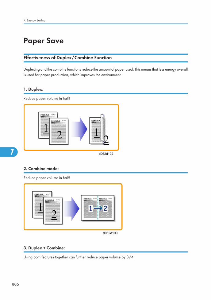
Paper Save
Effectiveness of Duplex/Combine Function
Duplexing and the combine functions reduce the amount of paper used. This means that less energy overallis used for paper production, which improves the environment.
1. Duplex:
Reduce paper volume in half!
2. Combine mode:
Reduce paper volume in half!
3. Duplex + Combine:
Using both features together can further reduce paper volume by 3/4!
7. Energy Saving
806
7

To check the paper consumption, look at the total counter and the duplex counter.
The total counter counts all pages printed.
• For one duplex page, the total counter goes up by 2.
• For a duplex job of a three-page original, the total counter goes up by 3.
The duplex counter counts pages that have images on both sides.
• For one duplex page, the duplex counter goes up by 1.
• For a duplex job of a three-page original, the duplex counter will only increase by 1, even thoughtwo sheets are used.
How to calculate the paper reduction ratio
How to calculate the paper reduction ratio, when compared with Single-sided copying, with no 2-in-1combine mode
Paper reduction ratio (%) = Number of sheets reduced: A/Number of printed original images: B x 100
• Number of sheets reduced: A
= Output pages in duplex mode/2 + Number of pages in Single-sided with combine mode + Numberof pages in Duplex with combine mode x 3/2A = ((2) + (3) + (4))/2 + (5) + (6) x 3/2
• Number of printed original images: B
= Total counter6 + Number of pages in Single-sided with combine mode + Number of pages in Duplexwith combine modeB = (1) + (5) + (6)
• (1) Total counter: SP 8581 001 (pages)
• (2) Single-sided with duplex mode: SP 8421 001 (pages)
• (3) Double-sided with duplex mode: SP 8421 002 (pages)
• (4) Book with duplex mode: SP 8421 003 (pages)
• (5) Single-sided with combine mode: SP 8421 004 (pages)
Paper Save
807
7

• (6) Duplex with combine mode: SP 8421 005 (pages)
7. Energy Saving
808
7

Model AT-C2.5 Machine Code: D086/D087
Appendices
1 November, 2010


TABLE OF CONTENTS1. Appendix: Specifications
General Specifications.......................................................................................................................................3
Main Frame....................................................................................................................................................3
Printer...............................................................................................................................................................7
Scanner...........................................................................................................................................................9
Supported Paper Sizes....................................................................................................................................10
Paper Feed...................................................................................................................................................10
Paper Exit......................................................................................................................................................13
Platen/ARDF Original Size Detection........................................................................................................18
Software Accessories.......................................................................................................................................20
Printer Drivers...............................................................................................................................................20
Scanner and LAN Fax drivers.....................................................................................................................20
Utility Software.............................................................................................................................................21
Optional Equipment.........................................................................................................................................22
ARDF (D541)...............................................................................................................................................22
Paper Feed Unit (D537)..............................................................................................................................22
LCT 2000-sheet (D538)..............................................................................................................................23
LCT 1200-sheet (D539)..............................................................................................................................23
1000-Sheet Booklet Finisher & Punch Unit (B793)..................................................................................24
1000-Sheet Finisher (B408).......................................................................................................................25
500-Sheet Finisher (D372).........................................................................................................................26
Bridge Unit (D386)......................................................................................................................................28
Shift Tray (D388).........................................................................................................................................29
1-bin Tray Unit (D536)...............................................................................................................................29
2. Appendix: Preventive Maintenance Tables
Maintenance Tables........................................................................................................................................31
Preventive Maintenance Items....................................................................................................................31
Others Yield Parts.........................................................................................................................................37
3. Appendix: SP Mode Tables
System SP1-xxx................................................................................................................................................39
SP1-XXX (Feed)............................................................................................................................................39
System SP2-xxx................................................................................................................................................71
SP2-XXX (Drum)...........................................................................................................................................71
1

System SP3-xxx..............................................................................................................................................155
SP3-XXX (Process).....................................................................................................................................155
System SP4-xxx..............................................................................................................................................207
SP4-XXX (Scanner)....................................................................................................................................207
System SP5-xxx..............................................................................................................................................233
SP5-XXX (Mode).......................................................................................................................................233
System SP6-xxx..............................................................................................................................................301
SP6-XXX (Peripherals)...............................................................................................................................301
System SP7-xxx..............................................................................................................................................311
SP7-XXX (Data Log)..................................................................................................................................311
System SP8-xxx..............................................................................................................................................346
SP8-xxx: Data Log2..................................................................................................................................346
Input and Output Check................................................................................................................................392
Input Check Table.....................................................................................................................................392
Output Check Table..................................................................................................................................403
Printer Service Mode.....................................................................................................................................414
SP1-XXX (Service Mode)..........................................................................................................................414
Scanner SP Mode..........................................................................................................................................421
SP1-xxx (System and Others)...................................................................................................................421
SP2-XXX (Scanning-image quality)..........................................................................................................421
Test Pattern Printing........................................................................................................................................423
INDEX...........................................................................................................................................................425
2

1. Appendix: Specifications
General Specifications
Main Frame
Configuration: Desktop
Print Process:Laser beam scanning & Dry electrostatic transfer system
4 drums tandem method
Number of scans: 1
Resolution:Scan: 600 dpi
Print: 600 dpi
Gradation:Scan: 600dpi / 10bits/pixel
Print: 600dpi / 4 bits/pixel
Original type: Sheets, book, objects
Maximum original size: A3/11" x 17"
Original referenceposition:
Left rear corner, ad hoc lists
3
1

Copy speed:
Plain (ADF 1 to 1, LT/ A4 LEF)
C2.5a: 30 cpm (color/black & white)
C2.5b: 35 cpm (color/black & white)
Thick 1 (169 g/m2 or less)
C2.5a: 17.5 cpm (color/black & white)
C2.5b 17.5 cpm (color/black & white)
Thick 2 (220 g/m2 or less)
C2.5a: 17.5 cpm (color/black & white)
C2.5b 17.5 cpm (color/black & white)
Thick 3 (256 g/m2 or less)
C2.5a: 17.5 cpm (color/black & white)
C2.5b 17.5 cpm (color/black & white)
Thick 4 (300 g/m2 or less)
C2.5a: 15 cpm (color/black & white) from By-pass
C2.5b: 15 cpm (color/black & white) from By-pass
OHP, Glossy (1200 dpi)
C2.5a: 17.5 cpm (color/black & white)
C2.5b 17.5 cpm (color/black & white)
First copy (normal mode):
C2.5a/ b
Color: 8 seconds or less (A4/LT LEF)
Black & white: 5 seconds or less (A4/LT LEF)
Warm-up time: 26 seconds or less (23°C)
Print Paper Capacity:
(80 g/m2, 20 lb)
Standard tray: 550 sheets x 2 + 100
By-pass tray: 100 sheets (Normal), 40 sheets (Thick 1: 106 - 169g/m2),20 sheets (Thick 2/3: 170 - 256 g/m2), 35 sheets (Postcard)
Optional paper feed tray: 550 sheets x 2
2000-sheet LCT: 2000 sheets
1200-sheet LCT: 1200 sheets
1. Appendix: Specifications
4
1

Print Paper Size:
(Refer to “Supported Paper Sizes”.)
- Minimum Maximum
Tray 1 A4/8.5" x 11" (LEF)
Tray 2A5 (LEF)/
8.5" x 11"A3/11" x 17"
By-pass 90 x 148 mm 305 x 600 mm
Optional TrayA5 (LEF)/
8.5" x 11"A3/11" x 17"
2000-sheet LCT A4/8.5" x 11" (LEF)
1200-sheet LCTB5 (LEF)/
257 x 182mm
A4 (LEF)/
297 x 210mm
Printing Paper Weight:
Standard tray: 60 to 256 g/m2 (16 to 68 lb.)
Optional paper tray: 60 to 256 g/m2 (16 to 68 lb.)
By-pass tray: 60 to 300 g/m2 (16 to 79.8 lb.)
Duplex unit: 60 to 169 g/m2 (16 to 45 lb.)
LCT 1200: 60 to 216 g/m2 (10 to 571Ib)
Output Paper Capacity:
Standard exit tray: 500 sheets or more (face down)*1
Shift Tray: 250 sheets (80 g/m2)
1-bin Tray: 125 (80 g/m2)
500-sheet finisher 500 (80 g/m2)
1000-sheet finisher: 250 + 1000 sheets (80 g/m2)
1000-sheet booklet finisher: 100 + 1000 sheets (80 g/m2)
*1: T6200, A4 LEF
Continuous copy: Up to 999 sheets
General Specifications
5
1

Zoom:
Arbitrary: From 25 to 400% (1% step)
Fixed:
North America Europe
25% 25%
50% 50%
65% 61%
73% 71%
78% 82%
85% 87%
93% 93%
100% 100%
121% 115%
129% 122%
155% 141%
200% 200%
400% 400%
Memory: Standard: 1.5 GB
Power Source:120 V, 60 Hz: More than 12A (for North America)
220 V – 240 V, 50/60 Hz: More than 8A (for Europe/ASIA)
Power Consumption:
- 120V 220 - 240V
Maximum 1584 W or less 1700 W or less
Energy Saver( Sleep Mode )
2.0 W or less 2.0 W or less
1. Appendix: Specifications
6
1

Noise Emission:
(Sound Power Level)
Model State MainframeComplete system
(*1)
C2.5a
Standby40 dB(A)
or Less
44 dB(A)
or Less
Operating
B/W: 66.5 dB(A)
or Less-
Color: 67.0 dB(A) orLess
Color: 70.4 dB(A) orLess
C2.5b
Standby40 dB(A)
or Less
46.9 dB(A)
or Less
Operating
B/W: 68.3 dB(A)
or Less-
Color: 68.5 dB(A) orLess
Color: 71.9 dB(A) orLess
(*1) The complete system consists of mainframe, ARDF, finisher, and LCT.
The above measurements were made in accordance with Ricoh standard methodology.
Dimensions (W x D x H):
Copier: 670 x 671 x 760 mm (26.4" x 26.4" x 29.9")
Copier + PFU or LCT: 670 x 671 x 1020 mm (26.4" x 26.4" x 40.2")
Weight: Less than 120 kg (265 lb.) [with ARDF excluding toner]
Printer
Printer Languages:
PCL 6/5c
RPCS (Refined Printing Command Stream)
Adobe PostScript 3 (optional)
PDF Direct (optional)
IPDS (optional)
PictBridge (optional)
MediaPrint: JPEG/TIFF (optional)
General Specifications
7
1

Resolution andGradation:
PCL 5c:
300 x 300 dpi : Available only in B/W mode
600 x 600 dpi : Fast (1 bit), Standard (2 bits), Fine (4 bits)
PCL 6:
600 x 600 dpi : Fast (1 bit), Standard (2 bits), Fine (4 bits) / 1200 x 1200dpi
RPCS:
600 x 600 dpi, 1,800 x 600 dpi*, 9600 dpi x 600 dpi*
*1,800 x 600 dpi = 600 x 600 dpi (2 bits)
*9600 dpi x 600 dpi* = 600 x 600 dpi (4 bits)
PS3:
600 x 600 dpi : Fast (1 bit), Standard (2 bits), Fine (4 bits)
Printing speed:
C2.5a:
30 ppm in Plain/Middle Thick mode
17.5 ppm in Thick/OHP mode (depending on paper type)
C2.5b:
35 ppm in Plain/Middle Thick mode
17.5 ppm in Thick/OHP mode (depending on paper type)
Resident Fonts:
PCL 6/5c (Standard):
45 Compatible fonts
13 International fonts
1 Bitmap font
Adobe PostScript 3 (Optional):
136 fonts (24 Type 2 fonts, 112 Type 14 fonts)
IPDS (Optional):
108 fonts
1. Appendix: Specifications
8
1

Host Interfaces:
USB2.0 Type A and Type B: Standard
USB Host (PictBridge): Optional
Ethernet (100 Base-TX/10 Base-T): Standard
Gigabit Ethernet (1000 Base-T): Optional
IEEE1284 parallel x 1: Optional
IEEE802.11a/g (Wireless LAN): Optional
Bluetooth (Wireless): Optional
Network Protocols: TCP/IP (IPv4, IPv6), IPX/SPX, AppleTalk (Auto Switching)
Scanner
Standard ScannerResolution:
Main scan/Sub scan
600 dpi
Available scanningResolution Range:
Twain Mode:
100 to1200 dpi
Delivery Mode:
100/200/300/400/600 dpi
Grayscales: 1 bit or 8 bits/pixel each for RGB
Scanning Throughput
(ARDF mode):
Scan to E-mail / Folder:
BW: 51 ipm (A4LEF / BW Text (Print) / 200dpi /Compression: On (MH))
FC: 51 ipm (A4LEF / FC Text / Photo / 200dpi / Compression: Standard)
Interface:Ethernet (100 Base-TX/10 Base-T/1000 Base-T for TCP/IP), Wireless LAN,GigaEthernet
Compression Method:B&W: TIFF (MH, MR, MMR)
Gray Scale, Full Color: JPEG
General Specifications
9
1

Supported Paper Sizes
Paper Feed
North America
BT: By-pass Tray, T1: Tray 1, T2/3/4: Tray 2/3/4, LCT 2000: Large Capacity Tray: 2000-sheet, LCT1200: Large Capacity Tray: 1200-sheet, DU: Duplex Unit
PaperSize
(W x L)BT T1
T2/3/4
LCT
2000
LCT
1200DU
A3 W 12" x 18" M - - - - -
A3 SEF 297 x 420mm M - M - - M
A4 SEF 210 x 297mm M - A - - M
A4 LEF 297 x 210mm M S M S S M
A5 SEF 148 x 210mm M - - - - -
A5 LEF 210 x 148mm M S A - - M
A6 SEF 105 x 148mm M - - - - -
B4 SEF 257 x 364mm M - M - - M
B5 SEF 182 x 257mm M - A - - M
B5 LEF 257 x 182mm M S M - S M
B6 SEF 128 x 182mm M - - - - -
Ledger 11" x 17" A - A - - M
Letter SEF 8.5" x 11" A - A - - M
Letter LEF 11" x 8.5" A M A M M M
Legal SEF 8.5" x 14" M - A - - M
GovernmentLegal SEF
8.25" x 14" M - M - - M
Half Letter SEF 5.5" x 8.5" A - - - - -
1. Appendix: Specifications
10
1

PaperSize
(W x L)BT T1
T2/3/4
LCT
2000
LCT
1200DU
Executive SEF 7.25" x 10.5" M - M - - M
Executive LEF 10.5" x 7.25" M - A - - M
F SEF 8" x 13" M - M - - M
Foolscap SEF 8.5" x 13" M - M - - M
Folio SEF
8.25" x 13" M - M - - M
11" x 15" M - M - - M
10" x 14" M - M - - M
8" x 10" M - M - - M
8K 267 x 390mm M - M - - M
16K SEF 195 x 267mm M - M - - M
16K LEF 267 x 195mm M - M - - M
Custom M - M - - -
Com10 Env. 4.125" x 9.5" M - - - - -
Monarch Env. 3.875" x 7.5" M - - - - -
C6 Env. 114 x 162mm M - - - - -
C5 Env. 162 x 229mm M - - - - -
DL Env. 110 x 220mm M - - - - -
Remarks:
A Supported: the sensor detects the paper size.
M Supported: the user specifies the paper size.
S Supported: depends on a technician adjustment
- Not supported
Supported Paper Sizes
11
1

Europe/ Asia
BT: By-pass Tray, T1: Tray 1, T2/3/4: Tray 2/3/4, LCT 2000: Large Capacity Tray: 2000-sheet, LCT1200: Large Capacity Tray: 1200-sheet, DU: Duplex Unit
PaperSize
(W x L)BT T1
T2/3/4
LCT
2000
LCT
1200DU
A3 W 12" x 18" M - - - - -
A3 SEF 297 x 420mm A - A - - M
A4 SEF 210 x 297mm A - A - - M
A4 LEF 297 x 210mm A M A M S M
A5 SEF 148 x 210mm A - - - - -
A5 LEF 210 x 148mm A S A - - M
A6 SEF 105 x 148mm A - - - - -
B4 SEF 257 x 364mm M - A - - M
B5 SEF 182 x 257mm M - A - - M
B5 LEF 257 x 182mm M S A - S M
B6 SEF 128 x 182mm M - - - - -
Ledger 11" x 17" M - M - - M
Letter SEF 8.5" x 11" M - A - - M
Letter LEF 11" x 8.5" M S M S S M
Legal SEF 8.5" x 14" M - M - - M
GovernmentLegal SEF
8.25" x 14" M - M - - M
Half Letter SEF 5.5" x 8.5" M - - - - -
Executive SEF 7.25" x 10.5" M - M - - M
Executive LEF 10.5" x 7.25" M - M - - M
F SEF 8" x 13" M - M - - M
Foolscap SEF 8.5" x 13" M - M - - M
1. Appendix: Specifications
12
1

PaperSize
(W x L)BT T1
T2/3/4
LCT
2000
LCT
1200DU
Folio SEF
8.25" x 13" M - M - - M
11" x 15" M - M - - M
10" x 14" M - M - - M
8" x 10" M - M - - M
8K 267 x 390mm M - M - - M
16K SEF 195 x 267mm M - M - - M
16K LEF 267 x 195mm M - M - - M
Custom M - M - - -
Com10 Env. 4.125" x 9.5" M - - - - -
Monarch Env. 3.875" x 7.5" M - - - - -
C6 Env. 114 x 162mm M - - - - -
C5 Env. 162 x 229mm M - - - - -
DL Env. 110 x 220mm M - - - - -
Remarks:
A Supported: the sensor detects the paper size.
M Supported: the user specifies the paper size.
S Supported: depends on a technician adjustment
- Not supported
Paper Exit
1000-Sheet Booklet Finisher
MF: Main Frame, Prf: Proof, Clr: Clear, Shf: Shift, Stp: Staple, SS: Saddle Stitch,
2/3 P: 2/3 Holes Punch, 4 P: 4 Holes Punch, N4P: North Europe 4 Holes Punch
Supported Paper Sizes
13
1
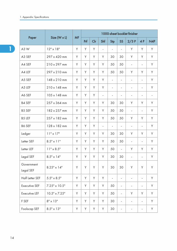
Paper Size (W x L) MF1000-sheet booklet finisher
Prf Clr Shf Stp SS 2/3 P 4 P N4P
A3 W 12" x 18" Y Y Y - - - Y Y Y
A3 SEF 297 x 420 mm Y Y Y Y 30 30 Y Y Y
A4 SEF 210 x 297 mm Y Y Y Y 50 50 - - Y
A4 LEF 297 x 210 mm Y Y Y Y 50 50 Y Y Y
A5 SEF 148 x 210 mm Y Y Y Y - - - - Y
A5 LEF 210 x 148 mm Y Y Y Y - - - - Y
A6 SEF 105 x 148 mm Y Y Y - - - - - -
B4 SEF 257 x 364 mm Y Y Y Y 30 30 Y Y Y
B5 SEF 182 x 257 mm Y Y Y Y 50 50 - - Y
B5 LEF 257 x 182 mm Y Y Y Y 50 50 Y Y Y
B6 SEF 128 x 182 mm Y Y Y - - - - - Y
Ledger 11" x 17" Y Y Y Y 30 30 Y Y Y
Letter SEF 8.5" x 11" Y Y Y Y 50 50 - - Y
Letter LEF 11" x 8.5" Y Y Y Y 50 - Y Y Y
Legal SEF 8.5" x 14" Y Y Y Y 30 30 - - Y
Government
Legal SEF8.25" x 14" Y Y Y Y 30 30 Y Y Y
Half Letter SEF 5.5" x 8.5" Y Y Y Y - - - - Y
Executive SEF 7.25" x 10.5" Y Y Y Y 50 - - - Y
Executive LEF 10.5" x 7.25" Y Y Y Y 50 - Y Y Y
F SEF 8" x 13" Y Y Y Y 30 - - - Y
Foolscap SEF 8.5" x 13" Y Y Y Y 30 - - - Y
1. Appendix: Specifications
14
1
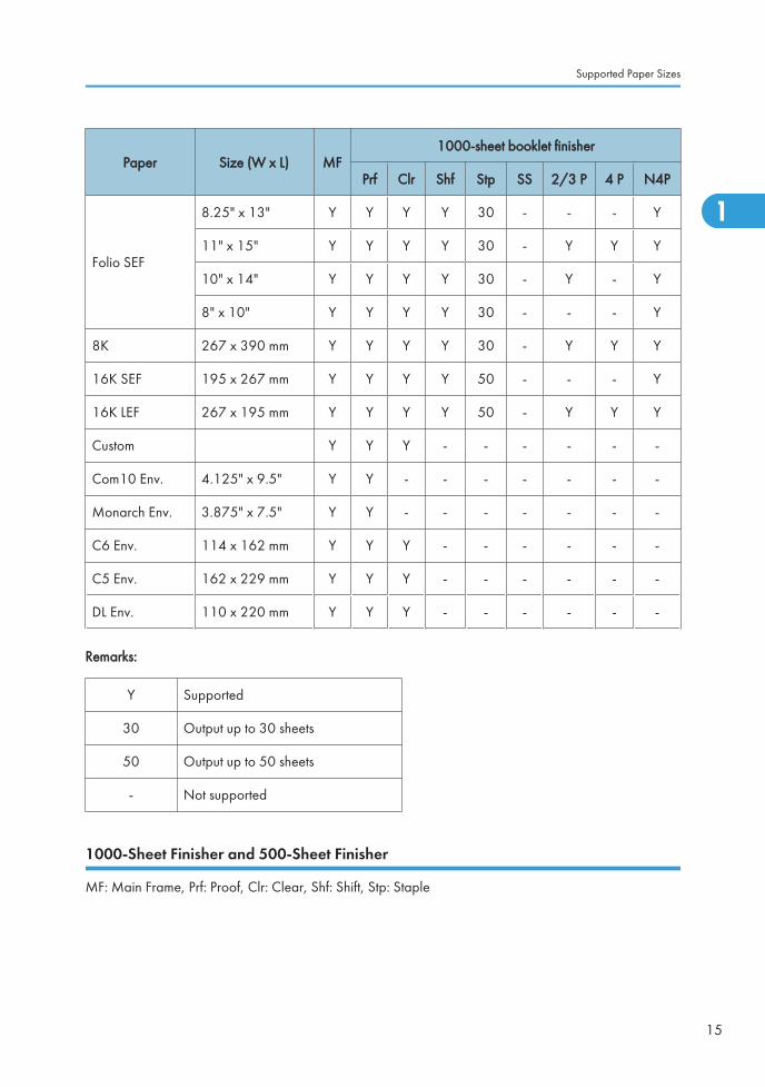
Paper Size (W x L) MF1000-sheet booklet finisher
Prf Clr Shf Stp SS 2/3 P 4 P N4P
Folio SEF
8.25" x 13" Y Y Y Y 30 - - - Y
11" x 15" Y Y Y Y 30 - Y Y Y
10" x 14" Y Y Y Y 30 - Y - Y
8" x 10" Y Y Y Y 30 - - - Y
8K 267 x 390 mm Y Y Y Y 30 - Y Y Y
16K SEF 195 x 267 mm Y Y Y Y 50 - - - Y
16K LEF 267 x 195 mm Y Y Y Y 50 - Y Y Y
Custom Y Y Y - - - - - -
Com10 Env. 4.125" x 9.5" Y Y - - - - - - -
Monarch Env. 3.875" x 7.5" Y Y - - - - - - -
C6 Env. 114 x 162 mm Y Y Y - - - - - -
C5 Env. 162 x 229 mm Y Y Y - - - - - -
DL Env. 110 x 220 mm Y Y Y - - - - - -
Remarks:
Y Supported
30 Output up to 30 sheets
50 Output up to 50 sheets
- Not supported
1000-Sheet Finisher and 500-Sheet Finisher
MF: Main Frame, Prf: Proof, Clr: Clear, Shf: Shift, Stp: Staple
Supported Paper Sizes
15
1

PaperSize
(W x L)MF
1000-sheet finisher 500-sheet finisher1-Bin Shift
Prf Clr Shf Stp Clr Shf Stp
A3 W 12" x 18" Y Y Y - - - - - - Y
A3 SEF297 x
420 mmY Y Y Y 30 Y Y 30 Y Y
A4 SEF210 x
297 mmY Y Y Y 50 Y Y 50 Y Y
A4 LEF297 x
210 mmY Y Y Y 50 Y Y 50 Y Y
A5 SEF148 x
210 mmY Y Y Y - Y Y - Y Y
A5 LEF210 x
148 mmY Y Y Y - Y Y - Y Y
A6 SEF105 x
148 mmY - - - - Y - - - Y
B4 SEF257 x
364 mmY Y Y Y 30 Y Y 30 Y Y
B5 SEF182 x
257 mmY Y Y Y 50 Y Y 50 Y Y
B5 LEF257 x
182 mmY Y Y Y 50 Y Y 50 Y Y
B6 SEF128 x
182 mmY Y - - - Y - - Y Y
Ledger 11" x 17" Y Y Y Y 30 Y Y 30 Y Y
Letter SEF 8.5" x 11" Y Y Y Y 50 Y Y 50 Y Y
Letter LEF 11" x 8.5" Y Y Y Y 50 Y Y 50 Y Y
Legal SEF 8.5" x 14" Y Y Y Y 30 Y Y 30 Y Y
Government
Legal SEF
8.25" x14"
Y Y Y Y - Y Y 30 Y Y
1. Appendix: Specifications
16
1

PaperSize
(W x L)MF
1000-sheet finisher 500-sheet finisher1-Bin Shift
Prf Clr Shf Stp Clr Shf Stp
Half Letter SEF5.5" x8.5"
Y Y Y Y - Y Y - Y Y
Executive SEF7.25" x10.5"
Y Y Y Y 50 Y Y 50 Y Y
Executive LEF10.5" x7.25"
Y Y Y Y 50 Y Y 50 Y Y
F SEF 8" x 13" Y Y Y Y 30 Y Y 30 Y Y
Foolscap SEF 8.5" x 13" Y Y Y Y 30 Y Y 30 Y Y
Folio SEF
8.25" x13"
Y Y Y Y 30 Y Y 30 Y Y
11" x 15" Y Y Y Y 30 Y Y 30 Y Y
10" x 14" Y Y Y Y 30 Y Y 30 Y Y
8" x 10" Y Y Y Y 30 Y Y 30 Y Y
8K267 x
390 mmY Y Y Y 30 Y Y 30 Y Y
16K SEF195 x
267 mmY Y Y Y 50 Y Y 50 Y Y
16K LEF267 x
195 mmY Y Y Y 50 Y Y 50 Y Y
Custom Y Y - - - - - - - Y
Com10 Env.4.125" x
9.5"Y - - - - Y Y - Y Y
Monarch Env.3.875" x
7.5"Y - - - - - - - Y Y
C6 Env.114 x
162 mmY Y - - - - - - Y Y
C5 Env.162 x
229 mmY Y - - - - - - Y Y
Supported Paper Sizes
17
1

PaperSize
(W x L)MF
1000-sheet finisher 500-sheet finisher1-Bin Shift
Prf Clr Shf Stp Clr Shf Stp
DL Env.110 x
220 mmY Y - - - - - - Y Y
Remarks:
Y Supported
30 Output up to 30 sheets
50 Output up to 50 sheets
- Not supported
Platen/ARDF Original Size Detection
Size
(width x length) [mm]
Platen ARDF Platen ARDF
Inches Inches Metric Metric
A3 (297 x 420) L - Y Y*3 Y
B4 (257 x 364) L - - Y*3 Y
A4 (210 x 297) L Y*1 Y Y*3 Y
A4 (297 x 210) S Y*3 Y Y*3 Y
B5 (182 x 257) L - - Y*3 Y
B5 (257 x 182) S - - Y*3 Y
A5 (148 x 210) L - - -*1 Y
A5 (210 x 148) S - - -*1 Y
B6 (128 x 182) L - - - -
B6 (182 x 128) S - - - -
11" x 17" (DLT) Y Y*2 - Y*2
11" x 15" - Y*2 - -
1. Appendix: Specifications
18
1

10" x 14" - Y - -
8.5" x 14" (LG) Y Y*2 - -
8.5" x 13" (F4) - Y*2 Y*4 Y*4
8.25" x 13" - - Y*4 Y*4
8" x 13"(F) - - Y*4 Y*4
8.5" x 11" (LT) Y*3 Y*2 Y*3 Y*2
11" x 8.5" (LT) Y*3 Y*2 Y*3 Y*2
8" x 10" - Y*2 - -
5.5" x 8.5" (HLT) -*1 Y - -
8.5" x 5.5" (HLT) -*1 Y - -
8K (267 x 390) - - Y*3 Y*2
16K L (195 x 267) - - Y*3 Y*2
16K S (267 x 195) - - Y*3 Y*2
7.25" x 10.5" (Executive) - Y - -
10.5" x 7.25" (Executive) - Y*2 - -
*1: Use SP4-303 to detect original sizes as A5 lengthwise/HLT when the message “Can-t detect originalsize” shows.
*2: The machine can detect the paper size depending on the setting of SP6-016-1.
*3: The machine can detect the paper size depending on the setting of SP4-305-1.
*4: The machine can detect the paper size depending on the setting of SP5-126-1.
Supported Paper Sizes
19
1

Software AccessoriesThe printer drivers and utility software are provided as following two CD-ROMs
1: Printer Drivers and Utilities CD-ROM
2: Scanner/PostScript® Drivers and Utilities CD-ROM.
An auto-run installer lets you to select the components you want to install.
Printer Drivers
Printer LanguageWindows 2000, XP, Server 2003, Vista,
Server 2008, 7
MacOS8.6 to 9.x,MacOSX10.1
or later
PCL5c/ PCL6
Yes No
PS3 Yes Yes
RPCS No No
• The PCL5c/6 and PS3 drivers are provided on the printer drivers CD-ROM
• The PS3 drivers are all genuine Adobe PS drivers, except for Windows 2000/XP/2003/Vista/7.Windows 2000 uses Microsoft PS. A PPD file for each operating system is provided with the driver.
• The PPD installer for Macintosh supports Mac OS X 10.1 or later versions.
• The LAN Fax driver lets you fax documents directly form your PC. Address Book Editor and CoverSheet Editor are to be installed as well. (These require the optional fax unit.)
Scanner and LAN Fax drivers
Printer LanguageWindows 2000, XP, Server
2003, Vista, 7
MacOS8.6 to 9.x, MacOSX10.1
or later
Network TWAIN Yes No
LAN-FAX Yes No
1. Appendix: Specifications
20
1
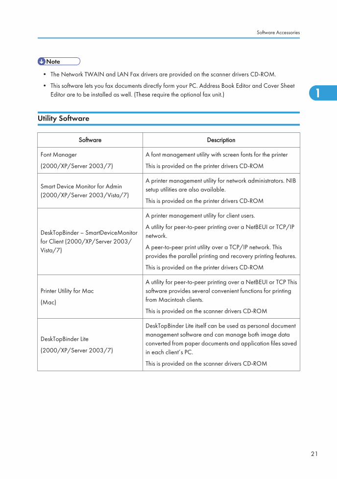
• The Network TWAIN and LAN Fax drivers are provided on the scanner drivers CD-ROM.
• This software lets you fax documents directly form your PC. Address Book Editor and Cover SheetEditor are to be installed as well. (These require the optional fax unit.)
Utility Software
Software Description
Font Manager
(2000/XP/Server 2003/7)
A font management utility with screen fonts for the printer
This is provided on the printer drivers CD-ROM
Smart Device Monitor for Admin(2000/XP/Server 2003/Vista/7)
A printer management utility for network administrators. NIBsetup utilities are also available.
This is provided on the printer drivers CD-ROM
DeskTopBinder – SmartDeviceMonitorfor Client (2000/XP/Server 2003/Vista/7)
A printer management utility for client users.
A utility for peer-to-peer printing over a NetBEUI or TCP/IPnetwork.
A peer-to-peer print utility over a TCP/IP network. Thisprovides the parallel printing and recovery printing features.
This is provided on the printer drivers CD-ROM
Printer Utility for Mac
(Mac)
A utility for peer-to-peer printing over a NetBEUI or TCP Thissoftware provides several convenient functions for printingfrom Macintosh clients.
This is provided on the scanner drivers CD-ROM
DeskTopBinder Lite
(2000/XP/Server 2003/7)
DeskTopBinder Lite itself can be used as personal documentmanagement software and can manage both image dataconverted from paper documents and application files savedin each client’s PC.
This is provided on the scanner drivers CD-ROM
Software Accessories
21
1

Optional Equipment
ARDF (D541)
Paper Size/Weight:
SimplexSize A3 to A5, DLT to HLT
Weight 40 to 128 g/m2 (10 to 34 lb.)
DuplexSize A3 to A5, DLT to HLT
Weight 52 to 105 g/m2 (14 to 28 lb.)
Table Capacity: 50 sheets (80 g/m2, 20 lb)
Original Standard Position: Rear left corner
Separation: Feed belt and separation roller
Original Transport: Roller transport
Original Feed Order: From the top original
Supported Magnification Ratios:
Copy - 32 to 200 %
FaxColor 32.6 to 200 %
Black & white 48.9 to 200 %
Power Source: DC 24V, 5V from the scanner unit
Power Consumption: 50 W or less
Dimensions (W × D × H) : 550 mm x 491 mm x 120 mm (21.7" x 19.3" x 4.7")
Weight: 10 kg (22 lb.)
Paper Feed Unit (D537)
Paper Feed System: FRR
Paper Height Detection: 5 steps (100%, 70%, 30%, 10% (Near end), and Empty)
Capacity: 500 sheets x 2 trays
Paper Weight: 60 to 256 g/m2 (16 to 68 lb.)
1. Appendix: Specifications
22
1

Paper Size: A3 SEF to A5, DLT SEF to HLT
Power Source: DC 24V, 5V (from the main frame)
Power Consumption: Less than 60 W (Max.)/ Less than 35 W (Ave,)
Dimensions (W x D x H): 580 mm x 620 mm x 260 mm (22.8" x 24.4" x 10.2")
Weight: 26 kg (57.3 lb.)
LCT 2000-sheet (D538)
Paper Size: A4 LEF/LT LEF
Paper Weight: 60 g/m2 to 256 g/m2 (16 lb. to 68 lb.)
Tray Capacity: 2,000 sheets (80 g/m2, 20lb.)
Remaining Paper Detection:5 steps (100%, 70%, 30%, 10%, Empty): Right Tray
4 steps (100%, 70%, 30%, Empty): Left Tray
Power Source: DC 24 V, 5 V (from copier/printer)
Power Consumption: 55 W (Max.)/30 W (Ave.)
Weight: 26 kg (57.3 lb.)
Size (W x D x H): 580 mm x 620 mm x 260 mm (22.8" x 24.4" x 10.2")
LCT 1200-sheet (D539)
Paper Size: A4 LEF/ LT LEF/ B5 LEF
Paper Weight: 60 g/m2 to 216 g/m2 (16 lb to 57 lb.)
Tray Capacity: 1,200 sheets (80 g/m2, 20lb)
Remaining Paper Detection: 5 steps (100%, 75%, 30%, 10%, End)
Power Source: 24 Vdc, 5 Vdc (from copier/printer)
Power Consumption: 55 W (Max)/ 25 W (Ave.)
Weight: 14 kg (30.8 lb.)
Optional Equipment
23
1
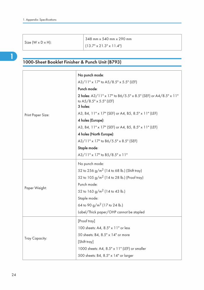
Size (W x D x H):348 mm x 540 mm x 290 mm
(13.7" x 21.3" x 11.4")
1000-Sheet Booklet Finisher & Punch Unit (B793)
Print Paper Size:
No punch mode:
A3/11" x 17" to A5/8.5" x 5.5" (LEF)
Punch mode:
2 holes: A3/11" x 17" to B6/5.5" x 8.5" (SEF) or A4/8.5" x 11"to A5/8.5" x 5.5" (LEF)3 holes:
A3, B4, 11" x 17" (SEF) or A4, B5, 8.5" x 11" (LEF)
4 holes (Europe):
A3, B4, 11" x 17" (SEF) or A4, B5, 8.5" x 11" (LEF)
4 holes (North Europe):
A3/11" x 17" to B6/5.5" x 8.5" (SEF)
Staple mode:
A3/11" x 17" to B5/8.5" x 11"
Paper Weight:
No punch mode:
52 to 256 g/m2 (14 to 68 lb.) (Shift tray)
52 to 105 g/m2 (14 to 28 lb.) (Proof tray)
Punch mode:
52 to 163 g/m2 (14 to 43 lb.)
Staple mode:
64 to 90 g/m2 (17 to 24 lb.)
Label/Thick paper/OHP cannot be stapled
Tray Capacity:
[Proof tray]
100 sheets: A4, 8.5" x 11" or less
50 sheets: B4, 8.5" x 14" or more
[Shift tray]
1000 sheets: A4, 8.5" x 11" (LEF) or smaller
500 sheets: B4, 8.5" x 14" or larger
1. Appendix: Specifications
24
1

Staple capacity:
Single size:
50 sheets: A4, 8.5" x 11" or smaller
30 sheets: B4, 8.5" x 14" or larger
Staple position:
3 positions
1-staple: 2 positions (Top Left, Top Right)
2-staples: 1 positions
Staple replenishment: Cartridge (5000 staples)
Power consumption: 60 W
Dimensions (W x D x H): 535 mm x 600 mm x 930 mm (21.1" x 23.6" x 36.6")
WeightWithout punch unit: 48 kg (105.8 lb.)
With punch unit: 50 Kg (110.3 lb.)
1000-Sheet Finisher (B408)
Upper Tray
Paper Size:A3 to A611" x 17" to 5.5" x 8.5"
Paper Weight: 60 to 157 g/m2 (16 to 42 lb.)
Paper Capacity:
250 sheets (A4 LEF/8.5" x 11" SEF or smaller)
50 sheets (A4, 8.5" x 11" or smaller)
30 sheets (B4, 8.5" x 14" or larger)
Lower Tray
Paper Size:
No staple mode:
A3 to B5, DLT to HLT
Staple mode:
A3, B4, A4, B5, DLT to LT
Optional Equipment
25
1

Paper Weight:No staple mode: 60 to 157 g/m2 (16 to 42 lb)
Staple mode: 64 to 90 g/m2 (17 to 24 lb)
Stapler Capacity:30 sheets (A3, B4, DLT, LG)
50 sheets (A4, B5 LEF, LT)
Paper Capacity:
No staple mode:
1,000 sheets (A4/LT or smaller: 80 g/m2, 20 lb.)
500 sheets (A3, B4, DLT, LG: 80 g/m2, 20 lb.)
Staple mode: (80 g/m2, 20 lb., number of sets)
Set Size2 to 9
10 to 50 -
Size 10 to 30 31 to 50
A4/LT LEFB5 LEF
100 100 to 20 100 to 20
A4/LT SEF 100 50 to 10 50 to 10
A3, B4, DLT, LG 50 50 to 10 -
Staple positions:1 Staple: 2 positions (Front, Rear)
2 Staples: 2 positions (Upper, Left)
Staple Replenishment: Cartridge (5,000 staples/cartridge)
Power Source: DC 24 V, 5 V (from the copier/printer)
Power Consumption: 50 W
Weight: 25 kg (55.2 lbs)
Dimensions (W x D x H): 527 x 520 x 790 mm (20.8" x 20.5" x 31.1")
500-Sheet Finisher (D372)
Paper Size: A3 to B6 (SEF)
Paper Weight: 52 to 128 g/m2 (14 to 34 lb.)
Tray Capacity:500 sheets: A4, LT or smaller
250 sheets: B4, LG or larger
1. Appendix: Specifications
26
1

Staple capacity:30 sheets (A3, B4, DLT, LG)
50 sheets (A4, LT or smaller)
Staple position:
3 positions
1-staple: 2 positions (Top right-oblique, Top left-oblique)
2-staples: 1 positions (Left)
Staple replenishment: Cartridge (5000 staples)
500-Sheet Finisher
Target Line Speed 77 mm/sec. to 205 mm/sec
Target CPM 35 cpm
Face-down Output Size
12"x18", A3 SEF to A6 SEF, DLT to HLT SEF
Shift sizes: A3 SEF to B5 SEF
A5, B6, A6 SEF labels possible
Paper Thickness52 g/m2 (45 K) to 157 g/m2 (135 K)
Up to 253 g/m2 (220K) without shift
Stapling
Stack Height for Stapling50 sheets: A4, LT and smaller
30 sheets: B4, LG and larger
Size A3 SEF to B5 SEF (can be mixed if same width)
Stack Thickness 64g/m2 (45 K) to 157 g/m (135 K)
Stapling PositionsFront/Oblique: 1, Front/Parallel: 1
Rear/Oblique: 1, Rear/Parallel: 1, 2 locations
Output Tray Capacity
Non-staple Mode 500 sheets: A4, LT and smaller
Staple Mode
250 sheets: B4, LGand larger
Stack Size (Stapling)
Stacks Size
Optional Equipment
27
1

2 to 9 Sheets 55 to 46A4, B5, LT LEF
10 to 50 Sheets 45 to 10
2 to 9 Sheets 55 to 27A4, B5, LT SEF
10 to 50 Sheets 25 to 8
2 to 9 Sheets 55 to 27A3, B4, DLT, LG
10 to 30 Sheets 25 to 8
Stacking Non-Stapling Mode Vertical: 15 mm or less
Horizontal: 15 mm or less
Jogging Precision
2 to 30 Sheets 2 mm
31 to 50 Sheets 3 mm
Dimensions (W x D x H) 396 x 551 x 276 mm (15.6 x 21.7 x 10.9 in.)
Weight 12 kg (26.4 lb)
Bridge Unit (D386)
Paper Size:
Standard sizes
A6 SEF to A3, HLT to DLT
Non-standard sizes
Width: 90 to 305 mm
Length: 148 to 600 mm
Paper Weight: 52 g/m2 to 256 g/m2, 16 lb. to 68 lb.
Paper Capacity:125 sheets (80 g/m2, 20 lb.): B4 or larger250 sheets (80 g/m2, 20 lb.): A4 or smaller
Power Source: DC 24 V, 5 V (form the copier/printer)
Dimensions (W x D x H): 415 mm x 412 mm x 111 mm (16.3" x 16.2" x 4.4")
Weight 5 kg (11 lb.)
1. Appendix: Specifications
28
1

Shift Tray (D388)
Paper Capacity:250 sheet (A4/ 81/2" x 111/2" or smaller: 80g/m2/ 20 lbs)
125 sheet (B4 81/2" x 111/2" or larger: 80g/m2/ 20 lbs)
Paper Size:
Standard sizes
A6 SEF to A3, HLT to DLT
Non-standard sizes
Width: 90 to 305 mm
Length: 148 to 600 mm
Paper Weight: 52-256 g/m2/ 14 - 68 lbs
Power Consumption: Max 10W (Power is supplied from the mainframe.)
Dimension (W x D x H): 423 mm x 468 mm x 114 mm (16.7" x 18.4" x 4.5")
Weight: Approx. 2kg (4.4lbs)
1-bin Tray Unit (D536)
Paper Size:Standard Size:
A3 /DLT to A5/ HLT SEF
Paper Weight: 60 to 169 g/m2, 16 to 45 lb.
Tray Capacity: 125 sheets (80 g/m2, 20 lb., A4)
Power Source: DC 24 V, 5 V (from the copier)
Power Consumption: Less than 1 W
Weight: 1.7 kg
Size (W x D x H): 565 mm x 410 mm x 115 mm (22.2" x 16.1" x 4.5")
Optional Equipment
29
1

1. Appendix: Specifications
30
1

2. Appendix: Preventive MaintenanceTables
Maintenance Tables
Preventive Maintenance Items
Chart: A4 (LT)/5%
Mode: 3 copies / original (prints/job)
Ratio 30%
Environment: Normal temperature and humidity
Yield may change depending on circumstances and print conditions.
Symbol keys: C: Clean, R: Replace, L: Lubricant, I: Inspect
Mainframe
Item 150K 200K 300K 450K EM Remarks
Scanner
Reflector C Optics cloth
1st/2nd/3rd mirrors C Optics cloth
Front and Rear Rails C Dry cloth
Exposure Glass C C Dry cloth; alcohol
ADF Exposure Glass C C Dry cloth; alcohol
APS Sensor C Dry cloth
PCDU
Dev. Unit–K R: 600K
Dev. Unit– C, M, Y R
Drum Unit-K, R
Drum Unit-C, M, Y R
31
2

Item 150K 200K 300K 450K EM Remarks
Developer-K R
Developer-C, M, Y R
Transfer
Image Transfer Belt-cleaning Unit
R
Image Transfer Belt Unit R: 600K
Paper Transfer Roller Unit R
Toner Collection BottleR:
150K
Fusing
Heating Roller R
-Bearing R/L S552R
Pressure Roller R
-Bearing R/L S552R
Entrance guide plate C
Exit guide plate C
Exit separate plate C
Thermopile CCotton swab withalcohol
Paper Path
Registration Roller C Damp cloth
Registration Sensor C Dry cloth
Vertical Transport Roller C Damp cloth
Vertical Transport Sensor C Dry cloth
Paper Feed Sensor C Dry cloth
Pick-up Belt C Dry cloth
2. Appendix: Preventive Maintenance Tables
32
2

Item 150K 200K 300K 450K EM Remarks
Feed Roller C Dry cloth
Separation Roller C Dry cloth
Fusing Entrance Sensor C Dry cloth
Fusing Exit Sensor C Dry cloth
Paper Dust Container C C
Duplex Unit
Inverter Roller C Damp cloth
Transport Roller C Damp cloth
Duplex Entrance Sensor C Dry cloth
Duplex Exit Sensor C Dry cloth
Miscellaneous
Ozone Filter R
Exhaust Filter R
Dust Glass C
ID Sensor C Blower Brush
*1: Clean this thermistor only when it gets paper dust.
ARDF (D541)
Item 120K EM Remarks
Sensors C Blower brush
Platen Sheet Cover CDamp cloth; alcohol (Replace ifrequired.)
White Plate C Dry or damp cloth
Drive Gear L Grease G501
Transport Roller C Damp cloth; alcohol
Maintenance Tables
33
2

Item 120K EM Remarks
Exit Roller C Damp cloth; alcohol
Inverter Roller C Damp cloth; alcohol
Idle Rollers C Damp cloth; alcohol
Two-tray Paper Feed Unit (D537)
Item EM Remarks
Feed Roller C Dry cloth
Separation Roller C Dry cloth
Pick-up Belt C Dry cloth
Paper Feed Sensor C Dry cloth
Relay Sensor C Dry cloth
Relay Roller C Damp cloth
Bottom Plate Pad C Damp cloth
1200-sheet LCT (D539)
Item EM Remarks
Feed Roller C Dry cloth
Separation Roller C Dry cloth
Pick-up Roller C Dry cloth
Paper Feed Sensor C Dry cloth
Relay Sensor C Dry cloth
Relay Roller C Damp cloth
Bottom Plate Pad C Damp cloth
2. Appendix: Preventive Maintenance Tables
34
2

2000-sheet LCT (D538)
Item EM Remarks
Feed Roller C Dry cloth
Separation Roller C Dry cloth
Pick-up Belt C Dry cloth
Paper Feed Sensor C Dry cloth
Relay Sensor C Dry cloth
Relay Roller C Damp cloth
Bottom Plate Pad C Damp cloth
1000-Sheet Booklet Finisher (B793)
Items EM Remarks
Rollers C Damp cloth
Discharge Brush C Dry cloth
Sensors C Blower brush
1000-Sheet Booklet Finisher Punch Kit (B807)
Items EM Remarks
Punch Chads C Discard chads.
1000-Sheet Finisher (B408)
Items EM Remarks
Rollers C Damp cloth
Discharge Brush C Dry cloth
Sensors C Blower brush
Maintenance Tables
35
2

1 Bin Tray (D536)
Items EM Remarks
Rollers C Damp cloth
Tray C Damp cloth
Sensor C Blower brush
Bearing C S552R
Bridge Unit (D386)
Items EM Remarks
Rollers C Damp cloth
Shift Tray (D388)
Items EM Remarks
Tray C Damp cloth
One-tray Paper Feed Unit (D387)
Item EM Remarks
Feed Roller C Dry cloth
Separation Roller C Dry cloth
Pick-up Roller C Dry cloth
Paper Feed Sensor C Dry cloth
Relay Sensor C Dry cloth
Relay Roller C Damp cloth
Bottom Plate Pad C Damp cloth
2. Appendix: Preventive Maintenance Tables
36
2

Side Tray (D542)
Items EM Remarks
Rollers C Damp cloth
Sensors C Blower brush
Others Yield Parts
The parts mentioned in these tables have a target yield. However, the total copy/print volume made bythe machine will not reach the target yield within the machine’s targeted lifetime if the machine is usedunder the target usage conditions (ACV, color ratio, P/J, and C/O). So, these parts are categorized notas PM parts but as yield parts (EM parts).
Mainframe
Item 120K 240K 480K 600K Remarks
Dev. Unit–C, M, Y R
Developer- C, M, Y R
ITB Unit R
ARDF
Item 80K 120K 240K Remarks
Pick-up Roller R Number of originals
Feed Belt R Number of originals
Separation Roller R Number of originals
Maintenance Tables
37
2

2. Appendix: Preventive Maintenance Tables
38
2

3. Appendix: SP Mode Tables
System SP1-xxx
SP1-XXX (Feed)
1001
[Leading Edge Registration] Leading Edge Registration Adjustment
(Tray Location, Paper Type, Color Mode), Paper Type -> Plain, Thick 1or Thick 2
Adjusts the leading edge registration by changing the registration motor operation timingfor each mode.
002 Tray: Plain *ENG
[–9 to 9 / 0.0 / 0.1 mm/step]
003 Tray: Middle Thick *ENG
004 Tray: Thick 1 *ENG
005 Tray: Thick 2 *ENG
007 By-pass: Plain *ENG
008 By-pass: Middle Thick *ENG
009 By-pass: Thick 1 *ENG
010 By-pass: Thick 2 *ENG
011 By-pass: Thick 3 *ENG
39
3

013 Duplex: Plain *ENG
[–9 to 9 / 0.0 / 0.1 mm/step]
014 Duplex: Middle Thick *ENG
015 Duplex: Thick 1 *ENG
016 Tray: Thick 3 *ENG
017 Tray: Plain:1200 *ENG
018 Tray: Middle Thick:1200 *ENG
019 Tray: Thick 1:1200 *ENG
020 By-pass: Plain:1200 *ENG
021 By-pass: Middle Thick:1200 *ENG
022 By-pass: Thick 1:1200 *ENG
023 Duplex: Plain:1200 *ENG
024 Duplex: Middle Thick:1200 *ENG
025 Duplex: Thick 1:1200 *ENG
1002
[Side to Side Reg.] Side-to-Side Registration Adjustment
Adjusts the side-to-side registration by changing the laser main scan start position for eachmode.
001 By-pass Table *ENG
[–4 to 4 / 0.0 / 0.1 mm/step]
002 Paper Tray 1 *ENG
003 Paper Tray 2 *ENG
004 Paper Tray 3 *ENG
005 Paper Tray 4 *ENG
006 Duplex *ENG
007 Paper Tray 5 *ENG
008 Large Capacity Tray *ENG
3. Appendix: SP Mode Tables
40
3

1003
[Paper Buckle] Paper Buckle Adjustment
(Tray Location, Paper Type), Paper Type: N: Normal, TH: Thick
Adjusts the amount of paper buckle at the registration roller by changing the paper feedtiming.
002 Paper Tray1: Plain *ENG [–9 to 5 / -2 / 1 mm/step]
003 Tray1: Middle Thick *ENG [–9 to 5 / -1 / 1 mm/step]
004 Paper Tray1: Thick1 *ENG[–9 to 5 / -2 / 1 mm/step]
007 Paper Tray2/3/4/5/LCT: Plain *ENG
008 Tray 2/3/4/5/LCT: Middle Thick *ENG [–9 to 5 / -1 / 1 mm/step]
009 Paper Tray2/3/4/5/LCT: Thick 1 *ENG [–9 to 5 / -2 / 1 mm/step]
012 By-pass: Plain *ENG[–9 to 5 / 0 / 1 mm/step]
013 By-pass: Middle Thick *ENG
014 By-pass: Thick 1 *ENG [–9 to 5 / -2 / 1 mm/step]
018 Duplex: Plain *ENG[–9 to 5 / 0 / 1 mm/step]
019 Duplex: Middle Thick *ENG
020 Duplex: Thick 1 *ENG [–9 to 5 / -2 / 1 mm/step]
021 Paper Tray1: Plain: 1200 *ENG
[–9 to 5 / 0 / 1 mm/step]
022 Tray1: Middle Thick: 1200 *ENG
023 Tray 2/3/4/5LCT: Plain: 1200 *ENG
024 Tray 2/3/4/5LCT: Mid: 1200 *ENG
025 By-pass: Plain: 1200 *ENG
026 By-pass: Middle Thick: 1200 *ENG
030 Duplex: Plain: 1200 *ENG[–9 to 5 / 0 / 1 mm/step]
031 Duplex: Middle Thick: 1200 *ENG
1007 [By-Pass Size Detection] By-Pass Size Detection Display
System SP1-xxx
41
3

001
LG *ENG[0 or 1 / 0 / 1 ]
0: OFF, 1: ON
Enables or disables the automatic paper size detection function of the by-pass tray.
This SP determines what paper size the machine detects if the detected size is less than 8.5".
0: OFF (Letter/SEF), 1: ON (Legal/SEF)
1101[Reload Permit Setting]
Specifies the settings of the reload permit for cold temperature in color mode.
001Pre-rotation Start Temp. *ENG [0 to 200 / 0 / 1 deg/step]
Specifies the pre-rotation start temperature.
002Reload Target Temp.:Center *ENG [120 to 180 / 150 / 1 deg/step]
Specifies the reload target temperature of the heating roller.
003Reload Target Temp.:Press *ENG [0 to 200 / 120 / 1 deg/step]
Specifies the reload target temperature of the pressure roller.
004
Temp.:Delta:Cold:Center *ENG [0 to 200 / 5 / 1 deg/step]
Specifies the temperature correction of the heating roller (center) when the fusing unit isdetermined as cold state.
005
Temp.:Delta:Cold:End *ENG [40 to 200 / 100 / 1 deg/step]
Specifies the temperature correction of the heating roller (end) when the fusing unit isdetermined as cold state.
006
Temp.:Delta:Cold:Press *ENG [0 to 200 / 65 / 1 deg/step]
Specifies the temperature correction of the pressure roller when the fusing unit is determinedas cold state.
007
Time:Cold *ENG [0 to 100 / 30 / 1 sec/step]
Specifies the threshold time for the fusiing reload when the fusing unit is determined as coldstate.
008
Temp.:Delta:Warm:Center *ENG [0 to 200 / 5 / 1 deg/step]
Specifies the temperature correction of the heating roller (center) when the fusing unit isdetermined as warm state.
3. Appendix: SP Mode Tables
42
3

009
Temp.:Delta:Warm:End *ENG [40 to 200 / 100 / 1 deg/step]
Specifies the temperature correction of the heating roller (end) when the fusing unit isdetermined as warm state.
010
Temp.:Delta:Warm:Press *ENG [0 to 200 / 65 / 1 deg/step]
Specifies the temperature correction of the pressure roller when the fusing unit is determinedas warm state.
011
Time:Warm *ENG [0 to 100 / 30 / 1 sec/step]
Specifies the threshold time for the fusing reload when the fusing unit is determined as warmstate.
012
Temp.:Delta:Hot:Center *ENG [0 to 200 / 5 / 1 deg/step]
Specifies the temperature correction of the heating roller (center) when the fusing unit isdetermined as hot state.
013
Temp.:Delta:Hot:End *ENG [40 to 200 / 100 / 1 deg/step]
Specifies the temperature correction of the heating roller (end) when the fusing unit isdetermined as hot state.
014
Temp.:Delta:Hot:Press *ENG [0 to 200 / 65 / 1 deg/step]
Specifies the temperature correction of the pressure roller when the fusing unit is determinedas hot state.
015
Time:Hot *ENG [0 to 100 / 30 / 1 sec/step]
Specifies the threshold time for the fusing reload when the fusing unit is determined as hotstate.
016
Temp.:Delta:Cold:BW:Center *ENG [0 to 200 / 15 / 1 deg/step]
Specifies the temperature correction of the heating roller (center) in the black and white modewhen the fusing unit is determined as cold state.
017
Temp.:Delta:Cold:BW:End *ENG [40 to 200 / 100 / 1 deg/step]
Specifies the temperature correction of the heating roller (end) in the black and white modewhen the fusing unit is determined as cold state.
018
Temp.Delta:Cold:BW:Press *ENG [0 to 200 / 70 / 1 deg/step]
Specifies the temperature correction of the pressure roller in the black and white mode whenthe fusing unit is determined as cold state.
System SP1-xxx
43
3

019
Time:Cold:BW *ENG [0 to 100 / 30 / 1 sec/step]
Specifies the threshold time for the fusing reload in black and white mode when the fusingunit is determined as cold state.
020
Temp.:Delta:Cold:BW2:Center
*ENG [0 to 200 / 15 / 1 deg/step]
Specifies the temperature correction of the heating roller (center) in the black and white modewhen the fusing unit is determined as warm state.
021
Temp.:Delta:Cold:BW2:End *ENG [40 to 200 / 100 / 1 deg/step]
Specifies the temperature correction of the heating roller (end) in the black and white modewhen the fusing unit is determined as warm state.
022
Temp.Delta:Cold:BW2:Press *ENG [0 to 200 / 100 / 1 deg/step]
Specifies the temperature correction of the pressure roller in the black and white mode whenthe fusing unit is determined as warm state.
023
Time:Cold:BW2 *ENG [0 to 100 / 30 / 1 sec/step]
Specifies the threshold time for the fusing reload in black and white mode when the fusingunit is determined as warm state.
1102[Feed Permit Setting]
Specified the settings of the paper feeding timing.
001
Temp.:Lower Delta:Center *ENG [0 to 200 / 15 / 1 deg/step]
Specifies the subtractive temperature of the heating roller (center) for the paper feedpermission.
002Temp.:Lower Delta:End *ENG [0 to 200 / 100 / 1 deg/step]
Specifies the subtractive temperature of the heating roller (end) for the paper feed permission.
003
Temp.:Upper Delta:Center *ENG [0 to 200 / 100 / 1 deg/step]
Specifies the additional temperature of the heating roller (center) for the paper feedpermission.
004Temp.:Upper Delta:End *ENG [0 to 200 / 100 / 1 deg/step]
Specifies the additional temperature of the heating roller (end) for the paper feed permission.
3. Appendix: SP Mode Tables
44
3

005Temp.:Lower Delta:Press *ENG [0 to 200 / 100 / 1 deg/step]
Specifies the subtractive temperature of the pressure roller for the paper feed permission.
006Rotation Time *ENG [0 to 100 / 0 / 1 sec/step]
Specifies the threshold time of the pre-rotation for the paper feed permission.
007Temp.:LowerDelta:Center:Sp.1
*ENG [0 to 200 / 5 / 1 deg/step]
008 Temp.:Lower Delta:End:Sp.1 *ENG [0 to 200 / 100 / 1 deg/step]
009Temp.:UpperDelta:Center:Sp.1
*ENG [0 to 200 / 100 / 1 deg/step]
010 Temp.:Upper Delta:End:Sp.1 *ENG [0 to 200 / 100 / 1 deg/step]
011 Temp.:Lower Delta:Press:Sp.1 *ENG [0 to 200 / 60 / 1 deg/step]
012 Rotation Time:Sp.1 *ENG [0 to 200 / 0 / 1 sec/step]
013Temp.:LowerDelta:Center:Sp.2
*ENG [0 to 200 / 5 / 1 deg/step]
014 Temp.:Lower Delta:End:Sp.2 *ENG [0 to 200 / 100 / 1 deg/step]
015Temp.:UpperDelta:Center:Sp.2
*ENG [0 to 200 / 15 / 1 deg/step]
016 Temp.:Upper Delta:End:Sp.2 *ENG [0 to 200 / 100 / 1 deg/step]
017 Temp.:Lower Delta:Press:Sp.2 *ENG [0 to 200 / 100 / 1 deg/step]
018 Rotation Time:Sp2 *ENG [0 to 100 / 0 / 1 sec/step]
019 Feed Permit Time *ENG [0 to 200 / 120 / 1 sec/step]
1105 [Print Target Temp]
(Printing Mode, Roller Type, [Color], Simplex/Duplex)
Roller Type –> Center and Ends: Heating roller, Pressure –> Pressure roller
Paper Type -> Plain, Thin, Thick, OHP, Middle Thick, Special
001Plain1:FC:Center *ENG [120 to 200 / 155 / 1 deg/step]
Specifies the heating roller target temperature for the ready condition in full color printing.
System SP1-xxx
45
3

002Plain1:FC:Press *ENG [100 to 200 / 120 / 1 deg/step]
Specifies the pressure roller target temperature for the ready condition in full color printing..
003Plain1:BW:Center *ENG [120 to 200 / 145 / 1 deg/step]
Specifies the heating roller target temperature for the ready condition in BW printing.
004Plain1:BW:Press *ENG [100 to 200 / 120 / 1 deg/step]
Specifies the pressure roller target temperature for the ready condition in BW printing.
005Plain2:FC:Center *ENG [120 to 200 / 160 / 1 deg/step]
Specifies the heating roller target temperature for the ready condition in full color printing.
006Plain2:FC:Press *ENG [100 to 200 / 120 / 1 deg/step]
Specifies the pressure roller target temperature for the ready condition in full coloe printing.
007Plain2:BW:Center *ENG [120 to 200 / 150 / 1 deg/step]
Specifies the heating roller target temperature for the ready condition in BW printing.
008Plain2:BW:Press *ENG [100 to 200 / 120 / 1 deg/step]
Specifies the pressure roller target temperature for the ready condition in BW printing.
009 Thin:FC:Center *ENG [120 to 200 / 150 / 1 deg/step]
010 Thin:FC:Press *ENG [100 to 200 / 120 / 1 deg/step]
011 Thin:BW:Center *ENG [120 to 200 / 140 / 1 deg/step]
012 Thin:BW:Press *ENG [100 to 200 / 120 / 1 deg/step]
013 M-thick:FC:Center *ENG [120 to 200 / 165 / 1 deg/step]
014 M-thick:FC:Press *ENG [100 to 200 / 120 / 1 deg/step]
015 M-thick:BW:Center *ENG [120 to 200 / 155 / 1 deg/step]
016 M-thick:BW:Press *ENG [100 to 200 / 120 / 1 deg/step]
017 Thick1:FC:Center *ENG [120 to 200 / 155 / 1 deg/step]
018 Thick1:FC:Press *ENG [100 to 200 / 120 / 1 deg/step]
019 Thick1:BW:Center *ENG [120 to 200 / 145 / 1 deg/step]
020 Thick1:BW:Press *ENG [100 to 200 / 120 / 1 deg/step]
3. Appendix: SP Mode Tables
46
3

021 Thick2:FC:Center *ENG [120 to 200 / 165 / 1 deg/step]
022 Thick2:FC:Press *ENG [100 to 200 / 120 / 1 deg/step]
023 Thick2:BW:Center *ENG [120 to 200 / 155 / 1 deg/step]
024 Thick2:BW:Press *ENG [100 to 200 / 120 / 1 deg/step]
025 Thick3:FC:Center *ENG [120 to 200 / 170 / 1 deg/step]
026 Thick3:FC:Press *ENG [100 to 200 / 120 / 1 deg/step]
027 Thick3:BW:Center *ENG [120 to 200 / 160 / 1 deg/step]
028 Thick3:BW:Press *ENG [100 to 200 / 120 / 1 deg/step]
029 Special1:FC:Center *ENG [120 to 200 / 160 / 1 deg/step]
030 Special1:FC:Press *ENG [100 to 200 / 120 / 1 deg/step]
031 Special1:BW:Center *ENG [120 to 200 / 150 / 1 deg/step]
032 Special1:BW:Press *ENG [100 to 200 / 120 / 1 deg/step]
033 Special2:FC:Center *ENG [120 to 200 / 155 / 1 deg/step]
034 Special2:FC:Press *ENG [100 to 200 / 120 / 1 deg/step]
035 Special2:BW:Center *ENG [120 to 200 / 145 / 1 deg/step]
036 Special2:BW:Press *ENG [100 to 200 / 120 / 1 deg/step]
037 Special3:FC:Center *ENG [120 to 200 / 165 / 1 deg/step]
038 Special3:FC:Press *ENG [100 to 200 / 120 / 1 deg/step]
039 Special3:BW:Center *ENG [120 to 200 / 155 / 1 deg/step]
040 Special3:BW:Press *ENG [100 to 200 / 120 / 1 deg/step]
041 Envelop:Center *ENG [120 to 200 / 180 / 1 deg/step]
042 Envelop:Press *ENG [100 to 200 / 120 / 1 deg/step]
101 Plain1:FC:Center:Low Speed *ENG [120 to 200 / 135 / 1 deg/step]
102 Plain1:FC:Press:Low Speed *ENG [100 to 200 / 120 / 1 deg/step]
103Plain1:BW:Center:LowSpeed
*ENG [120 to 200 / 135 / 1 deg/step]
System SP1-xxx
47
3

104 Plain1:BW:Press:Low Speed *ENG [100 to 200 / 120 / 1 deg/step]
105 Plain2:FC:Center:Low Speed *ENG [120 to 200 / 140 / 1 deg/step]
106 Plain2:FC:Press:Low Speed *ENG [100 to 200 / 120 / 1 deg/step]
107Plain2:BW:Center:LowSpeed
*ENG [120 to 200 / 135 / 1 deg/step]
108 Plain2:BW:Press:Low Speed *ENG [100 to 200 / 120 / 1 deg/step]
109M-thick:FC:Center:LowSpeed
*ENG [120 to 200 / 145 / 1 deg/step]
110 M-thick:FC:Press:Low Speed *ENG [100 to 200 / 120 / 1 deg/step]
111M-thick:BW:Center:LowSpeed
*ENG [120 to 200 / 140 / 1 deg/step]
112 M-thick:BW:Press:Low Speed *ENG [100 to 200 / 120 / 1 deg/step]
113 Thick1:FC:Center:Low Speed *ENG [120 to 200 / 150 / 1 deg/step]
114 Thick1:FC:Press:Low Speed *ENG [100 to 200 / 120 / 1 deg/step]
115Thick1:BW:Center:LowSpeed
*ENG [120 to 200 / 145 / 1 deg/step]
116 Thick1:BW:Press:Low Speed *ENG [100 to 200 / 120 / 1 deg/step]
117Special1:FC:Center:LowSpeed
*ENG [120 to 200 / 135 / 1 deg/step]
118Special1:FC:Press:LowSpeed
*ENG [100 to 200 / 120 / 1 deg/step]
119Special1:BW:Center:LowSpeed
*ENG [120 to 200 / 130 / 1 deg/step]
120Special1:BW:Press:LowSpeed
*ENG [100 to 200 / 120 / 1 deg/step]
121Special2:FC:Center:LowSpeed
*ENG [120 to 200 / 150 / 1 deg/step]
122Special2:FC:Press:LowSpeed
*ENG [100 to 200 / 120 / 1 deg/step]
3. Appendix: SP Mode Tables
48
3

123Special2:BW:Center:LowSpeed
*ENG [120 to 200 / 145 / 1 deg/step]
124Special2:BW:Press:LowSpeed
*ENG [100 to 200 / 120 / 1 deg/step]
125 Plain1:Glossy:Center *ENG [120 to 200 / 140 / 1 deg/step]
126 Plain1:Glossy:Press *ENG [100 to 200 / 120 / 1 deg/step]
127 Plain2:Glossy:Center *ENG [120 to 200 / 145 / 1 deg/step]
128 Plain2:Glossy:Press *ENG [100 to 200 / 120 / 1 deg/step]
129 M-thick:Glossy:Center *ENG [120 to 200 / 150 / 1 deg/step]
130 M-thick:Glossy:Press *ENG [100 to 200 / 120 / 1 deg/step]
131 OHP:Center *ENG [120 to 200 / 150 / 1 deg/step]
132 OHP:Press *ENG [100 to 200 / 120 / 1 deg/step]
133 Envelop:Center:Low Speed *ENG [120 to 200 / 170 / 1 deg/step]
134 Envelop:Press:Low Speed *ENG [100 to 200 / 120 / 1 deg/step]
135 Thin:FC:Center:Low Speed *ENG [120 to 200 / 135 / 1 deg/step]
136 Thin:FC:Press:Low Speed *ENG [100 to 200 / 120 / 1 deg/step]
137 Thin:BW:Center:Low Speed *ENG [120 to 200 / 130 / 1 deg/step]
138 Thin:BW:Press:Low Speed *ENG [100 to 200 / 120 / 1 deg/step]
139 Thick4:FC:Center *ENG [120 to 200 / 175 / 1 deg/step]
140 Thick4:FC:Press *ENG [100 to 200 / 120 / 1 deg/step]
141 Thick4:BW:Center *ENG [120 to 200 / 165 / 1 deg/step]
142 Thick4:BW:Press *ENG [100 to 200 / 120 / 1 deg/step]
1106 [Fusing Temp. Display]
001 Center - [-10 to 250 / - / 1 deg/step]
Displays the temperature of the heating roller.002 End -
System SP1-xxx
49
3

003 Pressure - [-10 to 250 / - / 1 deg/step]
Displays the temperature of the heating roller.004 Pressure End -
1107 [Standby Target Temp. Setting]
001
Standby Heater Off Time *ENG [0 to 100 / 15 / 1 sec/step]
Specifies the time that the fusing heater turns off after the fusing unit temperature has reachedits target temperature.
002Stanby/Preheat1: Press *ENG [0 to 125 / 90 / 1 deg/step]
Specifies the temperature of the pressure roller for the ready or energy save 1 mode.
004Preheat2:Press *ENG [0 to 125 / 90 / 1 deg/step]
Specifies the temperature of the pressure roller for the energy save 2 mode.
006Low Power:Press *ENG [0 to 125 / 60 / 1 deg/step]
Specifies the temperature of the pressure roller for the low power mode.
007Print Ready:Center *ENG [120 to 180 / 150 / 1 deg/step]
Specifies the temperature of the heating roller for the print ready condition.
008Print Ready:Press *ENG [100 to 200 / 120 / 1 deg/step]
Specifies the temperature of the pressure roller for the print ready condition.
1108 [After Reload/Job Target Temp.]
001Center *ENG [120 to 180 / 150 / 1 deg/step]
Specifies the temperature of the heating roller after re-load or job.
002Press *ENG [100 to 200 / 120 / 1 deg/step]
Specifies the temperature of the pressure roller after re-load or job.
1111 [Environment Correction:Fusing]
001
Temp.: Threshold: Low *ENG [0 to 100 / 17 / 1 deg/step]
Specifies the threshold temperature for low temperature. If the fusing temperature is 17°Cor less, the machine executes the fusing mode for low temperature.
3. Appendix: SP Mode Tables
50
3

002
Temp.: Threshold: High *ENG [0 to 100 / 30 / 1 deg/step]
Sepcifies the threshold temperature for high temperature. If the fusing temperature is 30°Cor more, the machine executes the fusing mode for high temperature.
003
Low Temp. Correction *ENG [0 to 15 / 5 / 1 deg/step]
Specifies the additional temperature for the target temperature. If the fusing temperature isin low temperature condition, this temperature is added to the taraget temperature.
004
High Temp. Correction *ENG [0 to 15 / 0 / 1 deg/step]
Specifies the additional temperature for the target temperature. If the fusing temperature isin high temperature condition, this temperature is added to the taraget temperature.
005 Job Low Temp. Correction *ENG [0 to 100 / 5 / 0.1 deg/step]
006 Job High Temp. Correction *ENG [0 to 100 / 0 / 0.1 deg/step]
007 Job Low Temp. Correction:Sp. *ENG [0 to 100 / 10 / 0.1 deg/step]
008Job High Temp.Correction:Sp.
*ENG [0 to 100 / 0 / 0.1 deg/step]
1112 [Repeat Temperature Correction]
001
Control Time 1 *ENG [0 to 300 / 100 / 1 sec/step]
Specifies the threshold time for entering the repeat temperature correction mode after the firstsheet of paper has reached to the registration roller.
002
Control Time 2 *ENG [0 to 300 / 300 / 1 sec/step]
Specifies the threshold time for entering the repeat temperature correction mode after thecontrol time 1 (specified with SP1112-001) has elapsed.
003
Temp.:Plain:Center:1 *ENG [-15 to 15 / 0 / 0.1 deg/step]
Specifies the correction temperature of the heating roller for plain paper when the operationtime of the machine is in the interval between control time 1 and control time 2.
004
Temp.:Plain:Press:1 *ENG [-10 to 10 / 0 / 0.1 deg/step]
Specifies the correction temperature of the pressure roller for plain paper when the operationtime of the machine is in the interval between control time 1 and control time 2.
System SP1-xxx
51
3
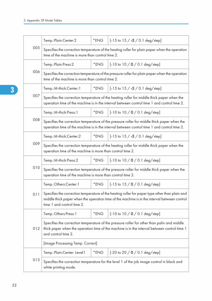
005
Temp.:Plain:Center:2 *ENG [-15 to 15 / -5 / 0.1 deg/step]
Specifies the correction temperature of the heating roller for plain paper when the operationtime of the machine is more than control time 2.
006
Temp.:Plain:Press:2 *ENG [-10 to 10 / 0 / 0.1 deg/step]
Specifies the correction temperature of the pressure roller for plain paper when the operationtime of the machine is more than control time 2.
007
Temp.:M-thick:Center:1 *ENG [-15 to 15 / -5 / 0.1 deg/step]
Specifies the correction temperature of the heating roller for middle thick paper when theoperation time of the machine is in the interval between control time 1 and control time 2.
008
Temp.:M-thick:Press:1 *ENG [-10 to 10 / 0 / 0.1 deg/step]
Specifies the correction temperature of the pressure roller for middle thick paper when theoperation time of the machine is in the interval between control time 1 and control time 2.
009
Temp.:M-thick:Center:2 *ENG [-15 to 15 / -5 / 0.1 deg/step]
Specifies the correction temperature of the heating roller for middle thick paper when theoperation time of the machine is more than control time 2.
010
Temp.:M-thick:Press:2 *ENG [-10 to 10 / 0 / 0.1 deg/step]
Specifies the correction temperature of the pressure roller for middle thick paper when theoperation time of the machine is more than control time 2.
011
Temp.:Others:Center:1 *ENG [-15 to 15 / 0 / 0.1 deg/step]
Specifies the correction temperature of the heating roller for paper type other than plain andmiddle thick paper when the operation time of the machine is in the interval between controltime 1 and control time 2.
012
Temp.:Others:Press:1 *ENG [-10 to 10 / 0 / 0.1 deg/step]
Specifies the correction temperature of the pressure roller for other than palin and middlethick paper when the operation time of the machine is in the interval between control time 1and control time 2.
[Image Processing Temp. Correct]
013
Temp.:Plain:Center: Level1 *ENG [-20 to 20 / 0 / 0.1 deg/step]
Specifies the correction temperature for the level 1 of the job image control in black andwhite printing mode.
3. Appendix: SP Mode Tables
52
3

014
Temp.:Plain:Center: Level2 *ENG [-20 to 20 / 0 / 0.1 deg/step]
Specifies the correction temperature for the level 2 of the job image control in black andwhite printing mode.
1113 [Curl Correction]
001
Execute Pattern *ENG[0 to 2 / 0 / 1 /step]
0: Off, 1: On (No Decurl), 2: On
Selects the curl correction type.
0: The curl correction is not done.
1: The curl correction is done only when paper is fed to the 1 bin tray.
2: The curl correction is always done.
002Humidity:Threshold:M-humid *ENG [0 to 100 / 1 / 1 %/step]
Specifies the threshold between low and middle humidity.
003Humidity:Threshold:H-humid *ENG [0 to 100 / 65 / 1 %/step]
Specifies the threshold between middle and high humidity.
004
Permit Temp.:Delta:Press:M-humid
*ENG [0 to 200 / 60 / 1 deg/step]
Specifies the threshold temperature for the curl control in middle humidity.
005
Permit Temp.:Delta:Press:H-humid
*ENG [0 to 200 / 50 / 1 deg/step]
Specifies the threshold temperature for the curl control in high humidity.
006
Permit Temp.:Delta:Press:M-humid:No Decurl
*ENG [0 to 200 / 50 / 1 deg/step]
Specifies the threshold temperature for the no curl control in middle humidity.
007
Permit Temp.:Delta:Press:H-humid:No Decurl
*ENG [0 to 200 / 40 / 1 deg/step]
Specifies the threshold temperature for the no curl control in high humidity.
System SP1-xxx
53
3

008
CPM:M-humid *ENG [0 to 100 / 80 / 1 %/step]
Specifies the CPM ratio of the decurl control against to the normal operation in middlehumidity.
009CPM:H-humid *ENG [0 to 100 / 65 / 1 %/step]
Specifies the CPM ratio of the decurl control against to the normal operation in high humidity.
010
CPM:M-humid:No Decurl *ENG [0 to 100 / 80 / 1 %/step]
Specifies the CPM ratio against of the no decurl control to the normal operation in middlehumidity.
011
CPM:H-humid:No Decurl *ENG [0 to 100 / 65 / 1 %/step]
Specifies the CPM ratio against of the no decurl control to the normal operation in highhumidity.
1114 [Heat Storage Status]
001Temp.:Threshold:Press *ENG [0 to 200 / 80 / 1 deg/step]
Specifies the threshold temperature of the pressure roller for the heat storage status.
002
Temp.:Threshold:Atmosphere
*ENG [0 to 200 / 60 / 1 deg/step]
Specifies the threshold temperature inside the machine for the heat storage feedback control.
1115 [Target Temp. Correction]
001Temp.:Delta:End *ENG [-100 to 100 / 0 / 1 deg/step]
Specifies the different temperature between end and center of the heating roller.
1116 [Heat Storage FB Control]
001Execution mode *ENG
[0 to 2 / 1 / 1 /step]
0: OFF, 1: ON (BW), 2: ON (BW/FC)
Selects the heat storage FB control mode.
011Time Out *ENG [0 to 500 / 5 / 1 sec/step]
Specifies the no-entry time for the heat strorage FB control after the LD units have fired.
3. Appendix: SP Mode Tables
54
3

021 Delay:Standard Speed:FC:1 *ENG [0 to 20,000 / 3500 / 1 msec/step]
022Delay:Standard Speed:BW:1
*ENG [0 to 20,000 / 1400 / 1 msec/step]
031 Delay:Standard Speed:FC:2 *ENG [0 to 20,000 / 3500 / 1 msec/step]
032Delay:Standard Speed:BW:2
*ENG [0 to 20,000 / 1400 / 1 msec/step]
041Press Reference Temp. *ENG [0 to 200 / 80 / 1 deg/step]
Specifies the standard temperature for the pressure roller during the heat storage FB control.
042Temp. Correction Lower Limit *ENG [-30 to 0 / -2 / 1 deg/step]
Specifies the lower llimit temperature for the heat storage FB control.
043Temp. Correction Upper Limit *ENG [0 to 30 / 0 / 1 deg/step]
Specifies the upper llimit temperature for the heat storage FB control.
051
Paper ThicknessCoefficient:Plain1
*ENG [0 to 100 / 20 / 1 /step]
Specifies the additional temperatreu to the heat strage FB control for plain paper 1.
052
Paper ThicknessCoefficient:Plain2
*ENG [0 to 100 / 20 / 1 /step]
Specifies the additional temperatreu to the heat strage FB control for plain paper 2.
1121 [Switch:Rotation Start/Stop]
001
Time:After Reload *ENG [0 to 100 / 60 / 1 sec/step]
Specifies the ON time of the pressure roler lamp after the fusing temperature has reachedthe reload temperature.
002
Time:After Recovery *ENG [0 to 100 / 15 / 1 sec/step]
Specifies the ON time of the pressure roler lamp after the fusing temperature has reachedthe target temperature.
003Time:After Job *ENG [0 to 100 / 0 / 1 sec/step]
Specifies the ON time of the pressure roler lamp after the paper feeding has finished.
System SP1-xxx
55
3

004
Press Temp.:After Reload *ENG [0 to 160 / 160 / 1 deg/step]
Specifies the target temperature of the pressure roller center area after the fusing temperaturehas reached the reload temperature.
005
End Uniform Start Temp.:B4 *ENG [0 to 250 / 200 / 1 deg/step]
Specifies the target temperature of the pressure roller end arear after the B4 paper feedinghas finished.
006
End Uniform Start Temp.:A4 *ENG [0 to 250 / 185 / 1 deg/step]
Specifies the target temperature of the pressure roller end arear after the A4 paper feedinghas finished.
007
End Uniform Start Temp.:A5 *ENG [0 to 250 / 170 / 1 deg/step]
Specifies the target temperature of the pressure roller end arear after the A5 paper feedinghas finished.
008Overshoot Prevent Temp. *ENG [0 to 250 / 220 / 1 deg/step]
Specifies the temperature of the heating roller for the overshoot prevention.
009Overshoot Prevent Time *ENG [0 to 100 / 10 / 1 sec/step]
Specifies the interval of the fusing unit rotation for the overshoot prevention.
1122 [Standby Rotation Setting] DFU
001Rotation Interval *ENG [0 to 240 / 60 / 1 min/step]
Specifies the rotation interval of the fusing unit in the stand-by mode.
002Rotation Time *ENG [0 to 60 / 0.7 / 0.1 sec/step]
Specifies the rotation time of the fusing unit in the stand-by mode.
1124[CPM Down Setting]
Specifies the settings for the CPM down mode.
001
Low:Down Temp. *ENG [-50 to 0 / -20 / 1 deg/step]
Specifies the CPM down threshold temperature for the low temperature condition. If the fusingtemperature decreases -20°C (adjustable) below the target temperature, the machine entersthe CPM down mode.
3. Appendix: SP Mode Tables
56
3
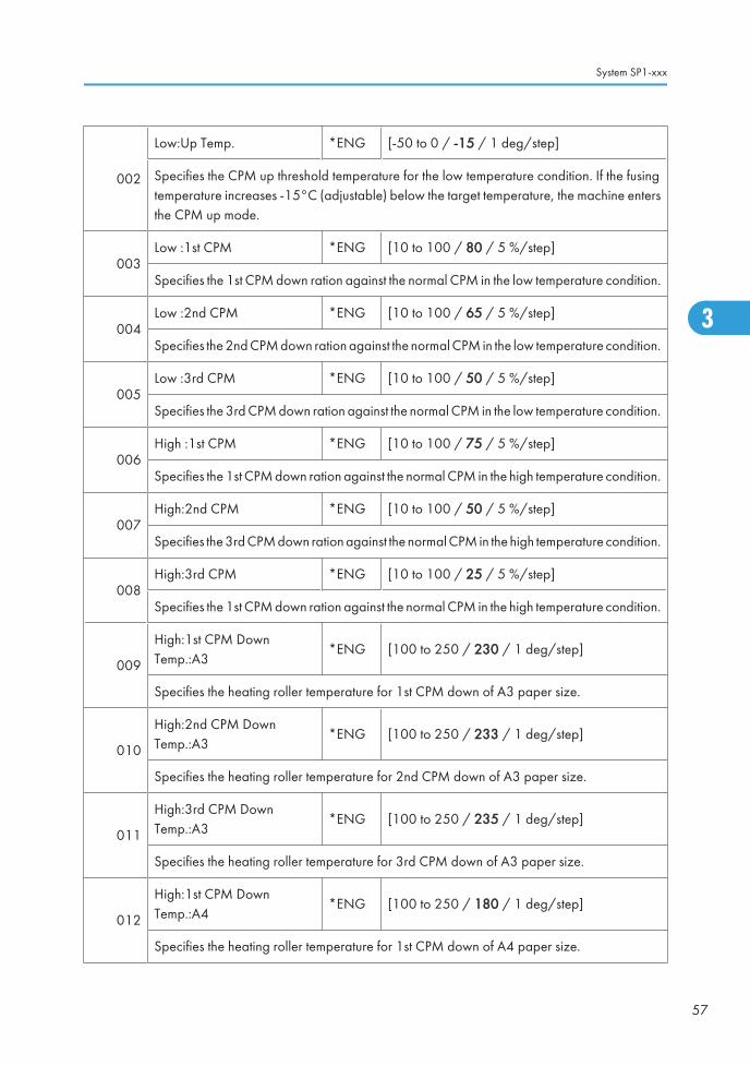
002
Low:Up Temp. *ENG [-50 to 0 / -15 / 1 deg/step]
Specifies the CPM up threshold temperature for the low temperature condition. If the fusingtemperature increases -15°C (adjustable) below the target temperature, the machine entersthe CPM up mode.
003Low :1st CPM *ENG [10 to 100 / 80 / 5 %/step]
Specifies the 1st CPM down ration against the normal CPM in the low temperature condition.
004Low :2nd CPM *ENG [10 to 100 / 65 / 5 %/step]
Specifies the 2nd CPM down ration against the normal CPM in the low temperature condition.
005Low :3rd CPM *ENG [10 to 100 / 50 / 5 %/step]
Specifies the 3rd CPM down ration against the normal CPM in the low temperature condition.
006High :1st CPM *ENG [10 to 100 / 75 / 5 %/step]
Specifies the 1st CPM down ration against the normal CPM in the high temperature condition.
007High:2nd CPM *ENG [10 to 100 / 50 / 5 %/step]
Specifies the 3rd CPM down ration against the normal CPM in the high temperature condition.
008High:3rd CPM *ENG [10 to 100 / 25 / 5 %/step]
Specifies the 1st CPM down ration against the normal CPM in the high temperature condition.
009
High:1st CPM DownTemp.:A3
*ENG [100 to 250 / 230 / 1 deg/step]
Specifies the heating roller temperature for 1st CPM down of A3 paper size.
010
High:2nd CPM DownTemp.:A3
*ENG [100 to 250 / 233 / 1 deg/step]
Specifies the heating roller temperature for 2nd CPM down of A3 paper size.
011
High:3rd CPM DownTemp.:A3
*ENG [100 to 250 / 235 / 1 deg/step]
Specifies the heating roller temperature for 3rd CPM down of A3 paper size.
012
High:1st CPM DownTemp.:A4
*ENG [100 to 250 / 180 / 1 deg/step]
Specifies the heating roller temperature for 1st CPM down of A4 paper size.
System SP1-xxx
57
3

013
High:2nd CPM DownTemp.:A4
*ENG [100 to 250 / 183 / 1 deg/step]
Specifies the heating roller temperature for 2nd CPM down of A4 paper size.
014
High:3rd CPM DownTemp.:A4
*ENG [100 to 250 / 185 / 1 deg/step]
Specifies the heating roller temperature for 3rd CPM down of A4 paper size.
015
High:1st CPM DownTemp.:B5:Press
*ENG [100 to 250 / 175 / 1 deg/step]
Specifies the pressure roller temperature for 1st CPM down of B5 paper size.
016
High:2nd CPM DownTemp.:B5:Press
*ENG [100 to 250 / 180 / 1 deg/step]
Specifies the pressure roller temperature for 2nd CPM down of B5 paper size.
017
High:3rd CPM DownTemp.:B5:Press
*ENG [100 to 250 / 185 / 1 deg/step]
Specifies the pressure roller temperature for 3rd CPM down of B5 paper size.
018
High:1st CPM DownTemp.:A5:Press
*ENG [100 to 250 / 180 / 1 deg/step]
Specifies the pressure roller temperature for 1st CPM down of A5 paper size.
019
High:2nd CPM DownTemp.:A5:Press
*ENG [100 to 250 / 185 / 1 deg/step]
Specifies the pressure roller temperature for 2nd CPM down of A5 paper size.
020
High:3rd CPM DownTemp.:A5:Press
*ENG [100 to 250 / 190 / 1 deg/step]
Specifies the pressure roller temperature for 3rd CPM down of A5 paper size.
021
High:1st CPM DownTemp.:A6:Press
*ENG [100 to 250 / 160 / 1 deg/step]
Specifies the pressure roller temperature for 1st CPM down of A6 paper size.
022
High:2nd CPM DownTemp.:A6:Press
*ENG [100 to 250 / 165 / 1 deg/step]
Specifies the pressure roller temperature for 2nd CPM down of A6 paper size.
3. Appendix: SP Mode Tables
58
3

023
High:3rd CPM DownTemp.:A6:Press
*ENG [100 to 250 / 170 / 1 deg/step]
Specifies the pressure roller temperature for 3rd CPM down of A6 paper size.
024Judging Interval *ENG [0 to 250 / 5 / 1 sec/step]
Specifies the interval for CPM down judgement.
1131 [Continues Print Mode Switch]
001Feed Permit Condition *ENG
[0 to 2 / 0 / 1 /step]
0: Productivity priority
1: Fusing quality priority 1
2: Fusing quality priority 2
Selects the paper feed permission type.
1132 [Maximum Duty Switch]
001 Control Method Switch *ENG[0 to 2 / 0 / 1 /step]
0: Fixed Duty, 1: Power Control
1141 [Fusing SC Issue Time Info]
001 SC Number *ENG Displays the issued SC number.
002 SC Cause *ENG [0 to 9 / - / 1/step]
101 Htg Roller:Ctr Diff1 *ENG[0 to 260 / - / 1 deg/step]
Displays the temperature at the center ofthe heating roller when an SC was issued.
102 Htg Rolloer:Ctr Det1 *ENG
103 Htg Roller:Ctr Corr1 *ENG
104 Htg Roller:End Diff1 *ENG[0 to 260 / - / 1 deg/step]
Displays the temperature at the end of theheating roller when an SC was issued.
105 Htg Roller:End Det1 *ENG
106 Htg Roller:End Corr1 *ENG
107 Press Roller Temp Value1 *ENG
[0 to 260 / - / 1 deg/step]
Displays the temperature at the pressureroller when an SC was issued.
System SP1-xxx
59
3

151 Htg Roller:Ctr Diff2 *ENG
[0 to 260 / - / 1 deg/step]152 Htg Rolloer:Ctr Det2 *ENG
153 Htg Roller:Ctr Corr2 *ENG
154 Htg Roller:End Diff2 *ENG
[0 to 260 / - / 1 deg/step]155 Htg Roller:End Det2 *ENG
156 Htg Roller:End Corr2 *ENG
157 Press Roller Temp Value2 *ENG [0 to 260 / - / 1 deg/step]
201 Htg Roller:Ctr Diff3 *ENG
[0 to 260 / - / 1 deg/step]202 Htg Rolloer:Ctr Det3 *ENG
203 Htg Roller:Ctr Corr3 *ENG
204 Htg Roller:End Diff3 *ENG
[0 to 260 / - / 1 deg/step]205 Htg Roller:End Det3 *ENG
206 Htg Roller:End Corr3 *ENG
207 Press Roller Temp Value3 *ENG [0 to 260 / - / 1 deg/step]
1142 [Fusing Jam Detection]
001
SC Display *ENG [0 or 1 / 0 / -]
Enables or disables the fusing consecutive jam (three times) SC detection.
0: No detection, 1: Detection
1151 [Pressure Setting]
001
Pressure Change ON/OFF *ENG [0 or 1 / 1 / -]
Enables or disables the pressure switching control for the fusing unit.
0: OFF , 1: ON
002Pressure Position1 *ENG [0 to 10,000 / 420 / 10 msec/step]
Specifies the rotation time of the pressure roller contact motor for the pressure position 1.
3. Appendix: SP Mode Tables
60
3

003Pressure Position2 *ENG [0 to 10,000 / 660 / 10 msec/step]
Specifies the rotation time of the pressure roller contact motor for the pressure position 2.
004Pressure Position3 *ENG [0 to 10,000 / 2130 / 10 msec/step]
Specifies the rotation time of the pressure roller contact motor for the pressure position 3.
005
Depressure Position *ENG [0 to 10,000 / 220 / 10 msec/step]
Specifies the rotation time of the pressure roller contact motor for the depression position (nopressure).
010
Shift Time *ENG [0 to 3600 / 5 / 1 sec/step]
Specifies the timing for depressing the fusing unit. If the machine does not get any jobs forspecified time by this SP after copying or printing, the machine depresses the fusing unit.
101 Pressure:Plain1/2 *ENG [0 to 3 / 3 / 1 /step]
Sets the default pressure position of the fusing unit for each paper type in normal speed.
0: Depression position (no pressure)
1: Position 1 (less pressure)
2: Position 2
3: Position 3 (strongest pressure)
102 Pressure:Thin *ENG [0 to 3 / 3 / 1 /step]
103 Pressure:M-thick *ENG [0 to 3 / 3 / 1 /step]
104 Pressure:Thick1 *ENG [0 to 3 / 3 / 1 /step]
105 Pressure:Thick2 *ENG [0 to 3 / 3 / 1 /step]
106 Pressure:Thick3 *ENG [0 to 3 / 3 / 1 /step]
107 Pressure:Special1 *ENG [0 to 3 / 3 / 1 /step]
108 Pressure:Special2 *ENG [0 to 3 / 3 / 1 /step]
109 Pressure:Special3 *ENG [0 to 3 / 3 / 1 /step]
110 Pressure:Envelope *ENG [0 to 3 / 1 / 1 /step]
151 Pressure:Plain1/2:Low Speed *ENG [0 to 3 / 3 / 1 /step]
System SP1-xxx
61
3

Sets the default pressure position of the fusing unit for each paper type in low speed.
0: Depression position (no pressure)
1: Position 1 (less pressure)
2: Position 2
3: Position 3 (strongest pressure)
152 Pressure:M-thick:Low Speed *ENG [0 to 3 / 3 / 1 /step]
153 Pressure:Thick1:Low Speed *ENG [0 to 3 / 3 / 1 /step]
154 Pressure:Special1:Low Speed *ENG [0 to 3 / 3 / 1 /step]
155 Pressure:Special2:Low Speed *ENG [0 to 3 / 3 / 1 /step]
156 Pressure:Plain1/2:Glossy *ENG [0 to 3 / 3 / 1 /step]
157 Pressure:M-thick:Glossy *ENG [0 to 3 / 3 / 1 /step]
158 Pressure:OHP *ENG [0 to 3 / 3 / 1 /step]
159 Pressure:Envelope:Low Speed *ENG [0 to 3 / 1 / 1 /step]
160 Pressure:Thin:Low Speed *ENG [0 to 3 / 3 / 1 /step]
161
Pressure:Thick4 *ENG [0 to 3 / 3 / 1 /step]
Sets the default pressure position of the fusing unit for thick 4 paper.
0: Depression position (no pressure)
1: Position 1 (less pressure)
2: Position 2
3: Position 3 (strongest pressure)
201Filler Edge Detection Counter ENG [0 to 9,000,000 / - / 1 /step]
Displays the detection time for the edge of the pressure roller actuator.
1152 [Fusing Nip Band Check]
001 Execute - [0 or 1 / 0 / 1]
Executes the nip band measurement between heating roller and pressure roller.
If the nip band width is not 8 mm, and fusing is not good, replace the pressure roller or installa new fusing unit.
3. Appendix: SP Mode Tables
62
3
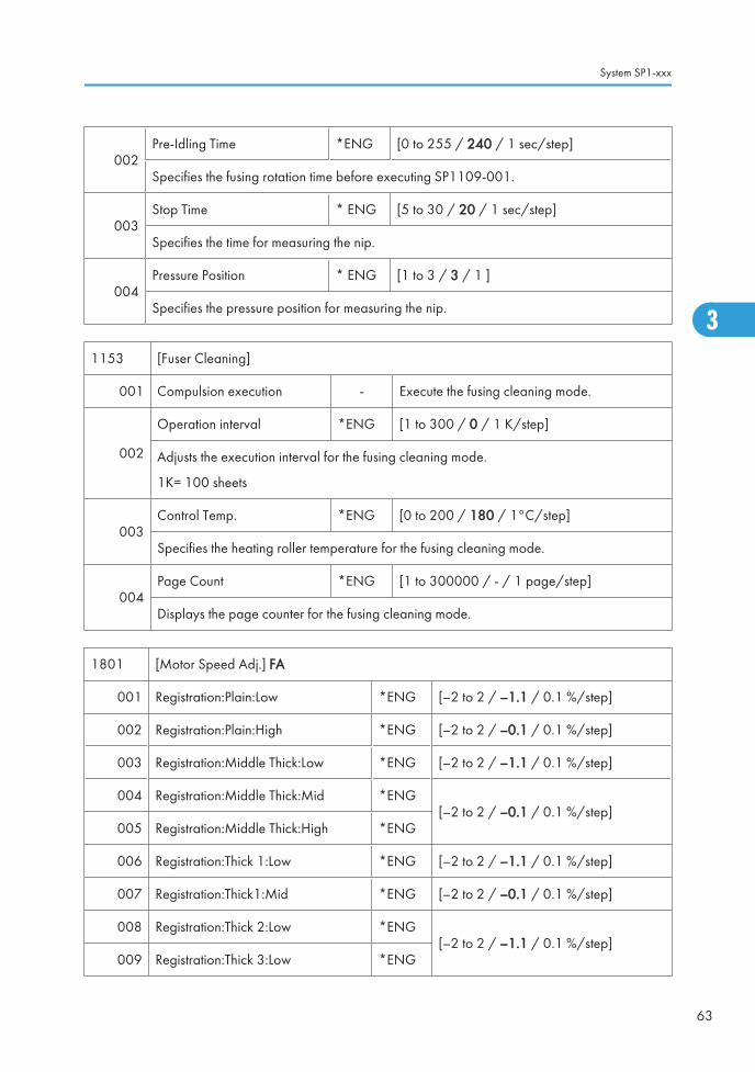
002Pre-Idling Time *ENG [0 to 255 / 240 / 1 sec/step]
Specifies the fusing rotation time before executing SP1109-001.
003Stop Time * ENG [5 to 30 / 20 / 1 sec/step]
Specifies the time for measuring the nip.
004Pressure Position * ENG [1 to 3 / 3 / 1 ]
Specifies the pressure position for measuring the nip.
1153 [Fuser Cleaning]
001 Compulsion execution - Execute the fusing cleaning mode.
002
Operation interval *ENG [1 to 300 / 0 / 1 K/step]
Adjusts the execution interval for the fusing cleaning mode.
1K= 100 sheets
003Control Temp. *ENG [0 to 200 / 180 / 1°C/step]
Specifies the heating roller temperature for the fusing cleaning mode.
004Page Count *ENG [1 to 300000 / - / 1 page/step]
Displays the page counter for the fusing cleaning mode.
1801 [Motor Speed Adj.] FA
001 Registration:Plain:Low *ENG [–2 to 2 / –1.1 / 0.1 %/step]
002 Registration:Plain:High *ENG [–2 to 2 / –0.1 / 0.1 %/step]
003 Registration:Middle Thick:Low *ENG [–2 to 2 / –1.1 / 0.1 %/step]
004 Registration:Middle Thick:Mid *ENG[–2 to 2 / –0.1 / 0.1 %/step]
005 Registration:Middle Thick:High *ENG
006 Registration:Thick 1:Low *ENG [–2 to 2 / –1.1 / 0.1 %/step]
007 Registration:Thick1:Mid *ENG [–2 to 2 / –0.1 / 0.1 %/step]
008 Registration:Thick 2:Low *ENG[–2 to 2 / –1.1 / 0.1 %/step]
009 Registration:Thick 3:Low *ENG
System SP1-xxx
63
3

010 Duplex CW:Plane:Low *ENG
[–4 to 4 / 0.0 / 0.1 %/step]
011 Duplex CW:Normal:High *ENG
012 Duplex CW:Middle Thick:Low *ENG
013 Duplex CW:Middle Thick:Mid *ENG
014 Duplex CW:Middle Thick:High *ENG
015 Duplex CW:Thick1:Low *ENG
016 Duplex CW:Thick1:Mid *ENG
017 Duplex CW:Thick2:Low *ENG
018 Duplex CW:Thick3:Low *ENG
019 Duplex CCW:Normal:High *ENG
[–4 to 4 / 0.0 / 0.1 %/step]020 Duplex CCW:Middle Thick:Mid *ENG
021 Duplex CCW:Middle Thick:high *ENG
023 Duplex CCW:Thick1:Mid *ENG
024 Reverse CW:Normal:High *ENG [–4 to 4 / –0.5 / 0.1%/step]
025 Reverse CW:Middle Thick:Mid *ENG [–4 to 4 / 0 / 0.1 %/step]
026 Reverse CW:Middle Thick:High *ENG [–4 to 4 / –0.5 / 0.1%/step]
028 Reverse CW:Thick1:Mid *ENG
[–4 to 4 / 0 / 0.1 %/step]
029 Reverse CCW:Normal:High *ENG
030 Reverse CCW:Middle Thick:Mid *ENG
031 Reverse CCW:Middle Thick:High *ENG
033 Reverse CCW:Thick1:Mid *ENG
034 Feed:Plain:Low *ENG [–2 to 2 / –1.1 / 0.1 %/step]
035 Feed:Plain:High *ENG [–2 to 2 / –0.1 / 0.1 %/step]
036 Feed:Middle thick:Low *ENG [–2 to 2 / –1.1 / 0.1 %/step]
037 Feed:Middle thick:Mid *ENG[–2 to 2 / –0.1 / 0.1 %/step]
038 Feed:Middle thick:High *ENG
3. Appendix: SP Mode Tables
64
3
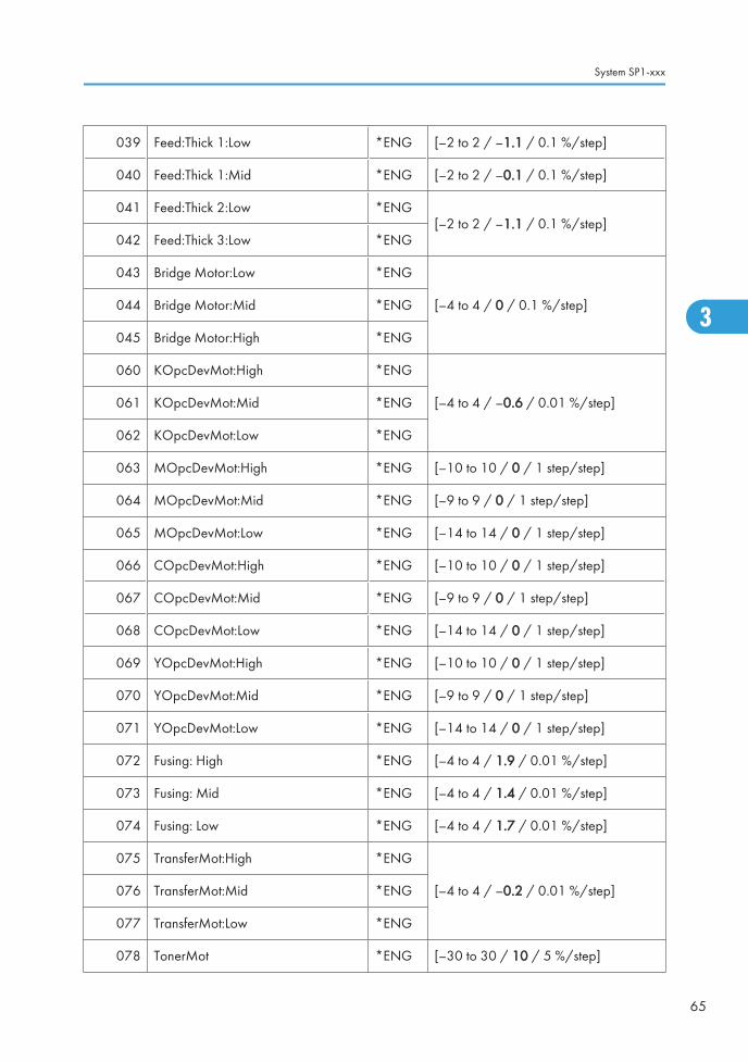
039 Feed:Thick 1:Low *ENG [–2 to 2 / –1.1 / 0.1 %/step]
040 Feed:Thick 1:Mid *ENG [–2 to 2 / –0.1 / 0.1 %/step]
041 Feed:Thick 2:Low *ENG[–2 to 2 / –1.1 / 0.1 %/step]
042 Feed:Thick 3:Low *ENG
043 Bridge Motor:Low *ENG
[–4 to 4 / 0 / 0.1 %/step]044 Bridge Motor:Mid *ENG
045 Bridge Motor:High *ENG
060 KOpcDevMot:High *ENG
[–4 to 4 / –0.6 / 0.01 %/step]061 KOpcDevMot:Mid *ENG
062 KOpcDevMot:Low *ENG
063 MOpcDevMot:High *ENG [–10 to 10 / 0 / 1 step/step]
064 MOpcDevMot:Mid *ENG [–9 to 9 / 0 / 1 step/step]
065 MOpcDevMot:Low *ENG [–14 to 14 / 0 / 1 step/step]
066 COpcDevMot:High *ENG [–10 to 10 / 0 / 1 step/step]
067 COpcDevMot:Mid *ENG [–9 to 9 / 0 / 1 step/step]
068 COpcDevMot:Low *ENG [–14 to 14 / 0 / 1 step/step]
069 YOpcDevMot:High *ENG [–10 to 10 / 0 / 1 step/step]
070 YOpcDevMot:Mid *ENG [–9 to 9 / 0 / 1 step/step]
071 YOpcDevMot:Low *ENG [–14 to 14 / 0 / 1 step/step]
072 Fusing: High *ENG [–4 to 4 / 1.9 / 0.01 %/step]
073 Fusing: Mid *ENG [–4 to 4 / 1.4 / 0.01 %/step]
074 Fusing: Low *ENG [–4 to 4 / 1.7 / 0.01 %/step]
075 TransferMot:High *ENG
[–4 to 4 / –0.2 / 0.01 %/step]076 TransferMot:Mid *ENG
077 TransferMot:Low *ENG
078 TonerMot *ENG [–30 to 30 / 10 / 5 %/step]
System SP1-xxx
65
3

079 Fusing Exit Motor: 1200 *ENG [–4 to 4 / 2.1 / 0.01 %/step]
100Drum Adjust *ENG
[0 or 1 / 1 / 1]
0: Off, 1: On
Enables or disables the drum amplitude adjustment.
101 MOpcDevMot:High *ENG
[–7 to 7 / 0 / 1 step/step]102 COpcDevMot:High *ENG
103 YOpcDevMot:High *ENG
104 MOpcDevMot:Mid *ENG
[–7 to 7 / 0 / 1 step/step]105 COpcDevMot:Mid *ENG
106 YOpcDevMot:Mid *ENG
107 MOpcDevMot:Low *ENG
[–14 to 14 / 0 / 1 step/step]108 COpcDevMot:Low *ENG
109 YOpcDevMot:Low *ENG
110 MOpcDevMot:1200 *ENG
[– 7 to 7 / 0 / 1 step/step]111 COpcDevMot:1200 *ENG
112 YOpcDevMot:1200 *ENG
120 Long:Registration:Plain:High *ENG [–2 to 2 / -0.1 / 0.1 %/step]
121 Long:Registration:Plain:Low *ENG [–2 to 2 / -1.1 / 0.1 %/step]
122 Long:Registration:Middle Thick:High *ENG
[–2 to 2 / -0.1 / 0.1 %/step]123
Long:Registration:MiddleThick:Middle
*ENG
124 Long:Registration:Middle Thick:Low *ENG [–2 to 2 / -1.1 / 0.1 %/step]
125 Long:Registration:Thick 1:Middle *ENG [–2 to 2 / -1 / 0.1 %/step]
126 Long:Registration:Thick 1:Low *ENG [–2 to 2 / -1.1 / 0.1 %/step]
127 Long:Registration:Thick 2:Low *ENG [–2 to 2 / -1.1 / 0.1 %/step]
128 Long:Registration:Thick 3:Low *ENG [–2 to 2 / -1.1 / 0.1 %/step]
3. Appendix: SP Mode Tables
66
3

129 Long:Fusing:Plain:High *ENG [–4 to 4 / 1.9 / 0.01 %/step]
130 Long:Fusing:Plain:Low *ENG [–4 to 4 / 2.1 / 0.01 %/step]
131 Long:Fusing:Middle Thick:High *ENG [–4 to 4 / 1.9 / 0.01 %/step]
132 Long:Fusing:Middle Thick:Middle *ENG [–4 to 4 / 1.4 / 0.01 %/step]
133 Long:Fusing:Middle Thick:Low *ENG [–4 to 4 / 2.1 / 0.01 %/step]
134 Long:Fusing:Thick 1:Middle *ENG [–4 to 4 / 2.0 / 0.01 %/step]
135 Long:Fusing:Thick 1:Low *ENG [–4 to 4 / 1.7 / 0.01 %/step]
136 Long:Fusing:Thick 2:Low *ENG [–4 to 4 / 1.7 / 0.01 %/step]
137 Long:Fusing:Thick 3:Low *ENG [–4 to 4 / 1.7 / 0.01 %/step]
1902 [Amplitude Control]
001 Execute - Execute drum phase adjustment.
002 Result *ENG
[0 to 3 / 0 / 1]
Displays the result of drum phase adjustment.
0: Successfully done
2: Sampling failure
3: Insufficient detection number
003 Auto Execution *ENG
[0 or 1 / 1 / -]
Turns the automatic drum phase adjustment on oroff.
0: Off, 1: On
1907 [Paper Feed Timing Adj.] DFU
002 Feed Solenoid ON: Plain *ENG [35 to 85 / 60 / 5 %/step]
System SP1-xxx
67
3

003 Feed Clutch OFF: Plain *ENG
[–10 to 10 / 0 / 1 mm/step]
004 Feed Clutch ON: Plain *ENG
005 Inverter Stop Position *ENG
006 Reverse Stop Position *ENG
007 Re-Feed Stop Position S Size *ENG
008 By-pass Solenoid OFF *ENG [0 to 40 / 0 / 1 mm/step]
009 By-pass Solenoid Re-ON *ENG [0 or 1 / 1 / -]
010 By-pass Feed Clutch ON *ENG [–10 to 10 / 0 / 1 mm/step]
012 Feed Solenoid ON: Thick *ENG [–10 to 40 / 0 / 2.5 mm/step]
013 Feed Clutch OFF: Thick *ENG
[–10 to 10 / 0 / 1 mm/step]014 Feed Clutch ON: Thick *ENG
015 Re-Feed Stop Position *ENG
1908 [LCT Feed Timing Adj.] DFU
010 Bridge Junction Gate Sol-ON *ENG
[–10 to 10 / 0 / 1 mm/step]
011 Bridge Junction Gate Sol-OFF *ENG
012 1 Bin Junction Gate Sol-ON *ENG
013 1 Bin Junction Gate Sol-OFF *ENG
015 Junction Gate SOL1:ON:Plain *ENG
016 Junction Gate SOL1:ON:Thick *ENG
017 Junction Gate SOL1:OFF:Plain *ENG
018 Junction Gate SOL1:OFF:Thick *ENG
1950[Fan Cooling Time Set]
Adjust the rotation time for each fan motor after a job end.
3. Appendix: SP Mode Tables
68
3

002 Fusing Exit Fan *ENG
[0 to 120 / 0 / 0.1 min./step]
006 Main Suction Fan *ENG
007 Paper Exit Fan *ENG
008 PSU Fan *ENG
009 Fusing IH Coil Fan *ENG
010 IH Power Supply Fan *ENG
011 Second Duct Fan *ENG
012 Third Duct Fan *ENG
1951[Fan Start Time Set]
Adjust the start time for each fan motor after a job end.
002 Fusing Exit Fan *ENG [0 to 900 / 0 / 1 sec/step]
006 Main Suction Fan *ENG [0 to 900 / 120 / 1 sec/step]
007 Paper Exit Fan *ENG [0 to 900 / 0 / 1 sec/step]
008 PSU Fan *ENG [0 to 900 / 120 / 1 sec/step]
009 Fusing IH Coil Fan *ENG
[0 to 900 / 0 / 1 sec/step]010 IH Power Supply Fan *ENG
011 Second Duct Fan *ENG
012 Third Duct Fan *ENG
1952 [Fan Control Off Mode Time Set]
001 - *ENG [0 to 60 / 10 / 1 min./step]
1953 [Extra Fan Control]
001Extra Fan Cooling State *ENG
[0 or 1 / 0 / 1 /step]
0: Off, 1: On
Displays the extra fan cooling is On or Off.
System SP1-xxx
69
3

002
Extra Fan Cooling: Time:Threshold
*ENG[0 to 180 / C2.5a: 110, C2.5b: 100 / 1 min./step]
Specifies the judgement time for entering the extra fan rotation mode.
003
Extra Fan Cooling: Rotat:Threshold
*ENG [0 to 999999999 / 0 / 1 mm/step]
Specifies the threshold rotation of the black development unit for entering the extra fanrotation mode.
004 Extra Fan Cooling: Start Date *ENGDisplays the execution time and date of the extrafan cooling.
005Extra Fan Cooling Time *ENG [0 to 120 / 30 / 0.1 min./step:
Specifies the execution time for the extra fan cooling.
1954[Extra Fan Control]
Specifies the execution time of the extra fan rotaion mode for each fan motor.
002Fan Cooling Time:Fusing ExitFan:Initial
*ENG [0 to 120 / 0 / 0.1 min./step]
006Fan Cooling Time:MainSuction Fan:Initial
*ENG [0 to 120 / 0 / 0.1 min./step]
007Fan Cooling Time:Paper ExitFan:Initial
*ENG [0 to 120 / 0 / 0.1 min./step]
008Fan Cooling Time:PSUFan:Initial
*ENG [0 to 120 / 0 / 0.1 min./step]
009Fan Cooling Time:Fusing IHCoil Fan:Initial
*ENG [0 to 120 / 0 / 0.1 min./step]
010Fan Cooling Time:IH PowerSupply Fan:Initial
*ENG [0 to 120 / 0 / 0.1 min./step]
011Fan Cooling Time:SecondDuct Fan:Initial
*ENG [0 to 120 / 0 / 0.1 min./step]
012Fan Cooling Time:Third DuctFan:Initial
*ENG [0 to 120 / 0 / 0.1 min./step]
3. Appendix: SP Mode Tables
70
3

System SP2-xxx
SP2-XXX (Drum)
2005
[Charge DC Voltage] Charge Roller DC Voltage Adjustment
(Paper Type, Process Speed, Color)
Paper Type –> Plain, Thick 1, Thick 2
Plain: High speed, Thick 1: Middle speed, Thick 2&FINE: Low speed
Adjusts the DC component of the charge roller bias in the various print modes.
Charge bias (DC component) is automatically adjusted during process control; therefore,adjusting these settings does not effect while process control mode (SP3-041-1 Default: ON)is activated. When deactivating process control mode with SP3-041-1, the values in theseSP modes are used for printing.
001 Plain: Bk *ENG
[0 to 1000 / 690 / 10 –V/step]
002 Plain: M *ENG
003 Plain: C *ENG
004 Plain: Y *ENG
005 Thick 1: Bk *ENG
006 Thick 1: M *ENG
007 Thick 1: C *ENG
008 Thick 1: Y *ENG
009 Thick 2&FINE: Bk *ENG
010 Thick 2&FINE: M *ENG
011 Thick 2&FINE: C *ENG
012 Thick 2&FINE: Y *ENG
[Charge DC: Correction]
013 PCU:Plain *ENG [–100 to 100 / -29 / 1 –V/step]
014 PCU:Thick 1 *ENG [–100 to 100 / -28 / 1 –V/step]
System SP2-xxx
71
3

015 PCU:Thick 2&FINE *ENG [–100 to 100 / -28 / 1 –V/step]
016 HVP:Plain *ENG [–100 to 100 / 20 / 1 –V/step]
017 HVP:Thick 1 *ENG [–100 to 100 / 20 / 1 –V/step]
018 HVP: Thick 2&FINE *ENG [–100 to 100 / 29 / 1 –V/step]
2006
[Charge AC Voltage] Charge Roller AC Voltage Adjustment
(Paper Type, Process Speed, Color)
Paper Type –> Plain, Thick 1, Thick 2
Plain: High speed, Thick 1: Middle speed, Thick 2&FINE: Low speed
Adjusts the AC component of the charge roller bias in the various print modes.
Charge bias (AC component) is adjusted by environment correction (SP2-007-xxx toSP2-011-xxx). These SPs are activated only when SP2-012-1 is set to "1: manual control".
001 Plain: Bk *ENG [0 to 3 / 1.9 / 0.01 KV/step]
002 Plain: M *ENG [0 to 3 / 2.2 / 0.01 KV/step]
003 Plain: C *ENG [0 to 3 / 2.2 / 0.01 KV/step]
004 Plain: Y *ENG [0 to 3 / 2.2 / 0.01 KV/step]
005 Thick 1: Bk *ENG [0 to 3 / 1.9 / 0.01 KV/step]
006 Thick 1: M *ENG [0 to 3 / 2.2 / 0.01 KV/step]
007 Thick 1: C *ENG [0 to 3 / 2.2 / 0.01 KV/step]
008 Thick 1: Y *ENG [0 to 3 / 2.2 / 0.01 KV/step]
009 Thick 2&FINE: Bk *ENG [0 to 3 / 1.9 / 0.01 KV/step]
010 Thick 2&FINE: M *ENG [0 to 3 / 2.2 / 0.01 KV/step]
011 Thick 2&FINE: C *ENG [0 to 3 / 2.2 / 0.01 KV/step]
012 Thick 2&FINE: Y *ENG [0 to 3 / 2.2 / 0.01 KV/step]
3. Appendix: SP Mode Tables
72
3

2007
[Charge AC Current: LL] Charge Roller AC Current Adjustment for LL
(Color)
Displays/sets the AC current target of the charge roller for LL environment (Low temperatureand Low humidity). DFU
001 Environmental Target: Bk *ENG [0 to 3 / 0.68 / 0.01 mA/step]
002 Environmental Target: M *ENG
[0 to 3 / 0.83/ 0.01 mA/step]003 Environmental Target: C *ENG
004 Environmental Target: Y *ENG
2008
[Charge AC Current: ML] Charge Roller AC Current Adjustment for MM
(Color)
Displays/sets the AC current target of the charge roller for ML environment (Meddletemperature and Low humidity). DFU
001 Environmental Target: Bk *ENG [0 to 3 / 0.7 / 0.01 mA/step]
002 Environmental Target: M *ENG
[0 to 3 / 0.87 / 0.01 mA/step]003 Environmental Target: C *ENG
004 Environmental Target: Y *ENG
2009
[Charge AC Current: MM] Charge Roller AC Current Adjustment for MM
(Color)
Displays/sets the AC current target of the charge roller for MM environment (Middletemperature and Middle humidity). DFU
001 Environmental Target: Bk *ENG [0 to 3 / 0.73 / 0.01 mA/step]
002 Environmental Target: M *ENG
[0 to 3 / 0.89 / 0.01 mA/step]003 Environmental Target: C *ENG
004 Environmental Target: Y *ENG
System SP2-xxx
73
3

2010
[Charge AC Current: MH] Charge Roller AC Current Adjustment for MH
(Color)
Displays/sets the AC current target of the charge roller for MH environment (Middletemperature and High humidity). DFU
001 Environmental Target: Bk *ENG [0 to 3 / 0.74 / 0.01 mA/step]
002 Environmental Target: M *ENG
[0 to 3 / 0.89 / 0.01 mA/step]003 Environmental Target: C *ENG
004 Environmental Target: Y *ENG
2011
[Charge AC Current: HH] Charge Roller AC Current Adjustment for HH
(Color)
Displays/sets the AC current target of the charge roller for HH environment (Hightemperature and High humidity). DFU
001 Environmental Target: Bk *ENG [0 to 3 / 0.74 / 0.01 mA/step]
002 Environmental Target: M *ENG
[0 to 3 / 0.87 / 0.01 mA/step]003 Environmental Target: C *ENG
004 Environmental Target: Y *ENG
2012 [Charge Output Control]
001 AC Voltage *ENG
Selects the AC voltage control type.
[0 or 1 / 0 / 1 /step]
0: Process control
1: Manual control (AC voltages are decidedwith SP2006.)
2013 [Environmental Correction: PCU]
3. Appendix: SP Mode Tables
74
3

001Current Environmental:Display
*ENG
Displays the environmental condition, which ismeasured in absolute humidity.
[1 to 5 / – / 1 /step]
1: LL (LL <= 4.3 g/m3)
2: ML (4.3 < ML <= 11.3 g/m3)
3: MM (11.3 < MM <= 18.0 g/m3)
4: MH (18.0 < MH <= 24.0 g/m3)
5: HH (24.0 g/m3 < HH)
002 Forced Setting *ENG
Selects the environmental condition manually.
[0 to 5 / 0 / 1 /step]
0: The environmental condition is determinedautomatically.
1: LL, 2: ML, 3: MM, 4: MH, 5: HH
003Absolute Humidity: Threshold1
*ENG
Changes the humidity threshold between LL andML.
[0 to 100 / 3.0 / 0.01 g/m3/step]
004Absolute Humidity: Threshold2
*ENG
Changes the humidity threshold between MLand MM.
[0 to 100 / 8.0 / 0.01 g/m3/step]
005Absolute Humidity: Threshold3
*ENG
Changes the humidity threshold between MMand MH.
[0 to 100 / 15.0 / 0.01 g/m3/step]
006Absolute Humidity: Threshold4
*ENG
Changes the humidity threshold between MHand HH.
[0 to 100 / 15.0 / 0.01 g/m3/step]
007 Current Temp.: Display *ENGDisplays the current temperature.
[0 to 100 / 0 / 1 deg/step]
008Current Relative Humidity:Display
*ENGDisplays the current relative humidity.
[0 to 100 / 0 / 1%RH/step]
009Current Absolute Humidity:Display
*ENGDisplays the absolute humidity.
[0 to 100 / 0 / 0.01 g/m3/step]
System SP2-xxx
75
3

010Previous Environmental:Display
*ENG
Displays the previous environmental condition,which is measured in absolute humidity.
[1 to 5 / – / 1 /step]
1: LL, 2: ML, 3: MM, 4: MH, 5: HH
011 Previous Temp.: Display *ENGDisplays the previous temperature.
[0 to 100 / 0 / 1 deg/step]
012Previous Relative Humidity:Display
*ENGDisplays the previous relative humidity.
[0 to 100 / 0 / 1%RH/step]
013Previous Absolute Humidity:Display
*ENGDisplays the previous absolute humidity.
[0 to 100 / 0 / 0.01 g/m3/step]
2014[Charge AC Control: Setting] DFU
Specifies the charge AC control interval or thresholod for each condition.
001 Exec Interval: Power ON *ENG[0 to 2000 / 500 / 1 page/step]
002 Exec Interval: Print *ENG
003 Page Interval *ENG [0 to 500 / 10 / 5 page/step]
004 Temperature *ENG [0 to 99 / 99 / 1 deg/step]
005 Relative Humidity *ENG [0 to 99 / 50 / 1 %RH/step]
006 Absolute Humidity *ENG [0 to 99 / 12 / 1 g/m3/step]
007 Temp Threshold M *ENG [0 to 99 / 5 / 1 deg/step]
008 RH Threshold M *ENG [0 to 99 / 25 / 1 %RH/step]
009 AH Threshold M *ENG [0 to 99 / 6 / 1 g/m3/step]
010 Temp Threshold S *ENG [0 to 20 / 1 / 0.1 deg/step]
011 RH Threshold S *ENG [0 to 50 / 5 / 1 %RH/step]
012 AH Threshold S *ENG [0 to 20 / 1 / 0.1 g/m3/step]
013 Non-use Time *ENG [0 to 1440 / 360 / 10 min/step]
2015 [Charge AC Control:Result]
3. Appendix: SP Mode Tables
76
3

001 Bk *ENG [0 to 9 / 0 / 1 /step]
0: Success
1: Out of tolerance range
2: Out of adjustable range
3: Adjustment incompleted
002 M *ENG
003 C *ENG
004 Y *ENG
2101
[Color Registration Correction] FA
These values are the parameters for the automatic line position adjustment and are adjustedat the factory. However, you must input a value for SP2101-001 after replacing the laseroptics housing unit. For details, see "Laser Optics Housing Unit" in the "Replacement andAdjustment" section. The value should be provided with the new laser optics housing unit.
001 Main Dot: Bk *ENG
[–512 to 511 / 0 / 1 dot/step]002 Main Dot: Ma *ENG
003 Main Dot: Cy *ENG
004 Main Dot: Ye *ENG
005 Sub Line: Bk *ENG
[–16384 to 16383 / 0 / 1 line/step]006 Sub Line: Ma *ENG
007 Sub Line: Cy *ENG
008 Sub Line: Ye *ENG
2102 [Magnification Adjustment] DFU
System SP2-xxx
77
3

001 Main Mag.: High Speed: Bk *ENG
These are results of the main scanlength adjustment.
[0 to 560 / 280 / 1 /step]
002 Main Mag.: Medium Speed: Bk *ENG
003 Main Mag.: Low Speed: Bk *ENG
004 Main Mag.: High Speed: M *ENG
005 Main Mag.: Medium Speed: M *ENG
006 Main Mag.: Low Speed: M *ENG
007 Main Mag.: High Speed: C *ENG
008 Main Mag.: Medium Speed: C *ENG
009 Main Mag.: Low Speed: C *ENG
010 Main Mag.: High Speed: Y *ENG
011 Main Mag.: Medium Speed: Y *ENG
012 Main Mag.: Low Speed: Y *ENG
013 Offset: Mag Bk1-2 *ENG
[-256 to 255 / 0 / 1 sub-dot/step]014 Offset: Mag M1-2 *ENG
015 Offset: Mag C1-2 *ENG
016 Offset: Mag Y1-2 *ENG
2103 [Erase Margin Adjustment] (Area, Paper Size)
Adjusts the erase margin by deleting image data at the margins.
001 Lead Edge Width *ENG[0 to 9.9 / 4.2 / 0.1 mm/step]
002 Trail. Edge Width *ENG
003 Left *ENG[0 to 9.9 / 2 / 0.1 mm/step]
004 Right *ENG
006 Duplex Trail. L Size *ENG [0 to 4 / 0 / 0.1 mm/step]
007 Duplex Trail. M Size *ENG [0 to 4 / 0 / 0.1 mm/step]
008 Duplex Trail. S Size *ENG [0 to 4 / 0 / 0.1 mm/step]
3. Appendix: SP Mode Tables
78
3

009 Duplex Left Edge *ENG[0 to 1.5 / 0.3 / 0.1 mm/step]
010 Duplex Right Edge *ENG
011 Duplex Trail. L Size:Thick *ENG [0 to 4 / 1 / 0.1 mm/step]
012 Duplex Trail. M Size:Thick *ENG [0 to 4 / 0.8 / 0.1 mm/step]
013 Duplex Trail. S Size:Thick *ENG [0 to 4 / 0.6 / 0.1 mm/step]
014 Duplex Left Edge:Thick *ENG[0 to 1.5 / 0.3 / 0.1 mm/step]
015 Duplex Right Edge:Thick *ENG
2105 [LD Power Adj.] (Process Speed, Color)
Adjusts the LD power of each color for each process speed.
Each LD power setting is decided by process control.
001 High Speed: Bk *ENG [50 to 120 / 100 / 1%/step]
Decreasing a value makes lines thinner on theoutput.
Increasing a value makes lines thicker on theoutput.
002 High Speed: Ma *ENG
003 High Speed: Cy *ENG
004 High Speed: Ye *ENG
005 Middle Speed: Bk *ENG [50 to 120 / 100 / 1%/step]
Decreasing a value makes lines thinner on theoutput.
Increasing a value makes lines thicker on theoutput.
006 Middle Speed: Ma *ENG
007 Middle Speed: Cy *ENG
008 Middle Speed: Ye *ENG
009 Low Speed: Bk *ENG [50 to 120 / 100 / 1%/step]
Decreasing a value makes lines thinner on theoutput.
Increasing a value makes lines thicker on theoutput.
010 Low Speed: Ma *ENG
011 Low Speed: Cy *ENG
012 Low Speed: Ye *ENG
2106 [Polygon Rotation Time]
Adjusts the time of the polygon motor rotation. DFU
System SP2-xxx
79
3

001 Warming-Up *ENG[0 to 60 / 10 / 1 sec/step]
002 Job End *ENG
2107[Image Parameter]
DFU
001 Image Gamma Flag *ENG[0 or 1 / 1 / 1 /step]
002 Shading Correction Flag *ENG
2109[Test Pattern]
Generates the test pattern using "COPY Window" tab in the LCD.
003 Pattern Selection - [0 to 23 / 0 / 1/step]
0 None
1: Vertical Line (1dot)
2: Vertical Line (2dot)
3: Horizontal (1dot)
4: Horizontal (2dot)
5: Grid Vertical Line
6: Grid Horizontal Line
7: Grid pattern Small
8: Grid pattern Large
9: Argyle Pattern Small
10: Argyle Pattern Large
11. Independent Pattern (1dot)
12. Independent Pattern (2dot)
13. Independent Pattern (4dot)
14. Trimming Area
16: Hound’s Tooth Check (Horizontal)
17: Band (Horizontal)
18: Band (Vertical)
19: Checker Flag Pattern
20: Grayscale Vertical Margin
21: Grayscale Horizontal Margin
23: Full Dot Pattern
005 Color Selection -
Specifies the color for the test pattern.
[1 to 4 / 1 / 1/step]
1: All colors, 2: Magenta, 3: Yellow, 4: Cyan
006 Density: Bk -Specifies the color density for the test pattern.
[0 to 15 / 15 / 1 /step]
0: Lightest density
15: Darkest density
007 Density: Ma -
008 Density: Cy -
009 Density: Ye -
3. Appendix: SP Mode Tables
80
3

2111 [Forced Line Position Adj.]
001 Mode a -
Executes the fine line position adjustment twice.
If this SP is not completed (NG is displayed), doSP2111-003 first and then try this SP again.
002 Mode b -
Executes the fine line position adjustment once.
If this SP is not completed, do SP2111-003 first andthen try this SP again.
003 Mode c -
Executes the rough line position adjustment once.
After doing this SP, make sure to executeSP2111-001 or -002. Otherwise, the line positionadjustment is not perfectly done.
2112 [TM/ID Sensor Check] ID Sensor Check FA
001 ExecuteThis SP is used to check the ID sensors at the factory.The results of this SP are displayed in SP2140 toSP2145.
2117
[Skew Adjustment]
Specifies a skew adjustment value for the skew motor M, C or Y.
These SPs must be used when a new laser optics housing unit is installed or when SC285occurs. For details, see "Laser Optics Housing Unit" in the "Replacement and Adjustment"section.
001 Pulse: M *ENG
[–100 to 100 / 0 / 1 pulse/step]002 Pulse: C *ENG
003 Pulse: Y *ENG
2118 [Skew Adjustment]
001 Execute: M *ENG Changes the current skew adjustment values to thevalues specified with SP2117.
These SPs must be used when a new laser opticshousing unit is installed or when SC285 occurs. Fordetails, see "Laser Optics Housing Unit" in the"Replacement and Adjustment" section.
002 Execute: C *ENG
003 Execute: Y *ENG
System SP2-xxx
81
3

2119[Skew Adjustment Display]
Displays the current skew adjustment value for each skew motor.
001 M *ENG
[–50 to 50 / 0 / 1 pulse/step]002 C *ENG
003 Y *ENG
2120[Thick Paper Skew Adj] Not used
Selects the skew adjustment for thick paper.
001 On/Off *ENG[0 or 1 / 1 / 1 /step]
0: Off, 1: On
2140
[ID Sensor Check Result] DFU
Displays the results of the ID sensor check.
Bk, M, C, Y: ID sensors for the process control
Front, Center, Rear: ID sensors for the automatic line position adjustment
001 Bk *ENG
[0 to 1024 / 0 / 1/step]
002 M *ENG
003 C *ENG
004 Y *ENG
005 Front *ENG
006 Center *ENG
007 Rear *ENG
2141
[ID Sensor Check Result: Ave.] DFU
Displays the average result values of the ID sensor check.
Bk, M, C, Y: ID sensors for the process control
Front, Center, Rear: ID sensors for the automatic line position adjustment
3. Appendix: SP Mode Tables
82
3
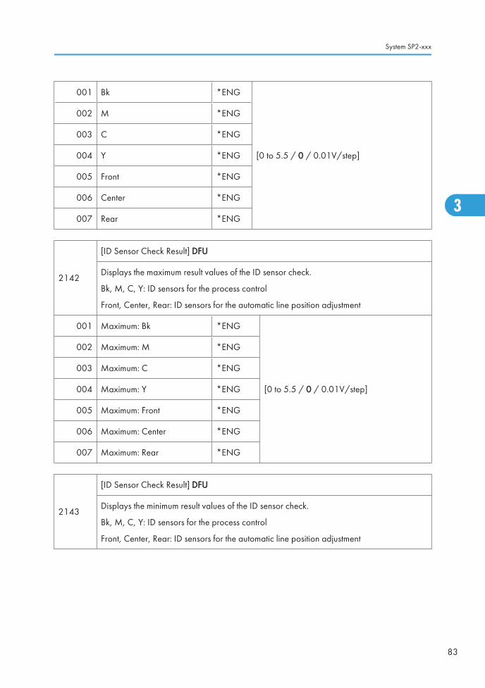
001 Bk *ENG
[0 to 5.5 / 0 / 0.01V/step]
002 M *ENG
003 C *ENG
004 Y *ENG
005 Front *ENG
006 Center *ENG
007 Rear *ENG
2142
[ID Sensor Check Result] DFU
Displays the maximum result values of the ID sensor check.
Bk, M, C, Y: ID sensors for the process control
Front, Center, Rear: ID sensors for the automatic line position adjustment
001 Maximum: Bk *ENG
[0 to 5.5 / 0 / 0.01V/step]
002 Maximum: M *ENG
003 Maximum: C *ENG
004 Maximum: Y *ENG
005 Maximum: Front *ENG
006 Maximum: Center *ENG
007 Maximum: Rear *ENG
2143
[ID Sensor Check Result] DFU
Displays the minimum result values of the ID sensor check.
Bk, M, C, Y: ID sensors for the process control
Front, Center, Rear: ID sensors for the automatic line position adjustment
System SP2-xxx
83
3

001 Minimum: Bk *ENG
[0 to 5.5 / 0 / 0.01V/step]
002 Minimum: M *ENG
003 Minimum: C *ENG
004 Minimum: Y *ENG
005 Minimum: Front *ENG
006 Minimum: Center *ENG
007 Minimum: Rear *ENG
2144
[ID Sensor Check Result] DFU
Displays the maximum result 2 values of the ID sensor check.
Bk, M, C, Y: ID sensors for the process control
Front, Center, Rear: ID sensors for the automatic line position adjustment
001 Maximum 2: Bk *ENG
[0 to 5.5 / 0 / 0.01V/step]
002 Maximum 2: M *ENG
003 Maximum 2: C *ENG
004 Maximum 2: Y *ENG
005 Maximum 2: Front *ENG
006 Maximum 2: Center *ENG
007 Maximum 2: Rear *ENG
2145
[ID Sensor Check Result] DFU
Displays the minimum result 2 values of the ID sensor check.
Bk, M, C, Y: ID sensors for the process control
Front, Center, Rear: ID sensors for the automatic line position adjustment
3. Appendix: SP Mode Tables
84
3

001 Minimum 2: Bk *ENG
[0 to 5.5 / 0 / 0.01V/step]
002 Minimum 2: M *ENG
003 Minimum 2: C *ENG
004 Minimum 2: Y *ENG
005 Minimum 2: Front *ENG
006 Minimum 2: Center *ENG
007 Minimum 2: Rear *ENG
2150
[Area Mag. Correction] LD Pulse Area Correction (Color, Area) FA
Adjusts the magnification for each area. The main scan (297 mm) is divided into 8 areas.Area 1 is at the front side of the machine (left side of the image) and area 8 is at the rearside of the machine (right side of the image).
Decreasing a value makes the image shift to the left side on the print.
Increasing a value makes the image shift to the right side on the print.
1 pulse = 1/16 dot
027 Area 0: Bk *ENG [-256 to 255 / 0 / 1sub-dot/step]
028 Area 1: Bk *ENG
Adjusts the area magnification for LD 0.
[–256 to 255 / 0 / 1 sub-dot/step ]
029 Area 2: Bk *ENG
030 Area 3: Bk *ENG
031 Area 4: Bk *ENG
032 Area 5: Bk *ENG
033 Area 6: Bk *ENG
034 Area 7: Bk *ENG
035 Area 8: Bk *ENG
036 Area 9: Bk *ENG
Not used037 Area 10: Bk *ENG
038 Area 11: Bk *ENG
039 Area 12: Bk *ENG
System SP2-xxx
85
3

079 Area 0: Ma *ENG Not used
080 Area 1: Ma *ENGAdjusts the area magnification for LD 0. [–255to255 / 0 / 1 sub-dot/step]
081 Area 2: Ma *ENG
[–256to 255 / 0 / 1 sub-dot/step]
082 Area 3: Ma *ENG
083 Area 4: Ma *ENG
084 Area 5: Ma *ENG
085 Area 6: Ma *ENG
086 Area 7: Ma *ENG
087 Area 8: Ma *ENG
088 Area 9: Ma *ENG
Not used089 Area 10: Ma *ENG
090 Area 11: Ma *ENG
091 Area 12: Ma *ENG
131 Area 0: Cy *ENG Not used
132 Area 1: Cy *ENG
Adjusts the area magnification for LD 0.
[–256 to 255 / 0 / 1 sub-dot/step]
133 Area 2: Cy *ENG
134 Area 3: Cy *ENG
135 Area 4: Cy *ENG
136 Area 5: Cy *ENG
137 Area 6: Cy *ENG
138 Area 7: Cy *ENG
139 Area 8: Cy *ENG
3. Appendix: SP Mode Tables
86
3

140 Area 9: Cy *ENG
Not used141 Area 10: Cy *ENG
142 Area 11: Cy *ENG
143 Area 12: Cy *ENG
183 Area 0: Ye *ENG Not used
184 Area 1: Ye *ENG
Adjusts the area magnification for LD 0.
[–256 to 255 / 0 / 1 sub-dot/step]
185 Area 2: Ye *ENG
186 Area 3: Ye *ENG
187 Area 4: Ye *ENG
188 Area 5: Ye *ENG
189 Area 6: Ye *ENG
190 Area 7: Ye *ENG
191 Area 8: Ye *ENG
192 Area 9: Ye *ENG
Not used193 Area 10: Ye *ENG
194 Area 11: Ye *ENG
195 Area 12: Ye *ENG
2152
[Area Shad. Correct. Setting] FA
Adjusts the area correction value for each LD power.
The main scan is divided into 16 areas. However, the image areas are limited from area 1to area 14.
For BK and Magenta, area 1 is at the rear side of the machine (left side of the image) andarea 14 is at the front side of the machine (right side of the image).
For Cyan and Yellow, area 1 is at the front side of the machine (right side of the image) andarea 14 is at the rear side of the machine (left side of the image).
System SP2-xxx
87
3

001 Area 0: Bk *ENG
This is for the synchronizing detection board.
[50 to 150 / 100 / 1 %/step]
002 Area 1: Bk *ENG
003 Area 2: Bk *ENG
004 Area 3: Bk *ENG
005 Area 4: Bk *ENG
006 Area 5: Bk *ENG
007 Area 6: Bk *ENG
008 Area 7: Bk *ENG
009 Area 8: Bk *ENG
010 Area 9: Bk *ENG
011 Area 10: Bk *ENG
012 Area 11: Bk *ENG
013 Area 12: Bk *ENG
014 Area 13: Bk *ENG
015 Area 14: Bk *ENG
016 Area 15: Bk *ENGThis is out of the image area.
[50 to 150 / 100 / 1 %/step]
033 Area 0: M *ENG This is for the synchronizing detection board.
3. Appendix: SP Mode Tables
88
3

034 Area 1: M *ENG
[50 to 150 / 100 / 1 %/step]
035 Area 2: M *ENG
036 Area 3: M *ENG
037 Area 4: M *ENG
038 Area 5: M *ENG
039 Area 6: M *ENG
040 Area 7: M *ENG
041 Area 8: M *ENG
042 Area 9: M *ENG
043 Area 10: M *ENG
044 Area 11: M *ENG
045 Area 12: M *ENG
046 Area 13: M *ENG
047 Area 14: M *ENG
048 Area 15: M *ENGThis is out of the image area.
[50 to 150 / 100 / 1 %/step]
065 Area 0: C *ENGThis is for the synchronizing detection board.
[50 to 150 / 100 / 1 %/step]
System SP2-xxx
89
3

066 Area 1: C *ENG
[50 to 150 / 100 / 1 %/step]
067 Area 2: C *ENG
068 Area 3: C *ENG
069 Area 4: C *ENG
070 Area 5: C *ENG
071 Area 6: C *ENG
072 Area 7: C *ENG
073 Area 8: C *ENG
074 Area 9: C *ENG
075 Area 10: C *ENG
076 Area 11: C *ENG
077 Area 12: C *ENG
078 Area 13: C *ENG
079 Area 14: C *ENG
080 Area 15: C *ENGThis is out of the image area.
[50 to 150 / 100 / 1 %/step]
097 Area 0: Y *ENGThis is for the synchronizing detection board.
[50 to 150 / 100 / 1 %/step]
3. Appendix: SP Mode Tables
90
3

098 Area 1: Y *ENG
[50 to 150 / 100 / 1 %/step]
099 Area 2: Y *ENG
100 Area 3: Y *ENG
101 Area 4: Y *ENG
102 Area 5: Y *ENG
103 Area 6: Y *ENG
104 Area 7: Y *ENG
105 Area 8: Y *ENG
106 Area 9: Y *ENG
107 Area 10: Y *ENG
108 Area 11: Y *ENG
109 Area 12: Y *ENG
110 Area 13: Y *ENG
111 Area 14: Y *ENG
112 Area 15: Y *ENG This is out of the image area.
2160[Vertical Line Width] DFU
Adjusts the width of the vertical line.
001 600dpi:Bk *ENG [10 to 15 / 13 / 1 /step]
002 600dpi:Ma *ENG
[10 to 15 / 15 / 1 /step]
003 600dpi:Cy *ENG
004 600dpi:Ye *ENG
005 1200dpi:Bk *ENG
006 1200dpi:Ma *ENG
007 1200dpi:Cy *ENG
008 1200dpi:Ye *ENG
System SP2-xxx
91
3

2180 [Line Position Adj. Setting Clear]
001 Color Regist. -
DFU
002 Main Scan Length Detection -
003 MUSIC Result -
004Area MagnificationCorrection
-
2181 [Line Position Adj. Result]
Displays the values for each correction.
• "Paper Int. Mag: Subdot" indicates the magnification correction value between twosheets of paper.
• "Mag.Cor. Subdot" indicates the magnification correction value.
• "M. Scan Erro." indicates the shift correction value in the main scan direction.
• "S. Scan Erro." Indicates the shift correction value in the sub scan direction.
• "M. Cor.: Dot" indicates the dot correction value in the main scan direction.
• "M. Cor.: Subdot" indicates the sub dot correction value in the main scan direction.
• Bk: Black, M: Magenta, C: Cyan, Y: Yellow
001 Paper Int. Mag: Subdot: Bk *ENG [–32768 to 32767 / 0 / 1 pulse/step]
002 Mag.Cor. Subdot: Bk *ENG [–32768 to 32767 / 0 / 1 pulse/step]
003 Skew: M *ENG [–5000 to 5000 / 0 / 0.001 um/step]
005 M. Scan Erro.: Left: M *ENG
[–5000 to 5000 / 0 / 0.001 um/step]
006 M. Scan Erro.: Center: M *ENG
007 M. Scan Erro.: Right: M *ENG
008 S. Scan Erro.: Left: M *ENG
009 S. Scan Erro.: Center: M *ENG
010 S. Scan Erro.: Right: M *ENG
011 M. Cor.: Dot: M *ENG [–512 to 511 / 0 / 1 dot/step]
012 M. Cor.: Subdot: M *ENG [–15 to 15 / 0 / 1 pulse/step]
3. Appendix: SP Mode Tables
92
3

013 Paper Int. Mag: Subdot: M *ENG
[–32768 to 32767 / 0 / 1 pulse/step]014 Mag.Cor. Subdot: M *ENG
015 M. Left Mag.: Subdot: M *ENG
016 M. Right Mag.: Subdot: M *ENG
017 S. Cor.: 600 Line: M *ENG [–16384 to 16383 / 0 / 1 line/step]
018 S. Cor.: 600 Sub: M *ENG [–1 to 1 / 0 / 0.001 line/step]
019 S. Cor.: 1200 Line: M *ENG [–16384 to 16383 / 0 / 1 line/step]
020 S. Cor.: 1200 Sub: M *ENG [–1 to 1 / 0 / 0.001 line/step]
021 Skew: C *ENG [–5000 to 5000 / 0 / 0.001 um/step]
023 M. Scan Erro.: Left: C *ENG
[–5000 to 5000 / 0 / 0.001 um/step]
024 M. Scan Erro.: Center: C *ENG
025 M. Scan Erro.: Right: C *ENG
026 S. Scan Erro.: Left: C *ENG
027 S. Scan Erro.: Center: C *ENG
028 S. Scan Erro.: Right: C *ENG
029 M. Cor.: Dot: C *ENG [–512 to 511 / 0 / 1 dot/step]
030 M. Cor.: Subdot: C *ENG [–15 to 15 / 0 / 1 pulse/step]
031 Paper Int. Mag: Subdot: C *ENG
[–32768 to 32767 / 0 / 1 pulse/step]032 Mag.Cor. Subdot: C *ENG
033 M. Left Mag.: Subdot: C *ENG
034 M. Right Mag.: Subdot: C *ENG
035 S. Cor.: 600 Line: C *ENG [–16384 to 16383 / 0 / 1 line/step]
036 S. Cor.: 600 Sub: C *ENG [–1 to 1 / 0 / 0.001 line/step]
037 S. Cor.: 1200 Line: C *ENG [–16384 to 16383 / 0 / 1 line/step]
038 S. Cor.: 1200 Sub: C *ENG [–1 to 1 / 0 / 0.001 line/step]
System SP2-xxx
93
3

039 Skew: Y *ENG
[–5000 to 5000 / 0 / 0.001 um/step]
041 M. Scan Erro.: Left: Y *ENG
042 M. Scan Erro.: Center: Y *ENG
043 M. Scan Erro.: Right: Y *ENG
044 S. Scan Erro.: Left: Y *ENG
045 S. Scan Erro.: Center: Y *ENG
046 S. Scan Erro.: Right: Y *ENG
047 M. Cor.: Dot: Y *ENG [–512 to 511 / 0 / 1 dot/step]
048 M. Cor.: Subdot: Y *ENG [–15 to 15 / 0 / 1 pulse/step]
049 Paper Int. Mag: Subdot: Y *ENG
[–32768 to 32767 / 0 / 1 pulse/step]050 Mag.Cor. Subdot: Y *ENG
051 M. Left Mag.: Subdot: Y *ENG
052 M. Right Mag.: Subdot: Y *ENG
053 S. Cor.: 600 Line: Y *ENG [–16384 to 16383 / 0 / 1 line/step]
054 S. Cor.: 600 Sub: Y *ENG [–1 to 1 / 0 / 0.001 line/step]
055 S. Cor.: 1200 Line: Y *ENG [–16384 to 16383 / 0 / 1 line/step]
056 S. Cor.: 1200 Sub: Y *ENG [–1 to 1 / 0 / 0.001 line/step]
2182
[Line Position Adj. Offset]
(Color) M. Scan: Main scan, S. Scan: Sub-scan
High: 154 mm/sec, Medium: 111 mm/sec, Low: 77 mm/sec
3. Appendix: SP Mode Tables
94
3

001 M Magnification *ENG Adjusts the line position manually.
[-1 to 1 / 0 / 0.001%/step]
When line shifts are not corrected by theautomatic line position adjustment, do thisSP.
Increasing a value reduces the image inthe main scan direction.
Decreasing a value enlarges the image inthe main scan direction.
002 C Magnification *ENG
003 Y Magnification *ENG
004 M. Scan: High: Dot: M *ENG [-512 to 511 / 0 / 1 dot/step]
005 M. Scan: High: Subdot: M *ENG [-15 to 15 / 0 / 1 pulse/step]
006 M. Scan: Medium: Dot: M *ENG [-512 to 511 / 0 / 1 dot/step]
007 M. Scan: Medium: Subdot: M *ENG [-15 to 15 / 0 / 1 pulse/step]
008 M. Scan: Low: Dot: M *ENG [-512 to 511 / 0 / 1 dot/step]
009 M. Scan: Low: Subdot: M *ENG [-15 to 15 / 0 / 1 pulse/step]
010 M. Scan: High: Dot: C *ENG [-512 to 511 / 0 / 1 dot/step]
011 M. Scan: High: Subdot: C *ENG [-15 to 15 / 0 / 1 pulse/step]
012 M. Scan: Medium: Dot: C *ENG [-512 to 511 / 0 / 1 dot/step]
013 M. Scan: Medium: Subdot: C *ENG [-15 to 15 / 0 / 1 pulse/step]
014 M. Scan: Low: Dot: C *ENG [-512 to 511 / 0 / 1 dot/step]
015 M. Scan: Low: Subdot: C *ENG [-15 to 15 / 0 / 1 pulse/step]
016 M. Scan: High: Dot: Y *ENG [-512 to 511 / 0 / 1 dot/step]
017 M. Scan: High: Subdot: Y *ENG [-15 to 15 / 0 / 1 pulse/step]
018 M. Scan: Medium: Dot: Y *ENG [-512 to 511 / 0 / 1 dot/step]
019 M. Scan: Medium: Subdot: Y *ENG [-15 to 15 / 0 / 1 pulse/step]
020 M. Scan: Low: Dot: Y *ENG [-512 to 511 / 0 / 1 dot/step]
021 M. Scan: Low: Subdot: Y *ENG [-15 to 15 / 0 / 1 pulse/step]
022 S. Scan: High: Line: M *ENG [-16384 to 16383 / 0 / 1 line/step]
System SP2-xxx
95
3

023 S. Scan: High: Subline: M *ENG [–1 to 1 / 0 / 0.001 /line]
024 S. Scan: Medium: Line: M *ENG [-16384 to 16383 / 0 / 1 line/step]
025 S. Scan: Medium: Subline: M *ENG [–1 to 1 / 0 / 0.001 /line]
026 S. Scan: Low: Line: M *ENG [-16384 to 16383 / 0 / 1 line/step]
027 S. Scan: Low: Subline: M *ENG Not used
028 S. Scan: High: Line: C *ENG [-16384 to 16383 / 0 / 1 line/step]
029 S. Scan: High: Subline: C *ENG [–1 to 1 / 0 / 0.001 /line]
030 S. Scan: Medium: Line: C *ENG [-16384 to 16383 / 0 / 1 line/step]
031 S. Scan: Medium: Subline: C *ENG [–1 to 1 / 0 / 0.001 /line]
032 S. Scan: Low: Line: C *ENG [-16384 to 16383 / 0 / 1 line/step]
033 S. Scan: Low: Subline: C *ENG Not used
034 S. Scan: High: Line: Y *ENG [-16384 to 16383 / 0 / 1 line/step]
035 S. Scan: High: Subline: Y *ENG [–1 to 1 / 0 / 0.001 /line]
036 S. Scan: Medium: Line: Y *ENG [-16384 to 16383 / 0 / 1 line/step]
037 S. Scan: Medium: Subline: Y *ENG [–1 to 1 / 0 / 0.001 /line]
038 S. Scan: Low: Line: Y *ENG [-16384 to 16383 / 0 / 1 line/step]
039 S. Scan: Low: Subline: Y *ENG Not used
2183 [Main Scan Length Detection] DFU
3. Appendix: SP Mode Tables
96
3

001 Execute: High: Bk -
Executes the adjustment for the main scan lengthdetection manually.
002 Execute: Medium: Bk -
003 Execute: Low: Bk -
004 Execute: High: M -
005 Execute: Medium: M -
006 Execute: Low: M -
007 Execute: High: C -
008 Execute: Medium: C -
009 Execute: Low: C -
010 Execute: High: Y -
011 Execute: Medium: Y -
012 Execute: Low: Y -
2184 [Main Scan Length Detection Target] DFU
001 Execute: Bk -
Executes the target value for the main scan lengthdetection.
002 Execute: M -
003 Execute: C -
004 Execute: Y -
2185
[Main Scan Length Detection Disp.]
Displays/adjusts the target value for the main scan magnification correction of the lineposition adjustment.
After replacing the laser optics housing unit, input the standard value for Bk provided withthe new unit. For details, see "Laser Optics Housing Unit" in the "Replacement Adjustment"section. It is not necessary to input the values for the other colors; these are automaticallyadjusted after doing the line position adjustment.
System SP2-xxx
97
3

001 Bk *ENG
[0 to 266667 / 249449 / 1 sub-dot/step]002 M *ENG
003 C *ENG
004 Y *ENG
2186 [Main Scan Length Detection] DFU
001Selection *ENG
[0 or 1 / 1 / 1/step]
0: Mag. Correction OFF,
1: Mag. Correction ON
Enables or disables the main scan length detection for the laser.
002Paper Interval *ENG [0 to 999 / 1 / 1 sec/step]
Adjusts the interval of the main scan length detection for the laser.
2190 [Line Position Adj.] DFU
001 Paper Int. Mag.: Subdot: Bk *ENG
[0 or 1 / 1 / 1/step]002 Paper Int. Mag.: Subdot: M *ENG
003 Paper Int. Mag.: Subdot: C *ENG
004 Paper Int. Mag.: Subdot: Y *ENG
005 M. Scan Mag.: Subdot: M *ENG [0 or 1 / 1 / 1/step]
0: Disable correction,
1: Enable correction
006 M. Scan Mag.: Subdot: C *ENG
007 M. Scan Mag.: Subdot: Y *ENG
008 Area Mag.: Subdot: M *ENG
[0 or 1 / 1 / 1/step]009 Area Mag.: Subdot: C *ENG
010 Area Mag.: Subdot: Y *ENG
012 Detection Error Level *ENG [-3500 to 3500 / 0 / 1 m/step]
2191[MUSIC Coefficient Setting] Line Position Adjustment: Coefficient Setting DFU
ch 0: ID sensor at rear, ch 1: ID sensor at center, ch 2: ID sensor at front
3. Appendix: SP Mode Tables
98
3
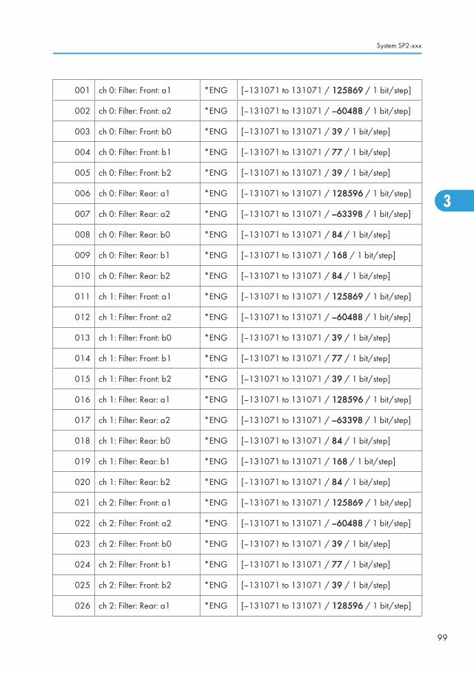
001 ch 0: Filter: Front: a1 *ENG [–131071 to 131071 / 125869 / 1 bit/step]
002 ch 0: Filter: Front: a2 *ENG [–131071 to 131071 / –60488 / 1 bit/step]
003 ch 0: Filter: Front: b0 *ENG [–131071 to 131071 / 39 / 1 bit/step]
004 ch 0: Filter: Front: b1 *ENG [–131071 to 131071 / 77 / 1 bit/step]
005 ch 0: Filter: Front: b2 *ENG [–131071 to 131071 / 39 / 1 bit/step]
006 ch 0: Filter: Rear: a1 *ENG [–131071 to 131071 / 128596 / 1 bit/step]
007 ch 0: Filter: Rear: a2 *ENG [–131071 to 131071 / –63398 / 1 bit/step]
008 ch 0: Filter: Rear: b0 *ENG [–131071 to 131071 / 84 / 1 bit/step]
009 ch 0: Filter: Rear: b1 *ENG [–131071 to 131071 / 168 / 1 bit/step]
010 ch 0: Filter: Rear: b2 *ENG [–131071 to 131071 / 84 / 1 bit/step]
011 ch 1: Filter: Front: a1 *ENG [–131071 to 131071 / 125869 / 1 bit/step]
012 ch 1: Filter: Front: a2 *ENG [–131071 to 131071 / –60488 / 1 bit/step]
013 ch 1: Filter: Front: b0 *ENG [–131071 to 131071 / 39 / 1 bit/step]
014 ch 1: Filter: Front: b1 *ENG [–131071 to 131071 / 77 / 1 bit/step]
015 ch 1: Filter: Front: b2 *ENG [–131071 to 131071 / 39 / 1 bit/step]
016 ch 1: Filter: Rear: a1 *ENG [–131071 to 131071 / 128596 / 1 bit/step]
017 ch 1: Filter: Rear: a2 *ENG [–131071 to 131071 / –63398 / 1 bit/step]
018 ch 1: Filter: Rear: b0 *ENG [–131071 to 131071 / 84 / 1 bit/step]
019 ch 1: Filter: Rear: b1 *ENG [–131071 to 131071 / 168 / 1 bit/step]
020 ch 1: Filter: Rear: b2 *ENG [–131071 to 131071 / 84 / 1 bit/step]
021 ch 2: Filter: Front: a1 *ENG [–131071 to 131071 / 125869 / 1 bit/step]
022 ch 2: Filter: Front: a2 *ENG [–131071 to 131071 / –60488 / 1 bit/step]
023 ch 2: Filter: Front: b0 *ENG [–131071 to 131071 / 39 / 1 bit/step]
024 ch 2: Filter: Front: b1 *ENG [–131071 to 131071 / 77 / 1 bit/step]
025 ch 2: Filter: Front: b2 *ENG [–131071 to 131071 / 39 / 1 bit/step]
026 ch 2: Filter: Rear: a1 *ENG [–131071 to 131071 / 128596 / 1 bit/step]
System SP2-xxx
99
3

027 ch 2: Filter: Rear: a2 *ENG [–131071 to 131071 / –63398 / 1 bit/step]
028 ch 2: Filter: Rear: b0 *ENG [–131071 to 131071 / 84 / 1 bit/step]
029 ch 2: Filter: Rear: b1 *ENG [–131071 to 131071 / 168 / 1 bit/step]
030 ch 2: Filter: Rear: b2 *ENG [–131071 to 131071 / 84 / 1 bit/step]
031 Q Format Selection *ENG [0 to 3 / 3 / 1/step]
2192[MUSIC Threshold Setting] Line Position Adjustment: Threshold Setting DFU
ch 0: ID sensor at rear, ch 1: ID sensor at center, ch 2: ID sensor at front
001 ch 0: 1st *ENG
[0.5 to 3 / 1.2 / 0.1 V/step]
002 ch 0: 2nd *ENG
003 ch 0: 3rd *ENG
004 ch 0: 4th *ENG
005 ch 1: 1st *ENG
006 ch 1: 2nd *ENG
007 ch 1: 3rd *ENG
008 ch 1: 4th *ENG
009 ch 2: 1st *ENG
010 ch 2: 2nd *ENG
011 ch 2: 3rd *ENG
012 ch 2: 4th *ENG
2193 [MUSIC Condition Set] Line Position Adjustment: Condition Setting
001Auto Execution *ENG
[0 or 1 / 1 / 1 ]
0: OFF, 1: ON
Enables/disables the automatic line position adjustment
3. Appendix: SP Mode Tables
100
3

002
Page: Job End: BW+FC *ENG [0 to 999 / 500 / 1 page/step]
Adjusts the threshold of the line position adjustment for BW and color printing mode afterjob end.
003Page: Job End: FC *ENG [0 to 999 / 200 / 1 page/step]
Adjusts the threshold of the line position adjustment for color printing mode after job end.
004
Page: Interrupt: BW+FC *ENG [0 to 999 / 200 / 1 page/step]
Adjusts the threshold of the line position adjustment for BW and color printing mode duringjob.
005Page: Interrupt: FC *ENG [0 to 999 / 200 / 1 page/step]
Adjusts the threshold of the line position adjustment for color printing mode during jobs.
006
Page: Stand-By: BW *ENG [0 to 999 / 100 / 1 page/step]
Adjusts the threshold of the line position adjustment for BW printing mode in stand-by mode.The line position adjustment is done when the number of outputs in BW printing mode reachesthe value specified with this SP and the condition of SP2-193-008 or SP2-193-009 issatisfied.
007
Page: Stand-By: FC *ENG [0 to 999 / 100 / 1 page/step]
Adjusts the threshold of the line position adjustment for BW printing mode in stand-by mode.The line position adjustment is done when the number of outputs in color printing modereaches the value specified with this SP and the condition of SP2-193-008 or SP2-193-009is satisfied.
008
Temp. *ENG [0 to 100 / 5 / 1deg/step]
Adjust the temperature change threshold for the line position adjustment (Mode b: adjustmentonce). The timing for line position adjustment depends on the combinations of severalconditions. Section Descriptions" section.
009
Time *ENG [1 to 1440 / 300 / 1 minute/step]
Adjust the time threshold for the line position adjustment (Mode b: adjustment once). Thetiming for line position adjustment depends on the combinations of several conditions.
010
Magnification *ENG [0 to 1 / 0.1 / 0.01%/step]
Adjusts the magnification threshold for line position adjustment. If the length of the main scanis changed by this amount since the previous MUSIC, then MSUIC is done again.
System SP2-xxx
101
3

011
Temp. 2 *ENG [0 to 100 / 10 / 1deg/step]
Adjust the temperature change threshold for the line position adjustment (Mode a: adjustmenttwice). The timing for line position adjustment depends on the combinations of severalconditions.
012
Time 2 *ENG [1 to 9999 / 600 / 1 minute/step]
Adjust the time threshold for the line position adjustment (Mode a: adjustment twice). Thetiming for line position adjustment depends on the combinations of several conditions.
013
Page: Power ON:BW+FC *ENG [0 to 999 / 200 / 1 page/step]
Adjusts the threshold for the condition of the line position adjustment for BW and color printingmode. The condition of the line position adjustment is determined for large conditiondifference and small condition difference when the number of outputs in color printing modereaches the value specified with this SP and the condition of SP3-510-009 or SP3-510-010is satisfied. However, it is basically not necessary to adjust this SP.
2194 [MUSIC Execution Result] Line Position Adjustment: Execution Result
001Year *ENG [0 to 99 / 0 / 1 year/step]
Displays the year of the last MUSIC execution.
002Month *ENG [1 to 12 / 1 / 1 month/step]
Displays the month of the last MUSIC execution.
003Day *ENG [1 to 31 / 1 / 1 day/step]
Displays the date of the last MUSIC execution.
004Hour *ENG [0 to 23 / 0 / 1 hour/step]
Displays the time (hour) of the last MUSIC execution.
005Minute *ENG [0 to 59 / 0 / 1 minute/step]
Displays the time (minute) of the last MUSIC execution.
006Temperature *ENG [0 to 100 / 0 / 1 deg/step]
Displays the temperature of the last MUSIC execution.
007 Execution Result *ENG[0 or 1 / 0 / 1 /step]
0: Completed successfully, 1: Failed
3. Appendix: SP Mode Tables
102
3

008 Number of Execution *ENG [0 to 999999 / 0 / 1 times/step]
009 Number of Failure *ENG [0 to 999999 / 0 / 1 times/step]
010 Error Result: M *ENG [0 to 9 / 0 / 1 /step]
0: Not done
1: Completed successfully
2: Cannot detect patterns
3: Fewer lines on the pattern than the target
4: Not used
5: Out of the adjustment range
6 to 9: Not used
011 Error Result: C *ENG
012 Error Result: Y *ENG
2197[MUSIC Start Time]
DFU
001 MUSIC Start Time (EDT) *ENG [10 to 40 / 20 / 10ms/step]
002 TM Sensor Position *ENG [50 to 500 / 105.5 / 0.1mm/step]
2198[Music A/D Interval]
ADC Trigger Counter
001 ADC Trigger Counter *ENG [7.5 to 20 / 10 / 0.1 s/step]
2199[Music Error Time Setting]
DFU
001 Error Detection Counter *ENG [0.5 to 4 / 2.5 / 0.1 sec /step]
2220[Skew Origin Set]
Executes the skew motor initialization in the laser optics unit.
001 M: Skew Motor - -
002 C: Skew Motor - -
003 Y: Skew Motor - -
System SP2-xxx
103
3

2221
[LD Power] LD Power Control
Adjusts the fixed LD power for each line speed and color.
These SPs are activated only when SP3-041-002 is set to "0".
Plain: High speed, Thick 1: Middle speed, Thick 2&Fine: Low speed
001 Plain: Bk *ENG
[0 to 200 / 100 / 1%/step]
Increasing this value makes the image densitydarker.
002 Plain: M *ENG
003 Plain: C *ENG
004 Plain: Y *ENG
005 Thick 1: Bk *ENG
006 Thick 1: M *ENG
007 Thick 1: C *ENG
008 Thick 1: Y *ENG
009 Thick 2&FINE: Bk *ENG
010 Thick 2&FINE: M *ENG
011 Thick 2&FINE: C *ENG
012 Thick 2&FINE: Y *ENG
2229
[Development DC Vias] Development DC Bias Adjustment
Adjusts the development bias.
Development bias is automatically adjusted during process control; therefore, adjusting thesesettings has no effect while Process Control (SP3-041-001 Default: ON) is activated.
After deactivating Process Control with SP3-041-001, the values in these SP modes are usedfor printing.
Plain: High speed, Thick 1: Middle speed, Thick 2&Fine: Low speed
3. Appendix: SP Mode Tables
104
3

001 Plain: Bk *ENG
[0 to 800 / 550 / 10 –V/step]
002 Plain: M *ENG
003 Plain: C *ENG
004 Plain: Y *ENG
005 Thick 1: Bk *ENG
006 Thick 1: M *ENG
007 Thick 1: C *ENG
008 Thick 1: Y *ENG
009 Thick 2&FINE:Bk *ENG
010 Thick 2&FINE:M *ENG
011 Thick 2&FINE:C *ENG
012 Thick 2&FINE:Y *ENG
2241[Temperature/Humidity: Display]
Displays the environment temperature and humidity.
001 Temperature - [–1280 to 1270 / - / 0.1deg/step]
002 Relative Humidity - [0 to 1000 / - / 0.1 %RH/step]
003 Absolute Humidity - [0 to 100 / - / 0.01 g/m3/step]
2302[Environmental Correction: Transfer]
Environmental Correction: Image Transfer Belt Unit
001Current EnvironmentalDisplay
- Displays the current environment condition.
System SP2-xxx
105
3

002 Forced Setting *ENG
Sets the environment condition manually.
[0 to 6 / 0 / 1 /step]
0: Automatic environment control
1: LL (Low temperature/ Low humidity)
2: ML (Middle temperature/ Low humidity)
3: MM (Middle temperature/ Middle humidity)
4: MH (Middle temperature/ High humidity)
5: HH (High temperature/ High humidity)
003Absolute Humidity:Threshold 1
*ENGAdjusts the threshold value between LL and ML.
[0 to 100 / 4 / 0.01 g/m3/step]
004Absolute Humidity:Threshold 2
*ENGAdjusts the threshold value between ML and MM.
[0 to 100 / 8 / 0.01 g/m3/step]
005Absolute Humidity:Threshold 3
*ENGAdjusts the threshold value between MM and MH.
[0 to 100 / 16 / 0.01 g/m3/step]
006Absolute Humidity:Threshold 4
*ENGAdjusts the threshold value between MH and HH.
[0 to 100 / 24 / 0.01 g/m3/step]
007 Temp Threshold *ENG [–5 to 30 / 5 / 1 deg/step]
2308[Paper Size Correction]
Adjusts the threshold value for the paper size correction.
001 Threshold 1 *ENG
[0 to 350 / 297 / 1 mm/step]
Threshold 1 < paper:
Paper is detected as "S1" size.
002 Threshold 2 *ENG
[0 to 350 / 257 / 1 mm/step]
Threshold 2 < paper < Threshold 1:
Paper is detected as "S2" size.
003 Threshold 3 *ENG
[0 to 350 / 210 / 1 mm/step]
Threshold 3 < paper < Threshold 2:
Paper is detected as "S3" size.
3. Appendix: SP Mode Tables
106
3

004 Threshold 4 *ENG
[0 to 350 / 148 / 1 mm/step]
Threshold 4 < paper < Threshold 3:
Paper is detected as "S4" size.
Paper < Threshold 4:
Paper is detected as "S5" size.
2311 [Non Image Area: Bias]
001 Image Transfer *ENG
Adjusts the bias of the image transfer belt betweenimages. This value is added to the value of theimage transfer belt bias.
[10 to 250 / 100 / 5 %/step]
002 Paper Transfer *ENG
Adjusts the bias of the paper transfer roller betweenimages.
[0 to 2000 / 500 / 1 V/step]
2326 [Transfer Roller CL: Bias] Transfer Roller Cleaning: Bias Adjustment
001Positive *ENG [0 to 2100 / 500 / 100 V /step]
Adjusts the positive voltage of the paper transfer roller for cleaning the paper transfer roller.
002Negative *ENG [10 to 400 / 100 / 10 %/step]
Adjusts the negative current of the paper transfer roller for cleaning the paper transfer roller.
003
Positive *ENG [0 to 2100 / 2000 / 100 V/step]
Adjusts the negative current limit of the paper transfer roller for cleaning the paper transferroller.
004 Negative *ENG [10 to 400 / 100 / 10 %/step]
2351[Common: BW: Bias] Image Transfer Belt: B/W: Bias Adjustment
Plain: High speed, Thick 1: Middle speed, Thick 2&Fine: Low speed
001ITB unit: Plain *ENG [0 to 80 / 25 / 1 A]
Adjusts the current for the image transfer belt in B/W mode for plain paper.
System SP2-xxx
107
3

002ITB unit: Thick 1 *ENG [0 to 80 / 12 / 1 A]
Adjusts the current for the image transfer belt in B/W mode for thick 1 paper.
003ITB unit: Thick 2 & FINE *ENG [0 to 80 / 12 / 1 A]
Adjusts the current for the image transfer belt in B/W mode for thick 2 paper or FINE mode.
2357[Common: FC: Bias] Image Transfer Belt: Full Color: Bias Adjustment
Plain: High speed, Thick 1: Middle speed, Thick 2&Fine: Low speed
001ITB unit: Plain: Bk *ENG [0 to 80 / 22 / 1 A]
Adjusts the current for the image transfer belt for Black in full color mode for plain paper.
002ITB unit: Plain: M *ENG [0 to 80 / 25 / 1 A]
Adjusts the current for the image transfer belt for Magenta in full color mode for plain paper.
003ITB unit: Plain: C *ENG [0 to 80 / 22 / 1 A]
Adjusts the current for the image transfer belt for Cyan in full color mode for plain paper.
004ITB unit: Plain: Y *ENG [0 to 80 / 28 / 1 A]
Adjusts the current for the image transfer belt for Yellow in full color mode for plain paper.
005ITB unit: Thick 1: Bk *ENG [0 to 80 / 11 / 1 A]
Adjusts the current for the image transfer belt for Black in full color mode for thick 1 paper.
006ITB unit: Thick 1: M *ENG [0 to 80 / 12 / 1 A]
Adjusts the current for the image transfer belt for Magenta in full color mode for thick 1 paper.
007ITB unit: Thick 1: C *ENG [0 to 80 / 11 / 1 A]
Adjusts the current for the image transfer belt for Cyan in full color mode for thick 1 paper.
008ITB unit: Thick 1: Y *ENG [0 to 80 / 14 / 1 A]
Adjusts the current for the image transfer belt for Yellow in full color mode for thick 1 paper.
009ITB unit: Thick 2 & FINE: Bk *ENG [0 to 80 / 11 / 1 A]
Adjusts the current for the image transfer belt for Black in full color mode for Thick 2 and fine.
3. Appendix: SP Mode Tables
108
3

010
ITB unit: Thick 2 & FINE: M *ENG [0 to 80 / 12 / 1 A]
Adjusts the current for the image transfer belt for Magenta in full color mode for Thick 2 andfine.
011ITB unit: Thick 2 & FINE: C *ENG [0 to 80 / 11 / 1 A]
Adjusts the current for the image transfer belt for Cyan in full color mode for Thick 2 and fine.
012
ITB unit: Thick 2 & FINE: Y *ENG [0 to 80 / 14 / 1 A]
Adjusts the current for the image transfer belt for Yellow in full color mode for Thick 2 andfine.
2360 [Common: BW Environment Correction Table]
001 Image Transfer: Plain *ENG[1 to 60 / 1 / 1 /step]
002 Image Transfer: Thick 1 *ENG
004 Image Transfer: Plain: Bk *ENG [1 to 60 / 13/ 1 /step]
005 Image Transfer: Plain: M *ENG
[1 to 60 / 2 / 1 /step]006 Image Transfer: Plain: C *ENG
007 Image Transfer: Plain: Y *ENG
008 Image Transfer: Thick 1: Bk *ENG [1 to 60 / 31 / 1 /step]
009 Image Transfer: Thick 1: M *ENG
[1 to 60 / 2 / 1 /step]010 Image Transfer: Thick 1: C *ENG
011 Image Transfer: Thick 1: Y *ENG
2401
[Plain: Bias]
Adjusts the DC voltage of the discharge plate for plain paper.
Plain: High speed, 1200: Low speed
001 Separation DC: Plain: 1st Side *ENG [0 to 4000 / 0 / 10 –V/step]
002 Separation DC: Plain: 2nd Side *ENG [0 to 4000 / 0 / 10 –V/step]
003 Separation DC: 1200: 1st Page *ENG [0 to 4000 / 0 / 10 –V/step]
004 Separation DC: 1200: 2nd side *ENG [0 to 4000 / 0 / 10 –V/step]
System SP2-xxx
109
3

2403
[Plain: Bias: BW]
Adjusts the current for the paper transfer roller for plain paper in black-and-white mode.
Plain: High speed, 1200: Low speed
001 Paper Transfer: Plain: 1st Side *ENG
[0 to 250 / 22 / 1 – A /step]002
Paper Transfer: Plain: 2ndSide
*ENG
003Paper Transfer: 1200: 1stSide
*ENG [0 to 250 / 7 / 1 – A /step]
004Paper Transfer: 1200: 2ndside
*ENG [0 to 250 / 12 / 1 – A /step]
2407
[Plain: Bias: FC]
Adjusts the current for the paper transfer roller for plain paper in full color mode.
Plain: High speed, 1200: Low speed
001 Paper Transfer: Plain: 1st Side *ENG [0 to 250 / 27 / 1 – A /step]
002Paper Transfer: Plain: 2ndSide
*ENG [0 to 250 / 33 / 1 – A /step]
003Paper Transfer: 1200: 1stSide
*ENG [0 to 250 / 10 / 1 – A /step]
004Paper Transfer: 1200: 2ndside
*ENG [0 to 250 / 12 / 1 – A /step]
2411
[Plain: Paper Size Correction]
Adjusts the size correction coefficient for the paper transfer roller current for each paper size.SP2403 and SP2407 are multiplied by these SP values.
Plain: High speed, 1200: Low speed
3. Appendix: SP Mode Tables
110
3

001Paper Transfer: Plain : 1stSide: S1
*ENG
[100 to 600 / 100 / 5%/step]
S1 size > 297 mm (Paper width)
002Paper Transfer: Plain: 2ndSide: S1
*ENG
003Separation DC: 1200: 1stSide
*ENG
004Separation DC: 1200: 2ndSide
*ENG
005Paper Transfer: Plain: 1st Side:S2
*ENG[100 to 600 / 105 / 5%/step]
297 mm > S2 size > 275 mm (Paper width)
006Paper Transfer: Plain: 2ndSide: S2
*ENG[100 to 600 / 120 / 5%/step]
297 mm > S2 size > 275 mm (Paper width)
007Paper Transfer: 1200: 1stSide: S2
*ENG[100 to 600 / 120 / 5%/step]
297 mm > S2 size > 275 mm (Paper width)
008Paper Transfer: 1200: 2ndSide: S2
*ENG [100 to 600 / 150 / 5%/step]
009Paper Transfer: Plain: 1st Side:S3
*ENG[100 to 600 / 110 / 5%/step]
275 mm > S3 size > 210 mm (Paper width)
010Paper Transfer: Plain: 2ndSide: S3
*ENG[100 to 600 / 140 / 5%/step]
275 mm > S3 size > 210 mm (Paper width)011
Paper Transfer: 1200: 1stSide: S3
*ENG
012Paper Transfer: 1200: 2ndSide: S3
*ENG [100 to 600 / 300 / 5%/step]
013Paper Transfer: Plain: 1st Side:S4
*ENG[100 to 600 / 115 / 5%/step]
210 mm > S4 size > 148 mm (Paper width)
014Paper Transfer: Plain: 2ndSide: S4
*ENG[100 to 600 / 160 / 5%/step]
210 mm > S4 size > 148 mm (Paper width)
015Paper Transfer: 1200: 1stSide: S4
*ENG[100 to 600 / 240 / 5%/step]
210 mm > S4 size > 148 mm (Paper width)
System SP2-xxx
111
3
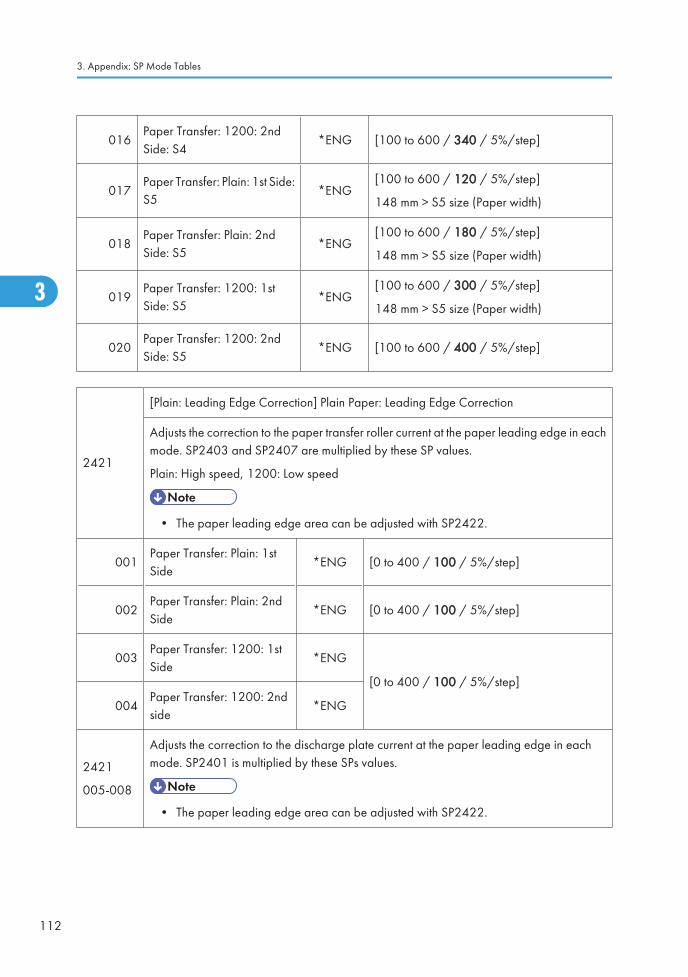
016Paper Transfer: 1200: 2ndSide: S4
*ENG [100 to 600 / 340 / 5%/step]
017Paper Transfer: Plain: 1st Side:S5
*ENG[100 to 600 / 120 / 5%/step]
148 mm > S5 size (Paper width)
018Paper Transfer: Plain: 2ndSide: S5
*ENG[100 to 600 / 180 / 5%/step]
148 mm > S5 size (Paper width)
019Paper Transfer: 1200: 1stSide: S5
*ENG[100 to 600 / 300 / 5%/step]
148 mm > S5 size (Paper width)
020Paper Transfer: 1200: 2ndSide: S5
*ENG [100 to 600 / 400 / 5%/step]
2421
[Plain: Leading Edge Correction] Plain Paper: Leading Edge Correction
Adjusts the correction to the paper transfer roller current at the paper leading edge in eachmode. SP2403 and SP2407 are multiplied by these SP values.
Plain: High speed, 1200: Low speed
• The paper leading edge area can be adjusted with SP2422.
001Paper Transfer: Plain: 1stSide
*ENG [0 to 400 / 100 / 5%/step]
002Paper Transfer: Plain: 2ndSide
*ENG [0 to 400 / 100 / 5%/step]
003Paper Transfer: 1200: 1stSide
*ENG
[0 to 400 / 100 / 5%/step]
004Paper Transfer: 1200: 2ndside
*ENG
2421
005-008
Adjusts the correction to the discharge plate current at the paper leading edge in eachmode. SP2401 is multiplied by these SPs values.
• The paper leading edge area can be adjusted with SP2422.
3. Appendix: SP Mode Tables
112
3

005Separation DC: Plain: 1stSide
*ENG
[0 to 400 / 100 / 5%/step]
006Separation DC: Plain: 2ndSide
*ENG
007Separation DC: 1200: 1stSide
*ENG
008Separation DC: 1200: 2ndSide
*ENG
2422
[Plain: Switch Timing: Lead. Edge]
Adjusts the bias/ voltage switch timing of the paper transfer roller/ discharge plate at thepaper leading edge between the erase margin area and the image area.
Plain: High speed, 1200: Low speed
001 Paper Transfer: Plain: 1st Side *ENG
[0 to 50 / 0 / 2 mm/step]
002Paper Transfer: Plain: 2ndSide
*ENG
003Paper Transfer: 1200: 1stSide
*ENG
004Paper Transfer: 1200: 2ndside
*ENG
005 Separation DC: Plain: 1st Side *ENG
006Separation DC: Plain: 2ndSide
*ENG
007Separation DC: 1200: 1stSide
*ENG
008Separation DC: 1200: 2ndSide
*ENG
System SP2-xxx
113
3

2423
[Plain: Trailing Edge Correction] Plain Paper: Trailing Edge Correction
Adjusts the correction coefficient to the paper transfer roller current for the paper trailingedge in each mode. SP2403 and SP2407 are multiplied by these SP values.
Plain: High speed, 1200: Low speed
• The paper trailing edge area can be adjusted with SP2424.
001 Paper Transfer: Plain: 1st Side *ENG
[0 to 400 / 100 / 5%/step]
002Paper Transfer: Plain: 2ndSide
*ENG
003Paper Transfer: 1200: 1stSide
*ENG
004Paper Transfer: 1200: 2ndside
*ENG
005 Separation DC: Plain: 1st Side *ENG
006Separation DC: Plain: 2ndSide
*ENG
007Separation DC: 1200: 1stSide
*ENG
008Separation DC: 1200: 2ndSide
*ENG
2424
[Plain: Switch Timing: Trail. Edge]
Adjusts the bias/voltage switch timing of the paper transfer roller/discharge plate at thepaper trailing edge between the erase margin area and the image area.
Plain: High speed, 1200: Low speed
3. Appendix: SP Mode Tables
114
3
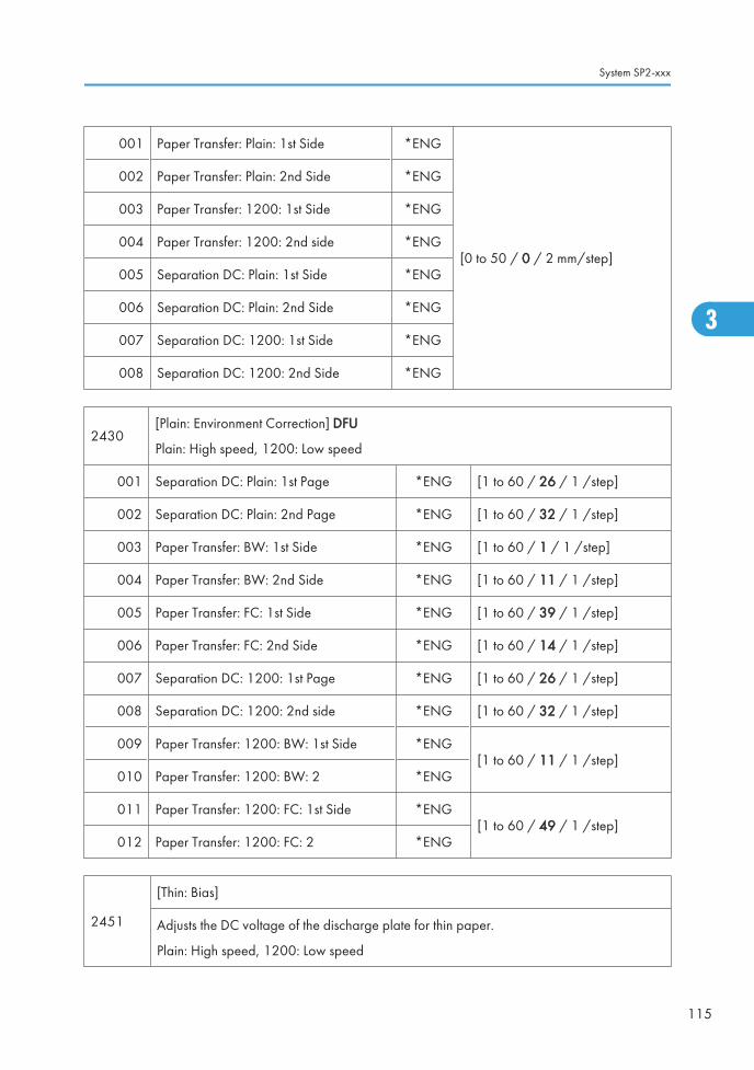
001 Paper Transfer: Plain: 1st Side *ENG
[0 to 50 / 0 / 2 mm/step]
002 Paper Transfer: Plain: 2nd Side *ENG
003 Paper Transfer: 1200: 1st Side *ENG
004 Paper Transfer: 1200: 2nd side *ENG
005 Separation DC: Plain: 1st Side *ENG
006 Separation DC: Plain: 2nd Side *ENG
007 Separation DC: 1200: 1st Side *ENG
008 Separation DC: 1200: 2nd Side *ENG
2430[Plain: Environment Correction] DFU
Plain: High speed, 1200: Low speed
001 Separation DC: Plain: 1st Page *ENG [1 to 60 / 26 / 1 /step]
002 Separation DC: Plain: 2nd Page *ENG [1 to 60 / 32 / 1 /step]
003 Paper Transfer: BW: 1st Side *ENG [1 to 60 / 1 / 1 /step]
004 Paper Transfer: BW: 2nd Side *ENG [1 to 60 / 11 / 1 /step]
005 Paper Transfer: FC: 1st Side *ENG [1 to 60 / 39 / 1 /step]
006 Paper Transfer: FC: 2nd Side *ENG [1 to 60 / 14 / 1 /step]
007 Separation DC: 1200: 1st Page *ENG [1 to 60 / 26 / 1 /step]
008 Separation DC: 1200: 2nd side *ENG [1 to 60 / 32 / 1 /step]
009 Paper Transfer: 1200: BW: 1st Side *ENG[1 to 60 / 11 / 1 /step]
010 Paper Transfer: 1200: BW: 2 *ENG
011 Paper Transfer: 1200: FC: 1st Side *ENG[1 to 60 / 49 / 1 /step]
012 Paper Transfer: 1200: FC: 2 *ENG
2451
[Thin: Bias]
Adjusts the DC voltage of the discharge plate for thin paper.
Plain: High speed, 1200: Low speed
System SP2-xxx
115
3

001 Separation DC: Plain: 1st Side *ENG [0 to 4000 / 2000 / 10 –V/step]003 Separation DC: 1200: 1st Page *ENG
2453
[Thin: Bias: BW]
Adjusts the current for the paper transfer roller for thin paper in black-and-white mode.
Plain: High speed, 1200: Low speed
001 Paper Transfer: Plain: 1st Side *ENG [0 to 250 / 22 / 1 – A /step]
003 Paper Transfer: 1200: 1st Side *ENG [0 to 250 / 11 / 1 – A /step]
2457
[Thin: Bias: FC]
Adjusts the current for the paper transfer roller for thin paper in full color mode.
Plain: High speed, 1200: Low speed
001 Paper Transfer: Plain: 1st Side *ENG [0 to 250 / 30 / 1 – A /step]
003 Paper Transfer: 1200: 1st Side *ENG [0 to 250 / 15 / 1 – A /step]
2461
[Thin: Paper Size Correction]
Adjusts the size correction coefficient for the paper transfer roller current for each paper size.SP2453 and SP2457 are multiplied by these SP values.
Plain: High speed
001 Paper Transfer: Plain: 1st Side: S1 *ENG[100 to 600 / 100 / 5%/step]
S1 size > 297 mm (Paper width)
005 Paper Transfer: Plain: 1st Side: S2 *ENG
[100 to 600 / 120 / 5%/step]
297 mm > S2 size > 275 mm (Paperwidth)
009 Paper Transfer: Plain: 1st Side: S3 *ENG
[100 to 600 / 140 / 5%/step]
297 mm > S2 size > 275 mm (Paperwidth)
013 Paper Transfer: Plain: 1st Side: S4 *ENG
[100 to 600 / 160 / 5%/step]
297 mm > S2 size > 275 mm (Pape rwidth)
3. Appendix: SP Mode Tables
116
3

017 Paper Transfer: Plain: 1st Side: S5 *ENG [100 to 600 / 180 / 5%/step]
2471
[Thin: Leading Edge Correction] Thin Paper: Leading Edge Correction
Adjusts the correction to the paper transfer roller current at the paper leading edge in eachmode. SP2453 and SP2457 are multiplied by these SP values.
Plain: High speed, 1200: Low speed
• The paper leading edge area can be adjusted with SP2472.
001 Paper Transfer: Plain: 1st Side *ENG[0 to 400 / 100 / 5%/step]
003 Paper Transfer: 1200: 1st Side *ENG
2471
Adjusts the correction to the discharge plate current at the paper leading edge in each mode.SP2451 is multiplied by these SP values.
• The paper leading edge area can be adjusted with SP2472.
005 Separation DC: Plain: 1st Side *ENG[0 to 400 / 100 / 5%/step]
007 Separation DC: 1200: 1st Side *ENG
2472
[Thin: Switch Timing: Lead. Edge]
Adjusts the bias/ voltage switch timing of the paper transfer roller/ discharge plate at thepaper leading edge between the erase margin area and the image area.
Plain: High speed, 1200: Low speed,
001 Paper Transfer: Plain: 1st Side *ENG
[0 to 50 / 0 / 2 mm/step]003 Paper Transfer: 1200: 1st Side *ENG
005 Separation DC: Plain: 1st Side *ENG
007 Separation DC: 1200: 1st Side *ENG
System SP2-xxx
117
3

2473
[Thin: Trailing Edge Correction] Thin Paper: Trailing Edge Correction
Adjusts the correction coefficient to the paper transfer roller current for the paper trailingedge in each mode. SP2453 and SP2457 are multiplied by these SP values.
Plain: High speed, 1200: Low speed
• The paper trailing edge area can be adjusted with SP2474.
001 Paper Transfer: Plain: 1st Side *ENG [0 to 400 / 100 / 5%/step]
003 Paper Transfer: 1200: 1st Side *ENG [0 to 400 / 100 / 5%/step]
005 Separation DC: Plain: 1st Side *ENG [0 to 400 / 100 / 5%/step]
007 Separation DC: 1200: 1st Side *ENG [0 to 400 / 100 / 5%/step]
2474
[Thin: Switch Timing: Trail. Edge]
Adjusts the bias/voltage switch timing of the paper transfer roller/discharge plate at thepaper trailing edge between the erase margin area and the image area.
Plain: High speed, 1200: Low speed
001 Paper Transfer: Plain: 1st Side *ENG[0 to 50 / 0 / 2 mm/step]
003 Paper Transfer: 1200: 1st Side *ENG
005 Separation DC: Plain: 1st Side *ENG[0 to 50 / 0 / 1 mm/step]
007 Separation DC: 1200: 1st Side *ENG
2480[Thin: Environment Correction]
Plain: High speed, 1200: Low speed
001 Separation DC: Plain: 1st Side *ENG [1 to 60 / 26 / 1 /step]
003 Paper Transfer: Plain: BW: 1st Side *ENG [1 to 60 / 11 / 1 /step]
005 Paper Transfer: Plain: FC: 1st Side *ENG [1 to 60 / 1 / 1 /step]
007 Separation DC: 1200: 1st Side *ENG [1 to 60 / 26 / 1 /step]
009 Paper Transfer: 1200: BW: 1st Side *ENG [1 to 60 / 11 / 1 /step]
011 Paper Transfer: 1200: FC: 1st Side *ENG [1 to 60 / 1 / 1 /step]
3. Appendix: SP Mode Tables
118
3

2481 [Glossy: Bias]
001Separation DC: Glossy: 1st Side *ENG [0 to 4000 / 2000 / 10 –V/step]
Adjusts the DC voltage of the discharge plate for glossy paper.
2482 [Glossy: Bias: BW]
001Paper Transfer: Glossy: 1st Side *ENG [0 to 250 / 12 / 1 – A /step]
Adjusts the current for the paper transfer roller for glossy paper in black-and-white mode.
2483 [Glossy: Bias: FC]
001Paper Transfer: Glossy: 1st Side *ENG [0 to 250 / 15 / 1 – A /step]
Adjusts the current for the paper transfer roller for glossy paper in full color mode.
2484 [Glossy: Paper Size Correction]
001 Paper Transfer: Glossy: 1st Side: S1 *ENG [100 to 600 / 100 / 5%/step]
005 Paper Transfer: Glossy: 1st Side: S2 *ENG [100 to 600 / 120 / 5%/step]
009 Paper Transfer: Glossy: 1st Side: S3 *ENG [100 to 600 / 140 / 5%/step]
013 Paper Transfer: Glossy: 1st Side: S4 *ENG [100 to 600 / 160 / 5%/step]
017 Paper Transfer: Glossy: 1st Side: S5 *ENG [100 to 600 / 180 / 5%/step]
2485 [Glossy: Leading Edge Correction]
001 Paper Transfer: 1st Side *ENG [10 to 400 / 100 / 5%/step]
005 Separation DC: 1st Side *ENG [10 to 400 / 100 / 5%/step]]
2486 [Glossy: Switch Timing: Lead. Edge]
001 Paper Transfer: 1st Side *ENG[0 to 50 / 0 / 2 mm/step]
005 Separation DC: 1st Side *ENG
2487 [Glossy: Trailing Edge Correction]
System SP2-xxx
119
3

001 Paper Transfer: 1st Side *ENG[0 to 400 / 100 / 5 %/step]
005 Separation DC: 1st Side *ENG
2488 [Glossy: Switch Timing: Trail. Edge]
001 Paper Transfer: 1st Side *ENG[0 to 50 / 0 / 2 mm/step]
005 Separation DC: 1st Side *ENG
2489 [Glossy: Environment Correction]
001 Separation DC: 1st Side *ENG [1 to 60 / 26 / 1 /step]
003 Paper Transfer: BW: 1st Side *ENG [1 to 60 / 11 / 1 /step]
005 Paper Transfer: FC: 2nd Side *ENG [1 to 60 / 1 / 1 /step]
2501
[Thick 1: Bias]
Adjusts the DC voltage of the discharge plate for thick 1 paper.
Plain: High speed, 1200: Low speed
001 Separation DC: Plain: 1st Side *ENG
[0 to 4000 / 1000 / 10 –V/step]002 Separation DC: Plain: 2nd Side *ENG
003 Separation DC: 1200: 1st Side *ENG
2502
[Thick 1: Bias: BW]
Adjusts the current for the paper transfer roller for thick 1 paper in black-and-white mode.
Plain: High speed, 1200: Low speed
001 Paper Transfer: Plain: 1st Side *ENG[0 to 250 / 24 / 1 – A /step]
002 Paper Transfer: Plain: 2nd Side *ENG
003 Separation DC: 1200: 1st Side *ENG [0 to 250 / 12 / 1 – A /step]
2507
[Thick 1: Bias: FC]
Adjusts the current for the paper transfer roller for thick 1 paper in full color mode.
Plain: High speed, 1200: Low speed
3. Appendix: SP Mode Tables
120
3

001 Paper Transfer: Plain: 1st Side *ENG[0 to 250 / 30 / 1 – A /step]
002 Paper Transfer: Plain: 2nd Side *ENG
003 Separation DC: 1200: 1st Side *ENG [0 to 250 / 15 / 1 – A /step]
2511
[Thick 1: Paper Size Correction]
Adjusts the size correction coefficient for the paper transfer roller current for each paper size.SP2502 and SP2507 are multiplied by these SP values.
Plain: High speed, 1200: Low speed
001 Paper Transfer: Plain: 1st Side: S1 *ENG [100 to 600 / 100 / 5%/step]
S1 size > 297 mm (Paper width)002 Paper Transfer: Plain: 2nd Side: S1 *ENG
003 Paper Transfer: 1200: 1st Side: S1 *ENG[100 to 600 / 100 / 5%/step]
S1 size > 297 mm (Paper width)
005 Paper Transfer: Plain: 1st Side: S2 *ENG
[100 to 600 / 105 / 5%/step]
297 mm > S2 size > 275 mm (Paperwidth)
006 Paper Transfer: Plain: 2nd Side: S2 *ENG
[100 to 600 / 130 / 5%/step]
297 mm > S2 size > 275 mm (Paperwidth)
007 Paper Transfer: 1200: 1st Side: S2 *ENG
[100 to 600 / 120 / 5%/step]
297 mm > S2 size > 275 mm (Paperwidth)
009 Paper Transfer: Plain: 1st Side: S3 *ENG
[100 to 600 / 110 / 5%/step]
275 mm > S3 size > 210 mm (Paperwidth)
010 Paper Transfer: Plain: 2nd Side: S3 *ENG
[100 to 600 / 160 / 5%/step]
275 mm > S3 size > 210 mm (Paperwidth)
011 Paper Transfer: 1200: 1st Side: S3 *ENG
[100 to 600 / 140 / 5%/step]
275 mm > S3 size > 210 mm (Paperwidth)
System SP2-xxx
121
3

013 Paper Transfer: Plain 1: 1st Side: S4 *ENG
[100 to 600 / 115 / 5%/step]
210 mm > S4 size > 148 mm (Paperwidth)
014 Paper Transfer: Plain: 2nd Side: S4 *ENG
[100 to 600 / 190 / 5%/step]
210 mm > S4 size > 148 mm (Paperwidth)
015 Paper Transfer: 1200: 1st Side: S4 *ENG
[100 to 600 / 160 / 5%/step]
210 mm > S4 size > 148 mm (Paperwidth)
017 Paper Transfer: Plain 1: 1st Side: S5 *ENG[100 to 600 / 120 / 5%/step]
148 mm > S5 size (Paper width)
018 Paper Transfer: Plain: 2nd Side: S5 *ENG[100 to 600 / 220 / 5%/step]
148 mm > S5 size (Paper width)
019 Paper Transfer: 1200: 1st Side: S5 *ENG[100 to 600 / 180 / 5%/step]
148 mm > S5 size (Paper width)
2521
[Thick 1: Leading Edge Correction] Thick 1 Paper: Leading Edge Correction
Adjusts the correction to the paper transfer roller current at the paper leading edge in eachmode. SP2502 and SP2507 are multiplied by these SP values.
Thick 1: Middle speed, 1200: Low speed
• The paper leading edge area can be adjusted with SP2522.
001 Paper Transfer: Plain: 1st Side *ENG[0 to 400 / 100 / 5%/step]
002 Paper Transfer: Plain: 2nd Side *ENG
003 Paper Transfer: 1200: 1st Side *ENG [0 to 400 / 100 / 5%/step]
005 Separation DC: Plain: 1st Side *ENG[0 to 400 / 100 / 5%/step]
006 Separation DC: Plain: 2nd Side *ENG
007 Separation DC: 1200: 1st Side *ENG [0 to 400 / 100 / 5%/step]
3. Appendix: SP Mode Tables
122
3

2522
[Thick 1: Switch Timing: Lead. Edge]
Adjusts the bias/ voltage switch timing of the paper transfer roller/ discharge plate at thepaper leading edge between the erase margin area and the image area.
Thick 1: Middle speed, 1200: Low speed
001 Paper Transfer: Thick 1: 1st Side *ENG[0 to 50 / 0 / 2 mm/step]
002 Paper Transfer: Thick 1: 2nd Side *ENG
005 Separation DC: Thick 1: 1st Side *ENG[0 to 50 / 0 / 2 mm/step]
006 Separation DC: Thick 1: 2nd Side *ENG
2523
[Thick 1: Trailing Edge Correction] Thick 1 Paper: Trailing Edge Correction
Adjusts the correction coefficient to the paper transfer roller current for the paper trailingedge in each mode. SP2502 and SP2507 are multiplied by these SP values.
Thick 1: Middle speed, 1200: Low speed
• The paper trailing edge area can be adjusted with SP2524.
001 Paper Transfer: Plain: 1st Side *ENG
[0 to 400 / 100 / 5%/step]002 Paper Transfer: Plain: 2nd Side *ENG
003 Paper Transfer: 1200: 1st Side *ENG
005 Paper Transfer: Plain: 1st Side *ENG
006 Paper Transfer: Plain: 2nd Side *ENG[0 to 400 / 100 / 5%/step]
007 Paper Transfer: 1200: 1st Side *ENG
2524
[Thick 1: Switch Timing: Trail. Edge]
Adjusts the bias/voltage switch timing of the paper transfer roller/discharge plate at thepaper trailing edge between the erase margin area and the image area.
Plain: High speed, 1200: Low speed
System SP2-xxx
123
3

001 Paper Transfer: Plain: 1st Side *ENG
[0 to 50 / 0 / 1 mm/step]
002 Paper Transfer: Plain: 2nd Side *ENG
003 Paper Transfer: 1200: 1st Side *ENG
005 Paper Transfer: Plain: 1st Side *ENG
006 Paper Transfer: Plain: 2nd Side *ENG
007 Paper Transfer: 1200: 1st Side *ENG
2530[Thick 1: Environment Correction]
Plain: High speed, 1200: Low speed
001 Separation DC: Plain: 1st Side *ENG[1 to 60 / 22 / 1 /step]
002 Separation DC: Plain: 2nd Side *ENG
003 Paper Transfer: Plain: BW: 1st Side *ENG[1 to 60 / 11 / 1 /step]
004 Paper Transfer: Plain: BW:2nd Side *ENG
005 Paper Transfer: Plain: FC: 1st Side *ENG [1 to 60 / 1 / 1 /step]
006 Paper Transfer: Plain: FC:2nd Side *ENG [1 to 60 / 11 / 1 /step]
007 Separation DC: 1200: 1st Side *ENG [1 to 60 / 22 / 1 /step]
009 Paper Transfer: 1200: BW: 1st Side *ENG [1 to 60 / 11 / 1 /step]
011 Paper Transfer: 1200: FC: 1st Side *ENG [1 to 60 / 1 / 1 /step]
2551[Thick 2: Bias]
Adjusts the DC voltage of the discharge plate for thick 2 paper.
001 Separation DC: 1st Side *ENG[0 to 4000 / 0 / 10 –V/step]
002 Separation DC: 2nd Side *ENG
2553[Thick 2: Bias: BW]
Adjusts the current for the paper transfer roller for thick 2 paper in black-and-white mode.
001 Paper Transfer: 1st Side *ENG [0 to 250 / 7 / 1 – A /step]
3. Appendix: SP Mode Tables
124
3

002 Paper Transfer: 2nd Side *ENG [0 to 250 / 12 / 1 – A /step]
2558[Thick 2: Bias: FC]
Adjusts the current for the paper transfer roller for thick 2 paper in full color mode.
001 Paper Transfer: 1st Side *ENG [0 to 250 / 16 / 1 – A /step]
002 Paper Transfer: 2nd Side *ENG [0 to 250 / 15 / 1 – A /step]
2561
[Thick 2: Paper Size Correction]
Adjusts the size correction coefficient for the paper transfer roller current for each paper size.SP2553 and SP2558 are multiplied by these SP values.
001 Paper Transfer: 1st Side: S1 *ENG [100 to 600 / 100 / 5%/step]
S1 size > 297 mm (Paper width)002 Paper Transfer: 2nd Side: S1 *ENG
003 Paper Transfer: 1st Side: S2 *ENG[100 to 600 / 105 / 5%/step]
297 mm > S2 size > 275 mm (Paper width)
004 Paper Transfer: 2nd Side: S2 *ENG[100 to 600 / 160 / 5%/step]
297 mm > S2 size > 275 mm (Paper width)
005 Paper Transfer: 1st Side: S3 *ENG[100 to 600 / 110 / 5%/step]
275 mm > S3 size > 210 mm (Paper width)
006 Paper Transfer: 2nd Side: S3 *ENG[100 to 600 / 260 / 5%/step]
275 mm > S3 size > 210 mm (Paper width)
007 Paper Transfer: 1st Side: S4 *ENG[100 to 600 / 120 / 5%/step]
210 mm > S4 size > 148 mm (Paper width)
008 Paper Transfer: 2nd Side: S4 *ENG[100 to 600 / 430 / 5%/step]
210 mm > S4 size > 148 mm (Paper width)
009 Paper Transfer: 1st Side: S5 *ENG[100 to 600 / 140 / 5%/step]
148 mm > S5 size (Paper width)
010 Paper Transfer: 2nd Side: S5 *ENG[100 to 600 / 600 / 5%/step]
148 mm > S5 size (Paper width)
System SP2-xxx
125
3

2571
[Thick 2: Leading Edge Correction] Thick 2 Paper: Leading Edge Correction
Adjusts the correction to the paper transfer roller current at the paper leading edge in eachmode. SP2553 and SP2558 are multiplied by these SP values.
• The paper leading edge area can be adjusted with SP2572.
001 Paper Transfer: 1st Side *ENG[0 to 400 / 100 / 5%/step]
002 Paper Transfer: 2nd Side *ENG
2571
Adjusts the correction to the discharge plate current at the paper leading edge in each mode.SP2551 is multiplied by these SP values.
• The paper leading edge area can be adjusted with SP2572.
003 Separation DC: 1st Side *ENG[0 to 400 / 100 / 5%/step]
004 Separation DC: 2nd Side *ENG
2572
[Thick 2: Switch Timing: Lead. Edge]
Adjusts the bias/ voltage switch timing of the paper transfer roller/ discharge plate at thepaper leading edge between the erase margin area and the image area.
001 Paper Transfer: 1st Side *ENG
[0 to 50 / 0 / 2mm/step]002 Paper Transfer: 2nd Side *ENG
003 Separation DC: 1st Side *ENG
004 Separation DC: 2nd Side *ENG
2573
[Thick 2: Trailing Edge Correction] Thick 2 Paper: Trailing Edge Correction
Adjusts the correction to the paper transfer roller current for the paper trailing edge in eachmode. SP2553 and SP2558 are multiplied by these SP values.
• The paper trailing edge area can be adjusted with SP2574.
001 Paper Transfer: 1st Side *ENG[0 to 400 / 100 / 5%/step]
002 Paper Transfer: 2nd Side *ENG
3. Appendix: SP Mode Tables
126
3

003 Separation DC: 1st Side *ENG [0 to 400 / 100 / 5%/step]
004 Separation DC: 2nd Side *ENG [0 to 400 / 100 / 5%/step]
2574
[Thick 2: Switch Trailing Edge Correction]
Adjusts the bias/voltage switch timing of the paper transfer roller/discharge plate at thepaper trailing edge between the erase margin area and the image area.
001 Paper Transfer: 1st Side *ENG
[0 to 50 / 0 / 2 mm/step]002 Paper Transfer: 2nd Side *ENG
003 Separation DC: 1st Side *ENG
004 Separation DC: 2nd Side *ENG
2580 [Thick 2 Environment Correction]
001 Separation DC: 1st Side *ENG[1 to 60 / 22 / 1 /step]
002 Separation DC: 2nd Side *ENG
003 Paper Transfer: BW: 1st Side *ENG[0 to 60 / 11 / 1 /step]
004 Paper Transfer: BW: 2nd Side *ENG
005 Paper Transfer: FC: 1st Side *ENG [1 to 60 / 53 / 1 /step]
006 Paper Transfer: FC: 2nd Side *ENG [1 to 60 / 11 / 1 /step]
2601[OHP: Bias]
Adjusts the DC voltage of the discharge plate for OHP.
001 Separation DC *ENG [0 to 4000 / 0 / 10 –V/step]
2603[OHP: Bias: BW]
Adjusts the current for the paper transfer roller for OHP in black-and-white mode.
001 Paper Transfer *ENG [0 to 250 / 12 / 1 – A /step]
System SP2-xxx
127
3

2608[OHP: Bias: FC]
Adjusts the current for the paper transfer roller for OHP in full color mode.
001 Paper Transfer *ENG [0 to 250 / 15 / 1 – A /step]
2611
[OHP: Paper Size Correction]
Adjusts the size correction coefficient for the paper transfer roller current for each paper size.SP2603 and SP2608 are multiplied by these SP values.
001 Paper Transfer: S1 *ENG[100 to 600 / 100 / 5%/step]
S1 size > 297 mm (Paper width)
002 Paper Transfer: S2 *ENG[100 to 600 / 140 / 5%/step]
297 mm > S2 size > 275 mm (Paper width)
003 Paper Transfer: S3 *ENG[100 to 600 / 200 / 5%/step]
275 mm > S3 size > 210 mm (Paper width)
004 Paper Transfer: S4 *ENG[100 to 600 / 260 / 5%/step]
210 mm > S4 size > 148 mm (Paper width)
005 Paper Transfer: S5 *ENG[100 to 600 / 330 / 5%/step]
148 mm > S5 size (Paper width)
2621
[OHP: Leading Edge Correction] OHP: Leading Edge Correction
Adjusts the correction to the paper transfer roller current at the paper leading edge in eachmode. SP2603 and SP2608 are multiplied by these SP values.
• The paper leading edge area can be adjusted with SP2622.
001 Paper Transfer *ENG [0 to 400 / 100 / 5%/step]
2621
Adjusts the correction to the discharge plate current at the paper leading edge in each mode.SP2601 is multiplied by these SP values.
• The paper leading edge area can be adjusted with SP2622.
002 Separation DC *ENG [0 to 400 / 100 / 5%/step]
3. Appendix: SP Mode Tables
128
3

2622
[OHP: Switch Timing: Lead. Edge]
Adjusts the bias/ voltage switch timing of the paper transfer roller/ discharge plate at thepaper leading edge between the erase margin area and the image area.
001 Paper Transfer *ENG[0 to 50 / 0 / 2 mm/step]
002 Separation DC *ENG
2623
[OHP: Trailing Edge Correction] OHP: Trailing Edge Correction
Adjusts the correction to the paper transfer roller current for the paper trailing edge in eachmode. SP2603 and SP2608 are multiplied by these SP values.
• The paper trailing edge area can be adjusted with SP2624.
001 Paper Transfer *ENG [0 to 400 / 100 / 5%/step]
002 Separation DC [0 to 400 / 100 / 5%/step]
2624
[OHP: Trailing Edge Correction]
Adjusts the bias/voltage switch timing of the paper transfer roller/discharge plate at thepaper trailing edge between the erase margin area and the image area.
001 Paper Transfer *ENG [–100 to 0 / 0 / 1 mm/step]
002 Separation DC *ENG [0 to 50 / 0 / 2 mm/step]
2630 [OHP: Environment Correction]
001 Separation DC *ENG [1 to 60 / 22 / 1 /step]
002 Paper Transfer: BW *ENG [1 to 60 / 11 / 1 /step]
003 Paper Transfer: FC *ENG [1 to 60 / 1 / 1 /step]
2650[Thick3: Bias]
Adjusts the DC voltage of the discharge plate for thick paper 3.
001 Separation DC: 1st Side *ENG[0 to 4000 / 1000 / 10 –V/step]
002 Separation DC: 2nd Side *ENG
System SP2-xxx
129
3

2651[Thick 3: Bias: BW]
Adjusts the current for the paper transfer roller for thick paper 3 in black-and-white mode.
001 Paper Transfer: 1st Side *ENG [0 to 250 / 10 / 1 – A /step]
002 Paper Transfer: 2nd Side *ENG [0 to 250 / 12 / 1 – A /step]
2652[Thick 3: Bias: FC]
Adjusts the current for the paper transfer roller for thick paper 3 in full color mode.
001 Paper Transfer: Thick 3: 1st Side *ENG [0 to 250 / 11 / 1 – A /step]
002 Paper Transfer: Thick 3: 2nd Side *ENG [0 to 250 / 15 / 1 – A /step]
2653
[Thick 3: Paper Size Correction]
Adjusts the size correction coefficient for the paper transfer roller current for each paper size.SP2651 and SP2652 are multiplied by these SP values.
001Paper Transfer: Thick 3: 1stSide: S1
*ENG[100 to 600 / 100 / 5%/step]
S1 size > 297 mm (Paper width)
002Paper Transfer: Thick 3: 1stSide: S2
*ENG[100 to 600 / 100 / 5%/step]
297 mm > S2 size > 275 mm (Paper width)
003Paper Transfer: Thick 3: 1stSide: S3
*ENG[100 to 600 / 100 / 5%/step]
275 mm > S3 size > 210 mm (Paper width)
004Paper Transfer: Thick 3: 1stSide: S4
*ENG[100 to 600 / 160 / 5%/step]
210 mm > S4 size > 148 mm (Paper width)
005Paper Transfer: Thick 3: 1stSide: S5
*ENG[100 to 600 / 100 / 5%/step]
148 mm > S5 size (Paper width)
006Paper Transfer: Thick 3: 2ndSide: S1
*ENG[100 to 600 / 260 / 5%/step]
S1 size > 297 mm (Paper width)
007Paper Transfer: Thick 3: 2ndSide: S2
*ENG[100 to 600 / 100 / 5%/step]
297 mm > S2 size > 275 mm (Paper width)
008Paper Transfer: Thick 3: 2ndSide: S2
*ENG[100 to 600 / 430 / 5%/step]
275 mm > S3 size > 210 mm (Paper width)
3. Appendix: SP Mode Tables
130
3

009Paper Transfer: Thick 3: 2ndSide: S4
*ENG[100 to 600 / 100 / 5%/step]
210 mm > S4 size > 148 mm (Paper width)
010Paper Transfer: Thick 3: 2ndSide: S4
*ENG[100 to 600 / 600 / 5%/step]
148 mm > S5 size (Paper width)
2654
[Thick 3: Leading Edge Correction] Thick 3 Paper: Leading Edge Correction
Adjusts the correction to the paper transfer roller current at the paper leading edge in eachmode. SP2651 and SP2652 are multiplied by these SP values.
• The paper leading edge area can be adjusted with SP2655.
001 Paper Transfer: 1st Side *ENG[0 to 400 / 100 / 5%/step]
002 Separation DC: 1st Side *ENG
2654
Adjusts the correction to the discharge plate current at the paper leading edge in each mode.SP2650 is multiplied by these SP values.
• The paper leading edge area can be adjusted with SP2655.
003 Paper Transfer: 2nd Side *ENG[0 to 400 / 100 / 5%/step]
004 Separation DC: 2nd Side *ENG
2655
[Thick 3: Switch Timing: Lead. Edge]
Adjusts the bias/ voltage switch timing of the paper transfer roller/ discharge plate at thepaper leading edge between the erase margin area and the image area.
001 Paper Transfer: 1st Side *ENG
[0 to 50 / 0 / 2 mm/step]002 Separation DC: 1st Side *ENG
003 Paper Transfer: 2nd Side *ENG
004 Separation DC: 2nd Side *ENG
System SP2-xxx
131
3

2656
[Thick 3: Trailing Edge Correction] Thick 3 Paper: Trailing Edge Correction
Adjusts the correction to the paper transfer roller current for the paper trailing edge in eachmode. SP2651 and SP2652 are multiplied by these SP values.
• The paper trailing edge area can be adjusted with SP2657.
001 Paper Transfer: 1st Side *ENG
[0 to 400 / 100 / 5%/step]002 Paper Transfer: 2nd Side *ENG
003 Separation DC: 1st Side *ENG
004 Separation DC: 2nd Side *ENG
2657
[Thick 3: Trailing Edge Correction]
Adjusts the bias/voltage switch timing of the paper transfer roller/discharge plate at thepaper trailing edge between the erase margin area and the image area.
001 Paper Transfer: 1st Side *ENG
[0 to 50 / 0 / 2 mm/step]002 Paper Transfer: 2nd Side *ENG
003 Separation DC: 1st Side *ENG
004 Separation DC: 2nd Side *ENG
2660
[Thick 3: Environment Correction] Thick 3 Paper: MM Environment Coefficient Adjustment
Adjusts the environment coefficient for each mode. When the environment is detected asMM, SP2651 and SP2652 are multiplied by these SP values.
001 Separation DC: 1st Side *ENG[1 to 60 / 22 / 1 /step]
002 Separation DC: 2nd Side *ENG
Adjusts the environment coefficient for each mode. When the environment is detected asMM, SP2650 is multiplied by these SP values.
003 Paper Transfer: BW: 1st Side *ENG[1 to 60 / 11 / 1 /step]
004 Paper Transfer: BW: 2nd Side *ENG
005 Paper Transfer: FC: 1st Side *ENG [1 to 60 / 55 / 1 /step]
3. Appendix: SP Mode Tables
132
3
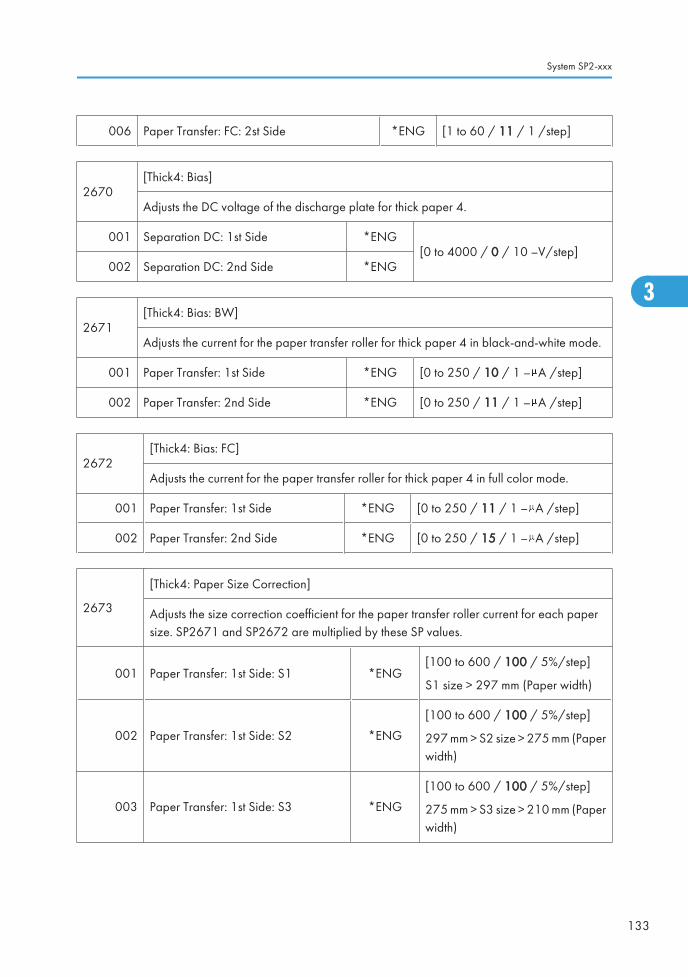
006 Paper Transfer: FC: 2st Side *ENG [1 to 60 / 11 / 1 /step]
2670[Thick4: Bias]
Adjusts the DC voltage of the discharge plate for thick paper 4.
001 Separation DC: 1st Side *ENG[0 to 4000 / 0 / 10 –V/step]
002 Separation DC: 2nd Side *ENG
2671[Thick4: Bias: BW]
Adjusts the current for the paper transfer roller for thick paper 4 in black-and-white mode.
001 Paper Transfer: 1st Side *ENG [0 to 250 / 10 / 1 – A /step]
002 Paper Transfer: 2nd Side *ENG [0 to 250 / 11 / 1 – A /step]
2672[Thick4: Bias: FC]
Adjusts the current for the paper transfer roller for thick paper 4 in full color mode.
001 Paper Transfer: 1st Side *ENG [0 to 250 / 11 / 1 – A /step]
002 Paper Transfer: 2nd Side *ENG [0 to 250 / 15 / 1 – A /step]
2673
[Thick4: Paper Size Correction]
Adjusts the size correction coefficient for the paper transfer roller current for each papersize. SP2671 and SP2672 are multiplied by these SP values.
001 Paper Transfer: 1st Side: S1 *ENG[100 to 600 / 100 / 5%/step]
S1 size > 297 mm (Paper width)
002 Paper Transfer: 1st Side: S2 *ENG
[100 to 600 / 100 / 5%/step]
297 mm > S2 size > 275 mm (Paperwidth)
003 Paper Transfer: 1st Side: S3 *ENG
[100 to 600 / 100 / 5%/step]
275 mm > S3 size > 210 mm (Paperwidth)
System SP2-xxx
133
3

004 Paper Transfer: 1st Side: S4 *ENG
[100 to 600 / 160 / 5%/step]
210 mm > S4 size > 148 mm (Paperwidth)
005 Paper Transfer: 1st Side: S5 *ENG[100 to 600 / 100 / 5%/step]
148 mm > S5 size (Paper width)
006 Paper Transfer: 2nd Side: S1 *ENG[100 to 600 / 260 / 5%/step]
S1 size > 297 mm (Paper width)
007 Paper Transfer: 2nd Side: S2 *ENG
[100 to 600 / 100 / 5%/step]
297 mm > S2 size > 275 mm (Paperwidth)
008 Paper Transfer: 2nd Side: S3 *ENG
[100 to 600 / 430 / 5%/step]
275 mm > S3 size > 210 mm (Paperwidth)
009 Paper Transfer: 2nd Side: S4 *ENG
[100 to 600 / 100 / 5%/step]
210 mm > S4 size > 148 mm (Paperwidth)
010 Paper Transfer: 2nd Side: S3 *ENG[100 to 600 / 600 / 5%/step]
148 mm > S5 size (Paper width)
2674
[Thick 4: Leading Edge Correction] Thick 4 Paper: Leading Edge Correction
Adjusts the correction to the paper transfer roller current at the paper leading edge in eachmode. SP2671 and SP2672 are multiplied by these SP values.
• The paper leading edge area can be adjusted with SP2675.
001 Paper Transfer: 1st Side *ENG[0 to 400 / 100 / 5%/step]
002 Separation DC: 1st Side *ENG
2674
Adjusts the correction to the discharge plate current at the paper leading edge in each mode.SP2670 is multiplied by these SP values.
• The paper leading edge area can be adjusted with SP2655.
3. Appendix: SP Mode Tables
134
3

003 Paper Transfer: 2nd Side *ENG[0 to 400 / 100 / 5%/step]
004 Separation DC: 2nd Side *ENG
2675
[Thick 4: Switch Timing: Lead. Edge]
Adjusts the bias/ voltage switch timing of the paper transfer roller/ discharge plate at thepaper leading edge between the erase margin area and the image area.
001 Paper Transfer: 1st Side *ENG
[0 to 50 / 0 / 2 mm/step]002 Separation DC: 1st Side *ENG
003 Paper Transfer: 2nd Side *ENG
004 Separation DC: 2nd Side *ENG
2676
[Thick 4: Trailing Edge Correction] Thick 4 Paper: Trailing Edge Correction
Adjusts the correction to the paper transfer roller current for the paper trailing edge in eachmode. SP2671 and SP2672 are multiplied by these SP values.
• The paper trailing edge area can be adjusted with SP2677.
001 Paper Transfer: 1st Side *ENG
[0 to 400 / 100 / 5%/step]002 Paper Transfer: 2nd Side *ENG
003 Separation DC: 1st Side *ENG
004 Separation DC: 2nd Side *ENG
2677
[Thick 4: Trailing Edge Correction]
Adjusts the bias/voltage switch timing of the paper transfer roller/discharge plate at thepaper trailing edge between the erase margin area and the image area.
001 Paper Transfer: 1st Side *ENG
[0 to 50 / 0 / 2 mm/step]002 Paper Transfer: 2nd Side *ENG
003 Separation DC: 1st Side *ENG
004 Separation DC: 2nd Side *ENG
System SP2-xxx
135
3

2680
[Thick 4: Environment Correction] Thick 4 Paper: MM Environment Coefficient Adjustment
Adjusts the environment coefficient for each mode. When the environment is detected asMM, SP2671 and SP2672 are multiplied by these SP values.
001 Separation DC: 1st Side *ENG[1 to 60 / 22 / 1 /step]
002 Separation DC: 2nd Side *ENG
Adjusts the environment coefficient for each mode. When the environment is detected asMM, SP2670 is multiplied by these SP values.
003 Paper Transfer: BW: 1st Side *ENG[1 to 60 / 11 / 1 /step]
004 Paper Transfer: BW: 2nd Side: *ENG
005 Paper Transfer: FC: 1st Side *ENG [1 to 60 / 55 / 1 /step]
006 Paper Transfer: FC: 2st Side *ENG [1 to 60 / 11 / 1 /step]
2751
[Special1: Bias]
Adjusts the DC voltage of the discharge plate for special paper 1.
Plain: High speed, Thick 1: Middle speed
001 Separation DC: Plain: 1st Side *ENG
[0 to 4000 / 0 / 10 –V/step002 Separation DC: Plain: 2nd Side *ENG
003 Paper Transfer: Thick 1: 1st Side *ENG
2753
[Special1: Bias: BW]
Adjusts the current for the paper transfer roller for special paper 1 in black-and-white mode.
P Plain: High speed, Fine: Low speed
001 Paper Transfer: Plain: 1st Side *ENG[0 to 250 / 22 / 1 – A /step]
002 Paper Transfer: Plain: 2nd Side *ENG
003 Paper Transfer: Plain: 1st Side *ENG [0 to 250 / 11 / 1 – A /step]
3. Appendix: SP Mode Tables
136
3

2757
[Special1: Bias: FC]
Adjusts the current for the paper transfer roller for special paper 1 in full color mode.
Plain: High speed, Fine: Low speed
001 Paper Transfer: Plain: 1st Side *ENG [0 to 250 / 30 / 1 – A /step]
002 Paper Transfer: Plain: 2nd Side *ENG [0 to 250 / 33 / 1 – A /step]
003 Paper Transfer: Plain: 1st Side *ENG [0 to 250 / 15 / 1 – A /step]
2761
[Special 1: Paper Size Correction]
Adjusts the size correction coefficient for the paper transfer roller current for each paper size.SP2753 and SP2757 are multiplied by these SP values.
Plain: High speed, Fine: Low speed
001 Paper Transfer: Plain: 1st Side: S1 *ENG [100 to 600 / 100 / 5%/step]
S1 size > 297 mm (Paper width)002 Paper Transfer: Plain: 2nd Side: S1 *ENG
005 Paper Transfer: Plain: 1st Side: S2 *ENG [100 to 600 / 120 / 5%/step]
297 mm > S2 size > 275 mm (Paperwidth)006 Paper Transfer: Plain: 2nd Side: S2 *ENG
009 Paper Transfer: Plain: 1st Side: S3 *ENG [100 to 600 / 140 / 5%/step]
275 mm > S3 size > 210 mm (Paperwidth)010 Paper Transfer: Plain: 2nd Side: S3 *ENG
013 Paper Transfer: Plain: 1st Side: S4 *ENG [100 to 600 / 160 / 5%/step]
210 mm > S4 size > 148 mm (Paperwidth)014 Paper Transfer: Plain: 2nd Side: S4 *ENG
017 Paper Transfer: Plain: 1st Side: S5 *ENG [100 to 600 / 180 / 5%/step]
148 mm > S5 size (Paper width)018 Paper Transfer: Plain: 2nd Side: S5 *ENG
System SP2-xxx
137
3

2771
[Special 1: Leading Edge Correction] Special 1 Paper: Leading Edge Correction
Adjusts the correction to the paper transfer roller current at the paper leading edge in eachmode. SP2753 and SP2757 are multiplied by these SP values.
Plain: High speed, Fine: Low speed
• The paper leading edge area can be adjusted with SP2772.
001 Paper Transfer: Plain: 1st Side *ENG [0 to 400 / 100 / 5%/step]
002 Paper Transfer: Plain: 2nd Side *ENG [0 to 400 / 100 / 5%/step]
003 Paper Transfer: 1200: 1st Side *ENG [0 to 400 / 100 / 5%/step]
2771
Adjusts the correction to the discharge plate current at the paper leading edge in each mode.SP2751 is multiplied by these SP values.
• The paper leading edge area can be adjusted with SP2772.
005 Separation DC: Plain: 1st Side *ENG[0 to 400 / 100 / 5%/step]
006 Separation DC: Plain: 2nd Side *ENG
007 Separation DC: 1200: 1st Side *ENG [0 to 400 / 100 / 5%/step]
2772
[Special 1: Switch Timing: Lead. Edge]
Adjusts the bias/ voltage switch timing of the paper transfer roller/ discharge plate at thepaper leading edge between the erase margin area and the image area.
Plain: High speed, 1200: Low speed
001 Paper Transfer: Plain: 1st Side *ENG[0 to 50 / 0 / 2 mm/step]
002 Paper Transfer: Plain: 2nd Side *ENG
003 Paper Transfer: 1200: 1st Side *ENG [0 to 50 / 0 / 1 mm/step]
005 Separation DC: Plain: 1st Side *ENG
[0 to 50 / 0 / 2 mm/step]006 Separation DC: Plain: 2nd Side *ENG
007 Separation DC: 1200: 1st Side *ENG
3. Appendix: SP Mode Tables
138
3

2773
[Special 1: Trailing Edge Correction] Special 1 Paper: Trailing Edge Correction
Adjusts the correction to the paper transfer roller current for the paper trailing edge in eachmode. SP2753 and SP2757 are multiplied by these SP values.
Plain: High speed, 1200: Low speed
• The paper trailing edge area can be adjusted with SP2774.
001 Paper Transfer: Plain: 1st Side *ENG
[0 to 400 / 100 / 5%/step]
002 Paper Transfer: Plain: 2nd Side *ENG
003 Paper Transfer: 1200: 1st Side *ENG
005 Separation DC: Plain: 1st Side *ENG
006 Separation DC: Plain: 2nd Side *ENG
007 Separation DC: 1200: 1st Side *ENG
2774
[Special 1: Switch Timing: Trail. Edge]
Adjusts the bias/voltage switch timing of the paper transfer roller/discharge plate at thepaper trailing edge between the erase margin area and the image area.
Plain: High speed, 1200: Low speed
001 Paper Transfer: Plain: 1st Side *ENG
[0 to 50 / 0 / 2 mm/step]
002 Paper Transfer: Plain: 2nd Side *ENG
003 Paper Transfer: 1200: 1st Side *ENG
005 Separation DC: Plain: 1st Side *ENG
006 Separation DC: Plain: 2nd Side *ENG
007 Separation DC: 1200: 1st Side *ENG
2780[Special 1: Environment Correction]
Plain: High speed, 1200: Low speed
001 Separation DC: Plain: 1st Side *ENG [1 to 60 / 26 / 1 /step]
002 Separation DC: Plain: 2nd Side *ENG [1 to 60 / 32 / 1 /step]
System SP2-xxx
139
3

003 Paper Transfer: Plain: BW: 1st Side *ENG[1 to 60 / 11 / 1 /step]
004 Paper Transfer: Plain: BW:2nd Side *ENG
005 Paper Transfer: Plain: FC: 1st Side *ENG [1 to 60 / 1 / 1 /step]
006 Paper Transfer: Plain: FC:2nd Side *ENG [1 to 60 / 14 / 1 /step]
007 Separation DC: 1200: 1st Side *ENG [1 to 60 / 26 / 1 /step]
009 Paper Transfer: 1200: BW: 1st Side *ENG [1 to 60 / 11 / 1 /step]
011 Paper Transfer: 1200: FC: 1st Side *ENG [1 to 60 / 1 / 1 /step]
2801
[Special 2: Bias]
Adjusts the DC voltage of the discharge plate for special paper 2.
Plain: High speed, 1200: Low speed
001 Separation DC: Plain: 1st Side *ENG [0 to 4000 / 0 / 10 –V/step]
002 Separation DC: Plain: 2nd Side *ENG [0 to 4000 / 3000 / 10 –V/step]
003 Separation DC: 1200: 1st Side *ENG [0 to 4000 / 2000 / 10 –V/step]
2803
[Special2: Bias: BW]
Adjusts the current for the paper transfer roller for special paper 2 in black-and-white mode.
Plain: High speed, 1200: Low speed
001 Paper Transfer: Plain: 1st Side *ENG[0 to 250 / 22 / 1 – A /step]
002 Paper Transfer: Plain: 2nd Side *ENG
003 Separation DC: 1200: 1st Side *ENG [0 to 200 / 11 / 1 – A /step]
2807
[Special2: Bias: FC]
Adjusts the current for the paper transfer roller for special paper 2 in full color mode.
Plain: High speed, Thick 2&Fine: Low speed
001 Paper Transfer: Plain: 1st Side *ENG [0 to 250 / 30 / 1 – A /step]
002 Paper Transfer: Plain: 2nd Side *ENG [0 to 250 / 33 / 1 – A /step]
003 Separation DC: 1200: 1st Side *ENG [0 to 250 / 15 / 1 – A /step]
3. Appendix: SP Mode Tables
140
3

2811
[Special2: Paper Size Correction]
Adjusts the size correction coefficient for the paper transfer roller current for each paper size.SP2803 and SP2807 are multiplied by these SP values.
001 Paper Transfer: Plain: 1st Side: S1 *ENG [100 to 600 / 100 / 5%/step]
S1 size > 297 mm (Paper width)002 Paper Transfer: Plain: 2nd Side: S1 *ENG
005 Paper Transfer: Plain: 1st Side: S2 *ENG
[100 to 600 / 120 / 5%/step]
297 mm > S2 size > 275 mm (Paperwidth)
006 Paper Transfer: Plain: 2nd Side: S2 *ENG
[100 to 600 / 120 / 5%/step]
297 mm > S2 size > 275 mm (Paperwidth)
009 Paper Transfer: Plain: 1st Side: S3 *ENG
[100 to 600 / 140 / 5%/step]
275 mm > S3 size > 210 mm (Paperwidth)
010 Paper Transfer: Plain: 2nd Side: S3 *ENG
[100 to 600 / 140 / 5%/step]
275 mm > S3 size > 210 mm (Paperwidth)
013 Paper Transfer: Plain: 1st Side: S4 *ENG
[100 to 600 / 160 / 5%/step]
210 mm > S4 size > 148 mm (Paperwidth)
014 Paper Transfer: Plain: 2nd Side: S4 *ENG
[100 to 600 / 160 / 5%/step]
210 mm > S4 size > 148 mm (Paperwidth)
017 Paper Transfer: Plain: 1st Side: S5 *ENG[100 to 600 / 180 / 5%/step]
148 mm > S5 size (Paper width)
018 Paper Transfer: Plain: 2nd Side: S5 *ENG[100 to 600 / 180 / 5%/step]
148 mm > S5 size (Paper width)
System SP2-xxx
141
3

2821
[Special 2: Leading Edge Correction] Special 2 Paper: Leading Edge Correction
Adjusts the correction to the paper transfer roller current at the paper leading edge in eachmode. SP2803 and SP2807 are multiplied by these SP values.
Plain: High speed, 1200: Low speed
• The paper leading edge area can be adjusted with SP2822.
001 Paper Transfer: Plain: 1st Side *ENG [0 to 400 / 100 / 5%/step]
002 Paper Transfer: Plain: 2nd Side *ENG [0 to 400 / 100 / 5%/step]
003 Paper Transfer: 1200: 1st Side *ENG [0 to 400 / 100 / 5%/step]
2821
Adjusts the correction to the discharge plate current at the paper leading edge in each mode.SP2801 is multiplied by these SP values.
• The paper leading edge area can be adjusted with SP2822.
005 Separation DC: Plain: 1st Side *ENG
[0 to 400 / 100 / 5%/step]006 Separation DC: Plain: 2nd Side *ENG
007 Separation DC: 1200: 1st Side *ENG
2822
[Special 2: Switch Timing: Lead. Edge]
Adjusts the bias/ voltage switch timing of the paper transfer roller/ discharge plate at thepaper leading edge between the erase margin area and the image area.
Plain: High speed, 1200: Low speed
001 Paper Transfer: Plain: 1st Side *ENG
[0 to 50 / 0 / 2 mm/step]
002 Paper Transfer: Plain: 2nd Side *ENG
003 Paper Transfer: 1200: 1st Side *ENG
005 Separation DC: Plain: 1st Side *ENG
006 Separation DC: Plain: 2nd Side *ENG
007 Separation DC: 1200: 1st Side *ENG
3. Appendix: SP Mode Tables
142
3

2823
[Special 2: Trailing Edge Correction] Special 2 Paper: Trailing Edge Correction
Adjusts the correction to the paper transfer roller current for the paper trailing edge in eachmode. SP2803 and SP2807 are multiplied by these SP values.
Plain: High speed, 1200: Low speed
• The paper trailing edge area can be adjusted with SP2824.
001 Paper Transfer: Plain: 1st Side *ENG[0 to 400 / 100 / 5%/step]
002 Paper Transfer: Plain: 2nd Side *ENG
003 Paper Transfer: 1200: 1st Side *ENG
[0 to 400 / 100 / 5%/step]005 Separation DC: Plain: 1st Side *ENG
006 Separation DC: Plain: 2nd Side *ENG
007 Separation DC: 1200: 1st Side *ENG
2824
[Special 2: Switch Timing: Trail. Edge]
Adjusts the bias/voltage switch timing of the paper transfer roller/discharge plate at thepaper trailing edge between the erase margin area and the image area.
Plain: High speed, 1200: Low speed
001 Paper Transfer: Plain: 1st Side *ENG
[0 to 50 / 0 / 2 mm/step]
002 Paper Transfer: Plain: 2nd Side *ENG
003 Paper Transfer: 1200: 1st Side *ENG
005 Separation DC: Plain: 1st Side *ENG
006 Separation DC: Plain: 2nd Side *ENG
007 Separation DC: 1200: 1st Side *ENG
2830[Special 2: Environment Correction]
Plain: High speed, 1200: Low speed
001 Paper Transfer: Plain: 1st Side *ENG [1 to 60 / 26 / 1 /step]
002 Paper Transfer: Plain: 2nd Side *ENG [1 to 60 / 32 / 1 /step]
System SP2-xxx
143
3

003 Paper Transfer: Plain: BW: 1st Side *ENG [1 to 60 / 1 / 1 /step]
004 Paper Transfer: Plain: BW:2nd Side *ENG [1 to 60 / 11 / 1 /step]
005 Paper Transfer: Plain: FC: 1st Side *ENG [1 to 60 / 1 / 1 /step]
006 Paper Transfer: Plain: FC:2nd Side *ENG [1 to 60 / 14 / 1 /step]
007 Paper Transfer: 1200: 1st Side *ENG [1 to 60 / 26 / 1 /step]
009 Paper Transfer: 1200: BW: 1st Side *ENG [1 to 60 / 11 / 1 /step]
011 Paper Transfer: 1200: FC: 1st Side *ENG [1 to 60 / 1 / 1 /step]
2851
[Special 3: Bias]
Adjusts the DC voltage of the discharge plate for special paper 3.
Plain: High speed, 1200: Low speed
001 Separation DC: Plain: 1st Side *ENG
[0 to 4000 / 0 / 10 –V/step]002 Separation DC: Plain: 2nd Side *ENG
003 Separation DC: 1200: 1st Side *ENG
2852
[Special 3: Bias: BW]
Adjusts the current for the paper transfer roller for special paper 3 in black-and-white mode.
Plain: High speed, 1200: Low speed
001 Paper Transfer: Plain: 1st Side *ENG[0 to 250 / 22 / 1 – A /step]
002 Paper Transfer: Plain: 2nd Side *ENG
003 Paper Transfer: 1200: 1st Side *ENG [0 to 250 / 11 / 1 – A /step]
2857
[Special 3: Bias: FC]
Adjusts the current for the paper transfer roller for special paper 3 in full color mode.
Plain: High speed, 1200: Low speed
001 Paper Transfer: Plain: 1st Side *ENG [0 to 250 / 30 / 1 – A /step]
002 Paper Transfer: Plain: 2nd Side *ENG [0 to 250 / 33 / 1 – A /step]
003 Paper Transfer: 1200: 1st Side *ENG [0 to 250 / 15 / 1 – A /step]
3. Appendix: SP Mode Tables
144
3

2861
[Special 3: Paper Size Correction]
Adjusts the size correction coefficient for the paper transfer roller current for each paper size.SP2852 and SP2857 are multiplied by these SP values.
001 Paper Transfer: 1st Side: S1 *ENG [100 to 600 / 100 / 5%/step]
S1 size > 297 mm (Paper width)002 Paper Transfer: 2nd Side: S1 *ENG
005 Paper Transfer: 1st Side: S2 *ENG
[100 to 600 / 120 / 5%/step]
297 mm > S2 size > 275 mm (Paperwidth)
006 Paper Transfer: 2nd Side: S2 *ENG
[100 to 600 / 120 / 5%/step]
297 mm > S2 size > 275 mm (Paperwidth)
009 Paper Transfer: 1st Side: S3 *ENG
[100 to 600 / 140 / 5%/step]
275 mm > S3 size > 210 mm (Paperwidth)
010 Paper Transfer: 2nd Side: S3 *ENG
[100 to 600 / 140 / 5%/step]
275 mm > S3 size > 210 mm (Paperwidth)
013 Paper Transfer: 1st Side: S4 *ENG
[100 to 600 / 160 / 5%/step]
210 mm > S4 size > 148 mm (Paperwidth)
014 Paper Transfer: 2nd Side: S4 *ENG
[100 to 600 / 160 / 5%/step]
210 mm > S4 size > 148 mm (Paperwidth)
017 Paper Transfer: 1st Side: S5 *ENG[100 to 600 / 180 / 5%/step]
148 mm > S5 size (Paper width)
018 Paper Transfer: 2nd Side: S5 *ENG[100 to 600 / 180 / 5%/step]
148 mm > S5 size (Paper width)
System SP2-xxx
145
3

2871
[Special 3: Leading Edge Correction] Special 3 Paper: Leading Edge Correction
Adjusts the correction to the paper transfer roller current at the paper leading edge in eachmode. SP2852 and SP2857 are multiplied by these SP values.
Plain: High speed, 1200: Low speed
• The paper leading edge area can be adjusted with SP2872.
001 Paper Transfer: Plain: 1st Side *ENG[0 to 400 / 100 / 5%/step]
002 Paper Transfer: Plain: 2nd Side *ENG
003 Paper Transfer: 1200: 1st Side *ENG [0 to 400 / 100 / 5%/step]
005-008
Adjusts the correction to the discharge plate current at the paper leading edge in each mode.SP2851 is multiplied by these SP values.
• The paper leading edge area can be adjusted with SP2872.
005 Separation DC: Plain: 1st Side *ENG[0 to 400 / 100 / 5%/step]
006 Separation DC: Plain: 2nd Side *ENG
007 Separation DC: 1200: 1st Side *ENG [0 to 400 / 100 / 5%/step]
2872
[Special 3: Switch Timing: Lead. Edge]
Adjusts the bias/ voltage switch timing of the paper transfer roller/ discharge plate at thepaper leading edge between the erase margin area and the image area.
Plain: High speed, 1200: Low speed
001 Paper Transfer: Plain: 1st Side *ENG[0 to 50 / 0 / 2 mm/step]
002 Paper Transfer: Plain: 2nd Side *ENG
003 Paper Transfer: 1200: 1st Side *ENG
[0 to 50 / 0 / 2 mm/step]005 Separation DC: Plain: 1st Side *ENG
006 Separation DC: Plain: 2nd Side *ENG
007 Separation DC: 1200: 1st Page *ENG [0 to 50 / 0 / 2 mm/step]
3. Appendix: SP Mode Tables
146
3

2873
[Special 3: Trailing Edge Correction] Special 3 Paper: Trailing Edge Correction
Adjusts the correction to the paper transfer roller current for the paper trailing edge in eachmode. SP2852 and SP2857 are multiplied by these SP values.
Plain: High speed, 1200: Low speed
• The paper trailing edge area can be adjusted with SP2874.
001 Paper Transfer: Plain: 1st Side *ENG
[0 to 400 / 100 / 5%/step]
002 Paper Transfer: Plain: 2nd Side *ENG
003 Paper Transfer: 1200: 1st Side *ENG
005 Separation DC: Plain: 1st Side *ENG
006 Separation DC: Plain: 2nd Side *ENG
007 Separation DC: 1200: 1st Side *ENG
2874
[Special 3: Switch Timing: Trail. Edge]
Adjusts the bias/voltage switch timing of the paper transfer roller/discharge plate at thepaper trailing edge between the erase margin area and the image area.
Plain: High speed, 1200: Low speed
001 Paper Transfer: Plain: 1st Side *ENG
[0 to 50 / 0 / 2 mm/step]
002 Paper Transfer: Plain: 2nd Side *ENG
003 Paper Transfer: 1200: 1st Side *ENG
005 Separation DC: Plain: 1st Side *ENG
006 Separation DC: Plain: 2nd Side *ENG
007 Separation DC: 1200: 1st Side *ENG
2880[Special 3: Environment Correction]
Plain: High speed, 1200: Low speed
001 Separation DC: Plain: 1st Side *ENG [1 to 60 / 26 / 1 /step]
002 Separation DC: Plain: 2nd Side *ENG [1 to 60 / 32 / 1 /step]
System SP2-xxx
147
3

003 Paper Transfer: Plain: BW: 1st Side *ENG[1 to 60 / 11 / 1 /step]
004 Paper Transfer: Plain: BW:2nd Side *ENG
005 Paper Transfer: Plain: FC: 1st Side *ENG [1 to 60 / 1 / 1 /step]
006 Paper Transfer: Plain: FC:2nd Side *ENG [1 to 60 / 11 / 1 /step]
007 Separation DC: 1200: 1st Side *ENG [1 to 60 / 26 / 1 /step]
009 Paper Transfer: 1200: BW: 1st Side *ENG [1 to 60 / 11 / 1 /step]
011 Paper Transfer: 1200: FC: 1st Side *ENG [1 to 60 / 1 / 1 /step]
2901
[OPC Drum Brake Time]
Adjusts the time when the OPC drum motor reverses from normal rotation after job end. DFU
Plain: High speed, Thick 1: Middle speed, Thick 2&Fine: Low speed
001 Plain *ENG
[300 to 1500 / 500 / 10 msec/step]002 Thick 1 *ENG
003 Thick 2 & FINE *ENG
2902[OPC Drum Reverse Time]
Adjusts the time for how long the OPC drum motor reverses after job end. DFU
001 All: BW *ENG [0 to 200 / 50 / 10 msec/step]
002 All: FC *ENG [0 to 200 / 50 / 10 msec/step]
2903
[Image Transfer Roller Brake Time]
Adjusts the time when the image transfer belt motor reverses from normal rotation after jobend. DFU
Plain: High speed, Thick 1: Middle speed, Thick 2&Fine: Low speed
003 Plain *ENG
[300 to 1500 / 500 / 10 msec/step]004 Thick 1 *ENG
005 Thick 2 & FINE *ENG
3. Appendix: SP Mode Tables
148
3

2904[OPC Drum Reverse Time]
Adjusts the time for how long the image transfer belt motor reverses after job end. DFU
003 All *ENG [0 to 200 / 40 / 10 msec/step]
2905
[Dev Rvs Time] Development Roller Reverse Time
Specifies the time of the development roller reverse rotation after the development unit hasstopped. The reverse rotation of the development roller is used for removing dust from thedevelopment roller.
001 K *ENG
[0 to 200 / 80 / 10 msec/step]002 M *ENG
003 C *ENG
004 Y *ENG
005
[Dev Rvs Threshold Counter]
All *ENG [0 to 400000 / 4000/ 10 mm/step]
Specifies the threshold distance for the development roller reverse mode. This sp refers tothe counters for SP2905-006 to -009.
[Dev Rvs Counter]
006 K *ENG
[0 to 999999999 / - / 1 mm/step]007 M *ENG
008 C *ENG
009 Y *ENG
2906[Phase Angle]
DFU
001 Y Drum *ENG
[0 to 359 / 0 / 1 deg/step]002 C Drum *ENG
003 M Drum *ENG
004 K Drum *ENG
System SP2-xxx
149
3

2906[Amplitude Setting]
DFU
006 Y Drum *ENG
[0 to 100 / 0.0 / 0.1 m/step]007 C Drum
008 M Drum
009 K Drum
2907
[ACS Setting (FC to Bk)]
Adjusts the threshold for moving away the image transfer belt from the color PCDUs. This SPmoves the image transfer belt away from the color PCDUs when the number of B/W imageprintouts reaches the number of sheets specified with this SP after consecutive full color imageprintouts in the full color mode.
If this SP is set to "0", the image transfer belt does not move away.
001 Continuous Bk Pages *ENG [0 to 10 / 0 / 1 sheet/step]
2908
[Gain Adjust] Gain Adjustment of Image Transfer Belt Motor DFU
0: High speed (Low level)
1: Middle high speed
2: Middle low speed
3: Low speed (High level)
001 255 mm/sec *ENG[0 or 1 / 0 / 1/step]
002 230 mm/sec *ENG
003 205 mm/sec *ENG [0 or 1 / 1 / 1/step]
004 154 mm/sec *ENG [0 or 1 / 2 / 1/step]
005 77 mm/sec *ENG [0 or 1 / 3 / 1/step]
2911 [Offset Angle] DFU
3. Appendix: SP Mode Tables
150
3

001 Y Drum *ENG
[0 to 359 / 0 / 1 deg/step]002 C Drum *ENG
003 M Drum *ENG
004 K Drum *ENG
2912 [Offset Amplitude Setting] DFU
001 Y Drum *ENG
[0 to 100 / 0.0 / 0.1 m/step]002 C Drum *ENG
003 M Drum *ENG
004 K Drum *ENG
2913 [Drum Control]
001 Rotation Direction *ENG [0 or 1 / 1 / -/step]
2920 [Transfer Motor Control]
001
0: Encorder 1 :FG *ENG [0 or 1 / 0 / 1 /step]
Selects the speed control mode for the ITB.
If SC443 occurs and machine does not recover, change this setting to "1".
002
SC443 Count *ENG [0 to 3 / 0 / 1 /step]
Displays the number of the ITB encodre error. SC443 is displayed if this counter counts to"3".
2930
[SecondaryFB: Threshold] Paper Transfer Roller Feed-back: Threshold Adjustment
Adjusts the threshold between high resistance (division 1) and low resistance (division 2) atthe paper transfer roller. This SP affects SP2931 to SP2939.
001 Voltage *ENG [0 to 7000 / 6000 / 10 –V/step]
2960 [Process Interval]
System SP2-xxx
151
3

001Additional Time *ENG [0 to 10 / 0 / 1 sec/step]
Adjusts the additional time for ending the machine's process.
2970 [Cleaning After JOB]
001
No Refresh *ENG[0 to 100 / 50 / 1 /step]
0: No cleaning
Specifies the threshold sheets for the cleaning of the paper transfer roller without the refreshmode.
002 Refresh *ENG[0 or 1 / 1 / 1 /step]
0: No cleaning, 1: Cleaning
003Cleaning Counter *ENG [0 to 9999 / - / 1 page/step]
This counter is used for the cleaning of the paper transfer roller.
2971 T1 Non Image Area ON Timing
001Standard Speed *ENG [–400 to 290 / 0 / 10 msec/step]
Adjusts the timing for the non-image area bias of the image transfer roller.
002 Medium Speed *ENG [–790 to 410 / 0 / 10 msec/step]
003 Low Speed *ENG [–790 to 410 / 0 / 10 msec/step]
2972B/W Image Request Timing
Adjusts the LD firing timing in black and white mode for each process speed.
001 Standard Speed *ENG [0 to 4000 / 0 / 10 msec/step]
002 Medium Speed *ENG [0 to 4000 / 0 / 10 msec/step]
003 Low Speed *ENG [0 to 4000 / 0 / 10 msec/step]
2973 Forced Process Down Threshold
001
- *ENG [0 to 5000 / 0 / 10 page/step]
Specifies the threshold pages for the forced processing stop at a continuous printing job.
0: No forced processing stop (default)
3. Appendix: SP Mode Tables
152
3

2974OPC PreCharge Time Control
Adjusts the pre-charge time of the drum for each process speed.
001 Standard Speed *ENG [0 to 940 / 90 / 10 msec/step]
002 Medium Speed *ENG [0 to 1240 / 90 / 10 msec/step]
003 Low Speed *ENG [0 to 2480 / 580 / 10 msec/step]
2980 -
001 Continuous Job Page *ENG [0 to 300 / 100 / 10 page/step]
002 OPC Drum Idling Time BW *ENG [0 to 600 / 30 / 10 sec/step]
003 OPC Drum Idling Time FC *ENG [0 to 600 / 30 / 10 sec/step]
2990 Print Duty Control
001Duty Control State *ENG
[0 or 1 / 0 / 1 /step]
0: No limit, 1: Limit
Limit or does not limit the duty control for a continuous printing job.
002Duty Control Thresh Time *ENG [0 to 195 / 100 / 10 min./step]
Specifies the judgment time for the duty control for a continuous printing job.
003
Duty Control Thresh *ENG [0 to 999999999 / 0 / 1 mm/step]
Specifies the threshold for the duty control for a continuous printing job.
0: No duty control (default)
004
Forced CPM Down Thresh:No Duty Control
*ENG [0 to 5000 / 0 / 1 page/step]
Specifies the threshold page for the forced processing stop without the duty limit.
005
Drum Stop Time: No DutyControl
*ENG [300 to 1500 / 500 / 10 msec/step]
Specifies the drum brake time without the duty limit.
System SP2-xxx
153
3

006
ITB Stop Time: No DutyControl
*ENG [300 to 1500 / 500 / 10 msec/step]
Specifies the ITB brake time without the duty limit.
007
Forced CPM Down Thresh:Duty Control
*ENG [0 to 5000 / 1 / 1 page/step]
Specifies the threshold page for the forced processing stop with the duty limit.
008Drum Stop Time: Duty Control *ENG [300 to 1500 / 1500 / 10 msec/step]
Specifies the drum brake time with the duty limit.
009ITB Stop Time: Duty Control *ENG [300 to 1500 / 1500 / 10 msec/step]
Specifies the ITB brake time with the duty limit.
010Duty Control: Start Time *ENG -
Displays the execution time of the duty limit control.
3. Appendix: SP Mode Tables
154
3

System SP3-xxx
SP3-XXX (Process)
3011 [Process Cont. Manual Execution]
001 Normal -
Executes the normal process control manually(potential control).
Check the result with SP3-325-001 and3-012-001 after executing this SP.
002 Density Adjustment - Executes the toner density adjustment manually.
003 Pre-ACC -
Executes the process control that is normally donebefore ACC.
The type of process control is selected withSP3-041-004.
004 Full MUSIC -Executes the process control that is normally doneat the same time as MUSIC. This SP does theMUSIC (line position adjustment) twice.
005 Normal MUSIC -Executes the process control that is normally doneat the same time as MUSIC. This SP does theMUSIC (line position adjustment) once.
3012
[Process Cont. Check Result] Process Control Self-check Result
Displays the result of the latest process control self-check.
All colors are displayed. The results are displayed in the order "Y C M K"
e.g., 11 (Y) 99 (C) 11 (M) 11 (K): The self-check for Cyan failed but the others weresuccessful.
See the "Error Condition Tables" in the Process Control Error section for details.
System SP3-xxx
155
3

001 History: Latest *ENG
[1111 to 99999999 / - / 1/step]
002 Result: Latest 1 *ENG
003 Result: Latest 2 *ENG
004 Result: Latest 3 *ENG
005 Result: Latest 4 *ENG
006 Result: Latest 5 *ENG
007 Result: Latest 6 *ENG
008 Result: Latest 7 *ENG
009 Result: Latest 8 *ENG
010 Result: Latest 9 *ENG
3013 [T Sensor Initial Set: Execution] Developer Initialization Setting
001 Execution: ALL -
Executes the developer initialization for each color.
002 Execution: COL -
003 Execution: Bk -
004 Execution: M -
005 Execution: C -
006 Execution: Y -
3014 [T Sensor Initial Set Result: Display] Developer Initialization Result: Display
001
Display: YCMK *ENG
[0 to 9999 / - / 1 /step ]
1: Success
2 to 9: Failure
Displays the developer initialization result. See section "Developer Initialization Result" in the"Appendix: Process Control Error Conditions" section for details on the meaning of eachcode.
All colors are displayed. Values are displayed in the order Y C M Bk.
e.g., 1 (Y) 2 (C) 1 (M) 1 (Bk): Initialization of Cyan failed but the others succeeded.
3. Appendix: SP Mode Tables
156
3

3015 [Forced Toner Supply: Execute] Forced Toner Supply ([Color])
001 Execution: ALL -
Executes the manual toner supply to thedevelopment unit.
002 Execution: COL -
003 Execution: Bk -
004 Execution: M -
005 Execution: C -
006 Execution: Y -
3016[Forced Toner Supply: Setting] Forced Toner Supply Setting ([Color])
Specifies the manual toner supply time for each color.
001 Supply Time: Bk *ENG
[0 to 30 / 4 / 1 sec/step]002 Supply Time: M *ENG
003 Supply Time: C *ENG
004 Supply Time: Y *ENG
3020[Vt Limit Error]
DFU
001 Delta Vt Threshold *ENG [0 to 5 / 5 / 0.01 V/step]
002 Upper Threshold *ENG [0 to 5 / 4.7 / 0.01 V/step]
003Threshold Number of Uppercounter
*ENG [0 to 99 / 20 / 1 time/step]
004 Lower Threshold *ENG [0 to 5 / 0.5 / 0.01 V/step]
005 Number of Lower counter *ENG [0 to 99 / 10 / 1 times/step]
System SP3-xxx
157
3

006 Upper Counter: Bk *ENG
[0 to 99 / 0 / 1 times/step]
007 Upper Counter: M *ENG
008 Upper Counter: C *ENG
009 Upper Counter: Y *ENG
010 Lower Counter: Bk *ENG
011 Lower Counter: M *ENG
012 Lower Counter: C *ENG
013 Lower Counter: Y *ENG
3021[TD Sensor Initial Set] Developer Initialization Setting
Specifies the developer agitation time for each color at the developer initialization. DFU
001 Agitation Time: Bk *ENG
[0 to 200 / 30 / 1 sec/step]002 Agitation Time: M *ENG
003 Agitation Time: C *ENG
004 Agitation Time: Y *ENG
005-008 Sets the execution flag of the developer initialization for each color.
005 Execution Flag: Bk *ENG[0 or 1 / 0 / 1/step]
0: Flag OFF, 1: Flag ON
This flag is cleared after executing TD sensorinitialization.
006 Execution Flag: M *ENG
007 Execution Flag: C *ENG
008 Execution Flag: Y *ENG
009 Prohibition *ENG
Enables or disables developer initialization.DFU
[0 or 1 / 0 / 1/step]
0: Enable, 1: Disable
3022[Toner Replenishment Mode] DFU
Specifies the toner supply time for each color in the toner supply mode.
3. Appendix: SP Mode Tables
158
3

001 Supply Number of times: Bk *ENG [0 to 30 / 8 / 1 sec/step]
002 Supply Number of times: M *ENG
[0 to 30 / 6 / 1 sec/step]003 Supply Number of times: C *ENG
004 Supply Number of times: Y *ENG
005-008 Sets the execution flag for the toner supply mode for each color.
005 Execution Flag: Bk *ENG[0 or 1 / 0 / 1/step]
0: Flag OFF, 1: Flag ON
This flag is cleared after executing TD sensorinitialization.
006 Execution Flag: M *ENG
007 Execution Flag: C *ENG
008 Execution Flag: Y *ENG
3041 [Process Control Type]
001Voltage Control *ENG
[0 or 1 / 1 / 1/step ] Alphanumeric
0: FIXED (Use the fixed values for the charge DC biasand development DC bias set with SP2-005 andSP2-229.)
1: CONTROL
Enables or disables potential control.
002LD Power Control *ENG
[0 or 1 / 1 / 1/step] Alphanumeric
0: FIXED (at the value in SP2221-xxx)
1: CONTROL (adjusted by process control)
Selects the LD power control mode.
003
AutoControl ProhibitionSet
*ENG[0 or 1 / 0 / -]
0: Permit, 1: Forbid
Enables or disables the automatic process control prohibition.
System SP3-xxx
159
3

004Pre-ACC *ENG
[0 to 2 / 2 / 1/step]
0: Not Executed
1: Process Control
2: TC Control (TD Adjustment)
3: Not used
Selects the process control mode that is done before ACC.
005
Pattern CalculationMethod
*ENG
[0 to 2 / 2 / 1/step]
0: FIXED
1: INITIALIZED
2: CALCULATED
Selects the process control method.
3043 [TD Adjustment Mode]
001
Repeat Number: Power ON *ENG [0 to 9 / 4 / 1 time/step]
Specifies the maximum number of repeats of the toner density adjustment at power on.
0: Disabled, 1 to 3: Repeat number,
4: Repeat three times (No consumption mode)
5: Repeat three times (Toner is supplied only when the toner density is too low, and toner isconsumed only when the toner density is too dark.)
6 to 9: Disabled
002
Repeat Number: Initialization *ENG [0 to 9 / 3 / 1 time/step]
Specifies the maximum number of repeats of the toner density adjustment at the developerinitialization.
0: Disabled, 1 to 3: Repeat number,
4: Repeat three times (No consumption mode)
5: Repeat three times (Toner is supplied only when the toner density is too low, and toner isconsumed only when the toner density is too dark.)
6 to 9: Disabled
3. Appendix: SP Mode Tables
160
3

003
Repeat Number: Non-use *ENG [0 to 9 / 0 / 1 time/step]
Specifies the maximum number of repeats of the toner density adjustment in stand by mode.
0: Disabled, 1 to 3: Repeat number,
4: Repeat three times (No consumption mode)
5: Repeat three times (Toner is supplied only when the toner density is too low, and toner isconsumed only when the toner density is too dark.)
6 to 9: Disabled
004
Repeat Number: ACC *ENG [0 to 9 / 3 / 1 time/step]
Specifies the maximum number of repeats of the toner density adjustment at ACC.
0: Disabled, 1 to 3: Repeat number,
4: Repeat three times (No consumption mode)
5: Repeat three times (Toner is supplied only when the toner density is too low, and toner isconsumed only when the toner density is too dark.)
6 to 9: Disabled
005Repeat Number: Recovery *ENG [0 to 9 / 0 / 1 time/step]
Not used
006
Repeat Number: Job End *ENG [0 to 9 / 4 / 1 time/step]
Specifies the maximum number of repeats of the toner density adjustment at job end.
0: Disabled, 1 to 3: Repeat number,
4: Repeat three times (No consumption mode)
5: Repeat three times (Toner is supplied only when the toner density is too low, and toner isconsumed only when the toner density is too dark.)
6 to 9: Disabled
007
Repeat: Interrupt *ENG [0 to 9 / 0 / 1 time/step]
Specifies the maximum number of repeats of the toner density adjustment during printing.DFU
008Toner Supply Coefficient *ENG [0 to 25.5 / 10 / 0.1 sec/step]
Adjusts the time for the toner supply mode when a toner density is detected to be low.
System SP3-xxx
161
3

009
Consumption pattern: Bk *ENG [0 to 255 / 5 / 1 time/step]
Specifies the belt mark generating time for checking the black toner density when toner densityis detected to be low at the toner density adjustment.
010
Consumption pattern: M *ENG [0 to 255 / 5 / 1 time/step]
Specifies the belt mark generating time for checking the magenta toner density when tonerdensity is detected to be low at the toner density adjustment.
011
Consumption pattern: C *ENG [0 to 255 / 5 / 1 time/step]
Specifies the belt mark generating time for checking the cyan toner density when toner densityis detected to be low at the toner density adjustment.
012
Consumption pattern: Y *ENG [0 to 255 / 5 / 1 time/step]
Specifies the belt mark generating time for checking the yellow toner density when tonerdensity is detected to be low at the toner density adjustment.
013T1 Bias: Bk *ENG [0 to 80 / 22 / 1 A/step]
Adjusts the image transfer belt bias for Black.
014T2 Bias: M *ENG [0 to 80 / 25 / 1 A/step]
Adjusts the image transfer belt bias for Magenta.
015T3 Bias: C *ENG [0 to 80 / 22 / 1 A/step]
Adjusts the image transfer belt bias for Cyan.
016T4 Bias: Y *ENG [0 to 80 / 28 / 1 A/step]
Adjusts the image transfer belt bias for Yellow.
017Developer Mixing Time *ENG [0 to 250 / 10 / 1 sec/step]
Specifies the developer mixing time at the toner density adjustment.
018
Consumption Pattern: LD: DUTY: Bk *ENG [0 to 15 / 15 / 1 /step]
Adjusts the LD duty for the toner consumption mode at the toner density adjustment.
In toner consumption mode, toner is discharged when the detected development gammavalues (SP3611-001) exceed the target values (SP3611-005) by more than the specifiedthresholds (SP3239-009).
3. Appendix: SP Mode Tables
162
3

019
Consumption Pattern: LD: DUTY: M *ENG [0 to 15 / 15 / 1 /step]
Adjusts the LD duty for the toner consumption mode at the toner density adjustment.
In toner consumption mode, toner is discharged when the detected development gammavalues (SP3611-002) exceed the target values (SP3611-006) by more than the specifiedthresholds (SP3239-009).
020
Consumption Pattern: LD: DUTY: C *ENG [0 to 15 / 15 / 1 /step]
Adjusts the LD duty for the toner consumption mode at the toner density adjustment.
In toner consumption mode, toner is discharged when the detected development gammavalues (SP3611-003) exceed the target values (SP3611-007) by more than the specifiedthresholds (SP3239-009).
021
Consumption Pattern: LD: DUTY: Y *ENG [0 to 15 / 15 / 1 /step]
Adjusts the LD duty for the toner consumption mode at the toner density adjustment.
In toner consumption mode, toner is discharged when the detected development gammavalues (SP3611-004) exceed the target values (SP3611-008) by more than the specifiedthresholds (SP3239-009).
3044[Toner Supply Type] Toner Supply Type ([Color])
Selects the toner supply method type.
001 Bk *ENG [0 to 4 / 4 / 1/step] Alphanumeric
0: FIXED (with the supply rates stored with SP 3401)
1: PID (Vtref_Fixed)
2: PID (Vtref_Control)
3: MBD (Vtref_Fixed)
4: MBD (Vtref_Control)
002 M *ENG
003 C *ENG
004 Y *ENG
3045[Toner End Detection: Set]
Enables/disables the toner alert display on the LCD.
001 ON/OFF *ENG[0 or 1 / 0 / 1/step]
0: Detect, 1: Not Detect
System SP3-xxx
163
3

3101[Toner End/Near End]
Displays the amount of each color toner. DFU
001 Toner Replenishment: Bk *ENG [1 to 600 / 450 / 1 g/step]
002 Toner Replenishment: M *ENG
[1 to 600 / 360 / 1 g/step]003 Toner Replenishment: C *ENG
004 Toner Replenishment: Y *ENG
005-008 Displays the consumed amount of each color toner.
005 K Toner Consumption *ENG
[0 to 3000 / 0 / 0.001 g/step]006 M Toner Consumption *ENG
007 C Toner Consumption *ENG
008 Y Toner Consumption *ENG
009-012Displays the remaining amount of each color toner. These are calculated by the operatingtimes of the toner supply pumps.
009 K Toner Remaining *ENG
[–50000 to 600 / 0 / 0.001 g/step]010 M Toner Remaining *ENG
011 C Toner Remaining *ENG
012 Y Toner Remaining *ENG
013-016
Adjusts the threshold of toner near end for each color. The toner near end message appearson the LCD when the remaining toner amount reaches this threshold. When one of theseSPs (SP3-101-009 to 012 or -032 to -035) reaches this threshold, toner near end isdetected.
013 Near End Threshold: Bk *ENG [0 to 600 / 30 / 1 g/step]
014 Near End Threshold: M *ENG
[0 to 600 / 25 / 1 g/step]015 Near End Threshold: C *ENG
016 Near End Threshold: Y *ENG
017-020 DFU
3. Appendix: SP Mode Tables
164
3

017 Cartridge Error Threshold: Bk *ENG
[–50000 to 0 / –50000 / 1 g/step]018 Cartridge Error Threshold: M *ENG
019 Cartridge Error Threshold: C *ENG
020 Cartridge Error Threshold: Y *ENG
021
Delta Vt Threshold *ENG [0 to 5 / 0.3 / 0.01 V/step]
This SP is the threshold for toner end. Delta Vt: Vt-Vtref
When both this SP and SP3-101-026 occur at same time, toner end is determined.
022-025Displays the total delta Vt (Vt-Vtref) value for each color.These are calculated by pixelcounting.
022 Delta Vt Sum: Bk *ENG
[0 to 655 / 0 / 0.01 V/step]023 Delta Vt Sum: M *ENG
024 Delta Vt Sum: C *ENG
025 Delta Vt Sum: Y *ENG
026 Delta Vt Sum Threshold *ENG [0 to 255 / 5 / 1 V/step]
028-031 Displays the consumed toner amount calculated with the pixel count for each color.
028 Pixel: Consumption: Bk *ENG
[0 to 3000 / 0 / 0.001 g/step]029 Pixel: Consumption: M *ENG
030 Pixel: Consumption: C *ENG
031 Pixel: Consumption: Y *ENG
032-035 Displays the remaining toner amount for each color, using pixel count.
032 Pixel: Remaining : Bk *ENG
[-50000 to 600 / 0 / 0.001 g/step]033 Pixel: Remaining : M *ENG
034 Pixel: Remaining : C *ENG
035 Pixel: Remaining : Y *ENG
036-039 Adjusts the threshold of toner end for each color.
System SP3-xxx
165
3

036 End Threshold: Bk *ENG
Not used037 End Threshold: M *ENG
038 End Threshold: C *ENG
039 End Threshold: Y *ENG
040-043 Displays the pixel M/A for each color.
040 Pixel M/A: Bk *ENG
[0 to 1 / 0.4 / 0.001 mg/cm2/step]041 Pixel M/A: M *ENG
042 Pixel M/A: C *ENG
043 Pixel M/A: Y *ENG
044Delta Vt Threshold Before NearEnd
*ENG
Adjusts the delta Vt (Vt – Vtref) of toner endbefore toner near end is detected.
[0 to 5 / 0.5 / 0.01 V/step]
045Delta Vt Sum Threshold BeforeNear End
*ENG
Adjusts the total delta Vt (Vt – Vtref) of tonerend before toner near end is detected.
[0 to 255 / 10 / 1 V/step]
046-049 Displays the latest mohno off time.
046 Mohno Off Time: Bk *ENG
[0 to 0xFFFFFFFF / 0 / 1 sec/step]047 Mohno Off Time: M *ENG
048 Mohno Off Time: C *ENG
049 Mohno Off Time: Y *ENG
3102
[Toner End Recovery]
Adjusts the number of times toner supply is attempted for each color when the TD sensorcontinues to detect toner end during toner recovery.
001 Repeat: Bk *ENG
[1 to 20 / 5 / 1 time/step]002 Repeat: M *ENG
003 Repeat: C *ENG
004 Repeat: Y *ENG
3. Appendix: SP Mode Tables
166
3

005Bottle Pre-Rotation ControlThreshold
*ENG [0 to 255 / 110 / 1 /step]
3131[TE Count m: Display]
Display the number of toner end detections for each color.
001 Bk *ENG
[0 to 99 / 0 / 1 time/step]002 M *ENG
003 C *ENG
004 Y *ENG
3201[TD Sensor: Vt Display]
Display the current voltage of the TD sensor for each color.
001 Current: Bk *ENG
[0 to 5.5 / 0.01 / 0.01 V/step]002 Current: M *ENG
003 Current: C *ENG
004 Current: Y *ENG
3211
[Vt Shift: Display/Set]
Adjusts the Vt correction value for each line speed.
Thick 1: Middle speed, Thick 2&Fine: Low speed
001 Thick 1 Shift: Bk *ENG [0 to 5 / 0.35 / 0.01 V/step]
002 Thick 1 Shift: M *ENG [0 to 5 / 0.33 / 0.01 V/step]
003 Thick 1 Shift: C *ENG [0 to 5 / 0.28 / 0.01 V/step]
004 Thick 1 Shift: Y *ENG [0 to 5 / 0.29 / 0.01 V/step]
005 Thick 2 & FINE Shift: Bk *ENG [0 to 5 / 0.35 / 0.01 V/step]
006 Thick 2 & FINE Shift: M *ENG [0 to 5 / 0.33 / 0.01 V/step]
007 Thick 2 & FINE Shift: C *ENG [0 to 5 / 0.28 / 0.01 V/step]
008 Thick 2 & FINE Shift: Y *ENG [0 to 5 / 0.29 / 0.01 V/step]
System SP3-xxx
167
3

009 Mid TCShift: Bk *ENG
[-0.5 to 0.5 / 0 / 0.01 V/step]010 Mid TCShift: M *ENG
011 Mid TCShift: C *ENG
012 Mid TCShift: Y *ENG
013 Low TCShift: Bk *ENG
[-0.5 to 0.5 / 0 / 0.01 V/step]014 Low TCShift: M *ENG
015 Low TCShift: C *ENG
016 Low TCShift: Y *ENG
3221[Vtcnt: Display/Set]
Displays or adjusts the current Vtcnt value for each color.
001 Current: Bk *ENG
[2 to 5 / 3.86 / 0.01 V/step]002 Current: M *ENG
003 Current: C *ENG
004 Current: Y *ENG
005-008
Displays or adjusts the Vtcnt value for each color at developer initialization. DFU
005 Initial: Bk *ENG
[2 to 5 / 3.86 / 0.01 V/step]006 Initial: M *ENG
007 Initial: C *ENG
008 Initial: Y *ENG
3222[Vtref: Display/Set]
Displays or adjusts the current Vtref value for each color.
3. Appendix: SP Mode Tables
168
3

001 Current: Bk *ENG
[0 to 5.5 / 3 / 0.01 V/step]002 Current: M *ENG
003 Current: C *ENG
004 Current: Y *ENG
005-008
Displays or adjusts the Vtref value for each color at developer initialization. DFU
005 Initial: Bk *ENG
[0 to 5.5 / 3 / 0.01 V/step]006 Initial: M *ENG
007 Initial: C *ENG
008 Initial: Y *ENG
009-012
Displays and adjusts Vtref correction by pixel coverage for each color. DFU
009 Pixel Correction: Bk *ENG
[-5 to 5.5 / 0 / 0.01 V/step]010 Pixel Correction: M *ENG
011 Pixel Correction: C *ENG
012 Pixel Correction: Y *ENG
3223[Vtref Upper Lower: Set] DFU
Adjusts the lower or upper limit value of Vtref for each color.
001 Lower: Bk *ENG
[0 to 5 / 2 / 0.01 V/step]002 Lower: M *ENG
003 Lower: C *ENG
004 Lower: Y *ENG
005 Upper: Bk *ENG
[0 to 5 / 4 / 0.01 V/step]006 Upper: M *ENG
007 Upper: C *ENG
008 Upper: Y *ENG
System SP3-xxx
169
3

009 Initial TC *ENGAdjusts the initial toner concentration.
[1 to 15 / 7 / 0.1 wt%/step]
010 Upper: TC *ENGAdjusts the upper limit of the toner concentration.
[1 to 15 / 9.5 / 0.1 wt%/step]
011 Lower: TC *ENGAdjusts the lower limit of the toner concentration.
[1 to 15 / 4 / 0.1 wt%/step]
012 Upper Sensitivity *ENGAdjusts the upper limit of the TD sensor sensitivity.
[0.2 to 0.5 / 0.44 / 0.001 V/wt% /step]
013 Lower Sensitivity *ENGAdjusts the lower limit of the TD sensor sensitivity.
[0.2 to 0.5 / 0.209 / 0.001 V/wt% /step]
014Toner Density Between H andM
*ENG [1 to 10 / 3.5 / 0.1 wt%/step]
015Toner Density Between M andL
*ENG [1 to 10 / 3.5 / 0.1 wt%/step]
016 Upper TC:K *ENG
[1 to 15 / 9 / 0.1 wt%/step]017 Upper TC:M *ENG
018 Upper TC:C *ENG
019 Upper TC:Y *ENG
3224[Vtref Correction: Pixel] DFU
Adjusts the coefficient of Vtref correction for each coverage and color.
001 Low Coverage Coefficient: Bk *ENG
[0 to 5 / 1 / 0.1 /step]002 Low Coverage Coefficient: M *ENG
003 Low Coverage Coefficient: C *ENG
004 Low Coverage Coefficient: Y *ENG
005 High Coverage Coefficient: Bk *ENG [0 to 5 / 1 / 0.01 V/step]
3. Appendix: SP Mode Tables
170
3

006 High Coverage Coefficient: M *ENG
[0 to 5 / 0.5 / 0.01 V/step]007 High Coverage Coefficient: C *ENG
008 High Coverage Coefficient: Y *ENG
009 Low Coverage: Threshold *ENG
Adjusts the threshold of the lowcoverage.
[0 to 20 / 3 / 0.1 %/step]
010 High Coverage: Threshold *ENG
Adjusts the threshold of the highcoverage.
[0 to 100 / 60 / 1 %/step]
011 TC Upper Limit Correction *ENG [0 to 5 / 0 / 0.1 wt%/step]
012 Upper Limit TC: Display: Bk *ENG
[1 to 15 / 10 / 0.1 wt% /step]013 Upper Limit TC: Display: M *ENG
014 Upper Limit TC: Display: C *ENG
015 Upper Limit TC: Display: Y *ENG
016 Process Control Execution Threshold *ENG [0 to 255 / 50 / 1 time/step]
3230 [Toner Supply MBD] DFU
001 ADD_TIME *ENG [0 to 1000 / 200 / 10 msec./step]
002 ADD:K *ENG
[0 to 2 / 1 / 0.01 /step]003 ADD:C *ENG
004 ADD:M *ENG
005 ADD:Y *ENG
006 ADD_MidSpd *ENG [0.01 to 5 / 1 / 0.01 /step]
007 ADD:LowSpd *ENG [0.01 to 5 / 1 / 0.01 /step]
008 MSEC_V *ENG [0 to 1 / 0.08 / 0.001 /step]
009 N_Delay *ENG [0 to 200 / 27 / 1 /step]
System SP3-xxx
171
3

030 PID:I:K *ENG
[0 to 100 / 0.24 / 0.01 /step]031 PID:I:C *ENG
032 PID:I:M *ENG
033 PID:I:Y *ENG
034 PID:P:K *ENG
[0 to 100 / 4.8 / 0.01 /step]035 PID:P:C *ENG
036 PID:P:M *ENG
037 PID:P:Y *ENG
038 PID_I_MidSpd *ENG [0 to 5 / 1 / 0.01 /step]
039 PID:I:LowSpd *ENG [0 to 5 / 0.5 / 0.01 /step]
040 PID_P_MidSpd *ENG [0 to 5 / 1 / 0.01 /step]
041 PID:P:LowSpd *ENG [0 to 5 / 0.5 / 0.01 /step]
060 AWILOW:K *ENG
[-1 to 1 / 0.208 / 0.01 /step]061 AWILOW:C *ENG
062 AWILOW:M *ENG
063 AWILOW:Y *ENG
064 AWPUP:K *ENG
[-1 to 1 / 1 / 0.0001 /step]065 AWPUP:C *ENG
066 AWPUP:M *ENG
067 AWPUP:Y *ENG
068 AWILOW_MidSpd *ENG [0 to 100 / 1 / 0.01 /step]
069 AWPUP_MidSpd *ENG [0 to 100 / 1 / 0.01 /step]
070 AWILOW:LowSpd *ENG [0 to 100 / 2 / 0.01 /step]
071 AWPUP:LowSpd *ENG [0 to 100 / 1 / 0.01 /step]
3. Appendix: SP Mode Tables
172
3

090 SMITH:K *ENG
[0 to 2 / 0.12 / 0.01 /step]091 SMITH:C *ENG
092 SMITH:M *ENG
093 SMITH:Y *ENG
094 SMITH_MidSpd *ENG [0 to 5 / 1 / 0.01 /step]
095 SMITH:LowSpd *ENG [0 to 5 / 2 / 0.01 /step]
100 Int_conserve_I_K *ENG
[-1000 to 1000 / 0 / 0.0001 /step]101 Int_conserve_I_C *ENG
102 Int_conserve_I_M *ENG
103 Int_conserve_I_Y *ENG
110 ANC_ref_conserve_K *ENG
[-1000 to 1000 / 0 / 0.0001 /step]111 ANC_ref_conserve_C *ENG
112 ANC_ref_conserve_M *ENG
113 ANC_ref_conserve_Y *ENG
120 ANC_A3_K *ENG
[0 to 1 / 0.08 / 0.001 /step]121 ANC_A3_C *ENG
122 ANC_A3_M *ENG
123 ANC_A3_Y *ENG
124 ANC_A4_K *ENG
[0 to 1 / 0.08 / 0.001 /step]125 ANC_A4_C *ENG
126 ANC_A4_M *ENG
127 ANC_A4_Y *ENG
128 ANC_A3_MidSpd *ENG [0 to 5 / 1 / 0.01 /step]
129 ANCA4T_MidSpd *ENG [0 to 5 / 1 / 0.01 /step]
130 ANC_A3_LowSpd *ENG [0 to 1 / 0.62 / 0.001 /step]
131 ANCA4T_LowSpd *ENG [0 to 1 / 0.5 / 0.001 /step]
System SP3-xxx
173
3

150 AWPNI_K *ENG
[-10 to 10 / 0.2 / 0.001 /step]151 AWPNI_C *ENG
152 AWPNI_M *ENG
153 AWPNI_Y *ENG
154 PID *ENG [0 to 5 / 1 / 0.01 /step]
180 ANCLA_K *ENG
[0 to 1 / 0.12 / 0.001 /step]181 ANCLA_C *ENG
182 ANCLA_M *ENG
183 ANCLA_Y *ENG
184 ANCLB_K *ENG
[0 to 1 / 0.15 / 0.001 /step]185 ANCLB_C *ENG
186 ANCLB_M *ENG
187 ANCLB_Y *ENG
188 ANCLA_MidSpd *ENG [0 to 5 / 1 / 0.01 /step]
189 ANCLB_MidSpd *ENG [0 to 5 / 0.5 / 0.01 /step]
190 ANCLA_LowSpd *ENG [0 to 5 / 0.5 / 0.01 /step]
191 ANCLB_LowSpd *ENG [0 to 5 / 0.4 / 0.01 /step]
210 PIX_TBL_1 *ENG
[0 to 5 / 1 / 0.01 /step]
211 PIX_TBL_2 *ENG
212 PIX_TBL_3 *ENG
213 PIX_TBL_4 *ENG
214 PIX_TBL_5 *ENG
3. Appendix: SP Mode Tables
174
3

215 PIX_TBL_6 *ENG
[0 to 5 / 1 / 0.01 /step]
216 PIX_TBL_7 *ENG
217 PIX_TBL_8 *ENG
218 PIX_TBL_9 *ENG
219 PIX_TBL_10 *ENG
220 PIX_TBL_11 *ENG
221 PIX_TBL_12 *ENG
222 PIX_COR_K *ENG
[0 to 5 / 1 / 0.01 /step]223 PIX_COR_C *ENG
224 PIX_COR_M *ENG
225 PIX_COR_Y *ENG
226 SEL_PIX_AVE *ENG [1 to 5 / 2 / 1 /step]
231 PID_I_LIM1_Std *ENG [0 to 1 / 0.068 / 0.001/step]
232 PID_I_LIM1_MidSpd *ENG [0 to 1 / 0.068 / 0.001/step]
233 PID_I_LIM1_LowSpd *ENG [0 to 1 / 0.036 / 0.001/step]
234 PID_I_LIM2_Std *ENG [0 to 1 / 0.068 / 0.001/step]
235 PID_I_LIM2_MidSpd *ENG [0 to 1 / 0.068 / 0.001/step]
236 PID_I_LIM2_LowSpd *ENG [0 to 1 / 0.036 / 0.001/step]
237 PID_P_LIM1_Std *ENG [0 to 1 / 0.068 / 0.001/step]
238 PID_ P _LIM1_MidSpd *ENG [0 to 1 / 0.068 / 0.001/step]
239 PID_ P _LIM1_LowSpd *ENG [0 to 1 / 0.036 / 0.001/step]
240 PID_ P _LIM2_Std *ENG [0 to 1 / 0.068 / 0.001/step]
241 PID_ P _LIM2_MidSpd *ENG [0 to 1 / 0.068 / 0.001/step]
242 PID_ P _LIM2_LowSpd *ENG [0 to 1 / 0.036 / 0.001/step]
243 PID_I_STDtoLOW *ENG [0 to 5 / 0.5 / 0.01/step]
244 PID_I_LOWtoSTD *ENG [0 to 5 / 2 / 0.01/step]
System SP3-xxx
175
3

245 PID_I_STDtoMID *ENG [0 to 5 / 1 / 0.01/step]
246 PID_I_MIDtoSTD *ENG [0 to 5 / 1 / 0.01/step]
247 PID_I_MIDtoLOW *ENG [0 to 5 / 0.5 / 0.01/step]
248 PID_I_LOWtoMID *ENG [0 to 5 / 2 / 0.01/step]
3231[Toner Supply: Setting] DFU
Adjusts the coefficient of the toner supply time for each color.
001 Conversion Coefficient:Bk *ENG [0.5 to 9.99 / 1.66 / 0.01 /step]
002 Conversion Coefficient: M *ENG [0.5 to 9.99 / 1.66/ 0.01 /step]
003 Conversion Coefficient: C *ENG [0.5 to 9.99 / 1.6 / 0.01 /step]
004 Conversion Coefficient: Y *ENG [0.5 to 9.99 / 1.66 / 0.01 /step]
3232 [Toner Supply Coefficient: Setting] DFU
001 Vt Proportion: Bk *ENG
[0 to 2550 / 50 / 1 /step]002 Vt Proportion: M *ENG
003 Vt Proportion: C *ENG
004 Vt Proportion: Y *ENG
005 Pixel Proportion: Bk *ENG
[0 to 2.55 / 0.47 / 0.01 /step]006 Pixel Proportion: M *ENG
007 Pixel Proportion: C *ENG
008 Pixel Proportion: Y *ENG
009 Vt Integral Control: Bk *ENG
[0 to 2550 / 500 / 1 /step]010 Vt Integral Control: M *ENG
011 Vt Integral Control: C *ENG
012 Vt Integral Control: Y *ENG
3. Appendix: SP Mode Tables
176
3

013 Vt Sum Times: Bk *ENG
[1 to 255 / 20 / 1 time/step]014 Vt Sum Times: M *ENG
015 Vt Sum Times: C *ENG
016 Vt Sum Times: Y *ENG
3233 [Pixel Proportion Coefficient 2: Setting] DFU
001 Correction Coefficient: 1 *ENG [0 to 2.55 / 1 / 0.01 /step]
002 Correction Coefficient: 2 *ENG [0 to 2.55 / 0.5 / 0.01 /step]
003 Correction Coefficient: 3 *ENG [0 to 2.55 / 0 / 0.01 /step]
004 Correction Coefficient: 4 *ENG [0 to 2.55 / 0.25 / 0.01 /step]
005 Correction Coefficient: 5 *ENG [0 to 2.55 / 0.5 / 0.01 /step]
3234 [Pixel Proportion Coefficient 3: Setting] DFU
001 Correction Value 1 *ENG [-0.1 to 0 / -0.01 / 0.01 /step]
002 Correction Value 2 *ENG [0 to 0.1 / 0.01 / 0.01 /step]
3235 [Toner Supply Coefficient: Display] DFU
001 Pixel Proportion 2: Bk *ENG
[0 to 2.55 / 1 / 0.01 /step]002 Pixel Proportion 2: M *ENG
003 Pixel Proportion 2: C *ENG
004 Pixel Proportion 2: Y *ENG
005 Pixel Proportion 3: Bk *ENG
[0.7 to 1.3 / 1 / 0.01 /step]006 Pixel Proportion 3: M *ENG
007 Pixel Proportion 3: C *ENG
008 Pixel Proportion 3: Y *ENG
System SP3-xxx
177
3

009 Vt Integral Value: Bk *ENG
[-255 to 255 / 0 / 0.01 /step]010 Vt Integral Value: M *ENG
011 Vt Integral Value: C *ENG
012 Vt Integral Value: Y *ENG
3236[Toner Supply Consumption: Display] DFU
Displays the toner amount of the latest toner supply for each color.
001 Latest: Bk *ENG
[0 to 40000 / 0 / 0.1 mg/step]002 Latest: M *ENG
003 Latest: C *ENG
004 Latest: Y *ENG
3237[Developer Mixing Setting] DFU
Displays the toner amount of the latest toner supply for each color.
001 Mixing Time *ENG [0 to 200 / 5 / 1 sec/step]
3238[Vt Target: Setting] DFU
Displays the Vt target value at developer initialization.
001 Bk *ENG
[0 to 5 / 2.5 / 0.01 V/step]002 M *ENG
003 C *ENG
004 Y *ENG
3239[Vtref Correction: Setting]
Adjusts the parameter for Vtref correction at the process control.
3. Appendix: SP Mode Tables
178
3

001 (+)Consumption: Bk *ENG
[0 to 1 / 0.05 / 0.01 V/step]
002 (+)Consumption: M *ENG
003 (+)Consumption: C *ENG
004 (+)Consumption: Y *ENG
005 (-)Consumption: Bk *ENG
006 (-)Consumption: M *ENG
007 (-)Consumption: C *ENG
008 (-)Consumption: Y *ENG
009-012 Threshold for development gamma rank.
009 P Rank 1 Threshold *ENG [0 to 2 / 0.2 / 0.1 /step]
010 P Rank 2 Threshold *ENG [0 to 2 / 0.05 / 0.1 /step]
011 P Rank 3 Threshold *ENG [-2 to 0 / -0.05 / 0.1 /step]
012 P Rank 4 Threshold *ENG [-2 to 0 / -0.2 / 0.1 /step]
013-014 Threshold for image density rank on the image transfer belt.
013 T Rank 1 Threshold *ENG [-1 to 0 / -0.2 / 0.01 V/step]
014 T Rank 2 Threshold *ENG [0 to 1 / 0.2 / 0.01 V/step]
3241 [Background Potential Setting]
001 Coefficient: Bk *ENG These are parameters for calculating the chargebias referring to the development bias at processcontrol.
[-1000 to 1000 / 0 / 1 /step]
DC charge bias = Development bias x (1 + 0.001x these vales) + SP3-241-005 to -008
002 Coefficient: M *ENG
003 Coefficient: C *ENG
004 Coefficient: Y *ENG
System SP3-xxx
179
3

005 Offset: Bk *ENG These are additional values for calculating thecharge bias referring to the development bias atprocess control.
[0 to 255 / 140 / 1 V/step]
DC charge bias = Development bias x (1 + 0.001x SP3-241-001 to -004) + these values
006 Offset: M *ENG
007 Offset: C *ENG
008 Offset: Y *ENG
3242[LD Power Setting]
Adjusts the coefficient for LD power control value at the process control.
001 StdSpd:Coefficient: Bk *ENG [-1000 to 1000 / 101 / 1 /step]
002 StdSpd:Coefficient: M *ENG [-1000 to 1000 / 62 / 1 /step]
003 StdSpd:Coefficient: C *ENG [-1000 to 1000 / 99 / 1 /step]
004 StdSpd:Coefficient: Y *ENG [-1000 to 1000 / 74 / 1 /step]
005 StdSpd:Offset: Bk *ENG [-1000 to 1000 / 69 / 1 /step]
006 StdSpd:Offset: M *ENG [-1000 to 1000 / 95 / 1 /step]
007 StdSpd:Offset: C *ENG [-1000 to 1000 / 63 / 1 /step]
008 StdSpd:Offset: Y *ENG [-1000 to 1000 / 82 / 1 /step]
009 MidSpd:coef:Bk *ENG [-1000 to 1000 / 101 / 1 /step]
010 MidSpd:coef:M *ENG [-1000 to 1000 / 62 / 1 /step]
011 MidSpd:coef:C *ENG [-1000 to 1000 / 99 / 1 /step]
012 MidSpd:coef:Y *ENG [-1000 to 1000 / 74 / 1 /step]
013 MidSpd:offset:Bk *ENG [-1000 to 1000 / 69 / 1 /step]
014 MidSpd:offset:M *ENG [-1000 to 1000 / 95 / 1 /step]
015 MidSpd:offset:C *ENG [-1000 to 1000 / 63 / 1 /step]
016 MidSpd:offset:Y *ENG [-1000 to 1000 / 82 / 1 /step]
017 LowSpd:Coef:Bk *ENG [-1000 to 1000 / 81 / 1 /step]
018 LowSpd:Coef:M *ENG [-1000 to 1000 / 61 / 1 /step]
019 LowSpd:Coef:C *ENG [-1000 to 1000 / 86 / 1 /step]
3. Appendix: SP Mode Tables
180
3

020 LowSpd:Coef:Y *ENG [-1000 to 1000 / 67 / 1 /step]
021 LowSpd:offset:Bk *ENG [-1000 to 1000 / 82 / 1 /step]
022 LowSpd:offset:M *ENG [-1000 to 1000 / 92 / 1 /step]
023 LowSpd:offset:C *ENG [-1000 to 1000 / 68 / 1 /step]
024 LowSpd:offset:Y *ENG [-1000 to 1000 / 87 / 1 /step]
3243[DevBias_SpdCorrectSetting]
Adjusts the coefficient or offset value for development bias correction for each speed.
001 MidSpd:Coef:Bk *ENG
[0.5 to 1.5 / 1 / 0.01 /step]002 MidSpd:Coef:M *ENG
003 MidSpd:Coef:C *ENG
004 MidSpd:Coef:Y *ENG
005 MidSpd:offset:Bk *ENG
[-128 to 127 / 0 / 1 V/step]006 MidSpd:offset:M *ENG
007 MidSpd:offset:C *ENG
008 MidSpd:offset:Y *ENG
009 LowSpd:Coef:Bk *ENG [0.5 to 1.5 / 0.9 / 0.01 /step]
010 LowSpd:Coef:M *ENG [0.5 to 1.5 / 0.91 / 0.01 /step]
011 LowSpd:Coef:C *ENG[0.5 to 1.5 / 0.9 / 0.01 /step]
012 LowSpd:Coef:Y *ENG
013 LowSpd:offset:Bk *ENG
[-128 to 127 / 0 / 1 V/step]014 LowSpd:offset:M *ENG
015 LowSpd:offset:C *ENG
016 LowSpd:offset:Y *ENG
3251[Coverage]
These (-001 to -016) are coefficients for SP3-222-009 to -012.
System SP3-xxx
181
3

001 Latest Pixel: Bk *ENG
Displays the latest coverage for each color.
[0 to 9999 / 0 / 1 cm2/step]
002 Latest Pixel: M *ENG
003 Latest Pixel: C *ENG
004 Latest Pixel: Y *ENG
005-008
Displays the average coverage of each color for the Vtref correction.
"Average S" is defined when the number of developed pages does not reach the numberspecified with SP3251-017.
005 Average S: Bk *ENG
[0 to 100 / 5 / 0.01 %/step]006 Average S: M *ENG
007 Average S: C *ENG
008 Average S: Y *ENG
009-012
Displays the average coverage of each color for the Vtref correction.
"Average M" is defined when the number of developed pages does not reach the numberspecified with SP3251-018.
009 Average M: Bk *ENG
[0 to 100 / 5 / 0.01 %/step]010 Average M: M *ENG
011 Average M: C *ENG
012 Average M: Y *ENG
013-016
Displays the average coverage of each color for the Vtref correction.
"Average L" is defined when the number of developed pages does not reach the numberspecified with SP3-251-019.
013 Average L: Bk *ENG
[0 to 100 / 5 / 0.01 %/step]014 Average L: M *ENG
015 Average L: C *ENG
016 Average L: Y *ENG
017-019 Adjusts the threshold for SP3-251-005 to -016.
017 Total Page Setting: S *ENG [1 to 100 / 10 / 1 sheet/step]
3. Appendix: SP Mode Tables
182
3

018 Total Page Setting: M *ENG [1 to 500 / 10 / 1 sheet/step]
019 Total Page Setting: L *ENG [1 to 999 / 50 / 1 sheet/step]
020-023 Adjusts the threshold for SP3-251-024 to -027.
020 Total Page Setting: S2 *ENG [1 to 100 / 40 / 1 sheet/step]
021 Total Page Setting: M2 *ENG [1 to 500 / 10 / 1 sheet/step]
022 Total Page Setting: L2 *ENG [1 to 999 / 50 / 1 sheet/step]
024-027 Displays the latest coverage ratio for each color.
024 Latest Coverage: Bk *ENG
[0 to 100 / - / 0.01 %/step]025 Latest Coverage: M *ENG
026 Latest Coverage: C *ENG
027 Latest Coverage: Y *ENG
028Displays the threshold of whether to perform developer churning or not.
DevMix Threshold *ENG [0 to 100 / 20 / 1 %/step]
3311[ID Sensor Detection Value: Vofset]
Displays the ID sensor (regular) offset voltage for Vsg adjustments.
001 Voffset reg: Bk *ENG [0 to 5 / 0 / 0.01 V/step]
002 Voffset reg: M *ENG
[0 to 5.5 / 0 / 0.01 V/step]003 Voffset reg: C *ENG
004 Voffset reg: Y *ENG
005-007 Displays the ID sensor (diffusion) offset voltage for Vsg adjustments.
005 Voffset dif: M *ENG
[0 to 5.5 / 0 / 0.01 V/step]006 Voffset dif: C *ENG
007 Voffset dif: Y *ENG
008-010 Displays the ID sensor offset voltage for Vsg adjustments.
System SP3-xxx
183
3

008 Voffset TM (Front) *ENG
[0 to 5.5 / 0 / 0.01 V/step]009 Voffset TM (Center) *ENG
010 Voffset TM (Rear) *ENG
3321 [Vsg Adjustment: Execution]
010 P/TM Sensor All -Execute the ID sensor initialization setting forall sensors
3322[Vsg Adjustment Result: Vsg]
Displays the result value of the Vsg adjustment for each sensor.
001 Vsg reg: Bk *ENG
[0 to 5.5 / 0 / 0.01 V/step]
002 Vsg reg: M *ENG
003 Vsg reg: C *ENG
004 Vsg reg: Y *ENG
005 Vsg dif: M *ENG
006 Vsg dif: C *ENG
007 Vsg dif: Y *ENG
008 Vsg TM (Front) *ENG
009 Vsg TM (Center) *ENG
010 Vsg TM (Rear) *ENG
3323 [Vsg Adjustment Result: Ifsg] DFU
001 Ifsg: Bk *ENG
[0 to 50 / 0 / 0.1 mA/step]002 Ifsg: M *ENG
003 Ifsg: C *ENG
004 Ifsg: Y *ENG
3. Appendix: SP Mode Tables
184
3

005 Ifsg TM (Front) *ENG
[0 to 50 / 0 / 0.1 mA/step]006 Ifsg TM (Center) *ENG
007 Ifsg TM (Rear) *ENG
3324 [Vsg Adjustment: Set] DFU
003 Vofset Error Counter *ENG [0 to 99 / 0 / 0.1 time/step]
004 Vofset Threshold *ENG [0 to 5 / 1 / 0.01 V/step]
005 Vsg Upper Threshold *ENG [0 to 5 / 4.5 / 0.01 V/step]
006 Vsg Lower Threshold *ENG [0 to 5 / 3.5 / 0.01 V/step]
3325
[Vsg Adjustment Result]
Displays the result of the Vsg adjustment.
The displayed numbers mean the result of each sensor (sensor for Front, sensor for Bk, sensorfor Cyan, sensor for Center, sensor for Magenta, sensor for Yellow and sensor for Rear).
001 Latest *ENG
[111111 to 999999 / 999999 / 1 /step]
9: Unexpected error
3: Offset voltage error
2: Vsg adjustment value error
1: O.K
002 Latest 1 *ENG
003 Latest 2 *ENG
004 Latest 3 *ENG
005 Latest 4 *ENG
006 Latest 5 *ENG
007 Latest 6 *ENG
008 Latest 7 *ENG
009 Latest 8 *ENG
010 Latest 9 *ENG
3361 [ID Sensor Sensitivity: Display] Not Used
System SP3-xxx
185
3

001 K2K (Latest) *ENG
[0 to 5 / - / 0.0001 /step]
002 K5K (Latest) *ENG
003 K2M (Latest) *ENG
004 K5M (Latest) *ENG
005 K2C (Latest) *ENG
006 K5C (Latest) *ENG
007 K2Y (Latest) *ENG
008 K5Y (Latest) *ENG
3362 [ID Sensor Sensitivity: Setting] DFU
001 K2: Upper *ENG [0 to 1 / 0.32 / 0.01 /step]
002 K2: Lower *ENG [0 to 1 / 0.22 / 0.01 /step]
003 K5: Upper *ENG [0 to 10 / 5 / 0.01 /step]
004 K5: Lower *ENG [0 to 1 / 0.5 / 0.01 /step]
005 Kn: Lower *ENG [0 to 1 / 0.1 / 0.01 /step]
006 Kn: Upper *ENG [0 to 1 / 1 / 0.01 /step]
007 K5 Edit Point *ENG [0 to 1 / 0.15 / 0.01 /step]
008 K5 Target Voltage *ENG [0 to 5 / 1.63 / 0.01 V/step]
009 K5 Approximate Method *ENG[0 to 1 / 1 / 1 /step]
0:Linear, 1: Curve
010K2: Upper/Lower LimitCoefficient 1
*ENG [0 to 1 / 0 / 0.01 /step]
011 K2: Upper Limit Correction *ENG [–0.2 to 0.4 / 0.03 / 0.01 /step]
012 K2: Lower Limit Correction *ENG [–0.2 to 0.4 / –0.03 / 0.01 /step]
013 Diffusion Correction: M *ENG
[0.75 to 1.35 / 1 / 0.01 /step]014 Diffusion Correction: C *ENG
015 Diffusion Correction: Y *ENG
3. Appendix: SP Mode Tables
186
3

016 K2: Check: M *ENG
[0 to 1 / 0.25 / 0.001 /step]017 K2: Check: C *ENG
018 K2: Check: Y *ENG
3363 [ID Pattern Timing Setting] DFU
001 Scan YCMBk *ENG
Adjusts the detection timing for the processcontrol pattern.
[-500 to 500 / 13.7 / 1 mm/step]
002 Detection Delay Time *ENG
Adjusts the timing when the paper transfer unit iskept away from the image transfer belt.
[0 to 2500 / 0 / 1 msec/step]
003 Delay Time *ENG
Adjusts the processing timing for the processcontrol pattern.
[0 to 2500 / 880 / 1 msec/step]
004 MUSIC Delay Time *ENG
Adjusts the processing timing for the pattern thatis used for the line position adjustment.
[-2500 to 2500 / 300 / 1 msec/step]
3371 [M/A Calculation] DFU
001 Correction Coefficient: Bk *ENG [0.5 to 2.0 / 1 / 0.01 /step]
002 Correction Coefficient: M *ENG [0.5 to 2.0 / 1 / 0.01 /step]
003 Correction Coefficient: C *ENG [0.5 to 2.0 / 1 / 0.01 /step]
004 Correction Coefficient: Y *ENG [0.5 to 2.0 / 1 / 0.01 /step]
005 Correction Coefficient: Bk *ENG [0.5 to 2.0 / 1 / 0.01 /step]
006 Correction Coefficient: M *ENG [0.5 to 2.0 / 1 / 0.01 /step]
007 Correction Coefficient: C *ENG [0.5 to 2.0 / 0.96 / 0.01 /step]
008 Correction Coefficient: Y *ENG [0.5 to 2.0 / 1.04 / 0.01 /step]
System SP3-xxx
187
3

3401[Fixed Supply Mode]
Adjusts the toner supply rate in the fixed toner supply mode.
001 Fixed Rate: Bk *ENG
[0 to 100 / 5 / 1 %/step]
These SPs are used only when SP3-044 is set to"1".
002 Fixed Rate: M *ENG
003 Fixed Rate: C *ENG
004 Fixed Rate: Y *ENG
3411[Toner Supply Rate: Display]
Displays the current toner supply rate.
001 Latest: Bk *ENG
[0 to 100 / - / 1 %/step]002 Latest: M *ENG
003 Latest: C *ENG
004 Latest: Y *ENG
3421 [Toner Supply Range]
001 Upper Limit: Bk *ENG
Adjusts the toner supply rate during printing.
[0 to 100 / 100 / 1%/step]
002 Upper Limit: M *ENG
003 Upper Limit: C *ENG
004 Upper Limit: Y *ENG
005 Minimum Supply Time: Bk *ENG
Adjusts the minimum toner supply time.
[0 to 1000 / 0 / 1 msec/step]
006 Minimum Supply Time: M *ENG
007 Minimum Supply Time: C *ENG
008 Minimum Supply Time: Y *ENG
3451 [Toner Supply Carry Over: Display] DFU
3. Appendix: SP Mode Tables
188
3

001 Bk *ENG
[0 to 10000 / 0 / 1 msec/step]002 M *ENG
003 C *ENG
004 Y *ENG
3452 [Toner Supply Carry Over: Setting] DFU
001 Maximum: Bk *ENG
[0 to 10000 / 1000 / 1 msec/step]002 Maximum: M *ENG
003 Maximum: C *ENG
004 Maximum: Y *ENG
3501[Process Control Target M/A]
Adjusts the target M/A.
001 Maximum M/A: Bk *ENG
[0 to 1 / 0.444 / 0.001 mg/cm2/step]002 Maximum M/A: M *ENG
003 Maximum M/A: C *ENG
004 Maximum M/A: Y *ENG
3510[Pixel Adj. Sheet Counter: Display]
Displays the total page counter for each adjustment mode.
System SP3-xxx
189
3

001 Potential Control: BW *ENG
[0 to 2000 / 0 / 1 page/step]
002 Potential Control: FC *ENG
003 Power ON: BW *ENG
004 Power ON: FC *ENG
005 MUSIC: BW *ENG
006 MUSIC: FC *ENG
007 Vsg Adj. *ENG
008 Charge AC Control *ENG
009 MUSIC: Power ON: BW *ENG
010 MUSIC: Power ON: FC *ENG
3511[Execution Interval: Setting]
Adjusts the threshold for each adjustment mode.
001 Job End: Potential Control: BW *ENG [0 to 2000 / 250 / 1 page/step]
002 Job End: Potential Control: FC *ENG [0 to 2000 / 100 / 1 page/step]
003 Interrupt: Potential Control: BW *ENG [0 to 2000 / 500 / 1 page/step]
004 Interrupt: Potential Control: FC *ENG [0 to 2000 / 200 / 1 page/step]
005 Initial: Potential Control: BW *ENG [0 to 2000 / 250 / 1 page/step]
006 Initial: Potential Control: FC *ENG [0 to 2000 / 100 / 1 page/step]
007 Vsg Adj. Counter *ENG[0 to 2000 / 0 / 1 page/step]
008 Charge AC Control Counter *ENG
019 Environmental Correction *ENG [0 or 1 / 1 / 1 /step]
0: Not Correct (OFF),
1: Correct (ON)
020 Gamma Correction *ENG
021 Non-use Time Correction *ENG
022 Correction Coefficient 1: JE: BW *ENG [0 to 1 / 0.2 / 0.01 page/step]
023 Correction Coefficient 2: JE: BW *ENG [0 to 1 / 1 / 0.01/step]
3. Appendix: SP Mode Tables
190
3

024 Correction Coefficient 1: JE: FC *ENG [0 to 1 / 0.5 / 0.01/step]
025 Correction Coefficient 2: JE: FC *ENG [0 to 1 / 1 / 0.01/step]
026Correction Coefficient 1: Interrupt:BW
*ENG [0 to 1 / 0.1 / 0.01/step]
027Correction Coefficient 2: Interrupt:BW
*ENG [0 to 1 / 1 / 0.01/step]
028Correction Coefficient 1: Interrupt:FC
*ENG [0 to 1 / 0.25 / 0.01/step]
029Correction Coefficient 2: Interrupt:FC
*ENG [0 to 1 / 1 / 0.01/step]
030 Max. Number Correction Threshold *ENG [0 to 99 / 5 / 1/step]
031 Max. Number Correction Counter *ENG [0 to 255 / 0 / 1/step]
3512[Image Quality Adj.: Interval]
Adjusts the timing for execution of process control and line position adjustment.
001 During Job *ENG [0 to 100 / 30 / 1 page/step]
002 During Stand-by *ENG [0 to 100 / 10 / 1 minute/step]
3513
[PCDU Motor Stop Time: Bk]
Displays the last time that the PCDU motors stopped.
These are used for process control execution timing.
001 Year *ENG [0 to 99 / 0 / 1/step]
002 Month *ENG [1 to 12 / 1 / 1/step]
003 Date *ENG [1 to 31 / 1 / 1/step]
004 Hour *ENG [0 to 23 / 0 / 1/step]
005 Minute *ENG [0 to 59 / 0 / 1/step]
System SP3-xxx
191
3

3514
[Environmental Display: Job End]
Displays the environmental conditions for the last job.
These are used for process control execution timing.
001 Temperature *ENG [-1280 to 1270 / - / 0.1°C/step]
002 Relative Humidity *ENG [0 to 1000 / - / 0.1%RH/step]
003 Absolute Humidity *ENG [0 to 1000 / - / 0.1 g/cm3/step]
3515
[Execution Interval: Display]
Displays the current interval for process control execution.
When the machine calculates the timing for process control, it uses a number of conditions.These are the results after considering all the conditions.
001 Job End: Potential Control: BW *ENG [0 to 2000 / 500 / 1 page/step]
002 Job End: Potential Control: FC *ENG [0 to 2000 / 200 / 1 page/step]
003 Interrupt: Potential Control: BW *ENG [0 to 2000 / 500 / 1 page/step]
004 Interrupt: Potential Control: FC *ENG [0 to 2000 / 200 / 1 page/step]
3516
[Refresh Mode] DFU
While making prints with low coverage, the developer is agitated with less toner consumptionand the toner carrier attraction tends to increase. This may cause low image density or poortransfer (white dots). To prevent this, the coagulated toner or overcharged toner has to beconsumed by performing the refresh mode.
001 Dev. Motor Rotation: Display: Bk *ENG
[0 to 1000 / 0 / 0.1 m/step]002 Dev. Motor Rotation: Display: M *ENG
003 Dev. Motor Rotation: Display: C *ENG
004 Dev. Motor Rotation: Display: Y *ENG
005 Rotation Threshold *ENG [0 to 1000 / 1 / 1 m/step]
3. Appendix: SP Mode Tables
192
3

006 Pixel Coverage Sum: Bk *ENG
[0 to 65535 / 0 / 1 cm2/step]
007 Pixel Coverage Sum: M *ENG
008 Pixel Coverage Sum: C *ENG
009 Pixel Coverage Sum: Y *ENG
010 Required Area: Bk *ENG
011 Required Area: M *ENG
012 Required Area: C *ENG
013 Required Area: Y *ENG
014 Refresh Threshold: Bk *ENG
[0 to 255 / 14 / 1 cm2/m/step]015 Refresh Threshold: M *ENG
016 Refresh Threshold: C *ENG
017 Refresh Threshold: Y *ENG
018 Pattern Generation Number: Bk *ENG
[0 to 255 / 0 / 1 time/step]
019 Pattern Generation Number: M *ENG
020 Pattern Generation Number: C *ENG
021 Pattern Generation Number: Y *ENG
022 Pattern Generation Number: Upper limit *ENG
023 Toner Consumption Pattern Area *ENG[10 to 2550 / 300 / 10 cm2/step]
024 Supply Coefficient *ENG [0 to 2.55 / 1 / 0.01/step]
025 Job End Area Coefficient *ENG [0.1 to 25.5 / 1 / 0.1/step]
026 Job End Vb Coefficient *ENG [0 to 100 / 40 / 1%/step]
027 Job End Length *ENG [0 to 56 / 12 / 1mm/step]
028 Job End Supply *ENG[0 to 1 / 0.45 / 0.001 mg/cm2/step]
System SP3-xxx
193
3

3517
[Blade damage prevention mode]
Adjusts the threshold temperature for preventing the cleaning blade in the transfer beltcleaning unit from being damaged. If the temperature is above this value, toner is appliedto the transfer belt at set intervals during the job to prevent the blade from flipping over.
001 Execution Temp. Threshold *ENG [0 to 50 / 40 / 1°C/step]
3518 [Image Quality Adj. Execution Flag] DFU
001 Toner End Recovery: Bk *ENG
[0 or 1 / 0 / 1/step]
0: OFF. 1: ON
002 Toner End Recovery: M *ENG
003 Toner End Recovery: C *ENG
004 Toner End Recovery: Y *ENG
005 Vsg Adj. *ENG
006 Developer Mixing *ENG
007 Process Control *ENG
[0 to 2 / 0 / 1/step]
0: OFF. 1: ON (once),
2: ON (twice)
008 MUSIC *ENG
[0 to 2 / 0 / 1/step]
0: OFF. 1: ON (once),
2: ON (twice)
009 MUSIC (Skew Correction) *ENG[0 or 1 / 0 / 1/step]
0: OFF. 1: ON010 Charge AC Control *ENG
011 Blade Damage Prevention *ENG
3519[Toner End Prohibition Setting]
Enables or disables each adjustment at toner near end.
3. Appendix: SP Mode Tables
194
3
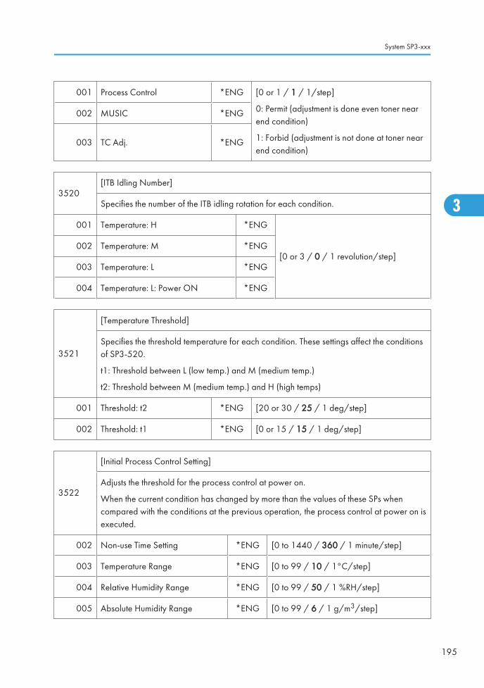
001 Process Control *ENG [0 or 1 / 1 / 1/step]
0: Permit (adjustment is done even toner nearend condition)
1: Forbid (adjustment is not done at toner nearend condition)
002 MUSIC *ENG
003 TC Adj. *ENG
3520[ITB Idling Number]
Specifies the number of the ITB idling rotation for each condition.
001 Temperature: H *ENG
[0 or 3 / 0 / 1 revolution/step]002 Temperature: M *ENG
003 Temperature: L *ENG
004 Temperature: L: Power ON *ENG
3521
[Temperature Threshold]
Specifies the threshold temperature for each condition. These settings affect the conditionsof SP3-520.
t1: Threshold between L (low temp.) and M (medium temp.)
t2: Threshold between M (medium temp.) and H (high temps)
001 Threshold: t2 *ENG [20 or 30 / 25 / 1 deg/step]
002 Threshold: t1 *ENG [0 or 15 / 15 / 1 deg/step]
3522
[Initial Process Control Setting]
Adjusts the threshold for the process control at power on.
When the current condition has changed by more than the values of these SPs whencompared with the conditions at the previous operation, the process control at power on isexecuted.
002 Non-use Time Setting *ENG [0 to 1440 / 360 / 1 minute/step]
003 Temperature Range *ENG [0 to 99 / 10 / 1°C/step]
004 Relative Humidity Range *ENG [0 to 99 / 50 / 1 %RH/step]
005 Absolute Humidity Range *ENG [0 to 99 / 6 / 1 g/m3/step]
System SP3-xxx
195
3

100
[Rapi_timer]
Time Setting *ENG [0 to 255 / 30 / 1 sec/step]
Adjusts the time-out time for the Rapi timer.
3531
[Non-use Time Process Control Setting]
Adjusts the threshold for the process control at stand-by.
When the current condition has changed by more than the values of these SPs whencompared with the conditions at the previous operation, the process control at stand-by isexecuted.
001 Non-use Time Setting *ENG [0 to 1440 / 360 / 1 minute/step]
002 Temperature Range *ENG [0 to 99 / 10 / 1°C/step]
003 Relative Humidity Range *ENG [0 to 99 / 50 / 1 %RH/step]
004 Absolute Humidity Range *ENG [0 to 99 / 6 / 1 g/m3/step]
005 Maximum Execution Number *ENG
Adjusts the maximum execution time for theprocess control at stand-by.
[0 to 99 / 10 / 1 time/step]
3611 [Development Gamma: Display/Set]
001 Bk (Current) *ENG
Displays the current development gamma foreach color.
[0 to 5 / - / 0.01 mg/cm2/kV /step]
002 M (Current) *ENG
003 C (Current) *ENG
004 Y (Current) *ENG
005 Bk (Target Display) *ENG
Displays the target development gamma foreach color.
[0 to 5 / 0.91 / 0.01 mg/cm2/kV /step]
006 M (Target Display) *ENG
007 C (Target Display) *ENG
008 Y (Target Display) *ENG
3. Appendix: SP Mode Tables
196
3

009 Bk (Standard Target Set) *ENG
Displays the standard target developmentgamma for each color.
[0 to 5 / 0.8 / 0.01 mg/cm2/kV /step]
010 M (Standard Target Set) *ENG
011 C (Standard Target Set) *ENG
012 Y (Standard Target Set) *ENG
013 Environmental Correction *ENG
Turns on or off the environmental correction fortarget development gamma.
[0 or 1 / 1 / - ]
0: Not Correct, 1: Correct
014 K (Max Correction) *ENGAdjusts the maximum correction value for eachcolor. These SPs are effective only when thesetting of SP3-611-013 is set to "1".
[0 to 5 / 0.15 / 0.01 mg/cm2/kv/step]
015 M (Max Correction) *ENG
016 C (Max Correction) *ENG
017 Y (Max Correction) *ENG
018 K (Max Abs Hum) *ENGAdjusts the maximum humidity correction valuefor each color. These SPs are effective only whenthe setting of SP3-611-013 is set to "1".
[1 to 99 / 20 / 1 g/m3/step]
019 M (Max Abs Hum) *ENG
020 C (Max Abs Hum) *ENG
021 Y (Max Abs Hum) *ENG
3612[Vk Display]
Displays Vk for each color.
001 Bk *ENG
[-300 to 300 / - / 1 V/step]002 M *ENG
003 C *ENG
004 Y *ENG
3621
[Development DC Control: Display]
Plain: High speed, Thick 1: Middle speed, Thick 2 & FINE: Low speed
Displays the development DC bias adjusted with the process control for each line speed andcolor.
System SP3-xxx
197
3

001 Plain: Bk *ENG
[0 to 700 / 550 / 1 -V/step]002 Plain: M *ENG
003 Plain: C *ENG
004 Plain: Y *ENG
005 Thick 1: Bk *ENG
[0 to 700 / 550 / 1 -V/step]006 Thick 1: M *ENG
007 Thick 1: C *ENG
008 Thick 1: Y *ENG
009 Thick 2 & FINE: Bk *ENG
[0 to 700 / 550 / 1 -V/step]010 Thick 2 & FINE: M *ENG
011 Thick 2 & FINE: C *ENG
012 Thick 2 & FINE: Y *ENG
3622[Development DC Control] DFU
Adjusts the limit of VB.
001 VB Limit *ENG [0 to 500 / 50 / 1 V/step]
3631
[Charge DC Control: Display]
Plain: High speed, Thick 1: Middle speed, Thick 2 & FINE: Low speed
Displays the charge DC voltage adjusted with the process control for each line speed andcolor.
001 Plain: Bk *ENG
[0 to 2000 / 690 / 1 -V/step]002 Plain: M *ENG
003 Plain: C *ENG
004 Plain: Y *ENG
3. Appendix: SP Mode Tables
198
3

005 Thick 1 & FINE: Bk *ENG
[0 to 2000 / 690 / 1 -V/step]006 Thick 1 & FINE: M *ENG
007 Thick 1 & FINE: C *ENG
008 Thick 1& FINE: Y *ENG
009 Thick 2 & FINE: Bk *ENG
[0 to 2000 / 690 / 1 -V/step]010 Thick 2 & FINE: M *ENG
011 Thick 2 & FINE: C *ENG
012 Thick 2 & FINE: Y *ENG
3641
[Charge AC Control: Display]
Plain: High speed
Displays the charge AC voltage adjusted with the process control for each color.
001 Plain: Bk *ENG
[0 to 3 / 1.75 / 0.01 kV/step]002 Plain: M *ENG
003 Plain: C *ENG
004 Plain: Y *ENG
3651
[LD Power Control: Display]
Plain: High speed, Thick 1: Middle speed, Thick 2 & FINE: Low speed
Displays the LD power adjusted for each environment.
001 Plain: Bk *ENG
[0 to 200 / 100 / 1 %/step]002 Plain: M *ENG
003 Plain: C *ENG
004 Plain: Y *ENG
System SP3-xxx
199
3

005 Thick 1: Bk *ENG
[0 to 200 / 100 / 1 %/step]006 Thick 1: M *ENG
007 Thick 1: C *ENG
008 Thick 1: Y *ENG
009 Thick 2 & FINE: Bk *ENG
[0 to 200 / 100 / 1 %/step]010 Thick 2 & FINE: M *ENG
011 Thick 2 & FINE: C *ENG
012 Thick 2 & FINE: Y *ENG
3710
[HST Concentration Control: Set]
TD Sensor: Toner Concentration Control Setting
Selects the toner concentration control method by HST memory, which is in the TD sensor.
001 Control Method: Selection *ENG[0 or 1 / 1 / - ]
0: Not Use, 1: Use
3711[HST Concentration Control: Bk]
Displays the factory settings of the black PCDU.
001 Vcnt *ENG [0 to 5 / 4 / 0.1 V/step]
002 Vt *ENG [0 to 5 / 2.5 / 0.1 V/step]
003 Sensitivity: HL *ENG [1.22 to 3.77 / 2.1 / 0.01 V/step]
004 Sensitivity: HM *ENG[0 to 2.55 / 1.05 / 0.01 V/step]
005 Sensitivity: ML *ENG
006 Set Detection *ENG [0 to 5 / 1 / 0.1 V/step]
007 Without Developer *ENG [0 to 5 / 1.2 / 0.1 V/step]
008 With Developer *ENG [0 to 5 / 1.3 / 0.1 V/step]
009 Serial Number 1 *ENG[0 to 255 / - / 1 V/step]
010 Serial Number 2 *ENG
3. Appendix: SP Mode Tables
200
3

011 Adjustment: Vt *ENG [0 to 5 / 3 / 0.1 V/step]
012 Adjustment: Vtref *ENG [0 to 5 / 3 / 0.1 V/step]
013 Adjustment: Vtcnt *ENG [0 to 5 / 4 / 0.01 V/step]
014 Adjustment: Gamma *ENG [0 to 2.55 / 0 / 0.01 mg/cm2/kV /step]
015 Adjustment: Vcnt Result *ENG [0 to 9 / 9 / 1 /step]
3712[HST Concentration Control: M]
Displays the factory settings of the magenta PCDU.
001 Vcnt *ENG [0 to 5 / 4 / 0.1 V/step]
002 Vt *ENG [0 to 5 / 2.5 / 0.1 V/step]
003 Sensitivity: HL *ENG [1.22 to 3.77 / 2.1 / 0.01 V/step]
004 Sensitivity: HM *ENG[0 to 2.55 / 1.05 / 0.01 V/step]
005 Sensitivity: ML *ENG
006 Set Detection *ENG [0 to 5 / 1 / 0.1 V/step]
007 Without Developer *ENG [0 to 5 / 1.2 / 0.1 V/step]
008 With Developer *ENG [0 to 5 / 1.3 / 0.1 V/step]
009 Serial Number 1 *ENG[0 to 255 / - / 1 V/step]
010 Serial Number 2 *ENG
011 Adjustment: Vt *ENG [0 to 5 / 3 / 0.1 V/step]
012 Adjustment: Vtref *ENG [0 to 5 / 3 / 0.1 V/step]
013 Adjustment: Vtcnt *ENG [0 to 5 / 4 / 0.01 V/step]
014 Adjustment: Gamma *ENG [0 to 2.55 / 0 / 0.01 mg/cm2/kV /step]
015 Adjustment: Vcnt Result *ENG [0 to 9 / 9 / 1 /step]
3713[HST Concentration Control: C]
Displays the factory settings of the cyan PCDU.
001 Vcnt *ENG [0 to 5 / 4 / 0.1 V/step]
System SP3-xxx
201
3

002 Vt *ENG [0 to 5 / 2.5 / 0.1 V/step]
003 Sensitivity: HL *ENG [1.22 to 3.77 / 2.1 / 0.01 V/step]
004 Sensitivity: HM *ENG[0 to 2.55 / 1.05 / 0.01 V/step]
005 Sensitivity: ML *ENG
006 Set Detection *ENG [0 to 5 / 1 / 0.1 V/step]
007 Without Developer *ENG [0 to 5 / 1.2 / 0.1 V/step]
008 With Developer *ENG [0 to 5 / 1.3 / 0.1 V/step]
009 Serial Number 1 *ENG[0 to 255 / - / 1 V/step]
010 Serial Number 2 *ENG
011 Adjustment: Vt *ENG [0 to 5 / 3 / 0.1 V/step]
012 Adjustment: Vtref *ENG [0 to 5 / 3 / 0.1 V/step]
013 Adjustment: Vtcnt *ENG [0 to 5 / 4 / 0.01 V/step]
014 Adjustment: Gamma *ENG [0 to 2.55 / 0 / 0.01 mg/cm2/kV /step]
015 Adjustment: Vcnt Result *ENG [0 to 9 / 9 / 1 /step]
3714[HST Concentration Control: Y]
Displays the factory settings of the yellow PCDU.
001 Vcnt *ENG [0 to 5 / 4 / 0.1 V/step]
002 Vt *ENG [0 to 5 / 2.5 / 0.1 V/step]
003 Sensitivity: HL *ENG [1.22 to 3.77 / 2.1 / 0.01 V/step]
004 Sensitivity: HM *ENG[0 to 2.55 / 1.05 / 0.01 V/step]
005 Sensitivity: ML *ENG
006 Set Detection *ENG [0 to 5 / 1 / 0.1 V/step]
007 Without Developer *ENG [0 to 5 / 1.2 / 0.1 V/step]
008 With Developer *ENG [0 to 5 / 1.3 / 0.1 V/step]
3. Appendix: SP Mode Tables
202
3

009 Serial Number 1 *ENG[0 to 255 / - / 1 V/step]
010 Serial Number 2 *ENG
011 Adjustment: Vt *ENG [0 to 5 / 3 / 0.1 V/step]
012 Adjustment: Vtref *ENG [0 to 5 / 3 / 0.1 V/step]
013 Adjustment: Vtcnt *ENG [0 to 5 / 4 / 0.01 V/step]
014 Adjustment: Gamma *ENG [0 to 2.55 / 0 / 0.01 mg/cm2/kV /step]
015 Adjustment: Vcnt Result *ENG [0 to 9 / 9 / 1 /step]
3800[Toner Collection Bottle Full Detection]
Displays/ adjusts the toner collection bottle detection settings. These SPs are used for NRS.
001 Condition *CTL [0 to 4 / 0 / 1 /step]
002 Detection Times *CTL [0 to 50 / - / 1 /step]
003 Print Page After Near Full *CTL [0 to 1000 / 0 / 1 sheet/step]
004 Pixel Count After Near Full *CTL [0 to 200000 / - / 1 cm2/step]
005 Pixel Count After Replacement *CTL
Displays the pixel counter after replacement oftoner collection bottle.
[0 to 200000 / - / 1 cm2/step]
008 Coefficient *ENG [0.5 to 1.5 / 1 / 0.1 /step]
011
Notice Setting *ENG
Enables or disables the calling for @Remote.
[0 or 1 / 1 / - ]
0: Enable @Remote calling
1: Disable @Remote calling
NOTE:
If the toner collection bottle has been replaced before the machine detects used toner nearfull when this setting is set to "0", the machine cannot detect toner collection bottle near full.In that case, set SP3-902-017 to "1".
System SP3-xxx
203
3

012
Day Threshold: TonerCollection bottle:NF
*ENG [1 to 30 / 5 / 1 day/step]
Sets the threshold days for the near-full display. The near-full of the toner collection bottle isdisplayed after the toner collection full sensor has detected the actuator in the toner collectionbottle.
013 Total:Toner Collection Bottle *ENGDisplays the total amount of the used toner.
[0 to 999999999 / 1 / 1]
014 Mechanism Full Detection Date *ENGDisplays the date of the full detection fot thetoner collection bottle.
3900[Waste Toner Full Detection]
Turns toner collection bottle full detection on or off.
001 ON/OFF Setting *ENG[0 or 1 / 1 / - ]
0: OFF, 1: ON
3901[New PCDU Detection]
Turns new PCDU detection on or off.
001 ON/OFF Setting *ENG[0 or 1 / 1 / - ]
0: OFF, 1: ON
3902
[Manual New Unit Set]
Turns the new unit detection flag for each PM unit on or off.The use of these counters is explained in the PM section and in the relevant parts of section3 (Replacement and Adjustment).
001 Development Unit: Bk *ENG
[0 or 1 / 0 / - ]
0: OFF, 1: ON
002 Development Unit: Y *ENG
003 Development Unit: C *ENG
004 Development Unit: M *ENG
3. Appendix: SP Mode Tables
204
3

005 Developer: Bk *ENG
[0 or 1 / 0 / - ]
0: OFF, 1: ON
006 Developer: Y *ENG
007 Developer: C *ENG
008 Developer: M *ENG
009 PCDU: Bk *ENG
[0 or 1 / 0 / - ]
0: OFF, 1: ON
010 PCDU: Y *ENG
011 PCDU: M *ENG
012 PCDU: C *ENG
013 Image Transfer Unit *ENG [0 or 1 / 0 / - ]
0: OFF, 1: ON
Do not use 3902-013 if you only change thecleaning unit.
3902-015: This is for the image transfer beltcleaning unit.
014 Fusing Unit *ENG
015 Cleaning Unit *ENG
016 Paper Transfer Unit *ENG
017 Toner Collection Bottle *ENG
018 Fusing Roller (Heating Roller) *ENG [0 or 1 / 0 / - ]
0: OFF, 1: ON
"Fusing Roller" is designated as "Heating Roller"in this manual.
019 Pressure Roller *ENG
3903Last Print Counter
Displays the rotation counter of the black development unit at five minutes interval.
System SP3-xxx
205
3

001 Counter 1 *ENG
[0 to 999999999 / - / 1 mm/step]
002 Counter 2 *ENG
003 Counter 3 *ENG
004 Counter 4 *ENG
005 Counter 5 *ENG
006 Counter 6 *ENG
007 Counter 7 *ENG
008 Counter 8 *ENG
009 Counter 9 *ENG
010 Counter 10 *ENG
011-
040Counter 11 to 40 *ENG
101 Last Fixed Date *ENG Displays the time of the latest stored counter.
102Last PM Counter SaveDestination
*ENGDisplays the counter number of the lateststored counter.
3. Appendix: SP Mode Tables
206
3
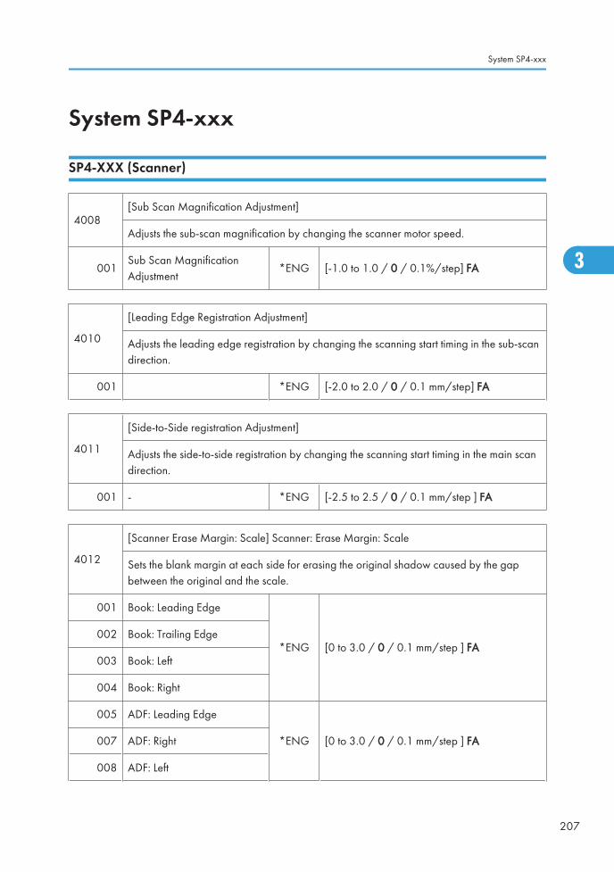
System SP4-xxx
SP4-XXX (Scanner)
4008[Sub Scan Magnification Adjustment]
Adjusts the sub-scan magnification by changing the scanner motor speed.
001Sub Scan MagnificationAdjustment
*ENG [-1.0 to 1.0 / 0 / 0.1%/step] FA
4010
[Leading Edge Registration Adjustment]
Adjusts the leading edge registration by changing the scanning start timing in the sub-scandirection.
001 *ENG [-2.0 to 2.0 / 0 / 0.1 mm/step] FA
4011
[Side-to-Side registration Adjustment]
Adjusts the side-to-side registration by changing the scanning start timing in the main scandirection.
001 - *ENG [-2.5 to 2.5 / 0 / 0.1 mm/step ] FA
4012
[Scanner Erase Margin: Scale] Scanner: Erase Margin: Scale
Sets the blank margin at each side for erasing the original shadow caused by the gapbetween the original and the scale.
001 Book: Leading Edge
*ENG [0 to 3.0 / 0 / 0.1 mm/step ] FA002 Book: Trailing Edge
003 Book: Left
004 Book: Right
005 ADF: Leading Edge
*ENG [0 to 3.0 / 0 / 0.1 mm/step ] FA007 ADF: Right
008 ADF: Left
System SP4-xxx
207
3

4013
[Scanner Free Run]
Performs the scanner free run with the exposure lamp on or off in the following mode.
Full color mode / Full Size / A3 or DLT
001 Lamp: ON*ENG
[0 or 1 / 0 / - ]
0: OFF, 1: ON002 Lamp: OFF
4014[Scan]
Execute the scanner free fun with each mode.
001 HP Detection Enable - Scanner free run with HP sensor check.
002 HP Detection Disable - Scanner free run without HP sensor check.
4020 [Dust Check]
001 Detection: ON/OFF *ENG
Turns the ADF scan glass dust check on/ off.
[0 or 1 / 0 / 1 /step]
0: OFF, 1: ON
002 Dust Detect: Level *ENG
Selects the detect level.
[0 to 8 / 4 / 1 /step]
0: lowest detection level
8: highest detection level
003 Correction Level *ENG
Selects the level of the sub scan line correctionwhen using the ARDF.
[0 to 4 / 0 / 1 /step]
0: Off
1: Weakest
2: Weak
3: Strong
4: Strongest
011 Dust Detect:On/Off:Rear *ENG Not used
012 Dust Detect:Lvl:Rear *ENG Not used
3. Appendix: SP Mode Tables
208
3

4301
[APS Operation Check]
Displays a code that represents the original size detected by the original sensors. (See "InputCheck Table".)
001 APS Operation Check - -
4303[APS Min Size (A5/HLT/16K)]
Specifies the result of the detection when the outputs from the original sensors are all OFF.
001APS Min. Size (A5/HLT/16K)
*ENG
[0 to 2 / 0 / 1 /step]
0: No Original
1: A5-Lengthwise (16K SEF if 4305 is set to 3)
2: A5-Sideways (16K LEF if 4305 is set to 3)
4305 [8K/16K Detection] *ENG
[0 to 3 / 0 / 1 /step]
0: Normal Detection (the machine detects A4/LTsize as A4 or LT, depending on the paper size setting)
1: A4-Sideways LT-Lengthwise
2: LT-Sideways A4-Lengthwise
3: 8K 16K
001 This program enables the machine to automatically recognize the 8K/16K size.
4308 [Scan Size Detection]
001
Detection ON/OFF *ENG
[0 or 1 / 1 / -]
0: OFF
1: ON
Turns on or off the CCD original size detection. This detection is used only when an originalis scanned in book scanning mode.
4309 [Scan Size Detect:Setting]
001
Original Density Thresh *ENG [0 to 255 / 32 / 1 digit/step]
Specifies the threshold between an original area and non-original area for the scan originalsize detection in book scanning mode.
System SP4-xxx
209
3

002Detection Time *ENG [20 to 100 / 60 / 20 msec/step]
Specifies the detection time for the scan original size detection in book scanning mode.
003Lamp ON:Delay Time *ENG [0 to 200 / 40 / 20 msec/step]
Specifies the lamp on timing for the scan original size detection in book scanning mode.
4310
[Scan Size Detect Value]
Displays the detected value by CCD. Each detection point for paper size and color isdisplayed on the LCD.
001 S1:R *ENG
[0 to 255 / - / 1 digit/step]
002 S1:G *ENG
003 S1:B *ENG
004 S2:R *ENG
005 S2:G *ENG
006 S2:B *ENG
007 S3:R *ENG
008 S3:G *ENG
009 S3:B *ENG
4400
[Scanner Erase Margin] *ENG
Set the Mask for Original.
These SPs set the area to be masked during platen (book) mode scanning.
3. Appendix: SP Mode Tables
210
3

001 Book: Leading Edge
[0 to 3.0 / 0 / 0.1 mm/step]
002 Book: Trailing Edge
003 Book: Left
004 Book: Right
005 ADF: Leading Edge
007 ADF: Right
008 ADF: Left
4417[IPU Test Pattern]
Selects the IPU test pattern.
001Test PatternSelection
[0 to 24 / 0 / 1/step ]
0: Scanned image
1: Gradation main scan A
2: Gradation main scan B
3: Gradation main scan C
4: Gradation main scan D
5: Gradation sub scan (1)
6: Grid pattern
7: Slant grid pattern
8: Gradation RGBCMYK
9: UCR pattern
10: Color patch 16 (1)
11: Color patch 16 (2)
12: Color patch 64
13: Grid pattern CMYK
14: Color patch CMYK
15: Gray pattern (1)
16: Gray pattern (2)
17: Gray Pattern (3)
18: Shading pattern
19: Thin line pattern
20: Scanned + Grid pattern
21: Scanned + Gray scale
22: Scanned + Color patch
23: Scanned + Slant Grid C
24: Scanned + Slant Grid D
4429 [Illegal Copy Output]
001 Copy
*ENG [0 to 3 / 3 / 1 /step]002 Scanner
003 Fax
System SP4-xxx
211
3

4450 [Scan Image Path Selection]
001Black Subtraction ON/OFF [0 or 1 / 1 / - ] 0: OFF, 1: ON
Uses or does not use the black reduction image path.
002SH ON/OFF [0 or 1 / 0 / 1 /step] 0: ON, 1: OFF
Uses or does not use the shading image path.
4460
[Digital AE Set] DFU
Specifies the level of deleting the background in the ADS mode. You can adjust its level foreach scanning method (platen, ADF).
001 Lower Limit *ENG [0 to 1023 / 364 / 4 digit/step]
002 Background Level *ENG [512 to 1532 / 932 / 1 digit/step]
4501[ACC Target Density]
Selects the ACC result.
001 Copy: K: Text *ENG
[0 to 10 / 5 / 1 /step]
10: Darkest density
002 Copy: C: Text *ENG
003 Copy: M: Text *ENG
004 Copy: Y: Text *ENG
005 Copy: K: Photo *ENG
006 Copy: C: Photo *ENG
007 Copy: M: Photo *ENG
008 Copy: Y: Photo *ENG
4505[ACC Cor:Bright]
Adjusts the offset correction for light areas of the ACC pattern.
3. Appendix: SP Mode Tables
212
3

001 Text:K *ENG
[-128 to 127 / 0 / 1 /step]002 Text:C *ENG
003 Text:M *ENG
004 Text:Y *ENG
005 Photo:K *ENG
[-128 to 127 / 0 / 1 /step]006 Photo:C *ENG
007 Photo:M *ENG
008 Photo:Y *ENG
4506[ACC Cor:Dark]
Adjusts the offset correction for dark areas of the ACC pattern.
001 Text:K *ENG
[-128 to 127 / 0 / 1 /step]002 Text:C *ENG
003 Text:M *ENG
004 Text:Y *ENG
005 Photo:K *ENG
[-128 to 127 / 0 / 1 /step]006 Photo:C *ENG
007 Photo:M *ENG
008 Photo:Y *ENG
4540
[Printer Vector Correction]
This SP corrects the printer coverage of 12 hues (RY, YR, YG, etc. x 4 Colors [R, G, B,Option]) for a total of 48 parameters.
System SP4-xxx
213
3

001-004 RY Phase: Option/R/G/B
*ENG
Specifies the printer vector correctionvalue.
[0 to 255 / 0 / 1 /step]
005-008 YR Phase: Option/R/G/B
009-012 YG Phase: Option/R/G/B
013-016 GY Phase: Option/R/G/B
017-020 GC Phase: Option/R/G/B
021-024 CG Phase: Option/R/G/B
025-028 CB Phase: Option/R/G/B
029-032 BC Phase: Option/R/G/B
033-036 BM Phase: Option/R/G/B
037-040 MB Phase: Option/R/G/B
041-044 MR Phase: Option/R/G/B
045-048 RM Phase: Option/R/G/B
4550 [Scanner Application: text/Printing]
4551 [Scanner Application: text]
4552 [Scanner Application: text (Drop Out Coor)]
4553 [Scanner Application: text-Photo]
4554 [Scanner Application: Photo]
4565 [Scanner Application: GrayScale]
4570 [Scanner Application: Color: Text/Photo]
4571 [Scanner Application: Color: Glossy Photo]
4572 [Scanner Application: AutoColor]
-005
MTF: 0 (Off), 1-15 (Strong) *ENG[0 to 15 / 8 / 1 /step]
0: MTF Off
Sets the MTF level (Modulation Transfer Function) designed to improve image contrast. Sethigher for stronger effect, lower for weaker effect.
3. Appendix: SP Mode Tables
214
3

-006Smoothing: 0 (x1), 1-7 (Strong) *ENG [0 to 7 / 4 / 1 /step]
Use to remove "jaggies" if they appear. Set higher for smoother images.
-007Brightness: 1–255 *ENG [1 to 255 / 128 / 1 /step]
Set higher for darker, set lower for lighter.
-008Contrast: 1–255 *ENG [1 to 255 / 128 / 1 /step]
Set higher for more contrast, set lower for less contrast.
-009
Independent Dot Erase (0), 1-7 (Strong) *ENG [0 to 7 / 0 / 1 /step]
Sets the erasure level of Irregular Dots. Set higher for stronger effect, lower for weaker effect.
0: Not activated
4580 [FAX Application: Text/Chart]
4582 [FAX Application: Text/Photo]
4583 [FAX Application: Photo]
-005
MTF: 0 (Off), 1-15 (Strong) *ENG[0 to 15 / 8 / 1 /step]
0: MTF Off
Sets the MTF level (Modulation Transfer Function) designed to improve image contrast. Sethigher for stronger effect, lower for weaker effect.
-006Smoothing: 0 (x1), 1-7 (Strong) *ENG [0 to 7 / 4 / 1 /step]
Use to remove "jaggies" if they appear. Set higher for smoother images.
-007Brightness: 1–255 *ENG [1 to 255 / 128 / 1 /step]
Set higher for darker, set lower for lighter.
-008Contrast: 1–255 *ENG [1 to 255 / 128 / 1 /step]
Set higher for more contrast, set lower for less contrast.
-009
Independent Dot Erase (0), 1-7 (Strong) *ENG [0 to 7 / 0 / 1 /step]
Selects the contrast level for B/W the Text mode. Sets the erasure level of Irregular Dots. Sethigher for stronger effect, lower for weaker effect.
0: Not activated
System SP4-xxx
215
3

-010
Texture Erase: 0 *ENG [0 to 2 / 0 / 1 /step]
Sets the erasure level of textures. Set higher for stronger effect, lower for weaker effect. ThisSP (suffix "-010") only exists in SP4580, 4582 and 4583.
0: Not activated
4581 [FAX Application: Text] DFU
4584 [FAX Application: Original 1] DFU
4585 [FAX Application: Original 2] DFU
-005
MTF: 0 (Off), 1-15 (Strong) *ENG[0 to 15 / 8 / 1 /step]
0: MTF Off
Sets the MTF level (Modulation Transfer Function) designed to improve image contrast. Sethigher for stronger effect, lower for weaker effect.
-006Smoothing: 0 (x1), 1-7 (Strong) *ENG [0 to 7 / 4 / 1 /step]
Use to remove "jaggies" if they appear. Set higher for smoother images.
-007Brightness: 1–255 *ENG [1 to 255 / 128 / 1 /step]
Set higher for darker, set lower for lighter.
-008Contrast: 1–255 *ENG [1 to 255 / 128 / 1 /step]
Set higher for more contrast, set lower for less contrast.
-009
Independent Dot Erase (0), 1-7 (Strong) *ENG [0 to 7 / 0 / 1 /step]
Selects the contrast level for B/W the Text mode. Sets the erasure level of Irregular Dots. Sethigher for stronger effect, lower for weaker effect.
0: Not activated
4600 [SBU Version Display]
001 SBU_ID -[0 to 0xFF / - / 1 /step]
Displays the ID of the SBU.
002 GASBU-N_ID - [0 to 0xFF / - / 1 /step]
003 VSP5100_ID - [0 to 0xFF / - / 1 /step]
3. Appendix: SP Mode Tables
216
3
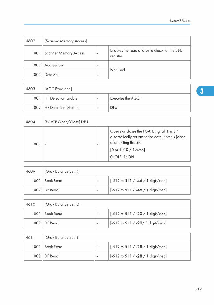
4602 [Scanner Memory Access]
001 Scanner Memory Access -Enables the read and write check for the SBUregisters.
002 Address Set -Not used
003 Data Set -
4603 [AGC Execution]
001 HP Detection Enable - Executes the AGC.
002 HP Detection Disable - DFU
4604 [FGATE Open/Close] DFU
001 - -
Opens or closes the FGATE signal. This SPautomatically returns to the default status (close)after exiting this SP.
[0 or 1 / 0 / 1/step]
0: OFF, 1: ON
4609 [Gray Balance Set: R]
001 Book Read - [-512 to 511 / -46 / 1 digit/step]
002 DF Read - [-512 to 511 / -46 / 1 digit/step]
4610 [Gray Balance Set: G]
001 Book Read - [-512 to 511 / -20 / 1 digit/step]
002 DF Read - [-512 to 511 / -20/ 1 digit/step]
4611 [Gray Balance Set: B]
001 Book Read - [-512 to 511 / -28 / 1 digit/step]
002 DF Read - [-512 to 511 / -28 / 1 digit/step]
System SP4-xxx
217
3

4623[Black Level Fine Adj. Display]
RE: Red Even signal, RO: Red Odd signal
001 Latest: RE Color -
Displays the black offset value (rough adjustment)for the even red signal in the CCD circuit board(color printing speed).
[0 to 16383 / 0 / 1 digit/step]
002 Latest: RO Color -
Displays the black offset value (rough adjustment)for the odd red signal in the CCD circuit board(color printing speed).
[0 to 16383 / 0 / 1 digit/step]
4624[Black Level Fine Adj. Display]
GE: Green Even signal, GO: Green Odd signal
001 Latest: GE Color -
Displays the black offset value (rough adjustment)for the even green signal in the CCD circuit board(color printing speed).
[0 to 16383 / 0 / 1 digit/step]
002 Latest: GO Color -
Displays the black offset value (rough adjustment)for the odd green signal in the CCD circuit board(color printing speed).
[0 to 16383 / 0 / 1 digit/step]
4625[Black Level Fine Adj. Display]
BE: Blue Even signal, BO: Blue Odd signal
001 Latest: BE Color -
Displays the black offset value (rough adjustment) for theeven blue signal in the CCD circuit board (color printingspeed).
[0 to 16383 / 0 / 1 digit/step]
002 Latest: BO Color -
Displays the black offset value (rough adjustment) for theodd blue signal in the CCD circuit board (color printingspeed).
[0 to 16383 / 0 / 1 digit/step]
3. Appendix: SP Mode Tables
218
3

4628[Analog Gain Adjustment] Gain Adjustment: Analog
Displays the gain value of the amplifiers on the controller for Red.
001 Latest: R Color - [0 to 7 / 0 / 1 digit/step]
4629[Analog Gain Adjustment] Gain Adjustment: Analog
Displays the gain value of the amplifiers on the controller for Green.
001 Latest: G Color - [0 to 7 / 0 / 1 digit/step]
4630[Analog Gain Adjustment] Gain Adjustment: Analog
Displays the gain value of the amplifiers on the controller for Blue.
001 Latest: B Color - [0 to 7 / 0 / 1 digit/step]
4631[Digital Gain Adjustment] Gain Adjustment: Digital
Displays the gain value of the amplifiers on the controller for RE or RO.
001 Latest: RE Color -[0 to 1023 / 0 / 1 digit/step]
002 Latest: RO Color -
4632[Digital Gain Adjustment] Gain Adjustment: Digital
Displays the gain value of the amplifiers on the controller for GE or GO.
001 Latest: GE Color -[0 to 1023 / 0 / 1 digit/step]
002 Latest: GO Color -
4633[Digital Gain Adjustment] Gain Adjustment: Digital
Displays the gain value of the amplifiers on the controller for BE or BO.
001 Latest: BE Color -[0 to 1023 / 0 / 1 digit/step]
002 Latest: BO Color -
4635 [SSCG Correction Set] DFU
System SP4-xxx
219
3

Switches SSCG noise cancellation on/off.
0: Off, 1: On
001 Correction ON/OFF [0 or 1 / 1 / -]
002 Adj ON/OFF [0 or 1 / 1 / -]
4636 [SSCG Correction] DFU
001 Execution Executes the SSCG correction.
002 Error Flag
[0 to 2 / 0 / 1]
0: Normal end
1: End during update
2: Do not apply correction
003 Apply 80H Executes the 80H setting copy.
004 Apply Correction Value Not used
4637 [SSCG Correction Value] DFU
001 Latest Setting:RE -
[0 to 255 / 128 / 1 digit/step]
002 Latest Setting:RO -
003 Latest Setting:GE -
004 Latest Setting:GO -
005 Latest Setting:BE -
006 Latest Setting:BO -
4638 [SSCG Correction Value] DFU
3. Appendix: SP Mode Tables
220
3

001 Last Setting:RE *ENG
[0 to 255 / 128 / 1 digit/step]
002 Last Setting:RO *ENG
003 Last Setting:GE *ENG
004 Last Setting:GO *ENG
005 Last Setting:BE *ENG
006 Last Setting:BO *ENG
4639 [SSCG Correction Value] DFU
001 Factory Setting:RE *ENG
[0 to 255 / 128 / 1 digit/step]
002 Factory Setting:RO *ENG
003 Factory Setting:GE *ENG
004 Factory Setting:GO *ENG
005 Factory Setting:BE *ENG
006 Factory Setting:BO *ENG
4640 [SSCG Noise Amplitude] DFU
001 Before Adj: RE
[0 to 1023 / 0 / 1 digit/step]
002 Before Adj: RO
003 Before Adj: GE
004 Before Adj: GO
005 Before Adj: BE
006 Before Adj: BO
System SP4-xxx
221
3

007 After Adj: RE
[0 to 1023 / 0 / 1 digit/step]
008 After Adj: RO
009 After Adj: GE
010 After Adj: GO
011 After Adj: BE
012 After Adj: BO
4645 [Scan Adjust Error]
001 White level -[0 to 65535 / 0 / 1 digit/step]
002 Black level -
4647[Read Hard Error]
Displays the result of the SBU connection check.
001 Power-ON -
[0 to 35535 / 0 / 1digit /step]
0: OK, Other: SBU connection check failure
If the SBU connection check fails, SC144 occurs.
4654[Black Level Fine Adj. Display]
RE: Red Even signal, RO: Red Odd signal
001Last Correct Value: REColor
*ENG
Displays the black offset value (rough adjustment)for the even red signal in the CCD circuit board(color printing speed).
[0 to 16383 / 0 / 1 digit/step]
002Last Correct Value: ROColor
*ENG
Displays the black offset value (rough adjustment)for the odd red signal in the CCD circuit board(color printing speed).
[0 to 16383 / 0 / 1 digit/step]
4655[Black Level Fine Adj. Display]
GE: Green Even signal, GO: Green Odd signal
3. Appendix: SP Mode Tables
222
3

001Last Correct Value: GEColor
*ENG
Displays the black offset value (rough adjustment)for the even green signal in the CCD circuit board(color printing speed).
[0 to 16383 / 0 / 1 digit/step]
002Last Correct Value: GOColor
*ENG
Displays the black offset value (rough adjustment)for the odd green signal in the CCD circuit board(color printing speed).
[0 to 16383 / 0 / 1 digit/step]
4656[Black Level Fine Adj. Display]
BE: Blue Even signal, BO: Blue Odd signal
001Last Correct Value: BEColor
*ENG
Displays the black offset value (rough adjustment)for the even blue signal in the CCD circuit board(color printing speed).
[0 to 16383 / 0 / 1 digit/step]
002Last Correct Value: BOColor
*ENG
Displays the black offset value (rough adjustment)for the odd blue signal in the CCD circuit board(color printing speed).
[0 to 16383 / 0 / 1 digit/step]
4658[Analog Gain Adjustment]
Displays the previous gain value of the amplifiers on the controller for Red.
001 Last Correct Value: R Color *ENG [0 to 7 / 0 / 1 digit/step]
4659[Analog Gain Adjustment]
Displays the previous gain value of the amplifiers on the controller for Green.
001 Last Correct Value: G Color *ENG [0 to 7 / 0 / 1 digit/step]
4660[Analog Gain Adjustment]
Displays the previous gain value of the amplifiers on the controller for Blue.
001 Last Correct Value: B Color *ENG [0 to 7 / 0 / 1 digit/step]
System SP4-xxx
223
3

4661[Digital Gain Adjustment]
RE: Red Even signal, RO: Red Odd signal
001 Last Correct Value: RE Color *ENG[0 to 1023 / 0 / 1 digit/step]
002 Last Correct Value: RO Color *ENG
4662[Digital Gain Adjustment]
GE: Green Even signal, GO: Green Odd signal
001 Last Correct Value: GE Color *ENG[0 to 1023 / 0 / 1 digit/step]
002 Last Correct Value: GO Color *ENG
4663[Digital Gain Adjustment]
BE: Blue Even signal, BO: Blue Odd signal
001 Last Correct Value: BE Color *ENG[0 to 1023 / 0 / 1 digit/step]
002 Last Correct Value: BO Color *ENG
4673[Black Level Fine Adj. Display]
RE: Red Even signal, RO: Red Odd signal
001 Factory Setting: RE Color *ENG
Displays the factory setting values of the black leveladjustment for the even red signal in the CCD circuitboard (color printing speed)..
[0 to 16383 / 0 / 1 digit/step]
002 Factory Setting: RO Color *ENG
Displays the factory setting values of the black leveladjustment (rough adjustment) for the odd redsignal in the CCD circuit board (color printingspeed).
[0 to 16383 / 0 / 1 digit/step]
4674[Black Level Fine Adj. Display]
GE: Green Even signal, GO: Green Odd signal
3. Appendix: SP Mode Tables
224
3

001 Factory Setting: GE Color *ENG
Displays the factory setting values of the black leveladjustment (rough adjustment) for the even greensignal in the CCD circuit board (color printingspeed).
[0 to 16383 / 0 / 1 digit/step]
002 Factory Setting: GO Color *ENG
Displays the factory setting values of the black leveladjustment (rough adjustment) for the odd greensignal in the CCD circuit board (color printingspeed).
[0 to 16383 / 0 / 1 digit/step]
4675[Black Level Fine Adj. Display]
BE: Blue Even signal, BO: Blue Odd signal
001 Factory Setting: BE Color *ENG
Displays the factory setting values of the black leveladjustment (rough adjustment) for the even bluesignal in the CCD circuit board (color printingspeed).
[0 to 16383 / 0 / 1 digit/step]
002 Factory Setting: BO Color *ENG
Displays the factory setting values of the black leveladjustment (rough adjustment) for the odd bluesignal in the CCD circuit board (color printingspeed).
[0 to 16383 / 0 / 1 digit/step]
4677[Analog Gain Adjustment]
Displays the factory setting values of the gain adjustment for Red.
001 Factory Setting: R Color *ENG [0 to 7 / 0 / 1 digit/step]
4678[Analog Gain Adjustment]
Displays the factory setting values of the gain adjustment for Green.
001 Factory Setting: G Color *ENG [0 to 7 / 0 / 1 digit/step]
System SP4-xxx
225
3

4679[Analog Gain Adjustment]
Displays the factory setting values of the gain adjustment for Blue.
001 Factory Setting: BE Color *ENG [0 to 7 / 0 / 1 digit/step]
4680[Digital Gain Adjustment]
Displays the gain value of the amplifiers on the controller for Red.
001 Factory Setting: RE Color *ENG[0 to 1023 / 0 / 1 digit/step]
002 Factory Setting: RO Color *ENG
4681[Digital Gain Adjustment]
Displays the gain value of the amplifiers on the controller for Green.
001 Factory Setting: GE Color *ENG[0 to 1023 / 0 / 1 digit/step]
002 Factory Setting: GO Color *ENG
4682[Digital Gain Adjustment]
Displays the gain value of the amplifiers on the controller for Blue.
001 Factory Setting: BE Color *ENG[0 to 1023 / 0 / 1 digit/step]
002 Factory Setting: BO Color *ENG
4688
[Scan Image Density Adjustment]
Adjusts the white shading parameter when scanning an image with the ARDF or 1-pass DF.
Adjusts the density level if the ID of outputs made in the DF and Platen mode is different.
001 ARDF *ENG [50 to 150 / 98 / 1%/ step ]
002 1-pass DF *ENG [50 to 150 / 98 / 1%/ step ]
4690[White Level Peak Read]
Displays the peak level of the white level scanning.
3. Appendix: SP Mode Tables
226
3

001 RE -[0 to 1023 / 0 / 1 digit/step]
002 RO -
4691[White Level Peak Read]
Displays the peak level of the white level scanning.
001 GE -[0 to 1023 / 0 / 1 digit/step]
002 GO -
4692[White Level Peak Read]
Displays the peak level of the white level scanning.
001 BE -[0 to 1023 / 0 / 1 digit/step]
002 BO -
4693[Black Level Peak Read]
Displays the peak level of the black level scanning.
001 RE -[0 to 1023 / 0 / 1 digit/step]
002 RO -
4694[Black Level Peak Read]
Displays the peak level of the black level scanning.
001 GE -[0 to 1023 / 0 / 1 digit/step]
002 GO -
4695[Black Level Peak Read]
Displays the peak level of the black level scanning.
001 BE -[0 to 1023 / 0 / 1 digit/step]
002 BO -
System SP4-xxx
227
3

4700 [CIS ID Display] Not used
4709 [CIS GB Chart Level: R] Not used
4710 [CIS GB Chart Level: G] Not used
4711 [CIS GB Chart Level: B] Not used
4712 [CIS GB Adj Value: R] Not used
4713 [CIS GB Adj Value: G] Not used
4714 [CIS GB Adj Value: G] Not used
4745 [CIS Image Level Error Flag] Not used
4746 [CIS GB Adj Error Flag] Not used
4747 [CIS GB Adj Error Flag] Not used
4748 [CIS M-Scan White Level: Avg. R] Not used
4749 [CIS M-Scan White Level: Avg. G] Not used
4750 [CIS M-Scan White Level: Avg. B] Not used
4784 [CIS White Level Peak Range: R] Not used
4785 [CIS White Level Peak Range: G] Not used
4786 [CIS White Level Peak Range: B] Not used
4787 [CIS White Level Peak Data: R] Not used
4788 [CIS White Level Peak Data: G] Not used
4789 [CIS White Level Peak Data: B] Not used
4790 [CIS White Level Peak Data: R] Not used
4791 [CIS White Level Peak Data: G] Not used
4792 [CIS White Level Peak Data: B] Not used
4793 [CIS Black Level Data: R] Not used
4794 [CIS Black Level Data: G] Not used
4795 [CIS Black Level Data: B] Not used
4796 [Low Density Color Correction] Not used
3. Appendix: SP Mode Tables
228
3

4797 [Digital AE: Rear Side] Not used
4798 [CIS LED Duty] Not used
4799 [CIS TEST Pattern] Not used
4802 [DF Shading FreeRun]
001 Lamp ON
-
Executes the scanner free run of shading movementwith exposure lamp on or off.
Press "OFF" to stop this free run. Otherwise, the freerun lasts.
002 Lamp OFF
4803 [Home Position Adjustment]
001 - - [-1 to 1 / 0 / 0.1 mm/step]
4804 [Home Position]
001 - - Executes the scanner HP detection.
4806 [Carriage Save]
001 - -
Moves the carriage from the scanner homeposition.
Dust may fall through the DF exposure glass.Therefore, do this SP when you transport themachine a long distance.
4807 [SBU Test Pattern Change]
001 - -
[0 to 255 / 0 / 1 /step]
1: Grid pattern
2: Gradation main scan
3: Gradation sub scan
4 to 250: Default (Scanning Image)
4808 [Factory Setting Input]
002 Execution Flag - [0 to 255 / 0 / 1 /step]
System SP4-xxx
229
3

4810 [Lamp Clock Selection] DFU
001- -
[0 or 1 / 1 / 1 /step]
0: Brand T, 1: Brand U
Selects the scanner lamp brand.
4902
[ACC Data Display]
This SP outputs the final data read at the end of ACC execution.
A zero is returned if there was an error reading the data.
[0 to 255 / 0 / 1 /step]
001 R DATA1 *ENG Photo C Patch Level 1 (8-bit)
002 G DATA1 *ENG Photo M Patch Level 1 (8-bit)
003 B DATA1 *ENG Photo Y Patch Level 1 (8-bit)
004 R DATA2 *ENG Photo C Patch Level 17 (8-bit)
005 G DATA2 *ENG Photo M Patch Level 17(8-bit)
006 B DATA2 *ENG Photo Y Patch Level 17 (8-bit)
4905[Dither Selection] DFU
Changes the parameters for error diffusion.
001 Dither Selection *ENG [0 to 255 / 0 / 1 /step]
4918
[Manual Gamma Adj]
Adjusts the offset data of the printer gamma for yellow in Photo mode.
See “Printer Gamma Correction" in the Replacement and Adjustment for how to use.
009 - -
Enter the manual gamma adjustment screen (-001to 008). For details, see the "Printer GammaCorrection" in the section "Replace andAdjustment".
4954 [Read/Restore Std]
001 Read New Chart - Execute the scanning of the A4 chart.
3. Appendix: SP Mode Tables
230
3
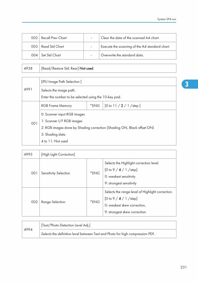
002 Recall Prev Chart - Clear the data of the scanned A4 chart.
003 Read Std Chart - Execute the scanning of the A4 standard chart.
004 Set Std Chart - Overwrite the standard data.
4958 [Read/Restore Std: Rear] Not used
4991
[IPU Image Path Selection ]
Selects the image path.
Enter the number to be selected using the 10-key pad.
001
RGB Frame Memory *ENG [0 to 11 / 2 / 1 /step ]
0: Scanner input RGB images
1: Scanner I/F RGB images
2: RGB images done by Shading correction (Shading ON, Black offset ON)
3: Shading data
4 to 11: Not used
4993 [High Light Correction]
001 Sensitivity Selection *ENG
Selects the Highlight correction level.
[0 to 9 / 4 / 1 /step]
0: weakest sensitivity
9: strongest sensitivity
002 Range Selection *ENG
Selects the range level of Highlight correction.
[0 to 9 / 4 / 1 /step]
0: weakest skew correction,
9: strongest skew correction
4994[Text/Photo Detection Level Adj.]
Selects the definition level between Text and Photo for high compression PDF.
System SP4-xxx
231
3

001PDF Sensitivity Level text/photo
*ENG
[0 to 2 / 1 / 1 /step]
0: Text priority
1: Normal
2: Photo priority
4996
[White Paper Detect Level]
Selects the threshold level of the original background density. Increasing this threshold levelmachine easily judge that an original is white.
001 - *ENG
[0 to 6 / 3 / 1 /step]
0: lightest
6: Darkest
3. Appendix: SP Mode Tables
232
3

System SP5-xxx
SP5-XXX (Mode)
5024[mm/inch Display Selection]
Display units (mm or inch) for custom paper sizes.
001 0:mm 1:inch *CTL0: mm (Europe/Asia)
1: inch (USA)
5045
[Accounting Counter]
Selects the counting method.
NOTE: The counting method can be changed only once, regardless of whether the countervalue is negative or positive.
001 Counter Method *CTL
[0 or 1 / 0 / - ]
0: Developments
1: Prints
5047[Paper Display]
Turns on or off the printed paper display on the LCD.
001 - *CTL[0 or 1 / 0 / - ]
0: OFF, 1: ON
5051[Toner Refill Detection Display]
Enables or disables the toner refill detection display.
5051 1 Toner Refill Detection Display *CTL
[0 or 1 / 0 / - ] Alphanumeric
0: ON
1: OFF
5055[Display IP Address]
Display or does not display the IP address on the LCD.
System SP5-xxx
233
3

001 - *CTL[0 or 1 / 0 / - ]
0: OFF 1: ON
5056[Coverage Counter Display]
Display or does not display the coverage counter on the LCD.
001 - *CTL[0 or 1 / 0 / - ]
0: Not display, 1: Display
5061[Toner Remaining Icon Display]
Display or does not display the remaining toner display icon on the LCD.
001 - *CTL[0 or 1 / 0 / - ]
0: Not display, 1: Display
5062[Parts Replacement Alert Display]
Display or does not display the PM part yield on the LCD.
001 Drum Unit: Bk *CTL
[0 or 1 / 1 / - ]
0: Not display, 1: Display
002 Drum Unit: M *CTL
003 Drum Unit: C *CTL
004 Drum Unit: Y *CTL
005 Development Unit: Bk *CTL
[0 or 1 / 1 / - ]
0: Not display, 1: Display
006 Development Unit: M *CTL
007 Development Unit: C *CTL
008 Development Unit: Y *CTL
009 Developer: Bk *CTL
[0 or 1 / 1 / - ]
0: Not display, 1: Display
010 Developer: M *CTL
011 Developer: C *CTL
012 Developer: Y *CTL
3. Appendix: SP Mode Tables
234
3

013 Image Transfer Belt *CTL
[0 or 1 / 1 / - ]
0: Not display, 1: Display
014 Image Transfer Cleaning Unit *CTL
015 Fusing Unit *CTL
016 Paper Transfer Roller Unit *CTL
017 Waster Toner Bottle *CTL
018 Fusing Roller (Heating Roller) *CTL
019 Pressure Roller *CTL
5066[Parts PM Menu Display Setting]
Display or does not display the "PM parts" button on the LCD.
001 - *CTL[0 or 1 / 1 / - ]
0: No display, 1: Display
5067
[Parts PM System Setting]
Selects the service maintenance or user maintenance for each PM parts.
If the user service is selected, PM alert is displayed on the LCD.
001 PCDU:Bk *CTL
[0: Service] or [1: User]002 PCDU:M *CTL
003 PCDU:C *CTL
004 PCDU:Y *CTL
005 Dev Unit:Bk *CTL
[0: Service] or [1: User]006 Dev Unit:M *CTL
007 Dev Unit:C *CTL
008 Dev Unit:Y *CTL
System SP5-xxx
235
3

009 Developer:Bk *CTL
[0: Service] or [1: User]010 Developer:M *CTL
011 Developer:C *CTL
012 Developer:Y *CTL
013 Int Trans Unit *CTL [0: Service] or [1: User]
014 Belt Cleaning Unit *CTL [0: Service] or [1: User]
015 Fusing Unit *CTL [0: Service] or [1: User]
016 Transfer Roller *CTL [0: Service] or [1: User]
017 WasteToner Bottle *CTL [0: Service] or [1: User]
018 Fusing Roller (Heating Roller) *CTL [0: Service] or [1: User]
019 Pressure Roller *CTL [0: Service] or [1: User]
5071 [Set Bypass Paper Size]
001
- *CTL[0 or 1 / 0 / -]
0: Off, 1: On
Turn on or off the paper size confirmation pop-up on the LED. This pop-up preventsmismatching between a paper size selected by the operation panel and an actual papersize on the by-pass tray.
5104
[A3/DLT Double Count] SSP
Specifies whether the counter is double clicked for A3/DLT size prints.
When you have to change this SP, ask your supervisor.
5104 1 Double Count *CTL
[0 to 2 / 0 / 1 /step]
0: NO (Normal count)
1: YES (Double count)
2: YES except By-pass (Normal count for unknownsize)
5104* A3/DLT Double Count (SSP)
3. Appendix: SP Mode Tables
236
3

Specifies whether the counter is doubled for A3/DLT. "Yes" counts except from the bypasstray. When "Yes" is selected, A3 and DLT paper are counted twice, that is A4 x2 and LTx2 respectively.
5113 [Optional Counter Type]
001Default Optional CounterType
*CTL
This program specifies the counter type.
0: None, 1: Key card (RK 3, 4)
2: Key card (down), 3: Prepaid card
4: Coin rack, 5: MF key card
8: Key counter + Vendor
9: Bar-code Printer
002External Optional CounterType
*CTL
This program specifies the external counter type.
0: None
1: Expansion Device 1
2: Expansion Device 2
3: Expansion Device 3
5114 [Optional Counter I/F]
001 MF Key Card Extension *CTL[0: Not installed/ 1: Installed (scanningaccounting)]
5118 [Disable Copying] *CTL [0: Not disabled/ 1: Disabled]
001 This program disables copying.
5120[Mode Clear Opt. CounterRemoval]
*CTL[0: Yes (removed)/ 1: Standby (installed but notused)/ 2: No (not removed)]
001This program updates the information on the optional counter. When you install or removean optional counter, check the settings.
5121 [Counter Up Timing] *CTL [0: Feed/ 1: Exit]
001This program specifies when the counter goes up. The settings refer to "paper feed" and"paper exit" respectively.
System SP5-xxx
237
3

5126 [F Size Original Setting] *ENG
[0 to 2 / 0 / 1 /step]
0: 8 1/2" x 13" (Foolscap)
1: 8 1/4" x 13" (Folio)
2: 8" x 13" (F)
001 Selects F size original setting.
5127 [APS Mode] *CTL [0: Not disabled/ 1: Disabled]
001 This program disables the APS.
5128 [Code Mode With Key/Card Option] *CTL -
001 DFU
5131 [Paper Size Type Selection] *ENG [0: JP (Japan)/ 1: NA / 2: EU]
001The program selects a paper size system from the following alternatives: the AB system (0),the LT system (1), and the AF system (2).
5148 Size Detection Off *CTL
[0: OFF/ 1: ON]
0: OFF (Detect)
1: ON (Not Detect)
001 Enables or disables the automatic paper size detection for the by-pass tray.
5150 [By-Pass Length Setting] *CTL [0: OFF/ 1: ON]
001
Determines whether the transfer sheet from the by-pass tray is used or not.
Normally the paper length for sub scanning paper from the by-pass tray is limited to 600mm, but this can be extended with this SP to 1260 mm.
5162 [App. Switch Method] *CTL [0: Soft Key Set/ 1: Hard Key Set]
001 This program specifies the switch that selects an application program.
3. Appendix: SP Mode Tables
238
3
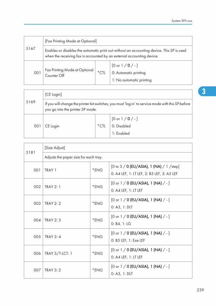
5167
[Fax Printing Mode at Optional]
Enables or disables the automatic print out without an accounting device. This SP is usedwhen the receiving fax is accounted by an external accounting device.
001Fax Printing Mode at OptionalCounter Off
*CTL
[0 or 1 / 0 / - ]
0: Automatic printing
1: No automatic printing
5169
[CE Login]
If you will change the printer bit switches, you must ‘log in’ to service mode with this SP beforeyou go into the printer SP mode.
001 CE Login *CTL
[0 or 1 / 0 / - ]
0: Disabled
1: Enabled
5181[Size Adjust]
Adjusts the paper size for each tray.
001 TRAY 1 *ENG[0 to 3 / 0 (EU/ASIA), 1 (NA) / 1 /step]
0: A4 LEF, 1: LT LEF, 2: B5 LEF, 3: A5 LEF
002 TRAY 2: 1 *ENG[0 or 1 / 0 (EU/ASIA), 1 (NA) / - ]
0: A4 LEF, 1: LT LEF
003 TRAY 2: 2 *ENG[0 or 1 / 0 (EU/ASIA), 1 (NA) / - ]
0: A3, 1: DLT
004 TRAY 2: 3 *ENG[0 or 1 / 0 (EU/ASIA), 1 (NA) / - ]
0: B4, 1: LG
005 TRAY 2: 4 *ENG[0 or 1 / 0 (EU/ASIA), 1 (NA) / - ]
0: B5 LEF, 1: Exe LEF
006 TRAY 3/T-LCT: 1 *ENG[0 or 1 / 0 (EU/ASIA), 1 (NA) / - ]
0: A4 LEF, 1: LT LEF
007 TRAY 3: 2 *ENG[0 or 1 / 0 (EU/ASIA), 1 (NA) / - ]
0: A3, 1: DLT
System SP5-xxx
239
3

008 TRAY 3: 3 *ENG[0 or 1 / 0 (EU/ASIA), 1 (NA) / - ]
0: B4, 1: LG
009 TRAY 3: 4 *ENG[0 or 1 / 0 (EU/ASIA), 1 (NA) / - ]
0: B5 LEF, 1: Exe LEF
010 TRAY 4: 1 *ENG[0 or 1 / 0 (EU/ASIA), 1 (NA) / - ]
0: A4 LEF, 1: LT LEF
011 TRAY 4: 2 *ENG[0 or 1 / 0 (EU/ASIA), 1 (NA) / - ]
0: A3, 1: DLT
012 TRAY 4: 3 *ENG[0 or 1 / 0 (EU/ASIA), 1 (NA) / - ]
0: B4, 1: LG
013 TRAY 4: 4 *ENG[0 or 1 / 0 (EU/ASIA), 1 (NA) / - ]
0: B5 LEF, 1: Exe LEF
018 LCT *ENG[0 to 2 / 0 (EU/ASIA), 1 (NA) / - ]
0: A4LEF, 1: LTLEF, 2: B5LEF
5186
[RK 4]
Enables or disables the prevention for RK4 (accounting device) disconnection.
If the RK4 is disconnected for 10 seconds when this SP is set to "1 (Enable)", the machineautomatically jams a sheet of paper and stops.
001 - *ENG
[0 or 1 / 0 / 1/step]
0: Disable
1: Enable
5188[Copy NV Version]
Displays the version number of the NVRAM on the controller board.
001 - - -
5191 [Mode Set] DFU
3. Appendix: SP Mode Tables
240
3

001- *CTL
[0 or 1 / 1 / -]
0: Off, 1: On
Enables or disables the STR (Suspend to RAM) mode.
5193 [External Controller Info. Settings]
001
- - -
Sets the external controller type. This setting is appropriately adjusted if an external controlleris installed in the machine.
[0 to 10 / 0 / 1/step]
0: No external controller installed
1: EFI controller
2: Ratio controller
3: Egret controller
4 to 10: Reserved
5195 [Limitless SW] DFU
001
- *CTL
[0 or 1 / 0 / -]
0: Productivity priority
1: Tray priority
Selects the paper feed mode.
Productivity priority:
This changes the feeding tray as soon as the machine detects the priority tray even the paperstill remains in the feeding tray.
Tray priority:
This changes the feeding tray after the paper in the tray where the machine has been feedingpaper has been run out of.
This SP is activated only when a customer selects the "Auto Paper Selsct".
5196 [90 degree rotation (copy)] JPN only
001 - *CTL -
5199 [Paper Exit After Staple End.]
System SP5-xxx
241
3

001 - *CTL[ 0 or 1 / 0 / -]
0: OFF, 1: ON
Enables or disables the paper feeding out from the finisher without stapling.
• If this setting is "1: ON", paper is fed out without stapling at the maximum number ofthe finisher stapling when the machine gets a multiple printing job (over maximumnumber).
• If this setting is "0: OFF", paper is fed out with stapling at the maximum number of thefinisher stapling when the machine gets a multiple printing job (over maximum number).
5212 [Page Numbering] *CTL
This program adjusts the position of the second side page numbers.
A "– value" moves the page number positions to the left edge. A "+ value" moves the pagenumber positions to the right edge.
003 Duplex Printout Right/Left Position [–10 to 10 / 0 / 1 mm/step]
004 Duplex Printout High/Low Position [–10 to 10 / 0 / 1 mm/step]
5302
[Set Time]
Adjusts the RTC (real time clock) time setting for the local time zone.
Examples: For Japan (+9 GMT), enter 540 (9 hours x 60 min.)
DOM: +540 (Tokyo)
NA: -300 (New York)
EU: + 60 (Paris)
CH: +480 (Peking)
TW: +480 (Taipei)
AS: +480 (Hong Kong)
002 Time Difference *CTL# [-1440 to 1440 / Area / 1 min./step ]
5307 [Summer Time]
3. Appendix: SP Mode Tables
242
3

001
Setting -
[ 0 to 1 / NA, EU, ASIA / 1 /step]
0: Disabled
1: Enabled
NA and EUR: 1, ASIA: 0
Enables or disables the summer time mode.
• Make sure that both SP5-307-3 and -4 are correctly set. Otherwise, this SP is notactivated even if this SP is set to "1".
003
Rule Set (Start) -
Specifies the start setting for the summer time mode.
There are 8 digits in this SP. For months 1 to 9, the "0" cannot be input in the first digit, so theeight-digit setting for -2 or -3 becomes a seven-digit setting.
1st and 2nd digits: The month. [1 to 12]
3rd digit: The week of the month. [1 to 5]
4th digit: The day of the week. [0 to 6 = Sunday to Saturday]
5th and 6th digits: The hour. [00 to 23]
7th digit: The length of the advanced time. [0 to 9 / 1 hour /step]
8th digit: The length of the advanced time. [0 to 5 / 10 minutes /step]
• The digits are counted from the left.
• Make sure that SP5-307-1 is set to "1".
For example: 3500010 (EU default)
The timer is advanced by 1 hour at am 0:00 on the 5th Sunday in March.
System SP5-xxx
243
3

004
Rule Set (End) - -
Specifies the end setting for the summer time mode.
There are 8 digits in this SP.
1st and 2nd digits: The month. [1 to 12]
3rd digit: The week of the month. [0 to 5]
4th digit: The day of the week. [0 to 7 = Sunday to Saturday]
5th and 6th digits: The hour. [00 to 23]
The 7th and 8 digits must be set to "00".
• The digits are counted from the left.
• Make sure that SP5-307-1 is set to "1".
5401[Access Control]
When installing the SDK application, SAS (VAS) adjusts the following settings. DFU
103
Default Document ACL *CTL
Whenever a new login user is added to the address book in external certification mode(for Windows, LDAP, RDH), the default document ACL is updated according to this SPsetting.
[0 to 3 / 0 / 1]
0: View
1: Edit
2: Edit/Delete
3: Full control
Note: This SP setting is ignored on a machine that is not using document server.
104Authentication Time *CTL
[0 to 255 / 0 / 1 sec./step]
0: 60 seconds
1 to 250 seconds
Specifies the timeout of the authentication.
162Extend Certification Detail *CTL
Bit 0: Log-out without an IC card
0: Not allowed (default)
1: Allowed
Selects the log out type for the extend authentication device.
3. Appendix: SP Mode Tables
244
3
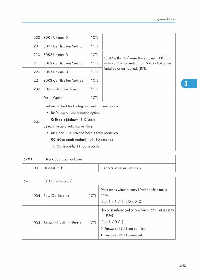
200 SDK1 Unique ID *CTL
"SDK" is the "Software Development Kit". Thisdata can be converted from SAS (VAS) wheninstalled or uninstalled. (DFU)
201 SDK1 Certification Method *CTL
210 SDK2 Unique ID *CTL
211 SDK2 Certification Method *CTL
220 SDK3 Unique ID *CTL
221 SDK3 Certification Method *CTL
230 SDK certification device *CTL
240
Detail Option *CTL -
Enalbes or disables the log out confirmation option.
• Bit 0: Log out confirmation option
0: Enable (default), 1: Disable
Selects the automatic log out time.
• Bit 1 and 2: Automatic log out timer reduction
00: 60 seconds (default), 01: 10 seconds,
10: 20 seconds, 11: 30 seconds
5404 [User Code Counter Clear]
001 UCodeCtrClr Clears all counters for users.
5411 [LDAP Certification]
004 Easy Certification *CTL
Determines whether easy LDAP certification isdone.
[0 or 1 / 1 / -] 1: On, 0: Off
005 Password Null Not Permit *CTL
This SP is referenced only when SP5411-4 is set to"1" (On).
[0 or 1 / 0 / -]
0: Password NULL not permitted.
1: Password NULL permitted.
System SP5-xxx
245
3

006 Detail Option *CTL
Determines whether LDAP option (anonymouscertification) is turned on or off.
Bit0
0: OFF, 1: ON
5413 [Lockout Setting]
001 Lockout On/Off *CTL
Switches on/off the lock on the local address bookaccount.
[0 or 1 / 0 / -]
0: Off, 1: On
002 Lockout Threshold *CTL
Sets a limit on the frequency of lockouts for accountlockouts.
[1 to 10 / 5 / 1/step]
003 Cancellation On/Off *CTL
Determines whether the system waits the prescribedtime for input of a correct user ID and passwordafter an account lockout has occurred.
[0 or 1 / 0 / -]
0: Off (no wait time, lockout not cancelled)
1: On (system waits, cancels lockout if correct userID and password are entered.
004 Cancellation Time *CTL
Determines the length of time that the system waitsfor correct input of the user ID and password aftera lockout has occurred. This setting is used only ifSP5413-3 is set to "1" (on).
[1 to 999 / 60 / 1 min./step]
005 Counter Clear Time *CTL Not Used
5414 [Access Mitigation]
001 Mitigation On/Off *CTL
Switches on/off masking of continuously used IDsand passwords that are identical.
[0 or 1 / 0 / -]
0: Off, 1: On
3. Appendix: SP Mode Tables
246
3

002 Mitigation Time *CTL
Sets the length of time for excluding continuousaccess for identical user IDs and passwords.
[0 to 60 / 15 / 1 min./step]
5415 [Password Attack]
001 Permissible Number *CTL
Sets the number of attempts to attack the system withrandom passwords to gain illegal access to thesystem.
[0 to 100 / 30 / 1 attempt/step]
002 Detect Time *CTL
Sets the time limit to stop a password attack oncesuch an attack has been detected.
[1 to 10 / 5 / 1 sec./step]
5416 [Access Information]
001 Access User Max Number *CTL
Limits the number of users used by the accessexclusion and password attack detection functions.
[50 to 200 / 200 / 1 users/step]
002Access Password MaxNumber
*CTL
Limits the number of passwords used by the accessexclusion and password attack detection functions.
[50 to 200 / 200 / 1 password/step]
003 Monitor Interval *CTL
Sets the processing time interval for referencinguser ID and password information.
[1 to 10 / 3 / 1 sec./step]
5417 [Access Attack]
001 Access Permissible Number *CTL
Sets a limit on access attempts when an excessivenumber of attempts are detected for MFP features.
[0 to 500 / 100 / 1/step]
002 Attack Detect Time *CTL
Sets the length of time for monitoring the frequencyof access to MFP features.
[10 to 30 / 10 / 1 sec./step]
System SP5-xxx
247
3

003 Productivity Fall Wait *CTL
Sets the wait time to slow down the speed ofcertification when an excessive number of accessattempts have been detected.
[0 to 9 / 3 / 1 sec./step]
004 Attack Max Number *CTL
Sets a limit on the number of requests received forcertification in order to slow down the certificationspeed when an excessive number of accessattempts have been detected.
[50 to 200 / 200 / 1 attempt/step]
5420
[User Authentication]
These settings should be done with the System Administrator.
Note: These functions are enabled only after the user access feature has been enabled.
001 Copy *CTL
Determines whether certification is requiredbefore a user can use the copy applications.
[0 or 1 / 0 / 1]
0: On, 1: Off
002
Color Security Setting *CTL -
Enables or disables the color copy limitation for each copy mode when the userauthentication is "ON".
0: Enable (default), 1: Disable
Bit0: B/W mode
Bit1: Mono color mode
Bit2: Two colors mode
Bit3: Full color mode
Bit4: Automatic color mode
Bit5 to 7: Reserved
011 Document Server *CTL
Determines whether certification is required beforea user can use the document server.
[0 or 1 / 0 / 1]
0: On, 1: Off
3. Appendix: SP Mode Tables
248
3

021 Fax *CTL
Determines whether certification is required beforea user can use the fax application.
[0 or 1 / 0 / 1]
0: On, 1: Off
031 Scanner *CTL
Determines whether certification is required beforea user can use the scan applications.
[0 or 1 / 0 / 1]
0: On, 1: Off
041 Printer *CTL
Determines whether certification is required beforea user can use the printer applications.
[0 or 1 / 0 / 1]
0: On, 1: Off
051 SDK1
*CTL
[0 or 1 / 0 / 1] 0: ON. 1: OFF
Determines whether certification is required beforea user can use the SDK application.
061 SDK2
071 SDK3
5430 [Auth Dialog Message Change]
001 Message Change On/Off *CTL
Turns on or off the displayed message change forthe authentication.
[0 or 1 / 0 / -]
0: Off, 1: On
002 Message Text Download *CTLExecutes the message download for theauthentication.
003 Message Text ID *CTL Inputs message text for the authentication.
5431 [External Auth Preset]
010Tag *CTL
[0 or 1 / 1 / -]
0: Not permit, 1: Permit
Turns on or off the tag copy permission for the external authentication.
System SP5-xxx
249
3

011Entry *CTL
[0 or 1 / 1 / -]
0: Not permit, 1: Permit
Turns on or off the copy permission of the entry information for the external authentication.
012Group *CTL
[0 or 1 / 1 / -]
0: Not permit, 1: Permit
Turns on or off the copy permission of the group information for the external authentication.
020Mail *CTL
[0 or 1 / 1 / -]
0: Not permit, 1: Permit
Turns on or off the copy permission of the mail information for the external authentication.
030Fax *CTL
[0 or 1 / 1 / -]
0: Not permit, 1: Permit
Turns on or off the copy permission of the fax information for the external authentication.
031
FaxSub *CTL[0 or 1 / 1 / -]
0: Not permit, 1: Permit
Turns on or off the copy permission of the fax additional information for the externalauthentication.
032Folder *CTL
[0 or 1 / 1 / -]
0: Not permit, 1: Permit
Turns on or off the copy permission of the folder information for the external authentication.
033
ProtectCode *CTL[0 or 1 / 1 / -]
0: Not permit, 1: Permit
Turns on or off the copy permission of the protection code information for the externalauthentication.
034SmtpAuth *CTL
[0 or 1 / 1 / -]
0: Not permit, 1: Permit
Turns on or off the copy permission of the SMTP information for the external authentication.
3. Appendix: SP Mode Tables
250
3

035LdapAuth *CTL
[0 or 1 / 1 / -]
0: Not permit, 1: Permit
Turns on or off the copy permission of the LDAP information for the external authentication.
036
Smb Ftp Auth *CTL[0 or 1 / 1 / -]
0: Not permit, 1: Permit
Turns on or off the copy permission of the SMB/FTP information for the externalauthentication.
037
AcntAcl *CTL[0 or 1 / 1 / -]
0: Not permit, 1: Permit
Turns on or off the copy permission of the account ACL information for the externalauthentication.
038
DocumentAcl *CTL[0 or 1 / 1 / -]
0: Not permit, 1: Permit
Turns on or off the copy permission of the document ACL information for the externalauthentication.
040
CertCrypt[0 or 1 / 1 / -]
0: Not permit, 1: Permit
Turns on or off the copy permission of the authentication information for the externalauthentication.
050
UserLimitCount *CTL[0 or 1 / 1 / -]
0: Not permit, 1: Permit
Turns on or off the copy permission of the maximum number information for the externalauthentication.
5481[Authentication Error Code]
These SP codes determine how the authentication failures are displayed.
001 System Log Disp *CTL
Determines whether an error code appears in thesystem log after a user authentication failure occurs.
[0 or 1 / 0 / 1]
0: Off, 1: On
System SP5-xxx
251
3

002 Panel Disp *CTL
Determines whether an error code appears on theoperation panel after a user authentication failureoccurs.
[0 or 1 / 1 / 1]
1: On, 0: Off
5490 [MF Key Card (Japan only)]
001 - *CTL
Sets up operation of the machine with a keycard.
[0 or 1 / 0 / 1]
0: Disabled. Cancels operation without a usercode.
1: Enabled. Allows operation without a user code.
5501 [PM Alarm] *CTL -
001 PM Alarm Level
[0 to 9999 / 0 / 1 /step]
0: Alarm off
1 to 9999: Alarm goes off when Value (1 to 9999) x 1000> PM counter
002 Original Count Alarm
[0 or 1 / 0 / – ]
0: No alarm sounds
1: Alarm sounds after the number of originals passingthrough the ARDF > 10,000
5504 [Jam Alarm] *CTL -
001
Sets the alarm to sound for the specified jam level (document misfeeds are not included).
[0 to 3 / 3 / 1 /step]
0: Zero (Off)
1: Low (2.5K jams)
2: Medium (3K jams)
3: High (6K jams)
3. Appendix: SP Mode Tables
252
3

5505
[Error Alarm]
Sets the error alarm level.
The error alarm counter counts "1" when any SC is detected. However, the error alarmcounter decreases by "1" when an SC is not detected during a set number of copied sheets(for example, default 1500 sheets).
The error alarm occurs when the SC error alarm counter reaches "5".
001 - *CTL[0 to 255 / C2.5a: 25, C2.5b: 35 / 100 copies /step]
5507 [Supply Alarm] *CTL -
001 Paper Supply Alarm 0: Off, 1: On, DFU
002 Staple Supply Alarm 0: Off, 1: On
003 Toner Supply Alarm 0: Off, 1: On, DFU
080 Toner Call Timing
Changes the timing of the "Toner Supply Call" via the@Remote, when the following conditions occur.
0: At replacement (default)
1: At near end
128 Interval :Others
[250 to 10000 / 1000 / 1 /step] DFU
132 Interval :A3
133 Interval :A4
134 Interval :A5
141 Interval :B4
142 Interval :B5
160 Interval :DLT
164 Interval :LG
166 Interval :LT
172 Interval :HLT
5508* [CC Call] *CTL -
System SP5-xxx
253
3

001*Jam Remains 0: Disable, 1: Enable
Enables/disables initiating a call for an unattended paper jam.
002*Continuous Jams 0: Disable, 1: Enable
Enables/disables initiating a call for consecutive paper jams.
003*Continuous Door Open 0: Disable, 1: Enable
Enables/disables initiating a call when the front door remains open.
011*
Jam Detection: Time Length [3 to 30 / 10 / 1 minute /step]
Sets the time a jam must remain before it becomes an "unattended paper jam". This settingis enabled only when SP5508-004 is set to "1".
012*
Jam Detection: Continuous Count [2 to 10 / 5 / 1 /step]
Sets the number of consecutive paper jams required to initiate a call. This setting is enabledonly when SP5508-004 is set to "1".
013*
Door Open: Time Length [3 to 30 / 10 / 1 /step]
Sets the length of time the door remains open before the machine initiates a call.
This setting is enabled only when SP5-508-004 is set to "1".
5515
[SC/Alarm Setting] *CTL -
With NRS (New Remote Service) in use, these SP codes can be set to issue an SC call whenan SC error occurs. If this SP is switched off, the SC call is not issued when an SC erroroccurs.
001 SC Call
[0 or 1 / 1 / - ]
0: Off
1: On
002 Service Parts Near End Call
003 Service Parts End Call
004 User Call
3. Appendix: SP Mode Tables
254
3

006 Communication Test Call
[0 or 1 / 1 / - ]
0: Off
1: On
007 Machine Information Notice
008 Alarm Notice
009 Non Genuine Toner Alarm
010 Supply Automatic Ordering Call
011 Supply Management Report Call
012 Jam/Door Open Call
5516
[Individual PM Part AlarmCall]
*CTL -
With @Remote in use, these SP codes can be set to issue an PM alarm call when one of SPparts reaches its yield.
001Disable/Enable Setting (0: Not send, 1:Send)
[0 or 1 / 1 / - ]
0: Not send, 1: Send
004 Percent yield for triggering PM alert [1 to 255 / 75 / 1 %/step]
5610 [Base Gamma Control Point: Command]
004Get Factory Default - -
Recalls the factory settings.
005Set Factory Default - -
Overwrites the current values onto the factory settings.
006Restore Original Value - -
Recalls the previous settings.
5611 [Toner Color in 2C]
001B-C *ENG
[0 to 128 / 100 / 1 /step]
128: Darkest density
Adjusts the Cyan correction value of the blue signal in two-color mode.
System SP5-xxx
255
3

002B-M *ENG
[0 to 128 / 100 / 1 /step]
128: Darkest density
Adjusts the Magenta correction value of the blue signal in two-color mode.
003G-C *ENG
[0 to 128 / 100 / 1 /step]
128: Darkest density
Adjusts the Cyan correction value of the blue signal in two-color mode.
004G-Y *ENG
[0 to 128 / 100 / 1 /step]
128: Darkest density
Adjusts the Yellow correction value of the blue signal in two-color mode.
005R-M *ENG
[0 to 128 / 100 / 1 /step]
128: Darkest density
Adjusts the Magenta correction value of the blue signal in two-color mode.
006R-Y *ENG
[0 to 128 / 100 / 1 /step]
128: Darkest density
Adjusts the Yellow correction value of the blue signal in two-color mode.
5618 [Color Mode Display Selection]
001- *CTL
[0 or 1 / 1 / - ]
0: ACS, Colour, Black & White, Two Colour, Singlecolour
1: ACD, Full Colour, Black & White
Selects the color selection display on the LCD.
• Memory Clear (SP5-801)
• The following tables list the items that are cleared. The serial number information, meter charge settingand meter charge counters (SP8-581, 582, 583, 584, and 586) are not cleared.
5731 [Counter Effect] JPN only
3. Appendix: SP Mode Tables
256
3

001Change Mk1 Cnt (Paper->Combine)
*CTL[0 or 1 / 0 / -]
0: Disabled, 1: Enabled
5801 [Memory Clear]
001 All ClearResets all correction data for process control and allsoftware counters, and returns all modes and adjustmentsto their default values.
002 Engine Clears the engine settings.
003 SCSInitializes default system settings, SCS (System ControlService) settings, operation display coordinates, and ROMupdate information.
004 IMH Memory Clr Initializes the IMH settings.
005 MCS Initializes the MCS settings.
006 Copier application Initializes all copier application settings.
007 Fax applicationInitializes the fax reset time, job login ID, all TX/RX settings,local storage file numbers, and off-hook timer.
008 Printer application
The following service settings:
• Bit switches
• Gamma settings (User & Service)
• Toner Limit
The following user settings:
• Tray Priority
• Menu Protect
• System Setting except for setting of Energy Saver
• I/F Setup (I/O Buffer and I/O Timeout)
• PCL Menu
009 Scanner applicationInitializes the scanner defaults for the scanner and all thescanner SP modes.
010 Web ServiceDeletes the network file application management files andthumbnails, and initializes the job login ID.
System SP5-xxx
257
3

011 NCSAll setting of Network Setup (User Menu)
(NCS: Network Control Service)
012 R-FaxInitializes the job login ID, SmartDeviceMonitor for
Admin, job history, and local storage file numbers.
014 Clear DCS Settings Initializes the DCS (Delivery Control Service) settings.
015 Clear UCS SettingsInitializes the UCS (User Information Control Service)settings.
016 MIRS SettingInitializes the MIRS (Machine Information Report Service)settings.
017 CCSInitializes the CCS (Certification and Charge-controlService) settings.
018 SRM Memory Check Initializes the SRM (System Resource Manager) settings.
019 LCS Initializes the LCS settings.
020 Web Uapli Initializes the web user application settings.
021 ECS Initializes the ECS settings.
5802
[Free Run]
Performs a free run on the copier engine.
• The machine starts free run in the same condition as the sequence of A4/LT, A3 orA4 SEF printing from the 1st or 2nd tray. Therefore, the correct paper should beloaded in the 1st tray or 2nd tray, but paper is not fed.
• The main switch has to be turned off and on after using the free run mode for a test.
001 B/W A4 LEF -
-002 FC A4 LEF -
003 FC A3 LEF -
5803 [Input Check] - See "Input Check Table" in this section.
5804 [Output Check] - See "Output Check Table" in this section.
3. Appendix: SP Mode Tables
258
3

5805 [Anti-Condensation Heater]
002 0:OFF / 1:ON *ENG [0 or 1 / 0 / -]
5806 [RFID CONT.READING]
001TIMES - [0 to 65535 / - / 1 /step]
Displays the counter for the RFID communication test.
002NOT 0 - [0 to 65535 / - / 1 /step]
Displays the counter for the RFID communication failure.
003RET. - [0 to 65535 / - / 1 /step]
Displays the counter for the RFID communication retry.
004 EXE.ALL - Execute the RFID communication test for all colors.
005 EXE.K - Execute the RFID communication test for balck.
006 EXE.M - Execute the RFID communication test for magenta.
007 EXE.C - Execute the RFID communication test for cyan.
008 EXE.Y - Execute the RFID communication test for yellow.
5810
[SC Reset]
Resets a type A service call condition.
• Turn the main switch off and on after resetting the SC code.
001 Fusing SC Reset - -
5811 [Machine Serial] Machine Serial Number Display
002 Display Displays the machine serial number.
004 BICU Inputs the machine serial number.
5812 [Service Tel. No. Setting]
System SP5-xxx
259
3
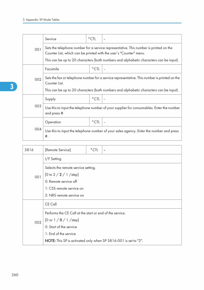
001
Service *CTL -
Sets the telephone number for a service representative. This number is printed on theCounter List, which can be printed with the user’s "Counter" menu.
This can be up to 20 characters (both numbers and alphabetic characters can be input).
002
Facsimile *CTL -
Sets the fax or telephone number for a service representative. This number is printed on theCounter List.
This can be up to 20 characters (both numbers and alphabetic characters can be input).
003
Supply *CTL -
Use this to input the telephone number of your supplier for consumables. Enter the numberand press #.
004
Operation *CTL -
Use this to input the telephone number of your sales agency. Enter the number and press#.
5816 [Remote Service] *CTL -
001
I/F Setting
Selects the remote service setting.
[0 to 2 / 2 / 1 /step]
0: Remote service off
1: CSS remote service on
2: NRS remote service on
002
CE Call
Performs the CE Call at the start or end of the service.
[0 or 1 / 0 / 1 /step]
0: Start of the service
1: End of the service
NOTE: This SP is activated only when SP 5816-001 is set to "2".
3. Appendix: SP Mode Tables
260
3

003
Function Flag
Enables or disables the remote service function.
[0 to 1 / 0 / 1 /step]
0: Disabled
1: Enabled
007
SSL Disable
Controls if RCG (Remote Communication Gate) confirmation is done by SSL during anRCG send for the @Remote over a network interface.
[0 or 1 / 0 / 1 /step]
0: Yes. SSL not used.
1: No. SSL used.
008
RCG Connect Timeout
Sets the length of time (seconds) for the time-out when the RCG (Remote CommunicationGate) connects during a call via the @Remote network.
[1 to 90 / 30 / 1 second /step]
009
RCG Write Timeout
Sets the length of time (seconds) for the time-out when sent data is written to the RCG duringa call over the @Remote network.
[1 to 100 / 60 / 1 second /step]
010
RCG Read Timeout
Sets the length of time (seconds) for the timeout when sent data is written from the RCGduring a call over the @Remote network.
[1 to 100 / 60 / 1 second /step]
011
Port 80 Enable -
Controls if permission is given to get access to the SOAP method over Port 80 on the@Remote network.
[0 or 1 / 0 / – ]
0: No. Access denied
1: Yes. Access granted.
System SP5-xxx
261
3

013
RFU Timing
Selects the timing for the remote firmware updating.
[0 or 1 / 1 / – ]
0: Any status of a target machine
1: Sleep or panel off mode only
021
RCG – C Registed
This SP displays the RCG-N installation end flag.
0: Installation not completed
1: Installation completed
022
RCG – C Regist Detail
This SP displays the RCG device installation status.
0: RCG device not registered
1: RCG device registered
2: Device registered
023
Connect Type (N/M)
This SP displays and selects the RCG-N connection method.
[0 or 1 / 0 / 1 /step
0: Internet connection
1: Dial-up connection
061 Cert. Expire Timing DFU Proximity of the expiration of the certification.
062 Use ProxyThis SP setting determines if the proxy server is used when themachine communicates with the service center.
063
Proxy Host
This SP sets the address of the proxy server used for communication between the RCGdevice and the gateway. Use this SP to set up or display the customer proxy server address.
The address is necessary to set up the embedded RCG-N.
• The address display is limited to 128 characters. Characters beyond the 128character are ignored.
• This address is customer information and is not printed in the SMC report.
3. Appendix: SP Mode Tables
262
3

064
Proxy PortNumber
This SP sets the port number of the proxy server used for communication between theembedded RCG-N and the gateway. This setting is necessary to set up the embeddedRCG-N.
• This port number is customer information and is not printed in the SMC report.
065
Proxy User Name
This SP sets the HTTP proxy certification user name.
• The length of the name is limited to 31 characters. Any character beyond the 31stcharacter is ignored.
• This name is customer information and is not printed in the SMC report.
066
Proxy Password
This SP sets the HTTP proxy certification password.
• The length of the password is limited to 31 characters. Any character beyond the 31stcharacter is ignored.
• This name is customer information and is not printed in the SMC report.
067CERT:Up State
Displays the status of the certification update.
0 The certification used by RCG-N is set correctly.
1The certification request (setAuthKey) for update has been received from the GWURL and certification is presently being updated.
2The certification update is completed and the GW URL is being notified of thesuccessful update.
3 The certification update failed, and the GW URL is being notified of the failed update.
4The period of the certification has expired and new request for an update is beingsent to the GW URL.
11A rescue update for certification has been issued and a rescue certification settingis in progress for the rescue GW connection.
System SP5-xxx
263
3

12The rescue certification setting is completed and the GW URL is being notified of thecertification update request.
13The notification of the request for certification update has completed successfully,and the system is waiting for the certification update request from the rescue GWURL.
14The notification of the certification request has been received from the rescue GWcontroller, and the certification is being stored.
15The certification has been stored, and the GW URL is being notified of the successfulcompletion of this event.
16The storing of the certification has failed, and the GW URL is being notified of thefailure of this event.
17The certification update request has been received from the GW URL, the GW URLwas notified of the results of the update after it was completed, but an certificationerror has been received, and the rescue certification is being recorded.
18The rescue certification of No. 17 has been recorded, and the GW URL is beingnotified of the failure of the certification update.
068
CERT:Error
Displays a number code that describes the reason for the request for update of thecertification.
0 Normal. There is no request for certification update in progress.
1 Request for certification update in progress. The current certification has expired.
2 An SSL error notification has been issued. Issued after the certification has expired.
3 Notification of shift from a common authentication to an individual certification.
4 Notification of a common certification without ID2.
5 Notification that no certification was issued.
6 Notification that GW URL does not exist.
069 CERT:Up ID The ID of the request for certification.
083 FirmUp Status Displays the status of the firmware update.
3. Appendix: SP Mode Tables
264
3

085 Firm Up User Check
This SP setting determines if the operator can confirm theprevious version of the firmware before the firmware updateexecution. If the option to confirm the previous version isselected, a notification is sent to the system manager and thefirmware update is done with the firmware files from the URL.
086 Firmware SizeAllows the service technician to confirm the size of thefirmware data files during the firmware update execution.
087 CERT: Macro Version Displays the macro version of the @Remote certification.
088 CERT: PAC Version Displays the PAC version of the @Remote certification.
089 CERT: ID2 CodeDisplays ID2 for the @Remote certification. Spaces aredisplayed as underscores (_). Asteriskes (****) indicate thatno @Remote certification exists.
090 CERT: Subject
Displays the common name of the @Remote certificationsubject. CN = the following 17 bytes. Spaces are displayedas underscores (_). Asterisks (****) indicate that no DESSexists.
091 CERT: Serial NumberDisplays serial number for the NRS certification. Asterisks(****) indicate that no DESS exists.
092 CERT: IssuerDisplays the common name of the issuer of the @Remotecertification. CN = the following 30 bytes. Asteriskes (****)indicate that no DESS exists.
093 CERT: Valid StartDisplays the start time of the period for which the current@Remote certification is enabled.
094 CERT: Valid EndDisplays the end time of the period for which the current@Remote certification is enabled.
150
Selection Country
Select the country where embedded RCG-M is installed in the machine. After selecting thecountry, you must also set the following SP codes for embedded RCG-M:
• SP5816-153
• SP5816-154
• SP5816-161
0: Japan, 1: USA, 2: Canada, 3: UK, 4: Germany, 5: France, 6: Italy,
7: Netherlands, 8: Belgium, 9: Luxembourg, 10: Spain
System SP5-xxx
265
3

151
Line Type AutomaticJudgment
Press [Execute].
Setting this SP classifies the telephone line where embedded RCG-M is connected as eitherdial-up (pulse dial) or push (DTMF tone) type, so embedded RCG-M can automaticallydistinguish the number that connects to the outside line.
• The current progress, success, or failure of this execution can be displayed withSP5816-152.
• If the execution succeeded, SP5816-153 will display the result for confirmation andSP5816-154 will display the telephone number for the connection to the outside line.
152
Line Type Judgment Result
Displays a number to show the result of the execution of SP5816 151. Here is a list of whatthe numbers mean.
0: Success
1: In progress (no result yet). Please wait.
2: Line abnormal
3: Cannot detect dial tone automatically
4: Line is disconnected
5: Insufficient electrical power supply
6: Line classification not supported
7: Error because fax transmission in progress – ioctl() occurred.
8: Other error occurred
9: Line classification still in progress. Please wait.
153
Selection Dial/Push
This SP displays the classification (tone or pulse) of the telephone line to the access pointfor embedded RCG-M. The number displayed (0 or 1) is the result of the execution ofSP5816-151. However, this setting can also be changed manually.
[0 or 1 / 0 / 1 /step]
0: Tone Dialing Phone
1: Pulse Dialing Phone
Inside Japan "2" may also be displayed:
0: Tone Dialing Phone
1: Pulse Dialing Phone 10PPS
2: Pulse Dialing Phone 20PPS
3. Appendix: SP Mode Tables
266
3

154
Outside LineOutgoing Number
The SP sets the number that switches to PSTN for the outside connection for embeddedRCG-M in a system that employs a PBX (internal line).
• If the execution of SP5816-151 has succeeded and embedded RCG-M hasconnected to the external line, this SP display is completely blank.
• If embedded RCG-M has connected to an internal line, then the number of theconnection to the external line is displayed.
• If embedded RCG-M has connected to an external line, a comma is displayed withthe number. The comma is inserted for a 2 sec. pause.
• The number setting for the external line can be entered manually (including commas).
156
Dial Up User Name
Use this SP to set a user name for access to remote dial up. Follow these rules when settinga user name:
• Name length: Up to 32 characters
• Spaces and # allowed but the entire entry must be enclosed by double quotationmarks (").
157
Dial Up Password
Use this SP to set a password for access to remote dial up. Follow these rules when settinga user name:
• Name length: Up to 32 characters
• Spaces and # allowed but the entire entry must be enclosed by double quotationmarks (").
161
Local Phone Number
Use this SP to set the telephone number of the line where embedded RCG-M is connected.This number is transmitted to and used by the Call Center to return calls.
Limit: 24 numbers (numbers only)
162
Connection Timing Adjustment: Incoming
When the Call Center calls out to an embedded RCG-M modem, it sends a repeating IDtone (*#1#). This SP sets the time the line remains open to send these ID tones after thenumber of the embedded RCG-M modem is dialed up and connected.
[0 to 24 / 1 / 1 /step]
The actual amount of time is this setting x 2 sec. For example, if you set "2" the line willremain open for 4 sec.
System SP5-xxx
267
3

163
Access Point
This is the number of the dial-up access point for RCG-M. If no setting is done for this SPcode, then a preset value (determined by the country selected) is used.
Default: 0
Allowed: Up to 16 alphanumeric characters
164 Line Connecting
This SP sets the connection conditions for the customer. This setting dedicates the line toRCG-M only, or sets the line for sharing between RCG-M and a fax unit.
[0 to 1 / 0 / 1 /step]
0: Sharing Fax
1: No Sharing Fax
• If this setting is changed, the copier must be cycled off and on.
• SP5816 187 determines whether the off-hook button can be used to interrupt a RCG-M transmission in progress to open the line for fax transaction.
173 Modem Serial Number This SP displays the serial number registered for the RCG-M.
174
Retransmission Limit
Normally, it is best to allow unlimited time for certification and ID2 update requests, andfor the notification that the certification has been completed. However, RCG-M generatescharges based on transmission time for the customer, so a limit is placed upon the timeallowed for these transactions.
If these transactions cannot be completed within the allowed time, do this SP to cancel thetime restriction.
187
FAX TX Priority -
This SP determines whether pushing the off-hook button will interrupt a RCG-M transmissionin progress to open the line for fax transaction. This SP can be used only if SP5816 164 isset to "0".
[0 or 1/ 0 / - ]
0: Disable, 1: Enable
200 Manual Polling - Executes the manual polling.
3. Appendix: SP Mode Tables
268
3

201
Regist: Status
Displays a number that indicates the status of the @Remote service device.
0: Neither the registered device by the external nor embedded RCG device is set.
1: The embedded RCG device is being set. Only Box registration is completed. In this status,this unit cannot answer a polling request from the external RCG.
2. The embedded RCG device is set. In this status, the external RCG unit cannot answer apolling request.
3. The registered device by the external RCG is being set. In this status the embedded RCGdevice cannot be set.
4 The registered module by the external RCG has not started.
202 Letter NumberAllows entry of the number of the request needed for the RCG-N device.
203 Confirm Execute Executes the inquiry request to the @Remote GW URL.
204 Confirm Result
Displays a number that indicates the result of the inquiry executed with SP5816 203.
0: Succeeded
1: Inquiry number error
2: Registration in progress
3: Proxy error (proxy enabled)
4: Proxy error (proxy disabled)
5: Proxy error (Illegal user name or password)
6: Communication error
7: Certification update error
8: Other error
9: Inquiry executing
205
Confirm Place
Displays the result of the notification sent to the device from the GW URL in answer to theinquiry request. Displayed only when the result is registered at the GW URL.
206 Register Execute Executes "Embedded RCG Registration".
System SP5-xxx
269
3

207
Register Result
Displays a number that indicates the registration result.
0: Succeeded
2: Registration in progress
3: Proxy error (proxy enabled)
4: Proxy error (proxy disabled)
5: Proxy error (Illegal user name or password)
6: Communication error
7: Certification update error
8: Other error
9: Registration executing
208 Error Code
Displays a number that describes the error code that was issued when either SP5816-204or SP5816-207 was executed.
Cause Code Meaning
Illegal Modem Parameter
-11001 Chat parameter error
-11002 Chat execution error
-11003 Unexpected error
Operation Error, IncorrectSetting
-12002Inquiry, registration attempted withoutacquiring device status.
-12003Attempted registration without execution of aninquiry and no previous registration.
-12004Attempted setting with illegal entries forcertification and ID2.
-12005@Remote communication is prohibited. Thedevice has an Embedded RC gate-relatedproblem.
3. Appendix: SP Mode Tables
270
3

Operation Error, IncorrectSetting
-12006A confirmation request was made after theconfirmation had been already completed.
-12007The request number used at registration wasdifferent from the one used at confirmation.
-12008Update certification failed because mainframewas in use.
-12009ID2 mismatch between an individualcertification and NVRAM
-12010 Certification area is not initialized.
Error Caused by Responsefrom GW URL
-2385Attempted dial up overseas without the correctinternational prefix for the telephone number.
-2387 Not supported at the Service Center
-2389 Database out of service
-2390 Program out of service
-2391 Two registrations for same device
-2392 Parameter error
-2393 Basil not managed
-2394 Device not managed
-2395 Box ID for Basil is illegal
-2396 Device ID for Basil is illegal
-2397 Incorrect ID2 format
-2398 Incorrect request number format
209 Instal Clear Releases the machine from its embedded RCG setup.
250 CommLog Print Prints the communication log.
5821 [Remote Service Address]
002 RCG IP Address *CTLSets the IP address of the RCG (RemoteCommunication Gate) destination for callprocessing at the remote service center.
System SP5-xxx
271
3

5824
[NV-RAM Data Upload]
Uploads the UP and SP mode data (except for counters and the serial number) from theNVRAM to an SD card. For details, see the "NVRAM Data Upload/Download" in the"System Maintenance Reference" of the Field Service Manual.
001 NV-RAM Data Upload # -
5825
[NV-RAM Data Download]
Downloads the UP and SP mode data from an SD card to the NVRAM. For details, see the"NVRAM Data Upload/Download" in the "System Maintenance Reference" of the FieldService Manual.
001 NV-RAM Download # -
5828 [Network Setting] *CTL -
050 1284 Compatibility (Centro)
Enables or disables 1284 Compatibility.
[0 or 1 / 1 / 1 / step]
0: Disabled, 1: Enabled
052 ECP (Centro)
Enables or disables ECP Compatibility.
[0 or 1 / 1 / 1 / step]
0: Disabled, 1: Enabled
• This SP is activated only when SP5-828-50 is setto "1".
065 Job Spooling
Enables/disables Job Spooling.
[0 or 1 / 0 / 1 / step]
0: Disabled, 1: Enabled
066 Job Spooling Clear: Start Time
Treatment of the job when a spooled job exists at poweron.
0: ON (Data is cleared)
1: OFF (Automatically printed)
3. Appendix: SP Mode Tables
272
3

069 Job Spooling (Protocol)
Validates or invalidates the job spooling function foreach protocol.
0: Validates
1: Invalidates
bit0: LPR
bit1: FTP
bit2: IPP
bit3: SMB
bit4: BMLinkS
bit5: DIPRINT
bit6: sftp
bit7: (Reserved)
090 TELNET (0: OFF 1: ON)
Enables or disables the Telnet protocol.
[0 or 1 / 1 / – ]
0: Disable, 1: Enable
091 Web (0: OFF 1: ON)
Enables or disables the Web operation.
[0 or 1 / 1 / – ]
0: Disable, 1: Enable
145 Active IPv6 Link Local Address
This is the IPv6 local address link referenced on theEthernet or wireless LAN (802.11b) in the format:
"Link Local Address" + "Prefix Length"
The IPv6 address consists of a total 128 bits configuredin 8 blocks of 16 bits each.
147 Active IPv6 Stateless Address 1These SPs are the IPv6 status addresses (1 to 5)referenced on the Ethernet or wireless LAN (802.11b)in the format:
"Status Address" + "Prefix Length"
The IPv6 address consists of a total 128 bits configuredin 8 blocks of 16 bits each.
149 Active IPv6 Stateless Address 2
151 Active IPv6 Stateless Address 3
153 Active IPv6 Stateless Address 4
155 Active IPv6 Stateless Address 5
System SP5-xxx
273
3

156 IPv6 Manual Address
This SP is the IPv6 manually set address referenced onthe Ethernet or wireless LAN (802.11b) in the format:
"Manual Set Address" + "Prefix Length"
The IPv6 address consists of a total 128 bits configuredin 8 blocks of 16 bits each.
158 IPv6 Gateway Address
This SP is the IPv6 gateway address referenced on theEthernet or wireless LAN (802.11b). The IPv6 addressconsists of a total 128 bits configured in 8 blocks of 16bits each.
161 IPv6 Stateless Auto Setting
Enables or disables the automatic setting for IPv6stateless.
[0 or 1 / 1 / 1 /step]
0: Disable, 1: Enable
236 Web Item visible
Displays or does not display the Web system items.
[0 x 0000 to 0 x ffff / 0 x ffff] 0: Not displayed, 1:Displayed
bit0: Net RICOH
bit1: Consumable Supplier
bit2-15: Reserved (all)
237 Web shopping link visible
Displays or does not display the link to Net RICOH onthe top page and link page of the web system.
[0 to 1 / 1 / 1]
0: Not display, 1:Display
238 Web supplies Link visible
Displays or does not display the link to ConsumableSupplier on the top page and link page of the websystem.
[0 to 1 / 1 / 1]
0: Not display, 1:Display
239 Web Link1 NameThis SP confirms or changes the URL1 name on the linkpage of the web system. The maximum characters forthe URL name are 31 characters.
240 Web URLThis SP confirms or changes the link to URL1 on the linkpage of the web system. The maximum characters forthe URL are 127 characters.
3. Appendix: SP Mode Tables
274
3

241 Web visible
Displays or does not display the link to URL1 on the toppage of the web system.
[0 to 1 / 1 / 1]
0: Not display, 1:Display
242 Web Link2 Name Same as "-239"
243 Web Link2 URL Same as "-240"
244 Web Link2 visible Same as "-241"
5832 [HDD] HDD Initialization *CTL -
001 HDD Formatting (ALL)
Initializes the hard disk. Use this SPmode only if there is a hard disk error.
002 HDD Formatting (IMH)
003 HDD Formatting (Thumbnail)
004 HDD Formatting (Job Log)
005 HDD Formatting (Printer Fonts)
006 HDD Formatting (User Info)
007 Mail RX Data
008 Mail TX Data
009 HDD Formatting (Data for a Design)
010 HDD Formatting (Log)
011 HDD Formatting (Ridoc I/F)
5836 [Capture Settings] *CTL -
001
Capture Function (0:Off 1:On) 0: Disable, 1: Enable
With this function disabled, the settings related to the capture feature cannot be initialized,displayed, or selected.
002Panel Setting 0: Displayed, 1: Not displayed
Displays or does not display the capture function buttons.
System SP5-xxx
275
3

5836-71 to 5836-78, Copier and Printer Document Reduction
The following 6 SP modes set the default reduction for stored documents sent to thedocument management server via the MLB.
Enabled only when optional MLB (Media Link Board) is installed.
071 Reduction for Copy Color 0: 1to-1, 1: 1/2, 2: 1/3, 3: 1/4
072 Reduction for Copy B&W Text 0: 1to-1, 1: 1/2, 2: 1/3, 3: 1/4, 6: 2/3
073 Reduction for Copy B&W Other 0: 1to-1, 1: 1/2, 2: 1/3, 3: 1/4, 6: 2/3
074 Reduction for Printer Color 0: 1to-1, 1: 1/2, 2: 1/3, 3: 1/4
075 Reduction for Printer B&W 0: 1to-1, 1: 1/2, 2: 1/3, 3: 1/4, 6: 2/3
076 Reduction for Printer B&W HQ 0: 1to-1, 1: 1/2, 2: 1/3, 3: 1/4
077 Reduction for Printer Color 12001: 1/2, 3: 1/4, 4: 1/6, 5: 1/8 (2: skipped) ,6: 2/3
078 Reduction for Printer B&W 12001: 1/2, 3: 1/4, 4: 1/6, 5: 1/8 (2: skipped) ,6: 2/3
5836-81 to 5836-86, Stored document format
The following 6 SP modes set Sets the default format for stored documents sent to thedocument management server via the MLB.
Enabled only when optional MLB (Media Link Board) is installed.
081 Format for Copy Color
0: JFIF/JPEG, 1: TIFF/MMR,
2: TIFF/MH, 3: TIFF/MR
• This SP is not used in this model.
082 Format for Copy B&W Text0: JFIF/JPEG, 1: TIFF/MMR,
2: TIFF/MH, 3: TIFF/MR
083 Format Copy B&W Other0: JFIF/JPEG, 1: TIFF/MMR,
2: TIFF/MH, 3: TIFF/MR
084 Format for Printer Color
0: JFIF/JPEG, 1: TIFF/MMR,
2: TIFF/MH, 3: TIFF/MR
• This SP is not used in this model.
3. Appendix: SP Mode Tables
276
3

085 Format for Printer B&W0: JFIF/JPEG, 1: TIFF/MMR,
2: TIFF/MH, 3: TIFF/MR
086 Format for Printer B&W HQ0: JFIF/JPEG, 1: TIFF/MMR,
2: TIFF/MH, 3: TIFF/MR
091
Default for JPEG [5 to 95 / 50 / 1 /step]
Sets the JPEG format default for documents sent to the document management server viathe MLB with JPEG selected as the format.
Enabled only when optional MLB (Media Link Board) is installed.
101 Primary srv IP addressSets the IP address for the primary capture server. This isbasically adjusted by the remote system.
102 Primary srv scheme This is basically adjusted by the remote system.
103 Primary srv port number This is basically adjusted by the remote system.
104 Primary srv URL path This is basically adjusted by the remote system.
111 Secondary srv IP addressSets the IP address for the secondary capture server. This isbasically adjusted by the remote system.
112 Secondary srv scheme This is basically adjusted by the remote system.
113 Secondary srv port number This is basically adjusted by the remote system.
114 Secondary srv URL path This is basically adjusted by the remote system.
120 Default Reso Rate Switch This is basically adjusted by the remote system.
121
Reso: Copy (Color) [0 to 3 / 2 / 1/step]
Selects the resolution for color copy mode. This is basically adjusted by the remote system.
0: 600dpi/ 1: 300dpi/ 2: 150dpi/ 3: 75dpi
122
Reso: Copy (Mono) [0 to 5 / 3 / 1/step]
Selects the resolution for BW copy mode. This is basically adjusted by the remote system.
0: 600dpi/ 1: 400dpi/ 2: 300dpi/ 3: 200dpi/ 4: 150dpi/ 5: 100dpi
System SP5-xxx
277
3

123
Reso: Print (Color)This is basically adjusted by the remote system.
[0 to 3 / 2 / 1/step]
Selects the resolution for color print mode. This is basically adjusted by the remote system.
0: 600dpi/ 1: 300dpi/ 2: 150dpi/ 3: 75dpi
124
Reso: Print (Mono)This is basically adjusted by the remote system.
[0 to 5 / 3 / 1/step]
Selects the resolution for BW print mode. This is basically adjusted by the remote system.
0: 600dpi/ 1: 400dpi/ 2: 300dpi/ 3: 200dpi/ 4: 150dpi/ 5: 100dpi
125
Reso: Fax (Color)This is basically adjusted by the remote system.
[0 to 6 / 4 / 1/step]
Selects the resolution for color fax mode. This is basically adjusted by the remote system.
0: 600dpi/ 1: 400dpi/ 2: 300dpi/ 3: 200dpi/ 4: 150dpi/ 5: 100dpi/ 6: 75dpi
126 Reso: Fax (Mono)This is basically adjusted by the remote system.
[0 to 6 / 3 / 1/step]
Selects the resolution for BW fax mode. This is basically adjusted by the remote system.
0: 600dpi/ 1: 400dpi/ 2: 300dpi/ 3: 200dpi/ 4: 150dpi/ 5: 100dpi/ 6: 75dpi
127
Reso: Scan (Color)This is basically adjusted by the remote system.
[0 to 6 / 4 / 1/step]
Selects the resolution for color scanning mode. This is basically adjusted by the remotesystem.
0: 600dpi/ 1: 400dpi/ 2: 300dpi/ 3: 200dpi/ 4: 150dpi/ 5: 100dpi/ 6: 75dpi
128
Reso: Scan (Mono)This is basically adjusted by the remote system.
[0 to 6 / 3 / 1/step]
Selects the resolution for BW scanning mode. This is basically adjusted by the remotesystem.
0: 600dpi/ 1: 400dpi/ 2: 300dpi/ 3: 200dpi/ 4: 150dpi/ 5: 100dpi/ 6: 75dpi
141All Addr Info Switch
[0 or 1 / 1 / -]
0: Off, 1: On
Turns on or off the all address information transmission for the captured resources.
3. Appendix: SP Mode Tables
278
3

142
Stand-by Doc MaxNumber
[10 to 10000 / 2000 / 1/step]
Selects the maximum number of captured documents to be transmitted to the documentserver.
5840 [IEEE 802.11]
006
Channel Max *CTL
[1 to 11 or 13 / 11 or 13 / 1 /step]
Europe/Asia: 1 to 13
NA/ Asia: 1 to 11
Sets the maximum number of channels available for data transmission via the wireless LAN.The number of channels available varies according to location. The default settings are setfor the maximum end of the range for each area. Adjust the upper 4 bits to set the maximumnumber of channels. DFU
• Do not change the setting.
007
Channel Min *CTL
[1 to 11 or 13 / 1 / 1 /step]
Europe: 1 to 13
NA/ Asia: 1 to 11
Sets the minimum number of channels available for data transmission via the wireless LAN.The number of channels available varies according to location. The default settings are setfor the minimum end of the range for each area. Adjust the lower 4 bits to set the minimumnumber of channels. DFU
• Do not change the setting.
System SP5-xxx
279
3

008 Transmission Speed *CTL
[0 x 00 to 0 x FF / 0 x FF to Auto / -]
0 x FF to Auto [Default]
0 x 11 – 55M Fix
0 x 10 – 48M Fix
0 x 0F – 36M Fix
0 x 0E – 18M Fix
0 x 0D – 12M Fix
0 x 0B – 9M Fix
0 x 0A – 6M Fix
0 x 07 – 11M Fix
0 x 05 – 5.5M Fix
0 x 08 – 1M Fix
0 x 13 – 0 x FE (reserved)
0 x 12 – 72M (reserved)
0 x 09 – 22M (reserved)
011 WEP key Select *CTL
Selects the WEP key.
[00 to 11 / 00 / 1 binary]
00: Key #1
01: Key #2 (Reserved)
10: Key #3 (Reserved)
11: Key #4 (Reserved)
042 Fragment Thresh *CTL
Adjusts the fragment threshold for the IEEE802.11card.
[256 to 2346 / 2346 / 1]
This SP is displayed only when the IEEE802.11card is installed.
043 1g CTS to Self *CTL
Determines whether the CTS self function is turnedon or off.
[0 to 1 / 1 / 1] 0: Off, 1: On
This SP is displayed only when the IEEE802.11card is installed.
044 11g Slot Time *CTLSelects the slot time for IEEE802.11.
[0 to 1 / 0 / 1] 0: 20 m, 1: 9 m
3. Appendix: SP Mode Tables
280
3

045 WPA Debug Lvl *CTL
Selects the debug level for WPA authenticationapplication.
[1 to 3 / 3 / 1] 1: Info, 2: warning, 3: error
This SP is displayed only when the IEEE802.11card is installed.
5841 [Supply Name Setting]
001 Toner Name Setting: Black
*CTLSpecifies supply names. These appear on thescreen when the user presses the Inquiry buttonin the user tools screen.
002 Toner Name Setting: Cyan
003 Toner Name Setting: Yellow
004Toner Name Setting:Magenta
007 OrgStamp
011 Staple Std1
012 Staple Std2
013 Staple Std3
014 Staple Std4
5842 [GWWS Analysis Mode] DFU
001 Setting 1 *CTLDefault: 00000000 – do not changeNetfiles: Jobs to be printed from the documentserver using a PC and the DeskTopBinder software
002 Setting 2 *CTL
Adjusts the debug program modesetting.
Bit7: 5682 mmseg-log setting
0: Date/Hour/Minute/Second
1: Minute/Second/Msec.
0 to 6: Not used
5844 [USB]
System SP5-xxx
281
3

001Transfer Rate *CTL
0x01: Full speed
0x04: Auto Change
Adjusts the USB transfer rate.
002 Vendor ID *CTL Displays the vendor ID. DFU
003 Product ID *CTL Displays the product ID. DFU
004 Device Release Number *CTLDisplays the development release version number.DFU
006 PnP Model Name *CTL Inputs the model name.
007 PnP Serial Number *CTL Inputs the serial number.
100Notify Unsupport *CTL
[0 or 1 / 1 / -]
0: Disable, 1: Enable
Enables or disables the unsupported USB display.
5845[Delivery Server Setting] *CTL -
Provides items for delivery server settings.
001FTP Port No. [0 to 65535 / 3670 / 1 /step]
Sets the FTP port number used when image files to the Scan Router Server.
002
IP Address (Primary) Range: 000.000.000.000 to 255.255.255.255
Use this SP to set the Scan Router Server address. The IP address under the transfer tab canbe referenced by the initial system setting.
006
Delivery Error Display Time [0 to 999 / 300 / 1 second /step]
Use this setting to determine the length of time the prompt message is displayed when atest error occurs during document transfer with the NetFile application and an externaldevice.
008
IP Address (Secondary) Range: 000.000.000.000 to 255.255.255.255
Specifies the IP address assigned to the computer designated to function as the secondarydelivery server of Scan Router. This SP allows only the setting of the IP address withoutreference to the DNS setting.
3. Appendix: SP Mode Tables
282
3
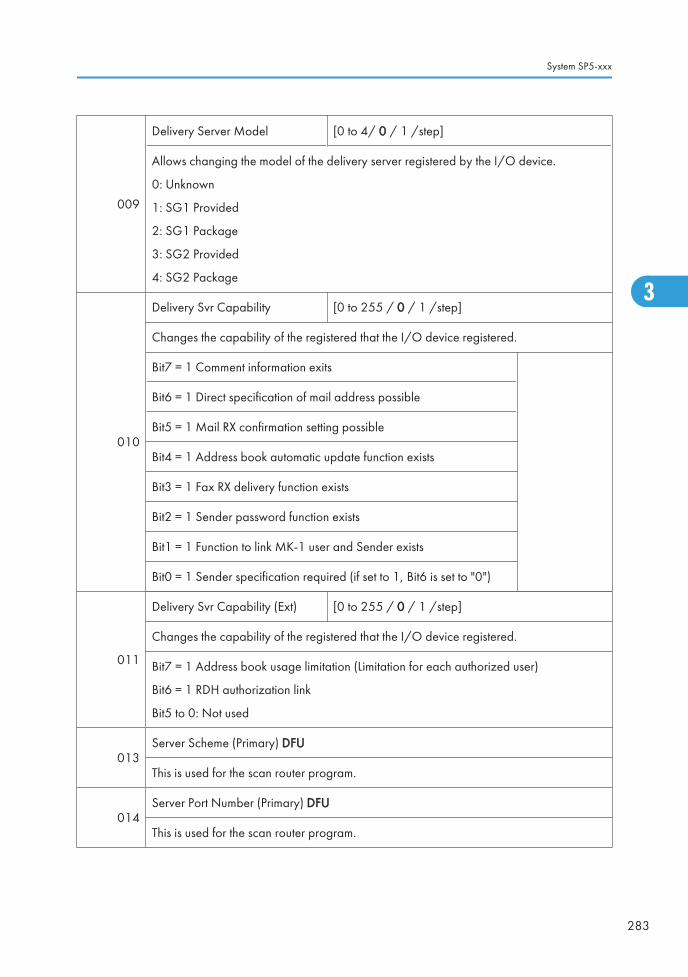
009
Delivery Server Model [0 to 4/ 0 / 1 /step]
Allows changing the model of the delivery server registered by the I/O device.
0: Unknown
1: SG1 Provided
2: SG1 Package
3: SG2 Provided
4: SG2 Package
010
Delivery Svr Capability [0 to 255 / 0 / 1 /step]
Changes the capability of the registered that the I/O device registered.
Bit7 = 1 Comment information exits
Bit6 = 1 Direct specification of mail address possible
Bit5 = 1 Mail RX confirmation setting possible
Bit4 = 1 Address book automatic update function exists
Bit3 = 1 Fax RX delivery function exists
Bit2 = 1 Sender password function exists
Bit1 = 1 Function to link MK-1 user and Sender exists
Bit0 = 1 Sender specification required (if set to 1, Bit6 is set to "0")
011
Delivery Svr Capability (Ext) [0 to 255 / 0 / 1 /step]
Changes the capability of the registered that the I/O device registered.
Bit7 = 1 Address book usage limitation (Limitation for each authorized user)
Bit6 = 1 RDH authorization link
Bit5 to 0: Not used
013Server Scheme (Primary) DFU
This is used for the scan router program.
014Server Port Number (Primary) DFU
This is used for the scan router program.
System SP5-xxx
283
3

015Server URL Path (Primary) DFU
This is used for the scan router program.
016Server Scheme (Secondary) DFU
This is used for the scan router program.
017Server Port Number (Secondary) DFU
This is used for the scan router program.
018Server URL Path (Secondary) DFU
This is used for the scan router program.
022
Rapid Sending Control
Enables or disables the prevention function for the continuous data sending error.
[0 to 1 / 0 / -]
0: Disable, 1: Enable
5846 [UCS Settings] *CTL -
001
Machine ID (For Delivery Server) Displays ID
Displays the unique device ID in use by the delivery server directory. The value is onlydisplayed and cannot be changed. This ID is created from the NIC MAC or IEEE 1394EUI. The ID is displayed as either 6-byle or 8-byte binary.
002
Machine ID Clear (For Delivery Server) Clears ID
Clears the unique ID of the device used as the name in the file transfer directory. Executethis SP if the connection of the device to the delivery server is unstable. After clearing theID, the ID will be established again automatically by cycling the machine off and on.
003
Maximum Entries [2000 to 20000/ 2000 /1 /step]
Changes the maximum number of entries that UCS can handle.
If a value smaller than the present value is set, the UCS managed data is cleared, and thedata (excluding user code information) is displayed.
006
Delivery Server Retry Timer [0 to 255 / 0 / 1 /step]
Sets the interval for retry attempts when the delivery server fails to acquire the deliveryserver address book.
3. Appendix: SP Mode Tables
284
3

007
Delivery Server Retry Times [0 to 255 / 0 / 1 /step]
Sets the number of retry attempts when the delivery server fails to acquire the delivery serveraddress book.
008
Delivery Server Maximum Entries[2000 to 50000 / 2000 / 1/step]
Sets the maximum number account entries of the delivery server user information managedby UCS.
010LDAP Search Timeout [1 to 255 / 60 / 1 /step]
Sets the length of the timeout for the search of the LDAP server.
020WSD Maximum Entries [5 to 250 / 250 / 1 /step]
Sets the maximum entries for the address book of the WSD (WS-scanner).
040Addr Book Migration (USB => HDD)
Not used in this machine.
041
Fill Addr Acl Info.
This SP must be executed immediately after installation of an HDD unit in a basic machinethat previously had no HDD. The first time the machine is powered on with the new HDDinstalled, the system automatically takes the address book from the NVRAM and writes itonto the new HDD. However, the new address book on the HDD can be accessed onlyby the system administrator at this stage. Executing this SP by the service technicianimmediately after power on grants full address book access to all users.
Procedure
1. Turn the machine off.
2. Install the new HDD.
3. Turn the machine on.
4. The address book and its initial data are created on the HDD automatically.
5. However, at this point the address book can be accessed by only the systemadministrator or key operator.
6. Enter the SP mode and do SP5846 041. After this SP executes successfully, any usercan access the address book.
System SP5-xxx
285
3

043 Addr Book Media
Displays the slot number where an address book data is in.
[0 to 30 / - /1]
0: Unconfirmed
1: SD Slot 1
2: SD Slot 2
4: USB Flash ROM
20: HDD
30: Nothing
047 Initialize Local Addr BookClears the local address book information, including theuser code.
048Initialize Delivery AddrBook
Clears the distribution address book information, except theuser code.
049 Initialize LDAP Addr BookClears the LDAP address book information, except the usercode.
050 Initialize All Addr BookClears all directory information managed by UCS, includingall user codes.
051 Backup All Addr Book Uploads all directory information to the SD card.
052 Restore All Addr Book Downloads all directory information from the SD card.
053 Clear Backup Info
Deletes the address book data from the SD card in theservice slot.
Deletes only the files that were uploaded from this machine.
This feature does not work if the card is write-protected.
• After you do this SP, go out of the SP mode, and thenturn the power off.
• Do not remove the SD card until the Power LED stopsflashing.
3. Appendix: SP Mode Tables
286
3

060
Search Option
This SP uses bit switches to set up the fuzzy search options for the UCS local address book.
Bit: Meaning
0: Checks both upper/lower case characters
1: Japan Only
2: Japan Only
3: Japan Only
4 to 7: Not Used
062
Complexity Option 1
Use this SP to set the conditions for password entry to access the local address book.Specifically, this SP limits the password entry to upper case and sets the length of thepassword.
[0 to 32 / 0 / 1 /step]
• This SP does not normally require adjustment.
• This SP is enabled only after the system administrator has set up a group passwordpolicy to control access to the address book.
063 Complexity Option 2 DFU
064 Complexity Option 3 DFU
065 Complexity Option 4 DFU
091 FTP Auth Port Setting
Specifies the FTP port for getting a distribution serveraddress book that is used in the identification mode.
[0 to 65535 / 3671 / 1 /step]
094 Encryption StatShows the status of the encryption function for theaddress book data.
System SP5-xxx
287
3

5847
[Rep Resolution Reduction] *CTL -
5847 1 through 5847 8 changes the default settings of image data transferred externallyby the Net File page reference function.
[0 to 5 / 2 / 1 /step]
5847 21 sets the default for JPEG image quality of image files handled by NetFile.
"Net files" are jobs to be printed from the document server using a PC and theDeskTopBinder software.
001 Rate for Copy Color 0: 1x
1: 1/2x
2: 1/3x
3: 1/4x
4: 1/6x
5: 1/8x
002 Rate for Copy B&W Text
003 Rate for Copy B&W Other
004 Rate for Printer Color
005 Rate for Printer B&W
006 Rate for Printer Color 1200dpi
0: 1x
1: 1/2x
2: 1/3x
3: 1/4x
4: 1/6x
5: 1/8x
007 Rate for Printer B&W 1200dpi
0: 1x
1: 1/2x
2: 1/3x
3: 1/4x
4: 1/6x
5: 1/8x
021
Network Quality Default for JPEG
Sets the default value for the quality of JPEG images sent as NetFile pages. This functionis available only with the MLB (Media Link Board) option installed.
[5 to 95 / 50 / 1 /step]
3. Appendix: SP Mode Tables
288
3

5848
[Web Service] *CTL -
5848 2 sets the 4-bit switch assignment for the access control setting. Setting of 0001 hasno effect on access and delivery from Scan Router.
5848 100 sets the maximum size allowed for downloaded images. The default is equalto 1 gigabyte.
002Access Ctrl: Repository (onlyLower 4 bits)
0000: No access control
0001: Denies access to DeskTop Binder.
0010: No writing control
003Access Control: Doc. Svr. Print(Lower 4 bits)
Switches access control on and off.
0000: No access control
0001: Denies access to DeskTop Binder.
004Access Control: User Directory(only Lower 4 bits)
007Access Ctrl: Comm. Log Fax(Lower 4 bits)
009 Access Ctrl: Job Ctrl (Lower 4 bits)
011Access Ctrl: Device management(Lower 4 bits)
021 Access Ctrl: Delivery (Lower 4 bits)
022Access Ctrl: uAdministration(Lower 4bits)
099Repository: Download ImageSetting
DFU
100Repository: Download ImageMax. Size
Specifies the max size of the image data that themachine can download.
[1 to 1024 / 1024 / 1 MB /step]
System SP5-xxx
289
3

210 Setting: LogType: Job1
NIA
211 Setting: LogType: Job2
212 Setting: LogType: Access
213 Setting: Primary Srv
214 Setting: Secondary Srv
215 Setting: Start Time
216 Setting: Interval Time
217 Setting: Timing
5849 [Installation Date] *CTL -
5849 1 DisplayThe "Counter Clear Day" has been changed to"Installation Date" or "Inst. Date".
5849 2 Switch to Print
Determines whether the installation date is printed onthe printout for the total counter.
[0 or 1 / 1 / - ]
0: OFF (No Print)
1: ON (Print)
003 Total Counter -
5850 [Address Book Function] *CTL -
003
Replacement of Circuit Classification Japan Only
The machine is sold ready to use with a G3 line. This SP allows you to switch all at onceto convert to G4 after you add a G4 line. Conversely, if for some reason the G4 linebecomes unusable, you can easily switch back to G3.
5851
[Bluetooth Mode]
Sets the operation mode for the Bluetooth Unit. Press either key.
[0:Public] [1: Private]
3. Appendix: SP Mode Tables
290
3

5853
[Stamp Data Download]
Use this SP to download the fixed stamp data stored in the firmware of the ROM and copyit to the HDD. This SP can be executed as many times as required. This SP must be executedafter replacing or formatting the hard disks.
• This SP can be executed only with the hard disks installed.
5856
[Remote ROM Update]
Allows the technician to upgrade the firmware using a local port (IEEE1284) whenupdating the remote ROM.
002 Local Port *CTL
[0 to 1 / 0 / 1/step]
0: Disable
1: Enable
5857 [Save Debug Log] *CTL -
001
On/Off (1:ON 0:OFF) 0: OFF, 1: ON
Switches the debug log feature on and off. The debug log cannot be captured until thisfeature is switched on.
002
Target (2: HDD 3: SD) 2: HDD, 3: SD Card
Selects the storage device to save debug logs information when the conditions set withSP5-858 are satisfied.
[ 2 to 3 / 2 / 1 /step]
005
Save to HDD
Saves the debug log of the input SC number in memory to the HDD.
A unique file name is generated to avoid overwriting existing file names on the SD Card.Up to 4MB can be copied to an SD Card. 4 MB segments can be copied one by one toeach SD Card.
006Save to SD Card
Saves the debug log of the input SC number in memory to the SD card.
009 Copy HDD to SD Card (Latest 4 MB)
010 Copy HDD to SD Card (Latest 4 MB Any Key)
System SP5-xxx
291
3

011 Erase HDD Debug Data
012 Erase SD Card Debug Data
013 Free Space on SD Card
014 Copy SD to SD (Latest 4 MB)
015 Copy SD to SD (Latest 4 MB Any Key)
016 Make HDD Debug
017 Make SD Debug
5858
[Debug Save When] *CTL -
These SPs select the content of the debugging information to be saved to the destinationselected by SP5857-002.SP5858-3 stores one SC specified by number. Refer to Section 4 for a list of SC error codes.
001 Engine SC Error
Turns on/off the debug save for SC codes generated bycopier engine errors.
[0 or 1 / 0 / 1/ step]
0: OFF, 1: ON
002 Controller SC Error
Turns on/off the debug save for SC codes generated byGW controller errors.
[0 or 1 / 0 / 1/ step]
0: OFF, 1: ON
003 Any SC Error [0 to 65535 / 0 / 1 /step]
004 Jam
Turns on/off the debug save for jam errors.
[0 or 1 / 0 / 1/ step]
0: OFF, 1: ON
5859 [Debug Save Key No.] *CTL -
3. Appendix: SP Mode Tables
292
3

001 Key 1
These SPs allow you to set up to 10 keys for log files forfunctions that use common memory on the controller board.
[–9999999 to 9999999 / 0 / – ]
002 Key 2
003 Key 3
004 Key 4
005 Key 5
006 Key 6
007 Key 7
008 Key 8
009 Key 9
010 Key 10
5860 [SMTP/POP3/IMAP4] *CTL -
020 Partial Mail Receive Timeout [1 to 168 / 72 / hour/step]
Sets the amount of time to wait before saving a mail that breaks up during reception. Thereceived mail is discarded if the remaining portion of the mail is not received during thisprescribed time.
021 MDN Response RFC2298 Compliance [0 to 1 / 1 / – ]
Determines whether RFC2298 compliance is switched on for MDN reply mail.
0: No
1: Yes
022 SMTP Auth. From Field Replacement [0 to 1 / 0 / – ]
Determines whether the FROM item of the mail header is switched to the validated accountafter the SMTP server is validated.
0: No. "From" item not switched.
1: Yes. "From item switched.
025 SMTP Auth. Direct Setting [0 or 1 / 0 / – ]
System SP5-xxx
293
3

Selects the authentication method for SMPT.
Bit switch:
• Bit 0: LOGIN
• Bit 1: PLAIN
• Bit 2: CRAM MD5
• Bit 3: DIGEST MD5
• Bit 4 to 7: Not used
• This SP is activated only when SMTP authorization is enabled by UP mode.
026S/MIVE: MIME HeaderSetting
-
Selects the MIME header type of an E-mail sentby S/MIME.
[0 to 2 / 0 / 1]
0: Microsoft Outlook Express standard
1: Internet Draft standard
2: RFC standard
5866 [E-mail Alert] Not Used
001 Report Validity *CTL
Enables or disables the e-mail alert.
[0 or 1 / 0 / – ]
0: Enable, 1: Disable
005 Add Date Field *CTL
Adds or does not add the date field to the headerof the alert mail.
[0 or 1 / 0 / – ]
0: Not added, 1: Added
5870 [Common Key Info Writing]
001 Writing *CTLWrites to flash ROM the common proof forvalidating the device for @Remote specifications.
003 Initializing *CTLInitializes the data area of the common proof forvalidating.
5873 [SD Card Appli Move]
3. Appendix: SP Mode Tables
294
3

001 Move ExecThis SP copies the application programs from the original SD card inSD card slot 3 to an SD card in SD card slot 1 or 2 (slot 1 has thepriority to be copied).
002 Undo Exec
This SP copies back the application programs from an SD card in SDCard Slot 3 to the original SD card in SD card slot 1 or 2 (slot 1 hasthe priority to be copied). Use this menu when you have mistakenlycopied some programs by using "Move Exec" (SP5873-1).
5875 [SC Auto Reboot]
001 Reboot Setting *CTL
Enables or disables the automatic reboot function whenan SC error occurs.
[0 or 1/ 0 / – ]
0: The machine reboots automatically when themachine issues an SC error and logs the SC error code.If the same SC occurs again, the machine does notreboot.
1: The machine does not reboot when an SC erroroccurs.
The reboot is not executed for Type A or C SC codes.
002 Reboot Type *CTL
Selects the reboot method for SC.
[0 or 1 / 0 / -]
0: Manual reboot, 1: Automatic reboot
5878 [Option Setup]
001 Data Overwrite Security -Enables the Data Overwrite Security unit. Press"EXECUTE" on the operation panel. Then turn themachine off and on.
002 HDD Encryption - Installs the HDD Encryption unit.
5881 [Fixed Phrase Block Erasing]
001 - - Deletes the fixed phrase.
5883[Line Speed Selection]
Selects the line speed for middle thick paper.
System SP5-xxx
295
3

001 Middle Thick *ENG
[0 or 1 / 1 / 1 /step]
0: MID CARD: Half Speed
1: MID CARD: Normal Speed
5885[Set WIM Function] Web Image Monitor Settings
Close or disclose the functions of web image monitor.
020 Document Server ACC Ctrl *CTL
0: OFF, 1: ON
Bit Meaning
0: Forbid all document server access (1)
1: Forbid user mode access (1)
2: Forbid print function (1)
3: Forbid fax TX (1)
4: Forbid scan sending (1)
5: Forbid downloading (1)
6: Forbid delete (1)
7: Reserved
050 Document Server List Def. Style *CTL
Selects the display type for the document boxlist.
[0 to 2 / 0 / 1]
0: Thumbnail, 1: Icon, 2: Details
051 Document Server List Def. Lines *CTL
Sets the number of documents to be displayedin the document box list.
[5 to 20 / 10 / 1]
100 Signature Setting *CTL
Selects whether the signature is added to thescanned documents with the WIM when theyare transmitted by an e-mail.
[0 to 2 / 0 / 1/step]
0: Setting for each e-mail
1: Signature for all
2: No signature
3. Appendix: SP Mode Tables
296
3

101 Set Encryption *CTL
Determines whether the scanned documentswith the WIM are encrypted when they aretransmitted by an e-mail.
[0 to 1 / 0 / 1]
0: Not encrypted, 1:Encryption
5887[SD Get Counter]
This SP determines whether the ROM can be updated.
001 - *CTL
This SP sends a text file to an SD card inserted inSD card Slot 2 (lower slot). The operation stores.The file is stored in a folder created in the rootdirectory of the SD card called SD_COUNTER.The file is saved as a text file (*.txt) prefixed withthe number of the machine.
1. Insert the SD card in SD card Slot 2 (lowerslot).
2. Select SP5887 then touch [EXECUTE].
Touch [Execute] in the message when you areprompted.
5888 [Personal Information Protect]
001 - *CTL
Selects the protection level for logs.
[0 to 1 / 0 / 1}
0: No authentication, No protection for logs
1: No authentication, Protected logs (only anadministrator can see the logs)
5893[SDK Application Counter] *CTL -
Displays the counter name of each SDK application.
001 SDK-1
002 SDK-2
003 SDK-3
004 SDK-4
System SP5-xxx
297
3

005 SDK-5
006 SDK-6
5894[Test Name1]
-
001 Test Name1_1 *ENG [0 to 2 / 0 / 1/step]
5895
[Application Invalidation]
Enables or disables the printer or scanner application.
These SPs are used only when an external controller is installed in the machine.
001 Printer *CTL [0 or 1 / 0 / -]
0: Enable
1: Disable002 Scanner *CTL
5907 [Plug & Play Maker/Model Name]
Selects the brand name and the production name for Windows Plug & Play. This informationis stored in the NVRAM. If the NVRAM is defective, these names should be registered again.
After selecting, press the "Original Type" key and "#" key at the same time. When the settingis completed, the beeper sounds five times.
5913 [Switchover Permission Time]
002
Print Application Timer *CTL [3 to 30 / 3 / 1 second /step]
Sets the amount of time to elapse while the machine is in standby mode (and the operationpanel keys have not been used) before another application can gain control of the display.
5967 [Copy Server Set Function] *CTL 0: ON, 1: OFF
Enables and disables the document server. This is a security measure that prevents imagedata from being left in the temporary area of the HDD. After changing this setting, you mustswitch the main switch off and on to enable the new setting.
3. Appendix: SP Mode Tables
298
3

5974[Cherry Server]
Specifies which version of ScanRouter, "Lite" or "Full", is installed.
001 Cherry Server *CTL
[0 or 1 / 0 / – ]
0: Lite
1: Full
5985
[Device Setting]
The NIC and USB support features are built into the GW controller. Use this SP to enableand disable these features. In order to use the NIC and USB functions built into the controllerboard, these SP codes must be set to "1".
001 On Board NIC
[0 to 2 / 0 / 1 /step]
0: Disable, 1: Enable, 2: Function limitation
When the "Function limitation" is set, "On board NIC" is limited onlyfor the NRS or LDAP/NT authentication.
• Other network applications than NRS or LDAP/NTauthentication are not available when this SP is set to "2". Eventhough you can change the initial settings of those networkapplications, the settings do not work.
002 On Board USB[0 or 1 / 0 / 1/step]
0: Disable, 1: Enable
5987 [Mech. Counter]
001 0: OFF / 1: ONThis SP detects that a mechanical counter device is removed. Ifit is detected, SC610 occurs.
5990[SP print mode]
Prints out the SMC sheets.
System SP5-xxx
299
3

001 All (Data List) -
-
002 SP (Mode Data List) -
003 User Program -
004 Logging Data -
005 Diagnostic Report -
006 Non-Default -
007 NIB Summary -
008 Capture Log -
021 Copier User Program -
022 Scanner SP -
023 Scanner User Program -
024 SDK/J Summary -
025 SDK/J Application Info -
5998[Fusing Cont mode] Fusing Control Mode
Turns the silent fusing warm-up mode on or off.
001 fast/silent *ENG
[0 or 1 / 1 / - ]
0: Silent (less noise)
1: Fast (less time)
Turns on or off the fusing unit preceding mode.
The machine turns on the fusing unit first by default after power-on or recovery from theenergy save mode.
If a customer does not want the fusing unit to rotate before sending a job to the machine,change this setting to "0". In this case, the first print time or recovery time may be little bitlonger than before.
3. Appendix: SP Mode Tables
300
3

System SP6-xxx
SP6-XXX (Peripherals)
6006 [ADF Adj.] ADF Adjustment
Adjusts the side-to-side and leading registration of originals with the ARDF.
001 Side-to-Side Registration
*ENG[-3.0 to 3.0 / 0 / 0.1 mm/step ]
002Side-to-Side Registration(2nd side)
003 Leading Edge Registration [-5.0 to 5.0 / 0 / 0.1 mm/step ]
Adjusts the amount of paper buckle to correct original skew for the front and rear sides.
005 Buckle: Duplex Front*ENG
[-3.0 to 3.0 / 0 / 0.1 mm/step ]
006 Buckle: Duplex Rear [-2.5 to 2.5 / 0 / 0.1 mm/step ]
Adjusts the erase margin at the original trailing edge.
007 Rear Edge Erase *ENG [-10 to 10 / 0 / 0.1 mm/step ]
6007
[ADF Input Check]
Displays the signals received from the sensors and switches of the ARDF. Only Bit 0 is usedfor ADF input check ( p.392 "Input and Output Check").
6008
[ADF Output Check]
Activates the electrical components for functional check.
It is not possible to activate more than one component at the same time ( p.392 "Inputand Output Check").
6009[ADF Free Run]
Performs a DF free run in simplex, duplex mode or stamp mode.
System SP6-xxx
301
3

001 Free Run Simplex Motion -
-002 Free Run Duplex Motion -
003 Free Run Stamp Motion -
6010[Stamp Position Adj.] Fax Stamp Position Adjustment
Adjusts the horizontal position of the stamp on the scanned originals.
6010 1 Stamp Position Adj. *ENG [-5.0 to 5.0 / 0 / 1 mm/step]
6011 [1-Pass ADF INPUT Check] Not used
6012 [1-Pass ADF OUTPUT Check] Not used
6016
[Original Size Detection Priority] Original Size Detection Priority
Specifies the original size for a size detected by the original sensor, since original sensorscannot recognize all sizes.
001Original Size DetectionPriority
*ENG[0 or 1 / 0 / - ]
0: Setting 1, 1: Setting 2
NA
Setting 1 Setting 2
DLT SEF Folio SEF 11" x 15"
LG SEF Foolscap SEF
LT SEF US EXE 8" x 10"
LT LEF US EXE LEF
EU/
ASIA
DLT SEF 8K 267 x 390 mm
LT SEF 16K 195 x 267 mm
LT LEF 16K 267 x 195 mm
6017[DF Magnification Adj.] DF Magnification Adjustment
Adjusts the magnification in the sub-scan direction for the ARDF.
001 DF Magnification Adj. *CTL [-5.0 to 5.0 / 0 / 0.1 %/step]
3. Appendix: SP Mode Tables
302
3

6020[Skew Correction Moving Setting]
Turns the original skew correction in the ARDF for all original sizes on or off.
001 - *ENG
[0 or 1 / 0 / - ]
0: Off (only for small original sizes)
1: On (for all original sizes)
6128[Punch Position: Sub Scan]
Adjusts the punching position in the sub scan direction.
001 Domestic (Japan) 2Hole *ENG
[-7.5 to 7.5 / 0 / 0.5 mm/step]]
002 North America 3Hole *ENG
003 Europe 4Hole *ENG
004 North Europe 4Hole *ENG
005 North Europe 2Hole *ENG
6129[Punch Position: Main Scan]
Adjusts the punching position in the main scan direction.
001 Domestic (Japan) 2Hole *ENG
[-2.0 to 2.0 / 0 / 0.4 mm/step]]
002 North America 3Hole *ENG
003 Europe 4Hole *ENG
004 North Europe 4Hole *ENG
005 North Europe 2Hole *ENG
6130[Skew Correction: Buckle Adj.]
Adjusts the paper buckle for each paper size.
System SP6-xxx
303
3

001 A3T *ENG
[-5.0 to 5.0 / 0 / 0.25 mm/step]]
002 B4T *ENG
003 A4T *ENG
004 A4Y *ENG
005 B5T *ENG
006 B5Y *ENG
007 DLT-T *ENG
008 LG-T *ENG
009 LT-T *ENG
010 LT-Y *ENG
011 12" x 18" *ENG
012 Other *ENG
6131[Skew Correction Control]
Selects the skew correction control for each paper size. These are only activated for B793.
3. Appendix: SP Mode Tables
304
3

001 A3T *ENG
[0 or 1 / 1 / 1/step]]
0: No (No skew correction)
1: Roller Stop Skew Correction
002 B4T *ENG
003 A4T *ENG
004 A4Y *ENG
005 B5T *ENG
006 B5Y *ENG
007 DLT-T *ENG
008 LG-T *ENG
009 LT-T *ENG
010 LT-Y *ENG
011 12" x 18" *ENG
012 Other *ENG
6132
[Jogger Fence Fine Adj]
This SP adjusts the distance between the jogger fences and the sides of the stack on thefinisher stapling tray in the Booklet Finisher B793. The adjustment is done perpendicular tothe direction of paper feed.
System SP6-xxx
305
3

001 A3T *ENG
[-1.5 to 1.5 / 0 / 0.5 mm/step]
+ Value: Increases distance between joggerfences and the sides of the stack.
- Value: Decreases the distance between thejogger fences and the sides of the stack.
002 B4T *ENG
003 A4T *ENG
004 A4Y *ENG
005 B5T *ENG
006 B5Y *ENG
007 DLT-T *ENG
008 LG-T *ENG
009 LT-T *ENG
010 LT-Y *ENG
011 12" x 18" *ENG
012 Other *ENG
6133
[Staple Position Adjustment]
Adjusts the staple position for each finisher (B408/B793/D372).
+ Value: Moves the staple position to the rear side.
- Value: Moves the staple position to the front side.
001 Finisher (B408/B793) *ENG [-3.5 to 3.5 / 0 / 1/step]
6134 [Saddle Stitch Position Adjustment]
User SPUse this SP to adjust the stapling position of the booklet stapler when paper is stapled andfolded in the Booklet Finisher B793.
3. Appendix: SP Mode Tables
306
3

001 A3T
[-3.0 to 3.0 / 0 / 0.2 mm/step]
+ Value: Shifts staple position toward the crease.
- Value: Shifts staple position away from the crease.
002 B4T
003 A4T
004 B5T
005 DLT-T
006 LG-T
007 LT-T
008 12" x 18"
009 Other
6135 [Folder Position Adj.]
User SPThis SP corrects the folding position when paper is stapled and folded in the Booklet FinisherB793.
001 A3T
[-3.0 to 3.0 / 0 / 0.2 mm/step]
+ Value: Shifts staple position toward the crease.
- Value: Shifts staple position away from the crease.
002 B4T
003 A4T
004 B5T
005 DLT-T
006 LG-T
007 LT-T
008 12" x 18"
009 Other
6136 [Folding Number]
User SP Sets the number of times that folding is done in the Booklet Finisher B793.
001 - [2 to 30 / 2 / 1 time/step]
System SP6-xxx
307
3

6137[Finisher Free Run]
These SPs are used only for B793 finisher.
001 Free Run 1 Free run for paper edge stapling.
002 Free Run 2 Free run for booklet stapling.
003 Free Run 3 Shipping free run. Simulates standby conditions during shipping.
004 Free Run 4 DFU
6138 [FIN (TIG) INPUT Check] Finisher (B793) Input Check
Displays the signals received from sensors and switches of the booklet finisher. ( p.392"Input and Output Check")
6139 [FIN (KIN) INPUT Check] Finisher (B408) Input Check
Displays the signals received from sensors and switches of the booklet finisher. ( p.392"Input and Output Check")
6140 [FIN (EUP) INPUT Check] Not used
6141 [FIN (ELB) INPUT Check] Finisher (D372) Input Check
Displays the signals received from sensors and switches of the booklet finisher. ( p.392"Input and Output Check")
6143 [FIN (TIG) OUPUT Check] Finisher (B793) Output Check
Displays the signals received from sensors and switches of the booklet finisher. ( p.392"Input and Output Check")
6144 [FIN (KIN) OUPUT Check] Finisher (B408) Output Check
Displays the signals received from sensors and switches of the booklet finisher. ( p.392"Input and Output Check")
6145 [FIN (EUP) OUPUT Check] Not used
3. Appendix: SP Mode Tables
308
3

6146 [FIN (ELB) OUPUT Check] Finisher (D372) Output Check
Displays the signals received from sensors and switches of the 500-sheet finisher. (p.392 "Input and Output Check")
6149
[Max. Pre-Stack Sheet] *ENG Number of Pre-Stack Sheets
This SP sets the number of sheets sent to the pre-stack tray.
Note:
You may need to adjust this setting or switch it off when feeding thick or slick paper.
001 - [0 to 3 / 3 / 1 sheet/step]
6150
[INPUT Check]
Displays the signals received from sensors and switches of the bridge unit (D386)/ side tray(D542) ( p.392 "Input and Output Check").
6151
[OUTPUT Check]
Displays the signals received from sensors and switches of the bridge unit (D386)/ side tray(D542) ( p.392 "Input and Output Check").
6152
[INPUT Check]
Displays the signals received from sensors and switches of the shift tray (D388) (p.392 "Input and Output Check").
6153
[OUTPUT Check]
Displays the signals received from sensors and switches of the shift tray (D388) (p.392 "Input and Output Check").
6154
[INPUT Check]
Displays the signals received from sensors and switches of the 1 bin tray (D536) (p.392 "Input and Output Check").
System SP6-xxx
309
3

6155
[OUTPUT Check]
Displays the signals received from sensors and switches of the 1 bin tray (D414) (p.392 "Input and Output Check").
001 1 bin: Junction Solenoid
6157[OUTPUT Check]
Not used in this machine
6160
[INPUT Check]
Displays the signals received from sensors and switches of the two-tray paper feed unit(D537), LCT 2000 (D538) and LCT 1200 (D539) ( p.392 "Input and Output Check").
6161
[OUTPUT Check]
Displays the signals received from sensors and switches of the two-tray paper feed unit(D537), LCT 2000 (D538) and LCT 1200 (D539) ( p.392 "Input and Output Check").
6801 [1-pass Stamp Unit] Not used
6830 [Extra Staples] Not used
6900[ADF Bottom Plate Setting]
This SP setting determines whether the bottom plate lift motor of the of the ADF switches on:
001 A3T *ENG
[0 or 1 / 0 / -]
0: Bottom plate lifts immediately after originalsare set (Default)
1: Bottom plate does not lift until [Start] key ispushed.
3. Appendix: SP Mode Tables
310
3

System SP7-xxx
SP7-XXX (Data Log)
7401[Total SC Counter]
Displays the number of SC codes detected.
001 SC Counter *CTL [0 to 9999 / 0 / 1/step ]
7403
[SC History]
Logs the SC codes detected.
The 10 most recently detected SC Codes are not displayed on the screen, but can be seenon the SMC (logging) outputs.
001 Latest
*CTL -
002 Latest 1
003 Latest 2
004 Latest 3
005 Latest 4
006 Latest 5
007 Latest 6
008 Latest 7
009 Latest 8
010 Latest 9
7404
[SC991 History]
Logs the SC991 detected.
The 10 most recently detected SC991 are not displayed on the screen, but can be seen onthe SMC (logging) outputs.
System SP7-xxx
311
3

001 Latest
*CTL -
002 Latest 1
003 Latest 2
004 Latest 3
005 Latest 4
006 Latest 5
007 Latest 6
008 Latest 7
009 Latest 8
010 Latest 9
7502[Total Paper Jam Counter]
Displays the total number of jams detected.
001 Total Jam * CTL [0 to 9999 / 0 / 1 sheet/step ]
7503[Total Original Jam Counter]
Displays the total number of original jams.
001 Original Jam counter *CTL [0 to 9999 / 0 / 1 original/step ]
7504
[Paper Jam Location]
ON: On check, OFF: Off Check
Displays the number of jams according to the location where jams were detected.
NOTE: The LCT is counted as the 3rd feed station.
3. Appendix: SP Mode Tables
312
3

001 At Power On *CTL
For details, ( "Jam Detection" in the"Main Chapters: Jam Detection" section.)
003 Tray 1: ON *CTL
004 Tray 2: ON *CTL
005 Tray 3: ON *CTL
006 Tray 4: ON *CTL
007 LCT : ON *CTL
008 Bypass: ON *CTL
009 Duplex: ON *CTL
011 Vertical Transport 1: ON *CTL
012 Vertical Transport 2: ON *CTL
013 Bank: Transport Sn1 *CTL
For details, ( "Jam Detection" in the"Main Chapters: Jam Detection" section.)
014 Bank: Transport Sn2 *CTL
017 Registration: ON *CTL
018 Fusing Entrance: ON *CTL
019 Fusing Exit: ON *CTL
020 Paper Exit: ON *CTL
021 Bridge Exit: ON *CTL
022 Bridge Transport: ON *CTL
024 Junction Gate Sensor : On *CTL
System SP7-xxx
313
3

025 Duplex Exit: ON *CTL
For details, ( "Jam Detection" in the"Main Chapters: Jam Detection" section.)
026 Duplex Entrance: ON (Out) *CTL
027 Duplex Entrance: ON (Out) *CTL
051 Vertical Transport 1: Off *CTL
052 Vertical Transport 2: Off *CTL
053 Bank Transport 1: Off *CTL
054 Bank Transport 2: Off *CTL
057 Registration Sensor: Off *CTL
058 LCT Feed Sensor : Off *CTL
060 Paper Exit Off *CTL
061 Bridge Exit: Off *CTL
062 Bridge Transport: Off *CTL
064 Junction Gate Sensor : Off *CTL
For details, ( "Jam Detection" in the"Main Chapters: Jam Detection" section.)
065 Duplex Exit: Off *CTL
066 Duplex Entrance: Off (In) *CTL
067 Duplex entrance : Off (Out) *CTL
100 Finisher Entrance: KIN *CTL
101 Finisher Shift Tray Exit: KIN *CTL
102 Finisher Staple: KIN *CTL
103 Finisher Exit: KIN *CTL
105 Finisher Tray Lift Motor: KIN *CTL
106 Finisher Jogger Motor: KIN *CTL
107 Finisher Shift Motor: KIN *CTL
108 Finisher Staple Motor: KIN *CTL
3. Appendix: SP Mode Tables
314
3

109 Finisher Exit Motor: KIN *CTL
For details, ( "Jam Detection" in the"Main Chapters: Jam Detection" section.)
191 Finisher Entrance: EUP *CTL
192 Finisher Proof Exit: EUP *CTL
193 Finisher Shift Tray Exit: EUP *CTL
194 Finisher Stapler Exit: EUP *CTL
195 Finisher Exit: EUP *CTL
198 Finisher Folder: EUP *CTL
199 Finisher Tray Motor: EUP *CTL
200 Finisher Jogger Motor: EUP *CTL
For details, ( "Jam Detection" in the"Main Chapters: Jam Detection" section.)
201 Finisher Shift Motor: EUP *CTL
202 Finisher Staple Moving Motor: EUP *CTL
203 Finisher Staple Motor: EUP *CTL
204 Finisher Folder Motor: EUP *CTL
206 Finisher Punch Motor: EUP *CTL
230 Fin Exit *CTL
231 Insufficient Data *CTL
7505[Original Jam Detection]
Displays the total number of original jams by location.
001 At Power On *CTL
003 Separation Sensor: On *CTL
004 Skew Correction Sensor: On *CTL
005 Scanning Entrance Sensor: On *CTL
System SP7-xxx
315
3

006 Registration Sensor: On *CTL
Not used
007 Original Exit Sensor: On *CTL
008 Reverse Sensor: On *CTL
013 Separation Sensor: On *CTL
014 Skew Correction Sn: On *CTL
015 Scanning Entrance Sn: On *CTL
016 Registration Sensor: On *CTL
017 Original Exit Sensor: On *CTL
053 Separation Sensor: Off *CTL
054 Skew Correction Sensor: Off *CTL
055 Scanning Entrance Sensor: Off *CTL
056 Registration Sensor: Off *CTL
Not used
057 Original Exit Sensor: Off *CTL
058 Reverse Sensor: Off *CTL
063 Separation Sensor: Off *CTL
064 Skew Correction Sn: Off *CTL
065 Scanning Entrance Sn: Off *CTL
066 Registration Sensor: Off *CTL
067 Original Exit Sensor: Off *CTL
7506[Jam Count by Paper Size]
Displays the number of jams according to the paper size.
3. Appendix: SP Mode Tables
316
3

005 A4 LEF
*CTL [0 to 9999 / 0 / 1 sheet/step ]
006 A5 LEF
014 B5 LEF
038 LT LEF
044 HLT LEF
132 A3 SEF
133 A4 SEF
134 A5 SEF
141 B4 SEF
142 B5 SEF
160 DLT SEF
164 LG SEF
166 LT SEF
172 HLT SEF
255 Others
7507[Plotter Jam History]
Displays the 10 most recently detected paper jams.
System SP7-xxx
317
3

001 Latest
*CTL -
002 Latest 1
003 Latest 2
004 Latest 3
005 Latest 4
006 Latest 5
007 Latest 6
008 Latest 7
009 Latest 8
010 Latest 9
7508[Original Jam History]
Displays the 10 most recently detected original jams.
001 Latest
*CTL -
002 Latest-1
003 Latest-2
004 Latest-3
005 Latest-4
006 Latest-5
007 Latest-6
008 Latest-7
009 Latest-8
010 Latest-9
7624Part Replacement Operation ON/OFF
Selects the PM maintenance for each part.
3. Appendix: SP Mode Tables
318
3

001 Drum Unit: Bk
[0 or 1 / 1 -]
0: No (Not PM maintenance)
1: Yes (PM maintenance)
002 Drum Unit: M
003 Drum Unit: C
004 Drum Unit: Y
005 Development Unit: Bk
006 Development Unit: M
007 Development Unit: C
008 Development Unit: Y
009 Developer: Bk
010 Developer: M
011 Developer: C
012 Developer: Y
013 Image Transfer Belt
[0 or 1 / 1 -]
0: Not PM maintenance
1: PM maintenance
014 Image Transfer Cleaning Unit
015 Fusing Unit
016 Paper Transfer Roller Unit
017 Waste Toner Bottle
018 Fusing Roller
019 Pressure Roller
7801 [ROM No/ Firmware Version]
255 Engine *CTLDisplays all versions and ROM numbers in themachine.
7803[PM Counter Display]
(Page, Unit, [Color])
System SP7-xxx
319
3

Displays the number of sheets printed for each current maintenance unit.
PM counters click up based on the number of A4 (LT) LEF size sheets printed. Therefore,the A3 (DLT) Double Count is activated. The Double Count cannot be deactivated.
When a unit is replaced, the machine automatically detects that the new unit is installed.Then, the current PM counter value is automatically moved to the PM Counter - Previous(SP7-906-1 to 10) and is reset to “0”.
The total number of sheets printed with the last unit replaced can be checked withSP7-906-1 to 10.
NOTE: The LCT is counted as the 3rd feed station.
001 Paper *CTL [0 to 9999999 / - / 1 sheet/ step]
002 Page: PCU: Bk *ENG
[0 to 9999999 / - / 1 sheet/ step]
003 Page: PCU: M *ENG
004 Page: PCU: C *ENG
005 Page: PCU: Y *ENG
006 Page: Development Unit: Bk *ENG
007 Page: Development Unit: M *ENG
008 Page: Development Unit: C *ENG
009 Page: Development Unit: Y *ENG
010 Page: Developer: Bk *ENG
011 Page: Developer: M *ENG
012 Page: Developer: C *ENG
013 Page: Developer: Y *ENG
3. Appendix: SP Mode Tables
320
3

014 Page: Image Transfer *ENG
[0 to 9999999 / - / 1 sheet/ step]
015 Page: Cleaning Unit *ENG
016 Page: Fusing Unit *ENG
017 Page: Paper Transfer Unit *ENG
018 Page: Toner Collection Bottle *ENG
019 Page: Fusing Roller *ENG
020 Page: Pressure Roller *ENG
Displays the number of revolutions of motors or clutches for each current maintenance unit.
[ 0 to 9999999 / 0 / 1 revolution/step ]
When a unit is replaced, the machine automatically detects that the new unit is installed.Then, the current PM counter value is automatically moved to the PM Counter - Previous(SP7-906-11 to 20) and is reset to “0”. The total number of revolutions made with the lastunit replaced can be checked with SP7-906-11 to 20.
031 Rotation: PCU: Bk
*ENG [0 to 999999999 / - / 1 mm/step ]
032 Rotation: PCU: M
033 Rotation: PCU: C
034 Rotation: PCU: Y
035 Rotation: Development Unit: Bk
036 Rotation: Development Unit: M
037 Rotation: Development Unit: C
038 Rotation: Development Unit: Y
039 Rotation: Developer Bk
040 Rotation: Developer M
041 Rotation: Developer C
042 Rotation: Developer Y
System SP7-xxx
321
3

043 Rotation: Image Transfer
*ENG [0 to 999999999 / - / 1 mm/step ]044 Rotation: Cleaning Unit
045 Rotation: Fusing Unit
046 Rotation: Paper Transfer Unit
047 Measurement: Toner Collection bottle *ENG [0 to 999999999 / - / 1 mg/step ]
048 Rotation: Fusing Roller*ENG [0 to 999999999 / - / 1 mm/step ]
049 Rotation: Pressure Roller
Displays the value given by the following formula:
(Current revolution ÷ Target revolution) × 100. This shows how much of the unit’s expectedlifetime has been used up.
The Rotation% counter is based on rotations, not prints. If the number of rotations reachesthe limit, the machine enters the end condition for that unit. If the print count lifetime is reachedfirst, the machine also enters the end condition, even though the R% counter is still less than100%.
061 Rotation (%): PCU: Bk
*ENG [0 to 255 / - / 1 %/step]
062 Rotation (%): PCU: M
063 Rotation (%): PCU: C
064 Rotation (%): PCU: Y
065 Rotation (%): Development Unit: Bk
066 Rotation (%): Development Unit: M
067 Rotation (%): Development Unit: C
068 Rotation (%): Development Unit: Y
069 Rotation (%): Developer Bk
070 Rotation (%): Developer M
071 Rotation (%): Developer C
072 Rotation (%): Developer Y
3. Appendix: SP Mode Tables
322
3

073 Rotation (%): Image Transfer Belt
*ENG [0 to 255 / - / 1 %/step]
074 Rotation (%): Cleaning Unit
075 Rotation (%): Fusing Unit
076 Rotation (%): Paper Transfer Unit
077 Measurement (%): Toner Collection bottle
078 Rotation (%): Fusing Roller
079 Rotation (%): Pressure Roller
Displays the value given by the following formula:
(Current printouts ÷ Target printouts) × 100. This shows how much of the unit’s expectedlifetime has been used up.
The Page% counter is based on printouts, not revolutions. If the number of printouts reachesthe limit, the machine enters the end condition for that unit. If the revolution count lifetime isreached first, the machine also enters the end condition, even though the Page% counteris still less than 100%.
091 Page (%): PCU Bk (Drum Unit)
*ENG [0 to 255 / - / 1 %/step]
092 Page (%): PCU M (Drum Unit)
093 Page (%): PCU C (Drum Unit)
094 Page (%): PCU Y (Drum Unit)
095 Page (%): Development Unit: Bk
096 Page (%): Development Unit: M
097 Page (%): Development Unit: C
098 Page (%): Development Unit: Y
System SP7-xxx
323
3

099 Page (%): Developer: Bk
*ENG [0 to 255 / - / 1 %/step]
100 Page (%): Developer: M
101 Page (%): Developer: C
102 Page (%): Developer: Y
103 Page (%): Image Transfer
104 Page (%): Cleaning Unit
105 Page (%): Fusing Unit
106 Page (%): Paper Transfer Unit
107 Page (%): Fusing Roller
108 Page (%): Pressure Roller
7804[PM Counter Reset] PM Counter Clear
(Unit, [Color])
Clears the PM counter.
Press the Enter key after the machine asks “Execute?”, which will store the PM counter valuein SP7-906 (PM Counter - Previous) and reset the value of the current PM counter(SP7-803) to “0”.
002 PCU (Drum Unit): Bk
- -
003 PCU (Drum Unit): M
004 PCU (Drum Unit): C
005 PCU (Drum Unit): Y
006 PCU (Drum Unit): All
007 Development Unit: Bk
008 Development Unit: M
009 Development Unit: C
010 Development Unit: Y
011 Development Unit: All
3. Appendix: SP Mode Tables
324
3

012 Developer: Bk
- -
013 Developer: M
014 Developer: C
015 Developer: Y
016 Developer: All
017 Image Transfer Belt
018 Cleaning Unit
019 Fusing Unit
020 Paper Transfer Unit
021 Toner Collection Bottle
022 Fusing Roller
023 Pressure Roller
100 All
7807[SC/Jam Counter Reset]
Clears the counters related to SC codes and paper jams.
001 SC/Jam Clear - -
7826 [MF Error Counter] Japan Only
001 Error Total
002 Error Staple
7827 [MF Error Counter Clear] Japan Only
7832[Self-Diagnose Result Display]
Displays the result of the diagnostics.
001 Diag. Result *CTL -
System SP7-xxx
325
3

7835 [ACC Counter]
001 Copy ACC *CTLDisplays the ACC exectuion times for each mode.
002 Printer ACC *CTL
7836Total Memory Size
Displays the memory capacity of the controller system.
7852
[DF Scan Glass Dust Check Counter]
Counts the number of occurrences (0 to 65,535) when dust was detected on the scanningglass of the ADF or resets the dust detection counter. Counting is done only if SP4-020-1(ADF Scan Glass Dust Check) is switched on.
001 Dust Detection Counter *CTL [0 to 9999 / - / 1 /step]
002 Dust Detection Clear Counter *CTL [0 to 9999 / - / 1 /step]
003 Dust Detection Counter: Back *CTL [0 to 9999 / - / 1 /step]
7853[Replacement Counter]
Displays the PM parts replacement number.
3. Appendix: SP Mode Tables
326
3

001 PCU: Bk *CTL
[0 to 255 / - / 1 /step]
002 PCU: M *CTL
003 PCU: C *CTL
004 PCU: Y *CTL
005 Development Unit: Bk *CTL
006 Development Unit: M *CTL
007 Development Unit: C *CTL
008 Development Unit: Y *CTL
009 Developer: Bk *CTL
010 Developer: M *CTL
011 Developer: C *CTL
012 Developer: Y *CTL
013 Image Transfer *CTL
[0 to 255 / - / 1 /step]
014 Cleaning Unit *CTL
015 Fusing Unit *CTL
016 Paper Transfer Unit *CTL
017 Toner Collection Bottle *CTL
018 Fusing Roller *CTL
019 Pressure Roller *CTL
System SP7-xxx
327
3

7855
[Coverage Range]
Sets the color coverage threshold.
Coverage rate = Coverage per page / A4 full coverage (dots) x 100
There are three coverage counters: Color 1, Color 2, and Color 3
• [A] 5% (default) is adjustable with SP7855-001.
• [B] 20% (default) is adjustable with SP7855-002.
• The setting value [B] must be set larger than [A].
The total numbers of printouts (BW printing plus color printing) for each coverage rangeare displayed with the following SPs.
• Color1 counter: SP8601-021
• Color2 counter: SP8601-022
• Color3 counter: SP8601-023
001 Coverage Range 1 *CTL [1 to 200 / 5 /1]
002 Coverage Range 2 *CTL [1 to 200 / 20 /1]
7901
[Assert Info] DFU
Records the location where a problem is detected in the program. The data stored in thisSP is used for problem analysis.
001 File Name
*CTL -002 Number of Lines
003 Location
7906
[Prev. Unit PM Counter]
(Page or Rotations, Unit, [Color]), Dev.: Development Unit
Displays the number of sheets printed with the previous maintenance units.
001 Paper *CTL [0 to 9999999 / - / 1 sheet/ step]
3. Appendix: SP Mode Tables
328
3

002 Page: PCU: Bk *ENG
[0 to 9999999 / - / 1 sheet/ step]
003 Page: PCU: M *ENG
004 Page: PCU: C *ENG
005 Page: PCU: Y *ENG
006 Page: Development Unit: Bk *ENG
007 Page: Development Unit: M *ENG
008 Page: Development Unit: C *ENG
009 Page: Development Unit: Y *ENG
010 Page: Developer: Bk *ENG
011 Page: Developer: M *ENG
012 Page: Developer: C *ENG
013 Page: Developer: Y *ENG
014 Page: Image Transfer *ENG
[0 to 9999999 / - / 1 sheet/ step]
015 Page: Cleaning Unit *ENG
016 Page: Fusing Unit *ENG
017 Page: Paper Transfer Unit *ENG
018 Page: Toner Collection Bottle *ENG
019 Page: Fusing Roller *ENG
020 Page: Pressure Roller *ENG
Displays the number of revolutions for motors or clutches in the previous maintenance units.
System SP7-xxx
329
3

031 Rotation: PCU: Bk
*ENG [0 to 999999999 / - / 1 mm/step ]
032 Rotation: PCU: M
033 Rotation: PCU: C
034 Rotation: PCU: Y
035 Rotation: Development Unit: Bk
036 Rotation: Development Unit: M
037 Rotation: Development Unit: C
038 Rotation: Development Unit: Y
039 Rotation: Developer Bk
040 Rotation: Developer M
041 Rotation: Developer C
042 Rotation: Developer Y
043 Rotation: Image Transfer
*ENG [0 to 999999999 / - / 1 mm/step ]044 Rotation: Cleaning Unit
045 Rotation: Fusing Unit
046 Rotation: Paper Transfer Unit
047 Measurement: Toner Collection bottle *ENG [0 to 999999999 / - / 1 mg/step ]
048 Rotation: Fusing Roller*ENG [0 to 999999999 / - / 1 mm/step ]
049 Rotation: Pressure Roller
Displays the number of sheets printed with the previous maintenance unit or toner cartridge.
3. Appendix: SP Mode Tables
330
3

061 Rotation (%): PCU: Bk
*ENG [0 to 255 / - / 1 %/step]
062 Rotation (%): PCU: M
063 Rotation (%): PCU: C
064 Rotation (%): PCU: Y
065 Rotation (%): Development Unit: Bk
066 Rotation (%): Development Unit: M
067 Rotation (%): Development Unit: C
068 Rotation (%): Development Unit: Y
069 Rotation (%): Developer Bk
070 Rotation (%): Developer M
071 Rotation (%): Developer C
072 Rotation (%): Developer Y
073 Rotation (%): Image Transfer Belt
*ENG [0 to 255 / - / 1 %/step]
074 Rotation (%): Cleaning Unit
075 Rotation (%): Fusing Unit
076 Rotation (%): Paper Transfer Unit
077 Measurement (%): Toner Collection bottle
078 Rotation (%): Fusing Roller
079 Rotation (%): Pressure Roller
Displays the value given by the following formula:
(Current count ÷ Yield count) x 100, where “Current count” is the current values in thecounter for the part, and “Yield count” is the recommended yield.
System SP7-xxx
331
3

091 Page (%): PCU Bk (Drum Unit)
*ENG [0 to 255 / - / 1 %/step]
092 Page (%): PCU M (Drum Unit)
093 Page (%): PCU C (Drum Unit)
094 Page (%): PCU Y (Drum Unit)
095 Page (%): Development Unit: Bk
096 Page (%): Development Unit: M
097 Page (%): Development Unit: C
098 Page (%): Development Unit: Y
099 Page (%): Developer: Bk
*ENG [0 to 255 / - / 1 %/step]
100 Page (%): Developer: M
101 Page (%): Developer: C
102 Page (%): Developer: Y
103 Page (%): Image Transfer
104 Page (%): Cleaning Unit
105 Page (%): Fusing Unit
106 Page (%): Paper Transfer Unit
107 Page (%): Fusing Roller
108 Page (%): Pressure Roller
7931[Toner Bottle Bk]
Displays the toner bottle information for Bk.
001 Machine Serial ID *ENG
002 Cartridge Ver *ENG
003 Brand ID *ENG
004 Area ID *ENG
005 Product ID *ENG
3. Appendix: SP Mode Tables
332
3

006 Color ID *ENG
007 Maintenance ID *ENG
008 New Product Information *ENG
009 Recycle Counter *ENG
010 Date *ENG
011 Serial No. *ENG
012 Toner Remaining *ENG
013 EDP Code *ENG
014 End History *ENG
015 Refill Information *ENG
016 Attachment: Total Counter *ENG
017 Attachment: Color Counter *ENG
018 End: Total Counter *ENG
019 End: Color Counter *ENG
020 Attachment Date *ENG
021 End Date *ENG
7932[Toner Bottle M]
Displays the toner bottle information for M.
001 Machine Serial ID *ENG
002 Cartridge Ver *ENG
003 Brand ID *ENG
004 Area ID *ENG
005 Product ID *ENG
006 Color ID *ENG
007 Maintenance ID *ENG
System SP7-xxx
333
3

008 New Product Information *ENG
009 Recycle Counter *ENG
010 Date *ENG
011 Serial No. *ENG
012 Toner Remaining *ENG
013 EDP Code *ENG
014 End History *ENG
015 Refill Information *ENG
016 Attachment: Total Counter *ENG
017 Attachment: Color Counter *ENG
018 End: Total Counter *ENG
019 End: Color Counter *ENG
020 Attachment Date *ENG
021 End Date *ENG
7933[Toner Bottle C]
Displays the toner bottle information for C.
001 Machine Serial ID *ENG
002 Cartridge Ver *ENG
003 Brand ID *ENG
004 Area ID *ENG
005 Product ID *ENG
006 Color ID *ENG
007 Maintenance ID *ENG
008 New Product Information *ENG
009 Recycle Counter *ENG
3. Appendix: SP Mode Tables
334
3

010 Date *ENG
011 Serial No. *ENG
012 Toner Remaining *ENG
013 EDP Code *ENG
014 End History *ENG
015 Refill Information *ENG
016 Attachment: Total Counter *ENG
017 Attachment: Color Counter *ENG
018 End: Total Counter *ENG
019 End: Color Counter *ENG
020 Attachment Date *ENG
021 End Date *ENG
7934[Toner Bottle Y]
Displays the toner bottle information for Y.
001 Machine Serial ID *ENG
002 Cartridge Ver *ENG
003 Brand ID *ENG
004 Area ID *ENG
005 Product ID *ENG
006 Color ID *ENG
007 Maintenance ID *ENG
008 New Product Information *ENG
009 Recycle Counter *ENG
010 Date *ENG
011 Serial No. *ENG
System SP7-xxx
335
3

012 Toner Remaining *ENG
013 EDP Code *ENG
014 End History *ENG
015 Refill Information *ENG
016 Attachment: Total Counter *ENG
017 Attachment: Color Counter *ENG
018 End: Total Counter *ENG
019 End: Color Counter *ENG
020 Attachment Date *ENG
021 End Date *ENG
7935 [Toner Bottle Log 1/2/3/4/5: Bk]
001 Serial No.
*ENG Displays the toner bottle information log 1 for Bk.002 Attachment Date
003 Attachment: Total Counter
004 Refill Information
011 Serial No.
*ENG Displays the toner bottle information log 2 for Bk.012 Attachment Date
013 Attachment: Total Counter
014 Refill Information
021 Serial No.
*ENG Displays the toner bottle information log 3 for Bk.022 Attachment Date
023 Attachment: Total Counter
024 Refill Information
3. Appendix: SP Mode Tables
336
3

031 Serial No.
*ENG Displays the toner bottle information log 4 for Bk.032 Attachment Date
033 Attachment: Total Counter
034 Refill Information
041 Serial No.
*ENG Displays the toner bottle information log 5 for Bk.042 Attachment Date
043 Attachment: Total Counter
044 Refill Information
7936 [Toner Bottle Log 1/2/3/4/5: M]
001 Serial No.
*ENG Displays the toner bottle information log 1 for M.002 Attachment Date
003 Attachment: Total Counter
004 Refill Information
011 Serial No.
*ENG Displays the toner bottle information log 2 for M.012 Attachment Date
013 Attachment: Total Counter
014 Refill Information
021 Serial No.
*ENG Displays the toner bottle information log 3 for M.022 Attachment Date
023 Attachment: Total Counter
024 Refill Information
031 Serial No.
*ENG Displays the toner bottle information log 4 for M.032 Attachment Date
033 Attachment: Total Counter
034 Refill Information
System SP7-xxx
337
3

041 Serial No.
*ENG Displays the toner bottle information log 5 for M.042 Attachment Date
043 Attachment: Total Counter
044 Refill Information
7937 [Toner Bottle Log 1/2/3/4/5: C]
001 Serial No.
*ENG Displays the toner bottle information log 1 for C.002 Attachment Date
003 Attachment: Total Counter
004 Refill Information
011 Serial No.
*ENG Displays the toner bottle information log 2 for C.012 Attachment Date
013 Attachment: Total Counter
014 Refill Information
021 Serial No.
*ENG Displays the toner bottle information log 3 for C.022 Attachment Date
023 Attachment: Total Counter
024 Refill Information
031 Serial No.
*ENG Displays the toner bottle information log 4 for C.032 Attachment Date
033 Attachment: Total Counter
034 Refill Information
041 Serial No.
*ENG Displays the toner bottle information log 5 for C.042 Attachment Date
043 Attachment: Total Counter
044 Refill Information
3. Appendix: SP Mode Tables
338
3

7938 [Toner Bottle Log 1/2/3/4/5: Y]
001 Serial No.
*ENG Displays the toner bottle information log 1 for Y.002 Attachment Date
003 Attachment: Total Counter
004 Refill Information
011 Serial No.
*ENG Displays the toner bottle information log 2 for Y.012 Attachment Date
013 Attachment: Total Counter
014 Refill Information
021 Serial No.
*ENG Displays the toner bottle information log 3 for Y.022 Attachment Date
023 Attachment: Total Counter
024 Refill Information
031 Serial No.
*ENG Displays the toner bottle information log 4 for Y.032 Attachment Date
033 Attachment: Total Counter
034 Refill Information
041 Serial No.
*ENG Displays the toner bottle information log 5 for Y.042 Attachment Date
043 Attachment: Total Counter
044 Refill Information
7950 [Unit Replacement Date]
System SP7-xxx
339
3

001 Image Transfer Belt
*ENGDisplays the replacement date of each PMunit.
002 Cleaning Unit
003 Paper Transfer Unit
004 Fusing Unit
005 Toner Collection Bottle
006 PCDU:Bk (Drum Unit)
*ENGDisplays the replacement date of each PMunit.
007 PCDU:M (Drum Unit)
008 PCDU:C (Drum Unit)
009 PCDU:Y (Drum Unit)
010 Fusing Roller
011 Pressure Roller
7951[Remaining Day Counter]
Displays the remaining unit life of each PM unit.
001 Page: PCU (Drum): Bk -
[0 to 255 / 255 / 1 day/step]
002 Page: PCU (Drum): M -
003 Page: PCU (Drum): C -
004 Page: PCU (Drum): Y -
005 Page: Development Unit: Bk -
006 Page: Development Unit: M -
007 Page: Development Unit: C -
008 Page: Development Unit: Y -
009 Page: Developer: Bk -
010 Page: Developer: M -
011 Page: Developer: C -
012 Page: Developer: Y -
3. Appendix: SP Mode Tables
340
3

013 Page: Image Transfer
- [0 to 255 / 255 / 1 day/step]
014 Page: Cleaning Unit
015 Page: Fusing Unit
016 Page: Paper Transfer Unit
017 Page: Fusing Roller
018 Page: Pressure Roller
031 Rotation: PCU (Drum): Bk
- [0 to 255 / 255 / 1 day/step]
032 Rotation: PCU (Drum): M
033 Rotation: PCU (Drum): C
034 Rotation: PCU (Drum): Y
035 Rotation: Development Unit: Bk
036 Rotation: Development Unit: M
037 Rotation: Development Unit: C
038 Rotation: Development Unit: Y
039 Rotation: Developer: Bk
040 Rotation: Developer: M
041 Rotation: Developer: C
042 Rotation: Developer: Y
043 Rotation: Image Transfer
- [0 to 255 / 255 / 1 day/step]
044 Rotation: Cleaning Unit
045 Rotation: Fusing Unit
046 Rotation: Paper Transfer Unit
047Measurement: Toner Collectionbottle
048 Page: Fusing Roller
049 Page: Pressure Roller
System SP7-xxx
341
3

7952[PM Yield Setting]
Adjusts the unit yield of each PM unit.
001Rotation: Image TransferBelt
*CTL [0 to 999999999 / 312707000 / 1 mm/step]
002 Rotation: Cleaning Unit *CTL [0 to 999999999 / 104236000 / 1 mm/step]
003 Rotation: Fusing Unit *CTL [0 to 999999999 / 172023000 / 1 mm/step]
004Rotation: Paper TransferUnit
*CTL [0 to 999999999 / 156354000 / 1 mm/step]
011 Page: Image Transfer Belt *CTL [0 to 999999 / 600000 / 1 sheet/step]
012 Page: Cleaning Unit *CTL [0 to 999999 / 200000 / 1 sheet/step]
013 Page: Fusing Unit *CTL [0 to 999999 / 300000 / 1 sheet/step]
014 Page: Paper Transfer Unit *CTL [0 to 999999 / 300000 / 1 sheet/step]
021Day Threshold: PCU(Drum): Bk
*CTL
Adjusts the threshold day for the near end fro eachPM unit.
[1 to 30 / 15 / 1 day/step]
These threshold days are used for @Remote alarms.
022Day Threshold: PCU(Drum): M
023Day Threshold: PCU(Drum): C
024Day Threshold: PCU(Drum): Y
025Day Threshold:Development Unit: Bk
026Day Threshold:Development Unit: M
027Day Threshold:Development Unit: C
028Day Threshold:Development Unit: Y
3. Appendix: SP Mode Tables
342
3

029Day Threshold: Developer:Bk
*CTL
Adjusts the threshold day for the near end fro eachPM unit.
[1 to 30 / 15 / 1 day/step]
These threshold days are used for @Remote alarms.
030Day Threshold: Developer:M
031Day Threshold: Developer:C
032Day Threshold: Developer:Y
033Day Threshold: ImageTransfer Belt
034Day Threshold: CleaningUnit
035 Day Threshold: Fusing Unit
036 Day Threshold: PTR Unit
037Day Threshold: TonerCollection Bottle
038Rotation: PCU (Drum Unit):Bk
*CTL [0 to 999999999 / 0 / 1 mm/step]
039Rotation: PCU (Drum Unit):M
040Rotation: PCU (Drum Unit):C
041Rotation: PCU (Drum Unit):Y
042Rotation: DevelopmentUnit: Bk
*CTL [0 to 999999999 / 0 / 1 mm/step]
043Rotation: DevelopmentUnit: M
044Rotation: DevelopmentUnit: C
045Rotation: DevelopmentUnit: Y
System SP7-xxx
343
3

046 Rotation: Developer: Bk
*CTL [0 to 999999999 / 0 / 1 mm/step]047 Rotation: Developer: M
048 Rotation: Developer: C
049 Rotation: Developer: Y
050 Page: PCU (Drum Unit): Bk
*CTL [0 to 999999 / 0 / 1 sheet/step]051 Page: PCU (Drum Unit): M
052 Page: PCU (Drum Unit): C
053 Page: PCU (Drum Unit): Y
054Page: Development Unit:Bk
*CTL [0 to 999999 / 0 / 1 sheet/step]055 Page: Development Unit: M
056 Page: Development Unit: C
057 Page: Development Unit: Y
058 Page: Developer: Bk
*CTL [0 to 999999 / 0 / 1 sheet/step]059 Page: Developer: M
060 Page: Developer: C
061 Page: Developer: Y
7953 [Operation Env. Log: PCDU: Bk]
Displays the PCDU rotation distance in each specified operation environment.
T: Temperature (°C), H: Relative Humidity (%)
001 T<=5: 0<=H<30 *CTL [0 to 99999999 / - / 1 mm/step]
002 T<=5: 30<=H<55 *CTL
003 T<=5: 55<=H<80 *CTL
004 T<=5: 80<=H<=100 *CTL
005 5<T<15: 0<=H<30 *CTL
006 5<T<15: 30<=H<55 *CTL
3. Appendix: SP Mode Tables
344
3

007 5<T<15: 55<=H<80 *CTL
008 5<T<15: 80<=H<=100 *CTL
009 15<=T<25: 0<=H<30 *CTL
010 15<=T<25: 30<=H<55 *CTL
011 15<=T<25: 55<=H<80 *CTL
012 15<=T<25: 80<=H<=100 *CTL
013 25<=T<30: 0<=H<30 *CTL
014 25<=T<30: 30<=H<55 *CTL
015 25<=T<30: 55<=H<80 *CTL
016 25<=T<30: 80<=H<=100 *CTL
017 30<=T: 0<=H<30 *CTL
018 30<=T: 30<=H<55 *CTL
019 30<=T: 55<=H<80 *CTL
020 30<=T: 80<=H<=100 *CTL
7954[Operation Env. Log Clear]
Clears the operation environment log.
001
7955 [Fusing: Stop] Not Used
System SP7-xxx
345
3

System SP8-xxx
SP8-xxx: Data Log2
Many of these counters are provided for features that are currently not available, such as sending colorfaxes, and so on. However, here are some Group 8 codes that when used in combination with others, canprovide useful information.
SP Numbers What They Do
SP8 211 to SP8 216 The number of pages scanned to the document server.
SP8 401 to SP8 406 The number of pages printed from the document server
SP8 691 to SP8 696 The number of pages sent from the document server
Specifically, the following questions can be answered:
• How is the document server actually being used?
• What application is using the document server most frequently?
• What data in the document server is being reused?
Most of the SPs in this group are prefixed with a letter that indicates the mode of operation (the mode ofoperation is referred to as an "application"). Before reading the Group 8 Service Table, make sure thatyou understand what these prefixes mean.
Prefixes What it means
T: Total: (Grand Total).Grand total of the items counted for all applications (C, F, P,etc.).
C: Copy application.
Totals (pages, jobs, etc.) executed for each application whenthe job was not stored on the document server.
F: Fax application.
P: Print application.
S: Scan application.
3. Appendix: SP Mode Tables
346
3
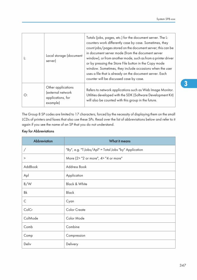
L:Local storage (documentserver)
Totals (jobs, pages, etc.) for the document server. The L:counters work differently case by case. Sometimes, theycount jobs/pages stored on the document server; this can bein document server mode (from the document serverwindow), or from another mode, such as from a printer driveror by pressing the Store File button in the Copy modewindow. Sometimes, they include occasions when the useruses a file that is already on the document server. Eachcounter will be discussed case by case.
O:
Other applications(external networkapplications, forexample)
Refers to network applications such as Web Image Monitor.Utilities developed with the SDK (Software Development Kit)will also be counted with this group in the future.
The Group 8 SP codes are limited to 17 characters, forced by the necessity of displaying them on the smallLCDs of printers and faxes that also use these SPs. Read over the list of abbreviations below and refer to itagain if you see the name of an SP that you do not understand.
Key for Abbreviations
Abbreviation What it means
/ "By", e.g. "T:Jobs/Apl" = Total Jobs "by" Application
> More (2> "2 or more", 4> "4 or more"
AddBook Address Book
Apl Application
B/W Black & White
Bk Black
C Cyan
ColCr Color Create
ColMode Color Mode
Comb Combine
Comp Compression
Deliv Delivery
System SP8-xxx
347
3

Abbreviation What it means
DesAplDesignated Application. The application (Copy, Fax, Scan, Print) used tostore the job on the document server, for example.
Dev Counter Development Count, no. of pages developed.
Dup, Duplex Duplex, printing on both sides
Emul Emulation
FC Full Color
FIN Post-print processing, i.e. finishing (punching, stapling, etc.)
Full Bleed No Margins
GenCopy Generation Copy Mode
GPC
Get Print Counter. For jobs 10 pages or less, this counter does not countup. For jobs larger than 10 pages, this counter counts up by the numberthat is in excess of 10 (e.g., for an 11-page job, the counter counts up11-10 =1)
IFax Internet Fax
ImgEdtImage Edit performed on the original with the copier GUI, e.g. borderremoval, adding stamps, page numbers, etc.
K Black (YMCK)
LS Local Storage. Refers to the document server.
LSize Large (paper) Size
Mag Magnification
MC One color (monochrome)
NRSNew Remote Service, which allows a service center to monitor machinesremotely. "NRS" is used overseas, "CSS" is used in Japan.
Org Original for scanning
OrgJam Original Jam
Palm 2Print Job Manager/Desk Top Editor: A pair of utilities that allows print jobsto be distributed evenly among the printers on the network, and allows filesto moved around, combined, and converted to different formats.
3. Appendix: SP Mode Tables
348
3

Abbreviation What it means
PC Personal Computer
PGSPages. A page is the total scanned surface of the original. Duplex pagescount as two pages, and A3 simplex count as two pages if the A3/DLTcounter SP is switched ON.
PJob Print Jobs
Ppr Paper
PrtJam Printer (plotter) Jam
PrtPGS Print Pages
RRed (Toner Remaining). Applies to the wide format model A2 only. Thismachine is under development and currently not available.
Rez Resolution
SC Service Code (Error SC code displayed)
Scn Scan
Sim, Simplex Simplex, printing on 1 side.
S-to-Email Scan-to-E-mail
SMCSMC report printed with SP5990. All of the Group 8 counters are recordedin the SMC report.
Svr Server
TonEnd Toner End
TonSave Toner Save
TXJob Send, Transmission
YMC Yellow, Magenta, Cyan
YMCK Yellow, Magenta, Cyan, Black
• All of the Group 8 SPs are reset with SP5 801 1 Memory All Clear.
System SP8-xxx
349
3

8 001
T:Total Jobs *CTLThese SPs count the number of times each application is usedto do a job.
[0 to 9999999/ 0 / 1]
Note: The L: counter is the total number of times the otherapplications are used to send a job to the document server,plus the number of times a file already on the document serveris used.
8 002 C:Total Jobs *CTL
8 003 F:Total Jobs *CTL
8 004 P:Total Jobs *CTL
8 005 S:Total Jobs *CTL
8 006 L:Total Jobs *CTL
• These SPs reveal the number of times an application is used, not the number of pages processed.
• When an application is opened for image input or output, this counts as one job.
• Interrupted jobs (paper jams, etc.) are counted, even though they do not finish.
• Only jobs executed by the customer are counted. Jobs executed by the customer engineer using theSP modes are not counted.
• When using secure printing (when a password is required to start the print job), the job is counted atthe time when either "Delete Data" or "Specify Output" is specified.
• A job is counted as a fax job when the job is stored for sending.
• When a fax is received to fax memory, the F: counter increments but the L: counter does not (thedocument server is not used).
• A fax broadcast counts as one job for the F: counter (the fax destinations in the broadcast are notcounted separately).
• A fax broadcast is counted only after all the faxes have been sent to their destinations. If onetransmission generates an error, then the broadcast will not be counted until the transmission has beencompleted.
• A printed fax report counts as one job for the F: counter.
• The F: counter does not distinguish between fax sending or receiving.
• When a copy job on the document server is printed, SP8022 also increments, and when a print jobstored on the document server is printed, SP8024 also increments.
• When an original is both copied and stored on the document server, the C: and L: counters bothincrement.
• When a print job is stored on the document server, only the L: counter increments.
• When the user presses the Document Server button to store the job on the document server, only theL: counter increments.
• When the user enters document server mode and prints data stored on the document server, only theL: counter increments.
3. Appendix: SP Mode Tables
350
3

• When an image received from Palm 2 is received and stored, the L: counter increments.
• When the customer prints a report (user code list, for example), the O: counter increments. However,for fax reports and reports executed from the fax application, the F: counter increments.
8 011 T:Jobs/LS *CTL
These SPs count the number of jobs stored to the documentserver by each application, to reveal how local storage isbeing used for input.
[0 to 9999999/ 0 / 1]
The L: counter counts the number of jobs stored from withinthe document server mode screen at the operation panel.
8 012 C:Jobs/LS *CTL
8 013 F:Jobs/LS *CTL
8 014 P:Jobs/LS *CTL
8 015 S:Jobs/LS *CTL
8 016 L:Jobs/LS *CTL
8 017 O:Jobs/LS *CTL
• When a scan job is sent to the document server, the S: counter increments. When you enter documentserver mode and then scan an original, the L: counter increments.
• When a print job is sent to the document server, the P: counter increments.
• When a network application sends data to the document server, the O: counter increments.
• When an image from Palm 2 is stored on the document server, the O: counter increments.
• When a fax is sent to the document server, the F: counter increments.
8 021 T:Pjob/LS *CTL
These SPs reveal how files printed from the documentserver were stored on the document server originally.
[0 to 9999999/ 0 / 1]
The L: counter counts the number of jobs stored fromwithin the document server mode screen at theoperation panel.
8 022 C:Pjob/LS *CTL
8 023 F:Pjob/LS *CTL
8 024 P:Pjob/LS *CTL
8 025 S:Pjob/LS *CTL
8 026 L:Pjob/LS *CTL
8 027 O:Pjob/LS *CTL
• When a copy job stored on the document server is printed with another application, the C: counterincrements.
• When an application like DeskTopBinder merges a copy job that was stored on the document serverwith a print job that was stored on the document server, the C: and P: counters both increment.
• When a job already on the document server is printed with another application, the L: counterincrements.
System SP8-xxx
351
3

• When a scanner job stored on the document server is printed with another application, the S: counterincrements. If the original was scanned from within document server mode, then the L: counterincrements.
• When images stored on the document server by a network application (including Palm 2), are printedwith another application, the O: counter increments.
• When a copy job stored on the document server is printed with a network application (Web ImageMonitor, for example), the C: counter increments.
• When a fax on the document server is printed, the F: counter increments.
8 031 T:Pjob/DesApl *CTL
These SPs reveal what applications were used to outputdocuments from the document server.
[0 to 9999999/ 0 / 1]
The L: counter counts the number of jobs printed fromwithin the document server mode screen at theoperation panel.
8 032 C:Pjob/DesApl *CTL
8 033 F:Pjob/DesApl *CTL
8 034 P:Pjob/DesApl *CTL
8 035 S:Pjob/DesApl *CTL
8 036 L:Pjob/DesApl *CTL
8 037 O:Pjob/DesApl *CTL
• When documents already stored on the document server are printed, the count for the applicationthat started the print job is incremented.
• When the print job is started from a network application (Desk Top Binder, Web Image Monitor, etc.)the L: counter increments.
8 041 T:TX Jobs/LS *CTL These SPs count the applications that stored files on thedocument server that were later accessed fortransmission over the telephone line or over a network(attached to an e-mail, or as a fax image by I-Fax).
[0 to 9999999/ 0 / 1]
Note: Jobs merged for sending are countedseparately.
The L: counter counts the number of jobs scanned fromwithin the document server mode screen at theoperation panel.
8 042 C:TX Jobs/LS *CTL
8 043 F:TX Jobs/LS *CTL
8 044 P:TX Jobs/LS *CTL
8 045 S:TX Jobs/LS *CTL
8 046 L:TX Jobs/LS *CTL
8 047 O:TX Jobs/LS *CTL
• When a stored copy job is sent from the document server, the C: counter increments.
• When images stored on the document server by a network application or Palm2 are sent as an e-mail, the O: counter increments.
3. Appendix: SP Mode Tables
352
3

8 051 T:TX Jobs/DesApl *CTLThese SPs count the applications used to send filesfrom the document server over the telephone line orover a network (attached to an e-mail, or as a faximage by I-Fax). Jobs merged for sending arecounted separately.
[0 to 9999999/ 0 / 1]The L: counter counts the number of jobs sent fromwithin the document server mode screen at theoperation panel.
8 052 C:TX Jobs/DesApl *CTL
8 053 F:TX Jobs/DesApl *CTL
8 054 P:TX Jobs/DesApl *CTL
8 055 S:TX Jobs/DesApl *CTL
8 056 L:TX Jobs/DesApl *CTL
8 057 O:TX Jobs/DesApl *CTL
• If the send is started from Desk Top Binder or Web Image Monitor, for example, then the O: counterincrements.
8 061
T:FIN Jobs *CTL [0 to 9999999/ 0 / 1]
These SPs total the finishing methods. The finishing method is specified by theapplication.
8 062
C:FIN Jobs *CTL [0 to 9999999/ 0 / 1]
These SPs total finishing methods for copy jobs only. The finishing method is specifiedby the application.
8 063
F:FIN Jobs *CTL [0 to 9999999/ 0 / 1]
These SPs total finishing methods for fax jobs only. The finishing method is specified bythe application.
Note: Finishing features for fax jobs are not available at this time.
8 064
P:FIN Jobs *CTL [0 to 9999999/ 0 / 1]
These SPs total finishing methods for print jobs only. The finishing method is specifiedby the application.
8 065
S:FIN Jobs *CTL [0 to 9999999/ 0 / 1]
These SPs total finishing methods for scan jobs only. The finishing method is specifiedby the application.
Note: Finishing features for scan jobs are not available at this time.
System SP8-xxx
353
3

8 066
L:FIN Jobs *CTL [0 to 9999999/ 0 / 1]
These SPs total finishing methods for jobs output from within the document server modescreen at the operation panel. The finishing method is specified from the print windowwithin document server mode.
8 067
O:FIN Jobs *CTL [0 to 9999999/ 0 / 1]
These SPs total finishing methods for jobs executed by an external application, over thenetwork. The finishing method is specified by the application.
8 06x 1 SortNumber of jobs started in Sort mode. When a stored copy job is set forSort and then stored on the document server, the L: counter increments.(See SP8 066 1)
8 06x 2 Stack Number of jobs started out of Sort mode.
8 06x 3 Staple Number of jobs started in Staple mode.
8 06x 4 BookletNumber of jobs started in Booklet mode. If the machine is in staple mode,the Staple counter also increments.
8 06x 5 Z-FoldNumber of jobs started In any mode other than the Booklet mode and setfor folding (Z-fold).
8 06x 6 PunchNumber of jobs started in Punch mode. When Punch is set for a print job,the P: counter increments. (See SP8 064 6.)
8 06x 7 Other Reserved. Not used.
8 06x 8Inside-
Fold
Number of jobs started In any mode other than the Booklet mode and setfor folding (Inside-fold).
8 06x 9Three-
IN-Fold
Number of jobs started In any mode other than the Booklet mode and setfor folding (Inside-IN-fold).
8 06x 10Three-
OUT-Fold
Number of jobs started In any mode other than the Booklet mode and setfor folding (Inside-OUT-fold).
8 071
T:Jobs/PGS *CTL [0 to 9999999/ 0 / 1]
These SPs count the number of jobs broken down by the number of pages in the job,regardless of which application was used.
3. Appendix: SP Mode Tables
354
3

8 072
C:Jobs/PGS *CTL [0 to 9999999/ 0 / 1]
These SPs count and calculate the number of copy jobs by size based on the numberof pages in the job.
8 073
F:Jobs/PGS *CTL [0 to 9999999/ 0 / 1]
These SPs count and calculate the number of fax jobs by size based on the number ofpages in the job.
8 074
P:Jobs/PGS *CTL [0 to 9999999/ 0 / 1]
These SPs count and calculate the number of print jobs by size based on the number ofpages in the job.
8 075
S:Jobs/PGS [0 to 9999999/ 0 / 1]
These SPs count and calculate the number of scan jobs by size based on the numberof pages in the job.
8 076
L:Jobs/PGS *CTL [0 to 9999999/ 0 / 1]
These SPs count and calculate the number of jobs printed from within the documentserver mode window at the operation panel, by the number of pages in the job.
8 077
O:Jobs/PGS *CTL [0 to 9999999/ 0 / 1]
These SPs count and calculate the number of "Other" application jobs (Web ImageMonitor, Palm 2, etc.) by size based on the number of pages in the job.
8 07x 1 1 Page 8 07x 8 21 to 50 Pages
8 07x 2 2 Pages 8 07x 9 51 to 100 Pages
8 07x 3 3 Pages 8 07x 10 101 to 300 Pages
8 07x 4 4 Pages 8 07x 11 301 to 500 Pages
8 07x 5 5 Pages 8 07x 12 501 to 700 Pages
8 07x 6 6 to 10 Pages 8 07x 13 701 to 1000 Pages
8 07x 7 11 to 20 Pages 8 07x 14 1001 to Pages
• For example: When a copy job stored on the document server is printed in document server mode,the appropriate L: counter (SP8076 0xx) increments.
• Printing a fax report counts as a job and increments the F: counter (SP 8073).
• Interrupted jobs (paper jam, etc.) are counted, even though they do not finish.
System SP8-xxx
355
3

• If a job is paused and re-started, it counts as one job.
• If the finisher runs out of staples during a print and staple job, then the job is counted at the time theerror occurs.
• For copy jobs (SP 8072) and scan jobs (SP 8075), the total is calculated by multiplying the numberof sets of copies by the number of pages scanned. (One duplex page counts as 2.)
• The first test print and subsequent test prints to adjust settings are added to the number of pages of thecopy job (SP 8072).
• When printing the first page of a job from within the document server screen, the page is counted.
8 111
T:FAX TX Jobs *CTL [0 to 9999999/ 0 / 1]
These SPs count the total number of jobs (color or black-and-white) sent by fax, eitherdirectly or using a file stored on the document server, on a telephone line.
Note: Color fax sending is not available at this time.
8 113
F: FAX TX Jobs *CTL [0 to 9999999/ 0 / 1]
These SPs count the total number of jobs (color or black-and-white) sent by fax directlyon a telephone line.
Note: Color fax sending is not available at this time.
8 11x 1 B/W
8 11x 2 Color
• These counters count jobs, not pages.
• This SP counts fax jobs sent over a telephone line with a fax application, including documents storedon the document server.
• If the mode is changed during the job, the job will count with the mode set when the job started.
• If the same document is faxed to both a public fax line and an I-Fax at a destination where both areavailable, then this counter increments, and the I-Fax counter (8 12x) also increments.
• The fax job is counted when the job is scanned for sending, not when the job is sent.
8 121
T:IFAX TX Jobs *CTL [0 to 9999999/ 0 / 1]
These SPs count the total number of jobs (color or black-and-white) sent, either directlyor using a file stored on the document server, as fax images using I-Fax.
Note: Color fax sending is not available at this time.
3. Appendix: SP Mode Tables
356
3

8 123
F: IFAX TX Jobs *CTL [0 to 9999999/ 0 / 1]
These SPs count the number of jobs (color or black-and-white) sent (not stored on thedocument server), as fax images using I-Fax.
Note: Color fax sending is not available at this time.
8 12x 1 B/W
8 12x 2 Color
• These counters count jobs, not pages.
• The counters for color are provided for future use; the color fax feature is not available at this time.
• The fax job is counted when the job is scanned for sending, not when the job is sent.
8 131
T:S-to-Email Jobs *CTL [0 to 9999999/ 0 / 1]
These SPs count the total number of jobs (color or black-and-white) scanned andattached to an e-mail, regardless of whether the document server was used or not.
8 135
S: S-to-Email Jobs *CTL [0 to 9999999/ 0 / 1]
These SPs count the number of jobs (color or black-and-white) scanned and attachedto e-mail, without storing the original on the document server.
8 13x 1 B/W
8 13x 2 Color
8 13x 3 ACS
• These counters count jobs, not pages.
• If the job is stored on the document server, after the job is stored it is determined to be color or black-and-white then counted.
• If the job is cancelled during scanning, or if the job is cancelled while the document is waiting to besent, the job is not counted.
• If the job is cancelled during sending, it may or may not be counted, depending on what stage of theprocess had been reached when the job was cancelled.
• If several jobs are combined for sending to the Scan Router, Scan-to-Email, or Scan-to-PC, or if onejob is sent to more than one destination. each send is counted separately. For example, if the samedocument is sent by Scan-to-Email as well as Scan-to-PC, then it is counted twice (once for Scan-to-Email and once for Scan-to-PC).
System SP8-xxx
357
3

8 141
T:Deliv Jobs/Svr *CTL [0 to 9999999/ 0 / 1]
These SPs count the total number of jobs (color or black-and-white) scanned and sentto a Scan Router server.
8 145
S: Deliv Jobs/Svr *CTL [0 to 9999999/ 0 / 1]
These SPs count the number of jobs (color or black-and-white) scanned in scanner modeand sent to a Scan Router server.
8 14x 1 B/W
8 14x 2 Color
8 14x 3 ACS
• These counters count jobs, not pages.
• The jobs are counted even though the arrival and reception of the jobs at the Scan Router servercannot be confirmed.
• If even one color image is mixed with black-and-white images, then the job is counted as a "Color"job.
• If the job is cancelled during scanning, or if the job is cancelled while the document is waiting to bedelivered, the job is not counted.
• If the job is cancelled during sending, it may or may not be counted, depending on what stage of theprocess had been reached when the job was cancelled.
• Even if several files are combined for sending, the transmission counts as one job.
8 151
T:Deliv Jobs/PC *CTL [0 to 9999999/ 0 / 1]
These SPs count the total number of jobs (color or black-and-white) scanned and sentto a folder on a PC (Scan-to-PC). Note: At the present time, 8 151 and 8 155 perform identical counts.
8 155
S:Deliv Jobs/PC *CTL [0 to 9999999/ 0 / 1]
These SPs count the total number of jobs (color or black-and-white) scanned and sentwith Scan-to-PC.
8 15x 1 B/W
8 15x 2 Color
8 15x 3 ACS
3. Appendix: SP Mode Tables
358
3

• These counters count jobs, not pages.
• If the job is cancelled during scanning, it is not counted.
• If the job is cancelled while it is waiting to be sent, the job is not counted.
• If the job is cancelled during sending, it may or may not be counted, depending on what stage of theprocess had been reached when the job was cancelled.
• Even if several files are combined for sending, the transmission counts as one job.
8 161 T:PCFAX TX Jobs *CTL These SPs count the number of PC Fax transmissionjobs. A job is counted from when it is registered forsending, not when it is sent.
[0 to 9999999/ 0 / 1]
Note: At the present time, these counters performidentical counts.
8 163 F:PCFAX TX Jobs *CTL
• This counts fax jobs started from a PC using a PC fax application, and sending the data out to thedestination from the PC through the copier.
8 171 T:Deliv Jobs/WSD *CTL These SPs count the pages scanned by WS.
[0 to 9999999/ 0 / 1]8 175 S:Deliv Jobs/WSD *CTL
-001 B/W
-002 Color
-003 ACS
8 181 T:Scan to Media Jobs *CTL These SPs count the scanned pages in a media by thescanner application.
[0 to 9999999/ 0 / 1]8 185 S:Scan to Media Jobs *CTL
-001 B/W
-002 Color
-003 ACS
System SP8-xxx
359
3

8 191 T:Total Scan PGS *CTL
These SPs count the pages scanned by eachapplication that uses the scanner to scan images.
[0 to 9999999/ 0 / 1]
8 192 C:Total Scan PGS *CTL
8 193 F:Total Scan PGS *CTL
8 195 S:Total Scan PGS *CTL
8 196 L:Total Scan PGS *CTL
• SP 8 191 to 8 196 count the number of scanned sides of pages, not the number of physical pages.
• These counters do not count reading user stamp data, or reading color charts to adjust color.
• Previews done with a scanner driver are not counted.
• A count is done only after all images of a job have been scanned.
• Scans made in SP mode are not counted.
Examples
• If 3 B5 pages and 1 A3 page are scanned with the scanner application but not stored, the S: countis 4.
• If both sides of 3 A4 sheets are copied and stored to the document server using the Store File buttonin the Copy mode window, the C: count is 6 and the L: count is 6.
• If both sides of 3 A4 sheets are copied but not stored, the C: count is 6.
• If you enter document server mode then scan 6 pages, the L: count is 6.
8 201
T:LSize Scan PGS *CTL [0 to 9999999/ 0 / 1]
These SPs count the total number of large pages input with the scanner for scan andcopy jobs. Large size paper (A3/DLT) scanned for fax transmission are not counted.
Note: These counters are displayed in the SMC Report, and in the User Tools display.
8 203
F: LSize Scan PGS *CTL [0 to 9999999/ 0 / 1]
These SPs count the total number of large pages input with the scanner for faxtransmission.
Note: These counters are displayed in the SMC Report, and in the User Tools display.
8 205
S:LSize Scan PGS *CTL [0 to 9999999/ 0 / 1]
These SPs count the total number of large pages input with the scanner for scan jobsonly. Large size paper (A3/DLT) scanned for fax transmission are not counted.
Note: These counters are displayed in the SMC Report, and in the User Tools display.
3. Appendix: SP Mode Tables
360
3

8 211 T:Scan PGS/LS *CTL These SPs count the number of pages scanned into thedocument server .
[0 to 9999999/ 0 / 1]The L: counter counts the number of pages stored fromwithin the document server mode screen at theoperation panel, and with the Store File button fromwithin the Copy mode screen
8 212 C:Scan PGS/LS *CTL
8 213 F:Scan PGS/LS *CTL
8 215 S:Scan PGS/LS *CTL
8 216 L:Scan PGS/LS *CTL
• Reading user stamp data is not counted.
• If a job is cancelled, the pages output as far as the cancellation are counted.
• If the scanner application scans and stores 3 B5 sheets and 1 A4 sheet, the S: count is 4.
• If pages are copied but not stored on the document server, these counters do not change.
• If both sides of 3 A4 sheets are copied and stored to the document server, the C: count is 6 and theL: count is 6.
• If you enter document server mode then scan 6 pages, the L: count is 6.
8 221
ADF Org Feeds *CTL [0 to 9999999/ 0 / 1]
These SPs count the number of pages fed through the ADF for front and back sidescanning.
8 221 1 Front
Number of front sides fed for scanning:
With an ADF that can scan both sides simultaneously, the Front side count isthe same as the number of pages fed for either simplex or duplex scanning.
With an ADF that cannot scan both sides simultaneously, the Front side countis the same as the number of pages fed for duplex front side scanning. (Thefront side is determined by which side the user loads face up.)
8 221 2 Back
Number of rear sides fed for scanning:
With an ADF that can scan both sides simultaneously, the Back count is thesame as the number of pages fed for duplex scanning.
With an ADF that cannot scan both sides simultaneously, the Back count isthe same as the number of pages fed for duplex rear-side scanning.
• When 1 sheet is fed for duplex scanning the Front count is 1 and the Back count is 1.
• If a jam occurs during the job, recovery processing is not counted to avoid double counting. Also, thepages are not counted if the jam occurs before the first sheet is output.
System SP8-xxx
361
3

8 231
Scan PGS/Mode *CTL [0 to 9999999/ 0 / 1]
These SPs count the number of pages scanned by each ADF mode to determine thework load on the ADF.
8 231 1 Large VolumeSelectable. Large copy jobs that cannot be loaded in theADF at one time.
8 231 2 SADF Selectable. Feeding pages one by one through the ADF.
8 231 3 Mixed Size Selectable. Select "Mixed Sizes" on the operation panel.
8 231 4 Custom Size Selectable. Originals of non-standard size.
8 231 5 PlatenBook mode. Raising the ADF and placing the originaldirectly on the platen.
8 231 6 Mixed 1side/ 2side Simplex and Duplex mode.
• If the scan mode is changed during the job, for example, if the user switches from ADF to Platen mode,the count is done for the last selected mode.
• The user cannot select mixed sizes or non-standard sizes with the fax application so if the original'spage sizes are mixed or non-standard, these are not counted.
• If the user selects "Mixed Sizes" for copying in the platen mode, the Mixed Size count is enabled.
• In the SADF mode if the user copies 1 page in platen mode and then copies 2 pages with SADF, thePlaten count is 1 and the SADF count is 3.
8 241
T:Scan PGS/Org *CTL [0 to 9999999/ 0 / 1]
These SPs count the total number of scanned pages by original type for all jobs,regardless of which application was used.
8 242C:Scan PGS/Org *CTL [0 to 9999999/ 0 / 1]
These SPs count the number of pages scanned by original type for Copy jobs.
8 243F:Scan PGS/Org *CTL [0 to 9999999/ 0 / 1]
These SPs count the number of pages scanned by original type for Fax jobs.
8 245S:Scan PGS/Org *CTL [0 to 9999999/ 0 / 1]
These SPs count the number of pages scanned by original type for Scan jobs.
3. Appendix: SP Mode Tables
362
3

8 246
L:Scan PGS/Org *CTL [0 to 9999999/ 0 / 1]
These SPs count the number of pages scanned and stored from within the documentserver mode screen at the operation panel, and with the Store File button from withinthe Copy mode screen
8 241 8 242 8 243 8 245 8 246
8 24x 1: Text Yes Yes Yes Yes Yes
8 24x 2: Text/Photo Yes Yes Yes Yes Yes
8 24x 3: Photo Yes Yes Yes Yes Yes
8 24x 4: GenCopy, Pale Yes Yes No Yes Yes
8 24x 5: Map Yes Yes No Yes Yes
8 24x 6: Normal/Detail Yes No Yes No No
8 24x 7: Fine/Super Fine Yes No Yes No No
8 24x 8: Binary Yes No No Yes No
8 24x 9: Grayscale Yes No No Yes No
8 24x 10: Color Yes No No Yes No
8 24x 11: Other Yes Yes Yes Yes Yes
• If the scan mode is changed during the job, for example, if the user switches from ADF to Platen mode,the count is done for the last selected mode.
System SP8-xxx
363
3

8 251 T:Scan PGS/ImgEdt *CTL These SPs show how many times Image Edit featureshave been selected at the operation panel for eachapplication. Some examples of these editing featuresare:
• Erase> Border
• Erase> Center
• Image Repeat
• Centering
• Positive/Negative
[0 to 9999999/ 0 / 1]
Note: The count totals the number of times the editfeatures have been used. A detailed breakdown ofexactly which features have been used is not given.
8 252 C:Scan PGS/ImgEdt *CTL
8 255 S:Scan PGS/ImgEdt *CTL
8 256 L:Scan PGS/ImgEdt *CTL
8 257 O:Scan PGS/ImgEdt *CTL
The L: counter counts the number of pages stored from within the document server mode screen at theoperation panel, and with the Store File button from within the Copy mode screen.
8 261 T:Scan PGS/ColCr *CTL -
8 262 C:Scan PGS/ ColCr *CTL -
8 265 S:Scn PGS/Color *CTL -
8 266 L:Scn PGS/ColCr *CTL -
8 26x 1 Color Conversion
These SPs show how many times color creation featureshave been selected at the operation panel.
8 26x 2 Color Erase
8 26x 3 Background
8 26x 4 Other
8 281 T:Scan PGS/TWAIN *CTL These SPs count the number of pages scanned using aTWAIN driver. These counters reveal how the TWAINdriver is used for delivery functions.
[0 to 9999999/ 0 / 1]Note: At the present time, these counters performidentical counts.
8 285 S:Scan PGS/TWAIN *CTL
3. Appendix: SP Mode Tables
364
3

8 291 T:Scan PGS/Stamp *CTL These SPs count the number of pages stamped with thestamp in the ADF unit.
[0 to 9999999/ 0 / 1]The L: counter counts the number of pages stored fromwithin the document server mode screen at theoperation panel, and with the Store File button fromwithin the Copy mode screen
8 293 F:Scan PGS/Stamp *CTL
8 295 S:Scan PGS/Stamp *CTL
8 301
T:Scan PGS/Size *CTL [0 to 9999999/ 0 / 1]
These SPs count by size the total number of pages scanned by all applications. Usethese totals to compare original page size (scanning) and output (printing) page size[SP 8-441].
8 302
C:Scan PGS/Size *CTL [0 to 9999999/ 0 / 1]
These SPs count by size the total number of pages scanned by the Copy application.Use these totals to compare original page size (scanning) and output (printing) pagesize [SP 8-442].
8 303
F:Scan PGS/Size *CTL [0 to 9999999/ 0 / 1]
These SPs count by size the total number of pages scanned by the Fax application. Usethese totals to compare original page size (scanning) and output page size [SP 8-443].
8 305
S:Scan PGS/Size *CTL [0 to 9999999/ 0 / 1]
These SPs count by size the total number of pages scanned by the Scan application.Use these totals to compare original page size (scanning) and output page size [SP8-445].
8 306
L:Scan PGS/Size *CTL [0 to 9999999/ 0 / 1]
These SPs count by size the total number of pages scanned and stored from within thedocument server mode screen at the operation panel, and with the Store File buttonfrom within the Copy mode screen. Use these totals to compare original page size(scanning) and output page size [SP 8-446].
System SP8-xxx
365
3

8 30x 1 A3
-
8 30x 2 A4
8 30x 3 A5
8 30x 4 B4
8 30x 5 B5
8 30x 6 DLT
8 30x 7 LG
8 30x 8 LT
8 30x 9 HLT
8 30x 10 Full Bleed
8 30x 254 Other (Standard)
8 30x 255 Other (Custom)
8 311
T:Scan PGS/Rez *CTL [0 to 9999999/ 0 / 1]
These SPs count by resolution setting the total number of pages scanned by applicationsthat can specify resolution settings.
8 315
S: Scan PGS/Rez *CTL [0 to 9999999/ 0 / 1]
These SPs count by resolution setting the total number of pages scanned by applicationsthat can specify resolution settings.
Note: At the present time, SP8-311 and SP8-315 perform identical counts.
8 31x 1 1200dpi <
8 31x 2 600dpi to 1199dpi
8 31x 3 400dpi to 599dpi
8 31x 4 200dpi to 399dpi
8 31x 5 < 199dpi
• Copy resolution settings are fixed so they are not counted.
• The Fax application does not allow finely-adjusted resolution settings so no count is done for the Faxapplication.
3. Appendix: SP Mode Tables
366
3

8 381 T:Total PrtPGS *CTL
These SPs count the number of pages printed by thecustomer. The counter for the application used forstoring the pages increments.
[0 to 9999999/ 0 / 1]The L: counter counts the number of pages stored fromwithin the document server mode screen at theoperation panel. Pages stored with the Store File buttonfrom within the Copy mode screen go to the C: counter.
8 382 C:Total PrtPGS *CTL
8 383 F:Total PrtPGS *CTL
8 384 P:Total PrtPGS *CTL
8 385 S:Total PrtPGS *CTL
8 386 L:Total PrtPGS *CTL
8 387 O:Total PrtPGS *CTL
• When the A3/DLT double count function is switched on with SP5104, 1 A3/DLT page is counted as2.
• When several documents are merged for a print job, the number of pages stored are counted for theapplication that stored them.
• These counters are used primarily to calculate charges on use of the machine, so the following pagesare not counted as printed pages:
- Blank pages in a duplex printing job.
- Blank pages inserted as document covers, chapter title sheets, and slip sheets.
- Reports printed to confirm counts.
- All reports done in the service mode (service summaries, engine maintenance reports, etc.)
- Test prints for machine image adjustment.
- Error notification reports.
- Partially printed pages as the result of a copier jam.
8 391
LSize PrtPGS *CTL [0 to 9999999/ 0 / 1]
These SPs count pages printed on paper sizes A3/DLT and larger.
Note: In addition to being displayed in the SMC Report, these counters are alsodisplayed in the User Tools display on the copy machine.
System SP8-xxx
367
3

8 401 T:PrtPGS/LS *CTLThese SPs count the number of pages printed from thedocument server. The counter for the application usedto print the pages is incremented.The L: counter counts the number of jobs stored fromwithin the document server mode screen at theoperation panel.
[0 to 9999999/ 0 / 1]
8 402 C:PrtPGS/LS *CTL
8 403 F:PrtPGS/LS *CTL
8 404 P:PrtPGS/LS *CTL
8 405 S:PrtPGS/LS *CTL
8 406 L:PrtPGS/LS *CTL
• Print jobs done with Web Image Monitor and Desk Top Binder are added to the L: count.
• Fax jobs done with Web Image Monitor and Desk Top Binder are added to the F: count.
8 411 Prints/Duplex *CTL
This SP counts the amount of paper (front/backcounted as 1 page) used for duplex printing. Lastpages printed only on one side are not counted.
[0 to 9999999/ 0 / 1]
8 421
T:PrtPGS/Dup Comb *CTL [0 to 9999999/ 0 / 1]
These SPs count by binding and combine, and n-Up settings the number of pagesprocessed for printing. This is the total for all applications.
8 422
C:PrtPGS/Dup Comb *CTL [0 to 9999999/ 0 / 1]
These SPs count by binding and combine, and n-Up settings the number of pagesprocessed for printing by the copier application.
8 423
F:PrtPGS/Dup Comb *CTL [0 to 9999999/ 0 / 1]
These SPs count by binding and combine, and n-Up settings the number of pagesprocessed for printing by the fax application.
8 424
P:PrtPGS/Dup Comb *CTL [0 to 9999999/ 0 / 1]
These SPs count by binding and combine, and n-Up settings the number of pagesprocessed for printing by the printer application.
8 425
S:PrtPGS/Dup Comb *CTL [0 to 9999999/ 0 / 1]
These SPs count by binding and combine, and n-Up settings the number of pagesprocessed for printing by the scanner application.
3. Appendix: SP Mode Tables
368
3

8 426
L:PrtPGS/Dup Comb *CTL [0 to 9999999/ 0 / 1]
These SPs count by binding and combine, and n-Up settings the number of pagesprocessed for printing from within the document server mode window at the operationpanel.
8 427
O:PrtPGS/Dup Comb *CTL [0 to 9999999/ 0 / 1]
These SPs count by binding and combine, and n-Up settings the number of pagesprocessed for printing by Other applications
8 42x 1 Simplex> Duplex
8 42x 2 Duplex> Duplex
8 42x 3 Book> Duplex
8 42x 4 Simplex Combine
8 42x 5 Duplex Combine
8 42x 6 2> 2 pages on 1 side (2-Up)
8 42x 7 4> 4 pages on 1 side (4-Up)
8 42x 8 6> 6 pages on 1 side (6-Up)
8 42x 9 8> 8 pages on 1 side (8-Up)
8 42x 10 9> 9 pages on 1 side (9-Up)
8 42x 11 16> 16 pages on 1 side (16-Up)
8 42x 12 Booklet
8 42x 13 Magazine
• These counts (SP8 421 to SP8 427) are especially useful for customers who need to improve theircompliance with ISO standards for the reduction of paper consumption.
• Pages that are only partially printed with the n-Up functions are counted as 1 page.
• Here is a summary of how the counters work for Booklet and Magazine modes:
Booklet Magazine
Original Pages Count Original Pages Count
1 1 1 1
System SP8-xxx
369
3

2 2 2 2
3 2 3 2
4 2 4 2
5 3 5 4
6 4 6 4
7 4 7 4
8 4 8 4
8 431
T:PrtPGS/ImgEdt *CTL [0 to 9999999/ 0 / 1]
These SPs count the total number of pages output with the three features below,regardless of which application was used.
8 432
C:PrtPGS/ImgEdt *CTL [0 to 9999999/ 0 / 1]
These SPs count the total number of pages output with the three features below with thecopy application.
8 434
P:PrtPGS/ImgEdt *CTL [0 to 9999999/ 0 / 1]
These SPs count the total number of pages output with the three features below with theprint application.
8 436
L:PrtPGS/ImgEdt *CTL [0 to 9999999/ 0 / 1]
These SPs count the total number of pages output from within the document server modewindow at the operation panel with the three features below.
8 437
O:PrtPGS/ImgEdt *CTL [0 to 9999999/ 0 / 1]
These SPs count the total number of pages output with the three features below withOther applications.
8 43x 1 Cover/Slip SheetTotal number of covers or slip sheets inserted. The count for acover printed on both sides counts 2.
8 43x 2 Series/BookThe number of pages printed in series (one side) or printed asa book with booklet right/left pagination.
8 43x 3 User StampThe number of pages printed where stamps were applied,including page numbering and date stamping.
3. Appendix: SP Mode Tables
370
3

8 441T:PrtPGS/Ppr Size *CTL [0 to 9999999/ 0 / 1]
These SPs count by print paper size the number of pages printed by all applications.
8 442
C:PrtPGS/Ppr Size *CTL [0 to 9999999/ 0 / 1]
These SPs count by print paper size the number of pages printed by the copyapplication.
8 443F:PrtPGS/Ppr Size *CTL [0 to 9999999/ 0 / 1]
These SPs count by print paper size the number of pages printed by the fax application.
8 444
P:PrtPGS/Ppr Size *CTL [0 to 9999999/ 0 / 1]
These SPs count by print paper size the number of pages printed by the printerapplication.
8 445
S:PrtPGS/Ppr Size *CTL [0 to 9999999/ 0 / 1]
These SPs count by print paper size the number of pages printed by the scannerapplication.
8 446
L:PrtPGS/Ppr Size *CTL [0 to 9999999/ 0 / 1]
These SPs count by print paper size the number of pages printed from within thedocument server mode window at the operation panel.
8 447O:PrtPGS/Ppr Size *CTL [0 to 9999999/ 0 / 1]
These SPs count by print paper size the number of pages printed by Other applications.
System SP8-xxx
371
3

8 44x 1 A3
8 44x 2 A4
8 44x 3 A5
8 44x 4 B4
8 44x 5 B5
8 44x 6 DLT
8 44x 7 LG
8 44x 8 LT
8 44x 9 HLT
8 44x 10 Full Bleed
8 44x 254 Other (Standard)
8 44x 255 Other (Custom)
• These counters do not distinguish between LEF and SEF.
8 451PrtPGS/Ppr Tray *CTL [0 to 9999999/ 0 / 1]
These SPs count the number of sheets fed from each paper feed station.
8 451 1 Bypass Bypass Tray
8 451 2 Tray 1 Copier
8 451 3 Tray 2 Copier
8 451 4 Tray 3 Paper Tray Unit (Option)
8 451 5 Tray 4 Paper Tray Unit (Option)
8 451 6 Tray 5 LCT (Option)
8 451 7 Tray 6 Currently not used.
8 451 8 Tray 7 Currently not used.
8 451 9 Tray 8 Currently not used.
8 451 10 Tray 9 Currently not used.
3. Appendix: SP Mode Tables
372
3

8 461
T:PrtPGS/Ppr Type *CTL [0 to 9999999/ 0 / 1]
These SPs count by paper type the number pages printed by all applications.
• These counters are not the same as the PM counter. The PM counter is based onfeed timing to accurately measure the service life of the feed rollers. However,these counts are based on output timing.
• Blank sheets (covers, chapter covers, slip sheets) are also counted.
• During duplex printing, pages printed on both sides count as 1, and a page printedon one side counts as 1.
8 462C:PrtPGS/Ppr Type *CTL [0 to 9999999/ 0 / 1]
These SPs count by paper type the number pages printed by the copy application.
8 463F:PrtPGS/Ppr Type *CTL [0 to 9999999/ 0 / 1]
These SPs count by paper type the number pages printed by the fax application.
8 464P:PrtPGS/Ppr Type *CTL [0 to 9999999/ 0 / 1]
These SPs count by paper type the number pages printed by the printer application.
8 466
L:PrtPGS/Ppr Type *CTL [0 to 9999999/ 0 / 1]
These SPs count by paper type the number pages printed from within the documentserver mode window at the operation panel.
8 46x 1 Normal
8 46x 2 Recycled
8 46x 3 Special
8 46x 4 Thick
8 46x 5 Normal (Back)
8 46x 6 Thick (Back)
8 46x 7 OHP
8 46x 8 Other
8 471PrtPGS/Mag *CTL [0 to 9999999/ 0 / 1]
These SPs count by magnification rate the number of pages printed.
System SP8-xxx
373
3

8 471 1 < 49%
8 471 2 50% to 99%
8 471 3 100%
8 471 4 101% to 200%
8 471 5 201% <
• Counts are done for magnification adjusted for pages, not only on the operation panel but performedremotely with an external network application capable of performing magnification adjustment aswell.
• Magnification adjustments done with printer drivers with PC applications such as Excel are alsocounted.
• Magnification adjustments done for adjustments after they have been stored on the document serverare not counted.
• Magnification adjustments performed automatically during Auto Reduce/Enlarge copying arecounted.
• The magnification rates of blank cover sheets, slip sheets, etc. are automatically assigned a rate of100%.
8 481 T:PrtPGS/TonSave *CTL
8 484 P:PrtPGS/TonSave *CTL
These SPs count the number of pages printed with the Toner Save feature switched on.
Note: These SPs return the same results as this SP is limited to the Print application.
[0 to 9999999/ 0 / 1]
8 491 T:PrtPGS/Col Mode *CTL
These SPs count the number of pagesprinted in the Color Mode by eachapplication.
8 492 C:PrtPGS/Col Mode *CTL
8 493 F:PrtPGS/Col Mode *CTL
8 496 L:PrtPGS/Col Mode *CTL
8 497 O:PrtPGS/Col Mode *CTL
8 49x 1 B/W
8 49x 2 Single Color
3. Appendix: SP Mode Tables
374
3

8 49x 3 Two Color
8 49x 4 Full Color
8 501 T:PrtPGS/Col Mode *CTLThese SPs count the number of pagesprinted in the Color Mode by the printapplication.
8 504 P:PrtPGS/Col Mode *CTL
8 057 O:PrtPGS/Col Mode *CTL
8 50x 1 B/W
8 50x 2 Mono Color
8 50x 3 Full Color
8 50x 4 Single Color
8 50x 5 Two Color
8 511T:PrtPGS/Emul *CTL [0 to 9999999/ 0 / 1]
These SPs count by printer emulation mode the total number of pages printed.
8 514P:PrtPGS/Emul *CTL [0 to 9999999/ 0 / 1]
These SPs count by printer emulation mode the total number of pages printed.
System SP8-xxx
375
3

8 514 1 RPCS
8 514 2 RPDL
8 514 3 PS3
8 514 4 R98
8 514 5 R16
8 514 6 GL/GL2
8 514 7 R55
8 514 8 RTIFF
8 514 9 PDF
8 514 10 PCL5e/5c
8 514 11 PCL XL
8 514 12 IPDL-C
8 514 13 BM-Links Japan Only
8 514 14 Other
8 514 15 IPDS
• SP8 511 and SP8 514 return the same results as they are both limited to the Print application.
• Print jobs output to the document server are not counted.
8 521T:PrtPGS/FIN *CTL [0 to 9999999 / 0 / 1]
These SPs count by finishing mode the total number of pages printed by all applications.
8 522
C:PrtPGS/FIN *CTL [0 to 9999999 / 0 / 1]
These SPs count by finishing mode the total number of pages printed by the Copyapplication.
8 523
F:PrtPGS/FIN *CTL [0 to 9999999 / 0 / 1]
These SPs count by finishing mode the total number of pages printed by the Faxapplication.
NOTE: Print finishing options for received faxes are currently not available.
3. Appendix: SP Mode Tables
376
3

8 524
P:PrtPGS/FIN *CTL [0 to 9999999 / 0 / 1]
These SPs count by finishing mode the total number of pages printed by the Printapplication.
8 525
S:PrtPGS/FIN *CTL [0 to 9999999 / 0 / 1]
These SPs count by finishing mode the total number of pages printed by the Scannerapplication.
8 526
L:PrtPGS/FIN *CTL [0 to 9999999 / 0 / 1]
These SPs count by finishing mode the total number of pages printed from within thedocument server mode window at the operation panel.
8 52x 1 Sort
8 52x 2 Stack
8 52x 3 Staple
8 52x 4 Booklet
8 52x 5 Z-Fold
8 52x 6 Punch
8 52x 7 Other
8 52x 8 Inside-Fold
8 52x 9 Three-IN-Fold
8 52x 10 Three-OUT-Fold
8 52x 11 Four-Fold
8 52x 12 KANNON-Fold
8 52x 13 Perfect-Bind
8 52x 14 Ring-Bind
• If stapling is selected for finishing and the stack is too large for stapling, the unstapled pages are stillcounted.
• The counts for staple finishing are based on output to the staple tray, so jam recoveries are counted.
System SP8-xxx
377
3

8 531 Staples *CTLThis SP counts the amount of staples used by the machine.
[0 to 9999999 / 0 / 1]
8 581
T:Counter *CTL [0 to 9999999 / 0 / 1]
These SPs count the total output broken down by color output, regardless of theapplication used. In addition to being displayed in the SMC Report, these counters arealso displayed in the User Tools display on the copy machine.
8 581 1 Total
8 581 2 Total: Full Color
8 581 3 B&W/Single Color
8 581 4 Development: CMY
8 581 5 Development: K
8 581 6 Copy: Color
8 581 7 Copy: B/W
8 581 8 Print: Color
8 581 9 Print: B/W
8 581 10 Total: Color
8 581 11 Total: B/W
8 581 12 Full Color: A3
8 581 13 Full Color: B4 JIS or Smaller
8 581 14 Full Color Print
8 581 15 Mono Color Print
8 581 16 Full Color GPC
8 581 17 Twin Colour Mode Print
8 581 18 Full Colour Print (Twin)
8 581 19 Mono Colour Print (Twin)
8 581 20 Full Colour Total (CV)
3. Appendix: SP Mode Tables
378
3

8 581 21 Mono Colour Total (CV)
8 581 22 Full Colour Print (CV)
8 582 C:Counter *CTL [0 to 9999999/ 0 / 1]
These SPs count the total output of the copy application broken down by color output.
8 582 1 B/W
8 582 2 Single Color
8 582 3 Two Color
8 582 4 Full Color
8 583 F:Counter *CTL [0 to 9999999/ 0 / 1]
These SPs count the total output of the fax application broken down by color output.
8 583 1 B/W
8 583 2 Single Color
8 584 P:Counter *CTL [0 to 9999999/ 0 / 1]
These SPs count the total output of the print application broken down by color output.
8 584 1 B/W
8 584 2 Mono Color
8 584 3 Full Color
8 584 4 Single Color
8 584 5 Two Color
8 586 L:Counter *CTL [0 to 9999999/ 0 / 1]
These SPs count the total output of the local storage broken down by color output.
8 582 1 B/W
8 582 2 Single Color
System SP8-xxx
379
3

8 582 3 Two Color
8 582 4 Full Color
8 591
O:Counter *CTL [0 to 9999999/ 0 / 1]
These SPs count the totals for A3/DLT paper use, number of duplex pages printed, andthe number of staples used. These totals are for Other (O:) applications only.
8 591 1 A3/DLT
8 591 2 Duplex
8 601
Coverage Counter *CTL [0 to 9999999/ 0 / 1]
These SPs count the total coverage for each color and the total printout pages for eachprinting mode.
8 601 1 B/W
8 601 2 Color
8 601 11 B/W Printing Pages
8 601 12 Color Printing Pages
8 601 21 Coverage Counter 1
8 601 22 Coverage Counter 2
8 601 23 Coverage Counter 3
8 617SDK Apli Counter *CTL [0 to 9999999/ 0 / 1]
These SPs count the total printout pages for each SDK applicaion.
8 617 1 SDK-1
-
8 617 2 SDK-2
8 617 3 SDK-3
8 617 4 SDK-4
8 617 5 SDK-5
8 617 6 SDK-6
3. Appendix: SP Mode Tables
380
3

8 631T:FAX TX PGS *CTL [0 to 9999999/ 0 / 1]
These SPs count by color mode the number of pages sent by fax to a telephone number.
8 633F:FAX TX PGS *CTL [0 to 9999999/ 0 / 1]
These SPs count by color mode the number of pages sent by fax to a telephone number.
8 63x 1 B/W
8 63x 2 Color
• If a document has color and black-and-white pages mixed, the pages are counted separately as B/W or Color.
• At the present time, this feature is provided for the Fax application only so SP8631 and SP8633 arethe same.
• The counts include error pages.
• If a document is sent to more than one destination with a Group transmission, the count is done foreach destination.
• Polling transmissions are counted but polling RX are not.
• Relay, memory, and confidential mailbox transmissions and are counted for each destination.
8 641
T:IFAX TX PGS *CTL [0 to 9999999/ 0 / 1]
These SPs count by color mode the number of pages sent by fax to as fax images usingI-Fax.
8 643
F:IFAX TX PGS *CTL [0 to 9999999/ 0 / 1]
These SPs count by color mode the number of pages sent by Fax as fax images usingI-Fax.
8 64x 1 B/W
8 64x 2 Color
• If a document has color and black-and-white pages mixed, the pages are counted separately as B/W or Color.
• At the present time, this feature is provided for the Fax application only so SP8641 and SP8643 arethe same.
• The counts include error pages.
• If a document is sent to more than one destination with a Group transmission, the count is done foreach destination.
System SP8-xxx
381
3

• Polling transmissions are counted but polling RX are not.
• Relay, memory, and confidential mailbox transmissions and are counted for each destination.
8 651
T:S-to-Email PGS *CTL [0 to 9999999/ 0 / 1]
These SPs count by color mode the total number of pages attached to an e-mail for boththe Scan and document server applications.
8 655
S:S-to-Email PGS *CTL [0 to 9999999/ 0 / 1]
These SPs count by color mode the total number of pages attached to an e-mail for theScan application only.
8 65x 1 B/W
8 65x 2 Color
• The count for B/W and Color pages is done after the document is stored on the HDD. If the job iscancelled before it is stored, the pages are not counted.
• If Scan-to-Email is used to send a 10-page document to 5 addresses, the count is 10 (the pages aresent to the same SMTP server together).
• If Scan-to-PC is used to send a 10-page document to 5 folders, the count is 50 (the document is sentto each destination of the SMB/FTP server).
• Due to restrictions on some devices, if Scan-to-Email is used to send a 10-page document to a largenumber of destinations, the count may be divided and counted separately. For example, if a 10-pagedocument is sent to 200 addresses, the count is 10 for the first 100 destinations and the count is also10 for the second 100 destinations, for a total of 20.).
8 661
T:Deliv PGS/Svr *CTL [0 to 9999999/ 0 / 1]
These SPs count by color mode the total number of pages sent to a Scan Router serverby both Scan and LS applications.
8 665
S:Deliv PGS/Svr *CTL [0 to 9999999/ 0 / 1]
These SPs count by color mode the total number of pages sent to a Scan Router serverby the Scan application.
8 66x 1 B/W
8 66x 2 Color
3. Appendix: SP Mode Tables
382
3

• The B/W and Color counts are done after the document is stored on the HDD of the Scan Routerserver.
• If the job is canceled before storage on the Scan Router server finishes, the counts are not done.
• The count is executed even if regardless of confirmation of the arrival at the Scan Router server.
8 671
T:Deliv PGS/PC *CTL [0 to 9999999/ 0 / 1]
These SPs count by color mode the total number of pages sent to a folder on a PC (Scan-to-PC) with the Scan and LS applications.
8 675
S:Deliv PGS/PC *CTL [0 to 9999999/ 0 / 1]
These SPs count by color mode the total number of pages sent with Scan-to-PC with theScan application.
8 67x 1 B/W
8 67x 2 Color
8 681 T:PCFAX TXPGS *CTL These SPs count the number of pages sent by PC Fax.These SPs are provided for the Fax application only,so the counts for SP8 681 and SP8 683 are the same.
[0 to 9999999/ 0 / 1]8 683 F:PCFAX TXPGS *CTL
• This counts pages sent from a PC using a PC fax application, from the PC through the copier to thedestination.
• When sending the same message to more than one place using broadcasting, the pages are onlycounted once. (For example, a 10-page fax is sent to location A and location B. The counter goesup by 10, not 20.)
8 691 T:TX PGS/LS *CTL These SPs count the number of pages sent from thedocument server. The counter for the application thatwas used to store the pages is incremented.
[0 to 9999999/ 0 / 1]The L: counter counts the number of pages stored fromwithin the document server mode screen at theoperation panel. Pages stored with the Store Filebutton from within the Copy mode screen go to the C:counter.
8 692 C:TX PGS/LS *CTL
8 693 F:TX PGS/LS *CTL
8 694 P:TX PGS/LS *CTL
8 695 S:TX PGS/LS *CTL
8 696 L:TX PGS/LS *CTL
System SP8-xxx
383
3

• Print jobs done with Web Image Monitor and Desk Top Binder are added to the count.
• If several documents are merged for sending, the number of pages stored are counted for theapplication that stored them.
• When several documents are sent by a Fax broadcast, the F: count is done for the number of pagessent to each destination.
8 701
TX PGS/Port *CTL [0 to 9999999/ 0 / 1]
These SPs count the number of pages sent by the physical port used to send them. Forexample, if a 3-page original is sent to 4 destinations via ISDN G4, the count for ISDN(G3, G4) is 12.
8 701 1 PSTN-1
8 701 2 PSTN-2
8 701 3 PSTN-3
8 701 4 ISDN (G3,G4)
8 701 5 Network
8 711 T:Scan PGS/Comp *CTL [0 to 9999999/ 0 / 1]
8 715S:Scan PGS/Comp *CTL [0 to 9999999/ 0 / 1]
These SPs count the number of pages sent by each compression mode.
8 715 1 JPEG/JPEG2000
8 715 2 TIFF(Multi/Single)
8 715 3 PDF
8 715 4 Other
8 715 5 PDF/Comp
8 721 T:Deliv PGS/WSD *CTL[0 to 9999999/ 0 / 1]
8 725S: Dvliv PGS/WSD *CTL
These SPs count the number of pages scanned by each scanner mode.
x 1 B/W -
3. Appendix: SP Mode Tables
384
3

x 2 Color -
8 731 T:Scan PGS/Media *CTL[0 to 9999999/ 0 / 1]
8 735
S:Scan PGS/Media *CTL
These SPs count the number of pages scanned and saved in a meia by each scannermode.
x 1 B/W -
x 2 Color -
8 741RX PGS/Port *CTL [0 to 9999999/ 0 / 1]
These SPs count the number of pages received by the physical port used to receive them.
8 741 1 PSTN-1
8 741 2 PSTN-2
8 741 3 PSTN-3
8 741 4 ISDN (G3,G4)
8 741 5 Network
8 771
Dev Counter *CTL [0 to 9999999/ 0 / 1]
These SPs count the frequency of use (number of rotations of the development rollers)for black and other color toners.
8 771 1 Total
8 771 2 K
8 771 3 Y
8 771 4 M
8 771 5 C
System SP8-xxx
385
3

8 781
Toner Bottle Info. *ENG [0 to 9999999/ 0 / 1]
These SPs display the number of already replaced toner bottles.
NOTE: Currently, the data in SP7-833-011 through 014 and the data in SP8-781-001through 004 are the same.
8 781 1 Toner: BK The number of black-toner bottles
8 781 2 Toner: Y The number of yellow-toner bottles
8 781 3 Toner: M The number of magenta-toner bottles
8 781 4 Toner: C The number of cyan-toner bottles
8 791 LS Memory Remain *CTL
This SP displays the percent of space availableon the document server for storing documents.
[0 to 100 / 0 / 1]
8 801
Toner Remain *CTL [0 to 100/ 0 / 1]
These SPs display the percent of toner remaining for each color. This SP allows the userto check the toner supply at any time.
Note: This precise method of measuring remaining toner supply (1% steps) is better thanother machines in the market that can only measure in increments of 10 (10% steps).
8 801 1 K
8 801 2 Y
8 801 3 M
8 801 4 C
8 851
Coverage Count: 0-10% *ENG [0 to 9999999/ 0 / 1]
These SPs display the number of scanned sheets on which the coverage of each coloris from 0% to 10%.
8 851 11 0 to 2%: BK 8 851 31 5 to 7%: BK
8 851 12 0 to 2%: Y 8 851 32 5 to 7%: Y
8 851 13 0 to 2%: M 8 851 33 5 to 7%: M
8 851 14 0 to 2%: C 8 851 34 5 to 7%: C
3. Appendix: SP Mode Tables
386
3

8 851 21 3 to 4%: BK 8 851 41 8 to 10%: BK
8 851 22 3 to 4%: Y 8 851 42 8 to 10%: Y
8 851 23 3 to 4%: M 8 851 43 8 to 10%: M
8 851 24 3 to 4%: C 8 851 44 8 to 10%: C
8 861
Coverage Count: 11-20% *ENG [0 to 9999999/ 0 / 1]
These SPs display the number of scanned sheets on which the coverage of each coloris from 11% to 20%.
8 861 1 BK
8 861 2 Y
8 861 3 M
8 861 4 C
8 871
Coverage Count: 21-30% *ENG [0 to 9999999/ 0 / 1]
These SPs display the number of scanned sheets on which the coverage of each coloris from 21% to 30%.
8 871 1 BK
8 871 2 Y
8 871 3 M
8 871 4 C
8 881
Coverage Count: 31%- *ENG [0 to 9999999/ 0 / 1]
These SPs display the number of scanned sheets on which the coverage of each coloris 31% or higher.
8 881 1 BK
8 881 2 Y
8 881 3 M
8 881 4 C
System SP8-xxx
387
3

8 891Page/Toner Bottle *ENG [0 to 9999999/ 0 / 1]
These SPs display the amount of the remaining current toner for each color.
8 891 1 BK
8 891 2 Y
8 891 3 M
8 891 4 C
8 901Page/Toner_prev1 *ENG [0 to 9999999/ 0 / 1]
These SPs display the amount of the remaining previous toner for each color.
8 901 1 BK
8 901 2 Y
8 901 3 M
8 901 4 C
8 911Page/Toner_prev2 *ENG [0 to 9999999/ 0 / 1]
These SPs display the amount of the remaining 2nd previous toner for each color.
8 911 1 BK
8 911 2 Y
8 911 3 M
8 911 4 C
8 921Coverage Count: Total *CTL [0 to 9999999/ 0 / 1]
Displays the total coverage and total printout number for each color.
3. Appendix: SP Mode Tables
388
3

8 921 1 BK (%)
8 921 2 Y (%)
8 921 3 M (%)
8 921 4 C (%)
8 921 11 Coverage /P: Bk
8 921 12 Coverage /P: Y
8 921 13 Coverage /P: M
8 921 14 Coverage /P: C
8 941
Machine Status *CTL [0 to 9999999/ 0 / 1]
These SPs count the amount of time the machine spends in each operation mode. TheseSPs are useful for customers who need to investigate machine operation forimprovement in their compliance with ISO Standards.
8 941 1 Operation TimeEngine operation time. Does not include time while controlleris saving data to HDD (while engine is not operating).
8 941 2 Standby TimeEngine not operating. Includes time while controller savesdata to HDD. Does not include time spent in Energy Save,Low Power, or Off modes.
8 941 3 Energy Save TimeIncludes time while the machine is performing backgroundprinting.
8 941 4 Low Power TimeIncludes time in Energy Save mode with Engine on. Includestime while machine is performing background printing.
8 941 5 Off Mode TimeIncludes time while machine is performing backgroundprinting. Does not include time machine remains powered offwith the power switches.
8 941 6 SC Total time when SC errors have been staying.
8 941 7 PrtJamTotal time when paper jams have been staying duringprinting.
8 941 8 OrgJamTotal time when original jams have been staying duringscanning.
System SP8-xxx
389
3

8 941 9 Supply PM Unit End Total time when toner end has been staying
8 951AddBook Register *CTL
These SPs count the number of events when the machine manages data registration.
8 951 1 User Code User code registrations.
[0 to 9999999/ 0 / 1]
8 951 2 Mail Address Mail address registrations.
8 951 3 Fax Destination Fax destination registrations.
8 951 4 Group Group destination registrations.
8 951 5 Transfer RequestFax relay destination registrationsfor relay TX.
8 951 6 F-Code F-Code box registrations.
8 951 7 Copy ProgramCopy application registrations withthe Program (job settings) feature.
[0 to 255 / 0 / 255]
8 951 8 Fax ProgramFax application registrations with theProgram (job settings) feature.
8 951 9 Printer ProgramPrinter application registrations withthe Program (job settings) feature.
8 951 10 Scanner ProgramScanner application registrationswith the Program (job settings)feature.
8 999Adomin. Counter List *CTL [0 to 9999999/ 0 / 1]
Displays the total coverage and total printout number for each color.
3. Appendix: SP Mode Tables
390
3

8 999 1 Total
8 999 2 Copy: Full Color
8 999 3 Copy: BW
8 999 4 Copy: Single Color
8 999 5 Copy: Two Color
8 999 6 Printer Full Color
8 999 7 Printer BW
8 999 8 Printer Single Color
8 999 9 Printer Two Color
8 999 10 Fax Print: BW
8 999 12 A3/DLT
8 999 13 Duplex
8 999 14 Coverage: Color (%)
8 999 15 Coverage: BW (%)
8 999 16 Coverage: Color Print Page (%)
8 999 17 Coverage: BW Print Page (%)
8 999 101 Transmission Total: Color
8 999 102 Transmission Total: BW
8 999 103 FAX Transmission
8 999 104 Scanner Transmission: Color
8 999 105 Scanner Transmission: BW
System SP8-xxx
391
3

Input and Output Check
Input Check Table
When entering the Input Check mode, 8 digits display the result for a section. Each digit corresponds to adifferent device as shown in the table.
Bit No. 7 6 5 4 3 2 1 0
Result 0 or 1 0 or 1 0 or 1 0 or 1 0 or 1 0 or 1 0 or 1 0 or 1
Copier
5803 DescriptionReading
0 1
5803 1 2nd Tray Size Detection See table 2 following this table.
5803 2 1st Tray Set Detection Set Not set
5803 3 1st Tray Paper Height Sensor1 See table 1 following this table.
5803 4 1st Tray Paper Height Sensor2 See table 1 following this table.
5803 5 2nd Tray Paper Height Sensor1 See table 1 following this table.
5803 6 2nd Tray Paper Height Sensor2 See table 1 following this table.
5803 7 1st Tray Paper End Detection No paper Paper remaining
5803 8 2nd Tray Paper End Detection No paper Paper remaining
5803 9 1st Tray Upper Limit Sensor Not upper limit Upper limit
5803 10 2nd Tray Upper Limit Sensor Not upper limit Upper limit
5803 11 Bypass Paper Width Detection See table 3 following this table.
5803 12 Bypass Paper End Detection No paper Paper remaining
5803 13 Bypass Paper Length Detection See table 3 following this table.
5803 14 1st Paper Feed Sensor Paper detected Paper not detected
5803 15 2nd Paper Feed Sensor Paper detected Paper not detected
3. Appendix: SP Mode Tables
392
3

5803 16 Exit Sensor Paper detected Paper not detected
5803 17 Tray Full Exit Sensor Paper not full Paper full
5803 18 Fusing Exit Sensor Paper not detected Paper detected
5803 19 Fusing Entrance Sensor Paper detected Paper not detected
5803 20 1st Feed Sensor Paper detected Paper not detected
5803 21 2nd Feed Sensor Paper detected Paper not detected
5803 22 Duplex Exit Sensor Paper detected Paper not detected
5803 23 Registration Sensor Paper detected Paper not detected
5803 24 Duplex Entrance Sensor Paper detected Paper not detected
5803 25 Junction Sensor Paper detected Paper not detected
5803 26 2nd Tray Set Detection Set Not set
5803 30 Toner End Sensor: Bk Toner end Toner remaining
5803 31 Toner End Sensor: M Toner end Toner remaining
5803 32 Toner End Sensor: C Toner end Toner remaining
5803 33 Toner End Sensor: Y Toner end Toner remaining
5803 34 Drum Phase Sensor: BkActuator not
detectedActuator detected
5803 35 Drum Phase Sensor: MActuator not
detectedActuator detected
5803 36 Drum Phase Sensor: CActuator not
detectedActuator detected
5803 37 Drum Phase Sensor: YActuator not
detectedActuator detected
5803 38 Interlock Release Detection 1 Front door open Front door closed
5803 39 Interlock Release Detection 2 Front door open Front door closed
5803 40 Right Door Closed Open
5803 41 Duplex Cover Closed Open
Input and Output Check
393
3

5803 42 Toner Collection Bottle Set Set Not set
5803 43 Toner Collection Full Sensor Not full Full
5803 46 ITB New Unit Detection Not new New
5803 49 Duplex Fan: Lock Normal Lock
5803 50 Airflow Fan: Front: Lock Normal Lock
5803 51 Airflow Fan: Rear: Lock Normal Lock
5803 52 Fusing Exit Fan: Lock Normal Lock
5803 53 2nd Duct Fan: Lock Normal Lock
5803 54 3rd Duct Fan: Lock Normal Lock
5803 55 Paper Exit Fan:Lock Normal Lock
5803 56 Fusing Coil Fan: Lock Normal Lock
5803 57 IH Power Supply Cooling Fan: Lock Normal Lock
5803 58 Airflow Fan: Middle 1: Lock Not used
5803 59 Airflow Fan: Middle 2: Lock Not used
5803 60 ITB Contact Motor Position Not contact Contact
5803 61 Paper Transfer Contact Motor Position Not contact Contact
5803 62 Toner Relay Motor: Lock Normal Lock
5803 63 ITB Drive Motor: Lock Normal Lock
5803 64 K Drum/Development Drive Motor: Lock Normal Lock
5803 65 M Drum/Development Drive Motor: Lock Normal Lock
5803 66 C Drum/Development Drive Motor: Lock Normal Lock
5803 67 Y Drum/Development Drive Motor: Lock Normal Lock
5803 68 Fusing Exit Motor:Lock Normal Lock
5803 80 HVPS:TTS:SC Detection SC detected No SC
5803 81 HVPS:CB:SC Detection SC detected No SC
5803 82 HVPS:D:SC Detection SC detected No SC
3. Appendix: SP Mode Tables
394
3

5803 83 Fusing Destination Detection: DOM (Dom) Set Not set
5803 84 Fusing Destination Detection: NA Set Not set
5803 87 Fusing New Unit Detection New Not new
5803 90 Zero-cross Signal - -
5803 91 Fusing Rotation SensorActuator not
detectedActuator detected
5803 92 Fusing Pressure Release Sensor Not contact Contact
5803 94 GAVD Open/Close DetectionClosed
(LD5V ON)
Open
(LD5V OFF)
5803 100 Keycard: Set Set Not set
5803 101 Mechanical Counter: Set Set Not set
5803 102 Mechanical Counter FC: Set Set Not set
5803 103 Key Counter: Set Set Not set
5803 110 IOB Version - -
5803 200 Scanner HP Sensor Not HP HP
5803 201 Platen Cover Sensor Open Closed
Table 1: Paper Height Sensor
0: Deactivated, 1: Activated (actuator inside sensor)
Remaining paper Paper height sensor 1 Paper height sensor 2
Full 0 0
Nearly full 1 0
Near end 1 1
Almost empty 0 1
Table 2: Paper Size Switch (Tray 2)
Switch 1 is used for tray set detection.
Input and Output Check
395
3

0: Pushed, 1: Not pushed
Models Switch Location
North America Europe/Asia 4 (bit0) 3 (bit1) 2 (bit2)
11" x 17" SEF*1
(A3 SEF)
A3 SEF*1
(11" x 17" SEF)0 0 1
8.5" x 14" SEF*2
(B4 SEF)
B4 SEF*2
(8.5" x 14" SEF)0 0 0
A4 SEF A4 SEF 1 1 0
8.5" x 11" SEF 8.5" x 11" SEF 1 1 1
B5 SEF B5 SEF 0 1 1
11" x 81/2" LEF*3
(A4 LEF)
A4 LEF*3
(11" x 81/2" LEF)1 0 0
10.5" x 7.25" LEF*4
(B5 LEF)
B5 LEF*4
(10.5" x 7.25" LEF)0 1 0
A5 LEF A5 LEF 1 0 1
*1: The machine detects either 11" x 17" SEF or A3 SEF, depending on the setting of SP 5-181-003.
*2: The machine detects either 8.5" x 14" SEF or B4 SEF, depending on the setting of SP 5-181-004.
*3: The machine detects either 11" x 81/2" LEF or A4 LEF, depending on the setting of SP 5-181-002.
*4: The machine detects either B5 LEF or 10.5" x 7.25" LEF, depending on the setting of SP 5-181-005.
ADF (D541)
6007 DescriptionReading
0 1
6007 1 Original Length 1 (B5 Detection Sensor) Paper not detected Paper detected
6007 2 Original Length 2 (A4 Detection Sensor) Paper not detected Paper detected
6007 3 Original Length 3 (LG Detection Sensor) Paper not detected Paper detected
6007 4 Original Width S Paper not detected Paper detected
3. Appendix: SP Mode Tables
396
3

6007 5 Original Width M Paper not detected Paper detected
6007 6 Original Width L Paper not detected Paper detected
6007 7 Original Width LL Paper not detected Paper detected
6007 9 Original Detection Paper not detected Paper detected
6007 10 Rear Edge Detection Paper not detected Paper detected
6007 11 Skew Correction Paper not detected Paper detected
6007 13 Registration Sensor Paper not detected Paper detected
6007 14 Exit Sensor Paper not detected Paper detected
6007 15 Feed Cover ADF cover close ADF cover open
6007 16 Lift Up ADF cover close ADF cover open
1000-Sheet Booklet Finisher (B793)
6138 DescriptionReading
0 1
6138 1Interference Escape Sensor
(Stapler Safety Sensor)Not interfered Interfered
6138 2Staple Moving HP Sensor
(Staple Unit HP Sensor)Not home position Home position
6138 3Stuck Relay1 Release HP Sensor (StopperS HP Sensor)
Not home position Home position
6138 4Exit Junction Gate HP Sensor
(Stack Feed Out HP Sensor)Home position Not home position
6138 5Jogger HP Sensor
(Jogger Fence HP Sensor)Not home position Home position
6138 6Staple Tray Paper Sensor
(Staple Tray Paper Sensor)Paper not detected Paper detected
Input and Output Check
397
3

6138 DescriptionReading
0 1
6138 7Rear Edge Fence HP Sensor
(Paper Stack Stopper HP Sensor)Not home position Home position
6138 8 Saddle Stitch Exit Sensor Paper detected Paper not detected
6138 9Stuck Relay2 Roller HP Sensor
(Clamp Roller HP Sensor)Home position Not home position
6138 10Folder Tray Full Sensor 1
(Bottom Tray HP 1 Sensor)Full Not full
6138 11Folder Tray Full Sensor 2
(Bottom Tray HP 2 Sensor)Not full Full
6138 12Folder Plate HP Sensor
(Fold Plate HP Sensor)Not home position Home position
6138 13Saddle Stitch Arrival Sensor
(Fold Unit Entrance Sensor)Paper not detected Paper detected
6138 14Folder Cam HP Sensor
(Fold Plate Cam HP Sensor)Not home position Home position
6138 15Staple Exit Sensor
(Stapler Tray Exit Sensor)Paper detected Paper not detected
6138 16Shift Tray Paper Sensor
(Shift Tray Paper Position Sensor)Shift tray not detected Shift tray detected
6138 17 Shift Tray Full Full Nor full
6138 18 Shift Roller HP Sensor Not home position Home position
6138 20Entrance Sensor
(Finisher Entrance Sensor)Paper detected Paper not detected
6138 21Shift Exit Sensor
(Shift Tray Exit Sensor)Paper not detected Paper detected
3. Appendix: SP Mode Tables
398
3

6138 DescriptionReading
0 1
6138 22Proof Exit Sensor
(Proof Tray Exit Sensor)Paper detected Paper not detected
6138 23 Exit Guide Plate HP Sensor Not home position Home position
6138 24Proof Full Sensor
(Proof Tray Full Sensor)Not full Full
6138 25 Upper Cover Sensor Open Close
6138 26Door SW
(Front Door Switch)Close Open
6138 27 Clincher Timing Sensor Encoder
6138 28 Clincher HP Sensor Home position Not home position
6138 29 Driver Timing Sensor Encoder
6138 30 Staple Near End Staple remaining Staple near end
6138 31 Self Priming Staple detected Staple not detected
6138 32 Driver HP Sensor Home position Not home position
6138 33 Punch Registration Detection HP Sensor Not home position Home position
6138 34Punch Moving HP Sensor
(Punch Movement HP Sensor)Not home position Home position
6138 35Punch HP Sensor
(Punch HP Sensor)Home position Not home position
6138 36Punch Pulse Count Sensor
(Punch Encoder Sensor)Encoder
6138 37Punch Chad Full Sensor
(Punch Hopper Full Sensor)Not full Full
6138 38Punch Registration Detection Sensor
(Paper Position Sensor)Paper detected Paper not detected
Input and Output Check
399
3

1000-Sheet Finisher (B408)
6139 Bit DescriptionReading
0 1
6139 1 Entrance Sensor Paper detected Paper not detected
6139 2Shift Exit Sensor
(Lower Tray Exit Sensor)Paper not detected Paper detected
6139 3Staple Entrance Sensor
(Stapler Tray Entrance Sensor)Paper detected Paper not detected
6139 4Staple Moving HP Sensor
(Stapler HP Sensor)Not home position Home position
6139 5Jogger HP Sensor
(Jogger Fence HP Sensor)Not home position Home position
6139 6 Stack Feed-out Belt HP Sensor Home position Not home position
6139 7 Staple Tray Paper Sensor Paper not detected Paper detected
6139 8Staple Rotation Sensor
(Staple Rotation HP Sensor)Not home position Home position
6139 9 Staple Sensor Staple detected Staple not detected
6139 10 Staple READY Detection Staple detected Staple not detected
6139 11Exit Guide Plate HP
(Exit Guide Plate HP Sensor)Not home position Home position
6139 12 Shift HP Sensor Not home position Home position
6139 13Paper Sensor
(Stack Height Sensor)
Output tray notdetected
Output traydetected
6139 14Tray Lower Sensor
(Lower Tray Lower Limit Sensor)Lower limit Not lower limit
6139 15Proof Full Sensor
(Paper Limit Sensor)Not full Full
3. Appendix: SP Mode Tables
400
3

500-Sheet Finisher (D372)
6145 DescriptionReading
0 1
6145 1 Entrance Sensor Paper detected Paper not detected
6145 2 Hitroll HP Sensor Paper not detected Paper detected
6145 3Front Jogger HP Sensor
(Front Jogger Fence HP Sensor)Home position Not home position
6145 4Rear Jogger HP Sensor
(Rear Jogger Fence HP Sensor)Home position Not home position
6145 5 Staple Tray Paper Sensor Paper detected Paper not detected
6145 6 Staple Moving HP Sensor Not HP HP
6145 7 Stack Feed-out Belt HP Not HP HP
6145 8 Shift Tray Paper Sensor Paper detected Paper not detected
6145 9 Upper Cover Sensor HP Not HP
6145 10 Staple Rotation Sensor HP Not HP
6145 11 Staple Near End HP Not HP
6145 12 Self Priming HP Not HP
6145 13 Shift Tray Limit Sensor Not full Full
Bridge Unit (D386)/ Side Tray (D542)
6150 DescriptionReading
0 1
6150 1 Bridge/Left: Exit Sensor Paper detected Paper not detected
6150 2 Bridge/Left: Feed Sensor Paper detected Paper not detected
6150 3 Bridge/Left: Shift Set Detection Set Not set
6150 4 Bridge/Left: Exit Cover Detection Closed Open
Input and Output Check
401
3

6150 5 Bridge/Left: Feed Cover Detection Closed Open
6150 6 Left/Left Exit Sensor Paper detected Paper not detected
Internal Shift Tray (D388)
6152 DescriptionReading
0 1
6152 1 Shift:Set Sensor Set Not Set
6152 2 Shift: Position Sensor Tray position: front Tray position: rear
1 Bin Tray (D536)
6154 DescriptionReading
0 1
6154 1 1 bin: Set Sensor Set Not Set
6154 2 1 bin: Paper Sensor Paper detected Paper not detected
One or Two-Tray PFU (D387/D537)/ LCIT 2000 (D538)/ LCIT 1200 (D539)
6160 DescriptionReading
0 1
6160 1 Bank: Tray3: Feed Sensor Paper not detected Paper detected
6160 2 Bank: Tray4: Feed Sensor Paper not detected Paper detected
6160 3 Bank: Tray5: Feed Sensor Paper not detected Paper detected
6160 4 Bank: Tray3: Relay Sensor Paper not detected Paper detected
6160 5 Bank: Tray4: Relay Sensor Paper not detected Paper detected
6160 6 Bank: Tray5: Relay Sensor Paper not detected Paper detected
6160 7 Bank: Feed Cover Detection Closed Open
3. Appendix: SP Mode Tables
402
3

6160 11 Bank: Palau: Paper Supply Switch Closed Open
6160 12 Bank: Palau: Slide Switch Closed Open
Output Check Table
Copier
5804 Display Description
5804 3 Drum/Dev Motor: K: HighSpeed Drum/Development Drive Motor-K: HighSpeed
5804 4 Drum/Dev Motor: K: MiddleSpeedDrum/Development Drive Motor-K: MiddleSpeed
5804 5 Drum/Dev Motor: K: LowSpeed Drum/Development Drive Motor-M: Low Speed
5804 10 Drum/Dev Motor: M: HighSpeedDrum/Development Drive Motor- C:HighSpeed
5804 11 Drum/Dev Motor: M: MiddleSpeedDrum/Development Drive Motor-Y: MiddleSpeed
5804 12 Drum/Dev Motor: M: LowSpeed Drum/Development Drive Motor-Y: Low Speed
5804 17 Drum/Dev Motor: C: HighSpeedDrum/Development Drive Motor- C:HighSpeed
5804 18 Drum/Dev Motor: C: MiddleSpeedDrum/Development Drive Motor-Y: MiddleSpeed
5804 19 Drum/Dev Motor: C: LowSpeed Drum/Development Drive Motor-Y: Low Speed
5804 24 Drum/Dev Motor: Y: HighSpeedDrum/Development Drive Motor- C:HighSpeed
5804 25 Drum/Dev Motor: Y: MiddleSpeedDrum/Development Drive Motor-Y: MiddleSpeed
5804 26 Drum/Dev Motor: Y: LowSpeed Drum/Development Drive Motor-Y: Low Speed
5804 31 Fusing Exit Motor: HighSpeed Fusing/Paper Exit Motor: HighSpeed
5804 32 Fusing Exit Motor: MiddleSpeed Fusing/Paper Exit Motor: Middle Speed
Input and Output Check
403
3
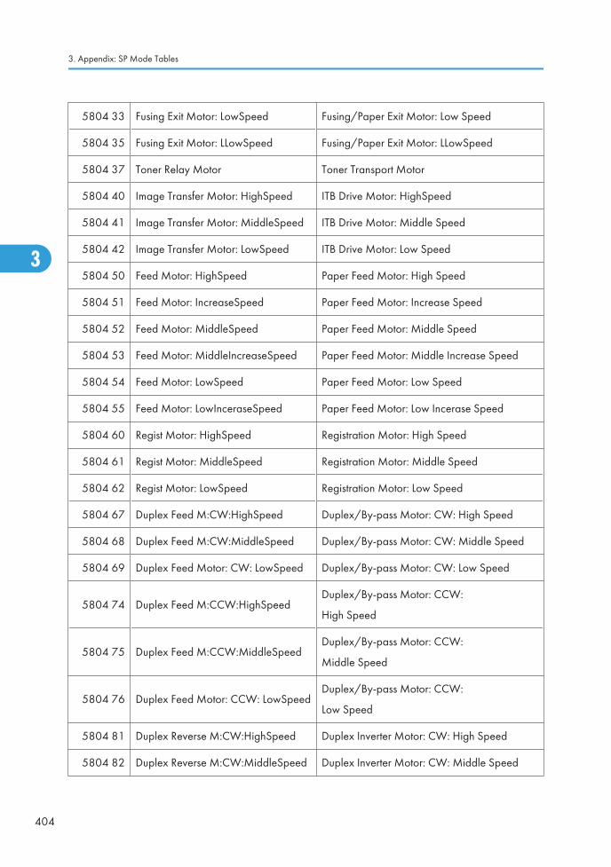
5804 33 Fusing Exit Motor: LowSpeed Fusing/Paper Exit Motor: Low Speed
5804 35 Fusing Exit Motor: LLowSpeed Fusing/Paper Exit Motor: LLowSpeed
5804 37 Toner Relay Motor Toner Transport Motor
5804 40 Image Transfer Motor: HighSpeed ITB Drive Motor: HighSpeed
5804 41 Image Transfer Motor: MiddleSpeed ITB Drive Motor: Middle Speed
5804 42 Image Transfer Motor: LowSpeed ITB Drive Motor: Low Speed
5804 50 Feed Motor: HighSpeed Paper Feed Motor: High Speed
5804 51 Feed Motor: IncreaseSpeed Paper Feed Motor: Increase Speed
5804 52 Feed Motor: MiddleSpeed Paper Feed Motor: Middle Speed
5804 53 Feed Motor: MiddleIncreaseSpeed Paper Feed Motor: Middle Increase Speed
5804 54 Feed Motor: LowSpeed Paper Feed Motor: Low Speed
5804 55 Feed Motor: LowInceraseSpeed Paper Feed Motor: Low Incerase Speed
5804 60 Regist Motor: HighSpeed Registration Motor: High Speed
5804 61 Regist Motor: MiddleSpeed Registration Motor: Middle Speed
5804 62 Regist Motor: LowSpeed Registration Motor: Low Speed
5804 67 Duplex Feed M:CW:HighSpeed Duplex/By-pass Motor: CW: High Speed
5804 68 Duplex Feed M:CW:MiddleSpeed Duplex/By-pass Motor: CW: Middle Speed
5804 69 Duplex Feed Motor: CW: LowSpeed Duplex/By-pass Motor: CW: Low Speed
5804 74 Duplex Feed M:CCW:HighSpeedDuplex/By-pass Motor: CCW:
High Speed
5804 75 Duplex Feed M:CCW:MiddleSpeedDuplex/By-pass Motor: CCW:
Middle Speed
5804 76 Duplex Feed Motor: CCW: LowSpeedDuplex/By-pass Motor: CCW:
Low Speed
5804 81 Duplex Reverse M:CW:HighSpeed Duplex Inverter Motor: CW: High Speed
5804 82 Duplex Reverse M:CW:MiddleSpeed Duplex Inverter Motor: CW: Middle Speed
3. Appendix: SP Mode Tables
404
3

5804 83Duplex Reverse Motor: CW:LowSpeed
Duplex Inverter Motor: CW: Low Speed
5804 88 Duplex Reverse M:CCW:HighSpeedDuplex Inverter Motor: CCW:
High Speed
5804 89Duplex ReverseM:CCW:MiddleSpeed
Duplex Inverter Motor: CCW:
Middle Speed
5804 90Duplex Reverse Motor: CCW:LowSpeed
Duplex Inverter Motor: CCW:
Low Speed
5804 95 ITB Contact Motor Image Transfer Belt Contact Motor
5804 96 Paper Transfer Contact Motor Paper Transfer Contact Motor
5804 97 1st Tray Lift Motor: Up Tray Lift Motor 1: Lift Up
5804 98 1st Tray Lift Motor: Down Tray Lift Motor 1: Lift Down
5804 99 2nd Tray Lift Motor: Up Tray Lift Motor 2: Lift Up
5804 100 2nd Tray Lift Motor: Down Tray Lift Motor 2: Lift Down
5804 102 Fusing Pressue Release Motor Pressure Roller Contact Motor
5804 104 Polygon Moter: LL Polygon Motor: LL
5804 105 Polygon Moter: L Polygon Motor: L
5804 107 Polygon Moter: HH Polygon Motor: HH
5804 110 Air Flow Fan: Front Ventilation Fan – Front
5804 111 Air Flow Fan:Rear Ventilation Fan – Rear
5804 112 Fusing Fan:H Fusing Fan: High Speed
5804 113 Fusing Fan:L Fusing Fan: Low Speed
5804 114 PSU Cooling Fan PSU Fan 1: High Speed
5804 115 2nd Duct Fan: H Duct Fan 2: High Speed
5804 117 3rd Duct Fan: H Duct Fan 3: High Speed
5804 119 Paper Exit Fan:H Paper Exit Fan: High Speed
5804 121 Fusing Coil Fan IH Coil Fan
Input and Output Check
405
3

5804 122 IH Power Supply Cooling Fan IH Inverter Fan
5804 126 Development Clutch: Bk Development Clutch-K
5804 127 Development Clutch: M Development Clutch-M
5804 128 Development Clutch: C Development Clutch-C
5804 129 Development Clutch: Y Development Clutch-Y
5804 130 Toner Bottle Clutch: Bk Toner Bottle Clutch-K
5804 131 Toner Bottle Clutch: M Toner Bottle Clutch-M
5804 132 Toner Bottle Clutch: C Toner Bottle Clutch-C
5804 133 Toner Bottle Clutch:Y Toner Bottle Clutch-Y
5804 134 Toner Supply Pump: Bk Toner Supply Clutch: Bk
5804 135 Toner Supply Pump: M Toner Supply Clutch: M
5804 136 Toner Supply Pump: C Toner Supply Clutch: C
5804 137 Toner Supply Pump: Y Toner Supply Clutch: Y
5804 138 1st Paper Feed Clutch Paper Feed Clutch 1
5804 139 2nd Paper Feed Clutch Paper Feed Clutch 2
5804 140 Bypass Feed Clutch By-pass Feed Clutch
5804 141 Bypass Pickup Solenoid Bypass Pickup Solenoid
5804 143 TD Sensor Shutter Solenoid ID Sensor Shutter Solenoid
5804 144 Exit Junction Solenoid Junction Gate 1 Solenoid
5804 145 1st Feed Pickup Solenoid 1st Pickup Solenoid
5804 146 2nd Feed Pickup Solenoid 2nd Pickup Solenoid
5804 150 Duplex Fan: HighSpeed
5804 151 Duplex Fan: LowSpeed
5804 152 Air Flow Fan: Middle 1
5804 153 Reserve Fan1: LowSpeed
5804 154 Air Flow Fan: Middle 2
3. Appendix: SP Mode Tables
406
3

5804 155 Reserve Fan2: LowSpeed
5804 161 PCL: Bk
5804 162 PCL: M
5804 163 PCL: C
5804 164 PCL: Y
5804 166 HST Sensor:Bk TD Sensor:Bk
5804 167 HST Sensor: M TD Sensor: M
5804 168 HST Sensor: C TD Sensor: C
5804 169 HST Sensor: Y TD Sensor: Y
5804 170 Toner End Sensor: Bk Toner End Sensor: Bk
5804 171 Toner End Sensor: M Toner End Sensor: M
5804 172 Toner End Sensor: C Toner End Sensor: C
5804 173 Toner End Sensor: Y Toner End Sensor: Y
5804 174 TM Sensor: Front ID Sensor: Front
5804 175 TM Sensor: Center ID Sensor: Center
5804 176 TM Sensor: Rear ID Sensor: Rear
5804 177 TM Sensor: M ID Sensor: M
5804 178 TM Sensor: C ID Sensor: C
5804 179 TM Sensor: Y ID Sensor: Y
5804 181 PP:Charge AC:Y:HighSpeed -
5804 182 PP:Charge AC:Y:MiddleSpeed -
5804 183 PP:Charge AC:Y:LowSpeed -
5804 186 PP:Development:K -
5804 187 PP:Development:M -
5804 188 PP:Development:C -
5804 189 PP:Development:Y -
Input and Output Check
407
3

5804 190 PP:Separation -
5804 192 RFID ON/OFF: K -
5804 193 RFID ON/OFF: Y -
5804 194 RFID ON/OFF: C -
5804 195 RFID ON/OFF: M -
5804 196 RFID COM ON:K -
5804 197 RFID COM ON: Y -
5804 198 RFID COM ON: C -
5804 199 RFID COM ON: M -
5804 202 Scanner Lamp -
5804 216 LD1: K -
5804 217 LD2: K -
5804 218 LD1: Ma -
5804 219 LD2: Ma -
5804 220 LD1: Cy -
5804 221 LD2: Cy -
5804 222 LD1: Ye -
5804 223 LD2: Ye -
5804 224 PP:ITB:K PP: Image Transfer Roller: K
5804 225 PP:ITB:M PP: Image Transfer Roller: M
5804 226 PP:ITB:C PP: Image Transfer Roller: C
5804 227 PP:ITB:Y PP: Image Transfer Roller: Y
5804 228 PP:PTR:+ PP: Paper Transfer Roller:+
5804 229 PP:PTR:- PP: Paper Transfer Roller:-
5804 231 PP: ChargeDC: K -
5804 232 PP: ChargeDC: M -
3. Appendix: SP Mode Tables
408
3

5804 233 PP: ChargeDC: C -
5804 234 PP: ChargeDC: Y -
5804 237 PP:Charge AC:K:HighSpeed -
5804 238 PP:Charge AC:K:MiddleSpeed -
5804 239 HVPS: ChargeAC: K: LowSpeed -
5804 244 PP:Charge AC:M:HighSpeed -
5804 245 PP:Charge AC:M:MiddleSpeed -
5804 246 HVPS: ChargeAC: M: LowSpeed -
5804 251 PP:Charge AC:C:HighSpeed -
5804 252 PP:Charge AC:C:MiddleSpeed -
5804 253 HVPS: ChargeAC: C: LowSpeed -
ARDF (D541)
6008 Display Description
6008 3 Feed Motor Forward Feed Motor-Forward rotation
6008 4 Feed Motor Reverse Feed Motor-Reverse rotation
6008 5 Relay Motor Forward Transport Motor- Forward rotation
6008 6 Relay Motor Reverse Transport Motor- Forward rotation
6008 9 Feed Clutch -
6008 10 Feed Solenoid Pick-up Solenoid
6008 11 Inverter Solenoid -
6008 12 Stamp Stamp Solenoid
1000-Sheet Booklet Finisher (B793)
6143 Display Description
Input and Output Check
409
3

6143 1 Shift Motor Shift Tray Motor
6143 2 Entrance Motor -
6143 3 Staple Relay Motor Stapler Unit Motor
6143 4 Knock Solenoid
6143 5 Junction Gate SOL 1 Proof Tray Gate Solenoid
6143 6 Junction Gate SOL 2 Staple Tray Gate Solenoid
6143 7 Folder Roller Rotation Motor Fold Roller Motor
6143 8 Staple Motor Staple Fold Motor
6143 10 Exit Guide Plate Motor -
6143 11 Shift Relay Motor Upper Transport Motor
6143 12 Tray Motor Shift Tray Motor
6143 13 Stack Feed-out Motor Positioning Roller Solenoid
6143 14 Stuck Relay1 Motor Upper Clamp Roller Motor
6143 15 Stuck Relay1 Release Motor Upper Retraction Motor
6143 16 Rear Edge Fence Drive Motor Bottom Fence Lift Motor
6143 17 Folder Plate Motor -
6143 18 Drive Roller Oscillating Motor Lower Retraction Motor
6143 19 Staple Moving Motor Staple Unit Driver Motor
6143 20 Jogger Motor Jogger Motor
6143 21 Punch Registration Moving Motor Paper Position Sensor Slide Motor
6143 22 Punch Motor -
6143 23 Punch Moving Motor Punch Movement Motor
1000-Sheet Finisher (B408)
6144 Display Description
3. Appendix: SP Mode Tables
410
3

6144 1 Relay Up Motor Upper Transport Motor
6144 2 Relay Down Motor Lower Transport Motor
6144 3 Exit Motor -
6144 4 Proof Junction Gate SOL Tray Junction Gate Solenoid
6144 5 Tray Up Motor Lower Tray Lift Motor
6144 6 Jogger Motor Jogger Fence Motor
6144 7 Staple Moving Motor Stapler Motor
6144 8 Staple Motor Stapler Hammer
6144 9 Staple Junction Gate SOL Stapler Junction Gate Solenoid
6144 10 Positioning Roller Solenoid Positioning Roller Solenoid
6144 11 Stack Feed-out Motor -
6144 12 Shift Motor -
6144 13 Exit Guide Plate Motor -
500-Sheet Finisher (D372)
6146 Display Description
6146 1 Carry Motor Transport Motor
6146 2 Hitroll Motor Positioning Roller Arm Motor
6146 3 Front Jogger Motor Front Fence Motor
6146 4 Rear Jogger Motor Rear Fence Motor
6146 5 Staple Moving Motor Stapler Movement Motor
6146 6 Stack Feed-out Motor Feed-Out Belt Motor
6146 7 Tray Motor Tray Lift Motor
6146 8 Staple Motor Stapler Motor
6146 9 Stopper Solenoid Stack Depressor Solenoid
Input and Output Check
411
3

Bridge Unit (D386)/ Side Tray (D542)
6151 Display Description
6151 1Bridge/Left: Feed Motor: CurrentSelection
Bridge: Feed Motor: Current switching signal
6151 2 Bridge/Left: Feed Motor:Reset Bridge: Feed Motor:Reset
6151 3 Bridge/Left: Feed Motor:Enable Bridge: Feed Motor:Enable
6151 6 Bridge/Left: Feed Motor: High Speed Bridge: Feed Motor: High Speed
6151 7Bridge/Left: Feed Motor: MiddleSpeed
Bridge: Feed Motor: Middle Speed
6151 8 Bridge/Left: Feed Motor: Low Speed Bridge: Feed Motor: Low Speed
6151 11 Bridge/Left: Junction Solenoid Bridge: Junction Solenoid
Shift Tray (D388)
6153 Display Description
6153 1 Shift: Lift-up Motor -
1 Bin Tray (D414)
6155 Display Description
6155 1 1 bin: Junction Solenoid -
One or Two-Tray PFU (D387/D537)/ LCIT 2000 (D538)/ LCIT 1200 (D539)
6161 Display Description
6161 7 Bank1: Feed Motor:242mm/sFeed Motor:242mm/s
(D537/ D538)
6161 17 Bank2: Feed Motor:242mm/s Feed Motor:242mm/s (D539)
6161 21 Bank2: Feed Motor:154mm/s Feed Motor:154mm/s (D539)
3. Appendix: SP Mode Tables
412
3

6161 30 Bank:Tray3: PU Solenoid Pick-up Solenoid (D537/D538 or D387)
6161 31 Bank:Tray4: PU Solenoid Pick-up Solenoid (D537/D539)
6161 32 Bank:Tray5: PU Solenoid Pick-up Solenoid (D539)
6161 35 Bank:Tray3: Feed Clutch Pick-up Solenoid (D537/D538 or D387)
6161 36 Bank:Tray4: Feed Clutch Pick-up Solenoid (D537/D539)
6161 37 Bank:Tray5: Feed Clutch Pick-up Solenoid (D539)
Input and Output Check
413
3

Printer Service Mode
SP1-XXX (Service Mode)
1001 Bit Switch
001 Bit Switch 1 0 1
bit 0 DFU - -
bit 1 DFU - -
bit 2 DFU - -
bit 3 No I/O Timeout 0: Disable 1: Enable
Enable: The MFP I/O Timeout setting will have no effect. I/O Timeouts will never occur.
bit 4 SD Card Save Mode 0: Disable 1: Enable
Enable: Print jobs will be saved to an SD Card in the GW SD slot (* "Card SaveFunction" in the System Maintenance Reference of the Field Service Manual).
bit 5 DFU - -
bit 6 DFU - -
bit 7 [RPCS,PCL]: Printable area frame border 0: Disable 1: Enable
Enable: The machine prints all RPCS and PCL jobs with a border on the edges of theprintable area.
1001 Bit Switch
3. Appendix: SP Mode Tables
414
3

002 Bit Switch 2 0 1
bit 0 DFU - -
bit 1 DFU - -
bit 2 Applying a collation Type Shift Collate Normal Collate
A collation type (shift or normal) will be applied to all jobs that do not already have a‘Collate Type’ configured.
• If #5-0 is enabled, this Bit Switch has no effect.
bit 3 [PCL5e/c,PS]: PDL Auto Switching 0: Enable 1: Disable
Disable: The MFPs ability to change the PDL processor mid-job.
Some host systems submit jobs that contain both PS and PCL5e/c. If Auto PDL switchingis disabled, these jobs will not be printed properly.
bit 4 DFU - -
bit 5 DFU - -
bit 6 DFU - -
bit 7 DFU - -
1001 Bit Switch
Printer Service Mode
415
3
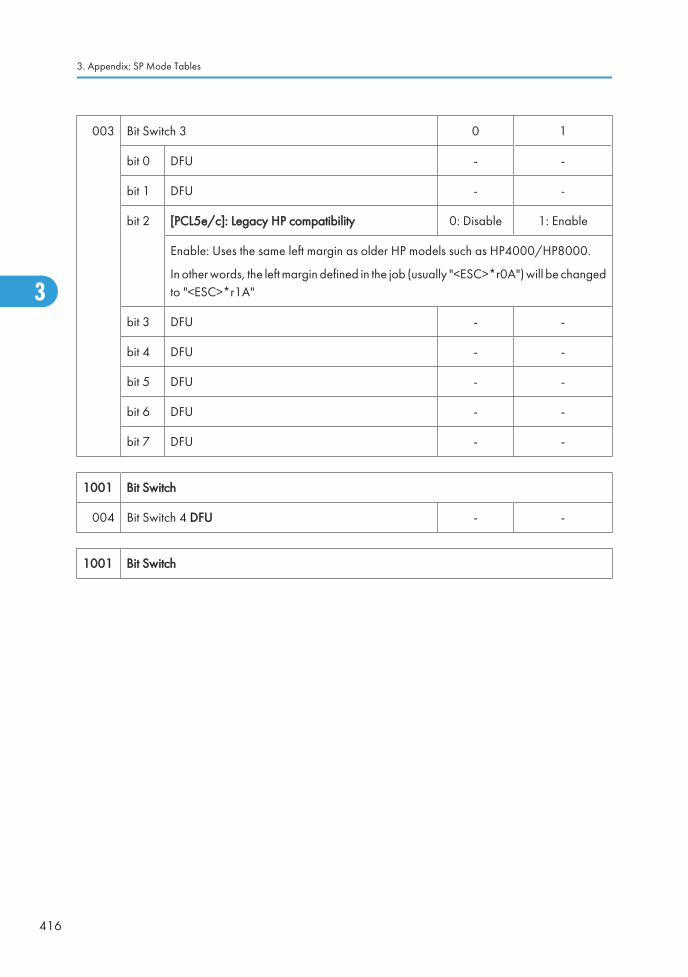
003 Bit Switch 3 0 1
bit 0 DFU - -
bit 1 DFU - -
bit 2 [PCL5e/c]: Legacy HP compatibility 0: Disable 1: Enable
Enable: Uses the same left margin as older HP models such as HP4000/HP8000.
In other words, the left margin defined in the job (usually "<ESC>*r0A") will be changedto "<ESC>*r1A"
bit 3 DFU - -
bit 4 DFU - -
bit 5 DFU - -
bit 6 DFU - -
bit 7 DFU - -
1001 Bit Switch
004 Bit Switch 4 DFU - -
1001 Bit Switch
3. Appendix: SP Mode Tables
416
3

005 Bit Switch 5 0 1
bit 0
Show "Collate Type", "Staple Type" and "PunchType" buttons on the operation panel.
Disable Enable
If enabled, users will be able to configure a Collate Type, Staple Type, and Punch Typefrom the operation panel. The available types will depend on the device and configuredoptions.
After enabling the function, the settings will appear under:
"User Tools > Printer Features > System"
bit 1 DFU - -
bit 2 DFU - -
bit 3 [PS] PS Criteria Pattern3 Pattern1
Change the number of PS criterion used by the PS interpreter to determine whether ajob is PS data or not.
Pattern3: includes most PS commands.
Pattern1: A small number of PS tags and headers
bit 4 Increase max number of the stored jobs to 1000jobs.
Disable(100)
Enable (1000)
Enable: Changes the maximum number of jobs that can be stored on the HDD via JobType settings to 1000. The default is 100.
bit 5 Face-up output Disable Enable
Enable: All print jobs will be output face-up in the destination tray.
bit 6 DFU - -
bit 7 DFU - -
1001 Bit Switch
006 Bit Switch 6 DFU - -
1001 Bit Switch
007 Bit Switch 7 DFU - -
Printer Service Mode
417
3

1001 Bit Switch
008 Bit Switch 8 0 1
bit 0 DFU - -
bit 1 DFU - -
bit 2 DFU - -
bit 3 [PCL,PS]: Allow BW jobs to print without requiringUser Code
Disable Enable
Enable: BW jobs submitted without a user code will be printed even if usercodeauthentication is enabled.
• Color jobs will not be printed without a valid user code.
bit 4 DFU - -
bit 5 DFU - -
bit 6 [PS]: Orientation Auto Detect Function Enable Disable
Disable: Automatically chooses page orientations of PostScript jobs (Landscape orPortrait) based on the content printed on the page.
bit 7 [PDF]: Orientation Auto Detect Function Enable Disable
Automatically chooses page orientations of PDF jobs (Landscape or Portrait) based onthe content printed on the page.
1003 [Clear Setting]
1003 1Initialize Printer System
Initializes settings in the "System" menu of the user mode.
1003 3 Delete Program
1004 [Print Summary]
1004 1Print Summary
Prints the service summary sheet (a summary of all the controller settings).
3. Appendix: SP Mode Tables
418
3

1005 [Display Version]
1005 1Disp. Version
Displays the version of the controller firmware.
1006 [Sample/Locked Print] *CTL 0: Linked, 1: On
1006 1Enables and disables the document server. When you select "0," the document server isenabled or disabled in accordance with Copy Service Mode SP5-967. When you select"1," the document server is enabled regardless of Copy Service Mode SP5-967.
1101
[Data Recall]
Recalls a set of gamma settings. This can be either a) the factory setting, b) the previoussetting, or c) the current setting.
1101 1 Factory
*CTL1101 2 Previous
1101 3 Current
1101 4 ACC
1102[Resolution Setting]
Selects the printing mode (resolution) for the printer gamma adjustment.
1102 12400x600 Photo, 1800x600 Photo, 600 x 600 Photo, 2400x600 Text, 1800x600, Text,600x600 Text
1103[Test Page]
Prints the test page to check the color balance before and after the gamma adjustment.
1103 1 Color Gray Scale
1103 2 Color Pattern
1104[Gamma Adjustment]
Adjusts the printer gamma for the mode selected in the "Mode Selection" menu.
Printer Service Mode
419
3

1104 1 Black: Highlight
*CTL [0 to 30 / 15 / 1/step ]
1104 2 Black: Shadow
1104 3 Black: Middle
1104 4 Black: IDmax
1104 21 Cyan: Highlight
1104 22 Cyan: Shadow
1104 23 Cyan: Middle
1104 24 Cyan: IDmax
1104 41 Magenta: Highlight
1104 42 Magenta: Shadow
1104 43 Magenta: Middle
1104 44 Magenta: IDmax
1104 61 Yellow: Highlight
1104 62 Yellow: Shadow
1104 63 Yellow: Middle
1104 64 Yellow: IDmax
1105
[Save Tone Control Value]
Stores the print gamma adjusted with the "Gamma Adj." menu item as the current setting.Before the machine stores the new "current setting", it moves the data currently stored as the"current setting" to the "previous setting" memory storage location.
1105 1 Save Tone Control Value
1106[Toner Limit]
Adjusts the maximum toner amount for image development.
1106 1 Toner Limit Value *CTL [100 to 400 / 260 / 1 %/step ]
3. Appendix: SP Mode Tables
420
3

Scanner SP Mode
SP1-xxx (System and Others)
1004[Compression Type]
Selects the compression type for binary picture processing.
1004 1 Compression Type *CTL[1 to 3 / 1 / 1/step ]
1: MH, 2: MR, 3: MMR
1005
[Erase margin]
Creates an erase margin for all edges of the scanned image.
If the machine has scanned the edge of the original, create a margin. This SP is activatedonly when the machine uses TWAIN scanning.
1005 1 Range from 0 to 5 mm *CTL [0 to 5 / 0 / 1 mm/step ]
1009 [Remote scan disable] *CTL[0 or 1 / 0 / - ]
0: enable, 1: disable
1009 1 Enable or disable remote scan.
1010 [Non Display Clear Light PDF] *CTL[0 or 1 / 0 / - ]
0: Display, 1: No display
1010 1 Enable or disable remote scan.
SP2-XXX (Scanning-image quality)
2021
[Compression Level (Gray-scale)]
Selects the compression ratio for grayscale processing mode (JPEG) for the three settings thatcan be selected at the operation panel.
Scanner SP Mode
421
3

2021 1 Level 3 (Middle Image Quality)
*CTL
[5 to 95 / 40 / 1 /step ]
2021 2 Level 2 (High Image Quality) [5 to 95 / 50 / 1 /step ]
2021 3 Level 4 (Low Image Quality) [5 to 95 / 30 / 1 /step ]
2021 4 Level 1 (Highest Image Quality) [5 to 95 / 60 / 1 /step ]
2021 5 Level 5 (Lowest Image Quality) [5 to 95 / 20 / 1 /step ]
2024
[Compression ratio of ClearLight PDF]
Selects the compression ratio for clearlight PDF for the two settings that can be selected atthe operation panel.
2024 1 Compression Ratio (Normal image)*CTL
[5 to 95 / 25 / 1 /step ]
2024 2 Compression Ratio (High comp image) [5 to 95 / 20 / 1 /step ]
3. Appendix: SP Mode Tables
422
3

Test Pattern PrintingPrinting Test pattern: SP2-109
Some of these test patterns are used for copy image adjustments but most are used primarily for designtesting.
• Do not operate the machine until the test pattern is printed out completely. Otherwise, an SC occurs.
1. Enter the SP mode and select SP2-109-003.
2. Enter the number for the test pattern that you want to print and press [#].
3. When you want to select the single color of Magenta, Yellow or Cyan for printing a test pattern, selectthe color with SP2-109-005 (2: Magenta, 3: Yellow, 4: Cyan).
4. When you want to change the density of printing a test pattern, select the density with SP2-109-006to -009 for each color.
• If you select "0" with SP2-109-006 to -009, the color to be adjusted to "0" does not come upon a test pattern.
5. When you are prompted to confirm your selection, touch "Yes" to select the test pattern for printing.
6. Touch "Copy Window" to open the copy window, then select the settings for the test print (paper sizeetc.).
• If you want to use black and white printing, touch "Black & White" on the LCD. If you want touse color printing, touch "Full Colour" on the LCD.
7. Press the "Start" key to start the test print.
8. After checking the test pattern, touch "SP Mode" on the LCD to return to the SP mode display.
9. Reset all settings to the default values.
10. Touch "Exit" twice to exit SP mode.
No. Pattern No. Pattern
0 None 11 Independent Pattern (1-dot)
1 Vertial Line (1dot) 12 Independent Pattern (2-dot)
2 Vertial Line (2dot) 13 Independent Pattern (4-dot)
3 Horizontal Line (1dot) 14 Triming Area
4 Horizontal Line (2dot) 16 Tooth Check (Horizontal)
Test Pattern Printing
423
3

5 Grid Vertical Line 17 Band (Horizontal)
6 Grid Horizontal Line 18 Band (Vertical)
7 Grid Pattern Small 19 Checker Flag Pattern
8 Grid Pattern Large 20 Grayscale (Vertical Margin)
9 Argyle Pattern Small 21 Grayscale (Horizontal Margin)
10 Argyle Pattern Large 23 Full Dot Pattern
3. Appendix: SP Mode Tables
424
3
Copyright © 2022 FDOKUMEN

