


Bahasa
Halaman
Hukum

CPU Serial Mode (C1.1)
Datasheet
aPR33A3
Integrated Circuits Inc. aPR33A3
FEATURES
Operating Voltage Range: 3V ~ 6.5V
Single Chip, High Quality Audio/Voice Recording & Playback Solution
No External ICs Required
Minimum External Components
User Friendly, Easy to Use Operation
Programming & Development Systems Not Required
No Battery Backup Required
External Reset pin.
Powerful Power Management Unit
Very Low Standby Current: 1uA
Low Power-Down Current: 15uA
Supports Power-Down Mode for Power Saving
Built-in Audio-Recording Microphone Amplifier
No External OPAMP or BJT Required
Easy to PCB layout
Configurable analog interface
Differential-ended MIC pre-amp for Low Noise
High Quality Line Receiver
High Quality Analog to Digital and PWM module
Resolution up to 16-bits
Up To Maximum 1024 Voice Sections controlled through 5 pins only
Built-in Memory-Management System
Integrated Circuits Inc. aPR33A3
170/ 340/ 680 sec. Voice Recording Length in aPR33A3
Powerful 16-Bits Digital Audio Processor.
Nonvolatile Flash Memory Technology
DESCRIPTION
Today’s consumers demand the best in audio/voice. They want crystal-clear sound wherever they
are in whatever format they want to use. APLUS delivers the technology to enhance a listener’s
audio/voice experience.
The aPR33A series are powerful audio processor along with high performance audio
analog-to-digital converters (ADCs) and digital-to-analog converters (DACs). The aPR33A series
are a fully integrated solution offering high performance and unparalleled integration with analog
input, digital processing and analog output functionality. The aPR33A series incorporates all the
functionality required to perform demanding audio/voice applications. High quality audio/voice
systems with lower bill-of-material costs can be implemented with the aPR33A series because of its
integrated analog data converters and full suite of quality-enhancing features such as sample-rate
convertor.
The aPR33A series C1.X is specially designed for simple CPU interface, user can record or
playback up to 1024 voices by 5 I/Os only. This mode built in one complete memory-management
system. The control side doesn’t need to be burdened complicated memory distribution problems
and it only needs to be through a simple instruction to proceed the audio/voice recording & playback
so it largely shorten the developing time. Meanwhile, Chip provides the power-management system
too. Users can let the chip enter power-down mode when unused. It can effectively reduce electric
current consuming to 15uA and increase the using time in any projects powered by batteries.
Integrated Circuits Inc. aPR33A3
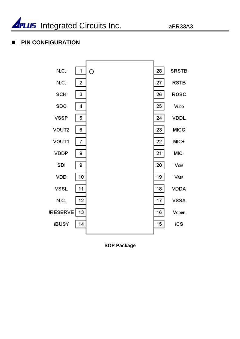
PIN CONFIGURATION
SOP Package
Integrated Circuits Inc. aPR33A3
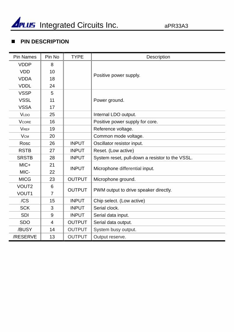
PIN DESCRIPTION
Pin Names Pin No TYPE Description
VDDP
VDD
VDDA
VDDL
8
10
18
24
Positive power supply.
VSSP
VSSL
VSSA
5
11
17
Power ground.
VLDO 25 Internal LDO output.
VCORE 16 Positive power supply for core.
VREF 19 Reference voltage.
VCM 20 Common mode voltage.
Rosc 26 INPUT Oscillator resistor input.
RSTB 27 INPUT Reset. (Low active)
SRSTB 28 INPUT System reset, pull-down a resistor to the VSSL.
MIC+
MIC-
21
22 INPUT Microphone differential input.
MICG 23 OUTPUT Microphone ground.
VOUT2
VOUT1
6
7 OUTPUT PWM output to drive speaker directly.
/CS 15 INPUT Chip select. (Low active)
SCK 3 INPUT Serial clock.
SDI 9 INPUT Serial data input.
SDO 4 OUTPUT Serial data output.
/BUSY 14 OUTPUT System busy output.
/RESERVE 13 OUTPUT Output reserve.
Integrated Circuits Inc. aPR33A3
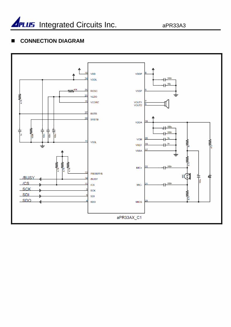
CONNECTION DIAGRAM
Integrated Circuits Inc. aPR33A3
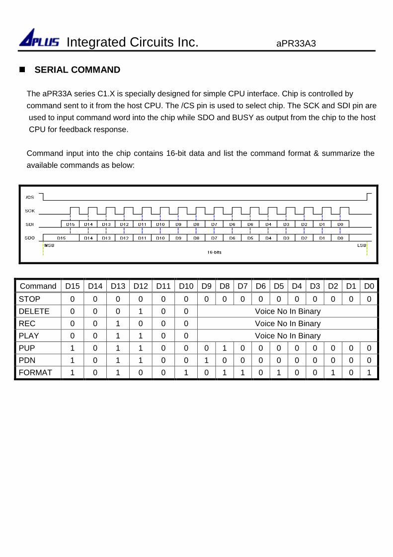
SERIAL COMMAND
Command D15 D14 D13 D12 D11 D10 D9 D8 D7 D6 D5 D4 D3 D2 D1 D0
STOP 0 0 0 0 0 0 0 0 0 0 0 0 0 0 0 0
DELETE 0 0 0 1 0 0 Voice No In Binary
REC 0 0 1 0 0 0 Voice No In Binary
PLAY 0 0 1 1 0 0 Voice No In Binary
PUP 1 0 1 1 0 0 0 1 0 0 0 0 0 0 0 0
PDN 1 0 1 1 0 0 1 0 0 0 0 0 0 0 0 0
FORMAT 1 0 1 0 0 1 0 1 1 0 1 0 0 1 0 1
Integrated Circuits Inc. aPR33A3
The aPR33A series C1.X is specially designed for simple CPU interface. Chip is controlled by
command sent to it from the host CPU. The /CS pin is used to select chip. The SCK and SDI pin are
used to input command word into the chip while SDO and BUSY as output from the chip to the host
CPU for feedback response.
Command input into the chip contains 16-bit data and list the command format & summarize the
available commands as below:
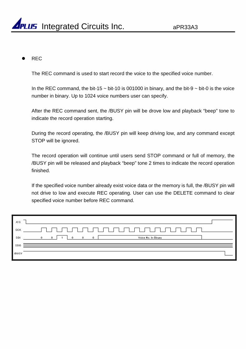
REC
The REC command is used to start record the voice to the specified voice number.
In the REC command, the bit-15 ~ bit-10 is 001000 in binary, and the bit-9 ~ bit-0 is the voice
number in binary. Up to 1024 voice numbers user can specify.
After the REC command sent, the /BUSY pin will be drove low and playback “beep” tone to
indicate the record operation starting.
During the record operating, the /BUSY pin will keep driving low, and any command except
STOP will be ignored.
The record operation will continue until users send STOP command or full of memory, the
/BUSY pin will be released and playback “beep” tone 2 times to indicate the record operation
finished.
If the specified voice number already exist voice data or the memory is full, the /BUSY pin will
not drive to low and execute REC operating. User can use the DELETE command to clear
specified voice number before REC command.
Integrated Circuits Inc. aPR33A3
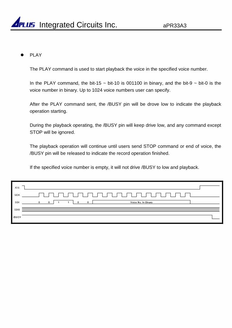
PLAY
The PLAY command is used to start playback the voice in the specified voice number.
In the PLAY command, the bit-15 ~ bit-10 is 001100 in binary, and the bit-9 ~ bit-0 is the
voice number in binary. Up to 1024 voice numbers user can specify.
After the PLAY command sent, the /BUSY pin will be drove low to indicate the playback
operation starting.
During the playback operating, the /BUSY pin will keep drive low, and any command except
STOP will be ignored.
The playback operation will continue until users send STOP command or end of voice, the
/BUSY pin will be released to indicate the record operation finished.
If the specified voice number is empty, it will not drive /BUSY to low and playback.
Integrated Circuits Inc. aPR33A3
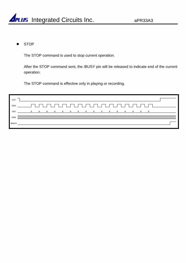
STOP
The STOP command is used to stop current operation.
After the STOP command sent, the /BUSY pin will be released to indicate end of the current
operation.
The STOP command is effective only in playing or recording.
Integrated Circuits Inc. aPR33A3
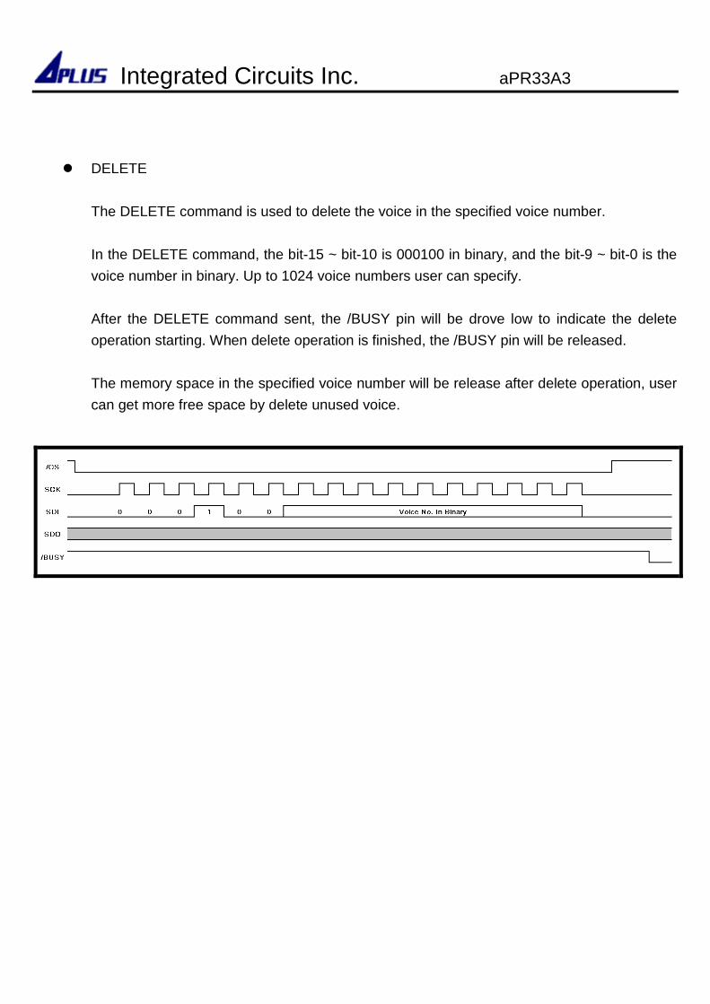
DELETE
The DELETE command is used to delete the voice in the specified voice number.
In the DELETE command, the bit-15 ~ bit-10 is 000100 in binary, and the bit-9 ~ bit-0 is the
voice number in binary. Up to 1024 voice numbers user can specify.
After the DELETE command sent, the /BUSY pin will be drove low to indicate the delete
operation starting. When delete operation is finished, the /BUSY pin will be released.
The memory space in the specified voice number will be release after delete operation, user
can get more free space by delete unused voice.
Integrated Circuits Inc. aPR33A3

PDN
The PDN command is used to enter the power-down mode.
After the PDN command sent, the /BUSY pin will be drove low to indicate the power-down
operation starting. When chip is in the power-down mode, the /BUSY pin will be released.
During chip in the sleep mode, the current consumption is reduced to IPDN and any command
except PUP will be ignored.
PUP
The PUP command is used to power up from sleep mode.
After the PUP command sent, the /BUSY pin will be drove low to indicate the power up
operation starting. When chip is in the idle mode, the /BUSY pin will be released. User can
execute REC, PLAY or DELETE, or other command in idle mode.
Integrated Circuits Inc. aPR33A3
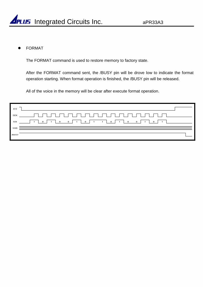
FORMAT
The FORMAT command is used to restore memory to factory state.
After the FORMAT command sent, the /BUSY pin will be drove low to indicate the format
operation starting. When format operation is finished, the /BUSY pin will be released.
All of the voice in the memory will be clear after execute format operation.
Integrated Circuits Inc. aPR33A3
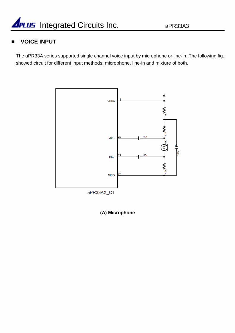
VOICE INPUT
The aPR33A series supported single channel voice input by microphone or line-in. The following fig.
showed circuit for different input methods: microphone, line-in and mixture of both.
(A) Microphone
Integrated Circuits Inc. aPR33A3
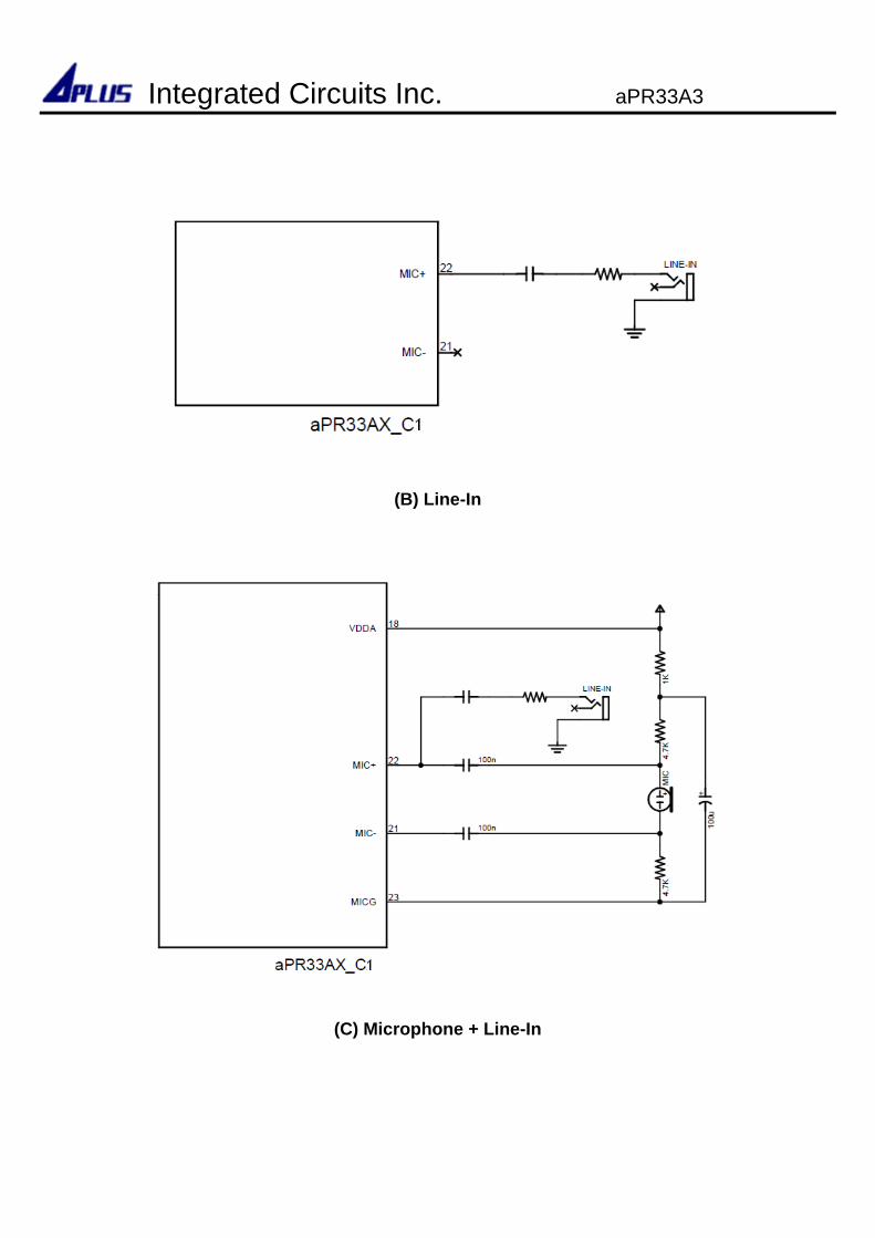
(B) Line-In
(C) Microphone + Line-In
Integrated Circuits Inc. aPR33A3
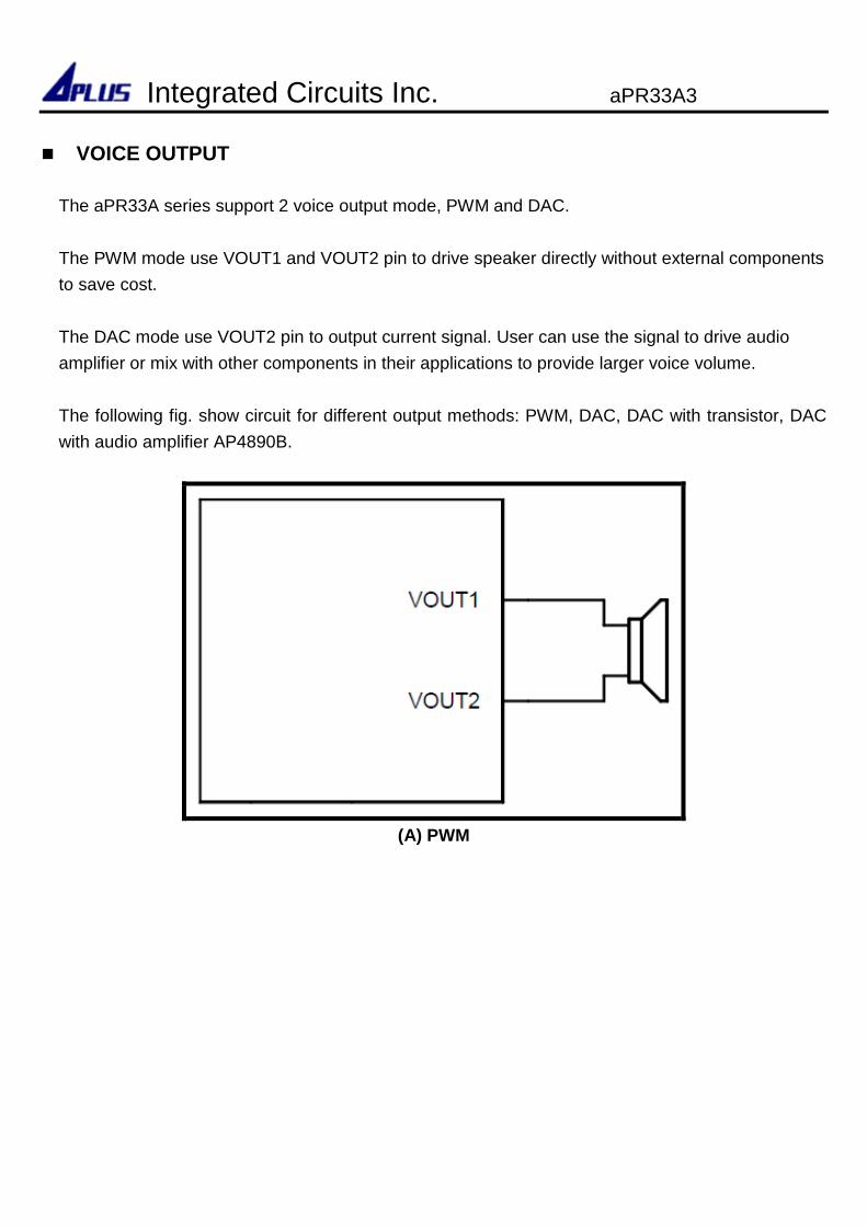
VOICE OUTPUT
The aPR33A series support 2 voice output mode, PWM and DAC.
The PWM mode use VOUT1 and VOUT2 pin to drive speaker directly without external components
to save cost.
The DAC mode use VOUT2 pin to output current signal. User can use the signal to drive audio
amplifier or mix with other components in their applications to provide larger voice volume.
The following fig. show circuit for different output methods: PWM, DAC, DAC with transistor, DAC
with audio amplifier AP4890B.
(A) PWM
Integrated Circuits Inc. aPR33A3
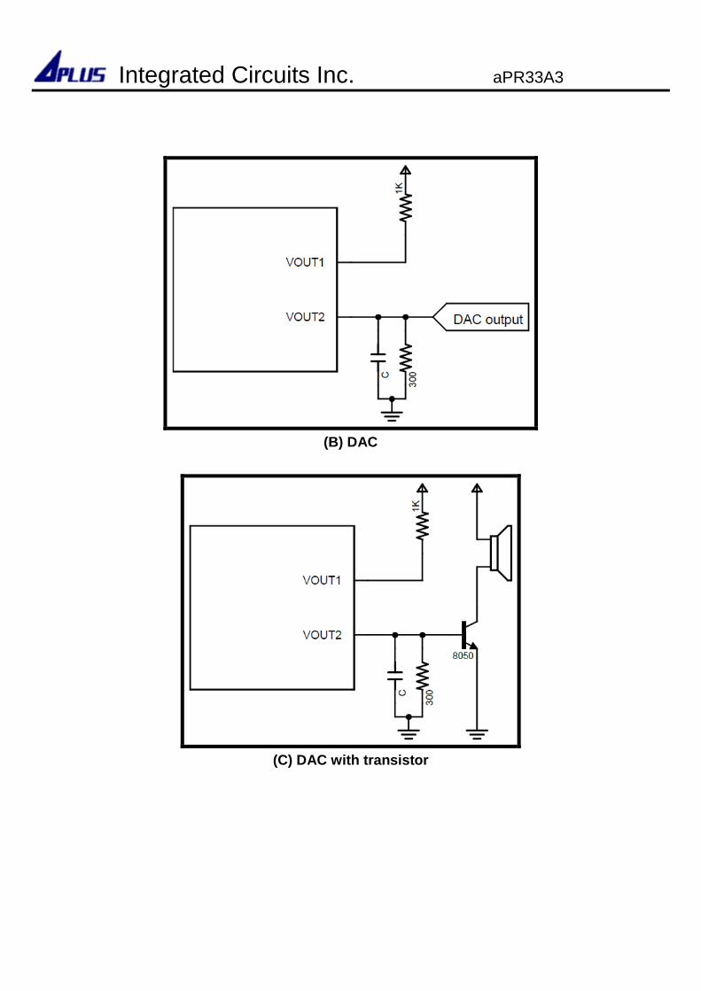
(B) DAC
(C) DAC with transistor
Integrated Circuits Inc. aPR33A3
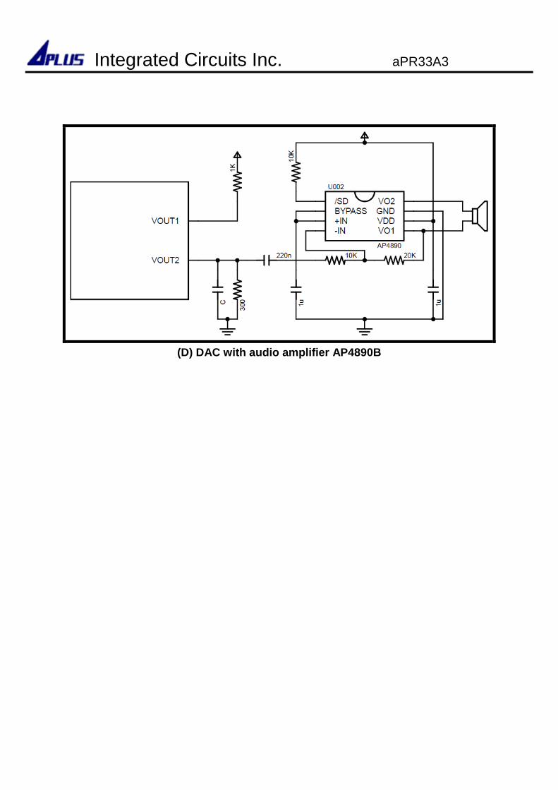
(D) DAC with audio amplifier AP4890B
Integrated Circuits Inc. aPR33A3
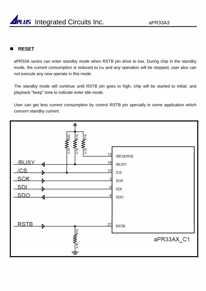
RESET
aPR33A series can enter standby mode when RSTB pin drive to low. During chip in the standby
mode, the current consumption is reduced to ISB and any operation will be stopped, user also can
not execute any new operate in this mode.
The standby mode will continue until RSTB pin goes to high, chip will be started to initial, and
playback “beep” tone to indicate enter idle mode.
User can get less current consumption by control RSTB pin specially in some application which
concern standby current.
Integrated Circuits Inc. aPR33A3
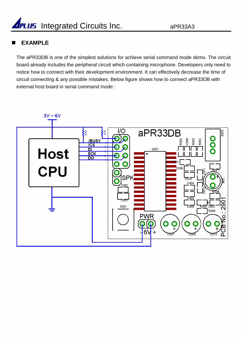
EXAMPLE
The aPR33DB is one of the simplest solutions for achieve serial command mode demo. The circuit
board already includes the peripheral circuit which containing microphone. Developers only need to
notice how to connect with their development environment. It can effectively decrease the time of
circuit connecting & any possible mistakes. Below figure shows how to connect aPR33DB with
external host board in serial command mode :
Integrated Circuits Inc. aPR33A3
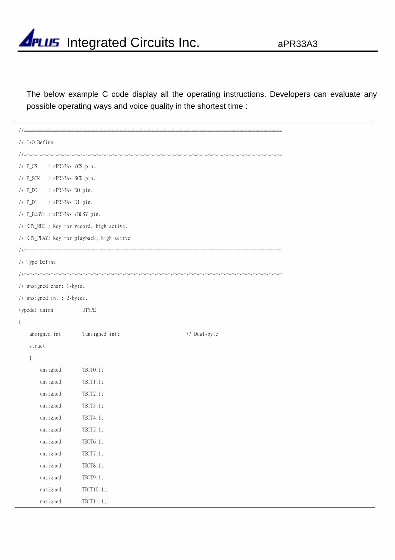
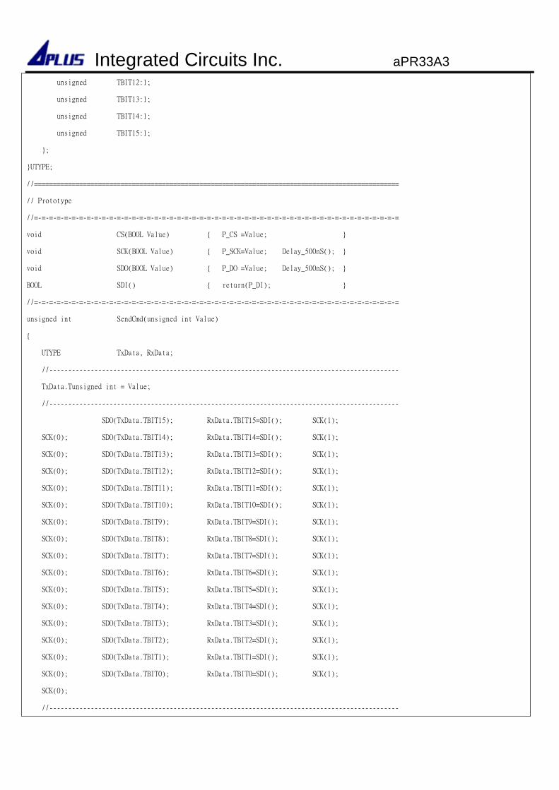
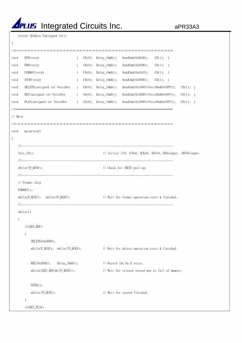
The below example C code display all the operating instructions. Developers can evaluate any
possible operating ways and voice quality in the shortest time :
//=================================================================================================
// I/O Define
//=-=-=-=-=-=-=-=-=-=-=-=-=-=-=-=-=-=-=-=-=-=-=-=-=-=-=-=-=-=-=-=-=-=-=-=-=-=-=-=-=-=-=-=-=-=-=-=-=
// P_CS : aPR33Ax /CS pin.
// P_SCK : aPR33Ax SCK pin.
// P_DO : aPR33Ax DO pin.
// P_DI : aPR33Ax DI pin.
// P_BUSY: : aPR33Ax /BUSY pin.
// KEY_REC : Key for record, high active.
// KEY_PLAY: Key for playback, high active
//=================================================================================================
// Type Define
//=-=-=-=-=-=-=-=-=-=-=-=-=-=-=-=-=-=-=-=-=-=-=-=-=-=-=-=-=-=-=-=-=-=-=-=-=-=-=-=-=-=-=-=-=-=-=-=-=
// unsigned char: 1-byte.
// unsigned int : 2-bytes.
typedef union UTYPE
unsigned int Tunsigned int; // Dual-byte
struct
unsigned TBIT0:1;
unsigned TBIT1:1;
unsigned TBIT2:1;
unsigned TBIT3:1;
unsigned TBIT4:1;
unsigned TBIT5:1;
unsigned TBIT6:1;
unsigned TBIT7:1;
unsigned TBIT8:1;
unsigned TBIT9:1;
unsigned TBIT10:1;
unsigned TBIT11:1;
Integrated Circuits Inc. aPR33A3
unsigned TBIT12:1;
unsigned TBIT13:1;
unsigned TBIT14:1;
unsigned TBIT15:1;
;
UTYPE;
//=================================================================================================
// Prototype
//=-=-=-=-=-=-=-=-=-=-=-=-=-=-=-=-=-=-=-=-=-=-=-=-=-=-=-=-=-=-=-=-=-=-=-=-=-=-=-=-=-=-=-=-=-=-=-=-=
void CS(BOOL Value) P_CS =Value;
void SCK(BOOL Value) P_SCK=Value; Delay_500nS();
void SDO(BOOL Value) P_DO =Value; Delay_500nS();
BOOL SDI() return(P_DI);
//=-=-=-=-=-=-=-=-=-=-=-=-=-=-=-=-=-=-=-=-=-=-=-=-=-=-=-=-=-=-=-=-=-=-=-=-=-=-=-=-=-=-=-=-=-=-=-=-=
unsigned int SendCmd(unsigned int Value)
UTYPE TxData, RxData;
//---------------------------------------------------------------------------------------------
TxData.Tunsigned int = Value;
//---------------------------------------------------------------------------------------------
SDO(TxData.TBIT15); RxData.TBIT15=SDI(); SCK(1);
SCK(0); SDO(TxData.TBIT14); RxData.TBIT14=SDI(); SCK(1);
SCK(0); SDO(TxData.TBIT13); RxData.TBIT13=SDI(); SCK(1);
SCK(0); SDO(TxData.TBIT12); RxData.TBIT12=SDI(); SCK(1);
SCK(0); SDO(TxData.TBIT11); RxData.TBIT11=SDI(); SCK(1);
SCK(0); SDO(TxData.TBIT10); RxData.TBIT10=SDI(); SCK(1);
SCK(0); SDO(TxData.TBIT9); RxData.TBIT9=SDI(); SCK(1);
SCK(0); SDO(TxData.TBIT8); RxData.TBIT8=SDI(); SCK(1);
SCK(0); SDO(TxData.TBIT7); RxData.TBIT7=SDI(); SCK(1);
SCK(0); SDO(TxData.TBIT6); RxData.TBIT6=SDI(); SCK(1);
SCK(0); SDO(TxData.TBIT5); RxData.TBIT5=SDI(); SCK(1);
SCK(0); SDO(TxData.TBIT4); RxData.TBIT4=SDI(); SCK(1);
SCK(0); SDO(TxData.TBIT3); RxData.TBIT3=SDI(); SCK(1);
SCK(0); SDO(TxData.TBIT2); RxData.TBIT2=SDI(); SCK(1);
SCK(0); SDO(TxData.TBIT1); RxData.TBIT1=SDI(); SCK(1);
SCK(0); SDO(TxData.TBIT0); RxData.TBIT0=SDI(); SCK(1);
SCK(0);
//---------------------------------------------------------------------------------------------
Integrated Circuits Inc. aPR33A3
return (RxData.Tunsigned int);
//=-=-=-=-=-=-=-=-=-=-=-=-=-=-=-=-=-=-=-=-=-=-=-=-=-=-=-=-=-=-=-=-=-=-=-=-=-=-=-=-=-=-=-=-=-=-=-=-=
void PUP(void) CS(0); Delay_10mS(); SendCmd(0xB100); CS(1);
void PDN(void) CS(0); Delay_10mS(); SendCmd(0xB200); CS(1);
void FORMAT(void) CS(0); Delay_10mS(); SendCmd(0xA5A5); CS(1);
void STOP(void) CS(0); Delay_10mS(); SendCmd(0x0000); CS(1);
void DELETE(unsigned int VoiceNo) CS(0); Delay_10mS(); SendCmd(0x1000|(VoiceNo&0x03FF)); CS(1);
void REC(unsigned int VoiceNo) CS(0); Delay_10mS(); SendCmd(0x2000|(VoiceNo&0x03FF)); CS(1);
void PLAY(unsigned int VoiceNo) CS(0); Delay_10mS(); SendCmd(0x3000|(VoiceNo&0x03FF)); CS(1);
//=================================================================================================
// Main
//=-=-=-=-=-=-=-=-=-=-=-=-=-=-=-=-=-=-=-=-=-=-=-=-=-=-=-=-=-=-=-=-=-=-=-=-=-=-=-=-=-=-=-=-=-=-=-=-=
void main(void)
//---------------------------------------------------------------------------------------------
Init_IO(); // Initial I/O: /CS=0, SCK=0, SDI=0, SDO=input, /BUSY=input.
//---------------------------------------------------------------------------------------------
while(!P_BUSY); // Check for /BUSY pull-up.
//---------------------------------------------------------------------------------------------
// Format chip
FORMAT();
while(P_BUSY); while(!P_BUSY); // Wait for format operation start & finished.
//---------------------------------------------------------------------------------------------
while(1)
if(KEY_REC)
DELETE(0x0000);
while(P_BUSY); while(!P_BUSY); // Wait for delete operation start & finished.
REC(0x0000); Delay_10mS(); // Record the No.0 voice.
while((KEY_REC)&(!P_BUSY)); // Wait for release record key or full of memory.
STOP();
while(!P_BUSY); // Wait for record finished.
if(KEY_PLAY)
Integrated Circuits Inc. aPR33A3
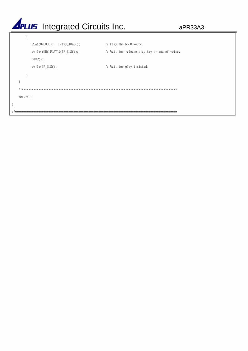
PLAY(0x0000); Delay_10mS(); // Play the No.0 voice.
while((KEY_PLAY)&(!P_BUSY)); // Wait for release play key or end of voice.
STOP();
while(!P_BUSY); // Wait for play finished.
//---------------------------------------------------------------------------------------------
return ;
//=================================================================================================
Integrated Circuits Inc. aPR33A3
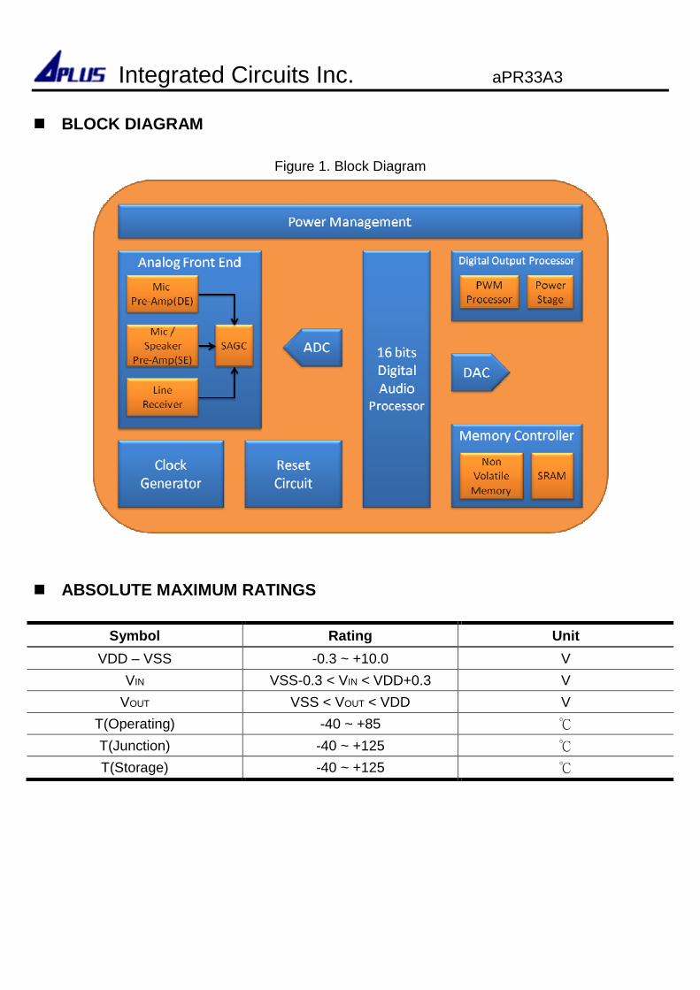
BLOCK DIAGRAM
Figure 1. Block Diagram
ABSOLUTE MAXIMUM RATINGS
Symbol Rating Unit
VDD – VSS -0.3 ~ +10.0 V
VIN VSS-0.3 < VIN < VDD+0.3 V
VOUT VSS < VOUT < VDD V
T(Operating) -40 ~ +85
T(Junction) -40 ~ +125
T(Storage) -40 ~ +125
Integrated Circuits Inc. aPR33A3
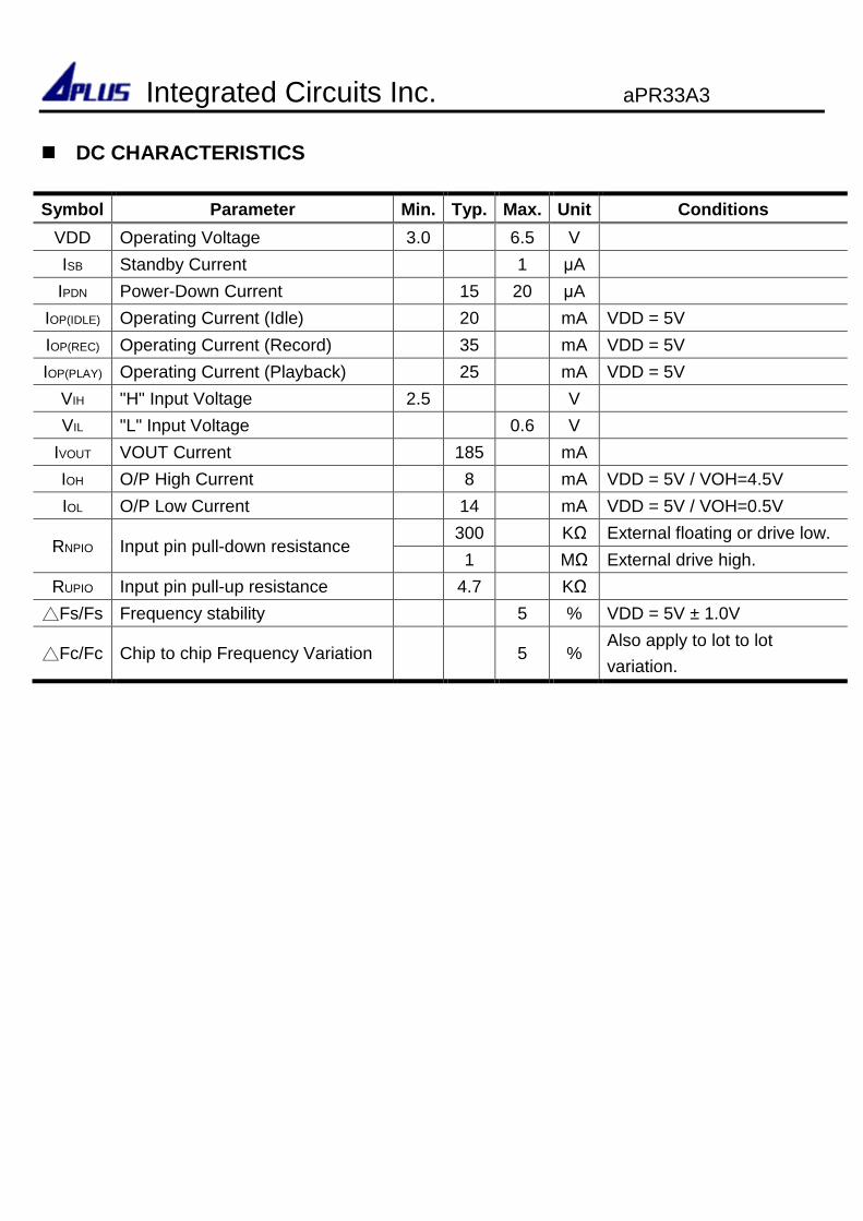
DC CHARACTERISTICS
Symbol Parameter Min. Typ. Max. Unit Conditions
VDD Operating Voltage 3.0 6.5 V
ISB Standby Current 1 µA
IPDN Power-Down Current 15 20 µA
IOP(IDLE) Operating Current (Idle) 20 mA VDD = 5V
IOP(REC) Operating Current (Record) 35 mA VDD = 5V
IOP(PLAY) Operating Current (Playback) 25 mA VDD = 5V
VIH "H" Input Voltage 2.5 V
VIL "L" Input Voltage 0.6 V
IVOUT VOUT Current 185 mA
IOH O/P High Current 8 mA VDD = 5V / VOH=4.5V
IOL O/P Low Current 14 mA VDD = 5V / VOH=0.5V
RNPIO Input pin pull-down resistance 300 KΩ External floating or drive low.
1 MΩ External drive high.
RUPIO Input pin pull-up resistance 4.7 KΩ
Fs/Fs Frequency stability 5 % VDD = 5V ± 1.0V
Fc/Fc Chip to chip Frequency Variation 5 % Also apply to lot to lot
variation.
Integrated Circuits Inc. aPR33A3
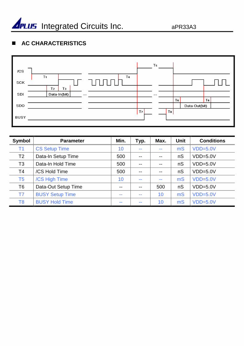
AC CHARACTERISTICS
Symbol Parameter Min. Typ. Max. Unit Conditions
T1 CS Setup Time 10 -- -- mS VDD=5.0V
T2 Data-In Setup Time 500 -- -- nS VDD=5.0V
T3 Data-In Hold Time 500 -- -- nS VDD=5.0V
T4 /CS Hold Time 500 -- -- nS VDD=5.0V
T5 /CS High Time 10 -- -- mS VDD=5.0V
T6 Data-Out Setup Time -- -- 500 nS VDD=5.0V
T7 BUSY Setup Time -- -- 10 mS VDD=5.0V
T8 BUSY Hold Time -- -- 10 mS VDD=5.0V
Integrated Circuits Inc. aPR33A3
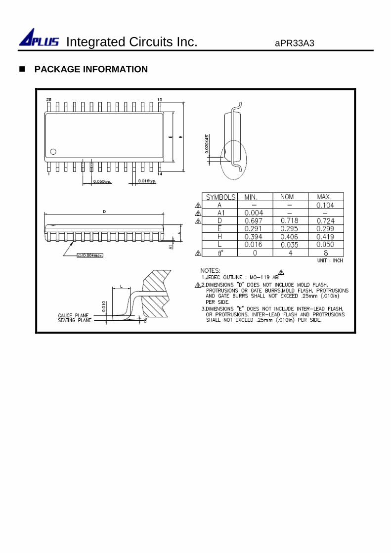
PACKAGE INFORMATION
Integrated Circuits Inc. aPR33A3
Copyright © 2022 FDOKUMEN

