


Bahasa
Halaman
Hukum


160TP–01
A89936
Radiator Cap
Thermostat
–COOLING COOLING SYSTEM (1NZ–FXE)16–1
268Author: Date:
2004 Prius – Preliminary Release (RM1075U)
COOLING SYSTEM (1NZ–FXE)LOCATION

160TQ–01
A88171
16–2–COOLING COOLING SYSTEM (1NZ–FXE)
269Author: Date:
2004 Prius – Preliminary Release (RM1075U)
ON–VEHICLE INSPECTION
1. INSPECT COOLING SYSTEM FOR LEAKSCAUTION:To avoid the danger of being burned, do not remove the ra-diator cap while the engine and radiator are still hot. Fluidand steam can be blown out under pressure.(a) Fill the radiator with coolant, then attach the radiator cap
tester.(b) Warm up the engine.(c) Pump it up to 177 kPa 1.8 kgf/cm2, 25.6 psi, then check
that the pressure does not drop.HINT:If the pressure drops, check the hose, radiator and water pumpfor leaks. If no external leaks are found. check the heater core,cylinder block and cylinder head.
2. CHECK ENGINE COOLANT LEVEL AT RESERVOIR(a) Check that the coolant level in the reservoir tank is between ”F” and ”L” lines when the engine is cold.If low, check for leaks and add ”Toyota Super Long Life Coolant” or similar high quality ethylene glycol basednon–silicate, non–amine, non–nitrite, and non–borate coolant with long–life hybrid organic acid technologyup to the ”FULL” line.3. CHECK ENGINE COOLANT QUALITY(a) Remove the radiator cap.CAUTION:To avoid the danger of being burned, do not remove the radiator cap while the engine and radiatorare still hot. Fluid and steam can be blown out under pressure.(b) Check that there are no excessive collections of rust or scale around the radiator cap or radiator filler
hole.HINT:If excessively dirty, replace the coolant.(c) Attach the radiator cap.

A73603
–COOLING COOLING SYSTEM (1NZ–FXE)16–3
270Author: Date:
2004 Prius – Preliminary Release (RM1075U)
4. INSPECT FIN BLOCKAGE(a) If the fins are clogged, wash them with water or a steam
cleaner and dry with compressed air.NOTICE: If the distance between the steam cleaner and core is
too close, the fins could be damaged. So keep the fol-lowing injection distance.
Injection PressurekPa (kgf/cm2, psi)
Injection Distancemm(in.)
2,942 to 4,903(30 to 50, 427 to 711)
300 (11.811)
4,903 to 7,845(50 to 80, 711 to 1,138)
500 (19.685)
If the fins are bent, straighten them with a screwdriveror pliers.
Be careful not to pour water directly onto electroniccomponents.

160TR–01
P13560
P00436
P24125
Valve Lift
Radiator Cap
Radiator Cap Tester
30 or more
A51912
16–4–COOLING COOLING SYSTEM (1NZ–FXE)
271Author: Date:
2004 Prius – Preliminary Release (RM1075U)
INSPECTION
1. INSPECT THERMOSTATHINT:The thermostat is imprinted with the valve opening tempera-ture.
(a) Immerse the thermostat in the water, then gradually heatthe water.
(b) Check the valve opening temperature.Valve opening temperature: 80 to 84C (176 to 183F)
HINT:If the valve opening temperature is not as specified, replace thethermostat.
(c) Check the valve lift.Valve lift:
Temperature Valve Lift
95C (205F) 8.5 mm (0.335 in.) or more
If the valve lift is not as specified, replace the thermostat.(d) Check that the valve is fully closed when the thermostat
is at low temperature (below 77C (171F)).If not fully closed, replace the thermostat.2. INSPECT RADIATOR CAP SUB–ASSYNOTICE: If the water filler cap is dirty, clean it with water. Before using the radiator cap tester, wet the relief
valve and pressure valve with coolant or water.
(a) Using a radiator cap tester, slowly pump the tester andcheck that the air is coming form the vacuum valve.Pumping speed: 1 push / 3 seconds or more
NOTICE: Pump the tester at a constant speed. Slant the radiator cap tester at an angle of over 30 as
shown in the illustration when checking.If air is not coming from the vacuum valve, replace the radiatorcap.

–COOLING COOLING SYSTEM (1NZ–FXE)16–5
272Author: Date:
2004 Prius – Preliminary Release (RM1075U)
(b) Pump the tester, then measure the relief valve openingpressure.Pumping speed: 1 push / 1 second or more
NOTICE: This pumping speed is for only the first pumping to
close the vacuum valve. After the first pumping, thepumping speed can be reduced.
Slant the radiator cap tester at an angle of over 30asshown in the illustration when checking.Standard opening pressure: 74 to 103 kPa (0.75 to 1.05 kgf/cm 2, 10.7 to 14.9 psi)Minimum opening pressure: 59 kPa (0.6 kgf/cm 2, 8.5 psi)
HINT:Use the tester’s maximum reading as the opening pressure.If the opening pressure is less than minimum, replace the radia-tor cap.

160TS–01
A88186
Cooling Fan MotorEngine Room Relay Block
Cooling Fan Relay
Cooling Fan Relay No. 2
Intergration Relay
Component parts
16–6–COOLING COOLING FAN SYSTEM (1NZ–FXE)
273Author: Date:
2004 Prius – Preliminary Release (RM1075U)
COOLING FAN SYSTEM (1NZ–FXE)LOCATION

160TT–01
A88672
ECM
Cooling Fan Relay No. 2
ECU – IG7.5A
CDS Fan 30A
IG1 Relay
AM1 7.5A
Water Temperature SW
Pressure SW
Fan Motor
Fan Motor
FAN
A/C AMP
RDI 30A
Main 120A
Battery
Cooling Fan Relay No. 1
Cooling Fan Relay No. 3
DC/DC100A
–COOLING COOLING FAN SYSTEM (1NZ–FXE)16–7
274Author: Date:
2004 Prius – Preliminary Release (RM1075U)
SYSTEM DIAGRAM

160TU–01
+–
+–
A88673
16–8–COOLING COOLING FAN SYSTEM (1NZ–FXE)
275Author: Date:
2004 Prius – Preliminary Release (RM1075U)
ON–VEHICLE INSPECTION1. INSPECT COOLING FAN AT LOW TEMPERATURE(LOWER THAN 83 C (181F))(a) Check that the coolant temperature is lower then 83C (181F).(b) Check that the cooling fan does not rotate when turn the power switch ON (ACC) with the A/C switch
OFF.2. INSPECT COOLING FAN AT HIGH TEMPERATURE (HIGHER THAN 93 C(199F))(a) Set the vehicle to the ”INSPECTION MOD1” (see page 01–5).(b) Warm up the engine .(c) Check that the cooling fan starts rotating when the coolant temperature is higher than approximately
100C (212F) with the A/C switch OFF and that it stops rotating when the temperature is lower thanspproximately 98C (208F).
NOTICE:The coolant temperature is sensed by the water temperature on the water outlet (engine outlet) ofthe cylinder head.
3. INSPECT COOLING FAN MOTOR(a) Disconnect the cooling fan motor connector.(b) Check that the cooling fan rotates smoothly when the bat-
tery is connected to the fan motor connector.(c) Using an ammeter, measure the current with step (b)
maintained.SST 09082–00030, 09083–00150Standard amperage: 9.2 to 11.0 A
(d) Connect the cooling fan motor connector.

160TV–01
A31260
A30519
–COOLING COOLING FAN SYSTEM (1NZ–FXE)16–9
276Author: Date:
2004 Prius – Preliminary Release (RM1075U)
INSPECTION
1. INSPECT COOLING FAN RELAY(a) Inspect the resistance.
(1) Using an ohmmeter, measure the resistance be-tween the terminals.
Standard:Tester Connection Specified Condition
3 – 5 10 kΩ or higher
3 – 5Below 1 Ω
(Apply battery voltage to terminals 1 and 2)
If the resistance is not as specified, replace the cooling fanrelay.
2. INSPECT COOLING FAN RELAY NO.2(a) Inspect the resistance.
(1) Using an ohmmeter, measure the resistance be-tween the terminals.
Standard:Tester Connection Specified Condition
3 – 4 Below 1 Ω
3 – 5 10 kΩ or higher
3 – 5Below 1 Ω
(Apply battery voltage to terminals 1 and 2)
If the resistance is not as specified, replace the cooling fan relayNo. 2.

A88173
16–10–COOLING COOLING FAN SYSTEM (1NZ–FXE)
277Author: Date:
2004 Prius – Preliminary Release (RM1075U)
3. INSPECT INTEGRATION RELAY(a) Inspect the resistance of the fan relay.
(1) Using an ohmmeter, measure the resistance be-tween the terminals.
Standard:Tester Connection Specified Condition
B1 – B4 10 kΩ or higher
B1 – B4Below 1 Ω
(Apply battery voltage to terminals B2 and B3)
If the resistance is not as specified, replace the integrationrelay.

160TW–01
A88174
–COOLING ENGINE COOLANT (1NZ–FXE)16–11
278Author: Date:
2004 Prius – Preliminary Release (RM1075U)
ENGINE COOLANT (1NZ–FXE)REPLACEMENT
1. REMOVE RADIATOR SUPPORT OPENING COVER(a) Remove the 6 clips and radiator support opening cover.
2. REMOVE ENGINE UNDER COVER LH3. REMOVE FRONT FENDER LINER LH(a) Remove the front part of the front fender liner LH.
4. DRAIN ENGINE COOLANTCAUTION:If the engine or radiator is hot, do not remove the radiatorcap.(a) Disconnect the coolant heat storage water pump connec-
tor.(b) Remove the radiator cap.(c) Connect a vinyl hose to the drain cock of the radiator.(d) Connect a vinyl hose to the drain cock of the engine.(e) Connect a vinyl hose to the drain cock of the coolant heat
storage tank assembly.CAUTION:If the tank has any malfunctions, the tank surface gets hot.To prevent burn injury, do not touch the tank.

A88177
Radiator Cap
Engine Drain Cock Plug
Radiator Drain Cock Plug Drain Cock Plug
16–12–COOLING ENGINE COOLANT (1NZ–FXE)
279Author: Date:
2004 Prius – Preliminary Release (RM1075U)
(f) Loosen the drain cock plugs of the radiator, engine andcoolant heat storage tank assembly, then drain the cool-ant.
CAUTION:Even if the engine is cold, the coolant in the coolant heatstorage tank assembly is still hot. Be careful of the hotcoolant when draining.HINT:Record the amount of the drained coolant. It will be referredwhen refilling the tank with coolant.
(g) Drain the coolant in the radiator reservoir tank.5. ADD ENGINE COOLANT(a) Tighten the drain cock plug of the coolant heat storage
tank assembly, then disconnect the vinyl hose.(b) Tighten the drain cock plug of the engine, then disconnect
the vinyl hose.Torque: 13 N ⋅m (133 kgf ⋅cm, 9.6 ft ⋅lbf)
(c) Tighten the drain cock plug of the radiator, then discon-nect the vinyl hose.

A92991
Vinyl Hose
A88678
–COOLING ENGINE COOLANT (1NZ–FXE)16–13
280Author: Date:
2004 Prius – Preliminary Release (RM1075U)
(d) Connect a vinyl hose to the bleeder plug of the radiatorassembly and the radiator reservoir tank.
HINT:Insert the vinyl hose to inside the radiator reservoir tank.
(e) Using a 6 mm socket hexagon wrench, loosen the radia-tor bleeder plug from the radiator support service hole.
(f) Fill the radiator with coolant up to the fill port.Capacity: 8.6 liters (9.1 US qts, 7.6 lmp. qts)
HINT: When filling coolant, press the radiator hose a few times.
If the coolant level goes down, add more coolant. Amount of coolant to fill: Approximately 2.4 liters (2.5
USgts, 2.1 lmp.gts) Use of improper coolants may damage the engine cooling
system. Only use ”Toyota Super Long Life Coolant”, or similar high
quality ethylene glycol based non–silicate, non–amine,non–nitrite, and non–borate coolant with long–life hybridorganic acid technology.
New Toyota vehicles are filled with Toyota Super LongLife Coolant (color is pink, premixed ethylene–glycol con-centration is approximately 50 % and freezing tempera-ture is –35C (–31F)). When replacing the coolant, Toy-ota Super Long Life Coolant is recommended.
Observe the coolant level inside the radiator by pressingthe inlet and outlet radiator hoses several times by hand.If the coolant level goes down, add the coolant.
NOTICE: Do not use plain water alone.
(g) Using a 6 mm socket hexagon wrench, tighten the radia-tor bleeder plug.Torque: 1.5 N ⋅m (15 kgf ⋅cm, 13 in. ⋅lbf)
(h) Install the radiator cop.(i) Fill the radiator reservoir tank with coolant to the full level.(j) Connect the coolant heat storage water pump connector.

A87542DLC3
A88678
16–14–COOLING ENGINE COOLANT (1NZ–FXE)
281Author: Date:
2004 Prius – Preliminary Release (RM1075U)
(k) Connect the hand–held tester to the DLC3.(l) Turn the power switch ON (IG).(m) Select the item:
DIAGNOSIS / ENHANCED OBD II / ENGINE AND ECT/ ACTIVE TEST /WATER PUMP
NOTICE: The water pump motor operates for 30 seconds after
WATER PUMP is ON in the ACTIVE TEST mode, thenit automatically stops operating.
Do not actuate the water pump motor without coolantfilled.
(n) Using a 6 mm socket hexagon wrench, loosen the radia-tor bleeder plug from the radiator support service hole.
(o) Remove the radiator cap, then fill the radiator with coolantup to the fill port.
HINT: When filling coolant, press the radiator hose a few times.
If the coolant level goes down, add more coolant.(p) Using a 6 mm socket hexagon wrench, tighten the radia-
tor bleeder plug.Torque: 1.5 N ⋅m (15 kgf ⋅cm, 13 in. ⋅lbf)
(q) Install the radiator cap.(r) Repeat steps (k) to (o) until coolant cannot be added.(s) Disconnect the vinyl hose between the bleeder plug of the
radiator assembly and the radiator reservoir tank.(t) Set the vehicle to the ”INSPECTION MOD1” (see page
01–5).(u) Warm up the engine until the thermostat is open.(v) Stop the engine, then wait until the coolant gets cold. Re-
move the radiator cap and check the coolant level.CAUTION:If the engine or radiator is hot, do not remove the radiatorcap.HINT:If the coolant level is lower, add coolant again. Warm up the en-gine, then check the coolant level.(w) When the coolant level stops going down, add coolant to
the radiator reservoir tank up to the full level.6. CHECK FOR ENGINE COOLANT LEAKS (See page 16–2)7. INSTALL FRONT FENDER LINER LH8. INSTALL ENGINE UNDER COVER LH9. INSTALL RADIATOR SUPPORT OPENING COVER

160TX–01
A92654
SST
A88890
A92654
SST
–COOLING WATER PUMP ASSY (1NZ–FXE)16–15
282Author: Date:
2004 Prius – Preliminary Release (RM1075U)
WATER PUMP ASSY (1NZ–FXE)REPLACEMENT1. REMOVE RADIATOR SUPPORT OPENING COVER (See page 16–11)2. REMOVE ENGINE UNDER COVER LH3. REMOVE ENGINE UNDER COVER RH4. DRAIN ENGINE COOLANT (See page 16–11)5. REMOVE FAN AND GENERATOR V BELT (See page 14–5)
6. REMOVE WATER PUMP PULLEY(a) Using SST, hold the water pump pulley.
SST 09960–10010 (09962–01000, 09963–00600)(b) Remove the 3 bolts and water pump pulley.
7. REMOVE WATER PUMP ASSY(a) Remove the 3 bolts and 2 nuts, then remove the water
pump assembly.
8. INSTALL WATER PUMP ASSY(a) Install a new gasket, then install the water pump assembly with the 3 bolts and 2 nuts.
Torque: 11 N ⋅m (112 kgf ⋅cm, 8.1 ft ⋅lbf)
9. INSTALL WATER PUMP PULLEY(a) Temporarily install the water pump pulley with the 3 bolts.(b) Using SST, hold the water pump pulley.
SST 09960–10010 (09962–01000, 09963–00600)(c) Tighten the 3 bolts with the specified torque.
Torque: 15 N ⋅m (153 kgf ⋅cm, 11 ft ⋅lbf)
10. INSTALL FAN AND GENERATOR V BELT11. INSPECT DRIVE BELT DEFLECTION AND TENSION (See page 14–1)12. ADD ENGINE COOLANT (See page 16–11)13. CHECK FOR ENGINE COOLANT LEAKS (See page 16–2)

16–16–COOLING WATER PUMP ASSY (1NZ–FXE)
283Author: Date:
2004 Prius – Preliminary Release (RM1075U)
14. INSTALL ENGINE UNDER COVER RH15. INSTALL ENGINE UNDER COVER LH16. INSTALL RADIATOR SUPPORT OPENING COVER
160TY–01
A37047
–COOLING WATER PUMP ASSY (1NZ–FXE)16–17
284Author: Date:
2004 Prius – Preliminary Release (RM1075U)
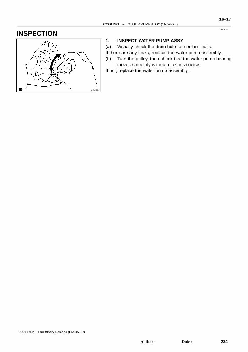
INSPECTION1. INSPECT WATER PUMP ASSY(a) Visually check the drain hole for coolant leaks.If there are any leaks, replace the water pump assembly.(b) Turn the pulley, then check that the water pump bearing
moves smoothly without making a noise.If not, replace the water pump assembly.

160TZ–01
A86915
A88872
A88873
1010
A92515
Jiggle Valve
16–18–COOLING THERMOSTAT (1NZ–FXE)
285Author: Date:
2004 Prius – Preliminary Release (RM1075U)
THERMOSTAT (1NZ–FXE)REPLACEMENT1. REMOVE RADIATOR SUPPORT OPENING COVER (See page 16–11)2. REMOVE ENGINE UNDER COVER LH3. REMOVE ENGINE UNDER COVER RH4. DRAIN ENGINE COOLANT (See page 16–11)
5. REMOVE WATER INLET(a) Remove the 2 nuts and water inlet with radiator outlet
hose.
6. REMOVE THERMOSTAT(a) Remove the thermostat.(b) Remove the gasket from the thermostat.
7. INSTALL THERMOSTAT(a) Install a new gasket to the thermostat.
(b) Install the thermostat so the jiggle valve faces upward.HINT:The jiggle valve may be set within 10of either side as illus-trated.

–COOLING THERMOSTAT (1NZ–FXE)16–19
286Author: Date:
2004 Prius – Preliminary Release (RM1075U)
8. INSTALL WATER INLET(a) Install the water inlet with radiator outlet hose with the 2 nuts.
Torque:9.0 N ⋅m (92 kgf ⋅cm, 80 in. ⋅lbf)9. ADD ENGINE COOLANT (See page 16–11)10. CHECK FOR ENGINE COOLANT LEAKS (See page 16–2)11. INSTALL ENGINE UNDER COVER RH12. INSTALL ENGINE UNDER COVER LH13. INSTALL RADIATOR SUPPORT OPENING COVER

160U0–01
A92516
Radiator Support Opening Cover
Clip
Inverter Bracket
Cooler Bracket
Horn Connector
Hood Lock Assy
Radiator Support
Hood Lock Control Cable
Front Bumper Cover
Engine Under Cover RH
N·m (kgf·cm, ft·lbf) : Specified torque
Engine Under Cover LH
x6
x5
x2
x3
x2
x3
x2
x4
8.5 (87, 75 in. ⋅lbf)
25 (255, 18)
20 (204, 15)
5.0 (51, 44 in. ⋅lbf)
21 (214, 16)
16–20–COOLING FAN (1NZ–FXE)
287Author: Date:
2004 Prius – Preliminary Release (RM1075U)
FAN (1NZ–FXE)COMPONENTS

A92526
x4
Fan Assy w/ Motor
N·m (kgf·cm, ft·lbf) : Specified torque
6.2 (63, 55 in. ⋅lbf)
7.5 (76, 66 in. ⋅lbf)
Radiator Outlet Hose
Radiator Inlet Hose
Temperature Switch Connector
Hose Clamp
Hose Clamp
Radiator Drain Cock Plug
Heat Storage Water By–pass Hose No. 1
Wire Harness
Fan Motor Connector
Inverter Cooling Hose No. 2
Inverter Cooling Hose No. 1
Inverter Cooling Hose No. 5
Fan
Fan
–COOLING FAN (1NZ–FXE)16–21
288Author: Date:
2004 Prius – Preliminary Release (RM1075U)

160U1–01
A86917
A86918
A86919
16–22–COOLING FAN (1NZ–FXE)
289Author: Date:
2004 Prius – Preliminary Release (RM1075U)
REPLACEMENT1. REMOVE REAR FLOOR BOARD NO.2 (See page 21–116)2. REMOVE DECK FLOOR BOX REAR (See page 21–116)3. REMOVE REAR FLOOR BOARD NO.3 (See page 21–116)4. DISCONNECT BATTERY NEGATIVE TERMINAL (See page 21–116)5. REMOVE RADIATOR SUPPORT OPENING COVER (See page 16–11)6. REMOVE ENGINE UNDER COVER LH7. REMOVE ENGINE UNDER COVER RH8. DRAIN ENGINE COOLANT(a) Drain the coolant in the radiator on the engine side (see page 16–11).(b) After draining the coolant in the radiator on the engine side, remove the radiator drain cock plug.(c) Drain the coolant in the radiator on the hybrid side (see page 22–4).9. REMOVE FRONT BUMPER COVER (See page 76–2)
10. REMOVE FAN ASSY W/MOTOR(a) Disconnect the connector and hose shown in the illustra-
tion.(b) After disconnecting the hose, remove the hose clamp.
(c) Disconnect the hose shown in the illustration.(d) After disconnecting the hose, remove the 2 hose clamps.
(e) Disconnect the connector shown in the illustration.

A86920
A86921
A86922
A86923
A86924
–COOLING FAN (1NZ–FXE)16–23
290Author: Date:
2004 Prius – Preliminary Release (RM1075U)
(f) Disconnect the hose shown in the illustration.
(g) Disconnect the radiator outlet hose.(h) Disconnect the radiator reservoir tank hose.
(i) Disconnect the inverter reservoir tank hose from theclamps.
(j) Disconnect the radiator inlet hose.(k) Disconnect the connector and remove the clamp shown
in the illustration.
(l) Remove the 3 bolts and inverter bracket.

A86925
A86926
A86927
A86928
A86929
16–24–COOLING FAN (1NZ–FXE)
291Author: Date:
2004 Prius – Preliminary Release (RM1075U)
(m) Remove the 2 bolts and cooler bracket.
(n) Disconnect the horn connector shown in the illustration.
(o) Remove the 3 bolts and disconnect the hood lock controlcable, then remove the hood lock assembly.
(p) Remove the 5 bolts and radiator support.(q) Remove the hood lock control cable from the radiator sup-
port.
(r) Disconnect the wire harness clamps shown in the illustra-tion.

A86930
A86931
–COOLING FAN (1NZ–FXE)16–25
292Author: Date:
2004 Prius – Preliminary Release (RM1075U)
(s) Remove the 4 bolts, then remove the fan with motor fromthe vehicle.
11. REMOVE FAN(a) Remove the 2 nuts and fan.
12. INSTALL FANTorque: 6.2 N ⋅m (63 kgf ⋅cm, 55 in. ⋅lbf)

A86930
A86929
A86928
A92969
16–26–COOLING FAN (1NZ–FXE)
293Author: Date:
2004 Prius – Preliminary Release (RM1075U)
13. INSTALL FAN ASSY W/MOTOR(a) Set the fan with motor to the vehicle, then install it with the
4 bolts.Torque: 7.5 N ⋅m (76 kgf ⋅cm, 66 in. ⋅lbf)
(b) Connect the 2 wire harness clamps shown in the illustra-tion.
(c) Install the hood lock control cable to the radiator support.(d) Install the radiator support with the 5 bolts.
Torque: 5.0 N ⋅m (51 kgf ⋅cm, 44 in. ⋅lbf)
(e) Connect the hood lock control cable to the hood lock as-sembly.
(f) Install the hood lock assembly with the 3 bolts.(See page 75–2)

A86926
B
AA92519
A
B
B
A89867
A86923
A86922
–COOLING FAN (1NZ–FXE)16–27
294Author: Date:
2004 Prius – Preliminary Release (RM1075U)
(g) Connect the horn connector shown in the illustration.
(h) Install the cooler bracket with the 2 bolts.Torque: 20 N⋅m (204 kgf ⋅cm, 15 ft ⋅lbf) for bolt A8.5 N⋅m (87 kgf ⋅cm, 75 in. ⋅lbf) for bolt B
(i) Install the inverter bracket with the 3 bolts.Torque: 21 N⋅m (214 kgf ⋅cm, 16 ft ⋅lbf) for bolt A25 N⋅m (255 kgf ⋅cm, 18 ft ⋅lbf) for bolt B
(j) Connect the connector and install the clamp.(k) Connect the radiator inlet hose.
(l) Connect the inverter reservoir tank to each clamp.

A86921
A86920
A86919
A86918
A86917
16–28–COOLING FAN (1NZ–FXE)
295Author: Date:
2004 Prius – Preliminary Release (RM1075U)
(m) Connect the radiator reservoir tank hose.(n) Connect the radiator outlet hose.
(o) Connect the hose shown in the illustration.
(p) Connect the connector shown in the illustration.
(q) Install the 2 hose clamps to the fan shroud.(r) Connect the hose shown in the illustration.
(s) Install the hose clamp to the fan shroud.(t) Connect the hose and connector shown in the illustration.

–COOLING FAN (1NZ–FXE)16–29
296Author: Date:
2004 Prius – Preliminary Release (RM1075U)
14. INSTALL FRONT BUMPER COVER (See page 76–2)15. CONNECT BATTERY NEGATIVE TERMINAL
Torque: 6.0 N ⋅m (61 kgf ⋅cm, 53 in. ⋅lbf)16. INSTALL REAR FLOOR BOARD NO.317. INSTALL DECK FLOOR BOX REAR18. INSTALL REAR FLOOR BOARD NO.219. ADD ENGINE COOLANT(a) Fill the radiator on the hybrid side with coolant (see page 22–4).(b) Fill the radiator on the engine side with coolant (see page 16–11).20. CHECK FOR ENGINE COOLANT LEAKS(a) Check the cooling system on the hybrid side for coolant leaks.(b) Check the cooling system on the engine side for coolant leaks (see page 16–2).21. INSTALL ENGINE UNDER COVER RH22. INSTALL ENGINE UNDER COVER LH23. INSTALL RADIATOR SUPPORT OPENING COVER24. POWER WINDOW CONTROL SYSTEM INITIALIZE (See page 01–28)

160U2–01
A92516
Radiator Support Opening Cover
Clip
Inverter Bracket
Cooler Bracket
Horn Connector
Hood Lock Assy
Radiator Support
Hood Lock Control Cable
Front Bumper Cover
Engine Under Cover RH
N·m (kgf·cm, ft·lbf) : Specified torque
Engine Under Cover LH
x6
x5
x2
x3
x2
x3
x2
x4
8.5 (87, 75 in. ⋅lbf)
25 (255, 18)
20 (204, 15)
5.0 (51, 44 in. ⋅lbf)
21 (214, 16)
16–30–COOLING NO.2 RADIATOR ASSY (1NZ–FXE)
297Author: Date:
2004 Prius – Preliminary Release (RM1075U)
NO.2 RADIATOR ASSY (1NZ–FXE)COMPONENTS

A92518
Radiator Outlet Hose
Radiator Inlet Hose
Inverter Cooling Hose No. 2
Wire Harness
Fan Motor Connector
Radiator Drain Cock Plug
Heat Storage Water By–pass Hose No. 1
Inverter Cooling Hose No. 5
Temperature Switch Connector
Inverter Cooling Hose No. 1
Hose Clamp
Hose Clamp
–COOLING NO.2 RADIATOR ASSY (1NZ–FXE)16–31
298Author: Date:
2004 Prius – Preliminary Release (RM1075U)

A92524N·m (kgf·cm, ft·lbf) : Specified torque
7.5 (76, 66 in. ⋅lbf)x4
Fan Assy w/ Motor
Radiator Support Upper LH
No. 2 Radiator Assy
Radiator Support Upper RH
Radiator Fan Temperature Switch
Radiator Support Lower LH
Radiator Support Lower RH
3.9 (40, 35 in. ⋅lbf)
5.0 (51, 44 in. ⋅lbf)
3.9 (40, 35 in. ⋅lbf)
5.0 (51, 44 in. ⋅lbf)
5.0 (51, 44 in. ⋅lbf)
3.9 (40, 35 in. ⋅lbf)
5.0 (51, 44 in. ⋅lbf)
16–32–COOLING NO.2 RADIATOR ASSY (1NZ–FXE)
299Author: Date:
2004 Prius – Preliminary Release (RM1075U)
160U3–01
A86932
SST
A86933
SST
A86933
–COOLING NO.2 RADIATOR ASSY (1NZ–FXE)16–33
300Author: Date:
2004 Prius – Preliminary Release (RM1075U)
REPLACEMENT1. REMOVE FAN ASSY W/MOTOR (See page 16–22)
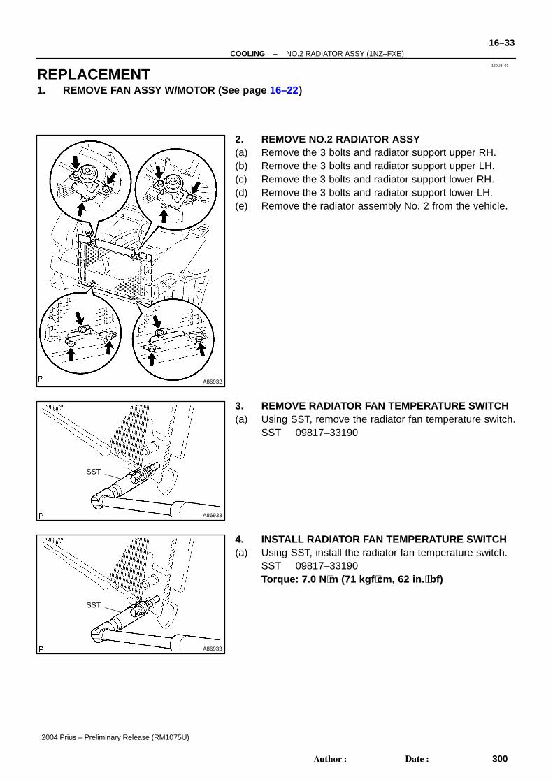
2. REMOVE NO.2 RADIATOR ASSY(a) Remove the 3 bolts and radiator support upper RH.(b) Remove the 3 bolts and radiator support upper LH.(c) Remove the 3 bolts and radiator support lower RH.(d) Remove the 3 bolts and radiator support lower LH.(e) Remove the radiator assembly No. 2 from the vehicle.
3. REMOVE RADIATOR FAN TEMPERATURE SWITCH(a) Using SST, remove the radiator fan temperature switch.
SST 09817–33190
4. INSTALL RADIATOR FAN TEMPERATURE SWITCH(a) Using SST, install the radiator fan temperature switch.
SST 09817–33190Torque: 7.0 N ⋅m (71 kgf ⋅cm, 62 in. ⋅lbf)

A
BB
BB
AA
A
AAA
A
A86934
16–34–COOLING NO.2 RADIATOR ASSY (1NZ–FXE)
301Author: Date:
2004 Prius – Preliminary Release (RM1075U)
5. INSTALL NO.2 RADIATOR ASSY(a) Install the radiator assembly No. 2 to the vehicle.(b) Install the radiator support lower LH with the 3 bolts.
Torque: 5.0 N⋅m (51 kgf ⋅cm, 44 in. ⋅lbf) for bolt A3.9 N⋅m (40 kgf ⋅cm, 35 in. ⋅lbf) for bolt B
(c) Install the radiator support lower RH with the 3 bolts.Torque: 5.0 N⋅m (51 kgf ⋅cm, 44 in. ⋅lbf) for bolt A3.9 N⋅m (40 kgf ⋅cm, 35 in. ⋅lbf) for bolt B
(d) Install the radiator support upper LH with the 3 bolts.Torque: 5.0 N⋅m (51 kgf ⋅cm, 44 in. ⋅lbf) for bolt A3.9 N⋅m (40 kgf ⋅cm, 35 in. ⋅lbf) for bolt B
(e) Install the radiator support upper RH with the 3 bolts.Torque: 5.0 N⋅m (51 kgf ⋅cm, 44 in. ⋅lbf) for bolt A3.9 N⋅m (40 kgf ⋅cm, 35 in. ⋅lbf) for bolt B
6. INSTALL FAN ASSY W/MOTOR (See page 16–22)

160U4–01
A88179
x6 Clip
Front Fender Liner LHHeat Storage Water By–pass Hose No. 1
Water Pump Connector
Drain Cock Plug
Temperature Sensor Connector
Coolant Heat Storage Tank Assy
Engine Under Cover RH
Front Bumper Cover
Heat Storage Water By–pass Hose No. 2
Engine Under Cover LH
Radiator Support Opening Cover
x2
x2
x3
x2
x3
x2x4
19 (194,14 )
19 (194, 14)
19 (194, 14)
N·m (kgf·cm, ft·lbf) : Specified torque
–COOLING COOLANT HEAT STORAGE TANK ASSY (1NZ–FXE)16–35
302Author: Date:
2004 Prius – Preliminary Release (RM1075U)
COOLANT HEAT STORAGE TANK ASSY (1NZ–FXE)COMPONENTS

160U5–01
A86936
A87327
16–36–COOLING COOLANT HEAT STORAGE TANK ASSY (1NZ–FXE)
303Author: Date:
2004 Prius – Preliminary Release (RM1075U)
REPLACEMENTCAUTION: Before and after the work, be sure to check DTCs and confirm that no DTCs is output. If the tank has any malfunctions, the tank surface gets hot. To prevent burn injury, do not touch
the tank. The coolant heat storage tank assembly is prohibited from being disassembled and can be dis-
assembled only as instructed.1. REMOVE REAR FLOOR BOARD NO.2 (See page 21–116)2. REMOVE DECK FLOOR BOX REAR (See page 21–116)3. REMOVE REAR FLOOR BOARD NO.3 (See page 21–116)4. DISCONNECT BATTERY NEGATIVE TERMINAL (See page 21–116)5. REMOVE RADIATOR SUPPORT OPENING COVER (See page 16–11)6. REMOVE ENGINE UNDER COVER LH7. REMOVE ENGINE UNDER COVER RH8. REMOVE FRONT BUMPER COVER (See page 76–2)9. REMOVE FRONT FENDER LINER LH(a) Remove the front fender liner LH partly.
10. DRAIN ENGINE COOLANT(a) Loosen the drain cock plug, then drain the coolant.CAUTION:Even if the engine is cold, the coolant in the coolant heatstorage tank assembly is still hot. Be careful of the hotcoolant when draining.
11. REMOVE COOLANT HEAT STORAGE TANK ASSY(a) Disconnect the 2 hoses shown in the illustration.
A86935
A87328
A87329
Stud Bolt
Claw Claw
–COOLING COOLANT HEAT STORAGE TANK ASSY (1NZ–FXE)16–37
304Author: Date:
2004 Prius – Preliminary Release (RM1075U)
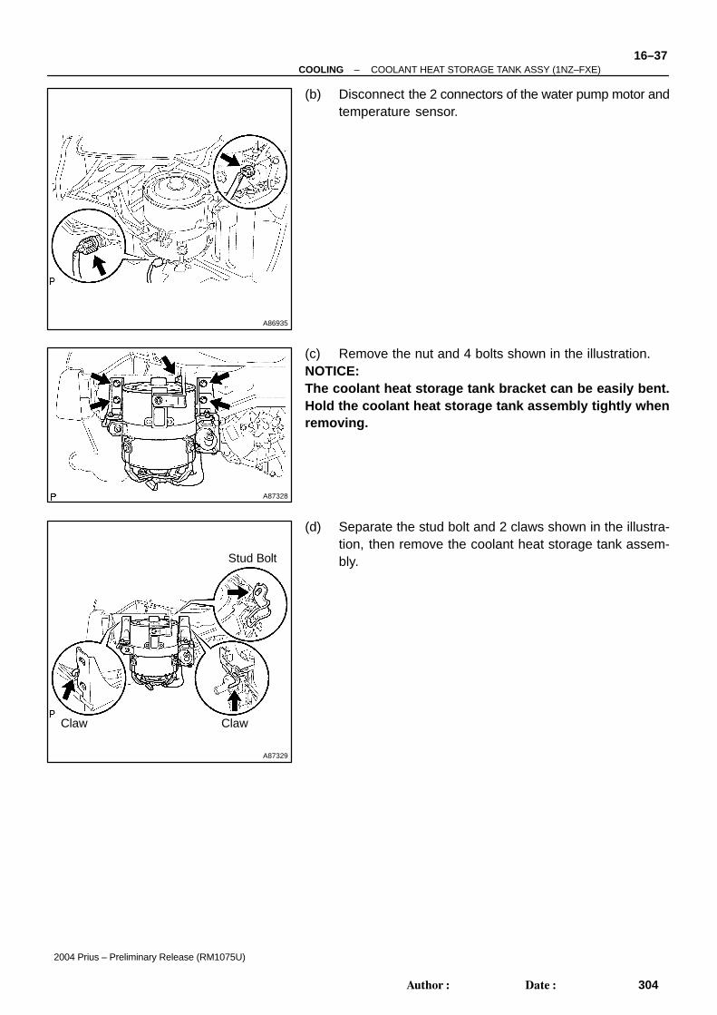
(b) Disconnect the 2 connectors of the water pump motor andtemperature sensor.
(c) Remove the nut and 4 bolts shown in the illustration.NOTICE:The coolant heat storage tank bracket can be easily bent.Hold the coolant heat storage tank assembly tightly whenremoving.
(d) Separate the stud bolt and 2 claws shown in the illustra-tion, then remove the coolant heat storage tank assem-bly.

A87330
Stud Bolt
ClawClaw
Insert Claws
Insert Stud Bolt
A87331
A86935
16–38–COOLING COOLANT HEAT STORAGE TANK ASSY (1NZ–FXE)
305Author: Date:
2004 Prius – Preliminary Release (RM1075U)
12. INSTALL COOLANT HEAT STORAGE TANK ASSY(a) Insert the 2 claws shown in the illustration to the vehicle
side, then insert the stud bolt to the vehicle side.NOTICE:The coolant heat storage tank bracket can be easily bent.Hold the coolant heat storage tank assembly tightly wheninstalling.
(b) Tighten the 4 bolts and nut shown in the illustration.Torque: 19 N ⋅m (194 kgf ⋅cm, 14 ft ⋅lbf)
NOTICE: When tightening bolt 1 and 2, push the coolant heat
storage tank bracket to the vehicle front. The coolant heat storage tank bracket can be easily
bent. Hold the coolant heat storage tank assemblytightly when installing.
(c) Connect the 2 connectors of the water pump motor andtemperature sensor.
A87327
–COOLING COOLANT HEAT STORAGE TANK ASSY (1NZ–FXE)16–39
306Author: Date:
2004 Prius – Preliminary Release (RM1075U)
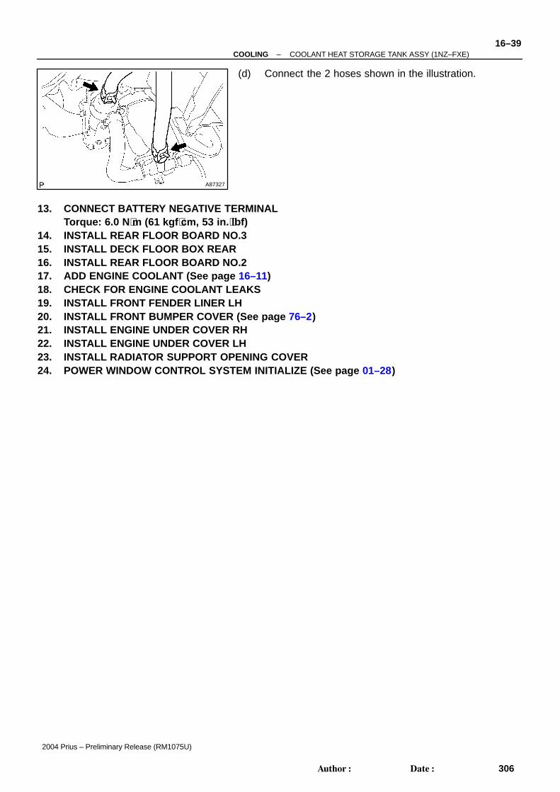
(d) Connect the 2 hoses shown in the illustration.
13. CONNECT BATTERY NEGATIVE TERMINALTorque: 6.0 N ⋅m (61 kgf ⋅cm, 53 in. ⋅lbf)
14. INSTALL REAR FLOOR BOARD NO.315. INSTALL DECK FLOOR BOX REAR16. INSTALL REAR FLOOR BOARD NO.217. ADD ENGINE COOLANT (See page 16–11)18. CHECK FOR ENGINE COOLANT LEAKS19. INSTALL FRONT FENDER LINER LH20. INSTALL FRONT BUMPER COVER (See page 76–2)21. INSTALL ENGINE UNDER COVER RH22. INSTALL ENGINE UNDER COVER LH23. INSTALL RADIATOR SUPPORT OPENING COVER24. POWER WINDOW CONTROL SYSTEM INITIALIZE (See page 01–28)
Top Related
Copyright © 2022 FDOKUMEN

