


Bahasa
Halaman
Hukum


Chapter 4
Variability Incorporated Simultaneous Decomposition of
Models Under Structural and Procedural Views
Muhammed Cagri Kaya1 , Selma Suloglu2, Gul Tokdemir3, Bedir Tekinerdogan4, and Ali H.
Dogru1
1Department of Computer Engineering, Middle East Technical University, Ankara, Turkey
2SoSoft Information Technologies, Ankara, Turkey
3Department of Computer Engineering, Cankaya University, Ankara, Turkey
4Information Technology, Wageningen University, Wageningen, The Netherlands
Abstract
This chapter presents hierarchical variability as an important development notion especially when considered
together with a systems specification through decomposition. A matured domain-specific environment is the
precondition for variability-centric engineering for compositional approaches as targeted in this study: Most of
the requirements have been already modeled, and most of the problem domain elements have corresponding
reusable solutions. Also, a mature domain enjoys a wide community of developers who are familiar with those
problems and solution-space elements and an effective set of specific tools. Decomposition is a fundamental
mechanism in many approaches for the specification of various dimensions of modeling. Decomposition of
especially structure modeling for software is not new. Here, variability guidance is incorporated into both
structure and process decomposition. This chapter combines such notions in the demonstration of variability-
centric development suggesting a structural and procedural decomposition of the system. The predecessors,
component-oriented approaches rely on the structural decomposition whereas service-oriented development is
being supported by process decomposition. A vending machine case study is presented in this chapter for
demonstrating the propagation of variability specification along with the enhancements of the component-
oriented model and the process model.

4.1. Introduction
Our era is witnessing advances software engineering toward compositional approaches, while these approaches
continue to inspire each other. However, none of them enjoy complete and widely-accepted methodologies.
Observed from such a perspective, this work can be classified as a component-oriented approach, significantly
influenced by Software Product Lines (SPL) and Service-Oriented Architecture (SOA) approaches. Actually, it
is not only the compositional avenue but also generation based techniques are effective in modern software
development environments. Transformational methods have also been considered in the more generalized
studies related to this research, belonging to the latter group.
Component orientation was defined in (Dogru and Tanik, 2003) as a process targeting composition of software
units. Actually, the decomposition view in software architecture was being addressed in those same days while
the related software architecture notions were developing in parallel. Association among the terminology
becomes more inclusive observing the strong connection between the software architecture and the
compositional concepts. It is worth mentioning here that most of the approaches have been introduced with their
“architecture” views preceding their “engineering” or “development” support. SPL Architecture (SPLA), for
example, enables SPL Engineering (SPLE) just like Model-Driven Architecture (MDA) supports Model-Driven
Development (MDD) or Model-Driven Engineering (MDE).
Studies addressing software architecture in a limited fashion are mostly concentrated on the “structure”
dimension of software-intensive systems, the Component-Oriented Software Engineering (COSE) therefore can
be viewed as one of the earlier approaches defining this new trend. This work contributes to COSE in the form
of addressing the other views of software architecture. This also coincides with addressing the data, function,
and control dimensions besides the existing structure dimension despite the fact that such addressing is done in
an implicit manner.
For summarizing the effects of SPLA and SOA to this work, feature modeling and especially variability
management as a related activity have been utilized as fundamental constituents in the modeling and the
development of systems. This perspective brings important consequences to the methodology for development.
Also, process modeling has been imported from SOA, with its suggested role as the overall control model for
the flow of executions. The commitment of web services to the tasks in a process model, constituting the next
most important global contribution of SOA is not a very new idea for COSE, where packages were dispatched to
components for the similar purpose.

It is worth mentioning the input from object orientation mostly through its modeling media–the Unified
Modeling Language (UML). For development with UML, the goal is to “write” code after defining various
cross sections of a software system through a set of graphical models. That is categorically different from the
compositional approaches where locating and integration of “already written” code is desired. Nevertheless,
UML has offered the component diagram, and even offers the usage of its diagrams for modeling the
“architectural views.” This is taken by the industry seriously and some tools do not even allow starting a UML
diagram unless the architectural view is first determined. Similarly, some UML tools identify themselves as
component-based as much as object-oriented. Of course, notions develop along with a chronology of
influences. A fundamental concept in components and further, in the mentioned approaches is the “interface.”
Objects, after all, are supporting an explicit interface notion in the form of the public sub-sets of their class
definitions.
Mentioning of UML brings an important issue when the bulk of the current development practices are
considered. UML-based activities usually start with the use case model. That is where a set of process
representing units are declared. These units are referred to as use cases. This is a logical model for the
processes, without an expectation to be associated with solution units (structure). However, such a central
model for UML is left alone without a methodical support for how to determine a good set of use cases–that is
process decomposition. Of course, process decomposition has not been the goal of the use-case diagrams, hence
they omit the flow specifications among the use cases: what is the order of their activations is not addressed,
and intentionally left out. This model is not desired to include the control dimension. Documentation of use-
case model descriptions is used to bridge the use-case specifications and control dimension. However, the
documentation is not explicitly expressed and associated with related use cases in a defined manner in UML-
based tools. Such association with the control dimension through documentation is left to analysts and
developers.
Nevertheless, even the most prominent code development targeting tool—UML—addresses some limited form
of process decomposition as the first step in modeling. Despite its intention to remain logical and to correspond
to only requirements, a use-case model is used as a map for the rest of the development: Each use case is taken
at a time, and its internals are defined using other UML diagrams. Such specification activity propagates to the
solution space preserving the same guidance map. The developers are quite conscious of which use case they
are currently implementing. Also, use case directed testing methods are quite common. Actually, the current

trend has not been very far from the presented approach in this chapter except for some notions being addressed
less and not utilizing the compositional power offered by the advancement of the development capabilities.
4.1.1 Variability in the Center of Development Activity
Most of the assumptions in optimizing the presented development approach are based on the existence of a
mature domain (Togay et al., 2008). This is the hidden assumption behind any modern approach anyway. A
mature domain can be characterized by the following properties:
1. Most of the domain requirements and reusable solutions have been developed,
2. A large community of developers are familiar with those domain repositories, and
3. Specific and effective tools are available.
SPLA, for example, is a domain-oriented technology. Also, the MDD would not be practically possible without
a scoped domain. It is known that the success of automatic-code generation depends on the width of the
boundary of its intended domain. Once the domain is known, the bulk of the necessary actions for the
development of the “next product” is also known. This knowledge can be arranged in the form of the common
features in any product and the variable ones that discriminate one product from another—all in the same
domain. Modeling of the commonalities and the variabilities is the foundation of SPLE.
A mature domain suggests the existence of a critical mass of engineers who are well knowledgeable about the
available assets for developing software in this specific domain. Components, for example, can be known by
their names and functional and non-functional properties. This also implies that possible sub-problem
definitions are known. The task of the developers now is to map the requirements to existing components and
configure the components and their interconnection as guided by variability management. Actually, we are
suggesting one additional layer between the requirements or selected features and the components: that is a
process model. The top-level variability is first mapped to the process model, hence instantiating it for the
required flow control of the system under development. Then the variability resolution ripples down the
hierarchy, to the components level. Assuming the requirement that the domain model is sufficiently mature, the
most important development effort will be consumed for the variability management.
The presented approach in this chapter corresponds to both “domain engineering” and “application engineering”
tasks of the SPLE. There are few options for variability modeling for the domain. The developers make their
choices starting with the highest-level, mostly by selecting variants for variation points. To enable the

configuration of the final system, following these choices, a hierarchical variability representation is required.
Also, constraints should propagate in general, from higher-level variability specifications to the lower-level
ones. Such specifications should be enabled to set-up the configuration interfaces of components for example,
for automated development. This research is supporting such mechanisms that are expected to leverage
variability-centric development probably as a new paradigm for development methodologies.
4.1.2 Chapter Objectives
There are significant messages this chapter intends to convey to the reader. The presented approach supports the
development of complex software intensive systems. Notions for efficiency are being utilized in modern
environments such as reuse being systematized by SPL. Here, a further automation is suggested by exploiting
some other notions that are explained below, while listing the targeted areas as the objectives to convey to the
reader:
1. Variability can be the most important input for development, for the environments (such as for SPL)
where certain capabilities have been established,
2. Hierarchical decomposition is an important notion in developing models and systems,
3. A system requires more than one model during development – their simultaneous development
(especially through hierarchical decomposition) is very important for the efficiency of the process.
A combination of these principles establishes an efficient development paradigm.
4.2. Background
This section includes an introduction about the basic concepts that form the foundation for this chapter. The
decomposition techniques for the structural and the procedural dimensions of software systems are discussed.
However, those decompositions can be guided by variability. Also, hierarchical modeling of variability is crucial
as it guides such decompositions. Hence, the hierarchical variability topic is introduced first.
4.2.1 Hierarchical Variability Specification
Variability modeling has been the target of many investigations since the usage of feature models (Kang et al.,
1990). Soon after, explicit variability modeling alternatives were developed as more preferred alternatives that
also suggested their association with hierarchy and constraints. Orthogonal Variability Model (OVM) (Pohl et
al., 2005), Covamof (Sinnema et al., 2004), and CVL-Common Variability Language (Haugen et al., 2012) can

be listed as the prominent and earlier work in this direction. The two important notions here that are hierarchy
and constraints, need to be considered simultaneously. Hierarchy allows the automated configuration of lower-
level variability specifications and eventually the software components because of the desire to support top-
down development strategy. Constraints, on the other hand, assume the enabling of specific associations among
the variabilities at different levels of the hierarchy.
Explicit variability modeling can be incorporated within the suggested approach in this chapter. It is considered
as future work. However, the main view here is enabling variability, wherever it originates towards more
automation for software development. That is why a mature domain is required and development is mostly
through configuration. Variability should guide configuration.
Our previous work about propagating variability specifications (Suloglu, 2013) in that manner involved variant-
to-variant associations from higher- to lower-level constituents (variation point regions in the models or
configuration interfaces in the software components). Development experimentation conducted during the early
work resulted in the suggestion to implement the variants as alternative flow paths in process models. At the
component level, variability is generally resolved through component replacement or component configuration.
Compliant components are expected to publish configuration interfaces that actually execute the external-to-
internal variation propagation. This latter option was possible within the mentioned early work.
Propagation of variability resolution in a set of hierarchically represented variation points has been
demonstrated in some examples that utilize COSE Modeling Language (COSEML)- and Business Process
Model and Notation (BPMN)-based representations for software components and process models, respectively.
The component-related representations are introduced in the following section, where variability specifications
and their propagation are also presented in examples.
The goal can be summarized as developing complex systems, mostly managing variability: Since commonality
is more defined, to specify a new product it is mostly the variability that should be addressed. For complex
systems, hierarchical modeling has been proposed earlier (Simon, 1996), complementing our variability
emphasis for our goal.
4.2.2 COSEML/XCOSEML for Structural Decomposition
COSEML emerged as a graphical modeling language for component-oriented development. It can represent
logical entities such as packages and their physical implementations such as components. Its aim is to meet the

graphical representation of the structural decomposition approach of COSE. Dynamic constructs to represent
procedural view are absent in this language. XCOSEML (Kaya et al., 2014) is an extended version of COSEML
equipped with variability and dynamic constructs. Unlike its predecessor COSEML, it is a text-based language.
In XCOSEML, language constructs and variability constructs are handled differently for easy management of
models conforming to “separation of concerns.” A graphical version of XCOSEML is under construction to ease
especially the process modeling (Cetinkaya, 2017).
COSEML aims to develop systems by composing pre-built software components in a mature domain. Therefore,
it did not use other concepts aside from components: such as objects, that are frequently used by the approaches
that aim code writing. Connectors were also considered as abstract entities that define connections between two
components. However, in (Cetinkaya et al., 2016), connectors became first-class entities like components by
handling communication concerns in them and including some extra capabilities, such as data conversion.
Dynamic view is first defined by XCOSEML for component orientation. Initially, in the process model of the
language (composition specification), plain messaging is shown explicitly. With the development of connectors,
the messaging among components is allocated in the connectors, and connectors assume a bigger role in the
development.
4.2.3 Process Decomposition for Software Composition
Usually, new processes leave the engineers with their creativity alone in creating new models. Earlier
methodologies were more detailed in providing step-by-step instructions based on text-based user requirements.
A considerable amount of detail is provided in the book of Pressman and Maxim (2015) for the hierarchical
definition of structure models based on existing data-flow models. Data-flow models in return were also
supported by methodological descriptions.
Most of our models should be organized in hierarchies that are naturally defined as a result of decomposition
activities. That is a requirement for reducing the complexity: according to Miller (1956) due to cognitive
limitations it is hard for our brains to concentrate on more than 7± 2 items at a time, especially if those items are
interrelated. Those items can be lines of code or other constituents of software definition models. Grouping
about seven items and encapsulating them under a new identifier reduces the total items significantly. However,
this technique alone usually is not enough. A program of 700 lines, for example, can be reduced to 100 functions
only for decomposition sake: every 7 lines can be organized as a function. However, the resulting 100 functions
are still considerably above our 7± 2 limit, let alone the ignored cohesion principle in determination of the
function boundaries.
So far, in the given example encapsulation reduced the cognition problem but not solved it completely. If those
modules are also sorted in a hierarchy, almost like a tree diagram, we have far better chances to understand the
model. As a result, looking at any locality in such a tree-based model, we can understand the whole by
understanding its parts. In such a model, parts are positioned in a way that represents the relation of a module
within the whole. Starting with the top module, we have better chances to keep the holistic view and orient
ourselves in any navigation across the model. As a summary, complex models should be arranged by
decomposition that corresponds to a hierarchy when conducted in a top-down manner.
One rare approach that suggests the hierarchy, hence the decomposition activity is the Axiomatic Design Theory
(ADT) (Suh, 1998). Equipped with various techniques to support modularity, this approach offers tools for
evaluating the coupling property of a given design. Although developed initially for mechanical engineering, the
approach was quickly adapted to software development. Its methodological dimension offers simultaneous
decomposition techniques for various development models. After the adaptation by the software industry, it was
applied to component orientation (Togay et al., 2008). Finally, ADT was used for process decomposition,
leveraging on its capability to decompose various models simultaneously (Togay et al., 2017). This is a
methodology imported in this research for guiding the decomposition due to its compatibility with the process
model and component model for simultaneous decomposition. However, a required condition is the persuasion
for the use of decomposition in the definition of a model. Following the concerns about preserving the holistic
view, this option is suitable. Also, ADT promotes this kind of orientation. As a summary, developing a model
mainly based on decomposition is supported by this research.
In relevant literature, it is widely acknowledged that large (Mendling at al., 2007) and complex (Mendling et al.,
2008) process models decrease the level of comprehension. They also create a setting which is unfavorable
though further error generation in these models. To overcome this undesired result, decomposition is proposed
as a supportive method.
Decomposition includes gradual dismantling of a system into smaller sub-systems (Dietz, 2006). It is argued
that decomposing process models into sub-models will provide a solution for complexity (Dumas et al., 2013).
This will also reverse the case of low understandability (Mendling et al., 2007). It is emphasized that
decomposition will result in easier communication and improved maintainability of process models (Milani et
al., 2016). It is also suggested that decomposition will promote reusability of the sub-models (Bass et al., 1998):
decomposed systems will have less coupling and more cohesion as a consequence.
In the literature, various concepts have been utilized interchangeably in relation to the process of decomposition.
Some of which are modularization, aggregation, generalization, and abstraction. Similarly, several approaches
have been proposed for decomposition of process models including rules and criteria.
Dijkman et al. (2016) provide a detailed review on the comprehensive concept of decomposition. They explore
studies on business process design approaches and furthermore classify studies based on how the processes and
their relationships are defined. They group related approaches accordingly. These groups are namely goal-based,
action-based, object-based and function-based approaches. The goal-based approaches (Anton et al., 1994) use
structured goal definition which is used to derive the process architecture. Sub-goals can be defined at the lower
levels which may be associated with sub-processes. Similarly, business actions/sub-actions and their relations
can be designed and then mapped to processes/sub-processes in action based approaches (Dietz, 2006). On the
other hand, object based approaches represent objects and their relations. The decomposition of objects can be
associated with process decomposition. In function based approaches, a hierarchical relation between business
functions is represented by a process/sub-process decomposition architecture.
Another recent review by (Milani et al, 2016) elaborates on methods of process model decomposition and
classifies them based on heuristics that utilize breakpoints, data objects, roles, shared processes, repetition, and
structuredness. Approaches that consider breakpoints are mainly grounded on the view that a process can be
broken down into sub-processes based on specific interest points called breakpoints or milestones during the
process lifespan which can be points where process properties are measurable (Milani et al., 2013). It is also
suggested that decomposition can be performed based on how data objects are shared between the activities,
hence yielding the activities using same objects placed in the same sub-process. Processes can be detached by
means of the stakeholder views (Turetken and Demirors, 2011) where stakeholders model and improve their
own processes individually which are then integrated to form the top level processes.
Another approach considered for decomposition is shared processes which combine process parts that are used
in different parts of the process. Within this perspective, alternative approaches might be also suggested where
behavioral aspects of process parts like sequential, parallel, or cyclical can be examined and the ones with
similar behavior are combined. Similarly, in the block-structuring approach, ‘‘single entry single exit’’ blocks
can be identified as process parts and through graph clustering related nodes can be combined as a sub-process

(Reijers et al., 2011). This will also result in enriched understanding and improved nature of decomposition
processes.
Similar ideas and propositions exist on concepts like vertical, horizontal and orthogonal modularization, and
composition and merging as stated in La Rosa et al. (2011). Also on aggregation which specifies a top-level
object being composed of lower-level fragments or being generalized that is a high-level abstraction of the
lower level variants (Muehlen et al., 2010). Similarly, as another concept, though providing an alternative view,
model abstraction describes aggregated activities of a process model in a more abstract view (Smirnov et al.,
2011). Another approach uses separation of concerns that are involved in process activities by specifying roles
played by activities for process decomposition (Caetano et al., 2010).
Methods for “how-to-decompose” are definitely not limited to the ones mentioned above. Within the last
decade, especially in recent years, alternatives were proposed and discussed both in academia and in practice.
For example, another basis for decomposition is through merging algorithms based on the graphs like EPCs
(Event-driven Process Chains) and BPMN (La Rosa et al., 2013). For example, Huang et al. (2018) apply a
graph mining algorithm to find out frequent subgraphs under the same process topic for merging processes,
which is needed to be checked for semantic correctness of the merged parts.
Johannsen et al. (2014) apply decomposition conditions of Wand and Weber (1989)—minimality, determinism,
losslessness, minimum coupling, and strong cohesion—to BPMN. They propose guidelines for a decomposition
process and argue that these guidelines should be redefined for each modeling language.
To summarize the overall picture regarding the domain of process decomposition, there has been progress in
terms of providing valuable insights and arguments into the practice. However, there is still need for a
generalized guideline for widely accepted criteria for consistent decomposition (Johannsen and Leist, 2012),
independent of the modeling context.
4.3. Variability-guided Decomposition
The advances in the compositional capabilities and the advantages of domain orientation can be leveraged in
promoting variability management as the main development activity. The details of how variability models are
developed is out of the scope of this work but can be found in several studies (Kang et al., 1990; Pohl, 2005;
Sinnema et al., 2004).

The goal is to treat variability as a guide during procedural and structural modeling where variability affects
process model first and then the process model shed light to structural decomposition along with its own
variability specification. All these activities focus on mostly “domain design” and “domain realization” part of
the “domain engineering.” In a process-oriented decomposition, the flow of the activities leads the structural
decomposition. The flow varies with respect to functionality and behavior also to cover the needs of different
stakeholders. In this case, variability model is going to answer the questions:
Why: the reasons for the process model to fork by representing variations;
How: the way the flow forks and joins via pinpointing the variation points with respect to constraints;
and
What: the capabilities of the process model through an ability to resolve variations to produce the final
product.
Therefore, corresponding variability model guides the process decomposition and establishes relations with
hierarchical variability in structural decomposition. The modeling techniques and approaches employed in our
approach are listed in Table 4.1.
Table 4.1. Modeling techniques and tools
Modeling Type Model Tool Type Specific Tool
Variability modeling Feature Model FeatureIDE (2018)
Process decomposition
Business Process Modeling
Notation (BPMN)
Signavio (2018)
Structural decomposition
Hierarchical Component
Decomposition (XCOSEML
HCD with its variability
model—VM)
XCOSEML tool
Our approach is not limited to the models used for process decomposition and variability modeling. The
modeling techniques and approaches are chosen for demonstration purposes as well as their popularity.
Variability guided decomposition process is elaborated with a set of steps along with affected models in Table
4.2.
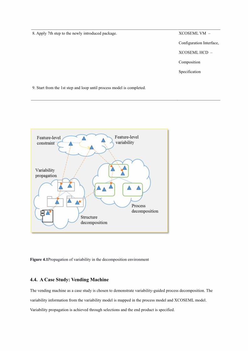
Concerning the “application engineering” part, mainly “application design and application realization,” the goal
is to conduct a top-down variability resolution while process and structure decomposition will accompany this
effort where necessary. Also, variability-resolution actions are expected to automate related decompositions.
Figure 4.1 depicts the variability decisions affecting the associated models.
Variability resolution first needs to consider the dependent variabilities at the feature level. If only feature
models are used to represent variabilities, such consideration will be the observation of “include” and “exclude”
constraints in the feature model. That way some further variability decisions will have to be made, preferably
automatically.
Next, ramifications of a resolution at the feature level should be considered. For example, selecting an optional
feature as a variability-resolution action will require further selections in some variability points in the process
model, or in the structure model, or in both. These kind of consequences may be automatically handled based on
the maturity of the domain and completeness in the domain models. Such a propagation can be from the feature
model to both the process model and the structure model, from the process model to the structure model, and
also can be internal to any model. By the way, the structure model in this work implies the COSEML
representation of the logical and component levels altogether.
Propagation of variability decisions can be observed to be taking place inside any model, and from a higher-
level model to a lower-level one. The structure level is considered as the lowest-level model, being below the
process model: It is only after determining the flow of the operations that the operation instances can be
connected.
A similar space of mutually-dependent models where the developers would be faced with the final status of all
the models after one design decision was implied by Togay (2008). However, an explicit addressing of such
methodological concerns was not incorporated. Also, variability was not employed. The interdependent actions
in a set of models could be from any model constituent to any other, exploring the possibilities in a
combinatorial complexity. Here, interventions are allowed only in the variant representations. This is both a
limitation to the complexity and the elevation of variability notion to the position where it becomes the primary
development action.

Table 4.2. Variability-guided decomposition steps
Step Affected Model
1. Start with appending an activity to the process model. BPMN Model
2. Analyze the feature model with respect to the recently added activity whether any
of the features are related to it and make the activity’s behavior diverse.
None
3. If there will be more than one possible realization of the activity, then convert them
to sub-processes to be decomposed further.
BPMN Model
4. Add a corresponding package to XCOSEML component decomposition model if
there is no package that can be related to the activity/sub-process. Otherwise, use an
existing package.
XCOSEML HCD –
Package Specification
5. Define relevant components and their functions with respect to activity/sub-process
if required.
XCOSEML HCD –
Component Interface
6. Specify variation point and related variants with constraints for the newly
introduced package and its parent package if exists. Define variation mappings among
newly defined variation points and variants.
XCOSEML VM –
Configuration Interface,
XCOSEML HCD –
Composition
Specification
7. Define a new function or use an existing one in the package composition for the
parent package. Specify or change the flow of the function with corresponding
variation points and variants through “variation specification attachments.” Append
new function to parent package interface if added.
XCOSEML VM –
Configuration Interface,
XCOSEML HCD –
Composition
Specification
8. Apply 7th step to the newly introduced package.
XCOSEML VM –
Configuration Interface,
XCOSEML HCD –
Composition
Specification
9. Start from the 1st step and loop until process model is completed.
Figure 4.1Propagation of variability in the decomposition environment
4.4. A Case Study: Vending Machine
The vending machine as a case study is chosen to demonstrate variability-guided process decomposition. The
variability information from the variability model is mapped in the process model and XCOSEML model.
Variability propagation is achieved through selections and the end product is specified.

The vending machine is an automated machine invented in the late 1880s which provides a diverse set of items
ranging from beverages, tickets, postcards, cigarettes, to hot pizzas. They accept payment by cash or, today,
even by credit cards. The vending machine in our case study offers beverages, solid food, and soft drinks.
Different items require different delivery processes for the vending machine. Solid food and soft drinks are
placed in the dispenser directly. On the other hand, preparation of hot beverages such as tea or coffee includes a
set of steps: placing cup and spoon, pouring tea or coffee, and adding sugar if requested.
A feature model for the vending machine has been created as shown in Figure 4.2. The feature model is the
source of variability information. This, in turn, configures the XCOSEML variability model, leads to variability
resolution, and propagation of resolution from upper levels to lower levels, all the way to components. In this
way, variability binding of the process model is completed towards the configuring of an application.
Figure 4.2 Feature model of vending machine case study
For the domain design and realization part, process decomposition for vending machine starts with the
initialization of corresponding models as shown in Table 4.3. Improvements in each stage of the decomposition
process are represented through a process model and an XCOSEML model conforming to the feature model.

Table 4.3 First stage of decomposition
Process Model
XCOSEML Structural
Model
Package VendingMachine
XCOSEML Variability
Related Models
None
Then, as shown in Table 4.4, the addition of the activities to the process model starts: Vending machine waits for
the payment at first. After analyzing the feature model, it is observed that the machine supports two different
payments: via cash or credit card. The feature “Payment_type” and its child features “Coin” and “Credit_card”
point out that payment process will be diversified. Therefore, a sub-process is added to the process model with
the name “Get Payment” to be decomposed further. The relation between “Coin” and “Credit_card” features are
“optional” as the vending machine can support either one or both of them. As no package exists that can be
related to payment associated activities, a new package “Payment” is added to the root of the XCOSEML
component decomposition. A variation point “PaymentType” and its variants “Coin” and “CreditCard” are
created with the “optional” relation, which is directly related to the newly introduced features. As our
decomposition is hierarchical, there should be a related variation point and variants defined for “Payment”
package which are “Type,” “Coin,” and “CreditCard,” respectively. In order to represent and enable propagation
from upper levels to lower levels of the hierarchy, variation mappings are defined. In this case, a one-to-one
mapping is established in composition specification: the variant of “PaymentType” in vending machine package
is mapped to “Coin,” that is the variant of “Type” in the payment package.
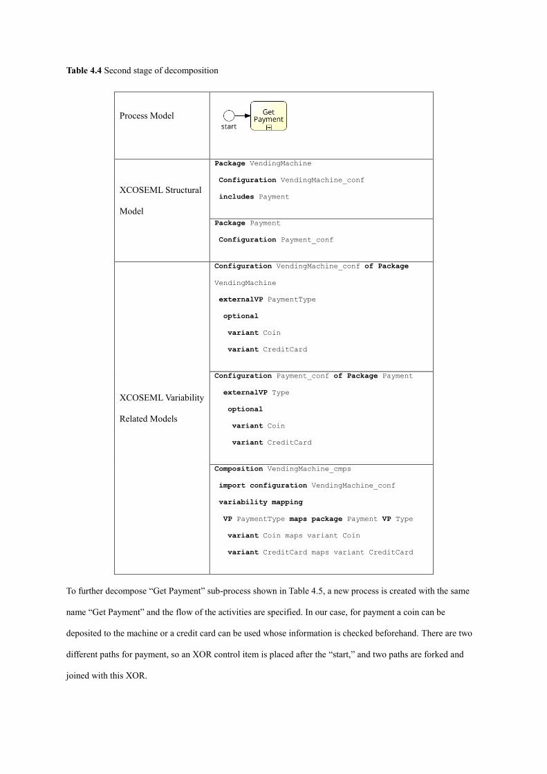
Table 4.4 Second stage of decomposition
Process Model
XCOSEML Structural
Model
Package VendingMachine
Configuration VendingMachine_conf
includes Payment
Package Payment
Configuration Payment_conf
XCOSEML Variability
Related Models
Configuration VendingMachine_conf of Package
VendingMachine
externalVP PaymentType
optional
variant Coin
variant CreditCard
Configuration Payment_conf of Package Payment
externalVP Type
optional
variant Coin
variant CreditCard
Composition VendingMachine_cmps
import configuration VendingMachine_conf
variability mapping
VP PaymentType maps package Payment VP Type
variant Coin maps variant Coin
variant CreditCard maps variant CreditCard
To further decompose “Get Payment” sub-process shown in Table 4.5, a new process is created with the same
name “Get Payment” and the flow of the activities are specified. In our case, for payment a coin can be
deposited to the machine or a credit card can be used whose information is checked beforehand. There are two
different paths for payment, so an XOR control item is placed after the “start,” and two paths are forked and
joined with this XOR.

There is no need to add a new package in XCOSEML structural decomposition as “Payment” is an appropriate
package for payment-related activities. Therefore, “Payment_comp” is introduced with two functions:
“GetCoin” and “ConnectBank.” There needs to be no change in the XCOSEML variation model. A function
“Operate” is defined in the “VendingMachine” root package which calls “GetPayment” function from the
“Payment” package. Therefore, a new function, “GetPayment” is specified in “Payment” composition
specification with the corresponding variability attachments. “GetPayment” function includes coin-related
activities (the “GetCoin” function) if only “Coin” is selected. This variability is represented by appending
“#ifSelected(Coin)#” attachment at the beginning of the coin related activities (Payment_comp.GetCoin). The
same holds for the “CreditCard” variation where the function call is surrounded with “#ifSelected(CreditCard)#”
attachment. In this way, the activities will be added with respect to the selection of the variants, namely “Coin”
and “CreditCard.”

Table 4.5 Third stage of decomposition
Process Model
XCOSEML
Structural
Model
Package VendingMachine
Configuration
VendingMachine_conf
includes Payment
Composition VendingMachine_cmps
import configuration VendingMachine_conf
Variability mapping
VP PaymentType maps package Payment VP Type
variant Coin maps variant Coin
variant CreditCard maps variant CreditCard
method Operate:
payment.getPayment
Package Payment
Configuration
Payment_conf
Component Payment_comp
interface Payment_int
Composition Payment_cmps
import Payment_conf
has Payment_comp
ContextParameters
coinInserted
creditCardProvided
Method GetPayment:
#vp Type ifSelected(Coin)#
guard(coinInserted) Payment_comp.GetCoin
#vp Type ifSelected(CreditCard)#
guard(creditCardProvided)
Payment_comp.ConnectBank
Interface Payment_int
providedMethods
GetCoin
ConnectBank
XCOSEML
Variability
Related Models
Configuration
VendingMachine_conf of
Package VendingMachine
externalVP PaymentType
optional
variant Coin
variant CreditCard
Configuration Payment_conf
of Package Payment
externalVP Type
optional
variant Coin
variant CreditCard
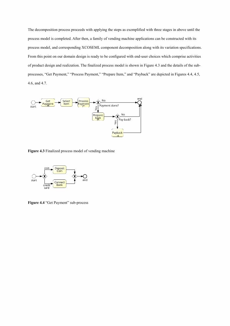
The decomposition process proceeds with applying the steps as exemplified with three stages in above until the
process model is completed. After then, a family of vending machine applications can be constructed with its
process model, and corresponding XCOSEML component decomposition along with its variation specifications.
From this point on our domain design is ready to be configured with end-user choices which comprise activities
of product design and realization. The finalized process model is shown in Figure 4.3 and the details of the sub-
processes, “Get Payment,” “Process Payment,” “Prepare Item,” and “Payback” are depicted in Figures 4.4, 4.5,
4.6, and 4.7.
Figure 4.3 Finalized process model of vending machine
Figure 4.4 “Get Payment” sub-process

Figure 4.5 "Process Payment" sub-process
Figure 4.6 “Prepare Item” sub-process
Figure 4.7 “Payback” sub-process
For the “product realization” part of “product engineering,” suppose the end user chooses “Beverages” from
“Container” and “Coin” from “Payment_type” from the feature model in Figure 4.2. The final feature model
includes all features that the final application covers, presented in Figure 4.8.

Figure 4.8 Configured feature model for the application
The propagation starts from the root package “VendingMachine” and is propagated to configure the interfaces
and compositions, which in turn provides the final product with its process model. The process model of the
application stays same as in Figure 4.1. However, the flow of the sub-processes is changed, which is shown in
Figures 4.9, 4.10, 4.11, and 4.12.
Figure 4.9 “Get payment” sub-process for the application
As “Coin” feature is selected, “Get Payment” includes only coin-related activities which are represented by the
“Deposit Coin.” Similarly, the activities related to the preparation of beverages are included in “Prepare Item”
sub-process, represented in Figure 4.10.
Figure 4.10 “Prepare Item” sub-process for the application
The selection of “coin” feature also affects “Process Payment” and “Payback” sub-processes to include only
coin related functionality, which is represented in Figures 4.11 and 4.12.
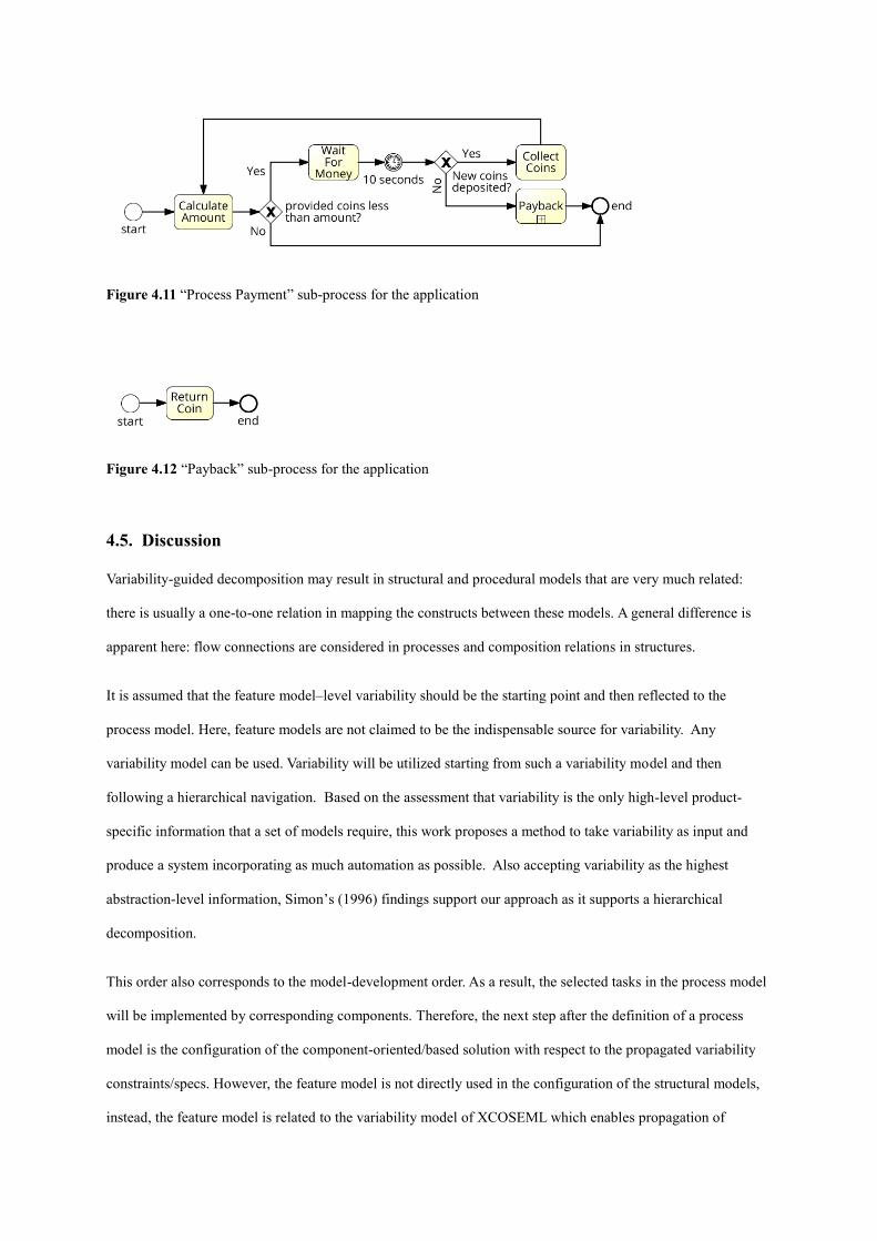
Figure 4.11 “Process Payment” sub-process for the application
Figure 4.12 “Payback” sub-process for the application
4.5. Discussion
Variability-guided decomposition may result in structural and procedural models that are very much related:
there is usually a one-to-one relation in mapping the constructs between these models. A general difference is
apparent here: flow connections are considered in processes and composition relations in structures.
It is assumed that the feature model–level variability should be the starting point and then reflected to the
process model. Here, feature models are not claimed to be the indispensable source for variability. Any
variability model can be used. Variability will be utilized starting from such a variability model and then
following a hierarchical navigation. Based on the assessment that variability is the only high-level product-
specific information that a set of models require, this work proposes a method to take variability as input and
produce a system incorporating as much automation as possible. Also accepting variability as the highest
abstraction-level information, Simon’s (1996) findings support our approach as it supports a hierarchical
decomposition.
This order also corresponds to the model-development order. As a result, the selected tasks in the process model
will be implemented by corresponding components. Therefore, the next step after the definition of a process
model is the configuration of the component-oriented/based solution with respect to the propagated variability
constraints/specs. However, the feature model is not directly used in the configuration of the structural models,
instead, the feature model is related to the variability model of XCOSEML which enables propagation of
variability resolutions. Reasons for this choice are: XCOSEML works with its own variability model, and a
feature model does not categorize its features as variation points and variants, however, these elements are
important in the configuration of structural decomposition. Besides, from the end-user point of view, the
contents of the feature model should be relevant and meaningful by representing available choices that the end
user can select. In fact, the feature model constructed in the variability-guided decomposition process is
developer-oriented which also includes functions of the system. Therefore, pruning of the feature model can be
an additional step before it comes into use. The remaining features that are not selected by end users either are
bound by the constraints or left to be chosen by developers of the system. In this way, variability resolution is
ready to affect the structural decomposition.
Concerning variability propagation to process models, there have been various works, a detailed survey can be
found in (La Rosa et al., 2017). Also, component models were addressed for variability. These separate efforts
are consolidated in this research for a holistic modeling and development methodology by also devising further
mechanisms for system composition. Here the important part is modeling variable parts of the process
decomposition in a manageable way. A prospective approach is the definition of sub-processes in the presence of
alternative or optional flows. The notion of sub-process also supports coherence, meaning that related flows are
composed with each other. By following this approach, it can be a good practice to contemplate about the
creation of a sub-process whenever the process model comes into a diversification point that serves different
needs.
4.5.1 About the Architecture
The software architecture corresponding to the presented approach suggests three fundamental models, feature
model, process model, and component model. The latter two will also be part of the run-time environment. If
variability were not incorporated a similar architectural structure could be maintained. However, additional
structures would be especially required for the development time. The existence of the feature model would be
questioned without variability. The process and the set of components would need to be shaped up as a result of
other models. Those models could include requirements and component based notations. Basically, the
architecture would not include support for propagating variability over configuration interfaces that themselves
would be excluded also. There would be bigger emphasis on a requirements model, guiding individually
different component and process solutions.

4.5.2 Simultaneous Decomposition and Variability
The suggested process is based on two foundations. The first one is promoting top-down approaches in
decomposition. Simon (1996) has suggested decomposition as the key tool for addressing complex engineering
design. Moreover, this decomposition should be carried in a hierarchical manner, starting from top. Our
approach accepts variability specifications as the highest-level information for software development. This is
felt more in the product development activities than in the domain model development. Therefore, variability
will be the reference point, guiding the development tasks that follow the abstraction levels after variability.
The other foundation is simultaneous decomposition. Since 1970s, the software industry has realized the
problems with Waterfall-like processes: Models developed in isolation (usually in a predetermined sequence
that does not allow revisiting the previous models much) will not render a consistent set of constituents to yield
code. As a response, evolutionary and iterative processes were invented to allow for different models
influencing each other. Suh (1998) specifically devised a method to develop a set of models simultaneously so
that once one model is finalized, all are finalized that are in compliance to each other. Both Simon and Suh
consent to the importance of building by decomposition as a starting point.
Various implementations of these ideas have been practiced. Here, variability-guided simultaneous
decomposition is promoted, as a synthesis of these foundations in an effort to gain important efficiency
increases in software development.
Similarly, variability in different models have been handled with different techniques. This should be continued,
however, the expected mature domain suggests the constraints among different kinds and locations of variability
being already defined. Also the necessary adaptations in different models should better be defined for all
possible variants. One outcome of this approach would be a fast connection between the problem and the
solution domains: Possible associations have already been set between the elements of these domains and
product development will iron out the details in constraint propagation. Once the decisions are made about the
variations, their repercussions in the requirements, design, or implementation will be followed by the constraint
navigations. Also to mention, horizontal (peer-to-peer) constraints are also important. They should be dealt with
as they would in any case. This research promotes top-down propagation as it is important in system definition.
As the ripple effect of any constraint resolution, any resultant vertical or horizontal constraint requirements
should be handled as intermediate steps. This may sometimes be painful.

Lastly, the decomposition is suggested to be carried top-down. In this perspective, the process is allocated in a
higher-level of abstraction than the structure. However, not depending on a variation point being in any of these
models, a top-down process should be carried out. This traversal, starting from the top, should advance until a
variation point is found and process it and continue. Meaning, the higher-levels without variation points will not
stop the process. Also the traversal will advance based on levels, not on models. Meaning, starting or ending at
any model will not hamper the process.
4.5.3 Proactive/Reactive Variability
Here, a short discussion about what would happen if variability was omitted, is presented. . In mature domains
such as an established SPL infrastructure, variability is a pillar whose absence will nullify the SPL practice
altogether. Still it is possible to contemplate a scenario where software development is carried out without the
variability capability and tried to be applied after the case. First of all, variability considers a set of software
products to be developed. Without it, the individual developments of a set of different products will be
addressed albeit how related they may be. The result will materialize as a set of maintenance projects that take
one product independent from the others, probably enduring difficulties due to the principle about the increased
complexity when changes are applied late in the process. Here the changes will be applied after almost
completion, hence very costly.
4.5.4 Disadvantages
One shortfall of the suggested approach is its dependence on advanced development environments, such as a
well-established SPL infrastructure. Also, availability of additional tools in such an environment would be
necessary. Since the idea is to increase the efficiency, this objective cannot be significantly achieved unless there
are specific tools integrated to such an established environment. The existing stand-alone tools mentioned in this
text have not been integrated to a full SPL infrastructure.
4.6. Conclusion
In this chapter, a variability-guided decomposition process defined that has been illustrated using a case study.
Incorporating variability into system development eases management of change in requirements and adoption to
change in a systematic way. It can be achieved proactively or reactively: constructing the system from the
perspective of variability from scratch or reconstruct existing system with identification of variable parts
respectively. The presented approach serves as guidance for the proactive attempt to variability. Decomposition

of the system into smaller processes sheds light on structural decomposition along with variations. The
hierarchical nature of process and structure enables propagation of variability specifications from upper levels to
lower levels by establishing relations and constraints between them for variability resolution. In this way,
variability binding is achieved in a systematic way by resolving variability in the upper levels and expecting
configurations in the lower levels to reveal a complete system.
4.7. Lessons Learned and Future Work
There is an unresolved question that can define future work problems related to the presented approach. That is
the question of how many isomorphism can be attainable in the various decomposition models for the modeling
“domains” of the ADT. In software development, this question corresponds to the similarity between the
requirements decomposition and the design decomposition. A ramification of this discussion would yield further
efficiency in SPL approaches where the isomorphism between the feature model and the component
decomposition would further automate the selection of components, once a product feature model is instantiated
from the domain model. A research on ramifications for such isomorphism can be a good future work.
Actually, ADT offers design matrices and a method to evaluate them for the assessment of coupling: if
functional requirements can map to design parameters in a one-to-one manner, the two models are uncoupled.
However, this also implies a possible isomorphism–reducing the work for building the topology of the
component network: Once the features are selected, so are the components and, further, their decomposition
connections. What is still missing to convert this topology to an executable system is to incorporate a process
model: define a set of connections for message sending and the ordering of the invocations for those messages.
Yet, data needs to be saved and forwarded to be used as input and output parameters for the messages that
stimulate methods. This is referred to as state management in the process modeling world.
ADT, allowing the coupling assessment through its “design matrices” would also allow two other coupling
classifications for the less-preferred design choices. These correspond to one-to-many or many-to-many
mappings between the functional requirements and design parameters. Usually the logical and physical parts of
the decomposition in COSEML more or less correspond to requirements and design models. In the higher levels
of a COSEML model, the diagram is suggested to preserve one-to-many relations from a parent node to its
children.

COSEML suggests to start with a logical decomposition and at any level when the developers can associate a
logical with a potential physical component, they stop the decomposition. Next, they link this logical module to
the component. It is also possible to decompose components into smaller components. However, the goal is to
reach a product practically and sooner; it is better to avoid composition or decomposition among the
components. The related work suggests the two-level hierarchy (Togay et al., 2017) where a logical-level model
is directly mapped to methods without a further structuring in the lower levels. That is reminiscent of the related
SOA technologies consisting of an “orchestration” that is a process model and a set of web service method calls.
However, it is possible to allow one-to-many as well as many-to-one relations from the logical level to the
components: One logical module could correspond to more than one readily available component for its
realization. An advanced COSEML engineer is supposed to decompose the logical level in an effort to convert
this sub-section of the model to a one-to-one mapping alternative. On the other hand, the logical model could
have been over decomposed where a component to be found in the industry could be implementing both of such
requirements. Also if possible, the modification in the lower levels of the logical part is preferred for one-to-one
mappings around such leaf-levels. However, the language does not impose any such restrictions.
4.8. References
Anton, A. I., McCracken, W. M., and Potts, C. 1994. Goal decomposition and scenario analysis in business process
reengineering. In: Wijers G., Brinkkemper S., Wasserman T. (eds) Advanced Information Systems Engineering. CAiSE
1994. Lecture Notes in Computer Science, vol 811: 94-104. Springer, Berlin, Heidelberg
Bass, L., Clements, P., and Kazman, R. 1998. Software Architecture in Practice. Addison-Wesley, Massachusetts.
Caetano, A., Silva, A. R., and Tribolet, J. 2010. Business Process Decomposition—An Approach Based on the Principle of
Separation of Concerns, Enterprise Modelling and Information Systems Architectures, 5(1): 44-57.
Cetinkaya, A., Kaya, M. C., and Dogru, A. H. 2016. Enhancing XCOSEML with connector variability for component
oriented development, In Proc SDPS 21st International Conference on Emerging Trends and Technologies in Designing
Healthcare Systems, 120-125, Orlando, Florida, December 4-6.
Cetinkaya, A. 2017. Variable Connectors in Component Oriented Development. MSc Thesis, Middle East Techical
University.
Dietz, J. L. G. 2006. The Deep Structure of Business Processes. Communications of the ACM, Vol. 49:59-64.
Dijkman, R., Vanderfeesten, I., and Reijers, H. A. 2016. Business process architectures: Overview, comparison and
framework. Enterprise Information Systems, 10(2) 129-158, doi:10.1080/17517575.2014.928951.
Dogru, A. H., and Tanik M. M. 2003. A process model for component-oriented software engineering. IEEE software, 20(2),
34-41.
Dumas, M., La Rosa, M., Mendling, J., and Reijers, H.A. 2013. Fundamentals of Business Process Management, Springer,
Berlin/Heidelberg.
FeatureIDE, 2018. http://www.featureide.com/ (accessed January 30, 2018).
Haugen, Ø., Wasowski, A., and Czarnecki, K. 2012. "CVL: common variability language." In SPLC, 266-267, Tokyo, Japan,
Aug 26-30.
Huang, Y., Li, W., Liang, Z., Xue, Y., and Wang, X. 2018. Efficient business process consolidation: combining topic features
with structure matching, Soft Computing, 22(2), 645-657.
Johannsen, F., and Leist, S. 2012. Wand and Weber’s decomposition model in the context of business process modeling,
Business & Information Systems Engineering, 54(5), 263-280.
Johannsen, F., Leist, S., and Tausch, R. 2014. Wand and Weber's good decomposition conditions for BPMN: An
interpretation and differences to Event-Driven Process Chains, Business Process Management Journal, 20(5), 693-729,
https://doi.org/10.1108/BPMJ-03-2013-0031.
Kang, K. C., Cohen, S. G., Hess, J. A., Novak, W. E., and Peterson, A. S. 1990. Feature-oriented domain analysis (FODA)
feasibility study. No. CMU/SEI-90-TR-21. Carnegie-Mellon Univ Pittsburgh Pa Software Engineering Inst.
Kaya, M. C., Suloglu, S., and Dogru, A. H. 2014. Variability modeling in component oriented system engineering, Proc
SDPS the 19th International Conference on Transformative Science and Engineering, Business and Social Innovation, 251-
259, Kuching Sarawak, Malaysia, June15-19.
La Rosa, M., Wohed, P., J. Mendling, et al. 2011. Managing process model complexity via abstract syntax Modifications,
IEEE Transactions on Industrial Informatics, 7(4), 614-629.
La Rosa, M., Dumas, M., Uba, R., and Dijkman R. 2013. Business process model merging: an approach to business process
consolidation. ACM Transactions on Software Engineering and Methodology (TOSEM), vol 22(2): 11:1-11:42.
La Rosa, M., Van Der Aalst, W. M. P., Dumas M., and Milani, F. P. 2017. Business process variability modeling: A survey,
ACM Computing Surveys, 50(1):1-45.
Mendling, J., Reijers, H. A., and Cardoso, J. 2007. What makes process models understandable?. In International Conference
on Business Process Management, Lecture Notes in Computer Science, vol. 4714, pp. 48-63, Barcelona, Spain, Sept 10-15.
Mendling, J., Verbeek, H. M. W., van Dongen, B. F., van der Aalst, W. M. P., and Neumann, G. 2008. Detection and
prediction of errors in EPCs of the SAP reference model, Data & Knowledge Engineering, 64(1), 312-329.

Milani, F., Dumas, M., and Matulevičius R. 2013. Decomposition driven consolidation of process models. In International
Conference on Advanced Information Systems Engineering, 193–207, Essen, Germany, June 12-16.
Milani, F., Dumas, M., Matulevicius, R., Ahmed, N., and Kasela, S. 2016. Criteria and heuristics for business process model
decomposition—Review and comparative evaluation, Business & Information Systems Engineering, 58(1), 7-17.
Miller, G. A. 1956. The magical number seven, plus or minus two: Some limits on our capacity for processing
information, Psychological Review, 63(2), 81.
Muehlen M. Z., Wisnosky D., and Kindrick J. 2010. Primitives: design guidelines and architecture for BPMN models. In
21st Australasian Conference on Information Systems, Brisbane, Australia, Dec 1-3.
Pohl, K., Bockle, G., and van der Linden F. 2005. Software Product Line Engineering Foundations, Principles, and
Techniques, Springer-Verlag Berlin Heidelberg.
Pressman, R. S., and Maxim, B. R. 2015. Software Engineering: A Practitioner's Approach, 8th edition. McGraw Hill
Education. New York.
Reijers, H. A., Mendling, J., and Dijkman, R. M. 2011. Human and automatic modularizations of process models to enhance
their comprehension, Information Systems, 36(5), 881-897.
Smirnov, S., Reijers, H. A., and Weske, M. 2011. A semantic approach for business process model abstraction, In
International Conference on Advanced Information Systems Engineering, 497-511, London, June 20-24.
Suloglu S. 2013. Model-Driven Variability Management in Choreography Specification, PhD Thesis, Computer Engineering
Department, Middle East Technical University (METU), Ankara, Turkey.
Signavio 2018. https://www.signavio.com/ (accessed January 30, 2018).
Simon, H. A. 1996. The sciences of the artificial, 3rd edition. The MIT Press, Cambridge, MA.
Sinnema M., Deelstra S., Nijhuis J., and Bosch J. 2004. COVAMOF: A framework for modeling variability in software
product families. In International Conference on Software Product Lines, 197–213, Boston, MA, Aug 30 – Sept 2.
Suh, N. P. 1998. Axiomatic design theory for systems. Research in Engineering Design, 10(4):189-209.
Togay, C. 2008. Systematic Component-Oriented Development with Axiomatic Design, PhD Thesis, Middle East Technical
University, Ankara, Turkey.
Togay, C., Dogru, A. H., and Tanik, J. U. 2008. Systematic component-oriented development with axiomatic design. Journal
of Systems and Software 81(11):1803-1815.

Togay, C., Tokdemir, G., and Dogru, A. H. 2017. Process decomposition using axiomatic design theory. In Proc SDPS the
22th International Conference on Emerging Trends and Technologies in Convergence Solutions, Birmingham, AL, USA,
Nov 5-9.
Turetken, O., and Demirors, O. 2011. Plural: a decentralized business process modeling method. Information Management
48(6):235–247.
Wand, Y., and Weber, R. 1989. A model of systems decomposition. In DeGross, J. I., Henderson, J. C. and Konsynski, B. R.
(Eds), Proceedings 10th International Conference on Information Systems, 41-51, Boston, MA.
Top Related
Copyright © 2022 FDOKUMEN

