


Bahasa
Halaman
Hukum


भारत सरकार
क दरीय विदयत पराधिकरण
(विदयत मतरालय) सिा भिन (उत तरी खड) ककष स. 622, छठा तल,
आर.क.परम, नई दिल ली-110066
टली फक स – 26103246, ई-मल – [email protected]
िबसाइट – www.cea.nic.in
सािवजननक नोदटस
विदयत अधिनियम, 2003 की िारा 177 क अिसरण म, क दरीय विदयत पराधिकरण (क.वि.परा.) दिारा क दरीय विदयत पराधिकरण (सरकषा और विदयत आपनत व स सबधित उपाय) विननयम, 2010 को तारीख 24.09.2010 को अधिसधित ककय गय थ। अब उपयक त विनियमो को क दरीय विदयत पराधिकरण (सरकषा और विदयत आपनतव स सबधित उपाय) विननयम, 2021 दिारा परनतसथावपत करिा परसतावित ह। उक त परारप विनियमो को क.वि.परा. की िबसाइट www.cea.nic.in पर उपलबि ह। विनियमो को 27.03 .2021 तक 11:00 बज स 16:00 बज तक ककसी भी काय दििस को मख य अभभयता (विधि), कमरा ि. 622, सिा भिि (उत तरी खड), छठा तल, आर.क.परम, िई दिल ली-110066 क कायालय म भी िखा जा सकता ह।
सभी दहतिारको एि आम जिता स परारप विनियमो पर अपिी दटप पणणया डाक अथिा ई-मल ([email protected]) क जररए मख य अभभयता (विधि), कमरा ि. 622, सिा भिि, (उत तरी खड), 6िा तल, आर.क.परम, िई दिल ली-110066 को 27.03 .2021 तक भजि का अिरोि ककया जाता ह।
(िी क ममशरा) सधिि, क.वि.परा.

GOVERNMENT OF INDIA
CENTRAL ELECTRICITY AUTHORITY
(MINISTRY OF POWER)
Sewa Bhawan (North Wing), Room No. 622, 6th Floor,
R. K. Puram, New Delhi-110066
Tel. Fax -011-26103246, email: [email protected]
Website: www.cea.nic.in
PUBLIC NOTICE
In exercise of the powers conferred under Section 177
of the Electricity Act, 2003, the Central Electricity Authority
(CEA) had notified the Regulations namely Central Electricity
Authority (Measures relating to Safety and Electric Supply)
Regulations, 2010 on 24.09.2010. It is now proposed to replace
the said regulations by the Central Electricity Authority
(Measures relating to Safety and Electric Supply)
Regulations, 2021. The proposed draft regulations are available
on the CEA Website www.cea.nic.in. The Regulations can also
be inspected in the office of Chief Engineer (Legal), Sewa
Bhawan (North Wing), Room No. 622, 6th Floor, R. K. Puram,
New Delhi-110066 on any working day till 27.03.2021 between
1100 hrs to 1600 hrs.
All the Stakeholders including the public are requested to
send their comments on the draft regulations to Chief Engineer
(Legal), Sewa Bhawan (North Wing), Room No. 622, 6th Floor,
R. K. Puram, New Delhi-110066 by post or through e-mail
([email protected]) latest by 27.03.2021.
(V K Mishra )
Secretary, CEA
1
CEA (Measures Relating to Safety and Electric
Supply) Regulations, 2021
Color Code:
Black color is meant for existing provisions including amendments
Red color is meant for deletions
Green color is additions

2
NOTIFICATION
No. CEI/1/59/CEA/EI – In exercise of the powers conferred by section 177 of the
Electricity Act, 2003 (36 of 2003), the Central Electricity Authority hereby makes
the following regulations for Measures relating to Safety and Electric Supply,
namely: -
Chapter I
1. Short title and Commencement. - (1) These regulations may be called the Central
Electricity Authority (Measures relating to Safety and Electric Supply) Regulations,
2021.
(2) They shall come into force on the date of their final publication in the Official
Gazette.
(3) Scope and extent of application. - These regulations are applicable to all electrical
installation, including electrical plant and electric lines, and persons engaged in
generation or transmission or distribution or trading or supply or use of electricity.
2. Definitions. - (a) In these regulations, unless the context otherwise requires,
(1) “Act” means the Electricity Act, 2003;
(2) “accessible” means within physical reach without the use of any appliance
or special effort;
(3) “aerial bunched cable (ABC)” means a self-supporting assembly of XLPE (Cross
Linked Polyethylene Insulation) insulated conductor(s) with a suitable metallic screen to
eliminate any magnetic/induction field reaching the external surface and bundled together
with an earthed bearer wire of suitable breaking strength;
(4) “ampere” means a unit of electric current and is a constant current which,
flowing in two parallel straight conductors of infinite length of negligible cross
section and placed at a distance of one meter apart in a vacuum will produce a
force of 2x10⁻⁷ Newton per meter length between the conductors;
(5) “apparatus” means electrical apparatus and includes all machines, fittings,
accessories and appliances in which conductors are used;
(6) “bare” means not covered with insulating materials;
(7) “bare conductor (of an overhead line)” means a wire without any insulation or
combination of wires not insulated from one another, suitable for carrying an
electric current and which can be arranged as to be electrically connected to a
system.
(8) “cable” means a length of insulated single conductor (solid or stranded) or of
two or more such conductors each provided with its own insulation, which are
laid up together. Such insulated conductor or conductors may or may not be
provided with an overall mechanical protective covering;
(9) “charging point” has the meaning assigned to in clause (da) of sub-regulation
(1) of regulation 2 of the Central Electricity Authority (Technical Standard for
Connectivity of the Distributed Generation Resources) Regulations, 2013;
(10) “charging stations” has the meaning assigned to in clause (db) of sub-
regulation (1) of regulation 2 of the Central Electricity Authority (Technical

3
Standard for Connectivity of the Distributed Generation Resources) Regulations,
2013;
(11) Chartered Electrical Safety Engineer means a person authorised by the
Appropriate Government as referred to in Regulation 5A.
(12) “circuit” means an arrangement of conductor or conductors for the purpose
of conveying electricity and forming a system or a branch of a system;
(13) “circuit breaker” means a device, capable of making and breaking the circuit
under all conditions, and unless otherwise specified, so designed as to break the
current automatically under abnormal conditions;
(14) “concentric cable” means a composite cable comprising an inner conductor
which is insulated and one or more outer conductors which are insulated from one
another and are disposed over the insulation of, and more or less around, the inner
conductor;
(15)“conductor” means any wire, cable, bar, tube, rail or plate used for conducting
electricity and so arranged as to be electrically connected to a system;
(16) “conduit” means rigid or flexible metallic tubing or mechanically strong and
fire resisting non-metallic tubing into which a cable or cables may be drawn for
the purpose of affording it or them mechanical protection;
(17) "connected load" means the sum of the ratings of the electricity consuming
apparatus connected to a consumer’s installation;
(18) “contact potential” means electric potential difference across the junction of
two different objects in the absence of electric current.
(19) “covered conductor” consists of a conductor surrounded by a covering made
of insulating material as protection against accidental contacts with other
conductors or with grounded parts such as tree branches etc. and is able to
withstand the phase to earth voltage temporarily.
(20) “covered with insulating material” means adequately covered with insulating
material of such quality and thickness as to prevent danger;
(21) “cut out” means any appliance for automatically interrupting the transmission
of electricity through the conductor when the current rises above a pre-determined
amount, and shall also include fusible cut-out;
(22) “danger” means danger to health or danger to life or any part of body from
shock, burn or other injury to persons, or property, or from fire or explosion,
attendant upon the generation, transmission, transformation, conversion,
distribution or use of electricity;
(23) “dead” means at or about earth potential and disconnected from any live
system. It is used only with reference to current carrying parts when these parts
are not live.
(24) “designated person” means a person whose name appears in the record
maintained under regulation 3(2) by the supplier or consumer, or the owner, agent
or manager of all electrical installations including mine, or the agent of any
company operating in an oil-field or the owner of a drilled well in an oil field or a
contractor.
(25) “earth” means the conductive mass of the earth, whose electric potential at
any point is conventionally taken as zero.
(26) “earthed” or “connected with earth” means connected with the general mass
of earth in such manner as to ensure at all times an immediate discharge of
electricity without danger;
(27) “earthing” means connection of the exposed conductive parts of an
installation to the main earthing terminal of that installation.

4
(28) “earthing conductor” means a protective conductor connecting the main earth
terminal (or equipotential bonding conductor of an installation when there is no
earth bus) to an earth electrode or to other means of earthing.
(29) “earthing system” means an electrical system in which all the conductors and
appliances are earthed;
(30) “electric vehicle” means any vehicle propelled, partly or wholly, by an
electric motor drawing current from a rechargeable storage battery, or from other
portable energy storage devices (rechargeable, using energy from a source off the
vehicle at a residential or public electricity service);
(31) “electric vehicle supply equipment” means a conductor, including the phase,
neutral and protective earth conductor, the electric vehicle couplers, attachment
plugs and all other accessory, devices, power outlets, safety function equipment,
or apparatus installed specifically for the purpose of delivering energy from the
premises wiring to the electric vehicle and allowing communication between
them, if required an element in electric vehicle (EV) charging infrastructure that
supplies electric energy for recharging the battery of electric vehicles;
(32) “Electrical-in-charge” means a person in charge of the electrical
department/section/installation of mines and oil fields responsible for safe
operation and maintenance of all electrical systems;
(33) “Electrical Inspector of Mines” means a person appointed as such by the
Appropriate Government under sub-section (1) of section 162 for the purpose of
electrical installations of mines and oil fields;
(34) “enclosed sub-station” means any premises or enclosure or part thereof, being
large enough to admit the entrance of a person after the apparatus therein is in
position, containing apparatus for transforming or converting electricity to or from
a voltage at or exceeding 650 V (other than transforming or converting solely for
the operation of switch gear or instruments) with or without any other apparatus
for switching, controlling or otherwise regulating the electricity, and includes the
apparatus therein;
(35) “enclosed switch-station” means any premises or enclosure or part thereof,
being large enough to admit the entrance of a person after the apparatus therein is
in position, containing apparatus for switching, controlling or otherwise
regulating electricity at or exceeding 650 V but not for transforming or converting
electricity (other than for transforming or converting solely for the operation of
switchgear or instruments) and includes the apparatus therein,
(36) “flameproof enclosure” means an enclosure in which the parts which can
ignite an explosive atmosphere are placed and which can withstand the pressure
developed during an internal explosion of an explosive mixture and which
prevents the transmission of explosion to the explosive atmosphere surrounding
the enclosure;
(37) “flexible cable” means a cable consisting of one or more cores each formed
of a group of wires, the diameter and the physical properties of the wires and
insulating material being such as to afford flexibility.
(38) “guarded” means covered, shielded, fenced or otherwise protected by means
of suitable casings, barrier, rails or metal screens to remove the possibility of
dangerous contact or approach by persons or objects to a point of danger;
(39) “hand-held portable apparatus” means an apparatus which is so designed as
to be capable of being held in the hands and moved while connected to a supply
of electricity;
(40) “High Voltage Direct Current (HVDC)” means Direct Current (DC) voltage
above 100000 Volts used for transmission of power.

5
(41) “inspector of mines” means an Inspector appointed under the Mines Act,1952
(35 of 1952);
(42) “Inspecting Officer” means officer responsible for carrying out the testing
and inspection of electrical installations under these regulations;
(43) “installation” means any composite electrical unit used for the purpose of
generating, transforming, transmitting, converting, distributing or utilizing
electricity;
(44) “intrinsically safe circuit” shall denote any circuit operating under its normal
operation and specified fault condition as specified in the Bureau of Indian
Standards, which when exposed to any spark, ignition, or any thermal effect whilst
operating under the above said conditions, is not capable of causing ignition of a
given explosive gas atmosphere;
(45) “intrinsically safe apparatus” shall denote electrical apparatus in which all
the circuits are intrinsically safe circuits;
(46) “increased safety type ‘e’” means a method of protection by which
additional measures are applied so as to give increased security against the
possibility of excessive temperatures and of occurrence of arcs and sparks in
apparatus which does not produce arcs or sparks in normal service;
(47) “lightning arrestor” means a device which has the property of diverting to
earth any electrical surge of excessively high amplitude applied to its terminals
and is capable of interrupting flow current if present and restoring itself thereafter
to its original operating conditions;
(48) “linked switch” means a switch with all the poles mechanically linked so as
to operate simultaneously;
(49) “live” means electrically charged;
(50) “main earthing terminal” means the terminal or bar which is the equipotential
bonding conductor of protective conductors, and conductors for functional
earthing, if any, to the means of earthing as in IS 732.
(51) “metallic covering” means mechanically strong metal covering surrounding
one or more conductors;
(52) “meter” means a device suitable for measuring, indicating and recording
consumption of electricity or any other quantity related with electrical system and
shall include, wherever applicable, other equipment such as Current Transformer
(CT), Voltage Transformer (VT) or Capacitor Voltage Transformer (CVT) with
necessary wiring and accessories;
(zj) “mine” has the same meaning as defined in the Mines Act, 1952 (35 of
1952);
(53) “Modulus of Rupture” means stress in a material just before it yields in a
flexure test.
(54) “neutral conductor” means that conductor of a multi-wire system, the
voltage of which is normally intermediate between the voltages of the other
conductors of the system and shall also include return wire of the single phase
system;
(55) “neutral point” common point of a star-connected polyphase system or
earthed mid-point of a single-phase system;
(56) “nominal voltage (of an electrical installation)” means value of the voltage
by which the electrical installation or part of the electrical installation is
designated and identified;
(57) “notified voltage” means a voltage notified by the Appropriate Government
under intimation to the Authority for the purpose of specifying the voltage level
upto which self-certification is to be carried out under regulation 30 and regulation
43;
6
(58) “occupier” means the owner or person in occupation of the premises where
electricity is used or proposed to be used;
(59) “ohm” means a unit of electrical resistance and is the electrical resistance
between two points of a conductor when a constant potential difference of one
volt, applied to these points produces a current of one ampere in the conductor,
provided no electromotive force is generated in the conductor;
(60) “open sparking” means sparking which owing to the lack of adequate
provisions for preventing the ignition of inflammable gas external to the apparatus
would ignite such inflammable gas;
(61) “overhead line” means any electric supply line which is placed above ground
and in the open air but excluding live rails of a traction system;
(62) "owner" means the company or body corporate or association or body of
individuals, whether incorporated or not or artificial juridical person which owns
or operates or maintains Electric Plants and Lines;
(63) “owner”, “agent” and “manager” of a mine have the same meanings as are
assigned to them in the Mines Act,1952 (35 of 1952);
(64) “point of commencement of supply of electricity” means the point at the
incoming terminal of the switchgear installed by the consumer;
(65) “poles” means the phase terminals of a Switch;
(66) “portable apparatus” means an apparatus which is so designed as to be
capable of being moved while in operation;
(67) “portable hand lamp” means a portable light-fitting provided with suitable
handle, guard and flexible cord connected to a plug;
(68) “protective conductor” means a conductor used for protection against electric
shock and intended for connecting together any of the following parts: -
a) exposed conductive parts,
b) extraneous conductive parts,
c) the main earthing terminal, and
d) the earthed point of the source, or an artificial neutral
(69) “Schedule” means a schedule to these regulations;
(70) “section” means a Section of the Act;
(71) “self-certification” means a certificate certification issued by a supplier or
the owner or consumer in the prescribed format as required under regulation 30
and regulation 43;
(72) “socket-outlet” means an electrical device that is for fixing at a point where
fixed wiring terminates, and provides a detachable connection with the pins of a
plug, and has two or more contacts and includes a cord extension socket attached
to a flexible cord that is permanently connected to installation wiring;
(73) “solar park” means a concentrated zone of development of solar power
generation projects and provides developers an area that is well characterized,
with proper infrastructure and access to amenities and where the risk of the
projects can be minimized.
(74) “span” means the horizontal distance between two adjacent supporting
points of an overhead conductor;
(75) “step voltage” means the potential difference between two points on the
earth’s surface, separated by distance of one pace, that will be assumed to be one
metre in the direction of maximum potential gradient.
(76) “street box” means a totally enclosed structure, either above or below
ground containing apparatus for transforming, switching, controlling or otherwise
regulating electricity;

7
(77) “supplier” means any generating company or licensee from whose system
electricity flows into the system of another generating company or licensee or
consumer;
(78) “supply lead” means a piece of equipment used to establish the connection
between the electric vehicle and either a socket-outlet or a charging point;
(79) “switch” means a manually operated device for opening and closing or for
changing the connection of a circuit;
(80) “switchboard” means an assembly including the switchgear for the control of
electrical circuits, electric connections and the supporting frame;
(81) “switchgear” shall denote switches, circuit breakers, cut-outs and other
apparatus used for the operation, regulation and control of circuits;
(82) “system” means an electrical system in which all the conductors and
apparatus are electrically connected to a common source of electric supply;
(83) “touch voltage” means the potential difference between the ground potential
rise of a grounded metallic structure and the surface potential at the point where a
person could be standing while at the same time having a hand in contact with the
grounded metallic structure.
(84) “transportable apparatus” means apparatus which is operated in a fixed
position but which is so designed as to be capable of being moved readily from
one place to another;
(85) “volt” means a unit of potential difference of electro-motive force and is the
difference of electric potential which exists between two points of a conductor
carrying a constant current of one ampere, when the power dissipated between
these points is one watt;
(86) “voltage” means the difference of electric potential measured in Volts
between any two conductors or between any part of either conductor and the earth
as measured by a voltmeter meeting Indian Standards;
(87) “watt” is a unit of active power and “MW” means megawatt and is equal to
106 watts.
(b) Words and expressions used and not defined in these regulations but defined in
the Act or any other rules or regulations made there under or any other relevant Indian
Standards shall have the meaning assigned to them.

8
Chapter II
Preliminary
3. Designating person(s) to operate and carry out the work on electrical lines and
apparatus.- (1) A supplier or a consumer, or the owner of electrical installation, or
agent or manager of a mine, or the agent of any company operating in an oil-field or
the owner of a drilled well in an oil field or a contractor who has entered into a
contract with a supplier or a consumer, or owner of electrical installation, or agent or
manager of a mine, or agent of any company operating in an oil-field or owner of a
drilled well in an oil field to carry out duties incidental to the generation,
transformation, transmission, conversion, distribution or use of electricity shall
designate persons person(s) for the purpose to operate and carry out the work on
electrical lines and apparatus.
(2) The Supplier or consumer, or the owner, agent or manager of a mine, or the agent
of any company operating in an oil-field or the owner of a drilled well in an oil field
or a contractor referred to on in sub-regulation (1) shall maintain a register record, in
paper and electronic form, wherein the names of the designated persons person(s)
and the purpose for which they are engaged designated, shall be entered.
(3) No person shall be designated under sub-regulation (1) unless, he possesses a
certificate of competency or electrical work permit, issued by the Appropriate
Government.
(i) his name is entered in the register referred to in sub-relgulation (2).
4. Inspection of record of designated officers person(s) and other safety measures.
- (1) The register record maintained under sub-regulation (2) of regulation 3 shall be
produced before the Electrical Inspector when required by him.
(2) If on inspection, the Electrical Inspector finds that the designated person does not
comply with sub-regulation (3) of regulation 3, he shall recommend the removal of
the name of such persons from the register record.
5. Electrical Safety Officer Officer(s). - (1) All suppliers of electricity including
generating companies, transmission companies and distribution companies shall
designate Electrical Safety Officer Officer(s) for ensuring observance of safety
measures specified under these regulations in their organisation, for construction,
operation and maintenance of power stations, sub-stations, transmission and
distribution lines electric system of all generating stations, transmission lines,
substations, distribution systems and supply lines.
(2) The Electrical Safety Officer shall possess a degree in Electrical Engineering
with at least five years experience in operation and maintenance of electrical

9
installations or a diploma in Electrical Engineering with at least ten years experience
in operation and maintenance of electrical installations.
Provided that the Electrical Safety Officer designated for mines shall possess
educational qualification as mentioned in sub regulation (2) with at least five years
of experience in operation and maintenance of electrical installations relevant to the
coal or oil or metal mines as applicable.
(3) The Electrical Safety Officer designated under sub-regulation (1), shall
carryout periodic tests as per the relevant standards and inspection of such
installations for ensuring observance of safety measures specified under these
regulations at intervals not exceeding one year, and keep a record thereof in Form
I or Form II or Form III, as the case may be, of Schedule IV and test reports, and
also keep a register of recommended safety requirements duly acknowledged by
the owner with date and compliances thereafter; and such records shall be made
available to the Electrical Inspector, as and when required.
(3) For every electrical installation including factory registered under the Factories
Act, 1948 (63 of 1948) and mines and oil field as defined in the Mines Act, 1952 (35
of 1952),where more than 250 kW of electrical load is connected, the owner of the
installation or the management of the factory or mines, as the case may be, shall
designate Electrical Safety Officer under sub regulation (1) and having
qualification and experience specified in sub-regulation (2), for ensuring the
observance of the safety provisions laid under the Act and the regulations made
thereunder, who shall carryout recommended periodic tests as per the relevant
standards, and inspect such installation at intervals not exceeding one year and keep
a record thereof in Form I or Form II or Form III or Form-IV, as the case may be,
of Schedule IV to these regulations; test reports and a register of recommendations in
regard with safety duly acknowledged by owner; compliances made thereafter; and
such records shall be made available to the Electrical Inspector, as and when
required.
5A.Chartered Electrical Safety Engineer.- (1) The Appropriate Government
shall authorise Chartered Electrical Safety Engineers from amongst persons having
the qualification, and experience as specified by the Authority under Schedule-XVI
to assist the owner or supplier or consumer of electrical installations for the purpose
of self-certification under regulation 30 and regulation 43.
(2) The Appropriate Government shall upload the name of the Chartered Electrical
Safety Engineer, as soon as any person is authorized as Chartered Electrical Safety
Engineer, on the web portal of the Government or Department dealing with matters
of inspection of electrical installations for the information of the owner or supplier
or consumer.
(3) The Central Electricity Authority shall, within a period of six months, frame
and publish the guidelines including the eligibility conditions for the purpose of
authorising the Chartered Electrical Safety Engineer.

10
6. Safety measures for operation and maintenance of electric plants. - (1) Engineers
and supervisors engaged or appointed to operate or undertake maintenance of any
part or whole of a thermal power generating station and a hydro power plant an
electrical plant together with the associated sub-station shall hold degree or diploma
in in Appropriate trade of Engineering relevant to the electrical installations from
a recognized institute or university.
(2) The technicians to assist engineers or supervisors shall possess a certificate in
Appropriate trade, preferably with a two years course from an Industrial Training
Institute recognized by the Central Government or the State Government.
(3) Engineers, supervisors and technicians engaged or appointed for operation and
maintenance of electric electrical plants should have successfully undergone the type
of training as specified in Schedule-I.
Provided that the existing employees, having two years experience, who do not fulfill
the above criterion, shall have to undergo the training program for technician as
specified in Schedule-I from training institute recognised under these regulations
before being engaged or appointed to operate or undertake maintenance of any part
or whole of an electrical plant together with the associated sub-station.
Provided further that the Appropriate Government may issue the competency
certificate to work as technicians on the basis of certificate issued by training institute
recognised under these regulations.
(4) The owner of every thermal power generating station and hydro power plant
electrical plant together with their associated sub-station shall arrange for training
of personnel engaged or appointed in the operation and to operate and undertake
maintenance of his the generating station electrical plant along with associated sub-
station in his its own or any other institute recognized under these regulations by the
Central Government or the State Government as per the guidelines framed by the
Authority and shall maintain record of the assessment forms of these personnel issued
by the training institute in the format prescribed in Schedule-I and such records shall
be made available to the Electrical Inspector, as and when required.
Provided that separate training shall be given to the persons engaged in operation and
maintenance of thermal power stations and hydro power stations electric plants
including associated sub-stations.
(5) The certificate of recognition of the training institute under these regulations shall
be displayed by the Institute at its website.
(6) Notwithstanding anything contained in sub-regulation (3), the training syllabus
as specified in Schedule-I may be customized by the owner of the electrical plant of
capacity below 100 MW owning the training institute for the purpose of imparting
training to its employees.
Provided that the customized training duration shall not be less than 15 weeks.

11
7. Safety measures for operation and maintenance of transmission, distribution
systems. - (1) Engineers or supervisors engaged or appointed in operation and
maintenance to operate or undertake maintenance of transmission and distribution
systems shall hold degree or diploma in electrical, mechanical, electronics and
instrumentation in Appropriate trade of Engineering from a recognized institute or
university.
(2) The technicians to assist engineers or supervisors shall possess a certificate in
Appropriate trade, preferably with a two years course from a Industrial Training
Institute recognized by the Central Government or State Government.
(3) Engineers, supervisors and technicians engaged or appointed for operation and
maintenance to operate or undertake maintenance of transmission and distribution
systems electric plants should have successfully undergone the type of training as
specified in Schedule-II.
Provided that the existing employees shall have to undergo the training mentioned
in sub-regulation (3) within three years from the date of coming into force of these
regulations.
Provided that the existing employees, having two years experience, who do not fulfill
the above criterion, shall have to undergo the training program for technician as
specified in Schedule-II from training institute recognised under these regulations
before being engaged or appointed to operate or undertake maintenance of
transmission and distribution systems.
Provided further that the Appropriate Government may issue the competency
certificate to work as technicians on the basis of certificate issued by training institute
recognised under these regulations.
(4) Owner of every transmission or distribution system shall arrange for training of
their personnel engaged or appointed in the operation and maintenance to operate
and undertake maintenance of transmission and distribution system, in his own
institute or any other institute recognized by the Central Government or the State
Government Central Electricity Authority as per the guidelines framed by the
Authority and shall maintain record of the assessment forms of these personnel (in
paper or electronic form) issued by the training institute in the format prescribed in
Schedule-II and such records shall be made available to the Electrical Inspector, as
and when required.
(5) The certificate of recognition of the training institute issued by the Central
Electricity Authority shall be displayed by the Institute at its website.
8. Keeping of records and inspection thereof (1) The generating company or licensee
shall maintain records of the maps, plans and sections relating to supply or
transmission of electricity and submit the same to the Electrical Inspector for
inspection as and when required by him and the licensee shall also be required to
submit the records of consumers to the Electrical Inspector.
(2) The Electrical Inspector shall supply a copy of the report of inspection referred to
in sub-regulation (1), to the generating company or licensee, as the case may be.

12
9. Deposit of maps. – When a license has been granted, two sets of maps showing, as
regards such licensee, the particulars specified in application for license shall be
signed and dated to correspond with the date of notification of the grant of the license
by an officer designated by the Appropriate Commission in this behalf, one set of
such maps shall be retained by the said officer and the other one shall be furnished to
the licensee.
10. Deposit of printed copies. - (1) Every person who is granted a license, shall, within
thirty days of the grant thereof, have copies of the license and maps, showing the area
of supply as specified in the license to exhibit the same for public inspection at all
reasonable times at his head office, his local offices, if any, and at the office of every
local authority within the area of supply.
(2) Every such licensee shall, within the aforesaid period of thirty days, supply free
of charge one copy of the license along with the relevant maps to every local authority
within the area of supply and shall also make necessary arrangement for the sale of
printed copies of the license and maps to all persons applying for the same, at a price
to be notified by the Appropriate Government from time to time.
11. Plan for area of supply to be made and kept open for inspection.- (1) The licensee
shall, after commencing to supply electricity, forthwith cause a plan, to be made in
electronic form, of the area of supply, and shall cause to be marked thereon the
alignment and in the case of underground works, the approximate depth below the
surface of all the existing electric supply lines, street distributing boxes and other
works, and shall once in every year cause that plan to be duly corrected so as to show
the electric supply lines, street distributing boxes and other works for the time being
in position and shall also, if so required by an Electrical Inspector, cause to be made
sections showing the approximate level of all his existing underground works other
than service lines.
(2) Every plan shall be drawn to such horizontal and vertical scale as the Appropriate
Commission may require.
Provided that no scale shall be required unless maps of the locality on that
scale are for the time being available to the public.
(3) Every plan and section so made or corrected, or a copy thereof, marked with the
date when it was made or corrected, shall be kept by the licensee at his principal
office or place of business within the area of supply, and shall at all reasonable times
be open to the inspection of all applicants, and copies thereof shall be supplied.
Provided that existing and old plans and sections and underground
distribution network shall be converted to electronic form within three years from the
date of commencement of these regulations.
(4) Global Positioning System (GPS) mapping or mapping through any other latest
technology, of existing and old plans and sections shall be completed within five
years from the date of commencement of these regulations and The licensee shall
ensure that all new and old plans and sections shall be compatible to the Global
Positioning System mapping or mapping through any other latest technology.

13
(5) The licensee shall, if required by an Electrical Inspector, and, where the licensee
is not a local authority, by the local authority, if any, concerned, supply free of charge
to such Electrical Inspector or local authority a duplicate copy of every such plan or
section or a part of the same duly corrected.
(6) The copies of plans and sections under this regulation shall be supplied by the
licensee to every applicant on the payment of such fee as the Appropriate
Commission may, by regulation, specify.

14
Chapter III
General safety requirements
12. General safety requirements pertaining to construction, installation,
protection, operation and maintenance of electric supply lines and apparatus (1)
All electric supply lines and apparatus shall be of sufficient rating for power,
insulation and estimated fault current and of sufficient mechanical strength, for the
duty cycle which they may be required to perform under the environmental conditions
of installation, and shall be constructed, installed, protected, worked and maintained
in such a manner as to ensure safety of human beings, animals and property.
(2) Save as otherwise provided further in these regulations, the relevant Indian
Standards or National Electrical Code or International Standard, if any, where relevant
Indian Standards are not available, shall be followed to carry out the purposes of this
these regulations and where relevant Indian Standards are not available, International
Standard shall be followed and in the event of any inconsistency, the provisions of
these regulations shall prevail.
(3) The material and apparatus used shall conform to the relevant specifications of the
Indian Standards or National Electrical Code or International Standards where relevant
Indian Standards are not available.
(4) All electrical equipment shall be installed above the Mean Sea Level (MSL) as
declared by local Municipal Authorities and where such equipment is to be installed
in the basement, consumer shall ensure that the design of the basement should be such
that there is no seepage or leakage or logging of water in the basement and shall ensure
compliance of these regulations.
Provided that where such MSL is not declared by the local Municipal Authority,
Highest Flood Level (HFL) recorded data by the local authority shall be used for this
purpose.
13. Service lines and apparatus on consumer’s premises. - (1) The supplier shall ensure
that all electric supply lines, wires, fittings and apparatus belonging to him or under
his control, upto the point of commencement of supply, which are on a consumer’s
premises, are in a safe-condition and in all respects fit for supplying electricity and the
supplier shall take precautions to avoid danger arising on such premises from such
supply lines, wires, fittings and apparatus.
(2) Service lines placed by the supplier on the premises of a consumer which are
underground or which are accessible shall be so insulated and protected by the supplier
as to be secured under all ordinary conditions against electrical, mechanical, chemical
or other injury to the insulation.
(3) The consumer shall, as far as circumstances permit, take precautions for the safe
custody of the equipment on his premises belonging to the supplier.
(4) The consumer shall also ensure that the installation of the licensee under his

15
control is maintained kept in a safe condition.
14. Switchgear on consumer’s premises. - (1) The supplier shall provide a suitable
switchgear in each conductor of every service line other than an earthed or earthed
neutral conductor or the earthed external conductor of a concentric cable within a
consumer’s premises, in an accessible position and such switchgear shall be
contained within an adequately enclosed fireproof receptacle:
Provided that where more than one consumer is supplied through a common
service line, each such consumer shall be provided with an independent switchgear
at the point of rigid junction to the common service.
(2) Every electric supply line other than the earthed or earthed neutral conductor of
any system or the earthed external conductor of a concentric cable shall be protected
by a suitable switchgear by its owner.
15. Identification of earthed and earthed neutral conductors and position of switches
and switchgear therein. - Where the conductors include an earthed conductor of a
two-wire system or an earthed neutral conductor of a multi-wire system or a
conductor which is to be connected thereto, the following conditions shall be
complied with: -
(i) an indication of a permanent nature shall be provided by the owner of the earthed
or earthed neutral conductor, or the conductor which is to be connected thereto, to
enable such conductor to be distinguished from any live conductor and such
indication shall be provided as per IS 732
(a) where the earthed or earthed neutral conductor is the property of the
supplier, at or near the point of commencement of supply;
(b) where a conductor forming part of a consumer’s system is to be
connected to the supplier’s earthed or earthed neutral conductor, at the
point where such connection is to be made;
(c) in all other cases, at a point corresponding to the point of
commencement of supply or at such other points as may be approved by
an Electrical Inspector.
(ii) no cut-out, link, or switch or circuit breaker other than a linked switch arranged
to operate simultaneously on the earthed or earthed neutral conductor and live
conductors shall be inserted or remain inserted in any earthed or earthed neutral
conductor of a two wire-system or in any earthed or earthed neutral conductor of a
multi-wire system or in any conductor connected thereto.
Provided that the above requirement shall not apply in case of-
(a) a link for testing purposes, or
(b) a switch for use in controlling a generator or transformer.
16. Earthed terminal on consumer’s premises. -(1) The supplier shall provide and
maintain on the consumer’s premises for the consumer’s use, a suitable earthed

16
terminal in an accessible position at or near the point of commencement of supply as
per relevant Indian Standard.
Provided that in the case of installation of voltage exceeding 250 V the
consumer shall, in addition to the aforementioned earthing arrangement, provide his
own earthing system with an independent electrode.
Provided further that the supplier may not provide any earthed terminal in the
case of installations already connected to his system on or before the date to be
specified by the State Government in this behalf if he is satisfied that the consumer’s
earthing arrangement is efficient.
(2) The consumer shall take all reasonable precautions to prevent mechanical
damage to the earthed terminal and its lead belonging to the supplier.
(3) The supplier may recover from the consumer the cost of installation on the basis
of schedule of charges published by him in advance and where such schedule of
charges is not published, the procedure laid down, in regulation 63 shall apply.
Explanation. - For the purposes of sub-regulation (1), the expression “point of
commencement of supply of electricity” shall mean the point at the incoming
terminal of the switchgear installed by the consumer.
17. Accessibility of bare conductors. - Where bare conductors are used in a building,
the owner of such conductors shall, -
(a) ensure that they are inaccessible;
(b) provide in readily accessible position switches for rendering them dead
whenever necessary; and
(c) take such other safety measures as are specified in the relevant Indian
Standards.
18. Danger Notices. - The owner of every installation of voltage exceeding 250 V shall
affix permanently in a conspicuous position a danger notice in Hindi or English and
the local language of the District, with a sign of skull and bones of a design as per IS
-2551 on-
(a) every motor, generator, transformer and other electrical plant and equipment
together with apparatus used for controlling or regulating the same;
(b) all supports of overhead lines of voltage exceeding 650 V which can be easily
climbed upon without the aid of ladder or special appliances;
(c) luminous tube sign requiring supply, X-ray and similar high frequency
installations of voltage exceeding 650 V but not exceeding 33 kV:
Provided that where it is not possible to affix such notices on any generator,
motor, transformer or other apparatus, they shall be affixed as near as possible thereto,
17
or the word ‘danger’ and the voltage of the apparatus concerned shall be permanently
painted on it:
Provided further that where the generator, motor, transformer or other apparatus
is within an enclosure one notice affixed to the said enclosure shall be sufficient for
the purposes of this regulation.
Explanation- For the purpose of clause (b) rails, tubular poles, wooden supports,
reinforced cement concrete poles without steps, I-sections and channels, shall be
deemed as supports which cannot be easily climbed upon
19. Handling of electric supply lines and apparatus. -(1) Before any conductor or
apparatus is handled, adequate precautions shall be taken, by earthing or other
suitable means, to discharge electrically such conductor or apparatus, and any
adjacent conductor or apparatus if there is danger therefrom, and to prevent any
conductor or apparatus from being accidentally or inadvertently electrically charged
when persons are working thereon.
(2) (a) Every person who is working on an electric supply line or apparatus or both
shall be provided with personal protective equipment (PPE), tools and devices such
as rubber gloves and rubber safety footwear suitable for working voltage, safety belts
for working at height, nonconductive ladder, earthing devices of Appropriate class,
helmet, line tester, hand lines lamp, voltage detector and hand tools as per relevant
Indian Standards specified in schedule –XVII or International Standards where
relevant Indian Standards are not available.
(b) Any other device for protecting him from mechanical and electrical injury due to
arc flash and such PPE, tools and devices shall conform to Indian Standards and
where relevant Indian Standards are not available, International Standard shall be
followed and shall always be maintained in sound and efficient working condition.
(3) (a) No person shall work on any live operate and undertake maintenance work
on any part or whole of an electrical plant together with the associated substation or
electric supply line or apparatus and no person shall assist such person on such work,
unless he is designated in that behalf under regulation 3(1) or engaged or appointed
under regulation 6(1) or regulation 7(1) or permitted under regulation 29(1) or under
Reg-115 (1) (ii) &(iii) and takes the safety precautions given in Part-I, Part-II, Part-
III and Part-IV of Schedule-III.
(4) Every telecommunication line on supports carrying a line of voltage exceeding
650 V but not exceeding 33 kV shall, for the purpose of working thereon, be deemed
to be a line of voltage exceeding 650 V.
(5) For the safety of operating personnel, All all non-current carrying metal parts of
switchgear and control panels shall be properly earthed and insulating floors or mat
conforming to IS 15652, of Appropriate voltage level shall be provided in front and
rear of the panels for the safety of operating personnel where such personnel are
required to carry out operation, maintenance or testing work.
(6) All panels shall be painted with the description of its identification at front and
at the rear.

18
20. Supply to vehicles and cranes. - Every person owning a vehicle, travelling crane,
or the like to which electricity is supplied from an external source shall ensure that it
is efficiently controlled by a suitable switch enabling all voltage to be cut off in one
operation and, where such vehicle, travelling crane or the like runs on metal rails, the
owner shall ensure that the rails are electrically continuous and earthed.
21. Cables for portable or transportable apparatus.- (1) Flexible cables shall not be
used for portable or transportable motors, generators, transformers, rectifiers, electric
drills, electric sprayers, welding sets or any other portable or transportable apparatus
unless they are heavily insulated for required voltage as per relevant Indian Standards
and adequately protected from mechanical injury damage.
(2) Where the protection is by means of metallic covering, the covering shall be in
metallic connection with the frame of any such apparatus and earthed.
(3) The cables shall be three core type and four core type for portable and
transportable apparatus working on single phase and three phase supply respectively
and the wire meant to be used for ground connection shall be easily identifiable.
22. Cables protected by bituminous materials. - (1) Where the supplier or the owner
has brought into use an electric supply line, other than an overhead line, which is not
completely enclosed in a continuous metallic covering connected with earth and is
insulated or protected in situ by composition or material of a bituminous character -
(i) any pipe, conduit, or the like into which such electric supply line may have
been drawn or placed shall, unless other arrangements are approved by the
Electrical Inspector in any particular case, be effectively sealed at its point of
entry into any street box so as to prevent any flow of gas to or from the street
box, and;
(ii) such electric supply line shall be periodically inspected and tested where
accessible, and the result of each such inspection and test shall be duly
recorded by the supplier or the owner.
(2) The supplier or the owner after the coming into force of these regulations, shall
not bring into use any further electric supply line as aforesaid which is insulated or
protected in situ by any composition or material known to be liable to produce
noxious or explosive gases on excessive heating.
23. Street boxes. - (1) Street boxes shall not contain gas pipes, and precautions shall be
taken to prevent, as far as reasonably possible, any influx of water or gas.
(2) Where electric supply lines forming part of different systems pass through the
same street box, they shall be readily distinguishable from one another and all electric
supply lines of voltage exceeding 650 V at or in street boxes shall be adequately
supported and protected so as to prevent risk of damage to or danger from adjacent
electric supply lines.
(3) All street boxes shall be regularly inspected for the purpose of detecting the
presence of gas and if any influx or accumulation is discovered, the owner shall give
immediate notice to any authority or company who have gas mains in the
neighborhood of the street box and in cases where a street box is large enough to

19
admit the entrance of a person after the electric supply lines or apparatus therein have
been placed in position, ample provision shall be made-
(i) to ensure that any gas which may by accident have obtained access to the
box shall escape before a person is allowed to enter and the box shall have
provision for sufficient cross ventilation; and
(ii) for the prevention of danger from sparking.
(4) The owners of all street boxes or pillar boxes containing circuits or apparatus
shall ensure that their covers and doors are kept closed and locked and are so provided
that they can be opened only by means of a key or a special appliance.
24. Distinction of different circuits.- The owner of every generating station, sub-
station, junction-box or pillar box in which there are any circuits or apparatus,
whether intended for operation at different voltages or at the same voltage, shall
ensure by means of indication of a permanent nature that the respective circuits are
readily distinguishable from one another.
25. Distinction of the installations having more than one feed. - The owner of every
installation including sub-station, double pole structure, four pole structure or any
other structure having more than one feed, shall ensure by means of indication of a
permanent nature, that the installation is readily distinguishable from other
installations.
26. Accidental charging.- (1) The owners of all circuits and apparatus shall so arrange
them that there shall be no danger of any part thereof becoming accidentally charged
to any voltage beyond the limits of voltage for which they are intended.
(2) Where alternating current and direct current circuits are installed on the same
box or support, they shall be so arranged and protected that they shall not come into
contact with each other when live.
27. Provisions applicable to protective equipment. - (1) Fire buckets filled with clean
dry sand and ready for immediate use for extinguishing fires, in addition to fire
extinguishers suitable for dealing with fires, shall be conspicuously marked and kept
in all generating stations, enclosed sub-stations and enclosed switching-stations in
convenient location.
(2) The fire extinguishers shall be tested for satisfactory operation as per relevant
Indian Standard at least once a year and record of such tests shall be maintained.
(2) Appropriate type of fire extinguisher conforming to relevant Indian Standards,
shall be installed, maintained and periodically inspected and tested as per IS 2190 for
extinguishing and controlling fire and record of such tests shall be maintained.
(3) Sufficient number of first-aid boxes or cupboards conspicuously marked and
equipped with such contents as the State Government may specify or as per IS 13115,
shall be provided and maintained at Appropriate locations in every generating station,
enclosed sub-station, enclosed switching station and in vehicles used for maintenance

20
of lines so as to be readily available and accessible during all working hours at all
the times and all such boxes and cupboards shall, except in the case of unattended
sub-stations and switching stations, be kept in charge of responsible persons who
are trained in first-aid treatment and one of such persons shall be available during
working hours.
(4) Two or more gas masks shall be provided conspicuously and installed and
maintained at accessible places in every generating station with capacity of 5 MW
and above and enclosed sub-station with transformation capacity of 5 MVA and
above for use in the event of fire or smoke:
Provided that where more than one generator with capacity of 5 MW and
above is installed in a power station, each generator shall be provided with at least
two separate gas masks in an accessible and conspicuous place.
Provided further that adequate number of gas masks shall be provided by the
owner at every generating station and enlosed sub-station with capacity less than 5
MW and 5 MVA respectively.
(5) In every manned generating station, sub-station or switching station of voltage
exceeding 650 V, an artificial respirator shall be provided and kept in good working
condition
(6) The locations of fire extinguishers, first-aid boxes, gas masks and artificial
respirator shall be displayed in the control room and operator cabin.
(7) Address and contact number of the nearest Doctor, hospital with a facility for
first-aid treatment for electric shock and burns, ambulance service and fire service
shall be prominently displayed near the electric shock treatment chart in control room
and operator cabin.
28. Display of instructions for resuscitation of persons suffering from electric
shock.- (1) Instructions, in English or Hindi and the local language of the District
and where Hindi is the local language, in English and Hindi for the resuscitation of
persons suffering from electric shock, shall be affixed by the owner in a conspicuous
place in every generating station, enclosed sub-station, enclosed switching station,
mines and in every factory as defined in clause (m) of section 2 of the Factory
Act,1948 (63 of 1948) in which electricity is used and in such other premises where
electricity is used as the Electrical Inspector may, by notice in writing served on the
owner, direct.
(2) The owner of every generating station, enclosed sub-station, enclosed switching
station and every factory or other premises to which these regulations apply, shall
ensure that all designated persons employed by him are acquainted with and are
competent to apply the instructions referred to in sub-regulation (1).
(3) In every manned generating station, sub-station or switching station of voltage
exceeding 650 V, an artificial respirator shall be provided and kept in good working
condition.
29. Precautions to be adopted by consumers, owners, occupiers, electrical
contractors, electrical workmen and suppliers.- (1) No electrical installation

21
work, including additions, alterations, repairs and adjustments to existing
installations, except such replacement of lamps, fans, fuses, switches, domestic
appliances of voltage not exceeding 250V and fittings as in no way alters its capacity
or character, shall be carried out upon the premises of or on behalf of any consumer,
supplier, owner or occupier for the purpose of supply to such consumer, supplier,
owner or occupier except by an electrical contractor licensed in this behalf by the
State Government and under the direct supervision of a person holding a certificate
of competency and by a person holding a permit issued or recognized by the State
Government.
Provided that in the case of works executed for or on behalf of the Central
Government and in the case of installations in mines, oil fields and railways, the
Central Government and in other cases the State Government, may, by notification
in the Official Gazette, exempt on such conditions as it may impose, any such work
described therein either generally or in the case of any specified class of consumers,
suppliers, owners or occupiers.
Provided further that, in the case of works executed for or on behalf of the
Central Government and in the case of installations in mines, oil fields and railways,
an electrical contractor having licence issued by any State Government or UT shall
not require licence from other State Government in which the works are to be
executed.
(2) No electrical installation work which has been carried out in contravention of
sub-regulation (1) shall either be energized or connected to the works of any supplier.
30. Periodical inspection and testing of installations.- (1) Where an installation is
already connected to the supply system of the supplier or trader, every such
installation shall be periodically inspected, and tested at intervals not exceeding five
years either by the Electrical Inspector or by the supplier, as may be directed by the
State Government in this behalf or in the case of installations belonging to, or under
the control of the Central Government, and in the case of installation in mines,
oilfields and railways, by the Central Government.
(2) The periodical inspection and testing of installation of voltage equal to or below
the notified voltage belonging to the owner or supplier or consumer, as the case may
be, shall be carried out by the owner or supplier or consumer and shall be self-
certified for ensuring observance of safety measures specified under these
regulations and the owner or supplier or consumer, as the case may be, shall submit
the report of self-certification to the Electrical Inspector in the format as specified by
the Authority;
Provided that the electrical installation so self-certified shall be considered as
duly inspected and tested only after the report of self-certification is duly received by
the office of Electrical Inspector;
Provided further that the owner or supplier or consumer has the option to get
his installation inspected and tested by the Electrical Inspector of the Appropriate
Government.

22
(2A) Notwithstanding anything contained in sub-regulation (2), every electrical
installation covered under section 54 of the Act including every electrical installation
of mines, oil fields and railways shall be periodically inspected and tested by the
Electrical Inspector of the Appropriate Government.
(2B) The Electrical Inspector shall, on receipt of the report of self-certification of
electrical installation referred in sub-regulation (2), verify the report submitted by the
owner or supplier or consumer, as the case may be, and record variation, if any, in
accordance with these regulations.
(2C) The Electrical Inspector in case of variations, which require rectification, direct
the owner or supplier or consumer, as the case may be, to rectify the same within a
period of fifteen days and the owner or supplier or consumer, as the case may be,
shall send a report of compliance to the Electrical Inspector.
(2D) The Electrical Inspector, in case not satisfied with the compliance report
submitted under sub-regulation (2C), shall inspect the electrical installation within a
period of one year from the date of submission of self-certification report and
intimate the owner or supplier or consumer of the installation the defects, if any, for
rectification within fifteen days.
(2E) If the owner or supplier or consumer, as the case may be, fails to comply with
the directions as given under sub-regulation (2D), such installation shall be liable to
be disconnected under the directions of the Electrical Inspector after serving the
owner or supplier or consumer or, as the case may be, of such installation with a
notice for a period not less than forty-eight hours.
(3) The periodical inspection and testing of installation of voltage above the notified
voltage belonging to the owner or supplier or consumer shall be carried out by the
Electrical Inspector.
(4) Where the supplier is directed by the Central Government or the State
Government, as the case may be, to inspect and test the installation, such supplier
shall report on the condition of the installation to the consumer concerned in the
Forms I, II and III as specified in Schedule-IV and shall submit a copy of such report
to the Electrical Inspector.
(5) The Electrical Inspector may, on receipt of such report, accept the report submitted
by the supplier or record variations as the circumstances of each case may require and
may recommend that the defects may be rectified as per report.
(6) In the event of the failure of the owner of any installation to rectify the defects in
his installation pointed out by the Electrical Inspector in his report and within the time
indicated therein, such installation shall be liable to be disconnected under the
directions of the Electrical Inspector after serving the owner of such installation with
a notice for a period not less than forty eight hours:
Provided that the installation shall not be disconnected in case an appeal is made under
sub section (2) of section 162 of the Act and the appellate authority has stayed the
orders of disconnection.

23
(7) It shall be the responsibility of the owner of all installations to maintain and operate
the installations in a condition free from danger and as recommended by the
manufacturer or by the relevant codes of practice of the Bureau of Indian Standards.
31. Testing of consumer’s installation.- (1) (a) Upon receipt of an application for a
new including or additional supply of electricity and before connecting the supply or
reconnecting the same after commencement of supply or recommencement of supply
after the supply has been disconnected for a period of six months, the supplier
(electrical power supplying company) shall either test the installation himself or
accept the test results submitted by the consumer when same has been duly signed
by the licensed electrical contractor.
(b) The testing equipment shall be calibrated through a Government authorized or
NABL accredited laboratory at periodical interval as recommended by NABL.
(2) The supplier shall maintain a record of test results obtained at each supply point
to a consumer, in a Schedule-V.
(3) If as a result of such inspection and test, the supplier is satisfied that the
installation is likely to be dangerous, he shall serve on the applicant a notice in
writing requiring him to make such modifications as are necessary to render the
installation safe and may refuse to connect or reconnect the supply until the required
modifications have been completed.
32. Installation and testing of generating units Generating units required to be
inspected by Electrical Inspector.- The capacity above which generating units
including generating units producing electricity from renewable sources of energy
will shall be required to be inspected by the Electrical Inspector before
commissioning, shall be as per the notification to be issued by the Appropriate
Government in this regard under the sub-section (1) of section 162 of the Act.
24
Chapter IV
General conditions relating to supply and use of electricity
33. Precautions against leakage before connection. -(1) The supplier shall not connect
his works with the installation or apparatus in the premises of any applicant for seeking
supply unless he is reasonably satisfied that the connection will not at the time of making
the connection cause a leakage from that installation or apparatus of a magnitude
detrimental to safety which shall be checked by measuring the installation or apparatus
insulation resistance as under, -
(i) all equipment apparatus shall have the insulation resistance (IR) value as
stipulated in the relevant Indian Standards;
(ii) on application of 500 V DC between each live conductor to be charged
and earth for a period of one minute the insulation resistance of installation and
equipment apparatus of voltage not exceeding 650 V shall be at least 1 MEGA
OHM or as specified in the relevant Indian Standard;
(iii) on application of 2.5 kV DC between each live conductor to be charged
and earth for a period of one minute, the insulation resistance of installation and
equipment apparatus of voltage exceeding 650 V but not exceeding 33 kV shall
be at least 5 MEGA OHM or as specified in the relevant Indian Standard.
(iv) on applying 5 kV or 10 kV DC between each conductor to be charged and
earth for a period of one minute, the insulation resistance of installation and
apparatus of voltage exceeding 33 kV shall be at least 500 MEGA OHM or as
specified in the relevant Indian Standard.
(v) on applying 5 kV or 10 kV DC between pin and cap of clean and dry insulator
for a period of one minute, the insulation resistance of insulator shall be at least
2000 MEGA OHM or as specified in the relevant Indian Standard.
(vi) for rotating machinery minimum insulation resistance at 40 degrees
centigrade shall be (n+1) MEGA OHM, where n is the operating voltage in kV;
(2) If the supplier declines to make a connection under the provisions of sub-regulation
(1) he shall convey to the applicant the reasons thereof, in writing for so declining.
34. Leakage on consumer’s premises. -(1) If the Electrical Inspector or the supplier has
reasons to believe that there is leakage in the system of a consumer which is likely to
affect injuriously the use of electricity by the supplier or by other persons, or which is
likely to cause danger, he may give the consumer notice in writing that he desires to
inspect and test the consumer’s installation.
(2) If on such notice being given the consumer does not give all reasonable facilities for
inspection and testing of his installation, or when an insulation resistance of the
consumer’s installation is so low as to prevent safe use of electricity, the supplier may,
and if directed so to do by the Electrical Inspector shall discontinue the supply of
electricity to the installation but only after giving to the consumer forty eight hours’ notice

25
in writing of disconnection of supply and shall not recommence the supply until he or the
Electrical Inspector is satisfied that the cause of the leakage has been removed.
35. Supply and use of electricity. - (1) The electricity shall not be supplied, transformed,
converted, inverted or used or continued to be supplied, transformed, converted, inverted
or used unless the conditions contained in sub-regulations (2) to (8) are complied with.
(2) The following controls of requisite capacity to carry and break the current shall be
placed as near as possible after the point of commencement of supply so as to be readily
accessible and capable of being easily operated to completely isolate the supply to the
installation, such equipment being in addition to any equipment installed for controlling
individual circuits or apparatus, namely: -
Supplied at voltage Aggregate installed
transformer or
apparatus capacity
Control
Not exceeding 650 V All A linked switch with fuse or a circuit
breaker by consumers
Exceeding 650 V and
Upto 11 kV
Upto 500 kVA A linked switch with fuse or a circuit
breaker by consumers
Above 500 kVA A circuit breaker by consumers
Above 11 kV and not
exceeding 33 kV
Upto 1250 kVA A linked switch with fuse or a circuit
breaker by consumers
Above 1250 kVA A circuit breaker by consumers
Exceeding 33 kV All A circuit breaker by consumers
Provided that where the point of commencement of supply and the consumer
apparatus are near each other separated by a distance less than 15 meter, only one linked
switch with fuse(s) or circuit breaker near the point of commencement of supply as
required by this clause shall be considered sufficient.
(3) In case of every transformer the following shall be provided; namely: -
(i) on primary side for transformers a linked switch with fuse or circuit breaker
of adequate capacity:
Provided that the linked switch with fuse or circuit breaker on the primary
side of the transformer may be of such capacity as to carry the full load current
and to break only the magnetising current of the transformer:
Provided further that for all transformers having a capacity of 5000
KVA and above installed before the year 2000; and having a capacity above
500 kVA installed after date of notification of this regulation, a circuit breaker
shall be provided:
(a) having a capacity 1000 KVA and above installed in or after the year
2000, a circuit breaker shall be provided and

26
Provided also that the linked switch with fuse or circuit breaker on the
primary side of the transformer shall not be required for the unit auxiliary
transformer and generator transformer;
(ii) in respect of all transformers installed in or after the year 2000, on the
secondary side of all transformers a circuit breaker of adequate rating shall be
installed:
Provided that for suppliers’ transformers of capacity below 1000 KVA,
a linked switch with fuse or circuit breaker of adequate rating shall be
installed on secondary side.
(4) Except in the case of composite control gear designed as a unit each distinct
circuit is to be protected against excess energy by means of suitable cut-out or a
circuit breaker of adequate breaking capacity suitably located and so constructed as
to prevent danger from overheating, arcing or scattering of hot metal when it comes
into operation and to permit for ready renewal of the fusible metal of the cut-out
without danger.
(5) The supply of electricity to each motor or a group of motors or other apparatus
meant for operating one particular machine shall be controlled by a suitable linked
switch or a circuit breaker or an emergency tripping device with manual reset of
requisite capacity placed in such a position as to be adjacent to the motor or a group
of motors or other apparatus readily accessible to and easily operated by the person
incharge and so connected in the circuit that by its means all supply of electricity can
be cut off from the motor or group of motors or apparatus from any regulating switch,
resistance of other device associated therewith.
(6) All insulating materials shall be chosen with special regard to the circumstances
of their proposed use and their mechanical strength shall be sufficient for their
purpose and so far as is practicable of such a character or so protected as to maintain
adequately their insulating property under all working conditions in respect of
temperature, moisture and dust; and
(7) Adequate precautions shall be taken to ensure that no live parts are so exposed as
to cause danger.
(8) Every consumer shall use all reasonable means to ensure that where electricity is
supplied by a supplier no person other than the supplier shall interfere with service
lines and apparatus placed by the supplier on the premises of the consumer.
36. Provisions for supply and use of electricity in multi-storeyed building more than
15 metres in height. - (1) The connected load and voltage of supply above which
inspection is to be carried out by an Electrical Inspector for a multi-storeyed building
of more than fifteen meters’ height shall be notified by the Appropriate Government.
(2) Before making an application for commencement of supply or recommencement
of supply after an installation has been disconnected for a period of six months or
more, the owner or ocupier occupier of a multi-storeyed building shall give not less
than thirty days notice in writing to the Electrical Inspector specifying therein the

27
particulars of installation and the supply of electricity shall not be commenced or
recommenced within this period, without the approval in writing of the Electrical
Inspector.
(3) The supplier or owner of the installation shall provide at the point of
commencement of supply a suitable isolating device with cut-out or breaker to
operate on all phases except neutral in the 3-phase, 4-wire circuit and fixed in a
conspicuous position at not more than 1.70 metres above the ground so as to
completely isolate the supply to the building in case of emergency.
(4) The owner or occupier of a multi-storeyed building shall ensure that electrical
installations and works inside the building are carried out and maintained in such a
manner as to prevent danger due to shock and fire hazards, and the installation is
carried out in accordance with the relevant codes of practice.
(5) No other service pipes and cables shall be taken along through the ducts provided
for laying power cables and all ducts provided for power cables and other services
shall be provided with fire barrier at each floor crossing.
(6) (a) Only Fire Retardant Low Smoke and Low Halogen (FRLSH) power cables
shall be used as per relevant IS:
Provided Fire Retardant Low Smoke and Zero Halogen (FRLSZH) as per BS
EN 60754 power cables shall be used in airports, hospitals and hotels irrespective of
height.
(b) Distribution of electricity to the floors shall be done using bus bar trunking
system.
Provided for airports, hospitals and hotels, distribution of electricity to the floors shall
be done using bus bar trunking system irrespective of height.
(7) Lightning protection of the building shall be as per IS/IEC 62305.
(8) Electrical Safety Verification of the installation shall be done as per IS 732.
37. Conditions applicable to installations of voltage exceeding 250 Volts. - The
following conditions shall be complied with where electricity of voltage above 250
V is supplied, converted, transformed or used; namely: -
(i) all conductors, other than those of overhead lines, shall be completely enclosed
in mechanically strong metal casing or metallic covering which is electrically and
mechanically continuous and adequately protected against mechanical damage
unless the said conductors are accessible only to an a designated person or are
installed and protected so as to prevent danger:
Provided that non-metallic conduits conforming to the relevant Indian
Standard Specifications may be used for installations of voltage not exceeding 650
V;
(ii) all metal works, enclosing, supporting or associated with the installation, other
than that designed to serve as a conductor shall be connected with an earthing

28
system as per standards laid down in the Indian Standards in this regard and the
provisions of regulation 41.
(iii) Every switchboard shall comply with the following, -
(a) have a clear space of not less than one metre in width shall be
provided in front of the switchboard;
(b) if there are any attachments or bare connections at the back of the
switchboard, the space, if any, behind the switchboard shall be either less
than twenty centimetres or more than seventy-five centimetres in width,
measured from the farthest protruding part of any attachment or
conductor;
(c) if the space behind the switchboard exceeds sevety five centimetres
in width, there shall be a passage way from either end of the switchboard,
clear to a height of 1.8 metres.
(iv) In case of installations provided in premises where inflammable materials
including gases and chemicals are produced, handled or stored, the electrical
installations, equipment and apparatus shall comply with the requirements of
flame proof, dust tight, totally enclosed or any other suitable type of electrical
fittings depending upon the hazardous zones as per the relevant Indian Standard
Specifications.
Provided that Electrical Safety Verification of the installation shall be
done as per IS 732.
(v) Where an application has been made to a supplier for supply of electricity to
any installation, he shall not commence the supply or where the supply has been
discontinued for a period of six months and above, recommence the supply unless
the consumer has complied with, in all respects the conditions of supply set out in
these regulations.
(vi) Where a supplier proposes to supply or use electricity at or to recommence
supply of voltage exceeding 250 V but not exceeding 650 V after it has been
discontinued for a period of six months, he shall, before connecting or
reconnecting the supply, give notice in writing of such intention to the Electrical
Inspector.
(vii) If at any time after connecting the supply, the supplier is satisfied that any
provision of these regulations are not being observed he shall give notice of the
same in writing to the consumer and the Electrical Inspector, specifying how the
provisions have not been observed and to rectify such defects in a reasonable time
and if the consumer fails to rectify such defects pointed out, he may discontinue
the supply after giving the consumer a reasonable opportunity of being heard and
recording reasons in writing and the supply shall be discontinued only on written
orders of an officer duly notified by the supplier in this behalf and shall be restored
with all possible speed after such defects are rectified by the consumer to the
satisfaction of the supplier.

29
(viii) Hospitals and medical establishments shall have safety measures as per
National Electrical Code.
38. Appeal to Electrical Inspector in regard to defects.- (1) If any applicant
for a supply or a consumer is dissatisfied with the action of the supplier in
declining to commence, to continue or to recommence the supply of electricity to
his premises on the grounds that the installation is defective or is likely to be
dangerous, he may appeal to the Electrical Inspector to test the installation and the
supplier shall not, if the Electrical Inspector intimates that the installation is free
from the defect or danger complained of, refuse supply to the consumer on the
grounds aforesaid, and shall, within twenty four hours after the receipt of such
intimation from the Electrical Inspector, commence, continue or recommence the
supply of electricity.
(2) Any test for which application has been made under sub regulation (1), shall
be carried out within seven days after the receipt of such application.
39. Precautions against failure of supply and notice of failures. - (1) The
layout of the electric supply lines of the supplier for the supply of electricity
throughout his area of supply shall under normal working conditions be
sectionalized and so arranged, and provided with switchgear or circuit-breakers,
so located, as to restrict within reasonable limits the extent of the portion of the
system affected by any failure of supply.
(2) The supplier shall take all reasonable precautions to avoid any accidental
interruptions of supply, and also to avoid danger to the public or to any employee
or designated person when engaged on any operation during and in connection
with the installation, extension, replacement, repair and maintenance of any
works.
(3) The supplier shall send to the Electrical Inspector a notice of failure of supply
of such kind as the Electrical Inspector may from time to time require to be
notified to him, and such notice shall be sent by the earliest mode of
communication after the failure occurs or after the failure becomes known to the
supplier and shall be in the Form given in Schedule-VI.
(4) For the purpose of testing or for any other purpose connected with the efficient
working of the supplier’s installations, the supply of electricity may be
discontinued by the supplier for such period as may be necessary, subject to not
less than twenty four hours’ notice being given by the supplier to all consumers
likely to be affected by such discontinuance:
Provided that no such notice shall be given in cases of emergency.

30
Chapter V
Safety provisions for electrical installations and apparatus of voltage not
exceeding 650 volts 1000 Volts AC & 1500 V DC :
40. Test for resistance of insulation installation.- (1) Where any electric supply line
for use at voltages not exceeding 650 V 1000 V AC or 1500 V DC is new or has
been disconnected from a system for the purpose of addition, alteration or repair,
such electric supply line shall not be reconnected to the system until the supplier or
the owner has applied the test under regulation 33 as per IS 732-6.
(2) The provision under sub-regulation (1) shall not apply to overhead lines except
overhead insulated cables, unless the Electrical Inspector otherwise directs in any
particular case.
41. Connection with earth.- The following conditions shall apply to the connection with
earth of systems at voltage normally exceeding 125 V 40 V but not exceeding 650 V
1000 V AC or 1500 V DC, namely:-
(i) neutral conductor of a 3-phase, 4-wire system and the middle conductor of a 2-
phase, 3-wire system shall be earthed by not less than two separate and distinct
connections with a minimum of two different earth electrodes or such large
number as may be necessary to bring the earth resistance to a satisfactory value
as per IS:3043 both at the generating station and at the sub-station.
(ii) the earth electrodes so provided, shall be inter-connected to reduce earth resistance.
(iii) neutral conductor shall also be earthed at one or more points along the distribution
system or service line in addition to any connection with earth which may be at the
consumer’s premises.
(iv) in the case of a system comprising electric supply lines having concentric cables, the
external conductor of such cables shall be earthed by two separate and distinct
connections with earth.
(v) the connection with earth may include a link by means of which the connection may
be temporarily interrupted for the purpose of testing or for locating a fault.
(vi) in a direct current three wire system, the middle conductor shall be earthed at the
generating station only, and the current from the middle conductor to earth shall be
continuously recorded by means of a recording ammeter, and if at any time the
current exceeds one-thousandth part of the maximum supply current, immediate
steps shall be taken to improve the insulation of the system, earthing and safety
measures shall be as per IS 732.
(vii) where the middle conductor is earthed by means of a circuit breaker with a resistance
connected in parallel, the resistance shall not exceed ten ohms and on the opening of
the circuit breaker, immediate steps shall be taken to improve the insulation of the
system, and the circuit breaker shall be reclosed as soon as possible.
(viii) the resistance shall be used only as a protection for the ammeter in case of earths on
the system and until such earths are removed and immediate steps shall be taken to
locate and remove the earth.
(ix) in the case of an alternating current system, there shall not be inserted in the
connection with earth any impedance, other than that required solely for the
operation of switchgear or instruments, cut-out or circuit breaker, and the result of

31
any test made to ascertain whether the current, if any, passing through the connection
with earth is normal, shall be duly recorded by the supplier.
(x) no person shall make connection with earth by the aid of, nor shall he keep it in
contact with, any water mains including metallic pipe systems for water and gas etc.
not belonging to him except with the consent of the owner thereof and of the
Electrical Inspector. every building shall have protective equipotential bonding by
interconnecting exposed and extraneous conductive parts as per IS 3043 & IS 732.
(xi) alternating current systems which are connected with earth as aforesaid shall be
electrically interconnected:
Provided that each connection with earth is bonded to the metal
sheathing and metallic armouring, if any, of the electric supply lines
concerned.
(xii) the frame of every generator, stationary motor, portable motor, and the metallic
parts, not intended as conductors, of all transformers and any other apparatus used
for regulating or controlling electricity, and all electricity consuming apparatus, of
voltage exceeding 250 V but not exceeding 650 V shall be earthed by the owner by
two separate and distinct connections with earth. as specified in IS 3043 and IS 732.
(xiii) neutral point of every generator and transformer shall be earthed by connecting it to
the earthing system by not less than two sepearte and distinct connections without
touching the frame as specified in as per IS 3043.
(xiv) all metal casing or metallic coverings containing or protecting any electric supply line
or apparatus shall be connected with earth and shall be so joined and connected
across all junction boxes and other openings as to make good mechanical and
electrical connection throughout their whole length:
Provided that conditions mentioned in this regulation shall not apply,
where the supply voltage does not exceed 250 V and the apparatus consists
of wall tubes or brackets, electroliers, switches, ceiling fans or other fittings,
other than portable hand lamps and portable and transportable apparatus,
unless provided with earth terminal and to class-II apparatus and appliances:
Provided further that where the supply voltage is not exceeding 250
V and where the installations are either new or renovated, all plug sockets
shall be of the three pin type, and the third pin shall be permanently and
efficiently earthed.
Explanation:- The expression “Class-II apparatus and appliance” shall have
the same meaning as is assigned to it in the relevant Indian Standards.
(xv) All earthing systems shall, -
(a) consist of equipotential bonding conductors capable of carrying the
prospective earth fault current and a group of pipes, rods and plate electrodes
for dissipating the current to the general mass of earth without exceeding the
allowable temperature limits as per relevant Indian Standards IS: 3043 in
order to maintain all non-current carrying metal works reasonably at earth
potential and to avoid dangerous contact potentials being developed on such
metal works;
(b) limit earth resistance sufficiently low to permit adequate fault current for the
operation of protective devices in time and to reduce neutral shifting;
maintain earth fault loop impedance sufficiently low to permit adequate fault
current for the operation of protective device with in the time stipulated in
IS: 3043 and to reduce neutral shifting through this shall be achieved by

32
supplementary bonding or Protective Multiple Earthing (PME) and to reduce
loop impedance protective conductors shall run along the power conductors.
(c) be mechanically strong, withstand corrosion and retain electrical continuity
during the life of the installation and all earthing systems shall be tested to
ensure efficient earthing, continuty resistance as per relevant IS, before the
electric supply lines or apparatus are energised.
(xvi) all earthing systems belonging to the supplier shall in addition, be tested for resistance
on dry day during the dry season not less than once every two years at least once a
year.
(xvii) Earth fault loop impedance shall be tested to ensure the automatic disconnection of
the protective device and a A record of every earth test made and the result thereof
shall be kept by the supplier for a period of not less than two years after the day of
testing and shall be available to the Electrical Inspector when required.
(xviii) Protection against indirect current shall be achieved by protective equipotential
bonding and automatic disconnection of supply.
(xix) Earth fault loop impedance of each circuit shall be limited to a upper value determined
by the type and current rating of the protective device used such that, on the occurrence
of an earth fault, disconnection of the supply shall occur before the prospective touch
voltage reaches a harmful value.
(xx) Where multiple sources are used in the same installation (e.g. Transformer and DG with
changeover facility), fault loop impedance shall be tested for both the sources and
automatic disconnection of supply shall be ensured.
Explanation:- The expression “Class-II apparatus and appliance” shall have
the same meaning as is assigned to it in the relevant Indian Standards
42. Earth leakage protective device. - The supply of electricity to every electrical
installation other than voltage not exceeding 250 V, below 2 kW and those
installations of voltage not exceeding 250 V, which do not attract provisions of
section 54 of the Act, shall be controlled by an earth leakage protective device whose
maximum earth leakage threshold for tripping should not exceed 30 milliamps for
domestic connections and 100 milliamps for all other installations, so as to
disconnect the supply instantly on the occurance of earth fault or leakage of current:
Provided that such earth leakage protective device shall not be required for
overhead supply lines having protective devices which are effectively bonded
to the neutral of supply transformers and conforming to regulation 73.
Protective Current Device.- The supply of electricity to every electrical
installation of 2 1 kW and above, which do not attract provisions of section 54 of
the Act, shall be controlled by a Residual Current Device as per IEC 61008-1 or
IEC 61009-1 or IEC 62423 whichever is applicable, or Arc Fault Detection Device
(AFDD) as per IEC 62606 whose rated residual operating current shall not exceed
30 milliampere so as to disconnect the supply instantly on the occurrence of earth
fault or leakage current.
Provided that such earth leakage protective protective device shall not be
required for overhead supply lines having protective devices which are
effectively bonded to the neutral of supply transformers and conforming to
regulation 73.

33
Chapter VI
Safety provisions for electrical installations and apparatus of voltage
exceeding 650 volts
43. Approval by Electrical Inspector and self-certification. – (1) (a) Every
electrical installation of notified voltage and below shall be inspected, tested and self-
certified by the owner or supplier or consumer, as the case may be, of the installation
before commencement of supply or recommencement after shutdown for six months and
above for ensuring observance of safety measures specified under these regulations and
such owner or supplier or consumer, as the case may be, shall submit the report of self-
certification to the Electrical Inspector in the formats as framed and issued by the
Authority:
Provided that the electrical installation so self-certified shall be considered fit
for the commencement of supply or recommencement after shutdown for six months
only after the report of self-certification is duly received by the office of Electrical
Inspector.
Provided further that the owner or supplier or consumer, as the case may be, has
the option to get his installation inspected and tested by the Electrical Inspector of the
Appropriate Government.
(b) Notwithstanding anything contained in clause (a), every electrical installation
covered under section 54 of the Act including every electrical installations of mines, oil
fields and railways shall be inspected and tested by the Electrical Inspector of the
Appropriate Government as specified in sub-regulation (3);
(2) The voltage above which inspection and testing of electrical installations including
installations of supplier or consumer shall be carried out by the Electrical Inspector shall
be notified by the Appropriate Government.
(3) Every electrical installation of voltage above the notified voltage and all the
apparatus of the generating stations and above the capacity specified under regulation
32, shall be inspected and tested by the Electrical Inspector before commencement of
supply or recommencement after shutdown for six months and above for ensuring
observance of safety measures specified under these regulations;
(4)(a) The Electrical Inspector shall, on receipt of the report of self-certification of
electrical installation referred in sub-regulation (1), verify the report submitted by the
owner or supplier or consumer, as the case may be, and record variation, if any, in
accordance with these regulations;
(b) The Electrical Inspector in case of variations which require rectification, direct the
owner or supplier or consumer to rectify the same within a period of fifteen days from
the date of recording of the variations and the owner or supplier or consumer, as the
case may be, shall send a report of compliance to the Electrical Inspector;
(c) If the Electrical Inspector, is not satisfied with the compliance report submitted under
clause (b), shall inspect the electrical installation within a period of ninety days from
the date of submission of self-certification report and intimate the owner or supplier or
consumer of the installation the defects, if any, for rectification within fifteen days;

34
(d) If the owner or supplier or consumer, as the case may be, fails to comply the
directions as given under clause (c), such installation shall be liable to be disconnected
under the directions of the Electrical Inspector after serving the owner or supplier or
consumer, as the case may be, of such installation with a notice for a period not less
than forty-eight hours.
(5) Before making an application to the Electrical Inspector for permission to
commence or recommence supply in installations above the notified voltage after an
installation has been disconnected for six months, the supplier shall ensure that electric
supply lines or apparatus of more than notified voltage belonging to him are placed in
position, properly joined, and duly completed and examined, and the supply of
electricity shall not be commenced by the supplier for installations of voltage needing
inspection under these regulations unless the provisions of regulations 12 to 29,
regulations 33 to 35, regulations 44 to 51 and regulations 55 to 77 have been complied
with and the approval in writing of the Electrical Inspector has been obtained by him:
Provided that the supplier may energize the aforesaid electric supply lines or
apparatus for the purpose of tests specified in regulation 46 and after successful testing,
the owner may energize the section of a line to prevent theft of conductors or towers,
subject to compliance of all the provisions of these regulations.
(6) The owner of any installations of voltage above the notified voltage shall, before
making application to the Electrical Inspector for approval of his installation or
additions thereto, test every circuit or additions thereto, other than an overhead line, and
satisfy himself that they withstand the application of the testing voltage set out in sub-
regulation (1) of regulation 46 and shall duly record the results of such tests and forward
them to the Electrical Inspector:
Provided that an Electrical Inspector may direct such owner to carry out such
tests, as he deems necessary or accept the certified tests of the manufacturer in respect
of any particular apparatus in place of the tests required by this regulation.
(7) The owner of any installation who makes any addition or alteration to his
installation shall not connect to the supply his apparatus or electric supply lines,
comprising the said alterations or additions, unless and until such alteration or addition
has been approved in writing by the Electrical Inspector or self-certified by the owner
of the installation, as the case may be.
(8) In case of installations of mines and oil fields, the electrical installations of voltage
1100 V and above shall not be connected to supply, unless and until such installation
work including alterations or additions or recommencement after shutdown for six
months are approved in writing by the Electrical Inspector of Mines.
Provided that the electrical installations of voltage below 1100 V in mines and oil fields
are to be self-certified by the Owner/Agent/Manager of the mine before commencement
of supply or recommencement after shutdown for six months in the manner specified in
sub regulation (1).
44. Use of electricity at voltage exceeding notified voltage 650 V (1) The Electrical
Inspector shall not authorise the supplier to commence supply or where the supply has

35
been discontinued for a period of six months and above, to recommence the supply at
voltage exceeding notified voltage to any consumer unless
(1) The Electrical Inspector, where the supply voltage exceeds the notified voltage shall
not authorise the supplier to commence supply or recommence the supply, where the
supply has been discontinued for a period of six months or the supplier, where the supply
voltage is equal to or below the notified voltage but exceeds 650 V, shall not commence
supply or recommence the supply, where supply has been discontinued for a period of
six months and above, to any consumer unless-
(a) all conductors and apparatus situated on the premises of the consumer are so
placed as to be inaccessible except to a designated person the person(s) designated
under regulation 3(1) or engaged or appointed under regulation 6(1) or regulation
7(1) or permitted under regulation 29(1) or under Reg-115 (1) (ii) &(iii) and all
operations in connection with the said conductors and apparatus are carried out by
a designated person the person(s) designated under regulation 3(1) or engaged or
appointed under regulation 6(1) or regulation 7(1) or permitted under regulation
29(1) or under Reg-115 (1) (ii) &(iii) ;
(b) the consumer has provided and agrees to maintain a separate building or a
locked weather proof and fire proof enclosure of agreed design and location, to
which the supplier at all times shall have access for the purpose of housing his
apparatus and metering equipment, or where the provision for a separate building
or enclosure is impracticable, the consumer has segregated the aforesaid apparatus
of the supplier from any other part of his own apparatus:
Provided that such segregation shall be by the provision of fire proof walls, if the
Electrical Inspector considers it to be necessary:
Provided further that in the case of an outdoor installation the consumer shall
suitably segregate the aforesaid apparatus belonging to the supplier from his own;
(c) all pole type sub-stations are constructed and maintained in accordance
with regulation 50.
(2) Where electricity at voltage exceeding 650 V is supplied, converted, transformed or
used, owner shall :
(i) he shall maintain safety clearances for electrical apparatus as per Bureau of
Indian Standard specification so that sufficient space is available for easy
operation and maintenance without any hazard to the operating and
maintenance personnel working near the equipment and for ensuring adequate
ventilation;
(ii) he shall not allow any encroachment below such installation:
Provided that where the Electrical Inspector comes across any such
encroachment, he shall direct the owner to remove such encroachments;
(iii) the maintain minimum safety working clearances specified in Schedule-VII
shall be maintained for the bare conductors or live parts of any apparatus in
outdoor sub-stations excluding overhead lines of installations of voltage
exceeding 650 V;

36
(iv) he shall ensure that the windings of motors or other apparatus live parts of all
apparatus within reach from any position in which a person may require to be,
are suitably protected so as to prevent danger;
(v) he shall ensure that where a transformer or transformers are used, suitable
provision shall be made, either by connecting with earth, a point of the circuit
at the lower voltage or otherwise, to guard against danger by reason of the
said circuit becoming accidentally charged above its normal voltage by
leakage from or contact with the circuit at the higher voltage;
(vi) not install a sub-station or a switching station with apparatus having more than
2000 litres of oil shall not be located in the basement where proper oil draining
arrangement cannot be provided;
(vii) he shall take the following measures, namely, where a sub-station or a
switching station with apparatus having more than 2000 litres of oil is
installed, whether indoor or outdoors,:-
(a) the baffle separation wall or fire barrier walls of four hours fire withstand
rating as per IS:1642 shall be provided between the apparatus,-
(i) where there is a single phase transformer banks in the switch-yards
of generating stations and sub-stations;
(ii) on the consumer premises;
(iii) where adequate clearance between the units as per IS: 3034 1646
for O-class oil or as per IEC 61936-1 IS:1180 for K-class oil is not
available.
(b) provisions shall be made for suitable oil soakpit and where use of more
than 9000 litres of oil in any one oil tank, receptacle or chamber is
involved, provision shall be made for the draining away or removal of
any oil which may leak or escape from the tank, receptacle or chamber
containing the same, and special precautions shall be taken to prevent the
spread of any fire resulting from the ignition of the oil from any cause
and adequate provision shall be made for extinguishing any fire which
may occur;
(c) spare oil shall not be stored in the vicinity of any oil filled equipment in
any such sub-station or switching station;
(d) all the transformers and switchgears shall be maintained in accordance
with the maintenance schedules prepared in accordance with the relevant
codes of practice of Bureau of Indian Standards;
(b) dry type of transformers only shall be used for installations inside the
residential and commercial buildings;
(viii) he shall take adequate fire detection and protection arrangement for
quenching the fire in the apparatus, without prejudice to the above measures;
(ix) he shall ensure that the transformers of 10 MVA and above rating or in
case of oil filled transformers with oil capacity of more than 2000 liters are
provided with fire fighting system as per IS - 3034: 1993 or with Nitrogen
Injection Fire Protection system;
(ix) he shall ensure that every transformer of 10MVA or reactors of 10 MVAR
and above rating shall be provided with High Velocity Water Spray System

37
as per IS 15325 or High Pressure Water Mist System as per NFPA 750 or
compressed air-foam system as per NFPA 850 or Nitrogen Injection Based
System;
(x) he shall take the following measures, namely, where it is necessary to locate
the sub-station, or switching station in the basement,:-
(a) the room shall necessarily be in the first basement at the periphery of
the basement;
(b) the entrances to the room shall be provided with fire resisting doors of
2 hour fire rating and the door shall always be kept closed and a notice
of this effect shall be affixed on outer side of the door;
(c) a curb (sill) of a suitable height shall be provided at the entrance in order
to prevent the flow of oil from a ruptured transformer into other parts
of the basement;
(d) direct access to the transformer room shall be provided from outside
and the surrounding walls shall be lined with fire bricks of four hours
fire withstand rating shall be provided as per IS: 1642;
(e) the cables to primary side and secondary side shall have sealing at all
floors and wall opening of atleast two hours fire withstand rating;
(f) Fire Retardant Low Smoke Low Halogen (FRLS) cable of two hours
rating shall be used.
(xi) ensure that oil filled transformers installed indoors in other than residential or
commercial buildings are placed at on the ground floor or not below the first
basement:
Provided that, in the event of no possibility for accomodating any future
expansion on the ground floor or in the first basement, the transformer can be
accomadeted on the first floor, provided that there is adequate oil drainage
facility, the building structure is sufficiently strong, transformer is placed in
separate room with direct access, no flammable material is stored in the room
and on the floors above.
(xii) he shall ensure that cable trenches inside the sub-stations and switching
stations containing cables are filled with sand, pebbles or similar non-
inflammable materials or completely covered with non-inflammable slabs.
(xii) he shall ensure that
(a) cable trenches inside the sub-stations and switching stations containing
cables are filled with sand, pebbles or similar non-inflammable materials
or completely covered with non-inflammable slabs;
(b) control room shall be provided with clean agent fire suppression system
having [zero] 0 Global Warming Potential (GWP) and [zero] 0 Ozone
Depletition Potential (ODP) as per NFPA 2001;
(xiii) he shall ensure that unless the conditions are such that all the conductors and
apparatus may be made dead at the same time for the purpose of cleaning or
for other work, the said conductors and apparatus shall be so arranged that
these may be made dead in sections, and that work on any such section may
be carried on by a person the person(s) designated under regulation 3(1) or
engaged or appointed under regulation 6(1) or regulation 7(1) or permitted
under regulation 29(1) or under Reg-115 (1) (ii) &(iii) without danger;

38
(xiv) Power and Control cables;
(a) Cables shall be Flame Retardant Low Smoke and Halogen (FR-LSH)
type as per relevant IS/ IEC.
(b) For laying of cables a broad based system involving cable galleries,
trenches, cable racks, shafts, cable sealing system etc. shall be provided.
(c) in outdoor switchyards, a cable trench system shall be provided.
(d) A comprehensive philosophy of segregation and proper spacing shall be
maintained.
(e) Power cables and control cables shall be laid on separate tiers.
(f) The laying of different voltage grade cables shall be on different tiers
according to the voltage grade of the cables with higher voltage grade
cables in topmost tier and control cables in bottommost tier.
(xv) Lightening protection;
a) The surge arrester (SA) which responds to over-voltages without any time
delay shall be installed for protection of 33 kV, 22 kV and 11 kV
switchgear, transformers, associated equipment and 33 kV, 22 kV and
11kV lines.
b) distribution class, heavy duty, gapless metal oxide (ZnO) type surge
arresters conforming to relevant IS shall be provided on the buses, high
voltage and low voltage sides of all transformers and on the incoming
terminations of 33/ 22 kV lines.
c) surge arresters shall be provided at the junction of overhead line and
under ground cable:.
Provided that these shall also be installed on 11 kV overhead lines,
both at sending end and terminating end.
d) Surge arresters conforming to relevant IS shall normally be installed on the high
voltage side of the transformer connected to overhead lines:.
Provided that surge arrester shall also be provided on the low
voltage side in areas of high isoceraunic activity.
e) surge arresters shall be single-phase units suitable for outdoor duty and
shall draw negligible current at operating voltage and at the same time
offer least resistance during the flow of surge current.
f) the rated voltage of surge arresters shall be 30 kV for use on 33 kV
systems and with nominal discharge current rating of 10 kA:
Provided that for system voltage of 22 kV, the rated voltage shall
be 20 kV with nominal discharge current rating of 7.5 kA.
g) the rated voltage of surge arresters shall be 9 kV (rms) for solidly earthed
11 kV system (co-efficient of earth not exceeding 80 per cent as per
relevant IS) with all the transformer neutrals directly earthed and the
nominal discharge current rating shall be 5 kA.
h) Surge arresters for transformers shall be mounted as near the transformers
as possible and the star point shall be connected to the independent
earthing point.
i) Surge arresters shall be connected to two independent earthing
connections.
39
j) The earthing lead for surge arrester shall not pass through any iron or
steel pipe, and shall be taken as directly as possible from the surge arrester
to a separate earth electrode or junction of the earth mat already provided
for the sub-station.
Provided that bends shall be avoided.
(3) Notwithstanding anything contained in the regulation 44 (2), dry type of
transformers only shall be used for installations inside the residential and
commercial buildings;
(4) All apparatus shall be protected against lightning and apparatus exceeding 220
kV shall also be protected against switching over voltages as per IS/IEC 62305. as
per IS/IEC 62305 provided that apparatus exceeding 220 kV shall also be protected
against switching over voltages.
(5) The equipment used for protection and switching shall be adequately co-
ordinated with the protected apparatus to ensure safe operation and to maintain the
stability of the inter-connected units of the power system.
(6) The minimum clearances specified in Schedule-VIII shall be maintained for bare
conductors or live parts of any HVDC apparatus in outdoor sub-stations, excluding
HVDC overhead lines of High Voltage Direct Current installations.
(7) There shall not be tapping of another transmission line from the main line for 66
kV and above class of lines.
(8) Fire Detection, Alarm and Protection System for Sub- station and Switchyard
a) A comprehensive fire detection, alarm as well as fire protection system shall
be installed in conformity with relevant IS. In addition, all buildings shall
conform to National Building Code.
b) All buildings inside the substation or switchyard such as control room
building, GIS hall, relay room etc., shall be provided with fire detection and
alarm system based on smoke detectors and/or heat detectors. The fire alarm
system shall conform to relevant IS or /IEC standards.
c) Water hydrant system shall be provided for the following areas in the sub-
stations and switchyards:
A. DG Set
B. Auxiliary power supply system area
C. Stores
D. Fire fighting pump house
E. Transformers or reactors
d) Portable fire extinguishers shall be provided in the control room building,
relay room, GIS hall, fire fighting pump house, stores and DG set area etc..
e) In case of switchyard associated with generating stations, water supply
system can be extended from the fire water pump house provided for the
generating station.

40
45. Inter-locks and protection for use of electricity at voltage exceeding 650 Volts.-
(1) The owner shall ensure the following, namley:-
(i) isolators and the controlling circuit breakers shall be inter-locked so that
the isolators cannot be operated unless the corresponding breaker is in open
position;
(ii) isolators and the corresponding earthing switches shall be inter-locked
so that no earthing switch can be closed unless and until the corresponding
isolator is in open position;
(iii) where two or more supplies are not intended to be operated in parallel,
the respective circuit breakers or linked switches controlling the supplies shall
be inter-locked to prevent possibility of any inadvertent paralleling or
feedback;
(iv) when two or more transformers are operated in parallel, the system shall
be so arranged as to trip the secondary breaker of a transformer in case the
primary breaker of that transformer trips;
(v) all gates or doors which give access to live parts of an installation shall
be inter-locked in such a way that these cannot be opened unless the live parts
are made dead and proper discharging and earthing of these parts should be
ensured before any person comes in close proximity of such parts;
(vi) where two or more generators operate in parallel and neutral switching
is adopted, inter-lock shall be provided to ensure that generator breaker
cannot be closed unless one of the neutrals is connected to the earthing
system.
(2) The following protection shall be provided in all systems and circuits to
automatically disconnect the supply under abnormal conditions, namly namely:-
(i) over current protection to disconnect the supply automatically if the
rated current of the equipment, cable or supply line is exceeded for a time
which the equipment, cable or supply line is not designed to withstand;
(ii) earth fault or earth leakage protection to disconnect the supply
automatically if the earth fault current exceeds the limit of current for keeping
the contact potential within the reasonable values;
(iii) gas pressure type and winding and oil temperature protection to give
alarm and tripping shall be provided on all transformers of ratings 1000 KVA
and above 1000 KVA;
(iv) transformers of capacity 10 MVA and above shall be protected against
incipient faults by differential protection;
(v) all generators with rating of 100 KVA and above shall be protected
against earth fault or leakage;

41
(vi) all generators of rating 1000 KVA and above shall be protected against
faults within the generator winding using restricted earth fault protection or
differential protection or by both;
(vii) high speed bus bar differential protection along with local breaker back
up protection shall be commissioned and shall always be available at all 132
kV and above voltage sub-stations and switching stations and generating
stations connected with the grid:
Provided that in respect of existing 132 kV sub-stations and switching
stations having more than one incoming feeders, the high speed bus bar
differential protection along with local breaker back up protection, shall be
commissioned and shall always be available;
(viii) deleted
(ix) distance protection and carrier communication protection shall be
provided for all lines connecting to 400/220 kV substation 132 kV substation
and above.
46. Testing, Operation and Maintenance.- (1) Before approval is accorded by the
Electrical Inspector under regulation 43 the manufacturer’s test certificates shall, if
required, be produced for all the routine tests as required under the relevant Indian
Standards or International Standards where relevant Indian Standards are not
available.
(2) No new apparatus, cable or supply line of voltage exceeding 650 Volts
shall be commissioned unless such apparatus, cable or supply line are subjected to
site tests as per relevant code of practice of the Bureau of Indian Standards or
International Standards where relevant Indian Standards are not available.
(3) No apparatus, cable or supply line of voltage exceeding 650 V which has
been kept disconnected, for a period of six months or more, from the system for
alterations or repair, shall be connected to the system until such apparatus, cable or
supply line are subjected to the relevant tests as per code of practice of Bureau of
Indian Standards to site tests as per relevant Indian Standards or International
Standards where relevant Indian Standards are not available.
(4) Notwithstanding the provisions of this regulation, the Electrical Inspector may
require certain tests to be carried out before or after charging the installations.
(5) All apparatus, cables and supply lines shall be maintained in healthy conditions
and tests shall be carried out periodically as per the relevant code of practice of the
Bureau of Indian Standards.
(6) Records of all tests, trippings, maintenance works and repairs of all equipment
apparatus, cables and supply lines shall be duly kept in such a way that these records
can be compared with earlier ones.
(7) It shall be the responsibility of the owner of all installations of voltage exceeding
650 V to maintain and operate the installations in a condition free from danger and

42
as recommended by the manufacturer or by the relevant codes of practice of the
Bureau of Indian Standards.
(8) Failures of transformers and reactors of 20 MVA or MVAR and higher capacity,
any 220 kV and above voltage level transformers, reactors, transmission line towers
and cables shall be reported by the consumer and the suppliers owner of electrical
installation, within forty eight hours of the occurrence of the failure, to the Central
Electricity Authority and the reasons for failure and measures to be taken to avoid
recurrence of failure shall be sent to the Central Electricity Authority within one
month of the occurrence in the format given in Schedule-IX.
47. Precautions to be taken against excess leakage in case of metal sheathed electric
supply lines.- The following precautions shall be taken in case of electric supply
lines other than overhead lines, for use at voltage exceeding 650 V; namely:-
(i) the conductors of the cable except the cable with thermoplastic or XLPE
insulation without any metallic screen or armour shall be enclosed in metal
sheathing which shall be electrically continuous and connected with earth, and
the conductivity of the metal sheathing shall be maintained and reasonable
precautions taken where necessary to avoid corrosion of the sheathing;
(ii) the resistance of the earth connection with metallic sheath shall be kept
low enough to permit the controlling circuit breaker or cut-out to operate in the
event of any failure of insulation between the metallic sheath and the conductor.
Explanation- For the purpose of this regulation;
(a) in the case of thermoplastic insulated and sheathed cables with metallic
armour the metallic wire or tape armour, shall be considered as metal sheathing.
(b) where an electric supply line as aforesaid has concentric cables and the
external conductor is insulated from an outer metal sheathing and connected with
earth, the external conductor may be regarded as the metal sheathing for the
purposes of this regulation provided that the foregoing provisions as to
conductivity are complied with.
48. Connection with earth for apparatus exceeding 650V.- (1) The entire switchyard
/ substaion equipment and buildings includng all non-current carrying metal parts
associated with an installation of voltage exceeding 650 V shall be effectively earthed
to a grounding system or mat which shall,-
(i) limit the touch and step potential to tolerable values as per relevant IS / IEEE
standards;
(ii) limit the ground potential rise to tolerable values so as to prevent danger due to
transfer of potential through ground, earth wires, cable sheath, fences, pipe lines,
etc.;
(iii) maintain the resistance of the earth connection to such a value as to make operation
of the protective device effective;
(2) In the case of star connected system with earthed neutrals or delta connected
system with earthed artificial neutral point,-

43
(i) the neutral point of every generator and transformer shall be earthed by
connecting it to the earthing system not by less than two separate and distinct
connections:
Provided that the neutral point of a generator may be connected to the
earthing system through an impedance to limit the fault current to the earth:
Provided further that in the case of multi-machine systems neutral
switching may be resorted to, for limiting the injurious effect of harmonic
current circulation in the system;
(ii) the generator or transformer neutral shall be earthed through a suitable
impedance where an appreciable harmonic current flowing in the neutral
connection causes interference, with communication circuits;
(iii) in case of the delta connected system the neutral point shall be obtained by
the insertion of a grounding transformer and current limiting resistance or
impedance wherever considered necessary at the commencement of such a
system.
(3) In case of generating stations, sub-stations and industrial installations of voltage
exceeding 33 kV, the system neutral earthing and protective frame earthing may be,
if system design so warrants, integrated into common earthing grid provided the
resistance to earth of combined mat does not cause the step and touch potential to
exceed its permissible values.
(4) Single phase systems of voltage exceeding 650 V shall be effectively earthed.
(5) In the case of a system comprising electric supply lines having concentric cables,
the external conductor shall be connected with earth.
(6) Where a supplier proposes to connect with earth an existing system for use at
voltage exceeding 650 V which has not hitherto been so connected with earth, he
shall give not less than fourteen days notice in writing together with particulars of
the proposed connection with earth to the telegraph-authority established under the
Indian Telegraph Act, 1885 (13 of 1885).
(7) Where the earthing lead and earth connection are used only in connection with
earthing guards erected under overhead lines of voltage exceeding 650 V where they
cross a telecommunication line or a railway line, and where such lines are equipped
with earth leakage, the earth resistance shall not exceed twenty five ohms and the
project authorities shall obtain No Objection Certificate (NOC) from Railway
Authorities and Power and Telecommunication Co-ordination Committee before
energisation of the facilities. (8) Every earthing system belonging to either the supplier or the consumer shall be
tested for its resistance to earth on a dry day during dry season not less than once a
year and records of such tests shall be maintained and produced, if so required, before
the Electrical Inspector.
49. General conditions as to transformation and control of electricity.- (1) Where
electricity of voltage exceeding 650 V is transformed, converted, regulated or

44
otherwise controlled in sub-stations or switching stations (including outdoor sub-
stations and outdoor switching stations) to be transformed or in street boxes
constructed underground, the following provisions shall be observed, namely:-
(i) sub-stations and switching stations shall preferably be erected above
ground, but where necessarily constructed underground due provisions for
ventilation and drainage shall be made and any space housing switchgear shall
not be used for storage of any materials especially inflammable and combustible
materials or refuse;
(xxi) (a) outdoor sub-stations except pole type sub-stations and outdoor
switching stations shall, unless the apparatus is completely enclosed in a metal
covering connected with earth, the said apparatus also being connected with the
system by armoured cables, be efficiently protected by fencing not less than 1.8
metres in height or other means so as to prevent access to the electric supply
lines and apparatus therein by an undesignated person and the fencing of such
area shall be earthed efficiently;
(ii)(b) The mounting of a transformer on a pole shall be as per Central
Electricity Authority (Technical Standards for Construction of Electrical Plants
and Electric Lines) Regulations, 2010.
Provided that the mounting of a transformer on a single pole or H pole shall be
at a height such that height of live parts above the surface accessible to general
public shall be 4.3 m (minimum) for rated voltages up to 52 kV and 6m
(minimum) for rated voltages above 52 kV.
(xxii) underground street boxes, other than sub-stations, which contain
transformers shall not contain switches or other apparatus, and switches, cut-outs
or other apparatus required for controlling or other purposes shall be fixed in
separate receptacle above ground wherever practicable.
(2) Where electricity is transformed, suitable connection shall be made by
connecting with earth a point of the system at the lower voltage and also to guard
against danger by reason of the said system becoming accidentally charged above its
normal voltage by leakage from a contact with the system at the higher voltage.
50. Pole type sub-stations.- Where platform type construction is used for a pole type
sub-station and sufficient space for a person to stand on the platform is provided, a
substantial hand rail shall be built around the said platform and if the hand rail is of
metal, it shall be connected with earth:
Provided that in the case of pole type sub-station on wooden supports and
wooden platform the metal hand-rail shall not be connected with earth.
51. Condensers.- Suitable arrangement shall be made for immediate and automatic or
manual discharge of every static condenser on disconnection of supply.
52. Supply to luminous tube sign installations of voltage exceeding 650 Volts but not
exceeding 33 kV.- (1) Any person who proposes to use or who is using electricity
for the purpose of operating a luminous tube sign installation, or who proposes to

45
transform or is transforming electricity to a voltage exceeding 650 V but not
exceeding 33 kV for any such purpose shall comply with the following conditions,
namely:-.
(i) all live parts of the installation, including all apparatus and live
conductors in the secondary circuit, but excluding the tubes except in the
neighbourhood of their terminals, shall be inaccessible to undesignated
persons and such parts shall be effectively screened;
(ii) irrespective of the method of obtaining the voltage of the circuit which
feeds the luminous discharge tube sign, no part of any conductor of such
circuit shall be in metallic connection, except in respect of its connection with
earth, with any conductor of the supply system or with the primary winding
of the transformer;
(iii) all live parts of an exterior installation shall be so disposed as to protect
them against the effects of the weather and such installation shall be so
arranged and separated from the surroundings as to limit, as far as possible,
the spreading of fire;
(iv) the secondary circuit shall be permanently earthed at the transformer
and the core of every transformer shall be earthed;
(v) where the conductors of the primary circuit are not in metallic
connection with the supply conductors, one phase of such primary circuit
shall be permanently earthed at the motor generator or convertor, or at the
transformer and an earth leakage circuit breaker of sufficient rating shall be
provided on the side of voltage not exceeding 250 V to detect the leakage in
such luminous tube sign installations;
(vi) a sub-circuit which forms the primary circuit of a fixed luminous
discharge tube sign installation shall be reserved solely for such purpose;
(vii) a separate primary final sub-circuit shall be provided for each
transformer or each group of transformers having an aggregate input not
exceeding 1,000 volt-amperes, of a fixed luminous discharge tube sign
installation;
(viii) an interior installation shall be provided with suitable adjacent means
for disconnecting all phases of the supply except the “neutral” in a 3-phase,
4-wire circuit;
(ix) for installations on the exterior of a building a suitable emergency fire-
proof linked switch to operate on all phases except the neutral in a 3-phase,
4-wire circuit shall be provided and fixed in a conspicuous position at not
more than 1.70 metres above the ground;
(x) a special “caution” notice shall be affixed in a conspicuous place on the
door of every enclosure of voltage exceeding 650 V but not exceeding 33
kV to the effect that the supply must be cut off before the enclosure is opened;

46
(xi) where static condensers are used, they shall be installed on the load side
of the fuses and the primary side of the transformers where the voltage does
not exceed 250 V;
(xii) where static condensers are used on primary side, provision shall be
made for automatic or manual discharging of the condensers when the supply
is cut off;
(xiii) before using the static condensers or any interrupting device on the
voltage exceeding 650 V, the executing agencies shall test and ensure that
automatic discharging device is functional thereon.
(2) The owner or user of any luminous tube sign or similar installation of voltage
exceeding 650 V but not exceeding 33 kV shall not bring the same into use
without giving to the Electrical Inspector not less than fourteen days notice in
writing of his intention so to do.
53. Supply to electrode boilers of voltage exceeding 650 Volt but not exceeding
33 kV.- (1) Where a system having a point connected with earth is used for supply
of electricity to an electrode boiler of voltage exceeding 650 V which is also
connected with earth, the owner or user of electrode boiler shall comply with the
following conditions, namely:-
(i) the metal work of the electrode boiler shall be efficiently connected to
the metal sheathing and metallic armouring, if any, of the electric supply line
of voltage exceeding 650 V but not exceeding 33 kV whereby electricity is
suppied to the electrode boiler;
(ii) the supply of electricity at voltage exceeding 650 V to the electrode
boiler shall be controlled by a suitable circuit-breaker so set as to operate in
the event of the phase currents becoming unbalanced to the extent of ten per
cent of the rated current consumption of the electrode boiler under normal
conditions of operation:
Provided that if in any case a higher setting is essential to ensure stability of
operation of the electrode boiler, the setting may be increased so as not to
exceed fifteen per cent of the rated current consumption of the electrode boiler
under normal conditions of operation;
(iii) an inverse time element device may be used in conjuction with the
aforesaid circuit breaker to prevent the operation thereof unnecessarily on the
occurrence of unbalanced phase currents of momentary or short duration;
(iv) the supplier or owner shall serve a notice in writing on the telegraph-
authority at least seven days prior to the date on which such supply of
electricity is to be afforded specifying the location of every point, including
the earth connection of the electrode boiler, at which the system is connected
with earth.

47
(2) The owner or user of any electrode boiler of voltage exceeding 650 V shall
not bring the same into use without giving the Electrical Inspector not less than
fourteen days notice in writing of his intention so to do.
54. Supply to X-ray and high frequency installations.- (1) Any person, who
proposes to use or who is using electricity for the purpose of operating an X-ray
or similar high-frequency installation, other than portable units or shock-proof
self contained and stationary units shall comply the following conditions,
namely:-
(i) mechanical barriers shall be provided to prevent too close an approach
to any parts of the X-ray apparatus of voltage exceeding 650 V but not
exceeding 33 kV, except the X-ray tube and its leads, unless such parts of
voltage exceeding 650 V but not exceeding 33 kV have been rendered shock
proof by being shielded by earthed metal or adequate insulating material;
(ii) where generators operating at 300 kV peak or more are used, such
generators shall be installed in rooms separate from those containing the other
equipment and any step-up transformer employed shall be so installed and
protected as to prevent danger;
(iii) a suitable switch shall be provided to control the circuit supplying a
generator, and shall be so arranged as to be open except while the door of the
room housing the generator is locked from the outside;
(iv) X-ray tubes used in therapy shall be mounted in an earthed metal
enclosure;
(v) every X-ray machine shall be provided with a milliammeter or other
suitable measuring instrument, readily visible from the control position and
connected, if practicable, in the earthed lead, but guarded if connected in the
lead of voltage exceeding 650 V but not exceeding 33 kV:
Provided that earth leakage circuit breaker of sufficient rating shall be
provided on the side wherein voltage does not exceed 250 V to detect the
leakage in such X-ray installations.
Explanation:- For the purpose of this regulation “shock proof”, as applied to
X-ray and high-frequency equipment, shall mean that such equipment is
guarded with earthed metal so that no person may come into contact with any
live part.
(2) (i) in the case of nonshock proof equipment, overhead conductors of
voltage exceeding 650 V but not exceeding 33 kV, unless suitably guarded
against personal contact, shall be adequately spaced and high voltage leads
on tilting tables and fluroscopes shall be adequately insulated or so
surrounded by barriers as to prevent inadvertent contact;
(ii) the circuit of voltage not exceeding 250 V of the step up transformer shall
contain a manually operated control device having overload protection, in
addition to the over current device for circuit protection, and these devices
shall have no exposed live parts and for diagnostic work there shall be an
48
additional switch in the said circuit, which shall be of one of the following
types:-
(a) a switch with a spring or other mechanism that will open
automatically except while held close by the operator, or;
(b) a time switch which will open automatically after a definite period
of time for which it has been set;
(iii) if more than one piece of apparatus be operated from the same source
of voltage exceeding 650 V, each shall be provided with a switch of
voltage exceeding 650 V to give independent control;
(iv) low frequency current-carrying parts of a machine of the quenched-gap
or open gap type shall be so insulated or guarded that they cannot be touched
during operation but the high frequency circuit-proper which delivers high-
frequency current normally for the therapeutic purposes shall be exempt from
such insulation;
(v) all X-ray generators having capacitors shall have suitable means for
discharging the capacitors manually;
(vi) except in the case of self-contained units, all 200 kV peak or higher X-
ray generators shall have a sphere gap installed in the system of voltage
exceeding 650 V but not exceeding 33 kV adjusted so that it will break down
on over voltage surges.
(3) (i) all non-current carrying metal parts of tube stands, fluroscopes and
other apparatus shall be properly earthed and insulating floors, mats or
platforms shall be provided for operators in proximity to parts of voltage
exceeding 650V unless such parts have been rendered shock proof;
(ii) where short wave therapy machines are used, the treatment tables and
examining chairs shall be wholly non-metallic.
(4) The owner of any X-ray installation or similar high frequency apparatus shall
not bring the same into use without giving to the Electrical Inspector not less than
fourteen days notice in writing of his intention to do so:
Provided that the aforesaid notice shall not be necessary in the case of
shock-proof portable X-ray and high-frequency equipment which have been
inspected before the commencement of their use and periodically thereafter.

49
Chapter VII
Safety requirements for overhead lines, underground cables and generating
stations
55. Material and strength.- (1) All conductors of overhead lines other than those
specified in regulation 68 shall have a breaking strength of not less than 350 kg.
(2) Where the voltage does not exceed 250 V and the span is of less than fifteen
metres and is drawn through the owner’s or consumer’s premises, a conductor having
an actual breaking strength of not less than 150 kg may be used.
56. Joints.- (1) No conductor or earthwire of an overhead line shall have more than one
joint in a span. and joint between conductors or earthwires of overhead lines shall be
mechanically and electrically secure under the conditions of operation.
Provided that there shall not be any joint in the conductor or the earthwire
of an overhead line over railway, metro track, river, highways, power line crossings
and on an overhead service wire to a consumer.
(2) The joint between conductors or earthwires of overhead lines shall be
mechanically and electrically secure under the conditions of operation and the
ultimate strength and the electrical conductivity of the joint shall be as per relevant
Indian Standards or International Standards, where relevant Indian Standards are not
available.
57. Maximum stresses and factors of safety.- (1) The load and permissible stresses on the structural members, conductors and ground wire of self supporting steel lattice towers or steel monopole towers for overhead transmission lines shall be in accordance with the specifications laid down, from time to time, by the Bureau of Indian Standards as per relevant Indian Standards or International Standards, where relevant Indian Standards are not available.
(2) Overhead lines not covered in sub-regulation (1) shall have the following
minimum factors of safety as per the table given below:-
Description minimum factors of safety
metal supports 1.5
mechanically processed concrete supports 2.0
hand-moulded concrete supports 2.5
wood supports 3.0
(8) (3) For the purpose of calculating the factors of safety in sub-regulation (2), the
following conditions shall be observed, namely:-
(i) the maximum wind pressure shall be as specified in the relevant Indian
Standards;
(ii) for cylindrical bodies the effective area shall be taken as full projected area
exposed to wind pressure; and
(iii) the maximum and minimum temperatures shall be such as specified in the
relevant Indian Standards.

50
(3) (4) The minimum factors of safety shall be based on such load as may cause
failure of the support to perform its function, assuming that the foundation and other
components of the structure are intact.
(4) (5) The load shall be equivalent to the yield point stress or the modulus of
rupture, as the case may be, for supports subject to bending and vertical loads and
the crippling load for supports used as strut.
(5) (6) The strength of the supports of the overhead lines in the direction of the line
shall not be less than one-fourth of the strength required in the direction transverse
to the line.
(6) (7) The minimum factor of safety for stay-wires, guard-wires or bearer-wires
shall be 2.5 based on the ultimate tensile strength of the wire.
(7) (8) The minimum factor of safety for conductors under maximum design wind
or ice loading shall be two as per IS 802, based on their ultimate tensile strength, in
addition, the conductor’s tension at 32° C, without external load, shall not exceed
the following percentages of the ultimate tensile strength of the conductor: -
(i) Initial unloaded tension …….. 35 per cent
(ii) Final unloaded tension …….. 25 per cent
Provided that for the conductors having a cross section of a generally
triangular shape, such as conductors composed of 3-wires, the final unloaded tension
at 320 C shall not exceed thirty per cent of the ultimate tensile strength of such
conductor.
(8) For the purpose of calculating the factors of safety in sub-regulation (2), the
following conditions shall be observed, namely:-
(i) the maximum wind pressure shall be as specified in the relevant Indian
Standards;
(ii) for cylindrical bodies the effective area shall be taken as full projected area
exposed to wind pressure; and
(iii) the maximum and minimum temperatures shall be such as specified in the
relevant Indian Standards.
(9) Notwithstanding anything contained in sub-regulation (2) to (8) in localities
where overhead lines are liable to accumulations of ice or snow, the load and
permissible stresses on the structural members, conductors and ground wire of self
supporting steel lattice towers and steel monopole towers for overhead transmission
lines shall be in accordance with the specifications laid down, from time to time, by
the Bureau of Indian Standards or as specified by Appropriate Government, by order
in writing. as per relevant Indian Standards or International Standards, where
relevant Indian Standards are not available and in accordance with the specifications
laid down, from time to time, by the Appropriate Government, by order in writing.

51
58. Clearance above ground in air of the lowest conductor of overhead lines.- (1)
No conductor of an overhead line, including service lines, erected across a street shall
at any part thereof be at a height of less than-
(i) for lines of voltage not exceeding 650 Volts - 5.8 metres
(ii) for lines of voltage exceeding 650 Volts but
not exceeding 33 kV - 6.1 metres
(2) No conductor of an overhead line, including service lines, erected along any
street shall at any part thereof be at a height less than-
(i) for lines of voltage not exceeding 650 Volts - 5.5 metres
(ii) for lines of voltage exceeding 650 Volts but
not exceeding 33 kV - 5.8 metres
(3) No conductor of an overhead line including service lines, erected elsewhere than
along or across any street shall be at a height less than -
(i) for lines of voltage upto and including - 4.6 metres
11,000 Volts,if bare
(ii) for lines of voltage upto and including - 4.0 metres
11,000 Volts, if insulated
(iii) for lines of voltage exceeding 11,000 Volts - 5.2 metres
but not exceeding 33 kV
(4) For lines of voltage exceeding 33 kV the clearance above ground shall not be
less than 5.2 metres plus 0.3 metre for every 33,000 Volts or part thereof by which
the voltage of the line exceeds 33,000 Volts;
Provided that the minimum clearance along or across any street shall not be
less than 6.1 metres.
(5) For High Voltage Direct Current (HVDC) lines, the clearance above ground
shall not be less than:-
Sl.
N
o.
DC
Voltage(kV)
Ground
Clearance
(mtrs.)
1. 100 kV 6.1
2. 200 kV 7.3
3. 300 kV 8.5
4. 400 kV 9.4
5. 500 kV 10.6
6. 600 kV 11.8
7. 800 kV 13.9
(6) Ground clearances shall be as specified in schedule-X.
(1) The minimum clearance above ground and across road surface of National
Highways or State Highways or other roads or highest traction conductor of railway
corridors or navigational or non-navigational rivers of the lowest conductor of an
alternating current overhead line, including service lines, of nominal voltage system
shall have the values specified in Schedule-X-A. The minimum clearances regarding
HVDC line shall be as per Schedule X-B.

52
(2) In case of electric lines of 33 kV and below passing through inhabitated urban or
rural areas, National Parks, Wildlife Sanctuaries, Conservation Reserves, Community
Reserves, Eco-sensitive zones around the protected areas and Wildlife Corridors,
underground cable or Aerial Bunched Cable or Covered Conductor shall be used.
Provided that underground cable would be used in case of laying of electric lines of 33kV and below passing through protected area (National Parks, Wildlife Sanctuaries, Conservation Reserves, Community Reserves), Eco-Sensitive Zones around the protected areas and Wildlife Corridors. Provided further that where protected areas are aquatic and marine in nature, Aerial Bunched Cable or Covered Conductor shall be used.
59. Clearance between conductors and trolley wires.- (1) No conductor of an
overhead line crossing a tramway or trolley bus route using trolley wires shall have
less than the following clearances above any trolley wire-
(i) lines of voltage not exceeding 650 Volts - 1.2 metres
Provided that where an insulated conductor suspended from a bearer wire
crosses over a trolley wire the minimum clearance for such insulated conductor shall
be 0.6 metre.
(ii) lines of voltage exceeding 650 Volts up to
and including 11,000 Volts
- 1.8
metres
(iii) lines of voltage exceeding 11,000 Volts but
not exceeding 33,000 Volts
- 2.5
metres
(iv) lines of voltage exceeding 33 kV - 3.0
metres
(2) In any case of a crossing specified in sub-regulation (1), whoever lays his line
later in time, shall provide the clearance between his own line and the line which will
be crossed in accordance with the provisions of the said sub-regulation:
Provided that if the later entrant is the owner of the lower line and is not able
to provide adequate clearance, he shall bear the cost for modification of the upper
line so as to comply with this sub-regulation.
60. Clearance from buildings of lines of voltage and service lines not exceeding 650
Volts.- (1) An overhead line shall not cross over an existing building as far as
possible and no building shall be constructed under an existing overhead line.
(2) Where an overhead line of voltage not exceeding 650 V passes above or adjacent
to or terminates on any building, the following minimum clearances from any
accessible point, on the basis of maximum sag, shall be observed, namely:-
(i) for any flat roof, open balcony, varandah roof and lean-to-roof-
(a) when the line passes above the building a vertical clearance of 2.5
metres from the highest point, and

53
(b) when the line passes adjacent to the building a horizontal clearance of
1.2 metres from the nearest point, and
(ii) for pitched roof-
(a) when the line passes above the building a vertical clearance of 2.5
metres immediately under the line, and
(b) when the line passes adjacent to the building a horizontal clearance of
1.2 metres.
(3) Any conductor so situated as to have a clearance less than that specified above
shall be replaced with Aerial Bunched Cable or adequately insulated and shall be
attached at suitable intervals to a bare earthed bearer wire having a breaking strength
of not less than 350 kg.
(4) The horizontal clearance shall be measured when the line is at a maximum
deflection from the vertical due to wind pressure.
(5) Vertical and horizontal clearances shall be as specified in schedule- X X -C.
Explanation:- For the purpose of this regulation, the expression “building” shall be
deemed to include any structure, whether permanent or temporary.
61. Clearances from buildings of lines of voltage exceeding 650 V.- (1) An overhead
line shall not cross over an existing building as far as possible and no building shall
be constructed under an existing overhead line.
(2) Where an overhead line of voltage exceeding 650 V passes above or adjacent to
any building or part of a building it shall have on the basis of maximum sag a vertical
clearance above the highest part of the building immediately under such line, of not
less than-
(i) for lines of voltages exceeding 650 Volts - 3.7 metres
upto and including 33,000 Volts
(ii)for lines of voltages exceeding 33 kV - 3.7 metres plus 0.30 metre
for every additional 33,000
Volts or part thereof.
(3) The horizontal clearance between the nearest conductor and any part of such
building shall, on the basis of maximum deflection due to wind pressure, be not less
than-
(i) for lines of voltages exceeding 650 V - 1.2 metres
upto and including 11,000 Volts
(ii) for lines of voltages exceeding 11,000 V - 2.0 metres
and up to and including 33,000 V
(iii) for lines of voltages exceeding 33 kV - 2.0 metres plus 0.3
metre fore every
additional 33kV
or part thereof.

54
(4) For High Voltage Direct Current (HVDC) systems, vertical clearance and
horizontal clearance, on the basis of maximum deflection due to wind pressure, from
buildings shall be maintained as below:
Sl.No DC Voltage (kV) Vertical Clearance
(mtrs.)
Horizontal
Clearance (mtrs.)
1. 100 kV 4.6 2.9
2. 200 kV 5.8 4.1
3. 300 kV 7.0 5.3
4. 400 kV 7.9 6.2
5. 500 kV 9.1 7.4
6. 600 kV 10.3 8.6
7. 800 kV 12.4 10.7
(5) Vertical and horizontal clearances shall be as specified in schedule-X-C.
Explanation:- For the purpose of this regulation the expresssion “building” shall be
deemed to include any structure, whether permanent or temporary.
(6) In case, requisite horizontal clearance from building is not available, Aerial
Bunched Cables with minimum 50% of the requisite horizontal clearance shall be
used for voltage not exceeding 33 kV.
62. Conductors at different voltages on same supports.- Where conductors forming
parts of systems at different voltages are erected on the same supports, the owner
shall make adequate provision to guard against danger to linemen and others, from
the lower voltage system being charged above its normal working voltage, by leakage
from or contact with the higher voltage system and the methods of construction and
the applicable minimum clearances between the conductors of the two systems shall
be as specified in regulation 69 for lines crossing each other.
63. Erection or alteration of buildings, structures, flood banks and elevation of
roads.- (1) If at any time subsequent to the erection of an overhead line, whether
covered with insulating material or not or underground cable , any person proposes
to erect a new building or structure or flood bank or to raise any road level or to carry
out any other type of work whether permanent or temporary or to make in or upon
any building, or structure or flood bank or road, any permanent or temporary addition
or alteration, such person and the contractor whom he employs to carry out the
erection, addition or alteration, shall, give intimation in writing of his intention to do
so, to the supplier or owner and to the Electrical Inspector and shall furnish therewith
a scale drawing showing the proposed building, structure, flood bank, road or any
addition or alteration and scaffolding thereof required during the construction.
(2) On receipt of such intimation, the supplier or owner shall examine,-
(a) whether the line or underground cable under reference was laid in
acordance with the provisions of these regulations and any other law for the
time being in force;
(b) whether it is technically feasible;
55
(c) whether it meets the requirement of Right of Way (ROW);
(d) whether such person was liable to pay the cost of alteration of the
overhead line or underground cable and if so, issue a notice within a period
of thirty days, to such person together with an estimate of the cost of the
expenditure likely to be incurred to so alter the overhead line or underground
cable and require him to deposit, within thirty days of the receipt of the notice,
with the supplier or owner, the amount of the estimated cost.
(3) If such person disputes the cost of alteration of the overhead line or underground
cable estimated by the supplier or owner or even the responsibility to pay such cost,
the dispute may be referred to the Electrical Inspector who shall after hearing both
parties decide upon the issue in accordance with sub-regulation (4).
(4) The Electrical Inspector shall estimate the cost of alteration of overhead line or
underground cable on the following basis, namely:-
(a) the cost of material used on the alteration after crediting the depreciated cost of
the material which shall be available from the existing line or underground cable;
(b) the wages of labour employed in affecting the alteration;
(c) supervision charge to the extent of fifteen per cent of the wages mentioned in clause
and charges incurred by the owner or supplier or consumer in complying with the
provisions of section 67 of the Act, in respect of such alterations.
(5) Any addition or alteration to the building or structure shall be allowed only after
the deposite of such estimated cost to the supplier or owner.
(6) No work upon such building, structure, flood bank, road and addition or
alteration thereto shall be commenced or continued until the Electrical Inspector
certifies that the provisions of regulations 58, 60 , 61, 64 and regulation 76 should
not be have not been contravened either during or after the aforesaid construction:
Provided that the Electrical Inspector may, if he is satisfied that the
overhead line or underground cable has been so guarded as to secure the protection
of persons or property from injury, certify that the work may be executed prior to the
alteration of the overhead line or underground cable or in the case of temporary
addition or alteration, without alteration of the overhead line or underground cable.
(7) The supplier or owner shall, on receipt of such deposit, alter the overhead line or
underground cable in such a way that it does not contravene the provisions
regulations 58, 60 , 61 and regulation 76 either during or after such construction
within two months from the date of such deposit or within such longer period as the
Electrical Inspector may permit for reasons to be recorded in writing.”.
64. Transporting and storing of material near overhead lines.- (1) No rods, pipes
or similar materials shall be taken below, or in the vicinity of, any bare overhead
conductors or lines if these contravene the provisions of regulations 60 and 61 unless such

56
materials are transported under the direct supervision of a person designated under
regulation 3(1) or engaged or appointed under regulation 6(1) or regulation 7(1) or
permitted under regulation 29(1) or under Reg-115 (1) (ii) &(iii) in that behalf by the
owner of such overhead conductors or lines.
(2) No blasting for any purpose shall be done within 300 metres from the
boundary of a sub-station or from the electric supply lines of voltage exceeding 650
V or tower structure thereof without the written permission of the owner of such
sub-station or electric supply lines or tower structures; and in case where such
installations are for the purpose of mining operations or incidental to the mining,
without the written permission of the Electrical Inspector of Mines.
(3) No material or earth work or agricultural produce shall be dumped or stored, no
trees grown below or in the vicinity of, bare overhead conductors, or lines to
contravene the provision of regulations 60 and 61.
(4) No flammable material shall be stored under the electric supply line.
(5) No fire shall be allowed above underground cables.
(6) Firing of any material below electric lines shall be prohibited.
65. General clearances.- (1) For the purpose of computing the vertical clearance of an
overhead line, the maximum sag of any conductor shall be calculated on the basis of
the maximum sag in still air and the maximum temperature as specified under
regulations 57 and computing any horizontal clearance of an overhead line the
maximum deflection of any conductor shall be calculated on the basis of the wind
pressure specified under regulations 57.
(2) No blasting for any purpose shall be done within 300 metres from the boundary
of a sub-station or from the electric supply lines of voltage exceeding 650 V or tower
structure thereof without the written permission of the owner of such sub-station or
electric supply lines or tower structures; and in case of mining lease hold area,
without the written permission of the Electrical Inspector of Mines.”
(3) No cutting of soil within ten meters from the tower structure of 132 kV and
above voltage level shall be permitted without the written permission of the owner
of tower structure.
(4) No person shall construct brick kiln or other polluting units near the installations
or transmission lines of 220 kV and above within a distance of 500 metres.
66. Routes proximity to aerodromes.- Overhead lines shall not be erected in the
vicinity of aerodromes unless the Airport Authorities have approved in writing the
route of the proposed lines as per relevant Indian Standards.
67. Maximum interval between supports.- All conductors shall be attached to supports
at intervals not exceeding the safe limits based on the ultimate tensile strength of the
conductor and the factor of safety specified under regulations 57.

57
Provided that in the case of overhead lines carrying conductors of voltage not
exceeding 650 V when erected in, over, along or across any street, the interval shall
not, without the consent in writing of the Electrical Inspector, exceed 65 metres.
68. Conditions to apply where telecommunication lines and power lines are carried
on same supports.- (1) Every overhead telecommunication line erected on supports
carrying a power line shall consist of conductors each having a breaking strength of
not less than 270 kg.
(2) Every telephone used on a telecommunication line erected on supports carrying
a power line shall be suitably guarded against lightning and shall be protected by cut-
outs.
(3) Where a telecommunication line is erected on supports carrying a power line of
voltage exceeding 650 V, arrangement shall be made to safeguard any person against
injury resulting from contact, leakage or induction between such power and
telecommunication lines.
69. Lines crossing or approaching each other and lines crossing street and road.-
Where an overhead line crosses or is in proximity to any telecommunication line,
either the owner of either the overhead line or the telecommunication line, whoever
lays his line later, shall arrange to provide for protective devices or guarding
arrangement in a manner laid down in code of practice or guidelines prepared by
Power and Telecommunication Coordination Committee and shall observe the
following provisions, namely:-
(i) when it is intended to erect a telecommunication line or an overhead
line which will cross or be in proximity to an overhead line or a
telecommunication line, as the case may be, the person proposing to erect
such line shall give one month’s notice of his intention so to do along with
the relevant details of protection and drawings to the owner of the existing
line;
(ii) guarding shall be provided where lines of voltage not exceeding 33 kV
cross a road or street or telecommunication line;
(iii) where an overhead line crosses or is in proximity to another overhead
line, guarding arrangements shall be provided so to guard against the
possibility of their coming into contact with each other;
(iv) where an overhead line crosses another overhead line, clearances shall
be as under:-
(Minimum clearances in metres between lines crossing each other)

58
Provided that no guardings are required when line of voltage exceeding 33
kV crosses over another line of 250 V and above voltage or a road or a tram
subject to the condition that adequate clearances are provided between the
lowest conductor of the line of voltage exceeding 33 kV and the top most
conductor of the overhead line crossing underneath the line of voltage
exceeding 33 kV and the clearances as stipulated in regulation 58 from the
topmost surface of the road maintained;
(v) where an overhead direct current (DC) line crosses another overhead
line, clearances shall be as under:-
(Minimum clearances in metres between AC and DC lines crossing
each other)
Sl.
No.
Sysytem
Voltage
AC/DC
100
kV DC
200
kV DC
300
kV DC
400
kV DC
500
kV DC
600 kV
DC
800KV
DC
1. Low and
Medium
AC
3.05 4.71 5.32 6.04 6.79 7.54 9.04
2. 11-66 kV
AC
3.05 4.71 5.32 6.04 6.79 7.54 9.04
3. 110-132
kV AC
3.05 4.71 5.32 6.04 6.79 7.54 9.04
4. 220 kV AC 4.58 4.71 5.32 6.04 6.79 7.54
9.04
5. 200 kV DC 4.71 4.71 5.32 6.04 6.79 7.54
9.04
6. 300 kV AC 5.32 5.32 5.32 6.04 6.79 7.54 9.04
Sl.
No
.
Nominal System
Voltage
(kv)
11-66
kV
110-
132
kV
220
kV
400
kV
800
765k
V
1200
KV
1. Low and
Medium
2.44
3.05 4.58
5.49 7.94 10.44
2. 11-66 kV 2.44
3.05 4.58 5.49 7.94 10.44
3. 110-132 kV 3.05
3.05 4.58 5.49
7.94 10.44
4. 220 kV 4.58
4.58 4.58 5.49
7.94 10.44
5. 400 kV 5.49
5.49 5.49
5.49 7.94 10.44
6. 800 765 kV 7.94
7.94 7.94 7.94 7.94 10.44
7 1200 10.44 10.44 10.44 10.44 10.44 10.44

59
7. 400 kV AC 5.49 5.49 5.49 6.04 6.79 7.54
9.04
8. 400 kV DC 6.04 6.04 6.04 6.04 6.79 7.54
9.04
9. 500 kV DC 6.79 6.79 6.79 6.79
6.79 7.54 9.04
10. 600 kV DC 7.54 7.54 7.54 7.54 7.54 7.54
9.04
11. 765 KV AC 7.94 7.94 7.94 7.94 7.94 7.94 9.04
12. 800 kV DC 7.94 7.94 7.94 7.94 7.94 7.94
9.04
9.04
13. 1200 KV
AC
10.44 10.44 10.44 10.44 10.44 10.44 10.44
(vi) a person erecting or proposing to erect a line which may cross or be in
proximity with an existing line, shall provide arrangements on his own line or
require the owner of the other overhead line to provide guarding arrangements
as referred to in clause (iii) and (iv).
(vii) in all cases referred to in this regulation the expenses of providing the
guarding arrangements or protective devices shall be borne by the person
whose line was last erected;
(viii) where two lines cross, the crossing shall be made as nearly at right angles
as the nature of the case admits and as near the support of the line as
practicable, and the support of the lower line shall not be erected below the
upper line;
(ix) the guarding arrangements shall ordinarily be carried out by the owner
of the supports on which it is made and he shall be responsible for its efficient
maintenace.
70. Guarding.- (1) Where guarding is required under these regulations the following
shall be observed , namely:-
(i) every guard-wire shall be connected with earth at each point at which
its electrical continuity is broken;
(ii) every guard-wire shall have an actual breaking strength of not less than
635 kg and if made of iron or steel , shall be galvanised;

60
(iii) every guard-wire or cross-connected systems of guard-wires shall have
sufficient current-carrying capacity to ensure them rendering dead, without
risk of fusing of the guard-wire or wires, till the contact of any live wire has
been removed.
(2) In the case of a line crossing over a trolley-wire the guarding shall be
subjected to the following conditions, namely:-.
(i) where there is only one trolley-wire, two guard-wires shall be erected
as in DIAGRAM-A;
(ii) where there are two trolley –wires and the distance between them does
not exceed 40 cms, two guard-wires shall be erected as in DIAGRAM-B;
(iii) where there are two trolley wires and the distance between them
exceeds 40 cms but does not exceed 1.2 metres, three guard-wires shall be
erected as in DIAGRAM-C;
(iv) where there are two trolley-wires and the distance between them
exceeds 1.2 metres, each trolley-wire shall be separately guarded as in
DIAGRAM-D;
(v) the rise of trolley boom shall be so limited that when the trolley leaves
the trolley-wire, it shall not foul the guard-wires; and
(vi) where a telegraph-line is liable to fall or be blown down upon an arm,
stay-wire or span-wire and so slide-down upon a trolley-wire, guard hooks
shall be provided to prevent such sliding.
DIAGRAM-A
20 Cms 20 Cms
O O
MIN 60 Cms
O
______________________________________________________________
DIAGRAM-B DIAGRAM-C
O O O O O
MIN MIN MIN MIN
60 Cms 60 Cms 60Cms 60 Cms
20 Cms 20 Cms 20 Cms 20
Cms
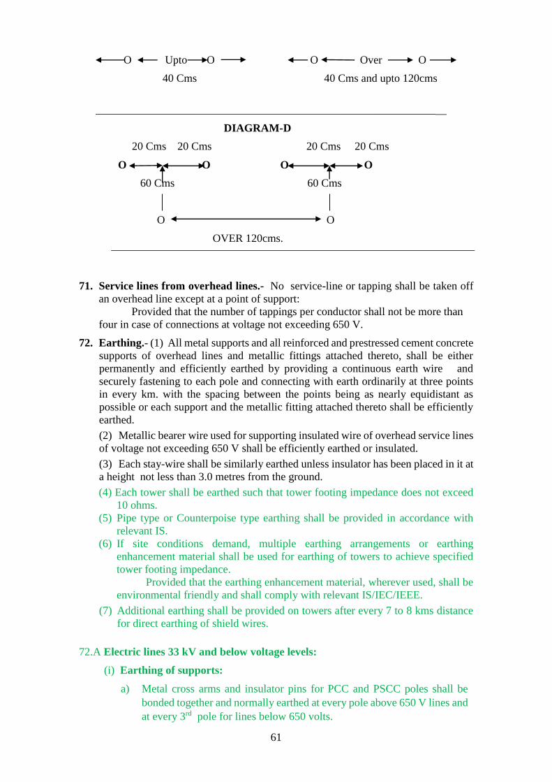
61
O Upto O O Over O
40 Cms 40 Cms and upto 120cms
_____________________________________________________________
DIAGRAM-D
20 Cms 20 Cms 20 Cms 20 Cms
O O O O
60 Cms 60 Cms
O O
OVER 120cms.
71. Service lines from overhead lines.- No service-line or tapping shall be taken off
an overhead line except at a point of support:
Provided that the number of tappings per conductor shall not be more than
four in case of connections at voltage not exceeding 650 V.
72. Earthing.- (1) All metal supports and all reinforced and prestressed cement concrete
supports of overhead lines and metallic fittings attached thereto, shall be either
permanently and efficiently earthed by providing a continuous earth wire and
securely fastening to each pole and connecting with earth ordinarily at three points
in every km. with the spacing between the points being as nearly equidistant as
possible or each support and the metallic fitting attached thereto shall be efficiently
earthed.
(2) Metallic bearer wire used for supporting insulated wire of overhead service lines
of voltage not exceeding 650 V shall be efficiently earthed or insulated.
(3) Each stay-wire shall be similarly earthed unless insulator has been placed in it at
a height not less than 3.0 metres from the ground.
(4) Each tower shall be earthed such that tower footing impedance does not exceed
10 ohms.
(5) Pipe type or Counterpoise type earthing shall be provided in accordance with
relevant IS.
(6) If site conditions demand, multiple earthing arrangements or earthing
enhancement material shall be used for earthing of towers to achieve specified
tower footing impedance.
Provided that the earthing enhancement material, wherever used, shall be
environmental friendly and shall comply with relevant IS/IEC/IEEE.
(7) Additional earthing shall be provided on towers after every 7 to 8 kms distance
for direct earthing of shield wires.
72.A Electric lines 33 kV and below voltage levels:
(i) Earthing of supports:
a) Metal cross arms and insulator pins for PCC and PSCC poles shall be
bonded together and normally earthed at every pole above 650 V lines and
at every 3rd pole for lines below 650 volts.

62
b) The support on each side of a road crossing, railway crossing or river
crossing shall be earthed.
c) Normally coil earthing shall be provided except for locations involving
railways, telegraph line, power line crossings and special structures where
pipe/rod type earthing shall be provided.:
d) Whenever the electric lines pass close to a well or a permanently moist
place, an earth should be provided in the well or the marshy place and
connected to the electric line pole.
e) All steel poles on which switches, transformers, fuses etc. are mounted
shall be earthed.
f) All poles above 650 volts, irrespective of inhabited areas, shall be earthed.
g) For poles below 650 V guarding with continuous earth wire (messenger
wire in case of aerial bunched cable) shall invariably be provided
invariably and shall be connected to earth at three equidistant points in
one km.
(ii) Anti Climbing Devices-
a) Anti climbing devices shall be provided on the supports.
b) For this purpose barbed wire conforming to relevant IS for a vertical
distance of 30 to 40 cm. at a height of 3.5 to 4 meters from ground level
or clamps with protruding spikes at a height of 3 to 4 meter shall be used.
(iii) Surge Arrester :-
a) The earthwire of appropriate size to take care of predicted/design fault
currents and lightning complying with relevant IS shall be used.
b) The earth wire shall be either of galvanized stranded steel (GSS) or
alternatively ACSR/ AACSR conductor.
73. Safety and protective devices.- (1) Every overhead line which is not being
suspended from a dead bearer wire, not being covered with insulating material and
not being a trolley-wire, is erected over any part of a street or other public place or
in any factory or mine or on any consumer’s premises shall be protected with earth
gaurding for rendering the line electrically harmless in case it breaks.
(2) An Electrical Inspector may, by notice in writing, require the owner of any such
overhead line, wherever it may be erected, to protect it in the manner specified in
sub-regulation (1).
(3) The owner of every overhead line of voltage exceeding 650 V shall make
adequate arrangements as per relevant Indian Standards to prevent undesignated
persons from ascending any of the supports of such overhead lines which can be
easily climbed upon without the help of a ladder or special appliances.
Explanation.- For the purpose of this relgulation, rails, reinforced cement concrete
poles and pre-stressed cement concrete poles without steps, tubular poles, wooden
supports without steps, I-sections and channels’ shall be deemed as supports which
cannot be easily climbed upon.

63
74. Protection against lightning.- (1) The owner of every overhead line, sub-station
or generating station which is exposed to lightning shall adopt efficient means for
diverting to earth any electrical surges due to lightning which may result into injuries.
(2) The earthing lead for any lightning arrestor shall be as short as possible and shall
not pass through any iron or steel pipe, but shall be taken as directly as possible from
the lightning arrestor without touching any metal part to a separate vertical ground
electrode shall be connected to the structure and to transformer earth terminal in
addition to earth electrode or junction of the earth mat already provided for the sub-
station of voltage exceeding 650 V subject to the avoidance of bends wherever
practicable.
75. Unused overhead lines.- Where an overhead line ceases to be used as an electric
supply line:
(i) the owner shall maintain it in a safe mechanical condition in accordance
with regulation 57 or remove it.
(ii) the Electrical Inspector shall, by a notice in writing served on the owner,
require him to maintain it in a safe mechanical condition or to remove it
within thirty days of the receipt of the notice.
76. Laying of cables.- (1) No underground power cable of voltage exceeding 33 kV
shall be laid without a minimum underground depth of 1.2 meters.
(2) No underground telecommunication cable shall be laid without a minimum
separation distance of 0.6 meters to the underground power cable of voltage
exceeding 33 kV.
77. Protection against electromagnetic interference. - The owner of every overhead
power line of voltage level 11 kV or higher shall submit proposal for obtaining obtain
Power Telecommunication Co-ordination Committee clearance to ensure safety of
the personnel and telecom equipment.
Chapter VII A
Safety requirements for generating stations
77A Safety provisions for Thermal Power Plant.-
(1) Power and control cables, and cabling
(a) (i) Power and control cables shall be flame retardant low smoke (FRLS)
type with fire survival (FS) cables to be provided for certain essential
auxiliaries.
(ii) Cables to be directly buried shall be essentially armoured type.
(iii) FRLS cables and FS cables shall meet test requirements as per relevant
ASTM (American Society of Testing and Materials), IEC, IEEE and SS
(Swedish Standards).
(iv) Derating factors for site ambient and ground temperatures, grouping
and soil resistivity shall be considered while determining the size of cables.

64
(b) (i) Cable installation shall be carried out as per relevant IS and other
applicable standards.
(ii) Power cables and control cables shall be laid on separate tiers. The laying
of different voltage grade cables shall be on different tiers according to the
voltage grade of the cables with higher voltage grade cables in topmost tier
and control cables in bottommost tier.
(iii) All cables associated with one unit shall preferably be segregated from
cables of other units.
(iv) Cable routes for one set of auxiliaries of same unit shall be segregated
from the other set.
(2) Fire detection, alarm and protection system.-
(i) A comprehensive fire detection, alarm as well as fire protection system shall
be installed for the Station in conformity with relevant IS.
(ii) Automatic fire detection and alarm system shall be intelligent and addressable
type and shall be provided to facilitate detection of fire at the incipient stage
and give warning to the firefighting staff.
(iii) Major equipment to be used for fire detection and protection system shall be
in accordance with relevant IS or UL (Underwriters Laboratories, USA) or
FM (Factory Mutuals, USA) or LPCB (Loss Prevention Certification Board,
UK) or VDS (Germany).
(iv) Dedicated fire water storage and pumping facilities of adequate capacities
shall be provided for the fire fighting system as per TAC guidelines.
Provided that the main fire water pumps shall be electrically driven and
standby pumps shall be diesel engine driven.
(v) All major and minor fire risks in the Station shall be protected against fire by
suitable automatic fire protection systems.
Provided that the following systems shall be generally adopted for various fire
risks:
(a) Automatic high velocity water spray system as per IS 15325, shall be
provided for the following areas:
(aa) Lubricating oil systems including storage tanks, purifier units, coolers,
turbine oil canal pipelines;
(ab) Generator seal oil system tanks, coolers;
(ac) Steam generator burner fronts.
(b) Steam turbine bearing housing and air pre-heater shall be provided with
manually actuated high velocity water spray system.
(c) Automatic medium velocity water spray system, complying with TAC
guidelines, shall be provided for the areas relating to:
(ca) Cable galleries, cable vaults, cable spreader rooms, cable risers, cable
shafts etc.;
(cb) Coal conveyors, transfer points, crusher houses etc.;
(cc) Fuel oil pumping stations;
(cd) LDO and day oil tanks;
(ce) DG set building.
(d) Automatic foam system shall be provided for fuel oil storage tanks as per
NFPA guidelines.

65
(e) Automatic inert gas flooding system, comprising of 2x100% inert gas
cylinder batteries conforming to NFPA, shall be provided for Unit control
rooms, control equipment rooms and area above false ceiling of these rooms.
(vii) Portable fire extinguisher as per TAC guidelines shall be provided for each
room/area of power station in addition to fixed fire protection system to
extinguish fire in its early phase to prevent its spread.
(viii) Fire station and fire tenders along with trained staff shall be provided for the
Station.
(ix) Passive fire protection measures such as fire barriers for cable galleries and
shafts etc., fire retardant coatings, fire resistant penetration sealing for all
openings in floors, ceilings, walls etc., fire proof doors etc. shall be provided
to prevent spreading and for containment of fire.
77B Safety requirement for hydro-electric generating stations,-
(i) Fire escape staircases or / galleries shall be provided in main station building or /
Cavern.
(ii) Each equipment room shall be provided with alternate exits to be used in case of
fire / or accidents, as per requirements of the Factory Act and other statutory
requirements.
(iii) Metal oxide surge arresters of suitable rating shall be provided for surge protection
of generators.
(iv) i) Resistance temperature detectors (RTD) or any other type of temperature sensors
at suitable locations for temperature monitoring of stator core, stator winding and
bearings shall be provided.
ii) Suitable arrangement for rotor winding temperature monitoring shall also be
provided.
(v) Fire fighting system
(a) General
(aa) The state of the art fire detection, alarm and protection system shall be
provided for the station. The fire protection system as well as hydrant
system shall be designed complying with the guidelines of NFPA.
(ab) All major and minor fire risks in the Station such as transformers, cable
galleries / shafts, control rooms etc. shall be protected against the fire by
suitable automatic fire protection systems. The state of the art automatic
fire detection and system shall be provided to facilitate detection of fire at
the incipient stage and warning to fire fighting staff.
(ac) Portable and mobile fire extinguishers shall be provided to extinguish fire
in the initial stage to prevent its spread.
(b) The provision shall be made for water sprinkler system for oil plant rooms,
especially in an underground power house. In addition, provision shall also be
made for fire hose cabinets / hydrants inside the power house as well as for the
transformer area. The water supply for the permanent fire protection
installation should be based on the largest fixed fire suppression system
demand plus the maximum hose stream demand of not less than 1890 L/min
for a 2-hour duration. Two nos. of fire pumps, each capable of pumping water
to fill the overhead water tank in 6 hours time shall be provided.
(c) Fire Protection System for Generator

66
ca) Either water based or CO2 type of fire suppression system shall be
provided.
cb) A water based system shall be adopted in underground power stations
because release of CO2 gas in an underground installation shall be
hazardous.
(vi) a) EHV or HV or LV power cables, busducts and control cables – Cables shall be
fire retardant, low smoke, low halogen (FRLS) (FRLSH) type. Directly buried
cables shall be essentially armoured type.
b) Cables shall be derated for the site ambient and ground temperatures, grouping
and soil resistivity as per relevant IS. Wherever feasible or practical, HV or LV
busduct shall be used for interconnection.
(vii)Cable trenches and cable racks - A comprehensive procedure for segregation /
separation of cables of different types / voltages shall be adopted for cable
installation. For laying of cables in a power house, a broad based system involving
cable gallery, tunnels, trenches, cable racks, shafts etc. shall be provided. In outdoor
switchyards, a cable trench system shall be provided. The main considerations shall
be:
(a) Segregation and proper spacing shall be maintained;
(b) Control, auxiliary low voltage (upto 1.1 kV) power and medium voltage (above
1.1 kV and upto 66 kV) power cables shall be laid in separate trays;
(c) Proper attention shall be given to ventilation or heat dissipation aspects
particularly in case of HV cables.

67
Chapter VIII
Safety requirements for Electric Traction
78. Application of chapter. - (1) The regulations in this chapter shall apply only where
electricity is used for the purposes of traction:
Provided that nothing in this chapter shall apply to electricity used for the
public carriage of passengers, animals or goods on, or for the lighting or ventilation
of the rolling stock of any railway or tramway subject to the provisions of the
Railways Act, 1989 (24 of 1989).
(2) In this chapter the conductor used for transmitting electricity to a vehicle is
referred to as the “line” and the other conductor as the “return”.
(3) The owner of the line, return, rails or trolley wire, as the case may be, shall be
responsible for the observance of regulations 79 to 92.
(4) Before an application is made by the owner of an installation of voltage
exceeding 650 V to the Electrical Inspector for permission to commence or
recommence supply after such installation has been disconnected for six months and
above, the supplier shall ensure that the electric supply lines or apparatus at voltage
exceeding 650 V belonging to him are placed in position, properly connected and
duly completed.
(5) The supply of electricity shall not be commenced by the supplier unless and until
the Electrical Inspector is satisfied that the provisions of regulations 44 to 50 and
regulation 79 to 92 have been complied with and the approval in writing of the
Electrical Inspector has been obtained by him.
79. Voltage of supply to vehicle.- No person shall supply electricity to any trolley wire
or other conductor at voltage exceeding 650 V used in direct electrical and
mechanical connection with any vehicle, except with the written approval of the
Central Government or the State Government, as the case may be, and subject to such
conditions as the State Government may think reasonable to impose.
80. Insulation of lines.- (1) Every line shall be insulated throughout and a line may
consist of either bare conductors supported on structures through insulators or
insulated cable.;
81. Insulation of returns.- (1) Where any rails on which cars run, or any conductors
laid between or within 0.9 metre of such rails, form any part of a return, such part
may be un-insulated and all other returns or parts of a return, shall be insulated,
unless they are of such conductivity as to secure the conditions required by sub-
regulations (2) and (3 ) of regulation 82.
(2) Where any part of a return is un-insulated, it shall be connected with the negative
or neutral of the system.

68
82. Proximity to metallic pipes.- (1) Where an un-insulated return is in proximity to
any metallic pipe, structure or substance not belonging to the owner of the return, the
owner of un-insulated return shall, if so required by the owner of such pipe, structure
or substance, connect his return therewith at his own expense.
(2) Where the return is partly or entirely un-insulated, the owner shall, in the
construction and maintenance of his system, adopt such means for reducing the
difference produced by the current between the potential of the un-insulated return
at any one point and the potential of the un-insulated return at any other point as to
ensure that the difference of potential between the un-insulated return and any
metallic pipe, structure or substance in the vicinity shall not exceed four volts where
the return is relatively positive, or one and one-third volts where the return is
relatively negative.
(3) The owner of any such pipe, structure or substance in respect of it require the
owner of the un-insulated return at reasonable times and intervals to ascertain by test
in his presence or in the presence of his representative, whether the condition
specified in sub-regulation (2) is fulfilled, and, if such condition is found to be
fulfilled, all reasonable expenses of, and incidental to, carrying out of the test shall
be borne by the owner of the pipe, structure or substance.
(4) The potential of un-insulated return with respect to earth at any point shall not
exceed fifty volt under normal conditions.
(5) The petroleum sidings installation earth shall be connected to the un-insulated
return to make it equi-potential and pipelines in the vicinity of the track should be
properly earthed.
83. Difference of potential on return.- Where the return is partly or entirely un-
insulated, the owner shall keep a continuous record of the difference of potential,
during the working of his system, between every junction of an insulated return with
an un-insulated return and the point on the route most distant from that junction, and
the difference of potential shall not, under normal running conditions, exceed a mean
value of seven volts between the highest momentary peak and the average for the
hour of maximum load.
84. Leakage on conduit system. - Where both the line and the return are placed within
a conduit, the following conditions shall be fulfilled in the construction and
maintenance of the system, namely: -
(i) where the rails are used to form any part of the return, they shall be electrically
connected at distances not exceeding 30 metres apart, with the conduit by
means of copper strips having a cross-sectional area of at least 0.40 sq. cm.
or by other means of equal conductivity and where the return is wholly
insulated and contained within the conduit, the latter shall be connected with
earth at the generating station or sub-station through an instrument suitable
for the indication of any contact or partial contact of either the line or the
return with the conduit; and

69
(ii) the leakage-current shall be ascertained daily, before or after the hours of
running, when the line is fully charged and if at any time it is found to exceed
0.6 ampere per km. of single tramway track, the transmission and use of
electricity shall be suspended unless the leakage is stopped within twenty-
four hours.
85. Leakage on system other than conduit system. - Where both the line and the return
are not placed within a conduit, the leakage current shall be ascertained daily before
or after the hours of running, when the line is fully charged and if at any time it is
found to exceed 0.3 ampere per km. of single tramway track, the transmission and
use of electricity shall be suspended unless the leakage is stopped within twenty-four
hours.
86. Passengers not to have access to electric circuit. - Precautions to the satisfaction
of an Electrical Inspector shall be taken by the owner of every vehicle to prevent,-
(i) the access of passengers to any portion of the electric circuit where there is
danger from electric shock;
(ii) any metal, hand-rail or other metallic substance liable to be handled by
passengers, becoming charged.
87. Isolation of sections.- Every trolley wire shall be constructed in sections not
exceeding 1.6 km. in length, and means shall be provided for isolating each section.
88. Minimum size and strength of trolley wire.- No trolley-wire shall be of less cross-
sectional area than 0.5 sq. cm. or shall have an actual breaking load of less than 2000
kg.
89. Height of trolley wire and length of span- A trolley wire or a traction feeder on the
same supports as a trolley wire shall, at no place be, at a height from the surface of
the street of less than 5.2 metres except, where it passes under a bridge or other fixed
structure, or through or along a tunnel or mineshaft or the like in which case it shall
be suspended to the satisfaction of an Electrical Inspector.
90. Earthing of guard wires. - Every guard wire shall be connected with earth at each
point at which its electrical continuity is broken and shall also be connected with the
rails at intervals of not more than five spans;
91. Proximity to magnetic observatories and laboratories.- Traction works shall not
be carried out in the vicinity of geomagnetic observatories and laboratories without
the concurrence of the Central Government or of any officer authorised by it in this
behalf.
92. Records. - (1) The owner shall keep the following records, namely : -
(i) daily records showing –

70
(a) the maximum working current from the source of supply;
(b) the maximum working voltage at the source of supply;
(c) the difference of potential, as required under regulation 83; and
(d) the leakage current, if any, as required under regulation 84 and 85.
(ii) occasional records showing –
(a) every test made under sub-regulation (2) and (3) of regulation 82
(b) every stoppage of leakage, together with the time occupied; and
(c) particulars of any abnormal occurrence affecting the electrical
working of the system.
(2) The records so kept under sub-regulation (1) shall be open to examination by
Electrical Inspector.

71
Chapter IX
Additional Safety requirements for mines and oil fields
93. Application of chapter.- The regulation in this chapter shall apply only where
electricity is used in mines as defined in the Mines Act, 1952 (35 of 1952) and oil fields.
94. Responsibility for observance.- (1) It shall be the duty of every person in charge
of and responsible to the mine including the owner, agent, manager, installation manager
and Engineer of mine and oil field to comply with and enforce the regulations in this
chapter and it shall be the duty of all persons employed to conduct their work in
accordance with these the regulations.
(2) In every mine or oil-field while electricity is being used such number of designated
supervisors and electricians shall be on duty as the owner may decide.
Explanation – For the purposes of this regulation, the word “Engineer” shall
(i) in the case of a coal mine, have the same meaning as assigned to it in the Coal Mines
Regulations, 1957 2017 as amended from time to time;
(ii) in the case of a metalliferous mine, have the same meaning as assigned to it in the
Metalliferous Mines Regulations, 1961, as amended from time to time; and
(iii) in the case of an oil mine field, means the ‘Installation Manager’ Electrical-in-charge
under the Oil Mines Regulations, 1984
95. Notices.- (1) On or before the first day of February in every year, in respect of every
mine or oil-field, returns giving the size and type of apparatus, together with such
particulars in regard to circumstances of its use as may be required, shall be sent to
the Electrical Inspector of Mines by the persons specified in regulation 94 in the
Form provided in Schedule-XI or, as the case may be, Schedule-XII, whichever is
applicable.
(2) The persons specified in regulation 94, shall also give to the Electrical Inspector
of Mines not less than seven days notice in writing of the intention to bring into use
any new installation in a mine or oil-field giving details of apparatus installed and its
location:
Provided that in case of any additions or alterations to an existing
installation of voltage not exceeding 650 V, immediate notice in writing shall be sent
to the Electrical Inspector of Mines before such additions or alterations are brought
into use:
Provided further that this regulation shall not apply to telecommunication or
signalling apparatus.
Provided further that in case of emergency which may lead to loss of life or
machinery and is deterimental to safety of mine, intimation shall be given within 24
hours to the Electrical Inspector of Mines giving the healthiness of the apparatus
alongwith self certification report of such additions or alterations undertaken.

72
96. Plans.- (1) A correct plan, on the same scale as the plan kept at the mine in fulfillment
of the requirements of the Mines Act, 1952 (35 of 1952), shall be available in the
office at the mine showing the position of all fixed apparatus and conductors therein,
other than lights, telecommunication or signaling apparatus, or cables for the same.
(2) A similar plan on the scale not less than 25 cm. to a km. (1:4000) shall be kept
by the manager or owner of one or more wells in any oil-field.
(3) A similar plan on such scale as the Central Government may direct, showing the
position of all electric supply lines, shall be kept in the office of any licensee or other
person transmitting or distributing electricity in a mine or oil-field.
(4) (3) The plans specified under this regulation shall be examined and corrected as
often as necessary to keep them up-to-date and the dates of such examinations shall
be entered thereon by the manager or owner of the mine or wells and such plans shall
be available to the Inspector, or inspector of mines, at any time. In case extent of
hazardous area is revised, equipment covered under such area shall be reviewed as
per IS-5571, IS-5572 and/or ATEX.
97. Lighting, overhead lines, communication and fire precautions. -
(1) In a mine illuminated by electricity, one or more flame safety lamps, or other
lights approved by the inspector of mines, shall be maintained in a state of continuous
illumination in all places where failure of the electric light at any time shall be
prejudicial to safety.
(1) Adequate illumination by electricity as per relevant IS shall be provided in the
mines.
Provided that in a belowground coalmine, such lighting fixtures shall be of a type
approved by the Chief Inspector of mines.
Provided that one or more flame safety lamps or such lighting system approved by
the Chief Inspector of mines shall be maintained in all places where failure of the electric
light at any time shall be prejudicial to safety.
Provided that in a belowground metalliferous mine or any open cast mine or oil
fields, such lighting fixtures shall be suitable for the type of application conforming to
the relevant IS or harmonized standards, and adequate emergency lighting system shall
be maintained in all places where failure of the electric light at any time shall be
prejudicial to safety.
(2) Efficient means of communication shall be provided in every mine between the point
where the switchgear under sub-regulation (1) of regulation 105 is erected, the shaft
bottom and other distributing centres in the mines.
(3) Fire extinguishing appliances of adequate capacity and of an approved type as per IS
15683 as amended from time to time shall be installed and properly maintained in every

73
place in a mine containing apparatus, other than cables, telecommunication and signalling
apparatus.
(4) In case of mines, minimum clearance above ground of the lowest conductor of
overhead lines or overhead cables where dumpers or trackless vehicles are being
operated, shall not be less than twelve meters in height from the ground across the road
where dumpers or trackless vehicles cross.
Provided where dumper bucket in raised position, the clearance between the top
of dumper body and to the lowest conductor of overhead lines or overhead cables shall
not be less than 1.00 metre.
98. Isolation and fixing of transformer and switchgear. - (1) Transformers and
switchgear shall be placed in a separate room, compartment or box where necessary or
in a manner to prevent danger of mechanical damage and spread of fire.
(2) Unless the apparatus is so constructed, protected and worked as to obviate the
risk of fire, no inflammable material shall be used in the construction of any room,
compartment or box containing apparatus, or in the construction of any of the fittings
therein and each such room, compartment or box shall be substantially constructed and
shall be kept dry and illuminated and efficient ventilation shall be provided for all
apparatus installed therein.
(3) All apparatus that has to be worked or attended to and all handles intended to be
operated shall be placed at a spacious working place which is accessible, clear of
obstruction and free from danger, so far as circumstances permit.
99. Method of earthing.- (1) Where earthing is necessary in a mine, it shall be carried
out by connection to an earthing system at the surface of the mine and in such manner as
may be approved by the Electrical Inspector of Mines.
(2) All metallic sheaths, coverings, handles, joint boxes, switchgear frames, instrument
covers, switch and fuse covers of boxes, all lamp holders, unless efficiently protected by
an insulated covering made of fire resisting material, and the frames and bedplates of
generators, transformers and motors, including portable motors, shall be earthed by
connection to an earthing system in the manner specified in sub-regulation (1).
(3) Where cables are provided with a metallic covering constructed and installed in
accordance with clause (iv) (d) of regulation 106, such metallic covering may be used as
a means of connection to the earthing system.
(4) All conductors of an earthing system shall have conductivity, at all parts and all
joints, at least equal to fifty per cent of that of the largest conductor used solely to supply
the apparatus, a part of which desired to be earthed:
Provided that no conductor of an earthing system shall have a cross-sectional area less
than 0.15 sq. cm. except in the case of the earth conductor of a flexible cable used with
portable apparatus where the voltage does not exceed 125 Volts, and the cross-sectional
area and conductance of the earthcore is not less than that of the largest of the live
conductors in the cable.

74
(5) All joints in earth conductors and all joints in the metallic covering of cables
shall be properly soldered or otherwise effectively made.
(6) No switch, fuse or circuit-breaker shall be inserted in any earth conductor.
(7) This regulation shall not apply, except in the case of portable apparatus, to any
system in a mine in which the voltage does not exceed 30 V.
100. Protective equipment.- Protective equipment.- (1) In the interest of safety,
Appropriate equipment shall be suitably placed in the mines for automatically
disconnecting supply to any part of the system, where a fault, including an the earth fault,
occurs and the earth fault current shall not be more than 750 milliampere in installations
of voltage exceeding 250 V and upto 1100V for below ground mines and oil fields, and
50 10 amperes in installations of voltage exceeding 1100V and up to 11KV in open cast
mines for belowground mines, open cast mines and oil mines or oil fields, and the
magnitude of the earth fault current shall be limited to these specified values by
employing suitably designed, restricted neutral system of power supply including neutral
monitoring protection.
Provided that in a below ground mine, for face equipment working on voltage
exceeding 1100V, the earth fault current shall be limited to such safe values considering
the unsafe conditions due to touch potential and ignition hazards as recommended by the
Electrical Inspector of Mines.
Provided further that maximum earth fault current or earth leakage current in
portable apparatus used in belowground and open cast mines and oil mines or oil fields
shall not exceed 30 mA for protection against electric shock.
Appropriate equipment shall be suitably placed for automatically disconnecting supply to
any part of the system in the event of earth fault or earth leakage.
Provided that the settings of protective devices thereof shall not exceed 100 milliamperes
for individual apparatus of voltage upto1100V.
Provided further that in installations where magnitude of aggregate capacitive current is
more than 10A, the owner of installations or user shall limit the earth fault current to
Appropriate value, with the approval of Electrical Inspector.
Appropriate PPE shall be used by the personnel for handling such apparatus to protect
against electric shock due to touch potential.
Appropriate PPE, being used, shall be checked by testing procedure as per guidelines of
OEM and periodicity of such checking shall be at least once in a year.

75
Alternate supply arrangement shall be made for rescue & safe operation.
(2) The operation of the switchgear and the relays shall be recorded daily at the
generating station, sub-station or switch station in a register kept for the purpose and in
electronic form.
(3) The effectiveness of switchgear and protective system shall always be kept in
working order and shall be checked once every three months by calibrating and testing at
least once in a year and the result thereof shall be recorded in separate register kept for
the purpose and in electronic form.
Provided that wherever numerical relays are being used they shall be
checked by testing procedure as per guidelines of OEM and periodicity of such
checking shall be at least once in a year.
101. Earthing metal. - (1) All metallic sheaths, coverings, handles, joint boxes,
switchgear frames, instrument covers, switch and fuse covers of boxes, all lamp holders,
unless efficiently protected by an insulated covering made of fire resisting material, and
the frames and bedplates of generators, transformers and motors, including portable
motors, shall be earthed by connection to an earthing system in the manner specified in
regulation 99.
(2) Where cables are provided with a metallic covering constructed and installed in
accordance with clause (d) of regulation 106, such metallic covering may be used as a
means of connection to the earthing system.
(3) All conductors of an earthing system shall have conductivity, at all parts and all
joints, at least equal to fifty per cent of that of the largest conductor used solely to supply
the apparatus, a part of which desired to be earthed:
Provided that no conductor of an earthing system shall have a cross-sectional area less
than 0.15 sq. cm. except in the case of the earth conductor of a flexible cable used with
portable apparatus where the voltage does not exceed 125 Volts, and the cross-sectional
area and conductance of the earthcore is not less than that of the largest of the live
conductors in the cable.
(4) All joints in earth conductors and all joints in the metallic covering of cables
shall be properly soldered or otherwise efficiently made.
(5) No switch, fuse or circuit-breaker shall be inserted in any earth conductor.

76
(6) This regulation shall not apply, except in the case of portable apparatus, to any system
in a mine in which the voltage does not exceed 30 V.
102. Voltage limits.-
Electricity shall not be transmitted into a belowground mine at a voltage exceeding 11000
Volts and shall not be used therein at a voltage exceeding 6600 Volts.
Provided that-
(i) where hand-held portable apparatus is used, the voltage shall not exceed 125 V;
(ii) where electric lighting is used –
(a) in underground belowground mines, the lighting system shall have a mid
or neutral point connected with earth and the voltage shall not exceed 125 V between
phases;
(b) on the surface of a mine or in an open cast mine or oil mines or oil fields, the
voltage may be raised to 250 V, if the neutral or the mid point of the system is connected
with earth and the voltage between the phases does not exceed 250 V;
(iii) where portable hand-lamps are used in underground belowground coal mines and
hazardous area of oil mines or oil fields, the voltage shall not exceed 30 V;
(iv)(a) where any circuit is used for the remote control or electric inter-locking of
apparatus, the circuit voltage shall not exceed 30 V for below ground mine or hazardous
area of oil fields.
Provided that in hazardous areas of oil mines or oil fields, the said voltage
can be up to 250 volts if the on-off control push-button stations (PBS) or remote controls
are housed in an Appropriate enclosure like:
i. Flameproof enclosure type ‘d’
ii. Pressurized enclosure type ‘p’
iii. Sand filled apparatus type ‘q’
iv. Increased safety enclosure type ‘e’, ‘n’, and ‘o’
Provided further that the control circuit shall have suitable protection against shock
hazards, and the trippings due to faults do not adversely affect the operational safety.
(b) In fixed plants on surface of the mines or opencast mines, the said voltage for the
remote control or electric inter-locking may be permitted up to 250V.
103. Transformers. - Where electricity is transformed in belowground mines and oil
fields, suitable provision shall be made to In mines or oil fields, the transformers used
for providing voltages to control circuits or remote control or interlocking or for hand
held apparatus, shall have suitable provision to guard against danger by reason of the
lower voltage apparatus becoming accidentally charged above its normal voltage by
leakage from or contact with the higher voltage apparatus.

77
104. Switchgear and terminals.- Switchgear and all terminals, cable-ends, cable-joints
and connections to apparatus shall be totally enclosed and shall be constructed,
installed and maintained as to comply with the following requirements, namely:-
(i) all parts shall be of mechanical strength sufficient to resist rough usage;
(ii) all conductors and contact areas shall be of adequate current-carrying
capacity and all joints in conductors shall be properly soldered or otherwise
efficiently made;
(iii) the lodgement of any matter likely to diminish the insulation or affect the
working of any switchgear shall be prevented;
(iv) all live parts shall be so protected or enclosed as to prevent persons
accidentally coming into contact with them and to prevent danger from arcs,
short-circuits, fire, water, gas or oil;
(v) where there may be risk of igniting gas, coal-dust, oil or other inflammable
material, all parts shall be so protected as to prevent open sparking; and
(vi) every switch or circuit-breaker shall be so constructed as to be capable of
opening the circuit it controls and dealing with any short-circuit without danger.
105. Disconnection of supply.- (1) Properly constructed switchgear for disconnecting
the supply of electricity to a mine or oil-field shall be provided at a point approved
recommended by the Electrical Inspector of Mines.
(2) At any time, when any cable or overhead line supplying electricity to the mine
from the aforesaid switchgear is live, a person designated to operate the said
switchgears shall be available within easy reach thereof:
Provided that in the case of gassy coal seam of second degree and third degree
gassiness, the main mechanical ventilator operated by electricity shall be interlocked
with the switchgear so as to automatically disconnect the power supply in the event
of stoppage of main mechanical ventilator.
(3) When necessary in the interest of safety, any apparatus suitably placed, shall be
provided for disconnecting the supply from every part of a system.
(4) If the Electrical Inspector of Mines, in the interest of safety considered it
necessary, he may direct that the apparatus specified in sub-regulation (3) shall be so
arranged as to disconnect automatically, from the supply, any section of the system
subjected to a fault.
(5) Every motor shall be controlled by switchgear which shall be so arranged as to
disconnect the supply from the motor and from all apparatus connected thereto and
such switchgear shall be so placed as to be easily operated by the person designated
to operate the motor.
(6) If the Electrical Inspector of Mines feels it Appropriate, the The motor shall be
controlled by a switchgear a protective mechanism to disconnect automatically the

78
supply in the event of conditions of over-current, over-voltage under voltage or no
voltage and single phasing.
(7) Auxiliary fan shall be interlocked with the switchgear controlling power supply
to the in-bye face equipment of below ground coal mine for automatic disconnection
of power supply in the event of the stoppage of the auxiliary fan.
(8) Every feeder of the mine shall be controlled in a manner so as to disconnect the
supply automatically in the event of conditions of over-current, short circuit, single
phasing, under-voltage as relevant.
106. Cables.- All cables, other than flexible cables for portable or transportable
apparatus, shall fulfill the following requirements, namely:-
(i) all such cables, other than the outer conductor of a concentric cable, shall be
covered with insulating material and shall be efficiently protected from
mechanical damage and supported at sufficiently frequent intervals and in such a
manner as to prevent damage to such cables;
(ii) (a) except as provided in clause (iii) no cables other than concentric cables
or single core or two core or multi core cables protected by a metallic covering
and which contain all the conductors of a circuit shall be used where the
voltage exceeds 125 V or when an Inspector considers that there is risk of
igniting gas or coal dust or other inflammable material, and so directs;
(b) the sheath of metal-sheathed cables and the metallic armouring of
armoured cables shall be of a thickness not less than that recommended from
time to time in the relevant standard of the Bureau of Indian Standards;
(iii) where a voltage exceeding 250 V but not exceeding 650 V direct current
system is used, two single core cables may be used for any circuit provided that
their metallic coverings are bonded together by earth conductors so placed that
the distance between any two consecutive bonds is not greater than thirty metres
measured along either cable;
(iv) The metallic covering of every cable shall be -
(a) electrically and mechanically continuous throughout;
(b) earthed, if it is required by sub-regulation (3) of regulation 101 to be
earthed by a connection to the earthing system of conductivity specified
therein;
(c) efficiently protected against corrosion where necessary;
(d) of a conductivity at all parts and at all joints at least equal to fifty per cent
of the conductivity of the largest conductor enclosed by the said metallic
covering; and
(e) where there may be risk of igniting gas, coal-dust, or other inflammable
material, so constructed as to prevent, as far as practicable, the occurrence of
open sparking as the result of any fault or leakage from live conductors.
79
(v) cables and conductors where connected to motors, transformers, switchgear
and other apparatus, shall be installed so that,-
(a) they are mechanically protected by securely attaching the metallic
covering to the apparatus; and
(b) the insulating material at each cable end is efficiently sealed so as to
prevent the diminution of its insulating properties;
(vi) where necessary to prevent abrasion or to secure gas-tightness, properly
constructed glands or bushes shall be provided;
(vii) unarmored cables or conductors shall be conveyed either in metallic pipes or
metal casings or suspended from efficient insulators by means of non-conducting
materials which will not cut the covering and which will prevent contact with any
timbering or metal work and if separate insulated conductors are used, they shall
be installed at least 3.75 cm. apart and shall not be brought together except at
lamps, switches and fittings.
107. Flexible cables.- (1) Flexible cables for portable or transportable apparatus shall be
two core or multi core, unless required for electric welding, and shall be covered
with insulating material which shall be efficiently protected from mechanical injury.
(2) If flexible metallic covering is used either as the outer conductor of a concentric
cable or as a means of protection from mechanical injury, it shall not be used by itself
to form an earth conductor for such apparatus, but it may be used for that purpose in
conjunction with an earthing core.
(3) Every flexible cable intended for use with portable or transportable apparatus
shall be connected to the system and to such apparatus by properly constructed
connectors:
Provided that for machines of voltage exceeding 650 V but not exceeding 33 kV
11KV a bolted type connector shall be used and the trailing cable shall be suitably
anchored at the machine end.
(4) At every point where flexible cables are joined to main cables, a circuit breaker
shall be provided which is capable of automatically disconnecting the supply from
such flexible cables.
(5) Every flexible cable attached to a portable or transportable machine shall be
examined periodically by the person designated to operate the machine, and if such
cable is used underground, it shall be examined at least once in each shift by such
person and if such cable is found to be damaged or defective, it shall forthwith be
replaced by a cable in good condition.
(6) If the voltage of the circuit exceeds 250 V, all flexible cables attached to any
transportable apparatus shall be provided with flexible metallic screening or pliable
armouring and cables of portable apparatus shall be provided with flexible metallic
screening on all the power and pilot cores.

80
Provided that the provision of this regulation shall not apply to flexible cables
attached to any transportable or portable apparatus used in open cast mines or below
ground mines where reeling and unreeling of such cables is necessary as per design
features of the equipment.
(7) All flexible metallic screening or armouring specified in sub-regulation (6) shall
fulfill the requirement specified in clause (iv) of regulation 106 .
Provided that in the case of separately screened flexible cables the
conductance of each such screen shall not be less than twenty five per cent of that of
the power conductor and the combined conductance of all such screens shall in no
case be less than that of 0.15 sq. cm. copper conductor.
(8) Flexible cable exceeding hundred metres in length shall not be used with any
portable or transportable apparatus:
Provided that such flexible cable when used with coal cutting machines or
cutter or loader or armoured face conveyor for long wall operation, or with shuttle
cars or load haul dumper or cutter loader or all alike equipment for development and
de-pillaring operation shall not exceed two hundred fifty metres in length:
Provided further that the aforesaid cable in case of an open cast mine when
used with electrically operated heavy earth moving machinery shall not exceed three
hundred metres in length and for bucked wheel excavator at 11 kV shall not exceed
one thousand metres in length.
(9) Flexible cable, when installed in a mine, shall be efficiently supported and
protected from mechanical injury.
(10) Flexible cables shall not be used with apparatus other than portable or
transportable apparatus.
(11) Where flexible cables are used they shall be detached or otherwise isolated from
the source of supply when not in use, and arrangements shall be made to prevent the
energising of such cables by undesignated persons.
108. Portable and transportable machines.- The person designated to operate an
electrically driven coal-cutter, or other portable or transportable machine, shall not
leave the machine while it is in operation and shall, before leaving the area in which
such machine is operating, ensure that the supply is disconnected from the flexible
cable which supplies electricity to the machine and when any such machine is in
operation, steps shall be taken to ensure that the flexible cable is not dragged along
by the machine:
Provided that all portable and transportable machines used in underground
mines shall operate on remote control from the concerned switchgear with pilot core
protection.
Provided further that the portable and transportable machines used in open cast mines
shall have the provision such that the power supply to the machine from concerned
switchgear is remotely controlled from the machine.

81
109. Sundry precautions.- (1) All apparatus shall be maintained reasonably free from
dust, dirt and moisture, and shall be kept clear of obstruction.
(2) All apparatus other than portable and transportable apparatus shall be housed in
a room, compartment or box so constructed as to protect the contents from damage
occasioned by falling material or passing traffic.
(2) All apparatus other than portable and transportable apparatus shall be housed in
a room, compartment or box so constructed as to protect the contents from damage
occasioned by falling material or passing traffic.
(3) Inflammable or explosive material shall not be stored in any room, compartment
or box containing apparatus, or in the vicinity of any apparatus.
(4) In case of a fault in any circuit, the part affected shall be made dead without
delay and shall remain so until the fault has been remedied.
(5) While lamps are being changed the supply shall be disconnected.
(6) No lampholder shall have metallic connection with the guard or other metal work
of a portable hand lamp.
(7) The following notices in Hindi and local language of the district, so designed
and protected as to be easily legible at all times, shall be exhibited at the following
places, namely:-
(i) where electrical apparatus is in use, a notice forbidding undesignated
persons to operate or otherwise interfere with such apparatus;
(ii) in the interior or at the surface of the mine where a telephone or other
means of communication is provided, a notice giving full instructions to
person, at the surface of the mine, designated to effect the disconnection of the
supply of electricity to the mine.
(8) All apparatus, including portable and transportable apparatus, shall be operated
only by those persons who are designated for the purpose.
(9) Where a plug-and-socket-coupling other than of bolted type is used with flexible
cables, an electrical inter-lock or other approved device shall be provided to prevent
the opening of the coupling while the conductors are live.
110. Precautions where gas exists.
(1) In any part of a coal-seam of the first degree gassiness –
(i) all cables shall be constructed, installed, protected, operated and maintained
in such a manner as to prevent risk of open sparking;
(ii) all signaling, telecommunication, remote control and insulation tester
circuits shall be so constructed, installed, protected, operated and maintained as
to be intrinsically safe;

82
(iii) all apparatus including portable and transportable apparatus including
lighting fittings used at any place which lies in-bye of the last ventilation
connection shall be flame-proof:
Provided that electrically operated or battery operated portable or transportable
apparatus such as shuttle car, men or material transporting equipment of
increased safety type “e” shall be permitted at any place with suitable monitoring
devices for detection of gases, if any;
(iv) all electric lamps at any place which lie in-bye of the last ventilation
connection and return airways shall be in flame proof enclosure and at other
places these shall be in increased safety enclosure type ‘e’.
(2) At any place which lies in any part of a coal-seam of second and third degree
gassiness –
(i) all signaling, telecommunication, remote control and insulation tester
circuits shall be so constructed, installed, protected, operated and maintained as
to be intrinsically safe;
(ii) all cables shall be constructed, installed, protected, operated and maintained
in such a manner as to prevent risk of open sparking;
(iii) all apparatus, including portable and transportable apparatus used at any
place within ninety metres of any working face or goaf in case of a second degree
gassy mine and within two hundred seventy metres of any working face or goaf
in case of third degree gassy mine or at any place which lies in-bye of the last
ventilation connection or in any return airways shall be flame-proof;
(iv) all electric lamps shall be enclosed in flame-proof enclosures.
(3) In any oil mine or oil-field, at any place within the zone-2 hazardous areas-
(i) all signaling and telecommunication, remote control and insulation tester
circuits shall be so constructed, installed, operated, protected and maintained
as to be intrinsically safe;
(ii) all cables shall be so constructed, installed, operated and maintained as to
prevent risk of open sparking;
(iii) all apparatus including portable and transportable apparatus shall have the
following types of enclosures conforming to the relevant Indian Standards,
namely:-
(a) flame-proof enclosure type ‘d’ or
(b) pressurized enclosure type ‘p’ or
(c) sand filled apparatus type ‘q’ or
(d) increased safety enclosure type ‘e’, ‘n’ and ‘o’
(iv) all electric lamps shall be enclosed in increased safety enclosure type ‘e’.
(4) In any oil mine or oil fields at any place within the zone-1 hazardous areas-

83
(i) all signaling and telecommunication, remote control and insulation tester
circuits shall be so constructed, installed, operated, protected and maintained
as to be intrinsically safe;
(ii) all cables shall be so constructed, installed, operated and maintained as to
prevent risk of open sparking;
(iii) all apparatus including portable and transportable apparatus shall
have the following types of enclosures conforming to the relevant Indian
Standards, namely:-
(a) flame-proof enclosure type ‘d’ or
(b) pressurized enclosure type ‘p’ or
(c) sand filled apparatus type ‘q’
(iv) all electric lamps shall be enclosed in flame-proof enclosures.
(5) In any oil mine at any place within zone-0 hazardous area, no electrical equipment
shall be used and where it is not practicable, intrinsically safe apparatus are only to be
used which shall be conforming to relevant Indian standards or relevant international
standard where Indian Standards are not available with the prior approval of the Inspector
and such installation of apparatus shall conform to relevant Indian standards or relevant
international standards where Indian Standards are not available and the details of
installation, certified by the Owner/ Agent/ Manager/ Installation manager shall be
submitted to the Electrical Inspector of mines.
(6) In any coal-seam of degree second and degree third gassiness or the hazardous
area the supply shall be discontinued;
(i) immediately, if open sparking occurs;
(ii) during the period required for examination or adjustment of the apparatus,
which shall necessitate the exposing of any part liable to open sparking;
(iii) the supply shall not be reconnected until the apparatus has been examined
by the electrical supervisor or one of his duly appointed assistants and until the
defect, if any, has been remedied or the necessary adjustment made; and
(iv) a flame safety lamp shall be provided and maintained in a state of
continuous illumination near an apparatus, including portable or transportable
apparatus, which remains energized and where the appearance of the flame of
such safety lamps indicates the presence of inflammable gas, the supply to all
apparatus in the vicinity shall be immediately disconnected and the incident
reported forthwith to an official of the mine and such apparatus shall be
interlocked with the controlling switch in such a manner as to disconnect
power supply automatically in the event of percentage of inflammable gas
exceeding one and one quarter in that particular district:
Provided that where apparatus for automatic detection of the percentage
of inflammable gas or vapor are employed in addition to the flame safety
lamps, such apparatus shall be approved by the inspector of mines and
maintained in perfect order.

84
(7) In any part of a coal-seam of any degree of gassiness or in any hazardous area of
an oil fields, if the presence of inflammable gas in the general body of air is found at any
time to exceed one and one quarter per cent, the supply of energy shall be immediately
disconnected from all cables and apparatus in the area and the supply shall not be
reconnected so long as the percentage of inflammable gas remains in excess of one and
one quarter per cent.
(8) In oil fields where concentration of inflammable gas exceeds twenty (20) percent of
its lower explosive limit (LEL) a system should be in place to activate an audio alarm at
Appropriate location. On activation of such alarm immediate action shall be taken to
make operations safe and to isolate the cause in order to ensure safety of men, equipment,
environment. In case the LEL rises to forty (40) percent, the supply of electricity shall be
cut-off automatically immediately from all cables and apparatus lying within thirty
metres of the installation and all sources of ignition shall also be removed from the said
area and normal work shall not be resumed unless the area is made gas-free:
Provided that such disconnection shall not apply to intrinsically safe environment
monitoring scientific instruments.
(9) Any such disconnection or reconnection of the supply shall be noted in the log
sheet in hard copy and electronic form which shall be maintained in the form set out in
Schedule-XIII and shall be reported to the Electrical Inspector of Mines
(10) The provisions of this regulation shall apply to any metalliferrous mine which
may be notified by the inspector of mines if inflammable gas occurs or if the inspector of
mines is of the opinion that inflammable gas is likely to occur in such mine.
Explanation – For the purpose of this regulation;
(1) the expression ‘coal-seam of first degree gassiness’, ‘coal-seam of second degree
gassiness’, ‘coal-seam of third degree gassiness’ and ‘flame-proof apparatus’ shall have
the meanings respectively assigned to them in the Coal Mines Regulations, 1957.
(2) The following areas in oil mine or oil fields shall be known as hazardous areas,
namely:-
(i) an area of not less than ninety metres around an oil-well where a blow-out
has occurred or is likely to occur, as may be designated by the Engineer-in
charge Installation Manager or the senior most official present at the site;
(ii) an area within ninety sixteen metres of an oil-well open discharge of
petroleum bearing fluid from a well under production test. which is being tested
by open flow;
(iii) an area within fifteen metres of :
(a) a producing well-head or any point of open discharge of the
crude there from or other point where emission of hazardous atmosphere is
normally likely to arise; or
(b) any wildcat or exploration well-head being drilled in an area where
abnormal pressure conditions are known to exist; or
(c) any exploration or interspaced well-head being drilled in the area
where abnormal pressure conditions are known to exist;

85
(iv) any area within four and one half three meters of:
(a) any producing well-head where a closed system of
production is employed such as to prevent the emission or
accumulation in the area in normal circumstances of a hazardous
atmosphere; or
(b) exploration or interspaced well-head being drilled in an area
where the pressure conditions are normal and where the system of
drilling employed includes adequate measures for the prevention
in normal circumstances of emission or accumulation within the
area of a hazardous atmosphere; or
(c) an oil-well which is being tested other than by open flow.
(3) “hazardous atmosphere” means an atmosphere containing any inflammable gases
or vapours in a concentration capable of ignition.
(4) “Zone 0 hazardous area” means “an area in which hazardous atmosphere is
continuously present.”
(5) “Zone 1 hazardous area” means “an area in which hazardous atmosphere is likely
to occur under normal operating conditions”.
(6) “Zone 2 hazardous area” means “an area in which hazardous atmosphere is likely
to occur under abnormal operating conditions”.
111. Shot-firing. – (1) When shot-firing is in progress adequate precautions shall be taken
to protect apparatus and conductors, other than those used for shot-firing, from
injury.
(2) Current from lighting or power circuits shall not be used for firing shots.
(3) The provisions of regulation 107 shall apply in regard to the covering and
protection of shot-firing cables construction of shot firing cables shall conform to IS
5950 and adequate precautions shall be taken to prevent such cable touching other
cables and apparatus.
112. Signaling. - Where electrical signaling is used,-
(i) adequate precautions shall be taken to prevent signal and telephone wires
coming into contact with other cables and apparatus;
(ii) the voltage used in any one circuit shall not exceed 30 V;
(iii) contact-makers shall be so constructed as to prevent the accidental closing
of the circuit; and
(iv) bare conductors, where used shall be installed in suitable insulators.
113. Haulage. - Haulage by electric locomotives on the overhead trolley-wire system, at
voltage not exceeding 650 V and haulage by storage battery locomotives may be
86
used with the prior consent in writing of the Electrical Inspector, and subject to such
conditions as he may impose in the interests of safety.
114. Earthing of neutral points. - Where the voltage of an alternating current system
exceeds 30 Volts, the neutral or mid-point shall be earthed by connection to an earthing
system in the manner specified in regulation 99.
Provided that when the system concerned is required for blasting and signaling purposes,
the provisions of this regulation shall not apply.
Provided further, that in case of unearthed neutral system, adequate protection shall
be provided with the approval of the Inspector it shall be equipped with a suitable
ground protection system that approved by the Electrical Inspector of Mines to
automatically isolate the supply of the faulty location. ensure isolation of power
supply to the faulty section in Appropriate manner.
115. Supervision. - (1)(i) One or more electrical supervisors as directed by the Electrical
Inspector of Mines shall be appointed in writing by the owner, agent or manager of
a mine or by the agent or the owner, of one or more wells in an oil field to supervise
the installation and such number of supervisors shall be on duty as per guidelines of
schedule XIV.
(ii)The electrical supervisor so appointed shall be the person holding a valid
Electrical Supervisor's Certificate of Competency, covering mining installations
issued by the Appropriate Government under sub-regulation (1) of regulation 29.
(iii) One or more electricians as directed by the Electrical Inspector of Mines
shall be appointed in writing by the owner, agent or manager of a mine or by the agent
or the owner, of one or more wells in an oil field for compliance with the duties
specified in this regulation.
(iii) One or more Adequate number of electricians as per guidelines mentioned in
schedule XIV shall be appointed in writing by owner, agent or manager of a mine or
by the owner or Agent of in an oil field for carrying out the duties.
(iv) The Electrician shall be a person holding license under sub-regulation (1) of
regulation 29 work permit issued by Appropriate Government.
OR
The person holding a certificate in electrical trade, preferably with a two years course
from an Industrial Training Institute recognized by the Central Government or the
State Government with two years experience in the mines (coal/oil/metal) and having
undergone the training as provided under Reg-116 can be appointed by the
Owner/Agent/Manager of a mine or by the owner or Agent, of one or more wells in
an oil fields to perform the duties.
(iv) The Electrician shall be a person holding license under sub-regulation (1) of
regulation 29.
(v) For small open cast mines and below ground mines receiving supply at
voltage not more than 650 V and not having portable or transportable apparatus,
electrical supervisor and electrician shall be appointed for more than one mine
by the Electrical Inspector of Mines.

87
(2) Every person appointed to operate, supervise, examine or adjust any apparatus
shall be competent to undertake the work which he is required to carry out as directed
by the Engineer.
(3) The electrical supervisor shall be responsible for the proper performance of the
following duties, by himself or by an electrician appointed under sub-regulation (1).
(i) thorough examination of all apparatus, including the testing of earth
conductors and metallic coverings for continuity, as often as may be necessary
to prevent danger;
(ii) examination and testing of all new apparatus, and of all apparatus, re-erected
in the mine before it is put into service in a new position.
(4) In the absence of any electrical supervisor, the owner, agent or manager of the
mine and oil field shall appoint in writing a substitute electrical supervisor.
(5) (i) The electrical supervisor or the substitute electrical supervisor appointed under
sub-regulation (4) to replace him shall be personally responsible for the
maintenance at the mine or oil-field, of a log-book made up of the daily log
sheets prepared in the form set out in Schedule- XIII.
(ii) The results of all tests carried out in accordance with the provisions of sub-
regulation (3) shall be recorded in the log-sheets prepared in the form set out in
Schedule- XIII.
115A. Training of personnel engaged for operation and maintenance of electrical
installations in Mines and oil fields:
(i) The persons engaged for operation and maintenance of electrical installations in Mines
are required to undergo the type of training meant for the particular mining installations
(Coal/Oil/Metal) as per Schedule-XV Part-I, II & III as applicable
(ii) The Owner /Agent of the mine shall arrange for training of their personnel engaged
in the operation and maintenance of electrical installations of mines in his own institute
or any other institute recognized by the Central Government or State Government.
Provided that the existing employees shall have to undergo the training mentioned in sub-
regulation 116(i) within three years from the date of coming into force of these
regulations.
(iii) The refresher training shall be imparted at a periodicity of intervals not more than
two years. A register or in electronic form by the Owner/Manager/Agent of a mine or
by the owner or agent, of one or more wells in an oil fields of the mine shall be
maintained wherein the names of the persons trained, due date of refresher training etc.,
shall be entered. The register maintained shall be produced before the Electrical
Inspector whenever required by him.

88
Chapter X
Safety Provisions for Electric Vehicle Charging Stations
116. General safety requirement for electric vehicle charging stations. - (1) All
electric vehicle charging stations shall be designed, installed, tested, certified, inspected
and connected in accordance with the provisions of this chapter.
(2) All electric vehicle charging stations shall be provided with protection against the
overload of input supply and output supply fittings.
(3) All electric vehicle charging points shall be installed so that any socket-outlet of
supply is at least 800 millimeter above the finished ground level.
(4) A cord extension set or second supply lead shall not be used in addition to the supply
lead for the connection of the electric vehicle to the electric vehicle charging point and it
shall be so constructed so that it cannot be used as a cord extension set.
(5) An adaptor shall not be used to connect a vehicle connector to a vehicle inlet.
(6) The electric vehicle parking place shall be such that the connection on the vehicle
when parked for charging shall be within five meter from the electric vehicle charging
point.
(7) Portable socket-outlets are not permitted to be used for electric vehicle charging.
(8) Suitable lightning protection system shall be provided for the electric vehicles
charging stations as per Indian Standards Code IS/ IEC 62305.
(9) The electric vehicle charging station shall be equipped with a protective device against
the uncontrolled reverse power flow from vehicle.
(10) One second after having disconnected the electric vehicle from the supply (mains),
the voltage between accessible conductive parts or any accessible conductive part and
earth shall be less than or equal to 42.4 V peak (30 V rms) , or 60 V D.C., and the stored
energy available shall be less than 20 J (as per IEC 60950) and if the voltage is greater
than 42.4 V peak (30 V rms) or 60 V D.C., or the energy is 20 J or more, a warning label
shall be attached in an Appropriate position on the charging stations.
(11) A vehicle connector used for Direct Current (D.C.) charging shall be locked on a
vehicle inlet if the voltage is higher than 60 V D.C. and the vehicle connector shall not
be unlocked (if the locking mechanism is engaged) when hazardous voltage is detected
through charging process including after the end of charging and in case of charging
system malfunction, a means for safe disconnection shall be provided.
(12) The Direct Current (D.C.) electric vehicle charging point shall disconnect supply of
electricity to prevent overvoltage at the battery, if output voltage exceeds maximum
voltage limit sent by the vehicle.

89
(13) The electric vehicle charging points shall not energize the charging cable when the
vehicle connector is unlocked and the voltage at which the vehicle connector unlocks
shall be lower than 60V.
117. Earth protection system for charging stations. - (1) All residual current device for
the protection of supplies for electric vehicle shall, -
(a) have a residual operating current of not greater than 30 mA;
(b) interrupt all live conductors, including the neutral; and
(c) have a performance at least equal to Type A and be in conformity with IS 732-
2018.
(2) All residual current devices used for the protection of supplies to electric vehicle shall
be permanently marked to identify their function and the location of the charging station
or socket outlet they protect.
(3) Each electric vehicle charging points shall be supplied individually by a dedicated
final sub-circuit protected by an overcurrent protective device complying with IEC
60947-2, IEC 60947-6-2 or the IEC 60269 series and the overcurrent protective device
shall be part of a switchboard.
(4) Co-ordination of various protective devices shall be required.
(5) Where required for service reasons, discrimination (selectivity) shall be maintained
between the residual current device protecting a connecting point and a residual current
device installed upstream.
(6) All electric vehicle charging stations shall be supplied from a sub-circuit protected by
a voltage independent residual current device and also providing personal protection that
is compatible with a charging supply for an electric vehicle.
(7) All electric vehicle charging stations shall be provided with an earth continuity
monitoring system that disconnects the supply in the event that the earthing connection
to the vehicle becomes ineffective.
(8) Earthing of all electric vehicle charging stations shall be as per IS 732.
(9) The cable may be fitted with an earth-connected metal shielding and the cable
insulation shall be wear resistant and maintain flexibility over the full temperature range.
(10) A protective earth conductor shall be provided to establish an equipotential
connection between the earth terminal of the supply and the conductive parts of the
vehicle which shall be of sufficient rating to satisfy the requirements of IEC 60364-5-54.
118. Requirement to prevent fire for electric vehicle charging stations. - (1)
Firefighting system for charging stations shall be provided in accordance with the
provisions of these regulations.

90
(2) Enclosure of charging stations shall be made of fire retardant material with self-
extinguishing property and free from Halogen.
(3) Fire detection, alarm and control system shall be provided as per relevant Indian
Standards.
(4) Power supply cables used in charging station or charging points shall conform to IEC
62893-1 and its relevant parts.
119. Testing of charging stations. - (1) All apparatus of charging stations shall have the
insulation resistance value as stipulated in the relevant IEC 61851-1.
(2) The owner of the charging station shall ensure that the tests as specified in the
manufacturer’s instructions for the residual current device and the charging station have
been carried out.
121. Inspection and periodic assessment of charging stations. - (1) Every charging
station shall be tested and inspected by the owner or the Electrical Inspector or Chartered
Electrical Safety Engineer before energisation of charging stations.
(2) The owner of the charging station shall ensure that test and inspection of charging
station is being carry out every year in the initial period of first three years after the
energisation of charging station and in every four years thereafter.
(3) The owner of the charging station shall establish and implement a safety assessment
programme for regular periodic assessment of the electrical safety of charging station.
120. Maintenance of records. - (1) The owner of the charging station shall keep records
in regard to design, construction and labelling to be compatible with a supply of standard
voltage at a nominal frequency of 50 Hertz of the charging station.
(2) The owner of the charging station shall keep records of the relevant test certificate as
indicated in these regulations and as per IEC 61851.
(3) The owner of the charging station shall keep records of the results of every inspection,
testing and periodic assessment and details of any issues observed during the assessment
and any actions required to be taken in relation to those issues.
(4) The owner of the charging station shall retain a copy of all records, as specified in sub
regulation (1), (2) and (3) of above, either in hard form or in electronic form, for at least
seven years and shall provide a copy of the records to the officials during the inspection.
121. International Standard for charging stations. - (1) The safety provisions of all
Alternating Current charging stations shall be in accordance with IEC 61851-1, IEC
61851-21 and IEC 61851-22.
(2) The safety provisions of all Direct Current charging stations shall be in accordance
with IEC 61851-1, IEC 61851-21, IEC 61851-23 and IEC 61851-24.
(3) Where the connection point is installed outdoors, or in a damp location, the equipment
shall have a degree of protection of at least IPX4 (Ingress Protection Code) in accordance
with IEC 60529.

91
Chapter XI
Additional safety requirements for HVDC
122.General Safety requirements.- (1) A wire mesh shall be provided beneath the walk
way; wherever constructed above the hanging valves in the valve hall.
(2) A Comprehensive fire detection, alarm and protection system as per Regulation 43
of Central Electricity Authority (Technical Standards for Construction of Electrical Plants
and Electric Lines) Regulation 2010 shall be provided in valve hall. Very early smoke
detection acquisition apparatus shall be provided in the valve hall to facilitate the early
detection of fire in the valve hall.
(3) Cables used for sensitive measurements shall be laid in separate and completely
screened or covered channels or galvanised steel pipes.
(4) A separate emergency source of illumination with automatic initiation shall be
provided in every room or campartment of HVDC station.
(5) No oil immersed apparatus shall be kept with in the valve hall.
(6) All doors of compartments containing modules equipped with laser diodes and
junction boxes of the fibre optic cables shall be locked and marked with laser warning
symbols.
123.Fencing of filter banks.- (1) AC and DC filter banks area shall be efficiently
protected by fencing or other means not less than 1.8 metres in height so as to prevent
access to the conductors and apparatus therein by any unauthorised person and the fencing
of such area shall be earthed effictively.
(2) The gate of fencing and earth switch of the filter bank shall be interlocked such that
the gate can be opened only after the disconnection and discharging of the filter bank
completely.
(3) The air core smoothing reactor shall be fenced all around and the fence shall not fall
in the Magnetic Clearance Contour (MCC) of the smoothing reactor.
(4) Common neutral bus in AC filters shall be grounded at one point only.
124.Earthing requirements.- (1) Converter transformer shall be provided with separate
perimeter earthing conductor.
(2) The line side neutral of the converter transformer bank shall be grounded at one point
only.
(4) Every part of support structure circumference of the air cored reactor shall be earthed
in a manner such that it is not forming closed loops.
(5) Radio Frequency Interference (RFI) screen of valve hall shall be electrically
connected and effectively earthed.
(6) Metallic sheeting, prefabricated strcuture members and trusses housing HVDC
apparatus shall be electrically connected and effectively earthed.

92
(7) Insulating pads or sleeves shall be provided between the steel reinforcement, in
foundation beneath the smoothing reactor, wherever they are crossing each other.
Chapter XII
Additional safety requirements for GIS
125.General Safety requirements.- (1) A separate emergency source of illumination
with automatic initiation shall be provided in every room or campartment of GIS station.
(2) Cable cover protection unit shall be provided between flanges of GIS and cable
termination unit.
(3) GIS installation of 220 kV and above voltage shall be provided with partial
discharge monitoring system.
(4) SF6 gas leakage rate from any single compartment of GIS to atmosphere and between
compartments shall not exceed as stipulated in IEC 62271-203.
126.Earthing requirements.- (1) Enclosure of GIS bay shall be earthed for high
frequency transient voltage, as per OEM (Original Equipment Manufacturer)
recommendations, apart from the regular earthing.
(2) Earthing of GIS installation shall be as per relevant Indian Standard or IEEE-80.
(3) Travelling wave energy generated inside the GIS due to switching operations shall be
diverted to the ground by providing effective earthing from bushing shroud to the ground.
127.Testing requirements.- GIS installation shall be tested at site for High Voltage
Power frequency test before commissioning and after any repairs involving opening of
pressurized compartments or as per OEM (Original Equipment Manufacturer)
recommendations.

93
Chapter XIII
Additional safety requirements for solar installations
128. General safety requirements.- (1) Solar modules without shrouded connectors
should be covered with lightproof material during installation/maintenance.
(2) Proper Segregation and clearance to be provided between positive and negative
components including wiring, terminal boxes, etc. inside the combiner box.
(3) Transparent acrylic sheets shall be provided between the positive and negative
terminals and terminal points shall be covered with insulating materials as well to prevent
any accidental contact after opening the box.
(4) All interior and exterior DC conduit, enclosures, cable assemblies, junction boxes,
combiner boxes, and disconnectors shall be identified with permanent marking.
(5) Clear pathways of minimum 75 cm in width for roof access and emergency exit shall
be provided for roof top system.
(6) Solar installations shall be efficiently protected by fencing or other means not less
than 1.8 metres in height so as to prevent unauthorised entry.
(7) Disconnection switches or circuit breakers provided to disconnect the PV system from
all other conductors of the system shall be located at a readily accessible location and
shall be manually operable.
(8) Three phases on the AC side and positive and negative conductor on the DC side
shall be marked and identified with different colours.
129. Earthing requirements.- (1) One point of the output circuit of PV system of voltage
exceeding 50 V DC shall be provided with a connection to earth, in addition to the normal
system earthing, for the purpose of limiting the imposed voltages from outside sources
and stabilize the voltage to earth during normal operation.
Provided that DC input negative earthing function shall be provided to prevent
potential induced degradation (PID).
Provided further that if there is Ground-Fault Protection (GFP) device in the
circuit, the grounding shall only be at that point.
(2) Earthing for AC and DC system shall be interconnected so as to have equipotential
system.
(3) The frame of inverter cabinet shall be connected with the earthing bus bar through the
earthing terminals using flexible braided copper wire.
(4) The inverter shall be provided with negative earthing on DC input side and Ground
fault detector interruption.
(5) Protective earthing shall be provided inside the inverter cabinet.

94
130. Protection, testing and interlocking requirements.-
1) Every combiner box shall be provided with suitable Type-1 Surge Protective
Device with arc extinguishing capability as per IEC61643 to avoid any risk of
fire.
2) The input circuits of combiner box shall be provided with over current protection
as per IEC60269.
3) The output circuits of combiner box shall be provided with isolation protection.
4) The combiner box for outdoor use shall be protected against corrosion, rust and
sunlight exposure and a protection class of IP65 or above is required.
5) Ingress protection (IP) for PV module and junction box/connectors shall be no
less than IP65 and IP67 respectively.
6) Earth fault protection for PV array and inverter shall be provided.
7) Lightning protection system shall be provided for the solar plant as per IS/IEC
62305-1/2/3/4-2010 (as amended).
8) The inverter in the PV systems connected to the grid, shall be provided with anti-
islanding protection for the purpose of detecting islanding and stop supplying
power if the grid is down.
9) ‘No volt relay’ shall be provided for net metering.
10) The inverter shall be provided with atleast fuse with disconnecting switch at DC
input side and circuit breaker with emergency stop switch at the AC output.
131. Handling of solar installations apparatus.- Persons designated under regulation
3(1) or engaged or appointed under regulation 6(1) or regulation 7(1) shall be provided
with dark glasses in addition to the PPEs required as per regulation 19 before entering the
solar installations.
132. Clearance requirements for PV modules and switchgear panels for solar
installations.- There shall be a minimum clearance of 500 mm between finished ground
level and bottom of any PV modules.
133.Requirement to prevent fire for solar installations.- (1) Firefighting system for
inverter room and control room shall be as per regulation 44 (2).
(2) Enclosure of combiners box shall be made of fire retardant material with self-
extinguishing property and free from Halogen.
134.Insulation resistance of inverter.- Insulation resistance shall be as stipulated in
regulation 33.

95
Chapter XIV
Additional safety requirements for wind energy installations
135. The wind turbines shall be located beyond 500m of human habitat considering the
acoustic levels and shadow flickers.
136. Smoke detection system shall be installed in nacelle to provide early warning and
alarm functions in the event of an electrical fire.
137. Fire protection system shall be designed considering remote locations of wind
generator and vast area covered having lack of communication and access and to
prevent major fire spread.
Provided that fire fighting system shall have remote anunciation of fire signaling
system to one or more control centres.
138. Fluid piping shall be routed below all electrical equipment to preclude leaked fluid
dripping on the equipment.
139. Only dry type transformers shall be used if located in the nacelle.
140. Lightning protection for blades, nacelles and towers shall be provided as per IS/IEC
62305.
141. Shield(s) shall be provided to isolate sparks generated from high speed brakes from
combustible equipment components and locations where leaked combustible fluids
can accumulate.

96
Chapter XV
Miscellaneous
143. Deviations. - (1) The Central Government or the State Government, as the case may
be, by order in writing, allow deviations in respect of matters referred in these regulations
except regulation 30 on the recommendation of or in consultation with Electrical
Inspector or Electrical Inspector of Mines, as the case may be.
(2) Power to remove difficulty.- If any difficulty arises in giving effect to any
provisions of these regulations, the Authority may, through an order, make such
provision not inconsistent with the provisions of the Act or Electricity Rules made
thereunder, as appear to be giving effect to the objectives of these regulations.

97
Schedule-I
Safety measures for operation and maintenance of electrical plants
[See sub-regulation (3) of regulation (6)]
Part I
(1) Duration and content of training shall be as specified below:-
(a) Thermal Power Stations.- (i) The minimum duration of the training courses
for the operating engineers and supervisors (mechanical, electrical and
instrumentation) shall be as specified in Table I for coal based, diesel engine based
and gas turbine based thermal power plants. The contents of training courses and
on job training, along with respective duration, shall be as specified in Part II, III,
IV, V, VI, VII, VIII and IX of this Schedule, Appropriate to the specialized course
in mechanical or electrical or instrumentation Engineering. Trainees should spend
time on observing different functions of Thermal Power Plant along with its
operation. After the lecture course is completed the trainees should be taken on
visits to a few modern power stations and factories manufacturing turbines,
generators, switch gear, instrumentation and auxiliary equipment. The remaining
period will be spent on in-plant training where the candidates will be given an
opportunity to operate or maintain the machinery by themselves under close
supervision of the regular operating staff as well as the training supervisors.
Arrangements shall be made for familiarizing the trainees with the operation of
power stations through simulator facilities.
TABLE I
Course Duration for Engineers and Supervisors – Thermal Power Plants
S.
No.
Training Course Coal Based
Plant
Diesel
Engine
Based Plant
Gas Turbine
Based Plant
1. Common Mechanical,
Electrical and Instrumentation
Course
5 Weeks 4 Weeks 4 ½ Weeks
2. Common On Job and
Simulator Training for
Mechanical, Electrical and
Instrumentation
12 Weeks 4 Weeks 8 Weeks
3. Specialized Course for
Engineers and Supervisors
(a) Mechanical
(b) Electrical
(c) Instrumentation
6 Weeks
4 Weeks
2 Weeks
2 Weeks
4 Weeks
2 Weeks
2½ Weeks
4 Weeks
2 Weeks
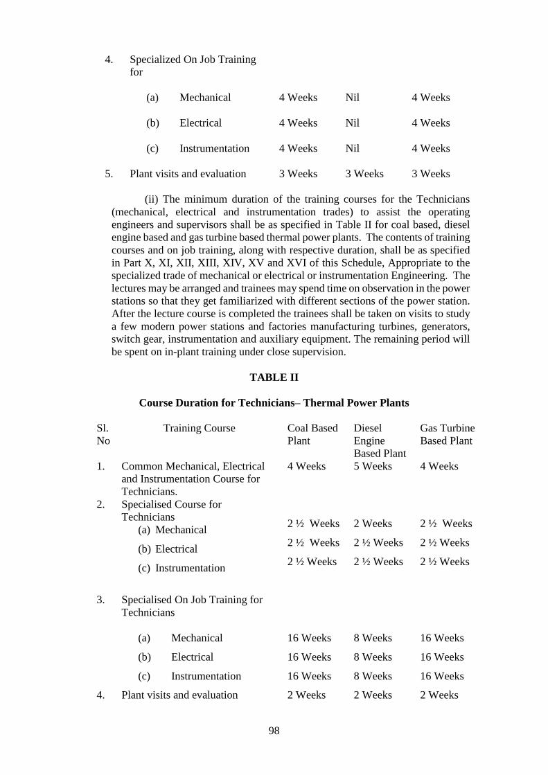
98
4. Specialized On Job Training
for
(a) Mechanical
(b) Electrical
(c) Instrumentation
4 Weeks
4 Weeks
4 Weeks
Nil
Nil
Nil
4 Weeks
4 Weeks
4 Weeks
5. Plant visits and evaluation 3 Weeks 3 Weeks 3 Weeks
(ii) The minimum duration of the training courses for the Technicians
(mechanical, electrical and instrumentation trades) to assist the operating
engineers and supervisors shall be as specified in Table II for coal based, diesel
engine based and gas turbine based thermal power plants. The contents of training
courses and on job training, along with respective duration, shall be as specified
in Part X, XI, XII, XIII, XIV, XV and XVI of this Schedule, Appropriate to the
specialized trade of mechanical or electrical or instrumentation Engineering. The
lectures may be arranged and trainees may spend time on observation in the power
stations so that they get familiarized with different sections of the power station.
After the lecture course is completed the trainees shall be taken on visits to study
a few modern power stations and factories manufacturing turbines, generators,
switch gear, instrumentation and auxiliary equipment. The remaining period will
be spent on in-plant training under close supervision.
TABLE II
Course Duration for Technicians– Thermal Power Plants
Sl.
No
Training Course Coal Based
Plant
Diesel
Engine
Based Plant
Gas Turbine
Based Plant
1. Common Mechanical, Electrical
and Instrumentation Course for
Technicians.
4 Weeks 5 Weeks 4 Weeks
2. Specialised Course for
Technicians
(a) Mechanical
(b) Electrical
(c) Instrumentation
2 ½ Weeks
2 ½ Weeks
2 ½ Weeks
2 Weeks
2 ½ Weeks
2 ½ Weeks
2 ½ Weeks
2 ½ Weeks
2 ½ Weeks
3. Specialised On Job Training for
Technicians
(a) Mechanical
(b) Electrical
(c) Instrumentation
16 Weeks
16 Weeks
16 Weeks
8 Weeks
8 Weeks
8 Weeks
16 Weeks
16 Weeks
16 Weeks
4. Plant visits and evaluation 2 Weeks 2 Weeks 2 Weeks

99
(b) Hydro Electric Power Stations.- (i) The minimum duration of the training
courses for the operating engineers and supervisors (Mechanical, Electrical and
Instrumentation) shall be as specified in Table III for hydro electric power
stations. The contents of training courses and on job training, along with
respective duration, shall be as specified in Part XVII, XVIII, XIX and XX of this
Schedule, Appropriate to the specialized course in mechanical or electrical or
instrumentation Engineering. The procedure for familiarization visits and in-plant
training shall be similar to that which has been specified in respect of thermal
power stations. Arrangement may be made for familiarizing the trainees with
operation of Hydro Power Stations through Simulator facilities.
TABLE III
Course duration for Engineers and Supervisors – hydro power plants
S.
No
Training Course Duration
1. Common Mechanical, Electrical and Instrumentation
Course for Engineers and Supervisors.
6 Weeks
2. Common On Job and Simulator Training for Mechanical,
Electrical and Instrumentation Engineers and
Supervisors.
7 Weeks
3. Specialised Course for Engineers and Supervisors
(a) Mechanical
(b) Electrical
(c) Instrumentation
2 ½ Weeks
4 Weeks
2 Weeks
4. Specialised On Job Training for Engineers and
Supervisors
(a) Mechanical
(b) Electrical
(c) Instrumentation
3 Weeks
4 Weeks
4 Weeks
5. Plant visits and evaluation 2 Weeks
(ii) The minimum duration of the training courses for the technicians
(mechanical, electrical and instrumentation) to assist the operating engineers and
supervisors shall be as specified in Table IV for hydro power stations. The
contents of training courses and on job training, along with respective duration,
shall be as specified in Part XXI, XXII, XXIII and XXIV of this Schedule,
Appropriate to the specialized trade in mechanical or electrical or instrumentation
Engineering. The procedure for familiarization visits and in-plant training shall
be similar to that which has been specified in respect of thermal power stations.
TABLE IV

100
Course Duration for Technicians – Hydro Power Plants
S.No
.
Training Course Duration
1. Common Mechanical, Electrical and Instrumentation
Course for Technicians
3 Weeks
2. Common On Job Training for Mechanical, Electrical and
Instrumentation for Technicians
4 Weeks
3. Specialised Course for Technicians
(a) Mechanical
(b) Electrical
(c) Instrumentation
1 ½ Weeks
2 Weeks
1 ½ Weeks
4. Specialised On Job Training for Technicians
(a) Mechanical
(b) Electrical
(c) Instrumentation
4 Weeks
4 Weeks
4 Weeks
5. Plant visits and evaluation 2 Weeks
(d) Sub-stations and switchyards of generating stations.- Those who are expected
to be engaged in the operation and maintenance of substation associated with the
generating station, shall be given a training of duration of not less than 2½ months
for engineers and supervisors (mechanical, electrical and instrumentation) and 1½
months for technicians (mechanical, electrical and instrumentation trades). The
minimum duration of the training courses for the operating engineers and supervisors
shall be as specified in Table V for substations associated with generating stations.
The minimum duration of the training courses for the technicians shall be as specified
in Table VI. The contents of the training course and on job training, along with
respective duration shall be as specified in Part XXV for engineers and supervisors
and as specified in Part XXVI of this Schedule for technicians to the extent of
practical job requirement in sub-station associated with the generating station. This
shall be followed by visits and in plant training. Arrangement for Simulator training
may also be made.
TABLE V
Course duration for Engineers and Supervisors – sub-stations associated with
generating stations
S.No. Training Course Duration
1. Common Mechanical, Electrical and Instrumentation
Course for Engineers and Supervisors.
6 Weeks
2. Common On Job and Simulator Training for Mechanical,
Electrical and Instrumentation Engineers and Supervisors.
4 Weeks
3. Plant visits and evaluation 2 Weeks
TABLE VI
Course Duration for Technicians – Substations Associated with Generating
Stations

101
S.No. Training Course Duration
1. Common Mechanical, Electrical and Instrumentation
Course for Technicians.
2½ Weeks
2. Common On Job Training, Industrial visits and evaluation 3 Weeks
(2) Facilities for creation of training institutes.- (a) The Training Institute shall have a
regular building, residential and recreation facilities.
(b) The Training Institute shall have a full time Principal and adequate number
of teaching staff.
(c) The Training Institute shall have adequate number of classrooms, seminar and
conference hall and auditorium, library, computer centre, workshops
(mechanical, electrical and basic workshops), laboratories (control and
instrumentation, water chemistry and relevant testing and research facilities). The
Training Institute shall have facilities for demonstration by static and working
models, simulators, training resource unit supported with Appropriate
reprographic facilities, Audio-visual training aides, Computer Based Training
(CBT) packages, Liquid Crystal Diode (LCD), Slide and Overhead projectors.
(d) The Training Institute shall have a regular tie-up with the Power Stations, Sub-
stations, Load Dispatch Centres, transmission and distribution utilities including
hot line training centres so as to provide training in the respective fields.
(e) The Institute shall have facilities to arrange refresher courses for those
personnel who have already experience in the operation and maintenance of a
generating station. The staff of the Training Institute shall be properly qualified
and preferably undergone a specialized training course in the art of imparting
training.
(f) The Institute shall have networking of training facilities with the reputed
educational or professional institutes.
(g) Assessment forms for Engineers and Supervisors and for Technicians to assist
the engineers and supervisors are given at Part XXVII of this Schedule.
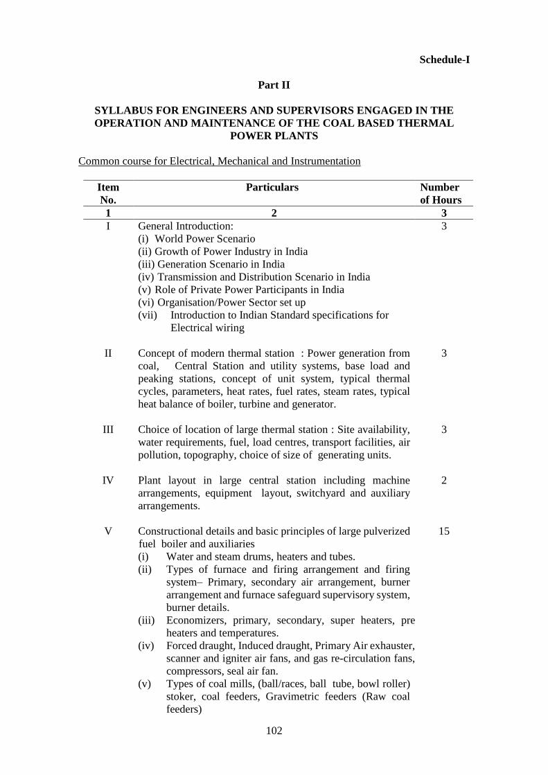
102
Schedule-I
Part II
SYLLABUS FOR ENGINEERS AND SUPERVISORS ENGAGED IN THE
OPERATION AND MAINTENANCE OF THE COAL BASED THERMAL
POWER PLANTS
Common course for Electrical, Mechanical and Instrumentation
Item
No.
Particulars Number
of Hours
1 2 3
I General Introduction:
(i) World Power Scenario
(ii) Growth of Power Industry in India
(iii) Generation Scenario in India
(iv) Transmission and Distribution Scenario in India
(v) Role of Private Power Participants in India
(vi) Organisation/Power Sector set up
(vii) Introduction to Indian Standard specifications for
Electrical wiring
3
II Concept of modern thermal station : Power generation from
coal, Central Station and utility systems, base load and
peaking stations, concept of unit system, typical thermal
cycles, parameters, heat rates, fuel rates, steam rates, typical
heat balance of boiler, turbine and generator.
3
III Choice of location of large thermal station : Site availability,
water requirements, fuel, load centres, transport facilities, air
pollution, topography, choice of size of generating units.
3
IV Plant layout in large central station including machine
arrangements, equipment layout, switchyard and auxiliary
arrangements.
2
V Constructional details and basic principles of large pulverized
fuel boiler and auxiliaries
(i) Water and steam drums, heaters and tubes.
(ii) Types of furnace and firing arrangement and firing
system– Primary, secondary air arrangement, burner
arrangement and furnace safeguard supervisory system,
burner details.
(iii) Economizers, primary, secondary, super heaters, pre
heaters and temperatures.
(iv) Forced draught, Induced draught, Primary Air exhauster,
scanner and igniter air fans, and gas re-circulation fans,
compressors, seal air fan.
(v) Types of coal mills, (ball/races, ball tube, bowl roller)
stoker, coal feeders, Gravimetric feeders (Raw coal
feeders)
15
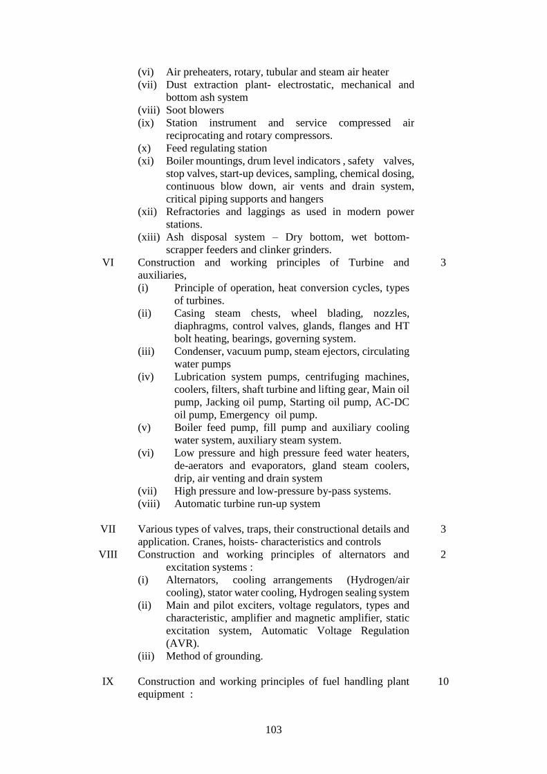
103
(vi) Air preheaters, rotary, tubular and steam air heater
(vii) Dust extraction plant- electrostatic, mechanical and
bottom ash system
(viii) Soot blowers
(ix) Station instrument and service compressed air
reciprocating and rotary compressors.
(x) Feed regulating station
(xi) Boiler mountings, drum level indicators , safety valves,
stop valves, start-up devices, sampling, chemical dosing,
continuous blow down, air vents and drain system,
critical piping supports and hangers
(xii) Refractories and laggings as used in modern power
stations.
(xiii) Ash disposal system – Dry bottom, wet bottom-
scrapper feeders and clinker grinders.
VI Construction and working principles of Turbine and
auxiliaries,
(i) Principle of operation, heat conversion cycles, types
of turbines.
(ii) Casing steam chests, wheel blading, nozzles,
diaphragms, control valves, glands, flanges and HT
bolt heating, bearings, governing system.
(iii) Condenser, vacuum pump, steam ejectors, circulating
water pumps
(iv) Lubrication system pumps, centrifuging machines,
coolers, filters, shaft turbine and lifting gear, Main oil
pump, Jacking oil pump, Starting oil pump, AC-DC
oil pump, Emergency oil pump.
(v) Boiler feed pump, fill pump and auxiliary cooling
water system, auxiliary steam system.
(vi) Low pressure and high pressure feed water heaters,
de-aerators and evaporators, gland steam coolers,
drip, air venting and drain system
(vii) High pressure and low-pressure by-pass systems.
(viii) Automatic turbine run-up system
3
VII Various types of valves, traps, their constructional details and
application. Cranes, hoists- characteristics and controls
3
VIII Construction and working principles of alternators and
excitation systems :
(i) Alternators, cooling arrangements (Hydrogen/air
cooling), stator water cooling, Hydrogen sealing system
(ii) Main and pilot exciters, voltage regulators, types and
characteristic, amplifier and magnetic amplifier, static
excitation system, Automatic Voltage Regulation
(AVR).
(iii) Method of grounding.
2
IX Construction and working principles of fuel handling plant
equipment :
10

104
(i) Coal Handling Plant :- Wagon Tippler, hoppers,
vibratory feeders , screen and conveyor system
crushers, magnetic separators and pulleys, dust
suppressors, dust extractors, stacker re-claimer, rotary
breakers, Merry-Go-Round system,
(ii) Fuel oil handling plant – Oil storage tanks, unloading
station oil pumps and heating arrangement
(iii) Coal transportation by ship- Coal transportation by
different types of ships such as gearless ship, geared
ship, self unloading ships, ship loading and unloading
equipment such as grab type and continuous ship
loaders / un-loaders.
(iv) Coal washing and blending
X Construction and working principles of Ash and slag
handling equipment :
Electrostatic precipitators, methods of conveying, pneumatic,
vacuumatic, hydraulic, bucket elevators, conveyors, screw
extractors, ash slurry pumps, High pressure and low pressure
pumps, dry ash collection. Power Environment Interface,
Environmental Management System
1
XI Water Sources and treatment :
(i) Raw water pumping station, domestic, circulating and
boiler makeup water treatment, River salinity, local
water conditions, water recovery system, their
variations in different seasons and effects on
power station operations.
(ii) Hydrogen generating plant
3
XII Fuels :
(i) Solid, liquid and gaseous fuels analysis.
(ii) Coal-types and suitability for different kinds of
boilers-alterations in firing methods due to change of
coal composition.
3
XIII General understanding of Basic flow diagrams in power
stations practice :
(i) Coal cycle. (ii) Fuel oil cycle.
(iii) Air and gas cycle.
(iv) Fly ash and bottom ash/ slag handling arrangements.
(v) Condensate and feed heating cycle (from condenser
hot well up to economizer).
(vi) Water and steam cycle (from economizer to turbine
inlet).
(vii) Chemical dosing circuit
(viii) Circulating water cycle.
(ix) Governing oil, turbine oil, generator, Seal oil circuit.
(x) Hydrogen filling in generator and hydrogen gland
sealing of generator. Bearing cooling system.
(xi) Stator water cooling cycle
3

105
XIV Direct and closed cooling water circuits, cooling towers -
types and characteristics.
3
XV D.C. and A.C. power supply for auxiliaries, arrangements of
unit and station boards, station lighting and automatic
changeover.
3
XVI Transformers: Main transformers, interconnecting
transformers, station/unit transformers, voltage grounding
transformers, type of connections, paralleling, tap changing
gear, Transformer Fire Prevention System
4
XVII Outdoor switchyard single line diagrams bus bars, circuit
breakers, isolators, current transformers, potential
transformers, lightning arresters, grounding.
4
XVIII Indoor and outdoor switchgear: Types - bulk oil, minimum oil,
air blast, vacuum air breaker, gas breaker constructional and
functional details.
4
XIX
XX
Working principle basics of Instrumentation and
measurements: Details of measuring instruments for pressure,
flow, temperature, level, draught, vibration, eccentricity,
conductivity, pH value, differential expansion, oxygen
analyser, voltage, current, active power, reactive power,
frequency, energy, winding temperature. Auto-controllers,
hydrogen purity meter, axial shift indicator and recorder, flue
gas analysers, megger - its use for primary detection of faults,
data acquisition system, digital distributed control, UPS, Unit
co-ordinated master control. Pre-commissioning/
commissioning activities-Boiler Hydraulic test, alkali boil
out, acid cleaning, TG: Alkali flushing of regenerative system,
acid cleaning of oil pipe lines. TG on barring gear. Others:
Steam blower, rotor valve blasting, steam roller
synchronizing
Operation, control and supervision
(i) General boiler start-up procedure.
(ii) Operation of boilers under different loading conditions,
soot blowing.
(iii) Analysis of feed and boiler water, fuel, flue gas at
station laboratory, Power plant chemistry-chemical
operating regime and control, steam purity
12
12
(iv) Banking and preservation of oilers.
(v) Demonstration wherever possible through simulators
of various operating conditions.
(vi) Handling of boiler under failure conditions, (such as
tripping of turbo-alternator set, high/ low drum levels,
flame failure, failure of supply to auxiliaries)
and under emergency conditions such as grid failures,
tube failures, fire out and furnace explosion

106
(vii) General start up procedure for high-pressure multi-
cylinder reheat type turbines from cold, warm and hot
conditions.
(viii) Handling of turbine, generator and auxiliary plant under
failure conditions, such as vacuum failure, low feed
water, condenser levels, excitation failure, circulating
water failure, feed water heater high levels, excessive
vibration, water or oil ingress in generator, failure of
lubricating, sealing oil circuits and emergency
conditions such as grid failure, black starting.
(ix) Alternator-synchronising, loading, parallel operations,
MW and MVAR sharing.
(x) Operation of vents and drains in boiler and turbine
XXI Controls and Protection - Sequential operation and interlocks:
(i) Unit protection and interlocks.
(ii) Boiler and auxiliaries.
(iii) Turbine and auxiliaries.
(iv) Combustion control-pressure, fuel, air and feed heating
cycle.
(v) Feed water and fuel heating cycle controls.
(vi) Turbine governing, speed setting, speed droop setting
and control circuits.
(vii) Generator protection - under-voltage, over-voltage,
differential reverse power, under-excitation, negative
phase sequence, earth fault with types of the relays
used, Back up impedance, frequency relay, pole
slipping and over current relays
(viii) Importance of sequential interlocks.
(ix) Transformer protection - differential, overload, earth
faults, high temperature, buchholz with types of the
relays used, Transformer Fire Prevention System.
(x) LT/HT motor electrical protection- Types of motors
and variable speed drive and speed controls.
(xi) Various types of pumps and their starting and control.
(xii) Steam pressure and temperature control.
(xiii) Furnace purging.
21
XXII (i) Various types of valves, maps, their constructional
details and application
(ii) Fire-fighting and emulsifier type protection.
1
XXIII General safety precautions, treatment of electrical or acid or
alkali burn, permit to work, first aid, protective clothing,
safety in movement and storage of materials, switchyard
safety.
1 ½
XXIV Indian Boiler Rules, Factory Act, Electricity Act, 2003,
Central Electricity Authority (Measures relating to Safety and
Electric Supply) Regulations, 2010 and other statutory
Regulations concerning Power Stations (General outline),
Environmental Pollution Act/Regulations.
4

107
XXV General plant maintenance procedure, PERT/CPM methods,
Power station records, maintenance planning.
6
XXVI Efficiency and environment, plant performance, generation
cost, efficiency monitoring and optimization, stack emission
monitoring and ambient air quality. Availability Based tariff,
CERC notification on Tariff.
12
XXVII Personnel management, duties and responsibilities, labour
laws and labour welfare.
2
XXVIII Broad Principles of material management and inventory
control
2
Total
145 ½ Hours
5 Weeks
XXIX
On Job Training:
(1) Control room desk operations :
(i) Pre-start checks,
(ii) Protection interlocks,
(iii) Light up procedures and routine checks,
(iv) Stopping and emergency operations of Boiler,
Turbine, Generator and their auxiliaries
(v) Electrical operation location and off-site plant
location
10 Weeks
2. Simulator training/Computer applications in operation and
maintenance of the plant
2 Weeks

108
Schedule-I
Part III
SYLLABUS FOR ENGINEERS AND SUPERVISORS ENGAGED IN THE
OPERATION AND MAINTENANCE OF THE DIESEL ENGINE BASED
POWER PLANTS
Common course for Electrical, Mechanical and Instrumentation
Item
No.
Particulars Number
of Hours
1 2 3
I
II
III
IV
V
General Introduction:
(i) World Power Scenario
(ii) Growth of Power Industry in India
(iii) Generation Scenario in India
(iv) Transmission and Distribution Scenario in India
(v) Role of Private Power Participants in India
(vi) Organisation/Power Sector set up
(vii) Introduction to Indian Standard specifications for Electrical
wiring
Concept of modern Diesel Power Station, Power Generation from
Heavy Fuels, Central Station and Utility systems, base load and
peaking stations, concept of unit systems, heat rates, heat balance
of engines and general principles of Thermodynamics, enthalpy,
entropy, etc.
Choice of location of large Diesel Station, Site availability, water
requirement, fuel, load centers, transport facilities, air pollution,
topography, choice of size of generating units.
Plant layout in large Diesel Station including machine
arrangements, equipment layout, and switch yard and auxiliary
arrangements.
(i) IC Engines, classification, based on 2 Stroke, 4 Stroke, SI,
CI, comparisons, difference between CI and SI,
classification by cylinder arrangements, engine parts and
materials used, indicated thermal efficiency%, mechanical
efficiency %, specific fuel consumption, air fuel ratio, cal.
value of fuel, etc.
(ii) Air standard cycles, thermodynamic relations, parameters,
Carnot cycle, Stirling cycle, Ericsson cycle, Lenoir cycle,
Auto cycle, Dual cycle, Diesel cycle, Atkinson cycle,
Brayton cycle, fuel air cycles, various losses, effect of
variables such as compression ratio, fuel ratio, etc.,
difference between real cycle and fuel air cycle, etc.
(iii) Petroleum fuels, introduction and structures, refining
processes and products, Diesel fuels, octane number, cetane
number, calorific value, viscosity, flash point, pour point,
3
3
2
2
18

109
VI
sulphur content, ash content, asphaltens, water and sediment
content, catalytic fines, problems caused by heavy fuels.
(iv) Combustion: - in IC engines, air fuel ratio – delay period and
factors affecting it – Diesel knock , theory and methods of
control, observations of burning of gases – cold starting of
IC engines and aids.
(v) Super charging objects – cycles – methods – effects of
supercharging on performance of the engine – superchargers
– turbo charging and methods.
(vi) Dual fuel and multifuel engines – combustion and factors
affecting combustion – characteristics of multi fuel engines
– suitability of various engines as multi fuel unit –
performance of multiple engines.
(vii) Engine – friction and lubrication – lubrication principles –
bearing lubrication – functions of lubricating system –
properties of lube oil – additives – classification of lube oils,
filters – crank case ventilation.
(viii) Engine cooling – areas of heat flow – heat transfer - piston
and cylinder temperature – quantity of water required –
cooling systems – air cooling, water cooling and
comparison, re – cooling of water, radiators , cooling fans,
thermostatic control, etc.
(ix) Constructional features of engine – crank case - crank shaft
– main and connecting rod bearings – connecting rod –
piston, crown and rings, cylinder liners, cylinder head –
exhaust and inlet valves – fuel injection pump – injectors –
cam shaft push rods – tappets – rocker arm etc.
(x) Performance and Testing of Engines – basic measurements
– speed – specific lube oil consumption – air consumption –
exhaust smoke – emissions – BHP – FHP and IHP
measurements, de-rating of engines.etc.
(xi) Air pollution – pollutants – Diesel emissions – smoke and
control – Diesel odour control – comparison of Diesel and
other fuel emissions.
Construction and working principles of D.G. plant auxiliaries :
(i) Heavy fuel oil handling system: – railway siding, package
boiler – transfer pumps – storage tanks, dip measurements,
temperature and density corrections, shrinkage - heat
tracing and controls – measurements of fuel parameters such
as viscosity, density, flash point, sulphur content, ash, water
content, acidity, calorific value, carbon residue, pour point,
fire fighting arrangements in the HFO storage area.
(ii) HFO Purifiers: - function of HFO centrifuge – purification –
clarification – principles of centrifugal pump – component
parts of separator and separator plant – layout diagram of
separator plant – sectional view of separator – operating
cycle of separator plant – recommended separator
temperatures – sludge removal , sludge transfer pump.
18
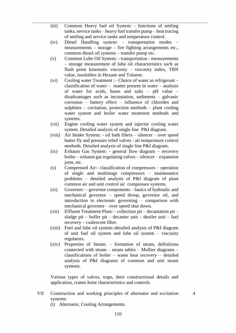
110
VII
(iii) Common Heavy fuel oil System: - functions of settling
tanks, service tanks – heavy fuel transfer pump – heat tracing
of settling and service tanks and temperature control.
(iv) Diesel Handling system: - transportation modes –
measurements – storage – fire fighting arrangements etc.,
common diesel oil systems – transfer pump etc.
(v) Common Lube Oil System: - transportation - measurements
– storage measurement of lube oil characteristics such as
flash point kinematic viscosity – viscosity index, TBN
value, insolubles in Hexane and Toluene.
(vi) Cooling water Treatment :– Choice of water as refrigerant –
classification of water – matter present in water – analysis
of water for acids, bases and salts – pH value –
disadvantages such as incrustation, sediments – galvanic
corrosion – battery effect – influence of chlorides and
sulphites – cavitation, protection methods – plant cooling
water system and boiler water treatment methods and
systems.
(vii) Engine cooling water system and injector cooling water
system. Detailed analysis of single line P&I diagram.
(viii) Air Intake System: - oil bath filters – silencer – over speed
butter fly and pressure relief valves - air temperature control
methods. Detailed analysis of single line P&I diagram.
(ix) Exhaust Gas System: - general flow diagram – recovery
boiler – exhaust gas regulating valves – silencer – expansion
joint, etc.
(x) Compressed Air:- classification of compressors – operation
of single and multistage compressors – maintenance
problems – detailed analysis of P&I diagram of plant
common air and unit control air compressor systems.
(xi) Governor: – governor components – basics of hydraulic and
mechanical governor – speed droop, governor oil, and
introduction to electronic governing – comparison with
mechanical governor – over speed shut down.
(xii) Effluent Treatment Plant: - collection pit – decantation pit –
sludge pit – buffer pit – decanter unit – deoiler unit – fuel
recovery – coalescent filter.
(xiii) Fuel and lube oil system:-detailed analysis of P&I diagram
of unit fuel oil system and lube oil system – viscosity
regulators.
(xiv) Properties of Steam: – formation of steam, definitions
connected with steam – steam tables – Mollier diagrams –
classifications of boiler – waste heat recovery – detailed
analysis of P&I diagrams of common and unit steam
systems.
Various types of valves, traps, their constructional details and
application, cranes hoist characteristics and controls.
Construction and working principles of alternator and excitation
systems:
(i) Alternator, Cooling Arrangements.
4
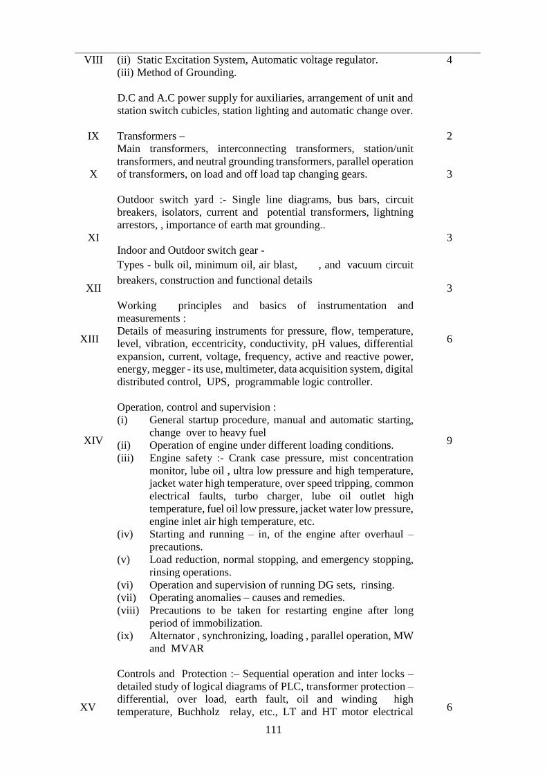
111
VIII
IX
X
XI
XII
XIII
XIV
XV
(ii) Static Excitation System, Automatic voltage regulator.
(iii) Method of Grounding.
D.C and A.C power supply for auxiliaries, arrangement of unit and
station switch cubicles, station lighting and automatic change over.
Transformers –
Main transformers, interconnecting transformers, station/unit
transformers, and neutral grounding transformers, parallel operation
of transformers, on load and off load tap changing gears.
Outdoor switch yard :- Single line diagrams, bus bars, circuit
breakers, isolators, current and potential transformers, lightning
arrestors, , importance of earth mat grounding..
Indoor and Outdoor switch gear -
Types - bulk oil, minimum oil, air blast, , and vacuum circuit
breakers, construction and functional details
Working principles and basics of instrumentation and
measurements :
Details of measuring instruments for pressure, flow, temperature,
level, vibration, eccentricity, conductivity, pH values, differential
expansion, current, voltage, frequency, active and reactive power,
energy, megger - its use, multimeter, data acquisition system, digital
distributed control, UPS, programmable logic controller.
Operation, control and supervision :
(i) General startup procedure, manual and automatic starting,
change over to heavy fuel
(ii) Operation of engine under different loading conditions.
(iii) Engine safety :- Crank case pressure, mist concentration
monitor, lube oil , ultra low pressure and high temperature,
jacket water high temperature, over speed tripping, common
electrical faults, turbo charger, lube oil outlet high
temperature, fuel oil low pressure, jacket water low pressure,
engine inlet air high temperature, etc.
(iv) Starting and running – in, of the engine after overhaul –
precautions.
(v) Load reduction, normal stopping, and emergency stopping,
rinsing operations.
(vi) Operation and supervision of running DG sets, rinsing.
(vii) Operating anomalies – causes and remedies.
(viii) Precautions to be taken for restarting engine after long
period of immobilization.
(ix) Alternator , synchronizing, loading , parallel operation, MW
and MVAR
Controls and Protection :– Sequential operation and inter locks –
detailed study of logical diagrams of PLC, transformer protection –
differential, over load, earth fault, oil and winding high
temperature, Buchholz relay, etc., LT and HT motor electrical
4
2
3
3
3
6
9
6

112
XVI
XVII
XVIII
XIX
XX
XXI
XXII
protection, types of motors, variable speed drives and controls,
generator protection – under and over voltage, differential, reverse
power, under excitation, negative phase sequence, earth fault, etc.,
various types of pumps, their starting and controls, neutral shift
relay, etc.
Fire Fighting and emulsifier type of protection.
General Safety precautions, treatment of electrical or acid or alkali
burns, work permits, first aid, protective clothing, safety in
movement and storage of materials, switch yard safety.
Indian Boiler Rules, Factory Act, Electricity Act, 2003, Central
Electricity Authority (Measures relating to Safety and Electric
Supply) Regulations, 2010 and other statutory Regulations
concerning power stations, Environmental Pollution Act/
Regulations.
General Plant Maintenance procedure, PERT/CPM methods, power
station records, maintenance planning.
Efficiency and environment, plant performance, generation cost,
efficiency monitoring and optimization, stack emission monitoring
and ambient air quality, fuel and lube oil conservation and
minimization of auxiliary losses. Availability based tariff, CERC
notification on tariff.
Personnel management, duties and responsibilities, labour laws and
labour welfare.
Broad Principles of material management and inventory control
Total
1
2
4
3
9
3
2
110 Hours
4 Weeks
XXIII On Job Training:
(1) Control Room Desk Operations:
(i) Prestart Checks.
(ii) Protection and starting inter locks.
(iii) Routine checks such as leakages, pressure, temperatures,
levels, operation of air, fuel, lube oil filters, checks for
lube oil flow in the engine and turbocharger, oil seal
pressure, checks for no water, no oil or fuel leaking from
decompression cocks, checks for abnormal noise, mist
concentration, crank case pressure, starting air pressure,
cylinder temperature after running, bearing temperatures,
starting firing sequence.
(iv) Stopping under emergency conditions of engine, generator
and auxiliaries, rinsing operations
2 Weeks

113
(v) On site Electrical operation location and off site plant
locations.
(vi) Simulator Training/Computer applications in operation
and maintenance of the plant.
2. To be associated with field maintenance Engineers in the area
(i) Fuel handling and purifier
(ii) Compressor and ETP
(iii) JW, LO Seal Pumps and drive, chemical dosing system
(iv) JW, IW level controllers viscosity Regulations
(v) Charge air Regulations, cyl. temp.monitor
(vi) Engine air modular protection including calibration of
inputs and setting of thresholds
(vii) Starting air control equipment and firing sequence.
(viii) Steam system level controllers, calibration, press
controllers, boiler circulating water pumps, condensate
transfer pumps, etc.
(ix) NDT and Welding
2 Weeks

114
Schedule-I
Part IV
SYLLABUS FOR ENGINEERS AND SUPERVISORS ENGAGED IN THE
OPERATION AND MAINTENANCE OF THE COMBINED CYCLE GAS
TURBINE BASED POWER PLANTS
Common course for Electrical, Mechanical and Instrumentation
Item No. Particulars Number of
Hours
1 2 3
I
II
III
IV
V
VI
VII
VIII
General Introduction:
(i) World Power Scenario
(ii) Growth of Power Industry in India
(iii) Generation Scenario in India
(iv) Transmission and Distribution Scenario in India
(v) Role of Private Power Participants in India
(vi) Organisation/Power Sector set up
(vii) Introduction to Indian Standard specifications for Electrical
wiring
Concept of Gas Turbine: power generation from petroleum fuels
such as naphtha , gas, modular NGL Central Station and utility
systems, base load and peaking stations, concept of system, typical
Open and Combined cycles, parameters, heat rates, fuel rates, steam
rates, typical heat balance of gas turbine, waste heat recovery boiler
and turbo generator.
Choice of location of large Gas Power Station: Site availability, water
requirements, fuel supply centers, air pollution, topography.
Plant layout in large central station including machine arrangements,
equipment layout, switchyard and auxiliary arrangements.
Constructional details and basic principles of gas turbines.
(i) Air filters
(ii) Compressors
(iii) Furnace chamber
(iv) Gas turbine
Gas Turbine Air Intake inlet air filtration, Exhaust system and
Compressor System, Gas turbine auxiliaries and governing system,
Air compressor and Air drawing system
Construction and functional features of steam turbine and auxiliaries,
governing system, oil system, control valves
Construction and working principles of Alternators and excitation
systems:
3
3
3
2
12
6
6
6

115
(i) Alternators, cooling arrangements (hydrogen/air cooling),
stator water cooling, hydrogen sealing system.
IX
X
XI
XII
XIII
XIV
XV
XVI
XVII
XVIII
(ii) Characteristic amplifier and magnetic amplifier, static
excitation system, Automatic Voltage Regulation (AVR).
(iii) Method of grounding.
Fuel handling, storage and supply, fuel characteristic
General understanding of Basic flow diagrams in power station
practice :
(i) Fuel cycle
(ii) Air Cycle
Direct and closed cooling water circuits, cooling towers, types and
characteristics.
D.C. and A.C. power supply for auxiliaries, arrangements of unit and
station boards, station lighting and automatic changeover.
Transformers: Main transformers, interconnecting transformers,
station/unit transformers, voltage grounding transformers, type of
connections, paralleling, tap changing gear.
Outdoor switchyard, single line diagrams, busbars, circuit breakers,
isolators, current transformers, potential transformers, lightning
arresters, grounding.
Indoor and outdoor switch gear: Types - bulk oil, minimum oil, air
blast, , and vacuum circuit breakers, construction and functional
details.
Working principle and basics of Instrumentation and measurements:
Details of measuring instruments for pressure, flow, temperature,
level, draught, vibration, eccentricity, conductivity, pH value,
differential expansion, oxygen analyzer, current, voltage, active
power, reactive power, frequency, energy, winding temperature.
Auto-controllers, axial shift indicator and recorder, flue gas analyzers,
Megger – its use for primary detection of faults, data acquisition
system, digital distributed control, UPS, Unit co-ordinated
master control.
Precommissioning/ Commissioning Activities
Operation, control and supervision
(i) General gas turbine start-up procedure.
(ii) Operation of gas turbine under different loading conditions.
(iii) Analysis of water, fuel, at station laboratory.
(iv) Demonstration wherever possible through simulators of
various operating conditions.
(v) Handling of gas/steam turbine under failure conditions (such
as tripping of turbo-alternator set, failure of supply to
3
6
1
2
3
3
3
8
4
22

116
auxiliaries) and under emergency conditions such as grid
failures, tube failures, fire out, etc.
XIX
XX
XXI
XXII
XXIII
(vi) General start up procedure for high-pressure turbines from cold
warm and hot conditions.
(vii) Handling of turbine, generator and auxiliary plant under failure
conditions, and emergency conditions such as grid failure.
(viii) Alternator-synchronizing, loading, parallel operations, MW
and MVAR sharing.
(ix) Water Treatment and water chemistry, R O System and mesied
bed, Boiler meter internal treatment
Controls and Protection – Sequential operation and interlocks:
(i) Unit protection and interlocks.
(ii) Gas turbine and auxiliaries.
(iii) Steam Turbine and auxiliaries.
(iv) Combustion control-pressure, fuel, air cycle.
(v) Turbine governing, speed setting, speed droop setting and
control circuits.
(vi) Generator protection, under-voltage, over-voltage, differential,
reverse power, under-excitation, negative phase sequence,
earth fault and types of relays used.
(vii) Importance of sequential inters locks.
(viii) Transformer protection - differential, overload,, earth faults,
high temperature, Buchholz and types of relays used.
(ix) LT/HT motor electrical protection
(x) Types of motors and variable speed drive and speed controls.
(xi) Various types of pumps and their starting and control.
(xii) Steam pressure and temperature control including automatic
detection and alarm system for naphtha fuel handling / storage.
(xiii) Furnace purging.
Fire-fighting equipment and permanent fire fighting appliances
including automatic detection.
General safety precautions, treatment of electrical or acid/ alkali burn,
permit to work, first aid, protective clothing, safety in movement and
storage of materials, switchyard safety, safe handling of naphtha fuel
in transport, storage and in gas turbines.
Indian Boiler Rules, Factory Act, Electricity Act, 2003, Central
Electricity Authority (Measures relating to Safety and Electric
Supply) Regulations, 2010 and other statutory Regulations
concerning Power Stations (General outline), Environmental
Pollution Act/Regulations.
General plant maintenance procedure, PERT/CPM methods, power
station records, maintenance planning.
18
1
2
4
6

117
XXIV
Efficiency and environment, plant performance, generation cost,
efficiency monitoring and optimization, stack emission monitoring
and ambient air quality. Availability Based Tariff, CERC notification
on Tariff, Gas Turbine Emission guidelines and control methods, Non
emission target levels, Power output allowance, Heat recovery
allowance, emission levels for other contaminants
9
XXV
XXVI
XXVII
Personnel management, duties and responsibilities, labour laws and
labour welfare.
Broad Principles of material management and inventory control
Total
On Job Training:
(1) Control room desk operations:
(i) Pre- start checks,
(ii) Protection interlocks ,
(iii) Light up procedures and routine checks ,
(iv) Stopping and emergency operation of Boiler , Turbine ,
(v) Generators and their auxiliaries
(vi) On site Electrical operation location and off-site plant
location
2. Simulator training/Computer application in operation and
maintenance of the plant
2
2
140 Hours
4½ Weeks
7 Weeks
1 Week
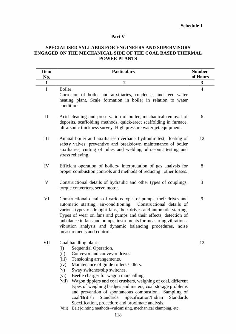
118
Schedule-I
Part V
SPECIALISED SYLLABUS FOR ENGINEERS AND SUPERVISORS
ENGAGED ON THE MECHANICAL SIDE OF THE COAL BASED THERMAL
POWER PLANTS
Item
No.
Particulars Number
of Hours
1 2 3
I
II
III
IV
V
VI
VII
Boiler:
Corrosion of boiler and auxiliaries, condenser and feed water
heating plant, Scale formation in boiler in relation to water
conditions.
Acid cleaning and preservation of boiler, mechanical removal of
deposits, scaffolding methods, quick-erect scaffolding in furnace,
ultra-sonic thickness survey. High pressure water jet equipment.
Annual boiler and auxiliaries overhaul- hydraulic test, floating of
safety valves, preventive and breakdown maintenance of boiler
auxiliaries, cutting of tubes and welding, ultrasonic testing and
stress relieving.
Efficient operation of boilers- interpretation of gas analysis for
proper combustion controls and methods of reducing other losses.
Constructional details of hydraulic and other types of couplings,
torque converters, servo motor.
Constructional details of various types of pumps, their drives and
automatic starting, air-conditioning. Constructional details of
various types of draught fans, their drives and automatic starting.
Types of wear on fans and pumps and their effects, detection of
unbalance in fans and pumps, instruments for measuring vibrations,
vibration analysis and dynamic balancing procedures, noise
measurements and control.
Coal handling plant :
(i) Sequential Operation.
(ii) Conveyor and conveyor drives.
(iii) Tensioning arrangements.
(iv) Maintenance of guide rollers / idlers.
(v) Sway switches/slip switches.
(vi) Beetle charger for wagon marshalling.
(vii) Wagon tipplers and coal crushers, weighing of coal, different
types of weighing bridges and meters, coal storage problems
and prevention of spontaneous combustion. Sampling of
coal/British Standards Specification/Indian Standards
Specification, procedure and proximate analysis. (viii) Belt jointing methods–vulcanising, mechanical clamping, etc.
4
6
12
8
3
9
12
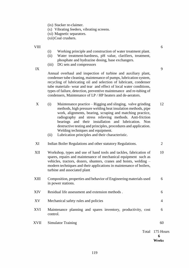
119
VIII
IX
X
XI
XII
XIII
XIV
XV
XVI
XVII
(ix) Stacker re-claimer.
(x) Vibrating feeders, vibrating screens.
(xi) Magnetic separators.
(xii) Coal crushers.
(i) Working principle and construction of water treatment plant.
(ii) Water treatment-hardness, pH value, clarifiers, treatment,
phosphate and hydrazine dosing, base exchangers.
(iii) DG sets and compressors
Annual overhaul and inspection of turbine and auxiliary plant,
condenser tube cleaning, maintenance of pumps, lubrication system,
recycling of lubricating oil and selection of lubricant, condenser
tube materials- wear and tear and effect of local water conditions,
types of failure, detection, preventive maintenance and re-tubing of
condensers, Maintenance of LP / HP heaters and de-aerators.
(i) Maintenance practice – Rigging and slinging, valve grinding
methods, high pressure welding heat insulation methods, pipe
work, alignments, bearing, scraping and matching practice,
radiography and stress relieving methods. Anti-friction
bearings and their installation and lubrication. Non
destructive testing and principles, procedures and application.
Welding techniques and equipment.
(ii) Lubrication principles and their characteristic.
Indian Boiler Regulations and other statutory Regulations.
Workshop, types and use of hand tools and tackles, fabrication of
spares, repairs and maintenance of mechanical equipment such as
vehicles, tractors, dozers, shunters, cranes and hoists, welding –
modern techniques and their applications in maintenance of boilers,
turbine and associated plant
Composition, properties and behavior of Engineering materials used
in power stations.
Residual life assessment and extension methods .
Mechanical safety rules and policies
Maintenance planning and spares inventory, productivity, cost
control.
Simulator Training
Total
6
9
12
2
10
6
6
4
6
60
175 Hours
6
Weeks

120
XVIII
On Job Training:
To be associated with field maintenance Engineers in the area of :
(i) Pressure parts maintenance
(ii) Rotary equipment maintenance
(iii) Pumps and drive maintenance
(iv) NDT and welding
(v) Turbine and auxiliaries maintenance
4 weeks

121
Schedule-I
Part VI
SPECIALISED SYLLABUS FOR ENGINEERS AND SUPERVISORS
ENGAGED ON THE MECHANICAL SIDE OF DIESEL ENGINE BASED
POWER PLANTS
Item
No.
Particulars Number
of Hours
1 2 3
I.
II.
III.
IV.
V.
Constructional details of hydraulic and other types of couplings,
torque converters - servo motor.
Constructional details of various types of pumps, their drives and
automatic starting, air conditioning. Constructional details of
various types of ventilation fans, and automatic starting, types of
wear on fans and pumps and their effects, detection of unbalance
in fans and pumps. Instruments for measuring vibrations,
vibration analysis and dynamic balancing procedures, noise
measurements and control.
Fuel handling plant: Detailed operation and maintenance of fuel
stock yard, fuel purifiers, heat tracing, transfer pumps, settling and
service tank, etc.,
(i) Water Treatment – quality of water, dozing of chemicals
for cooling water and boiler water. Study and effects of
water quality parameters.
(ii) Compressors.
Scheduled Overhaul and inspection of engine and auxiliaries of
the Plant:
(i) Scheduled engine maintenance works required at 1500
hours, 3000 hours, 6000 hours, 12000 hours and 24000
hours; maintenance procedures of lubricating oil pumps,
jacket water pump, etc., recycling of lubricating oil and
monitoring of lube oil parameters.
(ii) Types of failures in the engine, break down maintenance,
carrying out hydraulic tests on cylinder heads, exhaust
valves etc., calibration of injectors and fuel oil pumps
(iii) Maintenance of Turbocharger, dismantling, checking the
bearings, Compressor wheel, turbine shaft and blades,
cleaning, measurement of clearances on the compressor as
well as on the turbine side, before and after dismantling.
Turbo charger washing methods.
(iv) Routine checking of oil pressure, water pressure, inlet and
outlet temperature, operating condition monitoring, types
of failures and detection, scheduled maintenance works
2
5
2
3
15

122
VI
VII.
VIII.
IX
X
XI
such as bowl cleaning, replacement of clutch shoes, vertical
and horizontal bearing, de-sludging operation, starting
and stopping of separators.
Maintenance practice, valve grinding, lapping, high pressure
welding, heat insulation methods, pipe work and alignments.
Motor and pump coupling alignments, bearing, scraping and
matching practice, radiography and stress relieving methods,
antifriction bearings and their installation and lubrication. Non
destructive testing and principles, procedures and application.
Welding techniques and equipment . Replacing of oil seals and
bearings, reconditioning of inlet valves, exhaust valve, fuel
pumps, etc., maintenance of boiler circulating and condensate
transfer pumps, recovery, boiler backwash, etc.
Workshop, types and use of hand tools and tackles, fabrication of
spares, repairs and maintenance of mechanical equipment such as
fork lifts, cranes, hoists, welding – modern techniques and their
applications.
Composition, properties and behavior of Engineering materials
used in power stations.
Residual life assessment and extension methods.
Mechanical safety rules and policies.
Maintenance planning and spares inventory, productivity, cost
control.
Total
9
2
5
6
4
8
61 Hours
2 Weeks

123
Schedule-I
Part VII
SPECIALIZED SYLLABUS FOR ENGINEERS AND SUPERVISORS
ENGAGED ON THE MECHANICAL SIDE OF THE COMBINED CYCLE GAS
TURBINE BASED POWER PLANTS
Item No. Particulars Number
of Hours
1 2 3
I
II
III
IV
V
VI
VII
VIII
IX
Waste heat recovery boiler:
Corrosion of boiler and feed water heating plant, scale formation
in boiler in relation to water conditions.
Acid cleaning and preservation of boiler, mechanical removal of
deposits, auxiliary cooling water system, by pass stack and its
features.
Constructional details of hydraulic and other types of couplings,
torque converters, servo motor.
Constructional details of various types of pumps, their drives
and automatic starting, air-conditioning, various types of
draught fans, their drives and automatic starting.
Types of wear on fans and pumps and their effects, detection of
unbalance in fans and pumps, instruments for measuring
vibrations, vibration analysis and dynamic balancing
procedures, noise measurements and control.
(i) Water treatment- hardness, pH value, clarifiers,
treatment, phosphate and hydrazine dosing, base
exchangers.
(ii) DG sets and compressors.
Power cycle, piping, fittings, valves and thermal insulation, Gas
turbine overhaul procedures.
Annual overhaul and inspection of turbine and auxiliary plant,
condenser tube cleaning, maintenance of pumps lubrication
system, recycling of lubricating oil and selection of lubricant,
condenser tube materials- wear and tear and effect of local
water conditions, types of failure, detection, preventive
maintenance and re-tubing of condensers.
Maintenance practice – Rigging and slinging, valve grinding
methods, high pressure welding, heat insulation methods, pipe
work, alignments, bearing, scraping and matching practice,
radiography and stress relieving methods. Anti-friction bearings
and their installation and lubrication. Non destructive testing
6
3
6
3
5
6
6
12
10
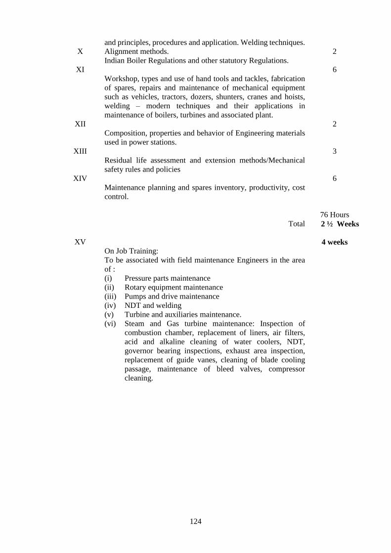
124
X
XI
XII
XIII
XIV
XV
and principles, procedures and application. Welding techniques.
Alignment methods.
Indian Boiler Regulations and other statutory Regulations.
Workshop, types and use of hand tools and tackles, fabrication
of spares, repairs and maintenance of mechanical equipment
such as vehicles, tractors, dozers, shunters, cranes and hoists,
welding – modern techniques and their applications in
maintenance of boilers, turbines and associated plant.
Composition, properties and behavior of Engineering materials
used in power stations.
Residual life assessment and extension methods/Mechanical
safety rules and policies
Maintenance planning and spares inventory, productivity, cost
control.
Total
On Job Training:
To be associated with field maintenance Engineers in the area
of :
(i) Pressure parts maintenance
(ii) Rotary equipment maintenance
(iii) Pumps and drive maintenance
(iv) NDT and welding
(v) Turbine and auxiliaries maintenance.
(vi) Steam and Gas turbine maintenance: Inspection of
combustion chamber, replacement of liners, air filters,
acid and alkaline cleaning of water coolers, NDT,
governor bearing inspections, exhaust area inspection,
replacement of guide vanes, cleaning of blade cooling
passage, maintenance of bleed valves, compressor
cleaning.
2
6
2
3
6
76 Hours
2 ½ Weeks
4 weeks

125
Schedule-I
Part VIII
SPECIALISED SYLLABUS FOR ENGINEERS AND SUPERVISORS
ENGAGED ON THE ELECTRICAL SIDE OF COAL, DIESEL ENGINE AND
GAS TURBINE BASED POWER PLANTS
Item
No.
Particulars Number
of Hours
1 2 3
1.
II
III
IV
V
VI
VII
VIII
IX
X
XI
Maintenance and commissioning of generators, excitation system,
generator seals, Generator protection- earth fault in rotor and
stator, negative phase sequence, loss of excitation, differential
protection, back up protection, reverse power protection, under-
voltage protection, overload protection, constructional details of
the relays used, method of setting and their testing, and over
heating of rotors.
Motor maintenance
Transformer protection - Buchholz relay, over current, differential
and earth fault protection, types of relays used, their construction,
testing and settings.
Transformer commissioning, di-electric strength of oil, insulation
resistance, tap changers, filtration of oil, pre- commissioning
testing. Tan-Delta resistivity of oil and preventive maintenance
of transformers, dissolved gas analysis.
Circuit breakers, commissioning and maintenance, isolators, dis-
connectors, bus bar arrangements, charging, synchronising with
the grid, disconnecting for repairs, maintenance of switchgear
contactors.
Maintenance of equipment in the outdoor switchyard, current
transformers, potential transformers and lightning arrestors,
operation and maintenance. Bus differential protection.
Thermography monitoring
Line protection, fault analysis, bus-bar and local breaker back-up
protection (LBB).
Cables – control cables, layouts of equipment at voltage
exceeding 650V, testing and maintenance.
Principle of electronic controls and transistorised circuits.
12
4
3
3
4
4
2
4
4
5
6

126
XII
XIII
XIV
XV
XVI
XVII
XVIII
XIX
Pneumatic and di-electric transmitters and receivers, servo-
motors.
Interlocking, sequential control circuits, details of components
used.
Calibration and testing of various types of instruments –indicating
instruments, measuring instruments, recorders, and analysers.
Statutory Electricity Acts and Rules and permit procedure
Starting and control equipment of various types of motors, station
battery-care and maintenance, trickle charging and extended
charging, operation and maintenance of rectifiers and battery
chargers, UPS, emergency power supply.
Economic load dispatch, power system control and operation,
MVAR-control, voltage Regulation and frequency control,
capacitors and reactors, islanding schemes, carrier current
equipment , telephones, telemetering.
Station Emergency lighting arrangements.
Simulator Training
Total
On Job Training (Applicable only for Engineers and Supervisors
engaged on Coal and Gas Turbine based plants):
To be associated with field electrical maintenance in the area of:
(i) HT/LT motors
(ii) Transformer maintenance
(iii) AC/DC supply systems, station batteries and DG sets
(iv) Generator/ excitation systems
(v) Switchyard / switchgear equipment maintenance
7
8
4
10
8
1
30
119 Hours
4 Weeks
4 weeks

127
Schedule-I
Part IX
SPECIALISED SYLLABUS FOR ENGINEERS AND SUPERVISORS
ENGAGED ON THE INSTRUMENTATION SIDE OF COAL, DIESEL ENGINE
AND GAS TURBINE BASED POWER PLANTS
Item No. Particulars Number
of Hours
1 2 3
I.
II.
III
IV.
V.
VI.
VII.
Working principles, calibration, control methods and
maintenance aspects of temperature measurement devices:
(i) Resistance thermometers, thermocouples
(ii) Recorders, indicators
(iii) Transmitters.
Working principles, calibration, control methods and
maintenance aspects of pressure measurement devices:
(i) Diaphragm gauges, Bourdon gauges
(ii) Recorders, indicators
(iii) Transmitters.
Working principles, calibration, control methods and
maintenance aspects of flow measurement devices:
(i) Positive, semi-positive, rate and differential pressure
flow meters
(ii) Recorders and indicators
(iii) Transmitters.
Working principles, calibration, control methods and
maintenance aspects of level measurement devices:
(i) Dip-sticks, sight glass, pressure gauge bellows /
diaphragm, float, buoyancy, gas purge, differential
pressure and capacitance type level measurement
system
(ii) Recorders and indicators
(iii) Transmitters.
Telemetering and signal conditioning – pneumatic systems,
electrical systems, electronic systems and maintenance
aspects.
Basic electronics – Component familiarisation and various
types of circuits, microprocessors
Turbovisory instruments – their basic principles, application
and calibration:
(i) Eccentricity and vibration, its interpretation and
measurements, different pick-ups, their location, etc.
(ii) Use of vibration instruments and analysis, differential
expansion, measurement and interpretation, different
4
4
4
4
3
2
6
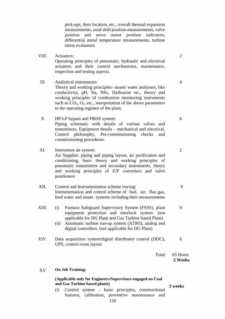
128
VIII.
IX
X
XI.
XII.
XIII.
XIV.
XV
pick-ups, their location, etc., overall thermal expansion
measurements, axial shift position measurements, valve
position and servo motor position indicators,
differential metal temperature measurements, turbine
stress evaluators
Actuators:
Operating principles of pneumatic, hydraulic and electrical
actuators and their control mechanisms, maintenance,
inspection and testing aspects.
Analytical instruments:
Theory and working principles- steam/ water analysers, like
conductivity, pH, Na, NH3, Hydrazine etc., theory and
working principles of combustion monitoring instruments
such as CO2, O2, etc., interpretation of the above parameters
to the operating regimes of the plant.
HP/LP bypass and PRDS system:
Piping schematic with details of various valves and
transmitters, Equipment details – mechanical and electrical,
Control philosophy, Pre-commissioning checks and
commissioning procedures.
Instrument air system:
Air Supplier, piping and piping layout, air purification and
conditioning, basic theory and working principles of
pneumatic transmitters and secondary instruments, theory
and working principles of E/P converters and valve
positioners
Control and Instrumentation scheme tracing:
Instrumentation and control scheme of fuel, air, flue gas,
feed water and steam systems including their measurements
(i) Furnace Safeguard Supervisory System (FSSS), plant
equipment protection and interlock system. (not
applicable for DG Plant and Gas Turbine based Plant)
(ii) Automatic turbine run-up system (ATRS), analog and
digital controllers. (not applicable for DG Plant)
Data acquisition system/digital distributed control (DDC),
UPS, control room layout
Total
On Job Training:
(Applicable only for Engineers/Supervisors engaged on Coal
and Gas Turbine based plants)
(i) Control system – basic principles, constructional
features, calibration, preventive maintenance and
2
4
6
2
9
9
6
65 Hours
2 Weeks
3 weeks

129
trouble shooting of analog control systems, level, flow,
pressure and temperature control systems, component /
cards used in control systems, static and dynamic
timing, control valves and dampers
(ii) Data acquisition system or distributed digital control
system – basic principles, constructional features,
calibration, preventive maintenance and trouble
shooting of digital and analog inputs to DAS and their
conditioning, I/O and interface, functioning of alarms,
monitoring formats and logs, sequence of events
1 week

130
Schedule-I
Part X
SYLLABUS FOR TECHNICIANS ENGAGED IN THE OPERATION AND
MAINTENANCE OF THE COAL BASED THERMAL POWER PLANTS
Common course for Electrical, Mechanical and Instrumentation
Item
No.
Particulars Numbers
of Hours
1 2 3
I.
II.
III.
IV.
V.
VI.
VII.
VIII.
IX.
X.
Power plant familiarisation
Fundamental units and their conversion (mechanical, electrical,
thermo-dynamic).
Engineering drawing and practice.
Fuels and combustion, types of fuels – their properties and
testing, requirement of efficient combustion
Boiler and boiler house plant and auxiliaries :
(i) General description
(ii) Arrangement of boilers
(iii) Boiler auxiliaries
(iv) Boiler instrumentation
(v) Fabrication and assembly of different parts of boiler and
its accessories
(vi) High pressure welding in boilers
(vii) Arrangement of pulverised fuel boiler in a modern
thermal power station
(viii) Operation appreciation (start-up, running and shutdown)
Water conditioning, pre-treatment and demineralisation, water
chemistry.
Ash handling- electrostatic precipitation and mechanical dust
collector- functions and description of two types.
Turbine and turbine house auxiliaries.
(i) Fundamental principle of steam turbine
(ii) Theory and operation of steam turbine
(iii) Governing and protection of turbine
(iv) Operation appreciation (start-up, running and shutdown)
Handling of turbines and boilers under emergency conditions.
Condenser and vacuum extraction plant :
(i) Purpose and function
(ii) Construction of surface condenser and vacuum pumps
6
2
6
4
16
4
2
12
4
3

131
XI.
XII.
XIII.
XIV.
XV.
XVI.
XVII.
XVIII.
XIX.
XX.
XXI
XXII.
XXIII
XXIV
Regenerative feed water heating, constructional details of low
pressure and high pressure feed water heaters, de-aerators and
evaporators.
Cooling water systems and cooling towers.
Flow diagrams of basic cycles and scheme tracing :
(i) Coal handling.
(ii) Steam and condensate
(iii) Ash and slag handling
(iv) Station services - domestic water, air conditioning,
ventilation, lifts
(v) Air services, air compressors, switchgear
(vi) Bearing cooling, and general service water system
(vii) Circulating water system
(viii) Feed water and reheating plant
(ix) Fuel oil system
(x) Station batteries and battery charging equipment
(xi) Station lighting, power supply and distribution boards.
Mechanical appreciation – correct use of machines, tools and
tackles, gauges, fits and clearances, tolerances, brazing,
soldering and welding, bearings, gears and thread, fasteners
Bearings types, installation and removal procedures and
maintenance of clearances and tolerances, oil seals types, their
applications and clearances.
Lubrication and cooling principles.
Station instrumentation and controls.
Fire-fighting installations in thermal power station.
Electric shocks, first aid, acid burn, alkali wounds, chlorine gas
poisoning and their treatment.
Duties and responsibilities of operators and plant attendants,
carrying out instructions, reporting to supervisors, recording and
reading unusual occurrences, expected behavior, discipline,
sincerity, cleanliness and love for machines.
Personnel safety equipment, cleanliness, caution and care in
power station working.
How electricity is generated, transmitted and distributed i.e.
generator to Consumer service board.
Principle and working of alternating current and direct current
generators and their parallel operation.
2
1
16
6
2
2
8
3
3
2
1
2
2
1
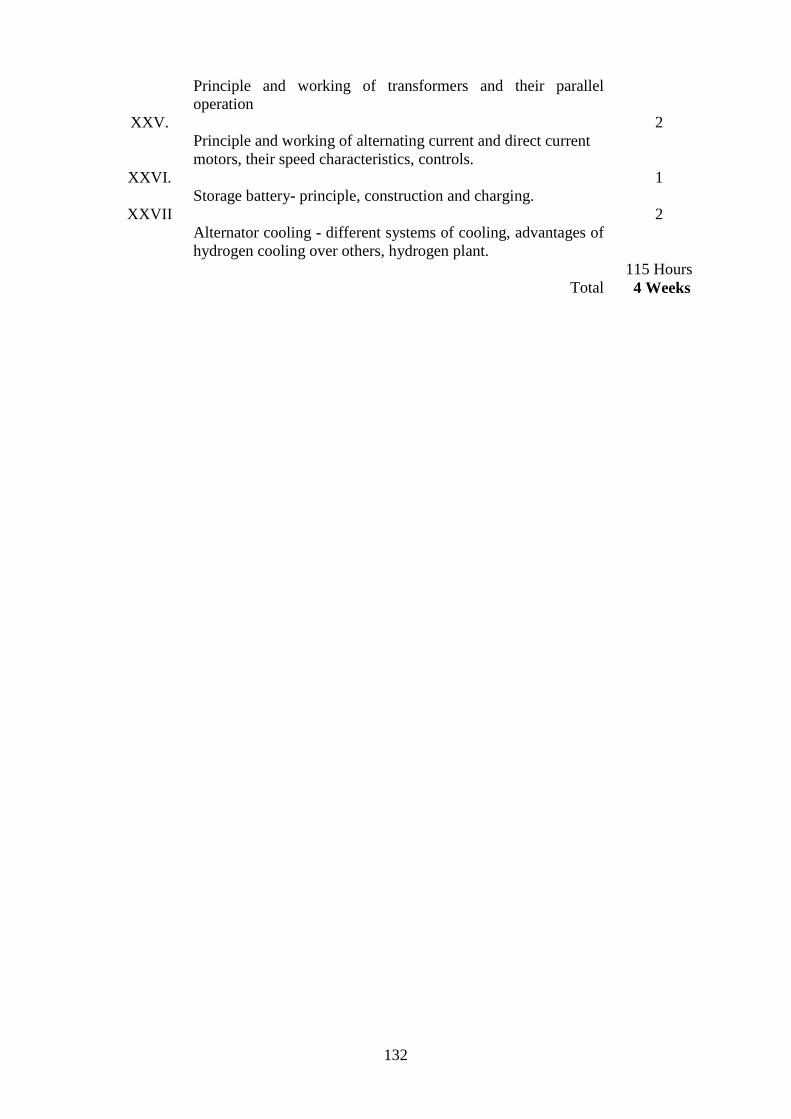
132
XXV.
XXVI.
XXVII
Principle and working of transformers and their parallel
operation
Principle and working of alternating current and direct current
motors, their speed characteristics, controls.
Storage battery- principle, construction and charging.
Alternator cooling - different systems of cooling, advantages of
hydrogen cooling over others, hydrogen plant.
Total
2
1
2
115 Hours
4 Weeks

133
Schedule-I
Part XI
SYLLABUS FOR TECHNICIANS ENGAGED IN THE OPERATION AND
MAINTENANCE OF THE DIESEL ENGINE BASED POWER PLANTS
Common course for Electrical, Mechanical and Instrumentation
Item
No.
Particulars Number
of Hours
1 2 3
I
II.
III.
IV
V.
VI
VII
VIII
IX
X
XI
XII
Power plant familiarization.
Fundamental units and their conversion and measurement
(mechanical, electrical, thermodynamic)
Engineering drawing and practice
Fuels and combustion, types of fuels – their properties and testing,
requirements of efficient combustion.
Diesel Engine and Auxiliaries :
(i) General description
(ii) Arrangement of engine
(iii) Engine auxiliaries
(iv) Assembly of different parts of engine and its accessories
(v) Engine instrumentation
(vi) Operation appreciation (start up, running and shut down).
Water conditioning, pre treatment and demineralization.
Effluent treatment, plant functions and description, importance of
treatment plant.
Turbochargers:
(i) Fundamental principles of turbocharger
(ii) Theory and operation of turbocharger
(iii) Monitoring and protection of turbocharger
Handling of Engine under Emergency conditions.
Fuel oil and lube oil separators:
(i) Purpose and function
(ii) Operation and maintenance of separators
Cooling water system and radiators.
Flow Diagrams of basic cycles and scheme tracing.
(i) Fuel handling.
(ii) Fuel oil system (HFO and Diesel oil)
(iii) Jacket water cooling system
8
4
6
8
24
6
4
6
6
6
2
24

134
XIII
XIV
XV
XVI
XVII
XVIII
XIX
XX
XXI
XXII
XXIII
(iv) Lube oil system
(v) Air intake system
(vi) Engine cooling water system
(vii) Exhaust gas system
(viii) Station services, domestic water, air conditioning,
ventilation, lifts, etc.
(ix) Air services, air compressor
(x) Steam system and heat tracing of fuel pipes
(xi) Station batteries and battery charging equipment
(xii) Station lighting, power supply and distribution boards,
switch gear.
Mechanical application – correct use of machines, tools and
tackles, gauges, fits and clearances, tolerances, brazing, soldering
and welding bearings, gears and thread, fasteners.
Station instrumentation and controls.
Fire fighting installation in D.G. power station.
Electric shocks, first aid, acid burns, alkali wounds/chlorine gas
poisoning and their treatment.
Duties and responsibilities of operators and plant attendants in
carrying out instructions, reporting to supervisors, recording,
reading unusual occurrences, expected behaviour, discipline,
sincerity, cleanliness and love for machines.
Safety equipment and personal cleanliness, cautions and cares in
power station working.
How electricity is generated, transmitted and distributed i.e.
generator to Consumer service board.
Principle and working of alternating current and direct current
generators and their parallel operation
Principle and working of transformers and their parallel operation
Principle and working of alternating current and direct current
motors, their speed characteristics and control.
Storage battery- principle, construction, boost charging, float
charging and importance of DC in DG power plant
Total
6
8
2
3
3
3
2
2
2
2
3
140 Hours
5 Weeks
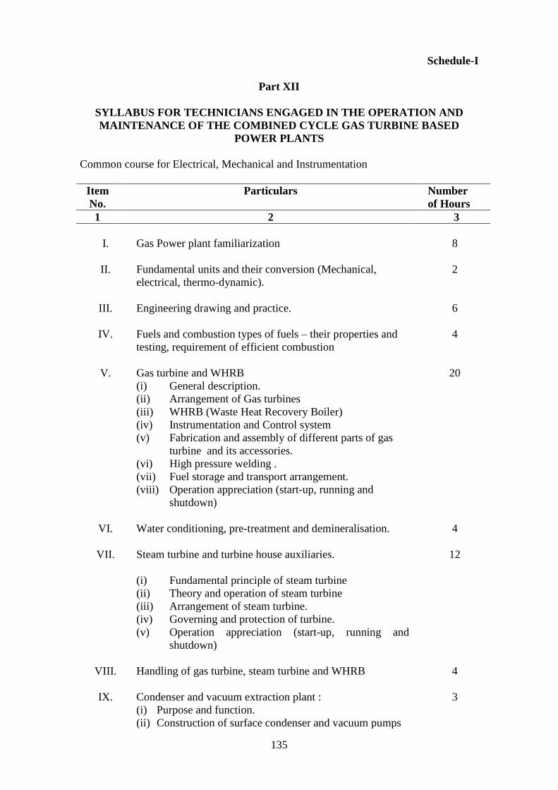
135
Schedule-I
Part XII
SYLLABUS FOR TECHNICIANS ENGAGED IN THE OPERATION AND
MAINTENANCE OF THE COMBINED CYCLE GAS TURBINE BASED
POWER PLANTS
Common course for Electrical, Mechanical and Instrumentation
Item
No.
Particulars Number
of Hours
1 2 3
I.
II.
III.
IV.
V.
VI.
VII.
VIII.
IX.
Gas Power plant familiarization
Fundamental units and their conversion (Mechanical,
electrical, thermo-dynamic).
Engineering drawing and practice.
Fuels and combustion types of fuels – their properties and
testing, requirement of efficient combustion
Gas turbine and WHRB
(i) General description.
(ii) Arrangement of Gas turbines
(iii) WHRB (Waste Heat Recovery Boiler)
(iv) Instrumentation and Control system
(v) Fabrication and assembly of different parts of gas
turbine and its accessories.
(vi) High pressure welding .
(vii) Fuel storage and transport arrangement.
(viii) Operation appreciation (start-up, running and
shutdown)
Water conditioning, pre-treatment and demineralisation.
Steam turbine and turbine house auxiliaries.
(i) Fundamental principle of steam turbine
(ii) Theory and operation of steam turbine
(iii) Arrangement of steam turbine.
(iv) Governing and protection of turbine.
(v) Operation appreciation (start-up, running and
shutdown)
Handling of gas turbine, steam turbine and WHRB
Condenser and vacuum extraction plant :
(i) Purpose and function.
(ii) Construction of surface condenser and vacuum pumps
8
2
6
4
20
4
12
4
3

136
X.
XI.
XII.
XIII.
XIV.
XV.
XVI.
XVII.
XVIII.
XIX.
XX.
XXI.
XXII.
XXIII.
Cooling water systems and cooling towers.
Flow diagrams of basic cycles and scheme tracing :
(i) Steam and condensate
(ii) Station services, domestic water, air conditioning,
ventilation, lifts
(iii) Air services, air compressors, switchgear.
(iv) Bearing cooling and general service water system.
(v) Circulating water system.
(vi) Feed water system
(vii) Fuel oil system
(viii) Station batteries and battery charging equipment
(ix) Station lighting, power supply and distribution boards
Mechanical appreciation – correct use of machines, tools and
tackles, gauges, fits and clearances, tolerances, brazing,
soldering and welding, bearings, gears and thread, fasteners
Station instrumentation and controls.
Fire-fighting installations in thermal power station.
Electric shocks, first aid, acid burn, alkali wounds, chlorine
gas poisoning and their treatment.
Duties and responsibilities of operators and plant attendants,
carrying out instructions, reporting to supervisors, recording
reading unusual occurrences, expected behavior, discipline,
sincerity, cleanliness and love for machines.
Safety of personnel and equipment, cleanliness, caution and
care in power station working.
How electricity is generated, transmitted and distributed i.e.
generator to Consumer service board.
Fundamental units, conversion and measurement of electrical
quantities.
Principle and working of alternating current and direct
current generators and their parallel operation.
Principle and working of transformers and their parallel
operation
Principle and working of alternating current and direct
current motors, their speed characteristics, controls.
Storage battery- principle, construction and charging.
1
18
6
8
2
3
3
3
2
1
2
2
2
1

137
XXIV.
Alternator cooling, different systems of cooling, advantages
of hydrogen cooling over others, hydrogen plant.
Total
2
119 Hours
4 Weeks

138
Schedule-I
Part XIII
SPECIALISED SYLLABUS FOR TECHNICIANS ENGAGED ON
MECHANICAL SIDE OF THE COAL AND GAS TURBINE BASED POWER
PLANTS
Item
No.
Particulars Number
of Hours
1 2 3
I.
II.
III.
IV.
V.
VI.
VII.
VIII.
IX.
X.
XI.
XII.
XIII.
XIV.
XV.
XVI.
XVII.
Types of bearings, oil seals and their uses.
Types of valves, safety valve, suction valve, delivery valve, non-
return valve, bypass valve, drain valve, air release valve, control
valve, float operated valve, solenoid operated and pneumatically
operated valve and their applications.
Efficiency loss in boiler / turbine cycle
Interpretation of instrument reading and accurate logging
Marking and measuring, workshop practice, welding and gas
cutting, pipe fitting methods
Pump maintenance
Shaft alignment methods
Drives maintenance, keys
Insulation types and applications
Mechanical safety
Vulcanizing
Couplings – different types- rigid, flexible, magnetic and fluid
couplings.
Clutches - different types and uses.
Maintenance of pneumatic measuring instruments, servomotors,
power cylinders and other thermostats, Monistats.
Maintenance of instruments, recorders, clocks.
Vibrations – general knowledge of their causes, effects, remedies,
measurement and balancing.
Total
On Job Training in above areas with hands on practicals
4
15
4
2
5
5
4
4
2
4
2
3
2
4
4
8
72 Hours
2 ½ Weeks
16 Weeks

139

140
Schedule-I
Part XIV
SPECIALISED SYLLABUS FOR TECHNICIANS ENGAGED ON
MECHANICAL SIDE OF THE DIESEL ENGINE BASED POWER PLANTS
Item
No.
Particulars Number
of Hours
1 2 3
I
II
III
IV
V
VI
VII
VIII
IX
X
XI
XII
XIII
XIV
XV
XVI
XVII
Types of bearings and their uses.
Types of valves, safety valve, suction valve, delivery valve, non
return valve, bypass valve, drain valve, air release valve, control
valve, float operated valve, solenoid operated and pneumatically
operated valve and their applications.
Efficiency computation in Diesel Engine.
Interpreting instrument reading and accurate logging.
Marking and measuring, workshop practice, welding and gas
cutting, pipe fitting methods.
Pumps maintenance.
Shaft alignment methods.
Drives maintenance keys
Insulation types and applications.
Mechanical safety
Vulcanizing
Coupling- different types, rigid, flexible, magnetic and fluid
couplings.
Clutches- different types and uses
Maintenance of pneumatic measuring instruments, servomotors,
power cylinders and other thermostats, monostats.
Maintenance of instruments, recorders, clocks
Vibration – general knowledge of their causes, effects, remedies,
measurement and balancing.
Total
On job Training in above areas with hands on practicals
3
5
4
2
4
4
4
4
2
4
2
2
2
4
4
8
58 Hours
2 Weeks
8 Weeks

141

142
Schedule-I
Part XV
SPECIALISED SYLLABUS FOR TECHNICIANS ENGAGED ON
ELECTRICAL SIDE OF THE COAL, DIESEL ENGINE AND GAS TURBINE
BASED POWER PLANTS
Item
No.
Particulars Number
of Hours
1 2 3
I.
II.
III.
IV
V
VI
VII
VIII
IX
X
XI
XII
XIII.
XIV.
XV.
XVI
XVII
Alarm systems – visual and audible.
Isolators, circuit breakers and contactors.
Earthing and neutral grounding, necessity of, methods for, safety
rules while handling electrical equipment . Reading electrical
circuit diagrams
Motor winding and repairs.
Maintenance of internal telephones and public address systems.
Meggering and testing of wiring and cable faults.
Maintenance of electrical motors.
Maintenance of electrical switchgears.
Fuses- re-wireable type, cartridges type, high rupturing capacity
fuse, constructional features of fuse and fuse sockets, knife type high
rupturing capacity fuses, use of pullers for insertion and removal,
colour code for fuse ratings.
Motor starters and their applications – direct-on-line, star –delta,
rotor resistance, contactors and relays
Meggers, avometers, voltmeters, ammeters, watt meters, energy
meters- general information about their use.
Maintenance of batteries and rectifiers
Maintenance of transformers and tap changers.
Laying and jointing of cables of voltage up to 250 V and exceeding
250 V but not exceeding 650 V.
Panel wiring methods, connections, earthing principles of operation
of small distribution transformers.
Current and potential transformers, purpose, connection and use.
Various types of drives.
2
3
4
4
3
3
3
8
8
5
6
3
6
4
2
2
2

143
XVIII
XIX
XX
Elementary knowledge of Engineering materials and their
properties.
Lubrication and cooling system
Total
On Job Training in above areas with hands on practicals:
(i) Technicians engaged on coal and gas based Power Plants.
(ii) Technicians engaged on Diesel engine based Power Plants.
2
4
74 Hours
2 ½ Weeks
16 Weeks
8 Weeks

144
Schedule-I
Part XVI
SPECIALISED SYLLABUS TECHNICIANS ENGAGED ON
INSTRUMENTATION SIDE OF THE COAL, DIESEL ENGINE AND GAS
TURBINE BASED POWER PLANTS
Item
No.
Particulars Number
of Hours
1 2 3
I
II
III
IV
V
VI
VII
VIII
IX
X
XI
XII
XIII
XIV
Pressure gauges – Bourdon type gauge, manometer, vacuum -
gauge, barometer, principles of operation, absolute pressure, gauge
and vacuum pressure and their inter-relationship, calibration.
Temperature indicators, mercury thermometers, resistance
thermometers, thermocouples, pyrometers, gas thermometers
temperature alarm, calibration.
Level gauges - different types - level alarm, calibration.
Flow meters - steam and water, general principles, calibration.
Instrument workshop practice – multi meters, megger
Electronic circuit diagram study, drilling, soldering, use of
resistance bridge and workshop potentiometer.
Electronics – components, oscilloscope, power supply, signal
generator applications, logics and timers.
Telemetering and signal conditioning, transducers, thresholds,
transmitters and their calibration.
Instrument air control systems
Actuator maintenance.
Analytical instruments.
Furnace safeguard supervisory instruments, turbovisory
instruments. (Not applicable in case of Diesel engine based power
plants and gas turbine based power plants.)
Instrument fault finding
Familiarisation of data acquisition system / distributed digital
control.
Power supplies and alarm system
5
4
3
3
6
8
12
2
4
3
6
2
3
6

145
XV
XVI
Safety precautions
Total
On Job Training in above areas with hands on practicals
(i) Technicians engaged on coal and gas based Power Plants.
(ii) Technicians engaged on Diesel engine based Power Plants.
1
68 Hours
2 ½ Weeks
16 Weeks
8 Weeks

Schedule-I
Part XVII
SYLLABUS FOR ENGINEERS AND SUPERVISORS ENGAGED IN THE
OPERATION AND MAINTENANCE OF THE HYDRO ELECTRIC POWER
PLANTS
Common course for Electrical, Mechanical and Instrumentation
Item
No.
Particulars Number
of Hours
1 2 3
I
II
General Introduction:
(i) World Power Scenario
(ii) Growth of Power Industry in India
(iii) Generation Scenario in India
(iv) Transmission and Distribution Scenario in India
(v) Role of Private Power Participants in India
(vi) Organisation / Power Sector set up
(vii) Introduction to Indian Standard specifications for
Electrical wiring
Concept of modern hydro station:
Types of stations, their role in the power systems, base load, and
peaking load, run-off-the river, storage type and pumped storage
power plants, concept of unit, typical surface and underground
hydro power stations.
5
3
III Choice of location of large hydro station: water availability land
availability, selection of installed capacity, selection of type of
turbine, choice of size of generating units.
3
IV Hydraulic system, reservoir, storage capacity, operation of
reservoirs, dams and barrages, intake, surge tank, power
tunnels/channel, fore bay and penstocks, pressure shaft, tail race
and tail race tunnel/channel, protection against water hammer and
negative pressure in penstocks and suction head. Dewatering of
water conductor systems.
3
V Plant lay out in hydro stations above 25MW capacity including
machine arrangement, equipment, switchyard and auxiliary
arrangements.
3
VI Constructional details and working principles of valves -
butterfly, spherical, needle etc.
(i) Requirements and principle of operation
(ii) Type and selection criteria of valves and their operation
and control.
3
VII Constructional details and working principles of hydro
mechanical equipment .
(i) Requirements and principle of operation.
(ii) Type and selection criteria of hydro mechanical
equipment and their operation and control.
3
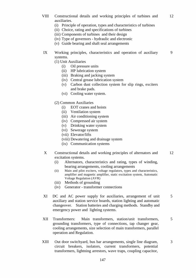
147
VIII Constructional details and working principles of turbines and
auxiliaries.
(i) Principle of operation, types and characteristics of turbines
(ii) Choice, rating and specifications of turbines
(iii) Components of turbines and their design
(iv) Type of governors - hydraulic and electronic
(v) Guide bearing and shaft seal arrangements
12
IX Working principles, characteristics and operation of auxiliary
systems.
(1) Unit Auxiliaries
(i) Oil pressure units
(ii) HP lubrication system
(iii) Braking and jacking system
(iv) Central grease lubrication system
(v) Carbon dust collection system for slip rings, exciters
and brake pads.
(vi) Cooling water system.
(2) Common Auxiliaries
(i) EOT cranes and hoists
(ii) Ventilation system
(iii) Air conditioning system
(iv) Compressed air system
(v) Drinking water system
(vi) Sewerage system
(vii) Elevator/lifts
(viii) Dewatering and drainage system
(ix) Communication systems
9
X Constructional details and working principles of alternators and
excitation systems.
(i) Alternators, characteristics and rating, types of winding,
bearing arrangements, cooling arrangements (ii) Main and pilot exciters, voltage regulators, types and characteristics,
amplifier and magnetic amplifier, static excitation system, Automatic
Voltage Regulation (AVR)
(iii) Methods of grounding
(iv) Generator - transformer connections
12
XI DC and AC power supply for auxiliaries, arrangement of unit
auxiliary and station service boards, station lighting and automatic
changeover. Station batteries and charging methods. Standby and
emergency power and lighting systems.
5
XII Transformers: Main transformers, station/unit transformers,
grounding transformers, type of connections, tap changer gear,
cooling arrangements, size selection of main transformers, parallel
operation and Regulation.
5
XIII Out door switchyard, bus bar arrangements, single line diagram,
circuit breakers, isolators, current transformers, potential
transformers, lightning arrestors, wave traps, coupling capacitor,
3

148
LMU and three element protection devices, grounding
arrangements.
XIV Indoor and out door switch gear: Types: MCB, bulk oil, minimum
oil, air blast, vacuum, breakers, constructional-functional
details and characteristics.
12
XV gas filled EHV switchgear
4
XVI (i) Working principle and basis of instrumentation and
measurements: Detail of measuring instruments for
pressure, flow, temperature, level, vibration, alignment and
current, voltage, power, reactive power, frequency, energy,
winding temperature, auto controllers, recorder, Megger- its
use for primary detection of faults, data acquisition system,
digital distributed control, UPS, unit co-ordinate master
control.
(ii) Testing of electrical and mechanical testing equipment
14
XVII Control and protection – sequential operation and interlocks
(i) Unit protection and interlocks
(ii) Turbine and auxiliaries and vibration monitoring
(iii) Turbine governing, speed setting, speed droop setting and
control circuits
(iv) Generator protection, under voltage, over voltage,
differential, reverse power, under excitation, negative phase
sequence, earth fault, etc.
(v) Different types of protection relays
(vi) Importance of sequential interlocks
(vii) Transformer protection- differential, over load, over
fluxing, restricted earth fault, high temperature, buchholz
protection
(viii) Types of motors and variable speed drive and control
(ix) Various types of pumps and their starting control
(x) Annunciation systems
(xi) On line monitoring devices
15
XVIII Operation control and supervision
(i) General machine start and stop procedure and sequence
(ii) Handling of turbine and generator and auxiliaries under
failure condition. such as, mechanical and electrical
auxiliary and governor failure, grid failure and other failure
conditions.
(iii) Alternator- synchronizing, loading, parallel operation,
active and reactive power sharing and frequency control.
12
XIX (i) Fire safety procedure
(ii) Fire protection of generator
(iii) Fire fighting and emulsifier type protection
5

149
XX General safety precautions, treatment of electrical or acid/alkali
burns, permit to work, first aid, protective gear/ clothing, safety in
movement and storage of materials, safety aspects of switchyard.
4
XXI Factory Act, Electricity Act, 2003, Central Electricity Authority
(Measures relating to Safety and Electric Supply) Regulations,
2010, and other statutory Regulations concerning power stations
(broad outline).
10
XXII Erection, testing and commissioning of turbine, generator, control
and instrumentation, switchyard and auxiliary systems,
maintenance procedures, PERT/CPM method, power station
records, maintenance planning.
12
XXIII
Plant performance, generation cost, machine availability and other
commercial aspects.
6
XXIV Personnel management, duties and responsibilities, labour laws
and labour welfare.
4
XXV Broad principles of material management, procurement procedure
and inventory control.
6
XXVI
Total
On job training:
(1) Control room desk operation:
(i) Pre-start checks
(ii) Protection interlocks
(iii) Startup procedure and routine checks
(iv) Stopping and emergency operation of turbine, generator
and their auxiliaries
(v) Operation of generating unit in abnormal circumstances
(vi) Simulator training/computer application for plants
2. Fire fighting and fire safety procedures during emergency.
173 Hours
6 Weeks
7 Weeks
(6 Weeks)
(1 week)

150
Schedule-I
Part XVIII
SPECIALISED SYLLABUS FOR OPERATION AND MAINTENANCE
ENGINEERS AND SUPERVISORS ENGAGED ON THE MECHANICAL SIDE
OF HYDRO ELECTRIC POWER PLANTS
Item
No.
Particulars Number
of Hours
1 2 3
I
Predictive, preventive and emergent maintenance, types of
failure and detection:
(i) Periodical maintenance and inspection of turbine and
auxiliaries
(ii) Maintenance of pumps, valves and pipe work
(iii) Lubrication principles and their characteristics
(iv) Purification of lubricating oil and selection
(v) Mechanical alignment
(vi) Static and dynamic balancing of machines
(vii) Maintenance planning
(viii) Modern techniques and their applications in maintenance
of turbine and associated auxiliaries.
(ix) Cavitation and erosion of under water components due
to higher abrasive silt laden water.
12
II 1. Pre-commissioning and commissioning tests of hydro
mechanical gates and inlet valves – dry and wet
2. Predictive, preventive and emergent maintenance of :
(i) Inlet valves
(ii) Hydro mechanical gates
(iii) EOT cranes
12
III Predictive, preventive and emergent maintenance of:
(i) Ventilation and air conditioning system
(ii) Central grease lubricating unit
(iii) Air compressors
(iv) Lifts
(v) DG sets
(vi) Fire fighting equipment
10
IV
Maintenance practices - rigging and slinging, bearing, scraping
and matching, radiography and stress relieving methods, anti-
friction bearings and their installation and lubrication, non
destructive testing and principles, procedure and application.
Welding techniques and equipment.
10
V Workshop: Types and use of hydraulic, pneumatic and hand tools
and tackles. Fabrication of spares. Repairs and maintenance of
mechanical equipment such as vehicles, dozers, cranes.
8

151
VI Composition, properties and behavior of Engineering materials
used in power stations
8
VII Residual life assessment and life extension methods
6
VIII Mechanical safety rules and practice
4
IX Spares inventory, productivity, cost control.
4
X
Total
On Job Training:
To be associated with field maintenance of :
(i) Turbine and auxiliaries like governor, shaft seal, inlet
valve, etc.
(ii) Common auxiliaries such as cooling water system,
compressed air, ventilation and air conditioning, fire
fighting, EOT cranes etc.
(iii) Welding and non destructive testing
(iv) Work shop procedures
74 Hours
2 ½ Weeks
3 weeks

152
Schedule-I
Part XIX
SPECIALISED SYLLABUS FOR OPERATION AND MAINTENANCE
ENGINEERS AND SUPERVISORS ENGAGED ON THE ELECTRICAL SIDE
OF THE HYDRO ELECTRIC POWER PLANT
Item
No.
Particulars Number
of Hours
1 2 3
I.
Predictive, preventive and emergent maintenance and inspection
of generators, excitation system, generator bearing. Principles
of electronic controls and transistorized circuits. Generator
protection- earth fault in rotor and stator, negative phase
sequence, loss of excitation, differential protection, back up
protection, reverse power protection, under/over voltage
protection, over load protection, dry out of generators.
Constructional details of the different types of relays and other
sensing equipment , method of setting and their testing. Wiring
details of control panels. Insulating materials and their use.
15
II. Predictive, preventive and emergent maintenance of motors.
4
III. Transformer: preventive maintenance of transformers, dielectric
strength of oil, insulation resistance, tap changers, filtration of oil.
Tan-Delta resistivity of oil, dissolved gas analysis and other
testing of oil
8
IV Transformer: Protection- Buchholz relay protection, over current
protection, differential protection and earth fault protection, types
of relays used, their construction, testing and setting.
Commissioning tests.
8
V Circuit breakers’ maintenance, isolators, disconnectors, bus bar
arrangements, charging, synchronizing with the grid,
disconnecting for repairs, maintenance of switchgear contactors.
8
VI Maintenance of equipment in the outdoor and indoor switchyard.
Operation and maintenance of current transformers, potential
transformers and lighting arrestors. Bus differential protection,
etc. LV, HV and EHV cables and their jointing and testing.
8
VII Maintenance of gas filled insulated switch gear.
6
VIII Station auxiliary supply, station battery-care and maintenance,
trickle charging and extended charging, operation and
maintenance of rectifiers and battery chargers, UPS, emergency
power supply, station grounding arrangements.
10
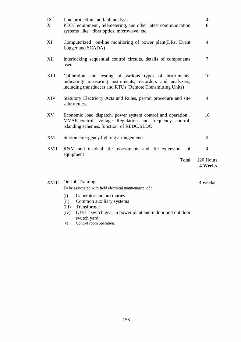
153
IX Line protection and fault analysis. 4
X PLCC equipment , telemetering, and other latest communication
systems like fiber optics, microwave, etc.
8
XI Computerized on-line monitoring of power plant(DRs, Event
Logger and SCADA)
4
XII Interlocking sequential control circuits, details of components
used.
7
XIII Calibration and testing of various types of instruments,
indicating/ measuring instruments, recorders and analyzers,
including transducers and RTUs (Remote Transmitting Units)
10
XIV Statutory Electricity Acts and Rules, permit procedure and site
safety rules.
4
XV Economic load dispatch, power system control and operation ,
MVAR-control, voltage Regulation and frequency control,
islanding schemes, function of RLDC/SLDC
10
XVI Station emergency lighting arrangements.
2
XVII R&M and residual life assessments and life extension of
equipment
4
Total
120 Hours
4 Weeks
XVIII On Job Training:
To be associated with field electrical maintenance of :
(i) Generator and auxiliaries
(ii) Common auxiliary systems
(iii) Transformer
(iv) LT/HT switch gear in power plant and indoor and out door
switch yard (v) Control room operation.
4 weeks

154
Schedule-I
Part XX
SPECIALISED SYLLABUS FOR OPERATION AND MAINTENANCE
ENGINEERS AND SUPERVISORS ENGAGED ON THE
INSTRUMENTATION SIDE OF THE HYDRO ELECTRIC POWER PLANTS
Item
No.
Particulars Number
of Hours
1 2 3
I. Working principles, calibration, control methods and maintenance
aspects of temperature measurement devices.
(i) Resistance thermometers, thermocouples
(ii) Recorders, indicators
(iii) Transmitters
(iv) Transducers and RTUs.
5
II. Working principles, calibration, control methods and maintenance
aspects of pressure measurement devices
(i) Diaphragm gauge, Bourdon gauge
(ii) Recorders, indicators
(iii) Transmitters
4
III. Working principles, calibration, control methods and maintenance
aspects of flow measurement devices:
(i) Positive, semi-positive, rate and differential pressure flow
meters.
(ii) Recorders and indicators
(iii) Transmitters.
4
IV. Working principles, calibration, control methods and maintenance
aspects of level measurement devices :
(i) Pressure gauge bellows/diaphragm, float, buoyancy, gas purge,
differential pressure and capacitance type level measurement
systems
(ii) Recorders and indicators
(iii) Transmitters
4
V. Telemetering and signal conditioning - pneumatic systems, electrical
systems, electronic systems and maintenance aspects.
4
VI Basic electronics – Component familiarization and various types of
circuits, microprocessors
8
VII Turbovisory instruments- their basic principles, application and
calibration : alignment and vibration, its interpretation and
measurements, different types of pick-ups, their location, etc., use of
vibration instruments and analysis, different pickups, their location,
etc., axial shift position measurements, valve position and servo
motor position indicators, differential metal temperature
measurements.
12

155
VIII
Actuators:
Operating principles of pneumatic, hydraulic and electrical actuators
and their control mechanisms, maintenance, inspection and testing
aspects.
6
IX Instrument air system:
Air Supplier, piping and piping layout.
4
X. Data acquisition systems. Microprocessor based control system for
generating units including governors and excitation systems. Digital
distributed control (DDC), UPS, control room layout
Total
11
62 Hours
2 Weeks
XI. On Job training:
(1) Control system – basic principles, construction features,
calibration, preventive maintenance and trouble shooting. Analog
control systems, level, flow, pressure and temperature control
systems, component/cards used in control systems, static and
dynamic timing, control valves and dampers.
(2) Data Acquisition System (DAS) or distributed digital control
system – basic principles, construction features, calibration,
preventive maintenance and trouble shooting of digital and analog
inputs to DAS and their conditioning, I/O and interface, functioning
of alarms, monitoring formats and logs, sequence of events.
2 weeks
2 weeks
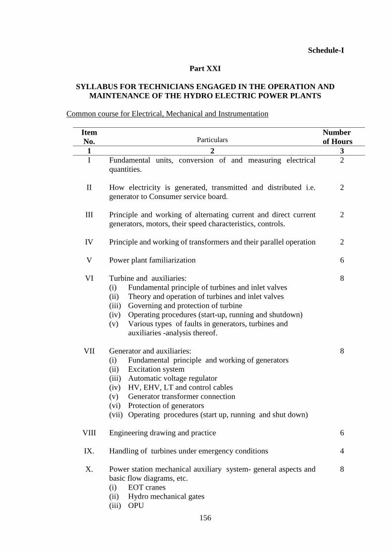
156
Schedule-I
Part XXI
SYLLABUS FOR TECHNICIANS ENGAGED IN THE OPERATION AND
MAINTENANCE OF THE HYDRO ELECTRIC POWER PLANTS
Common course for Electrical, Mechanical and Instrumentation
Item
No. Particulars Number
of Hours
1 2 3
I Fundamental units, conversion of and measuring electrical
quantities.
2
II How electricity is generated, transmitted and distributed i.e.
generator to Consumer service board.
2
III Principle and working of alternating current and direct current
generators, motors, their speed characteristics, controls.
2
IV Principle and working of transformers and their parallel operation
2
V Power plant familiarization
6
VI Turbine and auxiliaries:
(i) Fundamental principle of turbines and inlet valves
(ii) Theory and operation of turbines and inlet valves
(iii) Governing and protection of turbine
(iv) Operating procedures (start-up, running and shutdown)
(v) Various types of faults in generators, turbines and
auxiliaries -analysis thereof.
8
VII Generator and auxiliaries:
(i) Fundamental principle and working of generators
(ii) Excitation system
(iii) Automatic voltage regulator
(iv) HV, EHV, LT and control cables
(v) Generator transformer connection
(vi) Protection of generators
(vii) Operating procedures (start up, running and shut down)
8
VIII Engineering drawing and practice
6
IX. Handling of turbines under emergency conditions
4
X. Power station mechanical auxiliary system- general aspects and
basic flow diagrams, etc.
(i) EOT cranes
(ii) Hydro mechanical gates
(iii) OPU
8

157
(iv) Central grease lubricating unit
(v) HP lubrication system
(vi) Carbon dust collection system
(vii) Cooling water systems, bearing cooling, generator cooling
and transformer cooling
(viii) Braking and jacking system
(ix) Drainage and dewatering system
(x) Drinking water, air conditioning and ventilation system
(xi) Air services, air compressors
(xii) Lifts
XI. Mechanical appreciation – correct use of machines, tools and
tackles, gauges, fits and clearances, tolerances, brazing, soldering
and welding, bearings, gears and threads, fasteners.
6
XII Electrical appreciation- correct and Appropriate use of electrical
tools like Megger, tong testers, multi-meters, insulation testing
equipment, earthing and its importance.
6
XIII Bearings- types, installation and removal procedures and
maintenance, clearance and tolerances, oil seals- types,
applications with clearances.
2
XIV Lubrication and cooling principles.
2
XV Station instrumentation and controls.
4
XVI Power station electrical auxiliary system - general aspects and
basic flow diagrams, etc.
(i) Station lighting, power supply and distribution boards
(ii) Station batteries and battery charging system
(iii) Unit and station transformers
(iv) DG sets and their maintenance
8
XVII Electric shocks, first aid, acid burn, alkali wounds, Chlorine gas
poisoning and their treatment.
3
XVIII Fire fighting installations in hydro power station
2
XIX Personnel safety equipment, cleanliness, caution and care in
power station working. Importance of earthing.
2
XX Duties and responsibilities of operators and plant attendants,
carrying out instructions, reporting to supervisors, recording
reading, visual occurrence, expected behavior, discipline,
sincerity, cleanliness and love for machines
Total
3
86 Hours
3 Weeks
XXI On job Training in above areas with hands on practicals
4 weeks

158
Schedule-I
Part XXII
SPECIALISED SYLLABUS FOR TECHNICIANS TO BE ENGAGED ON THE
MECHANICAL SIDE OF THE HYDRO ELECTRIC POWER PLANTS
Item
No.
Particulars. Number
of Hours
1 2 3
I
Operation and general aspects of annual maintenance of turbine
and auxiliaries
(i) Turbine
(ii) Inlet valve
(iii) Governing system
(iv) Shaft seal
6
II Operation and general maintenance of common mechanical
auxiliaries:
(i) Pumps and associated pipe work such as cooling water system,
fire fighting system, drainage system, dewatering system
(ii) Air conditioning and ventilation system
(iii) Air compressors
(iv) EOT cranes
(v) Hydro mechanical gates
(vi) Turbine and generator bearing
(vii) Lifts
(viii) Fire fighting system for power house complex and
specifically for equipment like transformers and generators
with knowledge of different fire fighting systems.
6
III Types of valves- safety valve, suction valve, delivery valve, non-
return valve, bypass valve, drain valve, air release valve, control
valve, float operated valve, solenoid operated and pneumatically
operated valves and their applications.
4
IV Interpretation of instrument reading and accurate logging
2
V Workshop practice, making of spare parts, welding and gas cutting,
pipe fitting methods, introduction to various tools, tackles and
practice.
4
VI Shaft alignment methods.
4
VII Rubber components, their uses and handling.
2
VIII Maintenance of measuring instruments such as dial gauges,
micrometers, vernier calipers etc.
4
IX Couplings-different types, rigid and flexible coupling.
2
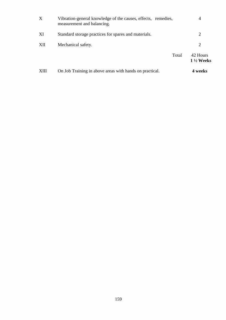
159
X Vibration-general knowledge of the causes, effects, remedies,
measurement and balancing.
4
XI Standard storage practices for spares and materials.
2
XII Mechanical safety.
2
Total
42 Hours
1 ½ Weeks
XIII On Job Training in above areas with hands on practical.
4 weeks

160
Schedule-I
Part XXIII
SPECIALISED SYLLABUS FOR TECHNICIANS TO BE ENGAGED ON THE
ELECTRICAL SIDE OF THE HYDRO ELECTRIC POWER PLANTS
Item
No.
Particulars Number
of Hours
1 2 3
I Operation and general aspects of annual maintenance of
generators and auxiliaries
(i) Generator and its dry out
(ii) Excitation system
(iii) AVR
8
II Operation and general maintenance of common electrical
auxiliaries
(i) Station supply
(ii) Batteries and chargers, DC distribution boards and
emergency lighting system
(iii) Motor winding and repairs
(iv) Understanding of electrical panel wiring
(v) PLCC system
(vi) EOT crane
8
III Operation and maintenance of transformers including oil filtration
6
IV Out door switch yard equipment such as isolators, circuit breakers
and contactors, earthing switches, CT, CVT, LA
3
V Indoor switch gear system
4
VI Alarm systems - visual and audible
2
VII Earthing and neutral grounding: necessity of methods for safety
while handling electrical equipment . Reading electrical circuit
diagrams
4
VIII Maintenance of internal telephones and public address system
3
IX Meggering and testing of electrical equipment, wiring and cables
3
X Maintenance of electrical switchgears
6
XI Fuses-rewirable types, cartridges type, high rupturing capacity
fuse, constructional features of fuse and fuse sockets, knife type
high rupturing capacity fuses, use of pullers for insertion and
removal, colour code for fuse ratings.
6
XII Motor starters and their applications- direct-on-line, star delta,
rotor resistance, contactors and relays
5

161
XIII Voltmeters, ammeters, watt meters, energy meters, meggers,
multimeters, tong testers and general information about their use
6
XIV Laying and jointing of cables of voltage upto 250 V and
exceeding 250 V but not exceeding 650 V.
4
XV Panel wiring methods, connections, earthing, and principles of
operation of small distribution transformers.
2
XVI Protection relays, current and potential transformers, purposes,
connections and use.
2
XVII Elementary knowledge of electrical Engineering materials and
their properties.
2
XVIII Basic knowledge of computers and on line monitoring system
2
XIX Familiarization with supervisory control and data acquisition
system.
4
XX
Total
On job Training in above areas with hands on practicals.
80 Hours 3 Weeks
4 weeks

162
Schedule-I
Part XXIV
SPECIALISED SYLLABUS FOR TECHNICIANS TO BE ENGAGED ON THE
INSTRUMENTATION SIDE OF THE HYDRO ELECTRIC POWER PLANTS
Item
No.
Particulars Number
of Hours
1 2 3
I. Familiarization with Supervisory control and data acquisition
system
4
II. Power supplies and alarm system
4
III. Power station instruments, their maintenance and testing
(i) Event sequence recorder
(ii) Disturbance fault recorders
(iii) Sequence controllers
(iv) Digital relays
4
IV Water flow meters and their application and maintenance
2
V Pressure gauge: Bourdon type gauge, barometer principles of
operation, absolute pressure, vacuum pressure, maintenance of
pressure gauges.
3
VI Level gauges: Different types of level gauges and their
application in power house and calibration
3
VII Temperature indicators: mercury thermometers, resistance
thermometers, thermocouples, their use in power house and
calibration
3
VIII Instrument workshop practice: electronic circuit diagram study,
multi-meters, Megger, drilling, soldering, use of resistance
bridge and workshop potentiometer
6
IX Electronic components, oscilloscope, power supply, signal
generator applications, logics and timers
8
X Telemetering and signal conditioning, transducers, thresholds,
transmitters and their calibration
8
XI Instrument fault finding
2
XII
XIII
Safety precautions
Total
On job Training in above areas with hands on practicals.
1
48 Hours
1 ½ Weeks
4 Weeks

163

164
Schedule-I
Part XXV
SYLLABUS FOR ENGINEERS AND SUPERVISORS ENGAGED IN
OPERATION AND MAINTENANCE OF SUB-STATIONS ASSOCIATED
WITH THE GENERATING STATIONS
Common course for Electrical, Mechanical and Instrumentation
Item
No.
Particulars Number
of Hours
1 2 3
I
II
III
IV
V
VI
VII
General Introduction:
(i) World Power Scenario
(ii) Growth of Power Industry in India
(iii) Generation Scenario in India
(iv) Transmission and Distribution Scenario in India
(v) Role of Private Power Participants in India
(vi) Organisation/Power Sector set up
(vii) Introduction to Indian Standard specifications for
Electrical wiring
(viii) Energy conservation
Layout and location of 66 kV and higher voltage sub-stations.
Main equipment used together with their specifications
including gas insulated switching systems
Concept of High Voltage DC Transmission
Construction of high voltage lines, types of towers, types of
insulators and their electrical and mechanical characteristics.
High tension feeders, their load carrying capacities.
(i) Alternating and direct currents, relation between voltage,
current, power, reactive power and common units in use.
Power factor, Ohm’s Law, resistance, reactance,
impedance, percentage impedance. Three phase vectors,
phase - displacement between current and voltage
(ii) Basic principles of transformation, magnetisation,
hysteresis, reluctance, retentivity, electromagnets. Flux
density, ampereturns equation for transformation,
reactors, etc.
(iii) Two winding, three winding and auto transformers.
Grounding transformers, salient features of shell type and
core type transformers, hot rolled and cold rolled steel
cores, stampings and their assembly. Different vector
groups and terminal connection
5
4
6
3
3
3
29

165
VIII
IX
X
XI
XII
(iv) Transformer fixtures, e.g., Buchholz relay, on-load and
off-load tap changer, breathers, conservators, bushings of
different types, thermometers, indicators, alarms
(v) Cooling of transformer and oil, different methods of
cooling, importance of oil filtering and drying-out of
transformers, di-electric strength of oil, different varieties
of filters and their comparison, types of radiators
(vi) Transformer tests – failure and causes, maintenance and
repairs
(vii) Parallel operation, Regulation, voltage control, tap
change, commissioning tests
Breakers:
(i) Functions of breakers, their action.
(ii) Different types of outdoor and indoor breakers, e.g. bulk
oil, minimum oil and air blast, SF6- principles and their
applications
(iii) Operating mechanism, manual, spring, hydraulic
pneumatic, motor
(iv) Breaker maintenance, failures and their causes,
Commissioning procedure
Bus bars:
(i) Indoor bus bars, their capacity, forces on them during
short circuit, bus bar mountings and their clearances
(ii) Strung and tubular type bus bars, their current ratings,
supports, jumpers, clearances.
(iii) Busbar fittings and connectors
(iv) Cables of voltage exceeding 650 V, types, their
maintenance and testing
Current and potential transformers:
(i) Types of current and potential transformers, their
working principles, ratings, accuracies.
(ii) Functions of current and potential transformers.
(iii) Failure of current and potential transformers, their
causes.
Isolators:
(i) Tilting and rotating isolators, with and without arcing
horns, horizontal center break type, tandem isolators,
earthing blades, current rating, breaking a circuit by
isolator, interlocking with circuit breaker
(ii) Maintenance of isolators
Lightning protection:
(i) Simple description of lightning phenomena, surges and
their protection
(ii) Construction of lightning arrestors and the principles of
their working
(iii) Different types of lightning arrestors and ratings
8
6
5
5
3

166
XIII
XIV
XV
XVI
XVII
XVIII
XIX
XX
(iv) Earthing and location of lightning arrestors.
(v) Codes and Practices for lightning protection
Capacitors
Control Room:
(i) Necessity and function of a control board, types of
boards, instruments of the board.
(ii) Functions of the various relays and indicators, mimic
diagram indicators, annunciator and alarm,
characteristics of relay testing and setting of relays
(iii) Remote control of breakers, isolators, tap changers,
indicators on the control board.
(iv) Control and power cables
(v) Metering, concept of tariff, event loggers, disturbance
recorders
Auxiliary supply:
(i) Current and ampere-hour ratings of batteries, battery
charging equipment, checking of specific gravity of
electrolyte, maintenance of batteries
(ii) Importance of direct current supply and its functions.
(iii) Auxiliary direct current supply
(iv) AC distribution board
Clearances and Compliance of CEA (Measures relating to
Safety and Electricity Supply) Regulations 2010
(i) Minimum clearance between phases and phase to ground
for different voltages
(ii) CEA(Measures relating to Safety and Electric Supply)
Regulations, 2010 pertaining to sub-stations.
Earthing:
(i) Safety earthing and system earthing, the method of
earthing e.g., solid earthing, resistance earthing, peterson
coil earthing, earthing of lightning arrestor, importance
and advantages of each type
(ii) Different types of earth electrodes, earthing mats,
recommended values of earth resistance, measurement of
earth resistance
Maintenance: Maintenance of log sheet and other records. The
importance of maintenance of good records.
Safety:
(i) Safety procedures and procedures for giving line clear
and taking it back. Maintenance of records of line clear.
(ii) First-aid, artificial respiration and shock treatment.
(i) Interlocking and sequential operation of different
equipment .
(ii) Protections :- Transformers, lines, reactors, bus bar.
3
10
5
5
3
3
10
8

167
XXI
XXII
XXIII
XXIV
XXV
XXVI
XXVII
XXVIII
XXIX
XXX
XXXI
XXXII
XXXIII
XXXIV
Synchronising, charging and discharging of lines of voltage
exceeding 650 V but not exceeding 33 kV. Live line testing.
Calibration and testing of various types of equipment, indicating
and measuring equipment , recorders, analysers.
Handling emergency conditions.
Diagnosing troubles in the plant from instruments and
annunciation.
Thermography monitoring.
Study of carrier system, PLCC
Auxiliary equipment such as compressors, station lighting, etc.
Fire-fighting equipment – their operations, maintenance and
refilling, emulsifier, fire wall protections
Personnel management, duties and responsibilities, labour
welfare and labour laws
Power and telecommunication co-ordination committee
(PTCC) guidelines.
Broad principles of material management and inventory control
Simulator Training
Total
On Job Training related to above areas
Industrial visits and evaluation
3
4
3
3
4
2
2
3
4
2
3
30
190 Hours
6 Weeks
4 Weeks
2 Weeks
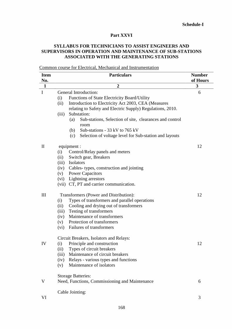
168
Schedule-I
Part XXVI
SYLLABUS FOR TECHNICIANS TO ASSIST ENGINEERS AND
SUPERVISORS IN OPERATION AND MAINTENANCE OF SUB-STATIONS
ASSOCIATED WITH THE GENERATING STATIONS
Common course for Electrical, Mechanical and Instrumentation
Item
No.
Particulars Number
of Hours
1 2 3
I
II
III
IV
V
VI
General Introduction:
(i) Functions of State Electricity Board/Utility
(ii) Introduction to Electricity Act 2003, CEA (Measures
relating to Safety and Electric Supply) Regulations, 2010.
(iii) Substation:
(a) Sub-stations, Selection of site, clearances and control
room
(b) Sub-stations - 33 kV to 765 kV
(c) Selection of voltage level for Sub-station and layouts
equipment :
(i) Control/Relay panels and meters
(ii) Switch gear, Breakers
(iii) Isolators
(iv) Cables- types, construction and jointing
(v) Power Capacitors
(vi) Lightning arrestors
(vii) CT, PT and carrier communication.
Transformers (Power and Distribution):
(i) Types of transformers and parallel operations
(ii) Cooling and drying out of transformers
(iii) Testing of transformers
(iv) Maintenance of transformers
(v) Protection of transformers
(vi) Failures of transformers
Circuit Breakers, Isolators and Relays:
(i) Principle and construction
(ii) Types of circuit breakers
(iii) Maintenance of circuit breakers
(iv) Relays - various types and functions
(v) Maintenance of isolators
Storage Batteries:
Need, Functions, Commissioning and Maintenance
Cable Jointing:
6
12
12
12
6
3

169
VII
VIII
IX
X
Cables-types, selection, cable trenches, cable routing and laying,
cable clamping, jointing and termination of HT, power and control
cables and junction box, etc.
Earthing:
Sub-station earthing, equipment earthing and Consumer earthing
and procedure for improving quality of earth resistance
Safety and fire fighting
(1) Safety
(i) Basic principle of safety, importance of safety rules and
their observation
(ii) List of Safety equipment, their use and maintenance thereof
(iii) Permit procedure
(iv) Self permit, Permit on phone and Procedures to be observed
(v) Electric shock and safety.
(vi) Causes of Accident, Precautions to be taken to avoid
accidents while working.
(2) Fire fighting:
(i) Principle and causes of fire, class of fire i.e., A, B, C.
Precautions to be taken to avoid fire
(ii) Fire fighting equipment , their type and use, their
periodical maintenance
Duties of staff:
Duties of staff assisting supervisory and operating staff and
maintenance of records
Human Resource Development:
(i) Personal development and motivation
(ii) Communication skill and its importance
(iii) Attitudinal training
Total
3
6
6
9
75 Hours
2 ½ Weeks
XI On job training, industrial visits and evaluation:
(1) Study Visits - after introduction:
(i) 1st visit :11 kV and 33 kV sub-station
(ii) 2nd visit : 66 kV and 132 kV sub-station
(iii) 3rd visit : 220 kV and 400 kV sub-station
2. Study and practicals
(i) Measurement of current, voltage, power, energy, frequency
and power factor
(ii) Testing and connection of over current and earth fault relays
(iii) Study of Buchholz relays
(iv) Measurement of earth resistivity
(v) Meggering of installation and equipment
(vi) Study and maintenance of breathers
(vii) Study of “on load tap changer” for transformer
(viii) Study of line construction materials and hardware
3 Weeks

170
(ix) Demonstration of conductor jointing
(x) Demonstration of cable jointing.
(xi) Study of various type of power fuses, control fuses, kitkat and
horn gaps.
(xii) Use of safety equipment and practicals followed for permit
on works
(xiii) First aid and fire fighting drills
(xiv) Energy conservation

Schedule-I
Part XXVII
ASSESSMENT FORMS (TRAINING PERFORMANCE)
(I) ASSESSMENT FORM FOR ENGINEERS AND SUPERVISORS
Name of the Trainee ……………………………………………………………
Period : From …………………….. to ……………………. (extended period).
Working in ………………………………………………………………………
Section …………………………………………………………………………..
Department ………………………………………………………………………
Item
No.
Particulars Marks
allotted
Marks
given
Remarks
1 2 3 4 5
I Punctuality and attendance
(i) Is he reluctant to continue on overtime
(ii) Is he in the habit of taking leaves at the
eleventh hour
(iii) Does he insist on compensatory off
+(5)
-(1)
-(1)
-(1)
II Intelligence and grasp:
(i) Does he have full knowledge of the plant and
equipment on which he is working and
follows the instructions given to him and can
execute them properly
(ii) Is he industrious, hard working and
painstaking
(iii) Has he shown any special skill of operation
in saving plant and equipment in trouble or
emergency
+(10)
+(5)
+(10)
III Temperament and behaviour:
(i) Behaviour with superiors/colleagues and
subordinates
(ii) Capacity to take quick and correct decisions
(iii) Capacity to handle independent
responsibility
+(5)
+(5)
+(10)
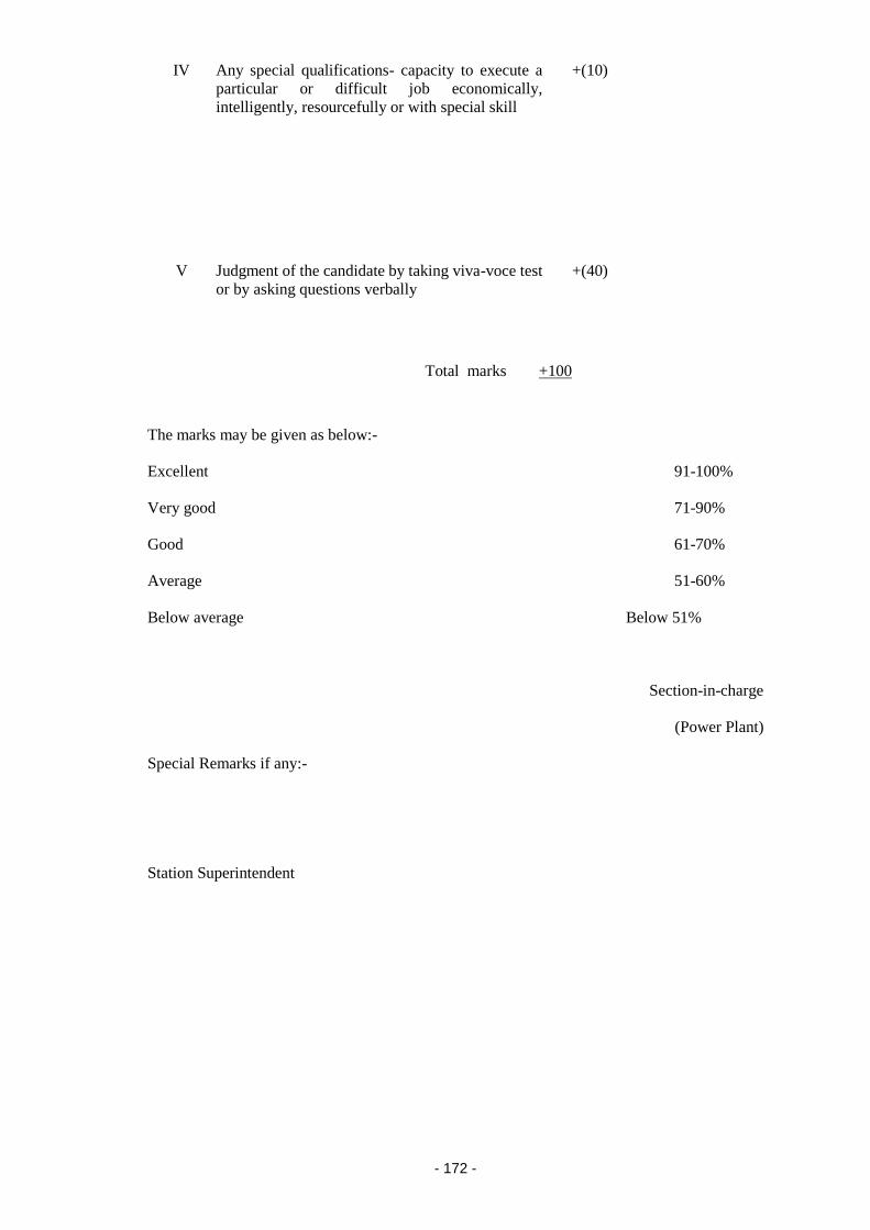
- 172 -
IV Any special qualifications- capacity to execute a
particular or difficult job economically,
intelligently, resourcefully or with special skill
+(10)
V Judgment of the candidate by taking viva-voce test
or by asking questions verbally
+(40)
Total marks +100
The marks may be given as below:-
Excellent 91-100%
Very good 71-90%
Good 61-70%
Average 51-60%
Below average Below 51%
Section-in-charge
(Power Plant)
Special Remarks if any:-
Station Superintendent

- 173 -
(II) ASSESSMENT FORM FOR ENGINEERS/SUPERVISORS
(For use of the Training Department)
(1) Name of the Trainee
…………………………………………………………………..
(2) Date of birth/age
………………………………………………………………………
(3) Training period : From ………………………….(Months)
………………………….
(4) Technical qualification
………………………………………………………………..
…………………………………………………………………………………………
…………………………………………………………………………………………
…………………………………………………………………………………………
(5) Specialisation if any
……………………………………………………………………
(6) Practical experience
……………………………………………………………………
(7) Marks secured in periodical tests (out of 100):
Test No. Date Written
Viva
On job Project
(8) Percentage of marks secured in all the tests:
(9) General Remarks and Recommendations:

- 174 -
Director of the Institute
(III) ASSESSMENT FORM FOR TECHNICIANS TO ASSIST ENGINEERS
AND SUPERVISORS
Name of the Trainee ……………………………………………………………
Period : From …………………….. to ……………………. (extended period).
Working in ………………………………………………………………………
Section …………………………………………………………………………..
Department ………………………………………………………………………
Item
No.
Particulars Marks
allotted
Marks
given
Remarks
1 2 3 4 5
I Punctuality and attendance:
(i) Does he attend the duty punctually
and avoids absenting without prior
intimation.
+(5)
(ii) Is he reluctant to continue on
overtime
(iii) Is he in the habit of taking leaves at
the eleventh hour
(iv) Is he even prepared to take leave
without wages
(v) Whether he availed medical leave
often
-(1)
-(1)
-(4)
-(1)
II Intelligence and grasp:
(i) Does he have full knowledge of the
plant and equipment on which he is
working and follows the instructions
given to him and can execute them
properly
(ii) Is he industrious, hard working and
painstaking
(iii) (a) Has he shown any special skill of
operation in saving plant and
equipment in trouble or emergency .
OR
(b) Has he shown any special skill or
innovation in any maintenance job.
+(10)
+(5)
+(10)
III Temperament and behaviour:
(i) Behaviour with superiors/colleagues
(ii) Capacity to take quick and correct
decisions by himself or to point out
the discrepancies to superiors
promptly while attending plant and
equipment.
+(5)
+(5)

- 175 -
(iii) Capacity to take independent charge
as plant attendants (Name of the
plant)
+(10)
IV Any special qualifications:
(i) Is he suitable for any other plant
other than the one mentioned above
at III(iii)
(ii) Can he record the readings correctly
(iii) Is he suitable for any particular
skilled maintenance job as an artisan.
(iv) Has he specialised in any particular
trade such as winder, high pressure
welding, etc.
+(10)
V Judgment of the candidate by taking viva-
voce test or by asking questions verbally
about power plant and equipment
+(40)
Total marks +100
The marks may be given as below:-
Excellent 91- 100%
Very good 71-90%
Good 61-70%
Average 51-60%
Below average Below 51%
Section-in-charge
(Power Plant)
Special Remarks if any:-

- 176 -
Station Superintendent
(IV) ASSESSMENT FORM FOR TECHNICIANS TO ASSIST ENGINEERS
AND SUPERVISORS
(For use of the Training Department)
(1) Name of the Trainee
…………………………………………………………………..
(2) Date of birth/age
………………………………………………………………………
(3) Training period : From ……………………to …….…….(Months)
………………….
(4) Highest technical qualification
………………………………………………………..
(5) Specialisation, if any
……………………………………………………………………
(6) Practical experience
……………………………………………………………………
(7) Marks secured in periodical tests (out of 100):
Test No. Date Written
Viva
On job
(8) Percentage of marks secured in all the tests:
…………………………………………
(9) General remarks and recommendations:

- 177 -
Director of the Institute

- 178 -
Schedule-II
Safety measures for operation and maintenance of transmission and distribution
system
[See sub-regulation (3) of regulation (7)]
Part I
(1). Duration and content of training shall be as specified below:
(i) Engineers and supervisors – The time allocation and various components of
the training course for engineers and supervisors who would be engaged on
operation and maintenance of transmission system shall be as given in Part II of
this Schedule.
(ii) Technicians – The time allocation and various components of the training
course for technicians who would assist the engineers and supervisors in
operation and maintenance of transmission system shall be as given in Part III
of this Schedule.
(iii) Engineers, Supervisors and Technicians – The time allocation and various
components of the training course for engineers, supervisors and Technicians in
operation and maintenance of sub-transmission and distribution system shall be
as given in Part IV, V and VI of this Scedule.
(iv) Refresher course - The duration and contents of the refresher courses shall
be determined jointly by the owner of the said system and training institute.
(v) Visits to factories- As part of practical training the trainees may be taken to
factories manufacturing equipment used in transmission and distribution
installations.
(vi) Performance of the trainee(s) – The training institutes shall group the
syllabus in modules for organising the training. The pass percentage in each
module for theory and for project work shall be 50% whereas for on job training
and for viva voce it shall be 75%. The sponsor(s) of the trainees may consider
the institution of incentives and awards for excellent performance during the
training and also for suitable action for sub-standard performance.
(2). Creation of the Institute:
(i) The existing training institutes established for training of personnel engaged
in operation and maintenance of generating stations and substations associated
with generating stations can create additional facilities for training in
transmission and distribution systems.
(ii) Guidelines for such institutes specified under Schedule-I (Item 2) under the
heading “Facilities for Creation of training institute” shall also be applicable for
institutes which would impart training in transmission and distribution systems.
(3). Assessment forms for engineers and supervisors and for Technicians to assist the
engineers and supervisors are given at Part XXVII of Schedule I .

- 179 -
Schedule-II
Part II
SYLLABUS FOR ENGINEERS AND SUPERVISORS FOR OPERATION AND
MAINTENANCE OF TRANSMISSION SYSTEM
Item
No.
Particulars Number
of Hours
1 2 3
I. General Introduction:
(i) World Power Scenario
(ii) Growth of Power Industry in India
(iii) Generation Scenario in India
(iv) Transmission and Distribution Scenario in India
(v) Role of Private Power Participants in India
(vi) Organisation/Power Sector set up
(vii) Introduction to Indian Standard specifications for
Electrical wiring
(viii) Energy Conversation
6
II. Power Generation:
(i) Types of generation: conventional and non-conventional;
Thermal Power Plant: components/ equipment and their
brief details and uses, features and characteristics of boiler,
turbine, generator, excitation, etc. Brief operational
aspects, captive power plants
(ii) Hydro Power Plant: components/ equipment and their
brief details; features and characteristics of turbine
generator, excitation, etc. Brief operational aspects
(iii) Gas Power Plant: concept of open cycle and combined
cycle; components, characteristics of gas turbines, brief
operational aspects, captive power plants
(iv) Nuclear Power Plant: salient features
(v) Non-Conventional Energy : various sources, working
principle, electricity generation
(vi) Co-generation, optimal mix of different types of
generation, base load and peak load operation
18
III. Power Transmission:
(1) HVAC and HVDC Transmission System
(i) Brief history of EHV transmission system in India
(ii) Tower types A, B, C, D and special towers
(iii) Conductors/Earthwire and their accessories, types,
configuration, transposition, selection criteria
(iv) Insulators and hardware fittings: types, strength, details
(v) Right of way, CEA (Measures relating to Safety and
Electric Supply) Regulations, 2010 and Acts, statutory
clearances from other agencies, compensation, etc.
(vi) Surveying, route alignment, profiling, tower spotting
(vii) Benching and soil classification, soil investigation and soil
resistivity measurement.
30

- 180 -
(viii) Tower design and testing, quality checks
(ix) Tower erection hardware and accessories, fitting
procedures, stringing, clearances, commissioning
(x) Operation and Maintenance of Transmission Line : line
patrolling, routine checks, filling log books, T & P,
thermovision scanning, fault failure analysis, hot line
maintenance, case studies
(xi) Development of HVDC technology, economics,
comparison with HVAC systems, principles of HVDC
conversion, HVDC lines, HVDC sub-stations - converters,
reactive power considerations, HVDC system, operation
and control, maintenance, AC and DC harmonics and
filtering, protection system, insulation, coordination,
emergencies and case studies.
(xii) FACTS (Flexible AC Transmission System)
(2) Sub - Stations (765kV/400 kV/220kV/132kV)
(i) Types : generation sub-station, grid sub-station, mobile
sub-station, gas insulated sub-station, HVDC sub-station,
indoor/outdoor, etc., general comparison
(ii) General arrangement and layout of switchyard, switching
schemes, single line diagram
(iii)Power Transformers and Reactors
(a) Types : major components, constructional details,
functions
(b) Design and selection, specification and rating
(c) Bushings, On Load Tap Changers (OLTC), Buchholz
relay, conservator, breather, thermo syphon filter,
indicators, etc.
(d) Cooling arrangements - methods of cooling, pumps,
fans, radiators, etc.
(e) Transformer tests
(f) Introduction to relevant Indian Standards
(iv) Switchgears and Introduction to relevant Indian Standard
(a) Circuit Breaker: types (MOCB, ABCB, VCB, ),
constructional details, layout arrangement,
connection to bus, design, selection parameters,
ratings/ specifications, interlocks and introduction to
relevant Indian Standard
(b) Isolator: types (Vertical, Horizontal, Pantography
Breaks, constructional details, Earth switch,
interlocks, design/selection, ratings/specifications
(c) Bus bar types, construction, supports, insulators,
connectors, jumpers, safety clearances,
design/selection, ratings/specifications
(d) CT/CVT/Lightning Arrestor/Lightning Mast: Types,
constructional details, use, location, selection/design,
ratings/specifications
(e) Power Line Carrier Communication (PLCC):
principle, purpose, types of coupling and choice of
75
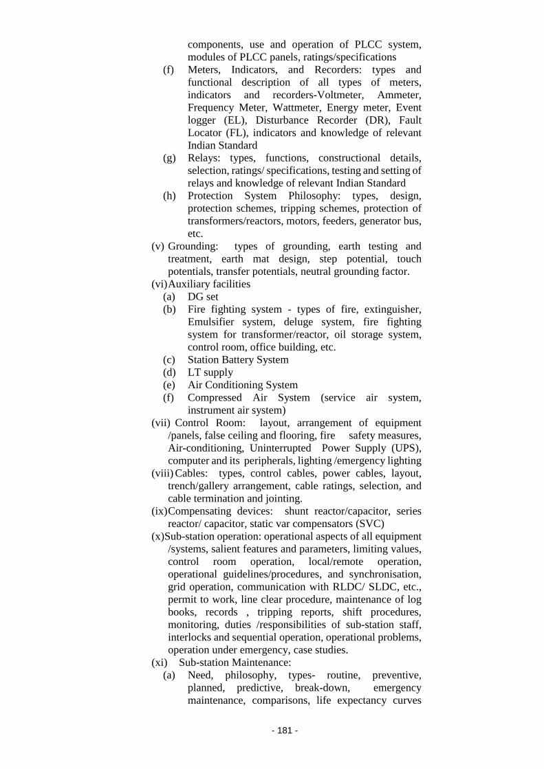
- 181 -
components, use and operation of PLCC system,
modules of PLCC panels, ratings/specifications
(f) Meters, Indicators, and Recorders: types and
functional description of all types of meters,
indicators and recorders-Voltmeter, Ammeter,
Frequency Meter, Wattmeter, Energy meter, Event
logger (EL), Disturbance Recorder (DR), Fault
Locator (FL), indicators and knowledge of relevant
Indian Standard
(g) Relays: types, functions, constructional details,
selection, ratings/ specifications, testing and setting of
relays and knowledge of relevant Indian Standard
(h) Protection System Philosophy: types, design,
protection schemes, tripping schemes, protection of
transformers/reactors, motors, feeders, generator bus,
etc.
(v) Grounding: types of grounding, earth testing and
treatment, earth mat design, step potential, touch
potentials, transfer potentials, neutral grounding factor.
(vi) Auxiliary facilities
(a) DG set
(b) Fire fighting system - types of fire, extinguisher,
Emulsifier system, deluge system, fire fighting
system for transformer/reactor, oil storage system,
control room, office building, etc.
(c) Station Battery System
(d) LT supply
(e) Air Conditioning System
(f) Compressed Air System (service air system,
instrument air system)
(vii) Control Room: layout, arrangement of equipment
/panels, false ceiling and flooring, fire safety measures,
Air-conditioning, Uninterrupted Power Supply (UPS),
computer and its peripherals, lighting /emergency lighting
(viii) Cables: types, control cables, power cables, layout,
trench/gallery arrangement, cable ratings, selection, and
cable termination and jointing.
(ix) Compensating devices: shunt reactor/capacitor, series
reactor/ capacitor, static var compensators (SVC)
(x) Sub-station operation: operational aspects of all equipment
/systems, salient features and parameters, limiting values,
control room operation, local/remote operation,
operational guidelines/procedures, and synchronisation,
grid operation, communication with RLDC/ SLDC, etc.,
permit to work, line clear procedure, maintenance of log
books, records , tripping reports, shift procedures,
monitoring, duties /responsibilities of sub-station staff,
interlocks and sequential operation, operational problems,
operation under emergency, case studies.
(xi) Sub-station Maintenance:
(a) Need, philosophy, types- routine, preventive,
planned, predictive, break-down, emergency
maintenance, comparisons, life expectancy curves

- 182 -
(bathtub curves), tools and tackles, testing
instruments, safety devices, sampling equipment , test
kits, visual checks, condition monitoring techniques,
on-line maintenance, daily/weekly/
monthly/quarterly/half yearly/annual maintenance of
different equipment , planning the maintenance
activities, preparation of maintenance estimates,
budgeting for control, maintenance records, history
(b) spare parts management
(c) Transformer and Reactor Maintenance-factors
affecting the life of transformer/reactor, types of
faults that can occur, reasons for breakdown, visual
checks/ inspection/ preliminary testing of various
components- oil sampling and testing, oil filtration,
Dissolved Gas Analysis (DGA), maintenance
Schedule, fault rectification, need for major overhaul
and methods
(d) Switchgear and Protection Maintenance :
maintenance of CB, isolator, earthswitch, support
insulators, CT/CVT, LA. Lightning Mast (LM),
meters/ recorders, PLCC, protective relay
maintenance, protection system maintenance
(e) Maintenance of auxiliaries and other systems- battery
and charging system, DG set, air conditioning plant,
compressed air system, fire fighting system,
switchyard – lighting, control room, earth resistance
testing, cables, compensating devices.
(xii) Erection and commissioning of sub-station, Project
Evaluation and Review Technique (PERT), Critical Path
Method (CPM), charts, project monitoring, erection, pre-
commissioning checks/tests, commissioning,
synchronisation.
(xiii) Civil works – surveying, site selection, soil
investigation, general layout and architectural drawing,
switchyard foundation, cable trench design, oil pit, control
room building, DG set building, Fire fighting system and
AC system- design, design and construction of roads,
drains, water supply pipe lines, fencing/compound wall.
3. Load Dispatch and Communication
(i) Load Dispatch Centres- functions, SLDC/RLDC, NLDC,
pre-dispatch, during-dispatch, post dispatch functions
(ii) Supervisory Control and Data Acquisition (SCADA)
System, RTU, front end computers, main computers, visual
display units, mimic boards
(iii) Energy Management System- functions
(iv) Load forecasting, generation scheduling, load management,
load shedding
(v) Hydro - thermal scheduling
(vi) Voltage/frequency control
(vii) Reactive Power Management
(viii) Grid Management - problems/solutions
18

- 183 -
(ix) Operational co-operation, import/export of energy, role of
tariff in system operation
(x) Maintenance, on-line maintenance
(xi) Grid disturbances- case studies
(xii) Software tools
Communication System: types- PLCC, microwave, leased
lines, fibre optics, satellite, V-SAT Communication,
comparison, characteristics, modules, planning criteria,
selection criteria , RTUs, modems, baud rate, communication
protocols, data exchange, system noise and interference,
integrated communication system, O&M of communication
system, protocol details, telemetry, tele-control and tele-
protection.
IV. Commercial Aspects And Contracts
(1) Commercial Aspects
(i) Introduction to commercial aspects of power
system/distribution system
(ii) Tariff Structure, types, components, methods of working
out, revenue realization
(iii) Energy accounting, Availability Based Tariff (ABT), inter-
utility tariff, commercial disputes and solutions
(iv) Inventory planning and control, bill of materials, purchase
procedures, standardization and codification of stores
(v) Resource mobilisation through bonds/ debentures/shares.
(vi) Cost Engineering, costing and control, estimation, estimates
for providing service (LT/HT) connections, street lighting.
(vii) Electricity Rules and Regulations, Enactment
(viii) Budget types, budgeting procedure, appropriation, budget
control.
(ix) Accounting, auditing.
(2) Contracts
(i) Contract basics, terminology
(ii) Qualification- requirement, pre-qualification, bids,
evaluation
(iii) Notice Inviting Tender (NIT), Notice Inviting Quotation
(iv) Preparation of bid documents, tendering/ bidding
(v) Bid opening, bid evaluation, award of contract,
monitoring of contract.
(vi) Contractual obligations/liquidation, guarantee /warranty
(vii) Vendor - qualification, development
(viii) Contractual problems and solutions
(ix) Revised cost estimation, justification for cost/time over-
run, substitute items
(x) Handing/taking over procedures, closing of contract
(xi) Legal issues of contracts, arbitration
24
12
V. Management:
(i) Principles of management, leadership, effective
communication, motivation, decision making, strategic
management
(ii) Management Information System
(iii) Project Management
12

- 184 -
(iv) Finance Management
(v) Construction Management
(vi) Materials Management
(vii) Total Quality Management
VI. System Planning and New Technologies:
(1) System Planning
(i) Introduction to power system planning requirements and
methods
(ii) Load forecasting and techniques
(iii) Load flow studies for planning
(iv) Preparation of feasibility report (FR), Detailed Project
Report (DPR)
(v) Approval/clearance of projects
(2) New Technologies:
(i) Latest development in transmission system design,
material, component, system, tariff, operation,
maintenance
(ii) Latest developments in distribution system design,
components, meters, system, tariff, operation,
maintenance
(iii) Latest developments in power system, communication,
application of computers to power system.
Total
6
6
207 Hours
7 Weeks
VII.
On Job Training:
(1) System Operation (On job)
(A) Sub-Station (Generating/Grid/Distribution)
(i) Layout, equipment familiarisation
(ii) Details, functioning, specification and different
parameters of switchyard, control room, auxiliary
system equipment
(iii) Shift handing/taking over, logging of parameters, routine
checks on equipment / systems
(iv) Operational aspects of equipment /systems,
synchronization, grid operation, charging procedure
(v) Line/feeder connections, protection schemes, loading
aspects, etc.
(vi) Salient features and operational aspects of HVDC sub-
station.
(B) Load Dispatch and Communication
(i) Load Dispatch Centre (NLDC/RLDC/SLDC): set up,
functioning
(ii) Supervisory Control and Data Acquisition (SCADA) and
Energy Management System (EMS) functioning
(iii) Load forecasting
(iv) Generation scheduling
(v) Voltage and frequency control activities
(vi) Communication system operation
(vii) System Software
3 Weeks

- 185 -
(viii) Shift operation
(2) System Maintenance (On job)
(A) Sub-Station Maintenance
(i) Visual checks, routine, preventive, planned, break-down
maintenance of equipment /system
(ii) Transformer, reactor, switchgear, relays, protection
system and auxiliary facilities.
(iii) Maintenance schedules
(iv) Referring log books/history records for maintenance.
(v) Testing Lab facilities, testing and commissioning.
(vi) Procedure for permit to work/line clear.
(vii) Safety devices and practices.
(B) T&D Line/Cable Maintenance
(i) Line patrolling, thermovision scanning, hot spots,
hardware replacement procedure, T&P.
(ii) Emergency Restoration System (ERS)
(iii) Hot Line Maintenance.
(iv) Industrial visits and evaluation
3 Weeks
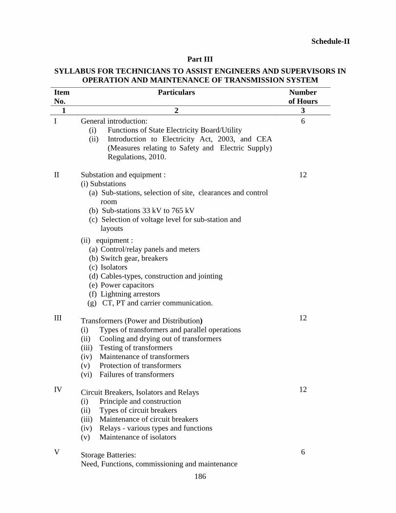
186
Schedule-II
Part III
SYLLABUS FOR TECHNICIANS TO ASSIST ENGINEERS AND SUPERVISORS IN
OPERATION AND MAINTENANCE OF TRANSMISSION SYSTEM
Item
No.
Particulars Number
of Hours
1 2 3
I
II
III
IV
V
General introduction:
(i) Functions of State Electricity Board/Utility
(ii) Introduction to Electricity Act, 2003, and CEA
(Measures relating to Safety and Electric Supply)
Regulations, 2010.
Substation and equipment :
(i) Substations
(a) Sub-stations, selection of site, clearances and control
room
(b) Sub-stations 33 kV to 765 kV
(c) Selection of voltage level for sub-station and
layouts
(ii) equipment :
(a) Control/relay panels and meters
(b) Switch gear, breakers
(c) Isolators
(d) Cables-types, construction and jointing
(e) Power capacitors
(f) Lightning arrestors
(g) CT, PT and carrier communication.
Transformers (Power and Distribution)
(i) Types of transformers and parallel operations
(ii) Cooling and drying out of transformers
(iii) Testing of transformers
(iv) Maintenance of transformers
(v) Protection of transformers
(vi) Failures of transformers
Circuit Breakers, Isolators and Relays
(i) Principle and construction
(ii) Types of circuit breakers
(iii) Maintenance of circuit breakers
(iv) Relays - various types and functions
(v) Maintenance of isolators
Storage Batteries:
Need, Functions, commissioning and maintenance
6
12
12
12
6
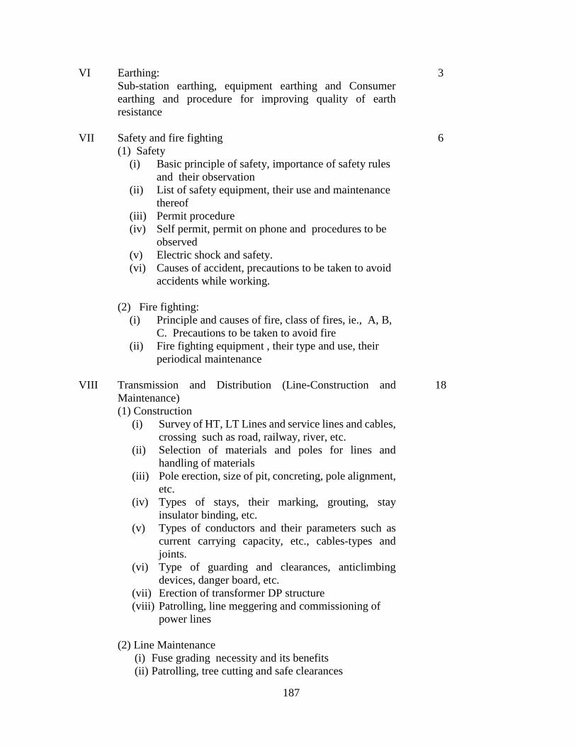
187
VI
VII
VIII
Earthing:
Sub-station earthing, equipment earthing and Consumer
earthing and procedure for improving quality of earth
resistance
Safety and fire fighting
(1) Safety
(i) Basic principle of safety, importance of safety rules
and their observation
(ii) List of safety equipment, their use and maintenance
thereof
(iii) Permit procedure
(iv) Self permit, permit on phone and procedures to be
observed
(v) Electric shock and safety.
(vi) Causes of accident, precautions to be taken to avoid
accidents while working.
(2) Fire fighting:
(i) Principle and causes of fire, class of fires, ie., A, B,
C. Precautions to be taken to avoid fire
(ii) Fire fighting equipment , their type and use, their
periodical maintenance
Transmission and Distribution (Line-Construction and
Maintenance)
(1) Construction
(i) Survey of HT, LT Lines and service lines and cables,
crossing such as road, railway, river, etc.
(ii) Selection of materials and poles for lines and
handling of materials
(iii) Pole erection, size of pit, concreting, pole alignment,
etc.
(iv) Types of stays, their marking, grouting, stay
insulator binding, etc.
(v) Types of conductors and their parameters such as
current carrying capacity, etc., cables-types and
joints.
(vi) Type of guarding and clearances, anticlimbing
devices, danger board, etc.
(vii) Erection of transformer DP structure
(viii) Patrolling, line meggering and commissioning of
power lines
(2) Line Maintenance
(i) Fuse grading necessity and its benefits
(ii) Patrolling, tree cutting and safe clearances
3
6
18

188
IX
X
(iii)Guarding of lines, clearances and maintenance,
attending to breakdowns.
(iv) Importance and maintenance of air-break switch,
dropout fuse set, dist. box etc.
(v) Pre-monsoon maintenance - necessity and procedure
thereof
(vi) Balancing of load using tong tester
(3) Service Connection, theft of energy
(i) Types of service connections (overhead, underground,
High Tension/ Low Tension, Single phase, Three
phase)
(ii) Point of supply, testing of Consumers’ wiring and
earthing terminals
(iii)Materials required for service connection, fuse
grading, underground cable connections (feeder pillar,
mini pillar, junction box.)
(iv) Theft of energy, preventive measures, unauthorized
extensions
(v) Consumer relations and dealing with Consumer
problems
Duties of staff
Duties of staff, assisting supervisory an operating staff
and maintenance of records
Human Resource Development
(i) Personal development and motivation
(ii) Communication skill and its importance
(iii)Attitudinal training
Total
6
9
90 Hours
3 Weeks
XI On Job Training, industrial visits and evaluation:
(1) Study Visits - after introduction
(i) 1st visit :11 kV and 33 kV sub-station
(ii) 2nd visit : 66 kV and 132 kV sub-station
(iii) 3rd visit : 220 kV and 400 kV sub-station
(2) Study and practicals
(i) Measurement of current, voltage, power, energy,
frequency and power factor
(ii) Testing and connection of relays
(iii) Study of Buchholz relays
(iv) Measurement of earth resistivity
(v) Meggering of installation and equipment
(vi) Study and maintenance of breathers
(vii) Study of “on load tap changer” for transformer
3 Weeks

189
(viii) Study of line construction materials and hardware
(ix) Demonstration of conductor jointing
(x) Demonstration of cable jointing.
(xi) Study of various type of power fuses, control fuses,
kitkat and horn gaps.
(xii) Use of safety equipment and practicals followed
for permit on works
(xiii) First aid and fire fighting drills

190
Schedule-II
Part IV
SYLLABUS FOR ENGINEERS ENGAGED IN THE OPERATION AND
MAINTENANCE OF SUB-TRANSMISSION AND DISTRIBUTION SYSTEM
Item
No.
Particulars Number
of Hours
1 2 3
I Overview of Power Sector Scenario:
(i) Growth of Power Industry in India
(ii) Organisation/ Power Sector set-up in India
(iii) Electricity Distribution in India
(iv) Private Participation in Distribution
(v) Distribution Reforms in India.
3
II Regulatory Environment – Rules and Regulations:
(i) Electricity Act,2003 – Provisions relating to electricity
distribution
(ii) Role of Regulatory Commissions
(iii) CEA(Measures relating to Safety and Electric
Supply) Regulations, 2010 – Relating to electricity
distribution.
(iv) Energy Conservation Act
3
III Distribution planning and optimization:
(i) Philosophy of distribution planning.
(ii) Acquaintance with software for distribution planning
and optimisation.
(iii) Operation of software.
(iv) Data entry formats and report generation.
(v) Case study.
30
IV Sub-transmission and Distribution Lines:
(i) Supports-towers/ poles:
(a) Types and selection criteria
(b) Surveying and erection
(ii) Line conductor/ cables:
(a) Classification
(b) Selection criteria
(c) Conductor stringing, jointing/ binding, sagging and
tensioning, clipping and jumpering
(d) Earthing arrangements
(iii) Cable – types, selection, cable trenches, cable routing
and laying, cable jointing and junction box
(iv) Earth wire/ neutral wire, guarding, etc.
(v) Selection and fixing of control devices, viz. Gang
Operating Switches, fuses, isolators and earthing
switches, lightning arrestors, and distribution box, etc.
(vi) Installation of service lines.
(vii) Street Lighting – design and layout methods.
15

191
(viii) Statutory clearances, viz. Environment and forest,
local bodies, railway and telegraph crossings, river
crossings, clearances under CEA (Measures relating to
Safety and Electric Supply) Regulations, 2010, Acts.
(ix) Line/ cable maintenance including hot line
maintenance – line patrolling, inspection, periodicity,
work permit, line clear and authorisation, erection of
temporary earth and restoration of supply, maintenance
T&P and safety devices, thermo vision scanning, hot
spots, etc.
V Electric Sub-Stations (33 kV and below):
(i) Type, site selection , layout and civil Engineering
requirements.
(ii) Bus bar arrangement, sub-station equipment, viz.
transformers, circuit breakers, etc.
(iii) Auxiliary systems, viz. DG set, battery system and
fire fighting system, etc.
(iv) Control panel, meters, indicators and recorders and
relays, etc.
(v) Erection, testing and commissioning of equipment
/systems
(vi) Earthing of sub-stations equipment and soil testing
(vii) Transformer oil and its testing
(viii) Operation and maintenance of all equipment ,
protective relays and auxiliaries.
15
VI Metering Requirements:
(i) Type of metering, viz. DT metering, feeder metering
and Consumer metering.
(ii) Regulations on installation of meters and technical
standards
(iii) Meter types, their settings and operation, testing and
sealing.
(iv) Selection of meter and metering equipment
(v) Familiarity with hardware (CMRI) and software for
meter data download, analysis and detection of meter
tampering
(vi) Role of advanced metering system in controlling
commercial losses
6
VII Concept of Losses and Loss Reduction Measures:
(i) Concept of AT& C losses
(ii) Segregation of losses.
(iii) Technical loss reduction measures.
(iv) Reactive power management.
(v) Detection of thefts, tampering, unauthorized loads
(vi) Anti-theft measures and case studies
(vii) Commercial loss reduction measures.
(viii) Penalties under the Act for theft and misuse of
power.
9

192
(ix) Energy audit and accounting.
(x) Demand side management.
VIII Reliability Issues, Quality of Power Supply, Customer
Awareness and Satisfaction:
(i) Reliability and quality of power supply and
reliability indices.
(ii) Causes and cures for breakdowns, tripping and
voltage and frequency fluctuation.
(iii) Creating customer awareness
(iv) Prompt attendance to faults.
(v) Overview of the Electricity Supply Codes of
Regulatory Commissions.
6
IX IT Intervention:
(i) Familiarisation with distribution software
packages and latest software tools and use thereof for
billing and revenue realisation, GIS mapping and
Consumer indexing, inventory control, keeping track
of equipment failure rate, quick fault location,
attendance, staff salary, energy accountability and
MIS etc.
(ii) SCADA – RTU, communication and distribution
automation.
(iii) Customer care and call centres.
12
X Rural Electrification:
(i) Outsourcing of distribution activities, appointment of
franchisees and self load management by villagers
and Gram Panchayats
(ii) Maintenance of complaint centres and fault removal,
etc., by village Panchayats etc.
(iii) Separation of rural and urban supply system
(iv) Fixation of responsibility for energy receipt and
supply balance.
(v) Rajiv Gandhi Grameen Vidyutikaran Yojana.
(vi) Distributed generation.
9
XI Project Management: Contracts:
(i) Contract basics and terminology
(ii) Qualification – requirement, pre-qualification
(iii) Bids – Technical and Commercial
(iv) Vendors – qualification, development
(v) Notice Inviting Tenders(NIT)/ Notice Inviting
Quotations(NIQ)
(vi) Preparation of Bid Documents, tendering/ bidding
(vii) Bid opening and evaluation, Award of contracts,
monitoring of contracts
(viii) Contractual obligations/ liquidation, guarantee/
warranty
9

193
(ix) Contractual problems and solutions
(x) Revision of cost estimates, justification of cost/ time
overrun and substitute items
(xi) Handling/taking over procedures, closing of contracts
(xii) Legal issues of contracts and arbitration
(xiii) CVC Guidelines.
XII Disaster Management:
(i) Institutional set-up for disaster Management
(ii) Impact of different types of disasters
(iii)Trigger mechanism and warning system
(iv) Check list and preparedness to address disasters.
(v) First aid techniques.
3
XIII Electrical Safety Aspects:
(i) Basic principles of safety, importance of safety rules
and their observance.
(ii) List of safety equipment, their use and maintenance
thereof.
(iii) Permit procedure - self permit, permit on phone and
procedures to be observed.
(iv) Electric shock, safety and procedure for recovery/
resuscitation.
(v) Causes of accidents, safe working procedures to
avoid accidents.
(vi) Principle and causes of fire, and precautions to be
taken to avoid fires.
9
XIV Field Visits and on-job training:
(i) Familiarisation with layout of sub-stations and
equipment
(ii) Operational aspects of equipment / systems and
synchronization
(iii) Line/ feeder connections, protection schemes, loading
aspects, balancing of loads
(iv) Planning shift operations.
(v) Maintenance schedules
(vi) Procedures for permit to work/ line clear
(vii) Testing lab facilities, testing and commissioning
(viii) Maintenance of Log Books/ history records and
adherence to the timely recording.
(ix) Familiarisation with IT tools.
Total
66
195 Hours
6 ½ Weeks

194
Schedule-II
Part V
SYLLABUS FOR SUPERVISORS ENGAGED IN THE OPERATION AND
MAINTENANCE OF SUB-TRANSMISSION AND DISTRIBUTION SYSTEM
Item
No.
Particulars Number of
Hours
1 2 3
I Overview of Power Sector Scenario
(i) Growth of Power Industry in India.
(ii) Organisation/ Power Sector set-up in India.
(iii) Electricity Distribution in India
(iv) Private Participation in Distribution.
(v) Distribution Reforms in India.
3
II Distribution Planning and Optimisation:
(i) Philosophy of distribution planning.
(ii) Acquaintance with software for distribution planning and
optimisation.
(iii) Operation of software.
(iv) Data entry formats and report generation.
(v) Case study.
6
III Sub-transmission and Distribution Lines:
(i) Supports-towers/ poles
(a) Types and selection criteria
(b) Surveying and erection
(ii) Line Conductor/ Cables –
(a) Classification
(b) Selection criteria
(c) Conductor stringing, jointing/ binding, sagging and
tensioning, clipping and jumpering
(d) Earthing arrangements
(iii) Cables – types, selection, cable trenches, cable routing
and laying, cable jointing and junction box
(iv) Earth wire/ neutral wire, guarding, etc.
(v) Selection and fixing of control devices, viz. Gang
Operating switches, fuses, isolators and earthing switches,
lightning arrestors, and distribution box, etc.
(vi) Installation of service lines.
(vii) Street Lighting – design and layout methods.
(viii) Statutory clearances, viz. environment and forest ,
local bodies, railway and telegraph crossings, river
crossings, clearances under Safety and Electric Supply
9

195
Regulations/Acts.
(ix) Line/ cable maintenance including hot line maintenance
– line patrolling, inspection, periodicity, work permit,
line clear and authorisation, erection of temporary earth
and restoration of supply, maintenance T&P and safety
devices, Thermo vision scanning, hot spots, etc.
IV Electric Sub-Stations (33 kV and below):
(i) Type, site selection , layout and civil Engineering
requirements.
(ii) Bus bar arrangement, sub-station equipment, viz.
transformers, circuit breakers, etc.
(iii) Auxiliary systems, viz. DG set, battery system and fire
fighting system, etc.
(iv) Control panel, meters, indicators and recorders and
relays, etc.
(v) Erection, testing and commissioning of equipment
/systems
(vi) Earthing of sub-stations equipment and soil testing
(vii) Transformer oil and its testing
(viii) Operation and maintenance of all equipment , protective
relays and auxiliaries.
9
V Metering Requirements:
(i) Type of metering, viz. DT metering, feeder metering and
Consumer metering.
(ii) Regulations on installation of meters and technical
standards
(iii) Meter types, their settings and operation, testing and
sealing.
3
VI Concept of Losses and Loss Reduction Measures:
(i) Concept of AT&C losses
(ii) Segregation of losses.
(iii) Technical loss reduction measures.
(iv) Reactive power management.
(v) Detection of thefts, tampering, unauthorized loads
(vi) Anti-theft measures and case studies
(vii) Commercial loss reduction measures.
(viii) Penalties under the Act for theft and misuse of
power.
(ix) Energy audit and accounting.
(x) Demand side management.
6
VII Reliability Issues, Quality of Power Supply, Customer
Awareness and Satisfaction:
(i) Reliability quality of power supply and reliability
indices.
3

196
(ii) Causes and cures for breakdowns, tripping and voltage
and frequency fluctuation.
(iii) Creating customer awareness
(iv) Prompt attendance to faults.
(v) Overview of the Electricity Supply codes of Regulatory
Commissions.
VIII IT Intervention:
(i) Familiarisation with distribution software packages and
latest software tools and use thereof for billing and
revenue realisation, GIS mapping and Consumer
indexing, Inventory control, keeping track of
equipment failure rate, quick fault location,
attendance, staff salary, Energy accountability and
MIS, etc.
(ii) SCADA – RTU, communication and distribution
automation.
(iii) Customer care and call centres.
(iv) Enterprise resource planning-
(a) Maintenance Management
(b) Asset Management
(c) Training Management
(d) Financial Accounting
(e) Material Management
(f ) Outage Management
(g) Time Management
6
IX Rural Electrification:
(i) Outsourcing of distribution activities, appointment of
franchisees and self load management by villagers and
Gram Panchayats.
(ii) Maintenance of complaint centres and fault removal,
etc., by Village Panchayats, etc.
(iii) Separation of rural and urban supply system
(iv) Fixation of responsibility for energy receipt and supply
balance.
(v) Rajiv Gandhi Grameen Vidyutikaran Yojana.
(vi) Distributed generation.
3
X Project Management: Contracts:
(i) Contract basics and terminology
(ii) Qualification – requirement, pre-qualification
(iii) Bids – technical and commercial
(iv) Vendors – qualification, development
(v) Notice Inviting Tenders(NIT)/ Notice Inviting
Quotations(NIQ)
(vi) Preparation of bid documents, tendering/ bidding
(vii) Bid opening and evaluation, award of contracts,
3

197
monitoring of contracts
(viii) Contractual obligations/ liquidation, guarantee/ warranty
(ix) Contractual problems and solutions
(x) Revision of cost estimates, justification of cost/ time
overrun and substitute items
(xi) Handling/taking over procedures, closing of contracts
(xii) Legal issues of contracts and arbitration
(xiii) CVC Guidelines.
XI Disaster Management:
(i) Institutional set-up for disaster management
(ii) Impact of different types of disasters
(iii) Trigger mechanism and warning system
(iv) Check list and preparedness to address disasters.
(v) First aid techniques.
3
XII Electrical Safety Aspects:
(i) Basic principles of safety, importance of safety rules
and their observance.
(ii) List of safety equipment, their use and maintenance
thereof.
(iii) Permit procedure- self permit, permit on phone and
procedures to be observed.
(iv) Electric shock, safety and procedure for recovery/
resuscitation.
(v) Causes of accidents, safe working procedures to avoid
accidents.
(vi) Principle and causes of fire, and precautions to be taken
to avoid fires.
6
XIII Field Visits and On-Job Training:
(i) Familiarisation with layout of sub-stations and
equipment
(ii) Operational aspects of equipment / systems and
synchronization
(iii) Line/ feeder connections, protection schemes, loading
aspects, balancing of loads
(iv) Planning shift operations.
(v) Maintenance schedules
(vi) Procedures for permit to work/ line clear
(vii) Testing lab facilities, testing and commissioning.
(viii) Maintenance of Log Books/ history records and
adherence to the timely recording.
(ix) Familiarization with IT tools.
Total
60
120 Hours

198
4 Weeks
Schedule-II
Part VI
SYLLABUS FOR TECHNICIANS ENGAGED IN THE OPERATION AND
MAINTENANCE OF SUB-TRANSMISSION AND DISTRIBUTION SYSTEM
Item
No.
Particulars Number
of Hours
1 2 3
I Overview of Power Sector Scenario:
(i) Growth of Power Industry in India.
(ii) Organisation/ Power Sector set-up in India.
(iii) Electricity Distribution in India
(iv) Private Participation in Distribution.
(v) Distribution Reforms in India.
3
II Sub-transmission and Distribution Lines:
(i) Survey for lines at voltage upto 250 V, lines at voltage
above 650 Volts but less than 33kV and for service lines
and cables and crossings such as road, railway, river and
other power and telecom lines.
(ii) Selection of line materials and towers/ poles and safe
handling of the same.
(iii) Erection of towers/ poles – size of pit, concreting and
pole/tower alignment, etc.
(iv) Line Conductors – types, selection criteria, conductor
stringing, jointing/ binding, sagging and tensioning,
clipping and jumpering and earthing arrangements.
(v) Types of stays, its marking, grouting, stay insulator,
binding, etc.
(vi) Cable – types, selection, cable trenches, cable routing
and laying, cable jointing and junction box, etc.
(vii) Types of guarding and clearances, earth wire/ neutral
wire, anti-climbing devices and danger boards and their
erection.
(viii) Selection and fixing of control devices, viz. Gang
Operating Switches, fuses, Isolators and earthing
switches, lightning arrestors, and distribution box, etc.
(ix) Installation of service lines.
(x) Street lighting – layout methods.
(xi) Line meggering and commissioning of distribution lines.
(xii) Line patrolling, inspection, periodicity, work permit, line
clear and authorisation, tree cutting and safe clearances,
erection of temporary earth, attending to breakdowns and
restoration of supply.
9
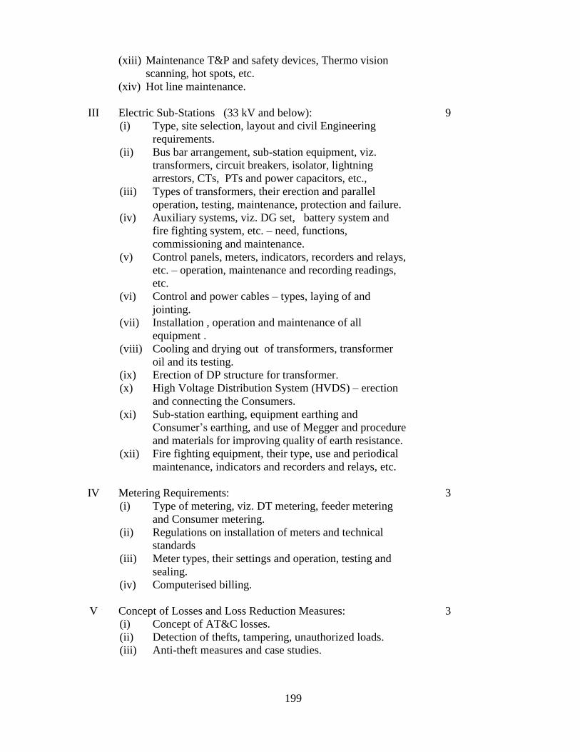
199
(xiii) Maintenance T&P and safety devices, Thermo vision
scanning, hot spots, etc.
(xiv) Hot line maintenance.
III Electric Sub-Stations (33 kV and below):
(i) Type, site selection, layout and civil Engineering
requirements.
(ii) Bus bar arrangement, sub-station equipment, viz.
transformers, circuit breakers, isolator, lightning
arrestors, CTs, PTs and power capacitors, etc.,
(iii) Types of transformers, their erection and parallel
operation, testing, maintenance, protection and failure.
(iv) Auxiliary systems, viz. DG set, battery system and
fire fighting system, etc. – need, functions,
commissioning and maintenance.
(v) Control panels, meters, indicators, recorders and relays,
etc. – operation, maintenance and recording readings,
etc.
(vi) Control and power cables – types, laying of and
jointing.
(vii) Installation , operation and maintenance of all
equipment .
(viii) Cooling and drying out of transformers, transformer
oil and its testing.
(ix) Erection of DP structure for transformer.
(x) High Voltage Distribution System (HVDS) – erection
and connecting the Consumers.
(xi) Sub-station earthing, equipment earthing and
Consumer’s earthing, and use of Megger and procedure
and materials for improving quality of earth resistance.
(xii) Fire fighting equipment, their type, use and periodical
maintenance, indicators and recorders and relays, etc.
9
IV Metering Requirements:
(i) Type of metering, viz. DT metering, feeder metering
and Consumer metering.
(ii) Regulations on installation of meters and technical
standards
(iii) Meter types, their settings and operation, testing and
sealing.
(iv) Computerised billing.
3
V Concept of Losses and Loss Reduction Measures:
(i) Concept of AT&C losses.
(ii) Detection of thefts, tampering, unauthorized loads.
(iii) Anti-theft measures and case studies.
3

200
VI Reliability issues, Quality of Power Supply, Customer
Awareness and Satisfaction:
(i) Introduction to reliability and quality of power supply.
(ii) Causes and cures for breakdowns, tripping and voltage
and frequency fluctuation.
(iii) Prompt attention to faults and customer care.
3
VII Electrical Safety Aspects:
(i) Basic principles of safety, importance of safety rules
and their observance.
(ii) List of safety equipment, their use and maintenance
thereof.
(iii) Permit procedure- self permit, permit on phone and
procedures to be observed.
(iv) Electric shock, safety and procedure for recovery/
resuscitation.
(v) Causes of accidents, safe working procedures to avoid
accidents.
(vi) Principle and causes of fire, and precautions to be taken
to avoid fires.
12
VIII Rural Electrification:
(i) Separation of rural and urban supply systems.
(ii) Rajiv Gandhi Grameen Vidyutikaran Yojana.
3
IX Disaster Management:
(i) Impact of different types of disasters.
(ii) Check list and preparedness to address disasters.
(iii) First aid techniques.
3
X Field Visits and On Job Training:
(i) Familiarisation with layout of sub-stations and
equipment .
(ii) Operational aspects of equipment / systems and
synchronization.
(iii) Line/ feeder connections, protection schemes, loading
aspects, balancing of loads.
(iv) Adherence to shift system.
(v) Maintenance schedules.
(vi) Procedures for permit to work/ line clear.
(vii) Testing lab facilities, testing and commissioning.
(viii) Safety aspects and safety drill.
(ix) Hot line maintenance.
(x) Maintenance of Log Books/ history records and
adherence to the timely recording.
(xi) Familiarisation with Tools and Plants (T&P).
(xii) Familiarisation with IT tools.
60

201
Total
108 Hours
4 Weeks

202
Schedule-III
Handling of electric supply lines and apparatus
[See sub-regulation (3) of regulation (19)]
Part-I
Precautions to be observed
(1) Hotline Maintenance trained personnel only are designated to do work on line.
(2) Work permit will be taken from the terminal substations at each end of the line.
(3) Work shall be performed with proper planning and prior understanding and clarity.
(4) Favourable climatic condition for hotline operations is sunny weather. If the weather
forecasts rain or thunderstorms work will not begin.
(5) Organisation of work shall be discussed among the members and responsibility of each
team member fixed.
(6) Before going to the work site all equipment and tools shall be inspected and checked for
correct operation.
(7) Auto re-closure shall be in `OFF’ position for the line at both ends.
(8) The work procedure shall be discussed with the team member at the tower location and
the responsibility of each member shall be properly defined.
(9) The land in close vicinity to the tower shall be cleared to provide a site area for the
required tools.
(10) All cleaned hot sticks, strain carrier and other assemblies shall be kept on the hotline
tool rack to avoid ground contact.
(11) Wear helmet, safety shoes and safety belt shall compulsorily be used.
(12) All hot sticks and ladders shall be cleaned and checked for integrity by the hot sticks
Tester.
(13) All linemen in the hotline team shall be equipped with personal protective equipment
during the work.
(14) No live-line team members on the tower and conductor shall wear any metallic chain,
wristwatch or ring to avoid any circulating current.
(15) The team linemen will wear conductive socks, boots, helmets and hand gloves. The
`hot-end’ lineman shall wear complete bare hand suit.
(16) Tarpaulin sheet should be laid on the work area.
(17) A light vehicle shall be kept nearby during entire work period.
Tools normally required for hot line maintenance operation :
The following tools conforming to relevant Indian Standard or equivalent specifications shall be
used in on-line working.
(1) Wire tongs
(2) Wire tongs saddle
(3) Tie sticks
(4) Strain link sticks
(5) Roller link sticks

203
(6) Suspension link sticks
(7) Auxiliary arms
(8) Strain carrier
(9) Gin poles
(10) Cum-a-along clamp
(11) Safety equipment like conductor guards, X-arm guards, insulator covers, hand gloves
etc.
(12) Hot sticks
Safe Working Distance :
The following safe working distances shall be observed
Phase to Phase Safe Clearance
kV Meter
11
33
66
110
132
220
400
0.61
0.71
0.91
1.02
1.07
1.52
2.13

204
Schedule-III
Handling electric supply lines and apparatus for carrying out shutdown work or testing
[See sub-regulation (3) of regulation (19)]
Part-II
Precautions to be observed
(1) Before commencement of any shut down work or testing in an electric supply line or
apparatus, the Engineer or Supervisor in-charge of the work or testing shall identify the possible
hazards, such as; electrocution, flash over, fall of person from height, fall of objects from height,
failure of Tools & Plants, fire, etc., that may be encountered while carrying out the work or testing
near charged area and take necessary precaution to protect the working personnel.
(2) The Engineer or Supervisor in-charge of the work shall, before commencement of any work,
brief the entire working group or gang of the hazards that may be encountered and the necessary
precautions to be taken by them.
(3) The Engineer or Supervisor in-charge of the work shall obtain proper Permit-To-Work (PTW)
from the concerned Operation In-charge(s) and ensure that the electric supply line or apparatus
or section is isolated from all sources of energy, de-energized and earthed.
(4) The Engineer or Supervisor in-charge of the work shall ensure that adequate and Appropriate
local earths are fixed at the zone of working, and the earthing rods remain connected to the
isolated section of the electric supply line or apparatus or section till all men and materials have
been moved away to safe zone and PTW is returned on completion of the work.
(5) If the local earths are required to be removed for any testing purpose, the same shall be done
only when all the working personnel are in the safe zone, on the ground or on the tower, and in
the presence of the Engineer or Supervisor. If the working personnel are required to go up or
approach the conductor(s) subsequently for any work, such as, removal of test leads, tightening
or adjustment, they shall be permitted to proceed only after re-fixing the local earths, as required.
(6) The Engineer or Supervisor in-charge of the work shall positively confirm by suitable means
that the electric supply line or apparatus or section is totally dead before giving clearance for the
working personnel to approach same.
(7) The Engineer or Supervisor in-charge of the work shall, while carrying out the shut down
work or testing, ensure that working personnel are maintaining safe distance from the adjacent
charged electric supply line or apparatus or section, and also, no objects, such as, Tools & Plants,
ladders, cranes, man-lifts, etc., are moved, so as to infringe the safe distance, endangering the
working personnel.
(8) Mobile cranes, derricks, man lifts and wheel mounted ladders shall be effectively earthed
when being moved or operated in close proximity with energized apparatus or section.

205
(9) Portable ladders and poles shall be carried only in the horizontal position when being moved
in close proximity with energized lines or equipment or area.
Further Precautions to be observed
(1) Adequate and effective supervision shall be ensured by the owner as well as the contractor
for all activities while working or testing on electric supply lines and apparatus when any shut
down work or testing is done near charged electric supply line or apparatus or section.
(2) Lone worker shall never be allowed to work on electric supply lines, equipment and apparatus
or while testing.
(3) Sufficient supervisory personnel shall be deployed for close monitoring while various type of
works are under progress at the same or different locations. Supervising work shall never be
delegated to the sub-contractors' personnel.
(4) The deployed Supervising Personnel shall not leave the working spot when shut down work
at height or testing is in the progress, as the working personnel may not be aware of the
consequences of unsafe practices. No other work, which requires them to move out of the
location, shall be undertaken by Supervising personnel, when shut down work or testing is in the
progress.
(5) Wherever shut down activities are required to be carried out for more than one day on the
any electric supply lines, apparatus or section, earthing(s) provided at the said work site shall be
inspected by the Engineer or Supervisor every day morning for their healthiness, fitness and
proper tightening, before giving clearance for the working personnel to climb the tower or
structure to resume the work.

206
Schedule-III
Handling HVDC apparatus for carrying out shutdown work or testing
[See sub-regulation (3) of regulation (19)]
Part-III
Precautions to be observed
(1) The Engineer or Supervisor in-charge of the work shall obtain proper Permit-To-Work (PTW)
from the concerned Operation In-charge(s) and ensure that the electric supply line or apparatus
or section is isolated from all sources of energy, de-energised and earthed.
(2) Before commencement of any shut down work or testing of HVDC apparatus, the Engineer
or Supervisor in-charge of the work or testing shall identify the possible hazards, such as;
electrocution, flash over, fall of person from height, fall of objects from height, failure of Tools
& Plants, fire, etc., that may be encountered while carrying out the work or testing near charged
area and take necessary precaution to protect the working personnel.
(3) The Engineer or Supervisor in-charge of the work shall, before commencement of any work,
brief the entire working group or gang of the hazards that may be encountered and the necessary
precautions to be taken by them.
(4) Attach warning labels to all neighboring installation parts (to be removed after the works have
been carried out).
(5) The Engineer or Supervisor in-charge of the work shall allow access to the Valve hall, DC
Filter Area, AC Filter Area and DC hall (if any) only when the apparatus therein are completely
de-energised effectively earthed.,
(6) The work on AC/DC filter bank shall only begin after grounding the entire capacitor bank.
(7) There shall be at least 10 minutes time gap between grounding the entire capacitor bank and
starting the work on bank. There after unit must be short circuited.
(8) The de-energized bushing shall be checked for stored charge by touching all the surfaces of
both indoor and outdoor side composite insulators and all other parts of the bushing using a proper
test instrument.
(9) The gas pressure inside HVDC through wall bushing shall be reduced to a level prescribed
by the manufacturer before starting any work or handling of the bushing.

207
Schedule-III
Handling Gas Insulated Switchgear (GIS) apparatus for carrying out shutdown work or
testing
[See sub-regulation (3) of regulation (19)]
Part-IV
Precautions to be observed
(1) The Engineer or Supervisor in-charge of the work shall obtain proper Permit-To-Work (PTW)
from the concerned Operation In-charge(s) and ensure that the electric supply line or apparatus
or section is isolated from all sources of energy, de-energised and earthed.
(2) Operation, maintenance and repair must be carried out by trained and certified personnel only.
(3) Before commencement of any shut down work or testing of GIS apparatus, the Engineer or
Supervisor in-charge of the work or testing shall identify the possible hazards, such as;
electrocution, flash over, fall of person from height, fall of objects from height, failure of Tools
& Plants, fire, etc., that may be encountered while carrying out the work or testing near charged
area and take necessary precaution to protect the working personnel.
(4) The Engineer or Supervisor in-charge of the work shall, before commencement of any work,
brief the entire working group or gang of the hazards that may be encountered and the necessary
precautions to be taken by them.
(5) Wear hearing protection during operation.
(6) Take care when touching the enclosure at any time as enclosures may heat up to the
temperature of 70°C.
(7) Observe the procedures for storage, transportation, and the use of filling equipment.
(8) Wear the personal protective equipment: respirator mask (self-contained breathing
equipment if necessary), protective overall, protective gloves, safety shoes, safety glasses.
(9) Attach warning labels to all neighboring installation parts (to be removed after the works have
been carried out).
(10) Provide proper electrical clearance as required by interlocking rules. Mark e.g. main
circuits and control circuits with Appropriate tags.
(11) Block off neighboring live parts with screens, insulating mats or spacer grids in order to
prevent unintended contacts.
(12) While working on any compartment in GIS, the immediate adjacent compartment(s) must
be also depressurized for safety of the working person.
(13) SF6 gas following events such as arc faults becomes contaminated and contains poisonous
substances. Hence, handling of SF6 in such cases must be done using proper PPEs and by a
trained personnel preferably from the original equipment manufacturer (OEM).
(14) The switchgear installation shall not be operated if the density of SF6 gas indicated at the
density monitors is not in the operating range.
(15) Do not remove any protective covers if an assembly is energized.
(16) The Engineer or Supervisor in-charge of the work shall ensure that adequate and
Appropriate local earths are fixed at the zone of working, and the earthing rods remain
connected to the isolated section of the electric supply line or apparatus or section till all men
and materials have been moved away to safe zone and PTW is returned on completion of the
work.

208
Schedule-IV
Forms of Inspection Report
[See regulation (30)]
FORM I
(Installations of voltage up to and including 250V)
Report No. __________ Date of Inspection by Electrical Inspector or self-certification by owner
_____________
Date of Last inspection or self-certification ___________________
1. Consumer No. ______________________
2. Voltage and system of supply:
(i) Volts ________________
(ii) No. of Phases _____________
(iii) AC/DC _______________
3. Type of wiring
4. Name of the consumer or owner _____________________________
5. Address of the consumer or owner _____________________________
6. Location of the premises _____________________________
7. Particulars of the installations: _____________________________
Number Connected Load in KW
(a) (i) Light Points ___________ _______________
(ii) Fan Points ___________ _______________
(iii) Plug Points ___________ _______________
State type of wiring whether casing capping, lead covered of teak wood batten, concealed
conduit, Tough Rubber Sheathed and any other type.
(b) Other equipment (complete details to be furnished):
(i) _____________________________
(ii) _____________________________
Total connected load in KW _____________________________
Maximum current demand in Amps _____________________________
(on the basis of total connected load)
(c) Generators details i.e. Make, S. No, KVA rating and Voltage:
(i) _____________________________
(ii) _____________________________
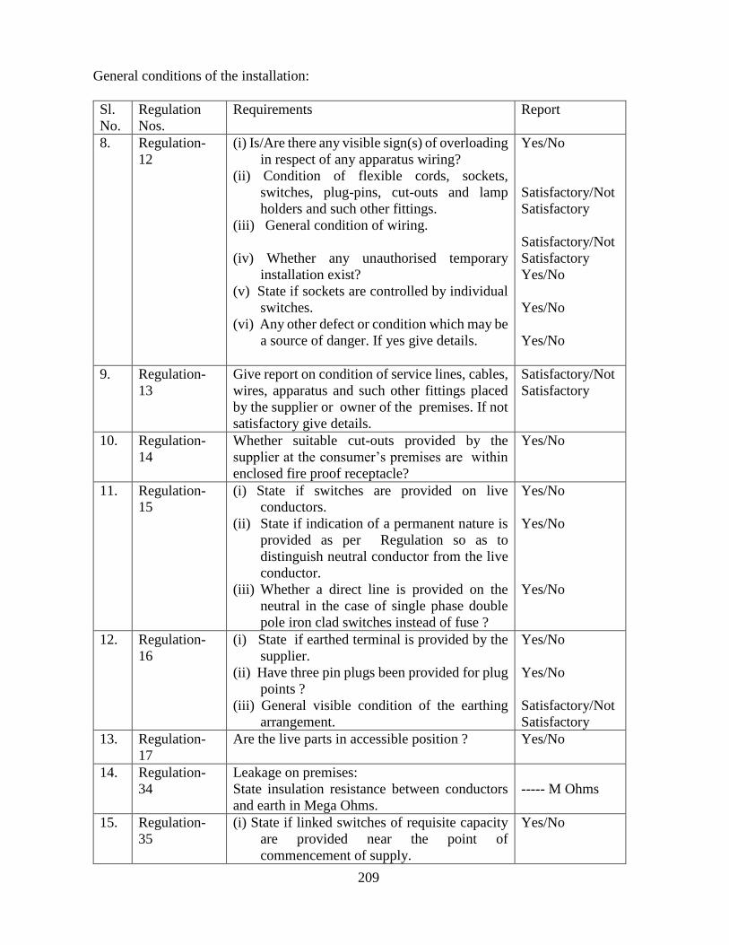
209
General conditions of the installation:
Sl.
No.
Regulation
Nos.
Requirements Report
8. Regulation-
12
(i) Is/Are there any visible sign(s) of overloading
in respect of any apparatus wiring?
(ii) Condition of flexible cords, sockets,
switches, plug-pins, cut-outs and lamp
holders and such other fittings.
(iii) General condition of wiring.
(iv) Whether any unauthorised temporary
installation exist?
(v) State if sockets are controlled by individual
switches.
(vi) Any other defect or condition which may be
a source of danger. If yes give details.
Yes/No
Satisfactory/Not
Satisfactory
Satisfactory/Not
Satisfactory
Yes/No
Yes/No
Yes/No
9. Regulation-
13
Give report on condition of service lines, cables,
wires, apparatus and such other fittings placed
by the supplier or owner of the premises. If not
satisfactory give details.
Satisfactory/Not
Satisfactory
10. Regulation-
14
Whether suitable cut-outs provided by the
supplier at the consumer’s premises are within
enclosed fire proof receptacle?
Yes/No
11. Regulation-
15
(i) State if switches are provided on live
conductors.
(ii) State if indication of a permanent nature is
provided as per Regulation so as to
distinguish neutral conductor from the live
conductor.
(iii) Whether a direct line is provided on the
neutral in the case of single phase double
pole iron clad switches instead of fuse ?
Yes/No
Yes/No
Yes/No
12. Regulation-
16
(i) State if earthed terminal is provided by the
supplier.
(ii) Have three pin plugs been provided for plug
points ?
(iii) General visible condition of the earthing
arrangement.
Yes/No
Yes/No
Satisfactory/Not
Satisfactory
13. Regulation-
17
Are the live parts in accessible position ? Yes/No
14. Regulation-
34
Leakage on premises:
State insulation resistance between conductors
and earth in Mega Ohms.
----- M Ohms
15. Regulation-
35
(i) State if linked switches of requisite capacity
are provided near the point of
commencement of supply.
Yes/No

210
(ii) State if the wiring is divided in suitable
number of circuits and each such circuit is
protected by suitable cut-out.
(iii) State if supply to each motor or apparatus is
controlled by suitable linked switch.
Yes/No
Yes/No
16. Regulation-
41
(i) Have the frames of every generator,
stationary motor and so far as practicable
portable motor and the metallic parts (not
intended as conductors) of all other
apparatus used for regulating* or
controlling electricity been earthed by two
separate and distinct connections with earth
?
(ii) Is the earth wire free from mechanical
damage ?
(iii) In the case of conduit, or lead covered
wiring, has the conduit or lead-cover been
efficiently earthed ?
(iv) If the consumer has his own earth-electrode,
state if it is properly executed and has been
tested. If yes give value of earth resistance.
Yes/No
Yes/No
Yes/No
Yes/No
------- Ohms.
17. Overhead
Lines
(i) State if the consumer has any overhead lines.
(ii) Does the overhead line near the premises of
consumer meets the requirement of
regulation 58, 60 and 61? If not, give
details.
(iii) Is guarding provided for overhead lines at
road crossings?
(iv) Any other remarks.
Yes/No
Yes/No
Yes/No
Date : Signature of the Inspecting Officer/ supplier /owner
Name ______________________
Designation _________________
File No. ____________________
Copy forwarded to Electrical Inspector for ………………... .
* Not applicable to isolated wall tubes or to brackets, electroliers, switches, ceiling fans and
such other fittings (other than portable hand lamps and transportable apparatus) unless
provided with earth terminal.
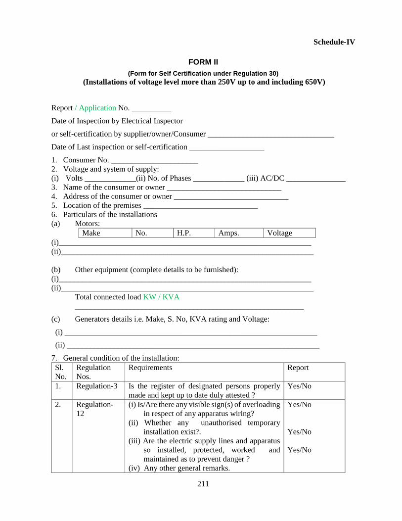
211
Schedule-IV
FORM II
(Form for Self Certification under Regulation 30)
(Installations of voltage level more than 250V up to and including 650V)
Report / Application No. __________
Date of Inspection by Electrical Inspector
or self-certification by supplier/owner/Consumer ________________________________
Date of Last inspection or self-certification ___________________
1. Consumer No. ______________________
2. Voltage and system of supply:
(i) Volts _____________(ii) No. of Phases _____________ (iii) AC/DC _______________
3. Name of the consumer or owner _____________________________
4. Address of the consumer or owner _____________________________
5. Location of the premises _____________________________
6. Particulars of the installations
(a) Motors:
Make No. H.P. Amps. Voltage
(i)________________________________________________________________
(ii)________________________________________________________________
(b) Other equipment (complete details to be furnished):
(i)________________________________________________________________
(ii)________________________________________________________________
Total connected load KW / KVA
__________________________________________________________
(c) Generators details i.e. Make, S. No, KVA rating and Voltage:
(i) ________________________________________________________________
(ii) ________________________________________________________________
7. General condition of the installation:
Sl.
No.
Regulation
Nos.
Requirements Report
1. Regulation-3 Is the register of designated persons properly
made and kept up to date duly attested ?
Yes/No
2. Regulation-
12
(i) Is/Are there any visible sign(s) of overloading
in respect of any apparatus wiring?
(ii) Whether any unauthorised temporary
installation exist?.
(iii) Are the electric supply lines and apparatus
so installed, protected, worked and
maintained as to prevent danger ?
(iv) Any other general remarks.
Yes/No
Yes/No
Yes/No

212
3. Regulation-
13
Give report on condition of service lines, cables,
wires, apparatus and such other fittings placed
by the supplier or owner of the premises. If not
satisfactory give details.
Satisfactory/Not
Satisfactory
4. Regulation-
14
Whether suitable cut-outs/CBs provided by the
supplier at the consumer’s premises are within
enclosed fire proof/resistant receptacle?
Yes/No
5. Regulation-
15
(i) Whether switches are provided on live
conductors?
(ii) Whether indication of a permanent nature is
provided as per Regulation so as to
distinguish neutral conductor from the live
conductor as per IS color code?
(iii) Whether a direct line is provided on the
neutral in the case of single phase double
pole iron clad switches/Isolators/CBs
instead of fuse ?
Yes/No
Yes/No
Yes/No
6. Regulation-
16
(i) Whether earthed terminal is provided by the
supplier?
(ii) General visible condition of the earthing
arrangement.
Yes/No
Satisfactory/Not
Satisfactory
7. Regulation-
17
(i) Are bare conductors in building inaccessible?
(ii) Whether readily accessible switches have
been provided for rendering them dead ?
Yes/No
Yes/No
8. Regulation-
18
12. Whether “Danger Notice” in Hindi and the local
language of the district and of a design as per
relevant Indian Standard is affixed permanently
in conspicuous position?.
Yes/No
9. Regulation-
19
(i) Whether insulating floor or mats conforming
to IS-15652:2006 have been provided?
(ii) Whether identification of panel has been
provided on the front and the rear of the
panel?
Yes/No
Yes/No
10. Regulation-
21
Whether flexible cables used for portable or
transportable equipment covered under the
Regulation, are heavily insulated and adequately
protected from mechanical injury?.
Yes/No
11. Regulation-
22
State the condition of metallic coverings
provided for various conductors.
Satisfactory/Not
Satisfactory
12. Regulation-
24
Whether the circuits or apparatus intended for
operating at different voltage(s) are
distinguishable by means of indication(s) of
permanent nature?.
Yes/No
13. Regulation-
26
Whether all circuits and apparatus are so
arranged that there is no danger of any part(s)
becoming accidentally charged to any voltage
Yes/No

213
beyond the limits of voltage for which it/they
is/are intended ?
14. Regulation-
27
(i) In the case of generating stations, whether
fire-buckets filled with clean dry sand have
been conspicuously marked and kept in
convenient situations in addition to fire-
extinguishers as per IS 3034 suitable for
dealing with minor electric fires ?
(ii) Whether First Aid Boxes or cupboards
conspicuously marked and properly
equipped are provided and maintained?.
(iii) Is adequate staff trained in First Aid
Treatment and fire fighting?
Yes/No
Yes/No
Yes/No
15. Regulation-
28
(i) Whether instructions in English or Hindi and
the local language of the district and where
Hindi is the local language, in English and
Hindi, for the resuscitation of persons
suffering from electric shock have been
affixed in a “conspicuous place” ?.
(ii) Are the designated persons able to apply
instructions for resuscitation of persons
suffering from electric shock ?
Yes/No
Yes/No
16. Regulation-
34
Leakage on premises:
State insulation resistance between conductors
and earth in Mega Ohms.
----- M Ohms
17. Regulation-
35
(i) Whether a suitable linked switch, or circuit
breaker is placed near the point of
commencement of supply so as to be
readily accessible and capable of being
easily operated to completely isolate the
supply ?
(ii) Whether every distinct circuit is protected
against excess electricity by means of a
suitable circuit breaker or cut-out ?
(iii) Whether suitable linked switch or circuit
breaker is provided near each motor or
apparatus for controlling supply to the
motor or apparatus?
(iv) Whether adequate precautions are taken to
ensure that no live parts are so exposed as
to cause danger?
Yes/No
Yes/No
Yes/No
Yes/No
18. Regulation-
37
(i) Whether clear space of 100 cm is provided
in front of the main switchboard?
(ii) Whether the space behind the switchboard
exceeds 75 cm in width or is less than 20
cm?
Yes/No
Yes/No
Yes/No

214
(iii) In case the clear space behind the
switchboard exceeds 75 cm. state whether a
passage way from either end of the
switchboard to a height of 1.80 metres is
provided.
19. Regulation-
41
(i) Has the neutral point at the transformer and
generator been earthed by two separate and
distinct connections with earth?
(ii) Have the frame of every generator, stationary
motor and so far as practicable portable
motor and the metallic parts (not intended
as conductors) of all transformers and any
other apparatus used for regulating or
controlling electricity and all apparatus
consuming electricity at voltage exceeding
250V but not exceeding 650V been earthed
by two separate and distinct connections
with earth ?
(iii) Have the metal casings or metallic
coverings containing or protecting any
electric supply line or apparatus been
properly earthed and so joined and
connected across all junction boxes as to
make good mechanical and electrical
connection?
(iv) Whether the consumer’s earth-electrode is
properly executed and has been tested. If
yes, give value of earth resistance?
(v) Is the earth wire free from any mechanical
damage ?
(vi) Whether record of earth resistance value
maintained?
Yes/No
Yes/No
Yes/No
Yes/No
------- Ohms.
Yes/No
Yes/No
20. Regulation 42 Whether Residual Current Device of
Appropriate capacity as defined in Regulation
have been provided?
Yes/No
21. Regulation-
45
Have the protections and interlocks for the
generating units been provided. Details of the
protections shall be given.
Yes/No
22. Overhead
Lines
(i) State if the consumer has any overhead lines.
(ii) Does the overhead line near the premises of
consumer meets the requirement of
regulations 58, 60 and 61? If not, give
details.
(iii) Is guarding provided for overhead lines as
per regulation 73?
(iv) Any other remarks.
Yes/No
Yes/No
Yes/No

215
Date :
Signature of the supplier/ Owner / Consumer
Name ______________________
Designation _________________
File No. ____________________
To: Office of Electrical Inspector for ………………...

216
Schedule-IV
FORM III
(Form for Self Certification under Regulation 30 /43)
(Installations of voltage exceeding 650V)
Report / Application No. __________
Date of Inspection by Electrical Inspector or self-certification by supplier/owner/Consumer
______________________________
Date of Last inspection or self-certification ___________________
1. Consumer No. ______________________
2. Voltage and system of supply:
(ii) Volts _____________(ii) No. of Phases _____________ (iii) AC/DC _______________
3. Name of the consumer or owner _____________________________
4. Address of the consumer or owner _____________________________
5. Location of the premises _____________________________
6. Particulars of the installations
(a) Transformer: (complete detail to be enclosed)
Make S. No. K.V.A. rating Voltage rating Type
(i)________________________________________________________________
(ii)________________________________________________________________
(b) Generators details i.e. Make, S. No, KVA rating and Voltage:
(i) ________________________________________________________________
(ii) ________________________________________________________________
(c) List of equipment with complete details of HT /LT switchgears/ apparatus with their
rating to be furnished):
(i)________________________________________________________________
(ii)________________________________________________________________
(iii) List of Motors with rating, protection, overload setting, size of earth conductor
used to be furnished
(d) Total connected load KW / KVA _________________________________________
Complete list of connected load to be furnished.
7. General condition of the installation:
Sl.
No.
Regulation
Nos
Requirements Report
1. Regulation-3 Is the register of the designated persons
properly made and kept up to date duly attested?
Yes/No
2. Regulation- 5 Whether Electrical Safety Officer as required
under the Regulation is designated?
Yes/No
3 Regulation-
12
(i) Is/Are there any visible sign(s) of overloading
in respect of any apparatus?
Yes/No
Yes/No

217
(ii) Whether any unauthorised temporary
installation exist?
(iii) Whether the motors and controlling
equipment are being over hauled
periodically and record kept of the same in
a register?
(iv) Whether the transformer oil samples are
being tested periodically and results
recorded in a register? State value of
dielectric strength of oil.
(v) Whether suitable lightning arrestors have
been provided near the transformers for
protection against lightning?
(vi) Whether earth resistance is being measured
periodically in dry and wet season and
results recorded in a register? Copy of
record to be enclosed.
(vii) Any other defect or condition which may
be a source of danger. If Yes please
explain?
(viii) Whether operation and maintenance
data has been clarified, categorized and
computerized for prompt and easy
retrieval?
(ix) Whether predictive maintenance is being
performed for installation of voltage
exceeding 650V?
(x) Whether residual life assessment and life
extension programmes are being
undertaken for installations or equipment of
voltage exceeding 650V (applicable for
installations or equipment more than 15
years old)? (xi) Whether all required type and routine tests at
factory done for equipment . Deficiencies and
Discrepancies in above test report and results,
if any, shall be reported?
(xii) Are there deficiencies in construction with
reference to Indian Standard requirements. Please specify.
Yes/No
Yes/No
----kV/mm
Yes/No
Yes/No
Yes/No
Yes/No
Yes/No
Yes/No
Yes/No
Yes/No
4. Regulation-
13
Give report on condition of service lines, cables,
wires, apparatus and such other fittings placed
by the supplier or owner of the premises. If not
satisfactory give details.
Satisfactory/Not
Satisfactory
5. Regulation-
14
Whether suitable cut-outs/CBs provided by the
supplier at the consumer’s premises are within
enclosed fire proof/resistant receptacle?
Yes/No

218
6. Regulation-
15
(i) Whether switches are provided on live
conductors?
(ii) Whether indication of a permanent nature is
provided as per Regulation so as to
distinguish neutral conductor from the live
conductor as per IS color code?
(iii) Whether a direct line is provided on the
neutral in the case of single phase double
pole iron clad switches/CBs instead of fuse
?
Yes/No
Yes/No
Yes/No
7. Regulation-
16
(i) Whether earthed terminal is provided by the
supplier?
(ii) General visible condition of the earthing
arrangement.
Yes/No
Satisfactory/Not
Satisfactory
8. Regulation-
17
(i) Are bare conductors in building inaccessible?
(ii) Whether readily accessible switches have
been provided for rendering them dead?
Yes/No
Yes/No
9. Regulation-
18
13. Whether “Danger Notice” in Hindi and the local
language of the district and of a design as per
relevant Indian Standard is affixed permanently
in conspicuous position?.
Yes/No
10. Regulation-
19
(i) Whether the practice of working on live lines
and apparatus is adopted? If so, have the
safety measure been adopted as per
Schedule-III?
(ii) Whether insulating floor or mats conforming
to IS-15652:2006 have been provided?
14. (iii) Whether identification of panel has
been provided on the front and the rear of
the panel?
Yes/No
Yes/No
Yes/No
11. Regulation-
21
Whether flexible cables used for portable or
transportable equipment covered under the
Regulation, are heavily insulated and adequately
protected from mechanical injury?.
Yes/No
12. Regulation-
22
State the condition of metallic coverings
provided for various conductors.
Satisfactory/Not
Satisfactory
13. Regulation-
24
Whether the circuits or apparatus intended for
operating at different voltage(s) are
distinguishable by means of indication(s) of
permanent nature?.
Yes/No
14. Regulation-
26
Whether all circuits and apparatus are so
arranged that there is no danger of any part(s)
becoming accidentally charged to any voltage
beyond the limits of voltage for which it/they
is/are intended ?
Yes/No

219
15. Regulation-
27
(i) In the case of generating stations and
enclosed sub stations, whether fire-buckets
filled with clean dry sand have been
conspicuously marked and kept in
convenient situations in addition to fire-
extinguishers as per IS 3034 suitable for
dealing with minor electric fires ?
(ii) Whether First Aid Boxes or cupboards
conspicuously marked and properly
equipped are provided and maintained?.
(iii) Is adequate staff trained in First Aid
Treatment and fire fighting?
Yes/No
Yes/No
Yes/No
16. Regulation-
28
(i) Whether instructions in English or Hindi and
the local language of the district and where
Hindi is the local language, in English and
Hindi, for the resuscitation of persons
suffering from electric shock have been
affixed in a “conspicuous place” ?.
(ii) Are the designated persons able to apply
instructions for resuscitation of persons
suffering from electric shock ?
Yes/No
Yes/No
17. Regulation-
34
Leakage on premises:
State insulation resistance between conductors
and earth in Mega Ohms.
----- M Ohms
18. Regulation-
35
(i) Whether a suitable linked switch, or circuit
breaker, or emergency tripping device is
placed near the point of commencement of
supply so as to be readily accessible and
capable of being easily operated to
completely isolate the supply?
(ii) Whether suitable linked switch or a circuit
breaker to carry and break the full load
current on the secondary side of a
transformer?
(iii) Whether every distinct circuit is protected
against excess electricity by means of a
suitable circuit breaker or cut-out?
(iv) Whether linked switch or circuit breaker or
emergency tripping device is provided near
the motor or other apparatus at voltage
exceeding 650V but not exceeding 33kV
for controlling supply to the motor or
apparatus?
(v) Whether adequate precautions are taken to
ensure that no live parts are so exposed as
to cause danger?
Yes/No
Yes/No
Yes/No
Yes/No
Yes/No
Yes/No
19. Regulation-
37
(i) Whether clear space of 100 cm is provided
in front of the main switchboard?
Yes/No

220
(ii) Whether the space behind the switchboard
exceeds 75 cm in width or is less than 20
cm?
(iii) In case the clear space behind the
switchboard exceeds 75 cm. State whether
a passage way from either end of the
switchboard to a height of 1.80 meters is
provided.
Yes/No
Yes/No
20. Regulation-
44
(i) Whether all conductors and apparatus
including live parts thereof are
inaccessible?
(ii) Whether all windings of motors or other
apparatus are suitably protected?
(iii) State in case of transformers or reactors or
switches or static condensers involving the
use of more than 2,000 litres of oil in one
chamber, if suitable oil soak pits are
provided?
(iv) Where 9,000 litres or more of oil is used in
any one oil tank, has provision, been made
for draining away or removal of oil which
may leak or escape from such tank(s)?
(v) Whether trenches inside sub-station
containing cables are filled with non-
inflammable material or completely
covered with non- inflammable slabs?
(vi) Are conductors and apparatus so arranged
that they may be made dead in sections for
carrying out work thereon?
(vii) Whether separate cable trays are provided
for control/Power/AC/DC cables?
(viii) Whether suitable fire fighting system as
per the Regulation has been provided?
(ix) Whether the baffle walls of four hours fire
rating between apparatus or consumer
premises, in a substation or a switching
station with apparatus having more than
2000 litres of oil are installed, have been
provided as required under the Regulation?
Yes/No
Yes/No
Yes/No
Yes/No
Yes/No
Yes/No
Yes/No
Yes/No
Yes/No
21. Regulation-
45
Whether protections and interlocks have been
provided? Give the details of the protection
schemes and their settings.
Yes/No
22. Regulation-
48
(i) Have the frames of every generator,
stationary motor, and so far as practicable
portable motor and metallic parts not
intended as conductors of all transformers
and any other apparatus used for regulating
or controlling electricity and all electricity
Yes/No

221
consuming apparatus at voltage exceeding
650V but not exceeding 33kV been earthed
by two separate and distinct connections
with earth?
(ii) Is the earth wire free from any mechanical
damage?
(iii) Has the neutral point at the transformer and
generator been earthed by two separate and
distinct connections with earth?
(iv) Have the metal casings or metallic
coverings containing or protecting any
electric supply line or apparatus been
properly earthed and so joined and
connected across all junction boxes as to
make good mechanical and electrical
connections throughout their whole length?
(v) Whether earthing has been properly
executed and has been tested. If yes, give
value of earth resistance.
Yes/No
Yes/No
Yes/No
Yes/No
------Ohms
23. Regulation-
49
(i) Is the outdoor (except pole type) sub-station
efficiently protected by fencing not less
than 1.8 metres in height?
(ii) Whether the mounting of a transformer on a
single pole or H pole is at a height such that
height of live parts above the surface
accessible to general public shall be 4.3 m
(minimum) for rated voltages upto 52 kV
and 6m (minimum) for rated voltages above
52 kV?
Yes/No
Yes/No
24 Regulation-
50
(i) Where platform type construction is used for
pole type sub-station, has sufficient space
for a man to stand on the platform been
provided?
(ii) Has hand-rail been provided and connected
with earth (if metallic and if sub-station has
not been erected on wooden supports and
wooden platform)?
Yes/No
Yes/No
25. Regulation-
51
Has suitable provision been made for immediate
and automatic or manual discharge of every
static condenser on disconnection of supply?
Yes/No
26 Overhead
Lines
(i) What is the minimum size of the conductors
of overhead lines used? State the type of
conductors.
(ii) Whether clearances above ground of the
lowest conductor of overhead lines are as
per regulation 58? State clearance.
Size of
Conductor ---
Yes/No
--- metres
Yes/No

222
(iii) On the basis of maximum sag, whether
vertical clearances where the line of voltage
exceeding 650V passes above or adjacent to
any building or part of a building are as per
regulation 61? State clearance.
(iv) On the basis of maximum deflection due to
wind pressure, whether horizontal
clearances between the nearest conductor
and any part of such building are as per
regulation 61? State clearance.
(v) Where conductors forming parts of system at
different voltages are erected on the same
supports, whether adequate provision has
been made as per regulation 62 to guard
against danger to linemen and others from
the lower voltage system being charged
above its normal working voltage by
leakage from or contact with the higher
voltage system ?
(vi) Where overhead lines cross or are in
proximity to each other whether they have
been suitably protected to guard against
possibility of their coming in contact with
each other as per regulation 69?
(vii) Has every guard wire been properly earthed
as per regulation 70 at each point at which
its electrical continuity is broken?
(viii)(a) Whether metal supports of overhead
lines and metallic fittings attached thereto
are permanently earthed as per regulation
72?
(b) Has each stay-wire (except in case where
an insulator has been placed in it at a height
not less than 3 meters from the ground)
been earthed as per regulation 72?
(ix)(a) Whether overhead line is suitably
protected with a device for rendering the
line electrically harmless in case it breaks
as per regulation 73?
(b) Whether anti-climbing devices have
been provided at each support as per
regulation 73?
(x) (a) Has the owner of overhead lines adopted
efficient means for diverting to earth any
electrical surges due to lightning in every
overhead line which is so exposed as to be
liable to injury from lightning as per
regulation 74?
--- metres
Yes/No
--- metres
Yes/No
Yes/No
Yes/No
Yes/No
Yes/No
Yes/No
Yes/No
Yes/No
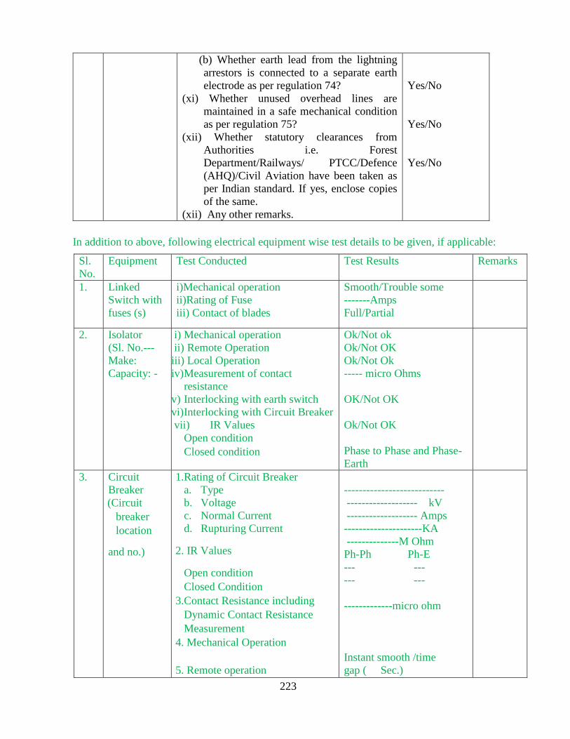
223
(b) Whether earth lead from the lightning
arrestors is connected to a separate earth
electrode as per regulation 74?
(xi) Whether unused overhead lines are
maintained in a safe mechanical condition
as per regulation 75?
(xii) Whether statutory clearances from
Authorities i.e. Forest
Department/Railways/ PTCC/Defence
(AHQ)/Civil Aviation have been taken as
per Indian standard. If yes, enclose copies
of the same.
(xii) Any other remarks.
Yes/No
Yes/No
Yes/No
In addition to above, following electrical equipment wise test details to be given, if applicable:
Sl.
No.
Equipment Test Conducted Test Results Remarks
1. Linked
Switch with
fuses (s)
i)Mechanical operation
ii)Rating of Fuse
iii) Contact of blades
Smooth/Trouble some
-------Amps
Full/Partial
2. Isolator
(Sl. No.---
Make:
Capacity: -
i) Mechanical operation
ii) Remote Operation
iii) Local Operation
iv) Measurement of contact
resistance
v) Interlocking with earth switch
vi) Interlocking with Circuit Breaker
vii) IR Values
Open condition
Closed condition
Ok/Not ok
Ok/Not OK
Ok/Not Ok
----- micro Ohms
OK/Not OK
Ok/Not OK
Phase to Phase and Phase-
Earth
3. Circuit
Breaker
(Circuit
breaker
location
and no.)
1.Rating of Circuit Breaker
a. Type
b. Voltage
c. Normal Current
d. Rupturing Current
2. IR Values
Open condition
Closed Condition
3.Contact Resistance including
Dynamic Contact Resistance
Measurement
4. Mechanical Operation
5. Remote operation
---------------------------
------------------- kV
------------------- Amps
---------------------KA
--------------M Ohm
Ph-Ph Ph-E
--- ---
--- ---
-------------micro ohm
Instant smooth /time
gap ( Sec.)

224
Circuit
breaker
control
circuits
6. Local Operation
7. Interlocking with Isolator
8. Interlocking with earth switch
9. Alarm and Trip for
OTI/WTI/Buchholz/PRV/etc.,
10. Earth Fault Relay
11.Over Current Relay
12. Under Voltage Relay
13. other safety Alarms
14. Whether all the provisions of
Regulation 35 are satisfactory?
OK/not OK
OK/not OK
OK/not OK
OK/not OK
OK/not OK
OK/not OK
OK/not OK
OK/not OK
4. Transformer
Tranformer
No.,
Location,
(Transforme
r Sl. No.
Make,
Capacity,
Voltage
Ratio, )
1. Insulation Resistance Values
i) HT to LT
ii) HT to Earth
iii) L T to Earth
2. Break down Voltage test
Oil sample I (Top)
Oil Sample II (Bottom)
3. Vector Group Test
4. Polarity Tests
5. Magnetising Balance
6. Tan Delta Test
7. Oil level in conservator tank
8. Oil level in breather cup
9. OTI/WTI settings
10. OTI/WTI alarm and trip
operation
11. Operation of Buchholz relay
12. Operation of PRV
13. Oil leakage
14. Interlock of door switch of
dry transformer
15. Clearances
i) Side Clearance:
ii) Between two
Transformers
16. Body Earth Resistance
17. Neutral Earth Resistance
18. Earth Flat size Material used
i)Body:
ii)Neutral:
19. Operation of ONLOAD &
OFFLOAD Tap Changers
--------------M ohm
--------------M ohm
--------------M ohm
--------------kV
--------------kV
OK/not OK
OK/not OK
OK/not OK
OK/not OK
OK/not OK
OK/not OK
A/T---- 0C A/T----0C
OK/not OK
OK/not OK
OK/not OK
OK/not OK
OK/not OK
---------Cms
----------Meters
---------- Ohm
N1---Ohm
N2---Ohm
OK/not OK

225
20. Sweep Frequency Resonance
Analysis Test (SFRA)
21. Dielectric Frequency
Resonance Analysis(DFRA)
Test
22. Partial Discharge Tests
OK/not OK
OK/not OK
OK/not OK
5 DG
Generators:
Generator
No.,
Location,
(Alternator
and Engine
Sl. No.
Make,
Capacity, )
1. Type of Generator
2. Interlocking with other
supply sources
3. Body earth resistance
4. Neutral earth resistance
5. Earth Flat size Material
used ( Cu/Al)
i)Body:
ii)Neutral:
6. Generator Protection
details
OK/not OK
---------- Ohm
N1---Ohm N2---Ohm
6. Cable
(Details to
be given:
size, length,
type)
1. Insulation Resistance Values:
1. Ph - Ph :
2. Ph – Earth :
3. Ph – Earth + other Ph :
2. Cable trays
3. Cable tray earthing
4. Cables bending radius
--------- M Ohm
---------M Ohm
---------M Ohm
Provided/ Not provided
Ok/not OK
OK/not OK ___ metre
7. Panels 1. No. of panels
2. Location of panel
3. Rating of the panel
4. Size and current rating of the
main Bus bars and the
distribution Bus bars of the
panel
5. Whether the Bus bar size of the
panel suitable to rating of the
panel
6. IP Protection of panel
7. Type of cable entry
8. No. of Incomers and Bus
couplers in a Panel
9. Ratings of the Circuit Breakers
10. No. of MCCBs of each rating
in the panel
----------------
To be enclosed.
____Amps
____ mm , _____Amps
Yes/No
________
Top Entry/Bottom Entry
______Nos.
____Amps
____Nos.

226
11. No. of spare MCCBs of each
rating
12. Panel Clearance from the wall
13. Clearance between two panels
i.e. adjacent panels
14. Whether all the provisions of
Regulation 37 followed
15. Size of the Earth strip used for
earthing of the panel
___Nos.
____ mm
____mm
Yes / No
____sq. mm
8. Earthing 1. Metal and Size of Earth Strips
2. Type of earthings
3. Location and No. of earth
electrode
4. Values of Earth resistance of
each earth electrode and Grid
5. Earth mat resistance
Cu/Al/GI --- Sq. mm
Plate/Pipe/Counterpoise
____Nos.
____Ω
_____Ω
9. Potential
Transformer
(i) Ratio test
(ii) Polarity test
(iii) BDV of oil
(iv) IR test
(v) tan Delta and Capacitance
measurement
OK/not OK
OK/not OK
----------kV
(R) P-E-------M Ohm
(Y) P-E-------M Ohm
(B) P-E-------M Ohm
-------------
10. Current
Transformer
(i) Ratio test
(ii) Polarity test
(iii) BDV of oil
(iv) IR test
(v) tan Delta and Capacitance
measurement
OK/not OK
OK/not OK
----------kV
(R) P-E-------M Ohm
(Y) P-E-------M Ohm
(B) P-E-------M Ohm
--------
11. Over Head
lines and DP
structure
1. Size of the Poles of DP
structure
2. Clearance between the phases
–phase and phase to earth.
3. Ground clearance of the
conductors
4. Check of electrical clearance
along the route of over head
line,
_______
________
________
Ok/ Not Ok
Ok/ Not Ok

227
5. Check of guarding and
clearance at road crossings
6. Check the footings of the poles
7. Earthing arrangements
8. What is the minimum size of
the conductors of over head
lines used? State the type of
conductors.
9. Whether all the provisions of
regulation 58, 61, 62, 69, 70
and 72 are satisfied.
Ok/ Not Ok
Ok/ Not Ok
____
Yes / No
General Observations:
1. Check of Phase to Phase , Phase to Ground
and Sectional clearance
2. Check of Manufacture test reports of
individual equipment ( Copies to be enclosed)
3. General observation and views ( Specific
deviation from the requirements of the
Regulations shall be clearly brought out)
Date :
Signature of the Supplier /Owner / Consumer
Name ______________________
Designation _________________
File No. ____________________
Schedule-IV
(For Self Certification by Supplier /Owner /Consumer)

228
CERTIFICATE
(Under Regulation 43 of CEA (Measures relating to Safety & Electricity
Supply) Regulation,2010)
This is to certify that the electrical installation is complete in all respects and the work has
been carried out conforming to the CEA (Measures relating to Safety & Electricity Supply)
Regulation, 2010 (as amended) and relevant Standards of IS/NEC/IEC. The site tests done are found
to be in order and it is electrically safe to operate the apparatus free from any danger.
Encl: Test reports
(Signature) (Signature)
Self-certifying supplier / owner / consumer Chartered Electrical Safety Engineer
Name ______________________ Name ______________________
File No. ____________________
To: Office of Electrical Inspector for ………………...

229
Schedule-IV
Forms of Inspection Report
[See sub-regulation (3) of regulation (30)]
FORM IV
(Electrical Installations in Mine)
Report No. __________ Date of Inspection :
Date of Last inspection ______________ Name of the Inspecting Officer:
1. Name of the Mine
2. Name of the Owner
3. Name of the Agent
4. Name of the Mine Manager
5. Name of the Colliery Engineer
6. Name of the Safety Officer
7. Name of the designated Electrical Safety Officer
8. Name of the Electrical Supervisor
9. Name of the workman Inspector (Electrical)
10. Name of the Engineer (concerned Section)
11. Name of the Working seam
12. Working District Inspected
13. Name of the persons accompanied during inspection:
14. Voltage and system of supply:
(vi) Volts ________________
(vii) No. of Phases _____________
(viii) AC/DC _______________
15. Particulars of the installations/apparatus installed and their location as per mine plan:
16. Illumination level:

230
17. Percentage of methane/other explosive gas :
18. Dry Bulb temperature, wet bulb temperature in case of underground mine.
19. Velocity/speed of air in case of underground mine
General conditions of the installation:
Sl.
No.
Regulation
Nos.
Requirements Report
1 Reg-95 On or before the first day of February in every
year, notice in the form set out in Schedule-XI
or Schedule-XII whichever is applicable is sent.
Yes/No
2. Reg-96 The plans specified under this regulation are
kept in the office of the mine manager and
available to the electrical Inspector of mines.
Yes/No
3
Reg. 97
1. Adequate illumination by electricity without
causing glare and strain shall be provided in
the mines.
2. Whether efficient means of communication
is provided between the point where the
switchgear under sub-regulation (1) regulation
105 is erected, the shaft bottom and other
distributing centers in the mine.
3. Whether Fire extinguishing appliances of
adequate capacity and of an approved type are
installed and properly maintained in every
place containing apparatus, other than cables,
telecommunication and signaling apparatus.
4. Is minimum clearance above ground of the
lowest conductor of over head lines or over
head cables where dumpers or trackless
vehicles are being operated, not less than
twelve meters in height
Yes/No
Satisfactory/Not
satisfactory
Yes/No
Satisfactory/Not
satisfactory
Yes/No
Satisfactory/Not
Satisfactory
Yes/No
4
Reg. 98
1. Are Transformers and switchgear placed in
a separate room, compartment or box where
necessary to prevent danger of mechanical
damage?
2. Is the room, compartment or box
substantially constructed and kept dry &
illuminated
3. Is efficient ventilation provided for all
apparatus installed therein?
Yes/No
Yes/No
Yes/No
5
Reg. 99
(1) Is earthing carried out by connection to an
earthing system at the surface of the mine
Yes/No

231
and in a manner approved by Electrical
inspector of mines.
(2) Are all metallic sheaths, coverings, handles,
joint boxes, switchgear frames, instrument
covers, switch and fuse covers of boxes, all
lamp holders, unless efficiently protected by
an insulated covering made of fire resisting
material, and the frames and bedplates of
generators, transformers and motors,
including portable motors, earthed by
connection to an earthing system in the
manner specified in regulation 99.
(3) Are all conductors, of an earthing system
having conductivity, at all parts and all joints,
at least equal to fifty per cent of that of the
largest conductor used solely to supply the
apparatus
Yes/No
Satisfactory/Not
satisfactory
Yes/No
6 Reg. 100
114
Whether the neutral or mid-point earthed by
connection to and system in the manner
specified in regulation 99.
Yes/No
7
Reg. 101
100
(1) Is automatically disconnection of supply to
any part of the system, where a fault, including
an earth fault, occurs and is the fault current
limited to the specified values, by employing
suitably designed, restricted neutral system of
power supply?
(2) Whether the operation of the switchgear and
the relays are recorded daily at the generating
station, sub-station or switch station in a
register kept for the purpose?
(3) Whether the effectiveness of the switchgear
and the protective system being always kept
and maintained in working order,
(4) Whether the switchgear and the protective
system checked once every three months and
the result thereof recorded in a separate register
kept for the purpose.
Yes/No
Yes/No
Yes/No
Yes/No
8
Reg. 102
1. Is electricity transmitted into a mine at a
voltage exceeding 11000 Volts and used
therein at a voltage exceeding 6600 Volts
2. 2. Is the voltage of Hand-held portable
apparatus used, not exceeding 125 V?
3.
3. In underground, Whether the lighting system
has a mid or neutral point connected with earth
and the voltage not exceeds 125 V between
phases is used?
Yes/No
Yes/No
Applicable/ Not
applicable
Yes/No
Applicable/ Not
applicable
Yes/No

232
4. On the surface of a mine or in an open cast
mine has the neutral or the midpoint of the
lighting system is connected with earth and the
voltage between the phases not exceeds 250 V?
5. Is the voltage of portable hand-lamps used in
underground working of mine or oil fields not
exceeding 30V?
Yes/No
Applicable/ Not
applicable
9
Reg. 103
Where electricity is transformed, has suitable
provision made to guard against danger by
reason of the lower voltage apparatus becoming
accidentally charged above its normal voltage
by leakage from or contact with the -higher
voltage apparatus.
Yes/No
10
Reg. 105
1. Whether properly constructed switchgear for
disconnecting the supply of electricity
provided at a point approved by Electrical
inspector of mines.
2. When any cable or overhead line supplying
electricity from the aforesaid switchgear is
live, whether a person designated to operate
the said switchgears is available within easy
reach thereof.
3. Whether the main mechanical ventilator
operated by electricity interlocked with the
switchgear so as to automatically disconnect
the power supply in the event of stoppage of
main mechanical ventilator.
4. Whether every motor is controlled by
switchgear, arranged so as to disconnect the
supply from the motor and from all apparatus
connected thereto and whether such switchgear
be so placed to easily operate by the person
designated to operate the motor.
5. Is the switchgear so placed, disconnects the
supply automatically, in the event of conditions
of over-current, over-voltage and single
phasing?
6. Is the Auxiliary fan interlocked with the
switchgear controlling power supply to the in
bye face equipment of below ground coal mine
for automatic disconnection of power supply in
the event of the stoppage of the auxiliary fan.
Yes/No
Yes/No
Yes/No
Applicable/ Not
applicable
Yes/No
Yes/No
Yes/No
Applicable/ Not
applicable
11
Reg. 106
1. Whether all cables are covered with
insulating material and efficiently protected
from mechanical damage and supported at
Yes/No
Satisfactory/Not
satisfactory

233
sufficiently frequent intervals and in such a
manner as to prevent damage to such cables
2. Whether all cables are protected by a metallic
covering and which contain all the conductors
of a circuit and the sheath of metal-sheathed
cables and the metallic armouring of armoured
cables is of a thickness not less than that
recommended in the relevant standard of the
Bureau of Indian Standards
3. Is the metallic covering of every cable
Electrically and mechanically continuous
throughout, earthed by a connection to the
earthing system of conductivity specified
therein and efficiently protected against
corrosion?
4. Whether the metallic covering of every cable
is having a conductivity at all parts and at all
joints at least equal to fifty per cent of the
conductivity of the largest conductor enclosed
by the said metallic covering
5. Are the cables and conductors where
connected to motors, transformers, switchgear
and other apparatus, installed so that they are
mechanically protected by securely attaching
the metallic covering to the apparatus and the
insulating material at each cable end is
efficiently sealed so as to prevent the
diminution of its insulating properties;
6.Whether properly constructed and certified
glands or bushes are used to prevent abrasion or
to secure gas-tightness
Yes/No
Satisfactory/Not
satisfactory
Yes/No
Satisfactory/Not
satisfactory
Yes/No
Satisfactory/Not
satisfactory
Yes/No
Satisfactory/Not
satisfactory
Yes/No
12
Reg. 107
1. Whether Flexible cables used for portable or
transportable apparatus are covered with
insulating material which shall be efficiently
protected from mechanical injury.
2. Is the flexible metallic covering of a cable,
used by itself to form an earth conductor for
such apparatus without an earth conductor
3. whether every flexible cable intended for use
with portable or transportable apparatus
connected to the system and to such apparatus
by properly constructed connectors
4. At every point where flexible cables are
joined to main cables, is a circuit breaker
provided which is capable of automatically
Yes/No
Yes/No
Yes/No
Yes/No
Yes/No

234
disconnecting the supply from such flexible
cables?
5. Is every flexible cable attached to a portable
or transportable machine examined periodically
by the designated person?
6. Whether Flexible cable exceeding in
specified length being used with any portable
or transportable
7. Are Flexible cables used with apparatus
other than portable or transportable apparatus?
Yes/No
Yes/No
13
Reg. 108 Whether all portable and transportable
machines operate on remote control from the
concerned switchgear with relevant provision.
Yes/No
14
Reg. 109
1. Whether all apparatus maintained reasonably
free from dust, dirt and moisture, and kept clear
of obstruction.
2. Whether the following notices in Hindi and
local language of the district, so designed and
protected as to be easily legible at all times, be
exhibited at the following places, namely;-
(i) where electrical apparatus is in use, a notice
forbidding undesignated persons to operate or
otherwise interfere with such apparatus;
(ii) In the interior or at the surface of the mine
where a telephone or other means of
communication is provided, a notice giving full
instructions to person, at the surface of the
mine, designated to effect the disconnection of
the supply of electricity to the mine.
3. Whether all apparatus, including portable
and transportable apparatus, operated only by
those persons who are designated for the
purpose.
4. Where a plug-and-socket-coupling other than
of bolted type is used with flexible cables,
whether an electrical inter-lock or other
approved device provided to prevent the
opening of the coupling while the conductors
are live.
Yes/No
Satisfactory/Not
satisfactory
Yes/No
Yes/No
Yes/No
Yes/No
15
Reg. 110
Give report on the compliance of provisions of
this regulation as the case maybe.
Yes/No
Satisfactory/Not
satisfactory
16
Reg. 112
1. Whether adequate precautions are taken
to prevent signal and telephone wires coming
into contact with other cables and apparatus.
2. Is the voltage used in any one circuit
not exceeding 30 V?
Yes/No
Yes/No
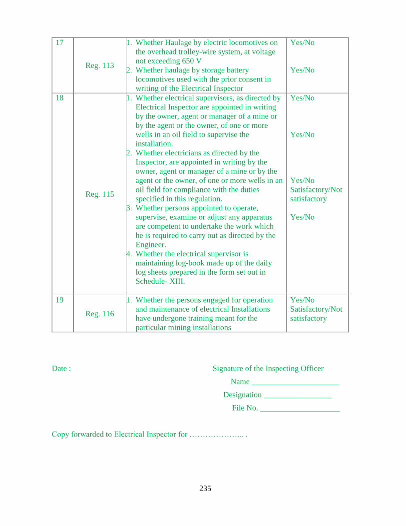
235
17
Reg. 113
1. Whether Haulage by electric locomotives on
the overhead trolley-wire system, at voltage
not exceeding 650 V
2. Whether haulage by storage battery
locomotives used with the prior consent in
writing of the Electrical Inspector
Yes/No
Yes/No
18
Reg. 115
1. Whether electrical supervisors, as directed by
Electrical Inspector are appointed in writing
by the owner, agent or manager of a mine or
by the agent or the owner, of one or more
wells in an oil field to supervise the
installation.
2. Whether electricians as directed by the
Inspector, are appointed in writing by the
owner, agent or manager of a mine or by the
agent or the owner, of one or more wells in an
oil field for compliance with the duties
specified in this regulation.
3. Whether persons appointed to operate,
supervise, examine or adjust any apparatus
are competent to undertake the work which
he is required to carry out as directed by the
Engineer.
4. Whether the electrical supervisor is
maintaining log-book made up of the daily
log sheets prepared in the form set out in
Schedule- XIII.
Yes/No
Yes/No
Yes/No
Satisfactory/Not
satisfactory
Yes/No
19
Reg. 116
1. Whether the persons engaged for operation
and maintenance of electrical Installations
have undergone training meant for the
particular mining installations
Yes/No
Satisfactory/Not
satisfactory
Date : Signature of the Inspecting Officer
Name ______________________
Designation _________________
File No. ____________________
Copy forwarded to Electrical Inspector for ………………... .
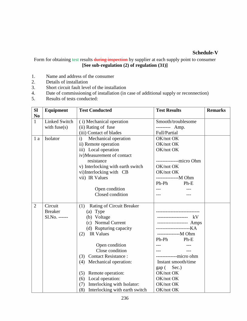
236
Schedule-V
Form for obtaining test results during inspection by supplier at each supply point to consumer
[See sub-regulation (2) of regulation (31)]
1. Name and address of the consumer
2. Details of installation
3. Short circuit fault level of the installation
4. Date of commissioning of installation (in case of additional supply or reconnection)
5. Results of tests conducted:
Sl
No
Equipment Test Conducted Test Results Remarks
1 Linked Switch
with fuse(s)
( i) Mechanical operation
(ii) Rating of fuse
(iii) Contact of blades
Smooth/troublesome
--------- Amp.
Full/Partial
1 a Isolator i) Mechanical operation
ii) Remote operation
iii) Local operation
iv) Measurement of contact
resistance
v) Interlocking with earth switch
vi) Interlocking with CB
vii) IR Values
Open condition
Closed condition
OK/not OK
OK/not OK
OK/not OK
--------------micro Ohm
OK/not OK
OK/not OK
--------------M Ohm
Ph-Ph Ph-E
--- ---
--- ---
2 Circuit
Breaker
Sl.No. ------
(1) Rating of Circuit Breaker
(a) Type
(b) Voltage
(c) Normal Current
(d) Rupturing capacity
(2) IR Values
Open condition
Close condition
(3) Contact Resistance :
(4) Mechanical operation:
(5) Remote operation:
(6) Local operation:
(7) Interlocking with Isolator:
(8) Interlocking with earth switch
---------------------------
------------------- kV
------------------- Amps
---------------------KA
--------------M Ohm
Ph-Ph Ph-E
--- ---
--- ---
-------------micro ohm
Instant smooth/time
gap ( Sec.)
OK/not OK
OK/not OK
OK/not OK
OK/not OK

237
Circuit
Breaker
Control
Circuits
(9) Alarm and Trip for
OTI/WTI/Buchholz/PRV
(10) Earth Fault Relay :
(11) Over current Relay :
(12) Under Voltage Relay:
(13) SF6 pressure alarm and trip
operation test
OK/not OK
OK/not OK
OK/not OK
OK/not OK
OK/not OK
3 Transformer
Sl. No. ----
(A) Insulation Resistance Values:
1. HT to LT :
2. HT to Earth:
3. LT to Earth:
(B) Break down Voltage Test
Oil Sample – I(Top)
Oil Sample – II (Bottom)
(C) Vector Group Test:
(D) Polarity Tests:
(E) Magnetizing Balance:
(F) Tan Delta Test ( as per capacity)
(G) Oil level in conservator Tank:
(H) Oil level in breather cup:
(I) OTI/WTI settings :
(J) OTI/WTI alarm and trip
operation
(K) Operation of Buchholz relay :
(L) Operation of PRV
(M) Oil leakage
(N) Interlock of door switch for dry
transformer
(O) Clearances for
Side clearance :
Between two Transformers:(P) Body
earth resistance
Neutral earth resistance
--------------M ohm
--------------M ohm
--------------M ohm
--------------kV
--------------kV
OK/not OK
OK/not OK
OK/not OK
OK/not OK
OK/not OK
OK/not OK
A/T---- 0C A/T----0C
OK/not OK
OK/not OK
OK/not OK
OK/not OK
OK/not OK
---------Cms
----------Meters
---------- Ohm
N1---Ohm
N2---Ohm
4 DG Set
Sl. Nos. for
1. Alternator:
2. Engine :
(A) Interlocking with other Supply
Sources:
(B) Body earth resistance
Neutral earth resistance
OK/not OK
---------- Ohm
N1---Ohm
N2---Ohm
5 Cables
Size: Sq. mm
(A) Insulation Resistance Values:
4. Ph - Ph :
5. Ph – Earth :
6. Ph – Earth + other Ph :
(B) Bending Radius:
--------- M Ohm
---------M Ohm
---------M Ohm
OK/not OK

238
6 Earthing : A) Metal and Size of
Earth Strips:
B) Type of Earthings:
(1) Plate Earthing:
(2) Pipe Earthing:
(3) Counter poise Earthing
:
(C) Values of Earth resistances of
earth electrodes for
(1) Reactor Neutral:
(2) LAs :
(3). Structure:
(4) Frames/Bodies of
Equipment:
(5) Motors :
Cu/Al/GI --- Sq. mm
Yes/No
Yes/No
Yes/No
N1 ----ohm N2 ----ohm
(R) ---ohm (Y) ---ohm
(B) ----ohm
--------ohm
--------ohm
--------ohm
7 Potential
Transformer
(i) Ratio test
(ii) Polarity test
(vi) BDV of oil
(vii) IR test
OK/not OK
OK/not OK
----------kV
(R) P-E-------M Ohm
(Y) P-E-------M Ohm
(B) P-E-------M Ohm
8. Current
Transformer
(i) Ratio test
(ii) Polarity test
(iii) BDV of oil
(vi) IR test
OK/not OK
OK/not OK
----------kV
(R) P-E-------M Ohm
(Y) P-E-------M Ohm
(B) P-E-------M Ohm
9. Transmission
line
(i) Physical condition of
conductor/tower
(ii) Check of tower accessories
(iii) Tower footing resistance
(iv) Conductor continuity test
(v) Check of ground clearance
(vi) Check of electrical clearance
along the route
OK/not OK
OK/not OK
----------Ohm
OK/not OK
OK/not OK
OK/not OK

239
General Observations :
Sl.No. Item Observations
1. Check of required phase to phase, phase to ground and
sectional clearance.
2. Check of equipment lay out and over all installation details.
3. Test of resistance of earth mat or earth electrodes as
applicable.
4. Check of consumer’s pre-commissioning test reports of
individual equipment.
5. Check of manufacturer’s routine/type test reports of
individual equipment.
6. Whether Inspector’s approval if applicable is obtained?
7. Whether owner’s self certification about compliance with
the Regulations is obtained?
8. General observation and views (specific deviation from the
requirements of the Regulations shall be clearly brought
out).
Name, Signature and Seal of the Authority

240
Schedule-VI
Form for notice in respect of failure of supply
[See sub-regulation (3) of regulation (39)]
(1) Name and address of the supplier :
(2) Date and time of failure of supply :
(3) Areas affected due to failure :
(4) Causes of failure :
(5) Probable time for restoration of supply :
(6) Additional information, if any :
Date :
(Name, Signature, Designation
and Seal of Authoity)
Place:
Time:

241
Schedule-VII
Minimum safety working clearances where electricity at voltage exceeding 650 V is
supplied, converted, transformed or used
[See sub-regulation (2)(iii) of regulation (44)]
(1) The above values are valid for altitude not exceeding 1000 m. A correction factor of
1.25 per cent per 100 m is to be applied for increasing the clearance for altitude more than
1000 m and upto 3000 m;
(2) The above safety working clearances are based on an insulation height of 2.44 m
which is the height of lowest point on the insulator, where it meets the earthed metal, from
the ground;
(3) “Safety Working Clearance” is the minimum clearance to be maintained in air
between the live part of the equipment on one hand and earth or another piece of
equipment or conductor on which it is necessary to carry out the work, on the other;
(4) The “Highest System Voltage” is defined as the highest rms phase to phase voltage
which occurs under normal operating conditions at any time and at any point of the
system. It excludes voltage transients (such as those due to system switching) and
temporary voltage variations due to abnormal system conditions (such as those due to
fault conditions or the sudden disconnection of large loads).
Highest System Voltage (kV) Safety Working Clearance (Metres)
12 2.6
36 2.8
72.5 3.1
145 3.7
245 4.3
420 6.4
800 10.3

242
Schedule-VIII
Minimum safety clearances to be maintained for bare conductors or live parts of any
apparatus in out-door HVDC sub-stations, excluding overhead lines of HVDC
istallations
[See sub-regulation (5) of regulation (44)]
S.No. DC Voltage (kV) Pole to Earth Clearance
(Metres)
Ground Clearance
(Metres)
1. 100 kV 1.17 4.55
2. 200 kV 1.80 5.65
3. 300 kV 2.45 6.75
4. 400 kV 3.04 8.00
5. 500 kV 3.65 9.00
6. 600 kV 3.98 10.1
7. 800 kV 5.3 11.2
(1) The above ground clearances are not applicable to equipment that are housed within
fence or a building and where access is prevented under energised condition through a
suitable safety interlocking scheme;
(2) The above pole to earth clearances are for conductor-structure electrode configuration
using gap factor k equal to 1.35.
(3) It is recognised that within a substation many different types of electrode configurations
shall be there with different values of k, therefore, the above clearance shall be modified
based upon the values of gap factor for a particular electrode configuration subjected to the
minimum ground clearance.
(4) Clearance shall be provided for electrical apparatus so that sufficient space is available
for easy operation and maintenance without any hazard to the operating and maintenance
personnel working near the equipment and for ensuring adequate ventilation.

243
Schedule-IX
Form for reporting failure of Transformers or Reactors of rating
20 MVA/MVAR and above
[See sub-regulation (8) of regulation (46)]
(1) Type of Equipment (Transformer or Reactor)
(2) Capacity (MVA/MVAR)
(3) Location (A
(4) Date of failure
(5) Year of manufacture
(6) Date of Installation
(7) Make
(8) Reasons for failure
(9) Measures being taken to avoid recurrence of failure
Date :
(Signature and name of Manager/Executive
Engineer of the installation)
TO:-
The Secretary
Central Electricity Authority
New Delhi

244
Schedule-IX
Part-A
Form for reporting failure of substation equipment & cable of 220 kV and above voltage
class
[See sub-regulation (8) of regulation (46)]
1. Name of Substation
2. Utility/Owner of substation
3. Faulty Equipment/cable
4. Rating plate details
(e.g. MVA, MVAR, Voltage, current, voltage ratio, CT ratio, PT/CVT ratio, tap range,
basic insulation level, continuous operating voltage & rated voltage & nominal
discharge current of SA, short circuit withstand current & time, duty cycle, size of cable
etc., as applicable for equipment/cable)
5. Make/Manufacturer
6. Serial No.
7. Year of manufacturing
8. Date of commissioning
9. Date and time of occurrence/discovery of fault
10. Fault discovered while equipment was in (Service/Maintenance)
11. Present condition of equipment (Completely damaged/reparable)
12. Details of previous maintenance (provide list of all maintenance activity & tests carried
out along with date of testing/maintenance and test results)
13. Details of previous failure of same equipment/cable (if the equipment was used after
repair or replacement of some parts)
14. Sequence of events leading to failure
15. Details of protection provided for the equipment/cable
16. Details of protection operated during fault and their settings
17. Atmospheric condition at the time of fault
18. Details of Tests done on equipment/cable after failure
19. Details, if any other equipment & accessories affected/damaged by faulty equipment
20. Reason for failure
21. Measures to be taken to avoid recurrence of failure
22. Date of restoration/replacement of faulty equipment/cable
23. Conclusion/recommendations
Note: Attach factory & commissioning test reports; event logger/disturbance recorder data &
photographs of failed equipment, if available.
Date :
(Signature and name of Manager/
Executive Engineer of the installation)
Contact details (Address /Mobile No./Phone No./Email)
To,
The Secretary
Central Electricity Authority
Sewa Bhawan, R.K.Puram
New Delhi-110066

245
Schedule-IX
Part-B
Form for reporting failure of Towers of 220 kV and above voltage class Transmission
lines
[See sub-regulation (8) of regulation (46)]
1. Name of Transmission line with voltage level:
2. Length of line (km):
3. Type of configuration [(S/C, D/C, S/C strung on D/C towers, narrow base etc.)
4. Number of Towers and Type of Towers failed: [suspension / tension/dead end /special
tower
/river crossing tower/ Power line crossing/Railway Crossing etc., with / without extension
(indicate the type & length of extension)]
5. Tower location No. with reference to nearest substation(indicate Name):
6. Name and size of conductor:
7. No. of sub-conductors per bundle and bundle spacing:
8. Number and size of Ground wire/OPGW (if provided):
9. Type of insulators in use(Porcelain / Glass / Polymer):
10. Configuration of insulators (I / V / Y / tension)
11. No. of insulators per string and No. of strings per phase:
12. Year of construction / commissioning:
13. Executing Agency:
14. Weather condition on the date of failure:
15. Terrain Category:
16. Wind Zone (1/2/3/4/5/6) and velocity of wind:
17. Details of earthing of tower (pipe type/ Counter poise):
18. Line designed as per IS: 802 (1977/1995/any other code):
19. The agency who designed the line:
20. Any Special consideration in design:
21. Date and time of occurrence/discovery of failure:
22. Power flow in the line prior to failure:
23. Any missing member found before / after failure of towers:
24. Condition of foundation after failure:
25. Brief Description of failure: [along with photographs(if available), other related
information like tower schedule, newspaper clipping for cyclone / wind storm etc.]
26. Probable cause of failure:
27. Details of previous failure of the line / tower:
28. Whether line will be restored on Emergency Restoration System (ERS) or Spare tower
will be used:
29. Likely date of restoration:
30. Present Status:
31. Details of any Tests carried out after failure:
32. Single line diagram / clearance diagram of the failed tower(s) with all dimensions
(Horizontal and vertical dimensions including the base width of tower)

246
33. Tower spotting data
34. Tower Schedule for the failed section
35. Sag tension calculation considered for the design of towers
36. Any other relevant information:
Date: (Signature and name of
Manager/Executive
Engineer of the installation)
Contact details (Address /Mobile No./Phone
No./Email)
To,
The Secretary
Central Electricity Authority
Sewa Bhawan, R.K.Puram
New Delhi-110066

- 247 -
Schedule-X-A
Minimum clearance in air above ground and across road surface of Highways or roads or railway corridors or
navigational or non-navigational rivers for lowest conductor of an alternating current overhead lines, including
service lines of nominal voltage system.
[See sub-regulation (1) of regulation (58)]
Nominal voltage of
system
Clearance above ground Clearance
between
conductor and
road surface
across Highway
(m)
Clearance
between
conductor
and rail level
across
Railway
Corridor
(m)
Clearance above HFL for River crossing
Across
Street
(m)
Along
Street
(m)
Elsewhere
(m)
Navigational
river
(m)
Non-navigatiional river
(m)
Upto 650 V 5.80 5.50 4.60 U/G Cable U/G Cable - 5.80
11 kV 6.50 5.80 4.60 U/G Cable U/G Cable - 6.50
22 kV 6.50 5.80 5.20 U/G Cable 14.1 - 6.50
33 kV 6.50 5.80 5.20 11.60 or U/G
Cable
14.10 - 6.50
66 kV 6.50 6.10 5.50 11.60 or U/G
Cable
14.10 19.00 6.50
110 kV 6.50 6.10 6.10 11.60 14.60 19.00 6.50
132 kV 6.50 6.10 6.10 11.60 14.60 19.22 6.50
220 kV 7.02 7.02 7.02 12.52 15.40 20.10 7.02
400 kV 8.84 8.84 8.84 14.00 17.90 21.90 8.84
765 kV 18.00* 18.00* 18.00* 18.80
23.40 25.55 18.00
1200 kV 24.00* 24.00* 24.00* 30.00 23.00 (from
highest
traction
conductor)
29.90 24.00
For navigable rivers, clearances shall be fixed in relation to the tallest mast in consultation with the concerned navigational/port authorities.
* Higher clearance due to predominantly induction effects and time varying electric field (ICNIRP limit: 10 kV/m for occupational exposure) at
voltage exceeding 400 kV.

- 248 -
Schedule-X-B
The minimum clearance in air above ground and across road surface of Highways, or Minimum clearance
between conductor and Rail Level or navigational or non-navigational rivers for lowest conductor of
High Voltage Direct Current (HVDC) overhead line of nominal voltage system
[See sub-regulation (6) of regulation (58)]
* Higher clearance due to predominantly time varying electric field (ICNIRP limit: 10 kV/m for occupational exposure) at voltage exceeding 400
kV.
1. Highway clearances required 4.75 m higher then ground clearances (considering the vehicle hight is 4.75, as mentioned in the Indian Road
Congress documents, 1983).
2. Railway clearances required 10% higher value than HVAC values ( HVAC values are mentioned in Indian Railway document :IRSOD,
2004).
3. Navigational River clearances as mentioned in the Regulation of Inland Waterways Authority of India (Classification of Inland Waterways
in India), Regulation, 2006.
Sl.
No.
DC
Voltage
(kV)
Ground
Clearance
(mtrs.) (m)
Clearance between
conductor and
road surface
across Highway
(m)
Minimum clearance
between conductor
and Rail Level
(m)
Clearance above HFL for River crossing
Navigational
River
(m)
Non-navigatiional River
(m)
1. 100 kV 6.50 - - - -
2. 200 kV 7.30 - - - -
3. 300 kV 8.50 - - - -
4. 400 kV 9.40 - - - -
5. 500 kV 12.50 17.25 21.23 22.90 12.50
7. 800 kV 18.00 22.75 25.74 25.90 18.00

- 249 -
Schedule-X X-C
Ground, Vertical and Horizontal clearances
[See sub-regulation (6) of regulation 58, sub-regulation (5) of regulation (60) and
sub-regulation (5) of regulation 61]

- 250 -
Schedule-XI
FORM OF ANNUAL RETURN FOR MINES
[See sub-regulation (1) of regulation (95)]
This form must be correctly filled up by the owner, agent, manager or engineer and
sent to the Inspector not later than the first day of February every year.
Part A
Year ending 20
Name of Mine State
Situation of Mine District
Postal address of Mine
Name and address of owner
Name of agent
Name of manager
Name of engineer
Name of Electrical Supervisor
Part B
(1) System of supply (whether direct current or alternating current)
Voltage of supply
Periodicity (if alternating current)
Source of supply.
(2) Voltage at which electricity is used for :-
Lighting
Power
(3) Particulars of Motor etc.
POWER
(a) On Surface
Type of Motor (H.P./K.W.) /
apparatus and voltage
Type of control gear Location Purpose for which used
(b) In Mine
Type of Motor
(H.P./K.W.) /
apparatus and voltage
Type of
control
gear
Location Purpose for
which used
Ventilation Percentage of
inflammable gas
or vapour
LIGHTING
Type of light fitting Wattage Location Percentage of inflammable
gas or vapor

- 251 -
Schedule-XII
FORM OF ANNUAL RETURN FOR OIL-FIELDS
[See sub-regulation (1) of regulation (95)]
This form must be correctly filled up by the owner, agent, manager or engineer and
sent to the Inspector not later than the first day of February every year.
Part A
Year ending 20
Situation of Oil-field State
Name of Oil-field District
Postal address of Oil-field
Name and address of owner
Name of agent
Name of manager
Name of engineer
Name of Electrical Supervisor
Part B
(1) System of supply (whether direct current or alternating current)
Voltage of supply
Periodicity (if alternating current)
Source of supply.
(2) Voltage at which electricity is used for :-
Lighting
Power
(3) Particulars of Motor etc. in use on the field :-
(a) On wells No. or other identifying
Mark of well
Drilling or
pumping
Type and H.P
of motor
No. of lamps
and type
Other electrical
appliances
1 2 3 4 5
(b) Not on wells Type and H.P of motor Purpose for which used Identifying mark on map
1 2 3
(4) Other electrical appliances, not including in item3, in use on the field.
Appliances Type and size in KW. Purpose for which used Identifying mark on map

- 252 -
Schedule-XIII
LOG SHEET FOR MINES AND OIL-FIELDS
[See sub-regulation (9) of regulation (110), clause (a) and (b) of sub-regulation (5) of
regulation (115)]
Daily Log sheet for
(1) Name of Electrical Supervisor
(2) Report as to:-
(a) Condition of the insulation of the system.
(b) Specified defects of insulation (particulars of each failure of apparatus
should be given).
(c) Accidents or dangerous occurrence (including any cases of electric shock
and any cases of open sparking in apparatus in use in places where
regulation 110 applies.
(d) Disconnection and reconnection of supply as required by sub-regulation (9)
of regulation 110.
(e) Examination of earth fault detectors or recorders as provided by sub-
regulation (3) of regulation 100.
(f) Examinations of apparatus as provided by Regulation 115.
(i) Routine examinations as required by clause (a) of sub-regulation (5)
of regulation 115.
(ii) Special examination* as required by clause (b) of sub-regulation (5)
of regulation 115.
(3) Remarks:-
Signed
Examined by
Electrical Supervisor:
Engineer:
Manager.
*State which apparatus has been examined or tested and result.
NOTE:.- This log sheet should be filled in as completely as possible. If, for instance, there
are no defects of insulation to report, the word ‘none’ should be written in the vacant space.
Schedule- XIV

- 253 -
Part-I
Guidelines for determining adequacy of designated supervisors on duty in
every mine or oil-field while electricity is being used
[See sub-regulation (1)(i) of regulation (115)]
Adequate number of electrical supervisors shall be designated in a mine for conducting the
operation and maintenance works of electrically operated machinery/ equipment/ apparatus
in accordance with the provisions of Regulations.
1. In case of belowground mine having conventional and semi-mechanized workings,
at least one electrical supervisor shall be designated in each working district in
each shift of operation/ maintenance.
2. In case of belowground mechanized mines consisting of Longwall machinery,
continuous miners, Blasting Gallery or alike equipment, at least two electrical
supervisors shall be designated for each machinery and associated apparatus/
substations in each shift of operation/ maintenance
3. In opencast mine consisting of Dragline, Bucket wheel excavators, High capacity
shovels or any alike equipment, at least one supervisor shall be designated for each
such machinery/ equipment inclusive of their switchgear based on size & type of
equipment in each shift of operation/ maintenance.
Provided that where the aggregate capacity of machinery is less than 2MVA, the
HEMM and associated switchgear can be grouped to bring under one supervisor.
4. In opencast mine consisting of HEMM such as Electrically operated Shovels &
Drilling Machines, associated switchgear, distribution lines, substations etc., at
least one electrical supervisor shall be designated in each shift of operation/
maintenance for maximum up to six numbers of such electrically operated
machinery/ equipment.
5. In case of opencast mines consisting of small and conventional electrical
machinery such as substation equipment, distribution lines, production machinery,
pump installations or any alike equipment, one electrical supervisor shall be
designated in each shift of operation/maintenance.
6. In case of oil/ gas/ coal based power plants with associated substations which are
supplying electricity to mine installations and forming part of mine, one electrical
supervisor in general shift of operation/ maintenance shall be designated.
7. In case of oil fields, where electrically operated drilling rigs inclusive of
generators, substation apparatus and other electrical machinery are in use, one
electrical supervisor in general shift of operation/ maintenance per rig shall be
designated.
8. In oil fields of production installations, group gathering stations, well pads or any
alike installations where substations and electrically operated equipment are in use,
at least one electrical supervisor in general shift of operation/ maintenance shall be
designated.

- 254 -
9. For the surface installations of a mine consisting of substations, switch stations,
distribution lines and other electrically operated machinery/ equipment, at least
one electrical supervisor in each shift shall be designated for operation/
maintenance.
Provided that where the aggregated capacity of substations and downstream
electrically operated machinery is more than 10MVA, additional electrical
supervisor shall be designated in each shift of operation/ maintenance.
Schedule-XIV

- 255 -
Part-II
Guidelines for determining adequate number of designated electricians on
duty in every mine or oil-field while electricity is being used
[See sub-regulation (1)(iii) of regulation (115)]
Adequate number of electricians shall be designated in a mine for conducting the operation
and maintenance works of electrically operated machinery/ equipment/ apparatus in
accordance with the provisions of Regulations:
1. In case of belowground mine having conventional and semi-mechanized workings,
at least two electricians shall be designated for each working district in each shift
of operation/ maintenance.
2. In case of belowground mechanized mines consisting of Longwall machinery,
continuous miners, Blasting Gallery or alike equipment, at least four electricians
shall be designated for each machinery/ associated apparatus/ substations in each
shift of operation/ maintenance
3. In opencast mine consisting of Dragline, Bucket wheel excavators, High capacity
shovels or any alike equipment, at least two electricians shall be designated for
each such machinery/ equipment inclusive of their switchgear based on size & type
of equipment in each shift of operation/ maintenance.
Provided that where the aggregate capacity of machinery is less than 1MVA, the
HEMM and associated switchgear can be grouped to bring under one electrician.
4. In opencast mine consisting of HEMM such as Electrically operated Shovels &
Drilling Machines, associated switchgear, distribution lines, substations etc., at
least one electrician shall be designated in each shift of operation/ maintenance for
maximum up to two numbers of such electrically operated machinery/ equipment.
5. In case of opencast mines consisting of small and conventional electrical
machinery such as substation equipment, distribution lines, production machinery,
pump installations or any alike equipment are in use, at least one electrician shall
be designated in each shift of operation/maintenance and additional electrician
shall be designated based on the type and size of installations and the area to be
covered.
6. In case of oil/ gas/ coal based power plants with associated substations which are
supplying electricity to mine installations and forming part of mine, at least one
electrician in each shift of operation/ maintenance shall be designated.
7. In case of oil mines, where electrically operated drilling rigs inclusive of
generators, substation apparatus and other electrical machinery are in use, two
electricians in each shift of operation/ maintenance per rig shall be designated.
8. In oil fields of production installations, group gathering stations, well pads or any
alike installations, where substations and electrically operated equipment are in
use, at least one electrician in each shift of operation/ maintenance shall be
designated. Where the distance between such installations exceeds one KM,

- 256 -
additional electrician shall be designated based on the type and size of installations
and the area to be covered.
9. For the surface installations of a mine consisting of substations, switch stations,
distribution lines and other electrically operated machinery/ equipment, at least
two electricians in each shift shall be designated for operation/ maintenance.
Provided that where the aggregated capacity of substations and downstream
electrically operated machinery is more than 5MVA additional electricians shall
be designated in each shift of operation/ maintenance.

- 257 -
Schedule-XIV-A
Guidelines for determining adequate number of designated electricians on
duty in every mine or oil-field while electricity is being used
[See sub-regulation (1)(iii) of regulation (115)]
Adequate number of electricians shall be appointed in a mine for conducting the operation
and maintenance works of electrically operated machinery/ equipment/ apparatus in
accordance with the provisions of Regulations:
10. In case of belowground mine having conventional and semi-mechanized workings,
at least two electricians shall be deployed for each working district in each shift of
operation/ maintenance.
11. In case of belowground mechanized mines consisting of Longwall machinery,
continuous miners, Blasting Gallery or alike equipment, at least four electricians
shall be deployed for each machinery/ associated apparatus/ substations in each
shift of operation/ maintenance
12. In opencast mine consisting of Dragline, Bucket wheel excavators, High capacity
shovels or any alike equipment, at least two electricians shall be appointed for each
such machinery/ equipment inclusive of their switchgear based on size & type of
equipment in each shift of operation/ maintenance.
Provided that where the aggregate capacity of machinery is less than 1MVA, the
HEMM and associated switchgear can be grouped to bring under one electrician.
13. In opencast mine consisting of HEMM such as Electrically operated Shovels &
Drilling Machines, associated switchgear, distribution lines, substations etc., at
least one electrician shall be deployed in each shift of operation/ maintenance for
maximum up to two numbers of such electrically operated machinery/ equipment.
14. In case of opencast mines consisting of small and conventional electrical
machinery such as substation equipment, distribution lines, production machinery,
pump installations or any alike equipment are in use, at least one electrician shall
be appointed in each shift of operation/maintenance and additional electrician shall
be appointed based on the type and size of installations and the area to be covered.
15. In case of oil/ gas/ coal based power plants with associated substations which are
supplying electricity to mine installations and forming part of mine, at least one
electrician in each shift of operation/ maintenance shall be appointed.
16. In case of oil mines, where electrically operated drilling rigs inclusive of
generators, substation apparatus and other electrical machinery are in use, two
electricians in each shift of operation/ maintenance per rig shall be appointed.
17. In oil fields of production installations, group gathering stations, well pads or any
alike installations, where substations and electrically operated equipment are in
use, at least one electrician in each shift of operation/ maintenance shall be
appointed. Where the distance between such installations exceeds one KM,
additional electrician shall be appointed based on the type and size of installations
and the area to be covered.

- 258 -
18. For the surface installations of a mine consisting of substations, switch stations,
distribution lines and other electrically operated machinery/ equipment, at least
two electricians in each shift shall be appointed for operation/ maintenance.
Provided that where the aggregated capacity of substations and downstream
electrically operated machinery is more than 5MVA additional electricians shall
be appointed in each shift of operation/ maintenance.

- 259 -
Training of personnel engaged for operation and maintenance of electrical
installations in Mines
(i)The persons engaged for operation and maintenance of electrical installations in Mines
are required to undergo the type of training meant for the particular mining installations
(Coal/Oil/Metal).
(ii) The refresher training shall be imparted at a periodicity of intervals not more than two
years. A register by the Owner/Manager/Agent of a mine or by the agent or the owner, of
one or more wells in an oil fields of the mine shall be maintained wherein the names of the
persons trained, due date of refresher training etc shall be entered. The register maintained
shall be produced before the Electrical Inspector whenever required by him.
(iii) The Owner /Agent of the mine shall arrange for training of their personnel engaged in
the operation and maintenance of electrical installations of mines in his own institute or
any other institute recognized by the Central Government or State Government.
Provided that the existing employees shall have to undergo the training mentioned in sub-
regulation 116(i) within three years from the date of coming into force of these
regulations.

- 260 -
SCHEDULE XV
TRAINING SYLLABUS FOR ELECTRICAL SUPERVISOR AND
ELECTRICIANS OF MINES
General Instructions
1. The content of training courses and on the job training / practical training may be
designed keeping in view the technical requirements as applicable.
2. The periodical refresher training may be customized as per the assessment and
requirement.
3. After the lecture course is completed, the trainees are required to be taken on visit
to a few modern power stations, testing labs, mechanized mine, manufacturer
facilities of transformer, motors, switchgears etc.,
4. Facilities of training institute / for creation of training institute:
I. The training institute shall have devoted facilities ― building, residential
and recreation facilities
II. The training institute shall have a full time Head of institute and adequate
number of teaching faculty /staff. The institute may engage visiting faculty
from operations in order to enhance the operating skills of the trainee.
III. The training institute shall have adequate number of lecture halls, seminar
and conference hall/ auditorium, library, computer centre, workshop,
laboratories etc.,
IV. The institute shall have facilities to arrange refresher courses to those
personnel who are already designated electrical supervisor in their work
fields.
V. The institute shall fill up the Assessment form for Electrical Supervisors/
Electricians towards the performance of each participant.
5. The threshold marks for passing through the evaluation test, inclusive of practical
test and written shall be 50% of total marks.

- 261 -
SCHEDULE XV
PART-I
TRAINING SYLLABUS FOR ELECTRICAL SUPERVISOR OF MINES (For
Coal or Metal Mines)
Item No Particulars Number
of Hours
1 Electrical Machineries:
I. Operation maintenance, pre-commissioning test of different
types of motors (AC &DC)
II. Operation maintenance, pre-commissioning test of different
types of generators (AC &DC),
III. Operation maintenance, pre-commissioning tests of different
types of transformers.
4
2 Electric Drives and Control:
(i) Operation maintenance of Different types of starters including
AC Drive, DC Drive, soft starters etc.,
2
3 Switchgear and protective devices:
(i) Operation maintenance, pre-commissioning tests of different
types of circuit breakers
(ii) Different types of protective schemes/protective devices and
their operation maintenance,
2
4 Earthing system: Requirements, types of earthing, maintenance,
chemical earthing and relevant provisions of IS - 3043.
3
5 Neutral system of power supply:
a. solid neutral earthing, restricted neutral earthing, isolated neutral
earthing , advantages / disadvantages;
b. provisions of the Regulation for suitably designed restricted neutral
system of power supply and the requirement of neutral fail safe relay
3
6 Operation and maintenance of substations and generating stations
including maintenance of storage battery and related auxiliaries.
3
7 Design and layout of sub-station, Safety in sub-station, switchyard and
switchboards
i. Safe working clearance;
ii. Guarding of live apparatus;
iii. Standard Operating Procedure (SOP) of circuit breakers,
transformers, isolators, surge arresters, instrument transformers,
storage tanks etc.,
3
8 Operation, maintenance of overhead lines and underground cables
I. Safety measures in overhead lines
II. Types of stays, its markings, grouting, stay insulator, binding
etc.,
III. Types of guarding and clearances, earth/neutral wire, anti-
climbing devices, and their erection.
IV. Selection and fixing of control devices viz. Linked switches,
fuses, isolators, and earthing switches, lightning arrestors etc.
4

- 262 -
V. Cables and conductors, their classification, construction,
insulation types, laying, mining type cables and the related
standards, cable jointing techniques and junction boxes
9 Electrical apparatus and machinery for mine installation ( as applicable
for a particular type of mine Oil/Coal/Metal)
I. Winders, man riding system, cranes
II. Electrically operated HEMM, portable transportable machinery,
dragline, bucket wheel excavator, SDL,LHD, Road header,
shearer, continuous miner
III. Salient features of Flameproof and intrinsically safe apparatus
for use in hazardous atmosphere of mine (coal/Oil) and relevant
provisions of the IS/IEC 60079 series of standards, operation
and maintenance of the flameproof and intrinsically safe
apparatus;
IV. LMD, Environment monitoring system
V. Circuit diagram of Drill control panel, GEB, different types of
circuit breakers, starters, Lighting & Signaling unit.
VI. Safety requirement of belt conveyor system installed in the
belowground coal mine, OCP
VII. Safety requirements of Drilling Rig in oil mine
VIII. Any other special type of Electrical machinery /
apparatus used in mines(coal/oil/metal)
8
10 General safety:
I. Procedure for obtaining permission to work for carrying out
operations and maintenance of electrical equipment (permit to
work as per IS:5216);
II. Safety in electrical workshop
III. Firefighting equipment, their type, use and periodical
maintenance, indicators, and recorders etc.
IV. First aid training, resuscitation of persons suffering from electric
shock etc.,
4
11 Legislation/statutes as amended from time to time:
I. Provisions of Central Electricity Authority( measures relating to
safety and electric supply), Regulations 2010;
II. Provisions of Electricity Act,2003
III. Relevant provisions of the mines Act, 1952
IV. Relevant provisions of the Coal Mines Regulation,1957
V. Relevant provisions of Metalliferous Mines Regulation, 1961
VI. Relevant provisions of Oil Mines Regulation, 1984
5
12 On-Site emergency management plan in case of contingency related to
electricity:
I. Emergency response procedure including response to off-site
emergency management plan and crisis and disaster management
plan;
3
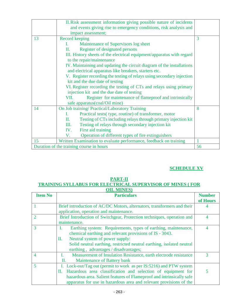
- 263 -
II. Risk assessment information giving possible nature of incidents
and events giving rise to emergency conditions, risk analysis and
impact assessment;
13 Record keeping
I. Maintenance of Supervisors log sheet
II. Register of designated persons
III. History sheets of the electrical equipment/apparatus with regard
to the repair/maintenance
IV. Maintaining and updating the circuit diagram of the installations
and electrical apparatus like breakers, starters etc.
V. Register recording the testing of relays using secondary injection
kit and the due date of testing
VI. Register recording the testing of CTs and relays using primary
injection kit and the due date of testing
VII. Register for maintenance of flameproof and intrinsically
safe apparatus(coal/Oil mine)
3
14 On Job training/ Practical/Laboratory Training
I. Practical tests( type, routine) of transformer, motor
II. Testing of CTs including relays through primary injection kit
III. Testing of relays through secondary injection kit
IV. First aid training
V. Operation of different types of fire extinguishers
8
15 Written Examination to evaluate performance, feedback on training 1
Duration of the training course in hours 56
SCHEDULE XV
PART-II
TRAINING SYLLABUS FOR ELECTRICAL SUPERVISOR OF MINES ( FOR
OIL MINES)
Item No Particulars Number
of Hours
1 Brief introduction of AC/DC Motors, alternators, transformers and their
application, operation and maintenance.
4
2 Brief Introduction of Switchgear, Protection techniques, operation and
maintenance.
4
3 I. Earthing system: Requirements, types of earthing, maintenance,
chemical earthing and relevant provisions of IS - 3043.
II. Neutral system of power supply:
Solid neutral earthing, restricted neutral earthing, isolated neutral
earthing , advantages / disadvantages;
4
4 I. Measurement of Insulation Resistance, earth electrode resistance
II. Maintenance of Battery bank
3
5 I. Lock-out/Tag out (permit to work as per IS:5216) and PTW system
II. Hazardous area classification and selection of equipment for
hazardous area. Salient features of Flameproof and intrinsically safe
apparatus for use in hazardous area and relevant provisions of the
5

- 264 -
IS/IEC 60079 series of standards, operation and maintenance of the
flameproof, intrinsically safe apparatus and other apparatus
conforming to the relevant Ex standards
6 Record keeping:
I. Maintenance of Supervisors log sheet
II. Register of designated persons
III. History sheets of the electrical equipment/apparatus with regard
to the repair/maintenance
IV. Maintaining and updating the circuit diagram of the installations
and electrical apparatus like breakers, starters etc.
V. Register recording the testing of relays using secondary injection
kit and the due date of testing
VI. Register recording the testing of CTs and relays using secondary
injection kit and the due date of testing
VII. Register for maintenance of flameproof and intrinsically safe
apparatus(coal/Oil mine)
3
7 Design layout, Safety in sub-station, switchyard and switchboards
i. Safe working clearance;
ii. Guarding of live apparatus;
Standard Operating Procedure (SOP) of circuit breakers,
transformers, isolators, surge arresters, instrument transformers,
storage tanks etc.
3
8 Operation, maintenance of overhead lines and underground cables
I. Safety measures in overhead lines
II. Types of stays, its markings, grouting, stay insulator, binding
etc.,
III. Types of guarding and clearances, earth/neutral wire, anti-
climbing devices, and their erection.
IV. Selection and fixing of control devices viz. Linked switches,
fuses, isolators, and earthing switches, lightning arrestors etc.
V. Cables and conductors, their classification, construction,
insulation types, laying, mining type cables and the related
standards, cable jointing techniques and junction boxes
3
9 General safety:
I. General Safety to be observed in oil and gas mine and adherence
to operator’s Safety Rules.
II. Firefighting equipment, their type, use and periodical
maintenance, indicators, and recorders etc.
III. First aid training, resuscitation of persons suffering from electric
shock etc.
3
10 Legislation:
I. Provisions of Central Electricity Authority (measures relating to
safety and electric supply), Regulations 2010;
II. Provisions of Electricity Act,2003
III. Relevant provisions of the mines Act, 1952
IV. Relevant provisions of Oil Mines Regulation, 1984 (amended
version)
5

- 265 -
11 On job training/ practical/Laboratory training 4
12 Written examination to evaluate the performance for awarding the
License
1
Total 42
SCHEDULE XV
PART-III
TRAINING SYLLABUS FOR ELECTRICIANS OF MINES
Item
No Particulars
Number of
Hours
1 Basic Electrical Engineering:
(i) Symbols of various electrical items/ machines/elements
(ii) Sketches and circuit diagrams for the electrical systems / installations
i.e. different types of distribution networks, starters and other
electrical apparatus
(iii) Different types of tools and devices being used to maintain the
electrical installations / apparatus such as Insulation tester, earth tester,
multimeter etc.,
3
2 Electrical Machineries:
I. Different types of motors (AC &DC), their applications,
operation and maintenance
II. Different types of generators (AC &DC), their application,
operation and maintenance
III. Different types of transformers, cooling of transformers, transformer
oil, protective devices in the transformer, the common causes of
failures, operation & maintenance.
3
3 Electric Drives and Control:
Starting and speed control of motors, different types of starters and their
operation maintenance
2
4 Switchgear and protective devices:
I. General Idea on Operation & Maintenance of different types of
circuit breakers , CT/PT
II. General idea on different types of relays such as over-current, earth
fault relays, broken conductor/negative sequence/ unbalance/single
phasing preventer, Differential protection etc.,
III. Various protective schemes with circuit diagram: for motors,
generators, transformers, capacitor banks etc.,
3

- 266 -
6 Earthing system: Requirements, types of earthing, maintenance, chemical
earthing and relevant provisions of IS - 3043.
2
7 Neutral system of power supply:
I. Solid neutral earthing, restricted neutral earthing, isolated neutral
earthing, advantages / disadvantages
II. Provisions of the statutory Regulation for suitably designed restricted
neutral system of power supply and the requirement of neutral fail safe
relay
2
9 Operation and maintenance of substations and generating stations including
maintenance of storage battery and related auxiliaries
3
10 Protection against voltage surges and lightning 1
11 Operation, maintenance of overhead lines and underground cables
I. Safety measures in overhead lines
II. Types of stays, its markings, grouting, stay insulator, binding etc.,
III. Types of guarding and clearances, earth / neutral wire, anti-climbing
devices and their installation / erection.
IV. Selection and fixing of control devices viz. Linked switches, fuses,
isolators, and earthing switches, lightning arrestors etc.,
V. Cables and conductors, their classification, construction, insulation
types, laying, mining type cables and the related standards, cable
jointing techniques and junction boxes
4
12 Electrical apparatus and machinery for mine installation ( as applicable for
a particular type of mine like Coal/Metal/Oil)
I. Winders, man riding system, cranes
II. Electrically operated HEMM, portable transportable machinery,
dragline, bucket wheel excavator, SDL,LHD, Road header,
shearer, continuous miner
III. Salient features of Flameproof and intrinsically safe apparatus for
use in hazardous atmosphere of mine (coal/Oil) and relevant
provisions of the IS/IEC 60079 series of standards, operation and
maintenance of the flameproof and intrinsically safe apparatus
IV. LMD, Environment monitoring system
V. Circuit diagram of Drill control panel, GEB, different types of circuit
breakers, starters, Lighting & Signaling unit.
VI. Safety requirements of belt conveyor system installed in the
belowground coal mine, OCPs etc.,
VII. Safety requirements of Drilling Rig in oil mine
VIII. Any other special type of Electrical machinery / apparatus
used in mines (coal / oil / metal)
8
13 General safety:
I. Procedure for obtaining permission to work for carrying out
operations and maintenance of electrical equipment (Permit to work
as per IS:5216);
II. Safety in electrical workshop
III. Firefighting equipment, their type, use and periodical maintenance,
indicators, and recorders etc.,
IV. First aid training, resuscitation of persons suffering from electric
shock etc.,
4

- 267 -
14 Legislation/statutes as amended from time to time:
Relevant regulations of Provisions of Central Electricity Authority(
measures relating to safety and electric supply), Regulations 2010
4
15 On Job training/ Practical/Laboratory Training
I. Erection and pre commissioning testing of transformers, motors,
generators, switchgear
II. Measurement of earth resistance, insulation resistance etc.,
III. Testing of CTs, relays etc.,
IV. First aid training
V. Operation of different types of fire extinguishers
8
16 Written Examination to evaluate performance, feedback on training 1
Duration of the training course in hours 48

- 268 -
Schedule-XVI
Criteria for authorizing the Chartered Electrical Safety Engineer (CESE)
In accordance the Regulation 5A of CEA (Measures relating to Safety and Electric Supply)
Regulations, 2018 (as amended), the Central Government has introduced Self-certification
of the electrical installation by the owner or Chartered Electrical Safety Engineer (CESE)
upto the notified voltage.
1. Short title and Commencement.:-
(1) These guidelines may be called the “Guidelines for appointment of Chartered Electrical
Safety Engineers (CESE)” under sub regulation 5A of Central Electricity Authority
(Measures relating to Safety and Electric Supply) Amendment Regulations, 2018.
(2) They shall come into force on the date of their publication in the Official Gazette.
2. Definitions: (1) In these regulations, unless the context otherwise requires,
(a) “Chartered Electrical Safety Engineer” means a person authorised by the Appropriate
Government as refered to in regulation 5A;’;
(b) “Notified Voltage” means a voltage notified by the Appropriate Government under
intimation to the Authority for the purpose of specifying the voltage level upto which
self-certification is to be carried out under regulation 30 and regulation 43;’;
(c) Words and expressions used and not defined in these regulations but defined in the
Electricity Act shall have the meanings respectively assigned to them in the Electricity
Act, 2003.
3. Qualification of Chartered Electrical Safety Engineer:
(a) The Chartered Electrical Safety Engineers shall be an Electrical Engineering degree
holder or equivalent degree with at least five years experience in operation and
maintenance of electrical installations and also shall have the knoweledge of
Electricity Act, Rules and Central Electricity Authority (Measures relating to Safety
and Electric Supply), Regulations, 2010 (as amended) or an Electrical Engineering
Diploma holder with at least 10 years of experience in operation and maintenance of
electrical installations and also shall have the knowledge of Electricity Act, Rules and
Central Electricity Authority (Measures relating to Safety and Electric Supply),
Regulations, 2010 (as amended).
(b) He/ She shall qualify the priscribed test/ interview conducted by Electrical Inspectorate
Department of the concerned Government, after paying the requisite fees. The
procedure for the test/interview shall be decided by the respective Government.

- 269 -
(c) Notwithstanding anything contained in clause (a), the Chartered Electrical Safety
Engineer shall have the knloweledge of other relevant Acts and Regulations related to
the electric supply in the respective State Government.
(d) Retired Electrical Inspector who were already notified by Appropriate Governament
would be eligible for CESE. However, state Government would have the responsibility
to take the decision on exemption for test/ interview for retired Electrical Inspector.
(e) The Chartered Electrical Safety Engineers shall not hold any post in Govt./Semi
Govt./PSUs or associated with any organisations which directly or indirectly
influence the working of CESE.
(f) He/ She shall for all the time in his possession have the basic testing equipment (some
basic testing equipment given in Annexure-I) as may be prescribed by the office of the
Electrical Inspector for testing of the electrical installations.
4. Scope of work: The Chartered Electrical Safety Engineers shall assist the owner or
supplier or consumer of electrical installations for the purpose of self-certification upto
the level of notified voltage under regulation 30 and regulation 43 of Central Electricity
Authority (Measures relating to Safety and Electric Supply), Regulations, 2010 (as
amended), provided those installation are not be covered under section 54 of Electricity
Act, 2003.
5. Duties & Responsibilities of Chartered Electrical Safety Engineer:
1. He / She shall carry out recommended tests as per the relevant Regulation and
Standards.
2. He / She shall test electrical installations & keep a record thereof in Form-I/ Form-
II/ Form-III as the case may be (as given in Schedule-IV) and submit the same along
with photographs/ vedio of the apparatus tested to the respective office of the
Electrical Inspector within seven working days from the date of testing and will
produce the same at the time renewal.
3. The Owner shall carry out the recommendations given by the CESE in his report,
within the time prescribed in the report. In case the owner fails to rectify the
shortcomings as dentified by the CESE even after the prescribed period, the CESE
shall inform the same to the office of the Electrical Inspector within a period of 15
days from the expiry of the time prescribed in the report of rectification. Such
records shall be made available to the office of the Electrical Inspector by the owner/
CESE, as and when required.
4. If, on inspection of installation of the owner or supplier or consumer, as the case
may be, the CESE is satisfied that the installation is likely to be dangerous for the
use of electricity, he/ she shall bring the same to the notice to the owner and the
office of Electrical Inspector within the period of 48 hours from the date of testing.
The Electrical Inspector on receipt of such notice should take immediately action
as per Regulation 31.
6. Fees and leavy chages of CESE:-
(a) Testing of electrical installation in a single premise up to notified voltage under
Regulation 43 is Rs. 5000/-.

- 270 -
(b) Periodic Testing of electrical instalation in a single premise up to notified voltage under
Regulation 30 is Rs. 3000/-.
Fees to be levied by the CESE from the Utilities shall be received in the modes other
than cash.
7. Accessibilibility of CESE to the Consumers: The Appropriate Government shall
upload the name of the authorized chartered Electrical Safety Engineer, within 15 days,
on the web portal of the Government or Department dealing with matters of inspection
of electrical installations for the information of the owner, supplier and consumer.
8. Others terms and conditions:
(a) It shall be the responsibility of owner of the Installation to maintain & operate the
installation in a condition free from danger and as recommended by the manufacturer
/CEI/EI/CESE or by the relevant codes of practice of the "Bureau of Indian Standards."
(b) The authorisation of a Chartered Electrical Safety Engineer shall be liable to be
suspended or cancelled by the Electrical Inspector, if he/she is found to be indulging
in willful negligence, mal-practice , misuse or any other activities affecting directly
and in-directly the safety of electrical installations. However, no such authorisation
shall be suspended/ cancelled unless an opportunity of being heard is given to the
concerned CESE.
(c) The authorisation of a Chartered Electrical Safety Engineer shall be intially for the
period of three years at the time of registration and the authorisation shall be extended
for a period of additional two years at a time by the office of the CEI/EI based on the
performances of CESE. However, the authorization will cease automatically on
his/her attaining the age of 65 years. There shall be only one time fees of Rs. 10000/-
for the registration as CESE.
(d) In case of any dispute arising betweeen CESE and owner or supplier or consumer on
the inspection, the decision of the Electrical Inspector of the respective Governament
on the same, shall prevail.
(e) Any electrical installation which have been checked/tested by the CESE could be
inspected/ revisited by the CEI/EI in case he/ she is not satisfied with the check/
testing carried out by CESE.
(f) The testing equipment used by the CESE shall be calibrated at any NABL accredited
laboratory at least once in every two years.

- 271 -
Annexure-I
Basic testing equipment.
01. Voltmeter: use to measure the voltage of any equipment/electrical appratus.
02. Ammeter: an instrument for measuring electric current in amperes.
03. Multimeter: A multimeter can measure voltage, current, and resistance.
04. Line Insulation Tester/ Earth Resistance Tester: an instrument for measuring
the resistance of electrical insulation.
05. Line Tester.
06. Tong-tester: An electrical meter with integral AC current clamp is known as a
clamp meter or clamp-on ammeter or tong tester.
07. Safety Helmet: It should be availble as per indian standard (IS:2925).
08. Safety Belt: It should be availble as per indian standard (IS: 2521).
09. Safety Shoes: It should be availble as per indian standard.
10. Hands Gloves: It should be availble as per indian standard.
11. Others necessarry testing kits: as suggesteed by the office of the CEI/EI.
12 Leakage current detection equipment.
13 Loop impedance meter
14 Phase sequence tester
15 mAmps leakage detection clamp

- 272 -
Schedule-XVII
Relevant Indian Standards (IS) for sub-regulation 19(2) issued by Bureau of Indian Standards 1. IS 4770: Rubber Gloves - Electrical Purposes 2. IS 15298: Personal Protective Equipment 3. IS 3521: Industrial Safety Belts and Harnesses Specification 4. IS 2925: Specification for Industrial Safety Helmets 5. IS 13772: Hand Tools for Live Working up to 1000 V AC and 1500 V DC

- 273 -
Top Related
Copyright © 2022 FDOKUMEN

