


Bahasa
Halaman
Hukum


T-Series
Streamline
BrightSites T-Series Streamline
Signify’s BrightSites Streamline Telecom Pole enables broadband deployments to be accomplished in an aesthetically pleasing manner. The integrated pole conceals wireless network equipment, such as cables and radios, in an attractive design to closely match existing infrastructure. BrightSites Streamline poles come in a range of colors, heights, and configurations. When combined with Signify’s innovative LED luminaires and controls, the BrightSites’ poles are best in-class technologies, allowing for a reduction in energy cost, promoting safer environments and are the infrastructure of the future. Customized configuration is possible, please consult our factory for the request.
BaseStructural steel base, hot-dip galvanized for corrosion resistance in outdoor environment. Base is enclosed by extruded aluminum powder-coated side panels and two powder-coated extruded aluminum doors for aesthetics and access to radios and power equipment inside. Concealed hinged doors are secured by keyed lock and tamper-resistance fasteners.
Radio Bay – Single tenant, supports up to four (4) Ericsson radios or three (3) Nokia Radios withmounting brackets, diplexer(s), fan tray and fans.
Auxiliary Bay supports power distribution unit with breakers, optional ANSI C12.7 certified, utility grade wireless meter.
Mid-pole9” round, steel welded construction, hot- dipped galvanized and wet spray for corrosion resistance in outdoor environment. Mid-pole houses bulkhead connectors, RF cables and Luminaire power wiring. Mid-pole provides Luminaire mounting connection for single or twin mount arms. Mount arms are available in 4, 6 or 8 ft. lengths.
Page 1 Revision: April, 01, 2020

Anchor bolt and transition covers Two-piece powder-coated sandcast, mechanically fastened to pole with stainless steel tamper resistant hardware and come in two styles: (T) Traditional and (C) Contemporary.
Wireless NetworkMultiband support – AWS (1695-2690MHz); PCS (1850-1995MHz); CBRS (3550-3700MHz); and LAA (5150-5925MHz)
Electrical120VAC/240VAC Power Distribution Unit (PDU) with 100A main disconnect. Up to six duplex branch breakers providing (12) 120VAC circuits which can be bridged to provide up to (6) double-pole 240VAC circuits. Integral Surge Protection Device offering unique protection levels for wireless and small cell applications. NEMA 4 rated enclosure mounted within base. Outlet – 120VAC courtesy outlet included in PDU available for field maintenance wiring.
MeterA meter socket is installed inside the pole and meter to be supplied by others.
FinishColor in accordance with the AAMA 2603 standard. Application of polyester powder coat paint (4 mils/100 microns) with 1 mils / 24 microns of tolerance. The Thermosetting resins provides a discoloration resistant finish in accordance with the ASTM D2244 standard, as well as luster retention in keeping with the ASTM D523 standard and humidity proof in accordance with the ASTM D2247 standard. The surface treatment achieves a minimum of 2000 hours for salt spray resistant finish in accordance with testing performed and per ASTM B117 standard.
For larger projects where a custom color is required, contact the factory for more information.
Manufacturing StandardThe electronic components sensitive to electrostatic discharge (ESD) are assembled in compliance with IEC61340-5-1 and ANSI/ESD S20.20 standards to eliminate ESD events that could decrease the useful life of the product.
Certifications and ComplianceManufactured to ISO 9001:2008 Standards. ETL listed per UL1598, IEC – 62368-1, 60950-22 (IT Equipment). ETL listed to US safety standards for wet locations. Telecom - NEBS GR487 CORE
System Description and Technical Specifications
Page 2 Revision: April, 01, 2020
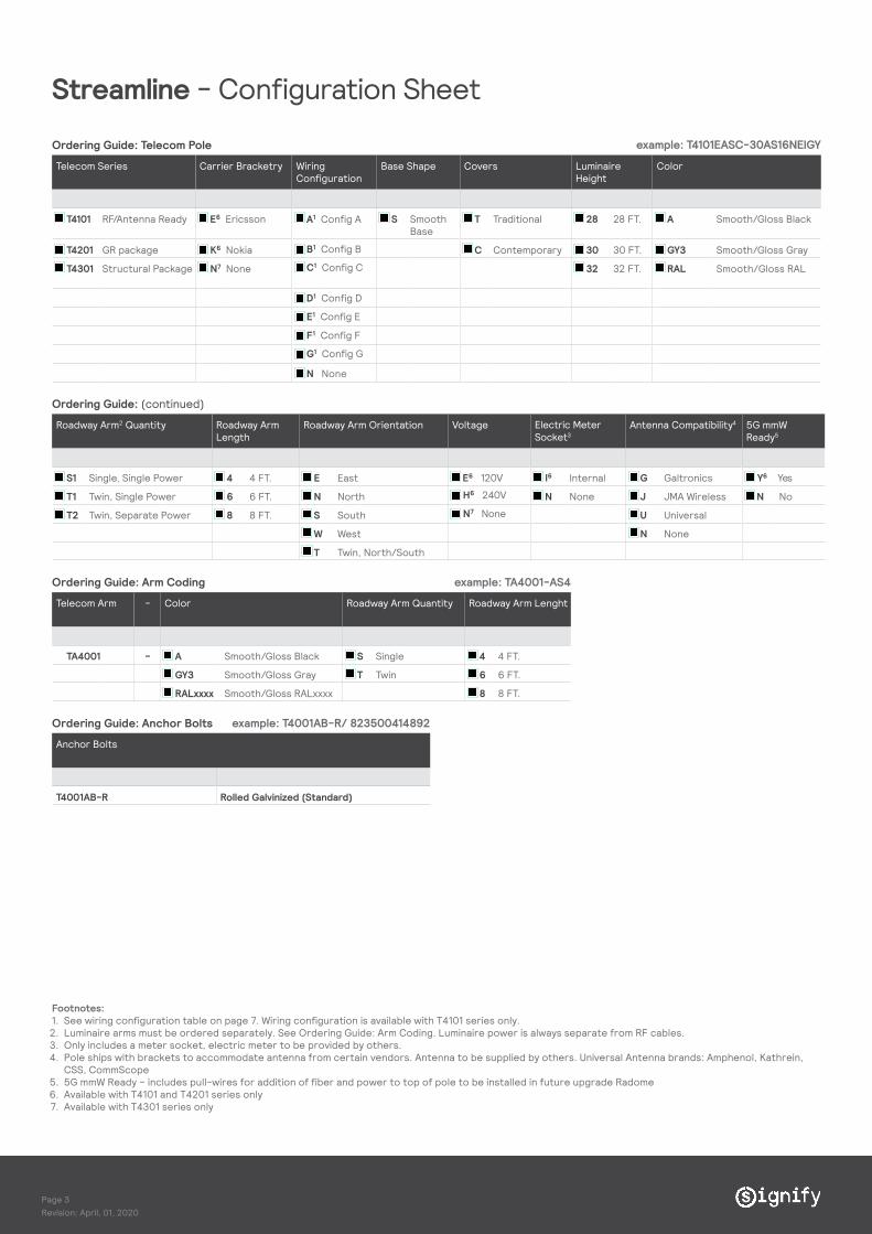
Ordering Guide: Telecom Pole
Telecom Series Carrier Bracketry Wiring Configuration
Base Shape Covers Luminaire Height
Color
T4101 RF/Antenna Ready E6 Ericsson A1 Config A S Smooth Base
T Traditional 28 28 FT. A Smooth/Gloss Black
T4201 GR package K6 Nokia C Contemporary 30 30 FT. GY3 Smooth/Gloss Gray
T4301 Structural Package N7 None 32 32 FT. RAL
Ordering Guide: (continued)
Roadway Arm2 Quantity Roadway Arm Length
Roadway Arm Orientation Voltage Electric Meter Socket3
Antenna Compatibility4 5G mmW Ready5
S1 Single, Single Power 4 4 FT. E East E6 120V I6 Internal G Galtronics Y6 Yes
T1 Twin, Single Power 6 6 FT. N North N None J JMA Wireless N No
T2 Twin, Separate Power 8 8 FT. S South U Universal
W West N None
T Twin, North/South
Ordering Guide: Arm Coding
Telecom Arm - Color Roadway Arm Quantity Roadway Arm Lenght
TA4001 - A Smooth/Gloss Black S Single 4 4 FT.
GY3 Smooth/Gloss Gray T Twin 6 6 FT.
RALxxxx Smooth/Gloss RALxxxx 8 8 FT.
Ordering Guide: Anchor Bolts
Anchor Bolts
T4001AB-R Rolled Galvinized (Standard)
example: T4101EASC-30AS16NEIGY
example: TA4001-AS4
example: T4001AB-R/ 823500414892
Footnotes: 1. See wiring configuration table on page 7. Wiring configuration is available with T4101 series only.2. Luminaire arms must be ordered separately. See Ordering Guide: Arm Coding. Luminaire power is always separate from RF cables.3. Only includes a meter socket, electric meter to be provided by others.4. Pole ships with brackets to accommodate antenna from certain vendors. Antenna to be supplied by others. Universal Antenna brands: Amphenol, Kathrein,
CSS, CommScope 5. 5G mmW Ready – includes pull-wires for addition of fiber and power to top of pole to be installed in future upgrade Radome 6. Available with T4101 and T4201 series only7. Available with T4301 series only
Streamline - Configuration Sheet
B1 Config B
C1 Config C
D1 Config D
E1 Config E
F1 Config F
N None
G1 Config G
H6 240V
N7 None
Smooth/Gloss RAL
Page 3 Revision: April, 01, 2020

Streamline - Wind load Spec
Pole Data – EPA Rating(Maximum Weight per Arm)Telecom Arm Lenght
(FT.)HT. 80 MPH 90 MPH 100 MPH 110 MPH 120 MPH 130 MPH 140 MPH 150 MPH
EPA (MAX. weight)
TA4001-_-S4 4' Single 3.55 (106.50) 3.25 (97.50) 2.5 (85.50) 2.5 (75.00) 2.15 (64.50)
TA4001-_-S6 6' Single 2.15 (64.50) 2.1 (63.00) 1.8 (54.00) 1.55 (46.50) N/A N/A
TA4001-_-S8 8' Single 1.35 (64.50) 1.25 (37.50) N/A N/A N/A N/A
TA4001-_-T4 4' Twin 3.55 (106.50) 3.25 (97.50) 2.85 (85.50) 2.5 (75.00) 2.15 (64.50)
TA4001-_-T6 6' Twin 2.15 (64.50) 2.1 (63.00) 1.8 (54.00) 1.55 (46.50) N/A N/A
TA4001-_-T8 8' Twin 1.35 (40.50) 1.25 (37.50) N/A N/A N/A N/A
Note: The recommended method for calculating EPA (Effective Projected Area) is in accordance with AASHTO 2009 standards, three second gusts and 50 year winds. EPA ratings shown are applied to arms and assume 30 lbs./sq. ft. load. Important: Do not obstruct space between anchor plate and concrete base.
28-3
2FT.
Page 4 Revision: April, 01, 2020

BREV
PART NO.
DWG NO.SCALESIZE SHEET
2 of 2B 1:4
443580153143106892-001* DO NOT SCALE THIS DRAWING *
Streamline - Drawings
Base Plate
WIREWAY OPENING10.0 in. [254 mm]
STREET SIDE
HOUSE SIDE
RA
DIO
BA
Y DO
OR
AU
XILI
AR
Y B
AY
DO
OR
BOLT CIRCLE (B.C.)18.0 in.
[457 mm]
18.00in SQ.457mm
8'-0"
17'-0"
14.5
19.7
7.5
14.0MAX.
15.0
9.0
8'-6"
28'-0thru 32'-0"
40'-8"
36 MAX.
2 PC. SAND CAST ALUMINUM TRANSITION COVER
EXTRUDED ALUMINUM ACCESS DOORS
2 PC. SAND CAST ALUMINUM ANCHOR BOLT COVER
7'-9" GALVANIZED STEEL
STRUCTURAL BASE
24'-3" GALVANIZED STEEL MID-POLE
8'-7"ANTENNA &
STRUCTURAL SUPPORT
Streamline with Twin Arm Streamline with Single Arm
Page 5 Revision: April, 01, 2020

© 2019 Signify HoldingCONFIDENTIALAll rights are reserved. Reproduction in whole or part is prohibited without the written consent of the copyright owner.
96.00
REV DESCRIPTION DATE BY ECN # CHK BY
1234
D
C
B
A
123
D
C
B
A
4
FLL INSERT THE MATERIAL DESCRIP. HERE - MULTI-LINE TEXT
WEIGHT
CONTROLLED DOCUMENTCheck ERP System Screen for Latest Revision
UNLESS OTHERWISE SPECIFIED:*ALL DIMENSIONS ARE IN INCHES.*ALL THREADS ARE UNC-2B OR UNF-2B AFTER COATING*ALL THREADS ARE TO BE VERIFIED WITH A THREAD GAGE
11/11/2019DWN BY
CHK BY
APPROVED BY
DATE
DATE
DATE
MATERIAL
DESCRIPTION
PART NO.
DWG NO.SCALESIZE SHEET
1 of 1D 1:8
Streamline Arm Spec * DO NOT SCALE THIS DRAWING *
4FT., 6 FT., AND 8FT. O.A DIMENSIONS
THIRDANGLE
PROJECTION
96.00
2.38
32.00
72.00
2.38
24.00
48.00
2.38
16.35
Streamline - Roadway Arms
7.00
4.00
4X .55
8.50
5.50
4ft Arm 6ft Arm
8ft Arm Mount plate
Page 6 Revision: April, 01, 2020

Streamline - Radio Configurations
Wiring Configurations ERICSSON NOKIA
A AWS 4T4R, PCS 4T4R 2 2 0 1 1 1
B AWS 2T2R, CBRS 4T4R, PCS 2T2R 1 1 2 0
C AWS 4T4R, CBRS 4T4R 2 2 0 1 1 1
D PCS 4T4R, CBRS 4T4R 2 2 0 1 1 1
E AWS 2T2R, LAA 2T2R, PCS 2T2R CBRS 2T2R 1 1 1 1 0 Configuration not available
F AWS 4T4R, CBRS 4T4R, PCS 4T4R Configuration not available 1 1 1 0
G AWS 4T4R, LAA 2T2R, PCS 4T4R 1 1 1* 0
Co
nfigu
rati
on
E///
220
3 A
WS
E///
220
3 P
CS
E///
220
5 L
AA
E///
220
8 C
BR
S
# o
f o
pen
slo
ts
No
kia
AH
FB A
WS
No
kia
AH
IB P
CS
No
kia
AZ
RB
LA
A
No
kia
AZ
RB
CB
RS
# o
f o
pen
slo
ts
Rad
io
Co
nfigu
rati
ons
Configuration not available
Configuration not available
Page 7 Revision: April, 01, 2020

© 2019 Signify Holding. All rights reserved. This document may be subjected to change. No representation or warrenty as to the accuracy or completeness of the information included herein is given and any liability for any action in reliance thereon is disclaimed. All trademarks are owned by Signify Holding or their respective owners.
Signify North America Corporation200 Franklin Square Drive.
Somerset. NJ08873Telephone 855-486-2216
www.signify.com
Copyright © 2022 FDOKUMEN

