


Bahasa
Halaman
Hukum


Dokumentation | EN
BC9191-0000 und BC9191-0100Room Controller for Buiding Automation
2021-11-18 | Version: 3.0.0


Table of contents
BC9191-0000 und BC9191-0100 3Version: 3.0.0
Table of contents1 Foreword .................................................................................................................................................... 7
1.1 Notes on the documentation.............................................................................................................. 71.2 Safety instructions ............................................................................................................................. 81.3 Notes on information security ............................................................................................................ 91.4 Documentation issue status .............................................................................................................. 9
2 Product overview..................................................................................................................................... 102.1 Introduction...................................................................................................................................... 102.2 Extension of the BC9191 with Bus Terminals ................................................................................. 112.3 Technical data ................................................................................................................................. 122.4 The Beckhoff Bus Terminal system................................................................................................. 14
3 Installation................................................................................................................................................ 163.1 Instructions for ESD protection........................................................................................................ 163.2 Assembly ......................................................................................................................................... 17
3.2.1 Dimensions ...................................................................................................................... 173.2.2 Installation position and minimum distances ................................................................... 173.2.3 Installation on mounting rails ........................................................................................... 19
3.3 Wiring............................................................................................................................................... 203.3.1 Internal power supply, GND, potential groups, insulation test and PE ............................ 203.3.2 BC9191-0000 - Terminal strip X1 .................................................................................... 233.3.3 BC9191-0100 - Terminal strip X1 .................................................................................... 253.3.4 Terminal strips X2 and X3 ............................................................................................... 273.3.5 Ethernet topologies.......................................................................................................... 293.3.6 Ethernet connection......................................................................................................... 303.3.7 Ethernet cable.................................................................................................................. 31
3.4 Disposal ........................................................................................................................................... 32
4 Parameterization and Commissioning .................................................................................................. 334.1 Start-up behavior ............................................................................................................................. 334.2 DIP switch........................................................................................................................................ 344.3 IP address ....................................................................................................................................... 36
4.3.1 IP address - overview ...................................................................................................... 364.3.2 Configuration with KS2000 .............................................................................................. 364.3.3 Address Configuration via TwinCAT System Manager.................................................... 374.3.4 Setting the address via BootP server .............................................................................. 374.3.5 Setting the address via DHCP server .............................................................................. 394.3.6 Auto IP address ............................................................................................................... 394.3.7 Subnet mask.................................................................................................................... 394.3.8 Testing the IP address..................................................................................................... 404.3.9 Reading the MAC-ID........................................................................................................ 404.3.10 Security settings .............................................................................................................. 41
4.4 BC configuration .............................................................................................................................. 414.4.1 Overview.......................................................................................................................... 414.4.2 Finding the Bus Terminal Controller with the TwinCAT System Manager....................... 434.4.3 Creating a TwinCAT configuration................................................................................... 45

Table of contents
BC9191-0000 und BC9191-01004 Version: 3.0.0
4.4.4 Downloading a TwinCAT configuration............................................................................ 464.4.5 Uploading a TwinCAT configuration ................................................................................ 484.4.6 Resources in the Bus Terminal Controller ....................................................................... 494.4.7 Ethernet ........................................................................................................................... 524.4.8 K-bus ............................................................................................................................... 544.4.9 PLC.................................................................................................................................. 57
4.5 Configuration of the integrated I/Os................................................................................................. 604.5.1 Analog I/Os ...................................................................................................................... 60
4.6 KS2000............................................................................................................................................ 614.6.1 KS2000 - Introduction ...................................................................................................... 614.6.2 Representation of the integrated inputs and outputs ....................................................... 63
5 Programming ........................................................................................................................................... 645.1 TwinCAT PLC.................................................................................................................................. 645.2 TwinCAT PLC - Error codes ............................................................................................................ 645.3 Remanent data ................................................................................................................................ 675.4 Persistent data................................................................................................................................. 685.5 Allocated flags ................................................................................................................................. 685.6 Local process image in delivery state (default config) ..................................................................... 695.7 Mapping the Bus Terminals ............................................................................................................. 705.8 Local process image in the TwinCAT configuration ........................................................................ 715.9 Creating a boot project .................................................................................................................... 715.10 Communication between TwinCAT and BX/BCxx50....................................................................... 725.11 Program transfer.............................................................................................................................. 73
5.11.1 Program Transfer via Ethernet ........................................................................................ 735.11.2 Up- and downloading of programs................................................................................... 75
5.12 Libraries........................................................................................................................................... 795.12.1 Libraries overview............................................................................................................ 79
6 PLC program............................................................................................................................................ 806.1 Fan controller with room temperature control .................................................................................. 806.2 Description of the POUs .................................................................................................................. 83
6.2.1 Description of the internal function blocks and subprograms .......................................... 836.2.2 ADS access of a higher-level controller......................................................................... 1016.2.3 BC9191 in Master /Slave mode ..................................................................................... 104
7 Ethernet .................................................................................................................................................. 1197.1 Introduction to the system ............................................................................................................. 119
7.1.1 Ethernet ......................................................................................................................... 1197.2 Modbus TCP.................................................................................................................................. 121
7.2.1 ModbusTCP Protocol..................................................................................................... 1217.2.2 ModbusTCP diagnostic.................................................................................................. 121
7.3 Modbus TCP Functions ................................................................................................................. 1227.3.1 Read holding register (Function 3) ................................................................................ 1227.3.2 Read input register (Function 4) .................................................................................... 1227.3.3 Preset single register (Function 6)................................................................................. 1237.3.4 Preset single register (Function 16)............................................................................... 1247.3.5 Read / write registers (Function 23)............................................................................... 124

Table of contents
BC9191-0000 und BC9191-0100 5Version: 3.0.0
7.4 ADS-Communication ..................................................................................................................... 1257.4.1 ADS-Communication ..................................................................................................... 1257.4.2 ADS protocol.................................................................................................................. 1267.4.3 ADS services ................................................................................................................. 1287.4.4 Examples ....................................................................................................................... 129
8 Error handling and diagnostics............................................................................................................ 1358.1 Diagnostics .................................................................................................................................... 1358.2 Diagnostic LEDs ............................................................................................................................ 1368.3 General errors ............................................................................................................................... 1388.4 ADS diagnostics ............................................................................................................................ 139
9 Appendix ................................................................................................................................................ 1429.1 BC9191 - First steps...................................................................................................................... 1429.2 General operating conditions......................................................................................................... 1459.3 Test standards for device testing................................................................................................... 1479.4 Bibliography................................................................................................................................... 1479.5 List of Abbreviations ...................................................................................................................... 1489.6 Support and Service ...................................................................................................................... 149

Table of contents
BC9191-0000 und BC9191-01006 Version: 3.0.0

Foreword
BC9191-0000 und BC9191-0100 7Version: 3.0.0
1 Foreword
1.1 Notes on the documentation
Intended audience
This description is only intended for the use of trained specialists in control and automation engineering whoare familiar with the applicable national standards.It is essential that the documentation and the following notes and explanations are followed when installingand commissioning these components.It is the duty of the technical personnel to use the documentation published at the respective time of eachinstallation and commissioning.
The responsible staff must ensure that the application or use of the products described satisfy all therequirements for safety, including all the relevant laws, regulations, guidelines and standards.
Disclaimer
The documentation has been prepared with care. The products described are, however, constantly underdevelopment.
We reserve the right to revise and change the documentation at any time and without prior announcement.
No claims for the modification of products that have already been supplied may be made on the basis of thedata, diagrams and descriptions in this documentation.
Trademarks
Beckhoff®, TwinCAT®, TwinCAT/BSD®, TC/BSD®, EtherCAT®, EtherCAT G®, EtherCAT G10®, EtherCAT P®,Safety over EtherCAT®, TwinSAFE®, XFC®, XTS® and XPlanar® are registered trademarks of and licensed byBeckhoff Automation GmbH. Other designations used in this publication may be trademarks whose use bythird parties for their own purposes could violate the rights of the owners.
Patent Pending
The EtherCAT Technology is covered, including but not limited to the following patent applications andpatents: EP1590927, EP1789857, EP1456722, EP2137893, DE102015105702 with correspondingapplications or registrations in various other countries.
EtherCAT® is registered trademark and patented technology, licensed by Beckhoff Automation GmbH,Germany.
Copyright
© Beckhoff Automation GmbH & Co. KG, Germany.The reproduction, distribution and utilization of this document as well as the communication of its contents toothers without express authorization are prohibited.Offenders will be held liable for the payment of damages. All rights reserved in the event of the grant of apatent, utility model or design.

Foreword
BC9191-0000 und BC9191-01008 Version: 3.0.0
1.2 Safety instructions
Safety regulations
Please note the following safety instructions and explanations!Product-specific safety instructions can be found on following pages or in the areas mounting, wiring,commissioning etc.
Exclusion of liability
All the components are supplied in particular hardware and software configurations appropriate for theapplication. Modifications to hardware or software configurations other than those described in thedocumentation are not permitted, and nullify the liability of Beckhoff Automation GmbH & Co. KG.
Personnel qualification
This description is only intended for trained specialists in control, automation and drive engineering who arefamiliar with the applicable national standards.
Description of instructions
In this documentation the following instructions are used. These instructions must be read carefully and followed without fail!
DANGERSerious risk of injury!Failure to follow this safety instruction directly endangers the life and health of persons.
WARNINGRisk of injury!Failure to follow this safety instruction endangers the life and health of persons.
CAUTIONPersonal injuries!Failure to follow this safety instruction can lead to injuries to persons.
NOTEDamage to environment/equipment or data lossFailure to follow this instruction can lead to environmental damage, equipment damage or data loss.
Tip or pointerThis symbol indicates information that contributes to better understanding.
Foreword
BC9191-0000 und BC9191-0100 9Version: 3.0.0
1.3 Notes on information securityThe products of Beckhoff Automation GmbH & Co. KG (Beckhoff), insofar as they can be accessed online,are equipped with security functions that support the secure operation of plants, systems, machines andnetworks. Despite the security functions, the creation, implementation and constant updating of a holisticsecurity concept for the operation are necessary to protect the respective plant, system, machine andnetworks against cyber threats. The products sold by Beckhoff are only part of the overall security concept.The customer is responsible for preventing unauthorized access by third parties to its equipment, systems,machines and networks. The latter should be connected to the corporate network or the Internet only ifappropriate protective measures have been set up.
In addition, the recommendations from Beckhoff regarding appropriate protective measures should beobserved. Further information regarding information security and industrial security can be found in ourhttps://www.beckhoff.com/secguide.
Beckhoff products and solutions undergo continuous further development. This also applies to securityfunctions. In light of this continuous further development, Beckhoff expressly recommends that the productsare kept up to date at all times and that updates are installed for the products once they have been madeavailable. Using outdated or unsupported product versions can increase the risk of cyber threats.
To stay informed about information security for Beckhoff products, subscribe to the RSS feed at https://www.beckhoff.com/secinfo.
1.4 Documentation issue statusVersion Comment3.0.0 • Migration
• Chapter Notes on ESD protection added• Chapter Disposal added• Chapter Notes on information security added• Safety instructions adapted to IEC 82079-1• New title page
2.0.0 • Chapter Programming and Parameterization and commissioning / IP address added1.1.0 • Chapter BC9191 in master/slave mode extended1.0.0 • First release
Firmware BC9191
The label under the coupler will tell you which firmware is installed on the Bus Coupler in delivery state.
Example:1416 SW:3.4 HW:6.1 0000The firmware in the example is 3.4.
Firmware Description3.4 Modbus UDP implemented3.3 FW 3.3 was not used3.2 Optimizations DHCP3.1 First firmware version from series delivery BC9191-0100, Modbus TCP : Client functionality
implemented3.0 First firmware version from series delivery BC9191

Product overview
BC9191-0000 und BC9191-010010 Version: 3.0.0
2 Product overview
2.1 Introduction
Fig. 1: BC9191
The BC9191 is a room controller in a compact design with decentralized intelligence.
The integrated digital and analog connections already cover the typical standard functionalities of roomtemperature control.The K-bus interface enables extensions from the entire signal spectrum of the Beckhoff Bus Terminalsystem.
Two Ethernet interfaces are available for communication with a higher-level master computer or otherBC9191s.
Furthermore, an additional sub-bus is available with both variants of the BC9191:
Variants of the BC9191
The BC9191 is available in two variants. These differ by the sub-bus, the memory extension and the cycletime.
• The variant BC9191-0000 [ 23] provides a CAN bus for connecting the KL6583 EnOcean transceiver.
• The variant BC9191-0100 [ 25] provides an RS485 interface for the efficient connection of roomcontrol units.

Product overview
BC9191-0000 und BC9191-0100 11Version: 3.0.0
Bus Terminal Controller BC9191-0000 BC9191-0100Sub-Bus EnOcean KL6853 RS485 / Modbus RTU / DMXPLC memory 48 kbyte 128 kbyteData memory 32 kbyte 128 kbytePLC cycle time(for 1000 commands without I/O cycle and K-bus)
approx. 0.9 ms approx. 0.7 ms
2.2 Extension of the BC9191 with Bus Terminals
Power supply of additional Bus Terminals and termination of the K-bus
The BC9191 does not have power contacts. Additionally inserted K-bus terminals must therefore be suppliedwith voltage by a power supply terminal.If a further potential group is required, a further power supply terminal must be provided as in the example. The K-bus must be terminated with the KL9010 end terminal. If the BC9191 is used without further terminals,do not use an end terminal, but insert the K-bus cover included in the scope of delivery.
Fig. 2: Extension of the BC9191 with Bus Terminals

Product overview
BC9191-0000 und BC9191-010012 Version: 3.0.0
2.3 Technical dataBus Terminal Controller BC9191-0000 BC9191-0100Number of Bus Terminals 64Maximum fieldbus byte number 512 bytes input, 512 bytes outputDigital inputs 3, for connecting potential-free contacts (e.g. for window contact,
dew point sensor, occupancy sensor)Digital outputs 1 x LED output, constant current 10 mA , max. 24 V (e.g. for LED
occupancy signal)1 x 230 VAC, 10 A, relay (e.g. for air heater)3 x 230 VAC, 1 A, relay (e.g. for 3-stage fan)2 x 230 VAC, 1 A, triac (e.g. for valves for heating and cooling)
Analog inputs 1 x PT/Ni1000 (PT1000: -20...+60 °C, NI1000: -15...+55 °C) for airtemperature measurement1 x resistance measurement for setpoint setting ( 0...10 kOhm)3 x 0...10 V (e.g. for CO2 sensor, air quality sensor, light sensor)
Analog outputs 2 x 0...10 V (e.g. air volume controller)Sub-bus systems 1 x K-bus
1 x system bus for KL6583(EnOcean)
1 x K-bus1 x RS485 (e.g. Modbus-RTU/DMX)
Dielectric strength 500 V (supply voltage/fieldbus)Supply voltage 110 ... 240 VAC
Current consumption typically 80 mA (230 V), max. 220 mA (85 V)Power loss max. 15 W, typically 8 W (without 24 V DC consumers and without
further bus terminals)K-bus power supply max. 200 mA24VDC power supply max. 100 mAWeight approx. 350 gPermissible ambient temperaturerange during operation
0 °C ... +55 °C
Permissible ambient temperaturerange during storage
-25 °C ... +85 °C
Permissible relative humidity max. 95 %, no condensationVibration / shock resistance conforms to EN 60068-2-6 / EN 60068-2-27EMC immunity / emission conforms to EN 61000-6-2 / EN 61000-6-4Correct installation position vertically on a mounting rail mounted horizontally on the wall (see
chapter Installation position [ 17])Protection class IP20Approvals/markings* CE UKCA, EAC
*) Real applicable approvals/markings see type plate on the side (product marking).

Product overview
BC9191-0000 und BC9191-0100 13Version: 3.0.0
PLC BC9191-0000 BC9191-0100Programming/configuration with TwinCAT via Ethernet (TwinCAT 2.11 Build 2034 or higher, no
TC3)Program memory 48 kbyte (minus task-
configuration minus POUsduring online change)
128 kbyte (minus task-configuration minus POUs duringonline change)
Data memory 32 kbyte 128 kbyteSource code memory 256 kbyteRemanent flags 2 kbytePersistent data 1000 bytesINPUT 2 kbyteOUTPUT 2 kbyteFLAG 4 kbytemax. variable size 16 kbyteMax. POUs Limited by memoryPLC cycle time for 1,000 commands(without I/O cycle, K-bus)
approx. 0.9 ms approx. 0.7 ms
Number of runtime systems 1Programming languages IEC 6-1131-3 (IL, LD, FBD, ST, SFC)Online Change yes
Fieldbus BC9191-0000 BC9191-0100Fieldbus EthernetEthernet connection 2 x RJ45 (internal switch)Auto-crossing yesData transfer rate 10/100 MbaudProtocols Modbus TCP/IP, Ethernet TCP/IP, Beckhoff ADS via TCP and UDPData transfer medium 4 x 2 twisted-pair copper cable; category 3 (10 Mbaud), category 5
(100 Mbaud)Distance between modules 100 m (distributor hub to BC9191)
Line: max. 100 m between two BC9191Topology - star wiring
- line wiring (20 x BC9191 in line maximum)Number of I/O modules only limited by the IP address rangeNumber of I/O points depending on the higher-level controller
Connections BC9191-0000 BC9191-0100Number of ADS connections via TCP/IP
5
Number of ADS connections via UDP/IP
1
Number of ModbusTCP connections 3SMTP (Simple Mail Transfer Protocol) yesSNTP (Simple Network Time Protocol) yesBootP/DHCP yes/yesUDP socket connections 3TCP socket connections 3

Product overview
BC9191-0000 und BC9191-010014 Version: 3.0.0
Try using as few TCP/IP connections as possibleThe number of TCP/IP connections should be reduced to a minimum. The fewer TCP/IP connec-tions you use, the more time the BC9191 has for its actual task. If possible, use communication viaADS instead of TCP/IP or UDP/IP communication.Communicate with "reasonable" time intervals for TCP/IP and for UDP/IP connections.Example:The task time of the BC9191 is 20 ms. In this case, you should not communicate with the BC9191more often than every 40 ms.
2.4 The Beckhoff Bus Terminal system
Up to 256 Bus Terminals, with 1 to 16 I/O channels per signal form
The Bus Terminal system is the universal interface between a fieldbus system and the sensor / actuatorlevel. A unit consists of a Bus Coupler as the head station, and up to 64 electronic series terminals, the lastone being an end terminal. Up to 255 Bus Terminals can be connected via the K-Bus extension. For eachtechnical signal form, terminals are available with one, two, four or eight I/O channels, which can be mixedas required. All the terminal types have the same mechanical construction, so that difficulties of planning anddesign are minimized. The height and depth match the dimensions of compact terminal boxes.
Decentralized wiring of each I/O level
Fieldbus technology allows more compact forms of controller to be used. The I/O level does not have to bebrought to the controller. The sensors and actuators can be wired decentrally, using minimum cable lengths.The controller can be installed at any location within the plant.
Industrial PCs as controllers
The use of an Industrial PC as the controller means that the operating and observing element can beimplemented in the controller's hardware. The controller can therefore be located at an operating panel, in acontrol room, or at some similar place. The Bus Terminals form the decentralized input/output level of thecontroller in the control cabinet and the subsidiary terminal boxes. The power sector of the plant is alsocontrolled over the bus system in addition to the sensor/actuator level. The Bus Terminal replaces theconventional series terminal as the wiring level in the control cabinet. The control cabinet can have smallerdimensions.
Bus Couplers for all usual bus systems
The Beckhoff Bus Terminal system unites the advantages of a bus system with the possibilities of thecompact series terminal. Bus Terminals can be driven within all the usual bus systems, thus reducing thecontroller parts count. The Bus Terminals then behave like conventional connections for that bus system. Allthe performance features of the particular bus system are supported.
Mounting on standardized mounting rails
The installation is standardized thanks to the simple and space-saving mounting on a standardized mountingrail (EN 60715, 35 mm) and the direct wiring of actuators and sensors, without cross connections betweenthe terminals. The consistent labelling scheme also contributes.
The small physical size and the great flexibility of the Bus Terminal system allow it to be used wherever aseries terminal is also used. Every type of connection, such as analog, digital, serial or the direct connectionof sensors can be implemented.
Modularity
The modular assembly of the terminal strip with Bus Terminals of various functions limits the number ofunused channels to a maximum of one per function. The presence of two channels in one terminal is theoptimum compromise of unused channels and the cost of each channel. The possibility of electrical isolationthrough potential feed terminals also helps to keep the number of unused channels low.

Product overview
BC9191-0000 und BC9191-0100 15Version: 3.0.0
Display of the channel state
The integrated LEDs show the state of the channel at a location close to the sensors and actuators.
K-Bus
The K-Bus is the data path within a terminal strip. The K-Bus is led through from the Bus Coupler through allthe terminals via six contacts on the terminals' side walls. The end terminal terminates the K-Bus. The userdoes not have to learn anything about the function of the K-Bus or about the internal workings of theterminals and the Bus Coupler. Many software tools that can be supplied make project planning,configuration and operation easy.
Potential feed terminals for isolated groups
The operating voltage is passed on to following terminals via three power contacts. You can divide theterminal strip into arbitrary isolated groups by means of potential feed terminals. The potential feed terminalsplay no part in the control of the terminals, and can be inserted at any locations within the terminal strip.
Up to 64 Bus Terminals can be used in a terminal block, with optional K-Bus extension for up to 256 BusTerminals. This count does include potential feed terminals, but not the end terminal.
Bus Couplers for various fieldbus systems
Various Bus Couplers can be used to couple the electronic terminal strip quickly and easily to differentfieldbus systems. It is also possible to convert to another fieldbus system at a later time. The Bus Couplerperforms all the monitoring and control tasks that are necessary for operation of the connected BusTerminals. The operation and configuration of the Bus Terminals is carried out exclusively by the BusCoupler. Nevertheless, the parameters that have been set are stored in each Bus Terminal, and are retainedin the event of voltage drop-out. Fieldbus, K-Bus and I/O level are electrically isolated.
If the exchange of data over the fieldbus is prone to errors or fails for a period of time, register contents (suchas counter states) are retained, digital outputs are cleared, and analog outputs take a value that can beconfigured for each output when commissioning. The default setting for analog outputs is 0 V or 0 mA. Digitaloutputs return in the inactive state. The timeout periods for the Bus Couplers correspond to the usualsettings for the fieldbus system. When converting to a different bus system it is necessary to bear in mind theneed to change the timeout periods if the bus cycle time is longer.
The interfaces
A Bus Coupler has six different methods of connection. These interfaces are designed as plug connectorsand as spring-loaded terminals.
Installation
BC9191-0000 und BC9191-010016 Version: 3.0.0
3 Installation
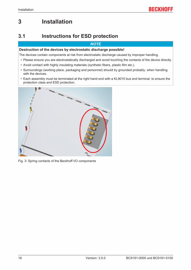
3.1 Instructions for ESD protectionNOTE
Destruction of the devices by electrostatic discharge possible!The devices contain components at risk from electrostatic discharge caused by improper handling.• Please ensure you are electrostatically discharged and avoid touching the contacts of the device directly.• Avoid contact with highly insulating materials (synthetic fibers, plastic film etc.).• Surroundings (working place, packaging and personnel) should by grounded probably, when handling
with the devices.• Each assembly must be terminated at the right hand end with a KL9010 bus end terminal, to ensure the
protection class and ESD protection.
Fig. 3: Spring contacts of the Beckhoff I/O components

Installation
BC9191-0000 und BC9191-0100 17Version: 3.0.0
3.2 Assembly
3.2.1 DimensionsThe BC9191-0000 and the BC9191-0100 are characterized by their low physical volume. The dimensionsgiven apply to both variants.
Fig. 4: Dimensions of the BC9191
If the BC9191-0000 or BC9191-0100 is extended by Bus Terminals, the total width is made up of the width ofthe Bus Terminal Controller, the width of the Bus Terminals used and the KL9010 bus end terminal. Theright-hand cover (5 mm) is then omitted. Depending on design, the Bus Terminals are 12 mm or 24 mmwide. The depth of the Bus Terminals of 68 mm is increased by the front wiring by approx. 5 mm to 10 mmdepending on the wire diameter.
3.2.2 Installation position and minimum distancesNOTE
Mounting specificationsTo ensure optimum function of the BC9191, observe the following specifications when installing it• Installation position• Minimum distances• Ambient temperature
Installation position
Mount the mounting rail horizontally so that the connection surfaces of the snapped-on BC9191 face forward(see figure Minimum distances).The BC9191 is then ventilated from bottom to top, which enables optimum cooling of the electronics byconvection. "From below" is relative to the acceleration of gravity.

Installation
BC9191-0000 und BC9191-010018 Version: 3.0.0
Fig. 5: BC9191 - Minimum distances
Minimum distances
When mounting, adhere to the minimum distances to other components and the walls of the control cabinetor terminal box employed as specified in the illustration above.
Ambient temperature
Ensure adequate ventilation so that the permissible ambient temperature range for the BC9191 ismaintained in the control cabinet or terminal box employed (see Technical data [ 12])!

Installation
BC9191-0000 und BC9191-0100 19Version: 3.0.0
3.2.3 Installation on mounting rails WARNING
Risk of injury through electric shock and damage to the device!Bring the BC9191 and the Bus Terminals into a safe, de-energized state before starting installation, disas-sembly or wiring!
Assembly
The BC9191 is snapped onto standard 35 mm mounting rails (DIN rails according to EN 60715) by applyingslight pressure:
1. Press the Bus Terminal Controller onto the mounting rail.2. With slight pressure, two latching lugs on the right-hand side then automatically engage in the mount-
ing rail.3. On the left side, insert a screwdriver into the upper notch of the orange latch and engage the latch with
a twisting motion.4. Bus Terminals are now installed. To do this, plug the components together with tongue and groove
and push the terminals against the mounting rail until the latch audibly engages on the mounting rail.If you first snap the terminals onto the mounting rail and then push them next to each other without thetongue and groove interlocking, no functional connection will be established! When correctly assem-bled, no significant gap should be visible between the housings.
5. If no Bus Terminals are attached, plug the K-bus cover with tongue and groove onto the BC9191 andpush it against the mounting rail until the latch audibly engages on the mounting rail.
Nature and source of the dangerThe locking mechanism of the terminals and couplers protrudes into the profile of the mounting rail.When installing the components, make sure that the locking mechanism doesn't come into conflictwith the fixing bolts of the mounting rail. For fastening mounting rails with a height of 7.5 mm underthe terminals and couplers, use flat fastening components such as countersunk head screws orblind rivets.
Disassembly
The BC9191 is secured to the mounting rail on the left-hand side by an orange rotary latch and on the right-hand side by a pull latch, which must be released for removal:
1. Insert a screwdriver into the lower recess of the orange rotary latch and release it by pressing on thescrewdriver. The retaining lug of the orange rotary latch then releases the mounting rail.
2. Lever the unlatching hook on the right-hand side of the BC9191 upwards with a screwdriver. An inter-nal mechanism pulls the two latching lugs from the DIN rail back into the terminal module,
3. The lock with the mounting rail is now released and the Bus Terminal Controller can be pulled from themounting rail without excessive force.
Connections within a Bus Terminal block
The electric connections between the Bus Terminal Controller and the Bus Terminals are automaticallyrealized by joining the components:
• The six spring contacts of the K-bus deal with the transfer of the data and the supply of the BusTerminal electronics.
• The power contacts deal with the supply for the field electronics and thus represent a supply rail withinthe Bus Terminal block. The power contacts of the BC9191 must be supplied via potential supplyterminals (KL9xxx).

Installation
BC9191-0000 und BC9191-010020 Version: 3.0.0
Power contactsDuring the design of a Bus Terminal block, the pin assignment of the individual Bus Terminals mustbe taken account of, since some types (e.g. analog Bus Terminals or digital 4-channel Bus Termi-nals) do not or not fully loop through the power contacts. Power supply terminals (KL91xx, KL92xxand EL91xx, EL92xx) interrupt the power contacts and thus represent the start of a new supply rail.
3.3 Wiring
3.3.1 Internal power supply, GND, potential groups, insulation testand PE
Internal power supply
The BC9191 has an integrated wide-range power supply unit:
• The AC input voltage may be in the range of 110 VAC to 240 VAC.• The integrated power supply unit generates all internally required voltages and also the electrically
isolated voltage 24 VDC (pin X1/16).• All GND connections are internally interconnected. To avoid interference, GND is capacitively
connected to PE and the spring contacts for the mounting rail.• The 24 VDC at pin X1/16, which is electrically isolated from the mains, can be loaded with max. 100 mA.
Fig. 6: BC9191 - Schematic diagram of the internal power supply

Installation
BC9191-0000 und BC9191-0100 21Version: 3.0.0
Potential groups
The BC9191 does not have power contacts. The power contacts of connected Bus Terminals must thereforebe supplied by a power supply terminal. If an additional potential group is required, an additional powersupply terminal must be provided, as in the example.
Fig. 7: BC9191 - Supply of the power contacts of connected Bus Terminals
Insulation testing
The connection between Bus Coupler / Bus Terminal Controller and Bus Terminals is realized automaticallyby latching the components. The transfer of the data and the supply voltage for the intelligent electronics inthe Bus Terminals is performed by the K-bus. The supply of the field electronics is performed through thepower contacts. Plugging together the power contacts creates a supply rail. Since some Bus Terminals (e.g.analog Bus Terminals or digital 4-channel Bus Terminals) do not loop through these power contacts or notcompletely, the pin assignments of the Bus Terminals must be observed.
The power supply terminals interrupt the power contacts, and represent the start of a new supply rail.
PE power contacts
The power contact labeled PE can be used as a protective earth. The contact is leading for safety reasonswhen mated and can dissipate short circuit currents up to 125 A.

Installation
BC9191-0000 und BC9191-010022 Version: 3.0.0
Fig. 8: Power contact on the left
It should be noted that, for reasons of electromagnetic compatibility, the PE contacts are capacitivelycoupled to the mounting rail. This can both lead to misleading results and to damaging the terminal duringinsulation testing (e.g. breakdown of the insulation from a 230 V power consuming device to the PEconductor). The PE supply line at the Bus Coupler / Bus Terminal Controller must be disconnected for aninsulation test. In order to uncouple further supply locations for the purposes of testing, the power supplyterminals can be pulled at least 10 mm out from the connected group of other terminals. In that case, the PEconductors do not have to be disconnected.
The PE power contact must not be used for other potentials.

Installation
BC9191-0000 und BC9191-0100 23Version: 3.0.0
3.3.2 BC9191-0000 - Terminal strip X1
Fig. 9: BC9191-0000 - Terminal strip X1 with interface for enocean
Terminal point Designation Connection Comment1 DI 1 Input for switching contact 1 For potential-free contact, e.g. window contact2 GND GND GND for switching contact 13 DI 2 Input for switching contact 2 For potential-free contact, e.g. dew point4 GND GND GND for switching contact 25 DI 3 Input for switching contact 3 For potential-free contact, e.g. occupancy sensor6 GND GND GND for switching contact 3 and LED7 DO1 LED output Output for LED, e.g. display on room control unit1 with constant
current 10 mA , max. 24 V8 PT1000 Input PT/NI 1000 Connection for PT/NI 10009 GND GND GND for PT/NI 1000 and set value generator10 Potentiometer Potentiometer Connection for setpoint generator (potentiometer 1 kΩ ...10 kΩ)11 AI 1 Analog input 1 Analog input 0…10 V (also usable as 24 V digital input)12 AI 2 Analog input 2 Analog input 0…10 V (also usable as 24 V digital input)13 AI 3 Analog input 3 Analog input 0…10 V (also usable as 24 V digital input)14 GND GND 0 V potential of the analog input signals15 GND GND GND of the data cable for KL6583 (shield of the data cable should
be connected to PE)16 +24 V +24 V direct voltage max. 100 mA for supply of KL6583 (EnOcean) or external operat-
ing device.Internal PolySwitch fuse that can be reset after triggering byswitching off the BC9191 or disconnecting the inadmissible con-sumer.
17 CAN+ CAN + Data cable for KL6583 (EnOcean)18 CAN+ CAN -
See also the EnOcean application example on the BC9191:https://infosys.beckhoff.com/content/1033/tcplclibenocean/html/tcplclibenocean_sample_bc9191.htm

Installation
BC9191-0000 und BC9191-010024 Version: 3.0.0
Potential-free contacts for the digital inputs at terminal strip X1
The digital inputs of the BC9191 expect potential-free contacts at the connections.24 V signals must not be used.
Fig. 10: Block diagram of the integrated digital inputs
Fig. 11: Block diagram LED output

Installation
BC9191-0000 und BC9191-0100 25Version: 3.0.0
3.3.3 BC9191-0100 - Terminal strip X1
Fig. 12: BC9191-0100 - Terminal strip X1 with RS485 interface
Terminal point Designation Connection Comment1 DI 1 Input for switching contact 1 For potential-free contact, e.g. window contact2 GND GND GND for switching contact 13 DI 2 Input for switching contact 2 For potential-free contact, e.g. dew point4 GND GND GND for switching contact 25 DI 3 Input for switching contact 3 For potential-free contact, e.g. occupancy sensor6 GND GND GND for switching contact 3 and LED7 DO1 LED output Output for LED, e.g. display on room control unit1 with constant
current 10 mA , max. 24 V8 PT1000 Input PT/NI 1000 Connection for PT/NI 10009 GND GND GND for PT/NI 1000 and set value generator10 Potentiometer Potentiometer Connection for setpoint generator (potentiometer 1 kΩ ...10 kΩ)11 AI 1 Analog input 1 Analog input 0…10 V (also usable as 24 V digital input)12 AI 2 Analog input 2 Analog input 0…10 V (also usable as 24 V digital input)13 AI 3 Analog input 3 Analog input 0…10 V (also usable as 24 V digital input)14 GND GND 0 V potential of the analog input signals15 GND GND GND of the RS485 (shield of the bus cable should be connected
to PE)16 +24 V +24 V direct voltage max. 100 mA for supply of KL6583 (EnOcean) or external operat-
ing device.Internal PolySwitch fuse that can be reset after triggering byswitching off the BC9191 or disconnecting the inadmissible con-sumer.
17 RS485 RS485/A RS485 data cable, e.g. Modbus RTU18 RS485 RS485/B
See also the application example DMX master with BC9191-0100:https://infosys.beckhoff.com/content/1033/tcplclibdmx/html/sample04.htm

Installation
BC9191-0000 und BC9191-010026 Version: 3.0.0
Potential-free contacts for the digital inputs at terminal strip X1
The digital inputs of the BC9191 expect potential-free contacts at the connections.24 V signals must not be used.
Fig. 13: Block diagram of the digital inputs
The digital output DO1 is intended for direct connection of an LED (10 mA).
Fig. 14: Block diagram LED output

Installation
BC9191-0000 und BC9191-0100 27Version: 3.0.0
3.3.4 Terminal strips X2 and X3
Fig. 15: BC9191-0000 and BC9191-0100 - Terminal strips X2 and X3
Power supply
AC voltage connection
The BC9191 Bus Terminal Controller uses an integrated power supply to generate the supply voltage (Us) of24 VDC required for operation.
The connection for the integrated wide-range power supply unit is made via connections 41 (L), 42 (N) and43 (PE) of terminal strip X3.This supply voltage supplies the electronics of the BC9191 as well as the electronics of the connected BusTerminals via the K-bus.It is electrically isolated from the field level voltage.
Power contacts supply (Up)
If the BC9191 is expanded with Bus Terminals, these must be supplied with Up via a power supply terminal.
Terminal strip X2
Terminalpoint
Designation Connection Comment
20 AO 1 Analog output 1 Analog output 0...10 V, e.g. air volume control21 GND GND GND for analog outputs22 AO 2 Analog output 2 Analog output 0...10 V, e.g. air volume control
Both analog outputs can be loaded with max. 10 mA. A connected actuator should have an internalresistance greater than 1 kOhm.

Installation
BC9191-0000 und BC9191-010028 Version: 3.0.0
Terminal strip X3
Terminalpoint
Designation Connection Comment
30 2 kW K1 Potential-free relay, 230 V~, 10 A, e.g. for electricalauxiliary heating
31 2 kW K2 Potential-free relay, 230 V~, 10 A, e.g. for electricalauxiliary heating
32 FAN 1 Fan Speed 1 Relay output, 230 V~, e.g. low fan speed33 FAN 2 Fan Speed 2 Relay output, 230 V~, e.g. medium fan speed34 FAN 3 Fan Speed 3 Relay output, 230 V~, e.g. high fan speed35 L Phase Supply for relay, fan speeds 1 to 336 N Neutral conductor Neutral conductor, e.g. for fan37 Y1 Triac output 1 Triac output 1, 230 V~, max 1 A, switches at zero
crossing, e.g. "heating" valve38 N N Neutral conductor for triac output 139 Y2 Triac output 2 Triac output 2, 230 V~, max 1 A, switches at zero
crossing, e.g. "cooling" valve40 N N Neutral conductor for triac output 241 L1 L1 Power supply connection 230 V~42 N Neutral conductor Power supply connection N43 FE Functional earth Ground connection, capacitively connected to GND
Installation
BC9191-0000 und BC9191-0100 29Version: 3.0.0
3.3.5 Ethernet topologies
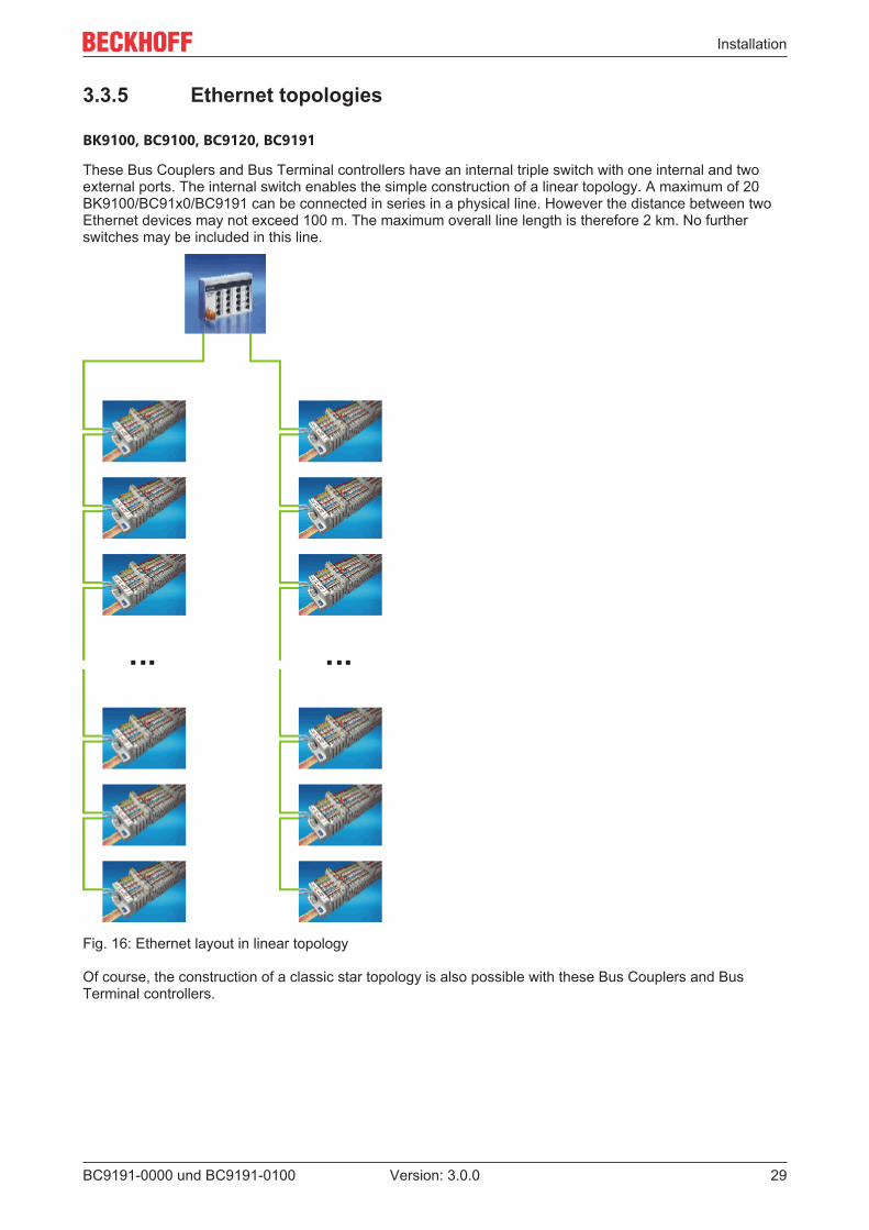
BK9100, BC9100, BC9120, BC9191
These Bus Couplers and Bus Terminal controllers have an internal triple switch with one internal and twoexternal ports. The internal switch enables the simple construction of a linear topology. A maximum of 20BK9100/BC91x0/BC9191 can be connected in series in a physical line. However the distance between twoEthernet devices may not exceed 100 m. The maximum overall line length is therefore 2 km. No furtherswitches may be included in this line.
Fig. 16: Ethernet layout in linear topology
Of course, the construction of a classic star topology is also possible with these Bus Couplers and BusTerminal controllers.

Installation
BC9191-0000 und BC9191-010030 Version: 3.0.0
3.3.6 Ethernet connectionThe connection to the Ethernet bus is made via an RJ45 plug (a Western plug).
Fig. 17: RJ45 plug
Pin assignment of the RJ45 plug
PIN Signal Description1 TD + Transmit +2 TD - Transmit -3 RD + Receive +4 - reserved5 - reserved6 RD - Receive -7 - reserved8 - reserved
Direct connection between PC with Ethernet card and BC9191
The BC9191 supports auto-crossing. A crossed or an uncrossed Ethernet cable can be used to connect aPC directly to the BC9191. The internal switch in the BC9191 detects this automatically.

Installation
BC9191-0000 und BC9191-0100 31Version: 3.0.0
Fig. 18: BC9191 - Auto-crossing
3.3.7 Ethernet cable
Transmission standards
10Base5
The transmission medium for 10Base5 consists of a thick coaxial cable ("yellow cable") with a max.transmission speed of 10 Mbaud arranged in a line topology with branches (drops) each of which isconnected to one network device. Because all the devices are in this case connected to a commontransmission medium, it is inevitable that collisions occur often in 10Base5.
10Base2
10Base2 (Cheaper net) is a further development of 10Base5, and has the advantage that the coaxial cable ischeaper and, being more flexible, is easier to lay. It is possible for several devices to be connected to one10Base2 cable. It is frequent for branches from a 10Base5 backbone to be implemented in 10Base2.
10BaseT
Describes a twisted pair cable for 10 Mbaud. The network here is constructed as a star. It is no longer thecase that every device is attached to the same medium. This means that a broken cable no longer results infailure of the entire network. The use of switches as star couplers enables collisions to be reduced. Usingfull-duplex connections they can even be entirely avoided.

Installation
BC9191-0000 und BC9191-010032 Version: 3.0.0
100BaseT
Twisted pair cable for 100 Mbaud. It is necessary to use a higher cable quality and to employ appropriatehubs or switches in order to achieve the higher data rate.
10BaseF
The 10BaseF standard describes several optical fiber versions.
Short description of the 10BaseT and 100BaseT cable types
Twisted-pair copper cable for star topologies, where the distance between two devices may not exceed 100meters.
UTP
Unshielded twisted pairThis type of cable belongs to category 3, and is not recommended for use in an industrial environment.
S/UTP
Screened/unshielded twisted pair (screened with copper braid)Has an overall shield of copper braid to reduce influence of external interference. This cable isrecommended for use with Bus Couplers.
FTP
Foiled shielded twisted pair (screened with aluminium foil)This cable has an outer screen of laminated aluminium and plastic foil.
S/FTP
Screened/foiled-shielded twisted pair (screened with copper braid and aluminium foil)Has a laminated aluminium screen with a copper braid on top. Such cables can provide up to 70 dBreduction in interference power.
STP
Shielded twisted pairDescribes a cable with an outer screen, without defining the nature of the screen any more closely.
S/STP
Screened/shielded twisted pair (wires are individually screened)This identification refers to a cable with a screen for each of the two wires as well as an outer shield.
ITP
Industrial Twisted-PairThe structure is similar to that of S/STP, but, in contrast to S/STP, it has only one pair of conductors.
3.4 DisposalProducts marked with a crossed-out wheeled bin shall not be discardedwith the normal waste stream. The device is considered as wasteelectrical and electronic equipment. The national regulations for thedisposal of waste electrical and electronic equipment must be observed.

Parameterization and Commissioning
BC9191-0000 und BC9191-0100 33Version: 3.0.0
4 Parameterization and Commissioning
4.1 Start-up behaviorWhen the BC9191 is switched on it checks its state, configures the K-bus, creates a configuration list basedon the connected Bus Terminals and starts its local PLC.
When the BC9191 starts up, the diagnostic LEDs light up and flash.In an error-free state, only the following green LEDs should light up after approx. 15 seconds:
• PLC LED• Power LED Vs• Power LED Vp• TC/DC LED, only if TwinCAT configuration is active• K-bus RUN LED, only if the BC 9191 has been extended with Bus Terminals
The position of the LEDs or which diagnostics LED flashes in the event of an error can be found in thechapter Diagnostics LEDs [ 136].
Fig. 19: Start-up behavior of the BC9191

Parameterization and Commissioning
BC9191-0000 und BC9191-010034 Version: 3.0.0
4.2 DIP switchThe BC9191 and BC9191-0100 feature an 8-position and a 2-position DIP switch. These DIP switches havedifferent functions.
1. 8-position DIP switch (red DIP switch) for setting the IP address for the configuration mode
2. 2-position DIP switch (blue DIP switch) for the addressing mode
Setting the Ethernet IP address by DIP switch
The red 8-position DIP switch sets the address of the last byte of the IP address.
The factory-preset default IP address is set to 172.16.21.xxx, where xxx represents the DIP switch setting.
The last byte of the IP address is set with the 8-position DIP switch on the basis of the binary numbersystem.
Fig. 20: Example of Ethernet IP address 172.16.21.1
Fig. 21: Example of Ethernet IP address 172.16.21.2

Parameterization and Commissioning
BC9191-0000 und BC9191-0100 35Version: 3.0.0
Fig. 22: Example of Ethernet IP address 172.16.21.40
The IP address is applied by restarting the BC9191.
Addressing mode
Blue 2-position DIP switch
Left switch position: off, right switch position: on.
• DIP switches 1-2 select the IP address mode (blue DIP switch in the picture).
DIP1 DIP2 Meaningoff off IP address 172.16.21.xxx (xxx corresponds to DIP switch 1-8), subnet mask
255.255.0.0, default gateway 0.0.0.0on off BootP (DIP 1-8 all off), BootP & Safe (DIP 1-8 all on)off on DHCPon on Configuration via the TwinCAT System Manager
Configuration mode, reset to factory settings
The following configurations can be made without configuration software using the DIP switch and the endterminal (KL9010).This mode is active if only one end terminal (KL9010) is plugged on the BC9191. Otherwise, the normalsettings apply.
• Switch off the BC9191, and plug in just the end terminal (KL9010).• Set the DIP switches 1 to 8 to the desired function in the table.
The position of the blue dual DIP switch has no influence.
Requirements
Setting Meaning / function DIP1 DIP2 DIP3 DIP4 DIP5 DIP6 DIP7 DIP8255 Restore factory settings ON ON ON ON ON ON ON ON254 Delete boot project OFF ON ON ON ON ON ON ON253 Delete TwinCAT Config ON OFF ON ON ON ON ON ON
• Switch the BC9191 on again. Following the successfully executed function the Error LED lights up andthe I/O RUN and I/O ERR LEDs flash alternately.
• After that you must switch the BC9191 off and remove the KL9010 again.• Subsequently you can connect Bus Terminals again if necessary and proceed as usual.
The restore factory settings function also deletes the standard room automation program included in thedelivery state of the BC9191.

Parameterization and Commissioning
BC9191-0000 und BC9191-010036 Version: 3.0.0
4.3 IP address
4.3.1 IP address - overviewThe IP address can be set using four different procedures, and these will be described in more detail below.
Procedure Explanation DIP switch 1/2(blue)
Necessary components
DIP switch Addressing via DIP switch [ 34] 1 = OFF / 2 = OFF noneKS2000 Addressing via KS2000 [ 36] 1 = OFF / 2 = OFF PC with network and KS2000
configuration softwareTwinCAT Addressing via TwinCAT System
Manager [ 37]1 = ON / 2 = ON PC with network and TwinCAT
BootP Addressing via BootP server [ 37] 1 = ON / 2 = OFF BootP serverDHCP Addressing via DHCP server [ 39] 1 = OFF / 2 = ON DHCP serverLocal IPaddress
Local IP address [ 39] 1 = ON / 2 = OFFor1 = OFF / 2 = ON
If no BootP or DHCP serverresponds or is available
4.3.2 Configuration with KS2000Using the KS2000 configuration software (as from version 3.2.8) you can set the TCP/IP address via a dialogbox or write directly into the registers. DIP switches 1 and 2 in blue should both be OFF (0) before switchingon.
In the KS2000 dialog box it is possible to:
• change the name of the controller• change the first three bytes of the IP address The last byte of the IP address is defined by DIP
switches 1 to 8.• change the settings of subnet mask, default gateway and DNS server.
Fig. 23: IP address setting with the KS2000 configuration software
Table 100
Register High byte Low byte0 IP-Byte 2 IP-Byte 11 Not used IP-Byte 3

Parameterization and Commissioning
BC9191-0000 und BC9191-0100 37Version: 3.0.0
Default
Byte Default value (hex) Default value (dec)1 0xAC 172dec
2 0x10 16dec
3 0x11 17dez
4 (DIP switch) (0 to 255dec)
4.3.3 Address Configuration via TwinCAT System ManagerAn operable ADS connection is necessary in order to set the IP address through the System Manager. Thiscan be done via Ethernet (see chapter Finding the Bus Terminal Controller with the TwinCAT SystemManager).
On the BC9191, switches 1 and 2 of the 2-pin blue DIP switch must be set to ON to enable IP addressing viathe System Manager.The settings made via the System Manager are then applied.
Fig. 24: Address Configuration via TwinCAT System Manager
You can read the current settings with Upload. If the Bus Terminal Controller was configured offline, the AddRoute button can be used to establish a connection to the Bus Terminal Controller. Edit the required
settings, activate the configuration and restart your Bus Terminal Controller with the green TwinCATicon (shortcut [Ctrl] [F4]). If the Bus Terminal Controller has been assigned a new IP address, you have to re-enter the new route with the new IP address (see chapter Finding the Bus Terminal Controller with theTwinCAT System Manager).
4.3.4 Setting the address via BootP serverWith the BC9191, the assignment of the IP address via a BootP server is activated via the DIP switch.

Parameterization and Commissioning
BC9191-0000 und BC9191-010038 Version: 3.0.0
IP address save modes
BootP & Save
With BootP & Save, the IP address issued by the BootP server is stored on the BX, and the BootP service isnot queried again at the next cold start.The address can be cleared again by reactivating the manufacturers' settings (using the KS2000 software orby DIP switch and end terminal [ 34]).
BootP
With BootP, the IP address assigned by the BootP server is only valid until the Bus Terminal Controller isswitched off. At the next restart, the BootP server has to issue a new IP address for the Bus TerminalController.The address is retained during a software reset of the Bus Terminal Controller.
Beckhoff BootP server
Beckhoff supply a BootP server for Windows 98, ME, NT4.0, NT2000 and XP. You will find the installationversion in the Unsupported Utilities folder on the Beckhoff Software Products CD, or on the internet underftp://ftp.beckhoff.com/.
Fig. 25: Configuration of the BootP server
As soon as the BootP server has started, the New MAC Address window shows all the Beckhoff nodes thatare working in BootP mode and still have not received an IP address. The assignment of the MAC-ID to IPaddress is made with the [<<] button. Successful assignment is displayed in the log window.To start the BootP server automatically when your PC boots, it is only necessary to provide a shortcut in theWindows autostart folder. Include the /Start parameter in the shortcut (.../TcBootPDlg.exe/start).

Parameterization and Commissioning
BC9191-0000 und BC9191-0100 39Version: 3.0.0
4.3.5 Setting the address via DHCP serverWith the BC9191, the assignment of the IP address via a DHCP server is activated via the dip switch of theBus Terminal Controller (see chapter DIP switch [ 34]).
For the BC9191, switch 1 of the 2-pin blue DIP switch must be set to OFF and switch 2 to ON.
If DHCP is active, the Bus Terminal Controller is automatically assigned an IP number by the DHCP server.The DHCP server must know the MAC ID of the Bus Terminal Controller for this.
The DNS name is formed from the type and the last 3 byte of the MAC ID. The MAC ID is given on theproduction label of the Bus Terminal Controller.
Example for BC9191• MAC ID: 00-01-05-01-02-03• DNS name: BC_010203
4.3.6 Auto IP addressAuto IP address is activated if no DHCP or BootP server is found. This can take several minutes. The AutoIP address is formed as follows:
In the event of a timeout IP address 169.254.[MAC_05].[MAC06] is generated. If MAC_05 is 0 it is set to 1.
3 ARP probes are then sent. If no response is received a gratuitous ARP is sent and the IP is saved.
If the IP address already exists, the values for [MAC_05] and [MAC06] [MAC_04] are added up, and anotherattempt is made.
4.3.7 Subnet maskThe subnet mask is subject to the control of the network administrator, and specifies the structure of thesubnet.
Small networks without a router do not require a subnet mask. The same is true if you do not use registeredIP numbers. A subnet mask can be used to subdivide the network with the aid of the mask instead of using alarge number of network numbers.
The subnet mask is a 32-bit number:
• Ones in the mask indicate the subnet part of an address space.• Zeros indicate that part of the address space which is available for the host IDs.
Description Binary representation Decimal representationIP address 10101100.00010000.00010001.11001000 172.16.17.200Subnet mask 11111111.11111111.00010100.00000000 255.255.20.0Network ID 10101100.00010000.00010000.00000000 172.16.16.0Host ID 00000000.00000000.00000001.11001000 0.0.1.200
Standard subnet mask
Address class Standard subnet mask (decimal) Standard subnet mask (hex)A 255.0.0.0 FF.00.00.00B 255.255.0.0 FF.FF.00.00C 255.255.255.0 FF.FF.FF.00

Parameterization and Commissioning
BC9191-0000 und BC9191-010040 Version: 3.0.0
Subnets and host numberNeither subnet 0 nor the subnet consisting only of ones may be used. Neither host number 0 northe host number consisting only of ones may be used! If the IP address is set using the KS2000 configuration software, it is necessary for the subnet maskalso to be changed with the KS2000 configuration software. Under BootP or DHCP the subnet mask is transmitted also by the server.
4.3.8 Testing the IP addressTo test the IP address you can use the Ping command in a Windows prompt.
Fig. 26: Testing the IP address using the Ping command
4.3.9 Reading the MAC-IDProceed as follows to read the MAC-ID:
• Change the IP address of your PC to 172.16.x.x. and SubNetMask to 255.255.0.0In the delivery condition of the BC9191, the IP address is 172.16.21.255 if DIP switches 1 to 8 are setto ON.
• Start the DOS window• Send a ping >ip-address< to the IP address 172.16.21.255• Read the MAC-ID with arp -a.

Parameterization and Commissioning
BC9191-0000 und BC9191-0100 41Version: 3.0.0
4.3.10 Security settingsThe security setting causes the Bus Terminal Controller to accept and process TCP/IP or UPD/IP telegramsonly from certain TCP/IP devices. If a TCP/IP device is not included in the table, the Bus Terminal controllerrefuses connections with this device. UDP telegrams from devices that are not entered in the table arerejected. In delivery state the table is empty, i.e. all devices have access to the Bus Coupler.
KS2000 dialog
From KS2000 version 4.3.0.39 security table entries can be made via dialog.
Fig. 27: Security settings
4.4 BC configuration
4.4.1 Overview
Configuration types
The BC9191 Bus Terminal Controllers can be configured in two different ways: DEFAULT CONFIG orTwinCAT CONFIG.
DEFAULT-CONFIG
Fixed addressing BC9191 in the DEFAULT CONFIG:

Parameterization and Commissioning
BC9191-0000 und BC9191-010042 Version: 3.0.0
input/output Designation Address Data typeDigital_Input_1 DI 1 IX 30.0 BoolDigital_Input_12 DI 2 IX 30.1 BoolDigital_Input_3 DI 3 IX 30.2 BoolAnalog_PT_1000 PT 1000 IW 2 IntegerAnalog_Setpoint Setpoint IW 6 IntegerAnalog_Input_1 AI 1 IW 10 IntegerAnalog_Input_2 AI 2 IW 14 IntegerAnalog_Input_3 AI 3 IW 18 IntegerAnalog_Output_1 AO 1 QW22 IntegerAnalog_Output_2 AO 2 QW26 IntegerDigital_LED_Output DO 1 QX 30.0 BoolRelay_Output_2KW 2 kW2 QX 30.1 BoolRelay_FAN_1 FAN 1 QX 30.2 BoolRelay_FAN_2 FAN 2 QX 30.3 BoolRelay_FAN_3 FAN 3 QX 30.4 BoolTRIAC_Y1_Output Y1 QX 30.5 BoolTRIAC_Y2_Output Y2 QX 30.6 BoolKL6581.InData CAN IB32 … IB43 12 bytesKL6581.OutData CAN QB32 … QB43 12 bytesFurther connected terminals start with the addresses IB44 or Qb44
Fixed addressing BC9191-0100 in the DEFAULT-CONFIG:
input/output Designation Address Data typeDigital_Input_1 DI 1 IX 30.0 BoolDigital_Input_12 DI 2 IX 30.1 BoolDigital_Input_3 DI 3 IX 30.2 BoolAnalog_PT_1000 PT 1000 IW 2 IntegerAnalog_Setpoint Setpoint IW 6 IntegerAnalog_Input_1 AI 1 IW 10 IntegerAnalog_Input_2 AI 2 IW 14 IntegerAnalog_Input_3 AI 3 IW 18 IntegerAnalog_Output_1 AO 1 QW22 IntegerAnalog_Output_2 AO 2 QW26 IntegerDigital_LED_Output DO 1 QX 30.0 BoolRelay_Output_2KW 2 kW2 QX 30.1 BoolRelay_FAN_1 FAN 1 QX 30.2 BoolRelay_FAN_2 FAN 2 QX 30.3 BoolRelay_FAN_3 FAN 3 QX 30.4 BoolTRIAC_Y1_Output Y1 QX 30.5 BoolTRIAC_Y2_Output Y2 QX 30.6 BoolKL6041.InData RS 485 IB32 … IB55 23 bytesKL6041.OutData RS 485 QB32 … QB55 23 bytesFurther connected terminals start with the addresses IB 56 or QB 56
TWINCAT-CONFIG
In the TWINCAT CONFIG the integrated inputs/outputs and connected Bus Terminals can be freely linked(TwinCAT System Manager file required). The configuration is transferred to the BC9191 with the SystemManager via ADS.

Parameterization and Commissioning
BC9191-0000 und BC9191-0100 43Version: 3.0.0
For the TwinCAT Config (TC file) you need a PC with TwinCAT 2.10 build 1322 or higher.
OThe System Manager of the TwinCAT 2 program can be used to parameterize the following properties:
• Variable I/O mapping• PLC settings• K-bus settings
The configuration can be transferred to the BCx9191 via ADS protocol.
The TwinCAT configuration can be used to link variables, I/Os and data.
In addition, the TwinCAT configuration can be used to parameterize special behavior, for example whetherdata are preserved or set to "0" in the event of an FK-Bus error.The internal clock of the BC9191 can be set via a tab in the System Manager.
4.4.2 Finding the Bus Terminal Controller with the TwinCATSystem Manager
An operable ADS connection is necessary in order to set the IP address through the System Manager. Withthe BC9191 and BC9191-0100, this can only be done via Ethernet.
A functioning Ethernet connection is necessary for the ADS connection via Ethernet. You can test the IPconnection with the PING command. By default the Bus Terminal Controller is set to 172.16.21.xxx with thesubnet mask 255.255.0.0. Set your PC to the same network class, for instance 172.16.200.100 (sub-netmask 255.255.0.0).
Now use PING to test whether a connection exists:
Now start the TwinCAT System Manager and look for the Bus Terminal Controller using the buttonhighlighted in the image or press F8:
Fig. 28: Finding the Bus Terminal Controller
Now look for the Bus Terminal Controller via Ethernet:

Parameterization and Commissioning
BC9191-0000 und BC9191-010044 Version: 3.0.0
Fig. 29: Choose Target System
Now find your Bus Terminal Controller via Broadcast Search. If you have several Bus Terminal Controllers inyour network, you can distinguish them by means of the name.The name is composed of "BX_" or "BC_" and the last three bytes of the MAC ID. The MAC ID can be foundon the underside of the housing of the BC9191.Example: MAC-ID: 00-01-05-00-1D-C3, then the default name is BC_001DC3.
If the Broadcast Search fails to find a device, check the Ethernet connection.
If the Bus Terminal Controller was addressed via DHCP, you can include the Bus Terminal Controller in yourconnection via the button Add Route in the Host Name dialog.
If the Bus Terminal Controller was addressed manually or via BootP, select the assigned IP address andestablish the connection via the button Add Route.
Acknowledge the password query dialog without making an entry. No password is required for Bus TerminalControllers. Bus Terminal controllers do not offer password support.

Parameterization and Commissioning
BC9191-0000 und BC9191-0100 45Version: 3.0.0
Fig. 30: Add Route Dialog
Now select the Bus Terminal Controller you want to connect to and scan the devices connected to it. TheBus Terminal Controller must be in Config mode (Shift-F4).
4.4.3 Creating a TwinCAT configurationIn order to configure a Bus Terminal Controller of the BCxx50, BCxx20, BXxx00 or BC9191 series, create aBX file in the System Manager. To simplify matters, files for the basic units have already been prepared.Open the corresponding Bus Terminal Controller with New from Template.
Fig. 31: Creating a TwinCAT configuration
Select the corresponding Bus Terminal Controller.

Parameterization and Commissioning
BC9191-0000 und BC9191-010046 Version: 3.0.0
Fig. 32: Selecting the Bus Terminal Controller
All Bus Terminal Controller components are now available:
• Fieldbus interface• K-bus interface
• PLC program [ 57]• SSB (only Bus Terminal Controllers of the BX series)
Please refer to the relevant chapter for device configuration.
4.4.4 Downloading a TwinCAT configurationThe TwinCAT configuration is loaded into the Bus Terminal Controller via ADS protocol.
Serial ADS protocol
(all Bus Terminal Controllers of the BXxx00 and BCxx50 series)
Enter the serial ADS connection, as described in the chapter Serial ADS .
ADS protocol via the fieldbus
(BC3150, BC5150, BC9x20, BC9050, BX3100, BX5100, BX9000, BC9191 only)
A prerequisite is that TwinCAT operates as master and is engaged in data exchange, i.e. the physical andfieldbus configuration must be complete, and data exchange must take place between the master(e.g. fieldbus master card) and the Bus Terminal Controller.
Choose Target System
Select the Bus Terminal Controller onto which the configuration is to be loaded. Use the function key F8 toopen the dialog for downloading your file to the corresponding device.

Parameterization and Commissioning
BC9191-0000 und BC9191-0100 47Version: 3.0.0
Fig. 33: Downloading a TwinCAT configuration
Select the corresponding Bus Terminal Controller.
Fig. 34: Selecting the Bus Terminal Controller
The state of the Bus Terminal Controller is shown at the bottom right of the System Manager.
Fig. 35: State of the Bus Terminal Controller
In Config mode / FreeRun the configuration can now be downloaded to Bus Terminal Controller. If the BusTerminal Controller is in Stop mode, ADS communication is not yet activated. In this case, it is not possibleto download the configuration.
To activate the TwinCAT configuration select Ctrl+Shift+F4 or Activate Configuration.
Fig. 36: Activating the TwinCAT configuration

Parameterization and Commissioning
BC9191-0000 und BC9191-010048 Version: 3.0.0
The current configuration is loaded onto the Bus Terminal Controller. The display will show Store Config, andthe BUS and I/O LED will flash. Once the configuration is successfully loaded onto Bus Terminal Controller,TwinCAT Config should appear in the display of a BXxx00. The corresponding program can now betransferred to the Bus Terminal Controller (program-download via the fieldbus) [ 73].
4.4.5 Uploading a TwinCAT configurationThe TwinCAT configuration is loaded into the Bus Terminal Controller via ADS protocol.
Serial ADS protocol
(all Bus Terminal Controllers of the BCxx50, BCxx20 and BXxx00 series)
Enter the serial ADS connection, as described in the chapter Serial ADS .
ADS protocol via the fieldbus
(BC3150, BC5150, BC9x20, BC9050, BX3100, BX5100, BX9000, BC9191 only)
A prerequisite is that TwinCAT operates as master and is engaged in data exchange, i.e. the physical andfieldbus configuration must be complete, and data exchange must take place between the master(e.g. fieldbus card) and the Bus Terminal Controller.
Choose Target System
Select the Bus Terminal Controller onto which the configuration is to be loaded. Use the function key [F8] toopen the dialog for downloading your file to the corresponding device.
Fig. 37: Choose Target System
Select the corresponding Bus Terminal Controller.

Parameterization and Commissioning
BC9191-0000 und BC9191-0100 49Version: 3.0.0
Fig. 38: Selecting the Bus Terminal Controller
The state of the Bus Terminal Controller is shown at the bottom right of the System Manager.
Fig. 39: State of the Bus Terminal Controller
Click on the red folder. The TwinCAT configuration will now be uploaded.
Fig. 40: Uploading the TwinCAT configuration
4.4.6 Resources in the Bus Terminal ControllerThe memory resources assigned in the Bus Terminal Controller are shown in the System Manager in theResources tab of the Bus Terminal Controller.
Mapping code
The mapping code is required for calculating the TwinCAT configuration (see Figure Memory for the codemapping). The percentages are added here. In the example from Fig. Memory for code mapping, 8% of thememory is allocated to the mapping calculation.

Parameterization and Commissioning
BC9191-0000 und BC9191-010050 Version: 3.0.0
Fig. 41: Memory for code mapping
Data memory mapping
Data memory for mapping. The values are to be considered individually, i.e. each value can be up to 100%.
Fig. 42: Data memory mapping
Used code and data memory
Fig. Code and data memory (1) "Used PLC code" in %.Fig. Code and data memory (2) "Used PLC data" in %.Fig. Code and data memory (3) "Used PLC source" in %.

Parameterization and Commissioning
BC9191-0000 und BC9191-0100 51Version: 3.0.0
Fig. 43: Code and data memory
Other memory
Fig. Other Memory (1) "Used Near Heap" is required for the COM interface and SSB. % values.Fig. Other Memory (2) "Used Huge Heap" is required for the ADS communication. % values. This valueshould be less than 30 %.Fig. Other Memory (3) "Used File Area" is required for the TwinCAT configuration, the TSM file and the16 kbyte flash access. % values.
Fig. 44: Other memory

Parameterization and Commissioning
BC9191-0000 und BC9191-010052 Version: 3.0.0
4.4.7 Ethernet
4.4.7.1 TwinCAT as master PLC
A higher-level controller (PC or CX with TwinCAT) can operate as a master PLC (control system) for the BusTerminal Controller (BC9x20, BC9050, BC9191 or BX9000). It queries the PLC variables depending on theset task time of the Bus Terminal Controller. This enables the higher-level controller to receive data from theBus Terminal Controller or to send data to it. The following communication options are supported:
• ADS TCP, cyclic or acyclic from the PLC using the ADS READ and WRITE function blocks• ADS UDP, cyclic• ModbusTCP (with TC Modbus client)• Bus Terminal Controller sends or reads data from the PLC using the ADS READ and WRITE function
blocks.
Fig. 45: Communication settings
GetHostByName: This function enables the IP address to be found based on the name (this only works ifthe IP address of the Bus Terminal Controller was assigned via DHCP)
PLC Variables: Data for the cyclic data connection. This must be linked into at least one task. 256 words ofinput or output is the maximum. Should more data be required for the transfer, these can be read or writtenacyclically via the flag area of the Bus Terminal Controller.
Diagnostic Data:
Coupler State: Should always be zero. "1" is set if, for example, the K-bus reports an errorBoxState: see Comment in the dialogMissedCnt: Should not count up if possible. Because TwinCAT operates in real time, but neither TCP norUDP are real-time protocols, is not impossible that the counter will increase under certain circumstances.The counter is incremented every time that data that is been transmitted at the beginning of the task has notyet returned by the time the task starts again.

Parameterization and Commissioning
BC9191-0000 und BC9191-0100 53Version: 3.0.0
The task time should be set in the following way
For ADS TCP, cyclic
Measure the required PLC time of the Bus Terminal Controller, add 20 to 30% and set the task time of theBus Terminal Controller accordingly. Now take three times this task time; the result corresponds to the tasktime on your master controller.
Example:Measured PLC time: 5 msSet a task time of 7 ms for the Bus Terminal Controller andset a task time of 3 x 7 ms = 21 ms for the Master PLC.
If you operate several Bus Terminal Controllers below the Master PLC, the Bus Terminal Controller with theslowest PLC time sets the task time for the Master PLC.
For ADS UDP, cyclic
Measure the required PLC time of the Bus Terminal Controller, add 20 to 30% and set the task time of theBus Terminal Controller accordingly. Now take two times this task time; the result corresponds to the tasktime on your master controller.
Example:Measured PLC time: 5 msSet a task time of 7 ms for the Bus Terminal Controller andset a task time of 2 x 7 ms = 14 ms for the Master PLC.
If you operate several Bus Terminal Controllers below the Master PLC, the Bus Terminal Controller with theslowest PLC time sets the task time for the Master PLC.
For ModbusTCP, cyclic
Measure the required PLC time of the Bus Terminal Controller, add 20 to 30% and set the task time of theBus Terminal Controller accordingly. Now take two times this task time; the result corresponds to the tasktime on your master controller.
Example:Measured PLC time: 5 msSet a task time of 7 ms for the Bus Terminal Controller andset a task time of 2 x 7 ms = 14 ms for the Master PLC.
If you operate several Bus Terminal Controllers below the Master PLC, the Bus Terminal Controller with theslowest PLC time sets the task time for the Master PLC.
Different PLC cycle times
If the Bus Terminal Controllers in your system require different cycle times for their local PLC processing,you can also adjust the time after which the Master PLC queries each individual Bus Terminal Controllerindividually.

Parameterization and Commissioning
BC9191-0000 und BC9191-010054 Version: 3.0.0
Fig. 46: Individual adjustment of the time after which the Master PLC queries the individual Bus TerminalController
Divider
Use the divider for this purpose. The divider takes as its basis the cycle time of the higher-level Master PLC,for example 10 ms. If the divider is now set to 2, a telegram is sent to the Bus Terminal Controller every2 x 10 ms, i.e. every 20 ms.
Modulo
Modulo can be used to set the timing for the higher-level Master PLC.
Example:Divider 3, Modulo 0, means that a telegram is sent after the 1st task cycle and then after every 3rd taskcycle.If the Modulo is set to 1, a telegram is only sent after the 2nd task cycle and then after every 3rd task cycle +1.
In systems with many Ethernet nodes this enables the number of Ethernet packets to be distributed moreevenly, which results in more uniform network load and avoids network load peaks.
4.4.8 K-busCover and end terminalUnlike the operation of a BC or BX series Bus Terminal Controller without integrated I/Os, no BusTerminal or end terminal has to be plugged on the BC9191!• BC9191 without further Bus Terminals => only insert K-bus cover• BC9191 with further Bus Terminals => termination of the K-bus with the KL9010 end terminal

Parameterization and Commissioning
BC9191-0000 und BC9191-0100 55Version: 3.0.0
BX Settings tab
Fig. 47: BX Settings tab
Check Terminals during Start-up
When a boot project is created, the current Bus Terminal configuration is stored. The connected BusTerminals are checked when the Bus Terminal Controller restarts. If this option is selected, the Bus TerminalController does not enter into data exchange. The PLC project will not be started.
Auto K-Bus Reset
Once a K-bus error has been rectified, the Bus Terminal Controller automatically resumes the dataexchange.
CAUTIONOnce a K-Bus error has been rectified, the outputs become active again immediately!Ensure that the outputs are reactivated immediately and that analog outputs retain their programmed value,if this is not dealt with in your PLC project.
Clear Outputs on Breakpoint
If breakpoints are set in PLC Control, the K-Bus is no longer processed, i.e. the outputs are set to a safestate (zero).
K-Bus Sync Mode
Writing and reading of the Bus Terminals can take place synchronously with task 1 or the fieldbus.
K-Bus Re-Trigger
If the processor is busy dealing with the PLC project or the SSB, the K-Bus cannot be processed for acertain amount of time. This leads to triggering of the Bus Terminal watchdog and dropping of the outputs.The Bus Terminal Controller is set such that the K-bus watchdog is re-triggered 3 times after 85 ms. The K-Bus watchdog would then be activated.K-Bus Re-Trigger 0: 100 ms

Parameterization and Commissioning
BC9191-0000 und BC9191-010056 Version: 3.0.0
K-Bus Re-Trigger 1: 2 x 85 ms = 170 msK-Bus Re-Trigger 2: 3 x 85 ms = 255 msK-Bus Re-Trigger 3: 4 x 85 ms = 340 ms
Reaction on K-Bus Error
In the event of a K-Bus error, the K-Bus inputs are set to "0" or retain their last state.
Response on PLC-Stop
The user can set the behavior of the fieldbus output data in the event of the PLC project being stopped. Themaster will use these data as input data. In the event of a PLC stop, the data can be set to "0" or remainunchanged.
BX Diag tab
Display of the cycle time for task 1, K-bus, fieldbus processing and the SSB load.
Fig. 48: BX Diag tab
Factory Settings: the Bus Terminal Controller is set to its delivery. These settings are reactivated via RestartSystem or by switching the system off and on again (display shows DEFAULT-CONFIG).Reset Maximum Values: resets the maximum values
K-Bus variables
PLC interface: Not supported (only included for moving CX or BX projects)
K-bus state: see Diagnostics
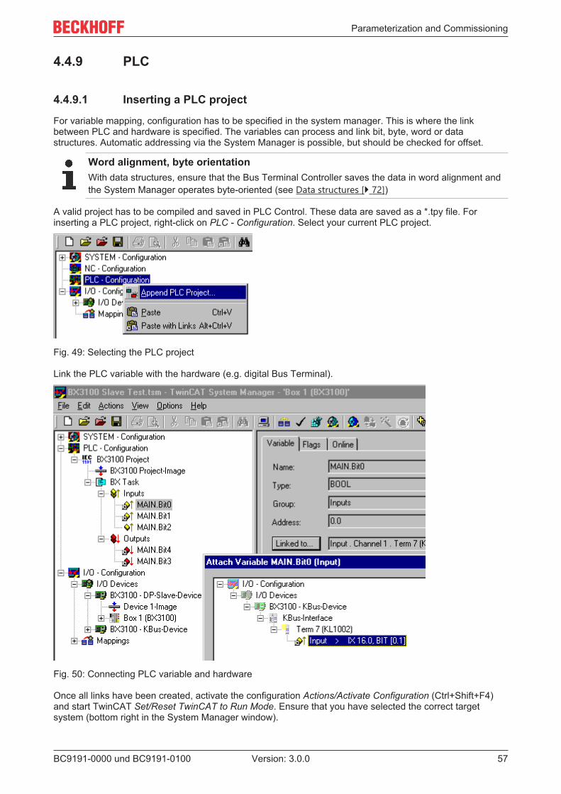
Parameterization and Commissioning
BC9191-0000 und BC9191-0100 57Version: 3.0.0
4.4.9 PLC
4.4.9.1 Inserting a PLC project
For variable mapping, configuration has to be specified in the system manager. This is where the linkbetween PLC and hardware is specified. The variables can process and link bit, byte, word or datastructures. Automatic addressing via the System Manager is possible, but should be checked for offset.
Word alignment, byte orientationWith data structures, ensure that the Bus Terminal Controller saves the data in word alignment andthe System Manager operates byte-oriented (see Data structures [ 72])
A valid project has to be compiled and saved in PLC Control. These data are saved as a *.tpy file. Forinserting a PLC project, right-click on PLC - Configuration. Select your current PLC project.
Fig. 49: Selecting the PLC project
Link the PLC variable with the hardware (e.g. digital Bus Terminal).
Fig. 50: Connecting PLC variable and hardware
Once all links have been created, activate the configuration Actions/Activate Configuration (Ctrl+Shift+F4)and start TwinCAT Set/Reset TwinCAT to Run Mode. Ensure that you have selected the correct targetsystem (bottom right in the System Manager window).

Parameterization and Commissioning
BC9191-0000 und BC9191-010058 Version: 3.0.0
Fig. 51: Target system display

Parameterization and Commissioning
BC9191-0000 und BC9191-0100 59Version: 3.0.0
4.4.9.2 Measuring the PLC cycle time
The task time is set in PLC Control. The default setting is 20 ms.
Fig. 52: Setting the task time
In the default setting, the PLC program is called every 20 ms, as long as the general cycle time is less than20 ms. To determine the load of your system, the PLC cycle time can be measured in the System Manager.In order to ensure trouble-free operation, the set task time should be 20-30 % higher than the measured totalcycle time. A precise cycle time breakdown can be found under K-Bus tab description. The total cycle time isdisplayed with the TcBase library (see TcBase.lbx or TcBaseBCxx50.lbx).
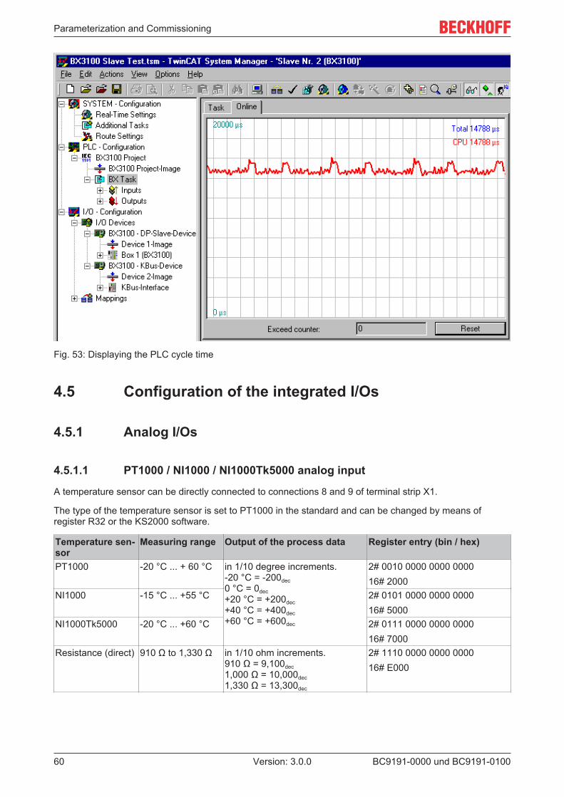
Parameterization and Commissioning
BC9191-0000 und BC9191-010060 Version: 3.0.0
Fig. 53: Displaying the PLC cycle time
4.5 Configuration of the integrated I/Os
4.5.1 Analog I/Os
4.5.1.1 PT1000 / NI1000 / NI1000Tk5000 analog input
A temperature sensor can be directly connected to connections 8 and 9 of terminal strip X1.
The type of the temperature sensor is set to PT1000 in the standard and can be changed by means ofregister R32 or the KS2000 software.
Temperature sen-sor
Measuring range Output of the process data Register entry (bin / hex)
PT1000 -20 °C ... + 60 °C in 1/10 degree increments.-20 °C = -200dec0 °C = 0dec+20 °C = +200dec+40 °C = +400dec+60 °C = +600dec
2# 0010 0000 0000 000016# 2000
NI1000 -15 °C ... +55 °C 2# 0101 0000 0000 000016# 5000
NI1000Tk5000 -20 °C ... +60 °C 2# 0111 0000 0000 000016# 7000
Resistance (direct) 910 Ω to 1,330 Ω in 1/10 ohm increments.910 Ω = 9,100dec1,000 Ω = 10,000dec1,330 Ω = 13,300dec
2# 1110 0000 0000 000016# E000

Parameterization and Commissioning
BC9191-0000 und BC9191-0100 61Version: 3.0.0
4.5.1.2 Potentiometer input
A setpoint potentiometer can be directly connected to connections 9 and 10 of terminal strip X1 for specifyingthe room temperature.
It is recommended to use a potentiometer with a nominal value of 10 kΩ.
The change of the resistance value from 0 to 10 kΩ is represented in the process value as 0 to 10000 steps.
The resolution is 10 bits.
4.5.1.3 Analog inputs (10 V)
3 analog inputs with a resolution of 10 bits are available at connections 11, 12 and 13 of terminal strip X1.
Input voltage Process value0 V 0dec
5 V 16383dec
10 V 32767dec
4.5.1.4 Analog outputs (10 V)
2 analog outputs with a resolution of 10 bits are available at connections 20 and 22 of terminal strip X2.Connection 21 is the common ground.
Process value Output voltage0dec 0 V16383dec 5 V32767dec 10 V
4.6 KS2000
4.6.1 KS2000 - IntroductionThe KS2000 configuration software permits configuration, commissioning and parameterization of buscouplers, of the affiliated bus terminals and of Fieldbus Box Modules. The connection between bus coupler /Fieldbus Box Module and the PC is established by means of the serial configuration cable or the fieldbus.

Parameterization and Commissioning
BC9191-0000 und BC9191-010062 Version: 3.0.0
Fig. 54: KS2000 configuration software
Configuration
You can configure the Fieldbus stations with the Configuration Software KS2000 offline. That means, settingup a terminal station with all settings on the couplers and terminals resp. the Fieldbus Box Modules can beprepared before the commissioning phase. Later on, this configuration can be transferred to the terminalstation in the commissioning phase by means of a download. For documentation purposes, you are providedwith the breakdown of the terminal station, a parts list of modules used and a list of the parameters you havemodified. After an upload, existing fieldbus stations are at your disposal for further editing.
Parameterization
KS2000 offers simple access to the parameters of a fieldbus station: specific high-level dialogs are availablefor all bus couplers, all intelligent bus terminals and Fieldbus Box modules with the aid of which settings canbe modified easily. Alternatively, you have full access to all internal registers of the bus couplers andintelligent terminals. Refer to the register description for the meanings of the registers.
Commissioning
The KS2000 software facilitates commissioning of machine components or their fieldbus stations: Configuredsettings can be transferred to the fieldbus modules by means of a download. After a login to the terminalstation, it is possible to define settings in couplers, terminals and Fieldbus Box modules directly online. Thesame high-level dialogs and register access are available for this purpose as in the configuration phase.
The KS2000 offers access to the process images of the bus couplers and Fieldbus Box modules.
• Thus, the coupler's input and output images can be observed by monitoring.• Process values can be specified in the output image for commissioning of the output modules.
All possibilities in the online mode can be used in parallel with the actual fieldbus mode of the terminalstation. The fieldbus protocol always has the higher priority in this case.

Parameterization and Commissioning
BC9191-0000 und BC9191-0100 63Version: 3.0.0
4.6.2 Representation of the integrated inputs and outputs
4.6.2.1 Configuration of the integrated inputs and outputs
The integrated inputs and outputs, as well as the sub-bus of the BC9191, are displayed as normal terminalsfor configuration in the KS2000 configuration software.
The configuration is then performed in the same way as for the respective standard Bus Terminal.
Fig. 55: Display of the BC9191 in the KS2000 software

Programming
BC9191-0000 und BC9191-010064 Version: 3.0.0
5 Programming
5.1 TwinCAT PLCThe Beckhoff TwinCAT Software System turns any compatible PC into a real-time controller with a multi-PLCsystem, NC axis control, programming environment and operating station. The TwinCAT programmingenvironment is also used for programming the BC/BX. If you have TwinCAT PLC (Windows NT4/2000/XP)installed, you can use the fieldbus connection or the serial port for downloading and debugging software.
TwinCAT I/O or TwinCAT PLC can also be used as the Ethernet Master (host), in order to exchange processdata with the Bus Terminal Controller. TwinCAT provides you with the System Manager as a configurationtool, as well as the drivers and the ADS protocol.
Bus Terminal Controllers of the BCxx50, BCxx20 and BXxx00 series
These 2nd-generation Bus Terminal Controllers are configured with the TwinCAT System Manager andprogrammed with TwinCAT PLC Control. TwinCAT PLC must be installed for these couplers (Windows NT4,Windows 2000, Windows XP).
Programming and program transfer• via the serial interface
• via the fieldbus interface [ 73] (only for Bus Terminal controllers for PROFIBUS, CANopen andEthernet)
Online change
The Bus Terminal Controllers of the BX series and the BCxx50 support online change. This means that thePLC program is replaced with a new program without interrupting the program. The switch-over to the newprogram occurs after the task is completed. This means that two versions of the PLC program have to bestored. 512 kbyte are available, which therefore have to be divided by two, leaving 256 kbyte for the actualPLC program. In addition, several kbyte are required for task configuration etc. During an online change,dynamic data are stored in memory. Should a program approach the memory limit (program size greaterthan 240 kbyte), the online change may no longer work, even though the program may still be written to theBX after "Rebuild all".
When is online change not available?
Online change is not available under certain conditions,.
• Inserting of a new library• Changing the task setting• "Rebuild all"• Controller memory limit is almost reached (PLC program greater than 90%)
5.2 TwinCAT PLC - Error codesError type DescriptionPLC compiler error Maximum number of POUs (...) exceededPLC compiler error Out of global data memory ...
Error POUs
For each function block one POU (process object unit) is created. 256 function blocks are available bydefault.

Programming
BC9191-0000 und BC9191-0100 65Version: 3.0.0
Fig. 56: Maximum number of POUs exceeded
If libraries are integrated this value may be insufficient. In this case, the number of POUs should beincreased.
To this end, open in PLC Control under Projects/Options...
Fig. 57: Menu path Projects / Options / Controller Settings
...the controller settings.
Fig. 58: Controller settings
Changing these settings will deactivate online changes.

Programming
BC9191-0000 und BC9191-010066 Version: 3.0.0
Global memory error
Fig. 59: Global memory insufficient
2 x 16 kbyte of data are available by default. If large data quantities are to be used, this range should beincreased. A maximum of 14 data segments are possible for the BX.
Fig. 60: Menu path Projects / Options / Build
Fig. 61: Build

Programming
BC9191-0000 und BC9191-0100 67Version: 3.0.0
5.3 Remanent data2000 bytes of remanent data are available on the BC9191 and the BX controller. These data are declared asVAR RETAIN in PLC Control.
ExampleVAR RETAIN Test :BOOL; Count :INT;END_VAR
Retain data are located between VAR RETAIN and END_VAR. These data are stored in a NOVRAM andare consistent across the whole 2 kbyte range. The RETAIN data are stored in the NOVRAM after eachcycle. For 2 kbyte approx. 2 ms are required (for 1 kbyte approx. 1 ms). The variables can be configuredlocally or globally. Allocated variables (%MB, %QB, %IB) cannot be used as remanent data.
Do not use VAR_RETAIN in function blocksVAR_RETAIN should not be used in function blocks. All FB data are copied into the retain memory.This leads to an unnecessary increase in cycle time, and the retain memory is filled with unneces-sary data.
Do not use variables with address as remanent dataVariables that have been assigned an address (%MB, %QB, %IB) must not be used as remanentdata.
Example for remanent data in the function block
This should be avoided, if possible, since all the data of a function block, in which even just a singleremanent bit is found, are stored by default. A program sample can be found below.
Function block test (no program code required - in ST semicolon is sufficient)FUNCTION_BLOCK TestVAR_INPUTEND_VARVAR_OUTPUTEND_VARVAREND_VARVAR_IN_OUT Counter :INT;END_VAR
MAIN programPROGRAM MAINVAR fb_Test:Test;END_VARVAR RETAIN iCounter1:INT;END_VAR
fb_Test(Counter:=iCounter1);
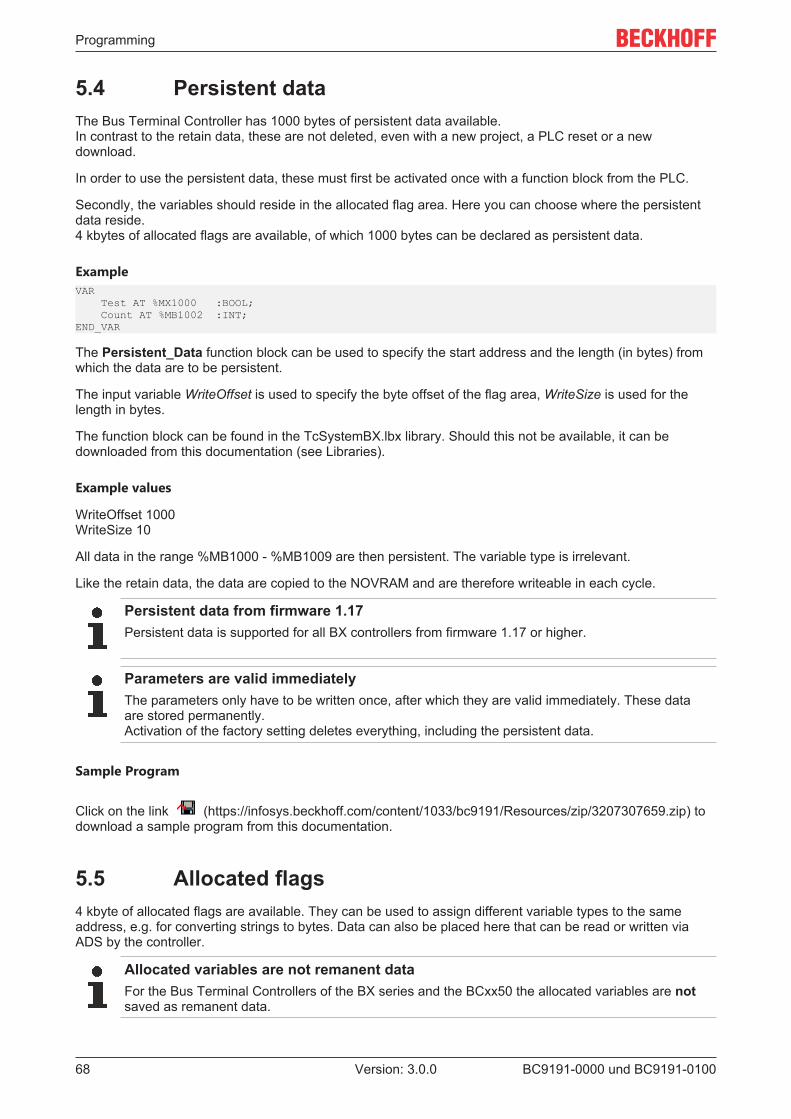
Programming
BC9191-0000 und BC9191-010068 Version: 3.0.0
5.4 Persistent dataThe Bus Terminal Controller has 1000 bytes of persistent data available.In contrast to the retain data, these are not deleted, even with a new project, a PLC reset or a newdownload.
In order to use the persistent data, these must first be activated once with a function block from the PLC.
Secondly, the variables should reside in the allocated flag area. Here you can choose where the persistentdata reside.4 kbytes of allocated flags are available, of which 1000 bytes can be declared as persistent data.
ExampleVAR Test AT %MX1000 :BOOL; Count AT %MB1002 :INT;END_VAR
The Persistent_Data function block can be used to specify the start address and the length (in bytes) fromwhich the data are to be persistent.
The input variable WriteOffset is used to specify the byte offset of the flag area, WriteSize is used for thelength in bytes.
The function block can be found in the TcSystemBX.lbx library. Should this not be available, it can bedownloaded from this documentation (see Libraries).
Example values
WriteOffset 1000WriteSize 10
All data in the range %MB1000 - %MB1009 are then persistent. The variable type is irrelevant.
Like the retain data, the data are copied to the NOVRAM and are therefore writeable in each cycle.
Persistent data from firmware 1.17Persistent data is supported for all BX controllers from firmware 1.17 or higher.
Parameters are valid immediatelyThe parameters only have to be written once, after which they are valid immediately. These dataare stored permanently.Activation of the factory setting deletes everything, including the persistent data.
Sample Program
Click on the link (https://infosys.beckhoff.com/content/1033/bc9191/Resources/zip/3207307659.zip) todownload a sample program from this documentation.
5.5 Allocated flags4 kbyte of allocated flags are available. They can be used to assign different variable types to the sameaddress, e.g. for converting strings to bytes. Data can also be placed here that can be read or written viaADS by the controller.
Allocated variables are not remanent dataFor the Bus Terminal Controllers of the BX series and the BCxx50 the allocated variables are notsaved as remanent data.

Programming
BC9191-0000 und BC9191-0100 69Version: 3.0.0
Reading/writing of allocated flags via ADS
The flags may also be read via the controller and ADS. In PROFIBUS, the DPV-1 services are used for thispurpose, in CANopen SDO communication is used.The AmsNetID can be obtained from the System Manager, or it can be displayed via the Bus TerminalController menu.The PLC port number is 800.
Index group Meaning Index offset (value range)0x4020 Flag (only BXxxx0) 0..4096
Example
BX programVAR Flag_01 AT %MB0: WORD;END_VAR
TwinCAT PC/CX master programVAR fbADRSREAD: ADSREAD; Flag_M: WORD;END_VAR
fbADRSREAD( NETID:='172.16.3.0.2.3' , (* AMSNetId BX *) PORT:=800 , (* 800 - PLC *) IDXGRP:=16#4020 , (* 0x4020hex falgs *) IDXOFFS:=0 , (* byte offset *) LEN:=2 , (* Lenght byte *) DESTADDR:=ADR(Merker) , READ:=TRUE , TMOUT:=t#1s );IF NOT fbADRSREAD.BUSY THEN fbADRSREAD(READ:=FALSE);END_IF
5.6 Local process image in delivery state (default config)The process image of the Bus Terminal Controller consists of input, output and flag area. In addition, thereare unallocated data without fixed address. They are created without specifying an address. For thesevariable types the memory allocation is as follows:
• BCxx50 48 kbyte,• BC9x20, BC9191 128 kbyte and• BXxx00 256 kbyte.
The maximum size of a variable or structure (array) is 16 kbyte. For the allocated data 2048 bytes of inputdata and 2048 bytes of output data are available. The Bus Terminal Controller has 4 kbyte of memoryallocated for the flag area.
In the delivery state (default configuration) of the BX/BCxx50, fixed addresses are allocated for all connectedBus Terminals. The data for Ethernet communication start from address offset 1000dec. The length of theEthernet data depends on how much data has been configured; on the BX9000 it has a maximum length of1000 bytes.
Inputs OutputsBus Terminal %IB0 ... Bus Terminal %QB0 ...Ethernet DATA (PLC variables) %IB1000 ...(ModbusTCP/ADS-TCP/ADS-UDP)
Ethernet DATA (PLC variables) %QB1000 ...(Modbus TCP/ADS-TCP/ADS-UDP)
... %IB2047 maximum ... %QB2047 maximum

Programming
BC9191-0000 und BC9191-010070 Version: 3.0.0
Addressing of the connected Bus Terminals
The default setting is for all the connected Bus Terminals to be assigned to the local process image.Mapping within the Bus Terminal Controller is carried out according to the following rule:First all the complex Bus Terminals, in the sequence they are physically inserted, followed by the digital BusTerminals which are filled to a byte. The default mapping of the complex Bus Terminals is:
• complete evaluation• Intel format• Word alignment
Example structure
Bus Terminal Controller: 1 x BCxx50, BCxx20 or BXxx00Position 1: 1 x KL1012Position 2: 1 x KL1104Position 3: 1 x KL2012Position 4: 1 x KL2034Position 5: 1 x KL1501Position 6: 1 x KL3002Position 7: 1 x KL4002Position 8: 1 x KL6001Position 9: 1 x KL9010
Table 1: Process image
Bus Terminal Position Input image Output image SizeKL1501 5 %IB0...%IB5 %QB0...%QB5 6 bytesKL3002 6 %IB6...%IB13 %QB6...%QB13 8 bytesKL4002 7 %IB14...%IB21 %QB14...%QB21 8 bytesKL6001 8 %IB22...%IB29 %QB22...%QB29 6 bytesKL1012 1 %IX30.0...%IX30.1 - 2-bitKL1104 2 %IX30.1...%IX30.5 - 4-bitKL2012 3 - %QX30.0...%IX30.1 2-bitKL2034 4 - %QX30.2...%IX30.5 4-bitKL9010 9 - - -
5.7 Mapping the Bus TerminalsThe precise assignment of the byte-oriented Bus Terminals may be found in the configuration guide for theparticular bus terminal. This documentation can be found on the Internet at http://www.beckhoff.de.
Byte oriented Bus Terminals Bit oriented Bus TerminalsKL15x1 KL10xx, KL11xx, KL12xx, KL17xx, KM1xxxKL25xx KL20xx, KL21xx, KL22xx, KL26xx, KL27xx, KM2xxxKL3xxxKL4xxxKL5xxxKL6xxxKL7xxxKL8xxx
KL9110, KL9160, KL9210, KL9260

Programming
BC9191-0000 und BC9191-0100 71Version: 3.0.0
5.8 Local process image in the TwinCAT configurationThe TwinCAT configuration (TwinCAT CONFIG) enables free mapping between fieldbus, K-bus and PLCvariables. Variables can be linked independent of their address via the System Manager.
Fig. 62: Changing variable links
Fig. 63: Linking a variable with an input
In the default configuration all Bus Terminals are assigned fixed addresses. If a Bus Terminal is inserted, thewhole address range may be shifted. The TwinCAT configuration enables allocated variables to be linked toa Bus Terminal, as required. This is parameterized in the System Manager, and the configuration is thendownloaded to the Bus Terminal Controller (see TwinCAT configuration). It is also possible to upload anexisting TwinCAT configuration.
5.9 Creating a boot projectThe following memory resources are available for generating the boot project
• approx. 250 kbyte flash on the Bus Terminal controllers of the BX series;

Programming
BC9191-0000 und BC9191-010072 Version: 3.0.0
• approx. 48 kbyte flash on the Bus Terminal controllers of the BCxx50 series.
PLC Control
After logging into TwinCAT PLC Control, a boot project can be created.
• Opening a PLC project• Selecting the target system (or selection the serial interface)• Logging into the BX/BCxx50• Creating a boot project (Online\Create boot project)
The PLC LED lights up green once a valid boot project is available on the BX/BCxx50.
In the Bus Terminal controllers of the BX series, the PLC LED flashes orange while boot project is created.The PLC LED lights up orange if no boot project is available on the BX.
Deleting a boot project
The boot project can be deleted from the Bus Terminal Controller. The following steps must be followed:
• Opening the project• Logging into the Bus Terminal Controller• Deleting the boot project (Online\Delete boot project)
The PLC LED lights up orange when the boot project is deleted.
Using the current project as boot projectAfter an online change the old project is still shown as boot project. To use the current project (afterthe online change) as the boot project, the boot project has to be recreated.
Bypassing the start of the boot project*
With the Bus Terminal controllers of the BX series, starting of the boot project during booting can beprevented by pressing the Navi button. This does not delete the boot project. The project is reloaded whenthe Bus Terminal Controller is rebooted.
* from version 0.85
5.10 Communication between TwinCAT and BX/BCxx50For transferring data from TwinCAT to the Bus Terminal Controller, it makes sense to organize the data in astructure. Please note the following to account for the differences in data management on the two systems.
• If two different data types are sent in sequence (e.g. byte and INT), the following variable is set to thenext even address offset
• Boolean variables should never be allocated individually within a structure, since they would invariablyoccupy 1 byte. Boolean expressions should always be masked in a byte or word.
Example 1: A structure on the BX/BCxx50 and on the PC
Variable BX/BCxx50 memory PC memory (TwinCAT)Byte %..B0 %..B0INT (1) %..B2 %..B1INT (2) %..B4 %..B3
Due to the fact that another variable type (INT) follows the first byte, in the BX/BCxx50 it was assigned thenext free even address. In order to achieve the same data structure on both systems, a dummy byte has tobe inserted in the PC project (see example 2).

Programming
BC9191-0000 und BC9191-0100 73Version: 3.0.0
Example 2: A structure on the BX/BCxx50 and on the PC with the same memory allocation
Variable BX/BCxx50 memory PC memory (TwinCAT)Byte %..B0 %..B0Byte(dummy)
%..B1 (not necessarily required, since the systemdeals with this itself if the variable does not exist)
%..B1
INT (1) %..B2 %..B2INT (2) %..B4 %..B4
Data structureType PB_DataSTRUCT wVar_1:WORD; iValue_1:INT; iValue_2:INT; iValue_3:INT;END_STRUCTEND_TYPE
Creating a variable structureVAR_Global strData_Out AT %QB1000:PB_Data; (*PLC Variables *) bInput_01 AT %IX0.0:BOOL; (* Input from a terminal *)END_VAR
Small programming examplestrData_Out.wVar_1.0:=bInput_01;
Do not use real values in a mixed data structureA mixed data structure should not contain real values. If this is nevertheless the case, the high andlow words must be swapped in the BX/BCxx50 or in the TwinCAT master project. It is better to usean array of Real values or to transfer the Real values individually.
Larger fieldbus data blocksYou can transfer larger fieldbus data blocks, in order to have a reserve for your structure. Disadvan-tage: These reserves are then transferred with each fieldbus telegram, resulting in overload of thefieldbus communication.
5.11 Program transfer
5.11.1 Program Transfer via EthernetTwinCAT offers a facility for transferring the user program to the Bus Terminal Controller over the fieldbus.The BC/BX can be selected as the target system in PLC Control, after saving in the registry and restartingthe TwinCAT system. The TwinCAT-level TwinCAT PLC is necessary.
Minimum requirements:
• TwinCAT 2.10 build 1251
Initializing the Bus Terminal Controllers
Possibility 1: If you use TwinCAT as a polling PLC.The coupler must first be made known to the system before it can be selected in PLC Control.Enter the Bus Terminal Controller in the System Manager, specify type, quantity and size of the fieldbusvariables and link them with a task. Save your settings and activate the configuration. Then start theTwinCAT system and the cyclic task.
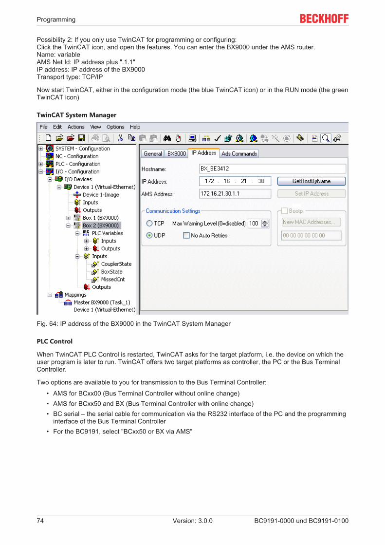
Programming
BC9191-0000 und BC9191-010074 Version: 3.0.0
Possibility 2: If you only use TwinCAT for programming or configuring:Click the TwinCAT icon, and open the features. You can enter the BX9000 under the AMS router.Name: variableAMS Net Id: IP address plus ".1.1"IP address: IP address of the BX9000Transport type: TCP/IP
Now start TwinCAT, either in the configuration mode (the blue TwinCAT icon) or in the RUN mode (the greenTwinCAT icon)
TwinCAT System Manager
Fig. 64: IP address of the BX9000 in the TwinCAT System Manager
PLC Control
When TwinCAT PLC Control is restarted, TwinCAT asks for the target platform, i.e. the device on which theuser program is later to run. TwinCAT offers two target platforms as controller, the PC or the Bus TerminalController.
Two options are available to you for transmission to the Bus Terminal Controller:
• AMS for BCxx00 (Bus Terminal Controller without online change)• AMS for BCxx50 and BX (Bus Terminal Controller with online change)• BC serial – the serial cable for communication via the RS232 interface of the PC and the programming
interface of the Bus Terminal Controller• For the BC9191, select "BCxx50 or BX via AMS"

Programming
BC9191-0000 und BC9191-0100 75Version: 3.0.0
Fig. 65: Selecting the data transfer route - AMS
After your program has been created, select the target system under the Online toolbar. TwinCAT must berunning to do this. In the sample, this is the Ethernet card with Box 1 and the Run-Time 1 of the BusTerminal Controller.
Fig. 66: Choose Target System
5.11.2 Up- and downloading of programsThe Bus Terminal Controller has a memory for the source code. It can be used for storing the program, thetask configuration, and the libraries. Should the memory be insufficient, the source code may be storedwithout task configuration and libraries. This takes up significant less memory space!
General settings
The timing of the source code download to the target system can be specified via Edit/Options. Open theoptions menu.

Programming
BC9191-0000 und BC9191-010076 Version: 3.0.0
Fig. 67: Opening the options menu
Select Source Download.
Fig. 68: Selecting Source Download
Here you can set which parts of the source code are to be downloaded to the Bus Terminal Controller, andwhen.
Source code only: the prx file with information on the online change is transferred. Login via online changeis possible (the PLC does not stop).All files: as Source code only, plus all required libraries.Source code only (compile info excluded): only the prx file is transferred. Login is only possible when thePLC stops.
Which option you can use depends on the size of your projects.
Downloading a program
The source code can be transferred to the target system on request. This requires the user to be logged inwith his program. Under Online/Source code download the program code can now be transferred to the BusTerminal Controller.

Programming
BC9191-0000 und BC9191-0100 77Version: 3.0.0
Fig. 69: Downloading the program code
After a short delay, a window will open that indicates the download progress.
Fig. 70: Download progress
Uploading a program
For uploading the program code again, open a new file in PLC Control. Then click on the PLC button.

Programming
BC9191-0000 und BC9191-010078 Version: 3.0.0
Fig. 71: Uploading a program
Select the data transfer route:
• BCxx50 or BX via AMS, if you are connected to the Bus Terminal Controller via the fieldbus, or• BCxx50 or BX via serial, if you are connected to the Bus Terminal Controller via the serial interface.
Fig. 72: Selecting the data transfer route
Then select the device and confirm with OK.
Fig. 73: Selecting the device
The source code will now be uploaded.

Programming
BC9191-0000 und BC9191-0100 79Version: 3.0.0
Password
You can protect your project with a password (in PLC Control Project/Options/Passwords).
5.12 Libraries
5.12.1 Libraries overviewThe TwinCAT 2 automation software provides various libraries for the BC9191-0000 and BC9191-0100 (seeBeckhoff Information System). These libraries are also used for the Bus Terminal Controllers (Bus Couplerswith PLC functionality) of the BC9050, BC9020, BC9120 and BX9000 series.
Download and documentation
If libraries are not installed by default, perform a download, extract the library from the .zip file and copy itinto the TwinCAT directory TwinCAT\PLC\LIB. KS2000KS2000KS2000
• Standard.lbx (installed by default in TwinCAT 2.11)• TcBaseBCxx50.lbx (installed by default in TwinCAT 2.11)
Documentation: https://infosys.beckhoff.com/content/1033/bc9xx0/3740793995.html• TcSystemBCxx50.lbx (installed by default in TwinCAT 2.11)
Documentation: https://infosys.beckhoff.com/content/1033/bc9xx0/3740791947.html• TcBaseBX9000.lbx
Documentation: https://infosys.beckhoff.com/content/1033/bx9000/3207183627.htmlDownload: https://infosys.beckhoff.com/content/1033/bx9000/Resources/zip/3207318539.zip
• TcSystemBX9000.lbx Documentation: https://infosys.beckhoff.com/content/1033/bx9000/3207213707.htmlDownload: https://infosys.beckhoff.com/content/1033/bx9000/Resources/zip/3207385995.zip
Further libraries with useful functions or communication blocks can also be found in the Beckhoff InformationSystem:https://infosys.beckhoff.com/content/1033/tcplclibsoverviewbc/html/tcplclibsoverview_bc.htm
When using the libraries, firmware 3.1 or higher is recommended for the BC9191-0000 and BC9191-0100.
Use the library that matches the firmwareAlways use the latest libraries in conjunction with the latest BC firmware. If you update the firmwareof your Bus Terminal Controller, please also update the libraries. Copy the new libraries into the LIBfolder, remove them from your project and re-insert them.

PLC program
BC9191-0000 und BC9191-010080 Version: 3.0.0
6 PLC program
6.1 Fan controller with room temperature controlThe BC9191 is supplied with a pre-installed PLC program. This OLC program can be used for a three-stagefan controller with room temperature control (heating/cooling) for a 4-pipe system.
The factory-installed PLC code for TwinCAT 2 is also available for download as a sample program in a ZIPfile (see Documentation and Downloads / Configuration files):
BC9191-0000: www.beckhoff.de/BC9191
BC9191-0100: www.beckhoff.de/BC9191-0100
Application
With the pre-installed standard air conditioning application it is possible to attain the highest energy efficiencystandard of EN15232 Class A. The standard application contains the basic room air conditioning functionsaccording to VDI 3813.
The application contains basic function blocks and basic functions such as:
• a local temperature measurement with smoothing function and a compensation value,• a local setpoint value shift/setpoint correction• a scaling function• the control of analog actuators• a PI controller with input via the proportional band• occupancy detection and occupancy signal• Window monitoring• local overriding of the fan stages is possible• load optimization is possible
Furthermore, room air conditioning functions are implemented, such as:
• energy level selection• function selection• Setpoint determination block for the different energy levels• 3-stage fan control (FanCoil)
Notes• The pre-installed standard air conditioning application is mapped as a default configuration, i.e. the
TwinCAT System Manager is not required for the linking of the PLC variables with the I/O level.• The Index Groups 16#4020 and 16#4021 can be accessed for both reading and writing from a higher-
level controller, e.g. BMS or floor controller, by ADS or Modbus TCP. This is accounted for in theapplication.
• Parameters of individual subprograms are saved persistently. See also PersistentDataGlobalState.
Main_1 (main program)
All subprograms are called in the main program of the standard application. The connections andcommunication between the program blocks are given in the main program by the connecting lines. All theprogram blocks can therefore be seen in a single functioning context.

PLC program
BC9191-0000 und BC9191-0100 81Version: 3.0.0
Fig. 74: Fan control - main program
Connection from block 0 to block 1
The EnergyLevelSelection_SetpointGeneration_FunctionSelection subprogram (EL_SP_FS) transmits theinformation regarding the energy level, the setpoints of the four energy levels for the heating and coolingoperation, the control function (heating/cooling/OFF) and the current room temperature (to blocks 2 and 4).
Connection from block 1 to block 2
FB_BC9191Room enables the cooling function with the valid/calculated energy level setpoint.
Connection from block 1 to block 4
FB_BC9191Room enables the heating function with the valid/calculated energy level setpoint.

PLC program
BC9191-0000 und BC9191-010082 Version: 3.0.0
Connection from block 1 to block 6
If the heating or cooling function is activated, it enables the fan coil on block 7.
Connection from block 2 to block 3
The cooling controller transmits its control value (0..100%) to the control valve. This control value is scaled tothe output signal with the value range 0..32767; block 3.
Connection from block 4 to block 5
The heating controller transmits its control value (0..100%) to the control valve. This control value is scaledto the output signal with the value range 0..32767; block 5.
Block 7
3-stage fan coil, which switches the stages automatically depending on the control signal from the controller.
System diagram
Fig. 75: Fan control - system diagram

PLC program
BC9191-0000 und BC9191-0100 83Version: 3.0.0
Data point listDP Name Type Program block / function
blockVariable Feature Terminal strip
Y01 Heating valve AA PI_Heating / fb-BC9191AO_0_10V_Heat-ing
stOut-Data.KL4001_02_AO2_X2_22_21_DataOut
manda-tory
X2 Contact X2:22; X2:21
Y02 Cooling valve AA PI_Cooling / fb-BC9191AO_0_10V_Cool-ing
stOut-Data.KL4001_01_AO1_X2_20_21_DataOut
manda-tory
X2 Contact X2:20; X2:21
Q1 3-stage fancoil
DA FanCoil stOut-Data.KL9191_DO_DataOut.2stOut-Data.KL9191_DO_DataOut.3stOut-Data.KL9191_DO_DataOut.4
bindingbindingbinding
X3 Contact X3:32; X3:35Contact X3:33; X3:35Contact X3:34; X3:35
D01 Window con-tact
DE EnergyLevel stIn-Data.KL9191_DI_DataIn.0
manda-tory
X1Contact X1:1; X1:2
D03 Occupancysensor
DE EnergyLevel stIn-Data.KL9191_DI_DataIn.2
manda-tory
X1Contact X1:5; X1:6
B01 Room temper-ature
AE PT/NI 1000NI1000Tk5000
EL_SP_FS / fb-BC9191TemperatureSen-sor
stIn-Data.KL3201_AI_RTD_X1_8_9_DataInstIn-Data.KL3201_AI_RTD_X1_8_9_State
bindingbinding
X1Contact X1:8; X1:9Contact X1:8; X1:9
R01 local set valuegenerator
AE 0 - 10,000 Ω
EL_SP_FS / fb-BC9191Poti / F_BC9191S-cale
stIn-Data.KL3061_01_AI_Poti_X1_10_9_DataInstIn-Data.KL3061_01_AI_Poti_X1_10_9_State
bindingbinding
X1Contact X1:10; X1:9Contact X1:10; X1:9
Key
AE: Analog inputAA: Analog outputDE: Digital inputDA: Digital output
6.2 Description of the POUs
6.2.1 Description of the internal function blocks and subprograms
6.2.1.1 FB_BC9191EnergyLevel
Fig. 76: Function block FB_BC9191EnergyLevel

PLC program
BC9191-0000 und BC9191-010084 Version: 3.0.0
Application
This function block is for the adaptation of the supply of energy for the use of the building. The type of roomutilization is set by the BMS. The longer a building or room is not used, the further the energy level can belowered. The energy level currently selected by the function block is transferred to the room temperaturecontroller.
Protection:
This operation mode is activated in the case of long absence times e.g. during works holidays or also when awindow is open. The energy level is very low and serves only to protect the building from damage caused byfrost or overheating.
Economy:
The Economy energy level is used for the economy mode. Economy mode is activated, for example, at nightby a timer switch schedule.
PreComfort:
The PreComfort energy level is for an unused room which, however, can be occupied again shortly. Thestandby mode is frequently activated by a timer schedule.
Comfort:If the room is occupied, it is in Comfort mode. Comfort mode can be activated by a timer switch schedule orby presence recognition.
VAR_INPUTName : Type
bSetDefault : BOOL;bEnable : BOOL;bWindow : BOOL;bProtection : BOOL;bEconomy : BOOL;bPreComfort : BOOL;bComfort : BOOL;
bSetDefault: If the variable is TRUE, the default values of the VAR_IN_OUT variables are adopted.
bEnable: The function block is activated by a TRUE at this input.
bWindow: The window contact is connected to this input. TRUE means that the window is OPEN. FALSEmeans that the window is CLOSED.
bProtection: Protection mode is activated with the input bProtection. Protection mode is active if the input isTRUE.
bEconomy: Economy mode is activated with the input bEconomy. Economy mode is active if the input isTRUE.
bPreComfort: The Pre-comfort level is activated with this input. The Pre-comfort level is active if the input isTRUE.
bComfort: The Comfort level is activated with this input if the room is occupied.
VAR_OUTPUTName : Type
eEnergyLevel : E_BC9191EnergyLevel;bStateProtection : BOOL;bStateEconomy : BOOL;bStatePreComfort : BOOL;bStateComfort : BOOL;
eEnergyLevel [ 85]: This output contains the current energy level.
bStateProtection: The state of the bProtection input is relayed to the outside in the operation modeseEnergyLevel_AUTO_I and eEnergyLevel_AUTO_II.

PLC program
BC9191-0000 und BC9191-0100 85Version: 3.0.0
bStateEconomy: The state of the bEconomy input is relayed to the outside in the operation modeseEnergyLevel_AUTO_I and eEnergyLevel_AUTO_II.
bStatePreComfort: The state of the bPreComfort input is relayed to the outside in the operation modeseEnergyLevel_AUTO_I and eEnergyLevel_AUTO_II.
bStateComfort: The state of the bComfort input is relayed to the outside in the operation modeseEnergyLevel_AUTO_I and eEnergyLevel_AUTO_II.
VAR_IN_OUTName : Type Persistent Default
eCtrlMode : E_BC9191EnergyLevel [ 85]; X eEnergyLevel_AUTO_I
eCtrlMode: Using this ENUM the operation mode can be preselected from the building management level.
6.2.1.2 E_BC9191EnergyLevelTYPE E_BC9191EnergyLevel:( eEnergyLevel_AUTO_I := 0, eEnergyLevel_Protection := 1, eEnergyLevel_Economy := 2, eEnergyLevel_PreComfort := 3, eEnergyLevel_Comfort := 4, eEnergyLevel_AUTO_II := 5);END_TYPE
eEnergyLevel_AUTO_I
Automatic mode I means that in this operation mode it is only possible to switch to the next higher energylevel if the lower energy levels are already TRUE. In this operation mode the states of the inputs bProtection,bEconomy, bPreComfort and bComfort are evaluated for the selection of the energy level. Please seediagram.

PLC program
BC9191-0000 und BC9191-010086 Version: 3.0.0
Fig. 77: Assignment of the energy level in automatic mode-I
eEnergyLevel_Protection
In this operation mode, which can be manually set by the building management level, the room/zone/area ismaintained in a minimum energy state. This operation mode is purely a Protection mode.
eEnergyLevel_Economy
In this operation mode, which can be manually set by the building management level, the room/zone/area ismaintained in economy mode. This operation mode is to be set in case of lengthy periods of absence or atnight.
eEnergyLevel_PreComfort
In this operation mode, which can be manually set by the building management level, the room/zone/area ismaintained in Pre-comfort mode. This operation mode is to be set in case of short periods of absence.
eEnergyLevel_Comfort
In this operation mode, which can be manually set by the building management level, the room/zone/area ismaintained in comfort mode. This operation mode is to be set in the case of presence.
eEnergyLevel_AUTO_II
Automatic mode II means that in this operation mode the energy level switches directly from the Protection,Economy or PreComfort energy level to the Comfort energy level on recognition of presence. Please seediagram.

PLC program
BC9191-0000 und BC9191-0100 87Version: 3.0.0
Fig. 78: Assignment of the energy level in automatic mode-II
6.2.1.3 FB_BC9191FanCoil
Fig. 79: Function block FB_BC9191FanCoil
Application
This function block maps a 3-stage fan. The three stages are switched via the control value (0...100%) of theheating or cooling controller. Furthermore there is a possibility to manually override the fan controller via theiStageManual or bStageUp or bStageDown input. A minimum switch-on time can be set via theudiSecMINPowerOnTime input, which is then valid for each stage.

PLC program
BC9191-0000 und BC9191-010088 Version: 3.0.0
VAR_INPUTName : Type
bSetDefault : BOOL;bEnable : BOOL;eCtrlFct : E_BC9191CtrlFct [ 90];rY_C : REAL;rY_H : REAL;bStageUp : BOOL;bStageDown : BOOL;iStageManual : INT;bReset : BOOL;
bSetDefault: If the variable is TRUE, the default values of the VAR_IN_OUT variables are adopted.
bEnable: The function block is activated if the variable bEnable is TRUE. No fan stage is activated with aFALSE.
eCtrlFct: This input is connected to the eCtrlFct output of the FB_BC9191FctSelection. This information isimportant in order to know whether the plant is in heating or cooling mode. In automatic mode, the fan stagesare only activated if
• the system is in heating mode and according to the control deviation the request for heating is active or• the system is in cooling mode and according to the control deviation the request for cooling is active.
rY_C: Input for the control value from the cooling controller.
rY_H: Input for the control value from the heating controller.
bStageUp: Local adjustment of the fan stage, stepwise increase by push button.
bStageDown: Local adjustment of the fan stage, stepwise decrease by push button.
iStageManual: The manual fan stage can/is set centrally via this input.iStageManual: = 0 corresponds to fan stage OFFiStageManual: = 1 corresponds to fan stage AUTOiStageManual: = 2 corresponds to fan stage01 activeiStageManual: = 3, corresponds to fan stage02 activeiStageManual: = 4, corresponds to fan stage03 active
bReset: Acknowledge input in case of a fault or an incorrect parameter.
VAR_OUTPUTName : Type
bStageOff : BOOL;bStageAuto : BOOL;bStage01 : BOOL;bStage02 : BOOL;bStage03 : BOOL;bFanCoilActive : BOOL;bPresence : BOOL;byState : BYTE;byError : BYTE;udiSecRT_MINPowerOnTime : UDINT;udiRT_TimePeriod : UDINT;bInvalidParameter : BOOL;
bStageOff: TRUE, fan stages are switched off.
bStageAuto: TRUE, fan controller is in automatic mode.
bStage01: TRUE, fan stage01 active.
bStage02: TRUE, fan stage02 active.
bStage03: TRUE, fan stage03 active.
bFanCoilActive: TRUE if one of the three fan stages is active. This output can be/is used to enablecontrollers in order to avoid a build up of heat or cold.

PLC program
BC9191-0000 und BC9191-0100 89Version: 3.0.0
bPresence: TRUE means that presence was detected via the bStageUp, bStageDown or iStageManualinputs.
byState: Indicates the state of the fan controller.byState.0:= Function block is activatedbyState.3:= Manual fan stage setting is activebyState.4:= bResetbyState.5:= Fan stage01 activebyState.6:= Fan stage02 activebyState.7:= Fan stage03 active
byError: Output of the errors as byte.byError.1:= bInvalidParameter
udiSecRT_MINPowerOnTime: Indicates the remaining time of the minimum switch-on time.
udiRT_TimePeriod: Indicates the remaining time of the manual override.
bInvalidParameter: Indicates that an incorrect input parameter is present. bInvalidParameter must beacknowledged with bReset.
VAR_IN_OUTName : Type Persistent Default
rValvePositionH_Stage01 : REAL; X 0 %rValvePositionH_Stage02 : REAL; X 21 %rValvePositionH_Stage03 : REAL; X 76 %rValvePositionC_Stage01 : REAL; X 0 %rValvePositionC_Stage02 : REAL; X 21 %rValvePositionC_Stage03 : REAL; X 76 %udiSecMINPowerOnTime : UDINT; X 120 seciFctModeFanCoil : INT; X 3udiTimePeriod : UDINT; X 60 min
rValvePositionH_Stage01: Limit value of the control value of the heating controller from which fan stage01is switched on.
rValvePositionH_Stage02: Limit value of the control value of the heating controller from which fan stage02is switched on.
rValvePositionH_Stage03: Limit value of the control value of the heating controller from which fan stage03is switched on.
rValvePositionC_Stage01: Limit value of the control value of the cooling controller from which fan stage01is switched on.
rValvePositionC_Stage02: Limit value of the control value of the cooling controller from which fan stage02is switched on.
rValvePositionC_Stage03: Limit value of the control value of the cooling controller from which fan stage03is switched on.
udiSecMINPowerOnTime: Minimum switch-on time that a fan must run for in a stage before switching to adifferent stage or switching off. Input in seconds (e.g. 120 corresponds to 120 s).
iFctModeFanCoil: The user has the possibility to activate the fan controller for heating mode or coolingmode or both modes via the valence of this variable. Valid values are 1, 2 or 3. Other values are invalid andbInvalidParameter is set to TRUE.
Cooling Heating Valence0 1 1 (= fan controller active in heating mode)1 0 2 (= fan controller active in cooling mode)1 1 3 (= fan controller active in heating mode and cooling mode)
udiTimePeriod: Timeframe during which the manual override is active in case of presence. Specified inminutes

PLC program
BC9191-0000 und BC9191-010090 Version: 3.0.0
6.2.1.4 E_BC9191CtrlFctTYPE E_BC9191CtrlFct:( eCtrlFct_Off := 0, eCtrlFct_Heating := 1, eCtrlFct_Cooling := 2);END_TYPE
eCtrlFct_Off
Function selection OFF active.
eCtrlFct_Heating
Function selection for heating operation active.
eCtrlFct_Cooling
Function selection for cooling operation active.
6.2.1.5 FB_BC9191FctSelection
Fig. 80: Function block FB_BC9191FctSelection
Application
This function block is for enabling room heating or room cooling. It can be used for 2-wire pipe systems(changeover) or 4-wire pipe systems.In the case of a 4-wire pipe system the changeover from heating to cooling operation takes placeautomatically on the basis of a comparison of the setpoint for the room temperature with the actual value forthe room temperature.
Sketch:
Fig. 81: Switching between heating and cooling mode

PLC program
BC9191-0000 und BC9191-0100 91Version: 3.0.0
In the case of a 2-wire pipe system the heating operation or cooling operation may only be enabled whenheating or cooling medium is present. The room temperature controller gets this information from the primaryunits.
In both 2-wire and 4-wire pipe systems the changeover between heating operation and cooling operation canbe delayed by a timer. The input variable udiChangeOverDelay must be greater than zero for this.
The following tables describe the interrelationship between the inputs and the eCtrlFct output of theFB_BC9191FctSelection function block.
In the 2-wire pipe system
bEnable bPipeSystem bFeedbHeatMedium bFeedbCoolMedium interimresult
bDewPoint eCtrlFct
0 0 0 0 OFF TRUE / FALSE OFF1 0 0 0 Heating TRUE / FALSE Heating1 0 0 1 Cooling TRUE OFF
FALSE Cooling1 0 1 0 Heating TRUE / FALSE Heating1 0 1 1 Heating TRUE / FALSE Heating
In the 4-wire pipe system
bEnable bPipeSystem T_Room ≤ Tsetpoint T_Room > Tsetpoint interimresult
bDewPoint eCtrlFct
0 1 0 0 OFF TRUE / FALSE OFF1 1 0 1 Cooling TRUE OFF
FALSE Cooling1 1 1 0 Heating TRUE / FALSE Heating1 1 1 1 Heating TRUE / FALSE Heating
VAR_INPUTName : Type
bSetDefault : BOOL;bEnable : BOOL;bPipeSystem : BOOL;bFeedbHeatMedium : BOOL;bFeedbCoolMedium : BOOL;bDewPoint : BOOL;rRoomTemp : REAL;stSetpoint : ST_BC9191SetpointRoom [ 97];
bSetDefault: If the variable is TRUE, the default values of the VAR_IN_OUT variables are adopted.
bEnable: TRUE enables the function block. If FALSE the function block is disabled and eCtrlFct :=eCtrlFct_Off.
bPipeSystem: FALSE means that a 2-wire pipe system is present. TRUE means that a 4-wire pipe systemis present.
bFeedbHeatMedium: Signal from the power generation or distribution that heating medium is available.
bFeedbCoolMedium: Signal from the power generation or distribution that cooling medium is available.
bDewPoint: The dew point sensor is connected to this input. If this is triggered the cooling control function isdeactivated and eCtrlFct:= eCtrlFct_Off is set.
rRoomTemp: This input variable transfers the current room temperature to the function block.
stSetpoint: STRUCTURE containing the setpoints for the individual energy levels.

PLC program
BC9191-0000 und BC9191-010092 Version: 3.0.0
VAR_OUTPUTName : Type
eCtrlFct : E_BC9191CtrlFct [ 90];uiReqHeating : UINT;uiReqCooling : UINT;udiRT_ChangeOverDelay : UDINT;
eCtrlFct: This output contains the current control function.
uiReqHeating: Is 1 if the room/zone requests heating energy. It is 0 if there is no heating requirement.
uiReqCooling: Is 1 if the room/zone requests cooling energy. It is 0 if there is no cooling requirement.
udiRT_ChangeOverDelay: Indicates the time remaining until the active control function is changed over.
VAR_IN_OUTName : Type Persistent Default
udiChangeOverDelay : UDINT; x 0
udiChangeOverDelay: Changeover time between the control functions. Must be specified in seconds. If theinput is greater than 0 it will always be observed. The variable must be 0 if there is to be no changeover timebetween the control functions.
6.2.1.6 FB_BC9191SetpointRoom
Fig. 82: Function block FB_BC9191SetpointRoom
Application
The function block FB_BC9191SetpointRoom assigns setpoints for cooling and heating operation to each ofthe energy levels Protection, Economy, PreComfort and Comfort. In connection with the function blockFB_BC9191EnergyLevel the room temperature controllers are assigned an energetically optimum setpoint inaccordance with the use of the room and the selected heating or cooling operation.

PLC program
BC9191-0000 und BC9191-0100 93Version: 3.0.0
Fig. 83: Assignment of energy levels
The resulting setpoint for the different energy levels is made up of:
1. the base setpoint value2. the local setpoint value shift (not in the case of the Protection setpoints)3. the central setpoint value shift (not in the case of the Protection setpoints)
The local shift due to a room setpoint generator and also the remote adjustment of the setpoints by abuilding management system only affect the Comfort and PreComfort energy levels.

PLC program
BC9191-0000 und BC9191-010094 Version: 3.0.0
Fig. 84: Mode of operation Setpoint shift
VAR_INPUTName : Type
bSetDefault : BOOL;bEnable : BOOL;rSetpointShiftHeat : REAL;rSetpointShiftCool : REAL;rSetpointShiftUser : REAL;bReset : BOOL;

PLC program
BC9191-0000 und BC9191-0100 95Version: 3.0.0
bSetDefault: If the variable is TRUE, the default values of the VAR_IN_OUT variables are adopted.
bEnable: The function block is activated if the variable bEnable is TRUE.
rSetpointShiftHeat: The rSetpointShiftHeat variable is used for the adaptation of the ComfortHeatingsetpoint of the building management system.
If the ComfortHeating setpoint is raised, then the setpoints for the ComfortCooling and PreComfortCoolingare also increased.Example:Energy levels Protection-
HeatingEconomy-Heating
PreCom-fortHeat-ing
Com-fortHeat-ing
Comfort-Cooling
PreComfort-Cooling
Economy-Cooling
ProtectionCool-ing
Base setpointvalue [°C]
12 15 19 21 24 28 35 40
Set-pointShiftHeat[K]
+3 - - - +3 +3 +3 - -
Resulting set-point [°C]
12 15 19 24 27 31 35 40
A lowering of the ComfortHeating setpoint affects only the ComfortHeating and PreComfortHeating setpoints.Example:Energy levels Protection-
HeatingEconomy-Heating
PreCom-fortHeat-ing
Com-fortHe-ating
Comfort-Cooling
PreComfort-Cooling
Economy-Cooling
Protection-Cooling
Base setpointvalue [°C]
12 15 19 21 24 28 35 40
Set-pointShiftHeat[K]
-3 - - -3 -3 - - - -
Resulting set-point [°C]
12 15 16 18 24 28 35 40
rSetpointShiftCool: The rSetpointShiftCoolvariable is used for the adaptation of the ComfortCoolingsetpoint of the building management system.
If the ComfortCooling setpoint is raised, then the setpoint for the PreComfortCooling is also raised.Example:Energy levels Protection-
HeatingEconomy-Heating
PreCom-fortHeat-ing
Com-fortHe-ating
Comfort-Cooling
PreComfort-Cooling
Economy-Cooling
Protection-Cooling
Base setpointvalue [°C]
12 15 19 21 24 28 35 40
SetpointShift-Cool [K]
+3 - - - - +3 +3 - -
Resulting set-point [°C]
12 15 19 21 27 31 35 40
A lowering of the ComfortCooling setpoint only affects the ComfortCooling. The PreComfortCooling is notchanged.Example:Energy levels Protection-
HeatingEconomy-Heating
PreCom-fortHeat-ing
Com-fortHe-ating
Comfort-Cooling
PreComfort-Cooling
Economy-Cooling
Protection-Cooling
Base setpointvalue [°C]
12 15 19 21 24 28 35 40
SetpointShift-Cool [K]
-3 - - - - -3 - -
Resulting set-point [°C]
12 15 19 21 21 28 35 40

PLC program
BC9191-0000 und BC9191-010096 Version: 3.0.0
If the setpoint of the PreComfort energy level is shifted beyond the setpoint of the Economy level, then thesetpoint of the Economy level adopts the value of the PreComfort level.Example:Energy levels Protection-
HeatingEconomy-Heating
PreCom-fortHeat-ing
Com-fortHe-ating
Comfort-Cooling
PreComfort-Cooling
Economy-Cooling
Protection-Cooling
Base setpointvalue [°C]
12 15 19 21 24 28 35 40
SetpointShift-Cool [K]
+8 - - - - +8 +8 - -
Resulting set-point [°C]
12 15 19 21 32 36 36 40
rSetpointShiftUser: The variable rSetpointShiftUser is used for local setpoint shifting of the user.A positive value of rSetpointShiftUser affects the setpoint of ComfortHeating, ComfortCooling andPreComfortColling.Example:Energy levels Protection-
HeatingEconomy-Heating
PreCom-fortHeat-ing
Com-fortHe-ating
Comfort-Cooling
PreComfort-Cooling
Economy-Cooling
Protection-Cooling
Base setpointvalue [°C]
12 15 19 21 24 28 35 40
SetpointShif-tUser [K]
+3 - - - +3 +3 +3 - -
Resulting set-point [°C]
12 15 19 24 27 31 35 40
A negative value of rSetpointShiftUser affects the setpoints of PreComfortHeating, ComfortHeating andComfortCooling.Example:Energy levels Protection-
HeatingEconomy-Heating
PreCom-fortHeat-ing
Com-fortHe-ating
Comfort-Cooling
PreComfort-Cooling
Economy-Cooling
Protection-Cooling
Base setpointvalue [°C]
12 15 19 21 24 28 35 40
SetpointShif-tUser [K]
-3 - - -3♠ -3 -3 - - -
Resulting set-point [°C]
12 15 16 18 21 28 35 40
bReset: Acknowledge input in case of a fault or an incorrect parameter.
VAR_OUTPUTName : Type
stSetpoint : ST_BC9191SetpointRoom [ 97]; bInvalidParameter : BOOL;
stSetpoint: Structure containing the setpoints for all energy levels.
bInvalidParameter: Indicates that an incorrect input parameter is present. bInvalidParameter must beacknowledged with bReset.
VAR_IN_OUTName : Type Persistent Default Range
rSetpointComfortHeat : REAL; X 21.0rSetpointPreComfortHeat : REAL; X 19.0rSetpointEconomyHeat : REAL; X 15.0rSetpointProtectionHeat : REAL; X 12.0rSetpointComfortCool : REAL; X 24.0rSetpointPreComfortCool : REAL; X 28.0rSetpointEconomyCool : REAL; X 35.0rSetpointProtectionCool : REAL; X 40.0
rSetpointComfortHeat: Setpoint for the Comfort heating energy level.

PLC program
BC9191-0000 und BC9191-0100 97Version: 3.0.0
rSetpointPreComfortHeat: Setpoint for the PreComfort heating energy level.
rSetpointEconomyHeat: Setpoint for the Economy heating energy level.
rSetpointProtectionHeat: Setpoint for the Protection heating energy level.
rSetpointComfortCool: Setpoint for the Comfort cooling energy level.
rSetpointPreComfortCool: Setpoint for the PreComfort cooling energy level.
rSetpointEconomyCool: Setpoint for the Economy cooling energy level.
rSetpointProtectionCool: Setpoint for the Protection cooling energy level.
6.2.1.7 ST_BC9191SetpointRoomTYPE ST_BC9191SetpointRoom :STRUCT stSetpointRoom_ComfortHeat : REAL:= 21.0; stSetpointRoom_PreComfortHeat : REAL:= 19.0; stSetpointRoom_EconomyHeat : REAL:= 15.0; stSetpointRoom_ProtectionHeat : REAL:= 12.0; stSetpointRoom_ComfortCool : REAL:= 24.0; stSetpointRooom_PreComfortCool : REAL:= 28.0; stSetpointRoom_EconomyCool : REAL:= 35.0; stSetpointRoom_ProtectionCool : REAL:= 40.0;END_STRUCTEND_TYPE
The values in the structure are defined with the preset values.

PLC program
BC9191-0000 und BC9191-010098 Version: 3.0.0
6.2.1.8 FB_BC9191PICtrl
Simple PI controller
Fig. 85: Function block FB_BC9191PICtrl
This PI controller does not work directly with a gain factor Kp, but instead calculates this internally from theso-called proportional band (input rXp) in relation to the control value limits (rYmin and rYmax), from whichKp is then determined internally.
Setting via the proportional band
The adjustment of the gain factor Kp of a controller often harbors the difficulty for the user that there is nosize reference to the application. If a heating controller normally operates within the two-figure range, then aflow rate controller can accept values in the five-figure range. It therefore makes sense to represent the Kpfactor in such a way that it has a reference to the possible control deviation and change of control value. TheP-part of the controller is regarded for the dimensioning of the Kp factor.The equation for this is:
• Control value = control deviation x gain factor → Y = E * Kp
this relationship also applies to the changes in the control deviation and the control value:
• Change in control value = change in control deviation • gain factor → ΔY = ΔE * Kp
Referenced to the minimum and maximum value of the control value, Y min and Ymax:
• Ymax - Ymin = (E (Ymax) -E (Ymin)) * Kp
This difference, E(Ymax)-E(Ymin), is called the proportional band (Xp). Transposed, the equation is then:
• Kp = (Ymax - Ymin) / Xp
The following diagram clarifies the functional interrelationship:
Fig. 86: Functional correlation Xp

PLC program
BC9191-0000 und BC9191-0100 99Version: 3.0.0
The proportional band Xp therefore indicates the size of the range of the control deviation that leads to anoutput of Ymin to Ymax from the controller.
A smaller Xp leads to a steeper function and thus to an increase in the Kp factor. However, the controldeviation limit values E(Ymax)-E(Ymin) are shifted:
Fig. 87: Functional correlation small Xp
Functional description
Step response of a simple PI controller, where the control gain has no influence on the integral component.Response of output Y(t) to a control deviation jump by E: when the control deviation jumps by E, output Yfirst jumps to KP*E by the proportional component and then grows by a further E in each interval TN.Note: The controller is designed in such a way that the controller starts at 0, i.e. without the KP*E jump, aftera PLC reset or restart.
Fig. 88: Step response PI controller
Basic function
A TRUE signal at the bEnable input activates the function block. The internal control algorithm is nowprocessed. The input value uiCtrlCycleCall specifies the number of PLC cycles after which the internalcontrol algorithm is processed. If uiCtrlCycleCall =1, then the new calculation takes place in each PLC cycle;if, conversely, it is set to 100, then a new calculation of the output values takes place only every 100 PLCcycles. The PLC cycle time is also accounted for in the control value calculation. An incorrect input valueleads to incorrect calculation.The inputs rW (setpoint), rX (actual value), rXp (proportional band) and rTn (integral action time) are theinput variables of the PI controller. They are used in each calculation cycle for the determination of the outputvalues rY (control value) and rE (control deviation). The control value can additionally be limited by the inputsrYMin and rYMax.
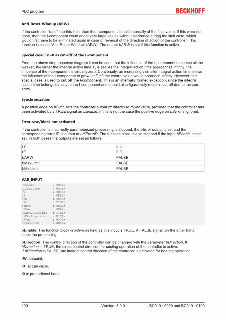
PLC program
BC9191-0000 und BC9191-0100100 Version: 3.0.0
Anti-Reset-Windup (ARW)
If the controller “runs” into this limit, then the I-component is held internally at the final value. If this were notdone, then the I-component could adopt very large values without hindrance during the limit case, whichwould first have to be eliminated again in case of reversal of the direction of action of the controller. Thisfunction is called “Anti-Reset-Windup” (ARW). The output bARW is set if this function is active.
Special case: Tn=0 as cut-off of the I-component
From the above step response diagram it can be seen that the influence of the I-component becomes all theweaker, the larger the integral action time Tn is set. As the integral action time approaches infinity, theinfluence of the I-component is virtually zero. Conversely, an increasingly smaller integral action time allowsthe influence of the I-component to grow; at Tn=0 the control value would approach infinity. However, thisspecial case is used to cut off the I-component. This is an internally formed exception, since the integralaction time belongs directly to the I-component and should also figuratively result in cut-off due to the zeroentry.
Synchronization
A positive edge on bSync sets the controller output rY directly to rSyncValue, provided that the controller hasbeen activated by a TRUE signal on bEnable. If this is not the case the positive edge on bSync is ignored.
Error case/block not activated
If the controller is incorrectly parameterized processing is stopped, the bError output is set and thecorresponding error ID is output at udiErrorID. The function block is also stopped if the input bEnable is notset. In both cases the outputs are set as follows:
rY 0.0rE 0.0bARW FALSEbMaxLimit FALSEbMinLimit FALSE
VAR_INPUTbEnable : BOOL;bDirection : BOOL;rW : REAL;rX : REAL;rXp : REAL;tTn : TIME;rYMin : REAL;rYMax : REAL;tTaskCycleTime : TIME;uiCtrlCycleCall : UINT;bSync : BOOL;rSyncValue : REAL;
bEnable: The function block is active as long as this input is TRUE. A FALSE signal, on the other hand,stops the processing.
bDirection: The control direction of the controller can be changed with the parameter bDirection. IfbDirection is TRUE, the direct control direction for cooling operation of the controller is active.If bDirection is FALSE, the indirect control direction of the controller is activated for heating operation.
rW: setpoint.
rX: actual value.
rXp: proportional band.

PLC program
BC9191-0000 und BC9191-0100 101Version: 3.0.0
tTn: integral action time in seconds. The I-component corrects the residual control deviation followingcorrection of the P-part. The smaller tTi is set, the faster the controller corrects. The control loop becomesunstable if the time is too short. Larger tTi-times must be entered in order to reduce the integrationcomponent. The integral action time should be selected to be longer than the stroke time of the valve ordamper drive. A zero value at this input deactivates the I-component.
rYMin: Lower limit of the control value.
rYMax: Upper limit of the control value.
tTaskCycleTime: Cycle time of the task in which the function block runs.
uiCtrlCycleCall: Call cycle of the function block as a multiple of the cycle time.Example: tTaskCycleTime = 20 ms, uiCtrlCycleCall =10 -> The control algorithm is called every 200 ms.Thus the outputs are also updated only every 200 ms.
bSync,rSyncValue: A rising edge at this input sets the (internal) I-component such that rSyncValue is outputat the control value output. If the I-component is deactivated by tTn=0ms, however, then this command isignored.
VAR_OUTPUTrY : REAL;rE : REAL;rEMin : REAL;bEMax : REAL;bARW : BOOL;bMaxLimit : BOOL;bMinLimit : BOOL;bError : BOOL;udiErrorId : UDINT;
rY: Control value.
rE: Control deviation (setpoint/actual value).
rEMin: Lower control deviation limit value, which results from the input proportional band.
rEMax: Upper control deviation limit value, which results from the input proportional band.
bARW: Anti-Reset-Windup function is active.
bMaxLimit: The control value has reached its upper limit value.
bMinLimit: The control value has reached its lower limit value.
bError: This output is switched to TRUE if the parameters entered are erroneous.
udiErrorId: Contains the error code if the values entered should be erroneous.
6.2.2 ADS access of a higher-level controllerThe building automation room controller supports the Beckhoff ADS and Modbus TCP protocols.The TCP port number for the ADS protocol is 48898. The UDP port number for the ADS protocol is 48899.The TCP port number of Modbus TCP has been standardized to the value 502
Access via the Beckhoff ADS protocol is described in this part of the documentation. ADS is the abbreviationfor Automation Device Specification and describes a device and fieldbus independent interface. TheBeckhoff ADS protocol is based on the TCP/IP or UDP/IP protocol. It allows the user within the Beckhoffsystem to use almost any connecting route to communicate with all the connected devices and toparameterize them. ADS function blocks can be used in TwinCAT PLC Control for this. The function blocksare contained in the TcSystem.lib library.

PLC program
BC9191-0000 und BC9191-0100102 Version: 3.0.0
Fig. 89: TcSystem.lib library
Structure of the ADS protocol
Fig. 90: Structure of the ADS protocol
AMSNetID
The AMSNetID provides a reference to the device that is to be addressed. This is created from the set TCP/IP address and an additional 2 bytes. These additional 2 bytes consist of "1.1" and cannot be changed.Example from a BC9191:

PLC program
BC9191-0000 und BC9191-0100 103Version: 3.0.0
IP address 172.16.21.10AMSNetID 172.16.21.10.1.1
Port number
The port number distinguishes sub-elements in the connected device.Port 800: local process data (e.g. BC9191)
Index group
The index group distinguishes different data within a port.0x4020 flag0x4021 flag bit
Index offset (value range)
Indicates the offset, from which reading or writing the byte is to start.Flag 0...4095Flag bit 0...32760
Sample flag: Port 800 / Index Group 16#4020 / Byte Offset 100
Fig. 91: Sample: writing flags with the FB ADSWrite
Sample Flag Bit: Port 800 / Index Group 16#4021 / Bit Offset 792
Fig. 92: Sample: writing flag bits with the FB ADSWrite

PLC program
BC9191-0000 und BC9191-0100104 Version: 3.0.0
6.2.3 BC9191 in Master /Slave mode
Requirements• the basic application program is installed on the BC9191 (slave) and the default configuration is active• an application that takes over the control and regulation algorithms of all connected BC9191 in master/
slave mode is installed on the higher-level controller – in this example a CX5020 (master). A TwinCATconfiguration is active on the master controller.
Basic information
On delivery (default configuration) of the BC9191, the onboard I/Os have fixed addresses. The data forEthernet communication start at the address offset 1000dec; this is a performance feature of the BC9191.This performance feature is used for the master/slave communication.
Inputs OutputsBus Terminal %IB0 ... Bus Terminal %QB0 ...Ethernet DATA (PLC variables) %IB1000 ...(ModbusTCP/ADS-TCP/ADS-UDP)
Ethernet DATA (PLC variables) %QB1000 ...(Modbus TCP/ADS-TCP/ADS-UDP)
... %IB2047 maximum ... %QB2047 maximum
Detailed description of the TwinCAT configuration of the master controller• generate a new TSM file and save it under MasterSlave_TcSM.tsm• Append Device ==> virtual Ethernet interface

PLC program
BC9191-0000 und BC9191-0100 105Version: 3.0.0
Fig. 93: Selection of the virtual Ethernet interface
• Append Box ==> select BC9191 and confirm with OK /==> do not open a template, confirm with theCancel button instead

PLC program
BC9191-0000 und BC9191-0100106 Version: 3.0.0
Fig. 94: Add BC9191 as BOX
• Add a PLC project so that the self-defined variable types are available.

PLC program
BC9191-0000 und BC9191-0100 107Version: 3.0.0
Fig. 95: Add PLC project
• insert PLC variables (for Ethernet communication) ==> inputs and outputs of the typeST_BC9191InData/ST_BC9191OutData under Box1 BC9191
• Edit a unique name, e.g. stInData_BC9191_10 and stOutData _BC9191_10 (reference to the name ofthe structure and to the BC9191 (e.g. 172.16.21.10))

PLC program
BC9191-0000 und BC9191-0100108 Version: 3.0.0
Fig. 96: Set assignable name
• Parameterization of Box 1 (BC9191)• Declare a unique /assignable name e.g. BC9191_10• Make communication settings in the IP address tab ==> adjust UDP and set the IP address

PLC program
BC9191-0000 und BC9191-0100 109Version: 3.0.0
Fig. 97: Set communication setting to UDP
• If the parameterization of Box1 BC9191 is complete, it can be marked and copied as necessary.• The respective name, the IP address and the names of the additional inputs and outputs must then be
edited.

PLC program
BC9191-0000 und BC9191-0100110 Version: 3.0.0
Fig. 98: Edit name of inputs and outputs
• Once the parameterization of the added BC9191s is complete, the inputs and outputs of the PLC taskare linked to the inserted PLC variables

PLC program
BC9191-0000 und BC9191-0100 111Version: 3.0.0
Fig. 99: Linking the structure of the PLC task with the PLC variables
Fig. 100: Linking the structure of the PLC task with the PLC variables

PLC program
BC9191-0000 und BC9191-0100112 Version: 3.0.0
Fig. 101: Display of the successful variable mapping
Detailed description of the TwinCAT PLC program of the master controller
(CX5020_BC9191_TcPLC.pro as ZIP file) (https://infosys.beckhoff.com/content/1033/bc9191/Resources/zip/3440596747.zip)
(MasterSlave_TcSM.tsm as ZIP file) (https://infosys.beckhoff.com/content/1033/bc9191/Resources/zip/3440598923.zip)
Fig. 102: Sample program with CX5020
• Depending on how many BC9191s are integrated in the master/slave application, it is necessary todeclare stInData_BC9191 and stOutData_BC9191 several times globally as allocated variables

PLC program
BC9191-0000 und BC9191-0100 113Version: 3.0.0
Fig. 103: Definition of BC9191 structures as global variables (CX5020)
• For the Ethernet communication used in the master/slave communication it is necessary to declare thePLC variables on the BC9191 side from the address offset 1000dec
Fig. 104: BC9191 structures are placed on IB1000 and QB1000 for master/slave communication
• The master/slave communication is monitored in the Monitoring () subprogram.• If the connection between master and slave is interrupted, the value of the structure
variable .BC9191_uiMonitoring falls to 0. In this case, the room/zone is no longer controlled centrally,but locally by the BC9191. The control functions are then taken over by the local PLC of the BC9191.

PLC program
BC9191-0000 und BC9191-0100114 Version: 3.0.0
Fig. 105: Diagnosis of the connection via the variable BC9119_uiMonitoring
The master application contains a visualization. On the basis of the VISU and communication via BeckhoffADS it is possible to execute read and write commands with the connected BC9191sIndexGroup 16#4020 and 16#4021 ==> IndexOffset, see figure
Fig. 106: Visualization of the master application (CX5020)

PLC program
BC9191-0000 und BC9191-0100 115Version: 3.0.0
Fig. 107: Display of Global Variables (BC9191)
NOTES• The BC9191 (C165) and CX/PC (x86) have different memory alignments; this must be taken into
account for data structures that are exchanged between the two control platforms. ==> See also theway the ST_BC9191InData and ST_BC9191OutData are structured.BC (165) ==> Data structures have a WORD (2 bytes) memory alignmentPC / CX (x86) ==> Data structures have a BYTE (1 byte) memory alignmentCX (ARM) ==> Data structures have a DWORD (4 bytes) memory alignment
• So that variables of the data type REAL are represented correctly by a PC on a BC9191 via thenetwork by Beckhoff ADS, the variables of the data type REAL must be converted to the correct format.That also has to be done if the PC is accessed from the BC9191. The conversion, i.e. the swapping ofthe HI and LOW word of a REAL variable can be done on the BC9191 or on the PC side with the aid ofthe function F_SwapRealEx.

PLC program
BC9191-0000 und BC9191-0100116 Version: 3.0.0
Fig. 108: Swap HI and LOW word
The PLC code, which runs locally on a BC9191 in the case of a communication interruption, is mapped oncemore on the master controller for each BC9191 and normally actively controls and regulates.
Blue and orange marked program sections belong functionally together.
Fig. 109: Assignment of two BC9191 in the master configuration

PLC program
BC9191-0000 und BC9191-0100 117Version: 3.0.0
In the individual programs that refer to an explicit BC9191, the assignment of the physical inputs and outputsmust be made in the corresponding structures and stInData_BC9191_xx stOutData_BC9191_xx .
Example for the BC9191_10
The assignment to the physical inputs takes place in the EL_SP_FS_BC9191_10(PRG) program section.(stInData_BC9191_10 : ST_BC9191InData;)The assignment to the physical outputs takes place in the program part MAIN_BC9191_10(PRG).(stOutData_BC9191_10 : ST_BC9191OutData;)
Fig. 110: Assignment of the physical inputs

PLC program
BC9191-0000 und BC9191-0100118 Version: 3.0.0
Fig. 111: Assignment of the physical outputs

Ethernet
BC9191-0000 und BC9191-0100 119Version: 3.0.0
7 Ethernet
7.1 Introduction to the system
7.1.1 EthernetEthernet was originally developed by DEC, Intel and XEROX (as the "DIX" standard) for passing databetween office devices. The term nowadays generally refers to the IEEE 802.3 CSMA/CD specification,published in 1985. Because of the high acceptance around the world this technology is available everywhereand is very economical. This means that it is easy to make connections to existing networks.
There are now a number of quite different transmission media: coaxial cable (10Base5), optical fiber(10BaseF) or twisted pairs (10BaseT) with screen (STP) or without screen (UTP). Coaxial cable (10Base5),optical fiber (10BaseF) or twisted pairs (10BaseT) with screen (STP) or without screen (UTP).
Ethernet transmits Ethernet packets from a sender to one or more receivers. This transmission takes placewithout acknowledgement, and without the repetition of lost packets. To achieve reliable datacommunication, there are protocols, such as TCP/IP, that can run on top of Ethernet.
MAC-ID
The sender and receiver of Ethernet packets are addressed by means of the MAC-ID. The MAC-ID is a 6byte identification code unique to every Ethernet device in the world. The MAC-ID consists of two parts. Thefirst part (i.e. the first 3 bytes) is a manufacturer identifier. The identifier for Beckhoff is 00 01 05. The next 3bytes are assigned by the manufacturer and implement a unique serial number. The MAC-ID can, forexample, be used for the BootP protocol in order to set the TCP/IP number. This involves sending atelegram containing the information such as the name or the TCP/IP number to the corresponding node. Youcan read the MAC-ID with the KS2000 configuration software.
The Internet Protocol (IP)
The internet protocol (IP) forms the basis of this data communication. IP transports data packets from onedevice to another; the devices can be in the same network, or in different networks. IP here looks after theaddress management (finding and assigning MAC-IDs), segmentation and routing. Like the Ethernetprotocol, IP does not guarantee that the data is transported - data packets can be lost, or their sequence canbe changed.
TCP/IP was developed to provide standardized, reliable data exchange between any numbers of differentnetworks. TCP/IP was developed to provide standardized, reliable data exchange between any numbers ofdifferent networks. Although the term is often used as if it were a single concept, a number of protocols arelayered together: z. B. IP, TCP, UDP, ARP and ICMP.
Transmission Control Protocol (TCP)
The Transmission Control Protocol (TCP) which runs on top of IP is a connection-oriented transport protocol.It includes error detection and handling mechanisms. Lost telegrams are repeated.
User Datagram Protocol (UDP)
UDP is connectionless transport protocol. It provides no control mechanism when exchanging data betweensender and receiver. This results in a higher processing speed than, for example, TCP. Checking whether ornot the telegram has arrived must be carried out by the higher-level protocol.

Ethernet
BC9191-0000 und BC9191-0100120 Version: 3.0.0
Fig. 112: User Datagram Protocol (UDP)
Protocols running on top of TCP/IP and UDP/IP
The following protocols can run on top of TCP/IP or UDP:
• ADS• ModbusTCP
Both of these protocols are implemented in parallel on the Bus Coupler, so that no configuration is needed toactivate the protocols.
Fig. 113: Protocols running on top of TCP/IP and UDP/IP
ADS can be used on top of either TCP or UDP, but ModbusTCP is always based on TCP/IP.

Ethernet
BC9191-0000 und BC9191-0100 121Version: 3.0.0
7.2 Modbus TCP
7.2.1 ModbusTCP ProtocolThe Ethernet protocol is addressed by means of the MAC-ID. The user does not normally need to beconcerned about this address. The IP number has a length of 4 bytes, and must be parameterized by theuser on the Bus Coupler and in the application. In ModbusTCP, the TCP port is set to 502. The UNIT can befreely selected under ModbusTCP, and does not have to be configured by the user.
Fig. 114: ModbusTCP Protocol
TCP port number
The TCP port number for ModbusTCP has been standardised to 502.
Modbus-Unit
The unit is returned by the slave.
ModbusTCP Protocol
Byte Name Description0 Transaction identifier is returned by the slave1 Transaction identifier is returned by the slave2 Protocol identifier always 03 Protocol identifier always 04 Length field 0 (if the message is less than 256 bytes in length)5 Length field Number of following bytes6 UNIT identifier returned by the slave7 Modbus Modbus protocol beginning with the function follows
7.2.2 ModbusTCP diagnostic
7.2.2.1 ModbusTCP diagnostic
See Modbus diagnostic function [ 122]
See ModbusTCP error answers [ 122]

Ethernet
BC9191-0000 und BC9191-0100122 Version: 3.0.0
7.2.2.2 ModbusTCP slave error answer (BK9000, BX/BC9xx0, BC9191, IP/ILxxxx-B/C900, EK9000)
When the user sends the slave either a request or information that the coupler does not understand, theslave responds with an error report. This response contains the function and the error code. 0x80 is added tothe value returned by the function.
Code Name Meaning1 ILLEGAL FUNCTION Modbus function not implemented2 ILLEGAL DATA ADDRESS Invalid address or length3 ILLEGAL DATA VALUE Invalid parameters
- Diagnostic functions- Wrong register
4 SLAVE DEVICE ERROR Watchdog or K-bus errorEK9000: E-bus error
6 SLAVE DEVICE BUSY Output data is already been received from another IP device
7.3 Modbus TCP Functions
7.3.1 Read holding register (Function 3)The Read holding register function can be used to read the input and output words and the registers. Inputsfrom offset 0 - 0xFF and outputs from offset 0x800 - 0x8FF, and for controllers (BC, BX) the flag area fromoffset 0x4000.
In this example the first two analog outputs (or two output words) are read. The analog outputs (or outputwords) start at offset 0x800. The length indicates the number of channels (or words) to be read.
Query
Byte name SampleFunction code 3Start address high 8Start address low 0Count high 0Count low 2
The fieldbus coupler answers with byte count 4, i.e. 4 bytes of data are returned. The query was for twoanalog channels, and these are distributed over two words. In the analog output process image, the firstchannel has the value 0x3FFF, while the second channel has the value 0x0.
Response
Byte name SampleFunction code 3Byte count 4Data 1 high byte 63Data 1 low byte 255Data 2 high byte 0Data 2 low byte 0
7.3.2 Read input register (Function 4)The function Read input register reads the inputs on a word basis.

Ethernet
BC9191-0000 und BC9191-0100 123Version: 3.0.0
In this example the first two analog inputs (or the first two input words) are read. The analog inputs (or inputwords) start at an offset of 0x0000. The length indicates the number of words to be read. A KL3002, forexample, has two words of input data. Therefore, the length to be entered at Number low is two.
Query
Byte name SampleFunction code 4Start address high 0Start address low 0Count high 0Count low 2
The fieldbus coupler answers with byte count 4, i.e. four bytes of data are returned. The query was for twoanalog channels, and these are now distributed over 2 words. In the analog input process image, the firstchannel has the value 0x0038, while the second channel has the value 0x3F1B.
Response
Byte name SampleFunction code 4Byte count 4Data 1 high byte 0Data 1 low byte 56Data 2 high byte 63Data 2 low byte 11
7.3.3 Preset single register (Function 6)The function Preset singles register can be used to access the output or flag process image (only forcontrollers) and the Modbus TCP interface.
Function 6 writes the first output word. The outputs start at an offset of 0x0800. Here again the offset alwaysdescribes a word. This means offset 0x0803 refers to the fourth word in the output process image.
Query
Byte name SampleFunction code 6Start address high 8Start address low 0Data high 63Data low 255
The Fieldbus Coupler replies with the same telegram and confirmation of the received value.
Response
Byte name SampleFunction code 6Start address high 8Start address low 0Data high 63Data low 255

Ethernet
BC9191-0000 und BC9191-0100124 Version: 3.0.0
7.3.4 Preset single register (Function 16)The Preset multiple register function can be used to write a number of outputs. The first two analog outputwords are written in this example. The outputs start at an offset of 0x0800. Here the offset always describesa word. Offset 0x0003 writes to the fourth word in the output process image. The length indicates the numberof words, and the Byte count is formed from the combination of all the bytes that are to be written.
Sample: 4 words - correspond to a byte count of 8
The data bytes contain the values for the analog outputs. In this example, two words are to be written. Thefirst word is to receive the value 0x7FFF, and the second word is to receive the value 0x3FFF.
Query
Byte name SampleFunction code 16Start address high 8Start address low 0Length high 0Length low 2Byte count 4Data 1 byte 1 127Date 1 byte 2 255Date 2 byte 1 63Data 2 byte 2 255
Response
The coupler replies with the start address and the length of the transmitted words.
Byte name SampleFunction code 16Start address high 8Start address low 0Length high 0Length low 2
7.3.5 Read / write registers (Function 23)A number of analog outputs can be written and a number of analog inputs read with one telegram using theRead / write registers function. In this example the first two analog output words are written, and the first twoanalog inputs are read. The analog outputs start at offset 0x0800, while the inputs start at offset 0x0000.Here the offset always describes a word. Offset 0x0003 writes to the fourth word in the output processimage. The length indicates the number of words, and the Byte count is formed from the combination of allthe bytes that are to be written. Sample: 4 words - correspond to a byte count of 8
The data bytes contain the values for the analog outputs. In this example, two words are to be written. Thefirst word is to receive the value 0x3FFF, and the second word is to receive the value 0x7FFF.

Ethernet
BC9191-0000 und BC9191-0100 125Version: 3.0.0
Query
Byte name SampleFunction code 23Read start address high 0Read start address low 0Read length high 0Read length low 2Write start address high 8Write start address low 0Write length high 0Write length low 2Byte count 4Data 1 high 63Data 1 low 255Data 2 high 127Data 2 low 255
Response
The coupler replies with the start address and the length of the bytes to be transferred in Byte count. Thedata information follows. In this example the first word contains 0x0038 while the second word contains0x3F0B.
Byte name SampleFunction code 23Byte count 4Data 1 high 0Data 1 low 56Data 2 high 63Data 2 low 11
7.4 ADS-Communication
7.4.1 ADS-CommunicationThe ADS protocol (ADS: Automation Device Specification) is a transport layer within the TwinCAT system. Itwas developed for data exchange between the different software modules, for instance the communicationbetween the NC and the PLC. This protocol enables communication with other tools from any point withinthe TwinCAT. If communication with other PCs or devices is required, the ADS protocol can use TCP/IP as abasis. Within a networked system it is thus possible to reach all data from any point.

Ethernet
BC9191-0000 und BC9191-0100126 Version: 3.0.0
Fig. 115: The ADS protocol as a transport layer within the TwinCAT system
The ADS protocol runs on top of the TCP/IP or UDP/IP protocols. It allows the user within the Beckhoffsystem to use almost any connecting route to communicate with all the connected devices and toparameterize them. Outside the Beckhoff system a variety of methods are available to exchange data withother software tools.
Software interfaces
ADS-OCX
The ADS-OCX is an Active-X component. It offers a standard interface to, for instance, Visual Basic, Delphi,etc.
ADS-DLL
You can link the ADS-DLL (DLL: Dynamic Link Library) into your C program.
OPC
The OPC interface is a standardised interface for communication used in automation engineering. Beckhoffoffer an OPC server for this purpose.
7.4.2 ADS protocolThe ADS functions provide a method for accessing the Bus Coupler information directly from the PC. ADSfunction blocks can be used in TwinCAT PLC Control for this. The function blocks are contained in theTcSystem.lib library. It is also equally possible to call the ADS functions from AdsOCX, ADSDLL or OPC. It ispossible to access all the data through ADS port number 300, and to access the registers of the Bus Couplerand Bus Terminals through ADS port number 100.

Ethernet
BC9191-0000 und BC9191-0100 127Version: 3.0.0
Fig. 116: Structure of the ADS protocol
AMSNetID
The AMSNetID provides a reference to the device that is to be addressed. This is created from the set TCP/IP address and an additional 2 bytes. These additional 2 bytes consist of "1.1", and cannot be altered.Sample:IP address 172.16.17.128AMSNetID 172.16.17.128.1.1
Port number
The port number distinguishes sub-elements in the connected device.Port 100: register accessPort 300: fieldbus process dataPort 800: local process data (BC90x0, C900 only)
Index group
The index group distinguishes different data within a port.
Index offset
Indicates the offset, from which reading or writing the byte is to start.
Len
Gives the length of the data, in bytes, that is to be read or written.
TCP port number
The TCP port number for the ADS protocol is 48898 or 0xBF02.

Ethernet
BC9191-0000 und BC9191-0100128 Version: 3.0.0
7.4.3 ADS services
Local Process Image PLC Task 1 Port 800/801
Data can be read from and written to the local process image. If it is necessary for outputs to be written, it isimportant to ensure that they are not used by the local PLC, because the local controller will overwrite thesevalues. The data are not associated with a watchdog, and therefore must not be used for outputs that wouldhave to be switched off in the event of a fault.
Index group Meaning Index offset (value range)0xF020 Inputs 0...20470xF021 Bit inputs 0...163760xF030 Outputs 0...20470xF031 Bit outputs 0...163760x4020 Flags 0...40950x4021 Flag bit 0...32760
ADS services
AdsServerAdsState
Data type (read only) MeaningString Start - the local PLC is running
Stop - the local PLC is in stop mode
AdsServerDeviceState
Data type (read only) MeaningINT 0 - Start - the local PLC is running
1 - Stop - the local PLC is in stop mode
AdsServerType
Data type (read only) MeaningString BX PLC Server
ADSWriteControl
Data type (write only) MeaningNetID Net ID of the Ethernet Controller*Port 800ADSSTATE 5 - RUN / 6 - STOPDEVSTATE 0LEN 0SRCADDR 0WRITE positive edge starts the function blockTMOUT e.g.: t#1000 ms
* BC9050, BC9020, BC9120, BC9191, BX9000
Register Access Port 100
On the Bus Terminal Controllers of the BX series, and on the BCxx50/xx20 and BC9191 , the ADS portnumber for register communication is fixed at 100.

Ethernet
BC9191-0000 und BC9191-0100 129Version: 3.0.0
Index group Index offset (value range) MeaningHi-Word Low Word
0 [READ ONLY] 0...127 0...255 Bus Coupler registerHigh-word table number of the Bus CouplerLow-word register number of the table
1...255 0...3 1...255 Bus Terminal registersHigh-word channel numberLow-word register number of the Bus Terminal
Timeout of the ADS function blockWhen reading the register, the time out for the ADS block has to be set to a time longer than 1 sec-ond.
Setting the passwordWhen writing to the registers, the password has to be set (see the documentation for the particularBus Terminal).
7.4.4 Examples
7.4.4.1 AMS routing table
The AMS routing table can be used for two functions:
1. If the AMS Net ID does not match the TCP/IP address, the link between the two non-matching num-bers can be entered here.The AMS Net ID matches the TCP/IP address if the first 4 bytes are identical and the AMS Net IDends with ".1.1".
2. Only AMS Net IDs stored in the table can access the BC9000 via ADS.
Please ensure that all ADS devices with which communication is required are entered in the table. If thetable is empty (default), all ADS devices can access the BC9000.
Processing the AMS routing table using the KS2000 configuration software
From KS2000 version 4.3.0.39 entries in the AMS routing table can be made via dialog.

Ethernet
BC9191-0000 und BC9191-0100130 Version: 3.0.0
Fig. 117: Displaying the AMS routing table using the KS2000 configuration software
Entering values in the routing table via ADS
The AMS routing table can be loaded into the BC9000 via ADS. Ensure that the first entry is that of thesender, since this setting becomes effective immediately and may otherwise prevent further entries in theAMS routing table.
Download (https://infosys.beckhoff.com/content/1033/bc9191/Resources/zip/6744240267.zip)
7.4.4.2 Example of communication between several BC9000
ADS-Communication
Data can be sent directly from one BC9000 to another BC9000 using the ADS function blocks from theTcADSBC.lb6 library. ADSREADEX can be used to read data from another BC9000, ADSWRITE can beused for writing. A maximum of 3 BC9000 can be accessed at the same time. In order to communicate withfurther BC9000s, the connection to at least one BC9000 has to be closed via ADSCLOSE.
Make sure that there are only a maximum of three connections from one BC9000 to other BC9000s. Youshould reserve the fourth connection for programming.
These connections may also be established by another remote station.

Ethernet
BC9191-0000 und BC9191-0100 131Version: 3.0.0
Example for a functioning ADS connection
Fig. 118: Functioning ADS connection
Sample program for connecting BC9000 to BC9000
Sample program in ST Master: (https://infosys.beckhoff.com/content/1033/bc9191/Resources/pr6/3440601099.pr6)
Sample program in ST Slave: (https://infosys.beckhoff.com/content/1033/bc9191/Resources/pr6/3440603275.pr6)
Cross communication only between BC9000 and BC9000Please note that a BK9000 only allows write access from a master, and that the BK9000 has to bepolled regularly at 1 second intervals. It is therefore recommended to use cross communication onlybetween BC9000 and BC9000 and not to BK9000.

Ethernet
BC9191-0000 und BC9191-0100132 Version: 3.0.0
Fig. 119: Communication between several BC9000 - topology
7.4.4.3 Example communication from BC9000 to a TwinCAT PC system
In some applications polling operation (master-slave principle) is not wanted. The ADS function blocks of theBC9000 enable both cross communication (from BC9000 to BC9000) and communication to the higher-levelcontroller (TwinCAT PC system). This means that the BC9000 application can decide when data are sent tothe TwinCAT PC system. Any fault information, for example, is transferred immediately to the TwinCAT PC.
Fig. 120: Communication from the BC9000 to the higher-level controller (TwinCAT PC system)
Requirement:TwinCAT 2.9 Build 1025The IP address matches the AMS Net ID plus ".1.1"
An >ipconfig< command issued in a Dos window can be used to find out the IP address of your PC.

Ethernet
BC9191-0000 und BC9191-0100 133Version: 3.0.0
Fig. 121: The command ipconfig
The AMS Net ID is displayed under Properties/AMS router.
Fig. 122: Display of the AMS Net ID under Properties/AMS Router
If the AMS Net ID does not match the TCP/IP address, the link can be entered in the routing table (table 2).
Example for AMS Net ID OK
AMS Net ID: 172.16.100.10.1.1TC/IP: 172.16.100.10
Required library: AdsBC.lb6

Ethernet
BC9191-0000 und BC9191-0100134 Version: 3.0.0
Example programs for a connection between BC9000 and TwinCAT PC
Sample program in ST Master: (https://infosys.beckhoff.com/content/1033/bc9191/Resources/pr6/3440601099.pr6)
Sample program in ST Slave: (https://infosys.beckhoff.com/content/1033/bc9191/Resources/pr6/3440603275.pr6)
7.4.4.4 Example: Changing the Ethernet Coupler settings via ADS
Requirement:For this example a BC9000 is required. Please note two local sockets are required for reading or writing!
Required library:AdsBC.lb6TcPlcUlititiesBC.lb6PlcSystemBC.lb6PlcHelperBC.lb6TcUtilitiesBC9000.lb6
Description:The function block enables setting of various parameters (see sample). A more detailed description of thefunction block can be found in the chapter Library.
Sample:
Sample program in ST
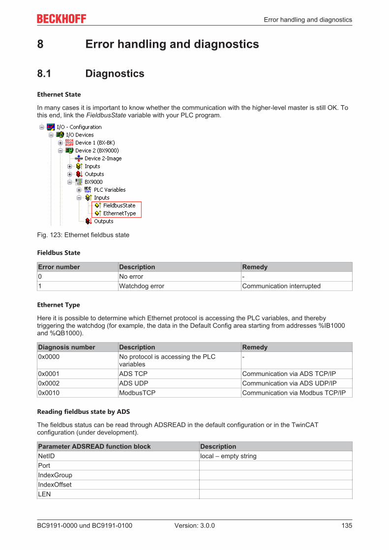
Error handling and diagnostics
BC9191-0000 und BC9191-0100 135Version: 3.0.0
8 Error handling and diagnostics
8.1 Diagnostics
Ethernet State
In many cases it is important to know whether the communication with the higher-level master is still OK. Tothis end, link the FieldbusState variable with your PLC program.
Fig. 123: Ethernet fieldbus state
Fieldbus State
Error number Description Remedy0 No error -1 Watchdog error Communication interrupted
Ethernet Type
Here it is possible to determine which Ethernet protocol is accessing the PLC variables, and therebytriggering the watchdog (for example, the data in the Default Config area starting from addresses %IB1000and %QB1000).
Diagnosis number Description Remedy0x0000 No protocol is accessing the PLC
variables-
0x0001 ADS TCP Communication via ADS TCP/IP0x0002 ADS UDP Communication via ADS UDP/IP0x0010 ModbusTCP Communication via Modbus TCP/IP
Reading fieldbus state by ADS
The fieldbus status can be read through ADSREAD in the default configuration or in the TwinCATconfiguration (under development).
Parameter ADSREAD function block DescriptionNetID local – empty stringPortIndexGroupIndexOffsetLEN

Error handling and diagnostics
BC9191-0000 und BC9191-0100136 Version: 3.0.0
State of the K-bus
An internal bus or Bus Terminal error is indicated in the K-bus state. A more precise fault description can beobtained via a function block (in preparation). To this end, link the K-bus-State variable with your PLCprogram.
Fig. 124: State of the K-bus
Error bit Description Error type0 No error No ERRORBit 0 K-bus error ERRORBit 2 K-bus is re-triggered NOTE
Reading K-bus state by ADS
In default or TwinCAT configuration the fieldbus state can be read via ADSREAD.
Parameter ADSREAD function block DescriptionNetID local – empty stringPort 1IndexGroup 16#0006IndexOffset 16#000C_9000LEN 1
8.2 Diagnostic LEDsThe BC9191-0000 and BC9191-0100 have LEDs for status display.
Diagnostic LEDs BC9191 and BC9191-0100 up to HW 4
Fig. 125: LEDs BC9191 to HW 4

Error handling and diagnostics
BC9191-0000 und BC9191-0100 137Version: 3.0.0
Diagnostic LEDs BC9191 and BC9191-0100 from HW 5
Fig. 126: LEDs BC9191 from HW 5
LEDs for PLC diagnostics
LED MeaningPLC on - PLC running, flashing - cycle time exceeded, off - cycle time permanently exceeded
or PLC stoppedTC/DC on - TwinCAT configuration active, off - Default configuration active, flashing TwinCAT
configuration faulty
LEDs for Ethernet diagnostics
LED MeaningLINK/ACT(RJ45)
on - LINK available, flashing - LINK available and communication
COM Communication with controller availableERROR flashing - DHCP or BootP active. Waiting for an IP address. short flashing - the source
code of the PLC program is loaded and is being checked. No boot project can be createdduring this check time.
LEDs for power supply diagnostics
LED MeaningPower LED Vs on - internal power supply 5 VDC okay (for hardware version 3 and 4 only visible with
unplugged connector X1)Power LED Vp on - 24 VDC power supply for external devices okay
LEDs for K-bus diagnostics
LED MeaningK-bus RUN on or flashing - K-bus runningK-bus ERR flashing (see error code) [ 138]

Error handling and diagnostics
BC9191-0000 und BC9191-0100138 Version: 3.0.0
Error code for K-bus diagnostics
Error code
Error argument
Description Remedy
- flashing con-tinuously
EMC problems • Check power supply for undervoltage or overvoltagepeaks
• Implement EMC measures• If a K-bus error is present, it can be localized by a restart
(by switching the BC9191 off and then on again)1 0 EEPROM checksum error Enter factory settings with the KS2000 configuration software
1 Code buffer overflow Insert fewer Bus Terminals. Too many entries in the table for theprogrammed configuration
2 Unknown data type Software update required for the BC91912 - reserve -3 0 K-bus command error • No Bus Terminal inserted
• One of the Bus Terminals is defective; halve the numberof Bus Terminals attached and check whether the error isstill present with the remaining Bus Terminals. Repeatuntil the defective Bus Terminal is located.
4 0 K-bus data error, break behind the BusCoupler
Check whether the n+1 Bus Terminal is correctly connected; re-place if necessary
n Break behind Bus Terminal n Check whether the KL9010 bus end terminal is connected5 n K-bus error in register communication
with Bus Terminal nExchange the nth Bus Terminal
6 0 Error at initialization Exchange Bus Coupler1 Internal data error Perform a hardware reset on the BC9191 (switch off and on
again)2 DIP switch changed after a software re-
setPerform a hardware reset on the BC9191 (switch off and onagain)
3 IP address already assigned Check whether the IP address already exists in the network.7 0 Note: cycle time was exceeded Warning: the set cycle time was exceeded. This note (flashing of
the LED)can only be reset by rebooting the BC9191.Short-term remedy: increase cycle time
9 0 Checksum error in Flash program Transmit program to the BC again1 Incorrect or faulty library implemented Remove the faulty library
10 n Bus Terminal n is not consistent withthe configuration that existed when theboot project was created
Check the nth Bus Terminal. The boot project must be deleted ifthe insertion of an nth Bus Terminal is intentional.
14 n nth Bus Terminal has the wrong format Start the BC9191 again, and if the error occurs again then ex-change the Bus Terminal.
15 n Number of Bus Terminals is no longercorrect
Start the BC9191 again. If the error occurs again, restore themanufacturers setting using the KS2000 configuration software
16 n Length of the K-bus data is no longercorrect
Start the Bus Coupler again. If the error occurs again, restore themanufacturers setting using the KS2000 configuration software
8.3 General errors
No data exchange after replacing a bus coupler
You have exchanged the Ethernet Bus Coupler and set the same TCP/IP number, but data is notexchanged.
Each Ethernet device has its own and unique MAC ID. This number is saved when connecting to theEthernet node and stored in a table. This table contains the correspondences between the MAC-ID and theTCP/IP number. You must clear this memory and you can do this by entering the command >arp -d< and theTCP/IP number of the Bus Coupler in the DOS window.Example: >arp -d 172.16.17.203<If the DHCP or BootP protocol is activated, the MAC ID of the new Bus Coupler must be set on the DHCP orBootP server after the coupler change.

Error handling and diagnostics
BC9191-0000 und BC9191-0100 139Version: 3.0.0
Communication errors when online *
After a period in the online state (logged in via Ethernet/AMS) the message Communication error - loggingout always occurs.
The data traffic through the Ethernet interface is jamming.
Remedy:
• reduce the level of data communication.• Stop the cyclical data traffic, or lengthen the task time.• Reduce the number of windows open in the online representation.• Log in via the serial interface.
* BC9000, C900 only
8.4 ADS diagnostics
Status inputs
It is possible to monitor the BK/BC9000, B/C900 Bus Coupler's communication in the System Manager. EachBus Coupler has status inputs that can be found in the hardware tree.
Fig. 127: Status and diagnostic inputs
Coupler state
Value Meaning0x0000 No error0x0001 Bus Terminal error; there is a K-bus error0x0002 Configuration error; the parameterized configuration does not match the actual configuration
MissedCnt
Ideal configuration:The task time is always longer than the Ethernet propagation delay. An Ethernet telegram is transmitted atthe beginning of the task, and it returns it to the PC again after a period of time, tEth. If the time tEth is alwayssmaller than the task time that has been set, the value in the MissedCnt counter remains constant.
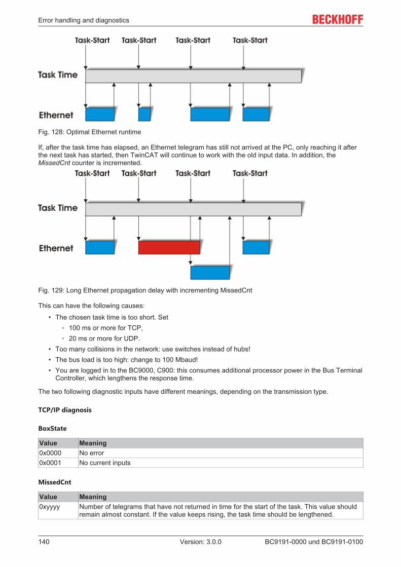
Error handling and diagnostics
BC9191-0000 und BC9191-0100140 Version: 3.0.0
Fig. 128: Optimal Ethernet runtime
If, after the task time has elapsed, an Ethernet telegram has still not arrived at the PC, only reaching it afterthe next task has started, then TwinCAT will continue to work with the old input data. In addition, theMissedCnt counter is incremented.
Fig. 129: Long Ethernet propagation delay with incrementing MissedCnt
This can have the following causes:
• The chosen task time is too short. Set 100 ms or more for TCP, 20 ms or more for UDP.
• Too many collisions in the network: use switches instead of hubs!• The bus load is too high: change to 100 Mbaud!• You are logged in to the BC9000, C900: this consumes additional processor power in the Bus Terminal
Controller, which lengthens the response time.
The two following diagnostic inputs have different meanings, depending on the transmission type.
TCP/IP diagnosis
BoxState
Value Meaning0x0000 No error0x0001 No current inputs
MissedCnt
Value Meaning0xyyyy Number of telegrams that have not returned in time for the start of the task. This value should
remain almost constant. If the value keeps rising, the task time should be lengthened.

Error handling and diagnostics
BC9191-0000 und BC9191-0100 141Version: 3.0.0
UDP/IP diagnosis
BoxState
Value Meaning0x0000 No error0x0001 No current inputs0x0002 Outputs are written as zero0xxxzz xx - warning level. The value here is incremented by one each time the data is not received in
time. When data is exchanged correctly, the value is decremented by one. When themaximum Warning Level (default 100) is reached, null is written to the output data, and it isonly enabled again for the normal process image when the Warning Level has reached null.
MissedCnt
Value Meaning0xyyyy Number of telegrams that have not returned in time for the start of the task. This value should
remain almost constant. If the value keeps rising, the task time should be lengthened.

Appendix
BC9191-0000 und BC9191-0100142 Version: 3.0.0
9 Appendix
9.1 BC9191 - First steps
Necessary components• BC9191 or BC9191-0100• Programming PC with TwinCAT 2 and Ethernet interface• Wiring material• A normal Ethernet cable between PC and BC9191
DIP switch settings
Set DIP switch 1 to ON, leave all other DIP switches OFF. A fixed IP address is used. Also set the doubleDIP switch to OFF. After setting the DIP switches, restart the BC9191.The BC9191 then has the IP address 172.16.21.1
Set an appropriate IP address on your programmer PC. For example: 172.16.100.100 (SubNetMask255.255.0.0).
Fig. 130: Fixed IP address of the programmer PC
Use the >Ping< command to check whether TCP/IP communication is available. Open the prompt (DOS box)and enter the following: Ping 172.16.21.1. If the ping is successful you can continue. If the ping is notanswered the communication is faulty. Then check the Ethernet connection:
• proper Ethernet cable• the DIP switch of the controller is switched on correctly• the IP address is changed on the programmer PC.

Appendix
BC9191-0000 und BC9191-0100 143Version: 3.0.0
Finding the Bus Terminal Controller with the TwinCAT System Manager
Start the System Manager. Select a new target system.
Fig. 131: System Manager
Click Search (Ethernet)...
Fig. 132: Finding the Bus Terminal Controller with the TwinCAT System Manager
Then click Broadcast Search. The Bus Terminal Controller now appears in the window. The host name isformed from the Bus Terminal Controller plus the last 3 bytes of the MAC ID and is therefore unique in yoursystem. The MAC ID is printed on a label below the Bus Terminal Controller. Set the options button to IPAddress and click Add Route. The Connected field should show a cross or "X". If a password query appearsconfirm with OK (leave blank). The password function is not implemented in the Bus Terminal Controller.
You can now select the Bus Terminal Controller. Click on the Bus Terminal Controller and confirm with OK.

Appendix
BC9191-0000 und BC9191-0100144 Version: 3.0.0
Fig. 133: Choose Target System
Your Bus Terminal Controller with name and IP address is shown in red at bottom left in the SystemManager. The field next to it should be blue and show Config Mode. If this is the case you can now scan thedevice. Right-click on I/O Devices then Scan Devices.
Fig. 134: Scan Devices
The System Manager should find 2 devices. The K-bus interface "Device 1 (BX-BK)" and the Ethernetinterface "Device 2 (BC9191-0100)".

Appendix
BC9191-0000 und BC9191-0100 145Version: 3.0.0
BC9191 in the System Manager
Fig. 135: Display of the BX9191 in the System Manager
Under device 1 (BX-BK) you can configure the terminal connection and the integrated periphery.
Under device 2 (BC9191-0100) you can make the settings for the Ethernet interface and the PLC variables.
If you do not want to use the pre-installed PLC program for a three-stage fan controller (see chapter 6), youcan insert your own program created with TwinCAT 2 PLC Control under PLC Configuration.
9.2 General operating conditionsThe following conditions must be met in order to ensure flawless operation of the fieldbus components.
Environmental conditions
Operation
The components may not be used without additional protection in the following locations:
• in difficult environments, such as where there are corrosive vapors or gases, or high dust levels• in the presence of high levels of ionizing radiation

Appendix
BC9191-0000 und BC9191-0100146 Version: 3.0.0
Condition Permissible rangePermissible ambient temperature during operation 0 °C ... +55 °CInstallation position Vertical on mounting rail mounted horizontally on the
wallVibration resistance conforms to EN 60068-2-6Shock resistance conforms to EN 60068-2-27EMC immunity conforms to EN 61000-6-2Emission conforms to EN 61000-6-4
Transport and storage
Condition Permissible rangePermissible ambient temperature during storage -25 °C ... +85 °CRelative humidity 95 %, no condensationFree fall up to 1 m in the original packaging
Protection classes and types
Condition Permissible rangeProtection class in accordance with IEC 536(VDE 0106, Part 1)
A protective conductor connection to the profile rail isnecessary!
Protection class conforms to IEC 529 IP20 (protection against contact with a standard testfinger)
Protection against foreign objects Less than 12 mm in diameterProtection against water no protection
Component identification
Every supplied component includes an adhesive label providing information about the product's approvals.Example for the BK2000 Bus Coupler:
Fig. 136: BK2000 - label
The following information is printed on the label:

Appendix
BC9191-0000 und BC9191-0100 147Version: 3.0.0
Printed item Meaning for this labelPrecise product identification BK2000 Lightbus CouplerSupply voltage 24 VDC
Data transfer rate 2.5 MbaudVendor Beckhoff Automation GmbHCE mark Conformity markUL mark Mark for UL approval. UL stands for the Underwriters Laboratories Inc., the
leading certification organization for North America, based in the USA.C = Canada, US = USA, LISTED 22ZA (the test results can be inspectedunder this entry)
Production identification From left to right, this sequence of characters indicates the week ofproduction (2 characters), the year of production (2 characters), thesoftware version (2 characters) and hardware version (2 characters), alongwith any special indications (4 characters).In this case the device is a BK2000- produced in calendar week 9- of 2021- with firmware version BF- in hardware version 6- without special designation
9.3 Test standards for device testing
EMC
EMC immunity
EN 61000-6-2
EMC emission
EN 61000-6-4
Vibration / shock resistance
Vibration resistance
EN 60068-2-6
Shock resistance
EN 60068-2-27, EN 60068-2-29
9.4 Bibliography
TCP/IP
TCP/IP (German)Configuration and operation of a TCP/IP networkby Kevin Washburn, Jim EvansPublisher: ADDISON-WESLEY Longmann Verlag

Appendix
BC9191-0000 und BC9191-0100148 Version: 3.0.0
TCP/IP (english)Illustrated, Volume1 The Protocolsby W. Richard StevensPublisher: ADDISON-WESLEY Longmann Verlag
Modbus/TCP
http://www.modicon.com/http://www.modbus.org
TwinCAT
Beckhoff Information System:http://infosys.beckhoff.com
9.5 List of Abbreviations
ADS
Automation Device Specification
IP20
Bus Terminal protection class
IPC
Industrial PC
I/O
Inputs and outputs
K-bus
Terminal bus
KS2000
Configuration software for Bus Terminals, Bus Couplers, Bus Terminal Controllers, Fieldbus Box modules,etc.
PE
The PE power contact can be used as a protective earth.
TwinCAT
The Windows Control and Automation Technology

Appendix
BC9191-0000 und BC9191-0100 149Version: 3.0.0
9.6 Support and ServiceBeckhoff and their partners around the world offer comprehensive support and service, making available fastand competent assistance with all questions related to Beckhoff products and system solutions.
Beckhoff's branch offices and representatives
Please contact your Beckhoff branch office or representative for local support and service on Beckhoffproducts!
The addresses of Beckhoff's branch offices and representatives round the world can be found on her internetpages: https://www.beckhoff.com
You will also find further documentation for Beckhoff components there.
Beckhoff Support
Support offers you comprehensive technical assistance, helping you not only with the application ofindividual Beckhoff products, but also with other, wide-ranging services:
• support• design, programming and commissioning of complex automation systems• and extensive training program for Beckhoff system components
Hotline: +49 5246 963 157Fax: +49 5246 963 9157e-mail: [email protected]
Beckhoff Service
The Beckhoff Service Center supports you in all matters of after-sales service:
• on-site service• repair service• spare parts service• hotline service
Hotline: +49 5246 963 460Fax: +49 5246 963 479e-mail: [email protected]
Beckhoff Headquarters
Beckhoff Automation GmbH & Co. KG
Huelshorstweg 2033415 VerlGermany
Phone: +49 5246 963 0Fax: +49 5246 963 198e-mail: [email protected]: https://www.beckhoff.com
List of figures
BC9191-0000 und BC9191-0100150 Version: 3.0.0
List of figuresFig. 1 BC9191........................................................................................................................................ 10Fig. 2 Extension of the BC9191 with Bus Terminals.............................................................................. 11Fig. 3 Spring contacts of the Beckhoff I/O components......................................................................... 16Fig. 4 Dimensions of the BC9191 .......................................................................................................... 17Fig. 5 BC9191 - Minimum distances...................................................................................................... 18Fig. 6 BC9191 - Schematic diagram of the internal power supply......................................................... 20Fig. 7 BC9191 - Supply of the power contacts of connected Bus Terminals......................................... 21Fig. 8 Power contact on the left ............................................................................................................. 22Fig. 9 BC9191-0000 - Terminal strip X1 with interface for enocean ...................................................... 23Fig. 10 Block diagram of the integrated digital inputs .............................................................................. 24Fig. 11 Block diagram LED output ........................................................................................................... 24Fig. 12 BC9191-0100 - Terminal strip X1 with RS485 interface .............................................................. 25Fig. 13 Block diagram of the digital inputs ............................................................................................... 26Fig. 14 Block diagram LED output ........................................................................................................... 26Fig. 15 BC9191-0000 and BC9191-0100 - Terminal strips X2 and X3.................................................... 27Fig. 16 Ethernet layout in linear topology ................................................................................................ 29Fig. 17 RJ45 plug..................................................................................................................................... 30Fig. 18 BC9191 - Auto-crossing............................................................................................................... 31Fig. 19 Start-up behavior of the BC9191 ................................................................................................. 33Fig. 20 Example of Ethernet IP address 172.16.21.1 .............................................................................. 34Fig. 21 Example of Ethernet IP address 172.16.21.2 .............................................................................. 34Fig. 22 Example of Ethernet IP address 172.16.21.40 ............................................................................ 35Fig. 23 IP address setting with the KS2000 configuration software......................................................... 36Fig. 24 Address Configuration via TwinCAT System Manager................................................................ 37Fig. 25 Configuration of the BootP server................................................................................................ 38Fig. 26 Testing the IP address using the Ping command ........................................................................ 40Fig. 27 Security settings .......................................................................................................................... 41Fig. 28 Finding the Bus Terminal Controller ............................................................................................ 43Fig. 29 Choose Target System................................................................................................................ 44Fig. 30 Add Route Dialog......................................................................................................................... 45Fig. 31 Creating a TwinCAT configuration............................................................................................... 45Fig. 32 Selecting the Bus Terminal Controller ......................................................................................... 46Fig. 33 Downloading a TwinCAT configuration........................................................................................ 47Fig. 34 Selecting the Bus Terminal Controller ......................................................................................... 47Fig. 35 State of the Bus Terminal Controller............................................................................................ 47Fig. 36 Activating the TwinCAT configuration.......................................................................................... 47Fig. 37 Choose Target System................................................................................................................ 48Fig. 38 Selecting the Bus Terminal Controller ......................................................................................... 49Fig. 39 State of the Bus Terminal Controller............................................................................................ 49Fig. 40 Uploading the TwinCAT configuration ......................................................................................... 49Fig. 41 Memory for code mapping ........................................................................................................... 50Fig. 42 Data memory mapping ................................................................................................................ 50Fig. 43 Code and data memory ............................................................................................................... 51Fig. 44 Other memory.............................................................................................................................. 51

List of figures
BC9191-0000 und BC9191-0100 151Version: 3.0.0
Fig. 45 Communication settings .............................................................................................................. 52Fig. 46 Individual adjustment of the time after which the Master PLC queries the individual Bus Termi-
nal Controller ............................................................................................................................... 54Fig. 47 BX Settings tab ............................................................................................................................ 55Fig. 48 BX Diag tab.................................................................................................................................. 56Fig. 49 Selecting the PLC project ........................................................................................................... 57Fig. 50 Connecting PLC variable and hardware ...................................................................................... 57Fig. 51 Target system display.................................................................................................................. 58Fig. 52 Setting the task time .................................................................................................................... 59Fig. 53 Displaying the PLC cycle time ..................................................................................................... 60Fig. 54 KS2000 configuration software.................................................................................................... 62Fig. 55 Display of the BC9191 in the KS2000 software........................................................................... 63Fig. 56 Maximum number of POUs exceeded......................................................................................... 65Fig. 57 Menu path Projects / Options / Controller Settings...................................................................... 65Fig. 58 Controller settings........................................................................................................................ 65Fig. 59 Global memory insufficient .......................................................................................................... 66Fig. 60 Menu path Projects / Options / Build ........................................................................................... 66Fig. 61 Build............................................................................................................................................. 66Fig. 62 Changing variable links................................................................................................................ 71Fig. 63 Linking a variable with an input.................................................................................................... 71Fig. 64 IP address of the BX9000 in the TwinCAT System Manager ...................................................... 74Fig. 65 Selecting the data transfer route - AMS....................................................................................... 75Fig. 66 Choose Target System................................................................................................................ 75Fig. 67 Opening the options menu........................................................................................................... 76Fig. 68 Selecting Source Download......................................................................................................... 76Fig. 69 Downloading the program code................................................................................................... 77Fig. 70 Download progress ..................................................................................................................... 77Fig. 71 Uploading a program ................................................................................................................... 78Fig. 72 Selecting the data transfer route.................................................................................................. 78Fig. 73 Selecting the device..................................................................................................................... 78Fig. 74 Fan control - main program ......................................................................................................... 81Fig. 75 Fan control - system diagram ...................................................................................................... 82Fig. 76 Function block FB_BC9191EnergyLevel ..................................................................................... 83Fig. 77 Assignment of the energy level in automatic mode-I ................................................................... 86Fig. 78 Assignment of the energy level in automatic mode-II .................................................................. 87Fig. 79 Function block FB_BC9191FanCoil............................................................................................. 87Fig. 80 Function block FB_BC9191FctSelection ..................................................................................... 90Fig. 81 Switching between heating and cooling mode............................................................................. 90Fig. 82 Function block FB_BC9191SetpointRoom .................................................................................. 92Fig. 83 Assignment of energy levels........................................................................................................ 93Fig. 84 Mode of operation Setpoint shift .................................................................................................. 94Fig. 85 Function block FB_BC9191PICtrl ................................................................................................ 98Fig. 86 Functional correlation Xp ............................................................................................................. 98Fig. 87 Functional correlation small Xp.................................................................................................... 99Fig. 88 Step response PI controller ......................................................................................................... 99Fig. 89 TcSystem.lib library ..................................................................................................................... 102

List of figures
BC9191-0000 und BC9191-0100152 Version: 3.0.0
Fig. 90 Structure of the ADS protocol ...................................................................................................... 102Fig. 91 Sample: writing flags with the FB ADSWrite................................................................................ 103Fig. 92 Sample: writing flag bits with the FB ADSWrite ........................................................................... 103Fig. 93 Selection of the virtual Ethernet interface .................................................................................... 105Fig. 94 Add BC9191 as BOX................................................................................................................... 106Fig. 95 Add PLC project........................................................................................................................... 107Fig. 96 Set assignable name ................................................................................................................... 108Fig. 97 Set communication setting to UDP.............................................................................................. 109Fig. 98 Edit name of inputs and outputs .................................................................................................. 110Fig. 99 Linking the structure of the PLC task with the PLC variables ...................................................... 111Fig. 100 Linking the structure of the PLC task with the PLC variables ...................................................... 111Fig. 101 Display of the successful variable mapping................................................................................. 112Fig. 102 Sample program with CX5020..................................................................................................... 112Fig. 103 Definition of BC9191 structures as global variables (CX5020).................................................... 113Fig. 104 BC9191 structures are placed on IB1000 and QB1000 for master/slave communication........... 113Fig. 105 Diagnosis of the connection via the variable BC9119_uiMonitoring............................................ 114Fig. 106 Visualization of the master application (CX5020) ........................................................................ 114Fig. 107 Display of Global Variables (BC9191) ......................................................................................... 115Fig. 108 Swap HI and LOW word .............................................................................................................. 116Fig. 109 Assignment of two BC9191 in the master configuration .............................................................. 116Fig. 110 Assignment of the physical inputs ............................................................................................... 117Fig. 111 Assignment of the physical outputs ............................................................................................. 118Fig. 112 User Datagram Protocol (UDP) ................................................................................................... 120Fig. 113 Protocols running on top of TCP/IP and UDP/IP ......................................................................... 120Fig. 114 ModbusTCP Protocol................................................................................................................... 121Fig. 115 The ADS protocol as a transport layer within the TwinCAT system ............................................ 126Fig. 116 Structure of the ADS protocol ...................................................................................................... 127Fig. 117 Displaying the AMS routing table using the KS2000 configuration software ............................... 130Fig. 118 Functioning ADS connection ....................................................................................................... 131Fig. 119 Communication between several BC9000 - topology.................................................................. 132Fig. 120 Communication from the BC9000 to the higher-level controller (TwinCAT PC system).............. 132Fig. 121 The command ipconfig ................................................................................................................ 133Fig. 122 Display of the AMS Net ID under Properties/AMS Router........................................................... 133Fig. 123 Ethernet fieldbus state ................................................................................................................. 135Fig. 124 State of the K-bus ........................................................................................................................ 136Fig. 125 LEDs BC9191 to HW 4 ................................................................................................................ 136Fig. 126 LEDs BC9191 from HW 5............................................................................................................ 137Fig. 127 Status and diagnostic inputs........................................................................................................ 139Fig. 128 Optimal Ethernet runtime............................................................................................................. 140Fig. 129 Long Ethernet propagation delay with incrementing MissedCnt.................................................. 140Fig. 130 Fixed IP address of the programmer PC ..................................................................................... 142Fig. 131 System Manager.......................................................................................................................... 143Fig. 132 Finding the Bus Terminal Controller with the TwinCAT System Manager................................... 143Fig. 133 Choose Target System................................................................................................................ 144Fig. 134 Scan Devices............................................................................................................................... 144Fig. 135 Display of the BX9191 in the System Manager ........................................................................... 145

List of figures
BC9191-0000 und BC9191-0100 153Version: 3.0.0
Fig. 136 BK2000 - label ............................................................................................................................. 146


Beckhoff Automation GmbH & Co. KGHülshorstweg 2033415 VerlGermanyPhone: +49 5246 [email protected]
More Information: www.beckhoff.com/BC9191
Copyright © 2022 FDOKUMEN

