


Bahasa
Halaman
Hukum

RELION® 670 SERIES— Phasor measurement unit RES670 Version 2.2 IEC Application manual

Document ID: 1MRK 511 407-UENIssued: June 2018
Revision: CProduct version: 2.2
© Copyright 2017 ABB. All rights reserved
Copyright
This document and parts thereof must not be reproduced or copied without writtenpermission from ABB, and the contents thereof must not be imparted to a thirdparty, nor used for any unauthorized purpose.
The software and hardware described in this document is furnished under a licenseand may be used or disclosed only in accordance with the terms of such license.
This product includes software developed by the OpenSSL Project for use in theOpenSSL Toolkit. (http://www.openssl.org/) This product includes cryptographicsoftware written/developed by: Eric Young ([email protected]) and Tim Hudson([email protected]).
TrademarksABB and Relion are registered trademarks of the ABB Group. All other brand orproduct names mentioned in this document may be trademarks or registeredtrademarks of their respective holders.
WarrantyPlease inquire about the terms of warranty from your nearest ABB representative.

Disclaimer
The data, examples and diagrams in this manual are included solely for the conceptor product description and are not to be deemed as a statement of guaranteedproperties. All persons responsible for applying the equipment addressed in thismanual must satisfy themselves that each intended application is suitable andacceptable, including that any applicable safety or other operational requirementsare complied with. In particular, any risks in applications where a system failureand/or product failure would create a risk for harm to property or persons(including but not limited to personal injuries or death) shall be the soleresponsibility of the person or entity applying the equipment, and those soresponsible are hereby requested to ensure that all measures are taken to exclude ormitigate such risks.
This document has been carefully checked by ABB but deviations cannot becompletely ruled out. In case any errors are detected, the reader is kindly requestedto notify the manufacturer. Other than under explicit contractual commitments, inno event shall ABB be responsible or liable for any loss or damage resulting fromthe use of this manual or the application of the equipment.

Conformity
This product complies with the directive of the Council of the EuropeanCommunities on the approximation of the laws of the Member States relating toelectromagnetic compatibility (EMC Directive 2004/108/EC) and concerningelectrical equipment for use within specified voltage limits (Low-voltage directive2006/95/EC). This conformity is the result of tests conducted by ABB inaccordance with the product standard EN 60255-26 for the EMC directive, andwith the product standards EN 60255-1 and EN 60255-27 for the low voltagedirective. The product is designed in accordance with the international standards ofthe IEC 60255 series.

Table of contents
Section 1 Introduction.....................................................................13This manual...................................................................................... 13Intended audience............................................................................ 13Product documentation.....................................................................14
Product documentation set..........................................................14Document revision history........................................................... 15Related documents......................................................................16
Document symbols and conventions................................................16Symbols.......................................................................................16Document conventions................................................................17
IEC 61850 edition 1 / edition 2 mapping...........................................18
Section 2 Application......................................................................27General IED application....................................................................27Wide area measurement functions...................................................29Back-up protection functions............................................................ 30Control and monitoring functions......................................................31Communication.................................................................................37Basic IED functions.......................................................................... 38
Section 3 Configuration..................................................................41Introduction.......................................................................................41Description of configuration RES670................................................42
Introduction..................................................................................42Description of configuration A20............................................ 42Description of configuration B20............................................ 44
Section 4 Analog inputs..................................................................47Introduction.......................................................................................47Setting guidelines............................................................................. 47
Setting of the phase reference channel.......................................48Example................................................................................. 48
Setting of current channels..........................................................48Example 1.............................................................................. 49Example 2.............................................................................. 49Example 3.............................................................................. 50Examples on how to connect, configure and set CTinputs for most commonly used CT connections....................54Example on how to connect a star connected three-phase CT set to the IED......................................................... 55
Table of contents
Phasor measurement unit RES670 2.2 IEC 1Application manual
Example how to connect delta connected three-phaseCT set to the IED....................................................................60Example how to connect single-phase CT to the IED............ 63
Relationships between setting parameter Base Current, CTrated primary current and minimum pickup of a protection IED.. 65Setting of voltage channels......................................................... 65
Example................................................................................. 65Examples how to connect, configure and set VT inputsfor most commonly used VT connections.............................. 66Examples on how to connect a three phase-to-earthconnected VT to the IED........................................................ 67Example on how to connect a phase-to-phaseconnected VT to the IED........................................................ 69Example on how to connect an open delta VT to the IEDfor high impedance earthed or unearthed networks...............71Example how to connect the open delta VT to the IEDfor low impedance earthed or solidly earthedpower systems....................................................................... 74
Section 5 Local HMI....................................................................... 77Display..............................................................................................78LEDs.................................................................................................80Keypad............................................................................................. 81Local HMI functionality..................................................................... 83
Protection and alarm indication................................................... 83Parameter management .............................................................84Front communication...................................................................85
Section 6 Wide area measurement system....................................87Protocol reporting via IEEE 1344 and C37.118 PMUREPORT........87
Identification................................................................................ 87Application...................................................................................87Operation principle...................................................................... 89
Frequency reporting............................................................... 91Reporting filters...................................................................... 93Scaling Factors for ANALOGREPORT channels................... 94PMU Report Function Blocks Connection Rules inPCM600 Application Configuration Tool (ACT)......................95
Setting guidelines...................................................................... 101
Section 7 Impedance protection...................................................107Power swing detection ZMRPSB ...................................................107
Identification.............................................................................. 107Application.................................................................................107
General.................................................................................107
Table of contents
2 Phasor measurement unit RES670 2.2 IECApplication manual
Basic characteristics.............................................................108Setting guidelines...................................................................... 108
Out-of-step protection OOSPPAM .................................................116Identification.............................................................................. 116Application.................................................................................116Setting guidelines...................................................................... 119
Section 8 Current protection.........................................................123Directional phase overcurrent protection, four steps OC4PTOC....123
Identification.............................................................................. 123Application.................................................................................123Setting guidelines...................................................................... 124
Settings for each step...........................................................126Setting example....................................................................129
Directional residual overcurrent protection, four steps EF4PTOC .134Identification.............................................................................. 134Setting guidelines...................................................................... 134
Common settings for all steps.............................................. 1352nd harmonic restrain...........................................................136Parallel transformer inrush current logic...............................137Switch onto fault logic...........................................................137Settings for each step (x = 1, 2, 3 and 4)............................. 138
Four step directional negative phase sequence overcurrentprotection NS4PTOC .....................................................................141
Identification.............................................................................. 141Application.................................................................................141Setting guidelines...................................................................... 143
Settings for each step ..........................................................143Common settings for all steps.............................................. 146
Sensitive directional residual overcurrent and power protectionSDEPSDE ..................................................................................... 147
Identification.............................................................................. 148Application.................................................................................148Setting guidelines...................................................................... 149
Thermal overload protection, one time constant, Celsius/Fahrenheit LCPTTR/LFPTTR.........................................................158
Identification.............................................................................. 158Application.................................................................................158Setting guideline........................................................................159
Directional underpower protection GUPPDUP............................... 160Identification.............................................................................. 160Application.................................................................................160Setting guidelines...................................................................... 162
Directional overpower protection GOPPDOP ................................165
Table of contents
Phasor measurement unit RES670 2.2 IEC 3Application manual
Identification.............................................................................. 165Application.................................................................................165Setting guidelines...................................................................... 167
Section 9 Voltage protection........................................................ 173Two step undervoltage protection UV2PTUV ................................173
Identification.............................................................................. 173Application.................................................................................173Setting guidelines...................................................................... 174
Equipment protection, such as for motors and generators...174Disconnected equipment detection...................................... 174Power supply quality ........................................................... 174Voltage instability mitigation................................................. 174Backup protection for power system faults...........................174Settings for two step undervoltage protection...................... 175
Two step overvoltage protection OV2PTOV ..................................176Identification.............................................................................. 176Application.................................................................................177Setting guidelines...................................................................... 177
Equipment protection, such as for motors, generators,reactors and transformers.................................................... 178Equipment protection, capacitors......................................... 178Power supply quality............................................................ 178High impedance earthed systems........................................ 178The following settings can be done for the two stepovervoltage protection.......................................................... 178
Section 10 Frequency protection....................................................181Underfrequency protection SAPTUF ............................................. 181
Identification.............................................................................. 181Application.................................................................................181Setting guidelines...................................................................... 181
Overfrequency protection SAPTOF ...............................................182Identification.............................................................................. 182Application.................................................................................183Setting guidelines...................................................................... 183
Rate-of-change of frequency protection SAPFRC .........................184Identification.............................................................................. 184Application.................................................................................184Setting guidelines...................................................................... 184
Frequency time accumulation protection function FTAQFVR........ 185Identification.............................................................................. 185Application.................................................................................185Setting guidelines...................................................................... 187
Table of contents
4 Phasor measurement unit RES670 2.2 IECApplication manual
Section 11 Multipurpose protection................................................189General current and voltage protection CVGAPC.......................... 189
Identification.............................................................................. 189Application.................................................................................189
Current and voltage selection for CVGAPC function............190Base quantities for CVGAPC function..................................193Application possibilities........................................................ 193Inadvertent generator energization...................................... 194
Setting guidelines...................................................................... 195Directional negative sequence overcurrent protection......... 195Negative sequence overcurrent protection...........................197Generator stator overload protection in accordance withIEC or ANSI standards......................................................... 199Open phase protection for transformer, lines orgenerators and circuit breaker head flashover protectionfor generators....................................................................... 201Voltage restrained overcurrent protection for generatorand step-up transformer....................................................... 202Loss of excitation protection for a generator........................ 203
Section 12 System protection and control......................................205Multipurpose filter SMAIHPAC....................................................... 205
Identification.............................................................................. 205Application.................................................................................205Setting guidelines...................................................................... 206
Setting example....................................................................206
Section 13 Secondary system supervision.....................................211Current circuit supervision CCSSPVC............................................211
Identification.............................................................................. 211Application.................................................................................211Setting guidelines...................................................................... 211
Fuse failure supervision FUFSPVC................................................212Identification.............................................................................. 212Application.................................................................................212Setting guidelines...................................................................... 213
General.................................................................................213Setting of common parameters............................................ 213Negative sequence based....................................................214Zero sequence based...........................................................215Delta U and delta I ...............................................................215Dead line detection...............................................................216
Section 14 Control..........................................................................217
Table of contents
Phasor measurement unit RES670 2.2 IEC 5Application manual
Logic rotating switch for function selection and LHMIpresentation SLGAPC.................................................................... 217
Identification.............................................................................. 217Application.................................................................................217Setting guidelines...................................................................... 218
Selector mini switch VSGAPC........................................................218Identification.............................................................................. 218Application.................................................................................218Setting guidelines...................................................................... 219
Generic communication function for Double Point indicationDPGAPC........................................................................................ 219
Identification.............................................................................. 219Application.................................................................................219Setting guidelines...................................................................... 220
Single point generic control 8 signals SPC8GAPC........................ 220Identification.............................................................................. 220Application.................................................................................221Setting guidelines...................................................................... 221
AutomationBits, command function for DNP3.0 AUTOBITS.......... 221Identification.............................................................................. 221Application.................................................................................222Setting guidelines...................................................................... 222
Single command, 16 signals SINGLECMD.................................... 222Identification.............................................................................. 222Application.................................................................................222Setting guidelines...................................................................... 224
Section 15 Logic.............................................................................227Tripping logic SMPPTRC ...............................................................227
Identification.............................................................................. 227Application.................................................................................227
Three-phase tripping............................................................ 228Single- and/or three-phase tripping...................................... 229Single-, two- or three-phase tripping.................................... 230Lock-out................................................................................230Example of directional data.................................................. 231Blocking of the function block...............................................233
Setting guidelines...................................................................... 233Trip matrix logic TMAGAPC........................................................... 233
Identification.............................................................................. 233Logic for group alarm ALMCALH....................................................234
Identification.............................................................................. 234Application.................................................................................234Setting guidelines...................................................................... 234
Table of contents
6 Phasor measurement unit RES670 2.2 IECApplication manual
Logic for group alarm WRNCALH.................................................. 234Identification.............................................................................. 234
Application............................................................................234Setting guidelines................................................................. 234
Logic for group indication INDCALH...............................................235Identification.............................................................................. 235
Application............................................................................235Setting guidelines................................................................. 235
Configurable logic blocks................................................................235Application.................................................................................235Setting guidelines...................................................................... 236
Configuration........................................................................ 236Fixed signal function block FXDSIGN............................................ 237
Identification.............................................................................. 237Application.................................................................................237
Boolean 16 to Integer conversion B16I.......................................... 238Identification.............................................................................. 238Application.................................................................................239
Boolean to integer conversion with logical noderepresentation, 16 bit BTIGAPC..................................................... 240
Identification.............................................................................. 240Application.................................................................................240
Integer to Boolean 16 conversion IB16.......................................... 241Identification.............................................................................. 241Application.................................................................................241
Integer to Boolean 16 conversion with logic noderepresentation ITBGAPC................................................................242
Identification.............................................................................. 242Application.................................................................................242
Elapsed time integrator with limit transgression and overflowsupervision TEIGAPC.....................................................................243
Identification.............................................................................. 243Application.................................................................................244Setting guidelines...................................................................... 244
Comparator for integer inputs - INTCOMP..................................... 244Identification.............................................................................. 244Application.................................................................................245Setting guidelines...................................................................... 245Setting example.........................................................................245
Comparator for real inputs - REALCOMP...................................... 246Identification.............................................................................. 246Application.................................................................................246Setting guidelines...................................................................... 246Setting example.........................................................................247
Table of contents
Phasor measurement unit RES670 2.2 IEC 7Application manual
Section 16 Monitoring.....................................................................249Measurement..................................................................................249
Identification.............................................................................. 249Application.................................................................................249Zero clamping............................................................................251Setting guidelines...................................................................... 252
Setting examples..................................................................255Gas medium supervision SSIMG................................................... 261
Identification.............................................................................. 261Application.................................................................................261Setting guidelines...................................................................... 262
Liquid medium supervision SSIML................................................. 263Identification.............................................................................. 263Application.................................................................................263Setting guidelines...................................................................... 263
Breaker monitoring SSCBR............................................................264Identification.............................................................................. 264Application.................................................................................264Setting guidelines...................................................................... 267
Setting procedure on the IED............................................... 267Event function EVENT....................................................................268
Identification.............................................................................. 268Application.................................................................................269Setting guidelines...................................................................... 269
Disturbance report DRPRDRE....................................................... 270Identification.............................................................................. 270Application.................................................................................270Setting guidelines...................................................................... 271
Recording times................................................................... 273Binary input signals.............................................................. 274Analog input signals............................................................. 275Sub-function parameters...................................................... 275Consideration....................................................................... 276
Logical signal status report BINSTATREP..................................... 277Identification.............................................................................. 277Application.................................................................................277Setting guidelines...................................................................... 278
Limit counter L4UFCNT..................................................................278Identification.............................................................................. 278Application.................................................................................278Setting guidelines...................................................................... 278
Running hour-meter TEILGAPC.....................................................279
Table of contents
8 Phasor measurement unit RES670 2.2 IECApplication manual
Identification.............................................................................. 279Application.................................................................................279Setting guidelines...................................................................... 279
Section 17 Metering....................................................................... 281Pulse-counter logic PCFCNT......................................................... 281
Identification.............................................................................. 281Application.................................................................................281Setting guidelines...................................................................... 281
Function for energy calculation and demand handling ETPMMTR 282Identification.............................................................................. 282Application.................................................................................282Setting guidelines...................................................................... 283
Section 18 Ethernet-based communication....................................285Access point................................................................................... 285
Application.................................................................................285Setting guidelines...................................................................... 285
Redundant communication.............................................................286Identification.............................................................................. 286Application.................................................................................287Setting guidelines...................................................................... 288
Merging unit....................................................................................289Application.................................................................................289Setting guidelines...................................................................... 290
Routes............................................................................................ 290Application.................................................................................290Setting guidelines...................................................................... 290
Section 19 Station communication.................................................291Communication protocols............................................................... 291IEC 61850-8-1 communication protocol......................................... 291
Application IEC 61850-8-1.........................................................291Setting guidelines...................................................................... 293Horizontal communication via GOOSE..................................... 293
Sending data........................................................................ 293Receiving data......................................................................294
IEC/UCA 61850-9-2LE communication protocol............................ 295Introduction................................................................................295Setting guidelines...................................................................... 297
Specific settings related to the IEC/UCA 61850-9-2LEcommunication..................................................................... 298Loss of communication when used with LDCM....................298Setting examples for IEC/UCA 61850-9-2LE and timesynchronization.................................................................... 303
Table of contents
Phasor measurement unit RES670 2.2 IEC 9Application manual
IEC 61850 quality expander QUALEXP.................................... 307LON communication protocol......................................................... 308
Application.................................................................................308MULTICMDRCV and MULTICMDSND..................................... 309
Identification......................................................................... 310Application............................................................................310Setting guidelines................................................................. 310
SPA communication protocol......................................................... 310Application.................................................................................310Setting guidelines...................................................................... 311
IEC 60870-5-103 communication protocol..................................... 313Application.................................................................................313
Functionality......................................................................... 313Design.................................................................................. 314
Settings......................................................................................316Settings for RS485 and optical serial communication.......... 317Settings from PCM600......................................................... 318
Function and information types................................................. 320DNP3 Communication protocol...................................................... 321
Application.................................................................................321
Section 20 Remote communication................................................323Binary signal transfer......................................................................323
Identification.............................................................................. 323Application.................................................................................323
Communication hardware solutions..................................... 324Setting guidelines...................................................................... 325
Section 21 Security........................................................................ 331Authority status ATHSTAT............................................................. 331
Application.................................................................................331Self supervision with internal event list INTERRSIG...................... 331
Application.................................................................................331Change lock CHNGLCK................................................................. 332
Application.................................................................................332Denial of service SCHLCCH/RCHLCCH ....................................... 333
Application.................................................................................333Setting guidelines...................................................................... 333
Section 22 Basic IED functions...................................................... 335IED identifiers TERMINALID.......................................................... 335
Application.................................................................................335Product information PRODINF....................................................... 335
Application.................................................................................335
Table of contents
10 Phasor measurement unit RES670 2.2 IECApplication manual
Factory defined settings............................................................ 336Measured value expander block RANGE_XP................................ 336
Identification.............................................................................. 337Application.................................................................................337Setting guidelines...................................................................... 337
Parameter setting groups............................................................... 337Application.................................................................................337Setting guidelines...................................................................... 338
Rated system frequency PRIMVAL................................................ 338Identification.............................................................................. 338Application.................................................................................338Setting guidelines...................................................................... 338
Summation block 3 phase 3PHSUM.............................................. 338Application.................................................................................339Setting guidelines...................................................................... 339
Global base values GBASVAL....................................................... 339Identification.............................................................................. 339Application.................................................................................339Setting guidelines...................................................................... 340
Signal matrix for binary inputs SMBI.............................................. 340Application.................................................................................340Setting guidelines...................................................................... 340
Signal matrix for binary outputs SMBO ......................................... 340Application.................................................................................341Setting guidelines...................................................................... 341
Signal matrix for mA inputs SMMI.................................................. 341Application.................................................................................341Setting guidelines...................................................................... 341
Signal matrix for analog inputs SMAI............................................. 341Application.................................................................................341Frequency values...................................................................... 342Setting guidelines...................................................................... 343
Test mode functionality TESTMODE..............................................348Application.................................................................................348
IEC 61850 protocol test mode..............................................348Setting guidelines...................................................................... 350
Time synchronization TIMESYNCHGEN........................................350Setting guidelines...................................................................... 350
System time..........................................................................350Synchronization....................................................................350Process bus IEC/UCA 61850-9-2LE synchronization.......... 353
Section 23 Requirements...............................................................355Current transformer requirements.................................................. 355
Table of contents
Phasor measurement unit RES670 2.2 IEC 11Application manual
Current transformer basic classification and requirements....... 355Conditions..................................................................................357Fault current.............................................................................. 358Secondary wire resistance and additional load......................... 358General current transformer requirements................................ 359Rated equivalent secondary e.m.f. requirements......................359Current transformer requirements for CTs according toother standards..........................................................................359
Current transformers according to IEC 61869-2,class P, PR...........................................................................360Current transformers according to IEC 61869-2, classPX, PXR (and old IEC 60044-6, class TPSand old British Standard, class X)........................................ 360Current transformers according to ANSI/IEEE..................... 360
Voltage transformer requirements.................................................. 361SNTP server requirements............................................................. 361PTP requirements...........................................................................362Sample specification of communication requirements for theprotection and control terminals in digital telecommunicationnetworks......................................................................................... 362IEC/UCA 61850-9-2LE Merging unit requirements ....................... 363
Section 24 Glossary....................................................................... 365
Table of contents
12 Phasor measurement unit RES670 2.2 IECApplication manual
Section 1 Introduction
1.1 This manualGUID-AB423A30-13C2-46AF-B7FE-A73BB425EB5F v19
The application manual contains application descriptions and setting guidelinessorted per function. The manual can be used to find out when and for what purposea typical protection function can be used. The manual can also provide assistancefor calculating settings.
1.2 Intended audienceGUID-C9B8127F-5748-4BEA-9E4F-CC762FE28A3A v11
This manual addresses the protection and control engineer responsible forplanning, pre-engineering and engineering.
The protection and control engineer must be experienced in electrical powerengineering and have knowledge of related technology, such as protection schemesand communication principles.
1MRK 511 407-UEN C Section 1Introduction
Phasor measurement unit RES670 2.2 IEC 13Application manual

1.3 Product documentation
1.3.1 Product documentation setGUID-3AA69EA6-F1D8-47C6-A8E6-562F29C67172 v16
IEC07000220-4-en.vsd
Plan
ning
& p
urch
ase
Engi
neer
ing
Inst
allin
g
Com
mis
sion
ing
Ope
ratio
n
Mai
nten
ance
Dec
omm
issi
onin
gD
eins
tallin
g &
disp
osal
Application manual
Operation manual
Installation manual
Engineering manual
Communication protocol manual
Cyber security deployment guideline
Technical manual
Commissioning manual
IEC07000220 V4 EN-US
Figure 1: The intended use of manuals throughout the product lifecycle
The engineering manual contains instructions on how to engineer the IEDs usingthe various tools available within the PCM600 software. The manual providesinstructions on how to set up a PCM600 project and insert IEDs to the projectstructure. The manual also recommends a sequence for the engineering ofprotection and control functions, as well as communication engineering for IEC61850.
The installation manual contains instructions on how to install the IED. Themanual provides procedures for mechanical and electrical installation. The chaptersare organized in the chronological order in which the IED should be installed.
The commissioning manual contains instructions on how to commission the IED.The manual can also be used by system engineers and maintenance personnel forassistance during the testing phase. The manual provides procedures for thechecking of external circuitry and energizing the IED, parameter setting andconfiguration as well as verifying settings by secondary injection. The manual
Section 1 1MRK 511 407-UEN CIntroduction
14 Phasor measurement unit RES670 2.2 IECApplication manual
describes the process of testing an IED in a substation which is not in service. Thechapters are organized in the chronological order in which the IED should becommissioned. The relevant procedures may be followed also during the serviceand maintenance activities.
The operation manual contains instructions on how to operate the IED once it hasbeen commissioned. The manual provides instructions for the monitoring,controlling and setting of the IED. The manual also describes how to identifydisturbances and how to view calculated and measured power grid data todetermine the cause of a fault.
The application manual contains application descriptions and setting guidelinessorted per function. The manual can be used to find out when and for what purposea typical protection function can be used. The manual can also provide assistancefor calculating settings.
The technical manual contains operation principle descriptions, and lists functionblocks, logic diagrams, input and output signals, setting parameters and technicaldata, sorted per function. The manual can be used as a technical reference duringthe engineering phase, installation and commissioning phase, and during normalservice.
The communication protocol manual describes the communication protocolssupported by the IED. The manual concentrates on the vendor-specificimplementations.
The point list manual describes the outlook and properties of the data pointsspecific to the IED. The manual should be used in conjunction with thecorresponding communication protocol manual.
The cyber security deployment guideline describes the process for handling cybersecurity when communicating with the IED. Certification, Authorization with rolebased access control, and product engineering for cyber security related events aredescribed and sorted by function. The guideline can be used as a technicalreference during the engineering phase, installation and commissioning phase, andduring normal service.
1.3.2 Document revision historyGUID-C8027F8A-D3CB-41C1-B078-F9E59BB73A6C v7
Document revision/date History–/May 2017 First release
A/October 2017 Information updated
B/March 2018 2.2 Maintenance release 1
C/June 2018 Added new functions and resolved bugs
1MRK 511 407-UEN C Section 1Introduction
Phasor measurement unit RES670 2.2 IEC 15Application manual
1.3.3 Related documentsGUID-94E8A5CA-BE1B-45AF-81E7-5A41D34EE112 v7
Documents related to RES670 Document numbersApplication manual 1MRK 511 407-UEN
Commissioning manual 1MRK 511 409-UEN
Product guide 1MRK 511 410-BEN
Technical manual 1MRK 511 408-UEN
Type test certificate 1MRK 511 410-TEN
670 series manuals Document numbersOperation manual 1MRK 500 127-UEN
Engineering manual 1MRK 511 398-UEN
Installation manual 1MRK 514 026-UEN
Communication protocol manual, DNP3 1MRK 511 391-UUS
Communication protocol manual, IEC60870-5-103
1MRK 511 394-UEN
Communication protocol manual, IEC 61850Edition 1
1MRK 511 392-UEN
Communication protocol manual, IEC 61850Edition 2
1MRK 511 393-UEN
Communication protocol manual, LON 1MRK 511 395-UEN
Communication protocol manual, SPA 1MRK 511 396-UEN
Point list manual, DNP3 1MRK 511 397-UUS
Accessories guide 1MRK 514 012-BEN
Cyber security deployment guideline 1MRK 511 399-UEN
Connection and Installation components 1MRK 513 003-BEN
Test system, COMBITEST 1MRK 512 001-BEN
Application guide, Communication set-up 1MRK 505 382-UEN
1.4 Document symbols and conventions
1.4.1 SymbolsGUID-2945B229-DAB0-4F15-8A0E-B9CF0C2C7B15 v13
The electrical warning icon indicates the presence of a hazardwhich could result in electrical shock.
The warning icon indicates the presence of a hazard which couldresult in personal injury.
Section 1 1MRK 511 407-UEN CIntroduction
16 Phasor measurement unit RES670 2.2 IECApplication manual
The caution hot surface icon indicates important information orwarning about the temperature of product surfaces.
Class 1 Laser product. Take adequate measures to protect the eyesand do not view directly with optical instruments.
The caution icon indicates important information or warning relatedto the concept discussed in the text. It might indicate the presenceof a hazard which could result in corruption of software or damageto equipment or property.
The information icon alerts the reader of important facts andconditions.
The tip icon indicates advice on, for example, how to design yourproject or how to use a certain function.
Although warning hazards are related to personal injury, it is necessary tounderstand that under certain operational conditions, operation of damagedequipment may result in degraded process performance leading to personal injuryor death. It is important that the user fully complies with all warning andcautionary notices.
1.4.2 Document conventionsGUID-96DFAB1A-98FE-4B26-8E90-F7CEB14B1AB6 v8
• Abbreviations and acronyms in this manual are spelled out in the glossary. Theglossary also contains definitions of important terms.
• Push button navigation in the LHMI menu structure is presented by using thepush button icons.For example, to navigate between the options, use and .
• HMI menu paths are presented in bold.For example, select Main menu/Settings.
• LHMI messages are shown in Courier font.For example, to save the changes in non-volatile memory, select Yes andpress .
• Parameter names are shown in italics.For example, the function can be enabled and disabled with the Operationsetting.
• Each function block symbol shows the available input/output signal.
1MRK 511 407-UEN C Section 1Introduction
Phasor measurement unit RES670 2.2 IEC 17Application manual
• the character ^ in front of an input/output signal name indicates that thesignal name may be customized using the PCM600 software.
• the character * after an input signal name indicates that the signal mustbe connected to another function block in the application configurationto achieve a valid application configuration.
• Dimensions are provided both in inches and millimeters. If it is not specificallymentioned then the dimension is in millimeters.
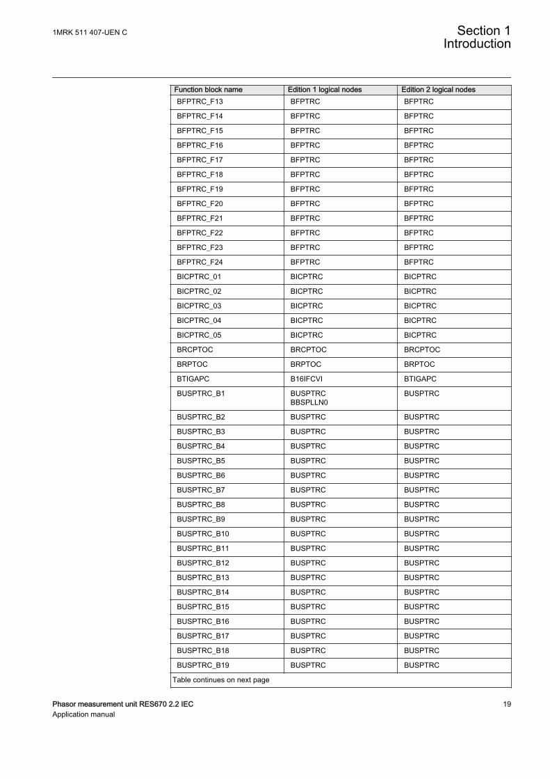
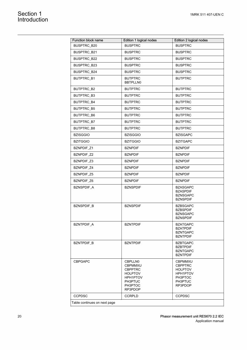
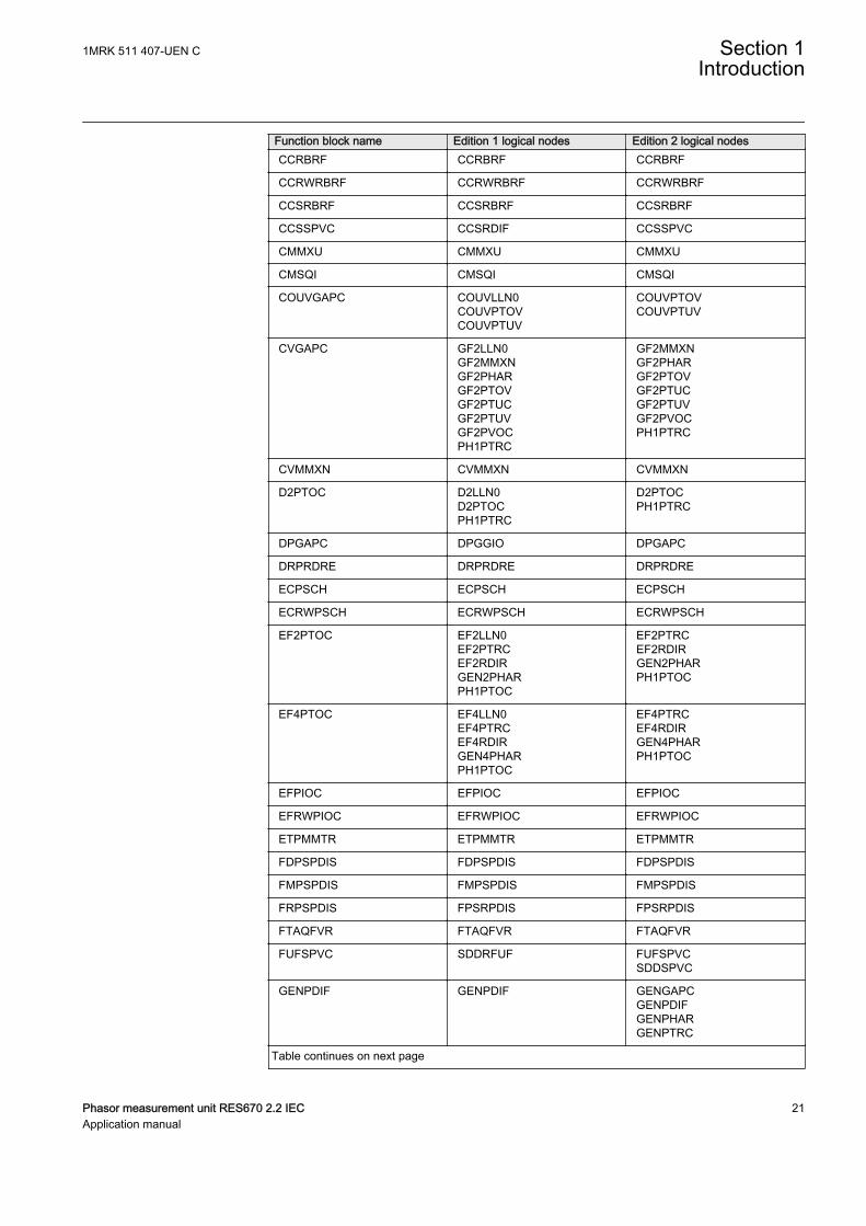
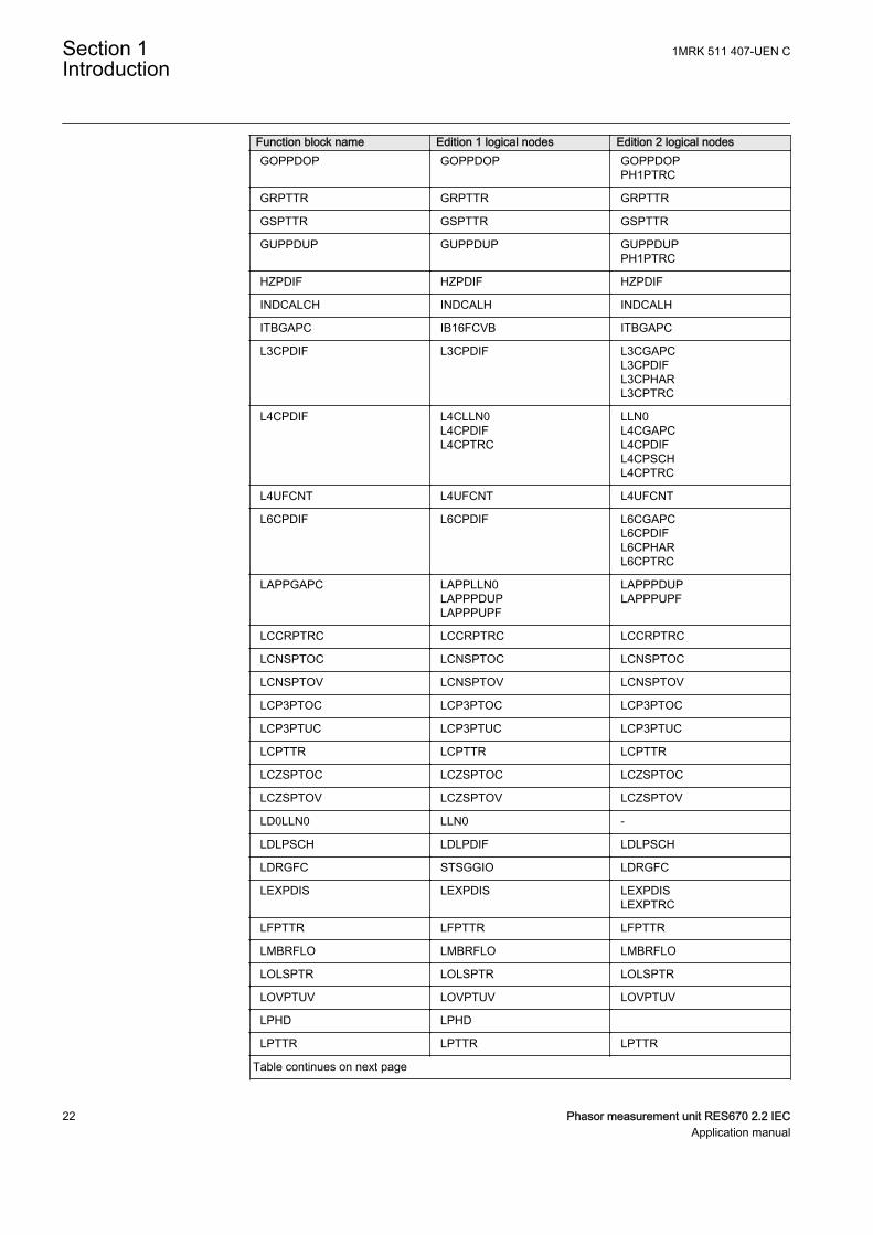
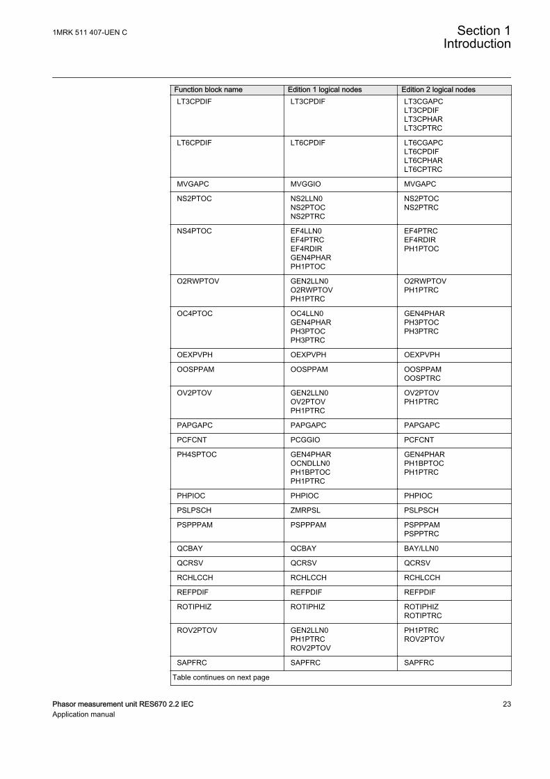
1.5 IEC 61850 edition 1 / edition 2 mappingGUID-C5133366-7260-4C47-A975-7DBAB3A33A96 v7
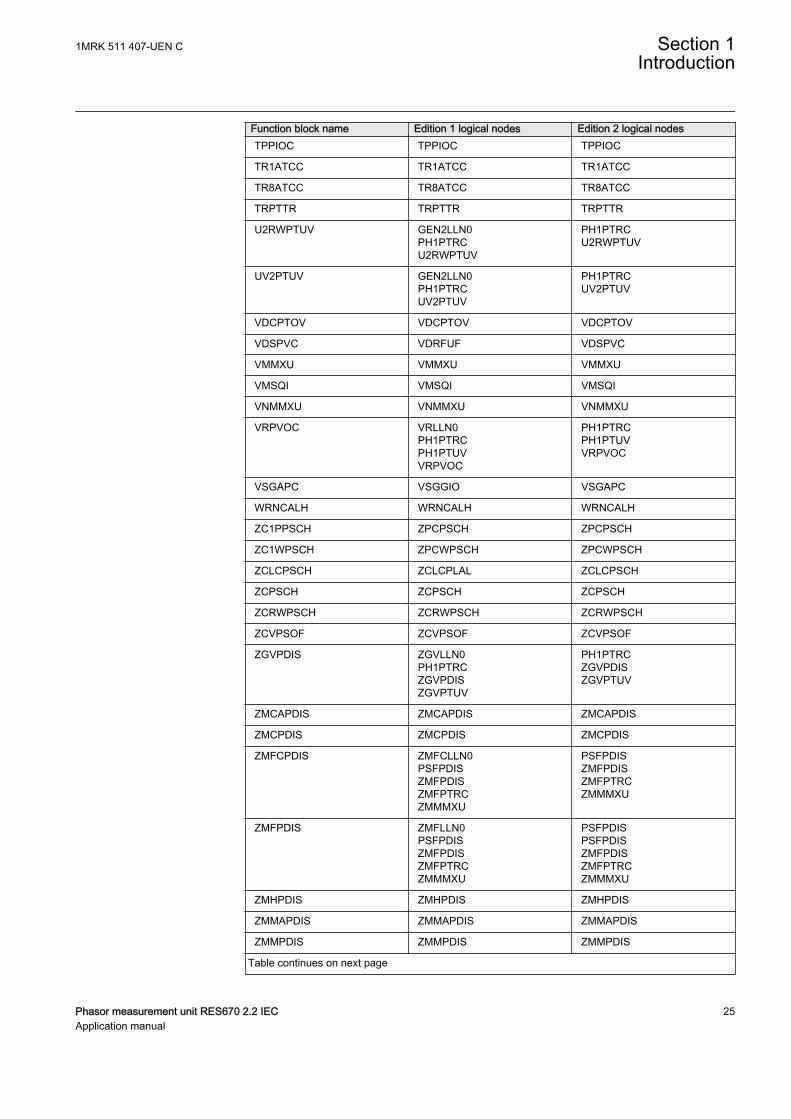
Function block names are used in ACT and PST to identify functions. Respectivefunction block names of Edition 1 logical nodes and Edition 2 logical nodes areshown in the table below.
Table 1: IEC 61850 edition 1 / edition 2 mapping
Function block name Edition 1 logical nodes Edition 2 logical nodesAEGPVOC AEGGAPC AEGPVOC
AGSAL AGSALSECLLN0
AGSAL
ALMCALH ALMCALH ALMCALH
ALTIM - ALTIM
ALTMS - ALTMS
ALTRK - ALTRK
BCZPDIF BCZPDIF BCZPDIF
BCZSPDIF BCZSPDIF BCZSPDIF
BCZTPDIF BCZTPDIF BCZTPDIF
BDCGAPC SWSGGIO BBCSWIBDCGAPC
BDZSGAPC BBS6LLN0BDZSGAPC
LLN0BDZSGAPC
BFPTRC_F01 BFPTRC BFPTRC
BFPTRC_F02 BFPTRC BFPTRC
BFPTRC_F03 BFPTRC BFPTRC
BFPTRC_F04 BFPTRC BFPTRC
BFPTRC_F05 BFPTRC BFPTRC
BFPTRC_F06 BFPTRC BFPTRC
BFPTRC_F07 BFPTRC BFPTRC
BFPTRC_F08 BFPTRC BFPTRC
BFPTRC_F09 BFPTRC BFPTRC
BFPTRC_F10 BFPTRC BFPTRC
BFPTRC_F11 BFPTRC BFPTRC
BFPTRC_F12 BFPTRC BFPTRC
Table continues on next page
Section 1 1MRK 511 407-UEN CIntroduction
18 Phasor measurement unit RES670 2.2 IECApplication manual
Function block name Edition 1 logical nodes Edition 2 logical nodesBFPTRC_F13 BFPTRC BFPTRC
BFPTRC_F14 BFPTRC BFPTRC
BFPTRC_F15 BFPTRC BFPTRC
BFPTRC_F16 BFPTRC BFPTRC
BFPTRC_F17 BFPTRC BFPTRC
BFPTRC_F18 BFPTRC BFPTRC
BFPTRC_F19 BFPTRC BFPTRC
BFPTRC_F20 BFPTRC BFPTRC
BFPTRC_F21 BFPTRC BFPTRC
BFPTRC_F22 BFPTRC BFPTRC
BFPTRC_F23 BFPTRC BFPTRC
BFPTRC_F24 BFPTRC BFPTRC
BICPTRC_01 BICPTRC BICPTRC
BICPTRC_02 BICPTRC BICPTRC
BICPTRC_03 BICPTRC BICPTRC
BICPTRC_04 BICPTRC BICPTRC
BICPTRC_05 BICPTRC BICPTRC
BRCPTOC BRCPTOC BRCPTOC
BRPTOC BRPTOC BRPTOC
BTIGAPC B16IFCVI BTIGAPC
BUSPTRC_B1 BUSPTRCBBSPLLN0
BUSPTRC
BUSPTRC_B2 BUSPTRC BUSPTRC
BUSPTRC_B3 BUSPTRC BUSPTRC
BUSPTRC_B4 BUSPTRC BUSPTRC
BUSPTRC_B5 BUSPTRC BUSPTRC
BUSPTRC_B6 BUSPTRC BUSPTRC
BUSPTRC_B7 BUSPTRC BUSPTRC
BUSPTRC_B8 BUSPTRC BUSPTRC
BUSPTRC_B9 BUSPTRC BUSPTRC
BUSPTRC_B10 BUSPTRC BUSPTRC
BUSPTRC_B11 BUSPTRC BUSPTRC
BUSPTRC_B12 BUSPTRC BUSPTRC
BUSPTRC_B13 BUSPTRC BUSPTRC
BUSPTRC_B14 BUSPTRC BUSPTRC
BUSPTRC_B15 BUSPTRC BUSPTRC
BUSPTRC_B16 BUSPTRC BUSPTRC
BUSPTRC_B17 BUSPTRC BUSPTRC
BUSPTRC_B18 BUSPTRC BUSPTRC
BUSPTRC_B19 BUSPTRC BUSPTRC
Table continues on next page
1MRK 511 407-UEN C Section 1Introduction
Phasor measurement unit RES670 2.2 IEC 19Application manual
Function block name Edition 1 logical nodes Edition 2 logical nodesBUSPTRC_B20 BUSPTRC BUSPTRC
BUSPTRC_B21 BUSPTRC BUSPTRC
BUSPTRC_B22 BUSPTRC BUSPTRC
BUSPTRC_B23 BUSPTRC BUSPTRC
BUSPTRC_B24 BUSPTRC BUSPTRC
BUTPTRC_B1 BUTPTRCBBTPLLN0
BUTPTRC
BUTPTRC_B2 BUTPTRC BUTPTRC
BUTPTRC_B3 BUTPTRC BUTPTRC
BUTPTRC_B4 BUTPTRC BUTPTRC
BUTPTRC_B5 BUTPTRC BUTPTRC
BUTPTRC_B6 BUTPTRC BUTPTRC
BUTPTRC_B7 BUTPTRC BUTPTRC
BUTPTRC_B8 BUTPTRC BUTPTRC
BZISGGIO BZISGGIO BZISGAPC
BZITGGIO BZITGGIO BZITGAPC
BZNPDIF_Z1 BZNPDIF BZNPDIF
BZNPDIF_Z2 BZNPDIF BZNPDIF
BZNPDIF_Z3 BZNPDIF BZNPDIF
BZNPDIF_Z4 BZNPDIF BZNPDIF
BZNPDIF_Z5 BZNPDIF BZNPDIF
BZNPDIF_Z6 BZNPDIF BZNPDIF
BZNSPDIF_A BZNSPDIF BZASGAPCBZASPDIFBZNSGAPCBZNSPDIF
BZNSPDIF_B BZNSPDIF BZBSGAPCBZBSPDIFBZNSGAPCBZNSPDIF
BZNTPDIF_A BZNTPDIF BZATGAPCBZATPDIFBZNTGAPCBZNTPDIF
BZNTPDIF_B BZNTPDIF BZBTGAPCBZBTPDIFBZNTGAPCBZNTPDIF
CBPGAPC CBPLLN0CBPMMXUCBPPTRCHOLPTOVHPH1PTOVPH3PTUCPH3PTOCRP3PDOP
CBPMMXUCBPPTRCHOLPTOVHPH1PTOVPH3PTOCPH3PTUCRP3PDOP
CCPDSC CCRPLD CCPDSC
Table continues on next page
Section 1 1MRK 511 407-UEN CIntroduction
20 Phasor measurement unit RES670 2.2 IECApplication manual
Function block name Edition 1 logical nodes Edition 2 logical nodesCCRBRF CCRBRF CCRBRF
CCRWRBRF CCRWRBRF CCRWRBRF
CCSRBRF CCSRBRF CCSRBRF
CCSSPVC CCSRDIF CCSSPVC
CMMXU CMMXU CMMXU
CMSQI CMSQI CMSQI
COUVGAPC COUVLLN0COUVPTOVCOUVPTUV
COUVPTOVCOUVPTUV
CVGAPC GF2LLN0GF2MMXNGF2PHARGF2PTOVGF2PTUCGF2PTUVGF2PVOCPH1PTRC
GF2MMXNGF2PHARGF2PTOVGF2PTUCGF2PTUVGF2PVOCPH1PTRC
CVMMXN CVMMXN CVMMXN
D2PTOC D2LLN0D2PTOCPH1PTRC
D2PTOCPH1PTRC
DPGAPC DPGGIO DPGAPC
DRPRDRE DRPRDRE DRPRDRE
ECPSCH ECPSCH ECPSCH
ECRWPSCH ECRWPSCH ECRWPSCH
EF2PTOC EF2LLN0EF2PTRCEF2RDIRGEN2PHARPH1PTOC
EF2PTRCEF2RDIRGEN2PHARPH1PTOC
EF4PTOC EF4LLN0EF4PTRCEF4RDIRGEN4PHARPH1PTOC
EF4PTRCEF4RDIRGEN4PHARPH1PTOC
EFPIOC EFPIOC EFPIOC
EFRWPIOC EFRWPIOC EFRWPIOC
ETPMMTR ETPMMTR ETPMMTR
FDPSPDIS FDPSPDIS FDPSPDIS
FMPSPDIS FMPSPDIS FMPSPDIS
FRPSPDIS FPSRPDIS FPSRPDIS
FTAQFVR FTAQFVR FTAQFVR
FUFSPVC SDDRFUF FUFSPVCSDDSPVC
GENPDIF GENPDIF GENGAPCGENPDIFGENPHARGENPTRC
Table continues on next page
1MRK 511 407-UEN C Section 1Introduction
Phasor measurement unit RES670 2.2 IEC 21Application manual
Function block name Edition 1 logical nodes Edition 2 logical nodesGOPPDOP GOPPDOP GOPPDOP
PH1PTRC
GRPTTR GRPTTR GRPTTR
GSPTTR GSPTTR GSPTTR
GUPPDUP GUPPDUP GUPPDUPPH1PTRC
HZPDIF HZPDIF HZPDIF
INDCALCH INDCALH INDCALH
ITBGAPC IB16FCVB ITBGAPC
L3CPDIF L3CPDIF L3CGAPCL3CPDIFL3CPHARL3CPTRC
L4CPDIF L4CLLN0L4CPDIFL4CPTRC
LLN0L4CGAPCL4CPDIFL4CPSCHL4CPTRC
L4UFCNT L4UFCNT L4UFCNT
L6CPDIF L6CPDIF L6CGAPCL6CPDIFL6CPHARL6CPTRC
LAPPGAPC LAPPLLN0LAPPPDUPLAPPPUPF
LAPPPDUPLAPPPUPF
LCCRPTRC LCCRPTRC LCCRPTRC
LCNSPTOC LCNSPTOC LCNSPTOC
LCNSPTOV LCNSPTOV LCNSPTOV
LCP3PTOC LCP3PTOC LCP3PTOC
LCP3PTUC LCP3PTUC LCP3PTUC
LCPTTR LCPTTR LCPTTR
LCZSPTOC LCZSPTOC LCZSPTOC
LCZSPTOV LCZSPTOV LCZSPTOV
LD0LLN0 LLN0 -
LDLPSCH LDLPDIF LDLPSCH
LDRGFC STSGGIO LDRGFC
LEXPDIS LEXPDIS LEXPDISLEXPTRC
LFPTTR LFPTTR LFPTTR
LMBRFLO LMBRFLO LMBRFLO
LOLSPTR LOLSPTR LOLSPTR
LOVPTUV LOVPTUV LOVPTUV
LPHD LPHD
LPTTR LPTTR LPTTR
Table continues on next page
Section 1 1MRK 511 407-UEN CIntroduction
22 Phasor measurement unit RES670 2.2 IECApplication manual
Function block name Edition 1 logical nodes Edition 2 logical nodesLT3CPDIF LT3CPDIF LT3CGAPC
LT3CPDIFLT3CPHARLT3CPTRC
LT6CPDIF LT6CPDIF LT6CGAPCLT6CPDIFLT6CPHARLT6CPTRC
MVGAPC MVGGIO MVGAPC
NS2PTOC NS2LLN0NS2PTOCNS2PTRC
NS2PTOCNS2PTRC
NS4PTOC EF4LLN0EF4PTRCEF4RDIRGEN4PHARPH1PTOC
EF4PTRCEF4RDIRPH1PTOC
O2RWPTOV GEN2LLN0O2RWPTOVPH1PTRC
O2RWPTOVPH1PTRC
OC4PTOC OC4LLN0GEN4PHARPH3PTOCPH3PTRC
GEN4PHARPH3PTOCPH3PTRC
OEXPVPH OEXPVPH OEXPVPH
OOSPPAM OOSPPAM OOSPPAMOOSPTRC
OV2PTOV GEN2LLN0OV2PTOVPH1PTRC
OV2PTOVPH1PTRC
PAPGAPC PAPGAPC PAPGAPC
PCFCNT PCGGIO PCFCNT
PH4SPTOC GEN4PHAROCNDLLN0PH1BPTOCPH1PTRC
GEN4PHARPH1BPTOCPH1PTRC
PHPIOC PHPIOC PHPIOC
PSLPSCH ZMRPSL PSLPSCH
PSPPPAM PSPPPAM PSPPPAMPSPPTRC
QCBAY QCBAY BAY/LLN0
QCRSV QCRSV QCRSV
RCHLCCH RCHLCCH RCHLCCH
REFPDIF REFPDIF REFPDIF
ROTIPHIZ ROTIPHIZ ROTIPHIZROTIPTRC
ROV2PTOV GEN2LLN0PH1PTRCROV2PTOV
PH1PTRCROV2PTOV
SAPFRC SAPFRC SAPFRC
Table continues on next page
1MRK 511 407-UEN C Section 1Introduction
Phasor measurement unit RES670 2.2 IEC 23Application manual

Function block name Edition 1 logical nodes Edition 2 logical nodesSAPTOF SAPTOF SAPTOF
SAPTUF SAPTUF SAPTUF
SCCVPTOC SCCVPTOC SCCVPTOC
SCHLCCH SCHLCCH SCHLCCH
SCILO SCILO SCILO
SCSWI SCSWI SCSWI
SDEPSDE SDEPSDE SDEPSDESDEPTOCSDEPTOVSDEPTRC
SESRSYN RSY1LLN0AUT1RSYNMAN1RSYNSYNRSYN
AUT1RSYNMAN1RSYNSYNRSYN
SLGAPC SLGGIO SLGAPC
SMBRREC SMBRREC SMBRREC
SMPPTRC SMPPTRC SMPPTRC
SP16GAPC SP16GGIO SP16GAPC
SPC8GAPC SPC8GGIO SPC8GAPC
SPGAPC SPGGIO SPGAPC
SSCBR SSCBR SSCBR
SSIMG SSIMG SSIMG
SSIML SSIML SSIML
PTRSTHR PTRSTHR PTRSTHR
STBPTOC STBPTOC BBPMSSSTBPTOC
STEFPHIZ STEFPHIZ STEFPHIZ
STTIPHIZ STTIPHIZ STTIPHIZ
SXCBR SXCBR SXCBR
SXSWI SXSWI SXSWI
T2WPDIF T2WPDIF T2WGAPCT2WPDIFT2WPHART2WPTRC
T3WPDIF T3WPDIF T3WGAPCT3WPDIFT3WPHART3WPTRC
TCLYLTC TCLYLTC TCLYLTCTCSLTC
TCMYLTC TCMYLTC TCMYLTC
TEIGAPC TEIGGIO TEIGAPCTEIGGIO
TEILGAPC TEILGGIO TEILGAPC
TMAGAPC TMAGGIO TMAGAPC
Table continues on next page
Section 1 1MRK 511 407-UEN CIntroduction
24 Phasor measurement unit RES670 2.2 IECApplication manual
Function block name Edition 1 logical nodes Edition 2 logical nodesTPPIOC TPPIOC TPPIOC
TR1ATCC TR1ATCC TR1ATCC
TR8ATCC TR8ATCC TR8ATCC
TRPTTR TRPTTR TRPTTR
U2RWPTUV GEN2LLN0PH1PTRCU2RWPTUV
PH1PTRCU2RWPTUV
UV2PTUV GEN2LLN0PH1PTRCUV2PTUV
PH1PTRCUV2PTUV
VDCPTOV VDCPTOV VDCPTOV
VDSPVC VDRFUF VDSPVC
VMMXU VMMXU VMMXU
VMSQI VMSQI VMSQI
VNMMXU VNMMXU VNMMXU
VRPVOC VRLLN0PH1PTRCPH1PTUVVRPVOC
PH1PTRCPH1PTUVVRPVOC
VSGAPC VSGGIO VSGAPC
WRNCALH WRNCALH WRNCALH
ZC1PPSCH ZPCPSCH ZPCPSCH
ZC1WPSCH ZPCWPSCH ZPCWPSCH
ZCLCPSCH ZCLCPLAL ZCLCPSCH
ZCPSCH ZCPSCH ZCPSCH
ZCRWPSCH ZCRWPSCH ZCRWPSCH
ZCVPSOF ZCVPSOF ZCVPSOF
ZGVPDIS ZGVLLN0PH1PTRCZGVPDISZGVPTUV
PH1PTRCZGVPDISZGVPTUV
ZMCAPDIS ZMCAPDIS ZMCAPDIS
ZMCPDIS ZMCPDIS ZMCPDIS
ZMFCPDIS ZMFCLLN0PSFPDISZMFPDISZMFPTRCZMMMXU
PSFPDISZMFPDISZMFPTRCZMMMXU
ZMFPDIS ZMFLLN0PSFPDISZMFPDISZMFPTRCZMMMXU
PSFPDISPSFPDISZMFPDISZMFPTRCZMMMXU
ZMHPDIS ZMHPDIS ZMHPDIS
ZMMAPDIS ZMMAPDIS ZMMAPDIS
ZMMPDIS ZMMPDIS ZMMPDIS
Table continues on next page
1MRK 511 407-UEN C Section 1Introduction
Phasor measurement unit RES670 2.2 IEC 25Application manual

Function block name Edition 1 logical nodes Edition 2 logical nodesZMQAPDIS ZMQAPDIS ZMQAPDIS
ZMQPDIS ZMQPDIS ZMQPDIS
ZMRAPDIS ZMRAPDIS ZMRAPDIS
ZMRPDIS ZMRPDIS ZMRPDIS
ZMRPSB ZMRPSB ZMRPSB
ZSMGAPC ZSMGAPC ZSMGAPC
Section 1 1MRK 511 407-UEN CIntroduction
26 Phasor measurement unit RES670 2.2 IECApplication manual
Section 2 Application
2.1 General IED application
GUID-CF75762E-73C1-40AF-8D6F-6EC3D8395982 v4
RES670 is a Phasor Measurement Unit (PMU) that provides power system ACvoltages and currents as phasors for all voltage levels in power system networks.Phasors are provided as real and imaginary or as magnitude and phase angle. Thereference for the phase angle may be either a PTP time synchronization source orthe NavStar Global Positioning System - GPS, both supplying highly accurate timeand date. The measured data in each PMU is time synchronized via one of thementioned time synchronization sources - with an accuracy of one microsecond -and transmitted to Phasor Data Concentrators (every 100 milliseconds, forexample). The accurate time tagging of measurements taken at differentgeographical locations makes it possible to derive the synchronized phasorquantities (synchrophasors). Based on synchrophasors, a number of power systemapplications are available.
The PMUs are installed at substation level, and can be connected directly to thecurrent and voltage transformers within the substations. Each RES670 may befitted with different options for time synchronization: PTP via the Ethernetnetwork, via the GPS system with an own antenna for the RES670, or via theIRIG-B signal received from an external GPS-based clock. It is also possible tohave a combination of the three to provide time synchronization redundancy for thePMU. RES670 streams out its synchrophasor data according to IEEE C37.118and/or IEEE 1344 standards for synchrophasor data streaming and with user-selectable reporting rates. RES670 supports reporting rates of 10, 25, 50, 100, and200 frames per second for 50Hz system (or 10, 12, 15, 30, 60, 120, and 240 framesper second for 60Hz system). Each RES670 can communicate its synchrophasordata to up to eight independent clients over TCP and/or six independent UDPchannels (unicast/multicast), simultaneously. More information is available inRES670 Application Manual under Wide Area Measurement System. section.
In addition to the synchrophasor communication standard (IEEE 1344, IEEEC37.118), RES670 is also compliant to IEC 61850-8-1 standard for integration tosubstation automation systems and exchange of GOOSE messages, whennecessary. RES670 is able to communicate over IEC 62439-3 PRP for redundantstation bus communication for both IEEE C37.118 and IEC 61850-8-1,simultaneously.
Figure 2 shows an example of a system architecture for a Wide Area MonitoringSystem (WAMS). PMUs are the building blocks for a WAMS. The architecture of aWAMS consists of the following main components:
1MRK 511 407-UEN C Section 2Application
Phasor measurement unit RES670 2.2 IEC 27Application manual
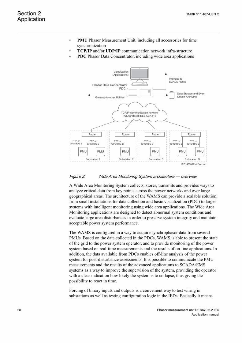
• PMU Phasor Measurement Unit, including all accessories for timesynchronization
• TCP/IP and/or UDP/IP communication network infra-structure• PDC Phasor Data Concentrator, including wide area applications
Substation 1
Visualization(Applications)
Interface toSCADA / EMS
Data Storage and EventDriven ArchivingGateway to other Utilities
Phasor Data ConcentratorPDC
Substation 2 Substation 3 Substation N
Router Router Router Router
TCP/IP communication networkPMU protocol IEEE C37.118
PMU PMU PMU PMUPMU PMU
PTP orGPS/IRIG-B
IEC140000114-2-en.vsd
PTP orGPS/IRIG-B
PTP orGPS/IRIG-B
PTP orGPS/IRIG-B
PTP orGPS/IRIG-B
PTP orGPS/IRIG-B
IEC140000114 V2 EN-US
Figure 2: Wide Area Monitoring System architecture — overview
A Wide Area Monitoring System collects, stores, transmits and provides ways toanalyze critical data from key points across the power networks and over largegeographical areas. The architecture of the WAMS can provide a scalable solution,from small installations for data collection and basic visualization (PDC) to largersystems with intelligent monitoring using wide area applications. The Wide AreaMonitoring applications are designed to detect abnormal system conditions andevaluate large area disturbances in order to preserve system integrity and maintainacceptable power system performance.
The WAMS is configured in a way to acquire synchrophasor data from severalPMUs. Based on the data collected in the PDCs, WAMS is able to present the stateof the grid to the power system operator, and to provide monitoring of the powersystem based on real-time measurements and the results of on-line applications. Inaddition, the data available from PDCs enables off-line analysis of the powersystem for post-disturbance assessments. It is possible to communicate the PMUmeasurements and the results of the advanced applications to SCADA/EMSsystems as a way to improve the supervision of the system, providing the operatorwith a clear indication how likely the system is to collapse, thus giving thepossibility to react in time.
Forcing of binary inputs and outputs is a convenient way to test wiring insubstations as well as testing configuration logic in the IEDs. Basically it means
Section 2 1MRK 511 407-UEN CApplication
28 Phasor measurement unit RES670 2.2 IECApplication manual
that all binary inputs and outputs on the IED I/O modules (BOM, BIM, IOM &SOM) can be forced to arbitrary values.
Central Account Management is an authentication infrastructure that offers asecure solution for enforcing access control to IEDs and other systems within asubstation. This incorporates management of user accounts, roles and certificatesand the distribution of such, a procedure completely transparent to the user.
The Flexible Product Naming allows the customer to use an IED-vendorindependent IEC 61850 model of the IED. This customer model will be exposed inall IEC 61850 communication, but all other aspects of the IED will remainunchanged (e.g., names on the local HMI and names in the tools). This offerssignificant flexibility to adapt the IED to the customers' system and standardsolution.
GUID-F5776DD1-BD04-4872-BB89-A0412B4B5CC3 v1
The following tables list all the functions available in the IED.Those functions that are not exposed to the user or do not need tobe configured are not described in this manual.
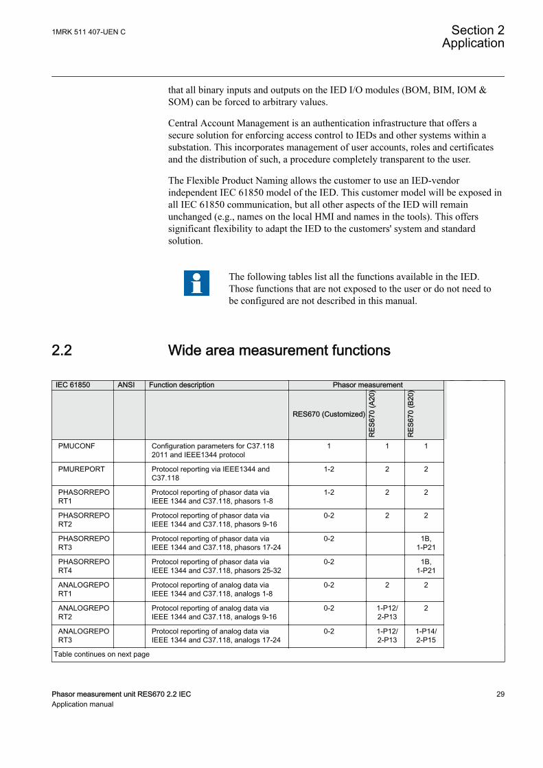
2.2 Wide area measurement functionsGUID-8A114D7E-8D1A-46ED-A928-B819ED163A52 v5
IEC 61850 ANSI Function description Phasor measurement
RES670 (Customized)
RES
670
(A20
)
RES
670
(B20
)
PMUCONF Configuration parameters for C37.118
2011 and IEEE1344 protocol1 1 1
PMUREPORT Protocol reporting via IEEE1344 andC37.118
1-2 2 2
PHASORREPORT1
Protocol reporting of phasor data viaIEEE 1344 and C37.118, phasors 1-8
1-2 2 2
PHASORREPORT2
Protocol reporting of phasor data viaIEEE 1344 and C37.118, phasors 9-16
0-2 2 2
PHASORREPORT3
Protocol reporting of phasor data viaIEEE 1344 and C37.118, phasors 17-24
0-2 1B,1-P21
PHASORREPORT4
Protocol reporting of phasor data viaIEEE 1344 and C37.118, phasors 25-32
0-2 1B,1-P21
ANALOGREPORT1
Protocol reporting of analog data viaIEEE 1344 and C37.118, analogs 1-8
0-2 2 2
ANALOGREPORT2
Protocol reporting of analog data viaIEEE 1344 and C37.118, analogs 9-16
0-2 1-P12/2-P13
2
ANALOGREPORT3
Protocol reporting of analog data viaIEEE 1344 and C37.118, analogs 17-24
0-2 1-P12/2-P13
1-P14/2-P15
Table continues on next page
1MRK 511 407-UEN C Section 2Application
Phasor measurement unit RES670 2.2 IEC 29Application manual
IEC 61850 ANSI Function description Phasor measurement
RES670 (Customized)
RES
670
(A20
)
RES
670
(B20
)
BINARYREPORT1
Protocol reporting of binary data viaIEEE 1344 and C37.118, binary 1-8
0-2 2 2
BINARYREPORT2
Protocol reporting of binary data viaIEEE 1344 and C37.118, binary 9-16
0-2 1-P16/2-P17
2
BINARYREPORT3
Protocol reporting of binary data viaIEEE 1344 and C37.118, binary 17-24
0-2 1-P16/2-P17
1-P18/2-P19
PMUSTATUS Diagnostics for C37.118 2011 andIEEE1344 protocol
1 1 1
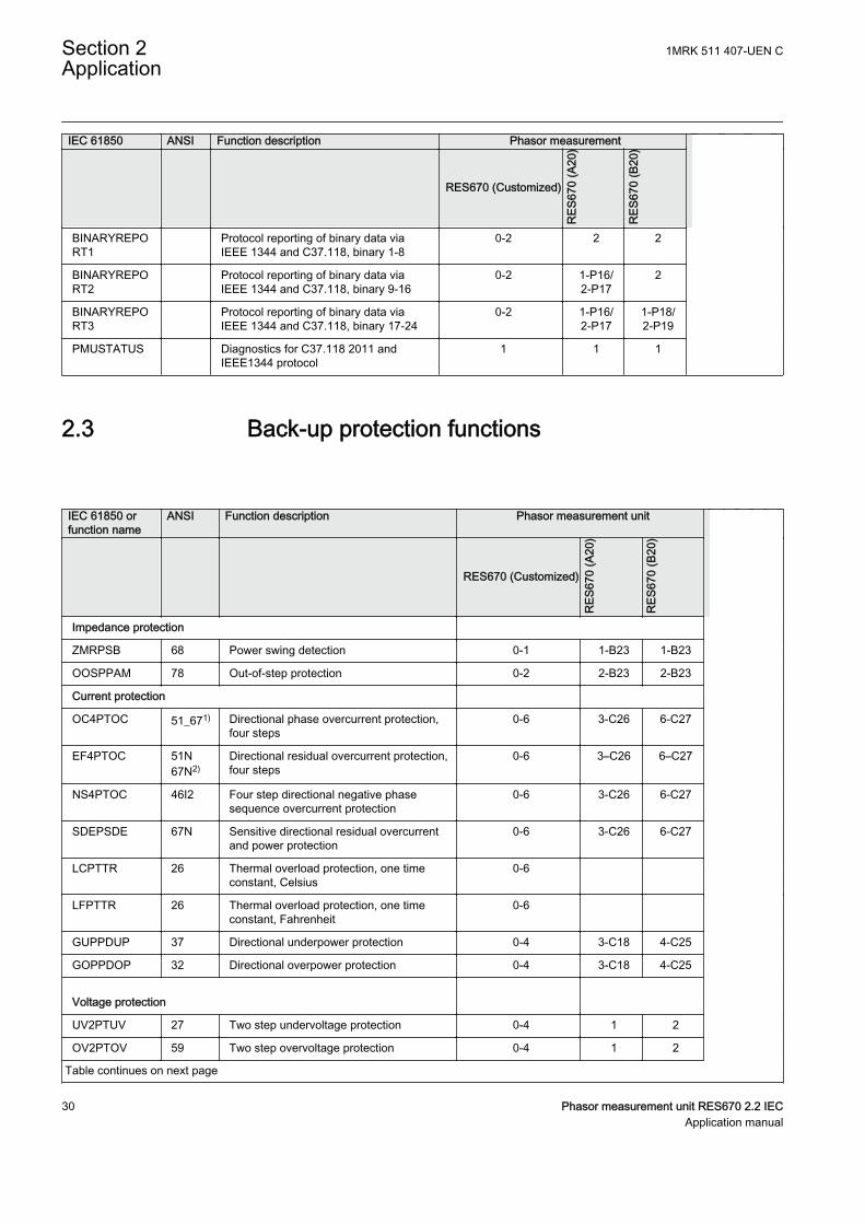
2.3 Back-up protection functionsGUID-A8D0852F-807F-4442-8730-E44808E194F0 v14
IEC 61850 orfunction name
ANSI Function description Phasor measurement unit
RES670 (Customized)R
ES67
0 (A
20)
RES
670
(B20
)
Impedance protection
ZMRPSB 68 Power swing detection 0-1 1-B23 1-B23
OOSPPAM 78 Out-of-step protection 0-2 2-B23 2-B23
Current protection
OC4PTOC 51_671) Directional phase overcurrent protection,four steps
0-6 3-C26 6-C27
EF4PTOC 51N67N2)
Directional residual overcurrent protection,four steps
0-6 3–C26 6–C27
NS4PTOC 46I2 Four step directional negative phasesequence overcurrent protection
0-6 3-C26 6-C27
SDEPSDE 67N Sensitive directional residual overcurrentand power protection
0-6 3-C26 6-C27
LCPTTR 26 Thermal overload protection, one timeconstant, Celsius
0-6
LFPTTR 26 Thermal overload protection, one timeconstant, Fahrenheit
0-6
GUPPDUP 37 Directional underpower protection 0-4 3-C18 4-C25
GOPPDOP 32 Directional overpower protection 0-4 3-C18 4-C25
Voltage protection
UV2PTUV 27 Two step undervoltage protection 0-4 1 2
OV2PTOV 59 Two step overvoltage protection 0-4 1 2
Table continues on next page
Section 2 1MRK 511 407-UEN CApplication
30 Phasor measurement unit RES670 2.2 IECApplication manual
IEC 61850 orfunction name
ANSI Function description Phasor measurement unit
RES670 (Customized)
RES
670
(A20
)
RES
670
(B20
)
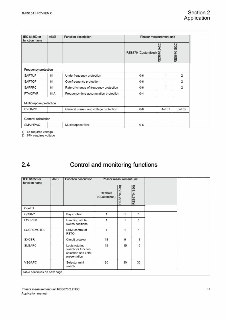
Frequency protection
SAPTUF 81 Underfrequency protection 0-6 1 2
SAPTOF 81 Overfrequency protection 0-6 1 2
SAPFRC 81 Rate-of-change of frequency protection 0-6 1 2
FTAQFVR 81A Frequency time accumulation protection 0-4
Multipurpose protection
CVGAPC General current and voltage protection 0-8 4–F01 6–F02
General calculation
SMAIHPAC Multipurpose filter 0-6
1) 67 requires voltage2) 67N requires voltage
2.4 Control and monitoring functionsGUID-E3777F16-0B76-4157-A3BF-0B6B978863DE v17
IEC 61850 orfunction name
ANSI Function description Phasor measurement unit
RES670(Customized)
RES
670
(A20
)
RES
670
(B20
)
Control
QCBAY Bay control 1 1 1
LOCREM Handling of LR-switch positions
1 1 1
LOCREMCTRL LHMI control ofPSTO
1 1 1
SXCBR Circuit breaker 18 9 18
SLGAPC Logic rotatingswitch for functionselection and LHMIpresentation
15 15 15
VSGAPC Selector miniswitch
30 30 30
Table continues on next page
1MRK 511 407-UEN C Section 2Application
Phasor measurement unit RES670 2.2 IEC 31Application manual

IEC 61850 orfunction name
ANSI Function description Phasor measurement unit
RES670(Customized)
RES
670
(A20
)
RES
670
(B20
)
DPGAPC Genericcommunicationfunction for DoublePoint indication
32 32 32
SPC8GAPC Single pointgeneric controlfunction 8 signals
5 5 5
AUTOBITS Automation bits,command functionfor DNP3.0
3 3 3
SINGLECMD Single command,16 signals
4 4 4
I103CMD Functioncommands for IEC60870-5-103
1 1 1
I103GENCMD Functioncommands genericfor IEC60870-5-103
50 50 50
I103POSCMD IED commandswith position andselect for IEC60870-5-103
50 50 50
I103POSCMDV IED directcommands withposition for IEC60870-5-103
50 50 50
I103IEDCMD IED commands forIEC 60870-5-103
1 1 1
I103USRCMD Functioncommands userdefined for IEC60870-5-103
4 4 4
Secondary systemsupervision
CCSSPVC 87 Current circuitsupervision
0–5 3–G01 5–G02
FUFSPVC Fuse failuresupervision
0-4 1–G01 2–G02
Logic
SMPPTRC 94 Tripping logic 12 12 12
SMAGAPC General startmatrix block
12 12 12
STARTCOMB Start combinator 32 32 32
TMAGAPC Trip matrix logic 12 12 12
Table continues on next page
Section 2 1MRK 511 407-UEN CApplication
32 Phasor measurement unit RES670 2.2 IECApplication manual
IEC 61850 orfunction name
ANSI Function description Phasor measurement unit
RES670(Customized)
RES
670
(A20
)
RES
670
(B20
)
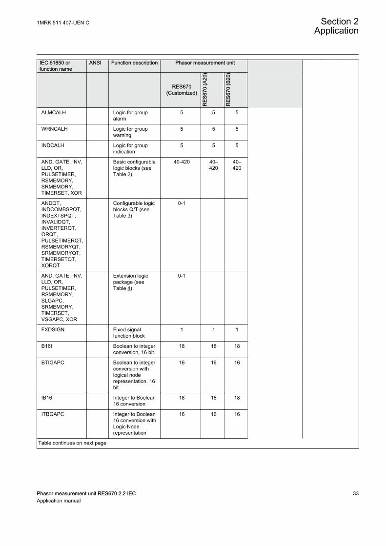
ALMCALH Logic for groupalarm
5 5 5
WRNCALH Logic for groupwarning
5 5 5
INDCALH Logic for groupindication
5 5 5
AND, GATE, INV,LLD, OR,PULSETIMER,RSMEMORY,SRMEMORY,TIMERSET, XOR
Basic configurablelogic blocks (seeTable 2)
40-420 40–420
40–420
ANDQT,INDCOMBSPQT,INDEXTSPQT,INVALIDQT,INVERTERQT,ORQT,PULSETIMERQT,RSMEMORYQT,SRMEMORYQT,TIMERSETQT,XORQT
Configurable logicblocks Q/T (seeTable 3)
0-1
AND, GATE, INV,LLD, OR,PULSETIMER,RSMEMORY,SLGAPC,SRMEMORY,TIMERSET,VSGAPC, XOR
Extension logicpackage (seeTable 4)
0-1
FXDSIGN Fixed signalfunction block
1 1 1
B16I Boolean to integerconversion, 16 bit
18 18 18
BTIGAPC Boolean to integerconversion withlogical noderepresentation, 16bit
16 16 16
IB16 Integer to Boolean16 conversion
18 18 18
ITBGAPC Integer to Boolean16 conversion withLogic Noderepresentation
16 16 16
Table continues on next page
1MRK 511 407-UEN C Section 2Application
Phasor measurement unit RES670 2.2 IEC 33Application manual

IEC 61850 orfunction name
ANSI Function description Phasor measurement unit
RES670(Customized)
RES
670
(A20
)
RES
670
(B20
)
TEIGAPC Elapsed timeintegrator with limittransgression andoverflowsupervision
12 12 12
INTCOMP Comparator forinteger inputs
30 30 30
REALCOMP Comparator for realinputs
30 30 30
Table 2: Total number of instances for basic configurable logic blocks
Basic configurable logic block Total number of instancesAND 280
GATE 40
INV 420
LLD 40
OR 298
PULSETIMER 40
RSMEMORY 40
SRMEMORY 40
TIMERSET 60
XOR 40
Table 3: Total number of instances for configurable logic blocks Q/T
Configurable logic blocks Q/T Total number of instancesANDQT 120
INDCOMBSPQT 20
INDEXTSPQT 20
INVALIDQT 22
INVERTERQT 120
ORQT 120
PULSETIMERQT 40
RSMEMORYQT 40
SRMEMORYQT 40
TIMERSETQT 40
XORQT 40
Section 2 1MRK 511 407-UEN CApplication
34 Phasor measurement unit RES670 2.2 IECApplication manual
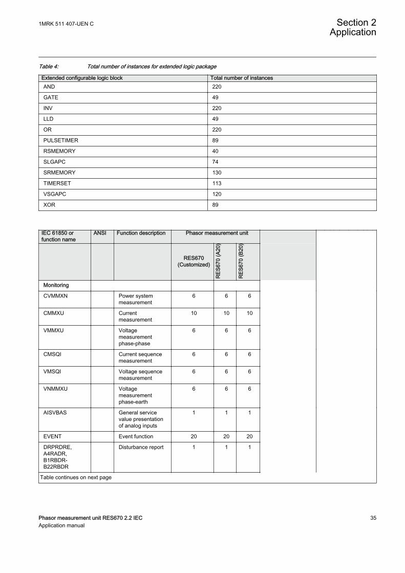
Table 4: Total number of instances for extended logic package
Extended configurable logic block Total number of instancesAND 220
GATE 49
INV 220
LLD 49
OR 220
PULSETIMER 89
RSMEMORY 40
SLGAPC 74
SRMEMORY 130
TIMERSET 113
VSGAPC 120
XOR 89
IEC 61850 orfunction name
ANSI Function description Phasor measurement unit
RES670(Customized)
RES
670
(A20
)
RES
670
(B20
)
Monitoring
CVMMXN Power systemmeasurement
6 6 6
CMMXU Currentmeasurement
10 10 10
VMMXU Voltagemeasurementphase-phase
6 6 6
CMSQI Current sequencemeasurement
6 6 6
VMSQI Voltage sequencemeasurement
6 6 6
VNMMXU Voltagemeasurementphase-earth
6 6 6
AISVBAS General servicevalue presentationof analog inputs
1 1 1
EVENT Event function 20 20 20
DRPRDRE,A4RADR,B1RBDR-B22RBDR
Disturbance report 1 1 1
Table continues on next page
1MRK 511 407-UEN C Section 2Application
Phasor measurement unit RES670 2.2 IEC 35Application manual
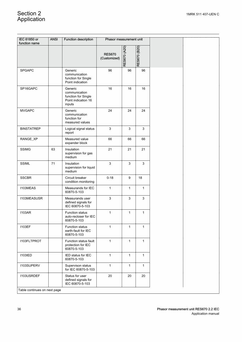
IEC 61850 orfunction name
ANSI Function description Phasor measurement unit
RES670(Customized)
RES
670
(A20
)
RES
670
(B20
)
SPGAPC Genericcommunicationfunction for SinglePoint indication
96 96 96
SP16GAPC Genericcommunicationfunction for SinglePoint indication 16inputs
16 16 16
MVGAPC Genericcommunicationfunction formeasured values
24 24 24
BINSTATREP Logical signal statusreport
3 3 3
RANGE_XP Measured valueexpander block
66 66 66
SSIMG 63 Insulationsupervision for gasmedium
21 21 21
SSIML 71 Insulationsupervision for liquidmedium
3 3 3
SSCBR Circuit breakercondition monitoring
0-18 9 18
I103MEAS Measurands for IEC60870-5-103
1 1 1
I103MEASUSR Measurands userdefined signals forIEC 60870-5-103
3 3 3
I103AR Function statusauto-recloser for IEC60870-5-103
1 1 1
I103EF Function statusearth-fault for IEC60870-5-103
1 1 1
I103FLTPROT Function status faultprotection for IEC60870-5-103
1 1 1
I103IED IED status for IEC60870-5-103
1 1 1
I103SUPERV Supervison statusfor IEC 60870-5-103
1 1 1
I103USRDEF Status for userdefined signals forIEC 60870-5-103
20 20 20
Table continues on next page
Section 2 1MRK 511 407-UEN CApplication
36 Phasor measurement unit RES670 2.2 IECApplication manual
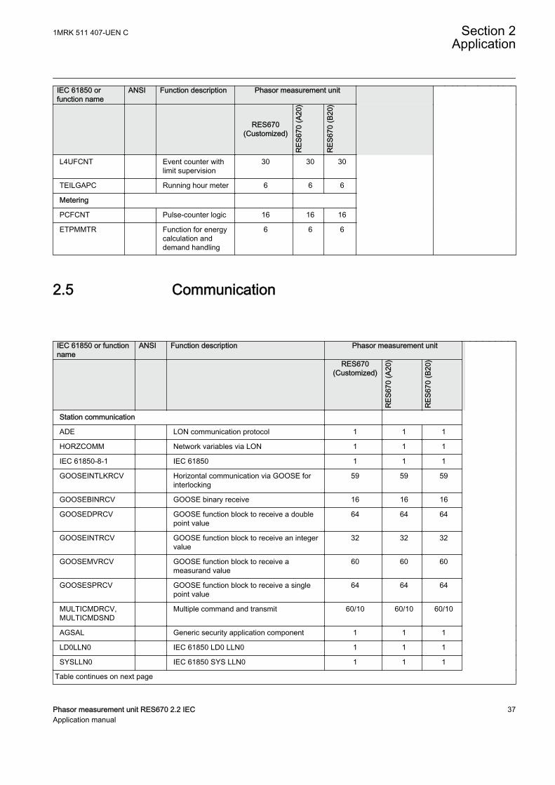
IEC 61850 orfunction name
ANSI Function description Phasor measurement unit
RES670(Customized)
RES
670
(A20
)
RES
670
(B20
)
L4UFCNT Event counter withlimit supervision
30 30 30
TEILGAPC Running hour meter 6 6 6
Metering
PCFCNT Pulse-counter logic 16 16 16
ETPMMTR Function for energycalculation anddemand handling
6 6 6
2.5 CommunicationGUID-5F144B53-B9A7-4173-80CF-CD4C84579CB5 v17
IEC 61850 or functionname
ANSI Function description Phasor measurement unit
RES670(Customized)
RES
670
(A20
)
RES
670
(B20
)
Station communication
ADE LON communication protocol 1 1 1
HORZCOMM Network variables via LON 1 1 1
IEC 61850-8-1 IEC 61850 1 1 1
GOOSEINTLKRCV Horizontal communication via GOOSE forinterlocking
59 59 59
GOOSEBINRCV GOOSE binary receive 16 16 16
GOOSEDPRCV GOOSE function block to receive a doublepoint value
64 64 64
GOOSEINTRCV GOOSE function block to receive an integervalue
32 32 32
GOOSEMVRCV GOOSE function block to receive ameasurand value
60 60 60
GOOSESPRCV GOOSE function block to receive a singlepoint value
64 64 64
MULTICMDRCV,MULTICMDSND
Multiple command and transmit 60/10 60/10 60/10
AGSAL Generic security application component 1 1 1
LD0LLN0 IEC 61850 LD0 LLN0 1 1 1
SYSLLN0 IEC 61850 SYS LLN0 1 1 1
Table continues on next page
1MRK 511 407-UEN C Section 2Application
Phasor measurement unit RES670 2.2 IEC 37Application manual
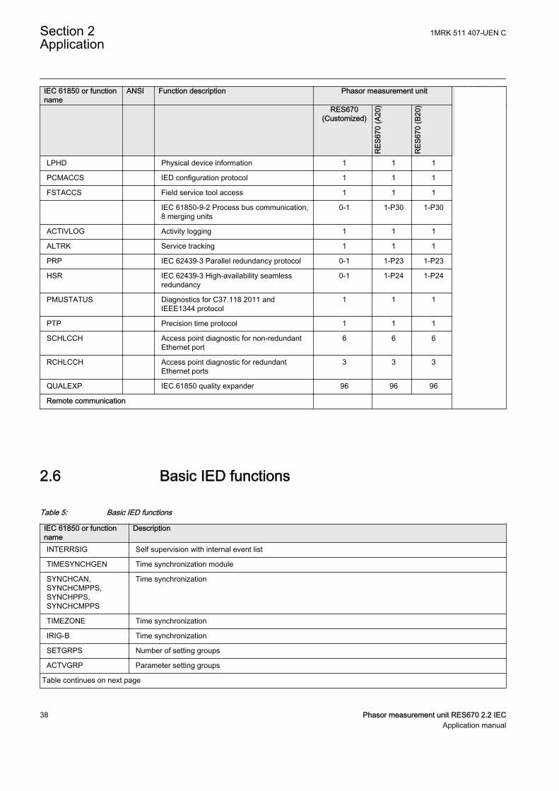
IEC 61850 or functionname
ANSI Function description Phasor measurement unit
RES670(Customized)
RES
670
(A20
)
RES
670
(B20
)
LPHD Physical device information 1 1 1
PCMACCS IED configuration protocol 1 1 1
FSTACCS Field service tool access 1 1 1
IEC 61850-9-2 Process bus communication,8 merging units
0-1 1-P30 1-P30
ACTIVLOG Activity logging 1 1 1
ALTRK Service tracking 1 1 1
PRP IEC 62439-3 Parallel redundancy protocol 0-1 1-P23 1-P23
HSR IEC 62439-3 High-availability seamlessredundancy
0-1 1-P24 1-P24
PMUSTATUS Diagnostics for C37.118 2011 andIEEE1344 protocol
1 1 1
PTP Precision time protocol 1 1 1
SCHLCCH Access point diagnostic for non-redundantEthernet port
6 6 6
RCHLCCH Access point diagnostic for redundantEthernet ports
3 3 3
QUALEXP IEC 61850 quality expander 96 96 96
Remote communication
2.6 Basic IED functionsGUID-C8F0E5D2-E305-4184-9627-F6B5864216CA v13
Table 5: Basic IED functions
IEC 61850 or functionname
Description
INTERRSIG Self supervision with internal event list
TIMESYNCHGEN Time synchronization module
SYNCHCAN,SYNCHCMPPS,SYNCHPPS,SYNCHCMPPS
Time synchronization
TIMEZONE Time synchronization
IRIG-B Time synchronization
SETGRPS Number of setting groups
ACTVGRP Parameter setting groups
Table continues on next page
Section 2 1MRK 511 407-UEN CApplication
38 Phasor measurement unit RES670 2.2 IECApplication manual

IEC 61850 or functionname
Description
TESTMODE Test mode functionality
CHNGLCK Change lock function
SMBI Signal matrix for binary inputs
SMBO Signal matrix for binary outputs
SMMI Signal matrix for mA inputs
SMAI1 - SMAI12 Signal matrix for analog inputs
3PHSUM Summation block 3 phase
ATHSTAT Authority status
ATHCHCK Authority check
AUTHMAN Authority management
FTPACCS FTP access with password
GBASVAL Global base values for settings
ALTMS Time master supervision
ALTIM Time management
COMSTATUS Protocol diagnostic
Table 6: Local HMI functions
IEC 61850 or functionname
ANSI Description
LHMICTRL Local HMI signals
LANGUAGE Local human machine language
SCREEN Local HMI Local human machine screen behavior
FNKEYTY1–FNKEYTY5FNKEYMD1–FNKEYMD5
Parameter setting function for HMI in PCM600
LEDGEN General LED indication part for LHMI
OPENCLOSE_LED LHMI LEDs for open and close keys
GRP1_LED1–GRP1_LED15GRP2_LED1–GRP2_LED15GRP3_LED1–GRP3_LED15
Basic part for CP HW LED indication module
1MRK 511 407-UEN C Section 2Application
Phasor measurement unit RES670 2.2 IEC 39Application manual

40
Section 3 Configuration
3.1 IntroductionSEMOD120082-1 v1
SEMOD120089-4 v9
There are two different software alternatives with which the IED can be ordered.The intention is that these configurations shall suit most applications with minor orno changes. The few changes required on binary input and outputs can be donefrom the signal matrix tool in the PCM600 engineering platform.
Only the main PMU reporting function (first instance) is switched On at delivery.The other PMU reporting function (second instance) and all the protectionfunctions are switched Off at delivery. Back-up functions that are not generallyused are also set to Off.
The configurations are:
• A20 – Phasor Measurement Unit, 3 bays, single busbar, 12AI (9I+3U)• B20 – Phasor Measurement Unit, 6 bays, double busbar, 24AI (9I+3U , 9I
+3U)
All IEDs can be reconfigured with the help of the Application Configuration Tool(ACT) in the PCM600 engineering platform. The IED can be adapted to specialapplications and special logic can be developed.
On request, ABB is available to support the re-configuration work, either directlyor to do the design checking.
Optional functions and optional IO ordered, will not be configured at delivery. Itmeans that the user shall configure and add them to the standard configuration. Itshould be noted that the standard only includes one binary input and one binaryoutput module and only the important outputs such as protection function alarmsare connected to the outputs. The required total IO must be calculated and specifiedat ordering.
Hardware modules are configured with the hardware configuration tool in thePCM600 engineering platform.
1MRK 511 407-UEN C Section 3Configuration
Phasor measurement unit RES670 2.2 IEC 41Application manual
3.2 Description of configuration RES670GUID-519904C2-A07A-44C1-808C-83681DC25AA4 v1
3.2.1 IntroductionIP14800-1 v1
3.2.1.1 Description of configuration A20GUID-DE587E43-5AB7-4B08-A7A2-051F0A050D83 v4
The configuration of the IED is shown in figure 3.
RES670 A20 configuration is applicable for a typical single busbar single breakerarrangement monitoring up to three bays. RES670 A20 is delivered in 1/2, 3/4 andfull (1/1)19" rack casing. For this application 12 analog inputs are used, thus onlyone transformer module (TRM) with 12 analog inputs (9I+3U) is available in A20standard configuration. As shown in figure 3, RES670 A20 configuration as aPMU is measuring one 3-phase voltage of the busbar and three 3-phase currents ofbays 1 to 3. There are two instances of PMU reporting functionality available inA20 configuration, meaning two independent IEEE C37.118/1344 data streams. Inthe standard A20 configuration, each instance of PMU, in addition to frequency-deviation and rate-of-change-of-frequency data, is reporting 16 synchrophasorsover IEEE C37.118/1344; that is four 3-phase synchrophasors and 12 single phasesynchrophasors in each data stream corresponding to the AC voltage and currentmeasurements.
In addition, each data stream includes 8 analog and 8 binary reporting channelsover IEEE C37.118/1344 in the standard configuration. The number of analog andbinary reporting channels can be extended to maximum 24 channels per PMUinstance (on each data stream) on request. This can be done when ordering theRES670 A20 configuration. In the standard A20 configuration, the analogreporting channels are used for reporting P and Q measurements from each bayover IEEE C37.118/1344.
In addition to the binary reporting channels, there are 4 trigger bits (FREQTRIG,DFDTTRIG, OCTRIG and UVTRIG) available per PMU instance, which are usedto report the existing protection function triggers over IEEE C37.118/1344.
The main functionality of the RES670 is synchrophasor reporting or PMUfunctionality. In addition, this configuration also includes general back-upprotection functions which are mainly intended for alarm purposes. Availableprotection functions in standard A20 configuration are Overvoltage, Undervoltage,Overfrequency, Underfrequency and Rate-of-change frequency.
Measuring functions for S, P, Q, I, U, PF, f are available for local presentation onthe local HMI and remote presentation via IEEE C37.118/1344 and/or via IEC61850. The calibration parameters on the measurement function allows calibrationat site to very high accuracy.
As shown in figure 3, there are optional functions such as Earth fault protection(EF4 PTOC), Overcurrent protection (OC4 PTOC), Under/Over power protection(GUPPDUP, GOPPDOP), etc. which can be added per request. RES670 A20
Section 3 1MRK 511 407-UEN CConfiguration
42 Phasor measurement unit RES670 2.2 IECApplication manual

function library also includes additional functions, which are available but notconfigured. Note that RES670 A20 must be reconfigured if any additionalfunctions are used.
As shown in figure 3, there are optional functions such as ground fault protection(EF4 PTOC), Overcurrent protection (OC4 PTOC), Under/Over power protection(GUPPDUP, GOPPDOP), etc. which can be added per request. RES670 A20function library also includes additional functions, which are available but notconfigured. Note that RES670 A20 must be reconfigured if any additionalfunctions are used.
SA PTUF
81U f<
SA PTOF
81 f>
UV2 PTUV
27 2(3U<)
V MMXU
MET U
RES670 A20 – Phasor Measurement Unit, 3 bays, single busbar, 12AI (9I+3U)
DRP RDRE
DFR/SER DR
WA1_VT
CCS SPVC
87 INd/I
OOS PPAM
78 Ucos
Other Functions available from the function library
Optional Functions
SDE PSDE
67N IN>
Q CBAY
3 Control
S SIMG
63
S SIML
71
WA1
CV MMXN
MET P/Q
SA PFRC
81 df/dt
OV2 PTOV
59 2(3U>)
V MSQI
MET Usqi
CV MMXN
MET P/Q
CV MMXN
MET P/Q
C MMXU
MET I
C MMXU
MET I
C MMXU
MET I
C MSQI
MET Isqi
C MSQI
MET Isqi
C MSQI
MET Isqi
PMU REP
PMU REP
BAY01_CT
BAY03_CT
BAY02_CT
IEEE Std 1344
IEEE Std C37.118
Phasor
data
IEEE Std 1344
IEEE Std C37.118
ETP MMTR
MET W/Varh
SMP PTRC
94 1→0
CV GAPC
2(I>/U<)
EF4 PTOC
51N_67N 4(IN>)
FUF SPVC
U>/I<
GOP PDOP
32 P>
GUP PDUP
37 P<
NS4 PTOC
46I2 4(I2>)
OC4 PTOC
51_67 4(3I>)
ZM RPSB
68 Zpsb
IEC140000122-2-en.vsdx
VN MMXU
MET UN
S SCBR S XCBR
3 Control
IEC140000122 V2 EN-US
Figure 3: Configuration diagram for configuration A20
1MRK 511 407-UEN C Section 3Configuration
Phasor measurement unit RES670 2.2 IEC 43Application manual
3.2.1.2 Description of configuration B20GUID-E8A586F6-E450-4B5E-AF00-1DC9A197A2A6 v4
The configuration of the IED is shown in figure 4.
RES670 B20 configuration is applicable for a typical double busbar single breakerarrangement monitoring up to six bays. RES670 B20 is delivered in ¾, and full(1/1)19" rack casing. For this application 24 analog inputs are used, thus twotransformer modules (TRM) with 12 analog inputs (9I+3U) per TRM are availablein B20 standard configuration. As shown in figure 4, RES670 B20 configuration asa PMU is measuring two 3-phase voltages of the busbars and six 3-phase currentsof bays 1 to 6. There are two instances of PMU reporting functionality available inB20 configuration, meaning two independent IEEE C37.118/1344 data streams.Each instance of PMU is reporting frequency-deviation and rate-of-change-of-frequency data. In the standard B20 configuration, in addition to frequency data,first instance of PMU (first data stream) is reporting 32 synchrophasors over IEEEC37.118/1344; that is eight 3-phase synchrophasors and 24 single phasesynchrophasors corresponding to the AC voltage and current measurements.Second instance of PMU (second data stream) is reporting 16 synchrophasors overIEEE C37.118/1344; that is four 3-phase synchrophasors and 12 single phasesynchrophasors corresponding to the AC voltage and current measurements. Thenumber of synchrophasor reporting channels on second instance of PMU can beextended to 32 channels per request. This can be done when ordering the RES670B20 configuration.
In addition, each data stream includes 16 analog and 16 binary reporting channelsover IEEE C37.118/1344 in the standard configuration. The number of analog andbinary reporting channels can be extended to maximum 24 channels per PMUinstance (on each data stream) on request. This can be done when ordering theRES670 B20 configuration. In the standard B20 configuration the analog reportingchannels are used for reporting P and Q measurements from each bay over IEEEC37.118/1344.
In addition to the binary reporting channels there are 4 trigger bits (FREQTRIG,DFDTTRIG, OCTRIG, and UVTRIG) available per PMU instance which are usedto report the existing protection function triggers over IEEE C37.118/1344.
The main functionality of the RES670 is synchrophasor reporting or PMUfunctionality. In addition, this configuration also includes general back-upprotection functions which are mainly intended for alarm purposes. Availableprotection functions in standard B20 configuration are Over Voltage, UnderVoltage, Over Frequency, Under Frequency and Rate of Change of Frequency.
Measuring functions for S, P, Q, I, U, PF, f are available for local presentation onthe local HMI and remote presentation via IEEE C37.118/1344 and/or via IEC61850. The calibration parameters on the measurement function allows calibrationat site to very high accuracy.
As shown in figure 4, there are optional functions such as Earth fault protection(EF4 PTOC), Overcurrent protection (OC4 PTOC), Under/Over power protection(GUPPDUP, GOPPDOP), etc. which can be added per request. RES670 B20
Section 3 1MRK 511 407-UEN CConfiguration
44 Phasor measurement unit RES670 2.2 IECApplication manual

function library also includes additional functions which are available but notconfigured. Note that RES670 B20 must be reconfigured if any additionalfunctions are used.
SA PTUF
81U f<
SA PTUF
81 f<
SA PTOF
81O f>
SA PTOF
81 f>
UV2 PTUV
27 2(3U<)
OV2 PTOV
59 2(3U>)
V MSQI
MET Usqi
V MMXU
MET U
RES670 B20 – Phasor Measurement Unit, 6 bays, double busbar, 24AI (9I+3U, 9I+3U)
DRP RDRE
DFR/SER DR
WA1_VT
C MMXU
MET I
C MSQI
MET Isqi
WA1
WA2
CV MMXN
MET P/Q
SA PFRC
81 df/dt
SA PFRC
81 df/dt
WA2_VT
UV2 PTUV
27 2(3U<)
OV2 PTOV
59 2(3U>)
V MMXU
MET U
V MSQI
MET Usqi
CV MMXN
MET P/Q
CV MMXN
MET P/Q
CV MMXN
MET P/Q
CV MMXN
MET P/Q
CV MMXN
MET P/Q
C MMXU
MET I
C MMXU
MET I
C MMXU
MET I
C MMXU
MET I
C MMXU
MET I
C MSQI
MET Isqi
C MSQI
MET Isqi
C MSQI
MET Isqi
C MSQI
MET Isqi
C MSQI
MET Isqi
Busbar VoltageSelection
PMU REP
PMU REP
BAY01_CT
BAY04_CT
BAY05_CT
BAY06_CT
BAY03_CT
BAY02_CT
IEEE Std 1344
IEEE Std C37.118
Phasor
data
IEEE Std 1344
IEEE Std C37.118
IEC140000123-2-en.vsdx
CCS SPVC
87 INd/I
OOS PPAM
78 Ucos
Other Functions available from the function library
Optional Functions
SDE PSDE
67N IN>
Q CBAY
3 Control
S SIMG
63
S SIML
71
ETP MMTR
MET W/Varh
SMP PTRC
94 1→0
CV GAPC
2(I>/U<)
EF4 PTOC
51N_67N 4(IN>)
FUF SPVC
U>/I<
GOP PDOP
32 P>
GUP PDUP
37 P<
NS4 PTOC
46I2 4(I2>)
OC4 PTOC
51_67 4(3I>)
ZM RPSB
68 Zpsb
VN MMXU
MET UN
S SCBR S XCBR
3 Control
IEC140000123 V2 EN-US
Figure 4: Configuration diagram for configuration B20
1MRK 511 407-UEN C Section 3Configuration
Phasor measurement unit RES670 2.2 IEC 45Application manual

46
Section 4 Analog inputs
4.1 IntroductionSEMOD55003-5 v11
Analog input channels must be configured and set properly in order to get correctmeasurement results and correct protection operations. For power measuring, alldirectional and differential functions, the directions of the input currents must bedefined in order to reflect the way the current transformers are installed/connectedin the field ( primary and secondary connections ). Measuring and protectionalgorithms in the IED use primary system quantities. Setting values are in primaryquantities as well and it is important to set the data about the connected current andvoltage transformers properly.
An AISVBAS reference PhaseAngleRef can be defined to facilitate service valuesreading. This analog channel's phase angle will always be fixed to zero degrees andremaining analog channel's phase angle information will be shown in relation tothis analog input. During testing and commissioning of the IED, the referencechannel can be changed to facilitate testing and service values reading.
The IED has the ability to receive analog values from primaryequipment, that are sampled by Merging units (MU) connected to aprocess bus, via the IEC 61850-9-2 LE protocol.
The availability of VT inputs depends on the ordered transformerinput module (TRM) type.
4.2 Setting guidelinesSEMOD55068-1 v1
SEMOD130348-4 v5
The available setting parameters related to analog inputs aredepending on the actual hardware (TRM) and the logicconfiguration made in PCM600.
If a second TRM is used, at least one TRM channel must beconfigured to get the service values. However, the MU physicalchannel must be configured to get service values from that channel.
1MRK 511 407-UEN C Section 4Analog inputs
Phasor measurement unit RES670 2.2 IEC 47Application manual
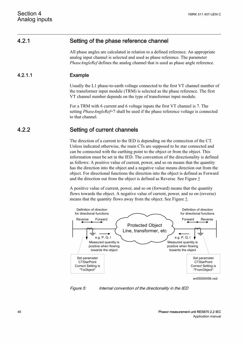
4.2.1 Setting of the phase reference channelSEMOD55055-5 v3
All phase angles are calculated in relation to a defined reference. An appropriateanalog input channel is selected and used as phase reference. The parameterPhaseAngleRef defines the analog channel that is used as phase angle reference.
4.2.1.1 ExampleSEMOD55055-11 v5
Usually the L1 phase-to-earth voltage connected to the first VT channel number ofthe transformer input module (TRM) is selected as the phase reference. The firstVT channel number depends on the type of transformer input module.
For a TRM with 6 current and 6 voltage inputs the first VT channel is 7. Thesetting PhaseAngleRef=7 shall be used if the phase reference voltage is connectedto that channel.
4.2.2 Setting of current channelsSEMOD55055-16 v6
The direction of a current to the IED is depending on the connection of the CT.Unless indicated otherwise, the main CTs are supposed to be star connected andcan be connected with the earthing point to the object or from the object. Thisinformation must be set in the IED. The convention of the directionality is definedas follows: A positive value of current, power, and so on means that the quantityhas the direction into the object and a negative value means direction out from theobject. For directional functions the direction into the object is defined as Forwardand the direction out from the object is defined as Reverse. See Figure 5
A positive value of current, power, and so on (forward) means that the quantityflows towards the object. A negative value of current, power, and so on (reverse)means that the quantity flows away from the object. See Figure 5.
Protected ObjectLine, transformer, etc
ForwardReverse
Definition of directionfor directional functions
Measured quantity ispositive when flowing
towards the object
e.g. P, Q, I
ReverseForward
Definition of directionfor directional functions
e.g. P, Q, IMeasured quantity ispositive when flowing
towards the object
Set parameterCTStarPoint
Correct Setting is"ToObject"
Set parameterCTStarPoint
Correct Setting is"FromObject" en05000456.vsd
IEC05000456 V1 EN-US
Figure 5: Internal convention of the directionality in the IED
Section 4 1MRK 511 407-UEN CAnalog inputs
48 Phasor measurement unit RES670 2.2 IECApplication manual

With correct setting of the primary CT direction, CTStarPoint set to FromObject orToObject, a positive quantities always flowing towards the protected object and adirection defined as Forward always is looking towards the protected object. Thefollowing examples show the principle.
4.2.2.1 Example 1SEMOD55055-23 v6
Two IEDs used for protection of two objects.
Transformer
protection
Transformer
Line
Line
Setting of current input:
Set parameter
CTStarPoint with
Transformer as
reference object.
Correct setting is
"ToObject"
ForwardReverse
Definition of direction
for directional functions
Line protection
Setting of current input:
Set parameter
CTStarPoint with
Transformer as
reference object.
Correct setting is
"ToObject"
Setting of current input:
Set parameter
CTStarPoint with
Line as
reference object.
Correct setting is
"FromObject"
IEC05000753=IEC05
000753=1=en=Origin
al[1].vsd
IsIs
Ip Ip Ip
IED IED
IEC05000753 V2 EN-US
Figure 6: Example how to set CTStarPoint parameters in the IED
Figure 6 shows the normal case where the objects have their own CTs. The settingsfor CT direction shall be done according to the figure. To protect the line, directionof the directional functions of the line protection shall be set to Forward. Thismeans that the protection is looking towards the line.
4.2.2.2 Example 2SEMOD55055-29 v7
Two IEDs used for protection of two objects and sharing a CT.
1MRK 511 407-UEN C Section 4Analog inputs
Phasor measurement unit RES670 2.2 IEC 49Application manual
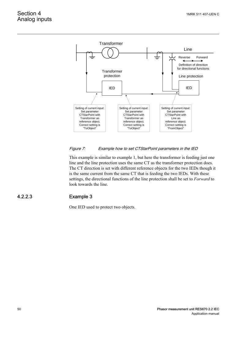
Transformer
protection
Transformer
Line
Setting of current input:
Set parameter
CTStarPoint with
Transformer as
reference object.
Correct setting is
"ToObject"
ForwardReverse
Definition of direction
for directional functions
Line protection
Setting of current input:
Set parameter
CTStarPoint with
Transformer as
reference object.
Correct setting is
"ToObject"
Setting of current input:
Set parameter
CTStarPoint with
Line as
reference object.
Correct setting is
"FromObject"
IED IED
IEC05000460 V2 EN-US
Figure 7: Example how to set CTStarPoint parameters in the IED
This example is similar to example 1, but here the transformer is feeding just oneline and the line protection uses the same CT as the transformer protection does.The CT direction is set with different reference objects for the two IEDs though itis the same current from the same CT that is feeding the two IEDs. With thesesettings, the directional functions of the line protection shall be set to Forward tolook towards the line.
4.2.2.3 Example 3SEMOD55055-35 v7
One IED used to protect two objects.
Section 4 1MRK 511 407-UEN CAnalog inputs
50 Phasor measurement unit RES670 2.2 IECApplication manual
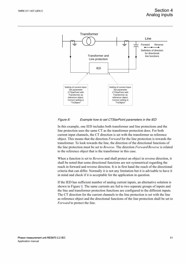
Transformer and
Line protection
Transformer
Line
Setting of current input:
Set parameter
CTStarPoint with
Transformer as
reference object.
Correct setting is
"ToObject"
ReverseForward
Definition of direction
for directional
line functions
Setting of current input:
Set parameter
CTStarPoint with
Transformer as
reference object.
Correct setting is
"ToObject"
IED
IEC05000461 V2 EN-US
Figure 8: Example how to set CTStarPoint parameters in the IED
In this example, one IED includes both transformer and line protections and theline protection uses the same CT as the transformer protection does. For bothcurrent input channels, the CT direction is set with the transformer as referenceobject. This means that the direction Forward for the line protection is towards thetransformer. To look towards the line, the direction of the directional functions ofthe line protection must be set to Reverse. The direction Forward/Reverse is relatedto the reference object that is the transformer in this case.
When a function is set to Reverse and shall protect an object in reverse direction, itshall be noted that some directional functions are not symmetrical regarding thereach in forward and reverse direction. It is in first hand the reach of the directionalcriteria that can differ. Normally it is not any limitation but it is advisable to have itin mind and check if it is acceptable for the application in question.
If the IED has sufficient number of analog current inputs, an alternative solution isshown in Figure 9. The same currents are fed to two separate groups of inputs andthe line and transformer protection functions are configured to the different inputs.The CT direction for the current channels to the line protection is set with the lineas reference object and the directional functions of the line protection shall be set toForward to protect the line.
1MRK 511 407-UEN C Section 4Analog inputs
Phasor measurement unit RES670 2.2 IEC 51Application manual
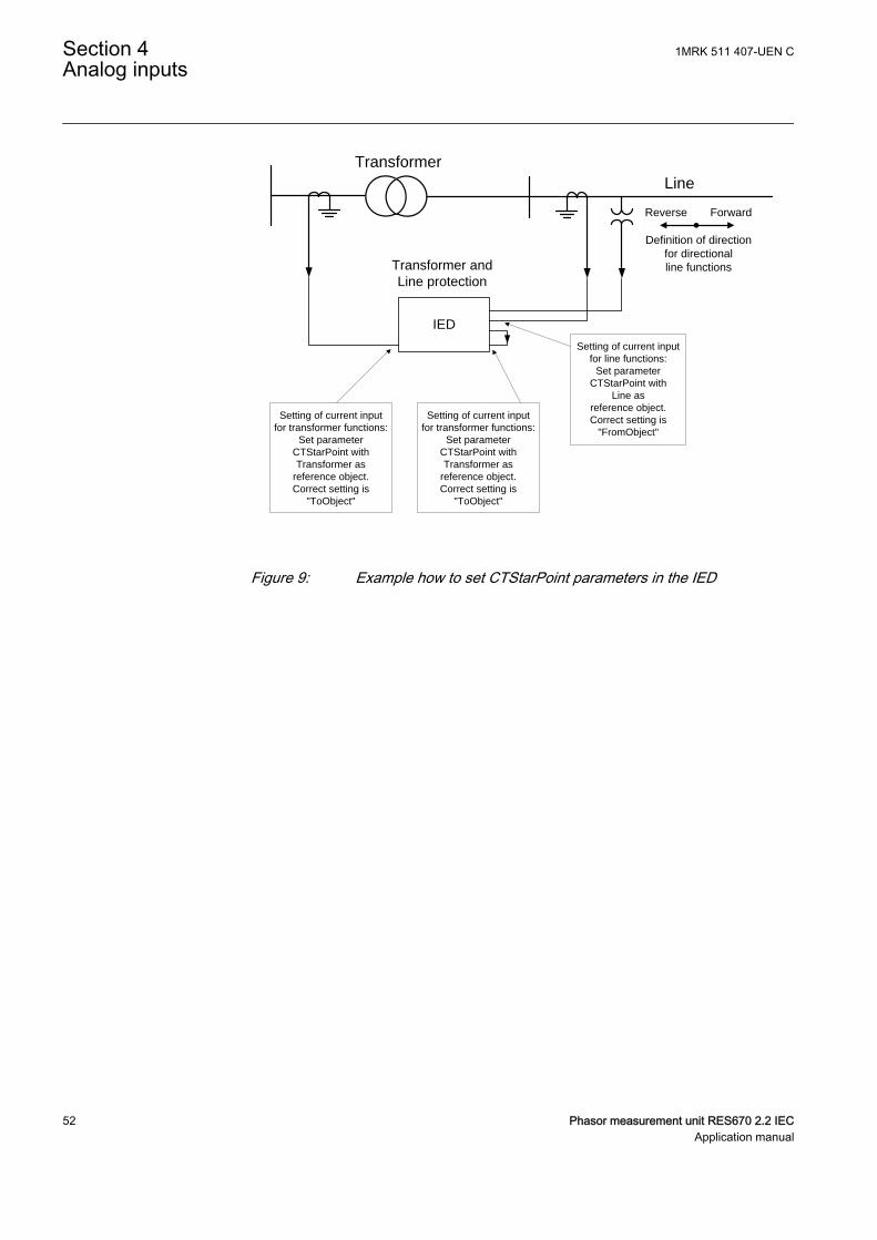
Transformer and
Line protection
Transformer
Line
Setting of current input
for transformer functions:
Set parameter
CTStarPoint with
Transformer as
reference object.
Correct setting is
"ToObject"
ForwardReverse
Definition of direction
for directional
line functions
Setting of current input
for transformer functions:
Set parameter
CTStarPoint with
Transformer as
reference object.
Correct setting is
"ToObject"
Setting of current input
for line functions:
Set parameter
CTStarPoint with
Line as
reference object.
Correct setting is
"FromObject"
IED
IEC05000462 V2 EN-US
Figure 9: Example how to set CTStarPoint parameters in the IED
Section 4 1MRK 511 407-UEN CAnalog inputs
52 Phasor measurement unit RES670 2.2 IECApplication manual
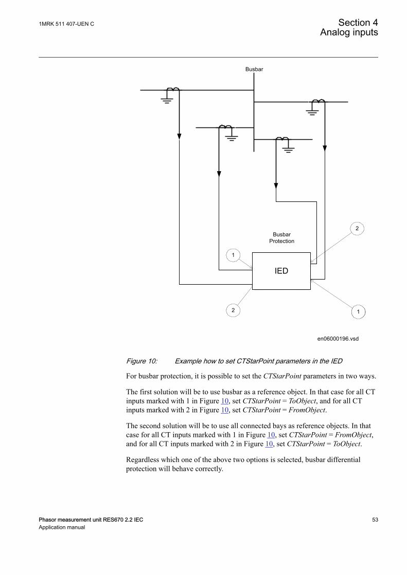
BusbarProtection
Busbar
1
2
2
1
en06000196.vsd
IED
1
IEC06000196 V2 EN-US
Figure 10: Example how to set CTStarPoint parameters in the IED
For busbar protection, it is possible to set the CTStarPoint parameters in two ways.
The first solution will be to use busbar as a reference object. In that case for all CTinputs marked with 1 in Figure 10, set CTStarPoint = ToObject, and for all CTinputs marked with 2 in Figure 10, set CTStarPoint = FromObject.
The second solution will be to use all connected bays as reference objects. In thatcase for all CT inputs marked with 1 in Figure 10, set CTStarPoint = FromObject,and for all CT inputs marked with 2 in Figure 10, set CTStarPoint = ToObject.
Regardless which one of the above two options is selected, busbar differentialprotection will behave correctly.
1MRK 511 407-UEN C Section 4Analog inputs
Phasor measurement unit RES670 2.2 IEC 53Application manual
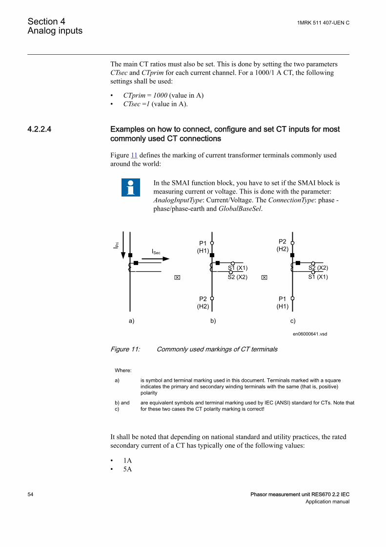
The main CT ratios must also be set. This is done by setting the two parametersCTsec and CTprim for each current channel. For a 1000/1 A CT, the followingsettings shall be used:
• CTprim = 1000 (value in A)• CTsec =1 (value in A).
4.2.2.4 Examples on how to connect, configure and set CT inputs for mostcommonly used CT connections
SEMOD55055-296 v7
Figure 11 defines the marking of current transformer terminals commonly usedaround the world:
In the SMAI function block, you have to set if the SMAI block ismeasuring current or voltage. This is done with the parameter:AnalogInputType: Current/Voltage. The ConnectionType: phase -phase/phase-earth and GlobalBaseSel.
ISec
I Pri
S1 (X1)
P1(H1)
P2(H2)
S2 (X2)
P2(H2)
P1(H1)
x x
a) b) c)
en06000641.vsd
S2 (X2) S1 (X1)
IEC06000641 V1 EN-US
Figure 11: Commonly used markings of CT terminals
Where:
a) is symbol and terminal marking used in this document. Terminals marked with a squareindicates the primary and secondary winding terminals with the same (that is, positive)polarity
b) andc)
are equivalent symbols and terminal marking used by IEC (ANSI) standard for CTs. Note thatfor these two cases the CT polarity marking is correct!
It shall be noted that depending on national standard and utility practices, the ratedsecondary current of a CT has typically one of the following values:
• 1A• 5A
Section 4 1MRK 511 407-UEN CAnalog inputs
54 Phasor measurement unit RES670 2.2 IECApplication manual
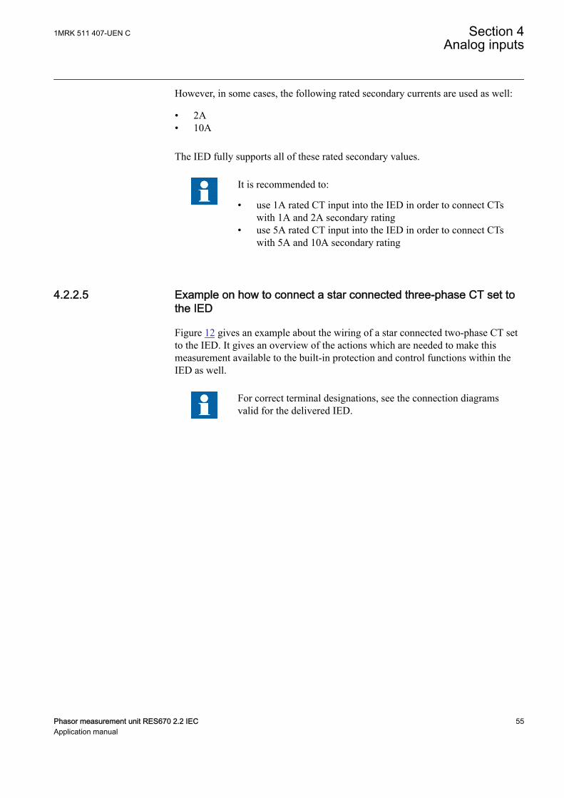
However, in some cases, the following rated secondary currents are used as well:
• 2A• 10A
The IED fully supports all of these rated secondary values.
It is recommended to:
• use 1A rated CT input into the IED in order to connect CTswith 1A and 2A secondary rating
• use 5A rated CT input into the IED in order to connect CTswith 5A and 10A secondary rating
4.2.2.5 Example on how to connect a star connected three-phase CT set tothe IED
SEMOD55055-352 v11
Figure 12 gives an example about the wiring of a star connected two-phase CT setto the IED. It gives an overview of the actions which are needed to make thismeasurement available to the built-in protection and control functions within theIED as well.
For correct terminal designations, see the connection diagramsvalid for the delivered IED.
1MRK 511 407-UEN C Section 4Analog inputs
Phasor measurement unit RES670 2.2 IEC 55Application manual
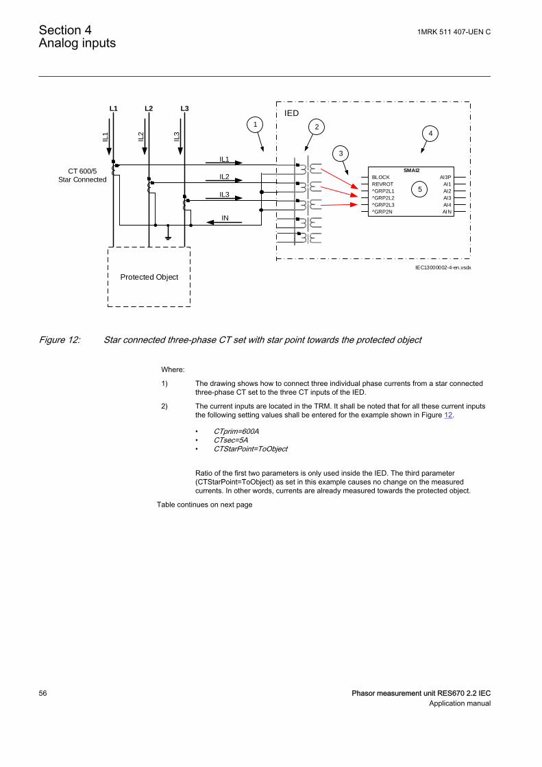
L1IL
1
IL2
IL3
L2 L3
Protected Object
CT 600/5Star Connected
IL1
IL2
IL3
IED
IEC13000002-4-en.vsdx
1 2
3
4
SMAI2
BLOCK
REVROT
^GRP2L1
^GRP2L2
^GRP2L3
^GRP2N
AI3P
AI1
AI2
AI3
AI4
AIN
5
IN
IEC13000002 V4 EN-US
Figure 12: Star connected three-phase CT set with star point towards the protected object
Where:
1) The drawing shows how to connect three individual phase currents from a star connectedthree-phase CT set to the three CT inputs of the IED.
2) The current inputs are located in the TRM. It shall be noted that for all these current inputsthe following setting values shall be entered for the example shown in Figure 12.
• CTprim=600A• CTsec=5A• CTStarPoint=ToObject
Ratio of the first two parameters is only used inside the IED. The third parameter(CTStarPoint=ToObject) as set in this example causes no change on the measuredcurrents. In other words, currents are already measured towards the protected object.
Table continues on next page
Section 4 1MRK 511 407-UEN CAnalog inputs
56 Phasor measurement unit RES670 2.2 IECApplication manual

3) These three connections are the links between the three current inputs and the three inputchannels of the preprocessing function block 4). Depending on the type of functions, whichneed this current information, more than one preprocessing block might be connected inparallel to the same three physical CT inputs.
4) The preprocessing block that has the task to digitally filter the connected analog inputs andcalculate:
• fundamental frequency phasors for all three input channels• harmonic content for all three input channels• positive, negative and zero sequence quantities by using the fundamental frequency
phasors for the first three input channels (channel one taken as reference forsequence quantities)
These calculated values are then available for all built-in protection and control functionswithin the IED, which are connected to this preprocessing function block. For thisapplication most of the preprocessing settings can be left to the default values.If frequency tracking and compensation is required (this feature is typically required onlyfor IEDs installed in power plants), then the setting parameters DFTReference shall be setaccordingly.Section SMAI in this manual provides information on adaptive frequency tracking for thesignal matrix for analogue inputs (SMAI).
5) AI3P in the SMAI function block is a grouped signal which contains all the data about thephases L1, L2, L3 and neutral quantity; in particular the data about fundamental frequencyphasors, harmonic content and positive sequence, negative and zero sequence quantitiesare available.AI1, AI2, AI3, AI4 are the output signals from the SMAI function block which contain thefundamental frequency phasors and the harmonic content of the corresponding inputchannels of the preprocessing function block.AIN is the signal which contains the fundamental frequency phasors and the harmoniccontent of the neutral quantity. In this example, GRP2N is not connected so this data iscalculated by the preprocessing function block on the basis of the inputs GRPL1, GRPL2and GRPL3. If GRP2N is connected, the data reflects the measured value of GRP2N.
Another alternative is to have the star point of the three-phase CT set as shown inFigure 13:
1MRK 511 407-UEN C Section 4Analog inputs
Phasor measurement unit RES670 2.2 IEC 57Application manual
L1IL
1
IL2
IL3
L2 L3
Protected Object
CT 800/1Star Connected
IL1
IL2
IL3
IED
IEC11000026-4-en.vsdx
4 12
3
SMAI2
BLOCK
REVROT
^GRP2L1
^GRP2L2
^GRP2L3
^GRP2N
AI3P
AI1
AI2
AI3
AI4
AIN
5
IN
IEC11000026 V4 EN-US
Figure 13: Star connected three-phase CT set with its star point away from the protected object
In the example, everything is done in a similar way as in the above describedexample (Figure 12). The only difference is the setting of the parameterCTStarPoint of the used current inputs on the TRM (item 2 in Figure 13 and 12):
• CTprim=600A• CTsec=5A• CTStarPoint=FromObject
The ratio of the first two parameters is only used inside the IED. The thirdparameter as set in this example will negate the measured currents in order toensure that the currents are measured towards the protected object within the IED.
A third alternative is to have the residual/neutral current from the three-phase CTset connected to the IED as shown in Figure 13.
Section 4 1MRK 511 407-UEN CAnalog inputs
58 Phasor measurement unit RES670 2.2 IECApplication manual
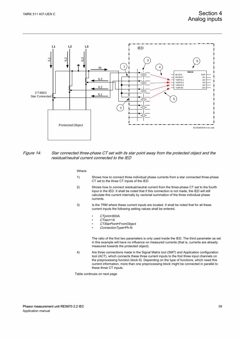
L1IL
1
IL2
IL3
L2 L3
Protected Object
CT 800/1
Star ConnectedIL1
IL2
IL3
IN
IED
1
3
4
2
5
IEC06000644-4-en.vsdx
6
SMAI2
BLOCK
REVROT
^GRP2L1
^GRP2L2
^GRP2L3
^GRP2N
AI3P
AI1
AI2
AI3
AI4
AIN
IEC06000644 V4 EN-US
Figure 14: Star connected three-phase CT set with its star point away from the protected object and theresidual/neutral current connected to the IED
Where:
1) Shows how to connect three individual phase currents from a star connected three-phaseCT set to the three CT inputs of the IED.
2) Shows how to connect residual/neutral current from the three-phase CT set to the fourthinput in the IED. It shall be noted that if this connection is not made, the IED will stillcalculate this current internally by vectorial summation of the three individual phasecurrents.
3) Is the TRM where these current inputs are located. It shall be noted that for all thesecurrent inputs the following setting values shall be entered.
• CTprim=800A• CTsec=1A• CTStarPoint=FromObject• ConnectionType=Ph-N
The ratio of the first two parameters is only used inside the IED. The third parameter as setin this example will have no influence on measured currents (that is, currents are alreadymeasured towards the protected object).
4) Are three connections made in the Signal Matrix tool (SMT) and Application configurationtool (ACT), which connects these three current inputs to the first three input channels onthe preprocessing function block 6). Depending on the type of functions, which need thiscurrent information, more than one preprocessing block might be connected in parallel tothese three CT inputs.
Table continues on next page
1MRK 511 407-UEN C Section 4Analog inputs
Phasor measurement unit RES670 2.2 IEC 59Application manual

5) Is a connection made in the Signal Matrix tool (SMT) and Application configuration tool(ACT), which connects the residual/neutral current input to the fourth input channel of thepreprocessing function block 6). Note that this connection in SMT shall not be done if theresidual/neutral current is not connected to the IED.
6) Is a Preprocessing block that has the task to digitally filter the connected analog inputs andcalculate:
• fundamental frequency phasors for all input channels• harmonic content for all input channels• positive, negative and zero sequence quantities by using the fundamental frequency
phasors of the first three input channels (channel one taken as reference forsequence quantities)
These calculated values are then available for all built-in protection and control functionswithin the IED, which are connected to this preprocessing function block in theconfiguration tool. For this application, most of the preprocessing settings can be left to thedefault values.If frequency tracking and compensation is required (this feature is typically required onlyfor IEDs installed in the generating stations), then the setting parameters DFTReferenceshall be set accordingly.
4.2.2.6 Example how to connect delta connected three-phase CT set to theIED
SEMOD55055-392 v7
Figure 15 gives an example how to connect a delta connected three-phase CT set tothe IED. It gives an overview of the required actions by the user in order to makethis measurement available to the built-in protection and control functions in theIED as well.
For correct terminal designations, see the connection diagramsvalid for the delivered IED.
Section 4 1MRK 511 407-UEN CAnalog inputs
60 Phasor measurement unit RES670 2.2 IECApplication manual

L1
IL1
IL2
IL3
L2 L3
Protected Object
IED
CT 6
00/5
in D
elta
DA
B C
onn
ecte
d
IL1-IL2
IL2-IL3
IL3-IL1
1 2
3 4
IEC11000027-3-en.vsdx
SMAI2
BLOCK
REVROT
^GRP2L1
^GRP2L2
^GRP2L3
^GRP2N
AI3P
AI1
AI2
AI3
AI4
AIN
IEC11000027 V3 EN-US
Figure 15: Delta DAB connected three-phase CT set
1MRK 511 407-UEN C Section 4Analog inputs
Phasor measurement unit RES670 2.2 IEC 61Application manual
Where:
1) shows how to connect three individual phase currents from a delta connected three-phaseCT set to three CT inputs of the IED.
2) is the TRM where these current inputs are located. It shall be noted that for all thesecurrent inputs the following setting values shall be entered.CTprim=600ACTsec=5A
• CTStarPoint=ToObject• ConnectionType=Ph-Ph
3) are three connections made in Signal Matrix Tool (SMT), Application configuration tool(ACT), which connect these three current inputs to first three input channels of thepreprocessing function block 4). Depending on the type of functions which need thiscurrent information, more then one preprocessing block might be connected in parallel tothese three CT inputs.
4) is a Preprocessing block that has the task to digitally filter the connected analog inputs andcalculate:
• fundamental frequency phasors for all three input channels• harmonic content for all three input channels• positive, negative and zero sequence quantities by using the fundamental frequency
phasors for the first three input channels (channel one taken as reference forsequence quantities)
These calculated values are then available for all built-in protection and control functionswithin the IED, which are connected to this preprocessing function block. For thisapplication most of the preprocessing settings can be left to the default values.If frequency tracking and compensation is required (this feature is typically required onlyfor IEDs installed in the generating stations) then the setting parameters DFTReferenceshall be set accordingly.
Another alternative is to have the delta connected CT set as shown in figure 16:
Section 4 1MRK 511 407-UEN CAnalog inputs
62 Phasor measurement unit RES670 2.2 IECApplication manual
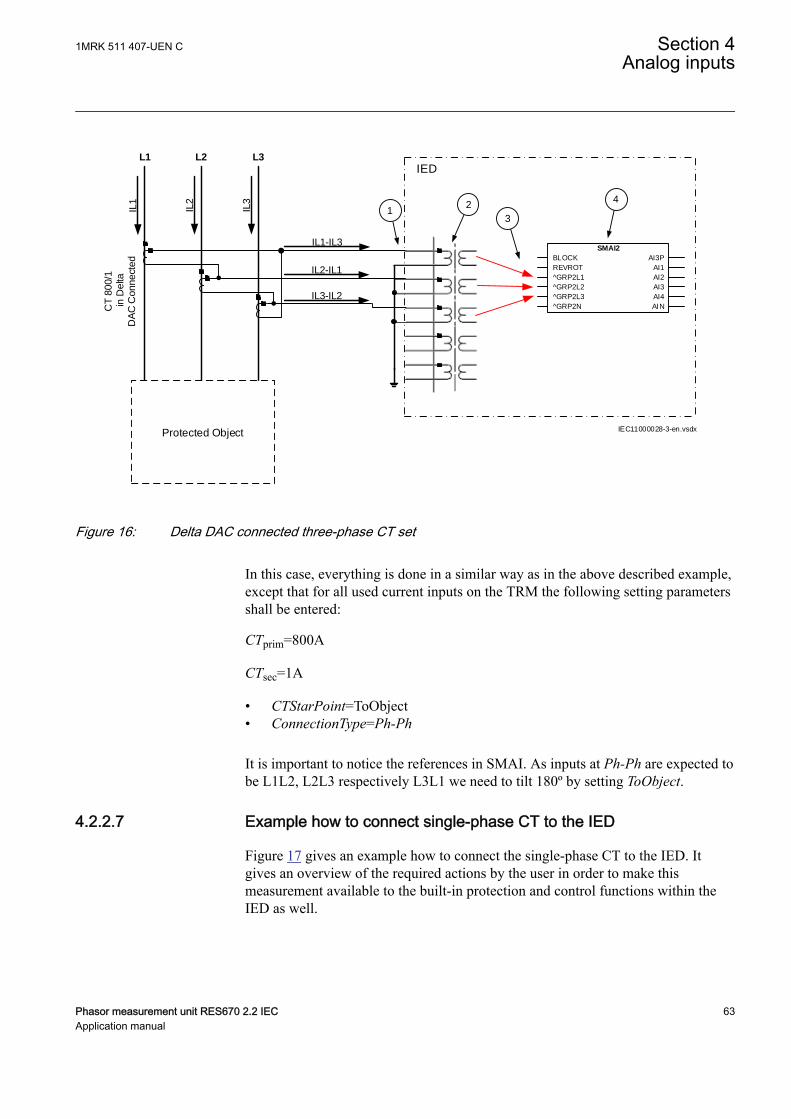
L1
IL1
IL2
IL3
L2 L3
Protected Object
IED
CT 8
00/1
in D
elta
DA
C C
onnect
ed
IL3-IL2
IL2-IL1
IL1-IL3
2
3
4
IEC11000028-3-en.vsdx
SMAI2
BLOCK
REVROT
^GRP2L1
^GRP2L2
^GRP2L3
^GRP2N
AI3P
AI1
AI2
AI3
AI4
AIN
1
IEC11000028 V3 EN-US
Figure 16: Delta DAC connected three-phase CT set
In this case, everything is done in a similar way as in the above described example,except that for all used current inputs on the TRM the following setting parametersshall be entered:
CTprim=800A
CTsec=1A
• CTStarPoint=ToObject• ConnectionType=Ph-Ph
It is important to notice the references in SMAI. As inputs at Ph-Ph are expected tobe L1L2, L2L3 respectively L3L1 we need to tilt 180º by setting ToObject.
4.2.2.7 Example how to connect single-phase CT to the IEDSEMOD55055-431 v8
Figure 17 gives an example how to connect the single-phase CT to the IED. Itgives an overview of the required actions by the user in order to make thismeasurement available to the built-in protection and control functions within theIED as well.
1MRK 511 407-UEN C Section 4Analog inputs
Phasor measurement unit RES670 2.2 IEC 63Application manual

For correct terminal designations, see the connection diagramsvalid for the delivered IED.
Protected Object
L1 L2 L3
IED
INP
INS
INS
2
IEC11000029-4-en.vsdx
4
3
CT
10
00
/1
a)
b)
(+)
(+)
(-)
(-)(+)
(-)
1 SMAI2
BLOCK
REVROT
^GRP2L1
^GRP2L2
^GRP2L3
^GRP2N
AI3P
AI1
AI2
AI3
AI4
AIN
IEC11000029 V4 EN-US
Figure 17: Connections for single-phase CT input
Where:
1) shows how to connect single-phase CT input in the IED.
2) is TRM where these current inputs are located. It shall be noted that for all thesecurrent inputs the following setting values shall be entered.For connection (a) shown in Fgure 17:CTprim= 1000 ACTsec= 1ACTStarPoint=ToObject For connection (b) shown in Figure 17:CTprim= 1000 ACTsec= 1ACTStarPoint=FromObject
3) shows the connection made in SMT tool, which connect this CT input to the fourth inputchannel of the preprocessing function block 4).
4) is a Preprocessing block that has the task to digitally filter the connected analog inputsand calculate values. The calculated values are then available for all built-in protectionand control functions within the IED, which are connected to this preprocessingfunction block.If frequency tracking and compensation is required (this feature is typically requiredonly for IEDs installed in the power plants) then the setting parameters DFTReferenceshall be set accordingly.
Section 4 1MRK 511 407-UEN CAnalog inputs
64 Phasor measurement unit RES670 2.2 IECApplication manual
4.2.3 Relationships between setting parameter Base Current, CTrated primary current and minimum pickup of a protectionIED
GUID-8EB19363-9178-4F04-A6AC-AF0C2F99C5AB v1
Note that for all line protection applications (e.g. distance protection or linedifferential protection) the parameter Base Current (i.e. IBase setting in the IED)used by the relevant protection function, shall always be set equal to the largestrated CT primary current among all CTs involved in the protection scheme. Therated CT primary current value is set as parameter CTPrim under the IED TRMsettings.
For all other protection applications (e.g. generator, shunt reactor, shunt capacitorand transformer protection) it is typically desirable to set IBase parameter equal tothe rated current of the protected object. However this is only recommended to doif the rated current of the protected object is within the range of 40% to 120% ofthe selected CT rated primary current. If for any reason (e.g. high maximum shortcircuit current) the rated current of the protected object is less than 40% of therated CT primary current, it is strongly recommended to set the parameter IBase inthe IED to be equal to the largest rated CT primary current among all CTs involvedin the protection scheme and installed on the same voltage level. This willeffectively make the protection scheme less sensitive; however, such measures arenecessary in order to avoid possible problems with loss of the measurementaccuracy in the IED.
Regardless of the applied relationship between the IBase parameter and the ratedCT primary current, the corresponding minimum pickup of the function on the CTsecondary side must always be verified. It is strongly recommended that theminimum pickup of any instantaneous protection function (e.g. differential,restricted earth fault, distance, instantaneous overcurrent, etc.) shall under nocircumstances be less than 4% of the used IED CT input rating (i.e. 1A or 5A).This corresponds to 40mA secondary for IED 1A rated inputs and to 200mAsecondary for IED 5A rated inputs used by the function. This shall be individuallyverified for all current inputs involved in the protection scheme.
Note that exceptions from the above 4% rule may be acceptable for very specialapplications (e.g. when Multipurpose filter SMAIHPAC is involved in theprotection scheme).
4.2.4 Setting of voltage channelsSEMOD55055-44 v4
As the IED uses primary system quantities, the main VT ratios must be known tothe IED. This is done by setting the two parameters VTsec and VTprim for eachvoltage channel. The phase-to-phase value can be used even if each channel isconnected to a phase-to-earth voltage from the VT.
4.2.4.1 ExampleSEMOD55055-47 v3
Consider a VT with the following data:
1MRK 511 407-UEN C Section 4Analog inputs
Phasor measurement unit RES670 2.2 IEC 65Application manual
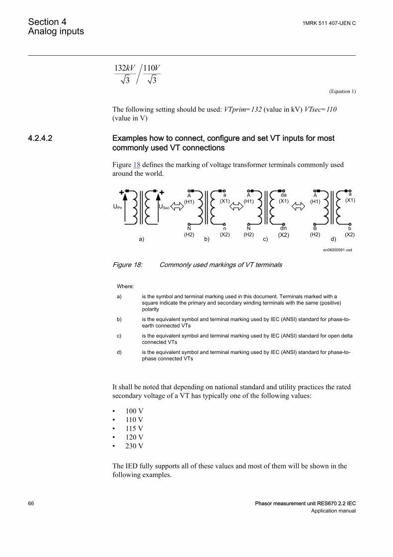
132 1103 3kV V
EQUATION2016 V1 EN-US (Equation 1)
The following setting should be used: VTprim=132 (value in kV) VTsec=110(value in V)
4.2.4.2 Examples how to connect, configure and set VT inputs for mostcommonly used VT connections
SEMOD55055-60 v6
Figure 18 defines the marking of voltage transformer terminals commonly usedaround the world.
A(H1)
B(H2)
b(X2)
a(X1)
A(H1)
N(H2)
n(X2)
a(X1)
b) c)
A(H1)
N(H2)
dn(X2)
da(X1)
d)
UPri
+ +USec
a)
en06000591.vsdIEC06000591 V1 EN-US
Figure 18: Commonly used markings of VT terminals
Where:
a) is the symbol and terminal marking used in this document. Terminals marked with asquare indicate the primary and secondary winding terminals with the same (positive)polarity
b) is the equivalent symbol and terminal marking used by IEC (ANSI) standard for phase-to-earth connected VTs
c) is the equivalent symbol and terminal marking used by IEC (ANSI) standard for open deltaconnected VTs
d) is the equivalent symbol and terminal marking used by IEC (ANSI) standard for phase-to-phase connected VTs
It shall be noted that depending on national standard and utility practices the ratedsecondary voltage of a VT has typically one of the following values:
• 100 V• 110 V• 115 V• 120 V• 230 V
The IED fully supports all of these values and most of them will be shown in thefollowing examples.
Section 4 1MRK 511 407-UEN CAnalog inputs
66 Phasor measurement unit RES670 2.2 IECApplication manual
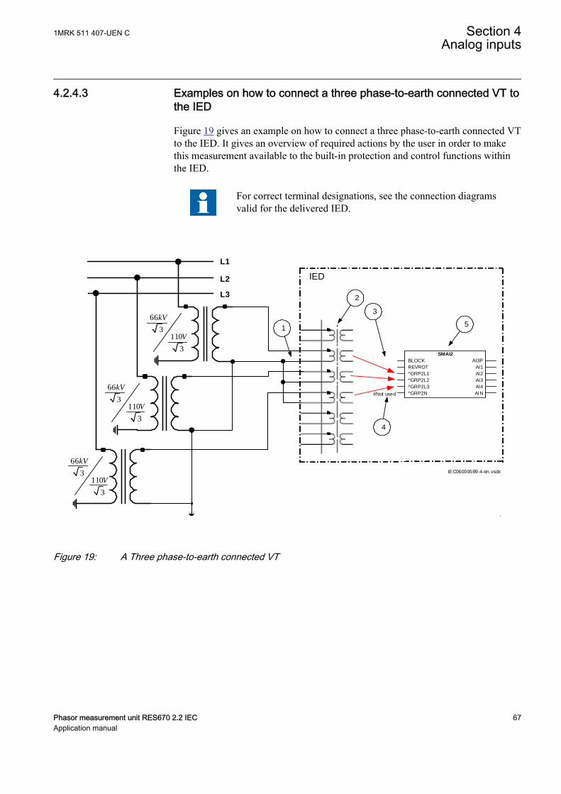
4.2.4.3 Examples on how to connect a three phase-to-earth connected VT tothe IED
SEMOD55055-87 v9
Figure 19 gives an example on how to connect a three phase-to-earth connected VTto the IED. It gives an overview of required actions by the user in order to makethis measurement available to the built-in protection and control functions withinthe IED.
For correct terminal designations, see the connection diagramsvalid for the delivered IED.
L1
IED L2
L3
66
3110
3
kV
V
1
3
2
66
3110
3
kV
V
66
3110
3
kV
V
.
#Not used
5
IEC06000599-4-en.vsdx
4
SMAI2
BLOCK
REVROT
^GRP2L1
^GRP2L2
^GRP2L3
^GRP2N
AI3P
AI1
AI2
AI3
AI4
AIN
IEC06000599 V4 EN-US
Figure 19: A Three phase-to-earth connected VT
1MRK 511 407-UEN C Section 4Analog inputs
Phasor measurement unit RES670 2.2 IEC 67Application manual
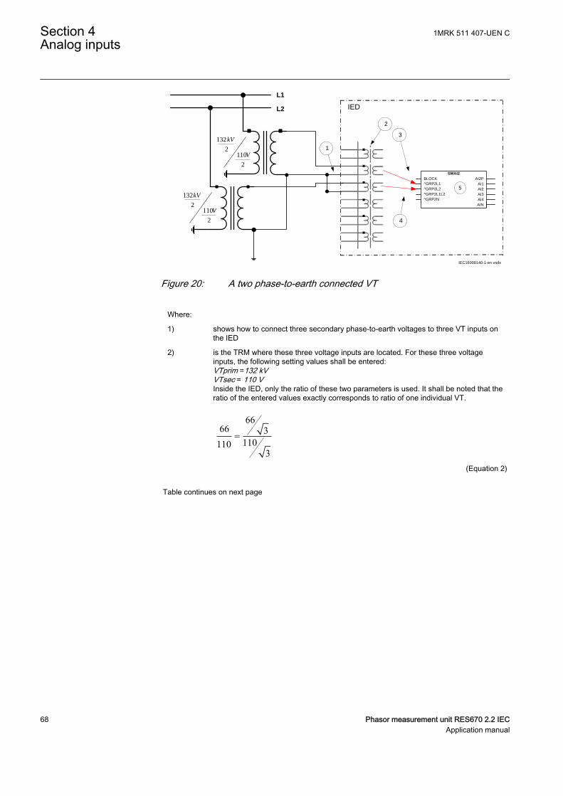
L1
IED L2
132
2110
2
kV
V
1
3
2
132
2110
2
kV
V
IEC16000140-1-en.vsdx
4
SMAI2BLOCK^GRP2L1^GRP2L2^GRP2L1L2^GRP2N
AI2PAI1AI2AI3AI4AIN
5
IEC16000140 V1 EN-US
Figure 20: A two phase-to-earth connected VT
Where:
1) shows how to connect three secondary phase-to-earth voltages to three VT inputs onthe IED
2) is the TRM where these three voltage inputs are located. For these three voltageinputs, the following setting values shall be entered:VTprim =132 kVVTsec = 110 VInside the IED, only the ratio of these two parameters is used. It shall be noted that theratio of the entered values exactly corresponds to ratio of one individual VT.
6666 3
1101103
=
EQUATION1903 V1 EN-US (Equation 2)
Table continues on next page
Section 4 1MRK 511 407-UEN CAnalog inputs
68 Phasor measurement unit RES670 2.2 IECApplication manual
3) are three connections made in Signal Matrix Tool (SMT), which connect these threevoltage inputs to first three input channels of the preprocessing function block 5).Depending on the type of functions which need this voltage information, more then onepreprocessing block might be connected in parallel to these three VT inputs.
4) shows that in this example the fourth (that is, residual) input channel of thepreprocessing block is not connected in SMT tool. Thus the preprocessing block willautomatically calculate 3Uo inside by vectorial sum from the three phase to earthvoltages connected to the first three input channels of the same preprocessing block.Alternatively, the fourth input channel can be connected to open delta VT input, asshown in Figure 22.
5) is a Preprocessing block that has the task to digitally filter the connected analog inputsand calculate:
• fundamental frequency phasors for all input channels• harmonic content for all input channels• positive, negative and zero sequence quantities by using the fundamental
frequency phasors for the first three input channels (channel one taken asreference for sequence quantities)
These calculated values are then available for all built-in protection and controlfunctions within the IED, which are connected to this preprocessing function block in theconfiguration tool. For this application most of the preprocessing settings can be left tothe default values. However the following settings shall be set as shown here:UBase=66 kV (that is, rated Ph-Ph voltage)If frequency tracking and compensation is required (this feature is typically requiredonly for IEDs installed in the generating stations) then the setting parametersDFTReference shall be set accordingly.
4.2.4.4 Example on how to connect a phase-to-phase connected VT to theIED
SEMOD55055-134 v7
Figure 21 gives an example how to connect a phase-to-phase connected VT to theIED. It gives an overview of the required actions by the user in order to make thismeasurement available to the built-in protection and control functions within theIED. It shall be noted that this VT connection is only used on lower voltage levels(that is, rated primary voltage below 40 kV).
1MRK 511 407-UEN C Section 4Analog inputs
Phasor measurement unit RES670 2.2 IEC 69Application manual
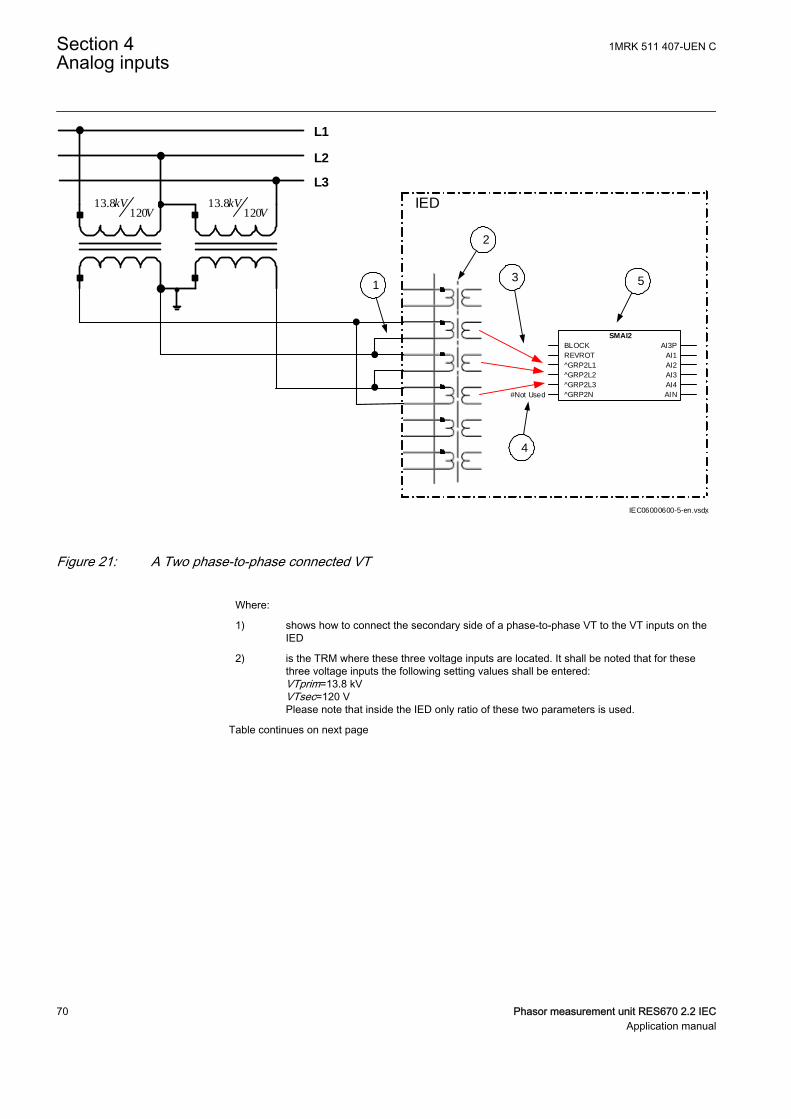
L1
IED
L2
L3
13.8120
kVV
1
2
#Not Used
13.8120
kVV
.
5
IEC06000600-5-en.vsdx
4
SMAI2
BLOCK
REVROT
^GRP2L1
^GRP2L2
^GRP2L3
^GRP2N
AI3P
AI1
AI2
AI3
AI4
AIN
3
IEC06000600 V5 EN-US
Figure 21: A Two phase-to-phase connected VT
Where:
1) shows how to connect the secondary side of a phase-to-phase VT to the VT inputs on theIED
2) is the TRM where these three voltage inputs are located. It shall be noted that for thesethree voltage inputs the following setting values shall be entered:VTprim=13.8 kVVTsec=120 VPlease note that inside the IED only ratio of these two parameters is used.
Table continues on next page
Section 4 1MRK 511 407-UEN CAnalog inputs
70 Phasor measurement unit RES670 2.2 IECApplication manual
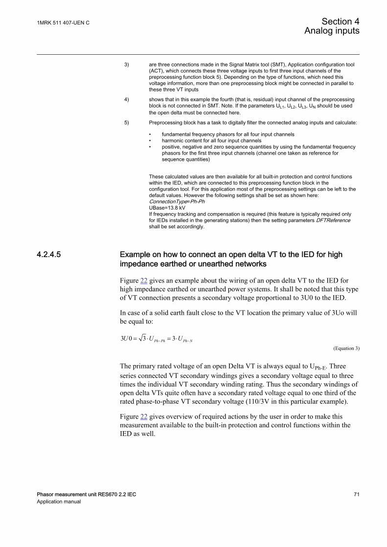
3) are three connections made in the Signal Matrix tool (SMT), Application configuration tool(ACT), which connects these three voltage inputs to first three input channels of thepreprocessing function block 5). Depending on the type of functions, which need thisvoltage information, more than one preprocessing block might be connected in parallel tothese three VT inputs
4) shows that in this example the fourth (that is, residual) input channel of the preprocessingblock is not connected in SMT. Note. If the parameters UL1, UL2, UL3, UN should be usedthe open delta must be connected here.
5) Preprocessing block has a task to digitally filter the connected analog inputs and calculate:
• fundamental frequency phasors for all four input channels• harmonic content for all four input channels• positive, negative and zero sequence quantities by using the fundamental frequency
phasors for the first three input channels (channel one taken as reference forsequence quantities)
These calculated values are then available for all built-in protection and control functionswithin the IED, which are connected to this preprocessing function block in theconfiguration tool. For this application most of the preprocessing settings can be left to thedefault values. However the following settings shall be set as shown here:ConnectionType=Ph-PhUBase=13.8 kVIf frequency tracking and compensation is required (this feature is typically required onlyfor IEDs installed in the generating stations) then the setting parameters DFTReferenceshall be set accordingly.
4.2.4.5 Example on how to connect an open delta VT to the IED for highimpedance earthed or unearthed networks
SEMOD55055-163 v9
Figure 22 gives an example about the wiring of an open delta VT to the IED forhigh impedance earthed or unearthed power systems. It shall be noted that this typeof VT connection presents a secondary voltage proportional to 3U0 to the IED.
In case of a solid earth fault close to the VT location the primary value of 3Uo willbe equal to:
3 0 3 3Ph Ph Ph NU U U- -= × = ×EQUATION1921 V3 EN-US (Equation 3)
The primary rated voltage of an open Delta VT is always equal to UPh-E. Threeseries connected VT secondary windings gives a secondary voltage equal to threetimes the individual VT secondary winding rating. Thus the secondary windings ofopen delta VTs quite often have a secondary rated voltage equal to one third of therated phase-to-phase VT secondary voltage (110/3V in this particular example).
Figure 22 gives overview of required actions by the user in order to make thismeasurement available to the built-in protection and control functions within theIED as well.
1MRK 511 407-UEN C Section 4Analog inputs
Phasor measurement unit RES670 2.2 IEC 71Application manual
L1
IED L2
L3
6.6
3110
3
kV
V
+3Uo
6.6
3110
3
kV
V
6.6
3110
3
kV
V
1
2
4
3
# Not Used
5
IEC06000601-4-en.vsdx
# Not Used
# Not Used
SMAI2
BLOCK
REVROT
^GRP2L1
^GRP2L2
^GRP2L3
^GRP2N
AI3P
AI1
AI2
AI3
AI4
AIN
IEC06000601 V4 EN-US
Figure 22: Open delta connected VT in high impedance earthed power system
Section 4 1MRK 511 407-UEN CAnalog inputs
72 Phasor measurement unit RES670 2.2 IECApplication manual

Where:
1) shows how to connect the secondary side of the open delta VT to one VT input on theIED.
+3U0 shall be connected to the IED
2) is the TRM where this voltage input is located. It shall be noted that for this voltage inputthe following setting values shall be entered:
3 6.6 11.43VTprim kV= × =
EQUATION1923 V1 EN-US (Equation 4)
110sec 3 110
3VT V= × =
EQUATION1924 V1 EN-US (Equation 5)
Inside the IED, only the ratio of these two parameters is used. It shall be noted that theratio of the entered values exactly corresponds to ratio of one individual open delta VT.
6.63 6.6 3
1101103
×=
EQUATION1925 V1 EN-US (Equation 6)
3) shows that in this example the first three input channel of the preprocessing block is notconnected in SMT tool or ACT tool.
4) shows the connection made in Signal Matrix Tool (SMT), Application configuration tool(ACT), which connect this voltage input to the fourth input channel of the preprocessingfunction block 5).
5) is a Preprocessing block that has the task to digitally filter the connected analog inputand calculate:
• fundamental frequency phasors for all four input channels• harmonic content for all four input channels• positive, negative and zero sequence quantities by using the fundamental
frequency phasors for the first three input channels (channel one taken asreference for sequence quantities)
These calculated values are then available for all built-in protection and controlfunctions within the IED, which are connected to this preprocessing function block in theconfiguration tool. For this application most of the preprocessing settings can be left tothe default values.If frequency tracking and compensation is required (this feature is typically required onlyfor IEDs installed in the generating stations ) then the setting parameters DFTReferenceshall be set accordingly.
1MRK 511 407-UEN C Section 4Analog inputs
Phasor measurement unit RES670 2.2 IEC 73Application manual
4.2.4.6 Example how to connect the open delta VT to the IED for lowimpedance earthed or solidly earthed power systems
SEMOD55055-199 v6
Figure 23 gives an example about the connection of an open delta VT to the IEDfor low impedance earthed or solidly earthed power systems. It shall be noted thatthis type of VT connection presents secondary voltage proportional to 3U0 to theIED.
In case of a solid earth fault close to the VT location the primary value of 3Uo willbe equal to:
33
Ph PhPh E
UUo U-
-= =
EQUATION1926 V1 EN-US (Equation 7)
The primary rated voltage of such VT is always equal to UPh-E Therefore, threeseries connected VT secondary windings will give the secondary voltage equalonly to one individual VT secondary winding rating. Thus the secondary windingsof such open delta VTs quite often has a secondary rated voltage close to ratedphase-to-phase VT secondary voltage, that is, 115V or 115/√3V as in this particularexample. Figure 23 gives an overview of the actions which are needed to make thismeasurement available to the built-in protection and control functions within theIED.
Section 4 1MRK 511 407-UEN CAnalog inputs
74 Phasor measurement unit RES670 2.2 IECApplication manual
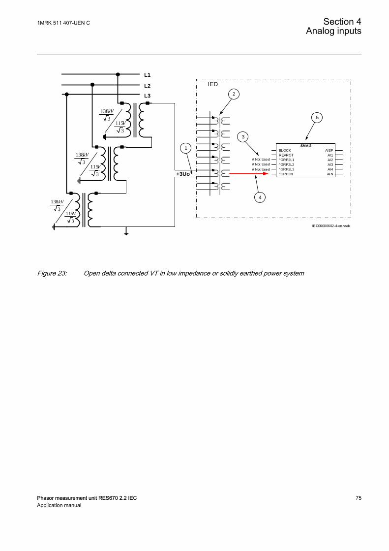
1
L1
IED L2
L3
138
3115
3
kV
V
+3Uo
138
3115
3
kV
V
138
3115
3
kV
V
IEC06000602-4-en.vsdx
# Not Used
# Not Used
# Not Used
SMAI2
BLOCK
REVROT
^GRP2L1
^GRP2L2
^GRP2L3
^GRP2N
AI3P
AI1
AI2
AI3
AI4
AIN
2
3
4
5
IEC06000602 V4 EN-US
Figure 23: Open delta connected VT in low impedance or solidly earthed power system
1MRK 511 407-UEN C Section 4Analog inputs
Phasor measurement unit RES670 2.2 IEC 75Application manual
Where:
1) shows how to connect the secondary side of open delta VT to one VT input in theIED.
+3Uo shall be connected to the IED.
2) is TRM where this voltage input is located. It shall be noted that for this voltage inputthe following setting values shall be entered:
1383 138
3VTprim kV= × =
EQUATION1928 V1 EN-US (Equation 8)
115sec 3 115
3VT V= × =
EQUATION1929 V1 EN-US (Equation 9)
Inside the IED, only the ratio of these two parameters is used. It shall be noted thatthe ratio of the entered values exactly corresponds to ratio of one individual opendelta VT.
138138 3
1151153
=
EQUATION1930 V1 EN-US (Equation 10)
3) shows that in this example the first three input channel of the preprocessing block isnot connected in SMT tool.
4) shows the connection made in Signal Matrix Tool (SMT), which connect this voltageinput to the fourth input channel of the preprocessing function block 4).
5) preprocessing block has a task to digitally filter the connected analog inputs andcalculate:
• fundamental frequency phasors for all four input channels• harmonic content for all four input channels• positive, negative and zero sequence quantities by using the fundamental
frequency phasors for the first three input channels (channel one taken asreference for sequence quantities)
These calculated values are then available for all built-in protection and controlfunctions within the IED, which are connected to this preprocessing function block inthe configuration tool. For this application most of the preprocessing settings can beleft to the default values.If frequency tracking and compensation is required (this feature is typically requiredonly for IEDs installed in the generating stations) then the setting parametersDFTReference shall be set accordingly.
Section 4 1MRK 511 407-UEN CAnalog inputs
76 Phasor measurement unit RES670 2.2 IECApplication manual
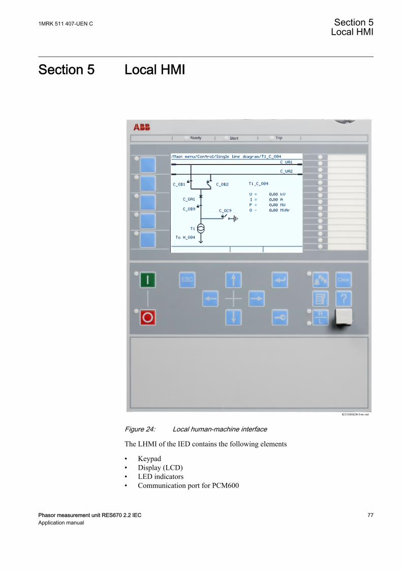
Section 5 Local HMIAMU0600442 v15
IEC13000239-3-en.vsd
IEC13000239 V3 EN-US
Figure 24: Local human-machine interface
The LHMI of the IED contains the following elements
• Keypad• Display (LCD)• LED indicators• Communication port for PCM600
1MRK 511 407-UEN C Section 5Local HMI
Phasor measurement unit RES670 2.2 IEC 77Application manual
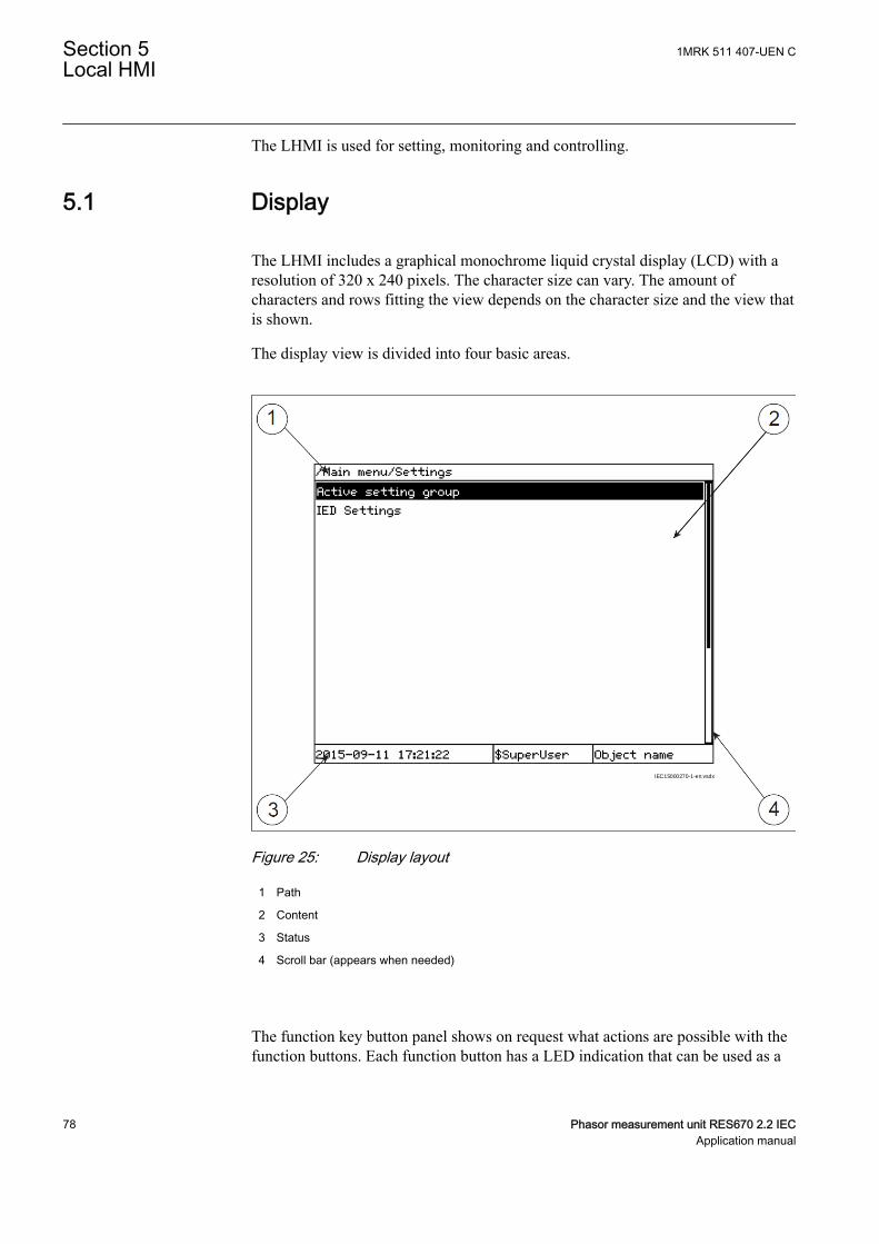
The LHMI is used for setting, monitoring and controlling.
5.1 DisplayGUID-55739D4F-1DA5-4112-B5C7-217AAF360EA5 v13
The LHMI includes a graphical monochrome liquid crystal display (LCD) with aresolution of 320 x 240 pixels. The character size can vary. The amount ofcharacters and rows fitting the view depends on the character size and the view thatis shown.
The display view is divided into four basic areas.
IEC15000270-1-en.vsdx
IEC15000270 V1 EN-US
Figure 25: Display layout
1 Path
2 Content
3 Status
4 Scroll bar (appears when needed)
The function key button panel shows on request what actions are possible with thefunction buttons. Each function button has a LED indication that can be used as a
Section 5 1MRK 511 407-UEN CLocal HMI
78 Phasor measurement unit RES670 2.2 IECApplication manual
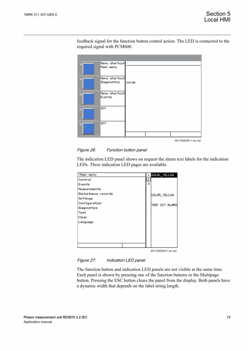
feedback signal for the function button control action. The LED is connected to therequired signal with PCM600.
IEC13000281-1-en.vsdGUID-C98D972D-D1D8-4734-B419-161DBC0DC97B V1 EN-US
Figure 26: Function button panel
The indication LED panel shows on request the alarm text labels for the indicationLEDs. Three indication LED pages are available.
IEC13000240-1-en.vsdGUID-5157100F-E8C0-4FAB-B979-FD4A971475E3 V1 EN-US
Figure 27: Indication LED panel
The function button and indication LED panels are not visible at the same time.Each panel is shown by pressing one of the function buttons or the Multipagebutton. Pressing the ESC button clears the panel from the display. Both panels havea dynamic width that depends on the label string length.
1MRK 511 407-UEN C Section 5Local HMI
Phasor measurement unit RES670 2.2 IEC 79Application manual
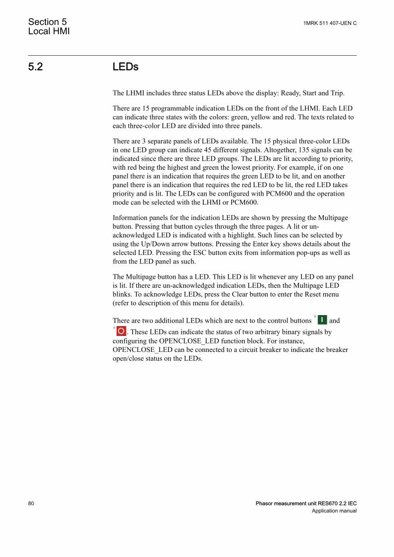
5.2 LEDsAMU0600427 v14
The LHMI includes three status LEDs above the display: Ready, Start and Trip.
There are 15 programmable indication LEDs on the front of the LHMI. Each LEDcan indicate three states with the colors: green, yellow and red. The texts related toeach three-color LED are divided into three panels.
There are 3 separate panels of LEDs available. The 15 physical three-color LEDsin one LED group can indicate 45 different signals. Altogether, 135 signals can beindicated since there are three LED groups. The LEDs are lit according to priority,with red being the highest and green the lowest priority. For example, if on onepanel there is an indication that requires the green LED to be lit, and on anotherpanel there is an indication that requires the red LED to be lit, the red LED takespriority and is lit. The LEDs can be configured with PCM600 and the operationmode can be selected with the LHMI or PCM600.
Information panels for the indication LEDs are shown by pressing the Multipagebutton. Pressing that button cycles through the three pages. A lit or un-acknowledged LED is indicated with a highlight. Such lines can be selected byusing the Up/Down arrow buttons. Pressing the Enter key shows details about theselected LED. Pressing the ESC button exits from information pop-ups as well asfrom the LED panel as such.
The Multipage button has a LED. This LED is lit whenever any LED on any panelis lit. If there are un-acknowledged indication LEDs, then the Multipage LEDblinks. To acknowledge LEDs, press the Clear button to enter the Reset menu(refer to description of this menu for details).
There are two additional LEDs which are next to the control buttons and. These LEDs can indicate the status of two arbitrary binary signals by
configuring the OPENCLOSE_LED function block. For instance,OPENCLOSE_LED can be connected to a circuit breaker to indicate the breakeropen/close status on the LEDs.
Section 5 1MRK 511 407-UEN CLocal HMI
80 Phasor measurement unit RES670 2.2 IECApplication manual
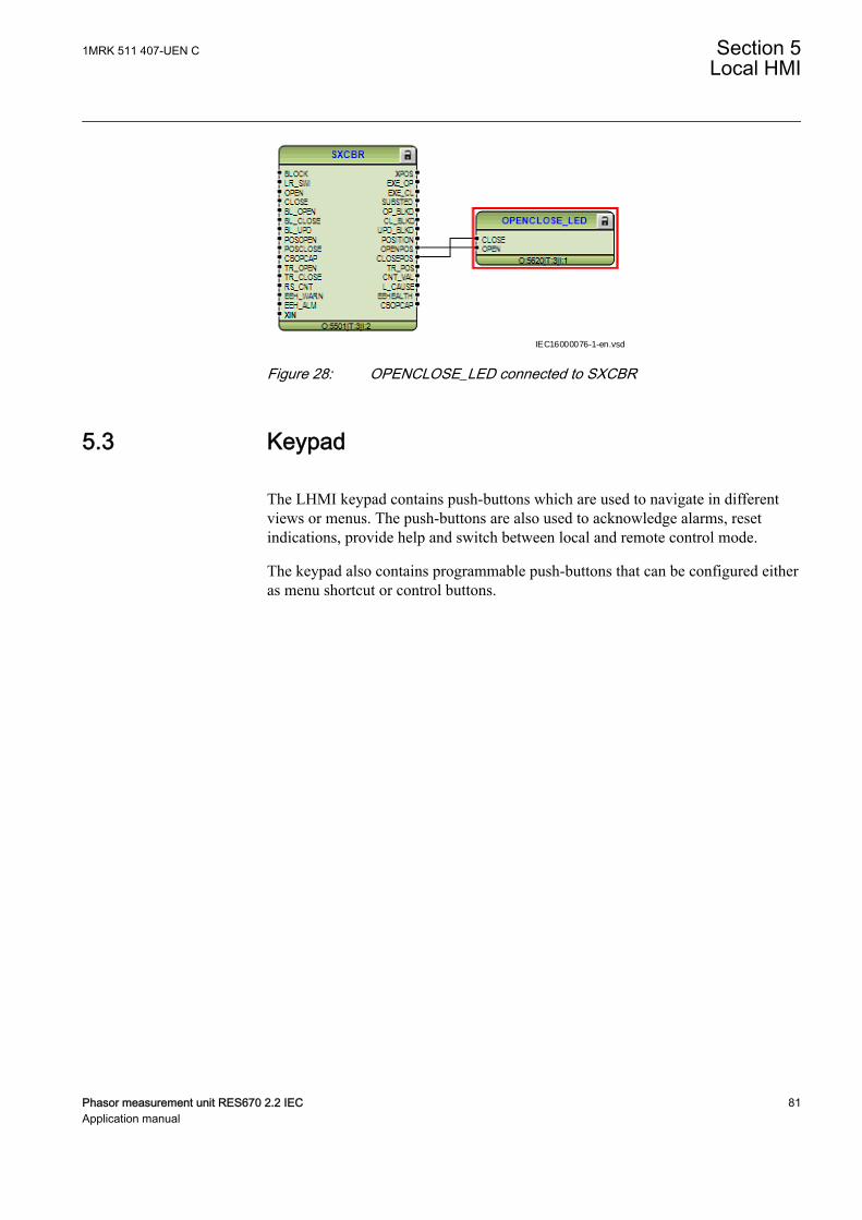
IEC16000076-1-en.vsdIEC16000076 V1 EN-US
Figure 28: OPENCLOSE_LED connected to SXCBR
5.3 KeypadAMU0600428 v19
The LHMI keypad contains push-buttons which are used to navigate in differentviews or menus. The push-buttons are also used to acknowledge alarms, resetindications, provide help and switch between local and remote control mode.
The keypad also contains programmable push-buttons that can be configured eitheras menu shortcut or control buttons.
1MRK 511 407-UEN C Section 5Local HMI
Phasor measurement unit RES670 2.2 IEC 81Application manual
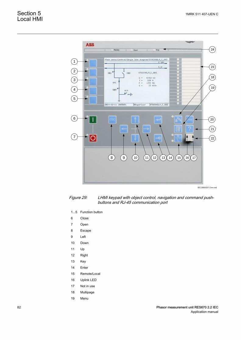
1
18
19
7
6
5
4
3
2
8
20
21
22
17161514131211109
23
24
IEC15000157-2-en.vsd
IEC15000157 V2 EN-US
Figure 29: LHMI keypad with object control, navigation and command push-buttons and RJ-45 communication port
1...5 Function button
6 Close
7 Open
8 Escape
9 Left
10 Down
11 Up
12 Right
13 Key
14 Enter
15 Remote/Local
16 Uplink LED
17 Not in use
18 Multipage
19 Menu
Section 5 1MRK 511 407-UEN CLocal HMI
82 Phasor measurement unit RES670 2.2 IECApplication manual
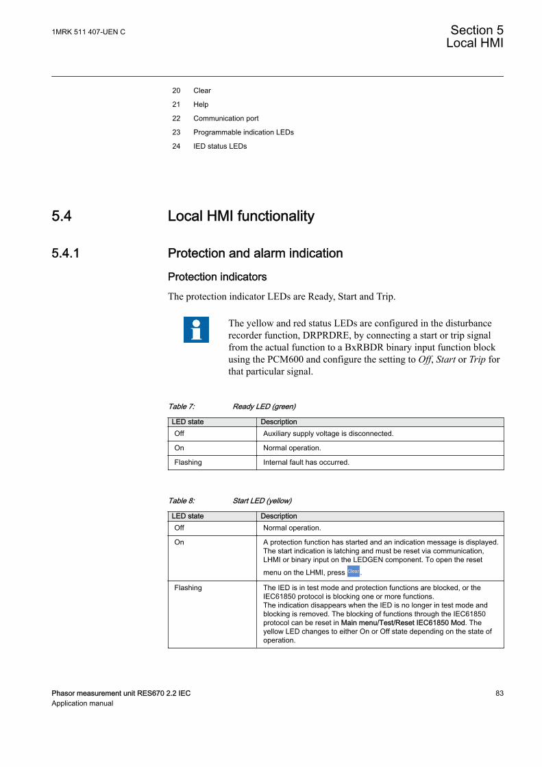
20 Clear
21 Help
22 Communication port
23 Programmable indication LEDs
24 IED status LEDs
5.4 Local HMI functionality
5.4.1 Protection and alarm indicationGUID-09CCB9F1-9B27-4C12-B253-FBE95EA537F5 v17
Protection indicatorsThe protection indicator LEDs are Ready, Start and Trip.
The yellow and red status LEDs are configured in the disturbancerecorder function, DRPRDRE, by connecting a start or trip signalfrom the actual function to a BxRBDR binary input function blockusing the PCM600 and configure the setting to Off, Start or Trip forthat particular signal.
Table 7: Ready LED (green)
LED state DescriptionOff Auxiliary supply voltage is disconnected.
On Normal operation.
Flashing Internal fault has occurred.
Table 8: Start LED (yellow)
LED state DescriptionOff Normal operation.
On A protection function has started and an indication message is displayed.The start indication is latching and must be reset via communication,LHMI or binary input on the LEDGEN component. To open the resetmenu on the LHMI, press .
Flashing The IED is in test mode and protection functions are blocked, or theIEC61850 protocol is blocking one or more functions.The indication disappears when the IED is no longer in test mode andblocking is removed. The blocking of functions through the IEC61850protocol can be reset in Main menu/Test/Reset IEC61850 Mod. Theyellow LED changes to either On or Off state depending on the state ofoperation.
1MRK 511 407-UEN C Section 5Local HMI
Phasor measurement unit RES670 2.2 IEC 83Application manual

Table 9: Trip LED (red)
LED state DescriptionOff Normal operation.
On A protection function has tripped. An indication message is displayed ifthe auto-indication feature is enabled in the local HMI.The trip indication is latching and must be reset via communication, LHMIor binary input on the LEDGEN component. To open the reset menu onthe LHMI, press .
Flasing Configuration mode.
Alarm indicatorsThe 15 programmable three-color LEDs are used for alarm indication. Anindividual alarm/status signal, connected to any of the LED function blocks, can beassigned to one of the three LED colors when configuring the IED.
Table 10: Alarm indications
LED state DescriptionOff Normal operation. All activation signals are off.
On • Follow-S sequence: The activation signal is on.• LatchedColl-S sequence: The activation signal is on, or it is off but the indication
has not been acknowledged.• LatchedAck-F-S sequence: The indication has been acknowledged, but the
activation signal is still on.• LatchedAck-S-F sequence: The activation signal is on, or it is off but the
indication has not been acknowledged.• LatchedReset-S sequence: The activation signal is on, or it is off but the
indication has not been acknowledged.
Flashing • Follow-F sequence: The activation signal is on.• LatchedAck-F-S sequence: The activation signal is on, or it is off but the
indication has not been acknowledged.• LatchedAck-S-F sequence: The indication has been acknowledged, but the
activation signal is still on.
5.4.2 Parameter managementGUID-5EE466E3-932B-4311-9FE1-76ECD8D6E245 v9
The LHMI is used to access the relay parameters. Three types of parameters can beread and written.
• Numerical values• String values• Enumerated values
Numerical values are presented either in integer or in decimal format withminimum and maximum values. Character strings can be edited character bycharacter. Enumerated values have a predefined set of selectable values.
Section 5 1MRK 511 407-UEN CLocal HMI
84 Phasor measurement unit RES670 2.2 IECApplication manual
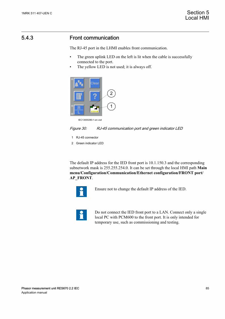
5.4.3 Front communicationGUID-FD72A445-C8C1-4BFE-90E3-0AC78AE17C45 v12
The RJ-45 port in the LHMI enables front communication.
• The green uplink LED on the left is lit when the cable is successfullyconnected to the port.
• The yellow LED is not used; it is always off.
IEC13000280-1-en.vsd
1
2
GUID-AACFC753-BFB9-47FE-9512-3C4180731A1B V1 EN-US
Figure 30: RJ-45 communication port and green indicator LED
1 RJ-45 connector
2 Green indicator LED
The default IP address for the IED front port is 10.1.150.3 and the correspondingsubnetwork mask is 255.255.254.0. It can be set through the local HMI path Mainmenu/Configuration/Communication/Ethernet configuration/FRONT port/AP_FRONT.
Ensure not to change the default IP address of the IED.
Do not connect the IED front port to a LAN. Connect only a singlelocal PC with PCM600 to the front port. It is only intended fortemporary use, such as commissioning and testing.
1MRK 511 407-UEN C Section 5Local HMI
Phasor measurement unit RES670 2.2 IEC 85Application manual

86
Section 6 Wide area measurement system
6.1 Protocol reporting via IEEE 1344 and C37.118PMUREPORT
GUID-0C45D2FA-1B95-4FCA-B23B-A28C2770B817 v1
6.1.1 IdentificationGUID-0090956B-48F1-4E8B-9A40-90044C71DF20 v1
Function description IEC 61850identification
IEC 60617identification
ANSI/IEEE C37.2device number
Protocol reporting via IEEE 1344 andC37.118
PMUREPORT - -
6.1.2 ApplicationGUID-8DF29209-252A-4E51-9F4A-B14B669E71AB v4
The phasor measurement reporting block moves the phasor calculations into anIEEE C37.118 and/or IEEE 1344 synchrophasor frame format. The PMUREPORTblock contains parameters for PMU performance class and reporting rate, theIDCODE and Global PMU ID, format of the data streamed through the protocol,the type of reported synchrophasors, as well as settings for reporting analog anddigital signals.
The message generated by the PMUREPORT function block is set in accordancewith the IEEE C37.118 and/or IEEE 1344 standards.
There are settings for Phasor type (positive sequence, negative sequence or zerosequence in case of 3-phase phasor and L1, L2 or L3 in case of single phasephasor), PMU's Service class (Protection or Measurement), Phasor representation(polar or rectangular) and the data types for phasor data, analog data and frequencydata.
Synchrophasor data can be reported to up to 8 clients over TCP and/or 6 UDPgroup clients for multicast or unicast transmission of phasor data from the IED.More information regarding synchrophasor communication structure andTCP/UDP configuration is available in section C37.118 Phasor Measurement DataStreaming Protocol Configuration.
Multiple PMU functionality can be configured in the IED, which can stream outsame or different data at different reporting rates or different performance (service)classes. There are 2 instances of PMU functionality available in the IED. Eachinstance of PMU functionality includes a set of PMU reporting function blockstagged by the same instance number (1 or 2). As shown in the following figures,each set of PMU reporting function blocks includes PMUREPORT,
1MRK 511 407-UEN C Section 6Wide area measurement system
Phasor measurement unit RES670 2.2 IEC 87Application manual
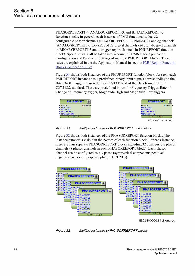
PHASORREPORT1-4, ANALOGREPORT1-3, and BINARYREPORT1-3function blocks. In general, each instance of PMU functionality has 32configurable phasor channels (PHASORREPORT1–4 blocks), 24 analog channels(ANALOGREPORT1-3 blocks), and 28 digital channels (24 digital-report channelsin BINARYREPORT1-3 and 4 trigger-report channels in PMUREPORT functionblock). Special rules shall be taken into account in PCM600 for ApplicationConfiguration and Parameter Settings of multiple PMUREPORT blocks. Theserules are explained in the the Application Manual in section PMU Report FunctionBlocks Connection Rules.
Figure 31 shows both instances of the PMUREPORT function block. As seen, eachPMUREPORT instance has 4 predefined binary input signals corresponding to theBits 03-00: Trigger Reason defined in STAT field of the Data frame in IEEEC37.118.2 standard. These are predefined inputs for Frequency Trigger, Rate ofChange of Frequency trigger, Magnitude High and Magnitude Low triggers.
IEC140000118-2-en.vsdIEC140000118 V2 EN-US
Figure 31: Multiple instances of PMUREPORT function block
Figure 32 shows both instances of the PHASORREPORT function blocks. Theinstance number is visible in the bottom of each function block. For each instance,there are four separate PHASORREPORT blocks including 32 configurable phasorchannels (8 phasor channels in each PHASORREPORT block). Each phasorchannel can be configured as a 3-phase (symmetrical components positive/negative/zero) or single-phase phasor (L1/L2/L3).
IEC140000119-2-en.vsd
IEC140000119 V2 EN-US
Figure 32: Multiple instances of PHASORREPORT blocks
Section 6 1MRK 511 407-UEN CWide area measurement system
88 Phasor measurement unit RES670 2.2 IECApplication manual

Figure 33 shows both instances of ANALOGREPORT function blocks. Theinstance number is visible in the bottom of each function block. For each instance,there are three separate ANALOGREPORT blocks capable of reporting up to 24Analog signals (8 Analog signals in each ANALOGREPORT block). These caninclude for example transfer of active and reactive power or reporting themilliampere input signals to the PDC clients as defined in IEEE C37.118 dataframe format.
IEC140000120-2-en.vsdIEC140000120 V2 EN-US
Figure 33: Multiple instances of ANALOGREPORT blocks
Figure 34 shows both instances of BINARYREPORT function blocks. The instancenumber is visible in the bottom of each function block. For each instance, there arethree separate BINARYREPORT blocks capable of reporting up to 24 Binarysignals (8 Binary signals in each BINARYREPORT block). These binary signalscan be for example dis-connector or breaker position indications or internal/external protection alarm signals.
IEC140000121-2-en.vsdIEC140000121 V2 EN-US
Figure 34: Multiple instances of BINARYREPORT blocks
6.1.3 Operation principleGUID-EB2B9096-2F9D-4264-B2D2-8D9DC65697E8 v3
The Phasor Measurement Unit (PMU) features three main functional principles:
1MRK 511 407-UEN C Section 6Wide area measurement system
Phasor measurement unit RES670 2.2 IEC 89Application manual
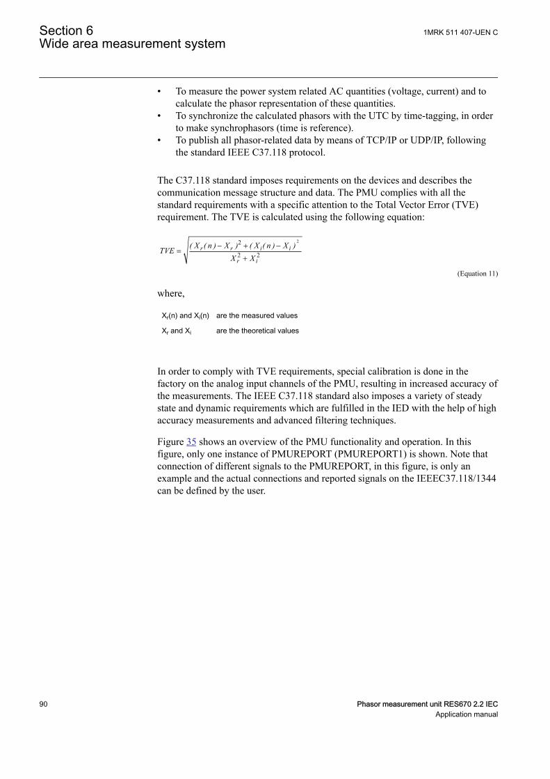
• To measure the power system related AC quantities (voltage, current) and tocalculate the phasor representation of these quantities.
• To synchronize the calculated phasors with the UTC by time-tagging, in orderto make synchrophasors (time is reference).
• To publish all phasor-related data by means of TCP/IP or UDP/IP, followingthe standard IEEE C37.118 protocol.
The C37.118 standard imposes requirements on the devices and describes thecommunication message structure and data. The PMU complies with all thestandard requirements with a specific attention to the Total Vector Error (TVE)requirement. The TVE is calculated using the following equation:
22
2 2r r i i
r i
( X ( n ) X ) ( X ( n ) X )TVEX X
- + -=
+
GUID-80D9B1EA-A770-4F50-9530-61644B4DEBBE V1 EN-US (Equation 11)
where,
Xr(n) and Xi(n) are the measured values
Xr and Xi are the theoretical values
In order to comply with TVE requirements, special calibration is done in thefactory on the analog input channels of the PMU, resulting in increased accuracy ofthe measurements. The IEEE C37.118 standard also imposes a variety of steadystate and dynamic requirements which are fulfilled in the IED with the help of highaccuracy measurements and advanced filtering techniques.
Figure 35 shows an overview of the PMU functionality and operation. In thisfigure, only one instance of PMUREPORT (PMUREPORT1) is shown. Note thatconnection of different signals to the PMUREPORT, in this figure, is only anexample and the actual connections and reported signals on the IEEEC37.118/1344can be defined by the user.
Section 6 1MRK 511 407-UEN CWide area measurement system
90 Phasor measurement unit RES670 2.2 IECApplication manual

IEC140000146-1-en.vsd
PHASOR1PHASOR2
PHASOR32
ANALOG1ANALOG2
ANALOG24
FREQTRIG
DFDTTRIG
MAGHIGHTRIGMAGLOWTRIG
BINARY1BINARY2
BINARY24
PMUREPORT1
SMAI
SMMI
MEAS.
TRM
MU
TRM
MIM
PROTECTION
OP
UP
OC
UV
OR
NUMIEEEC37.118 / 1344
messages
U/I samples
BIM
GPS / IRIG-B
PPS time data
UI
UI
I/P
8 TCP
6 UDC
IEC140000146 V2 EN-US
Figure 35: Overview of reporting functionality (PMUREPORT)
The TRM modules are individually AC-calibrated in the factory. The calibrationdata is stored in the prepared area of the TRM EEProm. The pre-processor block isextended with calibration compensation and a new angle reference method basedon timestamps. The AI3P output of the preprocessor block is used to provide therequired information for each respective PMUREPORT phasor channel. Moreinformation about preprocessor block is available in the section Signal matrix foranalog inputs SMAI.
6.1.3.1 Frequency reportingGUID-4F3BA7C7-8C9B-4266-9F72-AFB139E9DC21 v2
By using patented algorithm the IED can track the power system frequency in quitewide range from 9 Hz to 95 Hz. In order to do that, the three-phase voltage signalshall be connected to the IED. Then IED can adapt its filtering algorithm in orderto properly measure phasors of all current and voltage signals connected to theIED. This feature is essential for proper operation of the PMUREPORT function orfor protection during generator start-up and shut-down procedure.
This adaptive filtering is ensured by proper configuration and settings of allrelevant pre-processing blocks, see Signal matrix for analog inputs in theApplication manual. Note that in all preconfigured IEDs such configuration and
1MRK 511 407-UEN C Section 6Wide area measurement system
Phasor measurement unit RES670 2.2 IEC 91Application manual
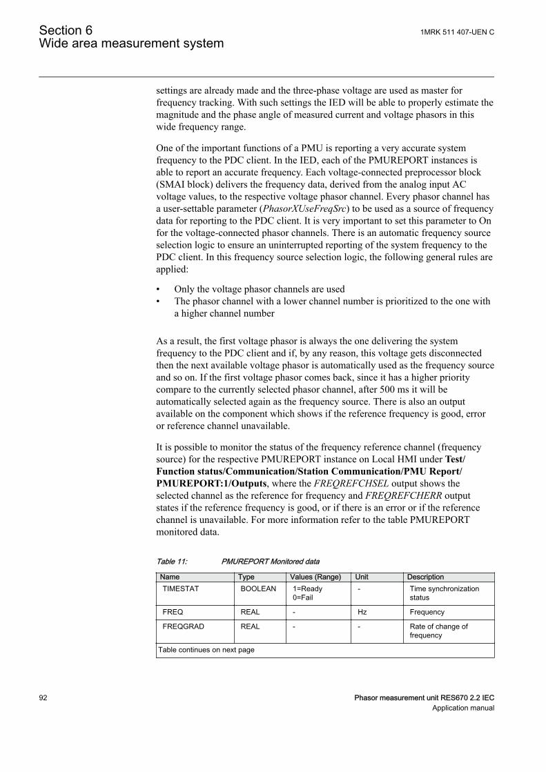
settings are already made and the three-phase voltage are used as master forfrequency tracking. With such settings the IED will be able to properly estimate themagnitude and the phase angle of measured current and voltage phasors in thiswide frequency range.
One of the important functions of a PMU is reporting a very accurate systemfrequency to the PDC client. In the IED, each of the PMUREPORT instances isable to report an accurate frequency. Each voltage-connected preprocessor block(SMAI block) delivers the frequency data, derived from the analog input ACvoltage values, to the respective voltage phasor channel. Every phasor channel hasa user-settable parameter (PhasorXUseFreqSrc) to be used as a source of frequencydata for reporting to the PDC client. It is very important to set this parameter to Onfor the voltage-connected phasor channels. There is an automatic frequency sourceselection logic to ensure an uninterrupted reporting of the system frequency to thePDC client. In this frequency source selection logic, the following general rules areapplied:
• Only the voltage phasor channels are used• The phasor channel with a lower channel number is prioritized to the one with
a higher channel number
As a result, the first voltage phasor is always the one delivering the systemfrequency to the PDC client and if, by any reason, this voltage gets disconnectedthen the next available voltage phasor is automatically used as the frequency sourceand so on. If the first voltage phasor comes back, since it has a higher prioritycompare to the currently selected phasor channel, after 500 ms it will beautomatically selected again as the frequency source. There is also an outputavailable on the component which shows if the reference frequency is good, erroror reference channel unavailable.
It is possible to monitor the status of the frequency reference channel (frequencysource) for the respective PMUREPORT instance on Local HMI under Test/Function status/Communication/Station Communication/PMU Report/PMUREPORT:1/Outputs, where the FREQREFCHSEL output shows theselected channel as the reference for frequency and FREQREFCHERR outputstates if the reference frequency is good, or if there is an error or if the referencechannel is unavailable. For more information refer to the table PMUREPORTmonitored data.
PID-6244-MONITOREDDATA v2
Table 11: PMUREPORT Monitored data
Name Type Values (Range) Unit DescriptionTIMESTAT BOOLEAN 1=Ready
0=Fail- Time synchronization
status
FREQ REAL - Hz Frequency
FREQGRAD REAL - - Rate of change offrequency
Table continues on next page
Section 6 1MRK 511 407-UEN CWide area measurement system
92 Phasor measurement unit RES670 2.2 IECApplication manual
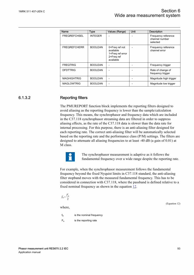
Name Type Values (Range) Unit DescriptionFREQREFCHSEL INTEGER - - Frequency reference
channel numberselected
FREQREFCHERR BOOLEAN 0=Freq ref notavailable1=Freq ref error2=Freq refavailable
- Frequency referencechannel error
FREQTRIG BOOLEAN - - Frequency trigger
DFDTTRIG BOOLEAN - - Rate of change offrequency trigger
MAGHIGHTRIG BOOLEAN - - Magnitude high trigger
MAGLOWTRIG BOOLEAN - - Magnitude low trigger
6.1.3.2 Reporting filtersGUID-D39153B5-81CE-4C1F-A816-C7A4C3407048 v2
The PMUREPORT function block implements the reporting filters designed toavoid aliasing as the reporting frequency is lower than the sample/calculationfrequency. This means, the synchrophasor and frequency data which are includedin the C37.118 synchrophasor streaming data are filtered in order to suppressaliasing effects, as the rate of the C37.118 data is slower than the data rate forinternal processing. For this purpose, there is an anti-aliasing filter designed foreach reporting rate. The correct anti-aliasing filter will be automatically selectedbased on the reporting rate and the performance class (P/M) settings. The filters aredesigned to attenuate all aliasing frequencies to at least -40 dB (a gain of 0.01) atM class.
The synchrophasor measurement is adaptive as it follows thefundamental frequency over a wide range despite the reporting rate.
For example, when the synchrophasor measurement follows the fundamentalfrequency beyond the fixed Nyquist limits in C37.118 standard, the anti-aliasingfilter stopband moves with the measured fundamental frequency. This has to beconsidered in connection with C37.118, where the passband is defined relative to afixed nominal frequency as shown in the equation 12.
0 2sFf ±
IECEQUATION2418 V1 EN-US (Equation 12)where,
f0 is the nominal frequency
Fs is the reporting rate
1MRK 511 407-UEN C Section 6Wide area measurement system
Phasor measurement unit RES670 2.2 IEC 93Application manual
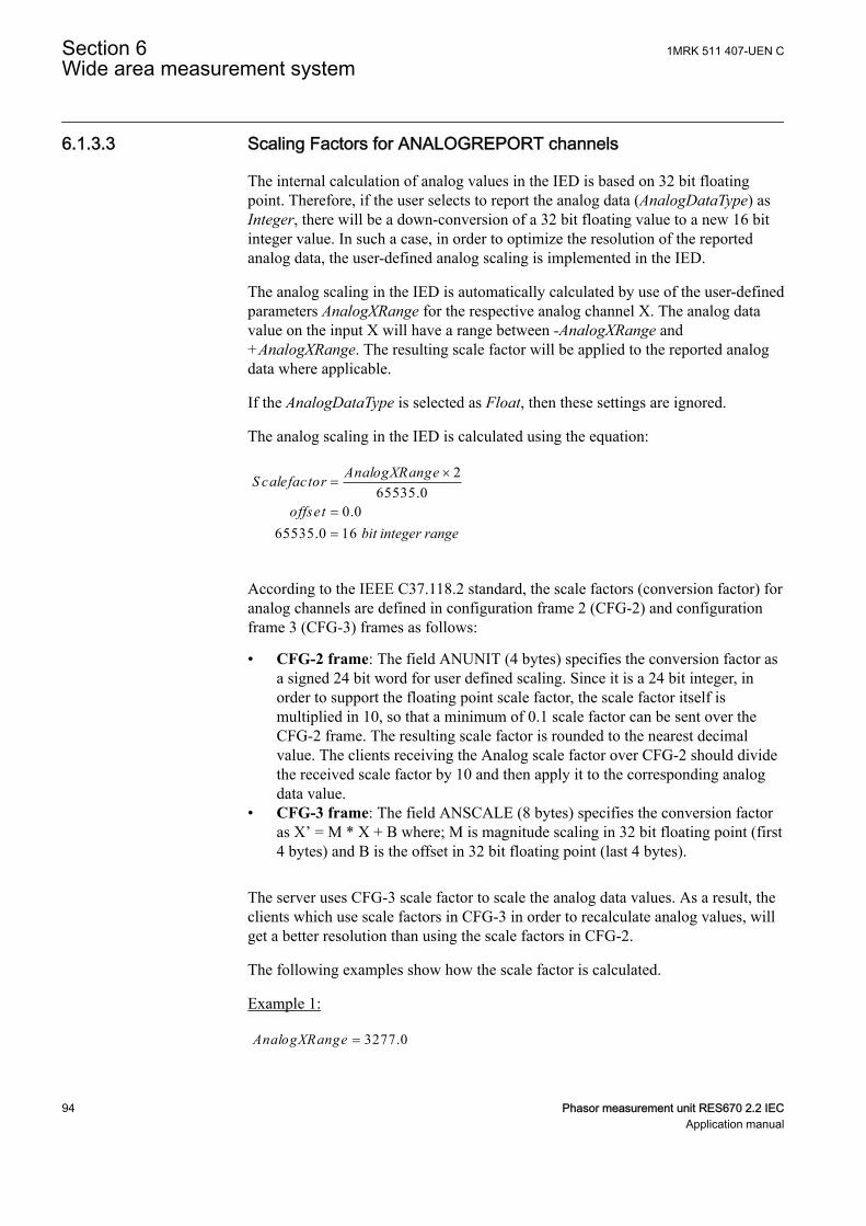
6.1.3.3 Scaling Factors for ANALOGREPORT channelsGUID-0DDAF6A9-8643-4FDD-97CF-9E35EF40AF7E v2
The internal calculation of analog values in the IED is based on 32 bit floatingpoint. Therefore, if the user selects to report the analog data (AnalogDataType) asInteger, there will be a down-conversion of a 32 bit floating value to a new 16 bitinteger value. In such a case, in order to optimize the resolution of the reportedanalog data, the user-defined analog scaling is implemented in the IED.
The analog scaling in the IED is automatically calculated by use of the user-definedparameters AnalogXRange for the respective analog channel X. The analog datavalue on the input X will have a range between -AnalogXRange and+AnalogXRange. The resulting scale factor will be applied to the reported analogdata where applicable.
If the AnalogDataType is selected as Float, then these settings are ignored.
The analog scaling in the IED is calculated using the equation:
265535.0
0.065535.0 16
AnalogXRangeS calefactor
offset
´=
== bit integer range
IECEQUATION2443 V1 EN-US
According to the IEEE C37.118.2 standard, the scale factors (conversion factor) foranalog channels are defined in configuration frame 2 (CFG-2) and configurationframe 3 (CFG-3) frames as follows:
• CFG-2 frame: The field ANUNIT (4 bytes) specifies the conversion factor asa signed 24 bit word for user defined scaling. Since it is a 24 bit integer, inorder to support the floating point scale factor, the scale factor itself ismultiplied in 10, so that a minimum of 0.1 scale factor can be sent over theCFG-2 frame. The resulting scale factor is rounded to the nearest decimalvalue. The clients receiving the Analog scale factor over CFG-2 should dividethe received scale factor by 10 and then apply it to the corresponding analogdata value.
• CFG-3 frame: The field ANSCALE (8 bytes) specifies the conversion factoras X’ = M * X + B where; M is magnitude scaling in 32 bit floating point (first4 bytes) and B is the offset in 32 bit floating point (last 4 bytes).
The server uses CFG-3 scale factor to scale the analog data values. As a result, theclients which use scale factors in CFG-3 in order to recalculate analog values, willget a better resolution than using the scale factors in CFG-2.
The following examples show how the scale factor is calculated.
Example 1:
3277.0AnalogXRange =IECEQUATION2446 V1 EN-US
Section 6 1MRK 511 407-UEN CWide area measurement system
94 Phasor measurement unit RES670 2.2 IECApplication manual
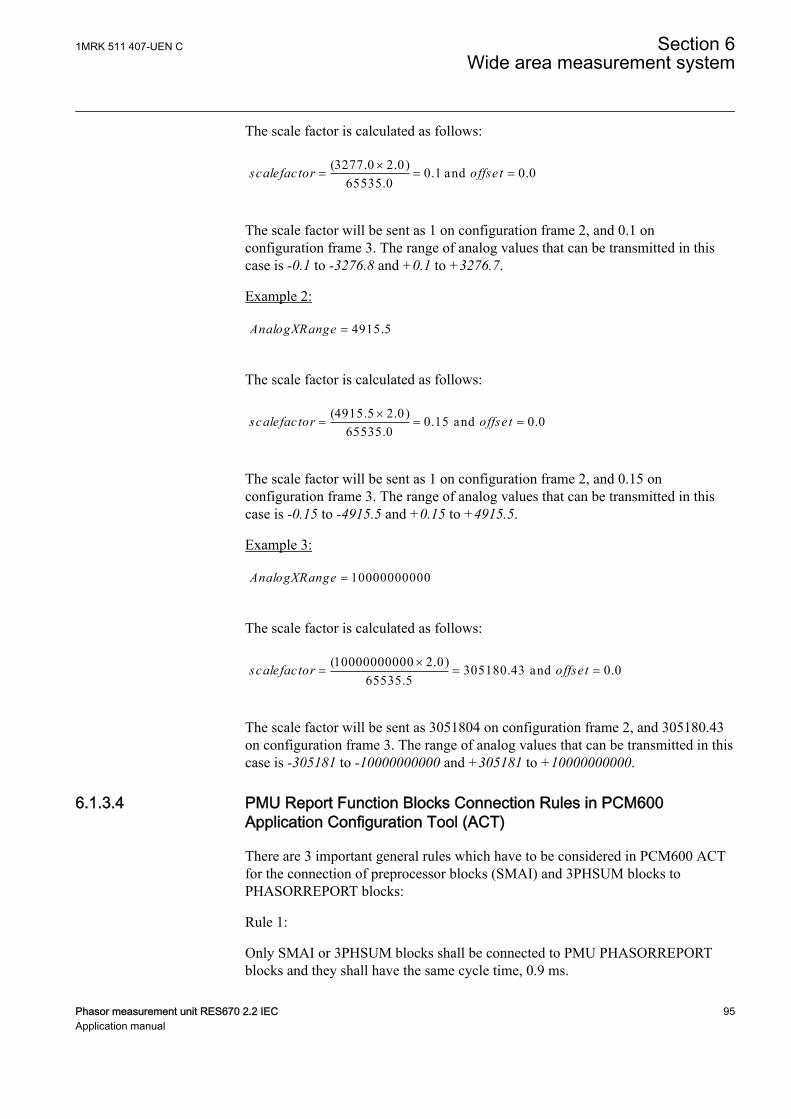
The scale factor is calculated as follows:
(3277.0 2.0) 0.1 and 0.065535.0
scalefactor offset´= = =
IECEQUATION2447 V1 EN-US
The scale factor will be sent as 1 on configuration frame 2, and 0.1 onconfiguration frame 3. The range of analog values that can be transmitted in thiscase is -0.1 to -3276.8 and +0.1 to +3276.7.
Example 2:
4915.5AnalogXRange =IECEQUATION2448 V1 EN-US
The scale factor is calculated as follows:
(4915.5 2.0) 0.15 and 0.065535.0
scalefactor offse t´= = =
IECEQUATION2449 V1 EN-US
The scale factor will be sent as 1 on configuration frame 2, and 0.15 onconfiguration frame 3. The range of analog values that can be transmitted in thiscase is -0.15 to -4915.5 and +0.15 to +4915.5.
Example 3:
10000000000AnalogXRange =IECEQUATION2450 V1 EN-US
The scale factor is calculated as follows:
(10000000000 2.0) 305180.43 and 0.065535.5
scalefactor offset´= = =
IECEQUATION2451 V1 EN-US
The scale factor will be sent as 3051804 on configuration frame 2, and 305180.43on configuration frame 3. The range of analog values that can be transmitted in thiscase is -305181 to -10000000000 and +305181 to +10000000000.
6.1.3.4 PMU Report Function Blocks Connection Rules in PCM600Application Configuration Tool (ACT)
GUID-66667179-F3E1-455B-8B99-6D73F37E949B v3
There are 3 important general rules which have to be considered in PCM600 ACTfor the connection of preprocessor blocks (SMAI) and 3PHSUM blocks toPHASORREPORT blocks:
Rule 1:
Only SMAI or 3PHSUM blocks shall be connected to PMU PHASORREPORTblocks and they shall have the same cycle time, 0.9 ms.
1MRK 511 407-UEN C Section 6Wide area measurement system
Phasor measurement unit RES670 2.2 IEC 95Application manual
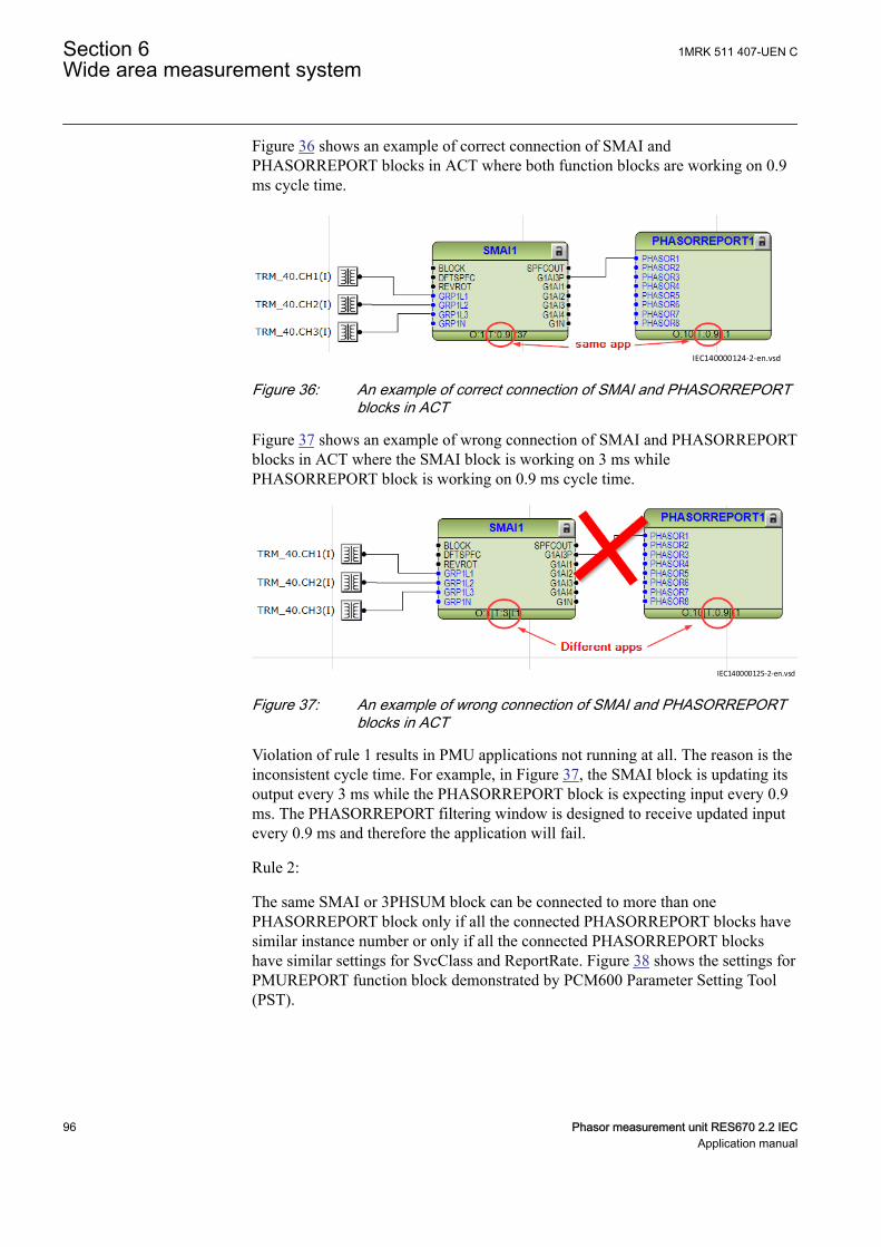
Figure 36 shows an example of correct connection of SMAI andPHASORREPORT blocks in ACT where both function blocks are working on 0.9ms cycle time.
IEC140000124-2-en.vsdIEC140000124 V2 EN-US
Figure 36: An example of correct connection of SMAI and PHASORREPORTblocks in ACT
Figure 37 shows an example of wrong connection of SMAI and PHASORREPORTblocks in ACT where the SMAI block is working on 3 ms whilePHASORREPORT block is working on 0.9 ms cycle time.
IEC140000125-2-en.vsdIEC140000125 V2 EN-US
Figure 37: An example of wrong connection of SMAI and PHASORREPORTblocks in ACT
Violation of rule 1 results in PMU applications not running at all. The reason is theinconsistent cycle time. For example, in Figure 37, the SMAI block is updating itsoutput every 3 ms while the PHASORREPORT block is expecting input every 0.9ms. The PHASORREPORT filtering window is designed to receive updated inputevery 0.9 ms and therefore the application will fail.
Rule 2:
The same SMAI or 3PHSUM block can be connected to more than onePHASORREPORT block only if all the connected PHASORREPORT blocks havesimilar instance number or only if all the connected PHASORREPORT blockshave similar settings for SvcClass and ReportRate. Figure 38 shows the settings forPMUREPORT function block demonstrated by PCM600 Parameter Setting Tool(PST).
Section 6 1MRK 511 407-UEN CWide area measurement system
96 Phasor measurement unit RES670 2.2 IECApplication manual
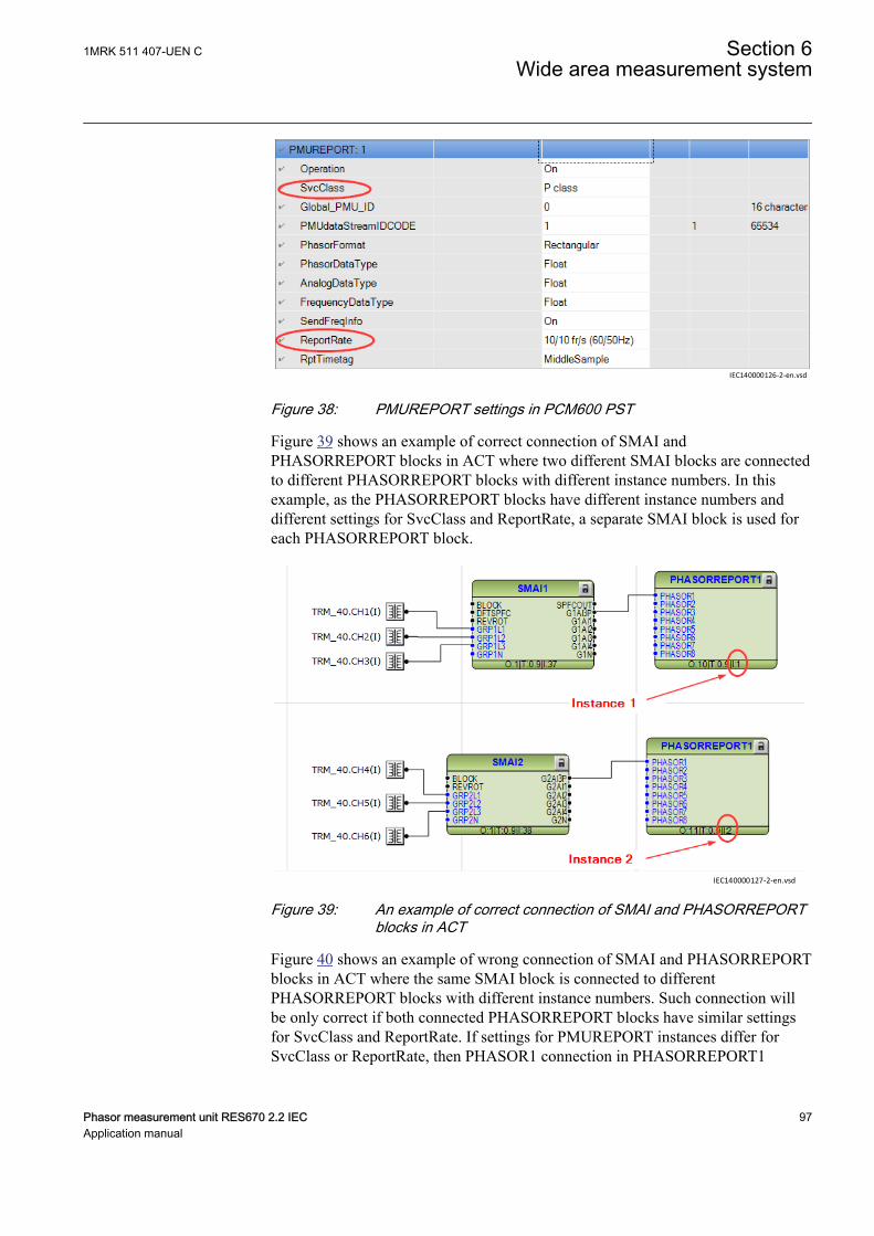
IEC140000126-2-en.vsd
IEC140000126 V2 EN-US
Figure 38: PMUREPORT settings in PCM600 PST
Figure 39 shows an example of correct connection of SMAI andPHASORREPORT blocks in ACT where two different SMAI blocks are connectedto different PHASORREPORT blocks with different instance numbers. In thisexample, as the PHASORREPORT blocks have different instance numbers anddifferent settings for SvcClass and ReportRate, a separate SMAI block is used foreach PHASORREPORT block.
IEC140000127-2-en.vsdIEC140000127 V2 EN-US
Figure 39: An example of correct connection of SMAI and PHASORREPORTblocks in ACT
Figure 40 shows an example of wrong connection of SMAI and PHASORREPORTblocks in ACT where the same SMAI block is connected to differentPHASORREPORT blocks with different instance numbers. Such connection willbe only correct if both connected PHASORREPORT blocks have similar settingsfor SvcClass and ReportRate. If settings for PMUREPORT instances differ forSvcClass or ReportRate, then PHASOR1 connection in PHASORREPORT1
1MRK 511 407-UEN C Section 6Wide area measurement system
Phasor measurement unit RES670 2.2 IEC 97Application manual
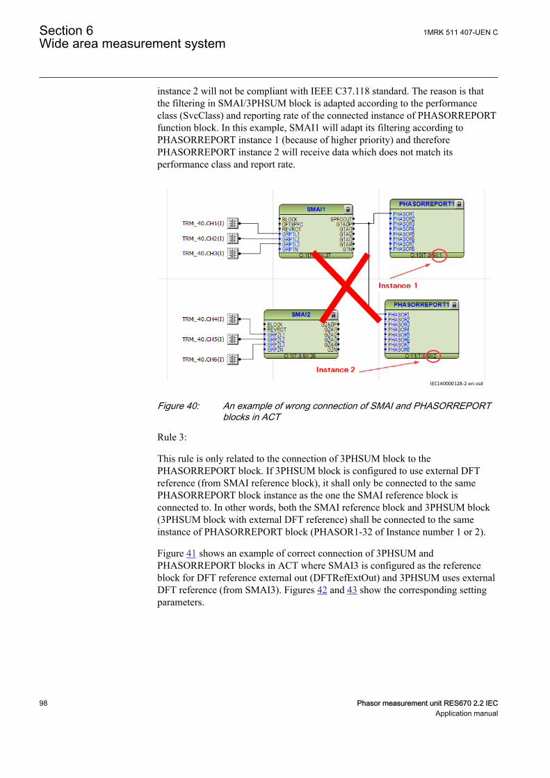
instance 2 will not be compliant with IEEE C37.118 standard. The reason is thatthe filtering in SMAI/3PHSUM block is adapted according to the performanceclass (SvcClass) and reporting rate of the connected instance of PHASORREPORTfunction block. In this example, SMAI1 will adapt its filtering according toPHASORREPORT instance 1 (because of higher priority) and thereforePHASORREPORT instance 2 will receive data which does not match itsperformance class and report rate.
IEC140000128-2-en.vsd
IEC140000128 V2 EN-US
Figure 40: An example of wrong connection of SMAI and PHASORREPORTblocks in ACT
Rule 3:
This rule is only related to the connection of 3PHSUM block to thePHASORREPORT block. If 3PHSUM block is configured to use external DFTreference (from SMAI reference block), it shall only be connected to the samePHASORREPORT block instance as the one the SMAI reference block isconnected to. In other words, both the SMAI reference block and 3PHSUM block(3PHSUM block with external DFT reference) shall be connected to the sameinstance of PHASORREPORT block (PHASOR1-32 of Instance number 1 or 2).
Figure 41 shows an example of correct connection of 3PHSUM andPHASORREPORT blocks in ACT where SMAI3 is configured as the referenceblock for DFT reference external out (DFTRefExtOut) and 3PHSUM uses externalDFT reference (from SMAI3). Figures 42 and 43 show the corresponding settingparameters.
Section 6 1MRK 511 407-UEN CWide area measurement system
98 Phasor measurement unit RES670 2.2 IECApplication manual
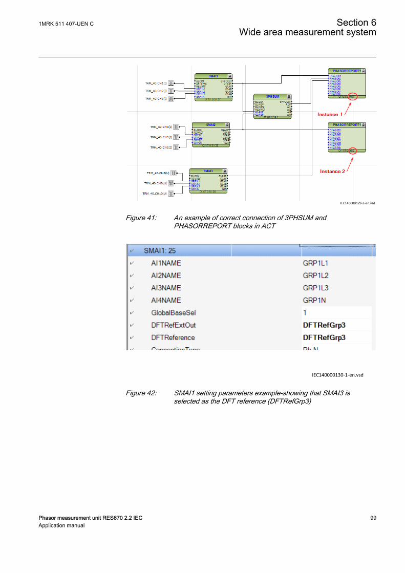
IEC140000129-2-en.vsd
IEC140000129 V2 EN-US
Figure 41: An example of correct connection of 3PHSUM andPHASORREPORT blocks in ACT
IEC140000130-1-en.vsdIEC140000130 V1 EN-US
Figure 42: SMAI1 setting parameters example-showing that SMAI3 isselected as the DFT reference (DFTRefGrp3)
1MRK 511 407-UEN C Section 6Wide area measurement system
Phasor measurement unit RES670 2.2 IEC 99Application manual
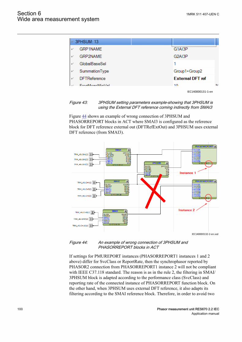
IEC140000131-1-enIEC140000131 V1 EN-US
Figure 43: 3PHSUM setting parameters example-showing that 3PHSUM isusing the External DFT reference coming indirectly from SMAI3
Figure 44 shows an example of wrong connection of 3PHSUM andPHASORREPORT blocks in ACT where SMAI3 is configured as the referenceblock for DFT reference external out (DFTRefExtOut) and 3PHSUM uses externalDFT reference (from SMAI3).
IEC140000132-2-en.vsdIEC140000132 V2 EN-US
Figure 44: An example of wrong connection of 3PHSUM andPHASORREPORT blocks in ACT
If settings for PMUREPORT instances (PHASORREPORT1 instances 1 and 2above) differ for SvcClass or ReportRate, then the synchrophasor reported byPHASOR2 connection from PHASORREPORT1 instance 2 will not be compliantwith IEEE C37.118 standard. The reason is as in the rule 2, the filtering in SMAI/3PHSUM block is adapted according to the performance class (SvcClass) andreporting rate of the connected instance of PHASORREPORT function block. Onthe other hand, when 3PHSUM uses external DFT reference, it also adapts itsfiltering according to the SMAI reference block. Therefore, in order to avoid two
Section 6 1MRK 511 407-UEN CWide area measurement system
100 Phasor measurement unit RES670 2.2 IECApplication manual
different filtering applied to the 3PHSUM block, both SMAI reference block and3PHSUM shall be connected to the same PHASORREPORT instance. In thisexample (Figure 44), SMAI3 adapts its filtering according to PHASORREPORT1instance 2 (due to connection) and 3PHSUM is adapting its filtering according toPHASORREPORT1 instance 1. On the other hand, since 3PHSUM is set to receiveexternal DFT reference from SMAI3, therefore If settings for PHASORREPORT1instances 1 and 2 above differ for SvcClass or ReportRate, then 3PHSUM blockwill be affected by two different filtering at the same time which is not possible.For example in Figure 44, PHASOR2 from PHASORREPORT1 instance 1 maynot be fully compliant with IEEE C37.118 standard.
Note: If the SMAI reference block is not connected to any PHASORREPORTblock, then 3PHSUM block can be freely connected to any PHASORREPORTblock regardless of its DFT reference setting.
Note: If more 3PHSUM blocks need to be used, all 3PHSUM blocks (usingexternal DFT ref) have to be connected to the same instance of PHASORREPORTblocks (PHASOR1-32 of Instance number 1 or 2).
Note: If settings SvcClass and ReportRate are the same for different instances ofPHASORREPORT blocks, then 3PHSUM block can be freely connected to any ofthem regardless of 3PHSUM block DFT reference setting or the reference SMAIblock connection.
Note: Violation of rules 2 or 3 results in non-compliancy with IEEE C37.118standard for some of the synchrophasors. In case of rule 2 violation, the non-compliancy only applies to synchrophasors from instance 2 and the synchrophasorsfrom instance 1 will be still compliant. The non-compliancy with the standard maybe quite obvious as in case of rule 2 violation with different SvcClass settings. Thisproduces big angle error. On the other hand, it may be difficult to detect the non-compliancy with the standard if rule 2 is violated with different ReportRates, or ifrule 3 is violated. In such cases, the synchrophasors may only fail to comply (withsmall error) in some particular test case(s).
For more information regarding 3PHSUM block application, please refer to theApplication Manual under section Basic IED functions.
6.1.4 Setting guidelinesGUID-83969957-DABF-4B9B-95C7-B9F0AF6E647A v2
Based on the functionality and appearance in PCM600, the PMU reportingfunctionality is categorized into 4 different categories (function block) as follows:
1. PMUREPORT2. PHASORREPORT3. ANALOGREPORT4. BINARYREPORT
1MRK 511 407-UEN C Section 6Wide area measurement system
Phasor measurement unit RES670 2.2 IEC 101Application manual
Each category has its corresponding parameter settings except forBINARYREPORT function block which does not have any specific parameters andsettings.
1. PMUREPORT is the main function block which controls the operation of otherPMU reporting function blocks. Each instance of PMUREPORT functionblock has the following parameters:• Operation: Enables/Disables the operation of the corresponding instance
of PMU reporting functionality by choosing On/Off setting.• SvcClass: It refers to the 1-byte SVC_CLASS field of the configuration
frame 3 (CFG-3) organization defined in IEEE C37.118.2 messageformat. Here the user can select the performance class (service class)used for synchrophasor data measurement according to IEEE C37.118.1standard. The options are P class or M class.Note: There are 2 PMUREPORT instances available (PMUREPORT:1and PMUREPORT:2) corresponding to 2 independent data streams. Theuser can set different or identical service class for each data stream. Incase of different service classes, special rules shall be considered inPCM600 ACT for the connection of preprocessor blocks (SMAI) and3PHSUM blocks to PHASORREPORT blocks. More details areavailable under section PMU Report Function Blocks Connection Rulesin PCM600 Application Configuration Tool (ACT).
• Global_PMU_ID: It refers to the 16-byte G_PMU_ID field of theconfiguration frame 3 (CFG-3) organization defined in IEEE C37.118.2message format. It is a 16-character (128 bits) user-assigned value whichcan be sent with the configuration 3 message. It allows uniquelyidentifying PMUs in a system that has more than 65535 PMUs. Thecoding for the 16 bytes is left to the user for assignment.
• PMUdataStreamIDCODE: It refers to the 2-byte IDCODE field of theconfiguration frame and data frame organization defined in IEEEC37.118.2 message format. It is a user assigned ID number (1-65534) foreach data stream sent out from the PMU. This is especially importantwhen having multiple data streams (multiple PMU functionality).Note: The data stream IDCODE is a unique code for each and every datastream in one physical PMU device. In the IED, there are 2PMUREPORT instances available (PMUREPORT:1 and PMUREPORT:2) corresponding to 2 independent data streams. The user must setdifferent IDCODEs for each instance.
• PhasorFormat: It refers to the Bit 0 of the FORMAT field of theconfiguration frames 1, 2 and 3 organization defined in IEEE C37.118.2message format. Here the user can select the format of the calculatedsynchrophasors. The options are Rectangular or Polar format.Rectangular format represents the synchrophasor as real and imaginaryvalues, real value first (a + bj) while the Polar format represents thesynchrophasor as magnitude and angle, magnitude first (A ejα).
• PhasorDataType: It refers to the Bit 1 of the FORMAT field of theconfiguration frames 1, 2 and 3 organization defined in IEEE C37.118.2message format. Here the user can select the data type of the calculatedsynchrophasors. The options are Integer or Float data. The
Section 6 1MRK 511 407-UEN CWide area measurement system
102 Phasor measurement unit RES670 2.2 IECApplication manual
synchrophasor data are sent via the PHASORS field of data frameorganization of IEEE C37.118.2 message format. Depends on the phasordata type, the size of PHASORS field can be 4 (Integer) or 8 (Float)bytes per IEEE C37.118.2 message.Integer data type for the phasors corresponds to a 16-bit integer value. Itrepresents a 16-bit signed integer, range –32 767 to +32 767, inrectangular format, and in polar format it represents a 16-bit unsignedinteger range 0 to 65535 for the magnitude and a 16-bit signed integer, inradians × 104, range –31 416 to +31 416 for the angle.Float data type for the phasors corresponds to 32-bit values in IEEEfloating-point format. In rectangular format, it represents real andimaginary, in engineering units (real value first) and in polar format itrepresents magnitude and angle, in engineering units (magnitude first)and angle in radians, range –π to + π.
• AnalogDataType: It refers to the Bit 2 of the FORMAT field of theconfiguration frames 1, 2 and 3 organization defined in IEEE C37.118.2message format. Here the user can select the type of the analog datawhich are reported along with the synchrophasor data over IEEEC37.118.2 message. The options are Integer or Float data correspondingto the 16-bit integer or 32-bit IEEE floating-point values, respectively.The analog data could be sampled data such as control signal ortransducer values, or it can be active and reactive power measurementvalues from each feeder in the substation. Values and ranges areseparately defined by user via the parameter settings related to theANALOGREPORT function block. The analog data are sent via theANALOG field of data frame organization of IEEE C37.118.2 messageformat. Depends on the analog data type, the size of ANALOG field canbe 2 (Integer) or 4 (Float) bytes per IEEE C37.118.2 message. Moreinformation is available under the section Scaling Factors forANALOGREPORT channels.
• FrequencyDataType: It refers to the Bit 3 of the FORMAT field of theconfiguration frames 1, 2 and 3 organization defined in IEEE C37.118.2message format. Here the user can select the type of the frequency-deviation and rate-of-change-of-frequency data (FREQ/DFREQ) whichcan be reported along with the synchrophasor data over IEEE C37.118.2message. The options are Integer or Float data corresponding to the 16-bit integer or 32-bit IEEE floating-point value, respectively.The frequency-deviation and rate-of-change-of-frequency data are sentvia the FREQ and DFREQ fields of data frame organization of IEEEC37.118.2 message format. Depends on the selected data type, the size ofeach field can be 2 (Integer) or 4 (Float) bytes per IEEE C37.118.2message.The data sent via the FREQ field is frequency deviation from nominalfrequency (50 Hz or 60 Hz), in mHz. It is ranged from –32.767 to+32.767 Hz. Integer data type for frequency-deviation data represents16-bit signed integers, range –32 767 to +32 767 32, and Float data typerepresents actual frequency value in IEEE floating-point format.The data sent via the DFREQ field is Rate Of Change Of Frequency(ROCOF), in Hertz per second times 100. It is ranged from –327.67 to
1MRK 511 407-UEN C Section 6Wide area measurement system
Phasor measurement unit RES670 2.2 IEC 103Application manual
+327.67 Hz per second. Integer data type for ROCOF data represents 16-bit signed integers, range –32 767 to +32 767 32, and Float data typerepresents actual value in IEEE floating-point format.
• SendFreqInfo: Enables/Disables sending of the frequency-deviation andRate Of Change Of Frequency (ROCOF) data by choosing On/Offsetting.
• ReportRate: It refers to the 2-byte DATA_RATE field of theconfiguration frames 1, 2 and 3 organization defined in IEEE C37.118.2message format. The DATA_RATE field is identifying the Rate ofphasor data transmissions by a 2-byte integer word (–32 767 to +32 767).Here the user can select the synchrophasor data reporting rate from thePMU based on the number of frames per second.In general, the IED has 5 different reporting rates (10, 25, 50, 100, 200fr/s) on the 50 Hz system frequency, and has 8 different reporting rates(10, 12, 15, 20, 30, 60, 120, 240 fr/s) on the 60 Hz system frequency.The options are as follows:• 10/10 fr/s (60/50Hz)• 12/10 fr/s (60/50Hz)• 15/10 fr/s (60/50Hz)• 20/25 fr/s (60/50Hz)• 30/25 fr/s (60/50Hz)• 60/50 fr/s (60/50Hz)• 120/100 fr/s (60/50Hz)• 240/200 fr/s (60/50Hz)
The first number is identifying the reporting rate in a 60Hz system, andthe second number is the reporting rate in a 50Hz system. For example,if the selected setting is 15/10 fr/s (60/50Hz), this means that thesynchrophasor data reporting rate would be 15 frames per second if thesystem frequency is 60Hz. Likewise, if the system frequency is 50Hz,the selected rate is equal to 10 frames per second.
• RptTimetag: It refers to the method of time-tagging used in the IEDwhich is related to the phasor estimation and filtering technique. Theoptions are FirstSample, MiddleSample and LastSample. The time-stampof the PMU output represents the phasor equivalent, frequency, andROCOF of the power system signal at the time it is applied to the PMUinput. All of these estimates must be compensated for PMU processingdelays including analog input filtering, sampling, and estimation groupdelay. If the sample time tags are compensated for all input delays, thetime tag of the sample in the middle of the estimation window can beused for the phasor estimation (output) time tag as long as the filteringcoefficients are symmetrical across the filtering window.Note: It is recommended to set this parameter on MiddleSample.
2. PHASORREPORT is the function block responsible for reporting thesynchrophasors. Each instance of PMUREPORT function block has 32 phasorchannels with the following setting parameters; where X is a number from 1 to32:
Section 6 1MRK 511 407-UEN CWide area measurement system
104 Phasor measurement unit RES670 2.2 IECApplication manual
• PhasorXReport: Enables/Disables the phasor channel X (reporting ofPhasorX) by choosing On/Off setting.
• PhasorX: The group selector for PhasorX. Here, the user can select thetype of reported synchrophasor from the phasor channel X as either a 3-phase symmetrical component or a single-phase phasor. The options areas follows:• A• B• C• NEGSEQ• POSSEQ• ZEROSEQ
• PhasorXUseFreqSrc: Enables/Disables the contribution of Phasorchannel X in automatic frequency source selection by choosing On/Offsetting. Each voltage-connected preprocessor block delivers thefrequency data, derived from the analog input AC voltage values, to therespective voltage phasor channel. Every phasor channel has a user-settable parameter (PhasorXUseFreqSrc) to be used as a source offrequency data for reporting to the PDC client. It is very important to setthis parameter to On for the voltage-connected phasor channels. There isan automatic frequency source selection logic to ensure an uninterruptedreporting of the system frequency to the PDC client. More information isavailable under the section Frequency reporting.
3. ANALOGREPORT is the function block responsible for reporting the analogvalues. Each instance of ANALOGREPORT function block has 24 analogchannels with the following setting parameters; where X is a number from 1 to24:• AnalogXRange: This parameter defines a range between -AnalogXRange
and +AnalogXRange for AnalogX value. The range will be used by theIED to apply a proper scale factor to the AnalogX values when Integerformat is used. It refers to the 4-byte ANUNIT field of the configurationframes 1, 2 organization and the 8-byte ANSCALE field of theconfiguration frame 3 organization defined in IEEE C37.118.2 messageformat. The AnalogXRange value can be a number between 3277.0 and10000000000. This setting is only important if the AnalogDataTypesetting is selected as Integer. More information is available under thesection Scaling Factors for ANALOGREPORT channels.
• AnalogXUnitType: Unit type for analog signal X. It refers to the 4-byteANUNIT field of the configuration frames 1, 2 organization defined inIEEE C37.118.2 message format. The options are Single point-on-wave,RMS of analog input and Peak of analog input.
1MRK 511 407-UEN C Section 6Wide area measurement system
Phasor measurement unit RES670 2.2 IEC 105Application manual

106
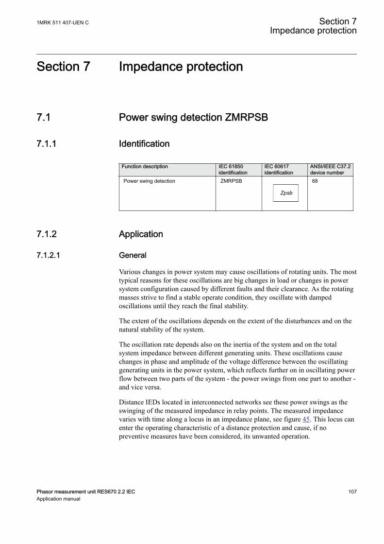
Section 7 Impedance protection
7.1 Power swing detection ZMRPSBIP14499-1 v3
7.1.1 IdentificationM14853-1 v3
Function description IEC 61850identification
IEC 60617identification
ANSI/IEEE C37.2device number
Power swing detection ZMRPSB
Zpsb
SYMBOL-EE V1 EN-US
68
7.1.2 ApplicationIP14969-1 v1
7.1.2.1 GeneralM13874-3 v3
Various changes in power system may cause oscillations of rotating units. The mosttypical reasons for these oscillations are big changes in load or changes in powersystem configuration caused by different faults and their clearance. As the rotatingmasses strive to find a stable operate condition, they oscillate with dampedoscillations until they reach the final stability.
The extent of the oscillations depends on the extent of the disturbances and on thenatural stability of the system.
The oscillation rate depends also on the inertia of the system and on the totalsystem impedance between different generating units. These oscillations causechanges in phase and amplitude of the voltage difference between the oscillatinggenerating units in the power system, which reflects further on in oscillating powerflow between two parts of the system - the power swings from one part to another -and vice versa.
Distance IEDs located in interconnected networks see these power swings as theswinging of the measured impedance in relay points. The measured impedancevaries with time along a locus in an impedance plane, see figure 45. This locus canenter the operating characteristic of a distance protection and cause, if nopreventive measures have been considered, its unwanted operation.
1MRK 511 407-UEN C Section 7Impedance protection
Phasor measurement unit RES670 2.2 IEC 107Application manual
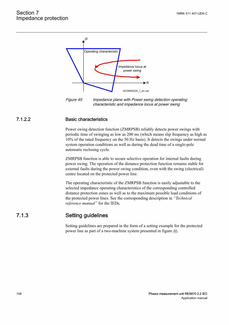
R
jX
Operating characteristic
Impedance locus atpower swing
IEC09000224_1_en.vsdIEC09000224 V1 EN-US
Figure 45: Impedance plane with Power swing detection operatingcharacteristic and impedance locus at power swing
7.1.2.2 Basic characteristicsM13874-11 v6
Power swing detection function (ZMRPSB) reliably detects power swings withperiodic time of swinging as low as 200 ms (which means slip frequency as high as10% of the rated frequency on the 50 Hz basis). It detects the swings under normalsystem operation conditions as well as during the dead time of a single-poleautomatic reclosing cycle.
ZMRPSB function is able to secure selective operation for internal faults duringpower swing. The operation of the distance protection function remains stable forexternal faults during the power swing condition, even with the swing (electrical)centre located on the protected power line.
The operating characteristic of the ZMRPSB function is easily adjustable to theselected impedance operating characteristics of the corresponding controlleddistance protection zones as well as to the maximum possible load conditions ofthe protected power lines. See the corresponding description in “Technicalreference manual” for the IEDs.
7.1.3 Setting guidelinesSEMOD52042-5 v5
Setting guidelines are prepared in the form of a setting example for the protectedpower line as part of a two-machine system presented in figure 46.
Section 7 1MRK 511 407-UEN CImpedance protection
108 Phasor measurement unit RES670 2.2 IECApplication manual
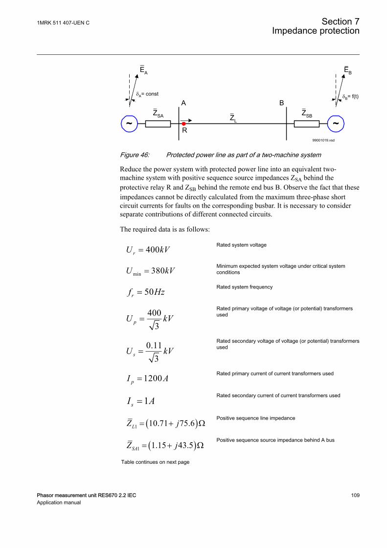
99001019.vsd
~~
EA
dA= const dB= f(t)
EB
A BZSA ZSBZL
R
IEC99001019 V1 EN-US
Figure 46: Protected power line as part of a two-machine system
Reduce the power system with protected power line into an equivalent two-machine system with positive sequence source impedances ZSA behind theprotective relay R and ZSB behind the remote end bus B. Observe the fact that theseimpedances cannot be directly calculated from the maximum three-phase shortcircuit currents for faults on the corresponding busbar. It is necessary to considerseparate contributions of different connected circuits.
The required data is as follows:
400rU kV=EQUATION1321 V1 EN-US
Rated system voltage
min 380U kV=EQUATION1322 V1 EN-US
Minimum expected system voltage under critical systemconditions
50rf Hz=EQUATION1323 V1 EN-US
Rated system frequency
4003pU kV=
EQUATION1324 V1 EN-US
Rated primary voltage of voltage (or potential) transformersused
0.113sU kV=
EQUATION1325 V1 EN-US
Rated secondary voltage of voltage (or potential) transformersused
1200pI A=EQUATION1326 V1 EN-US
Rated primary current of current transformers used
1sI A=EQUATION1327 V1 EN-US
Rated secondary current of current transformers used
( )1 10.71 75.6LZ j= + WEQUATION1328 V1 EN-US
Positive sequence line impedance
( )1 1.15 43.5SAZ j= + WEQUATION1329 V1 EN-US
Positive sequence source impedance behind A bus
Table continues on next page
1MRK 511 407-UEN C Section 7Impedance protection
Phasor measurement unit RES670 2.2 IEC 109Application manual
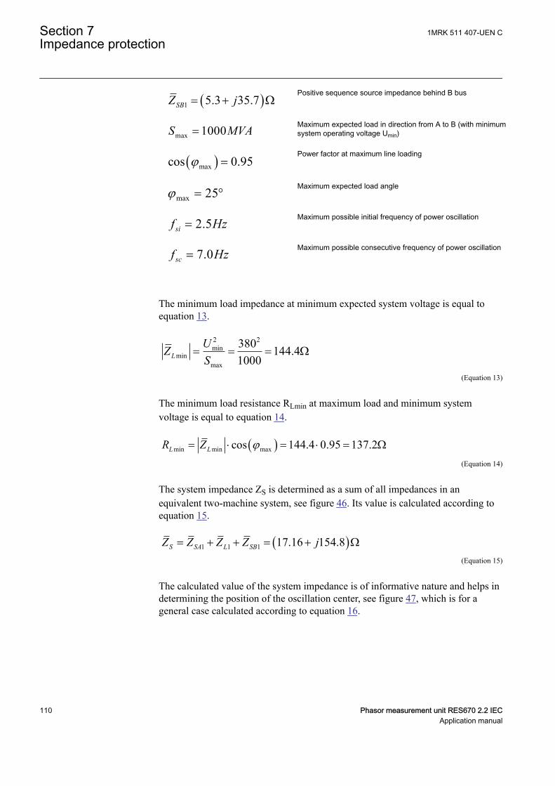
( )1 5.3 35.7SBZ j= + WEQUATION1330 V1 EN-US
Positive sequence source impedance behind B bus
max 1000S MVA=EQUATION1331 V1 EN-US
Maximum expected load in direction from A to B (with minimumsystem operating voltage Umin)
( )maxcos 0.95j =EQUATION1332 V1 EN-US
Power factor at maximum line loading
max 25j = °EQUATION1333 V1 EN-US
Maximum expected load angle
2.5sif Hz=EQUATION1334 V1 EN-US
Maximum possible initial frequency of power oscillation
7.0scf Hz=EQUATION1335 V1 EN-US
Maximum possible consecutive frequency of power oscillation
The minimum load impedance at minimum expected system voltage is equal toequation 13.
2 2min
minmax
380 144.41000L
UZS
= = = W
EQUATION1337 V1 EN-US (Equation 13)
The minimum load resistance RLmin at maximum load and minimum systemvoltage is equal to equation 14.
( )min min maxcos 144.4 0.95 137.2L LR Z j= × = × = WEQUATION1338 V1 EN-US (Equation 14)
The system impedance ZS is determined as a sum of all impedances in anequivalent two-machine system, see figure 46. Its value is calculated according toequation 15.
( )1 1 1 17.16 154.8S SA L SBZ Z Z Z j= + + = + WEQUATION1339 V1 EN-US (Equation 15)
The calculated value of the system impedance is of informative nature and helps indetermining the position of the oscillation center, see figure 47, which is for ageneral case calculated according to equation 16.
Section 7 1MRK 511 407-UEN CImpedance protection
110 Phasor measurement unit RES670 2.2 IECApplication manual
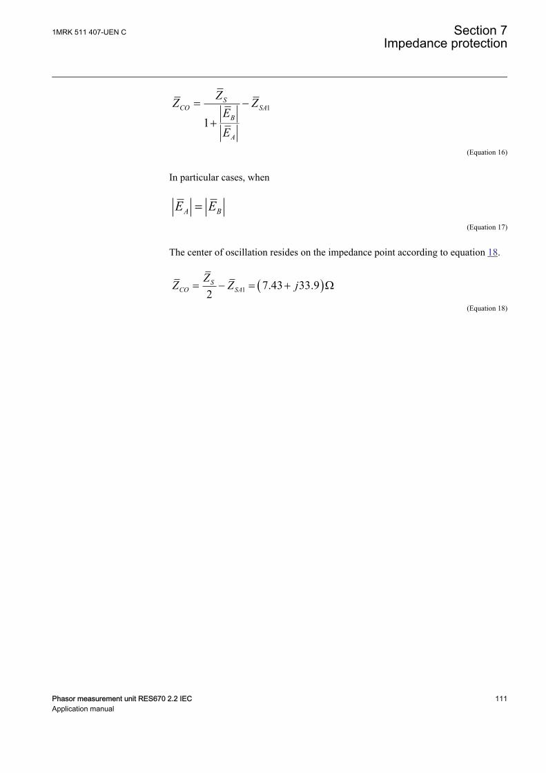
1
1
SCO SA
B
A
ZZ ZEE
= -
+
EQUATION1340 V1 EN-US (Equation 16)
In particular cases, when
A BE E=EQUATION1342 V1 EN-US (Equation 17)
The center of oscillation resides on the impedance point according to equation 18.
( )1 7.43 33.92
SCO SA
ZZ Z j= - = + W
EQUATION1341 V1 EN-US (Equation 18)
1MRK 511 407-UEN C Section 7Impedance protection
Phasor measurement unit RES670 2.2 IEC 111Application manual
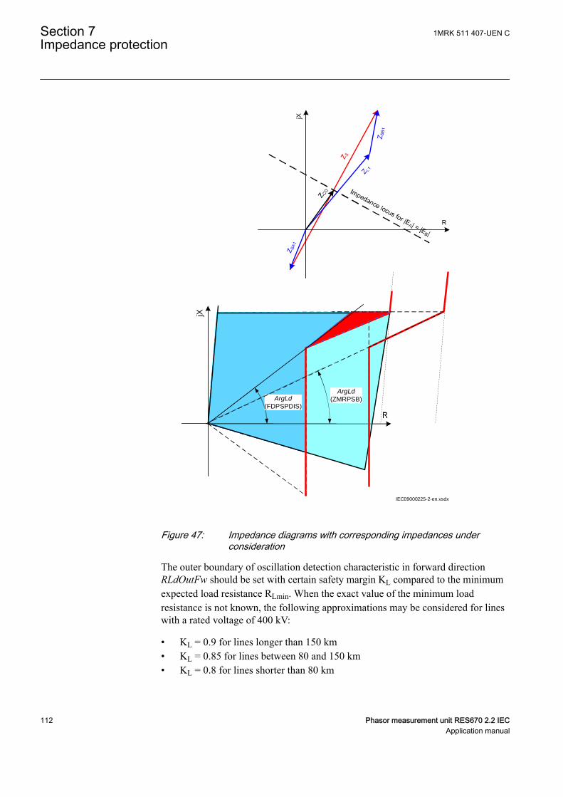
R
jX
ArgLd(ZMRPSB)ArgLd
(FDPSPDIS)
jX
R
IEC09000225-2-en.vsdx
IEC09000225 V2 EN-US
Figure 47: Impedance diagrams with corresponding impedances underconsideration
The outer boundary of oscillation detection characteristic in forward directionRLdOutFw should be set with certain safety margin KL compared to the minimumexpected load resistance RLmin. When the exact value of the minimum loadresistance is not known, the following approximations may be considered for lineswith a rated voltage of 400 kV:
• KL = 0.9 for lines longer than 150 km• KL = 0.85 for lines between 80 and 150 km• KL = 0.8 for lines shorter than 80 km
Section 7 1MRK 511 407-UEN CImpedance protection
112 Phasor measurement unit RES670 2.2 IECApplication manual
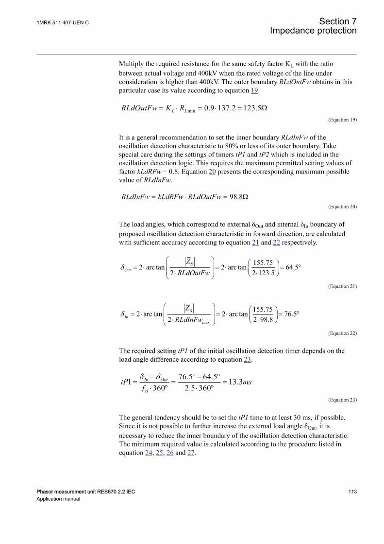
Multiply the required resistance for the same safety factor KL with the ratiobetween actual voltage and 400kV when the rated voltage of the line underconsideration is higher than 400kV. The outer boundary RLdOutFw obtains in thisparticular case its value according to equation 19.
min 0.9 137.2 123.5L LRLdOutFw K R= × = × = WEQUATION1343 V1 EN-US (Equation 19)
It is a general recommendation to set the inner boundary RLdInFw of theoscillation detection characteristic to 80% or less of its outer boundary. Takespecial care during the settings of timers tP1 and tP2 which is included in theoscillation detection logic. This requires the maximum permitted setting values offactor kLdRFw = 0.8. Equation 20 presents the corresponding maximum possiblevalue of RLdInFw.
98.8= × = WRLdInFw kLdRFw RLdOutFwEQUATION1344 V3 EN-US (Equation 20)
The load angles, which correspond to external δOut and internal δIn boundary ofproposed oscillation detection characteristic in forward direction, are calculatedwith sufficient accuracy according to equation 21 and 22 respectively.
155.752 arc tan 2 arc tan 64.52 2 123.5
dæ ö æ öç ÷= × = × = °ç ÷ç ÷× ×è øè ø
SOut
ZRLdOutFw
EQUATION1345 V1 EN-US (Equation 21)
max
155.752 arc tan 2 arc tan 76.52 2 98.8
dæ ö æ öç ÷= × = × = °ç ÷ç ÷× ×è øè ø
SIn
ZRLdInFw
EQUATION1346 V1 EN-US (Equation 22)
The required setting tP1 of the initial oscillation detection timer depends on theload angle difference according to equation 23.
76.5 64.51 13.3360 2.5 360
In Out
si
tP msf
d d- ° - °= = =
× ° × °EQUATION1347 V1 EN-US (Equation 23)
The general tendency should be to set the tP1 time to at least 30 ms, if possible.Since it is not possible to further increase the external load angle δOut, it isnecessary to reduce the inner boundary of the oscillation detection characteristic.The minimum required value is calculated according to the procedure listed inequation 24, 25, 26 and 27.
1MRK 511 407-UEN C Section 7Impedance protection
Phasor measurement unit RES670 2.2 IEC 113Application manual
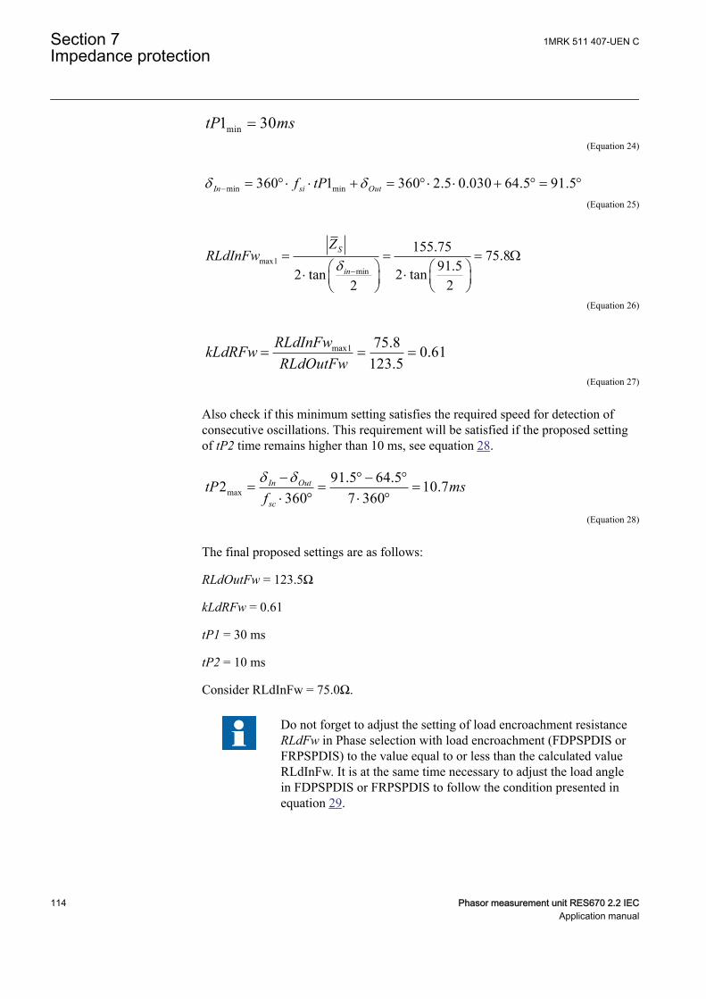
min1 30tP ms=EQUATION1348 V1 EN-US (Equation 24)
min min360 1 360 2.5 0.030 64.5 91.5In si Outf tPd d- = ° × × + = ° × × + ° = °EQUATION1349 V1 EN-US (Equation 25)
max1min
155.75 75.891.52 tan2 tan
22d -
= = = Wæ ö æ ö×× ç ÷ç ÷ è øè ø
S
in
ZRLdInFw
EQUATION1350 V1 EN-US (Equation 26)
max1 75.8 0.61123.5
= = =RLdInFwkLdRFwRLdOutFw
EQUATION1351 V1 EN-US (Equation 27)
Also check if this minimum setting satisfies the required speed for detection ofconsecutive oscillations. This requirement will be satisfied if the proposed settingof tP2 time remains higher than 10 ms, see equation 28.
max91.5 64.52 10.7
360 7 360In Out
sc
tP msf
d d- ° - °= = =
× ° × °EQUATION1352 V1 EN-US (Equation 28)
The final proposed settings are as follows:
RLdOutFw = 123.5Ω
kLdRFw = 0.61
tP1 = 30 ms
tP2 = 10 ms
Consider RLdInFw = 75.0Ω.
Do not forget to adjust the setting of load encroachment resistanceRLdFw in Phase selection with load encroachment (FDPSPDIS orFRPSPDIS) to the value equal to or less than the calculated valueRLdInFw. It is at the same time necessary to adjust the load anglein FDPSPDIS or FRPSPDIS to follow the condition presented inequation 29.
Section 7 1MRK 511 407-UEN CImpedance protection
114 Phasor measurement unit RES670 2.2 IECApplication manual
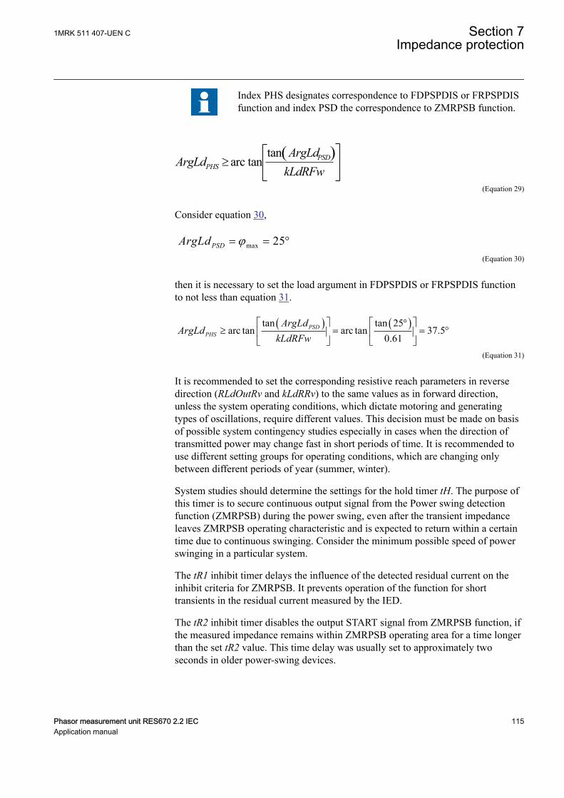
Index PHS designates correspondence to FDPSPDIS or FRPSPDISfunction and index PSD the correspondence to ZMRPSB function.
( )tanarc tan³ PSD
PHS
ArgLdArgLd
kLdRFwEQUATION1353 V2 EN-US (Equation 29)
Consider equation 30,
max 25PSDArgLd j= = °EQUATION1354 V1 EN-US (Equation 30)
then it is necessary to set the load argument in FDPSPDIS or FRPSPDIS functionto not less than equation 31.
( ) ( )tan tan 25arc tan arc tan 37.5
0.61é ù é ù°
³ = = °ê ú ê úë û ë û
PSDPHS
ArgLdArgLd
kLdRFwEQUATION1355 V1 EN-US (Equation 31)
It is recommended to set the corresponding resistive reach parameters in reversedirection (RLdOutRv and kLdRRv) to the same values as in forward direction,unless the system operating conditions, which dictate motoring and generatingtypes of oscillations, require different values. This decision must be made on basisof possible system contingency studies especially in cases when the direction oftransmitted power may change fast in short periods of time. It is recommended touse different setting groups for operating conditions, which are changing onlybetween different periods of year (summer, winter).
System studies should determine the settings for the hold timer tH. The purpose ofthis timer is to secure continuous output signal from the Power swing detectionfunction (ZMRPSB) during the power swing, even after the transient impedanceleaves ZMRPSB operating characteristic and is expected to return within a certaintime due to continuous swinging. Consider the minimum possible speed of powerswinging in a particular system.
The tR1 inhibit timer delays the influence of the detected residual current on theinhibit criteria for ZMRPSB. It prevents operation of the function for shorttransients in the residual current measured by the IED.
The tR2 inhibit timer disables the output START signal from ZMRPSB function, ifthe measured impedance remains within ZMRPSB operating area for a time longerthan the set tR2 value. This time delay was usually set to approximately twoseconds in older power-swing devices.
1MRK 511 407-UEN C Section 7Impedance protection
Phasor measurement unit RES670 2.2 IEC 115Application manual

The setting of the tEF timer must cover, with sufficient margin, the opening time ofa circuit breaker and the dead-time of a single-phase autoreclosing together withthe breaker closing time.
7.2 Out-of-step protection OOSPPAMGUID-8321AC72-187C-4E43-A0FC-AAC7829397C3 v1
7.2.1 IdentificationGUID-BF2F1533-BA39-48F0-A55C-0B13A393F780 v2
Function description IEC 61850identification
IEC 60617identification
ANSI/IEEE C37.2device number
Out-of-step protection OOSPPAM
<78
7.2.2 ApplicationGUID-11643CF1-4EF5-47F0-B0D4-6715ACEEC8EC v6
Under balanced and stable conditions, a generator operates with a constant rotor(power) angle, delivering an active electrical power to the power system, which isequal to the mechanical input power on the generator axis, minus the small lossesin the generator. In the case of a three-phase fault electrically close to the generator,no active power can be delivered. Almost all mechanical power from the turbine isunder this condition used to accelerate the moving parts, that is, the rotor and theturbine. If the fault is not cleared quickly, the generator may not remain insynchronism after the fault has been cleared. If the generator loses synchronism(Out-of-step) with the rest of the system, pole slipping occurs. This is characterizedby a wild flow of synchronizing power, which reverses in direction twice for everyslip cycle.
The out-of-step phenomenon occurs when a phase opposition occurs periodicallybetween different parts of a power system. This is often shown in a simplified wayas two equivalent generators connected to each other via an equivalenttransmission line and the phase difference between the equivalent generators is 180electrical degrees.
Section 7 1MRK 511 407-UEN CImpedance protection
116 Phasor measurement unit RES670 2.2 IECApplication manual
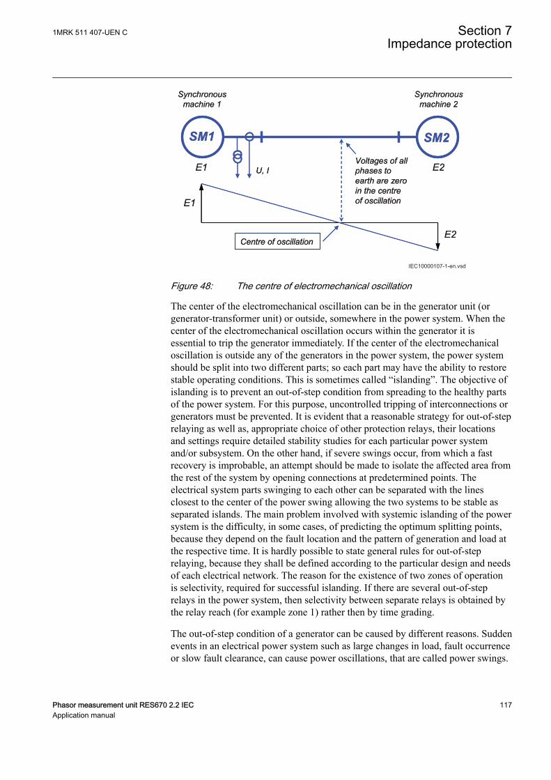
SM1
Synchronousmachine 1
Centre of oscillation
U, I
SM2
E1 E2
Synchronousmachine 2
E1
E2
Voltages of all phases to earth are zero in the centre of oscillation
SM1
Synchronousmachine 1
Centre of oscillation
U, I
SM2
E1 E2
Synchronousmachine 2
E1
E2
Voltages of all phases to earth are zero in the centre of oscillation
IEC10000107-1-en.vsdIEC10000107 V1 EN-US
Figure 48: The centre of electromechanical oscillation
The center of the electromechanical oscillation can be in the generator unit (orgenerator-transformer unit) or outside, somewhere in the power system. When thecenter of the electromechanical oscillation occurs within the generator it isessential to trip the generator immediately. If the center of the electromechanicaloscillation is outside any of the generators in the power system, the power systemshould be split into two different parts; so each part may have the ability to restorestable operating conditions. This is sometimes called “islanding”. The objective ofislanding is to prevent an out-of-step condition from spreading to the healthy partsof the power system. For this purpose, uncontrolled tripping of interconnections orgenerators must be prevented. It is evident that a reasonable strategy for out-of-steprelaying as well as, appropriate choice of other protection relays, their locationsand settings require detailed stability studies for each particular power systemand/or subsystem. On the other hand, if severe swings occur, from which a fastrecovery is improbable, an attempt should be made to isolate the affected area fromthe rest of the system by opening connections at predetermined points. Theelectrical system parts swinging to each other can be separated with the linesclosest to the center of the power swing allowing the two systems to be stable asseparated islands. The main problem involved with systemic islanding of the powersystem is the difficulty, in some cases, of predicting the optimum splitting points,because they depend on the fault location and the pattern of generation and load atthe respective time. It is hardly possible to state general rules for out-of-steprelaying, because they shall be defined according to the particular design and needsof each electrical network. The reason for the existence of two zones of operationis selectivity, required for successful islanding. If there are several out-of-steprelays in the power system, then selectivity between separate relays is obtained bythe relay reach (for example zone 1) rather then by time grading.
The out-of-step condition of a generator can be caused by different reasons. Suddenevents in an electrical power system such as large changes in load, fault occurrenceor slow fault clearance, can cause power oscillations, that are called power swings.
1MRK 511 407-UEN C Section 7Impedance protection
Phasor measurement unit RES670 2.2 IEC 117Application manual
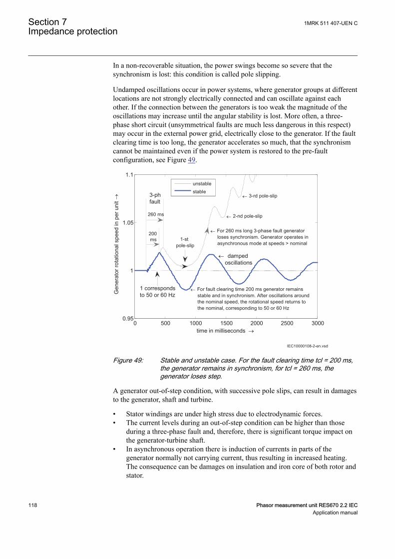
In a non-recoverable situation, the power swings become so severe that thesynchronism is lost: this condition is called pole slipping.
Undamped oscillations occur in power systems, where generator groups at differentlocations are not strongly electrically connected and can oscillate against eachother. If the connection between the generators is too weak the magnitude of theoscillations may increase until the angular stability is lost. More often, a three-phase short circuit (unsymmetrical faults are much less dangerous in this respect)may occur in the external power grid, electrically close to the generator. If the faultclearing time is too long, the generator accelerates so much, that the synchronismcannot be maintained even if the power system is restored to the pre-faultconfiguration, see Figure 49.
0 500 1000 1500 2000 2500 30000.95
1
1.05
1.1
time in milliseconds →
Gen
erat
or ro
tatio
nal s
peed
in p
er u
nit→
unstablestable
260 ms
200 ms
3-phfault
← For fault clearing time 200 ms generator remains stable and in synchronism. After oscillations around the nominal speed, the rotational speed returns to the nominal, corresponding to 50 or 60 Hz
← damped oscillations
← 3-rd pole-slip
1 correspondsto 50 or 60 Hz
← 2-nd pole-slip
1-stpole-slip
← For 260 ms long 3-phase fault generator loses synchronism. Generator operates in asynchronous mode at speeds > nominal
IEC10000108-2-en.vsdIEC10000108 V2 EN-US
Figure 49: Stable and unstable case. For the fault clearing time tcl = 200 ms,the generator remains in synchronism, for tcl = 260 ms, thegenerator loses step.
A generator out-of-step condition, with successive pole slips, can result in damagesto the generator, shaft and turbine.
• Stator windings are under high stress due to electrodynamic forces.• The current levels during an out-of-step condition can be higher than those
during a three-phase fault and, therefore, there is significant torque impact onthe generator-turbine shaft.
• In asynchronous operation there is induction of currents in parts of thegenerator normally not carrying current, thus resulting in increased heating.The consequence can be damages on insulation and iron core of both rotor andstator.
Section 7 1MRK 511 407-UEN CImpedance protection
118 Phasor measurement unit RES670 2.2 IECApplication manual
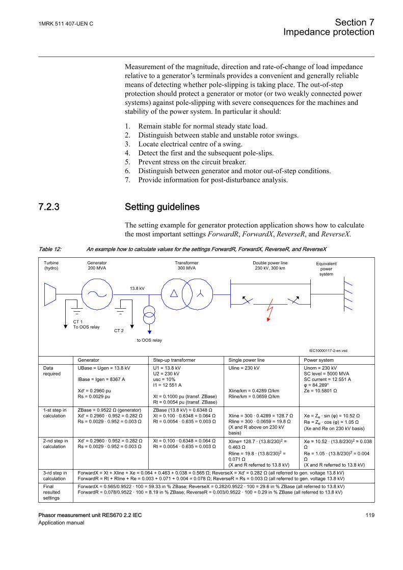
Measurement of the magnitude, direction and rate-of-change of load impedancerelative to a generator’s terminals provides a convenient and generally reliablemeans of detecting whether pole-slipping is taking place. The out-of-stepprotection should protect a generator or motor (or two weakly connected powersystems) against pole-slipping with severe consequences for the machines andstability of the power system. In particular it should:
1. Remain stable for normal steady state load.2. Distinguish between stable and unstable rotor swings.3. Locate electrical centre of a swing.4. Detect the first and the subsequent pole-slips.5. Prevent stress on the circuit breaker.6. Distinguish between generator and motor out-of-step conditions.7. Provide information for post-disturbance analysis.
7.2.3 Setting guidelinesGUID-CB86FCF6-8718-40BE-BDF2-028C24AB367D v6
The setting example for generator protection application shows how to calculatethe most important settings ForwardR, ForwardX, ReverseR, and ReverseX.
Table 12: An example how to calculate values for the settings ForwardR, ForwardX, ReverseR, and ReverseX
Turbine(hydro)
Generator200 MVA
Transformer300 MVA
Double power line230 kV, 300 km
Equivalentpowersystem
CT 1To OOS relay
CT 2
13.8 kV
IEC10000117-2-en.vsd
to OOS relay
IEC10000117 V2 EN-US
Generator Step-up transformer Single power line Power systemDatarequired
UBase = Ugen = 13.8 kV IBase = Igen = 8367 A Xd' = 0.2960 puRs = 0.0029 pu
U1 = 13.8 kVU2 = 230 kVusc = 10%I1 = 12 551 A Xt = 0.1000 pu (transf. ZBase)Rt = 0.0054 pu (transf. ZBase)
Uline = 230 kV Xline/km = 0.4289 Ω/kmRline/km = 0.0659 Ω/km
Unom = 230 kVSC level = 5000 MVASC current = 12 551 Aφ = 84.289°Ze = 10.5801 Ω
1-st step incalculation
ZBase = 0.9522 Ω (generator)Xd' = 0.2960 · 0.952 = 0.282 ΩRs = 0.0029 · 0.952 = 0.003 Ω
ZBase (13.8 kV) = 0.6348 ΩXt = 0.100 · 0.6348 = 0.064 ΩRt = 0.0054 · 0.635 = 0.003 Ω
Xline = 300 · 0.4289 = 128.7 ΩRline = 300 · 0.0659 = 19.8 Ω(X and R above on 230 kVbasis)
Xe = Ze · sin (φ) = 10.52 ΩRe = Ze · cos (φ) = 1.05 Ω(Xe and Re on 230 kV basis)
2-nd step incalculation
Xd' = 0.2960 · 0.952 = 0.282 ΩRs = 0.0029 · 0.952 = 0.003 Ω
Xt = 0.100 · 0.6348 = 0.064 ΩRt = 0.0054 · 0.635 = 0.003 Ω
Xline= 128.7 · (13.8/230)2 =0.463 ΩRline = 19.8 · (13.8/230)2 =0.071 Ω(X and R referred to 13.8 kV)
Xe = 10.52 · (13.8/230)2 = 0.038ΩRe = 1.05 · (13.8/230)2 = 0.004Ω(X and R referred to 13.8 kV)
3-rd step incalculation
ForwardX = Xt + Xline + Xe = 0.064 + 0.463 + 0.038 = 0.565 Ω; ReverseX = Xd' = 0.282 Ω (all referred to gen. voltage 13.8 kV)ForwardR = Rt + Rline + Re = 0.003 + 0.071 + 0.004 = 0.078 Ω; ReverseR = Rs = 0.003 Ω (all referred to gen. voltage 13.8 kV)
Finalresultedsettings
ForwardX = 0.565/0.9522 · 100 = 59.33 in % ZBase; ReverseX = 0.282/0.9522 · 100 = 29.6 in % ZBase (all referred to 13.8 kV)ForwardR = 0.078/0.9522 · 100 = 8.19 in % ZBase; ReverseR = 0.003/0.9522 · 100 = 0.29 in % ZBase (all referred to 13.8 kV)
1MRK 511 407-UEN C Section 7Impedance protection
Phasor measurement unit RES670 2.2 IEC 119Application manual

Settings ForwardR, ForwardX, ReverseR, and ReverseX.
• A precondition in order to be able to use the Out-of-step protection andconstruct a suitable lens characteristic is that the power system in which theOut-of-step protection is installed, is modeled as a two-machine equivalentsystem, or as a single machine – infinite bus equivalent power system. Thenthe impedances from the position of the Out-of-step protection in the directionof the normal load flow can be taken as forward.
• The settings ForwardX, ForwardR, ReverseX and ReverseR must, if possible,take into account, the post-disturbance configuration of the simplified powersystem. This is not always easy, in particular with islanding. But for the twomachine model as in Table 12, the most probable scenario is that only one lineis in service after the fault on one power line has been cleared by lineprotections. The settings ForwardX, ForwardR must therefore take intoaccount the reactance and resistance of only one power line.
• All the reactances and resistances (ForwardX, ForwardR, ReverseX andReverseR) must be referred to the voltage level where the Out-of-step relay isinstalled; for the example case shown in Table 12, this is the generator nominalvoltage UBase = 13.8 kV. This affects all the forward reactances andresistances in Table 12.
• All reactances and resistances must be finally expressed in percent of ZBase,where ZBase is for the example shown in Table 12 the base impedance of thegenerator, ZBase = 0.9522 Ω. Observe that the power transformer’s baseimpedance is different, ZBase = 0.6348 Ω. Observe that this latter powertransformer ZBase = 0.6348 Ω must be used when the power transformerreactance and resistance are transformed.
• For the synchronous machines as the generator in Table 12, the transientreactance Xd' shall be used. This due to the relatively slow electromechanicaloscillations under out-of-step conditions.
• Sometimes the equivalent resistance of the generator is difficult to get. A goodestimate is 1 percent of transient reactance Xd'. No great error is done if thisresistance is set to zero (0).
• Inclination of the Z-line, connecting points SE and RE, against the real (R)axis can be calculated as arctan ((ReverseX + ForwardX) / (ReverseR +ForwardR)), and is for the case in Table 12 equal to 84.55 degrees, which is atypical value.
Other settings:
• ReachZ1: Determines the reach of the zone 1 in the forward direction.Determines the position of the X-line which delimits zone 1 from zone 2. Setin % of ForwardX. In the case shown in Table 12, where the reactance of thestep-up power transformer is 11.32 % of the total ForwardX, the settingReachZ1 should be set to ReachZ1 = 12 %. This means that the generator –step-up transformer unit would be in the zone 1. In other words, if the centre of
Section 7 1MRK 511 407-UEN CImpedance protection
120 Phasor measurement unit RES670 2.2 IECApplication manual
oscillation would be found to be within the zone 1, only a very limited numberof pole-slips would be allowed, usually only one.
• StartAngle: Angle between the two equivalent rotors induced voltages (that is,the angle between the two internal induced voltages E1 and E2 in anequivalent simplified two-machine system) to get the start signal, in degrees.The width of the lens characteristic is determined by the value of this setting.Whenever the complex impedance Z(R, X) enters the lens, this is a sign ofinstability. The angle recommended is 110 or 120 degrees, because it is at thisrotor angle where problems with dynamic stability usually begin. Power angle120 degrees is sometimes called “the angle of no return” because if this angleis reached under generator swings, the generator is most likely to losesynchronism. When the complex impedance Z(R, X) enters the lens the startoutput signal (START) is set to 1 (TRUE).
• TripAngle: The setting TripAngle specifies the value of the rotor angle wherethe trip command is sent to the circuit breaker in order to minimize the stressto which the breaker is exposed when breaking the currents. The range of thisvalue is from 15° to 90°, with higher values suitable for longer breakeropening times. If a breaker opening is initiated at for example 60°, then thecircuit breaker opens its contacts closer to 0°, where the currents are smaller. Ifthe breaker opening time tBreaker is known, then it is possible to calculatemore exactly when opening must be initiated in order to open the circuitbreaker contacts as close as possible to 0°, where the currents are smallest. Ifthe breaker opening time tBreaker is specified (that is, higher than the default0.0 s, where 0.0 s means that tBreaker is unknown), then this alternative wayto determine the moment when a command to open the breaker is sent, isautomatically chosen instead of the more approximate method, based on theTripAngle.
• tReset: Interval of time since the last pole-slip detected, when the Out-of-stepprotection is reset. If there is no more pole slips detected under the timeinterval specified by tReset since the previous one, the function is reset. Alloutputs are set to 0 (FALSE). If no pole slip at all is detected under interval oftime specified by tReset since the start signal has been set (for example astable case with synchronism retained), the function is as well reset, whichincludes the start output signal (START), which is reset to 0 (FALSE) aftertReset interval of time has elapsed. However, the measurements of analoguequantities such as R, X, P, Q, and so on continue without interruptions.Recommended setting of tReset is in the range of 6 to 12 seconds.
• NoOfSlipsZ1: Maximum number of pole slips with centre of electromechanicaloscillation within zone 1 required for a trip. Usually, NoOfSlipsZ1= 1.
• NoOfSlipsZ2: Maximum number of pole slips with centre of electromechanicaloscillation within zone 2 required for a trip. The reason for the existence oftwo zones of operation is selectivity, required particularly for successfulislanding. If there are several pole slip (out-of-step) relays in the powersystem, then selectivity between relays is obtained by the relay reach (forexample zone 1) rather then by time grading. In a system, as in Table 12, thenumber of allowed pole slips in zone 2 can be the same as in zone 1.Recommended value: NoOfSlipsZ2 = 2 or 3.
• Operation: With the setting Operation OOSPPAM function can be set On/Off.
1MRK 511 407-UEN C Section 7Impedance protection
Phasor measurement unit RES670 2.2 IEC 121Application manual
• OperationZ1: Operation zone 1 On, Off. If OperationZ1 = Off, all pole-slipswith centre of the electromechanical oscillation within zone 1 are ignored.Default setting = On. More likely to be used is the option to extend zone 1 sothat zone 1 even covers zone 2. This feature is activated by the input to extendthe zone 1 (EXTZ1).
• OperationZ2: Operation zone 2 On, Off. If OperationZ1 = Off, all pole-slipswith centre of the electromechanical oscillation within zone 2 are ignored.Default setting = On.
• tBreaker: Circuit breaker opening time. Use the default value tBreaker = 0.000s if unknown. If the value is known, then a value higher than 0.000 isspecified, for example tBreaker = 0.040 s: the out-of-step function gives a tripcommand approximately 0.040 seconds before the currents reach theirminimum value. This in order to decrease the stress imposed to the circuitbreaker.
• GlobalBaseSel: This setting identifies the Global Base Values Group whereUBase and IBase are defined. In particular: UBase is the voltage at the pointwhere the Out-of-step protection is connected. If the protection is connected tothe generator output terminals, then UBase is the nominal (rated) phase tophase voltage of the protected generator. All the resistances and reactances aremeasured and displayed referred to voltage Ubase. Observe that ReverseX,ForwardX, ReverseR, and ForwardR must be given referred to UBase.IBase isthe protected generator nominal (rated) current, if the Out-of-step protectionbelongs to a generator protection scheme.
• InvertCTCurr: If the currents fed to the Out-of-step protection are measured onthe protected generator neutral side (LV-side) then inversion is not necessary(InvertCTCurr = Off), provided that the CT’s star point earthing complies withABB recommendations, as it is shown in Table 12. If the currents fed to theOut-of-step protection are measured on the protected generator terminals side,then invertion is necessary (InvertCTCurr = On), provided that the CT’s starpoint earthing complies with ABB recommendations, as it is shown in Table12.
Section 7 1MRK 511 407-UEN CImpedance protection
122 Phasor measurement unit RES670 2.2 IECApplication manual
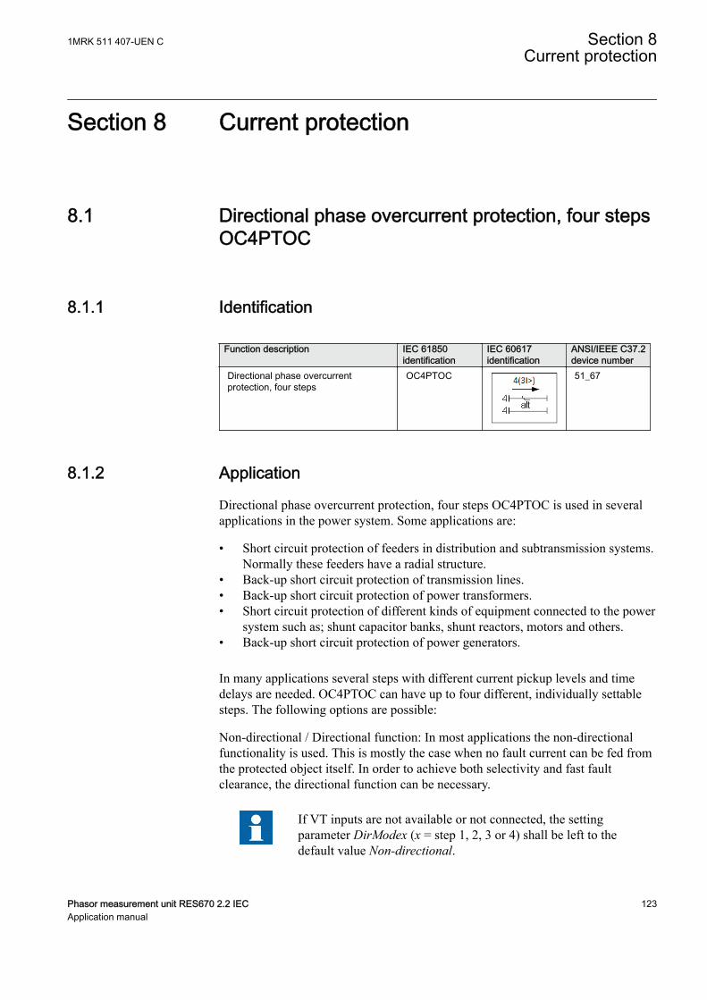
Section 8 Current protection
8.1 Directional phase overcurrent protection, four stepsOC4PTOC
SEMOD129998-1 v8
8.1.1 IdentificationM14885-1 v6
Function description IEC 61850identification
IEC 60617identification
ANSI/IEEE C37.2device number
Directional phase overcurrentprotection, four steps
OC4PTOC
TOC-REVA V2 EN-US
51_67
8.1.2 ApplicationM15335-3 v9
Directional phase overcurrent protection, four steps OC4PTOC is used in severalapplications in the power system. Some applications are:
• Short circuit protection of feeders in distribution and subtransmission systems.Normally these feeders have a radial structure.
• Back-up short circuit protection of transmission lines.• Back-up short circuit protection of power transformers.• Short circuit protection of different kinds of equipment connected to the power
system such as; shunt capacitor banks, shunt reactors, motors and others.• Back-up short circuit protection of power generators.
In many applications several steps with different current pickup levels and timedelays are needed. OC4PTOC can have up to four different, individually settablesteps. The following options are possible:
Non-directional / Directional function: In most applications the non-directionalfunctionality is used. This is mostly the case when no fault current can be fed fromthe protected object itself. In order to achieve both selectivity and fast faultclearance, the directional function can be necessary.
If VT inputs are not available or not connected, the settingparameter DirModex (x = step 1, 2, 3 or 4) shall be left to thedefault value Non-directional.
1MRK 511 407-UEN C Section 8Current protection
Phasor measurement unit RES670 2.2 IEC 123Application manual
Choice of time delay characteristics: There are several types of time delaycharacteristics available such as definite time delay and different types of inversetime delay characteristics. The selectivity between different overcurrent protectionsis normally enabled by co-ordination between the function time delays of thedifferent protections. To enable optimal co-ordination between all overcurrentprotections, they should have the same time delay characteristic. Therefore, a widerange of standardized inverse time characteristics are available for IEC and ANSI.It is also possible to tailor make the inverse time characteristic.
Normally, it is required that the phase overcurrent protection shall reset as fast aspossible when the current level gets lower than the operation level. In some casessome sort of delayed reset is required. Therefore, different kinds of resetcharacteristics can be used.
For some protection applications, there can be a need to change the current pick-uplevel for some time. A typical case is when the protection will measure the currentto a large motor. At the start up sequence of a motor the start current can besignificantly larger than the rated current of the motor. Therefore, there is apossibility to give a setting of a multiplication factor to the current pick-up level.This multiplication factor is activated from a binary input signal to the function.
Power transformers can have a large inrush current, when being energized. Thisphenomenon is due to saturation of the transformer magnetic core during parts ofthe period. There is a risk that inrush current will reach levels above the pick-upcurrent of the phase overcurrent protection. The inrush current has a large 2nd
harmonic content. This can be used to avoid unwanted operation of the protectionfunction. Therefore, OC4PTOC has a possibility of 2nd harmonic restrain if thelevel of 2nd harmonic current reaches a value above a set percent of thefundamental current.
The phase overcurrent protection is often used as a protection for two and threephase short circuits. In some cases, it is not wanted to detect single-phase earthfaults by the phase overcurrent protection. This fault type is detected and clearedafter operation of earth fault protection. Therefore, it is possible to make a choicehow many phases, at minimum, that have to have current above the pick-up level,to enable operation. If set 1 of 3 it is sufficient to have high current in one phaseonly. If set 2 of 3 or 3 of 3 single-phase earth faults are not detected.
8.1.3 Setting guidelinesIP14982-1 v1
M12982-4 v14
When inverse time overcurrent characteristic is selected, theoperate time of the stage will be the sum of the inverse time delayand the set definite time delay. Thus, if only the inverse time delayis required, it is important to set the definite time delay for thatstage to zero.
Section 8 1MRK 511 407-UEN CCurrent protection
124 Phasor measurement unit RES670 2.2 IECApplication manual
The parameters for the directional phase overcurrent protection, four stepsOC4PTOC are set via the local HMI or PCM600.
The following settings can be done for OC4PTOC.
Common base IED values for the primary current (IBase), primary voltage (UBase)and primary power (SBase) are set in global base values for settings functionGBASVAL.
GlobalBaseSel: Selects the global base value group used by the function to defineIBase, UBase and SBase as applicable.
MeasType: Selection of discrete Fourier filtered (DFT) or true RMS filtered (RMS)signals. RMS is used when the harmonic contents are to be considered, for examplein applications with shunt capacitors.
Operation: The protection can be set to On or Off.
AngleRCA: Protection characteristic angle set in degrees. If the angle of the faultloop current has the angle RCA, the direction to the fault is forward.
AngleROA: Angle value, given in degrees, to define the angle sector of thedirectional function, shown in Figure 50.
StartPhSel: Number of phases, with high current, required for operation. Thesetting possibilities are: 1 out of 3, 2 out of 3 and 3 out of 3. The default setting is 1out of 3.
IMinOpPhSel: Minimum current setting level for releasing the directional startsignals in % of IB. This setting should be less than the lowest step setting. Thedefault setting is 7% of IB.
2ndHarmStab: Operate level of 2nd harmonic current restrain set in % of thefundamental current. The setting range is 5 - 100% in steps of 1%. The defaultsetting is 20%.
1MRK 511 407-UEN C Section 8Current protection
Phasor measurement unit RES670 2.2 IEC 125Application manual
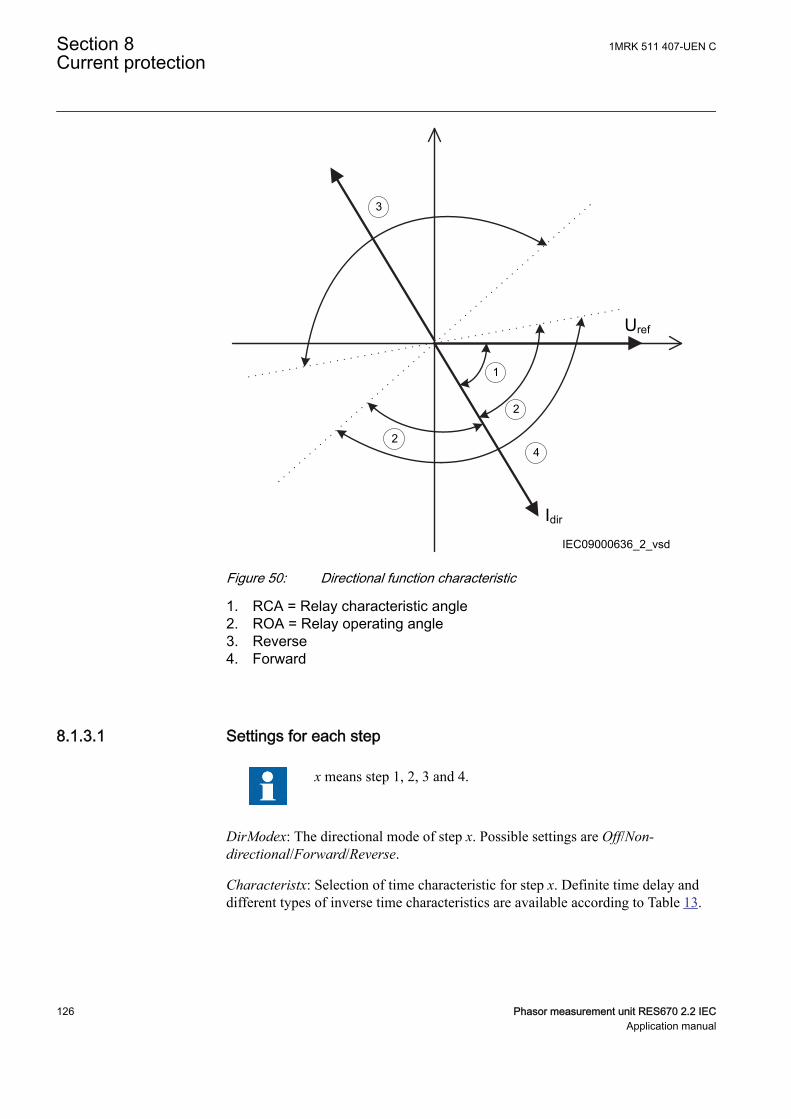
Uref
Idir
IEC09000636_2_vsd
1
2
2
3
4
IEC09000636 V2 EN-US
Figure 50: Directional function characteristic
1. RCA = Relay characteristic angle2. ROA = Relay operating angle3. Reverse4. Forward
8.1.3.1 Settings for each stepM12982-19 v10
x means step 1, 2, 3 and 4.
DirModex: The directional mode of step x. Possible settings are Off/Non-directional/Forward/Reverse.
Characteristx: Selection of time characteristic for step x. Definite time delay anddifferent types of inverse time characteristics are available according to Table 13.
Section 8 1MRK 511 407-UEN CCurrent protection
126 Phasor measurement unit RES670 2.2 IECApplication manual
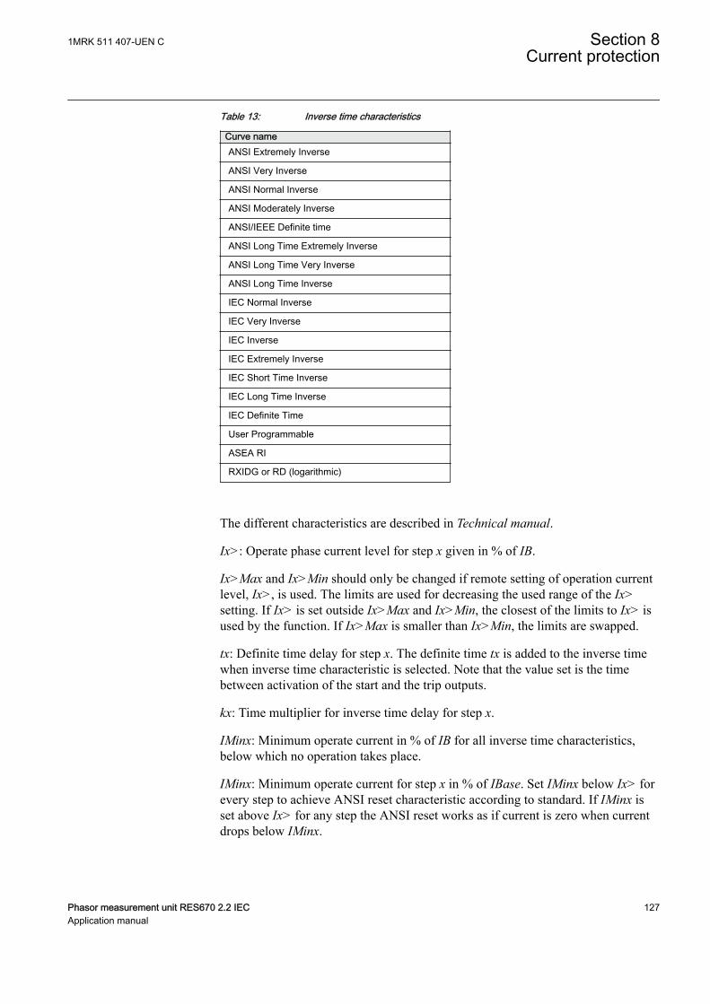
Table 13: Inverse time characteristics
Curve nameANSI Extremely Inverse
ANSI Very Inverse
ANSI Normal Inverse
ANSI Moderately Inverse
ANSI/IEEE Definite time
ANSI Long Time Extremely Inverse
ANSI Long Time Very Inverse
ANSI Long Time Inverse
IEC Normal Inverse
IEC Very Inverse
IEC Inverse
IEC Extremely Inverse
IEC Short Time Inverse
IEC Long Time Inverse
IEC Definite Time
User Programmable
ASEA RI
RXIDG or RD (logarithmic)
The different characteristics are described in Technical manual.
Ix>: Operate phase current level for step x given in % of IB.
Ix>Max and Ix>Min should only be changed if remote setting of operation currentlevel, Ix>, is used. The limits are used for decreasing the used range of the Ix>setting. If Ix> is set outside Ix>Max and Ix>Min, the closest of the limits to Ix> isused by the function. If Ix>Max is smaller than Ix>Min, the limits are swapped.
tx: Definite time delay for step x. The definite time tx is added to the inverse timewhen inverse time characteristic is selected. Note that the value set is the timebetween activation of the start and the trip outputs.
kx: Time multiplier for inverse time delay for step x.
IMinx: Minimum operate current in % of IB for all inverse time characteristics,below which no operation takes place.
IMinx: Minimum operate current for step x in % of IBase. Set IMinx below Ix> forevery step to achieve ANSI reset characteristic according to standard. If IMinx isset above Ix> for any step the ANSI reset works as if current is zero when currentdrops below IMinx.
1MRK 511 407-UEN C Section 8Current protection
Phasor measurement unit RES670 2.2 IEC 127Application manual
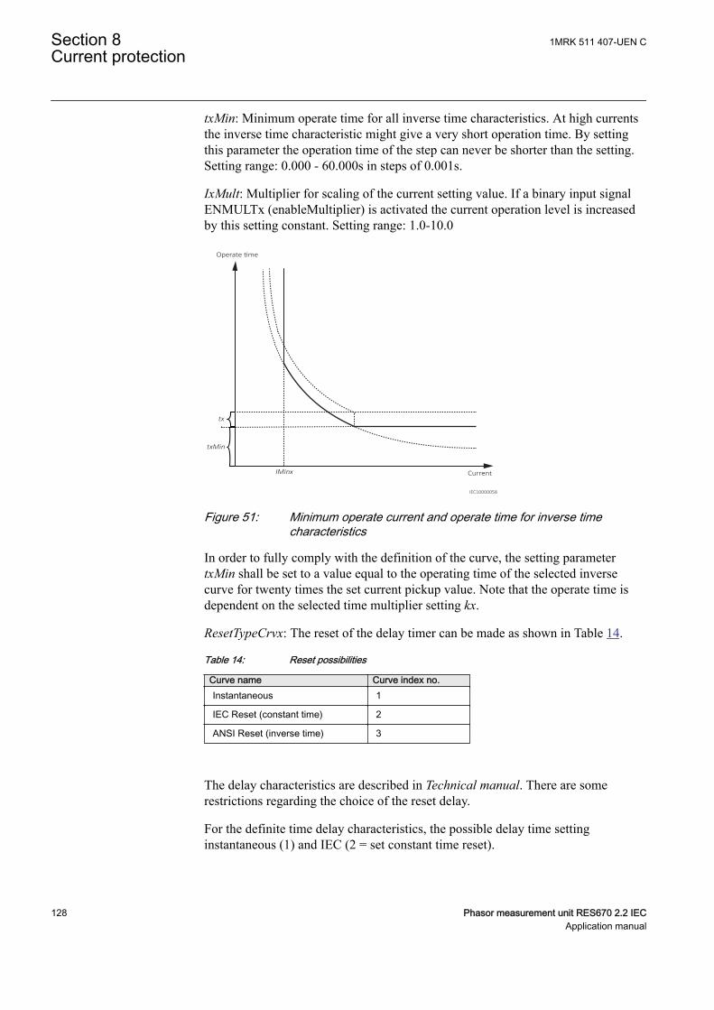
txMin: Minimum operate time for all inverse time characteristics. At high currentsthe inverse time characteristic might give a very short operation time. By settingthis parameter the operation time of the step can never be shorter than the setting.Setting range: 0.000 - 60.000s in steps of 0.001s.
IxMult: Multiplier for scaling of the current setting value. If a binary input signalENMULTx (enableMultiplier) is activated the current operation level is increasedby this setting constant. Setting range: 1.0-10.0
IMinx
Operate time
Current
tx
txMin
IEC10000058
IEC10000058 V2 EN-US
Figure 51: Minimum operate current and operate time for inverse timecharacteristics
In order to fully comply with the definition of the curve, the setting parametertxMin shall be set to a value equal to the operating time of the selected inversecurve for twenty times the set current pickup value. Note that the operate time isdependent on the selected time multiplier setting kx.
ResetTypeCrvx: The reset of the delay timer can be made as shown in Table 14.
Table 14: Reset possibilities
Curve name Curve index no.Instantaneous 1
IEC Reset (constant time) 2
ANSI Reset (inverse time) 3
The delay characteristics are described in Technical manual. There are somerestrictions regarding the choice of the reset delay.
For the definite time delay characteristics, the possible delay time settinginstantaneous (1) and IEC (2 = set constant time reset).
Section 8 1MRK 511 407-UEN CCurrent protection
128 Phasor measurement unit RES670 2.2 IECApplication manual
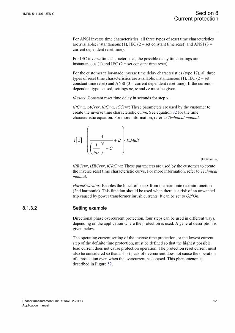
For ANSI inverse time characteristics, all three types of reset time characteristicsare available: instantaneous (1), IEC (2 = set constant time reset) and ANSI (3 =current dependent reset time).
For IEC inverse time characteristics, the possible delay time settings areinstantaneous (1) and IEC (2 = set constant time reset).
For the customer tailor-made inverse time delay characteristics (type 17), all threetypes of reset time characteristics are available: instantaneous (1), IEC (2 = setconstant time reset) and ANSI (3 = current dependent reset time). If the current-dependent type is used, settings pr, tr and cr must be given.
tResetx: Constant reset time delay in seconds for step x.
tPCrvx, tACrvx, tBCrvx, tCCrvx: These parameters are used by the customer tocreate the inverse time characteristic curve. See equation 32 for the timecharacteristic equation. For more information, refer to Technical manual.
[ ]
>
p
At s B IxMult
iC
in
= + ×
-
æ öç ÷ç ÷ç ÷æ öç ÷ç ÷è øè ø
EQUATION1261 V2 EN-US (Equation 32)
tPRCrvx, tTRCrvx, tCRCrvx: These parameters are used by the customer to createthe inverse reset time characteristic curve. For more information, refer to Technicalmanual.
HarmRestrainx: Enables the block of step x from the harmonic restrain function(2nd harmonic). This function should be used when there is a risk of an unwantedtrip caused by power transformer inrush currents. It can be set to Off/On.
8.1.3.2 Setting exampleGUID-20729467-24AB-42F0-9FD1-D2959028732E v1
Directional phase overcurrent protection, four steps can be used in different ways,depending on the application where the protection is used. A general description isgiven below.
The operating current setting of the inverse time protection, or the lowest currentstep of the definite time protection, must be defined so that the highest possibleload current does not cause protection operation. The protection reset current mustalso be considered so that a short peak of overcurrent does not cause the operationof a protection even when the overcurrent has ceased. This phenomenon isdescribed in Figure 52.
1MRK 511 407-UEN C Section 8Current protection
Phasor measurement unit RES670 2.2 IEC 129Application manual
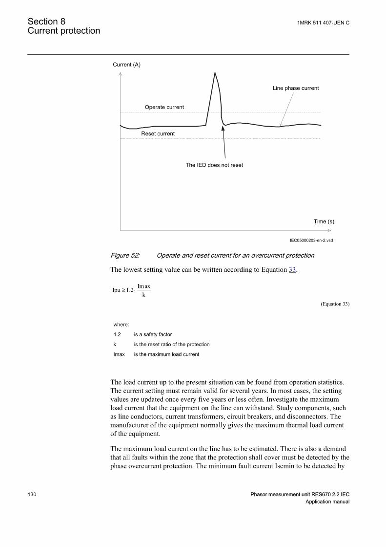
Operate current
Current (A)
The IED does not reset
Line phase current
Time (s)
Reset current
IEC05000203-en-2.vsdIEC05000203 V4 EN-US
Figure 52: Operate and reset current for an overcurrent protection
The lowest setting value can be written according to Equation 33.
ImaxIpu 1.2k
³ ×
EQUATION1262 V2 EN-US (Equation 33)
where:
1.2 is a safety factor
k is the reset ratio of the protection
Imax is the maximum load current
The load current up to the present situation can be found from operation statistics.The current setting must remain valid for several years. In most cases, the settingvalues are updated once every five years or less often. Investigate the maximumload current that the equipment on the line can withstand. Study components, suchas line conductors, current transformers, circuit breakers, and disconnectors. Themanufacturer of the equipment normally gives the maximum thermal load currentof the equipment.
The maximum load current on the line has to be estimated. There is also a demandthat all faults within the zone that the protection shall cover must be detected by thephase overcurrent protection. The minimum fault current Iscmin to be detected by
Section 8 1MRK 511 407-UEN CCurrent protection
130 Phasor measurement unit RES670 2.2 IECApplication manual
the protection must be calculated. Taking this value as a base, the highest pickupcurrent setting can be written according to Equation 34.
Ipu 0.7 Iscmin£ ×EQUATION1263 V2 EN-US (Equation 34)
where:
0.7 is a safety factor
Iscmin is the smallest fault current to be detected by the overcurrent protection.
As a summary, the operating current shall be chosen within the interval stated inEquation 35.
Imax1.2 Ipu 0.7 Iscmink
× £ £ ×
EQUATION1264 V2 EN-US (Equation 35)
The high current function of the overcurrent protection, which only has a short-delay trip time, must be given a current setting so that the protection is selective toother protection functions in the power system. It is desirable to have rapid trippingof faults within a large part of the power system to be protected by the protection(primary protected zone). A fault current calculation gives the largest current offaults, Iscmax, at the most remote part of the primary protected zone. The risk oftransient overreach must be considered, due to a possible DC component of theshort circuit current. The lowest current setting of the fastest stage can be writtenaccording to
max1.2 t schighI k I³ × ×
EQUATION1265 V1 EN-US (Equation 36)
where:
1.2 is a safety factor
kt is a factor that takes care of the transient overreach due to the DC component of the faultcurrent and can be considered to be less than 1.05
Iscmax is the largest fault current at a fault at the most remote point of the primary protection zone.
The operate time of the phase overcurrent protection has to be chosen so that thefault time is short enough that the protected equipment will not be destroyed due tothermal overload while, at the same time, selectivity is assured. For overcurrentprotection in a radial fed network, the time setting can be chosen in a graphicalway. This is mostly used in the case of inverse time overcurrent protection. Figure53 shows how the time-versus-current curves are plotted in a diagram. The timesetting is chosen to get the shortest fault time with maintained selectivity.
1MRK 511 407-UEN C Section 8Current protection
Phasor measurement unit RES670 2.2 IEC 131Application manual

Selectivity is assured if the time difference between the curves is larger than acritical time difference.
Time-current curves
Fault Current
10
10
0.01
10000
en05000204.ai
Str
tfunc1
n
n
tfunc2Trip
tim
e
n
IEC05000204 V2 EN-US
Figure 53: Fault time with maintained selectivity
The operation time can be set individually for each overcurrent protection.
To assure selectivity between different protection functions in the radial network,there has to be a minimum time difference Dt between the time delays of twoprotections. To determine the shortest possible time difference, the operation timeof the protection, the breaker opening time and the protection resetting time mustbe known. These time delays can vary significantly between different protectiveequipment. The following time delays can be estimated:
Protection operationtime:
15-60 ms
Protection resetting time: 15-60 ms
Breaker opening time: 20-120 ms
Section 8 1MRK 511 407-UEN CCurrent protection
132 Phasor measurement unit RES670 2.2 IECApplication manual
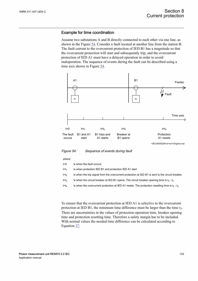
Example for time coordinationAssume two substations A and B directly connected to each other via one line, asshown in the Figure 54. Consider a fault located at another line from the station B.The fault current to the overcurrent protection of IED B1 has a magnitude so thatthe overcurrent protection will start and subsequently trip, and the overcurrentprotection of IED A1 must have a delayed operation in order to avoidmaloperation. The sequence of events during the fault can be described using atime axis shown in Figure 54.
I> I>
A1 B1Feeder
Time axis
t=0 t=t2 t=t3
The fault occurs
B1 trips and A1 starts
Breaker at B1 opens
=IEC05000205=2=en=Original.vsd
Fault
t=t4
Protection A1 resets
t=t1
B1 and A1 start
IEC05000205 V2 EN-US
Figure 54: Sequence of events during fault
where:
t=0 is when the fault occurs
t=t1 is when protection IED B1 and protection IED A1 start
t=t2 is when the trip signal from the overcurrent protection at IED B1 is sent to the circuit breaker.
t=t3 is when the circuit breaker at IED B1 opens. The circuit breaker opening time is t3 - t2
t=t4 is when the overcurrent protection at IED A1 resets. The protection resetting time is t4 - t3.
To ensure that the overcurrent protection at IED A1 is selective to the overcurrentprotection at IED B1, the minimum time difference must be larger than the time t3.There are uncertainties in the values of protection operation time, breaker openingtime and protection resetting time. Therefore a safety margin has to be included.With normal values the needed time difference can be calculated according toEquation 37.
1MRK 511 407-UEN C Section 8Current protection
Phasor measurement unit RES670 2.2 IEC 133Application manual
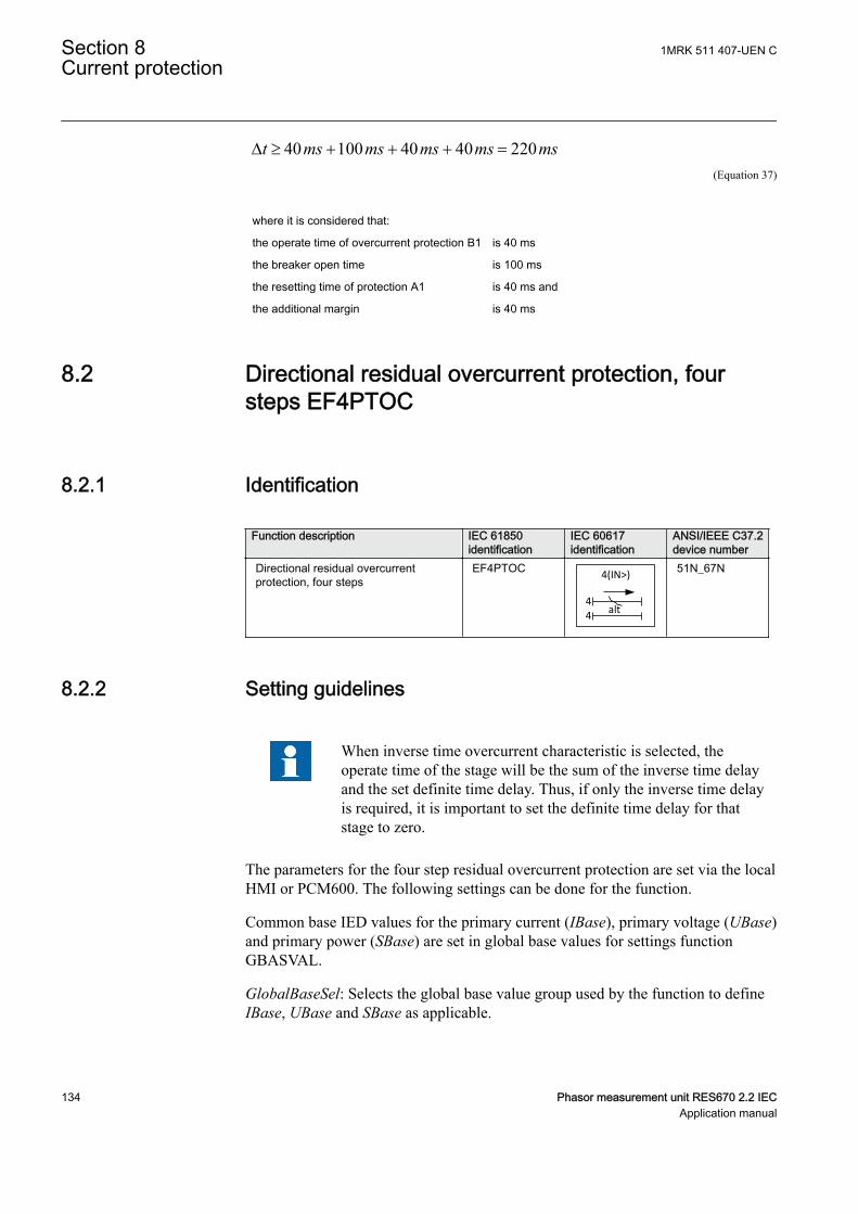
40 100 40 40 220t ms ms ms ms msD ³ + + + =EQUATION1266 V1 EN-US (Equation 37)
where it is considered that:
the operate time of overcurrent protection B1 is 40 ms
the breaker open time is 100 ms
the resetting time of protection A1 is 40 ms and
the additional margin is 40 ms
8.2 Directional residual overcurrent protection, foursteps EF4PTOC
IP14509-1 v8
8.2.1 IdentificationM14881-1 v6
Function description IEC 61850identification
IEC 60617identification
ANSI/IEEE C37.2device number
Directional residual overcurrentprotection, four steps
EF4PTOC 4(IN>)
4alt4
TEF-REVA V2 EN-US
51N_67N
8.2.2 Setting guidelinesIP14988-1 v1
M15282-3 v12
When inverse time overcurrent characteristic is selected, theoperate time of the stage will be the sum of the inverse time delayand the set definite time delay. Thus, if only the inverse time delayis required, it is important to set the definite time delay for thatstage to zero.
The parameters for the four step residual overcurrent protection are set via the localHMI or PCM600. The following settings can be done for the function.
Common base IED values for the primary current (IBase), primary voltage (UBase)and primary power (SBase) are set in global base values for settings functionGBASVAL.
GlobalBaseSel: Selects the global base value group used by the function to defineIBase, UBase and SBase as applicable.
Section 8 1MRK 511 407-UEN CCurrent protection
134 Phasor measurement unit RES670 2.2 IECApplication manual
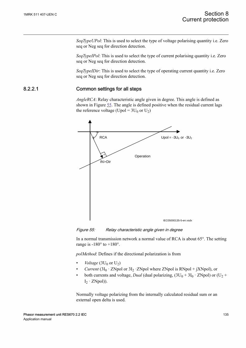
SeqTypeUPol: This is used to select the type of voltage polarising quantity i.e. Zeroseq or Neg seq for direction detection.
SeqTypeIPol: This is used to select the type of current polarising quantity i.e. Zeroseq or Neg seq for direction detection.
SeqTypeIDir: This is used to select the type of operating current quantity i.e. Zeroseq or Neg seq for direction detection.
8.2.2.1 Common settings for all stepsM15282-81 v10
AngleRCA: Relay characteristic angle given in degree. This angle is defined asshown in Figure 55. The angle is defined positive when the residual current lagsthe reference voltage (Upol = 3U0 or U2)
Upol = -3U0 or
IN>Dir
RCA
Operation
-3U2
IEC05000135-5-en.vsdxIEC05000135 V5 EN-US
Figure 55: Relay characteristic angle given in degree
In a normal transmission network a normal value of RCA is about 65°. The settingrange is -180° to +180°.
polMethod: Defines if the directional polarization is from
• Voltage (3U0 or U2)• Current (3I0 · ZNpol or 3I2 ·ZNpol where ZNpol is RNpol + jXNpol), or• both currents and voltage, Dual (dual polarizing, (3U0 + 3I0 · ZNpol) or (U2 +
I2 · ZNpol)).
Normally voltage polarizing from the internally calculated residual sum or anexternal open delta is used.
1MRK 511 407-UEN C Section 8Current protection
Phasor measurement unit RES670 2.2 IEC 135Application manual
Current polarizing is useful when the local source is strong and a high sensitivity isrequired. In such cases the polarizing voltage (3U0) can be below 1% and it is thennecessary to use current polarizing or dual polarizing. Multiply the required setcurrent (primary) with the minimum impedance (ZNpol) and check that thepercentage of the phase-to-earth voltage is definitely higher than 1% (minimum3U0>UPolMin setting) as a verification.
RNPol, XNPol: The zero-sequence source is set in primary ohms as base for thecurrent polarizing. The polarizing voltage is then achieved as 3I0 · ZNpol. TheZNpol can be defined as (ZS1-ZS0)/3, that is the earth return impedance of thesource behind the protection. The maximum earth-fault current at the local sourcecan be used to calculate the value of ZN as U/(√3 · 3I0) Typically, the minimumZNPol (3 · zero sequence source) is set. The setting is in primary ohms.
When the dual polarizing method is used, it is important that the setting INx> orthe product 3I0 · ZNpol is not greater than 3U0. If so, there is a risk for incorrectoperation for faults in the reverse direction.
IPolMin: is the minimum earth-fault current accepted for directional evaluation.For smaller currents than this value, the operation will be blocked. A typical settingis 5-10% of IB.
UPolMin: Minimum polarization (reference) polarizing voltage for the directionalfunction, given in % of UBase/√3.
IN>Dir: Operate residual current release level in % of IB for directionalcomparison scheme. The setting is given in % of IB and must be set below thelowest INx> setting, set for the directional measurement. The output signals,STFW and STRV can be used in a teleprotection scheme. The appropriate signalshould be configured to the communication scheme block.
8.2.2.2 2nd harmonic restrainM15282-90 v6
If a power transformer is energized there is a risk that the current transformer corewill saturate during part of the period, resulting in a transformer inrush current.This will give a declining residual current in the network, as the inrush current isdeviating between the phases. There is a risk that the residual overcurrent functionwill give an unwanted trip. The inrush current has a relatively large ratio of 2ndharmonic component. This component can be used to create a restrain signal toprevent this unwanted function.
At current transformer saturation a false residual current can be measured by theprotection. Here the 2nd harmonic restrain can prevent unwanted operation as well.
2ndHarmStab: The rate of 2nd harmonic current content for activation of the 2ndharmonic restrain signal. The setting is given in % of the fundamental frequencyresidual current.
Section 8 1MRK 511 407-UEN CCurrent protection
136 Phasor measurement unit RES670 2.2 IECApplication manual

8.2.2.3 Parallel transformer inrush current logicM15282-97 v6
In case of parallel transformers there is a risk of sympathetic inrush current. If oneof the transformers is in operation, and the parallel transformer is switched in, theasymmetric inrush current of the switched-in transformer will cause partialsaturation of the transformer already in service. This is called transferredsaturation. The 2nd harmonic of the inrush currents of the two transformers will bein phase opposition. The summation of the two currents will thus give a small 2nd
harmonic current. The residual fundamental current will however be significant.The inrush current of the transformer in service before the parallel transformerenergizing, will be a little delayed compared to the first transformer. Therefore, wewill have high 2nd harmonic current initially. After a short period this current willhowever be small and the normal 2nd harmonic blocking will reset.
en05000136.vsd
Power System
IN>IN>
IEC05000136 V1 EN-US
Figure 56: Application for parallel transformer inrush current logic
If the BlkParTransf function is activated, the 2nd harmonic restrain signal will latchas long as the residual current measured by the relay is larger than a selected stepcurrent level. Assume that step 4 is chosen to be the most sensitive step of the fourstep residual overcurrent protection function EF4PTOC. The harmonic restrainblocking is enabled for this step. Also the same current setting as this step is chosenfor the blocking at parallel transformer energizing.
The settings for the parallel transformer logic are described below.
BlkParTransf: This is used to On blocking at energising of parallel transformers.
UseStartValue: Gives which current level should be used for the activation of theblocking signal. This is given as one of the settings of the steps: Step 1/2/3/4.Normally, the step having the lowest operation current level should be set.
8.2.2.4 Switch onto fault logicM15282-106 v4
In case of energizing a faulty object there is a risk of having a long fault clearancetime, if the fault current is too small to give fast operation of the protection. Theswitch on to fault function can be activated from auxiliary signals from the circuitbreaker, either the close command or the open/close position (change of position).
1MRK 511 407-UEN C Section 8Current protection
Phasor measurement unit RES670 2.2 IEC 137Application manual
This logic can be used to issue a fast trip if one breaker pole does not closeproperly at a manual or automatic closing.
SOTF and under time are similar functions to achieve fast clearance atasymmetrical closing based on requirements from different utilities.
The function is divided into two parts. The SOTF function will give operation fromstep 2 or 3 during a set time after change in the position of the circuit breaker. TheSOTF function has a set time delay. The under time function, which has 2nd
harmonic restrain blocking, will give operation from step 4. The 2nd harmonicrestrain will prevent unwanted function in case of transformer inrush current. Theunder time function has a set time delay.
Below the settings for switch on to fault logics are described.
SOTF: This parameter can be set: Off/SOTF/Under Time/SOTF+Under Time.
ActivationSOTF: This setting will select the signal to activate SOTF function; CBposition open/CB position closed/CB close command.
StepForSOTF: If this parameter is set on step 3, the step 3 start signal will be usedas current set level. If set on step 2, the step 2 start signal will be used as current setlevel.
HarmBlkSOTF: This is used to On/Off harmonic restrain during SOTF conditions.
tSOTF: Time delay for operation of the SOTF function. The setting range is 0.000 -60.000 s in step of 0.001 s. The default setting is 0.100 s
t4U: Time interval when the SOTF function is active after breaker closing. Thesetting range is 0.000 - 60.000 s in step of 0.001 s. The default setting is 1.000 s.
ActUnderTime: Describes the mode to activate the sensitive undertime function.The function can be activated by Circuit breaker position (change) or Circuitbreaker command.
tUnderTime: Time delay for operation of the sensitive undertime function. Thesetting range is 0.000 - 60.000 s in step of 0.001 s. The default setting is 0.300 s
8.2.2.5 Settings for each step (x = 1, 2, 3 and 4)M15282-9 v12
Operation: Sets the protection to On or Off.
DirModex: The directional mode of step x. Possible settings are Off/Non-directional/Forward/Reverse.
Characteristx: Selection of time characteristic for step x. Definite time delay anddifferent types of inverse time characteristics are available.
Inverse time characteristic enables fast fault clearance of high current faults at thesame time as selectivity to other inverse time phase overcurrent protections can be
Section 8 1MRK 511 407-UEN CCurrent protection
138 Phasor measurement unit RES670 2.2 IECApplication manual
assured. This is mainly used in radial fed networks but can also be used in meshednetworks. In meshed networks, the settings must be based on network faultcalculations.
To assure selectivity between different protections, in the radial network, there hasto be a minimum time difference Dt between the time delays of two protections. Todetermine the shortest possible time difference, the operation time of protections,breaker opening time and protection resetting time must be known. These timedelays can vary significantly between different protective equipment. Thefollowing time delays can be estimated:
Protection operate time: 15-60 ms
Protection resetting time: 15-60 ms
Breaker opening time: 20-120 ms
The different characteristics are described in the technical reference manual.
tx: Definite time delay for step x. The definite time tx is added to the inverse timewhen inverse time characteristic is selected. Note that the value set is the timebetween activation of the start and the trip outputs.
INx>: Operate residual current level for step x given in % of IB.
INx>Max and INx>Min should only be changed if remote setting of operationcurrent level, INx>, is used. The limits are used for decreasing the used range ofthe INx> setting. If INx> is set outside INx>Max and INx>Min, the closest of thelimits to INx> is used by the function. If INx>Max is smaller than INx>Min, thelimits are swapped.
kx: Time multiplier for the dependent (inverse) characteristic for step x.
IMinx: Minimum operate current for step x in % of IB. Set IMinx below INx> forevery step to achieve ANSI reset characteristic according to standard. If IMinx isset above INx> for any step, signal will reset at current equals to zero.
txMin: Minimum operating time for inverse time characteristics. At high currents,the inverse time characteristic might give a very short operation time. By settingthis parameter, the operation time of the step can never be shorter than the setting.
1MRK 511 407-UEN C Section 8Current protection
Phasor measurement unit RES670 2.2 IEC 139Application manual
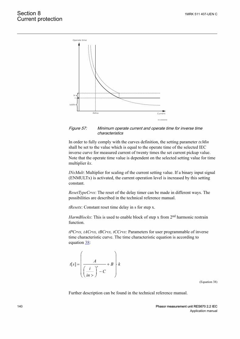
IMinx
Operate time
Current
tx
txMin
IEC10000058
IEC10000058 V2 EN-US
Figure 57: Minimum operate current and operate time for inverse timecharacteristics
In order to fully comply with the curves definition, the setting parameter txMinshall be set to the value which is equal to the operate time of the selected IECinverse curve for measured current of twenty times the set current pickup value.Note that the operate time value is dependent on the selected setting value for timemultiplier kx.
INxMult: Multiplier for scaling of the current setting value. If a binary input signal(ENMULTx) is activated, the current operation level is increased by this settingconstant.
ResetTypeCrvx: The reset of the delay timer can be made in different ways. Thepossibilities are described in the technical reference manual.
tResetx: Constant reset time delay in s for step x.
HarmBlockx: This is used to enable block of step x from 2nd harmonic restrainfunction.
tPCrvx, tACrvx, tBCrvx, tCCrvx: Parameters for user programmable of inversetime characteristic curve. The time characteristic equation is according toequation 38:
[ ] = + ×
->
æ öç ÷ç ÷ç ÷æ ö
ç ÷ç ÷è øè ø
p
At s B k
iC
inEQUATION1189 V1 EN-US (Equation 38)
Further description can be found in the technical reference manual.
Section 8 1MRK 511 407-UEN CCurrent protection
140 Phasor measurement unit RES670 2.2 IECApplication manual
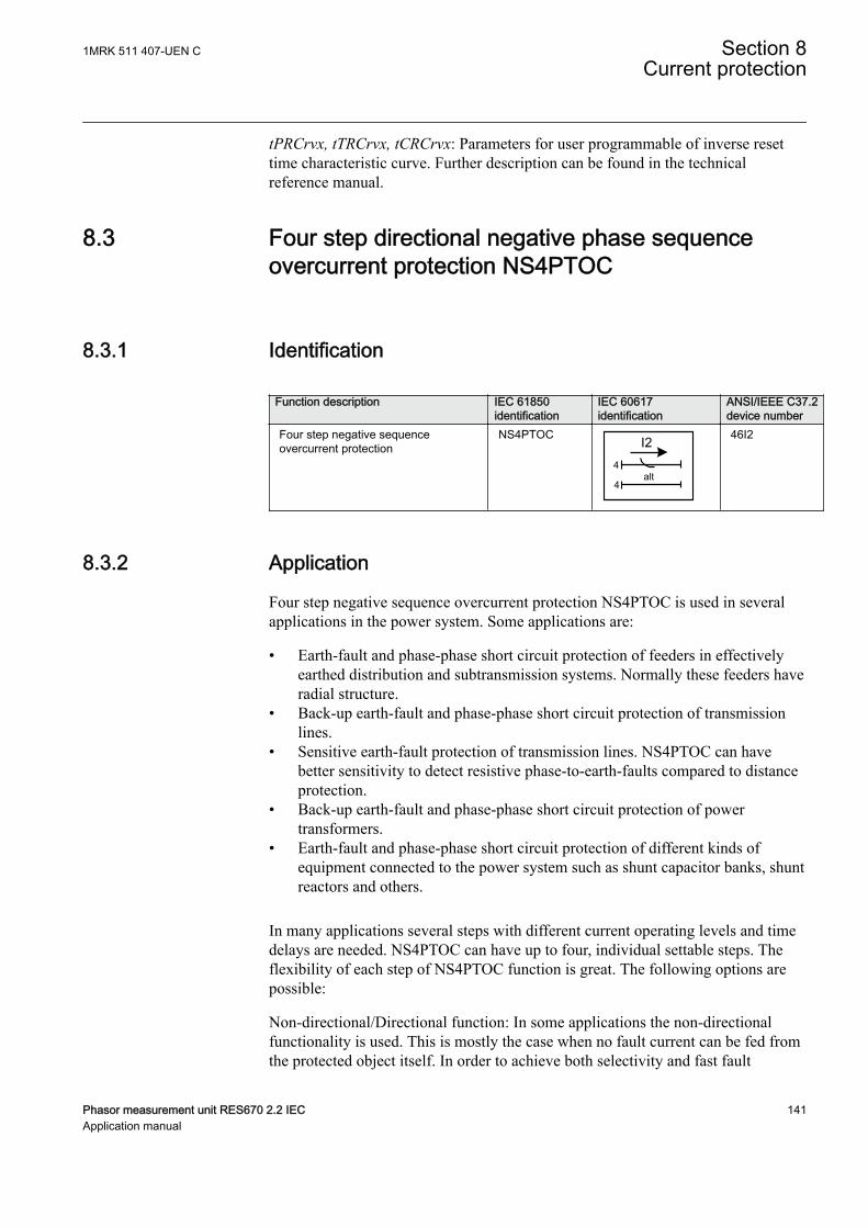
tPRCrvx, tTRCrvx, tCRCrvx: Parameters for user programmable of inverse resettime characteristic curve. Further description can be found in the technicalreference manual.
8.3 Four step directional negative phase sequenceovercurrent protection NS4PTOC
GUID-E8CF8AA2-AF54-4FD1-A379-3E55DCA2FA3A v1
8.3.1 IdentificationGUID-E1720ADA-7F80-4F2C-82A1-EF2C9EF6A4B4 v1
Function description IEC 61850identification
IEC 60617identification
ANSI/IEEE C37.2device number
Four step negative sequenceovercurrent protection
NS4PTOC I24
4alt
IEC10000053 V1 EN-US
46I2
8.3.2 ApplicationGUID-343023F8-AFE3-41C2-8440-1779DD7F5621 v2
Four step negative sequence overcurrent protection NS4PTOC is used in severalapplications in the power system. Some applications are:
• Earth-fault and phase-phase short circuit protection of feeders in effectivelyearthed distribution and subtransmission systems. Normally these feeders haveradial structure.
• Back-up earth-fault and phase-phase short circuit protection of transmissionlines.
• Sensitive earth-fault protection of transmission lines. NS4PTOC can havebetter sensitivity to detect resistive phase-to-earth-faults compared to distanceprotection.
• Back-up earth-fault and phase-phase short circuit protection of powertransformers.
• Earth-fault and phase-phase short circuit protection of different kinds ofequipment connected to the power system such as shunt capacitor banks, shuntreactors and others.
In many applications several steps with different current operating levels and timedelays are needed. NS4PTOC can have up to four, individual settable steps. Theflexibility of each step of NS4PTOC function is great. The following options arepossible:
Non-directional/Directional function: In some applications the non-directionalfunctionality is used. This is mostly the case when no fault current can be fed fromthe protected object itself. In order to achieve both selectivity and fast fault
1MRK 511 407-UEN C Section 8Current protection
Phasor measurement unit RES670 2.2 IEC 141Application manual
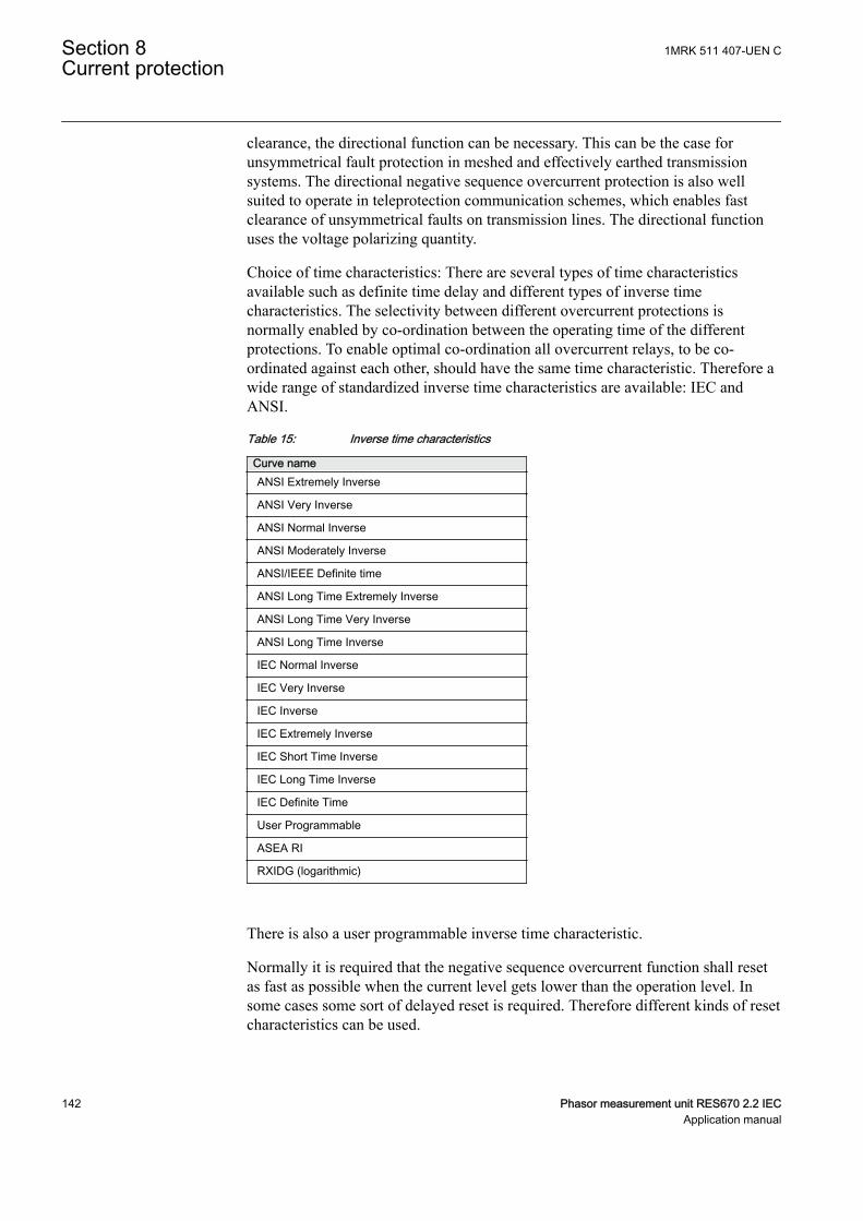
clearance, the directional function can be necessary. This can be the case forunsymmetrical fault protection in meshed and effectively earthed transmissionsystems. The directional negative sequence overcurrent protection is also wellsuited to operate in teleprotection communication schemes, which enables fastclearance of unsymmetrical faults on transmission lines. The directional functionuses the voltage polarizing quantity.
Choice of time characteristics: There are several types of time characteristicsavailable such as definite time delay and different types of inverse timecharacteristics. The selectivity between different overcurrent protections isnormally enabled by co-ordination between the operating time of the differentprotections. To enable optimal co-ordination all overcurrent relays, to be co-ordinated against each other, should have the same time characteristic. Therefore awide range of standardized inverse time characteristics are available: IEC andANSI.
Table 15: Inverse time characteristics
Curve nameANSI Extremely Inverse
ANSI Very Inverse
ANSI Normal Inverse
ANSI Moderately Inverse
ANSI/IEEE Definite time
ANSI Long Time Extremely Inverse
ANSI Long Time Very Inverse
ANSI Long Time Inverse
IEC Normal Inverse
IEC Very Inverse
IEC Inverse
IEC Extremely Inverse
IEC Short Time Inverse
IEC Long Time Inverse
IEC Definite Time
User Programmable
ASEA RI
RXIDG (logarithmic)
There is also a user programmable inverse time characteristic.
Normally it is required that the negative sequence overcurrent function shall resetas fast as possible when the current level gets lower than the operation level. Insome cases some sort of delayed reset is required. Therefore different kinds of resetcharacteristics can be used.
Section 8 1MRK 511 407-UEN CCurrent protection
142 Phasor measurement unit RES670 2.2 IECApplication manual

For some protection applications there can be a need to change the currentoperating level for some time. Therefore there is a possibility to give a setting of amultiplication factor IxMult to the negative sequence current pick-up level. Thismultiplication factor is activated from a binary input signal ENMULTx to thefunction.
8.3.3 Setting guidelinesGUID-460D6C58-598C-421E-AA9E-FD240210A6CC v3
The parameters for Four step negative sequence overcurrent protection NS4PTOCare set via the local HMI or Protection and Control Manager (PCM600).
The following settings can be done for the four step negative sequence overcurrentprotection:
Operation: Sets the protection to On or Off.
Common base IED values for the primary current (IBase), primary voltage (UBase)and primary power (SBase) are set in global base values for settings functionGBASVAL.
GlobalBaseSel: Selects the global base value group used by the function to defineIBase, UBase and SBase as applicable.
GUID-F7AA2194-4D1C-4475-8853-C7D064912614 v4
When inverse time overcurrent characteristic is selected, theoperate time of the stage will be the sum of the inverse time delayand the set definite time delay. Thus, if only the inverse time delayis required, it is important to set the definite time delay for thatstage to zero.
8.3.3.1 Settings for each stepGUID-CFB327EF-C5C4-44B5-AB4B-9C2916355FC5 v5
x means step 1, 2, 3 and 4.
DirModeSelx: The directional mode of step x. Possible settings are off/nondirectional/forward/reverse.
Characteristx: Selection of time characteristic for step x. Definite time delay anddifferent types of inverse time characteristics are available.
Table 16: Inverse time characteristics
Curve nameANSI Extremely Inverse
ANSI Very Inverse
ANSI Normal Inverse
Table continues on next page
1MRK 511 407-UEN C Section 8Current protection
Phasor measurement unit RES670 2.2 IEC 143Application manual
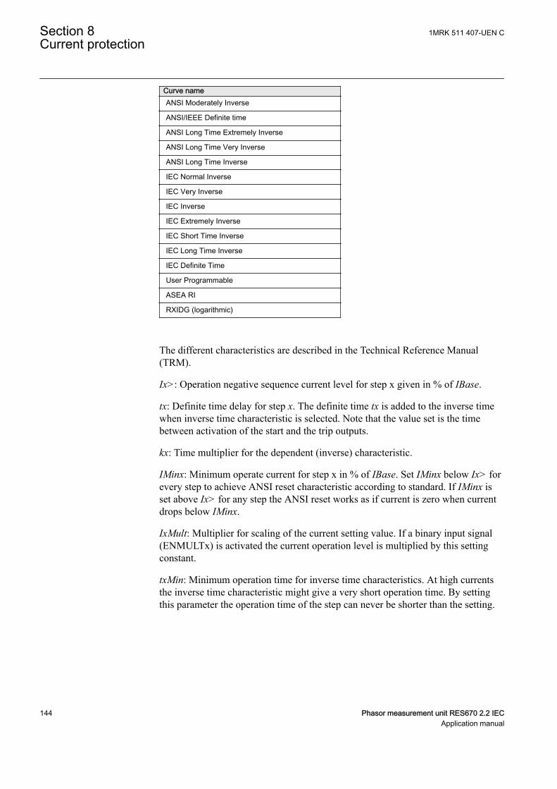
Curve nameANSI Moderately Inverse
ANSI/IEEE Definite time
ANSI Long Time Extremely Inverse
ANSI Long Time Very Inverse
ANSI Long Time Inverse
IEC Normal Inverse
IEC Very Inverse
IEC Inverse
IEC Extremely Inverse
IEC Short Time Inverse
IEC Long Time Inverse
IEC Definite Time
User Programmable
ASEA RI
RXIDG (logarithmic)
The different characteristics are described in the Technical Reference Manual(TRM).
Ix>: Operation negative sequence current level for step x given in % of IBase.
tx: Definite time delay for step x. The definite time tx is added to the inverse timewhen inverse time characteristic is selected. Note that the value set is the timebetween activation of the start and the trip outputs.
kx: Time multiplier for the dependent (inverse) characteristic.
IMinx: Minimum operate current for step x in % of IBase. Set IMinx below Ix> forevery step to achieve ANSI reset characteristic according to standard. If IMinx isset above Ix> for any step the ANSI reset works as if current is zero when currentdrops below IMinx.
IxMult: Multiplier for scaling of the current setting value. If a binary input signal(ENMULTx) is activated the current operation level is multiplied by this settingconstant.
txMin: Minimum operation time for inverse time characteristics. At high currentsthe inverse time characteristic might give a very short operation time. By settingthis parameter the operation time of the step can never be shorter than the setting.
Section 8 1MRK 511 407-UEN CCurrent protection
144 Phasor measurement unit RES670 2.2 IECApplication manual
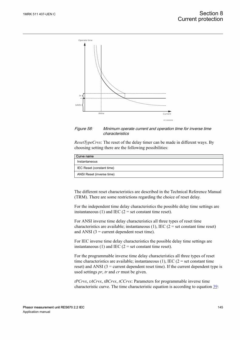
IMinx
Operate time
Current
tx
txMin
IEC10000058
IEC10000058 V2 EN-US
Figure 58: Minimum operate current and operation time for inverse timecharacteristics
ResetTypeCrvx: The reset of the delay timer can be made in different ways. Bychoosing setting there are the following possibilities:
Curve nameInstantaneous
IEC Reset (constant time)
ANSI Reset (inverse time)
The different reset characteristics are described in the Technical Reference Manual(TRM). There are some restrictions regarding the choice of reset delay.
For the independent time delay characteristics the possible delay time settings areinstantaneous (1) and IEC (2 = set constant time reset).
For ANSI inverse time delay characteristics all three types of reset timecharacteristics are available; instantaneous (1), IEC (2 = set constant time reset)and ANSI (3 = current dependent reset time).
For IEC inverse time delay characteristics the possible delay time settings areinstantaneous (1) and IEC (2 = set constant time reset).
For the programmable inverse time delay characteristics all three types of resettime characteristics are available; instantaneous (1), IEC (2 = set constant timereset) and ANSI (3 = current dependent reset time). If the current dependent type isused settings pr, tr and cr must be given.
tPCrvx, tACrvx, tBCrvx, tCCrvx: Parameters for programmable inverse timecharacteristic curve. The time characteristic equation is according to equation 39:
1MRK 511 407-UEN C Section 8Current protection
Phasor measurement unit RES670 2.2 IEC 145Application manual

[ ] = + ×
->
æ öç ÷ç ÷ç ÷æ ö
ç ÷ç ÷è øè ø
p
At s B k
iC
inEQUATION1189 V1 EN-US (Equation 39)
Further description can be found in the Technical reference manual (TRM).
tPRCrvx, tTRCrvx, tCRCrvx: Parameters for customer creation of inverse reset timecharacteristic curve. Further description can be found in the Technical ReferenceManual.
8.3.3.2 Common settings for all stepsGUID-A00A942B-E760-42EE-8FEB-F723426783F3 v1
x means step 1, 2, 3 and 4.
AngleRCA: Relay characteristic angle given in degrees. This angle is defined asshown in figure 59. The angle is defined positive when the residual current lags thereference voltage (Upol = -U2)
Section 8 1MRK 511 407-UEN CCurrent protection
146 Phasor measurement unit RES670 2.2 IECApplication manual
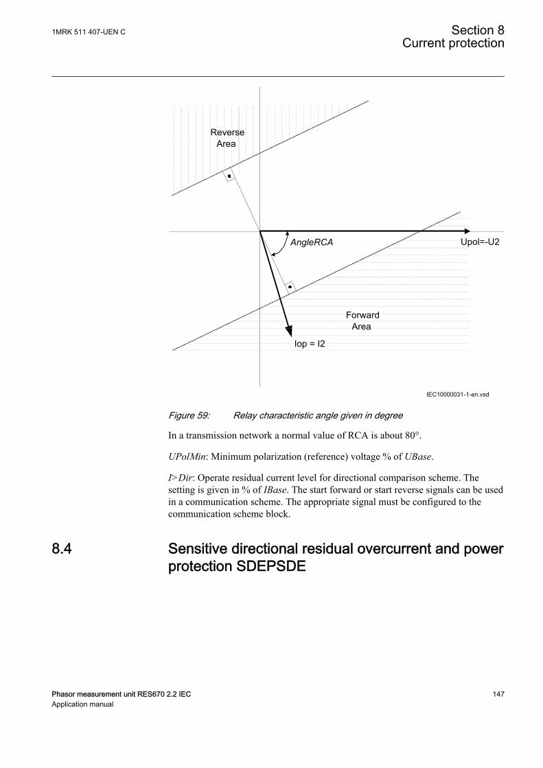
AngleRCA
ForwardArea
Iop = I2
Upol=-U2
ReverseArea
IEC10000031-1-en.vsdIEC10000031 V1 EN-US
Figure 59: Relay characteristic angle given in degree
In a transmission network a normal value of RCA is about 80°.
UPolMin: Minimum polarization (reference) voltage % of UBase.
I>Dir: Operate residual current level for directional comparison scheme. Thesetting is given in % of IBase. The start forward or start reverse signals can be usedin a communication scheme. The appropriate signal must be configured to thecommunication scheme block.
8.4 Sensitive directional residual overcurrent and powerprotection SDEPSDE
SEMOD171436-1 v4
1MRK 511 407-UEN C Section 8Current protection
Phasor measurement unit RES670 2.2 IEC 147Application manual
8.4.1 IdentificationSEMOD172025-2 v4
Function description IEC 61850identification
IEC 60617identification
ANSI/IEEE C37.2device number
Sensitive directional residual overcurrent and power protection
SDEPSDE - 67N
8.4.2 ApplicationSEMOD171959-4 v12
In networks with high impedance earthing, the phase-to-earth fault current issignificantly smaller than the short circuit currents. Another difficulty for earthfault protection is that the magnitude of the phase-to-earth fault current is almostindependent of the fault location in the network.
Directional residual current can be used to detect and give selective trip of phase-to-earth faults in high impedance earthed networks. The protection uses theresidual current component 3I0 · cos φ, where φ is the angle between the residualcurrent and the residual voltage (-3U0), compensated with a characteristic angle.Alternatively, the function can be set to strict 3I0 level with a check of angle φ.
Directional residual power can also be used to detect and give selective trip ofphase-to-earth faults in high impedance earthed networks. The protection uses theresidual power component 3I0 · 3U0 · cos φ, where φ is the angle between theresidual current and the reference residual voltage, compensated with acharacteristic angle.
A normal non-directional residual current function can also be used with definite orinverse time delay.
A backup neutral point voltage function is also available for non-directionalresidual overvoltage protection.
In an isolated network, that is, the network is only coupled to earth via thecapacitances between the phase conductors and earth, the residual current alwayshas -90º phase shift compared to the residual voltage (3U0). The characteristicangle is chosen to -90º in such a network.
In resistance earthed networks or in Petersen coil earthed, with a parallel resistor,the active residual current component (in phase with the residual voltage) should beused for the earth fault detection. In such networks, the characteristic angle ischosen to 0º.
As the amplitude of the residual current is independent of the fault location, theselectivity of the earth fault protection is achieved by time selectivity.
When should the sensitive directional residual overcurrent protection be used andwhen should the sensitive directional residual power protection be used? Considerthe following:
Section 8 1MRK 511 407-UEN CCurrent protection
148 Phasor measurement unit RES670 2.2 IECApplication manual

• Sensitive directional residual overcurrent protection gives possibility for bettersensitivity. The setting possibilities of this function are down to 0.25 % ofIBase, 1 A or 5 A. This sensitivity is in most cases sufficient in highimpedance network applications, if the measuring CT ratio is not too high.
• Sensitive directional residual power protection gives possibility to use inversetime characteristics. This is applicable in large high impedance earthednetworks, with large capacitive earth fault currents. In such networks, theactive fault current would be small and by using sensitive directional residualpower protection, the operating quantity is elevated. Therefore, betterpossibility to detect earth faults. In addition, in low impedance earthednetworks, the inverse time characteristic gives better time-selectivity in case ofhigh zero-resistive fault currents.
Phase currents
Phase-ground
voltages
IN
UN
IEC13000013-1-en.vsdIEC13000013 V1 EN-US
Figure 60: Connection of SDEPSDE to analog preprocessing function block
Overcurrent functionality uses true 3I0, i.e. sum of GRPxL1, GRPxL2 andGRPxL3. For 3I0 to be calculated, connection is needed to all three phase inputs.
Directional and power functionality uses IN and UN. If a connection is made toGRPxN this signal is used, else if connection is made to all inputs GRPxL1,GRPxL2 and GRPxL3 the internally calculated sum of these inputs (3I0 and 3U0)will be used.
8.4.3 Setting guidelinesSEMOD171961-4 v10
The sensitive earth fault protection is intended to be used in high impedanceearthed systems, or in systems with resistive earthing where the neutral pointresistor gives an earth fault current larger than what normal high impedance givesbut smaller than the phase-to-phase short circuit current.
1MRK 511 407-UEN C Section 8Current protection
Phasor measurement unit RES670 2.2 IEC 149Application manual
In a high impedance system the fault current is assumed to be limited by the systemzero sequence shunt impedance to earth and the fault resistance only. All the seriesimpedances in the system are assumed to be zero.
In the setting of earth fault protection, in a high impedance earthed system, theneutral point voltage (zero sequence voltage) and the earth fault current will becalculated at the desired sensitivity (fault resistance). The complex neutral pointvoltage (zero sequence) can be calculated as:
phase
0f
0
UU
3 R1
Z
=×
+
EQUATION1943 V1 EN-US (Equation 40)
Where
Uphase is the phase voltage in the fault point before the fault,
Rf is the resistance to earth in the fault point and
Z0 is the system zero sequence impedance to earth
The fault current, in the fault point, can be calculated as:
phase
j 0
0 f
3 UI 3I
Z 3 R
×= =
+ ×
EQUATION1944 V1 EN-US (Equation 41)
The impedance Z0 is dependent on the system earthing. In an isolated system(without neutral point apparatus) the impedance is equal to the capacitive couplingbetween the phase conductors and earth:
phase
0 c
j
3 UZ jX j
I
×= - = -
EQUATION1945 V1 EN-US (Equation 42)
Where
Ij is the capacitive earth fault current at a non-resistive phase-to-earth fault
Xc is the capacitive reactance to earth
In a system with a neutral point resistor (resistance earthed system) the impedanceZ0 can be calculated as:
Section 8 1MRK 511 407-UEN CCurrent protection
150 Phasor measurement unit RES670 2.2 IECApplication manual
c n0
c n
jX 3RZ
jX 3R
- ×=
- +
EQUATION1946 V1 EN-US (Equation 43)
Where
Rn is the resistance of the neutral point resistor
In many systems there is also a neutral point reactor (Petersen coil) connected toone or more transformer neutral points. In such a system the impedance Z0 can becalculated as:
( )n n c
0 c n n
n c n n c
9R X XZ jX // 3R // j3X
3X X j3R 3X X= - =
+ × -
EQUATION1947 V1 EN-US (Equation 44)
Where
Xn is the reactance of the Petersen coil. If the Petersen coil is well tuned we have 3Xn = Xc Inthis case the impedance Z0 will be: Z0 = 3Rn
Now consider a system with an earthing via a resistor giving higher earth faultcurrent than the high impedance earthing. The series impedances in the system canno longer be neglected. The system with a single phase to earth fault can bedescribed as in Figure 61.
1MRK 511 407-UEN C Section 8Current protection
Phasor measurement unit RES670 2.2 IEC 151Application manual
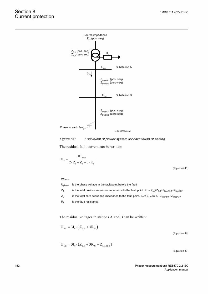
Substation A
Substation B
ZlineAB,1 (pos. seq)ZlineAB,0 (zero seq)
ZlineBC,1 (pos. seq)ZlineBC,0 (zero seq)
U0A
U0B
3I0
Phase to earth fault
RNZT,1 (pos. seq)ZT,0 (zero seq)
Source impedanceZsc (pos. seq)
en06000654.vsdIEC06000654 V1 EN-US
Figure 61: Equivalent of power system for calculation of setting
The residual fault current can be written:
phase
0
1 0 f
3U3I
2 Z Z 3 R=
× + + ×
EQUATION1948 V1 EN-US (Equation 45)
Where
Uphase is the phase voltage in the fault point before the fault
Z1 is the total positive sequence impedance to the fault point. Z1 = Zsc+ZT,1+ZlineAB,1+ZlineBC,1
Z0 is the total zero sequence impedance to the fault point. Z0 = ZT,0+3RN+ZlineAB,0+ZlineBC,0
Rf is the fault resistance.
The residual voltages in stations A and B can be written:
( )0 A 0 T,0 NU 3I Z 3R= × +
EQUATION1949 V1 EN-US (Equation 46)
OB 0 T,0 N lineAB,0U 3I (Z 3R Z )= × + +
EQUATION1950 V1 EN-US (Equation 47)
Section 8 1MRK 511 407-UEN CCurrent protection
152 Phasor measurement unit RES670 2.2 IECApplication manual
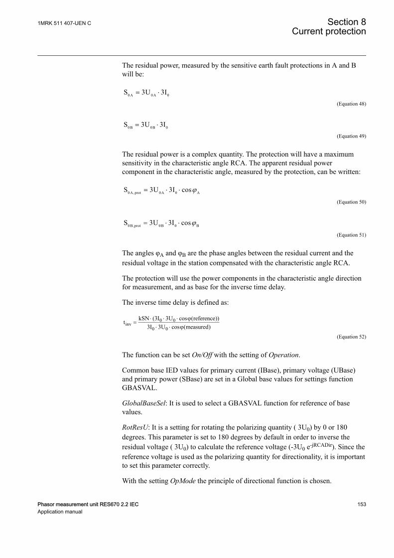
The residual power, measured by the sensitive earth fault protections in A and Bwill be:
0 A 0A 0S 3U 3I= ×
EQUATION1951 V1 EN-US (Equation 48)
0 B 0B 0S 3U 3I= ×
EQUATION1952 V1 EN-US (Equation 49)
The residual power is a complex quantity. The protection will have a maximumsensitivity in the characteristic angle RCA. The apparent residual powercomponent in the characteristic angle, measured by the protection, can be written:
0 A ,prot 0A 0 AS 3U 3I cosj= × ×
EQUATION1953 V1 EN-US (Equation 50)
0 B,prot 0B 0 BS 3U 3I cosj= × ×
EQUATION1954 V1 EN-US (Equation 51)
The angles φA and φB are the phase angles between the residual current and theresidual voltage in the station compensated with the characteristic angle RCA.
The protection will use the power components in the characteristic angle directionfor measurement, and as base for the inverse time delay.
The inverse time delay is defined as:
0 0inv
0 0
kSN (3I 3U cos (reference))t3I 3U cos (measured)
× × × j=
× × j
EQUATION1942 V2 EN-US (Equation 52)
The function can be set On/Off with the setting of Operation.
Common base IED values for primary current (IBase), primary voltage (UBase)and primary power (SBase) are set in a Global base values for settings functionGBASVAL.
GlobalBaseSel: It is used to select a GBASVAL function for reference of basevalues.
RotResU: It is a setting for rotating the polarizing quantity ( 3U0) by 0 or 180degrees. This parameter is set to 180 degrees by default in order to inverse theresidual voltage ( 3U0) to calculate the reference voltage (-3U0 e-jRCADir). Since thereference voltage is used as the polarizing quantity for directionality, it is importantto set this parameter correctly.
With the setting OpMode the principle of directional function is chosen.
1MRK 511 407-UEN C Section 8Current protection
Phasor measurement unit RES670 2.2 IEC 153Application manual
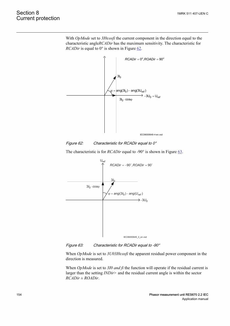
With OpMode set to 3I0cosfi the current component in the direction equal to thecharacteristic angleRCADir has the maximum sensitivity. The characteristic forRCADir is equal to 0° is shown in Figure 62.
= =o o0 , 90RCADir ROADir
03I
j = -0 refang(3I ) ang(3U )- =0 ref3U U
03I cos× j
IEC06000648-4-en.vsdIEC06000648 V4 EN-US
Figure 62: Characteristic for RCADir equal to 0°
The characteristic is for RCADir equal to -90° is shown in Figure 63.
IEC06000649_3_en.vsd
refU= − = 90 , 90RCADir ROADir
03I
03 ⋅ ϕI cos
ϕ = −0(3 ) ( )refang I ang U
− 03U
IEC06000649 V3 EN-US
Figure 63: Characteristic for RCADir equal to -90°
When OpMode is set to 3U03I0cosfi the apparent residual power component in thedirection is measured.
When OpMode is set to 3I0 and fi the function will operate if the residual current islarger than the setting INDir> and the residual current angle is within the sectorRCADir ± ROADir.
Section 8 1MRK 511 407-UEN CCurrent protection
154 Phasor measurement unit RES670 2.2 IECApplication manual
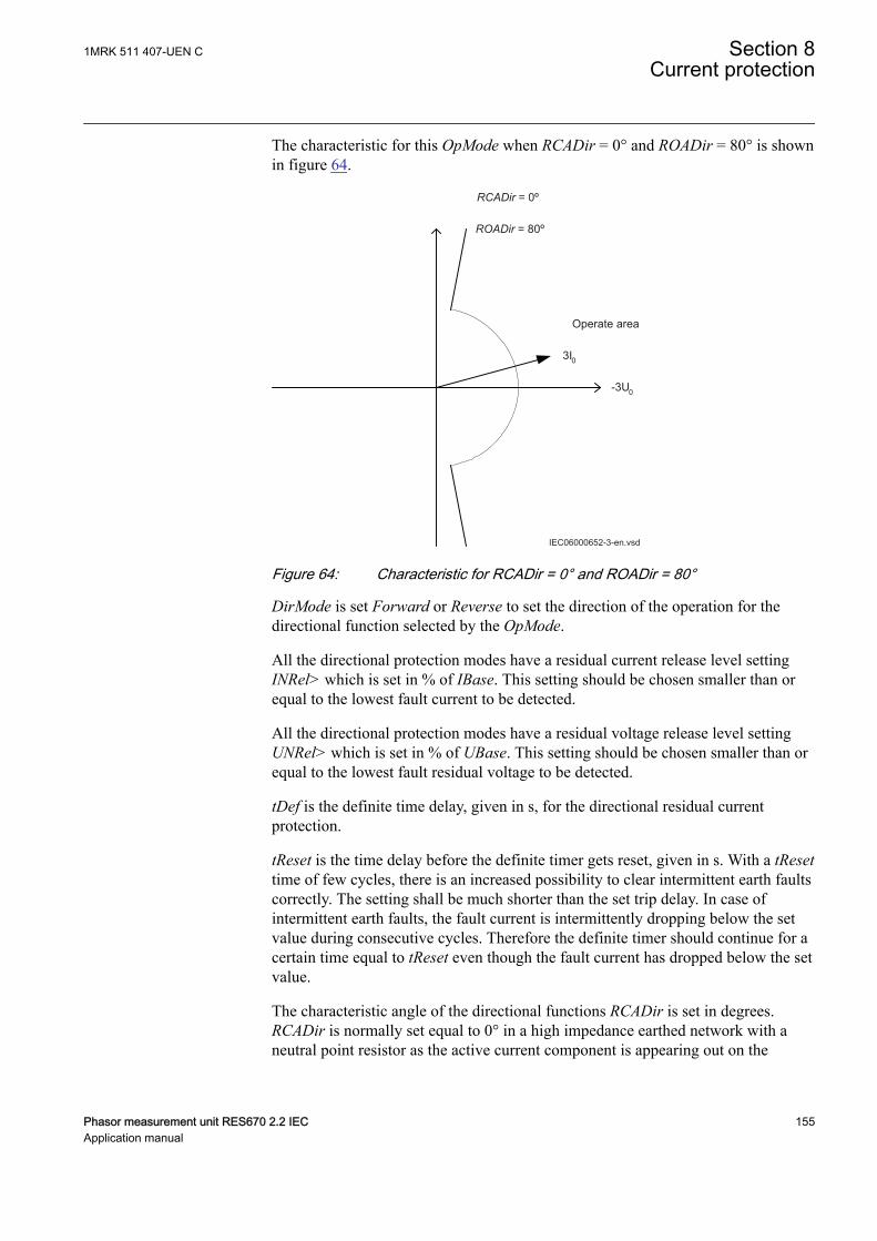
The characteristic for this OpMode when RCADir = 0° and ROADir = 80° is shownin figure 64.
-3U0
Operate area
3I0
RCADir = 0º
ROADir = 80º
IEC06000652-3-en.vsdIEC06000652 V3 EN-US
Figure 64: Characteristic for RCADir = 0° and ROADir = 80°
DirMode is set Forward or Reverse to set the direction of the operation for thedirectional function selected by the OpMode.
All the directional protection modes have a residual current release level settingINRel> which is set in % of IBase. This setting should be chosen smaller than orequal to the lowest fault current to be detected.
All the directional protection modes have a residual voltage release level settingUNRel> which is set in % of UBase. This setting should be chosen smaller than orequal to the lowest fault residual voltage to be detected.
tDef is the definite time delay, given in s, for the directional residual currentprotection.
tReset is the time delay before the definite timer gets reset, given in s. With a tResettime of few cycles, there is an increased possibility to clear intermittent earth faultscorrectly. The setting shall be much shorter than the set trip delay. In case ofintermittent earth faults, the fault current is intermittently dropping below the setvalue during consecutive cycles. Therefore the definite timer should continue for acertain time equal to tReset even though the fault current has dropped below the setvalue.
The characteristic angle of the directional functions RCADir is set in degrees.RCADir is normally set equal to 0° in a high impedance earthed network with aneutral point resistor as the active current component is appearing out on the
1MRK 511 407-UEN C Section 8Current protection
Phasor measurement unit RES670 2.2 IEC 155Application manual

faulted feeder only. RCADir is set equal to -90° in an isolated network as allcurrents are mainly capacitive.
ROADir is Relay Operating Angle. ROADir is identifying a window around thereference direction in order to detect directionality. ROADir is set in degrees. Forangles differing more than ROADir from RCADir the function is blocked. Thesetting can be used to prevent unwanted operation for non-faulted feeders, withlarge capacitive earth fault current contributions, due to CT phase angle error.
INCosPhi> is the operate current level for the directional function when OpModeis set 3I0Cosfi. The setting is given in % of IBase. The setting should be based oncalculation of the active or capacitive earth fault current at required sensitivity ofthe protection.
SN> is the operate power level for the directional function when OpMode is set3I03U0Cosfi. The setting is given in % of SBase. The setting should be based oncalculation of the active or capacitive earth fault residual power at requiredsensitivity of the protection.
The input transformer for the Sensitive directional residual over current and powerprotection function has the same short circuit capacity as the phase currenttransformers. Hence, there is no specific requirement for the external CT core, i.e.any CT core can be used.
If the time delay for residual power is chosen the delay time is dependent on twosetting parameters. SRef is the reference residual power, given in % of SBase. kSNis the time multiplier. The time delay will follow the following expression:
inv0 0
kSN Sreft
3I 3U cos (measured)j×
=× ×
EQUATION1957 V1 EN-US (Equation 53)
INDir> is the operate current level for the directional function when OpMode is set3I0 and fi. The setting is given in % of IBase. The setting should be based oncalculation of the earth fault current at required sensitivity of the protection.
OpINNonDir> is set On to activate the non-directional residual current protection.
INNonDir> is the operate current level for the non-directional function. The settingis given in % of IBase. This function can be used for detection and clearance ofcross-country faults in a shorter time than for the directional function. The currentsetting should be larger than the maximum single-phase residual current on theprotected line.
TimeChar is the selection of time delay characteristic for the non-directionalresidual current protection. Definite time delay and different types of inverse timecharacteristics are available:
Section 8 1MRK 511 407-UEN CCurrent protection
156 Phasor measurement unit RES670 2.2 IECApplication manual

Table 17: Inverse time characteristics
Curve nameANSI Extremely Inverse
ANSI Very Inverse
ANSI Normal Inverse
ANSI Moderately Inverse
ANSI/IEEE Definite time
ANSI Long Time Extremely Inverse
ANSI Long Time Very Inverse
ANSI Long Time Inverse
IEC Normal Inverse
IEC Very Inverse
IEC Inverse
IEC Extremely Inverse
IEC Short Time Inverse
IEC Long Time Inverse
IEC Definite Time
User Programmable
ASEA RI
RXIDG (logarithmic)
See chapter “Inverse time characteristics” in Technical Manual for the descriptionof different characteristics
tPCrv, tACrv, tBCrv, tCCrv: Parameters for customer creation of inverse timecharacteristic curve (Curve type = 17). The time characteristic equation is:
[ ] = + ×
->
æ öç ÷ç ÷ç ÷æ ö
ç ÷ç ÷è øè ø
p
At s B InMult
iC
inEQUATION1958 V1 EN-US (Equation 54)
tINNonDir is the definite time delay for the non directional earth fault currentprotection, given in s.
OpUN> is set On to activate the trip function of the residual over voltageprotection.
tUN is the definite time delay for the trip function of the residual voltageprotection, given in s.
1MRK 511 407-UEN C Section 8Current protection
Phasor measurement unit RES670 2.2 IEC 157Application manual
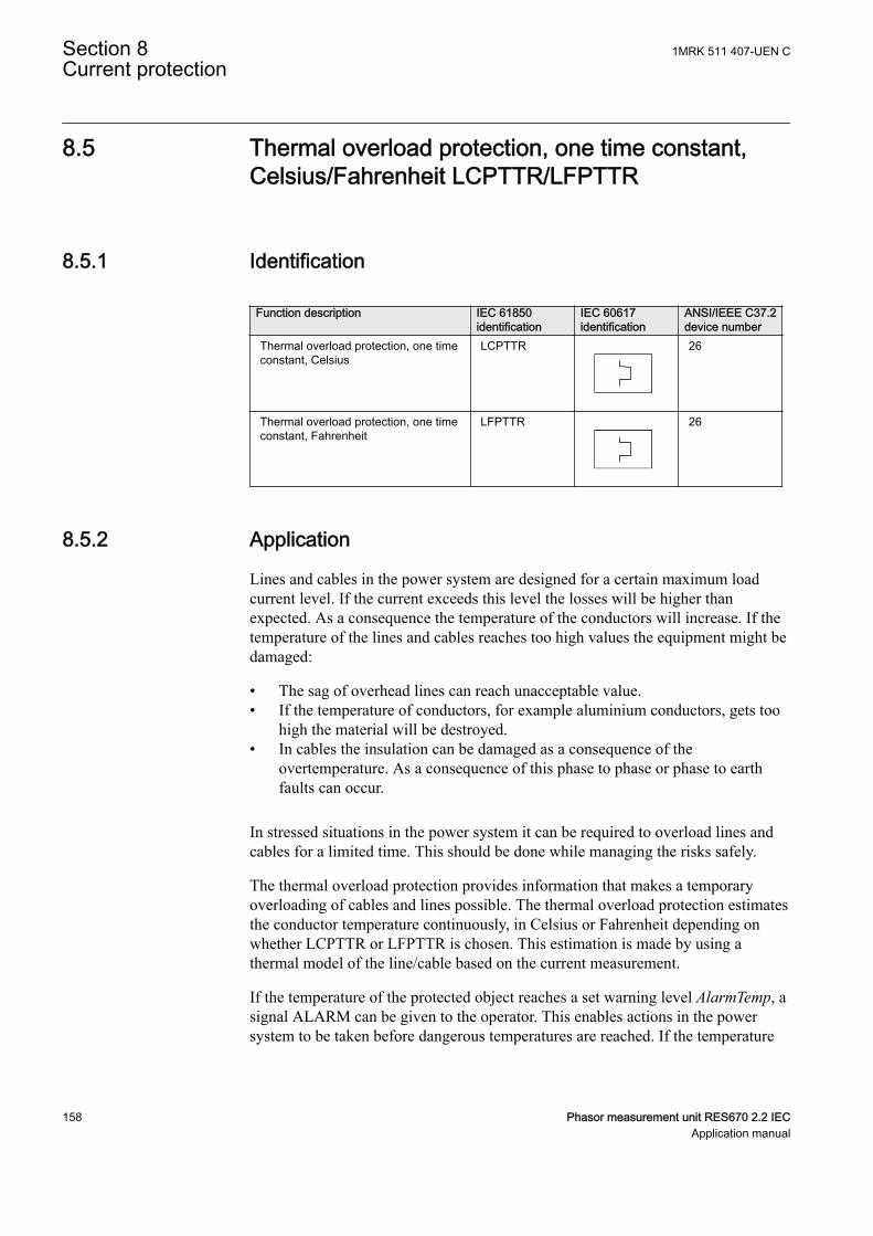
8.5 Thermal overload protection, one time constant,Celsius/Fahrenheit LCPTTR/LFPTTR
IP14512-1 v7
8.5.1 IdentificationM17106-1 v7
Function description IEC 61850identification
IEC 60617identification
ANSI/IEEE C37.2device number
Thermal overload protection, one timeconstant, Celsius
LCPTTR 26
Thermal overload protection, one timeconstant, Fahrenheit
LFPTTR 26
8.5.2 ApplicationM15283-3 v9
Lines and cables in the power system are designed for a certain maximum loadcurrent level. If the current exceeds this level the losses will be higher thanexpected. As a consequence the temperature of the conductors will increase. If thetemperature of the lines and cables reaches too high values the equipment might bedamaged:
• The sag of overhead lines can reach unacceptable value.• If the temperature of conductors, for example aluminium conductors, gets too
high the material will be destroyed.• In cables the insulation can be damaged as a consequence of the
overtemperature. As a consequence of this phase to phase or phase to earthfaults can occur.
In stressed situations in the power system it can be required to overload lines andcables for a limited time. This should be done while managing the risks safely.
The thermal overload protection provides information that makes a temporaryoverloading of cables and lines possible. The thermal overload protection estimatesthe conductor temperature continuously, in Celsius or Fahrenheit depending onwhether LCPTTR or LFPTTR is chosen. This estimation is made by using athermal model of the line/cable based on the current measurement.
If the temperature of the protected object reaches a set warning level AlarmTemp, asignal ALARM can be given to the operator. This enables actions in the powersystem to be taken before dangerous temperatures are reached. If the temperature
Section 8 1MRK 511 407-UEN CCurrent protection
158 Phasor measurement unit RES670 2.2 IECApplication manual
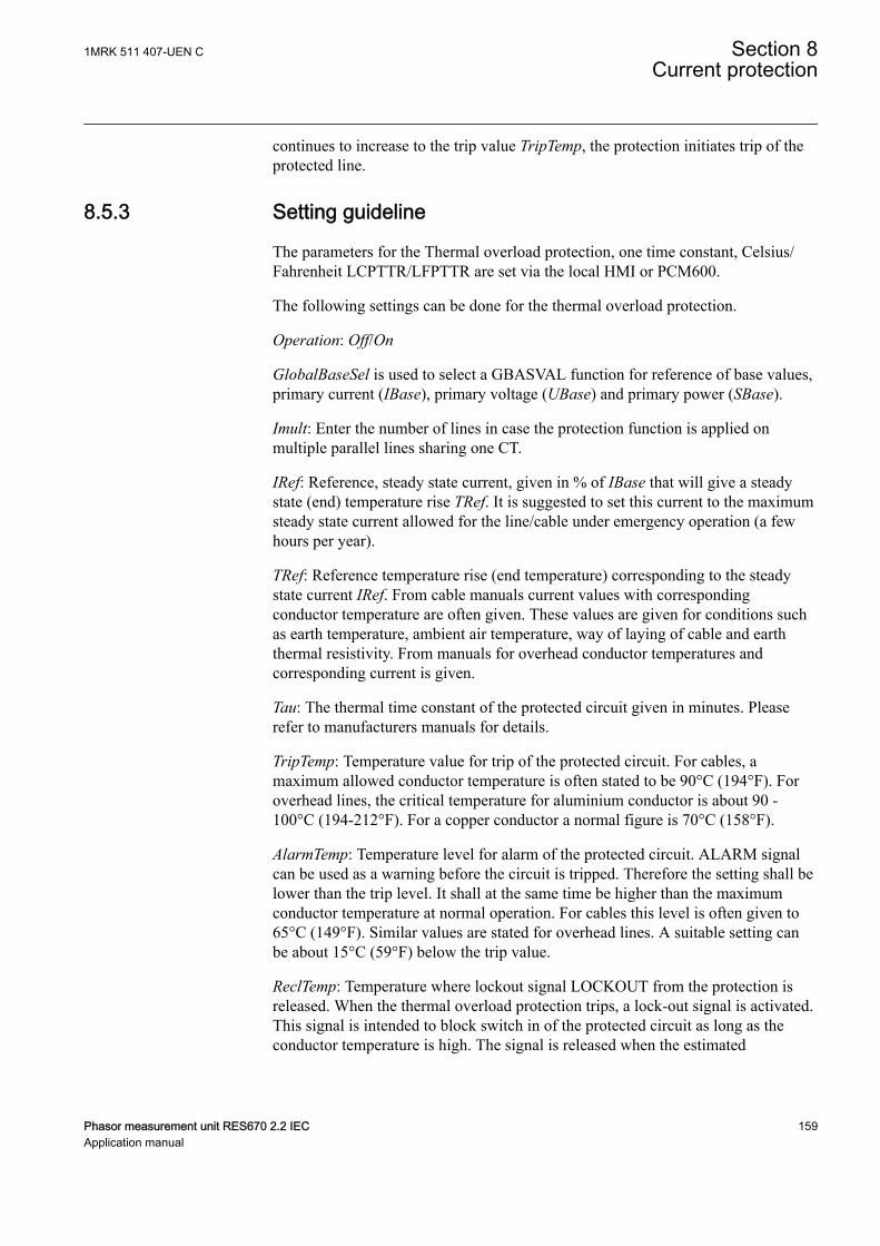
continues to increase to the trip value TripTemp, the protection initiates trip of theprotected line.
8.5.3 Setting guidelineIP14994-1 v1
M15094-3 v8
The parameters for the Thermal overload protection, one time constant, Celsius/Fahrenheit LCPTTR/LFPTTR are set via the local HMI or PCM600.
M15094-5 v10
The following settings can be done for the thermal overload protection.
Operation: Off/On
GlobalBaseSel is used to select a GBASVAL function for reference of base values,primary current (IBase), primary voltage (UBase) and primary power (SBase).
Imult: Enter the number of lines in case the protection function is applied onmultiple parallel lines sharing one CT.
IRef: Reference, steady state current, given in % of IBase that will give a steadystate (end) temperature rise TRef. It is suggested to set this current to the maximumsteady state current allowed for the line/cable under emergency operation (a fewhours per year).
TRef: Reference temperature rise (end temperature) corresponding to the steadystate current IRef. From cable manuals current values with correspondingconductor temperature are often given. These values are given for conditions suchas earth temperature, ambient air temperature, way of laying of cable and earththermal resistivity. From manuals for overhead conductor temperatures andcorresponding current is given.
Tau: The thermal time constant of the protected circuit given in minutes. Pleaserefer to manufacturers manuals for details.
TripTemp: Temperature value for trip of the protected circuit. For cables, amaximum allowed conductor temperature is often stated to be 90°C (194°F). Foroverhead lines, the critical temperature for aluminium conductor is about 90 -100°C (194-212°F). For a copper conductor a normal figure is 70°C (158°F).
AlarmTemp: Temperature level for alarm of the protected circuit. ALARM signalcan be used as a warning before the circuit is tripped. Therefore the setting shall belower than the trip level. It shall at the same time be higher than the maximumconductor temperature at normal operation. For cables this level is often given to65°C (149°F). Similar values are stated for overhead lines. A suitable setting canbe about 15°C (59°F) below the trip value.
ReclTemp: Temperature where lockout signal LOCKOUT from the protection isreleased. When the thermal overload protection trips, a lock-out signal is activated.This signal is intended to block switch in of the protected circuit as long as theconductor temperature is high. The signal is released when the estimated
1MRK 511 407-UEN C Section 8Current protection
Phasor measurement unit RES670 2.2 IEC 159Application manual
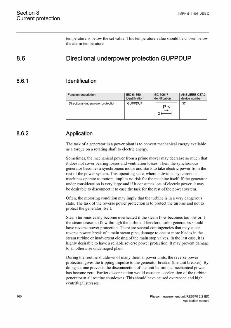
temperature is below the set value. This temperature value should be chosen belowthe alarm temperature.
8.6 Directional underpower protection GUPPDUPSEMOD156693-1 v4
8.6.1 IdentificationSEMOD158941-2 v4
Function description IEC 61850identification
IEC 60617identification
ANSI/IEEE C37.2device number
Directional underpower protection GUPPDUPP <
2SYMBOL-LL V2 EN-US
37
8.6.2 ApplicationSEMOD151283-4 v5
The task of a generator in a power plant is to convert mechanical energy availableas a torque on a rotating shaft to electric energy.
Sometimes, the mechanical power from a prime mover may decrease so much thatit does not cover bearing losses and ventilation losses. Then, the synchronousgenerator becomes a synchronous motor and starts to take electric power from therest of the power system. This operating state, where individual synchronousmachines operate as motors, implies no risk for the machine itself. If the generatorunder consideration is very large and if it consumes lots of electric power, it maybe desirable to disconnect it to ease the task for the rest of the power system.
Often, the motoring condition may imply that the turbine is in a very dangerousstate. The task of the reverse power protection is to protect the turbine and not toprotect the generator itself.
Steam turbines easily become overheated if the steam flow becomes too low or ifthe steam ceases to flow through the turbine. Therefore, turbo-generators shouldhave reverse power protection. There are several contingencies that may causereverse power: break of a main steam pipe, damage to one or more blades in thesteam turbine or inadvertent closing of the main stop valves. In the last case, it ishighly desirable to have a reliable reverse power protection. It may prevent damageto an otherwise undamaged plant.
During the routine shutdown of many thermal power units, the reverse powerprotection gives the tripping impulse to the generator breaker (the unit breaker). Bydoing so, one prevents the disconnection of the unit before the mechanical powerhas become zero. Earlier disconnection would cause an acceleration of the turbinegenerator at all routine shutdowns. This should have caused overspeed and highcentrifugal stresses.
Section 8 1MRK 511 407-UEN CCurrent protection
160 Phasor measurement unit RES670 2.2 IECApplication manual
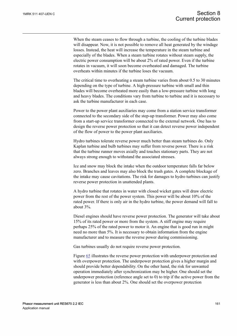
When the steam ceases to flow through a turbine, the cooling of the turbine bladeswill disappear. Now, it is not possible to remove all heat generated by the windagelosses. Instead, the heat will increase the temperature in the steam turbine andespecially of the blades. When a steam turbine rotates without steam supply, theelectric power consumption will be about 2% of rated power. Even if the turbinerotates in vacuum, it will soon become overheated and damaged. The turbineoverheats within minutes if the turbine loses the vacuum.
The critical time to overheating a steam turbine varies from about 0.5 to 30 minutesdepending on the type of turbine. A high-pressure turbine with small and thinblades will become overheated more easily than a low-pressure turbine with longand heavy blades. The conditions vary from turbine to turbine and it is necessary toask the turbine manufacturer in each case.
Power to the power plant auxiliaries may come from a station service transformerconnected to the secondary side of the step-up transformer. Power may also comefrom a start-up service transformer connected to the external network. One has todesign the reverse power protection so that it can detect reverse power independentof the flow of power to the power plant auxiliaries.
Hydro turbines tolerate reverse power much better than steam turbines do. OnlyKaplan turbine and bulb turbines may suffer from reverse power. There is a riskthat the turbine runner moves axially and touches stationary parts. They are notalways strong enough to withstand the associated stresses.
Ice and snow may block the intake when the outdoor temperature falls far belowzero. Branches and leaves may also block the trash gates. A complete blockage ofthe intake may cause cavitations. The risk for damages to hydro turbines can justifyreverse power protection in unattended plants.
A hydro turbine that rotates in water with closed wicket gates will draw electricpower from the rest of the power system. This power will be about 10% of therated power. If there is only air in the hydro turbine, the power demand will fall toabout 3%.
Diesel engines should have reverse power protection. The generator will take about15% of its rated power or more from the system. A stiff engine may requireperhaps 25% of the rated power to motor it. An engine that is good run in mightneed no more than 5%. It is necessary to obtain information from the enginemanufacturer and to measure the reverse power during commissioning.
Gas turbines usually do not require reverse power protection.
Figure 65 illustrates the reverse power protection with underpower protection andwith overpower protection. The underpower protection gives a higher margin andshould provide better dependability. On the other hand, the risk for unwantedoperation immediately after synchronization may be higher. One should set theunderpower protection (reference angle set to 0) to trip if the active power from thegenerator is less than about 2%. One should set the overpower protection
1MRK 511 407-UEN C Section 8Current protection
Phasor measurement unit RES670 2.2 IEC 161Application manual
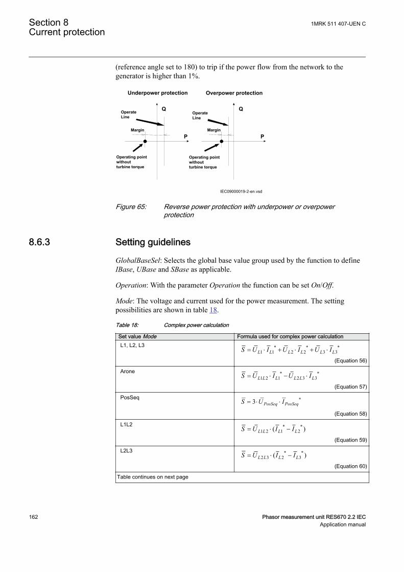
(reference angle set to 180) to trip if the power flow from the network to thegenerator is higher than 1%.
Underpower protection Overpower protection
Q Q
P P
Operating point without turbine torque
Margin Margin
OperateLine
OperateLine
Operating point without turbine torque
IEC09000019-2-en.vsdIEC09000019 V2 EN-US
Figure 65: Reverse power protection with underpower or overpowerprotection
8.6.3 Setting guidelinesSEMOD172134-4 v7
GlobalBaseSel: Selects the global base value group used by the function to defineIBase, UBase and SBase as applicable.
Operation: With the parameter Operation the function can be set On/Off.
Mode: The voltage and current used for the power measurement. The settingpossibilities are shown in table 18.
Table 18: Complex power calculation
Set value Mode Formula used for complex power calculationL1, L2, L3 * * *
1 1 2 2 3 3L L L L L LS U I U I U I= × + × + ×
EQUATION1697 V1 EN-US (Equation 56)
Arone * *1 2 1 2 3 3L L L L L LS U I U I= × - ×
EQUATION1698 V1 EN-US (Equation 57)
PosSeq *3 PosSeq PosSeqS U I= × ×
EQUATION1699 V1 EN-US (Equation 58)
L1L2 * *1 2 1 2( )L L L LS U I I= × -
EQUATION1700 V1 EN-US (Equation 59)
L2L3 * *2 3 2 3( )L L L LS U I I= × -
EQUATION1701 V1 EN-US (Equation 60)
Table continues on next page
Section 8 1MRK 511 407-UEN CCurrent protection
162 Phasor measurement unit RES670 2.2 IECApplication manual
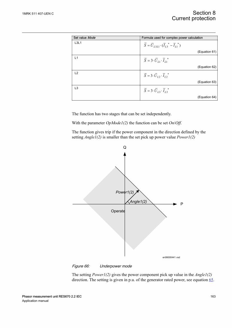
Set value Mode Formula used for complex power calculationL3L1 * *
3 1 3 1( )L L L LS U I I= × -
EQUATION1702 V1 EN-US (Equation 61)
L1 *1 13 L LS U I= × ×
EQUATION1703 V1 EN-US (Equation 62)
L2 *2 23 L LS U I= × ×
EQUATION1704 V1 EN-US (Equation 63)
L3 *3 33 L LS U I= × ×
EQUATION1705 V1 EN-US (Equation 64)
The function has two stages that can be set independently.
With the parameter OpMode1(2) the function can be set On/Off.
The function gives trip if the power component in the direction defined by thesetting Angle1(2) is smaller than the set pick up power value Power1(2)
Operate
Angle1(2)
Power1(2)
P
Q
en06000441.vsdIEC06000441 V1 EN-US
Figure 66: Underpower mode
The setting Power1(2) gives the power component pick up value in the Angle1(2)direction. The setting is given in p.u. of the generator rated power, see equation 65.
1MRK 511 407-UEN C Section 8Current protection
Phasor measurement unit RES670 2.2 IEC 163Application manual
Minimum recommended setting is 0.2% of SN when metering class CT inputs intothe IED are used.
3NS UBase IBase= × ×
EQUATION1708 V1 EN-US (Equation 65)
The setting Angle1(2) gives the characteristic angle giving maximum sensitivity ofthe power protection function. The setting is given in degrees. For active power theset angle should be 0° or 180°. 0° should be used for generator low forward activepower protection.
OperateAngle1(2) = 0°
Power1(2)
P
Q
en06000556.vsdIEC06000556 V1 EN-US
Figure 67: For low forward power the set angle should be 0° in theunderpower function
TripDelay1(2) is set in seconds to give the time delay for trip of the stage after pickup.
Hysteresis1(2) is given in p.u. of generator rated power according to equation 66.
3NS UBase IBase= × ×
EQUATION1708 V1 EN-US (Equation 66)
The drop out power will be Power1(2) + Hysteresis1(2).
The possibility to have low pass filtering of the measured power can be made asshown in the formula:
Section 8 1MRK 511 407-UEN CCurrent protection
164 Phasor measurement unit RES670 2.2 IECApplication manual
( )1Old CalculatedS k S k S= × + - ×
EQUATION1893 V1 EN-US (Equation 67)
Where
S is a new measured value to be used for the protection function
Sold is the measured value given from the function in previous execution cycle
SCalculated is the new calculated value in the present execution cycle
k is settable parameter
The value of k=0.92 is recommended in generator applications as the trip delay isnormally quite long.
The calibration factors for current and voltage measurement errors are set % ofrated current/voltage:
IAmpComp5, IAmpComp30, IAmpComp100
UAmpComp5, UAmpComp30, UAmpComp100
IAngComp5, IAngComp30, IAngComp100
The angle compensation is given as difference between current and voltage angleerrors.
The values are given for operating points 5, 30 and 100% of rated current/voltage.The values should be available from instrument transformer test protocols.
8.7 Directional overpower protection GOPPDOPSEMOD172360-1 v4
8.7.1 IdentificationSEMOD176574-2 v4
Function description IEC 61850identification
IEC 60617identification
ANSI/IEEE C37.2device number
Directional overpower protection GOPPDOPP >
2DOCUMENT172362-IMG158942V2 EN-US
32
8.7.2 ApplicationSEMOD172358-4 v2
The task of a generator in a power plant is to convert mechanical energy availableas a torque on a rotating shaft to electric energy.
1MRK 511 407-UEN C Section 8Current protection
Phasor measurement unit RES670 2.2 IEC 165Application manual
Sometimes, the mechanical power from a prime mover may decrease so much thatit does not cover bearing losses and ventilation losses. Then, the synchronousgenerator becomes a synchronous motor and starts to take electric power from therest of the power system. This operating state, where individual synchronousmachines operate as motors, implies no risk for the machine itself. If the generatorunder consideration is very large and if it consumes lots of electric power, it maybe desirable to disconnect it to ease the task for the rest of the power system.
Often, the motoring condition may imply that the turbine is in a very dangerousstate. The task of the reverse power protection is to protect the turbine and not toprotect the generator itself.
Steam turbines easily become overheated if the steam flow becomes too low or ifthe steam ceases to flow through the turbine. Therefore, turbo-generators shouldhave reverse power protection. There are several contingencies that may causereverse power: break of a main steam pipe, damage to one or more blades in thesteam turbine or inadvertent closing of the main stop valves. In the last case, it ishighly desirable to have a reliable reverse power protection. It may prevent damageto an otherwise undamaged plant.
During the routine shutdown of many thermal power units, the reverse powerprotection gives the tripping impulse to the generator breaker (the unit breaker). Bydoing so, one prevents the disconnection of the unit before the mechanical powerhas become zero. Earlier disconnection would cause an acceleration of the turbinegenerator at all routine shutdowns. This should have caused overspeed and highcentrifugal stresses.
When the steam ceases to flow through a turbine, the cooling of the turbine bladeswill disappear. Now, it is not possible to remove all heat generated by the windagelosses. Instead, the heat will increase the temperature in the steam turbine andespecially of the blades. When a steam turbine rotates without steam supply, theelectric power consumption will be about 2% of rated power. Even if the turbinerotates in vacuum, it will soon become overheated and damaged. The turbineoverheats within minutes if the turbine loses the vacuum.
The critical time to overheating of a steam turbine varies from about 0.5 to 30minutes depending on the type of turbine. A high-pressure turbine with small andthin blades will become overheated more easily than a low-pressure turbine withlong and heavy blades. The conditions vary from turbine to turbine and it isnecessary to ask the turbine manufacturer in each case.
Power to the power plant auxiliaries may come from a station service transformerconnected to the primary side of the step-up transformer. Power may also comefrom a start-up service transformer connected to the external network. One has todesign the reverse power protection so that it can detect reverse power independentof the flow of power to the power plant auxiliaries.
Hydro turbines tolerate reverse power much better than steam turbines do. OnlyKaplan turbine and bulb turbines may suffer from reverse power. There is a risk
Section 8 1MRK 511 407-UEN CCurrent protection
166 Phasor measurement unit RES670 2.2 IECApplication manual

that the turbine runner moves axially and touches stationary parts. They are notalways strong enough to withstand the associated stresses.
Ice and snow may block the intake when the outdoor temperature falls far belowzero. Branches and leaves may also block the trash gates. A complete blockage ofthe intake may cause cavitations. The risk for damages to hydro turbines can justifyreverse power protection in unattended plants.
A hydro turbine that rotates in water with closed wicket gates will draw electricpower from the rest of the power system. This power will be about 10% of therated power. If there is only air in the hydro turbine, the power demand will fall toabout 3%.
Diesel engines should have reverse power protection. The generator will take about15% of its rated power or more from the system. A stiff engine may requireperhaps 25% of the rated power to motor it. An engine that is well run in mightneed no more than 5%. It is necessary to obtain information from the enginemanufacturer and to measure the reverse power during commissioning.
Gas turbines usually do not require reverse power protection.
Figure 68 illustrates the reverse power protection with underpower IED and withoverpower IED. The underpower IED gives a higher margin and should providebetter dependability. On the other hand, the risk for unwanted operationimmediately after synchronization may be higher. One should set the underpowerIED to trip if the active power from the generator is less than about 2%. Oneshould set the overpower IED to trip if the power flow from the network to thegenerator is higher than 1%.
Underpower IED Overpower IED
Q Q
P P
Operating point without turbine torque
Margin Margin
OperateLine
OperateLine
Operating point without turbine torque
IEC06000315-2-en.vsdIEC06000315 V2 EN-US
Figure 68: Reverse power protection with underpower IED and overpowerIED
8.7.3 Setting guidelinesSEMOD172150-4 v7
GlobalBaseSel: Selects the global base value group used by the function to defineIBase, UBase and SBase as applicable.
1MRK 511 407-UEN C Section 8Current protection
Phasor measurement unit RES670 2.2 IEC 167Application manual
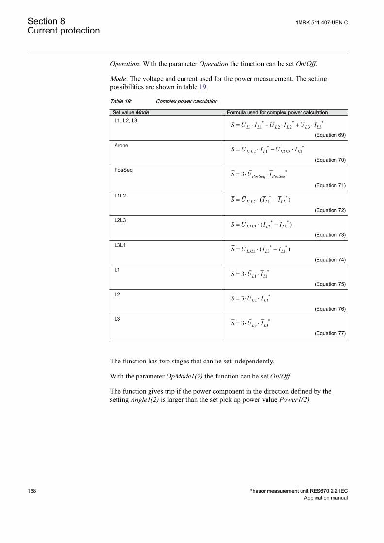
Operation: With the parameter Operation the function can be set On/Off.
Mode: The voltage and current used for the power measurement. The settingpossibilities are shown in table 19.
Table 19: Complex power calculation
Set value Mode Formula used for complex power calculationL1, L2, L3 * * *
1 1 2 2 3 3L L L L L LS U I U I U I= × + × + ×
EQUATION1697 V1 EN-US (Equation 69)
Arone * *1 2 1 2 3 3L L L L L LS U I U I= × - ×
EQUATION1698 V1 EN-US (Equation 70)
PosSeq *3 PosSeq PosSeqS U I= × ×
EQUATION1699 V1 EN-US (Equation 71)
L1L2 * *1 2 1 2( )L L L LS U I I= × -
EQUATION1700 V1 EN-US (Equation 72)
L2L3 * *2 3 2 3( )L L L LS U I I= × -
EQUATION1701 V1 EN-US (Equation 73)
L3L1 * *3 1 3 1( )L L L LS U I I= × -
EQUATION1702 V1 EN-US (Equation 74)
L1 *1 13 L LS U I= × ×
EQUATION1703 V1 EN-US (Equation 75)
L2 *2 23 L LS U I= × ×
EQUATION1704 V1 EN-US (Equation 76)
L3 *3 33 L LS U I= × ×
EQUATION1705 V1 EN-US (Equation 77)
The function has two stages that can be set independently.
With the parameter OpMode1(2) the function can be set On/Off.
The function gives trip if the power component in the direction defined by thesetting Angle1(2) is larger than the set pick up power value Power1(2)
Section 8 1MRK 511 407-UEN CCurrent protection
168 Phasor measurement unit RES670 2.2 IECApplication manual
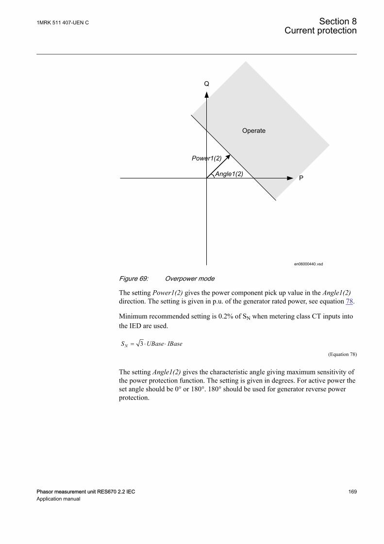
Operate
Angle1(2)
Power1(2)
P
Q
en06000440.vsdIEC06000440 V1 EN-US
Figure 69: Overpower mode
The setting Power1(2) gives the power component pick up value in the Angle1(2)direction. The setting is given in p.u. of the generator rated power, see equation 78.
Minimum recommended setting is 0.2% of SN when metering class CT inputs intothe IED are used.
3NS UBase IBase= × ×
EQUATION1708 V1 EN-US (Equation 78)
The setting Angle1(2) gives the characteristic angle giving maximum sensitivity ofthe power protection function. The setting is given in degrees. For active power theset angle should be 0° or 180°. 180° should be used for generator reverse powerprotection.
1MRK 511 407-UEN C Section 8Current protection
Phasor measurement unit RES670 2.2 IEC 169Application manual
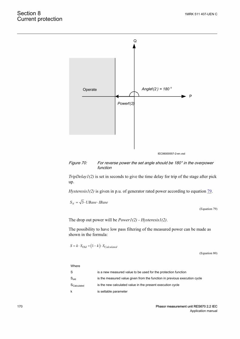
Operate Angle1(2 ) = 180 o
Power1(2)
P
Q
IEC06000557-2-en.vsdIEC06000557 V2 EN-US
Figure 70: For reverse power the set angle should be 180° in the overpowerfunction
TripDelay1(2) is set in seconds to give the time delay for trip of the stage after pickup.
Hysteresis1(2) is given in p.u. of generator rated power according to equation 79.
3NS UBase IBase= × ×
EQUATION1708 V1 EN-US (Equation 79)
The drop out power will be Power1(2) - Hysteresis1(2).
The possibility to have low pass filtering of the measured power can be made asshown in the formula:
( )1Old CalculatedS k S k S= × + - ×
EQUATION1893 V1 EN-US (Equation 80)
Where
S is a new measured value to be used for the protection function
Sold is the measured value given from the function in previous execution cycle
SCalculated is the new calculated value in the present execution cycle
k is settable parameter
Section 8 1MRK 511 407-UEN CCurrent protection
170 Phasor measurement unit RES670 2.2 IECApplication manual
The value of k=0.92 is recommended in generator applications as the trip delay isnormally quite long.
The calibration factors for current and voltage measurement errors are set % ofrated current/voltage:
IAmpComp5, IAmpComp30, IAmpComp100
UAmpComp5, UAmpComp30, UAmpComp100
IAngComp5, IAngComp30, IAngComp100
The angle compensation is given as difference between current and voltage angleerrors.
The values are given for operating points 5, 30 and 100% of rated current/voltage.The values should be available from instrument transformer test protocols.
1MRK 511 407-UEN C Section 8Current protection
Phasor measurement unit RES670 2.2 IEC 171Application manual

172
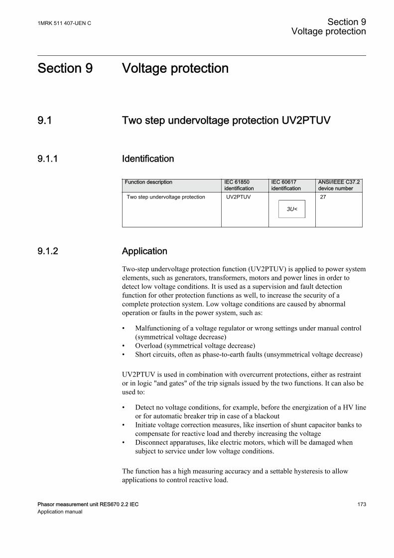
Section 9 Voltage protection
9.1 Two step undervoltage protection UV2PTUVIP14544-1 v3
9.1.1 IdentificationM16876-1 v7
Function description IEC 61850identification
IEC 60617identification
ANSI/IEEE C37.2device number
Two step undervoltage protection UV2PTUV
3U<
SYMBOL-R-2U-GREATER-THANV2 EN-US
27
9.1.2 ApplicationM13790-3 v8
Two-step undervoltage protection function (UV2PTUV) is applied to power systemelements, such as generators, transformers, motors and power lines in order todetect low voltage conditions. It is used as a supervision and fault detectionfunction for other protection functions as well, to increase the security of acomplete protection system. Low voltage conditions are caused by abnormaloperation or faults in the power system, such as:
• Malfunctioning of a voltage regulator or wrong settings under manual control(symmetrical voltage decrease)
• Overload (symmetrical voltage decrease)• Short circuits, often as phase-to-earth faults (unsymmetrical voltage decrease)
UV2PTUV is used in combination with overcurrent protections, either as restraintor in logic "and gates" of the trip signals issued by the two functions. It can also beused to:
• Detect no voltage conditions, for example, before the energization of a HV lineor for automatic breaker trip in case of a blackout
• Initiate voltage correction measures, like insertion of shunt capacitor banks tocompensate for reactive load and thereby increasing the voltage
• Disconnect apparatuses, like electric motors, which will be damaged whensubject to service under low voltage conditions.
The function has a high measuring accuracy and a settable hysteresis to allowapplications to control reactive load.
1MRK 511 407-UEN C Section 9Voltage protection
Phasor measurement unit RES670 2.2 IEC 173Application manual
In many cases, UV2PTUV is a useful function in circuits for local or remoteautomation processes in the power system.
9.1.3 Setting guidelinesM13851-3 v9
All the voltage conditions in the system where UV2PTUV performs its functionsshould be considered. The same also applies to the associated equipment, itsvoltage and time characteristic.
There is a very wide application area where general undervoltage functions areused. All voltage-related settings are made as a percentage of the global base valueUBase, which normally is set to the primary rated voltage level (phase-to-phase) ofthe power system or the high voltage equipment under consideration.
The trip time setting for UV2PTUV is normally not critical, since there must beenough time available for the main protection to clear short circuits and earthfaults.
Some applications and related setting guidelines for the voltage level are describedin the following sections.
9.1.3.1 Equipment protection, such as for motors and generatorsM13851-50 v3
The setting must be below the lowest occurring "normal" voltage and above thelowest acceptable voltage for the equipment.
9.1.3.2 Disconnected equipment detectionM13851-53 v3
The setting must be below the lowest occurring "normal" voltage and above thehighest occurring voltage, caused by inductive or capacitive coupling, when theequipment is disconnected.
9.1.3.3 Power supply qualityM13851-56 v3
The setting must be below the lowest occurring "normal" voltage and above thelowest acceptable voltage, due to regulation, good practice or other agreements.
9.1.3.4 Voltage instability mitigationM13851-59 v3
This setting is very much dependent on the power system characteristics, andthorough studies have to be made to find the suitable levels.
9.1.3.5 Backup protection for power system faultsM13851-62 v3
The setting must be below the lowest occurring "normal" voltage and above thehighest occurring voltage during the fault conditions under consideration.
Section 9 1MRK 511 407-UEN CVoltage protection
174 Phasor measurement unit RES670 2.2 IECApplication manual
9.1.3.6 Settings for two step undervoltage protectionM13851-65 v14
The following settings can be done for Two step undervoltage protectionUV2PTUV:
ConnType: Sets whether the measurement shall be phase-to-earth fundamentalvalue, phase-to-phase fundamental value, phase-to-earth RMS value or phase-to-phase RMS value.
Operation: Off or On.
UBase (given in GlobalBaseSel): Base voltage phase-to-phase in primary kV. Thisvoltage is used as reference for voltage setting. UV2PTUV will operate if thevoltage becomes lower than the set percentage of UBase. This setting is used whenConnType is set to PhPh DFT or PhPh RMS. Therefore, always set UBase as ratedprimary phase-to-phase voltage of the protected object. For more information, referto the Technical manual.
The setting parameters described below are identical for the two steps (n = 1 or 2).Therefore, the setting parameters are described only once.
Characteristicn: This parameter gives the type of time delay to be used. The settingcan be Definite time, Inverse Curve A, Inverse Curve B, Prog. inv. curve. Theselection is dependent on the protection application.
OpModen: This parameter describes how many of the three measured voltagesshould be below the set level to give operation for step n. The setting can be 1 outof 3, 2 out of 3 or 3 out of 3. In most applications, it is sufficient that one phasevoltage is low to give operation. If UV2PTUV shall be insensitive for single phase-to-earth faults, 2 out of 3 can be chosen. In subtransmission and transmissionnetworks the undervoltage function is mainly a system supervision function and 3out of 3 is selected.
Un<: Set operate undervoltage operation value for step n, given as % of theparameter UBase. The setting is highly dependent on the protection application. Itis essential to consider the minimum voltage at non-faulted situations. Normally,this non-faulted voltage is larger than 90% of the nominal voltage.
tn: time delay of step n, given in s. This setting is dependent on the protectionapplication. In many applications the protection function shall not directly tripwhen there is a short circuit or earth faults in the system. The time delay must becoordinated to the other short circuit protections.
tResetn: Reset time for step n if definite time delay is used, given in s. The defaultvalue is 25 ms.
tnMin: Minimum operation time for inverse time characteristic for step n, given ins. When using inverse time characteristic for the undervoltage function during verylow voltages can give a short operation time. This might lead to unselectivetripping. By setting t1Min longer than the operation time for other protections, suchunselective tripping can be avoided.
1MRK 511 407-UEN C Section 9Voltage protection
Phasor measurement unit RES670 2.2 IEC 175Application manual
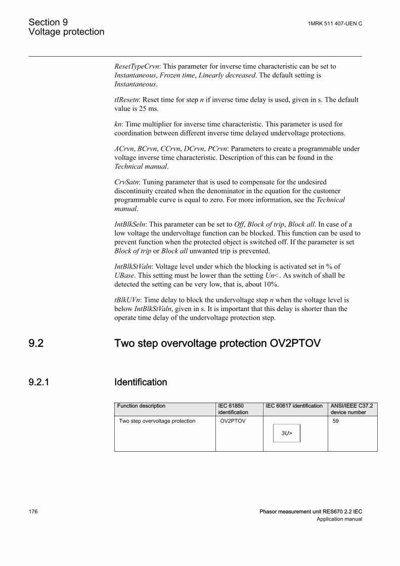
ResetTypeCrvn: This parameter for inverse time characteristic can be set toInstantaneous, Frozen time, Linearly decreased. The default setting isInstantaneous.
tIResetn: Reset time for step n if inverse time delay is used, given in s. The defaultvalue is 25 ms.
kn: Time multiplier for inverse time characteristic. This parameter is used forcoordination between different inverse time delayed undervoltage protections.
ACrvn, BCrvn, CCrvn, DCrvn, PCrvn: Parameters to create a programmable undervoltage inverse time characteristic. Description of this can be found in theTechnical manual.
CrvSatn: Tuning parameter that is used to compensate for the undesireddiscontinuity created when the denominator in the equation for the customerprogrammable curve is equal to zero. For more information, see the Technicalmanual.
IntBlkSeln: This parameter can be set to Off, Block of trip, Block all. In case of alow voltage the undervoltage function can be blocked. This function can be used toprevent function when the protected object is switched off. If the parameter is setBlock of trip or Block all unwanted trip is prevented.
IntBlkStValn: Voltage level under which the blocking is activated set in % ofUBase. This setting must be lower than the setting Un<. As switch of shall bedetected the setting can be very low, that is, about 10%.
tBlkUVn: Time delay to block the undervoltage step n when the voltage level isbelow IntBlkStValn, given in s. It is important that this delay is shorter than theoperate time delay of the undervoltage protection step.
9.2 Two step overvoltage protection OV2PTOVIP14545-1 v3
9.2.1 IdentificationM17002-1 v8
Function description IEC 61850identification
IEC 60617 identification ANSI/IEEE C37.2device number
Two step overvoltage protection OV2PTOV
3U>
SYMBOL-C-2U-SMALLER-THAN V2 EN-US
59
Section 9 1MRK 511 407-UEN CVoltage protection
176 Phasor measurement unit RES670 2.2 IECApplication manual
9.2.2 ApplicationM13799-3 v9
Two step overvoltage protection OV2PTOV is applicable in all situations, wherereliable detection of high voltage is necessary. OV2PTOV is used for supervisionand detection of abnormal conditions, which, in combination with other protectionfunctions, increase the security of a complete protection system.
High overvoltage conditions are caused by abnormal situations in the powersystem. OV2PTOV is applied to power system elements, such as generators,transformers, motors and power lines in order to detect high voltage conditions.OV2PTOV is used in combination with low current signals, to identify atransmission line, open in the remote end. In addition to that, OV2PTOV is alsoused to initiate voltage correction measures, like insertion of shunt reactors, tocompensate for low load, and thereby decreasing the voltage. The function has ahigh measuring accuracy and hysteresis setting to allow applications to controlreactive load.
OV2PTOV is used to disconnect apparatuses, like electric motors, which will bedamaged when subject to service under high voltage conditions. It deals with highvoltage conditions at power system frequency, which can be caused by:
1. Different kinds of faults, where a too high voltage appears in a certain powersystem, like metallic connection to a higher voltage level (broken conductorfalling down to a crossing overhead line, transformer flash over fault from thehigh voltage winding to the low voltage winding and so on).
2. Malfunctioning of a voltage regulator or wrong settings under manual control(symmetrical voltage decrease).
3. Low load compared to the reactive power generation (symmetrical voltagedecrease).
4. Earth-faults in high impedance earthed systems causes, beside the high voltagein the neutral, high voltages in the two non-faulted phases, (unsymmetricalvoltage increase).
OV2PTOV prevents sensitive equipment from running under conditions that couldcause their overheating or stress of insulation material, and, thus, shorten their lifetime expectancy. In many cases, it is a useful function in circuits for local orremote automation processes in the power system.
9.2.3 Setting guidelinesM13852-4 v10
The parameters for Two step overvoltage protection (OV2PTOV) are set via thelocal HMI or PCM600.
All the voltage conditions in the system where OV2PTOV performs its functionsshould be considered. The same also applies to the associated equipment, itsvoltage and time characteristic.
There are wide applications where general overvoltage functions are used. Allvoltage related settings are made as a percentage of a settable base primary voltage,
1MRK 511 407-UEN C Section 9Voltage protection
Phasor measurement unit RES670 2.2 IEC 177Application manual
which is normally set to the nominal voltage level (phase-to-phase) of the powersystem or the high voltage equipment under consideration.
The time delay for the OV2PTOV can sometimes be critical and related to the sizeof the overvoltage - a power system or a high voltage component can withstandsmaller overvoltages for some time, but in case of large overvoltages the relatedequipment should be disconnected more rapidly.
Some applications and related setting guidelines for the voltage level are givenbelow:
The hysteresis is for overvoltage functions very important to prevent that atransient voltage over set level is not “sealed-in” due to a high hysteresis. Typicalvalues should be ≤ 0.5%.
9.2.3.1 Equipment protection, such as for motors, generators, reactors andtransformers
M13852-10 v3
High voltage will cause overexcitation of the core and deteriorate the windinginsulation. The setting has to be well above the highest occurring "normal" voltageand well below the highest acceptable voltage for the equipment.
9.2.3.2 Equipment protection, capacitorsM13852-13 v1
High voltage will deteriorate the dielectricum and the insulation. The setting has tobe well above the highest occurring "normal" voltage and well below the highestacceptable voltage for the capacitor.
9.2.3.3 Power supply qualityM13852-16 v1
The setting has to be well above the highest occurring "normal" voltage and belowthe highest acceptable voltage, due to regulation, good practice or otheragreements.
9.2.3.4 High impedance earthed systemsM13852-19 v6
In high impedance earthed systems, earth-faults cause a voltage increase in thenon-faulty phases. Two step overvoltage protection (OV2PTOV) is used to detectsuch faults. The setting must be above the highest occurring "normal" voltage andbelow the lowest occurring voltage during faults. A metallic single-phase earth-fault causes the non-faulted phase voltages to increase a factor of √3.
9.2.3.5 The following settings can be done for the two step overvoltageprotection
M13852-22 v10
ConnType: Sets whether the measurement shall be phase-to-earth fundamentalvalue, phase-to-phase fundamental value, phase-to-earth RMS value or phase-to-phase RMS value.
Section 9 1MRK 511 407-UEN CVoltage protection
178 Phasor measurement unit RES670 2.2 IECApplication manual
Operation: Off/On.
UBase (given in GlobalBaseSel): Base voltage phase to phase in primary kV. Thisvoltage is used as reference for voltage setting. OV2PTOV measures selectivelyphase-to-earth voltages, or phase-to-phase voltage chosen by the setting ConnType.The function will operate if the voltage gets lower than the set percentage ofUBase. When ConnType is set to PhN DFT or PhN RMS then the IEDautomatically divides set value for UBase by √3. When ConnType is set to PhPhDFT or PhPh RMS then set value for UBase is used. Therefore, always set UBaseas rated primary phase-to-phase voltage of the protected object. If phase to neutral(PhN) measurement is selected as setting, the operation of phase-to-earth overvoltage is automatically divided by sqrt3. This means operation for phase-to-earthvoltage over:
(%) ( ) / 3U UBase kV> ×
and operation for phase-to-phase voltage over:
U (%) UBase(kV)> ×EQUATION1993 V1 EN-US (Equation 82)
The below described setting parameters are identical for the two steps (n = 1 or 2).Therefore the setting parameters are described only once.
Characteristicn: This parameter gives the type of time delay to be used. The settingcan be Definite time, Inverse Curve A, Inverse Curve B, Inverse Curve C or I/Prog.inv. curve. The choice is highly dependent of the protection application.
OpModen: This parameter describes how many of the three measured voltages thatshould be above the set level to give operation. The setting can be 1 out of 3, 2 outof 3, 3 out of 3. In most applications it is sufficient that one phase voltage is high togive operation. If the function shall be insensitive for single phase-to-earth faults 1out of 3 can be chosen, because the voltage will normally rise in the non-faultedphases at single phase-to-earth faults. In subtransmission and transmissionnetworks the UV function is mainly a system supervision function and 3 out of 3 isselected.
Un>: Set operate overvoltage operation value for step n, given as % of UBase. Thesetting is highly dependent of the protection application. Here it is essential toconsider the maximum voltage at non-faulted situations. Normally this voltage isless than 110% of nominal voltage.
tn: time delay of step n, given in s. The setting is highly dependent of the protectionapplication. In many applications the protection function is used to preventdamages to the protected object. The speed might be important for example in caseof protection of transformer that might be overexcited. The time delay must be co-ordinated with other automated actions in the system.
1MRK 511 407-UEN C Section 9Voltage protection
Phasor measurement unit RES670 2.2 IEC 179Application manual
tResetn: Reset time for step n if definite time delay is used, given in s. The defaultvalue is 25 ms.
tnMin: Minimum operation time for inverse time characteristic for step n, given ins. For very high voltages the overvoltage function, using inverse timecharacteristic, can give very short operation time. This might lead to unselectivetrip. By setting t1Min longer than the operation time for other protections suchunselective tripping can be avoided.
ResetTypeCrvn: This parameter for inverse time characteristic can be set:Instantaneous, Frozen time, Linearly decreased. The default setting isInstantaneous.
tIResetn: Reset time for step n if inverse time delay is used, given in s. The defaultvalue is 25 ms.
kn: Time multiplier for inverse time characteristic. This parameter is used for co-ordination between different inverse time delayed undervoltage protections.
ACrvn, BCrvn, CCrvn, DCrvn, PCrvn: Parameters to set to create programmableunder voltage inverse time characteristic. Description of this can be found in thetechnical reference manual.
CrvSatn: When the denominator in the expression of the programmable curve isequal to zero the time delay will be infinity. There will be an undesireddiscontinuity. Therefore a tuning parameter CrvSatn is set to compensate for thisphenomenon. In the voltage interval Un> up to Un> · (1.0 + CrvSatn/100) the usedvoltage will be: Un> · (1.0 + CrvSatn/100). If the programmable curve is used, thisparameter must be calculated so that:
0100
CrvSatnB C× - >
EQUATION1448 V1 EN-US (Equation 83)
HystAbsn: Absolute hysteresis set in % of UBase. The setting of this parameter ishighly dependent of the application. If the function is used as control for automaticswitching of reactive compensation devices the hysteresis must be set smaller thanthe voltage change after switching of the compensation device.
Section 9 1MRK 511 407-UEN CVoltage protection
180 Phasor measurement unit RES670 2.2 IECApplication manual
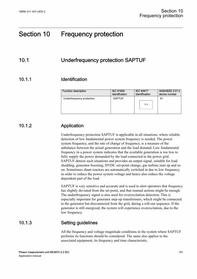
Section 10 Frequency protection
10.1 Underfrequency protection SAPTUFIP15746-1 v3
10.1.1 IdentificationM14865-1 v5
Function description IEC 61850identification
IEC 60617identification
ANSI/IEEE C37.2device number
Underfrequency protection SAPTUF
f <
SYMBOL-P V1 EN-US
81
10.1.2 ApplicationM13350-3 v4
Underfrequency protection SAPTUF is applicable in all situations, where reliabledetection of low fundamental power system frequency is needed. The powersystem frequency, and the rate of change of frequency, is a measure of theunbalance between the actual generation and the load demand. Low fundamentalfrequency in a power system indicates that the available generation is too low tofully supply the power demanded by the load connected to the power grid.SAPTUF detects such situations and provides an output signal, suitable for loadshedding, generator boosting, HVDC-set-point change, gas turbine start up and soon. Sometimes shunt reactors are automatically switched in due to low frequency,in order to reduce the power system voltage and hence also reduce the voltagedependent part of the load.
SAPTUF is very sensitive and accurate and is used to alert operators that frequencyhas slightly deviated from the set-point, and that manual actions might be enough.The underfrequency signal is also used for overexcitation detection. This isespecially important for generator step-up transformers, which might be connectedto the generator but disconnected from the grid, during a roll-out sequence. If thegenerator is still energized, the system will experience overexcitation, due to thelow frequency.
10.1.3 Setting guidelinesM13355-3 v8
All the frequency and voltage magnitude conditions in the system where SAPTUFperforms its functions should be considered. The same also applies to theassociated equipment, its frequency and time characteristic.
1MRK 511 407-UEN C Section 10Frequency protection
Phasor measurement unit RES670 2.2 IEC 181Application manual
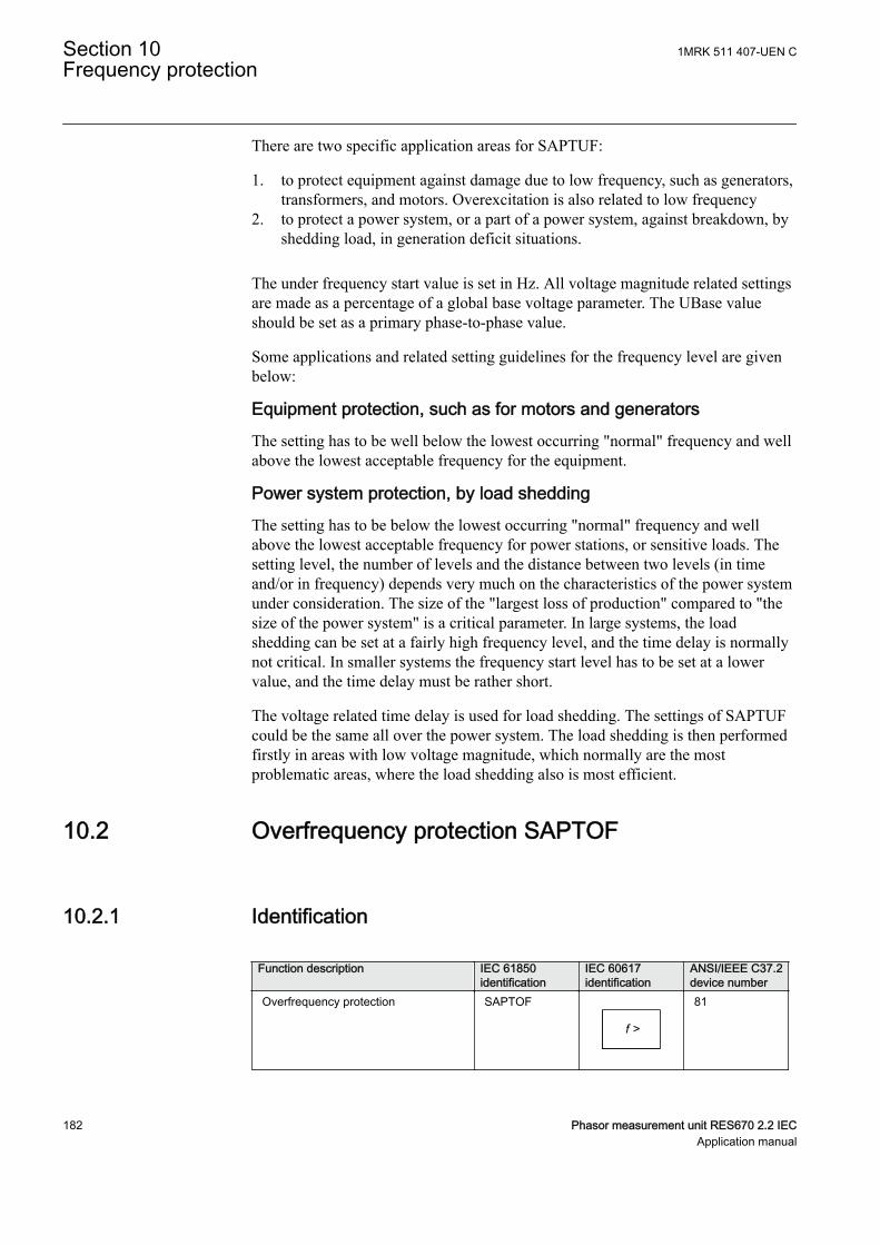
There are two specific application areas for SAPTUF:
1. to protect equipment against damage due to low frequency, such as generators,transformers, and motors. Overexcitation is also related to low frequency
2. to protect a power system, or a part of a power system, against breakdown, byshedding load, in generation deficit situations.
The under frequency start value is set in Hz. All voltage magnitude related settingsare made as a percentage of a global base voltage parameter. The UBase valueshould be set as a primary phase-to-phase value.
Some applications and related setting guidelines for the frequency level are givenbelow:
Equipment protection, such as for motors and generatorsThe setting has to be well below the lowest occurring "normal" frequency and wellabove the lowest acceptable frequency for the equipment.
Power system protection, by load sheddingThe setting has to be below the lowest occurring "normal" frequency and wellabove the lowest acceptable frequency for power stations, or sensitive loads. Thesetting level, the number of levels and the distance between two levels (in timeand/or in frequency) depends very much on the characteristics of the power systemunder consideration. The size of the "largest loss of production" compared to "thesize of the power system" is a critical parameter. In large systems, the loadshedding can be set at a fairly high frequency level, and the time delay is normallynot critical. In smaller systems the frequency start level has to be set at a lowervalue, and the time delay must be rather short.
The voltage related time delay is used for load shedding. The settings of SAPTUFcould be the same all over the power system. The load shedding is then performedfirstly in areas with low voltage magnitude, which normally are the mostproblematic areas, where the load shedding also is most efficient.
10.2 Overfrequency protection SAPTOFIP15747-1 v3
10.2.1 IdentificationM14866-1 v4
Function description IEC 61850identification
IEC 60617identification
ANSI/IEEE C37.2device number
Overfrequency protection SAPTOF
f >
SYMBOL-O V1 EN-US
81
Section 10 1MRK 511 407-UEN CFrequency protection
182 Phasor measurement unit RES670 2.2 IECApplication manual
10.2.2 ApplicationM14952-3 v4
Overfrequency protection function SAPTOF is applicable in all situations, wherereliable detection of high fundamental power system frequency is needed. Thepower system frequency, and rate of change of frequency, is a measure of theunbalance between the actual generation and the load demand. High fundamentalfrequency in a power system indicates that the available generation is too largecompared to the power demanded by the load connected to the power grid.SAPTOF detects such situations and provides an output signal, suitable forgenerator shedding, HVDC-set-point change and so on. SAPTOF is very sensitiveand accurate and can also be used to alert operators that frequency has slightlydeviated from the set-point, and that manual actions might be enough.
10.2.3 Setting guidelinesM14959-3 v7
All the frequency and voltage magnitude conditions in the system where SAPTOFperforms its functions must be considered. The same also applies to the associatedequipment, its frequency and time characteristic.
There are two application areas for SAPTOF:
1. to protect equipment against damage due to high frequency, such asgenerators, and motors
2. to protect a power system, or a part of a power system, against breakdown, byshedding generation, in over production situations.
The overfrequency start value is set in Hz. All voltage magnitude related settingsare made as a percentage of a settable global base voltage parameter UBase. TheUBase value should be set as a primary phase-to-phase value.
Some applications and related setting guidelines for the frequency level are givenbelow:
Equipment protection, such as for motors and generatorsThe setting has to be well above the highest occurring "normal" frequency and wellbelow the highest acceptable frequency for the equipment.
Power system protection, by generator sheddingThe setting must be above the highest occurring "normal" frequency and below thehighest acceptable frequency for power stations, or sensitive loads. The settinglevel, the number of levels and the distance between two levels (in time and/or infrequency) depend very much on the characteristics of the power system underconsideration. The size of the "largest loss of load" compared to "the size of thepower system" is a critical parameter. In large systems, the generator shedding canbe set at a fairly low frequency level, and the time delay is normally not critical. Insmaller systems the frequency START level has to be set at a higher value, and thetime delay must be rather short.
1MRK 511 407-UEN C Section 10Frequency protection
Phasor measurement unit RES670 2.2 IEC 183Application manual
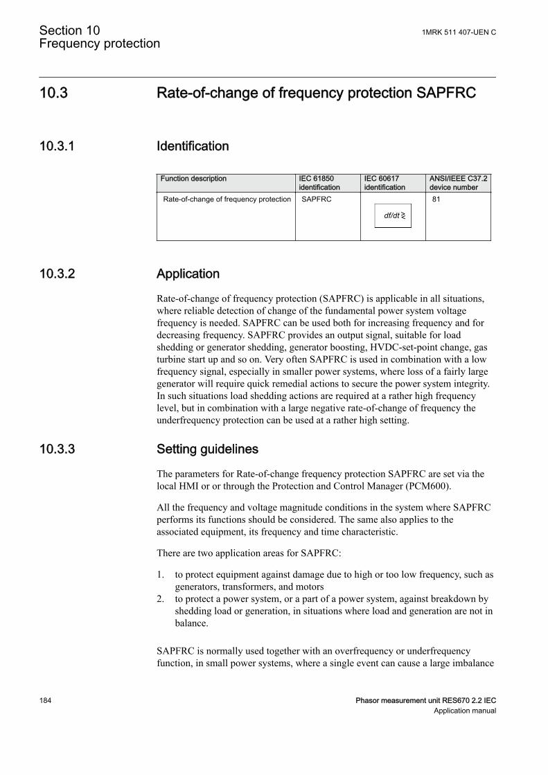
10.3 Rate-of-change of frequency protection SAPFRCIP15748-1 v4
10.3.1 IdentificationM14868-1 v4
Function description IEC 61850identification
IEC 60617identification
ANSI/IEEE C37.2device number
Rate-of-change of frequency protection SAPFRC
df/dt ><
SYMBOL-N V1 EN-US
81
10.3.2 ApplicationM14966-3 v5
Rate-of-change of frequency protection (SAPFRC) is applicable in all situations,where reliable detection of change of the fundamental power system voltagefrequency is needed. SAPFRC can be used both for increasing frequency and fordecreasing frequency. SAPFRC provides an output signal, suitable for loadshedding or generator shedding, generator boosting, HVDC-set-point change, gasturbine start up and so on. Very often SAPFRC is used in combination with a lowfrequency signal, especially in smaller power systems, where loss of a fairly largegenerator will require quick remedial actions to secure the power system integrity.In such situations load shedding actions are required at a rather high frequencylevel, but in combination with a large negative rate-of-change of frequency theunderfrequency protection can be used at a rather high setting.
10.3.3 Setting guidelinesM14971-3 v7
The parameters for Rate-of-change frequency protection SAPFRC are set via thelocal HMI or or through the Protection and Control Manager (PCM600).
All the frequency and voltage magnitude conditions in the system where SAPFRCperforms its functions should be considered. The same also applies to theassociated equipment, its frequency and time characteristic.
There are two application areas for SAPFRC:
1. to protect equipment against damage due to high or too low frequency, such asgenerators, transformers, and motors
2. to protect a power system, or a part of a power system, against breakdown byshedding load or generation, in situations where load and generation are not inbalance.
SAPFRC is normally used together with an overfrequency or underfrequencyfunction, in small power systems, where a single event can cause a large imbalance
Section 10 1MRK 511 407-UEN CFrequency protection
184 Phasor measurement unit RES670 2.2 IECApplication manual

between load and generation. In such situations load or generation shedding has totake place very quickly, and there might not be enough time to wait until thefrequency signal has reached an abnormal value. Actions are therefore taken at afrequency level closer to the primary nominal level, if the rate-of-change frequencyis large (with respect to sign).
The start value for SAPFRC is set in Hz/s. All voltage magnitude related settingsare made as a percentage of a settable base voltage, which normally is set to theprimary nominal voltage level (phase-phase) of the power system or the highvoltage equipment under consideration.
SAPFRC is not instantaneous, since the function needs some time to supply astable value. It is recommended to have a time delay long enough to take care ofsignal noise. However, the time, rate-of-change frequency and frequency stepsbetween different actions might be critical, and sometimes a rather short operationtime is required, for example, down to 70 ms.
Smaller industrial systems might experience rate-of-change frequency as large as 5Hz/s, due to a single event. Even large power systems may form small islands witha large imbalance between load and generation, when severe faults (orcombinations of faults) are cleared - up to 3 Hz/s has been experienced when asmall island was isolated from a large system. For more "normal" severedisturbances in large power systems, rate-of-change of frequency is much less,most often just a fraction of 1.0 Hz/s.
10.4 Frequency time accumulation protection functionFTAQFVR
GUID-124A1F91-44C0-4DB6-8603-CC8CA19AE2A6 v3
10.4.1 IdentificationGUID-87605DA0-EAA6-4A6C-BF03-7FDB187E1B29 v2
Function description IEC 61850identification
IEC 60617identification
ANSI/IEEEidentification
Frequency time accumulationprotection
FTAQFVR f<> 81A
10.4.2 ApplicationGUID-82CA8336-82BE-42AB-968A-D4F08941C9D0 v3
Generator prime movers are affected by abnormal frequency disturbances.Significant frequency deviations from rated frequency occur in case of majordisturbances in the system. A rise of frequency occurs in case of generationsurplus, while a lack of generation results in a drop of frequency.
The turbine blade is designed with its natural frequency adequately far from therated speed or multiples of the rated speed of the turbine. This design avoids themechanical resonant condition, which can lead to an increased mechanical stress onturbine blade. If the ratio between the turbine resonant frequencies to the system
1MRK 511 407-UEN C Section 10Frequency protection
Phasor measurement unit RES670 2.2 IEC 185Application manual

operating frequency is nearly equal to 1, mechanical stress on the blades isapproximately 300 times the nonresonant operating condition stress values. Thestress magnification factor is shown in the typical resonance curve in Figure 71.
1.0- +Frequency or Resonant Frequency
Ratio
Stre
ss M
agni
ficat
ion
Fact
or
IEC12000611-2-en.vsd
50
100
150
200
250
300
IEC12000611 V2 EN-US
Figure 71: Typical stress magnification factor curve according ANSI/IEEEC37.106-2003 Standard
Each turbine manufactured for different design of blades has various timerestriction limits for various frequency bands. The time limits depend on thenatural frequencies of the blades inside the turbine, corrosion and erosion of theblade edges and additional loss of blade lifetime during the abnormal operatingconditions.
The frequency limitations and their time restrictions for different types of turbinesare similar in many aspects with steam turbine limitations. Certain differences indesign and applications may result in different protective requirements. Therefore,for different type of turbine systems, different recommendations on the timerestriction limits are specified by the manufacturer.
However, the IEEE/ANSI C37.106-2003 standard "Guide for Abnormal FrequencyProtection for Power Generating Plants" provides some examples where the timeaccumulated within each frequency range is as shown in Figure 72.
Section 10 1MRK 511 407-UEN CFrequency protection
186 Phasor measurement unit RES670 2.2 IECApplication manual
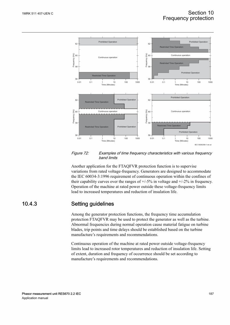
560.01 0.1 1 10 100 1000
58Freq
uenc
y (H
z)
Time (Minutes)
Time (Minutes)
Time (Minutes)
Time (Minutes)
IEC13000258-1-en.ai
Continuous operation
Prohibited Operation
60
62
560.01 0.1 1 10 100 1000
58Freq
uenc
y (H
z) Continuous operation60
62
560.01 0.1 1 10 100 1000
58Freq
uenc
y (H
z) 60
62
Continuous operation
560.01 0.1 1 10 100 1000
58Freq
uenc
y (H
z) Continuous operation60
62
Restricted Time Operation
Prohibited Operation
Prohibited Operation
Restricted Time Operation
Restricted Time Operation
Prohibited OperationProhibited Operation
Prohibited Operation
Prohibited Operation
Restricted Time Operation
Restricted Time Operation Restricted Time Operation
IEC13000258 V1 EN-US
Figure 72: Examples of time frequency characteristics with various frequencyband limits
Another application for the FTAQFVR protection function is to supervisevariations from rated voltage-frequency. Generators are designed to accommodatethe IEC 60034-3:1996 requirement of continuous operation within the confines oftheir capability curves over the ranges of +/-5% in voltage and +/-2% in frequency.Operation of the machine at rated power outside these voltage-frequency limitslead to increased temperatures and reduction of insulation life.
10.4.3 Setting guidelinesGUID-62C6D764-CAF2-4C2F-B91A-EBC611987D72 v3
Among the generator protection functions, the frequency time accumulationprotection FTAQFVR may be used to protect the generator as well as the turbine.Abnormal frequencies during normal operation cause material fatigue on turbineblades, trip points and time delays should be established based on the turbinemanufacture’s requirements and recommendations.
Continuous operation of the machine at rated power outside voltage-frequencylimits lead to increased rotor temperatures and reduction of insulation life. Settingof extent, duration and frequency of occurrence should be set according tomanufacture’s requirements and recommendations.
1MRK 511 407-UEN C Section 10Frequency protection
Phasor measurement unit RES670 2.2 IEC 187Application manual
Setting procedure on the IEDThe parameters for the frequency time accumulation protection FTAQFVR are setusing the local HMI or through the dedicated software tool in Protection andControl Manager (PCM600).
Common base IED values for primary current IBase and primary voltage UBaseare set in the global base values for settings function GBASVAL. TheGlobalBaseSel is used to select GBASVAL for the reference of base values.
FTAQFVR used to protect a turbine:
Frequency during start-up and shutdown is normally not calculated, consequentlythe protection function is blocked by CB position, parameter CBCheck enabled. Ifthe generator supply any load when CB is in open position e.g. excitationequipment and auxiliary services this may be considered as normal condition andCBCheck is ignored when the load current is higher then the set value ofCurrStartLevel. Set the current level just above minimum load.
EnaVoltCheck set to Disable.
tCont: to be coordinated to the grid requirements.
tAccLimit, FreqHighLimit and FreqLowLimit setting is derived from the turbinemanufacturer's operating requirements, note that FreqLowLimit setting must alwaysbe lower than the set value of FreqHighLimit.
FTAQFVR used to protect a generator:
Frequency during start-up and shutdown is normally not calculated, consequentlythe protection function is blocked by CB position, parameter CBCheck enabled.
CurrStartLevel set to Disable.
EnaVoltCheck set to Enable, voltage and frequency limits set according to thegenerators manufacturer's operating requirements. Voltage and frequency settingsshould also be coordinated with the starting values for over and underexcitationprotection.
tCont: to be coordinated to the grid requirements.
tAccLimit, FreqHighLimit and FreqLowLimit setting is derived from the generatormanufacturer's operating requirements.
Section 10 1MRK 511 407-UEN CFrequency protection
188 Phasor measurement unit RES670 2.2 IECApplication manual
Section 11 Multipurpose protection
11.1 General current and voltage protection CVGAPCIP14552-1 v2
11.1.1 IdentificationM14886-2 v3
Function description IEC 61850identification
IEC 60617identification
ANSI/IEEE C37.2device number
General current and voltage protection CVGAPC 2(I>/U<) -
11.1.2 ApplicationIP15008-1 v1
M13084-3 v5
A breakdown of the insulation between phase conductors or a phase conductor andearth results in a short circuit or an earth fault respectively. Such faults can result inlarge fault currents and may cause severe damage to the power system primaryequipment. Depending on the magnitude and type of the fault different overcurrentprotections, based on measurement of phase, earth or sequence current componentscan be used to detect these faults. Additionally it is sometimes required that theseovercurrent protections shall be directional and/or voltage controlled/restrained.
The over/under voltage protection is applied on power system elements, such asgenerators, transformers, motors and power lines in order to detect abnormalvoltage conditions. Depending on the type of voltage deviation and type of powersystem abnormal condition different over/under voltage protections based onmeasurement of phase-to-earth, phase-to-phase, residual- or sequence- voltagecomponents can be used to detect and operate for such incident.
The IED can be provided with multiple General current and voltage protection(CVGAPC) protection modules. The function is always connected to three-phasecurrent and three-phase voltage input in the configuration tool, but it will alwaysmeasure only one current and one voltage quantity selected by the end user in thesetting tool.
Each CVGAPC function module has got four independent protection elements builtinto it.
1. Two overcurrent steps with the following built-in features:
1MRK 511 407-UEN C Section 11Multipurpose protection
Phasor measurement unit RES670 2.2 IEC 189Application manual
• Definite time delay or Inverse Time Overcurrent (TOC/IDMT) delay forboth steps
• Second harmonic supervision is available in order to only allowoperation of the overcurrent stage(s) if the content of the secondharmonic in the measured current is lower than pre-set level
• Directional supervision is available in order to only allow operation ofthe overcurrent stage(s) if the fault location is in the pre-set direction(Forward or Reverse). Its behavior during low-level polarizing voltage issettable (Non-Directional, Block, Memory)
• Voltage restrained/controlled feature is available in order to modify thepick-up level of the overcurrent stage(s) in proportion to the magnitudeof the measured voltage
• Current restrained feature is available in order to only allow operation ofthe overcurrent stage(s) if the measured current quantity is bigger thanthe set percentage of the current restrain quantity.
2. Two undercurrent steps with the following built-in features:• Definite time delay for both steps
3. Two overvoltage steps with the following built-in features• Definite time delay or Inverse Time Overcurrent TOC/IDMT delay for
both steps4. Two undervoltage steps with the following built-in features
• Definite time delay or Inverse Time Overcurrent TOC/IDMT delay forboth steps
All these four protection elements within one general protection function worksindependently from each other and they can be individually enabled or disabled.However, note that all these four protection elements measure one selected currentquantity and one selected voltage quantity (see table 20 and table 21). It is possibleto simultaneously use all four protection elements and their individual stages.Sometimes, it is necessary to provide interaction between two or more protectionelements/stages within one CVGAPC function by appropriate IED configuration toobtain desired application functionality.
11.1.2.1 Current and voltage selection for CVGAPC functionSEMOD53443-6 v4
CVGAPC function is always connected to three-phase current and three-phasevoltage input in the configuration tool, but it will always measure only the singlecurrent and the single voltage quantity selected by the end user in the setting tool.
The user can select a current input, by a setting parameter CurrentInput, to measureone of the current quantities shown in table 20.
Section 11 1MRK 511 407-UEN CMultipurpose protection
190 Phasor measurement unit RES670 2.2 IECApplication manual
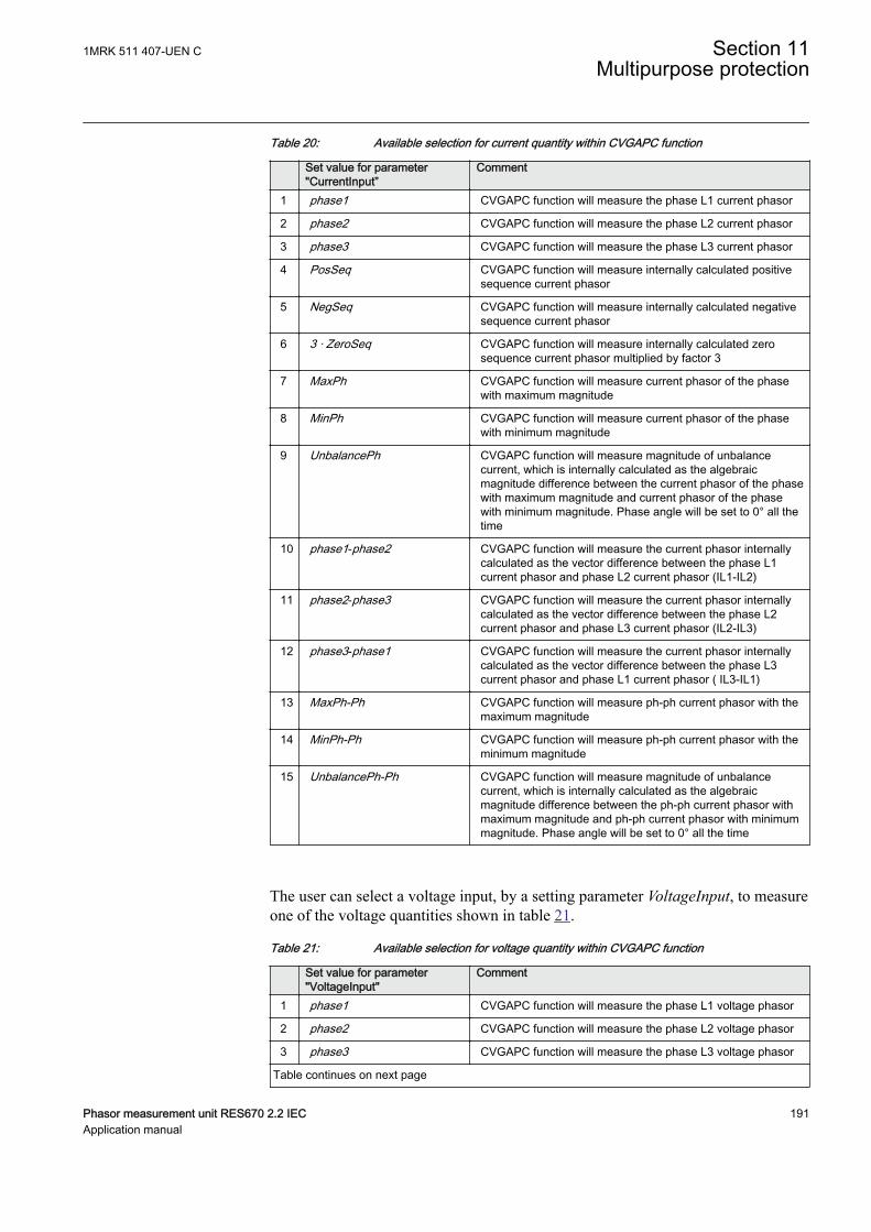
Table 20: Available selection for current quantity within CVGAPC function
Set value for parameter"CurrentInput”
Comment
1 phase1 CVGAPC function will measure the phase L1 current phasor
2 phase2 CVGAPC function will measure the phase L2 current phasor
3 phase3 CVGAPC function will measure the phase L3 current phasor
4 PosSeq CVGAPC function will measure internally calculated positivesequence current phasor
5 NegSeq CVGAPC function will measure internally calculated negativesequence current phasor
6 3 · ZeroSeq CVGAPC function will measure internally calculated zerosequence current phasor multiplied by factor 3
7 MaxPh CVGAPC function will measure current phasor of the phasewith maximum magnitude
8 MinPh CVGAPC function will measure current phasor of the phasewith minimum magnitude
9 UnbalancePh CVGAPC function will measure magnitude of unbalancecurrent, which is internally calculated as the algebraicmagnitude difference between the current phasor of the phasewith maximum magnitude and current phasor of the phasewith minimum magnitude. Phase angle will be set to 0° all thetime
10 phase1-phase2 CVGAPC function will measure the current phasor internallycalculated as the vector difference between the phase L1current phasor and phase L2 current phasor (IL1-IL2)
11 phase2-phase3 CVGAPC function will measure the current phasor internallycalculated as the vector difference between the phase L2current phasor and phase L3 current phasor (IL2-IL3)
12 phase3-phase1 CVGAPC function will measure the current phasor internallycalculated as the vector difference between the phase L3current phasor and phase L1 current phasor ( IL3-IL1)
13 MaxPh-Ph CVGAPC function will measure ph-ph current phasor with themaximum magnitude
14 MinPh-Ph CVGAPC function will measure ph-ph current phasor with theminimum magnitude
15 UnbalancePh-Ph CVGAPC function will measure magnitude of unbalancecurrent, which is internally calculated as the algebraicmagnitude difference between the ph-ph current phasor withmaximum magnitude and ph-ph current phasor with minimummagnitude. Phase angle will be set to 0° all the time
The user can select a voltage input, by a setting parameter VoltageInput, to measureone of the voltage quantities shown in table 21.
Table 21: Available selection for voltage quantity within CVGAPC function
Set value for parameter"VoltageInput"
Comment
1 phase1 CVGAPC function will measure the phase L1 voltage phasor
2 phase2 CVGAPC function will measure the phase L2 voltage phasor
3 phase3 CVGAPC function will measure the phase L3 voltage phasor
Table continues on next page
1MRK 511 407-UEN C Section 11Multipurpose protection
Phasor measurement unit RES670 2.2 IEC 191Application manual
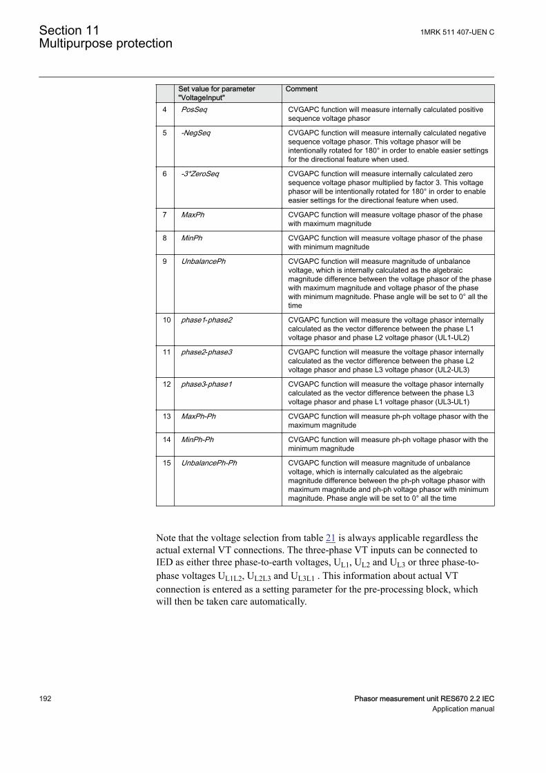
Set value for parameter"VoltageInput"
Comment
4 PosSeq CVGAPC function will measure internally calculated positivesequence voltage phasor
5 -NegSeq CVGAPC function will measure internally calculated negativesequence voltage phasor. This voltage phasor will beintentionally rotated for 180° in order to enable easier settingsfor the directional feature when used.
6 -3*ZeroSeq CVGAPC function will measure internally calculated zerosequence voltage phasor multiplied by factor 3. This voltagephasor will be intentionally rotated for 180° in order to enableeasier settings for the directional feature when used.
7 MaxPh CVGAPC function will measure voltage phasor of the phasewith maximum magnitude
8 MinPh CVGAPC function will measure voltage phasor of the phasewith minimum magnitude
9 UnbalancePh CVGAPC function will measure magnitude of unbalancevoltage, which is internally calculated as the algebraicmagnitude difference between the voltage phasor of the phasewith maximum magnitude and voltage phasor of the phasewith minimum magnitude. Phase angle will be set to 0° all thetime
10 phase1-phase2 CVGAPC function will measure the voltage phasor internallycalculated as the vector difference between the phase L1voltage phasor and phase L2 voltage phasor (UL1-UL2)
11 phase2-phase3 CVGAPC function will measure the voltage phasor internallycalculated as the vector difference between the phase L2voltage phasor and phase L3 voltage phasor (UL2-UL3)
12 phase3-phase1 CVGAPC function will measure the voltage phasor internallycalculated as the vector difference between the phase L3voltage phasor and phase L1 voltage phasor (UL3-UL1)
13 MaxPh-Ph CVGAPC function will measure ph-ph voltage phasor with themaximum magnitude
14 MinPh-Ph CVGAPC function will measure ph-ph voltage phasor with theminimum magnitude
15 UnbalancePh-Ph CVGAPC function will measure magnitude of unbalancevoltage, which is internally calculated as the algebraicmagnitude difference between the ph-ph voltage phasor withmaximum magnitude and ph-ph voltage phasor with minimummagnitude. Phase angle will be set to 0° all the time
Note that the voltage selection from table 21 is always applicable regardless theactual external VT connections. The three-phase VT inputs can be connected toIED as either three phase-to-earth voltages, UL1, UL2 and UL3 or three phase-to-phase voltages UL1L2, UL2L3 and UL3L1 . This information about actual VTconnection is entered as a setting parameter for the pre-processing block, whichwill then be taken care automatically.
Section 11 1MRK 511 407-UEN CMultipurpose protection
192 Phasor measurement unit RES670 2.2 IECApplication manual
11.1.2.2 Base quantities for CVGAPC functionSEMOD53443-112 v4
The parameter settings for the base quantities, which represent the base (100%) forpickup levels of all measuring stages shall be entered as setting parameters forevery CVGAPC function.
Base current shall be entered as:
1. rated phase current of the protected object in primary amperes, when themeasured Current Quantity is selected from 1 to 9, as shown in table 20.
2. rated phase current of the protected object in primary amperes multiplied by√3 (1.732 x Iphase), when the measured Current Quantity is selected from 10to 15, as shown in table 20.
Base voltage shall be entered as:
1. rated phase-to-earth voltage of the protected object in primary kV, when themeasured Voltage Quantity is selected from 1 to 9, as shown in table 21.
2. rated phase-to-phase voltage of the protected object in primary kV, when themeasured Voltage Quantity is selected from 10 to 15, as shown in table 21.
11.1.2.3 Application possibilitiesSEMOD53443-136 v3
Due to its flexibility the general current and voltage protection (CVGAPC)function can be used, with appropriate settings and configuration in many differentapplications. Some of possible examples are given below:
1. Transformer and line applications:• Underimpedance protection (circular, non-directional characteristic)• Underimpedance protection (circular mho characteristic)• Voltage Controlled/Restrained Overcurrent protection• Phase or Negative/Positive/Zero Sequence (Non-Directional or
Directional) Overcurrent protection• Phase or phase-to-phase or Negative/Positive/Zero Sequence over/under
voltage protection• Thermal overload protection• Open Phase protection• Unbalance protection
2. Generator protection• 80-95% Stator earth fault protection (measured or calculated 3Uo)• Rotor earth fault protection (with external COMBIFLEX RXTTE4
injection unit)• Underimpedance protection• Voltage Controlled/Restrained Overcurrent protection• Turn-to-Turn & Differential Backup protection (directional Negative
Sequence. Overcurrent protection connected to generator HV terminalCTs looking into generator)
• Stator Overload protection
1MRK 511 407-UEN C Section 11Multipurpose protection
Phasor measurement unit RES670 2.2 IEC 193Application manual
• Rotor Overload protection• Loss of Excitation protection (directional positive sequence OC
protection)• Reverse power/Low forward power protection (directional positive
sequence OC protection, 2% sensitivity)• Dead-Machine/Inadvertent-Energizing protection• Breaker head flashover protection• Improper synchronizing detection• Sensitive negative sequence generator over current protection and alarm• Phase or phase-to-phase or Negative/Positive/Zero Sequence over/under
voltage protection• Generator out-of-step detection (based on directional positive sequence
OC)• Inadvertent generator energizing
11.1.2.4 Inadvertent generator energizationSEMOD151947-4 v2
When the generator is taken out of service, and non-rotating, there is a risk that thegenerator circuit breaker is closed by mistake.
Three-phase energizing of a generator, which is at standstill or on turning gear,causes it to behave and accelerate similarly to an induction motor. The machine, atthis point, essentially represents the subtransient reactance to the system and it canbe expected to draw from one to four per unit current, depending on the equivalentsystem impedance. Machine terminal voltage can range from 20% to 70% of ratedvoltage, again, depending on the system equivalent impedance (including the blocktransformer). Higher quantities of machine current and voltage (3 to 4 per unitcurrent and 50% to 70% rated voltage) can be expected if the generator isconnected to a strong system. Lower current and voltage values (1 to 2 per unitcurrent and 20% to 40% rated voltage) are representative of weaker systems.
Since a generator behaves similarly to an induction motor, high currents willdevelop in the rotor during the period it is accelerating. Although the rotor may bethermally damaged from excessive high currents, the time to damage will be on theorder of a few seconds. Of more critical concern, however, is the bearing, whichcan be damaged in a fraction of a second due to low oil pressure. Therefore, it isessential that high speed tripping is provided. This tripping should be almostinstantaneous (< 100 ms).
There is a risk that the current into the generator at inadvertent energization will belimited so that the “normal” overcurrent or underimpedance protection will notdetect the dangerous situation. The delay of these protection functions might be toolong. The reverse power protection might detect the situation but the operation timeof this protection is normally too long.
For big and important machines, fast protection against inadvertent energizingshould, therefore, be included in the protective scheme.
Section 11 1MRK 511 407-UEN CMultipurpose protection
194 Phasor measurement unit RES670 2.2 IECApplication manual
The protection against inadvertent energization can be made by a combination ofundervoltage, overvoltage and overcurrent protection functions. The undervoltagefunction will, with a delay for example 10 s, detect the situation when the generatoris not connected to the grid (standstill) and activate the overcurrent function. Theovervoltage function will detect the situation when the generator is taken intooperation and will disable the overcurrent function. The overcurrent function willhave a pick-up value about 50% of the rated current of the generator. The trip delaywill be about 50 ms.
11.1.3 Setting guidelinesIP15009-1 v2
GUID-F7AA2194-4D1C-4475-8853-C7D064912614 v4
When inverse time overcurrent characteristic is selected, theoperate time of the stage will be the sum of the inverse time delayand the set definite time delay. Thus, if only the inverse time delayis required, it is important to set the definite time delay for thatstage to zero.
M13088-237 v4
The parameters for the general current and voltage protection function (CVGAPC)are set via the local HMI or Protection and Control Manager (PCM600).
Common base IED values for the primary current (IBase), primary voltage (UBase)and primary power (SBase) are set in global base values for settings functionGBASVAL.
GlobalBaseSel: Selects the global base value group used by the function to defineIBase, UBase and SBase as applicable.
The overcurrent steps has a IMinx (x=1 or 2 depending on step)setting to set the minimum operate current. Set IMinx belowStartCurr_OCx for every step to achieve ANSI reset characteristicaccording to standard. If IMinx is set above StartCurr_OCx for anystep the ANSI reset works as if current is zero when current dropsbelow IMinx.
11.1.3.1 Directional negative sequence overcurrent protectionM13088-3 v5
Directional negative sequence overcurrent protection is typically used as sensitiveearth-fault protection of power lines where incorrect zero sequence polarizationmay result from mutual induction between two or more parallel lines. Additionally,it can be used in applications on underground cables where zero-sequenceimpedance depends on the fault current return paths, but the cable negative-sequence impedance is practically constant. It shall be noted that directionalnegative sequence OC element offers protection against all unbalance faults(phase-to-phase faults as well). Care shall be taken that the minimum pickup ofsuch protection function shall be set above natural system unbalance level.
1MRK 511 407-UEN C Section 11Multipurpose protection
Phasor measurement unit RES670 2.2 IEC 195Application manual
An example will be given, how sensitive-earth-fault protection for power lines canbe achieved by using negative-sequence directional overcurrent protectionelements within a CVGAPC function.
This functionality can be achieved by using one CVGAPC function. The followingshall be done to ensure proper operation of the function:
1. Connect three-phase power line currents and three-phase power line voltagesto one CVGAPC instance (for example, GF04)
2. Set CurrentInput to NegSeq (please note that CVGAPC function measures I2current and NOT 3I2 current; this is essential for proper OC pickup levelsetting)
3. Set VoltageInput to -NegSeq (please note that the negative sequence voltagephasor is intentionally inverted in order to simplify directionality
4. Set base current IBase value equal to the rated primary current of power lineCTs
5. Set base voltage UBase value equal to the rated power line phase-to-phasevoltage in kV
6. Set RCADir to value +65 degrees (NegSeq current typically lags the invertedNegSeq voltage for this angle during the fault)
7. Set ROADir to value 90 degree8. Set LowVolt_VM to value 2% (NegSeq voltage level above which the
directional element will be enabled)9. Enable one overcurrent stage (for example, OC1)10. By parameter CurveType_OC1 select appropriate TOC/IDMT or definite time
delayed curve in accordance with your network protection philosophy11. Set StartCurr_OC1 to value between 3-10% (typical values)12. Set tDef_OC1 or parameter “k” when TOC/IDMT curves are used to insure
proper time coordination with other earth-fault protections installed in thevicinity of this power line
13. Set DirMode_OC1 to Forward14. Set DirPrinc_OC1 to IcosPhi&U15. Set ActLowVolt1_VM to Block
• In order to insure proper restraining of this element for CT saturationsduring three-phase faults it is possible to use current restraint feature andenable this element to operate only when NegSeq current is bigger than acertain percentage (10% is typical value) of measured PosSeq current inthe power line. To do this the following settings within the same functionshall be done:
16. Set EnRestrainCurr to On17. Set RestrCurrInput to PosSeq18. Set RestrCurrCoeff to value 0.10
If required, this CVGAPC function can be used in directional comparisonprotection scheme for the power line protection if communication channels to theremote end of this power line are available. In that case typically two NegSeqovercurrent steps are required. One for forward and one for reverse direction. As
Section 11 1MRK 511 407-UEN CMultipurpose protection
196 Phasor measurement unit RES670 2.2 IECApplication manual
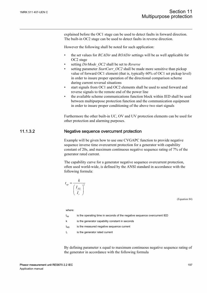
explained before the OC1 stage can be used to detect faults in forward direction.The built-in OC2 stage can be used to detect faults in reverse direction.
However the following shall be noted for such application:
• the set values for RCADir and ROADir settings will be as well applicable forOC2 stage
• setting DirMode_OC2 shall be set to Reverse• setting parameter StartCurr_OC2 shall be made more sensitive than pickup
value of forward OC1 element (that is, typically 60% of OC1 set pickup level)in order to insure proper operation of the directional comparison schemeduring current reversal situations
• start signals from OC1 and OC2 elements shall be used to send forward andreverse signals to the remote end of the power line
• the available scheme communications function block within IED shall be usedbetween multipurpose protection function and the communication equipmentin order to insure proper conditioning of the above two start signals
Furthermore the other built-in UC, OV and UV protection elements can be used forother protection and alarming purposes.
11.1.3.2 Negative sequence overcurrent protectionM13088-5 v4
Example will be given how to use one CVGAPC function to provide negativesequence inverse time overcurrent protection for a generator with capabilityconstant of 20s, and maximum continuous negative sequence rating of 7% of thegenerator rated current.
The capability curve for a generator negative sequence overcurrent protection,often used world-wide, is defined by the ANSI standard in accordance with thefollowing formula:
2op
NS
r
ktII
=æ öç ÷è ø
EQUATION1372 V1 EN-US (Equation 84)
where:
top is the operating time in seconds of the negative sequence overcurrent IED
k is the generator capability constant in seconds
INS is the measured negative sequence current
Ir is the generator rated current
By defining parameter x equal to maximum continuous negative sequence rating ofthe generator in accordance with the following formula
1MRK 511 407-UEN C Section 11Multipurpose protection
Phasor measurement unit RES670 2.2 IEC 197Application manual

7% 0, 07x pu= =EQUATION1373 V1 EN-US (Equation 85)
Equation 84 can be re-written in the following way without changing the value forthe operate time of the negative sequence inverse overcurrent IED:
2
2
1
op
NS
r
kxt
Ix I
×=
æ öç ÷×è ø
EQUATION1374 V1 EN-US (Equation 86)
In order to achieve such protection functionality with one CVGAPC functions thefollowing must be done:
1. Connect three-phase generator currents to one CVGAPC instance (forexample, GF01)
2. Set parameter CurrentInput to value NegSeq3. Set base current value to the rated generator current in primary amperes4. Enable one overcurrent step (for example, OC1)5. Select parameter CurveType_OC1 to value Programmable
op P
At k BM C
æ ö= × +ç ÷-è øEQUATION1375 V1 EN-US (Equation 87)
where:
top is the operating time in seconds of the Inverse Time Overcurrent TOC/IDMT algorithm
k is time multiplier (parameter setting)
M is ratio between measured current magnitude and set pickup current level
A, B, C and P are user settable coefficients which determine the curve used for Inverse TimeOvercurrent TOC/IDMT calculation
When the equation 84 is compared with the equation 86 for the inverse timecharacteristic of the OC1 it is obvious that if the following rules are followed:
1. set k equal to the generator negative sequence capability value2. set A_OC1 equal to the value 1/x23. set B_OC1 = 0.0, C_OC1=0.0 and P_OC1=2.04. set StartCurr_OC1 equal to the value x
then the OC1 step of the CVGAPC function can be used for generator negativesequence inverse overcurrent protection.
Section 11 1MRK 511 407-UEN CMultipurpose protection
198 Phasor measurement unit RES670 2.2 IECApplication manual
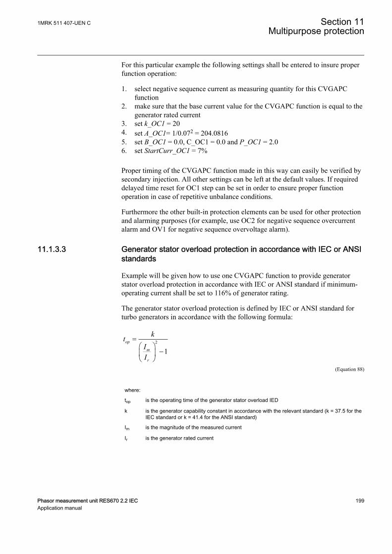
For this particular example the following settings shall be entered to insure properfunction operation:
1. select negative sequence current as measuring quantity for this CVGAPCfunction
2. make sure that the base current value for the CVGAPC function is equal to thegenerator rated current
3. set k_OC1 = 204. set A_OC1= 1/0.072 = 204.08165. set B_OC1 = 0.0, C_OC1 = 0.0 and P_OC1 = 2.06. set StartCurr_OC1 = 7%
Proper timing of the CVGAPC function made in this way can easily be verified bysecondary injection. All other settings can be left at the default values. If requireddelayed time reset for OC1 step can be set in order to ensure proper functionoperation in case of repetitive unbalance conditions.
Furthermore the other built-in protection elements can be used for other protectionand alarming purposes (for example, use OC2 for negative sequence overcurrentalarm and OV1 for negative sequence overvoltage alarm).
11.1.3.3 Generator stator overload protection in accordance with IEC or ANSIstandards
M13088-81 v3
Example will be given how to use one CVGAPC function to provide generatorstator overload protection in accordance with IEC or ANSI standard if minimum-operating current shall be set to 116% of generator rating.
The generator stator overload protection is defined by IEC or ANSI standard forturbo generators in accordance with the following formula:
2
1op
m
r
ktII
=æ ö
-ç ÷è ø
EQUATION1376 V1 EN-US (Equation 88)
where:
top is the operating time of the generator stator overload IED
k is the generator capability constant in accordance with the relevant standard (k = 37.5 for theIEC standard or k = 41.4 for the ANSI standard)
Im is the magnitude of the measured current
Ir is the generator rated current
1MRK 511 407-UEN C Section 11Multipurpose protection
Phasor measurement unit RES670 2.2 IEC 199Application manual
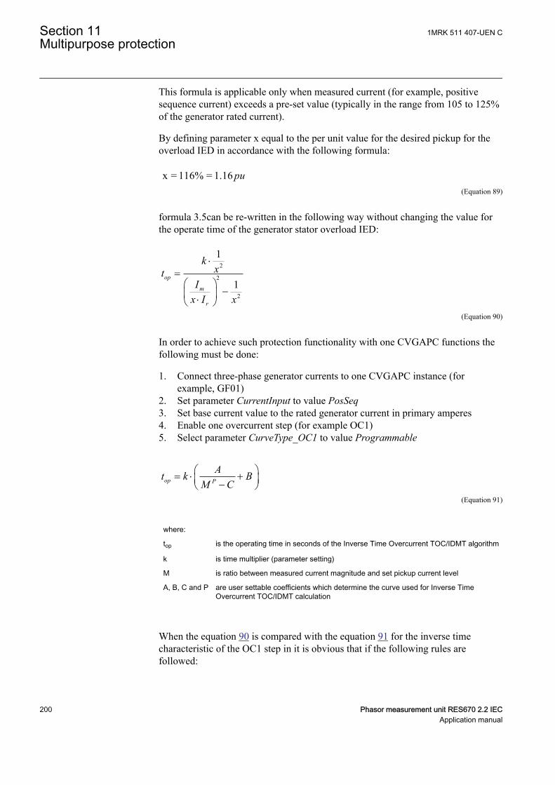
This formula is applicable only when measured current (for example, positivesequence current) exceeds a pre-set value (typically in the range from 105 to 125%of the generator rated current).
By defining parameter x equal to the per unit value for the desired pickup for theoverload IED in accordance with the following formula:
x = 116% = 1.16 puEQUATION1377 V2 EN-US (Equation 89)
formula 3.5can be re-written in the following way without changing the value forthe operate time of the generator stator overload IED:
2
2
2
1
1op
m
r
kxt
Ix I x
×=
æ ö-ç ÷×è ø
EQUATION1378 V1 EN-US (Equation 90)
In order to achieve such protection functionality with one CVGAPC functions thefollowing must be done:
1. Connect three-phase generator currents to one CVGAPC instance (forexample, GF01)
2. Set parameter CurrentInput to value PosSeq3. Set base current value to the rated generator current in primary amperes4. Enable one overcurrent step (for example OC1)5. Select parameter CurveType_OC1 to value Programmable
op P
At k BM C
æ ö= × +ç ÷-è øEQUATION1375 V1 EN-US (Equation 91)
where:
top is the operating time in seconds of the Inverse Time Overcurrent TOC/IDMT algorithm
k is time multiplier (parameter setting)
M is ratio between measured current magnitude and set pickup current level
A, B, C and P are user settable coefficients which determine the curve used for Inverse TimeOvercurrent TOC/IDMT calculation
When the equation 90 is compared with the equation 91 for the inverse timecharacteristic of the OC1 step in it is obvious that if the following rules arefollowed:
Section 11 1MRK 511 407-UEN CMultipurpose protection
200 Phasor measurement unit RES670 2.2 IECApplication manual
1. set k equal to the IEC or ANSI standard generator capability value2. set parameter A_OC1 equal to the value 1/x23. set parameter C_OC1 equal to the value 1/x24. set parameters B_OC1 = 0.0 and P_OC1=2.05. set StartCurr_OC1 equal to the value x
then the OC1 step of the CVGAPC function can be used for generator negativesequence inverse overcurrent protection.
1. select positive sequence current as measuring quantity for this CVGAPCfunction
2. make sure that the base current value for CVGAPC function is equal to thegenerator rated current
3. set k = 37.5 for the IEC standard or k = 41.4 for the ANSI standard4. set A_OC1= 1/1.162 = 0.74325. set C_OC1= 1/1.162 = 0.74326. set B_OC1 = 0.0 and P_OC1 = 2.07. set StartCurr_OC1 = 116%
Proper timing of CVGAPC function made in this way can easily be verified bysecondary injection. All other settings can be left at the default values. If requireddelayed time reset for OC1 step can be set in order to insure proper functionoperation in case of repetitive overload conditions.
Furthermore the other built-in protection elements can be used for other protectionand alarming purposes.
In the similar way rotor overload protection in accordance with ANSI standard canbe achieved.
11.1.3.4 Open phase protection for transformer, lines or generators and circuitbreaker head flashover protection for generators
M13088-142 v3
Example will be given how to use one CVGAPC function to provide open phaseprotection. This can be achieved by using one CVGAPC function by comparing theunbalance current with a pre-set level. In order to make such a function moresecure it is possible to restrain it by requiring that at the same time the measuredunbalance current must be bigger than 97% of the maximum phase current. Bydoing this it will be insured that function can only pickup if one of the phases isopen circuited. Such an arrangement is easy to obtain in CVGAPC function byenabling the current restraint feature. The following shall be done in order to insureproper operation of the function:
1. Connect three-phase currents from the protected object to one CVGAPCinstance (for example, GF03)
2. Set CurrentInput to value UnbalancePh3. Set EnRestrainCurr to On4. Set RestrCurrInput to MaxPh5. Set RestrCurrCoeff to value 0.97
1MRK 511 407-UEN C Section 11Multipurpose protection
Phasor measurement unit RES670 2.2 IEC 201Application manual
6. Set base current value to the rated current of the protected object in primaryamperes
7. Enable one overcurrent step (for example, OC1)8. Select parameter CurveType_OC1 to value IEC Def. Time9. Set parameter StartCurr_OC1 to value 5%10. Set parameter tDef_OC1 to desired time delay (for example, 2.0s)
Proper operation of CVGAPC function made in this way can easily be verified bysecondary injection. All other settings can be left at the default values. However itshall be noted that set values for restrain current and its coefficient will as well beapplicable for OC2 step as soon as it is enabled.
Furthermore the other built-in protection elements can be used for other protectionand alarming purposes. For example, in case of generator application by enablingOC2 step with set pickup to 200% and time delay to 0.1s simple but effectiveprotection against circuit breaker head flashover protection is achieved.
11.1.3.5 Voltage restrained overcurrent protection for generator and step-uptransformer
M13088-158 v4
Example will be given how to use one CVGAPC function to provide voltagerestrained overcurrent protection for a generator. Let us assume that the timecoordination study gives the following required settings:
• Inverse Time Over Current TOC/IDMT curve: ANSI very inverse• Pickup current of 185% of generator rated current at rated generator voltage• Pickup current 25% of the original pickup current value for generator voltages
below 25% of rated voltage
This functionality can be achieved by using one CVGAPC function. The followingshall be done in order to ensure proper operation of the function:
1. Connect three-phase generator currents and voltages to one CVGAPC instance(for example, GF05)
2. Set CurrentInput to value MaxPh3. Set VoltageInput to value MinPh-Ph (it is assumed that minimum phase-to-
phase voltage shall be used for restraining. Alternatively, positive sequencevoltage can be used for restraining by selecting PosSeq for this settingparameter)
4. Set base current value to the rated generator current primary amperes5. Set base voltage value to the rated generator phase-to-phase voltage in kV6. Enable one overcurrent step (for example, OC1)7. Select CurveType_OC1 to value ANSI Very inv8. If required set minimum operating time for this curve by using parameter
tMin_OC1 (default value 0.05s)9. Set StartCurr_OC1 to value 185%10. Set VCntrlMode_OC1 to On11. Set VDepMode_OC1 to Slope
Section 11 1MRK 511 407-UEN CMultipurpose protection
202 Phasor measurement unit RES670 2.2 IECApplication manual
12. Set VDepFact_OC1 to value 0.2513. Set UHighLimit_OC1 to value 100%14. Set ULowLimit_OC1 to value 25%
Proper operation of the CVGAPC function made in this way can easily be verifiedby secondary injection. All other settings can be left at the default values.Furthermore the other built-in protection elements can be used for other protectionand alarming purposes.
11.1.3.6 Loss of excitation protection for a generatorM13088-182 v3
Example will be given how by using positive sequence directional overcurrentprotection element within a CVGAPC function, loss of excitation protection for agenerator can be achieved. Let us assume that from rated generator data thefollowing values are calculated:
• Maximum generator capability to contentiously absorb reactive power at zeroactive loading 38% of the generator MVA rating
• Generator pull-out angle 84 degrees
This functionality can be achieved by using one CVGAPC function. The followingshall be done in order to insure proper operation of the function:
1. Connect three-phase generator currents and three-phase generator voltages toone CVGAPC instance (for example, GF02)
2. Set parameter CurrentInput to PosSeq3. Set parameter VoltageInput to PosSeq4. Set base current value to the rated generator current primary amperes5. Set base voltage value to the rated generator phase-to-phase voltage in kV6. Set parameter RCADir to value -84 degree (that is, current lead voltage for this
angle)7. Set parameter ROADir to value 90 degree8. Set parameter LowVolt_VM to value 5%9. Enable one overcurrent step (for example, OC1)10. Select parameter CurveType_OC1 to value IEC Def. Time11. Set parameter StartCurr_OC1 to value 38%12. Set parameter tDef_OC1 to value 2.0s (typical setting)13. Set parameter DirMode_OC1 to Forward14. Set parameter DirPrinc_OC1 to IcosPhi&U15. Set parameter ActLowVolt1_VM to Block
Proper operation of the CVGAPC function made in this way can easily be verifiedby secondary injection. All other settings can be left at the default values. Howeverit shall be noted that set values for RCA & ROA angles will be applicable for OC2step if directional feature is enabled for this step as well. Figure 73 shows overallprotection characteristic
1MRK 511 407-UEN C Section 11Multipurpose protection
Phasor measurement unit RES670 2.2 IEC 203Application manual
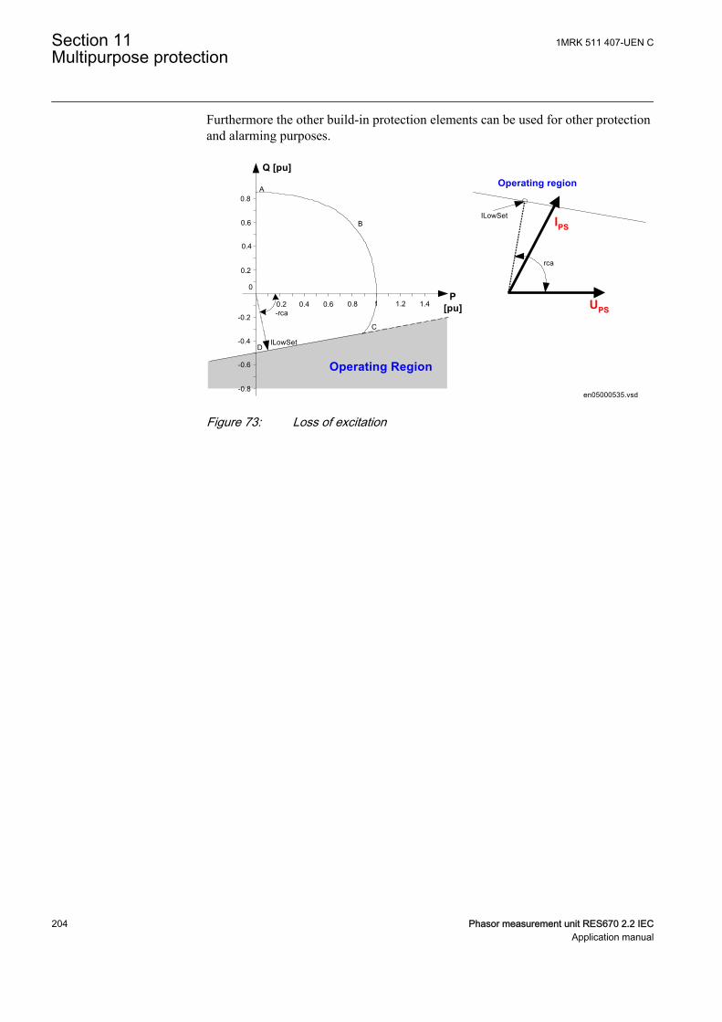
Furthermore the other build-in protection elements can be used for other protectionand alarming purposes.
0.2 0.4 0.6
-0.2
0.6
0.8
0.8 1
DILowSet
B
A
C
0.4
0.2
0
1.2 1.4
-0.4
-0.6
-0.8
-rca
Operating Region
Q [pu]
P[pu]
rca
UPS
IPSILowSet
Operating region
en05000535.vsdIEC05000535 V2 EN-US
Figure 73: Loss of excitation
Section 11 1MRK 511 407-UEN CMultipurpose protection
204 Phasor measurement unit RES670 2.2 IECApplication manual
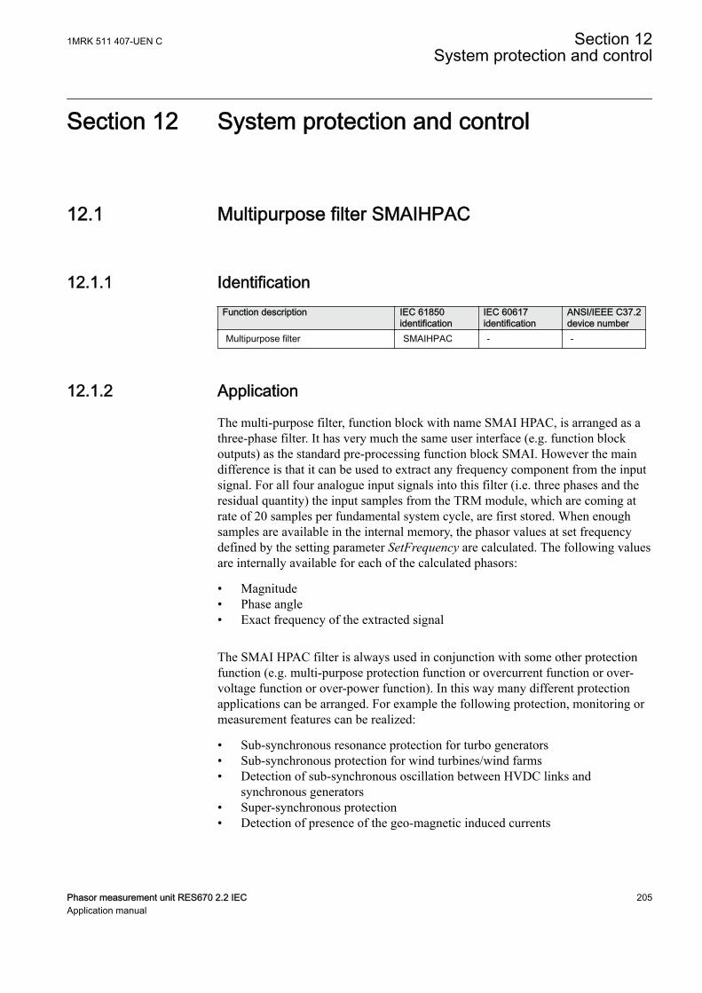
Section 12 System protection and control
12.1 Multipurpose filter SMAIHPACGUID-6B541154-D56B-452F-B143-4C2A1B2D3A1F v1
12.1.1 IdentificationGUID-8224B870-3DAA-44BF-B790-6600F2AD7C5D v1
Function description IEC 61850identification
IEC 60617identification
ANSI/IEEE C37.2device number
Multipurpose filter SMAIHPAC - -
12.1.2 ApplicationGUID-A1F20DD8-571E-42C3-84F3-C557EC352ED0 v1
The multi-purpose filter, function block with name SMAI HPAC, is arranged as athree-phase filter. It has very much the same user interface (e.g. function blockoutputs) as the standard pre-processing function block SMAI. However the maindifference is that it can be used to extract any frequency component from the inputsignal. For all four analogue input signals into this filter (i.e. three phases and theresidual quantity) the input samples from the TRM module, which are coming atrate of 20 samples per fundamental system cycle, are first stored. When enoughsamples are available in the internal memory, the phasor values at set frequencydefined by the setting parameter SetFrequency are calculated. The following valuesare internally available for each of the calculated phasors:
• Magnitude• Phase angle• Exact frequency of the extracted signal
The SMAI HPAC filter is always used in conjunction with some other protectionfunction (e.g. multi-purpose protection function or overcurrent function or over-voltage function or over-power function). In this way many different protectionapplications can be arranged. For example the following protection, monitoring ormeasurement features can be realized:
• Sub-synchronous resonance protection for turbo generators• Sub-synchronous protection for wind turbines/wind farms• Detection of sub-synchronous oscillation between HVDC links and
synchronous generators• Super-synchronous protection• Detection of presence of the geo-magnetic induced currents
1MRK 511 407-UEN C Section 12System protection and control
Phasor measurement unit RES670 2.2 IEC 205Application manual
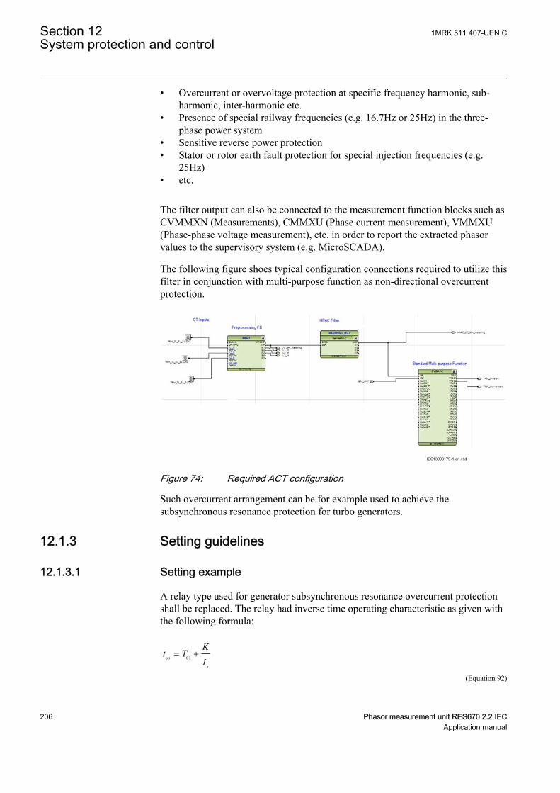
• Overcurrent or overvoltage protection at specific frequency harmonic, sub-harmonic, inter-harmonic etc.
• Presence of special railway frequencies (e.g. 16.7Hz or 25Hz) in the three-phase power system
• Sensitive reverse power protection• Stator or rotor earth fault protection for special injection frequencies (e.g.
25Hz)• etc.
The filter output can also be connected to the measurement function blocks such asCVMMXN (Measurements), CMMXU (Phase current measurement), VMMXU(Phase-phase voltage measurement), etc. in order to report the extracted phasorvalues to the supervisory system (e.g. MicroSCADA).
The following figure shoes typical configuration connections required to utilize thisfilter in conjunction with multi-purpose function as non-directional overcurrentprotection.
IEC13000179-1-en.vsdIEC13000179 V1 EN-US
Figure 74: Required ACT configuration
Such overcurrent arrangement can be for example used to achieve thesubsynchronous resonance protection for turbo generators.
12.1.3 Setting guidelines
12.1.3.1 Setting exampleGUID-5A3F67BD-7D48-4734-948C-01DAF9470EF8 v2
A relay type used for generator subsynchronous resonance overcurrent protectionshall be replaced. The relay had inverse time operating characteristic as given withthe following formula:
01op
s
Kt T
I= +
EQUATION13000029 V1 EN-US (Equation 92)
Section 12 1MRK 511 407-UEN CSystem protection and control
206 Phasor measurement unit RES670 2.2 IECApplication manual
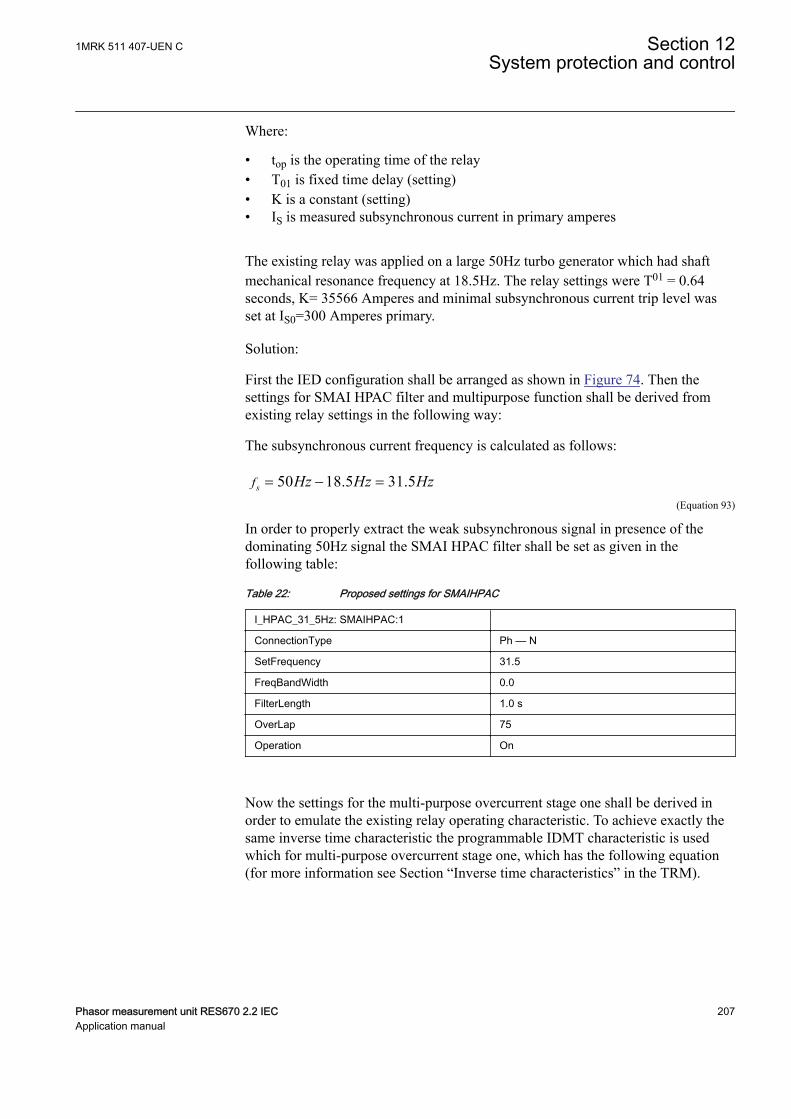
Where:
• top is the operating time of the relay• T01 is fixed time delay (setting)• K is a constant (setting)• IS is measured subsynchronous current in primary amperes
The existing relay was applied on a large 50Hz turbo generator which had shaftmechanical resonance frequency at 18.5Hz. The relay settings were T01 = 0.64seconds, K= 35566 Amperes and minimal subsynchronous current trip level wasset at IS0=300 Amperes primary.
Solution:
First the IED configuration shall be arranged as shown in Figure 74. Then thesettings for SMAI HPAC filter and multipurpose function shall be derived fromexisting relay settings in the following way:
The subsynchronous current frequency is calculated as follows:
50 18.5 31.5sf Hz Hz Hz= - =EQUATION13000030 V1 EN-US (Equation 93)
In order to properly extract the weak subsynchronous signal in presence of thedominating 50Hz signal the SMAI HPAC filter shall be set as given in thefollowing table:
Table 22: Proposed settings for SMAIHPAC
I_HPAC_31_5Hz: SMAIHPAC:1
ConnectionType Ph — N
SetFrequency 31.5
FreqBandWidth 0.0
FilterLength 1.0 s
OverLap 75
Operation On
Now the settings for the multi-purpose overcurrent stage one shall be derived inorder to emulate the existing relay operating characteristic. To achieve exactly thesame inverse time characteristic the programmable IDMT characteristic is usedwhich for multi-purpose overcurrent stage one, which has the following equation(for more information see Section “Inverse time characteristics” in the TRM).
1MRK 511 407-UEN C Section 12System protection and control
Phasor measurement unit RES670 2.2 IEC 207Application manual
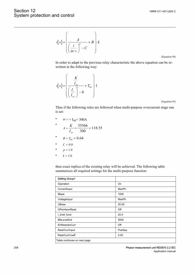
[ ] ptAs B k
i Cin
æ öç ÷ç ÷= + ×ç ÷æ ö -ç ÷ç ÷>è øè ø
EQUATION13000031 V1 EN-US (Equation 94)
In order to adapt to the previous relay characteristic the above equation can be re-written in the following way:
[ ] 011 10
so
s
so
t
KIs T
II
æ öç ÷ç ÷= + ×ç ÷æ öç ÷-ç ÷ç ÷è øè ø
EQUATION13000032 V1 EN-US (Equation 95)
Thus if the following rules are followed when multi-purpose overcurrent stage oneis set:
• in > = IS0= 300A• 35566 118.55
300so
AKI
= = =
•01 0.64B T= =
• 0.0C =
• 1.0p =
• 1.0k =
then exact replica of the existing relay will be achieved. The following tablesummarizes all required settings for the multi-purpose function:
Setting Group1
Operation On
CurrentInput MaxPh
IBase 1000
VoltageInput MaxPh
UBase 20.50
OPerHarmRestr Off
I_2ndI_fund 20.0
BlkLevel2nd 5000
EnRestrainCurr Off
RestrCurrInput PosSeq
RestrCurrCoeff 0.00
Table continues on next page
Section 12 1MRK 511 407-UEN CSystem protection and control
208 Phasor measurement unit RES670 2.2 IECApplication manual
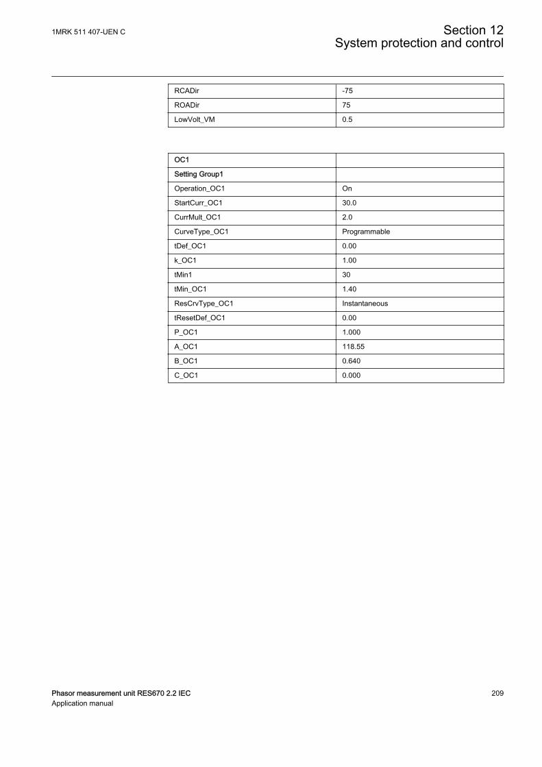
RCADir -75
ROADir 75
LowVolt_VM 0.5
OC1
Setting Group1
Operation_OC1 On
StartCurr_OC1 30.0
CurrMult_OC1 2.0
CurveType_OC1 Programmable
tDef_OC1 0.00
k_OC1 1.00
tMin1 30
tMin_OC1 1.40
ResCrvType_OC1 Instantaneous
tResetDef_OC1 0.00
P_OC1 1.000
A_OC1 118.55
B_OC1 0.640
C_OC1 0.000
1MRK 511 407-UEN C Section 12System protection and control
Phasor measurement unit RES670 2.2 IEC 209Application manual

210
Section 13 Secondary system supervision
13.1 Current circuit supervision CCSSPVCIP14555-1 v5
13.1.1 IdentificationM14870-1 v5
Function description IEC 61850identification
IEC 60617identification
ANSI/IEEE C37.2device number
Current circuit supervision CCSSPVC - 87
13.1.2 ApplicationM12395-13 v9
Open or short circuited current transformer cores can cause unwanted operation ofmany protection functions such as differential, earth-fault current and negative-sequence current functions. When currents from two independent three-phase setsof CTs, or CT cores, measuring the same primary currents are available, reliablecurrent circuit supervision can be arranged by comparing the currents from the twosets. If an error in any CT circuit is detected, the protection functions concernedcan be blocked and an alarm given.
In case of large currents, unequal transient saturation of CT cores with differentremanence or different saturation factor may result in differences in the secondarycurrents from the two CT sets. Unwanted blocking of protection functions duringthe transient stage must then be avoided.
Current circuit supervision CCSSPVC must be sensitive and have short operatetime in order to prevent unwanted tripping from fast-acting, sensitive numericalprotections in case of faulty CT secondary circuits.
Open CT circuits creates extremely high voltages in the circuitswhich is extremely dangerous for the personnel. It can also damagethe insulation and cause new problems. The application shall, thus,be done with this in consideration, especially if the protectionfunctions are blocked.
13.1.3 Setting guidelinesM12397-17 v8
GlobalBaseSel: Selects the global base value group used by the function to defineIBase, UBase and SBase as applicable.
1MRK 511 407-UEN C Section 13Secondary system supervision
Phasor measurement unit RES670 2.2 IEC 211Application manual
Current circuit supervision CCSSPVC compares the residual current from a three-phase set of current transformer cores with the neutral point current on a separateinput taken from another set of cores on the same current transformer.
IMinOp: It must be set as a minimum to twice the residual current in the supervisedCT circuits under normal service conditions and rated primary current.
Ip>Block: It is normally set at 150% to block the function during transientconditions.
The FAIL output is connected to the blocking input of the protection function to beblocked at faulty CT secondary circuits.
13.2 Fuse failure supervision FUFSPVCIP14556-1 v3
13.2.1 IdentificationM14869-1 v4
Function description IEC 61850identification
IEC 60617identification
ANSI/IEEE C37.2device number
Fuse failure supervision FUFSPVC - -
13.2.2 ApplicationSEMOD113803-4 v10
Different protection functions within the protection IED, operates on the basis ofthe measured voltage in the relay point. Examples are:
• impedance protection functions• undervoltage function• energizing check function and voltage check for the weak infeed logic
These functions can operate unintentionally if a fault occurs in the secondarycircuits between the voltage instrument transformers and the IED.
It is possible to use different measures to prevent such unwanted operations.Miniature circuit breakers in the voltage measuring circuits should be located asclose as possible to the voltage instrument transformers, and shall be equipped withauxiliary contacts that are wired to the IEDs. Separate fuse-failure monitoring IEDsor elements within the protection and monitoring devices are another possibilities.These solutions are combined to get the best possible effect in the fuse failuresupervision function (FUFSPVC).
FUFSPVC function built into the IED products can operate on the basis of externalbinary signals from the miniature circuit breaker or from the line disconnector. The
Section 13 1MRK 511 407-UEN CSecondary system supervision
212 Phasor measurement unit RES670 2.2 IECApplication manual
first case influences the operation of all voltage-dependent functions while thesecond one does not affect the impedance measuring functions.
The negative sequence detection algorithm, based on the negative-sequencemeasuring quantities is recommended for use in isolated or high-impedance earthednetworks: a high value of voltage 3U2 without the presence of the negative-sequence current 3I2 is a condition that is related to a fuse failure event.
The zero sequence detection algorithm, based on the zero sequence measuringquantities is recommended for use in directly or low impedance earthed networks:a high value of voltage 3U0 without the presence of the residual current 3I0 is acondition that is related to a fuse failure event. In cases where the line can have aweak-infeed of zero sequence current this function shall be avoided.
A criterion based on delta current and delta voltage measurements can be added tothe fuse failure supervision function in order to detect a three phase fuse failure.This is beneficial for example during three phase transformer switching.
13.2.3 Setting guidelinesIP15000-1 v1
13.2.3.1 GeneralM13683-3 v5
The negative and zero sequence voltages and currents always exist due to differentnon-symmetries in the primary system and differences in the current and voltageinstrument transformers. The minimum value for the operation of the current andvoltage measuring elements must always be set with a safety margin of 10 to 20%,depending on the system operating conditions.
Pay special attention to the dissymmetry of the measuring quantities when thefunction is used on long untransposed lines, on multicircuit lines and so on.
The settings of negative sequence, zero sequence and delta algorithm are in percentof the base voltage and base current for the function. Common base IED values forprimary current (IBase), primary voltage (UBase) and primary power (SBase) areset in Global Base Values GBASVAL. The setting GlobalBaseSel is used to select aparticular GBASVAL and used its base values.
13.2.3.2 Setting of common parametersM13683-9 v9
Set the operation mode selector Operation to On to release the fuse failurefunction.
The voltage threshold USealIn< is used to identify low voltage condition in thesystem. Set USealIn< below the minimum operating voltage that might occurduring emergency conditions. We propose a setting of approximately 70% ofUBase.
The drop off time of 200 ms for dead phase detection makes it recommended toalways set SealIn to On since this will secure a fuse failure indication at persistent
1MRK 511 407-UEN C Section 13Secondary system supervision
Phasor measurement unit RES670 2.2 IEC 213Application manual

fuse fail when closing the local breaker when the line is already energized from theother end. When the remote breaker closes the voltage will return except in thephase that has a persistent fuse fail. Since the local breaker is open there is nocurrent and the dead phase indication will persist in the phase with the blown fuse.When the local breaker closes the current will start to flow and the function detectsthe fuse failure situation. But due to the 200 ms drop off timer the output BLKZwill not be activated until after 200 ms. This means that distance functions are notblocked and due to the “no voltage but current” situation might issue a trip.
The operation mode selector OpMode has been introduced for better adaptation tosystem requirements. The mode selector enables selecting interactions between thenegative sequence and zero sequence algorithm. In normal applications, theOpMode is set to either UNsINs for selecting negative sequence algorithm orUZsIZs for zero sequence based algorithm. If system studies or field experiencesshows that there is a risk that the fuse failure function will not be activated due tothe system conditions, the dependability of the fuse failure function can beincreased if the OpMode is set to UZsIZs OR UNsINs or OptimZsNs. In modeUZsIZs OR UNsINs both negative and zero sequence based algorithms areactivated and working in an OR-condition. Also in mode OptimZsNs both negativeand zero sequence algorithms are activated and the one that has the highestmagnitude of measured negative or zero sequence current will operate. If there is arequirement to increase the security of the fuse failure function OpMode can beselected to UZsIZs AND UNsINs which gives that both negative and zero sequencealgorithms are activated and working in an AND-condition, that is, both algorithmsmust give condition for block in order to activate the output signals BLKU orBLKZ.
13.2.3.3 Negative sequence basedM13683-17 v9
The relay setting value 3U2> is given in percentage of the base voltage UBase andshould not be set lower than the value that is calculated according to equation 96.
1003
223
UBase
UU
EQUATION1519 V5 EN-US (Equation 96)
where:
U2 is the maximal negative sequence voltage during normal operation conditions, plus a marginof 10...20%
UBase is the base voltage for the function according to the setting GlobalBaseSel
The setting of the current limit 3I2< is in percentage of parameter IBase. Thesetting of 3I2< must be higher than the normal unbalance current that might existin the system and can be calculated according to equation 97.
Section 13 1MRK 511 407-UEN CSecondary system supervision
214 Phasor measurement unit RES670 2.2 IECApplication manual
1002
23 IBase
II
EQUATION1520 V5 EN-US (Equation 97)
where:
I2 is the maximal negative sequence current during normal operating conditions, plus a marginof 10...20%
IBase is the base current for the function according to the setting GlobalBaseSel
13.2.3.4 Zero sequence basedM13683-43 v8
The IED setting value 3U0> is given in percentage of the base voltage UBase. Thesetting of 3U0> should not be set lower than the value that is calculated accordingto equation 98.
1003
0303
UBase
UU
EQUATION1521 V4 EN-US (Equation 98)
where:
3U0 is the maximal zero sequence voltage during normal operation conditions, plus a margin of10...20%
UBase is the base voltage for the function according to the setting GlobalBaseSel
The setting of the current limit 3I0< is done in percentage of IBase. The setting of3I0< must be higher than the normal unbalance current that might exist in thesystem. The setting can be calculated according to equation 99.
3 03 0 100IIIBase
= × <
EQUATION2293 V3 EN-US (Equation 99)
where:
3I0< is the maximal zero sequence current during normal operating conditions, plus a margin of10...20%
IBase is the base current for the function according to the setting GlobalBaseSel
13.2.3.5 Delta U and delta IGUID-02336F26-98C0-419D-8759-45F5F12580DE v7
Set the operation mode selector OpDUDI to On if the delta function shall be inoperation.
1MRK 511 407-UEN C Section 13Secondary system supervision
Phasor measurement unit RES670 2.2 IEC 215Application manual
The setting of DU> should be set high (approximately 60% of UBase) and thecurrent threshold DI< low (approximately 10% of IBase) to avoid unwantedoperation due to normal switching conditions in the network. The delta current anddelta voltage function shall always be used together with either the negative or zerosequence algorithm. If USetprim is the primary voltage for operation of dU/dt andISetprim the primary current for operation of dI/dt, the setting of DU> and DI< willbe given according to equation 100 and equation 101.
DUUSet
UBaseprim> = 100.
EQUATION1523 V3 EN-US (Equation 100)
DIISetIBase
prim< = 100.
EQUATION1524 V4 EN-US (Equation 101)
The voltage thresholds UPh> is used to identify low voltage condition in thesystem. Set UPh> below the minimum operating voltage that might occur duringemergency conditions. A setting of approximately 70% of UBase is recommended.
The current threshold IPh> shall be set lower than the IMinOp for the distanceprotection function. A 5...10% lower value is recommended.
13.2.3.6 Dead line detectionM13683-78 v4
The condition for operation of the dead line detection is set by the parametersIDLD< for the current threshold and UDLD< for the voltage threshold.
Set the IDLD< with a sufficient margin below the minimum expected load current.A safety margin of at least 15-20% is recommended. The operate value musthowever exceed the maximum charging current of an overhead line, when only onephase is disconnected (mutual coupling to the other phases).
Set the UDLD< with a sufficient margin below the minimum expected operatingvoltage. A safety margin of at least 15% is recommended.
Section 13 1MRK 511 407-UEN CSecondary system supervision
216 Phasor measurement unit RES670 2.2 IECApplication manual
Section 14 Control
14.1 Logic rotating switch for function selection andLHMI presentation SLGAPC
SEMOD114936-1 v5
14.1.1 IdentificationSEMOD167845-2 v3
Function description IEC 61850identification
IEC 60617identification
ANSI/IEEE C37.2device number
Logic rotating switch for functionselection and LHMI presentation
SLGAPC - -
14.1.2 ApplicationSEMOD114927-4 v7
The logic rotating switch for function selection and LHMI presentation function(SLGAPC) (or the selector switch function block, as it is also known) is used to geta selector switch functionality similar with the one provided by a hardware multi-position selector switch. Hardware selector switches are used extensively byutilities, in order to have different functions operating on pre-set values. Hardwareswitches are however sources for maintenance issues, lower system reliability andextended purchase portfolio. The virtual selector switches eliminate all theseproblems.
SLGAPC function block has two operating inputs (UP and DOWN), one blockinginput (BLOCK) and one operator position input (PSTO).
SLGAPC can be activated both from the local HMI and from external sources(switches) via the IED binary inputs. It also allows the operation from remote (likethe station computer). SWPOSN is an integer value output, giving the actual outputnumber. Since the number of positions of the switch can be established by settings(see below), one must be careful in coordinating the settings with the configuration(if one sets the number of positions to x in settings – for example, there will beonly the first x outputs available from the block in the configuration). Also thefrequency of the (UP or DOWN) pulses should be lower than the setting tPulse.
From the local HMI, the selector switch can be operated from Single-line diagram(SLD).
1MRK 511 407-UEN C Section 14Control
Phasor measurement unit RES670 2.2 IEC 217Application manual
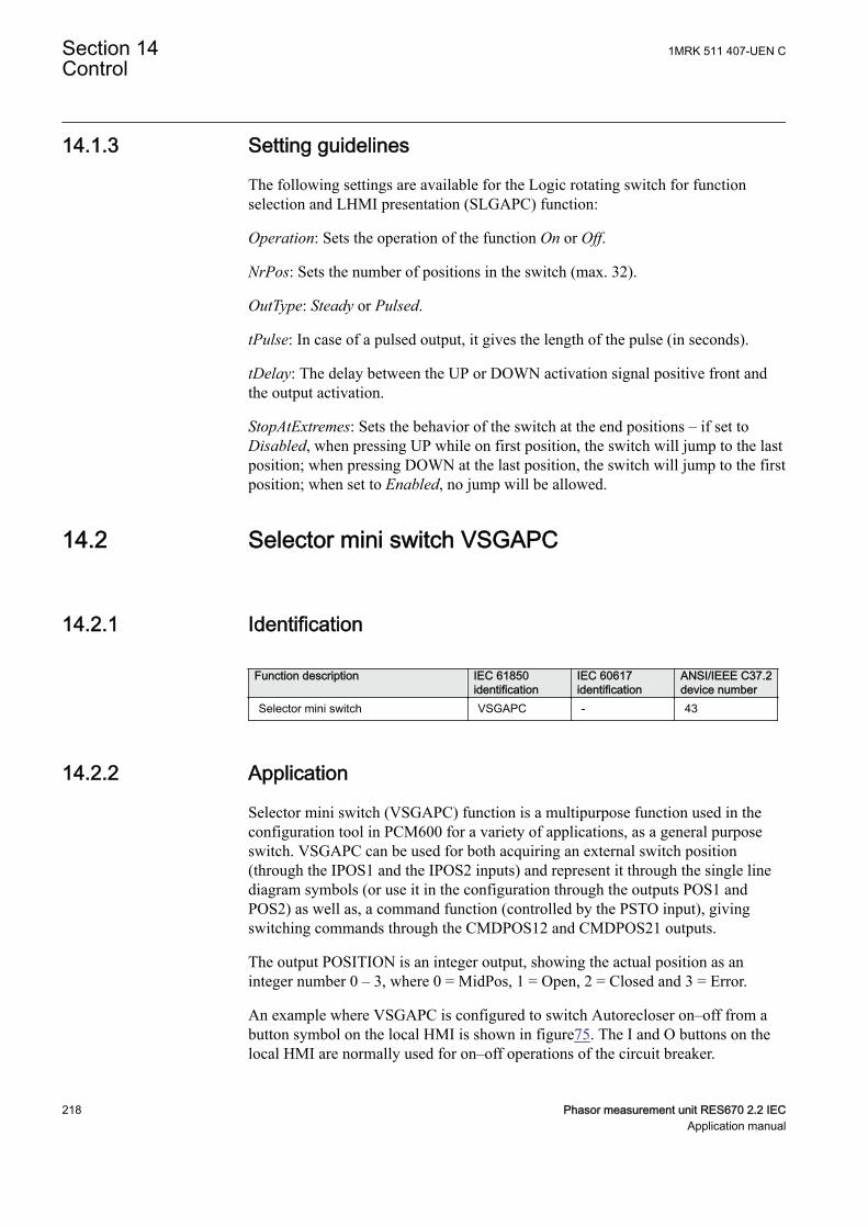
14.1.3 Setting guidelinesSEMOD115063-294 v7
The following settings are available for the Logic rotating switch for functionselection and LHMI presentation (SLGAPC) function:
Operation: Sets the operation of the function On or Off.
NrPos: Sets the number of positions in the switch (max. 32).
OutType: Steady or Pulsed.
tPulse: In case of a pulsed output, it gives the length of the pulse (in seconds).
tDelay: The delay between the UP or DOWN activation signal positive front andthe output activation.
StopAtExtremes: Sets the behavior of the switch at the end positions – if set toDisabled, when pressing UP while on first position, the switch will jump to the lastposition; when pressing DOWN at the last position, the switch will jump to the firstposition; when set to Enabled, no jump will be allowed.
14.2 Selector mini switch VSGAPCSEMOD158754-1 v3
14.2.1 IdentificationSEMOD167850-2 v4
Function description IEC 61850identification
IEC 60617identification
ANSI/IEEE C37.2device number
Selector mini switch VSGAPC - 43
14.2.2 ApplicationSEMOD158803-5 v9
Selector mini switch (VSGAPC) function is a multipurpose function used in theconfiguration tool in PCM600 for a variety of applications, as a general purposeswitch. VSGAPC can be used for both acquiring an external switch position(through the IPOS1 and the IPOS2 inputs) and represent it through the single linediagram symbols (or use it in the configuration through the outputs POS1 andPOS2) as well as, a command function (controlled by the PSTO input), givingswitching commands through the CMDPOS12 and CMDPOS21 outputs.
The output POSITION is an integer output, showing the actual position as aninteger number 0 – 3, where 0 = MidPos, 1 = Open, 2 = Closed and 3 = Error.
An example where VSGAPC is configured to switch Autorecloser on–off from abutton symbol on the local HMI is shown in figure75. The I and O buttons on thelocal HMI are normally used for on–off operations of the circuit breaker.
Section 14 1MRK 511 407-UEN CControl
218 Phasor measurement unit RES670 2.2 IECApplication manual
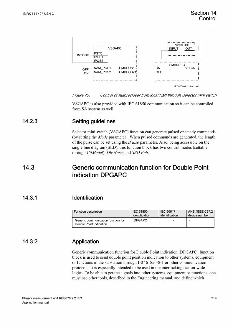
IEC07000112-3-en.vsd
PSTO
CMDPOS12
IPOS1
NAM_POS1NAM_POS2
IPOS2
CMDPOS21OFFON
VSGAPC
SMBRRECONOFF
SETON
INTONE
INVERTERINPUT OUT
IEC07000112 V3 EN-US
Figure 75: Control of Autorecloser from local HMI through Selector mini switch
VSGAPC is also provided with IEC 61850 communication so it can be controlledfrom SA system as well.
14.2.3 Setting guidelinesSEMOD158807-4 v4
Selector mini switch (VSGAPC) function can generate pulsed or steady commands(by setting the Mode parameter). When pulsed commands are generated, the lengthof the pulse can be set using the tPulse parameter. Also, being accessible on thesingle line diagram (SLD), this function block has two control modes (settablethrough CtlModel): Dir Norm and SBO Enh.
14.3 Generic communication function for Double Pointindication DPGAPC
SEMOD55384-1 v4
14.3.1 IdentificationGUID-E16EA78F-6DF9-4B37-A92D-5C09827E2297 v3
Function description IEC 61850identification
IEC 60617identification
ANSI/IEEE C37.2device number
Generic communication function forDouble Point indication
DPGAPC - -
14.3.2 ApplicationSEMOD55391-5 v8
Generic communication function for Double Point indication (DPGAPC) functionblock is used to send double point position indication to other systems, equipmentor functions in the substation through IEC 61850-8-1 or other communicationprotocols. It is especially intended to be used in the interlocking station-widelogics. To be able to get the signals into other systems, equipment or functions, onemust use other tools, described in the Engineering manual, and define which
1MRK 511 407-UEN C Section 14Control
Phasor measurement unit RES670 2.2 IEC 219Application manual
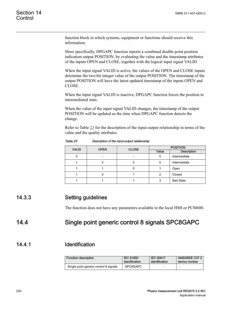
function block in which systems, equipment or functions should receive thisinformation.
More specifically, DPGAPC function reports a combined double point positionindication output POSITION, by evaluating the value and the timestamp attributesof the inputs OPEN and CLOSE, together with the logical input signal VALID.
When the input signal VALID is active, the values of the OPEN and CLOSE inputsdetermine the two-bit integer value of the output POSITION. The timestamp of theoutput POSITION will have the latest updated timestamp of the inputs OPEN andCLOSE.
When the input signal VALID is inactive, DPGAPC function forces the position tointermediated state.
When the value of the input signal VALID changes, the timestamp of the outputPOSITION will be updated as the time when DPGAPC function detects thechange.
Refer to Table 23 for the description of the input-output relationship in terms of thevalue and the quality attributes.
Table 23: Description of the input-output relationship
VALID OPEN CLOSE POSITIONValue Description
0 - - 0 Intermediate
1 0 0 0 Intermediate
1 1 0 1 Open
1 0 1 2 Closed
1 1 1 3 Bad State
14.3.3 Setting guidelinesSEMOD55398-5 v5
The function does not have any parameters available in the local HMI or PCM600.
14.4 Single point generic control 8 signals SPC8GAPCSEMOD176448-1 v3
14.4.1 IdentificationSEMOD176456-2 v3
Function description IEC 61850identification
IEC 60617identification
ANSI/IEEE C37.2device number
Single point generic control 8 signals SPC8GAPC - -
Section 14 1MRK 511 407-UEN CControl
220 Phasor measurement unit RES670 2.2 IECApplication manual

14.4.2 ApplicationSEMOD176511-4 v7
The Single point generic control 8 signals (SPC8GAPC) function block is acollection of 8 single point commands that can be used for direct commands forexample reset of LED's or putting IED in "ChangeLock" state from remote. In thisway, simple commands can be sent directly to the IED outputs, withoutconfirmation. Confirmation (status) of the result of the commands is supposed tobe achieved by other means, such as binary inputs and SPGAPC function blocks.
PSTO is the universal operator place selector for all controlfunctions. Even if PSTO can be configured to allow LOCAL orALL operator positions, the only functional position usable with theSPC8GAPC function block is REMOTE.
14.4.3 Setting guidelinesSEMOD176518-4 v7
The parameters for the single point generic control 8 signals (SPC8GAPC)function are set via the local HMI or PCM600.
Operation: turning the function operation On/Off.
There are two settings for every command output (totally 8):
PulseModex: decides if the command signal for output x is Latched (steady) orPulsed.
tPulsex: if PulseModex is set to Pulsed, then tPulsex will set the length of the pulse(in seconds).
14.5 AutomationBits, command function for DNP3.0AUTOBITS
SEMOD158589-1 v3
14.5.1 IdentificationGUID-C3BB63F5-F0E7-4B00-AF0F-917ECF87B016 v4
Function description IEC 61850identification
IEC 60617identification
ANSI/IEEE C37.2device number
AutomationBits, command function forDNP3 AUTOBITS - -
1MRK 511 407-UEN C Section 14Control
Phasor measurement unit RES670 2.2 IEC 221Application manual
14.5.2 ApplicationSEMOD158637-5 v4
Automation bits, command function for DNP3 (AUTOBITS) is used withinPCM600 in order to get into the configuration the commands coming through theDNP3.0 protocol.The AUTOBITS function plays the same role as functionsGOOSEBINRCV (for IEC 61850) and MULTICMDRCV (for LON).AUTOBITSfunction block have 32 individual outputs which each can be mapped as a BinaryOutput point in DNP3. The output is operated by a "Object 12" in DNP3. Thisobject contains parameters for control-code, count, on-time and off-time. Tooperate an AUTOBITS output point, send a control-code of latch-On, latch-Off,pulse-On, pulse-Off, Trip or Close. The remaining parameters are regarded asappropriate. For example, pulse-On, on-time=100, off-time=300, count=5 wouldgive 5 positive 100 ms pulses, 300 ms apart.
For description of the DNP3 protocol implementation, refer to the Communicationmanual.
14.5.3 Setting guidelinesSEMOD158639-5 v3
AUTOBITS function block has one setting, (Operation: On/Off) enabling ordisabling the function. These names will be seen in the DNP3 communicationmanagement tool in PCM600.
14.6 Single command, 16 signals SINGLECMDSEMOD119849-1 v2
14.6.1 IdentificationGUID-2217CCC2-5581-407F-A4BC-266CD6808984 v1
Function description IEC 61850identification
IEC 60617identification
ANSI/IEEE C37.2device number
Single command, 16 signals SINGLECMD - -
14.6.2 ApplicationM12445-3 v3
Single command, 16 signals (SINGLECMD) is a common function and alwaysincluded in the IED.
The IEDs may be provided with a function to receive commands either from asubstation automation system or from the local HMI. That receiving function blockhas outputs that can be used, for example, to control high voltage apparatuses inswitchyards. For local control functions, the local HMI can also be used. Togetherwith the configuration logic circuits, the user can govern pulses or steady outputsignals for control purposes within the IED or via binary outputs.
Section 14 1MRK 511 407-UEN CControl
222 Phasor measurement unit RES670 2.2 IECApplication manual
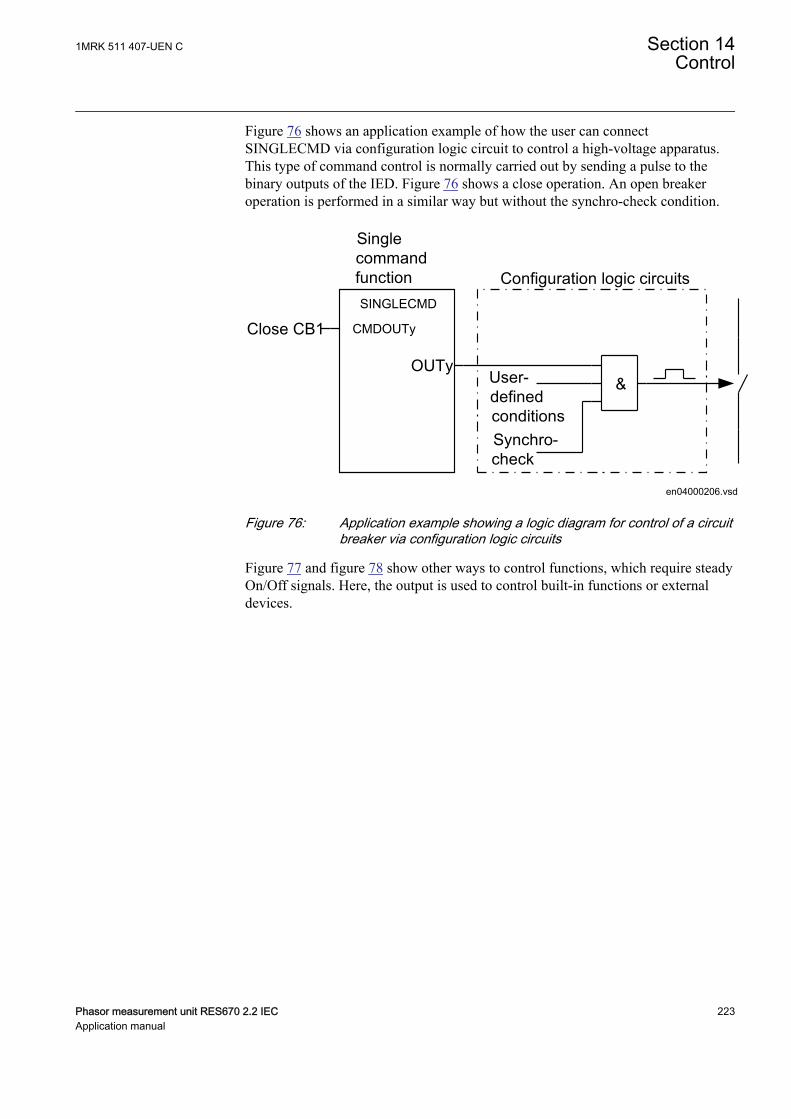
Figure 76 shows an application example of how the user can connectSINGLECMD via configuration logic circuit to control a high-voltage apparatus.This type of command control is normally carried out by sending a pulse to thebinary outputs of the IED. Figure 76 shows a close operation. An open breakeroperation is performed in a similar way but without the synchro-check condition.
SinglecommandfunctionSINGLECMD
CMDOUTy
OUTy
Close CB1
&User-definedconditionsSynchro-check
Configuration logic circuits
en04000206.vsdIEC04000206 V2 EN-US
Figure 76: Application example showing a logic diagram for control of a circuitbreaker via configuration logic circuits
Figure 77 and figure 78 show other ways to control functions, which require steadyOn/Off signals. Here, the output is used to control built-in functions or externaldevices.
1MRK 511 407-UEN C Section 14Control
Phasor measurement unit RES670 2.2 IEC 223Application manual
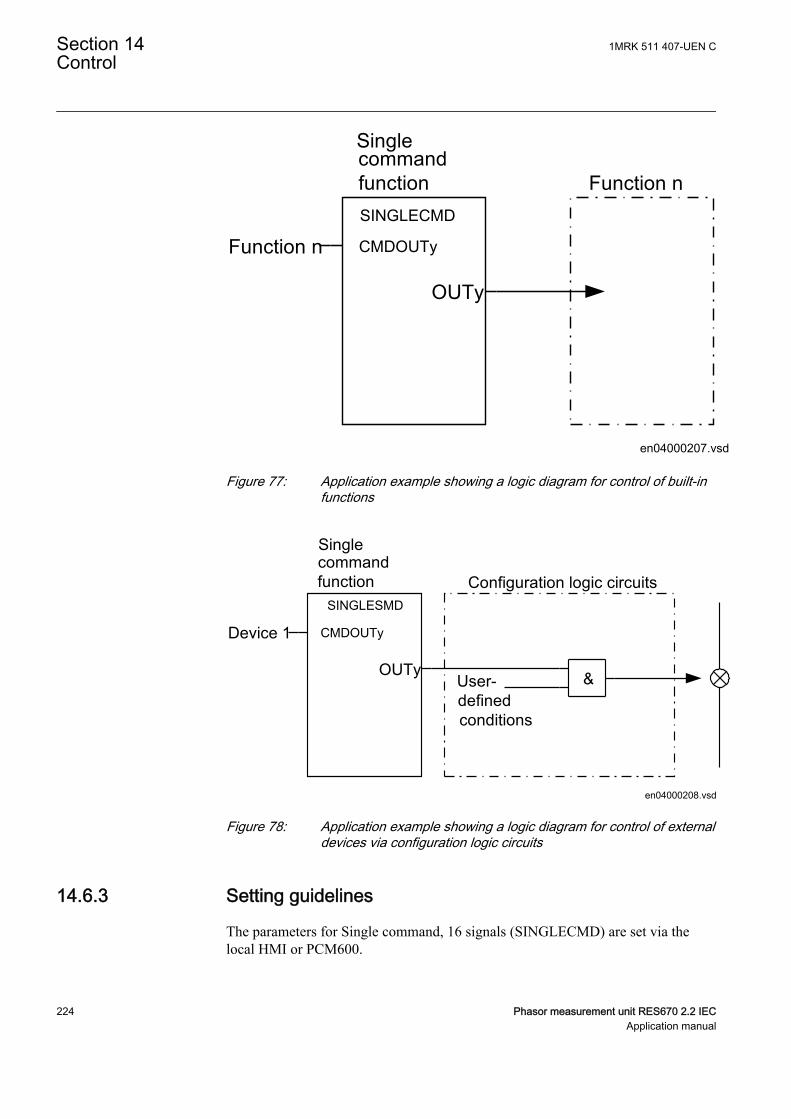
SinglecommandfunctionSINGLECMD
CMDOUTy
OUTy
Function n
en04000207.vsd
Function n
IEC04000207 V2 EN-US
Figure 77: Application example showing a logic diagram for control of built-infunctions
Singlecommandfunction
SINGLESMD
CMDOUTy
OUTy
Device 1
User-definedconditions
Configuration logic circuits
en04000208.vsd
&
IEC04000208 V2 EN-US
Figure 78: Application example showing a logic diagram for control of externaldevices via configuration logic circuits
14.6.3 Setting guidelinesM12448-3 v2
The parameters for Single command, 16 signals (SINGLECMD) are set via thelocal HMI or PCM600.
Section 14 1MRK 511 407-UEN CControl
224 Phasor measurement unit RES670 2.2 IECApplication manual
Parameters to be set are MODE, common for the whole block, and CMDOUTywhich includes the user defined name for each output signal. The MODE input setsthe outputs to be one of the types Off, Steady, or Pulse.
• Off, sets all outputs to 0, independent of the values sent from the station level,that is, the operator station or remote-control gateway.
• Steady, sets the outputs to a steady signal 0 or 1, depending on the values sentfrom the station level.
• Pulse, gives a pulse with 100 ms duration, if a value sent from the station levelis changed from 0 to 1. That means the configured logic connected to thecommand function block may not have a cycle time longer than the cycle timefor the command function block.
1MRK 511 407-UEN C Section 14Control
Phasor measurement unit RES670 2.2 IEC 225Application manual

226
Section 15 Logic
15.1 Tripping logic SMPPTRCIP14576-1 v4
15.1.1 IdentificationSEMOD56226-2 v7
Function description IEC 61850identification
IEC 60617identification
ANSI/IEEE C37.2device number
Tripping logic SMPPTRC
1 -> 0
IEC15000314 V1 EN-US
94
15.1.2 ApplicationM12252-3 v11
All trip signals from the different protection functions shall be routed through thetrip logic. All start signals and directional information can be routed through thetrip logic as well. In its simplest form, the trip logic will only link the TRIP signalto a binary output and make sure that the pulse time is long enough.
Tripping logic SMPPTRC offers three different operating modes:
• Three-phase tripping for all fault types (3ph operating mode)• Single-phase tripping for single-phase faults and three-phase tripping for
multi-phase and evolving faults (1ph/3ph operating mode).• Single-phase tripping for single-phase faults, two-phase tripping for two-phase
faults and three-phase tripping for three-phase faults (1ph/2ph/3ph operatingmode).
The logic also issues a three-phase tripping command when phase selection withinthe operating protection functions is not possible, or when external conditionsrequest three-phase tripping.To meet the different double, 1½ breaker and othermultiple circuit breaker arrangements, multiple identical SMPPTRC functionblocks are provided within the IED. In such installation, use one instance ofSMPPTRC function per circuit breaker.
If the OHL is connected to the substation via more than one breaker, oneSMPPTRC function block should be used for each breaker. For example whensingle-phase tripping and autoreclosing is used on the line, both breakers arenormally set up for 1/3-phase tripping and 1/3-phase autoreclosing. Alternatively,the breaker chosen as master can have single-phase tripping, while the slave
1MRK 511 407-UEN C Section 15Logic
Phasor measurement unit RES670 2.2 IEC 227Application manual
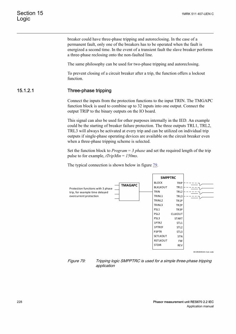
breaker could have three-phase tripping and autoreclosing. In the case of apermanent fault, only one of the breakers has to be operated when the fault isenergized a second time. In the event of a transient fault the slave breaker performsa three-phase reclosing onto the non-faulted line.
The same philosophy can be used for two-phase tripping and autoreclosing.
To prevent closing of a circuit breaker after a trip, the function offers a lockoutfunction.
15.1.2.1 Three-phase trippingM14828-7 v10
Connect the inputs from the protection functions to the input TRIN. The TMGAPCfunction block is used to combine up to 32 inputs into one output. Connect theoutput TRIP to the binary outputs on the IO board.
This signal can also be used for other purposes internally in the IED. An examplecould be the starting of breaker failure protection. The three outputs TRL1, TRL2,TRL3 will always be activated at every trip and can be utilized on individual tripoutputs if single-phase operating devices are available on the circuit breaker evenwhen a three-phase tripping scheme is selected.
Set the function block to Program = 3 phase and set the required length of the trippulse to for example, tTripMin = 150ms.
The typical connection is shown below in figure 79.
BLOCK
BLKLKOUT
TRIN
TRINL1
TRINL2
TRINL3
PSL1
PSL2
PSL3
1PTRZ
1PTREF
P3PTR
SETLKOUT
RSTLKOUT
STDIR
TRIP
SMPPTRC
TRL1
TRL2
TRL3
TR1P
TR2P
TR3P
CLLKOUT
START
STL1
STL2
STL3
FW
REV
Protection functions with 3 phase trip, for example time delayed overcurrent protection
TMAGAPC
STN
IEC05000544-4-en.vsdx
IEC05000544 V4 EN-US
Figure 79: Tripping logic SMPPTRC is used for a simple three-phase trippingapplication
Section 15 1MRK 511 407-UEN CLogic
228 Phasor measurement unit RES670 2.2 IECApplication manual
15.1.2.2 Single- and/or three-phase trippingM14828-11 v7
The single-/three-phase tripping operation mode will give single-phase tripping forsingle-phase faults and three-phase tripping for multi-phase fault. This operatingmode is always used together with a single-phase autoreclosing scheme.
The single-phase tripping operation mode can include different options and the useof the different inputs in the function block. Inputs TRINL1, TRINL2 and TRINL3shall be used for trip signals from functions with built-in phase selection logic suchas distance or line differential protection functions.
The inputs 1PTRZ and 1PTREF are used for single-phase tripping from functionswhich do not have built-in phase selection logic:
• 1PTRZ can be connected to the carrier aided trip signal from the distanceprotection scheme (it means that another distance protection function has seenor detected the fault)
• 1PTREF can be connected to an earth fault function such as EF4PTOC or acarrier aided trip signal from the earth fault protection scheme
These two inputs are combined with the external phase selection logic. Phaseselection signals from the external phase selector must be connected to the inputsPSL1, PSL2 and PSL3 to achieve the tripping on the respective single-phase tripoutputs TRL1, TRL2 and TRL3. The output TRIP is a general trip and is alwaysactivated independent of which phase is involved. Depending on which phases areinvolved the outputs TR1P, TR2P and TR3P will be activated as well.
When single-phase tripping schemes are used, a single-phase autoreclosing attemptis expected to follow. For cases where the autoreclosing is not in service or will notfollow for some reason, the input prepare three-phase trip P3PTR must beactivated. This input is normally connected to the output PREP3P on theautorecloser function SMBRREC but can also be connected to other signals, forexample, an external logic signal. If two circuit breakers are involved, oneSMPPTRC block instance and one SMBRREC instance are used for each circuitbreaker. This will ensure correct operation and behavior of each circuit breaker.
The output TR3P must be connected to the input TR3P on the SMBRREC functionin order to switch SMBRREC to perform a three-phase reclosing. If this signal isnot activated, SMBRREC will use single-phase dead time.
If a second line protection is utilizing the same SMBRREC, thethree-phase trip signal must be generated as OR conditions fromboth line protections.
Other back-up functions are connected to the input TRIN as described above forthree-phase tripping. A typical connection for a single-phase tripping scheme isshown in figure 80.
1MRK 511 407-UEN C Section 15Logic
Phasor measurement unit RES670 2.2 IEC 229Application manual
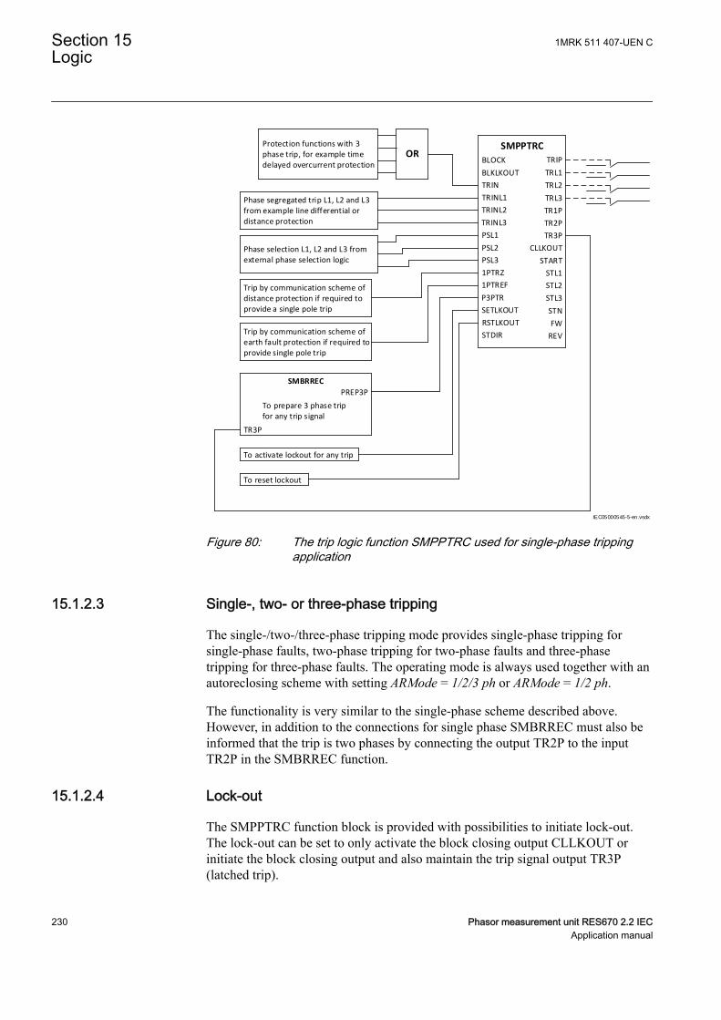
BLOCK
BLKLKOUT
TRIN
TRINL1
TRINL2
TRINL3
PSL1
PSL2
PSL3
1PTRZ
1PTREF
P3PTR
SETLKOUT
RSTLKOUT
STDIR
TRIP
SMPPTRC
TRL1
TRL2
TRL3
TR1P
TR2P
TR3P
CLLKOUT
START
STL1
STL2
STL3
FW
REV
Phase segregated trip L1, L2 and L3 from example line differential or distance protection
Phase selection L1, L2 and L3 from external phase selection logic
Trip by communication scheme of distance protection if required to provide a single pole trip
Trip by communication scheme of earth fault protection if required to provide single pole trip
To activate lockout for any trip
To reset lockout
Protection functions with 3 phase trip, for example time delayed overcurrent protection
OR
To prepare 3 phase trip for any trip signal
SMBRREC
PREP3P
TR3P
STN
IEC05000545-5-en.vsdx
IEC05000545 V5 EN-US
Figure 80: The trip logic function SMPPTRC used for single-phase trippingapplication
15.1.2.3 Single-, two- or three-phase trippingM14828-15 v5
The single-/two-/three-phase tripping mode provides single-phase tripping forsingle-phase faults, two-phase tripping for two-phase faults and three-phasetripping for three-phase faults. The operating mode is always used together with anautoreclosing scheme with setting ARMode = 1/2/3 ph or ARMode = 1/2 ph.
The functionality is very similar to the single-phase scheme described above.However, in addition to the connections for single phase SMBRREC must also beinformed that the trip is two phases by connecting the output TR2P to the inputTR2P in the SMBRREC function.
15.1.2.4 Lock-outM14828-18 v6
The SMPPTRC function block is provided with possibilities to initiate lock-out.The lock-out can be set to only activate the block closing output CLLKOUT orinitiate the block closing output and also maintain the trip signal output TR3P(latched trip).
Section 15 1MRK 511 407-UEN CLogic
230 Phasor measurement unit RES670 2.2 IECApplication manual
The lock-out can then be manually reset after checking the primary fault byactivating the input reset lock-out RSTLKOUT.
If external conditions are required to initiate a closing circuit lock-out but not tolockout trip, this can be achieved by activating input SETLKOUT. The settingAutoLock = Off means that the internal trip will not activate lock-out so onlyinitiation of the input SETLKOUT will result in lock-out. This is normally the casefor overhead line protection where most faults are transient. Unsuccessfulautoreclose and back-up zone tripping can in such cases be connected to initiatelock-out by activating the input SETLKOUT.
15.1.2.5 Example of directional dataGUID-08AC09AB-2B2F-4095-B06E-1171CF225869 v2
An example how to connect the directional data from different applicationfunctions to the trip function is given below, see Figure 81:
1MRK 511 407-UEN C Section 15Logic
Phasor measurement unit RES670 2.2 IEC 231Application manual
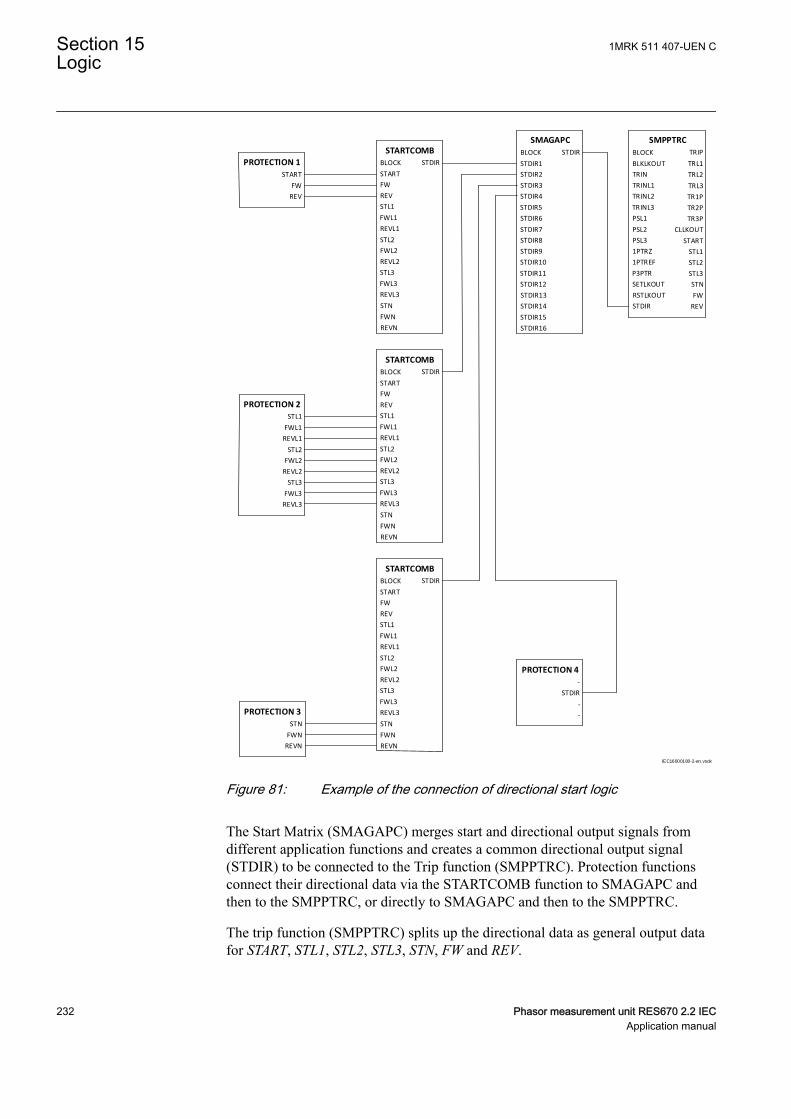
BLOCK
STDIR1
STDIR2
STDIR3
STDIR4
STDIR5
STDIR6
STDIR7
STDIR8
STDIR9
STDIR10
STDIR11
STDIR12
STDIR13
STDIR14
STDIR15
STDIR16
STDIR
SMAGAPC
START
FW
REV
PROTECTION 1
STL1
FWL1
REVL1
STL2
FWL2
REVL2
STL3
FWL3
REVL3
PROTECTION 2
STDIR
PROTECTION 4
-
-
-
BLOCK
START
FW
REV
STL1
FWL1
REVL1
STL2
FWL2
REVL2
STL3
FWL3
REVL3
STDIR
STARTCOMB
STN
FWN
REVN
BLOCK
BLKLKOUT
TRIN
TRINL1
TRINL2
TRINL3
PSL1
PSL2
PSL3
1PTRZ
1PTREF
P3PTR
SETLKOUT
RSTLKOUT
STDIR
TRIP
SMPPTRC
TRL1
TRL2
TRL3
TR1P
TR2P
TR3P
CLLKOUT
START
STL1
STL2
STL3
FW
REV
STN
BLOCK
START
FW
REV
STL1
FWL1
REVL1
STL2
FWL2
REVL2
STL3
FWL3
REVL3
STDIR
STARTCOMB
STN
FWN
REVN
BLOCK
START
FW
REV
STL1
FWL1
REVL1
STL2
FWL2
REVL2
STL3
FWL3
REVL3
STDIR
STARTCOMB
STN
FWN
REVN
STN
FWN
REVN
PROTECTION 3
IEC16000180-2-en.vsdx
IEC16000180 V2 EN-US
Figure 81: Example of the connection of directional start logic
The Start Matrix (SMAGAPC) merges start and directional output signals fromdifferent application functions and creates a common directional output signal(STDIR) to be connected to the Trip function (SMPPTRC). Protection functionsconnect their directional data via the STARTCOMB function to SMAGAPC andthen to the SMPPTRC, or directly to SMAGAPC and then to the SMPPTRC.
The trip function (SMPPTRC) splits up the directional data as general output datafor START, STL1, STL2, STL3, STN, FW and REV.
Section 15 1MRK 511 407-UEN CLogic
232 Phasor measurement unit RES670 2.2 IECApplication manual
All start and directional outputs are mapped to the logical node data model of thetrip function and provided via the IEC 61850 attributes dirGeneral, DIRL1, DIRL2,DIRL3 and DIRN.
15.1.2.6 Blocking of the function blockM14828-21 v4
Total block of the trip function is done by activating the input BLOCK and can beused to disable the outputs of the trip logic in the event of internal failures. Blockof lock-out output is achieved by activating the input BLKLKOUT.
15.1.3 Setting guidelinesM12274-3 v9
The parameters for tripping logic SMPPTRC are set via the local HMI or PCM600.
Operation: Sets the mode of operation. Off switches the tripping off. The normalselection is On.
Program: Sets the required tripping scheme. Normally 3 phase or 1ph/3ph is used.
TripLockout: Sets the scheme for lock-out. Off only activates the closing circuitlock-out output. On activates the closing circuit lock-out output and latches theTRIP related outputs. The normal selection is Off.
AutoLock: Sets the scheme for lock-out. Off only activates lock-out through theinput SETLKOUT. On additionally allows lock-out activation via the trip inputs.The normal selection is Off.
tTripMin: Sets the required minimum duration of the trip pulse. It should be set toensure that the circuit breaker is opened correctly. The normal setting is 0.150s.
tWaitForPHS: Sets a duration during which external phase selection must operatein order to get a single phase trip, after any of the inputs 1PTRZ or 1PTREF hasbeen activated. If no phase selection has been achieved, a three-phase trip will beissued after this time has elapsed.
tEvolvingFault: Secures two- or three-pole tripping depending on Programselection during evolving faults.
15.2 Trip matrix logic TMAGAPCIP15121-1 v4
15.2.1 IdentificationSEMOD167882-2 v3
Function description IEC 61850identification
IEC 60617identification
ANSI/IEEE C37.2device number
Trip matrix logic TMAGAPC - -
1MRK 511 407-UEN C Section 15Logic
Phasor measurement unit RES670 2.2 IEC 233Application manual
15.3 Logic for group alarm ALMCALHGUID-64EA392C-950F-486C-8D96-6E7736B592BF v1
15.3.1 IdentificationGUID-64EA392C-950F-486C-8D96-6E7736B592BF v1
Function description IEC 61850identification
IEC 60617identification
ANSI/IEEE C37.2device number
Logic for group alarm ALMCALH - -
15.3.2 ApplicationGUID-70B268A9-B248-422D-9896-89FECFF80B75 v1
Group alarm logic function ALMCALH is used to route alarm signals to differentLEDs and/or output contacts on the IED.
ALMCALH output signal and the physical outputs allows the user to adapt thealarm signal to physical tripping outputs according to the specific applicationneeds.
15.3.3 Setting guidelinesGUID-0BDD898A-360B-4443-A5CF-7619C80A17F4 v2
Operation: On or Off
15.4 Logic for group alarm WRNCALH
15.4.1 IdentificationGUID-3EBD3D5B-F506-4557-88D7-DFC0BD21C690 v4
Function description IEC 61850identification
IEC 60617identification
ANSI/IEEE C37.2device number
Logic for group warning WRNCALH - -
15.4.1.1 ApplicationGUID-FC0DBB7B-FF86-44BF-83D6-DDF120A176DE v1
Group warning logic function WRNCALH is used to route warning signals toLEDs and/or output contacts on the IED.
WRNCALH output signal WARNING and the physical outputs allows the user toadapt the warning signal to physical tripping outputs according to the specificapplication needs.
15.4.1.2 Setting guidelinesGUID-B08F2636-33DA-4937-92EB-1A8AC0909AB4 v2
OperationOn or Off
Section 15 1MRK 511 407-UEN CLogic
234 Phasor measurement unit RES670 2.2 IECApplication manual
15.5 Logic for group indication INDCALH
15.5.1 IdentificationGUID-3B5D4371-420D-4249-B6A4-5A168920D635 v4
Function description IEC 61850identification
IEC 60617identification
ANSI/IEEE C37.2device number
Logic for group indication INDCALH - -
15.5.1.1 ApplicationGUID-9BAD30FB-4B75-4E14-82A8-6A59B09FA6EA v1
Group indication logic function INDCALH is used to route indication signals todifferent LEDs and/or output contacts on the IED.
INDCALH output signal IND and the physical outputs allows the user to adapt theindication signal to physical outputs according to the specific application needs.
15.5.1.2 Setting guidelinesGUID-7E776D39-1A42-4F90-BF50-9B38F494A01E v2
Operation: On or Off
15.6 Configurable logic blocksIP11009-1 v4
The configurable logic blocks are available in two categories:
• Configurable logic blocks that do not propagate the time stamp and the qualityof signals. They do not have the suffix QT at the end of their function blockname, for example, SRMEMORY. These logic blocks are also available as partof an extension logic package with the same number of instances.
• Configurable logic blocks that propagate the time stamp and the quality ofsignals. They have the suffix QT at the end of their function block name, forexample, SRMEMORYQT.
15.6.1 ApplicationGUID-F5D6F065-441B-4296-AC56-F4DC1F5487E3 v3
A set of standard logic blocks, like AND, OR etc, and timers are available foradapting the IED configuration to the specific application needs. Additional logicblocks that, beside the normal logical function, have the capability to propagatetimestamp and quality are also available. Those blocks have a designationincluding the letters QT, like ANDQT, ORQT etc.
1MRK 511 407-UEN C Section 15Logic
Phasor measurement unit RES670 2.2 IEC 235Application manual

15.6.2 Setting guidelinesGUID-E6BD982D-9E47-4CC2-9666-6E5CABA414C0 v4
There are no settings for AND gates, OR gates, inverters or XOR gates as well as,for ANDQT gates, ORQT gates or XORQT gates.
For normal On/Off delay and pulse timers the time delays and pulse lengths are setfrom the local HMI or via the PST tool.
Both timers in the same logic block (the one delayed on pick-up and the onedelayed on drop-out) always have a common setting value.
For controllable gates, settable timers and SR flip-flops with memory, the settingparameters are accessible via the local HMI or via the PST tool.
15.6.2.1 ConfigurationGUID-D93E383C-1655-46A3-A540-657141F77CF0 v4
Logic is configured using the ACT configuration tool in PCM600.
Execution of functions as defined by the configurable logic blocks runs accordingto a fixed sequence with different cycle times.
For each cycle time, the function block is given an serial execution number. This isshown when using the ACT configuration tool with the designation of the functionblock and the cycle time, see example below.
IEC09000695_2_en.vsdIEC09000695 V2 EN-US
Figure 82: Example designation, serial execution number and cycle time forlogic function
Section 15 1MRK 511 407-UEN CLogic
236 Phasor measurement unit RES670 2.2 IECApplication manual
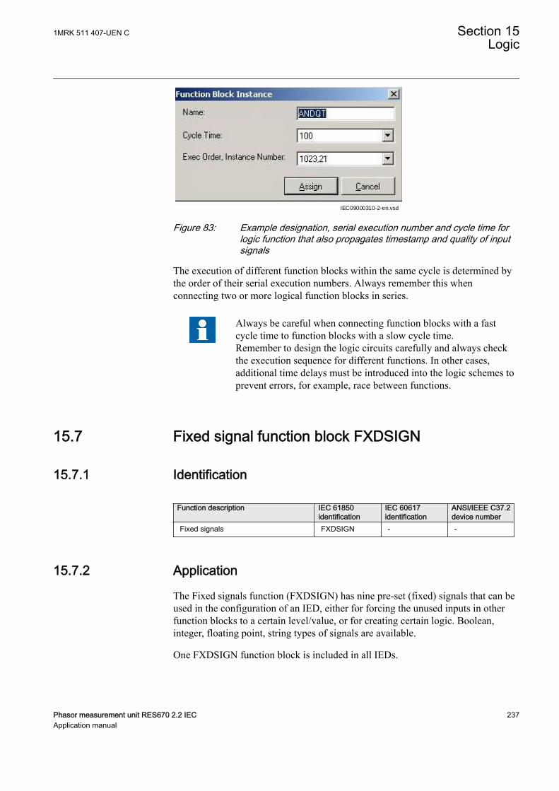
IEC09000310-2-en.vsdIEC09000310 V2 EN-US
Figure 83: Example designation, serial execution number and cycle time forlogic function that also propagates timestamp and quality of inputsignals
The execution of different function blocks within the same cycle is determined bythe order of their serial execution numbers. Always remember this whenconnecting two or more logical function blocks in series.
Always be careful when connecting function blocks with a fastcycle time to function blocks with a slow cycle time.Remember to design the logic circuits carefully and always checkthe execution sequence for different functions. In other cases,additional time delays must be introduced into the logic schemes toprevent errors, for example, race between functions.
15.7 Fixed signal function block FXDSIGNIP15080-1 v2
15.7.1 IdentificationSEMOD167904-2 v2
Function description IEC 61850identification
IEC 60617identification
ANSI/IEEE C37.2device number
Fixed signals FXDSIGN - -
15.7.2 ApplicationM15322-3 v15
The Fixed signals function (FXDSIGN) has nine pre-set (fixed) signals that can beused in the configuration of an IED, either for forcing the unused inputs in otherfunction blocks to a certain level/value, or for creating certain logic. Boolean,integer, floating point, string types of signals are available.
One FXDSIGN function block is included in all IEDs.
1MRK 511 407-UEN C Section 15Logic
Phasor measurement unit RES670 2.2 IEC 237Application manual
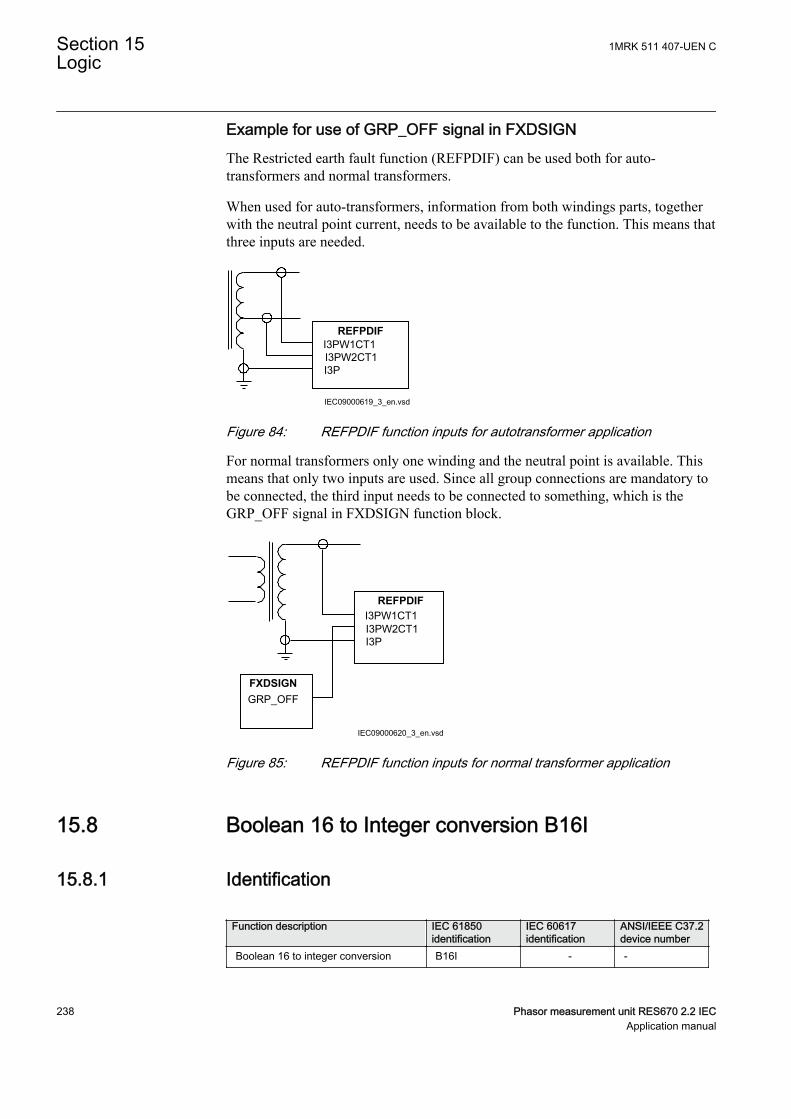
Example for use of GRP_OFF signal in FXDSIGNThe Restricted earth fault function (REFPDIF) can be used both for auto-transformers and normal transformers.
When used for auto-transformers, information from both windings parts, togetherwith the neutral point current, needs to be available to the function. This means thatthree inputs are needed.
I3PW1CT1I3PW2CT1 I3P
REFPDIF
IEC09000619_3_en.vsdIEC09000619 V3 EN-US
Figure 84: REFPDIF function inputs for autotransformer application
For normal transformers only one winding and the neutral point is available. Thismeans that only two inputs are used. Since all group connections are mandatory tobe connected, the third input needs to be connected to something, which is theGRP_OFF signal in FXDSIGN function block.
I3PW1CT1I3PW2CT1 I3P
REFPDIF
GRP_OFFFXDSIGN
IEC09000620_3_en.vsdIEC09000620 V3 EN-US
Figure 85: REFPDIF function inputs for normal transformer application
15.8 Boolean 16 to Integer conversion B16ISEMOD175715-1 v1
15.8.1 IdentificationSEMOD175721-2 v2
Function description IEC 61850identification
IEC 60617identification
ANSI/IEEE C37.2device number
Boolean 16 to integer conversion B16I - -
Section 15 1MRK 511 407-UEN CLogic
238 Phasor measurement unit RES670 2.2 IECApplication manual
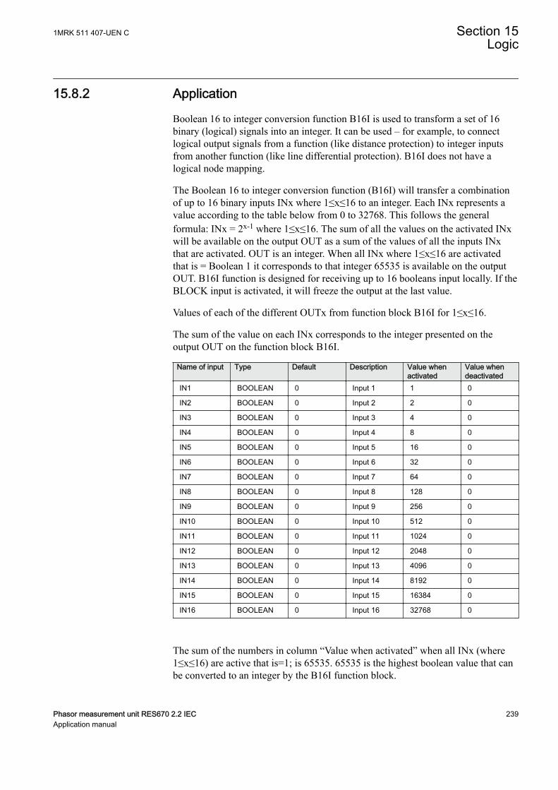
15.8.2 ApplicationSEMOD175832-4 v4
Boolean 16 to integer conversion function B16I is used to transform a set of 16binary (logical) signals into an integer. It can be used – for example, to connectlogical output signals from a function (like distance protection) to integer inputsfrom another function (like line differential protection). B16I does not have alogical node mapping.
The Boolean 16 to integer conversion function (B16I) will transfer a combinationof up to 16 binary inputs INx where 1≤x≤16 to an integer. Each INx represents avalue according to the table below from 0 to 32768. This follows the generalformula: INx = 2x-1 where 1≤x≤16. The sum of all the values on the activated INxwill be available on the output OUT as a sum of the values of all the inputs INxthat are activated. OUT is an integer. When all INx where 1≤x≤16 are activatedthat is = Boolean 1 it corresponds to that integer 65535 is available on the outputOUT. B16I function is designed for receiving up to 16 booleans input locally. If theBLOCK input is activated, it will freeze the output at the last value.
Values of each of the different OUTx from function block B16I for 1≤x≤16.
The sum of the value on each INx corresponds to the integer presented on theoutput OUT on the function block B16I.
Name of input Type Default Description Value whenactivated
Value whendeactivated
IN1 BOOLEAN 0 Input 1 1 0
IN2 BOOLEAN 0 Input 2 2 0
IN3 BOOLEAN 0 Input 3 4 0
IN4 BOOLEAN 0 Input 4 8 0
IN5 BOOLEAN 0 Input 5 16 0
IN6 BOOLEAN 0 Input 6 32 0
IN7 BOOLEAN 0 Input 7 64 0
IN8 BOOLEAN 0 Input 8 128 0
IN9 BOOLEAN 0 Input 9 256 0
IN10 BOOLEAN 0 Input 10 512 0
IN11 BOOLEAN 0 Input 11 1024 0
IN12 BOOLEAN 0 Input 12 2048 0
IN13 BOOLEAN 0 Input 13 4096 0
IN14 BOOLEAN 0 Input 14 8192 0
IN15 BOOLEAN 0 Input 15 16384 0
IN16 BOOLEAN 0 Input 16 32768 0
The sum of the numbers in column “Value when activated” when all INx (where1≤x≤16) are active that is=1; is 65535. 65535 is the highest boolean value that canbe converted to an integer by the B16I function block.
1MRK 511 407-UEN C Section 15Logic
Phasor measurement unit RES670 2.2 IEC 239Application manual
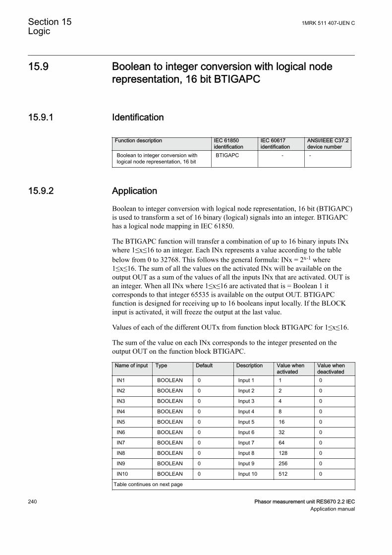
15.9 Boolean to integer conversion with logical noderepresentation, 16 bit BTIGAPC
SEMOD175753-1 v4
15.9.1 IdentificationSEMOD175757-2 v5
Function description IEC 61850identification
IEC 60617identification
ANSI/IEEE C37.2device number
Boolean to integer conversion withlogical node representation, 16 bit
BTIGAPC - -
15.9.2 ApplicationSEMOD175849-4 v6
Boolean to integer conversion with logical node representation, 16 bit (BTIGAPC)is used to transform a set of 16 binary (logical) signals into an integer. BTIGAPChas a logical node mapping in IEC 61850.
The BTIGAPC function will transfer a combination of up to 16 binary inputs INxwhere 1≤x≤16 to an integer. Each INx represents a value according to the tablebelow from 0 to 32768. This follows the general formula: INx = 2x-1 where1≤x≤16. The sum of all the values on the activated INx will be available on theoutput OUT as a sum of the values of all the inputs INx that are activated. OUT isan integer. When all INx where 1≤x≤16 are activated that is = Boolean 1 itcorresponds to that integer 65535 is available on the output OUT. BTIGAPCfunction is designed for receiving up to 16 booleans input locally. If the BLOCKinput is activated, it will freeze the output at the last value.
Values of each of the different OUTx from function block BTIGAPC for 1≤x≤16.
The sum of the value on each INx corresponds to the integer presented on theoutput OUT on the function block BTIGAPC.
Name of input Type Default Description Value whenactivated
Value whendeactivated
IN1 BOOLEAN 0 Input 1 1 0
IN2 BOOLEAN 0 Input 2 2 0
IN3 BOOLEAN 0 Input 3 4 0
IN4 BOOLEAN 0 Input 4 8 0
IN5 BOOLEAN 0 Input 5 16 0
IN6 BOOLEAN 0 Input 6 32 0
IN7 BOOLEAN 0 Input 7 64 0
IN8 BOOLEAN 0 Input 8 128 0
IN9 BOOLEAN 0 Input 9 256 0
IN10 BOOLEAN 0 Input 10 512 0
Table continues on next page
Section 15 1MRK 511 407-UEN CLogic
240 Phasor measurement unit RES670 2.2 IECApplication manual
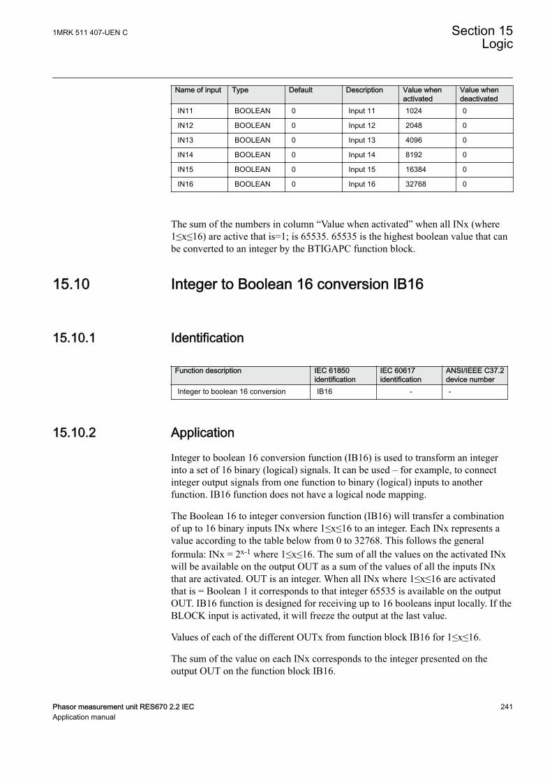
Name of input Type Default Description Value whenactivated
Value whendeactivated
IN11 BOOLEAN 0 Input 11 1024 0
IN12 BOOLEAN 0 Input 12 2048 0
IN13 BOOLEAN 0 Input 13 4096 0
IN14 BOOLEAN 0 Input 14 8192 0
IN15 BOOLEAN 0 Input 15 16384 0
IN16 BOOLEAN 0 Input 16 32768 0
The sum of the numbers in column “Value when activated” when all INx (where1≤x≤16) are active that is=1; is 65535. 65535 is the highest boolean value that canbe converted to an integer by the BTIGAPC function block.
15.10 Integer to Boolean 16 conversion IB16SEMOD158367-1 v2
15.10.1 IdentificationSEMOD167941-2 v2
Function description IEC 61850identification
IEC 60617identification
ANSI/IEEE C37.2device number
Integer to boolean 16 conversion IB16 - -
15.10.2 ApplicationSEMOD158499-5 v4
Integer to boolean 16 conversion function (IB16) is used to transform an integerinto a set of 16 binary (logical) signals. It can be used – for example, to connectinteger output signals from one function to binary (logical) inputs to anotherfunction. IB16 function does not have a logical node mapping.
The Boolean 16 to integer conversion function (IB16) will transfer a combinationof up to 16 binary inputs INx where 1≤x≤16 to an integer. Each INx represents avalue according to the table below from 0 to 32768. This follows the generalformula: INx = 2x-1 where 1≤x≤16. The sum of all the values on the activated INxwill be available on the output OUT as a sum of the values of all the inputs INxthat are activated. OUT is an integer. When all INx where 1≤x≤16 are activatedthat is = Boolean 1 it corresponds to that integer 65535 is available on the outputOUT. IB16 function is designed for receiving up to 16 booleans input locally. If theBLOCK input is activated, it will freeze the output at the last value.
Values of each of the different OUTx from function block IB16 for 1≤x≤16.
The sum of the value on each INx corresponds to the integer presented on theoutput OUT on the function block IB16.
1MRK 511 407-UEN C Section 15Logic
Phasor measurement unit RES670 2.2 IEC 241Application manual
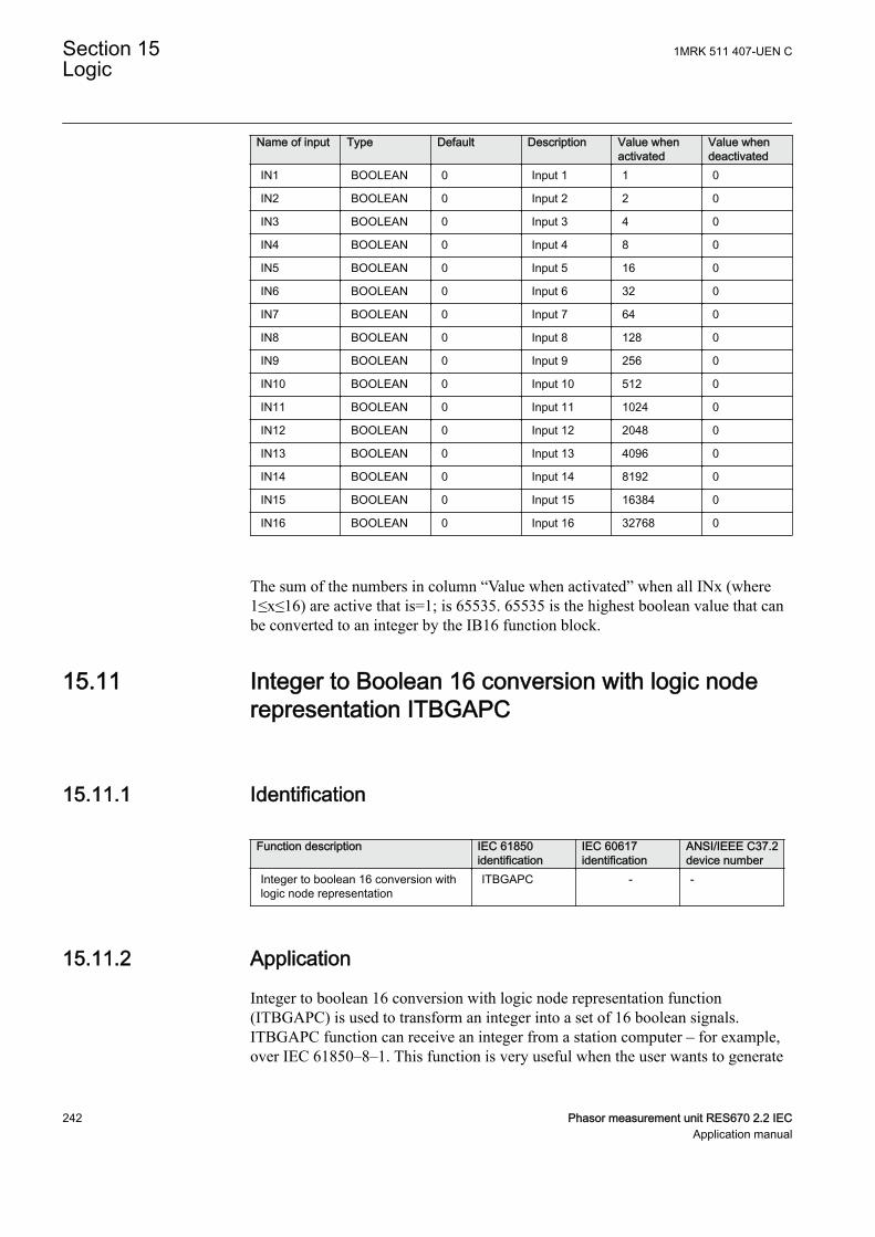
Name of input Type Default Description Value whenactivated
Value whendeactivated
IN1 BOOLEAN 0 Input 1 1 0
IN2 BOOLEAN 0 Input 2 2 0
IN3 BOOLEAN 0 Input 3 4 0
IN4 BOOLEAN 0 Input 4 8 0
IN5 BOOLEAN 0 Input 5 16 0
IN6 BOOLEAN 0 Input 6 32 0
IN7 BOOLEAN 0 Input 7 64 0
IN8 BOOLEAN 0 Input 8 128 0
IN9 BOOLEAN 0 Input 9 256 0
IN10 BOOLEAN 0 Input 10 512 0
IN11 BOOLEAN 0 Input 11 1024 0
IN12 BOOLEAN 0 Input 12 2048 0
IN13 BOOLEAN 0 Input 13 4096 0
IN14 BOOLEAN 0 Input 14 8192 0
IN15 BOOLEAN 0 Input 15 16384 0
IN16 BOOLEAN 0 Input 16 32768 0
The sum of the numbers in column “Value when activated” when all INx (where1≤x≤16) are active that is=1; is 65535. 65535 is the highest boolean value that canbe converted to an integer by the IB16 function block.
15.11 Integer to Boolean 16 conversion with logic noderepresentation ITBGAPC
SEMOD158419-1 v3
15.11.1 IdentificationSEMOD167944-2 v4
Function description IEC 61850identification
IEC 60617identification
ANSI/IEEE C37.2device number
Integer to boolean 16 conversion withlogic node representation
ITBGAPC - -
15.11.2 ApplicationSEMOD158512-5 v7
Integer to boolean 16 conversion with logic node representation function(ITBGAPC) is used to transform an integer into a set of 16 boolean signals.ITBGAPC function can receive an integer from a station computer – for example,over IEC 61850–8–1. This function is very useful when the user wants to generate
Section 15 1MRK 511 407-UEN CLogic
242 Phasor measurement unit RES670 2.2 IECApplication manual
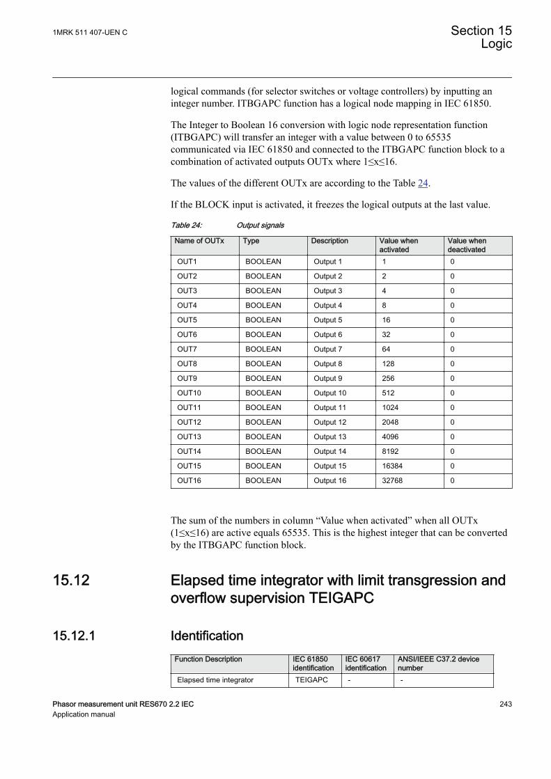
logical commands (for selector switches or voltage controllers) by inputting aninteger number. ITBGAPC function has a logical node mapping in IEC 61850.
The Integer to Boolean 16 conversion with logic node representation function(ITBGAPC) will transfer an integer with a value between 0 to 65535communicated via IEC 61850 and connected to the ITBGAPC function block to acombination of activated outputs OUTx where 1≤x≤16.
The values of the different OUTx are according to the Table 24.
If the BLOCK input is activated, it freezes the logical outputs at the last value.
Table 24: Output signals
Name of OUTx Type Description Value whenactivated
Value whendeactivated
OUT1 BOOLEAN Output 1 1 0
OUT2 BOOLEAN Output 2 2 0
OUT3 BOOLEAN Output 3 4 0
OUT4 BOOLEAN Output 4 8 0
OUT5 BOOLEAN Output 5 16 0
OUT6 BOOLEAN Output 6 32 0
OUT7 BOOLEAN Output 7 64 0
OUT8 BOOLEAN Output 8 128 0
OUT9 BOOLEAN Output 9 256 0
OUT10 BOOLEAN Output 10 512 0
OUT11 BOOLEAN Output 11 1024 0
OUT12 BOOLEAN Output 12 2048 0
OUT13 BOOLEAN Output 13 4096 0
OUT14 BOOLEAN Output 14 8192 0
OUT15 BOOLEAN Output 15 16384 0
OUT16 BOOLEAN Output 16 32768 0
The sum of the numbers in column “Value when activated” when all OUTx(1≤x≤16) are active equals 65535. This is the highest integer that can be convertedby the ITBGAPC function block.
15.12 Elapsed time integrator with limit transgression andoverflow supervision TEIGAPC
15.12.1 IdentificationGUID-1913E066-37D1-4689-9178-5B3C8B029815 v3
Function Description IEC 61850identification
IEC 60617identification
ANSI/IEEE C37.2 devicenumber
Elapsed time integrator TEIGAPC - -
1MRK 511 407-UEN C Section 15Logic
Phasor measurement unit RES670 2.2 IEC 243Application manual
15.12.2 ApplicationGUID-B4B47167-C8DE-4496-AEF1-5F0FD1768A87 v2
The function TEIGAPC is used for user-defined logics and it can also be used fordifferent purposes internally in the IED. An application example is the integrationof elapsed time during the measurement of neutral point voltage or neutral currentat earth-fault conditions.
Settable time limits for warning and alarm are provided. The time limit foroverflow indication is fixed to 999999.9 seconds.
15.12.3 Setting guidelinesGUID-2911D624-87D5-4427-BB2F-E0D1072394FA v3
The settings tAlarm and tWarning are user settable limits defined in seconds. Theachievable resolution of the settings depends on the level of the values defined.
A resolution of 10 ms can be achieved when the settings are defined within therange
1.00 second ≤ tAlarm ≤ 99 999.99 seconds
1.00 second ≤ tWarning ≤ 99 999.99 seconds.
If the values are above this range, the resolution becomes lower due to the 32 bitfloat representation
99 999.99 seconds < tAlarm ≤ 999 999.0 seconds
99 999.99 seconds < tWarning ≤ 999 999.0 seconds
Note that tAlarm and tWarning are independent settings, that is,there is no check if tAlarm > tWarning.
The limit for the overflow supervision is fixed at 999999.9 seconds.
15.13 Comparator for integer inputs - INTCOMP
15.13.1 IdentificationGUID-5992B0F2-FC1B-4838-9BAB-2D2542BB264D v1
Function description IEC 61850identification
IEC 60617identification
ANSI/IEEE C37.2device number
Comparison of integer values INTCOMP Int<=>
Section 15 1MRK 511 407-UEN CLogic
244 Phasor measurement unit RES670 2.2 IECApplication manual
15.13.2 ApplicationGUID-4C6D730D-BB1C-45F1-A719-1267234BF1B9 v1
The function gives the possibility to monitor the level of integer values in thesystem relative to each other or to a fixed value. It is a basic arithmetic functionthat can be used for monitoring, supervision, interlocking and other logics.
15.13.3 Setting guidelinesGUID-ADA3E806-BEF1-4D15-B270-207386A0AEE4 v2
For proper operation of comparison the set value should be set within the range of± 2 ×10⁹.
Setting procedure on the IED:
EnaAbs: This setting is used to select the comparison type between signed andabsolute values.
• Absolute: Comparison is performed on absolute values of input and referencevalues
• Signed: Comparison is performed on signed values of input and referencevalues.
RefSource: This setting is used to select the reference source between input andsetting for comparison.
• Input REF: The function will take reference value from input REF• Set Value: The function will take reference value from setting SetValue
SetValue: This setting is used to set the reference value for comparison whensetting RefSource is selected as SetValue.
15.13.4 Setting exampleGUID-13302FD6-1585-42FE-BD6D-44F231982C59 v2
For absolute comparison between inputs:
Set the EnaAbs = Absolute
Set the RefSource = Input REF
Similarly for Signed comparison between inputs
Set the EnaAbs = Signed
Set the RefSource =Input REF
For absolute comparison between input and setting
Set the EnaAbs = Absolute
1MRK 511 407-UEN C Section 15Logic
Phasor measurement unit RES670 2.2 IEC 245Application manual
Set the RefSource = Set Value
SetValue shall be set between -2000000000 to 2000000000
Similarly for signed comparison between input and setting
Set the EnaAbs = Signed
Set the RefSource = Set Value
SetValue shall be set between -2000000000 to 2000000000
15.14 Comparator for real inputs - REALCOMP
15.14.1 IdentificationGUID-0D68E846-5A15-4C2C-91A2-F81A74034E81 v1
Function description IEC 61850identification
IEC 60617identification
ANSI/IEEE C37.2device number
Comparator for real inputs REALCOMP Real<=>
15.14.2 ApplicationGUID-5F7B1683-9799-4D27-B333-B184F8861A5B v1
The function gives the possibility to monitor the level of real values in the systemrelative to each other or to a fixed value. It is a basic arithmetic function that can beused for monitoring, supervision, interlocking and other logics.
15.14.3 Setting guidelinesGUID-DE69FF5B-7D34-4A30-9060-214E98BFF798 v2
Setting procedure on the IED:
EnaAbs: This setting is used to select the comparison type between signed andabsolute values.
• Absolute: Comparison is performed with absolute values of input andreference.
• Signed: Comparison is performed with signed values of input and reference.
RefSource: This setting is used to select the reference source between input andsetting for comparison.
• Input REF: The function will take reference value from input REF• Set Value: The function will take reference value from setting SetValue
Section 15 1MRK 511 407-UEN CLogic
246 Phasor measurement unit RES670 2.2 IECApplication manual

SetValue: This setting is used to set the reference value for comparison whensetting RefSource is selected as Set Value. If this setting value is less than 0.2% ofthe set unit then the output INLOW will never pickup.
RefPrefix: This setting is used to set the unit of the reference value for comparisonwhen setting RefSource is selected as SetValue. It has 5 unit selections and they areMilli, Unity, Kilo, Mega and Giga.
EqualBandHigh: This setting is used to set the equal condition high band limit in %of reference value. This high band limit will act as reset limit for INHIGH outputwhen INHIGH.
EqualBandLow: This setting is used to set the equal condition low band limit in %of reference value. This low band limit will act as reset limit for INLOW outputwhen INLOW.
15.14.4 Setting exampleGUID-E7070CF6-B44B-4799-BE18-5C75B9FE2A87 v2
Let us consider a comparison is to be done between current magnitudes in therange of 90 to 110 with nominal rating is 100 and the order is kA.
For the above condition the comparator can be designed with settings as follows,
EnaAbs = Absolute
RefSource = Set Value
SetValue = 100
RefPrefix = Kilo
EqualBandHigh = 5.0 % of reference value
EqualBandLow = 5.0 % of reference value
Operation
The function will set the outputs for the following conditions,
INEQUAL will set when the INPUT is between the ranges of 95 to 105 kA.
INHIGH will set when the INPUT crosses above 105 kA.
INLOW will set when the INPUT crosses below 95 kA.
If the comparison should be done between two current magnitudes then thosecurrent signals need to be connected to function inputs, INPUT and REF. Then thesettings should be adjusted as below,
EnaAbs = Absolute
RefSource = Input REF
1MRK 511 407-UEN C Section 15Logic
Phasor measurement unit RES670 2.2 IEC 247Application manual

EqualBandHigh = 5.0 % of reference value
EqualBandLow = 5.0 % of reference value.
Section 15 1MRK 511 407-UEN CLogic
248 Phasor measurement unit RES670 2.2 IECApplication manual
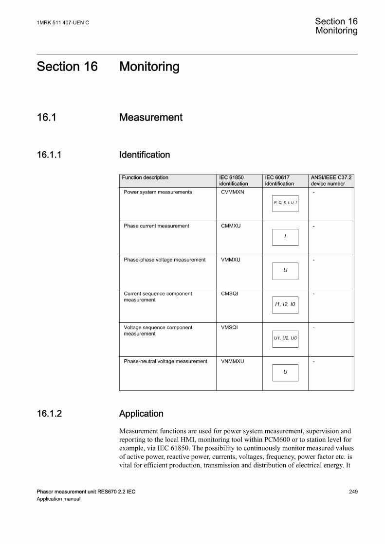
Section 16 Monitoring
16.1 MeasurementGUID-9D2D47A0-FE62-4FE3-82EE-034BED82682A v1
16.1.1 IdentificationSEMOD56123-2 v8
Function description IEC 61850identification
IEC 60617identification
ANSI/IEEE C37.2device number
Power system measurements CVMMXN
P, Q, S, I, U, f
SYMBOL-RR V1 EN-US
-
Phase current measurement CMMXU
I
SYMBOL-SS V1 EN-US
-
Phase-phase voltage measurement VMMXU
U
SYMBOL-UU V1 EN-US
-
Current sequence componentmeasurement
CMSQI
I1, I2, I0
SYMBOL-VV V1 EN-US
-
Voltage sequence componentmeasurement
VMSQI
U1, U2, U0
SYMBOL-TT V1 EN-US
-
Phase-neutral voltage measurement VNMMXU
U
SYMBOL-UU V1 EN-US
-
16.1.2 ApplicationSEMOD54488-4 v12
Measurement functions are used for power system measurement, supervision andreporting to the local HMI, monitoring tool within PCM600 or to station level forexample, via IEC 61850. The possibility to continuously monitor measured valuesof active power, reactive power, currents, voltages, frequency, power factor etc. isvital for efficient production, transmission and distribution of electrical energy. It
1MRK 511 407-UEN C Section 16Monitoring
Phasor measurement unit RES670 2.2 IEC 249Application manual

provides to the system operator fast and easy overview of the present status of thepower system. Additionally, it can be used during testing and commissioning ofprotection and control IEDs in order to verify proper operation and connection ofinstrument transformers (CTs and VTs). During normal service by periodiccomparison of the measured value from the IED with other independent meters theproper operation of the IED analog measurement chain can be verified. Finally, itcan be used to verify proper direction orientation for distance or directionalovercurrent protection function.
The available measured values from an IED are depending on theactual hardware (TRM) and the logic configuration made inPCM600.
All measured values can be supervised with four settable limits that is, low-lowlimit, low limit, high limit and high-high limit. A zero clamping reduction is alsosupported, that is, the measured value below a settable limit is forced to zero whichreduces the impact of noise in the inputs.
Dead-band supervision can be used to report measured signal value to station levelwhen change in measured value is above set threshold limit or time integral of allchanges since the last time value updating exceeds the threshold limit. Measurevalue can also be based on periodic reporting.
Main menu/Measurement/Monitoring/Service values/CVMMXN
The measurement function, CVMMXN, provides the following power systemquantities:
• P, Q and S: three phase active, reactive and apparent power• PF: power factor• U: phase-to-phase voltage amplitude• I: phase current amplitude• F: power system frequency
,The measuring functions CMMXU, VMMXU and VNMMXU provide physicalquantities:
• I: phase currents (amplitude and angle) (CMMXU)• U: voltages (phase-to-earth and phase-to-phase voltage, amplitude and angle)
(VMMXU, VNMMXU)
The CVMMXN function calculates three-phase power quantities by usingfundamental frequency phasors (DFT values) of the measured current and voltagesignals. The measured power quantities are available either, as instantaneouslycalculated quantities or, averaged values over a period of time (low pass filtered)depending on the selected settings.
Section 16 1MRK 511 407-UEN CMonitoring
250 Phasor measurement unit RES670 2.2 IECApplication manual
It is possible to calibrate the measuring function above to get better then class 0.5presentation. This is accomplished by angle and amplitude compensation at 5, 30and 100% of rated current and at 100% of rated voltage.
The power system quantities provided, depends on the actualhardware, (TRM) and the logic configuration made in PCM600.
The measuring functions CMSQI and VMSQI provide sequence componentquantities:
• I: sequence currents (positive, zero, negative sequence, amplitude and angle)• U: sequence voltages (positive, zero and negative sequence, amplitude and
angle).
16.1.3 Zero clampingGUID-8DABC3F5-6615-493C-B839-A5C557A2FAE8 v4
Measuring functions CVMMXN, CMMXU, VMMXU and VNMMXU have nointerconnections regarding any settings or parameters.
Zero clampings are also handled entirely by ZeroDb separately for each function'severy output signal. For example, zero clamping of U12 is handled byUL12ZeroDb in VMMXU, zero clamping of I1 is handled by IL1ZeroDb inCMMXU, and so on.
Example of CVMMXN operation
Outputs seen on the local HMI under Main menu/Measurements/Monitoring/Servicevalues(P_Q)/CVMMXN(P_Q):
S Apparent three-phase power
P Active three-phase power
Q Reactive three-phase power
PF Power factor
ILAG I lagging U
ILEAD I leading U
U System mean voltage, calculated according to selected mode
I System mean current, calculated according to selected mode
F Frequency
Relevant settings and their values on the local HMI under Main menu/Settings/IED settings/Monitoring/Servicevalues(P_Q)/CVMMXN(P_Q):
1MRK 511 407-UEN C Section 16Monitoring
Phasor measurement unit RES670 2.2 IEC 251Application manual
• When system voltage falls below UGenZeroDB, values for S, P, Q, PF, ILAG,ILEAD, U and F are forced to zero.
• When system current falls below IGenZeroDB, values for S, P, Q, PF, ILAG,ILEAD, U and F are forced to zero.
• When the value of a single signal falls below its set deadband, the value isforced to zero. For example, if the apparent three-phase power falls belowSZeroDb, the value for S is forced to zero.
16.1.4 Setting guidelinesSEMOD54481-165 v14
The available setting parameters of the measurement function CVMMXN,CMMXU, VMMXU, CMSQI, VMSQI, VNMMXU are depending on the actualhardware (TRM) and the logic configuration made in PCM600.
The parameters for the Measurement functions CVMMXN, CMMXU, VMMXU,CMSQI, VMSQI, VNMMXU are set via the local HMI or PCM600.
GlobalBaseSel: Selects the global base value group used by the function to defineIBase, UBase and SBase as applicable.
Operation: Off/On. Every function instance (CVMMXN, CMMXU, VMMXU,CMSQI, VMSQI, VNMMXU) can be taken in operation (On) or out of operation(Off).
The following general settings can be set for the Measurement function(CVMMXN).
PowAmpFact: Amplitude factor to scale power calculations.
PowAngComp: Angle compensation for phase shift between measured I & U.
Mode: Selection of measured current and voltage. There are 9 different ways ofcalculating monitored three-phase values depending on the available VT inputsconnected to the IED. See parameter group setting table.
k: Low pass filter coefficient for power measurement, U and I.
UGenZeroDb: Minimum level of voltage in % of UBase, used as indication of zerovoltage (zero point clamping). If measured value is below UGenZeroDb calculatedS, P, Q and PF will be zero.
IGenZeroDb: Minimum level of current in % of IBase, used as indication of zerocurrent (zero point clamping). If measured value is below IGenZeroDb calculatedS, P, Q and PF will be zero.
UAmpCompY: Amplitude compensation to calibrate voltage measurements at Y%of Ur, where Y is equal to 5, 30 or 100.
IAmpCompY: Amplitude compensation to calibrate current measurements at Y% ofIr, where Y is equal to 5, 30 or 100.
Section 16 1MRK 511 407-UEN CMonitoring
252 Phasor measurement unit RES670 2.2 IECApplication manual
IAngCompY: Angle compensation to calibrate angle measurements at Y% of Ir,where Y is equal to 5, 30 or 100.
The following general settings can be set for the Phase current measurement(CMMXU).
IAmpCompY: Amplitude compensation to calibrate current measurements at Y% ofIr, where Y is equal to 5, 30 or 100.
IAngCompY: Angle compensation to calibrate angle measurements at Y% of Ir,where Y is equal to 5, 30 or 100.
The following general settings can be set for the Phase-phase voltagemeasurement (VMMXU).
UAmpCompY: Amplitude compensation to calibrate voltage measurements at Y%of Ur, where Y is equal to 5, 30 or 100.
UAngCompY: Angle compensation to calibrate angle measurements at Y% of Ur,where Y is equal to 5, 30 or 100.
The following general settings can be set for all monitored quantities included inthe functions (CVMMXN, CMMXU, VMMXU, CMSQI, VMSQI, VNMMXU) Xin setting names below equals S, P, Q, PF, U, I, F, IL1-3, UL1-3UL12-31, I1, I2,3I0, U1, U2 or 3U0.
Xmin: Minimum value for analog signal X set directly in applicable measuringunit. This forms the minimum limit of the range.
Xmax: Maximum value for analog signal X. This forms the maximum limit of therange.
XZeroDb: Zero point clamping. A signal value less than XZeroDb is forced to zero.
Observe the related zero point clamping settings in Setting group N for CVMMXN(UGenZeroDb and IGenZeroDb). If measured value is below UGenZeroDb and/orIGenZeroDb calculated S, P, Q and PF will be zero and these settings will overrideXZeroDb.
XRepTyp: Reporting type. Cyclic (Cyclic), amplitude deadband (Dead band),integral deadband (Int deadband) or Deadband and xx se cyclic (xx: 5 sec, 30 sec,1 min). The reporting interval is controlled by the parameter XDbRepInt.
XDbRepInt: This setting handles all the reporting types. If setting is deadband inXRepTyp, XDbRepInt defines the deadband in m% of the measuring range. Forcyclic reporting type (XRepTyp : cyclic), the setting value reporting interval is inseconds. Amplitude deadband is the setting value in m% of measuring range.Integral deadband setting is the integral area, that is, measured value in m% ofmeasuring range multiplied by the time between two measured values.
XHiHiLim: High-high limit. Set as % of YBase (Y is SBase for S,P,Q UBase forVoltage measurement and IBase for current measurement).
1MRK 511 407-UEN C Section 16Monitoring
Phasor measurement unit RES670 2.2 IEC 253Application manual
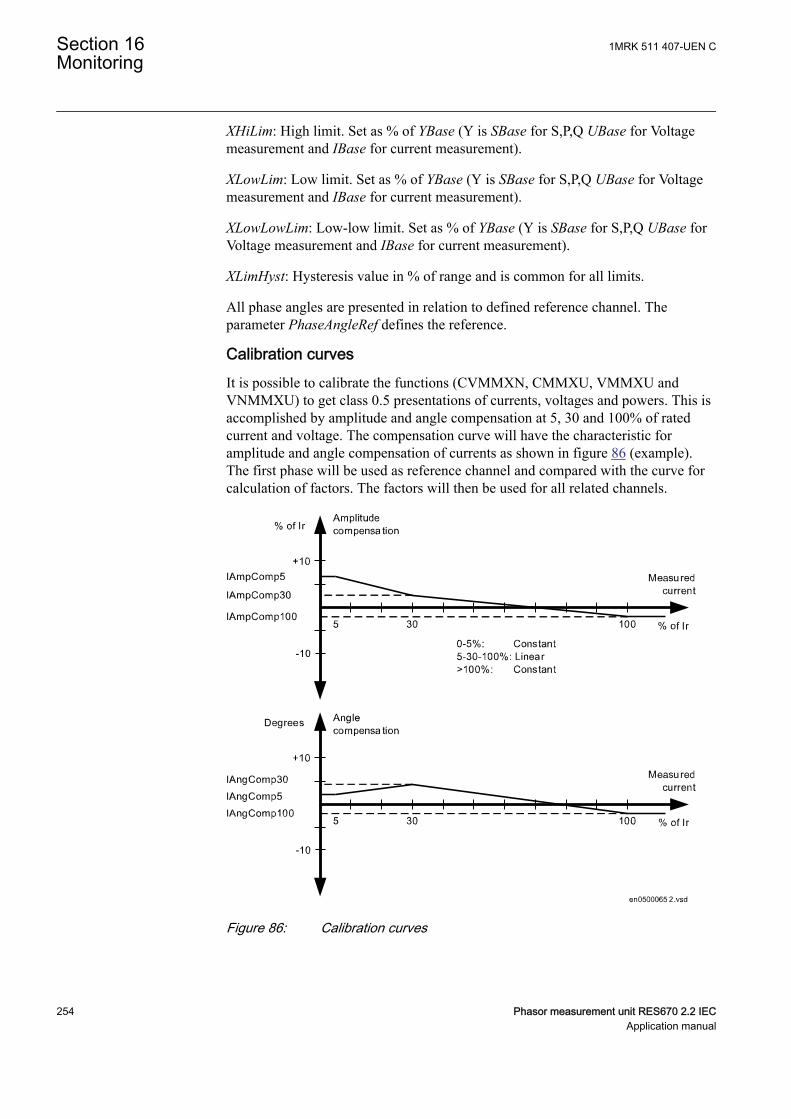
XHiLim: High limit. Set as % of YBase (Y is SBase for S,P,Q UBase for Voltagemeasurement and IBase for current measurement).
XLowLim: Low limit. Set as % of YBase (Y is SBase for S,P,Q UBase for Voltagemeasurement and IBase for current measurement).
XLowLowLim: Low-low limit. Set as % of YBase (Y is SBase for S,P,Q UBase forVoltage measurement and IBase for current measurement).
XLimHyst: Hysteresis value in % of range and is common for all limits.
All phase angles are presented in relation to defined reference channel. Theparameter PhaseAngleRef defines the reference.
Calibration curvesIt is possible to calibrate the functions (CVMMXN, CMMXU, VMMXU andVNMMXU) to get class 0.5 presentations of currents, voltages and powers. This isaccomplished by amplitude and angle compensation at 5, 30 and 100% of ratedcurrent and voltage. The compensation curve will have the characteristic foramplitude and angle compensation of currents as shown in figure 86 (example).The first phase will be used as reference channel and compared with the curve forcalculation of factors. The factors will then be used for all related channels.
IEC05000652 V2 EN-US
Figure 86: Calibration curves
Section 16 1MRK 511 407-UEN CMonitoring
254 Phasor measurement unit RES670 2.2 IECApplication manual
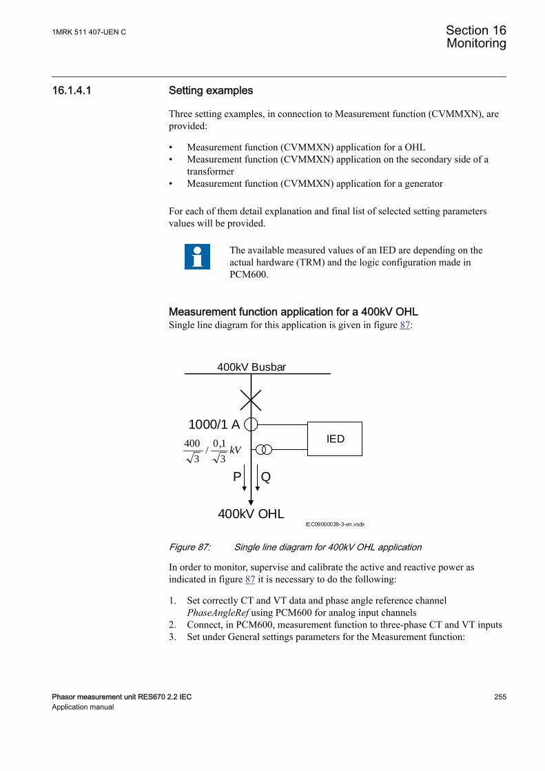
16.1.4.1 Setting examplesSEMOD54481-4 v5
Three setting examples, in connection to Measurement function (CVMMXN), areprovided:
• Measurement function (CVMMXN) application for a OHL• Measurement function (CVMMXN) application on the secondary side of a
transformer• Measurement function (CVMMXN) application for a generator
For each of them detail explanation and final list of selected setting parametersvalues will be provided.
The available measured values of an IED are depending on theactual hardware (TRM) and the logic configuration made inPCM600.
Measurement function application for a 400kV OHLSEMOD54481-12 v11
Single line diagram for this application is given in figure 87:
400kV Busbar
400kV OHL
P Q
1000/1 A
IEC09000039-3-en.vsdx
IEDkV
3
1,0/
3
400
IEC09000039-1-EN V3 EN-US
Figure 87: Single line diagram for 400kV OHL application
In order to monitor, supervise and calibrate the active and reactive power asindicated in figure 87 it is necessary to do the following:
1. Set correctly CT and VT data and phase angle reference channelPhaseAngleRef using PCM600 for analog input channels
2. Connect, in PCM600, measurement function to three-phase CT and VT inputs3. Set under General settings parameters for the Measurement function:
1MRK 511 407-UEN C Section 16Monitoring
Phasor measurement unit RES670 2.2 IEC 255Application manual
• general settings as shown in table 25.• level supervision of active power as shown in table 26.• calibration parameters as shown in table 27.
Table 25: General settings parameters for the Measurement function
Setting Short Description Selectedvalue
Comments
Operation Operation Off/On On Function must be On
PowAmpFact Amplitude factor to scale powercalculations
1.000 It can be used duringcommissioning to achieve highermeasurement accuracy.Typically no scaling is required
PowAngComp Angle compensation for phaseshift between measured I & U
0.0 It can be used duringcommissioning to achieve highermeasurement accuracy.Typically no angle compensationis required. As well here requireddirection of P & Q measurementis towards protected object (asper IED internal default direction)
Mode Selection of measured currentand voltage
L1, L2, L3 All three phase-to-earth VTinputs are available
k Low pass filter coefficient forpower measurement, U and I
0.00 Typically no additional filtering isrequired
UGenZeroDb Zero point clamping in % ofUbase
25 Set minimum voltage level to25%. Voltage below 25% willforce S, P and Q to zero.
IGenZeroDb Zero point clamping in % ofIbase
3 Set minimum current level to 3%.Current below 3% will force S, Pand Q to zero.
UBase (set inGlobal base)
Base setting for voltage level inkV
400.00 Set rated OHL phase-to-phasevoltage
IBase (set inGlobal base)
Base setting for current level inA
1000 Set rated primary CT currentused for OHL
SBase (set inGlobal base)
Base Setting for power base inMVA
1000 Set based on rated Power
Table 26: Settings parameters for level supervision
Setting Short Description Selectedvalue
Comments
PMin Minimum value -100 Minimum expected load
PMax Minimum value 100 Maximum expected load
PZeroDb Zero point clamping in 0.001% ofrange
3000 Set zero point clamping to 60MW that is, 3% of 200 MW
PRepTyp Reporting type db Select amplitude deadbandsupervision
PDbRepInt Cycl: Report interval (s), Db: In0.001% of range, Int Db: In0.001%s
2000 Set ±Δdb=40 MW that is, 2%(larger changes than 40 MW willbe reported)
Table continues on next page
Section 16 1MRK 511 407-UEN CMonitoring
256 Phasor measurement unit RES670 2.2 IECApplication manual
Setting Short Description Selectedvalue
Comments
PHiHiLim High High limit (physical value),% of SBase
60 High alarm limit that is, extremeoverload alarm, hence it will be415 MW.
PHiLim High limit (physical value), in %of SBase
50 High warning limit that is,overload warning, hence it will be371 MW.
PLowLim Low limit (physical value), in % ofSBase
-50 Low warning limit -500 MW
PLowLowlLim Low Low limit (physical value), in% of SBase
-60 Low alarm limit -600 MW
PLimHyst Hysteresis value in % of range(common for all limits)
1 Set ±Δ Hysteresis 20 MW that is,1% of range (2000 MW)
Table 27: Settings for calibration parameters
Setting Short Description Selectedvalue
Comments
IAmpComp5 Amplitude factor to calibratecurrent at 5% of Ir
0.00
IAmpComp30 Amplitude factor to calibratecurrent at 30% of Ir
0.00
IAmpComp100 Amplitude factor to calibratecurrent at 100% of Ir
0.00
UAmpComp5 Amplitude factor to calibratevoltage at 5% of Ur
0.00
UAmpComp30 Amplitude factor to calibratevoltage at 30% of Ur
0.00
UAmpComp100 Amplitude factor to calibratevoltage at 100% of Ur
0.00
IAngComp5 Angle calibration for current at5% of Ir
0.00
IAngComp30 Angle pre-calibration for currentat 30% of Ir
0.00
IAngComp100 Angle pre-calibration for currentat 100% of Ir
0.00
Measurement function application for a power transformerSEMOD54481-61 v9
Single line diagram for this application is given in figure 88.
1MRK 511 407-UEN C Section 16Monitoring
Phasor measurement unit RES670 2.2 IEC 257Application manual
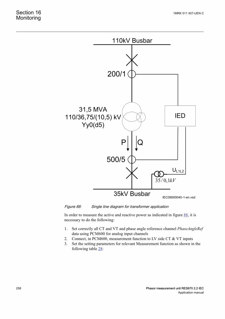
110kV Busbar
200/1
35 / 0,1kV
35kV Busbar
500/5
P Q
31,5 MVA110/36,75/(10,5) kV
Yy0(d5)
UL1L2
IEC09000040-1-en.vsd
IED
IEC09000040-1-EN V1 EN-US
Figure 88: Single line diagram for transformer application
In order to measure the active and reactive power as indicated in figure 88, it isnecessary to do the following:
1. Set correctly all CT and VT and phase angle reference channel PhaseAngleRefdata using PCM600 for analog input channels
2. Connect, in PCM600, measurement function to LV side CT & VT inputs3. Set the setting parameters for relevant Measurement function as shown in the
following table 28:
Section 16 1MRK 511 407-UEN CMonitoring
258 Phasor measurement unit RES670 2.2 IECApplication manual
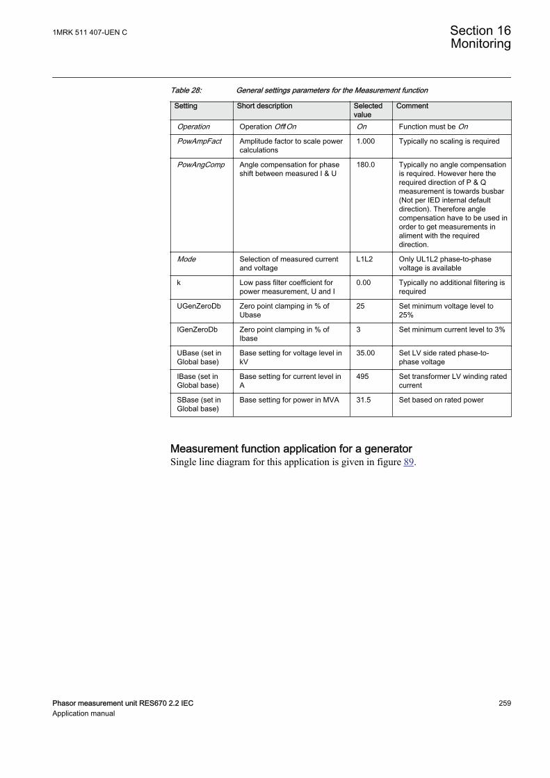
Table 28: General settings parameters for the Measurement function
Setting Short description Selectedvalue
Comment
Operation Operation Off/On On Function must be On
PowAmpFact Amplitude factor to scale powercalculations
1.000 Typically no scaling is required
PowAngComp Angle compensation for phaseshift between measured I & U
180.0 Typically no angle compensationis required. However here therequired direction of P & Qmeasurement is towards busbar(Not per IED internal defaultdirection). Therefore anglecompensation have to be used inorder to get measurements inaliment with the requireddirection.
Mode Selection of measured currentand voltage
L1L2 Only UL1L2 phase-to-phasevoltage is available
k Low pass filter coefficient forpower measurement, U and I
0.00 Typically no additional filtering isrequired
UGenZeroDb Zero point clamping in % ofUbase
25 Set minimum voltage level to25%
IGenZeroDb Zero point clamping in % ofIbase
3 Set minimum current level to 3%
UBase (set inGlobal base)
Base setting for voltage level inkV
35.00 Set LV side rated phase-to-phase voltage
IBase (set inGlobal base)
Base setting for current level inA
495 Set transformer LV winding ratedcurrent
SBase (set inGlobal base)
Base setting for power in MVA 31.5 Set based on rated power
Measurement function application for a generatorSEMOD54481-110 v8
Single line diagram for this application is given in figure 89.
1MRK 511 407-UEN C Section 16Monitoring
Phasor measurement unit RES670 2.2 IEC 259Application manual
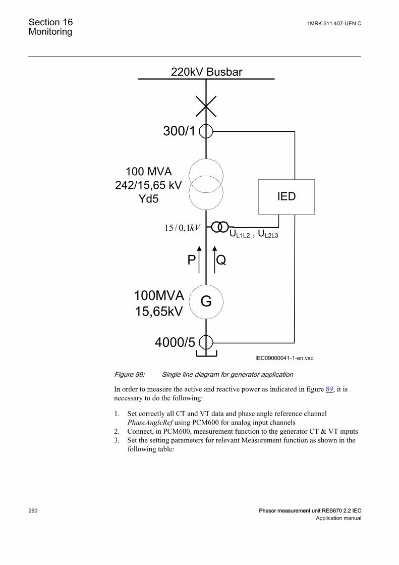
220kV Busbar
300/1
15 / 0,1kV
4000/5
100 MVA242/15,65 kV
Yd5
UL1L2 , UL2L3
G
P Q
100MVA15,65kV
IEC09000041-1-en.vsd
IED
IEC09000041-1-EN V1 EN-US
Figure 89: Single line diagram for generator application
In order to measure the active and reactive power as indicated in figure 89, it isnecessary to do the following:
1. Set correctly all CT and VT data and phase angle reference channelPhaseAngleRef using PCM600 for analog input channels
2. Connect, in PCM600, measurement function to the generator CT & VT inputs3. Set the setting parameters for relevant Measurement function as shown in the
following table:
Section 16 1MRK 511 407-UEN CMonitoring
260 Phasor measurement unit RES670 2.2 IECApplication manual

Table 29: General settings parameters for the Measurement function
Setting Short description Selectedvalue
Comment
Operation Operation Off/On On Function must be On
PowAmpFact Amplitude factor to scale powercalculations
1.000 Typically no scaling is required
PowAngComp Angle compensation for phaseshift between measured I & U
0.0 Typically no angle compensationis required. As well here requireddirection of P & Q measurementis towards protected object (asper IED internal default direction)
Mode Selection of measured currentand voltage
Arone Generator VTs are connectedbetween phases (V-connected)
k Low pass filter coefficient forpower measurement, U and I
0.00 Typically no additional filtering isrequired
UGenZeroDb Zero point clamping in % ofUbase
25% Set minimum voltage level to25%
IGenZeroDb Zero point clamping in % ofIbase
3 Set minimum current level to 3%
UBase (set inGlobal base)
Base setting for voltage level inkV
15,65 Set generator rated phase-to-phase voltage
IBase (set inGlobal base)
Base setting for current level inA
3690 Set generator rated current
16.2 Gas medium supervision SSIMGGUID-358AD8F8-AE06-4AEA-9969-46E5299D5B4B v3
16.2.1 IdentificationGUID-AD96C26E-C3E5-4B21-9ED6-12E540954AC3 v4
Function description IEC 61850identification
IEC 60617identification
ANSI/IEEE C37.2device number
Insulation gas monitoring function SSIMG - 63
16.2.2 ApplicationGUID-A840E38C-CC42-4995-A569-A6092DDB81B2 v5
Gas medium supervision (SSIMG) is used for monitoring the circuit breakercondition. Proper arc extinction by the compressed gas in the circuit breaker is veryimportant. When the pressure becomes too low compared to the required value, thecircuit breaker operation shall be blocked to minimize the risk of internal failure.Binary information based on the gas pressure in the circuit breaker is used as aninput signal to the function. The function generates alarms based on the receivedinformation.
1MRK 511 407-UEN C Section 16Monitoring
Phasor measurement unit RES670 2.2 IEC 261Application manual
16.2.3 Setting guidelinesGUID-DF6BEC98-F806-41CE-8C29-BEE9C88FC1FD v3
The parameters for Gas medium supervision SSIMG can be set via local HMI orProtection and Control Manager PCM600.
Operation: This is used to disable/enable the operation of gas medium supervisioni.e. Off/On.
PresAlmLimit: This is used to set the limit for a pressure alarm condition in thecircuit breaker.
PresLOLimit: This is used to set the limit for a pressure lockout condition in thecircuit breaker.
TempAlarmLimit: This is used to set the limit for a temperature alarm condition inthe circuit breaker.
TempLOLimit: This is used to set the limit for a temperature lockout condition inthe circuit breaker.
tPressureAlarm: This is used to set the time delay for a pressure alarm indication,given in s.
tPressureLO: This is used to set the time delay for a pressure lockout indication,given in s.
tTempAlarm: This is used to set the time delay for a temperature alarm indication,given in s.
tTempLockOut: This is used to set the time delay for a temperature lockoutindication, given in s.
tResetPressAlm: This is used for the pressure alarm indication to reset after a settime delay in s.
tResetPressLO: This is used for the pressure lockout indication to reset after a settime delay in s.
tResetTempLO: This is used for the temperature lockout indication to reset after aset time delay in s.
tResetTempAlm: This is used for the temperature alarm indication to reset after a settime delay in s.
Section 16 1MRK 511 407-UEN CMonitoring
262 Phasor measurement unit RES670 2.2 IECApplication manual
16.3 Liquid medium supervision SSIMLGUID-37669E94-4830-4C96-8A67-09600F847F23 v3
16.3.1 IdentificationGUID-4CE96EF6-42C6-4F2E-A190-D288ABF766F6 v3
Function description IEC 61850identification
IEC 60617identification
ANSI/IEEE C37.2device number
Insulation liquid monitoring function SSIML - 71
16.3.2 ApplicationGUID-140AA10C-4E93-4C23-AD57-895FADB0DB29 v7
Liquid medium supervision (SSIML) is used for monitoring the oil insulateddevice condition. For example, transformers, shunt reactors, and so on. When thelevel becomes too low compared to the required value, the operation is blocked tominimize the risk of internal failures. Binary information based on the oil level inthe oil insulated devices are used as input signals to the function. In addition, thefunction generates alarms based on the received information.
16.3.3 Setting guidelinesGUID-0C8E498B-2A65-44ED-91D6-53EC72F49222 v4
The parameters for Liquid medium supervision SSIML can be set via local HMI orProtection and Control Manager PCM600.
Operation: This is used to disable/enable the operation of liquid mediumsupervision i.e. Off/On.
LevelAlmLimit: This is used to set the limit for a level alarm condition in the oilinsulated device.
LevelLOLimit: This is used to set the limit for a level lockout condition in the oilinsulated device.
TempAlarmLimit: This is used to set the limit for a temperature alarm condition inthe oil insulated device.
TempLOLimit: This is used to set the limit for a temperature lockout condition inthe oil insulated device.
tLevelAlarm: This is used to set the time delay for a level alarm indication, given ins.
tLevelLockOut: This is used to set the time delay for a level lockout indication,given in s.
tTempAlarm: This is used to set the time delay for a temperature alarm indication,given in s.
1MRK 511 407-UEN C Section 16Monitoring
Phasor measurement unit RES670 2.2 IEC 263Application manual
tTempLockOut: This is used to set the time delay for a temperature lockoutindication, given in s.
tResetLevelAlm: This is used for the level alarm indication to reset after a set timedelay in s.
tResetLevelLO: This is used for the level lockout indication to reset after a set timedelay in s.
tResetTempLO: This is used for the temperature lockout indication to reset after aset time delay in s.
tResetTempAlm: This is used for the temperature alarm indication to reset after a settime delay in s.
16.4 Breaker monitoring SSCBR
16.4.1 IdentificationGUID-0FC081B2-0BC8-4EB8-9529-B941E51F18EE v7
Function description IEC 61850identification
IEC 60617identification
ANSI/IEEE C37.2device number
Breaker monitoring SSCBR - -
16.4.2 ApplicationGUID-45572680-3A39-4B3C-8639-4E4C5A95AA26 v10
The circuit breaker maintenance is usually based on regular time intervals or thenumber of operations performed. This has some disadvantages because there couldbe a number of abnormal operations or few operations with high-level currentswithin the predetermined maintenance interval. Hence, condition-basedmaintenance scheduling is an optimum solution in assessing the condition of circuitbreakers.
Circuit breaker contact travel timeAuxiliary contacts provide information about the mechanical operation, openingtime and closing time of a breaker. Detecting an excessive traveling time isessential to indicate the need for maintenance of the circuit breaker mechanism.The excessive travel time can be due to problems in the driving mechanism orfailures of the contacts.
Circuit breaker statusMonitoring the breaker status ensures proper functioning of the features within theprotection relay such as breaker control, breaker failure and autoreclosing. Thebreaker status is monitored using breaker auxiliary contacts. The breaker status isindicated by the binary outputs. These signals indicate whether the circuit breakeris in an open, closed or error state.
Section 16 1MRK 511 407-UEN CMonitoring
264 Phasor measurement unit RES670 2.2 IECApplication manual

Remaining life of circuit breakerEvery time the breaker operates, the circuit breaker life reduces due to wear. Thewear in a breaker depends on the interrupted current. For breaker maintenance orreplacement at the right time, the remaining life of the breaker must be estimated.The remaining life of a breaker can be estimated using the maintenance curveprovided by the circuit breaker manufacturer.
Circuit breaker manufacturers provide the number of make-break operationspossible at various interrupted currents. An example is shown in figure 90.
Num
ber o
f mak
e-br
eak
oper
atio
ns (
n)
Interrupted current (kA)
P1
P2
100000
50000
20000
10000
2000
5000
1000
100
200
500
10
20
50
0.1 0.2 0.5 1 2 5 10 20 50 100
IEC12000623_1_en.vsdIEC12000623 V1 EN-US
Figure 90: An example for estimating the remaining life of a circuit breaker
Calculation for estimating the remaining life
The graph shows that there are 10000 possible operations at the rated operatingcurrent and 900 operations at 10 kA and 50 operations at rated fault current.Therefore, if the interrupted current is 10 kA, one operation is equivalent to10000/900 = 11 operations at the rated current. It is assumed that prior to tripping,the remaining life of a breaker is 10000 operations. Remaining life calculation forthree different interrupted current conditions is explained below.
1MRK 511 407-UEN C Section 16Monitoring
Phasor measurement unit RES670 2.2 IEC 265Application manual
• Breaker interrupts at and below the rated operating current, that is, 2 kA, theremaining life of the CB is decreased by 1 operation and therefore, 9999operations remaining at the rated operating current.
• Breaker interrupts between rated operating current and rated fault current, thatis, 10 kA, one operation at 10kA is equivalent to 10000/900 = 11 operations atthe rated current. The remaining life of the CB would be (10000 – 10) = 9989at the rated operating current after one operation at 10 kA.
• Breaker interrupts at and above rated fault current, that is, 50 kA, oneoperation at 50 kA is equivalent to 10000/50 = 200 operations at the ratedoperating current. The remaining life of the CB would become (10000 – 200)= 9800 operations at the rated operating current after one operation at 50 kA.
Accumulated energyMonitoring the contact erosion and interrupter wear has a direct influence on therequired maintenance frequency. Therefore, it is necessary to accurately estimatethe erosion of the contacts and condition of interrupters using cumulativesummation of Iy. The factor "y" depends on the type of circuit breaker. The energyvalues were accumulated using the current value and exponent factor for CBcontact opening duration. When the next CB opening operation is started, theenergy is accumulated from the previous value. The accumulated energy value canbe reset to initial accumulation energy value by using the Reset accumulatingenergy input, RSTIPOW.
Circuit breaker operation cyclesRoutine breaker maintenance like lubricating breaker mechanism is based on thenumber of operations. A suitable threshold setting helps in preventive maintenance.This can also be used to indicate the requirement for oil sampling for dielectrictesting in case of an oil circuit breaker.
Circuit breaker operation monitoringBy monitoring the activity of the number of operations, it is possible to calculatethe number of days the breaker has been inactive. Long periods of inactivitydegrade the reliability for the protection system.
Circuit breaker spring charge monitoringFor normal circuit breaker operation, the circuit breaker spring should be chargedwithin a specified time. Detecting a long spring charging time indicates the time forcircuit breaker maintenance. The last value of the spring charging time can begiven as a service value.
Circuit breaker gas pressure indicationFor proper arc extinction by the compressed gas in the circuit breaker, the pressureof the gas must be adequate. Binary input available from the pressure sensor isbased on the pressure levels inside the arc chamber. When the pressure becomestoo low compared to the required value, the circuit breaker operation is blocked.
Section 16 1MRK 511 407-UEN CMonitoring
266 Phasor measurement unit RES670 2.2 IECApplication manual
16.4.3 Setting guidelinesGUID-AB93AD9B-E6F8-4F1A-B353-AA1008C15679 v3
The breaker monitoring function is used to monitor different parameters of thecircuit breaker. The breaker requires maintenance when the number of operationshas reached a predefined value. For proper functioning of the circuit breaker, it isalso essential to monitor the circuit breaker operation, spring charge indication orbreaker wear, travel time, number of operation cycles and accumulated energyduring arc extinction.
Since there is no current measurement in SAM600-IO, evaluationof the following parameters are not possible in the circuit breakercondition monitoring function (SSCBR):
• Circuit breaker status• Remaining life of the circuit breaker• Contact erosion estimation• Circuit breaker contact travel time
Ensure that OPENPOS, CLOSEPOS, INVDPOS, CBLIFEAL,IPOWALPH, IPOWLOPH, TRVTOPAL and TRVTCLAL signalsare not used in SAM600–IO.
16.4.3.1 Setting procedure on the IEDGUID-4E895FEA-74BF-4B11-A239-0574F8FF5188 v5
The parameters for breaker monitoring (SSCBR) can be set via the local HMI orProtection and Control Manager (PCM600).
Common base IED values for primary current (IBase), primary voltage (UBase)and primary power (SBase) are set in Global base values for settings functionGBASVAL.
GlobalBaseSel: It is used to select a GBASVAL function for reference of basevalues.
Operation: On or Off.
IBase: Base phase current in primary A. This current is used as reference forcurrent settings.
OpenTimeCorr: Correction factor for circuit breaker opening travel time.
CloseTimeCorr: Correction factor for circuit breaker closing travel time.
tTrOpenAlm: Setting of alarm level for opening travel time.
tTrCloseAlm: Setting of alarm level for closing travel time.
OperAlmLevel: Alarm limit for number of mechanical operations.
1MRK 511 407-UEN C Section 16Monitoring
Phasor measurement unit RES670 2.2 IEC 267Application manual

OperLOLevel: Lockout limit for number of mechanical operations.
CurrExponent: Current exponent setting for energy calculation. It varies fordifferent types of circuit breakers. This factor ranges from 0.5 to 3.0.
AccStopCurr: RMS current setting below which calculation of energyaccumulation stops. It is given as a percentage of IBase.
ContTrCorr: Correction factor for time difference in auxiliary and main contacts'opening time.
AlmAccCurrPwr: Setting of alarm level for accumulated energy.
LOAccCurrPwr: Lockout limit setting for accumulated energy.
SpChAlmTime: Time delay for spring charging time alarm.
tDGasPresAlm: Time delay for gas pressure alarm.
tDGasPresLO: Time delay for gas pressure lockout.
DirCoef: Directional coefficient for circuit breaker life calculation.
RatedOperCurr: Rated operating current of the circuit breaker.
RatedFltCurr: Rated fault current of the circuit breaker.
OperNoRated: Number of operations possible at rated current.
OperNoFault: Number of operations possible at rated fault current.
CBLifeAlmLevel: Alarm level for circuit breaker remaining life.
AccSelCal: Selection between the method of calculation of accumulated energy.
OperTimeDelay: Time delay between change of status of trip output and start ofmain contact separation.
16.5 Event function EVENTIP14590-1 v2
16.5.1 IdentificationSEMOD167950-2 v2
Function description IEC 61850identification
IEC 60617identification
ANSI/IEEE C37.2device number
Event function EVENTS00946 V1 EN-US
-
Section 16 1MRK 511 407-UEN CMonitoring
268 Phasor measurement unit RES670 2.2 IECApplication manual
16.5.2 ApplicationM12805-6 v11
When using a Substation Automation system with LON or SPA communication,time-tagged events can be sent at change or cyclically from the IED to the stationlevel. These events are created from any available signal in the IED that isconnected to the Event function (EVENT). The EVENT function block is used forLON and SPA communication.
Analog, integer and double indication values are also transferred through theEVENT function.
16.5.3 Setting guidelinesIP14841-1 v1
M12811-3 v3
The input parameters for the Event function (EVENT) can be set individually viathe local HMI (Main Menu/Settings / IED Settings / Monitoring / EventFunction) or via the Parameter Setting Tool (PST).
EventMask (Ch_1 - 16)M12811-5 v3
The inputs can be set individually as:
• NoEvents• OnSet, at pick-up of the signal• OnReset, at drop-out of the signal• OnChange, at both pick-up and drop-out of the signal• AutoDetect, the EVENT function makes the reporting decision (reporting
criteria for integers have no semantic, prefer to be set by the user)
LONChannelMask or SPAChannelMaskM12811-15 v2
Definition of which part of the event function block that shall generate events:
• Off• Channel 1-8• Channel 9-16• Channel 1-16
MinRepIntVal (1 - 16)M12811-29 v3
A time interval between cyclic events can be set individually for each inputchannel. This can be set between 0 s to 3600 s in steps of 1 s. It should normally beset to 0, that is, no cyclic communication.
M12811-34 v1
It is important to set the time interval for cyclic events in anoptimized way to minimize the load on the station bus.
1MRK 511 407-UEN C Section 16Monitoring
Phasor measurement unit RES670 2.2 IEC 269Application manual
16.6 Disturbance report DRPRDREIP14584-1 v2
16.6.1 IdentificationM16055-1 v9
Function description IEC 61850 identification IEC 60617identification
ANSI/IEEE C37.2device number
Disturbance report DRPRDRE - -
Disturbance report A1RADR - A4RADR - -
Disturbance report B1RBDR - B22RBDR - -
16.6.2 ApplicationM12152-3 v10
To get fast, complete and reliable information about disturbances in the primaryand/or in the secondary system it is very important to gather information on faultcurrents, voltages and events. It is also important having a continuous event-logging to be able to monitor in an overview perspective. These tasks areaccomplished by the disturbance report function DRPRDRE and facilitate a betterunderstanding of the power system behavior and related primary and secondaryequipment during and after a disturbance. An analysis of the recorded dataprovides valuable information that can be used to explain a disturbance, basis forchange of IED setting plan, improve existing equipment, and so on. Thisinformation can also be used in a longer perspective when planning for anddesigning new installations, that is, a disturbance recording could be a part ofFunctional Analysis (FA).
Disturbance report DRPRDRE, always included in the IED, acquires sampled dataof all selected analog and binary signals connected to the function blocks that is,
• Maximum 30 external analog signals,• 10 internal derived analog signals, and• 352 binary signals
Disturbance report function is a common name for several functions; Indications(IND), Event recorder (ER), Event list (EL), Trip value recorder (TVR),Disturbance recorder (DR).
Disturbance report function is characterized by great flexibility as far asconfiguration, starting conditions, recording times, and storage capacity areconcerned. Thus, disturbance report is not dependent on the operation of protectivefunctions, and it can record disturbances that were not discovered by protectivefunctions for one reason or another. Disturbance report can be used as an advancedstand-alone disturbance recorder.
Section 16 1MRK 511 407-UEN CMonitoring
270 Phasor measurement unit RES670 2.2 IECApplication manual
Every disturbance report recording is saved in the IED. The same applies to allevents, which are continuously saved in a ring-buffer. Local HMI can be used toget information about the recordings, and the disturbance report files may beuploaded in the PCM600 using the Disturbance handling tool, for report reading orfurther analysis (using WaveWin, that can be found on the PCM600 installationCD). The user can also upload disturbance report files using FTP or MMS (over61850–8–1) clients.
If the IED is connected to a station bus (IEC 61850-8-1), the disturbance recorder(record made and fault number) and the fault locator information are available. Thesame information is obtainable if IEC 60870-5-103 is used.
16.6.3 Setting guidelinesIP14874-1 v1
M12179-64 v9
The setting parameters for the Disturbance report function DRPRDRE are set viathe local HMI or PCM600.
It is possible to handle up to 40 analog and 352 binary signals, either internalsignals or signals coming from external inputs. The binary signals are identical inall functions that is, Disturbance recorder (DR), Event recorder (ER), Indication(IND), Trip value recorder (TVR) and Event list (EL) function.
User-defined names of binary and analog input signals are set using PCM600. Theanalog and binary signals appear with their user-defined names. The name is usedin all related functions (Disturbance recorder (DR), Event recorder (ER), Indication(IND), Trip value recorder (TVR) and Event list (EL)).
Figure 91 shows the relations between Disturbance report, included functions andfunction blocks. Event list (EL), Event recorder (ER) and Indication (IND) usesinformation from the binary input function blocks (BxRBDR). Trip value recorder(TVR) uses analog information from the analog input function blocks (AxRADR).Disturbance report function acquires information from both AxRADR andBxRBDR.
1MRK 511 407-UEN C Section 16Monitoring
Phasor measurement unit RES670 2.2 IEC 271Application manual
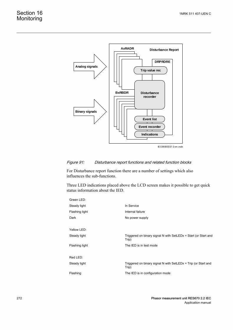
Trip value rec
Event list
Event recorder
Indications
Disturbancerecorder
AxRADR
BxRBDR
Disturbance Report
Binary signals
Analog signals
DRPRDRE
IEC09000337-3-en.vsdx
IEC09000337 V3 EN-US
Figure 91: Disturbance report functions and related function blocks
For Disturbance report function there are a number of settings which alsoinfluences the sub-functions.
Three LED indications placed above the LCD screen makes it possible to get quickstatus information about the IED.
Green LED:
Steady light In Service
Flashing light Internal failure
Dark No power supply
Yellow LED:
Steady light Triggered on binary signal N with SetLEDx = Start (or Start andTrip)
Flashing light The IED is in test mode
Red LED:
Steady light Triggered on binary signal N with SetLEDx = Trip (or Start andTrip)
Flashing The IED is in configuration mode
Section 16 1MRK 511 407-UEN CMonitoring
272 Phasor measurement unit RES670 2.2 IECApplication manual
OperationM12179-82 v7
The operation of Disturbance report function DRPRDRE has to be set On or Off. IfOff is selected, note that no disturbance report is registered, and none sub-functionwill operate (the only general parameter that influences Event list (EL)).
Operation = Off:
• Disturbance reports are not stored.• LED information (yellow - start, red - trip) is not stored or changed.
Operation = On:
• Disturbance reports are stored, disturbance data can be read from the localHMI and from a PC for example using PCM600.
• LED information (yellow - start, red - trip) is stored.
Every recording will get a number (0 to 999) which is used as identifier (localHMI, disturbance handling tool and IEC 61850). An alternative recordingidentification is date, time and sequence number. The sequence number isautomatically increased by one for each new recording and is reset to zero atmidnight. The maximum number of recordings stored in the IED is 100. The oldestrecording will be overwritten when a new recording arrives (FIFO).
To be able to delete disturbance records, Operation parameter hasto be On.
The maximum number of recordings depend on each recordingstotal recording time. Long recording time will reduce the number ofrecordings to less than 100.
The IED flash disk should NOT be used to store any user files. Thismight cause disturbance recordings to be deleted due to lack of diskspace.
16.6.3.1 Recording timesM12179-88 v6
The different recording times for Disturbance report are set (the pre-fault time,post-fault time, and limit time). These recording times affect all sub-functions moreor less but not the Event list (EL) function.
Prefault recording time (PreFaultRecT) is the recording time before the startingpoint of the disturbance. The setting should be at least 0.1 s to ensure enoughsamples for the estimation of pre-fault values in the Trip value recorder (TVR)function.
1MRK 511 407-UEN C Section 16Monitoring
Phasor measurement unit RES670 2.2 IEC 273Application manual
Postfault recording time (PostFaultRecT) is the maximum recording time after thedisappearance of the trig-signal (does not influence the Trip value recorder (TVR)function).
Recording time limit (TimeLimit) is the maximum recording time after trig. Theparameter limits the recording time if some trigging condition (fault-time) is verylong or permanently set (does not influence the Trip value recorder (TVR)function).
Operation in test modeM12179-492 v4
If the IED is in test mode and OpModeTest = Off. Disturbance report function doesnot save any recordings and no LED information is displayed.
If the IED is in test mode and OpModeTest = On. Disturbance report functionworks in normal mode and the status is indicated in the saved recording.
Post RetriggerM12155-173 v7
Disturbance report function does not automatically respond to any new trigcondition during a recording, after all signals set as trigger signals have been reset.However, under certain circumstances the fault condition may reoccur during thepost-fault recording, for instance by automatic reclosing to a still faulty power line.
In order to capture the new disturbance it is possible to allow retriggering(PostRetrig = On) during the post-fault time. In this case a new, complete recordingwill start and, during a period, run in parallel with the initial recording.
When the retrig parameter is disabled (PostRetrig = Off), a new recording will notstart until the post-fault (PostFaultrecT or TimeLimit) period is terminated. If a newtrig occurs during the post-fault period and lasts longer than the proceedingrecording a new complete recording will be started.
Disturbance report function can handle a maximum of 3 simultaneous disturbancerecordings.
16.6.3.2 Binary input signalsM12179-90 v9
Up to 352 binary signals can be selected among internal logical and binary inputsignals. The configuration tool is used to configure the signals.
For each of the 352 signals, it is also possible to select if the signal is to be used asa trigger for the start of the Disturbance report and if the trigger should be activatedon positive (1) or negative (0) slope.
OperationN: Disturbance report may trig for binary input N (On) or not (Off).
TrigLevelN: Trig on positive (Trig on 1) or negative (Trig on 0) slope for binaryinput N.
Section 16 1MRK 511 407-UEN CMonitoring
274 Phasor measurement unit RES670 2.2 IECApplication manual
Func103N: Function type number (0-255) for binary input N according toIEC-60870-5-103, that is, 128: Distance protection, 160: overcurrent protection,176: transformer differential protection and 192: line differential protection.
Info103N: Information number (0-255) for binary input N according toIEC-60870-5-103, that is, 69-71: Trip L1-L3, 78-83: Zone 1-6.
See also description in the chapter IEC 60870-5-103.
16.6.3.3 Analog input signalsM12179-92 v6
Up to 40 analog signals can be selected among internal analog and analog inputsignals. PCM600 is used to configure the signals.
The analog trigger of Disturbance report is not affected if analog input M is to beincluded in the disturbance recording or not (OperationM = On/Off).
If OperationM = Off, no waveform (samples) will be recorded and reported ingraph. However, Trip value, pre-fault and fault value will be recorded and reported.The input channel can still be used to trig the disturbance recorder.
If OperationM = On, waveform (samples) will also be recorded and reported ingraph.
NomValueM: Nominal value for input M.
OverTrigOpM, UnderTrigOpM: Over or Under trig operation, Disturbance reportmay trig for high/low level of analog input M (On) or not (Off).
OverTrigLeM, UnderTrigLeM: Over or under trig level, Trig high/low level relativenominal value for analog input M in percent of nominal value.
16.6.3.4 Sub-function parametersM12179-389 v3
All functions are in operation as long as Disturbance report is in operation.
IndicationsM12179-448 v4
IndicationMaN: Indication mask for binary input N. If set (Show), a status changeof that particular input, will be fetched and shown in the disturbance summary onlocal HMI. If not set (Hide), status change will not be indicated.
SetLEDN: Set red LED on local HMI in front of the IED if binary input N changesstatus.
Disturbance recorderM12179-446 v5
OperationM: Analog channel M is to be recorded by the disturbance recorder (On)or not (Off).
1MRK 511 407-UEN C Section 16Monitoring
Phasor measurement unit RES670 2.2 IEC 275Application manual

If OperationM = Off, no waveform (samples) will be recorded and reported ingraph. However, Trip value, pre-fault and fault value will be recorded and reported.The input channel can still be used to trig the disturbance recorder.
If OperationM = On, waveform (samples) will also be recorded and reported ingraph.
Setting informationGUID-B0D40F6D-3CE4-4FF3-81B4-B453FDD389CB v1
SetInfoInDrep: Parameter used to enable or disable the settings information indisturbance header.
Event recorderM12179-444 v4
Event recorder (ER) function has no dedicated parameters.
Trip value recorderM12179-442 v3
ZeroAngleRef: The parameter defines which analog signal that will be used asphase angle reference for all other analog input signals. This signal will also beused for frequency measurement and the measured frequency is used whencalculating trip values. It is suggested to point out a sampled voltage input signal,for example, a line or busbar phase voltage (channel 1-30).
Event listM12179-440 v3
Event list (EL) (SOE) function has no dedicated parameters.
16.6.3.5 ConsiderationM12179-420 v6
The density of recording equipment in power systems is increasing, since thenumber of modern IEDs, where recorders are included, is increasing. This leads toa vast number of recordings at every single disturbance and a lot of information hasto be handled if the recording functions do not have proper settings. The goal is tooptimize the settings in each IED to be able to capture just valuable disturbancesand to maximize the number that is possible to save in the IED.
The recording time should not be longer than necessary (PostFaultrecT andTimeLimit).
• Should the function record faults only for the protected object or cover more?• How long is the longest expected fault clearing time?• Is it necessary to include reclosure in the recording or should a persistent fault
generate a second recording (PostRetrig)?
Minimize the number of recordings:
• Binary signals: Use only relevant signals to start the recording that is,protection trip, carrier receive and/or start signals.
• Analog signals: The level triggering should be used with great care, sinceunfortunate settings will cause enormously number of recordings. Ifnevertheless analog input triggering is used, chose settings by a sufficient
Section 16 1MRK 511 407-UEN CMonitoring
276 Phasor measurement unit RES670 2.2 IECApplication manual
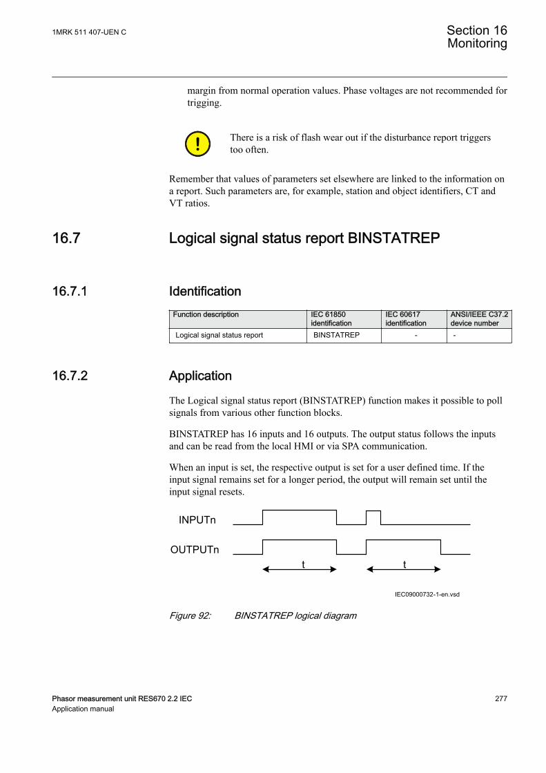
margin from normal operation values. Phase voltages are not recommended fortrigging.
There is a risk of flash wear out if the disturbance report triggerstoo often.
Remember that values of parameters set elsewhere are linked to the information ona report. Such parameters are, for example, station and object identifiers, CT andVT ratios.
16.7 Logical signal status report BINSTATREPGUID-E7A2DB38-DD96-4296-B3D5-EB7FBE77CE07 v2
16.7.1 IdentificationGUID-E0247779-27A2-4E6C-A6DD-D4C31516CA5C v3
Function description IEC 61850identification
IEC 60617identification
ANSI/IEEE C37.2device number
Logical signal status report BINSTATREP - -
16.7.2 ApplicationGUID-F9D225B1-68F7-4D15-AA89-C9211B450D19 v3
The Logical signal status report (BINSTATREP) function makes it possible to pollsignals from various other function blocks.
BINSTATREP has 16 inputs and 16 outputs. The output status follows the inputsand can be read from the local HMI or via SPA communication.
When an input is set, the respective output is set for a user defined time. If theinput signal remains set for a longer period, the output will remain set until theinput signal resets.
t t
INPUTn
OUTPUTn
IEC09000732-1-en.vsdIEC09000732 V1 EN-US
Figure 92: BINSTATREP logical diagram
1MRK 511 407-UEN C Section 16Monitoring
Phasor measurement unit RES670 2.2 IEC 277Application manual

16.7.3 Setting guidelinesGUID-BBDA6900-4C1A-4A7C-AEA5-3C49C2749254 v2
The pulse time t is the only setting for the Logical signal status report(BINSTATREP). Each output can be set or reset individually, but the pulse timewill be the same for all outputs in the entire BINSTATREP function.
16.8 Limit counter L4UFCNTGUID-22E141DB-38B3-462C-B031-73F7466DD135 v1
16.8.1 IdentificationGUID-F3FB7B33-B189-4819-A1F0-8AC7762E9B7E v3
Function description IEC 61850identification
IEC 60617identification
ANSI/IEEE C37.2device number
Limit counter L4UFCNT -
16.8.2 ApplicationGUID-41B13135-5069-4A5A-86CE-B7DBE9CFEF38 v2
Limit counter (L4UFCNT) is intended for applications where positive and/ornegative flanks on a binary signal need to be counted.
The limit counter provides four independent limits to be checked against theaccumulated counted value. The four limit reach indication outputs can be utilizedto initiate proceeding actions. The output indicators remain high until the reset ofthe function.
It is also possible to initiate the counter from a non-zero value by resetting thefunction to the wanted initial value provided as a setting.
If applicable, the counter can be set to stop or rollover to zero and continuecounting after reaching the maximum count value. The steady overflow output flagindicates the next count after reaching the maximum count value. It is also possibleto set the counter to rollover and indicate the overflow as a pulse, which lasts up tothe first count after rolling over to zero. In this case, periodic pulses will begenerated at multiple overflow of the function.
16.8.3 Setting guidelinesGUID-5AECCDBC-7385-4D9F-940C-9D4A0E59B106 v1
GUID-DA5DA8D7-4821-4BFB-86CC-28658E376270 v2
The parameters for Limit counter L4UFCNT are set via the local HMI or PCM600.
Section 16 1MRK 511 407-UEN CMonitoring
278 Phasor measurement unit RES670 2.2 IECApplication manual
16.9 Running hour-meter TEILGAPC
16.9.1 IdentificationGUID-3F9EF4FA-74FA-4D1D-88A0-E948B722B64F v1
Function Description IEC 61850identification
IEC 60617identification
ANSI/IEEE C37.2 devicenumber
Running hour-meter TEILGAPC - -
16.9.2 ApplicationGUID-225D8341-2D31-49F1-9B49-571346C0FE26 v1
The function is used for user-defined logics and it can also be used for differentpurposes internally in the IED. An application example is to accumulate the totalrunning/energized time of the generator, transformer, reactor, capacitor bank oreven line.
Settable time limits for warning and alarm are provided. The time limit foroverflow indication is fixed to 99999.9 hours. At overflow the accumulated timeresets and the accumulation starts from zero again.
16.9.3 Setting guidelinesGUID-D3BED56A-BA80-486F-B2A8-E47F7AC63468 v1
The settings tAlarm and tWarning are user settable limits defined in hours. Theachievable resolution of the settings is 0.1 hours (6 minutes).
tAlarm and tWarning are independent settings, that is, there is nocheck if tAlarm > tWarning.
The limit for the overflow supervision is fixed at 99999.9 hours.
The setting tAddToTime is a user settable time parameter in hours.
1MRK 511 407-UEN C Section 16Monitoring
Phasor measurement unit RES670 2.2 IEC 279Application manual

280
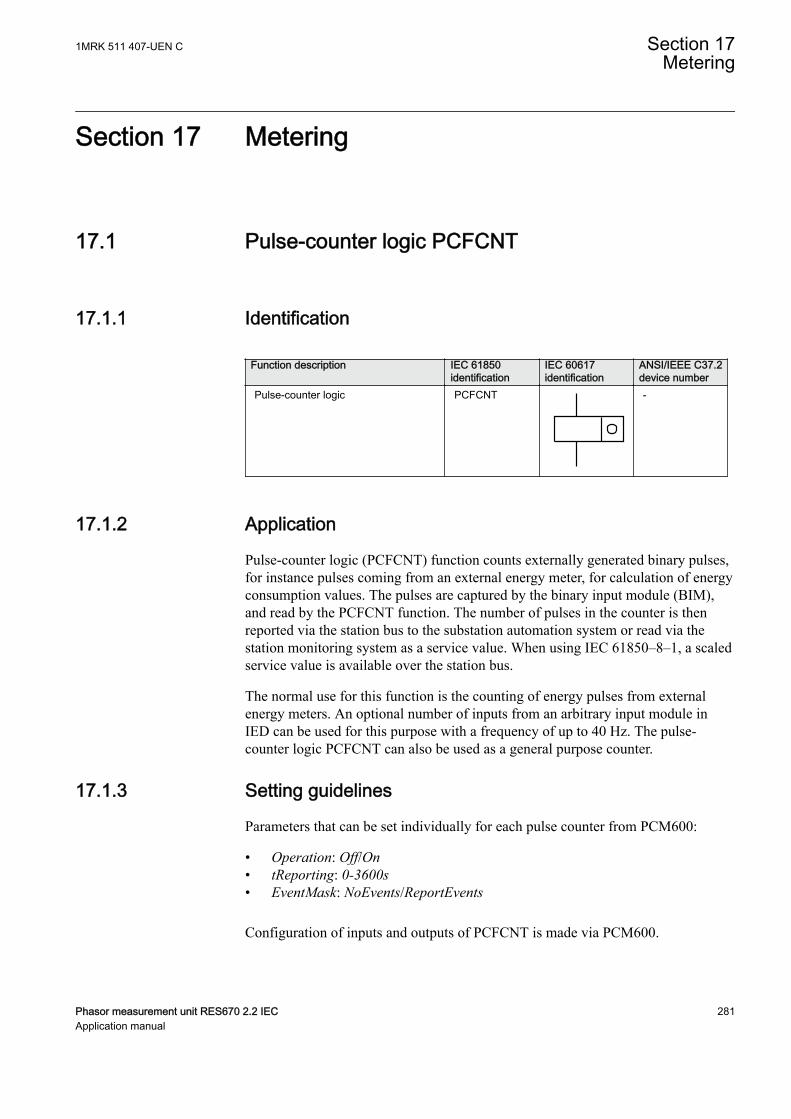
Section 17 Metering
17.1 Pulse-counter logic PCFCNTIP14600-1 v3
17.1.1 IdentificationM14879-1 v4
Function description IEC 61850identification
IEC 60617identification
ANSI/IEEE C37.2device number
Pulse-counter logic PCFCNT
S00947 V1 EN-US
-
17.1.2 ApplicationM13395-3 v6
Pulse-counter logic (PCFCNT) function counts externally generated binary pulses,for instance pulses coming from an external energy meter, for calculation of energyconsumption values. The pulses are captured by the binary input module (BIM),and read by the PCFCNT function. The number of pulses in the counter is thenreported via the station bus to the substation automation system or read via thestation monitoring system as a service value. When using IEC 61850–8–1, a scaledservice value is available over the station bus.
The normal use for this function is the counting of energy pulses from externalenergy meters. An optional number of inputs from an arbitrary input module inIED can be used for this purpose with a frequency of up to 40 Hz. The pulse-counter logic PCFCNT can also be used as a general purpose counter.
17.1.3 Setting guidelinesM13396-4 v9
Parameters that can be set individually for each pulse counter from PCM600:
• Operation: Off/On• tReporting: 0-3600s• EventMask: NoEvents/ReportEvents
Configuration of inputs and outputs of PCFCNT is made via PCM600.
1MRK 511 407-UEN C Section 17Metering
Phasor measurement unit RES670 2.2 IEC 281Application manual
On the Binary input module (BIM), the debounce filter default time is set to 1 ms,that is, the counter suppresses pulses with a pulse length less than 1 ms. The inputoscillation blocking frequency is preset to 40 Hz meaning that the counter detectsthe input to oscillate if the input frequency is greater than 40 Hz. Oscillationsuppression is released at 30 Hz. Block/release values for oscillation can bechanged on the local HMI and PCM600 under Main menu/Configuration/I/Omodules.
The setting is common for all input channels on BIM, that is, iflimit changes are made for inputs not connected to the pulsecounter, the setting also influences the inputs on the same boardused for pulse counting.
17.2 Function for energy calculation and demandhandling ETPMMTR
SEMOD153638-1 v2
17.2.1 IdentificationSEMOD175537-2 v4
Function description IEC 61850identification
IEC 60617identification
ANSI/IEEE C37.2device number
Function for energy calculation anddemand handling
ETPMMTR W_Varh -
17.2.2 ApplicationSEMOD175546-4 v5
Energy calculation and demand handling function (ETPMMTR) is intended forstatistics of the forward and reverse active and reactive energy. It has a highaccuracy basically given by the measurements function (CVMMXN). This functionhas a site calibration possibility to further increase the total accuracy.
The function is connected to the instantaneous outputs of (CVMMXN) as shown infigure 93.
Section 17 1MRK 511 407-UEN CMetering
282 Phasor measurement unit RES670 2.2 IECApplication manual
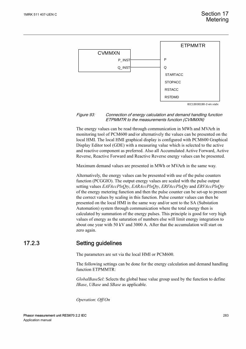
CVMMXN
P_INST
Q_INST
ETPMMTR
P
Q
RSTACC
RSTDMD
STARTACC
STOPACC
IEC13000190-2-en.vsdx
IEC13000190 V2 EN-US
Figure 93: Connection of energy calculation and demand handling functionETPMMTR to the measurements function (CVMMXN)
The energy values can be read through communication in MWh and MVArh inmonitoring tool of PCM600 and/or alternatively the values can be presented on thelocal HMI. The local HMI graphical display is configured with PCM600 GraphicalDisplay Editor tool (GDE) with a measuring value which is selected to the activeand reactive component as preferred. Also all Accumulated Active Forward, ActiveReverse, Reactive Forward and Reactive Reverse energy values can be presented.
Maximum demand values are presented in MWh or MVArh in the same way.
Alternatively, the energy values can be presented with use of the pulse countersfunction (PCGGIO). The output energy values are scaled with the pulse outputsetting values EAFAccPlsQty, EARAccPlsQty, ERFAccPlsQty and ERVAccPlsQtyof the energy metering function and then the pulse counter can be set-up to presentthe correct values by scaling in this function. Pulse counter values can then bepresented on the local HMI in the same way and/or sent to the SA (SubstationAutomation) system through communication where the total energy then iscalculated by summation of the energy pulses. This principle is good for very highvalues of energy as the saturation of numbers else will limit energy integration toabout one year with 50 kV and 3000 A. After that the accumulation will start onzero again.
17.2.3 Setting guidelinesSEMOD175556-4 v6
The parameters are set via the local HMI or PCM600.
The following settings can be done for the energy calculation and demand handlingfunction ETPMMTR:
GlobalBaseSel: Selects the global base value group used by the function to defineIBase, UBase and SBase as applicable.
Operation: Off/On
1MRK 511 407-UEN C Section 17Metering
Phasor measurement unit RES670 2.2 IEC 283Application manual

EnaAcc: Off/On is used to switch the accumulation of energy on and off.
tEnergy: Time interval when energy is measured.
tEnergyOnPls: gives the pulse length ON time of the pulse. It should be at least100 ms when connected to the Pulse counter function block. Typical value can be100 ms.
tEnergyOffPls: gives the OFF time between pulses. Typical value can be 100 ms.
EAFAccPlsQty and EARAccPlsQty: gives the MWh value in each pulse. It shouldbe selected together with the setting of the Pulse counter (PCGGIO) settings togive the correct total pulse value.
ERFAccPlsQty and ERVAccPlsQty : gives the MVArh value in each pulse. It shouldbe selected together with the setting of the Pulse counter (PCGGIO) settings togive the correct total pulse value.
For the advanced user there are a number of settings for direction, zero clamping,max limit, and so on. Normally, the default values are suitable for these parameters.
Section 17 1MRK 511 407-UEN CMetering
284 Phasor measurement unit RES670 2.2 IECApplication manual

Section 18 Ethernet-based communication
18.1 Access point
18.1.1 ApplicationGUID-2942DF07-9BC1-4F49-9611-A5691D2C925C v1
The access points are used to connect the IED to the communication buses (like thestation bus) that use communication protocols. The access point can be used forsingle and redundant data communication. The access points are also used forcommunication with the merging units and for time synchronization usingPrecision Time Protocol (PTP).
18.1.2 Setting guidelinesGUID-CEDC23B1-09F6-4C85-98D8-9D8E2C2553FE v2
The physical ports allocated to access points 2–6 have to be addedin the hardware tool in PCM600 before the access points can beconfigured. The factory setting only includes the physical portsallocated to the front port and access point 1.
The settings for the access points are configured using the Ethernet configurationtool (ECT) in PCM600.
The access point is activated if the Operation checkbox is checked for therespective access point and a partial or common write to IED is performed.
To increase security, it is recommended to deactivate the accesspoint when it is not in use.
Redundancy and PTP cannot be set for the front port (Access point 0) as redundantcommunication and PTP are only available for the rear optical Ethernet ports.
Subnetwork shows the SCL subnetwork to which the access point is connected.This column shows the SCL subnetworks available in the PCM600 project. SCLsubnetworks can be created/deleted in the Subnetworks tab of IEC 61850Configuration tool in PCM600.
When saving the ECT configuration after selecting a subnetwork,ECT creates the access point in the SCL model. Unselecting thesubnetwork removes the access point from the SCL model. Thiscolumn is editable for IEC61850 Ed2 IEDs and not editable for
1MRK 511 407-UEN C Section 18Ethernet-based communication
Phasor measurement unit RES670 2.2 IEC 285Application manual
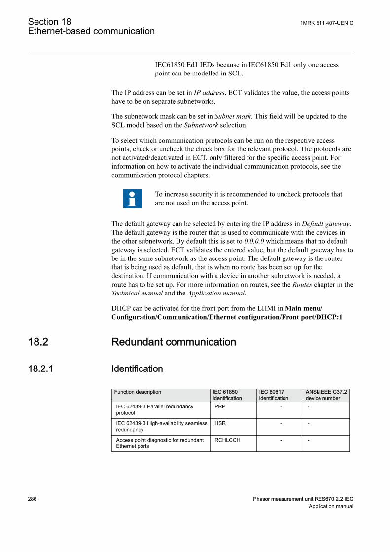
IEC61850 Ed1 IEDs because in IEC61850 Ed1 only one accesspoint can be modelled in SCL.
The IP address can be set in IP address. ECT validates the value, the access pointshave to be on separate subnetworks.
The subnetwork mask can be set in Subnet mask. This field will be updated to theSCL model based on the Subnetwork selection.
To select which communication protocols can be run on the respective accesspoints, check or uncheck the check box for the relevant protocol. The protocols arenot activated/deactivated in ECT, only filtered for the specific access point. Forinformation on how to activate the individual communication protocols, see thecommunication protocol chapters.
To increase security it is recommended to uncheck protocols thatare not used on the access point.
The default gateway can be selected by entering the IP address in Default gateway.The default gateway is the router that is used to communicate with the devices inthe other subnetwork. By default this is set to 0.0.0.0 which means that no defaultgateway is selected. ECT validates the entered value, but the default gateway has tobe in the same subnetwork as the access point. The default gateway is the routerthat is being used as default, that is when no route has been set up for thedestination. If communication with a device in another subnetwork is needed, aroute has to be set up. For more information on routes, see the Routes chapter in theTechnical manual and the Application manual.
DHCP can be activated for the front port from the LHMI in Main menu/Configuration/Communication/Ethernet configuration/Front port/DHCP:1
18.2 Redundant communication
18.2.1 IdentificationGUID-B7AE0374-0336-42B8-90AF-3AE1C79A4116 v1
Function description IEC 61850identification
IEC 60617identification
ANSI/IEEE C37.2device number
IEC 62439-3 Parallel redundancyprotocol
PRP - -
IEC 62439-3 High-availability seamlessredundancy
HSR - -
Access point diagnostic for redundantEthernet ports
RCHLCCH - -
Section 18 1MRK 511 407-UEN CEthernet-based communication
286 Phasor measurement unit RES670 2.2 IECApplication manual
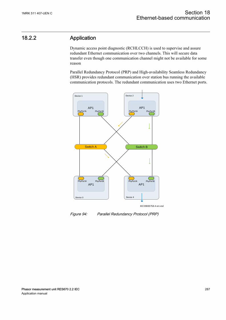
18.2.2 ApplicationGUID-172BA5D7-6532-4B0D-8C1D-2E02F70B4FCB v1
Dynamic access point diagnostic (RCHLCCH) is used to supervise and assureredundant Ethernet communication over two channels. This will secure datatransfer even though one communication channel might not be available for somereason
Parallel Redundancy Protocol (PRP) and High-availability Seamless Redundancy(HSR) provides redundant communication over station bus running the availablecommunication protocols. The redundant communication uses two Ethernet ports.
IEC09000758-4-en.vsd
Switch A
AP1 PhyPortB PhyPortA
AP1 PhyPortA PhyPortB
AP1 PhyPortB PhyPortA
AP1 PhyPortA PhyPortB
Switch B
Device 1 Device 2
Device 3 Device 4
IEC09000758 V4 EN-US
Figure 94: Parallel Redundancy Protocol (PRP)
1MRK 511 407-UEN C Section 18Ethernet-based communication
Phasor measurement unit RES670 2.2 IEC 287Application manual
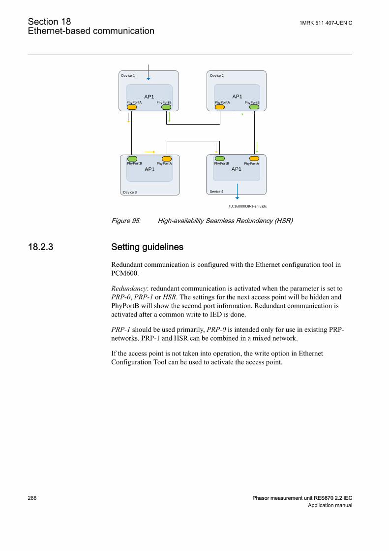
IEC16000038-1-en.vsdx
AP1 PhyPortB PhyPortA
AP1 PhyPortA PhyPortB
AP1 PhyPortA PhyPortB
AP1 PhyPortB PhyPortA
Device 1 Device 2
Device 3 Device 4
IEC16000038 V1 EN-US
Figure 95: High-availability Seamless Redundancy (HSR)
18.2.3 Setting guidelinesGUID-887B0AE2-0F2E-414D-96FD-7EC935C5D2D8 v1
Redundant communication is configured with the Ethernet configuration tool inPCM600.
Redundancy: redundant communication is activated when the parameter is set toPRP-0, PRP-1 or HSR. The settings for the next access point will be hidden andPhyPortB will show the second port information. Redundant communication isactivated after a common write to IED is done.
PRP-1 should be used primarily, PRP-0 is intended only for use in existing PRP-networks. PRP-1 and HSR can be combined in a mixed network.
If the access point is not taken into operation, the write option in EthernetConfiguration Tool can be used to activate the access point.
Section 18 1MRK 511 407-UEN CEthernet-based communication
288 Phasor measurement unit RES670 2.2 IECApplication manual
IEC16000039-1-en.vsdxIEC16000039 V1 EN-US
Figure 96: ECT screen with Redundancy set to PRP-1 on Access point 1 andHSR Access point 3
18.3 Merging unit
18.3.1 ApplicationGUID-E630C16F-EDB8-40AE-A8A2-94189982D15F v1
The IEC/UCA 61850-9-2LE process bus communication protocol enables an IEDto communicate with devices providing measured values in digital format,commonly known as Merging Units (MU). The rear access points are used for thecommunication.
The merging units (MU) are called so because they can gather analog values fromone or more measuring transformers, sample the data and send the data overprocess bus to other clients (or subscribers) in the system. Some merging units areable to get data from classical measuring transformers, others from non-conventional measuring transducers and yet others can pick up data from bothtypes.
1MRK 511 407-UEN C Section 18Ethernet-based communication
Phasor measurement unit RES670 2.2 IEC 289Application manual

IEC17000044-1-en.vsdx
IEC17000044 V1 EN-US
Figure 97: Merging unit
18.3.2 Setting guidelinesGUID-3449AB24-8C9D-4D9A-BD46-5DDF59A0F8E3 v1
For information on the merging unit setting guidelines, see section IEC/UCA61850-9-2LE communication protocol.
18.4 Routes
18.4.1 ApplicationGUID-19616AC4-0FFD-4FF4-9198-5E33938E5ABD v1
Setting up a route enables communication to a device that is located in anothersubnetwork. Routing is used when the destination device is not in the samesubnetwork as the default gateway.
The route specifies that when a package is sent to the destination device it shouldbe sent through the selected router. If no route is specified the source device willnot find the destination device.
18.4.2 Setting guidelinesGUID-2C4A312A-00DC-44C8-B2D9-CD0822E1C806 v1
Routes are configured using the Ethernet configuration tool in PCM600.
Operation for the route can be set to On/Off by checking and unchecking thecheck-box in the operation column.
Gateway specifies the address of the gateway.
Destination specifies the destination.
Destination subnet mask specifies the subnetwork mask of the destination.
Section 18 1MRK 511 407-UEN CEthernet-based communication
290 Phasor measurement unit RES670 2.2 IECApplication manual
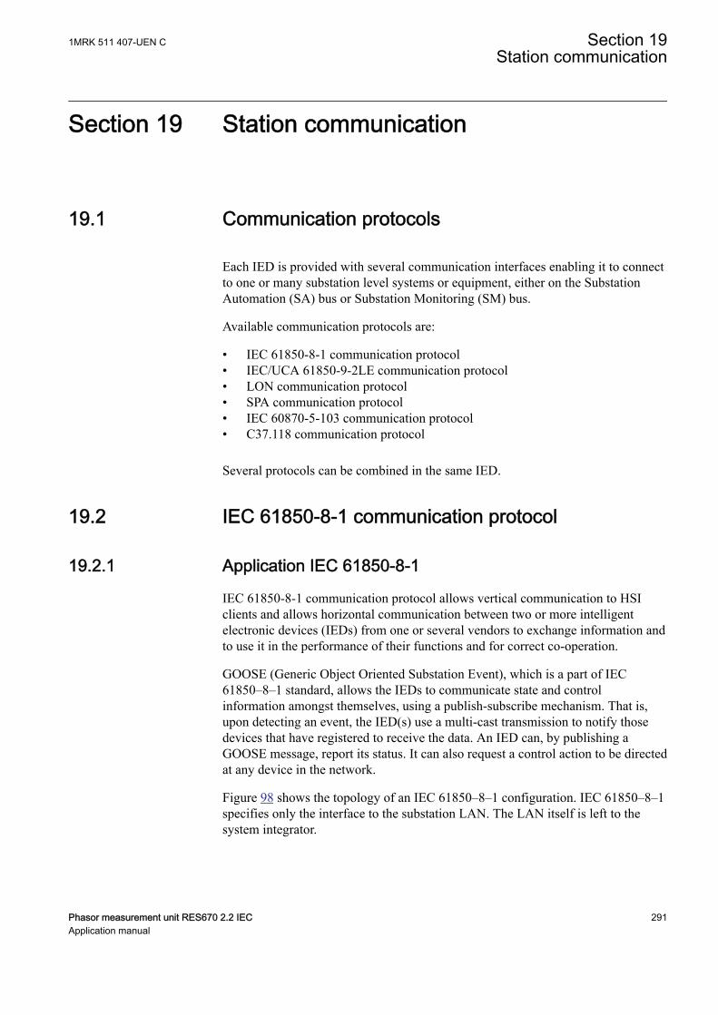
Section 19 Station communication
19.1 Communication protocolsM14815-3 v14
Each IED is provided with several communication interfaces enabling it to connectto one or many substation level systems or equipment, either on the SubstationAutomation (SA) bus or Substation Monitoring (SM) bus.
Available communication protocols are:
• IEC 61850-8-1 communication protocol• IEC/UCA 61850-9-2LE communication protocol• LON communication protocol• SPA communication protocol• IEC 60870-5-103 communication protocol• C37.118 communication protocol
Several protocols can be combined in the same IED.
19.2 IEC 61850-8-1 communication protocolIP14616-1 v2
19.2.1 Application IEC 61850-8-1IP14865-1 v2
M13912-3 v4
IEC 61850-8-1 communication protocol allows vertical communication to HSIclients and allows horizontal communication between two or more intelligentelectronic devices (IEDs) from one or several vendors to exchange information andto use it in the performance of their functions and for correct co-operation.
GOOSE (Generic Object Oriented Substation Event), which is a part of IEC61850–8–1 standard, allows the IEDs to communicate state and controlinformation amongst themselves, using a publish-subscribe mechanism. That is,upon detecting an event, the IED(s) use a multi-cast transmission to notify thosedevices that have registered to receive the data. An IED can, by publishing aGOOSE message, report its status. It can also request a control action to be directedat any device in the network.
M13913-3 v6
Figure 98 shows the topology of an IEC 61850–8–1 configuration. IEC 61850–8–1specifies only the interface to the substation LAN. The LAN itself is left to thesystem integrator.
1MRK 511 407-UEN C Section 19Station communication
Phasor measurement unit RES670 2.2 IEC 291Application manual
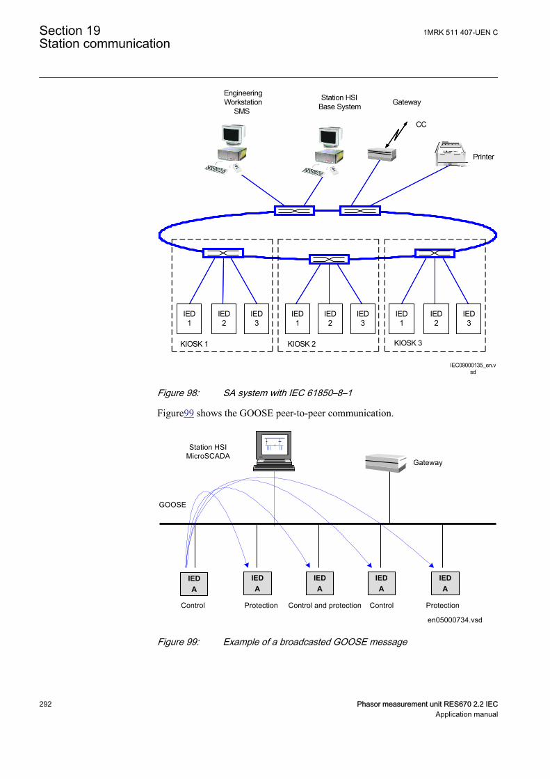
KIOSK 2 KIOSK 3
Station HSIBase System
EngineeringWorkstation
SMSGateway
Printer
CC
IEC09000135_en.vsd
KIOSK 1
IED 1
IED 2
IED 3
IED 1
IED 2
IED 3
IED 1
IED 2
IED 3
IEC09000135 V1 EN-US
Figure 98: SA system with IEC 61850–8–1M16925-3 v4
Figure99 shows the GOOSE peer-to-peer communication.
Control Protection Control ProtectionControl and protection
GOOSE
en05000734.vsd
Station HSIMicroSCADA
Gateway
IEDA
IEDA
IEDA
IEDA
IEDA
IEC05000734 V1 EN-US
Figure 99: Example of a broadcasted GOOSE message
Section 19 1MRK 511 407-UEN CStation communication
292 Phasor measurement unit RES670 2.2 IECApplication manual
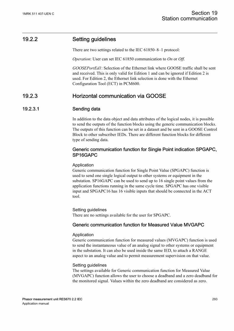
19.2.2 Setting guidelinesSEMOD55317-5 v7
There are two settings related to the IEC 61850–8–1 protocol:
Operation: User can set IEC 61850 communication to On or Off.
GOOSEPortEd1: Selection of the Ethernet link where GOOSE traffic shall be sentand received. This is only valid for Edition 1 and can be ignored if Edition 2 isused. For Edition 2, the Ethernet link selection is done with the EthernetConfiguration Tool (ECT) in PCM600.
19.2.3 Horizontal communication via GOOSE
19.2.3.1 Sending dataGUID-9888ECAD-8221-4B31-A443-EB1E3A9022C4 v1
In addition to the data object and data attributes of the logical nodes, it is possibleto send the outputs of the function blocks using the generic communication blocks.The outputs of this function can be set in a dataset and be sent in a GOOSE ControlBlock to other subscriber IEDs. There are different function blocks for differenttype of sending data.
Generic communication function for Single Point indication SPGAPC,SP16GAPC
SEMOD55999-1 v4
ApplicationSEMOD55350-5 v8
Generic communication function for Single Point Value (SPGAPC) function isused to send one single logical output to other systems or equipment in thesubstation. SP16GAPC can be used to send up to 16 single point values from theapplication functions running in the same cycle time. SPGAPC has one visibleinput and SPGAPC16 has 16 visible inputs that should be connected in the ACTtool.
Setting guidelinesSEMOD55376-5 v5
There are no settings available for the user for SPGAPC.
Generic communication function for Measured Value MVGAPCSEMOD55402-1 v3
ApplicationSEMOD55872-5 v10
Generic communication function for measured values (MVGAPC) function is usedto send the instantaneous value of an analog signal to other systems or equipmentin the substation. It can also be used inside the same IED, to attach a RANGEaspect to an analog value and to permit measurement supervision on that value.
Setting guidelinesSEMOD55424-5 v5
The settings available for Generic communication function for Measured Value(MVGAPC) function allows the user to choose a deadband and a zero deadband forthe monitored signal. Values within the zero deadband are considered as zero.
1MRK 511 407-UEN C Section 19Station communication
Phasor measurement unit RES670 2.2 IEC 293Application manual
The high and low limit settings provides limits for the high-high-, high, normal,low and low-low ranges of the measured value. The actual range of the measuredvalue is shown on the range output of MVGAPC function block. When a Measuredvalue expander block (RANGE_XP) is connected to the range output, the logicaloutputs of the RANGE_XP are changed accordingly.
19.2.3.2 Receiving dataGUID-CAE4B020-7131-49BF-BA29-3EEE0EFEA2B8 v2
The GOOSE data must be received at function blocks. There are different GOOSEreceiving function blocks depending on the type of the received data. Refer to theEngineering manual for more information about how to configure GOOSE.
Function block type Data TypeGOOSEBINRCV 16 single point
GOOSEINTLKRCV 2 single points16 double points
GOOSEDPRCV Double point
GOOSEINTRCV Integer
GOOSEMVRCV Analog value
GOOSESPRCV Single point
GOOSEXLNRCV Switch status
ApplicationGUID-808177B7-02CA-40DF-B41B-8B580E38478B v1
The GOOSE receive function blocks are used to receive subscribed data from theGOOSE protocol. The validity of the data value is exposed as outputs of thefunction block as well as the validity of the communication. It is recommended touse these outputs to ensure that only valid data is handled on the subscriber IED.An example could be to control the external reservation before operating on a bay.In the figure below, the GOOSESPRCV is used to receive the status of the bayreservation. The validity of the received data is used in additional logic toguarantee that the value has good quality before operation on that bay.
GOOSESPRCV
Block Spout DataValid CommValid Test
AND AND
Input1 outInput2 NoputInput3Input4
Input1 outInput2 NoputInput3Input4
Ext_Res_OK_To_Operate
IEC16000082=1=en.vsdIEC16000082 V1 EN-US
Figure 100: GOOSESPRCV and AND function blocks - checking the validity ofthe received data
Section 19 1MRK 511 407-UEN CStation communication
294 Phasor measurement unit RES670 2.2 IECApplication manual
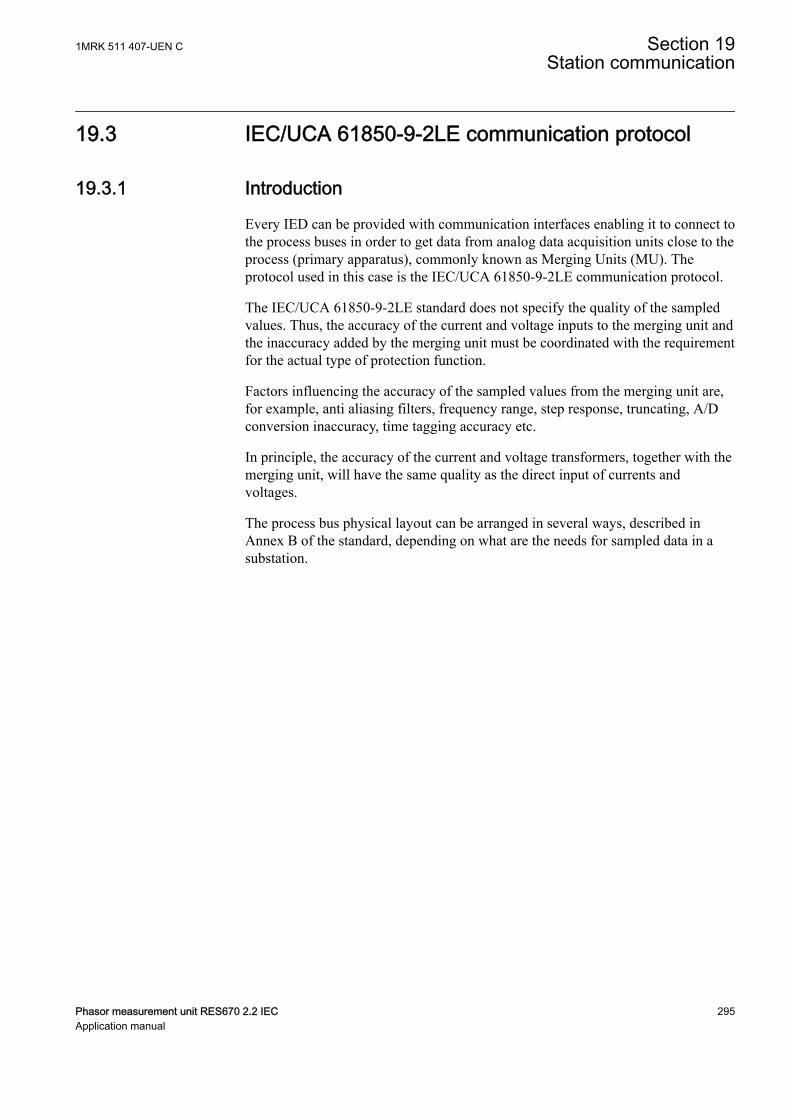
19.3 IEC/UCA 61850-9-2LE communication protocolSEMOD172279 v3
19.3.1 IntroductionSEMOD166571-1 v2
SEMOD166590-5 v6
Every IED can be provided with communication interfaces enabling it to connect tothe process buses in order to get data from analog data acquisition units close to theprocess (primary apparatus), commonly known as Merging Units (MU). Theprotocol used in this case is the IEC/UCA 61850-9-2LE communication protocol.
The IEC/UCA 61850-9-2LE standard does not specify the quality of the sampledvalues. Thus, the accuracy of the current and voltage inputs to the merging unit andthe inaccuracy added by the merging unit must be coordinated with the requirementfor the actual type of protection function.
Factors influencing the accuracy of the sampled values from the merging unit are,for example, anti aliasing filters, frequency range, step response, truncating, A/Dconversion inaccuracy, time tagging accuracy etc.
In principle, the accuracy of the current and voltage transformers, together with themerging unit, will have the same quality as the direct input of currents andvoltages.
The process bus physical layout can be arranged in several ways, described inAnnex B of the standard, depending on what are the needs for sampled data in asubstation.
1MRK 511 407-UEN C Section 19Station communication
Phasor measurement unit RES670 2.2 IEC 295Application manual
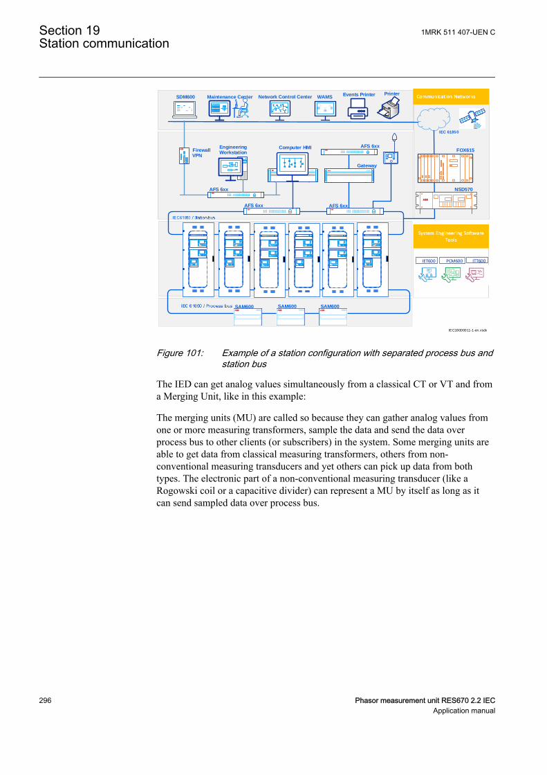
EngineeringWorkstation
Computer HMIFirewallVPN
Gateway
Network Control CenterMaintenance Center
AFS 6xx
AFS 6xx AFS 6xx
AFS 6xx
SAM600 SAM600 SAM600
IEC 61850
FOX615
WAMSSDM600
IET600 PCM600 ITT600
NSD570
Events Printer Printer
IEC18000011-1-en.vsdx
IEC18000011 V1 EN-US
Figure 101: Example of a station configuration with separated process bus andstation bus
The IED can get analog values simultaneously from a classical CT or VT and froma Merging Unit, like in this example:
The merging units (MU) are called so because they can gather analog values fromone or more measuring transformers, sample the data and send the data overprocess bus to other clients (or subscribers) in the system. Some merging units areable to get data from classical measuring transformers, others from non-conventional measuring transducers and yet others can pick up data from bothtypes. The electronic part of a non-conventional measuring transducer (like aRogowski coil or a capacitive divider) can represent a MU by itself as long as itcan send sampled data over process bus.
Section 19 1MRK 511 407-UEN CStation communication
296 Phasor measurement unit RES670 2.2 IECApplication manual
CTCT
ABBMerging
Unit
Ethernet Switch
IED
CombiSensor
Conventional VT
IEC61850-9-2LE
IEC61850-9-2LE
SplitterElectrical-to-
Optical Converter
1PPS
1PPS
110 V1 A1 A
IEC61850-8-1
Station Wide SCADA System
Station Wide GPS Clock
Other Relays
IEC61850-8-1
en08000069-3.vsd
IEC08000069 V2 EN-US
Figure 102: Example of a station configuration with the IED receiving analogvalues from both classical measuring transformers and mergingunits.
19.3.2 Setting guidelinesGUID-29B296B3-6185-459F-B06F-8E7F0C6C9460 v4
Merging Units (MUs) have several settings on local HMI under:
1MRK 511 407-UEN C Section 19Station communication
Phasor measurement unit RES670 2.2 IEC 297Application manual
• Main menu/Configuration/Analog modules/MUx:92xx. The correspondingsettings are also available in PST (PCM600).
• Main menu/Configuration/Communication/Merging units configuration/MUx:92xx. The corresponding settings are also available in ECT (PCM600).
XX can take value 01–12.
19.3.2.1 Specific settings related to the IEC/UCA 61850-9-2LEcommunication
SEMOD166590-24 v6
The process bus communication IEC/UCA 61850-9-2LE has specific settings,similar to the analog inputs modules.
If there are more than one sample group involved, time synch is mandatory. If thereis no time synchronization, the protection functions will be blocked due tocondition blocking.
CTStarPointx: These parameters specify the direction to or from object. See alsosection "Setting of current channels".
SyncLostMode: If this parameter is set to Block and the IED hardware timesynchronization is lost or the synchronization to the MU time is lost, the protectionfunctions in the list 30 will be blocked due to conditional blocking. If thisparameter is set to BlockOnLostUTC, the protection functions in list 30 are blockedif the IED hardware time synchronization is lost or the synchronization of the MUtime is lost or the IED has lost global common synchronization (i.e. GPS, IRIG-Bor PTP). SYNCH output will be set if IED hardware time synchronization is lost.MUSYNCH output will be set if either of MU or IED hardware timesynchronization is lost.
19.3.2.2 Loss of communication when used with LDCMGUID-29EFBCB7-2B4F-4AA1-B593-8E89838722E0 v5
If IEC/UCA 61850-9-2LE communication is lost, see examples in figures 103, 104and 105, the protection functions in table 30 are blocked as per gracefuldegradation.
Case 1:
Section 19 1MRK 511 407-UEN CStation communication
298 Phasor measurement unit RES670 2.2 IECApplication manual
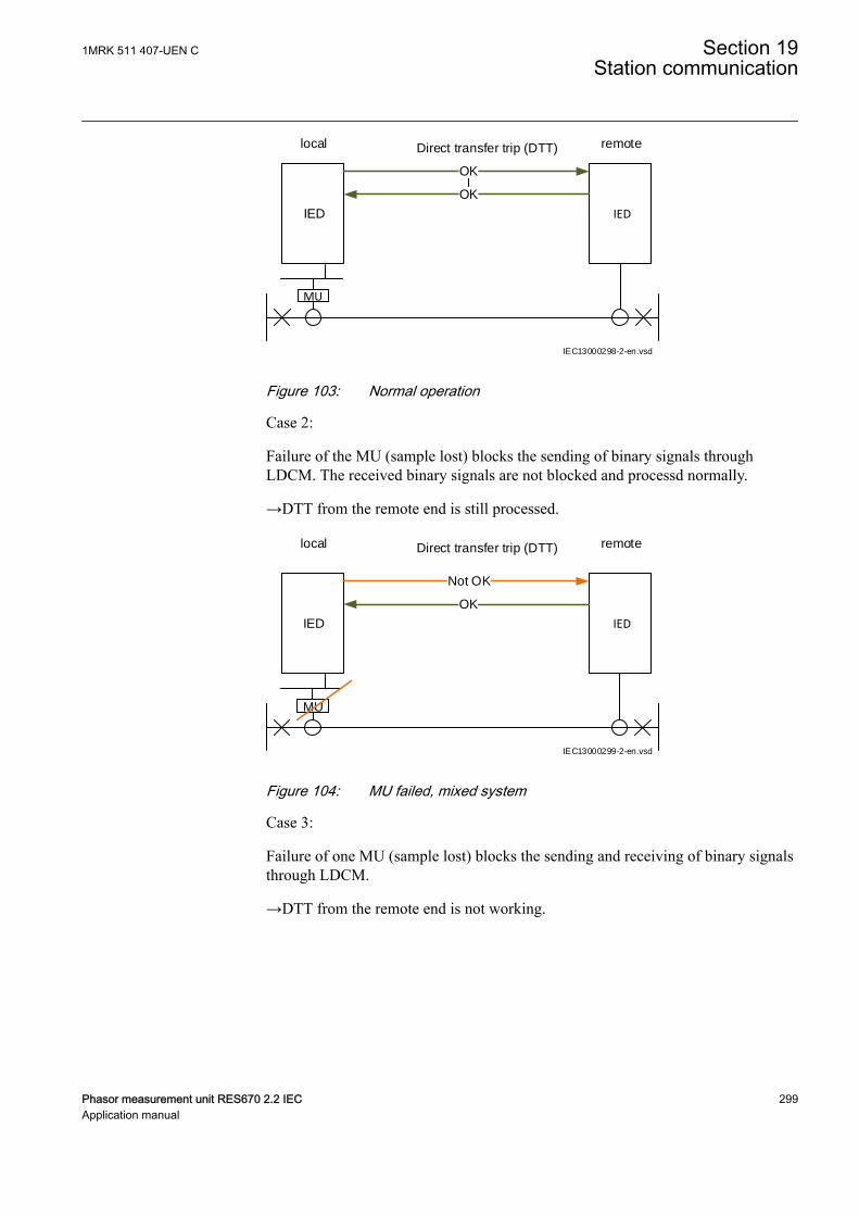
IEC13000298-2-en.vsd
IEDIED
MU
OK
OK
Direct transfer trip (DTT) local remote
IEC13000298 V2 EN-US
Figure 103: Normal operation
Case 2:
Failure of the MU (sample lost) blocks the sending of binary signals throughLDCM. The received binary signals are not blocked and processd normally.
→DTT from the remote end is still processed.
IEC13000299-2-en.vsd
Direct transfer trip (DTT) local remote
IEDIED
MU
Not OK
OK
IEC13000299 V2 EN-US
Figure 104: MU failed, mixed system
Case 3:
Failure of one MU (sample lost) blocks the sending and receiving of binary signalsthrough LDCM.
→DTT from the remote end is not working.
1MRK 511 407-UEN C Section 19Station communication
Phasor measurement unit RES670 2.2 IEC 299Application manual
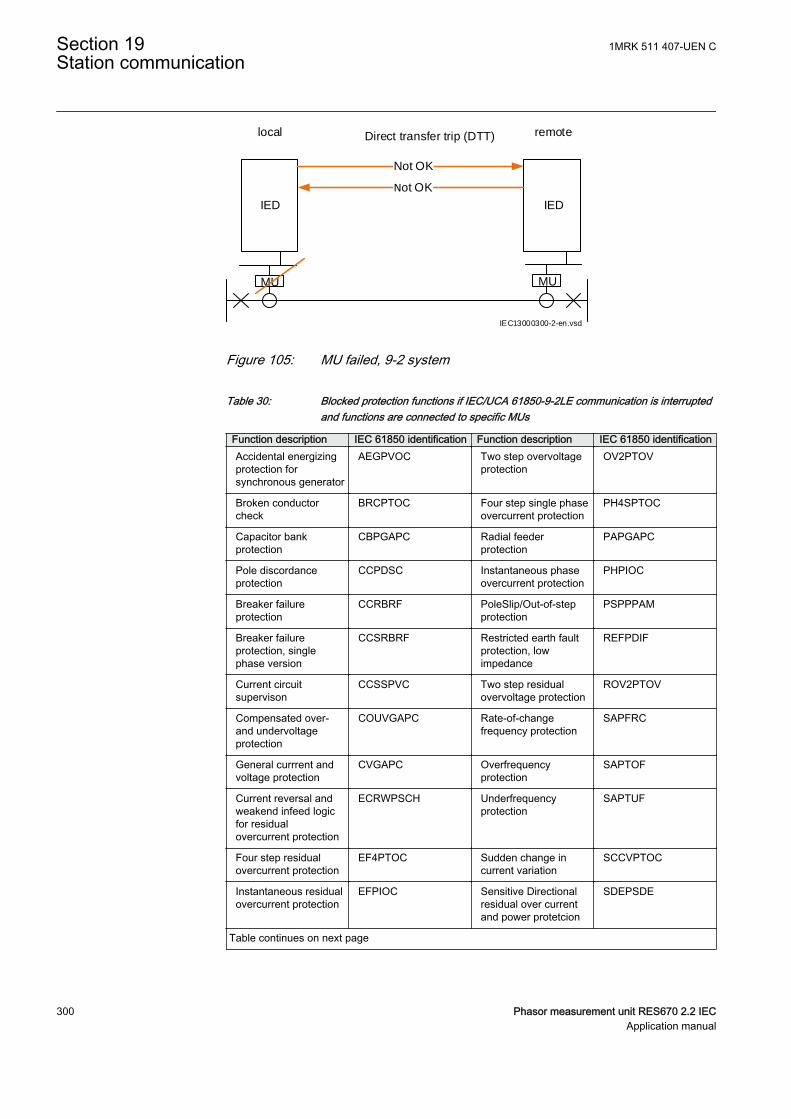
IEC13000300-2-en.vsd
Direct transfer trip (DTT) local remote
IEDIED
MU
Not OK
Not OK
MU
IEC13000300 V2 EN-US
Figure 105: MU failed, 9-2 system
Table 30: Blocked protection functions if IEC/UCA 61850-9-2LE communication is interruptedand functions are connected to specific MUs
Function description IEC 61850 identification Function description IEC 61850 identificationAccidental energizingprotection forsynchronous generator
AEGPVOC Two step overvoltageprotection
OV2PTOV
Broken conductorcheck
BRCPTOC Four step single phaseovercurrent protection
PH4SPTOC
Capacitor bankprotection
CBPGAPC Radial feederprotection
PAPGAPC
Pole discordanceprotection
CCPDSC Instantaneous phaseovercurrent protection
PHPIOC
Breaker failureprotection
CCRBRF PoleSlip/Out-of-stepprotection
PSPPPAM
Breaker failureprotection, singlephase version
CCSRBRF Restricted earth faultprotection, lowimpedance
REFPDIF
Current circuitsupervison
CCSSPVC Two step residualovervoltage protection
ROV2PTOV
Compensated over-and undervoltageprotection
COUVGAPC Rate-of-changefrequency protection
SAPFRC
General currrent andvoltage protection
CVGAPC Overfrequencyprotection
SAPTOF
Current reversal andweakend infeed logicfor residualovercurrent protection
ECRWPSCH Underfrequencyprotection
SAPTUF
Four step residualovercurrent protection
EF4PTOC Sudden change incurrent variation
SCCVPTOC
Instantaneous residualovercurrent protection
EFPIOC Sensitive Directionalresidual over currentand power protetcion
SDEPSDE
Table continues on next page
Section 19 1MRK 511 407-UEN CStation communication
300 Phasor measurement unit RES670 2.2 IECApplication manual
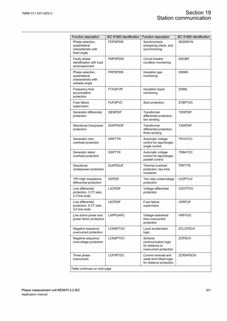
Function description IEC 61850 identification Function description IEC 61850 identificationPhase selection,quadrilateralcharacteristic withfixed angle
FDPSPDIS Synchrocheck,energizing check, andsynchronizing
SESRSYN
Faulty phaseidentification with loadenchroachment
FMPSPDIS Circuit breakercondition monitoring
SSCBR
Phase selection,quadrilateralcharacteristic withsettable angle
FRPSPDIS Insulation gasmonitoring
SSIMG
Frequency timeaccumulationprotection
FTAQFVR Insulation liquidmonitoring
SSIML
Fuse failuresupervision
FUFSPVC Stub protection STBPTOC
Generator differentialprotection
GENPDIF Transformerdifferential protection,two winding
T2WPDIF
Directional Overpowerprotection
GOPPDOP Transformerdifferential protection,three winding
T3WPDIF
Generator rotoroverload protection
GRPTTR Automatic voltagecontrol for tapchanger,single control
TR1ATCC
Generator statoroverload protection
GSPTTR Automatic voltagecontrol for tapchanger,parallel control
TR8ATCC
DirectionalUnderpower protection
GUPPDUP Thermal overloadprotection, two timeconstants
TRPTTR
1Ph High impedancedifferential protection
HZPDIF Two step undervoltageprotection
UV2PTUV
Line differentialprotection, 3 CT sets,2-3 line ends
L3CPDIF Voltage differentialprotection
VDCPTOV
Line differentialprotection, 6 CT sets,3-5 line ends
L6CPDIF Fuse failuresupervision
VDRFUF
Low active power andpower factor protection
LAPPGAPC Voltage-restrainedtime overcurrentprotection
VRPVOC
Negative sequenceovercurrent protection
LCNSPTOC Local accelerationlogic
ZCLCPSCH
Negative sequenceovervoltage protection
LCNSPTOV Schemecommunication logicfor distance orovercurrent protection
ZCPSCH
Three phaseovercurrent
LCP3PTOC Current reversal andweak-end infeed logicfor distance protection
ZCRWPSCH
Table continues on next page
1MRK 511 407-UEN C Section 19Station communication
Phasor measurement unit RES670 2.2 IEC 301Application manual
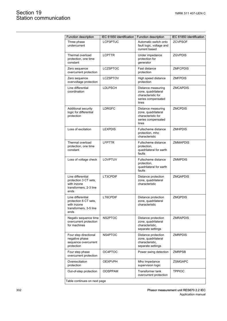
Function description IEC 61850 identification Function description IEC 61850 identificationThree phaseundercurrent
LCP3PTUC Automatic switch ontofault logic, voltage andcurrent based
ZCVPSOF
Thermal overloadprotection, one timeconstant
LCPTTR Under impedanceprotection forgenerator
ZGVPDIS
Zero sequenceovercurrent protection
LCZSPTOC Fast distanceprotection
ZMFCPDIS
Zero sequenceovervoltage protection
LCZSPTOV High speed distanceprotection
ZMFPDIS
Line differentialcoordination
LDLPSCH Distance measuringzone, quadrilateralcharacteristic forseries compensatedlines
ZMCAPDIS
Additional securitylogic for differentialprotection
LDRGFC Distance measuringzone, quadrilateralcharacteristic forseries compensatedlines
ZMCPDIS
Loss of excitation LEXPDIS Fullscheme distanceprotection, mhocharacteristic
ZMHPDIS
Thermal overloadprotection, one timeconstant
LFPTTR Fullscheme distanceprotection,quadrilateral for earthfaults
ZMMAPDIS
Loss of voltage check LOVPTUV Fullscheme distanceprotection,quadrilateral for earthfaults
ZMMPDIS
Line differentialprotection 3 CT sets,with inzonetransformers, 2-3 lineends
LT3CPDIF Distance protectionzone, quadrilateralcharacteristic
ZMQAPDIS
Line differentialprotection 6 CT sets,with inzonetransformers, 3-5 lineends
LT6CPDIF Distance protectionzone, quadrilateralcharacteristic
ZMQPDIS
Negativ sequence timeovercurrent protectionfor machines
NS2PTOC Distance protectionzone, quadrilateralcharacteristic,separate settings
ZMRAPDIS
Four step directionalnegative phasesequence overcurrentprotection
NS4PTOC Distance protectionzone, quadrilateralcharacteristic,separate settings
ZMRPDIS
Four step phaseovercurrent protection
OC4PTOC Power swing detection ZMRPSB
Overexcitationprotection
OEXPVPH Mho Impedancesupervision logic
ZSMGAPC
Out-of-step protection OOSPPAM Transformer tankovercurrent protection
TPPIOC
Table continues on next page
Section 19 1MRK 511 407-UEN CStation communication
302 Phasor measurement unit RES670 2.2 IECApplication manual
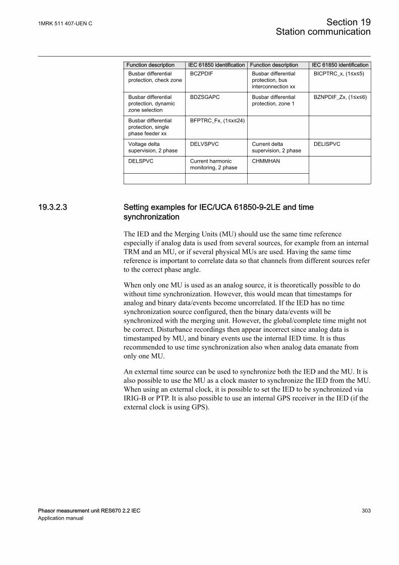
Function description IEC 61850 identification Function description IEC 61850 identificationBusbar differentialprotection, check zone
BCZPDIF Busbar differentialprotection, businterconnection xx
BICPTRC_x, (1≤x≤5)
Busbar differentialprotection, dynamiczone selection
BDZSGAPC Busbar differentialprotection, zone 1
BZNPDIF_Zx, (1≤x≤6)
Busbar differentialprotection, singlephase feeder xx
BFPTRC_Fx, (1≤x≤24)
Voltage deltasupervision, 2 phase
DELVSPVC Current deltasupervision, 2 phase
DELISPVC
DELSPVC Current harmonicmonitoring, 2 phase
CHMMHAN
19.3.2.3 Setting examples for IEC/UCA 61850-9-2LE and timesynchronization
GUID-CEDD520A-8A13-41DF-BFF1-8A3B4C00E098 v3
The IED and the Merging Units (MU) should use the same time referenceespecially if analog data is used from several sources, for example from an internalTRM and an MU, or if several physical MUs are used. Having the same timereference is important to correlate data so that channels from different sources referto the correct phase angle.
When only one MU is used as an analog source, it is theoretically possible to dowithout time synchronization. However, this would mean that timestamps foranalog and binary data/events become uncorrelated. If the IED has no timesynchronization source configured, then the binary data/events will besynchronized with the merging unit. However, the global/complete time might notbe correct. Disturbance recordings then appear incorrect since analog data istimestamped by MU, and binary events use the internal IED time. It is thusrecommended to use time synchronization also when analog data emanate fromonly one MU.
An external time source can be used to synchronize both the IED and the MU. It isalso possible to use the MU as a clock master to synchronize the IED from the MU.When using an external clock, it is possible to set the IED to be synchronized viaIRIG-B or PTP. It is also possible to use an internal GPS receiver in the IED (if theexternal clock is using GPS).
1MRK 511 407-UEN C Section 19Station communication
Phasor measurement unit RES670 2.2 IEC 303Application manual
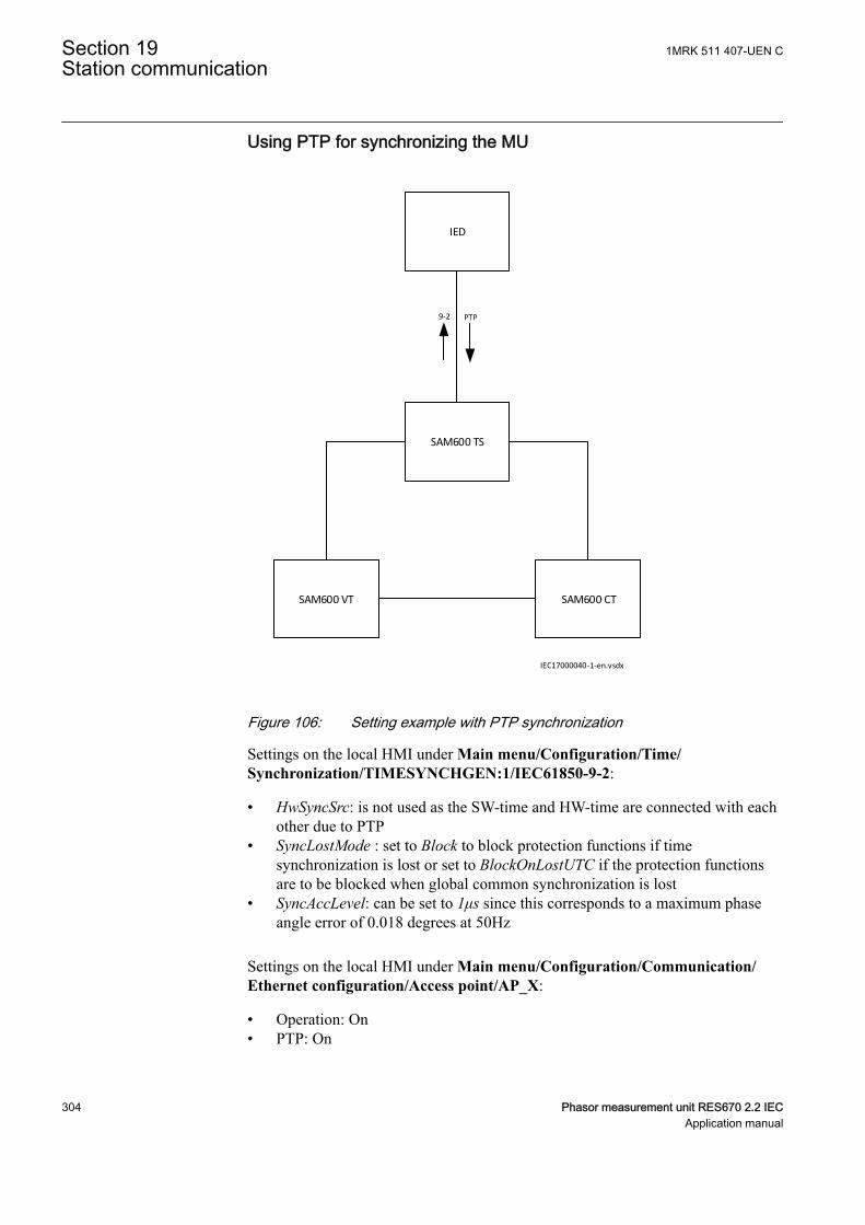
Using PTP for synchronizing the MU
SAM600 VT SAM600 CT
SAM600 TS
IED
PTP9-2
IEC17000040-1-en.vsdx
IEC17000040 V1 EN-US
Figure 106: Setting example with PTP synchronization
Settings on the local HMI under Main menu/Configuration/Time/Synchronization/TIMESYNCHGEN:1/IEC61850-9-2:
• HwSyncSrc: is not used as the SW-time and HW-time are connected with eachother due to PTP
• SyncLostMode : set to Block to block protection functions if timesynchronization is lost or set to BlockOnLostUTC if the protection functionsare to be blocked when global common synchronization is lost
• SyncAccLevel: can be set to 1μs since this corresponds to a maximum phaseangle error of 0.018 degrees at 50Hz
Settings on the local HMI under Main menu/Configuration/Communication/Ethernet configuration/Access point/AP_X:
• Operation: On• PTP: On
Section 19 1MRK 511 407-UEN CStation communication
304 Phasor measurement unit RES670 2.2 IECApplication manual
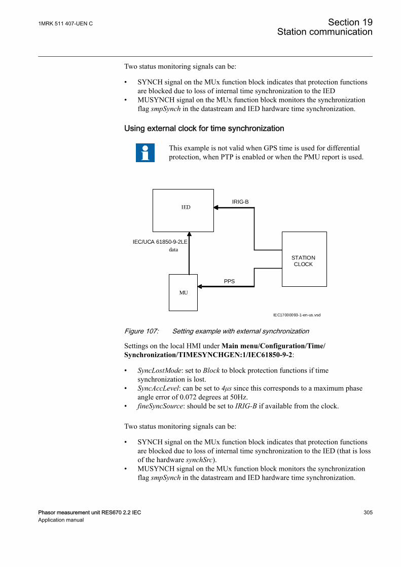
Two status monitoring signals can be:
• SYNCH signal on the MUx function block indicates that protection functionsare blocked due to loss of internal time synchronization to the IED
• MUSYNCH signal on the MUx function block monitors the synchronizationflag smpSynch in the datastream and IED hardware time synchronization.
Using external clock for time synchronization
This example is not valid when GPS time is used for differentialprotection, when PTP is enabled or when the PMU report is used.
IED
MU
data
IEC/UCA 61850-9-2LE
IRIG-B
STATIONCLOCK
IEC17000093-1-en-us.vsd
PPS
IEC17000093 V1 EN-US
Figure 107: Setting example with external synchronization
Settings on the local HMI under Main menu/Configuration/Time/Synchronization/TIMESYNCHGEN:1/IEC61850-9-2:
• SyncLostMode: set to Block to block protection functions if timesynchronization is lost.
• SyncAccLevel: can be set to 4μs since this corresponds to a maximum phaseangle error of 0.072 degrees at 50Hz.
• fineSyncSource: should be set to IRIG-B if available from the clock.
Two status monitoring signals can be:
• SYNCH signal on the MUx function block indicates that protection functionsare blocked due to loss of internal time synchronization to the IED (that is lossof the hardware synchSrc).
• MUSYNCH signal on the MUx function block monitors the synchronizationflag smpSynch in the datastream and IED hardware time synchronization.
1MRK 511 407-UEN C Section 19Station communication
Phasor measurement unit RES670 2.2 IEC 305Application manual
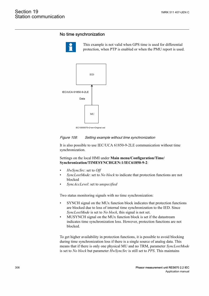
No time synchronization
This example is not valid when GPS time is used for differentialprotection, when PTP is enabled or when the PMU report is used.
IEC/UCA 61850-9-2LE
Data
MU
IED
IEC10000075=2=en=Original.vsd
IEC10000075 V2 EN-US
Figure 108: Setting example without time synchronization
It is also possible to use IEC/UCA 61850-9-2LE communication without timesynchronization.
Settings on the local HMI under Main menu/Configuration/Time/Synchronization/TIMESYNCHGEN:1/IEC61850-9-2:
• HwSyncSrc: set to Off• SyncLostMode: set to No block to indicate that protection functions are not
blocked• SyncAccLevel: set to unspecified
Two status monitoring signals with no time synchronization:
• SYNCH signal on the MUx function block indicates that protection functionsare blocked due to loss of internal time synchronization to the IED. SinceSyncLostMode is set to No block, this signal is not set.
• MUSYNCH signal on the MUx function block is set if the datastreamindicates time synchronization loss. However, protection functions are notblocked.
To get higher availability in protection functions, it is possible to avoid blockingduring time synchronization loss if there is a single source of analog data. Thismeans that if there is only one physical MU and no TRM, parameter SyncLostModeis set to No block but parameter HwSyncSrc is still set to PPS. This maintains
Section 19 1MRK 511 407-UEN CStation communication
306 Phasor measurement unit RES670 2.2 IECApplication manual
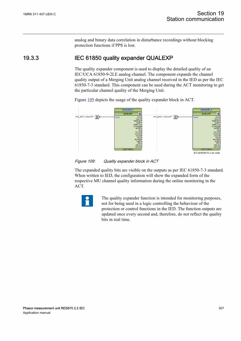
analog and binary data correlation in disturbance recordings without blockingprotection functions if PPS is lost.
19.3.3 IEC 61850 quality expander QUALEXPGUID-9C5DC78E-041B-422B-9668-320E62B847A2 v1
The quality expander component is used to display the detailed quality of anIEC/UCA 61850-9-2LE analog channel. The component expands the channelquality output of a Merging Unit analog channel received in the IED as per the IEC61850-7-3 standard. This component can be used during the ACT monitoring to getthe particular channel quality of the Merging Unit.
Figure 109 depicts the usage of the quality expander block in ACT.
IEC16000073-1-en.vsdxIEC16000073 V1 EN-US
Figure 109: Quality expander block in ACT
The expanded quality bits are visible on the outputs as per IEC 61850-7-3 standard.When written to IED, the configuration will show the expanded form of therespective MU channel quality information during the online monitoring in theACT.
The quality expander function is intended for monitoring purposes,not for being used in a logic controlling the behaviour of theprotection or control functions in the IED. The function outputs areupdated once every second and, therefore, do not reflect the qualitybits in real time.
1MRK 511 407-UEN C Section 19Station communication
Phasor measurement unit RES670 2.2 IEC 307Application manual

19.4 LON communication protocolIP14420-1 v1
19.4.1 ApplicationIP14863-1 v1
M14804-3 v6
Control Center
IED IEDIED
Gateway
Star couplerRER 111
Station HSIMicroSCADA
IEC05000663-1-en.vsdIEC05000663 V2 EN-US
Figure 110: Example of LON communication structure for a substationautomation system
An optical network can be used within the substation automation system. Thisenables communication with the IEDs through the LON bus from the operator’sworkplace, from the control center and also from other IEDs via bay-to-bayhorizontal communication. For LON communication an SLM card should beordered for the IEDs.
The fiber optic LON bus is implemented using either glass core or plastic core fiberoptic cables.
Table 31: Specification of the fiber optic connectors
Glass fiber Plastic fiberCable connector ST-connector snap-in connector
Cable diameter 62.5/125 m 1 mm
Max. cable length 1000 m 10 m
Wavelength 820-900 nm 660 nm
Transmitted power -13 dBm (HFBR-1414) -13 dBm (HFBR-1521)
Receiver sensitivity -24 dBm (HFBR-2412) -20 dBm (HFBR-2521)
Section 19 1MRK 511 407-UEN CStation communication
308 Phasor measurement unit RES670 2.2 IECApplication manual
The LON ProtocolM14804-32 v2
The LON protocol is specified in the LonTalkProtocol Specification Version 3from Echelon Corporation. This protocol is designed for communication in controlnetworks and is a peer-to-peer protocol where all the devices connected to thenetwork can communicate with each other directly. For more information of thebay-to-bay communication, refer to the section Multiple command function.
Hardware and software modulesM14804-35 v5
The hardware needed for applying LON communication depends on theapplication, but one very central unit needed is the LON Star Coupler and opticalfibers connecting the star coupler to the IEDs. To interface the IEDs from theMicroSCADA with Classic Monitor, application library LIB520 is required.
The HV Control 670 software module is included in the LIB520 high-voltageprocess package, which is a part of the Application Software Library inMicroSCADA applications.
The HV Control 670 software module is used for control functions in the IEDs.The module contains a process picture, dialogues and a tool to generate a processdatabase for the control application in MicroSCADA.
When using MicroSCADA Monitor Pro instead of the Classic Monitor, SA LIB isused together with 670 series Object Type files.
The HV Control 670 software module and 670 series Object Typefiles are used with both 650 and 670 series IEDs.
Use the LON Network Tool (LNT) to set the LON communication. This is asoftware tool applied as one node on the LON bus. To communicate via LON, theIEDs need to know
• The node addresses of the other connected IEDs.• The network variable selectors to be used.
This is organized by LNT.
The node address is transferred to LNT via the local HMI by setting the parameterServicePinMsg = Yes. The node address is sent to LNT via the LON bus, or LNTcan scan the network for new nodes.
The communication speed of the LON bus is set to the default of 1.25 Mbit/s. Thiscan be changed by LNT.
19.4.2 MULTICMDRCV and MULTICMDSNDSEMOD119881-1 v3
1MRK 511 407-UEN C Section 19Station communication
Phasor measurement unit RES670 2.2 IEC 309Application manual
19.4.2.1 IdentificationGUID-1A6E066C-6399-4D37-8CA5-3074537E48B2 v3
Function description IEC 61850identification
IEC 60617identification
ANSI/IEEE C37.2device number
Multiple command and receive MULTICMDRCV - -
Multiple command and send MULTICMDSND - -
19.4.2.2 ApplicationM14790-3 v5
The IED provides two function blocks enabling several IEDs to send and receivesignals via the interbay bus. The sending function block, MULTICMDSND, takes16 binary inputs. LON enables these to be transmitted to the equivalent receivingfunction block, MULTICMDRCV, which has 16 binary outputs.
19.4.2.3 Setting guidelinesSEMOD119915-1 v1
SettingsM14789-4 v3
The parameters for the multiple command function are set via PCM600.
The Mode setting sets the outputs to either a Steady or Pulsed mode.
19.5 SPA communication protocolIP14614-1 v1
19.5.1 ApplicationIP14785-1 v1
SEMOD115767-5 v7
SPA communication protocol is an alternative to IEC 60870-5-103, and they usethe same rear communication port.
When communicating with a PC connected to the utility substation LAN via WANand the utility office LAN (see Figure 111), and when using the rear opticalEthernet port, the only hardware required for a station monitoring system is:
• Optical fibers from the IED to the utility substation LAN• PC connected to the utility office LAN
Section 19 1MRK 511 407-UEN CStation communication
310 Phasor measurement unit RES670 2.2 IECApplication manual

IED IEDIED
Substation LAN
IEC05000715-4-en.vsd
Remote monitoring
Utility LAN
WAN
IEC05000715 V4 EN-US
Figure 111: SPA communication structure for a remote monitoring system via asubstation LAN, WAN and utility LAN
SPA communication is mainly used for the Station Monitoring System. It caninclude different IEDs with remote communication possibilities. Connection to aPC can be made directly (if the PC is located in the substation), via a telephonemodem through a telephone network with ITU (former CCITT) characteristics orvia a LAN/WAN connection.
glass <1000 m according to optical budget
plastic <25 m (inside cubicle) according to optical budget
FunctionalitySEMOD115767-25 v3
The SPA protocol V2.5 is an ASCII-based protocol for serial communication. Thecommunication is based on a master-slave principle, where the IED is a slave andthe PC is the master. Only one master can be applied on each fiber optic loop. Aprogram is required in the master computer for interpretation of the SPA-bus codesand for translation of the data that should be sent to the IED.
For the specification of the SPA protocol V2.5, refer to SPA-bus CommunicationProtocol V2.5.
19.5.2 Setting guidelinesM11876-3 v7
SPA, IEC 60870-5-103 and DNP3 use the same rear communication port. This portcan be set for SPA use on the local HMI under Main menu /Configuration /Communication /Station communication/Port configuration/SLM opticalserial port/PROTOCOL:1. When the communication protocol is selected, theIED is automatically restarted, and the port then operates as a SPA port.
The SPA communication setting parameters are set on the local HMI under Mainmenu/Configuration/Communication/Station communication/SPA/SPA:1.
1MRK 511 407-UEN C Section 19Station communication
Phasor measurement unit RES670 2.2 IEC 311Application manual
The most important SPA communication setting parameters are SlaveAddress andBaudRate. They are essential for all communication contact to the IED.SlaveAddress and BaudRate can be set only on the local HMI for rear and frontchannel communication.
SlaveAddress can be set to any value between 1–899 as long as the slave number isunique within the used SPA loop. BaudRate (communication speed) can be setbetween 300–38400 baud. BaudRate should be the same for the whole stationalthough different communication speeds in a loop are possible. If differentcommunication speeds are used in the same fiber optical loop or RS485 network,take this into account when making the communication setup in the communicationmaster (the PC).
With local fiber optic communication, communication speed is usually set to 19200or 38400 baud. With telephone communication, the speed setting depends on thequality of the connection and the type of modem used. Refer to technical data todetermine the rated communication speed for the selected communicationinterfaces.
The IED does not adapt its speed to the actual communicationconditions because the communication speed is set on the localHMI.
Section 19 1MRK 511 407-UEN CStation communication
312 Phasor measurement unit RES670 2.2 IECApplication manual
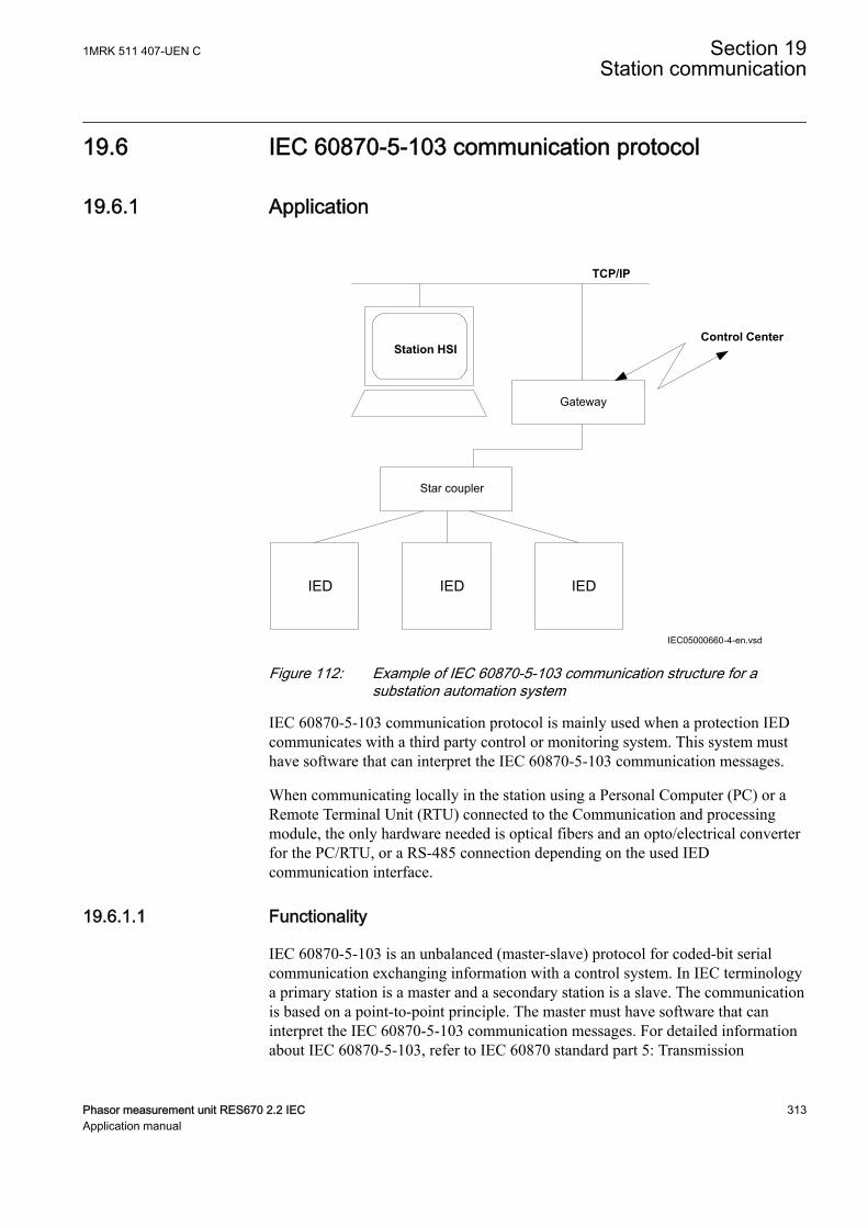
19.6 IEC 60870-5-103 communication protocolIP14615-1 v2
19.6.1 ApplicationIP14864-1 v1
M17109-3 v7
TCP/IP
Control Center
IED IEDIED
Gateway
Star coupler
Station HSI
IEC05000660-4-en.vsdIEC05000660 V4 EN-US
Figure 112: Example of IEC 60870-5-103 communication structure for asubstation automation system
IEC 60870-5-103 communication protocol is mainly used when a protection IEDcommunicates with a third party control or monitoring system. This system musthave software that can interpret the IEC 60870-5-103 communication messages.
When communicating locally in the station using a Personal Computer (PC) or aRemote Terminal Unit (RTU) connected to the Communication and processingmodule, the only hardware needed is optical fibers and an opto/electrical converterfor the PC/RTU, or a RS-485 connection depending on the used IEDcommunication interface.
19.6.1.1 FunctionalityM17109-38 v3
IEC 60870-5-103 is an unbalanced (master-slave) protocol for coded-bit serialcommunication exchanging information with a control system. In IEC terminologya primary station is a master and a secondary station is a slave. The communicationis based on a point-to-point principle. The master must have software that caninterpret the IEC 60870-5-103 communication messages. For detailed informationabout IEC 60870-5-103, refer to IEC 60870 standard part 5: Transmission
1MRK 511 407-UEN C Section 19Station communication
Phasor measurement unit RES670 2.2 IEC 313Application manual

protocols, and to the section 103, Companion standard for the informative interfaceof protection equipment.
19.6.1.2 DesignM17109-41 v1
GeneralM17109-43 v2
The protocol implementation consists of the following functions:
• Event handling• Report of analog service values (measurands)• Fault location• Command handling
• Autorecloser ON/OFF• Teleprotection ON/OFF• Protection ON/OFF• LED reset• Characteristics 1 - 4 (Setting groups)
• File transfer (disturbance files)• Time synchronization
HardwareM17109-59 v2
When communicating locally with a Personal Computer (PC) or a RemoteTerminal Unit (RTU) in the station, using the SPA/IEC port, the only hardwareneeded is:· Optical fibers, glass/plastic· Opto/electrical converter for the PC/RTU·PC/RTU
CommandsM17109-62 v4
The commands defined in the IEC 60870-5-103 protocol are represented indedicated function blocks. These blocks have output signals for all availablecommands according to the protocol. For more information, refer to theCommunication protocol manual, IEC 60870-5-103.
• IED commands in control direction
Function block with defined IED functions in control direction, I103IEDCMD.This block use PARAMETR as FUNCTION TYPE, and INFORMATIONNUMBER parameter is defined for each output signal.
• Function commands in control direction
Function block with pre-defined functions in control direction, I103CMD. Thisblock includes the FUNCTION TYPE parameter, and the INFORMATIONNUMBER parameter is defined for each output signal.
• Function commands in control direction
Section 19 1MRK 511 407-UEN CStation communication
314 Phasor measurement unit RES670 2.2 IECApplication manual
Function block with user defined functions in control direction, I103UserCMD.These function blocks include the FUNCTION TYPE parameter for each block inthe private range, and the INFORMATION NUMBER parameter for each outputsignal.
StatusM17109-74 v6
For more information on the function blocks below, refer to theCommunication protocol manual, IEC 60870-5-103.
The events created in the IED available for the IEC 60870-5-103 protocol arebased on the:
• IED status indication in monitor direction
Function block with defined IED functions in monitor direction, I103IED. Thisblock use PARAMETER as FUNCTION TYPE, and INFORMATION NUMBERparameter is defined for each input signal.
• Function status indication in monitor direction, user-defined
Function blocks with user defined input signals in monitor direction, I103UserDef.These function blocks include the FUNCTION TYPE parameter for each block inthe private range, and the INFORMATION NUMBER parameter for each inputsignal.
• Supervision indications in monitor direction
Function block with defined functions for supervision indications in monitordirection, I103Superv. This block includes the FUNCTION TYPE parameter, andthe INFORMATION NUMBER parameter is defined for each output signal.
• Earth fault indications in monitor direction
Function block with defined functions for earth fault indications in monitordirection, I103EF. This block includes the FUNCTION TYPE parameter, and theINFORMATION NUMBER parameter is defined for each output signal.
• Fault indications in monitor direction
Function block with defined functions for fault indications in monitor direction,I103FLTPROT. This block includes the FUNCTION TYPE parameter, and theINFORMATION NUMBER parameter is defined for each input signal.
This block is suitable for distance protection, line differential, transformerdifferential, over-current and earth-fault protection functions.
• Autorecloser indications in monitor direction
1MRK 511 407-UEN C Section 19Station communication
Phasor measurement unit RES670 2.2 IEC 315Application manual
Function block with defined functions for autorecloser indications in monitordirection, I103AR. This block includes the FUNCTION TYPE parameter, and theINFORMATION NUMBER parameter is defined for each output signal.
MeasurandsM17109-99 v2
The measurands can be included as type 3.1, 3.2, 3.3, 3.4 and type 9 according tothe standard.
• Measurands in public range
Function block that reports all valid measuring types depending on connectedsignals, I103Meas.
• Measurands in private range
Function blocks with user defined input measurands in monitor direction,I103MeasUsr. These function blocks include the FUNCTION TYPE parameter foreach block in the private range, and the INFORMATION NUMBER parameter foreach block.
Fault locationM17109-108 v1
The fault location is expressed in reactive ohms. In relation to the line length inreactive ohms, it gives the distance to the fault in percent. The data is available andreported when the fault locator function is included in the IED.
Disturbance recordingsM17109-111 v9
• The transfer functionality is based on the Disturbance recorder function. Theanalog and binary signals recorded will be reported to the master by polling.The eight last disturbances that are recorded are available for transfer to themaster. A file that has been transferred and acknowledged by the mastercannot be transferred again.
• The binary signals that are included in the disturbance recorder are those thatare connected to the disturbance function blocks B1RBDR to B22RBDR.These function blocks include the function type and the information numberfor each signal. For more information on the description of the Disturbancereport in the Technical reference manual. The analog channels, that arereported, are those connected to the disturbance function blocks A1RADR toA4RADR. The eight first ones belong to the public range and the remainingones to the private range.
19.6.2 SettingsM17109-116 v1
Section 19 1MRK 511 407-UEN CStation communication
316 Phasor measurement unit RES670 2.2 IECApplication manual
19.6.2.1 Settings for RS485 and optical serial communicationM17109-118 v12
General settingsSPA, DNP and IEC 60870-5-103 can be configured to operate on the SLM opticalserial port while DNP and IEC 60870-5-103 additionally can utilize the RS485port. A single protocol can be active on a given physical port at any time.
Two different areas in the HMI are used to configure the IEC 60870-5-103protocol.
1. The port specific IEC 60870-5-103 protocol parameters are configured under:Main menu/Configuration/Communication/Station Communication/IEC60870-5-103/• <config-selector>• SlaveAddress• BaudRate• RevPolarity (optical channel only)• CycMeasRepTime• MasterTimeDomain• TimeSyncMode• EvalTimeAccuracy• EventRepMode• CmdMode• RepIntermediatePos
<config-selector> is:• “OPTICAL103:1” for the optical serial channel on the SLM• “RS485103:1” for the RS485 port
2. The protocol to activate on a physical port is selected under:Main menu/Configuration/Communication/Station Communication/Portconfiguration/• RS485 port
• RS485PROT:1 (off, DNP, IEC103)• SLM optical serial port
• PROTOCOL:1 (off, DNP, IEC103, SPA)
1MRK 511 407-UEN C Section 19Station communication
Phasor measurement unit RES670 2.2 IEC 317Application manual
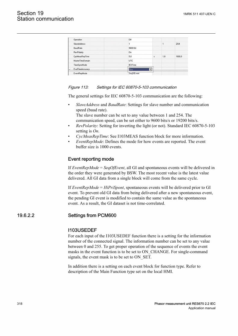
GUID-CD4EB23C-65E7-4ED5-AFB1-A9D5E9EE7CA8 V3 ENGUID-CD4EB23C-65E7-4ED5-AFB1-A9D5E9EE7CA8 V3 EN-US
Figure 113: Settings for IEC 60870-5-103 communication
The general settings for IEC 60870-5-103 communication are the following:
• SlaveAddress and BaudRate: Settings for slave number and communicationspeed (baud rate).The slave number can be set to any value between 1 and 254. Thecommunication speed, can be set either to 9600 bits/s or 19200 bits/s.
• RevPolarity: Setting for inverting the light (or not). Standard IEC 60870-5-103setting is On.
• CycMeasRepTime: See I103MEAS function block for more information.• EventRepMode: Defines the mode for how events are reported. The event
buffer size is 1000 events.
Event reporting modeIf EventRepMode = SeqOfEvent, all GI and spontaneous events will be delivered inthe order they were generated by BSW. The most recent value is the latest valuedelivered. All GI data from a single block will come from the same cycle.
If EventRepMode = HiPriSpont, spontaneous events will be delivered prior to GIevent. To prevent old GI data from being delivered after a new spontaneous event,the pending GI event is modified to contain the same value as the spontaneousevent. As a result, the GI dataset is not time-correlated.
19.6.2.2 Settings from PCM600M17109-132 v2
I103USEDEFGUID-A41170D6-2846-4E5E-8B7F-85B53D4EF6B6 v1
For each input of the I103USEDEF function there is a setting for the informationnumber of the connected signal. The information number can be set to any valuebetween 0 and 255. To get proper operation of the sequence of events the eventmasks in the event function is to be set to ON_CHANGE. For single-commandsignals, the event mask is to be set to ON_SET.
In addition there is a setting on each event block for function type. Refer todescription of the Main Function type set on the local HMI.
Section 19 1MRK 511 407-UEN CStation communication
318 Phasor measurement unit RES670 2.2 IECApplication manual
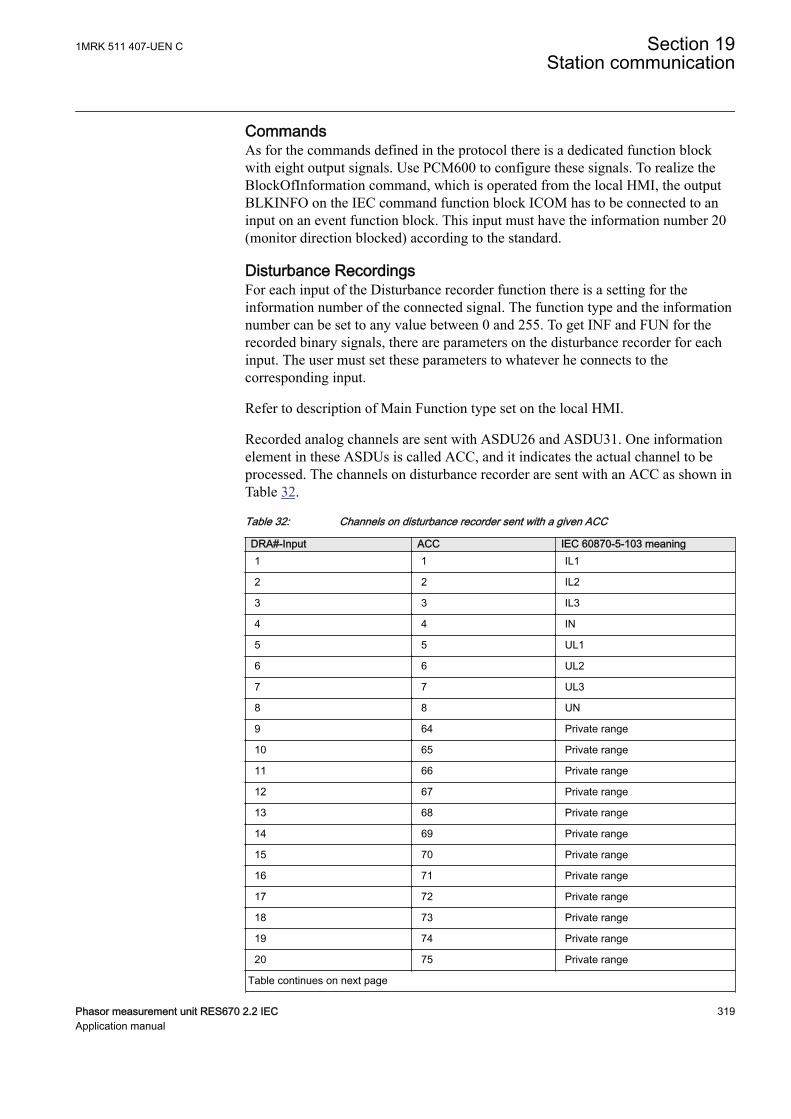
CommandsM17109-138 v2
As for the commands defined in the protocol there is a dedicated function blockwith eight output signals. Use PCM600 to configure these signals. To realize theBlockOfInformation command, which is operated from the local HMI, the outputBLKINFO on the IEC command function block ICOM has to be connected to aninput on an event function block. This input must have the information number 20(monitor direction blocked) according to the standard.
Disturbance RecordingsM17109-141 v8
For each input of the Disturbance recorder function there is a setting for theinformation number of the connected signal. The function type and the informationnumber can be set to any value between 0 and 255. To get INF and FUN for therecorded binary signals, there are parameters on the disturbance recorder for eachinput. The user must set these parameters to whatever he connects to thecorresponding input.
Refer to description of Main Function type set on the local HMI.
Recorded analog channels are sent with ASDU26 and ASDU31. One informationelement in these ASDUs is called ACC, and it indicates the actual channel to beprocessed. The channels on disturbance recorder are sent with an ACC as shown inTable 32.
Table 32: Channels on disturbance recorder sent with a given ACC
DRA#-Input ACC IEC 60870-5-103 meaning1 1 IL1
2 2 IL2
3 3 IL3
4 4 IN
5 5 UL1
6 6 UL2
7 7 UL3
8 8 UN
9 64 Private range
10 65 Private range
11 66 Private range
12 67 Private range
13 68 Private range
14 69 Private range
15 70 Private range
16 71 Private range
17 72 Private range
18 73 Private range
19 74 Private range
20 75 Private range
Table continues on next page
1MRK 511 407-UEN C Section 19Station communication
Phasor measurement unit RES670 2.2 IEC 319Application manual
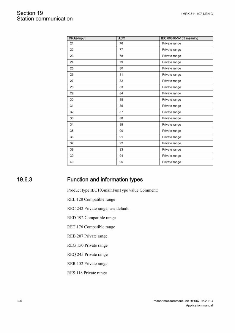
DRA#-Input ACC IEC 60870-5-103 meaning21 76 Private range
22 77 Private range
23 78 Private range
24 79 Private range
25 80 Private range
26 81 Private range
27 82 Private range
28 83 Private range
29 84 Private range
30 85 Private range
31 86 Private range
32 87 Private range
33 88 Private range
34 89 Private range
35 90 Private range
36 91 Private range
37 92 Private range
38 93 Private range
39 94 Private range
40 95 Private range
19.6.3 Function and information typesM17109-145 v7
Product type IEC103mainFunType value Comment:
REL 128 Compatible range
REC 242 Private range, use default
RED 192 Compatible range
RET 176 Compatible range
REB 207 Private range
REG 150 Private range
REQ 245 Private range
RER 152 Private range
RES 118 Private range
Section 19 1MRK 511 407-UEN CStation communication
320 Phasor measurement unit RES670 2.2 IECApplication manual
Refer to the tables in the Technical reference manual /Station communication,specifying the information types supported by the communication protocol IEC60870-5-103.
To support the information, corresponding functions must be included in theprotection IED.
There is no representation for the following parts:
• Generating events for test mode• Cause of transmission: Info no 11, Local operation
Glass or plastic fiber should be used. BFOC/2.5 is the recommended interface touse (BFOC/2.5 is the same as ST connectors). ST connectors are used with theoptical power as specified in standard.
For more information, refer to IEC standard IEC 60870-5-103.
19.7 DNP3 Communication protocol
19.7.1 ApplicationGUID-EF1F0C38-9FF6-4683-8B10-AAA372D42185 v1
For more information on the application and setting guidelines for the DNP3communication protocol refer to the DNP3 Communication protocol manual.
1MRK 511 407-UEN C Section 19Station communication
Phasor measurement unit RES670 2.2 IEC 321Application manual

322
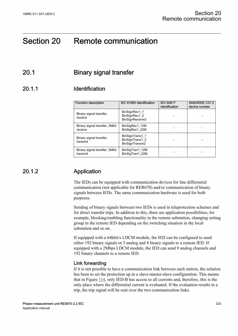
Section 20 Remote communication
20.1 Binary signal transferIP12423-1 v2
20.1.1 IdentificationM14849-1 v3
Function description IEC 61850 identification IEC 60617identification
ANSI/IEEE C37.2device number
Binary signal transfer,receive
BinSignRec1_1BinSignRec1_2BinSignReceive2
- -
Binary signal transfer, 2Mbitreceive
BinSigRec1_12MBinSigRec1_22M - -
Binary signal transfer,transmit
BinSignTrans1_1BinSignTrans1_2BinSignTransm2
- -
Binary signal transfer, 2Mbittransmit
BinSigTran1_12MBinSigTran1_22M - -
20.1.2 ApplicationIP16245-1 v1
M12844-3 v4
The IEDs can be equipped with communication devices for line differentialcommunication (not applicable for RER670) and/or communication of binarysignals between IEDs. The same communication hardware is used for bothpurposes.
Sending of binary signals between two IEDs is used in teleprotection schemes andfor direct transfer trips. In addition to this, there are application possibilities, forexample, blocking/enabling functionality in the remote substation, changing settinggroup in the remote IED depending on the switching situation in the localsubstation and so on.
If equipped with a 64kbit/s LDCM module, the IED can be configured to sendeither 192 binary signals or 3 analog and 8 binary signals to a remote IED. Ifequipped with a 2Mbps LDCM module, the IED can send 9 analog channels and192 binary channels to a remote IED.
Link forwardingGUID-DD3CF47C-A202-4416-954A-EFC0F8BEBCB7 v1
If it is not possible to have a communication link between each station, the solutionhas been to set the protection up in a slave-master-slave configuration. This meansthat in Figure 114, only IED-B has access to all currents and, therefore, this is theonly place where the differential current is evaluated. If the evaluation results in atrip, the trip signal will be sent over the two communication links.
1MRK 511 407-UEN C Section 20Remote communication
Phasor measurement unit RES670 2.2 IEC 323Application manual
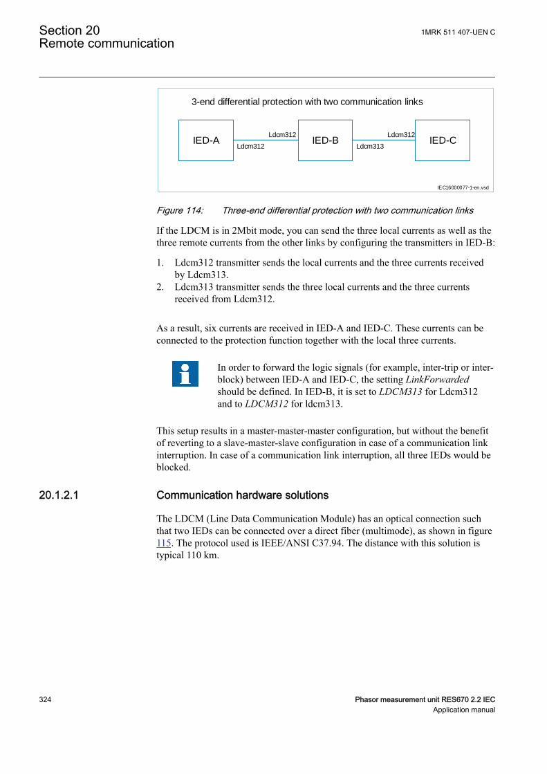
IED-A IED-B IED-C
IEC16000077-1-en.vsd
3-end differential protection with two communication links
Ldcm312
Ldcm312
Ldcm313
Ldcm312
IEC16000077 V1 EN-US
Figure 114: Three-end differential protection with two communication links
If the LDCM is in 2Mbit mode, you can send the three local currents as well as thethree remote currents from the other links by configuring the transmitters in IED-B:
1. Ldcm312 transmitter sends the local currents and the three currents receivedby Ldcm313.
2. Ldcm313 transmitter sends the three local currents and the three currentsreceived from Ldcm312.
As a result, six currents are received in IED-A and IED-C. These currents can beconnected to the protection function together with the local three currents.
In order to forward the logic signals (for example, inter-trip or inter-block) between IED-A and IED-C, the setting LinkForwardedshould be defined. In IED-B, it is set to LDCM313 for Ldcm312and to LDCM312 for ldcm313.
This setup results in a master-master-master configuration, but without the benefitof reverting to a slave-master-slave configuration in case of a communication linkinterruption. In case of a communication link interruption, all three IEDs would beblocked.
20.1.2.1 Communication hardware solutionsM12844-11 v7
The LDCM (Line Data Communication Module) has an optical connection suchthat two IEDs can be connected over a direct fiber (multimode), as shown in figure115. The protocol used is IEEE/ANSI C37.94. The distance with this solution istypical 110 km.
Section 20 1MRK 511 407-UEN CRemote communication
324 Phasor measurement unit RES670 2.2 IECApplication manual
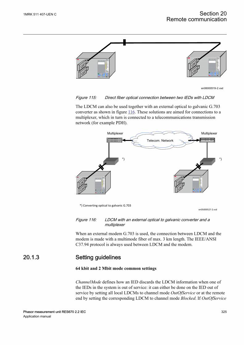
LDCM
LDCM
LDCM
LDCMLDCM
LDCMLDCMLDCM
LDCMLDCM
LDCM
LDCMLD
CMLD
CM
LDCMLDCM
en06000519-2.vsdIEC06000519 V2 EN-US
Figure 115: Direct fiber optical connection between two IEDs with LDCM
The LDCM can also be used together with an external optical to galvanic G.703converter as shown in figure 116. These solutions are aimed for connections to amultiplexer, which in turn is connected to a telecommunications transmissionnetwork (for example PDH).
Telecom. Network
*) *)
Multiplexer Multiplexer
en05000527-2.vsd*) Converting optical to galvanic G.703
IEC05000527 V2 EN-US
Figure 116: LDCM with an external optical to galvanic converter and amultiplexer
When an external modem G.703 is used, the connection between LDCM and themodem is made with a multimode fiber of max. 3 km length. The IEEE/ANSIC37.94 protocol is always used between LDCM and the modem.
20.1.3 Setting guidelinesM12454-3 v7
64 kbit and 2 Mbit mode common settings
ChannelMode defines how an IED discards the LDCM information when one ofthe IEDs in the system is out of service: it can either be done on the IED out ofservice by setting all local LDCMs to channel mode OutOfService or at the remoteend by setting the corresponding LDCM to channel mode Blocked. If OutOfService
1MRK 511 407-UEN C Section 20Remote communication
Phasor measurement unit RES670 2.2 IEC 325Application manual
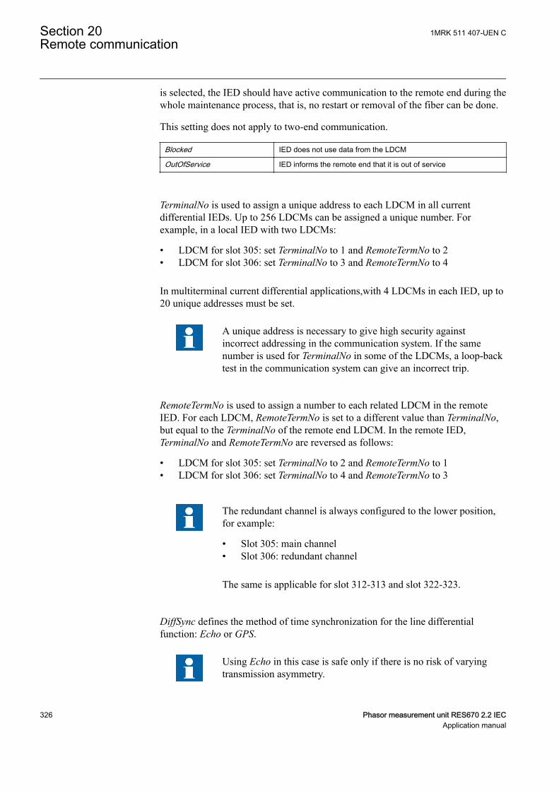
is selected, the IED should have active communication to the remote end during thewhole maintenance process, that is, no restart or removal of the fiber can be done.
This setting does not apply to two-end communication.
Blocked IED does not use data from the LDCM
OutOfService IED informs the remote end that it is out of service
TerminalNo is used to assign a unique address to each LDCM in all currentdifferential IEDs. Up to 256 LDCMs can be assigned a unique number. Forexample, in a local IED with two LDCMs:
• LDCM for slot 305: set TerminalNo to 1 and RemoteTermNo to 2• LDCM for slot 306: set TerminalNo to 3 and RemoteTermNo to 4
In multiterminal current differential applications,with 4 LDCMs in each IED, up to20 unique addresses must be set.
A unique address is necessary to give high security againstincorrect addressing in the communication system. If the samenumber is used for TerminalNo in some of the LDCMs, a loop-backtest in the communication system can give an incorrect trip.
RemoteTermNo is used to assign a number to each related LDCM in the remoteIED. For each LDCM, RemoteTermNo is set to a different value than TerminalNo,but equal to the TerminalNo of the remote end LDCM. In the remote IED,TerminalNo and RemoteTermNo are reversed as follows:
• LDCM for slot 305: set TerminalNo to 2 and RemoteTermNo to 1• LDCM for slot 306: set TerminalNo to 4 and RemoteTermNo to 3
The redundant channel is always configured to the lower position,for example:
• Slot 305: main channel• Slot 306: redundant channel
The same is applicable for slot 312-313 and slot 322-323.
DiffSync defines the method of time synchronization for the line differentialfunction: Echo or GPS.
Using Echo in this case is safe only if there is no risk of varyingtransmission asymmetry.
Section 20 1MRK 511 407-UEN CRemote communication
326 Phasor measurement unit RES670 2.2 IECApplication manual
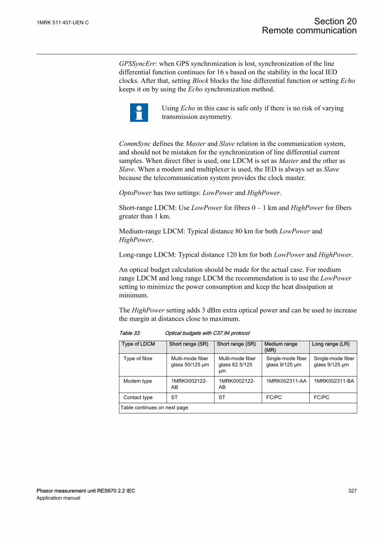
GPSSyncErr: when GPS synchronization is lost, synchronization of the linedifferential function continues for 16 s based on the stability in the local IEDclocks. After that, setting Block blocks the line differential function or setting Echokeeps it on by using the Echo synchronization method.
Using Echo in this case is safe only if there is no risk of varyingtransmission asymmetry.
CommSync defines the Master and Slave relation in the communication system,and should not be mistaken for the synchronization of line differential currentsamples. When direct fiber is used, one LDCM is set as Master and the other asSlave. When a modem and multiplexer is used, the IED is always set as Slavebecause the telecommunication system provides the clock master.
OptoPower has two settings: LowPower and HighPower.
Short-range LDCM: Use LowPower for fibres 0 – 1 km and HighPower for fibersgreater than 1 km.
Medium-range LDCM: Typical distance 80 km for both LowPower andHighPower.
Long-range LDCM: Typical distance 120 km for both LowPower and HighPower.
An optical budget calculation should be made for the actual case. For mediumrange LDCM and long range LDCM the recommendation is to use the LowPowersetting to minimize the power consumption and keep the heat dissipation atminimum.
The HighPower setting adds 3 dBm extra optical power and can be used to increasethe margin at distances close to maximum.
Table 33: Optical budgets with C37.94 protocol
Type of LDCM Short range (SR) Short range (SR) Medium range(MR)
Long range (LR)
Type of fibre Multi-mode fiberglass 50/125 μm
Multi-mode fiberglass 62.5/125μm
Single-mode fiberglass 9/125 μm
Single-mode fiberglass 9/125 μm
Modem type 1MRK0002122-AB
1MRK0002122-AB
1MRK002311-AA 1MRK002311-BA
Contact type ST ST FC/PC FC/PC
Table continues on next page
1MRK 511 407-UEN C Section 20Remote communication
Phasor measurement unit RES670 2.2 IEC 327Application manual
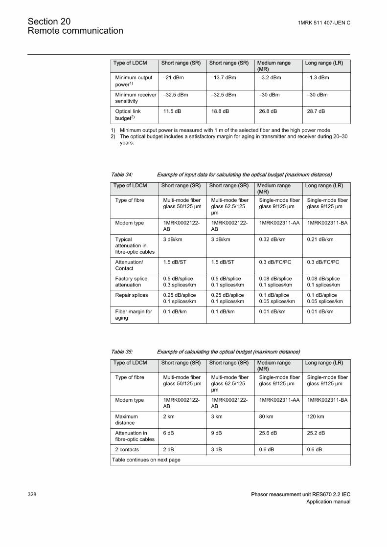
Type of LDCM Short range (SR) Short range (SR) Medium range(MR)
Long range (LR)
Minimum outputpower1)
–21 dBm –13.7 dBm –3.2 dBm –1.3 dBm
Minimum receiversensitivity
–32.5 dBm –32.5 dBm –30 dBm –30 dBm
Optical linkbudget2)
11.5 dB 18.8 dB 26.8 dB 28.7 dB
1) Minimum output power is measured with 1 m of the selected fiber and the high power mode.2) The optical budget includes a satisfactory margin for aging in transmitter and receiver during 20–30
years.
Table 34: Example of input data for calculating the optical budget (maximum distance)
Type of LDCM Short range (SR) Short range (SR) Medium range(MR)
Long range (LR)
Type of fibre Multi-mode fiberglass 50/125 μm
Multi-mode fiberglass 62.5/125μm
Single-mode fiberglass 9/125 μm
Single-mode fiberglass 9/125 μm
Modem type 1MRK0002122-AB
1MRK0002122-AB
1MRK002311-AA 1MRK002311-BA
Typicalattenuation infibre-optic cables
3 dB/km 3 dB/km 0.32 dB/km 0.21 dB/km
Attenuation/Contact
1.5 dB/ST 1.5 dB/ST 0.3 dB/FC/PC 0.3 dB/FC/PC
Factory spliceattenuation
0.5 dB/splice0.3 splices/km
0.5 dB/splice0.1 splices/km
0.08 dB/splice0.1 splices/km
0.08 dB/splice0.1 splices/km
Repair splices 0.25 dB/splice0.1 splices/km
0.25 dB/splice0.1 splices/km
0.1 dB/splice0.05 splices/km
0.1 dB/splice0.05 splices/km
Fiber margin foraging
0.1 dB/km 0.1 dB/km 0.01 dB/km 0.01 dB/km
Table 35: Example of calculating the optical budget (maximum distance)
Type of LDCM Short range (SR) Short range (SR) Medium range(MR)
Long range (LR)
Type of fibre Multi-mode fiberglass 50/125 μm
Multi-mode fiberglass 62.5/125μm
Single-mode fiberglass 9/125 μm
Single-mode fiberglass 9/125 μm
Modem type 1MRK0002122-AB
1MRK0002122-AB
1MRK002311-AA 1MRK002311-BA
Maximumdistance
2 km 3 km 80 km 120 km
Attenuation infibre-optic cables
6 dB 9 dB 25.6 dB 25.2 dB
2 contacts 2 dB 3 dB 0.6 dB 0.6 dB
Table continues on next page
Section 20 1MRK 511 407-UEN CRemote communication
328 Phasor measurement unit RES670 2.2 IECApplication manual
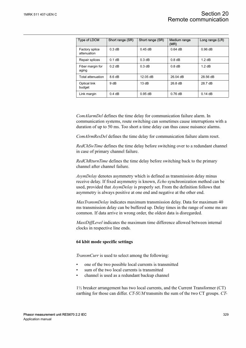
Type of LDCM Short range (SR) Short range (SR) Medium range(MR)
Long range (LR)
Factory spliceattenuation
0.3 dB 0.45 dB 0.64 dB 0.96 dB
Repair splices 0.1 dB 0.3 dB 0.8 dB 1.2 dB
Fiber margin foraging
0.2 dB 0.3 dB 0.8 dB 1.2 dB
Total attenuation 8.6 dB 12.05 dB 26.04 dB 28.56 dB
Optical linkbudget
9 dB 13 dB 26.8 dB 28.7 dB
Link margin 0.4 dB 0.95 dB 0.76 dB 0.14 dB
ComAlarmDel defines the time delay for communication failure alarm. Incommunication systems, route switching can sometimes cause interruptions with aduration of up to 50 ms. Too short a time delay can thus cause nuisance alarms.
ComAlrmResDel defines the time delay for communication failure alarm reset.
RedChSwTime defines the time delay before switching over to a redundant channelin case of primary channel failure.
RedChRturnTime defines the time delay before switching back to the primarychannel after channel failure.
AsymDelay denotes asymmetry which is defined as transmission delay minusreceive delay. If fixed asymmetry is known, Echo synchronization method can beused, provided that AsymDelay is properly set. From the definition follows thatasymmetry is always positive at one end and negative at the other end.
MaxTransmDelay indicates maximum transmission delay. Data for maximum 40ms transmission delay can be buffered up. Delay times in the range of some ms arecommon. If data arrive in wrong order, the oldest data is disregarded.
MaxtDiffLevel indicates the maximum time difference allowed between internalclocks in respective line ends.
64 kbit mode specific settings
TransmCurr is used to select among the following:
• one of the two possible local currents is transmitted• sum of the two local currents is transmitted• channel is used as a redundant backup channel
1½ breaker arrangement has two local currents, and the Current Transformer (CT)earthing for those can differ. CT-SUM transmits the sum of the two CT groups. CT-
1MRK 511 407-UEN C Section 20Remote communication
Phasor measurement unit RES670 2.2 IEC 329Application manual
DIFF1 transmits CT group 1 minus CT group 2 and CT-DIFF2 transmits CT group2 minus CT group 1.
CT-GRP1 and CT-GRP2 transmit the respective CT groups, and settingRedundantChannel determines that the channel is used as a redundant backupchannel. The redundant channel takes the CT group setting of the main channel.
RemAinLatency corresponds to LocAinLatency set in the remote IED.
AnalogLatency specifies the time delay (number of samples) between actualsampling and the time the sample reaches LDCM. The value is set to 2 whentransmitting analog data. When a merging unit according to IEC 61850-9-2 is usedinstead of the TRM, this parameter shall be set to 5.
CompRange value indicates the current peak value over which truncation is made.To set this value, knowledge of fault current levels is required. It is recommendedto set the minimum range that will cover the expected fault current value. Forexample, if a 40kA fault level is expected on the network, the 0-50kA settingsrange should be chosen.
2 Mbit mode specific settings
RedundantCh is used to set the channel as a redundant backup channel. Theredundant channel takes the CT group setting of the main channel, and ignores theCT group configured in its own transmit block.
LinkForwarded is used to configure the LDCM to merge the inter-trip and blocksignals from another LDCM-receiver. This is used when the analog signals for theLDCM-transmitter is connected to the receiver of another LDCM.
Section 20 1MRK 511 407-UEN CRemote communication
330 Phasor measurement unit RES670 2.2 IECApplication manual
Section 21 Security
21.1 Authority status ATHSTATSEMOD158575-1 v2
21.1.1 ApplicationSEMOD158527-5 v3
Authority status (ATHSTAT) function is an indication function block, whichinforms about two events related to the IED and the user authorization:
• the fact that at least one user has tried to log on wrongly into the IED and itwas blocked (the output USRBLKED)
• the fact that at least one user is logged on (the output LOGGEDON)
The two outputs of ATHSTAT function can be used in the configuration fordifferent indication and alarming reasons, or can be sent to the station control forthe same purpose.
21.2 Self supervision with internal event list INTERRSIGIP1721-1 v2
21.2.1 ApplicationM12625-3 v9
The protection and control IEDs have many functions included. The included self-supervision with internal event list function block provides good supervision of theIED. The fault signals make it easier to analyze and locate a fault.
Both hardware and software supervision is included and it is also possible toindicate possible faults through a hardware contact on the power supply moduleand/or through the communication.
Internal events are generated by the built-in supervisory functions. The supervisoryfunctions supervise the status of the various modules in the IED and, in case offailure, a corresponding event is generated. Similarly, when the failure is corrected,a corresponding event is generated.
Apart from the built-in supervision of the various modules, events are alsogenerated when the status changes for the:
• built-in real time clock (in operation/out of order).• external time synchronization (in operation/out of order).
1MRK 511 407-UEN C Section 21Security
Phasor measurement unit RES670 2.2 IEC 331Application manual
Events are also generated:
• whenever any setting in the IED is changed.
The internal events are time tagged with a resolution of 1 ms and stored in a list.The list can store up to 40 events. The list is based on the FIFO principle, that is,when it is full, the oldest event is overwritten. The list contents cannot be modified,but the whole list can be cleared using the Reset menu in the LHMI.
The list of internal events provides valuable information, which can be used duringcommissioning and fault tracing.
The information can, in addition to be viewed on the built in HMI, also be retrievedwith the aid of a PC with PCM600 installed and by using the Event MonitoringTool. The PC can either be connected to the front port, or to the port at the back ofthe IED.
21.3 Change lock CHNGLCKGUID-B48775D0-ACF0-49C6-A7F6-69AF37F1C68F v1
21.3.1 ApplicationGUID-51EEC9C7-8ECF-4546-BC26-326861654340 v4
Change lock function CHNGLCK is used to block further changes to the IEDconfiguration once the commissioning is complete. The purpose is to make itimpossible to perform inadvertent IED configuration and setting changes.
However, when activated, CHNGLCK will still allow the following actions thatdoes not involve reconfiguring of the IED:
• Monitoring• Reading events• Resetting events• Reading disturbance data• Clear disturbances• Reset LEDs• Reset counters and other runtime component states• Control operations• Set system time• Enter and exit from test mode• Change of active setting group
The binary input controlling the function is defined in ACT or SMT. TheCHNGLCK function is configured using ACT.
LOCK Binary input signal that will activate/deactivate the function, defined in ACT orSMT.
Section 21 1MRK 511 407-UEN CSecurity
332 Phasor measurement unit RES670 2.2 IECApplication manual
GUID-8C333BC0-AA7A-4ED1-A772-18C22E8EEE62 v6
When CHNGLCK has a logical one on its input, then all attemptsto modify the IED configuration and setting will be denied and themessage "Error: Changes blocked" will be displayed on the localHMI; in PCM600 the message will be "Operation denied by activeChangeLock". The CHNGLCK function should be configured sothat it is controlled by a signal from a binary input card. Thisguarantees that by setting that signal to a logical zero, CHNGLCKis deactivated. If any logic is included in the signal path to theCHNGLCK input, that logic must be designed so that it cannotpermanently issue a logical one to the CHNGLCK input. If such asituation would occur in spite of these precautions, then pleasecontact the local ABB representative for remedial action.
21.4 Denial of service SCHLCCH/RCHLCCH
21.4.1 ApplicationGUID-64F4D905-9F73-4073-B8F6-8D373155316A v5
The denial of service functionality is designed to limit the CPU load that can beproduced by Ethernet network traffic on the IED. The communication facilitiesmust not be allowed to compromise the primary functionality of the device. Allinbound network traffic will be quota controlled so that too heavy network loadscan be controlled. Heavy network load might for instance be the result ofmalfunctioning equipment connected to the network.
The functions Access point diagnostics function block measure the IED load fromcommunication and, if necessary, limit it for not jeopardizing the IEDs control andprotection functionality due to high CPU load. The function has the followingdenial of service related outputs:
• LINKSTS indicates the Ethernet link status for the rear ports (singlecommunication)
• CHALISTS and CHBLISTS indicates the Ethernet link status for the rear portschannel A and B (redundant communication)
• LinkStatus indicates the Ethernet link status for the front port
21.4.2 Setting guidelinesGUID-CE3344E8-539B-47E0-9C19-8239988BDBCF v3
The function does not have any parameters available in the local HMI or PCM600.
1MRK 511 407-UEN C Section 21Security
Phasor measurement unit RES670 2.2 IEC 333Application manual

334
Section 22 Basic IED functions
22.1 IED identifiers TERMINALIDIP15060-1 v2
22.1.1 ApplicationM15324-3 v6
IED identifiers (TERMINALID) function allows the user to identify the individualIED in the system, not only in the substation, but in a whole region or a country.
Use only characters A-Z, a-z and 0-9 in station, object and unitnames.
22.2 Product information PRODINFGUID-F67243CA-2429-4118-BBFF-3D62BF55E080 v2
22.2.1 ApplicationGUID-D78786E6-C34A-4E63-9D1E-0582C8F1F7E1 v9
Product information contains unchangeable data that uniquely identifies the IED.
Product information data is visible on the local HMI under Main menu/Diagnostics/IED status/Product identifiers and under Main menu/Diagnostics/IED Status/Identifiers:
Product information data is visible on the local HMI under Main menu/Diagnostics/IED status/Product identifiers and under Main menu/Diagnostics/IED Status/Identifiers.
• ProductVer• ProductDef• FirmwareVer• SerialNo• OrderingNo• ProductionDate• IEDProdType
Figure 117: IED summary
This information is very helpful when interacting with ABB product support (forexample during repair and maintenance).
1MRK 511 407-UEN C Section 22Basic IED functions
Phasor measurement unit RES670 2.2 IEC 335Application manual
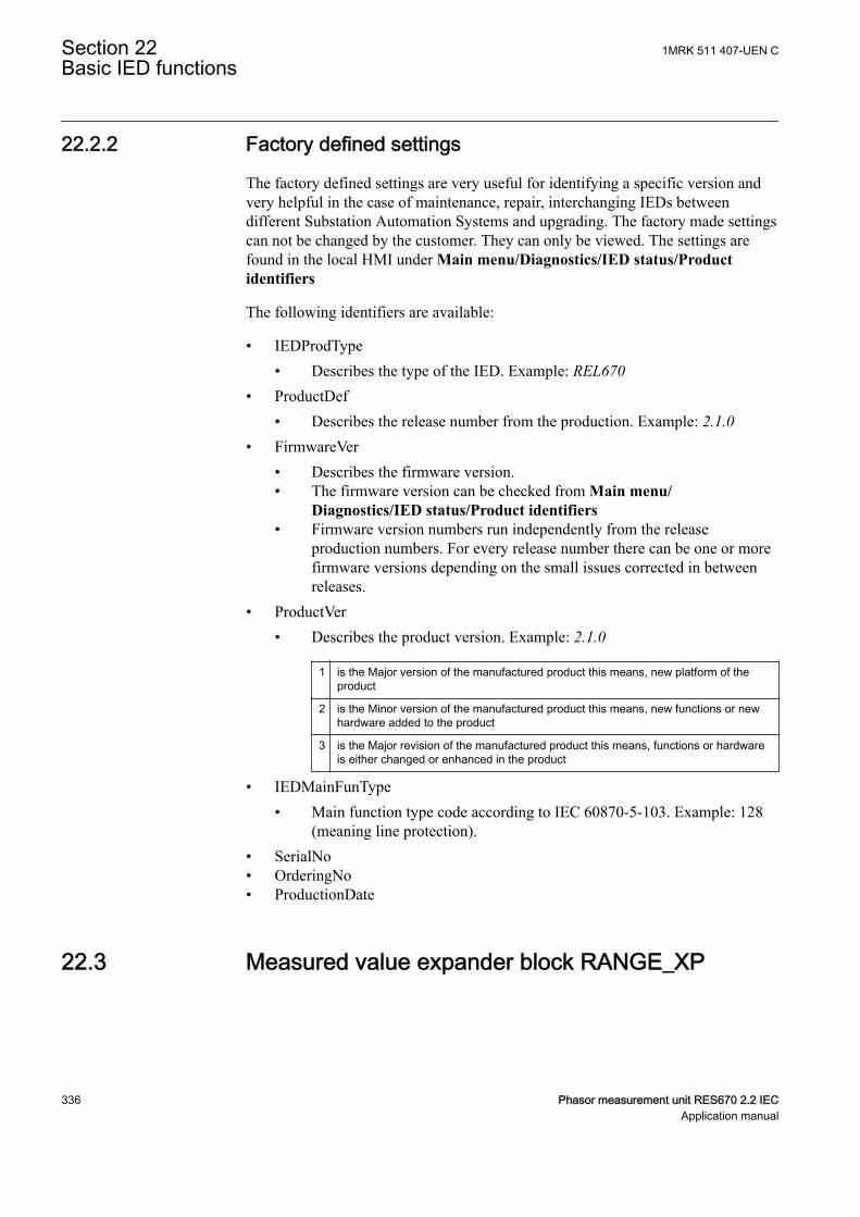
22.2.2 Factory defined settingsM11789-39 v11
The factory defined settings are very useful for identifying a specific version andvery helpful in the case of maintenance, repair, interchanging IEDs betweendifferent Substation Automation Systems and upgrading. The factory made settingscan not be changed by the customer. They can only be viewed. The settings arefound in the local HMI under Main menu/Diagnostics/IED status/Productidentifiers
The following identifiers are available:
• IEDProdType• Describes the type of the IED. Example: REL670
• ProductDef• Describes the release number from the production. Example: 2.1.0
• FirmwareVer• Describes the firmware version.• The firmware version can be checked from Main menu/
Diagnostics/IED status/Product identifiers• Firmware version numbers run independently from the release
production numbers. For every release number there can be one or morefirmware versions depending on the small issues corrected in betweenreleases.
• ProductVer• Describes the product version. Example: 2.1.0
1 is the Major version of the manufactured product this means, new platform of theproduct
2 is the Minor version of the manufactured product this means, new functions or newhardware added to the product
3 is the Major revision of the manufactured product this means, functions or hardwareis either changed or enhanced in the product
• IEDMainFunType• Main function type code according to IEC 60870-5-103. Example: 128
(meaning line protection).• SerialNo• OrderingNo• ProductionDate
22.3 Measured value expander block RANGE_XPSEMOD52451-1 v2
Section 22 1MRK 511 407-UEN CBasic IED functions
336 Phasor measurement unit RES670 2.2 IECApplication manual
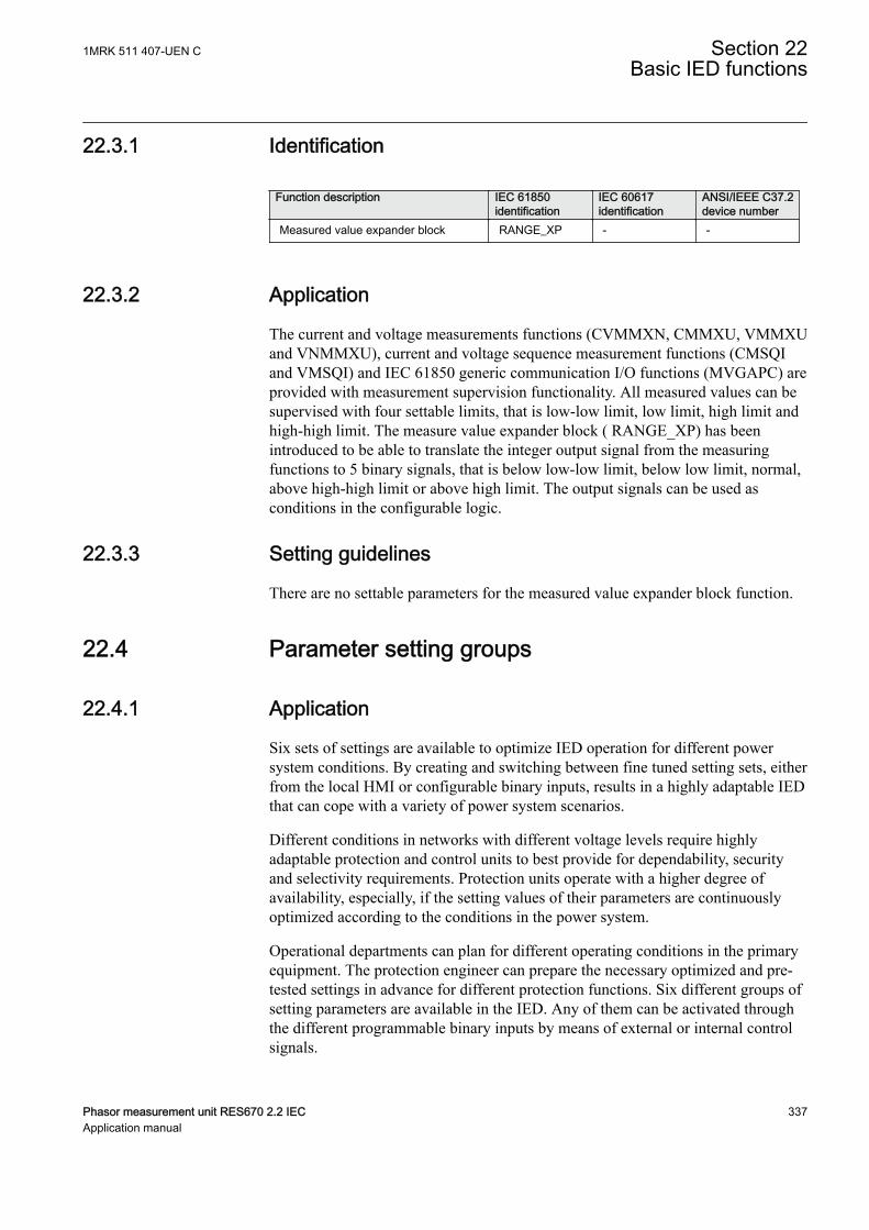
22.3.1 IdentificationSEMOD113212-2 v3
Function description IEC 61850identification
IEC 60617identification
ANSI/IEEE C37.2device number
Measured value expander block RANGE_XP - -
22.3.2 ApplicationSEMOD52434-4 v6
The current and voltage measurements functions (CVMMXN, CMMXU, VMMXUand VNMMXU), current and voltage sequence measurement functions (CMSQIand VMSQI) and IEC 61850 generic communication I/O functions (MVGAPC) areprovided with measurement supervision functionality. All measured values can besupervised with four settable limits, that is low-low limit, low limit, high limit andhigh-high limit. The measure value expander block ( RANGE_XP) has beenintroduced to be able to translate the integer output signal from the measuringfunctions to 5 binary signals, that is below low-low limit, below low limit, normal,above high-high limit or above high limit. The output signals can be used asconditions in the configurable logic.
22.3.3 Setting guidelinesSEMOD113223-4 v1
There are no settable parameters for the measured value expander block function.
22.4 Parameter setting groupsIP1745-1 v1
22.4.1 ApplicationM12007-6 v10
Six sets of settings are available to optimize IED operation for different powersystem conditions. By creating and switching between fine tuned setting sets, eitherfrom the local HMI or configurable binary inputs, results in a highly adaptable IEDthat can cope with a variety of power system scenarios.
Different conditions in networks with different voltage levels require highlyadaptable protection and control units to best provide for dependability, securityand selectivity requirements. Protection units operate with a higher degree ofavailability, especially, if the setting values of their parameters are continuouslyoptimized according to the conditions in the power system.
Operational departments can plan for different operating conditions in the primaryequipment. The protection engineer can prepare the necessary optimized and pre-tested settings in advance for different protection functions. Six different groups ofsetting parameters are available in the IED. Any of them can be activated throughthe different programmable binary inputs by means of external or internal controlsignals.
1MRK 511 407-UEN C Section 22Basic IED functions
Phasor measurement unit RES670 2.2 IEC 337Application manual
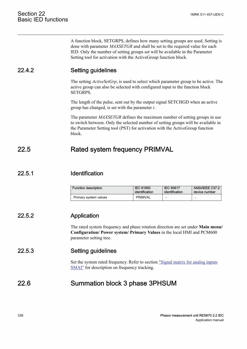
A function block, SETGRPS, defines how many setting groups are used. Setting isdone with parameter MAXSETGR and shall be set to the required value for eachIED. Only the number of setting groups set will be available in the ParameterSetting tool for activation with the ActiveGroup function block.
22.4.2 Setting guidelinesM15259-3 v4
The setting ActiveSetGrp, is used to select which parameter group to be active. Theactive group can also be selected with configured input to the function blockSETGRPS.
The length of the pulse, sent out by the output signal SETCHGD when an activegroup has changed, is set with the parameter t.
The parameter MAXSETGR defines the maximum number of setting groups in useto switch between. Only the selected number of setting groups will be available inthe Parameter Setting tool (PST) for activation with the ActiveGroup functionblock.
22.5 Rated system frequency PRIMVALIP15064-1 v2
22.5.1 IdentificationGUID-B8B3535D-227B-4151-9E98-BEB85F4D54DE v1
Function description IEC 61850identification
IEC 60617identification
ANSI/IEEE C37.2device number
Primary system values PRIMVAL - -
22.5.2 ApplicationM15288-3 v6
The rated system frequency and phase rotation direction are set under Main menu/Configuration/ Power system/ Primary Values in the local HMI and PCM600parameter setting tree.
22.5.3 Setting guidelinesM15292-3 v2
Set the system rated frequency. Refer to section "Signal matrix for analog inputsSMAI" for description on frequency tracking.
22.6 Summation block 3 phase 3PHSUMSEMOD55968-1 v2
Section 22 1MRK 511 407-UEN CBasic IED functions
338 Phasor measurement unit RES670 2.2 IECApplication manual
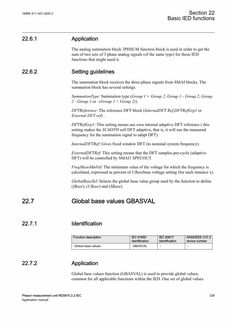
22.6.1 ApplicationSEMOD56004-4 v3
The analog summation block 3PHSUM function block is used in order to get thesum of two sets of 3 phase analog signals (of the same type) for those IEDfunctions that might need it.
22.6.2 Setting guidelinesSEMOD56006-4 v7
The summation block receives the three-phase signals from SMAI blocks. Thesummation block has several settings.
SummationType: Summation type (Group 1 + Group 2, Group 1 - Group 2, Group2 - Group 1 or –(Group 1 + Group 2)).
DFTReference: The reference DFT block (InternalDFT Ref,DFTRefGrp1 orExternal DFT ref) .
DFTRefGrp1: This setting means use own internal adaptive DFT reference ( thissetting makes the SUM3PH self DFT adaptive, that is, it will use the measuredfrequency for the summation signal to adapt DFT).
InternalDFTRef: Gives fixed window DFT (to nominal system frequency).
ExternalDFTRef: This setting means that the DFT samples-per-cycle (adaptiveDFT) will be controlled by SMAI1 SPFCOUT.
FreqMeasMinVal: The minimum value of the voltage for which the frequency iscalculated, expressed as percent of UBasebase voltage setting (for each instance x).
GlobalBaseSel: Selects the global base value group used by the function to define(IBase), (UBase) and (SBase).
22.7 Global base values GBASVALGUID-2FDB0A2C-10FE-4954-B6E4-9DA2EEEF1668 v1
22.7.1 IdentificationGUID-0D5405BE-E669-44C8-A208-3A4C86D39115 v3
Function description IEC 61850identification
IEC 60617identification
ANSI/IEEE C37.2device number
Global base values GBASVAL - -
22.7.2 ApplicationGUID-D58ECA9A-9771-443D-BF84-8EF582A346BF v4
Global base values function (GBASVAL) is used to provide global values,common for all applicable functions within the IED. One set of global values
1MRK 511 407-UEN C Section 22Basic IED functions
Phasor measurement unit RES670 2.2 IEC 339Application manual
consists of values for current, voltage and apparent power and it is possible to havetwelve different sets.
This is an advantage since all applicable functions in the IED use a single source ofbase values. This facilitates consistency throughout the IED and also facilitates asingle point for updating values when necessary.
Each applicable function in the IED has a parameter, GlobalBaseSel, defining oneout of the twelve sets of GBASVAL functions.
22.7.3 Setting guidelinesGUID-E3F5D754-BD17-4729-895B-957A09C2AC75 v4
UBase: Phase-to-phase voltage value to be used as a base value for applicablefunctions throughout the IED.
IBase: Phase current value to be used as a base value for applicable functionsthroughout the IED.
SBase: Standard apparent power value to be used as a base value for applicablefunctions throughout the IED, typically SBase=√3·UBase·IBase.
22.8 Signal matrix for binary inputs SMBISEMOD55793-1 v2
22.8.1 ApplicationM15310-3 v2
The Signal matrix for binary inputs function SMBI is used within the ApplicationConfiguration tool in direct relation with the Signal Matrix tool. SMBI representsthe way binary inputs are brought in for one IED configuration.
22.8.2 Setting guidelinesM15312-3 v3
There are no setting parameters for the Signal matrix for binary inputs SMBIavailable to the user in Parameter Setting tool. However, the user shall give a nameto SMBI instance and the SMBI inputs, directly in the Application Configurationtool. These names will define SMBI function in the Signal Matrix tool. The userdefined name for the input or output signal will also appear on the respectiveoutput or input signal.
22.9 Signal matrix for binary outputs SMBOSEMOD55215-1 v2
Section 22 1MRK 511 407-UEN CBasic IED functions
340 Phasor measurement unit RES670 2.2 IECApplication manual
22.9.1 ApplicationSEMOD55213-5 v4
The Signal matrix for binary outputs function SMBO is used within theApplication Configuration tool in direct relation with the Signal Matrix tool.SMBO represents the way binary outputs are sent from one IED configuration.
22.9.2 Setting guidelinesSEMOD55228-5 v2
There are no setting parameters for the Signal matrix for binary outputs SMBOavailable to the user in Parameter Setting tool. However, the user must give a nameto SMBO instance and SMBO outputs, directly in the Application Configurationtool. These names will define SMBO function in the Signal Matrix tool.
22.10 Signal matrix for mA inputs SMMISEMOD55233-1 v2
22.10.1 ApplicationSEMOD55237-5 v2
The Signal matrix for mA inputs function SMMI is used within the ApplicationConfiguration tool in direct relation with the Signal Matrix tool. SMMI representsthe way milliamp (mA) inputs are brought in for one IED configuration.
22.10.2 Setting guidelinesSEMOD55247-5 v2
There are no setting parameters for the Signal matrix for mA inputs SMMIavailable to the user in the Parameter Setting tool. However, the user must give aname to SMMI instance and SMMI inputs, directly in the ApplicationConfiguration tool.
22.11 Signal matrix for analog inputs SMAISEMOD55751-1 v2
22.11.1 ApplicationSEMOD55744-4 v10
Signal matrix for analog inputs (SMAI), also known as the preprocessor functionblock, analyses the connected four analog signals (three phases and neutral) andcalculates all relevant information from them like the phasor magnitude, phaseangle, frequency, true RMS value, harmonics, sequence components and so on.This information is then used by the respective functions connected to this SMAIblock in ACT (for example protection, measurement or monitoring functions).
1MRK 511 407-UEN C Section 22Basic IED functions
Phasor measurement unit RES670 2.2 IEC 341Application manual
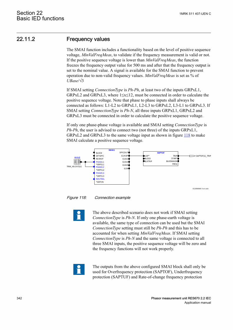
22.11.2 Frequency valuesGUID-B494B93C-B5AA-4FD6-8080-8611C34C2AD8 v5
The SMAI function includes a functionality based on the level of positive sequencevoltage, MinValFreqMeas, to validate if the frequency measurement is valid or not.If the positive sequence voltage is lower than MinValFreqMeas, the functionfreezes the frequency output value for 500 ms and after that the frequency output isset to the nominal value. A signal is available for the SMAI function to preventoperation due to non-valid frequency values. MinValFreqMeas is set as % ofUBase/√3
If SMAI setting ConnectionType is Ph-Ph, at least two of the inputs GRPxL1,GRPxL2 and GRPxL3, where 1≤x≤12, must be connected in order to calculate thepositive sequence voltage. Note that phase to phase inputs shall always beconnected as follows: L1-L2 to GRPxL1, L2-L3 to GRPxL2, L3-L1 to GRPxL3. IfSMAI setting ConnectionType is Ph-N, all three inputs GRPxL1, GRPxL2 andGRPxL3 must be connected in order to calculate the positive sequence voltage.
If only one phase-phase voltage is available and SMAI setting ConnectionType isPh-Ph, the user is advised to connect two (not three) of the inputs GRPxL1,GRPxL2 and GRPxL3 to the same voltage input as shown in figure 118 to makeSMAI calculate a positive sequence voltage.
SMAI1
BLOCK
DFTSPFC
REVROT
^GRP1L1
^GRP1L2
^GRP1L3
^GRP1N
SPFCOUT
G1AI3P
G1AI1
G1AI2
G1AI4
G1N
NEUTRAL
PHASEL3
PHASEL2
PHASEL1
UL1L2
SAPTOF
U3P*BLOCK
BLKTRIP
TRIPSTART
BLKDMAGN
FREQTRM_40.CH7(U)
SAPTOF(1)_TRIP
EC10000060-3-en.vsdx
IEC10000060 V3 EN-US
Figure 118: Connection example
The above described scenario does not work if SMAI settingConnectionType is Ph-N. If only one phase-earth voltage isavailable, the same type of connection can be used but the SMAIConnectionType setting must still be Ph-Ph and this has to beaccounted for when setting MinValFreqMeas. If SMAI settingConnectionType is Ph-N and the same voltage is connected to allthree SMAI inputs, the positive sequence voltage will be zero andthe frequency functions will not work properly.
The outputs from the above configured SMAI block shall only beused for Overfrequency protection (SAPTOF), Underfrequencyprotection (SAPTUF) and Rate-of-change frequency protection
Section 22 1MRK 511 407-UEN CBasic IED functions
342 Phasor measurement unit RES670 2.2 IECApplication manual
(SAPFRC) due to that all other information except frequency andpositive sequence voltage might be wrongly calculated.
22.11.3 Setting guidelinesGUID-C8D6C88B-87C6-44C1-804B-CF1594365EE6 v8
The parameters for the signal matrix for analog inputs (SMAI) functions are set viathe local HMI or PCM600.
Every SMAI function block can receive four analog signals (three phases and oneneutral value), either voltage or current. SMAI outputs give information aboutevery aspect of the 3ph analog signals acquired (phase angle, RMS value,frequency and frequency derivates, and so on – 244 values in total). Besides theblock “group name”, the analog inputs type (voltage or current) and the analoginput names that can be set directly in ACT.
Application functions should be connected to a SMAI block with same task cycleas the application function, except for e.g. measurement functions that run in slowcycle tasks.
DFTRefExtOut: Parameter valid only for function block SMAI1 .
Reference block for external output (SPFCOUT function output).
DFTReference: Reference DFT for the SMAI block use.
These DFT reference block settings decide DFT reference for DFT calculations.The setting InternalDFTRef will use fixed DFT reference based on set systemfrequency. DFTRefGrp(n) will use DFT reference from the selected group block,when own group is selected, an adaptive DFT reference will be used based oncalculated signal frequency from own group. The setting ExternalDFTRef will usereference based on what is connected to input DFTSPFC.
The setting ConnectionType: Connection type for that specific instance (n) of theSMAI (if it is Ph-N or Ph-Ph). Depending on connection type setting the notconnected Ph-N or Ph-Ph outputs will be calculated as long as they are possible tocalculate. E.g. at Ph-Ph connection L1, L2 and L3 will be calculated for use insymmetrical situations. If N component should be used respectively the phasecomponent during faults IN/UN must be connected to input 4.
Negation: If the user wants to negate the 3ph signal, it is possible to choose tonegate only the phase signals Negate3Ph, only the neutral signal NegateN or bothNegate3Ph+N. negation means rotation with 180° of the vectors.
GlobalBaseSel: Selects the global base value group used by the function to define(IBase), (UBase) and (SBase).
MinValFreqMeas: The minimum value of the voltage for which the frequency iscalculated, expressed as percent of UBase (for each instance n).
1MRK 511 407-UEN C Section 22Basic IED functions
Phasor measurement unit RES670 2.2 IEC 343Application manual
Settings DFTRefExtOut and DFTReference shall be set to defaultvalue InternalDFTRef if no VT inputs are available.
Even if the user sets the AnalogInputType of a SMAI block to“Current”, the MinValFreqMeas is still visible. However, using thecurrent channel values as base for frequency measurement is notrecommendable for a number of reasons, not last among thembeing the low level of currents that one can have in normaloperating conditions.
Examples of adaptive frequency tracking
Preprocessing block shall only be used to feed functions within thesame execution cycles (e.g. use preprocessing block with cycle 1 tofeed transformer differential protection). The only exceptions aremeasurement functions (CVMMXN, CMMXU,VMMXU, etc.)which shall be fed by preprocessing blocks with cycle 8.
When two or more preprocessing blocks are used to feed oneprotection function (e.g. over-power function GOPPDOP), it is ofoutmost importance that parameter setting DFTReference has thesame set value for all of the preprocessing blocks involved
Section 22 1MRK 511 407-UEN CBasic IED functions
344 Phasor measurement unit RES670 2.2 IECApplication manual
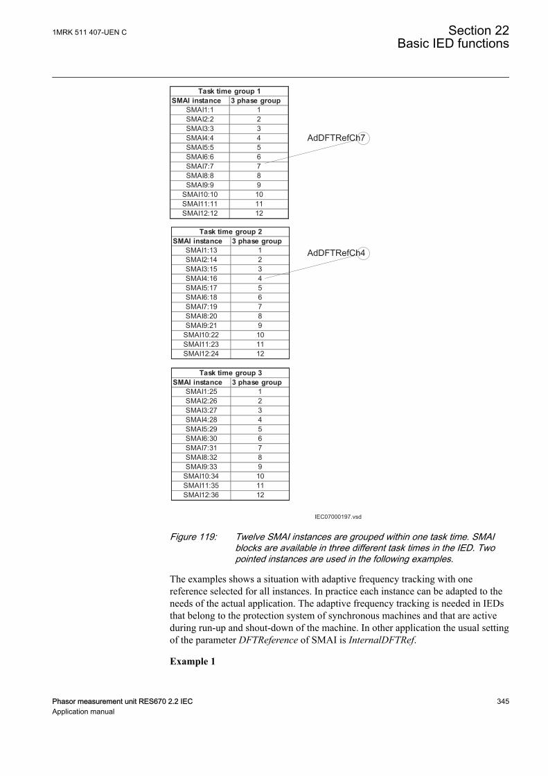
IEC07000197.vsd
SMAI instance 3 phase groupSMAI1:1 1SMAI2:2 2SMAI3:3 3SMAI4:4 4SMAI5:5 5SMAI6:6 6SMAI7:7 7SMAI8:8 8SMAI9:9 9
SMAI10:10 10SMAI11:11 11SMAI12:12 12
Task time group 1
SMAI instance 3 phase groupSMAI1:13 1SMAI2:14 2SMAI3:15 3SMAI4:16 4SMAI5:17 5SMAI6:18 6SMAI7:19 7SMAI8:20 8SMAI9:21 9
SMAI10:22 10SMAI11:23 11SMAI12:24 12
Task time group 2
SMAI instance 3 phase groupSMAI1:25 1SMAI2:26 2SMAI3:27 3SMAI4:28 4SMAI5:29 5SMAI6:30 6SMAI7:31 7SMAI8:32 8SMAI9:33 9
SMAI10:34 10SMAI11:35 11SMAI12:36 12
Task time group 3
AdDFTRefCh7
AdDFTRefCh4
IEC07000197 V2 EN-US
Figure 119: Twelve SMAI instances are grouped within one task time. SMAIblocks are available in three different task times in the IED. Twopointed instances are used in the following examples.
The examples shows a situation with adaptive frequency tracking with onereference selected for all instances. In practice each instance can be adapted to theneeds of the actual application. The adaptive frequency tracking is needed in IEDsthat belong to the protection system of synchronous machines and that are activeduring run-up and shout-down of the machine. In other application the usual settingof the parameter DFTReference of SMAI is InternalDFTRef.
Example 1
1MRK 511 407-UEN C Section 22Basic IED functions
Phasor measurement unit RES670 2.2 IEC 345Application manual
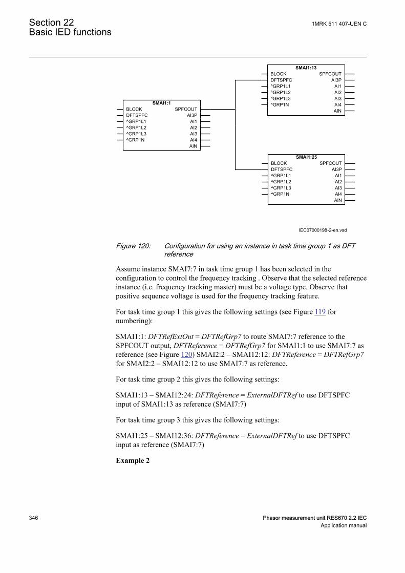
IEC07000198-2-en.vsd
SMAI1:1BLOCKDFTSPFC^GRP1L1^GRP1L2^GRP1L3^GRP1N
SPFCOUTAI3P
AI1AI2AI3AI4AIN
SMAI1:13BLOCKDFTSPFC^GRP1L1^GRP1L2^GRP1L3^GRP1N
SPFCOUTAI3P
AI1AI2AI3AI4AIN
SMAI1:25BLOCKDFTSPFC^GRP1L1^GRP1L2^GRP1L3^GRP1N
SPFCOUTAI3P
AI1AI2AI3AI4AIN
IEC07000198 V3 EN-US
Figure 120: Configuration for using an instance in task time group 1 as DFTreference
Assume instance SMAI7:7 in task time group 1 has been selected in theconfiguration to control the frequency tracking . Observe that the selected referenceinstance (i.e. frequency tracking master) must be a voltage type. Observe thatpositive sequence voltage is used for the frequency tracking feature.
For task time group 1 this gives the following settings (see Figure 119 fornumbering):
SMAI1:1: DFTRefExtOut = DFTRefGrp7 to route SMAI7:7 reference to theSPFCOUT output, DFTReference = DFTRefGrp7 for SMAI1:1 to use SMAI7:7 asreference (see Figure 120) SMAI2:2 – SMAI12:12: DFTReference = DFTRefGrp7for SMAI2:2 – SMAI12:12 to use SMAI7:7 as reference.
For task time group 2 this gives the following settings:
SMAI1:13 – SMAI12:24: DFTReference = ExternalDFTRef to use DFTSPFCinput of SMAI1:13 as reference (SMAI7:7)
For task time group 3 this gives the following settings:
SMAI1:25 – SMAI12:36: DFTReference = ExternalDFTRef to use DFTSPFCinput as reference (SMAI7:7)
Example 2
Section 22 1MRK 511 407-UEN CBasic IED functions
346 Phasor measurement unit RES670 2.2 IECApplication manual
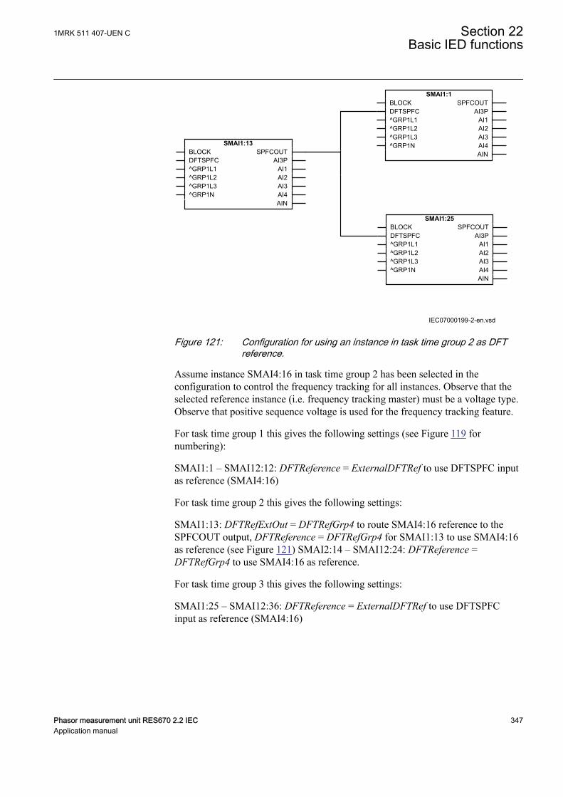
IEC07000199-2-en.vsd
SMAI1:13BLOCKDFTSPFC^GRP1L1^GRP1L2^GRP1L3^GRP1N
SPFCOUTAI3P
AI1AI2AI3AI4AIN
SMAI1:1BLOCKDFTSPFC^GRP1L1^GRP1L2^GRP1L3^GRP1N
SPFCOUTAI3P
AI1AI2AI3AI4AIN
SMAI1:25BLOCKDFTSPFC^GRP1L1^GRP1L2^GRP1L3^GRP1N
SPFCOUTAI3P
AI1AI2AI3AI4AIN
IEC07000199 V3 EN-US
Figure 121: Configuration for using an instance in task time group 2 as DFTreference.
Assume instance SMAI4:16 in task time group 2 has been selected in theconfiguration to control the frequency tracking for all instances. Observe that theselected reference instance (i.e. frequency tracking master) must be a voltage type.Observe that positive sequence voltage is used for the frequency tracking feature.
For task time group 1 this gives the following settings (see Figure 119 fornumbering):
SMAI1:1 – SMAI12:12: DFTReference = ExternalDFTRef to use DFTSPFC inputas reference (SMAI4:16)
For task time group 2 this gives the following settings:
SMAI1:13: DFTRefExtOut = DFTRefGrp4 to route SMAI4:16 reference to theSPFCOUT output, DFTReference = DFTRefGrp4 for SMAI1:13 to use SMAI4:16as reference (see Figure 121) SMAI2:14 – SMAI12:24: DFTReference =DFTRefGrp4 to use SMAI4:16 as reference.
For task time group 3 this gives the following settings:
SMAI1:25 – SMAI12:36: DFTReference = ExternalDFTRef to use DFTSPFCinput as reference (SMAI4:16)
1MRK 511 407-UEN C Section 22Basic IED functions
Phasor measurement unit RES670 2.2 IEC 347Application manual

22.12 Test mode functionality TESTMODEIP1647-1 v3
22.12.1 ApplicationM11407-3 v9
The protection and control IEDs may have a complex configuration with manyincluded functions. To make the testing procedure easier, the IEDs include thefeature that allows individual blocking of a single-, several-, or all functions.
This means that it is possible to see when a function is activated or trips. It alsoenables the user to follow the operation of several related functions to checkcorrect functionality and to check parts of the configuration, and to check parts.
22.12.1.1 IEC 61850 protocol test modeGUID-82998715-6F23-4CAF-92E4-05E1A863CF33 v5
The function block TESTMODE has implemented the extended testing modecapabilities for IEC 61850 Ed2 systems. Operator commands sent to the functionblock TESTMODE determine the behavior of the functions. The command can begiven remotely from an IEC 61850 client or from the LHMI under the Main menu/Test/Function test modes/Communication/Station Communication/IEC61850LD0 LLN0/LD0LLN0:1. The possible values of the function block TESTMODEare described in Communication protocol manual, IEC 61850 Edition 1 andEdition 2.
There is no setting in PCM600 via PST for the TESTMODE function block.
To be able to set the function block TESTMODE remotely, thesetting via path on LHMI and in PST: Main menu/Configuration/Communication/ Station Communication/IEC61850-8-1/IEC61850-8-1:1RemoteModControl may not be set to Off. Thepossible values of the parameter RemoteModControl are Off,Maintenance or All levels. The Off value denies all access tofunction block TESTMODE from remote, Maintenance requiresthat the category of the originator (orCat) is Maintenance and Alllevels allow any orCat.
The DataObject Mod of the Root LD.LNN0 can be set on the LHMI under Mainmenu/Test/Function test modes/Communication/Station communication/IEC61850 LD0 LLN0/LD0LLN0:1 to On, Off, TestBlocked,Test or Blocked.
When the setting of the DataObject Mod is changed at this level, all Logical Nodesinside the logical device update their own behavior according to IEC61850-7-4.The supported values of the function block TESTMODE are described inCommunication protocol manual, IEC 61850 Edition 2. When the function blockTESTMODE is in test mode the Start LED on the LHMI is turned on with steadylight.
Section 22 1MRK 511 407-UEN CBasic IED functions
348 Phasor measurement unit RES670 2.2 IECApplication manual
The parameter Mod of any specific function block can be configured under Mainmenu/Test/Function test modes/Communication/Station Communication
The parameter Mod can be set on the LHMI to the same values as for theDataObject Mod of the Root LD.LNN0 to On, Off, TestBlocked,Test or Blocked.For Example, Main menu/ Test/ Function test modes/ Differential protection/GeneratorDiff(87G,3Id/I>)/ GENPDIF(87G,3Id/I>):1.
It is possible that the behavior of the function block TESTMODE is also influencedby other sources as well, independent of the mode communicated via theIEC61850-8-1 station bus. For example the insertion of the test handle into the testswitch with its auxiliary contact is connected to a BI on the IED and further insidethe configuration to the input IED_TEST on the function block TESTMODE.Another example is when loss of Service Values appears, or as explained above thesetting via the LHMI.
When setting via PST or LHMI the parameterOperation of any function in an IEDis set to Off, the function is not executed and the behavior (beh) is set toOff and it isnot possible to override it. When a behavior of a function is Off the function willnot execute. The related Mod keeps its current state.
When IEC 61850 Mod of a function is set to Off or Blocked, theStart LED on the LHMI will be set to flashing to indicate theabnormal operation of the IED.
The IEC 61850-7-4 gives a detailed overview over all aspects of the test mode andother states of mode and behavior. The status of a function block behavior Beh isshown on the LHMI under the Main menu/Test/Function status/Function group/Function block descriptive name/LN name/Outputs.
• When the Beh of a function block is set to Test, the function block is notblocked and all control commands with a test bit are accepted.
• When the Beh of a function block is set to Test/blocked, all control commandswith a test bit are accepted. Outputs to the process via a non-IEC 61850 linkdata are blocked by the function block. Only process-related outputs onfunction blocks related to primary equipment are blocked. If there is an XCBRfunction block used, the outputs EXC_Open and EXC_Close are blocked.
• When the Beh of a function block is set to Blocked, all control commands witha test bit are accepted. Outputs to the process via a non-IEC 61850 link dataare blocked by the function block. In addition, the function block can beblocked when their Beh is blocked. This can be done if the function block hasa block input.
The block status of a component is shown on the LHMI as the Blk output under thesame path as for Beh:Main menu/Test/Function status/Function group/Functionblock descriptive name/LN name/Outputs. If the Blk output is not shown, thecomponent cannot be blocked.
1MRK 511 407-UEN C Section 22Basic IED functions
Phasor measurement unit RES670 2.2 IEC 349Application manual
22.12.2 Setting guidelinesM15260-3 v7
Remember always that there are two possible ways to place the IED in theTestMode= On” state. If, the IED is set to normal operation (TestMode = Off), butthe functions are still shown being in the test mode, the input signal IED_TEST onthe TESTMODE function block is activated in the configuration.
Forcing of binary input and output signals is only possible when the IED is in IEDtest mode.
22.13 Time synchronization TIMESYNCHGENIP1750-1 v2
22.13.1 Setting guidelinesIP15089-1 v3
All the parameters related to time are divided into two categories: System time andSynchronization.
22.13.1.1 System timeM11348-119 v6
The system time can be set manually via the local HMI under Main menu/Configuration/Time/System time. The time is set with years, month, day, hour,minute, second and millisecond. In addition, there are also settings for Day-Light-Saving and adjustment of Time-Zones.
22.13.1.2 SynchronizationM11348-143 v5
The setting parameters for the real-time clock with external time synchronizationare set via local HMI or PCM600. The path for Time Synchronization parameterson local HMI is Main menu/Configuration/Time/Synchronization. Theparameters are categorized as Time Synchronization (TIMESYNCHGEN) andIRIG-B settings (IRIG-B:1) in case that IRIG-B is used as the external timesynchronization source.
Time SynchronizationGUID-1F0B3D89-8323-430B-AF22-4076BBA882F0 v2
The time synchronization (TIMESYNCHGEN) parameters are divided in twocategories, "general" and "IEC61850-9-2" parameters.
The general parameters are as follows:
• FineSynchSource• SynchMaster
FineSynchSource: This parameter is used to select the time synchronization source.The options are "Off", "GPS", "IRIG-B", or "GPS+IRIG-B". In case that both GPSand IRIG-B are used (GPS+IRIG-B) for redundant time synchronization, the PMUwill automatically select the most accurate time synchronization source.
Section 22 1MRK 511 407-UEN CBasic IED functions
350 Phasor measurement unit RES670 2.2 IECApplication manual
SynchMaster: This parameter defines if the IED shall be used as a master clock(SNTP Server) for time synchronization within a Substation Automation Systemfor IEDs connected on a communication network (IEC61850-8-1). The options are"Off" or "SNTP-Server".
The IEC61850-9-2 parameters are as follows:
• SyncLostMode• SynchAccLevel
SyncLostMode: This parameter defines the time synchronization mode when usingprocess bus applications (IEC61850-9-2). The options are NoBlock, Block, andBlockOnLostUTC. If the parameter is set to Block or BlockOnLostUTC, then if thetime quality is worse than the limit set by SyncAccLevel, some functions will beblocked in the IED.
SyncAccLevel: This parameter is to define the required time synchronizationaccuracy for process bus applications. The options are "Class T5 (1µs)", "Class T4(4µs)", or "Unspecified". If it is set to "Unspecified", the time quality will bealways accepted and application functions will not be blocked due to the timequality.
IRIG-BGUID-822F8DCC-7110-49EC-BA87-9F930721D180 v1
The IRIG-B parameters have to be set according to the external clock providing theIRIG-B signal to the IED. The IRIG-B parameters (IRIG-B:1) are as follows:
• SynchType• TimeDomain• Encoding• TimeZoneAs1344
SynchType: This parameter is used to select the type of IRIG-B synchronization.The options are "BNC" or "Opto". The IRIG-B module has two inputs. One inputis for the electrical IRIG-B (BNC connector) that can handle both a pulse-widthmodulated signal (also called unmodulated) and an amplitude modulated signal(also called sine wave modulated). The other is an optical input type ST for opticalpulse-width modulated signal (IRIG-B 00X). The recommended IRIG-B signal forPMU time synchronization is IRIG-B optical (IRIG-B 00X) with IEEE1344support. If the optical IRIG-B signal is used, this parameter shall be set as "Opto",and If electrical IRIG-B signal is used (not recommended) this shall be set as"BNC". More information regarding IRIG-B module is available in TechnicalManual under section IED Hardware.
TimeDomain: This parameter shall be also set according to the external clock used.The options are "LocalTime" or "UTC".
Encoding: This parameter shall be set according to the type of encoding on theIRIG-B signal provided by the external clock. The options are "IRIG-B", "1344",or "1344TZ". The IRIG-B signal used for synchrophasor application has to support
1MRK 511 407-UEN C Section 22Basic IED functions
Phasor measurement unit RES670 2.2 IEC 351Application manual
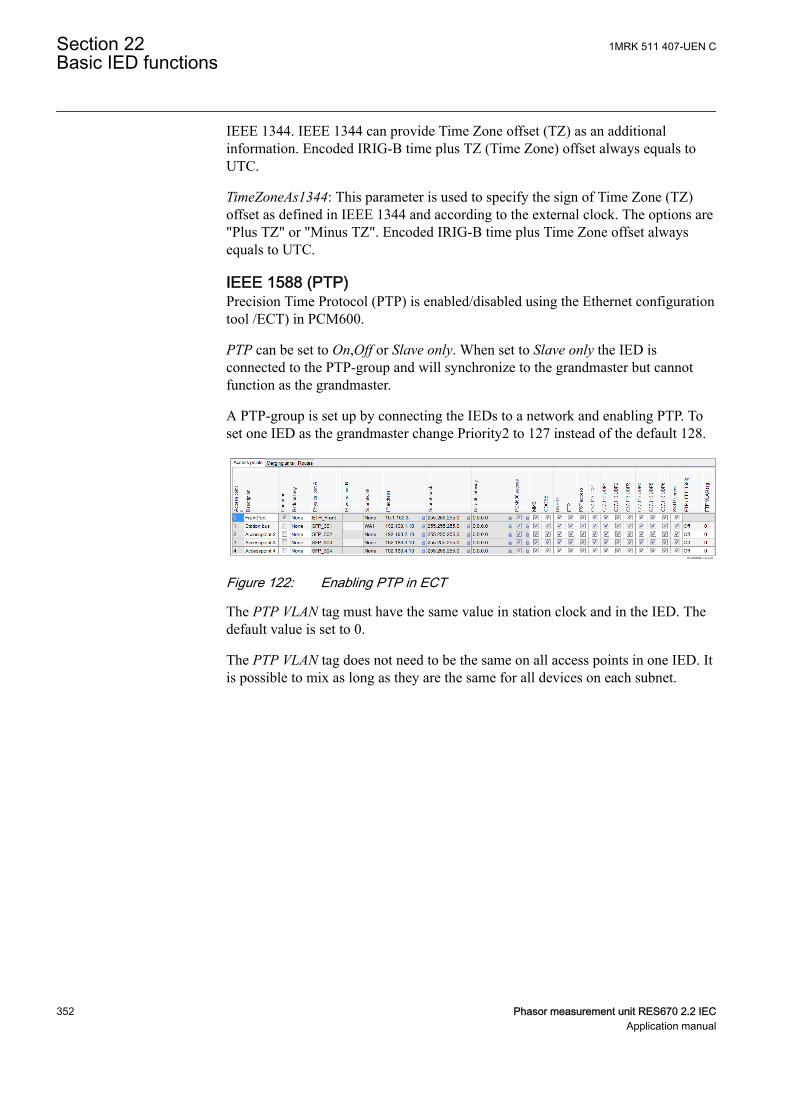
IEEE 1344. IEEE 1344 can provide Time Zone offset (TZ) as an additionalinformation. Encoded IRIG-B time plus TZ (Time Zone) offset always equals toUTC.
TimeZoneAs1344: This parameter is used to specify the sign of Time Zone (TZ)offset as defined in IEEE 1344 and according to the external clock. The options are"Plus TZ" or "Minus TZ". Encoded IRIG-B time plus Time Zone offset alwaysequals to UTC.
IEEE 1588 (PTP)GUID-424227EC-74A1-4628-8948-C1876840ABFE v3
Precision Time Protocol (PTP) is enabled/disabled using the Ethernet configurationtool /ECT) in PCM600.
PTP can be set to On,Off or Slave only. When set to Slave only the IED isconnected to the PTP-group and will synchronize to the grandmaster but cannotfunction as the grandmaster.
A PTP-group is set up by connecting the IEDs to a network and enabling PTP. Toset one IED as the grandmaster change Priority2 to 127 instead of the default 128.
IEC16000089-1-en.vsdx
IEC16000089 V1 EN-US
Figure 122: Enabling PTP in ECT
The PTP VLAN tag must have the same value in station clock and in the IED. Thedefault value is set to 0.
The PTP VLAN tag does not need to be the same on all access points in one IED. Itis possible to mix as long as they are the same for all devices on each subnet.
Section 22 1MRK 511 407-UEN CBasic IED functions
352 Phasor measurement unit RES670 2.2 IECApplication manual
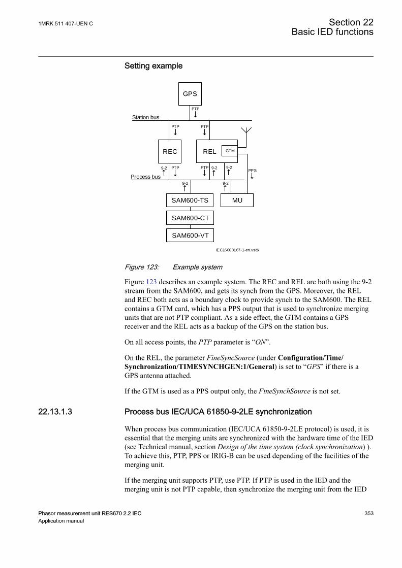
Setting example
9-2
REC
PTP
PTP
Station bus
GPS
SAM600-TS
SAM600-CT
SAM600-VT
PTP
PTP
9-2
PTP
REL
MU
GTM
PPS
IEC16000167-1-en.vsdx
9-2
9-2 9-2
Process bus
IEC16000167 V1 EN-US
Figure 123: Example system
Figure 123 describes an example system. The REC and REL are both using the 9-2stream from the SAM600, and gets its synch from the GPS. Moreover, the RELand REC both acts as a boundary clock to provide synch to the SAM600. The RELcontains a GTM card, which has a PPS output that is used to synchronize mergingunits that are not PTP compliant. As a side effect, the GTM contains a GPSreceiver and the REL acts as a backup of the GPS on the station bus.
On all access points, the PTP parameter is “ON”.
On the REL, the parameter FineSyncSource (under Configuration/Time/Synchronization/TIMESYNCHGEN:1/General) is set to “GPS” if there is aGPS antenna attached.
If the GTM is used as a PPS output only, the FineSynchSource is not set.
22.13.1.3 Process bus IEC/UCA 61850-9-2LE synchronizationGUID-6E384BDB-5598-4108-99B4-0B4A4E1828B2 v4
When process bus communication (IEC/UCA 61850-9-2LE protocol) is used, it isessential that the merging units are synchronized with the hardware time of the IED(see Technical manual, section Design of the time system (clock synchronization) ).To achieve this, PTP, PPS or IRIG-B can be used depending of the facilities of themerging unit.
If the merging unit supports PTP, use PTP. If PTP is used in the IED and themerging unit is not PTP capable, then synchronize the merging unit from the IED
1MRK 511 407-UEN C Section 22Basic IED functions
Phasor measurement unit RES670 2.2 IEC 353Application manual
via a PPS out from the GTM. If PTP is used in the IED and the merging unitcannot be synchronized from the IED, then use GPS-based clocks to provide PTPsynch as well as sync to the merging unit.
If synchronization of the IED and the merging unit is based on GPS, set theparameter LostSyncMode to BlockOnLostUTC in order to provide a block ofprotection functions whenever the global common time is lost.
If PTP is not used, use the same synchronization method for the HwSyncSrc as themerging unit provides. For instance, if the merging unit provides PPS assynchronization, use PPS as HwSyncSrc. If either PMU or LDCM in GPS-mode isused, that is, the hardware and software clocks are connected to each other,HwSyncSrc is not used and other means to synchronize the merging unit to the IEDis required. Either FineSyncSource is set to the same source that the merging unituses, or the PPS output from the GTM module is used to synchronize the mergingunit. If the PPS output from the GTM module is used to synchronize the mergingunit and PTP is not used, the IED does not know how the merging unit issynchronized and the parameter LostSyncMode must be set to NoBlock.
Section 22 1MRK 511 407-UEN CBasic IED functions
354 Phasor measurement unit RES670 2.2 IECApplication manual
Section 23 Requirements
23.1 Current transformer requirementsIP15171-1 v2
M11609-3 v2
The performance of a protection function will depend on the quality of themeasured current signal. Saturation of the current transformers (CTs) will causedistortion of the current signals and can result in a failure to operate or causeunwanted operations of some functions. Consequently CT saturation can have aninfluence on both the dependability and the security of the protection. Thisprotection IED has been designed to permit heavy CT saturation with maintainedcorrect operation.
23.1.1 Current transformer basic classification and requirementsM11611-3 v2
M11611-4 v5
To guarantee correct operation, the current transformers (CTs) must be able tocorrectly reproduce the current for a minimum time before the CT will begin tosaturate. To fulfill the requirement on a specified time to saturation the CTs mustfulfill the requirements of a minimum secondary e.m.f. that is specified below.
CTs are specified according to many different classes and standards. In principle,there are three different types of protection CTs. These types are related to thedesign of the iron core and the presence of airgaps. Airgaps affects the properties ofthe remanent flux.
The following three different types of protection CTs have been specified:
• The High Remanence type with closed iron core and no specified limit of theremanent flux
• The Low Remanence type with small airgaps in the iron core and the remanentflux limit is specified to be maximum 10% of the saturation flux
• The Non Remanence type with big airgaps in the iron core and the remanentflux can be neglected
Even though no limit of the remanent flux is specified in the IEC standard forclosed core CTs, it is a common opinion that the remanent flux is normally limitedto maximum 75 - 80 % of the saturation flux.
Since approximately year 2000 some CT manufactures have introduced new corematerials that gradually have increased the possible maximum levels of remanentflux even up to 95 % related to the hysteresis curve. Corresponding level of actualremanent flux is 90 % of the saturation flux (Ψsat). As the present CT standardshave no limitation of the level of remanent flux, these CTs are also classified as forexample, class TPX, P and PX according to IEC. The IEC TR 61869-100, Edition
1MRK 511 407-UEN C Section 23Requirements
Phasor measurement unit RES670 2.2 IEC 355Application manual
1.0 2017-01, Instrument transformers – Guidance for application of currenttransformers in power system protection, is the first official document thathighlighted this development. So far remanence factors of maximum 80% havebeen considered when CT requirements have been decided for ABB IEDs. Even inthe future this level of remanent flux probably will be the maximum level that willbe considered when decided the CT requirements. If higher remanence levelsshould be considered, it should often lead to unrealistic CT sizes.
Thus, now there is a need to limit the acceptable level of remanent flux. To be ableto guarantee the performance of protection IEDs, we need to introduce thefollowing classification of CTs.
There are many different standards and a lot of classes but fundamentally there arefour different types of CTs:
• Very High Remanence type CT• High Remanence type CT• Low Remanence type CT• Non Remanence type CT
The Very High Remanence (VHR) type is a CT with closed iron core (forexample. protection classes TPX, P, PX according to IEC, class C, K according toANSI/IEEE) and with an iron core material (new material, typically new alloybased magnetic materials) that gives a remanent flux higher than 80 % of thesaturation flux.
The High Remanence (HR) type is a CT with closed iron core (for example,protection classes TPX, P, PX according to IEC, class C, K according to ANSI/IEEE) but with an iron core material (traditional material) that gives a remanentflux that is limited to maximum 80 % of the saturation flux.
The Low Remanence (LR) type is a CT with small airgaps in the iron core (forexample, TPY, PR, PXR according to IEC) and the remanent flux limit is specifiedto be maximum 10% of the saturation flux.
The Non Remanence (NR) type is a CT with big airgaps in the core (for example,TPZ according to IEC) and the remanent flux can be neglected.
It is also possible that different CT classes of HR and LR type may be mixed.
CT type VHR (using new material) should not be used for protection CT cores.This means that it is important to specify that the remanence factor must not exceed80 % when ordering for example, class P, PX or TPX CTs. If CT manufacturers areusing new core material and are not able to fulfill this requirement, the CTs shall bespecified with small airgaps and therefore will be CTs of LR type (for example,class PR, TPY or PXR). Very high remanence level in a protection core CT cancause the following problems for protection IEDs:
Section 23 1MRK 511 407-UEN CRequirements
356 Phasor measurement unit RES670 2.2 IECApplication manual
1. Unwanted operation of differential (i.e. unit) protections for external faults2. Unacceptably delayed or even missing operation of all types of protections (for
example, distance, differential, overcurrent, etc.) which can result in loosingprotection selectivity in the network
No information is available about how frequent the use of the new iron corematerial is for protection CT cores, but it is known that some CT manufacturers areusing the new material while other manufacturers continue to use the old traditionalcore material for protection CT cores. In a case where VHR type CTs have beenalready installed, the calculated values of Eal for HR type CTs, for which theformulas are given in this document, must be multiplied by factor two-and-a-half inorder for VHR type CTs (i.e. with new material) to be used together with ABBprotection IEDs. However, this may result in unacceptably big CT cores, which canbe difficult to manufacture and fit in available space.
Different standards and classes specify the saturation e.m.f. in different ways but itis possible to approximately compare values from different classes. The ratedequivalent limiting secondary e.m.f. Eal according to the IEC 61869–2 standard isused to specify the CT requirements for the IED. The requirements are alsospecified according to other standards.
23.1.2 ConditionsM11610-3 v1
M11610-4 v4
The requirements are a result of investigations performed in our network simulator.The current transformer models are representative for current transformers of highremanence and low remanence type. The results may not always be valid for nonremanence type CTs (TPZ).
The performances of the protection functions have been checked in the range fromsymmetrical to fully asymmetrical fault currents. Primary time constants of at least120 ms have been considered at the tests. The current requirements below are thusapplicable both for symmetrical and asymmetrical fault currents.
Depending on the protection function phase-to-earth, phase-to-phase and three-phase faults have been tested for different relevant fault positions for example,close in forward and reverse faults, zone 1 reach faults, internal and external faults.The dependability and security of the protection was verified by checking forexample, time delays, unwanted operations, directionality, overreach and stability.
The remanence in the current transformer core can cause unwanted operations orminor additional time delays for some protection functions. As unwantedoperations are not acceptable at all maximum remanence has been considered forfault cases critical for the security, for example, faults in reverse direction andexternal faults. Because of the almost negligible risk of additional time delays andthe non-existent risk of failure to operate the remanence have not been consideredfor the dependability cases. The requirements below are therefore fully valid for allnormal applications.
1MRK 511 407-UEN C Section 23Requirements
Phasor measurement unit RES670 2.2 IEC 357Application manual
It is difficult to give general recommendations for additional margins forremanence to avoid the minor risk of an additional time delay. They depend on theperformance and economy requirements. When current transformers of lowremanence type (for example, TPY, PR) are used, normally no additional margin isneeded. For current transformers of high remanence type (for example, P, PX,TPX) the small probability of fully asymmetrical faults, together with highremanence in the same direction as the flux generated by the fault, has to be kept inmind at the decision of an additional margin. Fully asymmetrical fault current willbe achieved when the fault occurs at approximately zero voltage (0°).Investigations have shown that 95% of the faults in the network will occur whenthe voltage is between 40° and 90°. In addition fully asymmetrical fault currentwill not exist in all phases at the same time.
23.1.3 Fault currentM11613-3 v1
M11613-4 v3
The current transformer requirements are based on the maximum fault current forfaults in different positions. Maximum fault current will occur for three-phasefaults or single phase-to-earth faults. The current for a single phase-to-earth faultwill exceed the current for a three-phase fault when the zero sequence impedancein the total fault loop is less than the positive sequence impedance.
When calculating the current transformer requirements, maximum fault current forthe relevant fault position should be used and therefore both fault types have to beconsidered.
23.1.4 Secondary wire resistance and additional loadM11614-3 v1
M11614-4 v4
The voltage at the current transformer secondary terminals directly affects thecurrent transformer saturation. This voltage is developed in a loop containing thesecondary wires and the burden of all relays in the circuit. For earth faults the loopincludes the phase and neutral wire, normally twice the resistance of the singlesecondary wire. For three-phase faults the neutral current is zero and it is justnecessary to consider the resistance up to the point where the phase wires areconnected to the common neutral wire. The most common practice is to use fourwires secondary cables so it normally is sufficient to consider just a singlesecondary wire for the three-phase case.
The conclusion is that the loop resistance, twice the resistance of the singlesecondary wire, must be used in the calculation for phase-to-earth faults and thephase resistance, the resistance of a single secondary wire, may normally be usedin the calculation for three-phase faults.
As the burden can be considerable different for three-phase faults and phase-to-earth faults it is important to consider both cases. Even in a case where the phase-to-earth fault current is smaller than the three-phase fault current the phase-to-earthfault can be dimensioning for the CT depending on the higher burden.
Section 23 1MRK 511 407-UEN CRequirements
358 Phasor measurement unit RES670 2.2 IECApplication manual
In isolated or high impedance earthed systems the phase-to-earth fault is not thedimensioning case. Therefore, the resistance of the single secondary wire canalways be used in the calculation for this kind of power systems.
23.1.5 General current transformer requirementsM11615-3 v3
The current transformer ratio is mainly selected based on power system data forexample, maximum load and/or maximum fault current. It should be verified thatthe current to the protection is higher than the minimum operating value for allfaults that are to be detected with the selected CT ratio. It should also be verifiedthat the maximum possible fault current is within the limits of the IED.
The current error of the current transformer can limit the possibility to use a verysensitive setting of a sensitive residual overcurrent protection. If a very sensitivesetting of this function will be used it is recommended that the current transformershould have an accuracy class which have an current error at rated primary currentthat is less than ±1% (for example, 5P). If current transformers with less accuracyare used it is advisable to check the actual unwanted residual current during thecommissioning.
23.1.6 Rated equivalent secondary e.m.f. requirementsSEMOD53723-1 v1
M11616-3 v2
With regard to saturation of the current transformer all current transformers of highremanence and low remanence type that fulfill the requirements on the ratedequivalent limiting secondary e.m.f. Eal below can be used. The characteristic ofthe non remanence type CT (TPZ) is not well defined as far as the phase angleerror is concerned. If no explicit recommendation is given for a specific functionwe therefore recommend contacting ABB to confirm that the non remanence typecan be used.
The CT requirements for the different functions below are specified as a ratedequivalent limiting secondary e.m.f. Eal according to the IEC 61869-2 standard.Requirements for CTs specified according to other classes and standards are givenat the end of this section.
23.1.7 Current transformer requirements for CTs according toother standards
SEMOD53771-1 v1
M11623-4 v3
All kinds of conventional magnetic core CTs are possible to use with the IEDs ifthey fulfill the requirements corresponding to the above specified expressed as therated equivalent limiting secondary e.m.f. Eal according to the IEC 61869-2standard. From different standards and available data for relaying applications it ispossible to approximately calculate a secondary e.m.f. of the CT comparable withEal. By comparing this with the required rated equivalent limiting secondary e.m.f.Ealreq it is possible to judge if the CT fulfills the requirements. The requirementsaccording to some other standards are specified below.
1MRK 511 407-UEN C Section 23Requirements
Phasor measurement unit RES670 2.2 IEC 359Application manual

23.1.7.1 Current transformers according to IEC 61869-2, class P, PRM11623-6 v4
A CT according to IEC 61869-2 is specified by the secondary limiting e.m.f. EALF.The value of the EALF is approximately equal to the corresponding Eal. Therefore,the CTs according to class P and PR must have a secondary limiting e.m.f. EALFthat fulfills the following:
ALF alreqE maxE
EQUATION1383 V4 EN-US (Equation 102)
23.1.7.2 Current transformers according to IEC 61869-2, class PX, PXR (andold IEC 60044-6, class TPS and old British Standard, class X)
M11623-14 v5
CTs according to these classes are specified approximately in the same way by arated knee point e.m.f. Eknee (Ek for class PX and PXR, EkneeBS for class X and thelimiting secondary voltage Ual for TPS). The value of the Eknee is lower than thecorresponding Eal according to IEC 61869-2. It is not possible to give a generalrelation between the Eknee and the Eal but normally the Eknee is approximately 80 %of the Eal. Therefore, the CTs according to class PX, PXR, X and TPS must have arated knee point e.m.f. Eknee that fulfills the following:
( )knee k kneeBS al alreqE E E U 0.8 maximum of E» » » > ×
EQUATION2100 V2 EN-US (Equation 103)
23.1.7.3 Current transformers according to ANSI/IEEEM11623-22 v6
Current transformers according to ANSI/IEEE are partly specified in differentways. A rated secondary terminal voltage UANSI is specified for a CT of class C.UANSI is the secondary terminal voltage the CT will deliver to a standard burden at20 times rated secondary current without exceeding 10 % ratio correction. Thereare a number of standardized UANSI values for example, UANSI is 400 V for a C400CT. A corresponding rated equivalent limiting secondary e.m.f. EalANSI can beestimated as follows:
alANSI sr ct ANSI sr ct sr bANSIE 20 I R U 20 I R 20 I Z= × × + = × × + × ×
EQUATION971 V2 EN-US (Equation 104)
where:
ZbANSI The impedance (that is, with a complex quantity) of the standard ANSI burden for the specificC class (W)
UANSI The secondary terminal voltage for the specific C class (V)
Section 23 1MRK 511 407-UEN CRequirements
360 Phasor measurement unit RES670 2.2 IECApplication manual
The CTs according to class C must have a calculated rated equivalent limitingsecondary e.m.f. EalANSI that fulfils the following:
alANSI alreqE maximum of E>
EQUATION1384 V2 EN-US (Equation 105)
A CT according to ANSI/IEEE is also specified by the knee point voltageUkneeANSI that is graphically defined from an excitation curve. The knee pointvoltage UkneeANSI normally has a lower value than the knee-point e.m.f. accordingto IEC and BS. UkneeANSI can approximately be estimated to 75 % of thecorresponding Eal according to IEC 61869-2. Therefore, the CTs according toANSI/IEEE must have a knee point voltage UkneeANSI that fulfills the following:
kneeANSI alreqV 0.75 (max imum of E )> ×EQUATION2101 V2 EN-US (Equation 106)
23.2 Voltage transformer requirementsM11608-3 v5
The performance of a protection function will depend on the quality of themeasured input signal. Transients caused by capacitive voltage transformers(CVTs) can affect some protection functions.
Magnetic or capacitive voltage transformers can be used.
The capacitive voltage transformers (CVTs) should fulfill the requirementsaccording to the IEC 61869-5 standard regarding ferro-resonance and transients.The ferro-resonance requirements of the CVTs are specified in chapter 6.502 of thestandard.
The transient responses for three different standard transient response classes, T1,T2 and T3 are specified in chapter 6.503 of the standard. CVTs according to allclasses can be used.
The protection IED has effective filters for these transients, which gives secure andcorrect operation with CVTs.
23.3 SNTP server requirementsGUID-588FCD12-C494-445E-8488-8287B34EFD9A v4
The SNTP server to be used is connected to the local network, that is not more than4-5 switches or routers away from the IED. The SNTP server is dedicated for itstask, or at least equipped with a real-time operating system, that is not a PC withSNTP server software. The SNTP server should be stable, that is, eithersynchronized from a stable source like GPS, or local without synchronization.
1MRK 511 407-UEN C Section 23Requirements
Phasor measurement unit RES670 2.2 IEC 361Application manual

Using a local SNTP server without synchronization as primary or secondary serverin a redundant configuration is not recommended.
23.4 PTP requirementsGUID-741CC863-D760-49D6-85B2-AFECA222A8C3 v1
For PTP to perform properly, the Ethernet equipment that is used needs to becompliant with IEEE1588. The clocks used must follow the IEEE1588 standardBMC (Best Master Algorithm) and shall, for instance, not claim class 7 for a longertime than it can guarantee 1us absolute accuracy.
23.5 Sample specification of communicationrequirements for the protection and controlterminals in digital telecommunication networks
GUID-0A9F36AF-3802-42FE-8970-4662798C19D1 v3
The communication requirements are based on echo timing.
Bit Error Rate (BER) according to ITU-T G.821, G.826 and G.828
• <10-6 according to the standard for data and voice transfer
Bit Error Rate (BER) for high availability of the differential protection
• <10-8-10-9 during normal operation• <10-6 during disturbed operation
During disturbed conditions, the trip security function can cope with high bit errorrates up to 10-5 or even up to 10-4. The trip security can be configured to beindependent of COMFAIL from the differential protection communicationsupervision, or blocked when COMFAIL is issued after receive error >100ms.(Default).
Synchronization in SDH systems with G.703 E1 or IEEE C37.94
The G.703 E1, 2 Mbit shall be set according to ITU-T G.803, G.810-13
• One master clock for the actual network• The actual port Synchronized to the SDH system clock at 2048 kbit• Synchronization; bit synchronized, synchronized mapping• Maximum clock deviation <±50 ppm nominal, <±100 ppm operational• Jitter and Wander according to ITU-T G.823 and G.825• Buffer memory <250 μs, <100 μs asymmetric difference• Format.G 704 frame, structured etc.Format.• No CRC-check
Section 23 1MRK 511 407-UEN CRequirements
362 Phasor measurement unit RES670 2.2 IECApplication manual
Synchronization in PDH systems connected to SDH systems
• Independent synchronization, asynchronous mapping• The actual SDH port must be set to allow transmission of the master clock
from the PDH-system via the SDH-system in transparent mode.• Maximum clock deviation <±50 ppm nominal, <±100 ppm operational• Jitter and Wander according to ITU-T G.823 and G.825• Buffer memory <100 μs• Format: Transparent• Maximum channel delay• Loop time <40 ms continuous (2 x 20 ms)
IED with echo synchronization of differential clock (without GPS clock)
• Both channels must have the same route with maximum asymmetry of 0,2-0,5ms, depending on set sensitivity of the differential protection.
• A fixed asymmetry can be compensated (setting of asymmetric delay in builtin HMI or the parameter setting tool PST).
IED with GPS clock
• Independent of asymmetry.
23.6 IEC/UCA 61850-9-2LE Merging unit requirementsSEMOD166590-11 v5
The merging units that supply the IED with measured values via the process busmust fulfill the IEC/UCA 61850-9-2LE standard.
This part of the IEC 61850 is specifying “Communication Service Mapping(SCSM) – Sampled values over ISO/IEC 8802”, in other words – sampled dataover Ethernet. The 9-2 part of the IEC 61850 protocol uses also definitions from7-2, “Basic communication structure for substation and feeder equipment –Abstract communication service interface (ACSI)”. The set of functionalityimplemented in the IED (IEC/UCA 61850-9-2LE) is a subset of the IEC61850-9-2. For example the IED covers the client part of the standard, not theserver part.
The standard does not define the sample rate for data, but in the UCA users grouprecommendations there are indicated sample rates that are adopted, by consensus,in the industry.
There are two sample rates defined: 80 samples/cycle (4000 samples/sec. at 50Hzor 4800 samples/sec. at 60 Hz) for a merging unit “type1” and 256 samples/cyclefor a merging unit “type2”. The IED can receive data rates of 80 samples/cycle.
Note that the IEC/UCA 61850-9-2LE standard does not specify the quality of thesampled values, only the transportation. Thus, the accuracy of the current and
1MRK 511 407-UEN C Section 23Requirements
Phasor measurement unit RES670 2.2 IEC 363Application manual
voltage inputs to the merging unit and the inaccuracy added by the merging unitmust be coordinated with the requirement for actual type of protection function.
Factors influencing the accuracy of the sampled values from the merging unit arefor example anti aliasing filters, frequency range, step response, truncating, A/Dconversion inaccuracy, time tagging accuracy etc.
In principle the accuracy of the current and voltage transformers, together with themerging unit, shall have the same quality as direct input of currents and voltages.
Section 23 1MRK 511 407-UEN CRequirements
364 Phasor measurement unit RES670 2.2 IECApplication manual
Section 24 GlossaryM14893-1 v18
AC Alternating current
ACC Actual channel
ACT Application configuration tool within PCM600
A/D converter Analog-to-digital converter
ADBS Amplitude deadband supervision
ADM Analog digital conversion module, with timesynchronization
AI Analog input
ANSI American National Standards Institute
AR Autoreclosing
ASCT Auxiliary summation current transformer
ASD Adaptive signal detection
ASDU Application service data unit
AWG American Wire Gauge standard
BBP Busbar protection
BFOC/2,5 Bayonet fiber optic connector
BFP Breaker failure protection
BI Binary input
BIM Binary input module
BOM Binary output module
BOS Binary outputs status
BR External bistable relay
BS British Standards
BSR Binary signal transfer function, receiver blocks
BST Binary signal transfer function, transmit blocks
C37.94 IEEE/ANSI protocol used when sending binary signalsbetween IEDs
CAN Controller Area Network. ISO standard (ISO 11898) forserial communication
CB Circuit breaker
CBM Combined backplane module
1MRK 511 407-UEN C Section 24Glossary
Phasor measurement unit RES670 2.2 IEC 365Application manual
CCITT Consultative Committee for International Telegraph andTelephony. A United Nations-sponsored standards bodywithin the International Telecommunications Union.
CCM CAN carrier module
CCVT Capacitive Coupled Voltage Transformer
Class C Protection Current Transformer class as per IEEE/ ANSI
CMPPS Combined megapulses per second
CMT Communication Management tool in PCM600
CO cycle Close-open cycle
Codirectional Way of transmitting G.703 over a balanced line. Involvestwo twisted pairs making it possible to transmitinformation in both directions
COM Command
COMTRADE Standard Common Format for Transient Data Exchangeformat for Disturbance recorder according to IEEE/ANSIC37.111, 1999 / IEC 60255-24
Contra-directional Way of transmitting G.703 over a balanced line. Involvesfour twisted pairs, two of which are used for transmittingdata in both directions and two for transmitting clocksignals
COT Cause of transmission
CPU Central processing unit
CR Carrier receive
CRC Cyclic redundancy check
CROB Control relay output block
CS Carrier send
CT Current transformer
CU Communication unit
CVT or CCVT Capacitive voltage transformer
DAR Delayed autoreclosing
DARPA Defense Advanced Research Projects Agency (The USdeveloper of the TCP/IP protocol etc.)
DBDL Dead bus dead line
DBLL Dead bus live line
DC Direct current
DFC Data flow control
DFT Discrete Fourier transform
Section 24 1MRK 511 407-UEN CGlossary
366 Phasor measurement unit RES670 2.2 IECApplication manual
DHCP Dynamic Host Configuration Protocol
DIP-switch Small switch mounted on a printed circuit board
DI Digital input
DLLB Dead line live bus
DNP Distributed Network Protocol as per IEEE Std 1815-2012
DR Disturbance recorder
DRAM Dynamic random access memory
DRH Disturbance report handler
DSP Digital signal processor
DTT Direct transfer trip scheme
ECT Ethernet configuration tool
EHV network Extra high voltage network
EIA Electronic Industries Association
EMC Electromagnetic compatibility
EMF Electromotive force
EMI Electromagnetic interference
EnFP End fault protection
EPA Enhanced performance architecture
ESD Electrostatic discharge
F-SMA Type of optical fiber connector
FAN Fault number
FCB Flow control bit; Frame count bit
FOX 20 Modular 20 channel telecommunication system forspeech, data and protection signals
FOX 512/515 Access multiplexer
FOX 6Plus Compact time-division multiplexer for the transmission ofup to seven duplex channels of digital data over opticalfibers
FPN Flexible product naming
FTP File Transfer Protocol
FUN Function type
G.703 Electrical and functional description for digital lines usedby local telephone companies. Can be transported overbalanced and unbalanced lines
GCM Communication interface module with carrier of GPSreceiver module
1MRK 511 407-UEN C Section 24Glossary
Phasor measurement unit RES670 2.2 IEC 367Application manual
GDE Graphical display editor within PCM600
GI General interrogation command
GIS Gas-insulated switchgear
GOOSE Generic object-oriented substation event
GPS Global positioning system
GSAL Generic security application
GSE Generic substation event
HDLC protocol High-level data link control, protocol based on the HDLCstandard
HFBR connector type Plastic fiber connector
HLV circuit Hazardous Live Voltage according to IEC60255-27
HMI Human-machine interface
HSAR High speed autoreclosing
HSR High-availability Seamless Redundancy
HV High-voltage
HVDC High-voltage direct current
IDBS Integrating deadband supervision
IEC International Electrical Committee
IEC 60044-6 IEC Standard, Instrument transformers – Part 6:Requirements for protective current transformers fortransient performance
IEC 60870-5-103 Communication standard for protection equipment. Aserial master/slave protocol for point-to-pointcommunication
IEC 61850 Substation automation communication standard
IEC 61850–8–1 Communication protocol standard
IEEE Institute of Electrical and Electronics Engineers
IEEE 802.12 A network technology standard that provides 100 Mbits/son twisted-pair or optical fiber cable
IEEE P1386.1 PCI Mezzanine Card (PMC) standard for local busmodules. References the CMC (IEEE P1386, also knownas Common Mezzanine Card) standard for the mechanicsand the PCI specifications from the PCI SIG (SpecialInterest Group) for the electrical EMF (Electromotiveforce).
IEEE 1686 Standard for Substation Intelligent Electronic Devices(IEDs) Cyber Security Capabilities
IED Intelligent electronic device
Section 24 1MRK 511 407-UEN CGlossary
368 Phasor measurement unit RES670 2.2 IECApplication manual
IET600 Integrated engineering tool
I-GIS Intelligent gas-insulated switchgear
IOM Binary input/output module
Instance When several occurrences of the same function areavailable in the IED, they are referred to as instances ofthat function. One instance of a function is identical toanother of the same kind but has a different number in theIED user interfaces. The word "instance" is sometimesdefined as an item of information that is representative ofa type. In the same way an instance of a function in theIED is representative of a type of function.
IP 1. Internet protocol. The network layer for the TCP/IPprotocol suite widely used on Ethernet networks. IP is aconnectionless, best-effort packet-switching protocol. Itprovides packet routing, fragmentation and reassemblythrough the data link layer.2. Ingression protection, according to IEC 60529
IP 20 Ingression protection, according to IEC 60529, level 20
IP 40 Ingression protection, according to IEC 60529, level 40
IP 54 Ingression protection, according to IEC 60529, level 54
IRF Internal failure signal
IRIG-B: InterRange Instrumentation Group Time code format B,standard 200
ITU International Telecommunications Union
LAN Local area network
LIB 520 High-voltage software module
LCD Liquid crystal display
LDCM Line data communication module
LDD Local detection device
LED Light-emitting diode
LNT LON network tool
LON Local operating network
MCB Miniature circuit breaker
MCM Mezzanine carrier module
MIM Milli-ampere module
MPM Main processing module
MVAL Value of measurement
1MRK 511 407-UEN C Section 24Glossary
Phasor measurement unit RES670 2.2 IEC 369Application manual
MVB Multifunction vehicle bus. Standardized serial busoriginally developed for use in trains.
NCC National Control Centre
NOF Number of grid faults
NUM Numerical module
OCO cycle Open-close-open cycle
OCP Overcurrent protection
OEM Optical Ethernet module
OLTC On-load tap changer
OTEV Disturbance data recording initiated by other event thanstart/pick-up
OV Overvoltage
Overreach A term used to describe how the relay behaves during afault condition. For example, a distance relay isoverreaching when the impedance presented to it issmaller than the apparent impedance to the fault appliedto the balance point, that is, the set reach. The relay “sees”the fault but perhaps it should not have seen it.
PCI Peripheral component interconnect, a local data bus
PCM Pulse code modulation
PCM600 Protection and control IED manager
PC-MIP Mezzanine card standard
PELV circuit Protected Extra-Low Voltage circuit type according toIEC60255-27
PMC PCI Mezzanine card
POR Permissive overreach
POTT Permissive overreach transfer trip
Process bus Bus or LAN used at the process level, that is, in nearproximity to the measured and/or controlled components
PRP Parallel redundancy protocol
PSM Power supply module
PST Parameter setting tool within PCM600
PTP Precision time protocol
PT ratio Potential transformer or voltage transformer ratio
PUTT Permissive underreach transfer trip
RASC Synchrocheck relay, COMBIFLEX
RCA Relay characteristic angle
Section 24 1MRK 511 407-UEN CGlossary
370 Phasor measurement unit RES670 2.2 IECApplication manual

RISC Reduced instruction set computer
RMS value Root mean square value
RS422 A balanced serial interface for the transmission of digitaldata in point-to-point connections
RS485 Serial link according to EIA standard RS485
RTC Real-time clock
RTU Remote terminal unit
SA Substation Automation
SBO Select-before-operate
SC Switch or push button to close
SCL Short circuit location
SCS Station control system
SCADA Supervision, control and data acquisition
SCT System configuration tool according to standard IEC61850
SDU Service data unit
SELV circuit Safety Extra-Low Voltage circuit type according toIEC60255-27
SFP Small form-factor pluggable (abbreviation)Optical Ethernet port (explanation)
SLM Serial communication module.
SMA connector Subminiature version A, A threaded connector withconstant impedance.
SMT Signal matrix tool within PCM600
SMS Station monitoring system
SNTP Simple network time protocol – is used to synchronizecomputer clocks on local area networks. This reduces therequirement to have accurate hardware clocks in everyembedded system in a network. Each embedded node caninstead synchronize with a remote clock, providing therequired accuracy.
SOF Status of fault
SPA Strömberg Protection Acquisition (SPA), a serial master/slave protocol for point-to-point and ring communication.
SRY Switch for CB ready condition
ST Switch or push button to trip
Starpoint Neutral point of transformer or generator
1MRK 511 407-UEN C Section 24Glossary
Phasor measurement unit RES670 2.2 IEC 371Application manual
SVC Static VAr compensation
TC Trip coil
TCS Trip circuit supervision
TCP Transmission control protocol. The most commontransport layer protocol used on Ethernet and the Internet.
TCP/IP Transmission control protocol over Internet Protocol. Thede facto standard Ethernet protocols incorporated into4.2BSD Unix. TCP/IP was developed by DARPA forInternet working and encompasses both network layer andtransport layer protocols. While TCP and IP specify twoprotocols at specific protocol layers, TCP/IP is often usedto refer to the entire US Department of Defense protocolsuite based upon these, including Telnet, FTP, UDP andRDP.
TEF Time delayed earth-fault protection function
TLS Transport Layer Security
TM Transmit (disturbance data)
TNC connector Threaded Neill-Concelman, a threaded constantimpedance version of a BNC connector
TP Trip (recorded fault)
TPZ, TPY, TPX, TPS Current transformer class according to IEC
TRM Transformer Module. This module transforms currentsand voltages taken from the process into levels suitablefor further signal processing.
TYP Type identification
UMT User management tool
Underreach A term used to describe how the relay behaves during afault condition. For example, a distance relay isunderreaching when the impedance presented to it isgreater than the apparent impedance to the fault applied tothe balance point, that is, the set reach. The relay does not“see” the fault but perhaps it should have seen it. See alsoOverreach.
UTC Coordinated Universal Time. A coordinated time scale,maintained by the Bureau International des Poids etMesures (BIPM), which forms the basis of a coordinateddissemination of standard frequencies and time signals.UTC is derived from International Atomic Time (TAI) bythe addition of a whole number of "leap seconds" tosynchronize it with Universal Time 1 (UT1), thusallowing for the eccentricity of the Earth's orbit, therotational axis tilt (23.5 degrees), but still showing the
Section 24 1MRK 511 407-UEN CGlossary
372 Phasor measurement unit RES670 2.2 IECApplication manual
Earth's irregular rotation, on which UT1 is based. TheCoordinated Universal Time is expressed using a 24-hourclock, and uses the Gregorian calendar. It is used foraeroplane and ship navigation, where it is also sometimesknown by the military name, "Zulu time." "Zulu" in thephonetic alphabet stands for "Z", which stands forlongitude zero.
UV Undervoltage
WEI Weak end infeed logic
VT Voltage transformer
X.21 A digital signalling interface primarily used for telecomequipment
3IO Three times zero-sequence current.Often referred to as theresidual or the earth-fault current
3UO Three times the zero sequence voltage. Often referred toas the residual voltage or the neutral point voltage
1MRK 511 407-UEN C Section 24Glossary
Phasor measurement unit RES670 2.2 IEC 373Application manual

374

375

—ABB AB Grid Automation Products721 59 Västerås, SwedenPhone: +46 (0) 21 32 50 00
abb.com/protection-control
© Copyright 2017 ABB. All rights reserved. Specifications subject to change without notice. 1M
RK
511
40
7-U
EN
Copyright © 2022 FDOKUMEN

