


Bahasa
Halaman
Hukum


Amphenol Cable Glands andCord Grips
®
12-055
Amphenol

Amphenol®/Pyle® Cord Grips 55
Cord Grip Specifications 56-57
DB/DBM Group 58-59
DBZ Group 60-61
DBL/DBZL Group 62-63
DBA Group 64-65
DBF Group, Flared Nipples 66-67
DBZP Series 68-69
Grommets 70-71
Accessories 72-73
Introduction 1
Amphenol® Cable Glands 2-3
ATEX Approved Glands Featuring Elastometric Seals
EX-20 4-5
EX-25 6-7
EE-30 8-9
EX-35 10-11
EX-40 12-13
EX-45 14-15
EE-RG 16-17
ATEX Approved Glands Featuring Elastometric Seals for Flat Cable
EX-50 18-19
EX-55 20-21
ATEX Approved Barrier Glands
EX-60 22-23
EX-65 24-25
EX-70 26-27
EX-75 Stopper Box 28-29
Industrial Glands
CGA 30-31
CGSS 32-33
CGDS 34-35
CGU 36-37
Accessories
ARAdaptors & Reducers 38-39
Nylon Adaptors & Reducers 40-41
Insulated Adaptors 42-43
Mushroom Head Stopping Plugs 44-45
Nylon Mushroom Head Stopping Plugs 46-47
Type A & Type B Stopping Plugs 48-49
Breather Drain 50-51
Locknuts, Earth Tags, etc. 52
Entry Thread Reference Tables 53
Ingress Protection, Gland Weight Data 54
Table of Contents Page Number
For further information on your individual application requirements, contact:Amphenol CorporationAmphenol Industrial Operations40-60 Delaware AvenueSidney, New York 13838-1395Phone: 607-563-5011 Fax: 607-563-5351View and download or print Amphenol catalogs on-line at: www.amphenol-industrial.com
Amphenol operates quality systems that are certified to ISO 9001:2000 by third party registrars.
For product specific questions regarding RoHS compliance, consult Amphenol Industrial Operations, or call theRoHS Product Compliance and Technical Support line: 1-866-315-8559
Addtional Amphenol® Industrial Products 74-75
Amphenol Sales Offices and Distributors Listing 76

1
Amphenol Industrial Operations
Amphenol® Cable Glands and Cord GripsAmphenol Industrial offers more choices, more solutions, and more options than any other interconnectmanufacturer in the world. In addition to the broadest range of connector solutions in the market, we also offer anextensive line of Explosion Proof and General Duty Cable Glands. We also carry a complete line of liquid tight strain-relief products in our Cord Grip line of performance cable seals. Our combination of Glands and Cord Grips makesAmphenol Industrial the one stop supplier for all your connector and cable sealing solutions.
Cable GlandsAmphenol Industrial Operations, the worldwide leaderof explosion proof and hazardous environmentinterconnects, introduces our broad range ofexplosion proof and industrial cable glands. The newCable Gland product line is designed toperform in themost demanding environments. Amphenol’scomplete line of EX Zone 1 and 2 rated cable glandsoffers our customers great flexibility. In addition, wehave a complete line of general duty industrialapplication cable glands suitable for armored andunarmored cable.
• SIRA/ATEX certified to Exd/Exe (Class I, Div. I)
• CSA Approved
• IP66/68; Deluge; NEMA rated products
• Temperature Ranges from -40°F to +180°F
• Brass and Stainless Steel available.
Amphenol Cable Glands are RoHSCompliant.
Cord GripsWhether you need a straight, 45°, or 90° strain relief,Amphenol’s family of cord Grips has you covered.Strong, lightweight aluminum components provide along lasting, reliable liquid tight solution. AmphenolIndustrial Cord Grips offer a complete line of strainrelief options that include gland nuts, mechanicalclamps and basketweave cable grips. UL and CSAlisted, our Cord Grips have been put to the test forover 40 years.
• Tapered rubber grommets and seal
• Machined Components
• Male and female threads available
• Tapered conduit threads
Amphenol Cord Grips are availablewith RoHS Compliant options. Pleasecontact Amphenol Industrial Operationsfor information.

2
Amphenol Cable Glands and Cord Grips
Amphenol Explosion Proof and Industrial Cable GlandsThis section will provide you with information on Amphenol’s complete family of cable glands, and will assist you indetermining which of our glands will satisfy your specific need. If you have further questions, please contact ourfactory or one of the Amphenol Industrial distributors listed in the back of this catalog.
Features & Benefits
ATEX and CSA Certified: Approved to perform in the most hazardous environments.
Variety of Styles: Cable glands available to accommodate any cable type.
IP Ratings Included: Watertight seals allow for both indoor and outdoor applications.
Machined Components made from brass and stainless steel.
Complete Line of Accessories: Including locknuts, washers, and earth tags.
Entry Thread Flexibility: Both metric and NPT threads available on most styles.
Applications
• Oil and Gas Exploration Equipment
• Machine and Heavy Electronics
• Pharmaceutical Manufacturing Facilities
• Production Platforms
• Chemical and Paint Manufacturing Facilities
• Robotics and Welding Equipment
• Process Control Equipment
• Motors and Generators
Amphenol Industrial Operations, the recognized leader in explosion proof and hazardous environment interconnects,offers a complete line of Industrial and Explosion Proof Glands. Whether part of an integrated connector solution, oras part of a bulkhead feed through, Amphenol has the solution you are looking for. Our product range includesgeneral duty industrial cable glands meant to seal on unarmored cable, right up to our ATEX approved EX glandscapable of protecting the most rugged cable in your zone rated applications.
Our EX Approved Glands also provide a complete zone rated interconnect solution when used in conjunction withour ATEX approved Star-Line EX explosion proof connector series. For additional information on the Star-Line EXproduct, consult Amphenol catalog 12-054.

3
Gland Type Outer Seal Inner Seal Lead Option Armor Clamp Certification IP Rating Page Number
ATEX/CSA Approved Glands with Elastomeric SealsEX-20 � � � � Exd/Exe Deluge, IP66, 68 4
NEMA, 4X
EX-25 � � � � Exd/Exe IP66, IP67 6(Not CSA)
EE-30 � ✕ � ✕ Exe IP66 8
(Not CSA)
EX-35 � ✕ ✕ ✕ Exd/Exe IP66 10IP68
NEMA 4X
EX-40 � x2 ✕ ✕ ✕ Exd/Exe IP66 12IP68
NEMA 4X
EX-45 � ✕ ✕ ✕ Exd/Exe IP66 14IP68
NEMA 4X
EE-RG � ✕ ✕ ✕ Exe IP66 16IP68
ATEX/CSA Approved Glands with Elastomeric Seals for Flat CableEX-50 Flat Cable Flat Cable ✕ Braid Exd/Exe IP66 18
EX-55 Flat Cable ✕ ✕ ✕ Exd/Exe IP68 20
ATEX Approved Compound Filled Barrier GlandsEX-60 � Compound � � Exd Deluge, IP66, IP68 22
NEMA, 4X
EX-65 Compound Compound � ✕ Exd Deluge, IP66, IP68 24
NEMA, 4X
EX-70 � Compound � ✕ Exd Deluge, IP66, IP68 26
NEMA, 4X
EX-75 ✕ Compound ✕ ✕ Exd Deluge, IP66, IP68 28
(stopper box) NEMA, 4X
Non Hazardous Industrial GlandsCGA ✕ ✕ ✕ � Industrial (BS6121) IP30 30
CGSB � ✕ ✕ � Industrial IP66 32
CGDS � � � � Industrial IP67 34
CGU � ✕ � ✕ Industrial IP66, IP66 36
www.amphenol-industrial.com
Amphenol Cable Glands
Cable Gland Selection GuideThis table is designed to be a quick reference to the cable glands found in this publication.

4
ATEX/CSA Approved Glands with Elastomeric Seals
EX-20EX-20EX-20EX-20EX-20EX-20 type glands provide a seal on the inner sheath, a seal on the outer sheath, an entry thread seal and auniversal armor clamp for armored cable. The armor clamp provides an electrical bond between the cable armor andthe gland. EX-20 glands can also be used to terminate unarmored or lead sheathed cables. EX-20 type glandsmaintain Flameproof Exd and Increased Safety Exe methods of explosion protection; IP66, 68 to 25 meters and isdeluge resistant. An integral ‘O’ ring entry thread seal is fitted to metric versions as standard.
DESIGN STANDARD
EN50014:1998, EN50018:2000, EN50019:2000 & EN 50281-1-1:1998
EXAMPLE PART NUMBER
EX-20 [W] [X] [Y] [R] [YY] [ZZ]W - Gland material (B = Brass / S = Stainless Steel)X - Seal Material (1 = Neoprene / 3 = Silicone)Y - Plating (0 = No Plating / 1 = Nickel / 2 = Tin / 3 = Zinc / 4 =
Electroless Nickel)R - Reduced bore option
YY - Gland size (Cable Range)ZZ - Entry thread
Sample: EX-20-B-1-0-R-20-M20
CERTIFICATION
ATEX II 2 GD, E Exd IIC / E Exe IICSA Exd IIC/Exe II 4X, Class 1, Zone 1
CERTIFICATE
Sira 05ATEX1120X - Ex Notified Body No. 0518Pending
APPLICATION
EExd EquipmentEX-20 type glands will only maintain Flameproof Exd integrity when used with cable that is substantially round and compact with extrudedbedding. The cable shall be deemed to be effectively filled. Ref: IEC60079-14:2002 Section 10.4.2
Gas Group Internal Ignition Source Enclosure Volume Which Zone Use Type EX-20 GlandIIC, IIB, IIA NO Any Zone 1 or 2 YES
IIB, IIA YES Any Zone 2 YESIIB, IIA YES 2 liters or less Zone 1 YES
EExe Equipment Other EquipmentGas Group II, Zones 1 and 2 Ignitable Dust, Zones 21 and 22
OPERATING TEMPERATURES
Standard Seals -20°C to +85°CExtended Seals - 60°C to +180°C (Silicone seals)
INGRESS PROTECTION
IP66 and IP68 @ 25 meters, Enclosure Type 4XMeets the requirements of DTS01 1991
MATERIALS
Brass CZ121 (EX-20-B)316 Stainless Steel (EX-20-S)
Inner and outer sheath material: Standard (EX-20-W-1) Neoprene, black. Option (EX-20-W-3) Silicone, white.Reduced bore outer sheath seal (R) Silicone, red (EX-20-W-X-Y-R)
Entry thread seal: Nitrile is supplied with neoprene seal version. Silicone is supplied with silicone seal version
GLAND MARKING
CENELEC and ATEXExample:Amphenol 13838 USA EX-20-B-1-0-R-20-M20 XX Sira 05ATEX1120X II 2GD EExdIIC / EExe II (XX = Year Code)
B
D CA
5
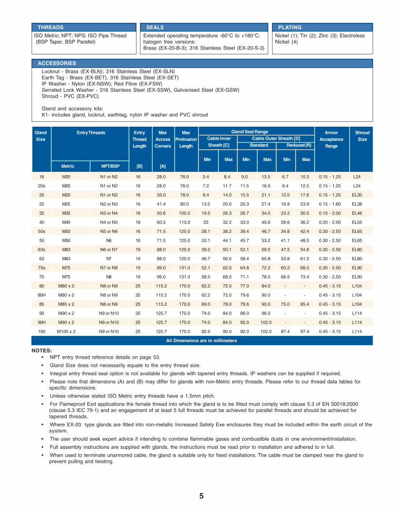
• NPT entry thread reference details on page 53.
• Gland Size does not necessarily equate to the entry thread size.
• Integral entry thread seal option is not available for glands with tapered entry threads. IP washers can be supplied if required.
• Please note that dimensions (A) and (B) may differ for glands with non-Metric entry threads. Please refer to our thread data tables forspecific dimensions.
• Unless otherwise stated ISO Metric entry threads have a 1.5mm pitch.
• For Flameproof Exd applications the female thread into which the gland is to be fitted must comply with clause 5.3 of EN 50018:2000(clause 5.3 IEC 79-1) and an engagement of at least 5 full threads must be achieved for parallel threads and should be achieved fortapered threads.
• Where EX-20 type glands are fitted into non-metallic Increased Safety Exe enclosures they must be included within the earth circuit of thesystem.
• The user should seek expert advice if intending to combine flammable gases and combustible dusts in one environment/installation.
• Full assembly instructions are supplied with glands, the instructions must be read prior to installation and adhered to in full.
• When used to terminate unarmored cable, the gland is suitable only for fixed installations. The cable must be clamped near the gland toprevent pulling and twisting.
NOTES:
16 M20 N1 or N2 16 28.0 78.0 3.4 8.4 9.0 13.5 6.7 10.3 0.15 - 1.25 L24
20s M20 N1 or N2 16 28.0 78.0 7.2 11.7 11.5 16.0 9.4 12.5 0.15 - 1.25 L24
20 M20 N1 or N2 16 33.0 78.0 9.4 14.0 15.5 21.1 12.0 17.6 0.15 - 1.25 EL30
25 M25 N2 or N3 16 41.4 90.0 13.5 20.0 20.3 27.4 16.8 23.9 0.15 - 1.60 EL38
32 M32 N3 or N4 16 50.6 105.0 19.5 26.3 26.7 34.0 23.2 30.5 0.15 - 2.00 EL46
40 M40 N4 or N5 16 60.5 113.0 23 32.2 33.0 40.6 28.6 36.2 0.20 - 2.00 EL55
50s M50 N5 or N6 16 71.5 125.0 28.1 38.2 39.4 46.7 34.8 42.4 0.30 - 2.50 EL65
50 M50 N6 16 71.5 125.0 33.1 44.1 45.7 53.2 41.1 48.5 0.30 - 2.50 EL65
63s M63 N6 or N7 19 88.0 125.0 39.2 50.1 52.1 59.5 47.5 54.8 0.30 - 2.50 EL80
63 M63 N7 19 88.0 125.0 46.7 56.0 58.4 65.8 53.8 61.2 0.30 - 2.50 EL80
75s M75 N7 or N8 19 99.0 131.0 52.1 62.0 64.8 72.2 60.2 68.0 0.30 - 2.50 EL90
75 M75 N8 19 99.0 131.0 58.0 68.0 71.1 78.0 66.5 73.4 0.30 - 2.50 EL90
80 M80 x 2 N8 or N9 25 115.2 170.0 62.2 72.0 77.0 84.0 - - 0.45 - 3.15 L104
80H M80 x 2 N8 or N9 25 115.2 170.0 62.2 72.0 79.6 90.0 - - 0.45 - 3.15 L104
85 M85 x 2 N8 or N9 25 115.2 170.0 69.0 78.0 79.6 90.0 75.0 85.4 0.45 - 3.15 L104
90 M90 x 2 N9 or N10 25 125.7 170.0 74.0 84.0 88.0 96.0 - - 0.45 - 3.15 L114
90H M90 x 2 N9 or N10 25 125.7 170.0 74.0 84.0 92.0 102.0 - - 0.45 - 3.15 L114
100 M100 x 2 N9 or N10 25 125.7 170.0 82.0 90.0 92.0 102.0 87.4 97.4 0.45 - 3.15 L114
All Dimensions are in millimeters
Gland Entry Threads Entry Max Max Armor ShroudSize Thread Across Protrusion Acceptance Size
Length Corners Length Range
Min Max Min Max Min MaxMetric NPT/BSP [B] [A]
Gland Seal RangeCable Inner Cable Outer Sheath [D]Sheath [C] Standard Reduced (R)
THREADS
ISO Metric; NPT; NPS; ISO Pipe Thread(BSP Taper, BSP Parallel)
SEALS
Extended operating temperature -60°C to +180°C,halogen free versions:Brass (EX-20-B-3); 316 Stainless Steel (EX-20-S-3)
PLATING
Nickel (1); Tin (2); Zinc (3); ElectrolessNickel (4)
ACCESSORIES
Locknut - Brass (EX-BLN); 316 Stainless Steel (EX-SLN)Earth Tag - Brass (EX-BET), 316 Stainless Steel (EX-SET)IP Washer - Nylon (EX-NSW); Red Fibre (EX-FSW)Serrated Lock Washer - 316 Stainless Steel (EX-SSW), Galvanised Steel (EX-GSW)Shroud - PVC (EX-PVC)
Gland and accessory kits:K1- includes gland, locknut, earthtag, nylon IP washer and PVC shroud

6
ATEX/CSA Approved Glands with Elastomeric Seals
EX-25EX-25 type glands provide a seal on the inner sheath, a seal on the outer sheath and an armor specific clamp forarmored cable. The armor clamp provides an electrical bond between the cable armor and the gland. EX-25 typeconnectors can be used to terminate lead sheath cables. EX-25 type glands maintain Flameproof Exd andIncreased Safety Exe methods of explosion protection and IP66, IP67.
DESIGN STANDARD
EN50014:1998, EN50018:2000, EN50019:2000 and EN 50281-1-1:1998
EXAMPLE PART NUMBER
EX-25* [W] [X] [Y] [R] [YY] [ZZ]* - Armor Types (W = SWA / X = SWB / Z = STA)
W - Gland material (B = Brass / S = Stainless Steel)X - Seal Material (1 = Neoprene / 3 = Silicone / 4 = No Seal)Y - Plating (0 = No Plating / 1 = Nickel / 2 = Tin / 3 = Zinc / 4 =
Electroless Nickel)R - Reduced bore option
YY - Gland size (Cable Range)ZZ - Entry Thread
Sample: EX-25-W-B-1-0-R-20-M20
CERTIFICATION
ATEX II 2 GD, E Exd IIC / E Exe II
CERTIFICATE
SIRA 05ATEX1122X - Ex Notified Body No. 0518
APPLICATION
EExd EquipmentEX-25 type glands will only maintain Flameproof Exd integrity when used with cable that is substantially round and compact with extrudedbedding. The cable shall be deemed to be effectively filled. Ref: IEC60079-14:2002 Section 10.4.2
Gas Group Internal Ignition Source Enclosure Volume Which Zone Use Type EX-25 GlandIIC, IIB, IIA NO Any Zone 1 or 2 YES
IIB, IIA YES Any Zone 2 YESIIB, IIA YES 2 litres or less Zone 1 YES
EExe Equipment Other EquipmentGas Group II, Zones 1 and 2 Ignitable Dust, Zones 21 and 22
OPERATING TEMPERATURES
Standard Seals -20°C to +80°CSilicone Seals - 60°C to +180°C
INGRESS PROTECTION
IP66 and IP67
VARIATIONS
Omission of outer seal:Brass (EX-25*-B-4); 316 Stainless Steel (EX-25-*-S-4)
MATERIALS
Brass CZ121 (EX-25-*-B)316 Stainless Steel (EX-25-*-S)
GLAND MARKING
CENELEC and ATEXExample:Amphenol 13838 USA EX-25W-B-1-0-R-20-M20 XX SIRA 05ATEX1122X II 2GD IP67 EExdIIC / EExe II (XX = Year Code)
A D C
B
7
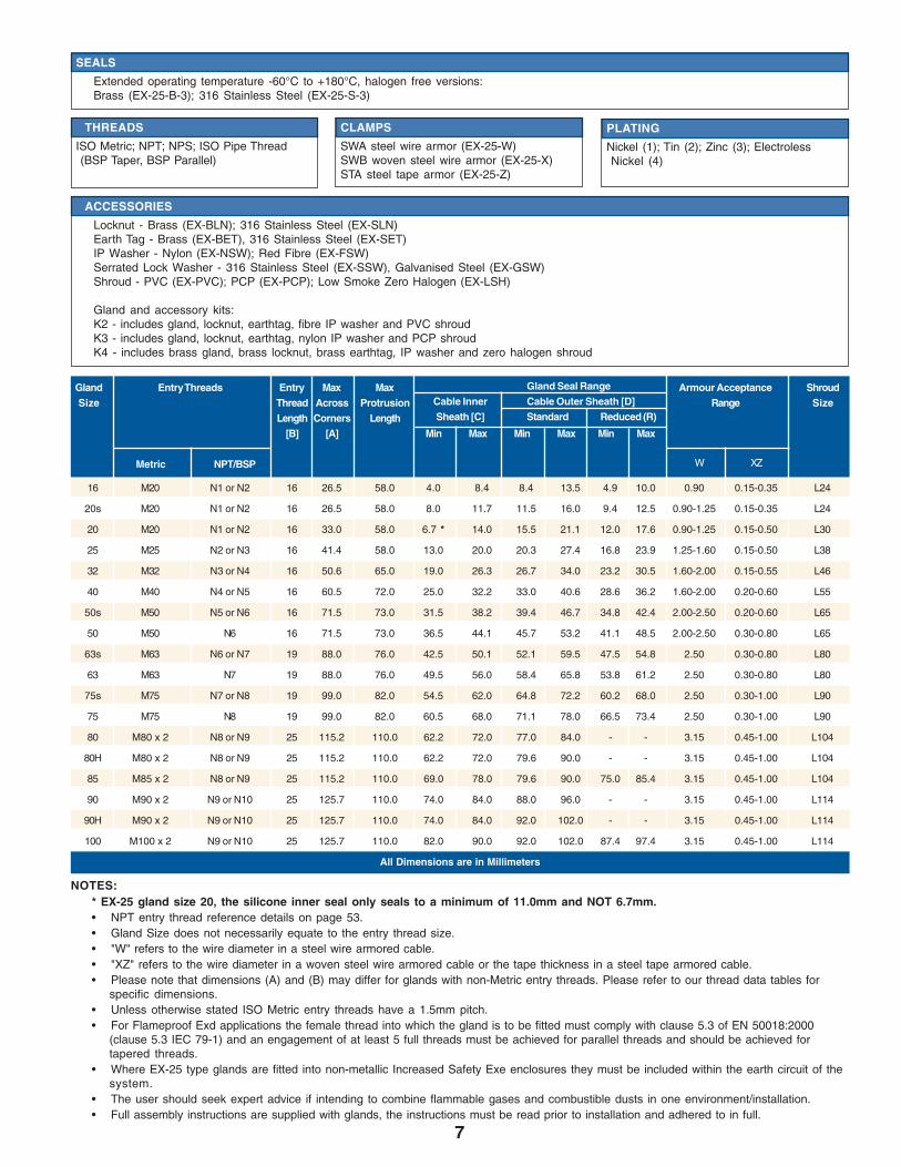
* EX-25 gland size 20, the silicone inner seal only seals to a minimum of 11.0mm and NOT 6.7mm.• NPT entry thread reference details on page 53.• Gland Size does not necessarily equate to the entry thread size.• "W" refers to the wire diameter in a steel wire armored cable.• "XZ" refers to the wire diameter in a woven steel wire armored cable or the tape thickness in a steel tape armored cable.• Please note that dimensions (A) and (B) may differ for glands with non-Metric entry threads. Please refer to our thread data tables for
specific dimensions.• Unless otherwise stated ISO Metric entry threads have a 1.5mm pitch.• For Flameproof Exd applications the female thread into which the gland is to be fitted must comply with clause 5.3 of EN 50018:2000
(clause 5.3 IEC 79-1) and an engagement of at least 5 full threads must be achieved for parallel threads and should be achieved fortapered threads.
• Where EX-25 type glands are fitted into non-metallic Increased Safety Exe enclosures they must be included within the earth circuit of thesystem.
• The user should seek expert advice if intending to combine flammable gases and combustible dusts in one environment/installation.• Full assembly instructions are supplied with glands, the instructions must be read prior to installation and adhered to in full.
NOTES:
16 M20 N1 or N2 16 26.5 58.0 4.0 8.4 8.4 13.5 4.9 10.0 0.90 0.15-0.35 L24
20s M20 N1 or N2 16 26.5 58.0 8.0 11.7 11.5 16.0 9.4 12.5 0.90-1.25 0.15-0.35 L24
20 M20 N1 or N2 16 33.0 58.0 6.7 * 14.0 15.5 21.1 12.0 17.6 0.90-1.25 0.15-0.50 L30
25 M25 N2 or N3 16 41.4 58.0 13.0 20.0 20.3 27.4 16.8 23.9 1.25-1.60 0.15-0.50 L38
32 M32 N3 or N4 16 50.6 65.0 19.0 26.3 26.7 34.0 23.2 30.5 1.60-2.00 0.15-0.55 L46
40 M40 N4 or N5 16 60.5 72.0 25.0 32.2 33.0 40.6 28.6 36.2 1.60-2.00 0.20-0.60 L55
50s M50 N5 or N6 16 71.5 73.0 31.5 38.2 39.4 46.7 34.8 42.4 2.00-2.50 0.20-0.60 L65
50 M50 N6 16 71.5 73.0 36.5 44.1 45.7 53.2 41.1 48.5 2.00-2.50 0.30-0.80 L65
63s M63 N6 or N7 19 88.0 76.0 42.5 50.1 52.1 59.5 47.5 54.8 2.50 0.30-0.80 L80
63 M63 N7 19 88.0 76.0 49.5 56.0 58.4 65.8 53.8 61.2 2.50 0.30-0.80 L80
75s M75 N7 or N8 19 99.0 82.0 54.5 62.0 64.8 72.2 60.2 68.0 2.50 0.30-1.00 L90
75 M75 N8 19 99.0 82.0 60.5 68.0 71.1 78.0 66.5 73.4 2.50 0.30-1.00 L90
80 M80 x 2 N8 or N9 25 115.2 110.0 62.2 72.0 77.0 84.0 - - 3.15 0.45-1.00 L104
80H M80 x 2 N8 or N9 25 115.2 110.0 62.2 72.0 79.6 90.0 - - 3.15 0.45-1.00 L104
85 M85 x 2 N8 or N9 25 115.2 110.0 69.0 78.0 79.6 90.0 75.0 85.4 3.15 0.45-1.00 L104
90 M90 x 2 N9 or N10 25 125.7 110.0 74.0 84.0 88.0 96.0 - - 3.15 0.45-1.00 L114
90H M90 x 2 N9 or N10 25 125.7 110.0 74.0 84.0 92.0 102.0 - - 3.15 0.45-1.00 L114
100 M100 x 2 N9 or N10 25 125.7 110.0 82.0 90.0 92.0 102.0 87.4 97.4 3.15 0.45-1.00 L114
All Dimensions are in Millimeters
Gland Entry Threads Entry Max Max Armour Acceptance ShroudSize Thread Across Protrusion Range Size
Length Corners Length[B] [A] Min Max Min Max Min Max
Metric NPT/BSP
Gland Seal RangeCable Inner Cable Outer Sheath [D]Sheath [C] Standard Reduced (R)
W XZ
SEALS
Extended operating temperature -60°C to +180°C, halogen free versions:Brass (EX-25-B-3); 316 Stainless Steel (EX-25-S-3)
THREADS
ISO Metric; NPT; NPS; ISO Pipe Thread(BSP Taper, BSP Parallel)
PLATING
Nickel (1); Tin (2); Zinc (3); ElectrolessNickel (4)
CLAMPS
SWA steel wire armor (EX-25-W)SWB woven steel wire armor (EX-25-X)STA steel tape armor (EX-25-Z)
ACCESSORIES
Locknut - Brass (EX-BLN); 316 Stainless Steel (EX-SLN)Earth Tag - Brass (EX-BET), 316 Stainless Steel (EX-SET)IP Washer - Nylon (EX-NSW); Red Fibre (EX-FSW)Serrated Lock Washer - 316 Stainless Steel (EX-SSW), Galvanised Steel (EX-GSW)Shroud - PVC (EX-PVC); PCP (EX-PCP); Low Smoke Zero Halogen (EX-LSH)
Gland and accessory kits:K2 - includes gland, locknut, earthtag, fibre IP washer and PVC shroudK3 - includes gland, locknut, earthtag, nylon IP washer and PCP shroudK4 - includes brass gland, brass locknut, brass earthtag, IP washer and zero halogen shroud
8
ATEX/CSA Approved Glands with Elastomeric Seals
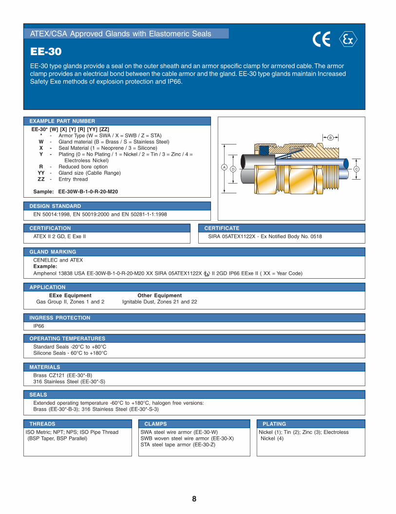
EE-30EE-30 type glands provide a seal on the outer sheath and an armor specific clamp for armored cable. The armorclamp provides an electrical bond between the cable armor and the gland. EE-30 type glands maintain IncreasedSafety Exe methods of explosion protection and IP66.
DESIGN STANDARD
EN 50014:1998, EN 50019:2000 and EN 50281-1-1:1998
EXAMPLE PART NUMBER
EE-30* [W] [X] [Y] [R] [YY] [ZZ]* - Armor Type (W = SWA / X = SWB / Z = STA)
W - Gland material (B = Brass / S = Stainless Steel)X - Seal Material (1 = Neoprene / 3 = Silicone)Y - Plating (0 = No Plating / 1 = Nickel / 2 = Tin / 3 = Zinc / 4 =
Electroless Nickel)R - Reduced bore option
YY - Gland size (Cablle Range)ZZ - Entry thread
Sample: EE-30W-B-1-0-R-20-M20
CERTIFICATION
ATEX II 2 GD, E Exe II
CERTIFICATE
SIRA 05ATEX1122X - Ex Notified Body No. 0518
APPLICATION
EExe Equipment Other EquipmentGas Group II, Zones 1 and 2 Ignitable Dust, Zones 21 and 22
OPERATING TEMPERATURES
Standard Seals -20°C to +80°CSilicone Seals - 60°C to +180°C
INGRESS PROTECTION
IP66
SEALS
Extended operating temperature -60°C to +180°C, halogen free versions:Brass (EE-30*-B-3); 316 Stainless Steel (EE-30*-S-3)
THREADS
ISO Metric; NPT; NPS; ISO Pipe Thread(BSP Taper, BSP Parallel)
PLATING
Nickel (1); Tin (2); Zinc (3); ElectrolessNickel (4)
MATERIALS
Brass CZ121 (EE-30*-B)316 Stainless Steel (EE-30*-S)
GLAND MARKING
CENELEC and ATEXExample:Amphenol 13838 USA EE-30W-B-1-0-R-20-M20 XX SIRA 05ATEX1122X II 2GD IP66 EExe II ( XX = Year Code)
CLAMPS
SWA steel wire armor (EE-30-W)SWB woven steel wire armor (EE-30-X)STA steel tape armor (EE-30-Z)
A D C
B
9
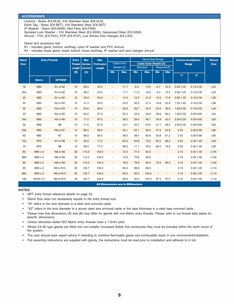
• NPT entry thread reference details on page 53.
• Gland Size does not necessarily equate to the entry thread size.
• "W" refers to the wire diameter in a steel wire armored cable.
• "XZ" refers to the wire diameter in a woven steel wire armored cable or the tape thickness in a steel tape armored cable.
• Please note that dimensions (A) and (B) may differ for glands with non-Metric entry threads. Please refer to our thread data tables forspecific dimensions.
• Unless otherwise stated ISO Metric entry threads have a 1.5mm pitch.
• Where EX-30 type glands are fitted into non-metallic Increased Safety Exe enclosures they must be included within the earth circuit ofthe system.
• The user should seek expert advice if intending to combine flammable gases and combustible dusts in one environment/installation.
• Full assembly instructions are supplied with glands, the instructions must be read prior to installation and adhered to in full.
NOTES:
Cable Outer Sheath [D]
ACCESSORIES
Locknut - Brass (EX-BLN); 316 Stainless Steel (EX-SLN)Earth Tag - Brass (EX-BET), 316 Stainless Steel (EX-SET)IP Washer - Nylon (EX-NSW); Red Fibre (EX-FSW)Serrated Lock Washer - 316 Stainless Steel (EX-SSW), Galvanised Steel (EX-GSW)Shroud - PVC (EX-PVC); PCP (EX-PCP); Low Smoke Zero Halogen (EX-LSH)
Gland and accessory kits:K1 - includes gland, locknut, earthtag, nylon IP washer and PVC shroudK4 - includes brass gland, brass locknut, brass earthtag, IP washer and zero halogen shroud
Gland Entry Threads Entry Max Max Armour Acceptance ShroudSize Thread Across Protrusion Range Size
Length Corners Length[B] [A] Min Max Min Max Min Max
Metric NPT/BSP
Gland Seal Range
Cable Inner
Sheath [C] Standard Reduced (R)
W XZ
16 M20 N1 or N2 10 26.5 54.0 - 11.7 9.0 13.5 6.7 10.3 0.90-1.25 0.15-0.35 L24
20s M20 N1 or N2 10 26.5 54.0 - 11.7 11.5 16.0 9.4 12.5 0.90-1.25 0.15-0.35 L24
20 M20 N1 or N2 10 33.0 54.0 - 14.0 15.5 21.0 12.0 17.6 0.90-1.25 0.15-0.50 L30
25 M25 N2 or N3 10 41.4 54.0 - 20.0 20.3 27.4 16.8 23.9 1.25-1.60 0.15-0.50 L38
32 M32 N3 or N4 10 50.6 60.0 - 26.3 26.7 34.0 23.2 30.5 1.60-2.00 0.15-0.55 L46
40 M40 N4 or N5 15 60.5 67.0 - 32.2 33.0 40.6 28.6 36.2 1.60-2.00 0.20-0.60 L55
50s M50 N5 or N6 15 71.5 67.0 - 38.2 39.4 46.7 34.8 42.4 2.00-2.50 0.20-0.60 L65
50 M50 N6 15 71.5 67.0 - 44.1 45.7 53.2 41.1 48.5 2.00-2.50 0.30-0.80 L65
63s M63 N6 or N7 15 88.0 69.0 - 50.1 52.1 59.5 47.5 54.8 2.50 0.30-0.80 L80
63 M63 N7 15 88.0 69.0 - 56.0 58.4 65.8 53.8 61.2 2.50 0.30-0.80 L80
75s M75 N7 or N8 15 99.0 77.0 - 62.0 64.8 72.2 60.2 68.0 2.50 0.30-1.00 L90
75 M75 N8 15 99.0 77.0 - 68.0 71.1 78.0 66.5 73.4 2.50 0.30-1.00 L90
80 M80 x 2 N8 or N9 20 115.2 104.0 - 72.0 77.0 84.0 - - 3.15 0.45-1.00 L104
80H M80 x 2 N8 or N9 20 115.2 104.0 - 72.0 79.6 90.0 - - 3.15 0.45-1.00 L104
85 M85 x 2 N8 or N9 20 115.2 104.0 - 78.0 79.6 90.0 75.0 85.4 3.15 0.45-1.00 L104
90 M90 x 2 N9 or N10 20 125.7 104.0 - 84.0 88.0 96.0 - - 3.15 0.45-1.00 L114
90H M90 x 2 N9 or N10 20 125.7 104.0 - 84.0 92.0 102.0 - - 3.15 0.45-1.00 L114
100 M100 x 2 N9 or N10 20 125.7 104.0 - 90.0 92.0 102.0 87.4 97.4 3.15 0.45-1.00 L114
All Dimensions are in Millimeters
10
ATEX/CSA Approved Glands with Elastomeric Seals
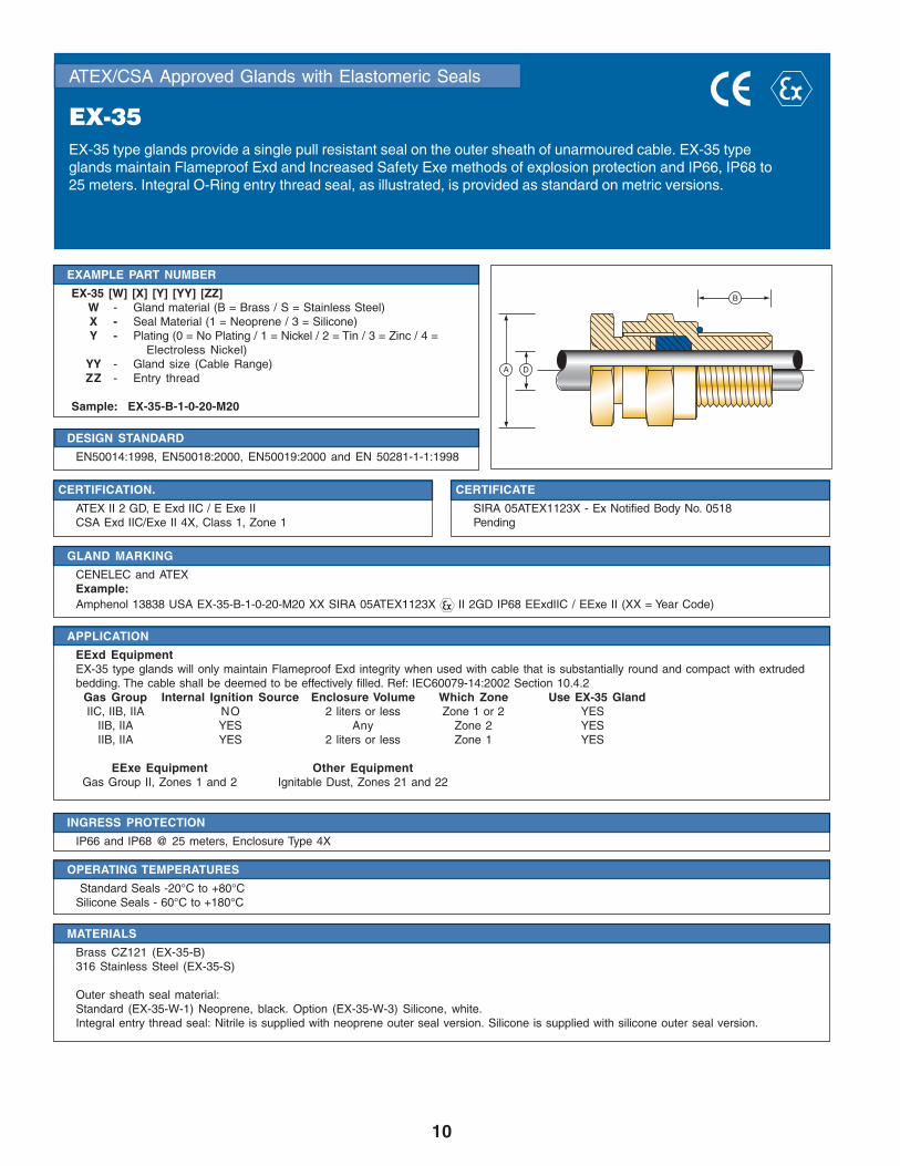
EX-35EX-35 type glands provide a single pull resistant seal on the outer sheath of unarmoured cable. EX-35 typeglands maintain Flameproof Exd and Increased Safety Exe methods of explosion protection and IP66, IP68 to25 meters. Integral O-Ring entry thread seal, as illustrated, is provided as standard on metric versions.
DESIGN STANDARD
EN50014:1998, EN50018:2000, EN50019:2000 and EN 50281-1-1:1998
EXAMPLE PART NUMBER
EX-35 [W] [X] [Y] [YY] [ZZ]W - Gland material (B = Brass / S = Stainless Steel)X - Seal Material (1 = Neoprene / 3 = Silicone)Y - Plating (0 = No Plating / 1 = Nickel / 2 = Tin / 3 = Zinc / 4 =
Electroless Nickel)YY - Gland size (Cable Range)ZZ - Entry thread
Sample: EX-35-B-1-0-20-M20
CERTIFICATION.
ATEX II 2 GD, E Exd IIC / E Exe IICSA Exd IIC/Exe II 4X, Class 1, Zone 1
CERTIFICATE
SIRA 05ATEX1123X - Ex Notified Body No. 0518Pending
APPLICATION
EExd EquipmentEX-35 type glands will only maintain Flameproof Exd integrity when used with cable that is substantially round and compact with extrudedbedding. The cable shall be deemed to be effectively filled. Ref: IEC60079-14:2002 Section 10.4.2
Gas Group Internal Ignition Source Enclosure Volume Which Zone Use EX-35 GlandIIC, IIB, IIA NO 2 liters or less Zone 1 or 2 YES
IIB, IIA YES Any Zone 2 YESIIB, IIA YES 2 liters or less Zone 1 YES
EExe Equipment Other EquipmentGas Group II, Zones 1 and 2 Ignitable Dust, Zones 21 and 22
OPERATING TEMPERATURES
Standard Seals -20°C to +80°CSilicone Seals - 60°C to +180°C
INGRESS PROTECTION
IP66 and IP68 @ 25 meters, Enclosure Type 4X
MATERIALS
Brass CZ121 (EX-35-B)316 Stainless Steel (EX-35-S)
Outer sheath seal material:Standard (EX-35-W-1) Neoprene, black. Option (EX-35-W-3) Silicone, white.Integral entry thread seal: Nitrile is supplied with neoprene outer seal version. Silicone is supplied with silicone outer seal version.
GLAND MARKING
CENELEC and ATEXExample:Amphenol 13838 USA EX-35-B-1-0-20-M20 XX SIRA 05ATEX1123X II 2GD IP68 EExdIIC / EExe II (XX = Year Code)
B
DA

11
• NPT entry thread reference details on page 53.
• Suitable only for fixed installations. The cable must be clamped near the gland to prevent pulling and twisting.
• Gland Size does not necessarily equate to the entry thread size.
• Integral entry thread seal option is not available for glands with tapered entry threads. IP washers can be supplied if required.
• Please note that dimensions (A) and (B) may differ for glands with non-Metric entry threads. Please refer to our thread data tables forspecific dimensions.
• Unless otherwise stated ISO Metric entry threads have a 1.5mm pitch.
• For Flameproof Exd applications the female thread into which the gland is to be fitted must comply with clause 5.3 of EN 50018:2000(clause 5.3 IEC 79-1) and an engagement of at least 5 full threads must be achieved for parallel threads and should be achieved fortapered threads.
• Where EX-35 type glands are fitted into non-metallic Increased Safety Exe enclosures they must be included within the earth circuitof the system.
• The user should seek expert advice if intending to combine flammable gases and combustible dusts in one environment/installation.
• Full assembly instructions are supplied with glands, the instructions must be read prior to installation and adhered to in full.
NOTES:
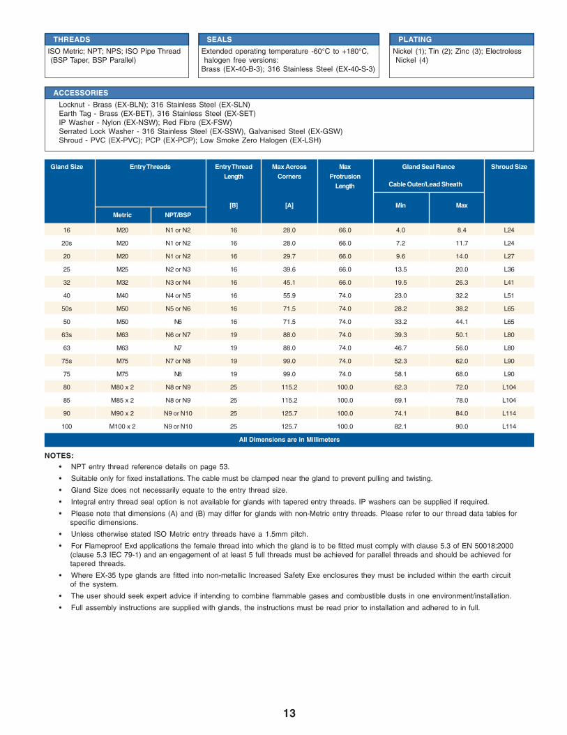
16 M20 N1 or N2 16 28.0 33.0 4.0 8.4 L24
20s M20 N1 or N2 16 28.0 33.0 7.2 11.7 L24
20 M20 N1 or N2 16 33.0 33.0 9.6 14.0 L30
25 M25 N2 or N3 16 41.4 33.0 13.5 20.0 L38
32 M32 N3 or N4 16 50.6 33.0 19.5 26.3 L46
40 M40 N4 or N5 16 60.5 37.0 23.0 32.2 L55
50s M50 N5 or N6 16 71.5 37.0 28.2 38.2 L65
50 M50 N6 16 71.5 37.0 33.2 44.1 L65
63s M63 N6 or N7 19 88.0 37.0 39.3 50.1 L80
63 M63 N7 19 88.0 37.0 46.7 56.0 L80
75s M75 N7 or N8 19 99.0 37.0 52.3 62.0 L90
75 M75 N8 19 99.0 37.0 58.1 68.0 L90
80 M80 x 2 N8 or N9 25 115.2 50.0 62.3 72.0 L104
85 M85 x 2 N8 or N9 25 115.2 50.0 69.1 78.0 L104
90 M90 x 2 N9 or N10 25 125.7 50.0 74.1 84.0 L114
100 M100 x 2 N9 or N10 25 125.7 50.0 82.1 90.0 L114
All Dimensions are in Millimeters
Gland Size Entry Threads Entry Thread Max Across Max Gland Seal Rance Shroud SizeLength Corners Protrusion
Length
[B] [A] Min MaxMetric NPT/BSP
Cable Outer/Lead Sheath
THREADS
ISO Metric; NPT; NPS; ISO PipeThread (BSP Taper, BSP Parallel)
PLATING
Nickel (1); Tin (2); Zinc (3);Electroless Nickel (4)
SEALS
Extended operating temperature -60°C to +180°C, halogen freeversions:
Brass (EX-35-B-3); 316 Stainless Steel (EX-35-S-3)
ACCESSORIES
Locknut - Brass (EX-BLN); 316 Stainless Steel (EX-SLN)Earth Tag - Brass (EX-BET), 316 Stainless Steel (EX-SET)IP Washer - Nylon (EX-NSW); Red Fibre (EX-FSW)Serrated Lock Washer - 316 Stainless Steel (EX-SSW), Galvanised Steel (EX-GSW)Shroud - PVC (EX-SPVC); PCP (EX-SPCP); Low Smoke Zero Halogen (EX-LSH)
Gland and accessory kits:K2 - includes gland, locknut, fiber IP washer and PVC shroudK3- includes gland, locknut, nylon IP washer and PCP shroud
12
ATEX/CSA Approved Glands with Elastomeric Seals
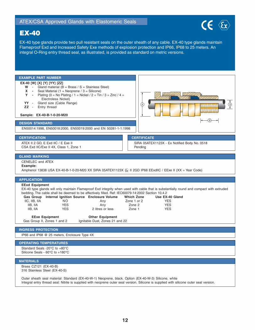
EX-40EX-40 type glands provide two pull resistant seals on the outer sheath of any cable. EX-40 type glands maintainFlameproof Exd and Increased Safety Exe methods of explosion protection and IP66, IP68 to 25 meters. Anintegral O-Ring entry thread seal, as illustrated, is provided as standard on metric versions.
DESIGN STANDARD
EN50014:1998, EN50018:2000, EN50019:2000 and EN 50281-1-1:1998
EXAMPLE PART NUMBER
EX-40 [W] [X] [Y] [YY] [ZZ]W - Gland material (B = Brass / S = Stainless Steel)X - Seal Material (1 = Neoprene / 3 = Silicone)Y - Plating (0 = No Plating / 1 = Nickel / 2 = Tin / 3 = Zinc / 4 =
Electroless Nickel)YY - Gland size (Cable Range)ZZ - Entry thread
Sample: EX-40-B-1-0-20-M20
CERTIFICATION
ATEX II 2 GD, E Exd IIC / E Exe IICSA Exd IIC/Exe II 4X, Class 1, Zone 1
CERTIFICATE
SIRA 05ATEX1123X - Ex Notified Body No. 0518Pending
APPLICATION
EExd EquipmentEX-40 type glands will only maintain Flameproof Exd integrity when used with cable that is substantially round and compact with extrudedbedding. The cable shall be deemed to be effectively filled. Ref: IEC60079-14:2002 Section 10.4.2
Gas Group Internal Ignition Source Enclosure Volume Which Zone Use EX-40 GlandIIC, IIB, IIA NO Any Zone 1 or 2 YES
IIB, IIA YES Any Zone 2 YESIIB, IIA YES 2 litres or less Zone 1 YES
EExe Equipment Other EquipmentGas Group II, Zones 1 and 2 Ignitable Dust, Zones 21 and 22
OPERATING TEMPERATURES
Standard Seals -20°C to +80°CSilicone Seals - 60°C to +180°C
INGRESS PROTECTION
IP66 and IP68 @ 25 meters, Enclosure Type 4X
MATERIALS
Brass CZ121 (EX-40-B)316 Stainless Steel (EX-40-S)
Outer sheath seal material: Standard (EX-40-W-1) Neoprene, black. Option (EX-40-W-3) Silicone, whiteIntegral entry thread seal: Nitrile is supplied with neoprene outer seal version. Silicone is supplied with silicone outer seal version.
GLAND MARKING
CENELEC and ATEXExample:Amphenol 13838 USA EX-40-B-1-0-20-M20 XX SIRA 05ATEX1123X II 2GD IP68 EExdIIC / EExe II (XX = Year Code)
B
DA
13
• NPT entry thread reference details on page 53.
• Suitable only for fixed installations. The cable must be clamped near the gland to prevent pulling and twisting.
• Gland Size does not necessarily equate to the entry thread size.
• Integral entry thread seal option is not available for glands with tapered entry threads. IP washers can be supplied if required.
• Please note that dimensions (A) and (B) may differ for glands with non-Metric entry threads. Please refer to our thread data tables forspecific dimensions.
• Unless otherwise stated ISO Metric entry threads have a 1.5mm pitch.
• For Flameproof Exd applications the female thread into which the gland is to be fitted must comply with clause 5.3 of EN 50018:2000(clause 5.3 IEC 79-1) and an engagement of at least 5 full threads must be achieved for parallel threads and should be achieved fortapered threads.
• Where EX-35 type glands are fitted into non-metallic Increased Safety Exe enclosures they must be included within the earth circuitof the system.
• The user should seek expert advice if intending to combine flammable gases and combustible dusts in one environment/installation.
• Full assembly instructions are supplied with glands, the instructions must be read prior to installation and adhered to in full.
NOTES:
Cable Outer/Lead Sheath
16 M20 N1 or N2 16 28.0 66.0 4.0 8.4 L24
20s M20 N1 or N2 16 28.0 66.0 7.2 11.7 L24
20 M20 N1 or N2 16 29.7 66.0 9.6 14.0 L27
25 M25 N2 or N3 16 39.6 66.0 13.5 20.0 L36
32 M32 N3 or N4 16 45.1 66.0 19.5 26.3 L41
40 M40 N4 or N5 16 55.9 74.0 23.0 32.2 L51
50s M50 N5 or N6 16 71.5 74.0 28.2 38.2 L65
50 M50 N6 16 71.5 74.0 33.2 44.1 L65
63s M63 N6 or N7 19 88.0 74.0 39.3 50.1 L80
63 M63 N7 19 88.0 74.0 46.7 56.0 L80
75s M75 N7 or N8 19 99.0 74.0 52.3 62.0 L90
75 M75 N8 19 99.0 74.0 58.1 68.0 L90
80 M80 x 2 N8 or N9 25 115.2 100.0 62.3 72.0 L104
85 M85 x 2 N8 or N9 25 115.2 100.0 69.1 78.0 L104
90 M90 x 2 N9 or N10 25 125.7 100.0 74.1 84.0 L114
100 M100 x 2 N9 or N10 25 125.7 100.0 82.1 90.0 L114
All Dimensions are in Millimeters
Gland Size Entry Threads Entry Thread Max Across Max Gland Seal Rance Shroud SizeLength Corners Protrusion
Length
[B] [A] Min MaxMetric NPT/BSP
THREADS
ISO Metric; NPT; NPS; ISO Pipe Thread(BSP Taper, BSP Parallel)
PLATING
Nickel (1); Tin (2); Zinc (3); ElectrolessNickel (4)
SEALS
Extended operating temperature -60°C to +180°C,halogen free versions:
Brass (EX-40-B-3); 316 Stainless Steel (EX-40-S-3)
ACCESSORIES
Locknut - Brass (EX-BLN); 316 Stainless Steel (EX-SLN)Earth Tag - Brass (EX-BET), 316 Stainless Steel (EX-SET)IP Washer - Nylon (EX-NSW); Red Fibre (EX-FSW)Serrated Lock Washer - 316 Stainless Steel (EX-SSW), Galvanised Steel (EX-GSW)Shroud - PVC (EX-PVC); PCP (EX-PCP); Low Smoke Zero Halogen (EX-LSH)
.

14
ATEX/CSA Approved Glands with Elastometric Seals
EX-45EX-45 type glands provide a seal on the outer sheath of unarmoured cable and a conduit connection thread. EX-40-M type glands provide a male thread for connection and EX-40-F type glands provide a female thread forconnection. EX-45 type glands maintain Flameproof Exd and Increased Safety Exe methods of explosionprotection and IP66, IP68 to 25 metres. An ‘O’ ring IP entry thread seal is fitted as standard.
DESIGN STANDARD
EN50014:1998, EN50018:2000, EN50019:2000 and EN 50281-1-1:1998
EXAMPLE PART NUMBER
EX-45 [A] [W] [X] [Y] [YY] [ZZ]A - M = Male Connector / F = Female ConnectorW - Gland material (B = Brass / S = Stainless Steel)X - Seal Material (1 = Neoprene / 3 = Silicone)Y - Plating (0 = No Plating / 1 = Nickel / 2 = Tin / 3 = Zinc / 4 =
Electroless Nickel)Z - Connection Thread
YY - Gland size (Cable Range)ZZ - Entry thread
Sample: EX-45-F-B-1-0-M20-20-M20
CERTIFICATION
ATEX II 2 GD, E Exd IIC / E Exe IICSA Exd IIC/Exe II 4X, Class 1, Zone 1
CERTIFICATE
SIRA 05ATEX1123X - Ex Notified Body No. 0518Pending
APPLICATION
EExd EquipmentEX-45 type glands will only maintain Flameproof Exd integrity when used with cable that is substantially round and compact with extrudedbedding. The cable shall be deemed to be effectively filled. Ref: IEC60079-14:2002 Section 10.4.2
Gas Group Internal Ignition Source Enclosure Volume Which Zone Use EX-45 GlandIIC, IIB, IIA NO Any Zone 1 or 2 YES
IIB, IIA YES Any Zone 2 YESIIB, IIA YES 2 litres or less Zone 1 YES
EExe Equipment Other EquipmentGas Group II, Zones 1 and 2 Ignitable Dust, Zones 21 and 22
OPERATING TEMPERATURES
Standard Seals -20°C to +80°CSilicone Seals - 60°C to +180°C
INGRESS PROTECTION
IP66 and IP68 @ 25 meters, Enclosure Type 4X
MATERIALS
Brass CZ121 (EX-45-A-B)316 Stainless Steel (EX-45-A-S)
Outer sheath seal material: Standard (EX-45-A-W-1) Neoprene, black. Option (EX-45-A-W-3) Silicone, whiteIntegral entry thread seal: Nitrile is supplied with neoprene outer seal version. Silicone is supplied with silicone outer seal version.
GLAND MARKING
CENELEC and ATEXExample:Amphenol 13838 USA EX-45-F-B-1-0-M20-20-M20 XX SIRA 05ATEX1123X II 2GD IP68 EExdIIC / EExe II (XX = Year Code)
B
B
DA
A D
15
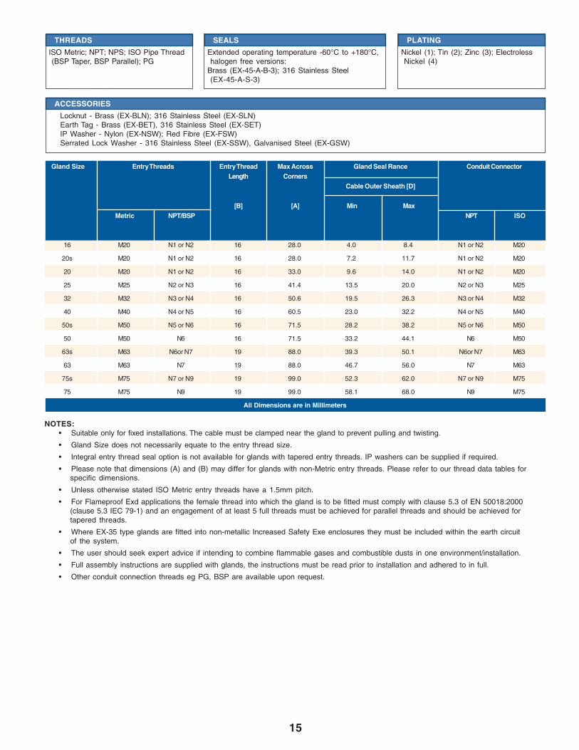
Gland Size Entry Threads Entry Thread Max Across Gland Seal Rance Conduit ConnectorLength Corners
Cable Outer Sheath [D]
[B] [A] Min MaxMetric NPT/BSP NPT ISO
• Suitable only for fixed installations. The cable must be clamped near the gland to prevent pulling and twisting.
• Gland Size does not necessarily equate to the entry thread size.
• Integral entry thread seal option is not available for glands with tapered entry threads. IP washers can be supplied if required.
• Please note that dimensions (A) and (B) may differ for glands with non-Metric entry threads. Please refer to our thread data tables forspecific dimensions.
• Unless otherwise stated ISO Metric entry threads have a 1.5mm pitch.
• For Flameproof Exd applications the female thread into which the gland is to be fitted must comply with clause 5.3 of EN 50018:2000(clause 5.3 IEC 79-1) and an engagement of at least 5 full threads must be achieved for parallel threads and should be achieved fortapered threads.
• Where EX-35 type glands are fitted into non-metallic Increased Safety Exe enclosures they must be included within the earth circuitof the system.
• The user should seek expert advice if intending to combine flammable gases and combustible dusts in one environment/installation.
• Full assembly instructions are supplied with glands, the instructions must be read prior to installation and adhered to in full.
• Other conduit connection threads eg PG, BSP are available upon request.
NOTES:
16 M20 N1 or N2 16 28.0 4.0 8.4 N1 or N2 M20
20s M20 N1 or N2 16 28.0 7.2 11.7 N1 or N2 M20
20 M20 N1 or N2 16 33.0 9.6 14.0 N1 or N2 M20
25 M25 N2 or N3 16 41.4 13.5 20.0 N2 or N3 M25
32 M32 N3 or N4 16 50.6 19.5 26.3 N3 or N4 M32
40 M40 N4 or N5 16 60.5 23.0 32.2 N4 or N5 M40
50s M50 N5 or N6 16 71.5 28.2 38.2 N5 or N6 M50
50 M50 N6 16 71.5 33.2 44.1 N6 M50
63s M63 N6or N7 19 88.0 39.3 50.1 N6or N7 M63
63 M63 N7 19 88.0 46.7 56.0 N7 M63
75s M75 N7 or N9 19 99.0 52.3 62.0 N7 or N9 M75
75 M75 N9 19 99.0 58.1 68.0 N9 M75
All Dimensions are in Millimeters
THREADS
ISO Metric; NPT; NPS; ISO Pipe Thread(BSP Taper, BSP Parallel); PG
PLATING
Nickel (1); Tin (2); Zinc (3); ElectrolessNickel (4)
SEALS
Extended operating temperature -60°C to +180°C,halogen free versions:
Brass (EX-45-A-B-3); 316 Stainless Steel(EX-45-A-S-3)
ACCESSORIES
Locknut - Brass (EX-BLN); 316 Stainless Steel (EX-SLN)Earth Tag - Brass (EX-BET), 316 Stainless Steel (EX-SET)IP Washer - Nylon (EX-NSW); Red Fibre (EX-FSW)Serrated Lock Washer - 316 Stainless Steel (EX-SSW), Galvanised Steel (EX-GSW)
16
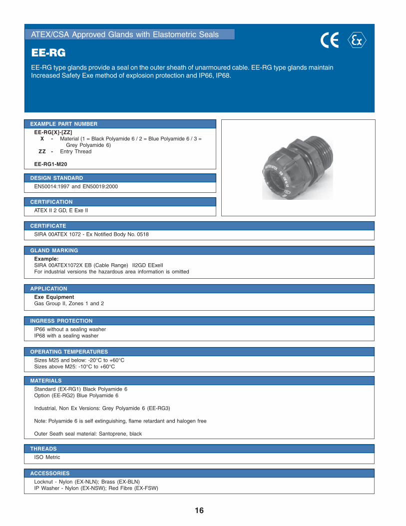
ATEX/CSA Approved Glands with Elastometric Seals
EE-RGEE-RG type glands provide a seal on the outer sheath of unarmoured cable. EE-RG type glands maintainIncreased Safety Exe method of explosion protection and IP66, IP68.
DESIGN STANDARD
EN50014:1997 and EN50019:2000
EXAMPLE PART NUMBER
EE-RG[X]-[ZZ]X - Material (1 = Black Polyamide 6 / 2 = Blue Polyamide 6 / 3 =
Grey Polyamide 6)ZZ - Entry Thread
EE-RG1-M20
CERTIFICATION
ATEX II 2 GD, E Exe II
CERTIFICATE
SIRA 00ATEX 1072 - Ex Notified Body No. 0518
APPLICATION
Exe EquipmentGas Group II, Zones 1 and 2
OPERATING TEMPERATURES
Sizes M25 and below: -20°C to +60°CSizes above M25: -10°C to +60°C
INGRESS PROTECTION
IP66 without a sealing washerIP68 with a sealing washer
MATERIALS
Standard (EX-RG1) Black Polyamide 6Option (EE-RG2) Blue Polyamide 6
Industrial, Non Ex Versions: Grey Polyamide 6 (EE-RG3)
Note: Polyamide 6 is self extinguishing, flame retardant and halogen free
Outer Seath seal material: Santoprene, black
THREADS
ISO Metric
GLAND MARKING
Example:SIRA 00ATEX1072X EB (Cable Range) II2GD EExeIIFor industrial versions the hazardous area information is omitted
ACCESSORIES
Locknut - Nylon (EX-NLN); Brass (EX-BLN)IP Washer - Nylon (EX-NSW); Red Fibre (EX-FSW)
17
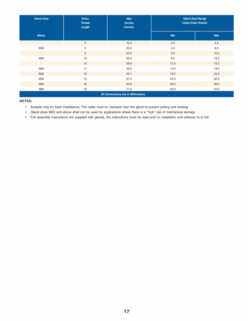
• Suitable only for fixed installations. The cable must be clamped near the gland to prevent pulling and twisting
• Gland sizes M25 and above shall not be used for applications where there is a "high" risk of mechanical damage
• Full assembly instructions are supplied with glands, the instructions must be read prior to installation and adhered to in full
NOTES:
Gland Size Entry Max Gland Seal RangeThread Across Cable Outer SheathLength Corners
Metric Min Max
- 9 16.5 3.5 6.0
M16 9 20.9 5.0 8.0
- 9 24.2 6.0 10.0
M20 10 26.4 8.0 13.5
- 10 28.6 10.0 15.0
M25 11 35.2 13.0 19.0
M32 12 45.1 18.0 25.0
M40 14 57.2 24.0 32.0
M50 16 64.9 29.0 38.0
M63 16 71.5 36.0 44.0
All Dimensions are in Millimeters

18
ATEX/CSA Approved Glands with Elastometric Seals for Flat Cable
EX-50EX-50 type glands provide pull resistant seals on the inner and outer sheath and a braid armor clamp. The armorclamp provides an electrical bond between the cable armor and the gland. EX-50 type glands maintainFlameproof Exd and Increased Safety Exe methods of explosion protection and IP66.
DESIGN STANDARD
EN 50014:1998, EN 50018:2000, EN 50019:2000 and EN 50281-1-1:1998
EXAMPLE PART NUMBER
EX-50 [W] [Y] [YY] [ZZ]W - Gland Material (B = Brass / S = Stainless Steel)Y - Plating (0 = No Plating / 1 = Nickel / 2 = Tin / 3 = Zinc / 4 =
Electroless Nickel)YY - Gland Size (Cable Range)ZZ - Entry Thread
Sample: EX-50-B-3-20S-M20
CERTIFICATION
ATEX II 2 GD, E Exd IIC / E Exe II
CERTIFICATE
SIRA 05ATEX1121X - Ex Notified Body No. 0518
APPLICATION
EExd EquipmentEX-50 type glands will only maintain Flameproof Exd integrity when used with cable that has a suitable profile and is compact with extrudedbedding. The cable shall be deemed to be effectively filled. Ref: IEC60079-14:2002 Section 10.4.2
Gas Group Internal Ignition Source Enclosure Volume Which Zone Use EX-50 GlandIIC, IIB, IIA NO 2 litres or less Zone 1 or 2 YES
IIB, IIA YES Any Zone 2 YESIIB, IIA YES 2 litres or less Zone 1 YES
EExe Equipment Other EquipmentGas Group II, Zones 1 and 2 Ignitable Dust, Zones 21 and 22
MATERIALS
Brass CZ121 (EX-50-B)316 Stainless Steel (EX-50-S)
INGRESS PROTECTION
IP66
OPERATING TEMPERATURES
Standard Seals - 60°C to +180°C
THREADS
ISO Metric; NPT; NPS; ISO Pipe Thread (BSP Taper, BSP Parallel)
PLATING
Nickel (1); Tin (2); Zinc (3); Electroless Nickel (4)
GLAND MARKING
CENELEC and ATEXExample:Amphenol 13838 USA EX-50-B-3-20S-M20 XX SIRA 05ATEX1121X II 2GD IP66 EExdIIC / EExe II (XX = Year Code)
A D C
B

19
Cable Inner Sheath [C]
Gland Seal Range
Cable Outer Sheath [D]
Width Thickness
• Gland Size does not necessarily equate to the entry thread size.
• "X" refers to the wire diameter in a braided cable.
• Please note that dimensions (A) and (B) may differ for glands with non-Metric entry threads. Please refer to our thread data tables forspecific dimensions.
• Unless otherwise stated ISO Metric entry threads have a 1.5mm pitch.
• For Flameproof Exd applications the female thread into which the gland is to be fitted must comply with clause 5.3 of EN 50018:2000(clause 5.3 IEC 79-1) and an engagement of at least 5 full threads must be achieved for parallel threads and should be achieved fortapered threads.
• Where EX-50 type glands are fitted into non-metallic Increased Safety Exe enclosures they must be included within the earth circuit ofthe system.
• The user should seek expert advice if intending to combine flammable gases and combustible dusts in one environment/installation.
• Full assembly instructions are supplied with glands, the instructions must be read prior to installation and adhered to in full.
NOTES:
Width Thickness
Gland Entry Threads Entry Max Across Max ArmorSize Thread Corners Protrusion Acceptance
Length Length Range
Metric [B] [A] Min Max Min Max Min Max Min Max [X]
20s M20 16 26.5 58.0 6.3 11.7 4.0 7.0 7.9 11.7 4.5 7.0 0.1-0.3
20R M20 16 33.0 58.0 8.1 13.5 5.8 6.2 7.5 16.1 3.0 8.3 0.1-0.45
20 M20 16 33.0 58.0 10.3 13.5 5.6 9.0 11.0 13.5 4.5 9.0 0.1-0.3
All Dimensions are in Millimeters
ACCESSORIES
Locknut - Brass (EX-BLN); 316 Stainless Steel (EX-SLN)Earth Tag - Brass (EX-BET), 316 Stainless Steel (EX-SET)IP Washer - Nylon (EX-NSW); Red Fibre (EX-FSW)Serrated Lock Washer - 316 Stainless Steel (EX-SSW), Galvanised Steel (EX-GSW)
20
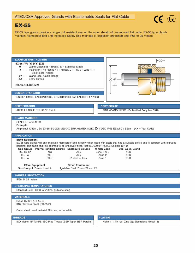
ATEX/CSA Approved Glands with Elastometric Seals for Flat Cable
EX-55EX-55 type glands provide a single pull resistant seal on the outer sheath of unarmoured flat cable. EX-55 type glandsmaintain Flameproof Exd and Increased Safety Exe methods of explosion protection and IP68 to 25 meters.
DESIGN STANDARD
EN50014:1998, EN50018:2000, EN50019:2000 and EN50281-1-1:1998
EXAMPLE PART NUMBER
EX-55 [W] [Y] [YY] [ZZ]W - Gland Material(B = Brass / S = Stainless Steel)Y - Plating (0 = No Plating / 1 = Nickel / 2 = Tin / 3 = Zinc / 4 =
Electroless Nickel)YY - Gland Size (Cable Range)ZZ - Entry Thread
EX-55-B-3-20S-M20
CERTIFICATION
ATEX II 2 GD, E Exd IIC / E Exe II
CERTIFICATE
SIRA 05ATEX1121X - Ex Notified Body No. 0518
APPLICATION
EExd EquipmentEX-55 type glands will only maintain Flameproof Exd integrity when used with cable that has a suitable profile and is compact with extrudedbedding. The cable shall be deemed to be effectively filled. Ref: IEC60079-14:2002 Section 10.4.2
Gas Group Internal Ignition Source Enclosure Volume Which Zone Use EX-55 GlandIIC, IIB, IIA NO Any Zone 1 or 2 YES
IIB, IIA YES Any Zone 2 YESIIB, IIA YES 2 litres or less Zone 1 YES
EExe Equipment Other EquipmentGas Group II, Zones 1 and 2 Ignitable Dust, Zones 21 and 22
OPERATING TEMPERATURES
Standard Seal - 60°C to +180°C (Silicone seal)
INGRESS PROTECTION
IP68 @ 25 meters
PLATING
Nickel (1); Tin (2); Zinc (3); Electroless Nickel (4)
MATERIALS
Brass CZ121 (EX-55-B)316 Stainless Steel (EX-55-S)
Outer sheath seal material: Silicone, red or white
THREADS
ISO Metric; NPT; NPS; ISO Pipe Thread (BSP Taper, BSP Parallel)
GLAND MARKING
CENELEC and ATEXExample:Amphenol 13838 USA EX-55-B-3-20S-M20 XX SIRA 05ATEX1121X II 2GD IP68 EExdIIC / EExe II (XX = Year Code)
B
DA

21
• Suitable only for fixed installations. The cable must be clamped near the gland to prevent pulling and twisting.
• Gland Size does not necessarily equate to the entry thread size.
• Integral entry thread seal option is not available for glands with tapered entry threads. IP washers can be supplied if required.
• Please note that dimensions (A) and (B) may differ for glands with non-Metric entry threads. Please refer to our thread data tables forspecific dimensions.
• Unless otherwise stated ISO Metric entry threads have a 1.5mm pitch.
• For Flameproof Exd applications the female thread into which the gland is to be fitted must comply with clause 5.3 of EN 50018:2000(clause 5.3 IEC 79-1) and an engagement of at least 5 full threads must be achieved for parallel threads and should be achieved fortapered threads.
• Where EX-55 type glands are fitted into non-metallic Increased Safety Exe enclosures they must be included within the earth circuit ofthe system.
• The user should seek expert advice if intending to combine flammable gases and combustible dusts in one environment/installation.
• Full assembly instructions are supplied with glands, the instructions must be read prior to installation and adhered to in full.
NOTES:
Gland Entry Threads Entry Max Gland Seal RangeSize Thread Across Cable Outer Sheath [D]
Length Corners Width Thickness
Metric [B] [A] Min Max Min Max
ACCESSORIES
Locknut - Brass (EX-BLN); 316 Stainless Steel (EX-SLN)Earth Tag - Brass (EX-BET), 316 Stainless Steel (EX-SET)IP Washer - Nylon (EX-NSW); Red Fibre (EX-FSW)Serrated Lock Washer - 316 Stainless Steel (EX-SSW), Galvanised Steel (EX-GSW)
20s M20 16 26.5 6.3 11.7 4.0 7.0
20R M20 16 33.0 8.1 13.5 5.8 6.2
20 M20 16 33.0 10.3 13.5 5.6 9.0
All Dimensions are in Millimeters

22
ATEX / CSA Approved Compound Filled Barrier Glands
EX-60EX-60 type glands provide a Flameproof EExd compound filled barrier, a seal on the outer sheath, a universalarmor clamp for armored, screened or braided cable and an entry thread seal. The armor clamp provides anelectrical bond between the cable armor, screen or braid and the gland. EX-60 type glands maintain EExdFlameproof method of explosion protection; IP66, 68 to 100 meters and is deluge resistant.
DESIGN STANDARD
EN50014:1998, EN50018:2000, EN50019:2000 and EN50281-1-1:1998IEC 60079-0 (2000-06), IEC 60079-1 (2001-02)
EXAMPLE PART NUMBER
EX-60 [W] [Y] [R] [YY] [ZZ]W - Gland Material (B = Brass / S = Stainless Steel)Y - Plating (0 = No Plating / 1 = Nickel / 2 = Tin / 3 = Zinc / 4 =
Electroless Nickel)R - Reduced bore option
YY - Gland Size (Cable Range)ZZ - Entry Thread
EX-60-B-1-R-20S-M20
CERTIFICATION
ATEX II 2 GD, E Exd IIC / E Exe IICSA Exd I & IIC 4X, Class 1, Zone 1
CERTIFICATE
SIRA 05SIRA1124X - Ex Notified Body No. 0518Pending
APPLICATION
EExd EquipmentEX-60 type Glands will maintain Flameproof Exd integrity when used with any armored or unarmored cable types. Ref: IEC60079-14:2002Section 10.4.2
Gas Group Internal Ignition Source Enclosure Volume Which Zone Use EX-60 GlandI, IIC, IIB, IIA YES Any Zone 1 or 2 YES
Other EquipmentMining Equipment Group I, M2Ignitable Dust, Zones 21 and 22
CURING TIME
@ 21°CConductor termination can be effected after 1 hourThe equipment can be energised after 4 hoursThe compound chamber can be inspected after 4 hours
INGRESS PROTECTION
IP66 & IP68 @ 100 MetersMeets the requirements of DTS01 1991
OPERATING TEMPERATURES
- 60°C to +85°C
GLAND MARKING
CENELEC and ATEXExample:Amphenol 13838 USA EX-60-B-1-R-20S-M20 XX SIRA 05ATEX1124X I M2 II 2GD EExd I & IIC IP68 (XX = Year Code)
DA
B
C
23
Gland Entry Threads Entry Max Max Armor ShroudSize Thread Across Protrusion Acceptance Size
Length Corners Length Standard Reduced (R) Range
[B] [A] Max Max Max Min Max Min MaxNo. of Over Inner
Metric NPT/BSP
GlandSeal RangeCable Inner Cable Outer Sheath [D]
Sheath / Cores [C]
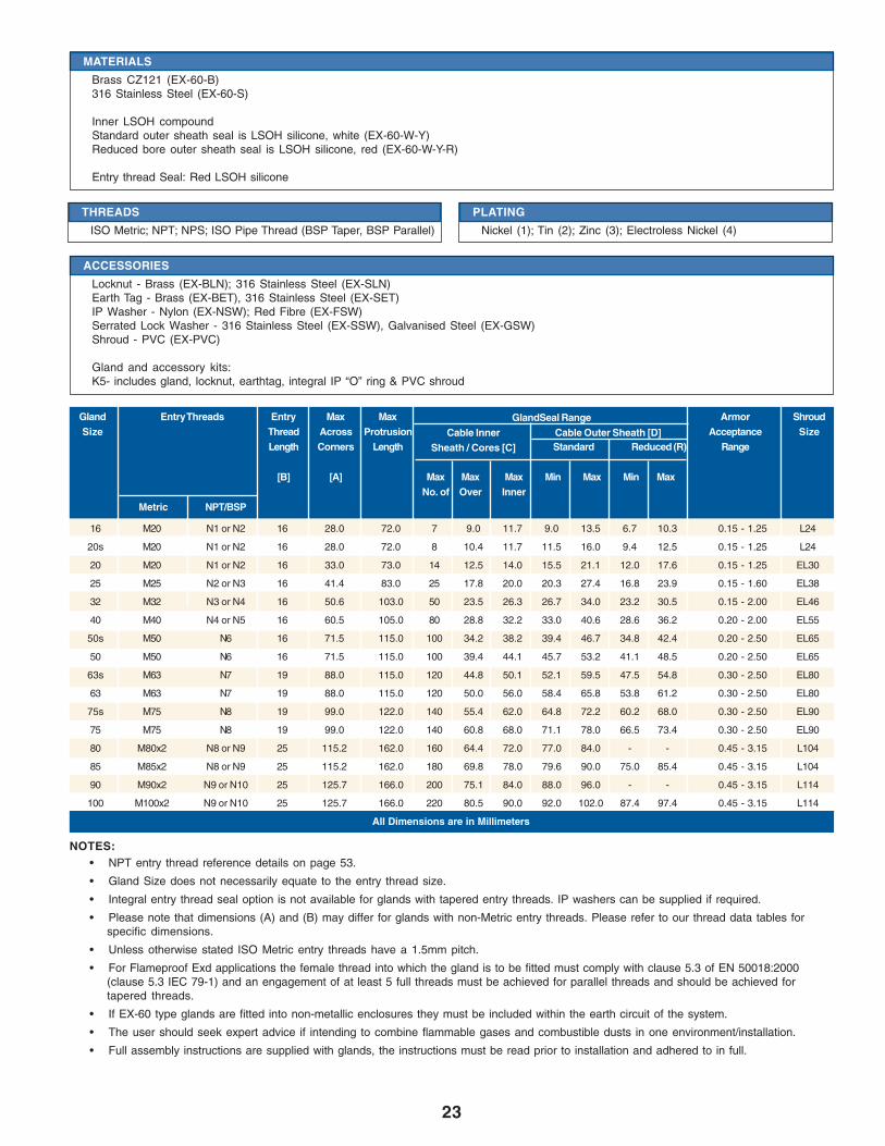
16 M20 N1 or N2 16 28.0 72.0 7 9.0 11.7 9.0 13.5 6.7 10.3 0.15 - 1.25 L24
20s M20 N1 or N2 16 28.0 72.0 8 10.4 11.7 11.5 16.0 9.4 12.5 0.15 - 1.25 L24
20 M20 N1 or N2 16 33.0 73.0 14 12.5 14.0 15.5 21.1 12.0 17.6 0.15 - 1.25 EL30
25 M25 N2 or N3 16 41.4 83.0 25 17.8 20.0 20.3 27.4 16.8 23.9 0.15 - 1.60 EL38
32 M32 N3 or N4 16 50.6 103.0 50 23.5 26.3 26.7 34.0 23.2 30.5 0.15 - 2.00 EL46
40 M40 N4 or N5 16 60.5 105.0 80 28.8 32.2 33.0 40.6 28.6 36.2 0.20 - 2.00 EL55
50s M50 N6 16 71.5 115.0 100 34.2 38.2 39.4 46.7 34.8 42.4 0.20 - 2.50 EL65
50 M50 N6 16 71.5 115.0 100 39.4 44.1 45.7 53.2 41.1 48.5 0.20 - 2.50 EL65
63s M63 N7 19 88.0 115.0 120 44.8 50.1 52.1 59.5 47.5 54.8 0.30 - 2.50 EL80
63 M63 N7 19 88.0 115.0 120 50.0 56.0 58.4 65.8 53.8 61.2 0.30 - 2.50 EL80
75s M75 N8 19 99.0 122.0 140 55.4 62.0 64.8 72.2 60.2 68.0 0.30 - 2.50 EL90
75 M75 N8 19 99.0 122.0 140 60.8 68.0 71.1 78.0 66.5 73.4 0.30 - 2.50 EL90
80 M80x2 N8 or N9 25 115.2 162.0 160 64.4 72.0 77.0 84.0 - - 0.45 - 3.15 L104
85 M85x2 N8 or N9 25 115.2 162.0 180 69.8 78.0 79.6 90.0 75.0 85.4 0.45 - 3.15 L104
90 M90x2 N9 or N10 25 125.7 166.0 200 75.1 84.0 88.0 96.0 - - 0.45 - 3.15 L114
100 M100x2 N9 or N10 25 125.7 166.0 220 80.5 90.0 92.0 102.0 87.4 97.4 0.45 - 3.15 L114
All Dimensions are in Millimeters
• NPT entry thread reference details on page 53.
• Gland Size does not necessarily equate to the entry thread size.
• Integral entry thread seal option is not available for glands with tapered entry threads. IP washers can be supplied if required.
• Please note that dimensions (A) and (B) may differ for glands with non-Metric entry threads. Please refer to our thread data tables forspecific dimensions.
• Unless otherwise stated ISO Metric entry threads have a 1.5mm pitch.
• For Flameproof Exd applications the female thread into which the gland is to be fitted must comply with clause 5.3 of EN 50018:2000(clause 5.3 IEC 79-1) and an engagement of at least 5 full threads must be achieved for parallel threads and should be achieved fortapered threads.
• If EX-60 type glands are fitted into non-metallic enclosures they must be included within the earth circuit of the system.
• The user should seek expert advice if intending to combine flammable gases and combustible dusts in one environment/installation.
• Full assembly instructions are supplied with glands, the instructions must be read prior to installation and adhered to in full.
NOTES:
THREADS
ISO Metric; NPT; NPS; ISO Pipe Thread (BSP Taper, BSP Parallel)
PLATING
Nickel (1); Tin (2); Zinc (3); Electroless Nickel (4)
MATERIALS
Brass CZ121 (EX-60-B)316 Stainless Steel (EX-60-S)
Inner LSOH compoundStandard outer sheath seal is LSOH silicone, white (EX-60-W-Y)Reduced bore outer sheath seal is LSOH silicone, red (EX-60-W-Y-R)
Entry thread Seal: Red LSOH silicone
ACCESSORIES
Locknut - Brass (EX-BLN); 316 Stainless Steel (EX-SLN)Earth Tag - Brass (EX-BET), 316 Stainless Steel (EX-SET)IP Washer - Nylon (EX-NSW); Red Fibre (EX-FSW)Serrated Lock Washer - 316 Stainless Steel (EX-SSW), Galvanised Steel (EX-GSW)Shroud - PVC (EX-PVC)
Gland and accessory kits:K5- includes gland, locknut, earthtag, integral IP “O” ring & PVC shroud
24
ATEX / CSA Approved Compound Filled Barrier Glands
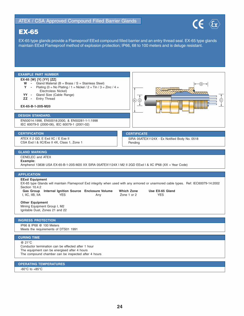
EX-65EX-65 type glands provide a Flameproof EExd compound filled barrier and an entry thread seal. EX-65 type glandsmaintain EExd Flameproof method of explosion protection; IP66, 68 to 100 meters and is deluge resistant.
DESIGN STANDARD.
EN50014:1998, EN50018:2000, & EN50281-1-1:1998IEC 60079-0 (2000-06), IEC 60079-1 (2001-02)
EXAMPLE PART NUMBER
EX-65 [W] [Y] [YY] [ZZ]W - Gland Material (B = Brass / S = Stainless Steel)Y - Plating (0 = No Plating / 1 = Nickel / 2 = Tin / 3 = Zinc / 4 =
Electroless Nickel)YY - Gland Size (Cable Range)ZZ - Entry Thread
EX-65-B-1-20S-M20
CERTIFICATION
ATEX II 2 GD, E Exd IIC / E Exe IICSA Exd I & IIC/Exe II 4X, Class 1, Zone 1
CERTIFICATE
SIRA 05ATEX1124X - Ex Notified Body No. 0518Pending
APPLICATION
EExd EquipmentEX-65 type Glands will maintain Flameproof Exd integrity when used with any armored or unarmored cable types. Ref: IEC60079-14:2002Section 10.4.2
Gas Group Internal Ignition Source Enclosure Volume Which Zone Use EX-65 GlandI, IIC, IIB, IIA YES Any Zone 1 or 2 YES
Other EquipmentMining Equipment Group I, M2Ignitable Dust, Zones 21 and 22
CURING TIME
@ 21°CConductor termination can be effected after 1 hourThe equipment can be energised after 4 hoursThe compound chamber can be inspected after 4 hours
INGRESS PROTECTION
IP66 & IP68 @ 100 MetersMeets the requirements of DTS01 1991
OPERATING TEMPERATURES
-60°C to +85°C
GLAND MARKING
CENELEC and ATEXExample:Amphenol 13838 USA EX-65-B-1-20S-M20 XX SIRA 05ATEX1124X I M2 II 2GD EExd I & IIC IP68 (XX = Year Code)
A D
B
C
25
• NPT entry thread reference details on page 53.
• Gland Size does not necessarily equate to the entry thread size.
• Integral entry thread seal option is not available for glands with tapered entry threads. IP washers can be supplied if required.
• Please note that dimensions (A) and (B) may differ for glands with non-Metric entry threads. Please refer to our thread data tables forspecific dimensions.
• Unless otherwise stated ISO Metric entry threads have a 1.5mm pitch.
• For Flameproof Exd applications the female thread into which the gland is to be fitted must comply with clause 5.3 of EN 50018:2000(clause 5.3 IEC 79-1) and an engagement of at least 5 full threads must be achieved for parallel threads and should be achieved fortapered threads.
• If EX-65 type glands are fitted into non-metallic enclosures they must be included within the earth circuit of the system.
• The user should seek expert advice if intending to combine flammable gases and combustible dusts in one environment/installation.
• Full assembly instructions are supplied with glands, the instructions must be read prior to installation and adhered to in full.
NOTES:
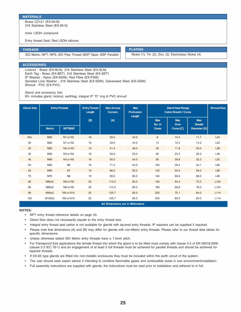
Gland Size Entry Threads Entry Thread Max Across Max Gland Seal Range Shroud SizeLength Corners Protrusion Cable Sheath / Cores
Length[B] [A] Max Max Max
No. of Over SheathMetric NPT/BSP Cores Cores [C] Diameter [D]
20s M20 N1 or N2 16 28.0 42.0 8 10.4 11.7 L24
20 M20 N1 or N2 16 33.0 44.0 14 12.5 14.0 L20
25 M25 N2 or N3 16 41.4 48.0 25 17.8 20.0 L38
32 M32 N3 or N4 16 50.6 53.0 50 23.5 26.3 L46
40 M40 N4 or N5 16 60.5 54.0 80 28.8 32.2 L55
50 M50 N6 16 71.5 54.0 100 39.4 44.1 L65
63 M63 N7 19 88.0 55.0 120 50.0 56.0 L80
75 M75 N8 19 99.0 60.0 140 60.8 68.0 L90
80 M80x2 N8 or N9 25 115.2 80.0 160 64.4 72.0 L104
85 M85x2 N8 or N9 25 115.2 80.0 180 69.8 78.0 L104
90 M90x2 N9 or N10 25 125.7 85.0 200 75.1 84.0 L114
100 M100x2 N9 or N10 25 125.7 85.0 220 80.5 90.0 L114
All Dimensions are in Millimeters
THREADS
ISO Metric; NPT; NPS; ISO Pipe Thread (BSP Taper, BSP Parallel)
MATERIALS
Brass CZ121 (EX-65-B)316 Stainless Steel (EX-65-S)
Inner LSOH compound
Entry thread Seal: Red LSOH silicone
PLATING
Nickel (1); Tin (2); Zinc (3); Electroless Nickel (4)
ACCESSORIES
Locknut - Brass (EX-BLN); 316 Stainless Steel (EX-SLN)Earth Tag - Brass (EX-BET), 316 Stainless Steel (EX-SET)IP Washer - Nylon (EX-NSW); Red Fibre (EX-FSW)Serrated Lock Washer - 316 Stainless Steel (EX-SSW), Galvanised Steel (EX-GSW)Shroud - PVC (EX-PVC)
Gland and accessory kits:K5- includes gland, locknut, earthtag, integral IP “O” ring & PVC shroud
26
ATEX / CSA Approved Compound Filled Barrier Glands
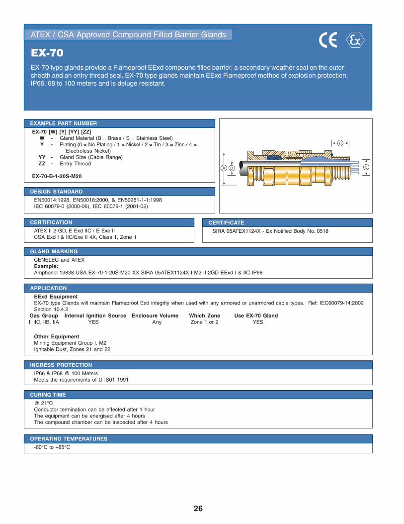
EX-70EX-70 type glands provide a Flameproof EExd compound filled barrier, a secondary weather seal on the outersheath and an entry thread seal. EX-70 type glands maintain EExd Flameproof method of explosion protection;IP66, 68 to 100 meters and is deluge resistant.
DESIGN STANDARD
EN50014:1998, EN50018:2000, & EN50281-1-1:1998IEC 60079-0 (2000-06), IEC 60079-1 (2001-02)
EXAMPLE PART NUMBER
EX-70 [W] [Y] [YY] [ZZ]W - Gland Material (B = Brass / S = Stainless Steel)Y - Plating (0 = No Plating / 1 = Nickel / 2 = Tin / 3 = Zinc / 4 =
Electroless Nickel)YY - Gland Size (Cable Range)ZZ - Entry Thread
EX-70-B-1-20S-M20
CERTIFICATION
ATEX II 2 GD, E Exd IIC / E Exe IICSA Exd I & IIC/Exe II 4X, Class 1, Zone 1
CERTIFICATE
SIRA 05ATEX1124X - Ex Notified Body No. 0518
APPLICATION
EExd EquipmentEX-70 type Glands will maintain Flameproof Exd integrity when used with any armored or unarmored cable types. Ref: IEC60079-14:2002Section 10.4.2
Gas Group Internal Ignition Source Enclosure Volume Which Zone Use EX-70 GlandI, IIC, IIB, IIA YES Any Zone 1 or 2 YES
Other EquipmentMining Equipment Group I, M2Ignitable Dust, Zones 21 and 22
CURING TIME
@ 21°CConductor termination can be effected after 1 hourThe equipment can be energised after 4 hoursThe compound chamber can be inspected after 4 hours
INGRESS PROTECTION
IP66 & IP68 @ 100 MetersMeets the requirements of DTS01 1991
OPERATING TEMPERATURES
-60°C to +85°C
GLAND MARKING
CENELEC and ATEXExample:Amphenol 13838 USA EX-70-1-20S-M20 XX SIRA 05ATEX1124X I M2 II 2GD EExd I & IIC IP68
DA
B
C
27
• NPT entry thread reference details on page 53.
• Gland Size does not necessarily equate to the entry thread size.
• Integral entry thread seal option is not available for glands with tapered entry threads. IP washers can be supplied if required.
• Please note that dimensions (A) and (B) may differ for glands with non-Metric entry threads. Please refer to our thread data tables forspecific dimensions.
• Unless otherwise stated ISO Metric entry threads have a 1.5mm pitch.
• For Flameproof Exd applications the female thread into which the gland is to be fitted must comply with clause 5.3 of EN 50018:2000(clause 5.3 IEC 79-1) and an engagement of at least 5 full threads must be achieved for parallel threads and should be achieved fortapered threads.
• If EX-70 type glands are fitted into non-metallic enclosures they must be included within the earth circuit of the system.
• The user should seek expert advice if intending to combine flammable gases and combustible dusts in one environment/installation.
• Full assembly instructions are supplied with glands, the instructions must be read prior to installation and adhered to in full.
NOTES:
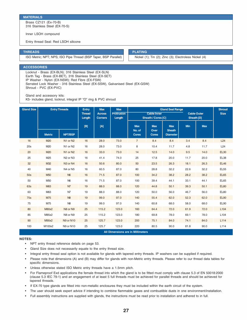
Gland Size Entry Threads Entry Max Max Gland Seal Range ShroudThread Across Protrusion Cable Inner Cable Outer SizeLength Corners Length Sheath / Cores [C] Sheath [D]
[B] [A] Max Max Max Min MaxNo. of Over Sheath
Metric NPT/BSP Cores Cores Diameter
16 M20 N1 or N2 16 28.0 73.0 7 8.4 8.4 3.4 8.4 L24
20s M20 N1 or N2 16 28.0 73.0 8 10.4 11.7 4.8 11.7 L24
20 M20 N1 or N2 16 33.0 73.0 14 12.5 14.0 9.5 14.0 EL30
25 M25 N2 or N3 16 41.4 74.0 25 17.8 20.0 11.7 20.0 EL38
32 M32 N3 or N4 16 50.6 80.0 50 23.5 26.3 18.1 26.3 EL46
40 M40 N4 or N5 16 60.5 87.0 80 28.8 32.2 22.6 32.2 EL55
50s M50 N6 16 71.5 87.0 100 34.2 38.2 28.2 38.2 EL65
50 M50 N6 16 71.5 87.0 100 39.4 44.1 33.1 44.1 EL65
63s M63 N7 19 88.0 88.0 120 44.8 50.1 39.3 50.1 EL80
63 M63 N7 19 88.0 88.0 120 50.0 56.0 46.7 56.0 EL80
75s M75 N8 19 99.0 97.0 140 55.4 62.0 52.3 62.0 EL90
75 M75 N8 19 99.0 97.0 140 60.8 68.0 58.0 68.0 EL90
80 M80x2 N8 or N9 25 115.2 123.0 160 64.4 72.0 61.9 72.0 L104
85 M85x2 N8 or N9 25 115.2 123.0 180 69.8 78.0 69.1 78.0 L104
90 M90x2 N9 or N10 25 125.7 123.0 200 75.1 84.0 74.1 84.0 L114
100 M100x2 N9 or N10 25 125.7 123.0 220 80.5 90.0 81.8 90.0 L114
All Dimensions are in Millimeters
THREADS
ISO Metric; NPT; NPS; ISO Pipe Thread (BSP Taper, BSP Parallel)
PLATING
Nickel (1); Tin (2); Zinc (3); Electroless Nickel (4)
MATERIALS
Brass CZ121 (Ex-70-B)316 Stainless Steel (EX-70-S)
Inner LSOH compound
Entry thread Seal: Red LSOH silicone
ACCESSORIES
Locknut - Brass (EX-BLN); 316 Stainless Steel (EX-SLN)Earth Tag - Brass (EX-BET), 316 Stainless Steel (EX-SET)IP Washer - Nylon (EX-NSW); Red Fibre (EX-FSW)Serrated Lock Washer - 316 Stainless Steel (EX-SSW), Galvanised Steel (EX-GSW)Shroud - PVC (EX-PVC)
Gland and accessory kits:K5- includes gland, locknut, integral IP “O” ring & PVC shroud

28
ATEX / CSA Approved Compound Filled Barrier Glands
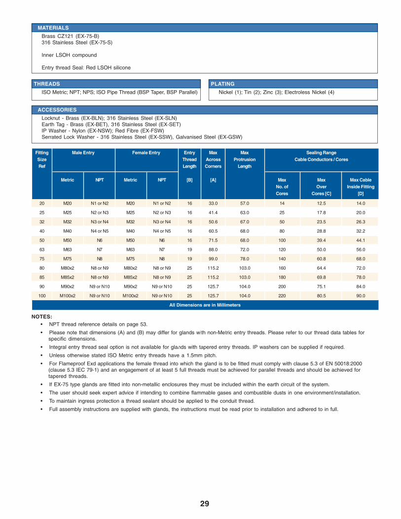
EX-75EX-75 type glands provide a Flameproof EExd compound filled barrier seal on the cables individual conductorswithin a conduit. It also provides an entry thread seal. EX-75 type glands maintain EExd Flameproof method ofexplosion protection; IP66, 68 to 100 meters and is deluge resistant.
DESIGN STANDARD
EN50014:1998, EN50018:2000, & EN50281-1-1:1998IEC 60079-0 (2000-06), IEC 60079-1 (2001-02)
EXAMPLE PART NUMBER
EX-75 [W] [Y] [YY] [ZZ1] [ZZ2]W - Gland Material (B = Brass / S = Stainless Steel)Y - Plating (0 = No Plating / 1 = Nickel / 2 = Tin / 3 = Zinc / 4 =
Electroless Nickel)YY - Gland Size (Cable Range)
ZZ1 - Male ThreadZZ2 - Female Entry Thread
EX-75-B-1-20S-M20
CERTIFICATION
ATEX II 2 GD, E Exd IIC / E Exe IICSA Exd I & IIC/Exe II 4X, Class 1, Zone 1
CERTIFICATE
SIRA 03ATEX1479X - Ex Notified Body No. 0518
APPLICATION
EExd EquipmentEX-75 type Glands will maintain Flameproof Exd integrity when used with any armored or unarmored cable types. Ref: IEC60079-14:2002Section 10.4.2
Gas Group Internal Ignition Source Enclosure Volume Which Zone Use EX-75 GlandI, IIC, IIB, IIA YES Any Zone 1 or 2 YES
Other EquipmentMining Equipment Group I, M2Ignitable Dust, Zones 21 and 22
CURING TIME
@ 21°CConductor termination can be effected after 1 hourThe equipment can be energised after 4 hoursThe compound chamger can be inspected after 4 hours
INGRESS PROTECTION
IP66 & IP68 @ 100 MetersMeets the requirements of DTS01 1991
OPERATING TEMPERATURES
-60°C to +85°C
GLAND MARKING
CENELEC and ATEXExample:Amphenol 13838 USA EX-75-B-1-20S-M20 XX SIRA05ATEX1120X I M2 II 2GD EExd I & IIC IP68
MATING CONDUIT ORCABLE GLAND
A D
B
C
29
• NPT thread reference details on page 53.
• Please note that dimensions (A) and (B) may differ for glands with non-Metric entry threads. Please refer to our thread data tables forspecific dimensions.
• Integral entry thread seal option is not available for glands with tapered entry threads. IP washers can be supplied if required.
• Unless otherwise stated ISO Metric entry threads have a 1.5mm pitch.
• For Flameproof Exd applications the female thread into which the gland is to be fitted must comply with clause 5.3 of EN 50018:2000(clause 5.3 IEC 79-1) and an engagement of at least 5 full threads must be achieved for parallel threads and should be achieved fortapered threads.
• If EX-75 type glands are fitted into non-metallic enclosures they must be included within the earth circuit of the system.
• The user should seek expert advice if intending to combine flammable gases and combustible dusts in one environment/installation.
• To maintain ingress protection a thread sealant should be applied to the conduit thread.
• Full assembly instructions are supplied with glands, the instructions must be read prior to installation and adhered to in full.
NOTES:
20 M20 N1 or N2 M20 N1 or N2 16 33.0 57.0 14 12.5 14.0
25 M25 N2 or N3 M25 N2 or N3 16 41.4 63.0 25 17.8 20.0
32 M32 N3 or N4 M32 N3 or N4 16 50.6 67.0 50 23.5 26.3
40 M40 N4 or N5 M40 N4 or N5 16 60.5 68.0 80 28.8 32.2
50 M50 N6 M50 N6 16 71.5 68.0 100 39.4 44.1
63 M63 N7 M63 N7 19 88.0 72.0 120 50.0 56.0
75 M75 N8 M75 N8 19 99.0 78.0 140 60.8 68.0
80 M80x2 N8 or N9 M80x2 N8 or N9 25 115.2 103.0 160 64.4 72.0
85 M85x2 N8 or N9 M85x2 N8 or N9 25 115.2 103.0 180 69.8 78.0
90 M90x2 N9 or N10 M90x2 N9 or N10 25 125.7 104.0 200 75.1 84.0
100 M100x2 N9 or N10 M100x2 N9 or N10 25 125.7 104.0 220 80.5 90.0
All Dimensions are in Millimeters
Fitting Male Entry Female Entry Entry Max Max Sealing RangeSize Thread Across Protrusion Cable Conductors / CoresRef Length Corners Length
Metric NPT Metric NPT [B] [A] Max Max Max CableNo. of Over Inside FittingCores Cores [C] [D]
THREADS
ISO Metric; NPT; NPS; ISO Pipe Thread (BSP Taper, BSP Parallel)
PLATING
Nickel (1); Tin (2); Zinc (3); Electroless Nickel (4)
ACCESSORIES
Locknut - Brass (EX-BLN); 316 Stainless Steel (EX-SLN)Earth Tag - Brass (EX-BET), 316 Stainless Steel (EX-SET)IP Washer - Nylon (EX-NSW); Red Fibre (EX-FSW)Serrated Lock Washer - 316 Stainless Steel (EX-SSW), Galvanised Steel (EX-GSW)
MATERIALS
Brass CZ121 (EX-75-B)316 Stainless Steel (EX-75-S)
Inner LSOH compound
Entry thread Seal: Red LSOH silicone

30
Non-Hazardous Industrial Glands
CGACGA type glands provide an integral armor clamp for armored cable. The integral armor clamp provides anelectrical bond between the cable armor and the gland. CGA type glands maintain IP30.
DESIGN STANDARD
BS 6121:1989
EXAMPLE PART NUMBER
CG[X] [W] [Y] [YY] [ZZ]X - Clamp Type (See Clamps)W - Gland Material ( B = Brass / S = Stainless Steel)Y - Plating (0 = No Plating / 1 = Nickel / 2 = Tin / 3 = Zinc / 4 =
Electroless Nickel)YY - Gland Size (Cable Range)ZZ - Entry Thread
Sample: CGA-B-3-20S-M20
GLAND MARKING
Example:BS6121 Part 1 CGA-B-3-20S-M20 Amphenol
INGRESS PROTECTION
IP30
MATERIALS
Brass CZ121 (CGA-B)
THREADS
ISO Metric only
VARIATIONS
All variants of the CGA type gland feature a separate armor clamping ring to allow for inspection of the clamped armor:Brass (CGA-B)
ACCESSORIES
Locknut - Brass (EX-BLN); Steel (EX-MLN)Earth Tag - Brass (EX-BET)Shroud - PVC (EX-PVC)
Gland and accessory kits:K6- includes gland, steel locknut, earthtag and PVC shroud
CLAMPS
SWA Clamping using gland body (CGA)SWA steel wire armor - clamping ring (CGL)SWB woven steel wire armor or STA steeltape armor - clamping ring (CGZ)
PLATING
Nickel (1); Tin (2); Zinc (3); ElectrolessNickel (4)
OPERATING TEMPERATURES
-100°C to +600°C
B
D DA
31
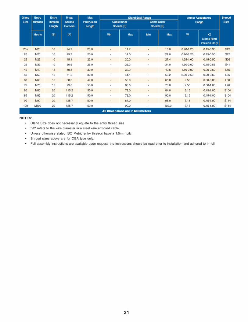
• Gland Size does not necessarily equate to the entry thread size
• "W" refers to the wire diameter in a steel wire armored cable
• Unless otherwise stated ISO Metric entry threads have a 1.5mm pitch
• Shroud sizes above are for CGA type only.
• Full assembly instructions are available upon request, the instructions should be read prior to installation and adhered to in full
NOTES:
20s M20 10 24.2 20.0 - 11.7 - 16.0 0.90-1.25 0.15-0.35 S22
20 M20 10 29.7 20.0 - 14.0 - 21.0 0.90-1.25 0.15-0.50 S27
25 M25 10 45.1 22.0 - 20.0 - 27.4 1.25-1.60 0.15-0.50 S36
32 M32 10 50.6 25.0 - 26.3 - 34.0 1.60-2.00 0.15-0.55 S41
40 M40 15 60.5 30.0 - 32.2 - 40.6 1.60-2.00 0.20-0.60 L55
50 M50 15 71.5 32.0 - 44.1 - 53.2 2.00-2.50 0.20-0.60 L65
63 M63 15 88.0 42.0 - 56.0 - 65.8 2.50 0.30-0.80 L80
75 M75 15 99.0 50.0 - 68.0 - 78.0 2.50 0.30-1.00 L90
80 M80 20 115.2 50.0 - 72.0 - 84.0 3.15 0.45-1.00 S104
85 M85 20 115.2 50.0 - 78.0 - 90.0 3.15 0.45-1.00 S104
90 M90 20 125.7 50.0 - 84.0 - 96.0 3.15 0.45-1.00 S114
100 M100 20 125.7 50.0 - 90.0 - 102.0 3.15 0.45-1.00 S114
All Dimensions are in Millimeters
Gland Entry Entry M<ax Max ShroudSize Threads Threads Across Protrusion Cable Inner Cable Outer Size
Length Corners Length Sheath [C] Sheath [D]
Metric [B] [A] Min Max Min Max W XZClamp Ring
Version Only
Gland Seal Range Armor AcceptanceRange

32
Non Hazardous Industrial Glands
CGSB or CGSSCGSB or CGSSCGSB or CGSSCGSB or CGSSCGSB or CGSSCGSB and CGSS type glands provide a seal on the outer sheath and an armor specific clamp for armored cable.The armor clamp provides an electrical bond between the cable armor and the gland; and maintain IP66 rating.
DESIGN STANDARD
BS EN 50262: 1999
EXAMPLE PART NUMBER
CGSB* [W] [Y] [R] [YY] [ZZ]* - Armor Type (W = SWA / X = SWB / Z = STA)
W - Seal Material (1 = Neoprene / 3 = Silicone)Y - Plating (0 = No Plating / 1 = Nickel / 2 = Tin / 3 = Zinc / 4 =
Electroless Nickel)R - Reduced bore option
YY - Gland Size (Cable Range)ZZ - Entry Thread
Sample: CGSB-W-1-3-R-20S-M20
GLAND MARKING
Example:CGSB-W-1-3-R-20S-M20 Amphenol
INGRESS PROTECTION
IP66
MATERIALS
Brass CZ121 (CGSB)316 Stainless Steel (CGSS)
Outer sheath seal material: Standard Neoprene, black. Option Silicone, whiteReduced bore outer sheath seal (R) Silicone, red
THREADS
ISO Metric; NPT; NPS; ISO Pipe Thread (BSP Taper, BSP Parallel);
PLATING
Nickel (1); Tin (2); Zinc (3); Electroless Nickel (4)
ACCESSORIES
Locknut - Brass (EX-BLN); 316 Stainless Steel (EX-SLN)Earth Tag - Brass (EX-BET), 316 Stainless Steel (EX-SET)IP Washer - Nylon (EX-NSW); Red Fibre (EX-FSW)Serrated Lock Washer - 316 Stainless Steel (EX-SSW), Galvanised Steel (EX-GSW)Shroud - PVC (EX-PVC); PCP (EX-SPCP); Low Smoke Zero Halogen (EX-LSH)
Gland and accessory kits:K7- includes gland, locknut, earthtag and PVC shroudK8 - includes brass gland, brass locknut, brass earthtag and zero halogen shroud
SEALS
Extended operating temperature -60°C to +200°C, halogen freeversions:
Brass (CGSB-*-3); 316 Stainless Steel (CGSS-*-3)
CLAMPS
SWA steel wire armor (CGSB-W)SWB woven steel wire armor or STA steel tape armor (CGSB-X)SWA, SWB and STA armor clamps (CGSB-Z)
OPERATING TEMPERATURES
Standard Seals -20°C to +80°CSilicone Seals - 60°C to +200°C
A D C
B
33
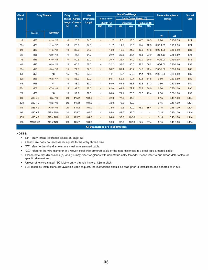
• NPT entry thread reference details on page 53.
• Gland Size does not necessarily equate to the entry thread size.
• "W" refers to the wire diameter in a steel wire armored cable.
• "XZ" refers to the wire diameter in a woven steel wire armored cable or the tape thickness in a steel tape armored cable.
• Please note that dimensions (A) and (B) may differ for glands with non-Metric entry threads. Please refer to our thread data tables forspecific dimensions.
• Unless otherwise stated ISO Metric entry threads have a 1.5mm pitch.
• Full assembly instructions are available upon request, the instructions should be read prior to installation and adhered to in full.
NOTES:
Gland Entry Threads Entry Max Max Armour Acceptance ShroudSize Thread Across Protrusion Range Size
Length Corners Length[B] [A] Min Max Min Max Min Max
Metric NPT/BSP
Gland Seal Range
Cable Inner
Sheath [C] Standard Reduced (R)
W XZ
Cable Outer Sheath [D]
16 M20 N1 or N2 10 26.5 54.0 - 11.7 9.0 13.5 6.7 10.3 0.90 0.15-0.35 L24
20s M20 N1 or N2 10 26.5 54.0 - 11.7 11.5 16.0 9.4 12.5 0.90-1.25 0.15-0.35 L24
20 M20 N1 or N2 10 33.0 54.0 - 14.0 15.5 21.0 12.0 17.6 0.90-1.25 0.15-0.50 L30
25 M25 N2 or N3 10 41.4 54.0 - 20.0 20.3 27.4 16.8 23.9 1.25-1.60 0.15-0.50 L38
32 M32 N3 or N4 10 50.6 60.0 - 26.3 26.7 34.0 23.2 30.5 1.60-2.00 0.15-0.55 L46
40 M40 N4 or N5 15 60.5 67.0 - 32.2 33.0 40.6 28.6 36.2 1.60-2.00 0.20-0.60 L55
50s M50 N5 or N6 15 71.5 67.0 - 38.2 39.4 46.7 34.8 42.4 2.00-2.50 0.20-0.60 L65
50 M50 N6 15 71.5 67.0 - 44.1 45.7 53.2 41.1 48.5 2.00-2.50 0.30-0.60 L65
63s M63 N6 or N7 15 88.0 69.0 - 50.1 52.1 59.4 47.5 54.8 2.50 0.30-0.80 L80
63 M63 N7 15 88.0 69.0 - 56.0 58.4 65.8 53.8 61.2 2.50 0.30-0.80 L80
75s M75 N7 or N8 15 99.0 77.0 - 62.0 64.8 72.2 60.2 68.0 2.50 0.30-1.00 L90
75 M75 N8 15 99.0 77.0 - 68.0 71.1 78.0 66.5 73.4 2.50 0.30-1.00 L90
80 M80 x 2 N8 or N9 20 115.2 104.0 - 72.0 77.0 84.0 - - 3.15 0.45-1.00 L104
80H M80 x 2 N8 or N9 20 115.2 104.0 - 72.0 79.6 90.0 - - 3.15 0.45-1.00 L104
85 M85 x 2 N8 or N9 20 115.2 104.0 - 78.0 79.6 90.0 75.0 85.4 3.15 0.45-1.00 L104
90 M90 x 2 N9 or N10 20 125.7 104.0 - 84.0 88.0 96.0 - - 3.15 0.45-1.00 L114
90H M90 x 2 N9 or N10 20 125.7 104.0 - 84.0 92.0 102.0 - - 3.15 0.45-1.00 L114
100 M100 x 2 N9 or N10 20 125.7 104.0 - 90.0 92.0 102.0 87.4 97.4 3.15 0.45-1.00 L114
All Dimensions are in Millimeters
34
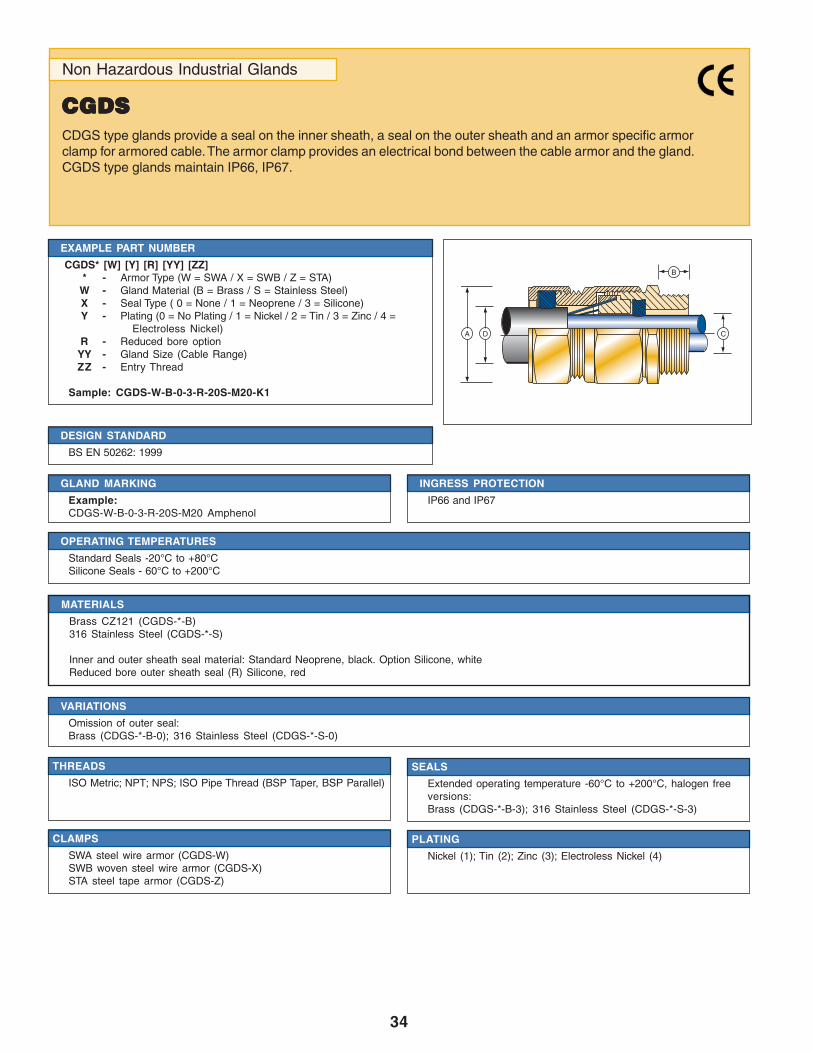
Non Hazardous Industrial Glands
CGDSCGDSCGDSCGDSCGDSCDGS type glands provide a seal on the inner sheath, a seal on the outer sheath and an armor specific armorclamp for armored cable. The armor clamp provides an electrical bond between the cable armor and the gland.CGDS type glands maintain IP66, IP67.
DESIGN STANDARD
BS EN 50262: 1999
EXAMPLE PART NUMBER
CGDS* [W] [Y] [R] [YY] [ZZ]* - Armor Type (W = SWA / X = SWB / Z = STA)
W - Gland Material (B = Brass / S = Stainless Steel)X - Seal Type ( 0 = None / 1 = Neoprene / 3 = Silicone)Y - Plating (0 = No Plating / 1 = Nickel / 2 = Tin / 3 = Zinc / 4 =
Electroless Nickel)R - Reduced bore option
YY - Gland Size (Cable Range)ZZ - Entry Thread
Sample: CGDS-W-B-0-3-R-20S-M20-K1
GLAND MARKING
Example:CDGS-W-B-0-3-R-20S-M20 Amphenol
INGRESS PROTECTION
IP66 and IP67
MATERIALS
Brass CZ121 (CGDS-*-B)316 Stainless Steel (CGDS-*-S)
Inner and outer sheath seal material: Standard Neoprene, black. Option Silicone, whiteReduced bore outer sheath seal (R) Silicone, red
THREADS
ISO Metric; NPT; NPS; ISO Pipe Thread (BSP Taper, BSP Parallel)
VARIATIONS
Omission of outer seal:Brass (CDGS-*-B-0); 316 Stainless Steel (CDGS-*-S-0)
SEALS
Extended operating temperature -60°C to +200°C, halogen freeversions:Brass (CDGS-*-B-3); 316 Stainless Steel (CDGS-*-S-3)
OPERATING TEMPERATURES
Standard Seals -20°C to +80°CSilicone Seals - 60°C to +200°C
CLAMPS
SWA steel wire armor (CGDS-W)SWB woven steel wire armor (CGDS-X)STA steel tape armor (CGDS-Z)
PLATING
Nickel (1); Tin (2); Zinc (3); Electroless Nickel (4)
A D C
B

35
* CGDS gland size 20, the silicone inner seal only seals to a minimum of 11.0mm and NOT 6.7mm.
• NPT entry thread reference on page 53.
• Gland Size does not necessarily equate to the entry thread size.
• "W" refers to the wire diameter in a steel wire armored cable.
• "XZ" refers to the wire diameter in a woven steel wire armored cable or the tape thickness in a steel tape armored cable.
• Please note that dimensions (A) and (B) may differ for glands with non-Metric entry threads. Please refer to our thread data tables forspecific dimensions.
• Unless otherwise stated ISO Metric entry threads have a 1.5mm pitch.
• Full assembly instructions are available upon requests, the instructions should be read prior to installation and adhered to in full.
NOTES:
Gland Entry Threads Entry Max Max Armour Acceptance ShroudSize Thread Across Protrusion Range Size
Length Corners Length[B] [A] Min Max Min Max Min Max
Metric NPT/BSP
Cable Outer Sheath [D]
Gland Seal Range
Cable Inner
Sheath [C] Standard Reduced (R)
W XZ
16 M20 N1 or N2 16 26.5 58.0 4.0 8.4 8.4 13.5 4.9 10.0 0.90 0.15-0.35 L24
20s M20 N1 or N2 16 26.5 58.0 8.0 11.7 11.5 16.0 9.4 12.5 0.90-1.25 0.15-0.35 L24
20 M20 N1 or N2 16 33.0 58.0 6.7 * 14.0 15.5 21.0 12.0 17.6 0.90-1.25 0.15-0.50 L30
25 M25 N2 or N3 16 41.4 58.0 13.0 20.0 20.3 27.4 16.8 23.9 1.25-1.60 0.15-0.50 L38
32 M32 N3 or N4 16 50.6 65.0 19.0 26.3 26.7 34.0 23.2 30.5 1.60-2.00 0.15-0.55 L46
40 M40 N4 or N5 16 60.5 72.0 25.0 32.2 33.0 40.6 28.6 36.2 1.60-2.00 0.20-0.60 L55
50s M50 N5 or N6 16 71.5 73.0 31.5 38.2 39.4 46.7 34.8 42.4 2.00-2.50 0.20-0.60 L65
50 M50 N6 16 71.5 73.0 36.5 44.1 45.7 53.2 41.1 48.5 2.00-2.50 0.30-0.80 L65
63s M63 N6 or N7 19 88.0 76.0 42.5 50.1 52.1 59.4 47.5 54.8 2.50 0.30-0.80 L80
63 M63 N7 19 88.0 76.0 49.5 56.0 58.4 65.8 53.8 61.2 2.50 0.30-0.80 L80
75s M75 N7 or N8 19 99.0 82.0 54.5 62.0 64.8 72.2 60.2 68.0 2.50 0.30-1.00 L90
75 M75 N8 19 99.0 82.0 60.5 68.0 71.1 78.0 66.5 73.4 2.50 0.30-1.00 L90
80 M80 x 2 N8 or N9 25 115.2 110.0 62.2 72.0 77.0 84.0 - - 3.15 0.45-1.00 L104
80H M80 x 2 N8 or N9 25 115.2 110.0 62.2 72.0 79.6 90.0 - - 3.15 0.45-1.00 L104
85 M85 x 2 N8 or N9 25 115.2 110.0 69.0 78.0 79.6 90.0 75.0 85.4 3.15 0.45-1.00 L104
90 M90 x 2 N9 or N10 25 125.7 110.0 74.0 84.0 88.0 96.0 - - 3.15 0.45-1.00 L114
90H M90 x 2 N9 or N10 25 125.7 110.0 74.0 84.0 92.0 102.0 - - 3.15 0.45-1.00 L114
100 M100 x 2 N9 or N10 25 125.7 110.0 82.0 90.0 92.0 102.0 87.4 97.4 3.15 0.45-1.00 L114
All Dimensions are in Millimeters
ACCESSORIES
Locknut - Brass (EX-BLN); 316 Stainless Steel (EX-SLN)Earth Tag - Brass (EX-BET), 316 Stainless Steel (EX-SET)IP Washer - Nylon (EX-NSW); Red Fibre (EX-FSW)Serrated Lock Washer - 316 Stainless Steel (EX-SSW), Galvanised Steel (EX-GSW)Shroud - PVC (EX-PVC); PCP (EX-PCP); Low Smoke Zero Halogen (EX-LSH)
Gland and accessory kits:K1 - includes gland, locknut, earthtag and PVC shroudK8 - includes brass gland, brass locknut, brass earthtag and zero halogen shroud
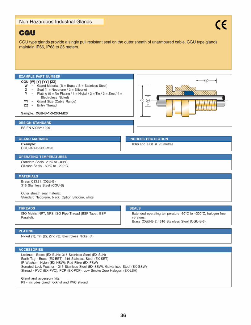
36
Non Hazardous Industrial Glands
CGUCGUCGUCGUCGUCGU type glands provide a single pull resistant seal on the outer sheath of unarmoured cable. CGU type glandsmaintain IP66, IP68 to 25 meters.
DESIGN STANDARD
BS EN 50262: 1999
EXAMPLE PART NUMBER
CGU [W] [Y] [YY] [ZZ]W - Gland Material (B = Brass / S = Stainless Steel)X - Seal (1 = Neoprene / 3 = Silicone)Y - Plating (0 = No Plating / 1 = Nickel / 2 = Tin / 3 = Zinc / 4 =
Electroless Nickel)YY - Gland Size (Cable Range)ZZ - Entry Thread
Sample: CGU-B-1-3-20S-M20
GLAND MARKING
Example:CGU-B-1-3-20S-M20
INGRESS PROTECTION
IP66 and IP68 @ 25 metres
MATERIALS
Brass CZ121 (CGU-B)316 Stainless Steel (CGU-S)
Outer sheath seal material:Standard Neoprene, black. Option Silicone, white
THREADS
ISO Metric; NPT; NPS; ISO Pipe Thread (BSP Taper, BSPParallel);
SEALS
Extended operating temperature -60°C to +200°C, halogen freeversions:Brass (CGU-B-3); 316 Stainless Steel (CGU-B-3);
PLATING
Nickel (1); Tin (2); Zinc (3); Electroless Nickel (4)
OPERATING TEMPERATURES
Standard Seals -20°C to +80°CSilicone Seals - 60°C to +200°C
ACCESSORIES
Locknut - Brass (EX-BLN); 316 Stainless Steel (EX-SLN)Earth Tag - Brass (EX-BET), 316 Stainless Steel (EX-SET)IP Washer - Nylon (EX-NSW); Red Fibre (EX-FSW)Serrated Lock Washer - 316 Stainless Steel (EX-SSW), Galvanised Steel (EX-GSW)Shroud - PVC (EX-PVC); PCP (EX-PCP); Low Smoke Zero Halogen (EX-LSH)
Gland and accessory kits:K9 - includes gland, locknut and PVC shroud
B
DA
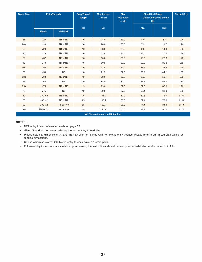
37
• NPT entry thread reference details on page 53.
• Gland Size does not necessarily equate to the entry thread size.
• Please note that dimensions (A) and (B) may differ for glands with non-Metric entry threads. Please refer to our thread data tables forspecific dimensions.
• Unless otherwise stated ISO Metric entry threads have a 1.5mm pitch.
• Full assembly instructions are avalable upon request, the instructions should be read prior to installation and adhered to in full.
NOTES:
Gland Size Entry Threads Entry Thread Max Across Max Gland Seal Range Shroud SizeLength Corners Protrusion Cable Outer/Lead Sheath
Length [D[
[B] [A] Min MaxMetric NPT/BSP
16 M20 N1 or N2 16 28.0 33.0 4.0 8.4 L24
20s M20 N1 or N2 16 28.0 33.0 7.2 11.7 L24
20 M20 N1 or N2 16 33.0 33.0 9.6 14.0 L30
25 M25 N2 or N3 16 41.4 33.0 13.5 20.0 L38
32 M32 N3 or N4 16 50.6 33.0 19.5 26.3 L46
40 M40 N4 or N5 16 60.5 37.0 23.0 32.2 L55
50s M50 N5 or N6 16 71.5 37.0 28.2 38.2 L65
50 M50 N6 16 71.5 37.0 33.2 44.1 L65
63s M63 N6 or N7 19 88.0 37.0 39.3 50.1 L80
63 M63 N7 19 88.0 37.0 46.7 56.0 L80
75s M75 N7 or N8 19 99.0 37.0 52.3 62.0 L90
75 M75 N8 19 99.0 37.0 58.1 68.0 L90
80 M80 x 2 N8 or N9 25 115.2 50.0 62.3 72.0 L104
85 M85 x 2 N8 or N9 25 115.2 50.0 69.1 78.0 L104
90 M90 x 2 N9 or N10 25 125.7 50.0 74.1 84.0 L114
100 M100 x 2 N9 or N10 25 125.7 50.0 82.1 90.0 L114
All Dimensions are in Millimeters
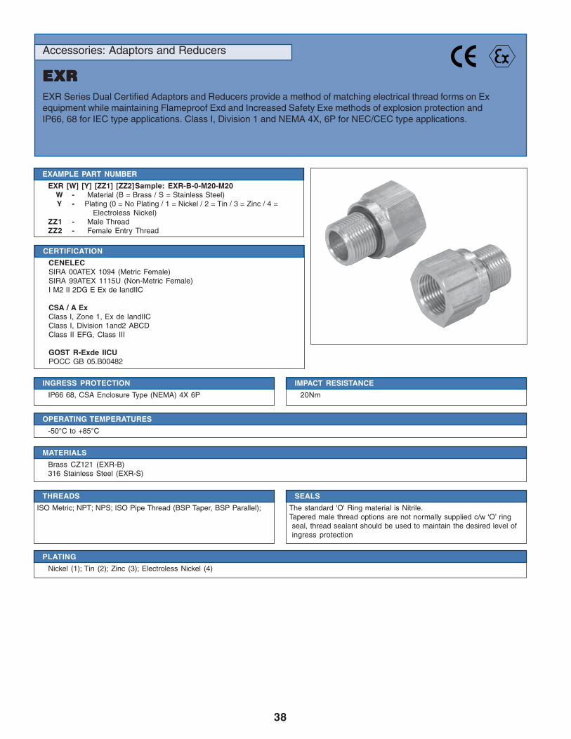
38
Accessories: Adaptors and Reducers
EXREXREXREXREXREXR Series Dual Certified Adaptors and Reducers provide a method of matching electrical thread forms on Exequipment while maintaining Flameproof Exd and Increased Safety Exe methods of explosion protection andIP66, 68 for IEC type applications. Class I, Division 1 and NEMA 4X, 6P for NEC/CEC type applications.
CERTIFICATION
CENELECSIRA 00ATEX 1094 (Metric Female)SIRA 99ATEX 1115U (Non-Metric Female)I M2 II 2DG E Ex de IandIIC
CSA / A ExClass I, Zone 1, Ex de IandIICClass I, Division 1and2 ABCDClass II EFG, Class III
GOST R-Exde IICUPOCC GB 05.B00482
EXAMPLE PART NUMBER
EXR [W] [Y] [ZZ1] [ZZ2]Sample: EXR-B-0-M20-M20W - Material (B = Brass / S = Stainless Steel)Y - Plating (0 = No Plating / 1 = Nickel / 2 = Tin / 3 = Zinc / 4 =
Electroless Nickel)ZZ1 - Male ThreadZZ2 - Female Entry Thread
INGRESS PROTECTION
IP66 68, CSA Enclosure Type (NEMA) 4X 6P
IMPACT RESISTANCE
20Nm
MATERIALS
Brass CZ121 (EXR-B)316 Stainless Steel (EXR-S)
SEALS
The standard 'O' Ring material is Nitrile.Tapered male thread options are not normally supplied c/w ‘O’ ringseal, thread sealant should be used to maintain the desired level ofingress protection
THREADS
ISO Metric; NPT; NPS; ISO Pipe Thread (BSP Taper, BSP Parallel);
PLATING
Nickel (1); Tin (2); Zinc (3); Electroless Nickel (4)
OPERATING TEMPERATURES
-50°C to +85°C
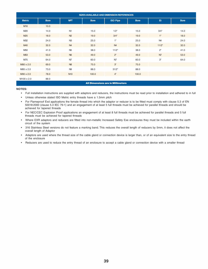
39
SIZES AVAILABLE AND DIMENSION REFERENCES
M16 10.0
M20 14.0 N1 15.0 1/2" 15.0 3/4" 14.0
M25 18.0 N2 19.0 3/4" 19.0 1" 18.0
M32 24.0 N3 25.0 1" 25.0 N4 24.0
M40 32.0 N4 32.0 N4 32.0 11/2" 32.0
M50 41.0 N5 38.0 11/2" 38.0 2" 41.0
M63 53.0 N6 49.0 2" 49.0 N7 53.0
M75 64.0 N7 60.0 N7 60.0 3" 64.0
M80 x 2.0 69.0 N8 75.0 3" 75.0
M85 x 2.0 73.0 N9 88.0 31/2" 88.0
M90 x 2.0 78.0 N10 100.0 4" 100.0
M100 x 2.0 88.0
Metric Bore NPT Bore ISO Pipe Bore Et Bore
• Full installation instructions are supplied with adaptors and reducers, the instructions must be read prior to installation and adhered to in full
• Unless otherwise stated ISO Metric entry threads have a 1.5mm pitch
• For Flameproof Exd applications the female thread into which the adaptor or reducer is to be fitted must comply with clause 5.3 of EN50018:2000 (clause 5.3 IEC 79-1) and an engagement of at least 5 full threads must be achieved for parallel threads and should beachieved for tapered threads
• For NEC/CEC Explosion Proof applications an engagement of at least 8 full threads must be achieved for parallel threads and 5 fullthreads must be achieved for tapered threads
• Where EXR adaptors and reducers are fitted into non-metallic Increased Safety Exe enclosures they must be included within the earthcircuit of the system
• 316 Stainless Steel versions do not feature a marking band. This reduces the overall length of reducers by 5mm, it does not affect theoverall length of Adaptor
• Adaptors are used where the thread size of the cable gland or connection device is larger than, or of an equivalent size to the entry threadof the enclosure
• Reducers are used to reduce the entry thread of an enclosure to accept a cable gland or connection device with a smaller thread
NOTES:
All Dimensions are in Millimeters

40
Accessories: Nylon Adaptors and Reducers
EXRNEXRN Series Certified Adaptors and Reducers provide a method of matching electrical threadforms on Exequipment while maintaining Increased Safety Exe methods of explosion protection and IP66, 68 for IEC typeapplications.Adaptors are used where the thread size of the cable gland or connection device is larger than, or of equivalent size tothe entry thread of the enclosure.Reducers are used to reduce the entry thread of an enclosure to acept a cable gland or connection device with asmaller thread.
CERTIFICATION
CENELECSIRA 00ATEX 3091 (Metric Female)SIRA 99ATEX 3116U (Non-Metric Female)II 2DG E Ex e II
CSA / A ExClass I, Zone 1, Ex e IIClass I, Division 2 ABCDClass II EFG, Class III
EXAMPLE PART NUMBER
EXRN [ZZ1] [ZZ2]ZZ1 - Male ThreadZZ2 - Female Entry Thread
Sample: EXRN-M20-M25
INGRESS PROTECTION
IP66 68, CSA Enclosure Type (NEMA) 4X 6P
OPERATING TEMPERATURES
-50°C to +85°C
MATERIALS
30% Glass Filled Nylon (EXRN)
SEALS
The standard 'O' Ring material is Nitrile
THREADS
ISO Metric; NPT; NPS; ISO Pipe Thread (BSP Taper, BSP Parallel)
IMPACT RESISTANCE
7Nm

41
M16 9.3
M20 11.0 N1 12.0 I1 12.0 E2 11.0
M25 16.0 N2 13.0 I2 13.0 E3 16.0
M32 21.0 N3 18.0 I3 18.0 E4 21.0
M40 31.0 N4 33.0 I4 33.0 E5 31.0
M50 40.0 N5 38.0 I5 38.0 E6 40.0
SIZES AVAILABLE AND DIMENSION REFERENCES
Metric Bore NPT Bore ISO Pipe Bore ET Bore
All Dimensions are in Millimeters
• Full installation instructions are supplied with adaptors and reducers, the instructions must be read prior to installation and adhered to in full
• Unless otherwise stated ISO Metric entry threads have a 1.5mm pitch
• Adaptors are used where the thread size of the cable gland or connection device is larger than, or of an equivalent size to the entry threadof the enclosure
• Reducers are used to reduce the entry thread of an enclosure to accept a cable gland or connection device with a smaller thread
NOTES:
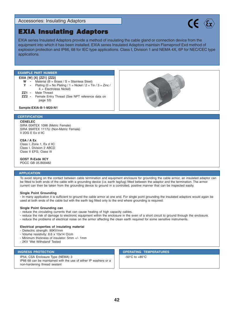
42
Accessories: Insulating Adaptors
EXIA Insulating AdaptorsEXIA Insulating AdaptorsEXIA Insulating AdaptorsEXIA Insulating AdaptorsEXIA Insulating AdaptorsEXIA series Insulated Adaptors provide a method of insulating the cable gland or connection device from theequipment into which it has been installed. EXIA series Insulated Adaptors maintain Flameproof Exd method ofexplosion protection and IP66, 68 for IEC type applications. Class I, Division 1 and NEMA 4X, 6P for NEC/CEC typeapplications.
CERTIFICATION
CENELECSIRA 00ATEX 1098 (Metric Female)SIRA 99ATEX 1117U (Non-Metric Female)II 2DG E Ex d IIC
CSA / A ExClass I, Zone 1, Ex d IICClass I, Division 2 ABCDClass II EFG, Class III
GOST R-Exde IICYPOCC GB 05.B00482
EXAMPLE PART NUMBER
EXIA [W] [X] [ZZ1] [ZZ2]W - Material (B = Brass / S = Stainless Steel)Y - Plating (0 = No Plating / 1 = Nickel / 2 = Tin / 3 = Zinc /
4 = Electroless Nickel)ZZ1 - Male ThreadZZ2 - Female Entry Thread (See NPT reference data on
page 53)
Sample:EXIA-B-1-M20-N1
INGRESS PROTECTION
IP54, CSA Enclosure Type (NEMA) 3IP66 68 can be maintained with the use of either IP washers or anon-hardening thread sealant
OPERATING TEMPERATURES
-50°C to +85°C
APPLICATION
To avoid relying on the contact between cable termination and equipment enclosure for grounding the cable armor, an insulated adaptor canbe fitted to both ends of the cable with a grounding device (i.e. earth tag/lug) fitted between the adaptor and the termination. The armorcurrent can then be taken from the grounding device to ground in a controlled, positive manner that can be inspected easily.
Single Point Grounding- In many application it is sufficient to ground the cable armor at one end. For single point grounding the insulated adaptors would again beused at both ends of the cable but with the earth tag fitted only to the end where grounding is required.
Single Point Grounding can- reduce the circulating currents that can cause heating of high capacity cables.- reduce the risk of damage to electronic equipment within the enclosure in the even of a short circuit to ground through the enclosure.- reduce the problems of electrical noise on the armor affecting the clean earth required for some sensitive instruments.
Electrical properties of insulating material- Dielectric strength: 90KV/mm- Volume resistivity: 8.6 x 10x14 O/cm- Minimum thickness of insulator: 5mm +/- 1mm- 2KV 'Wet Withstand' Tested

43
M20 30.5 35.5 54.0 16.0 17.0 13.5
M25 37.6 43.2 54.0 16.0 17.0 19.0
M32 47.2 54.3 54.0 16.0 17.0 25.0
M40 55.9 64.1 54.0 16.0 17.0 30.0
M50 70.1 80.8 54.0 16.0 17.0 40.5
M63 80.0 92.0 54.0 16.0 17.0 53.0
M75 95.3 109.5 54.0 16.0 17.0 65.0
M80 x 2.0 100.0 114.0 63.0 20.0 22.0 70.0
M85 x 2.0 106.4 114.0 63.0 20.0 22.0 75.0
M90 x 2.0 106.4 114.0 63.0 20.0 22.0 80.0
SIZES AVAILABLE AND DIMENSION REFERENCES
Metric Hex A/F Hex A/C Total Length Male Length Female Depth Bore
All Dimensions are in Millimeters
• Full installation instructions are supplied with insulated adaptors, the instructions must be read prior to installation and adhered to in full
• Unless otherwise stated ISO Metric entry threads have a 1.5mm pitch
• For Flameproof Exd applications the female thread into which the adaptor is to be fitted must comply with clause 5.3 of EN50018:2000 (clause 5.3 IEC 79-1) and an engagement of at least 5 full threads must be achieved for parallel threads and should beachieved for tapered threads
NOTES:
MATERIALS
Brass CZ121 (EXIA-B)316 Stainless Steel (EXIA-S)
IMPACT RESISTANCE
7Nm
THREADS
ISO Metric; NPT; NPS; ISO Pipe Thread (BSP Taper, BSP Parallel)
PLATING
Nickel (1); Tin (2); Zinc (3); Electroless Nickel (4)

44
Accessories: Stopping Plugs
EXSPH Stopping PlugsEXSPH Series Dual Certified Metallic Dome Head Stopping Plugs provide a method of filling unused entries inEx equipment while maintaining Flameproof Exd and Increased Safety Exe methods of explosion protection andIP66, 68 for IEC type applications. Class I, Division 1 and NEMA 4X, 6P for NEC/CEC type applications.
CERTIFICATION
CENELECSIRA 00ATEX1094 I M2 II 2DG E Ex de IandIIC
CSA / A ExClass I, Zone 1, Ex de IandIICClass I, Division 1and2 ABCDClass II EFG, Class III
GOST R-Exde IICYPOCC GB 05.B00482
EXAMPLE PART NUMBER
EXSPH [W] [Y] [ZZ]W - Material (B = Brass / S = Stainless Steel)Y - Plating (0 = No Plating / 1 = Nickel / 2 = Tin / 3 = Zinc / 4 =
Electroless Nickel)ZZ - Male Entry Thread
Sample: EXSPH-B-1-M20
INGRESS PROTCTION
IP66 68, CSA Enclosure Type (NEMA) 4X 6P
IMPACT RESISTANCE
20Nm
MATERIALS
Brass CZ121 (SPMH-B)316 Stainless Steel (SPMH-S)
SEALS
The standard 'O' Ring material is Nitrile
THREADS
ISO Metric; NPT; NPS; ISO Pipe Thread (BSP Taper, BSP Parallel)
PLATING
Nickel (1); Tin (2); Zinc (3); Electroless Nickel (4)
OPERATING TEMPERATURES
-50°C to +85°C

45
M16 A
M20 B N1 C P1 C
M25 B N2 C P2 C
M32 B N3 E P3 C
M40 B N4 E P4 C
M50 B N5 E P5 C
M63 B N6 E P6 C
M75 B N7 F P7 C
M80 x 2.0 D N8 F P8 C
M85 x 2.0 D N9 F
M90 x 2.0 D N10 F
M100 x 2.0 D
SIZES AVAILABLE AND DIMENSION REFERENCES
Metric Dim Ref NPT Dim Ref ISO Pipe Dim Ref
DIMENSIONS
Dimension Reference A B C D E F
• EXSPH type stopping plugs are designed for use within either clearance holes or parallel threaded entries, for taper threaded entries wewould recommend the use of EXSP type stopping plugs on page 48.
• Full installation instructions are supplied with stopping plugs, the instructions must be read prior to installation and adhered to in full
• Unless otherwise stated ISO Metric entry threads have a 1.5mm pitch
• For Flameproof Exd applications the female thread into which the stopping plug is to be fitted must comply with clause 5.3 of EN 50018:2000(clause 5.3 IEC 79-1) and an engagement of at least 5 full threads must be achieved for parallel threads and should be achieved for taperedthreads
• For NEC/CEC Explosion Proof applications an engagement of at least 8 full threads must be achieved for parallel threads and 5 full threadsmust be achieved for tapered threads
• Where metallic stopping plugs are fitted into non-metallic Increased Safety Exe enclosures they must be included within the earth circuit ofthe system
NOTES:
All Dimensions are in Millimeters
Head Diameter Minimum 6.0mm larger than the major thread diameter
Hex Socket A/F 8.0 10.0 10.0 10.0 10.0 10.0
Total Length 21.5 21.5 24.5 25.5 29.0 39.0
Thread Length 16.0 16.0 19.0 22.0 23.5 33.5

46
Accessories: Stopping Plugs
EXSPHN Stopping PlugEXSPHN Stopping PlugEXSPHN Stopping PlugEXSPHN Stopping PlugEXSPHN Stopping PlugEXSPHN Series Glass Filled Nylon Dome Head Stopping Plugs provide a method of filling unused entries inincreased safety equipment, maintaining Increased Safety Exe methods of explosion protection and IP66, 68 forIEC type applications.
CERTIFICATION
CENELECSIRA 00ATEX3091 II 2DG E Ex eII
CSA / A ExClass I, Zone 1, Ex e IIClass I, Division 2 ABCDClass II EFG, Class III
EXAMPLE PART NUMBER
EXSPHN [ZZ]ZZ - Male Thread size
Sample: EXSPHN-M20
INGRESS PROTECTION
IP66 68, CSA Enclosure Type (NEMA) 4X 6P
IMPACT RESISTANCE
7Nm
MATERIALS
30% Glass Filled Nylon (SPMHN)
SEALS
The standard 'O' Ring material is Nitrile
THREADS
ISO Metric; NPT; NPS; ISO Pipe Thread (BSP Taper, BSPParallel); PG
OPERATING TEMPERATURES
-50°C to +85°C
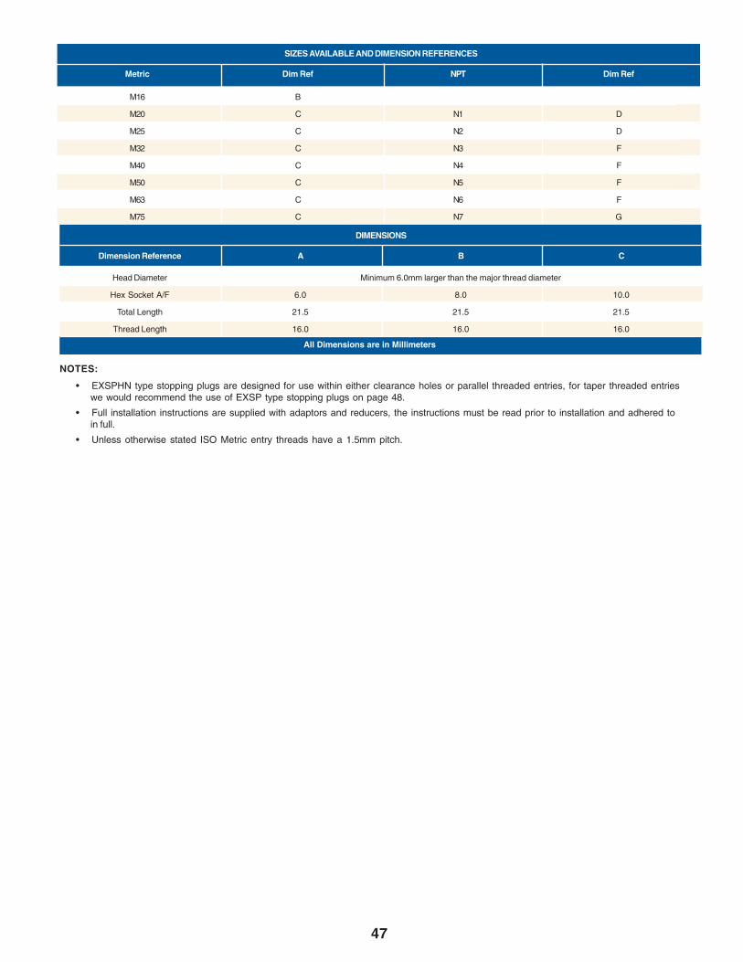
47
M16 B
M20 C N1 D
M25 C N2 D
M32 C N3 F
M40 C N4 F
M50 C N5 F
M63 C N6 F
M75 C N7 G
SIZES AVAILABLE AND DIMENSION REFERENCES
Metric Dim Ref NPT Dim Ref
DIMENSIONS
Dimension Reference A B C
All Dimensions are in Millimeters
• EXSPHN type stopping plugs are designed for use within either clearance holes or parallel threaded entries, for taper threaded entrieswe would recommend the use of EXSP type stopping plugs on page 48.
• Full installation instructions are supplied with adaptors and reducers, the instructions must be read prior to installation and adhered toin full.
• Unless otherwise stated ISO Metric entry threads have a 1.5mm pitch.
NOTES:
Head Diameter Minimum 6.0mm larger than the major thread diameter
Hex Socket A/F 6.0 8.0 10.0
Total Length 21.5 21.5 21.5
Thread Length 16.0 16.0 16.0
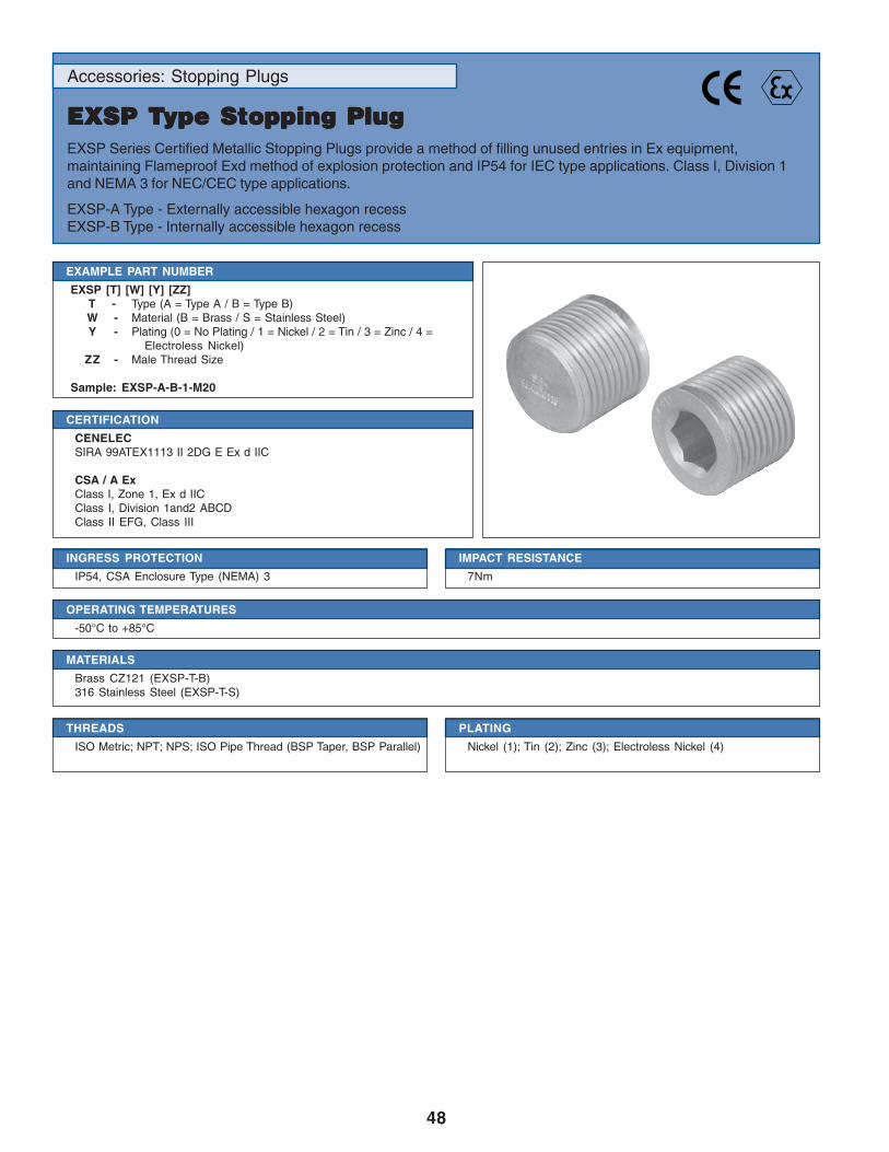
48
Accessories: Stopping Plugs
EXSP TEXSP TEXSP TEXSP TEXSP Type Stopping Plugype Stopping Plugype Stopping Plugype Stopping Plugype Stopping PlugEXSP Series Certified Metallic Stopping Plugs provide a method of filling unused entries in Ex equipment,maintaining Flameproof Exd method of explosion protection and IP54 for IEC type applications. Class I, Division 1and NEMA 3 for NEC/CEC type applications.
EXSP-A Type - Externally accessible hexagon recessEXSP-B Type - Internally accessible hexagon recess
CERTIFICATION
CENELECSIRA 99ATEX1113 II 2DG E Ex d IIC
CSA / A ExClass I, Zone 1, Ex d IICClass I, Division 1and2 ABCDClass II EFG, Class III
EXAMPLE PART NUMBER
EXSP [T] [W] [Y] [ZZ]T - Type (A = Type A / B = Type B)W - Material (B = Brass / S = Stainless Steel)Y - Plating (0 = No Plating / 1 = Nickel / 2 = Tin / 3 = Zinc / 4 =
Electroless Nickel)ZZ - Male Thread Size
Sample: EXSP-A-B-1-M20
INGRESS PROTECTION
IP54, CSA Enclosure Type (NEMA) 3
IMPACT RESISTANCE
7Nm
MATERIALS
Brass CZ121 (EXSP-T-B)316 Stainless Steel (EXSP-T-S)
PLATING
Nickel (1); Tin (2); Zinc (3); Electroless Nickel (4)
THREADS
ISO Metric; NPT; NPS; ISO Pipe Thread (BSP Taper, BSP Parallel)
OPERATING TEMPERATURES
-50°C to +85°C

49
M16 A
M20 B N1 C P1 E
M25 B N2 C P2 E
M32 B N3 D P3 G
M40 B N4 D P4 G
M50 B N5 D P5 G
M63 B N6 D P6 G
M75 B N7 F P7 G
M80 x 2.0 F N8 F P8 G
M85 x 2.0 F N9 F
M90 x 2.0 F N10 F
M100 x 2.0 F
SIZES AVAILABLE AND DIMENSION REFERENCES
Metric Dim Ref NPT Dim Ref ISO Pipe Dim Ref
• Full installation instructions are supplied with stopping plugs, the instructions must be read prior to installation and adhered to in full
• Unless otherwise stated ISO Metric entry threads have a 1.5mm pitch
• For Flameproof Exd applications the female thread into which the stopping plug is to be fitted must comply with clause 5.3 of EN50018:2000 (clause 5.3 IEC 79-1) and an engagement of at least 5 full threads must be achieved for parallel threads and should beachieved for tapered threads
• For NEC/CEC Explosion Proof applications an engagement of at least 8 full threads must be achieved for parallel threads and 5 fullthreads must be achieved for tapered threads
NOTES:
DIMENSIONS
Dimension Reference A B C D E F G
Hex Socket A/F 8.0 10.0 10.0 10.0 10.0 10.0 10.0
Length (min) 17.0 17.0 14.0 16.0 18.0 22.0 25.0
All Dimensions are in Millimeters
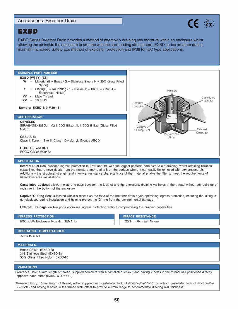
50
Moisture
Internal Dust Seal
Captive 'O' Ring Seal
CastellatedLocknut
External DrainageMoisture Out
Air In
Accessories: Breather Drain
EXBDEXBDEXBDEXBDEXBDEXBD Series Breather Drain provides a method of effectively draining any moisture within an enclosure whilstallowing the air inside the enclosure to breathe with the surrounding atmosphere. EXBD series breather drainsmaintain Increased Safety Exe method of explosion protection and IP66 for IEC type applications.
CERTIFICATION
CENELECSIRA99ATEX3050U I M2 II 2DG EExe I/II; II 2DG E Exe (Glass FilledNylon)
CSA / A ExClass I, Zone 1, Exe II; Class I Division 2, Groups ABCD
GOST R-Exde IICYPOCC GB 05.B00482
EXAMPLE PART NUMBER
EXBD [W] [Y] [ZZ]W - Material (B = Brass / S = Stainless Steel / N = 30% Glass Filled
Nylon)Y - Plating (0 = No Plating / 1 = Nickel / 2 = Tin / 3 = Zinc / 4 =
Electroless Nickel)YY - Male ThreadZZ - 10 or 15
Sample: EXBD-B-0-M20-15
INGRESS PROTECTION
IP66, CSA Enclosure Type 4x, NEMA 4x
IMPACT RESISTANCE
20Nm. (7Nm GF Nylon)
APPLICATION
Internal Dust Seal provides ingress protection to IP66 and 4x, with the largest possible pore size to aid draining, whilst retaining filtrationcapabilities that remove debris from the moisture and retains it on the surface where it can easily be removed with compressed air.Additionally the structural strength and chemical resistance characteristics of the material enable the filter to meet the requirements ofhazardous area installations
Castellated Locknut allows moisture to pass between the locknut and the enclosure, draining via holes in the thread without any build up ofmoisture in the bottom of the enclosure
Captive 'O' Ring Seal is located within a recess on the face of the breather drain again optimising ingress protection, ensuring the 'o'ring isnot displaced during installation and helping protect the 'O' ring from the environmental damage
External Drainage via two ports optimises ingress protection without compromising the draining capabilities
VARIATIONS
Clearance Hole: 10mm length of thread, supplied complete with a castellated locknut and having 2 holes in the thread wall positioned directlyopposite each other (EXBD-W-Y-YY-10)
Threaded Entry: 15mm length of thread, either supplied with castellated locknut (EXBD-W-Y-YY-15) or without castellated locknut (EXBD-W-Y-YY-15NL) and having 3 holes in the thread wall, offset to provide a 9mm range to accommodate differing wall thickness.
MATERIALS
Brass CZ121 (EXBD-B)316 Stainless Steel (EXBD-S)30% Glass Filled Nylon (EXBD-N)
OPERATING TEMPERATURES
-50°C to +85°C
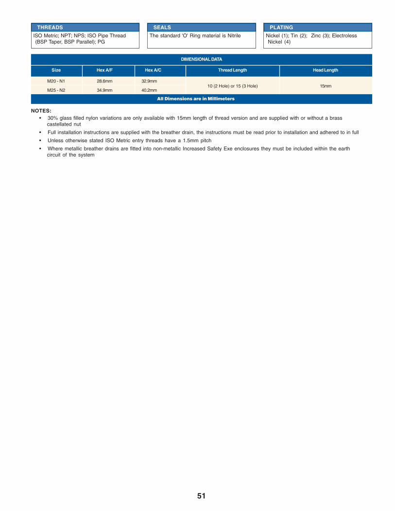
51
M20 - N1 28.6mm 32.9mm
M25 - N2 34.9mm 40.2mm
DIMENSIONAL DATA
Size Hex A/F Hex A/C Thread Length Head Length
10 (2 Hole) or 15 (3 Hole) 15mm
• 30% glass filled nylon variations are only available with 15mm length of thread version and are supplied with or without a brasscastellated nut
• Full installation instructions are supplied with the breather drain, the instructions must be read prior to installation and adhered to in full
• Unless otherwise stated ISO Metric entry threads have a 1.5mm pitch
• Where metallic breather drains are fitted into non-metallic Increased Safety Exe enclosures they must be included within the earthcircuit of the system
NOTES:
All Dimensions are in Millimeters
THREADS
ISO Metric; NPT; NPS; ISO Pipe Thread(BSP Taper, BSP Parallel); PG
SEALS
The standard 'O' Ring material is Nitrile
PLATING
Nickel (1); Tin (2); Zinc (3); ElectrolessNickel (4)
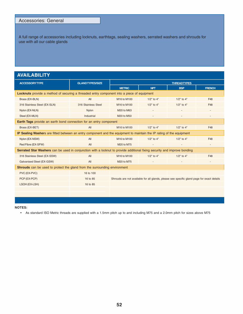
52
Accessories: General
A full range of accessories including locknuts, earthtags, sealing washers, serrated washers and shrouds foruse with all our cable glands
AVAILABILITY
ACCESSORY TYPE GLAND TYPES/SIZE THREAD TYPES
METRIC NPT BSP FRENCH
Locknuts provide a method of securing a threaded entry component into a piece of equipment
Brass (EX-BLN) All M16 to M100 1/2" to 4" 1/2" to 4" F48
316 Stainless Steel (EX-SLN) 316 Stainless Steel M16 to M100 1/2" to 4" 1/2" to 4" F48
Nylon (EX-NLN) Nylon M20 to M63 - - -
Steel (EX-MLN) Industrial M20 to M50 - - -
Earth Tags provide an earth bond connection for an entry component
Brass (EX-BET) All M16 to M100 1/2" to 4" 1/2" to 4" F48
IP Sealing Washers are fitted between an entry component and the equipment to maintain the IP rating of the equipment
Nylon (EX-NSW) All M16 to M100 1/2" to 4" 1/2" to 4" F48
Red Fibre (EX-SFW) All M20 to M75 - - -
Serrated Star Washers can be used in conjunction with a locknut to provide additional fixing security and improve bonding
316 Stainless Steel (EX-SSW) All M16 to M100 1/2" to 4" 1/2" to 4" F48
Galvanised Steel (EX-GSW) All M20 to M75 - - -
Shrouds can be used to protect the gland from the surrounding environment
PVC (EX-PVC) 16 to 100
PCP (EX-PCP) 16 to 85 Shrouds are not available for all glands, please see specific gland page for exact details
LSOH (EX-LSH) 16 to 85
• As standard ISO Metric threads are supplied with a 1.5mm pitch up to and including M75 and a 2.0mm pitch for sizes above M75
NOTES:
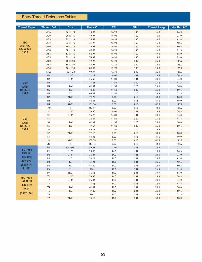
53
Entry Thread Reference Tables
ISOMETRIC
IEC 604231993
NPTANSI
B1.20.11983
NPSANSI
B1.20.11983
ISO PipeParallel
ISO R/7;
BS2779
(BSPP, G,R, PF)
ISO PipeTaper to
ISO R/7;
BS21
(BSPT, GK)
M16 16 x 1.5 15.97 16.93 1.50 16.0 26.5
M20 20 x 1.5 19.97 16.93 1.50 16.0 33.0
M25 25 x 1.5 24.97 16.93 1.50 16.0 41.4
M32 32 x 1.5 31.97 16.93 1.50 16.0 50.6
M40 40 x 1.5 39.97 16.93 1.50 16.0 60.4
M50 50 x 1.5 49.97 16.93 1.50 16.0 71.5
M63 63 x 1.5 62.97 16.93 1.50 19.0 88.0
M75 75 x 1.5 74.97 16.93 1.50 19.0 99.0
M80 80 x 2.0 19.97 12.70 2.00 25.0 115.2
M85 85 x 2.0 84.97 12.70 2.00 25.0 115.2
M90 90 x 2.0 89.97 12.70 2.00 25.0 125.7
M100 100 x 2.0 99.97 12.70 2.00 25.0 125.7
N1 1/2" 21.22 14.00 1.81 19.9 26.5
N2 3/4" 26.57 14.00 1.81 20.1 33.0
N3 1" 33.23 11.50 2.20 21.5 41.4
N4 11/4" 41.99 11.50 2.20 25.6 50.6
N5 11/2" 48.05 11.50 2.20 26.0 60.5
N6 2” 60.09 11.50 2.20 26.9 71.5
N7 21/2" 72.70 8.00 3.18 39.9 88.0
N8 3” 88.61 8.00 3.18 41.5 99.0
N9 31/2" 101.36 8.00 3.18 42.8 115.2
N10 4" 113.97 8.00 3.18 44.0 125.7
S1 1/2" 20.90 14.00 1.81 19.9 26.5
S2 3/4" 26.26 14.00 1.81 20.1 33.0
S3 1" 32.84 11.50 2.20 21.5 41.4
S4 11/4" 41.61 11.50 2.20 25.6 50.6
S5 11/2" 47.67 11.50 2.20 26.0 60.5
S6 2" 59.72 11.50 2.20 26.9 71.5
S7 21/2" 72.16 8.00 3.18 39.9 88.0
S8 3" 88.06 8.00 3.18 41.5 99.0
S9 31/2" 100.78 8.00 3.18 42.8 115.2
S10 4" 113.43 8.00 3.18 44.0 125.7
F48 PG48 (FR) 59.61 11.00 2.31 26.9 71.5
P1 1/2" 20.96 14.0 1.81 19.9 26.5
P2 3/4" 26.44 14.0 1.81 20.1 33.0
P3 1” 33.25 11.0 2.31 25.0 41.4
P4 11/4" 41.91 11.0 2.31 25.6 50.6
P5 11/2" 47.80 11.0 2.31 26.0 60.5
P6 2" 5961 11.0 2.31 26.9 71.5
P7 21/2" 75.18 11.0 2.31 39.9 88.0
T1 1/2" 20.96 14.0 1.81 19.9 26.5
T2 3/4" 26.44 14.0 1.81 20.1 33.0
T3 1" 33.25 11.0 2.31 25.0 41.4
T4 11/4" 41.91 11.0 2.31 25.6 50.6
T5 11/2" 47.80 11.0 2.31 26.0 60.5
T6 2" 5961 11.0 2.31 26.9 71.5
T7 21/2" 75.18 11.0 2.31 39.9 88.0
Thread Types Thread Ref Size Major Ø TPI Pitch Thread Length Min Hex A/C

54
Ingress Protection
It is essential when selecting cable glands and/or accessories to ensure that the products will maintain the IP rating ofthe equipment and the integrity of the installation.
IP Codes are based on the IEC Standard 529, degrees of protection provided by enclosures.
In most cases Peppers cable glands will maintain Ingress Protection of the equipment into which they are installed to:
IP 66• Dust Tight. No ingress of dust possible.• Protected against heavy seas or powerful jets of water
IP67• Dust Tight. No ingress of dust possible• Protected against harmful ingress of water when immersed between a depth of 150mm to 1m
IP68• Dust Tight. No ingress of dust possible.• Protected against submersion. Suitable for continuous immersion in water at stated depth.• Depth stated for Amphenol cable glands is 25m
DTS 01 (Deluge)• This test was originally constructed by shell and Esso in the UK to simulate the routine deluging of electrical equipment on offshore
installations.
IP 54- Minimum requirement for Hazardous Location products• Dust protected. Prevents ingress of dust sufficient to cause harm.• Protected from splashing water from any direction
As a general guide to selecting the sealing method that is most likely to maintain the required IP rating for differententry types, we recommend:
• Clearance Holes - Integral ‘O’ ring seal or nylon IP washer• Parallel Threaded Entries - Integral ‘O’ ring seal, IP washer or non-hardening thread sealant• Taper Threaded Entries - Non-hardening thread sealant
Gland Weight Data
Gland Size Entry Cable Gland TypeThread
EX-20 EX-25 EE-30 EX-35 EX-40 EE-RG EX-60 EX-65 EX-70 EX-75 CGA
All weights are approximate and shown in grams
NOTES:
• Weights shown are for Brass versions (except Nylon EE-RG)
• To estimate weights for 316 Stainless Steel versions apply a factor of 0.92
• Weights for glands with non-metric entry threads will vary
• Approximate weights for EX-45, EX-50, EX-55 are available on application
• Approximate weights for CGDS, CGSS and CGU industrial glands are the same as for EX versions
16 M20 164 144 134 84 142 6 165 - - - -
20s M20 160 130 124 90 144 - 165 115 180 - 52
20 M20 250 186 180 94 158 8 240 170 260 215 84
25 M25 400 262 262 152 256 16 400 260 385 340 140
32 M32 750 420 402 176 298 28 725 384 570 485 180
40 M40 1095 672 680 332 556 35 1060 585 885 730 436
50s M50 1415 980 1040 570 980 - 1435 - 1035 - -
50 M50 1295 758 764 458 796 65 1340 700 1160 875 480
63s M63 2345 1410 1410 850 1410 - 2100 - 1555 - -
63 M63 2005 1140 1185 684 1170 74 2025 1040 1695 1355 910
75s M75 1980 1745 1730 954 1565 - 2330 - 1750 - -
75 M75 2200 1375 1495 764 1310 - 2240 1150 1880 1475 1070
80 M80 3970 3255 3130 1430 2130 - 4985 2730 3860 3415 1770
85 M85 3300 2655 2500 1290 1980 - 4065 2255 3250 2830 -
90 M90 4314 3559 3280 1510 2360 - 5215 2790 3985 3985 -
100 M100 3537 2795 3054 1485 2285 - 4410 2450 3580 3580 -

55
Amphenol®/Pyle® Industrial Cord GripsAmphenol®/Pyle® Industrial Cord Grips make sure your cord or cable stays in and everything else stays out. Thisproduct is designed for liquid-tight strain relief of cord, cable, and flexible conduit. Available in straight, 45°, and 90°styles, Amphenol®/Pyle® cord grips are UL listed, and CSA certified.
This section will provide information on a large family of cable pass-thru and strain relief devices for use withindustrial connectors by showing complete assemblies as well as component parts. Contact your Amphenol®/Pyle®
distributor for assistance.
Features & Benefits
UL Listed and CSA certified. Used for sealing where moving parts or handling can abuse connections.
Tapered rubber grommet and seat. Secure cord the entire length of grommet making a liquid-tight seal.
Variety of styles: straight, 45°, 90°, and flexible. Assures ease of installation and permits custom cable routing
Various strain relief options: Standard compression nut, mechanical clamp nut or basket weave styles.
Tapered conduit threads. Provide strong water and oil-tight joint.
Machined components. Strong, lightweight, and have long service life.
Male and female threads. Provides versatility in panelboard or threaded hub applications
ApplicationsFOR POWER CONTROL:
• Switchboards• Machine Tools• Heating and Cooling• Lighting and Ballasts• Portable Equipment• Motors and Generators• Production Machinery• Processing Equipment• Robotics and Welding• Standby Power• Medical/Dental Equipment
FOR COMMUNICATION:
• Radio and Radar• Television• Transformers• Data Processing• Instruments
FOR TRANSPORATION
• Shipyards• Refrigerated Containers• Railroad and Trucking
Materials and FinishesStraight Bodies Copper-free aluminum bar stock45° & 90° Bodies Cadmium plated ferrous alloyGrommets Oil-resistant synthetic rubberWashers Cadmium plated cold rolled steelCompression Nuts Copper-free aluminum bar stockMechanical Nuts Cast Aluminum

56
CORD GRIPSPECIFICATIONS
†The overcurrent protection for conductor types marked with an obelisk (†) shall not exceed 15amperes for 14AWG and 30 amperes for 10 AWG copper.
*For dry locations only. See 75°C column for wet locations
Temperature Rating of Conductors (Copper)
60°C 75°C 85°C 90°CSize (140°F) (176°F) (185°F) (194°F)
†TW, †UF †FEPW, †RH, V TA, TBS, SA,AWG †RHW, †THW, AVB, SIS, †FEP,
†THWN,†XHHW, †FEPB, †RHH,MCM †USE, †ZW †THHN
†XHHW*
18 . . . . . . . . . 14
16 . . . . . . 18 18
14 20† 20† 25 25†
12 25† 25† 30 30†
10 30 35† 40 40†
8 40 50 55 55
6 55 65 70 75
4 70 85 95 95
3 85 100 110 110
2 95 115 125 130
1 110 130 145 150
0 125 150 165 170
Ambient 60°C 75°C 85°C 90°CTemp. °C (°F) (140°F) (176°F) (185°F) (194°F)
31-40 (87-104) .82 .88 .90 .91
41-45 (105-113) .71 .82 .85 .87
46-50 (114-122) .58 .75 .80 .82
51-60 (123-141) . . . .58 .67 .71
61-70 (142-158) . . . .35 .52 .58
71-80 (159-176) . . . . . . .30 .41
Fraction Decimal Mm Fraction Decimal Mm
1/64 0.0156 0.379 33/64 0.5156 13.097
1/32 0.0312 0.794 17/32 0.5312 13.494
3/64 0.0469 1.191 35/64 0.5469 13.891
1/16 0.0625 1.588 9/16 0.5625 14.288
5/64 0.0781 1.984 37.64 0.5781 14.684
3/32 0.0938 2.381 19/32 0.5938 15.081
7/64 0.1094 2.778 39/64 0.6094 15.478
1/8 0.1250 3.175 5/8 0.6250 15.875
9/64 0.1406 3.572 41/64 0.6406 16.272
5/32 0.1562 3.969 21/32 0.6562 16.669
11/64 0.1719 4.366 43/64 0.6719 17.066
3/16 0.1875 4.762 11/16 0.6875 17.462
13/64 0.2031 5.159 45/64 0.7031 17.859
7/32 0.2188 5.556 23/32 0.7188 18.256
15/64 0.2344 5.953 47/64 0.7344 18.653
1/4 0.2500 6.350 3/4 .7500 19.050
17/64 0.2656 6.747 49/64 0.7655 19.447
9/32 0.2812 7.144 26/32 0.7812 19.844
19/64 0.2969 7.541 51/64 0.7969 20.241
5/16 0.3125 7.938 13/16 0.8125 20.638
21/64 0.3281 8.334 53/64 0.8281 21.034
11/32 0.3438 8.731 27/32 0.8438 21.431
23/64 0.3594 9.128 55/64 0.8594 21.828
3/8 0.3750 9.525 7/8 0.8750 22.225
25/64 0.3906 9.922 57/64 0.8906 22.622
13/32 0.4062 10.319 29/32 0.9062 23.019
27/64 0.4219 10.716 59/64 0.9219 23.416
7/16 0.4375 11.112 15/16 0.9375 23.812
29/64 0.4531 11.509 61/64 0.9531 24.209
15/32 0.4688 11.906 31/32 0.9688 24.606
31/64 0.4844 12.303 63/64 0.9844 25.003
1/2 0.5000 12.700 1 1.0000 25.400
Fraction Conversion TableAllowable Ampacitiesof Insulated Conductors
as taken from 1987 Edition of National Electric Code.
Rated 0-2000 Volts, 60° to 90°Not More Than Three Conductors in Raceway or Cable or Earth(Directly Buried), Based on Ambient Temperature of 30°C(86°F)
Ampacity Correction Factors
For ambient temperatures other than 30°C, multiplythe ampacities shown above by the appropriate factorshown below.
Amphenol Cord Grips
Cord Grip Specifications

57
NOTE: Dimensions are approximate. When possible consult manufacturer’s data. NOTE: These are approximate currents to be used for selecting cord wire sizes.
MotorHorsePower 200 V. 230V. 460V 575V. 115V. 230V.
1/20 0.39 0.34 0.17 0.14 1.30 0.65
1/12 0.55 0.48 0.24 0.19 1.90 0.95
1/8 0.74 0.64 0.32 0.26 2.60 1.30
1/6 0.90 0.78 0.39 0.31 3.24 1.62
1/4 1.22 1.06 0.53 0.42 4.40 2.20
1/3 1.52 1.32 0.66 0.53 5.47 2.74
1/2 2.07 1.80 0.90 0.72 7.45 3.73
3/4 2.88 2.50 1.25 1.00 10.1 5.07
1 3.68 3.20 1.60 1.28 126 6.31
1½ 5.18 4.50 2.25 1.80 17.2 8.59
2 6.67 5.80 2.90 2.32 21.4 10.7
3 9.66 8.40 4.20 3.36 29.1 14.5
5 15.4 13.4 6.68 5.35 42.9 21.4
7½ 22.6 19.6 9.82 7.86 58.4 29.2
10 29.7 25.8 12.9 10.3 . . . 36.3
15 43.6 38.0 19.0 15.2 . . . 49.4
20 57.4 49.9 24.9 20.0 . . . . . .
25 70.9 61.7 30.8 24.7 . . . . . .
30 84.3 73.3 36.7 29.3 . . . . . .
40 111. 96.4 48.2 38.5 . . . . . .
50 137. 119. 59.6 47.6 . . . . . .
60 163. 142. 70.8 56.6 . . . . . .
75 201. 175. 87.6 70.0 . . . . . .
AWG Number of Conductors andType of Cord Size of Approximate O.D. in Inches
Conductors2 3 4
SJ, SJO 18 .300 .330 .360
16 .330 .360 .390
14 .375 .395 .420
S, SO, ST, STO 18 .385 .400 .430
16 .400 .425 .480
14 .530 .560 .605
12 .600 .635 .665
10 .640 .690 .745
8 .820-.930 .885-1.010 .975-1.100
W 6 .700-.840 .750-.910 .820-.990
4 1.080 1.170 1.270
3 1.170 1.240 1.340
2 1.270 1.340 1.480
1 1.440 1.510 1.680
1/0 1.520 1.650 1.790
2/0 1.650 1.750 1.930
3/0 1.770 1.890 2.070
4/0 1.920 2.070 2.260
250 2.160 2.390 –
14 – – .410
12 – – .450
10 – – .530
Bus Drop Cable 8 – – .670
AMPERAGES OF ELECTRIC MOTORSAMPERAGES OF ELECTRIC MOTORSAMPERAGES OF ELECTRIC MOTORSAMPERAGES OF ELECTRIC MOTORSAMPERAGES OF ELECTRIC MOTORS
Motor Full Load Current (Amps)
Three Phase Single Phase
Selected Cord and Cable Diameters Amperages of Electric Motors
Amphenol Cord Grips
Cord Grip Specifications
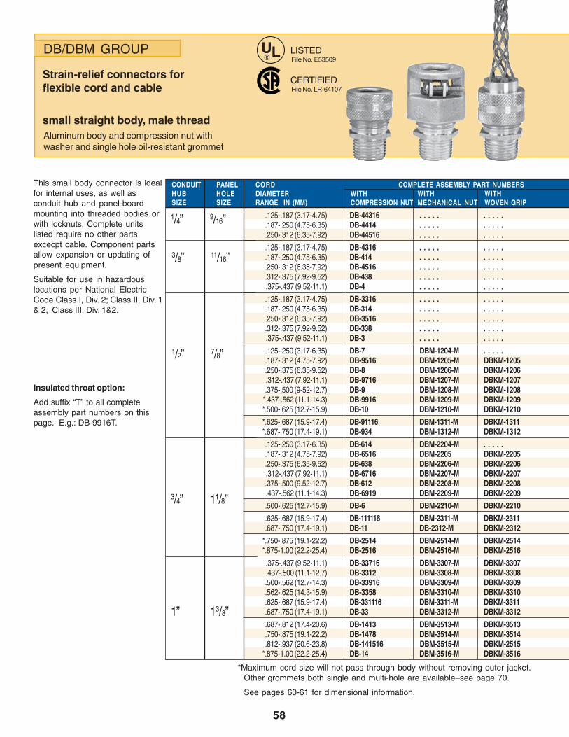
58
Insulated throat option:
Add suffix “T” to all completeassembly part numbers on thispage. E.g.: DB-9916T.
DB/DBM GROUP
Strain-relief connectors forflexible cord and cable
small straight body, male threadAluminum body and compression nut withwasher and single hole oil-resistant grommet
UL®
CERTIFIEDFile No. LR-64107
LISTEDFile No. E53509
This small body connector is idealfor internal uses, as well asconduit hub and panel-boardmounting into threaded bodies orwith locknuts. Complete unitslisted require no other partsexcecpt cable. Component partsallow expansion or updating ofpresent equipment.
Suitable for use in hazardouslocations per National ElectricCode Class I, Div. 2; Class II, Div. 1& 2; Class III, Div. 1&2.
CONDUIT PANEL CORDHUB HOLE DIAMETER WITH WITH WITHSIZE SIZE RANGE IN (MM) COMPRESSION NUT MECHANICAL NUT WOVEN GRIP
.125-.187 (3.17-4.75) DB-44316 . . . . . . . . . .
.187-.250 (4.75-6.35) DB-4414 . . . . . . . . . .
.250-.312 (6.35-7.92) DB-44516 . . . . . . . . . .
.125-.187 (3.17-4.75) DB-4316 . . . . . . . . . .
.187-.250 (4.75-6.35) DB-414 . . . . . . . . . .
.250-.312 (6.35-7.92) DB-4516 . . . . . . . . . .
.312-.375 (7.92-9.52) DB-438 . . . . . . . . . ..375-.437 (9.52-11.1) DB-4 . . . . . . . . . .
.125-.187 (3.17-4.75) DB-3316 . . . . . . . . . .
.187-.250 (4.75-6.35) DB-314 . . . . . . . . . .
.250-.312 (6.35-7.92) DB-3516 . . . . . . . . . .
.312-.375 (7.92-9.52) DB-338 . . . . . . . . . ..375-.437 (9.52-11.1) DB-3 . . . . . . . . . .
.125-.250 (3.17-6.35) DB-7 DBM-1204-M . . . . .
.187-.312 (4.75-7.92) DB-9516 DBM-1205-M DBKM-1205
.250-.375 (6.35-9.52) DB-8 DBM-1206-M DBKM-1206.312-.437 (7.92-11.1) DB-9716 DBM-1207-M DBKM-1207.375-.500 (9-52-12.7) DB-9 DBM-1208-M DBKM-1208
*.437-.562 (11.1-14.3) DB-9916 DBM-1209-M DBKM-1209*.500-.625 (12.7-15.9) DB-10 DBM-1210-M DBKM-1210
*.625-.687 (15.9-17.4) DB-91116 DBM-1311-M DBKM-1311*.687-.750 (17.4-19.1) DB-934 DBM-1312-M DBKM-1312
.125-.250 (3.17-6.35) DB-614 DBM-2204-M . . . . .
.187-.312 (4.75-7.92) DB-6516 DBM-2205 DBKM-2205
.250-.375 (6.35-9.52) DB-638 DBM-2206-M DBKM-2206.312-.437 (7.92-11.1) DB-6716 DBM-2207-M DBKM-2207.375-.500 (9.52-12.7) DB-612 DBM-2208-M DBKM-2208.437-.562 (11.1-14.3) DB-6919 DBM-2209-M DBKM-2209
.500-.625 (12.7-15.9) DB-6 DBM-2210-M DBKM-2210
.625-.687 (15.9-17.4) DB-111116 DBM-2311-M DBKM-2311
.687-.750 (17.4-19.1) DB-11 DB-2312-M DBKM-2312
*.750-.875 (19.1-22.2) DB-2514 DBM-2514-M DBKM-2514*.875-1.00 (22.2-25.4) DB-2516 DBM-2516-M DBKM-2516
.375-.437 (9.52-11.1) DB-33716 DBM-3307-M DBKM-3307
.437-.500 (11.1-12.7) DB-3312 DBM-3308-M DBKM-3308.500-.562 (12.7-14.3) DB-33916 DBM-3309-M DBKM-3309.562-.625 (14.3-15.9) DB-3358 DBM-3310-M DBKM-3310.625-.687 (15.9-17.4) DB-331116 DBM-3311-M DBKM-3311.687-.750 (17.4-19.1) DB-33 DBM-3312-M DBKM-3312
.687-.812 (17.4-20.6) DB-1413 DBM-3513-M DBKM-3513
.750-.875 (19.1-22.2) DB-1478 DBM-3514-M DBKM-3514
.812-.937 (20.6-23.8) DB-141516 DBM-3515-M DBKM-2515*.875-1.00 (22.2-25.4) DB-14 DBM-3516-M DBKM-3516
*Maximum cord size will not pass through body without removing outer jacket. Other grommets both single and multi-hole are available–see page 70.
See pages 60-61 for dimensional information.
1/4” 9/16”
3/8” 11/16”
1/2” 7/8”
3/4” 11/8”
1” 13/8”
COMPLETE ASSEMBLY PART NUMBERS
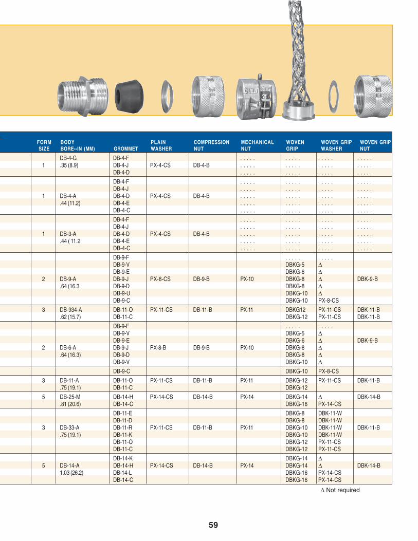
59
COMPONENT PART NUMBERSFORM BODY PLAIN COMPRESSION MECHANICAL WOVEN WOVEN GRIP WOVEN GRIPSIZE BORE--IN (MM) GROMMET WASHER NUT NUT GRIP WASHER NUT
DB-4-G DB-4-F . . . . . . . . . . . . . . . . . . . .1 .35 (8.9) DB-4-J PX-4-CS DB-4-B . . . . . . . . . . . . . . . . . . . .
DB-4-D . . . . . . . . . . . . . . . . . . . .
DB-4-F . . . . . . . . . . . . . . . . . . . .DB-4-J . . . . . . . . . . . . . . . . . . . .
1 DB-4-A DB-4-D PX-4-CS DB-4-B . . . . . . . . . . . . . . . . . . . ..44 (11.2) DB-4-E . . . . . . . . . . . . . . . . . . . .
DB-4-C . . . . . . . . . . . . . . . . . . . .
DB-4-F . . . . . . . . . . . . . . . . . . . .DB-4-J . . . . . . . . . . . . . . . . . . . .
1 DB-3-A DB-4-D PX-4-CS DB-4-B . . . . . . . . . . . . . . . . . . . ..44 ( 11.2 DB-4-E . . . . . . . . . . . . . . . . . . . .
DB-4-C . . . . . . . . . . . . . . . . . . . .
DB-9-F . . . . . . . . . .DB-9-V DBKG-5 ∆DB-9-E DBKG-6 ∆
2 DB-9-A DB-9-J PX-8-CS DB-9-B PX-10 DBKG-8 ∆ DBK-9-B.64 (16.3 DB-9-D DBKG-8 ∆
DB-9-U DBKG-10 ∆DB-9-C DBKG-10 PX-8-CS
3 DB-934-A DB-11-O PX-11-CS DB-11-B PX-11 DBKG12 PX-11-CS DBK-11-B.62 (15.7) DB-11-C DBKG-12 PX-11-CS DBK-11-B
DB-9-F . . . . . . . . . .DB-9-V DBKG-5 ∆DB-9-E DBKG-6 ∆ DBK-9-B
2 DB-6-A DB-9-J PX-8-B DB-9-B PX-10 DBKG-8 ∆.64 (16.3) DB-9-D DBKG-8 ∆
DB-9-V DBKG-10 ∆DB-9-C DBKG-10 PX-8-CS
3 DB-11-A DB-11-O PX-11-CS DB-11-B PX-11 DBKG-12 PX-11-CS DBK-11-B.75 (19.1) DB-11-C DBKG-12
5 DB-25-M DB-14-H PX-14-CS DB-14-B PX-14 DBKG-14 ∆ DBK-14-B.81 (20.6) DB-14-C DBKG-16 PX-14-CS
DB-11-E DBKG-8 DBK-11-WDB-11-D DBKG-8 DBK-11-W
3 DB-33-A DB-11-R PX-11-CS DB-11-B PX-11 DBKG-10 DBK-11-W DBK-11-B.75 (19.1) DB-11-K DBKG-10 DBK-11-W
DB-11-O DBKG-12 PX-11-CSDB-11-C DBKG-12 PX-11-CS
DB-14-K DBKG-14 ∆5 DB-14-A DB-14-H PX-14-CS DB-14-B PX-14 DBKG-14 ∆ DBK-14-B
1.03 (26.2) DB-14-L DBKG-16 PX-14-CSDB-14-C DBKG-16 PX-14-CS
∆ Not required
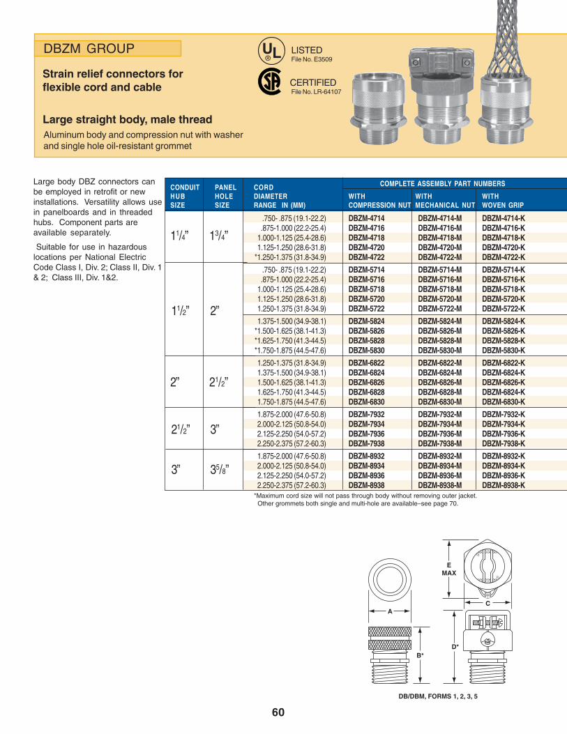
60
DBZM GROUP
Strain relief connectors forflexible cord and cable
Large straight body, male threadAluminum body and compression nut with washerand single hole oil-resistant grommet
Large body DBZ connectors canbe employed in retrofit or newinstallations. Versatility allows usein panelboards and in threadedhubs. Component parts areavailable separately.
Suitable for use in hazardouslocations per National ElectricCode Class I, Div. 2; Class II, Div. 1& 2; Class III, Div. 1&2.
CONDUIT PANEL CORDHUB HOLE DIAMETER WITH WITH WITHSIZE SIZE RANGE IN (MM) COMPRESSION NUT MECHANICAL NUT WOVEN GRIP
.750- .875 (19.1-22.2) DBZM-4714 DBZM-4714-M DBZM-4714-K.875-1.000 (22.2-25.4) DBZM-4716 DBZM-4716-M DBZM-4716-K
1.000-1.125 (25.4-28.6) DBZM-4718 DBZM-4718-M DBZM-4718-K1.125-1.250 (28.6-31.8) DBZM-4720 DBZM-4720-M DBZM-4720-K
*1.250-1.375 (31.8-34.9) DBZM-4722 DBZM-4722-M DBZM-4722-K
.750- .875 (19.1-22.2) DBZM-5714 DBZM-5714-M DBZM-5714-K.875-1.000 (22.2-25.4) DBZM-5716 DBZM-5716-M DBZM-5716-K
1.000-1.125 (25.4-28.6) DBZM-5718 DBZM-5718-M DBZM-5718-K1.125-1.250 (28.6-31.8) DBZM-5720 DBZM-5720-M DBZM-5720-K1.250-1.375 (31.8-34.9) DBZM-5722 DBZM-5722-M DBZM-5722-K
1.375-1.500 (34.9-38.1) DBZM-5824 DBZM-5824-M DBZM-5824-K*1.500-1.625 (38.1-41.3) DBZM-5826 DBZM-5826-M DBZM-5826-K*1.625-1.750 (41.3-44.5) DBZM-5828 DBZM-5828-M DBZM-5828-K*1.750-1.875 (44.5-47.6) DBZM-5830 DBZM-5830-M DBZM-5830-K
1.250-1.375 (31.8-34.9) DBZM-6822 DBZM-6822-M DBZM-6822-K1.375-1.500 (34.9-38.1) DBZM-6824 DBZM-6824-M DBZM-6824-K1.500-1.625 (38.1-41.3) DBZM-6826 DBZM-6826-M DBZM-6826-K1.625-1.750 (41.3-44.5) DBZM-6828 DBZM-6828-M DBZM-6824-K1.750-1.875 (44.5-47.6) DBZM-6830 DBZM-6830-M DBZM-6830-K
1.875-2.000 (47.6-50.8) DBZM-7932 DBZM-7932-M DBZM-7932-K2.000-2.125 (50.8-54.0) DBZM-7934 DBZM-7934-M DBZM-7934-K2.125-2.250 (54.0-57.2) DBZM-7936 DBZM-7936-M DBZM-7936-K2.250-2.375 (57.2-60.3) DBZM-7938 DBZM-7938-M DBZM-7938-K
1.875-2.000 (47.6-50.8) DBZM-8932 DBZM-8932-M DBZM-8932-K2.000-2.125 (50.8-54.0) DBZM-8934 DBZM-8934-M DBZM-8934-K2.125-2.250 (54.0-57.2) DBZM-8936 DBZM-8936-M DBZM-8936-K2.250-2.375 (57.2-60.3) DBZM-8938 DBZM-8938-M DBZM-8938-K
*Maximum cord size will not pass through body without removing outer jacket. Other grommets both single and multi-hole are available–see page 70.
11/4” 13/4”
11/2” 2”
LISTEDFile No. E3509
CERTIFIEDFile No. LR-64107
2” 21/2”
21/2” 3”
3” 35/8”
COMPLETE ASSEMBLY PART NUMBERS
UL®
B*D*
C
EMAX
A
DB/DBM, FORMS 1, 2, 3, 5

61
COMPONENT PART NUMBERS
FORM SIZEDIMENSIONS 1 2 3 5 7-Z 8-Z 9-ZA .88 1.13 1.25 1.63 2.23 2.53 3.28B * 1.53 1.84 2.06 2.69 3.22 3.22 3.91C – 1.38 1.38 1.75 2.00 2.50 3.00D * – 2.49 2.69 3.50 4.02 4.43 4.88E MAX – 1.66 1.66 2.069 2.78 3.46 4.10
*With nut snug, grommet not compressed.
ACROSSFLATS
FORM BODY PLAIN COMPRESSION MECHANICAL WOVEN WOVEN GRIP WOVEN GRIPSIZE BORE–IN (MM) GROMMET WASHER NUT NUT GRIP WASHER NUT
DBZ-714 DBZ-716-W DBKG-14 LZW-9316-16ADBZ-716 DBZ-716-W DBKG-16 LZW-9316-16A
7-Z DBZ-47-M DBZ-718 DBZ-720-W DBZ-7-B DBZ-7-B DBKG-18 LZW-9316-20A DBZ-7-B1.31 (33.2) DBZ-720 DBZ-720-W DBKG-20 LZW-9316-20A
DBZ-722 DBZ-723-W DBKG-22 ∆DBZ-714 DBZ-716-W DBKG-14 LZW-9316-16ADBZ-716 DBZ-716-W DBKG-16 LZW-9316-16A
7-Z DBZ-57-M DBZ-718 DBZ-720-W DBZ-7-B DBZ-7-M DBKG-18 LZW-9316-20A DBZ-7-B1.44 (36.6) DBZ-720 DBZ-720-W DBKG-20 LZW-9316-20A
DBZ-722 DBZ-723-W DBKG-22 ∆DBZ-824 DBZ-824-W DBKG-26 ∆
8-Z DBZ-58-M DBZ-826 DBZ-826-W DBZ-8-B DBZ-8-M DBKG-26 ∆ DBZ-8-B1.56 (39.7) DBZ-828 DBZ-828-W DBKG-28 ∆
DBZ-830 DBZ-831-W DBKG-28 ∆DBZ-822 DBZ-824-W DBKG-22 LZW-9320-22ADBZ-824 DBZ-824-W DBKG-26 ∆
8-Z DBZ-68-M DBZ-826 DBZ-828-W DBZ-8-B DBZ-8-M DBKG-26 ∆ DBZ-8-B1.94 (49.2) DBZ-828 DBZ-828-W DBKG-28 ∆
DBZ-830 DBZ-831-W DBKG-28 ∆DBZ-932 DBZ-932-W DBKG-34 ∆
9-Z DBZ-79-M DBZ-934 DBZ-936-W DBZ-9-B DBZ-9-M DBKG-34 ∆ DBZ-9-B2.44 (62.0) DBZ-936 DBZ-936-W DKGZ-38 ∆
DBZ-938 DBZ-939-W DBKG-38 ∆DBZ-932 DBZ-932-W DBKG-34 ∆
9-Z DBZ-89-M DBZ-934 DBZ-936-W DBZ-9-B DBZ-9-M DBKG-34 ∆ DBZ-9-B2.44 (62.0) DBZ-936 DBZ-936-W DBKG-38 ∆
DBZ-938 DBZ-939-W DBKG-38 ∆∆ Not required
D*B*
DBZ, FORMS 7-Z, 8-Z, 9-Z
A
C
E Max

62
DBL/DBZL GROUP
Strain-relief connectorsfor flexible cord and cable
90° elbow body, male threadFerrous alloy body, aluminum compression nutwith washer and single hole oil-resistant grommet
These 90° connectors allow theinstallation of cord and cable evenin tight quarters. Rugged ferrousalloy body and aluminumcompression nut assure long life inabusive situations.
Suitable for use in hazardouslocations per National ElectricCode Class I, Div. 2; Class II, Div. 1& 2; Class III, Div. 1&2.
CONDUIT PANEL CORDHUB HOLE DIAMETER WITH WITH WITHSIZE SIZE RANGE IN (MM) COMPRESSION NUT MECHANICAL NUT WOVEN GRIP
.125-.250 (3.17-6.35) DB-790 DBL-1204-M . . . . .
.187-.312 (4.75-7.92) DB-9590 DBL-1205-M DBKL-1205
.250-.375 (6.35-9.52) DB-890 DBL-1206-M DBKL-1206.312-.437 (7.92-11.1) DB-9790 DBL-1207-M DBKL-1207.375-.500 (9.52-12.7) DB-990 DBL-1208-M DBKL-1208
* .437-.562 (11.1-14.3) DB-9990 DBL-1209-M DBKL-1209* .500-.625 (12.7-15.9) DB-1090 DBL-1210-M DBKL-1210
.312-.375 (7.92-9.52) DB-113890 DBL-2306-M DBKL-2306.375-.437 (9.52-11.1) DB-1171690 DBL-2307-M DBKL-2307.437-.500 (11.1-12.7) DB-111290 DBL-2308-M DBKL-2308.500-.562 (12.7-14.3) DB-1191690 DBL-2309-M DBKL-2309.562-.625 (14.3-15.9) DB-115890 DBL-2310-M DBKL-2310.625-.687 (15.9-17.4) DB-11111690 DBL-2311-M DBKL-2311
* .687-.750 (17.4-19.1) DB-1190 DBL-2312-M DBKL-2312
.687-.812 (17.4-20.6) DB-141390 DBL-3513-M DBKL-3513
.750-.875 (19.1-22.2) DB-147890 DBL-3514-M DBKL-3514
.812-.937 (20.6-23.8) DB-14151690 DBL-3515-M DBKL-3515* .875-1.000 (22.2-25.4) DB-1490 DBL-3516-M DBKL-3516
.750-.875 (19.1-22.2) DBZL-4714 DBZL-4714-M DBZL-4714-K.875-1.000 (22.2-25.4) DBZL-4716 DBZL-4716-M DBZL-4716-K
1.000-1.125 (25.4-28.6) DBZL-4718 DBZL-4718-M DBZL-4718-K1.125-1.250 (28.6-31.8) DBZL-4720 DBZL-4720-M DBZL-4720-K
*1.250-1.375 (31.8-34.9) DBZL-4722 DBZL-4722-M DBZL-4722-K
*1.375-1.500 (34.9-38.1) DBZL-5824 DBZL-5824-M DBZL-5824-K*1.500-1.625 (38.1-41.3) DBZL-5826 DBZL-5826-M DBZL-5826-K*1.625-1.750 (41.3-44.5) DBZL-5828 DBZL-5828-M DBZL-5828-K*1.750-1.875 (44.5-47.6) DBZL-5830 DBZL-5830-M DBZL-5830-K
*1.375-1.500 (34.9-38.1) DBZL-6824 DBZL-6824-M DBZL-6824-K*1.500-1.625 (38.1-14.3) DBZL-6826 DBZL-6826-M DBZL-6826-K*1.625-1.875 (44.5-47.6) DBZL-6828 DBZL-6828-M DBZL-6828-K*1.750-1.875 (44.5-47.6) DBZL-6830 DBZL-6830-M DBZL-6830-K
*Maximum cord size will not pass through body without removing outer jacket. Other grommets both single and multi-hole are available–see page 70.
LISTEDFile No. E53509
CERTIFIEDFile No. LR-64107
COMPLETE ASSEMBLY PART NUMBERS
Insulated throat option:
Add suffix “T” to completeassembly part numbersfor ½”-1” only.
E.g.:DBL-3514-MT.
1/2” 7/8”
3/4” 11/8”
1” 13/8”
11/4” 13/4”
11/2” 2”
2” 21/2”
UL®
A
D
C
B†
F
D
E†
DBL, FORMS 2, 3, 5 DBLZ, FORMS 7-Z, 8-Z
B†
C
A
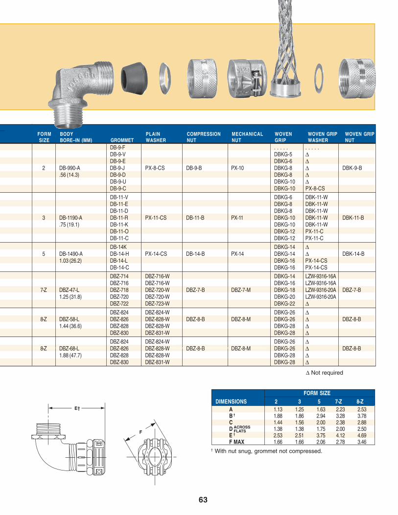
63
COMPONENT PART NUMBERS
FORM SIZEDIMENSIONS 2 3 5 7-Z 8-Z
A 1.13 1.25 1.63 2.23 2.53B † 1.88 1.86 2.94 3.28 3.78C 1.44 1.56 2.00 2.38 2.88D 1.38 1.38 1.75 2.00 2.50E † 2.53 2.51 3.75 4.12 4.69F MAX 1.66 1.66 2.06 2.78 3.46
† With nut snug, grommet not compressed.
ACROSSFLATS
FORM BODY PLAIN COMPRESSION MECHANICAL WOVEN WOVEN GRIP WOVEN GRIPSIZE BORE–IN (MM) GROMMET WASHER NUT NUT GRIP WASHER NUT
DB-9-F . . . . . . . . . .DB-9-V DBKG-5 ∆DB-9-E DBKG-6 ∆
2 DB-990-A DB-9-J PX-8-CS DB-9-B PX-10 DBKG-8 ∆ DBK-9-B.56 (14.3) DB-9-D DBKG-8 ∆
DB-9-U DBKG-10 ∆DB-9-C DBKG-10 PX-8-CS
DB-11-V DBKG-6 DBK-11-WDB-11-E DBKG-8 DBK-11-WDB-11-D DBKG-8 DBK-11-W
3 DB-1190-A DB-11-R PX-11-CS DB-11-B PX-11 DBKG-10 DBK-11-W DBK-11-B.75 (19.1) DB-11-K DBKG-10 DBK-11-W
DB-11-O DBKG-12 PX-11-CDB-11-C DBKG-12 PX-11-C
DB-14K DBKG-14 ∆5 DB-1490-A DB-14-H PX-14-CS DB-14-B PX-14 DBKG-14 ∆ DBK-14-B
1.03 (26.2) DB-14-L DBKG-16 PX-14-CSDB-14-C DBKG-16 PX-14-CS
DBZ-714 DBZ-716-W DBKG-14 LZW-9316-16ADBZ-716 DBZ-716-W DBKG-16 LZW-9316-16A
7-Z DBZ-47-L DBZ-718 DBZ-720-W DBZ-7-B DBZ-7-M DBKG-18 LZW-9316-20A DBZ-7-B1.25 (31.8) DBZ-720 DBZ-720-W DBKG-20 LZW-9316-20A
DBZ-722 DBZ-723-W DBKG-22 ∆DBZ-824 DBZ-824-W DBKG-26 ∆
8-Z DBZ-58-L DBZ-826 DBZ-828-W DBZ-8-B DBZ-8-M DBKG-26 ∆ DBZ-8-B1.44 (36.6) DBZ-828 DBZ-828-W DBKG-28 ∆
DBZ-830 DBZ-831-W DBKG-28 ∆DBZ-824 DBZ-824-W DBKG-26 ∆
8-Z DBZ-68-L DBZ-826 DBZ-828-W DBZ-8-B DBZ-8-M DBKG-26 ∆ DBZ-8-B1.88 (47.7) DBZ-828 DBZ-828-W DBKG-28 ∆
DBZ-830 DBZ-831-W DBKG-28 ∆
∆ Not required
F
E†

64
DBA GROUP
Strain relief connectors forflexible cord and cable
45° elbow body, male threadFerrous alloy body, aluminum compression nutwith washer and single hole oil-resistant grommet
Customize your installationwith our 45° DBA connectors.Like the DBL, the steel bodyand aluminum compressionnut will provide many years oftrouble free service.
CONDUIT PANEL CORDHUB HOLE DIAMETER WITH WITH WITHSIZE SIZE RANGE IN (MM) COMPRESSION NUT MECHANICAL NUT WOVEN GRIP
.125-.250 (3.17-6.35) DB-745 DBA-1204-M . . . . .
.187-.312 (4.75-7.92) DB-9545 DBA-1205-M DBKA-1205
.250-.375 (6.35-9.52) DB-845 DBA-1206-M DBKA-1206.312-.437 (7.92-11.1) DB-9745 DBA-1207-M DBKA-1207.375-.500 (9.52-12.7) DB-945 DBA-1208-M DBKA-1208
* .437-.562 (11.1-14.3) DB-9945 DBA-1209-M DBKA-1209*.500-.625 (12.7-15.9) DB-1045 DBA-1210-M DBKA-1210
.312-.375 (7.92-9.52) DB-113845 DBA-2306-M DBKA-2306.375-.437 (9.52-11.1) DB-1171645 DBA-2307 DBKA-2307.437-.500 (11.1-12.7) DB-111245 DBA-2308-M DBKA-2308.500-.562 (12.7-14.3) DB-1191645 DBA-2309-M DBKA-2309.562-.625 (14.3-15.9) DB-15845 DBA-2310-M DBKA-2310.625-.687 (15.9-17.4) DB-11111645 DBA-2311-M DBKA-2311
*.687-.750 (17.4-19.1) DB-1145 DBA-2312-M DBKA-2312
.687-.812 (17.4-14.2) DB-141345 DBA-3513-M DBKA-3513
.750-.875 (19.1-22.2) DB-147845 DBA-3514-M DBKA-3514
.812-.937 (14.2-23.8) DB-14151645 DBA-3515-M DBKA-3515*.875-1.000 (22.2-25.4) DB-1445 DBA-3516-M DBKA-3516
*Maximum cord size will not pass through body without removing outer jacket. Other grommets both single and multi-hole are available–see page 70.
LISTED
CERTIFIEDFile No. LR-64107
COMPLETE ASSEMBLY PART NUMBERS
Insulated throat option:
Add suffix “T” to all completeassembly part numberson this page.
E.g.:DBKA-3513-T.
1/2” 7/8”
3/4” 11/8”
1” 13/8”
FORM SIZEDIMENSIONS 2 3 5
A 1.13 1.25 1.63B† 1.31 1.56 2.31C 1.31 1.38 1.44D† 1.96 2.21 3.12E 1.38 1.38 1.75FMAX 1.66 1.66 2.06
ACROSSFLATS
†With nut snug, grommet notcompressed
B†
C
A
D†
C
E
F
File No. E53509
UL®
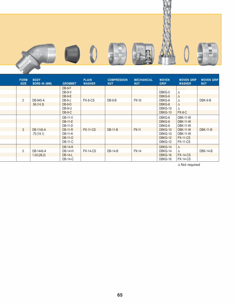
65
COMPONENT PART NUMBERSFORM BODY PLAIN COMPRESSION MECHANICAL WOVEN WOVEN GRIP WOVEN GRIPSIZE BORE–IN (MM) GROMMET WASHER NUT NUT GRIP WASHER NUT
DB-9-F . . . . . . . . . .DB-9-V DBKG-5 ∆DB-9-E DBKG-6 ∆
2 DB-945-A DB-9-J PX-8-CS DB-9-B PX-10 DBKG-8 ∆ DBK-9-B.56 (14.3) DB-9-D DBKG-8 ∆
DB-9-U DBKG-10 ∆DB-9-C DBKG-10 PX-8-C
DB-11-V DBKG-6 DBK-11-WDB-11-E DBKG-8 DBK-11-WDB-11-D DBKG-8 DBK-11-W
3 DB-1145-A DB-11-R PX-11-CS DB-11-B PX-11 DBKG-10 DBK-11-W DBK-11-B.75 (19.1) DB-11-K DBKG-10 DBK-11-W
DB-11-O DBKG-12 PX-11-CSDB-11-C DBKG-12 PX-11-CS
DB-14-K DBKG-14 ∆5 DB-1445-A DB-14-H PX-14-CS DB-14-B PX-14 DBKG-14 ∆ DBK-14-B
1.03 (26.2) DB-14-L DBKG-16 PX-14-CSDB-14-C DBKG-16 PX-14-CS
∆ Not required
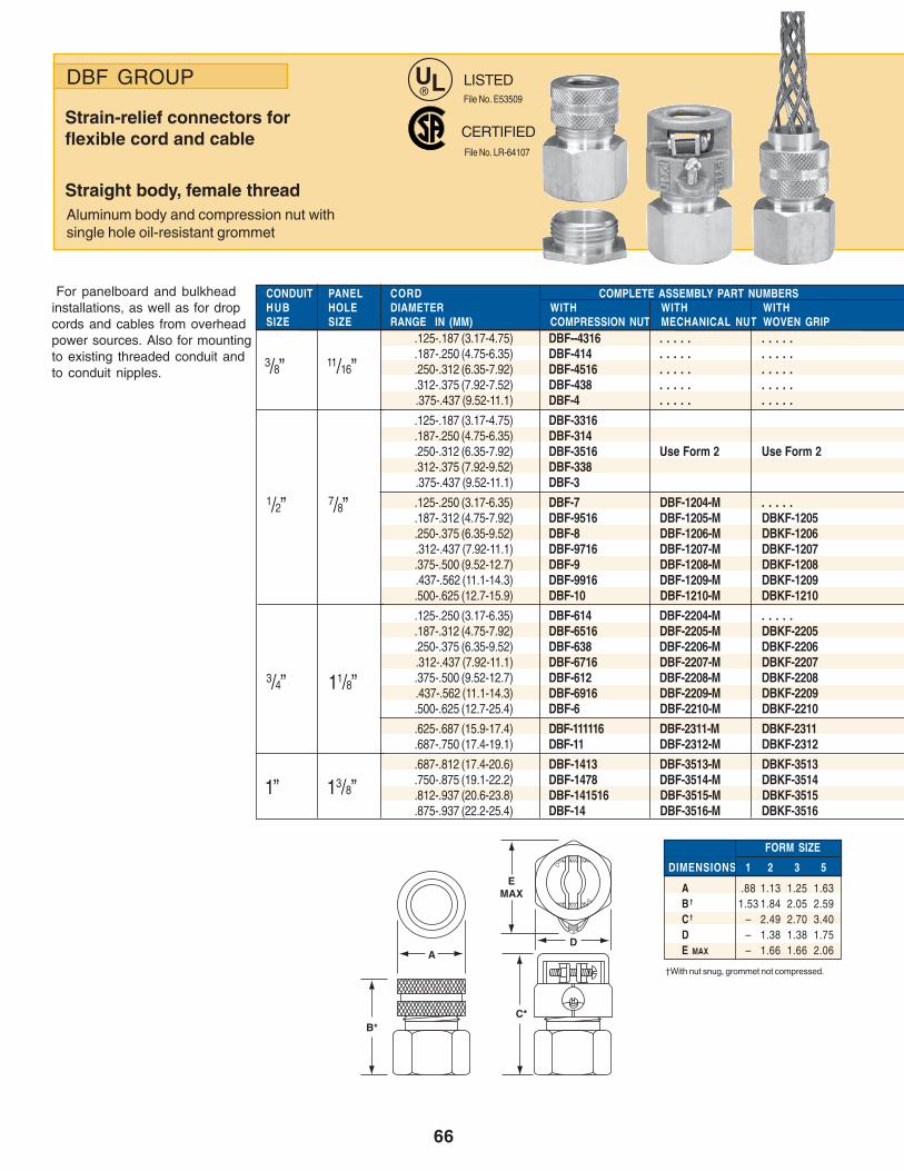
66
DBF GROUP
Strain-relief connectors forflexible cord and cable
Straight body, female threadAluminum body and compression nut withsingle hole oil-resistant grommet
For panelboard and bulkheadinstallations, as well as for dropcords and cables from overheadpower sources. Also for mountingto existing threaded conduit andto conduit nipples.
CONDUIT PANEL CORDHUB HOLE DIAMETER WITH WITH WITHSIZE SIZE RANGE IN (MM) COMPRESSION NUT MECHANICAL NUT WOVEN GRIP
.125-.187 (3.17-4.75) DBF--4316 . . . . . . . . . .
.187-.250 (4.75-6.35) DBF-414 . . . . . . . . . .
.250-.312 (6.35-7.92) DBF-4516 . . . . . . . . . .
.312-.375 (7.92-7.52) DBF-438 . . . . . . . . . ..375-.437 (9.52-11.1) DBF-4 . . . . . . . . . .
.125-.187 (3.17-4.75) DBF-3316
.187-.250 (4.75-6.35) DBF-314
.250-.312 (6.35-7.92) DBF-3516 Use Form 2 Use Form 2
.312-.375 (7.92-9.52) DBF-338.375-.437 (9.52-11.1) DBF-3
.125-.250 (3.17-6.35) DBF-7 DBF-1204-M . . . . .
.187-.312 (4.75-7.92) DBF-9516 DBF-1205-M DBKF-1205
.250-.375 (6.35-9.52) DBF-8 DBF-1206-M DBKF-1206.312-.437 (7.92-11.1) DBF-9716 DBF-1207-M DBKF-1207.375-.500 (9.52-12.7) DBF-9 DBF-1208-M DBKF-1208.437-.562 (11.1-14.3) DBF-9916 DBF-1209-M DBKF-1209.500-.625 (12.7-15.9) DBF-10 DBF-1210-M DBKF-1210
.125-.250 (3.17-6.35) DBF-614 DBF-2204-M . . . . .
.187-.312 (4.75-7.92) DBF-6516 DBF-2205-M DBKF-2205
.250-.375 (6.35-9.52) DBF-638 DBF-2206-M DBKF-2206.312-.437 (7.92-11.1) DBF-6716 DBF-2207-M DBKF-2207.375-.500 (9.52-12.7) DBF-612 DBF-2208-M DBKF-2208.437-.562 (11.1-14.3) DBF-6916 DBF-2209-M DBKF-2209.500-.625 (12.7-25.4) DBF-6 DBF-2210-M DBKF-2210
.625-.687 (15.9-17.4) DBF-111116 DBF-2311-M DBKF-2311
.687-.750 (17.4-19.1) DBF-11 DBF-2312-M DBKF-2312
.687-.812 (17.4-20.6) DBF-1413 DBF-3513-M DBKF-3513
.750-.875 (19.1-22.2) DBF-1478 DBF-3514-M DBKF-3514
.812-.937 (20.6-23.8) DBF-141516 DBF-3515-M DBKF-3515
.875-.937 (22.2-25.4) DBF-14 DBF-3516-M DBKF-3516
LISTEDFile No. E53509
CERTIFIED
COMPLETE ASSEMBLY PART NUMBERS
3/8” 11/16”
1/2” 7/8”
3/4” 11/8”
1” 13/8”
FORM SIZE
DIMENSIONS 1 2 3 5
A .88 1.13 1.25 1.63B † 1.53 1.84 2.05 2.59C † – 2.49 2.70 3.40D – 1.38 1.38 1.75E MAX – 1.66 1.66 2.06
†With nut snug, grommet not compressed.
File No. LR-64107
B*C*
D
EMAX
A
UL®

67
COMPONENT PART NUMBERS
*FLARED NIPPLE
Used for mounting type DBF connectors on sheet metalboxes and cabinets, and for drop cords/cables fromoverhead power distribution ducts.
Flared Nipple not included unless specially ordered. Toinclude flared nipple with assembly change catalog numbersas follows:
• with compression nut, change DBF to DHF• with mechanical nut, change DBF to DBH• with weave grip, change DBKF to DBKH
HUB MAX. PANEL PARTSIZE THICKNESS NO. A B C D E F
3/8” 1/8” DH-38 .86 .44 .33 .12 .09 .69
1/2” 3/16” DH-1 1.00 .56 .44 .12 .12 .86
3/4” 3/16” DH-2 1.25 .80 .44 .12 .12 1.09
1” 1/4” DH-3 1.50 1.00 .56 .19 .16 1.36
DIMENSIONS
A
BE
C D
F – Recommended minimum clearance(Standard knockouts satisfactory).
FORM BODY PLAIN COMPRESSION MECHANICAL WOVEN WOVEN GRIP WOVEN GRIP FLAREDSIZE BORE–IN (MM) GROMMET WASHER NUT NUT GRIP WASHER NUT NIPPLE*
DB-4-F . . . . . . . . . . . . . . . . . . . .DB-4-J . . . . . . . . . . . . . . . . . . . .
1 DBF-4-A DB-4-D PX-4-CS DB-4-B . . . . . . . . . . . . . . . . . . . . DH-38.440 (11.2) DB-4-E . . . . . . . . . . . . . . . . . . . .
DB-4-C . . . . . . . . . . . . . . . . . . . .
DB-4-F . . . . . . . . . . . . . . . . . . . .DB-4-J . . . . . . . . . . . . . . . . . . . .
1 DBF-3-A DB-4-D PX-4-CS DB-4-B . . . . . . . . . . . . . . . . . . . . DH-1.440 (11.2) DB-4-E . . . . . . . . . . . . . . . . . . . .
DB-4-C . . . . . . . . . . . . . . . . . . . .
DB-9-F . . . . . . . . . .DB-9-V DBKG-5 ∆DB-9-E DBKG-6 ∆
2 DBF-9-A DB-9-J PS-8-CS DB-9-B PX-10 DBKG-8 ∆ DBK-9-B DH-1.620 (15.7) DB-9-D DBKG-8 ∆
DB-9-V DBKG-10 ∆DB-9-C DBKG-10 PX-8-CS
DB-9-F . . . . . . . . . . . . . . .DB-9-V DBKG-5 ∆DB-9-E DBKG-6 ∆
2 DBF-6-A DB-9-J PX-8-CS DB-9-B PX-10 DBKG-8 ∆ DBK-9-B DH-2.620 (15.7) DB-9-D DBKG-8 ∆
DB-9-V DBKG-10 ∆DB-9-C DBKG-10 PX-8-CS
3 DBA-11-A DB-11-O PX-11-CS DB-11-B PX-11 DBKG-12 PX-11-CS DBK-11-B DH-2.750 (19.1) DB-11-C DBKG-12 PX-11-CS
DB-14-K DBKF-14 ∆5 DBF-14-A DB-14-H PX-14-CS DB-14-B PX-14 DBKG-14 ∆ DBK-14-B DH-3
1.030 (26.2) DB-14-L DBKG-16 PX-14-CSDB-14-C DBKFG-16 PX-14-CS
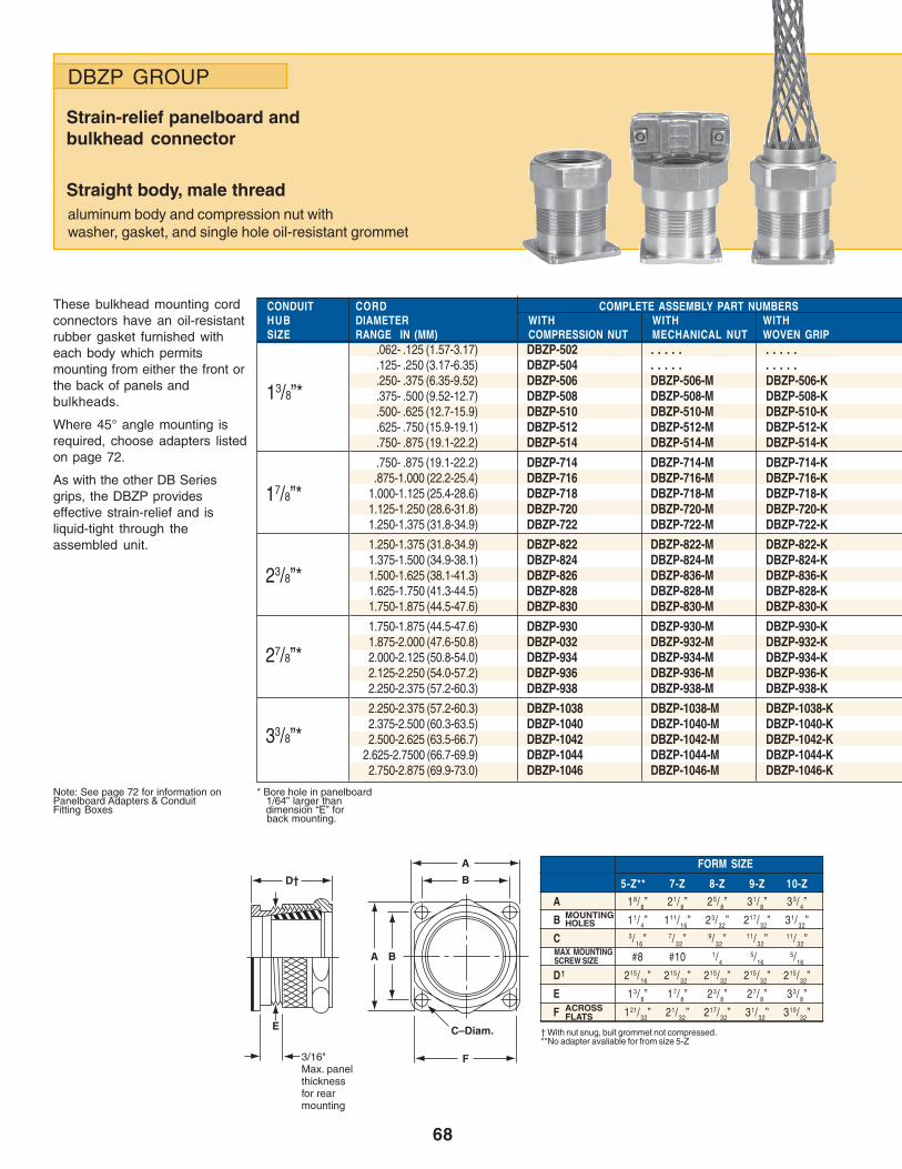
68
DBZP GROUP
Strain-relief panelboard andbulkhead connector
Straight body, male threadaluminum body and compression nut withwasher, gasket, and single hole oil-resistant grommet
These bulkhead mounting cordconnectors have an oil-resistantrubber gasket furnished witheach body which permitsmounting from either the front orthe back of panels andbulkheads.
Where 45° angle mounting isrequired, choose adapters listedon page 72.
As with the other DB Seriesgrips, the DBZP provideseffective strain-relief and isliquid-tight through theassembled unit.
CONDUIT CORDHUB DIAMETER WITH WITH WITHSIZE RANGE IN (MM) COMPRESSION NUT MECHANICAL NUT WOVEN GRIP
.062- .125 (1.57-3.17) DBZP-502 . . . . . . . . . .
.125- .250 (3.17-6.35) DBZP-504 . . . . . . . . . .
.250- .375 (6.35-9.52) DBZP-506 DBZP-506-M DBZP-506-K
.375- .500 (9.52-12.7) DBZP-508 DBZP-508-M DBZP-508-K
.500- .625 (12.7-15.9) DBZP-510 DBZP-510-M DBZP-510-K
.625- .750 (15.9-19.1) DBZP-512 DBZP-512-M DBZP-512-K
.750- .875 (19.1-22.2) DBZP-514 DBZP-514-M DBZP-514-K
.750- .875 (19.1-22.2) DBZP-714 DBZP-714-M DBZP-714-K.875-1.000 (22.2-25.4) DBZP-716 DBZP-716-M DBZP-716-K
1.000-1.125 (25.4-28.6) DBZP-718 DBZP-718-M DBZP-718-K1.125-1.250 (28.6-31.8) DBZP-720 DBZP-720-M DBZP-720-K1.250-1.375 (31.8-34.9) DBZP-722 DBZP-722-M DBZP-722-K
1.250-1.375 (31.8-34.9) DBZP-822 DBZP-822-M DBZP-822-K1.375-1.500 (34.9-38.1) DBZP-824 DBZP-824-M DBZP-824-K1.500-1.625 (38.1-41.3) DBZP-826 DBZP-836-M DBZP-836-K1.625-1.750 (41.3-44.5) DBZP-828 DBZP-828-M DBZP-828-K1.750-1.875 (44.5-47.6) DBZP-830 DBZP-830-M DBZP-830-K
1.750-1.875 (44.5-47.6) DBZP-930 DBZP-930-M DBZP-930-K1.875-2.000 (47.6-50.8) DBZP-032 DBZP-932-M DBZP-932-K2.000-2.125 (50.8-54.0) DBZP-934 DBZP-934-M DBZP-934-K2.125-2.250 (54.0-57.2) DBZP-936 DBZP-936-M DBZP-936-K2.250-2.375 (57.2-60.3) DBZP-938 DBZP-938-M DBZP-938-K
2.250-2.375 (57.2-60.3) DBZP-1038 DBZP-1038-M DBZP-1038-K2.375-2.500 (60.3-63.5) DBZP-1040 DBZP-1040-M DBZP-1040-K2.500-2.625 (63.5-66.7) DBZP-1042 DBZP-1042-M DBZP-1042-K
2.625-2.7500 (66.7-69.9) DBZP-1044 DBZP-1044-M DBZP-1044-K2.750-2.875 (69.9-73.0) DBZP-1046 DBZP-1046-M DBZP-1046-K
COMPLETE ASSEMBLY PART NUMBERS
FORM SIZE
5-Z** 7-Z 8-Z 9-Z 10-Z
A 18/8” 21/8” 25/8” 31/8” 33/4”
B 11/4” 111/16” 23/32” 217/32” 31/32”
C 3/16” 7/32” 9/32” 11/32”11/32”
#8 #10 1/45/16
5/16
D † 215/16” 215/32” 215/32” 215/32” 215/32”
E 13/8” 17/8” 23/8” 27/8” 33/8”
F 121/32” 21/32” 217/32” 31/32” 319/32”
* Bore hole in panelboard 1/64” larger than dimension “E” for back mounting.
Note: See page 72 for information onPanelboard Adapters & ConduitFitting Boxes
MOUNTINGHOLES
MAX MOUNTINGSCREW SIZE
ACROSSFLATS
† With nut snug, buit grommet not compressed.**No adapter avaliable for from size 5-Z
13/8”*
17/8”*
23/8”*
27/8”*
33/8”*
3/16"Max. panelthicknessfor rearmounting
A B
B
A
C–Diam.
F
D†
E

69
COMPONENT PART NUMBERS
∆ Not required
FORM BODY PLAIN COMPRESSION MECHANICAL WOVEN WOVEN GRIP WOVEN GRIPSIZE BORE–IN (MM) GROMMET WASHER NUT NUT GRIP WASHER NUT
DBZ-502 DBZ-504-W . . . . . . . . . . . . . . . . . . . .DBZ-504 DBZ-504-W . . . . . . . . . . . . . . . . . . . .DBZ-506 DBZ-508-W DBKG-6 LZW-9312-10A
5-Z DBZ-5-P DBZ-508 DBZ-508-W DBZ-5-B DBZ-5-M DBKG-8 LZW-9312-10A DBZ-5-B.937 (23.8) DBZ-510 DBZ-512-W DBKG-10 LZW-9312-12A
DBZ-512 DBZ-512-W DBKG-12 LZW-9312-12ADBZ-514 DBZ-515-W DBKG-14-Z ∆DBZ-714 DBZ-716-W DBKG-14 LZW-9316-16ADBZ-716 DBZ-716-W DBKG-16 LZW-9316-16A
7-Z DBZ-7-P DBZ-718 DBZ-720-W DBZ-7-M DBZ-7-M DBKG-18 LZW-9316-20A DBZ-7-B1.437 (36.5) DBZ-720 DBZ-720-W DBKG-20 LZW-9316-20A
DBZ-722 DBZ-723-W DBKG-22 ∆DBZ-822 DBZ-824-W DBKG-22 LZW-9320-22ADBZ-824 DBZ-824-W DBKG-26 ∆
8-Z DBZ-8-P DBZ-826 DBZ-828-W DBZ-8-B DBZ-8-M DBKG-26 ∆ DBZ-8-B1.937 (49.2) DBZ-828 DBZ-828-W DBKG-28 ∆
DBZ-830 DBZ-831-W DBKG-28 ∆DBZ-930 DBZ-932-W DBKG-28 LZW-9324-28ADBZ-932 DBZ-932-W DBKG-34 ∆
9-Z DBZ-9-P DBZ-934 DBZ-936-W DBZ-9-B DBZ-9-M DBKG-34 ∆ DBZ-9-B2.437 (61.9) DBZ-936 DBZ-936-W DBKG-38 ∆
DBZ-938 DBZ-939-W DBKG-38 ∆DBZ-1038 DBZP-1040-W DBKG-38 LZW-9328-38ADBZ-1040 DBZP-1040-W DBKG-40-Z ∆
10-Z DBZP-10-P DBZ-1042 DBZP-1044-W DBZ-10-B DBZ-10-M DBKG-46-Z ∆ DBZ-10-B2.875 (73.0) DBZ-1044 DBZ-1044-W DBKG-46-Z ∆
DBZ-1046 DBZ-1046-W DBKG-46-Z ∆
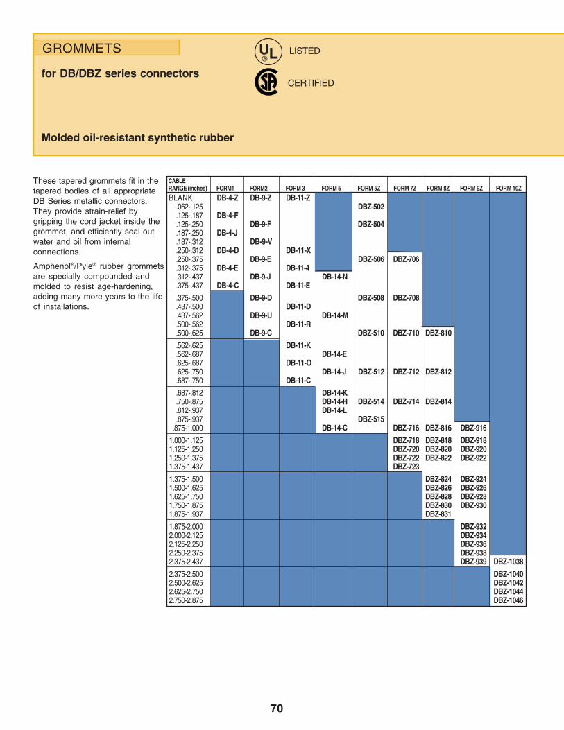
70
These tapered grommets fit in thetapered bodies of all appropriateDB Series metallic connectors.They provide strain-relief bygripping the cord jacket inside thegrommet, and efficiently seal outwater and oil from internalconnections.
Amphenol®/Pyle® rubber grommetsare specially compounded andmolded to resist age-hardening,adding many more years to the lifeof installations.
LISTED
CERTIFIED
CABLERANGE (inches) FORM1 FORM2 FORM 3 FORM 5 FORM 5Z FORM 7Z FORM 8Z FORM 9Z FORM 10Z
BLANK DB-4-Z DB-9-Z DB-11-Z.062-.125 DBZ-502.125-.187 DB-4-F.125-.250 DB-9-F DBZ-504.187-.250 DB-4-J.187-.312 DB-9-V.250-.312 DB-4-D DB-11-X.250-.375 DB-9-E DBZ-506 DBZ-706.312-.375 DB-4-E DB-11-4.312-.437 DB-9-J DB-14-N.375-.437 DB-4-C DB-11-E
.375-.500 DB-9-D DBZ-508 DBZ-708
.437-.500 DB-11-D
.437-.562 DB-9-U DB-14-M
.500-.562 DB-11-R
.500-.625 DB-9-C DBZ-510 DBZ-710 DBZ-810
.562-.625 DB-11-K
.562-.687 DB-14-E
.625-.687 DB-11-O
.625-.750 DB-14-J DBZ-512 DBZ-712 DBZ-812
.687-.750 DB-11-C
.687-.812 DB-14-K
.750-.875 DB-14-H DBZ-514 DBZ-714 DBZ-814
.812-.937 DB-14-L
.875-.937 DBZ-515.875-1.000 DB-14-C DBZ-716 DBZ-816 DBZ-916
1.000-1.125 DBZ-718 DBZ-818 DBZ-9181.125-1.250 DBZ-720 DBZ-820 DBZ-9201.250-1.375 DBZ-722 DBZ-822 DBZ-9221.375-1.437 DBZ-723
1.375-1.500 DBZ-824 DBZ-9241.500-1.625 DBZ-826 DBZ-9261.625-1.750 DBZ-828 DBZ-9281.750-1.875 DBZ-830 DBZ-9301.875-1.937 DBZ-831
1.875-2.000 DBZ-9322.000-2.125 DBZ-9342.125-2.250 DBZ-9362.250-2.375 DBZ-9382.375-2.437 DBZ-939 DBZ-1038
2.375-2.500 DBZ-10402.500-2.625 DBZ-10422.625-2.750 DBZ-10442.750-2.875 DBZ-1046
GROMMETS
for DB/DBZ series connectors
Molded oil-resistant synthetic rubber
UL®
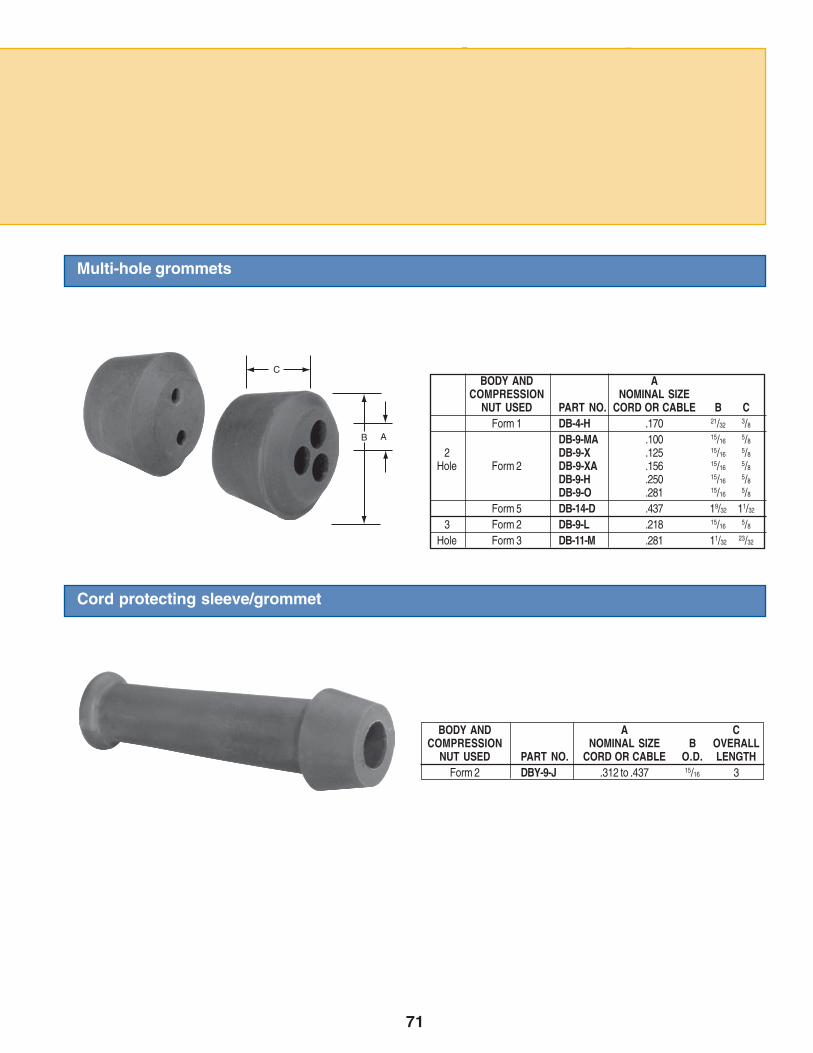
71
Multi-hole grommets
Cord protecting sleeve/grommet
BODY AND A CCOMPRESSION NOMINAL SIZE B OVERALL
NUT USED PART NO. CORD OR CABLE O.D. LENGTHForm 2 DBY-9-J .312 to .437 15/16 3
BODY AND ACOMPRESSION NOMINAL SIZE
NUT USED PART NO. CORD OR CABLE B CForm 1 DB-4-H .170 21/32 3/8
DB-9-MA .100 15/16 5/8
2 DB-9-X .125 15/16 5/8
Hole Form 2 DB-9-XA .156 15/16 5/8
DB-9-H .250 15/16 5/8
DB-9-O .281 15/16 5/8
Form 5 DB-14-D .437 19/32 11/32
3 Form 2 DB-9-L .218 15/16 5/8
Hole Form 3 DB-11-M .281 11/32 23/32
B A
C
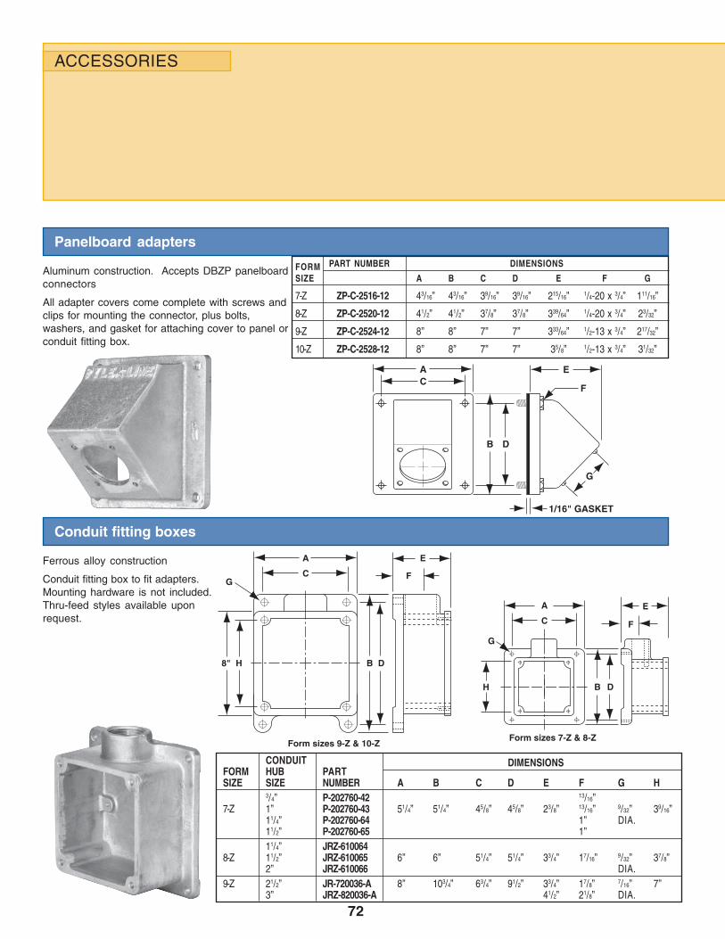
72
Panelboard adapters
Aluminum construction. Accepts DBZP panelboardconnectors
All adapter covers come complete with screws andclips for mounting the connector, plus bolts,washers, and gasket for attaching cover to panel orconduit fitting box.
Conduit fitting boxes
Ferrous alloy construction
Conduit fitting box to fit adapters.Mounting hardware is not included.Thru-feed styles available uponrequest.
G
Form sizes 9-Z & 10-ZForm sizes 7-Z & 8-Z
8" H B D
C
A
F
E
F
E
G
H B D
C
A
F
1/16" GASKET
E
DB
CA
G
CONDUITFORM HUB PARTSIZE SIZE NUMBER A B C D E F G H
3/4” P-202760-42 13/16”7-Z 1” P-202760-43 51/4” 51/4” 45/8” 45/8” 23/8” 13/16” 9/32” 39/16”
11/4” P-202760-64 1” DIA.11/2” P-202760-65 1”11/4” JRZ-610064
8-Z 11/2” JRZ-610065 6” 6” 51/4” 51/4” 33/4” 17/16” 9/32” 37/8”2” JRZ-610066 DIA.
9-Z 21/2” JR-720036-A 8” 103/4” 63/4” 91/2” 33/4” 17/8” 7/16” 7”3” JRZ-820036-A 41/2” 21/8” DIA.
DIMENSIONS
FORMSIZE A B C D E F G
7-Z ZP-C-2516-12 43/16” 43/16” 39/16” 39/16” 215/16” 1/4-20 x 3/4” 111/16”
8-Z ZP-C-2520-12 41/2” 41/2” 37/8” 37/8” 339/64” 1/4-20 x 3/4” 23/32”
9-Z ZP-C-2524-12 8” 8” 7” 7” 333/64” 1/2-13 x 3/4” 217/32”
10-Z ZP-C-2528-12 8” 8” 7” 7” 35/8” 1/2-13 x 3/4” 31/32”
PART NUMBER DIMENSIONS
ACCESSORIES

73
Cord Grip handles
For use with Star-Line® and otherelectrical devices that are tapped forconduit and use flexible cord or cable.
These handles not only fit electricalconnectors, but will also work well on heavyduty portable equipment.
Both D and T handles are made of castaluminum and come complete with a locknuton male thread “A.” Hub “B” accepts type DBcord grips with male thread (not included)
Serves also as a convenient means forhanging your plugs, receptacles or portableequipment.
PHA-22 ¾” ¾PHA-33 1” 1”
PART “A” MALE “B”FEMALENUMBER THREAD THREADPH-2 ¾” ¾”
PH-3 1” 1”PH-5 1½” 1½”
TYPE PH D-HANDLE
B
A
B
A
TYPE PHA T-HANDLE

74
Amphenol Industrial Operations
Additional Amphenol® / Pyle® Industrial Products
Star-Line® Heavy DutyConnectors
Amphenol/Pyle Star-Line connectors are heavy dutyenvironmental solutions for high amperage and high densitycontrol and instrumentation applications. They are designedto perform up to amperages of 1135 amps at 1000/VAC orVDC rating. Other features include:
• Exceeds MIL-5015 E and R specifications• UL listed and CSA listed• Double lead Acme threads provide complete coupling in
one turn of the coupling nut and do not clog underadverse weather conditions
• Large wiring space provided in cable housing and conduitfitting bodies.
• Operating temperatures from -67°F to +257°F• IP67 rated for environmental sealing.• Hard anodic coating provides dielectric strength with heat
and corrosion resistance.• 5 Shell styles with over 150 insert patterns available.• Solder, crimp and pressure terminals available. Circuit
breaking power and control types.• Variety of backend accessories including basketweave
cable grips, straight or angled adapters and receptaclemounted to junction boxes.
Typical markets include mass transportation, automotivetooling, power generation, and petrochemical. For moreinformation ask for catalog 12-054.
Star-Line EX® Connectors forHarsh/Explosive Environments
Amphenol/Pyle Star-Line EX connectors are a hybrid form ofthe Star-Line series with higher temperature ranges. Thisfamily shares features of the Star-Line with additionalfeatures that include:
• Ceneluc Certified for use in Zone 1-IIc locations.• EX Certified to ATEX certification #03ATEX 1101X• Can be terminated onto unarmored or armored and
sheathed cables built to several popular standards.• Custom cable assemblies are availableTypical markets include mass transportation,pharmaceutical, manufacturing, power generation, andpetrochemical. For more information, ask for catalog 12-054.
Amphenol is one of the largest manufacturers of interconnect solutions worldwide. Amphenol’s broad offering ofproducts are highly suitable for industrial applications where cable glands and cord grip products are used. Several ofthe Amphenol Heavy Duyy Connectors are shown here and on the next page.
For more information, please see relevant literature or Amphenol’s Website: www.amphenol-industrial.com

75
Amphenol Industrial Operations
Additional Amphenol® / Pyle® Industrial Products
Star-Line® and MIL-5015Connectors with RADSOK®
Connectors enhanced with RADSOK high amperagecontacts can handle up to 150% higher amperages thanconnectors with standard contacts. These are called Amphe-Power™ Connectors and are currently offered in threepopular industrial connector families:
• 5015 AC Series• GT Reverse Bayonet• Pyle P-Lok SeriesAlso, the Star-Line Series has inserts available with specialRADSOK contacts, and the Neptune® Series is offeredexclusively with RADSOK contacts.
The RADSOK patented contact has a hyperbolic, stampedgrid configuration within the socket cylinder. As a male pin isinserted, axial members in the female socket deflect,enabling high current flow across the connection withminimal voltage loss.
Typical markets: power generation, petrochemical, and masstransportation. For more information on RADSOK highamperage contacts, ask for Brochure SL-391,Amphe-Power™ Connectors with RADSOK Technology.
Amphenol Neptune® Connectorswith RADSOK®
The Neptune® Series is a new power connector familyfeaturing the RADSOK contact system. Feature include:
• Machined aluminum components• IP 68-8 rated through SIRA• Operating temperature rated to -67°F to +225°F• Three key design to limit cross mating.• Anodic hardcoat plating.• Double lead acme threads for easy coupling.• Decreased weight and panel layout in comparison to the
competition.• Contacts are nickel silver alloy plated and they are
designed for longer life/mating cycles.The Neptune is offered exclusively with RADSOK contacttechnology. Currently inserts are available with 30 Ampthrough 400 Amp/480 volts.
Typical Markets include oil exploration equipment,convention center power distribution, geophysical trucks,portable power distribution equipment, and communicationshelters. For more information on the Neptune Series ofconnectors ask for Product Data Sheet 192.
Amphenol offers RADSOK® contact technology for several industrial connectors. The RADSOK contact is designedfor high amperage applications.

Mouser Electronics
Authorized Distributor
Click to View Pricing, Inventory, Delivery & Lifecycle Information: Amphenol:
DB2-020P DBZM-5714-M DBZM-4720 DBZM-4718 DBZL-5830 DBZL-5828 DBZM-4722-K DBZM-6828 DBY-9-J
Top Related
Copyright © 2022 FDOKUMEN

