


Bahasa
Halaman
Hukum


2711P PanelView Plus Operator Terminals700, 1000, 1250, 1500
User Manual
AB PLCs
Important User Information Because of the variety of uses for the products described in this publication, those responsible for the application and use of these products must satisfy themselves that all necessary steps have been taken to assure that each application and use meets all performance and safety requirements, including any applicable laws, regulations, codes and standards. In no event will Rockwell Automation be responsible or liable for indirect or consequential damage resulting from the use or application of these products.
Any illustrations, charts, sample programs, and layout examples shown in this publication are intended solely for purposes of example. Since there are many variables and requirements associated with any particular installation, Rockwell Automation does not assume responsibility or liability (to include intellectual property liability) for actual use based upon the examples shown in this publication.
Allen-Bradley publication SGI-1.1, Safety Guidelines for the Application, Installation and Maintenance of Solid-State Control (available from your local Rockwell Automation office), describes some important differences between solid-state equipment and electromechanical devices that should be taken into consideration when applying products such as those described in this publication.
Reproduction of the contents of this copyrighted publication, in whole or part, without written permission of Rockwell Automation, is prohibited.
Throughout this publication, notes may be used to make you aware of safety considerations. The following annotations and their accompanying statements help you to identify a potential hazard, avoid a potential hazard, and recognize the consequences of a potential hazard:
PanelView, PanelView Plus, RSView and VersaView are trademarks of Rockwell Automation.Microsoft, Windows and Windows NT are registered trademarks of Microsoft Corporation.
WARNING
!Identifies information about practices or circumstances that can cause an explosion in a hazardous environment, which may lead to personal injury or death, property damage, or economic loss.
ATTENTION
!Identifies information about practices or circumstances that can lead to personal injury or death, property damage, or economic loss.
IMPORTANT Identifies information that is critical for successful application and understanding of the product.

Table of Contents
Preface Objectives. . . . . . . . . . . . . . . . . . . . . . . . . . . . . . . . . Preface-iPacking List . . . . . . . . . . . . . . . . . . . . . . . . . . . . . . . Preface-iManual Contents . . . . . . . . . . . . . . . . . . . . . . . . . . . . Preface-iiIntended Audience . . . . . . . . . . . . . . . . . . . . . . . . . . Preface-iiRelated Publications . . . . . . . . . . . . . . . . . . . . . . . . Preface-iiiEuropean Communities (EC) Directive Compliance . Preface-iiiRockwell Automation Support . . . . . . . . . . . . . . . . . Preface-iv
Chapter 1Overview Chapter Objectives . . . . . . . . . . . . . . . . . . . . . . . . . . . . . . 1-1
Hardware Features . . . . . . . . . . . . . . . . . . . . . . . . . . . . . . 1-1Software Support . . . . . . . . . . . . . . . . . . . . . . . . . . . . . . . 1-2Modular Components . . . . . . . . . . . . . . . . . . . . . . . . . . . . 1-2Base Configured Unit . . . . . . . . . . . . . . . . . . . . . . . . . . . . 1-3Communication Modules. . . . . . . . . . . . . . . . . . . . . . . . . . 1-4Remote AC Power Supply . . . . . . . . . . . . . . . . . . . . . . . . . 1-4Display Modules . . . . . . . . . . . . . . . . . . . . . . . . . . . . . . . . 1-5Catalog Number Configuration. . . . . . . . . . . . . . . . . . . . . . 1-7Product Components. . . . . . . . . . . . . . . . . . . . . . . . . . . . . 1-7
Chapter 2Installation Chapter Objectives . . . . . . . . . . . . . . . . . . . . . . . . . . . . . . 2-1
Hazardous Locations . . . . . . . . . . . . . . . . . . . . . . . . . . . . . 2-1Environmental Considerations . . . . . . . . . . . . . . . . . . . . . . 2-2Enclosures . . . . . . . . . . . . . . . . . . . . . . . . . . . . . . . . . . . . 2-2Clearances . . . . . . . . . . . . . . . . . . . . . . . . . . . . . . . . . . . . 2-2Required Tools . . . . . . . . . . . . . . . . . . . . . . . . . . . . . . . . . 2-2Mounting Dimensions . . . . . . . . . . . . . . . . . . . . . . . . . . . . 2-3Cutout Dimensions . . . . . . . . . . . . . . . . . . . . . . . . . . . . . . 2-7Panel Installation. . . . . . . . . . . . . . . . . . . . . . . . . . . . . . . . 2-8
Chapter 3Applying Power Chapter Objectives . . . . . . . . . . . . . . . . . . . . . . . . . . . . . . 3-1
Wiring and Safety Guidelines. . . . . . . . . . . . . . . . . . . . . . . 3-1Applying DC Power . . . . . . . . . . . . . . . . . . . . . . . . . . . . . 3-2Applying AC Power. . . . . . . . . . . . . . . . . . . . . . . . . . . . . . 3-3Resetting the Terminal. . . . . . . . . . . . . . . . . . . . . . . . . . . . 3-3Startup Sequence . . . . . . . . . . . . . . . . . . . . . . . . . . . . . . . 3-4
Chapter 4Using Configuration Mode Chapter Objectives . . . . . . . . . . . . . . . . . . . . . . . . . . . . . . 4-1
Starting Configuration Mode . . . . . . . . . . . . . . . . . . . . . . . 4-1Loading an ME Application . . . . . . . . . . . . . . . . . . . . . . . . 4-4Running an Application. . . . . . . . . . . . . . . . . . . . . . . . . . . 4-5Application Settings. . . . . . . . . . . . . . . . . . . . . . . . . . . . . . 4-5AB PLCs
i Publication 2711P-UM001A-EN-P
Table of Contents ii
Terminal Settings . . . . . . . . . . . . . . . . . . . . . . . . . . . . . . . 4-5Networks and Communications . . . . . . . . . . . . . . . . . . . . . 4-6Diagnostic Setup . . . . . . . . . . . . . . . . . . . . . . . . . . . . . . . . 4-15File Management. . . . . . . . . . . . . . . . . . . . . . . . . . . . . . . . 4-16Display. . . . . . . . . . . . . . . . . . . . . . . . . . . . . . . . . . . . . . . 4-18Input Devices . . . . . . . . . . . . . . . . . . . . . . . . . . . . . . . . . . 4-20Print Setup . . . . . . . . . . . . . . . . . . . . . . . . . . . . . . . . . . . . 4-24Startup Options. . . . . . . . . . . . . . . . . . . . . . . . . . . . . . . . . 4-26System Event Log . . . . . . . . . . . . . . . . . . . . . . . . . . . . . . . 4-30System Information . . . . . . . . . . . . . . . . . . . . . . . . . . . . . . 4-31Time/Date/Regional Settings . . . . . . . . . . . . . . . . . . . . . . . 4-34
Chapter 5Installing and Replacing Components
Chapter Objectives . . . . . . . . . . . . . . . . . . . . . . . . . . . . . . 5-1Required Tools . . . . . . . . . . . . . . . . . . . . . . . . . . . . . . . . . 5-1Precautions. . . . . . . . . . . . . . . . . . . . . . . . . . . . . . . . . . . . 5-1Installing RAM and Internal Compact Flash . . . . . . . . . . . . 5-2Installing and Replacing the Logic Module . . . . . . . . . . . . . 5-3Installing/Replacing a Communication Module . . . . . . . . . . 5-5Replacing the Display Module . . . . . . . . . . . . . . . . . . . . . . 5-7Replacing the Battery . . . . . . . . . . . . . . . . . . . . . . . . . . . . 5-9Replacing Bezel . . . . . . . . . . . . . . . . . . . . . . . . . . . . . . . . 5-11Replacing Backlight. . . . . . . . . . . . . . . . . . . . . . . . . . . . . . 5-13Installing the Remote AC Power Supply . . . . . . . . . . . . . . . 5-16Removing the Product Label . . . . . . . . . . . . . . . . . . . . . . . 5-16Installing Keypad Legend Inserts . . . . . . . . . . . . . . . . . . . . 5-17Using an External Compact Flash Card. . . . . . . . . . . . . . . . 5-18
Chapter 6Terminal Connections Chapter Objectives . . . . . . . . . . . . . . . . . . . . . . . . . . . . . . 6-1
Wiring and Safety Guidelines. . . . . . . . . . . . . . . . . . . . . . . 6-1Logic Controller Cable Charts . . . . . . . . . . . . . . . . . . . . . . 6-2USB Ports . . . . . . . . . . . . . . . . . . . . . . . . . . . . . . . . . . . . . 6-4Serial Connections. . . . . . . . . . . . . . . . . . . . . . . . . . . . . . . 6-5Ethernet Connections . . . . . . . . . . . . . . . . . . . . . . . . . . . . 6-8DH-485/DH+/Remote I/O Module . . . . . . . . . . . . . . . . . . . 6-10
Chapter 7Transferring files Chapter Objectives . . . . . . . . . . . . . . . . . . . . . . . . . . . . . . 7-1
Using a Compact Flash Card . . . . . . . . . . . . . . . . . . . . . . . 7-1
Publication 2711P-UM001A-EN-P

Table of Contents iii
Chapter 8Troubleshooting and Maintenance Chapter Objectives . . . . . . . . . . . . . . . . . . . . . . . . . . . . . . 8-1
General Troubleshooting. . . . . . . . . . . . . . . . . . . . . . . . . . 8-1Troubleshooting Components . . . . . . . . . . . . . . . . . . . . . . 8-3Ethernet Problems. . . . . . . . . . . . . . . . . . . . . . . . . . . . . . . 8-7Advanced Troubleshooting . . . . . . . . . . . . . . . . . . . . . . . . 8-8System Error Messages . . . . . . . . . . . . . . . . . . . . . . . . . . . 8-9System Identification Errors . . . . . . . . . . . . . . . . . . . . . . . . 8-10Restarting in Configuration Mode. . . . . . . . . . . . . . . . . . . . 8-11Startup Problems. . . . . . . . . . . . . . . . . . . . . . . . . . . . . . . . 8-12Restarting in Safe Mode . . . . . . . . . . . . . . . . . . . . . . . . . . . 8-12LED Indicators . . . . . . . . . . . . . . . . . . . . . . . . . . . . . . . . . 8-12Firmware Upgrade . . . . . . . . . . . . . . . . . . . . . . . . . . . . . . 8-13Cleaning the Display Window . . . . . . . . . . . . . . . . . . . . . . 8-14
Appendix A - Specifications
Index
AB PLCs
Publication 2711P-UM001A-EN-P
Table of Contents iv
Publication 2711P-UM001A-EN-P

Preface
Objectives This preface provides information on the contents of this manual including:
• contents of manual
• intended audience
• European Union Directive Compliance
• Rockwell Automation Support
Packing List The following items are shipped with an assembled PanelView Plus terminal:
• DC power terminal block
• RSView Machine Edition Runtime
• Mounting clips (up to 8)
• Microsoft Windows CE License Agreement
• Installation guide
AB PLCs
i Publication 2711P-UM001A-EN-P
Preface ii
Manual Contents
Intended Audience No special knowledge is required to understand this manual or operate the PanelView Plus terminal. However, it is important that you understand the functions and operations of Machine Edition applications that will run on the terminal. Consult the application designer for this information.
Chapter Title Description
1 Overview Provides overview of the PanelView Plus terminals including features and product components.
2 Installation Gives Instructions on how to install the PanelView Plus terminal in a panel or enclosure.
3 Applying Power Describes how to apply power and reset the PanelView Plus terminal.
4 Using Configuration Mode Shows how to use the PanelView Plus configuration screens to load/run applications and configure terminal settings for the PanelView Plus terminal.
5 Installing and Replacing Components
Shows how to install and replace components of the VersaView CE terminal including:
• Logic Module
• RAM/Internal Compact Flash
• Communication Module
• Display Module
• Battery
• Display Module Bezel
• Backlight
• AC Power Supply
• Product Label
• Keypad Legend Inserts
• External Compact Flash Card
6 Terminal Connections Describes connections on the base unit of the PanelView Plus terminal and the communication modules.
7 Transferring Files Provides information on transferring files using an External Compact Flash Card.
8 Troubleshooting Provides assistance on isolating operating problems.
Publication 2711P-UM001A-EN-P

Preface iii
Equipment installers must be familiar with standard panel installation techniques.
Related Publications You may want to refer to the following for additional information:
• online help for RSView Studio or RSLinx
• documentation for your logic controller or processor
European Communities (EC) Directive Compliance
If this product has the CE mark it is approved for installation within the European Union and EEA regions. It has been designed and tested to meet the following directives.
EMC Directive
This product is tested to meet the Council Directive 89/336/EC Electromagnetic Compatibility (EMC) by applying the following standards, in whole or in part, documented in a technical construction file:
• EN 50081-2 EMC - Generic Emission Standard, Part 2 - Industrial Environment
• EN 61000-6-2 EMC - Generic Immunity Standard, Part 2 - Industrial Environment
This product is intended for use in an industrial environment.
Low Voltage Directive
This product is tested to meet Council Directive 73/23/EEC Low Voltage, by applying the safety requirements of EN 61131-2 Programmable Controllers, Part 2 - Equipment Requirements and Tests. For specific information required by EN 61131-2, see the appropriate sections in this publication, as well as the Allen-Bradley publication Industrial Automation Wiring and Grounding Guidelines For Noise Immunity, publication 1770-4.1.
Open style devices must be provided with environmental and safety protection by proper mounting in enclosures designed for specific application conditions. See NEMA Standards publication 250 and IEC publication 529, as applicable, for explanations of the degrees of protection provided by different types of enclosure.
AB PLCs
Publication 2711P-UM001A-EN-P
Preface iv
Rockwell Automation Support
Before you contact Rockwell Automation for technical assistance, we suggest you please review the troubleshooting information contained in this publication first.
If the problem persists, call your local Rockwell Automation representative or contact Rockwell Automation in one of the following ways:
Software and Firmware Upgrades
To receive software updates (software serial number required) and firmware upgrades for your terminal:
• call your local Rockwell Automation sales office or distributor
• call Rockwell Software at 1-440-646-7800 or fax 1-440-646-7801
• access www.software.rockwell.com
Phone United States/Canada
1.440.646.5800
Outside United States/Canada
You can access the phone number for your country via the Internet:
1. Go to http://www.ab.com
2. Click on Product Support (http://support.automation.rockwell.com)
3. Under Support Centers, click on Contact Information
Internet ⇒ 1. Go to http://www.ab.com
2. Click on Product Support (http://support.automation.rockwell.com)
Publication 2711P-UM001A-EN-P

Chapter 1
Overview
Chapter Objectives This chapter gives an overview of the PanelView Plus terminals including:
• hardware features
• software support
• modular components
• base configured unit
• communication modules
• remote AC power supply
• display modules
• catalog number configuration and product components
Hardware Features
The PanelView Plus terminals are operating and display devices that run RSView Machine Edition (V3.0 or later). Features include:
• graphic color display modules with keypad, touch screen, or keypad & touch screen support
• analog resistive touch screen
• field replaceable bezels
• modular communications for easy add-on capability
• memory expansion modules for field upgrades to 256 MB
• Compact Flash Card slot supports Type I/II Compact Flash Cards
• USB ports provides connections for keyboard/mouse/printer support
• Ethernet and serial communications
• IrDA infrared data port
• same panel cutouts as the PanelView Standard and PanelView Enhanced terminals
AB PLCs
1 Publication 2711P-UM001A-EN-P
1-2 Overview
Software Support RSView Machine Edition runtime (3.0 or later) is included with the PanelView Plus terminal and does not require activation.
Modular Components The PanelView Plus terminals use modular components allowing for flexible configuration, installation, and upgrades. Items can be ordered as separate components or factory assembled per your configuration.
Communication Module
Logic Module
Display Module
Publication 2711P-UM001A-EN-P
Overview 1-3
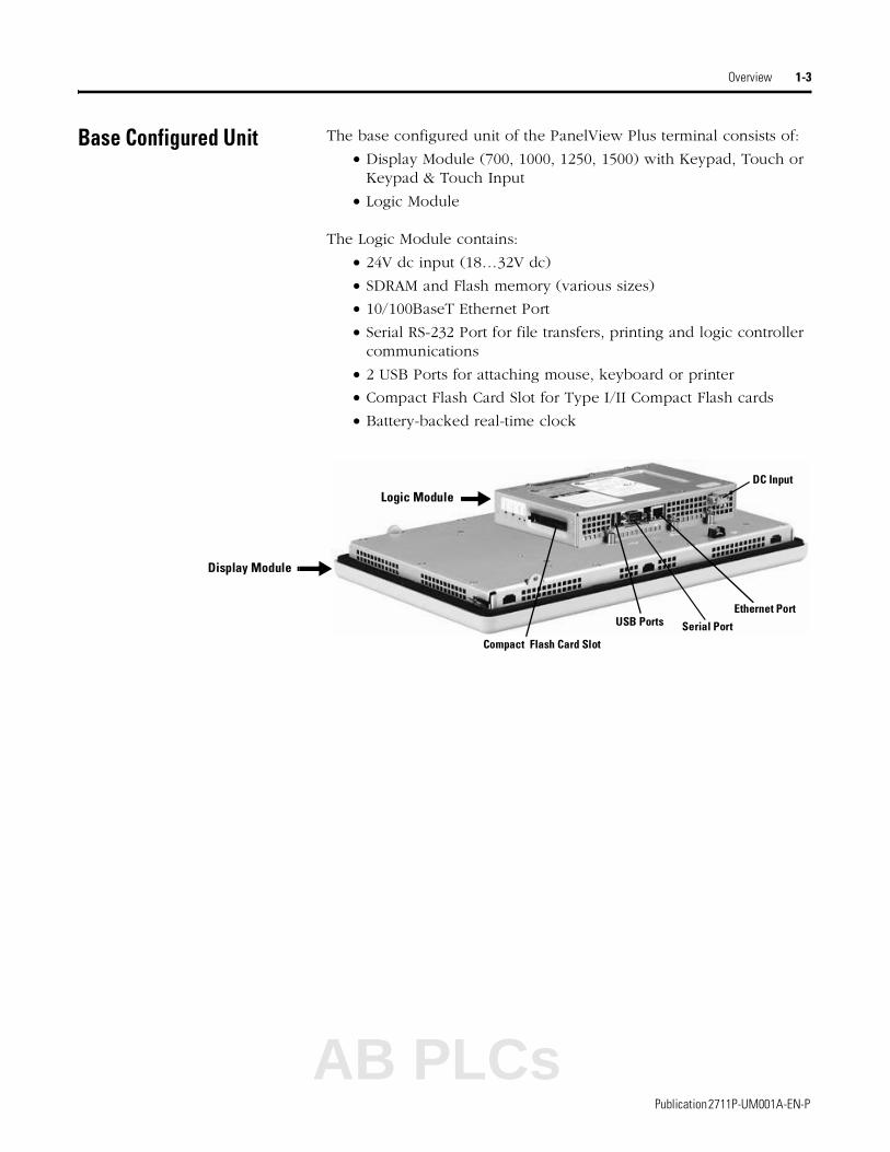
Base Configured Unit The base configured unit of the PanelView Plus terminal consists of:
• Display Module (700, 1000, 1250, 1500) with Keypad, Touch or Keypad & Touch Input
• Logic Module
The Logic Module contains:
• 24V dc input (18…32V dc)
• SDRAM and Flash memory (various sizes)
• 10/100BaseT Ethernet Port
• Serial RS-232 Port for file transfers, printing and logic controller communications
• 2 USB Ports for attaching mouse, keyboard or printer
• Compact Flash Card Slot for Type I/II Compact Flash cards
• Battery-backed real-time clock
DC Input
Ethernet Port
Serial Port
Compact Flash Card Slot
USB Ports
Logic Module
Display Module
AB PLCs
Publication 2711P-UM001A-EN-P
1-4 Overview
Communication Modules You can attach a separate Communication Module to the base configured unit of the PanelView Plus terminal to increase your communications capability.
• DH+/DH485/Remote I/O
The Communication Modules install easily on top of the Logic Module on the back of the unit.
Remote AC Power Supply The Logic Module provides a DC power input. For applications using AC power, a remote AC to DC power supply is available for DIN Rail mounting.
Communication Module
Publication 2711P-UM001A-EN-P

Overview 1-5
Display Modules The PanelView Plus terminals offer a range of TFT color graphic displays with either keypad, touch screen, or keypad & touch support.
• 700 (6.5 inch)
• 1000 (10.4 inch)
• 1250 (12.1 inch)
• 1500 (15 inch)
All of the displays have common features and firmware providing for easy migration to a larger display. Field replaceable bezels are also available.
Touch Screen
The following illustration shows a 1000 touch screen display. All of the touch screen displays are analog resistive and similar except for size.
IrDA Port
Allen-Bradley Label
Touch Screen
AB PLCs
Publication 2711P-UM001A-EN-P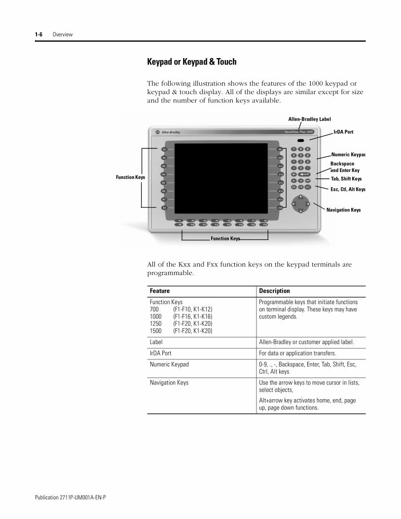
1-6 Overview
Keypad or Keypad & Touch
The following illustration shows the features of the 1000 keypad or keypad & touch display. All of the displays are similar except for size and the number of function keys available.
All of the Kxx and Fxx function keys on the keypad terminals are programmable.
Backspace and Enter Key
IrDA Port
Navigation Keys
Numeric Keypad
Function Keys
Allen-Bradley Label
Tab, Shift Keys
Esc, Ctl, Alt Keys
Function Keys
Feature Description
Function Keys700 (F1-F10, K1-K12) 1000 (F1-F16, K1-K16) 1250 (F1-F20, K1-K20) 1500 (F1-F20, K1-K20)
Programmable keys that initiate functions on terminal display. These keys may have custom legends.
Label Allen-Bradley or customer applied label.
IrDA Port For data or application transfers.
Numeric Keypad 0-9, ., -, Backspace, Enter, Tab, Shift, Esc, Ctrl, Alt keys
Navigation Keys Use the arrow keys to move cursor in lists, select objects,
Alt+arrow key activates home, end, page up, page down functions.
Publication 2711P-UM001A-EN-P
Overview 1-7
271
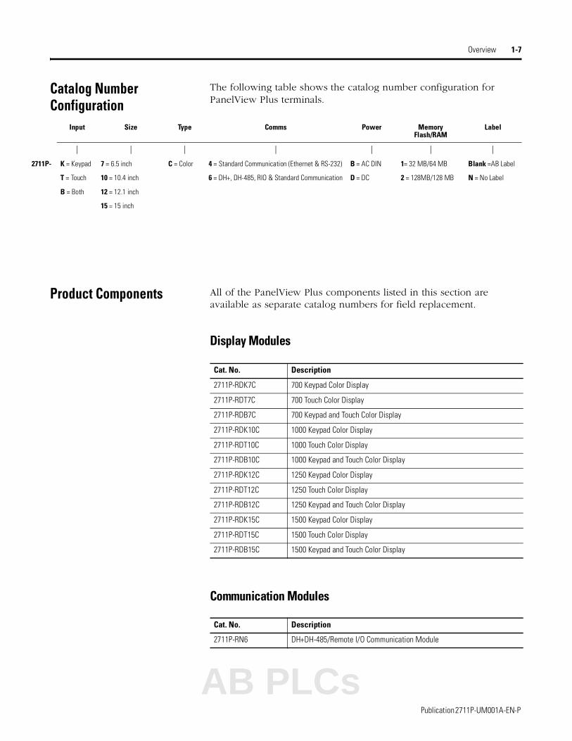
Catalog Number Configuration
The following table shows the catalog number configuration for PanelView Plus terminals.
Product Components All of the PanelView Plus components listed in this section are available as separate catalog numbers for field replacement.
Display Modules
Communication Modules
Input Size Type Comms Power MemoryFlash/RAM
Label
| | | | | | |
1P- K = Keypad 7 = 6.5 inch C = Color 4 = Standard Communication (Ethernet & RS-232) B = AC DIN 1= 32 MB/64 MB Blank =AB Label
T = Touch 10 = 10.4 inch 6 = DH+, DH-485, RIO & Standard Communication D = DC 2 = 128MB/128 MB N = No Label
B = Both 12 = 12.1 inch
15 = 15 inch
Cat. No. Description
2711P-RDK7C 700 Keypad Color Display
2711P-RDT7C 700 Touch Color Display
2711P-RDB7C 700 Keypad and Touch Color Display
2711P-RDK10C 1000 Keypad Color Display
2711P-RDT10C 1000 Touch Color Display
2711P-RDB10C 1000 Keypad and Touch Color Display
2711P-RDK12C 1250 Keypad Color Display
2711P-RDT12C 1250 Touch Color Display
2711P-RDB12C 1250 Keypad and Touch Color Display
2711P-RDK15C 1500 Keypad Color Display
2711P-RDT15C 1500 Touch Color Display
2711P-RDB15C 1500 Keypad and Touch Color Display
Cat. No. Description
2711P-RN6 DH+DH-485/Remote I/O Communication Module
AB PLCs
Publication 2711P-UM001A-EN-P
1-8 Overview
Remote AC Power Supply
Logic Module
Internal Compact Flash Cards
RAM Memory
Compact Flash Cards (Blank)
Cat. No. Description
2711P-RSACDIN AC to DC DIN Rail Power Supply, 85…265V ac, 47…63 Hz
Cat. No. Description
2711P-RP Logic Module without memory
Cat. No. Description
2711P-RW1 32 MB Compact Flash with RSView Machine Edition
2711P-RW2 128 MB Compact Flash with RSView Machine Edition
2711P-RW3 256 MB Compact Flash with RSView Machine Edition
Cat. No. Description
2711P-RR64 64 MB SODIMM Memory
2711P-RR128 128 MB SODIMM Memory
2711P-RR256 256 MB SODIMM Memory
Cat. No. Description
2711P-RC1 32 MB Blank Compact Flash Card
2711P-RC2 128 MB Blank Compact Flash Card
2711P-RC3 256 MB Blank Compact Flash Card
2711P-RC4 512 MB Blank Compact Flash Card
2711P-RCH Compact Flash to PCMCIA Adapter
Publication 2711P-UM001A-EN-P

Overview 1-9
Legend Kits
Protective Antiglare Overlays
Backlights
Miscellaneous
Cat. No. Description
2711P-RFK7 Replacement Legend Strips for 700 Keypad Terminal
2711P-RFK10 Replacement Legend Strips for 1000 Keypad Terminal
2711P-RFK12 Replacement Legend Strips for 1250 Keypad Terminal
2711P-RFK15 Replacement Legend Strips for 1500 Keypad Terminal
Cat. No. Description
2711P-RGK7 Antiglare Overlay for PanelView Plus 700 Keypad or Keypad/Touch Terminal
2711P-RGT7 Antiglare Overlay for PanelView Plus 700 Touch Terminal
2711P-RGK10 Antiglare Overlay for PanelView Plus 1000 Keypad or Keypad/Touch Terminal
2711P-RFT10 Antiglare Overlay for PanelView Plus 1000 Touch Terminal
2711-RFK12 Antiglare Overlay for PanelView Plus 1250 Keypad or Keypad/Touch Terminal
2711-RFT12 Antiglare Overlay for PanelView Plus 1250 Touch Terminal
2711-RFK15 Antiglare Overlay for PanelView Plus 1500 Keypad or Keypad/Touch Terminal
2711-RFT15 Antiglare Overlay for PanelView Plus 1500 Touch Terminal
Cat. No. Description
2711P-RL7C Replacement Color Backlight for PanelView Plus 700 Terminals
2711P-RL10C Replacement Color Backlight for PanelView Plus 1000 Terminals
2711P-RL12C Replacement Color Backlight for PanelView Plus 1250 Terminals
Cat. No. Description
2711P-RY2032 Replacement Battery
2711P-RTMC Mounting Clips
6189-2CONN DC, AC and 6182 Relay Connectors
AB PLCs
Publication 2711P-UM001A-EN-P
1-10 Overview
Adapter Plates
Cables
Communication Adapters
Cat. No. Description
2711P-RAK7 Adapts a PanelView Plus 700 Keypad Terminal to a PanelView Standard 900 Keypad Cutout
2711P-RAT7 Adapts a PanelView Plus 700 Touch Terminal to a PanelView Standard 900 Touch Cutout
2711P-RAK10 Adapts a PanelView Plus 1000 Keypad Terminal to a PanelView 1000/1000E Keypad Cutout
2711P-RAT10 Adapts a PanelView Plus 1000 Touch Terminal to a PanelView 1000/1000E Touch Cutout
2711P-RAK12E Adapts a PanelView Plus 1250 (or PV1000/1000E) Keypad Terminal to a PanelView 1200/1400E Keypad Cutout
2711P-RAT12E2 Adapts a PanelView Plus 1250 (or PV1000/1000E) Touch Terminal to a PanelView 1200E Touch Cutout
2711P-RAT12E Adapts a PanelView Plus 1250 (or PV1000/1000E) Touch Terminal to a PanelView 1400E Touch Cutout
2711P-RAK12S Adapts a PanelView Plus 1250 (or PV1000/1000E) Keypad Terminal to a PanelView Standard 1400 Keypad Cutout
2711P-RAT12S Adapts a PanelView Plus 1250 (or PV1000/1000E) Touch Terminal to a PanelView Standard 1400 Touch Cutout
2711P-RAK15 Adapts a PanelView Plus 1500 Keypad or Keypad & Touch Terminal to a PanelView 1200E/1400E Keypad Terminal
2711P-RAT15 Adapts a PanelView Plus 1500 Touch Terminal to a PanelView 1400E Touch Cutout
Cat. No. Description
2711P-EX04 Ethernet CAT5 Crossover Cable, Industrial Grade, 4.3 m (14 ft)
2711-NC13 RS-232 Operating Cable (9-pin D-Shell to 9-pin D-Shell), 5 m (16.4 ft)
2711-NC14 RS-232 Operating/Programming Cable (9-pin D-Shell to 9-pin D-Shell), 10 m (32.7 ft)
2711-NC21 RS-232 Operating Cable (9-pin D-Shell to 8-pin Mini DIN), 5 m (16.4 ft)
2711-NC22 RS-232 Operating Cable (9-pin D-Shell to 8-pin Mini DIN), 10 m (32.7 ft)
1761-CBL-AS03 DH-485 Operating Cable, 3 m (10 ft)
1761-CBL-AS09 DH-485 Operating Cable, 9 m (30 ft)
Cat. No. Description
1761-NET-AIC AIC+ Advanced Interface Converter
1747-AIC Isolated Link Coupler with DH-485 Communication Module (2711P-RN6)
Publication 2711P-UM001A-EN-P

Chapter 2
Installation
Chapter Objectives This chapter provides instructions on how to install the PanelView Plus terminals. It provides information on:
• hazardous locations
• environment
• enclosures
• clearances
• required tools
• mounting dimensions
• cutout dimensions
• panel installation
Hazardous Locations This PanelView Plus terminals are suitable for use in:
• Class I, Division 2, Groups A, B, C, D
• Class II, Division 2, Groups F, G
• Class III, Division 1
• or non-hazardous locations
The following statement applies to use in hazardous locations.
Do not install the terminals in environments where atmospheric gases have ignition temperatures less than 135 °C or 275 °F. In additon, the PanelView Plus terminals have an operating temperature code of T4 (maximum operating temperature of 55 °C or 131 °F).
WARNING
!Explosion Hazard
• Substitution of components may impair suitability for hazardous locations.
• Do not disconnect equipment unless power has been switched off and area is known to be non-hazardous.
• Do not connect or disconnect components unless power has been switched off.
• All wiring must comply with N.E.C. articles 501-4(b), 502-4(b), 503-3(b) as appropriate.
Peripheral equipment must be suitable for the location it is used in.
AB PLCs
1 Publication 2711P-UM001A-EN-P
2-2 Installation
Environmental Considerations
The PanelView Plus terminals are suitable for use in an industrial environment when installed in accordance with these instructions. Specifically, this equipment is intended for use in clean, dry
environments (Pollution Degree 2(1) and with circuits not exceeding
Over Voltage Category II(2) (IEC 60664-1).(3)
(1) Pollution Degree 2 is an environment where, normally only non-conductive pollution occurs except that occasionally a temporary conductivity caused by condensation shall be expected.
(2) Over Voltage Category II is the load level section of the electrical distribution system. At this level transient voltages are controlled and do not exceed the impulse voltage capability of the product’s insulation.
(3) Pollution Degree 2 and Over Voltage Category II are International Electrotechnical Commissions (IEC) designations.
Enclosures The terminals must be mounted in a panel or enclosure to protect the internal circuitry. The terminals meet IP54 and NEMA Type 12/13 and 4X (indoor) ratings only when mounted in a panel or enclosure with the equivalent rating. When the terminal is not mounted in a panel, it is not secure or safe for operation. You must comply with NEMA Type 4X (indoor) requirements for environmental specifications.
Clearances You must allow adequate clearances around the terminal, inside the enclosure, for adequate ventilation. Consider heat produced by other devices in the enclosure. The ambient temperature around the terminals must be between 0…55 °C (32…131 ºF).
Minimum clearances for ventilation are:
• top and bottom clearance: 51 mm (2 in)
• side clearances: 25 mm (1 in)
Maximum side clearance for insertion of memory card and cable wiring is 102 mm (4 in).
Required Tools Besides the tools required for the panel or enclosure cutouts, you will need the following for installation:
• small slotted screw driver
• torque wrench (N•m/in-lb)
Publication 2711P-UM001A-EN-P
Installation 2-3
Mounting Dimensions This section provides mounting dimensions for the PanelView Plus terminals. The depth dimensions are shown for:
• base configured unit (Display Module and Logic Module)
• base configured unit with Communication Module
All dimensions are in mm (inches).
PanelView Plus 700
700 Touch Screen Terminal
179 (7.04)
246 (9.68)
290 (11.40)
193(7.58)
a 55 (2.18) Display to Logic Moduleb 83 (3.27) Display to Communication Module
a 55 (2.18) Display to Logic Moduleb 83 (3.27) Display to Communication Module
b
a
a
b
700 Keypad or Keypad & Terminal
AB PLCs
Publication 2711P-UM001A-EN-P
2-4 Installation
PanelView Plus 1000
329 (12.97)
248 (9.77)
399 (15.72)
248 (9.77)
a 55 (2.18) Display to Logic Moduleb 83 (3.27) Display to Communication Module
a 55 (2.18) Display to Logic Moduleb 83 (3.27) Display to Communication Module
b
a
a
b
1000 Keypad or Keypad & Touch Terminal
1000 Touch Screen Terminal
Publication 2711P-UM001A-EN-P

Installation 2-5
PanelView Plus 1250
282 (11.12)
416 (16.36)
363(14.30)
282 (11.12)
a 55 (2.18) Display to Logic Moduleb 83 (3.27) Display to Communication Module
a 55 (2.18) Display to Logic Moduleb 83 (3.27) Display to Communication Module
a
b
a
b
1250 Keypad or Keypad & Touch Terminal
1250 Touch Screen Terminal
AB PLCs
Publication 2711P-UM001A-EN-P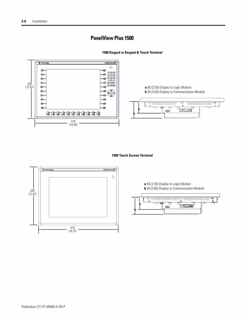
2-6 Installation
PanelView Plus 1500
1500 Touch Screen Terminal
330 (12.97)
419 (18.46)
416 (16.37)
330(12.97)
a 65 (2.55) Display to Logic Moduleb 93 (3.65) Display to Communication Module
a 65 (2.55) Display to Logic Moduleb 93 (3.65) Display to Communication Module
ab
a
b
1500 Keypad or Keypad & Touch Terminal
Publication 2711P-UM001A-EN-P

Installation 2-7
Cutout Dimensions This section provides panel cutout dimensions for each terminal. Use the full size template shipped with your terminal to mark the cutout dimensions. All dimensions are in mm (inches).
PanelView Plus Terminal Height Width
PanelView Plus 700 Keypad or Keypad & Touch 167 (6.57) 264 (10.39)
PanelView Plus 700 Touch 154 (6.08) 220 (8.67)
PanelView Plus 1000 Keypad or Keypad & Touch 224 (8.8) 375 (14.75)
PanelView Plus 1000 Touch 224 (8.8) 305 (12.00)
PanelView Plus 1250 Keypad or Keypad & Touch 257 (10.11) 390 (15.35)
PanelView Plus 1250 Touch 257 (10.11) 338 (13.29)
PanelView Plus 1500 Keypad or Keypad & Touch 305 (12.00) 419 (16.50)
PanelView Plus 1500 Touch 305 (12.00) 391 (15.40)
AB PLCs
Publication 2711P-UM001A-EN-P
2-8 Installation
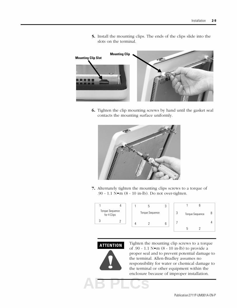
Panel Installation All of the PanelView Plus terminals are installed in the same manner using clips for mounting. The number of clips used (4, 6 or 8) varies by terminal type. The mounting clips are shipped with each terminal.
To install a PanelView Plus terminal in a panel:
1. Cut an opening in the panel using the panel cutout provided with the terminal. Remove any sharp edges or burrs.
2. Make sure the terminal sealing gasket is properly positioned on the terminal as shown. This gasket forms a compression type seal. Do not use sealing compounds.
3. If using keypad legend strips on keypad terminals, we recommend that you install the strips before installing the terminal. Be careful not to pinch the legend strip during installation.
4. Place the terminal in the panel cutout.
ATTENTION
!• Disconnect all electrical power from the panel
before making the panel cutout.
• Make sure the area around the panel cutout is clear.
• Do not allow metal cuttings to enter any components already installed in the panel.
• Failure to follow these instructions may result in personal injury or damage to panel components.
Sealing Gasket
Publication 2711P-UM001A-EN-P
Installation 2-9
5. Install the mounting clips. The ends of the clips slide into the slots on the terminal.
6. Tighten the clip mounting screws by hand until the gasket seal contacts the mounting surface uniformly.
7. Alternately tighten the mounting clips screws to a torque of .90 - 1.1 N•m (8 - 10 in-lb). Do not over-tighten.
Mounting Clip SlotMounting Clip
ATTENTION
!Tighten the mounting clip screws to a torque of .90 - 1.1 N•m (8 - 10 in-lb) to provide a proper seal and to prevent potential damage to the terminal. Allen-Bradley assumes no responsibility for water or chemical damage to the terminal or other equipment within the enclosure because of improper installation.
1
2
3
4
5
6
7
8 Torque Sequence
24 6
51 3Torque Sequence
for 4 Clips
1 4
3 2
Torque Sequence
AB PLCs
Publication 2711P-UM001A-EN-P
2-10 Installation
Publication 2711P-UM001A-EN-P

Chapter 3
Applying Power
Chapter Objectives This chapter provides information:
• wiring and safety guidelines
• connecting DC power
• connecting AC power
• resetting the terminal
• powerup sequence
Wiring and Safety Guidelines
Use publication NFPA 70E, Electrical Safety Requirements for Employee Workplaces when wiring the PanelView Plus terminals. In addition to the NFPA guidelines:
• connect the terminal and other similar electronic equipment to its own branch circuit.
• protect the input power by a fuse or circuit breaker rated at no more than 15 Amps.
• route incoming power to the terminal by a separate path from the communication lines.
• where power and communication lines must cross, they should cross at right angles.Communication lines can be installed in the same conduit as low level DC I/O lines (less than 10 volts).
• shield and ground cables appropriately to avoid Electromagnetic Interference (EMI). Grounding minimizes noise from EMI and is a safety measure in electrical installations.
For additional grounding recommendations, refer to the National Electrical Code published by the National Fire Protection Association of Boston.
AB PLCs
1 Publication 2711P-UM001A-EN-P
3-2 Applying Power
Applying DC Power The PanelView Plus terminals have an integrated power supply that operates on 24V dc. The electrical input ratings are:
• 24V dc nominal (18…32V dc)
• 70 Watts maximum (2.9A @24V dc)
The power supply is internally protected against reverse polarity.
The input power, terminal block on the power supply is removable and supports the following wire sizes:
PanelView Plus terminals using 24V dc power are EN 61131-2 Equipment Class II devices.
To connect DC power:
1. Secure the DC power wires to the terminal block screws.
2. Secure the Functional Earth (FE) ground wire to the terminal block screw.
3. Apply 24V dc power to the terminal.
Wire TypeWire Size
(2-wire maximum per terminal)
Terminal Block
Screw Torque
Stranded #16 to #22 AWG .23 - .45 N•m (2 - 4 in-lbs)
Solid #18 to #22 AWG .23 - .45 N•m (2 - 4 in-lbs)
ATTENTION
!Use a Class 2/SELV (Safety Extra-Low Voltage) isolated and ungrounded power supply as input power to the PanelView Plus terminal. This power source provides protection so that under nominal and single fault conditions, the voltage between conductors and between conductors and Functional Earth/Protective Earth does not exceed a safe value.
Logic Module with
+ DC Positive
- DC Negative
Functional Earth Ground
Publication 2711P-UM001A-EN-P

Applying Power 3-3
Applying AC Power Connecting to AC power requires the AC Power Supply (2711-RSACDIN) that mounts to a DIN Rail. This power supply converts DC power to AC power and has the following electrical input ratings:
• 85…264 V ac (47…63 Hz)
• 120 VA maximum
For more information, refer to the installation instructions shipped with the power supply.
Resetting the Terminal All PanelView Plus terminals have both a Reset switch and a Default switch on the side of the logic module.
Reset
Use the RESET switch to restart the terminal without having to disconnect and reapply power. Insert a thin probe into the hole marked RESET and press the switch. The terminal will perform a series of startup tests and run RSView ME or the loaded .MER application depending on how the terminal is configured.
Default
Safe Mode is a diagnostics mode where the system is reduced to a known state that allows recovery from a configuration or application problem. Use the DEFAULT switch with the RESET switch to start the terminal in Safe Mode. This is a diagnostics mode where the system is reduced to a known state that allows recovery from a software problem. Safe Mode ignores all user changes to the system and avoids any problem that is due to interactions with end-user software or changes.
For more details on Safe Mode, refer to page 8-12.
Reset Default
AB PLCs
Publication 2711P-UM001A-EN-P
3-4 Applying Power
• Insert a thin probe into the hole marked DEFAULT and press the switch, then;
• Insert the probe into the hole marked RESET and press the switch. The system will restart immediately into the Safe Mode.
Startup Sequence After a reset, the PanelView Plus performs a series of startup tests and then either:
• runs the .MER application currently loaded in the terminal
• enters PanelView Plus configuration mode
The action that occurs depends on what startup options are configured for your PanelView Plus terminal.
ATTENTION
!Use a nonconducting object to press the RESET and DEFAULT switch. Do not use a conducting object such as a paper clip or you may damage the terminal. Do not use the tip of a pencil; graphite may damage the terminal.
Publication 2711P-UM001A-EN-P

Chapter 4
Using Configuration Mode
Chapter Objectives This chapter shows how to use the configuration screens of your PanelView Plus terminal to:
• perform data entry and navigation
• load an ME application
• run an ME application
• modify application settings
• modify terminal settings
Starting Configuration Mode
When you reset or startup the PanelView Plus, you should automatically enter Configuration Mode.
If you are unable to enter confguration mode, see page 8-11 in Chapter 8, Troubleshooting.
To access Configuration Mode from a running application:
• press the Goto Configuration Mode button.
The application stops running but is still loaded.
To activate buttons:
• on keypad terminals, select the corresponding function key [Fx]
• on touch screen terminals, tap the button with your finger or stylus.
• if a mouse is attached, make selections with the mouse.
Name of application that is currently loaded. Only appears if application is loaded.
AB PLCs
1 Publication 2711P-UM001A-EN-P
4-2 Using Configuration Mode
Data Entry and Navigation
Configuration Mode uses screen buttons for data entry and navigation.
• On terminals with a touch screen, tap the button with your finger or stylus.
• On terminals with a keypad, select the function key listed on the button, or in some cases, the corresponding key on the keypad.
Besides operation specific buttons which are used to modify configuration data, most screens have a combination of the following buttons.
Main Screen Button Description
Load Application (F1) Opens another screen where you can select an application to load. Once loaded, the application name will appear under Current Application.
Run Application (F2) Runs the .MER application displayed under Current Application. An application must be loaded before you can run it.
Application Settings (F3) Opens a menu of application-specific configuration settings.
Terminal Settings (F4) Opens a menu of options to configure non-application, specific terminal settings for the PanelView Plus terminal.
Delete Log Files Before Running (F5)
Toggles between Yes and No. If you select Yes, all data log files, alarm history and alarm status file will be deleted before the application is run. If you select No, log files are not deleted first.
Reset (F7) Resets the terminal. The action that occurs on startup depends on whether you defined shortcut paths in the Windows Startup folder.
Exit (F8) Exits Configuration Mode.
Screen Buttons Description
Returns to the previous screen.
Accepts modified values and returns to previous screen.
Cancels the current operation without saving any changes.
Moves highlight up or down a list.
Selects a highlighted screen or item from a list.
Close[F10]
OK[F7]
Cancel[F8]
Publication 2711P-UM001A-EN-P

Using Configuration Mode 4-3
Input PanelMany screens have buttons that access fields where you must enter/edit data. When you press the button or function key, the Input Panel opens ready for you to input data.
If the field is restricted to a numeric value, only the 0-9 keys will be enabled. If the value is an IP address, the 0-9 and decimal point keys will be enabled. All other buttons will be disabled.
To enter characters in the Display Area:
1. Select a character on the Character Keyboard.
2. Press the Select button to copy the character to the Display Area.
3. When done entering all characters, press Enter. You will return to the previous screen.
You will return to the previous screen with the newly data entered.
Display Area
Character Keyboard
Controls
• on a touch terminal, tap the keys.
• on a keypad terminal, use the arrow keys on the keypad to select keys.
• If a mouse is attached, use the mouse to select keys.
Controls Function
SHF Switches keys between their shifted and unshifted state. The initial default is shifted.
CAPS Switches keys between lowercase and uppercase characters. The initial default is lowercase.
SPACE Enters a space between characters in the Display Area.
Backspace Deletes the previous character (to the left of the cursor) in the Display Area.
Select Selects a character and enters it in the Display Area.
Right, Left, Up, Down Arrow Keys Selects the character to the right, left, above or below the currently selected character.
Enter Accepts the entered characters and returns to the previous screen
ESC Cancels the current operation and returns to the previous screen.
AB PLCs
Publication 2711P-UM001A-EN-P
4-4 Using Configuration Mode
Loading an ME Application To load an RSView ME .MER application, select the Load Application button on the main screen:
1. Select the Source button to select the storage location of the application file you want to load. The options are:
• Internal Storage - the Internal Compact Flash in the PanelView Plus terminal.
• External Storage 1 - the External Compact Flash card loaded in the card slot of the terminal.
• External Storage 2 - for future use.
2. Select an .MER file from the list. Use the up and down cursor keys to select a file.
3. Select the Load button to load the application.
You will be asked if you want to replace the terminals’ current communication configuration with the application’s communication configuration.
4. Select Yes or No. If you select Yes, any changes made to the device addresses or driver properties in the RSLinx Communications screen will be lost.
The name of the currently loaded application will appear at the top of the main Configuration Mode screen.
Moves highlight up
Moves highlight down
List of .mer applications stored in the compact flash of the terminal.
Publication 2711P-UM001A-EN-P

Using Configuration Mode 4-5
Running an Application To run the currently loaded application, select the Run Application button on the main Configuration Mode screen. An application must be loaded, before you can run it. Log files generated by the application may be deleted if this option was selected on the main screen or enabled as a Startup Option under Terminal Settings.
Application Settings From the Application Settings screen, you can show device shortcuts defined for the loaded .MER application. For example, your .MER application might have SLC defined as a device shortcut name for the SLC 5/05. Device shortcuts are read-only and cannot be edited.
Terminal Settings From Terminal Settings, you can open screens to configure and modify non-application settings for the PanelView Plus terminal.
Moves highlight up
Moves highlight down
Selects highlighted item and opens screen
Returns to previous screen.
• On a touch terminal, tap the button.
• On a keypad terminal, press the corresponding key on the keypad
Terminal Setting Description
Diagnostic Forwards diagnostic messages form a remote log destination to a computer running diagnostics.
Display Shows the temperature of the display, sets the intensity of the backlight, and enables/disables the screen saver.
File Management Copies or deletes application files or font files from a storage location.
Input Devices Configures settings for the keypad, touch screen, or attached keyboard and mouse.
Networks and Communications Configures network connections and communication settings specific to the application (DHPlus, DH485, Remote I/O, Serial).
Print Setup Configures settings for printing displays, alarm messages, and diagnostics messages generated by the application.
Startup Options Specifies whether the terminal starts up in configure or run mode. Also lets you enable/disable tests to run on the terminal at startup.AB PLCs
Publication 2711P-UM001A-EN-P

4-6 Using Configuration Mode
Networks and Communications
From the Networks and Communications screen, you can access settings for:
• KEPServer Serial Port ID’s
• Network Connections
• RSLinx Communications
KEPServer Serial Port ID’s
To access the KEPServer Serial Port ID’s screen, you must have KEPServer Enterprise installed on your terminal. Otherwise, you will get an error message when accessing this screen. If you plan on using KEPServer Enterprise and serial communications, you must specify which COM port to use.
System Event Log Displays a list of system events currently logged by the terminal.
System Information Displays power, temperature, battery and memory details for the terminal. Also shows the firmware number for RSView ME and technical support information.
Time/Date/Regional Settings Sets the date, time, language and numeric format used by the terminal and applications.
Terminal Setting Description
Terminal Settings
Networks and Communications
KEPServer Serial Port ID’s
Publication 2711P-UM001A-EN-P

Using Configuration Mode 4-7
RSLinx Communications
The RSLinx Communications screen shows a treeview of installed communication cards and network configurations. You can:
• edit/view the driver settings for the communication protocol used by your .MER application.
• edit the device address of the controller on the network.
The procedure for editing these settings is the same regardless of the communication protocol. The only differences are the properties for each communication protocol and the device address of the logic controller. The properties for each communication protocol are defined immediately after this section.
Terminal Settings
Networks and Communications
RSLinx Communications
Communication Driver
Ethernet Driver
AB PLCs
Publication 2711P-UM001A-EN-P
4-8 Using Configuration Mode
To edit communication settings:
1. From the RSLinx Configuration Screen, select the communication card installed on your terminal.
2. Select the Driver Settings button.
A properties screen opens showing the current communication settings for the driver.
3. To modify a setting, select the setting and then the Edit button. The Input Panel opens showing the current setting.
4. Using the Input Panel, modify the setting and then select the Enter button.
You return to the previous screen with the newly entered data.
To edit the device address of the logic controller:
1. From the RSLinx Configuration screen, select a device node.
2. Select the Edit Device button.
A screen opens showing the name of the device and its current node address.
3. To modify the device address, press the Device Address button. The Input Panel opens showing the current address.
4. Using the Input Panel, modify the address and then select the Enter button.
You return to the previous screen with the new address.
IMPORTANT Modified settings do take effect until the terminal is rebooted.
Publication 2711P-UM001A-EN-P

Using Configuration Mode 4-9
DHPlus Properties
The DHPlus Properties screen lets you view or modify settings for a PanelView Plus connected to a DHPlus network.
DH485 Properties
The DH485 Properties screen lets you view or modify settings for a PanelView Plus connected to a DH-485 network.
Remote I/O Properties
The RIO Properties screen configures Remote I/O communication settings for the PanelView Plus terminal on a Remote I/O link.
Field Description Valid Values
Jumper ID Identifies the communication card if multiple cards are installed on terminal.
0 - 3
Station Number The unique address of the PanelView Plus on the DHPlus network.
0 - 77 (octal)
Baud Rate The baud rate of the DHPlus network. 57600 (default)115200230400
Field Description Valid Values
Jumper ID Identifies the communication card if multiple cards are installed on terminal.
0 - 3
Station Number The unique station number of the PanelView Plus on the DH-485 network.
0 - 31 (decimal)
Baud Rate The baud rate of the DH-485 network. 960019200
MaxStationNumber The maximum station number on the DH-485 network. The value must be greater than or equal to the Station Number.
0-31 (decimal)
Field Description Valid Values
Jumper ID Identifies the communication card if multiple cards are installed on terminal.
0 - 3
Baud Rate The baud rate of the Remote I/O network. 57600 (default)115200230400
AB PLCs
Publication 2711P-UM001A-EN-P
4-10 Using Configuration Mode
Serial Properties
The Serial Properties screen configures settings for serial communications (using the RS-232 serial port) on the PanelView Plus terminal.
Field Description Valid Values
Device The serial device your PanelView Plus terminal is connected to.
PLC_CH0KF2SLC_CH0KF3KFCKFC15AC_CH0
Error Check Type of error checking used. Error checking is automatically configured if Use Auto Config is set to Yes.
BCC, CRC
Parity Type of parity used. The parity is automatically configured if Use Auto Config is set to Yes.
None, Odd, Even
Stop Bits Number of stop bits used. 1 or 2
Ack Timeout Ack/Poll timeout value in milliseconds. 20 - 60,000 ms
Max Retries Maximum number of retries before the serial driver fails.
0 - 255
Station Station number based on a specific device. PLC_CH0 0-77 (octal)KF2 0-77 (octal)SLC_CH0 0-31KF3 0-31KFC 1-99KFC15 1-99AC_CH0 0-255
Baud Rate Data rate at which serial driver communicates. The baud rate is automatically configured if Use Auto Config is set to Yes.
110, 300, 600, 1200, 4800 9600, 19200, 38400, 115200
Use Auto Config Automatically or manually configures the baud rate, parity and error checking parameters.
Yes (auto configure)No (manual configure)
Com Port Communication port used on the PanelView Plus terminal.
1 (COM1)2 (COM2)
Publication 2711P-UM001A-EN-P

Using Configuration Mode 4-11
Network Connections
The Network Connections screen lets you configure the following for the PanelView Plus terminal:
• Device Name
• Network Adapters
• Network Identification
Device Name
The Device Name screen identifies the PanelView Plus terminal to other computers on the network.
Field Description Valid Values
Device Name Name that identifies the PanelView Plus terminal to other computers on the network.
15 characters maximum, without spaces
Device Description Provides a description of the terminal. 50 characters maximum
Terminal Settings
Networks and Communications
Network Connections
Terminal Settings
Networks and Communications
Network Connections
Device Name
PanelView Plus
2711P-PVPlus
AB PLCs
Publication 2711P-UM001A-EN-P
4-12 Using Configuration Mode
Network Adapters
The Network Adapters screen configures driver settings for all network adapters installed on the terminal. The only network adapter on the PanelView Plus terminal is the (IntelR) Fast Ethernet Controller.
Press the Name Servers button and/or IP Address button to access driver settings.
Name Servers
Defines Name Server addresses for the Network Adapter. These addresses are automatically assigned if DHCP is enabled for the network adapter.
Field Description Valid Values
Primary DNS The address of the primary DNS resolver. xxx.xxx.xxx.xxx
Secondary DNS The address of the secondary DNS resolver. xxx.xxx.xxx.xxx
Primary WINS The address of the primary WINS resolver. xxx.xxx.xxx.xxx
Secondary WINS The address of the secondary WINS resolver. xxx.xxx.xxx.xxx
Terminal Settings
Networks and Communications
Network Connections
Network Adapters
E100CE1:Built-in Ethernet Controller
Publication 2711P-UM001A-EN-P
Using Configuration Mode 4-13
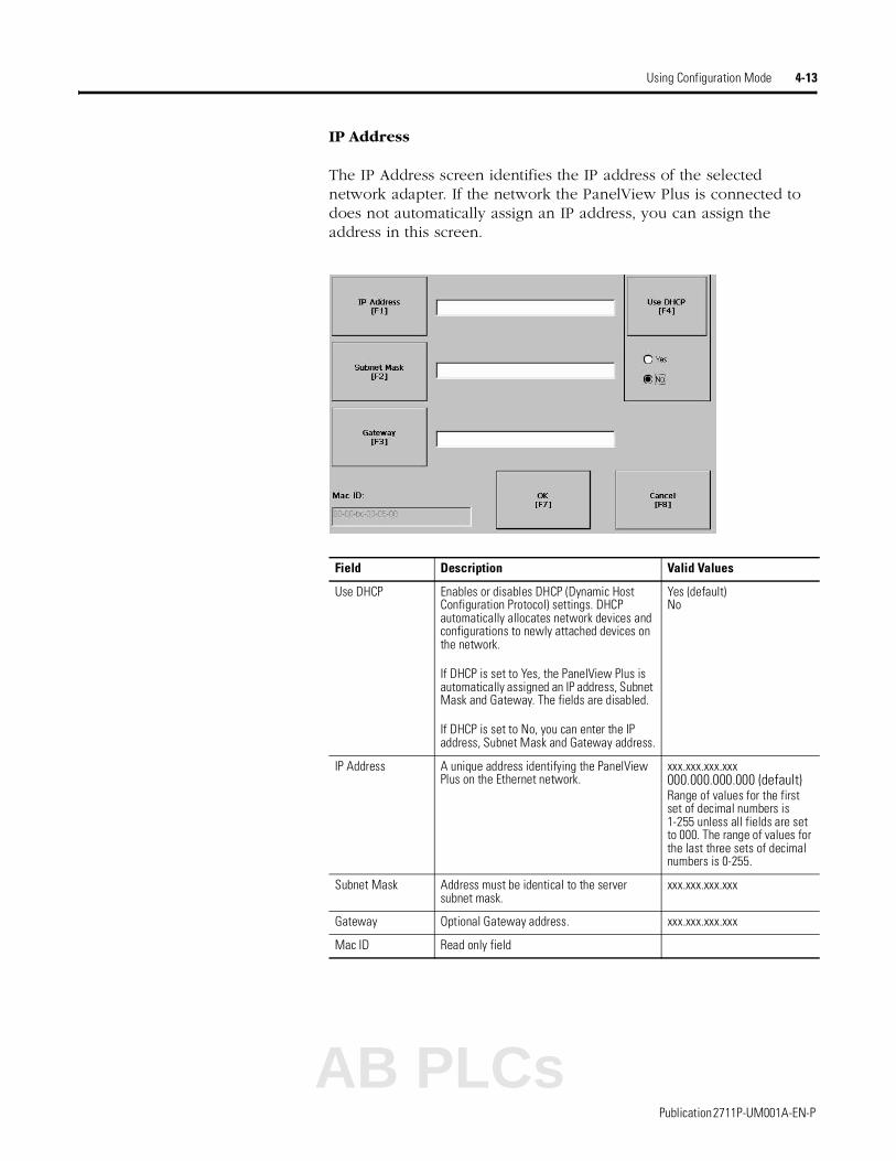
IP Address
The IP Address screen identifies the IP address of the selected network adapter. If the network the PanelView Plus is connected to does not automatically assign an IP address, you can assign the address in this screen.
Field Description Valid Values
Use DHCP Enables or disables DHCP (Dynamic Host Configuration Protocol) settings. DHCP automatically allocates network devices and configurations to newly attached devices on the network.
If DHCP is set to Yes, the PanelView Plus is automatically assigned an IP address, Subnet Mask and Gateway. The fields are disabled.
If DHCP is set to No, you can enter the IP address, Subnet Mask and Gateway address.
Yes (default)No
IP Address A unique address identifying the PanelView Plus on the Ethernet network.
xxx.xxx.xxx.xxx000.000.000.000 (default)Range of values for the first set of decimal numbers is 1-255 unless all fields are set to 000. The range of values for the last three sets of decimal numbers is 0-255.
Subnet Mask Address must be identical to the server subnet mask.
xxx.xxx.xxx.xxx
Gateway Optional Gateway address. xxx.xxx.xxx.xxx
Mac ID Read only field
AB PLCs
Publication 2711P-UM001A-EN-P
4-14 Using Configuration Mode
Network Identification
The Network Identification screen configures settings that enable the PanelView Plus terminal to gain access to network resources. You can enter a user name, password and domain (provided by your network administrator).
Field Description Valid Values
User Name Identifies the user to the network. 70 characters maximum
Password Characters that gain access to network along with the user name.
No character limitation
Domain Name Provided by network administrator. 15 characters maximum
Terminal Settings
Networks and Communications
Network Connections
Network Identification
Publication 2711P-UM001A-EN-P

Using Configuration Mode 4-15
Diagnostic Setup The Diagnostic Setup screen configures diagnostics for the current computer. The screen shows a treeview of possible diagnostic nodes.
The Remote Log Destination forwards messages that it receives to a Windows 2000/XP computer running diagnostics. The location is determined by the IP address and port number.
Message RoutingThe Message Routing screen lets you access the following screens:
• Remote Log
• RSView Diagnostics List
Each one of the above screens shows a list of messages that can be sent to that destination. The list shows the On/Off status of each message type. Use the On/Off button to turn a message type on or off. A message type is enabled if it has a checked box.
To access the Remote Log Setup or Message Routing, select the node and then the Edit button.
Terminal Settings
Diagnostic Setup
Field Description Valid Values
Address Address of the remote Windows 2000/XP computer.
xxx.xxx.xxx.xxx
Port The port used to communicate with the remote Windows 2000/XP computer.
4445 (default)
AB PLCs
Publication 2711P-UM001A-EN-P
4-16 Using Configuration Mode
File Management The File Management screen lets you access screens to:
• Delete Files
• Copy Files
Delete Files
From the Delete Files screen you can select options to:
• Delete Applications - deletes an .MER application file from a storage location.
• Delete Fonts - deletes a font file from a storage location.
• Delete Log Files - deletes any data log files, alarm history files and alarm status files in the System Default location on the PanelView Plus terminal.
Delete Application or Font Files
The process for deleting an application file or a font file is the same.
1. Select the Source button to select the storage location of the application or font file that you want to delete.
• Internal Storage - the Internal Compact Flash in the PanelView Plus terminal.
• External Storage 1 - the External Compact Flash card loaded in the card slot of the terminal.
• External Storage 2 - for future use.
2. Select a file from the list.
3. Select the Delete button.
4. You will be asked if you want to delete the selected application or font file from the storage location. Select Yes or No.
Terminal Settings
File Management
Delete Files
Publication 2711P-UM001A-EN-P

Using Configuration Mode 4-17
Delete Log Files
Select this option to delete any data log files, alarm history files and alarm status files in the System Default location on the PanelView Plus terminal. You will be asked to confirm the operation.
Do you want to delete all of the RSView ME Station Log Files?
Select Yes or No. Any log files not located in the System Default location will not be deleted.
Copy Files
From the Copy Files screen, you can select options to:
• Copy Applications - copies an .MER application file from one storage location to another
• Copy Fonts - copies a font file from one storage location to another.
Copy Applications or Fonts
The process for copying an application file or a font file is the same.
1. Select the Source button to select the location of the application or font file that you want to copy.
• Internal Storage - the Internal Compact Flash in the PanelView Plus terminal.
• External Storage 1 - the External Compact Flash card loaded in the card slot of the terminal.
• External Storage 2 - for future use.
Terminal Settings
File Management
Copy Files
List of files stored in Compact Flash of terminal.
AB PLCs
Publication 2711P-UM001A-EN-P
4-18 Using Configuration Mode
2. Select the Destination button on the same screen to open the following screen.
3. Select the Destination button to select the storage location where you want to copy the application or font file to.
• Internal Storage - the Internal Compact Flash in the PanelView Plus terminal.
• External Storage 1 - the External Compact Flash card loaded in the card slot of the terminal.
• External Storage 2 - for future use.
4. Select the Copy button to copy the selected application or font file to the selected destination.
If the file exists, you will receive a warning and will be asked if you want to overwrite the existing application.
5. Select Yes or No.
Display The Display screen allows you to open screens to access:
• Display Temperature
• Display Intensity
• Screen Saver
Display Temperature
The Display Temperature screen shows the current temperature of the display.
Terminal Settings
Display
Display Temperature
Publication 2711P-UM001A-EN-P

Using Configuration Mode 4-19
Display Intensity
The Display Intensity screen lets you view or modify the current intensity of the backlight. The default intensity is 100%. When you change the intensity, the terminal temporarily changes to that intensity. The change is not permanent until you select OK.
The screen indicates whether the current intensity of the backlight will be used when the PanelView Plus terminal starts up. The button toggles between Yes or No.
Screen Saver
The Screen Saver screen lets you:
• disable the screen saver
• enable the screen saver after the selected idle time
• adjust the brightness of the screen saver
Terminal Settings
Display
Display Intensity
Terminal Settings
Display
Screen Saver
Select Up or Down Cursor button to increase or decrease the screen saver brightness
AB PLCs
Publication 2711P-UM001A-EN-P
4-20 Using Configuration Mode
Input Devices The Input Devices screen lets you access screens to view and modify settings for:
• Keyboard
• Keypad
• Mouse
• Touch Screen
Keyboard and Keypad Setup
The Keyboard and Keypad screen opens these screens:
• Key Repeat Settings
• Keyboard Settings
Key Repeat Settings for Attached Keyboard or PanelView Plus Keypad
The Key Repeat Settings configures settings for keys on the PanelView Plus terminal or keys an attached keyboard.
Field Description Valid Values
Repeat Rate The number of times per second a key repeats when you hold down a key.
0 - 30The default is 0 or disabled
Repeat Delay The amount time that elapses before a key repeats when you hold down a key.
200 ms400 ms 600 ms1 sec1.5 sec2 sec2.5 sec
The following values are not available settings for an attached keyboard:200ms, 1.5 sec, 2 sec, 2.5 sec
Terminal Settings
Input Devices
Keyboard or Keypad
Publication 2711P-UM001A-EN-P

Using Configuration Mode 4-21
Key Settings for Attached Keyboard
The Keyboard Settings screen enables or disables the Ctrl-Alt-Esc option. This key sequence is equivalent to the Ctrl-Alt-Del sequence on a computer. The default is currently enabled.
Key Settings for PanelView Plus Keypad
The Keypad Settings screen enables/disables Single Key Mode option which is used to restrict multiple or simultaneous key presses.
Field Description Valid Values
Single Key Mode Enables or disables Single Key Mode.
If enabled, any programmable key that is pressed inhibits all keys until the programmable key is pressed again. This includes the Alt, Ctrl, Shift keys.
If enabled with abort, any secondary key press will terminate the initial key press immediately.
If disabled, there are no restrictions on key presses.
EnabledEnabled with AbortDisabled (default)
Hold Off Time The length of time to ignore multiple presses of the same key.
400 ms (default)
AB PLCs
Publication 2711P-UM001A-EN-P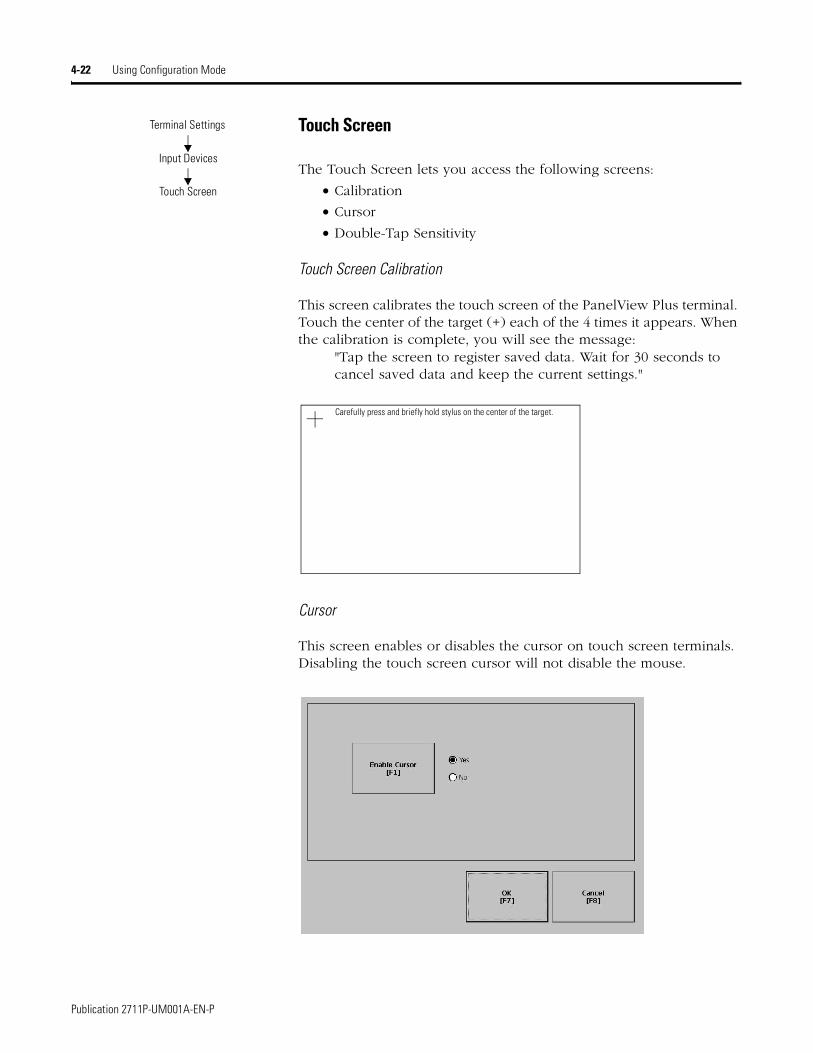
4-22 Using Configuration Mode
Touch Screen
The Touch Screen lets you access the following screens:
• Calibration
• Cursor
• Double-Tap Sensitivity
Touch Screen Calibration
This screen calibrates the touch screen of the PanelView Plus terminal. Touch the center of the target (+) each of the 4 times it appears. When the calibration is complete, you will see the message:
"Tap the screen to register saved data. Wait for 30 seconds to cancel saved data and keep the current settings."
Cursor
This screen enables or disables the cursor on touch screen terminals. Disabling the touch screen cursor will not disable the mouse.
Terminal Settings
Input Devices
Touch Screen
Carefully press and briefly hold stylus on the center of the target.
Publication 2711P-UM001A-EN-P

Using Configuration Mode 4-23
Double-Tap Sensitivity
This screen lets you set and test the sensitivity for both speed and physical distance between touch screen presses.
• The Set button sets the sensitivity of touch screen presses.
• The Test button tests the sensitivity of touch screen presses. If you double-tap the test button with the time set using the Set button, the Test button will reverse it’s foreground and background colors.
Mouse
The Mouse screen sets and tests the sensitivity for both speed and physical distance between mouse clicks. This process is identical to that for setting Double-Tap sensitivity for the touch screen.
Terminal Settings
Input Devices
Mouse
AB PLCs
Publication 2711P-UM001A-EN-P
4-24 Using Configuration Mode
Print Setup The Print Setup screen lets you access screens to configure print options for:
• Displays
• Alarms
• Diagnostic messages.
Display, Alarm , and Diagnostic Print Setup
The general setup for printing displays, alarm messages and diagnostics messages from an RSView .MER application is the same. The Advanced Settings for each function are different.
Advanced Settings for Display Print Setup
Select the Advanced Settings button to:
• change print orientation (portait or landscape)
• enable or disable draft mode
Field Description Valid Values
PCL Printer Type of printer to use. Laser (default)Inkjet
Port Port to use for printing displays, alarm messages, and diagnostic messages.
Network (default)USB
Network Path Network path of printer to use if the Port selection is Network.
519 characters maximum
Advanced Settings Press this button to open additional settings.
Terminal Settings
Networks and Communications
Print Setup
Publication 2711P-UM001A-EN-P

Using Configuration Mode 4-25
Advanced Settings for Diagnostic Messages and Alarm Messages
The following screen configures when to print diagnostic or alarm messages that are sent to the Network or USB port.
To configure how messages are queued for printing, select the Print Messages After button and set one of the following options:
• Specified number of messages
Prints messages after 60 are queued or another specified value. The default is 60 (about one full page of messages.)
• 500 messages or timeout period, whichever is first
Prints after 500 messages are queued or a specific time period has elapsed, whichever comes first. The default time period is 168 hours (7 days). You can specify another value. For example, if 350 messages are in the queue and 7 days have elapsed, the 350 messages will print.
• Specified number of messages or timeout period, whichever is first
Prints after a specified number of messages are queued or a specific time period has elapsed, whichever comes first.
The default number of messages to queue is 60. The default timeout period is 168 hours (7 days). You can change both values. For example, the number of messages is set to 75 and the timeout period is set to 48 hours (2 day). If the queue has 75 messages after only 24 hours, these messages will print. If there are only 15 messages in the queue at 48 hours, the 15 messages will not print until the time period has elapsed.
AB PLCs
Publication 2711P-UM001A-EN-P
4-26 Using Configuration Mode
Startup Options The Startup Options screen accesses the following screens to modify:
• RSView ME Station Startup
• Startup Tests
RSView ME Station Startup
The RSView Machine Station Startup screen specifies what action the PanelView Plus terminal takes on startup:
• Do not start RSView ME Station
• Go to Configure Mode
• Run the Current Application
This option is available only if an application is loaded.
RSView ME Station will start up based on shortcuts in the Windows Startup folder and whether an application is loaded.
Select the On Startup button to switch between Do not start RSView ME, Go to Configure Mode, or Run the Current Application. Select the button under the last two options to configure specific settings for each mode.
Terminal Settings
Startup Options
RSView ME Station Startup
Publication 2711P-UM001A-EN-P

Using Configuration Mode 4-27
Configuration Mode
The Configuration Mode Options screen specifies whether the PanelView Plus will boot up in Configure Mode:
• with the current application loaded.
• with the communication configuration of the current application or the terminal’s RSLinx communication configuration.
If you select Yes to replace the terminal’s communication configuration with that of the application, any changes made to the device addresses or driver properties in the RSLinx Communications screen will be lost.
These options are available only if an application is loaded in the terminal. If an application is not loaded, both options are disabled and set to No.
Run Options
The Run Options screen specifies whether or not:
• to replace the terminal’s communication (RSLinx) settings with application settings when the application is run.
If you select Yes, any changes to the device addresses or driver properties in the RSLinx Communications screen will be lost when the terminal boots up.
• to delete log files (data, alarm history, alarm status) generated by the terminal from the System Default location before running the application.
Configuration Mode Run Options
AB PLCs
Publication 2711P-UM001A-EN-P
4-28 Using Configuration Mode
Startup Tests
The PanelView Plus can run extended tests on startup. The Startup Tests screen provides access to these screens:
• Startup Tests Settings
• Repeat Count
Select Tests
The Select Tests screen shows a list of each test that can be performed on the PanelView Plus terminal at startup and its current On/Off status. You can turn any test in the list on or off by selecting the On/Off button. The terminal will only run tests with a checked box.
Terminal Settings
Startup Options
Startup Tests
Publication 2711P-UM001A-EN-P

Using Configuration Mode 4-29
Startup Tests Settings
From the Startup Tests Settings screen, you can:
• enable extended diagnostics to run on the terminal at startup
• disable extended diagnostics at startup
• specify how many times to repeat the selected tests that are run on the terminal during startup.
The Repeat Count field shows the current value. You can enter a value in the range of 0 - 128.
IMPORTANT Enabling Extended Diagnostics and setting a high Repeat Count will increase the time it takes the terminal to reboot.
The tests will run each time you reset or cycle power to the terminal until you disable Extended Diagnostics. Setting a low repeat count will also decrease the startup time.
AB PLCs
Publication 2711P-UM001A-EN-P
4-30 Using Configuration Mode
System Event Log The System Event Log screen displays a list of system events currently logged by the PanelView Plus terminal.
• To display System Event Log Details for a specific event, select an event and then select the More Details button.
• To clear all System Event Logs, press the Clear All button.
Terminal Settings
System Event Log
Publication 2711P-UM001A-EN-P

Using Configuration Mode 4-31
System Information The System Information screen lets you access:
• RSView ME Station information
• Terminal Information
Terminal Information
The Terminal Information screen displays the following details for the PanelView Plus terminal:
• total power on time
• processor temperature
• battery voltage and battery state
• amount of memory on terminal
All fields are read only except for memory allocation.
To access details on Memory Allocation, select the Memory Allocation button.
Terminal Settings
System Information
Terminal Information
AB PLCs
Publication 2711P-UM001A-EN-P
4-32 Using Configuration Mode
Memory Allocation
The Memory Allocation screen displays:
• amount of allocated storage or program memory
• amount of storage or program memory currently in use
You can modify the allocation of storage or program memory. Press the Up or Down button to increase/decrease the memory allocation. Each button press changes the allocation by a value of 4. If you change the allocation for one type of memory, the other is automatically updated accordingly.
Publication 2711P-UM001A-EN-P

Using Configuration Mode 4-33
RSView ME Station Information
The About RSView ME Station screen provides access to:
• RSView ME Station firmware number
• Rockwell Technical Support information
Terminal Settings
System Information
About RSView ME Station
AB PLCs
Publication 2711P-UM001A-EN-P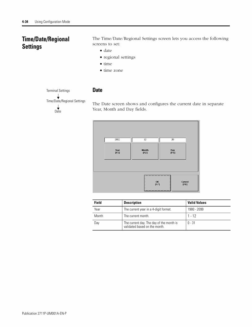
4-34 Using Configuration Mode
Time/Date/Regional Settings
The Time/Date/Regional Settings screen lets you access the following screens to set:
• date
• regional settings
• time
• time zone
Date
The Date screen shows and configures the current date in separate Year, Month and Day fields.
Field Description Valid Values
Year The current year in a 4-digit format. 1980 - 2099
Month The current month. 1 - 12
Day The current day. The day of the month is validated based on the month.
0 - 31
Terminal Settings
Time/Date/Regional Settings
Date
Publication 2711P-UM001A-EN-P

Using Configuration Mode 4-35
Time
The Time screen shows and configures the current time in 24-hour format in separate Hour, Minute and Second fields.
Field Description Valid Values
Hour The current hour in 24-hour format. 0 - 23
Minute The current minute in 24-hour format. 0 - 59
Seconds The current second in 24-hour format. 0 - 59
Terminal Settings
Time/Date/Regional Settings
Time
AB PLCs
Publication 2711P-UM001A-EN-P
4-36 Using Configuration Mode
Time Zone
The Time Zone screen shows the current time zone that is installed on the PanelView Plus terminal. Time zones are installed as a part of the operating system. Changing the time zone adjusts the current time and date to match the new time zone.
If the selected time zone supports Daylight Savings, you can select the Daylight Savings button.
Daylight Savings
The Daylight Savings screen configures whether daylight savings time is in effect for the current time zone. Daylight Savings is set to Yes for all time zones except for Japanese, which does support daylight savings. Daylight savings changes are not permanently applied until you close the Time Zone screen.
Language Default Time Zone
English (GMT -05:00) Eastern Time (US & Canada)
French (GMT +01:00) Brussels, Copenhagen, Madrid, Paris
German (GMT +01:00) Amsterdam, Berlin, Bern, Rome, Stockholm, Vienna
Japanese (GMT +09:00) Osaka, Sapporo, Tokyo
Terminal Settings
Time/Date/Regional Settings
Time Zone
Publication 2711P-UM001A-EN-P

Using Configuration Mode 4-37
Regional Settings
The Regional Settings screen allows you to access these screens:
• Language
• Numeric Format
• Long Date Format
• Short Date Format
• Time Format
The current language is shown at the bottom of the Regional Settings screen.
Language
The Language screen allows you to select a language that is installed on the PanelView Plus. Languages are installed as a part of the operating system.
Numeric Format screen
The Numeric Format Screen allows you to modify the decimal separator used by the current language. The default decimal separator is ".". The field will accept a separator up to 3 characters.
Terminal Settings
Time/Date/Regional Settings
Regional Settings
Terminal Settings
Time/Date/Regional Settings
Regional Settings
Language
Terminal Settings
Time/Date/Regional Settings
Regional Settings
Numeric Format
AB PLCs
Publication 2711P-UM001A-EN-P
4-38 Using Configuration Mode
Time Format
The Time Format screen configures the time format for the current language. A sample of the current time is shown using the currently selected format.
Field Description Example
Time Format
h:mm:ss tt (default)h = hour, no leading zerott = AM or PM symbol
7:23:02 AM or 1:13:31 PM11:43:59 AM
hh:mm:ss tthh = hour with leading zerott = AM or PM symbol
07:23:02 AM or 01:13:31 PM11:43:59 PM
H:mm:ssH = hour in 24 hour format, no leading zero
7:03:42 or 1:13:3223:43:59
HH:mm:ssHH = hour in 24-hour format with leading zero
07:03:42 or 01:13:2223:43:59
AM Symbol Characters to indicate AM. If the time format is set to h:mm:ss tt or hh:mm:ss tt, you can modify the AM symbol.
AM (default)12 character maximum
PM Symbol Characters to indicate PM. If the time format is set to h:mm:ss tt or hh:mm:ss tt, you can modify the PM symbol.
PM (default)12 character maximum
Separator Character(s) that separate fields in time format. : (default)3 character maximum
Terminal Settings
Time/Date/Regional Settings
Regional Settings
Time Format
Publication 2711P-UM001A-EN-P

Using Configuration Mode 4-39
Short Date Format
The Short Date Format screen configures the short date format used by the current language. A sample of the current date is shown using the currently selected short date format.
Field Short Date Formats Example
Format M/d/yyyy (default)M/d/yyMM/dd/yyMM/dd/yyyyyy/MM/ddyyyy-MM-dddd-MMM-yy
1/2/20031/2/0301/02/0301/02/200303/01/022003-01-0202-Jan-03
Separator Character(s) separator for fields in time format. The default separator is either - or / depending on short date format.
- or / (default)3 character maximum
Terminal Settings
Time/Date/Regional Settings
Regional Settings
Short Date Format
AB PLCs
Publication 2711P-UM001A-EN-P
4-40 Using Configuration Mode
Long Date Format
The Long Date Format screen configures the long date format used by the current language. A sample of the current date is shown using the currently selected long date format.
Field Short Date Formats Example
Format
dddd, MMMM, dd, yyyy (default)dddd is name of week dayMMMM is name of monthdd is 2-digit day of month with leading zeroyyyy is 4-digit year
Monday, January 01, 2003
MMMM dd, yyyyMMMM is name of monthdd is 2-digit day of month with leading zeroyyyy is 4-digit year
January 01, 2003
dddd, dd MMMM, yyyydddd is name of week daydd is 2-digit day of month with leading zeroMMMM is name of monthyyyy is 4-digit year
Monday, 01 January, 2003
dd MMMM, yyyydd is 2-digit day of month with leading zeroMMMM is name of monthyyyy is 4-digit year
01 January, 2003
Terminal Settings
Time/Date/Regional Settings
Regional Settings
Long Date Format
Publication 2711P-UM001A-EN-P

Chapter 5
Installing and Replacing Components
Chapter Objectives This chapter shows how to install, replace or upgrade various components of the PanelView Plus terminal, including:
• Logic Module
• RAM and Internal Compact Flash
• Communication Module
• Display Module
• Battery
• Display Module Bezel
• Backlight
• AC Power Supply
• Product Label
• Keypad Legend Inserts
• External Compact Flash Card
Required Tools Tools required to install or replace the various components of the PanelView Plus terminal are:
• #1 and #2 Phillips screwdriver
• Electrostatic (ESD) wristband
Precautions Before installing or replacing any components, disconnect power from the PanelView Plus terminal. During installation, take care not to touch any of the exposed electronic components.
ATTENTION
!Disconnect all power from the PanelView Plus terminal before installing or replacing any components. Failure to disconnect power may result in electrical shock and/or damage to the terminal.
ATTENTION
!Work in a static free environment and wear a properly grounded ESD wristband.
Be careful when touching any of the exposed electronic components to prevent damage from electrostatic discharge (ESD).
AB PLCs
1 Publication 2711P-UM001A-EN-P
5-2 Installing and Replacing Components
Installing RAM and Internal Compact Flash
The Logic Module (2711P-RP) of the PanelView Plus terminal does not contain RAM (2711P-RRxxx) or Internal Compact Flash (2711P-RWx) when ordered as a separate component. You must install the RAM and Internal Compact Flash before attaching the Logic Module to the Display Module.
To install/replace RAM and/or Internal Compact Flash:
1. Remove power from the terminal.
2. Place the terminal, display side down, on a flat stable surface.
3. Loosen the 6 captive screws that secure the Logic Module.
4. Carefully lift the Logic Module away from the terminal and turn over to expose the circuit board.
5. Locate the RAM module on the circuit board. Pull the metal retaining clips away from the module and slide out the RAM module (if present).
6. Insert the new RAM module at a 45° angle and snap down.
7. Locate the Internal Compact Flash card. Unscrew and remove the retaining clip that secures the card.
8. Pull out the Compact Flash card (if present).
9. Insert the new Compact Flash card.
10. Re-attach retaining clip.
11. Attach the Logic Module by aligning the 2 connectors on the bottom of the module with the connectors on the Display Module.
12. Push down on the Logic Module until firmly seated.
13. Tighten the 6 captive screws that secure the Logic Module to a torque of .68 N•m (6-8 in-lb).
IMPORTANT Wear a properly ground ESD wristband before touching any of the electronic components in the Logic Module.
Skip Steps 5 - 6 if not replacing RAM.
Retaining Clips
Skip Steps 7 - 11 if not replacing Internal Compact Flash.
Publication 2711P-UM001A-EN-P
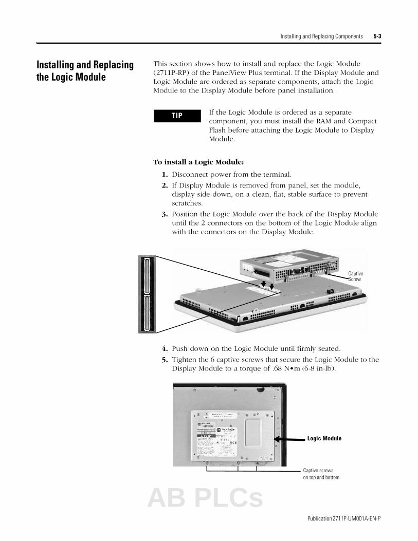
Installing and Replacing Components 5-3
Installing and Replacing the Logic Module
This section shows how to install and replace the Logic Module (2711P-RP) of the PanelView Plus terminal. If the Display Module and Logic Module are ordered as separate components, attach the Logic Module to the Display Module before panel installation.
To install a Logic Module:
1. Disconnect power from the terminal.
2. If Display Module is removed from panel, set the module, display side down, on a clean, flat, stable surface to prevent scratches.
3. Position the Logic Module over the back of the Display Module until the 2 connectors on the bottom of the Logic Module align with the connectors on the Display Module.
4. Push down on the Logic Module until firmly seated.
5. Tighten the 6 captive screws that secure the Logic Module to the Display Module to a torque of .68 N•m (6-8 in-lb).
TIP If the Logic Module is ordered as a separate component, you must install the RAM and Compact Flash before attaching the Logic Module to Display Module.
CaptiveScrew
Logic Module
Captive screws on top and bottom
AB PLCs
Publication 2711P-UM001A-EN-P
5-4 Installing and Replacing Components
To replace the Logic Module:
Before replacing the Logic Module, you must remove the Communication Module (if attached). You will also need to remove the Internal RAM and Compact Flash from the Logic Module to reuse in the new Logic Module.
1. Disconnect power from the terminal.
2. Disconnect all power and communication cables.
3. If Display Module is removed from panel, set the module, display side down, on a clean, flat, stable surface to prevent scratches.
4. Remove the 4 screws that attach the Communication Module (if attached) to the Logic Module. Carefully lift the Communication Module away from the Logic Module.
5. Remove the 6 captive screws that secure the Logic Module to the Display Module.
6. Carefully lift the Logic Module away from the back of the Display Module.
7. Remove the internal RAM and Compact Flash from the Logic Module if you want to reuse them in the future. Refer to page 5-2.
8. Install the new Logic Module as described on page 5-3.
9. Attach the Communication Module (if necessary).
Logic Module
Communication Module
Display Module
Captive Screw
Screw
IMPORTANT Wear a properly ground ESD wristband before touching any of the electronic components in the Logic Module.
Publication 2711P-UM001A-EN-P

Installing and Replacing Components 5-5
Installing/Replacing a Communication Module
This section shows how to install and replace a Communication Module on the PanelView Plus terminal. The Communication Module installs over the Logic Module. The Communication Modules are available as separate catalog numbers for specific communication protocols. The installation is the same for all modules regardless of the communication type.
To install a Communication Module:
1. Disconnect power from the terminal.
2. If Display Module is removed from panel, set the module, display side down, on a clean, flat, stable surface to prevent scratches.
3. Remove the label covering the Communication Module connector on the Logic Module.
WARNING
!If you connect or disconnect any communication cable with power applied to this module or any device on the network, an electrical arc can occur. This could cause an explosion in hazardous location installations. Be sure that power is removed or the area is nonhazardous before proceeding.
TIP The Logic Module must be attached to the Display Module before you attach the Communication Module.
Logic Module
REMOVE LABEL TO INSTALLCOMMUNICATION MODULE
AB PLCs
Publication 2711P-UM001A-EN-P
5-6 Installing and Replacing Components
4. Position the Communication Module over the Logic Module so that the connectors on bottom of module align with connectors on Logic Module.
5. To prevent Electrostatic Discharge (ESD) between the modules, allow the Communication Module to touch the Logic Module before making connection.
6. Push down on Communication Module until connectors are firmly seated.
7. Tighten the 4 screws that secure the Communication Module to the Logic Module. Tighten screws to a torque of .68 N•m (6-8 in-lb).
To replace a Communication Module:
1. Disconnect power from the terminal.
2. Disconnect communication cables from the Communication Module.
3. Remove the 4 screws that secure the Communication Module to the Logic Module.
4. Carefully lift the Communication Module away from the Logic Module and set aside.
5. Follow steps 4 - 7 above.
Communication Module
Connector
Logic Module
Screw
AttachedCommunication Module
Publication 2711P-UM001A-EN-P

Installing and Replacing Components 5-7
Replacing the Display Module
This sections shows how to replace the Display Module (2711P-RDxxxx). It is necessary to remove the Communication Module from the Logic Module to perform this operation.
1. Disconnect power from the terminal.
2. Remove terminal from panel.
3. Detach the Communication Module (if attached) from the Logic Module by removing the 4 screws.
4. Loosen the 6 captive screws that attach the Logic Module to the Display Module.
5. Carefully lift the Logic Module from the terminal.
6. Set the Display Module aside.
Communication Module
Display Module
Logic Module
Logic Module
Captive screws on top and bottom
AB PLCs
Publication 2711P-UM001A-EN-P
5-8 Installing and Replacing Components
7. Position the new Logic Module over the new Display Module so that the connectors align.
8. Push down on the Logic Module until firmly seated.
9. Tighten the 6 captive screws that secure the Logic Module to the Display Module to a torque of .68 N•m (6-8 in-lb).
10. Attach the Communication Module (if necessary) and tighten the 4 screws to a torque of .68 N•m (6-8 in-lb).
Publication 2711P-UM001A-EN-P

Installing and Replacing Components 5-9
Replacing the Battery The lithium battery (2711P-RY2032) is used by the real-time clock and static RAM; it is not used for application backup or retention. The clock module has a life expectancy of 2 years without power.
To replace the battery:
1. Disconnect power from the terminal.
2. Place the terminal, display side down, on a flat stable surface.
3. Detach Communication Module (if attached) from the Logic Module by removing the 4 screws.
4. Loosen the 6 captive screws that attach the Logic Module to the Display Module.
WARNING
!When you connect or disconnect the battery an electrical arc can occur. This could cause an explosion in hazardous location installations. Be sure that power is removed or the area is nonhazardous before proceeding. Replace the battery only with the indicated catalog number.
For Safety information on the handling of lithium batteries, including handling and disposal of leaking batteries, see Guidelines for Handling Lithium Batteries, publication AG 5-4.
Do not dispose of battery in a fire or incinerator. Dispose of used batteries in accordance with local regulations.
Store batteries in a cool, dry environment. We recommend 25 °C with 40…60% relative humidity. You may store batteries for up to 30 days between -45…85 °C, such as during transportation. To avoid possible leakage, do not store batteries above 60 °C for more than 30 days.
Captive screws
Logic Module
AB PLCs
Publication 2711P-UM001A-EN-P
5-10 Installing and Replacing Components
5. Carefully lift the Logic Module away from the terminal and flip over to expose the circuit board.
6. Locate the battery on the circuit board.
7. Press down firmly on the middle part of battery retainer clip. The battery will pop out.
8. Slide the new battery under the 3-prong holder and push down.
9. Attach the Logic Module by aligning the 2 connectors on the bottom of the module align with the connectors on the terminal.
10. Push down on the Logic Module until firmly seated.
11. Tighten the 6 captive screws that secure the Logic Module to a torque of .68 N•m (6-8 in-lb).
12. Attach the Communication Module (if necessary) and tighten the 4 screws to a torque of .68 N•m (6-8 in-lb).
IMPORTANT Wear a properly ground ESD wristband before touching any of the electronic components in the Logic Module.
Battery
Press down here to pop battery out.
Publication 2711P-UM001A-EN-P
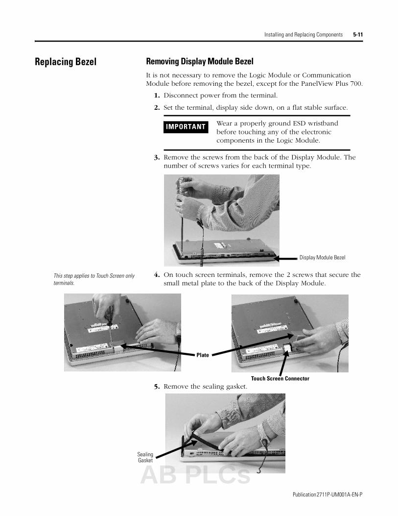
Installing and Replacing Components 5-11
Replacing Bezel Removing Display Module BezelIt is not necessary to remove the Logic Module or Communication Module before removing the bezel, except for the PanelView Plus 700.
1. Disconnect power from the terminal.
2. Set the terminal, display side down, on a flat stable surface.
3. Remove the screws from the back of the Display Module. The number of screws varies for each terminal type.
4. On touch screen terminals, remove the 2 screws that secure the small metal plate to the back of the Display Module.
5. Remove the sealing gasket.
IMPORTANT Wear a properly ground ESD wristband before touching any of the electronic components in the Logic Module.
Display Module Bezel
This step applies to Touch Screen only terminals.
Plate
Touch Screen Connector
Sealing Gasket
AB PLCs
Publication 2711P-UM001A-EN-P
5-12 Installing and Replacing Components
6. Lift the back of the Display Module away from the bezel.
Work on a clean, flat, stable surface to protect the display from debris, scratches and damage.
7. Detach all connectors (maximum of 3). The number of connectors varies by model. • IrDa connector• Function Key connector• Touch Screen connector
8. Set bezel aside.
Replacing Display Module Bezel1. Make sure new bezel is free of lint and marks before attaching.
2. Attach the following connectors. The number of connectors varies by model.
• IrDa connector
• Function Key connector
3. Place the back of the Display Module over the new bezel. Be careful not to pinch any of the cables.
Allow the Touch Screen connector to extend out of the access opening.
4. Attach Touch Screen connector.
5. Replace the sealing gasket (shown in step 5 on page 5-11).
6. Attach screws that secure Display Module to bezel and tighten to a torque of 1.35 - 1.58 N•m (12-14 in-lb).
7. On touch screen terminals, re-attach the small metal plate to the back of the Display Module using 2 screws (shown in step 4 on page 5-11).
Display Module Bezel
Publication 2711P-UM001A-EN-P

Installing and Replacing Components 5-13
Replacing Backlight This section shows how to replace the backlight for the 700, 1000, and 1250 models. The 1500 does not have a replaceable backlight.
1. Disconnect power from the terminal.
2. Remove Display Module bezel as described on page 5-11.
3. Remove the 4 screws that secure the LCD Display.
4. Lift the LCD Display and detach the Display Connector from the circuit board. The location of the connector varies by model.
Display Connector
AB PLCs
Publication 2711P-UM001A-EN-P
5-14 Installing and Replacing Components
5. Detach the Backlight Connector from the circuit board.
The 1250 has two Backlight Connectors.
For PanelView Plus 700/1000Work on a clean, flat, stable surface to protect the display from debris, scratches and damage.
6. Press the retaining tab that secures the backlight and then pull out the backlight.
7. Insert the new backlight.
Backlight Connector
Backlight Retaining Tab
Backlight
Publication 2711P-UM001A-EN-P

Installing and Replacing Components 5-15
For PanelView Plus 1250 (has 2 Backlights)
Work on a clean, flat, stable surface to protect the display from debris, scratches and damage.
8. Remove the 2 screws that secure each of the two backlights and then remove the backlights.
9. Insert the new backlights and then secure each with the 2 screws.
10. Attach the Backlight Connector to the circuit board (shown in step 5 on page 5-14).
11. Attach the LCD Display Connector to the circuit board (shown in step 4 on page 5-13).
12. Secure the LCD Display by attaching the 4 screws. The terminals use different size screws. Use the following chart to tighten the screws.
13. Replace the Display Module bezel as described on 5-12.
Backlights
PanelView Plus Screw Size Torque
700 2.5 mm .68 N•m (6-8 in-lb)
1000/1250 #4 .68 N•m (6-8 in-lb)
1500 #6 .90 - 1.1 N•m (8-10 in-lb)
AB PLCs
Publication 2711P-UM001A-EN-P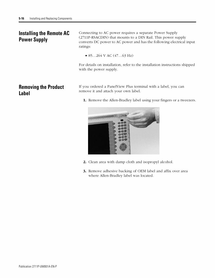
5-16 Installing and Replacing Components
Installing the Remote AC Power Supply
Connecting to AC power requires a separate Power Supply (2711P-RSACDIN) that mounts to a DIN Rail. This power supply converts DC power to AC power and has the following electrical input ratings:
• 85…264 V AC (47…63 Hz)
For details on installation, refer to the installation instructions shipped with the power supply.
Removing the Product Label
If you ordered a PanelView Plus terminal with a label, you can remove it and attach your own label.
1. Remove the Allen-Bradley label using your fingers or a tweezers.
2. Clean area with damp cloth and isopropyl alcohol.
3. Remove adhesive backing of OEM label and affix over area where Allen-Bradley label was located.
Publication 2711P-UM001A-EN-P
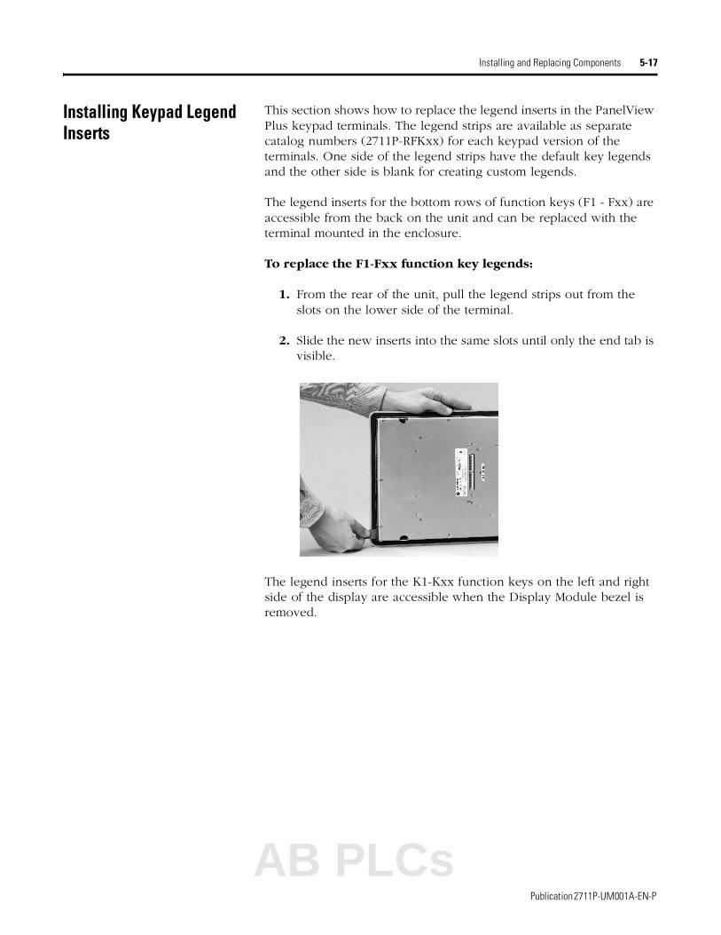
Installing and Replacing Components 5-17
Installing Keypad Legend Inserts
This section shows how to replace the legend inserts in the PanelView Plus keypad terminals. The legend strips are available as separate catalog numbers (2711P-RFKxx) for each keypad version of the terminals. One side of the legend strips have the default key legends and the other side is blank for creating custom legends.
The legend inserts for the bottom rows of function keys (F1 - Fxx) are accessible from the back on the unit and can be replaced with the terminal mounted in the enclosure.
To replace the F1-Fxx function key legends:
1. From the rear of the unit, pull the legend strips out from the slots on the lower side of the terminal.
2. Slide the new inserts into the same slots until only the end tab is visible.
The legend inserts for the K1-Kxx function keys on the left and right side of the display are accessible when the Display Module bezel is removed.
AB PLCs
Publication 2711P-UM001A-EN-P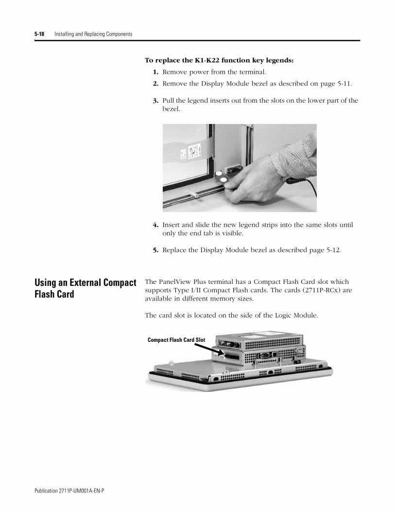
5-18 Installing and Replacing Components
To replace the K1-K22 function key legends:
1. Remove power from the terminal.
2. Remove the Display Module bezel as described on page 5-11.
3. Pull the legend inserts out from the slots on the lower part of the bezel.
4. Insert and slide the new legend strips into the same slots until only the end tab is visible.
5. Replace the Display Module bezel as described page 5-12.
Using an External Compact Flash Card
The PanelView Plus terminal has a Compact Flash Card slot which supports Type I/II Compact Flash cards. The cards (2711P-RCx) are available in different memory sizes.
The card slot is located on the side of the Logic Module.
Compact Flash Card Slot
Publication 2711P-UM001A-EN-P
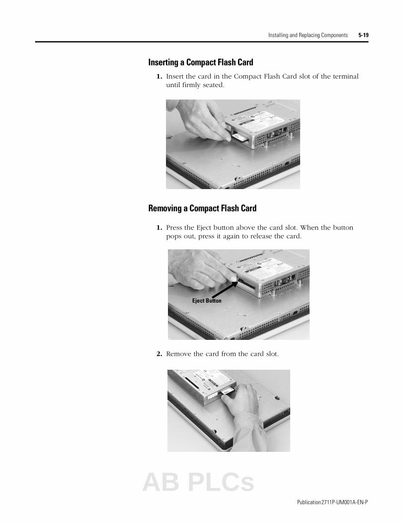
Installing and Replacing Components 5-19
Inserting a Compact Flash Card1. Insert the card in the Compact Flash Card slot of the terminal
until firmly seated.
Removing a Compact Flash Card
1. Press the Eject button above the card slot. When the button pops out, press it again to release the card.
2. Remove the card from the card slot.
Eject Button
AB PLCs
Publication 2711P-UM001A-EN-P
5-20 Installing and Replacing Components
Publication 2711P-UM001A-EN-P

Chapter 6
Terminal Connections
Chapter Objectives This chapter provides network and device connections for the PanelView Plus terminals, including:
• wiring and safety guidelines
• Logic Controller Cable Charts
• USB Ports
• Serial connections on base unit
• Ethernet (onboard communications)
• DH485/DH+/RIO Communications Module
Wiring and Safety Guidelines
Use publication NFPA 70E, Electrical Safety Requirements for Employee Workplaces when wiring the PanelView Plus terminals. In addition to the NFPA general guidelines:
• route communication cables to terminal by a separate path from incoming power:
• where power and communication lines must cross, they should cross at right angles. Communication lines can be installed in the same conduit as low level DC I/O lines (less than 10 volts).
• shield and ground cables appropriately to avoid Electromagnetic Interference (EMI).Grounding minimizes noise from EMI and is a safety measure in electrical installations.
• use the National Electric Code published by the National Fire Protection Association as a source for grounding.
IMPORTANT Do not run signal wiring and power wiring in the same conduit.
AB PLCs
1 Publication 2711P-UM001A-EN-P
6-2 Terminal Connections
Logic Controller Cable Charts
Refer to the following charts for a summary of PanelView Plus terminal connections to controllers and network interface modules.
Runtime Communication Cables - To Controllers
Note 1: 2711P-CBL-EX04 can be used for direct connections only
Note 2: 1784-CP14 can be used for direct connections only
Cables: PanelView Plus to Processor
Protocol PanelView Plus Comm PortSLC-500, 5/01, 5/02
CH1 RJ45 (DH-485)
SLC-5/03, 5/04, 5/05CH0 (9-pin RS-232)
(DF1 or DH-485)
SLC 5/03CH1 (RJ45)
(DH-485)
SLC 5/04CH1 (DH+)
SLC 5/05CH1 (ENET)
DF1(any)
RS-232 (DF1) Comm Port (9-pin)PanelView Plus 700 -1500 N/A
2711-NC13 (16ft/5m)2711-NC14 (32ft/10m)2706-NC13 (10ft/3m)
N/A N/A N/A
DH-485 Serial(any)
RS-232 (DH-485) Comm Port (9-pin)PanelView Plus 700 -1500
use AIC+ Module(1761-NET-AIC)
Connect to Port 1 or 2
2711-NC13 (16ft/5m)2711-NC14 (32ft/10m)2706-NC13 (10ft/3m)
use AIC+ Module(1761-NET-AIC)
Connect to Port 1 or 2N/A N/A
DH-485xxx6xx
DH-485 Communication PortPanelView Plus 700 -15002711P-xxx6xx
1761-CBL-AS03 (10ft/3m)
1761-CBL-AS09 (30ft/9m)
use AIC+ Module(1761-NET-AIC)
Connect to Port 3
1761-CBL-AS03 (10ft/3m)
1761-CBL-AS09 (30ft/9m)
**Note 1**
N/A N/A
EtherNet/IP(any)
EtherNet/IP Comm PortPanelView Plus 700 -1500
N/A Use 1761-NET-ENI Module with Ethernet cable N/A N/A
2711P- CBL-EX04 Ethernet
Crossover Cable
**Note 2*
Remote I/Oxxx6xx
Remote I/O Communication PortPanelView Plus 700 -15002711P-xxx6xx
SLC 5/02 onlyuse 1747-SN with
shielded twinaxial cable use 1747-SN Module with shielded twinaxial cable
DHPlusxxx6xx
DH+ Communication PortPanelView Plus 700 -15002711P-xxx6xx
N/A N/A N/Ashielded
twin axialcable
N/A
IMPORTANT You must configure the Channel 0 Port of the SLC 5/03, 5/04, 5/05 controller for DH-485 communications using the RSLogix 500 (AI500 software).
Publication 2711P-UM001A-EN-P
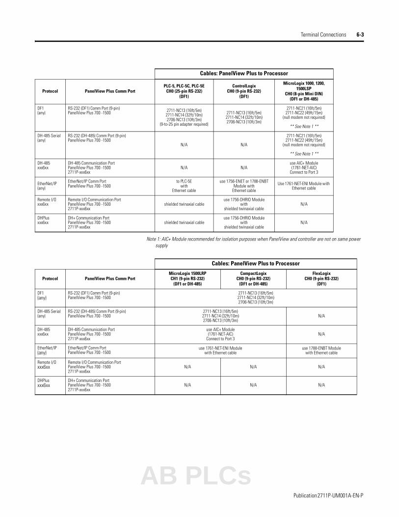
Terminal Connections 6-3
Note 1: AIC+ Module recommended for isolation purposes when PanelView and controller are not on same power supply
Cables: PanelView Plus to Processor
Protocol PanelView Plus Comm PortPLC-5, PLC-5C, PLC-5E
CH0 (25-pin RS-232)(DF1)
ControlLogixCH0 (9-pin RS-232)
(DF1)
MicroLogix 1000, 1200, 1500LSP
CH0 (8-pin Mini DIN)(DF1 or DH-485)
DF1(any)
RS-232 (DF1) Comm Port (9-pin)PanelView Plus 700 -1500 2711-NC13 (16ft/5m)
2711-NC14 (32ft/10m)2706-NC13 (10ft/3m)
(9-to-25 pin adapter required)
2711-NC13 (16ft/5m)2711-NC14 (32ft/10m)2706-NC13 (10ft/3m)
2711-NC21 (16ft/5m)2711-NC22 (49ft/15m)
(null modem not required)
** See Note 1 **
DH-485 Serial(any)
RS-232 (DH-485) Comm Port (9-pin)PanelView Plus 700 -1500
N/A N/A
2711-NC21 (16ft/5m)2711-NC22 (49ft/15m)
(null modem not required)
** See Note 1 **
DH-485xxx6xx
DH-485 Communication PortPanelView Plus 700 -15002711P-xxx6xx
N/A N/Ause AIC+ Module(1761-NET-AIC)
Connect to Port 3
EtherNet/IP(any)
EtherNet/IP Comm PortPanelView Plus 700 -1500
to PLC-5E with
Ethernet cable
use 1756-ENET or 1788-ENBT Module with
Ethernet cable
Use 1761-NET-ENI Module with Ethernet cable
Remote I/Oxxx6xx
Remote I/O Communication PortPanelView Plus 700 -15002711P-xxx6xx
shielded twinaxial cable use 1756-DHRIO Module
withshielded twinaxial cable
N/A
DHPlusxxx6xx
DH+ Communication PortPanelView Plus 700 -15002711P-xxx6xx
shielded twinaxial cableuse 1756-DHRIO Module
withshielded twinaxial cable
N/A
Cables: PanelView Plus to Processor
Protocol PanelView Plus Comm PortMicroLogix 1500LRPCH1 (9-pin RS-232)
(DF1 or DH-485)
CompactLogixCH0 (9-pin RS-232)
(DF1 or DH-485)
FlexLogixCH0 (9-pin RS-232)
(DF1)
DF1(any)
RS-232 (DF1) Comm Port (9-pin)PanelView Plus 700 -1500
2711-NC13 (16ft/5m)2711-NC14 (32ft/10m)2706-NC13 (10ft/3m)
DH-485 Serial(any)
RS-232 (DH-485) Comm Port (9-pin)PanelView Plus 700 -1500
2711-NC13 (16ft/5m)2711-NC14 (32ft/10m)2706-NC13 (10ft/3m)
N/A
DH-485xxx6xx
DH-485 Communication PortPanelView Plus 700 -15002711P-xxx6xx
use AIC+ Module(1761-NET-AIC)
Connect to Port 3N/A
EtherNet/IP(any)
EtherNet/IP Comm PortPanelView Plus 700 -1500
use 1761-NET-ENI Modulewith Ethernet cable
use 1788-ENBT Modulewith Ethernet cable
Remote I/Oxxx6xx
Remote I/O Communication PortPanelView Plus 700 -15002711P-xxx6xx
N/A N/A N/A
DHPlusxxx6xx
DH+ Communication PortPanelView Plus 700 -15002711P-xxx6xx
N/A N/A N/A
AB PLCs
Publication 2711P-UM001A-EN-P
6-4 Terminal Connections
USB Ports The PanelView Plus terminal has two USB ports. The Windows CE operating system currently only supports standard USB keyboard and mouse devices (that is, HID devices) with native device drivers. It also supports some USB printers that have Printer Control Language (PCL) capabilities. A vendor-specific Windows CE driver will be required for all other USB devices.
The USB device can plug into either one of the two USB ports on the PanelView Plus terminal. While the USB interface is designed to be connected and disconnected under power, the Windows CE operating system will not automatically recognize any changes made under power.
USB Connector Pinout
Cables: PanelView Plus to Communication Adapters
1747-AIC
1761-NET-AIC
Protocol PanelView Plus Comm Port Port 1 (9-pin) Port 28-pin Mini DIN()
Port 3(DH485)
1761-NETDNIor 1771-NET-ENI
DF1 (any) RS-232 Comm Port (9-pin)PanelView Plus 700 -15002711P-xxx4xx
N/A2711-NC13 (16ft/5m)
2711-NC14 (32ft/10m)2706-NC13 (10ft/3m)
2711-NC21 (16ft/5m)2711-NC12 (32ft/10m) N/A
2711-NC21 (16ft/5m)2711-NC12 (32ft/10m)
DH-485 Serial(any)
RS-232 Comm Port (9-pin)PanelView Plus 700 - 1500 N/A 2711-NC13 (16ft/5m)
2711-NC14 (32ft/10m)2706-NC13 (10ft/3m)
2711-NC21 (16ft/5m)2711-NC12 (32ft/10m) N/A
DH-485xxx6xx
DH-485 Communication PortPanelView Plus 700 - 15002711P-xxx6xx
1761-CBL-AS03 (10ft/3m)
1761-CBL-AS09 (30ft/9m)or wired
N/ADH-485 Cable N/A
Pin Signal
1 USBVCC
2 USBD-
3 USBD+
4 USB-GND
WARNING
!If you connect or disconnect the USB cable with power applied to the PanelView Plus or the serial device on the other end of the cable, an electrical arc can occur. This could cause an explosion in hazardous location installations. Be sure that power is removed or the area is nonhazardous before proceeding.
4321
4321
USB Ports
Publication 2711P-UM001A-EN-P

Terminal Connections 6-5
Serial Connections The base configured unit of the PanelView Plus terminal has a multi-purpose serial RS-232 port that supports:
• DH-485 communications through a serial connection
• DF1 full duplex communications with controllers using direct connections or modem connections
• third party point-to-point communications
• application uploads/downloads
• printing
The serial port on the base configured unit of the PanelView Plus terminal is a 9-pin, male, RS-232 connector. The table below shows the pinout descriptions for this port and how these pins map to the serial ports on the controllers.
Pins 1 - 9 are electrically isolated.
The maximum cable length for serial communications is 15.24 meters (50 feet).
PanelView Plus RS-232 Port 9-pin DCE
SLC9-pin
PLC25-pin
MicroLogix/ DNI 8-pin DIN
12 2 3 4
3 3 2 7
4 4 20
5 5 7 2
6 6 6
7 7 4
8 8 5
9Connector Shell Chassis Gnd
WARNING
!If you connect or disconnect the serial cable with power applied to the PanelView Plus or the serial device on the other end of the cable, an electrical arc can occur. This could cause an explosion in hazardous location installations. Be sure that power is removed or the area is nonhazardous before proceeding.
Serial RS-232 Port
Base Configured Unit of PanelView Plus
1569
Insert tie in hole and use as strain relief for all attached cables.
RXD
TXD
DTR
COM
DSR
RTS
CTS
AB PLCs
Publication 2711P-UM001A-EN-P
6-6 Terminal Connections
Modem Connection
Wire or radio modem communications is possible between the PanelView Plus and controller. Each modem must support full duplex communications. Refer to your modem user manual for details on settings and configuration.
Constructing a Null Modem Cable
To construct a null modem cable, refer to the following pinout:
9-pin 25-pin 9-pin
3 3 3
2 2 2
5 7 5
1 8 1
4 20 4
6 6 6
8 5 8
7 4 7
DF1 Port
Optical Isolator
Modem
Modem
Controller
PanelView Plus
Publication 2711P-UM001A-EN-P

Terminal Connections 6-7
Computer or Printer Connections
The RS-232 serial port on the base configured unit of the PanelView Plus terminal supports:
• application uploads/downloads using a direct connection
• or printing
Printer
RS-232 Port
RS-232 Port
9-pin male123456789
TXD (Data Transmit)RXD (Data Receive)
COMDTR
DSRRTSCTSNC
DCD9-pin male123456789
(pulled high to +12V)
NC
NC
NC
PanelView Plus Port (DCE)Printer/Computer Port (DTE)
Available CablesCat. No. 2711-NC13, 5 m (16.4 ft)Cat. No. 2711-NC14, 10 m (32.7 ft)Cat. No. 2706-NC13, 3 m (10 ft)
25-pin to 9-pin Adapter
(if required)
with Handshaking
RXDTXD
COM
RTSCTS
9-pin malePanelView Plus Printer Port (DCE)
23
9-pin235
Printer/Computer Port (DTE)25-pin
27
3
5 COM
Upload/Download or Printer Cable without Hardware Handshaking
RXDTXDCOM
Computer
Base Configured Unit of PanelView Plus
AB PLCs
Publication 2711P-UM001A-EN-P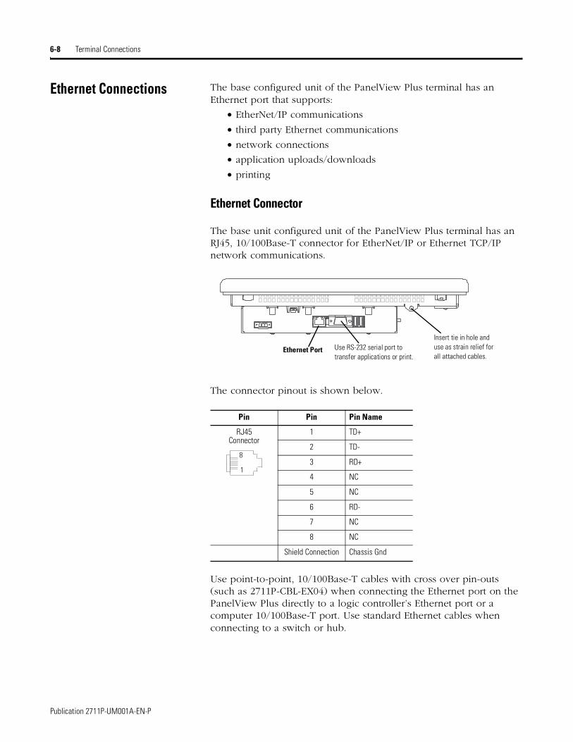
6-8 Terminal Connections
Ethernet Connections The base configured unit of the PanelView Plus terminal has an Ethernet port that supports:
• EtherNet/IP communications
• third party Ethernet communications
• network connections
• application uploads/downloads
• printing
Ethernet Connector
The base unit configured unit of the PanelView Plus terminal has an RJ45, 10/100Base-T connector for EtherNet/IP or Ethernet TCP/IP network communications.
The connector pinout is shown below.
Use point-to-point, 10/100Base-T cables with cross over pin-outs (such as 2711P-CBL-EX04) when connecting the Ethernet port on the PanelView Plus directly to a logic controller’s Ethernet port or a computer 10/100Base-T port. Use standard Ethernet cables when connecting to a switch or hub.
Pin Pin Pin Name
RJ45 Connector
1 TD+
2 TD-
3 RD+
4 NC
5 NC
6 RD-
7 NC
8 NC
Shield Connection Chassis Gnd
Ethernet Port Use RS-232 serial port to transfer applications or print.
Insert tie in hole and use as strain relief for all attached cables.
1
8
Publication 2711P-UM001A-EN-P

Terminal Connections 6-9
Cables
Category 5 shielded and unshielded twisted-pair cables with RJ45 connectors are supported. If 100 Mbit/second data rates are used, we recommend that you use a shielded cable. The shielded cable will help insure that industrial noise immunity levels are maintained. The maximum cable length between the terminal’s Ethernet port and a 10/100Base-T port on an Ethernet hub (without repeaters or fiber) is 100 meters (328 feet). In industrial applications, keep the cable length to a minimum.
WARNING
!If you connect or disconnect the Ethernet cable with power applied to the PanelView Plus or any device on the network, an electrical arc can occur. This could cause an explosion in hazardous location installations. Be sure that power is removed or the area is nonhazardous before proceeding.
AB PLCs
Publication 2711P-UM001A-EN-P
6-10 Terminal Connections
DH-485/DH+/Remote I/O Module
The PanelView Plus terminal with a DH-485/DH+/Remote I/O Communication Module supports communications with the following networks:
• DH+ networks
• DH-485 networks
• Remote I/O networks
You can communicate with only one network at one time.
Module Connections
The DH-485/DH+/Remote I/O Module is supplied with 2 ferrites for cables. After installing the communications cable, place the ferrite around the cable close to the Module Connector. The ferrites suppress EMI (Electromagnetic Interference) from the cable.
AllenBradley
DH4851
2345
6
3
2
1
DH+ RIO
Remote I/O3. Clear2. Shield/Drain1. Blue
DH+3. Blue2. Shield/Drain1. Clear
1. Earth Ground2. Shield/Drain3. Signal Ground4. Channel B5. Channel A6. Termination Resistance
LED Indicator
Publication 2711P-UM001A-EN-P
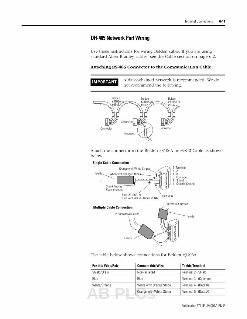
Terminal Connections 6-11
DH-485 Network Port Wiring
Use these instructions for wiring Belden cable. If you are using standard Allen-Bradley cables, see the Cable section on page 6-2.
Attaching RS-485 Connector to the Communication Cable
Attach the connector to the Belden #3106A or #9842 Cable as shown below.
The table below shows connections for Belden #3106A.
IMPORTANT A daisy-chained network is recommended. We do not recommend the following.
For this Wire/Pair Connect this Wire To this Terminal
Shield/Drain Non-jacketed Terminal 2 - Shield
Blue Blue Terminal 3 - (Common)
White/Orange White with Orange Stripe Terminal 4 - (Data B)
Orange with White Stripe Terminal 5 - (Data A)
Belden#3106A or#9842
Belden#3106A or#9842
Belden#3106A or#9842
Connector
Connector
Connector
Incorrect
Orange with White Stripes
White with Orange Stripes
Shrink TubingRecommended
Blue (#3106A) orBlue with White Stripes (#9842)
Drain Wire
6 Terminal5 A4 B3 Common2 Shield1 Chassis Ground
Single Cable Connection
to Previous Device
to Successive Device
Multiple Cable Connection
Ferrite
Ferrite
Ferrite
AB PLCs
Publication 2711P-UM001A-EN-P
6-12 Terminal Connections
DHPlus Network Connections
Use the Belden 9463 twin axial cable (1770-CD) to connect a PanelView Plus terminal to the DH+ link.
You can connect a DH+ link in 2 ways:
• trunk line/drop line - from the drop line to the connector screw terminals on the DH+ connectors of the processor
• daisy chain - to the connector screw terminals on the DH+ connectors on the processor
Follow these guidelines when installing DH+ communication links:
• do not exceed these cable lengths:
– trunk line-cable length: 3,048 m (10,000 ft)
– drop-cable length: 30.4 m (100 ft)
The maximum cable length is determined by baud rate.
• do not connect more than 64 stations on a single DH+ link
Logic Controller
PanelView Plus
82 or 150 Ohm Terminating Resistor
Blue 3Shield SH 2
Clear 1
Clear 1Shield SH 2
Blue 3
Belden
Ferrite
Publication 2711P-UM001A-EN-P

Terminal Connections 6-13
Remote I/O Connections
To connect a PanelView Plus terminal to a Remote I/O scanner, use cable Catalog No. 1770-CD (equivalent to Belden 9463). The maximum cable length (link distance) is determined by the baud rate.
• 2,800 meters (10,000 feet) for 57.6K baud
• 1,400 meters (5,000 feet) for 115.2K baud
• 700 meters (2,500 feet) for 230.4K
See Programmable Controller Wiring and Grounding Guidelines, Publication 1770-4.1. The user manual for the I/O scanner module also provides cabling information.
The orientation of the Remote I/O Connector on the PanelView Plus is reversed from the PLC Scanner connector. However, the polarity is the same as the scanner card connection to the SLC.
Logic Controller or Scanner Remote I/O Port
PanelView Plus
82 or 150 Ohm Terminating Resistor
Blue 1Shield SH 2
Clear 3
Clear 3Shield SH 2
Blue 1
Belden
Ferrite
AB PLCs
Publication 2711P-UM001A-EN-P
6-14 Terminal Connections
Publication 2711P-UM001A-EN-P

Chapter 7
Transferring files
Chapter Objectives This chapter covers information on:
• transferring applications using a Compact Flash Card
Using a Compact Flash Card The PanelView Plus terminal allows you to copy or load files using a compact flash card from RSView ME. To copy files in RSView ME using a compact flash card, see page 4-17.
IMPORTANT For details on transferring .MER applications from a computer to the PanelView Plus terminal, refer to RSView Studio help or documentation.
AB PLCs
1 Publication 2711P-UM001A-EN-P
7-2 Transferring files
Publication 2711P-UM001A-EN-P

Chapter 8
Troubleshooting and Maintenance
Chapter Objectives This chapter provides information on how to isolate and correct common operating problems with system components.
• general troubleshooting
• troubleshooting individual components (display, touch screen, keypad, attached keyboard or mouse)
• Ethernet
• startup
• advanced troubleshooting
• system error messages
• system identification errors
• restarting in configuration mode
• startup problems
• restarting in safe mode
• LED indicators
• firmware upgrade
• cleaning the display window
General Troubleshooting This section provides a list of general troubleshooting steps to follow when trying to isolate problems.
• Check for adequate power. The PanelView Plus terminal requires 24V dc at 1.5 A minimum. An under-powered unit could result in unpredictable behavior.
The AC Power Supply (2711P-RSACDIN) meets Class 2/SELV requirements, and is approved for the PanelView Plus terminal.
• Check LED indicators on the Logic Module. Is power on? Is the unit attempting to start? The red LED should be Off, except for a few brief flashes, and the green LED should be On. If the LEDs remain Off, the power supply or Logic Module has failed. Check the power cable. Replace the Logic Module if the power is within range; if not, replace the power supply.
AB PLCs
1 Publication 2711P-UM001A-EN-P
8-2 Troubleshooting and Maintenance
If the terminal powers up and stops during startup, the state of the Logic Module LEDs indicate the following:
Blinking red LED indicates a recoverable error.
Solid red LED indicates a non-recoverable and fatal error.
• Check messages at startup for errors. Record any error message and refer to the System Error Message table on page 8-9 for troubleshooting.
• Check voltages and temperatures. From Configuration Mode, open Terminal Settings>System Information>Terminal Information.
– Battery Voltage should be at least 2.75 V. Replace the battery if less than 2.75 V.
– Display Temperatures should be less than 55 °C. The CPU
temperature should be less than 95 °C.
If the temperatures are higher, check for obstructed airflow through the chassis and attempt to moderate the ambient temperatures within the enclosure and surroundings.
• Check System Event Log for errors or unexpected reboots. From Configuration Mode, open Terminal Settings>System Event Log.
• Use Extended Diagnostics to perform more extensive hardware testing at startup. From Configuration Mode, open Terminal Settings>Startup Tests>Select Tests.
Red LED Green LED Description
Blinking Off Last firmware download failed. Repeat firmware download.
Blinking Blinking EBC boot loader firmware failed or is missing. Load new EBC firmware
Blinking ON Windows CE OS firmware failed or is missing. Load new CE OS firmware.
Red LED Green LED Description
On Off Fatal hardware error occurred in Logic Module. Replace the Logic Module.
On Blinking Fatal hardware error occurred in Display Module. Replace the Display Module.
Publication 2711P-UM001A-EN-P

Troubleshooting and Maintenance 8-3
Select one or more of the tests you want to run. Enable extended diagnostics and set the iteration or repeat count.
Restart the PanelView Plus terminal. The Serial Port test requires a loopback connector with the following connections.
Extended Diagnostics are performed at every startup until disabled. A failure will momentarily halt startup and display an error message.
Troubleshooting Components
This section provides tips on how to isolate problems with individual components of the PanelView Plus terminal, including the display, touch screen, keypad, attached keyboard or mouse.
Display Problems
This section provides tips on how to isolate problems with the Display.
• Check the brightness setting of the Display Module. Is the display brightness dim or unreadable?
From Configuration Mode, open Terminal Settings>Display Intensity.
• Check the Screen Saver settings. Is the backlight turning off or dimming the display unexpectedly.
From Configuration Mode, open Terminal Settings>Display>Screen Saver.
• Check the LED indicators on the Logic Module. Do they flash during startup? Is power on and is the unit attempting to start?
• Check the Display temperature. From Configuration Mode, open the Terminal Settings>Display>Display Temperature screen. Poor contrast and slow screen updates will occur if the Display is too cold or too hot.
123456789
N/CRXTXDTRN/CDSRRTSCTSN/C
DB9 Connector (female)
AB PLCs
Publication 2711P-UM001A-EN-P
8-4 Troubleshooting and Maintenance
• Check the startup messages. Is the Display operating at all and do the startup messages appear? Record any error message and use the System Error Message table on page 8-9 for troubleshooting.
• Replace the Display Module if all other attempts do not resolve problem. If replacing the Display Module corrects the problem, then the Display was not functioning properly.
Touch Screen Problems
This section provides tips on how to isolate problems with the Touch Screen.
• Check the catalog number of the unit. Verify that your terminal has a touch screen by looking at the label on the Display Module.
• Perform a calibration of the touch screen. From Configuration Mode, open Terminal Settings>Input Devices>Touch Screen>Calibration. Follow the directions.
The calibration requires 4 user screen touches. When the touches do not converge to a satisfactory calibration, you are asked repeatedly for additional screen touches and the calibration process never terminates. A touch screen that does not calibrate is not present or not functioning properly. Replace the bezel or the Display Module.
• Check the Cursor Enable setting for the touch screen. Is the cursor visible? From Configuration Mode, open Terminal Settings>Input Devices>Touch Screen>Cursor.
• Check the pointer input by attaching a USB mouse. If the mouse works, but the touch screen does not, then the touch driver or touch screen is not functioning properly. If both the mouse and the touch screen are not working, then it is an application problem.
• Does touching or dragging on the screen appear to work? If yes, even if incorrectly, the touch screen is present and working but requires calibration.
• Replace Bezel or Display Module if all other attempts do not resolve the problem. If replacing the Display Module or bezel corrects the problem, then the touch screen was not functioning properly.
Publication 2711P-UM001A-EN-P

Troubleshooting and Maintenance 8-5
Keypad Problems
This section provides tips on how to isolate problems with the Keypad:
• Check Multi-Key/Hold-Off settings. From Configuration Mode, open Terminal Settings>Keypad>Keypad Settings.
Is the Hold-Off Delay longer than expected, or are multiple key presses being held by Multi-Key Lockout? Check all configurable settings.
• Check key input by attaching a USB keyboard. If the keyboard works, but the keypad does not, then the keypad driver or keypad is not working. If both the keypad and keyboard are not working, then the problem may be the application.
• Replace the Display Module if all other attempts do not resolve problem. If replacing the Display Module corrects the problem, then the keypad was not functioning properly.
Problems with Attached Mouse
This section provides tips on how to isolate problems with an attached Mouse.
• Check the Cursor Enable setting. Is the cursor visible? From Configuration Mode, open Terminal Settings>Input Devices>Touch Screen>Cursor. Also check mouse settings.
• Check the USB cable and connection. Detach and then re-attach the mouse. Cycle power to the terminal.
• Is the mouse a USB composite device? If the mouse is a keyboard/mouse composite device, then try a stand-alone USB mouse.
• Replace the USB mouse. Try a different model or manufacturer. Check Knowledgebase at the http://support.rockwellautomation.com site for a list of USB devices that are compatible with the PanelView Plus terminal. If attaching a new mouse resolves the problem, then the old mouse was not working or non-compliant.
Problems with Attached Keyboard
This section provides tips on how to isolate problems with the Keyboard:
AB PLCs
Publication 2711P-UM001A-EN-P
8-6 Troubleshooting and Maintenance
• Check for enabled Alt-Ctrl keys. From Configuration Mode, open Terminal Settings>Input Devices>Keyboard>Keyboard Settings.
Are the keys enabled as expected? Check all configurable settings in Keyboard Properties.
• If keypad is present, check input using the keypad. If the keypad works, but the keyboard does not, then the keyboard driver or keyboard is probably not working. If both the keypad and the keyboard are not working, then it is probably an application problem.
• Check the USB cable and connector. Detach and re-attach the keyboard. Insure a good connection. Cycle power to the terminal.
• Is the keyboard a USB composite device? If the keyboard is a keyboard/mouse composite device, then try a stand-alone USB keyboard.
• Replace the USB keyboard. Try a different model or manufacturer. Check Knowledgebase at the http://support.rockwellautomation.com site for a list of USB devices that are compatible with the PanelView Plus terminal. If a new keyboard resolves the problem, then the old keyboard was probably non-compliant.
Publication 2711P-UM001A-EN-P

Troubleshooting and Maintenance 8-7
Ethernet Problems • Check LED indicators at the Ethernet connector. The green LED indicates a communications link and should be ON. The amber LED indicates data activity and should be flashing. Verify that there is a connection to the hub?
• Check cable connections and quality of cable. Check for good connections and things such as quality, crimping, hub connection, and uplink ports.
• Check IP Address of the Built-In Ethernet Controller. From Configuration Mode, select Terminal Settings>Networks and Communications>Network Connections>Network Adaptors.
If DHCP is enabled, the device expects a valid IP address to be acquired within a several seconds after startup. The TCP/IP protocol automatically assigns 169.254.nnn.nnn when it fails to acquire an IP address from the server. In general, an IP address that begins with 169 will not support a network connection.
A bad Ethernet connection and the absence of a valid IP address are typically reported in a Communications error message box with the Winsock critical error 10065 - "No route to host".
• Check for conflicting IP addresses. If DHCP is not enabled, make sure the IP address you specify is not in conflict with the address of another device on the network.
• Check the Device Name of the PanelView Plus terminal. Do not allow devices on the network with same (host) name. From Configuration Mode, open Terminal Settings>Communications and Networks>Network Connections>Device Name.
• Contact your Network Administrator to check peer or server settings. The “other side” of the Ethernet connection may also be a problem.
AB PLCs
Publication 2711P-UM001A-EN-P
8-8 Troubleshooting and Maintenance
Advanced Troubleshooting 1. Take advantage of alternate connectivity - mouse versus touch screen, keyboard versus keypad, serial communications, and alternate Ethernet connections.
2. Know useful keyboard shortcuts so that you can navigate around the system without a mouse or touch screen.
3. From Configuration Mode, select Terminal Settings>System Event Log to check the event log. Look for error conditions or reasons for unexpected reboots.
4. Check the configuration settings in Configuration Mode for incorrect settings.
5. Most importantly, general troubleshooting thoroughness means getting answers to questions such as:
• Does the failure always happen? Is it repeatable?
• Does the failure happen at bootup or some other time? Is there a set of actions that reveal the problem?
• Does the failure occur on just one terminal or on multiple machines? If more than one machine, what do they have in common? If not all machines, then what is different between machines that fail and those that don’t?
• What appears on the screen, the LED indicators?
• Lastly, and most important; did everything work until recently? If so, what changed?
Publication 2711P-UM001A-EN-P

Troubleshooting and Maintenance 8-9
System Error Messages The following table provides a list of system error messages that may display on startup.
Error Number Displayed Message Description
1 RAM Test POST RAM Test failure
23 Internal CF Internal Compact Flash Card access failure
25 EXE Valid System firmware is incompatible with the boot loader
30 Watchdog Test POST Watchdog Test failure
31 Stuck Key POST Stuck Key Test failure
31.5 Stuck Touch POST Stuck Touch Test failure
32 Battery Test POST dead battery failure
33.5 NVRAM Access Non-volatile memory access failure
34 Display EEPROM Display Module EEPROM data is corrupted
34.5 Display Temp Display Module over-temperature failure
35.5 CPU Temp Processor over-temperature failure
40 EXE Check System firmware is missing or corrupt
50 External CF External Compact Flash card access failure
71 Eboot HW Test Eboot failure
AB PLCs
Publication 2711P-UM001A-EN-P
8-10 Troubleshooting and Maintenance
System Identification Errors The error messages in this section appear on bootup if incorrect or invalid components are used with the PanelView Plus terminal.
• The following dialog appears if a VersaView CE Logic Module is attached to a PanelView Display Module or a PanelView Plus Logic Module is attached to a VersaView CE Display Module. It is recommended that you use a VersaView CE Display Module with a VersaView CE Logic Module and a PanelView Plus Display Module with a PanelView Plus Logic Module. This is a warning allowing you to continue to operate.
• The following dialog appears if the PanelView Plus Logic Module contains a 6189-RWx Internal Compact Flash card for the VersaView CE terminal.
After pressing OK, you will be asked to power off the terminal and insert a valid 2711P-RWx Internal Compact Flash card for the PanelView Plus terminal.
• The following dialog appears if the VersaView CE Logic Module contains a 2711P-RWx Internal Compact Flash card for the PanelView Plus terminal
.
After pressing OK, you will be asked to power of the terminal and insert a valid 6189-RWx Internal Compact Flash card for the VersaView CE terminal.
(6189-RWX)
Publication 2711P-UM001A-EN-P

Troubleshooting and Maintenance 8-11
• The following dialog appears if the Internal Compact Flash in the PanelView Plus Logic Module is corrupt or invalid. This is a fatal error
After pressing OK, you will be asked to power of the terminal and insert a valid 6189-RWx Internal Compact Flash card.
Restarting in Configuration Mode
If the PanelView Plus is configured to run an RSView ME .mer application and you need to enter configuration mode, use the following procedure.
To enter Configuration Mode while an application is running:
• press the Goto Configuration Mode button on the application screen
To enter Configuration Mode at startup:
1. On a Keypad terminal, hold down the Shift key.
On a Touch Screen terminal, tap the screen multiple times.
The following screen appears.
2. Press the Continue button to access the Configuration Mode screen.
If you are unable to enter confguration mode even after pressing the Continue button, the firmware may be corrupted. Reload the firmware. See page 8-13.
TIP Begin pressing or tapping when the startup messages have completed and when the first cursor appears.
AB PLCs
Publication 2711P-UM001A-EN-P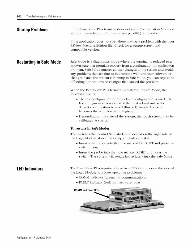
8-12 Troubleshooting and Maintenance
Startup Problems If the PanelView Plus terminal does not enter Configuration Mode on startup, then reload the firmware. See page8-13 for details.
If the application does not start, there may be a problem with the .mer RSView Machine Edition file. Check for a startup screen and compatible version.
Restarting in Safe Mode Safe Mode is a diagnostics mode where the terminal is reduced to a known state that permits recovery from a configuration or application problem. Safe Mode ignores all user changes to the system and avoids any problems that are due to interactions with end-user software or changes. Once the system is running in Safe Mode, you can repair the offending applications or changes that caused the problem.
When the PanelView Plus terminal is restarted in Safe Mode, the following occurs:
• The last configuration or the default configuration is used. The last configuration is restored at the next reboot unless the default configuration is saved (flushed), in which case it becomes the new Persistent Registry.
• Depending on the state of the system, the touch screen may be calibrated at startup.
To restart in Safe Mode:
The switches that control Safe Mode are located on the right side of the Logic Module above the Compact Flash card slot.
• Insert a thin probe into the hole marked DEFAULT and press the switch, then;
• Insert the probe into the hole marked RESET and press the switch. The system will restart immediately into the Safe Mode
LED Indicators The PanelView Plus terminals have two LED indicators on the side of the Logic Module to isolate operating problems:
• COMM indicator (green) for communications
• FAULT indicator (red) for hardware faults
COMM and Fault LEDs
Publication 2711P-UM001A-EN-P
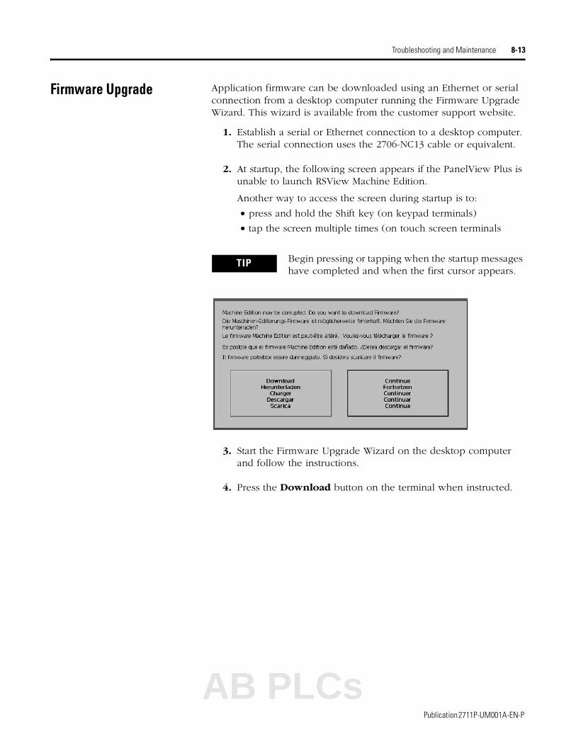
Troubleshooting and Maintenance 8-13
Firmware Upgrade Application firmware can be downloaded using an Ethernet or serial connection from a desktop computer running the Firmware Upgrade Wizard. This wizard is available from the customer support website.
1. Establish a serial or Ethernet connection to a desktop computer. The serial connection uses the 2706-NC13 cable or equivalent.
2. At startup, the following screen appears if the PanelView Plus is unable to launch RSView Machine Edition.
Another way to access the screen during startup is to:
• press and hold the Shift key (on keypad terminals)
• tap the screen multiple times (on touch screen terminals
3. Start the Firmware Upgrade Wizard on the desktop computer and follow the instructions.
4. Press the Download button on the terminal when instructed.
TIP Begin pressing or tapping when the startup messages have completed and when the first cursor appears.
AB PLCs
Publication 2711P-UM001A-EN-P
8-14 Troubleshooting and Maintenance
Cleaning the Display Window
To clean the display window:
1. Disconnect power from the terminal at the power source.
2. Use a clean sponge or soft cloth with a mild soap or detergent to clean the display.
3. Dry the display with a chamois or moist cellulose sponge to avoid water spots.
Removing Paint and Grease
Remove fresh paint splashes and grease before drying by rubbing lightly with isopropyl alcohol (70% concentration). Afterward, wash using a mild soap or detergent. Rinse with clean water.
Use a protective antiglare overlay for easier cleaning of display window.
ATTENTION
!Use of abrasive cleaners or solvents may damage the display. Do not scrub or use brushes.
Publication 2711P-UM001A-EN-P

Appendix A
Specifications
Electrical
Environmental
Display
DC PowerInput Voltage DCPower Consumption DC
24V dc nominal (18…32V dc)70 Watts maximum (2.9A @24V dc)
AC Power (2711P-RSAC)Input Voltage ACPower Consumption AC
85…264V ac, 47…63 Hz120VA maximum
Operating Temperature 0…55 °C (32…131 °F)
Non-operating Temperature -25…70 °C (-13 to 158 °F)
Relative Humidity 0…95% without condensation
Shock Operating 15 g at 11 ms
Shock Non-Operating 30 g at 11 ms
Vibration 10…57 Hz, 0.012 pk-pk displacement57…500 Hz, 2 g pk acceleration
Ratings Nema Type 12, 13, 4X (Indoor use only), IP54, IP65
Display Type Color Active Matrix TFT Thin-Film Transistor with LCD Liquid Crystal Display
Display Area Size700100012501500
6.5 inch10.4 inch12.1 inch15.0 inch
Display Area (W x H)700100012501500
132 x 99 mm (6.7 inch diagonal)211 x 158 mm (10.4 inch diagonal)246 x 184 mm (12.1 inch diagonal)304 x 228 mm (15.1 inch diagonal)
Resolution700100012501500
640 x 480640 x 480800 x 6001024 x 768
Touch Technology Analog ResistiveAB PLCs
1 Publication 2711P-UM001A-EN-P
A-2 Specifications
Mechanical
Agency Certifications
Weight (for base unit without modules)700 Keypad or Keypad & Touch700 Touch 1000 Keypad or Keypad & Touch1000 Touch1250 Keypad or Keypad & Touch1250 Touch1500 Keypad or Keypad & Touch1500 Touch
1.9 kg (4.2 lbs)1.7 kg (3.8 lbs)2.9 kg (6.3 lbs)2.6 kg (5.7 lbs)3.4 kg (7.6 lbs)3.2 kg (7.1 lbs)4.6 kg (10.0 lbs)4.2 kg (9.3 lbs)
Dimensions H x W x D (for base unit without communication module)
700 Keypad or Keypad & Touch 193 x 290 x 55 mm7.58 x 11.40 x 2.18 in
700 Touch 179 x 246 x 55 mm7.04 x 9.68 x 2.18 in
1000 Keypad or Keypad & Touch 248 x 399 x 55 mm9.77 x 15.72 x 2.18 in
1000 Touch 248 x 329 x 55 mm9.77 x 12.97 x 2.18 in
1250 Keypad or Keypad & Touch 282 x 416 x 55 mm11.12 x 16.36 x 2.18 in
1250 Touch 282 x 363 x 55 mm11.12 x 14.30 x 2.18 mm
1500 Keypad or Keypad & Touch 330 x 469 x 65 mm12.97 x 18.46 x 2.55 in
1500 Touch 330 x 416 x 65 mm12.97 x 16.37 x 2.55 in
Agency Certifications
When product is marked:
N223
Marked for all applicable directives
Marked for all applicable acts
UL Listed Industrial Control EquipmentUL Listed Industrial Control Equipment for use in CanadaUL Listed Industrial Control Equipment for use in:
• Class I, Div 2 Group A, B, C, D• Class II, Div 2 Group F, G• Class III, Div 1 Hazardous Locations
Publication 2711P-UM001A-EN-P

Index
AAC power supply 1-4, 1-8
electrical ratings 3-3installation 5-16
accessories 1-7adapter plates 1-10antiglare overlays 1-9application
loading .mer 4-4running .mer 4-5
Bbacklight
brightness 4-19replacement 5-13
backlights, replacement 1-9base unit 1-3battery replacement 1-9, 5-9bezel replacement 5-11
Ccables 1-10
runtime communication cables 6-2catalog number configuration 1-7cleaning display 8-14communication adapters 1-10communication modules 1-4, 1-7
DH+/DH485/RIO 1-4installing and replacing 5-5
communicationscables 6-2DH+/DH485/RIO module 6-10DH485 4-9, 6-11DHPlus 4-9, 6-12Ethernet 4-12, 6-8Remote I/O 6-13serial 4-10, 6-5USB ports 6-4
compact flash card slotinserting card 5-18
configuration modeloading application 4-4running application 4-5terminal settings 4-5
copying filesapplications 4-17font files 4-17
Ctrl-Alt key sequence 4-21cutout dimensions for each terminal 2-7
Ddate 4-34date format 4-39DC power A-1
connections 3-2electrical ratings 3-2SELV power supply 3-2
deleting filesapplications 4-16font files 4-16log files 4-16
DH485cables 6-2configuration 4-9network wiring 6-11settings in configuration mode 4-9
DHPluscables 6-2configuration 4-9network connections 6-12settings in configuration mode 4-9
diagnosticsin Configuration Mode 4-15
display modules 1-6, 1-7keypad 1-6replacing 5-7touch screen 1-5troubleshooting 8-3
display settingsin configuration mode 4-18
EEthernet
cables 6-2, 6-9configuration 4-12connector pinout 6-8troubleshooting 8-7
European Communities Directive Compliance Preface-iii
external compact flash cards 1-8, 5-18
Ffirmware upgrade 8-13function keys
keypad terminals 1-6
Hhardware features 1-1hardware monitor 4-31AB PLCs
Publication 2711P-UM001A-EN-P

2 Index
Iinput devices
keyboard 4-20keypad 4-20mouse 4-23touch screen 4-22
input panel 4-3installation 2-1
1000H mounting dimensions 2-41250H mounting dimensions 2-51500H mounting dimensions 2-6700H mounting dimensions 2-3ambient temperature 2-2backlight 5-13battery 5-9bezel 5-11clearances 2-2communication module 5-5display module 5-7enclosures 2-2environment 2-2hazardous locations 2-1legend inserts 5-17mounting clips 2-9mounting dimensions 2-3panel cutout dimensions 2-7panel installation 2-8product label 5-16required tools 2-2
intended audience Preface-iiIP address 4-13
Kkeyboard
troubleshooting 8-5keyboard settings 4-20keypad legend inserts 1-9, 5-17keypad settings 4-20
troubleshooting 8-5
Llanguages 4-37LED indicators 8-12legend inserts
installation 5-17loading application 4-4logic module 1-8
features 1-3installing and replacing 5-3
Mmemory
allocations 4-32installing and replacing 5-2
modular components 1-2mounting clips 1-9, 2-9mounting dimensions 2-3
1000H 2-41250H 2-51500H 2-6700H 2-3
mouse 4-23, 6-4troubleshooting 8-5
multikey lockout 4-21
Nnetwork connections 4-11
Ppacking list Preface-ipanel installation 2-8power
AC 3-3DC 3-2
print setupfor alarms 4-24for diagnostic messages 4-24for displays 4-24
product components 1-7
RRAM 1-8
installing and replacing 5-2Remote I/O
cables 6-2, 6-13connection 6-13settings 4-9
reset switch 3-3resetting terminal 3-3, 4-2RSView ME
firmware number 4-33
Ssafe mode 3-3, 8-12screen saver 4-19serial communications
computer connection 6-7DF1 6-5
Publication 2711P-UM001A-EN-P

Index 3
DH485 6-5null modem cable 6-6ports 6-5, 6-8printing 6-5, 6-7transferring applications 6-5using a modem 6-6
serial connections 6-5serial settings 4-10software 1-2specifications
agency certifications A-2electrical A-1environmental A-1mechanical A-2
starting in Configuration Mode 8-11startup problems 8-12startup settings 4-26startup tests 4-28support Preface-iv, 4-33system error messages 8-9system event log 4-30system identification errors 8-10system information 4-31
Tterminal information 4-31terminal settings 4-5
copying files 4-17date 4-34deleting files 4-16DH485 4-9DHPlus 4-9diagnostics 4-15display 4-18file management 4-16input devices 4-20long date format 4-40memory allocation 4-32network connections 4-11numeric format 4-37print setup 4-24regional settings 4-37
Remote I/O 4-9RSView ME info 4-33screen saver 4-19serial 4-10short date format 4-39startup options 4-26startup tests 4-28system event log 4-30system information 4-31terminal info 4-31time 4-35time format 4-38time zone 4-36time/date/regional settings 4-34
time 4-35time format 4-38touch screen
calibration 4-22cursor enable 4-22double-tap sensitivity 4-23troubleshooting 8-4
troubleshooting 8-1display module 8-3Ethernet 8-7firmware upgrade 8-13general 8-1keyboard 8-5keypad 8-5LED indicators 8-12starting in Configuration Mode 8-11starting in safe mode 3-3, 8-12startup problems 8-12system error messages 8-9system identification errors 8-10touch screen 8-4
UUSB ports 6-4
connector pinouts 6-4
Wwiring and safety guidelines 3-1
AB PLCs
Publication 2711P-UM001A-EN-P
4 Index
Publication 2711P-UM001A-EN-P

Publication 2711P-UM001A-EN-P - March 2003 5 PN 41061-314-01(1)Copyright © 2003 Rockwell Automation, Inc. All rights reserved. Printed in the U.S.A.
Rockwell Automation Support
Rockwell Automation tests all of our products to ensure that they are fully operational when shipped from the manufacturing facility.
If you are experiencing installation or startup problems, please review the troubleshooting information contained in this publication first. If you need technical assistance to get your module up and running, please contact Customer Support (see the table below); our trained technical specialists are available to help.
If the product is not functioning and needs to be returned, contact your distributor. You must provide a Customer Support case number to your distributor in order to complete the return process.
Your Questions or Comments on this Manual
If you find a problem with this manual, please notify us of it on the enclosed How Are We Doing form.
Phone United States/Canada
1.440.646.5800
Outside United States/Canada
You can access the phone number for your country via the Internet:
1. Go to http://support.rockwellautomation.com/
2. Under Contacting Customer Support and Other Countries, click on Click here
Internet Worldwide Go to http://support.rockwellautomation.com/
Top Related
Copyright © 2022 FDOKUMEN

